C-130T. FLIGHT MANUAL (2006) - page 1
THE
1
NAVAIR 01-75GAL-1
AIRCRAFT
INDOCTRI-
2
NATION
NATOPS FLIGHT MANUAL
NORMAL
3
PROCEDURES
NAVY MODEL
C-130T
FLIGHT
4
CHARAC
AIRCRAFT
THIS PUBLICATION SUPERSEDES NAVAIR 01-75GAL-1
DATED 04 JUNE 2004.
EMERGENCY
5
PROCEDURES
THIS PUBLICATION IS INCOMPLETE WITHOUT NAVAIR 01-75GAI-1.1
ALL-WEATHER
6
OPERATIONS
COMM
7
PROCEDURES
SPECIAL
8
MISSIONS
CREW RESP
9
AND COORD
DISTRIBUTION STATEMENT C — Distribution authorized to U.S. Government
Agencies and their contractors to protect publications required for official use or for
administrative or operational purposes only (15 November 2006). Other requests for
this document shall be referred to Department of the Navy, Naval Air Systems
Command, PMA207, Building 419 Suite 100B, 46990 Hinkle Circle, Patuxent River,
EVALUATION
10
MD 20670-1627.
DESTRUCTION NOTICE — For unclassified, limited documents, destroy by any
method that will prevent disclosure of contents or reconstruction of the document.
PERFORM
11
DATA
ISSUED BY AUTHORITY OF THE CHIEF OF NAVAL OPERATIONS AND
UNDER THE DIRECTION OF THE COMMANDER,
NAVAL AIR SYSTEMS COMMAND.
INDEX &
FOLDOUTS
0801LP1063460
1 (Reverse Blank)
15 NOVEMBER 2006
01-75GAL-1
INTERIM CHANGE SUMMARY
The following Interim Changes have been cancelled or previously incorporated into this manual.
INTERIM
CHANGE
NUMBER(S)
REMARKS/PURPOSE
1 thru 3
Previously incorporated.
The following Interim Changes have been incorporated into this Change/Revision.
INTERIM
CHANGE
NUMBER(S)
REMARKS/PURPOSE
4
Adds a new TCAS Warning to provide a procedure to be followed in the event of a TCAS
Display Failure.
5
Incorporates new minimum military experience requirements.
6
Change Figure 5--1. Minimum Military Experience Requirements to correctly reference Note 4
for T2P hours in model.
7
Incorporation of AFC 424 Fuel Tank Foam.
Interim Changes Outstanding — To be maintained by the custodian of this manual.
INTERIM
CHANGE
ORIGINATOR/DATE
PAGES
NUMBER
(or DATE/TIME GROUP)
AFFECTED
REMARKS/PURPOSE
8
242013Z MAY 07
4--15/18
Fuel Tank Foam Weight Charts
9
272002Z SEP 07
4--18b, 8--56
Reduce airspeed limit with landing
lights extended
10
172013Z OCT 07
11--24
T56 Engine Oil SYS EP
5/(6 blank)
ORIGINAL
P 042000Z DEC 07
FM COMNAVAIRSYSCOM PATUXENT RIVER MD//4.0P//
TO ALL HERCULES AIRCRAFT ACTIVITIES
INFO COMNAVAIRFORES SAN DIEGO CA//N42/N52//
COMNAVAIRFOR SAN DIEGO CA//N45/N421D//
COMNAVAIRSYSCOM PATUXENT RIVER MD//4.0P/4.1/5.0F/5.1/PMA-207//
COMNAVSAFECEN NORFOLK VA//11//
COMFLELOGSUPPWING FORT WORTH TX//JJJ//
MSGID/GENADMIN,USMTF,2007/COMNAVAIRSYSCOM AIR-4.0P//
SUBJ/C-130T AIRCRAFT NATOPS PUBLICATIONS INTERIM CHANGE//
REF/A/DESC:EML/CNAFR/28NOV2007//
REF/B/DESC:DOC/NAVAIR/27NOV2007//
REF/C/DESC:DOC/NAVAIR/15NOV2006//
NARR/REF A IS C-130T MM CONCURRENCE.
REF B IS AIRS 2007-238.
REF C IS C-130T NATOPS FLIGHT MANUAL (NFM), NAVAIR 01-75GAL-1, DTD
15 NOVEMBER 2006.//
POC/GREG HIRSEKORN/CNTR/UNIT:4.0P NATOPS OFFICE
/NAME:PATUXENT RIVER MD /TEL:585 591-0088
/EMAIL:GREGORY.HIRSEKORN(AT)NAVY.MIL//
GENTEXT/REMARKS/1. THIS MESSAGE IS ISSUED IN RESPONSE TO REFS A AND
B. THIS MESSAGE ISSUES INTERIM CHANGE (IC) NUMBER 11 TO REF C.
2. SUMMARY.
A. THIS MESSAGE ISSUES A REDUCTION IN THE AIRSPEED LIMIT WITH
LANDING LIGHTS EXTENDED AS NOTED ON FIGURE 4-11, WHICH WAS
OMITTED WITH THE RELEASE OF IC 9.
B. THE FOLLOWING IS A PEN AND INK CHANGE ONLY TO REF C. NO
REPLACEMENT PAGES WILL BE PROVIDED FOR THIS SPECIFIC CHANGE.
C. PLEASE ENSURE THAT THE INTERIM CHANGE SUMMARY PAGE 5 IS
UPDATED IN WHEN INCORPORATION OF THIS PEN AND INK CHANGE IS
COMPLETED.
3. CHANGE REF C (C-130T NFM), CHAPTER 4, AIRCRAFT OPERATING
LIMITATIONS AS FOLLOWS:
A. PAGE 4-32, FIG 4-11. SUMMARY OF LIMITATIONS (SHEET 1 OF 2),
SPEED KNOTS INDICATED AIRSPEED:
(1) DELETE: LANDING LIGHTS EXTENDED 250.
(2) ADD: LANDING LIGHTS EXTENDED 170.
4. POINTS OF CONTACT:
A. C-130T NATOPS PROGRAM MANAGER: LCDR ROBERT ADAIR, CFLSW,
TEL DSN 739-7800 X267, COMM (817) 782-7800 X267, EMAIL:
ROBERT.ADAIR(AT)NAVY.MIL
B. NAVAIR POCS:
(1) MARTY SCANLON, 4.0P NATOPS INTERIM CHANGE COORDINATOR,
TEL DSN 757-6045, OR COMM (301) 757-6045,
EMAIL: MARTIN.SCANLON(AT)NAVY.MIL
(2) MR. STEVE JOBE, C/KC-130FRT CLASS DESK, TEL DSN 757-1975,
COMM (301) 757-1975, EMAIL: STEVEN.JOBE(AT)NAVY.MIL
(3) KRISTIN SWIFT, 4.0P NATOPS CHIEF ENGINEER, DSN 995-4193,
COMM (301) 995-4193, EMAIL: KRISTIN.SWIFT(AT)NAVY.MIL
(4) AIRWORTHINESS GLOBAL CUSTOMER SUPPORT TEAM, TEL:
301-757-0187, E-MAIL: AIRWORTHINESS(AT)NAVY.MIL.
5. THIS MESSAGE WILL BE POSTED ON THE NATEC WEBSITE,
MESSAGES MAY BE FOUND IN TWO PLACES ON THIS WEBSITE:
A. IN THE NATOPS IC DATABASE FOUND UNDER THE TMAPS OPTION.
B. IN THE AFFECTED PUBLICATIONS(S) JUST AFTER THE IC SUMMARY
PAGE. IF THE IC MESSAGE INCLUDES REPLACEMENT PAGES, THEY
NAVAIR 042000Z DEC 07
Page 1 of 2
01-75GAL-1 IC 11
WILL BE ADDITIONALLY PLACED WITHIN THE MANUAL AND REPLACED
PAGES DELETED. MESSAGES ARE NORMALLY POSTED IN THE DATABASE
BEFORE APPEARING IN THE PUBLICATION. THIS MESSAGE WILL ALSO
BE POSTED ON THE AIRWORTHINESS WEBSITE WEBSITE,
AIRWORTHINESS.NAVAIR.NAVY.MIL. IF UNABLE TO VIEW THIS
MESSAGE ON EITHER THE NATEC OR NATOPS WEBSITES, INFORM THE
NATOPS GLOBAL CUSTOMER SUPPORT TEAM AT (301) 342-3276, DSN
342-3276, OR BY EMAIL AT NATOPS(AT)NAVY.MIL.
C. INFORMATION REGARDING THE AIRWORTHINESS PROCESS, INCLUDING
A LISTING OF ALL CURRENT INTERIM FLIGHT CLEARANCES, NATOPS
AND NATIP PRODUCTS ISSUED BY NAVAIR 4.0P, CAN BE FOUND AT OUR
WEBSITE: AIRWORTHINESS.NAVAIR.NAVY.MIL.
6. E-POWER FOLDER ID: 435760, TRACKING NUMBER: 29273.//
NAVAIR 042000Z DEC 07
Page 2 of 2
01-75GAL-1 IC 11
P 172013Z OCT 07
FM COMNAVAIRSYSCOM PATUXENT RIVER MD//4.0P//
TO ALL HERCULES AIRCRAFT ACTIVITIES
INFO COMNAVAIRFORES SAN DIEGO CA//N42/N52//
COMNAVAIRFOR SAN DIEGO CA//N45/N421D//
COMNAVAIRSYSCOM PATUXENT RIVER MD//4.0P/4.1/5.0F/5.1/PMA-207//
COMNAVSAFECEN NORFOLK VA//11//
COMFLELOGSUPPWING FORT WORTH TX//JJJ//
MSGID/GENADMIN/COMNAVAIRSYSCOM AIR 4.0P//
SUBJ/C-130T AIRCRAFT NATOPS PUBLICATIONS INTERIM CHANGE//
REF/A/DESC:EML/CNAFR/10OCT2007//
REF/B/DESC:DOC/NAVAIR/04OCT2007//
REF/C/DESC:DOC/NAVAIR/15NOV2006//
NARR/REF A IS C-130T COG CNAFR CONCURRENCE.
REF B IS AIRS 2007-203.
REF C IS C-130T NATOPS FLIGHT MANUAL (NFM), NAVAIR 01-75GAL-1, DTD
15 NOVEMBER 2006.//
POC/JOHN WICKENHOFER/CNTR/4.0P FLIGHT CLEARANCE/LOC:PATUXENT RIVER
MD/TEL:301 342-2414/EMAIL:JOHN.WICKENHOFER.CTR(AT)NAVY.MIL//
GENTEXT/REMARKS/1. THIS MESSAGE IS ISSUED IN RESPONSE TO REFS A AND B.
THIS MESSAGE ISSUES INTERIM CHANGE (IC) NUMBER 10 TO REF C.
2. SUMMARY.
A. THIS MESSAGE ADDS A CAUTION AND NEW PROCEDURE WITH REGARD
TO LOW OIL LEVEL WARNING LIGHT DUE TO DUAL RGB SCAVENGE PUMP
FAILURE.
B. REPLACEMENT PAGES CONTAINING THESE CHANGES FOR DOWNLOADING
AND INSERTION INTO REF C WILL BE ATTACHED TO THIS INTERIM
CHANGE MESSAGE WHEN IT IS POSTED ON THE NATEC AND
AIRWORTHINESS WEBSITES (SEE LAST PARA BELOW).
3. THESE CHANGES IMPACT THE FOLLOWING NATOPS FLIGHT MANUAL. THE
REPLACEMENT PAGE PACKAGE INCLUDES THE FOLLOWING PAGES:
A. REF C (C-130T NFM), PAGES,5/(6 BLANK), 11-23, 11-24, AND
11-24A(B BLANK).
4. POINTS OF CONTACT:
A. C-130T NATOPS PROGRAM MANAGER: LCDR RODNEY TURBAK, CFLSW,
TEL DSN 739-7800 X267, COMM (817) 782-7800 X267, EMAIL:
RODNEY.TURBAK(AT)NAVY.MIL
B. NAVAIR POCS:
(1) MARTY SCANLON, 4.0P NATOPS INTERIM CHANGE COORDINATOR,
TEL DSN 757-6045, OR COMM (301) 757-6045,
EMAIL: MARTIN.SCANLON(AT)NAVY.MIL
(2) MR. STEVE JOBE, C/KC-130FRT CLASS DESK, TEL DSN 757-1975,
COMM (301) 757-1975, EMAIL: STEVEN.JOBE(AT)NAVY.MIL
(3) KRISTIN SWIFT, 4.0P NATOPS CHIEF ENGINEER, DSN 995-4193,
COMM (301) 995-4193, EMAIL: KRISTIN.SWIFT(AT)NAVY.MIL
(4) AIRWORTHINESS GLOBAL CUSTOMER SUPPORT TEAM, TEL:
301-757-0187, E-MAIL: AIRWORTHINESS(AT)NAVY.MIL.
5. THIS MESSAGE WILL BE POSTED ON THE NATEC WEBSITE,
MESSAGES MAY BE FOUND IN TWO PLACES ON THIS WEBSITE:
A. IN THE NATOPS IC DATABASE FOUND UNDER THE TMAPS OPTION.
B. IN THE AFFECTED PUBLICATIONS(S) JUST AFTER THE IC SUMMARY
PAGE. IF THE IC MESSAGE INCLUDES REPLACEMENT PAGES, THEY
WILL BE ADDITIONALLY PLACED WITHIN THE MANUAL AND REPLACED
PAGES DELETED. MESSAGES ARE NORMALLY POSTED IN THE DATABASE
BEFORE APPEARING IN THE PUBLICATION. THIS MESSAGE WILL ALSO
BE POSTED ON THE NATOPS WEBSITE,
NAVAIR 172013Z OCT 07
Page 1 of 2
01-75GAL-1 IC 10
AIRWORTHINESS.NAVAIR.NAVY.MIL. IF UNABLE TO VIEW THIS
MESSAGE ON EITHER THE NATEC OR NATOPS WEBSITES, INFORM THE
NATOPS GLOBAL CUSTOMER SUPPORT TEAM AT (301) 342-3276, DSN
342-3276, OR BY EMAIL AT NATOPS(AT)NAVY.MIL.
C. INFORMATION REGARDING THE AIRWORTHINESS PROCESS, INCLUDING
A LISTING OF ALL CURRENT INTERIM FLIGHT CLEARANCES, NATOPS
AND NATIP PRODUCTS ISSUED BY NAVAIR 4.0P, CAN BE FOUND AT OUR
WEBSITE: AIRWORTHINESS.NAVAIR.NAVY.MIL.
6. E-POWER FOLDER ID: 433691, TRACKING NUMBER: 28712.//
NAVAIR 172013Z OCT 07
Page 2 of 2
01-75GAL-1 IC 10
P 272002Z SEP 07
FM COMNAVAIRSYSCOM PATUXENT RIVER MD//4.0P//
TO ALL HERCULES AIRCRAFT ACTIVITIES
INFO COMNAVAIRFORES SAN DIEGO CA//N42/N52//
COMNAVAIRFOR SAN DIEGO CA//N45/N421D//
COMNAVAIRSYSCOM PATUXENT RIVER MD//4.0P/4.1/5.0F/5.1/PMA-207//
COMNAVSAFECEN NORFOLK VA//11//
COMFLELOGSUPPWING FORT WORTH TX//JJJ//
MSGID/GENADMIN/COMNAVAIRSYSCOM AIR 4.0P//
SUBJ/C-130T AIRCRAFT NATOPS PUBLICATIONS INTERIM CHANGE//
REF/A/DESC:EML/CNAFR/26SEP2007//
REF/B/DESC:DOC/NAVAIR/29AUG2007//
REF/C/DESC:DOC/NAVAIR/15NOV2006//
NARR/REF A IS C-130T COG CNAFR CONCURRENCE.
REF B IS AIRS 2007-181.
REF C IS C-130T NATOPS FLIGHT MANUAL (NFM), NAVAIR 01-75GAL-1, DTD
15 NOVEMBER 2006.//
POC/JOHN WICKENHOFER/CNTR/4.0P FLIGHT CLEARANCE/LOC:PATUXENT RIVER MD
/TEL:301 342-2414/EMAIL:JOHN.WICKENHOFER.CTR(AT)NAVY.MIL//
GENTEXT/REMARKS/1. THIS MESSAGE IS ISSUED IN RESPONSE TO REFS A AND B.
THIS MESSAGE ISSUES INTERIM CHANGE (IC) NUMBER 09 TO REF C.
2. SUMMARY.
A. THIS MESSAGE ISSUES A REDUCTION IN THE AIRSPEED LIMIT WITH
LANDING LIGHTS EXTENDED.
B. REPLACEMENT PAGES CONTAINING THESE CHANGES FOR DOWNLOADING
AND INSERTION INTO REF C WILL BE ATTACHED TO THIS INTERIM
CHANGE MESSAGE WHEN IT IS POSTED ON THE NATEC AND
AIRWORTHINESS WEBSITES (SEE LAST PARA BELOW).
3. THESE CHANGES IMPACT THE FOLLOWING EXISTING NATOPS FLIGHT
MANUAL. THE REPLACEMENT PAGE PACKAGE INCLUDES THE FOLLOWING
PAGES:
A. REF C (C-130T NFM), PAGES 5/(6 BLANK), 4-18A, 4-18B, 8-55,
AND 8-56.
4. POINTS OF CONTACT:
A. C-130T NATOPS PROGRAM MANAGER: LCDR RODNEY TURBAK, CFLSW,
TEL DSN 739-7800 X267, COMM (817) 782-7800 X267, EMAIL:
RODNEY.TURBAK(AT)NAVY.MIL
B. NAVAIR POCS:
(1) MARTY SCANLON, 4.0P NATOPS INTERIM CHANGE COORDINATOR,
TEL DSN 757-6045, OR COMM (301) 757-6045,
EMAIL: MARTIN.SCANLON(AT)NAVY.MIL
(2) MR. STEVE JOBE, C/KC-130FRT CLASS DESK, TEL DSN 757-1975,
COMM (301) 757-1975, EMAIL: STEVEN.JOBE(AT)NAVY.MIL
(3) KRISTIN SWIFT, 4.0P NATOPS CHIEF ENGINEER, DSN 995-4193,
COMM (301) 995-4193, EMAIL: KRISTIN.SWIFT(AT)NAVY.MIL
(4) AIRWORTHINESS GLOBAL CUSTOMER SUPPORT TEAM, TEL:
301-757-0187, E-MAIL: AIRWORTHINESS(AT)NAVY.MIL.
5. THIS MESSAGE WILL BE POSTED ON THE NATEC WEBSITE,
MESSAGES MAY BE FOUND IN TWO PLACES ON THIS WEBSITE:
A. IN THE NATOPS IC DATABASE FOUND UNDER THE TMAPS OPTION.
B. IN THE AFFECTED PUBLICATIONS(S) JUST AFTER THE IC SUMMARY
PAGE. IF THE IC MESSAGE INCLUDES REPLACEMENT PAGES, THEY
WILL BE ADDITIONALLY PLACED WITHIN THE MANUAL AND REPLACED
PAGES DELETED. MESSAGES ARE NORMALLY POSTED IN THE DATABASE
BEFORE APPEARING IN THE PUBLICATION. THIS MESSAGE WILL ALSO
BE POSTED ON THE NATOPS WEBSITE,
NAVAIR 272002Z SEP 07
Page 1 of 2
01-75GAL-1 IC 9
AIRWORTHINESS.NAVAIR.NAVY.MIL. IF UNABLE TO VIEW THIS
MESSAGE ON EITHER THE NATEC OR NATOPS WEBSITES, INFORM THE
NATOPS GLOBAL CUSTOMER SUPPORT TEAM AT (301) 342-0870, DSN
342-0870, OR BY EMAIL AT NATOPS(AT)NAVY.MIL.
C. INFORMATION REGARDING THE AIRWORTHINESS PROCESS, INCLUDING
A LISTING OF ALL CURRENT INTERIM FLIGHT CLEARANCES, NATOPS
AND NATIP PRODUCTS ISSUED BY NAVAIR 4.0P, CAN BE FOUND AT OUR
WEBSITE: AIRWORTHINESS.NAVAIR.NAVY.MIL.
6. E-POWER FOLDER ID: 432205, TRACKING NUMBER: 28272.//
BT
NAVAIR 272002Z SEP 07
Page 2 of 2
01-75GAL-1 IC 9
P 242013Z MAY 07
FM COMNAVAIRSYSCOM PATUXENT RIVER MD//4.0P//
TO ALL HERCULES AIRCRAFT ACTIVITIES
INFO COMNAVAIRFORES SAN DIEGO CA//N42/N52//
COMNAVAIRFOR SAN DIEGO CA//N45/N421D//
COMNAVAIRSYSCOM PATUXENT RIVER MD//4.1/5.0F/5.1/PMA-207//
COMNAVSAFECEN NORFOLK VA//11//
COMFLELOGSUPPWING FORT WORTH TX//JJJ//
MSGID/GENADMIN/COMNAVAIRSYSCOM AIR 4.0P//
SUBJ/C-130T AIRCRAFT NATOPS PUBLICATIONS INTERIM CHANGE//
REF/A/DESC:EML/CFLSW/24MAY2007//
REF/B/DESC:DOC/NAVAIR/10APR2007//
REF/C/DESC:DOC/NAVAIR/15NOV2006//
NARR/REF A IS C-130T MODEL MANAGER UNIT CONCURRENCE.
REF B IS AIRS 2007-100.
REF C IS C-130T NATOPS FLIGHT MANUAL (NFM), NAVAIR 01-75GAL-1, DTD
15 NOVEMBER 2006.//
POC/JOHN WICKENHOFER/CNTR/4.0P FLIGHT CLEARANCE/LOC:PATUXENT RIVER MD
/TEL:304 342-2414/EMAIL:JOHN.WICKENHOFER.CTR(AT)NAVY.MIL//
GENTEXT/REMARKS/1. THIS MESSAGE IS ISSUED IN RESPONSE TO REFS A AND B.
THIS MESSAGE RE-ISSUES INTERIM CHANGE (IC) NUMBER 08 TO REF C.
2. SUMMARY.
A. THIS MESSAGE RE-ISSUES CHANGES TO THE NEW RECENTLY RELEASED
REVISION OF REF C. THE CHANGES ARE IRT INCORPORATION OF FUEL
TANK FOAM WEIGHT LIMIT CHARTS ASSOCIATED WITH AFC 424 FUEL
TANK FOAM.
B. REPLACEMENT PAGES CONTAINING THESE CHANGES FOR DOWNLOADING
AND INSERTION INTO REF C WILL BE ATTACHED TO THIS INTERIM
CHANGE MESSAGE WHEN IT IS POSTED ON THE NATEC AND NATOPS
WEBSITES (SEE LAST PARA BELOW).
3. THESE CHANGES IMPACT THE FOLLOWING EXISTING NATOPS FLIGHT
MANUAL. THE REPLACEMENT PAGE PACKAGE INCLUDES THE FOLLOWING
PAGES:
A. REF C (C-130T NFM), PAGES 5/(6 BLANK), 4-15 THRU 4-18B.
4. POINTS OF CONTACT:
A. C-130T NATOPS PROGRAM MANAGER: LCDR RODNEY TURBAK, CFLSW,
TEL DSN 739-7800 X267, COMM (817) 782-7800 X267, EMAIL:
RODNEY.TURBAK(AT)NAVY.MIL
B. NAVAIR POCS:
(1) MARTY SCANLON, 4.0P NATOPS INTERIM CHANGE COORDINATOR,
TEL DSN 757-6045, OR COMM (301) 757-6045,
EMAIL: MARTIN.SCANLON(AT)NAVY.MIL
(2) MR. STEVE JOBE, C/KC-130FRT CLASS DESK, TEL DSN 757-1975,
COMM (301) 757-1975, EMAIL: STEVEN.JOBE(AT)NAVY.MIL
(3) CDR JR NASH, 4.0P NATOPS OFFICER, TEL DSN 995-2052
OR COMM (301) 995-2052, EMAIL: JAMES.NASH(AT)NAVY.MIL
(4) KRISTIN SWIFT, 4.0P NATOPS CHIEF ENGINEER, DSN 995-4193,
COMM (301) 995-4193, EMAIL: KRISTIN.SWIFT(AT)NAVY.MIL 5. THIS
72 HOURS OF RELEASE. NEW NATOPS IC MESSAGES MAY BE FOUND IN TWO PLACES
ON THIS WEBSITE:
A. IN THE NATOPS IC DATABASE FOUND UNDER THE TMAPS OPTION.
B. IN THE AFFECTED PUBLICATIONS(S) JUST AFTER THE IC SUMMARY PAGE.
IF THE IC MESSAGE INCLUDES REPLACEMENT PAGES, THEY WILL BE ADDITIONALLY
PLACED WITHIN THE MANUAL AND REPLACED PAGES DELETED.
MESSAGES ARE NORMALLY POSTED IN THE DATABASE BEFORE APPEARING IN THE
PUBLICATION. THIS MESSAGE WILL ALSO BE POSTED ON THE NATOPS WEBSITE,
NAVAIR 242013Z MAY 07
Page 1 of 2
01-75GAL-1 IC 8
AIRWORTHINESS.NAVAIR.NAVY.MIL. IF UNABLE TO VIEW THIS MESSAGE ON EITHER
THE NATEC OR NATOPS WEBSITES, INFORM THE NATOPS GLOBAL CUSTOMER SUPPORT
TEAM AT (301) 342-3276, DSN 342-3276, OR BY EMAIL AT NATOPS(AT)NAVY.MIL.
C. E-POWER FOLDER NUMBER 426742. TRACKING NUMBER 27241.//
BT
#1234
NNNN
NAVAIR 242013Z MAY 07
Page 2 of 2
01-75GAL-1 IC 8
01-75GAL-1
LIST OF EFFECTIVE PAGES
Effective Pages
Page Numbers
Original
1
(Reverse Blank)
Original
3
(Reverse Blank)
Original
5
(Reverse Blank)
Original
7
(Reverse Blank)
Original
9
(Reverse Blank)
Original
11
(Reverse Blank)
Original
13 thru 39 (Reverse Blank)
Original
41 thru 49 (Reverse Blank)
Original
51
(Reverse Blank)
Original
1-1 thru 1-17 (Reverse Blank)
Original
2-1 thru 2-343 (Reverse Blank)
Original
3-1 thru 3-5 (Reverse Blank)
Original
4-1 thru 4-38
Original
53
(Reverse Blank)
Original
5-1 thru 5-19 (Reverse Blank)
Original
55
(Reverse Blank)
Original
6-1 thru 6-3 (Reverse Blank)
Original
7-1 thru 7-5 (Reverse Blank)
Original
8-1 thru 8-102
Original
9-1 thru 9-16
Original
57
(Reverse Blank)
Original
10-1 thru 10-9 (Reverse Blank)
Original
59 thru 61 (Reverse Blank)
Original
11-1 thru 11-117 (Reverse Blank)
Original
63
(Reverse Blank)
Original
12-1 thru 12-22
Original
65
(Reverse Blank)
Original
13-1 (Reverse Blank)
Original
67
(Reverse Blank)
Original
14-1 thru 14-23 (Reverse Blank)
Original
69
(Reverse Blank)
Original
15-1 thru 15-20
Original
71
(Reverse Blank)
Original
16-1 thru 16-30
Original
73
(Reverse Blank)
Original
Index-1 thru Index-35 (Reverse Blank)
Original
FO-1 (Reverse Blank)
11/(12 blank)
ORIGINAL
01-75GAL-1
NATOPS Flight Manual Navy Model
C-130T Aircraft
CONTENTS
Page
No.
PART I — THE AIRCRAFT
CHAPTER
1
— GENERAL DESCRIPTION
1.1
THE AIRCRAFT
1-1
1.1.1
Accommodations
1-1
1.1.2
Propulsion
1-1
1.1.3
Aircraft Dimensions
1-1
1.1.4
Crew Stations
1-1
CHAPTER
2
— SYSTEMS AND EQUIPMENT
2.1
ENGINES
2-1
2.1.1
Power Section
2-1
2.1.2
Extension Shaft Assembly
2-1
2.1.3
Reduction Gear Assembly
2-1
2.1.4
Engine Fuel and Control System
2-5
2.1.5
Starting System
2-9
2.1.6
Ignition System
2-9
2.1.7
Engine Controls and Control Systems
2-9
2.1.8
Engine Instruments
2-20
2.2
FIRE AND OVERHEAT DETECTION SYSTEMS
2-22
2.2.1
Fire Detection System
2-22
2.2.2
Turbine Overheat Warning Systems
2-23
2.2.3
Nacelle Overheat Warning Systems
2-25
2.2.4
Bleed Air Duct Overheat Detection System (ODS)
2-26
2.3
FIRE EXTINGUISHING SYSTEM
2-28
2.3.1
Fire Extinguishing System Controls
2-28
2.4
PROPELLERS
2-31
2.4.1
Propeller Assembly
2-31
2.4.2
Propeller Speed Control System
2-32
2.4.3
Negative Torque Signal Lockout System
2-34
2.4.4
Propeller Controls
2-34
13
ORIGINAL
01-75GAL-1
Page
No.
2.5
OIL SYSTEM
2-36
2.5.1
Oil System Controls
2-36
2.5.2
Oil System Indicators
2-38
2.6
FUEL SYSTEMS
2-39
2.6.1
Fuel Flow
2-39
2.6.2
Refueling and Defueling
2-39
2.6.3
Internal Tanks
2-39
2.6.4
Water Removal System
2-40
2.6.5
Vent System
2-40
2.6.6
Crossfeed Primer System
2-41
2.6.7
External Tanks
2-41
2.6.8
Fuel Dump System
2-42
2.6.9
Fuel Strainer and Heater Unit
2-44
2.6.10
Fuel System Controls
2-44
2.6.11
Fuel System Indicators
2-45
2.6.12
Single-Point Refueling and Defueling System
2-47
2.7
ELECTRICAL POWER SUPPLY SYSTEMS
2-50
2.7.1
Bus Switching Units (Aircraft 165313 and Up)
2-51
2.7.2
External Power Provisions
2-54
2.7.3
Primary Ac System
2-54
2.7.4
Primary Ac System Controls
2-54
2.7.5
Secondary Ac System
2-61
2.7.6
Secondary Ac System Indicators
2-65
2.7.7
Dc Power System
2-65
2.7.8
Dc System Controls
2-86
2.8
HYDRAULIC POWER SUPPLY SYSTEMS
2-87
2.8.1
Utility Hydraulic System
2-87
2.8.2
Booster Hydraulic System
2-89
2.8.3
Auxiliary Hydraulic System
2-91
2.9
FLIGHT CONTROL SYSTEMS
2-93
2.9.1
Main Surface Control Systems
2-94
2.9.2
Trim Tab Control Systems
2-97
2.9.3
Flap Control System
2-101
2.10
LANDING GEAR SYSTEM
2-105
2.10.1
Main Landing Gear
2-105
ORIGINAL
14
01-75GAL-1
Page
No.
2.10.2
Nose Landing Gear
2-106
2.10.3
Landing Gear System Controls and Indicators
2-107
2.11
NOSEWHEEL STEERING SYSTEM
2-112
2.12
BRAKE SYSTEM
2-112
2.12.1
Brake System Accumulators
2-116
2.12.2
Brake Antiskid Provisions
2-116
2.12.3
Brake System Controls and Indicators
2-116
2.13
ANTISKID SYSTEM
2-117
2.13.1
Antiskid System Operation
2-117
2.13.2
Skid-Detector Operation
2-118
2.13.3
Antiskid System Controls and Indicators
2-118
2.14
CARGO DOOR AND RAMP SYSTEM
2-118
2.14.1
Cargo Door and Ramp Controls
2-119
2.14.2
Cargo Door and Ramp Indicators
2-120
2.15
BLEED-AIR SYSTEM
2-125
2.15.1
Engine Bleed-Air Pressure Regulator Controls
2-125
2.15.2
Bleed-Air Pressure Gauge
2-125
2.15.3
BLEED AIR DIVIDER VALVE Switch
2-126
2.16
AIR-CONDITIONING SYSTEMS
2-126
2.16.1
Airflow Regulation
2-126
2.16.2
Air Temperature Control
2-129
2.16.3
Refrigeration
2-129
2.16.4
Water Separator
2-130
2.16.5
Cargo Compartment Underfloor Heating
2-130
2.16.6
Auxiliary Ventilation
2-130
2.16.7
Air-Conditioning System Controls and Indicators
2-130
2.17
PRESSURIZATION SYSTEM
2-137
2.17.1
Outflow Valve
2-137
2.17.2
Cabin Pressure Controller
2-137
2.17.3
Safety Valve
2-137
2.17.4
Pressurization System Controls and Indicators
2-137
2.18
ANTI-ICING AND DEICING SYSTEMS
2-141
2.18.1
Wing and Empennage Leading Edge Anti-Icing System
2-142
2.18.2
Radome Anti-Icing System
2-146
2.18.3
Engine Inlet Air Duct Anti-Icing Systems
2-146
15
ORIGINAL
01-75GAL-1
Page
No.
2.18.4
Propeller Anti-Icing and Deicing Systems
2-146
2.18.5
Ice Detection System
2-148
2.18.6
Pitot Tube Anti-Icing System
2-150
2.18.7
Windshield Anti-Icing System
2-150
2.18.8
Nacelle Preheat System (If Installed)
2-151
2.19
AUXILIARY POWER UNIT
2-152
2.19.1
Compressor Assembly
2-152
2.19.2
Power Turbine Assembly
2-152
2.19.3
Accessory Assembly
2-152
2.19.4
APU Oil System
2-152
2.19.5
APU Fuel System
2-152
2.19.6
APU Control System
2-154
2.19.7
APU Controls
2-154
2.19.8
APU Indicators
2-155
2.20
INSTRUMENTS
2-156
2.20.1
Standby Attitude Indicator
2-156
2.20.2
Pitot-Static Instruments
2-157
2.20.3
Miscellaneous Instruments
2-164
2.20.4
Magnetic Compass
2-164
2.21
COMMUNICATION AND NAVIGATION EQUIPMENT
2-165
2.21.1
AN/AIC-18 or AN/AIC-25 Intercommunication System
2-165
2.21.2
AN/AIC-13 Public Address System
2-179
2.21.3
Communication-Navigation Management System
2-183
2.21.4
AN/ARN-151(V) Satellite Signals Navigation Set (Global Positioning System)
2-198
2.21.5
AN/ARC-186(V) VHF AM-FM Radio
2-207
2.21.6
AN/ARC-159(V)1 UHF Command Radio (Aircraft Not Modified by AFC-338)
2-207
2.21.7
AN/ARC-210 V/UHF Radio (Aircraft Modified by AFC-338)
2-211
2.21.8
KY-58 Encryption Unit
2-225
2.21.9
KY-58 Encryption Unit (UHF Encryption Units Modified by AFC-338)
2-232
2.21.10
AN/ARC-190 HF Command Radio
2-234
2.21.11
Encryption Unit (AN/USC-43(V)3)
2-238
2.21.12
DF-206 Automatic Direction Finder
2-245
2.21.13
AN/ARN-126 VHF Navigation System
2-247
2.21.14
TACAN
2-250
2.21.15
AN/ARA-63A Receiving-Decoding Group
2-254
2.21.16
AN/ARA-50 UHF Direction Finder (Aircraft Prior to 164993)
2-255
2.21.17
DF-301E UHF Direction Finder (Aircraft 164993 and Up)
2-256
2.21.18
AN/APN-232(V)6 Combined Altitude Radar Altimeter
2-258
ORIGINAL
16
01-75GAL-1
Page
No.
2.21.19
Ground Proximity Warning System (Mark VII)
2-260
2.21.20
Altitude Alerter/Preselect System
2-266
2.21.21
Identification Friend-or-Foe (IFF)/Mode S Transponder
System with Traffic Alert and Collision Avoidance System (TCAS)
2-267
2.21.22
AN/APX-76B IFF Interrogator
2-285
2.21.23
FCS 105 Flight Control System
2-288
2.21.24
LTN-72/LN-100 Inertial Navigation System
2-309
2.21.25
LTN-211 Omega Navigation System
2-345
2.21.26
True Airspeed Computer
2-345
2.21.27
AN/APS-133(M) Multimode Radar Set
2-346
2.21.28
C-12 Compass System
2-355
2.22
LIGHTING SYSTEM
2-360
2.22.1
Exterior Lights
2-361
2.22.2
Interior Lighting
2-367
2.23
OXYGEN SYSTEM
2-369
2.23.1
Oxygen Regulator
2-377
2.23.2
Liquid Oxygen Converter
2-378
2.23.3
Heat Exchanger Units (Prior to AFC-383)
2-378
2.23.4
Coiled Tube Heat Exchanger (AFC-383)
2-378
2.23.5
Oxygen Manual Shutoff Valve
2-378
2.23.6
Liquid Oxygen Quantity Indicator and Test Switch
2-378
2.23.7
Low-Level Warning Light
2-378
2.23.8
Portable Oxygen Bottles
2-379
2.23.9
Flightcrew Quick-Don Oxygen Masks
2-379
2.23.10
Oxygen System Operation
2-379
2.23.11
Oxygen Duration
2-379
2.24
CARGO LOADING EQUIPMENT
2-379
2.24.1
Tiedown Fittings
2-379
2.24.2
Cargo Nets
2-379
2.24.3
Snatch Blocks
2-379
2.24.4
Wheeled Pry Bars
2-380
2.24.5
Tiedown Devices
2-380
2.24.6
Tiedown Chains
2-380
2.24.7
Auxiliary Ramps
2-380
2.24.8
Portable Winch
2-380
2.24.9
Loading Instructions
2-380
17
ORIGINAL
01-75GAL-1
Page
No.
2.25
TROOP CARRYING EQUIPMENT
2-380
2.26
CASUALTY CARRYING EQUIPMENT
2-380
2.27
PARATROOP EQUIPMENT
2-383
2.27.1
Seats
2-383
2.27.2
Paratroop Doors
2-383
2.27.3
Paratroop Jump Platforms
2-383
2.27.4
Anchor Lines
2-383
2.27.5
Jump Signals
2-384
2.27.6
Air Deflectors
2-384
2.27.7
AN/ASH-37 Structural Data Recording Set (SDRS)
2-385
2.28
EMERGENCY SYSTEMS
2-385
2.28.1
Alarm System
2-385
2.28.2
Emergency Lights
2-386
2.28.3
Crash Survivable Flight Incident Recorder (CSFIR)
2-386
2.29
ENTRANCE DOORS
2-386
2.29.1
Crew Entrance Door
2-386
2.29.2
Paratroop Doors
2-388
2.29.3
Door-Open Warning System
2-388
2.30
SEATS
2-389
2.30.1
Crew Seats
2-389
2.30.2
Safety Belt and Shoulder Harness
2-392
2.30.3
Shoulder Harness Inertia-Reel Lock Lever
2-392
2.31
MISCELLANEOUS EQUIPMENT
2-392
2.31.1
Windshield Wipers
2-392
2.31.2
Toilet Facilities
2-392
2.31.3
Galley Equipment
2-392
2.31.4
Airborne Ladders
2-393
2.31.5
Protective Covers
2-393
2.31.6
Blackout Curtains
2-393
ORIGINAL
18
01-75GAL-1
Page
No.
CHAPTER
3
— AIRCRAFT SERVICING
3.1
GROUND SERVICING AND SUPPORT EQUIPMENT
3-1
3.2
EXTERNAL POWER REQUIREMENTS
3-1
3.3
EXTERNAL AIR REQUIREMENTS
3-1
3.4
NORMAL OPERATION OF THE SINGLE-POINT REFUELING SYSTEM
3-1
3.4.1
Refueling or Defueling Operation
3-1
3.5
AIRFIELD CONDITIONS
3-1
3.5.1
High-Strength Airfields
3-1
3.5.2
Marginal-Strength Airfields
3-5
3.5.3
Using the Chart
3-5
CHAPTER
4
— AIRCRAFT OPERATING LIMITATIONS
4.1
INTRODUCTION
4-1
4.2
INSTRUMENT MARKINGS
4-1
4.3
ENGINE AND PROPELLER LIMITATIONS
4-1
4.4
AUXILIARY POWER UNIT LIMITATIONS
4-1
4.5
FUEL UNBALANCE LIMITS
4-9
4.6
FUEL
4-9
4.6.1
High Rates of Climb
4-12
4.6.2
Effect of Emergency Fuel on Range
4-12
4.6.3
Fuel Boiloff
4-12
4.7
AIRSPEED LIMITATIONS
4-13
4.8
CROSSWIND LIMITATIONS
4-20
4.9
MANEUVER LOAD FACTOR LIMITS
4-20
4.10
WEIGHT LIMITATIONS
4-20
4.10.1
Gross Weight Limits
4-21
4.10.2
Landing Gross Weights
4-21
4.10.3
Weight Limitations Chart
4-22
19
ORIGINAL
01-75GAL-1
Page
No.
4.11
CENTER OF GRAVITY LIMITATIONS
4-24
4.12
PROHIBITED MANEUVERS
4-26
4.13
RAMP LOADING LIMITATIONS
4-26
4.14
TAXI AND GROUND LIMITATIONS
4-26
4.15
SUBSTANDARD AIRFIELD OPERATIONS
4-27
4.16
MAXIMUM PASSENGER LOAD FOR EXTENDED OVERWATER FLIGHTS
4-27
4.17
GROUND FLOTATION
4-28
4.17.1
Footprint Loading (Pressure)
4-28
4.17.2
Unit Construction Index
4-28
4.17.3
Equivalent Single-Wheel Load
4-28
4.17.4
Load Classification Number
4-28
4.17.5
California Bearing Ratio
4-28
4.17.6
Aircraft Classification Number/Pavement Classification Number
4-28
PART II — INDOCTRINATION
CHAPTER
5
— INDOCTRINATION
5.1
INDOCTRINATION
5-1
5.2
GROUND-TRAINING SYLLABUSES
5-1
5.2.1
Pilot Ground-Training Syllabus
5-1
5.2.2
Flight Engineer Ground Training Syllabus
5-7
5.2.3
Second Flight Engineer Ground Training Syllabus
5-8
5.2.4
Loadmaster Ground Training Syllabus
5-9
5.2.5
Second Loadmaster Ground Training Syllabus
5-10
5.3
FLIGHT TRAINING SYLLABUSES
5-10
5.3.1
Pilot Flight Training Syllabus
5-10
5.3.2
Flight Engineer Flight Training Syllabus
5-13
5.3.3
Second Flight Engineer Training Syllabus
5-14
5.3.4
Loadmaster Flight Training Syllabus
5-16
5.3.5
Second Loadmaster Flight Training Syllabus
5-16
5.4
MINIMUM EXPERIENCE REQUIREMENTS
5-17
5.5
FLIGHT CREW REQUIREMENTS
5-17
5.5.1
Normal Crew
5-17
5.5.2
Functional Checkflight Crew
5-18
ORIGINAL
20
01-75GAL-1
Page
No.
5.5.3
Essential Crew
5-18
5.5.4
Augmented Crew
5-18
5.5.5
Crew Scheduling
5-18
5.5.6
Crew Duty, Rest, and On-Deck Time
5-18
5.5.7
Minimum Currency Requirements
5-19
5.5.8
Ferry Pilots
5-19
5.6
PERSONAL FLYING EQUIPMENT REQUIREMENTS
5-19
PART III — NORMAL PROCEDURES
CHAPTER
6
— BRIEFING AND DEBRIEFING
6.1
BRIEFING
6-1
6.1.1
Passenger Briefing
6-1
6.2
DEBRIEFING
6-3
6.2.1
All Flights
6-3
6.2.2
Special Flights
6-3
CHAPTER
7
— MISSION PLANNING
7.1
INTRODUCTION
7-1
7.2
WEIGHT AND BALANCE
7-1
7.3
FLIGHT PLANNING PROCEDURES
7-1
7.3.1
Long-Range Cruise
(Utilizing Constantly Decreasing Torque with Decrease in Weight)
7-1
7.3.2
Long-Range Cruise (Utilizing Constant True Airspeed)
7-2
7.3.3
High-Speed Cruise
7-2
7.3.4
Maximum Endurance
7-2
7.4
FACTORS AFFECTING RANGE
7-2
7.4.1
Effect of Altitude on Range
7-2
7.4.2
Effect of Nonstandard Temperature on Range
7-2
7.4.3
Effect of Wind on Range
7-3
7.4.4
Effect of Gross Weight on Range
7-3
7.4.5
Effect of Partial-Power Cruise on Range
7-3
7.4.6
Effect of Icing on Range
7-3
7.4.7
Effect of Fuel Temperature on Range
7-3
7.4.8
Effects of Alternate Fuel On Range
7-3
7.4.9
Effect of Increased Headwind Versus Higher Altitude
7-4
21
ORIGINAL
01-75GAL-1
Page
No.
7.5
FUEL REQUIREMENTS
7-4
7.6
ADDITIONAL OVERWATER REQUIREMENTS
7-4
7.7
FORMS
7-5
CHAPTER
8
— INSPECTIONS, CHECKLISTS, AND PROCEDURES
8.1
PREPARATION FOR FLIGHT
8-1
8.1.1
Aircraft Status Check
8-1
8.1.2
Checklists
8-1
8.2
AIRCRAFT PREFLIGHT
8-1
8.2.1
Prior to Entrance Inspection
8-1
8.2.2
Prior to External Power Application
8-2
8.2.3
External Power Application
8-5
8.2.4
Interior Inspection (Flight Station)
8-6
8.2.5
Interior Inspection (Cargo Compartment)
8-17
8.2.6
Exterior Inspection
8-22
8.3
COCKPIT CHECKLIST
8-28
8.4
BEFORE START
8-29
8.5
STARTING ENGINES
8-33
8.6
BEFORE TAXI
8-39
8.7
TAXI
8-42
8.7.1
Crosswind Taxiing
8-47
8.7.2
Backing the Aircraft
8-47
8.8
ENGINE RUNUP (OPTIONAL)
8-47
8.9
TAKEOFF
8-50
8.10
TAKEOFF PROCEDURES
8-53
8.10.1
Normal Takeoff
8-53
8.10.2
Maximum-Effort Takeoff and Obstacle Clearance
8-55
8.10.3
Crosswind Takeoff
8-55
8.11
AFTER TAKEOFF
8-55
ORIGINAL
22
01-75GAL-1
Page
No.
8.12
DESCENT
8-57
8.12.1
Normal Descent
8-58
8.12.2
Maximum-Range Descent
8-58
8.12.3
Rapid Descent — Clean
8-58
8.12.4
Rapid Descent — Dirty
8-58
8.13
APPROACH
8-58
8.14
LANDING
8-59
8.15
LANDING PROCEDURES
8-60
8.15.1
Normal Landing
8-60
8.15.2
Propeller Reversing
8-60
8.15.3
Crosswind Landing
8-62
8.15.4
Gust Correction
8-63
8.15.5
Wind Shear
8-63
8.15.6
Decreasing Headwind
8-64
8.15.7
Increasing Headwind
8-64
8.15.8
No-Flap Landing
8-64
8.15.9
Minimum Run Landing
8-65
8.15.10
Landing on Wet Runways
8-65
8.15.11
Landing on Icy Runways
8-65
8.15.12
Touch-and-Go Landing
8-65
8.16
GO-AROUND
8-66
8.17
AFTER LANDING
8-67
8.18
SECURE
8-68
8.19
BEFORE LEAVING THE AIRCRAFT
8-70
8.20
CRUISE ENGINE SHUTDOWN
8-71
8.21
AIRSTART
8-73
8.22
NIGHT FLYING
8-74
8.23
Operation of the Air-Conditioning Systems
8-75
8.23.1
Ground Air-Conditioning
8-75
8.23.2
ln-Flight Air-Conditioning
8-76
8.24
OPERATION OF THE PRESSURIZATION SYSTEM
8-76
8.24.1
Pressurized Flight — Automatic Pressure Control
8-76
8.24.2
Pressurized Flight — Manual Pressure Control
8-77
23
ORIGINAL
01-75GAL-1
Page
No.
8.24.3
Nonpressurized Flight
8-78
8.24.4
Pressurized Flight — Transition from Manual to Automatic Control
8-79
8.24.5
Pressurized Flight — Transition from Automatic to Manual Control
8-79
8.25
CARGO DOOR AND RAMP OPERATION
8-80
8.25.1
Operation of the Cargo Door and Ramp from the Ramp Control Panel
8-80
8.25.2
Operation of Cargo Door and Ramp with Handpump Pressure
8-81
8.25.3
In-Flight Operation
8-82
8.25.4
Operation of the Cargo Door and Ramp from the ADS Control Panel
8-83
8.26
OPERATION OF THE ANIT-ICE/DEICE SYSTEMS
8-84
8.26.1
Operation of Engine Inlet Air Duct Anti-Icing Systems
8-84
8.26.2
Operation of Propeller Anti-Icing and Deicing Systems
8-84
8.26.3
Operation of Windshield Anti-Icing System
8-85
8.27
OPERATION OF THE APU
8-86
8.27.1
Starting the APU
8-87
8.27.2
Loading the APU
8-88
8.27.3
Stopping the APU
8-88
8.28
FUEL MANAGEMENT
8-89
8.28.1
Wing Tanks to Engines Fuel Flow
8-90
8.28.2
Auxiliary Power Unit Fuel Flow
8-91
8.29
PROPELLER NORMAL GOVERNING REINDEXING
8-91
8.29.1
Reindexing Procedures
8-91
8.30
SYNCHROPHASER CHECK
8-92
8.31
TEMPERATURE CONTROLLING CHECKS
8-92
8.32
USE OF WHEELBRAKES
8-93
8.32.1
Taxiing
8-93
8.32.2
Landing
8-93
8.32.3
Parking
8-95
8.33
STATIC START PROCEDURE
8-95
8.34
WINDMILL TAXI START
8-97
8.34.1
Three Engine Takeoff
8-98
8.35
EXTERNAL AIR (HUFFER) APPLICATION
8-100
ORIGINAL
24
01-75GAL-1
Page
No.
CHAPTER 9 — FUNCTIONAL CHECKFLIGHT PROCEDURES
9.1
GENERAL
9-1
9.1.1
Checkpilots
9-1
9.1.2
Checkflights and Forms
9-1
9.1.3
Conditions Requiring Functional Checkflights
9-1
9.2
PROCEDURES
9-2
9.2.1
Pretaxi
9-3
9.2.2
Pretakeoff
9-4
9.2.3
Climb (Profiles A, B, and E FL 190; Profiles C, D and F 6,000 Feet)
9-5
9.2.4
Level (Profiles A and B FL 190, Profiles C and D 6,000 Feet)
9-5
9.2.5
Descent/Level 2,000 Feet or Below (Profiles A, D and F)
9-12
9.2.6
Approach (Profiles A, D and F)
9-15
9.2.7
Landing and Shutdown (Profiles A, B, C, D, E and F)
9-16
PART IV — FLIGHT CHARACTERISTICS
CHAPTER
10
— FLIGHT CHARACTERISTICS
10.1
INTRODUCTION
10-1
10.2
STALLS
10-1
10.2.1
Practice Stalls
10-1
10.3
SPINS
10-6
10.4
FLIGHT CONTROLS
10-6
10.5
LEVEL-FLIGHT CHARACTERISTICS
10-7
10.6
MANEUVERING FLIGHT
10-7
10.6.1
Fin Stall
10-7
10.6.2
Fin Stall Recovery
10-8
10.7
DIVING
10-8
10.8
FLIGHT CHARACTERISTICS UNDER PARTIAL POWER CONDITIONS
10-8
10.8.1
Practice Maneuvers with One or More Engines Inoperative
10-8
10.8.2
Turns
10-8
10.8.3
Effect of Speed on Trim
10-9
10.8.4
Landing and Go-Around
10-9
25
ORIGINAL
01-75GAL-1
Page
No.
PART V — EMERGENCY PROCEDURES
CHAPTER
11
— EMERGENCY PROCEDURES
11.1
INTRODUCTION
11-1
11.1.1
Engine Shutdown Conditions
11-1
11.1.2
Engine Shutdown Procedure
11-4
11.1.3
Cleanup
11-4
11.2
GROUND EMERGENCIES
11-5
11.2.1
Auxiliary Power Unit Fire
11-5
11.2.2
Cargo Compartment Refrigerator Overheat Warning Light
11-5
11.2.3
Start Valve Open Light Illumination
11-5
11.2.4
Engine Fire
11-6
11.2.5
Engine Overheating
11-6
11.2.6
Emergency Entrances
11-7
11.2.7
Ground Evacuation
11-7
11.2.8
Brake System Malfunctions
11-9
11.3
TAKEOFF EMERGENCIES
11-11
11.3.1
Abort Procedures
11-11
11.3.2
Engine Failure After Refusal Speed
11-12
11.4
IN-FLIGHT EMERGENCIES
11-13
11.4.1
Engine Failure
11-13
11.4.2
Propeller Malfunctions
11-15
11.4.3
Engine Fires
11-21
11.4.4
Engine Overheating
11-21
11.4.5
Auxiliary Power Unit Fire
11-21
11.4.6
Turbine Overheat Warning
11-22
11.4.7
Nacelle Overheat Warning
11-22
11.4.8
High Turbine Inlet Temperature
11-22
11.4.9
High Oil Temperature
11-22
11.4.10
Engine Systems Failure
11-22
11.4.11
Fuel System Failure
11-26
11.4.12
Fuel Dumping
11-31
11.4.13
Electrical Systems Failure
11-33
11.4.14
Generator Failure
11-39
11.4.15
Fuselage Fire/Smoke and fumes Elimination
11-42
11.4.16
Electrical Fire
11-43
11.4.17
Cargo Compartment Refrigerator Overheat Warning Light
11-46
11.4.18
Bleed-Air Ducting Failure/Overheat Detection System (ODS) Warning Lights
11-46
ORIGINAL
26
01-75GAL-1
Page
No.
11.4.19
Emergency Operation of Cabin Pressurization System
11-50
11.4.20
Emergency Operation of Air-Conditioning Systems
11-50
11.4.21
Emergency Operation of Leading Edge Anti-Icing System
11-50
11.4.22
Wing Fire
11-51
11.4.23
In-Flight Door Warning
11-52
11.4.24
In-Flight Release of Liferaft
11-53
11.4.25
Windshield and Window Failure
11-54
11.4.26
Rapid Decompression
11-55
11.4.27
Hydraulic Systems Failure
11-55
11.4.28
Landing Gear System Failure
11-65
11.5
CARGO JETTISON
11-79
11.5.1
Cargo Jettison Procedure
11-79
11.6
BAILOUT PROCEDURES
11-80
11.6.1
NB-8 Personnel Parachute
11-83
11.7
CONTROLLABILITY
11-84
11.7.1
Controllability Check
11-84
11.8
LANDING EMERGENCIES
11-85
11.8.1
Landing With Engines Inoperative
11-85
11.8.2
Go-Around With One or Two Engines Inoperative
11-88
11.8.3
Landing With Tire Failure
11-89
11.8.4
Landing Gear Retracted
11-89
11.8.5
Landing on Soft Ground or Unprepared Runways
11-91
11.8.6
Loss of Nosewheel Steering During Landing
11-91
11.8.7
Landing With a Cocked Nosewheel
11-91
11.8.8
Nosewheel Shimmy
11-91
11.9
DITCHING
11-92
11.9.1
Ditching Characteristics
11-92
11.9.2
Preparation for Ditching
11-93
11.9.3
Ditching Procedures
11-93
11.9.4
Abandoning Aircraft
11-98
11.10
EMERGENCY EQUIPMENT
11-100
11.10.1
Hand-Operated Fire Extinguisher
11-100
11.10.2
Master Light Shutoff Switches
11-100
11.10.3
First-Aid Kits
11-101
11.10.4
Hand Axes
11-101
11.10.5
Emergency Lights
11-101
11.10.6
Liferafts
11-101
27
ORIGINAL
01-75GAL-1
Page
No.
11.10.7
Emergency Transmitters
11-101
11.10.8
Lifevests
11-102
11.10.9
Antiexposure Suits
11-102
11.10.10
Retaining harnesses
11-102
11.10.11
Emergency Passenger Oxygen System (EPOS)/Victim Rescue Unit (VRU)
11-102
11.10.12
Main Landing Gear Tiedown Fixtures
11-103
11.10.13
Hazmat Spill Kit
11-103
11.10.14
Emergency Ditching Equipment
11-103
11.11
GPWS AURAL WARNING (TERRAIN TERRAIN/WHOOP, PULL UP GPWS)
AND WINDSHEAR ESCAPE MANEUVER
11-106
PART VI — ALL-WEATHER OPERATIONS
CHAPTER
12
— ALL-WEATHER OPERATIONS
12.1
INTRODUCTION
12-1
12.2
INSTRUMENT FLIGHT PROCEDURES
12-1
12.2.1
Holding
12-1
12.2.2
Penetrations
12-1
12.2.3
Instrument Approaches
12-3
12.3
ICING CONDITIONS
12-3
12.3.1
Clear-Air Icing
12-13
12.4
TURBULENCE AND THUNDERSTORMS
12-13
12.5
COLD-WEATHER PROCEDURES
12-14
12.5.1
Before Entering the Aircraft
12-14
12.5.2
Before Starting Engines
12-15
12.5.3
Starting Engines
12-16
12.5.4
Before Taxi
12-17
12.5.5
Taxiing Instructions
12-17
12.5.6
Ground Tests
12-18
12.5.7
Takeoff
12-18
12.5.8
Landing
12-18
12.5.9
Landing on Icy Runways
12-19
12.5.10
Stopping Engines
12-19
12.5.11
Before Leaving the Aircraft
12-19
12.6
HOT-WEATHER PROCEDURES
12-19
12.6.1
Before Entering the Aircraft
12-19
12.6.2
Before Starting Engines
12-20
ORIGINAL
28
01-75GAL-1
Page
No.
12.6.3
Taxiing Instructions
12-20
12.6.4
Takeoff
12-20
12.6.5
Cruise
12-20
12.6.6
Landing
12-20
12.6.7
Before Leaving the Aircraft
12-20
12.7
DESERT PROCEDURES
12-21
12.7.1
Before Entering the Aircraft
12-21
12.7.2
Before Starting Engines
12-21
12.7.3
Taxiing Instructions
12-21
12.7.4
Takeoff
12-21
12.7.5
Cruise
12-22
12.7.6
Landing
12-22
12.7.7
Stopping Engines
12-22
12.7.8
Before Leaving the Aircraft
12-22
PART VII — COMMUNICATION PROCEDURES
CHAPTER
13 — COMMUNICATION PROCEDURES
13.1
INTRODUCTION
13-1
13.2
RADIO COMMUNICATIONS
13-1
13.3
VISUAL SIGNALS
13-1
13.4
LOST COMMUNICATION AND
EMERGENCY COMMUNICATION PROCEDURES
13-1
PART VIII — SPECIAL MISSIONS
CHAPTER
14 — SPECIAL MISSIONS
14.1
FORMATION FLYING
14-1
14.1.1
Tactical Formation Procedures
14-1
14.2
ASSISTED TAKEOFF SYSTEM
14-5
14.2.1
Mounting of the Assisted Takeoff Units
14-5
14.2.2
Assisted Takeoff System Storage and Operating Temperature
14-6
14.2.3
Assisted Takeoff System Controls
14-6
14.2.4
Effect of Temperature on Assisted Takeoff Performance
14-8
14.2.5
Inspection of Assisted Takeoff Units
14-8
14.2.6
Assisted Takeoff System Installation and Removal
14-10
14.2.7
Assisted Takeoff
14-11
29
ORIGINAL
01-75GAL-1
Page
No.
14.3
AERIAL DELIVERY SYSTEM
14-12
14.3.1
Crew Requirements
14-12
14.3.2
Pendulum Release System
14-12
14.3.3
Static Line Anchor Cables
14-12
14.3.4
Static Line Retrievers
14-12
14.3.5
Aerial Delivery System Controls
14-12
14.3.6
Operation of Aerial Delivery System
14-14
14.4
EXPEDITIOUS OFFLOAD
14-14
14.4.1
Expeditious Offload Procedures
14-14
14.4.2
Expeditious Offload Checklist
14-16
14.5
DANGEROUS OR HAZARDOUS CARGO
14-19
14.6
HOSPITAL AIR EVACUATION
14-20
14.7
SINGLE-POINT REFUELING WITH AUXILIARY
POWER UNIT OR ENGINE RUNNING
14-20
14.7.1
Preparation for Refueling
14-20
14.7.2
Refueling Wing Tanks
14-21
14.7.3
Securing After Refueling
14-22
14.8
SINGLE-POINT DEFUELING WITH APU OR ENGINE RUNNING
14-22
PART IX — CREW RESPONSIBILITIES AND COORDINATION
CHAPTER 15 — FLIGHTCREW RESPONSIBILITY AND CREW
RESOURCE MANAGEMENT
15.1
INTRODUCTION
15-1
15.2
MINIMIZING ERRORS
15-1
15.3
KEY COMPONENTS OF CRM
15-1
15.3.1
Decision Making (DM)
15-1
15.3.2
Assertiveness
15-2
15.3.3
Mission Analysis (MA)
15-2
15.3.4
Communications (CM)
15-2
15.3.5
Leadership (LD)
15-2
15.3.6
Adaptability/Flexability (AF)
15-2
15.3.7
Situational Awareness (SA)
15-2
15.3.8
Factors Affecting CRM
15-3
ORIGINAL
30
01-75GAL-1
Page
No.
15.4
OPERATIONAL RISK MANAGEMENT
15-3
15.4.1
Five-Step Sequence
15-3
15.4.2
Three Levels of Application
15-4
15.4.3
Four Principles of Application
15-4
15.5
COCKPIT INTERUPPTIONS AND DISTRACTIONS
15-4
15.5.1
Automatic and Concious Processing
15-4
15.5.2
Reducing Human Factor Errors
15-5
15.6
CREW DESCRIPTIONS
15-5
15.6.1
Transport Aircraft Commander (TAC)
15-5
15.6.2
Copilot (CP)
15-5
15.6.3
Flight Engineer (FE)
15-6
15.6.4
Loadmaster/Second Loadmaster (LM/2LM)
15-6
15.6.5
Second Flight Engineer (2FE)
15-6
15.7
CREW RESPONSIBILITES
15-6
15.7.1
Mission Planning/Briefing
15-6
15.7.2
Flight Planning
15-7
15.7.3
Preflight
15-8
15.7.4
Start
15-9
15.7.5
Taxi
15-9
15.7.6
Takeoff
15-9
15.7.7
Departure
15-10
15.7.8
Enroute
15-11
15.7.9
Instrument Procedures
15-12
15.7.10
Missions
15-12
15.7.11
Descent/Approach
15-12
15.7.12
Landing
15-13
15.7.13
Postlanding/Taxi/Shutdown
15-14
15.7.14
Postflight
15-14
15.7.15
Debrief
15-14
15.8
SPECIAL CONSIDERATIONS
15-14
15.8.1
Functional Checkflights
15-14
15.8.2
Inflight Refueling
15-15
15.8.3
Formation Flights
15-16
15.8.4
Training
15-16
15.9
EMERGENCIES
15-16
31
ORIGINAL
01-75GAL-1
Page
No.
PART X — EVALUATION
CHAPTER
16
— EVALUATION
16.1
CONCEPT
16-1
16.2
IMPLEMENTATION
16-1
16.3
DEFINITIONS
16-1
16.4
GROUND EVALUATION
16-2
16.4.1
Open-Book Examination
16-2
16.4.2
Closed-Book Examination
16-2
16.4.3
Oral Examination
16-2
16.4.4
Grading Instructions
16-2
16.5
FLIGHT EVALUATION
16-2
16.6
FLIGHT EVALUATION GRADING CRITERIA
16-3
16.6.1
Aircraft Commander/T2P
16-3
16.6.2
Flight Engineer
16-11
16.6.3
Second Flight Engineer
16-16
16.6.4
Loadmaster Evaluation
16-19
16.6.5
Second Loadmaster Evaluation
16-25
16.7
FLIGHT EVALUATION GRADE DETERMINATION
16-29
16.8
FINAL GRADE DETERMINATION
16-29
16.9
RECORDS AND REPORTS
16-30
16.10
NATOPS EVALUATION WORKSHEETS
16-30
PART XI — PERFORMANCE DATA
Refer to NAVAIR 01-75GAI-1.1 for Performance Data
INDEX
Index-1
ORIGINAL
32
01-75GAL-1
LIST OF ILLUSTRATIONS
Page
No.
CHAPTER 1
— THE AIRCRAFT
Figure 1-1.
General Arrangement
1-2
Figure 1-2.
Flight Station Forward
1-4
Figure 1-3.
Pilot Side Shelf and Extension
1-5
Figure 1-4.
Copilot Side Shelf and Extension
1-8
Figure 1-5.
Overhead Control Panel (Typical)
1-10
Figure 1-6.
Main Instrument Panel (Typical)
1-11
Figure 1-7.
Navigator Station (Typical)
1-12
Figure 1-8.
Observer Station
1-17
CHAPTER 2
— SYSTEMS AND EQUIPMENT
Figure
2-1.
T56-A-16 Engine
2-2
Figure
2-2.
Engine Fuel Flow
2-6
Figure
2-3.
Engine Control Quadrant
2-11
Figure
2-4.
Flight Control Pedestal
2-12
Figure
2-5.
Low-Speed Ground Idle Buttons
2-13
Figure
2-6.
Temperature Datum Control Valve Panel
2-15
Figure
2-7.
Electronic Fuel Correction Lights
2-16
Figure
2-8.
Engine Start Control System (Simplified Diagram)
2-17
Figure
2-9.
Normal Engine Starting Sequence
2-18
Figure
2-10.
Engine Starting and Fuel Enrichment Panel
2-19
Figure
2-11.
Engine Instrument Panel
2-21
Figure
2-12.
Warning System Test Panel
2-23
Figure
2-13.
Master Fire Warning Light
2-24
Figure
2-14.
Nacelle Overheat Control Panel and Lights
2-26
Figure
2-15.
Bleed Air Overheat Detection System (ODS)
2-27
Figure
2-16.
Fire Extinguishing System
2-29
Figure
2-17.
Fire Emergency Control Panel
2-30
Figure
2-18.
Propeller Controls
2-33
Figure
2-19.
Synchrophaser Control Switch Panel
2-36
Figure
2-20.
Oil Cooler Flap Control Panel
2-37
Figure
2-21.
Oil Cooler Augmentation Control Panel
2-38
Figure
2-22.
Fuel Quantity Data Table
2-40
Figure
2-23.
Fuel Control Panel
2-42
Figure
2-24.
Auxiliary Fuel Control Panel
2-43
Figure
2-25.
Single-Point Refueling Control Panel
2-49
Figure
2-26.
Ac Primary Power Supply
2-52
Figure
2-27.
Ac Primary Power Distribution
2-56
33
ORIGINAL
01-75GAL-1
Page
No.
Figure
2-28.
Overhead Electrical Panel
2-59
Figure
2-29.
Ac Secondary Power System (Aircraft Prior to 165313)
2-62
Figure
2-30.
Ac Secondary Power System (Aircraft 165313 and Up)
2-63
Figure
2-31.
Dc Power Supply
2-66
Figure
2-32.
Ac Bus Power Sources
2-67
Figure
2-33.
Dc Power Distribution
2-68
Figure
2-34.
Pilot Side Circuit Breaker Panel
2-70
Figure
2-35.
Pilot Upper Circuit Breaker Panel
2-73
Figure
2-36.
Pilot Lower Circuit Breaker Panel
2-75
Figure
2-37.
Copilot Side Circuit Breaker Panel
2-77
Figure
2-38.
Copilot Upper Circuit Breaker Panel
2-79
Figure
2-39.
Copilot Lower Circuit Breaker Panel
2-82
Figure
2-40.
Aft Fuselage Junction Box
2-84
Figure
2-41.
Battery Compartment Circuit Breakers
2-85
Figure
2-42.
Utility Hydraulic System
2-88
Figure
2-43.
Booster Hydraulic System
2-90
Figure
2-44.
Auxiliary Hydraulic System
2-92
Figure
2-45.
Hydraulic Control Panel
2-93
Figure
2-46.
Surface Control System
2-95
Figure
2-47.
Control Wheels
2-96
Figure
2-48.
Rudder Pedal Adjustment Control
2-97
Figure
2-49.
Control Boost Switch Panel
2-98
Figure
2-50.
Trim Tab System Controls and Indicators
2-99
Figure
2-51.
Flap Control System
2-102
Figure
2-52.
Flap Control Panel
2-103
Figure
2-53.
Main Landing Gear System
2-108
Figure
2-54.
Nose Landing Gear System
2-109
Figure
2-55.
Landing Gear Controls and Indicators
2-110
Figure
2-56.
Nose Landing Gear Ground Pin
2-113
Figure
2-57.
Nosegear Uplock Emergency Release Handle
2-114
Figure
2-58.
Steering Wheel
2-114
Figure
2-59.
Main Landing Gear Brake System
2-115
Figure
2-60.
Parking Brake Handle
2-117
Figure
2-61.
Cargo Door and Ramp Hydraulic System
2-121
Figure
2-62.
Cargo Door and Ramp Controls
2-122
Figure
2-63.
Bleed-Air System
2-127
Figure
2-64.
Bleed-Air Pressure Gauge
2-129
Figure
2-65.
Air-Conditioning Systems
2-131
Figure
2-66.
Air-Conditioning and Pressurization Control Panel
2-133
Figure
2-67.
AIR CONDITIONING Master Switch Control Functions
2-134
Figure
2-68.
Pressurization System
2-138
ORIGINAL
34
01-75GAL-1
Page
No.
Figure
2-69.
Cabin Pressurization Chart
2-139
Figure
2-70.
Emergency Depressurization Handle
2-141
Figure
2-71.
Cabin Altimeter
2-142
Figure
2-72.
Anti-Icing System
2-143
Figure
2-73.
Anti-Icing and Deicing Systems Control Panels
2-145
Figure
2-74.
Propeller Anti-Icing and Deicing System
2-147
Figure
2-75.
Ice Detection Panel
2-149
Figure
2-76.
Auxiliary Power Unit
2-153
Figure
2-77.
Auxiliary Power Unit Control Panel
2-154
Figure
2-78.
Pilot Instrument Panel
2-158
Figure
2-79.
Copilot Instrument Panel
2-159
Figure
2-80.
Pitot-Static System
2-161
Figure
2-81.
Standby Attitude Indicator
2-162
Figure
2-82.
Table of Communications and Associated Electronic Equipment
2-167
Figure
2-83.
Antenna Locations
2-170
Figure
2-84.
Electrical and Electronic Equipment Installation
2-171
Figure
2-85.
Heading Reference System
2-176
Figure
2-86.
Intercommunication System Control Panels
2-177
Figure
2-87.
AN/AIC-13 Public Address Control Panels
2-181
Figure
2-88.
CNMS Controlled Systems
2-184
Figure
2-89.
CNMS Components Locations
2-185
Figure
2-90.
Control Display Navigation Unit Front Panel
2-187
Figure
2-91.
CDNU Symbology
2-188
Figure
2-92.
CDNU Page Tree
2-191
Figure
2-93.
Special Function Keys [AN/ARC-210(V) Not Installed]
2-192
Figure
2-94.
Direct Access Keys [AN/ARC-210(V) Not Installed]
2-194
Figure
2-95.
VHF Comm Page [AN/ARC-210(V) Not Installed]
2-209
Figure
2-96.
AN/ARC-159(V)1 UHF Command Radio Control Panels
2-210
Figure
2-97.
Table of AN/ARC-210 Modes
2-212
Figure
2-98.
AN/ARC-210(V) UHF/VHF Communication System Components Location
2-213
Figure
2-99.
AN/ARC-210(V) V/UHF Control Unit Functions
2-215
Figure
2-100.
CYZ-10 Data Transfer Device
2-217
Figure
2-101.
AN/ARC-210(V) V/UHF Comm Pages
2-219
Figure
2-102.
AN/ARC-210(V) V/UHF 1/2 Page
2-221
Figure
2-103.
V/UHF Non-Antijam Presets Page
2-223
Figure
2-104.
V/UHF Antijam Presets Page
2-224
Figure
2-105.
KY-58 Encryption Unit Control Panels
2-226
Figure
2-106.
AN/ARC-190 HF Command Radio Control Panels
2-235
Figure
2-107.
Encryption Unit Control Panels (USC-43)
2-239
Figure
2-108.
Automatic Direction-Finder Control Panel (DF-206)
2-246
35
ORIGINAL
01-75GAL-1
Page
No.
Figure
2-109.
NAV Page (AN/ARN-139 Installed)
2-249
Figure
2-110.
TACAN Air-to-Air Interaction
2-253
Figure
2-111.
AN/ARA-63A Receiving-Decoding Group Control Panel
2-254
Figure
2-112.
AN/APN-232(V)6 Combined Altitude Radar Altimeter
2-259
Figure
2-113.
Ground Proximity Warning System Switches and Control Panel
2-261
Figure
2-114.
Altitude Alerter/Preselect Control
2-267
Figure
2-115.
IFF/Mode S Transponder Controls
2-270
Figure
2-116.
Mode 1 Display Selection
2-273
Figure
2-117.
Mode 2 and Mode 3A Display Selection
2-274
Figure
2-118.
Flight ID Mode Display Selection
2-275
Figure
2-119.
Mode S Address Display Selection
2-276
Figure
2-120.
Traffic Alert and Collision Avoidance System (TCAS) Coverage Area
2-278
Figure
2-121.
TCAS Range Display
2-279
Figure
2-122.
VSI/TRA Display Indicator
2-280
Figure
2-123.
TCAS Traffic Symbology
2-281
Figure
2-124.
TCAS Aural Announcements
2-283
Figure
2-125.
AN/APX-76B(V) IFF Interrogator Controls and Indicators
2-286
Figure
2-126.
FCS 105 Flight Control System Indicators
2-289
Figure
2-127.
Flight Control System Controls and Annunciator Lights
2-293
Figure
2-128.
Navigation Selector Control Panels
2-299
Figure
2-129.
LTN-72/LN-100 Inertial Navigation Controls and Indicators
2-310
Figure
2-130.
INS Search Patterns
2-340
Figure
2-131.
True Airspeed Computer Indicator
2-346
Figure
2-132.
AN/APS-133(M) Multimode Radar Indicator Control Panels
2-347
Figure
2-133.
C-12 Compass System Tie-In
2-356
Figure
2-134.
C-12 Compass System Control Panels and Magnetic Compensator
2-358
Figure
2-135.
Exterior Lights Illumination Pattern
2-362
Figure
2-136.
Exterior Lights Locations
2-363
Figure
2-137.
Landing and Taxi Lights Control Panel
2-364
Figure
2-138.
Exterior Lights Control Panel
2-365
Figure
2-139.
Interior Lighting
2-368
Figure
2-140.
Lighting Controls (Typical)
2-370
Figure
2-141.
Oxygen System
2-374
Figure
2-142.
Oxygen Duration
2-376
Figure
2-143.
Typical Troop Seating Arrangement
2-381
Figure
2-144.
Typical Litter Arrangement
2-382
Figure
2-145.
Pilot Paratroop Panel
2-384
Figure
2-146.
Copilot Paratroop Panel
2-385
Figure
2-147.
Entrance to Aircraft
2-387
Figure
2-148.
Crew Door Jettison Handle
2-388
ORIGINAL
36
01-75GAL-1
Page
No.
Figure 2-149. Door-Open Warning Lights and Control
2-389
Figure 2-150. Crew Seats
2-390
CHAPTER 3
— AIRCRAFT SERVICING
Figure 3-1.
Servicing Diagram
3-2
Figure 3-2.
Ground Flotation Characteristics
3-4
CHAPTER 4
— AIRCRAFT OPERATING LIMITATIONS
Figure 4-1.
Instrument Markings
4-2
Figure 4-2.
T56-A-16 Engine and Propeller Limitations
4-7
Figure 4-3.
Fuel Performance and Cross-Reference/Aviation Turbine Fuel Brand Names
4-10
Figure 4-4.
Fuel Versus Rate of Climb
4-12
Figure 4-5.
Average Fuel Weight/Specific Gravity Temperature
4-14
Figure 4-6.
Limit Flightspeed Versus Altitude and Weight Limitations
4-15
Figure 4-7.
Gross Weight Limits
4-22
Figure 4-8.
Center of Gravity Limitations
4-25
Figure 4-9.
Gross Weight and Fuel Weights for Substandard Airfield Operations
4-29
Figure 4-10.
Aircraft Classification Number
4-31
Figure 4-11.
Summary of Limitations
4-32
Figure 4-12.
Standard Symbols
4-34
CHAPTER 5
— INDOCTRINATION
Figure 5-1.
Minimum Military Experience Requirements
5-17
CHAPTER 8 — INSPECTIONS, CHECKLISTS, AND PROCEDURES
Figure 8-1.
Inspection Diagram
8-23
Figure 8-2.
Radiation Hazard Area
8-40
Figure 8-3.
Turning Radii
8-43
Figure 8-4.
Danger Areas
8-48
Figure 8-5.
Normal Takeoff and Initial Climb
8-54
Figure 8-6.
Normal Approach and Landing
8-61
Figure 8-7.
Aircraft Position for Static Start
8-96
Figure 8-8.
Normal Procedures Checklist
8-101
CHAPTER 9 — FUNCTIONAL CHECKFLIGHT PROCEDURES
Figure 9-1.
Flight Profile
9-2
37
ORIGINAL
01-75GAL-1
Page
No.
CHAPTER 10 — FLIGHT CHARACTERISTICS
Figure 10-1.
Power-Off Stall Speeds —
Sea Level, ICAO Standard Atmosphere, Flaps Up
10-2
Figure 10-2.
Power-Off Stall Speeds —
Sea Level, ICAO Standard Atmosphere, 50-Percent Flaps
10-3
Figure 10-3.
Power-Off Stall Speeds —
Sea Level, ICAO Standard Atmosphere, 100-Percent Flaps
10-4
Figure 10-4.
Power-Off Stall Speeds —
Sea Level, ICAO Standard Atmosphere, Gear Up or Down,
70-Percent Flaps, Out of Ground Effect
10-5
CHAPTER 11
— EMERGENCY PROCEDURES
Figure
11-1.
Emergency Equipment
11-2
Figure
11-2.
Emergency Entrances
11-8
Figure
11-3.
Two Engines Inoperative
11-14
Figure
11-4.
Approximate Wing Fuel Dump Time
11-32
Figure
11-5.
Bus Isolation Procedure
11-47
Figure
11-6.
ODS Warning Alarm Procedures
11-49
Figure
11-7.
Portable Oxygen Bottle Duration
11-54
Figure
11-8.
Hydraulic Fluid Level Check
11-57
Figure
11-9.
Wing-Flap Emergency Controls
11-63
Figure
11-10.
Landing Gear System Selector Valve
11-66
Figure
11-11.
Landing Gear Emergency Extension Controls
11-68
Figure
11-12.
Main Landing Gear Access and Tiedown
11-72
Figure
11-13.
Emergency Exits — Air and Ground
11-81
Figure
11-14.
Low-Speed Flight-Idle Thrust
11-86
Figure
11-15.
Emergency Exits — Water
11-94
Figure
11-16.
Center Escape Ladder Installation
11-95
Figure
11-17.
Ditching Chart
11-96
Figure
11-18.
Liferaft Releases
11-99
Figure
11-19.
LRU-15/A Liferaft Assembly
11-108
Figure
11-20.
LPP-1, -1A Life Preserver
11-109
Figure
11-21.
Emergency Radio and Parachute
11-110
Figure
11-22.
AN/PRC-149 Radio Set Main Items Identification
11-111
Figure
11-23.
AN/PRC-149 Mode Selector Switch
11-111
Figure
11-24.
Emergency Procedures
11-116
CHAPTER 12
— ALL-WEATHER OPERATIONS
Figure 12-1.
Typical Penetration
12-2
Figure 12-2.
Circling-Approach Runway Offset Methods
12-4
ORIGINAL
38
01-75GAL-1
Page
No.
Figure 12-3.
Typical Instrument Approach — Four or Three Engines —
NDB, VOR, or Range Procedures
12-5
Figure 12-4.
Typical Instrument Approach — Two Engines — NDB, VOR, or Range Procedures . . . 12-6
Figure 12-5.
Typical ILS — Four or Three Engines
12-7
Figure 12-6.
Typical ILS — Two Engines
12-8
Figure 12-7.
Typical Radar Approach Pattern — Four or Three Engines
12-9
Figure 12-8.
Typical Radar Approach Pattern — Two Engines
12-10
Figure 12-9.
Typical TACAN Pattern — Four or Three Engines
12-11
Figure 12-10.
Typical TACAN Pattern — Two Engines
12-12
CHAPTER 14
— SPECIAL MISSIONS
Figure 14-1.
Formation Flying — Normal Wing Position
14-2
Figure 14-2.
En Route Weather Penetration
14-4
Figure 14-3.
Formation Lighting
14-5
Figure 14-4.
Assisted Takeoff System
14-7
Figure 14-5.
Typical Effect of Temperature on ATO
14-9
Figure 14-6.
Paratroop Anchor Line Support Controls
14-15
Figure 14-7.
Static Line Retriever Control Panels
14-15
CHAPTER 15
— FLIGHTCREW RESPONSIBILITY AND COORDINATION
Figure 15-1.
Crew Duties and Procedures for Normal Takeoff
15-18
Figure 15-2.
Crew Right--Seat Takeoff Guide
15-20
Figure 15-3.
Right--Seat Full--Stop Landing
15-20
39/(40 blank)
ORIGINAL
01-75GAL-1
LIST OF ABBREVIATIONS/ACRONYMS
#
BSU. Bus switching unit.
2FE. Second Flight Engineer.
BT. Bromotrifluoromethane.
A
BTU. British thermal unit.
AACS. Aircraft Approach Control system.
BTU. Basic terminal unit.
AAPS. Altitude alerter/preselect system.
C
ac. Alternating current.
CARA. Combined altitude radar altimeter.
ACN. Aircraft classification number.
CBIT. Continuous built--in test.
ADF. Automatic direction finder.
CBR. California bearing ratio.
ADI. Attitude director indicator.
CDNU. Control display navigation unit.
ADS. Air delivery system.
CDU. Control display unit.
AF. Adaptability/flexibility.
CG. Center of gravity.
AGL. Above ground level.
CI. Control indicator.
AME. Amplitude modulation equivalent.
CM. Communication.
ANDVT. Advanced narrowband digital voice
CM. COMSEC module.
terminal.
CNMS. Communication navigational management
AP. Autopilot.
system.
APU. Auxiliary power unit.
CP. Copilot.
ARTC. Air route traffic control.
CRM. Crew resource management.
ASR. Airport surveillance radar.
CSFIR. Crash survivable flight incident recorder.
ATC. Air Traffic Control.
CU. Control unit.
ATCRBS. Air traffic control beacon system.
CW. Continuous wave.
ATO. Assisted takeoff.
D
B
dc. Direct current.
BAROSET. Barometric pressure setting.
DG. Directional gyro.
BBC. Backup Bus Controller.
DH. Decision height.
BC. Bus Controller.
BCN. Beacon.
DM. Decision making.
BDHI. Bearing distance heading indicator.
DME. Distance measuring equipment.
BIT. Built-in-test.
DTD. Data transfer device.
BITE. Built-in-test equipment.
DTM. Data transfer module.
41
ORIGINAL
01-75GAL-1
E
H
EGT. Exhaust gas temperature.
Hp. Pressure altitude.
hp. Horsepower.
EHE. Estimated horizontal error.
HF. High frequency.
EPOS. Emergency passenger oxygen system.
HSI. Horizontal situation indicator.
ESWL. Equivalent single-wheel load.
Hz. Hertz.
ETA. Estimated time of arrival.
I
ETD. Estimated time of departure.
IAS. Indicated airspeed.
ETE. Estimated time enroute.
ICAO. International Civil Aviation Organization.
ETP. Equivalent time point.
ICS. Intercommunications system.
F
IFF. Identification friend or foe.
°F. Temperature in degrees Fahrenheit.
IFR. Instrument flight rules.
FCF. Functional test flight.
ILS. Instrument landing system.
FCS. Flight control system.
IMC. Instrument meteorological condition.
FE. Flight engineer.
INAV. Integrated navigation.
FLIP. Flight information publication.
INS. Inertial navigation system.
FOD. Foreign object damage.
INU. Inertial navigation unit.
IOAT. Indicated outside air temperature.
FOM. Figure--of--merit.
IRU. Interface receptacle unit.
FPLN. Flight plan.
ISS. Interface shipsets.
fpm. Feet per minute.
K
FS. Fuselage station.
KHz. Kilohertz.
G
KIAS. Knots indicated airspeed.
G/A. Go-around.
KTAS. Knots true airspeed.
GCA. Ground controlled approach.
kVA. kilovolt-ampere.
GI. Ground idle.
L
GPS. Global positioning system.
LCN. Load classification number.
GPWS. Ground proximity warning system.
LD. Leadership.
GS. Glideslope.
LD. Load.
GS. Groundspeed.
LED. Light emitting diode.
GSE. Ground support equipment.
LHS. Left hand side.
GSI. Glideslope indicator.
LM. Loadmaster.
GW. Gross weight.
LM/2LM. Loadmaster/Second loadmaster.
ORIGINAL
42
01-75GAL-1
LOC. Line of communication.
P
P. Pilot.
LSB. Lower sideband.
PA. Public address system.
LPP. Life preserver personal.
PAC. Pilot at controls.
LZ. Landing zone.
PAR. Precision approach radar.
M
PCN. Pavement classification number.
MA. Mission analysis.
PIC. Pilot in command.
MAF. Maintenance action form.
PNAC. Pilot not at controls.
MDA. Minimum descent altitude.
ppg. Pounds per gallon.
pph. Pounds per hour.
MDL. Mission data loader.
ppm. Pounds per minute.
MHz. Megahertz.
pps. Precise positioning service.
MLG. Main landing gear.
psi. Pressure in pounds per square inch.
MLS. Microwave landing system.
psig. Gauge pressure, pounds per square inch.
MSU. Mode selector unit.
PSR. Point of safe return.
N
Q
QNH. Station pressure.
NAVAID. Navigational aid.
R
NAVSTAR. Navigational system using timing and
R/C. Rate of climb.
ranging.
R/D. Rate of descent.
NDB. Nondirectional beacon.
RHS. Right hand side.
NFO. Naval flight officer.
RMI. Radio magnetic indicator.
NLG. Nose landing gear.
RNAV. Area navigation.
nm. Nautical miles.
RON. Remain overnight.
NTS. Negative torque signal.
rpm. Revolutions per minute.
NVIS. Night vision imaging system.
RT. Remote terminal.
RT. Receiver transmitter.
O
S
OAT. Outside air temperature.
SA. Situational awareness.
ODS. Overheat detection system.
SDC. Signal data converter.
OFP. Operational flight program.
SDRR. Signal data recorder--reproducer.
ONS. Omega navigation system.
SDRS. Structural data recording set.
ORM. Operational risk management.
SEP. Spherical error probable.
43
ORIGINAL
01-75GAL-1
SPS. Standard positioning service.
VMCA. Air minimum control speed.
SSB. Single side band.
VR. Refusal speed.
VS. Power-off stall speed.
STC. Sensitivity time control.
VAC . Volts alternating current.
T
VALI. Variable altitude limit index.
TAC Transport aircraft commander.
VFR. Visual flight rules.
TACAN Tactical air navigation.
VMC . Visual meteorological conditions.
TAS True airspeed.
VOR. VHF omnidirectional range.
TCAS. Traffic alert and collision avoidance system.
VRU . Victim rescue unit.
TD. Temperature datum.
Vs. Vertical speed hold.
TIT. Turbine inlet temperature.
Vs. Stall speed.
VSI. Vertical speed indicator.
U
VSI/TRA. Vertical speed indicator/traffic
and
UCI. Unit construction index.
resolution advisory.
USB. Upper sideband.
W
UTC. Universal coordinated time.
WPT. Waypoint.
V
Y
VCEF. Critical engine failure speed.
YD. Yaw damper.
ORIGINAL
44
01-75GAL-1
PREFACE
SCOPE
This NATOPS manual is issued by the authority of the Chief of Naval Operations and under the direction of
Commander, Naval Air Systems Command in conjunction with the Naval Air Training and Operating Procedures
Standardization (NATOPS) program. It provides the best available operating instructions for most circumstances,
but no manual is a substitute for sound judgment. Operational necessity may require modification of the procedures
contained herein. Read this manual from cover to cover. It’s your responsibility to have a complete knowledge of
its contents.
APPLICABLE PUBLICATIONS
The following applicable publications complement this manual:
NAVAIR 01--75GAL--1C (Normal/Emergency Card Checklist)
NAVAIR 01--75GAL--1F (Functional Checkflight Checklist)
NAVAIR 01--75GAA--9 (Cargo Loading)
NAVAIR 00--80T--112 (Instrument Flight Manual)
NAVAIR 00--80V--49 (Air Navigation Manual)
NAVAIR 01--75GAI--1.1 (Combined Performance Data Manual)
HOW TO GET COPIES
Additional copies of this manual and changes thereto may be procured through the local supply system from NAVICP
Philadelphia via DAAS in accordance with NAVSUP P-409 (MILSTRIP/MILSTRAP), or a requisition can be
submitted to Naval Supply Systems Command via the Naval Logistics Library (NLL) website, www.nll.navsup.na-
vy.mil. This publication is also available to view and download from the NATEC website, www.natec.navy.mil.
Automatic Distribution (with Updates)
This publication and changes to it are automatically sent to activities that are established on the Automatic
Distribution Requirements List (ADRL) maintained by Naval Air Technical Data and Engineering Services
Command (NATEC), in San Diego, CA. If there is continuing need for this publication, each activity’s Central
Technical Publication Librarian must coordinate with the NATOPS Model Manager of this publication to ensure
appropriate numbers of this and associated derivative manuals are included in the automatic mailing of updates to
this publication.
Note
Activities not coordinating with the NATOPS Model Manager unit for
more than 12 months may be dropped from distribution.
UPDATING THE MANUAL
To ensure that the manual contains the latest procedures and information, NATOPS review conferences are held in
accordance with the current OPNAVINST 3710 series.
45
ORIGINAL
01-75GAL-1
CHANGE RECOMMENDATIONS
Recommended changes to this manual or other NATOPS publications may be submitted by anyone in accordance
with OPNAVINST 3710.7 series.
Change recommendations of any nature, URGENT/PRIORITY/ROUTINE should be submitted directly to the
Model Manager via the NATOPS website (https://natops.navair.navy.mil) and the AIRS (Airworthiness Issue
Resolution System) database. The AIRS is an application that allows the Model Manager and the NATOPS Office,
Naval Air Systems Command (NAVAIR) AIR-4.0P to track all change recommendations with regards to NATOPS
products. The Model Manager will be automatically notified via email when a new recommendation is submitted.
A classified side of the website is available to submit classified information via the SIPRNET.
The address of the Model Manager of this aircraft/publication is:
Commander
Fleet Logistics Support Wing
1049 Boyington Drive
Naval Air Station Joint Reserve Base
Fort Worth, Texas 76127-1049
Telephone:
Commercial (817) 782-7800
Autovon
739-7800
YOUR RESPONSIBILITY
NATOPS manuals are kept current through an active manual change program. Any corrections, additions, or
constructive suggestions for improvement of its contents should be submitted by urgent, priority or routine change
recommendations, as appropriate, at once.
NATOPS MANUAL INTERIM CHANGES
Interim changes are changes or corrections to the NATOPS manuals promulgated by CNO or COMNAVAIRSYS-
COM. Interim Changes are issued either as printed pages, or as a naval message. The Interim Change Summary page
isprovidedasarecordofallinterim changes.Upon receiptofachangeorrevision, thecustodian ofthemanualshould
check the updated Interim Change Summary to ascertain that all outstanding interim changes have been either
incorporated or canceled; those not incorporated shall be recorded as outstanding in the section provided.
CHANGE SYMBOLS
Revised text is indicated by a black vertical line in either margin of the page, like the one printed next to this
paragraph. The change symbol shows where there has been a change. The change might be material added or
information restated. A change symbol in the margin by the chapter number and title indicates a new or completely
revised chapter.
WARNINGS, CAUTIONS, AND NOTES
The following definitions apply to WARNINGs, CAUTIONs, and Notes found throughout the manual.
An operating procedure, practice, or condition, etc., that may result in
injury or death, if not carefully observed or followed.
ORIGINAL
46
01-75GAL-1
CAUTION
An operating procedure, practice, or condition, etc., that may result in
damage to equipment, if not carefully observed or followed.
Note
An operating procedure, practice, or condition, etc., that is essential to
emphasize.
WORDING
The concept of word usage and intended meaning adhered to in preparing this manual is as follows:
1.
“Shall” has been used only when application of a procedure is mandatory.
2.
“Should” has been used only when application of a procedure is recommended.
3.
“May” and “need not” have been used only when application of a procedure is optional.
4.
“Will” has been used only to indicate futurity, never to indicate any degree of requirement for application of
a procedure.
5. Land immediately is self--explanatory.
6. Land as soon as possible means land at the first site at which a safe landing can be made.
7. Land as soon as practical means extended flight is not recommended. The landing and duration of flight is at
the discretion of the pilot in command.
47
ORIGINAL

01-75GAL-1
8
ORIGINAL
48
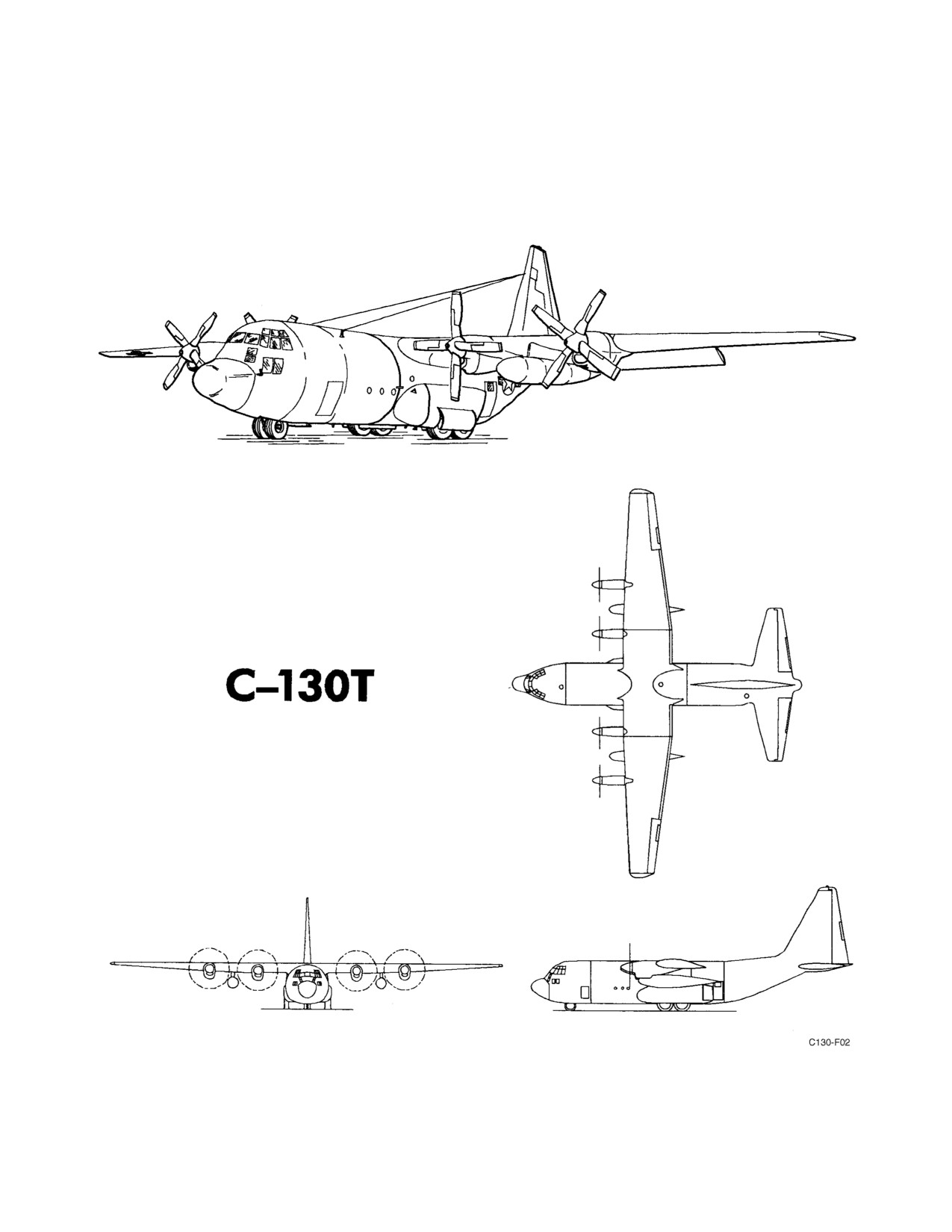
01-75GAL-1
49/(50 blank)
ORIGINAL
01-75GAL-1
PART I
The Aircraft
Chapter 1 — General Description
Chapter 2 — Systems and Equipment
Chapter 3 — Aircraft Servicing
Chapter 4 — Aircraft Operating Limitations
51/(52 blank)
ORIGINAL
01-75GAL-1
CHAPTER 1
General Description
1.1
THE AIRCRAFT
The Lockheed C-130T is a high-wing, all-metal, long-range, land-based monoplane. The mission of this aircraft is
to provide rapid transportation of personnel or cargo for delivery by parachute or landing. The aircraft can be used
as tactical transports and can be converted readily for ambulance or aerial delivery missions. The aircraft can land
and take off on short runways and can be used on landing strips such as those found in advance base operation.
1.1.1 Accommodations
1. Ground troops — 78.
2. Ground troops (including wheelwell seats) — 92.
3. Paratroops — 64.
4. Litters/attendants — 70/2.
5. Litters/attendants — 66/6.
Actual litter capacity may be less due to modifications.
1.1.2 Propulsion
Power is supplied by four Allison T56-A-16, turboprop, constant-speed engines. There are provisions for externally
mounted ATO units to provide additional thrust for takeoff. Each engine drives a four-blade Hamilton Standard
Hydromatic, constant-speed propeller with full feathering and reversible pitch.
1.1.3 Aircraft Dimensions
The principal dimensions of the C-130T aircraft are:
1. Wing span — 132 feet 7 inches.
2. Length — 99 feet 5 inches.
3. Height — 38 feet 4 inches.
4. Stabilizer span — 52 feet 8 inches.
5. Cargo compartment:
a. Length — 40 feet.
b. Width (minimum) — 10 feet 3 inches.
c. Height (minimum) — 9 feet.
1.1.4 Crew Stations
Crew stations are provided for a pilot, copilot, flight engineer, and/or second flight engineer. The loadmaster and
second loadmaster should use passenger seats located in the cargo compartment.
1-1
ORIGINAL
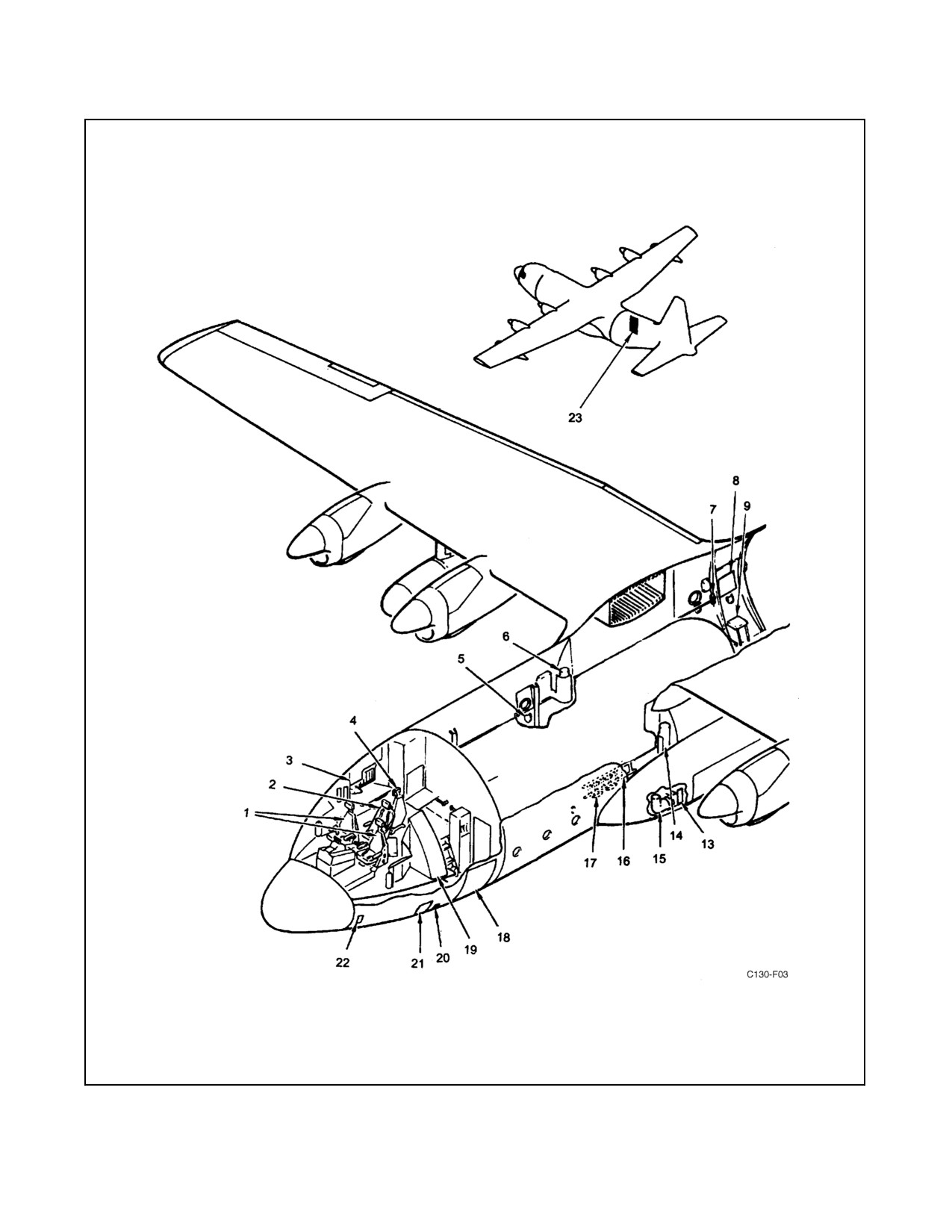
01-75GAL-1
Figure 1-1. General Arrangement (Sheet 1 of 2)
ORIGINAL
1-2
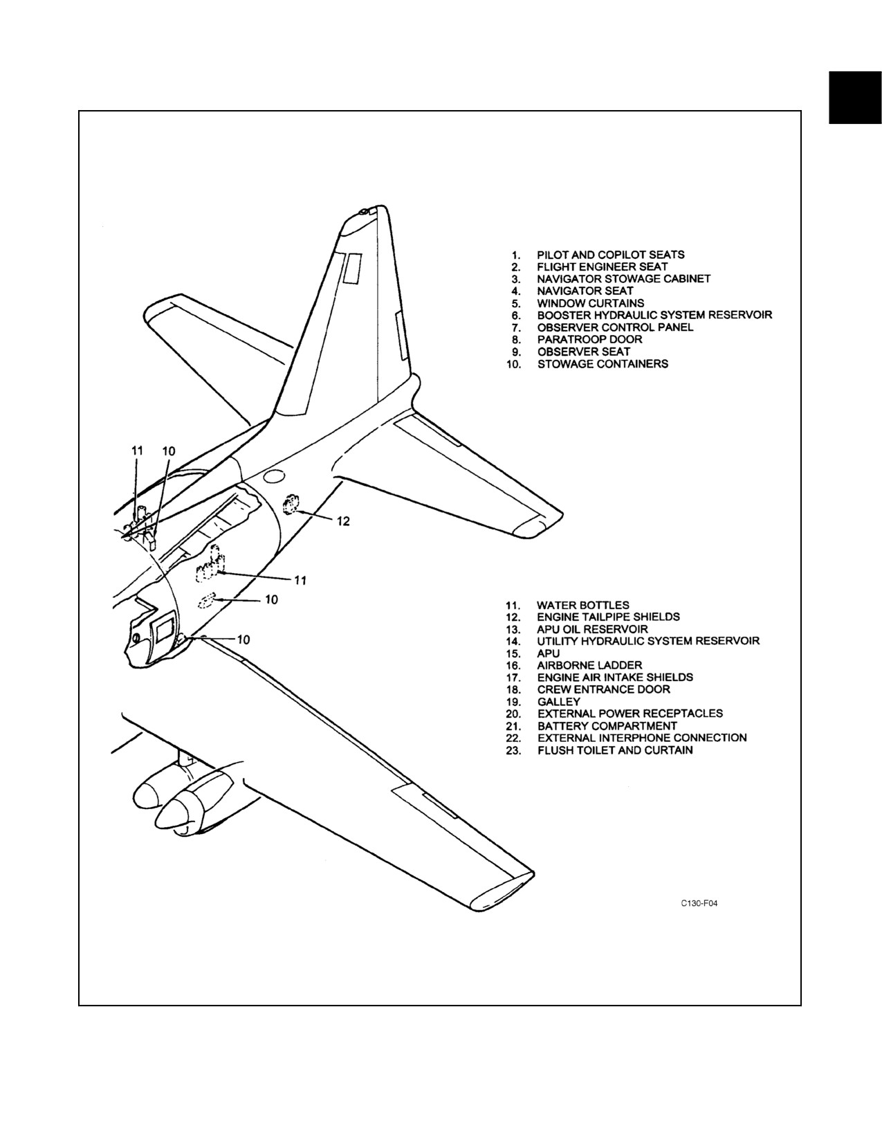
01-75GAL-1
Figure 1-1. General Arrangement (Sheet 2)
1-3
ORIGINAL
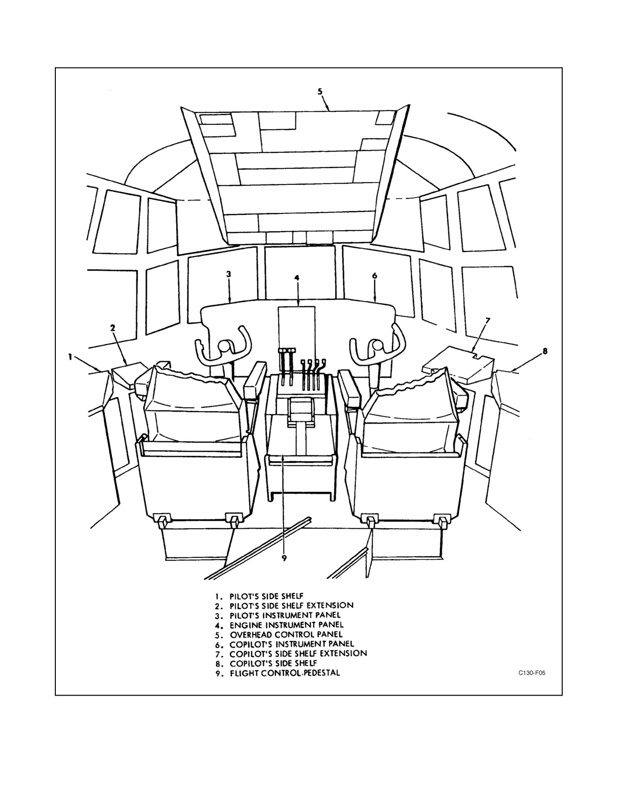
01-75GAL-1
Figure 1-2. Flight Station Forward
ORIGINAL
1-4
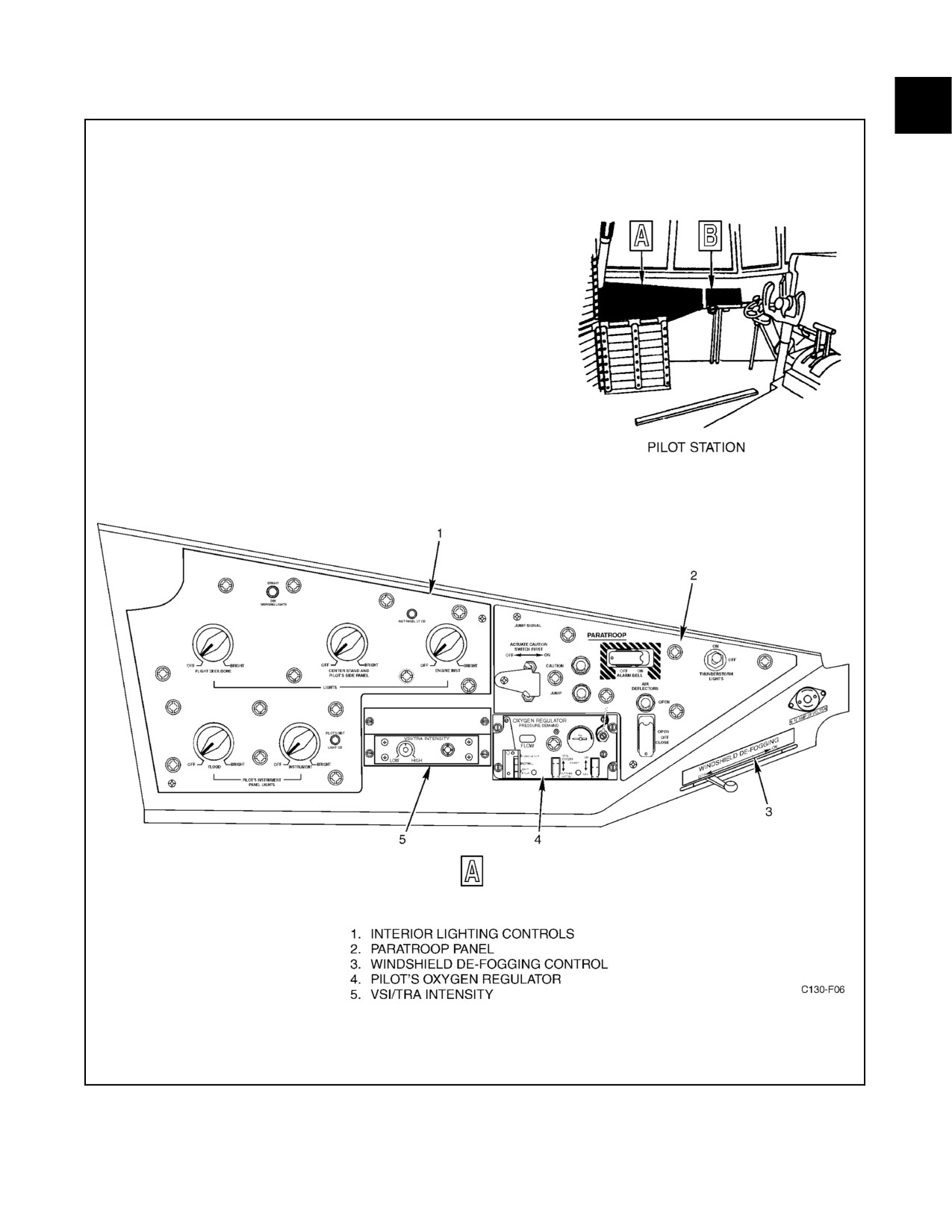
01-75GAL-1
Figure 1-3. Pilot Side Shelf and Extension (Sheet 1 of 3)
1-5
ORIGINAL
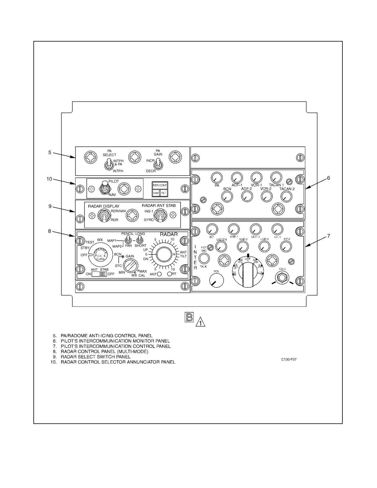
01-75GAL-1
Figure 1-3. Pilot Side Shelf and Extension (Sheet 2)
ORIGINAL
1-6
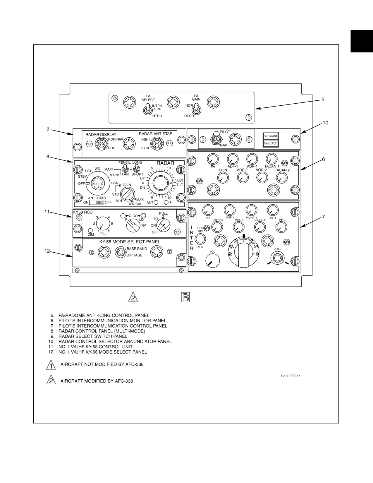
01-75GAL-1
Figure 1-3. Pilot Side Shelf and Extension (Sheet 3)
1-7
ORIGINAL
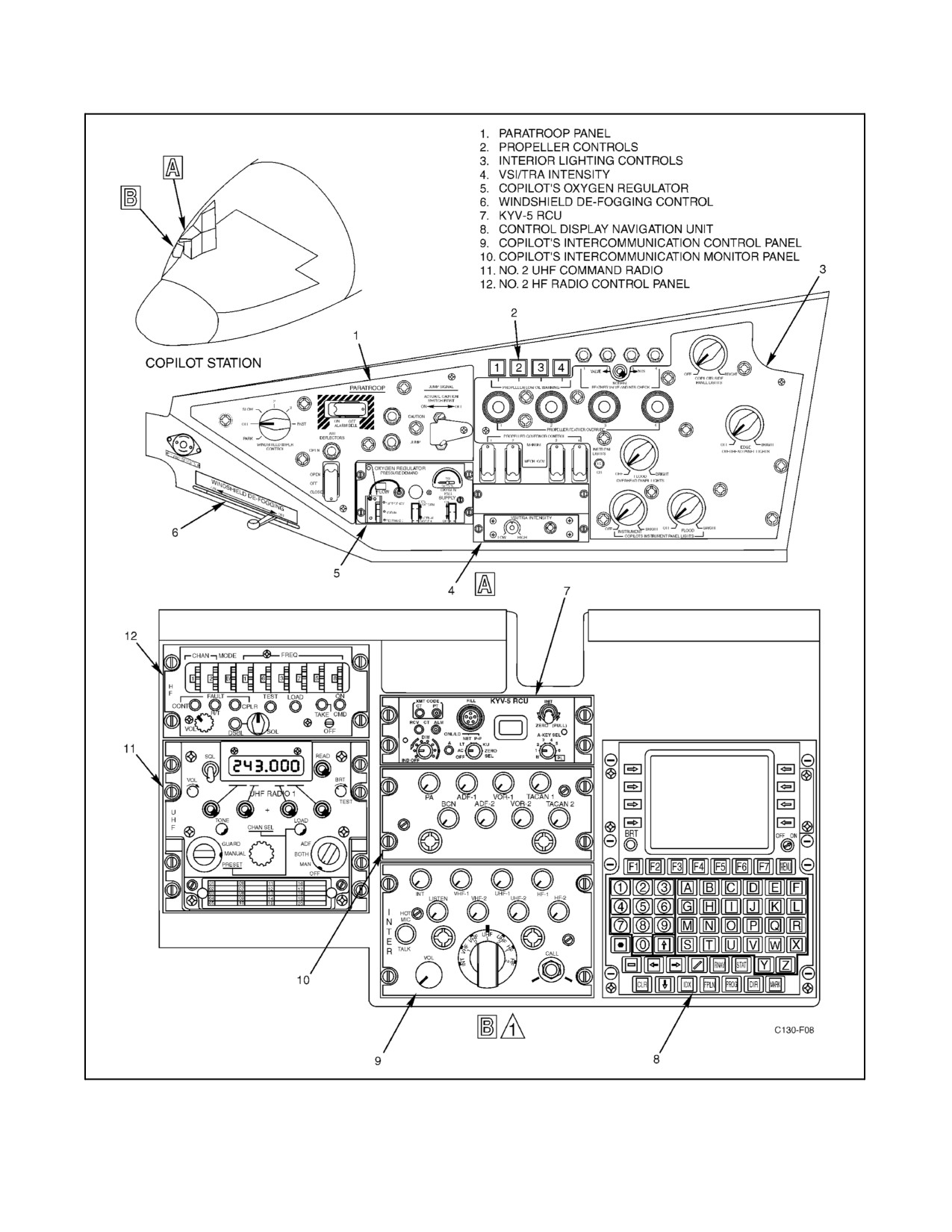
01-75GAL-1
Figure 1-4. Copilot Side Shelf and Extension (Sheet 1 of 2)
ORIGINAL
1-8
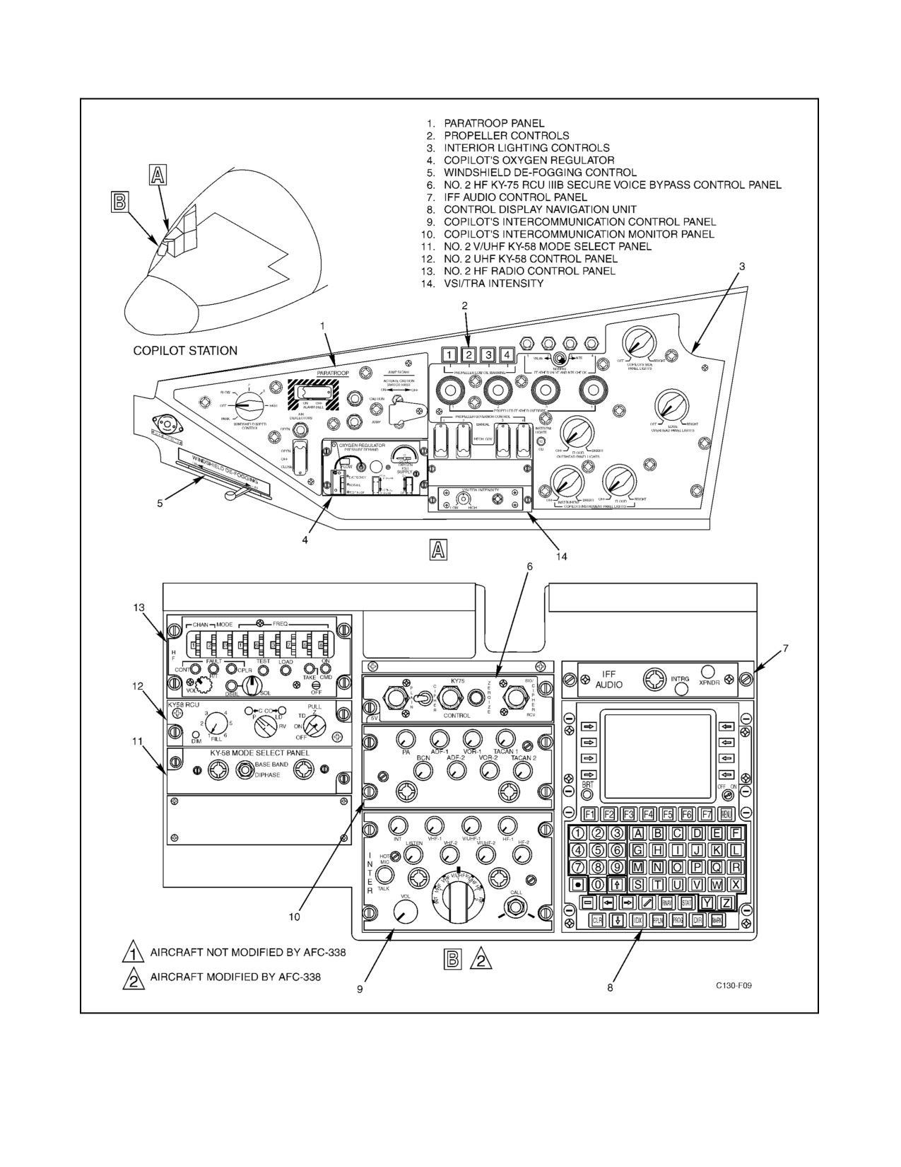
01-75GAL-1
Figure 1-4. Copilot Side Shelf and Extension (Sheet 2)
1-9
ORIGINAL
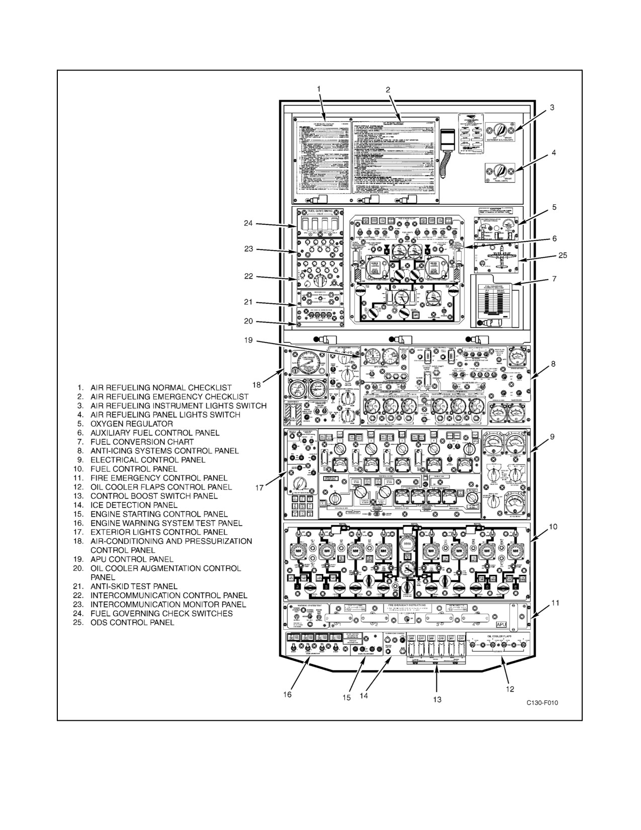
01-75GAL-1
Figure 1-5. Overhead Control Panel (Typical)
ORIGINAL
1-10
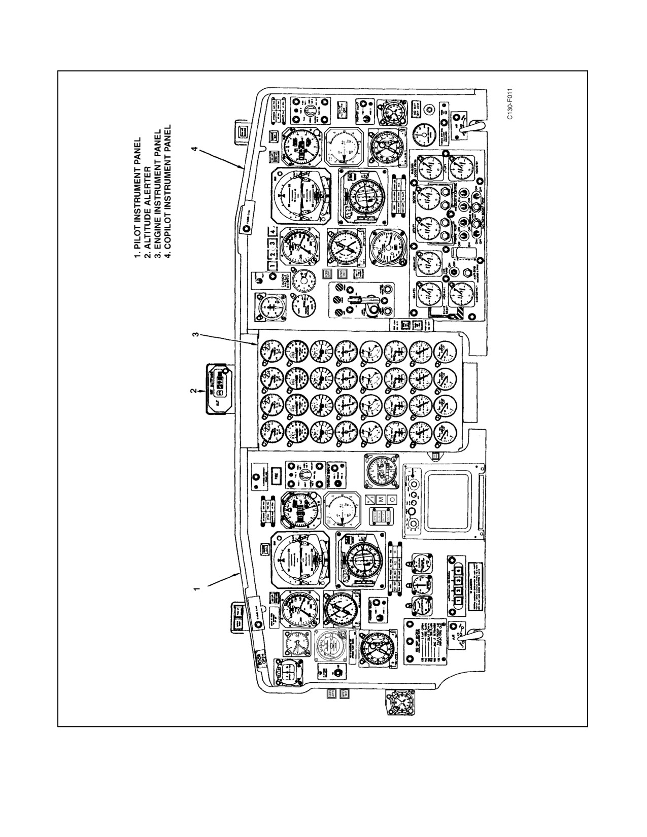
01-75GAL-1
Figure 1-6. Main Instrument Panel (Typical)
1-11
ORIGINAL
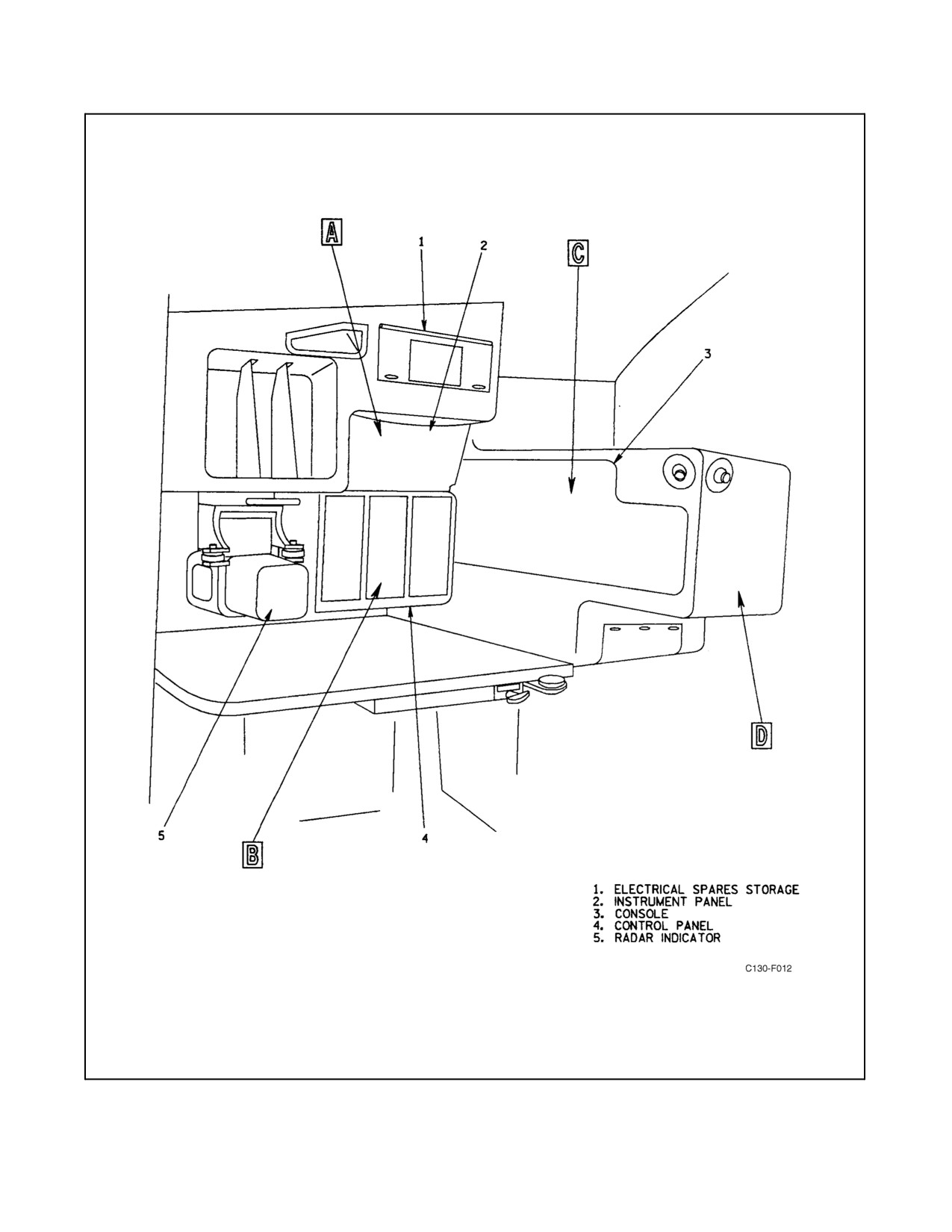
01-75GAL-1
Figure 1-7. Navigator Station (Typical) (Sheet 1 of 5)
ORIGINAL
1-12
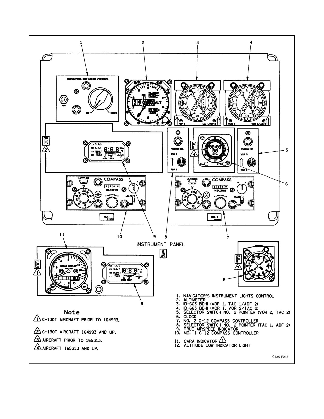
01-75GAL-1
Figure 1-7. Navigator Station (Typical) (Sheet 2)
1-13
ORIGINAL
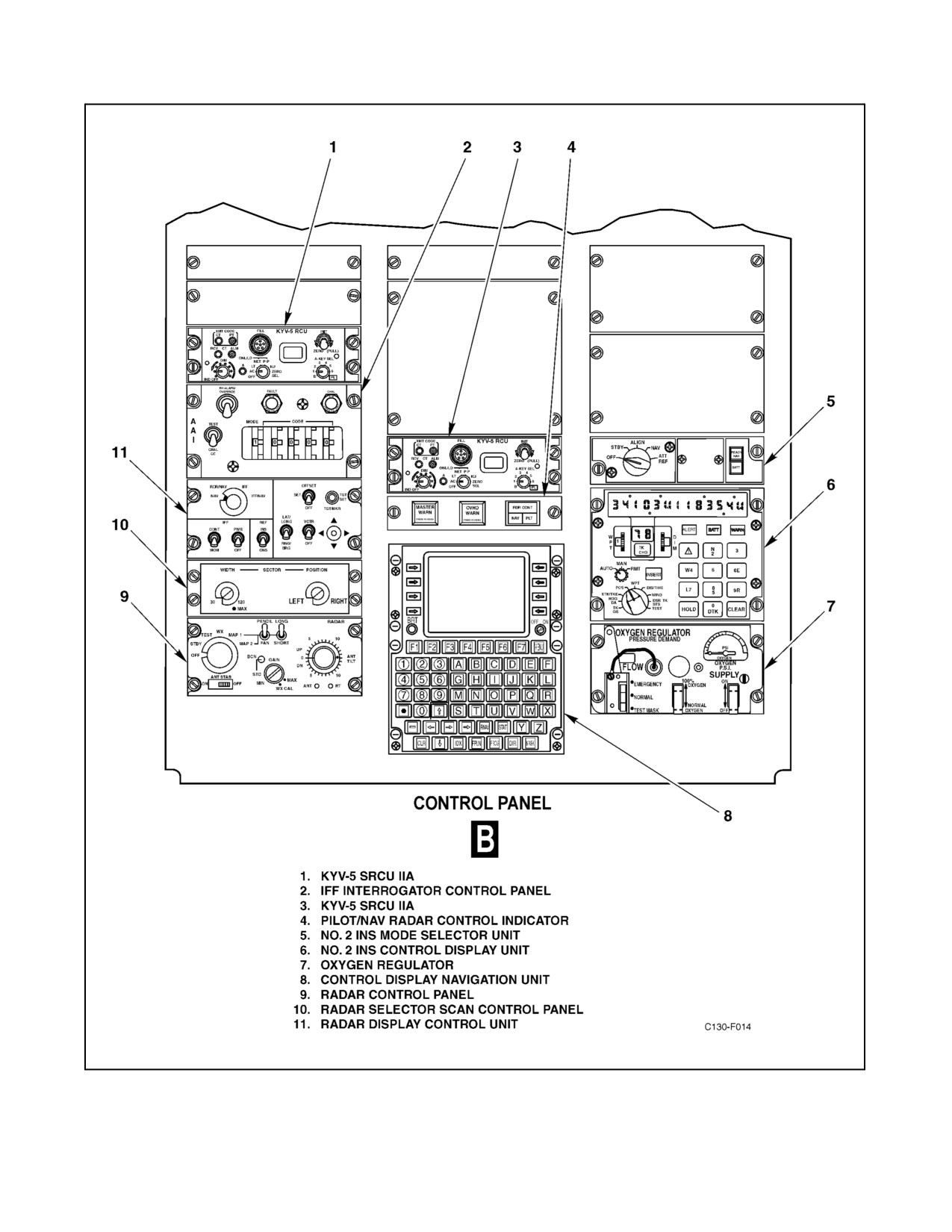
01-75GAL-1
Figure 1-7. Navigator Station (Typical) (Sheet 3)
ORIGINAL
1-14
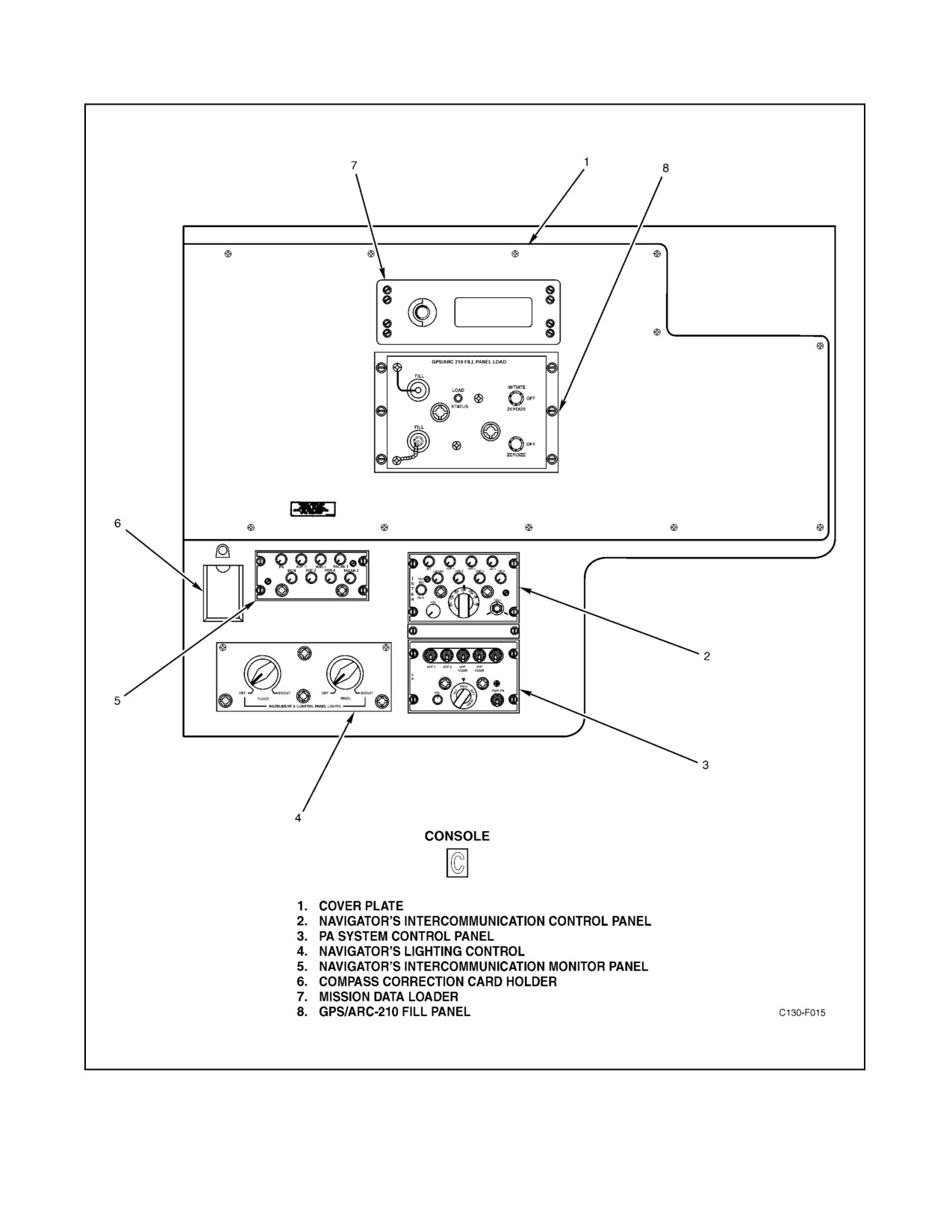
01-75GAL-1
Figure 1-7. Navigator Station (Typical) (Sheet 4)
1-15
ORIGINAL
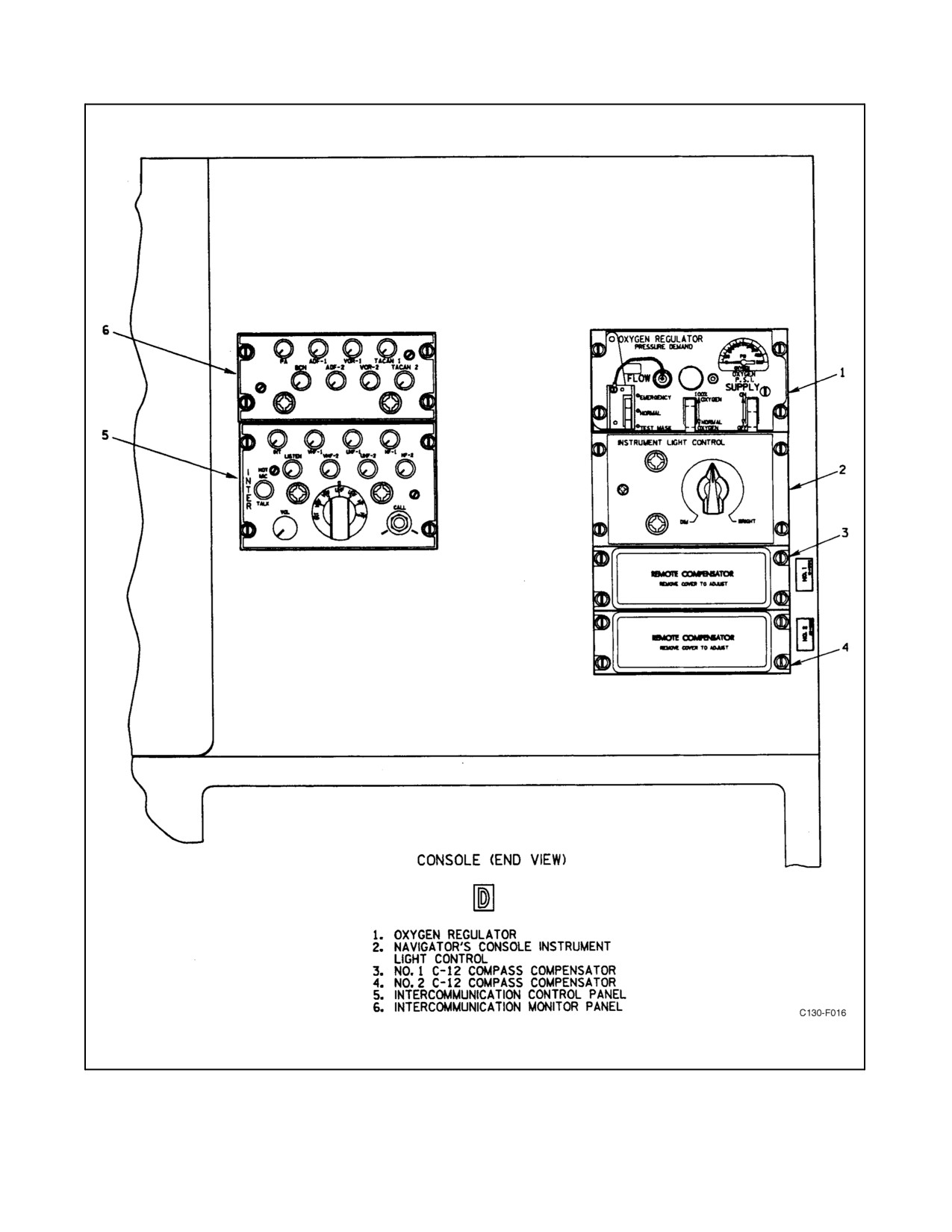
01-75GAL-1
Figure 1-7. Navigator Station (Typical) (Sheet 5)
ORIGINAL
1-16
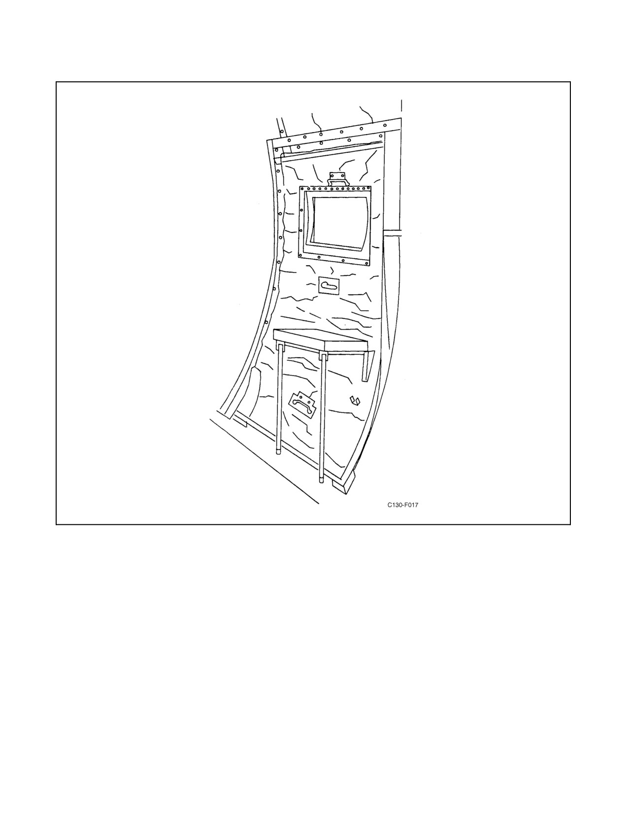
01-75GAL-1
Figure 1-8. Observer Station
1-17/(1-18 blank)
ORIGINAL
//////////////////////////