C-130T. FLIGHT MANUAL (2006) - page 5
01-75GAL-1
The READ control switch causes the selected preset channel frequency to be displayed on the FREQ/(CHAN) readout
indicator.
Preset channel frequency storage is achieved by setting up the desired frequency and channel and then pressing the
LOAD control pushbutton switch.
2.21.6.1.2 Antenna Selector Panels
The antenna selector panels (see Figure 2-96) are equipped with a single toggle-type switch that can be set to one
of two positions: TOP or BOTTOM. The switch permits manual selection of operation through the top-mounted
antenna or bottom-mounted antenna.
2.21.6.2 Normal Operation of the UHF Command Radio
To put the radio into operation, proceed as follows:
1. Place the function selector switch to MAIN or BOTH.
2. Allow 1 minute for warmup.
3. Select a channel using the channel selector knob or a frequency using the manual frequency selector switches.
4. To receive only, activate the respective UHF monitor switch-volume knob on the ICS control panel; turn the
knob to the midrange position.
5. Adjust the volume as necessary with the VOL knob on the UHF radio control panel to obtain a comfortable
reception level.
6. To transmit and receive, place the transmission selector switch on the ICS control panel to UHF.
7. Select the desired antenna by placing the UHF ANT SEL switch to TOP or BOTTOM.
To turn the radio off:
8. Place the function selector switch to the OFF position.
Note
When operating a UHF communication radio under emergency conditions,
set the UHF mode selector switch to GUARD and the function selector
switch to MAIN. Do not use the BOTH position since the noise from the
two receivers may make the incoming signal unintelligible.
If the equipment fails in some particular function, the remaining workable functions may satisfy minimum
requirements for operation. If transmission on a preset channel is not possible, an attempt may be made to use a
manually selected channel or the guard frequency. If reception fails on a selected channel, reception on the guard
frequency may be tried.
2.21.7 AN/ARC-210 V/UHF Radio (Aircraft Modified by AFC-338)
Two V/UHF radio systems, designated V/UHF No. 1 and V/UHF No. 2, provide voice transmissions in the frequency
bands and modes listed in Figure 2-97. The No. 1 V/UHF radio operates from 28-Vdc power from the isolated dc
bus through the V/UHF COMM NO. 1 circuit breakers (2) on the copilot upper circuit breaker panel. The No. 2
V/UHF radio operates from 28-Vdc power from the essential dc bus through the V/UHF COMM NO. 2 circuit
breakers (2) on the copilot upper circuit breaker panel.
2-211
ORIGINAL

01-75GAL-1
MODE
FREQUENCY RANGE
FUNCTIONS
Low VHF (FM)
30 - 87.9875 MHz
Normal Voice, Secure Voice, SINCGARS, Tone Transmission
VHF (AM)
108 - 135.9875 MHz
Normal Voice, Secure Voice, ADF, Tone Transmission, Transmit inhibited
from 108 to 117.9875 MHz
VHF (AM/FM)
136 - 155.9875 MHz
Normal Voice, Secure Voice, ADF, Tone Transmission, Default is FM
VHF (FM)
156 - 173.9875 MHz
Normal Voice, Secure Voice, Maritime Operation, Tone Transmission
UHF (AM/FM)
225 - 399.9875 MHz
Normal Voice, Secure Voice, HAVEQUICK, ADF, Tone Transmission,
Default is AM
Figure 2-97. Table of AN/ARC-210 Modes
2.21.7.1 V/UHF Radio Controls
2.21.7.1.1 Control Display Navigation Unit
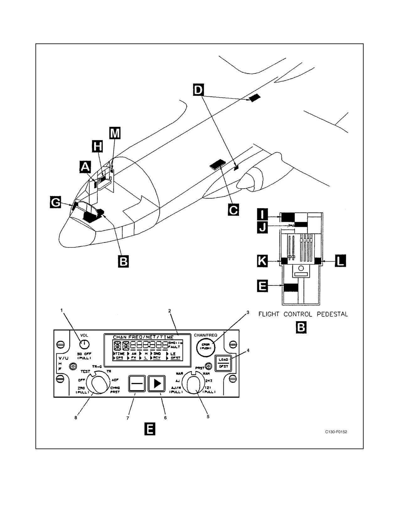
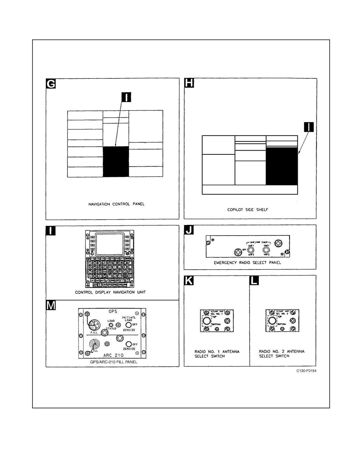
The Control Display Navigation Units (Figure 2-98), located on the flight control pedestal and the copilot side shelf
extension, provide primary operating control for both V/UHF radios.
2.21.7.1.2 Control Unit
A V/UHF Control Unit (Figure 2-98) is located on the flight control pedestal and is provided for emergency control
of the V/UHF COMM No. 1 radio. A list of controls and indicators is provided in Figure 2-99.
2.21.7.1.3 Antenna Selector Panel
The antenna selector panels (Figure 2-98) are equipped with a single toggle-type switch that can be set to one of two
positions: TOP or BOTTOM. The switch permits the manual selection of operations through the top-mounted
antenna or bottom-mounted antenna.
2.21.7.1.4 Emergency Select Switch Panel
The emergency select switch panel (Figure 2-98) is equipped with two switches that can be set to one of two positions:
VHFx or UHFx (x = 1,2). With the switch in the VHF position, the AN/ARC-186 tunes to guard frequency 121.5
MHz. With the switch in the UHF position, the AN/ARC 210 tunes to guard frequency 243 MHz. One switch controls
the No. 1 system and the other switch controls the No. 2 system.
2.21.7.1.5 GPS/ARC-210 Fill Panel
The GPS/ARC-210 fill panel is located between the navigators station and radio operators station (Figure 2-98). For
ARC-210 operations, the panel is equipped with a fill connector and a switch. Preset information is loaded into the
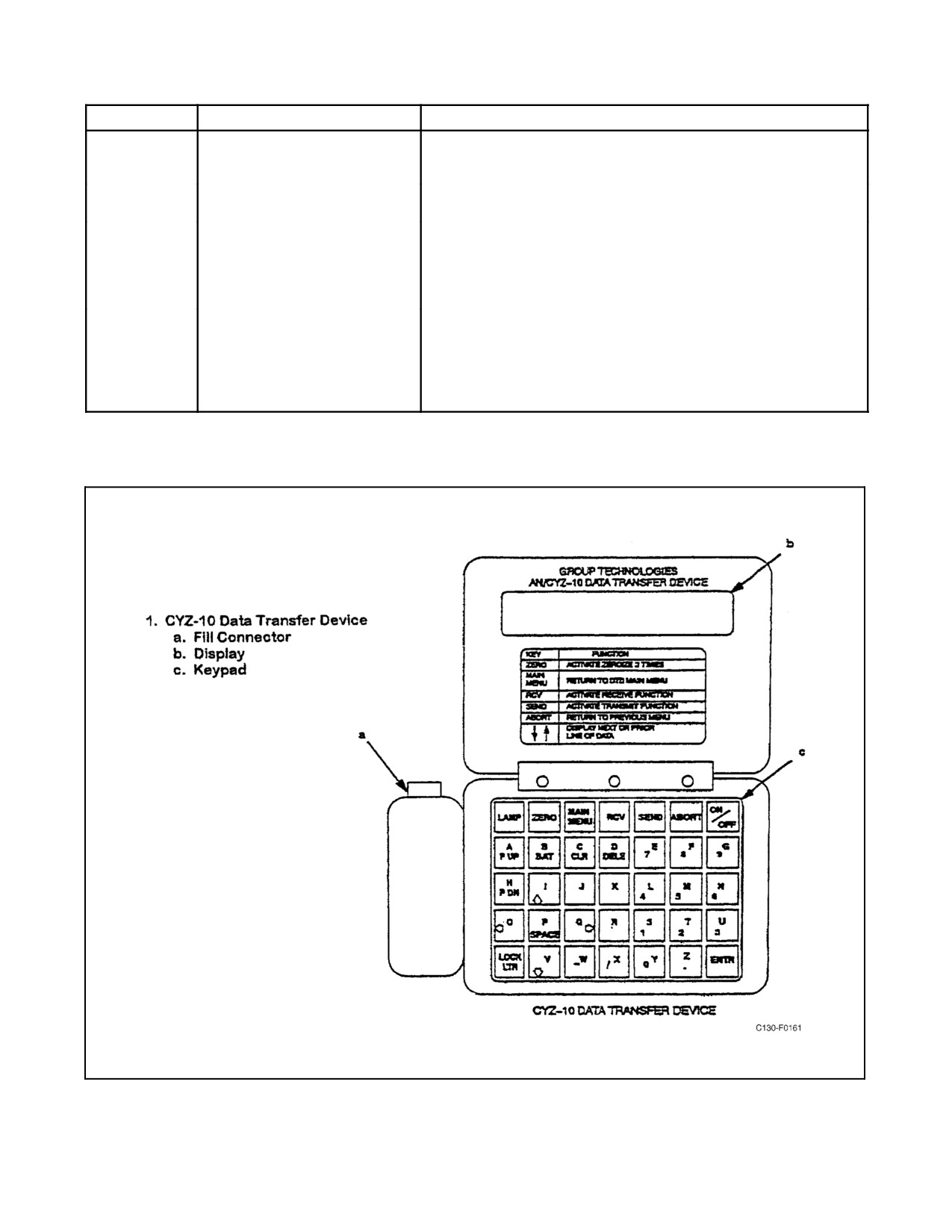
ARC-210 radio via the fill connector using the CYZ-10 Data Transfer Device (DTD) (Figure 2-100). Zeroization of
preset information occurs by momentarily placing the switch in the ZEROIZE position.
2.21.7.2 Normal Operations of the V/UHF Radio Using the CDNU
Note
Normal operations are given assuming that the AN/CYZ-10 Data Transfer
Device has been loaded with the appropriate preset information.
ORIGINAL
2-212
01-75GAL-1
Figure 2-98. AN/ARC-210(V) UHF/VHF Communication System Components Location (Sheet 1 of 2)
2-213
ORIGINAL
01-75GAL-1
Figure 2-98. AN/ARC-210(V) UHF/VHF Communication System Components Location (Sheet 2)
ORIGINAL
2-214

01-75GAL-1
ITEM
CONTROL/INDICATOR
FUNCTION
1
SQ OFF
SQ OFF push-pull switch disables main receiver squelch in the “out”
VOL-(disabled)
position and enables squelch in the “in” position.
2
CHAN/FREQ/NET/TIME Display
Liquid crystal module display. Displays channel, frequency, net time,
mode, or built-in-test (BIT) results.
3
CHAN/FREQ CSR Selector
CHAN (channel)/FREQ (frequency) CRSR (cursor) pushbutton rotary
switch. Each time the switch is depressed, the cursor position
changes. Rotating the switch changes the channel or frequency value
depending upon the mode selected and the cursor position.
4
LOAD/OFST
Pushbutton switch. When depressed, enables the loading of various
data depending upon the mode selected.
5
Frequency Mode Selector
Isolated position rotary switch (knob must be pulled out to enter or exit
positions marked PULL). Selects the following frequency modes.
121
(PULL)
With the rotary switch pulled and placed in the 121 position
(pull-to-turn), VHF guard mode is selected. The transmitter and main
receiver are tuned to 121.500 MHz (AM). The preset and manual
frequency selector controls become inoperative.
243
With the rotary switch pulled and placed in the 243 position
(pull-to-turn), UHF guard mode is selected. The transmitter and main
receiver are tuned to 243.000 MHz (AM). The preset and manual
frequency selector controls become inoperative. Selection of this
mode will also turn on the radio with the operational mode selector in
the OFF condition with primary power present.
MAN
Selects manual frequency select mode. Operator may select any of
the radio operating frequencies. The following ancillary modes may
also be selected.
NOTE
To select ancillary modes, the ancillary mode pushbutton switch
(7) is used to position the cursor under the desired mode, and the
pointer pushbutton switch (6) is used to select or deselect the
mode.
Manual Ancillary Modes
GPS
Global Positioning System (GPS) time mode. Enables the receipt of
time from a GPS Receiver when a CD-17/ARC Frequency
Countermeasures Controller is attached to the Receiver-Transmitter.
AM/FM
AM/FM mode selection. Identifies modulation to be employed in the
VHF band 136 to 155.985 MHz and the UHF band 225 to 399.985
MHz.
SND/RCV
Send (SND) and receive (RCV) mode. Used for over-the-air transfers
between radios on the same frequency when the LOAD/OFST
pushbutton is depressed. HAVEQUICK TOD may be transferred with
the radio operating frequency in the UHF range. SINCGARS ERF may
be transferred if the radio operating frequency is in the VHF-FM
(30-87.975 MHz) range. This switch is also used for Emergency Start
time.
OFST
Offset mode. Enables the selection of any frequency in the valid
operating bands from 30 to 399.975 MHz in 5-kHz steps. Offsets of 0
kHz, ±5 kHz and ±10 kHz can be selected after the pointer is placed in
front of the OFST menu selection, and pressing the LOAD/OFST
pushbutton switch to increment in 5 kHz steps.
Figure 2-99. AN/ARC-210(V) V/UHF Control Unit Functions (Sheet 1 of 3)
2-215
ORIGINAL

01-75GAL-1
ITEM
CONTROL/INDICATOR
FUNCTION
5
(cont.)
Manual Ancillary Modes (cont.)
PRST
Preset mode. Using the CHAN/FREQ switch, the operator may select
up to 25 preset channels (1 through 25) for simplex operation. The
selected channel, frequency, and modulation type (AM/FM) is
displayed. SCAN mode is selected when SCAN is displayed. Preset
channels 22 through 25 are scanned. Channel 22 is the command
channel and 23 through 25 are secondary channels. When a signal is
detected on a scan channel, the channel number and frequency are
displayed. Depressing LOAD/OFST during scanning will RESULT in
the selection of the last active channel. Depressing LOAD/OFST a
second and/or third time will tune the Receiver-Transmitter to the last
active second and/or third channel. Depressing the LOAD/OFST a
fourth time will resume scanning operations. The same ancillary
modes described for MAN mode are also available in the PRST.
MAR
Maritime mode. Operator may select any one of the 57 preset
maritime channels (channels 1 through 28 and 60 through 88).
Maritime channel and transmit frequency are displayed. Alternately
depressing the LOAD/OFST pushbutton while in the MAR mode
changes transmit frequency and station operation from shore to
ship-station and back.
AJ
ECCM AJ (Anti-Jam) mode. Operator may select up to 25 AJ preset
networks, either HAVEQUICK or SINCGARS ECCM nets, if all 25
channels are loaded with fill information, or the SINCGARS CUE channel
in addition to Cold Start channel. The channel and preset net number are
displayed when the Cold Start channel is selected. Following operator
selection, the appliqué supplies all frequency and control data for
operation of the Receiver-Transmitter and antenna. The operator may
define a HAVEQUICK channel by loading the WOD/MWOD and
HAVEQUICK type. In HAVEQUICK, the GPS and SND/RCV time
ancillary modes are available. In SINCGARS the GPS, SND/RCV ERF
(ECCM Remote Fill), H (Hopsets), L (Lockout Sets), and LE (Late Entry)
modes are available and SINCGARS CUE channel is monitored.
AJ/M (PULL)
With the rotary switch pulled and placed in the AJ/M position
(pull-to-turn), AJ/M (anti-jam/master net) mode is selected. Provides
same capabilities as AJ mode plus the added functions associated
with a SINCGARS master net controller.
6
Pointer Pushbutton Switch
Positions pointer to select or deselect ancillary mode option identified
by cursor positioned by ancillary mode pushbutton switch (7).
7
Ancillary Mode Pushbutton
Positions cursor under various ancillary mode options. Used with
Switch
pointer pushbutton switch (6) to select and deselect ancillary modes.
8
Operational Mode Selector
Isolated position rotary switch (knob must be pulled out to enter or exit
positions marked Pull). Selects the following operational modes.
ZRO (PULL)
With rotary switch pulled and placed in the ZRO (zeroize) position, all
ECCM fill data is zeroized by completely erasing them from memory.
ZRO is displayed.
OFF
Select Off mode. Turns power off.
TEST
Selects Test mode. Initiates Built-in-Test (BIT) of the control unit,
Receiver-Transmitter, appliqué, antenna converter unit, and antenna.
Display is blanked except for a momentary side pointer followed by
the decimal point with the test in progress. Faults detected are
displayed. With no faults detected, the display illuminates all function
indicators. The operator may single step through each test and display
the results by depressing the LOAD/OFST pushbutton switch (4)
within 2 seconds of selecting test mode. Test mode takes precedence
over all operations except 243 MHz Guard.
Figure 2-99. AN/ARC-210(V) V/UHF Control Unit Functions (Sheet 2)
ORIGINAL
2-216
01-75GAL-1
ITEM
CONTROL/INDICATOR
FUNCTION
8
(cont.)
TR+G
Selects main Receiver-Transmitter mode plus guard mode. The main
receiver, transmitter, and guard receiver are on and able to perform all
functions.
TR
Selects main Receiver-Transmitter mode. The main communications
receiver and transmitter are on. Guard Receiver is off.
ADF
Selects automatic direction finding mode. Transmitter functions
normally. The main receiver is connected to the ADF antenna port.
The receiver will provide normal receive audio in addition to providing
the demodulated ADF signal. Guard receiver is on. In FM mode,
degraded operation may be noted.
CHNG PRST
Selects change presets mode. Preset channels including COLD
START, CUE, and corresponding operating frequencies and
modulation can be loaded into Receiver-Transmitter memory and the
HAVEQUICK ECCM net codes loaded into the ECCM controller
memory. Presets may be loaded by the operator via the control unit,
MIL-STD-1553B data bus or data transfer device.
Figure 2-99. AN/ARC-210(V) V/UHF Control Unit Functions (Sheet 3)
Figure 2-100. CYZ-10 Data Transfer Device
2-217
ORIGINAL
01-75GAL-1
2.21.7.2.1 Loading Presets into Radios
1.
Connect the DTD to the GPS/ARC-210 Fill Port located at the radio operator’s station using fill cable.
2.
Press ON/OFF to turn on the DTD.
3.
Press “A” for “Application” on the DTD key pad.
4.
Select “XMIT” by pressing the ENTER key on the DTD key pad.
5.
Press “P” for “Platform” on the DTD key pad.
6.
Press P UP or P DN on the DTD key pad to select the appropriate fill file.
7.
Press ENTER to select “BUSSED.”
8.
Press ⇓ key to initiate gathering of data.
9.
Press ⇓ key to initiate loading.
10.
Disconnect cable.
11.
Press ON/OFF to turn off the DTD.
Note
Prior to step 12, verify three satellites have been acquired on the RNAV
Page of the CDNU. This page can be found by first pressing the RNAV key
and then pressing ⇒ key until the page is found.
12.
On the CDNU, enter “/I” in the scratchpad and press Function Key F3.
13.
Wait 3 minutes for presets to load into the radios. The CDNU will display “UPLOAD DONE” when loading
is complete.
2.21.7.2.2 V/UHF Radio Tuning and Control
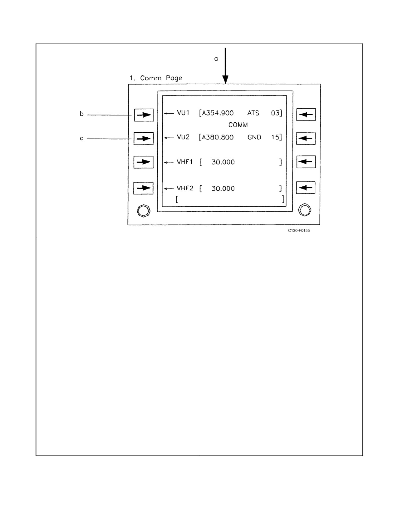
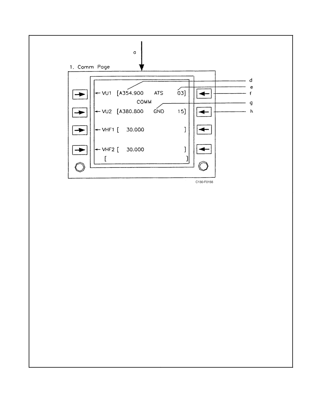
The V/UHF radios are tuned and controlled via the CDNU Comm page or detailed VHF page. System power is
controlled via the CDNU Power page (a box around the system name indicates the unit is powered). The Comm page
is accessed via the F3 key or via the index page. Tuning is accomplished by entering the appropriate frequency in
the scratchpad and then pressing the line select key next to the corresponding radio. Pressing the line select key with
no frequency in the scratchpad (blank scratchpad) will access the detailed page for the corresponding radio. Quick
tuning can be accomplished by entering the frequency in the scratchpad and pressing F1 for V/U-1 or F2 for V/U-2.
Pressing the F1 or F2 keys with no frequency in the scratchpad will access the corresponding detailed V/UHF page.
Returning to the previously selected frequency may be accomplished by tuning 0. For additional functions and
controls of the V/UHF radios, refer to Figures 2-101 through 2-104.
ORIGINAL
2-218
01-75GAL-1
1.
Comm Page.
(6) Valid non-antijam preset number: Tunes radio
to frequency associated with preset number.
a.
Access Comm Page via Index 1/2 Page.
Frequency, modulation type and alphabetic ID
b.
Depends on scratchpad entry:
(if applicable) are displayed in brackets.
(1)
Blank Accesses VU1 1/2 Page.
(7) Valid alphabetic ID: Tunes radio to frequency
(2)
Valid modulation type: Sets modulation type
associated with alphabetic ID.
(A for AM; F for FM) of frequency in brackets.
(8) Valid maritime channel: Tunes radio to
(3)
Valid frequency: Tunes radio to frequency in
frequency associated with maritime channel.
scratchpad. Frequency and modulation type
Frequency, modulation type, transmission
are displayed in brackets [ ]. Radio selects
frequency designation (SHP for ship; SHO for
default modulation type for frequency band.
shore), and channel number preceded by M
Decimal point and trailing zeros are not
are displayed in brackets.
required.
(9) Letter S: Toggles scan function on and off.
(4)
Valid modulation and valid frequency: Same
With scan enabled, radio scans through
as (2) and (3).
frequencies defined on Scan List Page. If
LOCK or HELD mode become operational
(5)
Valid antijam preset number: Tunes radio to
while scanning was active, radio automatically
net number associated with preset number.
tunes to locked or held frequency when
Antijam preset number must be preceded by
scanning is toggled off. If no frequency was
an A when entered into scratchpad. If any
locked or held, radio tunes to frequency it was
data associated with the antijam preset are
tuned to prior to activation of scanning.
missing, error message will appear in
brackets in place of the net number. When
(10) Zero (0) in scratchpad: Tunes radio to
preset A26 is entered, CUE is displayed
previously tuned frequency. Frequency and all
indicating radio is tuned to the CUE frequency.
associated attributes are displayed in
When preset A27 is entered, COLD is
brackets.
displayed indicating radio is tuned to the
c. Function same as LSK1 except for VU2.
COLD START frequency.
Figure 2-101. AN/ARC-210(V) V/UHF Comm Pages (Sheet 1 of 2)
2-219
ORIGINAL
01-75GAL-1
1.
Comm Page (cont).
(2) Scanning enabled and blank in
scratchpad: Scanning is interrupted and
d.
Frequency or net radio is tuned to preceding
last locked-on frequency (or command
letter indicates:
frequency if no previous lock has
(1) A = AM modulation
occurred) is held. Locked-on frequency
(2) F = FM modulation
and HELD are displayed in brackets.
Resume scanning by pressing LSK5
(3) SX = (x = 1, 2, 3 or 4): Current scan
second time.
frequency as defined on Scan List Page.
H or S following net number indicates net
g.
This field can be occupied by five different
type (H = HAVEQUICK, S = SINCGARS)
items:
e.
Preset number of frequency defined on VU
(1) Alphabetic ID = Three-letter alphabetic
preset pages. Preceding blank, A or M
identifier.
indicates:
(2) CUE = Antijam preset A26 has been
(1) Blank = Non-antijam preset
entered and radio is tuned to the CUE
frequency.
(2) A = Antijam preset
(3) COLD = Antijam preset A27 has been
(3) M = Maritime preset
entered and radio is tuned to the cold
f.
Operations associated with LSK5 are defined
start frequency.
in two different situations:
(4) SHP = Ship station maritime preset
(1) Valid offset (0, ±.005, ±.01) entered into
selected.
scratchpad: Offset is added to frequency
(5) SHO = Shore station maritime preset
in brackets. Has to be a non-antijam or
selected.
non-maritime frequency.
h.
LSK6 functions same as LSK5 except for
VU2.
Figure 2-101. AN/ARC-210(V) V/UHF Comm Pages (Sheet 2)
ORIGINAL
2-220
01-75GAL-1
1.
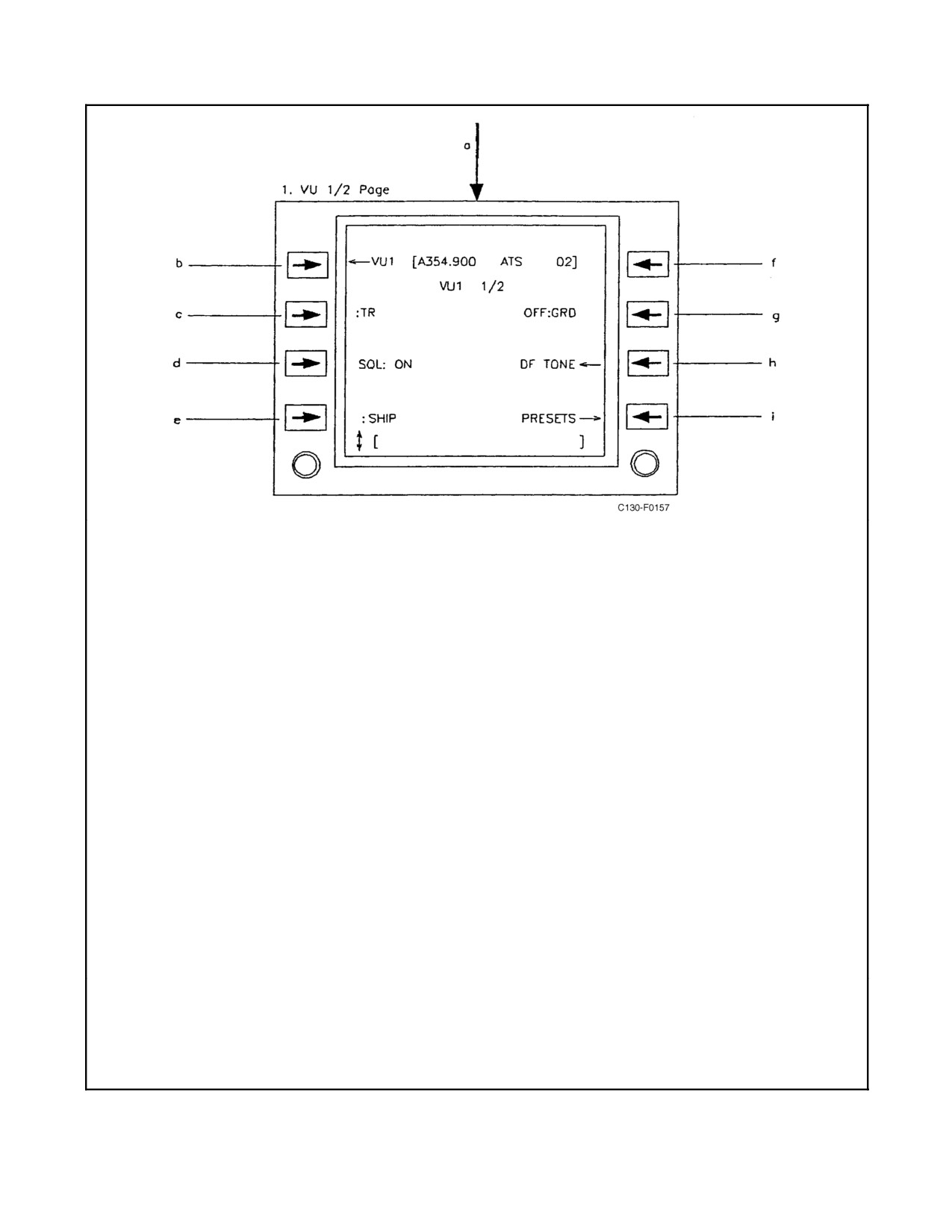
VU1 1/2 Page (VU1 1/2 Page shown).
(2) Radio is turned to SINCGARS net: Arrow
followed by SINCGR SETUP is displayed
a. Access VU1 1/2 Page via Comm Page
adjacent to LSK4: Accesses VU1
(Figure 2-101).
SINCGARS Setup Page.
b. Accesses Comm Page if blank in scratch-
(3) Radio is tuned to HQ net: Arrow followed
pad. Otherwise, operates same as defined
by HQ SETUP is displayed adjacent to
for LSK1 on Comm Page (Figure 2-101).
LSK4: Accesses VU1 HQ Setup Page.
c. Selects radio mode:
f. Operates same as defined for LSK5 on
(1) TR
Comm Page (Figure 2-101)
(2) TR+G
g. Sets VU1 guard channel to UHF GUARD,
(3) ADF (ADF is not an option with VU2).
VHF GUARD or OFF (notes 2 and 3)
d. Toggles squelch.
h. Toggles DF tone:
(1) SQL: ON
(1) DF TONE*=On
(2) SQL: OFF
(2) DF TONE ← =OFF
e. Depends on radio operation:
NOTE
(1) Radio is tuned to non-antijam frequency
DF TONE disappears from CDNU screen
other than maritime channels 6, 8, 72 or
when a HQ is selected.
77: Toggles between SHIP and SHORE.
i. Accesses VU1 Non-AJ Presets Page or VU1
Selection of SHORE while maritime
AJ Presets Page depending on frequency
channel 6, 8, 72 or 77 is active is not
type in brackets, antijam (AJ) or non-antijam
permitted.
(non AJ).
Notes:
1.
Selecting guard frequency via emergency radio select panel tunes radio to 243.000 MHz AM.
2.
Selecting VHF GRD with LS6 tunes radio to 121.500 MHz AM.
3.
Selecting UHF GRD with LS6 tunes radio to 243.000 MHz AM.
Figure 2-102. AN/ARC-210(V) V/UHF 1/2 Page (Sheet 1 of 2)
2-221
ORIGINAL
01-75GAL-1
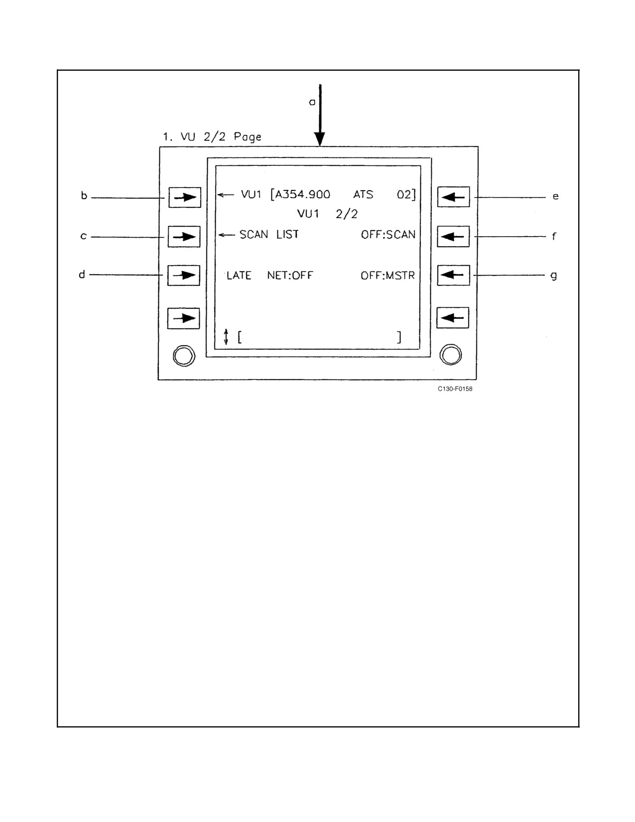
1. VU 2/2 Page (VU1 2/2 Page shown).
(4) SINCGARS net not active: LATE NET is
set to OFF and toggling is not permitted.
a. Access VU1 2/2 Page via Comm Page
(Figure 2-101).
e. Operations are same as defined for LSK5 on
Comm Page (Figure 2-101).
b. Operations are same as described for LSK1
on Comm Page except when scratchpad is
f. Toggles scanning mode ON and OFF.
blank. When scratchpad is blank accesses
g. Depends on SINCGARS status:
Comm Page.
(1) SINCGARS net active and VU1 not
c. Accesses Scan List Page.
attempting late net entry: Toggles MSTR
d. Depends on SINCGARS status:
ON and OFF.
(1) SINCGARS net active and VU1 not in
(2) SINCGARS net active and VU1
net or acting as net master. Toggles late
attempting late net entry: MSTR is set to
entry ON and OFF.
OFF and toggling is not permitted. Any
attempt to toggle MSTR will generate
(2) SINCGARS net active and VU1 in net:
error message.
LATE NET is set to OFF and toggling is
not permitted.
(3) SINCGARS net not active: MSTR is set
to OFF and toggling is not permitted.
(3) SINCGARS net active and VU1 net
master: LATE NET is set to OFF and
toggling is not permitted. Any attempt to
toggle LATE NET will generate error
message.
Figure 2-102. AN/ARC-210(V) V/UHF 2/2 Page (Sheet 2)
ORIGINAL
2-222
01-75GAL-1
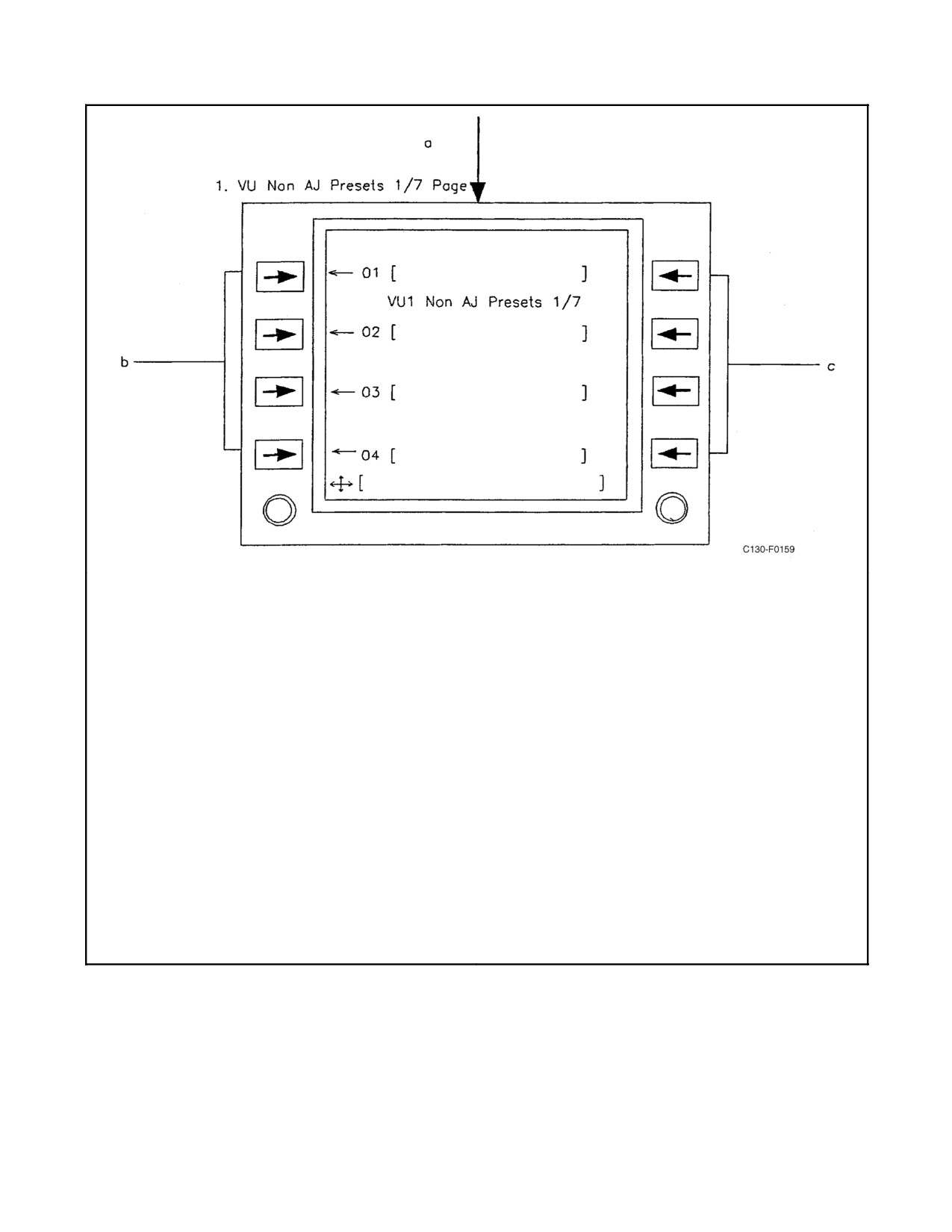
1. VU Non AJ Presets Page (VU1 Non AJ Presets
(6) Valid frequency and alphabetic ID: Inputs
1/7 Page shown).
frequency and alphabetic ID into
brackets. Frequency and alphabetic ID
a. Access VU1 Non AJ Presets 1/7 Page via
must be separated by slash (/).
VU1 1/2 Page and scrolling as required.
(7) Minus-slash symbol (-/): Deletes
b. Depends on scratchpad entry:
frequency in brackets. Alphabetic
(1) Blank: Radio tunes to frequency in
identifier remains present.
brackets and accesses VU1 1/2 Page.
(8) Slash-minus symbol (/-): Deletes
(2) Valid modulation type: Sets modulation
alphabetic identifier from brackets.
type of frequency in brackets.
Frequency remains present.
(3) Valid frequency: Inputs frequency from
(9) Minus (-) or minus-slash-minus (-/-):
scratchpad into brackets. Radio selects
Deletes both frequency and alphabetic
default modulation type for frequency
identifier from brackets.
band.
c. Adds valid offset (0, ±.005, ±.01) entered into
(4) Valid frequency and valid modulation
scratchpad to frequency in brackets.
type: Inputs frequency and modulation
from scratchpad into brackets.
(5) Valid alphabetic ID: Assigns alphabetic
ID to frequency in brackets.
Figure 2-103. V/UHF Non-Antijam Presets Page
2-223
ORIGINAL
01-75GAL-1
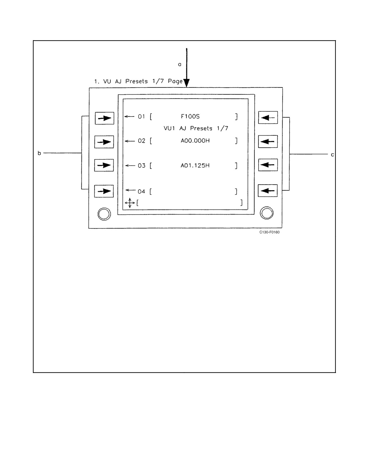
1. VU AJ Presets Page (VU1 AJ Presets 1/7 Page
(4) Minus-slash symbol (-/): Deletes
shown).
frequency in brackets. Alphabetic
identifier remains present.
a. Access VU1 AJ Presets 1/7 Page via VU1
1/2 Page and scrolling as required.
(5) Slash-minus symbol (/-): Deletes
b. Depends on scratchpad entry:
alphabetic identifier from brackets.
Frequency remains present.
(1) Blank: Radio tunes to frequency in
brackets and accesses VU1 1/2 Page.
(6) Minus (-) or minus-slash-minus (-/-):
(2) Valid alphabetic ID: Assigns alphabetic
Deletes both frequency and alphabetic
ID to frequency net in brackets.
identifier from brackets.
(3) Valid HQ frequency net number and valid
alphabetic ID: Inputs net number and
c. With blank scratchpad accesses HQ setup
when HQ net is in associated brackets. With
alphabetic ID into brackets. Frequency
net number and alphabetic ID must be
blank scratchpad accesses SINCGARS
separated by slash (/).
setup page, when SINCGARS net is in
associated brackets.
Figure 2-104. V/UHF Antijam Presets Page
2.21.7.2.3 Normal Operation
Operate the V/UHF radio as follows:
1. Tune desired frequency in V/UHF-1 or V/UHF-2 via the CDNU.
2. To receive, pull the corresponding V/UHF push-pull mixer switch on the intercommunication control panel
(ICS).
ORIGINAL
2-224
01-75GAL-1
3. Adjust squelch (via CDNU) and volume (via individual mixer switch or master volume knob on ICS panel).
4. To transmit, place the transmission selector on the ICS panel to the V/UHF-1 or V/UHF-2 position.
2.21.7.3 Normal Operations of the V/UHF Radio Using the Control Unit
Note
Normal operations are given assuming that the radio has been loaded with
preset information in accordance with the procedure provided in the
previous paragraphs. Since the control unit is considered to be a backup
unit, only critical operations are described.
2.21.7.3.1 Manual Mode Operations
1. Place the OPERATIONAL MODE SELECTOR switch to TR&G or TR.
2. Place the FREQUENCY MODE SELECTOR switch to MAN.
3. Rotate the CHAN/FREQ/CRSR selector to the desired frequency value. Press the selector to change the cursor
position.
2.21.7.3.2 Preset Mode Operations
1. Place the OPERATIONAL MODE SELECTOR switch to TR&G or TR.
2. Place the FREQUENCY MODE SELECTOR switch to PRST.
3. Rotate the CHAN/FREQ/CRSR selector to the desired preset number.
2.21.7.3.3 Receiving Time From GPS
1. Place the OPERATIONAL MODE SELECTOR switch to TR&G or TR.
2. Place the FREQUENCY MODE SELECTOR switch to MAN.
3. Press the ANCILLARY MODE pushbutton switch until GPS is underlined.
4. Press the POINTER pushbutton switch to receive GPS time.
2.21.7.3.4 AJ Mode Operations
1. Place the OPERATIONAL MODE SELECTOR switch to TR&G or TR.
2. Place the FREQUENCY MODE SELECTOR switch to AJ.
3. Rotate the CHAN/FREQ/CRSR selector to the desired preset number.
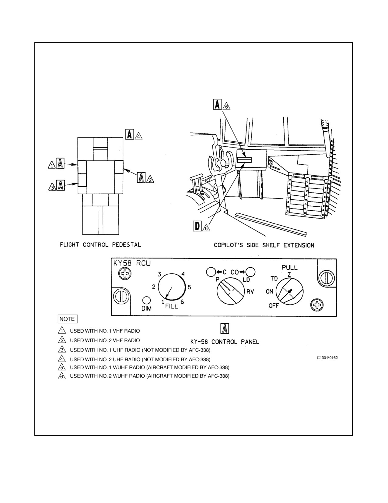
2.21.8 KY-58 Encryption Unit
Four encryption units provide for the transmission and reception of coded voice messages on the two UHF command
radios (AN/ARC-159 UHF radios on aircraft not modified by AFC-338) and the two VHF AM-FM radios. A
microphone and control panel are provided for each radio. The encryption units are located on the flight control
pedestal (see Figure 2-105).
2-225
ORIGINAL
01-75GAL-1
Figure 2-105. KY-58 Encryption Unit Control Panels (Sheet 1 of 3)
ORIGINAL
2-226
01-75GAL-1
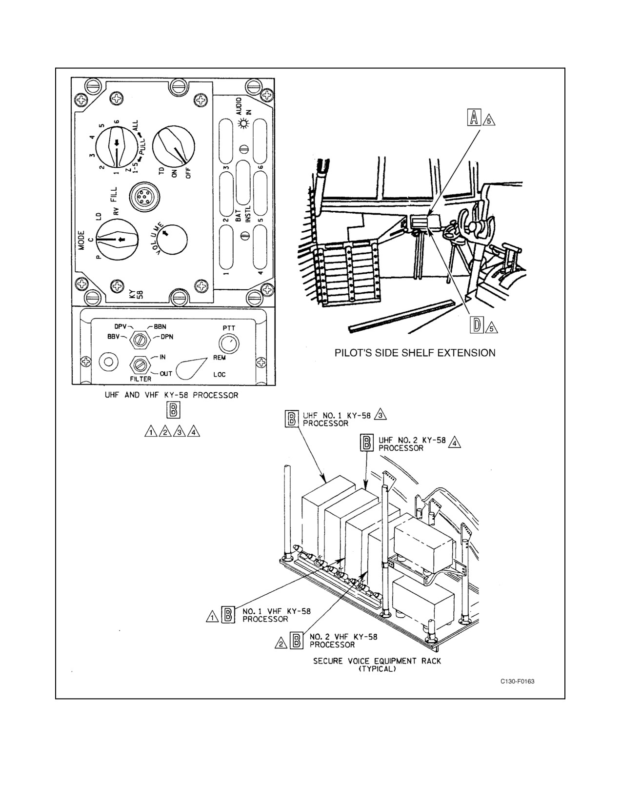
Figure 2-105. KY-58 Encryption Unit Control Panels (Sheet 2)
2-227
ORIGINAL
01-75GAL-1
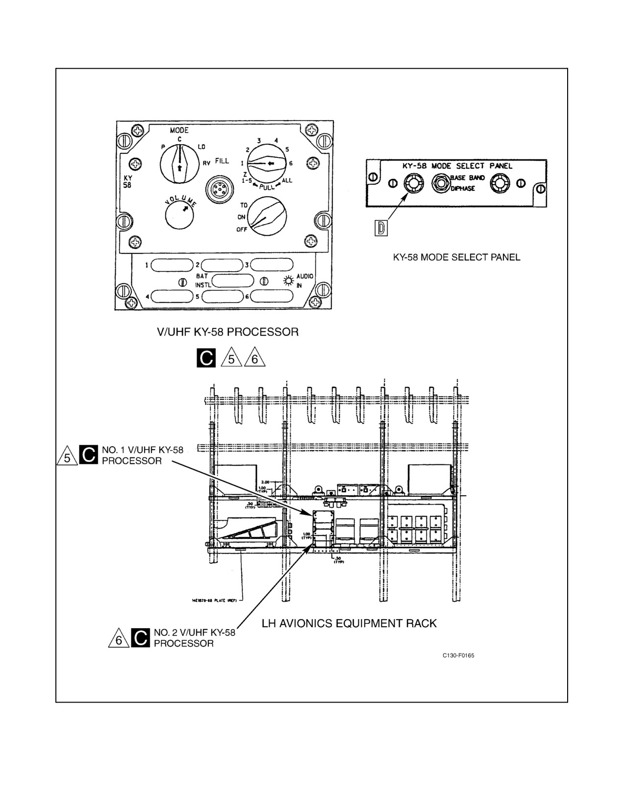
Figure 2-105. KY-58 Encryption Unit Control Panels (Sheet 3)
ORIGINAL
2-228
01-75GAL-1
The pilot and copilot must use the handheld microphones for encrypted transmissions in the radio coupled to the
respective KY-58.
Note
Classified information will not be discussed on the ICS or on radios
operating in the secure mode while other radios are transmitting in clear
mode. Conversely, no radio will transmit in clear mode while classified
information is being discussed on the ICS or another radio transmitting in
secure mode.
Power is supplied to the No. 1 UHF radio encryption unit from the isolated dc bus through a NO. 1 KY 28/58 circuit
breaker on the copilot upper circuit breaker panel. Power is supplied to the No. 2 UHF unit from the essential dc bus
through a NO. 2 KY 28/58 circuit breaker on the copilot upper circuit breaker panel. Power is supplied to the No.
1 VHF radio encryption unit from the isolated dc bus through two NO. 1 KY 28/58 circuit breakers on the copilot
upper circuit breaker panel. Power is supplied to the No. 2 VHF unit from the essential dc bus through two NO. 2
KY 28/58 circuit breakers on the copilot upper circuit breaker panel.
2.21.8.1 Secure-Voice Controls and Indicators
Controls for operation of the systems are provided on each remote control unit. Additional controls are provided on
the processor mount (see Figure 2-105).
2.21.8.1.1 KY-58 Remote Control Unit Controls
The KY-58 remote control unit provides switches and indicators for operating the system. The switches and
indicators are described as follows:
1. DIM switch — The DIM switch controls the brightness of the indicator lights.
2. Cipher light — The green cipher light indicates that secure-voice communications are being transmitted or
received when the mode switch is in the C or CO position.
3. Cipher-only light — Theyellow cipheronly light indicatesthat themodeswitchis inCO cipher-onlyposition.
4. FILL switch — The six-position FILL switch selects the preset code storage position.
5. Mode switch — A five-position (P, C, CO, LD, RV) mode switch controls the various modes of operation.
The positions are described as follows:
a. Plain (P) — Radio is used as plain-language receiver and transmitter.
b. Cipher (C) — Radio is used to transmit and receive secure-voice communications. The radio will also
receive plain-language communications.
c. Cipher only (CO) — Radio is used to transmit and receive secure-voice communications only.
d. Load (LD) — Processor will accept preset codes into storage.
e. RV — This position is not operational.
2-229
ORIGINAL
01-75GAL-1
6. Function switch — The four-position (OFF, ON, TD, Z) function switch controls the various functions. The
positions are described as follows:
a. OFF — Removes power to the processor.
b. ON — Applies power to the processor.
c. Time delay (TD) — This position is not used.
d. Zeroize (Z) — The preset codes are erased from all fill positions. The switch must be pulled and turned to
be placed to this position.
2.21.8.1.2 KY-58 Processor Mount Controls
The Z-AHQ adapter in the KY-58 processor mount provides the following controls:
1.
BBV/DPV/BBN/DPN switch — A four-position, screwdriver-operated rotary switch used to adapt the
processor to the radio and remote control unit. The BBV position provides baseband signal processing for
AN/ARC-159(V)l UHF radios and ARC-186 VHF radios. The DPV position provides diphase signal
processing for AN/ARC-159(V)l UHF radios. The BBN and DPN positions are not used.
2.
REMOTE/LOCAL (REM/LOC) switch — A two-position rotary switch, spring-loaded to the REM position.
Rotating the switch momentarily to the LOC position places theprocessor in local operation controlled by the
controls on the processor front panel until a remote unit PTT switch is actuated.
3.
PTT pushbutton switch — This switch is pressed for transmitting purposes when operating the processor on
local status.
4.
FILTER switch — A two-position IN, OUT screwdriver-operated rotary switch. The IN position provides a
filtered cipher output. The OUT position bypasses the filter.
5.
Processor controls — The controls on the KY-58 processor are used to operate the processor when loading
preset codes into the system. The controls are described as follows:
a. MODE switch — The four-position (P, C, LD, RV) switch controls the mode of operation of the processor.
The positions are functionally the same as described for the RCU.
b. Function switch — The three-position (TD, ON, OFF) switch controls power to the processor. The TD
position is not functional and the OFF-ON positions control the power.
c. FILL switch — The eight-position FILL switch (Z 1-5, ALL, 1, 2, 3, 4, 5, 6) selects and zeroizes the preset
code storage positions.
d. VOLUME control — The volume control adjusts the audio level of the system.
2.21.8.2 Normal Operation of the KY-58 Secure Voice Communications System
2.21.8.2.1 Loading
1. Place REM/LOC switch in LOC position.
2. Place BBV/DPV/BBN/DPN switch to BBV or DPV position.
3. Connect loading device to fill connector.
ORIGINAL
2-230
01-75GAL-1
4.
Place MODE switch in C position.
5.
Place TD/ON/OFF switch in ON position. Continuous beeping (crypto alarm) and backg0round noise is heard
in headset.
6.
Press PTT (push-to-talk) button and release. Crypto alarm is silenced. The KY-58 is ready for loading.
7.
Place MODE switch in LD position. Constant tone indicates an empty storage register. A beep indicates a
variable is stored in the register.
8.
Turn the loading device on.
9.
Place FILL switch to 1 to 6 as desired.
10.
Turn the loading device to output storage register 1 to 6.
11.
Press and release PTT pushbutton switch.
12.
Turn the MODE switch on the loading device to OFF/CHECK.
13.
Place the MODE switch to the C position.
14.
Disconnect loading device.
15.
Place TD/ON/OFF switch to OFF position.
16.
Repeat steps 1 through 15 for each KY-58 system.
2.21.8.2.2 Operation
To operate in the plain-text mode:
1. Place processor MODE switch to P position.
2. Place processor FILL switch to desired register position.
3. Place processor function switch to ON.
4. Actuate PTT switch to clear power-up alarm.
5. Select desired operating frequency on the applicable UHF or VHF control panel.
6. Place REM/LOC control switch to REM.
7. Place RCU function switch to ON.
8. Place RCU MODE switch to P position.
9. Place RCU FILL switch to desired register position. Transmission and reception will be in plain text.
To transmit in the cipher-text mode:
10. Contact receiving station to switch applicable KY-58 unit to C.
11. Place processor MODE switch to C.
2-231
ORIGINAL
01-75GAL-1
12. Place RCU MODE switch to C.
a. Note that the C indicator illuminates.
b. Transmission and reception will be in cipher text.
2.21.9 KY-58 Encryption Unit (UHF Encryption Units Modified by AFC-338)
Two encryption units provide for the transmission and reception of coded voice messages on the two AN/ARC-210
V/UHF radios. The encryption units used with the No. 1 and No. 2 V/UHF radios are installed in the Left Hand
Avionics Equipment Rack. The encryption unit control unit used with the No. 1 V/UHF radio is located on the pilot
side shelf extension. The encryption unit control unit used with the No. 2 V/UHF radio is located on the copilot side
shelf extension. (See Figure 2-105.)
Note
Classified information will not be discussed on the ICS or on radios
operating in thesecuremodewhileotherradios aretransmitting in theclear
mode. Conversely, no radio will transmit in theclearmode whileclassified
information is being discussed on the ICS or another radio transmitting in
secure mode.
Power is supplied to the No. 1 V/UHF radio encryption unit from the isolated dc bus through a No. 1 KY-58 circuit
breaker on the copilot upper circuit breaker panel. Power is supplied to the No. 2 V/UHF radio encryption unit from
the essential dc bus through the No. 2 KY-58 circuit breaker on the copilot upper circuit breaker panel.
2.21.9.1 Secure-Voice Controls and Indicators
A remote control unit and a separate switch panel control each encryption unit. Z-AHQ processor mounts are not
installed with encryption units interfacing with the AN/ARC-210 radios.
2.21.9.1.1 KY-58 Remote Control Unit Controls
The KY-58 remote control unit provides switches and indicators for operating the system. The switches and
indicators are described as follows:
1. DIM switch — The DIM switch controls the brightness of the indicator lights.
2. Cipher light — The green cipher light indicates that secure-voice communications are being transmitted or
received when the mode switch is in the C or CO position.
3. Cipher-only light — Theyellow cipheronly light indicatesthat themodeswitchis inCO cipher-onlyposition.
4. FILL switch — The six-position FILL switch selects the preset code storage position.
5. Mode switch — A five-position (P, C, CO, LD, RV) mode switch controls the various modes of operation.
The positions are described as follows:
a. Plain (P) — Radio is used as plain-language receiver and transmitter.
b. Cipher (C) — Radio is used to transmit and receive secure-voice communications. The radio will also
receive plain-language communications.
c. Cipher only (CO) — Radio is used to transmit and receive secure-voice communications only.
ORIGINAL
2-232
01-75GAL-1
d. Load (LD) — Processor will accept preset codes into storage.
e. RV — This position is not operational.
6. Function switch — The four-position (OFF, ON, TD, Z) function switch controls the various functions. The
positions are described as follows:
a. OFF — Removes power to the processor.
b. ON — Applies power to the processor.
c. Time delay (TD) — This position is not used.
d. Zeroize (Z) — The preset codes are erased from all fill positions. The switch must be pulled and turned to
be placed to this position.
2.21.9.1.2 Baseband/Diphase Switch Panel
A two-position switch provides the capability to select baseband or diphase signal processing.
2.21.9.2 Normal Operation of the KY-58 Secure Voice Communications System
2.21.9.2.1 Loading
1. Connect loading device to the encryption unit fill connector.
2. Place the control unit MODE switch in the C position.
3. Place the control unit FUNCTION switch to the ON position. Continuous beeping (crypto alarm) and
backg0round noise is heard in headset.
4. Press the PTT (push to talk) button and release. Crypto alarm is silenced. The KY-58 is ready for loading.
5. Place control unit MODE switch in LD position. Constant tone indicates an empty storage register. A beep
indicates a variable is stored in the register.
6. Turn the loading device on.
7. Place control unit FILL switch to 1 to 6 as desired.
8. Select output storage register 1 to 6 on the loading device.
9. Press and release PTT pushbutton switch.
10. Turn the loading device off.
11. Place the control unit FUNCTION switch to the OFF position.
12. Repeat steps 1 through 11 for the other encryption unit.
2.21.9.2.2 Operation
To operate in the plain text mode:
1. Place the control unit MODE switch to P position.
2. Place the control unit FILL switch to desired register position.
2-233
ORIGINAL
01-75GAL-1
3. Place control unit FUNCTION switch to ON.
4. Actuate PTT switch to clear power-up alarm.
5. Select desired operating frequency on the AN/ARC-210 radio. Transmission and reception will be in plain
text.
To operate in cipher text mode:
6. Contact receiving station to switch applicable KY-58 unit to C.
7. Place control unit MODE switch to C or CO. Transmission and reception will be in cipher text. Plain text
reception will be heard if the operator has selected C. Plain text reception will not be heard if the operator has
selected CO.
For further information on the KY-58, refer to Supplement NAVAIR 01-75GAA-2-8-1.
2.21.10 AN/ARC-190 HF Command Radio
Two separate but identical HF command radio installations, for single-sideband and amplitude-modulation
operation, provide two-way voice and code communication in the 2- to 30-MHz frequency range. The radios receive
and transmit on any one of 280,000 manually selected frequency channels spaced at 100-Hz increments, or any one
of 30 preset frequency channels in the HF band. Modes of operation are upper sideband (USB), lower sideband (LSB),
amplitude modulation equivalent (AME), continuous wave (CW), data USB, and data LSB. The No. 1 HF command
radio operates from 115-volt, three-phase, essential ac bus power supplied through HF COMM NO. 1 circuit breakers
on the pilot side circuit breaker panel. The No. 2 HF command radio operates from 115-volt, three-phase, main ac
bus power supplied through HF COMM NO. 2 circuit breakers on the copilot upper circuit breaker panel.
2.21.10.1 HF Command Radio Controls
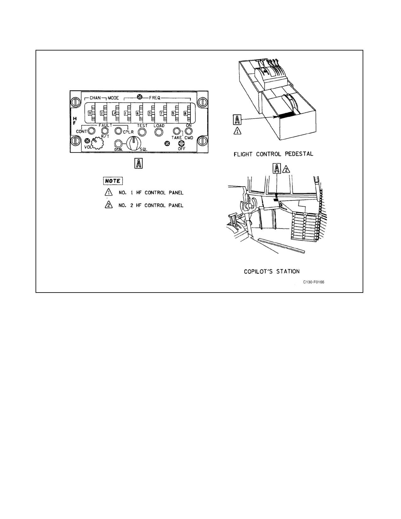
A separate control panel (see Figure 2-106) for each radio contains all the controls necessary for frequency selection
of any of the 280,000 available channels. The No. 1 HF control panel is located on the flight control pedestal and
the No. 2 HF control panel is located on the copilot side shelf extension. Thumbwheel switches are provided for
selection of frequency channels, preset channels, and modes of operation. A spring-loaded, momentary-action switch
is used for turning the radio set on or off. Selection for reception or transmission through the HF radio transceivers
is made at the appropriate ICS control panel(s).
2.21.10.1.1 CHAN Switches
Two thumbwheel switches are provided that select 30 channels (00 through 29) for preset mode and frequency data.
2.21.10.1.2 MODE Switch
A thumbwheel switch is provided to select the following modes:
1. LV — lower sideband voice.
2. UV — upper sideband voice.
3. LD — lower sideband data.
4. UD — upper sideband data.
5. CW — continuous wave.
ORIGINAL
2-234
01-75GAL-1
Figure 2-106. AN/ARC-190 HF Command Radio Control Panels
6. AM — amplitude modulation equivalent.
7. P — preset.
8. A — undefined (CONTL FAULT indicator will illuminate when in this mode).
2.21.10.1.3 FREQ Switch
Six thumbwheel switches are provided that select 280,000 frequency channels spaced at 100-Hz increments from
2.0000 to 29.9999 MHz. Selection below 2.0000 MHz will cause a control fault indication.
2.21.10.1.4 TAKE CMD/OFF Switch
A spring-loaded, momentary-action switch is used for turning the radio set on or off, or taking command from an
alternate radio set control.
2.21.10.1.5 ON Indicator
The ON indicator is illuminated when radio set power is turned on.
2-235
ORIGINAL
01-75GAL-1
2.21.10.1.6 TAKE CMD Indicator
The TAKE CMD indicator is illuminated when the radio set control has taken command.
2.21.10.1.7 LOAD Pushbutton Switch
Amomentary-actionpushbuttonswitchcausesmodeandfrequencydatatobestoredinthereceiver-transmitterpreset
channel memory when pressed. Data is stored in the memory location indicated by the preset channel switches.
2.21.10.1.8 TEST Pushbutton Switch
A momentary-action pushbutton switch initiates the self-test cycle. When pressed, all fault indicators illuminateand
the radio set goes through a receive self-test cycle. When released, all fault indicators are extinguished. If the test fails,
one of the fault indicators remains illuminated, depending upon where the fault is. After pressing the TEST
pushbutton, the next time the microphone push-to-test switch is pressed, a transmit self-test cycle is initiated. If the
test fails, one of the fault indicators will be illuminated.
2.21.10.1.9 SQL Switch
A four-position SQL switch selects the squelch threshold level. The squelch is fully disabled with the switch in the
full counterclockwise position.
2.21.10.1.10 DSBL Pushbutton Switch
The DSBL switch is an alternate-action pushbutton switch that disables the squelch threshold when pressed in. When
in the out position, squelch threshold level is selected by the SQL switch.
2.21.10.1.11 VOL Switch
The eight-position VOL switch sets the receiver-transmitter audio output level.
2.21.10.1.12 CONT FAULT Indicator
The CONT FAULT indicator is illuminated when a malfunction occurs in the radio set control, if FREQ switches
are set below 2.0000 MHz, if CHAN switches are set to an unloaded preset channel with the mode switch set to P,
or when the mode switch is set to A.
2.21.10.1.13 R/T FAULT Indicator
The R/T fault indicator is illuminated when a malfunction occurs in the receiver-transmitter.
2.21.10.1.14 CPLR FAULT Indicator
The CPLR FAULT indicator is illuminated when a malfunction occurs in the antenna coupler.
2.21.10.2 Normal Operation of the HF Command Radio
2.21.10.2.1 Operation On Preset Channels
To put the HF command radio into operation:
1. Momentarily actuate the TAKE CMD/OFF switch to TAKE CMD. The ON and TAKE CMD indicators will
light.
ORIGINAL
2-236
01-75GAL-1
2. Set the MODE switch to P.
3. Set the CHAN switches to the desired channel that has been previously loaded. The CONT FAULT indicator
will illuminate if an unloaded preset channel is selected.
4. Momentarily key the radio set.
5. Adjust VOL and SQL controls as desired.
To turn the HF command radio off:
6. Momentarily actuate the TAKE CMD/OFF switch to OFF.
2.21.10.3 Operation on Nonpreset Channels
To put the HF command radio into operation:
1. Momentarily actuate the TAKE CMD/OFF switch to TAKE CMD. The ON and TAKE CMD indicators will
light.
2. Set the MODE switch to the desired mode.
3. Set the FREQ switches to the desired frequency.
4. Momentarily key the radio set.
5. Adjust VOL and SQL controls as desired.
To turn the HF command radio off:
6. Momentarily actuate the TAKE CMD/OFF switch to OFF.
2.21.10.3.1 Mode and Frequency Presetting
To preset modes and frequencies:
1. Momentarily actuate the TAKE CMD/OFF switch to TAKE CMD. The ON and TAKE CMD indicators will
light.
2. Set the MODE switch to the desired mode (except A).
3. Set FREQ switches to the desired frequency.
4. Set CHAN switches to the desired channel (00 to 29).
5. Press the LOAD pushbutton.
6. Repeat steps 2 through 5 for each preset channel desired.
7. Momentarily actuate the TAKE CMD/OFF switch to OFF.
2.21.10.3.2 Fault Clearing
To clear faults of a temporary nature and to extinguish the fault indicators, operate one of the FREQ switches off
frequency and back again.
2-237
ORIGINAL
01-75GAL-1
2.21.11 Encryption Unit (AN/USC-43(V)3)
Provisions for two identical HF advanced narrowband digital voice terminal (ANDVT) secure voice systems are
installed. Each system is used with an HF radio; No.1 is used with HF No. 1 and No. 2 is used with HF No. 2. The
HF secure voice system equipment is integrated with and operates with the HF radio to permit secure voice
communication. The ANDVT system consists of a COMSEC module (CM) mated with basic terminal units (BTU)
and remote control panels. The system has two basic modes of operation: plain or cipher. The plain mode is used
during normal HF communication. The cipher mode is used when secure voice communications are required. The
HF radio must be operational and the secure voice system equipment must be installed and operational for proper
secure voice operations. The receiving station must be properly equipped to receive transmissions in the cipher mode.
When the secure voice system equipment is removed, the HF radio may be operated normally. Power is provided
to the No.1 system from the essential dc bus through the AN/USC-43 circuit breaker on the pilot side circuit breaker
panel and for the No. 2 system by the main dc bus through the AN/USC-43 circuit breaker on the copilot upper circuit
breaker panel.
2.21.11.1 HF Secure Voice Controls and Indicators
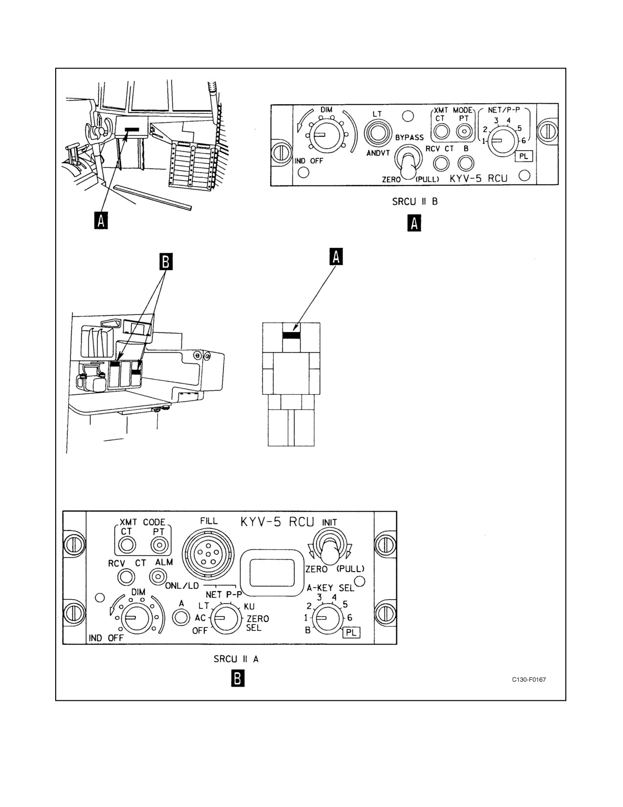
Thesplit remotecontrol unit (SRCU IIA and IIB)control panels forthesystem arelocated on thecopilot sideconsole
and at the navigator station for C-130T aircraft and on the copilot side console and at the radio operator station on
KC-130T aircraft. (See Figure 2-107.) The CM/BT is located in the radio operator equipment rack on KC-130T
aircraft and on the secure equipment rack on C-130T aircraft. The panels provide controls and indicators for operating
the system as follows:
Note
Classified information will not be discussed on the intercommunication
system or on radios operating in the secure mode while other radios are
transmitting in clear mode. Conversely, no radio will transmit in clear
mode while classified information is being discussed on the intercommu-
nication system or another radio transmitting in secure mode.
2.21.11.1.1 SRCU IIB Controls and Indicators
1. DIM switch. Controls the intensity of all panel indicator lights. The IND OFF completely deactivates all
indicator lights and does not affect the intensity of the panel illumination.
2. LT (light test) pushbutton switch. Activates the lamp test.
3. BYPASS/ANDVT/ZERO (PULL) switch. The three-position lever action (BYPASS, ANDVT, ZERO
(PULL)) switch controls the modes of operation as follows:
a. BYPASS — Controls and routes HF communications around the CM.
b. ANDVT — System is used to transmit and receive secure voice communication.
c. ZERO (PULL) — The switch erases all TEKs stored in the CM and does not require the CM POWER switch
to be in the RMT position to be operable.
4. XMT MODE CT (transmit mode cipher text) light. The green XMT MODE CT light indicates the system is
on-line and ready to transmit in the secure mode.
5. XMT MODE PT (transmit mode plain text) light. The green XMT MODE PT light indicates the system is
on-line and ready to transmit in the plain language mode.
ORIGINAL
2-238
01-75GAL-1
Figure 2-107. Encryption Unit Control Panels (USC-43) (Sheet 1 of 2)
2-239
ORIGINAL
01-75GAL-1
Figure 2-107. Encryption Unit Control Panels (USC-43) (Sheet 2)
ORIGINAL
2-240
01-75GAL-1
6. RCV CT (receive cipher text) light. The green RCV CT light indicates that a secure voice coded message is
being received.
7. B (BTU) light. The green B light indicates BTU power is on and the RCU-IIB panel has control.
8. NET/P-P Switch. Selects one of six traffic encryption keys (TEKs) or plain text when RCU-IIB has control.
2.21.11.1.2 SRCU IIA Controls and Indicators
1.
XMT MODE CT (transmit mode cipher text) light. The green XMT MODE CT light indicates the system is
on-line and ready to transmit in the secure mode.
2.
XMT MODE PT (transmit mode plain text) light. The green XMT MODE PT light indicates the system is
on-line and ready to transmit in the plain language mode.
3.
RCV CT (receive cipher text) light. The green RCV CT light indicates that a secure voice coded message is
being received.
4.
ALM (alarm) light. The green light indicates a crypto alarm in the system. The light flashes momentarily
during an alarm check.
5.
Fill connector. Provides connection for a fill device.
6.
Numeric display. Displays results or status of system functions.
7.
Mode initiate switch. The three-position lever lock INIT, normal, ZERO (PULL) switch is used to initiate
off-line functions. Modes of operation are as follows:
a. INIT (initiate) — Initiates off-line functions selected by the RCU-IIA function switch.
b. Normal — Normal position for system secure voice operation.
c. ZERO (PULL) — When the switch is positioned to ZERO (PULL), all TKEs stored in the CM are erased
(zeroized). The switch will remain in ZERO (PULL) until manually returned to the normal position, it is
not spring-loaded back to normal.
8.
A-KEY SEL switch. The eight-position (B, 1, 2, 3, 4, 5, 6, PL) switch controls operation as follows:
a. B — Selects control of the RCU-IIB.
b. 1,2,3,4,5,6 — Selects one of six TEKs for secure voice operation.
c. PL — Selects plain text operation.
9.
FUNCTION switch. The seven-position OFF, AC, LT, ONL/LD NET, ONL/LD P-P, KU, ZERO SEL switch
is used to control off-line functions or put the terminal in an on-line mode. Modes of operation are as follows:
a. OFF — Shuts the system off when the CM POWER switch is in the RMT position. RCU has no power
control when the CM POWER switch is in the OFF position.
b. AC (alarm check) — Enables the manual initiation of a COMSEC confidence check, which includes a
cryptographic alarm check. An alarm check initiated on the RCU-IIA checks the CM logic. The check is
initiated when the Mode Initiate switch is positioned to INIT. The INIT position will have no effect if the
A-KEY SEL switch is in either the B or PL positions.
2-241
ORIGINAL
01-75GAL-1
c. LT (lamp test) —Enables the testing of the panel indicator lights when Mode Initiate switch is positioned
to INIT. Once initiated, the RCU-IIA discrete indicators are sequenced. After release of the switch, the
display characters are sequenced through all 16 digits.
d. ONL/LD NET (on-line/load net) — Puts the system in the on-line net operating mode.
Note
The CM can normally be filled by positioning the Mode Initiate switch to
1NIT and there is no traffic through the system. TEKs can only be loaded
at the CM.
e. NL/LD P-P (on-line/load point to point) — Puts the system in the on-line point to point operating mode.
Note
The CM can normally be filled by positioning the Mode Initiate switch to
INIT and there is no traffic through the system. TEKs can only be loaded
at the CM.
f.
KU (TEK update) — Enables display of the update status of the TEK selected by the A-KEY SEL switch,
and performs the update of TEKs 1 through 6 by positioning the Mode Initiate switch to INIT. The INIT
position will have no affect if the A-KEY SEL switch is in either the B or PL positions.
g. ZERO SEL (zero select) — Allows selected TEK zeroization by positioning the Mode Initiate switch to
INIT. The INIT position will have no effect if the A-KEY SEL switch is in either the B or PL positions.
10.
A (BTU) light. The green A light indicates BTU power is on and the RCU-IIA panel has control.
11.
DIM switch. Controls the intensity of all panel indicator lights. The IND OFF completely deactivates all
indicator lights, including the display, and does not affect the intensity of the panel illumination.
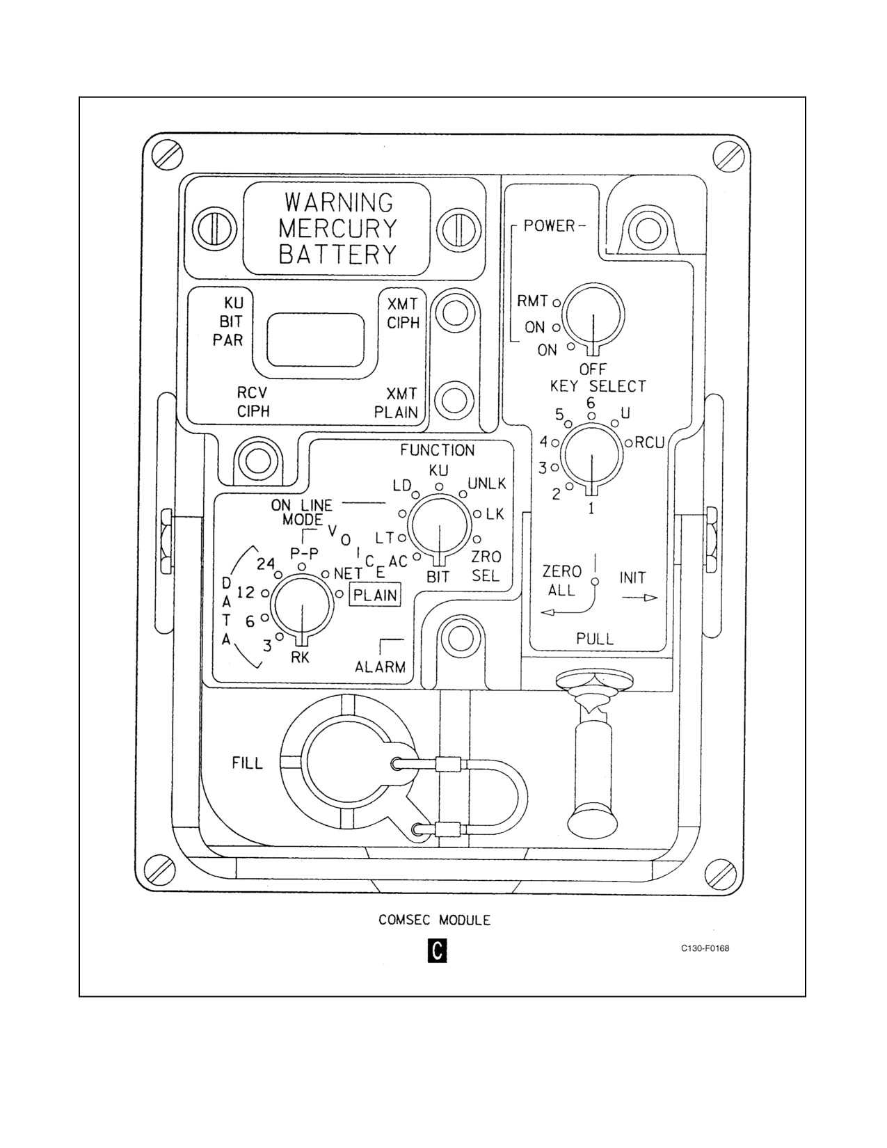
2.21.11.1.3 COMSEC Module Controls and Indicators
1. KU/BIT PAR display. Displays key update count, display error and fault codes, parity KU operations and
channel quality.
2. XMT CIPH light. Indicates cipher operation selection.
3. XMT PLAIN light. Indicates plain operation selection.
4. POWER light. Indicates power on. Only operable when the second ON position of the POWER SWITCH is
selected.
5. POWER switch. Controls system power and provides for different system power configurations. The switch
positions are described as follows:
a. OFF — All power is removed from the system.
b. First ON — Supplies power to the BTUs. CM indicator lights and display will be off.
c. Second ON — Supplies power to the BTUs. CM indicator lights and display will be on.
d. RMT — Transfers power and system control to the RCU. CM display, indicator lights and controls off and
disabled.
ORIGINAL
2-242
01-75GAL-1
6.
KEY SELECT switch. Controls system functions. Switch positions are described as follows:
a. 1 THRU 6 — Memory storage for traffic keys.
b. U — Memory storage for rekeying AK and MK operation.
c. RCU — Memory storage for RCU CM key.
7.
ZERO ALL/INIT switch. Controls selected modes of operation. Switch positions are described as follows:
a. INIT — Activation required for all off-line modes.
b. ZERO ALL — Erases all key memory storage.
8.
ALARM light. Indicates COMSEC alarm condition. Also comes on momentarily during transmit.
9.
FILL connector. Provides connection for fill device. (Key transfer interface.)
10.
DATA/VOICE switch. Active with function switch on-line. Selects secure voice, plain text, RK (AK and MK)
or data rate.
11.
FUNCTION switch. Controls selected modes of operation. Switch positions are described as follows:
a. ON LINE MODE — Enables plain text or secure voice operation.
b. LD — Key load.
c. KU — Key update count.
d. UNLK — CM unlock.
e. LK — CM lock.
f. ZRO SEL — Zero selected key.
g. BIT — Fault detect.
h. AC — CM alarm check.
i. LT — Lamp test.
12.
RCV CIPH light. Indicates a secure voice coded message is being received.
2.21.11.2 HF Secure Voice System Loading Procedures
2.21.11.2.1 Loading TEKs and System Operation
To load the TEKs and place the HF secure voice in operation proceed as follows.
Note
D The system may be loaded using either the KYK-13 fill
device or
AN/CYZ-10 data transfer device. Procedures for both are contained in the
following steps.
D The following procedures load a TEK into the storage location selected by
the CM KEY SEL switch. This can only be accomplished after the system
has been initialized and the CM is not in a loaded state.
2-243
ORIGINAL
01-75GAL-1
2.21.11.2.2 KYK-13 Fill Device Loading Procedures
1. Place the CM POWER switch to second ON position.
2. Connect KYK-13 to the CM FILL connector.
3. Turn on the KYK-13 and select the location of the key to be transferred to the CM.
4. Place the CM KEY SELECT switch to the position at which the key is to be loaded.
5. Place CM FUNCTION switch to LD.
6. Place the CM ZERO ALL/INIT switch to the INIT position and release it. The display will flash 01
momentarily for a successful transfer, or FF for a failed load procedure. If FF is displayed, check CM and
KYK-13 then repeat the procedure. If procedure fails again, record the failed display code and report this data
to Maintenance.
7. After completion of loading, turn off the KYK-13 and remove its connector from the CM fill port.
CAUTION
Failure to turn the KYK-l3 off prior to removal from the CM may cause the
TEKs to zeroize.
2.21.11.2.3 AN/CYZ-10 Data Transfer Device Loading Procedures
1. Place the CM POWER switch to second ON position.
2. Insert the crypto ignition key into the AN/CYZ-10.
3. Connect AN/CYZ-10 to the CM FILL connector.
4. On AN/CYZ-10, select APPL, FILL, SETUP, PROTOCOL, CFD, KY13 or KYl5, and XMIT.
5. On AN/CYZ-l0, page down to view key, press Enter to select key, select Quit when key has been selected.
6. On AN/CYZ-10, press Clear Key.
7. Press push-to-talk button on the handset to start crypto fill initiate.
8. After completion of loading, remove the AN/CYZ-l0 connector from the CM fill port.
2.21.11.3 CM Control Transfer Procedures
Procedures to transfer control from the CM to the RCUs are as follows:
1. Position the CM switches as follows:
a. FUNCTION switch to ON LINE.
b. KEY SELECT switch to RCU.
c. POWER switch to RMT. All CM indications will go out and RCU indications will come on.
ORIGINAL
2-244
01-75GAL-1
2. Place the RCUIIA Function switch to NET ONL/LD.
3. Set intensity level. Rotate the Dim switch clockwise from the IND OFF position to turn on and increase the
intensity of the indicators and displays to a visible level.
4. Place the RCU-IIA A-KEY SEL switch to the filled position for a previously loaded key (1, 2, 3, 4, 5, 6) for
secure voice operation, or the PL position for plaintext operation.
2.21.11.4 RCU Control Transfer Procedures
Procedures to transfer control from the RCU-IIA to the RCU-IIB are as follows:
1. Position the RCU-IIA A-Key switch to B.
2. Place the RCU-IIB NET P-P switch to the filled position for a previously loaded key (1, 2, 3, 4, 5, 6) for secure
voice operation, or the PL position for plaintext operation.
2.21.11.5 Set Intensity Level
Rotate the DIM switch clockwise from the IND OFF position to turn on and increase the intensity of the indicators
and displays to a visible level.
Note
When operating the secure voice in the secure mode and when the radio
PTT is pressed, wait for system crypto preamble to cease before talking.
2.21.11.6 Zeroize System and Shutdown
1. To zeroize the system, place the ZERO ALL/INIT switch on the CM to the ZERO position. This zeroizes all
TEKs in a connected CM.
2. To turn the system off, place the POWER switch to OFF.
2.21.12 DF-206 Automatic Direction Finder
Two complete DF-206 automatic direction-finding systems are installed. The systems are combination automatic
direction-finding and radio receiver systems within the frequency range of 190 to 1750 kHz. The systems supply
direction-findinginformationforvisualdisplayonthepilotandcopilotRMIsandthenavigatorBDHI.Withnosignal
present, the pointer parks at 90_ right of the lubber line. Each RMI has an azimuth card and two pointers. The systems
have two uses: as an automatic direction finder, and as a voice receiver. As an automatic direction finder, each system
automatically and continuously determines the bearing of the station with respect to the aircraft, and displays the
bearing visually on the RMI and BDHI. As a voice receiver, the system provides reception of weather reports from
range stations and entertainment from broadcast stations and is a backup communications receiver. The ADF systems
operate from 26-Vac power from the essential ac bus through the ADF No. 1 and No. 2 fuses on the pilot lower circuit
breaker panel, and from 28-Vdc power from the essential dc bus through the ADF No. 1 and No. 2 circuit breakers
on the copilot upper circuit breaker panel.
2.21.12.1 Automatic Direction-Finder Controls
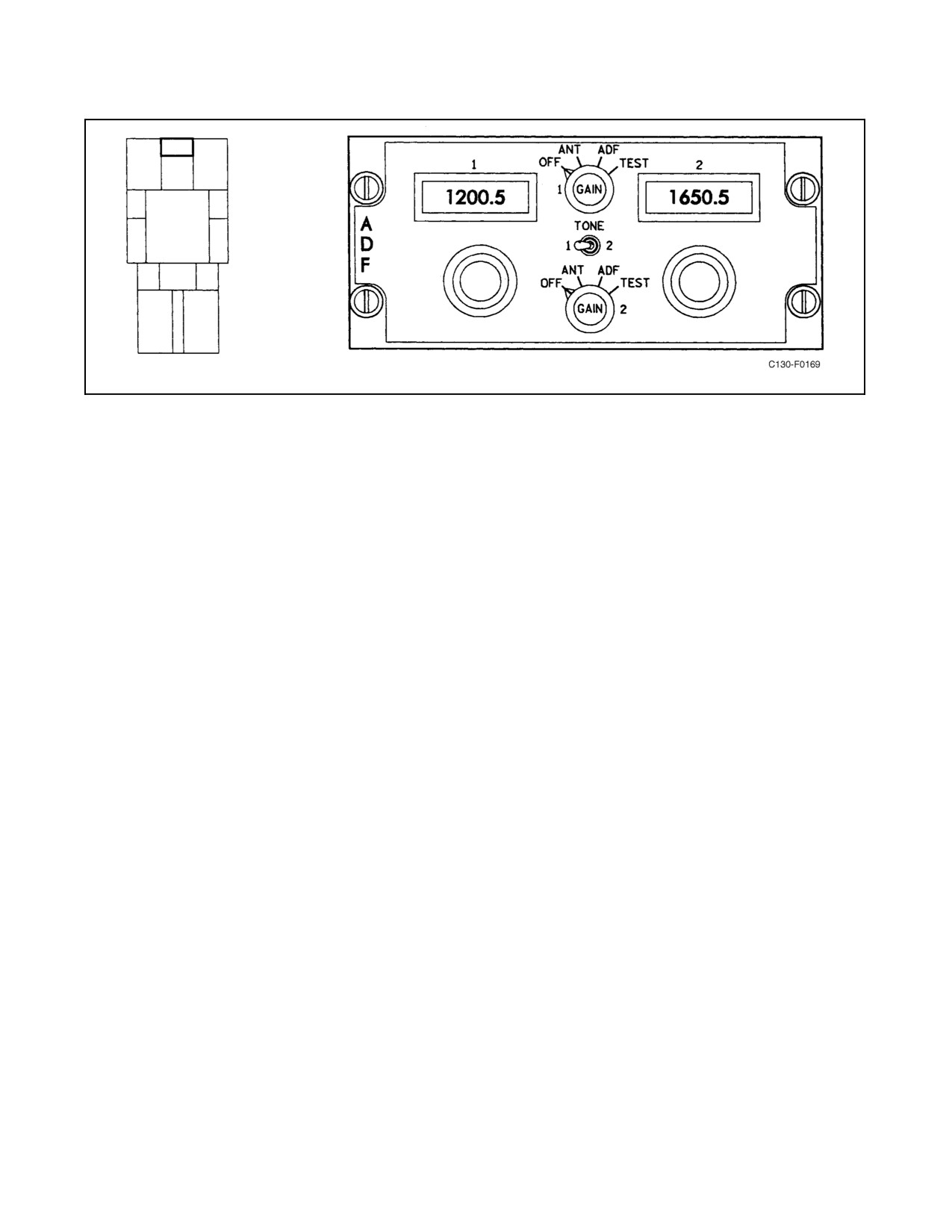
The dual control panel for operation of both ADF systems is mounted on the flight control pedestal (see Figures 2-4
and 2-108). The control panel consists of the following controls and indicators.
2-245
ORIGINAL
01-75GAL-1
Figure 2-108. Automatic Direction-Finder Control Panel (DF-206)
2.21.12.1.1 Function Selector Knobs
The function selector knobs permit selection of the following functions:
1.
OFF — No power to system.
2.
ANT — Used for reception of voice and for tuning. The loop antenna is not used.
3.
ADF — Radio signals received by the loop antenna are compared with signals received by the sense antenna
to provide a relative bearing to the selected station. This bearing information is displayed on the pilot and
copilot RMI and the navigator BDHI.
4.
TEST — Generates a tone signal to provide an on-channel test signal for self-test. The bearing pointer drives
to 45_ right of the lubber line during self-test.
5.
GAIN knob — The GAIN knob controls the volume for the ANT, ADF, and TEST position of the function
selector knobs.
6.
TONE switch — Provides CW tone to either system No. 1 or No. 2.
7.
Frequency indicators — Used to provide a digital readout in kHz of the frequency to which the ADF system
is tuned.
8.
Frequency selector knobs — Permit selection of the desired frequency as indicated on the adjacent frequency
indicator.
a. The large knob is used to select thousands and hundreds of kHz in 100-kHz steps.
b. The middle knob is used to select tens of kHz in 10-kHz steps.
c. The small knob is used to select units and tenths of kHz in 0.5-kHz steps.
ORIGINAL
2-246
01-75GAL-1
2.21.12.2 Normal Operation of the Automatic Direction Finder
1. Position thefunction selectorknob to ANT. Select an unused frequency for test. Allow 5 minutes forwarmup.
2. Pull the applicable ADF monitor switch volume knob on the ICS control panel; turn the knob to the midrange
position.
3. Perform the test by positioning the function selector knob to TEST. Observe that the ADF pointer for the
corresponding system on the pilot or copilot RMI and the navigator BDHI indicates 45_ right from the lubber
line. A beat tone should be heard in the headset.
4. Select the desired operating frequency with the frequency selector knobs and adjust the volume control on the
ADF control panel as necessary to obtain a comfortable reception level.
5. Position the function selector knob to the operational mode desired (ANT or ADF).
2.21.12.2.1 Automatic Direction Finding
1. Place the function selector knob for the desired system(s) to ANT.
2. Select operating frequencies with the frequency selector knobs.
3. Find magnetic bearing to the station by placing the function selector knob to the ADF position and observing
position of pointers on the pilot and copilot RMIs or navigator BDHI.
Note
If the received signal is too weak for reliable use, the pointer will be idled
at 90_ left of the lubber line.
2.21.12.2.2 Voice Reception
For use as a voice receiver, either of the two function selector knob positions, ANT or ADF, may be used, but ANT
will usually provide a clearer signal.
2.21.13 AN/ARN-126 VHF Navigation System
Two independent VHF navigation systems are installed on the aircraft. Each system receiver performs dual functions.
When tuned to a VOR frequency, the receiver furnishes VOR magnetic bearing to the pilot and copilot BDHIs, and
to the navigator No. 2 BDHI. When VOR/ILS is selected on the NAV SEL switch, VOR course deviation, to-from
indication, and systemvalidity are provided to the flight control system for display and flight computer steering.
Tuning the receiver to an ILS frequency activates the localizer and glideslope sections of the receiver. With VOR
ILS selected on the NAV SEL switch, horizontal and vertical position information is furnished by the receiver to the
flight control system for display on the HSIs and ADIs and for use by the flight computers to compute steering signals
for the autopilot and ADI command bars. The glideslope section of the receiver also provides information to the
ground proximity warning system computer. ILS validity is provided to ensure that a valid signal is being received
by the flight control system. Magnetic heading information to the No. 1 VHF navigation system is provided by the
No. 1 C-12 compass while the No. 2 VHF navigation system receives its heading information from the No. 2 C-12
compass. The pilot and copilot HSIs provide desired course data to the No. 1 and No. 2 VHF navigation systems,
respectively, for course deviation resolution. Audio signals from the VOR stations may be monitored on the ICS by
pulling out theappropriateVOR 1 orVOR 2 monitorswitches. Themarker beacon section ofthe No. 1 VHF receiver
gives visual and aural coded signals when the aircraft is in range of or passing over a marker beacon transmitter. The
2-247
ORIGINAL
01-75GAL-1
visual signal is given through three press-to-test colored indicator lights on a panel on the pilot instrument panel:
white (labeled A/I) for airway/inner marker, amber (labeled M) for an ILS middle marker, and blue (labeled O) for
an ILS outer marker (see Figure 2-78). A two-position, HI-LO marker beacon switch, located on the pilot instrument
panel, is used to select either high or low receiver sensitivity according to the strength of the incoming signal. The
LO position of the switch narrows the apparent width of marker beacon transmissions. The audio signal (400 Hz for
outer marker, 1300 Hz for middle marker, and 3000 Hz for airway/inner markers) is provided through the ICS. Some
airport installations, such as category II, have an inner marker that indicates a point at which the aircraft is at a
designated decision height on the glideslope between the middle marker and the landing threshold. The airways inner
marker is utilized to indicate the inner marker beacon position. The No. 1 and No. 2 VHF navigational systems are
supplied 28-Vdc power from the essential dc bus through the VOR/ILS NO. 1 and NO. 2 circuit breakers on the
copilot upper circuit breaker panel. The NO. 1 and NO. 2 VHF navigational systems are supplied with 26-Vac power
from the essential ac bus through the VOR/ILS NO. 1 and NO. 2 circuit breakers on the pilot upper circuit breaker
panel.
2.21.13.1 VHF Navigation System Control and Tuning
The VOR navigation radios are tuned and controlled via the CDNU Nav page. System power is controlled via the
CDNU Power page (a box around the system name indicates the unit is powered). The NAV page is accessed via
the F6 key or via the index page. Tuning is accomplished by entering the appropriate frequency in the scratchpad and
then pressing the line select key next to the corresponding radio. Returning to the previously selected frequency may
be accomplished by tuning 0. For additional functions and controls of the VOR navigation radios, refer to Figure
2-109.
2.21.13.2 Normal Operation of VHF Navigation Systems
2.21.13.2.1 VHF Navigation System Operation
To put the TACAN system(s) into operation, proceed as follows:
1. Tune desired frequency in VOR-1 or VOR-2 via the CDNU.
2. Set pointer select switches as necessary for the selected VOR receiver to the BDHI.
3. Select appropriate VOR/ILS position with NAV SEL switch for display on HSI.
4. Set course to be flown with the course set knob.
5. Check station identifier by pulling out the appropriate VOR monitor switch-volume mixer on the ICS control
panel.
6. Adjust volume as necessary via individual mixer switch or master volume knob on ICS panel.
2.21.13.2.2 VHF Navigation Test
1. Tune a valid frequency in VOR-1 or VOR-2 via the CDNU (a valid VOR frequency is required to test).
2. Place the required NAV SEL switch(es) in the appropriate position for TACAN operation.
ORIGINAL
2-248
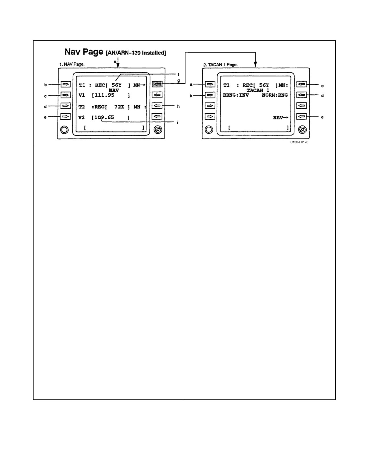
01-75GAL-1
1.
NAV Page.
2.
TACAN 1 Page.
a.
Access Nav Page via Index 1/2 Page.
a.
Depends on scratchpad entry:
b.
Depends on scratchpad entry:
(1) Blank: Toggles operating mode:
REC — Receiver mode
(1) Blank: Toggles operating mode:
T/R — Transmit/receive mode
REC — Receiver mode
A/R — Air-to-air receive mode
T/R — Transmit/receive mode
A/T — Air-to-air transmit/receive mode
A/R — Air-to-air receive mode
A/T — Air-to-air transmit/receive mode
(2) Valid TACAN channel: Tunes TAC1 to
channel. New channel is displayed in brackets
(2) Valid TACAN channel: Tunes TAC1 to
[ ].
channel. New channel is displayed in brackets
[ ].
(3) Zero (0): Tunes TAC1 to previously tuned
channel. Channel in brackets [ ] is replaced.
(3) Zero (0): Tunes TAC1 to previously tuned
channel. Channel in brackets [ ] is replaced.
b.
Toggles bearing (BRNG) between inverse (INV)
and normal (NORM).
c.
Depends on scratchpad entry.
c.
Toggles TAC1 pairing state between:
(1) Valid frequency: Tunes VOR1 to frequency.
New frequency is displayed in brackets [ ].
(1) MN — manual
(2) Zero (0): Tunes VOR1 to previously tuned
(2) PR — paired
frequency.
d.
Toggles RNG:
d.
Functions same LS1 except for TAC2.
(1) NORM: normal
e.
Functions same LS2 except for VOR2.
(2) EXT: extended
f.
Indicates TAC1 is tuned to channel 56Y.
e.
Returns to NAV Page.
g.
Accesses TACAN 1 Page.
h.
Indicates TACAN pairing state specified on TAC1
Page:
(1) MN — manual
(2) PR — paired
i.
Indicates VOR 2 is tuned to 109.65 MHz.
Figure 2-109. NAV Page (AN/ARN-139 Installed)
2-249
ORIGINAL
01-75GAL-1
3. Select a course providing zero deviation with the course select knob.
4. Test VOR via CDNU (access via IDX, then SYSTEMS TEST page 2/2).
a. The TO-FROM indication should indicate TO.
b. All three marker beacon lights should flicker.
c. The course deviation bar should have slight right deflection.
d. A 30-Hz VOR and marker beacon test tone should be heard.
e. Bearing indications should be between 1 and 5 degrees.
f. The NAV warning flag should come into view after 1 second and go out of view within 5 seconds.
2.21.13.2.3 ILS Navigation Test
1. Tune a valid ILS frequency in VOR-1 or VOR-2 via the CDNU (a valid VOR frequency is required to test).
2. Place the required NAV SEL switch(es) in the appropriate position for TACAN operation.
3. Test VOR via CDNU (access via IDX, then SYSTEMS TEST page 2/2).
a. The course deviation bar should indicate a right deflection of approximately one dot.
b. The glideslope indicator should indicate a down deflection of approximately one dot.
c. All three marker beacon lights should flicker.
d. A 30-Hz VOR and marker beacon test tone should be heard.
e. The glideslope warning flag should come into view after 1 second and then go out of view within 5 seconds.
f. The NAV warning flag should come into view after 1 second and go out of view within 5 seconds.
2.21.14 TACAN
Note
The No. 1 TACAN system is an AN/ARN-139(V), and the No. 2 TACAN
system is an AN/ARN-118(V).
Two independently operating TACAN navigation systems are installed on the aircraft (see Figure 2-109). When the
TACAN systems areon and operating, magneticbearing information as indicated is furnished to thepilot andcopilot
BDHI and selectable at the navigator station on the navigator left- and right-hand BDHI. The No. 1 TACAN system
supplies distance and distance validity directly to the pilot BDHI and navigator left-hand BDHI, while the No. 2
system supplies the copilot BDHI and navigator right-hand BDHI. Distance information from the No. 1 system is
displayed on the pilot HSI miles display whenever system No. 1 is operating and the pilot NAV SEL switch is in
any position except INS 1, CDNU, or TAC 2. Similarly, distance information from the No. 2 system is displayed
on the copilot HSI miles display whenever system No. 2 is operating and the copilot NAV SEL switch is in any
position other than INS 2, CDNU, or TAC 1. When a TACAN is selected on the instrument selector control panel,
the selected system course deviation, to-from indication, and TACAN validity (flag warning) are provided to the
flight control system (FCS 105) for display on the HSI and for use by the flight computers to compute a steering signal
ORIGINAL
2-250
01-75GAL-1
to the autopilot and ADI command bars. Magnetic heading information to the No. 1 TACAN is normally provided
by the No. 1 C-12 compass, while the No. 2 TACAN system normally receives its heading from the No. 2 C-12
compass. The pilot and copilot HSIs provide desired course data to the No. 1 and No. 2 TACAN systems,
respectively, for course deviation resolution. TACAN audio signals can be monitored by pulling the appropriate
TACAN monitor switch-volume knob on the intercommunication system control panel. The TACAN systems are
powered by 28-Vdc power and 115-Vac power from essential dc and ac buses through TACAN NO. 1 and NO. 2
ac and dc circuit breakers on the copilot upper circuit breaker panel.
Note
When using the AN/ARN-139 TACAN for bearing information and
switching between TAC 1 and ADF 2 at the navigator No. 1 BDHI, the
TACAN bearing function at the pilot HSI (if TAC 1 is selected), copilot
HSI (if TAC 1 is selected), and NAV BDHI (if TAC 1 is selected) may
break lock-on for 2 or 3 seconds, and then recover lock-on to indicate the
correct TACAN bearing. This anomaly may occur either while switching
from TAC 1 to ADF 2, or from ADF 2 to TAC 1.
The TACAN navigation set has provisions for 126 X and 126 Y channels. The Y channels differ from the X channels
in frequency assignment and pulse spacing. The maximum operating range of the TACAN navigation set is 390 nm
when the selected TACAN station is a surface beacon and 200 nm when the selected TACAN station is an airborne
beacon.
Note
D The Y channels were developed to alleviate congestion of the X channels.
Use of Y channels is encouraged in air-to-air modes.
D In air-to-air modes, the receiver aircraft must select a channel 63 channels
above or below the cooperating aircraft channel. Audio station identifica-
tion is not received from cooperating aircraft.
Use of Y channels is recommended to prevent possible DME interference. Also, to prevent interference from IFF
or transponder signals, select Y channels or select X channels between 11 and 58, or 74 and 121.
2.21.14.1 TACAN System Control and Tuning
The TACAN navigation radios are tuned and controlled via the CDNU Nav page or detailed TACAN page. System
power is controlled via the CDNU Power page (a box around the system name indicates the unit is powered). The
NAV page is accessed via the F6 key or via the index page. Tuning is accomplished by entering the appropriate
channel in the scratchpad and then pressing the line select key next to the corresponding radio. Pressing the line select
key with no channel in the scratchpad (blank scratchpad) will access the detailed page for the corresponding radio.
Quick tuning for the TACANs can be accomplished by entering the channel in the scratchpad and pressing F4 for
TACAN-1 or F5 for TACAN-2. Pressing the F4 or F5 keys with no channel in the scratchpad will access the
corresponding detailed TACAN page. Returning to the previously selected frequency may be accomplished by
tuning 0. The TACAN and DME can be set to automatically tune to the channel paired with the VOR frequencies.
Paired operation is enabled using the right-side line select key next to the respective TACAN. The letters “PR” on
theCDNU display indicatethepaired function is enabledand thepaired TACANchannel willautomatically betuned
to correspond with the VOR frequency; “MN” indicates that the paired function is not enabled. For additional
functions and controls of the TACAN navigation radios, refer to Figure 2-109.
2-251
ORIGINAL
01-75GAL-1
2.21.14.2 TACAN Air-to-Air Interaction
Figure 2-110 gives the information received for a receiver TACAN set based on the interaction between modes
selected on a transmitter and receiver TACAN. To use Figure 2-110:
Note
The AN/ARN-118(V) TACAN system can receive both distance and
bearing information from other suitably equipped aircraft but can only
transmit distance information.
1. Under TRANSMITTER, select the TACAN set and mode.
2. To the right of RECEIVER, select the TACAN set and mode.
3. Read the results where the TRANSMITTER column and RECEIVER row intersect.
To find the information a transmitter receives, reverse the above procedure.
2.21.14.3 Normal Operation of TACAN Systems
2.21.14.3.1 Preflight or Ground Test
1. Turn on TACAN and set to T/R mode via CDNU.
Note
Normal warm-up time is 90 seconds.
2. Place the required NAV SEL switch(es) in the appropriate position for TACAN operation.
3. Test TACAN via CDNU (access via IDX, then SYSTEMS TEST page 2/2).
a. The distance shutter and NAV flag on the HSI should come into view, if not already in view.
b. The TACAN bearing pointer should slew to 270 degrees for a nominal 7 seconds.
c. The distance shutter and NAV flag go out of view.
d. The distance indication on BDHI and HSI should be 000.0 ±2 nm, and the bearing pointers should slew
to 180 degrees ±5.
All indications should remain displayed for approximately 15 seconds and the system returns to normal operation.
2.21.14.3.2 TACAN System Operation
To put the TACAN system(s) into operation, proceed as follows:
1. Turn on TACAN and set to T/R mode via CDNU.
Note
Normal warm-up time is 90 seconds. There is no delay when switching
from REC to T/R.
ORIGINAL
2-252
01-75GAL-1
Note: This table is applica-
TRANSMITTER
ble to air-to-air operations
AN/ARN-118(V)
AN/ARN-139(V)
only.
A/A
A/A
A/A
A/A
BCN
BCN
BCN
BCN
A/A
NORM
NORM
INV
INV
NORM
NORM
INV
INV
MODE
REC
A/A T/R
NORMAL
EXTEND
NORMAL
EXTEND
NORMAL
EXTEND
NORMAL
EXTEND
R
AN/ARN-
A/A REC
B
B
E
118(V)
C
AN/ARN-
A/A T/R
D
D
D
D
D
D
D
B/D
B/D
E
139(V)
I
A/A
D
D
D
D
D
D
D
B/D
B/D
V
NORM
E
NORMAL
R
A/A
D
D
D
D
D
D
D
D
D
NORM
EXTEND
A/A
D
D
D
D
D
B/D
B/D
D
D
INV
NORMAL
A/A
D
D
D
D
D
D
D
D
D
INV
EXTEND
BCN
D
D
D
D
D
D
D
B/D
B/D
NORM
NORMAL
BCN
D
D
D
D
D
D
D
D
D
NORM
EXTEND
BCN
D
D
D
D
D
B/D
B/D
D
D
INV
NORMAL
BCN
D
D
D
D
D
D
D
D
D
INV
EXTEND
NO INFORMATION AVAILABLE
BEARING
DISTANCE
BEARING AND DISTANCE
B
D
B/D
Figure 2-110.
TACAN Air-to-Air Interaction
2. Tune desired frequency in TACAN-1 or TACAN-2 via the CDNU.
3. SelectappropriateTACANpositionwithNAVSELswitchfordisplayonHSI.(NoSELswitchactionrequired
to display TACAN information on BDHIs.)
4. Set course to be flown with the course set knob.
5. Check station identifier by pulling out the appropriate TACAN monitor switch-volume mixer on the ICS
control panel.
Note
Audio station identification is not received from cooperating aircraft.
6. Adjust volume as necessary via individual mixer switch or master volume knob on ICS panel.
7. Ifair-to-airmodeofoperation is desired, set in achannel that is63 digitsremoved fromthechannelin theother
aircraft (e.g., channel 15 is selected by one aircraft, while the other aircraft selects channel 78).
2-253
ORIGINAL
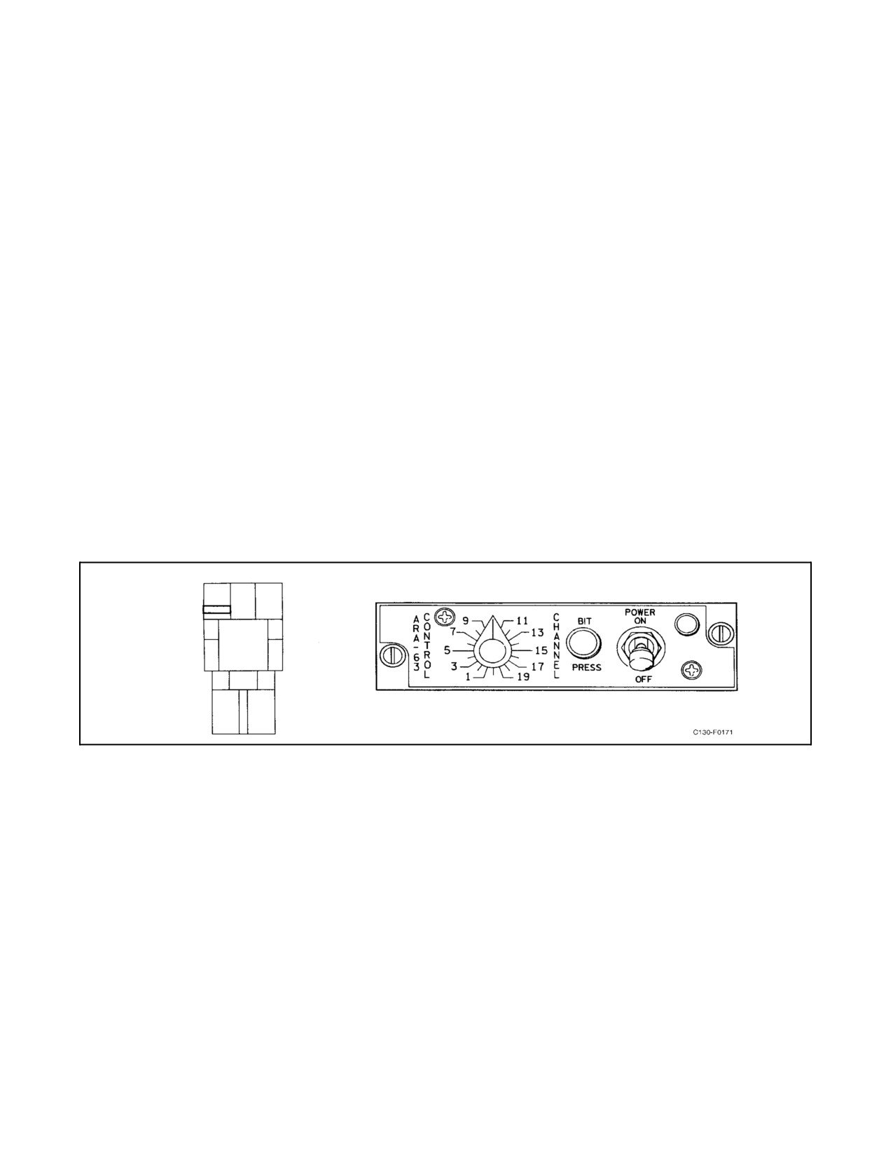
01-75GAL-1
Note
In general, avoid using channels close to 1 or 126 for air-to-air mode of
operation. Also avoid using local TACAN channels. With interrogating
aircraft flying in close proximity of each other, it is possible that erroneous
distances may be displayed because of the calibration of the TACAN
system in either aircraft.
2.21.15 AN/ARA-63A Receiving-Decoding Group
The receiving-decoding group is the airborne part of the aircraft approach control system.
2.21.15.1 Receiving-Decoding Group Controls
A receiving-decoding group control panel (see Figure 2-111) located on the flight control pedestal provides the
primary operating controls for the system. The panel contains a POWER switch and indicator, a pushbutton BIT
switch, and a CHANNEL select switch.
The ARA-63A receives and decodes TPN-30, TRN-28 and SPN-41 scanning beam pulse-coded microwave landing
system signals from ground/surface stations. The system continuously computes lateral (azimuth) and vertical
(elevation) deviations from the optimum approach line in space. Flight instrument indications are similar to ILS
except:
Figure 2-111. AN/ARA-63A Receiving-Decoding Group Control Panel
1. Aone-dotdeflectionoftheazimuthindicatorcorrespondstoa6_aircraftdeviationfromtheoptimumapproach
line. Azimuth deviations of up to 6_ result in a proportional deflection on the indicator. Azimuth deviation
of 6_ to 20_ results in full-scale deflection on the indicator. If ARA-63A is selected, optimum azimuth is
displayed by the ADI runway symbol and HSI course deviation bar on the affected flight director.
2. A one-dot elevation deflection oftheelevation indicatorcorresponds to a1.4_ resultin proportionaldeflection
on the indicator. Elevation deviations from 1.4_ to 10.0_ result in a full-scale deflection on the indicator. If
ARA-63A is selected, optimum elevation is displayed by the ADI and HSI glideslope pointers on the affected
flight director.
The ARA-63A system is supplied with three-phase 115-Vac essential ac power through the AN/ARA-63 circuit
breakers located on the pilot side circuit breaker panel. The system is supplied with 28-Vdc essential dc power
through the AN/ARA-63 circuit breaker located on the copilot upper circuit breaker panel.
ORIGINAL
2-254
01-75GAL-1
Note
D The AN/ARA-63A is not compatible with civil microwave landing
systems.
D If required, DME must be obtained from the aircraft TACAN equipment.
2.21.15.1.1 POWER Switch and Indicator Lamp
When the POWER switch is selected to OFF, no power is supplied to the system. When the POWER switch is
selected to ON, power is supplied to the system and the power indicator lamp illuminates.
2.21.15.1.2 CHANNEL Selector
The CHANNEL select switch is a rotary switch and is used to select any one of the 20 PCMLS channels in the Ku
band (see Figure 2-111).
2.21.15.1.3 BIT Switch
The pushbutton BIT switch provides the pilot with a degree of confidence in the systems operation. When the switch
is depressed and held, thesystem causes thefollowing indications to appear. Forcorrect system functioning, theADI
command bars will indicate fly right and fly left at a 4-second-per-cycle rate and the glideslope pointer will indicate
on glideslope. A malfunction detected by the BIT turns on failure indicators in the receiver or decoder, or both.
Note
The optimum elevation angle selector on the back of the receiver is not
intended for routine aircrew use. Verification of the desired optimum
elevation angle (normally 3_) is recommended during preflight on sorties
requiring use of the AN/ARA-63A system.
2.21.15.2 Normal Operation of the Receiving-Decoding Group
To turn the system on:
1. Place the POWER switch to the ON position.
2. Select the desired operating channel.
3. Place the NAV SEL switch to the ARA-63 position.
4. To test the system, depress and hold the BIT pushbutton switch.
To turn the system off:
5. Place the POWER switch to the OFF position.
2.21.16 AN/ARA-50 UHF Direction Finder (Aircraft Prior to 164993)
The UHF direction finder is used to indicate the relative bearing of, and to home on, radio signals being received by
the No. 1 AN/ARN-159 UHF (or AN/ARC-210 V/UHF for aircraft modified by AFC-338) radio. When the operator
sets the radio to the ADF function, continuous indication of relative bearing is provided by the No. 2 needle of the
RMI on the pilot and copilot instrument panels. The UHF direction finder operates from 115-Vacpower and 28-Vdc
power from the main ac bus and main dc bus through UHF DF circuit breakers on the copilot upper circuit breaker
panel.
2-255
ORIGINAL
01-75GAL-1
2.21.17 DF-301E UHF Direction Finder (Aircraft 164993 and Up)
The DF-301E direction finder is used to indicate the relative bearing of, and to home on, radio signals being received
by the No. 1 AN/ARN-159 UHF (or AN/ARC-210 V/UHF for aircraft modified by AFC-338) radio. When the
operator sets the radio to the ADF function, continuous indication of relative bearing is provided by the No. 2 needle
of the RMIs, on the pilot and copilot instrument panels. The DF-301E direction finder operates from 28-volt main
dc bus power provided through the UHF DF circuit breaker on the copilot upper circuit breaker panel.
2.21.17.1 AN/ARA-50 or DF-301E UHF Direction Finder Controls
The direction finder is controlled from the No. 1 UHF or V/UHF-1 radio (see Figure 2-96) on the flight control
pedestal. The direction finder is turned on by placing the function switch in the ADF position or by selecting ADF
operations via the CDNU for aircraft modified by AFC-338. The operating frequency is selected on the No. 1 UHF
or V/UHF-1 radio.
2.21.17.2 Normal Operation of the AN/ARA-50 or DF-301E UHF Direction Finder with AN/ARC-159
UHF Radio (Aircraft Prior to AFC-338)
2.21.17.2.1 Homing
Home on UHF radio stations as follows:
1. Rotate the function switch on the No. 1 UHF radio to the ADF position.
2. Select the operating frequency on the No. 1 UHF radio.
3. Turn the aircraft to place the head of the No. 2 bearing pointer under the top index of the RMI.
4. To turn off, move the function switch on the UHF radio from the ADF position.
2.21.17.2.2 Direction Finding
Perform direction finding as follows:
1. Rotate the function switch on the No. 1 UHF radio to the ADF position.
2. Select the operating frequency on the No. 1 UHF radio.
3. Read the bearing to the received signal under the head of the No. 2 bearing pointer on the compass card of the
RMI.
4. To turn off, move the function switch on the UHF radio from the ADF position.
2.21.17.2.3 Emergency Operation of the Direction Finder
The direction finder has no provision for emergency operation. If a fault in the direction finder interferes with
operation of the UHF radio, remove the P879 plug on the front panel of the AM-3624/ARA-50 amplifier relay. The
amplifier relay is located on the electrical control and supply rack (see Figure 2-82).
2.21.17.3 Operation of the AN/ARA-50 or DF-301E UHF Direction Finder with ARC-210 V/UHF
Radio (Aircraft Modified by AFC-338)
2.21.17.3.1 Homing
Home on UHF radio frequencies as follows:
1. Press the F1 function key on the CDNU to display the VU1 1 of 2 Page.
ORIGINAL
2-256
01-75GAL-1
2. Enter the operating frequency in the scratchpad of the CDNU and press line select key 1 (first left selection
button) to tune the V/UHF radio.
3. Toggle the operational mode (line select key 2) from T/R or TR&G to ADF.
4. Turn the aircraft to place the head of the No. 2 bearing pointer under the top index of the BDHI.
5. To turn off, from the VU1 1 of 2 Page, toggle the operational mode (line select key 2) from ADF to TR&G
or TR.
2.21.17.3.2 Direction Finding
Perform direction finding as follows:
1. Press the F1 function key on the CDNU to display the VU1 1 of 2 Page.
2. Enter the operating frequency in the scratchpad of the CDNU and press line select key 1 (first left selection
button) to tune the V/UHF radio.
3. Toggle the operational mode (line select key 2) from T/R or TR&G to ADF.
4. Read the bearing to the received signal under the head of the No. 2 bearing pointer on the compass card of the
BDHI.
5. To turn off, from the VU1 1 of 2 Page, toggle the operational mode (line select key 2) from ADF to TR&G
or TR.
2.21.17.3.3 Emergency Operation of the Direction Finder (Aircraft Modified by AFC-338)
The direction finder can be controlled from the V/UHF control unit located on the pedestal.
2.21.17.3.4 Homing with V/UHF Pedestal Control Unit
Home on UHF radio stations as follows:
1. Rotate the frequency selector switch to MAN.
2. Rotate the chan/freq/csr selector switch to the operating frequency. Press the selector switch to change cursor
positions.
3. Rotate the operational selector switch to ADF.
4. Turn the aircraft to place the head of the No. 2 bearing pointer under the top index of the BDHI.
5. To turn off, rotate the operational selector switch to TR or TR&G.
2.21.17.3.5 Direction Finding with V/UHF Pedestal Control Unit
Perform direction finding as follows:
1. Rotate the frequency selector switch to MAN.
2. Rotate the chan/freq/csr selector switch to the operating frequency. Press the selector switch to change cursor
positions.
3. Rotate the operational selector switch to ADF.
2-257
ORIGINAL
01-75GAL-1
4. Read the bearing to the received signal under the head of the No. 2 bearing pointer on the compass card of the
BDHI.
5. To turn off, rotate the operational selector switch to TR or TR&G.
2.21.18 AN/APN-232(V)6 Combined Altitude Radar Altimeter
CARA indicators, one each in the pilot and navigator instrument panels, are installed in C-130T aircraft prior to
164993. C-130T aircraft 164993 and up have CARA indicators installed in the pilot and copilot instrument panels
(Figure 2-112). CARA indicates the altitude the aircraft is above the terrain, up to 50,000 feet. The pilot CARA
provides information to the ground proximity warning system, and, on C-130T aircraft prior to 164993, the pilot and
copilot decision height annunciators. On C-130T aircraft 164993 and up, the pilot and copilot decision height
annunciators are provided information by their respective CARA indicators. The CARA system consists of two
indicators, two antennas, and one receiver-transmitter.
The system operates from 28-Vdc essential bus power through the ALTIMETER RADAR CMBD ALT circuit
breaker on the copilot upper circuit breaker panel.
2.21.18.1 CARA Indicators and Controls
The following items are located on each indicator:
1.
Analog altitude pointer and dial — The pointer indicates altitude from 0 to 5,000 feet. Above 5,000 feet, the
pointer is masked. The dial is graduated in increments of 10 feet from 0 to 500, 50 feet from 500 to 1,000, and
500 feet from 1,000 to 5,000.
2.
Digital altitude display — Five light-emitting diodes provide a digital indication of altitude and indicate in
1-foot increments from 0 to 100 feet and 10-foot increments from 100 to 50,000 feet. The word FAIL is
displayed by the LED if the system fails.
3.
LO altitude warning indicator — The indicator illuminates when the VALI setting has been attained.
4.
R/T status indicator — Illumination indicates a fault in the receiver-transmitter.
5.
Ambient light sensor — Senses cockpit light level and works in conjunction with the BRT knob to set digital
display brightness.
6.
BRT knob — Used to changebrightnessofthedigital display,as setby theambient lightsensorduringcockpit
low-light conditions. During bright light conditions, the ambient light sensorsets thedisplay to bright and the
BRT knob cannot dim the display.
7.
SET knob — The radar altimeter control SET knob serves three functions: as an on-off control, to set the VALI,
and as a test button to check the system. Initially, turning the knob clockwise applies power to the system;
further rotation of the knob rotates the VALI indicator from zero to a desired minimum altitude setting.
Momentarily depressing the SET knob activates the self-test feature of the system, and, if the system is
operating properly, the following sequence of events will occur:
a. The analog altitude pointer will move to 500 feet, the digital display will read 88888, and the R/T indicator
will illuminate for approximately 1.5 seconds. The LO indicator will also illuminate if the VALI is set above
500 feet.
b. After approximately l.5 seconds, the system will complete the self-test with a digital reading of 300 ±10
feet. The R/T indicator will be extinguished. The LO indicator will be illuminated if the VALI is set above
300 feet. This test will terminate approximately 1.5 seconds later. If, instead of events a and b occurring,
theword FAIL appears on thedigital display and theanalog altitudepointer goes behind themask, afailure
has occurred in the indicator. If the R/T indicator also illuminates when the word FAIL appears on the digital
display, the most probable failure is in the receiver-transmitter.
ORIGINAL
2-258
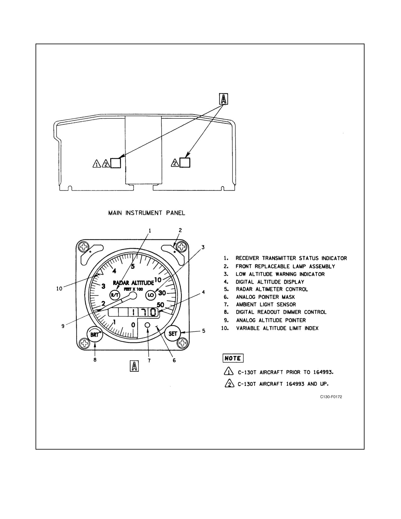
01-75GAL-1
Figure 2-112. AN/APN-232(V)6 Combined Altitude Radar Altimeter
2-259
ORIGINAL
01-75GAL-1
8. VALI — The VALI indicates the altitude setting at which the LO altitude warning indicator will illuminate.
The SET knob is used to set the VALI. On C-130T aircraft prior to 164993, the decision height annunciators
on the ADIs are set through the pilot CARA indicator SET knob. On C-130T aircraft 164993 and up, the pilot
and copilot decision height annunciators are set through the respective (pilot or copilot) CARA indicator SET
knob.
2.21.18.2 Normal Operation of the CARA
Note
TheCARA may break lock andtheheightindication mayfluctuateorcycle
duringgroundoperationorinflightabove10,000feetwiththenoselanding
gear down. This is normal and not a discrepant condition as long as
operation is normal under other conditions.
To put the CARA into operation:
1. Onthepilotindicator,rotatetheSETknoboutoftheoffdetent.Wait5secondsforwarmup.Theanalogaltitude
pointer indicates zero.
2. Set the desired altitude reference with the SET knob.
To test the radar altimeter for correct operation:
3. Set the VALI to 400 feet.
4. Momentarily depress theSET knob. Observe that the analog pointer moves to 500 ±10 feet, the digital display
reads 88888, and the R/T indicator illuminates. After approximately 1.5 seconds, observe that the digital
display changes to 300 ±10 feet, the analog pointer moves to 300 ±10 feet, the R/T lamp extinguishes, and
the LO lamp illuminates. This display lasts approximately 1.5 seconds, after which the system returns to
normal operation.
To turn the CARA off:
5. Rotate the SET knob on the pilot indicator to off.
Repeat steps 1 through 5 on the navigator/copilot indicator.
2.21.19 Ground Proximity Warning System (Mark VII)
The GPWS provides both the pilot and copilot with visual and aural warnings for a flight condition or aircraft attitude
that, if uncorrected, would cause the aircraft to come in close proximity or contact the terrain in its flightpath. The
Mark VII GPWS consists of a solid-state computer, warning annunciators on the pilot and copilot instrument panel
and glareshield, an air data computer (barometric altitude/rate and Mach), tactical (TACT) and approach (APPR)
mode selector switches and annunciators on the pilot and copilot instrument panels, and switches to monitorlanding
gear and flap position (see Figure 2-113). The Mark VII GPWS receives signals from the radar altimeter, VHF
navigation system, No. 1 and No. 2 flight director system, and the vertical gyro. Power is supplied from the essential
ac and essential dc buses through the GPWS circuit breakers located on the copilot upper circuit breaker panel.
2.21.19.1 Annunciators and Controls
GPWS annunciators and controls are located on the instrument panel and center pedestal (see Figure 2-113) and are
explained in the following paragraphs.
ORIGINAL
2-260
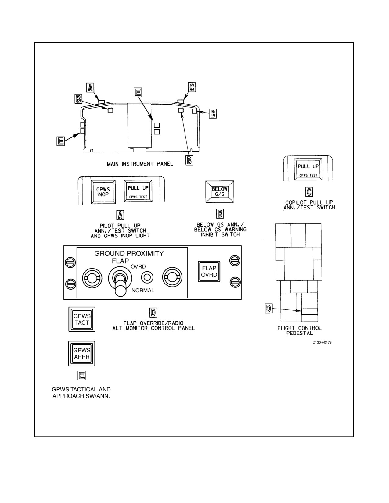
01-75GAL-1
Figure 2-113. Ground Proximity Warning System Switches and Control Panel
2-261
ORIGINAL
01-75GAL-1
2.21.19.1.1 PULL UP Annunciators/GPWS TEST Switches
The combination PULL UP annunciators/GPWS TEST switches are located on the pilot and copilot main instrument
panels. When the aircraft enters the warning envelope of excessive sink rate (mode 10) or excessive closure rate (mode
2), the PULL UP annunciator lights will illuminate and the aural “Whoop whoop pull up” is heard on all flight station
positions through the pilot and copilot intercommunications system. When an annunciator/switch is depressed, a
self-test is initiated if the aircraft is on the ground or airborne above 200 feet.
2.21.19.1.2 BELOW G/S Annunciators/Switches
The BELOW G/S annunciators are located on the pilot and copilot instrument panels. The annunciators are also
push-typeswitchesusedtoinhibitglideslopewarningsbelow1,500feetaltitude.Whentheaircraftentersthewarning
envelope of descent below glideslope (mode 5), the BELOW G/S annunciator lights will illuminate and an aural
“Glideslope” warning is heard on all flight station positions through the pilot and copilot ICS.
2.21.19.1.3 GPWS INOP Annunciator
The GPWS INOP annunciator is located on the pilot instrument panel glareshield adjacent to the PULL UP
annunciator. The annunciator illuminates when any of the following conditions occur:
1. No validated signal is being received from the radio/radar altimeter.
2. No validated signal (barometric altitude/rate) is being received from the GPWS air data computer.
3. A fault exists within the GPWS.
4. Other system wiring faults.
2.21.19.1.4 GPWS TACT Switches and Annunciators
Combination GPWS TACT switches/annunciators are located on the pilot and copilot instrument panels. Tactical
mode annunciation is provided by GPWS TAC mode advisory lights located on the pilot and copilot instrument
panels. The switches are used when mission requirements specify en route flight below 800 feet AGL or when a
maximum-effort landing is to be made. Depression of either switch sets the GPWS to the tactical mission mode and
causes the annunciator to illuminate. The GPWS can be reset to the normal mode by depressing the switch again or
by ascending through 2,450 feet AGL.
2.21.19.1.5 GPWS APPR Switches and Annunciators
Combination GPWS APPR switches/annunciators are located on the pilot and copilot instrument panels. Approach
modeannunciation is provided by GPWS APPR modeadvisory lights located on thepilot and copilot modeadvisory
panel. The switches provide the means for supplying the GPWS computer with glideslope information for approach
mode operation. The GPWS approach mode is automatically selected when either VOR/ILS No. 1 or VOR/ILS No.
2 is tuned to a localizer frequency and selected on the pilot NAV SEL switch. At this time, glideslope information
is supplied to the GPWS computer and the pilot GPWS APPR annunciator illuminates. Selecting a localizer-tuned
VOR/ILS with the copilot NAV SEL switch and momentarily depressing the copilot GPWS APPR switch will allow
the copilot to fly the ILS approach with the GPWS computer being supplied glideslope information from VOR//ILS
selected by the copilot. At this time the pilot GPWS APPR annunciator will be extinguished and the copilot
annunciator will be illuminated. To resume flying the ILS approach, the pilot selects a localizer-tuned VOR/ILS and
momentarily depresses the GPWS APPR switch on the pilot instrument panel. The copilot annunciator will
extinguish, the pilot annunciator will illuminate, and the GPWS computer will again be supplied information from
the VOR/ILS selected by the pilot.
2.21.19.1.6 GROUND PROXIMITY FLAP OVERRIDE Switch
The GROUND PROXIMITY FLAP OVERRIDE switch is a two-position (NORMAL, OVERRIDE) toggle switch
on theground proximity flap-override control panel mounted on theflight control pedestal (Figure2-113). When the
ORIGINAL
2-262
01-75GAL-1
switch is placed to the NORMAL position, the circuit to the 40-percent flap switch (located in the flap control
quadrant) is completed for appropriate aircraft configuration signals (mode 4B) to be validated by the GPWS
computer. When the switch is placed to the OVERRIDE position, the 40-percent flap switch is inhibited and no
warning signal is available. This feature is provided for operations below 245 feet with partial flap settings.
2.21.19.1.7 Nose Landing Gear Down-and-Locked Limit Switch
The nose landing gear down-and-locked limit switch provides the GPWS computer with the appropriate aircraft
configuration data when the aircraft enters the envelope for terrain clearance (mode 4A) with the landing gear not
in the down position.
2.21.19.2 Modes of Operation
The ground proximity warning system provides aural warnings, along with visual warnings, that segregate the
various warnings when the aircraft flightpath and configuration would result in imminent hazardous proximity to the
terrain. The following paragraphs describe the visual and aural warnings for the various modes.
2.21.19.2.1 Mode 1A — Excessive Sink Rate
Mode 1A is independent of aircraft configuration and is functional at all times. When the aircraft penetrates a
predetermined outer envelope, the PULL UP annunciator is illuminated and the “SINK RATE” aural warning is
given. If the inner envelope is penetrated, the “WHOOP WHOOP PULL UP” warning is given. The mode 1A
envelope is shaped in such a manner that, at higher altitudes, steeper visual approaches can be made without causing
a warning, and, at lower altitudes, additional protection has been added for windshear and visual transition.
2.21.19.2.2 Mode 1B — Excessive Sink Rate, Tactical Mission Mode
When mode 1B is selected and landing gear is down, the boundaries for the inner and outer envelopes are changed
to accommodate the higher sink rates that may be required for a maximum effort landing. The warnings given are
the same as for mode 1A. When the landing gear is up, no warnings are provided.
2.21.19.2.3 Mode 2A — Excessive Closure Rate, Flaps Up
Mode 2A provides alerts and warnings for excessive closure rates with respect to terrain. At airspeeds up to 195 KIAS,
theboundary limits rangefrom thelowerlimitof30feet radio/radaraltitudeataclosurerateof2,038 fpmto theupper
limit of 1,650 feet radio/radar altitude at a closure rate of 5,733 fpm. As airspeed is increased from 195 KIAS to 250
KIAS, the upper boundary increases proportionally to 2,450 feet and 9,800 fpm. If the aircraft penetrates mode 2A
envelope, the PULL UP annunciator illuminates and the “TERRAIN-TERRAIN” warning is sounded. If this warning
lasts longer than 1.4 seconds, the aural warning changes to “WHOOP WHOOP PULL UP.” When the aircraft leaves
the boundary with landing gear and flaps up and not in tactical mission mode, the “TERRAIN-TERRAIN” aural
warning returns and is repeated every 0.75 second until the aircraft gains 300 feet barometric altitude above the values
existing when the aircraft left the boundary. The altitude gain function is inhibited when the landing gear is extended
or when GPWS is in the tactical mission mode.
2.21.19.2.4 Mode 2B — Excessive Closure Rate, Flaps Down or Tactical Mission Mode
Lowering the flaps to landing position or in the tactical mission mode switches the CB computer to mode 2B.
Penetration of mode 2B boundary activates the same warnings as in mode 2A except that the lower limit is raised
to 200 feet radio/radar altitude at 2,253 fpm and the upper limit is lowered to 790 feet radio/radar altitude at 3,000
fpm. Below 700 feet terrain clearance with landing gear and flaps down, the “WHOOP WHOOP PULL UP” warning
is inhibited and only the “TERRAIN-TERRAIN” warning will sound.
2.21.19.2.5 Mode 3 — Descent After Takeoff
Mode3warningsareprovidedwhenabarometricaltitudelossoccursaftertakeofforduring amissed approach.Mode
3 is effective between 30 and 533 feet radio/radar altitude for climbout speeds up to 178 KIAS, and between 30 and
2-263
ORIGINAL
01-75GAL-1
1,066 feet for climbout speeds above 178 KIAS. If the aircraft descends through this boundary during climbout after
takeoff or during a missed approach, the PULL UP annunciator will illuminate and the “DON’T SINK” aural warning
will sound twice. If an additional 20 percent of altitude is lost, the “DON’T SINK” aural warning is repeated. A
pull-up warning is not issued so as not to cause overreaction during this critical period when the aircraft stall margin
may be very small. In addition, if the aircraft passes over rising terrain during climbout and loses more than 25 percent
of radio/radar altitude, a “TOO LOW TERRAIN” aural warning will sound. This feature is not activated until the
aircraft has reached a radio/radar altitude of 150 feet.
The missed-approach mode does not arm until the aircraft is below 245 feet radio/radar altitude and both the flaps
and gear are in the landing position.
2.21.19.2.6 Mode 4A — Insufficient Terrain Clearance, Gear Up
Mode 4A provides forinsufficient terrain clearance when the aircraft landing gearis not down and locked. Themode
4A upper boundary is 400 feet radio/radar altitude for airspeeds up to 178 KIAS. This boundary increases
proportionally up to 800 feet as airspeed is increased from 178 to 226 KIAS. Penetration of the 400-foot boundary
at less than 178 KIAS causes the PULL UP annunciator to illuminate and the “TOO LOW GEAR” aural warning
to sound. Penetration of the boundary between 400 and 800 feet with airspeed between 178 and 226 KIAS causes
thePULL UP annunciatorto illuminateand the“TOO LOWTERRAIN”aural warning to sound. The aural warnings
are given twice. If an additional 20 percent of radio/radar altitude is lost, the aural warnings are repeated. The warning
is silenced when the landing gear is down and locked.
2.21.19.2.7 Mode 4B — Insufficient Terrain Clearance, Flaps Up
Mode 4B is activated when the landing gear is down and locked but the flaps are not in the landing position. Mode
4B differs from mode 4A in that the boundary altitude decreases to 245 feet radio/radar altitude when the gear is
lowered and airspeed is increased above 159 KIAS. Penetration of the boundary above 159 KIAS causes the PULL
UP annunciator to illuminate and the “TOO LOW TERRAIN” aural warning to sound. Penetration of the boundary
at 159 KIAS or below causes the PULL UP annunciator to illuminate and the “TOO LOW FLAPS” aural warning
to sound. The aural warning is given twice and repeated twice when an additional 20 percent radio/radar altitude is
lost. The warning is silenced by selecting landing flaps.
2.21.19.2.8 Mode 4C — Insufficient Terrain Clearance, Tactical Mission Mode
Mode 4C is activated when the GPWS TACT switch on the pilot instrument panel is actuated to place the GPWS
in the tactical mission mode. The PULL UP annunciators are illuminated and aural warnings are given as follows:
1. Descent through 150 feet with airspeed greater than 150 KIAS produces no warning.
2. Descent through 150 feet with airspeed 150 KIAS or less illuminates the PULL UP annunciator and produces
a “TOO LOW GEAR” aural warning if the landing gear is up or a “TOO LOW FLAPS” aural warning if the
flaps are up.
2.21.19.2.9 Mode 5 — Descent Below Glideslope
Mode 5 is activated when an ILS frequency has been selected and the GPWS approach mode is selected. There are
two boundaries (soft and loud) for this mode. The first (soft) boundary occurs when the aircraft is below 1,000 feet
radio/radar altitude and more than 1.3 dots below the glideslope beam. The second (loud) boundary is when the
aircraft is below 300 feet radio/radar altitude and more than 2 dots below the glideslope beam. When the soft boundary
is penetrated, the BELOW G/S annunciator illuminates and a “GLIDESLOPE” aural warning is sounded at one-half
volume. If the loud boundary is penetrated, the aural warning is sounded at normal volume. The repetition rate of
theaural is variedas afunction oftheradio/radaraltitudeandglideslopedeviation.Therepetitionrateisslow at1,000
feet and 1.3 dots deviation, speeding up as altitude decreases and/or glideslope deviation increases.
ORIGINAL
2-264

01-75GAL-1
2.21.19.2.10 Mode 6A — Descent Below Decision Height
Mode 6A provides a “MINIMUMS, MINIMUMS” aural warning between 30 and 1,000 feet radio/radar altitude
when the aircraft passes through the decision height as set on the radio/radar altimeter. No warning annunciator is
illuminated in this mode. If the decision height is reset to a lower altitude, no output is produced. The threshold may
be reset by climbing above 1,000 feet radio/radar altitude, descending below 30 feet, or retracting and reextending
the landing gear.
2.21.19.2.11 Mode 6B — Descent Below Decision Height, Tactical Mode
When flying a tactical mission with the GPWS set to the tactical mission mode and with airspeed greater than 150
KIAS, an “ALTITUDE-ALTITUDE” aural warning will sound when the aircraft is more than 50 feet below the
minimum altitude set on the radio/radar altimeter.
2.21.19.2.12 Mode 7 — Windshear
The windshear mode is not operational.
2.21.19.2.13 Mode 8 — Excessive Bank Angle
Mode 8 provides a warning for excessive bank angle based on radio/radar altitude and roll attitude. The computer
also considers roll rate and descent rate in arriving at an output. The bank angle boundary begins at 130 feet radio/radar
altitude and 60_ maximum bank angle, decreasing to 30 feet and 10_ maximum bank angle. Exceeding the bank angle
or inducing a roll rate that, if continued, would result in exceeding the bank angle for a given altitude, causes a “BANK
ANGLE” aural warning. The audio alert may be repeated once after a 0.75-second delay.
2.21.19.3 Summary of System Visual/Aural Alerts and Warnings
Simultaneous visual annunciator alert and audio advisories occur when the outer envelopes of modes 1 through 5
are penetrated. Warnings are issued upon entering the inner envelopes of modes 1A, 1B, 2A, and 2B. Modes 3, 4,
and 5 issue alert advisories only and are not followed by warnings. See the following table for summary.
2.21.19.4 Message Priorities
With the possibility of more than one warning occurring at the same time, a priority system of message transmission
is built into the GPWS computer. The various messages, their priority, and their associated modes are as follows:
PRIORITY
MESSAGE
MODE
1
Whoop whoop pull up
1A, 1B, 2A and 2B
2
Terrain
2A and 2B
3
Minimums
6A
4
Too low terrain
4A, 4B and 4C
5
Too low gear
4A and 4C
6
Too low flaps
4B and 4C
7
Sink rate
1A and 1B
8
Don’t sink
3
9
Glideslope
5
10
Bank angle
8
11
Altitude
6B
2-265
ORIGINAL
01-75GAL-1
2.21.19.5 Normal Operation of the GPWS
Note
If the GPWS INOP annunciator illuminates steady or flashes after power
is applied, a malfunction/failure in the GPWS computer is indicated.
2.21.19.5.1 GPWS Approach Mode Operation
To place the GPWS in the approach mode:
1. Tune the No. 1 or No. 2 VOR to a valid ILS localizer frequency.
2. Select the tuned VOR/ILS with the pilot or copilot NAV SEL switch.
If the pilot makes the selection:
3. Verify the pilot GPWS APPR annunciator is illuminated indicating the GPWS is in the approach mode
utilizing glideslope information from the VOR/ILS selected by the pilot.
If the copilot makes the selection:
4. Momentarily depress the copilot GPWS APPR switch.
5. Verify the copilot GPWS APPR annunciator is illuminated indicating the GPWS is in the approach mode
utilizing glideslope information from the VOR/ILS selected by the copilot.
Should the pilot wish to assume control from the copilot:
1. Select the VOR/ILS that is tuned to the proper ILS frequency utilizing the pilot NAV SEL switch.
2. Momentarily depress the GPWS APPR switch.
3. Verify that the pilot GPWS APPR switch illuminates and the copilot GPWS APPR switch extinguishes.
2.21.19.5.2 GPWS Tactical Mode Operation
To operate the GPWS in the tactical mission mode:
1. Set the radio/radar altimeter minimum altitude marker to the desired minimum altitude for the tactical
low-level route.
2. Momentarily depress the pilot or copilot GPWS TACT switch.
3. Verify the GPWS TACT annunciators on the pilot and copilot instrument panels illuminate.
To return the GPWS to normal mode:
4. Momentarily depress the pilot or copilot GPWS TACT switch.
5. VerifytheGPWSTACTannunciatorsextinguish.TheGPWSmayalsoberesettonormalby climbingthrough
2,450 feet AGL.
2.21.20 Altitude Alerter/Preselect System
The altitude alerter/preselect system consists of an altitude alerter/preselect control, located on the main instrument
panel glareshield, and a tone generator mounted overhead in the flight station. The system provides automatic visual
and aural signals during approach to or departure from a preselected altitude. The operating range of the altitude
alerter/preselect control is 0 to 50,000 feet in 100-foot increments. The system is interconnected with the pilot
altimeter-encoder, air data control No. 1, and the pilot and copilot interphone system for tone generator aural signal
ORIGINAL
2-266
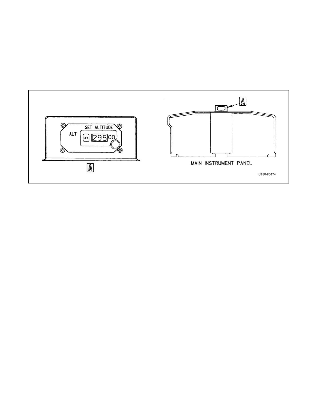
01-75GAL-1
reception. The altitude alerter/preselect system uses 26-Vac power from the essential ac bus through the ALTITUDE
ALERT circuit breaker on the pilot upper circuit breaker panel.
2.21.20.1 Altitude Alerter/Preselect System Controls
Altitude alerter/preselect control contains a manual set knob, an ALT alert light, and a failure warning (OFF) flag
(see Figure 2-114).
Figure 2-114. Altitude Alerter/Preselect Control
2.21.20.1.1 Manual Set Knob
The manual set knob is used to preset the desired altitude for visual display on the altitude alerter/preselect control.
2.21.20.1.2 ALT Alert Light
The ALT alert light provides an illuminated signal that the aircraft is approaching within 1,000 feet of the preset
altitude or departing the preset altitude by ±300 feet. As the aircraft approaches the outer level (1,000 feet) of a preset
altitude, the ALT alert light and aural tone generator are activated. The tone generator is activated for approximately
2 seconds. The ALT alert light, however, remains illuminated until the aircraft crosses the inner level (300 feet) of
the preset altitude, at which time it is extinguished. Should the aircraft depart from the preset altitude by more than
±300 feet, the aural tone and ALT alert light will again be activated. The light will remain illuminated until the aircraft
returns to the preset altitude or until a new altitude is selected.
2.21.20.1.3 Failure Warning Flag
The failure warning (OFF) flag indicates a loss of flag alarm signal from the altimeter or a loss of electrical power
to the indicator.
2.21.21 Identification Friend-or-Foe (IFF)/Mode S Transponder System with Traffic Alert and
Collision Avoidance System (TCAS)
2.21.21.1 IFF/Mode S Transponder System
The IFF/Mode S Transponder is a combined IFF and Mode S transponder. The IFF portion of the system provides
surveillance and identification functions to surface or airborne interrogator radar sets. When interrogated, the IFF
transponder automatically transmits a reply. The reply, dependent upon what type of interrogation, will identify the
2-267
ORIGINAL
01-75GAL-1
aircraft or report its altitude. When operated in the secure mode, it will reply using the secure code of the day, thereby
identifying itselfas friendly. TheModeS portion ofthesystem provides theaircraft with apermanent uniqueaddress
code that is used in Mode S replies. The transponder also provides a means of transmitting a specially coded signal
known as an emergency reply that contains the aircraft’s identification and altitude.
2.21.21.1.1 System Components
The IFF/Mode S transponder system consists of an IFF transponder, located in the IFF equipment rack; a combined
TCAS/IFF control panel and an IFF caution light, located on the center pedestal; and two antennas, one located on
the top of the fuselage and one located on the bottom of the fuselage. There are provisions for a KIT-1C/TSEC Mode
4 computer in the IFF equipment rack.
The transponder receives 28 Vdc from the essential DC bus through the IFF CMPTR circuit breaker on the copilot’s
upper circuit breaker panel. The combined TCAS/IFF control panel receives 28 Vdc from the essential DC bus
through the TCAS/IFF CONTROL circuit breaker on the copilot’s upper circuit breaker panel.
2.21.21.1.2 Theory of Operation
The transponder receives interrogations on 1030 MHz and transmits replies to interrogations on 1090 MHz. When
an interrogation is received, the transponder monitors the signal on the top and bottom antenna ports and selects the
best port based on signal strength and time of arrival. The system will transmit a coded reply in response to an
interrogation if the signal has the proper characteristics for the mode selected. The coded reply is sent through the
transmitter and antennas to the interrogating station.
The transponder has two independent RF receiver channels, allowing both top and bottom interrogations to be
monitoredsimultaneously.TheIFFportionofthetransponderis asurveillancesystemforclassifyingtargets aseither
friendly or hostile. There are six IFF modes: 1, 2, 3A, C, 4, and S. Modes 1 and 2 are used by the military for
identification. Mode 3A is used by both military and civilian air traffic control stations. Mode C is used to report the
aircraft’s altitude to an air traffic control station. Mode C replies are determined by altitude information provided from
theairdatacomputer. Mode4is amilitary encryptedcodethatis classified.This code,orkey,is loadedinto theMode
4 computer. Successful identification of a target is based on both the interrogator and transponder possessing the same
code. Mode S is a two-way (up/down) digital data link which transmits Mode 3A, Mode C, a unique aircraft
identification code, and Mode S information/instructions between Mode S capable air traffic control stations and/or
other Mode S/TCAS capable aircraft. The unique aircraft identification code/address is based on the aircraft bureau
number and is set into the transponder via hardwired aircraft wiring discretes. Using this unique code, interrogations
can be directed to a particular aircraft and replies can be positively identified. Channel interference (RF clutter) can
be minimized because an air traffic control station or aircraft can limit its interrogations to specific targets of interest.
Mode S replies are dependent on what was requested in the Mode S interrogation and are coordinated by the
transponder. When the aircraft is on the ground, the transponder will receive a signal from the right main landing gear
touchdown switch. This will allow the Mode S reply to include the information that the aircraft is on the ground.
2.21.21.1.3 IFF/Mode S Transponder Controls
Control of the IFF/Mode S transponder system is accomplished with the combined TCAS/IFF control panel (see
Figure 2-115). Before turning the control panel on, the Combined Altitude Radar Altimeter (CARA) must be
operating. Power must also be applied to the High Integration Air Data Computer through the HIADC DC circuit
breaker on the copilot’s side circuit breaker panel.
MASTER SYSTEM Switch
The MASTER SYSTEM SWITCH on the combined TCAS/IFF control panel allows the operator to select the
following operating conditions for the transponder: OFF, STBY (standby), NORM (normal sensitivity), and EMER
(emergency). When the switch is set to OFF, all power is removed from the system. When the switch is set to STBY,
ORIGINAL
2-268
01-75GAL-1
the SYS GO annunciator will illuminate momentarily. The transponder receives air and ground interrogations but
does not reply. When the switch is set to NORM, the SYS GO annunciator will illuminate momentarily. Depending
on which mode is enabled, the transponder will reply to air and ground interrogations in Mode 3A, C, and S. When
the switch is set to EMER, the transponder will transmit emergency code 7700 in Mode 3A to indicate the aircraft
is in distress. The transponder will reply with an emergency code regardless of which mode is selected. EMER reply
does not affect Mode C or Mode 4 operation. The switch must be pushed down and then turned in order to select
EMER.
IDENT Reply
An IDENT reply can be made in Mode 1, 2, 3A, or S. This mode of operation is selected by placing the REMOTE
MIC ENABLE SWITCH on the combined TCAS/IFF control panel to OFF and momentarily pressing the IDNT
button. The system will automatically transmit the reply during the time the IDNT button is pressed and released for
atotalof18 seconds.Thismodeofoperationmay alsobeselectedby placingtheREMOTEMIC ENABLESWITCH
to MIC and the pilot or copilot keying either of the UHF or V/UHF radios. The system will automatically transmit
thereplyduringthetimeradiosarekeyedand releasedforatotal of18 seconds.Placing theREMOTE MICENABLE
SWITCH to MIC will inhibit the IDNT button from operating.
MODE SELECT/TCAS ENABLE Switch
The MODE SELECT/TCAS ENABLE switch is a six position rotary switch enabling different modes of operation
and allowing for selection of TCAS functions. In the OFF position, Modes 3A, C, and S are disabled and TCAS is
set to standby. Selection of MODE 3A enables mode 3A only. MODE C enables modes 3A and C and MODE S
enables modes S, C, and 3A.
MODE 1-2 Switch
The MODE 1-2 switch is a four-position rotary switch enabling Mode 1, Mode 2 or Mode 1 and 2 operating modes.
2.21.21.1.4 IFF/Mode S Transponder Display Selections
The control panel contains switches that are used to select and input the desired code for Modes 1, 2, 3A, and S and
Flight ID. See Figures 2-116 through 2-119 for display selections and entering selected codes.
2.21.21.1.5 Mode 4 Operations
When the KIT-1C/TSEC Mode 4 computer is installed, Mode 4 interrogations bypass the decoder in the transponder
and are applied directly to the Mode 4 computer. The Mode 4 interrogation signal is decoded and applied to a Mode
4 recognition circuit. When a Mode 4 coincidence exists, the Mode 4 recognition circuit generates a signal to the
Mode4 computer, which in turn generates asignal to theMode4 reply. The REPLY annunciator on the control panel
illuminates to indicatethataMode4 replyis beingtransmitted. AnIFF Cautionlight islocated onthecenterpedestal.
The IFF Caution light will illuminate when the aircraft receives incompatible Mode 4 interrogations under the
following conditions:
1. The Mode 4 switch is OFF.
2. The transponder is in STBY.
3. The Mode 4 computer is not properly responding to interrogations.
4. The Mode 4 computer is connected but the crypto codes are not loaded (zeroized).
2-269
ORIGINAL
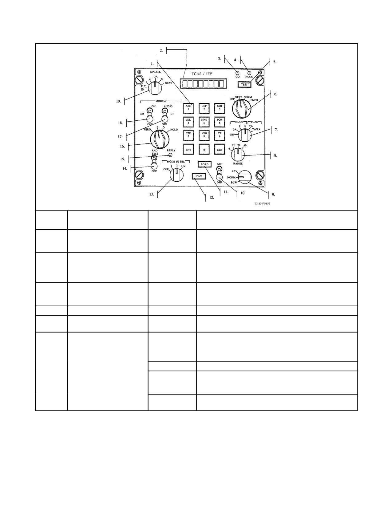
01-75GAL-1
SWITCH
ITEM
CONTROL
POSITION
FUNCTION
1.
CODE ENTRY KEYPAD
N/A
The Code Entry Keypad consists of 12 keys used to provide
entry of Mode S Address, Mode 1, Mode 2, Mode 3A and
Flight ID codes.
2.
ALPHANUMERIC
N/A
Consists of an eight Alphanumeric Character, Liquid Crystal
CHARACTER DISPLAY
Display. Display has white characters on a black
backg0round. Displays selected codes, software version,
status, failures and transponder messages.
3.
GO ANNUNCIATOR
N/A
Indicates no failures in the system or indicates a new
transponder message has been received by the control
panel.
4.
NOGO ANNUNCIATOR
N/A
Indicates system failures.
5.
SYSTEM TEST
N/A
Momentary test pushbutton to activate system functional test.
PUSHBUTTON
6.
MASTER SYSTEM SWITCH
Four position rotary switch allowing master system control to
the OFF, STBY, NORM and EMER positions. OFF and
EMER positions are locking, to select and deselect these
positions the switch must be pushed and turned.
OFF
Completely disables all transponder and TCAS functions.
STBY
Inhibits transmission of Modes 1, 2, 3A, C, 4 and S. All other
control panel functions shall be enabled. Inhibits TCAS TA
and TA/RA interrogations.
NORM
Enables selected transponder mode replies. Enables TCAS
TA and TA/RA interrogations if selected.
Figure 2-115.
IFF/Mode S Transponder Controls (Sheet 1 of 3)
ORIGINAL
2-270

01-75GAL-1
SWITCH
ITEM
CONTROL
POSITION
FUNCTION
EMER
Enables transponder Modes 1, 2, 3A and S to reply with an
emergency code automatically regardless of the selection on
the Mode Select and TCAS Enable Switch. Mode 3A shall
transmit code 7700. The emergency feature does not affect
Mode C or Mode 4 operation.
7.
MODE SELECT AND TCAS
Six position rotary switch enabling the different modes of
ENABLE SWITCH
operation and allowing for selection of TCAS functions.
OFF
Disables Modes 3A, C, S and sets TCAS to standby.
3A
Selection of Mode 3A shall enable Mode 3A only.
C
Selection of Mode C shall enable Mode C and continue to
enable Mode 3A.
S
Selection of Mode S shall enable Mode S and continue to
enable Modes 3A and C.
TA
Selection of TA shall enable TCAS traffic advisories and
continue to enable Modes 3A, C and S.
TA/RA
Selection of TA/RA shall enable TCAS traffic and resolution
advisories and continue to enable Modes 3A, C and S.
8.
HORIZONTAL RANGE
Four position rotary switch allowing the selection of
SWITCH
horizontal display range in nautical miles.
6
Selects 6 nm range for VSI/TRA displays.
12
Selects 12 nm range for VSI/TRA displays.
20
Selects 20 nm range for VSI/TRA displays.
40
Selects 40 nm range for VSI/TRA displays.
9.
VERTICAL RANGE SWITCH
Three position rotary switch allowing selection of altitude
ranges, with respect to aircraft, for traffic display on the
VSI/TRA displays.
ABV
Sets TCAS range limits at 9,900 ft above and 2,700 ft below
aircraft.
NORM
Sets TCAS range limits at 2,700 ft above and below aircraft.
BLW
Sets TCAS range limits at 2,700 ft above and 9,900 ft below
aircraft.
10.
REMOTE MIC ENABLE
Two position locking lever toggle switch that controls IDENT
SWITCH
function.
OFF
Allows IDENT to be performed when IDNT pushbutton is
momentarily pressed.
MIC
Allows IDENT function to be performed upon keying of either
UHF or V/UHF radio by the pilot or copilot and inhibits the
front panel IDNT Switch.
11.
LOAD PUSHBUTTON
N/A
Momentary pushbutton used to transmit a completed code to
the transponder or TCAS computer as displayed on the LCD.
12.
IDENT PUSHBUTTON
N/A
Momentary pushbutton labeled IDNT used to initiate IDENT
when the Remote Mic Enable Switch is in the OFF position.
Figure 2-115. IFF/Mode S Transponder Controls (Sheet 2)
2-271
ORIGINAL
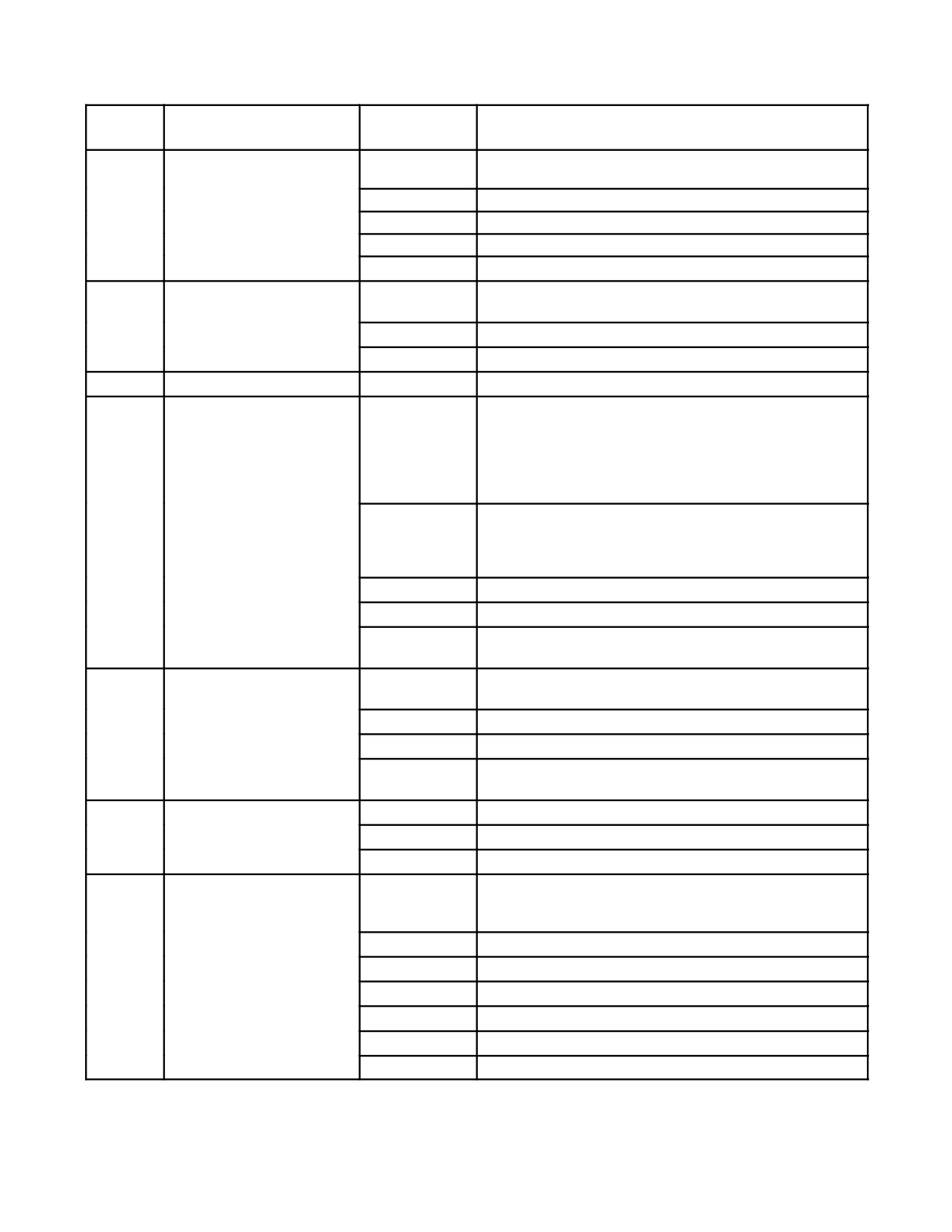
01-75GAL-1
SWITCH
ITEM
CONTROL
POSITION
FUNCTION
13.
MODE 1-2 SWITCH
Four position rotary switch allowing Mode 1, Mode 2 or Mode
1 and 2 operating modes.
OFF
Disables Mode 1 and Mode 2 operation.
1
Enables Mode 1 operation.
2
Enables Mode 2 operation.
1+2
Enables Mode 1 and Mode 2 operation.
14.
RAD TEST SWITCH
Two position momentary selection locking lever switch to
enable the Mode 4 radiated test function.
OFF
Inhibits Mode 4 radiated verify bit 1 test.
RAD TEST
Enables Mode 4 radiated verify bit 1 test.
15.
REPLY ANNUNCIATOR
N/A
Indicates Mode 4 replies are being transmitted.
16.
MODE 4 CODE CONTROL
Four position spring-loaded rotary switch. Allows selection of
SWITCH
Mode 4 A or B Code, HOLD or ZERO. The ZERO position is
a locking position, to select the switch must be pushed and
turned. The HOLD position is spring-loaded, to activate the
HOLD function the switch must be turned and held
momentarily.
HOLD
The Mode 4 HOLD control shall enable an operator in the
aircraft to retain the Mode 4 Code settings if power is to be
removed from the transponder while the aircraft is on the
ground.
A
Permits selection of Mode 4 Code A.
B
Permits selection of Mode 4 Code B.
ZERO
When selected shall zeroize Mode 4 Code A and Code B in
KIT-1C and KIR-1C if installed in the aircraft.
17.
REPLY MONITORING
Three position locking lever switch allowing control of the
CONTROL SWITCH
front panel reply indicator and the Mode 4 audio.
OFF
Disables Mode 4 REPLY annunciator and audio.
LT
Enables front panel REPLY annunciator operation.
AUDIO
Enables Mode 4 audio tone and front panel REPLY
annunciator operation.
18.
MODE 4 ON/OFF SWITCH
Two position locking lever switch allowing Mode 4 enable.
OFF
Mode 4 operation is disabled.
ON
Enables Mode 4 operation.
19.
DISPLAY SELECT SWITCH
Six position rotary switch allowing selection of the different
display Modes in the Alphanumeric Character Display
(Item 2.)
FLT ID
Enables FLT ID Display and Keypad Entry Mode.
1
Enables Mode 1 Display and Keypad Entry Mode.
2
Enables Mode 2 Display and Keypad Entry Mode.
3A
Enables Mode 3A Display and Keypad Entry Mode.
S
Enables Mode S Display and Keypad Entry Mode.
STAT
Enables display of transponder status messages.
Figure 2-115. IFF/Mode S Transponder Controls (Sheet 3)
ORIGINAL
2-272

01-75GAL-1
1.
Selecting 1 in the DPL SEL switch enables the Mode 1 display and keypad entry mode.
2.
Mode-1 code entries are displayed in the 4th and 5th character locations starting from the left on the LCD.
3.
Mode-1 code range is from 00 to 73 (octal). Keys 0 to 7 are enabled for the first entry; keys 8, 9, ENT and
alpha entries are disabled. Keys 0 to 3 are enabled for the second entry; Keys 4 to 9, ENT key, and alpha
entries are disabled. Alpha entries are not allowed for code entry of Mode-1.
4.
If a complete Mode-1 code is displayed on the LCD, and a new valid key is pressed, then the number se-
lected will be displayed in the first location assigned for Mode-1 code on the LCD. Remaining entry char-
acters for Mode-1 code are indicated by displaying an underscore.
5.
Subsequent entries will be displayed to the right of the first entry. Mode-1 has a maximum of two locations
to complete a code.
6.
Invalid key entries for Mode-1 code will not affect the code currently being displayed. If the CLR key is
pressed, then the transmitted Mode-1 code is recalled and displayed on the LCD, replacing the complete
or incomplete code that was previously being displayed.
7.
To transmit the code displayed on the LCD, the pilot must press the LOAD pushbutton key.
8.
There is a five (5) second timer after each key is pressed. If after those five seconds a new entry has not
been made, then the currently transmitted code is recalled and displayed on the LCD.
9.
There is a five (5) second timer after a completed Mode-1 code has been selected and displayed on the
LCD. If after those five seconds the LOAD has not been pressed to transmit the completed code, then the
transmitted Mode 1 code is recalled and displayed on the LCD.
Figure 2-116. Mode 1 Display Selection
5. The transponder transmitter is defective.
6. The Mode 4 computer video interfaces have failed.
Note
The IFF Caution light does not operate unless the Mode 4 computer is
installed.
The landing gear interlock line to the KIT-1C/TSEC and KIR-1C crypto computers is controlled by the left main
landing gear switch. When the landing gear is down, the switch is deenergized, grounding the landing gear interlock
line. When the landing gear is raised, the landing gear interlock line is opened and the KIT-1C/TSEC and KIR-1C
crypto computers go to electrical hold.
When either the KIT-1C/TSEC or KIR-1C crypto computers are first loaded with the Mode 4 key, the key will not
be lost if power is removed. After the aircraft takes off and the landing gear is retracted, the Mode 4 key will be
zeroized with the next loss of power. To hold the key, lower the landing gear and place the combined TCAS/IFF
control panel’s Mode 4 code control switch in the hold position, in that order. The Mode 4 code control switch is
spring-loaded and only needs to be placed in the HOLD position momentarily.
2-273
ORIGINAL

01-75GAL-1
1.
Selecting 2 in the DPL SEL switch enables Mode-2 display and keypad entry mode. Selecting 3A in the
DPL SEL switch enables Mode-3A (ATC) display and keypad entry mode.
2.
Mode 2 or 3A codes are displayed in the 3rd, 4th, 5th, and 6th character locations, starting from the left of
the LCD.
3.
Mode 2 or 3A code range is from 0000 to 7777(octal). Keys 0 to 7 are enabled; keys 8, 9, ENT, and alpha
entries are inhibited.
4.
If a complete Mode 2 or 3A code is displayed on the LCD window and a new valid key is pressed, then
the number selected will be displayed in the first location assigned for Mode 2 or 3A code on the LCD.
Remaining entries for a Mode-2 or 3A complete code are indicated by an underscore.
5.
Subsequent entries replace the underscores and are displayed to the right of the first entry. A complete
Mode-2 or Mode-3A code is one that covers the four center characters of the LCD window.
6.
Invalid key entries for Mode-2 code do not alter the code currently being displayed.
7.
If the CLR key is pressed when the DPL SEL 2 is selected, then the transmitted Mode-2 code is recalled
and displayed on the LCD, replacing the complete or incomplete code displayed, whatever the case may
be.
8.
If the CLR key is pressed when the DPL SEL 3A is selected, then the transmitted Mode-3A code is
recalled and displayed on the LCD, replacing the complete or incomplete code displayed, whatever the
case may be.
9.
To transmit the Mode-2 or Mode-3A code displayed on the LCD, the pilot must press the LOAD
pushbutton key.
10.
There is a five (5) second timer after each key is pressed. If after those five seconds a new entry has not
been made, then the currently transmitted code is recalled and displayed on the LCD.
11.
There is a five (5) second timer after a completed Mode-2 and 3A code has been selected and displayed
on the LCD. If after those five seconds LOAD has not been pressed to transmit the completed code then
the transmitted Mode-2 or Mode-3A code is recalled and displayed on the LCD.
12.
When the control panel EMER mode is enabled, the Mode-3A military emergency code 7700 is displayed.
The Mode-3A code remains at 7700 as long as the Master System Switch is in the EMER position. The
control panel retains in non-volatile memory the Mode-3A, 4096 code displayed prior to going into EMER
mode. When the operator returns the Master System Switch position from EMER back to NORM or
STBY, the control panel displays the Mode-3A, 4096 code selected prior to emergency.
13.
During the EMER selection, the front panel keypad is disabled.
Figure 2-117. Mode 2 and Mode 3A Display Selection
ORIGINAL
2-274

01-75GAL-1
1.
Selecting FLAT ID in the DPL SEL switch enables the Flight ID display and keypad entry mode.
2.
Flight ID is displayed using all eight characters on the LCD.
3.
Flight ID code range is from 00000000 to 99999999 and all alpha entries are valid.
4.
If a complete Flight ID code is displayed on the LCD and a key is pressed, then that entry is displayed in
the first character location (from the left). The remaining characters are replaced by an underscore
indicating remaining entries need to be entered.
5.
To select the alpha characters the same key must be pressed repeatedly so that it is possible for the user
to scroll through the number and the alphabet characters. For example, pressing key 1 four times displays
1-A-B-C; pressing key 2 four times display 2-D-E-F, etc.
6.
To validate a new entry and move to the next character, the ENT key must be pressed which causes the
next character to be blanked, pending a new entry. Entering a new number or alpha character replaces
the blank indication for the current digit.
7.
Pressing the CLR key replaces the current entry with an underscore and returns control to the previous
location for a new entry.
8.
During first character entry, pressing the CLR key causes the current character being displayed to be
replaced with an underscore.
9.
To enter a Flight ID code that has less than eight characters, the pilot must enter spaces to complete the
code. For example, DL4567 is entered D-L-4-5-6-7-space-space.
10.
To enter a space the pilot must simply press the ENT key upon which the underscore for that location is
removed and remain blank.
11.
Blank characters or spaces between alpha and/or numeric entries are not recognized.
12.
Spaces or ENT key is inhibited for entries into the first character location.
13.
To transmit the code displayed on the LCD, the user must press the LOAD pushbutton key. There are no
timers associated with incomplete or complete codes displayed on the LCD.
14.
All eight-character locations including spaces must be entered to complete a Flight ID code. If an
incomplete code is displayed on the LCD, then the LOAD key is inhibited.
15.
After a complete code has been entered and the LOAD key has been pressed to transmit the new code,
pressing the CLR key causes the panel to replace the present code displayed with underscores. The
control panel continues to transmit the present code until a new code has been validated for transmission
by pressing the LOAD key.
16.
Flight ID codes is transmitted following ISO-5 format.
Figure 2-118. Flight ID Mode Display Selection
2-275
ORIGINAL

01-75GAL-1
1.
Selecting S in the DPL SEL switch enables Mode-S display and keypad entry mode.
2.
Mode-S addresses are displayed using eight character locations on the LCD.
3.
Mode-S address range is from 00000000 to 77777777. Keys 0 to 7 are enabled; keys 8, 9, ENT, and
alpha entries are inhibited.
4.
If a complete Mode-S address is displayed on the LCD and a valid key is pressed, then the number
selected is displayed in the first location assigned for Mode-S address on the LCD. Pending entries to
complete Mode-S address are indicated with an underscore.
5.
Subsequent entries are displayed to the right of the first entry. A complete Mode-S address is one that
completes all eight-character locations on the LCD.
6.
Invalid key entries for Mode-S address do not affect the address currently displayed.
7.
If the CLR key is pressed when the DPL SEL S position is selected, then the transmitted Mode S address
is recalled and displayed on the LCD, replacing the complete or incomplete address displayed, whatever
the case may be.
8.
To transmit the address displayed on the LCD, the user must press the LOAD pushbutton key.
9.
There is a five (5) second timer after each key is pressed. If after those five seconds a new entry has not
been made, then the currently transmitted address is recalled and displayed on the LCD.
10.
There is a five (5) second timer after a completed Mode-S address has been selected and displayed on
the LCD module. If after those five seconds the LOAD has not been pressed to transmit the completed
address, then the previously transmitted Mode-S address is recalled and displayed on the LCD.
Figure 2-119. Mode S Address Display Selection
When the Reply Monitoring Control Switch, on the combined TCAS/IFF control panel, is placed in the AUDIO
position, the Mode 4 audio warning is annunciated under the following conditions:
1. The IFF/Mode S transponder receives a compatible Mode 4 interrogation but the Master System Switch is set
to STBY or the Mode 4 switch is Off.
2. Anytime the IFF/Mode S transponder receives an incompatible Mode 4 interrogation.
3. When eithertheKIT-1C/TSEC orKIR-1C crypto computers are first loaded with the Mode4 key, the key will
not be lost if power is removed. When the aircraft takes off and the landing gear is retracted, the IFF/Mode
S transponder receives a compatible or incompatible Mode 4 interrogation but the KIT-1C/TSEC crypto
computer codes are zeroized.
4. The IFF/Mode S transponder receives a compatible or incompatible Mode
4 interrogation but the
KIT-1C/TSEC crypto computer has not been installed in the aircraft.
2.21.21.1.6 IFF/Mode S Transponder Self Test
The IFF/Mode S transponder system has a built-in self-test for enabled transponder modes. The transponder
continuously monitors and tests itself when power is applied to it. The flightcrew can initiate a test by placing the
MASTER SYSTEM SWITCH on the control panel to NORM and pressing the TEST button. First, a lamp test of
thecontrol panel will beconducted, turning all ofthecontrolpanel lightsand theIFF Cautionlight onfortheduration
of the TEST button being held. Then the control panel will conduct an internal test. CP PASS will appear on the
control panel if the self-test passes. CP FAIL will appear if there is an internal failure of the control panel. The GO
light will illuminate and SYS GO will appear when the system is operational for the transponder modes selected. A
NOGO annunciator will illuminate when the transponder is partially or completely inoperative. To view fault
messages, position the DPL SEL (Display Select) switch to STAT. Pressing ENT will show additional failures if
ORIGINAL
2-276
01-75GAL-1
thereis morethan one failure. The fault message, SYS FAIL, indicates that thetransponder is partially orcompletely
inoperative or the combined TCAS/IFF control panel has lost transmitting and receiving signals from the
transponder. The fault message, KIT FAIL, indicates that the Mode 4 is inoperative. The fault message, ALT FAIL,
indicates that the transponder is not receiving altitude information from the High Integration Air Data Computer.
Modes C and S will be inoperative if ALT FAIL is displayed.
2.21.21.2 Traffic Alert and Collision Avoidance System
TheTrafficAlertandCollision AvoidanceSystem (TCAS)is anonboard advisorysystem designedto actas abackup
to the air traffic control radar beacon system (ATCRBS) and the “see and avoid” procedures used by flightcrews. By
computing the closure rate and altitude of all transponder-equipped aircraft in the surrounding airspace, TCAS can
anticipate a potential midair collision before it has a chance to materialize.
2.21.21.2.1 System Components
The TCAS system consists of a TCAS computer, located in the IFF equipment rack; a combined TCAS/IFF control
panel, located on the center pedestal; and two Vertical Speed Indicator/Traffic Resolution Advisory Display
Indicators (VSI/TRA), one located on the pilot’s instrument panel and one located on the copilot’s instrument panel.
Thesystemalsohastwoantennas,onelocatedonthetopofthefuselageand onelocated onthebottomofthefuselage,
and a cockpit speaker, located on the right side of the cockpit.
The TCAS computer receives 28 Vdc from the essential DC bus through the TCAS CMPTR circuit breaker on the
copilot’s upper circuit breaker panel. The pilot’s VSI/TRA receives 28 Vdc from the isolated DC bus through the
PILOT VSI/TRA circuit breaker on the copilot’s upper circuit breaker panel. The copilot’s VSI/TRA receives 28 Vdc
from the essential DC bus through the COPILOT VSI/TRA circuit breaker on the copilot’s upper circuit breaker
panel.
2.21.21.2.2 Theory of Operation
TCAS,workinginconjunctionwiththeIFF/ModeStransponder,monitorstheflightpathsofthe50closestorhighest
threat aircraft in the TCAS equipped aircraft’s immediate airspace. This airspace is approximately 80 nm or more;
however, the TCAS display is limited to 40 nm. Depending on the IFF Mode the intruding aircraft is using, TCAS
determines the range, bearing, and altitude of other aircraft, relative to the TCAS equipped aircraft. TCAS
continuously monitors the flight paths of these aircraft to determine if any of them constitute a potential collision
hazard. If a potential collision hazard is detected, an advisory is displayed to the pilot and copilot on the VSI/TRAs
and an aural indication/warning is heard in the headsets.
The advisory may also provide guidance for an ideal vertical avoidance maneuver. If both aircraft are equipped with
TCAS, the two systems are able to communicate through their Mode S and coordinate complementary vertical
avoidance maneuvers between aircraft. Vertical guidance to avoid midair collisions is accomplished when the TCAS
equipped aircraft interrogates the Mode C and/or Mode S transponders of potential intruder aircraft and provides
advisories to the flightcrew in order to assure vertical separation. Two levels of advisories are provided:
1. Traffic Advisory (TA). Traffic advisories will indicate the range, bearing, and relative altitude of the intruder
aircraft to aid in the sighting of the intruder aircraft. TAs from aircraft with only a Mode A transponder will
not display all of the available data.
2. Resolution Advisory (RA). Resolution advisories indicate what vertical maneuver should be performed or
avoided in order to assure safe separation between aircraft. RAs can only be generated by other aircraft that
have altitude-reporting capability.
The two types of advisories correspond to time-based protection zones around the aircraft. The airspace around the
TCAS equipped aircraft where an RA would be announced represents the warning area, while the larger airspace
where a TA would be announced is the caution area. See Figure 2-120.
2-277
ORIGINAL
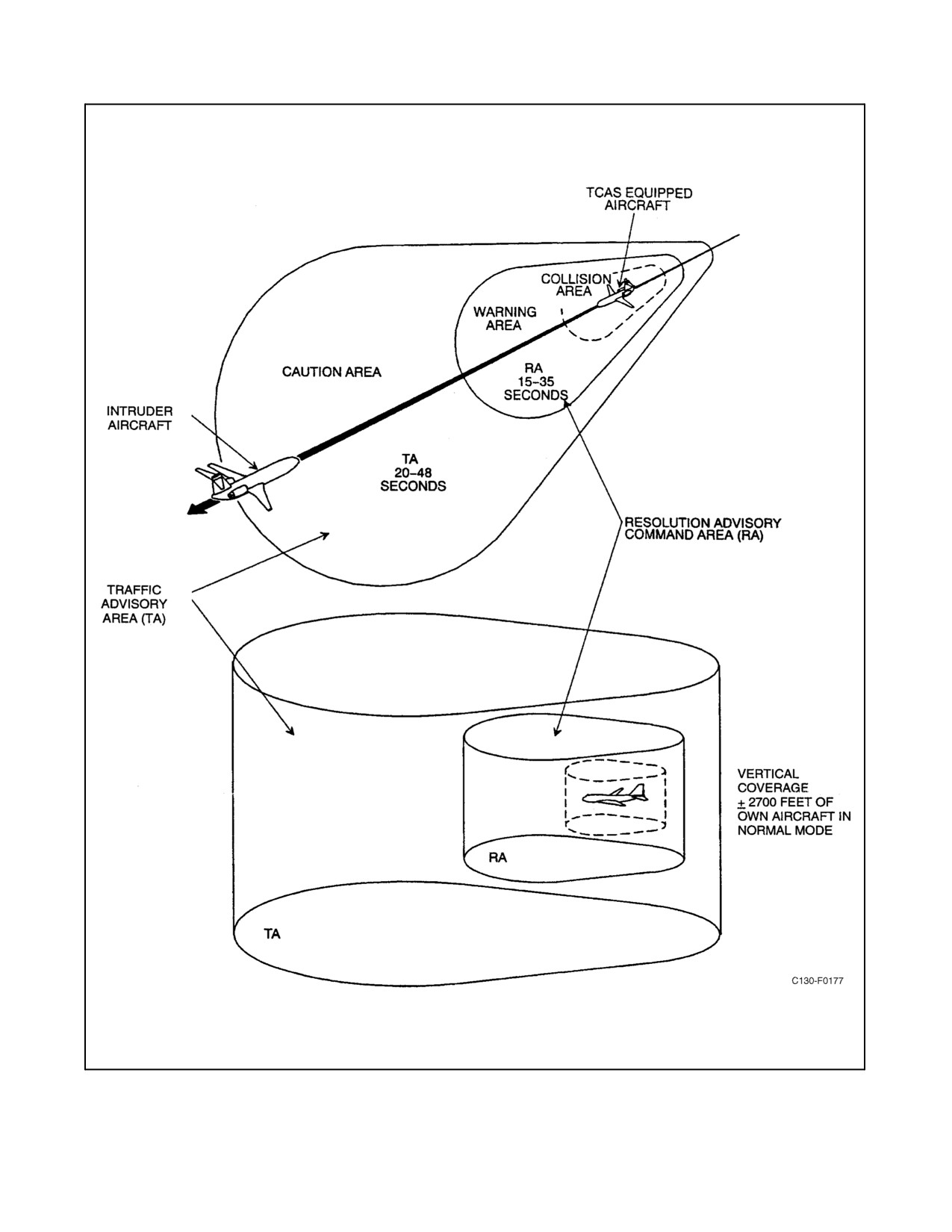
01-75GAL-1
Figure 2-120. Traffic Alert and Collision Avoidance System (TCAS) Coverage Area
ORIGINAL
2-278

01-75GAL-1
2.21.21.2.3 TCAS Operation and Control
Operation and control of TCAS are accomplished with the combined TCAS/IFF control panel. Before selecting
TCAS functions, the Combined Altitude Radar Altimeter (CARA) and the transponder Mode C must be operating.
For normal TCAS operation, the MASTER SYSTEM SWITCH must be placed in the NORM (normal) position. The
MODE SELECT/TCAS ENABLE SWITCH must be placed in the TA or TA/RA position. For full control details,
refer to Figure 2-115.
MASTER SYSTEM Switch
When the MASTER SYSTEM switch is placed in the OFF or STBY position, all TCAS TAs and RAs will be
inhibited. TA and RA information is available when the MASTER SYSTEM switch is placed in the NORM or EMER
position. When the EMER (emergency) position is selected and the MODE SELECT/TCAS ENABLE SWITCH is
in the TA/RA position, TCAS will issue both TAs and RAs and the transponder will broadcast an emergency code
in Mode 3A, and reply to Modes C and S air and ground interrogations.
MODE SELECT/TCAS ENABLE Switch
When the MODE SELECT/TCAS ENABLE switch is placed in TA, TCAS will only issue TA information — no
RA information will be issued. This mode prevents TCAS from issuing RAs when the aircraft is intentionally flying
close to another aircraft, such as in formation or on a closely spaced parallel approach. Only TAs will appear on the
VSI/TRAs in this mode. When the MODE SELECT/TCAS ENABLE switch is placed in TA/RA, TCAS will issue
both TA and RA information. This is the normal TCAS operating mode. Both TAs and RAs will appear on the
VSI/TRAs. With either TA or TA/RA selected on the MODE SELECT/TCAS ENABLE switch, the IFF/Mode S
transponder will reply to air and ground interrogations in Modes 3A, C, and S.
HORIZONTAL RANGE Switch
The HORIZONTAL RANGE SWITCH selects the horizontal display range on the VSI/TRAs in nautical miles. See
Figure 2-121 for the dimensions of each range.
VERTICAL RANGE Switch
The VERTICAL RANGE switch selects the altitude range, with respect to the aircraft, for traffic displays on the
VSI/TRAs. ABV sets the range at 9,900 feet above and 2,700 feet below the aircraft. NORM sets the range at 2,700
feet above and 2,700 feet below the aircraft. BLW sets the range at 2,700 feet above and 9,900 feet below the aircraft.
RANGE BEING
RANGE BEING
DISPLAYED
DISPLAYED LEFT
RANGE BEING
TCAS RANGE
FORWARD OF
AND RIGHT OF
DISPLAYED AFT OF
SETTING
RANGE RING
AIRCRAFT
AIRCRAFT
AIRCRAFT
6
2 nm
6 nm
4.2 nm
2.5 nm
12
Inner 2 nm
12 nm
8.3 nm
5 nm
Outer 5 nm
20
8.4 nm
20 nm
14 nm
8.4 nm
40
17 nm
40 nm
28 nm
17 nm
Figure 2-121. TCAS Range Display
2.21.21.2.4 TCAS Visual Display and Indications
The VSI/TRAs display vertical speed data (current rate of climb or rate of descent information) and TCAS traffic
and resolution advisory information (Figure 2-122). As a vertical speed indicator, the VSI/TRA provides a standard
2-279
ORIGINAL
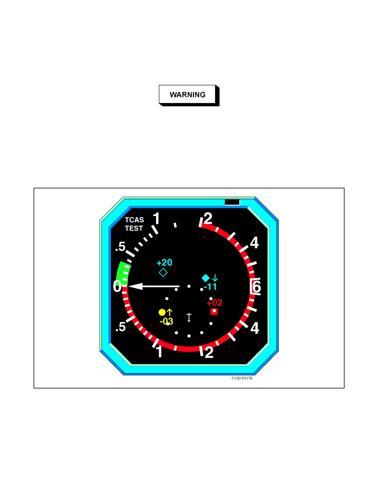
01-75GAL-1
displayofverticalspeedinfeetperminutewitharangeplusorminus6,000 feetperminute.As atrafficandresolution
advisory indicator, the VSI/TRAs display symbols representing local air traffic within a variable range up to 40 nm
of the TCAS equipped aircraft. Up to 8 aircraft can be displayed at any given time. Each symbol reflects the bearing,
relative altitude, and range of each aircraft.
Prolonged VHF No. 1 transmissions in the 135.025 to 137.500 and 120.775
to 121.500 MHz frequency bands can result in the loss of displayed targets
on the TCAS VSI/TRAs. The flight crew should utilize the VHF No. 2 or
V/UHF radios if communications are required at the affected frequencies.
A white aircraft symbol representing aircraft position is displayed in the lower center of the VSI/TRA. This is
surrounded by a white range ring made up of 12 dots, each corresponding to a normal clock position. The function
of the range ring is to assist in interpreting TCAS information. The position of the range knob determines the scale
of the VSI/TRA display. The various scales are shown in Figure 2-121.
Figure 2-122. VSI/TRA Display Indicator
The VSI/TRA indicator uses color-coded symbols and data tags to map intruder aircraft, proximate air traffic, and
other air traffic. Four traffic symbols are used: solid circle, solid square, solid diamond, and hollow diamond. The
traffic symbols, with their corresponding colors and display functions, are shown in Figure 2-123. A two-digit data
tag number, with a plus (+) or minus (-) sign and arrow, may appear either above or below a traffic symbol. For traffic
ORIGINAL
2-280