C-130T. FLIGHT MANUAL (2006) - page 7
01-75GAL-1
GAIN Control
The GAIN control provides manual control of receiver gain and has concentric knobs. The outer knob, when fully
clockwise in the WX CAL position, provides preset calibrated functions such as contour and penetration
compensation. The inner knob is for variable sensitivity time control. It is active in the MAP2 mode and
LONG/SHORT pulse, and inactive in all other modes.
ANT and RT Indicators
In TEST function only, the ANT and RT indicators light to indicate detected faults.
2.21.27.1.3 Display Control Unit
Display control unit functions affect the navigator indicator only.
Display Mode Selection Switch
A four-position rotary switch selects one of four mutually exclusive display mode presentations; radar only (RDR),
radar with navigation overlay (RDR/NAV), IFF only, and IFF with navigation overlay (IFF/NAV).
In the RDR display mode, the interface unit is turned off and transmits no data to the indicator. In this display mode,
the indicator displays only the normal radar return as selected at the radar control panel and operation of any other
controls on the display control unit will have no effect on the radar display.
In the RDR/NAV display mode, the radar returns are overlayed with navigation information obtained from an INS
system. In this mode, the TGT MKR controls are active. Navigation data may be displayed on both the navigator
and pilot indicators when the radar display switch on the pilot radar select switch panel is placed in the RDR/NAV
position.
In the IFF display mode, only IFF targets and azimuth lines are displayed on the indicator. The TGT MKR and
refueling OFFSET controls are functional in this mode.
In the IFF/NAV display mode, the IFF display is overlayed with navigation information obtained from an INS. The
TGT MKR and refueling OFFSET controls are functional in this mode.
IFF Power Switch
The IFF power switch controls power to the AN/APX-76B IFF system.
IFF Challenge Switch
The IFF challenge switch controls the type of challenge to be enabled by the AN/APX-76B IFF system, either
momentary (MOM) or continuous (CONT). The MOM position is spring loaded to return to the center (OFF)
position.
REF Switch
The REF switch selects which navigation system is to be used for the radar.
2.21.27.1.4 Target Marker System
There are five selectors used to control the target marker system and associated information.
1. A four-position TGT/MKR left-right-up-down slew switch used to call up the target marker display and the
marker position.
2-351
ORIGINAL
01-75GAL-1
2. A two-position (LAT/LONG-RNG/BRG) switch to select the display format of the target marker coordinates
in latitude/longitude or range/bearing.
3. A two-position (VCTR-OFF) mode switch to select vector mode display.
4. Amomentary-contactpushbuttonswitch(TGTSET)usedtoselectavariableoriginforrangeand bearingdata,
when in the vector mode.
5. A three-position (OFFSET-SET-OFF) switch is used in the SET position to set a vertical offset line to facilitate
tanker tracking during aerial refueling operations. Azimuth position of the offset line can be set with left or
right movement of the TGT/MKR switch. The OFFSET position frees the TGT/MKR switch for other uses
but retains the offset display.
TGT/MKR will not display if data is not received from the selected navigation system, or if the RDR mode is selected.
VCTR (ON)-TGT/MKR is displayed with VCTR selected. After the TGT/MKR switch is held for 1/2 second, it
moves in the commanded direction within screen display limits. When the switch is released for 1 second, the
coordinates in LAT/LONG are computed to one-tenth of a minute resolution and displayed. In RNG/BRG, the
TGT/MKR initial point of reference is present position. A new point of reference (that point from which calculations
are made) can be established by slewing the TGT/MKR over the new point and pressing TGT SET. A vector line
will be drawn from this point to the next TGT/MKR position. The following information will be displayed in the
lower left corner of the indicator:
1. MKR — Indicates vector mode.
2. R:XXX — Indicates range in nm.
3. TO:XXXx — Indicates magnetic or true heading to the target.
4. FR:XXXx — Indicates magnetic or true heading from the target.
5. OFF (VECTOR) — After the TGT/MKR switch is released, the LAT/LONG coordinates are displayed. In
RNG/BRG, aircraft present position will always be the reference point and the TGT SET is disabled. The
vector will be drawn from present position to the TGT/MKR positions, if in IFF or IFF/NAV.
2.21.27.1.5 Display Messages
If the radar is selected to a particular mode and the data is not supplied (i.e., IFF mode selected but the IFF switch
is not turned to ON) the message NO IFF will be displayed on the indicator.
2.21.27.1.6 Sector Scan Control Panel
The sector scan control panel allows the operator to select a more narrow sector for antenna scanning. The WIDTH
knob is detented to the 180_ scan mode. As soon as this knob is moved from the detent, the antenna begins a 120_
scan. By rotating the knob counterclockwise, the scan angle can be continuously reduced to 30_. The POSITION
knob is used to select the centerline of the scan width. The scan centerline is continuously variable between 75_ of
the aircraft centerline.
2.21.27.2 Radar Select Switch Panel
The radar select switch panel contains the following controls for display selection and stabilization source selection.
1. RADAR DISPLAY switch — Selects the display to be presented on the pilot radar indicator. The two-position
switch enables the pilot to select either RDR/NAV or RDR.
ORIGINAL
2-352
01-75GAL-1
2. RADAR ANT STAB switch — Selects the source for stabilization of the radar antenna. In the GYRO position,
stabilization is provided by the No. 2 flight director gyro (vertical reference). In the INS-1 position,
stabilization is provided by the No. 1 INS.
2.21.27.3 Pilot/Navigator Radar Select and Annunciator Panel
The pilot/navigator radar select and annunciator panel (see Figure 2-132) located on the pilot side shelf extension
has a two-position (PILOT-NAV) switch and a combination RDR CONT PLT-NAV annunciator. The PILOT-NAV
switch permits the pilot to select the desired radar control panel (pilot or navigator) for control of the weather map
or beacon functions. If the switch is positioned to NAV (navigator control panel) and the IFF or IFF/NAV position
is selected on the display control unit, control of the radar is automatically switched to the pilot radar control panel.
The annunciator on the panel indicates which control panel (pilot or navigator) has control of the radar. The PLT
annunciator illuminates when the pilot has control of the radar, and the NAV annunciator illuminates when the
navigator has control.
2.21.27.4 Pilot/Navigator Radar Control Indicator Panel
The pilot/navigator radar control indicator panel (see Figure 2-132) on the navigator control panel contains a
combination PLT-NAV RDR CONT annunciator. The PLT portion of the annunciator illuminates when the pilot
has control of the radar, and the NAV annunciator illuminates when the navigator has control.
2.21.27.5 Normal Operation of the Radar Set
Before placing the function selector switch to WX, MAP1, MAP2, or BCN,
ensure that a radiation pattern is clear (37 feet for personnel, 52 feet for
possible flammable liquid ignition). Avoid directing the energy beam
toward structures, personnel grouping areas, or areas where aircraft are
being refueled/defueled.
CAUTION
The radar R/T unit and waveguide are pressurized by aircraft cabin
pressure. The radar set may be operated without pressurization up to 20,000
feet cabin pressure. If cabin pressurization is lost above 20,000 feet, the
function selector switch must be placed to STBY to prevent arc-over in the
magnetron.
2.21.27.5.1 System Test
To place the radar system in the test function, proceed as follows:
1. Verify that the stabilization reference (No. 2 flight director) is operating. On aircraft 163022 and up, if theNo.
2 flight director stabilization is not operating, place the RADAR ANT STAB switch on the pilot radar select
switch panel to the INS-1 position after the No. 1 INS has been turned on. Set the following controls to the
positions listed:
2-353
ORIGINAL
01-75GAL-1
a. Radar control panel:
(1) Function selector switch to TEST.
(2) ANT TILT control to 0.
(3) GAIN control to WX CAL.
(4) STC control fully clockwise.
b. Radar indicator:
(1) Range selector to 150.
(2) TGT CLAR control to midrange.
(3) INT control to midrange.
(4) NOR-MKR-DLY switch to NOR.
Note
If the function selector switch was in the OFF position, there will be a
3-minute warmup delay before the test pattern can be evaluated. If the
function selector switch is positioned to TEST before the expiration of the
3-minute warmup delay, the radar indicator will either remain dark or
display a series of narrow, colored bands (“persian rug” effect).
2.
After expiration of initial 3-minute warmup period, a test pattern should be displayed on the radar indicator.
3.
Adjust the INT control on the radar indicator for a comfortable brightness of the test pattern display.
4.
Check test pattern for:
a. The presence of five distinct color bands in the lower third of the scope: green, yellow, red, yellow, green.
The width of each band is not critical. Absence of these color bands indicates a probable fault in either the
receiver-transmitter or antenna.
b. A gradual increase of green test noise from the outer edge of the outer green test band to approximately 80
nm, and a fairly uniform band of test noise (green) from approximately 80 nm to 100 nm. Either a uniform
noise level from 50 to 100 nm or the absence of all noise in this region indicates a failed RT unit.
c. Some random noise may be displayed beyond the green test noise band. The TGT CLAR control may be
used to adjust backg0round and test noise level. Adjustment of TGT CLAR control should reduce
backg0round noise to only a few random dots.
d. Alphanumerics (TEST and 150/30), five azimuth cursors, and five segmented range markers displayed in
blue.
e. A three-color bar (red, yellow, green) below the 150/30 in upper right.
5.
After evaluating test pattern, set function selector switch on radar control panel to STBY.
2.21.27.5.2 Radar System — Standby
When the radar function selector switch is set to STBY from TEST, WX, MAP1, MAP2, or BCN, most of the system
components remain warmed up; only the magnetron and high-voltage circuits are deenergized. Full operation is
ORIGINAL
2-354
01-75GAL-1
resumed immediately when the function switch is returned to TEST, WX, MAP1, MAP2, or BCN. When the function
switch is set to STBY, the ANT STAB switch should be left in the ON position.
2.21.27.5.3 Operation Without Antenna Stabilization
Failure of the antenna stabilization will cause a portion of the display to be blanked out while in level flight or cause
targets to fade during roll or pitch movements of the aircraft. If antenna stabilization fails, set the ANT STAB switch
on the radar control panel to OFF. This switch disables antenna stabilization and locks the antenna so that 0_ tilt is
the preset plane of the aircraft.
2.21.27.5.4 Radar Turnoff
To turn off the radar system equipment after use, position the controls as follows:
1. Radar indicator — Mode switch to NOR.
2. Radar control panel:
a. ANT TILT control to 0.
b. ANT STAB switch to ON.
c. GAIN control to WX CAL.
d. STC control fully clockwise.
e. Function selector switch to OFF.
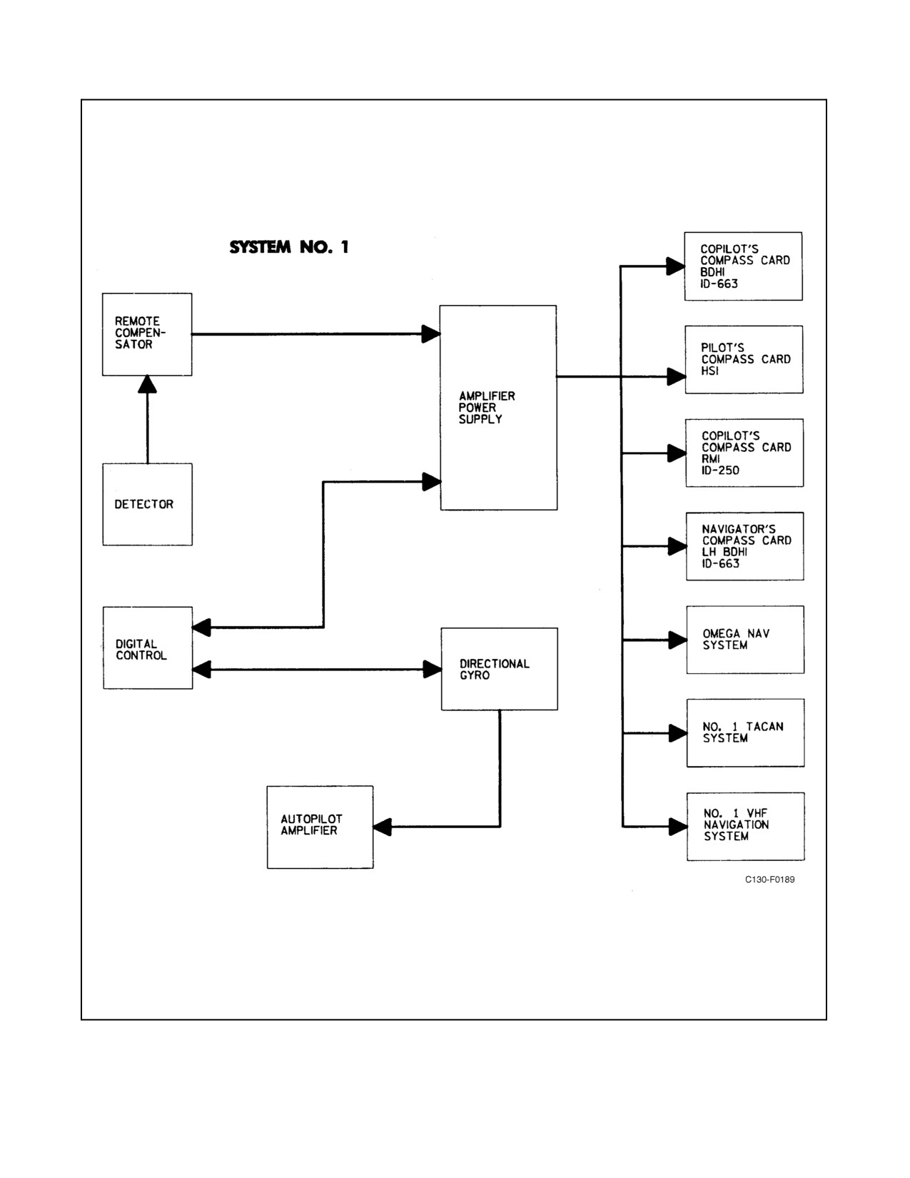
2.21.28 C-12 Compass System
Two individual C-12 compass systems are installed in the aircraft. Each system provides an accurate heading
reference to aid in navigation, regardless of the latitude position of the aircraft. In addition to providing a visual
heading reference, each system furnishes heading information to other navigation systems in the aircraft (see Figure
2-133). Normally the No. 1 C-12 compass system supplies heading to certain systems and instruments, and the No.
2 C-12 compass system supplies heading to other systems and instruments. However, if one C-12 compass system
should malfunction, it is possibletousetheotherC-12compass systemto supplyheading toinstruments andsystems
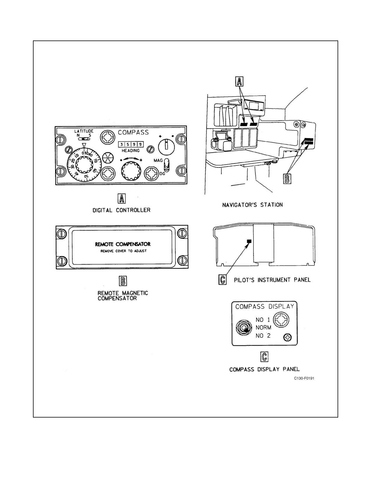
normally connected to the failed compass. The COMPASS DISPLAY selector switch on the pilot instrument panel
can be used to select the No. 1 or No. 2 compass system (see Figure 2-134). When the switch is in the NORM position,
heading is supplied by both compass systems as shown in Figure 2-133. Operating controls and indicators for the
No. 1 and No. 2 compass systems are located on the digital controllers (see Figure 2-134) for each system. The digital
controllers are located on the navigator instrument panel. Each system is capable of operating in either one of two
modes. In the magnetic heading mode, used in latitudes where no distortion of the Earth’s magnetic field is
encountered, the directional gyro in the system is slaved to the Earth’s magnetic field and the indicators display
magnetic heading of the aircraft. In the directional gyro mode, used in latitudes where the magnetic meridian is
distorted or weak, the system gyro acts as a directional gyro and maintains the position manually selected by the
operator. The indicators display the manually established heading. The No. 1 and No. 2 compass systems receive
ac power from the essential ac bus through the COMPASS NO. 1 and NO. 2 circuit breakers on the pilot upper circuit
breaker panel. The compass coupler receives ac power from the essential ac bus through the COMPASS TRANSFER
circuit breakers on the pilot upper circuit breaker panel. The No. 1 and No. 2 compass select relays receive 28-Vdc
power from the essential dc bus through the COMPASS TRANSFER circuit breaker on the copilot upper circuit
breaker panel.
2-355
ORIGINAL
01-75GAL-1
Figure 2-133. C-12 Compass System Tie-In (Sheet 1 of 2)
ORIGINAL
2-356

01-75GAL-1
Figure 2-133. C-12 Compass System Tie-In (Sheet 2)
2-357
ORIGINAL
01-75GAL-1
Figure 2-134. C-12 Compass System Control Panels and Magnetic Compensator
ORIGINAL
2-358
01-75GAL-1
2.21.28.1 C-12 Compass System Controls
Controls and indicators for the compass systems are located on the respective system digital controller (see Figure
2-134). The following paragraphs list the controls and indicators and describe their function in the system.
2.21.28.1.1 LATITUDE N-S Switch
The LATITUDE N-S switch allows selection of north (N) or south (S) latitude correction, dependent on aircraft
location.
2.21.28.1.2 Latitude Knob
The latitude knob is rotated to set the correct latitude location, in degrees, of the aircraft position. This setting allows
the compass system to automatically correct the Earth rate and coriolis errors at the set latitude.
2.21.28.1.3 Mode Switch
The mode switch selects compass operating mode. When the switch is set in the MAG position, the directional gyro
in the compass is slaved to a magnetic azimuth detector. The digital reading on the heading indicator will show
magnetic heading. This switch position is used in latitudes where no distortion of the Earth’s magnetic field is
encountered. When the switch is set in DG, the gyro acts as an independent directional gyro. The digital reading in
the heading indicator is manually set with the synchronizer knob. This mode of operation is normally used for
short-range navigation in the upper latitudes where the magnetic meridian is distorted or weak.
2.21.28.1.4 Synchronizing Control
The synchronizing control is used in conjunction with the annunciator to provide fast system synchronization when
the compass system begins initial operation in the magneticheading (MAG)mode selection of themode switch. The
synchronizer knob is rotated in the direction indicated by annunciator needle deflection markings above the
annunciator until the needle is centered. When the needle is centered, the compass is synchronized in magnetic
heading mode and the digital drums in the heading windows display the magnetic heading of the aircraft. When the
directional gyro mode has been selected with the mode switch, the synchronizer knob is used to manually set the
digital drums in the heading windows to the desired course heading.
2.21.28.1.5 Annunciator
The annunciator provides visual indication of system synchronization when the compass system begins initial
operation in the magnetic heading mode.
2.21.28.1.6 HEADING Indicator
The HEADING indicator provides digital readout of aircraft heading in 0.1_ increments.
2.21.28.1.7 Power Adequacy Indicator
The power adequacy indicator gives a red indication to indicate that system power input has dropped below the safe
operating level.
2.21.28.1.8 COMPASS DISPLAY Selector Switch
The COMPASS DISPLAY selector switch is located on the pilot instrument panel (see Figure 2-134). There are three
switch positions: NO. 1, NORM, and NO. 2. Placing the switch in the NO. 1 position, operates the No. 1 compass
select relay, which switches all instruments and systems to the No. 1 compass system. Placing the switch in the NO.
2 position, operates the No. 2 compass select relay, which switches all instruments and systems to theNo. 2 compass
2-359
ORIGINAL
01-75GAL-1
system. In the NORM position, no switching occurs and heading is supplied by both compass systems as shown in
Figure 2-133.
2.21.28.2 Normal Operation of the C-12 Compass System
Note
The C-12 compass systems begin to operate when power is supplied to the
aircraft electrical ac buses. However, a 5-minute warmup is required for
gyro stabilization.
To set the compass for desired aircraft heading:
1. Set the COMPASS DISPLAY switch to NORM.
2. Set LATITUDE N-S switch to correct latitude for aircraft position.
3. Rotatelatitudeknob toset presentaircraft positiondegrees oflatitudeundertheindex.Additional settingsmay
be required depending on direction and time in flight.
4. Set desired compass operating mode with the mode switch (MAG or DG).
5. IfMAG has been selected in step 4, allow annunciatorneedle to center automatically or manually synchronize
the system with the synchronizing control.
6. If DG position has been selected in step 4, set desired heading in the heading windows with thesynchronizing
control.
Note
During autopilot operation with the compass in DG, changing the heading
with the synchronizer knob will cause a change only in the heading
indicator and will not cause the aircraft to change heading.
2.21.28.2.1 Emergency Operation of the C-12 Compass
Emergency operation of the C-12 compass can be accomplished as follows:
1. The power adequacy indicator on the digital controller indicates that system power has dropped below safe
operating level. Utilize the other C-12 compass system if it is still operable.
2. Position the COMPASS DISPLAY switch to select the C-12 compass system that is still operable.
3. In the event both systems become inoperable, the system may be operated as a directional gyro (DG mode),
which will bypass coriolis and meridian convergency compensation since these circuits are applied to the
magnetic slaving circuits.
2.22
LIGHTING SYSTEM
The lighting system is composed of exterior and interior groups of lights and their controls. Receptacles are also
provided on the sides of the pilot and copilot side shelves for connecting a signal light. The pilot, copilot, and engine
instrument lights operate on ac power and all others operate on dc power. The pilot, copilot, and engine instrument
lights use 6-volt bulbs only. All other panel lights use 28-volt bulbs.
ORIGINAL
2-360
01-75GAL-1
2.22.1 Exterior Lights
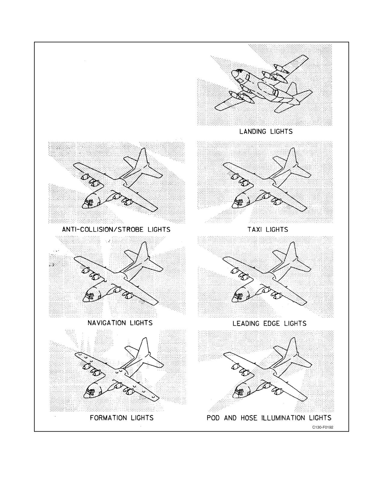
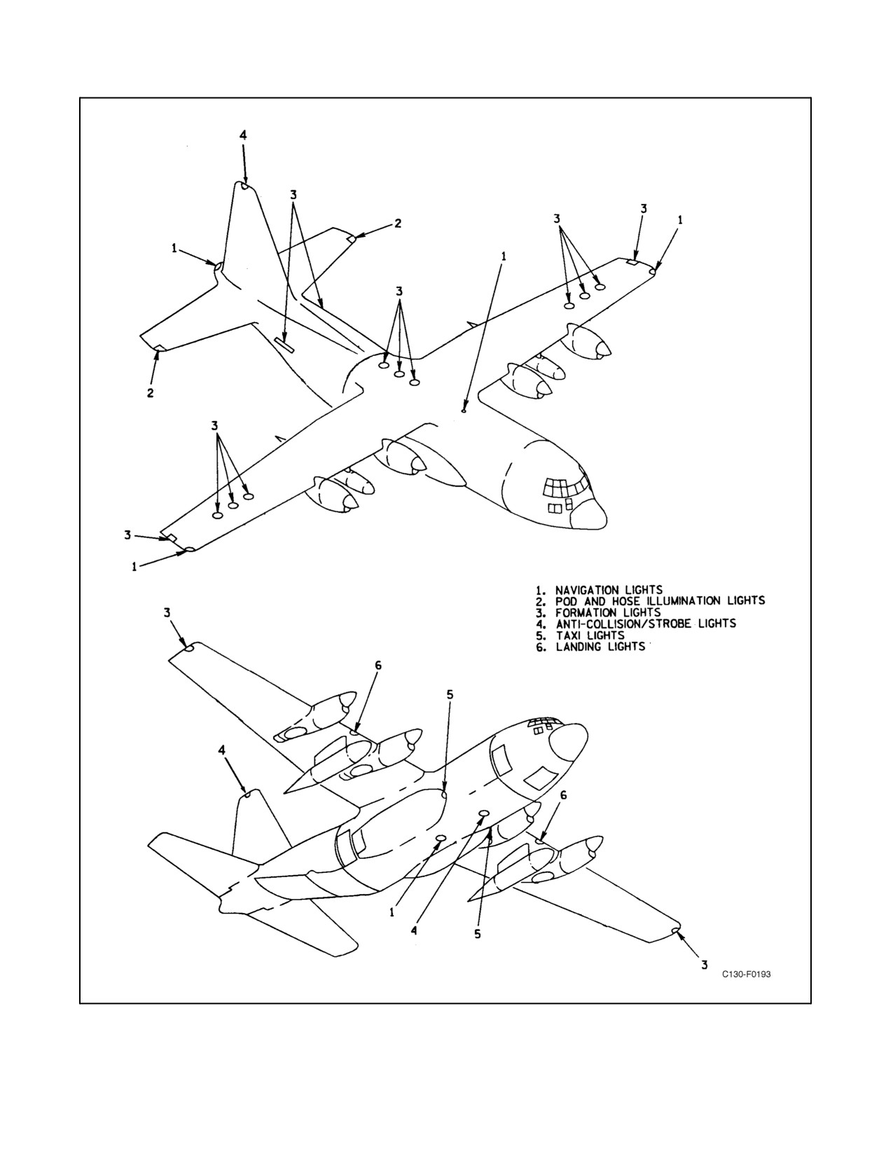
Theexteriorgroupofaircraftlights(seeFigure2-135andFigure2-136)comprisesalanding lighton theundersurface
of each wing; 2 taxiing lights on the main landing gear doors; 11 formation, 6 navigation, and 2 anticollision lights
disposed around the aircraft; 2 pod and hose illumination lights on the horizontal stabilizer tips; and a light on each
side of the fuselage to illuminate the wing leading edges. Power for all these lights is supplied from the essential and
main dc buses through the EXTERIOR LIGHTS circuit breakers on the copilot lower circuit breaker panel.
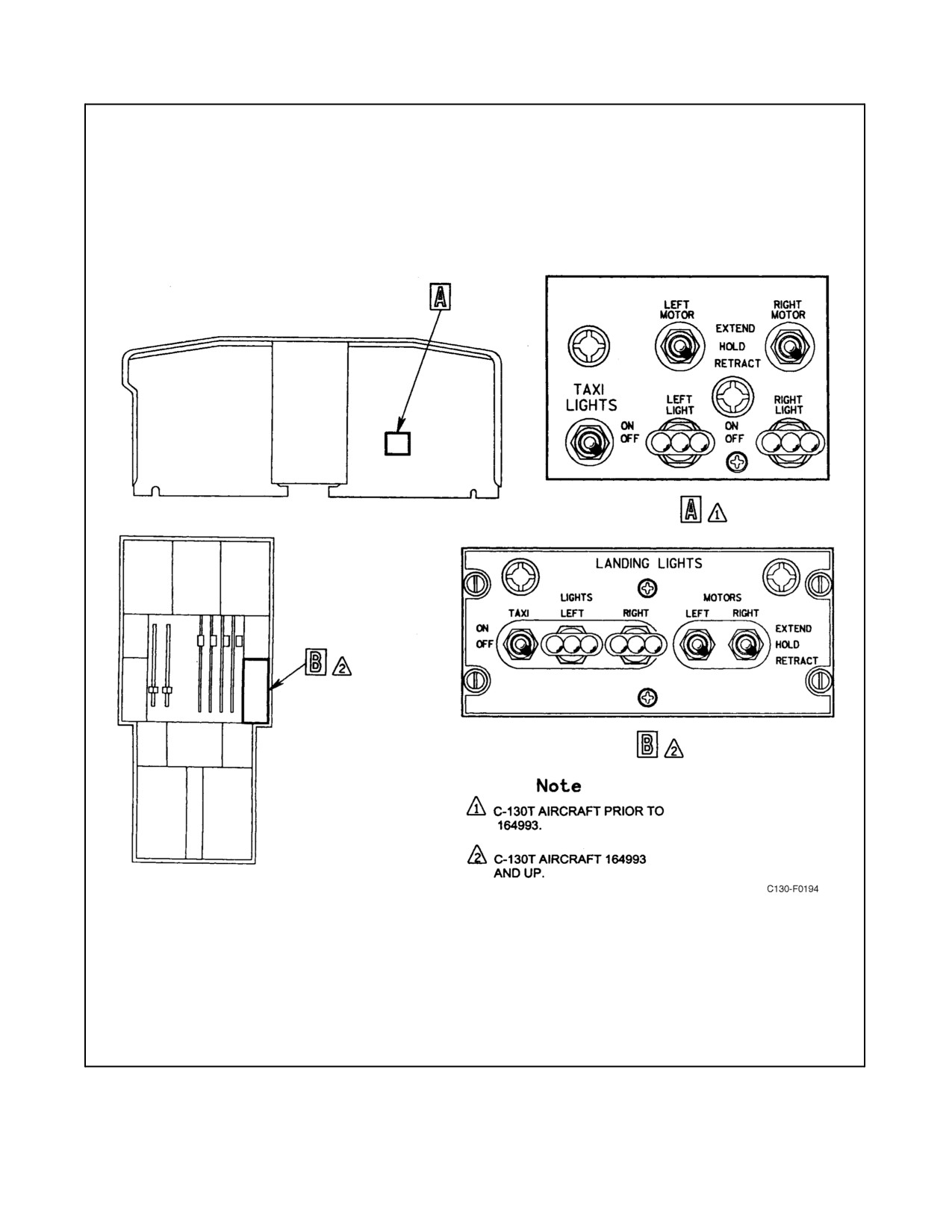
2.22.1.1 Landing Lights
A retractable landing light is mounted in the underside of each wing, in the leading edge and approximately midway
between the inboard and outboard engine nacelles. Switches for extension and retraction and for illumination control
are located on the landing lights control panel (see Figure 2-137). The two extension and retraction motor switches,
labeled right and left, are three-position (EXTEND, HOLD, RETRACT) toggle switches. The right switch energizes
the right-hand landing light actuator motor, retracting or extending the light when the switch is moved to the
RETRACT or EXTEND positions. The left switch energizes the left-hand light actuator motor in the same manner.
When either switch is moved to the HOLD positions the respective landing light actuator motor is deenergized, and
the light will lock in position. Two two-position (ON, OFF) toggle switches control the illumination of the landing
lights. When either switch is moved to the ON position, the corresponding light illuminates. When either switch is
moved to OFF, the corresponding light is deenergized. Power for landinglight illumination is supplied from the
essential dc bus through the EXTERIOR LIGHTS LH and RH LANDING LIGHTS circuit breakers on the copilot
lowercircuit breakerpanel, and forthe light extension and retraction actuators through theEXTERIOR LIGHTS LH
and RH LANDING LIGHTS MTR circuit breakers on the same panel.
CAUTION
Do not operate the landing lights for prolonged periods while the aircraft
is on the ground since these lights have no cooling facility.
2.22.1.2 Taxiing Lights
Illumination of the two taxiing lights, one mounted on the inside of each main landing gear door, is controlled by
atwo-position (ON, OFF)toggleswitch on thelanding lightcontrol panel(seeFigure2-137). Poweris suppliedfrom
the main dc bus through the EXTERIOR LIGHTS TAXI circuit breaker on the copilot lower circuit breaker panel.
2.22.1.3 Formation Lights
The thirteen formation lights comprise three on the outer panel of each wing, three on top of the fuselage aft of the
wing, one on each side of the fuselage aft of the paratroop door, and one on each wingtip. The controls for the
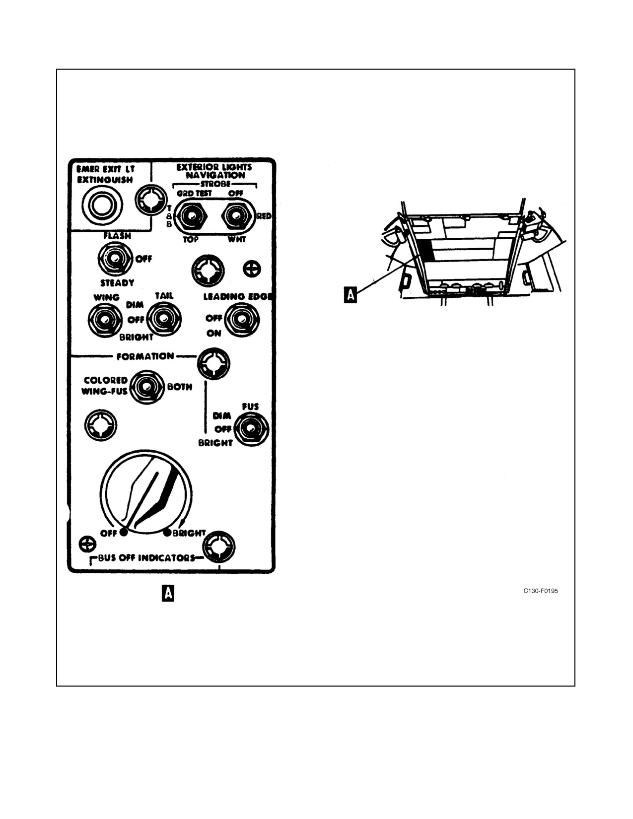
formation lights are located on the overhead panel next to the electrical control panel. A three-position switch
(COLORED WING — FUS, center, BOTH) selects the exterior lights to be illuminated. The COLORED WING —
FUS selects the fuselage formation lights and colored wingtip navigation lights; the center position selects only the
top formation lights; BOTH selects top and bottom formation lights. The illumination and intensity of all thirteen
formation lights is controlled simultaneously through a single rheostat switch on the exterior lights control panel (see
Figure 2-138). The switch is turned clockwise from the OFF position to illuminate the lights and then further turned
toward BRIGHT to increase the brilliance; rotation of the switch in the counterclockwise direction decreases the
brilliance of the lights until the OFF position is reached. Power for the lights is supplied from the main dc bus through
the EXTERIOR LIGHTS FORMATION circuit breaker on the copilot lower circuit breaker panel.
2-361
ORIGINAL
01-75GAL-1
Figure 2-135. Exterior Lights Illumination Pattern
ORIGINAL
2-362
01-75GAL-1
Figure 2-136. Exterior Lights Locations
2-363
ORIGINAL
01-75GAL-1
Figure 2-137. Landing and Taxi Lights Control Panel
ORIGINAL
2-364
01-75GAL-1
Figure 2-138. Exterior Lights Control Panel
2-365
ORIGINAL
01-75GAL-1
2.22.1.4 Navigation Lights
The navigation lighting system consists of six lights: a red light on the left wingtip, a green light on the right wingtip,
two white lights on the trailing edge of the tailcone, a white light on top of the fuselage forward of the wing, and a
white light on the lower surface of the fuselage. All lights can be set dim or bright. The red and green wingtip lights
and the white tail lights can also be set to flash or to glow continuously. The white lights on the top and bottom of
the fuselage, however, will only illuminate continuously. The navigation lights selector switch turns the lights on
and off and controls the flashing mechanism, and the wing and tail navigation lights dimming switches control the
intensity of the lights. The selector switch is a three-position (STEADY, OFF, FLASH) toggle switch, located on
the exterior lights control panel (see Figure 2-138). When the switch is in the STEADY position, the lights glow
continuously. When the switch is in the FLASH position, the wingtip lights and the white taillights flash
simultaneously. The wing and tail navigation lights dimming switches are three-position (BRIGHT, OFF, DIM)
toggle switches and are located on the exterior lights control panel. The white lights on the top and bottom of the
fuselage are controlled by a separate three-position (BRIGHT, OFF, DIM) toggle switch located on the exterior lights
control panel. Power for the lights is supplied from the essential dc bus through the EXTERIOR LIGHTS
NAVIGATION and POSITION circuit breaker on the copilot lower circuit breaker panel.
2.22.1.5 Anticollision/Strobe Lights
The aircraft is equipped with two combination anticollision/strobe lights, one on top of the vertical stabilizer and the
other on the underside of the center fuselage. Each light contains a high-intensity, white, xenon arc-discharge light
and a high-intensity red light. The dual anticollision/strobe lights are controlled by two toggle switches on the exterior
lights control panel (see Figure 2-138). The left-hand select switch has three positions (GRD TEST, T & B, TOP).
When the select switch is placed to the T & B position, both upper and lower red or white lights will function in flight,
but only theupperred light will function when theaircraft ison theground. Auxiliarytouchdown relayNo. 3disables
the upper white light and the lower red and white lights when the aircraft is on the ground. When the select switch
is placed to the TOP position, only the upper light will function. When the select switch is placed to the GRD TEST
position, both upperand lowerred orwhitelightswill functionon theground. Theright-hand controlswitch hasthree
positions (OFF, RED, WHT) and is used along with the select switch to control thelight colorunder various weather
conditions. In the OFF position, the lights are deenergized. Power for the anticollision/strobe lights is supplied from
the essential dc bus through the ANTICOLLISION LIGHT circuit breaker on the copilot lower circuit breaker panel
and the essential ac bus through the STROBE LT BOTTOM and TOP circuit breakers on the pilot side circuit breaker
panel.
2.22.1.5.1 Wing Leading Edge Lights
Alight is installed on each sideofthefuselagein aposition that will illuminatetheenginenacellesand theimmediate
leading edge area of each wing. The lights are controlled through a two-position (ON, OFF) toggle switch on the
exterior lights control panel (see Figure 2-138) and are powered from the main dc bus through the EXTERIOR
LIGHTS WING LEADING EDGE circuit breaker on the copilot lower circuit breaker panel.
2.22.1.6 Pod and Hose Illumination Lights
A white pod and hose illumination light is located in the forward edge of each horizontal stabilizer tip. These lights
are positioned to illuminate the in-flight refueling pods. A two-position (ON, OFF) pod and hose illumination switch
locatedon theauxiliary fuelcontrol panel(Figure2-24)controls theoperation ofthelights.When theswitch isplaced
to the ON position, the lights will illuminate. Placing the switch to the OFF position de-energizes the lights. Power
for the pod and hose illumination is supplied from the essential dc bus through the POD & HOSE ILLUM circuit
breaker on the copilot side circuit breaker panel.
ORIGINAL
2-366
01-75GAL-1
2.22.1.7 Signal Lamp
A portable signal lamp and a case containing four colored lenses (red, amber, blue, and green) are stowed at the
navigator station. An extension cord permits the lamp to be plugged into receptacles on either the pilot or copilot side
shelves. The lamp is illuminated by depressing a trigger switch. Power is supplied from the main dc bus through the
INTERIOR LIGHTS PILOT and COPILOT SIGNAL OUTLETS circuit breakers on the copilot lower circuit breaker
panel.
2.22.2 Interior Lighting
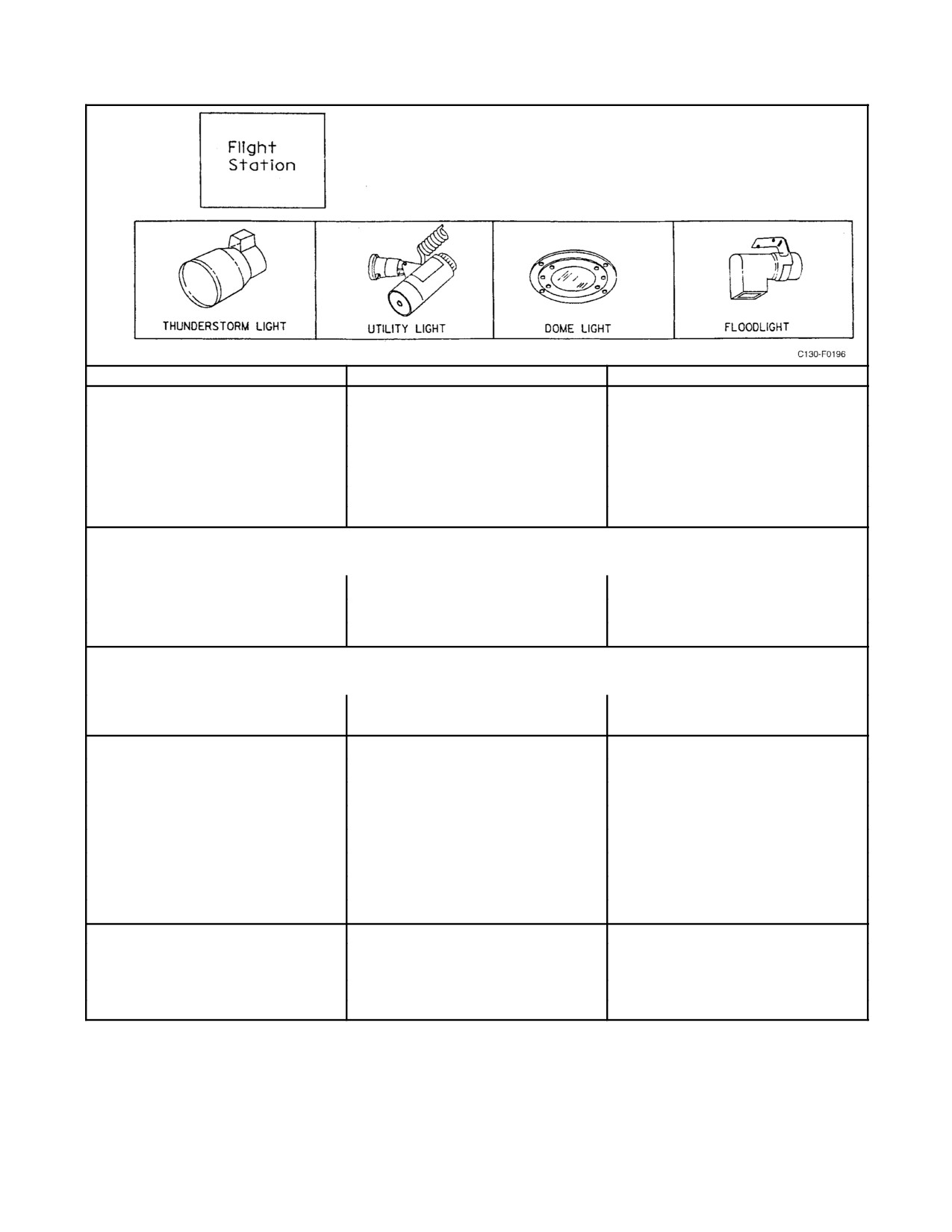
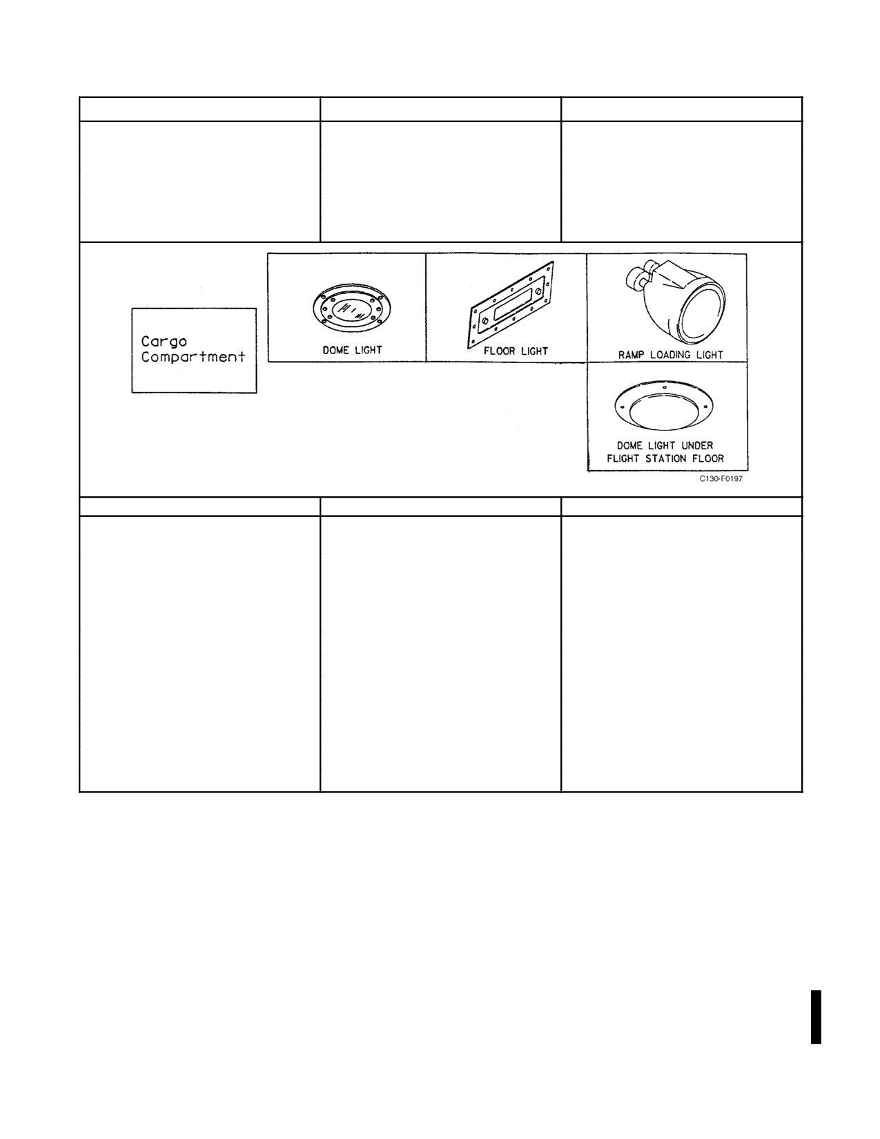
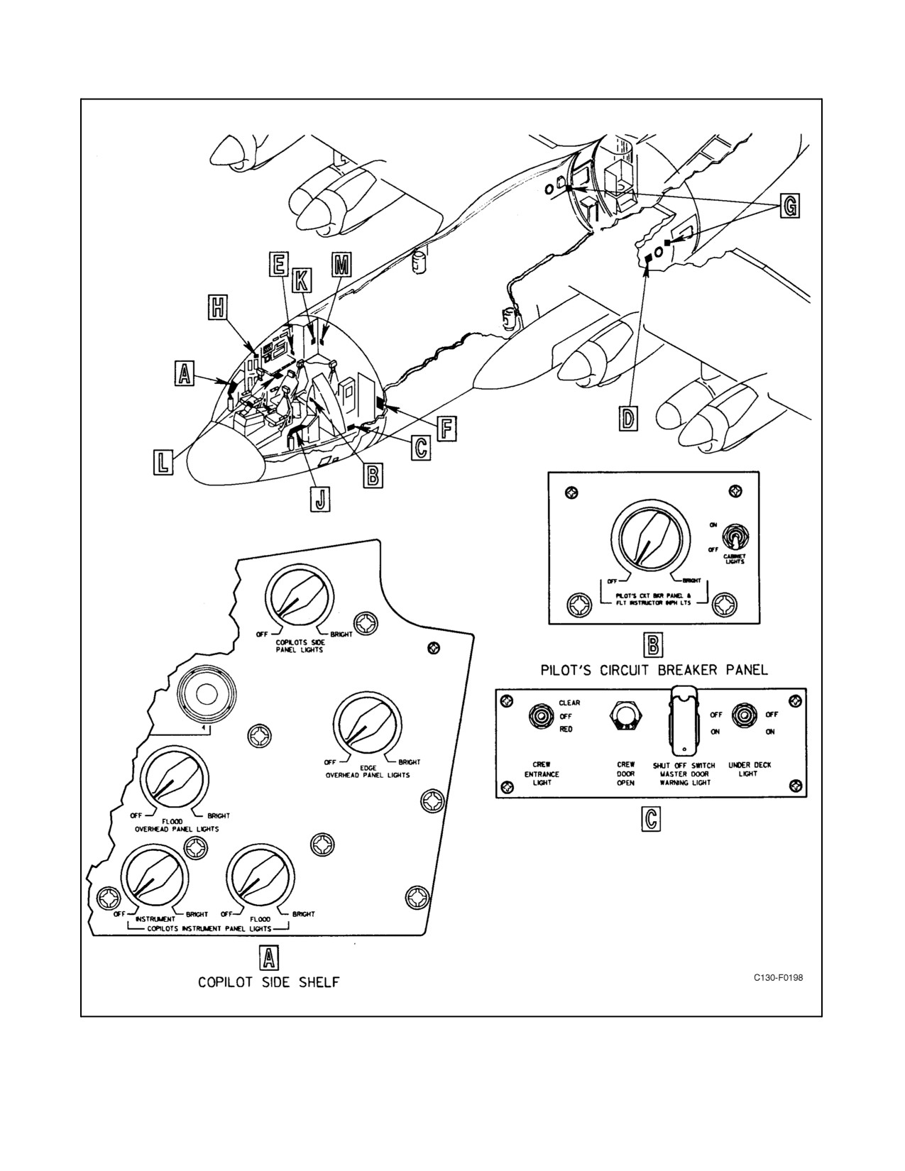
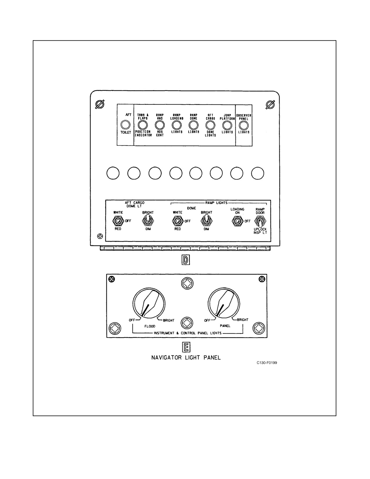
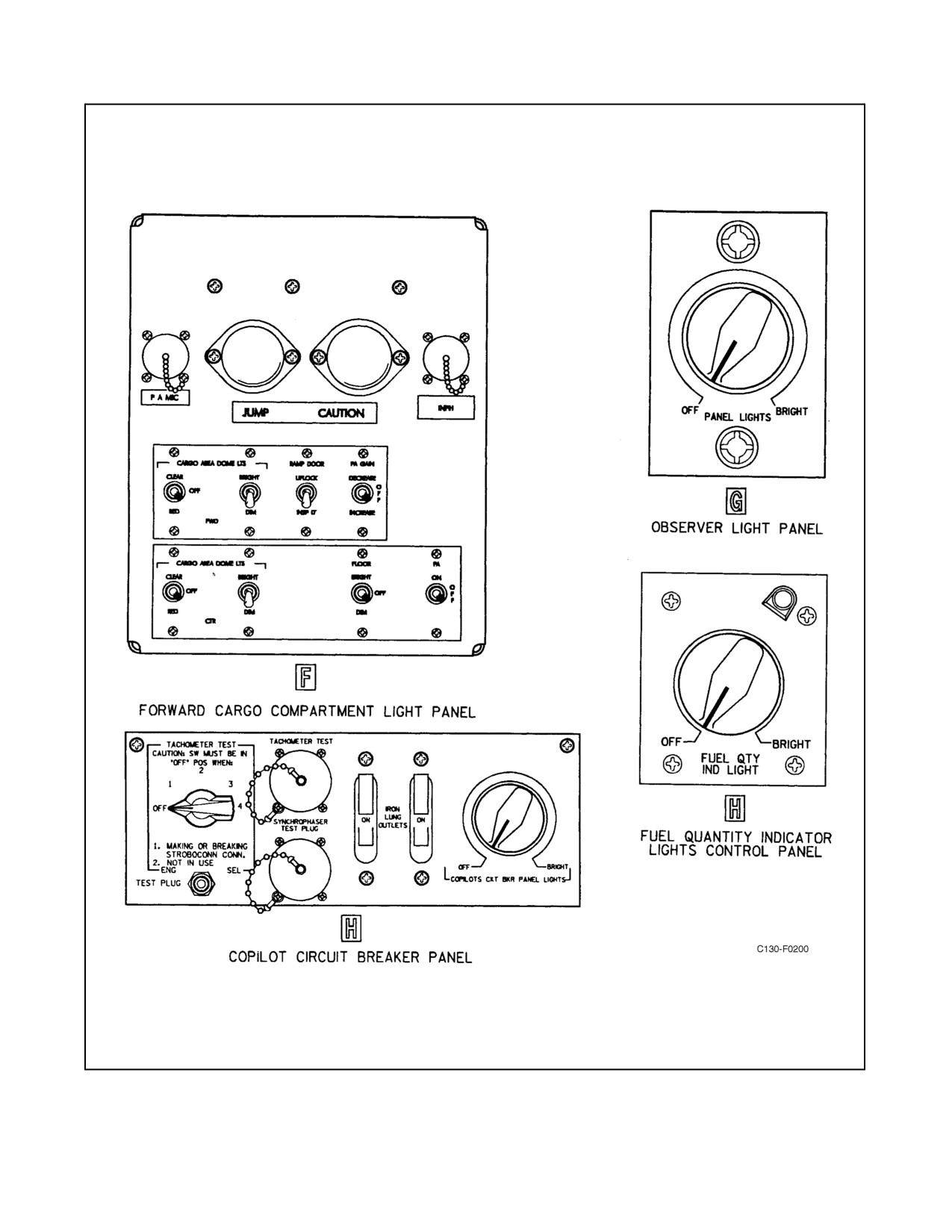
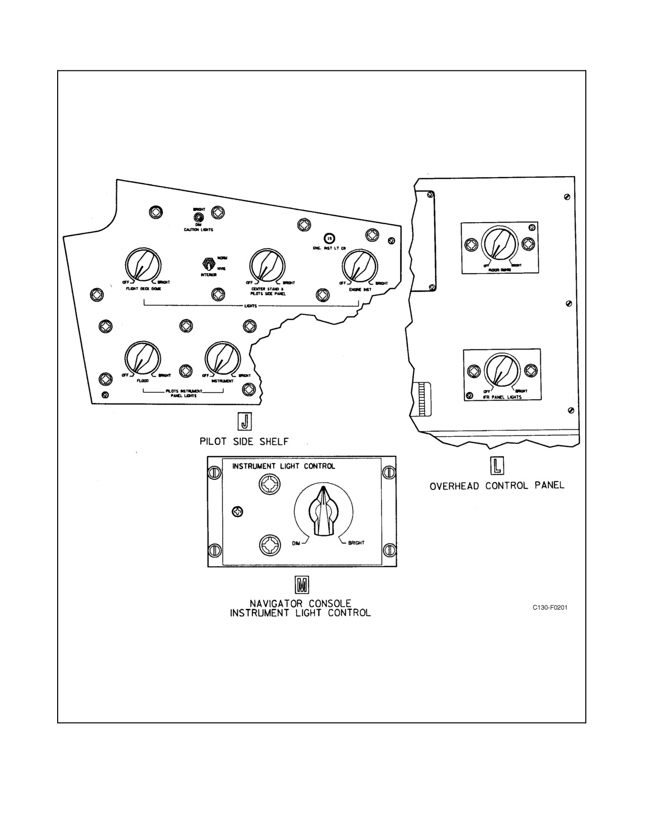
Interior lighting consists of flight station and cargo compartment lighting. The various types of lighting, location of
controls, and locations of circuit breakers for the light circuits are listed in Figure 2-139. Interior lighting control
panels and their locations are shown in Figure 2-140. The pilot and copilot instrument lights and the engine
instrument lights are ac powered from the essential ac bus and protected by fuses on the ac distribution panel aft of
the upper bunk and by circuit breakers located adjacent to the respective switches. The copilot secondary lights are
powered by the isolated dc bus through a COPILOT SECONDARY LIGHTS circuit breaker on the pilot side circuit
breaker panel. The pilot and engine secondary instrument lights are powered by the essential dc bus through a PILOT
& ENG SEC INST LIGHTS circuit breaker on the copilot lower circuit breaker panel. All other interior lighting is
dc powered from the main dc bus and protected by circuit breakers on the copilot lower circuit breaker panel.
The copilot secondary lights are powered by the essential dc bus through a COPILOT SECONDARY LIGHTS circuit
breaker on the copilot’s lower circuit breaker panel. The pilot and engine secondary instrument lights are powered
by theisolated dcbus through a PILOT & ENG SEC INST LIGHTS circuit breaker on the pilot’s side circuit breaker
panel.
2.22.2.1 VSI/TRA Indicator Intensity Lighting Control
Lighting and dimming control for pilot and copilot VSI/TRAs are controlled by a combination of three methods:
1. An integral light sensor located in the upper left-hand corner of the bezel which detects the ambient light and
adjusts VSI/TRA luminosity accordingly.
2. Via general instrument panel lighting controlled by either the pilot or copilot INSTRUMENT PANEL
LIGHTS/INSTRUMENT rheostat on the respective side shelf.
3. The VSI/TRA Dimmer Control which is located on the respective side shelf.
The integral light sensor is the primary controller as it adjusts for ambient light settings. Instrument panel lighting
will also control backlighting in a dark cockpit with a fine adjustment available through the use of the individual
VSI/TRA dimmer controls. The dimmer controls have no effect if there is ambient lighting on the light sensor or if
the instrument panel light control rheostat is not in use.
2.22.2.2 Thunderstorm Lights
Thunderstorm lighting is provided by four white dome lights, two white thunderstorm floodlights, and main
instrument panel white floodlights. These lights are controlled by a two-position (ON, OFF) THUNDERSTORM
LIGHTS switch on the pilot side shelf (see Figure 1-3). Also, when the THUNDERSTORM LIGHTS switch is placed
in the ON position, the circuits to the warning instrument lights dimming relays are opened, thereby preventing the
warning lights from being dimmed.
2-367
ORIGINAL
01-75GAL-1
LIGHTS
CONTROLS LOCATION
CIRCUIT BREAKER LOCATION
PILOT
Instrument Lighting
Pilot Side Shelf
Fuse on Main Ac Distribution Panel
Engine Instrument Lighting
Pilot Side Shelf
Fuse on Main Ac Distribution Panel
Pedestal and Pilot Side Shelf Lighting
Pilot Side Shelf
Copilot Lower Circuit Breaker Panel
Instrument Panel Lighting
Pilot Side Shelf
Copilot Lower Circuit Breaker Panel
Pilot Circuit Breaker Panel Lights
Pilot Circuit Breaker Panel
Copilot Lower Circuit Breaker Panel
Pilot Utility Light
On Light
Copilot Lower Circuit Breaker Panel
Thunderstorm lights switch turns on these lights
B
Two White Thunderstorm Lights
Pilot Side Shelf
Copilot Lower Circuit Breaker Panel
Four White Dome Lights
Pilot Side Shelf
Copilot Lower Circuit Breaker Panel
Instrument Floodlights
Pilot Side Shelf
Copilot Lower Circuit Breaker Panel
Dome lights switch turns on these lights
B
Four White Dome Lights and Two White
Pilot Side Shelf
Copilot Lower Circuit Breaker Panel
Thunderstorm Lights
COPILOT
Instrument Lighting
Copilot Side Shelf
Fuse on Main Ac Distribution Panel
Copilot Instrument Panel Floodlighting
Copilot Side Shelf
Pilot Side Circuit Breaker Panel
Overhead Panel Lighting
Copilot Side Shelf
Copilot Lower Circuit Breaker Panel
Overhead Panel Floodlighting
Copilot Side Shelf
Copilot Lower Circuit Breaker Panel
Copilot Side Shelf Lighting
Copilot Side Shelf
Copilot Lower Circuit Breaker Panel
Copilot Circuit Breaker Panel Lighting
Copilot Circuit Breaker Panel
Copilot Lower Circuit Breaker Panel
Copilot Utility Light
On Light
Copilot Lower Circuit Breaker Panel
NAVIGATOR
Navigator Instrument and Control Panel
Navigator Lights Control Panel
Copilot Lower Circuit Breaker Panel
Lighting
Navigator Utility Light
ON Light
Copilot Lower Circuit Breaker Panel
Navigator Console Instrument Lights
Navigator Console
Copilot Lower Circuit Breaker Panel
Figure 2-139. Interior Lighting (Sheet 1 of 2)
ORIGINAL
2-368
01-75GAL-1
LIGHTS
CONTROLS LOCATION
CIRCUIT BREAKER LOCATION
FLIGHT ENGINEER
Flight Engineer Utility Light
ON Light
Copilot Lower Circuit Breaker Panel
Fuel Quantity Indicator Lights
Copilot RH Distribution Box
Copilot Lower Circuit Breaker Panel
IFR Panel Lights
Overhead Control Panel
Copilot Lower Circuit Breaker Panel
IFR Panel Floodlighting
Overhead Control Panel
Copilot Lower Circuit Breaker Panel
LIGHTS
CONTROLS LOCATION
CIRCUIT BREAKER LOCATION
Floor Lights
Forward Cargo Compartment Light
Copilot Lower Circuit Breaker Panel
Panel
Forward Dome Lights
Forward Cargo Compartment Light
Copilot Lower Circuit Breaker Panel
Panel
Center Dome Lights
Forward Cargo Compartment Light
Copilot Lower Circuit Breaker Panel
Panel
Aft Dome Lights
Aft Fuselage Junction Box
Aft Fuselage Junction Box
Ramp Dome Lights
Aft Fuselage Junction Box
Aft Fuselage Junction Box
Two White Ramp Loading Lights
Aft Fuselage Junction Box
Aft Fuselage Junction Box
Crew Door Entrance Light
Crew Door Warning Light Panel
Copilot Lower Circuit Breaker Panel
Under Deck Light
Crew Door Warning Light Panel
Copilot Lower Circuit Breaker Panel
Left Observer Panel Lights
Left Observer Panel
Aft Fuselage Junction Box
Right Observer Panel Lights
Left Observer Panel
Aft Fuselage Junction Box
Figure 2-139. Interior Lighting (Sheet 2)
2.23
OXYGEN SYSTEM
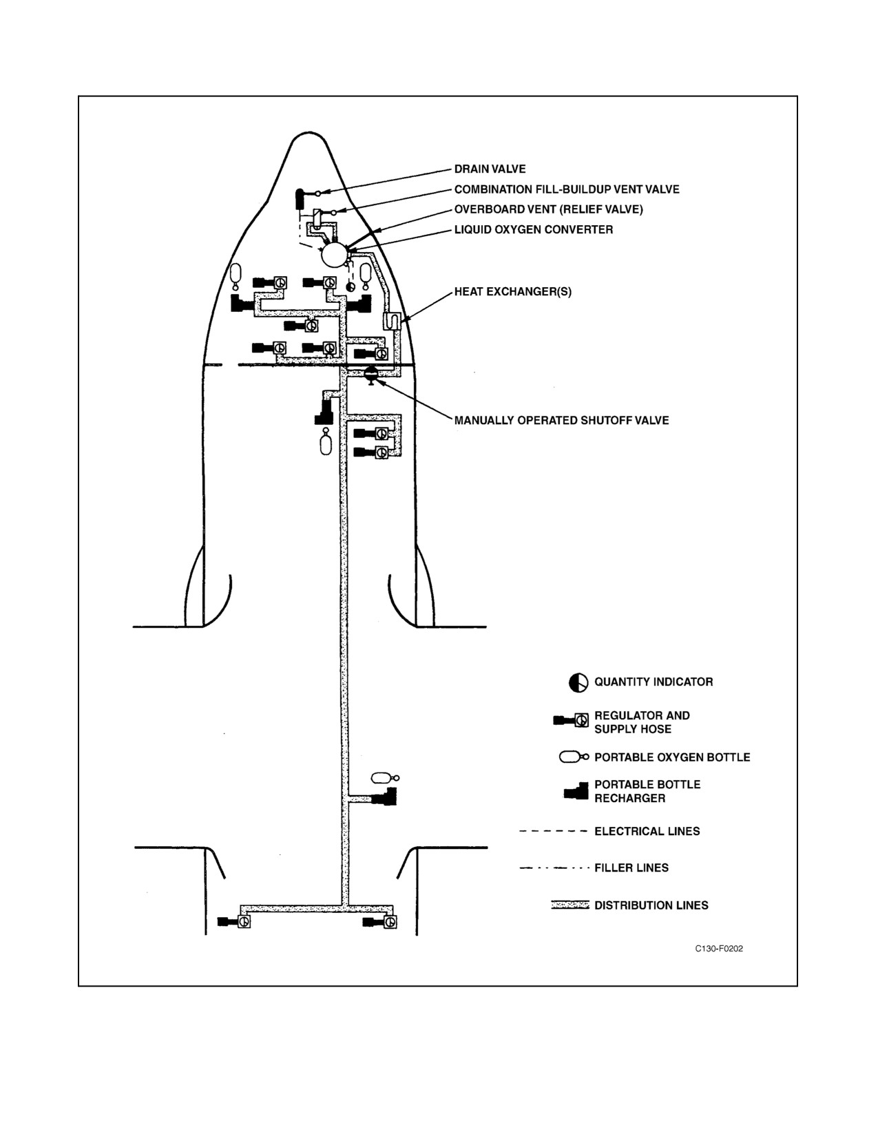
The aircraft is equipped with a 300-psi liquid oxygen system (see Figure 2-141). The system uses diluter-demand
automatic pressure-breathing regulators and operates at an indicated pressure of 270 to 455 psi in a static system
under a no-flow condition. Under a continuous breathing condition, the pressure should indicate 270 to 340 psi.
Manual selection enables the system to provide oxygen diluted in varying proportions corresponding to changes in
cabin altitude or, for emergency use, 100-percent oxygen. Four portable units, chargeable through the main system,
also are provided for use by crewmembers moving around within the aircraft or for emergency use. Emergency
Passenger Oxygen System
(EPOS) units, also called a Victim Rescue Units
(VRU), are provided for
non-crewmembers, for flights up to 30,000 feet.
2-369
ORIGINAL
01-75GAL-1
Figure 2-140. Lighting Controls (Typical) (Sheet 1 of 4)
ORIGINAL
2-370
01-75GAL-1
Figure 2-140. Lighting Controls (Typical) (Sheet 2)
2-371
ORIGINAL
01-75GAL-1
Figure 2-140. Lighting Controls (Typical) (Sheet 3)
ORIGINAL
2-372
01-75GAL-1
Figure 2-140. Lighting Controls (Typical) (Sheet 4)
2-373
ORIGINAL
01-75GAL-1
Figure 2-141. Oxygen System
ORIGINAL
2-374

01-75GAL-1
Oxygen is supplied from a 25-liter liquid oxygen converter in the right-hand side of the nose wheelwell which is filled
through an externally accessible valve. The oxygen supply is fed from the converter through a heat exchanger (see
Note) to six supply regulators in the flight station and four in the cargo compartment. The system also supplies four
portable-unit charging outlets, one outboard of the pilot seat, one outboard of the copilot seat, one on the right side
ofthecargo compartment forward bulkhead, and oneon therightsideofthecargocompartment, aftofthewheelwell.
Note
D AFC-383 replaced the aircraft’s twin flat plate liquid oxygen heat
exchangers with a single coiled tube heat exchanger. Aircraft modified by
AFC-383 are less susceptible to flow degradations under unusually high
demand conditions.
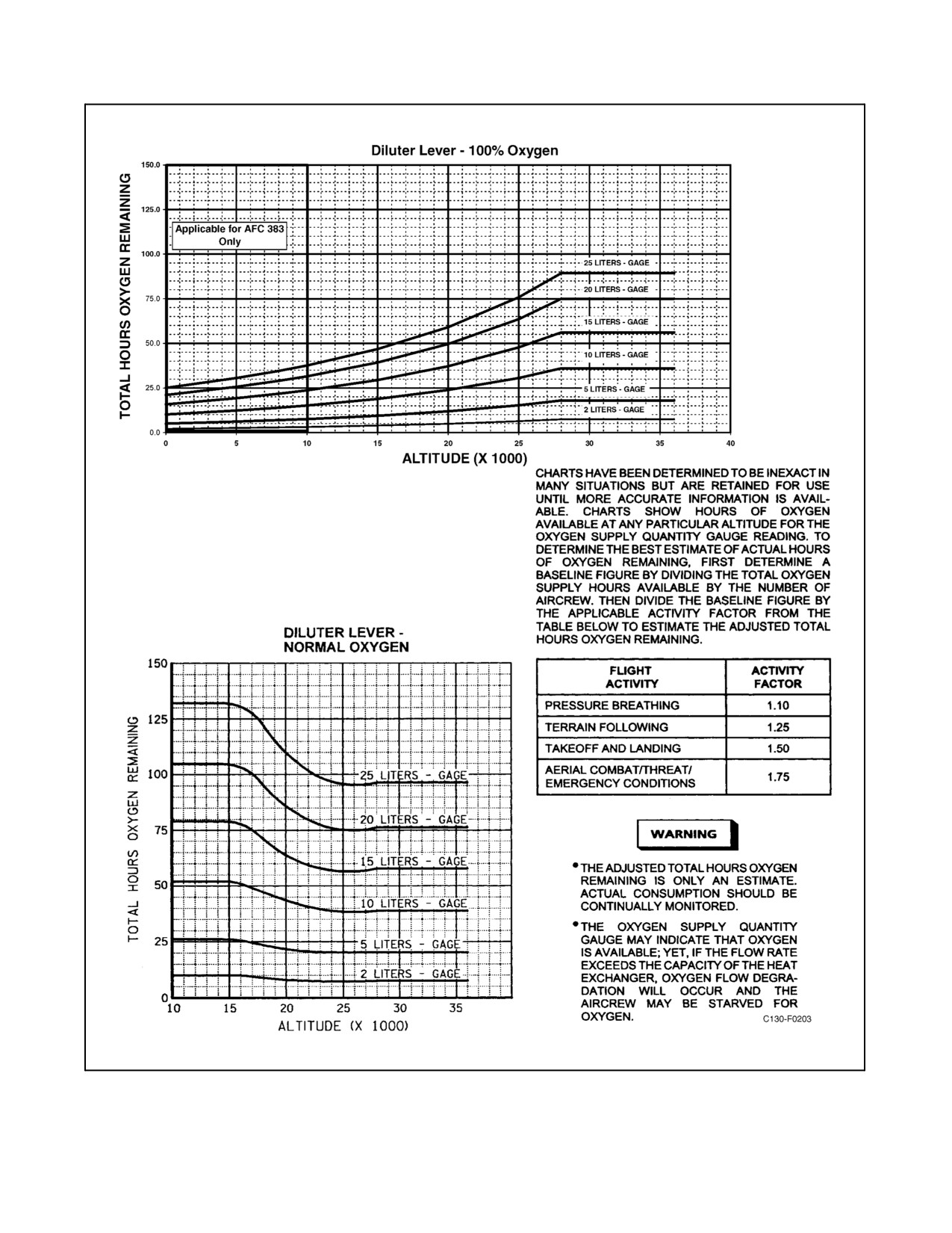
D When 100 percent is being supplied, less oxygen is consumed per person
as altitude increases; therefore, the oxygen duration increases with an
increase in cabin altitude (see Figure 2-142).
The oxygen system flow rate can vary widely depending on both the aircrew’s consumption of oxygen and the
system’s ability to convert the liquid oxygen into a gas. Crew consumption rates will vary depending on a number
of factors; in particular, use of either the emergency or 100-percent oxygen settings on the regulator will greatly
increaseoxygenconsumption.Theoxygensupplyflowrateislimitedbytheheatexchanger’sabilitytowarmgaseous
oxygentoabreathabletemperature.Thetemperatureoftheoxygen gassupplied totheaircrewwill normallydecrease
as the flow rate increases. However, when flow rate begins to exceed the capacity of the heat exchanger, the
temperature will decrease markedly and the system pressure at the regulators may decrease. The aircrew may be
starved for oxygen even though an adequate supply of oxygen remains within the converter (see OXYGEN FLOW
DEGRADATION emergency procedure in chapter 11). This is particularly true in aircraft not modified by AFC-383.
(Applicable to aircraft not modified by AFC-383). Whenever the aircrew
is operating on 100-percent oxygen below 15,000 feet cabin altitude,
oxygen quantity, temperature and pressure shall be closely monitored for
both the oxygen consumption rate and oxygen flow degradation. Failureto
adequately monitor oxygen regulator gauge pressure may allow an
undetected oxygen flow degradation situation to develop.
For aircraft not modified by AFC-383, the oxygen system is capable of sustaining five crewmembers breathing 100
percent oxygen for most flight activities when the aircraft is above 15,000 feet. At lower altitudes, the oxygen system
maximum flow rate may not sustain the entire crew on 100-percent oxygen. The worst case occurs at sea level in a
threat or an emergency environment with aircrew on 100-percent oxygen
For aircraft modified by AFC-383, the oxygen system is capable of sustaining ten crewmembers breathing 100
percent oxygen until depletion of the oxygen supply under the following conditions:
CONDITION
CABIN ALTITUDE
DURATION
Air Drop Mission
Ground level and up
Unlimited
Pre-breathing (low to
moderate crew workload)
Emergency Use (smoke in the
Ground level to 3,000 feet
Up to 30 minutes
cabin, toxic fumes, etc.) (high
Above 3,000 ft
Unlimited
crew workload
2-375
ORIGINAL
01-75GAL-1
Figure 2-142. Oxygen Duration
ORIGINAL
2-376

01-75GAL-1
For aircraft modified by AFC-383, the oxygen system is capable of sustaining ten crewmembers breathing 100
percent oxygen and simultaneously refilling protable oxygen bottles as follows:
PORTABLE OXYGEN BOTTLE
CABIN ALTITUDE
FILLING INTERVAL
Ground
No bottle refilling
2,500 feet
1 bottle every 6 minutes
5,000 feet
1 bottle every 3 minutes
10,000 feet
1 bottle every 1.6 minutes
12,500 feet
1 bottle continuously
2.23.1 Oxygen Regulator
A diluter-demand automatic-pressure breathing regulator is located at each crewmember station. Two additional
regulators are located in the cargo compartment. The crewmember regulators are located as follows: on the pilot and
copilot side shelves, the flight engineer overhead panel, the navigator control panel and the observer panels forward
of the left and right paratroop doors. Two regulators are located at the forward right side of the cargo compartment.
Regulators are provided at each end of the flight station lower crew bunk (see Figure 2-141). Each regulator is
equipped with a flow indicator, a pressure gauge, three toggle-type switches to control regulator operation, and an
inlet filter to prevent the entry of foreign particles into the system.
2.23.1.1 Oxygen Supply Lever
A manual, two-position supply lever is located at the lower right corner of each regulator. When the lever is set to
ON, oxygen is supplied to the regulator unit; when the lever is at OFF, the oxygen supply to the regulator is shut off
to prevent any waste of oxygen from the regulator unit when not in use.
2.23.1.2 Diluter Lever
The two-position diluter lever on each regulator unit may be used to shut off the air port manually and allow the
regulator to deliver pure oxygen at all altitudes or to provide automatic mixing of air and oxygen as required to
maintain normal body oxygen needs at all altitudes. When set to 100% OXYGEN, the regulator supplies pure oxygen
without air dilution; with the lever at NORMAL OXYGEN, the normal air/oxygen dilution characteristics of the
regulator are maintained. The lever is designed to prevent intermediate settings between 100% OXYGEN and
NORMAL OXYGEN.
2.23.1.3 Emergency Toggle Lever
The emergency toggle lever on each regulator has three positions: EMERGENCY, NORMAL, and TEST MASK.
With the lever at EMERGENCY, oxygen is supplied to the mask at continuous positive pressure for emergency use.
With the lever at NORMAL, oxygen flow is controlled automatically by the regulator. The spring-loaded TEST
MASK position is used when a positive pressure is required at any altitude to test the fit of the mask around the face.
CAUTION
When positive pressure is required, it is mandatory that the oxygen mask
be well fitted to the face. Unless special precautions are taken to ensure no
leakage, the continued use of positive pressure under these conditions will
result in rapid depletion of the oxygen supply. Except when unscheduled
pressure increase is required, the emergency toggle lever should remain in
the center NORMAL position.
2-377
ORIGINAL
01-75GAL-1
2.23.1.4 Visual Flow Indicator
The visual flow indicator on each regulator is a slide-and-window device in which, during normal use of the oxygen
mask, the indicator shows oxygen flow by blinking with the breathing cycle of the user. Oxygen flow ceases when
the blinker is not visible.
2.23.1.5 Pressure Gauge
The pressure gauge on the regulator is a dial-type instrument indicating system pressure in pounds per square inch.
2.23.2 Liquid Oxygen Converter
The 25-liter liquid oxygen converter, enclosed within a removable fiberglass cover, is mounted in the right side of
the nose wheelwell. It is filled through a combination filler-buildup-vent valve contained in a filler box adjacent to
the converter but accessible through a door on the right side of the nose fuselage. The converter is also connected
toadrainvalveinthelowersideofthenosewheelwellskin.Thefunctionofthecombination filler-buildup-ventvalve
isautomatic,andchargingoftheoxygensystemisaccomplishedautomaticallyoncompletionofthefillingoperation.
2.23.3 Heat Exchanger Units (Prior to AFC-383)
Two heat exchanger units, installed in the system below the flight station floor, ensure the delivery of oxygen within
the required temperature range to all regulators. The oxygen is warmed by passing through the heat exchangers and
not by any form of controllable system heating.
When opening the oxygen shutoff valve after it has been turned to the OFF
position, open slowly to the ON position. A sudden rush of pressurized
oxygen into adepleted system could causeafireand subsequentexplosion.
2.23.4 Coiled Tube Heat Exchanger (AFC-383)
A coiled tube heat exchanger, installed below the flight deck floor outboard of the flight deck air conditioning unit,
ensures the delivery of oxygen within the required temperature range to all regulators. The oxygen is warmed by
passing through the heat exchanger and not by any form of controllable system heating.
2.23.5 Oxygen Manual Shutoff Valve
A manual shutoff valve is mounted on the right side of the cargo compartment forward bulkhead above the
air-conditioning unit. The valve is normally in the open position and is used to shut off the oxygen supply to the
regulator distribution lines.
2.23.6 Liquid Oxygen Quantity Indicator and Test Switch
A capacitance-type quantity indicator, which permits monitoring of the total aircraft supply of liquid oxygen
available in the converter, is installed at the lower right side of the copilot instrument panel. (See Figure 2-79.) A
press-to-test switch adjacent to the quantity indicator allows functional checking of the indicator. The indicator is
powered by the ac instruments and engine fuel control bus through the LIQUID OXYGEN LOW LEVEL circuit
breaker on the pilot lower circuit breaker and fuse panel.
2.23.7 Low-Level Warning Light
A LIQ OXY QTY LOW warning light, which illuminates to indicate that the supply of liquid oxygen remaining
within the converter has reached a low level of approximately 2.5 liters, is mounted on the copilot instrument panel
ORIGINAL
2-378
01-75GAL-1
adjacent to the oxygen system quantity indicator. The warning light is powered by the essential dc bus through the
LIQUID OXYGEN LOW LEVEL circuit breaker on the copilot lower circuit breaker panel.
2.23.8 Portable Oxygen Bottles
Four portable oxygen bottles, shown in Figure 2-141, are provided for use by crewmembers at high altitudes to
facilitate movement within the aircraft or for emergencies. The portable bottle consists of a cylinder and a
pressure-demand regulator. Two of the bottles are stowed within the flight station, one outboard of the pilot and the
otheroutboardofthecopilot; thethird ismounted ontherightsideoftheforwardbulkhead inthecargocompartment;
and the fourth is mounted on the right side in the aft section of the cargo compartment. Adjacent to each stowage
location is a recharging outlet fed from the main oxygen supply system. Recharging of the portable bottles is
accomplished at the normal system pressure of 300 psi through a filler valve and flexible hose stowed in a clip at the
recharging point. The four-position selector knob on the regulator allows for increasing continuous positive pressure
to the user. The settings, 30M, 42M, and EMER, deliver 100-percent oxygen at continuous positive pressure.
2.23.9 Flightcrew Quick-Don Oxygen Masks
Each quick-don unit consists of a quick-don suspension device and oxygen mask that contains an integral microphone
assembly that connects to the crewmember headset and the aircraft communications system. Microphone switching
from the headset to the oxygen mask is accomplished automatically as the suspension device is donned.
2.23.10 Oxygen System Operation
For normal operation of the system, the oxygen supply lever is placed to ON and the diluter lever is placed to
NORMAL. The diluter lever should be placed to 100-percent oxygen if any symptoms of hypoxia are present or if
doubt exists that the diluter mixture is sufficient. The emergency position of the diluter lever is not currently used.
2.23.11 Oxygen Duration
The oxygen duration chart (see Figure 2-142) is based on the25-liter converter furnishing 670 cubic feet of oxygen
and shows duration for 100% OXYGEN and NORMAL OXY GEN selections of the oxygen regulator diluter lever.
2.24
CARGO LOADING EQUIPMENT
Cargo loading equipment includes a hydraulically operated cargo door and loading ramp and miscellaneous
equipment for loading and securing vehicles, cargo, litters, and troop seats.
2.24.1 Tiedown Fittings
Tiedown fittings areinstalled on thecargo floor, ramp, and sidewalls. Thefloorfittings areflushmounted and consist
oftiedown rings and attachment studs. Thefloorrings havearated strength of10,000 pounds. Theramp andsidewall
fittings are tiedown rings with a rated strength of 5,000 pounds. Twelve threaded sockets are distributed along the
edges of the cargo floor for the attachment of 25,000-pound fittings.
2.24.2 Cargo Nets
Threecargonetsaresuppliedfortyingdownpalletizedcargoandsmallitems stackedtogether. Thesenets havehooks
and rings for attaching to the cargo floor and for the installation of tiedown devices. The cargo nets are stowed in
boxes on the left and right sidewall above the ramp and on the aft cargo door.
2.24.3 Snatch Blocks
Two removable snatch blocks are stowed in the stowage box at the forward cargo compartment bulkhead. Refer to
the applicable loading manual for use of snatch blocks.
2-379
ORIGINAL
01-75GAL-1
2.24.4 Wheeled Pry Bars
Two wheeled pry bars are provided on the aircraft. These pry bars are used for handling boxes and crates in the cargo
compartment and may be used either singly or in pairs.
CAUTION
Although the wheeled pry bar has a capacity of 5,000 pounds, the cargo
floor will not withstand this load on the small area of contact of the wheels.
Refer to the applicable loading manual for pry-bar limitations.
2.24.5 Tiedown Devices
Two types of tiedown devices are supplied with the aircraft for securing cargo. Onetype is a turnbucklearrangement
for tightening the tiedown chains. These devices are stowed in racks aft of the flight station and on the right and left
sidewalls of the cargo compartment. The other type consists of webbing straps with hooks for attaching the straps
to the tiedown fittings. These devices are stowed in a box on the aft cargo door.
2.24.6 Tiedown Chains
Chains for use with the tiedown devices for securing cargo are supplied with the aircraft. These chains are stowed
in boxes on the left and right sidewalls above the ramp.
2.24.7 Auxiliary Ramps
Four auxiliary ramps are supplied with the aircraft. The two truck loading ramps are used when loading from thebed
ofatruckorsupport equipment,thesearestowed ontherightsidewall abovetheramp.Thetwoground loadingramps
are used when the ramp is extended to ground level, these are stowed on the cargo door.
2.24.8 Portable Winch
The portable winch is located in the cargo compartment and is powered by main ac or main dc through a receptacle
on the electronic equipment rack aft of the 245 bulkhead.
2.24.9 Loading Instructions
For detailed information concerning cargo loading and tiedown, and aerial delivery instructions, refer to the
applicable loading manual.
2.25
TROOP CARRYING EQUIPMENT
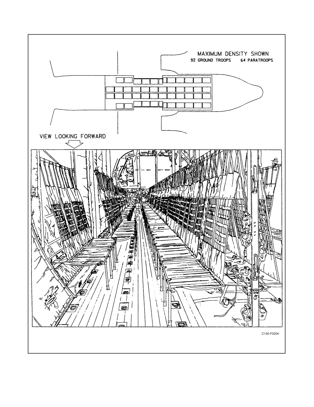
When the C-130T aircraft is used as a troop carrier, seating accommodations are provided for 64 paratroops or 78
ground troops (see Figure 2-143). By using the seat attachment provisions on the wheelwell walls, 14 additional
ground troops can be carried. For paratroop airdrop missions, the seats are installed on a 24-inch spacing. For ground
troops or personnel transport, the seats are installed with a 20-inch spacing. The installed seats form a single row down
each side of the cargo compartment and a double row (back-to-back) down the center of the cargo compartment. When
the aircraft is not being used for transporting troops, the seats are rolled up and stowed. The method of installation
and stowing the seats is given on the instruction placards located on the center seat stanchions, and the cargo
compartment left wheelwell wall. For detailed information, see the applicable loading manual.
2.26
CASUALTY CARRYING EQUIPMENT
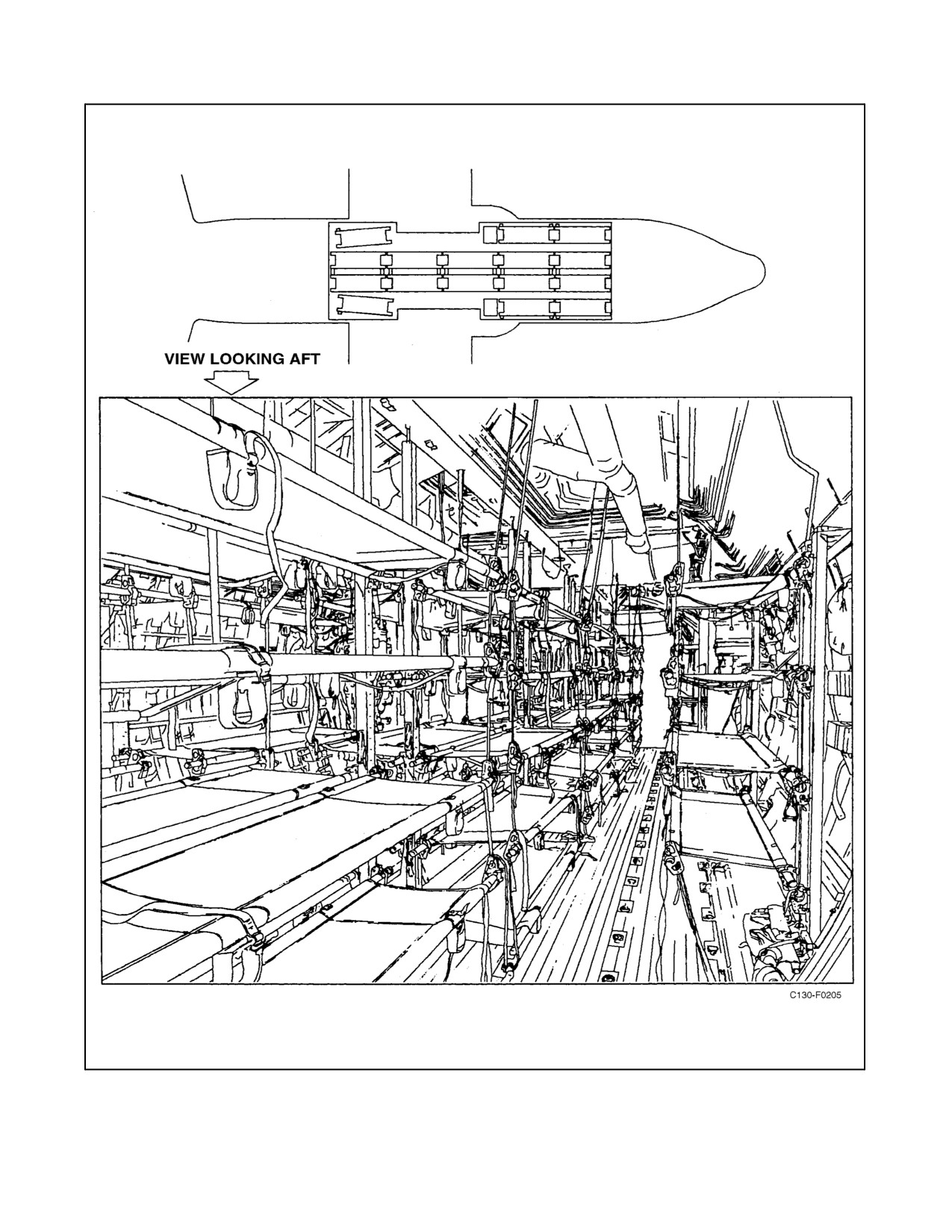
Casualty transport facilities for approximately 70 litters and 2 attendants or 66 litters and 6 attendants, are provided
with the C-130T aircraft. Actual litter capacity may be less due to modifications (see Figure 2-144). For detailed
instructions on litter installation and stowage, see the applicable loading manual.
ORIGINAL
2-380
01-75GAL-1
Figure 2-143. Typical Troop Seating Arrangement
2-381
ORIGINAL
01-75GAL-1
Figure 2-144. Typical Litter Arrangement
ORIGINAL
2-382
01-75GAL-1
2.27
PARATROOP EQUIPMENT
Paratroop equipment consists of seats, paratroop doors, jump platforms, anchor lines, jump signals, and air
deflectors.
2.27.1 Seats
Seats are provided for installation in the cargo compartment. When the seats are in use, they are installed in a single
row down each side of the cargo compartment and a double row (back-to-back) down the center of the cargo
compartment. Seatbelts are provided and may be installed with 24-inch spacing to accommodate paratroops or with
20-inch spacing to accommodate ground troops or personnel. The number of seats available is as follows:
1. Ground troops — 78.
2. Ground troops (including wheelwell seats) — 92.
3. Paratroops — 64.
When the seats are not in use, they are rolled and stowed in the cargo compartment. For detailed installation and
stowage instructions, refer to the applicable loading manual.
2.27.2 Paratroop Doors
A paratroop door is located on each side of the fuselage forward of the ramp. Each door is unlocked by a handle located
in the center of the door. After the latch pins are released, the door is raised manually with an inward and upward
movement. The door is held in the open position by a spring-loaded latch that must be released manually before the
door can be closed.
2.27.3 Paratroop Jump Platforms
Two metal, nonskid jump platforms are used in the paratroop door openings for paratroop jump operation. Install
and use the jump platforms in accordance with the applicable loading manual.
2.27.4 Anchor Lines
Four metallic-cable anchor lines are installed on reels in the aft section of the cargo compartment. They are installed
by attaching the aft end of each anchor-line to a u-bolt on the anchor line supporting arm. Each arm is electrically
controlled by an individual aft anchor-line arm switch on the left side of the cargo compartment forward bulkhead
(see Figure 14-6). Electrical power is furnished by the 28-volt main dc bus, through the LH and RH AFT ANCHOR
LINE ARM circuit breakers on the copilot lower circuit breaker panel. The forward end of the anchor line is attached
to similaru-bolts onthecargocompartment forwardbulkhead. Referto theapplicableloadingmanual forinstallation
procedures.
CAUTION
The electrical control system of the cargo door and ramp is inactivated
when the anchor line support arms are not in the up position. If the anchor
line support arms are extended prior to the cargo door reaching the
up-and-locked position, the door will free fall onto the arms.
2-383
ORIGINAL
01-75GAL-1
2.27.5 Jump Signals
Jump signals consist of red and green lights. A jump signal is located on the forward and aft frame of each paratroop
door, on each aft anchor arm, and on the forward cargo compartment light panel. Two indicator lights are located
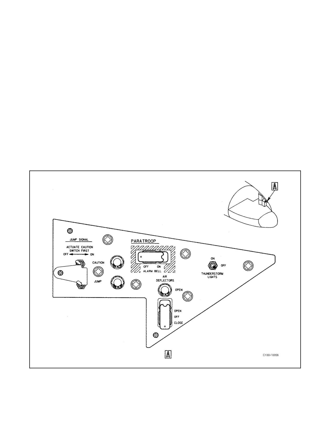
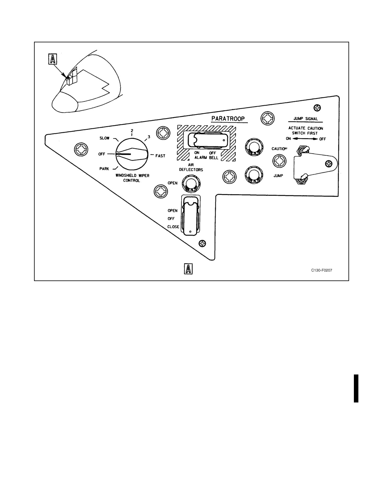
on the pilot and copilot side shelf. The jump signals are controlled from the pilot and copilot paratroop panels (see
Figures 2-145 and 2-146) by two two-position (ON, OFF) toggle switches. A cam is installed between the switches
sotheJUMPswitchcannotbeactuateduntiltheCAUTIONswitchisplacedintheON position.When theCAUTION
switch is placed in the ON position, the red lights go on; when the JUMP switch is placed in the ON position, the
green lights go on and the red lights go off. The jump signals are powered by 28-Vdc power from the battery bus
through the TROOP JUMP LIGHTS circuit breaker on the pilot side circuit breaker panel.
2.27.6 Air Deflectors
Air deflectors are located on each side of the fuselage, forward of the paratroop doors, forming the rear section of
the main landing gear wheelwell fairing. The air deflectors are opened to approximately 30_ by actuation of a
three-position (OPEN, OFF, CLOSE) guarded toggle switch on the pilot and copilot paratroop panel (see Figures
2-145 and 2-146). A warning light above the AIR DEFLECTORS switch is illuminated when the doors are not closed.
The AIR DEFLECTORS switch and the warning light are energized by 28-Vdc power from the main dc bus through
the PARATROOP AIR DEFLECTOR circuit breakers on the copilot lower circuit breaker panel.
Figure 2-145. Pilot Paratroop Panel
ORIGINAL
2-384
01-75GAL-1
Figure 2-146. Copilot Paratroop Panel
2.27.7 AN/ASH-37 Structural Data Recording Set (SDRS)
The Structural Data Recording Set (SDRS) is used to measure and increase the accuracy of structural fatigue data
for the airframe and critical components. The system consists of Data Entry Keyboard on the starboard side of FS245,
a Recorder Converter and Memory Unit in the RH under deck area, a Motion Pickup Transducer, and Strain Sensors
located in the left wing. The system also incorporates an AN/UYQ-76 ground support unit used primarily to
download recorded flight data. The system receives 28 Vdc power from the essential dc bus through the SDRS circuit
breaker on the copilot’s lower circuit breaker panel.
2.28
EMERGENCY SYSTEMS
Various types of emergency systems are furnished to minimize hazards to the aircraft and to personnel in case of fire
or accident. Description of removeable emergency equipment is located in Chapter 11.
2.28.1 Alarm System
The alarm system consists of four alarm bells in the cargo compartment and two switches, one on the pilot side shelf
and the other on the copilot side shelf. The alarm system is used for crew and passenger warning or paratroop warning.
All the bells sound when either guarded switch is ON. Power for operation of the bells is supplied from the battery
bus through the ALARM BELL circuit breaker on the pilot side circuit breaker panel.
2-385
ORIGINAL

01-75GAL-1
2.28.2 Emergency Lights
Portable, battery operated emergency lights (Figure 11-1) are installed on stationary terminal blocks located near each
normal or emergency exit. The lights are located as follows:
LOCATION
NO. OF LIGHTS
Crew entrance door
1
Paratroop doors
2
Overhead emergency escape hatches
3
Right-side exit
1
Left-side exit
1
When installed, the lights can be either individually controlled by the three-position (ON, OFF, ARM) switch on each
light assembly or collectively extinguished by the EMER EXIT LT EXTINGUISH pushbutton on the overhead
electrical control panel. In order for the EMER EXIT LT EXTINGUISH push-button to be able to extinguish a light,
however, the associated light assembly switch must be positioned to ARM. An inertia switch in each of the light
assemblies actuates the light when the aircraft is subjected to a decelerating force exceeding 2-1/2g. The lights will
also illuminate if power on the essential dc bus fails. An individual light assembly can be removed for emergency
portable use by pulling the release handle on the light assembly. The control system for the installed system is
supplied 28-Vdc power from the essential dc bus through the EMER EXIT LIGHT CONTROL circuit breaker on
the copilot lower circuit breaker panel and from the battery bus through the EMER EXIT LIGHT EXTINGUISHER
circuit breaker on the pilot side circuit breaker panel. The batteries are not recharged by the exit light control circuit.
2.28.3 Crash Survivable Flight Incident Recorder (CSFIR)
The Crash Survivable Flight Incident Recorder (CSFIR) is installed to provide a combination flight incident and
cockpit voice recorder. The CSFIR receives and stores flight data, navigation data, and engine performance data into
crash-survivable memory for analysis in the event of an aircraft incident or mishap. Memory capacity provides for
recording two hours of flight data and thirty minutes of audio data. The memory is continuously overwritten with
the most recent two hours of flight data and 30 minutes of voice data. The CSFIR does not require operator input
and is operational when aircraft electric power is applied. The system’s primary components are a Signal Data
Recorder-Reproducer (SDRR) and Voice and Data Recorder (VADR) located in the aft overhead tail section and a
Cockpit Control Indicator located on the flight station pedestal (Figure 2-4). The system receives 115-Vac power
from the essential ac bus through the CSFIR TMU 115VAC circuit breaker on the pilot’s lower circuit breaker panel
and 28-Vdc power from the essential dc bus through the CSFIR 28VDC circuit breaker on the copilot’s lower circuit
breaker panel.
2.29
ENTRANCE DOORS
Entrance to the aircraft can be gained through the crew entrance door or the paratroop doors.
2.29.1 Crew Entrance Door
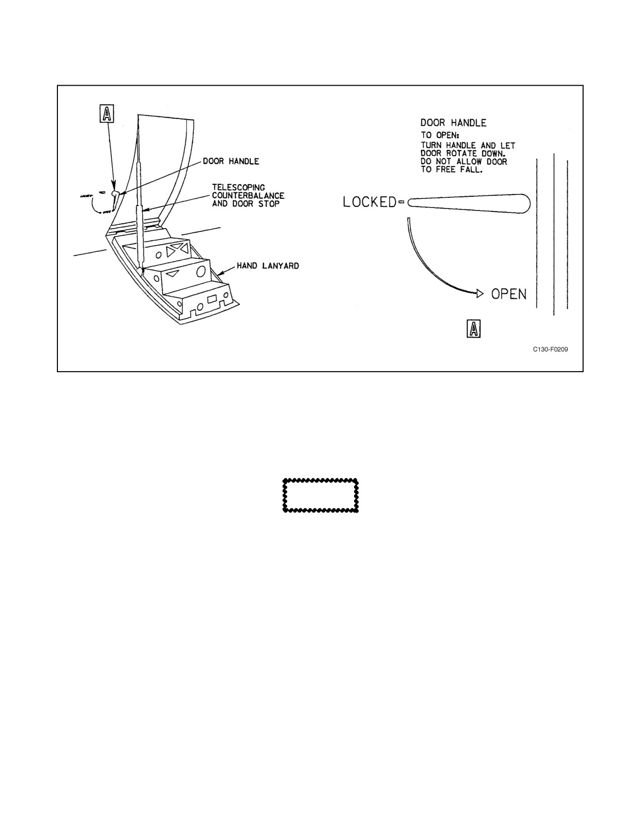
The crew entrance door (see Figure 2-147) is located on the forward left side of the aircraft. The door is opened from
the outside by rotating the door handle downward. The door should be allowed to swing slowly downward until the
spring-loaded telescoping counterbalance and door stop holds the door at the proper angle for use.
Stand clear of the door when operating the handle so as to prevent personal
injury if the door should fall free.
ORIGINAL
2-386
01-75GAL-1
Figure 2-147. Entrance to Aircraft
Steps on the inside of the door facilitate entrance to the aircraft. A hand lanyard on the aft side of the inside face of
thedooris provided forpulling thedoorclosed preparatory to flight. To open thedoor from the inside, turn theinside
handle in a counterclockwise direction.
CAUTION
When opening the door from the inside, use the hand lanyard so as to
restrain the door if it should fall free.
2.29.1.1 Crew Door Jettison Handle
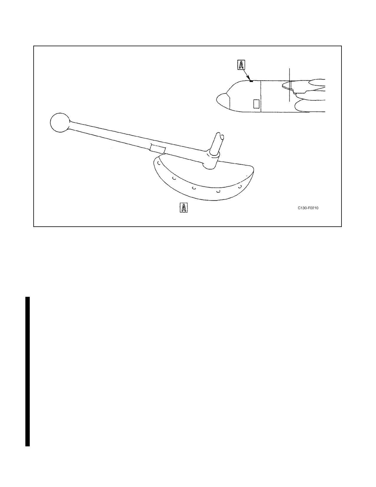
The crew door jettison handle (see Figure 2-148), painted yellow, is located on the ceiling of the flight station, 3 feet
to the left of the centerline of the aircraft and slightly aft of the pilot seat. Pulling the handle down actuates a cable
through a bellcrank assembly to pull the locking pins from the top of the door at the same time that the hinge pins
drop from the bottom hinge and the telescoping counterbalance is released.
Note
Do not attempt to jettison the crew door when cabin pressure is greater than
3.1 inches Hg. Above 3.1 inches Hg, the load on the door is too great for
the jettison mechanism to operate. In addition, should the door jettison at
a greater pressure differential, there may be some explosive decompression
effects.
2-387
ORIGINAL
01-75GAL-1
Figure 2-148. Crew Door Jettison Handle
2.29.2 Paratroop Doors
A paratroop door is located on either side of the fuselage just aft of the wheelwell fairing. These doors are normally
used for loading paratroops or passengers. The doors are opened by turning the door handle clockwise, pushing in,
and sliding the door upward. Two paratroop door ladders are provided to aid personnel entering the aircraft from
ground level.
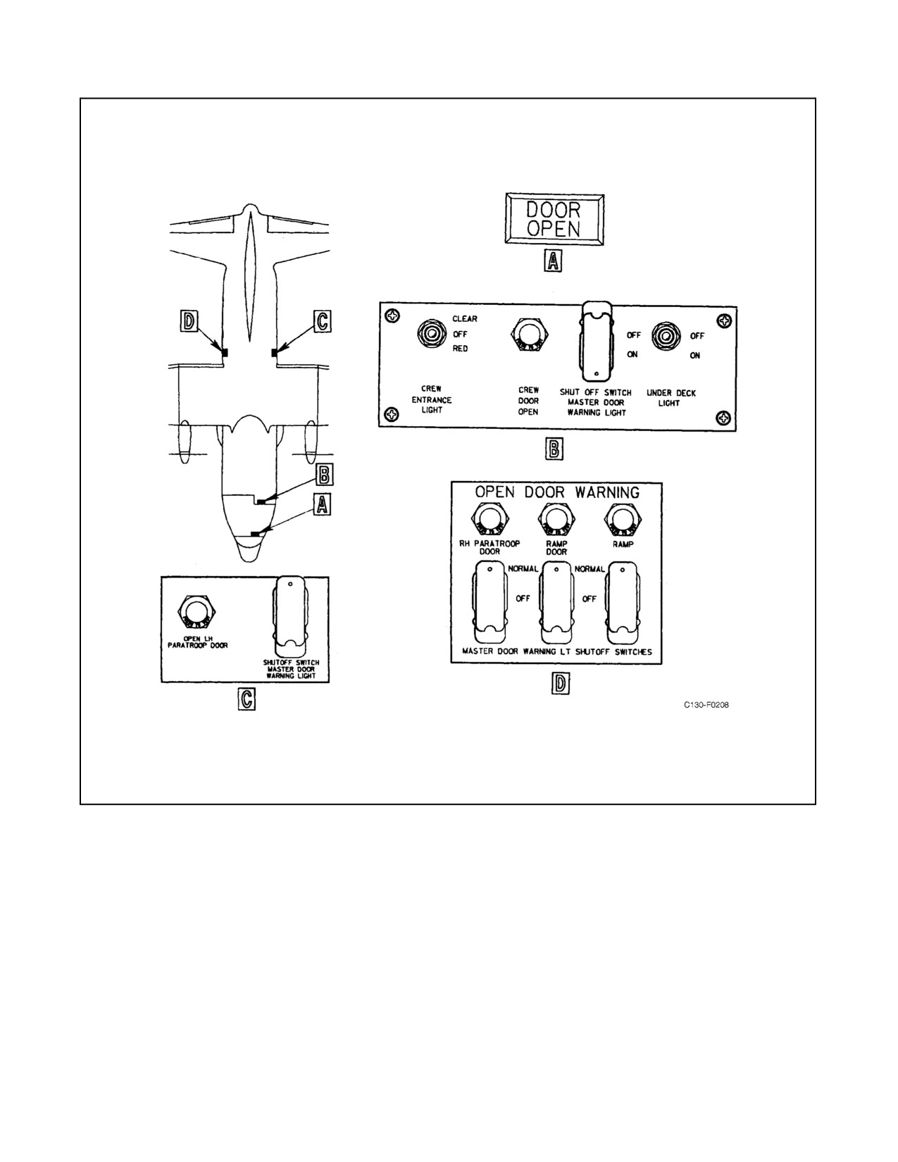
2.29.3 Door-Open Warning System
The door-open warning system (see Figure 2-149) consists of a master DOOR OPEN warning light on the pilot
glareshield and a light and master light shutoff switch for each door. Power for operation of the door warning system
is supplied from the main dc bus through the DOOR WARNING LIGHT circuit breaker on the copilot lower circuit
breaker panel.
2.29.3.1 Master DOOR OPEN Warning Light
The master DOOR OPEN warning light is located on the pilot glareshield. It will go on whenever any one of the doors
is not closed and locked.
2.29.3.1.1 Door Open Warning Lights
A door open warning light is provided for each door. Any one of these lights will go on when the corresponding door
is not closed and locked and cannot be turned off except by securing the door.
2.29.3.2 Master Light Shutoff Switches
Each door is provided with a master door warning light shutoff switch. The switches are located with each individual
door-open light. The switches are used to turn off the master door-open light on the pilot glareshield after it has gone
on to indicate that one of the doors is not securely locked. This will provide for another indication for the flightcrew
should another door become insecure.
ORIGINAL
2-388
01-75GAL-1
Figure 2-149. Door-Open Warning Lights and Control
2.30
SEATS
2.30.1 Crew Seats
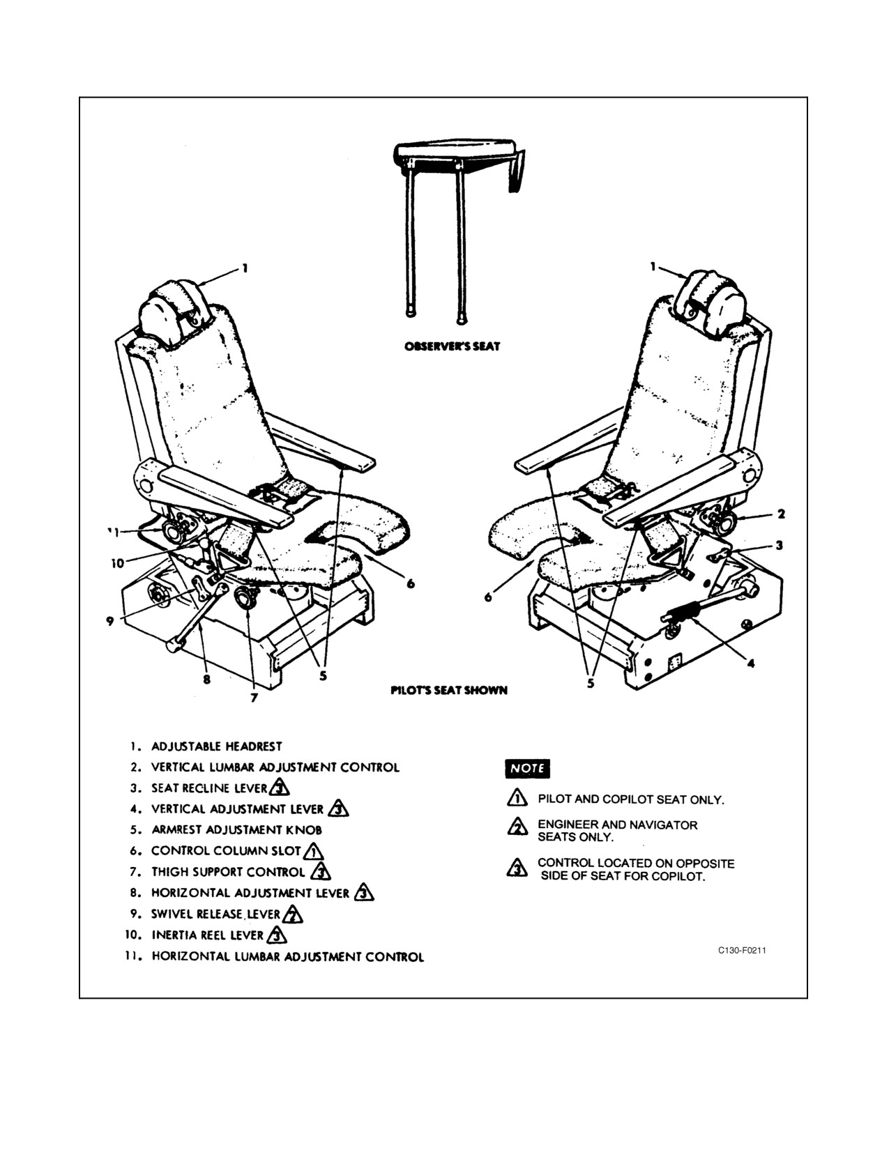
Thecrewmembers intheflightstation areprovided withseats designedforusewith back-styleparachutes (seeFigure
2-150). The seats are adjustable both fore and aft and up and down. Headrests are an integral part of the seat and adjust
vertically. Use of the vertical adjustment lever on the side of the seat permits vertical movement of the seat, and use
of the horizontal adjustment lever on the opposite side of the seat permits fore and aft movement of the seat. Moving
a swivel release lever on the navigator and flight engineer seats releases a locking device and permits the seats to be
swiveled. Both observers are provided with platform-type seats attached to the paratroop doors. These seats can be
folded and stowed against the paratroop doors.
2-389
ORIGINAL
01-75GAL-1
Figure 2-150. Crew Seats
ORIGINAL
2-390
01-75GAL-1
2.30.1.1 Seat Controls
Seat controls are designed to adjust the seat position and contour to the physical build of the individual crewmember.
They are easily adjusted to the comfort of the crewmember and lock in any desired position.
2.30.1.1.1 Horizontal Adjustment Lever
Ahorizontaladjustmentleverlocksandunlockstheseatadjustmentmechanism,allowingtheseattobeadjustedfrom
an aft to a forward position. Moving the lever aft unlocks the adjustment mechanism, and the seat can be moved in
either direction. Moving the lever forward locks the adjustment mechanism.
2.30.1.1.2 Vertical Adjustment Lever
A vertical adjustment lever, which has a button to release the lever from the locked position, is located at the side
of each seat. The seat itself is spring loaded to the up position. To adjust the seat for height, sit down in the seat and
press the button. With less weight on the seat, the button releases more easily. The seat will tend to move up or down,
depending on the weight applied to it. When the desired height is obtained, release the button, and the seat will lock
in the nearest detented position.
2.30.1.1.3 Recline Lever
A seat recline lever, located on the side of the seat, is a manual control that allows the back of the seat to be tilted
forward or aft.
2.30.1.1.4 Armrest Adjustment Knob
The armrest adjustment knob, when rotated, sets the desired vertical angle of the individual armrest. The armrests
may be rotated to the stowed position (full up) where they must be physically pushed into the side of the seat. To
unstow, thearmrestsmust bepulled outaway fromthesideoftheseat androtated downto theirlast adjustedposition.
2.30.1.1.5 Thigh Support Control
The thigh support control, located on the side of the seat, is rotated to adjust the forward edge of the seat vertically
to match the position of the thigh. This will provide the crewmember with the most comfortable thigh support.
2.30.1.1.6 Horizontal Lumbar (Lumbar In-Out) Adjustment Control
The horizontal lumbar adjustment control, located on the aft side of the seat, is rotated to adjust the back of the seat
(lumbar area) fore and aft. This, coupled with the vertical lumbar support adjustment, will provide the crewmember
with the most comfortable back support.
2.30.1.1.7 Vertical Lumbar (Lumbar Up-Down) Adjustment Control
Theverticallumbaradjustmentcontrol,locatedontheoppositesideoftheseatfromthehorizontal lumbaradjustment
control, is rotated to adjust the back of the seat (lumbar area) up and down. This, coupled with the horizontal lumbar
support adjustment, will provide the crewmember with the most comfortable back support.
2.30.1.1.8 Flight Engineer and Navigator Seat Swivel Release Lever
A swivel release lever(s), located on the flight engineer and navigator seats underneath the inertia-reel lock control,
controls the rotational movement of the seat. When the swivel release lever is rotated, the seat locking device is
released and the seat can be rotated to any detented position. When the lever is released, the locking device engages,
keeping the seat in the selected detent.
2-391
ORIGINAL
01-75GAL-1
2.30.2 Safety Belt and Shoulder Harness
All crew seats are provided with a conventional seatbelt and shoulder harness to retain the crewmember in the seat
in the event of a crash landing.
2.30.3 Shoulder Harness Inertia-Reel Lock Lever
A two-position (forward LOCK, aft UNLOCKED) shoulderharness inertia-reel lever is located on the pilot, copilot,
navigator, and flight engineer seats (see Figure 2-150). The inertia-reel lever may be moved without pressing down.
When the lever is in the aft (UNLOCKED) position, the reel harness cable will extend to allow a crewmember to lean
forward in the seat; however, the reel harness cable will automatically lock when an impact force of 2g to 3g on the
aircraft is encountered. When the reel is locked in this manner, it will remain locked until the lever is moved to the
forward position and then returned to the aft position. When the lever is in the forward (LOCK) position, the reel
harness cable is manually locked so that the seat occupant is prevented from moving forward.
The LOCK position is used during takeoffs and landings and whenever a ditching or crash is imminent. This position
provides an added safety measure over and above that of the automatic safety lock.
The seats must be facing forward for the inertia reel to function
automatically.
2.31
MISCELLANEOUS EQUIPMENT
Miscellaneous equipment consists of windshield wipers, sextant step, toilet facilities, galley provisions, ladders,
protective covers, blackout curtains, and alarm bells.
2.31.1 Windshield Wipers
Two electrically operated windshield wipers are installed: one on the pilot windshield panel and one on the copilot
windshield panel. The windshield wipers are controlled by a six-position (PARK, OFF, SLOW, 2, 3, FAST)
rotary-type WINDSHIELD WIPER CONTROL switch on the copilot side shelf (see Figure 1-4). The windshield
wipers are powered by 28-Vdc power from the main dc bus through the WINDSHIELD WIPER circuit breaker on
the copilot lower circuit breaker panel.
2.31.2 Toilet Facilities
Toilet facilities consist of an electrically powered flush-type toilet and two carry-on/off-type urinal-holding tanks.
The flush toilet is a fixed type, located aft of the right paratroop door, which folds up to clear the cargo loading
envelope. It empties into an integral waste container and is serviced through an external adapter on the right aft
fuselage. The toilet is powered by 28-Vdc power from the main dc bus through the AFT TOILET circuit breaker on
the aft fuselage junction box. The urinal facilities are located on the cargo compartment forward bulkhead.
2.31.3 Galley Equipment
Crew galley provisions, installed on the left side of the flight deck, are as follows: a 4-gallon water tank and sink,
two 2-gallon liquid containers, a cup dispenser, an electrically operated oven or microwave oven (aircraft 165378
and 165379) and two food-warming cups, a cold storage drawer and frozen food compartment, a refuse container,
and storage compartments. Additional liquid containers are installed in the cargo compartment aft of the paratroop
ORIGINAL
2-392
01-75GAL-1
doors. Electrical outlets forconnecting portablegalley equipment are installed forward ofthe left paratroop doorand
on the right sidewall aft of the forward cargo compartment bulkhead. Power to the galley is supplied from the
left-hand ac bus through the CARGO COMPT and FLIGHT DECK GALLEY power circuit breakers on the pilot
upper circuit breaker panel.
2.31.4 Airborne Ladders
Onemaintenanceladderisinstalledontheaircraft.Themaintenanceladderhasnospecificareainwhichtobestowed;
however, it is usually stowed in the cargo compartment forward of the booster hydraulic reservoir.
2.31.5 Protective Covers
Protective covers for the engine tailpipes are stowed in a container attached to the left side of the cargo compartment
above the ramp.
Covers for the engine inlet air ducts and APU exhaust are stowed on the left side of the forward cargo compartment.
Protective covers for the pitot tubes are stowed in the miscellaneous stowage container.
2.31.6 Blackout Curtains
Blackout curtains for the windows in the cargo compartment are stowed in pockets next to each window.
2-393/(2-394 blank)
ORIGINAL
01-75GAL-1
CHAPTER 3
Aircraft Servicing
3.1
GROUND SERVICING AND SUPPORT EQUIPMENT
The ground support equipment for the aircraft shall be those items pertaining to ramp dispatch and operation of the
aircraft. A servicing diagram (see Figure 3-1) identifies the location of items for servicing.
3.2
EXTERNAL POWER REQUIREMENTS
The external power source should provide a 200-/115-volt, three-phase, 400-Hz, ac source at a capacity of 40 kVA,
but preferably 60 kVA. Its phase must be A-B-C. The 28-Vdc external source should have a capacity of at least 400
amperes.
CAUTION
When external ground equipment is used, the units will be placed the
maximum distance from the aircraft that cords or ducts will permit.
3.3
EXTERNAL AIR REQUIREMENTS
Engine ground starting may be accomplished with a standard airstarting unit that will deliver a minimum of 90 ppm
airflow at 25-psi pressure. The ground airstart connection is located aft, and adjacent to, the APU access door.
3.4
NORMAL OPERATION OF THE SINGLE-POINT REFUELING SYSTEM
At times it may be necessary for the flightcrew to perform the refueling. Use only the fuels specified for this aircraft.
If a single-point refueling truck or fuel pit is available, the single-point refueling system may be used. If a single-point
fuel source is not available, refueling must be accomplished through the individual wing-tank filler ports.
3.4.1 Refueling or Defueling Operation
Note
At times it may be necessary for the flightcrew to perform refueling and
defueling operations. Under these conditions, refer to NAVAIR
01-75GAA-2-1.
3.5
AIRFIELD CONDITIONS
3.5.1 High-Strength Airfields
Where airfield runway strength data are available in terms of any of the methods shown in Figure 3-2, the chart should
be used as a guide to airfield-aircraft comparability. Where airfield/runway data are not available, the aircraft can
operate satisfactorily from most smooth, relatively hard surfaced airfields. Permanent-type (paved) airfields listed
in the USAF/USN Flight Information Publications are adequate for most aircraft operations. For normal operation,
tire pressure for a nominal tire deflection of 32 percent is recommended as shown by the high-strength airfield line
on Figure 3-2.
3-1
ORIGINAL
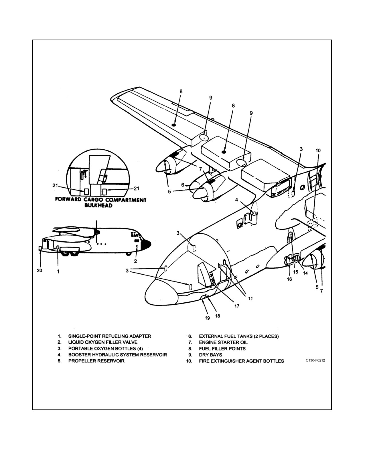
01-75GAL-1
Figure 3-1. Servicing Diagram (Sheet 1 of 2)
ORIGINAL
3-2
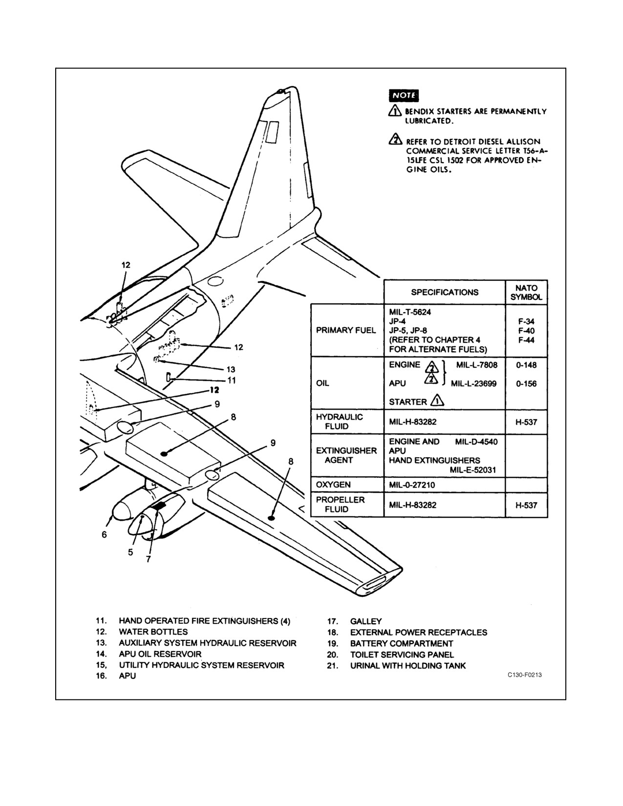
01-75GAL-1
Figure 3-1. Servicing Diagram (Sheet 2)
3-3
ORIGINAL
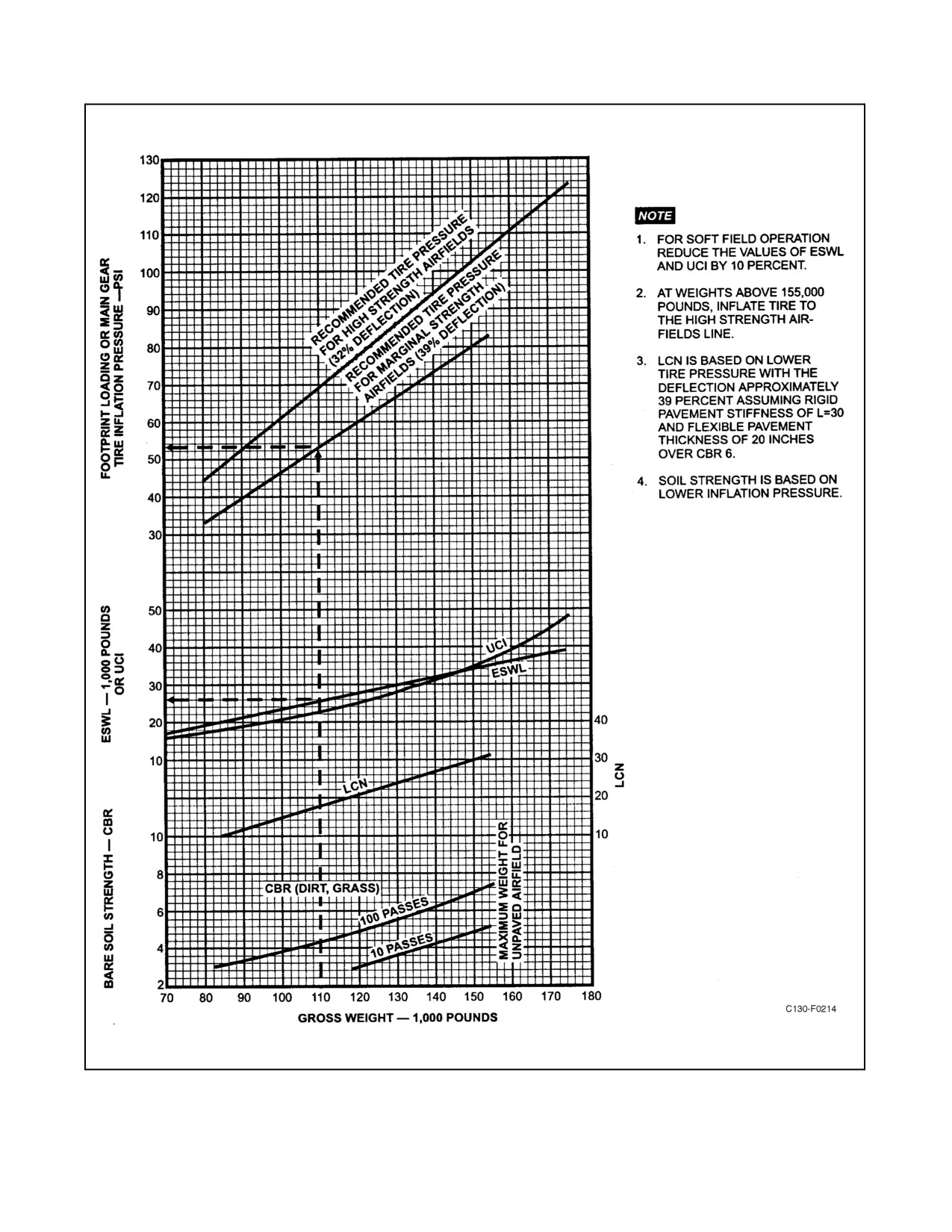
01-75GAL-1
Figure 3-2. Ground Flotation Characteristics
ORIGINAL
3-4
01-75GAL-1
3.5.2 Marginal-Strength Airfields
This category includes marginal-strength airfields, temporary airfields such as airfields with minimum surfacing, or
unsurfaced airfields such as would be encountered at forward-area airfields used in air head operations or airfields
in remote areas of the world. The minimum soil strength required for aircraft operation is within the CBR values of
3 to 5. Operational feasibility on unsurfaced airfields depends upon the soil type, soil moisture content, and
operational frequency. For marginal-strength airfields, a tire deflection of 39 percent is used as shown on Figure3-2.
CAUTION
Do not exceed 39-percent tire deflection.
3.5.3 Using the Chart
3.5.3.1 Example 1
GIVEN: A C-130T aircraft is required to operate into an unsurfaced airfield with a gross weight of 110,000 pounds.
FIND: Footprint loading and ESWL for soft field operation.
SOLUTION: Enter Figure 3-2 at the bottom of the chart on the vertical line representing 110,000-pound gross weight.
Proceed upward to the point of intersection with the footprint loading line for marginal strength airfields and read
53 psi (minimum) for main gear inflation pressure. Wherethe vertical line representing 110,000-pound gross weight
crosses the ESWL line, read 26,000 pounds; then reduce this value by 10 percent for soft-field operation to obtain
a final ESWL value of 23,400 pounds.
3.5.3.2 Example 2
GIVEN: A C-130T is required to operate into an airfield with an LCN of 25.
FIND: Footprint loading and maximum gross weight for unpaved runway operation.
SOLUTION: Enter Figure 3-2 on the horizontal line representing an LCN value of 25; where this line crosses the
LCN line, proceed vertically down from this point to read a maximum gross weight of 133,000 pounds. Proceed
upward on the 133,000-pound gross weight line to the marginal-strength airfield footprint loading line; then, at the
intersection of these lines, proceed horizontally to obtain a minimum main landing gear inflation pressure of 69 psi.
3-5/(3-6 blank)
ORIGINAL
01-75GAL-1
CHAPTER 4
Aircraft Operating Limitations
4.1
INTRODUCTION
This aircraft has certain well-defined limitations to its operation. Maximum performance requires careful
consideration of these limitations. The instrument marking illustration (see Figure 4-1) and the engine and propeller
limitations illustration (see Figure 4-2) contain certain limitations that are not repeated in text. This fact should be
remembered when using this chapter. A summary of limitations is shown in Figure 4-11.
4.2
INSTRUMENT MARKINGS
Flight and engine instrument markings are shown in Figure 4-1 and are not repeated in text.
Note
The markings shown in this part are for flight station indications and are
not to be confused with limits shown in the Technical Manual of
Maintenance Instructions.
4.3
ENGINE AND PROPELLER LIMITATIONS
Operating time limits, allowable observed TIT ranges, oil temperature, oil pressure, engine speed, propeller
governing, and starter operation limits, respectively, are tabulated in Figure 4-2 and are not repeated in text.
Note
All limits given in Figure 4-2 are flight station indicated limits and are not
to be confused with maintenance manual limits.
4.4
AUXILIARY POWER UNIT LIMITATIONS
In-flight use of the APU is limited to ac generator operation. Do not attempt to use APU bleed air during flight.
The APU must be on speed and warmed up a minimum of 1 minute before applying a bleed-air load.
The APU starter duty cycle is limited to 1 minute on and 4 minutes off.
TheAPUmustbeallowedtostabilizeaminimumof1minutewithout ableed-airloadbeforeplacingtheAPUcontrol
switch to STOP.
CAUTION
During cold-weather operations, allow a minimum of 4 minutes before
applying a bleed-air load.
Note
The APU generator is not considered a load on the APU for warmup after
start or stabilization prior to shutdown.
4-1
ORIGINAL
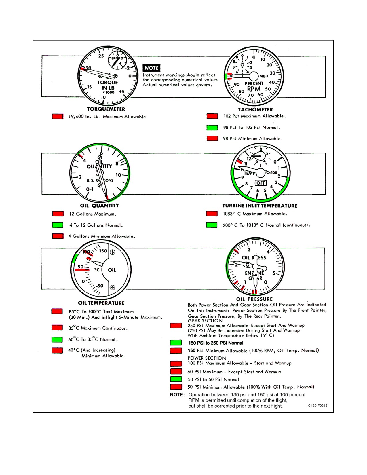
01-75GAL-1
Figure 4-1. Instrument Markings (Sheet 1 of 5)
ORIGINAL
4-2
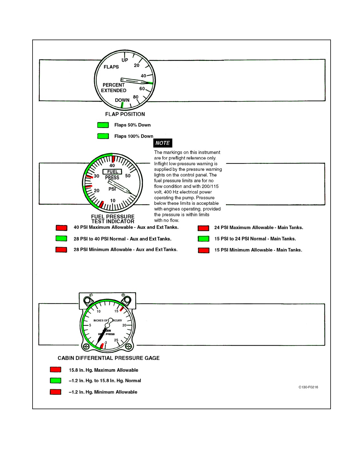
01-75GAL-1
Figure 4-1. Instrument Markings (Sheet 2)
4-3
ORIGINAL
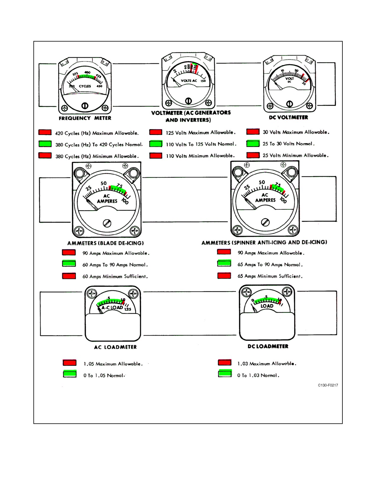
01-75GAL-1
Figure 4-1. Instrument Markings (Sheet 3)
ORIGINAL
4-4
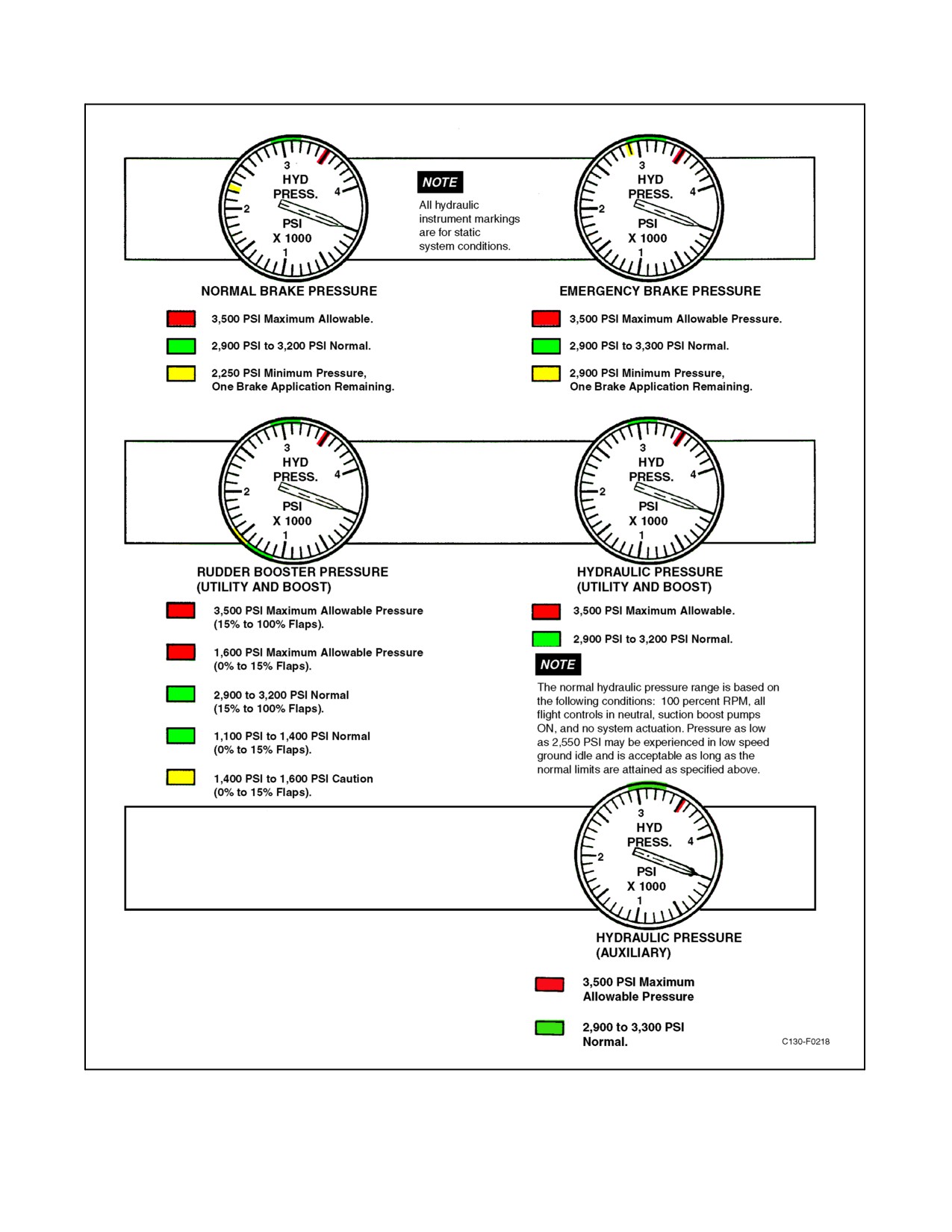
01-75GAL-1
Figure 4-1. Instrument Markings (Sheet 4)
4-5
ORIGINAL
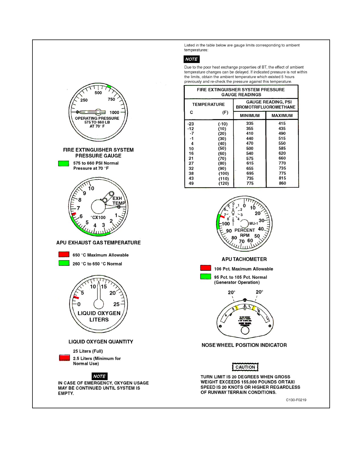
01-75GAL-1
Figure 4-1. Instrument Markings (Sheet 5)
ORIGINAL
4-6
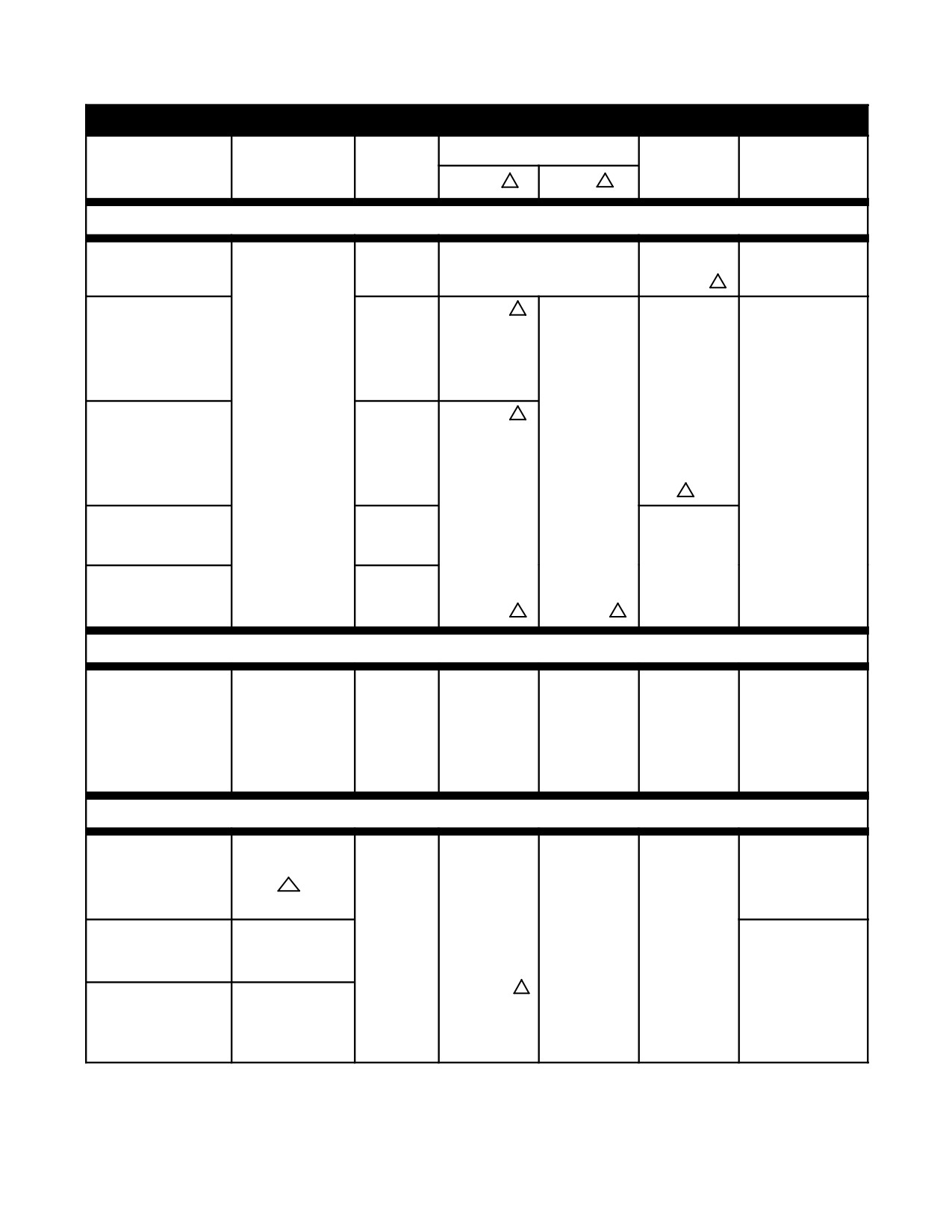
01-75GAL-1
ENGINE LIMITS
OIL PRESSURE (PSIG)
MAXIMUM
INDICATED
ENGINE CONDITION
TIT °C
RPM %
R/G 1
P/S 1
OIL TEMP °C
TORQUE IN-LB
GROUND OPERATION
720 °C - 830
°C
Positive oil pressure
100
START LIMITS
indicated by 35% rpm
-40
5
75.5
250
2
100
100 For
Minimum until oil
69.0
50
(warmup only)
30 minutes
temperature is
LOW SPEED
(flight idle and
above 0 °C
GROUND IDLE
below)
(start position)
then 85
60 to 85
60
102
250
2
Note
94
HIGH SPEED
-54 to -40
GROUND IDLE
for start and
(start position)
warmup
only
5
106
100 maximum
MAXIMUM
96
for 30 minutes
REVERSE (0°)
then 85
4,500 maximum at
FLIGHT
100.5
oil temperature
IDLE (34°)
92.5
150
3
50
4
0
0 to +40 °C
TAKE-OFF
TAKE-OFF
1083
102
250
100
100 for
90° throttle
(5
minutes max)
(warmup only)
5 minutes,
position
then:
85
19,600
60
60 - 85
40 and
1067
98
150
50
increasing
FLIGHT OPERATION
MILITARY
1049
102
250
100
100 for
19,600
(30 minutes)
(warmup only)
5 minutes,
then:
6
85
60
60 - 85
CLIMB
1010
19,600
Note
DURING AIR-
98
150
8
50
40 and
MAXIMUM
1010
START, 4,500 IS
CONTINUOUS
increasing
MAXIMUM AT OIL
TEMPERATURE
OF 0 TO +40 °C
Figure 4-2. T56-A-16 Engine and Propeller Limitations (Sheet 1 of 2)
4-7
ORIGINAL
01-75GAL-1
OVERTEMPERATURE OPERATION
STARTING OVERTEMPERATURE
CONDITION
ACTION REQUIRED
TIT exceeds 830 _C (excluding momentary overshoot
Record the discrepancy.
and peak at 94% rpm)
TIT exceeds 850 _C (excluding momentary peak at
Discontinue the start and record the discrepancy. One
94% rpm)
restart is permitted after cooling to below 200 _C TIT. If
TIT exceeds 850 _C on second start, discontinue start
and record. Restart is not recommended.
TIT exceeds 965 _C
Discontinue the start and record the discrepancy. (An
overtemperature inspection is required.)
A torch other than normal enrichment burst requires an overtemperature inspection.
POWER ACCELERATION PEAK
Exceeds 1,083 _C for more than 5 seconds or exceeds
Reduce power to hold temperature within limits. Record
1,175 _C momentarily.
the discrepancy. (Overtemperature inspection required
before next flight.)
STARTER OPERATING LIMITS
1 minute ON, 1 minute OFF, 1 minute ON, 5 minutes OFF, 1 minute ON, 30 minutes OFF.
Release starter switch at 60% rpm. Start valve open light should extinguish within 15 seconds after switch is released.
PROPELLER GOVERNING LIMITS
NORMAL LIMITS (Normal Or Mechanical Operation) 98.0 - 102.0 percent.
If stable rpm cannot be maintained (excluding allowable fluctuation of ±0.5 percent), refer to PROPELLER
MALFUNCTIONS in Part V.
PROPELLER AUXILIARY PUMP OPERATING LIMIT
1 minute ON, 1 minute OFF, not to exceed 2 minutes operation in any 30 minute period.
Notes
1
Under stabilized conditions, allowable fluctuation is
5
–54 _C is the minimum oil temperature for MIL-L-7808 oil.
±10 psi for the power section and ±20 psi for the
-40 _C is the minimum oil temperature for MIL-L-23699
reduction gear section.123456
oil.
2
250 psi may be exceeded during start and warmup with
6
Use only when mission requirements demand higher power.
ambient temperature below 15 _C.
3
Operation below 150 psig when rpm is below 100 percent
7
Underscored values on sheet 1 denote limits; values not
is permitted if 150 psig can be maintained at 100 percent
underscored on sheet 1 denote normal operating values.
rpm.
All limits on this Figure are flight station limits and are not
to be confused with maintenance manual limits.
4
If pressure is below 50 psig at low-speed ground idle,
8
Operation between 130 psi and 150 psi at 100 percent
condition is acceptable provided pressure is within limits
RPM is permitted until completion of the flight, but shall
at 100 percent rpm.
be corrected prior to the next flight.
Figure 4-2. T56-A-16 Engine and Propeller Limitations (Sheet 2)
ORIGINAL
4-8
01-75GAL-1
4.5
FUEL UNBALANCE LIMITS
If fuel weight becomes unbalanced through varied rates of consumption or from having an engine shut down, periodic
trimming is required. The fuel unbalance limits are:
1.
1,000 pounds between tanks of a symmetrical pair (main or external).
2.
500 to 1,000 pounds more in an outboard tank than an inboard tank.
3.
1,500 pounds between the left and right wings except as stated in item 4.
4. One auxiliary tank full and the other auxiliary tank empty, provided all other tanks are symmetrically fueled
or unbalanced toward the opposite side within the above limits.
4.6
FUEL
TheapprovedemergencyfuelsfortheT56-A-16enginearelistedinorderofpreferenceinFigure4-3.Mixing ofthese
fuels with each other is permissible. In this case, the mixture will be considered as the grade that predominates in
the mixture if it is at least 95 percent, and all operations will be in accordance with the operating instructions for that
grade. If the mixture is less than 95 percent, consider the fuel to be the one with the least desirable characteristics.
If it is necessary to use aviation gasoline with turbine fuels, foaming may occur.
CAUTION
D NATO fuels F-34, F-35, F-42, and F-44 should not be used if operating
temperatures below -55 _F are anticipated.
D The presence of even relatively small quantities of TCP result in severe
erosion, scaling, and pitting of the first-stage turbine nozzle vanes and the
turbine inlet thermocouples. Automotive gasoline is not acceptable
because of common use of TCP and a variety of other undesirable additives.
The use of aviation gasoline containing tetraethyl lead (grades 80/87,
100/130, and 115/145) should be held to the minimum necessary because
of the heat-absorbing quality of the lead coating that is deposited in the
turbine section. If engines are operated for 50 hours with leaded gasoline,
the turbine blades must be inspected for possible overheat damage. When
aviation gasoline is used, decreased lubrication of all fuel components can
be expected. Further, continued use of aviation gasoline will result in
engine power loss and decreased engine operating efficiency.
The engine power available when using different fuels is not affected in electronic fuel scheduling since a specific
TIT is scheduled for each throttle position. However, external temperature datum valve adjustment may be necessary
for consistent engine starts when using JP-5/JP-8-type fuels (F-44 or F-34).
When attempting a start with JP-5/JP-8 and kerosene-type fuels at ambient
temperatures below -37 _C, the TIT and rpm should be closely monitored
since stall and over-temperature may be experienced during the start.
4-9
ORIGINAL
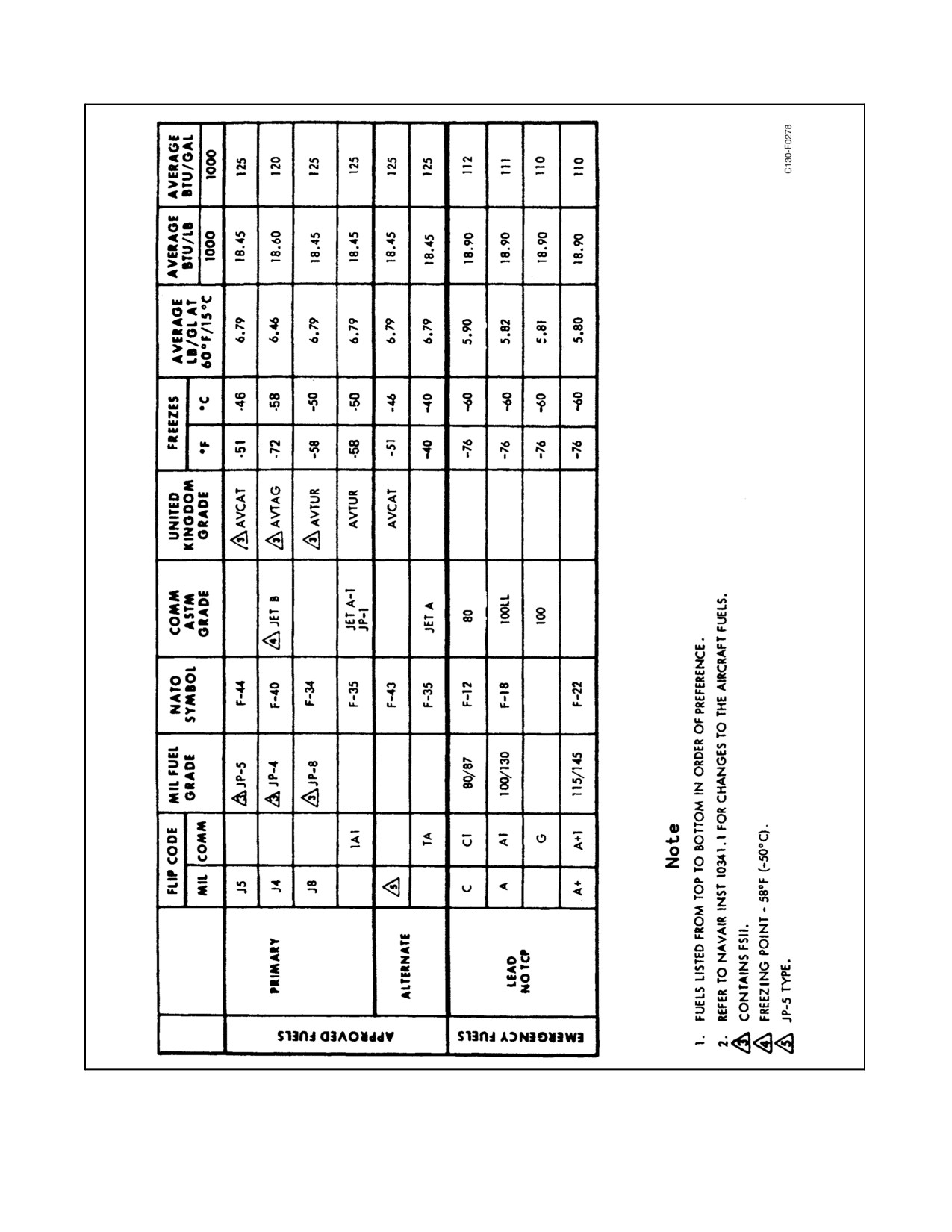
01-75GAL-1
Figure 4-3. Fuel Performance and Cross-Reference/Aviation Turbine Fuel Brand Names (Sheet 1 of 2)
ORIGINAL
4-10

01-75GAL-1
OIL COMPANY
PRODUCT NAME
ASTM DESIGNATION
AMERICAN
AMERICAN JET FUEL TYPE A
JET A
AMERICAN JET FUEL TYPE A-1
JET A-1
ATLANTIC RICHFIELD
ARCOJET A
JET A
ARCOJET A-1
JET A-1
ARCOJET B
JET B
BP TRADING
BP A T K
JET A-1
BP A T G
JET B
BRITISH AMERICAN
B-A JET, FUEL JP-1
JET A
B-A JET, FUEL JP-4
JET B
CALIFORNIA TEXAS
CALTEX JET A-1
JET A-1
CALTEX JET B
JET B
CITIES SERVICE
TURBINE TYPE A
JET A
CONTINENTAL
CONOCO JET-40
JET A
CONOCO JET-50
JET A
CONOCO JET-60
JET A-1
CONOCO JP-4
JET B
EXXON
EXXON (ESSO) TURBINE FUEL A
JET A
EXXON (ESSO) TURBINE FUEL A-1
JET A-1
EXXON (ESSO) TURBINE FUEL B
JET B
MOBIL
MOBIL JET A
JET A
MOBIL JET A-1
JET A-1
MOBIL JET B
JET B
PHILLIPS
PHILJET A-50
JET A
PHILJET JP-4
JET B
PURE
PUREJET TURBINE FUEL TYPE A
JET A
PUREJET TURBINE FUEL TYPE A-1
JET A-1
SHELL
AEROSHELL TURBINE FUEL 640
JET A
AEROSHELL TURBINE FUEL 650
JET A-1
AEROSHELL TURBINE FUEL JP-4
JET B
STANDARD OF CALIFORNIA
CHEVRON JET FUEL A-1
JET A-1
CHEVRON TURBINE FUEL B
JET B
STANDARD OF TEXAS
STANDARD TURBINE FUEL A-1
JET A-1
STANDARD TURBINE FUEL B
JET B
STANDARD OIL CO
STANDARD JET A
JET A
STANDARD JET A-1
JET A-1
STANDARD JET B
JET B
STANDARD (OHIO)
JET A KEROSENE
JET A
JET A-1 KEROSENE
JET A-1
TEXACO
TEXACO AVJET A
JET A
TEXACO AVJET A-1
JET A-1
TEXACO AVJET B
JET B
UNION OIL
76 TURBINE FUEL
JET A-1
UNION JP-4
JET B
Figure 4-3. Fuel Performance and Cross-Reference/Aviation Turbine Fuel Brand Names (Sheet
2)
4-11
ORIGINAL

01-75GAL-1
CAUTION
When ambient temperature is below -25 _F and it is anticipated that
JP-5/JP-8 will be used, some JP-4 should be reserved for starting the
engines and APU. If JP-4 is not available, the JP-5/JP-8 should be mixed
with at least 10-percent aviation gasoline. To do this, add the aviation
gasoline first, then finish filling with JP-5/JP-8.
4.6.1 High Rates of Climb
When using high-volatility fuels, high rates of climb may create a fuel boiling-venting problem. The rate of climb
should berestricted to thevalues shown inFigure4-4,depending onthefuelused andthefueltemperature(allfigures
estimated).
Note
The presence of small quantities of aviation gasoline in turbine fuel can
trigger foaming.
FUEL TEMPERATURE,
NATO
TYPE OF FUEL
START OF MISSION
RATE OF CLIMB
SYMBOL
JP-8
Up to 135 _F
Not restricted.
F-34
JP-5
Up to 135 _F
Not restricted.
F-44
JP-4
Up to 125 _F
Not restricted.
F-40
125 to 135 _F
Maximum rate of climb to 29,000 feet. Above
29,000 feet, 300 feet per minute.
Aviation Gasoline
80 to 90 _F
Maximum rate of climb to 30,000 feet. Above
F-12
30,000 feet, 300 feet per minute.
F-18
90 to 100 _F
Maximum rate of climb to 24,000 feet. Above
F-22
24,000 feet, 300 feet per minute.
100 to 110 _F
Maximum rate of climb to 18,000 feet. Above
18,000 feet, 300 feet per minute.
110 to 120 _F
Maximum rate of climb to 14,000 feet. Above
14,000 feet, 300 feet per minute.
Figure 4-4. Fuel Versus Rate of Climb
4.6.2 Effect of Emergency Fuel on Range
The BTU content per pound of all fuels does not vary significantly; therefore, the range will depend on the pounds
of fuel aboard.
4.6.3 Fuel Boiloff
When using high-volatility fuels, loss of fuel can be incurred during climb by boiloff because of volatility and by
slugging. Slugging occurs as a result of fuel frothing and departing vapors entraining large quantities of froth while
ORIGINAL
4-12

01-75GAL-1
spewing from the vents. Foaming tendencies are aggravated by high initial fuel temperatures, high rates of climb,
and at high altitude.
JP-4 is arelatively low-volatility fuel; however, at very high fuel temperatures, high rates of climb, and high altitude,
boiloff and slugging can occur.
JP-5/JP-8 fuel is characterized by low volatility; therefore, boiloff and slugging are unlikely. The following table
demonstrates the estimated loss of range because of boiloff when using aviation gasoline:
APPROXIMATE LOSS OF RANGE WHEN CLIMBING TO
FUEL
THESE CRUISE ALTITUDES
TEMPERATURE
25,000
35,000
125 °F
12 percent
20 percent
110 °F
8 percent
15 percent
90 °F
3 percent
10 percent
70 °F
0 percent
5 percent
4.7
AIRSPEED LIMITATIONS
The limiting airspeed for a mission is interrelated with the cargo weight and maneuver load factors required for the
mission and the gust load that may be encountered in turbulence. Recommended and maximum airspeeds are shown
in Figure 4-6. These speeds are referenced to specific cargo-fuel (see Figure 4-5) combinations or gross weights on
the weight limitations charts and to the allowable maneuver load factors. Any cruise speed up to the recommended
speed may be utilized up to and including moderate turbulence.
The maximum speed should never be exceeded. The maneuver load factors
and the weight distribution shown on the weight limitations charts (see
Figure 4-6) should also be observed carefully.
Note
D If more than 2.5_ of aileron tab deflection is required to trim unsymmetrical
fuel at speeds faster than 200 KIAS, reduce VH to 5 KIAS less than shown
in Figure 4-6, as applicable.
D Operation in the areas between recommended speed limits and maximum
speed limits is permissible for initiating penetrations from 20,000 feet at
250 KIAS, provided the corresponding maneuver load factors are not
exceeded.
The aircraft should not be operated in conditions of severe turbulence because gusts can be encountered that may
impose excessive loads. However, if flight in severe turbulence cannot be avoided, flight should be in the range of
65 knots above power-off stalling speed for the operating gross weight, not to exceed 180 KIAS (see Figure 10-1).
4-13
ORIGINAL
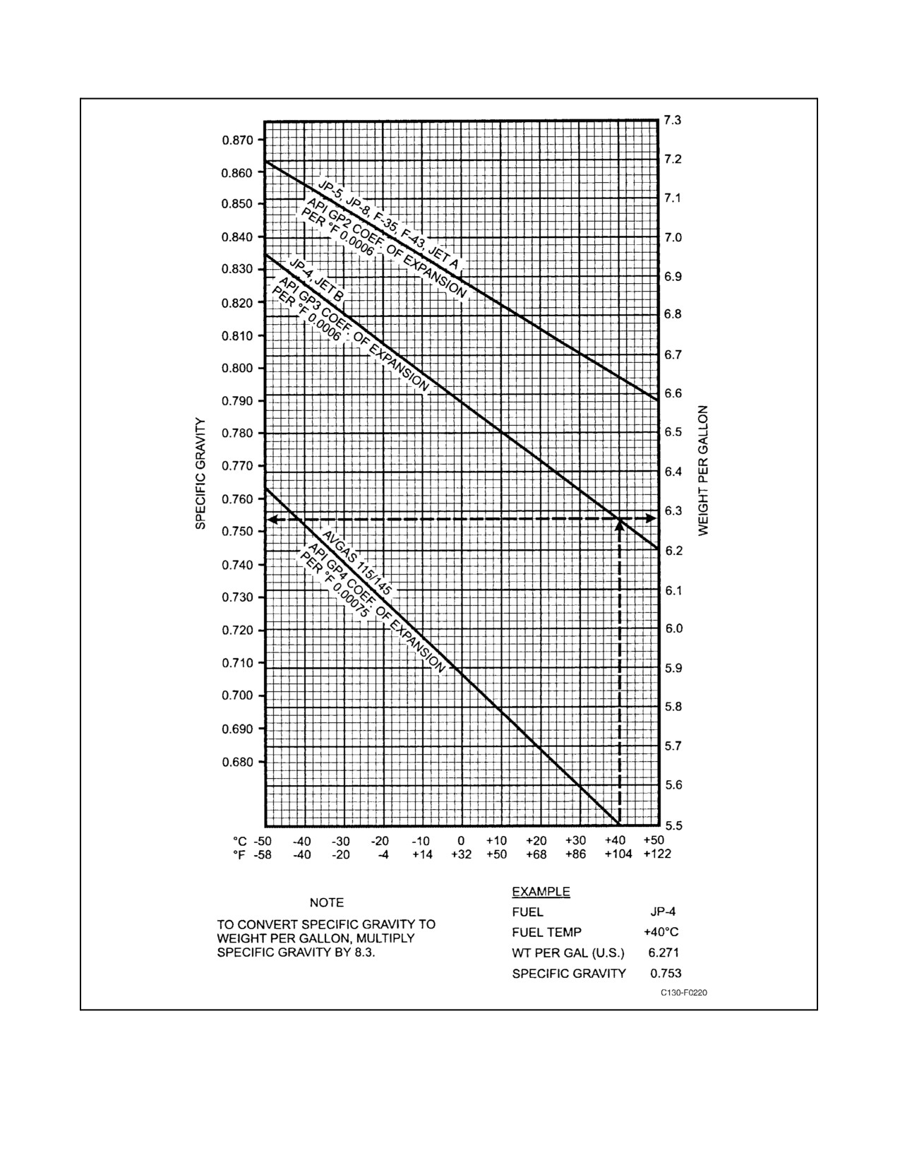
01-75GAL-1
Figure 4-5. Average Fuel Weight/Specific Gravity Temperature
ORIGINAL
4-14
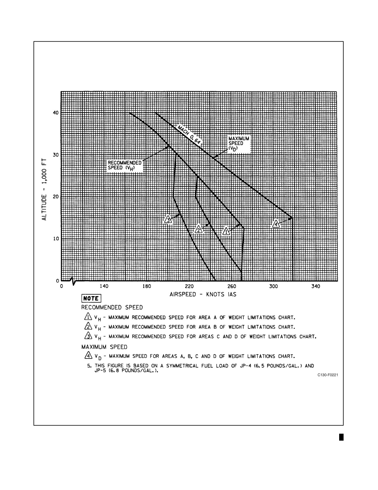
01-75GAL-1
Figure 4-6. Limit Flightspeed Versus Altitude and Weight Limitations (Sheet 1 of 5)
4-15
ORIGINAL W/IC 8
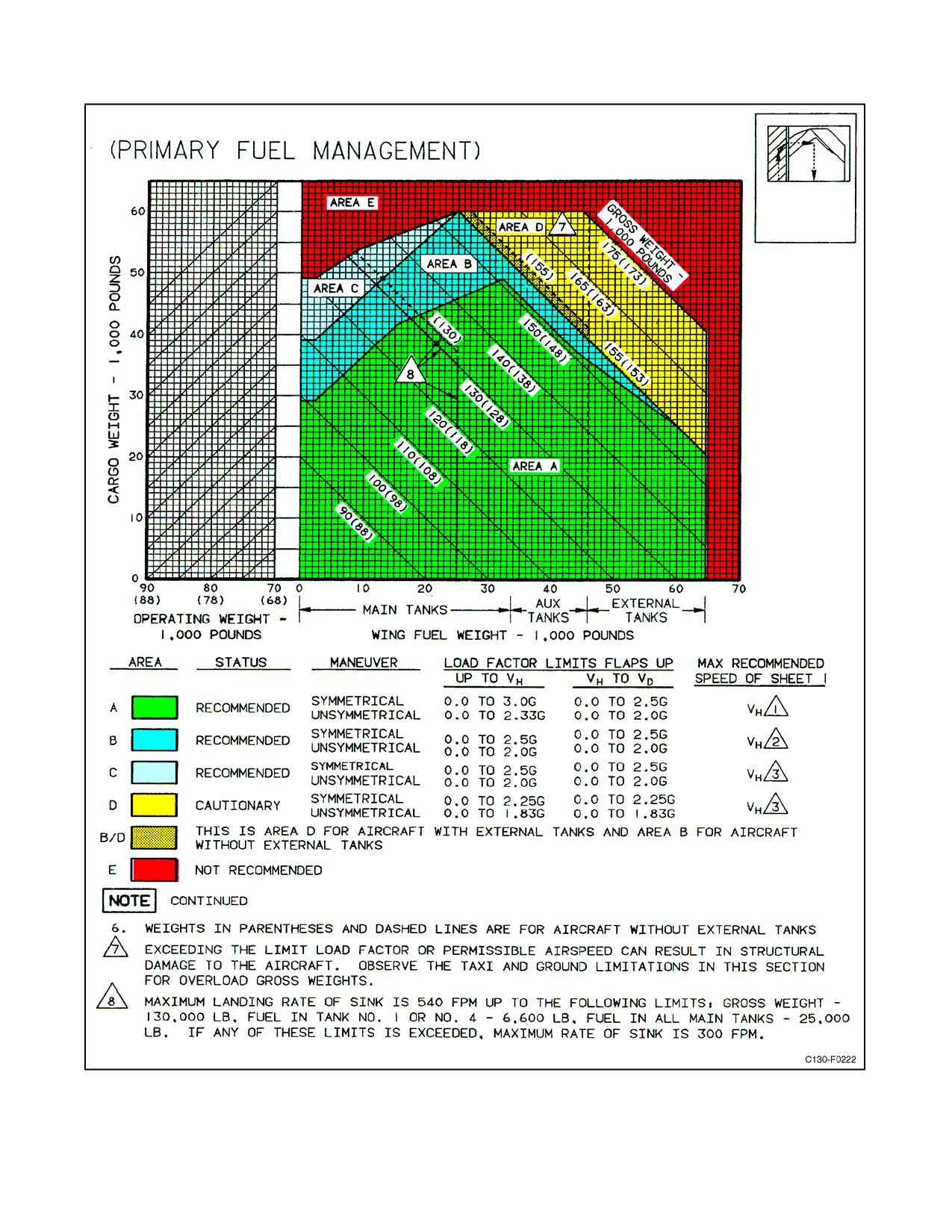
01-75GAL-1
Figure 4-6. Limit Flightspeed Versus Altitude and Weight Limitations (Sheet 2)
ORIGINAL
4-16
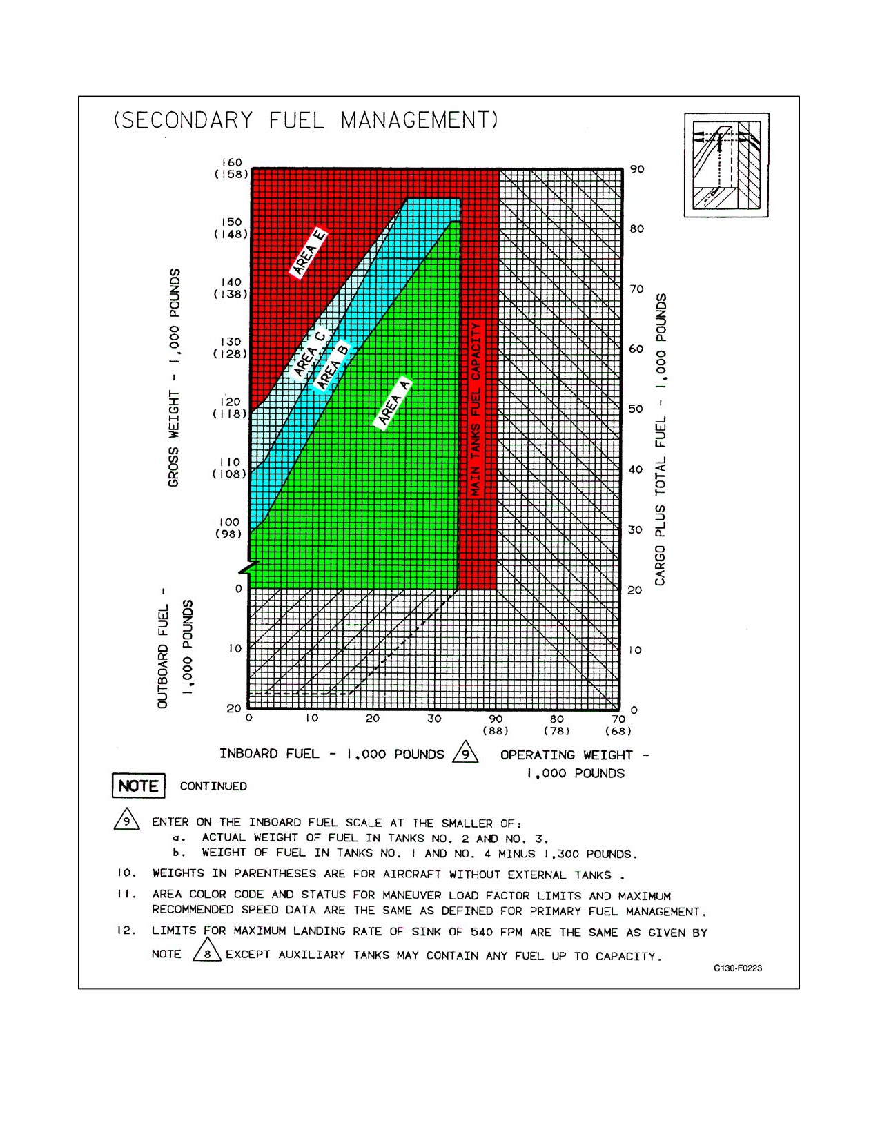
01-75GAL-1
Figure 4-6. Limit Flightspeed Versus Altitude and Weight Limitations (Sheet 3)
4-17
ORIGINAL
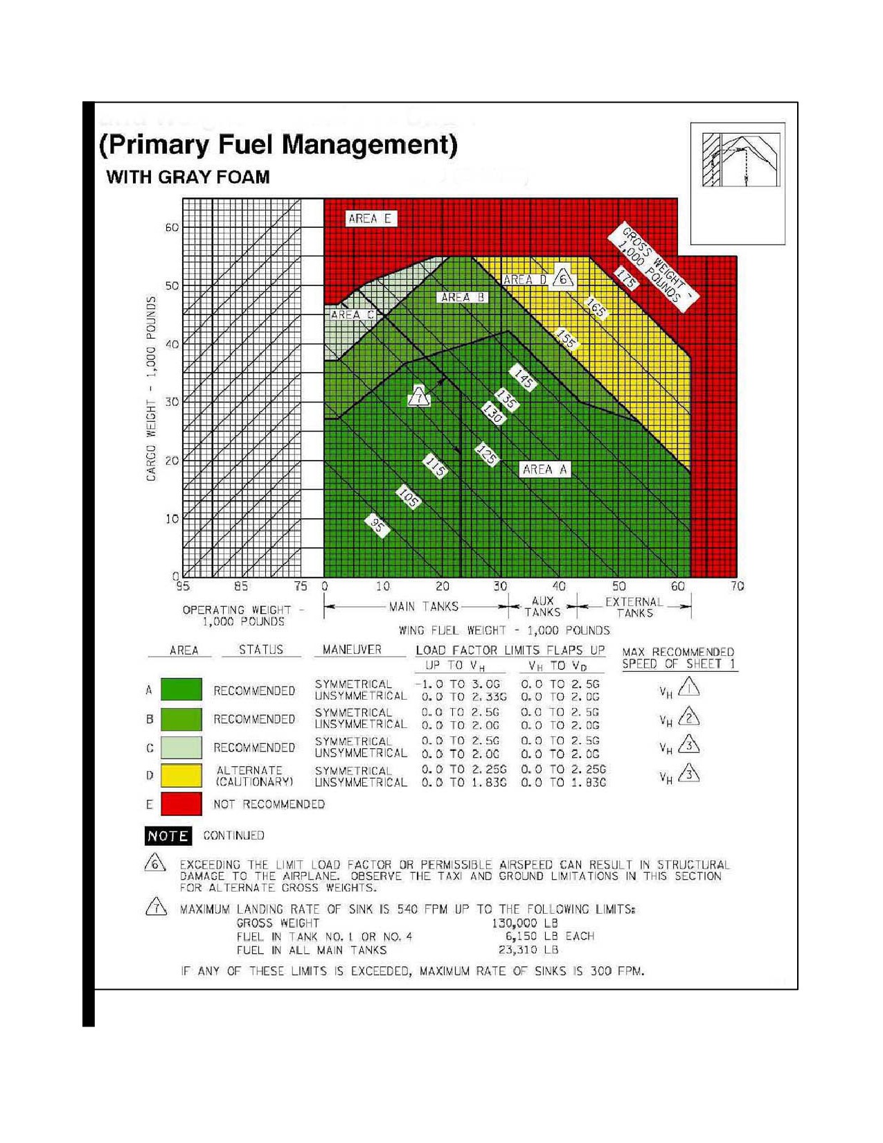
01-75GAL-1
Figure 4-6. Limit Flightspeed Versus Altitude and Weight Limitations (Sheet 4)
ORIGINAL W/IC 8
4-18
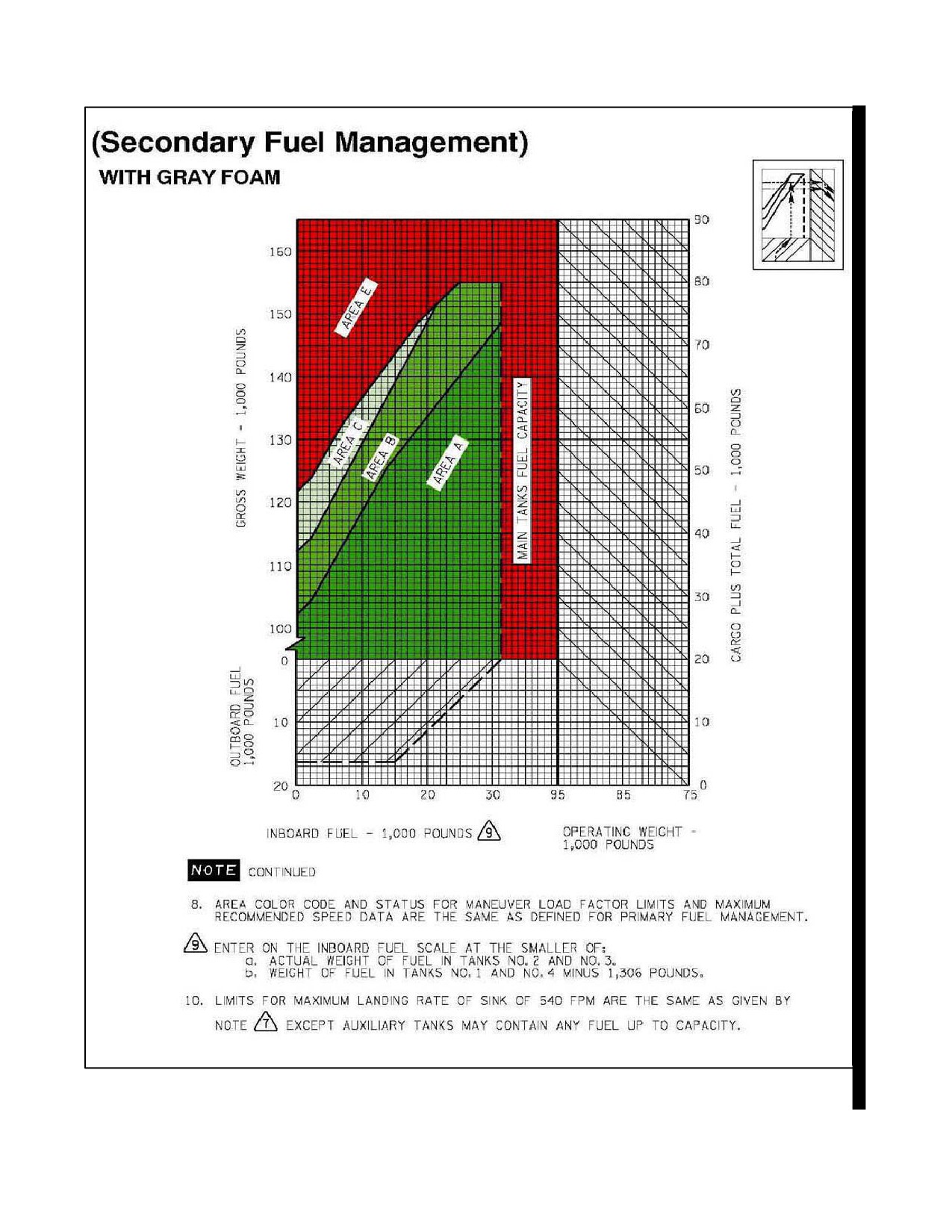
01-75GAL-1
Figure 4-6. Limit Flightspeed Versus Altitude and Weight Limitations (Sheet 5)
4-18a
W/IC 8

01-75GAL-1
Never exceed the following airspeeds for the condition noted:
1. Flaps extended.
PERCENTAGE
AIRSPEED (KIAS)
CAUTION
Avoid abrupt or full-rudder deflection with the flaps lever positioned 15 percent or greater (high rudder
boost) and airspeed 210 KIAS or greater.
10
220
20
210
30
200
40
190
50
(takeoff)
180
60
165
70
155
80
150
90
145
100
(landing)
145
2. Landing gear extended — Do not exceed 170 KIAS with the landing gear extended.
3. Landing lights extended — 170 KIAS.
4. Autopilot operation.
a. Do not operate with the autopilot engaged during takeoff and landing.
b. During ILS coupled approach, do not operate with the autopilot engaged below 200 feet AGL.
c. Do not operate with the autopilot engaged at gross weights above 155,000 pounds.
5. Fuel distribution.
CAUTION
If the total fuel in both external tanks exceeds 9,355 pounds in combination
with less than 25,000 pounds of internal wing tank fuel, do not exceed 290
KIAS.
W/IC9
4-18b