C-130T. FLIGHT MANUAL (2006) - page 10
01-75GAL-1
c. Wing structure, aileron, trim tab.
d. Flaps, flapwell.
e. Engine exhaust areas.
f. External fuel tank:
(1) General condition, fuel leaks.
g. Liferafts (visual scan).
6.
Aft fuselage and empennage — Checked:
a. Paratroop doors.
b. Tailskid.
c. Exterior structure.
d. Cargo ramp and door.
e. Tail structure and control surfaces.
f. Safety valve.
7.
No. 1 and 2 engines, nacelles, propellers, left wing — Checked:
a. Liferafts (visual scan).
b. External fuel tank — General Condition, Fuel Leaks.
c. Engine exhaust areas.
d. Flaps, flap well.
e. Wing structure, aileron, trim tab.
f. Propeller spinner and blades.
g. Nacelle exterior structure — General Condition, Fluid Leaks.
8.
Left wheelwell and center fuselage — Checked:
a. Hydraulic ground test valve — Pinned, Door Secured.
b. Left main landing gear, wheelwell area:
(1) Wheels, tires.
(2) Struts, jackscrews.
(3) Brakes, hydraulic lines.
(4) Structure — General Condition.
8-27
ORIGINAL
01-75GAL-1
c. Exterior Structure — General Condition.
d. APU area — Intake, Exhaust.
9. Forward fuselage, left side and bottom — Checked:
a. Exterior structure — General Condition.
8.3
COCKPIT CHECKLIST
This checklist shall be completed prior to the Before Start Checklist and shall be completed by the flight engineer
prior to other crewmembers assuming their respective crew positions. A crewmember shall remain at the aircraft after
completion of this checklist. If this checklist is completed and the aircraft does not fly, complete the After Landing,
Secure, and the Before Leaving the Aircraft Checklists.
1. Nose landing gear pin and ground wire — Removed.
2. Propeller panel — Set:
a. FEATHER VALVE & NTS CHECK switch — VALVE.
b. Propeller feather override buttons — Out.
c. Propeller governing switches — As Required.
CAUTION
Circuit breakers that arepulled by maintenance personnel shall beclamped
and not reset until the proper repair has been made. Circuit breakers that are
out and not clamped shall be investigated.
Note
If the SURGE SUPPR PROT DEV FUSE on the pilot lower circuit breaker
panel has blown, indicated by the red pin appearing in the indicator
window, initiate maintenance action.
3.
Circuit breakers — Checked.
4.
Fuel panel — Set:
Note
Fuel boost pump pressure is required for all engine starts. If auxiliary/exter-
nal tank fuel is available, it may be utilized for start and taxi.
a. Dump pump switches — OFF.
b. Main tank BOOST PUMP switches — ON.
c. AUX/EXT tank BOOST PUMP switches — As Required.
ORIGINAL
8-28
01-75GAL-1
d. Main tank crossfeed valves — OPEN.
e. Auxiliary/external/bypass crossfeed valves — As Required.
f. Crossfeed separation valve — OPEN/As Required.
5.
Throttles — GROUND IDLE.
6.
Condition levers — GROUND STOP.
7.
SYNCHROPHASE MASTER switch — OFF.
8.
Temperature datum control valve switches — As Required.
8.4
BEFORE START
1.
Hot mike — ON (P) (CP) (FE).
2.
Cockpit Checklist — Complete (FE).
3.
Passengers — Briefed (LM).
4.
Electrical panel — Set (FE):
a. Engine generators — OFF.
b. Inverters — As Required.
c. Dc power switch — BATTERY.
d. Dc BUS TIE switch — Tied.
e. External ac power switch — External Ac Power (if available).
5.
Radios — ON, _____ Primary (CP).
Note
D The copilot shall state over the ICS which radio is being utilized for primary
communication prior to transmitting. All other crewmembers shall select
the primary radio on their respective ICS panel.
D When performing a self-contained start only, the radio required for
communication to ground shall be turned on. With isolated DC as the only
power source available, only UHF 1 and VHF 1 will operate.
D Regardless of maintenance status of the radio, all radios should beselected
“on” through CDNU to ensure operation of ISS.
6.
Lights — Set (FE):
a. Interior — As Required.
8-29
ORIGINAL
01-75GAL-1
b. Exterior:
(1) Anticollision — ON.
(2) Navigation — FLASH.
(3) Other lights — As Required.
7. Clear APU — Clear (LM).
CAUTION
D When starting the APU with battery power only, leave the dc BUS TIE
switch untied until the APU reaches 35 percent (start light out), then tie the
DC bus to arm the APU fire detection system.
D When operating the APU, monitor the wing and empennage anti-icing
indicators. An indication of a temperature rise means that an anti-icing
valve is open. The APU should be shut down as damage to a heated surface
or fuel tank sealant may occur.
Note
Once the loadmaster has cleared the APU, the flight engineer will start the
APU.
8.
APU panel — Set (FE).
Note
D Place the bleed-air switch to open 1 minute after the on-speed light has
illuminated.
D If the APU cannot be started, an external air source can be connected to the
external pressure connection for use in starting engines. Refer to this
chapter for external airstart procedures.
9.
APU generator — As Required (FE).
When switching on the APU generator, ensure the external power switch
automatically switches off. If the external power switch does not
automatically switch off, manually place the switch to off and record the
discrepancy. Failure of the external power switch to be switched off
automatically or manually will damage the switch and may lead to an
electrical fire.
ORIGINAL
8-30
01-75GAL-1
10. Inverters — Set (FE):
a. Copilot ac instruments inverter switch — ESSENTIAL AC BUS/ESS AV BUS.
b. Ac instrument and engine fuel control inverter switch — ESSENTIAL DC BUS.
11. Fuel quantity and distribution — Checked, ____ LBS (P) (FE).
Do not pull and clamp associated fuel quantity circuit breakers unless the
gauge is blank or the display is unusable. Refer to Chapter 2 for error codes.
Note
The pilot shall verify proper fuel distribution and state the total fuel. Refer
to Chapter 4 for fuel management and distribution.
12.
Oil cooler flaps — As Required (CP).
Note
D On aircraft 165313 and up, the oil cooler flaps should be in the AUTO
position for engine starts.
D On aircraft prior to
165313, the oil cooler flaps should be in the
OPEN/FIXED position for engine starts when the temperature is 27 _C (81
_F) or above.
13.
Ramp and door selector — 6N, NEUTRAL (LM).
14.
Hydraulic panel — SET, EMERGENCY SELECTED (CP):
Note
If utility system hydraulic pressure is indicated after the auxiliary hydraulic
pump is turned on and before starting the No. 2 engine, a malfunction of
thehydraulicground test valveis indicated. Theground test valve may still
be open.
a. BRAKE SELECT switch — EMERGENCY.
b. Auxiliary pump switch — ON/Pressure Up.
c. ANTI-SKID switch — ON.
d. Engine pump switches — ON.
e. SUCTION BOOST PUMP switches — ON/Lights Out.
CAUTION
Starting an engine with an inoperative suction boost pump may result in
damage to the engine-driven hydraulic pump.
8-31
ORIGINAL
01-75GAL-1
15. Parking brake — Set, Remove Chocks (P).
CAUTION
D To avoid engaging the brakes on only one side of the aircraft, the brakes
must be firmly depressed and held until the parking brakes are engaged.
Brakes are difficult to actuate and set because of the angle of the brake ped-
als to the operator’s feet.
D The parking brake handle shall be held firmly until the brakes are set. Do
not allow the handle to release and slam against the stops.
Note
Depress pedals individually and monitor the emergency brake pressure
gauge for a pressure drop as each pedal is depressed.
16.
Oxygen — Checked, OFF (All):
Note
To expedite checklist completion, the oxygen system check should be
performed upon arrival at the aircraft.
a. Inspect hose, mask, and regulator for cleanliness and damage.
b. Hold mask facing away from yourself.
c. Position the supply lever to ON.
d. Connect the ICS cord. Hold the emergency lever to the TEST MASK position and key the ICS button.
Release the ICS button and emergency lever and disconnect the ICS cord. The pilot, copilot, and flight
engineer ICS cords shall remain connected.
e. Disconnect the mask from the hose assembly and blow slightly into the hose.
Note
Back pressure indicates a properly functioning regulator.
f.
Reconnect hose to mask.
g. Diluter lever — 100%.
h. Emergency toggle lever — EMERGENCY.
i.
Place mask over nose and mouth and breathe for a minimum of three cycles. The blinker shall show
alternately black and white.
j.
Hold breath momentarily; blinker should remain black. Return the emergency toggle lever to NORMAL.
The blinker should remain black.
ORIGINAL
8-32
01-75GAL-1
k. Breathe for a minimum of three cycles. Leave the regulator in the following positions:
(1) Emergency toggle lever — NORMAL.
(2) Diluter lever — 100%.
(3) Supply lever — OFF.
(4) Oxygen mask — Connected.
17.
GROUND IDLE buttons — LOW (FE).
18.
Flap lever — Set (CP).
Note
Set flap lever to correspond with flap position indicator.
19.
Chocks, nose pin — Removed (LM).
Note
Theaircraft commanderand flight engineershall visually confirm nosepin
removal and placement in the flight station.
20.
INS, GPS — As Required (CP) (FE).
8.5
STARTING ENGINES
The normal engine starting sequence is 3, 4, 2, 1. If at any time a “stop start” is required, the condition lever will be
placed to GROUND STOP prior to releasing the START switch. The term “on speed” is used to indicate that the
engine is stabilized in low-speed ground idle.
1. Clear No. 3 engine — No. 3 Clear (LM); Turning 3 (P), Rotation (LM).
a. ENGINE BLEED AIR switch — OVERRIDE.
b. Condition lever — RUN.
CAUTION
D Do not start an engine if the start valve open light is illuminated prior to
actuating the ENGINE GROUND START switch.
D If the start valve open light does not illuminate within 5 seconds after the
ENGINE GROUND START switch is placed in START, discontinue the
start. Maintenance action is required.
D If the propeller does not rotate within 5 seconds after the ENGINE
GROUND START switch is placed in START and the start valve open
light is illuminated, stop start. Maintenance action is required prior to
another start attempt. Repeated attempts to start may result in internal
starter damage.
8-33
ORIGINAL
01-75GAL-1
c. ENGINE GROUND START switch — START:
(1)
Place the ENGINE GROUND START switch to the START position and hold. The start valve open
light should illuminate within 5 seconds.
(2)
The starting cycle is automatic and requires no further action if the engine accelerates smoothly and
continuously, TIT is normal (720 to 830 _C), and the engine stabilizes on speed within 1 minute.
(3)
Monitor the engine instruments continuously during start. Keep one hand on the condition lever and
the other on the START switch of the engine being started. Be prepared to stop start immediately if an
abnormal indication is observed.
(4)
The loadmaster will monitor the propeller. If no rotation is observed within 5 seconds after the pilot
states, “Turning,” the loadmaster will state, “Negative rotation.”
Note
D
During start ofthefirst engine, check thebleed-airmanifold pressure at 10-
to 16-percent rpm. If the pressure is less than 32 psi but equal to or more
than 22 psi, continue the start and record the discrepancy. If the pressure
is less than 22 psi, stop start and initiate maintenance action. The engine
start time limit is 60 seconds from propeller rotation to low-speed ground
idle.
D
Do not perform an engine start if the TIT is above 200 _C. TIT may be
brought below 200 _C by motoring the engine with the starter while the
condition lever is in GROUND STOP.
D
If a malfunction occurs that requires discontinuing the start, the pilot,
copilot, flight engineer, or loadmaster shall call “Stop start” and state the
malfunction.
D
If the propeller does not rotate, reduce bleed-air manifold pressure below
45 psi and attempt another start. The bleed-air manifold pressure may be
reduced by turning off engine bleed air and using APU bleed air.
D
If the engine does not light-off before 35-percent rpm or maximum
starter-motor rpm is reached, discontinue the start.
D
If the propeller rpm stagnates or begins to decay, a stalled start is occurring.
Stop start. Do not engage the starter again unless the propeller has stopped
rotating. Motor the engine to approximately 25-percent with the condition
lever in GROUND STOP to remove unburned fuel from the turbine before
attempting another start.
D
The sequence of events on a stalled start is the same as a normal start until
the beginning of a stall, which is indicated by slower than normal
acceleration in the 36- to 50-percent range. TIT will be at or close to the
start-limiting temperature of 830 _C, and fuel flow will decrease as the
temperature datum system performs a take operation to prevent TIT from
exceeding 830 _C. Rpm will usually stagnate during this take operation,
and when the temperature datum system has taken fuel to its full capability,
an overtemperature may occur and rpm will begin to decay. Stop start
immediately to prevent engine damage. If the rpm has not reached
starter-release speed, the starter may be left engaged after the condition
lever has been placed to GROUND STOP to continue airflow through the
engine.
ORIGINAL
8-34
01-75GAL-1
(5) During normal start, the following sequence (b) through (j) shall be observed and called on the ICS by
the flight engineer. The loadmaster shall call rotation:
(a) Rotation — Rotation should be indicated on the tachometer within 5 seconds of switch actuation.
(b) Fuel flow — If fuel enrichment is not selected, fuel flow will increase to approximately 300 pph
followed by a rise in TIT. If fuel enrichment is selected, fuel flow will be approximately 500 to 1,500
pph.
(c) Ignition — Ignition should follow fuel flow indication and be indicated by a rise in TIT by
35-percent rpm.
(d) Oil pressures — Positive oil pressures will be indicated by 35-percent rpm.
(e) Hydraulic pressure — Indication of pressure by propeller on speed in low-speed ground idle.
(f) Parallel — Engine fuel pumps in parallel operation, indicated by secondary fuel pump pressure light
ON.
(g) Starter — Release switch at 60-percent rpm.
(h) Series — Engine fuel pumps in series operation, indicated by the secondary fuel pump pressure light
out and a drop in TIT at approximately 65-percent rpm.
(i) Peak TIT — Peak TIT is the highest indicated temperature observed during the slow steady increase
of indicated temperature and is exclusive of the momentary overshoot normally experienced at
approximately 94-percent rpm.
(j) Stable start.
CAUTION
D If there is no positive indication of oil pressure from the reduction gearbox
or engine power section by 35-percent rpm, immediately stop start.
D After moving a condition lever to GROUND STOP, do not move the lever
again until propeller rotation has ceased. Moving a condition lever from
GROUND STOP to RUN while the engine rpm is decreasing could result
in damage to the engine. Do not reengage the starter until rotation has
stopped.
D Throttles must not be moved out of the GROUND IDLE detent during
engine ground start. The resultant increase in propeller blade angle will
reduce the engine acceleration.
(6)
At approximately 16-percent rpm, fuel flow will be indicated and light-off will follow. The secondary
fuel pump pressure light may illuminate momentarily, then go out. The light will illuminate again
before the engine reaches 65-percent rpm.
Note
If light-off is not achieved on the first start attempt, fuel enrichment may
be used on the second start. Do not use fuel enrichment if the engine
indicates a TIT of 100 _C or more prior to start. TIT may be brought below
100 _C by motoring the engine. Do not select fuel enrichment after starter
engagement.
8-35
ORIGINAL
01-75GAL-1
(7) The ENGINE GROUND START switch shall be released at 60-percent rpm.
CAUTION
D The starter regulator valve is deenergized when the START switch is re-
leased. When the START switch is released, look for a rise in bleed-air
manifold pressure or a cutback in TIT in the engine supplying air to confirm
that the starter regulator valve has closed. Verify that the start valve open
light extinguishes within 15 seconds of switch release.
D If a positive rise in bleed-air manifold pressure or a cutback in TIT is not
noted when the START switch is released, move the condition lever to
GROUND STOP and close the respective engine bleed-air valve. To
determine whether the starter regulator valve closed, ensure that the
propeller is not rotating and reopen the bleed-air valve with the condition
lever in GROUND STOP. If the propeller begins to rotate, the starter
regulator valve is stuck open and the engine cannot be started without
damage. If the propeller does not rotate when the engine bleed-air valve is
opened, it may be assumed that the starter regulator valve is closed. In this
case, an engine start may be performed if a positive rise in the manifold
bleed-air pressure or a cutback in TIT occurs after the START switch is
released.
(8)
The secondary fuel pump pressure light will go out at approximately 65-percent rpm.
Note
Refer to Chapter 4 for engine start limitations.
(9)
The engine should accelerate to low-speed ground idle within 1 minute. If the engine rpm does not
stabilize on speed within 1 minute, discontinue the start. During extreme ambient conditions (high
altitude, high temperature), the starting air supply may be inadequate to stabilize the engine within the
time limit at low-speed ground idle (while start temperature remains within limits). Under these
conditions, the start may be continued beyond 60 seconds to 70 seconds, provided that the engine is
accelerating smoothly and at a constant rate. Discontinue start after 70 seconds (move condition lever
to GROUND STOP and record the discrepancy). If engine acceleration hesitates or appears to be
stagnating, the engine must be shut down immediately to avoid turbine damage since overtemperature
may exist downstream of the thermocouples.
d. Hydraulic pump and pressure — Pressure Up/Checked (CP):
Note
A positive indication of hydraulic pressure should be noted by the time the
engine is on speed, and normal operating pressure shall be indicated within
30 seconds after the engine is on speed. This check shall be accomplished
on the first flight of the day.
(1) After the No. 3 engine is on speed, check the No. 3 hydraulic pump by operating the flight controls.
Stabilize the controls and check that the static pressure is within limits.
(2) Turn the No. 3 hydraulic pump off and cycle the flight controls to bleed off residual pressure. Leave
the pump off.
ORIGINAL
8-36
01-75GAL-1
(3) After the No. 4 engine is on speed, check the No. 4 hydraulic pump as indicated in steps 1 and 2 above.
Turn the No. 3 and No. 4 hydraulic pumps on.
(4) After the No. 2 engine is on speed, check the No. 2 hydraulic pump as indicated in steps 1 and 2 above.
(5) After the No. 1 engine is on speed, check the No. 1 hydraulic pump as indicated in steps 1 and 2 above.
Turn the No. 1 and No. 2 hydraulic pumps on.
e. Low-speed ground idle — As Required (P) (FE).
Note
After the first engine is started and stabilized in low-speed ground idle and
all instruments indicate normal, reset the engine to normal ground idle and
allow the engine to stabilize. Use this engine as the starting air source for
the other engines.
f. Engine generator switch — ON (FE).
When switching on the engine generator, ensure the external power switch
automatically switches off. If the external power switch does not
automatically switch off, manually place the switch to off and record the
discrepancy. Failure of the external power switch to be switched off
automatically or manually will damage the switch and may lead to an
electrical fire.
Note
D When the engine is on speed, the flight engineer shall ensure that the engine
generator is developing proper voltage, place the engine generator switch
to ON, and state, “Generator on.” This indicates the copilot is clear to
continue the checklist.
D On aircraft 165313 and up, the engine generator must be placed on prior to
checking voltage.
2. APU generator — ON, Checked (FE).
When switching on the APU generator, ensure the external power switch
automatically switches off. If the external power switch does not
automatically switch off, manually place the switch to off and record the
discrepancy. Failure of the external power switch to be switched off
automatically or manually will damage the switch and may lead to an
electrical fire.
8-37
ORIGINAL
01-75GAL-1
Note
Check the voltage and frequency of the APU generator and place the switch
to ON. On aircraft 165313 and up, the APU generator must be placed on
prior to checking voltage. The APU generator must be on for low-speed
ground idle operation if the engine-driven generators are off line. If the
APU generator fails, the low-speed ground idle buttons must be disengaged
in order to prevent a drain on the battery.
3.
Dc power switch — BATTERY, Remove External Power (FE).
4.
Clear No. 4 engine — No. 4 Clear (LM); Turning 4 (P), Rotation (LM).
Note
Repeat steps 1a. through 1f. for all engines.
5.
AIR CONDITIONING master switch — NO PRESS (FE).
Note
After stabilization of the flight deck and cargo compartment temperatures,
the temperature controls may be operated in AUTO or MANUAL.
6.
External power and ground equipment — Removed, Clear (LM).
7.
Clear No. 2 engine — No. 2 Clear (LM); Turning 2 (P), Rotation (LM).
8.
Clear No. 1 engine — No. 1 Clear (LM); Turning 1 (P), Rotation (LM).
9.
ENGINE BLEED AIR switches — Set (FE):
Note
Check each engine bleed air regulator individually using the following
procedure.
a. ENGINE BLEED AIR switches (for regulators not being checked) — OFF.
b. Throttles — GROUND IDLE/Normal Ground Idle Rpm.
c. Cargo compartment air-conditioner — ON.
d. Flight station air-conditioner — OFF.
e. APU bleed air — OFF.
f. Bleed-air pressure — Checked.
Note
If individual regulator pressures are not within approximately 3 psi of each
other, place all engine bleed-air switches to OVERRIDE or OFF as
required for takeoff.
ORIGINAL
8-38
01-75GAL-1
g. ENGINE BLEED AIR switches — As Required.
Note
Bleed-airpressureshould beapproximately 50 psi with all regulators in the
ON position.
10. Fuel panel — Set (FE):
Note
All fuel boost pumps and crossfeed valves shall be checked (if not
previously checked) prior to performing the following steps.
a. Crossfeed valves — Closed.
b. Crossfeed separation valve — Closed.
c. Boost pumps — OFF.
8.6
BEFORE TAXI (ONLY CIRCLED ITEMS NEED TO BE CHECKED AT OPERATIONAL STOPS)
CAUTION
During prolonged ground operation at high ambient temperatures, engine
oil temperaturemust bemonitored constantly. Useoil cooleraugmentation
to maintain lower oil temperatures. Ifengine oil temperatures approach the
upper limit, throttle settings must be increased to improve air circulation.
Note
D Refer to Chapter 4 for engine limitations.
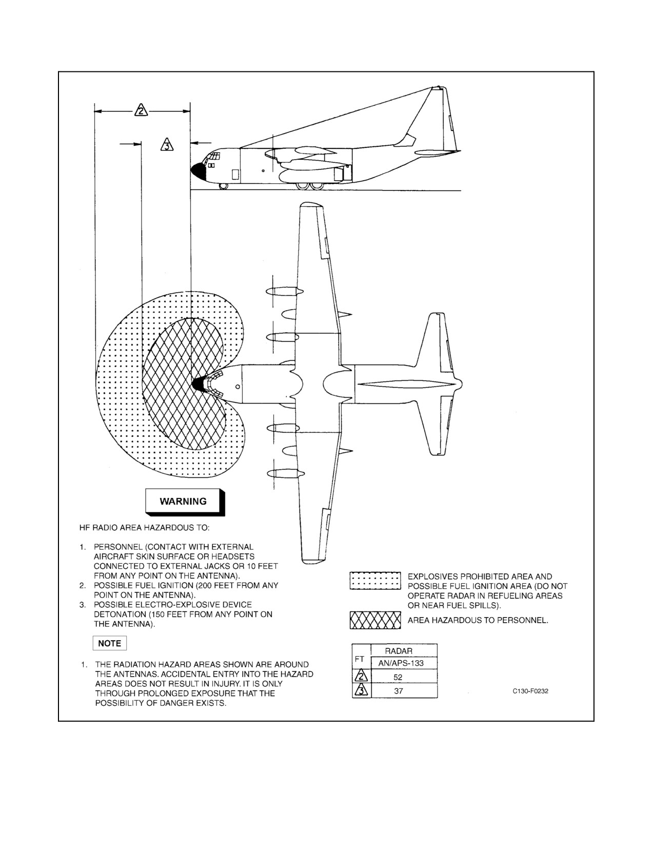
D See Figure 8-2 for radiation hazard area.
1.
ANTI-ICING — As Required (FE).
a. Wing and empennage anti-icing indicators — Normal (FE).
b. NESA Windshield anti-icing — As Required (FE).
2.
Radar and IFF transponder — STANDBY (P) (CP) (FE):
a. The pilot will verify that the radar is in STANDBY and that the radar indicator
(screen)
is
on and
operational.
b. The copilot will verify that the IFF transponder is in STANDBY.
c. The flight engineer will verify that the navigator station radar is in STANDBY.
3.
Compasses — Checked (state heading) (P) (CP):
a. The pilot will compare the headings of the No. 1, No. 2, and magnetic compasses and will state the heading
of the No. 1 compass. The pilot will also verify that the compass display switch is in the NORM position.
8-39
ORIGINAL
01-75GAL-1
Figure 8-2. Radiation Hazard Area
ORIGINAL
8-40
01-75GAL-1
b. The copilot will compare the headings of the No. 1 and 2 compasses and will state the heading of the No.
2 compass.
c. The flight engineer will verify that the latitude N-S switch is in the appropriate hemisphere, the latitude
knobissettothelocallatitude,andtheNo.1 and2 compassheadings matchthosedisplayedat thenavigator
station. No flight engineer response is required unless a discrepancy exists.
4.
Attitude select switches — Checked (P) (CP):
a. Press the attitude select switches. Check that the GYRO ATT lights illuminate, ADI flags are not in view,
and proper attitude references are displayed.
b. Press the attitude select switches and observe that normal INS ATT indications return.
5.
Ground proximity warning system — Set (CP):
a. Flap override switch — NORM.
6.
Flaps — 50 Percent (CP):
a. Move the flaps to 0 percent then to 50 percent and note normal operation of the rudder boost system.
7.
Ground equipment — Clear (P) (CP) (LM).
8.
Crew aboard — Aboard, Doors Closed and Checked (LM).
Check the hooks on the crew entrance door to see that they contact the
eyebolts. The hooks may be slightly loose as long as contact is made.
9. Hydraulic pressures and quantities — Checked (CP) (LM).
10. Oil cooler augmentation — As Required (FE).
CAUTION
On aircraft prior to 165313, the oil cooler flaps shall be fully open and
switches FIXED before activating oil cooler augmentation. On aircraft
165313 and up, the oil cooler flap switches must be in AUTO for oil cooler
augmentation to work.
11. Passengers, cargo, SDRS — Set (LM):
a. Ensure SDRS circuit breakers closed and apply 28-Vdc power to aircraft.
b. Display powers up in night vision mode, press DIM to restore. Keypad performs self-test and will
momentarily display READY indicating bit pass.
c. Display will show aircraft type C-130. If another type aircraft is shown, reconfiguration is required using
AN/UYQ-76.
8-41
ORIGINAL
01-75GAL-1
d. Display will show Julian date. If correct, press SCROLL key. If incorrect, use numeric keys to enter correct
date and press ENTER.
e. Display will show military time. If correct, press SCROLL key. If incorrect, use numeric keys to enter
correct time and press ENTER.
f.
Display will show WFW. Enter correct Wing Fuel Weight to nearest thousand pounds and press ENTER.
Valid range is 0 to 65K WFW (includes all internal fuel tanks, both auxiliary tanks and both external tanks).
g. Display will show FFW. EntertheFuselageFuel Weight to thenearest thousand poundsand pressENTER.
Valid range is 0 to 25K.
h. Display will show GW. Enter the Gross Weight to the nearest thousand pounds and press ENTER. Valid
range is 50 to 200K.
i.
Display will show MC. Enter appropriate Mission Code from placard and press ENTER.
j.
If BIT PASS is shown, press ENTER. If BIT FAIL is shown, MU should be downloaded using
AN/UYQ-76.
k. If MU READY is displayed, press SCROLL to verify entries and press SEND. If MU>80% is shown, MU
should be downloaded using AN/UYQ-76.
l.
When data transmission is complete, display will show COMPLETE. If FAILURE appears on display, wait
ten seconds and press SEND again. If FAILURE appears again, system must be repaired.
8.7
TAXI
Flight engineer items not requiring coordination may beaccomplished priorto thechecklist challenge. This does not
preclude response to the checklist when an item is called by the copilot.
CAUTION
D Landing gear and tire damage may result from any attempt to pivot on a
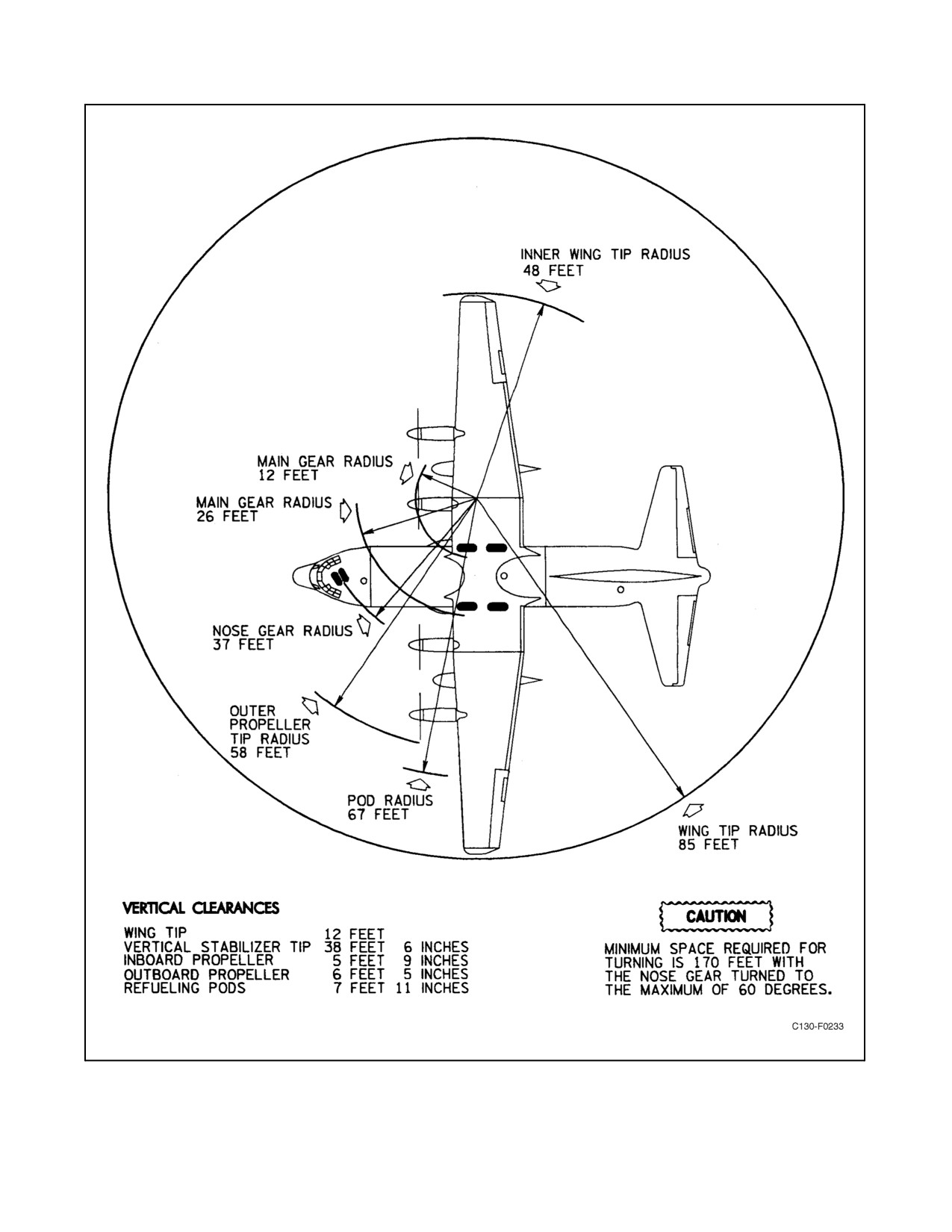
locked wheel. See Figure 8-3 for the minimum space and clearance required
for turning.
D Turning with brakes locked on one side or pivoting is prohibited. While
turning the aircraft, avoid hard or abrupt brake applications or braking to
a stop in a turn since damage to the nose landing gear and/or supporting
structure may result. If any of the above is required in a turn, initiate
maintenance action.
D Extreme caution must be exercised and very low taxi speeds observed when
taxiing over soft terrain because of landing gear loads and aircraft taxi load
factors.
ORIGINAL
8-42
01-75GAL-1
Figure 8-3. Turning Radii
8-43
ORIGINAL
01-75GAL-1
CAUTION
D
Engines shall be changed to normal ground-idle operation by disengaging
the LOW SPEED GROUND IDLE buttons rather than by throttle move-
ment. Movement of the throttles beyond the limits of 9_ to 30_ coordinator
angle (at ambient temperatures above 27 _C) may cause rpm stall and over-
temperature. These parameters are roughly equal to the throttle positions
of two throttle knob widths forward to one knob width aft of GROUND
IDLE. Should the LOW SPEED GROUND IDLE buttons be inadvertently
released by throttle movement, return the throttles to GROUND IDLE. The
engine should accelerate to normal ground-idle rpm. When downshifting
from normal to low-speed ground idle, the copilot will monitor the engine
instruments and be prepared to shutdown the engine if a stall and/or over-
temperature of 850 _C or greater occurs. If a popping noise (compressor
stall) occurs when changing from normal ground idle to LOW SPEED
GROUND IDLE or from LOW SPEED GROUND IDLE to normal ground
idle, maintenance action is required prior to flight.
D
Low-speed ground idle shall be used to the maximum extent possible
during all taxi operations.
D
Avoid the use of brakes as much as practical during taxi, particularly after
a landing that involved braking. Care should be taken not to ride thebrakes
by inadvertent toe pressure. Placing the heels on the floor should preclude
inadvertent brake application.
D
Skidding or skipping of the nosewheel may occur when the aircraft is
turning because of either wet pavement or an aft center of gravity. These
movements can be avoided by using asymmetrical power and avoiding
abrupt steering changes.
D
After turning, move the aircraft approximately 5 feet in a straight line to
realign the main landing gear before stopping.
D
Excessive oil temperatures and overheated brakes may be interrelated
during ground operation. If throttles are advanced to provide better oil
cooling, the higher thrust may increase taxi speed and require the pilot to
drag the brakes. If oil temperatures exceed limits, engine life is adversely
affected. If the brakes are overheated, wheel failures and brake fires may
result. The use of low-speed ground idle will normally maintain oil
temperatures within desired limits, reduce taxi speeds, reduce noise levels,
and conserve fuel. Use oil cooler augmentation to maintain lower oil
temperatures. During taxi, the oil temperatures should be monitored
closely to avoid exceeding limits.
1.
Brakes — Checked (P) (CP):
CAUTION
Do not switch from theemergency to normal brakesystem until theaircraft
is clear of obstructions or stopped.
ORIGINAL
8-44
01-75GAL-1
a. BRAKE SELECT switch — EMERGENCY.
b. Test brakes.
c. BRAKE SELECT switch — NORMAL.
d. Test brakes.
Note
The pilot shall conduct the brake checks, and the copilot shall operate the
hydraulic control panel switches.
2. Generators and loads — ON, Checked (FE):
CAUTION
Ensure that the ac BUS TIE switch is off before powering the main ac bus
with an engine-driven generator.
a. Place the APU generator switch to the OFF position and note that the No. 2 engine generator assumes the
essential ac bus load.
b. Rotate the voltage and frequency selector switch to each engine generator position and note that voltage
and frequency of each phase are within limits.
c. Rotate the phase selector switch to each phase position and check each engine generator loadmeter for an
indication of a load within limits.
d. Check each TR unit loadmeter for an indication of a load within limits.
e. Rotate the dc voltmeter selector switch to each position and check that the voltage is within limits.
f. Place APU generator to the ON position and note that the APU generator assumes the essential AC bus load.
3. Ice detection — Checked (FE):
CAUTION
Do not hold the ice detector test switch in the No. 2 or No. 3 position longer
than 5 seconds. Thetest cyclemay berepeated once; wait 5 minutes forthe
ice detector to cool before performing the test sequence again. Failure to
comply may result in damage to the ice detector probe.
a. Place the ice detector test switch in the No. 2 position. Note that the icing conditions ON light illuminates.
Wait at least 12 seconds, during which the icing conditions ON light should remain illuminated. Place the
PROP&ENGINEANTI-ICINGMASTERswitchtotheRESETpositionandnotethattheicingconditions
ON light is extinguished.
b. Place the ice detector test switch in the No. 3 position and note that the icing conditions ON light
illuminates. Wait at least
12 seconds, during which the icing conditions ON light should remain
illuminated.
c. Place each ENGINE INLET AIR DUCT ANTI-ICING switch ON (one at a time). Note a slight decrease
in torque and/or rise in TIT. Placethe switches off (oneat atime) and note aslight increasein torqueand/or
decrease in TIT.
8-45
ORIGINAL
01-75GAL-1
d. Check the propeller blade, spinner, and spinner base as follows:
If the BLADE DEICING ammeter falls below the limits specified in
Chapter 4, do not fly into icing conditions.
CAUTION
When the aircraft is on the ground, do not operate propeller anti-icing or
deicing for an engine that is not running. The propeller must be operating
to dissipate theheat generated by theheating elements and prevent damage
to the elements. Never operate the system for more than two cycles while
the aircraft is on the ground. Anti-icing and deicing may be used for a
propeller feathered in flight.
Note
The solid-state deicing timer will reset to start with the No. 4 propeller
when first activated and progressively energize the circuits for propeller
Nos. 1, 2, 3 and 4.
(1)
Place the No. 4 PROPELLER ICE CONTROL switch to ON and observe that a load is indicated on
all three ammeters (SPINNER ANTI-ICING, SPINNER DEICING, and BLADE DEICING).
(2)
Leave the PROPELLER ICE CONTROL switch ON until the heating cycle is completed, indicated by
a drop on the deicing ammeters. The spinner anti-icing ammeter will indicate continuously.
(3)
Place the next switch in sequence to ON and check for approximately a 20-ampere increase on the
SPINNER ANTI-ICING ammeter, 65 to 90 amperes on the SPINNER deicing ammeter, and 60 to
90 amperes on the BLADE DEICING ammeter.
(4)
Repeat step (3) for each propeller.
(5)
When all propellers have been checked and the NO ICE light is illuminated, place the PROP & ENGINE
ANTI-ICING MASTER switch to RESET, and observe that the NO ICE light is extinguished and there
is no load on any of the anti-icing or deicing ammeters.
(6)
Place all four PROPELLER ICE CONTROL switches OFF.
4.
Propeller reversing — Checked (P) (FE).
Note
D Reverse propellers in symmetrical pairs and check that rpm and torque are
within limits. Check the reverse power differential between engines; if
greater than 1,000 inch-pounds, compensate for the differential during
subsequent reverse operation and record the discrepancy for maintenance
action. During the reverse checks, the pilot should keep left hand lightly on
the nosewheel steering to feel for any pull.
D Propeller reversing shall be checked prior to the first flight of the day.
ORIGINAL
8-46
01-75GAL-1
8.7.1 Crosswind Taxiing
The aircraft can be taxied, with fourengines operating, in a30-knot, 90_ crosswind by use ofnosewheel steering and
rudder control only. Taxiing, with four engines operating, can be accomplished in up to a 60-knot, 90_ crosswind
by use of nosewheel steering, rudder and aileron control, differential braking, and differential power. Turns to a
crosswind heading shall be performed with great caution and at slow speeds to prevent centrifugal force from aiding
the wind in tipping the aircraft. Statically, the aircraft is capable of withstanding a 70-knot, 90_ crosswind without
tipping over.
8.7.2 Backing the Aircraft
CAUTION
Brakes shall not be used during backing operations because of the
possibility of the aircraft sitting on its tail and causing structural damage.
Note
Monitor engine oil temperature during backing operations. Use oil cooler
augmentation if necessary.
1.
Ensure there is sufficient clearance to safely operate the aircraft and the maneuvering area is free of all debris
that could damage the propellers or injure ground personnel.
2.
Conduct a thorough brief to include pilot feet placement, direction of turns (if required), and which
crewmember will direct the evolution from the cargo compartment. References for turns will be in relation to
the tail toward the No. 1 or No. 4 engine.
3.
Position a crewmember on ICS at the ramp control panel, and open the ramp and cargo door. This crewmember
shall provide guidance to the pilot during the backing operation to ensure aircraft remains clear of obstacles
and on the designated taxi surface.
4.
Both pilots shall place their feet flat on the deck throughout the evolution.
5.
Reverse propellers simultaneously.
6.
Use forward thrust to stop the backward movement of the aircraft.
7.
After backing, taxi the aircraft forward in a straight line approximately 5 feet to realign the main landing gear.
8.8
ENGINE RUNUP (OPTIONAL)
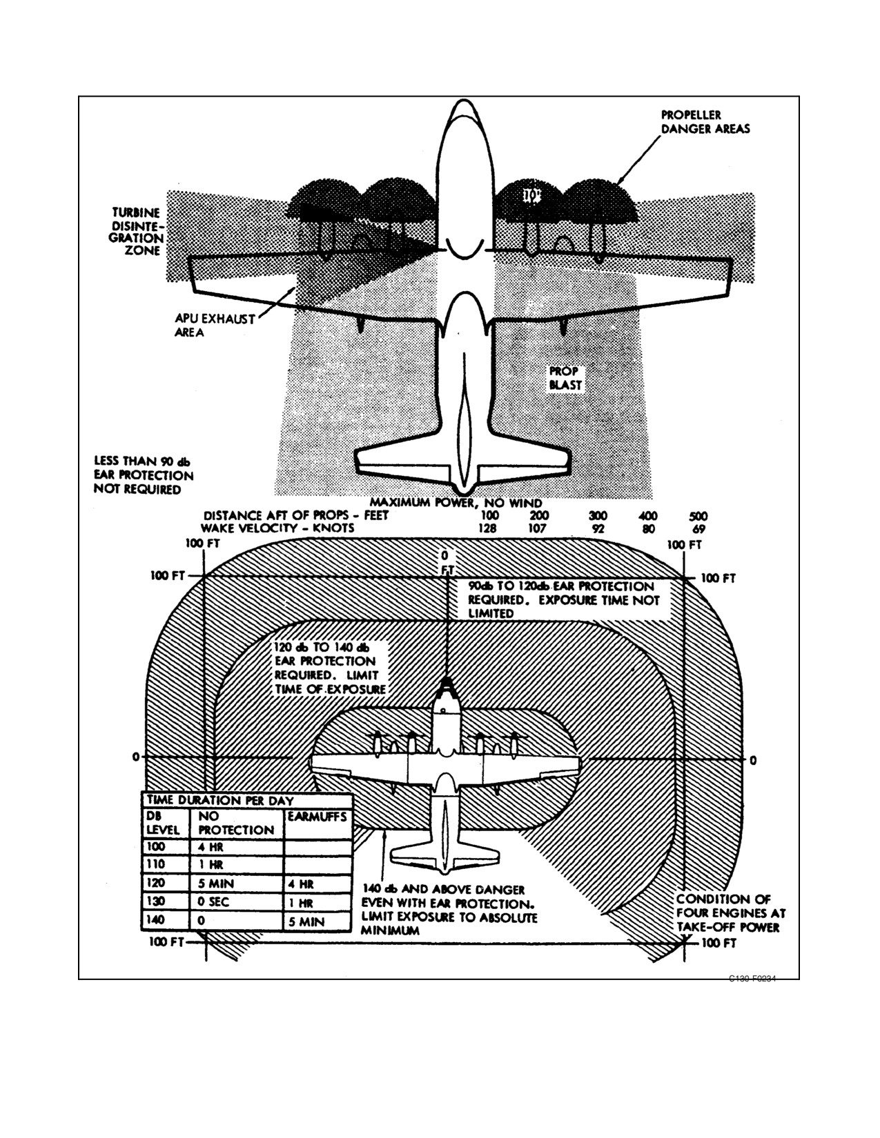
Select an area that is free of foreign objects. Head the aircraft into the wind. See Figure 8-4 for danger areas.
CAUTION
D To prevent excessive stresses on the propeller and to prevent wing lift and
resultant severe structural damage because of a propeller contacting the
ground, the aircraft will be headed into the wind within 30_ of wind direc-
tion for engine power settings in excess of 7,000-inch-pounds of torque
when the wind velocity is in excess of 10 knots.
D Do not runup the engines where thepropeller blast will blow across an area
used by other aircraft.
8-47
ORIGINAL
01-75GAL-1
Figure 8-4. Danger Areas
ORIGINAL
8-48
01-75GAL-1
CAUTION
D Do not runup all four engines to takeoff power simultaneously. The thrust
available is sufficient to skid locked wheels and chocks. Do not runup two
engines on one side simultaneously. The thrust available is sufficient to
skid the nosewheel sideways. Simultaneous full reverse power on all en-
gines may result in lifting the nosewheels off the ground.
D Foroperation on snow-coveredsurfaces attemperatures nearfreezing oron
slippery surfaces, deviations must be made for engine and propeller check
procedures. Check engines in symmetrical pairs when necessary. Use
reverse thrust on the remaining pair of engines to prevent the aircraft from
sliding forward. Brakes alone will not prevent the aircraft from moving
forward if each of the four engines is producing more than approximately
8,000-inch-pounds of torque. Avoid parking the aircraft close together
during ground test. When runup must be conducted on slippery surfaces,
do not attempt to make full-power checks until the aircraft is lined up on
the runway ready for takeoff.
Note
The copilot will stabilize the yoke, monitor the outside of the aircraft for
movement, and guard the brakes for inadvertent release or failure.
1.
Nosewheel, parking brake — Centered, Set (P).
2.
Engine runup — Complete (FE):
a. Check that idle rpm is within limits.
b. Advance the throttles to FLIGHT IDLE and note the torque.
c. Advance the throttles to the flight range and observe the TIT change as electronic fuel controlling is reached
(as indicated by the electronic fuel correction lights going out). The TIT at this point should be 800 to 840
_C. If no change in TIT is observed, refer to temperature datum system checks in this chapter.
d. Propeller operation — Set the throttles between 8,000- and 9,000-inch-pounds of torque:
Note
Gusty or strong wind conditions may cause excessive rpm fluctuations.
(1) Check that propeller rpm is within limits in normal and mechanical governing. If reindexing is required
to bring rpm within limits, refer to reindexing procedures in this chapter.
e. Retard all throttles to FLIGHT IDLE and check that rpm and torque are within limits.
8-49
ORIGINAL
01-75GAL-1
Torque should be at least 200 inch-pounds higher per engine than those
values observed in step 2b. If not, a low pitchstop malfunction exists.
Maintenance action is required prior to flight.
f. Retard throttles to GROUND IDLE.
CAUTION
If a decrease in torque is not indicated when throttles are moved to
GROUND IDLE, shut down the engine by placing the condition lever to
GROUND STOP. Maintenance action is required prior to flight.
8.9
TAKEOFF (ONLY CIRCLED ITEMS NEED TO BE CHECKED AT OPERATIONAL STOPS)
1. Exits — Secure (ALL).
2. Fuel panel — Set (FE):
a. Main tank fuel boost pumps — ON.
b. All crossfeed valves — Closed.
c. Auxiliary/external tank pumps — OFF.
3. Flaps — 50 Percent (P) (CP) (LM).
4. Flight controls — Checked (P) (CP).
CAUTION
If restricted or jammed flight controls are detected or suspected, no attempt
should be made to free the controls. Maintenance action is required prior
to flight.
5. Hydraulic quantities — Checked (LM).
6. Trim tabs — Set (P):
a. Elevator tab power switch — NORMAL.
b. Trim tab position indicators — Zero/As Required.
7. Seatbelts — Fastened (All).
Note
Shoulder harnesses shall be used on all seats so equipped.
ORIGINAL
8-50
01-75GAL-1
8.
Crew — Briefed (P):
a. Air minimum control speeds.
b. Refusal speed.
c. Rotation and takeoff speeds.
d. Pilot intentions should an emergency arise.
e. Radio and NAVAID setup to include primary departure radio, all VOR, TACAN, and ADF settings, the
IFF code, and the NAV select panel setting.
f. Specifics (where applicable) — Critical field conditions, snow or ice, wet runway, obstacle clearance and
terrain considerations, heavy gross weight takeoff, and SID.
g. Confirm crew understanding of clearance and, when applicable, instrument departure.
9.
Electrical panel — Set (FE):
a. Engine generators — ON.
b. AC BUS TIE switch — OFF.
c. APU generator — OFF.
d. AC Instrument and Engine Fuel Control switch — ESSENTIAL AC BUS/ESS AV AC BUS (some
aircraft).
e. DC BUS TIE switch — NORMAL.
10.
Instruments, altimeters — Checked, Set (state setting of the barometric altimeter and radar altimeter) (P) (CP)
(FE):
Note
This step shall be performed with the engines in normal ground idle.
a. The pilot shall check the engine instruments and pilot instrument panel and shall state the settings of the
pilot barometric altimeter and radar altimeter.
b. The copilot shall check the engine instruments and copilot instrument panel and shall state the settings of
the copilot barometric altimeter and radar altimeter. Copilot shall check any “check status” indications on
CDNU.
c. The flight engineer shall check the engine instruments.
11.
APU panel — Set (FE).
12.
Pressurization — Set (FE).
13.
Antiskid — Checked (FE):
After the ANTI-SKID TEST switch is actuated to either the FWD or AFT
position, wait at least 3 seconds before moving the test switch to the
oppositesetofwheels.Amorerapidactuationofthetestswitchcouldresult
inamomentarylossofbrakeswiththenormalbrakesystemselected.Faster
actuation of the test switch will also result in erroneous test light
indications.
8-51
ORIGINAL
01-75GAL-1
CAUTION
Do not attempt to test the antiskid system while the aircraft is being taxied.
a. With the ANTI-SKID INOPERATIVE light out, fully depress and hold the brake pedals.
b. Check that all four ANTI-SKID test lights are out.
c. Place the test switch in the FWD position and release. The two FWD lights should illuminate and then go
out. A slight bump may be felt in the brake pedals, indicating the antiskid control valves are functioning.
d. Place the test switch in the AFT position and release. The two AFT lights should illuminate and then go
out. A slight bump may be felt in the brake pedals.
e. Ensure that the test switch is in the OFF position.
Note
Ground anti-skid test shall be checked on the first flight of the day.
14. Radar, IFF transponder — As Required (P) (CP).
15. Oil cooler augmentation — OFF (FE).
CAUTION
Ensure that oil cooler augmentation is off before operating the oil cooler
flaps.
16. Oil cooler flaps — AUTO (CP).
17. Lights — Set (CP) (FE):
a. Landing and taxi lights — ON.
b. Navigation light — STEADY.
c. Strobe — As Required.
18. Anti-icing panel — Set (FE):
a. NESA WINDSHIELD switches — NORMAL.
CAUTION
Pitot heat shall not be left ON for an extended period while the aircraft is
on the ground.
b. PITOT HEAT switches — ON.
c. ENGINE INLET AIR DUCT ANTI-ICING switches — As Required.
ORIGINAL
8-52
01-75GAL-1
d. PROPELLER ICE CONTROL switches — As Required.
e. PROP & ENGINE ANTI-ICING MASTER — As Required.
19. Lineup — Complete (P) (CP) (FE):
a. Flaps — 50 Percent.
b. Attitude indicators — ON/Normal Indication.
c. Compass heading — Aligned With Runway.
d. Trim — Set.
8.10
TAKEOFF PROCEDURES
The following paragraphs discuss normal, maximum-effort, obstacle clearance, and crosswind takeoffs. Use the
performance charts to predict aircraft performance. Refer to Chapter 4 for limitations and Chapter 11 for emergency
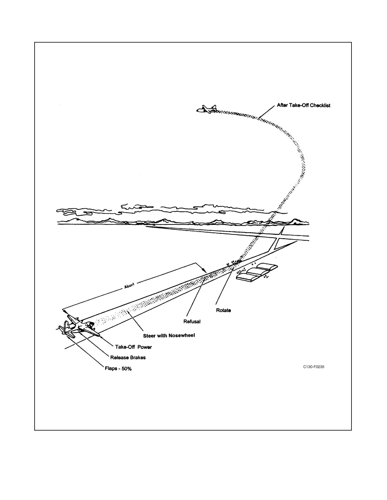
procedures during takeoff. See Figure 8-5 for takeoff and initial climb pattern.
Note
When takeoff performance is critical, cabin pressurization and air-condi-
tioning bleed air should be turned off to achieve maximum power.
8.10.1 Normal Takeoff
The throttles are gradually advanced toward maximum power, and the crew monitors the engine instruments to ensure
maximum power is not exceeded. Normal takeoffs are made with 50-percent flaps. Anytime charted performance
is desired, power should be applied before the brakes are released. A rolling takeoff is permitted provided charted
takeoff power is established within 5 seconds after the aircraft begins its takeoff roll.
CAUTION
D During low ambient temperatures, it is possible to exceed the maximum al-
lowable torque before reaching the TIT specified in Chapter 4. Addition-
ally, ram air effect during takeoff will increase torque for any fixed TIT.
Torque must either be set below maximum allowable when setting power
for takeoff or it must be reduced as airspeed builds during the takeoff roll.
D During the takeoff, the pilot will set takeoff power and maintain directional
control with the nosewheel steering until rudder controls become effective
(50 to 60 KIAS). Concurrently, the copilot will hold the control column
forward, keeping the wings level with the ailerons and will monitor throttle
positions. As speed increases, the pilot maintains aircraft control by
coordinated flight control use. At 80 KIAS, the copilot will call “80 knots”
and the pilot will crosscheck the airspeed indicator to ensure concurrence.
The copilot will call “Refusal” when required and “Rotate” at the briefed
rotate airspeed. The word “Abort” may be called by any flight station
crewmember detecting a discrepancy affecting safety of flight prior to
refusal/rotate (as required).
8-53
ORIGINAL
01-75GAL-1
Figure 8-5. Normal Takeoff and Initial Climb
ORIGINAL
8-54
01-75GAL-1
Note
D When air minimum control speed (one-engine inoperative, in ground
effect) is greater than the chart takeoff speed, use this air minimum control
speed for takeoff speed. The obstacle clearance speed for this condition is
the chart speed or air minimum control speed (one engine inoperative, in
ground effect) whichever is greater. It is desirable to accelerate to the
two-engine inoperative air minimum control speed as soon after takeoff as
feasible and before retracting flaps above the 15-percent position.
D For all operations below 1,000 feet AGL, the pilot not flying shall place
his/her hand at the base of the throttles. This does not preclude removal for
landing gear and/or flap actuation.
D If the aircraft is loaded to an aft center of gravity, forward pressure on the
control column will aid in steering effectiveness.
8.10.2 Maximum-Effort Takeoff and Obstacle Clearance
Note
If the runway or runway environment require maximum-effort perfor-
mance, all engine bleed air should be shut off.
A maximum-effort takeoff is made by holding the brakes until the engines are stabilized at maximum power. For
maximum-effort takeoff, accelerate on the runway to takeoff speed and pull up the nose until the aircraft leaves the
ground. Takeoff speed will be such that minimum control speed is disregarded. Retract the landing gear and adjust
the aircraft attitude to attain obstacle-clearance speed. After clearing the obstacle, slowly retract the flaps while
maintaining altitude and accelerate to best climb speed. Refer to NAVAIR 01-75GAI-1.1 (performance manual) for
maximum-effort takeoff data.
Note
The minimum flap retraction speed for a maximum-effort takeoff is
obstacle clearance speed plus 10 knots.
8.10.3 Crosswind Takeoff
Crosswind takeoffs, with regard to directional control of the aircraft, are made essentially the same as normal takeoffs.
Initially, the pilot maintains directional control with nosewheel steering and differential power while the copilot
maintains a wings-level attitude with the ailerons. In higher crosswinds, a greater amount of differential power and
ailerons must be applied. After takeoff, the line of flight should be aligned with the runway until crossing the airfield
boundary. Refer to NAVAIR 01-75GAI-1.1 for crosswind performance data.
8.11
AFTER TAKEOFF
As soon as airborne (and at the command of the pilot), retract the landing gear. When a safe altitude is reached and
at no less than 20 KIAS above takeoff speed, retract the flaps.
8-55
ORIGINAL
01-75GAL-1
D When the flaps are retracted, the aircraft will lose lift and tend to sink. The
pilot shall react by pulling the aircraft nose up as necessary to continue
climbing and accelerating to maintain a safe margin above the stall speed
for the changing configuration. Flap retraction should not be accompanied
by a combination of banked turns and power reduction because of the
danger of stall at flap retraction speed. The effect of flap retraction on
available rudder deflection and the consequent increase in air minimum-
control speed should also be considered.
D Retracting the landing gear and flaps simultaneously will result in an
increase in air minimum-control speed.
Note
D Retracting the landing gear and flaps simultaneously will result in slower
than normal operation of both and may cause the hydraulic low-pressure
warning light to come on.
D After airborne, accelerate to the desired climb speed determined from the
performance charts.
D To prevent excessively high nose attitudes and to allow for bettervisibility
during VMC climbs, climb speeds greater than performance chart data are
permissible.
1.
Gear, flaps, lights — Checked (CP) (FE):
a. Landing gear up and locked.
b. Flaps up and indicating up.
c. Taxi lights off, landing lights/retracted.
When extending or retracting landing lights ensure lights are off prior to
movement, this is to prevent possible spatial disorientation to pilot at
controls.
2. Hydraulic panel — Checked, Set (CP):
a. Auxiliary hydraulic pump — OFF.
b. Rudder boost pressure — LOW.
3. SYNCHROPHASE MASTER switch — As Required (FE):
a. Set to engine nearest 100-percent rpm.
4. Pressurization — Checked (FE):
a. Ensure aircraft is pressurizing.
b. Set pressure controller to cruise altitude.
5. Wings and aircraft interior — Checked (LM).
8-56
ORIGINAL W/IC 9
01-75GAL-1
Prior to performing anti-icing checks, a thorough inspection of the wings
and aircraft interior shall be conducted.
6. Leading edge anti-icing — Checked, Set (FE).
Note
Leading edge anti-icing shall be checked on the first flight of the day. Turn
the wing and empennage anti-icing ON until a temperature rise is noted on
theindicators.Thiswilleliminateanymoistureinthesystem.Thewingand
empennage check shall be coordinated with the pilot.
7. Fuel panel — As Required (FE).
8. Hot mike — As Required (P) (CP) (FE).
8.12
DESCENT
This check will be accomplished prior to initial VFR or instrument pattern entry.
Note
Flight idle torque at slow descent and approach speeds may result in
negative torque and produce an NTS signal on one or more engines. The
resulting rpm and power fluctuations will cause the aircraft to yaw. To
correct this condition, move the throttle(s) forward to bring torque out of
the NTS range. The use of wing and empennage anti-icing may further
decrease flight-idle torque.
1.
Crew — Briefed (P/CP):
a. Distance and time to landing.
b. Weather.
c. Approach:
(1) Primary and alternate approach.
(2) NAVAID set up.
(3) Minimum safe altitude.
(4) Final approach course.
(5) DH/MDA and missed approach point.
(6) Timing (if required).
(7) Missed approach instructions.
8-57
ORIGINAL
01-75GAL-1
(8) Flap setting.
(9) Approach and landing speeds.
2. Passengers, cargo — As Required (LM).
3. Pressurization — Set (FE).
4. Barometric altimeter — Set (state setting) (P) (CP).
Note
Barometric altimeters will be set to station pressure (QNH) if available
when transiting the transition level. Altimeters may be set when above but
cleared through the transition level.
5. Temperature datum control valves — As Required (FE).
Note
Temperature datum control valves, if locked, should be reset prior to an
altitude change of 5,000 feet.
8.12.1 Normal Descent
This descent is made by retarding the throttles to flight idle with the gear and flaps retracted and descending at
maximum level-flight (VH) speeds. The normal descent chart presented in the NAVAIR 01-75GAI-1.1 is based on
maximum level-flight (VH) speeds. Refer to Chapter 4 for airspeed limitations.
8.12.2 Maximum-Range Descent
This descent is made by retarding the throttles to flight idle with gear and flaps retracted and descending at maximum
lift-over-dragspeeds.Thisdescentwillprovideamoderatesinkrate(approximately1,500 fpm)forenrouteletdown.
8.12.3 Rapid Descent — Clean
At high airspeeds, the highest descent rates are obtained by retarding the throttles to flight idle with the gear and flaps
retracted and descending at maximum allowable airspeeds, listed in Chapter 4. The rapid descent chart with gear and
flaps retracted is based upon maximum allowable speeds for 35,000 pounds of cargo or less.
8.12.4 Rapid Descent — Dirty
At low airspeeds, the highest descent rates are obtained by retarding the throttles to flight idle, decreasing airspeed
to 145 knots, and extending landing gear and full flaps. Descend at or below 145 knots.
8.13
APPROACH
1. Galley floor — Set (LM).
2. Fuel panel — As Required (FE).
3. Seatbelts — Fastened (All).
Note
Shoulder harnesses shall be used on all seats so equipped.
ORIGINAL
8-58
01-75GAL-1
4. Altimeters — Set (state setting of both barometric altimeter and radar altimeter) (P) (CP).
This step shall not be completed until the QNH has been set.
5. NAV SEL switch — As Required (P) (CP).
This checklist shall not be completed until the NAV SEL switch is selected
for the final approach NAVAID and the final approach course has been
selected on the HSI.
CAUTION
All visual approaches shall be backed up with an instrument approach
serving the airfield of intended landing.
Note
True heading is presented on the HSI whenever the INS position is selected.
All runways, instrument approaches, and radar vectors are based on
magnetic headings.
8.14
LANDING
To preclude landing with the yaw damper engaged, this checklist shall not
be commenced until the autopilot controller is fully disengaged. If a
coupled approach is being executed, the autopilot shall be disengaged no
lower than 200 feet AGL.
1. Hot mike — ON (P) (CP) (FE).
2. Flaps — As Required (P) (CP).
3. Landing gear — Down, Checked, Centered (P) (CP) (FE).
4. Hydraulic panel — Checked, Set (CP):
a. Auxiliary hydraulic pump — ON.
b. Hydraulic pressures — Checked.
8-59
ORIGINAL
01-75GAL-1
5. Lights — Set (CP):
a. Landing lights — Extended, ON.
b. Taxi lights — ON.
6. SYNCHROPHASE MASTER switch — OFF (FE).
7. Pressurization — Checked (FE):
a. Ensure aircraft is depressurizing.
8. Antiskid — Checked (FE):
a. Check that all four ANTI-SKID lights illuminate after wheel rotation stops.
b. Place the test switch to the FWD position. All four lights should go out.
c. Release test switch to OFF. The two FWD lights should illuminate momentarily. After 2
to 3 seconds, all
four lights should illuminate and remain illuminated.
d. Repeat steps b and c for the aft wheels.
8.15
LANDING PROCEDURES
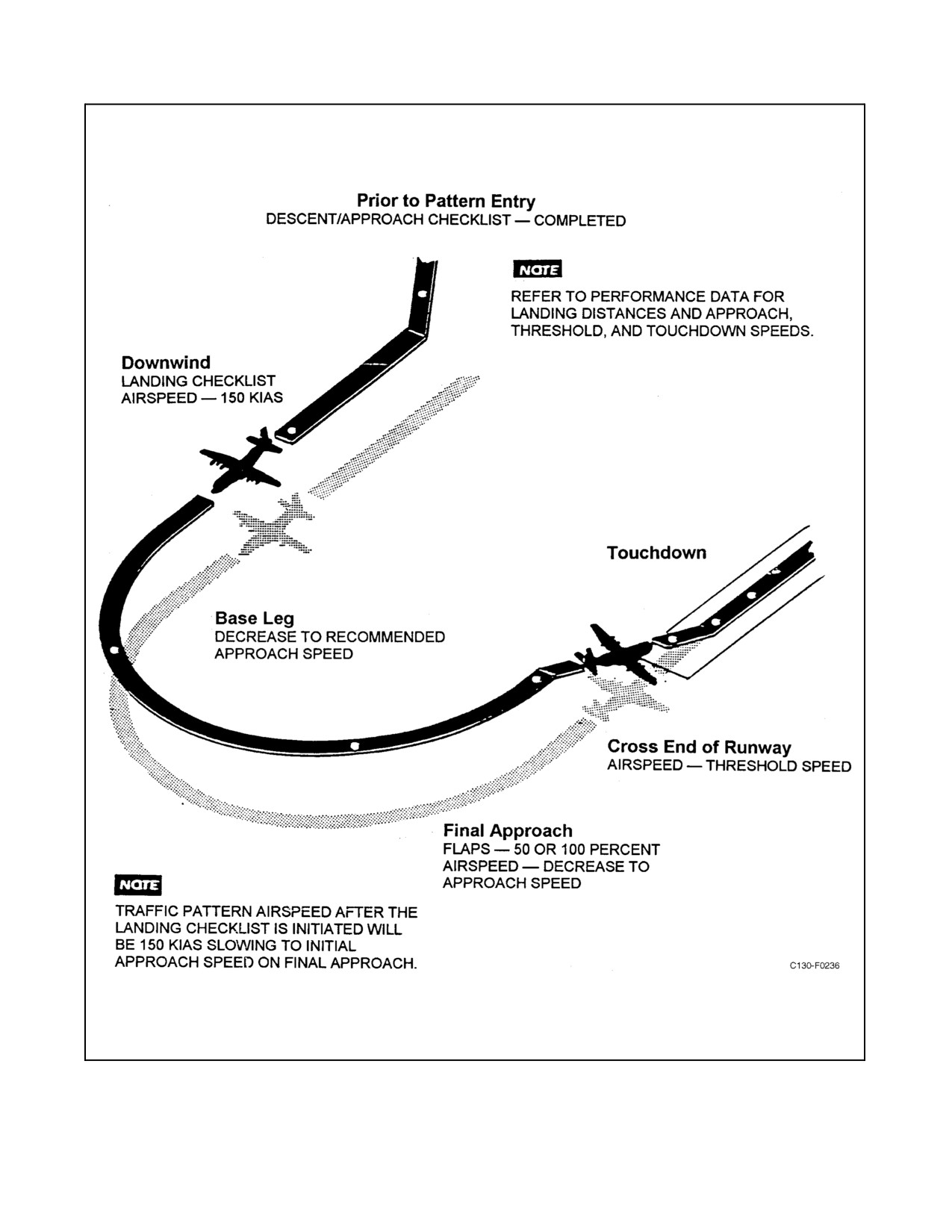
See Figure 8-6 for the landing pattern.
8.15.1 Normal Landing
The normal landing configuration is with 50- or 100-percent flaps. Refer to NAVAIR 01-75GAI-1.1 for landing
speeds and distances.
CAUTION
It is possible to scrape the aft bottom of the aircraft when landing with
extreme nose-high attitudes.
Every landing should be planned according to runway length available and the general prevailing operating
conditions. Normal landings should also be planned to use all of the available runway length to promote safe, smooth,
and unhurried operating practices; to preclude abrupt reverse power changes; and to save wear on the brakes. The
VFR pattern downwind airspeed is 150 KIAS or computed approach speed, whichever is higher. On final approach,
begin to decrease airspeed from approach speed at a point that will allow a gradual slowup to cross the runway
threshold at the threshold speed. Touchdown should be planned at the speed computed from the appropriate landing
speed chart. After the main wheels touch down, smoothly lower the nosewheel to the runway. When the main and
nose landing gear are firmly on the runway, the copilot must hold forward pressure on the control column and
maintain a wings-level attitude with ailerons, as needed. Concurrently, the pilot maintains directional control and
decelerates the aircraft using rudder, differential power, nosewheel steering, and differential brakes according to
speed, wind, and runway conditions. Reverse thrust is applied by moving the throttles from FLIGHT IDLE to
GROUND IDLE and then into the reverse range in coordination with nosewheel steering. Brakes must be checked
during the landing roll.
8.15.2 Propeller Reversing
Every landing should be planned as though reverse thrust were not available. Do not use the brakes more than
necessary as sustained braking will overheat the brake assemblies. On a long runway, allow the aircraft to roll until
it loses speed. Check the brakes to ensure braking action is available.
ORIGINAL
8-60
01-75GAL-1
Figure 8-6. Normal Approach and Landing
8-61
ORIGINAL
01-75GAL-1
D Retarding the throttles below FLIGHT IDLE at airspeeds above 115 KIAS
could result in power loss/bogdown or flameout on one or more engines,
particularly when operating in high ambient temperatures. This consider-
ation does not prohibit the use of full reverse at higher airspeeds when
reversing action is essential to stopping within the confines of the runway.
If power loss/bogdown or flameout occurs, maintenance action is required
prior to subsequent flight.
D The failure of one or more propellers to reverse may result in complete loss
of directional control. After touchdown, if the throttles are moved into the
ground range too rapidly, it is possible to lose control of the aircraft before
a propeller malfunction can be detected. The movement from the flight
range into the ground range should be made at a reasonable rate that will
allow malfunction detection, such as failure of a low pitchstop to retract.
At the first indication of directional control difficulty during reversing,
immediately return all throttles to GROUND IDLE. Maintain directional
control with flight controls, differential braking, and nosewheel steering as
required. After identifying the affected propeller, symmetrical propellers
may be reversed and the affected engine shut down while it is in ground
idle. Rudder, differential power, and brakes are the primary means of
directional control.
CAUTION
D Propeller reversing with an unbalanced fuel load can cause an extreme
wing-low attitude and undesirable control characteristics.
D During the final stage of landing roll, reduce reverse thrust if conditions
permit to prevent debris from causing restriction to visibility or engine
damage.
8.15.3 Crosswind Landing
NAVAIR 01-75GAI-1.1 contains maximum allowable crosswind information. Landing with a crosswind in excess
of 35 knots is not recommended. Use normal approach speeds if the wind is steady. When winds are gusty, a slight
increase in approach airspeed is recommended. Immediately after the main wheels touch down, lower the nosewheels
and hold in firm contact by using the elevators. During landing roll, control the aircraft directionally by using the
following methods, listed by priority:
1. Aileron and rudder control.
2. Nosewheel steering.
3. Differential braking.
4. Differential power.
ORIGINAL
8-62
01-75GAL-1
The upwind wing has atendency to rise when reverse thrust is applied. Since this tendency is most pronounced when
the flaps are extended 100 percent, flaps should be raised before applying reverse power on landing in severe
crosswinds.
CAUTION
An engine-out condition may add difficulty to a crosswind approach and
landing by adding to the drift and weathervaning.
8.15.4 Gust Correction
Increase rotation speed, approach speed, threshold speed, and landing speed by the full gust increment, not to exceed
10 knots.
Note
Use of a correction factor for gusts or other accelerations which may affect
the aircraft should be undertaken with consideration of all the factors
involved.Ifacorrectionis requiredto compensateforagiven gustvelocity,
the value of the correction must be the same regardless of wind direction.
This is true because the objective is to provide a safety margin for maneuver
loads while flying the aircraft through a series of accelerations. The
accelerations can be equally severe whether they are produced by
head-wind, crosswind, or tailwind. However, since a pilot cannot estimate
the frequency or timing of gusts with practical accuracy, it is possible for
the aircraft to arrive at the flare point with gust correction added during an
interval when gusts have stopped momentarily. Undersuch conditions, the
distance consumed dissipating excess airspeed could move the touchdown
point farther down the runway than planned. Therefore, whenever a
correction factor is added for gusts or other accelerations, the pilot must be
prepared to accept a correspondingly higher approach speed with the
possibility of increased landing distance. If stopping distance available
beyond the maximum estimated touchdown point is marginal, the pilot
should select a longer runway or proceed to an alternate base.
8.15.5 Wind Shear
Wind shear is a complex phenomenon. It can affect the airplane in all phases of flight, but is most critical during the
approach and landing phase. Wind shear can exist as a rapid change in wind velocity and direction as well as vertical
air movement. There are certain conditions which indicate the possibility of wind shear being present. As a general
rule, the amount of shear is greater ahead of warm fronts although the most common occurrences follow the passage
of cold fronts during periods of gusty surface winds. When a temperature change of 10 _F or more is reported across
the front or if the front is moving at 30 knots or more, conditions are excellent for wind shear. In addition, when
thunderstorms are present in the area of intended landing, the possibility of encountering wind shear is increased.
The power required, vertical speed, and pitch attitude, used in conjunction with the wind reported on the ground,
provide an indication of potential wind shear.
8-63
ORIGINAL
01-75GAL-1
In relation to a known surface wind, be alert for:
1. An unusually steep or shallow rate of descent required to maintain glidepath.
2. An unusually high or low power setting required to maintain approach airspeed.
3. A large variation between actual and computed ground speed.
When a reported surface wind would not justify an increased airspeed (for example: calm wind on the surface), but
wind shear is suspected, adjustment of approach speed may be used to provide an increased speed margin. The
following are two wind shear phenomena which are commonly found on final approach.
8.15.6 Decreasing Headwind
Initial reaction of the airplane when suddenly encountering a decreasing headwind (or an increasing tailwind) is a
drop in indicated airspeed and a decrease in pitch attitude resulting in a loss of altitude. The pilot must add power
and increase pitch to regain the proper glidepath. Once speed and glidepath are regained, however, prompt reduction
of power is necessary. It will now require less power and a greater rate of descent to maintain the proper profile in
the decreased headwind. If the initial corrections of increased power/pitch are not promptly removed after regaining
glidepath and airspeed, a long landing at high speed will result.
8.15.7 Increasing Headwind
The initial airplane reaction to an increasing headwind (decreasing tailwind) is an increase in indicated airspeed and
an increase in pitch attitude resulting in a gain in altitude. The pilot should reduce pitch and power to regain the proper
glidepath.Asglidepathisregained,thepilotmustimmediatelycompensatefortheincreasingheadwindbyincreasing
pitch and power. It will now require more power and a decreased rate of descent to maintain the proper profile. Be
very cautious in making reductions of power and pitch to avoid a low-power, high-sink condition which could lead
to a correction through the glidepath from which a recovery could not be made.
If the airplane becomes unstable on final approach due to wind shear and
theapproach profilecan not bepromptly reestablished, a go-around should
be immediately accomplished.
8.15.8 No-Flap Landing
1. Place the GPWS switch to OVERRIDE.
Ensure the GPWS switch is returned to NORMAL prior to performing
subsequent touch-and-go or full-stop landings.
2. Fly a slightly wider, slightly longer pattern to compensate for the higher no-flap airspeeds.
3. Do not flare but rather allow the aircraft to fly onto the runway.
ORIGINAL
8-64
01-75GAL-1
CAUTION
If the touchdown is lower than the charted speed, it is possible for the aft
end of the fuselage to contact the ground.
4. When applying reverse thrust at high speed, pull the throttles into reverse slowly.
5. Longer ground rolls will result from the higher touchdown speeds.
8.15.9 Minimum Run Landing
Fly a normal pattern, slowing the aircraft to arrive over the threshold at the maximum effort threshold speed with
100-percent flaps. This threshold speed is approximately 6 knots below the normal threshold speed when aircraft
weight exceeds 105,000 pounds. Fly the aircraft onto the ground, touching down as close to the end of the runway
as possible. Immediately touch down the nosewheel. Reverse the propellers and apply full antiskid braking as
required.
8.15.10 Landing on Wet Runways
Reverse thrust, antiskid braking, and nosewheel steering capabilities minimize normal hazards associated with wet
runways.
8.15.11 Landing on Icy Runways
Operation on ice is hazardous and should be attempted only when necessary. Use of nosewheel steering should be
minimized, and taxi speed must be slow. Directional control can be maintained with asymmetrical power and
nosewheel steering at taxi speeds, and with asymmetrical power and rudder at speeds above rudder effectiveness.
Touchdown should be made at the minimum safe speed possible, and maximum aerodynamic drag is obtained by
holding the nosewheel off of the ground for as long as possible. Use symmetrical power and reverse thrust as the
primary means to obtain braking action and to prevent yawing and skidding.
Landing should not be attempted on ice-covered runways if crosswinds
require large corrections.
8.15.12 Touch-and-Go Landing
Before the first touch and go, all normal checklists shall be completed through the Landing Checklist. After the first
touch and go, theTouch-and-Go Landing Checklist may be used until theaircraft departs the airport traffic/approach
control area. The operational stop portions of the After Landing, Before Taxi, and Takeoff Checklists shall be used
for full-stop landings when hatches/doors are opened and/or flaps and/or trim tabs are operated.
Touch-and-go landings require a significant element of caution because of the many actions that must be executed
while rolling on the runway. The actions required during touch-and-go landings are divided into three categories:
on the runway, after takeoff, and landing.
After the aircraft has touched down (both main and nosewheels), the pilot flying the aircraft will call for flaps to be
set at 50 percent by stating “Flaps 50”; the other pilot will complete the checklist. When the trim is set for takeoff,
8-65
ORIGINAL
01-75GAL-1
the pilot not flying will state “Flaps 50, trim set, throttles.” The pilot flying will smoothly advance the throttles to
the briefed setting. The flight engineer will state the torque values in
5,000-inch-pound
increments
up to
15,000-inch-pounds and will then state “Power set” upon reaching the briefed setting.
Note
If repeated touch-and-go landings are planned,
leave
the
landing
gear
extended to cool the wheels and brakes.
8.15.12.1 On the Runway
1. Flaps — 50 Percent (P/CP).
2. Trim tabs — Set (P/CP).
3. Throttles — As Required (P/CP).
8.15.12.2 After Takeoff
1. Gear, flaps, lights — Checked (P/CP) (FE).
8.15.12.3 Landing
1. Crew — Briefed (P/CP):
a. Type approach.
b. Type landing (flap setting, simulated engine(s) out).
c. Touch and go/full stop.
2. Flaps — As Required (P) (CP).
3. Landing gear — Down, Checked, Centered (P) (CP) (FE).
4. Hydraulic panel — Checked (P/CP):
a. Auxiliary hydraulic pump — As Required.
b. Hydraulic pressures — Checked.
8.16
GO-AROUND
When a go-around is anticipated, alert the crew, delay full flap extension, and keep the airspeed higher than normal.
When a go-around is decided upon, proceed as follows:
1.
“Go around” command given to crew.
2. Advance throttles as required.
3.
“Flaps 50” percent (speed and altitude permitting).
Retracting flaps from 100 to 50 percent will increase stall speed. Without
proper power and attitude corrections, sink rate will also increase. This is
particularly noticeable at lower than normal airspeeds. If safe altitude and
airspeed are not attained, inadvertent touchdown and/or stall may occur.
ORIGINAL
8-66
01-75GAL-1
4.
“Gear up” (when certain the aircraft will not touch down).
5. Proceed with normal After Takeoff Touch-and-Go procedures.
8.17
AFTER LANDING (ONLY CIRCLED ITEMS NEED TO BE CHECKED AT OPERATIONAL
STOPS)
Flight engineer items not requiring coordinated action may be accomplished after the pilot has called for the After
Landing Checklist. This does not preclude response to the checklist when called by the copilot.
No door or hatch may be opened without the aircraft commander’s
permission. The aircraft commander shall not allow a door or hatch to be
opened until the aircraft is verified to beunpressurized. Ifany doubt exists,
the copilot shall open the right swing window.
1. Flaps — As Required (CP).
2. Oil cooler flaps, augmentation — As Required (FE).
CAUTION
On aircraft prior to 165313, ensure that the oil cooler flaps are open and the
switches are FIXED before activating oil cooler augmentation. On aircraft
165313 and up, the switches must be in AUTO.
3.
Lights — Set (CP) (FE).
Note
Use of the taxi and landing lights will be at the aircraft commander’s
discretion. The lights will normally be turned off except during operations
at night or in reduced visibility.
4.
Radar, IFF transponder — STANDBY (P) (CP) (FE).
5.
Pressurization — No Pressure (FE).
Note
Ensure the differential pressure is zero prior to placing the AIR
CONDITIONING master switch to NO PRESS.
6.
Anti-icing panel — OFF (FE).
7.
APU panel — Set (FE):
a. APU CONTROL switch — START, RUN.
8-67
ORIGINAL
01-75GAL-1
8.
Electrical panel — Set (FE):
a. APU generator — ON, Checked.
Note
The APU generator must be on for low-speed ground idle operation since
the engine-driven generators will be off line.
b. Dc BUS TIE switch — Tied.
Note
The main ac bus may be powered by the APU generator provided no
engine-driven generator is supplying power and the ac BUS TIE switch is
in the ON position.
8.18
SECURE
1.
Parking brake — Set (P).
Note
If necessary, the pilot may clear the loadmaster to exit the aircraft using the
crew entrance door.
2.
Oil cooler augmentation switches — OFF (FE).
3.
Shutdown, NTS check — Complete (All):
CAUTION
D During engine shutdown, do not move the condition lever from GROUND
STOP to RUN while the propeller is still rotating.
D Engine shutdown should not be accomplished when taxi speed, wind
velocity, or a combination of wind velocity and taxi speed is greater than
20 knots. Engine shutdown under these conditions may damage the safety
coupling. When doubt exists as to the effective speed, shutdown should be
delayed.
Note
D On engine shutdown, some fuel will be seen draining from the engine drain
mast. In the event of “No drip,” the pilot shall wait until the propeller has
ceased rotation and then motor the engine to 25-percent rpm with the
starter, leaving the condition lever in GROUND STOP.
D To extend engine life, engines shall be operated in low-speed ground idle
for at least 2 minutes prior to shutdown.
D Engines shall be shut down from low-speed ground idle.
ORIGINAL
8-68
01-75GAL-1
a. Copilot shall place the FEATHER VALVE AND NTS CHECK switch in the NTS position.
b. Copilot shall move the condition levers to GROUND STOP.
c. Copilot and flight engineer shall observe zero fuel flow and illumination of the applicable NTS lights.
CAUTION
If zero fuel flow is not observed, move the applicable condition lever to
FEATHER to mechanically shut off fuel.
d. A crewmember shall observe proper operation of each drip valve. Drips may be observed from inside the
aircraft.
Note
NTS lights may not illuminate when shutting down engines from
low-speed ground idle. If NTS lights do not illuminate, restart the engine
and shut down from NORMAL ground idle. If the NTS lights illuminate
after a NORMAL ground idle shutdown, no further action is required. If the
NTS lights still do not illuminate from NORMAL ground idle, mainte-
nance action is required prior to the next flight.
4. Unnecessary equipment — OFF (All).
5. Oxygen — Checked, OFF (All).
6. Chocks, nose pin — Installed (LM).
The aircraft shall be chocked prior to installation of nose pin. Movement
of aircraft could cause injury or death.
7. Parking brake — Released (P).
8. Hydraulic panel — SET, EMERGENCY SELECTED (CP):
CAUTION
The engine pump switches shall be left on after engine shutdown. If the
switch is left off, pressure buildup because of thermal expansion of the
hydraulic fluid may cause the suction line hydraulic shutoff valve to fail.
a. SUCTION BOOST PUMP switches — OFF.
b. ANTI-SKID switch — ON.
8-69
ORIGINAL
01-75GAL-1
c. Auxiliary hydraulic pump switch — OFF.
d. Brake pressures — Depleted.
9.
AIR CON MASTER — AUX VENT (FE).
8.19
BEFORE LEAVING THE AIRCRAFT
1.
Oil cooler flaps — As Required.
2.
Radar — OFF.
3.
Air-conditioning — OFF.
4.
Bleed air — OFF.
5.
Electrical panel — Set:
a. Engine generator switches — OFF.
b. Inverters — OFF.
c. BSU switches (some aircraft) — OFF.
6.
Fuel panel — Set:
a. Fuel BOOST PUMP switches — OFF.
b. CROSSFEED VALVE switches — Closed.
7.
Temperature datum valves — Null.
8.
Oxygen — NORMAL/100%/OFF.
9.
Hydraulic panel — Set.
10.
Ac BUS TIE switch — OFF.
11.
APU generator — OFF.
12.
APU panel — Set:
a. APU BLEED AIR VALVE switch — CLOSE.
b. APU CONTROL switch — STOP.
13.
Radios — OFF.
14.
Wheels — Chocked.
15.
Parking brake — Released.
16.
Lights — Set/OFF.
17.
Dc BUS TIE and BATTERY — Set:
ORIGINAL
8-70
01-75GAL-1
a. Dc BUS TIE switch — NORMAL.
b. Dc power switch — OFF.
c. Dc voltmeter switch — MAIN DC BUS.
Note
If the DC voltmeter switch is left in the BAT position for an extended length
of time, the output of the battery will be decreased.
18. INS/GPS — OFF.
19. Emergency exit light switch — Depressed.
20. Covers, plugs — Installed.
21. Interior/exterior lights — OFF.
22. Doors and ramp — As Required.
23. Aircraft battery — Disconnected.
CAUTION
Never install rig pins in the control system or secure the flight deck controls
as a means of locking the surfaces against wind gusts. Otherwise, damage
to the hydraulic booster and/or cable system is likely to result.
8.20
CRUISE ENGINE SHUTDOWN
Engine shutdown may be performed during cruise flight to achieve optimum fuel economy to meet mission
requirements. Refer to NAVAIR 01-75GAI-1.1 for range information.
Operating in the freezing range with visible moisture present may cause
icing that will prevent starting of shutdown engines.
CAUTION
D Do not place the condition levers in any position other than FEATHER,
RUN, or AIRSTART during flight. Stopping or hesitating between the
FEATHER, RUN, or AIRSTART positions can result in undesirable op-
eration of the engine-propeller system.
D NTS check should be accomplished on one engine at a time.
8-71
ORIGINAL
01-75GAL-1
1. Crew — Briefed (CP).
2. SYNCHROPHASE MASTER — OFF (FE).
3. Propeller governor control — Mechanical (CP).
4. FEATHER VALVE and NTS switch — VALVE (CP).
5. Airspeed — Below 180 KIAS (P).
6. NTS check — Complete (FE):
CAUTION
If NTS action is not observed by -1,860 inch-pounds, advance the throttle
and return the engine to normal operation. Secure the engine bleed air
switch, and record the malfunction. If the NTS is operative, continue the
procedure for engine shutdown.
Note
Torque should decrease and the highest negative torque value should be
noted. NTS action should begin at -1,260 (±600) inch-pounds as indicated
by an increase in torque and the blinking of the NTS light each time the
feather valve has moved to the feather position. During the NTS check,
torquefluctuations to positive500 inch-pounds(maximum)areconsidered
normal.
a. Throttle — 4,000 Inch-Pounds or More (P).
b. WING and EMPENNAGE ANTI-ICING — ON (FE).
c. ENGINE BLEED AIR switch (engine being checked) — OVRD (FE).
d. ENGINE BLEED AIR switch (other engines) — OFF/One at a Time (FE).
e. Slowly retard the throttle observing decrease in torque value until NTS action is observed — Checked (FE).
f.
Advance throttle into positive torque range — Advanced (FE).
Note
Repeat steps 6a through 6f for engines remaining as required.
g. WING and EMPENNAGE ANTI-ICING — OFF (FE).
h. ENGINE BLEED AIR switches — ON (FE).
i.
NTS check — Complete (FE).
7.
Throttle of engine to be shut down — FLIGHT IDLE (P).
8.
ENGINE BLEED AIR switches on operative engines — ON (FE).
9.
SYNCHROPHASE MASTER — Reset as Required (FE).
CAUTION
When pulling a condition lever to FEATHER, pull it all the way to the
detent to ensure that the propeller is fully feathered. If the lever is left at
midposition and the NTS is inoperative, an engine decoupling is possible.
ORIGINAL
8-72
01-75GAL-1
10. Condition lever — FEATHER (CP).
11. Fuel boost pump — OFF (FE).
12. ENGINE BLEED AIR switch — OFF (FE).
13. Engine generator switch — Set (FE):
a. Generator switch (aircraft prior to 165313) — Tripped/OFF (FE).
b. Generator switch (aircraft 165313 and up) — OFF (FE).
14. Propeller feather override button — Out (CP).
15. Throttle of engine shutdown — Full Forward (P).
16. Oil cooler flap — Closed/Fixed (CP).
17. Fuel management — Checked (FE).
8.21
AIRSTART
Before restarting an engine that has been shut down in flight, be sure that the TIT for that engine has dropped below
200 _C. Temperature higher than 200 _C will increase the likelihood of a hot start. Never move the throttle below
the FLIGHT IDLE position in flight. The position of the engine condition lever is assumed to be FEATHER. The
engine will normally come up to speed more rapidly if the airspeed is reduced to 180 knots or less.
CAUTION
D Do not attempt to restart an engine that was shutdown because of fire or fire
warning or any other engine malfunction unless, in the opinion of the pilot,
a greater emergency exists.
D Do not attempt to restart an engine with an inoperative NTS except in case
of a greater emergency. Prior to airstart of an engine on which the NTS has
been previously determined to be inoperative, reduce the airspeed to 130
KIAS and the altitude to below 5,000 feet.
D If negative de-enrichment is observed, the copilot will immediately return
the condition lever to FEATHER. A second start may be attempted with
fuel enrichment switch in the OFF position.
1.
Fire handle — In (CP).
2.
Throttle — Set Approximately 1 Inch Above FLIGHT IDLE (P).
3.
Fuel BOOST PUMP switch — ON (FE).
4.
Oil cooler flap switch — Automatic (CP).
5.
Fuel enrichment switch — NORMAL (P).
6.
PROPELLER GOVERNOR CONTROL switch — MECH (CP).
7.
NTS check switch — VALVE (CP).
8.
TEMP DATUM CONTROL VALVE switch — AUTO (FE).
8-73
ORIGINAL
01-75GAL-1
CAUTION
D If, during an airstart at 10-percent rpm, the flight engineer has not called
NTS, the copilot will return the condition lever immediately to FEATHER.
A second start attempt is not recommended unless, in the opinion of thepi-
lot, a greater emergency exists.
D Normal light-off should occur by the time the engine reaches 30-percent
rpm. If the engine does not light-off prior to reaching 40-percent rpm,
discontinue the start and return the condition lever to FEATHER
immediately.
Note
D Hold the condition lever in AIRSTART until light-off, then release to
RUN. Monitor engine instruments as on a ground start. Monitor the NTS
check light for an NTS indication as indicated by a blinking of the light.
D If normal airstart cannot be accomplished because of failure of the propeller
to rotateand thebladeanglechangeis indicated by illumination oftheNTS
light, an emergency start may be attempted by placing the BLEED AIR
switch to OVRD and using the engine starter to help unlock the propeller
brake.
9.
Condition lever — AIRSTART (CP).
10.
Generator switch — Reset/ON (FE).
11.
Fuel enrichment switch — OFF (P).
12.
ENGINE BLEED AIR switch — ON (FE).
13.
PROPELLER GOVERNOR CONTROL switch — NORMAL (CP).
14.
Engine instruments — In Limits (FE).
8.22
NIGHT FLYING
Theaircraftpresentsnoparticularproblems whennight flying.Theaircraftlighting systemis excellentin thecockpit,
fuselage, and exterior. In addition to the following, all procedures recommended for day VFR and IFR flights shall
apply to night flying.
1. The landing lights shall be extended and on for all takeoffs and landings.
Turn landing lights off prior to retraction. Failure to do so may result in
spatial disorientation.
ORIGINAL
8-74
01-75GAL-1
2. Do not remove the emergency exit lights stowed by the emergency exits for any use except an emergency.
These are part of the aircraft emergency equipment and should always be readily available.
3. A flashlight with a red lens shall be readily available in the cockpit for all night flying.
4. During ground operation, turn on the leading edge lights to prevent personnel on the ground from inadvertently
walking into the propeller.
Note
Reflections of the anticollision/strobe light on clouds may cause vertigo.
8.23
OPERATION OF THE AIR-CONDITIONING SYSTEMS
The air-conditioning systems can beoperated from bleed airsupplied by the APU or by the engines while theaircraft
is on the ground, or an external ground compressor unit may be attached. The engines supply the bleed air for
operating the air-conditioning system in flight.
CAUTION
D Do not open the TEMP CONTROL circuit breakers on the copilot lower
circuit breaker panel during operation of the air-conditioning systems.
Opening these circuit breakers will disable the automatic shutoff circuit and
may result in damage to the air-conditioning equipment.
D Do not reset if mechanical failure of the unit is known or suspected.
Note
Either of the airflow regulators will be closed automatically to stop entry
of bleed air if an overpressure condition occurs in the water separator inlet
duct. In the event that either air-conditioning unit is shut down
automatically, select a warmer temperature with the temperature control
switch/knob for the affected system. After 3 minutes or longer, place the
AIR CONDITIONING master switch to OFF and then back to the original
position. After the air conditioning unit operation stabilizes, select
temperature as desired.
8.23.1 Ground Air-Conditioning
Ground air-conditioning is accomplished by using either an external unit or the aircraft air-conditioning system.
8.23.1.1 Air-Conditioning With an External Unit
1. Place a ground air-conditioning adapter in the airscoop of the system to be operated.
2. Attach the hose of the ground air-conditioning unit to the adapter.
3. Position the AIR CONDITIONING master switch to AUX VENT.
Note
Airscoop adapters for ground air-conditioning are stowed on a rack aft of
the right paratroop door.
8-75
ORIGINAL
01-75GAL-1
8.23.1.2 Air-Conditioning with Aircraft System
1. Place the ENGINE BLEED AIR switches in the OFF position.
2. Start the APU.
3. Place the APU BLEED AIR VALVE switch in the OPEN position.
4. Check the bleed-air pressure gauge.
5. Position either the air-conditioning CARGO COMPT or FLT STA switches to NORM.
6. Position the EMERGENCY DEPRESSURIZATION switch to NORMAL.
7. Turn the AIR CONDITIONING master switch to NO PRESS.
8. Hold the temperature control switches in the COOL or WARM position as desired for30 seconds, then return
to AUTO. This procedure will position the temperature control valve to the approximately desired position
more rapidly and minimize the amount of hot bleed air entering the compartment when the temperature
rheostat knobs are in COOL.
9. Position the temperature rheostat knobs as desired.
Note
Use the underfloor heater fan if the LH ac bus is powered.
10. Turn the AIR CONDITIONING master switch to OFF before starting an engine.
8.23.2 ln-Flight Air-Conditioning
1. Place the AIR CONDITIONING master switch in NO PRESS, AUTO PRESS, or MAN PRESS, as desired.
2. Position the temperature control switches to AUTO.
3. Position the temperature rheostat knobs as desired.
4. Position the UNDERFLOOR HEATING heat switch to ON.
8.24
OPERATION OF THE PRESSURIZATION SYSTEM
8.24.1 Pressurized Flight — Automatic Pressure Control
To allow rapid egress in event of an emergency, do not pressurize the
aircraft during taxi or takeoff operations.
ORIGINAL
8-76
01-75GAL-1
8.24.1.1 Before Takeoff
1. Turn the RATE knob to MIN.
2. Set the CABIN ALT knob to desired cabin cruise altitude but never less than field elevation.
3. Set the AIR CONDITIONING master switch to AUTO PRESS.
8.24.1.2 After Takeoff Climb
1. Set theRATE knob to thedesired rate. Adjust theratesetting as required during climbso thatthecabinreaches
the selected altitude at the same time the aircraft reaches cruise altitude. Thus, the rate-of-climb pressure
change is held to a minimum. The rate-of-cabin pressure change is held constant only up to pressure controller
differential limit.
Note
Monitor cabin altitude against aircraft altitude to make sure that cabin
altitude stays within the isobaric range (see Figure 2-69).
8.24.1.3 Cruise
During pressurized flight, monitor the cabin differential pressure and cabin altitude. Do not allow cabin differential
pressure to exceed the maximum allowable for the aircraft.
8.24.1.4 Descent
1. Set the CABIN ALT knob for the desired cabin altitude.
2. Set the RATE knob to the desired rate.
8.24.1.5 Before Landing
Check the cabin differential pressure before landing. If more than 1.5 inches of mercury is indicated, the CABIN ALT
knob and the RATE knob should be adjusted to higher settings to increase the rate of depressurization.
Note
Cabin differential pressure will be zero for landing. If the differential
pressure is less than 0.5 inch of mercury, no discomfort will be experienced
if the AIR CONDITIONING master switch is turned to a nonpressure
position.
8.24.2 Pressurized Flight — Manual Pressure Control
8.24.2.1 Before Takeoff
1. Set the AIR CONDITIONING master switch to MAN PRESS.
2. Hold the MANUAL PRESS CONT switch to the INCREASE position until a pressure indication is noted on
the cabin rate-of-climb indicator.
3. Set the altitude selector knob to read 10,000 feet.
8-77
ORIGINAL
01-75GAL-1
8.24.2.2 After Takeoff Climb
Hold the MANUAL PRESS CONT switch in the INCREASE position until an indication of cabin pressure is
observed on thecabin vertical velocity indicator. Exercisecaution during manual pressurecontrol in order to prevent
excessive rate-of-cabin pressure changes that can cause extreme discomfort to passengers and crew. Operation of the
MANUAL PRESS CONT switch by momentarily holding it in the desired position and then releasing it to the OFF
position will provide satisfactory control. Monitor the aircraft vertical velocity indicator, cabin vertical velocity
indicator, cabin differential pressure gauge, and the cabin altimeter. Establish as closely as possible a constant cabin
rate of climb by intermittently positioning the MANUAL PRESS CONT switch momentarily to the INCREASE
position. By reaching the normal differential pressure at the desired cabin altitude when the aircraft reaches cruise
altitude, the minimum rate of cabin pressure change will be attained.
Note
D After switching from automatic to manual pressure control, the MANUAL
PRESS CONT switch must be held in the DECREASE position for
approximately 40 seconds to open the outflow valve fully.
D Monitor cabin altitude against aircraft altitude to make sure that cabin
altitude stays within the isobaric range (see Figure 2-69).
8.24.2.3 Cruise
When the aircraft has reached stabilized cruise conditions, adjust the outflow valve with the manual control switch
to maintain a constant differential pressure and constant cabin pressure altitude. Monitor the cabin differential
pressure gauge and the cabin altimeter so as not to exceed the allowable limits.
8.24.2.4 Descent
As soon as the aircraft starts the descent, position the MANUAL PRESS CONT switch momentarily to the
INCREASE position in order to establish a decrease of cabin pressure altitude. Maintain a comfortable rate-of-cabin
pressure change by intermittently positioning the outflow valve until the desired altitude is reached. Allow cabin
differential pressure to decrease by positioning the MANUAL PRESS CONT switch to open the outflow valve.
8.24.2.5 Before Landing
Check the cabin differential pressure prior to landing. If more than 1.5 inches of mercury differential pressure exists,
momentarily position the MANUAL PRESS CONT switch to the DECREASE position to control the rate of cabin
depressurization.
Set the AIR CONDITIONING master switch (as required).
Note
Cabin differential pressure will be zero for landing. If cabin differential
pressure does not exceed 0.5 inch of mercury, no discomfort will be
experienced if the aircraft is depressurized by turning the AIR CON-
DITIONING master switch to a nonpressure position.
8.24.3 Nonpressurized Flight
Before takeoff:
1. Set the AIR CONDITIONING master switch to NO PRESS or AUX VENT.
ORIGINAL
8-78
01-75GAL-1
8.24.3.1 Transition from Nonpressurization to Pressurization During Flight
1. Turn RATE knob to MIN.
2. Set CABIN ALT knob to desired cabin altitude.
3. Turn AIR CONDITIONING master switch to AUTO PRESS.
Allow cabin differential pressure to build up to approximately 2 inches of mercury to provide sufficient pressure for
the pneumatically actuated controller to stabilize and maintain a selected rate.
4. Turn RATE knob to desired rate.
Adjust the rate setting so that the cabin reaches the selected altitude at the same time the aircraft reaches cruise altitude.
The rate of cabin pressure change is thus held to a minimum.
8.24.3.2 Transition from Pressurization to Nonpressurization During Flight
1. Set RATE knob to desired rate.
2. Set CABIN ALT knob to aircraft altitude at altitudes below 10,000 feet.
3. When above 10,000 feet, turn the AIR CONDITIONING master switch to MAN PRESS and hold the
MANUAL PRESS CONT switch in the DECREASE position.
Cabin altitude will increase at the rate selected until cabin pressure equals atmospheric pressure. The differen-
tial pressure is thus reduced at a controlled rate.
4. Turn AIR CONDITIONING master switch to NO PRESS/AUX VENT (as soon as differential pressure
reaches zero).
8.24.4 Pressurized Flight — Transition from Manual to Automatic Control
1. Ensure proper control and positioning of the outflow valve. Momentarily position the MANUAL PRESS
CONT switch to DECREASE; check for decrease on the cabin rate-of-climb indicator. Momentarily position
the MANUAL PRESS CONT switch to INCREASE to stop decrease of cabin pressure and stabilize the cabin.
2. Set the rate knob to MIN.
3. Set the CABIN ALT knob slightly below present cabin altitude. Monitor cabin rate-of-climb indicator. An
indication of increase in cabin pressure indicates controller takeover.
4. Set AIR CONDITIONING master switch to AUTO PRESS.
5. Monitor cabin rate-of-climb indicator.
8.24.5 Pressurized Flight — Transition from Automatic to Manual Control
1. Position AIR CONDITIONING master switch to MAN PRESS.
2. Position MANUAL PRESS CONT switch to DECREASE. Monitor cabin rate-of-climb indicator for an
indication of decrease in cabin pressure.
3. When positive control of the outflow valve is ensured, momentarily position the MANUAL PRESS CONT
switch to INCREASE to stabilize the cabin pressure.
4. Set the cabin pressure controller to 10,000 feet.
8-79
ORIGINAL
01-75GAL-1
8.25
CARGO DOOR AND RAMP OPERATION
ADS ramp supports (grasshopper arms), located on either side of the ramp, prevent it from lowering beyond the
horizontal position in flight. When ground operations requirethe ramp to belowered beyond the horizontal position,
these arms may be easily disconnected at their attachment points on the ramp. During ground operation, the ADS
control panel on the flight control pedestal is disabled through a touchdown relay. Interlock microswitches prevent
electrical actuation of the cargo door and ramp, in flight or on the ground, when the aft anchor line arms are not in
the stowed position (refer to paragraph 14.3). See Figure 2-62 for location of controls.
CAUTION
D Whenever the ramp is resting against a solid object (ground, truck bed,
etc.), do not use the ramp for loading or unloading unless the handpump
pressure gauge indicates a minimum of 500 psi. Serious damage may result
if the locking action of the ramp cylinders is lost because of reduced pres-
sure.
D Do not raise or lower the cargo door unless the aft anchor line arms are in
the stowed position. Severe structural damage could result.
D Ensure the auxiliary hydraulic pump switches (flight station and control
panel) are OFF and that the cargo door and ramp manual controls are in their
neutral positions before applying electrical power to the aircraft.
8.25.1 Operation of the Cargo Door and Ramp from the Ramp Control Panel
Note
A 60-Kva power source is required to start the electric auxiliary hydraulic
pump motor. The aircraft APU generator will handle the start current and
may be used if a suitable external power source is not available.
Open the cargo door and ramp as follows:
1. Ensure the cargo door and ramp manual control valves are in the neutral position.
2. Place the auxiliary hydraulic PUMP switch in the ON position.
3. Hold the cargo DOOR switch in the OPEN position until the door is up and locked.
4. Hold the RAMP switch in the LOWER position until the ramp moves to the desired position. If the ramp is
being lowered against a solid object, ensure the handpump pressure gauge indicates a minimum of 500 psi
when the ramp is in its desired position.
Note
The ramp may be stopped in any position by releasing the RAMP switch
to the spring-loaded neutral position. Stop the ramp at a position above
horizontal and disconnect the ADS ramp supports if the desired final
position is below the horizontal.
5. Place the auxiliary hydraulic PUMP switch in the OFF position.
ORIGINAL
8-80
01-75GAL-1
Close the cargo door and ramp as follows:
1. Ensure the cargo door and ramp manual control valves are in the neutral position.
2. Place the auxiliary hydraulic PUMP switch in the ON position.
3. Hold the RAMP switch in the RAISE position until the ramp is up and locked. Visually inspect the locks for
proper closure.
If the ADS ramp supports have been disconnected, they shall be
reconnected prior to flight.
CAUTION
Before lowering the cargo door, visually inspect for adequate clearance
from cargo or equipment loaded on the ramp.
4. Hold the cargo DOOR switch in the CLOSE position until the door is closed and locked.
In the event the cargo door is released from the uplock by the cargo door
uplock manual release, the door should be allowed to free-fall closed. Do
notchangethepositionoftheDOORswitchormanualcontrolvalvehandle
while the door is in transit.
5. Check to ensure that the DOOR and RAMP OPEN warning lights have extinguished.
6. Place the auxiliary hydraulic PUMP switch in the OFF position.
Note
The sequence of opening the cargo door first and closing it last is important
to follow.This willprovidethemaximum clearanceforcargoloaded onthe
ramp.
8.25.2 Operation of Cargo Door and Ramp with Handpump Pressure
Open the cargo door and ramp as follows:
1. Move the cargo door manual control valve handle to the OPEN position. Operatethe handpump until thedoor
is up and locked.
2. Move the cargo door manual control valve handle to the NEUT position.
8-81
ORIGINAL
01-75GAL-1
CAUTION
When operating the ramp manually, ensure the ramp control knob is rotated
in a clockwise direction to prevent adverse lock sequence action.
3. Movetheramp manual control knob to theNo. 1 (unlock)position. Operatethehandpump until all ramp locks
are disengaged and retracted.
4. Move the ramp manual control knob to the No. 2 (lower) position. Operate the handpump until the ramp
reaches the desired position. Disconnect the ADS ramp support arms if necessary. If the ramp is being lowered
against a solid object, continue to operate the handpump until the handpump pressure gauge indicates a
minimum of 500 psi.
5. Move the ramp manual control knob to the No. 3N (neutral) position for loading and unloading operations.
Close the cargo door and ramp as follows:
1. Move the ramp manual control knob to the No. 4 (raise) position. Operate the handpump until the ramp is
closed.
If the ADS ramp supports have been disconnected they shall be reconnected
prior to flight.
2. Move the ramp manual control knob to the No. 5 (lock) position. Operate the handpump until the handpump
pressure gauge reads 3,000 psi and all ramp locks are visually engaged and the locking mechanism audibly
snaps over center.
3. Move the ramp manual control knob to the No. 6N (neutral) position.
4. Move the cargo door manual control handle to the OPEN position.
5. Operate the handpump until the handpump pressure gauge reads 2,000 psi.
6. Pull the cargo door uplock manual release lever.
7. While the cargo door manual uplock release lever is pulled, return the cargo door manual control handle to
the NEUT position.
8. Allow the door to settle toward the closed position. Release the uplock manual release handle.
9. MovethecargodoormanualcontrolhandletotheCLOSEposition.Operatethehandpumpuntilthecargodoor
is closed and locked.
10. Move the cargo door manual control valve handle to the NEUT position.
8.25.3 In-Flight Operation
See Figure 2-62 for location of controls.
ORIGINAL
8-82
01-75GAL-1
D Do not open the ramp in flight unless the ADS ramp supports are properly
attached. Movement of the ramp below the horizontal position could result
in the loss of control of the aircraft.
D Before opening the cargo door and ramp in flight, ensure all loose gear in
thecargo compartment is properly secured. Personnel aft ofthewheelwells
should wear restraining harnesses or parachutes.
CAUTION
Do not open the cargo door and ramp in flight at speeds above the limiting
airspeed of 150 KIAS.
If the cargo door and ramp are to be operated from the ramp control panel, proceed as follows:
1. Establish communications with the pilot. Ensure the aircraft has been depressurized and slowed to a suitable
airspeed.
2. Clear the ramp area and cargo compartment of all unnecessary personnel.
3. When cleared by the pilot, operate the cargo door and ramp in the same manner as for ground operations. Use
auxiliary hydraulic pump pressure, if possible. If the situation requires, the cargo door and ramp can be
operated in flight using handpump pressure.
8.25.4 Operation of the Cargo Door and Ramp from the ADS Control Panel
Open the cargo door and ramp as follows:
1. Depressurize the aircraft.
2. Slow to 150 KIAS or less.
3. Establish communications with an observer in the cargo compartment. Ensure the cargo compartment is clear
of all unnecessary personnel.
4. Place the cockpit auxiliary hydraulic pump switch on the hydraulic control panel to ON.
5. Move the RAMP AND DOOR CONT switch on the ADS control panel to the OPEN position.
6. Illumination of the green RAMP and DOOR OPEN light on the ADS control panel will occur when the door
is up and locked and the ramp is in the aerial delivery position. When the light illuminates, place the RAMP
AND DOOR CONT switch in the OFF position.
Should the cargo door and ramp fail to open, place the ADS RAMP &
DOOR and the auxiliary hydraulic pump switches to OFF prior to sending
personnel aft to investigate.
7. Turn the cockpit auxiliary hydraulic pump switch to OFF.
8-83
ORIGINAL
01-75GAL-1
Close the cargo door and ramp as follows:
1. Turn the cockpit auxiliary hydraulic pump switch on the hydraulic control panel to ON.
2. WhentheLoadmastersignalsthecargohasbeendropped,and theramp anddoorareais clear,movetheRAMP
AND DOOR CONT switch on the ADS panel to the CLOSE position.
3. Themasterdoorwarninglightwillextinguishwhenthecargodoorandramp arefully closedand locked.When
the light goes out, move the RAMP AND DOOR CONT switch on the ADS panel to the OFF position.
4. Turn the cockpit auxiliary hydraulic pump switch to OFF.
8.26
OPERATION OF ANTI-ICE/DEICE SYSTEMS
8.26.1 Operation of Engine Inlet Air Duct Anti-Icing Systems
1. To turn the systems on manually, position the PROP & ENGINE ANTI-ICING MASTER switch to
MANUAL and the ENGINE INLET AIR DUCT ANTI-ICING switches to ON.
2. To allow the system to beturned on automatically by the icedetection system, position thePROP & ENGINE
ANTI-ICING MASTER switch to AUTO and the ENGINE INLET AIR DUCT ANTI-ICING switches to ON.
3. To shut the systems off while leaving them subject to automatic control, move the PROP & ENGINE
ANTI-ICING MASTER switch to RESET and let the ENGINE INLET AIR DUCT ANTI-ICING switches
remain in the ON position.
4. To shut the systems off, place the ENGINE INLET AIR DUCT ANTI-ICING switches in the OFF position.
Note
If an engine is shut down during flight, the inlet duct anti-icing should be
left on if icing conditions exist. However, this will not be possible if the fire
emergency handle is pulled.
8.26.2 Operation of Propeller Anti-Icing and Deicing Systems
1. To turn on the anti-icing and deicing systems manually, place the PROP & ENG ANTI-ICING MASTER
switch in the MANUAL position and the PROPELLER ICE CONTROL switches in the ON position.
Note
To allow the system to be turned on automatically by the ice detection
system, place the PROP & ENG ANTI-ICING MASTER switch in the
AUTO position and the PROPELLER ICE CONTROL switches in the ON
position.
2. To turn off the systems and leave them subject to automatic control by the ice detection system, move the
PROP & ENG ANTI-ICING MASTER switch to the RESET position and release it to the AUTO position.
3. To turn off the propeller anti-icing and deicing systems, place the PROPELLER ICE CONTROL switches in
the OFF position.
ORIGINAL
8-84
01-75GAL-1
A hazardous condition exists if one propeller blade deicing system
malfunctions and the propeller deicing is turned on after ice has
accumulated on the propeller. The resultant unbalance could cause
structural damage to the nacelle before the propeller could be feathered.
Check the propeller blade deicing system on the ground before each
mission in accordance with the preceding paragraph. If the BLADE
DE-ICING ammeter reading is not within limits, abort all missions
requiring flight into known or suspected icing conditions. Check the
propeller blade de-icing system in flight before the aircraft is flown into
known or suspected icing conditions. If the BLADE DE-ICING ammeter
reading falls below 65 amperes for a period not exceeding 15 seconds in
each 1-minute deicing cycle (indicating one propeller malfunctioning),
leave the PROP & ENG ANTI-ICING MASTER switch in MANUAL.
Feather the propeller on the first indication of unusual vibration. If the
BLADE DE-ICING ammeter reading falls below 60 amperes for more than
15 seconds in each 1-minute deicing cycle (indicating more than one
propeller malfunctioning), do not fly into known or suspected icing
conditions.
CAUTION
Do not operate the propeller anti-icing or deicing for an engine that is not
running when the aircraft is on the ground. The engine must be running in
order to dissipate the heat generated by the heating elements to prevent
damage to the elements. Never operate the system for more than two cycles
while the aircraft is on the ground. Anti-icing and deicing may be used for
a propeller feathered in flight.
Note
A preflight check of propeller deicing can be made with the engines
running. Turn on all the PROPELLER ICE CONTROL switches and check
for continuous indications on the two deicing ammeters. If an ammeter
pointerdrops foraperiodof15seconds, thedeicing systemis notoperating
properly for one propeller. To determine which propeller has an inoperative
phase, the propeller circuits can be energized individually and the
ammeters monitored.
8.26.3 Operation of Windshield Anti-Icing System
1. When the outside air temperature is below 81 _F (27 _C), turn the NESA WINDSHIELD anti-icing switches
to NORMAL before taxi:
8-85
ORIGINAL
01-75GAL-1
CAUTION
Operation of NESA anti-icing when outside airtemperature is above 81 _F
(27 _C) will increase the possibility of delamination within the NESA
panels.
Always place the NESA WINDSHIELD anti-icing switches in the NORMAL position before takeoff to reduce
thermal shock and the possibility of cracking the windshield.
CAUTION
Monitor operation of the anti-icing systems by feeling the glass and
observing ice formation on the panels. Turn off the system if any of the
following conditions is noticed:
a. Panels feel excessively hot.
b. Electrical arcing is observed in one of the panels.
c. One of the panels containing thermistors is not heating. This might cause the other panels in the same system
to overheat.
2. If ice is forming on the windshields at a rate higher than it can be removed by operating the anti-icing system
in NORMAL, set theswitches to HI until out ofthe extremeicing conditions. Do not use theHI position when
turning on a system initially.
3. When ambient temperature is below -45 _F, use the COLD START switch by operating it 5 seconds on, 10
seconds off to raise the temperature of the windshields until it is above -45 _F. The system will then function
to control windshield temperature automatically.
CAUTION
Do not exceed the operating limits of 5 seconds on, 10 seconds off when
operating the COLD START switch. To do so might cause the windshield
panels to be damaged.
8.27
OPERATION OF THE APU
The APU can be operated on the ground to supply bleed air/electrical power and in flight to supply electrical power
only. It is operated from the APU control panel on the overhead control panel. The APU will start and operate at
altitudes from -1,000 feet to 20,000 feet.
ORIGINAL
8-86
01-75GAL-1
During ground starting and operation of the APU, personnel must stand
clear of the compressor air intake and exhaust, and plane of rotation of the
turbine and the compressor. Exercise extreme care to prevent foreign
material from entering the air intake, as turbine failure may be sufficiently
violent to damage equipment and endanger nearby personnel.
Note
D The APU may not start or operate at altitudes above 20,000 feet.
D When operating the APU with less than 2,000 pounds of fuel in the No. 2
tank, turn the fuel boost pump on to maintain surgebox fuel level.
8.27.1 Starting the APU
1. Inspect area around APU for foreign objects to prevent FOD to the APU (ground operation).
2. Inspect APU inlet for freedom of obstruction and APU for condition (ground operation).
3. Provide adequate isolated dc power.
4. APU generator — OFF.
5. APU BLEED AIR VALVE switch — CLOSE.
6. APU CONTROL switch — START.
After the APU CONTROL switch is placed in the START position, power is supplied to open the APU inlet door.
When the door opens, the APU DOOR OPEN light illuminates. When the door opens to the 15_ position, power is
then supplied to the starter, the start light, and to the holding circuits. When the starter brings the APU up to
approximately 10-percent rpm, a switch operated by oil pressure closes to complete the fuel and ignition circuits.
After light-off, the combined power of the starter and combustion gases on the power turbine continues the
acceleration of the assembly.
7. APU CONTROL switch — RUN.
Release APU CONTROL switch to RUN when the start light illuminates. At approximately 35-percent rpm the
35-percent switch opens, deenergizing the starter and the start light. The APU is now under its own power, and
acceleration continues. At 95-percent speed, another centrifugal switch closes and deenergizes the ignition circuit,
and connects power to the BLEED AIR VALVE switch and the ON SPEED light. When full speed is reached, the
governor assumes control and limits rotation to approximately 100-percent rpm. In case of governor failure, the
overspeed switch prevents the turbine from exceeding 110 percent by opening the circuit to the fuel shutoff valve
holding relay, which shuts off the fuel.
8-87
ORIGINAL
01-75GAL-1
CAUTION
D At approximately 35-percent rpm, the START light will go out. If thelight
does not go out within 1 minute, move the APU CONTROL switch to
STOP and wait 4 minutes before making another start attempt. The starter
duty cycle is 1 minute on, 4 minutes off. Do not reengage the starter while
the turbine is rotating.
D If isolated dc power is interrupted while the APU is operating, the control
circuit will be opened, causing the unit to stop. Place the APU CONTROL
switch to STOP and perform the APU starting procedures.
Note
If the APU does not light off during ground start in extreme cold weather,
preheat the APU with an external source of heat prior to second start
attempt.
8.27.2 Loading the APU
1. Assure that the APU is on speed and warmed up for a minimum of 1 minute.
2. APU BLEED AIR VALVE switch — OPEN (ground operation).
During ground operation, monitortheleading edge temperatureindicators.
A rise indicates that an anti-icing valve is open, and the APU must be shut
down to prevent damage to heated surfaces.
3. Manifold air pressure — Checked (35 psi minimum) (ground operation).
4. Bleed-air duct leakage — Checked (ground operation).
5. APU generator — Checked/As Required.
CAUTION
Operation of the APU in sandy, graveled, or other loosely surfaced areas
may cause foreign object ingestion.
8.27.3 Stopping the APU
1. APU BLEED AIR VALVE switch — CLOSE.
2. APU generator — OFF.
ORIGINAL
8-88
01-75GAL-1
3. APU CONTROL switch — STOP.
Note
Allow the APU to stabilize a minimum of 1 minute prior to placing the
APU CONTROL switch in the STOP position.
The APU will shut down and the door will close after oil pressure drops to approximately 20 psi (approximately
18-percent rpm).
4. APU DOOR OPEN, START, and ON SPEED lights are extinguished.
8.28
FUEL MANAGEMENT
Fuel management is accomplished by positioning switches on the fuel control panel. Fuel routing is governed by fuel
tank selection and crossfeed valve positioning. Fuel gauges indicate quantities in each tank, and a totalizer on the
fuel control panel indicates total fuel remaining in the wing tanks. An additional check of fuel quantities may be made
by keeping a log based on engine fuel flow and time.
Operating more than two engines from one main tank boost pump may
result in flame-out of one or more engines due to fuel starvation.
CAUTION
When the aircraft is parked with the fuel tanks more than 75-percent full,
all crossfeed valves should be closed. Otherwise, low tanks may be
overfilled by slow transfer of fuel through the boost pump check-valve
bleed orifice from the crossfeed manifold.
Note
Usable fuel quantity (for the wing tanks) is based on 4_ noseup attitude and
wings level. Refer to Chapter 4 for allowable wing tank fuel when landing.
To crossfeed fuel from a heavy tank, proceed as follows:
1. Crossfeed valve (heavy tank) — OPEN.
2. Crossfeed separation valve — OPEN.
Note
The CROSSFEED SEPARATION valve switch must be placed in the flow
position (open) when feeding fuel from tanks in onewing to engines on the
other wing.
3. Crossfeed valve (light main tank(s)) — OPEN.
4. BOOST PUMP switch (light main tank(s)) — OFF.
8-89
ORIGINAL
01-75GAL-1
When trimming is complete:
5. All main BOOST PUMP switches — ON.
6. All crossfeed valves — Closed.
7. Crossfeed separation valve — Closed.
8. Crossfeed primer button — Depressed.
8.28.1 Wing Tanks to Engines Fuel Flow
Design of the fuel system allows tank-to-engine or crossfeed-to-engine fuel flow. Tank-to-engine routing is normally
used at all times when fuel is being taken from the main tanks. Crossfeed-to-engine routing is used when using fuel
from the external tanks or auxiliary tanks or when trimming the aircraft. Although static head pressure is sufficient
to force fuel from the wing tanks through the system under most conditions, boost pump operation is recommended
at all times. The following procedures are recommended for fuel management, using only the wing tanks.
8.28.1.1 Takeoff Fuel Flow
1. Place all main tank BOOST PUMPS in the ON position.
2. Close all CROSSFEED VALVE switches (this places all engines on tank-to-engine fuel routing).
8.28.1.2 Cruise Fuel Flow
As the auxiliary fuel tanks have only one fuel pump, auxiliary fuel shall be used before external fuel on long-range
overwater missions. In the event of an auxiliary tank pump failure, this procedure would ensure sufficient fuel to
return to the point of departure. On short-range missions, it is recommended that fuel be used from the external tanks
before the auxiliary tanks to preclude landing with fuel in the external tanks. When operating with less than 6,000
pounds of total fuel in the main fuel tanks, place theCROSSFEED VALVE switch to OPEN and the BOOST PUMP
switch to ON for all tanks containing fuel. Place the CROSSFEED SEPARATION valve switch to open. When fuel
quantity of any main tank is less than 1,000 pounds, the engine being fed by that tank will be placed on crossfeed
operation.
8.28.1.2.1 Fuel Contamination Check
1. Open the crossfeed separation valve.
2. Turn the left auxiliary/external tank BOOST PUMP switch ON. Place the left auxiliary/external tank
CROSSFEED VALVE switch to the open position. Crossfeed manifold pressure should be 28 to 40 psi.
3. Place the No. 2 engine CROSSFEED VALVE switch to the open position.
Note
When opening the main tank crossfeed valves, observe fluctuation of fuel
pressure for indication that the valve has opened. Monitor TIT, torque, and
fuel flow for approximately 1 minute.
4. When satisfied that the No. 2 engine is operating satisfactorily, place theNo. 1 engine CROSSFEED VALVE
switch to the OPEN position.
5. When satisfied that the No. 1 engine is operating satisfactorily, place the crossfeed separation valve to the
closed position.
ORIGINAL
8-90
01-75GAL-1
6. Repeat steps 2 through 5 for the right auxiliary/external tank and No. 3 and No. 4 engines.
7. When the desired amount of fuel has been used or when the tank empty light illuminates, place the
CROSSFEED VALVE switches to the closed position.
8.28.1.3 Approach and Landing Fuel Flow
1. Place all main tank boost pumps in the ON position.
2. Close the crossfeed separation valve.
Note
Auxiliary/external fuel may be used for landing provided the crossfeed
separation valve is closed.
8.28.2 Auxiliary Power Unit Fuel Flow
Fuel for operation of the APU is gravity fed from the No. 2 tank through a motor-operated shutoff valve outside the
tank boundary in the No. 2 dry bay. The valve is open when the APU CONTROL switch is in the START or RUN
(APU operating) positions and is closed when the APU CONTROL switch is in the STOP position or when the APU
fire emergency control handle is pulled.
Note
When operating the APU with less than 2,000 pounds of fuel in the No. 2
main tank, turn that fuel boost pump ON to maintain surge-box fuel level.
8.29
PROPELLER NORMAL GOVERNING REINDEXING
Normal governing and synchrophase operation of the propeller system functions best when the normal governing
rpm of each propeller is indexed as near as possible to the mechanical rpm setting of the propeller. Since throttle
manipulation may cause normal governing to shift slightly, it will usually be advantageous to wait until after takeoff
and in smooth, level flight before reindexing. If normal governing is out of limits or fluctuating on the ground,
reindexing should be performed.
8.29.1 Reindexing Procedures
Note
If the reindexing procedure is performed on the ground, all throttles must
be set for at least 8,000 inch-pounds of torque to ensure that propellers are
governing. If erratic operation results, start the procedure over.
1. Place all PROPELLER GOVERNOR CONTROL switches to MECH GOV.
2. Place the SYNCHROPHASE MASTER switch to the engine nearest 100 percent (crosscheck rpm with
frequency meter) and wait 15 to 30 seconds.
3. Break the shearwire on the PROP RESYNCHROPHASE switch.
4. Hold the PROP RESYNCHROPHASE switch in the RESYNC position while performing steps 5 through 7.
5. Place all PROPELLER GOVERNOR CONTROL switches to NORMAL and wait 15 to 30 seconds.
8-91
ORIGINAL
01-75GAL-1
6. Place the SYNCHROPHASE MASTER switch to OFF.
7. Release the PROP SYNCHROPHASE switch to NORMAL.
8. Repeat steps 1 through 7, except place the SYNCHROPHASE MASTER switch to the other engine.
9. Place the PROPELLER GOVERNOR CONTROL switches to NORMAL.
8.30
SYNCHROPHASER CHECK
1. Set the throttles above 65_ (crossover) with a minimum of 8,000 inch-pounds of torque.
2. In normal governing, select a master engine.
3. Move the throttle of the selected master engine to FLIGHT IDLE.
4. The slaved engine’s rpm should follow the master if the synchrophaser system is operating. If the rpm does
not follow the master, record it in the aircraft records.
5. Advance the master engine throttle as in step 1.
6. When the slave engine rpm has stabilized with the master, turnoff the SYNCHROPHASE MASTER switch.
8.31
TEMPERATURE CONTROLLING CHECKS
CAUTION
Monitor torque and TIT closely while advancing throttles to avoid
exceeding limits.
1. Set the throttles for approximately 910 _C TIT and take bleed air from the engines by operating the wing and
empennage anti-icing system:
CAUTION
Do not operate the wing and empennage anti-icing system on the ground
for more than 30 seconds.
a. The TIT should rise slightly and then return to the previous setting.
b. If the TIT does not return to the previous setting, the electronic temperature controlling system has
malfunctioned.
2. Return the throttles to GROUND IDLE.
3. If temperature controlling is inoperative, the TEMP DATUM CONTROL VALVE switch shall be placed to
NULL.
CAUTION
When operating with the TEMP DATUM CONTROL VALVE switch in
NULL, move the throttles slowly to prevent an overtemperature.
ORIGINAL
8-92
01-75GAL-1
8.32
USE OF WHEELBRAKES
Use reverse thrust to maintain safe taxi speeds and minimize brake wear. When the antiskid system is used, shorter
landing rolls are attained. Unless minimum landing roll is required, the maximum potential of the antiskid system
should not be used.
The antiskid system is designed to prevent skids at high speeds under light wheel loads. When required, brakes may
be applied immediately after touchdown. The antiskid system will prevent tire skidding if operating properly;
however, it is not designed to perform as an automatic braking system. Continuous braking from the point of
touchdown until taxi speed will cause continuous cycling of the antiskid system, accelerated brake wear and extreme
heat buildup.
8.32.1 Taxiing
When taxiing, the following braking procedures will minimize brake wear and heat buildup.
1. Ensure brakes are not dragged to control taxi speed. Excessive heat will build up in the brake/wheel/tire
assembly if brakes are dragged during taxi.
2. Reverse thrust and the use of low-speed ground idle are the primary means ofcontrolling taxi speed. Iftaxiing
downwind or downhill causes excessive oil temperature because of reverse thrust, stop the aircraft with brakes,
then allow the aircraft to accelerate until brakes must be reapplied to control taxi speed. Continue this cycle
as required. This will result in less heat buildup than dragging the brakes.
3. Use the brakes as little as possible when turning the aircraft on the ground.
4. Do not taxi into crowded parking areas if overheated brakes are known or suspected.
8.32.2 Landing
1. The full landing roll and propeller reversing should be used to minimize the use of brakes.
2. After excessive braking, allow 10 minutes cooling time preceding the next takeoff. This is required because
critical field length increases because of heated brakes.
Note
If the runway available exceeds critical field length by a minimum of 300
feet, the 10-minute cooling time may be omitted.
3. If landing ground roll must be minimized, the following procedures provide maximum braking effect:
a. Immediately after touchdown, lower the nosegear to the runway and smoothly apply brake pedal pressure
until maximum pedal travel is achieved. The brakes remain applied in this manner until the aircraft is
stopped.
b. If full antiskid braking is used for landing, the gear should be left extended after an immediate subsequent
takeoff for a minimum of 15 minutes before retracting the gear or before another braked landing is
attempted.
c. If a landing requiring full antiskid braking is followed by engine running offload operations, aircrews must
be aware of the hazards associated with heat buildup in the brake/wheel/tire assembly. Minimize use of
brakes, keep personnel clear of the wheelwell area to the maximum extent possible, and be prepared to
evacuate if overheating is indicated.
8-93
ORIGINAL
01-75GAL-1
4. Ifconductingaseriesoffullantiskidbrakedlandings,theminimumairbornecoolingintervalbetweenlandings
is 15 minutes. In order to operate at this minimum interval, gross weight is limited to 130,000 pounds or less,
landing gear must remain extended during the traffic pattern, and no tail wind factor is permissible.
Failure to cool the brakes could result in tire explosion or wheelwell fire.
5. A partially braked landing is defined as a smooth, 3-second brake application with steadily increasing brake
pedal pressure initiated at approximately 90 KIAS. Slight braking to bring the aircraft to a full stop or to
maintain taxi speed is permissible.
6. The following precautions will minimize brake wear during landings and shall be observed.
a. If the antiskid system is inoperative, use extreme care when applying brakes immediately after touchdown
and before applying reverse thrust or at anytime there is considerable lift on the wings. Heavy brake pressure
can result in locking the wheels more easily if brakes are applied immediately after touchdown than if the
same pressure is applied after the full weight of the aircraft is on the wheels.
Once a wheel is locked in this manner, it will not unlock when the load is increased as long as brake pressure is
maintained. Stopping the aircraft is dependent on the friction of the tires on the runway. Scuffing of rubber from the
tires reduces friction with the runway. Therefore if one pair of wheels locks during brake application, there is a
tendency for the aircraft to turn away from the locked wheels.
Further application of brake pressure to those wheels will not correct the skid. Since the coefficient of friction goes
down when a wheel begins to skid, a locked wheel will not free itself until brake pressure is reduced.
After any full antiskid braking operation above 130,000 pounds, ensure
adequate brake/tire cooling time prior to further aircraft operation.
Approximate ground cooling time is 65 minutes.
CAUTION
If a takeoff is required prior to the recommended ground cooling time
following a full antiskid braked landing at gross weights exceeding
130,000 pounds, and brakes are required during an aborted takeoff, brake
failure, wheel and tire overheat, and/or tire deflation may occur.
Note
Three fusible plugs are installed in each main landing gear wheel. The
fusible plugs function on tubeless tire installations to minimize tire
blowout caused by wheelbrake overheat. When wheel rim temperature
reaches 390 _F, the fusible plug core melts, allowing the tire to deflate at
a safe rate.
ORIGINAL
8-94
01-75GAL-1
8.32.3 Parking
1. If brake failure is indicated, brakes have been used excessively, or hot brakes are suspected, request fire
department inspection of the brakes and tires. Maximum braking during landing at heavy gross weight is the
most likely cause of hot brakes.
D All personnel other than those in the fire department shall evacuate the
immediate area. The area on both sides of the wheel shall be cleared of
personnel and equipment for at least 300 feet. Do not approach the main
wheel area when extreme temperatures are suspected. If necessary,
personnel approach should be from fore or aft.
D If hot brakes are known or suspected on one side only, set the opposite
parking brake. Chock the nosegear and proceed with ground evacuation. If
brakes on both sides are known or suspected to be overheated, do not set
the parking brake, chock the nosegear, and proceed with ground
evacuation.
Note
D Peak temperatures occur in the brake assembly from approximately 1 to 5
minutes and in the wheel and tire assembly from approximately 20 to 30
minutes after a maximum braking operation.
D Brake fires are less likely to occur in overheated brake assemblies if the
brakes are released as soon as possible after the aircraft is parked.
2. Do not taxi or tow the aircraft for at least 15 minutes after overheated brakes have been cooled. If hot brakes
are known or suspected, initiate maintenance action.
8.33
STATIC START PROCEDURE
This static start procedure is predicated on a C-130 aircraft (or equivalent) providing the air blast.
CAUTION
Prior to attempting a static start, ensure that the starter or starter shaft is
removed.
1. Position C-130 or equivalent aircraft on starting area facing into wind, with the flaps up.
2. Conduct a FOD walkdown.
3. Positiontheaircraftasindicated inFigure8-7.This willprovidenose-to-tailclearancebetweenthetwoaircraft
if the aft aircraft moves during starting procedures.
4. Brief crews on special signals that will be used during starting, and position ground observers for visual
sighting.
8-95
ORIGINAL
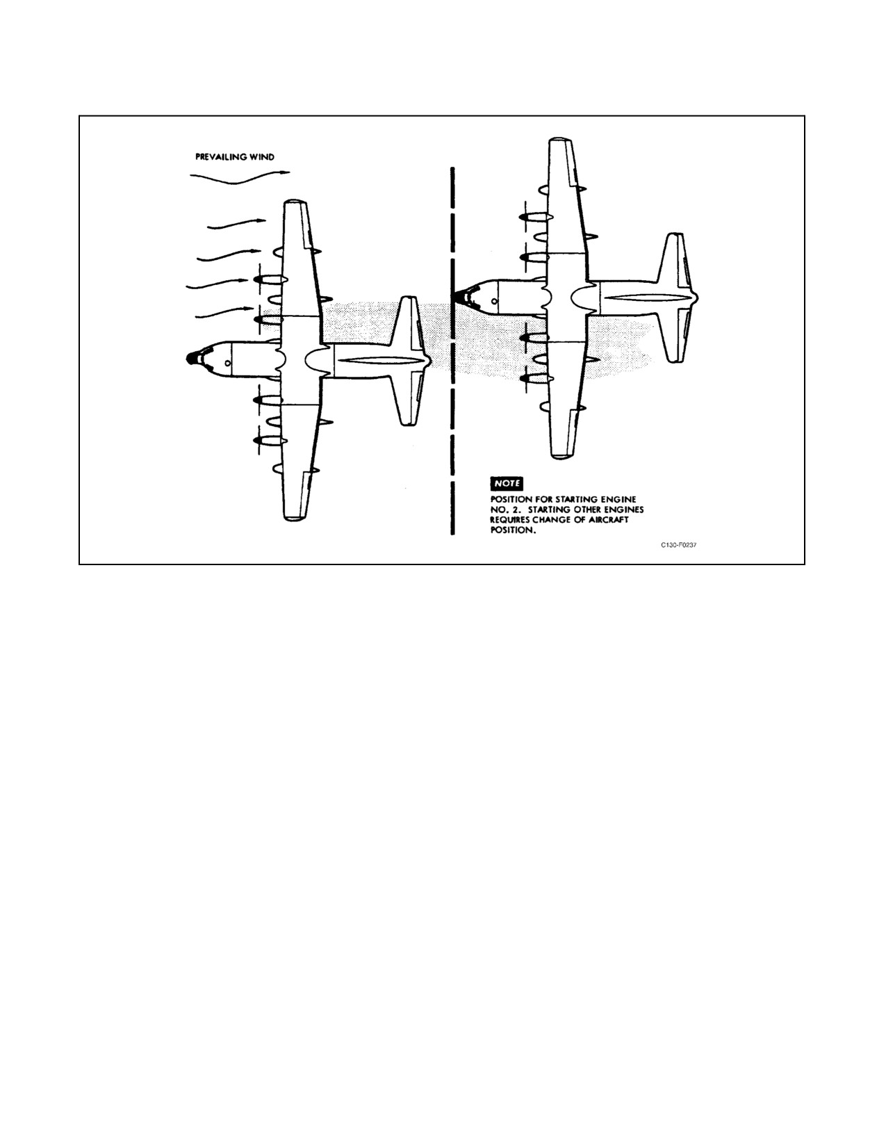
01-75GAL-1
Figure 8-7. Aircraft Position for Static Start
5. Establish communication between aircraft.
6. Complete necessary checklists.
7. Place chocks fore and aft of each forward main landing gear wheel.
8. Start one of the inboard engines for electrical power.
9. Secure APU.
10. Remove all ground equipment.
11. Position propeller blade cuff in line with island on the spinner base.
12. Place throttle at FLIGHT IDLE.
13. Close all doors, windows, and hatches.
14. Move condition lever to RUN; leave ENGINE BLEED AIR switch OFF until engine is on speed.
15. On front aircraft, upon signal from rear aircraft, increase power to 900_ TIT on all engines.
16. If propeller rotation does not begin, request maximum power on front aircraft.
17. After propeller rotation starts, observe normal start sequence. When 60-percent rpm is reached, place throttle
to GROUND IDLE.
ORIGINAL
8-96