SH-60B HELICOPTER. FLIGHT MANUAL (2008) - page 12
A1-H60BB-NFM-000
20.6.2 Safety Considerations During Evaluation Flights
Due to the broad significance of safety, it is impractical to list all contingencies that may fall under the general
category of safety grading criteria. Generally, mission success is subject to compromise when there are any safety
infractions,omissions,ordeviations,beginningwithmission planningand endingwith thepostflight debriefing.The
following provide additional guidance in these areas:
1. Violationsofpertinentdirectivesorproceduresthathaveadirectbearingonthesafecompletionofthemission,
or negligence in following any procedure or directive that jeopardizes the safety of the crew or aircraft, will
constitute an overall grade of UNQUALIFIED. The degree of jeopardy involved, in the absence of specific
directives, must be determined by the instructor/evaluator based on good judgment and experience.
2. The latitude given the examiner in grading safety items must be exercised with care. The examiner must
observe a discrepancy that directly contributes to an unsafe condition to justify an overall grade of
UNQUALIFIED for safety reasons.
3. When an in--flight safety discrepancy is imminent, and the pilot/crewman appears unaware of the condition
orhas not taken theappropriateaction, theexaminerwill correct thesituation by directing that action betaken.
Safety of flight cannot and shall not be compromised due to the reluctance on the part of the examiner to correct
any discrepancy.
4. If a grade of UNQUALIFIED is given for safety reasons, the examiner will include a written statement
describing the deficiency on the NATOPS Evaluation Report. The statement shall be clearly entitled SAFETY
DISCREPANCY.
20.6.3 Flight Evaluation Grading Criteria
The grading criteria establish the standard for grading flightcrew performance, but do not relieve the
evaluator/instructor from using good judgment based on experience. In those items where a flightcrewmember fails
to meet the minimums set forth in the grading criteria, but the examiner (through past experience and judgment)
knows that the discrepancy could have been caused by other factors such as weather, turbulence, or partial
malfunction of aircraft or weapons systems, the examiner may assign a grade of QUALIFIED. A note to this effect
will be included on the NATOPS Evaluation Report. Critical areas/subareas are denoted with an asterisk (*). Only
those subareas observed or required will be graded. The grades assigned for the subareas shall be determined by
comparing the degree of adherence to standard procedures with ratings as listed. Momentary deviations from standard
procedures should not be considered as unqualified, provided such deviations do not jeopardize flight safety or
mission performance and the evaluee applies prompt corrective action.
QUALIFIED. An individual shall be considered QUALIFIED in each subarea if standard procedures were executed
in accordance with the provisions of this manual and its subsets (i.e., checklists).
CONDITIONALLY QUALIFIED. An individual shall be considered CONDITIONALLY QUALIFIED in each
subarea if minimal omissions, errors, or deviations are made, none of which would affect successful completion of
mission or safety of flight/crew.
UNQUALIFIED. An individual shall be considered UNQUALIFIED for a subarea where any omissions, errors, or
deviations are made, which would affect the successful completion of the mission or safety of the flight/crew. Failure
to utilizechecklists or completerequired systems checks shall result in a gradeof UNQUALIFIED for theapplicable
subarea.
20.7
PILOT GRADING CRITERIA
20.7.1 Oral Examination and OFT/WST Procedures Evaluation Grading Criteria
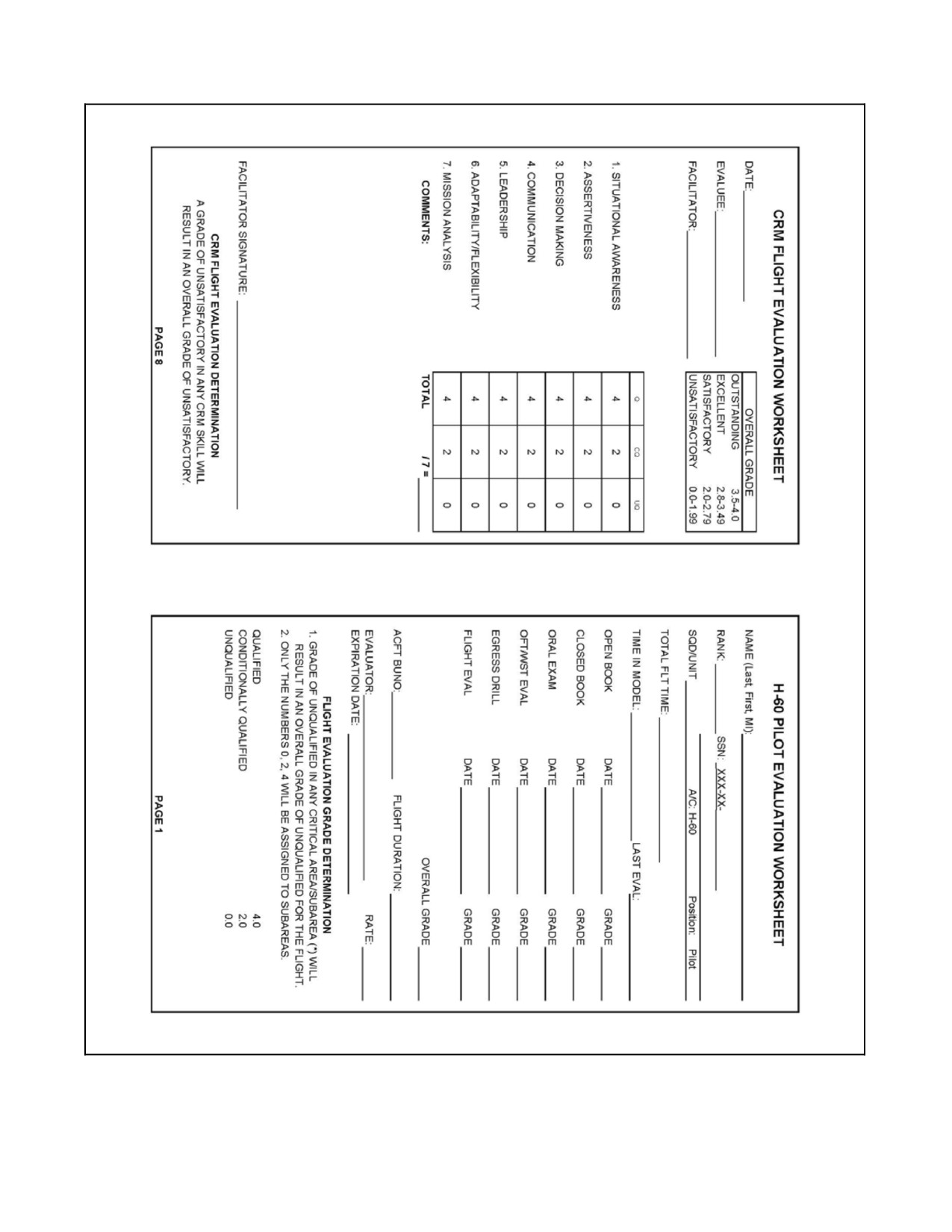
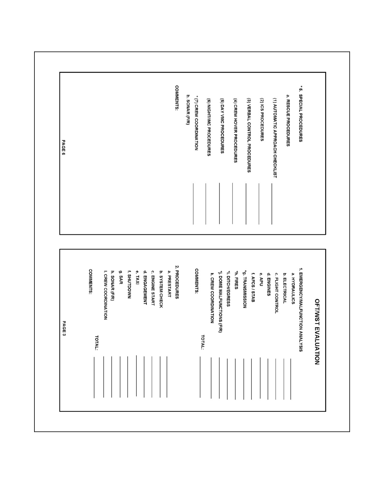
The NATOPS Pilot Evaluation Worksheet (Figure 20-1) is to be used to enter the status assigned as a result of the
oral examination and the OFT/WST procedures evaluation. Final examination grades are to be determined by the
evaluator/instructor.
ORIGINAL
20-4
A1-H60BB-NFM-000
20.7.1.1 Oral Examination
1. HELICOPTER SYSTEMS.
QUALIFIED. Exhibits a thorough knowledge of helicopter systems and their operations. Answers all
questions on the systems satisfactorily.
CONDITIONALLY QUALIFIED. Shows a slight lack of familiarity with helicopter systems and their
operation. Could have applied corrective action in case of emergency or malfunction of any system.
UNQUALIFIED. Shows a definite lack of familiarity with helicopter systems and their operation. Could not
have applied proper corrective action in case of emergency or malfunction of a system due to this lack of
knowledge.
20.7.1.2 OFT/WST Evaluation
1.
EMERGENCIES/MALFUNCTION ANALYSIS.
QUALIFIED. Exhibits thorough knowledge of, and familiarity with, all cockpit switches and controls in the
application of corrective action necessary in combating system malfunctions. Demonstrated thorough
knowledge of emergency procedures with no deviations.
CONDITIONALLY QUALIFIED. Exhibits satisfactory knowledge of, and familiarity with, all cockpit
switches and controls in the application of corrective action necessary in combating system malfunctions.
Identification of emergency procedures was slower than normal, but still considered safe. Demonstrated
satisfactory knowledge of emergency procedures with minor deviations.
UNQUALIFIED. Shows lack of familiarity with cockpit switches and controls. Unable to apply corrective
action necessary to cope with helicopter system malfunctions. Slow and hesitant in the recognition of
malfunctions. Misses one or more emergency procedures or sequential steps in corrective action that
compounded the situation.
2.
PROCEDURES.
QUALIFIED. NATOPS procedures and checklists followed without deviation, omission, or errors. Displayed
complete knowledge and familiarity with the cockpit. Properly utilized copilot. Complied with all safety
precautions.
CONDITIONALLY QUALIFIED. NATOPS procedures and checklists followed with minor deviation,
omission, or errors. Displayed satisfactory knowledge and familiarity with the cockpit. Did not fully utilize
copilot. Safety of flight was not jeopardized by discrepancies in checklists.
UNQUALIFIED. Did not utilize checklists. Demonstrated a complete lack of familiarity with cockpit. Did
not utilize copilot. Disregarded safety precautions.
20.7.2 Flight Evaluation
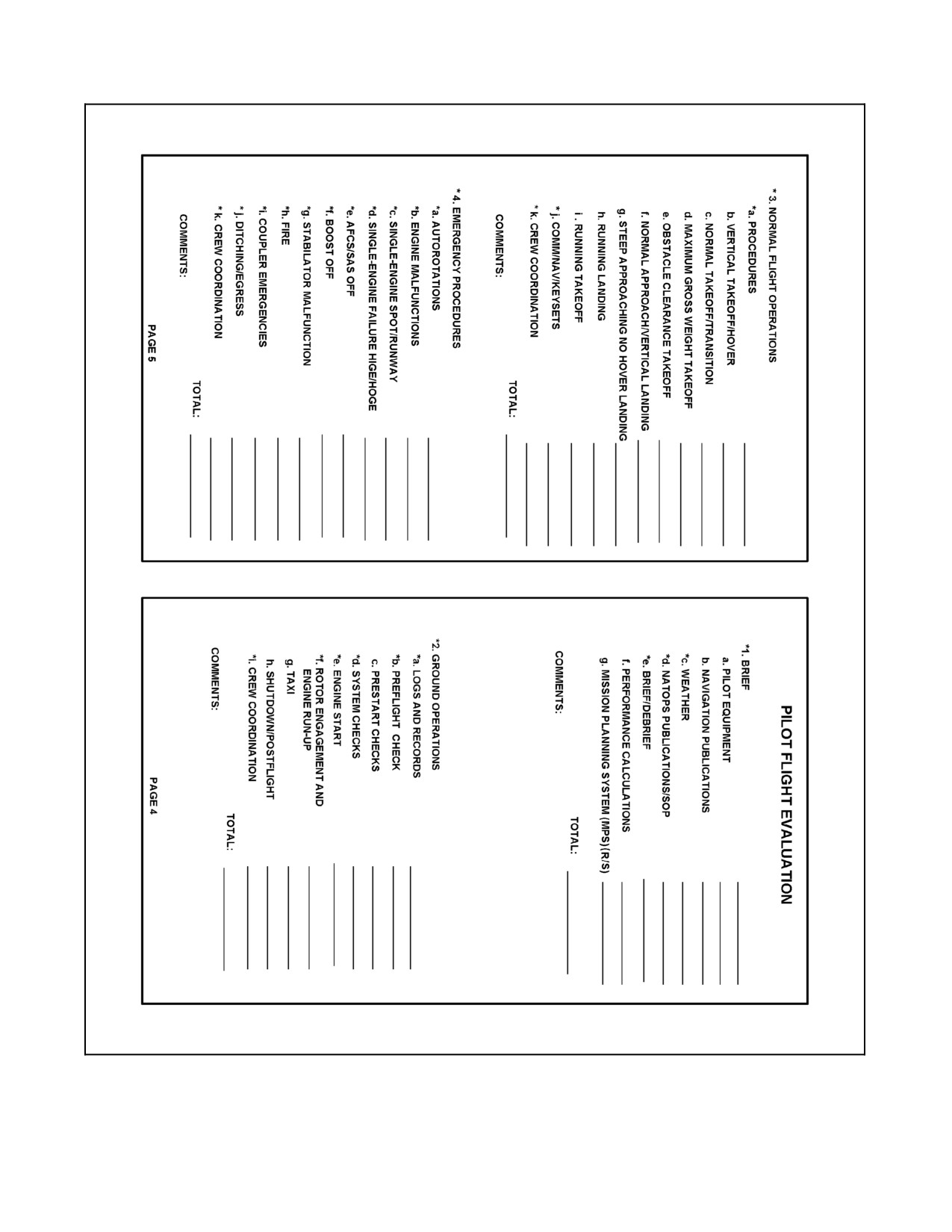
The NATOPS Evaluation Worksheet (Figure 20-1) shall be used to enter the status assigned as a result of the flight
evaluation.
*1. AREA 1 — BRIEF.
a. PILOT EQUIPMENT.
QUALIFIED. Possessed all personal flight gear in accordance with applicable directives. All gear subject
to periodic inspections was up to date and current. Knew location of all equipment.
CONDITIONALLY QUALIFIED. Unsure of location of some equipment.
UNQUALIFIED. Nonstandard, missing, or out--of--date equipment noted. Did not know the location of
most equipment.
20-5
ORIGINAL
A1-H60BB-NFM-000
b. NAVIGATION PUBLICATIONS.
QUALIFIED. Ensured all navigation publications necessary for flight were present and up to date.
CONDITIONALLY QUALIFIED. Ensured all publications necessary for flight were present. Minor
omissions related to currency of publications not affecting safety of flight.
UNQUALIFIED. Publications not carried in aircraft or out of date.
*c. WEATHER.
QUALIFIED. Obtained and interpreted all the available weather and sea information affecting the flight
and the planned mission. Obtained a forecast for all intended operating and landing areas.
CONDITIONALLY QUALIFIED. Obtained and interpreted weather and sea information with only minor
errors. The errors did not adversely affect the safety of the flight or violate civilian or military flight rules.
UNQUALIFIED. Unable to properly interpret weather sequences, weather forecast information, or sea
environment to safely and effectively complete the mission.
*d. NATOPS FLIGHT MANUAL/POCKET CHECKLIST(S)/SOP.
QUALIFIED. Both publications current with respect to incorporated changes.
CONDITIONALLY QUALIFIED. Publications current with respect to incorporated changes.
UNQUALIFIED. Current changes not incorporated in either publication.
*e. BRIEF/DEBRIEF.
QUALIFIED. The briefing was conducted in an orderly, well--organized manner in accordance with the
NATOPS briefing guide. Debriefing was conducted in a professional manner and contained constructive
criticism of the entire flight.
CONDITIONALLY QUALIFIED. The briefing was conducted in an orderly manner with errors and/or
omissions not affecting the safe and orderly completion of the mission. The debriefing was not complete.
UNQUALIFIED. Did not brief for the mission in accordance with this manual. No debriefing guide was
used and/or the debriefing was omitted.
f.
PERFORMANCE CALCULATIONS
QUALIFIED. Ensured all applicable performance calculations were compiled before flight, with no errors
or omissions.
CONDITIONALLY QUALIFIED. Completed applicable performance calculations before flight with
minor deviation.
UNQUALIFIED. Did not complete performance calculations in accordance with this manual. Calculations
incomplete or incorrect.
ORIGINAL
20-6
A1-H60BB-NFM-000
g. MISSION PLANNING SYSTEM (MPS)
QUALIFIED. Properly utilized MPS. Successfully entered all data needed for flight operations and
compared results to performance calculations. The downloaded MPS files would have greatly enhanced
aircrew situational awareness and reduced aircrew workload.
CONDITIONALLY QUALIFIED. Completed MPS process, but unable to enter all data required without
guidance. Flight could be safely conducted with cards completed, but numerous areas such as
communications, navigation, and performance calculations were not utilized. MPS cards used would
slightly enhance situational awareness and provide a minor reduction in aircrew workload.
UNQUALIFIED. Could not successfully complete the MPS process. Data was consistently entered
incorrectly or neglected entirely. Use of downloaded MPS cards could create confusion in the aircraft and
result in increased aircrew workload and decreased situational awareness.
*2. AREA 2--GROUND OPERATIONS.
*a. LOGS AND RECORDS.
QUALIFIED. Consulted the Aircraft Discrepancy Book (ADB) for completeness, accuracy, and the status
of the helicopter. Reviewed the Maintenance Action Forms (MAFs) from the previous ten flights for
discrepancies and corrective action. Filled out the applicable sections of the NAVFLIRS without errors or
omissions. Reviewed weight and balance for currency and within limits.
CONDITIONALLY QUALIFIED. Consulted the ADB for status of the helicopter, but failed to properly
avail themselves of all the information contained therein, and/or neglected to review the previous ten
flights.
UNQUALIFIED. Failed to ascertain that all grounding discrepancies had been corrected. Accepted a
helicopter that was not ready for flight. Failed to review weight and balance limitations.
*b. PREFLIGHT CHECK.
QUALIFIED. Accomplished the preflight inspection as outlined in this manual. Ensured proper servicing
of the helicopter in accordance with the planned mission.
CONDITIONALLY QUALIFIED. Accomplished the preflight inspection as outlined in this manual with
minor omissions or errors, none of which could affect safety of flight.
UNQUALIFIED. Performed the required preflight inspection with errors and/or omissions that could affect
safety of flight. Failed to verify that the helicopter was serviced and ready for flight.
c. PRESTART CHECKS.
QUALIFIED. NATOPS procedures and checklist followed without deviation, omission, or errors.
Displayed complete knowledge and familiarity with the cockpit. Properly utilized copilot. Complied with
all visual signals and safety precautions.
CONDITIONALLY QUALIFIED. Deviations and omissions of the prescribed procedures caused undue
delay. Hesitation in the manipulation of cockpit switches and circuit breakers. Marginal use of the copilot.
UNQUALIFIED. Did not utilize checklist. Demonstrated a complete lack of familiarity with cockpit. Did
not utilize copilot. Disregarded visual signals and/or safety precautions.
*d. SYSTEMS CHECKS.
QUALIFIED. Performed all checks in accordance with this manual. Ensured proper operation of all
equipment.
CONDITIONALLY QUALIFIED. Minor deviations and/or omissions in the use of checklists not
involving safety of flight. Incomplete systems checks.
UNQUALIFIED. Failed to follow checklist. Did not perform required checks in accordance with this
manual.
20-7
ORIGINAL
A1-H60BB-NFM-000
*e. ENGINE START.
QUALIFIED. NATOPS procedures and checklist followed without deviation, omission, or errors.
Displayed complete knowledge and familiarity with the cockpit. Properly utilized copilot.
CONDITIONALLY QUALIFIED. Deviations and omissions of the prescribed procedures caused delayed
and erratic starting. Poor timing in the manipulation of the controls. Demonstrated lack of knowledge of
starting procedures. Marginally effective use of copilot.
UNQUALIFIED. Could not start the engine and/or demonstrated a complete lack of proper procedure or
limitations.
*f. ROTOR ENGAGMENT AND ENGINE RUNUP.
QUALIFIED. NATOPS procedures followed without error and/or omission. Proper procedures used to
effect smooth, safe operation. Desired directional control maintained without abrupt changes.
CONDITIONALLY QUALIFIED. Improper or incomplete use of checklist resulting in nonstandard
procedures. Rough or erratic engagement. Misinterpretation of visual signals. No errors that affected
mission capability or flight safety.
UNQUALIFIED. Did not utilize checklists. Disregarded visual signals. Significant errors that could affect
safety of aircrew and/or ground personnel.
g. TAXI.
QUALIFIED. NATOPS procedures followed without error and/or omission. Proper procedures used to
effect smooth safe operation. Desired directional control maintained without abrupt changes.
CONDITIONALLY QUALIFIED. Minor deviations from standard procedures, none of which jeopardized
safe operation. Directional control slightly erratic.
UNQUALIFIED. NATOPS procedures were not followed. Errors or omissions that jeopardized or could
jeopardize safe operation.
h. SHUTDOWN/POSTFLIGHT.
QUALIFIED. The securing of rotors, engines, and all equipment was done in accordance with this manual.
Ensured that a complete postflight inspection was performed. Completed NAVFLIRS and VIDS/MAFS
forms completely and correctly.
CONDITIONALLY QUALIFIED. The securing of the rotors, engines, and all equipment was performed, but
not in the order prescribed in this manual. Minor deviations or omissions are allowed unless deviations or
omissions are injurious to the equipment or personnel. Minor omissions on postflight and/or flight
documentation.
UNQUALIFIED. Did not shut down the rotors, engines, or equipment in accordance with standard
procedures. Deviations or omissions in the procedures that if allowed to continue would be injurious to
equipment or personnel. Did not ensure a postflight was conducted. Did not fill out NAVFLIRS and/or
VIDS/MAFS.
*i. CREW COORDINATION.
QUALIFIED. Demonstrated effective crew utilization throughout all areas. Crew never placed in jeopardy.
CONDITIONALLY QUALIFIED. Did not fully or properly utilize crew.
UNQUALIFIED. Failed to utilize crew, resulting in safety implications.
ORIGINAL
20-8
A1-H60BB-NFM-000
*3. AREA 3--NORMAL FLIGHT OPERATIONS.
*a. PROCEDURES.
QUALIFIED. NATOPS procedures followed with no deviation. Checklists used. Site selected for landing
was adequate. Pattern for selected site showed proper planning. Demonstrated complete knowledge and
utilization of AFCS functions.
CONDITIONALLY QUALIFIED. Minor deviations from NATOPS procedures that did not jeopardize
safety of flight.
UNQUALIFIED. NATOPS procedures not followed. Failed to use checklists.
b. VERTICAL TAKEOFF/HOVER.
QUALIFIED. NATOPS procedures followed without error or deviation. Power was applied smoothly and
positively. Heading remained constant.
CONDITIONALLY QUALIFIED. Minor deviations in procedures not affecting safety of flight. Aircraft
and/or power not handled smoothly, but still effectively.
UNQUALIFIED. NATOPS procedures not followed. Power control was not smooth or applied in
accordance with standard procedure.
c. NORMAL TAKEOFF/TRANSITION.
QUALIFIED. Transition to climb airspeed made with a smooth addition of collective pitch to prevent
settling. All control applications smooth.
CONDITIONALLY QUALIFIED. Transition to climb airspeed was made, but with slight settling. Power
control applied abruptly. Heading control somewhat erratic.
UNQUALIFIED. Allowed aircraft to settle. Heading and power control abrupt.
d. MAXIMUM GROSS WEIGHT TAKEOFF.
QUALIFIED. NATOPS procedures followed without error or deviation. Hover check completed. Power
was applied smoothly and positively. Heading remained constant.
CONDITIONALLY QUALIFIED. Minor deviations in procedures not affecting safety of flight. Aircraft
and/or power not handled smoothly, but still effectively.
UNQUALIFIED. NATOPS procedures not followed. Power control was not smooth or applied in
accordance with standard procedure. Hover check not performed. Touched surface after takeoff.
e. OBSTACLE CLEARANCE TAKEOFF.
QUALIFIED. NATOPS procedures followed without error or deviation. Power was applied smoothly and
positively. Heading remained constant.
CONDITIONALLY QUALIFIED. Minor deviations in procedures not affecting safety of flight. Aircraft
and/or power not handled smoothly, but still effectively.
UNQUALIFIED. NATOPS procedures not followed. Power control was not smooth or applied in
accordance with standard procedure. Did not clear obstacle.
20-9
ORIGINAL
A1-H60BB-NFM-000
f.
NORMAL APPROACH/VERTICAL LANDING.
QUALIFIED. NATOPS procedures followed to place helicopter in a position for a proper approach. Power
was handled in a smooth manner so as to effect proper approach speed, altitude, and descent rate. Aircraft
controlled so as to arrive at normal hover with zero groundspeed, proper attitude, and power. Smooth
descent and no drift on touchdown.
CONDITIONALLY QUALIFIED. Aircraft altitude and power control rough. Slight over-- or undershoot.
Slight drift on touchdown.
UNQUALIFIED. Power applications erratic and rough. Erratic altitude and heading control. Excessive
descent rate and/or drift on touchdown.
g. STEEP APPROACH/NO HOVER LANDING.
QUALIFIED. NATOPS procedures followed to place helicopter in a position for a proper approach. Power
was handled in a smooth manner so as to effect proper approach speed and descent rate. Aircraft controlled
so as to arrive at touchdown point with little or no forward roll.
CONDITIONALLY QUALIFIED. Aircraft attitude and power control rough. Slight groundspeed on
touchdown.
UNQUALIFIED. Excessive sink rate. Power applications erratic and rough. Erratic attitude and heading
control. Missed intended point of touchdown. Excessive groundspeed on touchdown.
h. RUNNING LANDING.
QUALIFIED. NATOPS procedures followed to place aircraft on proper approach path with proper airspeed,
descent rate, and attitude. Transition from approach to landing smooth with no abrupt power or heading
changes.
CONDITIONALLY QUALIFIED. Minor deviations in procedures which did not jeopardize safety of
flight. Aircraft attitude, airspeed, power, and heading control rough.
UNQUALIFIED. Proper procedures not followed. Touchdown in skid. Over--rotated just prior to
touchdown. Landing speed exceeded helicopter limitations. Poor heading control on rollout.
i.
RUNNING TAKEOFF.
QUALIFIED. NATOPS procedures followed without error or deviation. Power was applied smoothly and
positively. Heading remained constant.
CONDITIONALLY QUALIFIED. Minor deviations in procedures not affecting safety of flight. Aircraft
and/or power not handled smoothly, but still effectively.
UNQUALIFIED. NATOPS procedures not followed. Power control was not smooth or applied in
accordance with standard procedure. Poor heading control on ground roll. Over--rotated helicopter just after
lift--off.
*j. COMM/NAV/KEYSETS.
Note
The COMM/NAV/KEYSETS evaluation shall be limited to the areas
listed. The pilot NATOPS evaluation is not intended to be an evaluation of
NATIP publication (NTRP 3--22.2--SH60B) related material, although
Mission Systems related emergencies may be evaluated. Tactics shall not
be evaluated.
ORIGINAL
20-10
A1-H60BB-NFM-000
QUALIFIED. Demonstrates a thorough ability to recall system operations, functions, and capabilities. Able
to accomplish operation ofcommunication,navigation andkeyset systemswithout hesitationorerror.Able
to accurately navigate aircraft using system navigation tools and symbols without hesitation or error. Able
to operate keys and display functions without hesitation or error.
CONDITIONALLY QUALIFIED. Demonstrates the ability to recall system operational functions, and
capabilities sufficient to operate the communication, navigation, and keysets with minor procedural errors
or omissions not affecting the continuation of the mission.
UNQUALIFIED. Lacks the ability to recall system operations, functions, and capabilities and/or makes
procedural errors affecting mission accomplishment.
*k. CREW COORDINATION.
QUALIFIED. Demonstrated effective crew utilization throughout all areas. Crew never placed in jeopardy.
CONDITIONALLY QUALIFIED. Did not fully or properly utilize crew.
UNQUALIFIED. Failed to utilize crew, resulting in safety implications.
*4. AREA 4--EMERGENCY PROCEDURES.
*a. AUTOROTATIONS.
QUALIFIED. All procedures carried out in accordance with this manual. Minor non--recurring
discrepancies not affecting flight safety.
CONDITIONALLY QUALIFIED. Airspeed, Nr, and heading control erratic. Slight drift at recovery.
UNQUALIFIED. Airspeed, Nr, and heading control beyond safe limits. Implemented techniques that
would have jeopardized the successful completion and recovery of the autorotation.
*b. ENGINE MALFUNCTIONS.
QUALIFIED. Properly analyzed the emergency situation and took appropriate action. Utilized PNAC and
crew as needed.
CONDITIONALLY QUALIFIED. Properly analyzed the emergency situation and accomplished the
required action, but with minor errors or omissions that did not preclude the successful completion of the
appropriate action.
UNQUALIFIED. Made errors or omissions that if allowed to continue would jeopardize safety of flight.
*c. SINGLE ENGINE TO A SPOT/RUNWAY.
QUALIFIED. All procedures carried out in accordance with NATOPS. Power was handled in a smooth
manner so as to effect proper approach speed and descent rate. Aircraft controlled so as to arrive at
touchdown with proper attitude and power.
CONDITIONALLY QUALIFIED. Followed procedures with only minor deviations that did not affect
safety of flight. Did not prebrief approach to PNAC.
UNQUALIFIED. Did not follow proper procedures. Handling of aircraft jeopardized safety of flight.
Touched down with excessive descent rate or unsafe groundspeed.
20-11
ORIGINAL
A1-H60BB-NFM-000
*d. SINGLE ENGINE FAILURE HIGE/HOGE.
QUALIFIED. All procedures carried out in accordance with NATOPS. Power was handled in a smooth
manner so as to effect a safe recovery. Descent rate, Nr, and nose attitude were controlled. Landed with no
drift. Minor Nr droop is allowable.
CONDITIONALLY QUALIFIED. Followed procedures with only minor deviations that did not affect
safety of flight. Landed with slight drift. Moderate Nr droop.
UNQUALIFIED. Did not follow proper procedures. Handling of aircraft jeopardized safety of flight.
Touched down with excessive sink rate, Nr control was erratic. Landed with excessive drift or severe Nr
droop.
*e. AFCS/SAS OFF.
QUALIFIED. Aircraft control smooth and positive. Heading, altitude, and attitude properly maintained.
CONDITIONALLY QUALIFIED. Aircraft control occasionally rough but without jeopardizing safety of
flight.
UNQUALIFIED. Aircraft control rough and abrupt. Jeopardized safety of flight.
*f. BOOST OFF.
QUALIFIED. Aircraft control smooth and positive. Heading, altitude, and attitude properly maintained.
CONDITIONALLY QUALIFIED. Aircraft control occasionally rough but without jeopardizing safety of
flight.
UNQUALIFIED. Aircraft control rough and abrupt. Jeopardized safety of flight.
*g. STABILATOR MALFUNCTION.
QUALIFIED. All procedures carried out in accordance with this manual.
CONDITIONALLY QUALIFIED. Slight deviations from procedures. Did not jeopardize safety of flight.
UNQUALIFIED. Did not follow procedures. Jeopardized safety of flight.
*h. FIRE.
QUALIFIED. All procedures carried out in accordance with this manual.
CONDITIONALLY QUALIFIED. Slight deviations from procedures. Did not jeopardize safety of flight.
UNQUALIFIED. Did not follow procedures. Jeopardized safety of flight.
*i. COUPLER EMERGENCIES.
QUALIFIED. All procedures carried out in accordance with this manual.
CONDITIONALLY QUALIFIED. Slight deviations from procedures. Did not jeopardize safety of flight.
Delay in analysis of malfunction.
UNQUALIFIED. Did not follow procedures. Jeopardized safety of flight. Failure to analyze malfunction.
*j. DITCHING/EGRESS.
QUALIFIED. All procedures carried out in accordance with this manual.
CONDITIONALLY QUALIFIED. Slight deviations from procedures. Did not jeopardize safety of flight.
Delay in analysis of malfunction.
UNQUALIFIED. Did not follow procedures. Jeopardized safety of flight. Failure to analyze malfunction.
ORIGINAL
20-12
A1-H60BB-NFM-000
*k. CREW COORDINATION.
QUALIFIED. Demonstrated effective crew utilization throughout all areas. Crew never placed in jeopardy.
CONDITIONALLY QUALIFIED. Did not fully or properly utilize crew.
UNQUALIFIED. Failed to utilize crew, resulting in safety implications.
*5. AREA 5 — SPECIAL PROCEDURES.
*a. RESCUE PROCEDURES.
(1) AUTOMATIC APPROACH CHECKLIST.
QUALIFIED. NATOPS procedures and checklist followed without deviation, omissions, or errors.
Displayed complete understanding and familiarity with the cockpit switches and procedures.
CONDITIONALLY QUALIFIED. Deviations and omissions of the prescribed procedures caused undue
delay. Hesitation in the manipulation of cockpit switches. Marginally effective use of copilot.
UNQUALIFIED. Did not utilize checklist. Demonstrated a complete lack of familiarity with cockpit. Did
not utilize copilot.
(2) ICS PROCEDURES.
QUALIFIED. Utilized standard ICS terminology in accordance with NATOPS.
CONDITIONALLY QUALIFIED. Used nonstandard or slight deviations from standard ICS terminology.
Did not jeopardize safety of flight.
UNQUALIFIED. Did not follow procedures. Jeopardized safety of flight or safety of swimmer or survivor.
(3) VERBAL CONTROL PROCEDURES.
QUALIFIED. NATOPS procedures and terminology utilized in order to expeditiously fly aircraft to proper
location.
CONDITIONALLY QUALIFIED. Deviations and omissions of the prescribed procedures caused undue
delay. Did not jeopardize safety of flight.
UNQUALIFIED. Did not follow procedures. Positioned aircraft improperly for rescue completion. Safety
of flight jeopardized.
(4) CREW HOVER PROCEDURES.
QUALIFIED. NATOPS ICS, flight, crew hover, and control transfer procedures followed without
deviation, omissions, or errors. Procedures briefed were followed during conduct of flight.
CONDITIONALLY QUALIFIED. Deviations or omissions of the prescribed procedures caused undue
delay. Did not jeopardize safety of flight.
UNQUALIFIED. Did not follow procedures. Significant deviations from crew NATOPS brief. Jeopardized
safety of flight.
(5) DAY VMC PROCEDURES.
QUALIFIED. NATOPS day, VMC rescue, and manual approach procedures followed without deviation,
omissions, or errors. Safely manipulated aircraft into appropriate swimmer deployment regime.
CONDITIONALLY QUALIFIED. Deviations from, or omissions of, the prescribed ICS communications
and NATOPS procedures caused undue delay. Did not jeopardize safety of flight.
UNQUALIFIED. Did not follow procedures. Jeopardized safety of flight.
(6) NIGHT/IMC PROCEDURES.
QUALIFIED. NATOPS Night/IMC rescue procedures followed without deviation, omissions, or errors.
Demonstrated effective use and understanding of windline rescue pattern.
20-13
ORIGINAL
A1-H60BB-NFM-000
CONDITIONALLY QUALIFIED. Deviations and/or omissions of the prescribed procedures caused undue
delay. Misunderstanding of windline rescue pattern and automatic approach procedures. Did not jeopardize
safety of flight.
UNQUALIFIED. Did not follow procedures. Jeopardized safety of flight.
(7) CREW COORDINATION.
QUALIFIED. Demonstrated effective copilot and aircrew utilization throughout rescue procedures.
Included entire crew in decision--making processes during conduct of rescue.
CONDITIONALLY QUALIFIED. Did not fully or properly utilize aircrew or copilot for mission
accomplishment. Slow to respond to aircrew recommendations regarding positioning or conduct of rescue.
No impact overall on safety of flight.
UNQUALIFIED. Failed to utilize copilot and/or aircrew, caused alienation of crew during flight, actions
resulted in jeopardizing safety of flight.
b. SONAR PROCEDURES (F/R).
QUALIFIED. Demonstrated thorough knowledge of NATOPS procedures in manipulation of the controls
to set the equipment into full operation.
CONDITIONALLY QUALIFIED. Demonstrated a fair knowledge of the equipment but deviated from the
NATOPS procedures. Was able to complete assigned mission.
UNQUALIFIED. Demonstrated lack of knowledge of the equipment and did not use NATOPS procedures.
Made major deviations or omissions that prolonged the mission or caused the mission to fail.
20.8
AIRCREW GRADING CRITERIA
20.8.1 Oral Examination Grading Criteria
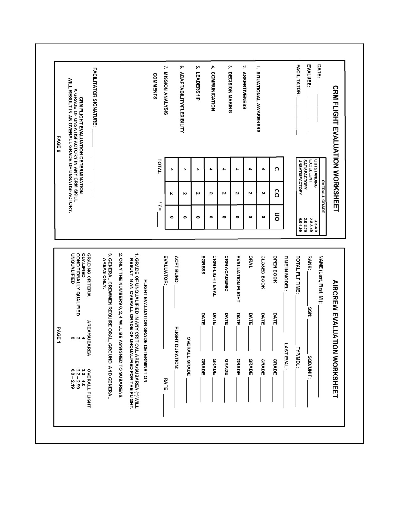
The NATOPS Aircrew Evaluation Worksheet (Figure 20-2) is to be used to enter the status assigned as a result of
oral examinations.
QUALIFIED. Demonstrated a thorough knowledge of location, operation and/or procedures of discussed item.
Answers all questions satisfactorily.
CONDITIONALLY QUALIFIED. Shows a slight lack of familiarity with or knowledge/understanding of the
procedures and operation of discussed item. Answered all questions with minor deviations not detrimental to aircrew
duties.
UNQUALIFIED. Definite lack of knowledge and/or understanding of discussed item. Unable to answer questions
considered essential for safe and proper execution of aircrew duties.
20.8.2 Flight Evaluation Grading Criteria
The NATOPS Aircrew Evaluation Worksheet (Figure 20-2) should be used to enter the status assigned as a result
of the flight evaluation. General crewmen (Aerial Door Gunners, SAR Medical Technicians, Special Mission
Crewmen, and Lookout Non--Aircrewmen) require ORAL, GROUND, and GENERAL areas only.
1. GROUND OPERATIONS.
*a. NATOPS FLIGHT MANUAL/POCKET CHECKLIST/SOP.
QUALIFIED. Publications current with respect to all incorporated changes.
CONDITIONALLY QUALIFIED. Publications are current with minor deviations.
UNQUALIFIED. Current changes not incorporated in either publication.
ORIGINAL
20-14
A1-H60BB-NFM-000
*b. FLIGHT EQUIPMENT.
QUALIFIED. Demonstrated thorough knowledge of location, operation and proper wearing of all safety
and survival equipment.
CONDITIONALLY QUALIFIED. Demonstrated satisfactory knowledge of location, operation and proper
wearing of all safety and survival equipment with minor deviations.
UNQUALIFIED. Non standard, missing on or properly worn. Did not know the location of all safety and
survival equipment.
c. AIRCRAFT DISCREPANCY BOOK.
QUALIFIED. Reviewed the ADB for completeness, accuracy, and the status of the aircraft.
CONDITIONALLY QUALIFIED. Consulted the ADB for status of the aircraft, but failed to properly avail
them self of all the information contained therein.
UNQUALIFIED. Failed to review the ADB for completeness, accuracy, and the status of the aircraft.
d. BRIEF/DEBRIEF/MISSION PLANNING.
QUALIFIED. Arrived to the brief having obtained/given all information pertinent to the successful
completion of the mission.
CONDITIONALLY QUALIFIED. Met the criteria for QUALIFIED except for minor omissions, not
affecting the successful completion of the mission.
UNQUALIFIED. Major omissions which could affect the successful completion of the mission or failed
to attend.
*e. PREFLIGHT.
QUALIFIED. Accomplished the preflight inspection as outlined in this manual.
CONDITIONALLY QUALIFIED. Accomplished the preflight inspection as outlined in this manual with
minor deviations/omissions not affecting safety of flight.
UNQUALIFIED. Performed required preflight inspection with deviations/omissions which affected safety
of flight
*f. AIRCRAFT SERVICING/HANDLING.
QUALIFIED. Ensured proper servicing and handling procedures as outlined in this manual.
CONDITIONALLY QUALIFIED. Completed servicing and handling procedures as outlined in this
manual with minor deviations/omissions not affecting safety of flight.
UNQUALIFIED. Performed servicing and handling with deviations/omissions which affected safety of
flight.
*g. SAFETY.
QUALIFIED. Observed all safety precautions and displayed no conduct that could jeopardize safety of
flight.
CONDITIONALLY QUALIFIED. Observed safety precautions with minor deviations not affecting safety
of flight.
UNQUALIFIED. Flagrant disregard of safety precautions which affected safety of flight.
20-15
ORIGINAL
A1-H60BB-NFM-000
2. GENERAL OPERATIONS.
*a. CHECKLIST UTILIZATION.
QUALIFIED. Procedures completed in the proper sequence as outlined in this manual.
CONDITIONALLY QUALIFIED. Procedures completed with minor deviations/omissions not affecting
safety of flight.
UNQUALIFIED. Major omissions/deviations which affected safety of flight.
*b. EMERGENCY PROCEDURES.
QUALIFIED. Recognized emergencies and followed procedures stated in this manual.
CONDITIONALLY QUALIFIED. Recognized emergencies with minor deviations not affecting safety of
flight.
UNQUALIFIED. Failed to recognize emergencies and/or follow procedures stated in this manual which
affected safety of flight.
c. LOOKOUT PROCEDURES.
QUALIFIED. Observed all safety precautions and displayed sound judgment.
CONDITIONALLY QUALIFIED. Observed safety precautions and displayed sound judgment with minor
errors not affecting safety of flight.
UNQUALIFIED. Flagrant disregard of safety precautions which affected safety of flight.
d. OPERATIONAL CHECKS.
QUALIFIED. Procedures completed in the proper sequence as outlined in this manual.
CONDITIONALLY QUALIFIED. Procedures completed with minor deviations/omissions not affecting
safety of flight.
UNQUALIFIED. Major omissions/deviations which affected safety of flight.
*e. AIRCRAFT LIMITATIONS.
QUALIFIED. Familiar with all aircraft limitations. Operated within the limitations outlined in this manual.
CONDITIONALLY QUALIFIED. Familiar with aircraft limitations. Operated within limitations with
minor deviations/omissions not affecting safety of flight.
UNQUALIFIED. Unfamiliar with aircraft limitations. Operated outside of limitations which affected
safety of flight.
f.
RADIO PROCEDURES.
QUALIFIED. Provided a constant status, using standard terminology that was clear and concise.
CONDITIONALLY QUALIFIED. Provided a constant status with minor deviations/omissions not
affecting safety of flight.
UNQUALIFIED. Major deviations/omissions which affected safety of flight.
ORIGINAL
20-16
A1-H60BB-NFM-000
*g. SAFETY.
QUALIFIED. Observed all safety precautions and displayed no conduct that could jeopardize safety of
flight.
CONDITIONALLY QUALIFIED. Observed safety precautions with minor deviations/omissions not
affecting safety of flight.
UNQUALIFIED. Flagrant disregard of safety precautions which affect safety of flight.
3. SAR OPERATIONS.
*a. CHECKLIST UTILIZATION.
QUALIFIED. Procedures completed in the proper sequence as outlined in this manual.
CONDITIONALLY QUALIFIED. Procedures completed with minor deviations/omissions not affecting
safety of flight.
UNQUALIFIED. Major deviations/omissions which affected safety of flight.
*b. HOIST OPERATIONS/LIMITATIONS.
QUALIFIED. Followed approved procedures and limitations outlined in this manual.
CONDITIONALLY QUALIFIED. Followed approved procedures and limitations with minor deviations/
omissions not affecting safety of flight.
UNQUALIFIED. Major deviations/omissions which affected safety of flight.
c. ICS PROCEDURES.
QUALIFIED. Provided a constant status, using standard terminology that was clear and concise.
CONDITIONALLY QUALIFIED. Provided a constant status with minor deviations/omissions not
affecting safety of flight.
UNQUALIFIED. Major deviations/omissions which affected safety of flight.
d. SAR EQUIPMENT OPERATIONS.
QUALIFIED. Demonstrated thorough knowledge and operation of equipment.
CONDITIONALLY QUALIFIED. Demonstrated adequate knowledge and operation of equipment with
minor deviations/omissions not affecting the safe completion of the mission.
UNQUALIFIED. Demonstrated a lack of knowledge and operation of equipment.
*e. HOIST EMERGENCIES.
QUALIFIED. Recognized emergencies and followed procedures stated in this manual.
CONDITIONALLY QUALIFIED. Recognized emergencies with minor deviations not affecting safety of
flight.
UNQUALIFIED. Failed to recognize emergencies and/or follow procedures stated in this manual which
affect safety of flight.
20-17
ORIGINAL
A1-H60BB-NFM-000
f. DAY/NIGHT SAR OPERATIONS.
QUALIFIED. Followed procedures outlined in this manual.
CONDITIONALLY QUALIFIED. Followed procedures with minor deviations/omissions not affecting
safety of flight.
UNQUALIFIED. Major deviations/omissions which affected safety of flight.
*g. SAFETY.
QUALIFIED. Observed all safety precautions and displayed no conduct that could jeopardize safety of
flight.
CONDITIONALLY QUALIFIED. Observed safety precautions with minor deviations not affecting safety
of flight.
UNQUALIFIED. Flagrant disregard of safety precautions which affected safety of flight.
4. UTILITY OPERATIONS.
*a. CHECKLIST UTILIZATION.
QUALIFIED. Procedures completed in the proper sequence as outlined in this manual.
CONDITIONALLY QUALIFIED. Procedures completed with minor deviations/omissions not affecting
safety of flight.
UNQUALIFIED. Major omissions/deviations which affected safety of flight.
b. CARGO/VERTREP OPERATIONS.
QUALIFIED. Followed procedures outlined in this manual.
CONDITIONALLY QUALIFIED. Followed procedures with minor deviations/omissions not affecting
safety of flight.
UNQUALIFIED. Major deviations/omissions which affected safety of flight.
c. HIFR OPERATIONS.
QUALIFIED. Followed procedures outlined in this manual.
CONDITIONALLY QUALIFIED. Followed procedures with minor deviations/omissions not affecting
safety of flight.
UNQUALIFIED. Major deviations/omissions which affected safety of flight.
d. SHIPBOARD OPERATIONS.
QUALIFIED. Followed procedures outlined in this manual.
CONDITIONALLY QUALIFIED. Followed procedures with minor deviations/omissions not affecting
safety of flight.
UNQUALIFIED. Major deviations/omissions which affected safety of flight.
ORIGINAL
20-18
A1-H60BB-NFM-000
e. ICS PROCEDURES.
QUALIFIED. Provided a constant status, using standard terminology that was clear and concise.
CONDITIONALLY QUALIFIED. Provided a constant status with minor deviations/omissions not
affecting safety of flight.
UNQUALIFIED. Major deviations/omissions which affected safety of flight.
*f. LIMITATIONS.
QUALIFIED. Within limitations outlined in this manual.
CONDITIONALLY QUALIFIED. Within limitations with minor deviations/omissions not affecting safety
of flight.
UNQUALIFIED. Outside of limitations which affected safety of flight.
*g. SAFETY.
QUALIFIED. Observed all safety precautions and displayed no conduct that could jeopardize safety of
flight.
CONDITIONALLY QUALIFIED. Observed safety precautions with minor deviations not affecting safety
of flight.
UNQUALIFIED. Flagrant disregard of safety precautions which affected safety of flight.
5.
NON--ACOUSTIC OPERATIONS.
a. RADAR/IFF.
QUALIFIED. Demonstrated a thorough knowledge of equipment, control functions, troubleshooting and
procedures.
CONDITIONALLY QUALIFIED. Demonstrated a fair knowledge of equipment, control functions,
troubleshooting and procedures with minor errors not affecting the mission.
UNQUALIFIED. Demonstrated a complete lack of knowledge with errors that affected the mission.
b. ELECTRONIC SUPPORT MEASURES.
QUALIFIED. Demonstrated a thorough knowledge of equipment, control functions, troubleshooting and
procedures.
CONDITIONALLY QUALIFIED. Demonstrated a fair knowledge of equipment, control functions,
troubleshooting and procedures with minor errors not affecting the mission.
UNQUALIFIED. Demonstrated a complete lack of knowledge with errors that affected the mission.
c. ISD/ASE.
QUALIFIED. Demonstrated a thorough knowledge of equipment, control functions, troubleshooting and
procedures.
CONDITIONALLY QUALIFIED. Demonstrated a fair knowledge of equipment, control functions,
troubleshooting and procedures with minor errors not affecting the mission.
UNQUALIFIED. Demonstrated a complete lack of knowledge with errors that affected the mission.
20-19
ORIGINAL
A1-H60BB-NFM-000
d. NAVIGATION.
QUALIFIED. Demonstrated a thorough knowledge of equipment, control functions, troubleshooting and
procedures.
CONDITIONALLY QUALIFIED. Demonstrated a fair knowledge of equipment, control functions,
troubleshooting and procedures with minor errors not affecting the mission.
UNQUALIFIED. Demonstrated a complete lack of knowledge with errors that affected the mission.
e. COMMUNICATION.
QUALIFIED. Demonstrated a thorough knowledge of equipment, control functions, troubleshooting and
procedures.
CONDITIONALLY QUALIFIED. Demonstrated a fair knowledge of equipment, control functions,
troubleshooting and procedures with minor errors not affecting the mission.
UNQUALIFIED. Demonstrated a complete lack of knowledge with errors that affected the mission.
f.
FLIR.
QUALIFIED. Demonstrated a thorough knowledge of equipment, control functions, troubleshooting and
procedures.
CONDITIONALLY QUALIFIED. Demonstrated a fair knowledge of equipment, control functions,
troubleshooting and procedures with minor errors not affecting the mission.
UNQUALIFIED. Demonstrated a complete lack of knowledge with errors that affected the mission.
*g. SAFETY.
QUALIFIED. Observed all safety precautions and displayed no conduct that could jeopardize safety of
flight.
CONDITIONALLY QUALIFIED. Observed safety precautions with minor deviations not affecting safety
of flight.
UNQUALIFIED. Flagrant disregard of safety precautions which affected safety of flight.
6. ACOUSTIC OPERATIONS.
a. DIPPING/MAD OPERATIONS.
QUALIFIED. Demonstrated a thorough knowledge of equipment, control functions and procedures.
CONDITIONALLY QUALIFIED. Demonstrated a fair knowledge of equipment, control functions and
procedures with minor errors not affecting the mission.
UNQUALIFIED. Demonstrated a complete lack of knowledge with errors that affected the mission.
*b. EMERGENCY PROCEDURES.
QUALIFIED. Recognized emergencies and followed procedures stated in this manual.
CONDITIONALLY QUALIFIED. Recognized emergencies with minor deviations not affecting safety of
flight.
UNQUALIFIED. Failed to recognize emergencies and/or follow procedures stated in this manual which
affected safety of flight.
ORIGINAL
20-20
A1-H60BB-NFM-000
c. ICS PROCEDURES.
QUALIFIED. Provided a constant status, using standard terminology that was clear and concise.
CONDITIONALLY QUALIFIED. Provided a constant status with minor deviations/omissions not
affecting safety of flight.
UNQUALIFIED. Major deviations/omissions which affected safety of flight.
d. TROUBLESHOOTING.
QUALIFIED. Followed approved troubleshooting procedures outlined in this manual.
CONDITIONALLY QUALIFIED. Followed approved troubleshooting procedures with minor errors not
affecting the mission.
UNQUALIFIED. Major errors which affected safety of flight.
e. SONOBUOY OPERATIONS.
QUALIFIED. Demonstrated a thorough knowledge of equipment, control functions and procedures.
CONDITIONALLY QUALIFIED. Demonstrated a fair knowledge of equipment, control functions and
procedures with minor errors not affecting the mission.
UNQUALIFIED. Demonstrated a complete lack of knowledge with errors that affected the mission.
*f. LIMITATIONS.
QUALIFIED. Within limitations outlined in this manual.
CONDITIONALLY QUALIFIED. Within limitations with minor deviations/omissions not affecting safety
of flight.
UNQUALIFIED. Outside of limitations which affected safety of flight.
*g. SAFETY.
QUALIFIED. Observed all safety precautions and displayed no conduct that could jeopardize safety of
flight.
CONDITIONALLY QUALIFIED. Observed safety precautions with minor deviations not affecting safety
of flight.
UNQUALIFIED. Flagrant disregard of safety precautions which affected safety of flight.
20.9
FLIGHT EVALUATION GRADE DETERMINATION
The following procedures shall be used in determining the oral, OFT/WST, and flight evaluation grade. A grade of
UNQUALIFIED in any critical area or critical subarea will result in an overall grade of UNQUALIFIED for the flight.
Otherwise, flight evaluation (or area) grades shall be determined by assigning the following numerical equivalents
to the adjective grade for each subarea:
UNQUALIFIED
0.0
CONDITIONALLY QUALIFIED
2.0
QUALIFIED
4.0
20-21
ORIGINAL
A1-H60BB-NFM-000
Note
Only the numerals 0, 2, or 4 will be assigned in subareas. No interpolation
is allowed. To determine the numerical grade for each area and the overall
grade for the flight, add all the points assigned to the subareas and divide
this sum by the number of subareas graded. The adjective grade shall then
be determined on the basis of the following scale:
FLIGHT:
0.0 to 2.19 UNQUALIFIED.
2.2 to 2.99 CONDITIONALLY QUALIFIED.
3.0 to 4.00 QUALIFIED.
ORAL or OFT/WST:
0.0 to 2.99 UNQUALIFIED.
3.0 to 4.00 QUALIFIED.
EXAMPLE: (Add subarea numerical equivalents)
(4 + 2 + 4 + 2 + 4)/5 = 16/5 = 3.20 QUALIFIED.
20.10 FINAL GRADE DETERMINATION
The final NATOPS evaluation grade shall be based on the results of the oral, OFT/WST, and flight evaluation. An
evaluee who receives an UNQUALIFIED on any ground examination or the flight evaluation shall be placed in an
UNQUALIFIED status until achieving a grade of CONDITIONALLY QUALIFIED or QUALIFIED on a
reevaluation.
20.11 RECORDS AND REPORTS
A NATOPS Evaluation Report (OPNAV Form 3710/7) shall be completed for each evaluation and forwarded to the
evaluee’s commanding officer. This report shall be filed in the individual’s flight training record and retained therein
in accordance with OPNAVINST 3710.7 (series). In addition, an entry shall be made in the Flight Log Book
(OPNAV 3760/10) under QUALIFICATION AND ACHIEVEMENTS.
QUALIFICATION
DATE
SIGNATURE
NATOPS EVAL. H-60 (Series)
(DATE)
(Authenticating Signature)
(Unit Administering Qualification)
PILOT/AIRCREWMAN
20.12 NATOPS EVALUATION FORMS
In addition to the NATOPS Evaluation Report, the Evaluator/Instructor provides a NATOPS flight evaluation
worksheet (Figure 20-1 and 20-2) for use during the flight. All of the flight areas and subareas are listed on the
worksheet with space.
ORIGINAL
20-22
A1-H60BB-NFM-000
Figure 20-1. Pilot Evaluation Worksheet (Sheet 1 of 4)
20-23
ORIGINAL
A1-H60BB-NFM-000
Figure 20-1. Pilot Evaluation Worksheet (Sheet 2)
ORIGINAL
20-24
A1-H60BB-NFM-000
Figure 20-1. Pilot Evaluation Worksheet (Sheet 3)
20-25
ORIGINAL
A1-H60BB-NFM-000
Figure 20-1. Pilot Evaluation Worksheet (Sheet 4)
ORIGINAL
20-26
A1-H60BB-NFM-000
Figure 20-2. Aircrewman Evaluation Worksheet (Sheet 1 of 3)
20-27
ORIGINAL
A1-H60BB-NFM-000
Figure 20-2 Aircrewman Evaluation Worksheet (Sheet 2)
ORIGINAL
20-28
A1-H60BB-NFM-000
Figure 20-2 Aircrewman Evaluation Worksheet (Sheet 3)
20-29/(20-30 blank)
ORIGINAL
A1-H60BB-NFM--000
PART XI
Performance Data
Chapter 21 — Performance Data Introduction
Chapter 22 — Standard Data
Chapter 23 — Takeoff
Chapter 24 — Climb
Chapter 25 — Range
Chapter 26 — Hover Endurance
Chapter 27 — Emergency Operation
Chapter 28 — Level Flight Performance Charts
75/(76 blank)
ORIGINAL
A1-H60BB-NFM-000
CHAPTER 21
Performance Data Introduction
21.1
INTRODUCTION
The performance data covered in Chapters 22, 23, 24, 25, 26, 27, and 28 is arranged by type of chart, with each type
of chart discussed in a separate chapter. Each chapter, and the charts contained within, is arranged in the order that
reflects the sequence of operational use. Each chapter incorporates a page containing explanatory text which describes
the functions indicated for each chart, conditions assumed in chart preparation, and guidelines to permit adjustment
of the solution attained.
The sample problem, typical of the normal mission of the helicopter, includes the sample problem data shown on
each chart contained within that chapter. If conditions are less than the lowest value shown on a chart, use the lowest
value shown. Limitations that should not be exceeded are identified on appropriate charts.
Subsequent chapters contain the following: Chapter 22 contains information that is needed to enter charts found in
subsequent chapters; Chapter 23 provides the necessary information concerning takeoff performance; Chapter 24
provides the necessary climb performance; Chapter 25 presents range data; Chapter 26 presents hover endurance
data; Chapter 27 provides performance data associated with emergency or nonstandard conditions; and Chapter 28
provides information to select and determine level flight performance data at various conditions.
21.1.1 Sample Problem
A sample problem, typical of a normal mission, is included with each type chart in applicable chapters. For
consistency and continuity, the chart values shown on the charts are actual chart values used in the sample problem
explanatory text. The explanatory text for each type chart used in computing the sample problem contains a graphic
illustration explaining how that chart is used.
21.2
FACTORS AFFECTING RANGE AND ENDURANCE
As weight decreases, the power required to maintain constant airspeed decreases. Heavily loaded helicopters must
fly at a greater power setting than lightly loaded helicopters flying at the same speed. Altitude has a marked effect
on the performance of all gas turbine engines. Air density and temperature decrease as altitude increases. As the
density of the air decreases, the mass flow of air through the engine decreases and efficiency decreases. The gas
turbine operates more efficiently at lower temperatures encountered at high altitudes because thethrust delivered per
pound of air consumed is higher at high altitudes. Since power output decreases and efficiency increases, specific
fuel consumption decreases with increased altitude. A definite advantage is gained when operating at high altitudes
since higher true airspeed will result from a given power output. The helicopter is limited in using the gas turbines
for fullest efficiency at altitude. This is not due to the engines, but to the decreased lift capability of the rotor system
at high altitudes. For flight planning purposes, consult the appropriate charts in Part XI.
21.3
PLANNING FOR AND TRANSPORT OF CARGO
Detailed procedures for planning, loading, securing, and delivery of cargo loads are contained in the Cargo Loading
Manual, Navy Model H-46 Helicopters (NAVAIR 01-250-HDA-9), and Packaging and Handling of Dangerous
Materials for Transportation by Military Aircraft (NAVSUPPUB 505).
21-1/(21-2 blank)
ORIGINAL
A1-H60BB-NFM-000
CHAPTER 22
Standard Data
22.1
TEMPERATURE CONVERSION CHART
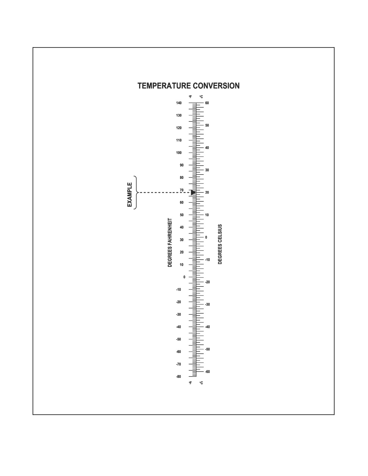
The Temperature Conversion Chart (Figure 22-1) provides a conversion of temperature scale that will permit
conversion between Fahrenheit and Celsius temperatures.
22.1.1 Sample Problem for Use of Temperature Conversion Chart
Enter the left side of chart at 68 °F. Then, trace right to the Celsius scale and read 20 °C.
22.2
DENSITY ALTITUDE CHART
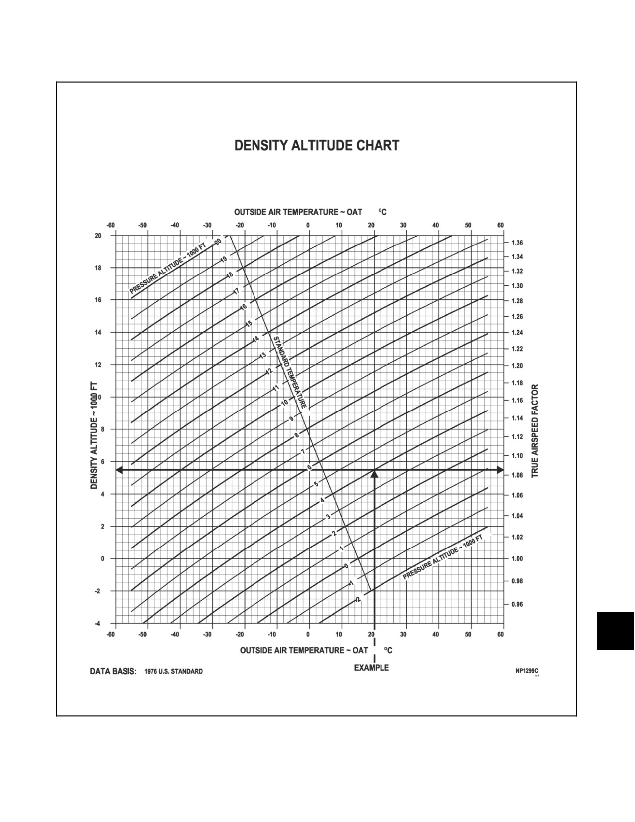
The Density Altitude Chart (Figure 22-2) provides a density altitude when ambient temperature is applied to pressure
altitude. The chart also contains an airspeed conversion factor that, when used to multiply a calibrated airspeed,
provides a true airspeed.
22.2.1 Sample Problem for Use of Density Altitude Chart
1. Enter bottom of chart at OAT (+20 °C) and trace up to pressure altitude line (4,000 ft).
2. Trace left to the density altitude scale and read density altitude (5,500 ft) or trace right to the airspeed
conversion scale and read conversion factor (1.085).
22.3
BLADE STALL CHART
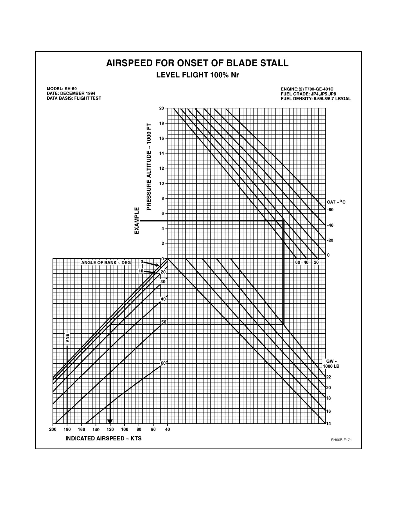
The Airspeed for Onset of Blade Stall Chart (Figure 22-3) represents speeds at which stall begins to occur on the
retreating blade tip. At these speeds, reasonable maneuvers or mild turbulence can be tolerated. Increased airspeed,
severe turbulence, or abrupt control maneuvers at or near these speeds will increase the severity of the stall, and the
helicopter will become more difficult to control. If blade stall is allowed to fully develop, a complete loss of control
will be experienced and the helicopter will pitch up and to the left. The use of forward cyclic to correct this pitch up
may aggravate the stall as it increases the angle of attack of the retreating blade.
22.3.1 Sample Problem for Use of Blade Stall Chart
Given:
1. Gross weight: 22,000 pounds.
2. Angle of bank: 20°.
3. Pressure altitude: 5,000 feet.
4. OAT: 20°.
5. Rotor speed: 100 percent Nr.
Determine:
Maximum recommended speed.
Solution:
1. Enter chart at left at 5,000 foot pressure altitude.
2. Move horizontally to 20 °C OAT line.
3. Move down to known or estimated gross weight, 22,000 pounds.
4. Move left to 20° angle of bank influence line.
5. Move down to read the indicated airspeed (KTS).
6. The indicated airspeed for the above conditions would be 120 KIAS.
22-1
ORIGINAL
A1-H60BB-NFM-000
Figure 22-1. Temperature Conversion Chart
ORIGINAL
22-2
A1-H60BB-NFM-000
Figure 22-2. Density Altitude Chart
22-3
ORIGINAL
A1-H60BB-NFM-000
Figure 22-3. Airspeed for Onset of Blade Stall Chart
ORIGINAL
22-4
A1-H60BB-NFM-000
22.4
ENGINE PERFORMANCE
Performance planning is used to determine if the installed engines have enough power (torque) to accomplish the
assigned mission. Planning should also be used to determine single engine capability. The actual torque available
tothepilotundermissionconditionsiswhatiscritical, andit isimportant todeterminethispriortothemission.When
mission planning, use Aircraft Torque Factor (ATF), and for single engine capability, use the Engine Torque Factor
(ETF) for the weakest engine (lowest ETF). In all calculations in this section, ATF can be substituted for ETF.
22.4.1 Engine Performance Charts
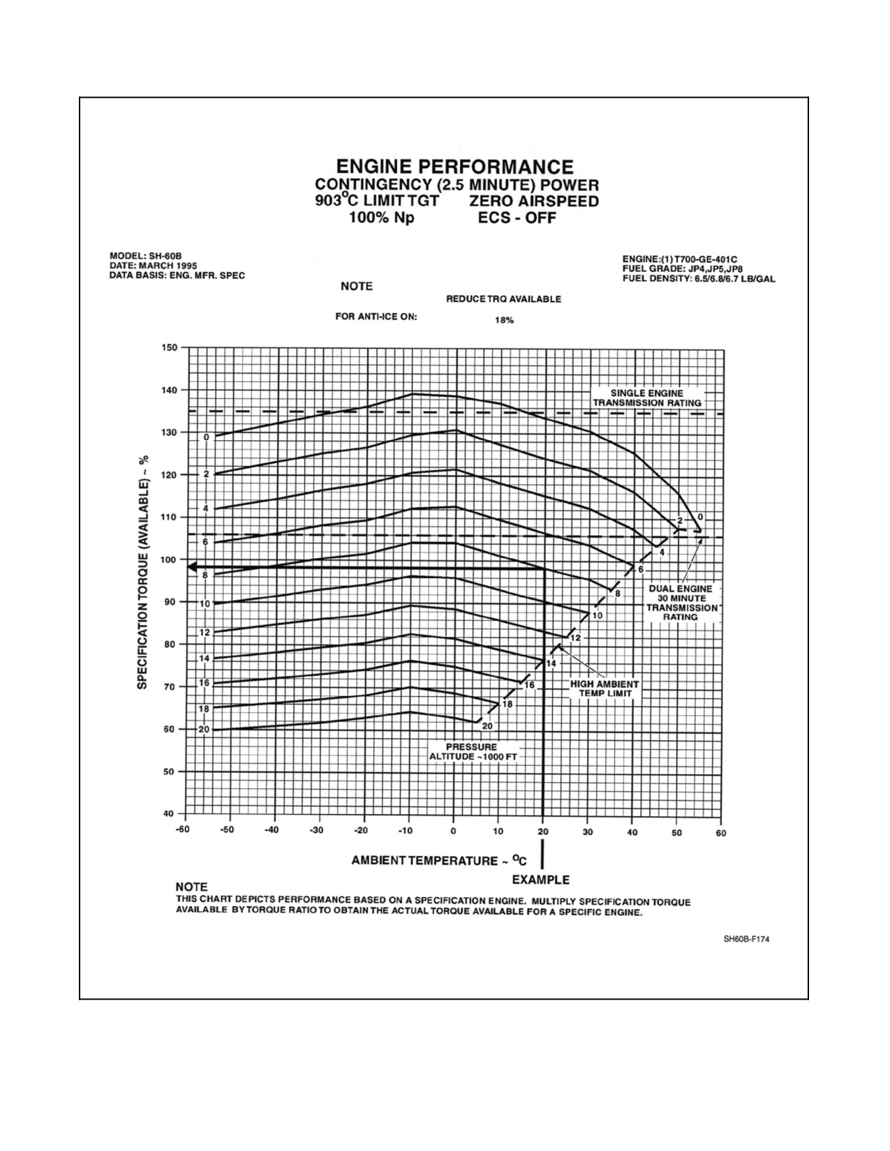
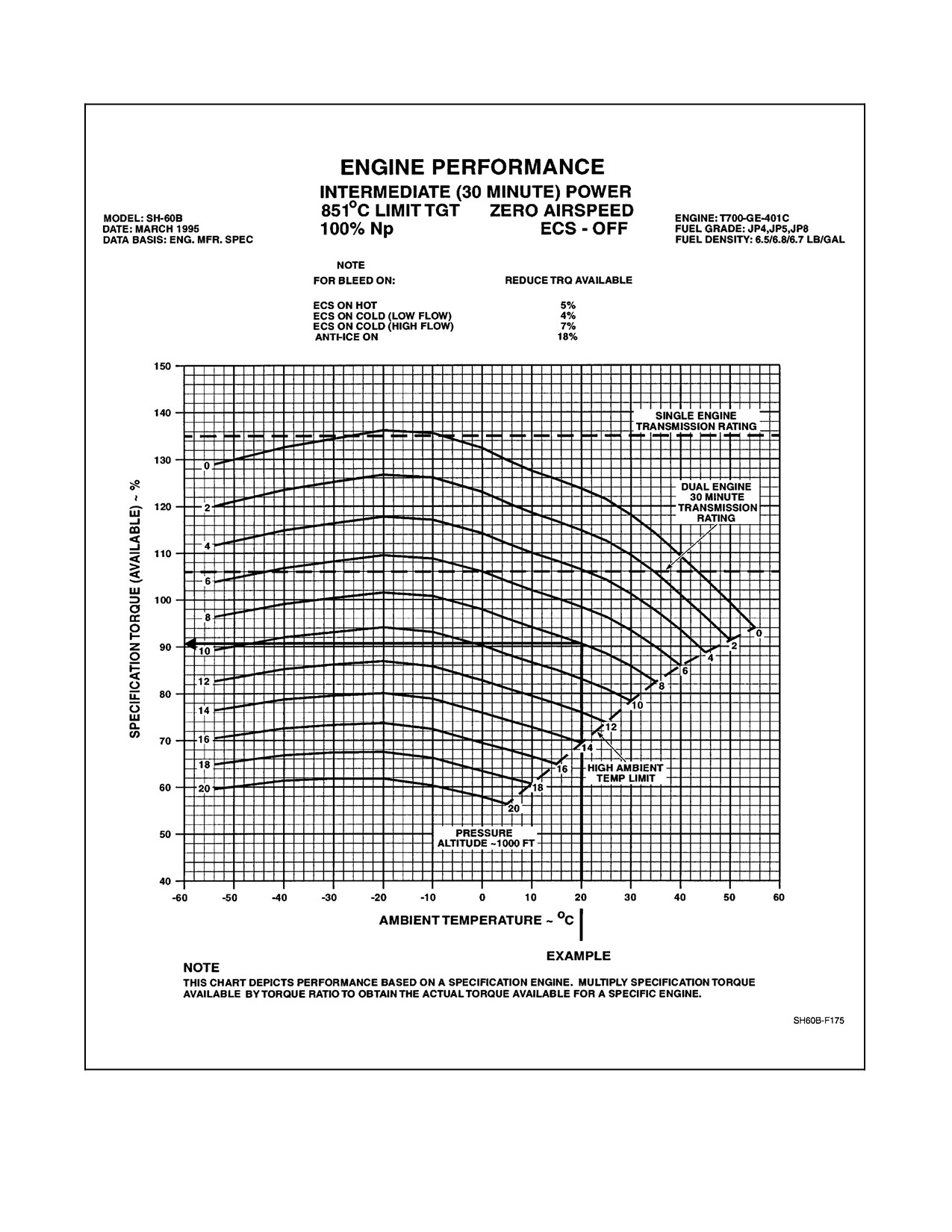
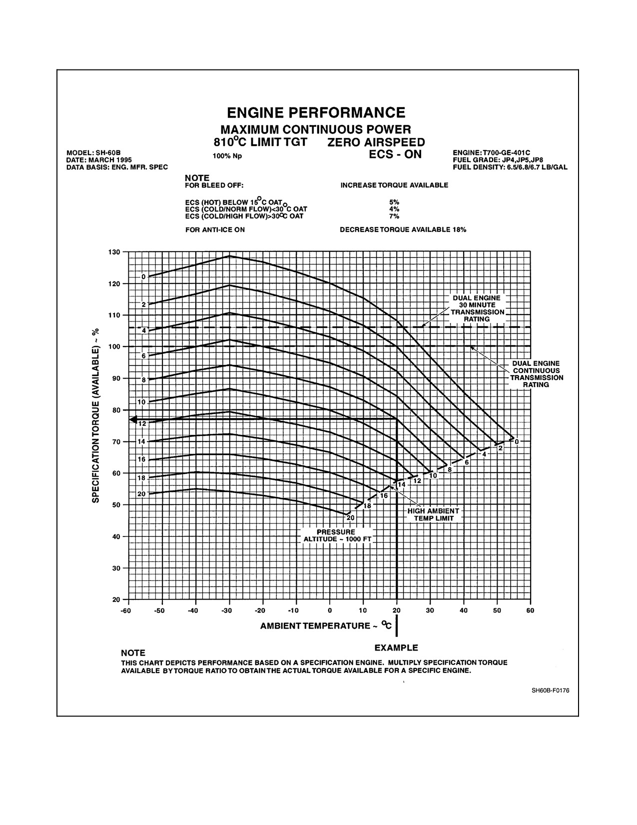
TheEnginePerformanceCharts(Figures22-4,22-5,and22-6)providetorqueavailableat contingency,intermediate,
and maximum continuous power when ambient temperature factors are applied to pressure altitude.
22.4.1.1 Engine Performance, Contingency (2.5 Minute) Power Chart
The Engine Performance Contingency (2.5 Minute) Power Chart (Figure 22-4) provides a torque value at 903 °C TGT
when ambient temperature is applied to pressure altitude.
22.4.1.2 Engine Performance, Intermediate (30 Minute) Power Chart
The Engine Performance, Intermediate (30 Minute) Power Chart (Figure 22-5) uses like factors in the same manner
as Figure 22-4 to provide a torque at 851 °C TGT.
22.4.1.3 Engine Performance, Maximum Continuous Power Chart
The Engine Performance, Maximum Continuous Power Chart (Figure 22-6) uses like factors in the same manner as
Figure 22-4 to provide a torque at 810 °C TGT.
22.4.1.4 Sample Problem for Use of Engine Performance, Contingency (2.5 Minute) Power,
Intermediate (30 Minute) Power and Maximum Continuous Power Charts
Enter bottom of chart at Ambient Temperature 20 °C. Trace up to 8,000 feet Pressure Altitude line, then trace left
to the Specification Torque (Available) scale and read percent Torque.
22.4.1.5 Torque Factor Terms
1. Torque Ratio (TR): The ratio of torque available to specification torque at the desired ambient temperature.
2. Engine Torque Factor (ETF): The ratio of an individual--engine torque available to specification torque at a
reference temperature of 35 °C.
3. Aircraft Torque Factor (ATF): The ratio of an individual aircraft power available to specification power at a
reference temperature of 35 °C. The ATF is the average of the ETFs of both engines.
22.4.2 Engine Performance Procedures
22.4.2.1 Torque Factor Method
The torque factor method provides an accurate indication of actual torque available for a specific engine by
incorporating ambient temperature effects on degraded engine performance. To calculate actual torque available,
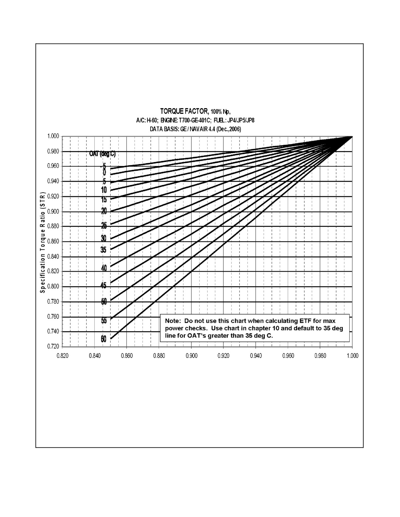
multiply the specification torque available (obtained from the Engine Performance Power Charts) by the TR for the
specific engine. To obtain the TR, use the Torque Power Chart (Figure 22-7) and enter the ETF and ambient
temperature. For ambient temperatures below --5 °C, TR always equals 1.0. For ambient temperatures above 35 °C,
TR equals ETF. The aircraft HIT log forms for each engine provide the ETF obtained from the maximum power check
torque factor method.
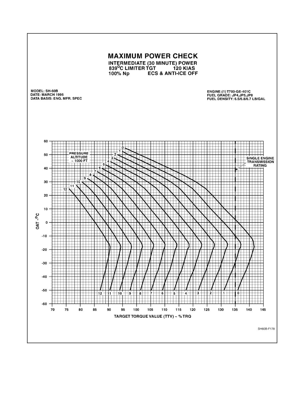
22.4.2.2 Maximum Power Check
The Maximum Power Chart (Figure 22-8) is used during engine power checks to determine target torque value
(TTV).
22-5
ORIGINAL
A1-H60BB-NFM-000
Figure 22-4. Engine Performance, Contingency (2.5--Minute) Power Chart
ORIGINAL
22-6
A1-H60BB-NFM-000
Figure 22-5. Engine Performance, Intermediate (30--Minute) Power Chart
22-7
ORIGINAL
A1-H60BB-NFM-000
Figure 22-6. Engine Performance, Maximum Continuous Power Chart
ORIGINAL
22-8
A1-H60BB-NFM-000
Engine Torque Factor (ETF)
Figure 22-7. Torque Factor Chart
22-9
ORIGINAL
A1-H60BB-NFM-000
Figure 22-8. Maximum Power Check Chart
ORIGINAL
22-10
A1-H60BB-NFM-000
22.4.2.3 Engine Bleed Air
With engine bleed air turned ON, the actual torque available is reduced as follows:
1. Engine Anti--Ice ON: Reduce torque determined from engine performance intermediate power chart by a
constant 18 percent TRQ (Example: 90 percent TRQ --18 percent TRQ = 72 percent TRQ).
2. ECS on HOT: Reduce torque available by 5 percent.
3. ECS on COLD (Low Flow): Reduce torque available by 4 percent.
4. ECS on COLD (High Flow): Reduce torque available by 7 percent.
22.4.3 Torque Factor Sample Problem
Ambient Temperature: 20 °C.
Pressure Altitude: 8,000 feet.
ETF #1 Engine: .96.
ETF #2 Engine: 1.0.
ECS and Anti--Ice OFF.
ATF (.98) is the average of ETF #1 (.96) and ETF #2 (1.0). For intermediate power available enter the Engine
Performance Intermediate (30--Minute) Power Chart (Figure 22-5) with OAT (20 °C) and pressure altitude of 8,000
feet to obtain a specification torque available of 90.5.
For Mission Planning:
Enter the Torque Power Chart (Figure 22-7) with ATF (.98) and OAT (20 °C) to obtain a TR of .987. Multiply the
specification torque available (90.5) by the TR (.987) to obtain the actual intermediate dual--engine torque available
of 89 percent.
For Single Engine Capability:
#1 Engine is the weakest engine (lowest ETF). For Engine #1, enter Figure 22-7 with ETF (.96) and OAT (20 °C)
to obtain a TR of .973. Multiply the specification torque available (90.5) by the TR (.973) to obtain the actual
intermediate single engine torque available of 88 percent for Engine #1.
22-11/(22-12 blank)
ORIGINAL
A1-H60BB-NFM-000
CHAPTER 23
Takeoff
23.1
HOVER CHARTS
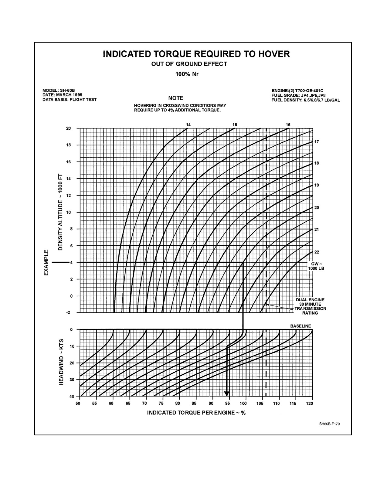
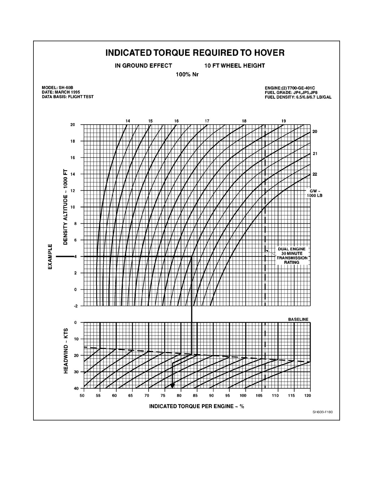
The Indicated Torque Required to Hover Charts (Figures 23-1 and 23-2) provide the indicated torque required to
hoveratal0footwheel heightand out-of-groundeffect whendensity altitudeis appliedto grossweight andheadwind
factors.
Note
Although (Figures 23-1 and 23-2) are for standard temperature, the use of
density altitude results in only minor variations of hover performance from
that indicated by the charts.
23.1.1 Indicated Torque Required to Hover Out of Ground Effect
The Indicated Torque Required to Hover Out of Ground Effect Chart (Figures 23-1) provides the indicated torque
required to hover when density altitude is applied to gross weight and headwind factors. Hovering in crosswind
conditions may require up to 4 percent additional torque.
23.1.1.1 Sample Problem for Use of Indicated Torque Required to Hover Out of Ground Effect
1. Entertheleft sideofchart at 4,000 foot density altitude, then traceright to the 20,000 pound gross-weight line.
2. Trace down to the headwind baseline.
3. Follow the headwind influence line to the l0 knot headwind line, then trace to the torque scale and read
94 percent indicated torque per engine.
23.1.2 Indicated Torque Required to Hover 10 Feet In Ground Effect
The Indicated Torque Required To Hover 10 Feet In Ground Effect Chart (Figure 23-2) uses like factors in the same
manner as Figures 23-1 to provide the indicated torque required to hover in ground effect.
1. Entertheleft sideofchart at 4,000 foot density altitude, then traceright to the 20,000 pound gross-weight line.
2. Trace down the headwind baseline.
3. Follow the headwind influence line to the 25 knot headwind line, then trace to the torque scale and read
77 percent indicated torque per engine.
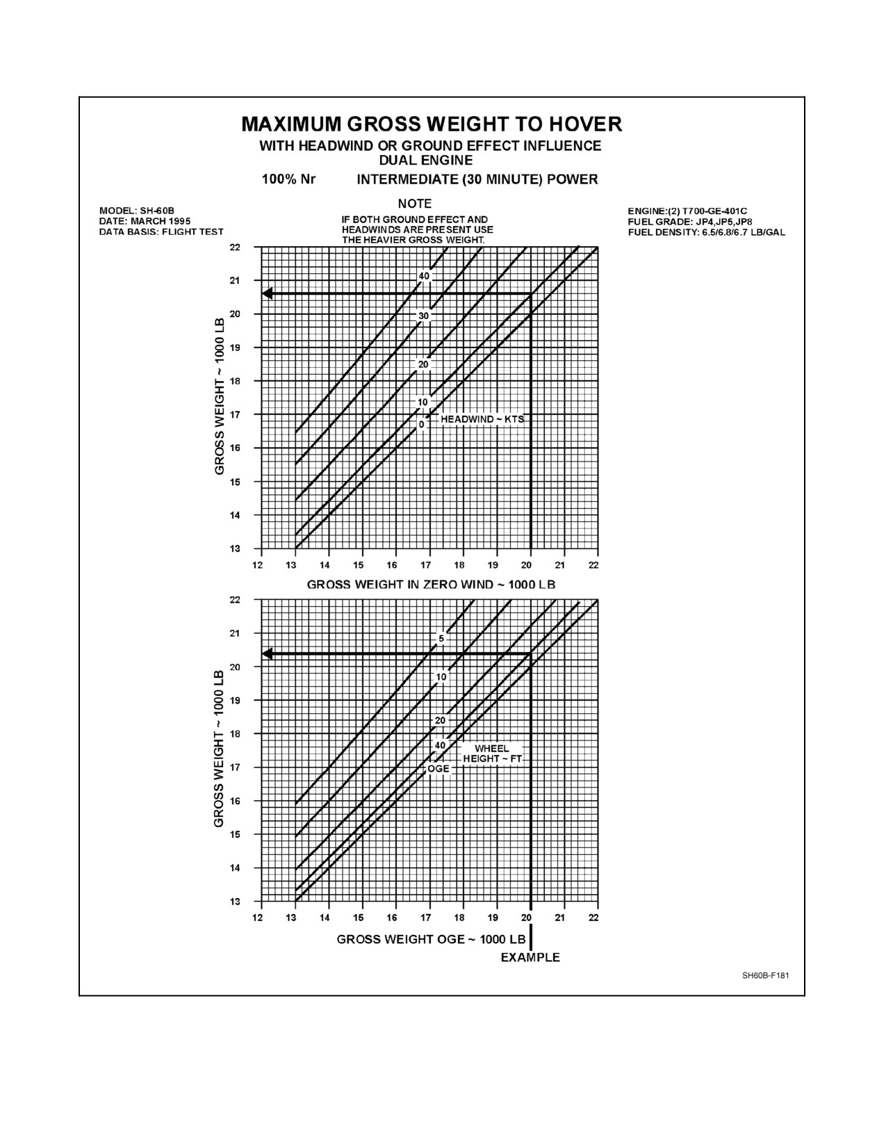
23.1.3 Maximum Gross Weight to Hover, Headwind or Ground Effect Influence
The ability to hover at various gross weights with headwinds or ground effect factors is provided in the Maximum
Gross Weight to Hover, with Headwind or Ground Effect Influence Chart (Figure 23-3).
23.1.3.1 Sample Problem for Use of Maximum Gross Weight to Hover, Headwind or Ground Effect
Influence
1. Enter bottom of chart at 20,000 pounds gross weight, zero wind, then trace up to headwind 10 knots. Trace
left to read gross weight of 20,600 pounds.
2. Enter bottom of chart at 20,000 pounds gross weight, then trace up to wheel height 40 feet. Trace left to read
20,400 pounds gross weight.
3. If both ground effect and headwinds are present, use the heavier gross weight.
23-1
ORIGINAL
A1-H60BB-NFM-000
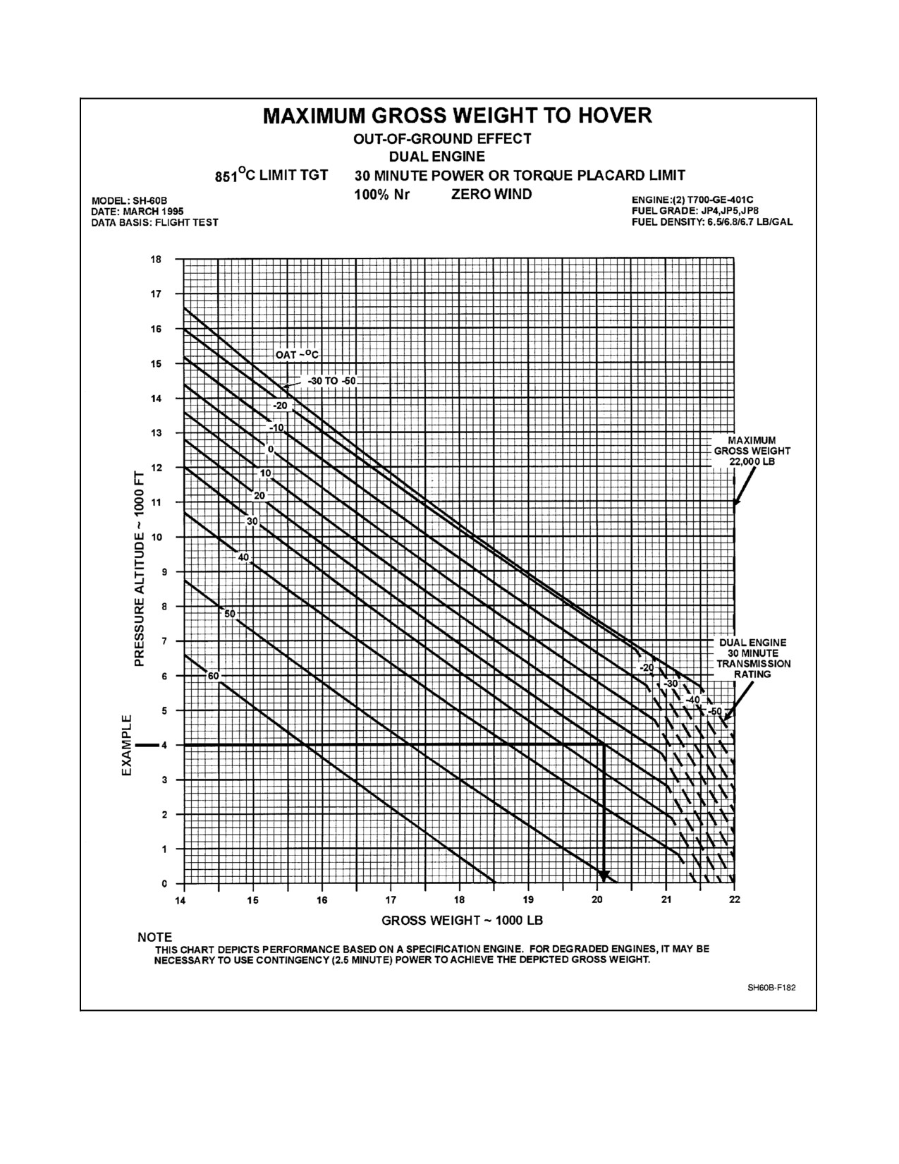
23.1.4 Maximum Gross Weight to Hover Out of Ground Effect
The ability to hover out of ground effect at 30 minute power or at torque placard limit at various pressure altitudes
and temperatures is provided in the Maximum Gross Weight to Hover, Duel Engine, Out-of-Ground Effect Chart
(Figure 23-4).
23.1.4.1 Sample Problem for Use of Maximum Gross Weight to Hover, Out of Ground Effect
1. Enterleft sideat 4,000-foot pressurealtitude, traceright to 20 °C OAT, thentracedownto read20,100 pounds.
ORIGINAL
23-2
A1-H60BB-NFM-000
Figure 23-1. Indicated Torque Required to Hover Out of Ground Effect Chart
23-3
ORIGINAL
A1-H60BB-NFM-000
Figure 23-2. Indicated Torque Required to Hover 10 Feet In Ground Effect Chart
ORIGINAL
23-4
A1-H60BB-NFM-000
Figure 23-3. Maximum Gross Weight to Hover, with Headwind or Ground Effect Influence Chart
23-5
ORIGINAL
A1-H60BB-NFM-000
Figure 23-4. Maximum Gross Weight to Hover, Dual Engine, Out of Ground Effect Chart
ORIGINAL
23-6
A1-H60BB-NFM-000
CHAPTER 24
Climb
24.1
CLIMB PERFORMANCE, DUAL-ENGINE, 30 MINUTE POWER, ZERO WIND
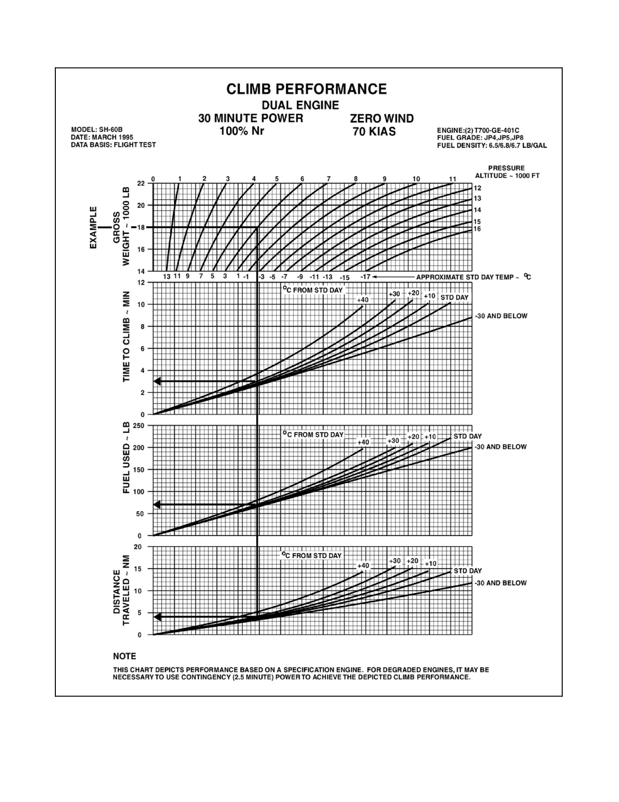
The Climb Performance Chart (Figure 24-1) provides a means of determining time to climb, fuel used, and horizontal
distance traveled at various gross weights at other than standard day conditions.
24.1.1 Sample Problem for Use of Climb Performance Chart, Dual-Engine, 30 Minute Power, Zero
Wind
Enter left side of chart at 18,000 pounds gross weight, trace right to 6,000 feet pressure altitude line, trace down
through approximate standard day temperature of -3 °C, continue down to standard day deviation line of +10 °C,
then trace left to read 2.9 minutes, 68 pounds fuel, and 4 nm distance.
24-1
ORIGINAL
A1-H60BB-NFM-000
Figure 24-1. Climb Performance, Dual-Engine, 30 Minute Power, Zero Wind Chart
ORIGINAL
24-2
A1-H60BB-NFM-000
CHAPTER 25
Range
25.1
RANGE CHARTS
25.1.1 Maximum Range, Standard Day Chart
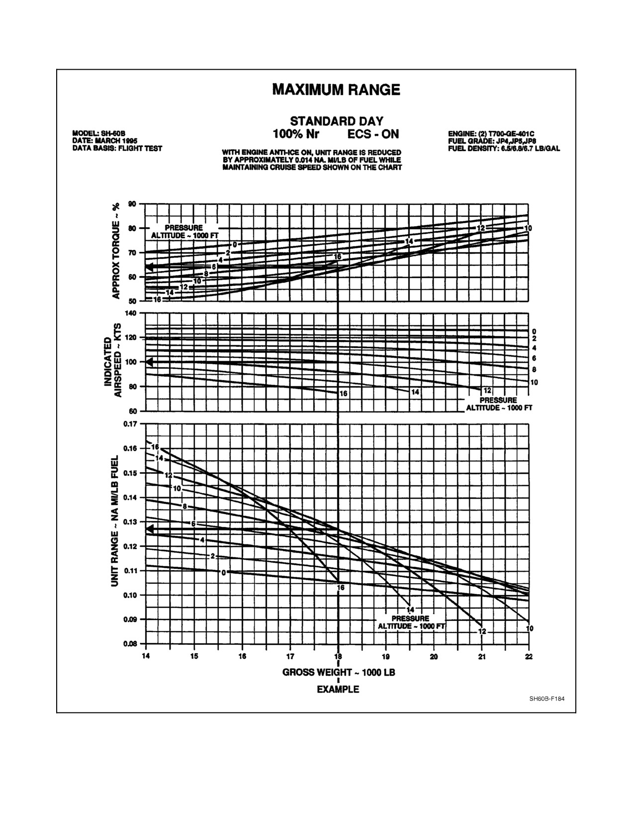
The Maximum Range, Standard Day, Dual Engine Chart (Figure 25-1) provides the unit range, indicated airspeed,
and approximate torque when gross weight is applied to pressure altitude to produce maximum range for the
helicopter.
25.1.1.1 Sample Problem for Use of Maximum Range, Standard Day Chart
1. Enter thebottom ofthe chart at 18,000 pounds gross weight. Trace up to the10,000 foot pressure altitudeline,
then trace left to the unit range scale of approximate nautical miles per pound of fuel and read 0.127 nautical
miles per pound of fuel.
2. From the gross weight/pressure altitude intersection, continue to trace up to the next pressure altitude
intersection, 10,000 feet, then trace left to the airspeed scale and read 100 KIAS.
3. Return to the gross weight/pressure altitude intersection, continue to trace up to the next pressure altitude
intersection, 10,000 feet, then trace left and read approximate torque of 64 percent.
25.1.2 Bingo Profile, Maximum Range with Dual Engine
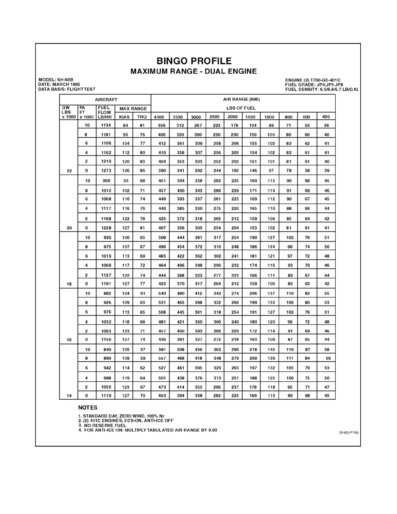
The Bingo Profile Maximum Range with Dual Engine Chart (Figure 25-2) contains the Bingo Profile for maximum
range with both engines operating.
25.1.3 Nautical Miles per Pound of Fuel Conversion Chart
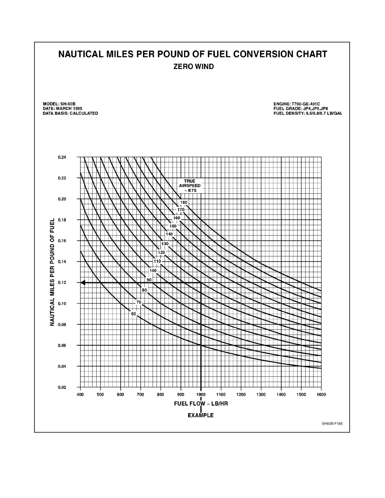
The Nautical Miles Per Pound of Fuel Conversion Chart (Figure 25-3) provides the factors necessary to determine
nautical miles per pound of fuel from the combination of total fuel flow pound per hour (pph) and true airspeed.
25.1.3.1 Sample Problem for Nautical Miles per Pound of Fuel Conversion Chart
Enter bottom of chart at 1,000 pounds per hour fuel flow, trace up to the 120 true airspeed knots line, then trace left
and read 0.12 nautical miles per pound of fuel.
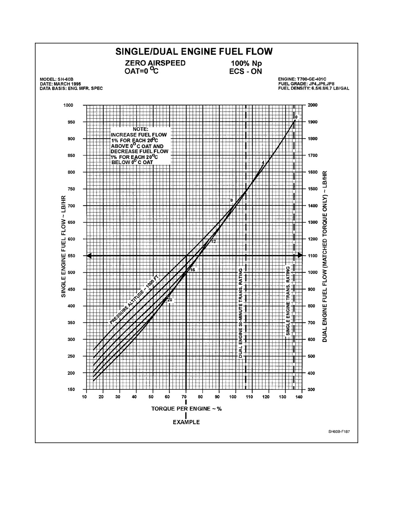
25.1.4 Single/Dual-Engine Fuel Flow
Engine fuel flow is presented in the Single/Dual Engine Fuel Flow Chart (Figure 25-4) for various torque and
pressure altitudes at a baseline OAT of 0 _C. When operating at other than 0 _C OAT, engine fuel flow is increased
1 percent for each 20 _C above the baseline temperature and decreased 1 percent for each 20 _C below the baseline
temperature, dual--engine fuel flow may be obtained from Figure 25-4 when each engine is indicating approximately
the same torque by averaging the indicated torques and reading fuel flow from the dual--engine fuel flow scale. To
determine single engine fuel flow during level flight, enter the fuel flow chart at double the torque required for
dual--engine level flight as determined from the level flight performance charts, and obtain fuel flow from the single
engine scale. The single engine torque may not exceed the transmission limit shown on the chart. With bleed air on,
dual--engine fuel flow increases as follows:
1. Anti--ice ON: +84 pounds per hour (single--engine: +42 pph).
2. Heater ON: +10 pounds per hour.
25-1
ORIGINAL
A1-H60BB-NFM-000
Figure 25-1. Maximum Range, Standard Day, Dual Engine Chart
ORIGINAL
25-2
A1-H60BB-NFM-000
Figure 25-2. Bingo Profile, Maximum Range Dual Engine Chart
25-3
ORIGINAL
A1-H60BB-NFM-000
Figure 25-3. Nautical Miles per Pound of Fuel Conversion Chart
ORIGINAL
25-4
A1-H60BB-NFM-000
Figure 25-4. Single/Dual--Engine Fuel Flow Chart
25-5/(25-6 blank)
ORIGINAL
A1-H60BB-NFM-000
CHAPTER 26
Hover Endurance
26.1
HOVER ENDURANCE, OUT OF GROUND EFFECT
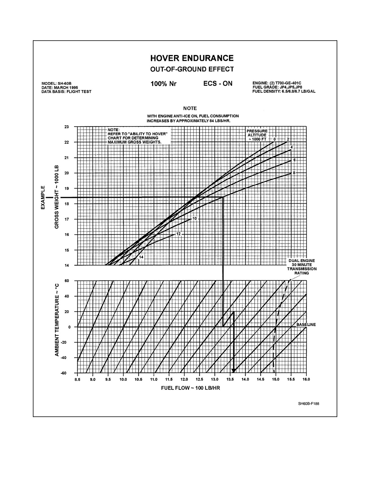
The Hover Endurance, Out of Ground Effect Chart (Figure 26-1) provides fuel flow required to hover at various gross
weights, pressure altitudes, and ambient temperatures.
26.1.1 Sample Problem for Hover Endurance, Out of Ground Effect
Enter left side of chart with known gross weight (18,400 pounds). Trace right to pressure altitude influence line
(8,000 feet), trace down to ambient temperature baseline, trace along influence line to ambient temperature +20 °C,
then trace down to read fuel flow 13.6. Multiply by 100 pounds per hour = 1,360 pounds per hour. Fuel flow will
increase approximately 42 pounds per hour per engine with anti--ice on.
26-1
ORIGINAL
A1-H60BB-NFM-000
Figure 26-1. Hover Endurance, Out of Ground Effect Chart
ORIGINAL
26-2
A1-H60BB-NFM-000
CHAPTER 27
Emergency Operation
27.1
ABILITY TO MAINTAIN LEVEL FLIGHT, SINGLE ENGINE CHART
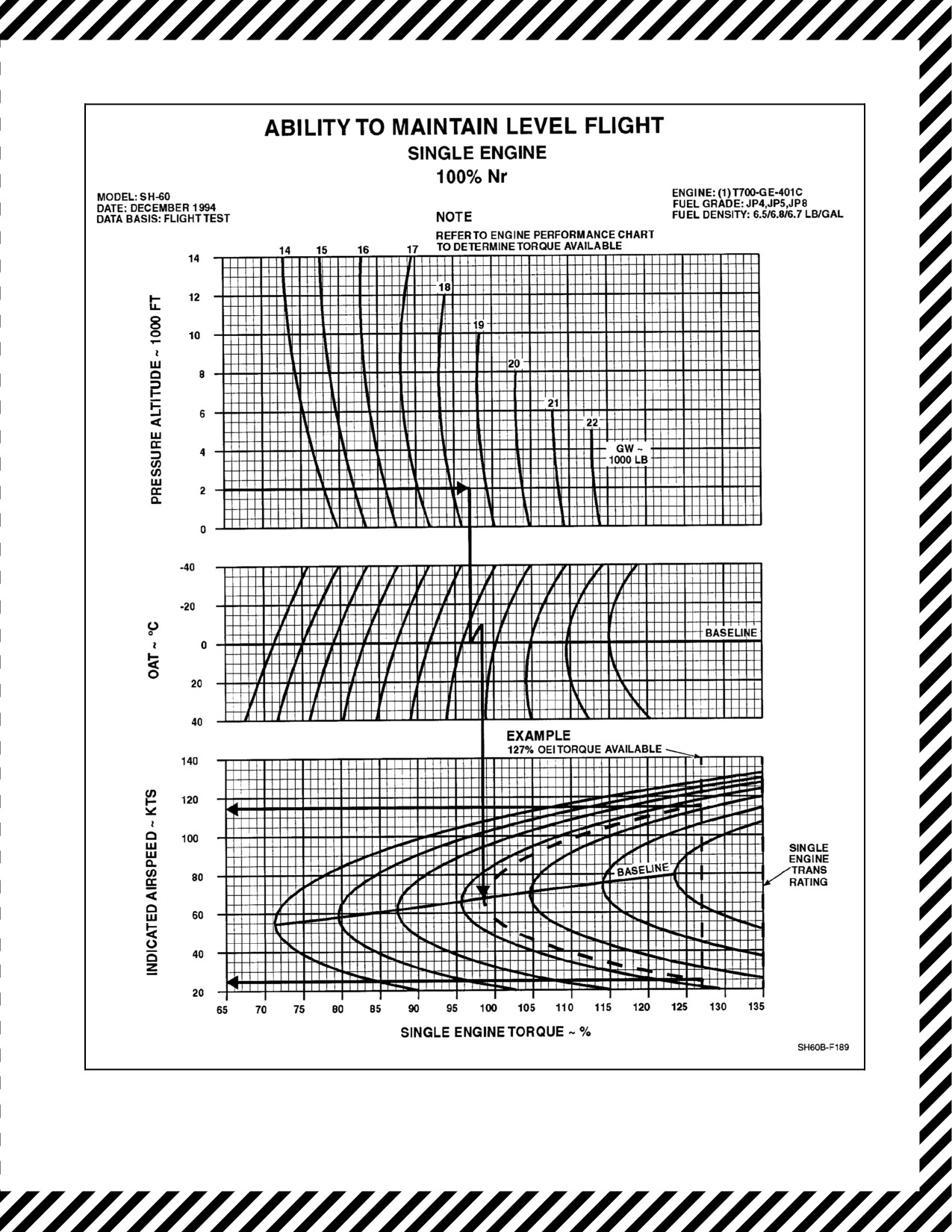
The Ability To Maintain Level Flight, Single Engine Chart (Figure 27-1) provides the speed range wherein single
engine level flight may be maintained at various density altitudes and gross weights at a torque value the engine is
producing.
27.1.1 Sample Problem for Use of Ability to Maintain Level Flight, Single Engine Chart
1. Enter the upper chart on the left side at a 2,000 foot pressure altitude and trace right to 18,500 pounds gross
weight.
2. Trace down to OAT baseline, then follow influence line up to --10 °C.
3. Trace down to the indicated airspeed baseline.
4. Follow the influence line down to where it intersects the torque available line, 127 percent OEI torque
available. (Torque available is provided by Engine Performance, Military Power Charts, Chapter 22.)
5. At bottom of chart at 127 percent OEI torque available, trace left to read the Vmin at 22 KIAS.
6. Return to the indicated airspeed baseline, follow the influence lineup to where it intersects 127 percent torque
available, then trace left to read Vmax 118 KIAS.
27.2
CLIMB PERFORMANCE, SINGLE ENGINE, 30 MINUTE POWER
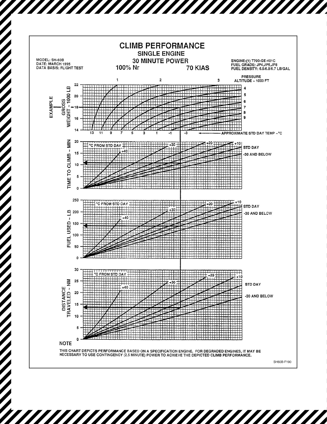
The Climb Performance, Single Engine, 30 Minute Power Chart (Figure 27-2) provides single engine climb data
(30 minute power) at various gross weights, pressure altitudes, and ambient temperatures.
27.2.1 Sample Problem for Climb Performance, Single Engine, 30 Minute Power Chart
Enter chart at left at known gross weight (18,000 pounds). Traceright to pressure altitudeinfluence line(5,000 feet).
Trace down through approximate standard day temperature (--2 °C), trace down to °C from standard day influence
line, then trace left to read: time to climb (11 minutes), fuel used (140 pounds), and distance traveled (14 nm).
27.3
RANGE CHART
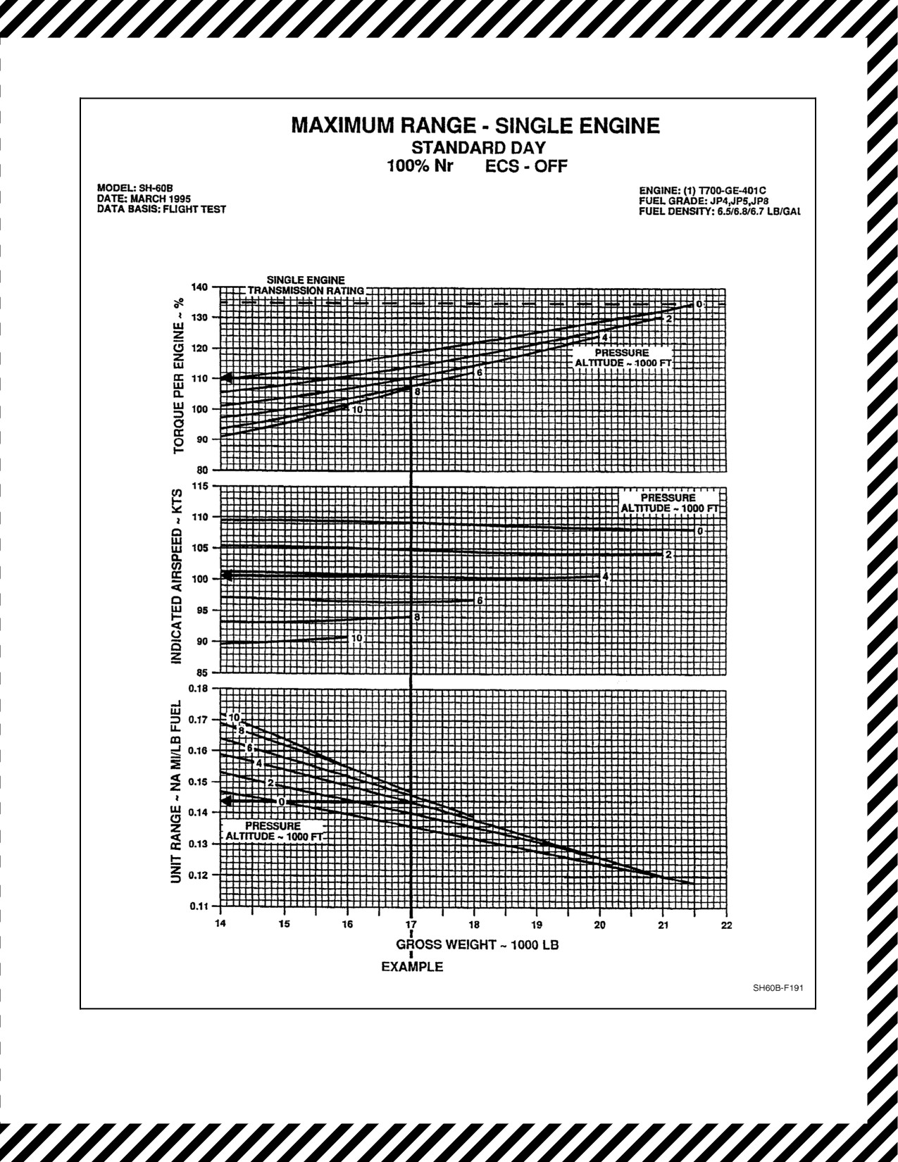
The Maximum Range Single Engine, Standard Day Chart (Figure 27-3) is based on the power to provide maximum
range for the helicopter during a one--engine operation. The chart uses like factors in the same manner as the range
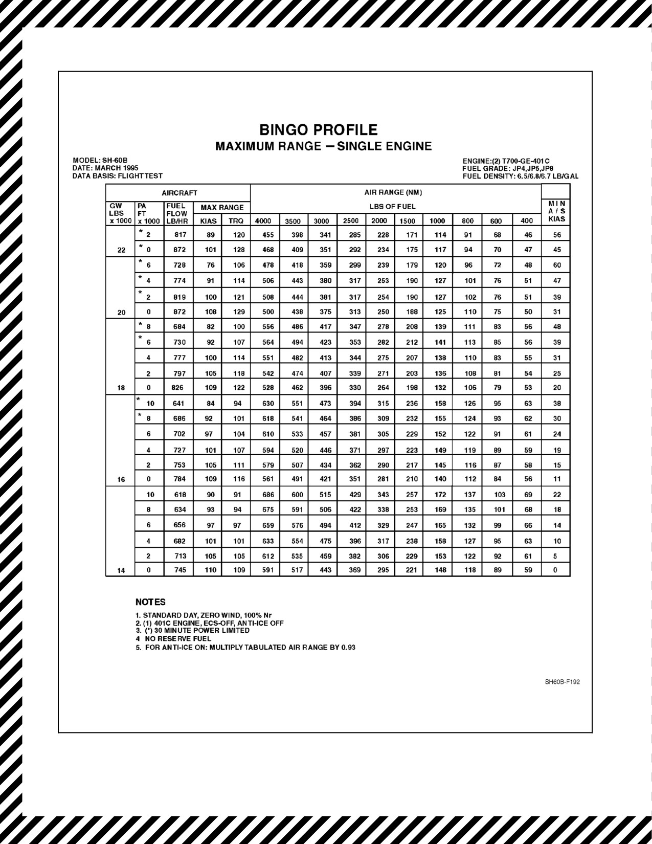
charts in Chapter 25; therefore, explanatory text and sample problem data are not included. The maximum range
single engine Bingo Profile is contained in the Bingo Profile, Maximum Range Single Engine Chart Figure 27-4.
27.4
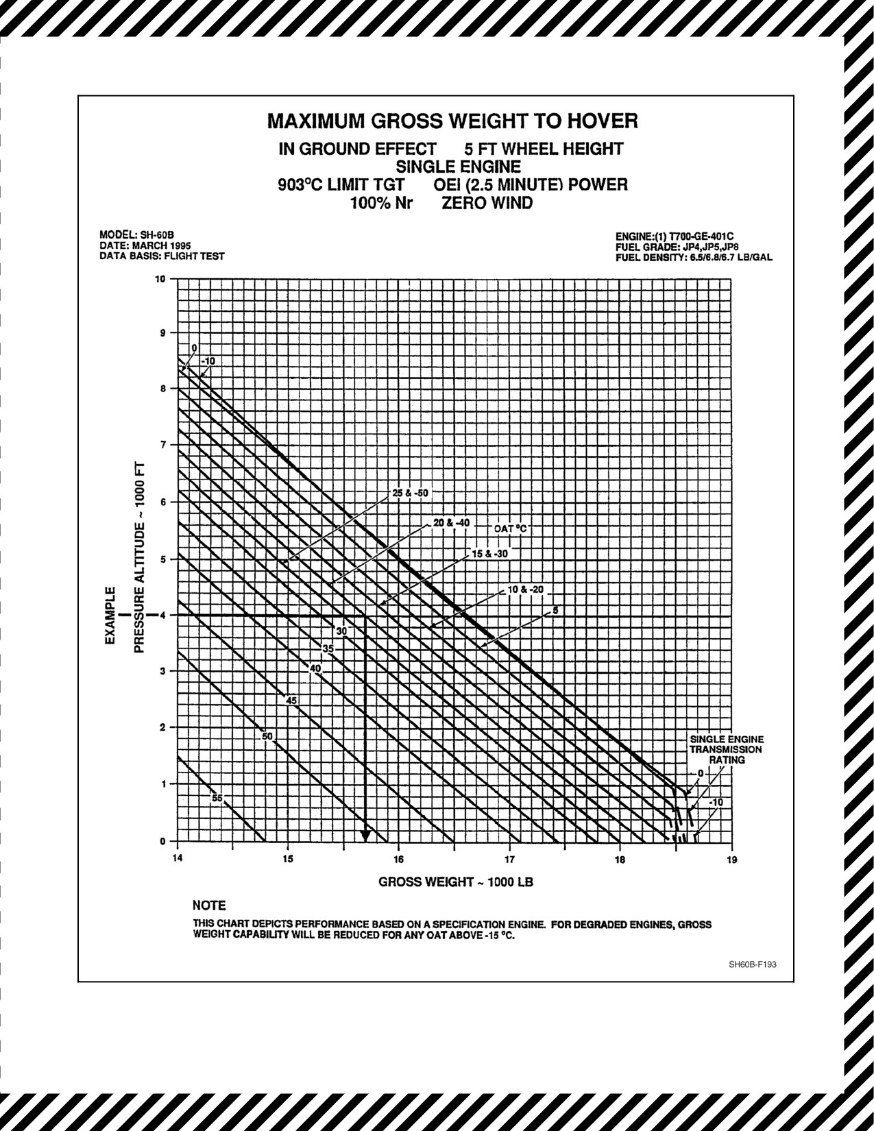
MAXIMUM GROSS WEIGHT TO HOVER IN GROUND EFFECT, SINGLE ENGINE
The Maximum Gross Weight To Hover In Ground Effect Chart is depicted in Figure 27-5. This chart assumes a 5
foot wheel height at 100 percent Nr, one engine inoperative (OEI) 2.5 minute power, and zero wind conditions.
27-1
ORIGINAL
A1-H60BB-NFM-000
27.4.1 Sample Problem for Maximum Gross Weight to Hover In Ground Effect, Single Engine
Enter chart at left at known pressure altitude (4,000 feet). Trace right to OAT °C (+20 and --40), then trace down to
read gross weight (15,700 pounds).
27.5
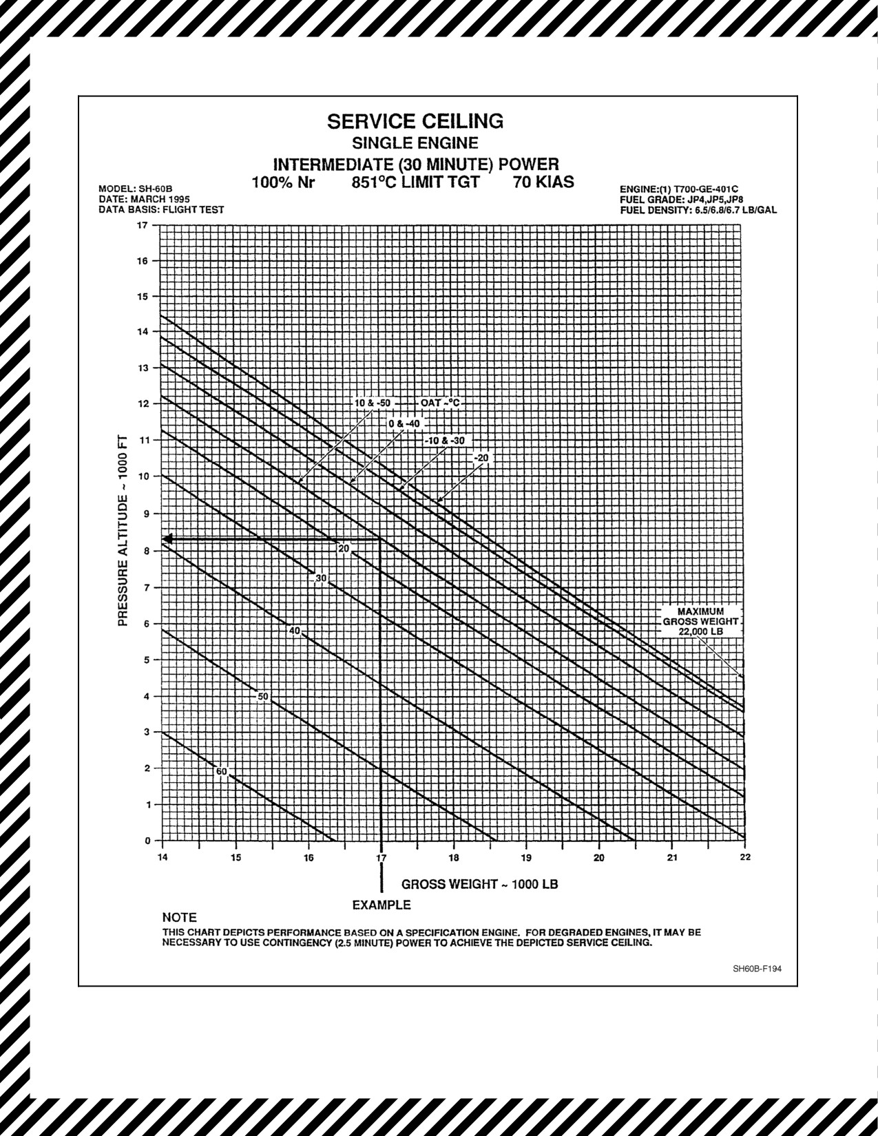
SERVICE CEILING, SINGLE ENGINE, INTERMEDIATE (30 MINUTE) POWER
This Service Ceiling, Single Engine, Intermediate (30 Minute) Power Chart (Figure 27-6) depicts the service ceiling
attainable at various gross weights and ambient temperatures. Intermediate (30 minute) (851 °C TGT limit) power,
70 KIAS at 100 percent Nr is assumed.
27.5.1 Sample Problem for Service Ceiling, Single Engine, Intermediate (30 Minute) Power
Enter bottom of chart at known gross weight (17,000 pounds), trace up to outside air temperature (OAT) influence
line (+10 and --50 °C), then trace left to read pressure altitude (8,350 feet).
ORIGINAL
27-2
A1-H60BB-NFM-000
Figure 27-1. Ability to Maintain Level Flight, Single Engine Chart
27-3
ORIGINAL
A1-H60BB-NFM-000
Figure 27-2. Climb Performance, Single Engine, 30 Minute Power Chart
ORIGINAL
27-4
A1-H60BB-NFM-000
Figure 27-3. Maximum Range, Single Engine, Standard Day Chart
27-5
ORIGINAL
A1-H60BB-NFM-000
Figure 27-4. Bingo Profile, Maximum Range Single Engine Chart
ORIGINAL
27-6
A1-H60BB-NFM-000
Figure 27-5. Maximum Gross Weight to Hover, in Ground Effect, Single Engine Chart
27-7
ORIGINAL
A1-H60BB-NFM-000
Figure 27-6. Service Ceiling, Single Engine, Intermediate (30 Minute) Power Chart
ORIGINAL
27-8
A1-H60BB-NFM-000
CHAPTER 28
Level Flight Performance Charts
28.1
SERVICE CEILING, DUAL-ENGINE, INTERMEDIATE (30 MINUTE) POWER OR TORQUE
PLACARD LIMIT
The Service Ceiling, Dual--Engine, Intermediate (30 Minute) Power Or Torque Placard Limit Chart (Figure 28-1)
depicts the service ceiling attainable at various gross weights and ambient temperatures. Intermediate (30 minute,
851 °C TGT limit) power or torque placard limit and 70 KIAS at 100 percent Nr is assumed.
28.1.1 Sample Problem for Service Ceiling, Dual-Engine, Intermediate (30 Minute) Power or
Torque Placard Limit
1. Enter bottom of chart at known gross weight (20,700 pounds), trace up to outside air temperature (OAT)
influence line (0 °C), then trace left to read pressure altitude (12,000 feet).
28.2
CRUISE CAPABILITY, TIME, AND RANGE
The Cruise Capability, Time, and Range Chart (Figure 28-2) provides time and range solutions to variable fuel flow,
true airspeed, and fuel quantity conditions in zero wind with no fuel reserve.
28.2.1 Sample Problem for Cruise Capability, Time, and Range Chart
1. Enter chart at left at known fuel quantity in pounds (1,500 pounds). Trace right to fuel flow 100 pounds per
hour line (1,100 pounds), trace down to true airspeed ~ KTS (100), then trace down and read 1.36 hours or
trace left from true airspeed ~ KTS (100) line and read 136 nm.
28.3
AIRSPEED SYSTEM CORRECTION FROM LEVEL FLIGHT CHARTS
All indicated airspeeds shown on the cruise charts are based on level flight. The Airspeed System Correction From
Level Flight Chart (Figure 28-3) provides the airspeed correction to be added to the level flight performance IAS
value to determine the related airspeed indicator reading for other than level flight mode. There are relatively large
variations in airspeed system errors associated with climbs and descents. These errors are significant and the Airspeed
System Correction From Level Flight Chart (Figure 28-3) is provided primarily to show the general magnitude and
direction of the errors associated with the various flight modes. If desired this figure may be used in the manner shown
to calculate specific airspeed corrections.
The following anomalies in the airspeed indicating system may be observed on the pilot and copilot airspeed
indicators:
1. During takeoffs, in the speed range of 40 to 80 KIAS, 5 to 10 KIAS airspeed fluctuation may be observed on
the pilot and copilot airspeed indicators.
2. Power changes in high power, low airspeed climbs may cause as much as 30 knot airspeed changes in indicated
airspeed. Increase in power causes an increase in indicated airspeed, and a decrease in power causes a decrease
in indicated airspeed.
3. The pilot and copilot airspeed indicators may be unreliable during high power climbs at low airspeeds (less
than 50 KIAS) with the copilot system reading as much as 30 knots lower than the pilot system.
28.3.1 Sample Problem for Airspeed System Correction from Level Flight Charts
Enterbottom ofchart at indicated airspeed from level flight performancechart (70 knots), trace up to climb influence
line, trace left to airspeed correction knots and read (7 knots).
28-1
ORIGINAL
A1-H60BB-NFM-000
28.4
OPTIMUM ALTITUDE FOR MAXIMUM RANGE
The Optimum Altitude For Maximum Range Chart (Figure 28-4) provides the pressure altitude at which to cruise
to obtain the maximum possible range for any gross weight and OAT conditions. The altitude determined for
optimum range may also be used for optimum endurance. Use this chart at current or anticipated takeoff conditions
and move along the temperature guide lines to the estimated gross weight for cruise and obtain the optimum pressure
altitude. Turn to the level flight performance chart closest to the altitude/temperature combination predicted by the
optimum range chart for specific cruise information. This method optimizes cruise performance for long range
missions when the altitudes flown are not restricted by operational requirements.
28.4.1 Sample Problem for Optimum Altitude for Maximum Range
1. Enterleft at ambient temperatureof+22 °C and read right to takeoff pressurealtitude of2,000 feet, moveright
along temperature trend lines to known or estimated gross weight (16,800 pounds), move down to read
optimum pressure altitude (12,000 feet), move left to read OAT at optimum altitude (+3 °C).
2. To select the appropriate level flight performance chart, use the temperature/altitude combination predicted
by the optimum altitude for maximum range chart and apply these predicted values to the level flight
performance chart nearest these conditions. Use of the level flight performance chart for 12,000 feet and 0 °C
would be correct in determining cruise conditions for this example, but observe altitude limits in Chapter 4
and OPNAV 3710.7 (series).
28.5
LEVEL FLIGHT PERFORMANCE CHARTS
28.5.1 Description
The Level Flight Performance Charts (Figures 28-5, 28-6, 28-7, 28-8, 28-9, 28-10, 28-11, 28-12, 28-13, 28-14,
28-15, 28-16, 28-17, 28-18, 28-19, 28-20, 28-21, and 28-22) present torque required and total fuel flow as a function
of airspeed, altitude, temperature, and gross weight at 100 percent Nr. Scales for both true airspeed and indicated
airspeed are presented. Maximum level flight airspeed (Vh) is obtained at the intersection of the gross weight arc and
torque available 30 minutes or the transmission torque limit, whichever is lower. Airspeeds that will produce
maximum range, maximum endurance, and maximum rate of climb are also shown. Level flight performance charts
are provided from sea level to 10,000 feet pressure altitude in units of 2,000 feet. The charts provide level flight data
for free air temperatures from --20 °C to +40 °C in units of 10 or 20.
28.5.2 Use of Charts
To use the charts, it is usually necessary to know the planned pressure altitude, estimated outside air temperature,
planned cruise speed, TAS, and gross weight. First, select the proper chart on the basis of planned cruise pressure
altitude and temperature, or by using the optimum altitude for maximum range chart. Enter the chart at the cruise
airspeed, IAS, move up and read TAS, move up to the gross weight arc, move left and read torque required, and then
move right and read associated fuel flow. Maximum performance conditions are determined by entering the chart
where the maximum (LONG RANGE) range line or the maximum endurance and rate of climb (MAX END AND
R/C)intersects thegross weight line; then read airspeed, fuel flow and torque required. Normally, sufficient accuracy
can be obtained by selecting the chart nearest the planned cruising altitude and OAT or, more conservatively, by
selecting the chart with the next higher altitude and OAT. If greater accuracy is required, interpolation between
altitudes and/or temperatures is permissible. To be conservative, use the gross weight at the beginning of the cruise
flight. For greater accuracy on long flights, it is preferable to determine cruise information for several flight segments
to allow for the decreasing gross weight.
1. Airspeed. True and indicated airspeeds are presented at opposite sides of each chart. On any chart, indicated
airspeed can be directly converted to true airspeed by reading directly across the chart without regard to other
chart information.
2. Torque. Since pressure altitude and temperature are fixed for each chart, torque required varies according to
gross weight and airspeed. The torque and torque limits shown on these charts are for dual-- and single--engine
operation. The maximum torque available is presented on each chart as either the transmission torque limit,
torque available 30 minutes, or torque available continuously. The dual--engine torque limit placard is
ORIGINAL
28-2
A1-H60BB-NFM-000
presented above the TAS scale of each chart where applicable. Single--engine torque, OEI continuous, and OEI
2.5 minute limits are also represented.
3.
Fuel Flow. Fuel flow scales are provided opposite the torque scales. On any chart, torque may be converted
directly to fuel flow without regard to other chart information. Data shown is for two--engine operation. For
single--engine fuel flow, refer to the Single/Dual--Engine Fuel Flow Chart Figure 25-4.
4.
Long Range. The long range lines (LONG RANGE) indicate the combinations of gross weight and airspeed
that will producethegreatest flight rangeperpoundoffuelunderzerowind conditions.When maximumrange
airspeed is above maximum torque available, the resulting maximum airspeed should be used for maximum
range.
5.
Maximum Endurance and Rate of Climb. The maximum endurance and rate of climb lines (MAX END and
R/C) indicate the combinations of gross weight and airspeed that will produce the maximum endurance and
the maximum rate of climb. The torque required for level flight at this condition is a minimum, providing a
minimum fuel flow (maximum endurance) and a maximum torque changeavailable forclimb (maximum rate
of climb).
6.
Single Engine. The minimum and maximum single--engine speeds can be determined by using acombination
of torque available (Chapter 22) and level flight performance charts. To calculate single--engine speeds, first
determine the torque available at the TGT limit desired and then divide by 2 (for example: 90 percent TQ/2
= 45 percent TQ). Select the appropriate level flight performance chart for the desired flight condition and enter
the torque scale with the torque value derived above. Move to the intersection of torque available and mission
gross weight arc and read down to determine minimum single--engine speed. Move further across to the second
intersection of torque and weight and read maximum single--engine speed. If no intersections occur, there are
no single--engine level flight capabilities for the conditions.
7.
Additional Uses. Thelow speed end ofthelevel flight performancecharts (below 40 knots)is shownprimarily
to familiarize the pilot with the low speed power requirements of the helicopter. It shows the power margin
available for climb or acceleration during maneuvers, such as Nape of the Earth flight. At zero airspeed, the
torquerepresents thetorquerequired to hoverout ofground effect. In general, mission planning forlow--speed
flight should be based on hover performance out of ground effect. Refer to Chapter 23.
28-3
ORIGINAL