SH-60B HELICOPTER. FLIGHT MANUAL (2008) - page 11
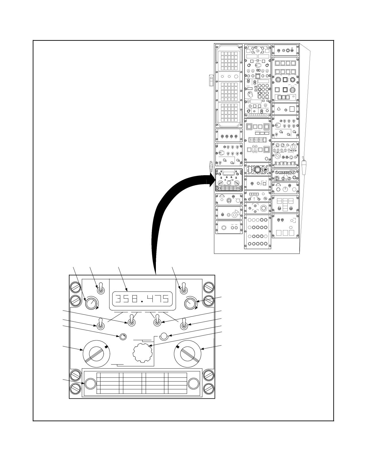
A1-H60BB-NFM-000
1
2
3
1
SOL
READ
FREQY (CHAN)
VOL
BRT
5
OFF
6
6
TEST
6
6
12
7
TONE
LOAD
U
8
H
CHAN SEL
ADF
F
GUARD
11
BOTH
9
MANUAL
MAIN
PRESET
OFF
01
06
11
16
10
02
07
12
17
03
08
13
18
04
09
14
19
05
10
15
20
LSI 017--0858--0
Figure 15-5. Backup UHF Radio Control Panel (BuNo through 162990) (Sheet 1 of 2)
ORIGINAL
15-20
A1-H60BB-NFM-000
INDEX
NUMBER
CONTROL LABELS
FUNCTIONAL DESCRIPTION
(Backup UHF radio
Provides controls and displays necessary to operate a UHF radio in the
control panel)
backup mode.
1
VOL
Continuously variable potentiometer used to adjust the audio volume to
compensate for varying levels of cockpit noise.
2
SQ/OFF
The SQUELCH control is a two-position toggle switch that enables squelch
circuitry in the ON position. In effect, it eliminates the background noise
level when there are no incoming transmissions being received.
3
FREQ/(CHAN)
Six-digit frequency readout. Also displays two-digit channel when PRESET
knob (NO. 11) is used.
4
READ
Momentary switch that causes the frequency of the selected preset
channel to be displayed at the frequency/channel readout (NO. 3). When
toggled, the frequency will be displayed for about 10 seconds.
5
BRT/TEST
Rotary knob to control display intensity. Full clockwise causes display to
read all 8s.
6
(Frequency Setting)
Four spring-loaded ON-OFF-ON toggles used to enter the six-digit UHF
frequency. Observed in the readout (NO. 3) immediately above the
switches.
7
LOAD
Non-illuminated pushbutton used to permanently store frequencies in
preset channels.
8
CHAN SEL
The channel control is used to select any one of 20 preset frequencies
when the frequency selector mode switch (NO. 11) is in the PRESET
position. The selected channel is displayed by the frequency/channel
readout (NO. 3).
9
(Mode selector)
The mode selector is a four-position rotary switch for selection of the
following UHF-1 modes of operation:
ADF
Not functional in the SH-60B.
BOTH
Same as for MAIN with auxiliary guard receiver energized.
MAIN
Transmitter and main receiver are energized and tuned to frequency
selected by frequency selector mode control and applicable controls.
OFF
Not functional in the SH-60B.
10
(Tableau)
Tableau for manually recording frequency of preset channels.
11
(Frequency mode
The frequency mode selector is a three-position rotary switch used to
selector)
select the following modes:
GUARD
Tunes main receiver/transmitter to the guard frequency. The guard
frequency is displayed at the frequency readout (NO. 3).
MANUAL
Allows selection of any of 7,000 possible operating frequencies using the
four frequency selector switches (NO. 6).
PRESET
Allows selection of any one of 20 preset channels. The selected channel
number is displayed at the frequency/channel readout (NO. 3).
12
TONE
The TONE transmit control is a momentary pushbutton switch which
commands a 1-KHz tone to be transmitted for the duration of the switch
depression.
Figure 15-5. Backup UHF Radio Control Panel (BuNo through 162990) (Sheet 2)
15-21
ORIGINAL
A1-H60BB-NFM-000
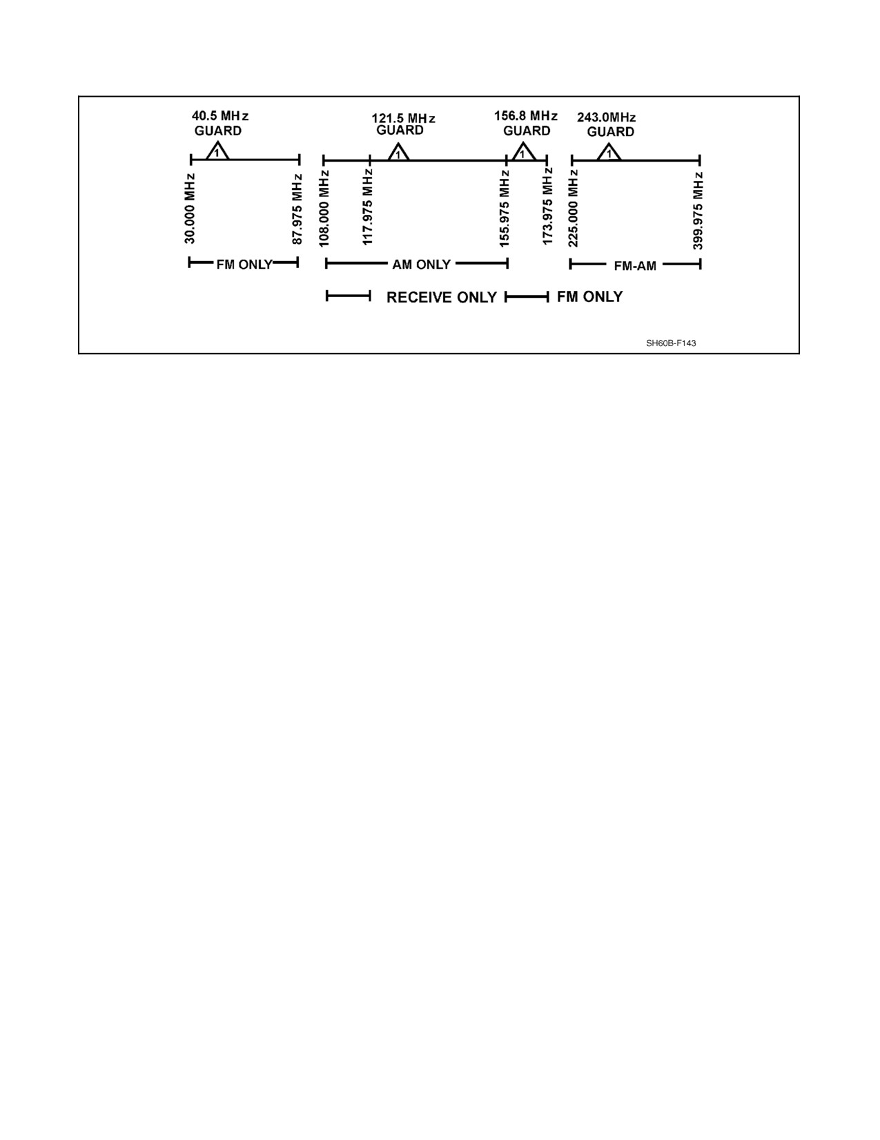
Figure 15-6. ARC--182 Frequency Ranges
Power for UHF--1 receiver/transmitter is supplied from the DC essential bus through a circuit breaker on the cockpit
overhead circuit breaker panel marked RADIO NO. 1 R/T UHF. Power for UHF--2 receiver/transmitter is supplied
from the NO. 2 DC primary bus through a circuit breaker marked RADIO NO. 2 R/T UHF on the SO circuit breaker
panel.
In the event of COMM CONTR failure, the ARC--182 performs the same as the ARC--159. CSCG/ACP failure modes
are covered in Figure 15-4. Either UHF/VHF radio may be selected for use with the KY--58 speech security set to
provide for enciphered and encoded message reception and transmission. This is done by placing the SECURE switch
on the COMM CONTR Panel in the ON position corresponding to the selected radio.
Note
The KY--58 will not pass guard relay or transmission.
The two UHF/VHF radios can be used to relay UHF/VHF communication the same as the ARC--159. For optimum
relay operation of the ARC--182, observe the following:
1. Avoid UHF to UHF frequency separations of less than 10 MHz.
2. Avoid frequency separations of multiples of 29 MHz (29, 58, 87, 116, 145 MHz, etc.).
3. Avoid UHF to UHF relays to frequencies below 265 MHz.
4. Avoid VHF to VHF relays where possible.
Note
In the RELAY mode, certain UHF to UHF frequency combinations (and
most VHF to VHF frequency combinations) will result in squeals,
interference, motorboating or distortion.
ORIGINAL
15-22
A1-H60BB-NFM-000
The two UHF/VHF antennas on the helicopter operate similarly to the ARC--159 antennas.
CAUTION
Unsecured folded main rotor blades can flap enough in high winds or high
sea states to strike the upper UHF antenna. To prevent damage to the rotor
blades and antenna, blade crutches shall be applied when the blades are
folded and the ambient conditions are conducive to blade flapping.
Note
D In the event of a partial antenna failure, VHF frequencies may be inoperable
but degraded operation of UHF communications may still be possible.
D Garbled or distorted side tones during radio transmissions may be
experienced for certain VHF frequency combinations (within 10 MHz)
when the mixer switch on the alternate radio is selected. The distortion is
caused by feedback into the alternate radio receiver and does not affect the
quality oftheoutgoingtransmission. Sidetonedistortioncan beeliminated
by deselecting the nontransmitting radio receiver mixer switch.
D In the UHF frequency band, FM signals may be received when AM is
selected, and vice versa. The received signals will be weak and highly
distorted, however, if the proper modulation (AM or FM) is not selected.
D When G REC is selected, the guard frequency monitored will be the guard
frequency of the frequency band in operation.
15.1.5.2.1
UHF/VHF Backup
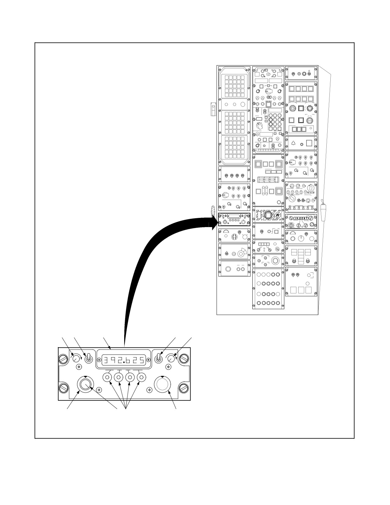
In the event of COMM CONTR panel failure, the UHF/VHF radio can be operated directly from the backup
UHF/VHF radio control panel (Figure 15-7). Place XMTR SEL switch on the pilot radio control panel to the UHF
BKUP position. In the event of ACP and/or backup radio control failure, the tone pushbutton for UHF--1 is hardwired
to the radio to allow operation.
Note
D The backup UHF/VHF radio control panel may display a dot when
switching to BKUP position. To activate the display, rotate the CHAN SEL
knob oneposition and back, ortoggleafrequency slew switch up and back.
D In BKUP, if 243 is selected and the pilot radio control panel is returned to
normal operation, 243.000 will remain in the backup UHF/VHF radio
control panel display, but the actual frequency will be selected and
displayed by theCOMM CONTR control panel.To clearthedisplay,rotate
the frequency mode selector to PRESET.
15-23
ORIGINAL
A1-H60BB-NFM-000
1
2
3
4
5
VOL
SQL
FREQ/(CHAN)
AM
BRT
U
H
F
OFF
FM
V/U
READ
T/R&G
H
F
PRESET
LOAD
T/R
DF
G
OFF
TEST
MAN
243
MODE
9
8
7
6
Figure 15-7. Backup UHF/VHF Radio Control Panel (BuNo 162991 and Subsequent) (Sheet 1 of 2)
ORIGINAL
15-24
A1-H60BB-NFM-000
CONTROL/
ITEM NO.
INDICATOR
FUNCTION
1
VOL
Potentiometer. Adjust audio output level.
2
SQL/OFF
Toggle switch. Enables main receiver squelch in SQL position.
3
Frequency/
Incandescent lamps. Display frequency selected, channel selected, or built-in
channel display
test (BIT) results. Displays hundreds, tens, and units. Decimal point (is off in
PRESET), tenths, hundredths, and thousandths MHz frequency.
4
UHF AM/FM
Toggle switch. Selects either AM or FM operating modes when tuned to a
selector
frequency in the UHF band.
5
BRT
Potentiometer. Varies light intensity of FREQ/(CHAN) display.
6
Operational
Rotary switch.
mode selector
T/R
Enables main receiver/transmitter of radio.
T/R & G
Enables guard receiver in addition to functions described for T/R. Guard receiver
is automatically tuned to proper frequency for selected operating band of main
receiver.
DF
Not functional in the SH-60B.
TEST
Initiates built-in test sequence of receiver/transmitter. Results of test are displayed
on FREQ/(CHAN) display.
7
Frequency slew
Momentary contact on-off-on toggle switches. The first switch increases hundreds
switches
and tens MHz frequency in up position and decreases frequency in down position.
The second switch increases units MHz frequency in up position and decreases
frequency in down position. The third switch increases tenths MHz frequency in up
position and decreases frequency in down position, and the fourth switch increases
hundredths and thousandths MHz frequency in up position and decreases
frequency in down position.
8
CHAN SEL
Rotary switch. Permits selection of 1 of 30 preset frequencies (channels) when
operational mode is set to PRESET.
9
Frequency
Rotary switch.
mode selector
243
Turns on radio and causes main receiver/transmitter to tune to 243.000 MHz
(UHF AM) guard frequency. All front panel controls except VOL, SQL, and BRT
are disabled.
MAN
Permits manual change in operating frequency by using frequency control
switches. CHAN SEL control has no effect. Transmitter and receivers are
disabled during frequency change.
G (Guard)
Tunes receiver/transmitter to guard frequency to the band to which the radio was
last tuned (Note ).
PRESET
Permits selection of any 1 of 30 preset operating frequencies. Selected channel
number is displayed on front panel tenths MHz readout for channels under 10,
and units and tenths MHz readout for channels greater than 10.
READ
Permits display of frequency of preset operating channel instead of channel
number. Displayed frequency may be altered by use of frequency control
switches, but stored frequency will not change.
LOAD
Loads frequency selected in READ mode into memory to alter preset channel
frequency. No change in stored preset frequency unless frequency has been
changed while frequency mode selector has been set to READ.
Note
If
the frequency mode selector is set to PRESET or READ and then back to G (guard), the guard frequency
displayed will be the one appropriate for the frequency band of the preset channel. If the frequency mode
selector is then set to MAN and back to G, the guard frequency displayed will be the one appropriate for the
frequency band of the manually selected frequency.
Figure 15-7. Backup UHF/VHF Radio Control Panel (BuNo 162991 and Subsequent) (Sheet 2)
15-25
ORIGINAL
A1-H60BB-NFM-000
15.1.5.2.2 UHF/VHF Test
The backup UHF/VHF radio control panel three test functions are receiver/transmitter monitoring (on--line), control
monitoring (continuously), and receiver/transmitter testing (off--line).
1. Receiver/transmitter monitoring BIT (on--line). The backup UHF/VHF radio control sends a transmit
command every 1 to 3 seconds that asks for receiver/transmitter BIT results. The receiver/transmitter replies
with a receive command followed by BIT results. BIT results contain three constant monitor faults:
voltage--to--standing wave ratio (VSWR), forward power (RF output), and loss of lock (synthesizer failure).
2. Control monitoring BIT (on--line). Continuous on--line BIT monitors the control microcomputer. Should the
microcomputerfailinternally,orbecauseofafaultypowersupply,thebackupcontroldisplaywillblankexcept
for the decimal point. Receiver/transmitter testing BIT (off--line).
3. Selecting TEST on the backup control panel commands the receiver/transmitter into a BIT algorithm. During
test, the backup control display is blank except for the decimal point. Upon completion of test (approximately
5 seconds), the receiver/transmitter sends BIT results which are then displayed by the backup control panel.
Sample test readouts are shown in Figure 15-8.
MODE
DISPLAY
FAULT
INTERPRETATION
RCV
AT LOL OR RMT CONTINUE
SELECT TEST MODE
(NOTE)
XMT
REDUCED PWR HIGH VSWR
SELECT TEST MODE
TEST
8 8 8.8 8
8
NONE
SELECT TEST MODE
TEST
0
6
1
VSWR
RT AND ANTENNA SYSTEM
TEST
6
5
1
FWD POWER
REPLACE RT
TEST
2
2
1
LOL
REPLACE RT
TEST
1
5
7
RT
REPLACE RT
TEST
3
3
3
RT
REPLACE RT
TEST
3
3
2
RT
REPLACE RT
TEST
3
2
4
RT
REPLACE RT
TEST
1
5
7
INTERFACE OR RT
REPLACE RT
TEST
RMT CONT
REPLACE RMT CONTROL
Note
LOL designates loss of lock.
Figure 15-8. AN/ARC--182 BIT Test
15.1.5.3 HF Radio
The AN/ARC--174A(V)2 HF radio operates in the frequency range of 2 to
29.9999 MHz. Provisions exist for
narrowband secure--voice USB and LSB. Power is supplied from the NO. 2 DC primary bus through a circuit breaker
marked HF RAD R/T MT--AMPL CPLR in the ATO circuit breaker panel.
15.1.5.3.1 HF Radio Operation
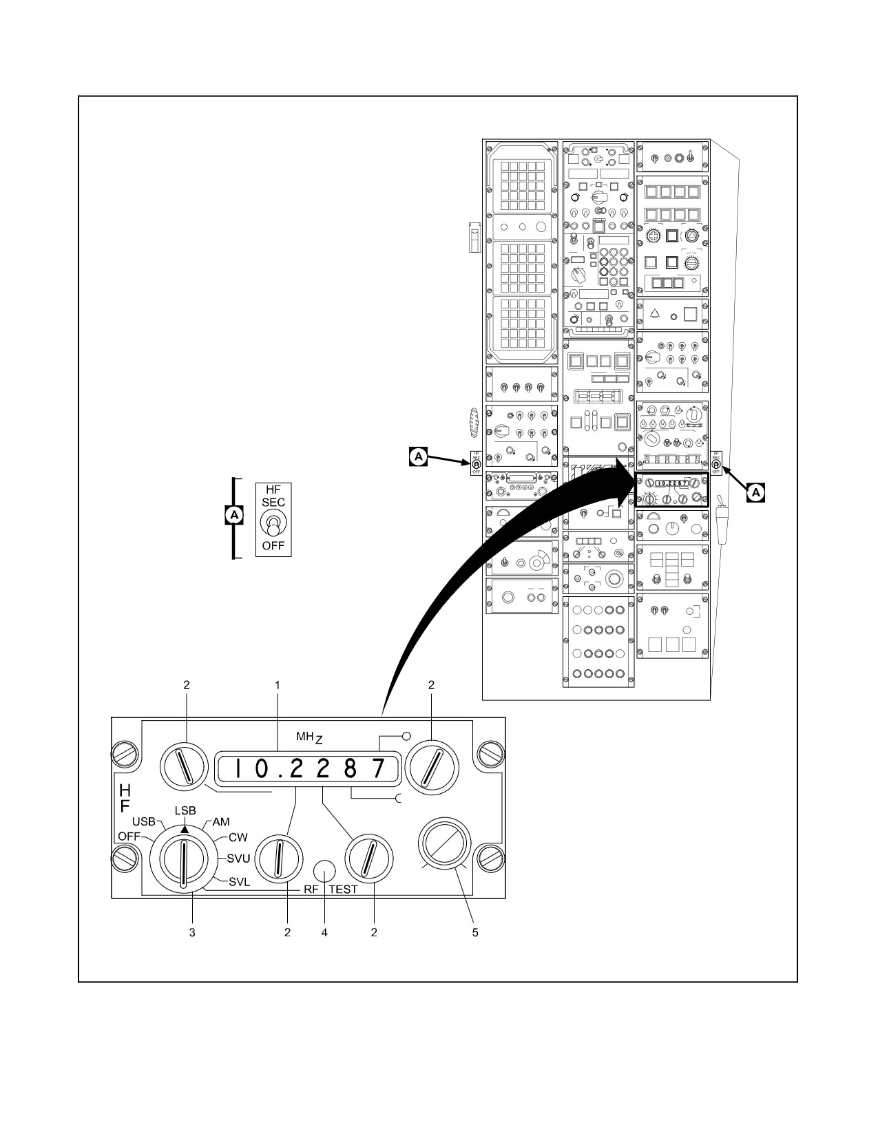
Steps foroperation oftheHF radio referto theHF radio control panel (Figure 15-9). To transmit, position theXMTR
SEL switch on the radio control panel to HF (Figure 15-3). Key transmitter to tune selected frequency. Once the tune
cycle has been completed, the radio is tuned.
ORIGINAL
15-26
A1-H60BB-NFM-000
Do not operate HF transmitter on deck when personnel are within 50 feet
of the antennas. Radiation hazard exists.
Note
D Unlike older HF radios, it is not necessary to tune a particular frequency
prior to shutting down the radio.
D USN communication personnel generally specify HF radio frequencies as
the frequency of the center of the sideband emission rather than the carrier
(window) frequency. Most other communications activities such as
commercial, USAF, and foreign military specify the window frequency
which must be set on the radio control. Therefore, it may be necessary to
set a frequency 1.5 to 2.0 KHz (0.0015 to 0.0020 MHz) off of the frequency
specified in USN communications plans. Shift down for USB and up for
LSB.
15.1.5.3.2 HF Test
1. Select RF TEST. Lamp may blink for up to one minute but must eventually come on steady.
2. Key the radio momentarily. The tune tone should be audible for 4 to 8 seconds and the RF TEST light should
go out. (This step will energize the antenna. For most reliable results, it should be conducted while airborne.)
3. After the tone stops, the RF TEST light may blink for up to one minute but must eventually come on steady.
4. If these indications are not received, the HF radio may not be fully operational and the results of the test should
be passed to maintenance personnel.
15.1.6 Intercommunication System
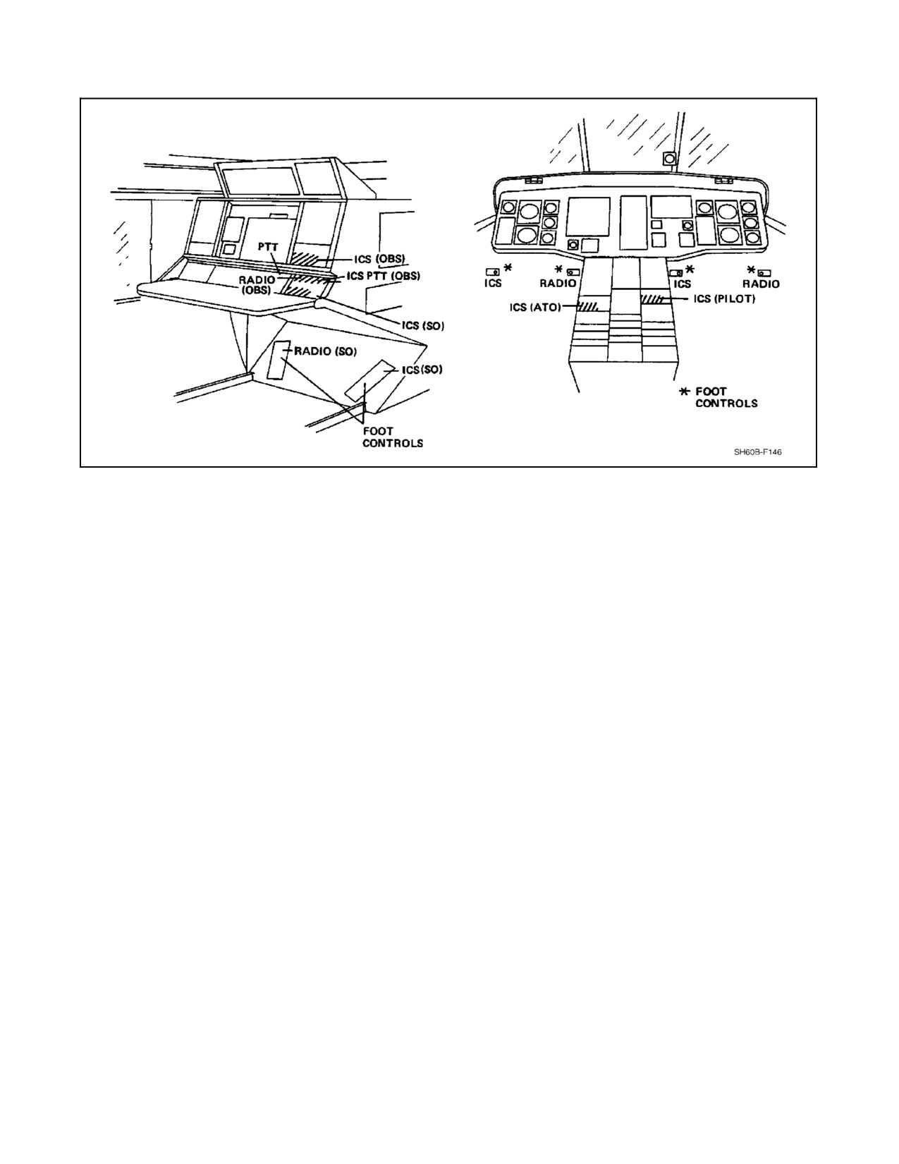
The ICS permits communications between aircrewmembers. Each crewmember RSC panel includes controls for ICS
operation (Figure 15-10). Additional inputs to the ICS network through IBs allow voice communications from the
hoist operator station or from outside the helicopter while on the ground.
The pilot, ATO, SO, and instructor stations internal voice microphones may be voice actuated or push--to--talk (PTT). At
the pilot and ATO station, the intercommunication PTT switch is the first detent of a trigger switch on the cyclicgrip
(the second detent actuates a selected radio transmitter). In addition, the pilot, ATO, and SO stations have two
footpedal communication switches. The ICS switch for the instructor station is a pushbutton located below the
instructor RSC panel. The ICS switches for the rescue hoist station are located on the hover trim control grip and the
crewman rescue hoist pendant.
The ICS CALL switch on the cyclic grip or RSC overrides all transmissions or receptions. This allows
communication with the other crewmen, regardless of the configuration RSC switches.
15-27
ORIGINAL
A1-H60BB-NFM-000
SQL
LSI 017--0862--0
Figure 15-9. HF Radio Control Panel (Sheet 1 of 2)
ORIGINAL
15-28
A1-H60BB-NFM-000
INDEX
NUMBER
CONTROL LABELS
FUNCTIONAL DESCRIPTION
HF
The HF radio panel contains the switch functions and indications needed
to operate the HF radio transmitter/receiver.
A
The HF SECURE ON/OFF lever-lock toggle switch on the COMM
CONTR panel is used to transmit secure-voice.
1,2
MHz (rotary switches)
The frequency readout and frequency selector controls are drum
displays and rotary switches used to select one of 280,000 usable HF
frequencies in the range from 2.0000 to 29.9999 MHz in increments of
100 Hz.
3
(Mode select)
The Mode select switch is an eight-position rotary switch. It provides the
following mode selections.
USB, LSB, AM
These positions allow the user to select one of three possible clear voice
modes of radio transmission and reception — USB, LSB, or AM. USB
and LSB can be used to transmit/receive secure voice.
CW
Not implemented in the SH-60B.
SVU, SVL
These modes are for narrowband operation and are only usable when a
compatible HF secure-voice encoder, such as the KYV-5, is integrated with
the HF radio. SVU and SVL can be used for both transmit and receive
(transmit toggle switch on the CSCG must be on). The difference between
SVU and SVL, and USB and LSB is a 10 db decrease in volume for SVU
and SVL.
RF TEST
Placing the mode selector switch in this position allows the user to
isolate an HF radio fault to an individual unit. This is accomplished by
selecting an HF frequency and keying the system. The status of the RF
TEST lamp (NO. 4) will indicate which unit is faulty.
4
RF TEST
The yellow RF TEST lamp indicates which unit is faulty when the RF
TEST position of the mode selector switch is used. Indications and their
meaning are as follows:
OFF — Fault is in the receiver/transmitter unit.
ILLUMINATED STEADY AFTER BLINKING — Normal operation and no
fault.
BLINKING — Fault is in amplifier-power supply or antenna coupler. A
BLINKING indication can be further interpreted by aural monitoring.
After the tune cycle has been completed, the normal tune tone should
disappear from the headset. A continuing tone indicates a fault in the
Power Amplifier or Power Supply. An interrupted tone (beeping)
occurring about 10 seconds after the tune cycle is initiated indicates a
fault in the Antenna Coupler.
5
SQL
The SQUELCH control provides a selection of eight squelch
threshold-level settings which reduces the background noise between
transmissions.
Figure 15-9 HF Radio Control Panel (Sheet 2)
15-29
ORIGINAL
A1-H60BB-NFM-000
Figure 15-10. Intercommunications System (ICS) Controls
Note
D To avoid the possibility of communications interference, DO NOT utilize
ICS while simultaneously transmitting on UHF/VHF or HF.
D To prevent hot mike of other selected transmitters and loss of VOX ICS,
ensure the ANDVT (USC--43/KYV--5) HF SECURE toggle switches are
OFF when not in use. The toggle switches are mounted on the side of the
center console, one on the pilot side and one on the ATO side.
D ICS operation requires AC power. ICS will not be available when the
battery is the only source of electrical power.
15.1.7 Speech Security System
15.1.7.1 Speech Security Equipment, TSEC/KY-58
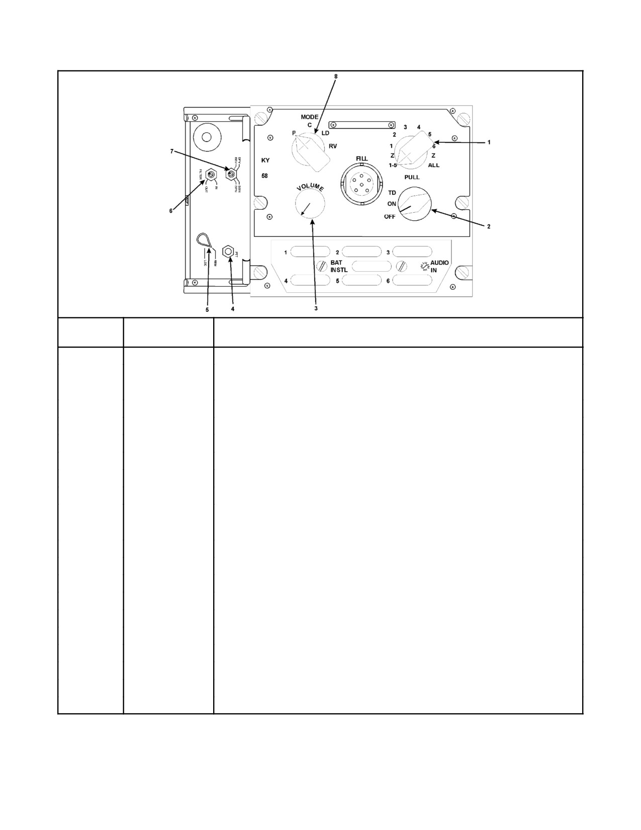
The half--duplex, wideband KY--58 and interface adapter (Z--AHQ) (Figure 15-11) provide secure operation for the
UHF radios. The KY--58 and ZAHQ replaced the older KY--28 speech security equipment. When UHF secure
operation is selected on the COMM CONTR panel, the selected UHF Receiver/Transmitter (R/T) operates in
conjunction with the KY--58. The other UHF R/T is allowed simultaneous transmissions in the clear. Audio signals
from the crewmember headsets are routed to the KY--58 by the CSCG ACP. The KY--58, located in the Mission
Avionics Rack (MAR), encrypts the audio signals, which are then sent to the selected UHF R/T via the CSCG ACP.
Secure UHF audio received by the UHF R/T is routed to the KY--58 by the CSCG ACP. The KY--58 decrypts the
signals using the operational code and sends the clear audio to the CSCG ACP for distribution. Primary mission
power is required for secure communications.
The KY--58 incorporates several advantages over the KY--28 it replaced. It allows up to six codes to be electrically
loaded at one time into its memory, providing greater tactical communications flexibility. In addition, keying of the
KY--58 is done using the same loading devices as the KYV--5 and KG--45.
ORIGINAL
15-30
A1-H60BB-NFM-000
INDEX
CONTROL
NUMBER
LABELS
FUNCTIONAL DESCRIPTION
1
FILL Select
Z
Zeroizes memory locations 1 through 5 simultaneously.
1-5
1
Addresses memory location 1.
2
Addresses memory location 2.
3
Addresses memory location 3.
4
Addresses memory location 4.
5
Addresses memory location 5.
6
Addresses memory location 6.
Z
Zeroizes memory locations 1 through 6 simultaneously.
ALL
2
Power Switch
Removes power from the KY-58. Clear voice is still available.
TD
Selects a time delay for use when transmitting through a COMM relay station.
ON
Applies power to the KY-58 (normal mode).
OFF
Removes power from the KY-58. Clear voice is still available.
3
VOLUME Control
Adjusts output volume of received signal when in cipher mode.
4
PTT
Push-to-talk.
5
LOC/REM
Selects local or remote operation (remote normal operation).
6
FILTER
Baseband premodulation filtering.
IN
Selects filtering.
OUT
Deselects filtering (normal mode).
Figure
15-11. TSEC/KY--58 and Z--AHQ Interface Adapter Controls and Indicators (Sheet 1 of 2)
15-31
ORIGINAL
A1-H60BB-NFM-000
INDEX
CONTROL
NUMBER
LABELS
FUNCTIONAL DESCRIPTION
7
Function switch
BBN or BBV
Selects baseband (FM) mode. (Note)
DPN or DPV
Selects diphase (AM) mode. (Note)
8
MODE Control
Switch
P
Permits transmission of plain voice.
C
Permits transmission of cipher voice.
LD
Permits loading of variables into the KY-58.
RV
Permits reception of a remotely keyed variable.
Note
BBN and BBV are interchangeable. DPN and DPV are interchangeable.
Figure 15-11. TSEC/KY--58 and Z--AHQ Interface Adapter Controls and Indicators (Sheet 2)
These codes are retained by the internal battery or aircraft power until zeroized. Refer to the current operational
communication plan for proper mode and code selection. Refer to Figure 15-12 for troubleshooting procedures.
Note
D The ability to receive but not be heard indicates a diphase/baseband
mismatch. (Diphase can receive baseband, but baseband cannot receive
diphase).
D Inability to hold a key may be the result of a weak or dead battery.
D A good key with the apparent inability to transmit or receive secure voice
(noise following the beep) may indicate a code mismatch.
D When in secure voice mode, radio volume is controlled on the KY--58. The
CSCG control panel radio volume is disabled.
D Clearguard transmissions do not pass through theKY--58; guard should be
monitored on the radio not in secure mode.
The KY--58/Z--AHQ assembly memory can be zeroized by the following methods:
1. Depressing the zeroize button on the CSCG control panel.
2. Selecting Z 1--5 or Z ALL on the KY--58.
15.1.7.1.1 Z-AHQ Adapter
The KY--58 is mechanically mounted to the Z--AHQ adapter as shown in Figure 15-11.
15.1.7.2 Tactical Speech Security Equipment, TSEC/KYV-5
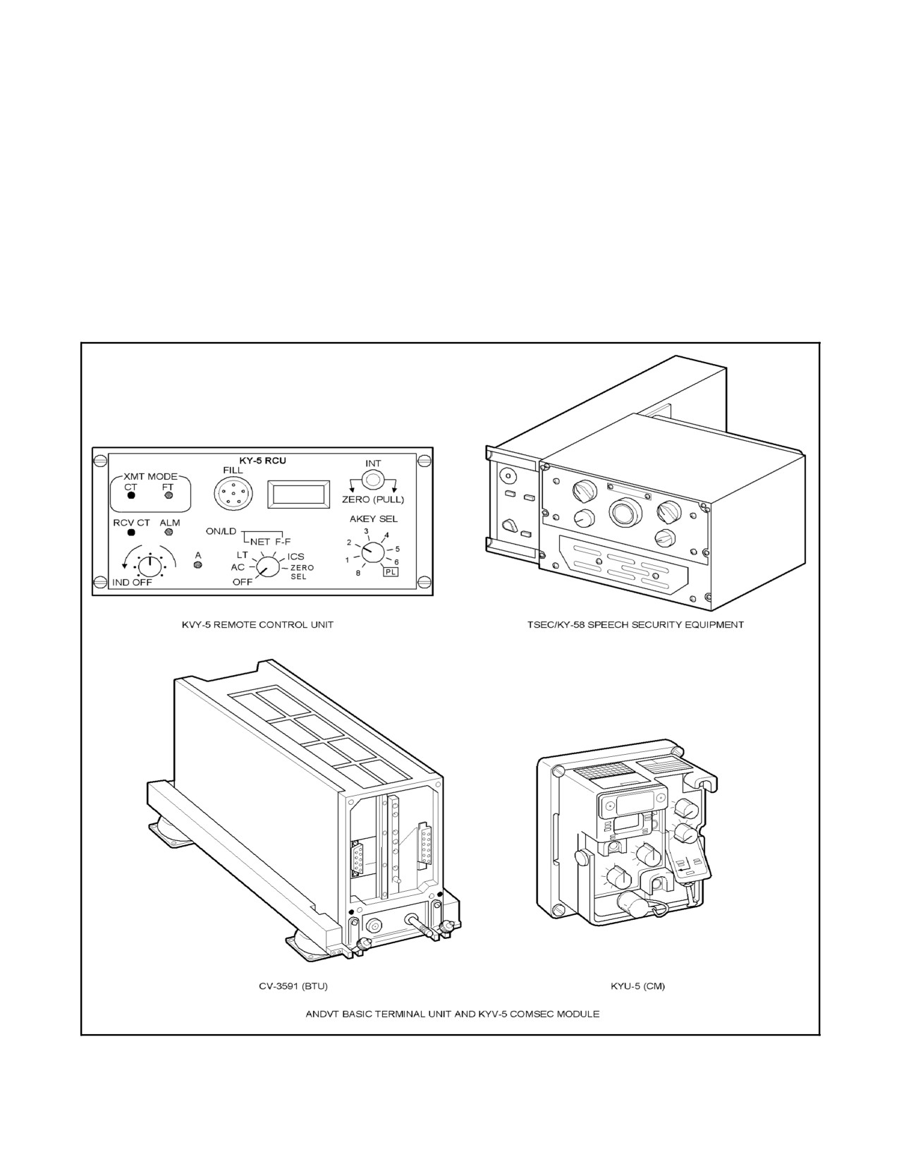
The half--duplex, narrowband KYV--5 (Figure 15-13) consists of:
1. Processor.
2. Remote Control Unit.
ORIGINAL
15-32
A1-H60BB-NFM-000
TONE
OCCURS
INDICATES
PROCEDURE
Continuous beeping
At turn-on.
Clear by pushing and releasing
(cryptoalarm) with
push-to-talk (PTT) button.
background noise
Continuous beeping
At any time other than
Equipment or battery
Repeat TURN-ON procedures. If the
(cryptoalarm alarm)
turn-on.
failure.
alarm does not clear, change the
prime battery. If it still does not clear,
turn the equipment in for
maintenance.
Continuous tone
Any time an empty
1. An empty storage
Follow LOAD procedure to enter a
(parity alarm)
register is addressed
register.
new cryptovariable. If the alarm
and PTT is depressed
2. An invalid
does not clear, change the prime
and held.
cryptovariable is
battery. If it still does not clear, turn
present.
the equipment in for maintenance.
3. Equipment fails to
receive a valid
cryptovariable sent by a
remote keying
operation.
4. Equipment failure.
A single beep
1. Each time PTT is
1.Begin speaking.
initiated with the
2. A valid
equipment in cipher
cryptovariable.
and a filled storage
3. The cryptovariable
register is addressed.
has passed the parity
2. When a
check.
cryptovariable has
been successfully
received.
3. At the beginning of
a receive message.
A single beep in time
After the preamble is
Begin speaking.
delay (TD)
sent.
Background noise
At turn-on.
The KY-58 is working
If no background noise is heard at
properly.
turn-on, turn equipment in for
maintenance. (Note)
A single beep followed
At any time in cipher
Receiving station on a
1. Turn fill select switch to the
by a burst of noise
text mode.
different variable than
common variable.
transmitting station.
2. As a last resort, contact
transmitting station in plain and
agree to meet on a particular
variable.
Note
This is important because the absence of noise indicates a malfunction which cannot be otherwise detected.
It does not affect the communications capability. It does, however, affect the security provided by the KY-58.
Figure 15-12. KY--58 Aural Tones
15-33
ORIGINAL
A1-H60BB-NFM-000
The KYV--5 provides secure--voice operation capability for the HF radio. When HF secure operation is selected on
the COMM CONTR panel, the HF radio operates in conjunction with the KYV--5. Audio signals received by the HF
radio are routed to the KYV--5, via the CSCG ACP, for decryption. Clear audio is then returned to the ACP for
distribution to crewmember headsets. Audio signals from crewmember headsets are routed to the KYV--5 by the
CSCG ACP. The KYV--5 encrypts the audio signals and sends them to the HF radio, via the CSCG ACP, for
transmission. Power is supplied from the NO. 2 DC primary bus through a circuit breaker located in the mission
avionics circuit breaker panel, marked HF SECURE.
Note
The ARC--182 VHF radio, installed in ESP--modified aircraft as an
aftermarket kit, is inoperable with the HF SECURE switch in the ON
position.
Figure 15-13. Tactical Speech Security Equipment
ORIGINAL
15-34
A1-H60BB-NFM-000
15.1.7.2.1 Processor
The KYV--5 processor contains the circuits required for encryption/decryption of HF audio signals. The processor
contains the electrically inserted operational code. Principles of operation for the KYV--5 processor are contained
in classified publications.
15.1.7.2.2 Remote Control Unit
The remote control unit provides an interface for controlling the KYV--5 and is located on the MAR. The operational
code is electrically inserted into the remote control unit, which sends it to the KYV--5 processor. The code can be
zeroized by activation of the ZERO CODE switch on the COMM CONTR panel. The zeroize signal is sent to the
remote control unit, which forwards it to the processor. Electrical reinsertion of the code is required when the code
has been zeroized. The code is zeroized in the following two situations:
1. Activation of the zero code switch on the COMM CONTR panel.
2. PWR/FILL dial switch is rotated to OFF/ZEROIZE position.
15.1.7.3 Radio Terminal Set, AN/ARQ-44 (Data Link)
The Radio Terminal Set (Data Link) is a full--duplex, secure RF link between the helicopter and the ship. Operating
in the super high frequency (SHF) spectrum, it provides two--way secure data and secure voice communications
between the ship and the helicopter. The data link has three modes of operation which are selectable on the CSCG.
In ASW mode, the R/T transmits acoustic sensor data on RF channel NO. 1. In ASST mode, it transmits radar/IFF
sensor data on RF channel NO. 1. ASW/ASST modes are normally used only for maintenance. In AUTO mode, the
Data Link receives antenna pointing, antenna selection, RF channel selection, and mode commands from SAC--1.
In HELO CONTROL, all information except ship commands are transmitted and received. The data link consists
of the following components: communication security equipment, receiver/transmitter
(R/T), multiplexer--
demultiplexer (mux--demux), and the data link antennas.
15.1.7.3.1 Communication Security Equipment, TSEC/KG-45
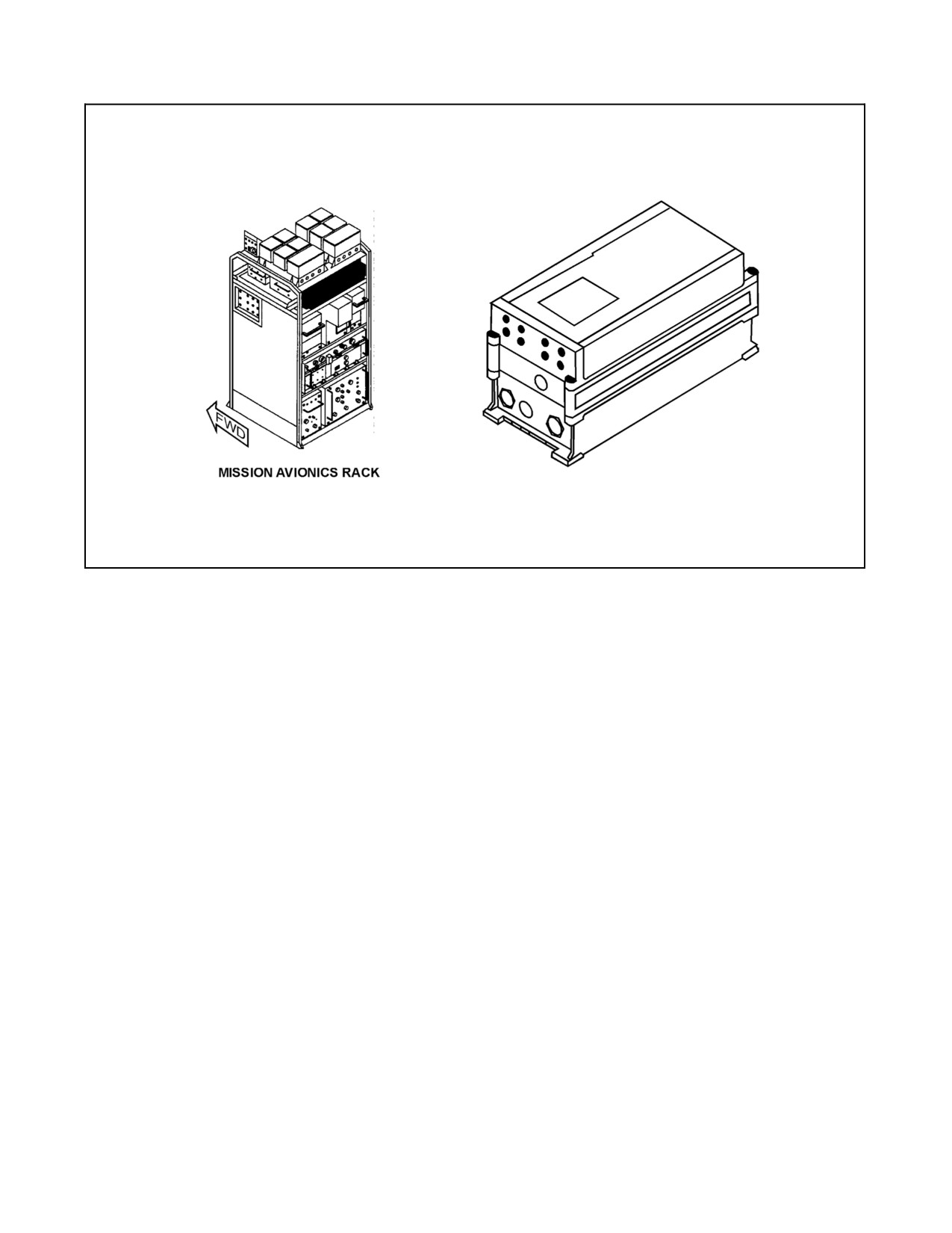
The KG--45 (Figure 15-14) is a high--speed, full--duplex key generator that provides cryptographic security for both
uplink and downlink data between the tactical avionics and the ship electronics systems. The KG--45 encrypts and
decrypts the data link signal for the radio terminal set. The KG--45 is zeroized by loss of power for approximately
two minutes. The data link cannot be operated without a properly keyed KG--45. The KG--45 must be keyed with
MSN PWR on. Once keyed, the KG--45 will continue to operate in the voice mode with SAC power secured (e.g.,
performing engine overspeed checks on hardwire). Power is supplied from the NO. 2 DC primary bus through a
circuit breaker marked DATA LINK SECURE located on the mission avionics circuit breaker panel.
15.1.7.3.2 Receiver/Transmitter, RT-1275/ARQ-44
The radio R/T provides for continuous wave transmission and reception of mission data between own ship and the
helicopter. During uplink, the R/T receives transmission from one of the antennas and sends it to the mux--demux.
Data for downlink is received from the mux--demux and routed for transmission. When the data link switch is in
RADIATE, RF output is available to either antenna or the hardwire port. In STBY, the transmitter will not radiate.
The Weight--On--Wheels switch causes the RF output to shift to the dummy load, while low--level RF power is still
present at the hardwire port. Each of the 16 available data link channels contains two discrete SHF frequencies, one
for uplink and one for downlink.
15.1.7.3.3 Multiplexer-Demultiplexer, TD-1254/ARQ-44
The mux--demux functions as two basic units, a multiplexer and a demultiplexer. Both units operate simultaneously.
The demultiplexer receives uplink data from the R/T and sends it through the KG--45 for decryption. Upon return
ofthedecrypted data, the demultiplexerseparates and routes thedata to various onboard equipment. Themultiplexer
gathers downlink data, arranges it into the proper format, sends it through the KG--45 for encryption, and then to the
R/T for transmission to the ship.
15-35
ORIGINAL
A1-H60BB-NFM-000
Figure 15-14. Communications Security Equipment TSEC/KG--45
15.1.7.3.4 Data-Link Antennas, AS-3273/ARQ-44
The two data--link antennas are independently steered to continuously point at the ship; however, only one antenna
will radiate at any given time. The AOP computes the relative bearing of the ship from the helicopter and sends the
antenna select commands to the mux--demux. The mux--demux passes the commands to the R/T to control selection
oftheRF powerto theappropriateantenna. Theforward antennaoperates from 285° to 075° relative. The aft antenna
covers the area from 071° to 289° relative. This gives a 4° overlap to prevent loss of synchronization.
15.1.8 Identification System
The IFF subsystem is comprised of two components: the IFF transponder and associated KIT--1/TSEC series
transponder computer, which responds to interrogation from other friendly units; and the IFF interrogator and
associated KIT--1/TSEC series interrogator computer, which interrogates other units for identification.
15.1.8.1 IFF Transponder
The transponder is made up of the APX--100 receiver/transmitter and KIT--1/TSEC series transponder computer. It
is controlled from the IFF transponder control panel on the lower console (Figure 15-15).The transponder cannot be
controlled by mission computer commands. The IFF subsystem can operate in four modes. Mode 1 provides 32 code
combinations, any one of which may be selected in flight. Mode 2 and Mode 3/A each provide 4,096 codes. Mode
4 provides military secure IFF. Mode C provides altitude encoding. Power is supplied by the NO. 1 DC primary bus
through a circuit breaker marked APX--100 CONTR XPONDR located in the ATO circuit breaker panel.
ORIGINAL
15-36
A1-H60BB-NFM-000
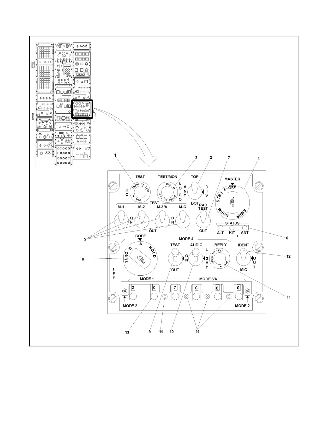
Figure 15-15. IFF Transponder Control Panel (Sheet 1 of 3)
15-37
ORIGINAL
A1-H60BB-NFM-000
INDEX
NUMBER
CONTROL LABELS
FUNCTIONAL DESCRIPTION
IFF
The IFF Transponder Control Panel provides the controls for the IFF
Transponder Set. The Transponder cannot be controlled as a result of
control commands received from the computer.
1
TEST
The green TEST GO and the red TEST/MON NO-GO PRESS TO
TEST, turn to dim, annunciators indicate satisfactory operation of the
2
MON, NO-GO
transponder for selftest of Modes 1, 2, 3/A, 4, and C.
The green GO light indicates a good self-test. The red NO-GO light
indicates a bad self-test on the KIT-1/TSEC Series Computer code is
connected and Mode 4 is not coded or the Master selector is in STBY.
The monitor function of the red light causes the light to illuminate
momentarily when the transponder replies to an interrogation with
MASTER in NORM.
3
ANT
The Antenna Control is a three-position toggle switch used to select the
IFF antenna.
TOP
Top position selects the upper IFF antenna.
DIV
Diversity position selects automatic switching between the upper and
lower IFF antennas.
BOT
Bottom position selects the lower IFF antenna.
4
MASTER
The MASTER selector is a four-position rotary switch with the following
functions:
OFF
OFF turns transponder off. Switch must be pulled outward to rotate to
this position.
STBY
Standby places transponder in warmup condition.
NORM
Normal causes the transponder to operate normally.
EMER
Emergency conditions the transponder to transmit emergency reply
signals to Mode 1, 2, and 3/A interrogations, regardless of mode-control
settings. The switch must be pulled outward to rotate to this position.
5
ON
When normal mode selected (center position), respective mode is on
and will respond to challenges.
M-1 TEST
Mode 1 momentary self-test.
OUT
Out (off) position for Mode 1.
M-2
Mode 2 momentary self-test.
OUT
Out (off) position for Mode 2.
M-3/A
Mode 3/A momentary self-test.
OUT
Out (off) position for Mode 3/A.
M-C
Mode C (Altitude Encoding) momentary self-test.
OUT
Out (off) position for Mode C.
6
STATUS
Three red LED annunciators which isolate the fault status of the external
units that provide data to the IFF system.
ALT
Fault in altimeter, encoding barometric altimeter at pilot position.
KIT
KIT-1 series Encryption unit fault.
ANT
Fault in selected IFF antenna.
7
RAD TEST/OUT
The RAD TEST/OUT control is a two-position toggle switch for control
of the transponder test circuitry, as follows:
RAD TEST
Causes the transponder to reply to test mode interrogations and to
verify BIT #1 for Mode 4.
Figure
15-15. IFF Transponder Control Panel (Sheet 2)
ORIGINAL
15-38
A1-H60BB-NFM-000
INDEX
NUMBER
CONTROL LABELS
FUNCTIONAL DESCRIPTION
OUT
Monitor — The red TEST/MON light will illuminate when the
transponder replies to interrogation.
8
MODE 4 CODE Selector
CODE
The MODE 4 CODE selector is a four-position rotary switch with the
following selections:
ZERO
Causes code in both the KIT-1/TSEC series and the KIR-1/TSEC series
computers to be erased. A mechanical latch must be released to turn
the switch to zero. There is no guard when going from ZERO to B or A.
B
Selects Mode 4, Code B.
A
Selects Mode 4, Code A.
HOLD
Causes the KIT-1/TSEC series and the KIR-1/TSEC series computers
to hold their codes before securing power. The switch is spring loaded
out of this position so that it will return to the A position when released
by the operator.
9
MODE 4 TEST/ON/OUT
The MODE 4 TEST/ON/OUT is a three-position toggle switch used to
enable or test Mode 4. The up position (TEST) is spring loaded to return
to the middle position (ON) when the switch is released. The bottom
position (OUT) has a mechanical interlock to prevent inadvertently
switching to Mode 4 off.
10
MODE 4
The AUDIO/LIGHT/OUT Control is a three-position toggle switch used
AUDIO/LIGHT/OUT
to select the methods by which invalid Mode 4 interrogations are
indicated.
AUDIO selects both audio tone and the IFF caution light on the
Caution/Advisory Panel.
LIGHT, only the IFF caution light on Caution/Advisory Panel.
OUT, no indications of invalid Mode 4 interrogation. A mechanical
interlock is provided to prevent inadvertent movement of the switch to
OUT.
11
MODE 4 REPLY
The green MODE 4 REPLY PRESS TO TEST, turn-to-dim, annunciator
indicates the transmission of valid Mode 4 replies.
12
IDENT/OUT/MIC
The IDENT/OUT/MIC selector is a three-position toggle switch. The
IDENT position is spring loaded. When momentarily selected, it initiates
the Identification of Position (I/P) reply for approximately 20 seconds.
Selection of OUT prevents triggering of the I/P function. Selection of the
MIC position enables the I/P replies to be transmitted when the pilot
presses either of his PTT switches.
13
MODE 1, MODE 3/A
The MODE 1 and MODE 3/A code selectors are six unidirectional
(Code Selectors)
thumbwheel switches used to select Mode 1 and Mode 3/A reply codes.
The first two switches are for Mode 1 codes (octal numbers in range 00
to 73). The last four switches are for Mode 3/A codes (octal numbers in
the range 0000 to 7777).
14
MODE 2 (Code
The two cover-retaining screws are loosened and the cover enclosing
Selectors)
MODE 1 and MODE 3/A is raised to reveal MODE 2 code settings. The
MODE 2 four-digit octal code is inserted via the pushbutton switches
and observed on the MODE 2 code display. MODE 2 codes are
assigned by operational commanders. After insertion of MODE 2, the
cover is lowered and the cover retaining screws tightened.
Figure
15-15. IFF Transponder Control Panel (Sheet 3)
15-39
ORIGINAL
A1-H60BB-NFM-000
15.1.8.2 Transponder Computer, KIT-1 TSEC Series
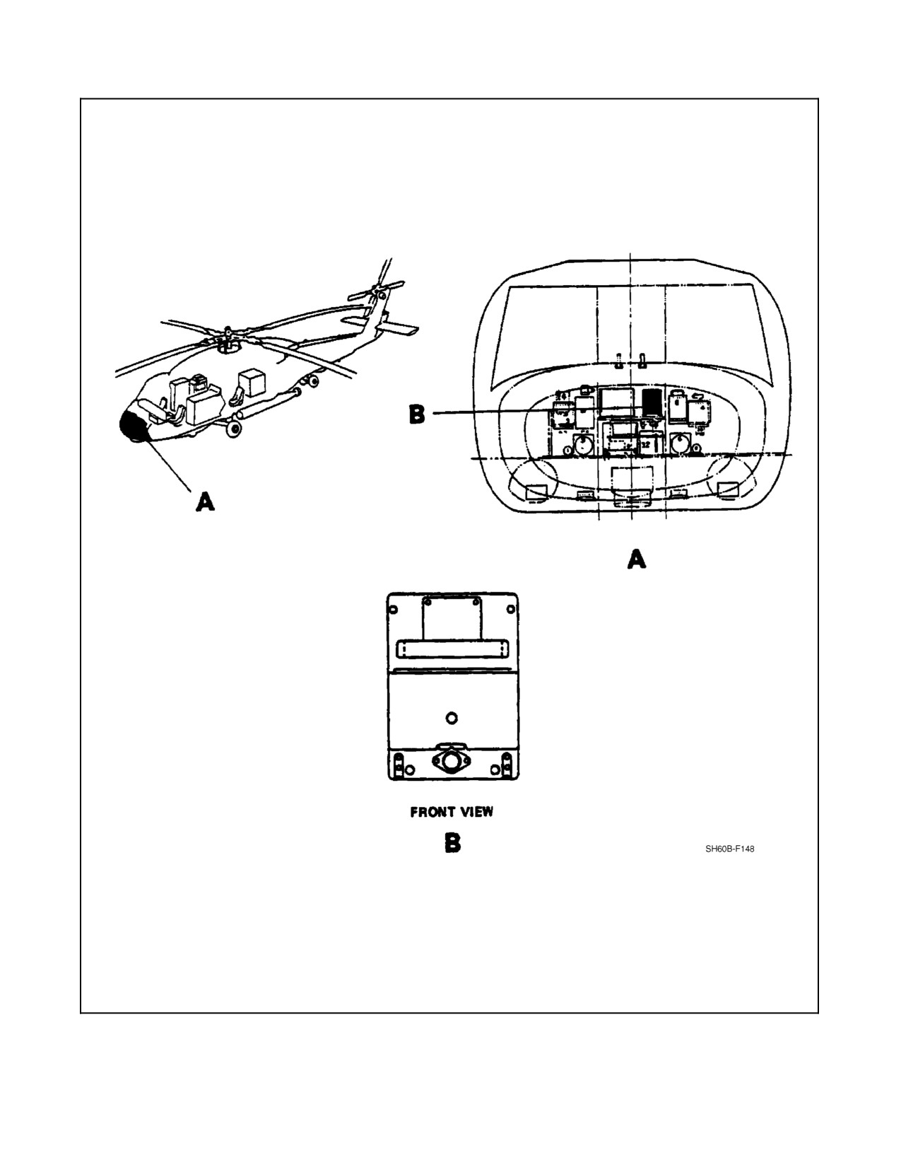
The transponder computer (Figure 15-16) processes mode 4 IFF challenges and generates properly coded responses.
The transponder computer uses a manually inserted operational code to decode the interrogation and produce the
response. The response is then sent back to the IFF transponder for transmission. Power is supplied from the NO. 2
AC primary bus through a circuit breaker marked COMPTR XPONDR located in the corner circuit breaker panel.
The IFF subsystem can operate in four modes. Mode 1 provides 32 code combinations, any one of which may be
selected in flight. Mode 2 and mode 3/A provide 4,096 codes each, any one of which may be selected in flight. Mode
4 provides military secure IFF.
Note
The HOLD position should be utilized priorto shutdown if anothertakeoff
is anticipated during the code period.
The IFF subsystem can operate in four modes. Mode 1 provides 32 code combinations, any one of which may be
selected in flight. Mode 2 and mode 3/A provide 4,096 codes each, any one of which may be selected in flight. Mode
4 provides military secure IFF.
The transponder computer generates coded replies in response to valid interrogations from an interrogator
cryptographic computer. Two Mode 4 codes are set in the transponder computer prior to flight, one for the present
code period and one for the succeeding code period. From this time on, whenever the IFF is turned off or electrical
poweris disconnectedforapproximately15 to20 seconds,thecodeswill becleared. Thiscan beprevented byturning
the CODE switch to HOLD position at least 15 seconds prior to power interruption. The KIR--1/TSEC functions in
the same manner. Power is supplied by the NO. 1 DC primary bus through a circuit breaker, located in the overhead
circuit breaker panel, marked APX--100 CONTR XPONDR.
The Mode 4 codes for both the KIT--1/TSEC and KIR--1/TSEC may be cleared manually by turning the CODE switch
to ZERO position. This is a guarded position and requires pulling out and turning to reach the ZERO position.
Likewise, the HOLD function transfers both KIT and KIR codes to hold.
The transponder will give a green reply light to indicate that it has responded to an interrogation. The transponder
will also give an audio and/or IFF caution light indication if it is unable to respond to a valid mode 4 interrogation.
These may be selected or inhibited using the MODE 4 AUDIO/LIGHT/OUT switch (Figure 15-15).
All audible and visual indications are inhibited in the OUT position. The
IFF caution indicators warn the operator of potential life--threatening
conditions relating to the ability to respond to Mode 4 interrogations.
The IFF caution indicator warns of conditions in which Mode 4 interrogations are not being responded to, possibly
resulting from the transponder being in standby or having Mode 4 disabled (e. g., Mode 4 select switch in OUT
position). The IFF caution indications further serves to warn of a zeroized or malfunctioning IFF crypto computer.
The ANT toggle switch offers three selections: TOP, BOT (Bottom), and DIV (Diversity). When TOP is selected,
the transponder will only respond to interrogations from the top antenna. When BOT is selected, responses are only
allowed from the bottom antenna. When DIV is selected, the transponder will respond automatically through the
antenna receiving the strongest signal. The selection of TOP or BOT will not inhibit the transponder from processing
signalsfromaspecificantenna.Thetransponderattemptstomakediversityselectiononreceivedsignalsandattempts
to respond through the antenna having the strongest received signal. If the antenna favored by transponder diversity
selection process is disabled by the ANT toggle switch, no response will be transmitted.
ORIGINAL
15-40
A1-H60BB-NFM-000
Figure 15-16. Transponder Computer KIT--1/TSEC Series, Mode 4
15-41
ORIGINAL
A1-H60BB-NFM-000
Use of the TOP or BOT vice the DIV selection may cause the transponder
not to reply to valid Mode 4 interrogations. Failure to respond to a valid
Mode 4 interrogation may identify you as a potential foe. Take immediate
corrective action in accordance with local directives.
CAUTION
An IFF antenna fault will be indicated on the ANT status annunciator on
the IFF panel (Figure 15-15). This could indicate a failure to transmit. If
using an individual antenna, switch to the other one in an effort to correct
the problem by using the ANT toggle switch (Figure 15-15) on the IFF
panel.
Note
ARC--182 transmissions in the VHF band may cause the test GO (green
light) or NO--GO (red light) on the IFF transponder control panel to
illuminate momentarily.
15.1.8.3 IFF Interrogator
The interrogator is made up of the AN/APX--76B IFF interrogator, the KIR--1/TSEC series interrogator computer,
and the AN/APS--124 Radar Set. In SHIP Control--ASST mode, it can be remotely controlled by the ship via the data
link. A challenge may be issued from the COMM CONTR panel at any time, provided the CSCG control switch is
placed in the manual position. The mode and code of interrogation are also entered from the COMM CONTR panel.
The ATO may then elect to have all responses in the selected mode displayed or only those involving both mode and
code. Interrogation then may be made by activating the Challenge (CHAL) button to accept a correct MODE or
MODE and CODE reply. Challenge correct code (CHAL CC) may be used to accept only a correct MODE and CODE
reply.
While operating IFF in auto sweep or single sweep mode and the mode was
activated by the SO keyset, the SO will receive no indication when the IFF
code is being interrogated, even if AUTO IFF is activated.
Note
Radar power--on causes a resetting of the Interrogator amplifier. At least
one manual challenge must be issued from the COMM CONTR panel
before an uplinked challenge will be accepted and processed.
ORIGINAL
15-42
A1-H60BB-NFM-000
15.1.8.4 Interrogator Computer, KIR-1/TSEC
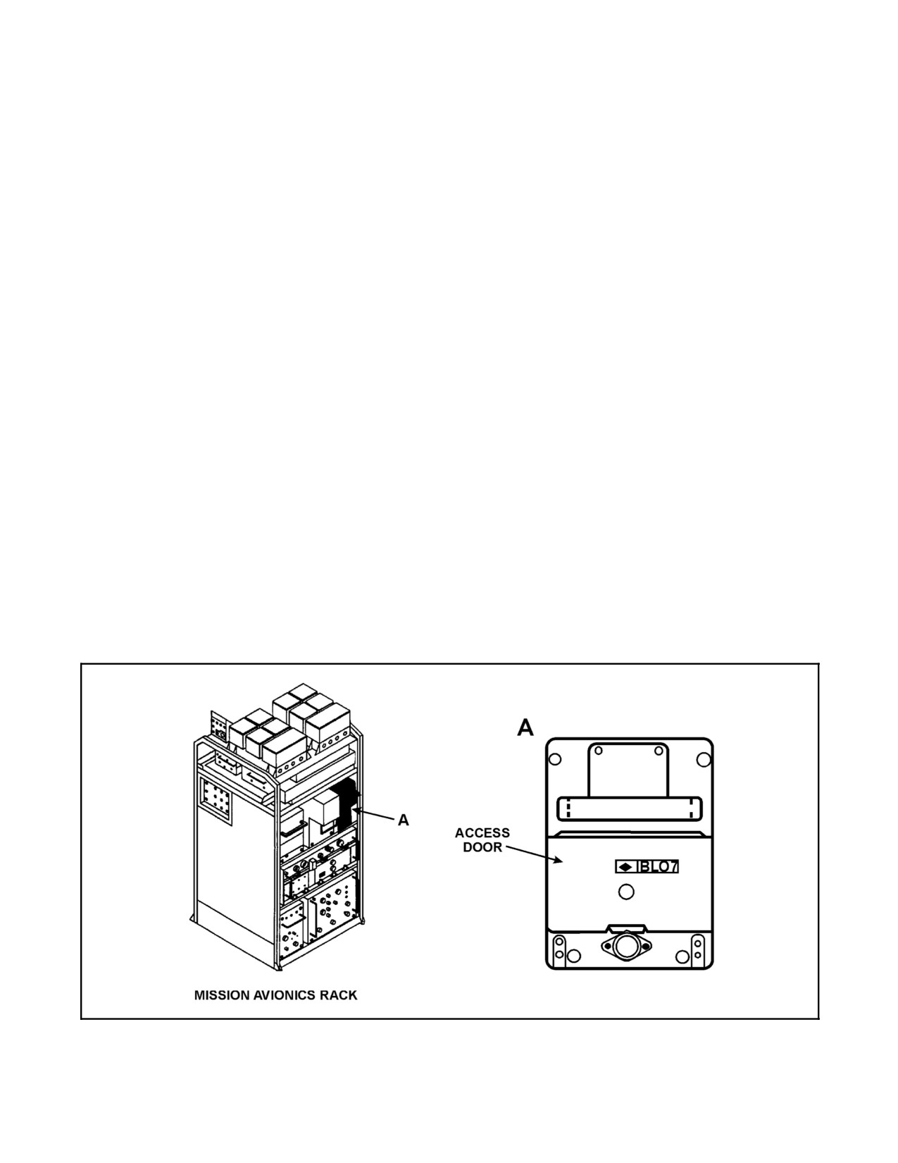
The Interrogator Computer (Figure 15-17) generates Mode 4 IFF interrogation pulses. The Mode 4 challenge is
activated via the IFF Electrical Synchronizer, which sends a pretrigger to the Interrogator Computer. The Interrogator
Computer uses a manually inserted operational code to generate the required pulse train for the Mode 4 interrogation.
The interrogation pulses are then returned to the IFF Interrogator for transmission. The Mode 4 reply received from
the interrogated station is sent to the Interrogator Computer by the IFF Interrogator. The computer uses the
operational codeto check thereply for propercoded response. The KIR--1/TSEC code is electrically held in thesame
manner as the KIT--1/TSEC. Use of the HOLD feature on the Transponder Control Panel will shift the code back to
hold. There are three methods of zeroizing the code:
1. Mode 4 code switch on IFF Transponder Control Panel (zeroize position).
2. Loss of electrical power for 15 to 20 seconds.
3. Loading door is opened.
Note
D Override of the M4 ALARM may compromise the Mode 4 code.
D ARC--182 transmissions in the VHF band may cause erroneous IFF
contacts. Selection of another COMM frequency may eliminate the
problem.
Certain failures of the interrogator computer will disallow interrogations (indicated by a red CHAL Flag). If the M4
alarm switch on the COMM CONTR panel is placed to ORIDE, it may be possible to force a challenge. If the ORIDE
is successful, a challenge will be issued. At the present time, there are no aural or visual indications of M4 ALARM
activation except for the failure to challenge.
Power is supplied from the NO. 2 DC primary bus through a circuit breaker in the mission avionics circuit breaker
panel marked IFF INTERG.
Figure 15-17. Interrogator Computer, KIR--1/TSEC Series
15-43
ORIGINAL
A1-H60BB-NFM-000
15.1.9 Interference Blanker
The interference blanker prevents interference due to simultaneous transmissions on the following transmitters:
1. IFF interrogator.
2. IFF transponder.
3. TACAN set.
Whenever these units transmit, a suppression input pulse is sent to the interference blanker by the transmitter. The
interference blanker then sends suppression pulses to the other two transmitters. The interference blanker also sends
suppression pulses to the electronic support measures (ESM) system to prevent spurious inputs to the ESM from the
aircraft transmitters. Power is supplied from the NO. 1 AC primary bus through a circuit breaker marked INTRF
BLANKER in the center circuit breaker panel. The interference blanker is located in the pilot seatwell.
15.1.10 Radio Terminal Set, AN/ARQ-44 or AN/ARQ-44A
The radio terminal set (data link) provides a directional RF link between the aircraft and the ship. See NTRP
3--22.4--SH60B for system description.
ORIGINAL
15-44
A1-H60BB-NFM-000
CHAPTER 16
Navigation
16.1
INTRODUCTION
The navigation subsystem determines flight data, such as air and groundspeed, heading, altitude, and attitude of the
helicopter. It provides this data for visual display on cockpit indicators and it relays navigational data to the data
handling subsystem.
16.2
NAVIGATION OPERATIONS
The navigation function processing requirements are partitioned into five subfunctions:
1. Navigation synchronization, used to synchronize ship and helicopter navigation systems.
2. Position keeping, utilizes Doppler radar navigation.
3. Position correction, used to determine and correct errors which arise due to helicopter navigation drift and
sonobuoy drift.
4. Fly--to--point (FTP), provides processing for FTP positions and generated flight path direction commands and
display information.
5. Provides navigational inputs for sensor processing and display.
These subfunctions are performed using various combinations of the navigation equipment described in the
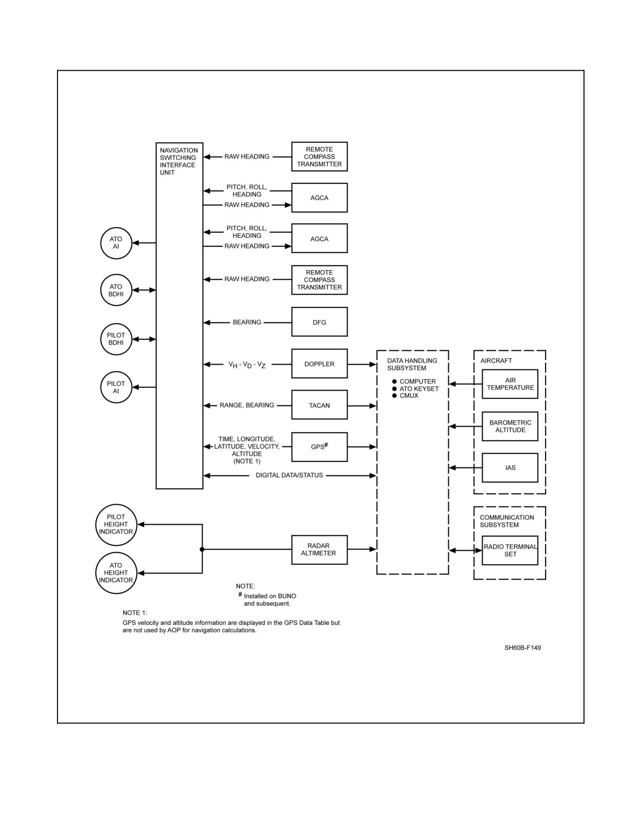
following sections. Figure 16-1 shows the functional flow of navigation data in the system.
16.3
COMPONENTS OF THE NAVIGATION SUBSYSTEM
In this subsection, the various components and units that make up the navigation subsystem are described, along with
their function, location, and operation. The functional interface of the navigation system is the navigation switching
interface unit (NSIU).
16.3.1 Navigation Switching Interface Unit
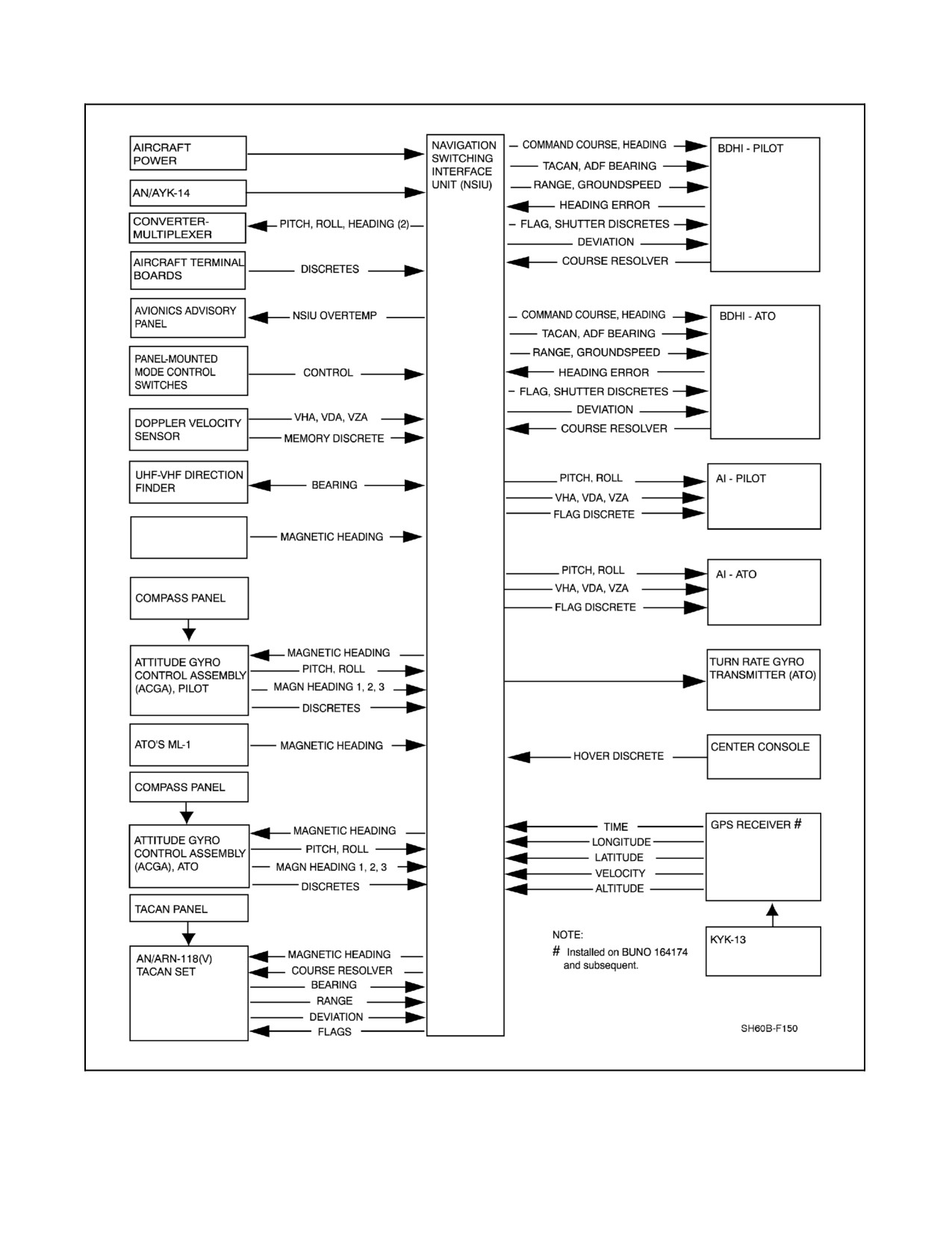
The NSIU is located in the nose avionics bay and serves as an interface between navigation source equipment and
the associated displays and data processors (Figure 16-2). The NSIU receives data from navigational sensing devices
and distributes this data to navigation displays and subsystem elements. Operator selection of source data is done
usingthefollowing:modeselectcontrol panellocated onthepilot/ATOinstrument panel,COMP panel,and theTCN
panel. In the event of a loss of AC power to the NSIU, or if the NSIU fails, power--off latching relays will establish
the following conditions:
1. Pilot AI will be driven from the pilot AGCA.
2. ATO AI will be driven from the copilot AGCA.
3. Both stations turn--rate needles will be driven from their respective sources.
4. Both BDHIs will only display:
a. Magnetic heading.
b. NO. 2 needle pointing to the currently selected TACAN station.
5. Both mode select panels will be inoperative.
6. No DME data will be available.
Power is supplied from the AC essential bus through two circuit breakers, located on the center circuit breaker panel,
and marked NSIU POWER and NSIU NAV REF, respectively.
16-1
ORIGINAL
A1-H60BB-NFM-000
164174
Figure 16-1. Navigation Subsystem Components Block Diagram
ORIGINAL
16-2
A1-H60BB-NFM-000
PILOT ML-1
Figure 16-2. Navigation Switching Interface Unit (NSIU) Functional Interface
16-3
ORIGINAL
A1-H60BB-NFM-000
16.3.2 Compass System
16.3.2.1 Attitude Gyro Control Assembly (AGCA) (Pilot and ATO)
The AGCA consists of a displacement gyroscope, electronic control amplifier, and compass system controllers.
There are two displacement gyroscopes. They supply heading information depending on AGCA mode selected on
the COMP panel (Figure 16-2).
When power is applied to the AGCA, the displacement gyroscope (stable platform) must be erected. The information
required to align the platform is provided by the compass system controller and the remote compass transmitter
(ML--1). A rough alignment phase lasting 2 minutes orients the platform generally in the proper position. At that
point a fine alignment phase begins. During this phase the gyro precesses at a normal rate until the platform is
precisely aligned.
Each stable platform provides the stable reference from which changes in aircraft pitch, roll, and heading are
measured. It consists of a two--gyro, three--gimbal assembly. The gyro heading (directional) gyro is mounted on the
innermost gimbal and is erected parallel to the surface of the Earth with its spin axis oriented toward magnetic north
in the slaved mode. The pitch (vertical) gyro is mounted on the middle gimbal. For attitude stabilization, this gyro
is erected perpendicular to the surface of the Earth, with its spin axis parallel to the local vertical. The displacement
gyroscope provides heading, pitch, and roll information via pick--offs from the inner, middle, and outer gimbals,
respectively. The information is sent to the electronic control amplifier for processing and distribution.
The electronic control amplifier
(ECA) contains an azimuth servo amplifier, slaving amplifier, deviation
compensator, turn and acceleration control features, fast synchronization circuitry, malfunction monitoring circuitry,
and power supplies. The electronic control amplifiers route heading, pitch, and roll synchro signals to the NSIU and
to AFCS for distribution to the various equipments. Power is supplied from the AC essential bus (pilot) and NO. 1
AC primary bus (ATO) through two circuit breakers on the overhead circuit breaker panel, marked PILOT ECA and
ATO ECA, respectively.
The electronic control amplifier contains the circuits required to:
1. Erect the stable platform.
2. Process heading information.
3. Correct for anomalies in the ML--1s as they detect the magnetic field of the Earth.
4. Distribute pitch, roll, and heading information.
5. Slave heading gyro to magnetic heading.
6. Suspend erection or remove compass slaving during aircraft acceleration.
7. Perform system monitoring and fault detection.
8. Correct for effects of the rotation of the Earth.
The ECA receives magnetic heading from the remote compass transmitter ML--1 via the NSIU. Mode select
information, heading information, and latitude correction information (for Earth rotation) are received from the
compass system controller. This information is processed by the electronic control amplifier and signals are generated
for the pitch, roll, and heading torques in the stable platform to control erection of the gyros. When acceleration of
the aircraft either linearly or rotationally exceeds cutoff points, the electronic control amplifier reduces erection and
slaving voltages to prevent loss of the stable platform from overdriving the torques.
ORIGINAL
16-4
A1-H60BB-NFM-000
Pitch and roll information received from the stable platform drives follow--up servos in the electronic control
amplifier. The pitch and roll servos provide three--wire synchro signals to the NSIU and automatic flight control
system (AFCS). Heading information received from the stable platform is processed by the electronic control
amplifier, and four separate three--wire synchro heading signals are generated. The information represented by these
signals depends on the mode of operation selected on the compass system controller.
The electronic control amplifier monitors critical voltages and signals during operation to detect system
malfunctions. If a malfunction is detected, an AGCA FAIL signal is transmitted to the NSIU. This alerts the pilot
to allow switching navigation displays from one AGCA to the other so that valid information is provided.
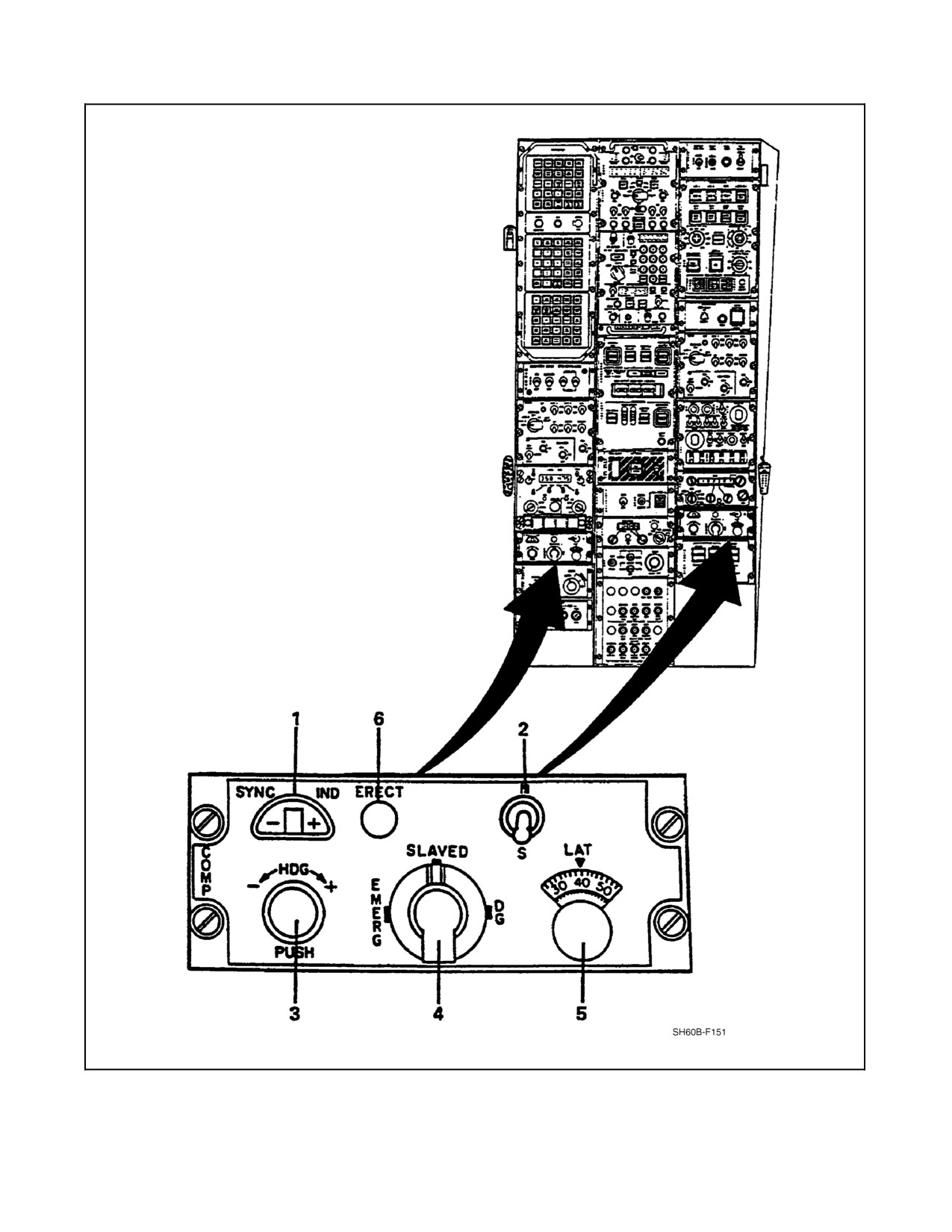
The compass system controller (Figure 16-3) contains the controls and indicators required to operate the AGCA.
Functions of the compass system controller are:
1. Providing synchronization display.
2. Setting local latitude, north or south hemisphere.
3. Setting heading information.
4. Selecting AGCA mode.
5. Generating latitude correction signals.
6. Enabling fast SYNC and fast erect functions.
16.3.2.2 Remote Compass Transmitters (Pilot and ATO), ML-1(MOD)
There are two remote compass transmitters, both located in the tail cone section. One operates with the pilot AGCA
and the other operates with the ATO AGCA. The remote compass transmitters, commonly referred to as flux valves,
detect the direction of the Earth magnetic field and transmit this information electrically through a slaving circuit to
a torque motor in the AGCA Directional Gyroscopes. The AGCA torque motor maintains the directional gyroscope
heading reference in a fixed position relative to the Earth magnetic field.
16.3.2.3 Bearing-Distance-Heading Indicators
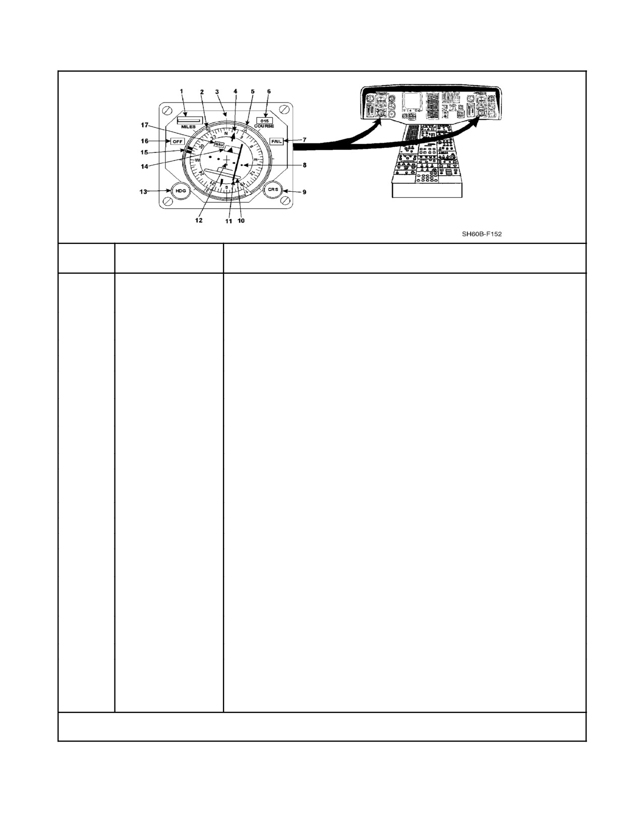
The BDHIs are primary navigation instruments. The BDHI uses navigation data from various sources to present the
pilotwithasymbolicdisplayofthehorizontalnavigationsituation.Inadditiontocoursesettings,bearinginformation
from the TACAN and DFG equipment is presented on the BDHI. Figure 16-4 shows the BDHI and describes its
individual indicators. Power for the pilot BDHI is supplied from the AC essential bus and DC essential bus through
two circuit breakers located in the center circuit breaker panel and the overhead circuit breaker panel, both marked
PILOT BDHI. Power for the ATO BDHI is supplied from the NO. 1 DC primary bus and NO. 1 AC primary bus
through two circuit breakers located in the ATO circuit breaker panel and center circuit breaker panel, respectively.
16-5
ORIGINAL
A1-H60BB-NFM-000
Figure 16-3. Compass System Controller (Sheet 1 of 2)
ORIGINAL
16-6
A1-H60BB-NFM-000
INDEX
NUMBER
CONTROL
FUNCTIONAL DESCRIPTION
1
SYNC IND
The Synchronization Indicator indicates the synchronization between the
directional gyro output and the remote compass when the SLAVED mode is
selected with the mode selector switch. If they are not synchronized, the
indicator shows in which direction a correction must be made to avoid
ambiguity.
2
N/S
The two-position (N/S) hemisphere selector toggle switch permits the selection
of either North or South latitude for use by the system.
3
HDG
The PUSH to SYNC is a push-and-turn switch (spring return to center) that
+/--
provides heading set. When the HDG button is pressed, the heading set
PUSH
control markings indicate the direction to turn the control to provide a
decreasing (--) or increasing (+) heading change. When synchronized, the
synchronization indicator is centered.
4
Mode selector
The mode selector is a three-position rotary switch used to select one of the
following modes of operation:
SLAVED
The SLAVED mode is the primary mode of operation (gyro stabilized magnetic
compass). The SLAVED mode synchronizes the directional gyro output to the
remote compass heading. When selected, fast synchronization occurs in the
same manner as when the system is first turned on.
EMERG
The compass mode is for emergency use only, when the directional gyro is
disabled. Only remote compass information is used for heading (unstabilized
magnetic heading).
DG
The directional gyro mode is normally selected when local magnetic conditions
or operations in high latitudes make the magnetic compass information
unreliable. Because no magnetic correction is applied to the directional gyro,
manual insertion of latitude information is essential to compensate for
precession caused by the rotation of the Earth.
5
LAT
The latitude selector knob and readout window are used to set the latitude to
that of the helicopter during operations in the DG or SLAVED mode. The
readout window displays latitudes 0° to 90°, graduated in two-degree intervals
with major divisions and numerals every ten degrees.
6
ERECT
Pushbutton that provides fast compass synchronization and AI fast erect.
Figure 16-3. Compass System Controller (Sheet 2)
16-7
ORIGINAL
A1-H60BB-NFM-000
INDEX
NUMBER
CONTROL
FUNCTIONAL DESCRIPTION
1
Range counter
Displays digital range information in hundreds, tens, units, and tenths of a
mile (Doppler groundspeed in knots when BDHI is in Doppler mode). Range
is slant range to a TACAN station or horizontal range to an FTP.
2
Bearing needle
Indicates relative bearing to signal source being tracked by DFG.
NO. 1
3
Lubber line
Reference line indicating center line of aircraft.
4
Course arrow
Indicates selected course on compass case.
5
Bearing needle
Indicates relative bearing to selected TACAN station.
NO. 2
6
COURSE counter
Displays course to the nearest degree. Indicates same value as course
arrow.
7
Fail flag
Unit Fault Indicator indicates failure of one or more internal status
monitoring tests.
8
Course dots
Scale for deviation bar. 1 dot = 5° deviation.
9
CRS
The course select knob is used for manual course selection.
Positions course pointer (4) and sets course counter (6).
10
Deviation bar slot
Slot for control arm of deviation bar.
11
Deviation bar
Fly-to bar that indicates deviation from selected course.
12
Aircraft symbol
Miniature aircraft for orientation reference.
13
HDG
The heading select knob is used to manually set heading. Positions heading
select marker.
14
To/From indicator
When pointing to the head of the course pointer, arrow indicates aircraft
flying TO a TACAN station or FTP, when pointing to tail, it indicates flying
FROM a TACAN station or FTP.
15
Heading select
Indicates heading necessary to maintain selected or computer generated
marker (heading bug)
course.
16
OFF flag
Indicates absence of internal power or external ground.
17
NAV flag
When computer is in TACAN mode, indicates TACAN data is unreliable.
When computer is in CPTR mode, indicates the absence of a fly-to-point.
When computer is in DPLR mode, indicates Doppler groundspeed is below
8 knots.
Note
Selection of ALTR mode may bypass power failure.
Figure 16-4. Bearing--Distance--Heading Indicator
ORIGINAL
16-8
A1-H60BB-NFM-000
Both AC and DC power are required for proper BDHI operation. The AC power supply provides operating voltages
to rotating components. The DC power is used for various latching solenoids in the BDHI. The latching solenoids
provide for computer control of the HDG and CRS knobs, thus if DC power is lost or the DC circuit breaker is out,
FTP steering and Doppler steering will be lost.
Three modes are available: TCN (TACAN), CPTR (computer), and DPLR (Doppler) (Figure 16-5). Operating modes
of the two BDHIs can be independently selected by their respective mode--select panels (Figure 16-6).
MODES
DISPLAY
INDICATOR
TACAN
COMPUTER
DOPPLER
Needle 1
ADF/OTPI
ADF/OTPI
ADF/OTPI
Needle 2
TACAN radial
TACAN radial
TACAN radial
Compass card
Magnetic heading
True heading
Magnetic heading
Heading marker
Set by knob (manual)
Command heading to
Command heading to fly
FTP
selected course
Course Arrow
Set by knob (manual)
Course to FTP
Set by knob (manual)
Deviation bar
Course error
Course error
Command heading error
Course window
Selected course
Course to FTP
Selected course
Range window
TACAN DME
Range to FTP
Doppler groundspeed
Figure 16-5. BDHI Displayed Data as a Function of Selected Mode
16.3.3 Radar Navigation Set, AN/APN-217
The radar navigation set (RNS) is the Doppler groundspeed sensor, designed to operate reliably even in low seastate
conditions and over land. The SEA mode is the default mode whereas the LAND mode is selected through the AOP
and MPD controls. The RNS provides groundspeed information to the automatic flight control system (AFCS) for
coupled hover operations. This information is also displayed on the Attitude Indicators (AI) by the heading velocity
(VH) and drift velocity (VD) bars and by the vertical velocity (VZ) pointer. It provides three axis velocities that are
used to compute the groundspeed that may be displayed on the BDHI. The RNS transmits four narrow beams to the
surface of the Earth and measures the Doppler shift of the return signal due to aircraft motion. From these
measurements, the heading, drift, and vertical aircraft velocities are calculated. This data is sent to the NSIU in analog
form and then to the pilot and ATO AIs. When the BDHI mode is selected to Doppler, the NSIU displays Doppler
groundspeed and heading to fly which it calculates from the heading and drift velocities and the course selected.
Digital vector components are sent to the data handling subsystem, where they are used for Doppler navigation. The
Doppler radar will maintain a reliable track over sea state one at steady bank angles up to and beyond 45°. However,
Doppler tracking is severely degraded by vertical acceleration, roll acceleration, and pitch and roll rate, especially
in combination. Loss of Doppler track is indicated by short periods of Doppler in memory. In situations where this
could affect navigation (i.e., bias development), avoid abrupt maneuvers or turns combined with climbs or descents.
Power is applied to the RNS whenever AC and DC power are available and the DPLR switch on the MSN SYS panel
is ON. The DPLR button on the mode select panel (Figure 16-6) causes the Doppler groundspeed to be displayed
in the range readout window of the BDHI (Figure 16-4).
16-9
ORIGINAL

A1-H60BB-NFM-000
INDEX
FUNCTION
Mode select
This panel permits the pilots to select the source of heading and attitude reference and the
panel
gyro to be used for heading and turn-rate displays.
AI
TURN RATE
Alternate-action pushbutton with two displays.
NORM
The turn-rate gyro normally associated with each AI is being used as the source of turn rate
(i.e., the pilot turn-rate gyro is feeding the pilot AI turn-rate needle and the ATO turn-rate gyro
feeds the ATO AI turn-rate needle).
ALTR
Selection of ALTR on the pilot turn-rate button switches the source of the pilot turn-rate
indication to the ATO turn-rate gyro. The ATO ALTR turn-rate selection switches his turn-rate
source to the pilot turn-rate gyro.
HARS
The heading attitude reference system pushbutton, alternate action with light display for each
condition.
NORM
The HARS normally associated with each AI and BDHI is being used as the source of attitude
and heading. The pilot HARS provides pitch and roll to the pilot AI and heading to the pilot
BDHI; the ATO HARS provides pitch and roll to the ATO AI and heading to the ATO BDHI.
ALTR
Selection of Alternate (ALTR) on the pilot HARS switches the source of the pilot attitude and
heading indications on the pilot AI and BDHI to the ATO HARS. The ATO ALTR selection
similarly switches the attitude and heading indication source to the pilot HARS. Only one HARS
switch can be in ALTR. Pilot selection of ALTR will override the ATO selection and return the
ATO to NORM.
HVR
The hover pushbutton is an alternate-action pushbutton switch/display. When illuminated
(green), VH, VD, and VZ signals from the Doppler are displayed on crossed bars and a pointer
on both AIs for use by the pilot and ATO during hovering flight.
Figure 16-6. Mode Select Control Panel (Sheet 1 of 2)
ORIGINAL
16-10
A1-H60BB-NFM-000
INDEX
FUNCTION
BDHI
TCN
The TACAN pushbutton, when pressed, illuminates green and causes the RANGE readout
window on the applicable BDHI to display TACAN range. In addition, the course select and
heading set knobs on the applicable BDHI are enabled.
CPTR
The computer pushbutton, when pressed, illuminates green and causes range to a computer
derived FTP to be displayed in the RANGE readout window. Bearing to the FTP is displayed on
the course pointer. In this mode, the course set and heading set knobs are disabled and the
heading bug is driven by the computer as command information to the pilot or ATO, as
applicable.
DPLR
The Doppler pushbutton, when pressed, illuminates green and causes groundspeed to be
displayed in the RANGE readout window of the BDHI. During this mode, the course set knob is
enabled, but the heading set knob is disabled, and the heading bug is driven by an NSIU as
command information to the pilot or ATO, as applicable.
Figure 16-6. Mode Select Control Panel (Sheet 2)
The NAV flag will appear on the BDHI in the DPLR mode whenever Doppler groundspeed is below 8 knots. If the
RNS shifts to the memory mode, the NAV window will remain blank and the VH, VD, and VZ pointers will freeze.
Power is supplied from the NO. 2 DC primary bus and the NO. 1 AC primary bus through two circuit breakers located
on the ATO and the center circuit breaker panels, both marked NAC RDR SET.
16.3.4 TACAN Navigation Set, AN/ARN-118(V)
The TACAN navigation set consists of a receiver/transmitter (R/T) and control and is a polar--coordinate navigation
system, with the aircraft at the origin. The TACAN Set receives a UHF signal from a TACAN surface station (ground
or shipboard) or aircraft and calculates the magnetic bearing and slant range to that station. Station identification
codes are conveyed by audio modulation of the returning signal. The range of the TACAN is limited to line--of--sight
and increases with aircraft altitude up to 123 nm at 10,000 feet. The TACAN set operates on a channel selected from
252 available channels, 126 “x” (FAA) and 126 “y” (tactical). Range information is determined by measurement of
the time for round--trip travel of the radio signal between the helicopter and TACAN station. Aircraft radial is
determined by phase measurements which are converted to azimuth indications. The TACAN range and bearing are
displayed on the pilot and ATO BDHI. The TACAN Set also provides high resolution digital outputs of range and
bearing to the CMUX for use in updating the helicopter position.
16.3.4.1 Receiver/Transmitter
The R/T contains all transmitting, receiving, and decoding circuits. The R/T decodes the control and switches to the
proper mode. The receiver and transmitter sections (in T/R or A/A T/R modes) are tuned to the frequencies that
correspond to the channel specified in the control word. Transmit and receive frequencies are always 63 MHz apart.
Power is supplied from the NO. 1 AC primary bus through a circuit breaker, marked TACAN R/T, located on the
center circuit breaker panel.
The R/T switches between the upper and lower antennas signal every 5 seconds until a usable beacon signal is
received on one of the antennas. The antenna with the usable signal is used as the receiver antenna. The bearing is
determined with an accuracy of ±1°.
Note
NAVAIDS listed in the FLIP publications correspond to the X channels
unless otherwise noted.
16-11
ORIGINAL
A1-H60BB-NFM-000
16.3.4.2 TACAN Control
The TACAN control contains all controls and indicators required for operation of the TACAN set (Figure 16-7). The
control relays the TACAN audio station identification signal to the audio converter--processor. Figure 16-4 is a list of the
controls and indicators on the BDHI. Refer to Figure 16-8 for a list of the BDHI indications for each operating mode
as selected on the TACAN control. Power is supplied from the NO. 1 DC primary bus through the circuit breaker marked
TACAN CONTR, located on the ATO circuit breaker panel, and the NO. 1 AC primary bus through the circuit breaker
marked TACAN R/T, located on the center circuit breaker panel.
16.3.4.3 TACAN Operation
For TACAN operation in all modes, use the following procedures:
1. Set TACAN mode switch as desired (REC, T/R, A/A REC, A/A T/R).
2. Set TACAN control CHANNEL selector controls to desired channel.
3. Wait approximately 5 seconds for signal acquisition and lock--on. If bearing signal lock--on does not occur,
the TACAN remains in the search mode with the NAV flag in view.
4. Check that TACAN control TEST indicator is not lit.
5. Check that correct station audio identification signal is received.
6. Read BDHI bearing pointer NO. 2 needle for relative bearing of the beacon. Read MILES window for distance
to the beacon in T/R mode.
If the surface beacon bearing signal is temporarily lost, the TACAN switches to bearing memory and retains the last
valid bearing information for 3 seconds. If the signal is reacquired within the 3 seconds, the TACAN locks on the
signal to provide continuous valid bearing information.
When the bearing signal is lost or becomes unreliable and after the memory time of 3 seconds elapses, the TACAN
switches to an automatic self--test to determine if TACAN operation is correct. During the automatic self--test the only
possible indication on the BDHI is a momentary NAV flag in view. If there is a detected malfunction in the TACAN
system, the TEST indicator on the TACAN control lights at the end of the test cycle and all BDHI bearing, course
deviation, and TO/FROM information may be erroneous. If the TEST indicator does not light at the end of the test
cycle but the TACAN has still not reacquired the bearing signal, the NAV flag remains in view, indicating that the
TACAN is in bearing search.
When a new TACAN channel is selected, the NO. 2 needle may slew to a bearing 90° greater than the relative bearing
of the TACAN station for a nominal 2 seconds, with NAV flag in view, before the NO. 2 needle slews to the correct
bearing and the flag is lifted.
16.3.4.4 Air-to-Air Receive Mode (A/A REC)
In the A/A REC mode, the TACAN calculates the relative bearing to an aircraft equipped with a bearing transmitter
and rotating antenna. The ARN--118(V) TACAN is not capable of transmitting TACAN bearing and few aircraft are
suitably equipped. Any number of aircraft can receive bearing information from one suitably equipped aircraft.
Note
In all TACAN systems there is the possibility of interference from IFF,
transponder, and DME signals when operating in the air--to--air modes. In
order to minimize the possibility of interference, it is recommended that
Y--channels be used and that channels 1 through 11, 50 through 74, and 121
through 126 be avoided.
Use either preassigned channel pairings or establish channel pairing with a 63 channel separation.
ORIGINAL
16-12
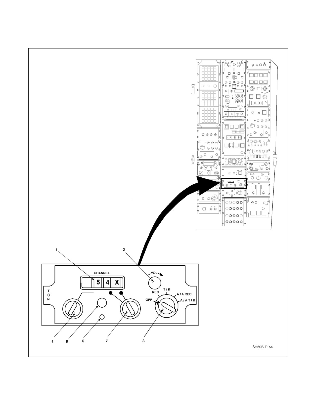
A1-H60BB-NFM-000
Figure 16-7. TACAN Control Panel (TCN) (Sheet 1 of 2)
16-13
ORIGINAL
A1-H60BB-NFM-000
INDEX
NUMBER
CONTROL
FUNCTIONAL DESCRIPTION
1
CHANNEL
Displays selected TACAN channel.
2
VOL
Varies level of audio identification signal.
3
Mode selector
switch
OFF switch for TACAN system.
OFF
Receive mode. TACAN system receives and measures surface beacon
REC
fundamental bearing and calculates the relative bearing. No distance
information calculated.
Transmit/receive mode. TACAN system interrogates a surface beacon
and receives both bearing and distance information, which is used to
T/R
calculate slant-range distance and relative bearing to the surface
beacon.
Air-to-air receive mode. TACAN system receives bearing information
A/A REC
from a suitably equipped, cooperating aircraft and calculates the
relative bearing to the cooperating aircraft. No distance information
available.
A/A T/R
Air-to-air transmit/receive mode. TACAN system interrogates a suitably
equipped, cooperating aircraft and receives and calculates the
slant-range distance and relative bearing to the suitably equipped
cooperating aircraft. On cooperating aircraft (not equipped with bearing
producing equipment) only slant-range distance is calculated. In this
mode, the TACAN system provides distance replies to other aircraft
when interrogated.
4, 7
CHANNEL
Selects desired TACAN, which is displayed in the CHANNEL digital
display.
5
TEST (switch)
Initiates system self-test or confidence test.
6
TEST (indicator)
Lights when malfunction occurs during manual or automatic system
self-test. Flashes at start of self-test cycle to check indicator lamp.
Figure
16-7. TACAN Control Panel (TCN) (Sheet 2)
ORIGINAL
16-14
A1-H60BB-NFM-000
TACAN MODE
BDHI
INDICATION
REC
T/R
A/A REC
A/A T/R
COURSE
Selected TACAN
Selected TACAN
Selected TACAN
Selected TACAN radial to
WINDOW
radial to surface
radial to surface
radial to suitably
suitably equipped,
beacon.
beacon.
equipped,
cooperating aircraft.
cooperating aircraft.
COURSE
Selected TACAN
Selected TACAN
Selected TACAN
Selected TACAN radial to
POINTER
radial to surface
radial to surface
radial to suitably
suitably equipped,
beacon on compass
beacon on compass
equipped,
cooperating aircraft on
card.
card.
cooperating aircraft
compass card.
on compass card.
COURSE
Aircraft deviation left
Aircraft deviation left
Aircraft deviation
Aircraft deviation left or right
DEVIATION
or right of selected
or right of selected
left or right of
of selected TACAN radial. If
BAR
TACAN radial.
TACAN radial.
selected TACAN
cooperating aircraft is not
radial. If
suitably equipped, course
cooperating aircraft
deviation information is invalid
is not suitably
and NAV flag is in view.
equipped, no
indications and NAV
flag is in view.
TO-FROM
Whether course is TO
Whether course is TO
Whether course is
Whether course is TO or
ARROW
or FROM surface
or FROM surface
TO or FROM
FROM suitably equipped,
(NOTE 1)
beacon.
beacon.
suitably equipped,
cooperating aircraft. If
cooperating aircraft.
cooperating aircraft is not
If cooperating
suitably equipped, TO-FROM
aircraft is not
information is unreliable and
suitably equipped,
NAV flag is in view.
indication is invalid
and NAV flag is in
view.
BEARING
Relative bearing of
Relative bearing of
Relative bearing of
Relative bearing of suitably
POINTER
surface beacon with
surface beacon with
suitably equipped,
equipped, cooperating aircraft
(NOTE 2)
respect to aircraft
respect to aircraft
cooperating aircraft
with respect to aircraft
heading. Magnetic
heading. Magnetic
with respect to
heading. Magnetic bearing
bearing indicated on
bearing indicated on
aircraft heading.
indicated on compass card. If
compass card.
compass card.
Magnetic bearing
cooperating aircraft is not
indicated on
suitably equipped, NAV flag is
compass card.
in view.
MILES
Shuttered (distance
Slant-range distance
Shuttered (distance
Slant-range distance to
WINDOW
not calculated in
to surface beacon
not calculated in
cooperating aircraft (NOTE 3).
REC).
(NOTE 3).
A/A REC mode).
Notes:
1. TO/FROM arrow indicates whether flight on heading displayed in course window would fly aircraft to or from
selected TACAN beacon.
2. NAV flag is in view when bearing information is unreliable.
3. Distance shutter in view when distance is unreliable.
Figure 16-8. TACAN Operating Modes and BDHI Indications
16-15
ORIGINAL
A1-H60BB-NFM-000
16.3.4.5 Air-to-Air Transmit/Receive Mode (A/A T/R)
In the A/A T/R mode, the ARN--118(V) interrogates a suitably equipped, cooperating aircraft (bearing and distance
information) or a cooperating aircraft (distance only information). The suitably equipped, cooperating aircraft
supplies the interrogating aircraft with both bearing and distance information. The cooperating aircraft supplies the
interrogating aircraft with only distance information. At least five aircraft can receive distance information from an
interrogated aircraft. In this mode, the ARN--118(V) TACAN also supplies distance information to the other aircraft
when interrogated. When the ARN--118(V) is interrogated and supplying distance information to more than one
aircraft, the ratio of the distance between the ARN--118(V) and the furthermost aircraft and the distance between the
ARN--118(V) and the nearest aircraft must be no greater than 4:1.
Note
With interrogating aircraft flying in close proximity of each other, it is
possible that a negative distance may be displayed due to the calibration of
the TACAN system in either aircraft. Since the BDHI cannot display
negative distances, a TACAN output of negative .1 nm is displayed as
399.9 nm and an output of negative 0.5 nm is displayed as 399.5 nm.
16.3.4.6 In-Flight Confidence Test
The in--flight confidence test is initiated when the TEST switch on the TACAN control is momentarily pressed. A
manual self--test is activated and the system is checked providing a greater than 85 percent confidence level. The test
can be terminated at any point by switching either the CHANNEL selector controls or mode selector on the TACAN
control. Perform in--flight confidence test using the same procedures as in the Mission/Weapon System Checklist,
Chapter 7.
Note
It is not necessary to select an unused channel to perform the TACAN test.
16.3.5 Direction Finder Group (DFG), AN/ARA-50
The DFG, when in automatic direction finder (ADF) mode, provides relative bearing to another station transmitting
on a selected UHF frequency and, when in the OTPI mode, to a deployed sonobuoy transmitting on a selected
sonobuoy VHF channel. Selection of ADF or OTPI mode and frequency/channel is made on the COMM CONTR
panel. The ADF or OTPI bearing is displayed on the BDHI via the NSIU by the NO. 1 needle. The AN/ARA--50 is
used for the following:
1. Location of deployed sonobuoys (OTPI mode).
2. Backup navigation (UHF ADF mode).
Note
ADF is unavailable in secure voice mode. Power is supplied from the AC
essential bus and DC essential bus through circuit breakers located on the
center circuit breaker panel and the overhead circuit breaker panel. They are
labeled DF GP PWR and DIR FINDER GROUP, respectively.
16.3.6 On-Top Position Indicator Receiver
The on--top position indicator (OTPI) receiver, R--1651/ARA, is used in conjunction with the direction finder group
(DFG) to provide bearing information to a VHF signal from a sonobuoy. Effective on BuNo 164174 and subsequent,
the OTPI receiver R--1651/ARA is replaced by OTPI receiver R--2330/ARN--146 to provide for the 99--channel
sonobuoy tuning capability. In theOTPImodeofoperation used with sonobuoys, thereceiverrecovers theAMaudio
signal from the RF carrier. This provides a means for fixing the position of sonobuoys. Power is supplied from the
AC essential bus and DC essential bus through circuit breakers in the center circuit breaker panel, marked DF GP
PWR and DIR FINDER GROUP respectively.
ORIGINAL
16-16
A1-H60BB-NFM-000
Note
D RAST main probe must be in the up position in order to receive accurate
OTPI information.
D HF radio transmissions in the range of 5.83 to 28.85 MHz may result in
incorrect OTPI bearing information.
The tuning or channel selection of the OTPI Receiver is accomplished by the pressing of channel selection buttons
on the COMM CONTR panel. A threshold signal--strength indicator on the COMM CONTR panel, fed by the OTPI
Receiver, tells the operator whether or not the received signal is strong enough to track. The signal--strength indicator
will be green when the received signal is valid (Figure 15-1).
16.4
GLOBAL POSITIONING SYSTEM
GPS is a radio positioning navigation and time transfer system consisting of NAVSTAR satellites, ground based
control facilities, and receiving equipment capable of receiving the GPS satellite signals. The GPS system provides
worldwide, accurate, three--dimensional position and velocity information. The helicopter installed GPS system
components consist of:
1. GPS Receiver, AN/ARN--151, R--2332/AR.
2. GPS Control Indicator, AN/ARN--151, C--12100.
3. GPS Antenna, AS--3822/URN.
4. GPS Antenna Electronics Unit, AM--7324/URN.
5. Data Bus Coupler (2), AN/ARN--151, CV--2453.
GPS receives satellite data via a fixed reception pattern antenna and the Antenna Electronics Unit. The receiver
decodes the data and utilizes it to compute the helicopter position. Position is computed by comparing
time--of--arrival measurements from thesatellite signals. Velocity is computed by comparing Dopplermeasurements
of the carrier frequency of the satellite signal.
GPS receivers are capable of operating in seven states. Each receiver channel operates in only one state at a time. Five
of the seven states are displayed by the LAMPS MK III GPS system on the GPS data table (Figure 16-9). These five
states are: State1, Searching C/A Code; State2,Direct P--codeAcquisition; State3, CodeTracking/No CarrierLock;
State 5, Carrier Lock Achieved/Data Demodulation (also called Normal Acquisition); State 7, Reacquisition In
Process.
The GPS interface allows the GPS capability to come online when the helicopter mission systems are powered up.
Power is supplied to the GPS receiver from the NO. 1 AC primary bus on the SO circuit breaker panel.
16.4.1 Navigation Modes
The ATO may select the GPS as the primary navigation mode by depressing the GPS OPTN pushbutton switch on
the ATO keyset, then selecting GPS NAV, then On--top--Navigation modes are automatically selected by the AOP
in the following sequence. GPS will be used if available and turned ON. If GPS is not available or turned OFF, or
if the GPS Estimated Horizontal Error (EHE) exceeds 500 yards, navigation will revert to Doppler navigation mode.
AirMassnavigationmodewillbeusedlastifneitherGPSnorDopplerisavailable.WhenusingGPSasthenavigation
mode, the Bearing--Distance--Heading Indicator (BDHI) displays are driven by navigation data sent from the GPS
Receiver to the SAC--1 via the 1553B Data Bus.
16-17
ORIGINAL
A1-H60BB-NFM-000
The GPS can first be used for navigation when AOP determines that the GPS position has met the initial availability
criteria. The initial availability criteria have been met when the receiver has no faults, holds four satellites in state
5, and the EHE is less than 150 yards. If the EHE grows larger than 500 yards while the receiver is tracking four
satellites in state 5, then Doppler navigation mode will become the active navigation mode and the last GPS position
will be used to initialize the Doppler equations. If Doppler navigation mode is not available, air mass mode equations
will be initialized with the last GPS position. The GPS navigation mode will be maintained as long as the EHE
remains less than 500 yards and the receiver holds four satellites in state 5. If the number of satellites in state 5 drops
below four, AOP will start a 3--minute time; if GPS does not hold four satellites in state 5 after 3 minutes, the
navigation mode will switch to Doppler or air mass. This helps prevent frequent navigation mode switching while
maneuvering and during satellite constellation changes.
Note
AOP may maintain GPS navigation mode for up to 3 minutes when less
than 4 satellites held in state 5. This can cause an increase in EHE of up to
005 (450 to 550 yards) before AOP reverts to Doppler navigation mode. If
acceptable GPS EHE cannot be maintained during critical mission phases,
consideration should be given to turning GPS off via GPS OPTIONS
pushbutton switch on ATO keyset.
The GPS is capable of providing two different levels of navigational accuracy. The Standard Positioning System
(SPS) provides a positional accuracy from 150 to 500 yards. The Precise Positioning System (PPS) is capable of
providing a positional accuracy of 16 yards. A precision code (P-- or Y--code) is transmitted over both the L1 and
L2 frequencies sent by each satellite. The L1 frequency also carries a coarse acquisition code (C/A code). When
Selective--Availability (SA) is on, the PPS will be degraded for all users tracking the P-- or C/A--codes. If
Antispoofing (A/S) is enabled (Y--code vice P--code), the P--code is denied to users who do not have special
cryptographic keys. The C/A--code will remain available to all users. The cryptographic keys are loaded into the GPS
receiver via the GPS Control--Indicator (Figure 16-10). After entering the cryptographic code, the KEY STATUS line
of the GPS DATA page via TABLE pushbutton switch must be checked to verify the proper key was entered (Figure
16-11). The AS key may be erased by depressing the guarded ZEROIZE pushbutton switch on the Control Indicator
or by selecting ZEROIZE from the SEL GPS OPTN cue by depressing the GPS OPTN pushbutton switch on the ATO
keyset.
GPS operation or availability is displayed to the ATO and SO via the Navigation mode field on the MPD. When GPS
is in use, the Navigation mode will be displayed as G XXX. The G indicates GPS, XXX indicates the GPS EHE in
hundreds of yards, rounded to the nearest hundred. GPS data is polled and updated at a 200 ms rate and transferred
to the navigation subsystem via the 1553B Data Bus. The EHE is continuously displayed and updated on the MPD.
If the EHE exceeds 500 yards, indicated by the XXX going to 005, the navigation mode will automatically be set
to Doppler. This will be indicated by a D followed by the GPS reported EHE in the NAV MODE area of the display.
GPS is considered for reselection as the navigation sensor by AOP when GPS data becomes valid and the EHE is
less than 333 yards. GPS will be selected automatically as the navigation mode if the difference between the AOP
calculated position and the GPS reported position is less than 100 yards. If the difference between the AOP calculated
position and the GPS reported position is greater than 100 yards, the SEL GPS NAV cue will be displayed with the
OFF option preselected. A GPS Correct Symbol appears on the display, representing the difference between the GPS
reported position and the AOP calculated position from the Doppler or Air Mass navigation modes. This gives the
ATO the option to use GPS as the active navigation mode by selecting GPS, or to continue using Doppler or Air Mass
navigation mode by selecting the OFF default option.
ORIGINAL
16-18
A1-H60BB-NFM-000
1 of 3
GPS DATA
CPCI VERSION
XXXX
OP ENTER
GPS
1 GET GPS PRESET
HH MM SS
ALTITUDE
XXXX
XXXXXX
2 TIME
HH MM SS
HH MM SS
3 DATE (Y/M/D)
YY/MM/DD
4 LATITUDE
XX XX.X
N
XX XX.X N
5 LONGITUDE
XXX XX.X
W
XXX XX.X W
6 CRS/SPD
XXX/XXX
XXX/XXX
7 SEND INIT DATA
HH MM SS
ENT LINE NO
XX
2 of 3
GPS OPTIONS
EHE
XXXX
NAV MODE
XXX
EVE
XXXX
MAG VAR
XXX
KEY STATUS
HHHH
BIAS CALC
OFF
ALMANAC REQ
XXX
CONSTELLCHNG
XXX
RCVR MODE
XXXX
3 of 3
SATELLITE SUMMARY
CHAN
SV
STATE
C/NO
J/S
1
XX
X
XXX
XXX
2
XX
X
XXX
XXX
3
XX
X
XXX
XXX
4
XX
X
XXX
XXX
5
XX
X
XXX
XXX
Figure 16-9.
GPS Data Table
16-19
ORIGINAL
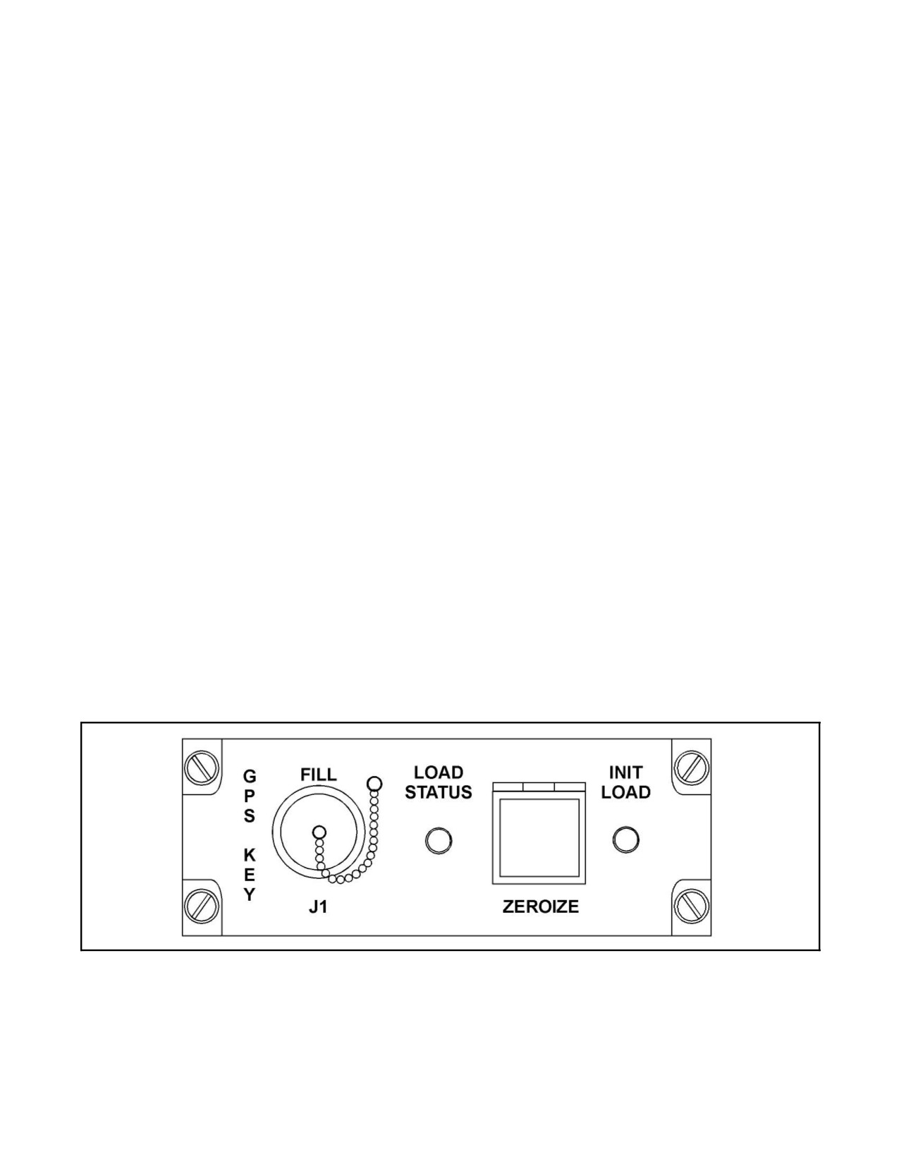
A1-H60BB-NFM-000
The GPS Correct Symbol (G TTTT) (G indicating GPS and TTTT as the most recent time of the last GPS data update)
displays at the point to which the helicopter position will be corrected if the GPS data is accepted by selection of the
ACCEPT option. If the GPS positional data is accepted by the depression of the ENT NO CHNG pushbutton switch,
the helicopter and all Doppler and air mass referenced sonobuoy positions, fixes, LAMPS Tracks, GPS Correct
Symbol, ATTs, and MAD Marks that are not designated as geographic points or are not currently updated to the
position, will have the GPS position correction applied. All radar targets are corrected by an amount corresponding
to their true radar range on the next full radar sweep.
If the AOP GPS navigation mode is OFF but the receiver is providing data which passes the availability criteria, the
MPD shows the current navigation mode with a slash through it. If the operator selects GPS via the GPS OPTN
pushbutton switch and the position difference between GPS and AOP is less than 100 yards, the navigation mode
changes to GPS and updates the helicopter position and helicopter entered tactical symbols. If the difference between
GPS and AOP position is greater than 100 yards, selection of GPS via the GPS OPTN pushbutton switch displays
the GPS CORRECT cue, with the difference in the GPS position and the active mode position shown in yards. The
ACCEPT option will be preselected and the GPS Correct Symbol will be displayed. Accepting the GPS position
correction will change the navigation mode to GPS and update the helicopter position and helicopter entered tactical
symbols.
GPS OFFSET is the vector difference between the ACFT position held by GPS and the ACFT position held by
DAME. Whenever a DAME update is performed, GPS offset is calculated and entered into the NAV Parameters
Table. All uplinked/downlinked symbols then have this GPS offset applied. This maintains identical relative tactical
plots on the aircraft and the ship but causes a mismatch in symbol latitude/longitudes when verbalized over the data
link. ATO/SO should verify offset value each time a DAME update is completed. If the data link is lost after DAME
update and cannot be regained using other techniques (or if data link cannot be gained when transitioning to another
LAMPS MK III ship), consideration should be given to performing an INIT HELO. This will clear the GPS OFFSET
value contained in NAV Parameters Table.
16.4.2 GPS Options
GPS has five selectable options. Depression of the GPS OPTN pushbutton switch on the ATO keyset displays the
SEL GPS OPTN cue with the five options. The five options and the functions performed are:
1. ZEROIZE — Erases the GPS key presently held in the GPS receiver memory.
2. GPS NAV — Displays SEL GPS NAV cue. Selection may be made to set the navigation function to GPS or
OFF. The BIAS CALC option will always remain OFF. The mode not in use is the default selection.
Figure 16-10. GPS Control Indicator
ORIGINAL
16-20
A1-H60BB-NFM-000
DISPLAY
(H1)(H2)(H3)(H4)
(Notes 1,2)
MEANING
NOTES
H1
8
Key entered was accepted and verified by GPS satellite data (can take up
3
to 12 minute to verify).
4
GPS accepted the key but is waiting to verify the code.
2
GPS took the key from the key loader, but the code did not match with
satellite data.
1
Key Failed Parity.
0
No key received.
H2
8
Group Unique Variable (GUV) code in use.
4
4
2 hour alert — 2 hours remain before expiration of last key.
2
Insufficient key for mission duration.
1
Zeroize error — Code not zeroized properly.
0
All keys entered properly, no errors or warnings.
7
Combination of 4, 2, and 1.
6
Combination of 4 and 2.
5
Combination of 4 and 1.
3
Combination of 2 and 1.
H3/H4
Mission duration — Indicates number of days the GPS can operate without
5
reloading keys (should be something non-zero).
Notes:
1. If the GPS control indicator will not load a key, it may be necessary to remove and reinstall the batteries
from the GPS unit. This will clear all GPS memory, including almanac data. (GPS will require 1 to 3
hours of tracking time to regain enough almanac data to provide sufficient accuracy for AOP use (<500
yards). The time requirement can be lessened by entering current lat/long and UTC time.)
2. All hexadecimal characters should display zero if crypto key is properly zeroized.
3. Upon initial load, H1 should indicate 4, and will indicate 8 once verified by a GPS satellite. If the key is no
longer valid after having been verified, a 2 will be displayed.
4. This digit will display an 8 when the GUV is loaded.
5. This was designed to be used primarily with Crypto Variable (CV) keymat. The GPS can accept up to 12
different monthly and weekly CV keys, but will keep only enough keys for 84 days.
Figure 16-11. Key Status Display Format
16-21
ORIGINAL
A1-H60BB-NFM-000
3.
MAG VAR — Displays SEL MAG VAR cue. Selection may be made to set MAG VAR to GPS or OFF. The
mode not in use is the default selection.
Note
Coefficients for magnetic variation (MAG VAR) provided by present
software in GPS receiver units may not be accurate. If GPS provided MAG
VAR differs from actual local value (or value utilized by ship), GPS MAG
VAR input to AOP should be turned off via GPS OPTIONS pushbutton
switch and MAG VAR should be manually entered into NAV Parameters
Table.
4.
GEO DES — Displays the SEL GEO DES cue. Selection of the DESIG or UNDESIG option allows the ATO
to designate or undesignate any symbol that can be hook verified and downlinked as a geographic point, with
the exception of an ATT. The mode not in use is the default selection.
5.
GPS CORR — Displays the GPS CORRECT cue with the number of yards the helicopter position will be
corrected if the ACCEPT option is selected. Selection of ACCEPT will result in the helicopter and all Doppler
or air mass referenced sonobuoy positions, fixes, LAMPS Tracks, ATTs, and MAD Marks that are not
designated as geographic points being corrected to the GPS reported position. Selection of the REJECT option
will terminate GPS processing and remove the GPS Correct Symbol from the display.
Note
GPS option 5 (GPS CORRECT) will be accepted by AOP even if the
current GPS solution is invalid (including loss of power to GPS receiver).
Performing GPS correct with invalid solution will cause significant errors
in thenavigation plot. ATO/SO should utilizeGPS datatableto verify GPS
solution validity and GPS position prior to utilizing this function.
16.4.3 GPS Data Table
The GPS data table (Figure 16-12) is displayed by depressing theTABLE pushbutton switch and then selecting GPS
DATA. When the GPS is initialized it will attempt to acquire satellite signals to localize the position of the helicopter.
The GPS requires only one satellite to initiate the search. The satellite search and acquisition status is displayed on
the GPS data table in the Satellite Summary field. When one satellite signal is located and being processed in state
5, the GPS should be able to acquire additional satellite signals on its own.
The GPS receiver has a battery to maintain the volatile memory of the last available helicopter position and the AS
key in use at the time of system shutdown. It uses that data to commence the initial satellite search upon system
initialization. If the helicopter has been inactive for an extended period of time and its position significantly altered
since system shutdown, if the GPS antenna is shielded from signal reception, or if the battery is depleted, GPS may
notbeabletolocalizethehelicopterpositionwithoutoperatorassistance.TheGPSdatawillbedisplayedon theMPD
in the column under GPS. The TIME field will display the last time stored at system shutdown and will be updated
when the GPS acquires the first satellite signal. The operator may assist the localization by entering the current Zulu
time, date, latitude, longitude, and helicopter course and speed. After this data is entered, select SEND INIT DATA
to update the GPS. When the GPS data becomes valid, theGPS reported data will be moved to theOP ENTER fields
of the display.
A power interrupt (of greater than 7 seconds duration) to the GPS receiver causes the receiver to go into and remain
intheINITmodeasindicatedontheGPSdatatable.ToregainGPSNAV,ATO orSO mustgo totheEquipmentStatus
Table and select and initialize GPS. Attempts to utilize options from the GPS OPTIONS cue or GPS data table will
not cause the receiver to return to the NAV mode.
ORIGINAL
16-22
A1-H60BB-NFM-000
SUMMARY FIELD
MEANING
CHAN
Indicates the GPS receiver channel number.
SV
Indicates the Satellite Vehicle (SV) number. Each GPS satellite has a system assigned
ID number. This number is passed to the GPS receiver when the satellite signal is
acquired.
STATE
Indicates the GPS receiver channel tracking status.
1 — Searching C/A Code
2 — Direct P-code Acquisition
3 — Code Tracking/No Carrier
4 — Not Used
5 — Carrier Lock Achieved/Data Demodulation
6 — Not Used
7 — Reacquisition in Process
C/NO
Indicates carrier-to-noise ratio.
J/S
Indicates jamming-to-signal ratio.
Figure 16-12. GPS Data Display Satellite Summary Field Definitions
When the GPS receiver is in the NAV mode and the AOP is using GPS data, use of GET GPS PRESET function (line
1) ontheGPSdatatablewillcauseerroneousautomaticrepositioningofthehelicoptersymbol.Anerroneousposition
is a wraparound of 0.0N/0.0E relative to GRP and can be anywhere within a 512 X 512 nautical mile tactical grid.
Once valid the GPS NAV MODE solution is eventually achieved and helicopter symbol will again automatically
reposition to remove the error. If this function is used, ATO/SO should note aircraft latitude/longitude prior to
initiating GET GPS PRESET function so that, should GPS become unavailable, the aircraft symbol can be
repositioned to the proper latitude/longitude. Use of this function should be avoided, especially in flight.
Other fields on the display are GPS OPTIONS, ALMANAC REQ, and CONSTELL CHNG. The GPS OPTIONS
field will reflect the status of the NAV MODE and MAG VAR as either GPS or OFF, as selected by the operator from
the SEL GPS OPTN cue. The ALMANAC REQ and CONSTELL CHNG status will be reported as either ON or OFF.
BIAS CALC will be reported as OFF.
16.4.4 GPS Accuracy Considerations
The AN/ARN--151(V) R--2332/AR GPS may develop a navigation position runoff error as great as 20 to 40 nm with
an EHE indication of less than 150 yards. This runoff error is caused by a receiver software defect which occurs when
the crypto keys are loaded. Runoff error may occur shortly after the receiver is keyed or later in the flight during
satellite swap. AOP will use the invalid data to display the helicopter position inaccurately on the tactical display
and the Navigation Parameters Table.
16.4.4.1 Runoff Error Avoidance
To reduce the potential for invalid GPS data, adhere to the following procedures:
1. On deck:
a. After keying the GPS receiver and loading AOP, ensure the navigation mode field on the MPD indicates
GPS is available.
b. WhenGPSisavailable, performan INIT/TESTofGPSviatheEquipment StatusTablefromeithertheATO
or SO keyset.
16-23
ORIGINAL
A1-H60BB-NFM-000
2. When switching from Doppler or Air Mass to GPS as the primary navigation mode during flight:
a. Select GPS NAV via the ATO keyset.
b. Ensure the navigation mode field on the MPD indicates GPS is available.
c. When GPS is available, perform an INIT/TEST of GPS via the Equipment Status Table from either the ATO
or SO keyset.
Note
Performing an INIT/TEST of GPS requires up to two minutes to complete.
ORIGINAL
16-24
A1-H60BB-NFM--000
PART VIII
Mission Systems
Chapter 17 — Armament Systems
Chapter 18 — Aircraft Mission Avionics
69/(70 blank)
ORIGINAL
A1-H60BB-NFM-000
CHAPTER 17
Armament Systems
Refer to NTRP 3-22.4-SH60B for applicable armament systems information.
17-1/(17-2 blank)
ORIGINAL
A1-H60BB-NFM-000
CHAPTER 18
Aircraft Mission Avionics
Refer to NTRP 3-22.4-SH60B for applicable avionics systems information.
18-1/(18-2 blank)
ORIGINAL
A1-H60BB-NFM--000
PART IX
Crew Resource Management
Chapter 19 — Crew Resource Management
71/(72 blank)
ORIGINAL
A1-H60BB-NFM-000
CHAPTER 19
Crew Resource Management
19.1
INTRODUCTION
The goal of Crew Resource Management (CRM) is to improve mission effectiveness, minimize crew--preventable
errors, maximize crew coordination, and optimize risk management. CRM principles are integrated into every aspect
of flight operations. They begin with mission planning and continue through the flight brief, mission execution, and
debrief. Proper CRM requires that all crewmembers actively participate in each phase of the flight.
Successful crews display good CRM by the effective use and integration of all available knowledge, skills, and
resources (people, equipment, weapon systems, and facilities) in the safe and efficient accomplishment of an assigned
mission.
19.1.1 Minimizing Errors
One of the key benefits of CRM is the increase in aircrew effectiveness by minimizing or reducing crew--preventable
errors. Error is an inevitable result of the natural limitation of human performance and the function of complex
systems. Some errors will occur despite the best intentions of the aircrew. Human error is a normal by--product of
human behavior. Experience alone cannot eliminate errors; however, research indicates that the effective transfer of
experience from senior crewmembers to less experienced crewmembers can have a positive effect in preventing
knowledge--based errors. Since errors cannot be completely prevented, it is important for aircrews to detect them as
early as possible and to minimize or manage their impact. CRM can be viewed as a method of error management.
Well--managed errors are an indicator of effective crew performance. CRM is not and never will be the only
mechanism to eliminate error and assure safety in a high--risk endeavor such as naval aviation. CRM is one of an array
of tools that aircrews can use to minimize or manage error.
19.2
CRM PROGRAM ADMINISTRATION
CRM academic and flight currency requirements shall be completed and documented in accordance with
OPNAVINST 1542.7 (series). All Assistant NATOPS Instructors shall be designated CRM Facilitators.
19.3
CRM SKILLS AND BEHAVIORS
Integrated CRM incorporates the use of specifically defined behavioral skills into all Navy/Marine Corps aviation
operations. Aircrew that use the following skills and behaviors will improve mission effectiveness and reduce the
potential for mishaps.
1. Situational Awareness (SA): The ability to maintain awareness of what is happening in the aircraft and in the
mission.
2. Assertiveness (AS): Thewillingness to actively participateand theability to stateand maintain one’s position.
3. Decision Making (DM): The ability to use logic and sound judgement based on the information available.
4. Communication (CM): The ability to clearly and accurately send and acknowledge information, instructions,
or commands, and provide useful feedback.
5. Leadership (LD): The ability to direct and coordinate the activities of other crewmembers or wingmen and to
encourage the crew to work together as a team.
6. Adaptability/Flexibility (AF): The ability to alter a course of action to meet situational demands.
7. Mission Analysis (MA): The ability to coordinate, allocate, and monitor crew and aircraft resources.
19.3.1 Situational Awareness (SA)
Effective situational awareness refers to the ability to identify the source and nature of problems, extract and interpret
essential information, maintain an accurate perception of the external environment, and detect a situation requiring
action.
19-1
ORIGINAL
A1-H60BB-NFM-000
Situational awareness requires that the aircrew know who is responsible for specific activities, what is happening,
when events are supposed to occur, and where the aircraft is in three--dimensional space. Situational awareness is the
single most important factor in improving mission effectiveness and safety for aircrews. The lack of situational
awareness among crewmembers can lead to disastrous consequences.
To maintain and/or recover situational awareness, conduct a comprehensive brief, acknowledge potential problems,
communicate, use all information sources, and ensure all crewmembers are updated on any changes to the briefed
mission and sequence of events. Factors that reduce situational awareness are insufficient communication,
fatigue/stress, task overload/underload, group mindset, press on regardless philosophy, and degraded operating
conditions.
Combat the loss of situational awareness by actively questioning and evaluating mission progress, using assertive
behaviors when necessary, analyzing the situation, and updating and revising the image of the mission. Situational
awareness is a critical factor in the ability to respond effectively to a situation. Maintaining a high level of situational
awareness will better prepare crews to respond to unexpected situations.
19.3.2 Assertiveness (AS)
Assertiveness refers to the ability, willingness, and readiness to take action, including making decisions,
demonstrating initiative and the courage to act, and stating and maintaining your position until convinced otherwise
by the facts.
Assertive behaviors include providing relevant information without being asked, making suggestions, asking
questions as necessary, confronting ambiguities, maintaining a position when challenged, stating opinions on
decisions or procedures, and refusing an unreasonable request. Assertive statements typically use active verbs or
recommend an action. To create an assertive statement, get the attention of the receiver, state your concern, offer a
solution, and ask for feedback. Aircrew members must be willing to act assertively if they are going to fulfill their
responsibility toward mission success.
19.3.3 Decision Making (DM)
Effective decision making refers to the ability to use logic and sound judgment to make decisions based on available
information. The decision--making process involves assessing the problem, verifying information, identifying
solutions, anticipating consequences of decisions, informing others of decision and rationale, and evaluating
decisions.
Factors that promote good decision making include teamwork, time, alert crewmembers, decision strategies, and
experience. Barriers to good decision making include lack of time, inaccurate or ambiguous information, pressure
to perform, and rank difference. To overcome these barriers, use NATOPS/SOP to select the best decision,
cross--check information, evaluate the rationale for making the decision, and use assertive behaviors. Once a hazard
has been detected, evaluate it to determine its potential effect on the planned flight by considering its impact on the
aircraft, environment, situation, operations, and personnel. The analysis should consider the crew’s relative ability
to copewith thechanges. Allowing othercrewmembers to participate in the decision--making process is encouraged;
however, this does not mean that all decisions have to be made by committee.
19.3.4 Communication (CM)
Effective communication refers to the ability to clearly and accurately send and acknowledge timely information,
instructions, or commands, and provide useful feedback. It is important to make sure everyone involved fully
understands what is being communicated in order to conduct effective missions, avoid mishaps, pass information
from one person to another, and maintain group situational awareness.
Active communication between the sender and receiver is accomplished by the following:
1. Sender should provide information as required, provide information when asked, convey information
concisely, convey useful information, convey accurate information, verbalize plans, and use nonverbal
communication appropriately.
2. Receiver should acknowledge communication, repeat information, reply with questions or comments, ask for
clarification, and provide useful feedback.
ORIGINAL
19-2
A1-H60BB-NFM-000
Barriers to communication are events or situations that distort or interfere with communication. Examples of
communication barriers are radio/ICS malfunctions, differences in rank/experience, task overload, gender, attitudes,
and culture. Overcoming barriers can be accomplished by using active listening techniques, feedback, appropriate
mode of communication and decibel level, and standard terminology. Effective communication is vital at all times,
both inside and outside the aircraft. The crew must be aware of any barriers to communication; the greatest enemy
of effective communication is the illusion of it.
19.3.5 Leadership (LD)
Leadership is the ability to direct and coordinate the activities of all crewmembers and to ensure the crew works
together as a team. Leadership is not solely the responsibility of the PIC; each crewmember has specialized duties
and qualifications.
Two types of leadership exist — designated leadership and functional leadership.
1. Designated leadership is leadership by authority, crew position, rank, or title. Designated leadership is the
normal mode of leadership.
2. Functional leadership is leadership by knowledge or expertise. Functional leadership is temporary and allows
the most qualified individual to take charge of the situation.
The leader is in control of the situation and has certain responsibilities. The leader must be able to direct and
coordinate the crew’s activities, delegate tasks, and ensure that the crew understands what is expected of them.
Leaders focus attention on the crucial aspects of the situation, keep crewmembers informed of mission--relevant
information, provide feedback to the crew on their performance, and create and maintain a professional atmosphere.
It is more effective to influence individuals than to dictate. This can be accomplished by making suggestions, making
the crew want to perform activities, and leading by inspiration. Feedback should be given to the crew on both good
and bad performance.
19.3.6 Adaptability/Flexibility (AF)
Adaptability and/or flexibility refer to the ability to alter one’s course of action contingent on, or as a function of,
another’s action and/or as the situation demands. Adaptable/flexible crewmembers should be able to alter their
behavior to meet situational demands, be open and receptive to others’ ideas, help others when necessary, maintain
constructive behavior under pressure, and adapt to internal and external environmental changes.
Unbriefed situations requiring adaptability include an emergency, transitions, an incapacitated crewmember, and
when crew interactions are strained. When faced with a critical decision, the crew should stop, analyze the situation,
recognize and acknowledge any change or abnormality, ask for assistance, and interact constructively with others.
The crew should then conduct an operational evaluation, determine if an SOP is appropriate, propose a course of
action, and gain support for the actions chosen. Once a decision has been made, it is not irrevocable. The crew should
keep an open mind and evaluate the decision against new data. A mission’s success depends on the crew’s ability to
alter behavior and dynamically manage resources to meet changing situational demands. To effectively respond to
situations, crews must remain flexible in their decision making and actions.
19.3.7 Mission Analysis (MA)
Missionanalysisreferstotheabilitytocoordinate,allocate,andmonitorcrewandaircraftresources.Missionanalysis
is a crew effort.
The three stages of mission analysis arepermission organizing and planning, in--flight monitoring and updating, and
postmission review. Each stage of mission analysis has an impact on the mission. Premission analysis establishes
mission requirements and constraints, organizes resources, specifies both long--term and short--term plans, and
advises the crew what to expect during the mission. A good preflight brief establishes crew expectations, is
interactive, comprehensive, and valued by all crewmembers. In--flight analysis involves monitoring the current
situation, critiquing previous decisions, and informing the crew of changes to flight concept. Postmission review
covers the entire mission, provides feedback, and determines areas for future improvement. A good debrief is
interactive,focused, timely,and valuableto allcrewmembers. Failureto developagoodplan, orto reviseaplanwhen
the situation changes, can result in a failed mission or a mishap.
19-3
ORIGINAL
A1-H60BB-NFM-000
19.3.8 Factors Affecting CRM
TherearenumerousfactorsexternalandinternaltotheaircraftthatcanaffectgoodCRM.Theaircrewmustbevigilant
in recognizing these factors and develop plans to minimize their impact.
Factors internal to the aircraft that might impact CRM include time available, fatigue, distractions, stress, lack of
attention, or poor attitude. High crew workloads can impact crew coordination. Low workload situations may result
in complacency. The breakdown of CRM may be caused by the fixation on one task, confusion, violation of
NATOPS/SOP, no one in charge, no lookout doctrine, failure to meet mission objectives, and/or absence of
communication.
19.3.9 CRM Attitude
Aircrew performance can be improved through training, thereby increasing the aggregate level of knowledge, skills,
and attitudes required for the mission. Improving CRM skills will often require crewmembers to change their attitude
towardcrewinteraction.Improvedapplication ofCRM skillswill increasemission effectiveness,reduceorminimize
the impact of aircrew errors, and increase safety by reducing poor crew--coordination mishaps.
19.4
OPERATIONAL RISK MANAGEMENT (ORM)
The operating environment and multimission capability of the H--60 places every crew in a situation where risks may
have to be taken. The ability to properly assess risk depends on input from each crewmember as to the requirements
of the mission. If every crewmember is not aware of all the risks, a bad decision can result. Accident investigations
show that almost all pilot--error accidents are the result of a chain of bad decisions. One bad decision reduces the
alternatives for continued safe flight. Usually a crewmember needs only to bring attention to a bad decision to stop
the chain of events that could lead to an accident or dire situation.
ORM fits into the overall planning and implementation of CRM. The two share many of the same aspects with regard
to missionanalysis, decisionmaking, communication,leadership, adaptability/flexibility,and situationalawareness.
ORM is a closed--loop process that identifies and controls hazards.
19.4.1 Five-Step Sequence
The use of ORM assessment is normally done during the preflight mission analysis stage. It follows a five--step
sequence:
1. Identify hazards (e.g., route study, weather brief).
2. Assess hazards (e.g., LZ obstacles, loss of wind effect).
3. Make risk decisions (e.g., navigation around areas of known icing, selecting an altitude to avoid terrain).
4. Implement controls (e.g., SOP, briefs, and rehearsals).
5. Supervise and watch for change (CRM principle of leadership and the need to enforce standards).
19.4.2 Three Levels of Application
The three application levels of ORM utilize the CRM skills of adaptability/flexibility, situational awareness, and
mission analysis.
1. When applying time--critical ORM, very little time is available for assessment. Situational awareness and
adaptability/flexibility are required to perform the five--step sequence.
2. When applying deliberate ORM, time is not an issue. Normal planning time is available to perform mission
analysis.
3. When applying in--depth ORM, the integration of mission analysis is easily accomplished due to the advanced
planning time allocated.
ORIGINAL
19-4
A1-H60BB-NFM-000
19.4.3 Four Principles of Application
The four principles of applying ORM share a commonality with decision making, mission analysis, and situational
awareness.
1. Accept risk when benefits outweigh the cost.
2. Accept no unnecessary risk.
3. Anticipate and manage risk by planning.
4. Make risk decisions at the right level.
During every mission, the decision must be made to either accept or decline the risks. If the returns on the risks are
not worthwhile, they must provide a justifiable return for the effort. During the mission analysis (planning) phase
of the flight, risks are addressed using control measures and proper briefing techniques. The aircrew, using good
situational awareness, must identify those risks and deal with in--flight challenges as they occur appropriately.
19.5
COCKPIT INTERRUPTIONS AND DISTRACTIONS
The skills of CRM are utilized and accepted by aircrew’s worldwide. Due to the fact that error is universal and in most
cases unavoidable, CRM has been defined as the management of human error.
Human factor errors have been attributed to a majority of all Navy/Marine aircraft mishaps. One of the largest
components of human factor errors is cockpit interruptions and distractions. Activities such as routine conversations
sometimes interfere with monitoring and controlling the aircraft. Research indicates that people are able to perform
two tasks concurrently only in limited circumstances, even if they are skillful in performing each task separately.
Humans have two cognitive systems that enable them to perform tasks: one involves conscious control, the other is
an automatic system that operates separately from conscious control. The conscious system is slow and effortful; it
performs one operation at a time, in sequence. Automated cognitive processes develop as we acquire skill; these
processes are specific to each task, operate rapidly and fluidly, and require little effort or attention.
Many real--world tasks require a mixture of automatic and conscious processing. A skilled pilot in a familiar aircraft
performing a familiar mission can perform the flight largely on the automatic system, leaving enough conscious
capacity to carry on a conversation. However, if the automatic (cognitive) system is allowed to operate without
conscious supervision, the pilot is vulnerable to a type of error called habit capture. For example, if the pilot intends
(and briefs) to take a different route than usual and is distracted by conversation, the pilot will be more prone to revert
to an automatic response and take the usual or often--used route of flight.
19.5.1 Reducing Human Factor Errors
The reduction of human factor errors will increase mission effectiveness and safety. There are several strategies for
reducing the vulnerability of aircrew to human factor errors caused by interruptions and distractions:
1. Recognize that conversation is a powerful distraction.
2. Recognize that head--down tasks greatly reduce one’s ability to monitor other crewmembers and the status of
the aircraft.
3. Schedule/reschedule activities to minimize conflicts, especially during critical in--flight operations.
4. When two tasks must be performed at the same time, set up a scan and avoid letting attention linger too long
on either task.
5. Treat interruptions as red flags.
6. Explicitly assign PAC, PNAC, and aircrewman responsibilities, especially in abnormal situations.
19-5
ORIGINAL
A1-H60BB-NFM-000
19.6
AIRCREW DEFINITIONS
The following definitions apply to CRM discussions:
1. Formation Leader — Pilot responsible for safe and effective execution of formation flight.
2. Helicopter Aircraft Commander (HAC)/Pilot In Command (PIC) — The cockpit crewmember designated as
pilot in command of the aircraft. The HAC/PIC may occupy either cockpit seat.
3. Copilot (CP) — The cockpit crewmember not designated as the PIC.
4. Pilot at the Controls (PAC) — The cockpit crewmember exercising physical control of the aircraft regardless
of seat or position.
5. Pilot not at the Controls (PNAC) — The cockpit crewmember not exercising physical control of the aircraft,
regardless of seat or position.
6. Aircrewmen (AC) — All enlisted members of the aircrew.
7. Sensor Operator (SO) — The enlisted aircrewman operating mission and acoustic systems in the SO seat.
8. Aircrew — All personnel (pilots and aircrewmen) assigned to the crew.
19.7
CREW GENERAL RESPONSIBILITIES
The following general descriptions of responsibilities apply to CRM discussions:
1.
Formation Leader — Ultimately responsible for the planning, organization, and integration of actions by the
flight. If a disagreement in the formation exists, the Formation Leader should take the most conservative action
untilmoreinformationisavailable.Duringsituationswithhighworkloads(e.g.,multiplemalfunctions,severe
weather, communication difficulties in airport traffic area), the Formation Leader should consider delegating
tasks to other elements in the formation.
2.
PIC — Ultimately responsible for the planning, organization, and integration of actions by the crew. If a
disagreement in the aircraft exists, the PIC should take the most conservative action until more information
is available. During situations with high workloads
(e.g., multiple malfunctions, severe weather,
communication difficulties in airport traffic area), the PIC should consider delegating the flying to the CP in
order to apply maximum attention to the situation at hand.
3.
CP — Assisting the PIC in the execution of the mission.
4.
PAC.
a. Flying within established parameters, monitoring of flight instruments, and safely maneuvering the
helicopter.
b. Complying with all instructions from the controlling agency.
c. Directing the PNAC to read appropriate checklists and provide backup during high workload maneuvers.
Note
D Cockpit duties that may interfere with the PAC’s ability to maintain flight
within established operational parameters may be transferred to the PNAC.
D The PAC should not operate any mission system.
d. Verbalizing plans and ensuring the information is understood and acknowledged.
e. Notifying the PNAC if experiencing vertigo.
f. Announcing all altitude changes while below 500 ft AGL to include intended level--off altitude.
g. Acknowledge RADALT tones except when operating in a traffic pattern.
ORIGINAL
19-6
A1-H60BB-NFM-000
5.
PNAC.
a. Assisting the PAC as required (e.g., changing radio frequencies, copying controller instructions).
b. Reading and completing checklists.
c. Monitoring engine performance instruments, nonflight instruments, fuel usage, and navigation as
necessary.
d. Backing up the PAC on altitudes, airspeeds, and AOB.
e. Informing the PAC verbally of deviations from established limits.
f. The PNAC should intervene to prevent a hazardous situation if it appears the PAC has lost situational
awareness. In extreme situations, the PNAC should take the controls if the PAC:
(1) Does not respond to two challenges.
(2) Exceeds NATOPS operating limits.
(3) As required for safety of flight.
g. Acknowledge RADALT tones except when operating in a traffic pattern.
6.
Sensor Operator/Aircrewmen.
a. Routinely inspecting the cabin for abnormalities.
b. Ensuring that mission--required equipment is properly tested prior to arriving on station.
c. Informing the HAC of any mission system degradations in a timely manner.
d. Operating mission systems to extract, analyze, interpret, and classify data obtained by sensors and provide
that information for general and tactical use.
7.
Aircrew.
a. Monitoring the aircraft and communicating abnormal indications/conditions.
b. Maintaining a proper lookout and reporting obstacles, air traffic, hazards, or dangerous situations using
clock position, high/low altitude calls, or distance as appropriate.
c. Calling out hold/waveoff/evasive maneuver when appropriate to ensure safety of flight.
d. Communicating that their personal comfort level is being approached or exceeded.
e. Questioning and obtaining clarification on parts of the brief or in--flight directions that are not clear or are
incomplete.
f. Having a thorough knowledge of the equipment at their station, its operation, and tactical employment.
g. Knowing their individual duties and responsibilities and maintaining awareness of the duties and
responsibilities of the other crewmembers, including their strengths and weaknesses.
h. Monitoring other crewmembers for signs of stress, fatigue, overload, spatial disorientation, vertigo, or
tunnel vision and being assertive in voicing concerns when they see a situation that might affect safety of
flight.
19.7.1 Dual--Concurrence Items
In flight, the following items require concurrence from two members of the aircrew that the correct control is selected
before the control is moved.
1. PCLs.
2. Engine T--handles.
3. Fuel selectors.
4. Generators.
5. Fuel Dump.
19-7
ORIGINAL
A1-H60BB-NFM-000
19.8
CREW BRIEF AND PREFLIGHT
The PIC shall ensure a proper NATOPS brief is conducted with all crewmembers. The brief shall be conducted in
accordance with Chapter 6. The PIC should ensure that the crew reviews the ADB and is familiar with all performance
parameters required for the mission. The PIC shall ensure that each crewmember and each passenger is equipped with
all necessary survival gear. The PIC shall also ensure each crewmember understands their individual area of
responsibility during preflight. PIC shall ensure all passengers are properly briefed. All other crewmembers shall
assist the PIC as directed.
19.9
CHECKLIST METHODS
The crew should use the challenge--reply--reply checklist method or the challenge--reply checklist method as
appropriate. When using the challenge--reply--reply checklist method, one crewmember reads the challenge and the
reply. The crewmember performing the action will respond with the reply indicating that the task is complete. When
using the challenge--reply checklist method, the crewmember will read the checklist aloud; challenge and reply to
each item in sequence, then report the checklist complete.
1. The challenge--reply--reply checklist method should be used for the following checklists: Prestart, Systems
Check, Starting Engines, Rescue Hoist Operational Check, and Cargo Hook Operational Check.
2. During the Rotor Engagement Checklist, the challenge--reply--reply method will be used until the beginning
of the Post Engagement Checklist. From the Post Engagement Checklist on the challenge--reply method
should be used with the PNAC affecting switches and the PAC monitoring all flight controls. This will allow
the PAC to monitor the rotor disc and the plane captain/LSE while the aircraft is in the chocks with the rotors
turning.
3. For all other checklists, the challenge--reply method should be used.
19.10 AIRCRAFT CONTROL CHANGES
Aircraft control changes will be three--way positive. This will ensure that one pilot maintains aircraft control at all
times. The following sequence should be used:
1. The PAC should initiate the change with the words, “YOU HAVE THE CONTROLS”.
2. The pilot assuming the controls takes physical control of the aircraft and will respond, “I HAVE THE
CONTROLS”.
3. The pilot who just relinquished the controls then responds, “YOU HAVE THE CONTROLS”.
19.11 SIMULATED EMERGENCIES
The PIC shall ensure that each simulated emergency that involves a descent has associated with it a waveoff altitude
and an absolute minimum altitude or hard deck. The term hard deck is defined as an absolute altitude that the aircraft
shall not descend below in a simulated emergency during approach or descent to the surface, airfield, or water.
Waveoff altitude or soft deck is defined as the minimum altitude at which appropriate control inputs shall be made
to arrest the rate of descent to ensure that the hard deck is not violated. The PAC shall initiate waveoff control inputs
at the waveoff altitude to achieve single--engine level--flight parameters above or at the established hard deck. The
cockpit configuration shall be normalized by the PNAC once the aircraft is either re--established at a safe altitude or
safely on deck.
The one exception to the soft deck/hard deck procedure is for simulated emergencies where the intent is to continue
the approach to a landing. An example of this exception includes a simulated single--engine failure over a landing
pad where the intent is to perform a practice landing on the pad.
ORIGINAL
19-8
A1-H60BB-NFM--000
PART X
NATOPS Evaluation
Chapter 20 — NATOPS Evaluation
73/(74 blank)
ORIGINAL
A1-H60BB-NFM-000
CHAPTER 20
NATOPS Evaluation
20.1
CONCEPT
The standard operating procedures prescribed in this manual represent the optimum method of operating this aircraft.
The NATOPS evaluation program is intended to evaluate compliance with NATOPS procedures by observing and
grading individuals and units. This evaluation is tailored for compatibility with the various operational commitments
and missions of Navy units. The prime objective of the NATOPS evaluation program is to assist the commanding
officer in improving unit readiness and safety. Maximum benefit from the NATOPS evaluation program is achieved
only through the vigorous support of the program by commanding officers as well as flightcrewmembers.
20.1.1 Applicability
The NATOPS evaluation will be administered to all aircrew maintaining a current flight status in the H--60 helicopter
within the time limitations prescribed in the current NATOPS General Flight and Operating Instructions
(OPNAVINST 3710.7 [series]).
20.2
IMPLEMENTATION
The NATOPS evaluation program shall be carried out in every unit operating naval aircraft. Aircrew desiring to
attain/retain qualification in the aircraft shall be evaluated initially in accordance with OPNAVINST 3710.7 (series).
The NATOPS evaluators and instructors shall administer the program as outlined in OPNAVINST 3710.7 (series).
Those who receive a grade of UNQUALIFIED on a ground or flight evaluation shall be allowed 30 days in which
to complete a reevaluation. A maximum of 60 days may elapse between the day the initial ground evaluation was
commenced and the date the flight evaluation is satisfactorily completed. The NATOPS evaluator and NATOPS
instructor will administer the program through discharge of the following responsibilities.
20.2.1 NATOPS Evaluator
1. AssiststheNATOPSinstructorinallphasesoftheprogram.On request,theevaluatorwill beavailabletoassist
the unit in any phase of the training cycle.
2. Administers NATOPS evaluations in accordance with OPNAVINST 3710.7 (series). They will fly training or
operational flights with a cross--section of theunit to observe adherenceto standard operating procedures. The
missions observed will be those scheduled for that phase of the unit’s training cycle.
20.2.2 NATOPS Instructor
1. Implements and coordinates an aggressive and continuing NATOPS education and evaluation program
pertaining to all aspects of standard operating procedures.
2. Enhances the educational benefits of the NATOPS program by flying with all squadron pilots/crewmembers
as often as possible.
3. Administers the NATOPS evaluation to each squadron pilot/crewmember at least once each year.
20.3
DEFINITIONS
The following terms, which are used throughout this section, are defined as to their specific meaning within the
NATOPS program:
1. NATOPS Evaluation. An annual evaluation of a crewmember’s standardization. The NATOPS evaluation
consists of an open-- and closed--book examination, an Operational Flight Trainer/Weapons System Trainer
20-1
ORIGINAL
A1-H60BB-NFM-000
(OFT/WST) evaluation (if available), and a flight evaluation. Annual NATOPS currency may be maintained
by satisfactory completion of these examinations in conjunction with a flight evaluation or (at the unit
commanding officer’s discretion) an OFT/WST evaluation. An OFT/WST cannot be used in lieu of a flight
evaluation for initial qualification or requalification after lapse of currency.
2.
NATOPS reevaluation. A partial NATOPS evaluation administered to a flightcrewmember who has been
placed in an unqualified status by receiving an UNQUALIFIED grade for any of the ground examinations or
the evaluation flight. Only those areas in which an unsatisfactory level was noted need to be observed during
a reevaluation.
3.
QUALIFIED. The degree of standardization demonstrated by a very reliable flightcrewmember who has a
good knowledge of standard operating procedures and a thorough understanding of aircraft capabilities and
limitations.
4.
CONDITIONALLY QUALIFIED. That degree of standardization demonstrated by a flightcrewmember who
meets the minimum acceptable standards. He is considered safe enough to fly as a PIC or to perform normal
duties without supervision, but more practice is needed to become QUALIFIED.
5.
UNQUALIFIED. That degree of standardization demonstrated by a flightcrewmember who fails to meet
minimum acceptable criteria. They should receive supervised instruction until A GRADE OF QUALIFIED
or CONDITIONALLY QUALIFIED is achieved.
6.
Area. A routine of preflight, flight, or postflight.
7.
Subarea. A performance subdivision within an area that is observed and evaluated during an evaluation flight.
8.
Critical Area. Any area or subarea that covers items of significant importance to the overall mission
requirements, the marginal performance that would jeopardize safe conduct of the flight.
9.
Emergency. An aircraft component, system failure, or condition that requires instantaneous recognition,
analysis, and proper action.
10.
Malfunction. An aircraft component, system failure, or condition that requires recognition and analysis, but
permits more deliberate action than is required for an emergency.
20.4
MULTI--SERIES QUALIFIED AIRCREW
1.
Conduct an open book examination for each qualified series NFM.
2.
Conduct a closed book examination for each qualified series NFM.
3.
Conduct an oral brief to include differences in series.
4.
Simulator should be completed if available.
5.
Flight evaluation conducted in H--60 model aircraft.
20.5
GROUND EVALUATION
Before commencing the flight evaluation, an evaluee must achieve a minimum grade of QUALIFIED on the
open--book and closed--book examinations and OFT/WST evaluation (ifavailable). Theoral examination is also part
of the ground evaluation, but may be conducted as part of the flight evaluation.
20.5.1 Open--Book Examination
Questions in this category may be based on tables, graphs, charts, figures, and other information not conducive to
memorization. The number of questions on the examination shall be between 40 and 80. The purpose of the
open--book portion of the written examination is to evaluate the knowledge of appropriate publications and the
aircraft. The maximum time for this examination shall not exceed 5 working days.
ORIGINAL
20-2
A1-H60BB-NFM-000
20.5.2 Closed--Book Examination
The number of questions shall be between 40 and 80. The purpose of the closed--book portion of the written
examination is to evaluate the individual’s knowledge of the aircraft systems and procedures that would normally
be required to commit to memory to safely operate the aircraft. The maximum time limit for this examination shall
not exceed 3 hours.
20.5.3 Oral Evaluation
This examination is designed to evaluate the examinee’s overall knowledge of the aircraft systems and ability to
recognize malfunctions. Such questions should be direct and positive and shall not be opinionated.
20.5.4 OFT/WST Procedures Evaluation
The OFT/WST (if available) can be used to evaluate the crewmembers’ efficiency in the execution of normal
procedures and their reaction to simulated emergencies and malfunctions.
20.5.5 Grading Instructions
Examination grades shall be compared on a 4.0 scale and converted to an adjective grade of QUALIFIED or
UNQUALIFIED.
20.5.5.1 Open--Book Examination
To obtain a grade of QUALIFIED, an evaluee must obtain a minimum score of 3.5.
20.5.5.2 Closed--Book Examination
To obtain a grade of QUALIFIED, an evaluee must obtain a minimum score of 3.3. On retake examinations, an
evaluee must obtain a minimum score of 3.5 to obtain a grade of QUALIFIED.
20.5.5.3 Oral Examination and OFT/WST Procedures Evaluation (if conducted)
To obtain a grade of QUALIFIED an evaluee must obtain a 3.0.
20.6
FLIGHT EVALUATION
The NATOPS flight evaluation is intended to measure pilot and crewmemberperformance with regard to knowledge
of and adherence to prescribed procedures. The number of flights required to complete the flight evaluation should
be kept to a minimum, normally one. It may be conducted on any operational or training flight and only those areas
observed will be graded. The grade for the flight evaluation and overall NATOPS evaluation shall be determined as
outlined in this section. Areas and subareas to be evaluated are outlined here with the critical areas/subareas marked
by an asterisk.
20.6.1 Conduct of the Evaluation
An evaluation of emergency procedures should be conducted in an OFT/WST, if available, in addition to the actual
flight evaluation. This will allow for a more realistic training/evaluation scenario than can be accomplished in the
actual aircraft.
20-3
ORIGINAL