SH-60B HELICOPTER. FLIGHT MANUAL (2008) - page 10
A1-H60BB-NFM-000
12.13.2 Internal Engine Fire
Internal Engine Fire
LEGEND
CAUSE/REMARKS
CORRECTIVE ACTION
Internal
An Internal Engine Fire is
*1. Starter — Engage. Motor Engine.
Engine Fire
indicated by a rise in TGT above
2. Portable Fire Extinguisher — As Required.
540 ºC after engine shutdown.
3. Starter — Secure (once TGT decreases below
540 ºC).
12.13.3 APU Fire
APU exhaust fires are most commonly the result of pooled fuel in the combustion chamber priorto start (a wet start).
This often occurs when attempting to restart following an APU failure. Since the exhaust fire is confined to the
exhaust section, activation of the fire extinguishing system without an illuminated APU fire T--handle may be
ineffective. In most cases, continued operation of the APU will extinguish the flame.
APU Fire
LEGEND
CAUSE/REMARKS
CORRECTIVE ACTION
FIRE (APU)
Indicates that a fire detector
*1. APU T--Handle — PULL.
(APU) has actuated a fire warning
*2. Confirm Fire.
circuit. The safety of the
*3. FIRE EXT switch — RESERVE (MAIN if required
helicopter’s occupants is the
and available).
primary consideration when a fire
occurs. If airborne, the most
If
airborne and fire continues:
important single action can be
*4. LAND IMMEDIATELY.
taken by the pilot is to land the
helicopter safely as soon as
If
fire appears extinguished:
possible.
*5. Land As Soon As Possible.
If
on ground:
*6. Fire extinguisher — As required.
Severity of the fire and
7. FUEL PUMP switch — OFF.
conditions present will
8. APU CONTR switch — OFF.
dictate
whether
an
immediate landing/ditching
is required.
Note
HF transmissions, sunlight
filtered through smoke,
haze, water, or at sunrise or
sunset may trigger the fire
detectors and cause a false
fire indication.
ORIGINAL
12-70
A1-H60BB-NFM-000
12.13.4 Cockpit Fire/Cabin Fire
Cockpit Fire/Cabin Fire
LEGEND
CAUSE/REMARKS
CORRECTIVE ACTION
Cockpit Fire/
If
source is known:
Cabin Fire
*1. Affected power switches and CBs — Secure.
*2. Portable Fire Extinguisher — As required.
D
Severity of the fire and
conditions present will
If
fire continues or source is unknown:
dictate
whether an
*3. Cabin/doors/vents/ECS — CLOSE/OFF,
immediate
landing/
as required.
ditching is required.
*4. Unnecessary electrical equipment and
D
Vapors from the portable
CBs — SECURE.
fire extinguisher agent,
If
fire continues:
although not poisonous,
*5. Land As Soon As Possible.
can cause asphyxiation
by displacement of
oxygen in a confined
space. The cabin should
Without AC power, the engine and inlet anti--ice valves
be ventilated as soon as
are automatically opened. With an improperly
practical.
operating engine inlet anti--ice system, a loss of up to
D
It may not be advisable
49 percent power available per engine is possible.
to secure all electrical
6. Stabilator — Manually slew to zero.
power, thus losing
AFCS, ICS, and flight
7. NO. 1 and NO. 2. GENERATOR switches — OFF,
instruments prior to
as required.
achieving
VMC or
8. BATT switch — OFF, as required.
landing/ditching.
If
fire is extinguished:
9. Smoke and Fumes Elimination emergency
CAUTION
procedure — Perform.
10. Land as soon as practical.
If
source of fire is unknown,
consideration should
be
given to securing Mission
Power immediately when
securing
unnecessary
electrical
equipment to
prevent system damage.
12-71
ORIGINAL
A1-H60BB-NFM-000
12.13.5 Sonobuoy Lithium Battery Venting
Sonobuoy Lithium Battery Venting
LEGEND
CAUSE/REMARKS
CORRECTIVE ACTION
Sonobuoy
Lithium battery failure can result
If the pungent odor and rusty metallic taste characteristic
Lithium
in the release of sulfur dioxide
of SO2 fumes are detected, execute the following
Battery
gas.
procedure:
Venting
Portable fire extinguishers shall not be used to
extinguish burning lithium fires since a violent
reaction may occur.
*1. Alert crew; sonobuoys — Jettison.
Note
If jettison of weapon pylon stores is not desired,
sonobuoys must be launched manually.
*2. Smoke and Fumes Elimination emergency
procedure — Perform.
Sulfur dioxide exposure in low concentrations can
result in lightheadedness, dizziness, headache,
difficulty in breathing, and possible loss of
consciousness. An indication of the presence of a
venting sonobuoy may be an acidic taste in the mouth
or a distinct odor similar to that of an electrical fire.
12.13.6 Smoke and Fumes Elimination
Smoke and Fumes Elimination
LEGEND
CAUSE/REMARKS
CORRECTIVE ACTION
Smoke and
*1. Airspeed — Adjust, as required.
Fumes
*2. Doors/windows/vents — Open.
Elimination
*3. Aircraft — Yaw, as required.
ORIGINAL
12-72
A1-H60BB-NFM-000
12.13.7 Immediate Landing/Ditching
The sequence of events necessary to successfully conduct an immediate landing/ditching demand prior coordination
and briefing. After a water landing, the aircraft tends to sink nose down and roll unpredictably to either side within
10 seconds. Depending on available power and rotor speed, the PAC may not be able to arrest these motions with
collective or cyclic application. The aircraft may maintain some degree of buoyancy in the fuel cell transition section
(approximately 2 to 5 minutes) after water landing.
Water pressure may prevent opening the emergency egress windows until the aircraft fills with water. For minimum
loads on impact and to minimize the possibility of immediate rollover on touchdown, a ditching should be made into
the prevailing winds and into or just past the crest on the backside of a wave.
Activate the jettison handle, then push out, down, and forward on the lower forward corner of the window to free
it from the upper retention pins. The windows should be jettisoned prior to water entry and, if time permits, the cabin
doors should be opened to optimize safe crew egress.
For overland flights, terrain along the route should be considered in an immediate landing scenario. Consideration
should be given to closing cabin doors and windows prior to landing to maximize aircrew survivability.
Emergency exit from or entrance into the helicopter is provided through jettisonable windows and cabin doors. Emergency
exits are shown in Figure 12-7.
D During any emergency egress, particular care must be taken to avoid being
struck by the rotor blades
D Remain strapped in until rotors and all violent motion have stopped.
12-73
ORIGINAL
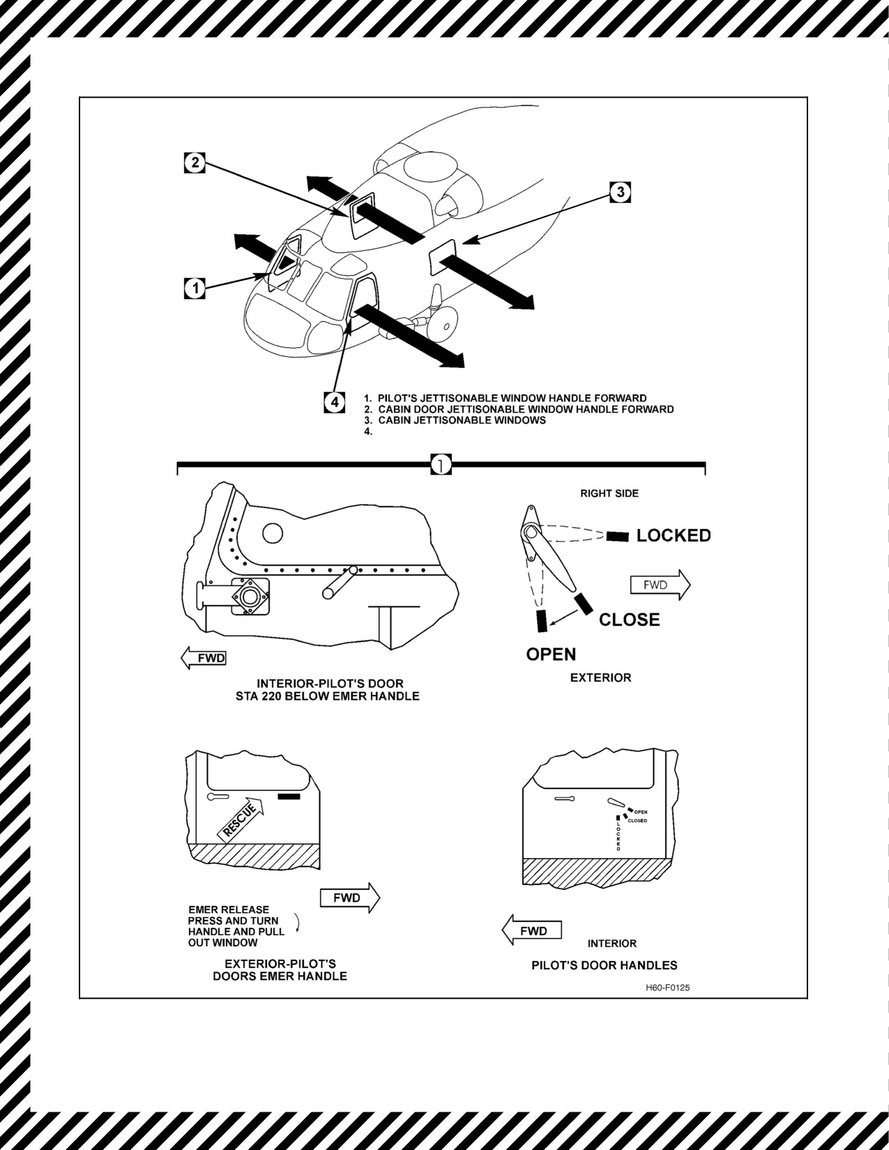
A1-H60BB-NFM-000
HANDLE PULL TAB
ATO JETTISONABLE WINDOW HANDLE FORWARD
Figure 12-7. Emergency Exits (Sheet 1 of 3)
ORIGINAL
12-74
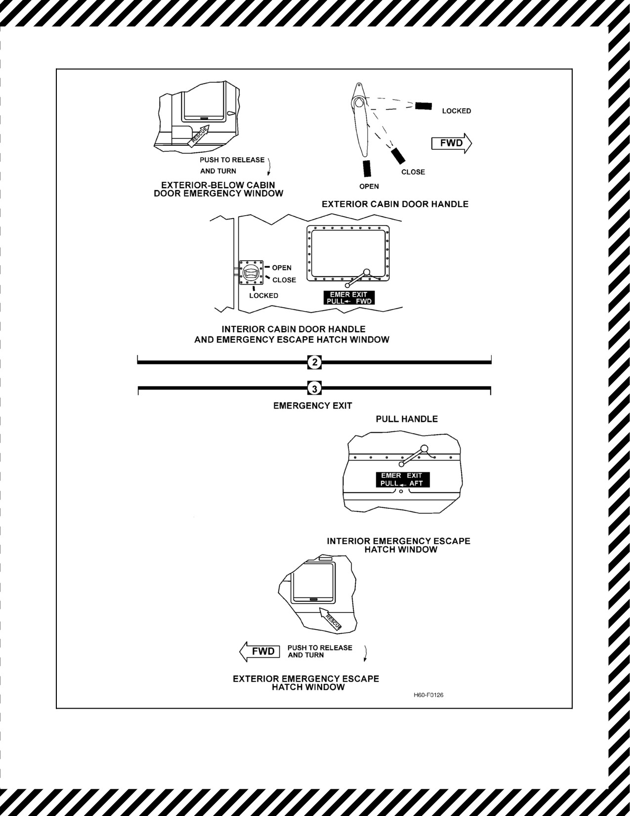
A1-H60BB-NFM-000
Figure 12-7. Emergency Exits (Sheet 2)
12-75
ORIGINAL
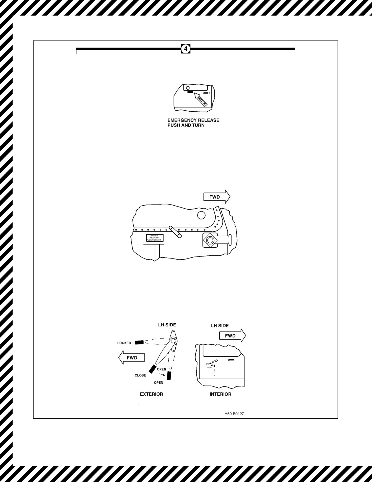
A1-H60BB-NFM-000
EXTERIOR - ATO'S DOOR
BELOW EMERGENCY HANDLE
INTERIOR - ATO'S DOOR HANDLES
STA 220 BELOW EMERGENCY HANDLE
ATO'S DOOR HANDLES
Figure 12-7. Emergency Exits (Sheet 3)
ORIGINAL
12-76
A1-H60BB-NFM-000
12.13.8 Planned Ditching
When an emergency situation dictates a water landing, the crew shall execute the Immediate Landing/Ditching
procedures.
Note
D Time permitting, crew and passengers should check survival gear and
jettison all unnecessary equipment/cargo, especially articles that may
impede egress.
D Priorto ditching, consideractivating theADHEELS manually.ADHEELS
will remain on for approximately 45 minutes.
Theselection ofditching heading should bedetermined by evaluation ofsea and wind conditions. It is recommended
that the aircraft ditch parallel to and near the crest of the swell, if there is a crosswind of 25 knots or less.
If there is a strong crosswind, ditch into the wind, making contact on the upslope of the swell near the top. Wave
motionisindicativeofwinddirection,butswelldoesnotnecessarilymovewiththewind.Conditionsofwatersurface
are indicative of wind speed. If visibility is restricted, ditch heading may be determined from forecast data.
12.13.9 Emergency Crash Position
The risk of personal injury during an autorotative landing or ditching can be significantly reduced by properly
positioning oneself for the landing. All aircrew should position their seats up and aft in order for the seat stroke to
absorb more of the crash loads. Aircrew should sit erect with head firmly against the headrest, elbows tucked in
tightly, arms crossed in front of body, and feet flat on the deck.
The downward stroke of the seat will change the frame of reference needed
for egress. Extended handles, hatches, and controls within the cockpit will
notbelocatedinthesamefamiliarplaces.Keeplegsclearofunderseatarea.
Downward travel of seat may cause injury or entrapment.
12-77
ORIGINAL
A1-H60BB-NFM-000
12.13.10 Immediate Landing/Ditching (Pilot)
Immediate Landing/Ditching (Pilot)
LEGEND
CAUSE/REMARKS
CORRECTIVE ACTION
Immediate
Emergency exit from or entrance into
*1. Crew and passengers — Alert.
Landing/Ditching
the helicopter is provided through
*2. Shoulder harness — Locked.
(Pilot)
jettisonable windows and cabin doors.
*3. External cargo/stores/fuel — JETTISON/
Emergency exits are shown in Figure
DUMP as required.
12-7.
*4. Searchlight — As required.
*5. MAYDAY/IFF — TRANSMIT/EMER.
D
In order to minimize the
CAUTION
potential for serious injury,
instructor seat occupant
should
assume crash
Time permitting, consideration should be
position and lower head until
given to executing APU Emergency Start
their chin touches their chest
procedure to maintain electrical and hydraulic
prior to an emergency
power upon rotor disengagement.
landing or ditching.
In the flare:
D
Stores jettisoned at descent
rates greater than those
*6. Windows — Jettison, as required.
listed in the NATIP have not
been tested. Aircraft/rotor
system
impact
from
jettisoned stores may be
possible.
After actuation, the position of the emergency
jettison window lever may cause snagging of
personal survival gear, impeding egress.
Time permitting, reset jettison handle to the
aft position prior to egress.
After landing:
*7. PCLs — OFF.
*8. Rotor Brake — ON.
*9. ATO Collective — STOW.
After all violent motion stops:
*10. EGRESS.
Failure to remain strapped in aircraft until all
violent motion or inrushing water stops may
result in injury or incapacitation.
ORIGINAL
12-78
A1-H60BB-NFM-000
12.13.11 Immediate Landing/Ditching (Aircrewmen)
Immediate Landing/Ditching (Aircrewmen)
LEGEND
CAUSE/REMARKS
CORRECTIVE ACTION
Immediate
Emergency exit from or entrance
*1. Harness — Locked.
Landing/
into the helicopter is provided
*2. Seat — Up and aft.
Ditching
through jettisonable windows and
*3. Windows — Jettison, as required.
(Aircrewmen)
cabin doors. Emergency exits are
shown in Figure 12-7.
*4. ASO Table — UP AND LOCKED.
*5. Assume crash position.
In order to minimize the
potential for serious injury,
Attaining and maintaining a proper crash position in
instructor seat occupant
a seat is the most critical step that can be taken prior
should assume crash
to impact. Aircrew shall not delay in assuming a
position and lower head until
seated crash position or leave a seated crash
their chin touches their
position to accomplish other tasks on this checklist.
chest
prior
to
and
emergency landing or
ditching.
12.13.12 Lost Aircraft Procedures (Open Ocean)
Lost Aircraft Procedures (Open Ocean)
LEGEND
CAUSE/REMARKS
CORRECTIVE ACTION
Lost Aircraft
Note
1. Confess.
Procedures
Remain calm.
2. Climb.
(Open Ocean)
3. Conserve fuel.
4. Communicate.
5. Maintain adequate fuel to allow for landing or
controlled ditch.
6. Utilize the following aircraft sensors as
appropriate:
a. TACAN.
b. Radar.
c. IFF.
d. ESM.
e. Data link.
f. UHF Homer.
12-79
ORIGINAL
A1-H60BB-NFM-000
12.13.13 Underwater Egress
Underwater Egress
LEGEND
CAUSE/REMARKS
CORRECTIVE ACTION
Underwater
*1. HABD — As required.
Egress
*2. ICS Cords — Disconnect.
*3. Door/Window — Open/Jettison.
D
The downward stroke of the seat
*4. Place hand on known reference point.
will change the frame of reference
*5. Harness — RELEASE.
needed for egress. Extended
handles, windows, and controls
*6. Exit Helicopter.
will not be located in the same
After egress:
relative position. Keep legs clear
from under seat area. Downward
*7.
Swim clear of helicopter and inflate
travel of seat may cause injury or
LPU.
entrapment.
D
Do not inflate LPU until outside
helicopter.
D
Water pressure may prevent
opening the emergency egress
windows until the cabin fills with
water. The windows should be
jettisoned prior to water entry to
optimize the ability of the crew to
safely egress.
D
Failure to disconnect ICS cord
can impede egress. Personal
gear may snag during egress,
notably on collectives, FLIR
HCUs, Parking Brake and RAST
release
handles,
PCLs/Fuel
Selector Levers/Fire T--Handles,
or extended Emergency Jettison
Window handles.
D
If entanglement or disorientation
delays egress, hold onto a
reference point with one hand.
Using the other hand, place
HABD in your mouth, clear water
from your mouthpiece, and
continue with egress.
D
To prevent injury while ascending
to the surface and breathing from
the HABD, continually exhale to
vent the expanding air from your
lungs.
ORIGINAL
12-80
A1-H60BB-NFM-000
12.14 MISSION EQUIPMENT/WEAPON SYSTEM EMERGENCIES
12.14.1 Cargo Hook Emergency Release
Cargo Hook Emergency Release
LEGEND
CAUSE/REMARKS
CORRECTIVE ACTION
Cargo Hook
1. RESCUE HOIST — OFF.
Emergency
2. RAST MASTER — OFF.
Release
3. MAD reeling machine POWER — OFF.
Use of emergency release may cause injury to
crewman.
4. Cyclic stick EMER REL — Press.
12.14.2 RAST Main Probe Messenger Failure
RAST Main Probe Messenger Failure
LEGEND
CAUSE/REMARKS
CORRECTIVE ACTION
RAST Main
If the messenger cable winch should fail/jam while raising
Probe
or lowering and sufficient cable is deployed to attach the
Messenger
hauldown cable or cable is attached, proceed as follows:
Failure
Injury to crewmen may result if RAST power is
applied during the following procedure.
1. RAST MASTER — OFF.
2. Remove the quick release pin from the messenger
light and remove the messenger light assembly.
3. Pull in messenger cable until the haul-down cable
is locked in the main probe and the messenger is
disconnected.
4. Secure messenger cable.
5. RAST MASTER — ON.
6. H-DOWN LKD and MESSGR IN lights — ON.
Note
If thehaul downcable cannot be attachedand theRA
landing must be made, proceed with RAST
Messenger Jettison and Back-up Messenger Cable
Employment.
12-81
ORIGINAL
A1-H60BB-NFM-000
12.14.3 RAST Messenger Jettison
RAST Messenger Jettison
LEGEND
CAUSE/REMARKS
CORRECTIVE ACTION
RAST
1. RAST MASTER — ON.
Messenger
2. CARGO HOOK ARMING — SAFE.
Jettison
3. RESCUE HOIST — OFF.
4. MAD reeling machine power — OFF.
5. Cyclic stick EMER REL — PRESS.
12.14.4 RAST Backup Messenger Cable Employment
RAST Backup Messenger Cable Employment
LEGEND
CAUSE/REMARKS
CORRECTIVE ACTION
RAST Backup
Note
Messenger
The RAST hauldown cable--
Cable
normal release and the
Employment
RAST messenger cable
Injury to crewmen may result if RAST
power
is
emergency shear
(EMER
applied during the following procedure.
REL) are disabled when the
1. RAST MASTER — OFF.
RAST MASTER switch is
2. Remove the quick release pin from the
OFF.
messenger light and remove the messenger
light assembly.
3. Messenger cable — Remove from probe.
4. Secure line to a point on the probe.
5. Insert backup assembly adapter into main probe
from top. Guide with tube assembly.
6. Push messenger adapter through detents on
probe and pay out line until instructed to stop.
7. Deck crew will connect RA cable.
8. Pull in line until hauldown cable is locked in the
main probe and the backup messenger cable is
disconnected.
9. RAST MASTER — ON.
ORIGINAL
12-82
A1-H60BB-NFM-000
12.14.5 RAST Cable Emergency Release
RAST Cable Emergency Release
LEGEND
CAUSE/REMARKS
CORRECTIVE ACTION
RAST Cable
Note
1. RAST emergency release T--handle — PULL.
Emergency
The RAST hauldown cable
Release
emergency release T--handle
is a mechanical system
which will operate regardless
of RAST MASTER switch
position.
12-83
ORIGINAL
A1-H60BB-NFM-000
12.14.6 RAST Main Probe Fails to Extend
RAST Main Probe Fails to Extend
LEGEND
CAUSE/REMARKS
CORRECTIVE ACTION
RAST Main
Note
If
the main probe fails to extend electrically:
Probe Fails to
D
Ensure cable release is
Extend
in the up position before
attempting manual ex-
tension of main RAST
Injury to crewmen may result if RAST power is
probe.
applied prior to manual main probe extension.
D
Inadvertent extension
1. RAST MASTER — OFF.
of the RAST main probe
2. Pull pip pin from under the manual cable tension
is possible when the
release. Lower the manual cable tension release
adapter is inserted into
arm to relieve cable tension.
the shaft hole.
3. Remove ratchet with adapter from its stowed
D
When retrieving cable
position.
into hoist manually, two
positive clicks will be
felt. Do not retract any
further. This indicates
messenger in and
Inserting the adapter with the ratchet attached while
hauldown cable locked.
the main probe is in the up position may cause
serious injury to crewman.
4. Remove adapter from ratchet, slide shaft lock
away from shaft hole. Insert adapter shaft and lock
into place with shaft lock slide.
5. Raise the manual cable tension release arm and
replace pip pin.
Check area beneath the aircraft to be sure it is clear
of personnel and obstructions.
6. Push down on the release lever to unlock probe.
Probe will extend rapidly to extended position.
7. Remove ratchet adapter from shaft hole and
attempt normal RAST procedures.
If unsuccessful:
8. Insert ratchet and pay out cable to ship deck.
The full 90 feet of cable can be extended in one
minute.
9. After hauldown cable has been connected,
retrieve by reversing ratchet and reel up until
cable is locked in probe.
10. RAST MASTER — ON.
11. H’DOWN LKD and MSGR IN lights — ON.
ORIGINAL
12-84
A1-H60BB-NFM-000
12.14.7 RAST Main Probe Fails to Retract
RAST Main Probe Fails to Retract
LEGEND
CAUSE/REMARKS
CORRECTIVE ACTION
RAST Main
Note
1. RAST LAMP TEST — Press.
Probe Fails to
RAST main probe must be
2. MSGR IN light — On.
Retract
in the up position in order to
3. Main probe — Visually check.
receive accurate OTPI
information.
4. MAIN PROBE — DOWN, then UP.
CAUTION
D Running landing shall not be attempted with
main probe extended.
D Do not attempt to retract probe with ratchet.
Damage will occur.
D Ground taxi is not recommended with main
probe extended.
12-85
ORIGINAL
A1-H60BB-NFM-000
12.14.8 MAD Reel Failure with Towed Body Deployed
ASQ--81 MAD Reel Failure with Towed Body Deployed
LEGEND
CAUSE/REMARKS
CORRECTIVE ACTION
ASQ--81 MAD Reel
Failure with Towed
CAUTION
Body Deployed
With less than 12 feet of cable unrecoverable,
maintain 50 to 55 KIAS until on final approach.
1.
Day or night VMC recovery procedure:
a. Coordinate assistance with ground
personnel.
b. MAD reeling machine POWER — ON.
c. MAGNETIC DETECTING SET PWR — OFF.
d. Position crewman in cargo door to inform
pilot of towed body position and altitude.
e. Establish hover so as to keep MAD towed
body clear of deck.
f. Lower aircraft until towed body is on deck.
g. Ground personnel maintain tension on cable,
land aircraft on prepared surface.
h. Recover cable, proceed with mission or to
aircraft parking area.
2.
Night/IMC jettison procedure:
a. CARGO HOOK ARMING — SAFE.
b. RESCUE HOIST — OFF.
c. RAST MASTER — OFF.
d. MAD reeling machine POWER — ON.
e. Cyclic stick EMER REL — Press.
If the MAD bird is lost in flight, the MAD cable shall
be cut immediately.
ORIGINAL
12-86
A1-H60BB-NFM-000
12.14.9 ASQ--81 Towed Body Down Limit Switch Malfunction
ASQ--81 Towed Body Down Limit Switch Malfunction
LEGEND
CAUSE/REMARKS
CORRECTIVE ACTION
ASQ--81 Towed
Note
Body Down Limit
If the MAD towed body
Switch
stops at an intermediate
Malfunction
position during deploy--
ment, the CABLE LIMIT
Towed body jettison is possible. Avoid populated
MAD LIMIT
light on the MAD reeling
areas.
machine control panel
*1. if no cable limit light within 61 seconds —
and the MAD LIMIT light
Cease MAD reeling operations.
on the caution/advisory
panel should flash
*2. Alert crew.
continuously.
3. REEL — IN.
12.14.10 ASQ--81 Towed Body Fails to Seat Properly
ASQ--81 Towed Body Fails to Seat Properly
LEGEND
CAUSE/REMARKS
CORRECTIVE ACTION
ASQ--81 Towed
1. REEL — Out (5 seconds).
Body Fails to Seat
a. Deploy towed body approximately 20 feet
Properly
from the pylon.
CAUTION
Do not attempt to reseat if the Unit 3 FAIL light has
illuminated as a result of a failure to seat properly.
2. REEL — IN.
3. Pilot observe proper seating of the MAD towed
body.
4. Land as soon as practical, and avoid
populated areas.
12-87
ORIGINAL
A1-H60BB-NFM-000
12.14.11 Rescue Hoist Failure
Rescue Hoist Failure
LEGEND
CAUSE/REMARKS
CORRECTIVE ACTION
Rescue Hoist
*1. Cease hoisting.
Failure
*2. Visually inspect hoist.
*3. Verify:
b. HYDRAULIC BACKUP PUMP caution
lights — OFF.
c. HYDRAULIC BACKUP PUMP switch — ON.
d. RESCUE HOIST switch — ALL.
e. RESCUE HOIST circuit breakers — IN.
a RESCUE HOIST CTRL (SO OVHD,
NO. 2 DC PRI, ROW 6, CB 13).
(1) RESCUE HOIST CTRL (SO OVHD,
NO. 1 DC PRI, ROW 6, CB 2).
(2) RSQ HOIST POWER (SO OVHD,
NO. 2 AC PRI, ROW 2, CB 3).
If a bird’s nest or Lucas Western, proceed to step 6.
If a bird’s nest is suspected, do not attempt to raise
or lower the hoist to avoid further damage to the
rescue hoist/cable or cable separation.
*4. Check normal raise/lower at all stations.
*5. BACKUP CONTROL — Select.
D Operation of rescue hoist in BACK-UP
CONTROL mode will bypass limit switches.
Cable separation may occur.
D If hoist jams, do not attempt to RAISE/LOWER
any further as this could shear the cable.
6. Attempt to set personnel/cargo on deck/water.
If unable:
7. Cable grip — Rig.
ORIGINAL
12-88
A1-H60BB-NFM-000
12.14.12 Cable Grip Rigging Procedures
Cable Grip Rigging Procedures
LEGEND
CAUSE/REMARKS
CORRECTIVE ACTION
Cable Grip
1. Attach cable grip shackle to crewman safety
Rigging
belt.
Procedures
2. Attach crewman safety belt to rescue hoist
boom.
3. Connect cable grip to hoist cable by placing the
cable between the jaws of the cable grip,
shackle end up.
4. Pull up on crewman safety belt to slacken hoist
cable.
Ensure altitude is sufficient to keep
survivor/swimmer clear of the water.
5. Report ready for forward flight.
12.14.12.1 Runaway Hoist
Runaway Hoist
LEGEND
CAUSE/REMARKS
CORRECTIVE ACTION
Runaway
*1. BACKUP CONTROL. — Select.
Hoist
CAUTION
Operation of rescue hoist using BACKUP CONTROL
inhibits limit switches.
If payout continues:
*2. Hydraulic pump — Secure.
3. Attempt to set person/cargo on deck/water.
If unable:
4. Cable grip — Rig.
12.14.12.2 Rescue Hoist Fouled Cable
Rescue Hoist Fouled Cable
LEGEND
CAUSE/REMARKS
CORRECTIVE ACTION
Rescue Hoist
*1. Pay out cable and attempt to free hangup.
Fouled Cable
If unable:
*2. Cut/shear cable — As required.
12-89
ORIGINAL
A1-H60BB-NFM-000
12.14.12.3 Rescue Hoist Cable Cut
Rescue Hoist Cable Cut
LEGEND
CAUSE/REMARKS
CORRECTIVE ACTION
Rescue Hoist
*1. Emergency shear switch — SHEAR.
Cable Cut
If unable:
*2. Direct pilot to press EMER REL button.
12.14.12.4 Rescue Hoist Cable Separation
Rescue Hoist Cable Separation
LEGEND
CAUSE/REMARKS
CORRECTIVE ACTION
Rescue Hoist
Note
1. Quick Splice procedure — Perform.
Cable
For proper Quick Splice pro-
Separation
cedures, refer to NTTP
3--50.1 series.
12.15 MISCELLANEOUS CAUTION/ADVISORY LIGHTS
12.15.1 IFF Flashing Caution
IFF Flashing Caution Light
LEGEND
CAUSE/REMARKS
CORRECTIVE ACTION
IFF Flashing
Indicates IFF mode
4
is not
1. MODE 4 TEST/ON/OUT switch — TEST.
Caution Light
responding to interrogation.
2. Observe GO indicator light ON.
If GO indicator light does not illuminate or TEST/MON
IFF
NO GO or a STATUS light illuminates:
3. MODE 4 TEST/ON/OUT switch — OUT.
The helicopter may be viewed as a potential foe.
Proceed in accordance with local directives.
12.15.2 LEFT or RIGHT RACK FAN Caution Light On
LEFT or RIGHT RACK FAN Caution Light On
LEGEND
CAUSE/REMARKS
CORRECTIVE ACTION
1. Check applicable circuit breaker — RH RACK, LH
LEFT RACK
RACK BLOWER (SO circuit breaker panel).
FAN
2. Acoustic paneling — Remove.
RIGHT RACK
FAN
ORIGINAL
12-90
A1-H60BB-NFM-000
12.15.3 WOW Advisory Light On In Flight
WOW Advisory Light On In Flight
LEGEND
CAUSE/REMARKS
CORRECTIVE ACTION
WOW
Illumination of the WOW light in
flight indicates that the aircraft
Weight on Wheels switch is stuck
or malfunctioning.
Flying with a stuck Weight on Wheels (WOW) switch
will disable WOW functions including emergency
jettison circuits, radar altitude low altitude aural
warning. Engine Out and Low Rotor RPM lights.
Pulling the WOW circuit breaker will not restore
proper operation of some WOW functions in the air.
Pulling the WOW circuit breaker in flight may disable
the Low Rotor RPM lights and the #1 and #2 Engine
Out warning lights.
If the light is illuminated in flight:
1. Land as soon as practical.
12.15.4 Hellfire Missile Emergencies
12.15.5 Hellfire Missile Aborted Launch
This condition exists if the ATO depresses the HCU RELEASE CONSENT button but the system subsequently
aborts the launch before a firing pulse is sent to any of the Hellfire missile squibs. An ACRT BIT status word for
the affected Hellfire missile will be set stating the launch was aborted. If that occurs, perform the following steps:
Hellfire Missile Aborted Launch
LEGEND
CAUSE/REMARKS
CORRECTIVE ACTION
Hellfire
Note
1. Alert crew.
Missile
D
If the RELEASE CONSENT
If a new Hellfire priority missile is selected by the ACRT:
Aborted
button is depressed within
Launch
2. Proceed with the AGM-114 Hellfire Missile
2 seconds following an
Launch checklist.
attempted launch, the ACRT
will ignore any attempts to
If a new Hellfire priority missile is not selected:
launch another Hellfire
3. PWR/ARM — OFF.
missile and will display an
4. MASTER ARM — SAFE.
“INV TRIG” alert on the MPD.
5. LAUNCHER RESET — INITIATE.
D
No special recovery or
Hellfire
missile handling
6. ACRT BIT status words — CHECK.
procedures are required.
If no critical faults:
7. Proceed with the AGM-114 Hellfire Missile
Launch checklist.
If critical BIT status exists or Hellfire missile launch
portion of the mission is complete:
8. PWR/ARM — OFF.
9. WPN SELECT — OFF.
10. MASTER ARM — Verify SAFE.
11. FLIR OPERATIONAL PAGE — SELECT.
12. HELLFIRE PWR — OFF.
12-91
ORIGINAL
A1-H60BB-NFM-000
12.15.5.1 Hellfire Missile Hangfire
This condition exists if the ATO depresses the RELEASE CONSENT button but the Hellfire missile remains on the
rail after the squib firing pulses have been sent to both the Hellfire missile and rocket motor squibs. The rocket motor
may or may not ignite. A Hellfire missile hangfire condition is noted on the MPD by displaying the text HNG beneath
the Hellfire missile fail symbol.
Note
Normal rocket motor burn time is less than 3 seconds. A rocket motor
failure may cause the motor to slow burn or smolder and smoke for more
than 3 seconds.
Hellfire Missile Hangfire
LEGEND
CAUSE/REMARKS
CORRECTIVE ACTION
Hellfire Missile
Note
If rocket motor ignites and aircraft yaws:
Hangfire
The missile thermal
1. Adjust controls as required to maintain straight
battery does not provide
and level flight.
the voltage for the rocket
2. Alert crew.
motor fire train. Aircraft
power via the Signal
Data Converter
(AH
SDC) is required to fire
The Hellfire missile thermal battery produces
the rocket motor squibs.
voltage for up to 30 minutes after the Hellfire
If motor squibs have not
missile squib is automatically fired during the
fired within 1.5 seconds
launch sequence. If continued flight is possible,
after launch attempt, the
the aircraft should remain airborne with Hellfire
missile Safe and Arm
missile pointed in a safe direction for a minimum
Device
(SAD) will
of
30 minutes to allow the thermal battery to
mechanically return to
become inert.
the safe condition. This
If a new priority Hellfire missile is selected by the
will disconnect the firing
ACRT:
circuit from the rocket
motor squibs.
3. Proceed with the AGM--114 Hellfire Missile
Launch checklist.
If a new priority Hellfire missile is not selected:
4. PWR/ARM — OFF.
5. WPN SELECT — OFF.
6. MASTER ARM — SAFE.
7. LAUNCHER RESET — Initiate.
8. ACRT BIT status words — Check.
If no critical faults:
9. Proceed with the AGM--114 Hellfire Missile
Launch checklist.
If critical BIT status exists or Hellfire missile launch
portion of the mission is complete:
10. FLIR OPERATION PAGE — Select.
11. HELLFIRE PWR — OFF.
ORIGINAL
12-92
A1-H60BB-NFM-000
Hellfire Missile Hangfire (cont)
LEGEND
CAUSE/REMARKS
CORRECTIVE ACTION
Hellfire Missile
If fuel/time permits:
Hangfire (Cont)
12. Keep Hellfire missile pointed in safe direction for
30 minutes.
CAUTION
EOD personnel, usually located aboard aviation
ships, are specially trained to properly handle and
dispose of hung ordnance. Personnel should not
handle hung ordnance for at least 30 minutes after
attempted launch.
If shore facility not available:
13. Proceed to aviation ship, if available.
14. Proceed to own ship — Use offset approach
procedures.
If shipboard recovery with hung ordnance not an
option:
15. Execute Selective Jettison of M299 Launcher
emergency procedure.
12-93
ORIGINAL
A1-H60BB-NFM-000
12.15.5.2 Hellfire Missile Misfire
Hellfire Missile Misfire
LEGEND
CAUSE/REMARKS
CORRECTIVE ACTION
Hellfire
Note
1. Alert crew.
Missile
The missile thermal battery
Misfire
does not provide the voltage
for the rocket motor fire
train. Aircraft power via the
Signal Data Converter (AH
The Hellfire missile thermal battery produces voltage
SDC) is required to fire the
for up to 30 minutes after the Hellfire missile squib is
rocket motor squibs. If
automatically fired during the launch sequence. If
motor squibs have not fired
continued flight is possible, the aircraft should remain
within
1.5
seconds after
airborne with Hellfire missile pointed in a safe
launch attempt, the missile
direction for a minimum of 30 minutes to allow the
Safe and Arm Device (SAD)
thermal battery to become inert.
will mechanically return to
If
a new priority Hellfire missile is selected by the ACRT:
the safe condition. This will
disconnect the firing circuit
2. Proceed with the AGM--114 Hellfire Missile Launch
from the rocket motor
checklist.
squibs.
If
a new priority Hellfire missile is not selected:
3. PWR/ARM — OFF.
4. WPN SELECT — OFF.
5. MASTER ARM — SAFE.
6. LAUNCHER RESET — Initiate.
7. ACRT BIT status words — Check.
If
no critical faults:
8. Proceed with the AGM--114 Hellfire Missile Launch
checklist.
If
critical BIT status exists or Hellfire missile launch
portion of the mission is complete:
9. FLIR OPERATION PAGE — Select.
10. HELLFIRE PWR — OFF.
If fuel/time permits:
11. Keep Hellfire missile pointed in safe direction for 30
minutes.
ORIGINAL
12-94
A1-H60BB-NFM-000
12.15.5.3 Hellfire Missile Unlatched
Hellfire Missile Unlatched
LEGEND
CAUSE/REMARKS
CORRECTIVE ACTION
Hellfire
If this occurs, an AOP alert message “XXX MISSILE
Missile
UNLATCHED” will be displayed.
Unlatched
1. Inform the crew.
2. Slow helicopter (70 to 80 KIAS preferable),
reduce/limit maneuvering. Avoid flying over
populated areas.
3. Perform visual inspection of launcher/missiles.
a. If the missile appears uploaded normally, land
as soon as practical.
b. If missile does not appear to be properly seated,
land as soon as practical and only fly over
uninhabited areas.
12.15.6 FLIR Uncommanded Lasing
FLIR Uncommanded Lasing
LEGEND
CAUSE/REMARKS
CORRECTIVE ACTION
FLIR
If the FLIR/LRD continues to lase after the SO or ATO
Uncommanded
releases the Laser Trigger and LASING alert is visible on
Lasing
the MPD without operator command:
*1. WEAPON SELECT (AN/ASQ-198) — OFF.
*2. MASTER ARM — Verify SAFE.
*3. LASER — DISABLE.
If lasing continues:
*4. FLIR PWR — OFF.
*5. FLIR circuit breakers — Pull (SO circuit breaker
panel, SO OVHD: FLIR AC, FLIR/HFSAC,
FLIR/HFS AC) .
12.15.7 Torpedo Emergencies
12.15.7.1 Hung Torpedo
Hung Torpedo
LEGEND
CAUSE/REMARKS
CORRECTIVE ACTION
Hung Torpedo
If a torpedo launch is initiated, and the torpedo remains
attached to the BRU--14/A:
1. MASTER ARM — SAFE.
2. Point aircraft in a safe direction.
3. Land as soon as practical.
12-95
ORIGINAL
A1-H60BB-NFM-000
12.15.8 Stores Emergencies
12.15.8.1 Selective Jettison of M299 Launcher
Selective Jettison of M299 Launcher
LEGEND
CAUSE/REMARKS
CORRECTIVE ACTION
Selective
1. HELLFIRE PWR — OFF.
Jettison of
2. WPN SELECT — PORT FWD.
M299 Launcher
3. MASTER ARM — ARM.
4. PWR/ARM — ON.
5. MISSILE MODE/JETT — MAN.
6. Verify the WEAPON LAUNCH switch
indicates RDY.
Note
Missile Ready indicator light will illuminate.
7. WEAPON LAUNCH — Depress.
8. Verify the WEAPON LAUNCH switch
indicates AWAY.
9. WPN SELECT — OFF.
10. MASTER ARM — SAFE.
11. PWR/ARM — OFF.
12. Record aircraft position (latitude/longitude).
13. Land as soon as practical.
12.15.8.2 Hung Sonobuoy/SLC
Hung Sonobuoy/SLC
LEGEND
CAUSE/REMARKS
CORRECTIVE ACTION
Hung
Note
1. Airspeed — Adjust to 80 KIAS.
Sonobuoy/
If a hung SLC is experienced,
2. Visually inspect spider assembly and plumbing for
SLC
manual refiring will only move
damage.
the SLC assembly slightly
3. Attempt to dislodge by manually refiring sonobuoy
and bleed down the launcher
tube.
pressure, thereby losing
emergency capability to
If sonobuoy fails to launch:
jettison all sonobuoys.
4. Avoid autorotative flight.
5. Sono Launcher safety valve — SAFE.
6. MASTER ARM — SAFE.
7. Maintain balanced flight and avoid steep turns to
the left.
8. Land as soon as practical and avoid populated
areas.
ORIGINAL
12-96
A1-H60BB-NFM-000
12.15.8.3 LAUNCH/JETT FAIL Caution Light On
LAUNCH/JETT FAIL Caution Light On
LEGEND
CAUSE/REMARKS
CORRECTIVE ACTION
LAUNCH/
1. Armament circuit breakers — Pull:
JETT FAIL
a. NO. 1 DC PRIMARY BUS marked ARMAMENT
JETT A (ATO, ROW 3, CB 11).
b. NO. 2 DC PRIMARY BUS marked ARMAMENT
JETT B (ATO, ROW 3, CB 21).
c. NO. 2 DC PRIMARY BUS marked ARMAMENT
SYS (ATO, ROW 3, CB 19).
d. NO. 2 DC PRIMARY BUS marked ARMAMENT
JETT, JETT D (ATO, ROW 3, CB 22)
(BuNo 162349 and subsequent only).
2. Armament circuit breakers — Reset.
12.16 CREW--SERVED WEAPONS
12.16.1 M60D/M240D Emergencies
A malfunction or stoppage is any interruption in the cycle of operation caused by the faulty action of the gun or
ammunition. These malfunctions/stoppages can be further defined as:
1. Hangfire: A delay in the functioning of the cartridge propelling charge.
2. Misfire: A complete failure to fire.
12.16.1.1 M60D/M240D Cook--Off
M60D/M240D Cook--Off
LEGEND
CAUSE/REMARKS
CORRECTIVE ACTION
M60D/M240D
*1. Barrel — SAFE DIRECTION.
Cook--Off
*2. Weapon — ALLOW TO COOL (min 5 minutes).
*3. Chamber — INSPECT AND CLEAR.
CAUTION
A barrel is considered hot if the gunner has fired 200
or more rounds within 2 minutes (rapid rate of fire).
The barrel will become hot enough to cause a
cook--off.
12-97
ORIGINAL
A1-H60BB-NFM-000
12.16.1.2 M60D/M240D Failure to Fire/Jammed Gun
M60D/M240D Failure to Fire/Jammed Gun
LEGEND
CAUSE/REMARKS
CORRECTIVE ACTION
M60D/M240D
*1. Barrel — SAFE DIRECTION.
Failure to
*2. Wait 5 Seconds.
Fire/Jammed
*3. Charging Handle — RETRACT AND LOCK.
Gun
*4. Safety — TO SAFE.
*5. Chamber — INSPECT AND CLEAR.
If chamber cannot be cleared in 10 seconds a
possibility for cook--off exists, close feed tray cover
and allow to cool for 5 minutes then re--inspect and
clear.
Note
Gun will jam if collection bag is not emptied often.
12.16.1.3 M60D/M240D Runaway Gun
M60D/M240D Runaway Gun
LEGEND
CAUSE/REMARKS
CORRECTIVE ACTION
M60D/M240D
*1. Barrel — SAFE DIRECTION.
Runaway Gun
*2. Ammo Belt — BREAK BY TWISTING.
If weapon does not stop firing:
*3. Continue pointing in safe direction until ammo is
expended.
*4. Chamber — INSPECT AND CLEAR.
To avoid further damage, continued firing of weapon
shall not be conducted until weapon is inspected.
*5. Weapon status — REPORT.
ORIGINAL
12-98
A1-H60BB-NFM-000
12.16.1.4 M60D/M240D Clear Weapon Procedures
M60D/M240D Clear Weapon Procedures
LEGEND
CAUSE/REMARKS
CORRECTIVE ACTION
M60D/M240D
1. Charging Handle — RETRACT AND LOCK.
Clear Weapon
2. Safety — TO SAFE.
Procedures
3. Feed tray cover — OPEN.
4. Ammo — REMOVE.
5. Chamber — INSPECT AND CLEAR.
Failure to ensure no live/expended cartridges remain
in the chamber, feed tray, or receiver may result in
accidental discharge. Utilize a flashlight if necessary
to ensure weapon is clear.
6. Weapon status — REPORT.
12.16.2 GAU-16/A Emergencies
12.16.2.1 GAU--16/A Cook--Off
GAU--16/A Cook--Off
LEGEND
CAUSE/REMARKS
CORRECTIVE ACTION
GAU--16/A
*1. Barrel — SAFE DIRECTION.
Cook--Off
*2. Weapon — ALLOW TO COOL (min 5 minutes).
Avoid opening the feed cover of a hot gun. If cook--off
occurs, there may be a pause between firings. Allow
to cool for 5 minutes after last round has fired.
*3. Chamber/T--slot — INSPECT AND CLEAR.
12.16.2.2 GAU--16/A Jammed Gun
GAU--16/A Jammed Gun
LEGEND
CAUSE/REMARKS
CORRECTIVE ACTION
GAU--16/A
*1. Barrel — SAFE DIRECTION.
Jammed Gun
*2. Wait 5 seconds.
*3. Charging handle — CHARGE ONCE.
*4. Attempt to fire.
If weapon does not fire:
*5. Chamber/T--slot — INSPECT AND CLEAR.
12-99
ORIGINAL
A1-H60BB-NFM-000
12.16.2.3 GAU--16/A Runaway Gun
GAU--16/A Runaway Gun
LEGEND
CAUSE/REMARKS
CORRECTIVE ACTION
GAU--16/A
*1. Barrel — SAFE DIRECTION.
Runaway Gun
*2. Charging handle — PULL DOWN.
Avoid opening the feed cover of a hot gun. If cook--off
occurs, there may be a pause between firings. Allow
to cool for 5 minutes after last round has fired.
*3. Feed tray cover — OPEN.
*4. Ammo — REMOVE.
*5. Feed tray cover — CLOSE.
*6. Charging handle — CHARGE ONCE.
*7. Chamber/T--slot — INSPECT AND CLEAR.
To avoid further damage, continued firing of weapon
shall not be conducted until weapon is inspected.
ORIGINAL
12-100
A1-H60BB-NFM-000
12.16.2.4 GAU--16/A Clear Weapon Procedures
GAU--16/A Clear Weapon Procedures
LEGEND
CAUSE/REMARKS
CORRECTIVE ACTION
GAU--16/A
1. Safety — SAFE.
Clear Weapon
2. AN/PEQ--3 — OFF.
Procedures
3. AN/PEQ--3 lens covers — ON.
4. Feed tray cover — OPEN.
5. Ammo — REMOVE FROM FEED TRAY.
6. Feed tray cover — CLOSE.
7. Charging handle — CHARGE ONCE.
8. Feed tray cover — OPEN.
9. Chamber/T--slot — INSPECT AND CLEAR.
D Chamber may be hot. Use caution while
inspecting T--slot.
D If chamber is not clear, repeat steps
6. through 9. once and remove any remaining
rounds. If unable to clear weapon, execute hung
ordnance procedures IAW local directives.
CAUTION
Do not disassemble the GAU--16 while attempting to
clear weapon in flight.
10. Weapon status — REPORT.
12.16.2.5 AN/PEQ-3 Uncommanded Lasing
AN/PEQ--3 UNCOMMANDED LASING
LEGEND
CAUSE/REMARKS
CORRECTIVE ACTION
AN/PEQ-3
*1. AN/PEQ--3 — OFF.
Uncommanded
*2. AN/PEQ--3 lens covers — ON.
Lasing
*3. Batteries — REMOVE.
The AN/PEQ--3 Laser is a
class 3B non--eyesafe laser
with a NOHD of 263 meters.
12-101/(12-102 blank)
ORIGINAL
A1-H60BB-NFM--000
PART VI
All-Weather Operations
Chapter 13 — Instrument Procedures
Chapter 14 — Extreme Weather Operations
65/(66 blank)
ORIGINAL
A1-H60BB-NFM-000
CHAPTER 13
Instrument Procedures
13.1
INSTRUMENT FLIGHT PROCEDURES
With the exception of some repetition necessary for continuity, the procedures and techniques contained in this
chapter are only those that differ or are in addition to normal operating procedures. Prior to conducting instrument
flying, careful preflight planning is necessary. Refer to the NATOPS Instrument Flight Manual for detailed
instrument flight procedures.
13.1.1 Instrument Takeoff (ITO)
During a full ITO (no external visual reference), the hover bars will provide the only indication of stability over the
ground.
The following general procedures are recommended:
1. Select hover bars.
2. Smoothly increase collective to takeoff power and maintain a hover attitude by referencing the AI. Allow
AFCS to maintain heading (feet off pedal trim microswitches once airborne).
3. Smoothlyincreasecollectivetoclimboutpower.Asthehelicopterpassesthrough20feetontheradaraltimeter,
position the cyclic forward to establish a 5º nose down attitude and accelerate into forward climbing flight.
4. As the helicopter accelerates, crosscheck radar altimeter and VSI for positive rates of climb. Rate of climb
should be 500 fpm or greater.
5. Maintain a smooth acceleration up to 90 KIAS, referencing the AI and airspeed indicator.
13.1.2 Instrument Crew Coordination
In order to prevent possible pilot task saturation, the flight crew shall discuss and assign cockpit responsibilities prior
to instrument flight. The responsibilities shall include complying with clearances, making radio calls, switching
navigation aids and radios, monitoring navigation, reviewing approach procedures, maintaining a visual/instrument
scan during an approach, and landing procedures. Prior to commencing an instrument approach, the pilots should
review approach publication information. The PAC shall comply with clearances and should make radio calls. The
PNAC should notify thePAC ofdeviations from published orassigned procedures, call thefield in sight, and backup
the PAC during visual transition following an approach. The aircrewmen should monitor the radios and maintain a
good lookout.
13.1.2.1 Instrument Climbs and Descents
The PAC shall verbalize his intentions to vacate one altitude for another. The PNAC shall monitor flight instruments
and provide “100 FEET PRIOR” (or as briefed) call. Upon reaching intended altitude, the PNAC shall verbally note
that RDRALT/BARALT pushbutton is latched/steady.
13.1.3 Instrument Approach Procedure
Two methods for ensuring cockpit coordination and instrument scan responsibility are recommended: change of
scans or change of controls. Instrument scan responsibility shall be specifically briefed.
Note
Pilots shall verbally acknowledge a change ofscan responsibility by useof
phrases such as “I’M ON INSTRUMENTS,” or “I’M VISUAL”.
13-1
ORIGINAL
A1-H60BB-NFM-000
13.1.3.1 Change of Scans
In this procedure, the PAC flies the instrument approach and makes the landing. The PAC maintains an instrument
scan until the landing phase commences. The PNAC backs up the PAC on instruments and scans outside for the
landing environment. Once the PNAC has the landing environment in sight, and can safely continue the approach,
the PACE will provide the PAC with a brief description of the visual approach (e.g., glideslope, line--up) and then
assume instrument scan responsibilities. The PAC shall commence a visual scan outside and continue the approach
to a landing. The PNAC maintains an instrument scan until landing is assured. If a missed approach is initiated, the
PAC will ensure obstacle clearance and then assume instrument scan responsibilities. The PNAC will provide backup
instrument scan.
13.1.3.2 Change of Controls
In this procedure, the PAC flies the instrument approach and switches controls to the PNAC for landing. Once the
PNAC has the landing environment in sight, and can safely continue the approach visually, the PNAC shall inform
the PAC, take the flight controls and continue the approach to landing. The initial PAC continues an instrument scan
until landing is assured. If a missed approach is initiated, the initial PAC reassumes control of the aircraft and the
initial PNAC provides backup instrument scan and obstruction clearance.
13.2
SIMULATED INSTRUMENT FLIGHTS
13.2.1 Lookout Procedures
Thepossibilityofamidaircollisionrequirescontinuouscautionwhenengagedin simulatedinstrument flights.When
the PAC’s attention is directed toward controlling the aircraft on instruments, the area of surveillance for which the
PAC is responsible shall be covered by a lookout familiar with aviation, instructed in specific duties, and provided
with direct communication to the pilots.
13.2.2 Safety Precautions
Since the PAC will be devoting total attention to instrument flying, the PNAC will operatethe navigation equipment
and assume lookout responsibility. When engaged in simulated instrument flights, the crew is responsible for
knowledge of and compliance with the following safety precautions:
1. The lookout shall be indoctrinated thoroughly in the nature and importance of specific duties and shall not be
distracted from the assigned duties.
2. ICS shall be operable between both pilots and lookout during simulated instrument flight.
13.3
UNUSUAL ATTITUDES
13.3.1 Unusual Attitudes
Unusual attitudes are considered to be pitch attitudes in excess of 30° and/or roll attitudes in excess of 60°. Unusual
attitudes will mostly likely be encountered following an AFCS malfunction, AI degradation, vertigo or poor
instrument scan.
13.3.2 Unusual Attitude Recovery
If the pilot uses information presented by the AI correctly, a recovery from an unusual attitude can be executed
quickly. If AI degradation is suspected, the importance of crosschecking the operable AI must be stressed. If both
AI indications are erroneous, the PAC shall immediately switch to a partial panel instrument scan and commence
recovery.
While reducing airspeed during recovery from an unusual attitude is important, the recovery can be expedited by
decreasing the angle of bank while simultaneously applying aft cyclic. As soon as the angle of bank is corrected, the
airspeed indicator and altimeter become the primary pitch instruments. Airspeed should be crosschecked with the
AI to obtain an instant indication of pitch attitude. High sink rates can be experienced with no change in attitude.
ORIGINAL
13-2
A1-H60BB-NFM-000
Therefore, the radar altimeter and VSI should be given strong emphasis. Do not chase the VSI upon recovery. When
a diving spiral is experienced, excessive aft cyclic may aggravate the maneuver, tighten the turn, and result in blade
stall.
CAUTION
During unusual attitude recoveries, avoid excessive forward airspeed and
conditions of flight near a hover where vortex ring state conditions may
occur.
See Chapter 12 for the Unusual Attitude Recovery emergency procedure.
13-3/(13-4 blank)
ORIGINAL
A1-H60BB-NFM-000
CHAPTER 14
Extreme Weather Operations
14.1
COLD--WEATHER OPERATIONS
14.1.1 General
Extreme cold temperatures and conditions cause adverse effects on aircraft materials. Rubber, plastic, and fabric
material stiffen, and may crack or even shatter, when loads are applied. Oils congeal and grease hardens. Dissimilar
metals contract differentially. Moisture, usually from condensation or melted ice, freezes in critical areas. Tire,
landing gear strut, and accumulator air pressures decrease as the temperature decreases. Refer to Chapter 3 for specific
cold--weather servicing requirements. Extreme diligence on the part of both ground and flight crews is required to
ensure successful cold weather operations. Since it is not usually practical to completely cover an unhangared aircraft,
thoseparts not protected by covers requireparticularattention. Ifhangarspaceis available, theaircraftshould bekept
in a heated hangar when OAT is forecast below 0 °C (32 °F).
For cold--weather flights, use the normal procedures in Chapter 7, with the exceptions or additions in the following
paragraphs.
14.1.2 Cold--Weather Preflight Check
14.1.2.1 Exterior Inspection
1. Check the fuel drains for ice. Blockage of the drains may be an indication of water in the fuel tanks.
2. Check engine inlets for ice or snow, specifically at the lowest point up to the front swirl vanes. If ice or snow
is found, remove as much as possible by hand and then thaw the engine out with heated air or deicing fluid
before attempting start.
CAUTION
D Ice removal shall never be done by scraping or chipping. Remove ice by
applying heat or approved de--icing fluids.
D Failure to remove ice and snow will cause engine damage.
3. Check main rotor head and blades, tail rotor, and flight controls for ice and snow.
CAUTION
Failure to remove snow and ice accumulations can result in serious
aerodynamic and structural effects in flight.
4. Check the following vents/ports for ice blockage:
CAUTION
Failure to ensure vents/ports are free from ice can cause false and erratic
instrument indications and equipment malfunctions.
14-1
ORIGINAL
A1-H60BB-NFM-000
a. Fuel tank vents.
b. Engine oil tank vents.
c. Transmission vents.
d. Battery vent.
e. Pitot--static tubes and ports.
5. Check that tires are not frozen to the ground.
6. Check landing gear struts and hydraulic accumulator for proper servicing.
7. Apply preheat if available.
14.1.2.2 Interior Inspection
1. Check PCL’s for freedom of movement before engine start.
CAUTION
A PCL that is difficult to move may be indicative of a frozen power
available spindle (PAS) or PAS cable. Do not force PCL movement as this
may damage the PAS cable.
2. Flight controls may be difficult to move after the aircraft has been cold soaked. If the controls are not
sufficiently free for a safe start and low power warm--up, heat the affected controls.
3. Install THPs in the MTMU just prior to engine start.
14.1.3 Engine Oil System Characteristics
1. It is normal to observe high engine oil pressure during initial starts when oil is cold. Run engine at IDLE until
oilpressureiswithinlimits.Oilpressureshouldreturntothenormalrangeafteroperating 5 minutes.However,
time required for warm--up will depend on temperature of the engine and lubrication system before start.
2. During starts in extreme cold weather (near --40 °C), the following oil pressure characteristics are typical:
a. Oil pressure may remain at zero for about the first 20 to 30 seconds after initiating the start. Abort the start
if there is no oil pressure within l minute after initiating a start.
b. Once oil pressure begins to indicate, it will increase rapidly and exceed the prescribed 100--psi limit. The
pressure will decrease below 100 psi as oil temperature rises . This condition is considered normal. The time
for oil pressure to decrease to 100 psi or below will depend on the severity of the ambient temperature, but
it should occur within 5 minutes after starting the engine. Do not advance the PCL to FLY until engine oil
pressure is indicating normal.
c. Oil pressure may increase above the maximum pressure limit if the engine is accelerated above idle while
oil temperature is below normal operating range. The pressurewill decreaseto within the normal operating
range as the oil temperature increases. The impending bypass indicator has a thermal lockout below 38 °C
to prevent thePDIbutton from popping. TheOIL FILTER BYPASS caution may appearduring cold starts.
When engine oil temperature reaches approximately 38 °C, the caution should disappear.
14.1.4 Engine Starting
Although cold weather does not generally affect normal engine operation, it may result in problems such as ice in
fuel lines, control valves and fuel sumps, possibly preventing a successful cold weather start. Consideration should
be given to preheating fuel components prior to flight operations.
ORIGINAL
14-2
A1-H60BB-NFM-000
CAUTION
When starting an engine that has been exposed to low temperatures overnight,
watch for a rise in TGT within 40 seconds. If no TGT rise is evident, abort the
start. Prime the engine and attempt another engine start. If there is no
overboard fuel flow during prime, inspect for ice in the sumps and filters.
During cold weather operation, allow longer warm--up period to bring
transmission oil temperature up to desired operating range. Monitor oil
pressure and temperature closely.
Note
When on an icy surface, it is advisable to utilize No--Rotor Brake Start
Procedures to prevent possible aircraft rotation caused by the rapid increase
in torque experienced during a Rotor Brake Start Procedure and
engagement.
14.1.4.1 Engine Warmup and Control Exercise
1. At temperatures between --17 °C and --31 °C, warm up engine at IDLE for 3 minutes. During engine warm--up,
position cyclic control 1 inch forward of neutral and move tail rotor pedals alternately 3/8 inch.
2. At temperatures between --31° and --40 °C, warm up engine at IDLE for 3 minutes. During engine warm--up,
position cyclic control 5/8 inch forward, gradually increasing cyclic movement to 2 inches. Move each tail
rotor pedal 1/8 inch, and gradually increase movement to 1/2 inch.
Note
Consideration should be given to using the ROTOR BRAKE START
procedure during engine warm--up.
14.1.4.2 Taxiing
The helicopter should not be taxied until all engine temperatures and system pressures are within normal limits.
Taxiing in soft snow or on ice offers special problems. All taxiing should be done at low speeds, with wide--radius
turns. The distance from obstructions and other aircraft should be as large as possible. Taxiing in snow usually
requires higher than normal taxi power, which reduces visibility from blowing snow. If this should occur, taxi at a
slowerground speed orhavethehelicoptertowed to a takeoffposition. A buildup ofsnow may occur in front oftires;
after passing snow buildup, taxiing will be normal. Do not exceed 15 KGS.
14.1.4.3 Takeoff
Cold weather presents no particular takeoff problems unless the cold weather is accompanied by snow. A slight
yawing motion, induced by light pedal application, should break the tires free when they are frozen to the surface.
The problem of restricted visibility, due to blowing or swirling snow (from the rotor wash) can be acute and may
require use of ITO procedures. Minimum time should be spent in a hover prior to transition to forward flight. If the
takeoff area is surrounded by a large expanse of smooth, unbroken snow, there is danger that the pilots may become
disoriented because of the absence of visible ground reference objects. In this case, use any available fixed objects
for reference. The distances used will depend on the size and color of the objects and the type of takeoff.
14.1.4.4 Cruise
During cruise, use the APU for ECS operation, as required. If the flight is over large, unbroken expanses of snow, the
helicopter should be flown entirely on instruments at a safe altitude. Another important factor that should not be
overlooked is the effect of low temperatures upon true airspeeds, DA, and fuel consumption.
14-3
ORIGINAL
A1-H60BB-NFM-000
With ECS on, maximum torque available is reduced by approximately 7 percent per engine. Fuel flow will increase
by approximately 45 pounds per hour per engine. With engine anti--ice on, maximum torque available is reduced by
up to 18 percent perengineand can bereduced by upto 49percent iftheinletanti--icevalvehas malfunctioned.Using
the APU to power the ECS will increase fuel consumption by approximately 150 pounds per hour.
14.1.4.5 Landing
During normal operations, helicopters are often required to land or maneuver in areas other than prepared airfields.
During cold--weather operations, this frequently involves landing and taking off from snow--covered terrain. The
snow depth is usually less in open areas where there is little or no drift effect. The snow depth is usually greater on
the downward side of ridges and wooded areas. Whenever possible, the crew should familiarize themselves with the
type of terrain under the snow (tundra, brush, marshland, etc.). Running landings are recommended when landing
on loose snow. Maintain enough ground speed to remain ahead of a snow cloud, but not over 15 KGS on touchdown.
On all snow landings, anticipate the worst conditions; restricted visibility due to loose swirling snow and an unfirm
ice crust under the snow. When loose or powdery snow is expected, make an approach and landing with little or no
hovertominimizetheeffectoftherotorwashonthesnow.Ifpossible,useprominentground--referenceobjectsduring
theapproachandlanding.Ifnosuchobjectsareavailable,areferencemarkerdroppedfrom thehelicopterwillsuffice.
After contacting the surface, slowly decrease collective until the aircraft is firmly on the ground. Be ready to take
off immediately. If, while decreasing collective, one wheel should hang up or break through the crust; do not reduce
power until it is positively determined that the aircraft will not settle. If possible, have a crewmember visually check
the surface before reducing power.
Note
When shutting down on an icy surface, it is advisable to allow the rotor to
coast down to prevent possible aircraft rotation caused by a rapid
application of the rotor brake.
14.1.5 Before Leaving the Helicopter
1. Protect the wheels from freezing to the ground by towing/taxiing on to planks or sandbags.
2. Leave the parking brake off.
3. Open the scuppers on cockpit windows. This will permit sufficient air circulation to retard frost formation and
reduce cracking of transparent areas due to differential contraction.
4. Drain moisture accumulations from sumps and strainers as soon as possible.
5. Install engine inlet plugs after shutdown to prevent accumulation of ice and snow in engines.
6. Remove the THPs from the MTMU to prevent them from freezing. Keep them in a heated space until needed.
14.2
SNOW PRECAUTIONS
The problems encountered when operating from covered surfaces are significant. The restricted visibility caused by
blowingsnowcanbepartiallyovercomebyplacingsmokegrenadesorcoloredobjects,suchaspineboughs,apainted
drum, or a panel marker in the landing area for visual reference. The smoke grenade will indicate the wind direction
and allow an estimate of the wind direction and velocity. The pilot should be aware of the fact that there is no horizon
reference when flying over large, unbroken expanses of snow. If this situation exists, fly at a safe instrument altitude
and use the attitude indicator for a horizon reference. When preparing to land, select an area devoid of loose or
powdery snow to minimize the restrictions to visibility from blowing snow. Takeoffs into fog or low clouds when
the temperature is at or near freezing could result in engine air inlet icing. Climb speeds should be higher than normal
under such conditions.
ORIGINAL
14-4
A1-H60BB-NFM-000
Running takeoffs arepermitted ifgroundspeed is held to 60 knotsorbelowon levelterrain beforeleaving theground.
Running landings are recommended when landing on loose snow. Maintain enough groundspeed to remain ahead
of a snow cloud but not to be over approximately 15 knots at touchdown.
14.3
ICE PRECAUTIONS
Icing conditions will affect aircraft in numerous different manners dependent on the OAT and level of the icing
conditions encountered. If unanticipated icing conditions are encountered, your first consideration should be to exit
the icing environment. If unable to exit the icing environment, it is necessary to have an understanding of the icing
severity levels and factors that affect ice accumulation rates in addition to the possible degradations that may occur in
aircraft performance.
D Flightintoknownicing conditionswithout de--iceequipment isprohibited.
D Flight into forecasted or known moderate or severe icing conditions is
prohibited.
D OAT gauges are not calibrated instruments and may provide false information.
D Ice shed from the rotor blades and/or other rotating components presents
a hazard to personnel during landing and shutdown.
CAUTION
D Ice shed from the main rotor may strike the tail rotor during rapid descents
following flight in icing conditions.
D Ice formation on the lower hub assembly of the main rotor head may
prevent droop--stop engagement on shutdown.
14.3.1 Engine/Inlet Anti--Icing
The engine inlet has a tub area forward of the swirl vanes with no provision to drain water which may collect. Water
pooled in the intake ducting will freeze in cold weather and may result in foreign object damage (FOD). Since it can
only be removed using approved de--ice fluid or hot air, pooled water must be removed prior to freezing. Intakes shall
also be checked for ice on preflight.
When the engines are operating and the OAT reaches 5 °C or below in visible moisture, the engine inlet guide vanes
and the inlet are susceptible to icing. The ENG ANTI--ICE switches shall be turned on when OAT is 5 °C or below
in visible moisture.
CAUTION
Ice damage to the T700 engine may be characterized by a high pitched noise
with no associated power loss or secondary indication.
14-5
ORIGINAL
A1-H60BB-NFM-000
Note
Significant power available losses and increased fuel consumption can be
expected as a result of the actuation of the engine and engine inlet anti--ice
systems.
14.3.2 Helicopters Not Equipped with Blade De--Ice
If icing conditions are encountered or the ICE DETECTED caution appears due to suspected icing conditions,
immediatelyturnonallanti--icingequipment,seekaconditionwhereicingisnotpresent,andlandassoonaspractical
(Refer to Chapter 12 for emergency procedure). Initial ice accumulation will be noted on the windshield wiper arms,
mirrorsupport brackets, main landing gearand externalstores. Themain rotorblades mayundergo periodicshedding
of ice that will result in light to moderate vibrations felt through the controls and the airframe. Ice shedding from the
main and tail rotor may strike each other and the fuselage causing dents in the blades and the airframe.
Ground personnel should remain well clear of the helicopter during landing and shutdown, and passengers and
crewmembers should not exit the helicopter until the rotor has stopped. The aircraft should be closely inspected
following flight in icing conditions.
14.3.3 Ice Rate Detector
The ice rate detector, mounted on the NO. 2 engine cowling, senses the accumulation of ice and activates the ICE
DETECTED caution. Correspondingly, an aspirate heater on the probe is activated to heat the probe and shed the ice.
As the ice melts, the ICE DETECTED caution will disappear. The frequency at which the ICE DETECTED caution
cycles on and off may give an indication of the icing severity level.
14.3.4 Helicopters Equipped with Blade De--Ice
Flight is permitted in forecast or known trace or light icing conditions. All anti--ice/de--ice systems shall be turned
on prior to entering visible moisture (including clouds) at ambient temperatures of 5 °C or less. When icing is
unexpectedly encountered, turn on all anti--icing and de--ice equipment immediately.
Refer to Chapter 22 for torque available. An additional torque increase up to 14 percent per engine may be experienced
due to ice build--up during normal operation of the blade de--ice system. The crew should closely monitor engine
instruments to prevent exceeding limits and/or rotor droop.
Ice accumulation resulting in a 20 percent torque increase indicates that
normal autorotational rotor rpm may not be attainable should dual--engine
failure occur.
The main rotor hub and blades may accumulate ice prior to initiation of a de--ice cycle. Moderate vibration levels
of short duration can be expected in the controls and airframe during normal de--ice cycles. The torques should be
carefully monitored for any constant torque increase over clear air torque. An increase of over 10 percent matched
torque should result in urgent consideration to vacate the environment, unless the task is considered essential.
Should unacceptable vibration levels and excessive torque requirements persist, the pilot should leave the icing
environment as soon as possible.
If torque required increases 20 percent above that required for level flight, at the airspeed being maintained prior to
entering icing, exit the icing environment or land the aircraft as soon as possible. Some impact damage to the aircraft
can be expected during flight into icing conditions.
If the blade de--ice system is not operating, asymmetric shedding of ice may cause imbalances, which may result in
severe vibrations. These vibrations will normally subside after 30--60 seconds when ice from other blades is shed.
Some impact damage to the aircraft can be expected during flight into icing conditions.
ORIGINAL
14-6
A1-H60BB-NFM-000
Icing of the droop stops and anti--flapping restrainers during extended flight in icing conditions may prevent their
normal operation during rotor shutdown. When the droop stops fail to engage, the main rotor blades may droop to
within four feet of the ground during shutdown. Strong, gusty winds may also cause excessive flapping of the main
rotor blades, presenting the additional hazard of potential contact with the aft fuselage. If the droop stops are suspected
to be stuck in the flight position, caution must be exercised during shutdown to ensure personnel remain clear and
flight controls are positioned to avoid excess main rotor blade flapping. Refer to Chapter 12 for the appropriate
emergency procedure.
CAUTION
D The potential exists for incomplete blade fold following flight in icing
conditions. Visually ensure all blade fold micro--switch contact surfaces are
free of ice accumulations prior to attempting a blade fold sequence.
D The potential exists for the anti--flapping devices to remain in the open
position following flight in icing conditions.
14.3.5 Pitot--Static Tube Heater
Pitot heat shall be turned on when OAT is 5 °C or below and/or visible moisture is present.
Failure to turn on pitot heat in icing conditions may cause erroneous
airspeed indications, which may lead to downward programming of the
stabilator and loss of control of the aircraft.
14.4
THUNDERSTORMS AND TURBULENCE
14.4.1 Thunderstorms
Avoid flight through or near thunderstorms. If thunderstorms are encountered during flight, consider the option of
landing and waiting for the storm to pass, if possible.
A severe lightning strike to the aircraft is likely to result in the loss of all electrical power sources, except the battery
(including the APU generator even if it is not operating at the time), and in damage to a majority of electronic circuits.
Due to electrical system design, battery power may only be available for operation of components associated with
thebatteryutilitybusfollowingalightningstrike.Withthelossofallelectricalpower,theonlyremaininginstruments
still availableto thepilots foran emergencylanding wouldbethestandby instruments.Alightningstrikethatinduces
voltagesin theenginewiringharness wouldsignificantly damagetheDECUsand possiblyotherrelatedcomponents.
14.4.2 Turbulence
The aircraft should not be flown in a manner that will result in deviations from the normal limitations. Use the
following techniques when operating in turbulent air.
14-7
ORIGINAL
A1-H60BB-NFM-000
14.4.2.1 When Encountering Turbulent Air
The following procedures are recommended:
1. Crew — Alert.
2. Airspeed — Adjust as follows:
a. For moderate turbulence, limit airspeed to blade stall speed minus 15 knots.
b. For light turbulence, limit airspeed to blade stall speed minus 10 knots.
3. Loose equipment — Secure.
14.4.2.2 In Turbulent Air
The collective position, when adjusted for the airspeeds mentioned above, should not be adjusted and the AI should
be used as the primary pitch instrument. The pitot static instruments may vary excessively in turbulence and should
not berelied upon. Airspeed indications may vary as much as 40KIAS. Bymaintaining aconstant collectiveposition
and a level flight attitude on the AI, airspeed will remain relatively constant even when erroneous readings are
presented by the airspeed indicator.
14.4.2.3 Starting Rotors
Position thehelicopterinto thewind. Hold thecyclicinto thewind and increase therotor rpm immediately to prevent
excessive flapping of the blades. (Refer to Chapter 4 for maximum wind velocities for engaging rotors).
14.4.2.4 Descending
A long, fairly flat approach with power on will afford better handling characteristics than will a steep, slow, or
low--power approach.
14.4.2.5 Stopping Rotors
Position the helicopter into the wind. Use the normal procedure for stopping rotors. Hold the cyclic into the wind
to reduce the tendency of blades to bump against the droop stops. Apply the rotor brake when the rotor speed is
reduced below 40 percent.
14.5
RAIN PRECAUTIONS
Pitot heat shall be turned on when visible moisture is present to reduce water accumulation in the pitot static system.
Note
Water intrusion into nose bay avionics compartment can lead to AFCS
computer failure.
14.6
HOT WEATHER AND DESERT OPERATIONS
More power will be required to hover during hot weather than on a standard day. Hovering altitude will be lower for
the same gross weight and power settings on a hot day. Plan the flight thoroughly to compensate for existing
conditions by using the Performance Charts in Part XI. When weather conditions permit, leave scupper vents and
cabin doors open on the ground to ventilate the helicopter.
Note
D Fuel densities will decrease as the ambient temperature rises, resulting in
a decrease in operating range.
D High humidity increases the DA and effectively reduces the efficiency of
the rotor system. For every 10 percent increase in relative humidity the DA
increases approximately 100 feet. Thus a high relative humidity, close to
100 percent, can effectively increase the DA by as much as 1,000 feet.
ORIGINAL
14-8
A1-H60BB-NFM-000
During ground operations, if engine oil pressure falls into the red range when the PCL lever is in the IDLE position
and/or the ENGINE OIL PRESS caution light comes on when the PCL lever is in the idle position, slightly advance
the PCL lever. If the engine oil pressure returns to the yellow range and the ENGINE OIL PRESS caution light
extinguishes, engine oil pressure is acceptable.
14.6.1 Desert Procedures
Desert operations generally involve operating in a very hot, dry, dusty, often windy atmosphere. Under such
conditions, sand and dust will often be found in vital areas. Severe damage may be caused by sand and dust. Consider
towing the helicopter into takeoff position. If possible, takeoff should be on a hard, clean surface, free from sand and
dust.
Note
Operations in extremely dusty conditions for extended periods may cause
the ICE DETECTED caution light to illuminate due to particle buildup on
the detector.
14.6.2 Preflight Inspection
Plan the flight thoroughly to compensate for existing conditions by using the Performance Charts in Part XI. Check
for sand and dust in control hinges, actuating linkages, and inspect tires for proper inflation. High temperatures may
cause over--inflation. Check oleo struts for sand and dust, especially in the area next to the cylinder seal, and remove
any accumulation with a clean, dry cloth. Inspect for and remove any sand and dust deposits on the instrument panel,
switches, flight controls, and the engine control quadrant.
14.6.3 Engine Starting
If possible, engine starting and ground operations should be made from a hard, clean surface with aircraft positioned
into the wind.
14.6.4 Taxi
When it is absolutely necessary to taxi in sand and dust, get the helicopter airborne as quickly as possible to lessen
sand and dust intake by the engines and erosion of the main rotor blades.
14.6.5 Takeoff
Execute takeoff and climb as rapidly as possible.
14.6.6 Cruise
Avoid flying through sand or dust storms, when possible. Excessive dust and grit in the air will cause considerable
damage to internal engine parts and erosion of the main rotor blades.
14.6.7 Landing
The best procedure to lessen blowing sand and dust during landing is a steep approach with a no--hover landing.
14.6.8 Engine Shutdown
Shut down the engine as soon as practical, to lessen the intake of sand and dust.
14.6.9 Postflight Inspection
Install all protective covers and shields. Except when sand and dust are blowing, leave scupper vents and cabin doors
open to ventilate the helicopter.
14-9/(14-10 blank)
ORIGINAL
A1-H60BB-NFM--000
PART VII
Communications and Navigation
Chapter 15 — Communication Equipment and Procedures
Chapter 16 — Navigation
67/(68 blank)
ORIGINAL
A1-H60BB-NFM-000
CHAPTER 15
Communication Equipment
and Procedures
15.1
COMMUNICATIONS
15.1.1 Introduction
The communication subsystem handles the transfer of sensor and tactical data between the helicopter and ship and
also routes internal communication among helicopter crewmembers. The communication subsystem has the
following capabilities:
Note
D Aircraft BuNo through 162990 are equipped with ARC--159 UHF radio
sets. Aircraft BuNo 162991 and subsequent are equipped with ARC--182
UHF/VHF radio sets. VHF and UHF FM are additional capabilities
provided by the ARC--182 UHF/VHF radio sets.
D To prevent hot mike of other selected transmitters and loss of VOX ICS,
ensure the ANDVT (USC--43/KYV--5) HF SECURE toggle switches are
OFF when not in use. The toggle switches are mounted on the side of the
center console, one on the pilot side and one on the ATO side.
1. Two--way clear or secure voice (UHF or UHF/VHF) between the helicopter and other units (KY--58 and
ARC--159 or ARC--182).
2. Two--way clear or secure, over--the--horizon voice (HF) between the helicopter and other units (KYV--5 and
ARC--174).
3. Two--way secure computer--to--computer data link for data and voice transfer (KG--45 and ARQ--44).
4. Transmission of sonobuoy command tones.
5. Communications relay (UHF or UHF/VHF).
6. IFF/SIF interrogation and identification of friendly or hostile targets and response to interrogations from
friendly forces. THP 21 permits IFF interrogation from ATO and SO keysets.
The communication subsystem performs five major functions:
1. Communications control.
2. Data link between ship and helicopter.
3. Voice communications.
4. IFF.
5. Intercommunications.
15-1
ORIGINAL
A1-H60BB-NFM-000
15.1.1.1 Communications System Control Group
The communications system control group (CSCG) provides a central control and interface capability for internal
and external communications in the LAMPS MK III System.
The CSCG consists of:
1. Audio--converter processor (ACP).
2. Communications control panel (COMM CONTR).
3. Radio control panels (remote switching control (RSC)) for pilot, ATO, SO, and observer.
4. Hoist operator position and maintenance interconnecting boxes (IB).
Communication signals are routed through the CSCG in order to provide a single point of control for selection and routing
of radio and intercommunications signals. The ATO or pilot controls the operating mode and tuning of UHF or UHF/VHF
radios, selection of clear or secure--voice communications, and IFF interrogation from the COMM CONTR. The CSCG
collects equipment status information from communications units and displays failures by means of status lights located
on the COMM CONTR Panel. CSCG reports overall status over the 1553 data bus to digital data computer 1 (AYK--14)
(SAC--1). The CSCG also receives and distributes audible warning tones as follows:
1. Low altitude:
a. High index (250 feet) — Approximately 6 tone pulses at both pilot stations.
b. Variable index (set on the RAD ALT) — Approximately 6 tone pulses and a steady red light at each pilot
station corresponding to the individually set variable index.
c. Low index (35 feet with coupler engaged) — Continuous tone and light pulses at both pilot stations.
2. RAD ALT failure — A continuous beeping tone at both pilot stations indicating a loss of track.
3. Helicopter threat warning — Three tones which may be initiated by the AOP are addressable via the 1553 bus
(for use on BuNo 162991 and subsequent only).
Note
The aural alert will occur only if the aircraft is equipped with a --29 Audio
Converter--Processor.
4. Stabilator failure — A unique beeping tone at both pilot stations.
5. Missile warning — A unique audible warning can be heard at each pilot station when a missile plume is
detected or the system is tested.
The CSCG also performs automatic UHF radio switching under software control to send signals to command
activated sonobuoys. The actual sonobuoy commands are generated by the acoustic subsystem.
Power is supplied from the NO. 2 DC primary, NO. 1 AC primary, and AC essential buses through three circuit
breakers, all marked CONV PROCR AUDIO. They are located on the ATO and center circuit breaker panels.
15.1.1.1.1 Audio Converter-Processor
TheACPislocatedunderthelowerconsoleandperformsswitching,processing, androuting ofcommand andcontrol
data for the following:
1. UHF or UHF/VHF receiver/transmitters.
2. Speech security equipment.
3. Direction finder group.
4. Data link.
5. IFF interrogator.
6. Sonobuoy receivers.
7. ICS.
ORIGINAL
15-2
A1-H60BB-NFM-000
If the frequency display on the COMM CONTR Panel goes to all zeros (0) and does not return, this may be cleared
utilizing the following procedure:
1. Set CSCG AUTO/MAN to MAN.
2. Depress and release TEST.
3. After approximately 5 seconds, depress and release TEST again.
4. System should now be in normal operation. If not, cycle PWR to the affected UHF radio. (Radio NO. 1 R/T
UHF on DC ESS BUS; radio NO. 2 R/T UHF on NO. 2 DC PRI BUS.)
5. If the problem is still not cleared, cycle CONV PROCR AUDIO (NO. 1 AC PRI BUS). System should now
be in normal operation. Return AUTO/MAN to AUTO.
Note
In an emergency, selection of BKUP will allow immediate use, following
backup procedures.
15.1.2 Communications Control Panel
Primary control of the communication subsystem is through the communications control (COMM CONTR) panel,
located on the cockpit lower console. Individual controls and indicators are described in Figure 15-1 for ARC--159
radio sets or Figure 15-2 for ARC--182 radio sets. The COMM CONTR panel provides control for UHF--1, UHF--2,
HF Secure, DataLink, intercommunication,and IFFInterrogator, alongwith certainassociated navigationfunctions.
The primary functions of the COMM CONTR panel are:
1. UHF and VHF mode, channel, and frequency selection.
2. UHF, VHF, and HF clear/secure mode selection.
3. IFF interrogator mode and code selection.
4. CSCG automatic or manual mode selection.
5. OTPI selection and tuning.
6. Self--test initiation.
Note
All aircraft communications will be interrupted for approximately 45 seconds
during a CSCG self--test. If initiated while airborne by inadvertent depression
of the CSCG TEST pushbutton, selection of test from the equipment status
table of the data handling/data display subsystem or reinitialization of the
CSCG, place the CSCG mode switch to manual and press the CSCG self--test
pushbutton to abort the test.
7. Status display.
15-3
ORIGINAL
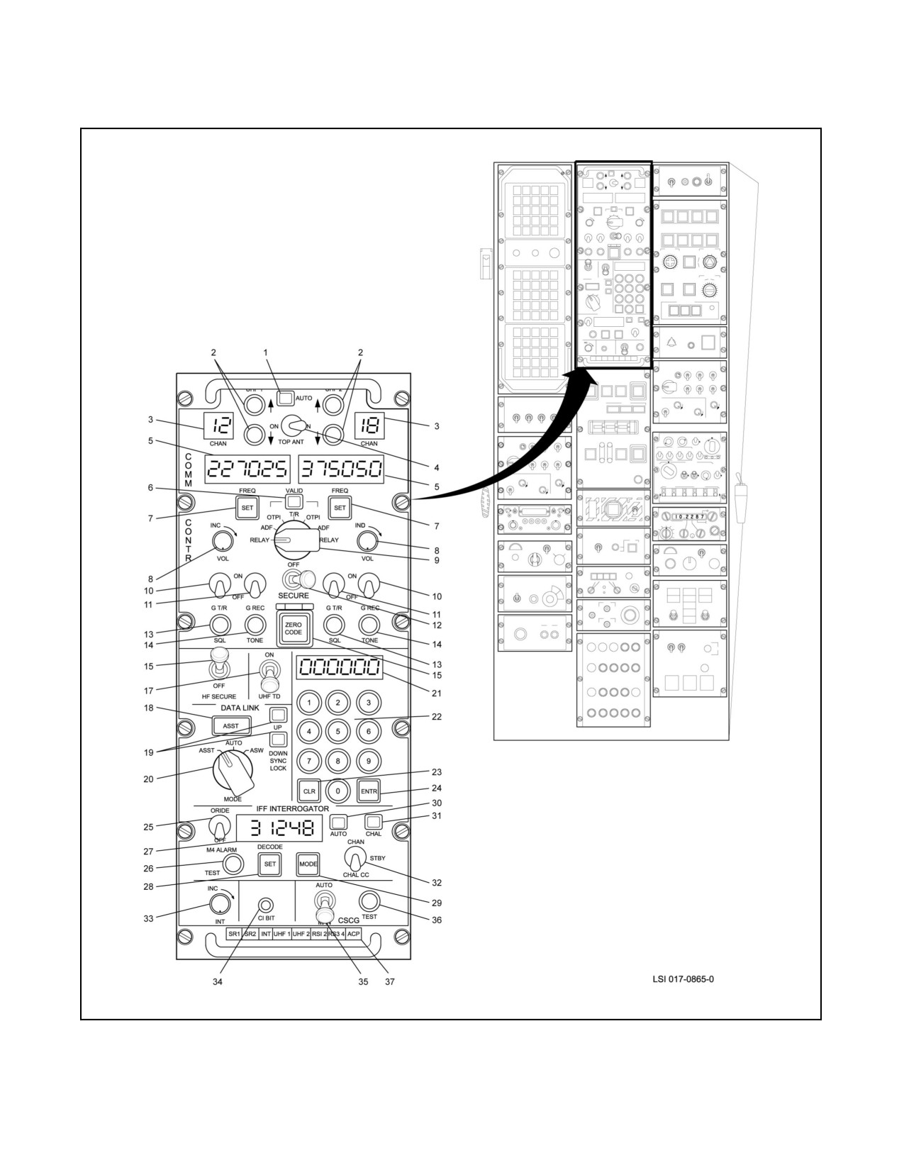
A1-H60BB-NFM-000
Figure 15-1. Communications Control Panel (BuNo through 162990) (Sheet 1 of 5)
ORIGINAL
15-4
A1-H60BB-NFM-000
INDEX
NUMBER
CONTROL LABELS
FUNCTIONAL DESCRIPTION
COMM CONTR
The communications control panel allows manual or computer control of
the communications subsystem.
1
AUTO
Indicates software control of CSCG functions. Not currently implemented
in the SH-60B.
2
UHF-1, UHF 2
Four pushbutton switches, two switches for each UHF/VHF radio. Upper
(Channel
switch increases channel number by one for each actuation; lower switch
Select-up/down)
decreases the channel number by one for each actuation.
3
CHAN
Channel, two-digit, numeric display indicating UHF or OTPI channel being
used. Two displays, one for UHF-1 and one for UHF-2. Displays 00 to 20
for normal UHF; 01 to 31 for OTPI. Channel selection accomplished by
operating UHF-1, UHF-2 pushbuttons. If G T/R is selected, CHAN is
blanked.
4
TOP ANT
Top antenna, two-position, left-right toggle switch.
ON (Right)
UHF-2 assigned to top antenna; UHF-1 to bottom antenna.
ON (Left)
UHF-1 assigned to top antenna; UHF-2 to bottom antenna.
5
FREQ
Two, six-digit, numeric displays, one for UHF-1 and one for UHF-2.
Indicates active frequency corresponding to channel selected, frequency
spans 225.000 to 399.975 MHz in 25 kHz steps. 243.000 MHz displayed,
if G T/R ON is selected. Not affected by OTPI selection.
6
VALID
Two-position, magnetic flag indicator which indicates OTPI strength.
Black
Data not valid. Indicates weak OTPI signal.
Green
Data valid. Indicates OTPI is receiving signal of sufficient strength to
provide reliable pointing.
Red/White
Indicates control indicator switch settings conflict.
7
SET
Two white-illuminated momentary pushbutton switches, one for each
UHF/VHF radio. Used to change the frequency of the selected channel.
8
VOL
Volume, 12 position rotary switch.
INC
Increase, clockwise rotation increases audio output (30 db range). Two
switches, one for each UHF radio. Inoperative while in secure voice.
9
Mode selector switch
Seven-position rotary switch selects UHF-1 and UHF-2 radio modes.
RELAY
Receipt/retransmission, reception on one UHF radio will automatically key
and modulate the other radio. (Frequencies must be at least 50 MHz apart
for BuNos prior to 162106 and at least 10 MHz apart for BuNo 162106
and subsequent.)
ADF
Automatic direction finding mode on the selected UHF/VHF radio.
OTPI
On-top position indicator (OTPI) is activated. OTP channel is displayed in
the corresponding UHF CHAN display.
T/R
Both radios in transmit/receive mode (normal position).
10
G T/R
Guard transmit/receive two-position toggle. Two switches, one for each
UHF radio.
OFF
UHF radio is tuned by normal channel selection.
ON
Respective UHF radio is automatically tuned (main receiver and
transmitter) to guard frequency (243.000 MHz) and clear voice. Overrides
all other UHF modes including secure voice, OTPI, ADF, RELAY, and
sonobuoy commands.
Figure 15-1. Communications Control Panel (BuNo through 162990) (Sheet 2)
15-5
ORIGINAL
A1-H60BB-NFM-000
INDEX
NUMBER
CONTROL LABELS
FUNCTIONAL DESCRIPTION
11
G REC
Guard receiver, two-position toggle switch. Two switches, one for each
UHF radio.
OFF
Allows monitoring of main receiver only.
ON
Allows simultaneous monitoring of main and auxiliary guard receivers.
12
SECURE
Three-position, lever-lock, left-right throw, center-off toggle switch.
ON (left)
Secure voice operation of UHF-1 radio. Inhibits plain reception.
ON (right)
Secure voice operation of UHF-2 radio. Inhibits plain reception.
13
SQL
Squelch, alternate action, non-illuminated pushbutton switch. Successive
depression causes release to inactivated state. Two switches, one for
each UHF radio.
14
TONE
Tone, momentary, non-illuminated pushbutton switch. Commands UHF
radio to transmit 1020 Hz audio tone for the duration of the depression.
Two switches, one for each UHF radio.
15
ZERO CODE
Pushbutton with spring-loaded guard, illuminated when activated. Used to
zeroize HF and UHF Speech Security Equipment.
16
HF SECURE/ON
Two-position, lever-lock toggle switch. Locked in ON position, all HF
transmissions are encrypted, reception can be either plain or secure. The
ARC-182 VHF Radio, installed in ESP Mod Aircraft as an aftermarket kit,
is inoperable with this switch in the ON position.
17
UHF TD/ON
UHF Time Delay, two-position, lever-lock toggle switch. Commands KY-58
to insert a time delay prior to transmission or retransmission of UHF
signals.
18
Magnetic Flag
When data link mode selector switch is in AUTO, indicator is driven by
data bus software. Two-position, magnetically actuated flag annunciator,
edge light illuminated.
ASW
Data link is in ASW mode. Acoustic data and ESM is downlinked.
ASST
Data link is in ASST mode. RADAR data and ESM is downlinked.
19
SYNC LOCK
Synchronization locked, two-position flag annunciator. Red color indicates
sync loss. Green indicates sync lock.
Note
Sync Lock does not indicate valid data transfer or proper crypto
keying.
UP
Data link RF signal from ship to helicopter.
DOWN
Data link RF signal from helicopter to ship.
20
MODE
Data link mode selector three-position rotary switch (intended for
maintenance/troubleshooting).
AUTO
Enables data bus control of data link ASST/ASW mode.
ASST
Commands data link operation in ASST mode, link channel 01.
ASW
Commands data link operation in ASW mode, link channel 01.
21
Display
Six-digit numeric display. Used for setting UHF/VHF channel frequency
and IFF Interrogator code. As number is keyed, it appears in the right
display position. Subsequent keyings cause selected digits to shift to the
left.
Figure 15-1.
Communications Control Panel (BuNo through 162990) (Sheet 3)
ORIGINAL
15-6
A1-H60BB-NFM-000
INDEX
NUMBER
CONTROL LABELS
FUNCTIONAL DESCRIPTION
22
0,1,2,3,4,5,6,7,8,9
Numeric keyboard, 10 momentary pushbuttons. Proper number of digits
Keyboard
MUST be entered (i.e., 6 for UHF, 2 or 4 for IFF).
23
CLR
Clear momentary pushbutton, clears display of any selected series of
digits so that a new series of digits can be selected. Set must be pressed
again to reenter.
24
ENTR
Enter momentary pushbutton, enters displayed frequency or code into
system, display returns to an all blank state.
25
M4 ALARM
Mode 4 Alarm two-position toggle switch.
ORIDE
Override, IFF interrogator computer overrides the Mode 4 (M4) alarm and
allows the ATO to force a challenge. Using this feature may compromise
the M4 code.
26
TEST
Momentary, non-illuminated pushbutton switch commands a
transponder/interrogator loop test. Transponder must be in NORMAL.
27
DECODE
Six-digit numeric display. The four digits on the left display interrogator
code. Two characters on the right display IFF mode (1,2,3,4a, and 4b),
set via sequential pushes of the MODE pushbutton. In M4 all digits in the
left display area are blanked.
28
SET
White-illuminated, momentary pushbutton switch, allows changing of code
by the keyboard display.
29
MODE
White-illuminated, momentary pushbutton switch, causes the IFF mode
and code to advance.
30
AUTO
Two-position, magnetic status flag annunciator IFF control modes.
GREEN
IFF interrogator is being controlled by software.
BLACK
IFF interrogator is being controlled manually by the CSCG panel.
31
CHAL
Three-position, magnetic status flag annunciator, indicates interrogator
status when CHAL switch is activated.
GREEN
CHAL switch activated signals being transmitted from the interrogator.
BLACK
CHAL switch released.
RED
CHAL switch activated, interrogator ‘no go’ is received by the CSCG ACP
indicating challenge may be unsuccessful. ORIDE activation may change
the flag to green. If the annunciator remains red after ORIDE activation,
M4 challenges are disabled.
32
Challenge Switch
Three-position toggle switch momentary in up-and-down positions.
Causes interrogator to transmit an interrogation with the mode of
interrogation determined by the mode display setting.
CHAL
Challenge, momentary up position. ACP sends a challenge-enable
command to the Interrogator to accept a correct mode reply. Correct
mode replies will display a single bar. Correct mode and code will display
a double bar.
STBY
Standby, normal inactive position.
CHAL CC
Challenge correct code momentary down position. ACP sends a challenge
command which enables interrogator to accept only a correct code and
mode reply. A double bar will be displayed.
Figure 15-1. Communications Control Panel (BuNo through 162990) (Sheet 4)
15-7
ORIGINAL
A1-H60BB-NFM-000
INDEX
NUMBER
CONTROL LABELS
FUNCTIONAL DESCRIPTION
33
INT
Intensity, 10 position variable potentiometer.
INC
Increase, clockwise rotation increases luminous intensity of all COMM
CONTROL numeric displays from minimum intensity upward. Full
counterclockwise position is a LAMP test. All ‘8s will be displayed and all
fault lights except ACP.
34
CI BIT
Control indicator built-in test black and white magnetic flag annunciator.
White indicates that the COMM CONTR panel has failed.
35
CSCG
Communications system control group ACP two-position, lever-lock,
toggle switch.
MAN
Manual, COMM CONTR panel controls CSCG units.
AUTO
Automatic, COMM CONTR functions are controlled by software, via data
bus interface.
36
TEST
CSCG self-test momentary, non-illuminated pushbutton switch. Pressing of
button starts an interruptive self-test only when AUTO/MAN switch is in
MAN position. TEST is aborted if the TEST button is pressed again. In
AUTO, TEST may be initiated through software.
37
Status Annunciators
Eight yellow-illuminated annunciators that display non-availability of
CSCG and other units. Illuminates when equipment is not available
because of failure or power off. Lack of coding of security equipment
controlled by CSCG (KY-58) will cause the ACP annunciator to illuminate.
The annunciator legends in left to right sequence are defined as follows:
SR1
Sonobuoy receiver, NO. 1.
SR2
Sonobuoy receiver, NO. 2.
INT
IFF interrogator.
UHF 1
UHF, NO. 1 radio.
UHF 2
UHF, NO. 2 radio.
RS1 2
Pilot and ATO Radio panels.
RS3 4
SO and observer Radio panels.
ACP
Audio converter-processor (light is not tested when Lamp Test is selected
but tested when CSCG TEST is initiated).
Figure 15-1. Communications Control Panel (BuNo through 162990) (Sheet 5)
ORIGINAL
15-8
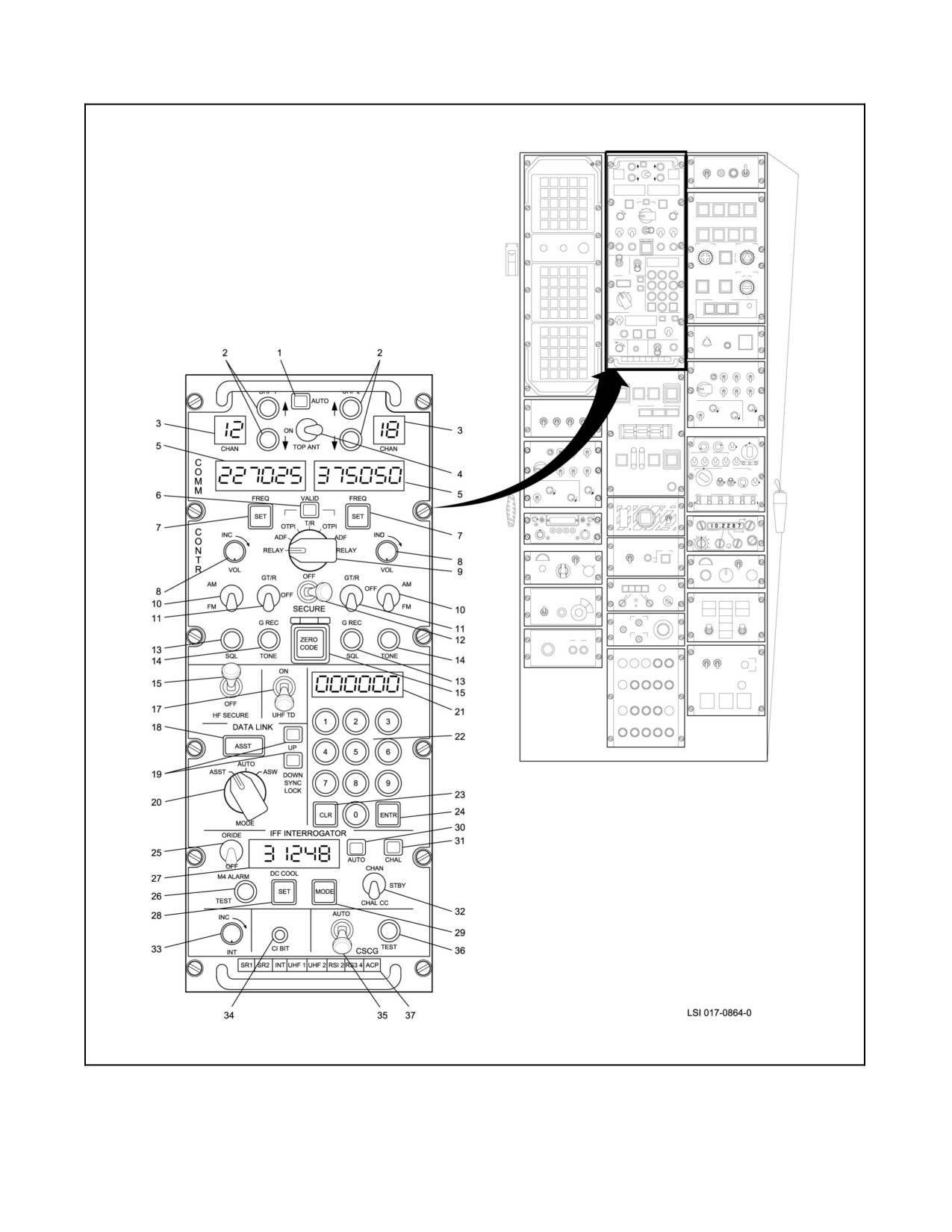
A1-H60BB-NFM-000
Figure 15-2. Communications Control Panel (BuNo 162991 and Subsequent) (Sheet 1 of 6)
15-9
ORIGINAL
A1-H60BB-NFM-000
INDEX
NUMBER
CONTROL LABELS
FUNCTIONAL DESCRIPTION
COMM CONTR
The communications control panel allows manual or computer control of
the communications subsystem.
1
AUTO
Indicates software control of CSCG functions. Not currently implemented
in the SH-60B.
2
UHF-1, UHF-2
Four pushbutton switches, two switches for each UHF/VHF radio. Upper
(Channel
switch increases channel number by one for each actuation; lower switch
Select-up/down)
decreases the channel number by one for each actuation.
3
CHAN
Channel, two-digit, numeric display indicating UHF, VHF, or OTPI channel
being used. Two displays, one for UHF-1 and one for UHF-2. Displays 00
to 20 for normal UHF/VHF; 01 to 31 for OTPI. Channel selection
accomplished by operating UHF-1, UHF-2 pushbuttons. If G T/R is
selected, CHAN is blanked.
4
TOP ANT
Top antenna, two-position, left-right toggle switch.
ON (Right)
UHF-2 assigned to top antenna; UHF-1 to bottom antenna. (Except when
in OTPI or ADF modes.)
ON (Left)
UHF-1 assigned to top antenna; UHF-2 to bottom antenna. (Except when in
OTPI, ADF, or BACKUP modes.)
5
FREQ
Two, six-digit, numeric displays, one for UHF-1 and one for UHF-2. Indicates
active frequency corresponding to channel selected, frequency spans of
30.000 to 87.975 MHz FM, 108.000 to 155.975 MHz AM, 156.000 to
173.975 MHz FM, and 225.000 to 399.975 MHz AM/FM in 25 kHz steps. If
G T/R ON is selected, the display will indicate the guard frequency of the
frequency band in operation. Not affected by OTPI selection.
6
VALID
Two-position, magnetic flag indicator that indicates OTPI strength.
Black
Data not valid. Indicates weak OTPI signal.
Green
Data valid. Indicates OTPI is receiving signal of sufficient strength to
provide reliable pointing.
Red/White
Indicates control indicator switch settings conflict.
7
SET
Two white-illuminated momentary pushbutton switches, one for each
UHF/VHF radio. Used to change the frequency of the selected channel.
8
VOL
Volume, 12-position rotary switch.
INC
Increase, clockwise rotation increases audio output (30 db range). Two
switches, one for each UHF radio. Inoperative while in secure voice.
9
Mode selector switch
Seven-position rotary switch selects UHF-1 and UHF-2 radio modes. For
software versions THP-20 and subsequent, OTPI operation is
accomplished by rotating the Mode Selector Switch to OTPI and tuning
the desired sonobuoy using the TUNE OTPI pushbuttons on the ATO
keyset. For this configuration, the OTPI channel displayed in the UHF
CHAN display does not correspond to the sonobuoy tuned on the MPD.
RELAY
Receipt/retransmission, reception on one UHF/VHF radio will automatically
key and modulate the other radio (Note 1).
Figure 15-2. Communications Control Panel (BuNo 162991 and Subsequent) (Sheet 2)
ORIGINAL
15-10
A1-H60BB-NFM-000
INDEX
NUMBER
CONTROL LABELS
FUNCTIONAL DESCRIPTION
ADF
Automatic direction finding mode, in the UHF band, on the selected
UHF/VHF radio.
OTPI
On-top position indicator (OTPI) is activated. OTPI channel is displayed in
the corresponding UHF CHAN display.
T/R
Both radios in transmit/receive mode (normal position).
10
AM/FM
Two-position toggle switch. For the UHF-band (225.000 to 399.975 MHz)
only. FM mode will be selected in the lower position. AM mode will be
selected in the upper position. One toggle switch each is provided for
UHF-1 and UHF-2.
11
G T/R-OFF-G REC
Three position toggle switch. In the lower position, G REC, it will allow
monitoring of the main and guard receiver outputs. In the upper position (G
T/R), the radio unit will be automatically tuned (main receiver and transmitter)
to the guard frequency of the band in operation and the clear voice. It
overrides all other modes including secure voice, OTPI, ADF, Relay, and
sonobuoy commands. In the center position, OFF, the radio shall be tuned
by channel selection for the voice mode and allow monitoring of the main
receiver only. One toggle switch each is provided for UHF-1 and UHF-2.
12
SECURE
Three-position, lever-lock, left-right throw, center-off toggle switch.
ON (left)
Secure voice operation of UHF-1 radio.
ON (right)
Secure voice operation of UHF-2 radio.
13
SQL
Squelch, alternate action, pushbutton switch. Enables/disables radio
squelch circuits. Two switches, one each for UHF-1 and UHF-2.
14
TONE
Tone, momentary, non-illuminated pushbutton switch. Commands
UHF/VHF radio to transmit 1020 Hz audio tone for the duration of the
depression. Two switches, one for each UHF/VHF radio. UHF-1 TONE
pushbutton is hardwired to allow operation in case of failure of the ACP
and/or the backup radio control.
15
ZERO CODE
Pushbutton with spring-loaded guard, illuminated when activated. Used to
zeroize HF and UHF/VHF speech security equipment.
16
HF SECURE/ON
Two-position, lever-lock toggle switch. Locked in ON position. All HF
transmissions are encrypted; reception can be either plain or secure. These
HF secure toggle switches are inoperative on aircraft with ANDVT
incorporated.
17
UHF TD/ON
UHF/VHF Tone Delay, two-position, lever-lock toggle switch (Note 2).
Commands KY-58 to insert a time delay prior to transmission or
retransmission of UHF/VHF signals.
18
Magnetic Flag
When data link mode selector switch is in AUTO, indicator is driven by data
bus software. Two-position, magnetically actuated flag annunciator, edge light
illuminated.
ASW
Data link is in ASW mode. Acoustic data and ESM is downlinked.
ASST
Data link is in ASST mode. RADAR data and ESM is downlinked.
Figure 15-2. Communications Control Panel (BuNo 162991 and Subsequent) (Sheet 3)
15-11
ORIGINAL
A1-H60BB-NFM-000
INDEX
NUMBER
CONTROL LABELS
FUNCTIONAL DESCRIPTION
19
SYNC LOCK
Synchronization locked, two-position flag annunciator. Red color indicates
sync loss. Green indicates sync lock.
Note
Sync Lock does not indicate valid data transfer of proper crypto
keying.
UP
Data link RF signal from ship to helicopter.
DOWN
Data link RF signal from helicopter to ship.
20
MODE
Data link mode selector three-position rotary switch (intended for
maintenance/troubleshooting).
AUTO
Enables data bus control of data link ASST/ASW mode.
ASST
Commands data link operation in ASST mode, link channel 01.
ASW
Commands data link operation in ASW mode, link channel 01.
21
Display
Six-digit numeric display. Used for setting UHF/VHF channel frequency
and IFF Interrogator code. As number is keyed, it appears in the right
display position. Subsequent keyings cause selected digits to shift to the
left.
22
0,1,2,3,4,5,6,7,8,9
Numeric keyboard, 10 momentary pushbuttons. Proper number of digits
keyboard
(leading and trailing 0s) MUST be entered (i.e., 6 digits for UHF, 6 for
VHF, and 2 or 4 for IFF. (Note: Leading and trailing 0s are required)).
23
CLR
Clear momentary pushbutton, clears display of any selected series of
digits so that a new series of digits can be selected.
24
ENTR
Enter momentary pushbutton, enters displayed frequency or code into
system, display returns to an all blank state.
25
M4 ALARM
Mode 4 Alarm two-position toggle switch.
ORIDE
Override, IFF interrogator computer overrides the Mode 4 (M4) alarm and
allows the ATO to force a challenge. Using this feature may compromise the
M4 code.
26
TEST
Momentary, non-illuminated pushbutton switch commands a
transponder/interrogator loop test. Transponder must be in NORMAL.
Interrogator challenges Mode 3, Code 0000.
27
DECODE
Six-digit numeric display. The four digits on the left display interrogator
code. Two characters on the right display IFF mode (1,2,3,4a, and 4b),
set via sequential pushes of the MODE pushbutton. In M4 all digits in the
left display area are blanked.
28
SET
White-illuminated, momentary pushbutton switch, allows changing of code
by the keyboard display.
29
MODE
White-illuminated, momentary pushbutton switch, causes the IFF mode
and code to advance.
30
AUTO
Two-position, magnetic status flag annunciator IFF control modes.
GREEN
IFF interrogator is being controlled by software.
BLACK
IFF interrogator is being controlled manually by the CSCG panel.
Figure 15-2.
Communications Control Panel (BuNo 162991 and Subsequent) (Sheet 4)
ORIGINAL
15-12
A1-H60BB-NFM-000
INDEX
NUMBER
CONTROL LABELS
FUNCTIONAL DESCRIPTION
31
CHAL
Three-position, magnetic status flag annunciator, indicates interrogator status
when CHAL switch is activated.
GREEN
CHAL switch activated signals being transmitted from the interrogator.
BLACK
CHAL switch released.
RED
CHAL switch activated, interrogator ‘no go’ is received by the CSCG ACP,
indicating challenge may be unsuccessful. ORIDE activation may change
the flag to green. If the annunciator remains red after ORIDE activation,
M4 challenges are disabled.
32
Challenge Switch
Three-position toggle switch momentary in up-and-down positions.
Causes interrogator to transmit an interrogation with the mode of
interrogation determined by the mode display setting.
CHAL
Challenge, momentary up position. ACP sends a challenge-enable
command to the interrogator to accept a correct mode reply. Correct
mode replies will display a single bar. Correct mode and code will display
a double bar.
STBY
Standby, normal inactive position.
CHAL CC
Challenge correct code momentary down position. ACP sends a challenge
command which enables interrogator to accept only a correct code and
mode reply. A double bar will be displayed.
33
INT
Intensity, 10 position variable potentiometer.
INC
Increase, clockwise rotation increases luminous intensity of all COMM
CONTROL numeric displays from minimum intensity upward. Full
counterclockwise position is a LAMP test. All ‘8s will be displayed and all
fault lights except ACP.
34
CI BIT
Control indicator built-in test black and white magnetic flag annunciator.
White indicates that the COMM CONTR panel has failed.
35
CSCG
Communications system control group ACP two-position, lever-lock,
toggle switch.
MAN
Manual, COMM CONTR panel controls CSCG units.
AUTO
Automatic, COMM CONTR functions are controlled by software, via data
bus interface.
36
TEST
CSCG self-test momentary, non-illuminated pushbutton switch. Pressing of
button starts an interruptive self-test only when AUTO/MAN switch is in MAN
position and the remote switching controls are not in the CALL mode. TEST
is aborted if the TEST button is pressed again. In AUTO, TEST may be
initiated through software.
Figure 15-2.
Communications Control Panel (BuNo 162991 and Subsequent) (Sheet 5)
15-13
ORIGINAL
A1-H60BB-NFM-000
INDEX
NUMBER
CONTROL LABELS
FUNCTIONAL DESCRIPTION
37
Status Annunciators
Eight yellow-illuminated annunciators that display non-availability of CSCG
and other units. Illuminates when equipment is not available because of
failure or power off. Lack of coding of security equipment controlled by
CSCG (KY-58 and KYV-5) will cause the ACP annunciator to illuminate. The
annunciator legends in left to right sequence are defined as follows:
SR1
Sonobuoy receiver, NO. 1.
SR2
Sonobuoy receiver, NO. 2.
INT
IFF interrogator.
UHF 1
UHF, NO. 1 radio.
UHF 2
UHF, NO. 2 radio.
RS1 2
Pilot and ATO RADIO panels.
RS3 4
SO and observer RADIO panels.
ACP
Audio converter-processor (light is not tested when Lamp Test is selected but
tested when CSCG TEST is initiated).
Notes:
1. Avoid relay frequency separations of less than 10 MHz, frequency separations of multiples of 29 MHz,
UHF relays below 265 MHz, and VHF to VHF relays.
2. A delay will occur regardless of the UHF TD switch position on the COMM CONTR panel if the KY-58
delay is selected on (switch external on KY-58).
Figure 15-2. Communications Control Panel (BuNo 162991 and Subsequent) (Sheet 6)
15.1.3 Radio Control Panels
The four radio control panels (Figure 15-3) allow crewmembers to control the audio received at and transmitted from
theirstation.PowerissuppliedbytheNO. 1ACprimary andAC essentialbuses forthepilotand ATOfrom thecenter
circuit breaker panel, through two circuit breakers marked AUDIO and CONV PROCR AUDIO respectively, and
by115Vac,1phasefortheSOandobserverthroughacircuitbreakermarkedCOMMSWGlocated ontheSOconsole
avionics rack circuit breaker panel. These panels are also referred to as RSCs.
Note
The audio channels to be recorded on the FLIR VCR are controlled by the
switches on the radio control panels (SO or instructor) to which the VCR audio
input is connected.
15.1.4 Hoist Operator and Maintenance IBs
The IBs allow maintenance personnel and hoist operators to patch into the aircraft ICS. The ICS is powered by the CSCG
(see paragraph 15.1.1). The boxes contain volume controls and a push--to--talk switch. The ACP directs audio to and from
the IBs. The maintenance IB is located in the external ICS/ARM access cavity above the left mainmount.
15.1.5 Radios
15.1.5.1 UHF Radios, AN/ARC-159
Note
ARC--159 UHF radio sets are installed in aircraft BuNos through 162990.
ARC--182 UHF/VHF radio sets (refer to paragraph 15.1.5.2) are installed
in aircraft BuNo 162991 and subsequent.
ORIGINAL
15-14
A1-H60BB-NFM-000
1
2
3
4
RADIO
BIT
UHF--1
UHF--2
DIL
REC
REC
6
OFF
OFF
XMTR SEL
7
D/L
UHF--2
HF
UHF
UHF--1
8
BKUP
HF
SONO
TACAN
OFF
REC
REC
OFF
OFF
5
ICS
VOL
VOL
MIC MODE
INC
INC
NET
VOX
CONF
INC
NORM
CALL
PTT
9
12
11
10
LSI 017--0857--0
Figure 15-3. Radio Control Panel (Sheet 1 of 2)
15-15
ORIGINAL
A1-H60BB-NFM-000
INDEX
CONTROL
NUMBER
LABELS
FUNCTIONAL DESCRIPTION
RADIO
Allows independent selection of receivers while restricting transmission
selection to one. The OFF position disables audio of selected radio.
1
BIT
Magnetically actuated flag BIT indicator.
BLACK
Go.
WHITE
No go, indicates failure in control box.
2
UHF-1/REC
UHF-1 radio two-position toggle. Receiver, permits monitoring UHF-1
audio.
3
UHF-2/REC
UHF-2 radio two-position toggle. Receive, permits monitoring UHF-2
audio.
4
D/L/REC
Data link (D/L) two-position toggle. Receive, permits monitoring of D/L
secure audio.
5
XMTR SEL
Transmitter select six-position rotary switch selects radio transmission
mode.
UHF-1
UHF-1 radio transmission and reception.
UHF-2
UHF-2 radio transmission and reception.
D/L
D/L voice transmission and reception.
H/F
High frequency radio transmission and reception.
UHF BKUP
UHF or UHF/VHF radio backup (not available to SO or OBS stations).
6
HF/REC
High frequency radio two-position toggle. Receive, permits monitoring
HF.
7
SONO/REC
Sonobuoy two-position toggle. Receive, permits monitoring of
sonobuoy receiver audio.
8
TACAN/REC
TACAN two-position toggle. Receive, permits monitoring of TACAN
identifier tone.
ICS
Intercommunications System.
9
NET
Intercommunications system net, three-position toggle switch.
Establishes intercom net.
CONF
Conference, connects pilot and ATO positions for cockpit RADIO
panels and connects SO and observer positions for cabin RADIO
panels.
NORM
Normal, connects originator station to all other stations set to NORM
and to the hoist operator and groundcrew ICS boxes.
CALL
Connects originator station to all other crew positions, overrides CONF
selection at any RADIO panel. In an emergency (COMM CONTR or
ACP power failure), provides backup communications to all stations.
10
VOL
Volume, 12-position rotary switch. Volume control for radio audio at
headset.
11
MIC MODE
Microphone mode control.
VOX
Voice-operated transmission 12-position rotary switch.
INC
Establishes audio threshold which must be exceeded by the
crewmember microphone signal before microphone signal is
transmitted to other crewmembers. Clockwise rotation increases
threshold.
PTT
Push-to-talk when control is in this position. Switch must be actuated
for ICS voice transmission.
12
VOL
Volume, twelve-position rotary switch. Volume control for intercom
audio at headset.
Figure 15-3. Radio Control Panel (Sheet 2)
ORIGINAL
15-16
A1-H60BB-NFM-000
The two sets, designated as UHF--1 and UHF--2, can be tuned to any of 7,000 communication frequencies. Each
transceiver is provided with a separate guard receiver that will receive voice transmissions on the standard emergency
frequency of 243.0 MHz. The UHF transceivers have a line--of--sight range. Line--of--sight range in nautical miles
to a spot on thesurface ofthe Earth may beestimated by multiplying 1.23 times thesquare root of thealtitude in feet.
Derivation of this formula is left to the reader. Ranges will be greater for any elevation of the other station.
Power for UHF--1 receiver/transmitter is supplied from the DC essential bus through a circuit breaker on the cockpit
overhead circuit breaker panel, marked RADIO NO. 1 R/T UHF. Power for UHF--2 receiver/transmitter is supplied
from the NO. 2 DC primary bus through a circuit breaker marked RADIO NO. 2 R/T UHF on the SO circuit breaker
panel.
In the event of COMM CONTR failure, UHF--1 may be used by the pilot by selecting backup on the RSC and can
be controlled from the backup UHF radio control panel. UHF--2 may be used by the ATO for guard communications
only by selecting UHF backup on the RSC. If the ACP fails, the pilot will automatically be connected to UHF--1.
The ATO will automatically be connected to UHF--2, preset to Guard T/R. Internal communications between all
aircrew may be made by selecting CALL on the RSC (foot or cyclic switch) or by using the CALL pushbutton switch
on the cyclic for the pilots and the floor switch for the SO. Pilots only can also talk to each other externally over
GUARD. If the AC power fails, the pilot will automatically be connected to UHF--1 via the backup UHF radio control
panel. In this case, the ATO will have no internal or external communication capability. CSCG/ACP failure modes
are covered in Figure 15-4.
Up to 20 channels (1 to 20)can bepreset fordirect tuning by channel selection on either radio. An additional channel
(00) is available for independent frequency selection on either radio. Once channels are preset, the preset frequencies
remain stored after power is removed from the unit.
The two UHF radios can be used to relay secure or clear voice UHF communication between two stations. Secure
data link cannot be relayed. If secure--voice relay transmissions or monitoring by the flightcrew are required, the
SECURE switch on the COMM CONTR panel must be in either ON position. A correctly keyed appropriate
wideband speech security set must be installed. Secure voice relay without monitoring or transmitting capability may
be conducted without a wideband security set installed. The system will allow simultaneous clear and secure transmissions
by the flightcrew. The selected UHF radio may be used by the flightcrew in secure voice while the other radio will be
available in clear voice mode.
Note
The KY--58 will not pass guard relay or transmission.
There are two UHF antennas on the helicopter. Using a switch on the panel, the operator may select either UHF--1
or UHF--2 to operate with the top antenna. The otheris selected automatically to use thebottom antenna. In theevent
of communication difficulty using the top antenna, the operator may attempt to correct the problem by switching the
communicating unit to the bottom antenna.
The data handling system automatically selects whichever UHF radio is connected to the bottom antenna for
command activated sonobuoy command transmission. To provide this capability, the CSCG must be in AUTO and
the UHF connected to the bottom antenna must not be in SECURE, G T/R, or UHF BKUP. The data handling system
will momentarily cancel the ADF mode, relay mode, or T/R UHF transmissions in order to send its sonobuoy
commands.
15.1.5.1.1 UHF Backup
In the event of COMM CONTR panel failure, the UHF--1 radio can be operated directly from the backup UHF radio
control panel (Figure 15-5). Place the XMTR SEL switch on the pilot radio control panel (Figure 15-3) to the UHF
BKUP position.
15-17
ORIGINAL
A1-H60BB-NFM-000
OPERATIONAL CAPABILITY
MODE
UHF-1
UHF-2
ADF
OTPI
DL
IFF
ICS
Pilot RSC BKUP
Pilot control via
ATO — Full
UHF-2 only
Yes
Yes
Yes
Yes
selected
backup control
control SO &
(Note 9)
(Notes 1, 3)
panel, bottom
OBS-T/R control
ANT
ATO RSC BKUP
Pilot — Full
ATO — Guard
UHF-1 only
Yes
Yes
Yes
Yes
selected
control SO and
T/R fixed volume
(Notes 1, 4)
OBS-T/R control
TOP ANT
Loss of ACP PRI
Pilot control via
ATO — Guard
No
No
No
No
Call only
PWR (NO. 1 AC
backup control
T/R fixed volume
PRI BUS) (Notes
panel, bottom
TOP ANT
2, 5)
ANT
Loss of ACP/CI
Bottom ANT only
TOP ANT only
No
Yes
Yes
Yes
Yes
DC PWR (NO. 2
DC PRI BUS)
(Note 6)
Loss of UHF R/T
No
Yes
UHF-2 only
Yes
Yes
Yes
Yes
PWR (DC ESS
BUS) (Note 7)
(NO. 2 DC PRI
Yes
No
UHF-1 only
Yes
Yes
Yes
Yes
BUS) (Note 8)
Notes:
1. Selection of UHF BKUP mode on RSC precludes all other transmit control functions.
2. BKUP mode must be selected on RSC.
3. UHF-1 FREQ and CHAN display blanks, UHF or UHF/VHF backup control energizes.
4. UHF-2 FREQ and CHAN display blanks.
5. CI panel blanks, call function powered via AC ESS BUS.
6. No CI ‘Zero Code’ function.
7. Zeros on UHF-1 FREQ display for DC ESS BUS.
8. Zeros on UHF-2 FREQ display for DC PRI BUS.
9. If the CSCG ICS function is completely lost, crew intercom can be achieved by using UHF or UHF/VHF
radio side tones. All stations must select the same UHF transmit function on RSC and then use radio
PTT switch for intercom.
Figure 15-4. CSCG Failure Matrix
15.1.5.2 UHF/VHF Radios, AN/ARC-182
The AN/ARC--182 UHF/VHF transceivers operate in the following frequency ranges: from 30.000 through
87.975 MHz FM, 108.000 through 117.975 MHz AM (receive only, VOR), 118.000 through 155.975 MHz AM,
156.000 through 173.975 MHz FM, and 225.000 to 399.975 MHz AM/FM (FM for data transmissions or limited
voice). Figure 15-6 illustrates these operating ranges and guard frequencies.
Note
UHF/VHF transmitter power reduction, down to 2 watts, may occur with high
radio temperatures or if the transmitter is keyed continuously for longer than
1 m inute.
ORIGINAL
15-18
A1-H60BB-NFM-000
Note
ARC--182 UHF/VHF radio sets are installed on BuNo 162991 and
subsequent aircraft. For aircraft equipped with ARC--159 radio sets, refer
to paragraph 15.1.5.1.
In addition, each unit is provided with a separate guard receiver that will receive voice transmissions on the standard
emergency frequency corresponding to each frequency band; that is, 40.5 MHz, 121.5 MHz, 156.8 MHz, and
243.0 MHz. If G T/R is on, the ARC--182 radio set will tune the guard frequency of the frequency band in operation.
The UHF/VHF transceivers have a line--of--sight range.
A minimum of propagation problems will be experienced if the receiver/transmitter is used as follows: 30 to 87.975 MHz
band for close in, air--to--ground communications up to 60 miles distance; 108 to 155.975 MHz band for air traffic control
up to 120 miles from the ground station; 155.975 to 173.975 MHz maritime band for communications up to 120 miles
from the ground station; and 225 to 399.975 MHz band for communications up to 120 miles from the ground station.
Distances up to 300 miles may be achieved in air--to--air communications with frequencies above 117.975 MHz.
External sources of RF may interfere with ARC--182 operations. In addition, the receiver/transmitter may cause
interference with the installed mission equipment.
Operations within 5 nm of commercial radio and TV broadcast stations can
cause white noise or music interference, which degrades radio reception in the
30.0
to
173.975 MHz frequency bands. Interference from commercial
broadcast stations can suddenly render two--way radio communications in the
VHF--AM aviation band (108.0 to 155.975 MHz) completely unusable,
causing loss of two--way radio communications. During actual IMC
approaches, pilots shall use UHF--AM frequencies to the maximum extent
practical for primary or backup communications with ground controlling
agencies.
Note
Low VHF band reception can be improved by deselecting guard (G REC —
OFF). This helps eliminate undesired signals from the guard receiver being
mixed with desired signals from the main receiver.
ADF and OTPI interference will be characterized by false or erroneous bearing indications or needle fluctuations.
Active sonobuoy interference will be characterized by display zone noise up to and including complete obliteration
of target return. Observe the following frequency separations for optimum performance:
1. ADF — 10 MHz separation.
2. OTPI and active sonobuoy radio frequencies — 5 MHz separation.
a. Sonobuoy radio frequencies can be found in the ASW Tactical Pocket Guide (NTTP 3--22.5--ASW).
Note
Upper antenna utilization, for communications, is recommended while using
the OTPI.
15-19
ORIGINAL