SH-60B HELICOPTER. FLIGHT MANUAL (2008) - page 8
A1-H60BB-NFM-000
PROFILE
D
At 94 percent Ng, the aircraft will be light on its
wheels. Be vigilant for signs of dynamic
rollover; maintain a centered cyclic and be
prepared to lower collective quickly. Sideward
tip path may increase possibility of dynamic
rollover.
D
The WOW switch may trigger, enabling AFCS
functions associated with flight; keep collect-
ive trim switch depressed. Emergency jettison
and fuel dump functions are enabled; keep
personnel clear of the aircraft.
D
For shipboard operations, request amber deck,
open RSD beams and slacken Main Landing
Gear chains. Ensure chains do not become taut;
dynamic instability may result.
CAUTION
D
When attempting engine crossbleed starts with
the engine intake cowling removed, a hot start
may be experienced if the bleed air plug is not
installed in the anti--ice bleed air line.
D
For a crossbleed start, the good engine should
indicate the maximum Ng safely attainable.
Donor Ng less than 94 percent may result in hot
starts.
Note
A full fuel load is recommended when conduct-
ing a crossbleed start to mitigate effects of a
high power setting on deck.
a.
Fireguard posted, area clear.
b.
AIR SOURCE ECS/START switch — ENG.
c.
APU CONTR switch — OFF.
d.
ENGINE IGNITION switch — NORM.
e.
Fuel Selectors — XFD/DIR (as required).
f.
Collective — Increase to set 94 percent Ng on operating engine.
g.
ENG — START (normal procedures apply).
h.
Collective — FULL DOWN.
ORIGINAL
10-22
A1-H60BB-NFM-000
PROFILE
i. PCL — FLY.
j. Fuel selectors — DIR.
k. Repeat steps f. to j. for opposite engine, as required.
A
9.
Windshield anti--ice operation/interlock — CHECK.
Note
APU GEN must be ON to provide AC power
for the following checks.
a. APU — START.
b. NO. 1 and NO. 2 GENERATOR switches — OFF.
c. PILOT/COPILOT WINDSHIELD ANTI--ICE switches — ON.
d. Note increase in temperature only on the pilot windshield.
e. NO. 1 or NO. 2 GENERATOR switches — ON.
f. Note increase in windshield temperature on copilot windshield
and pilot
windshield
remains heated.
Note
When windshield anti--ice is turned on, it may
take up to 60 seconds until a noticeable change
in windshield temperature can be detected.
g. PILOT/COPILOT WINDSHIELD ANTI--ICE switches — OFF.
h. NO. 1 and NO. 2 GENERATOR switches — ON.
A
10. Electrical systems — CHECK.
Power transfer from the APU generator to the
NO. 1 generator may cause disengagement of
SAS 1, SAS 2, TRIM, AUTO PLT, and
Stabilator which may cause rotors to dip as low
as 4 feet.
Note
The APU GEN must be on to ensure power is
supplied to the VIDS in the event of generator
dropoff.
a. APU — VERIFY ON.
b. APU generator — VERIFY ON.
10-23
ORIGINAL
A1-H60BB-NFM-000
PROFILE
c.
Underfrequency protection — TEST.
(1)
NO. 1 and NO. 2 PCLs — RETARD SLOWLY.
(2)
#1 GEN and #2 GEN cautions — Appear between 92 percent and 97 percent Nr. Allow
a 3--second time delay. Note Nr.
(3)
NO. 1 and NO. 2 PCLs — FLY. Note #1 GEN and #2 GEN cautions are OUT.
d.
AC system bus tie connector — TEST.
(1)
NO. 1 GENERATOR switch — OFF.
(a)
#1 GEN caution — APPEARS.
(b) #1 CONV caution — REMAINS OFF.
(c) AC ESS BUS OFF caution — REMAINS OFF.
(2)
NO. 1 GENERATOR switch — ON, #1 GEN caution OUT.
(3)
Repeat steps (1) and (2) for NO. 2 generator.
e.
DC system bus tie connector — TEST.
(1)
NO. 1 CONVERTER POWER circuit breaker (CENTER, NO. 1 AC PRI BUS, ROW
1, CB 14) — PULL.
(a) SAS 1 pushbutton — NOTE OFF, THEN RESET ON.
(b) #1 CONV caution — APPEARS.
(c) DC ESS BUS OFF caution — REMAINS OFF.
(d) COPILOT Mode selector panel lights — ON.
(2)
NO. 1 CONVERTER circuit breaker — RESET. #1 CONV caution OUT.
(3)
Repeat steps (1) and (2), pulling NO. 2 CONVERTER POWER circuit breaker
(CORNER, NO. 2 AC PRI BUS, ROW 2, CB 4). SAS 1 pushbutton should remain ON.
f.
AFCS voltage relay check.
Note
During this check, it is acceptable for some
AFCS fail advisory lights to illuminate.
(1) AC ESNTL BUS SUPPLY circuit breaker (NO. 1 AC PRI, CORNER, ROW 1,
CB 12) — PULL, pilot’s AI OFF flag should remain out of view.
(2) CMPTR PWR/RESET pushbutton — CHECK ON.
(3) AC ESNTL BUS SUPPLY circuit breaker — RESET.
A
C D
11. Flight controls — CHECK.
a. Disengage AUTO PLT, TRIM, SAS 2, and SAS 1 pushbuttons noting no jump in cyclic or
tip--path plane.
b. Engage SAS 1, SAS 2, TRIM, and AUTO PLT pushbuttons.
ORIGINAL
10-24
A1-H60BB-NFM-000
PROFILE
A B C D
12. Ground vibration analysis (tail, oil cooler, input, NSV) — AS REQUIRED.
A B C D
13. Alternate tooth wear — AS REQUIRED.
D
Be vigilant for signs of dynamic rollover;
maintain a centered cyclic and be prepared to
lower collective quickly. Sideward tip path
may increase possibility of dynamic rollover.
D
Maintain a centered cyclic equivalent to a level
tip path on level ground. Forward tip path may
allow tail wheel to become light and allow tail
wheel to slide sideways.
D
The WOW switch may trigger, enabling AFCS
functions associated with flight; keep collect-
ive trim switch depressed. Fuel Dump, Rescue
Hoist, Rescue Hoist Shear, and Cargo Hook
Shear functions are enabled; keep personnel
clear of the aircraft.
D
Tie--downs should be removed prior to pulling
torque.
Note
D
The following procedures are for shore--based
operations only. No attempt should be made to
perform these procedures aboard ship.
D
A full fuel load is recommended when conduct-
ing these procedures to mitigate the effects of
a high power setting on deck.
D
Collect ATABS data in accordance with the
A1--H60CA--VIB--100 manual.
With the NO. 1
ENG operating in FLY and NO. 2 ENG shutdown:
a. Allow 5 min for stabilization at 100 percent Nr, flat pitch.
After 5 min:
b. Collective — INCREASE TORQUE TO 75--80 percent.
c. ATABS — COLLECT DATA.
d. Collective — FULL DOWN.
e. Ignition switch — NORM.
f. NO. 2 Fuel Selector — DIR.
g. NO. 2 ENG — START.
h. NO. 2 PCL — FLY.
i. Allow 5 min for stabilization at 100 percent Nr, flat pitch.
10-25
ORIGINAL
A1-H60BB-NFM-000
PROFILE
After 5 min:
j. Collective — INCREASE TORQUE TO 35--40
percent.
k. ATABS — COLLECT DATA.
l. Collective — FULL DOWN.
m. NO. 1 ENG — SHUTDOWN.
(1) ENG IGNITION switch — OFF.
(2) NO. 1 PCL and Fuel Selector — OFF.
n. Allow 5 minutes for stabilization at 100 percent Nr, flat pitch.
After 5 min:
o. Collective — INCREASE TORQUE TO 75--80
percent.
p. ATABS — COLLECT DATA.
q. Collective — FULL DOWN.
A
C
14. Main rotor track and balance — AS REQUIRED.
CAUTION
Care must be taken when reseating struts.
Helicopter damage may occur if excessive
control inputs are made.
A B
15. Engine anti--ice system — CHECK (as required).
a. PCL (engine not being checked) — AS REQUIRED.
Failure of the ENG ANTI--ICE ON advisory to
illuminate when the ENG ANTI--ICE switch is
selected to ON, or when the Ng is below
approximately 88 percent regardless of the
switch position; or constant illumination of the
ENG ANTI--ICE ON advisory with Ng greater
than 90 percent (94 percent if OAT is 15 °C or
greater) and the ENG ANTI--ICE switch OFF
are indicative of a malfunctioning anti--ice/start
bleed valve. This condition may cause engine
flameout during low power settings such as
quick stops and autorotative flight.
Note
D Engine Anti--ice Check should be performed
into the wind on deck, in a hover over a suitable
landing pad, or in a stable, level--flight regime.
D On deck or in a hover, it may be necessary to
retard the PCL on the engine not being checked
to prevent a vertical climb.
ORIGINAL
10-26
A1-H60BB-NFM-000
PROFILE
b. ENG ANTI--ICE switch (engine being checked) — OFF.
c. Collective
— RAISE TO INCREASE Ng OF ENGINE BEING CHECKED TO
90 PERCENT OR ABOVE (94 percent or above if OAT is above 15 ºC).
d. ENG ANTI--ICE ON advisory (engine being checked) — OFF.
e. ENG ANTI--ICE switch (engine being checked) — ON.
Confirm:
(1) ECS SHUTDOWN caution (if ECS on and AIR SOURCE ECS/START
switch — ENG).
Note
ECS will not shut down if AIR SOURCE
ECS/START switch is in APU.
(2) TGT increases 30 °C to 100 °C.
(3) ENG ANTI--ICE ON advisory appears.
(4) ENG INLET ANTI--ICE ON advisory:
(a) OAT above 13 ºC — OFF.
(b) OAT above 4 ºC up to 13 ºC — May appear.
(c) OAT 4 ºC and below — Appears.
A TGT increase greater than 100 ºC and/or
appearance of either ENG INLET ANTI--ICE
ON advisory when OAT is above 13 ºC may
result in a loss in available torque at intermedi-
ate power up to 49 percent when the engine
anti--ice system is activated. If any part of the
engine anti--ice check fails, maintenance action
is required prior to flight into icing conditions.
Note
ENG INLET ANTI--ICE ON advisory illumin-
ates when engine inlet temperature reaches 93 °C
which may take approximately 90 seconds.
f. ENG ANTI--ICE switch (engine being checked) — OFF.
Confirm:
(1) TGT decreases.
(2) ENG ANTI--ICE ON advisory — DISAPPEARS.
10-27
ORIGINAL
A1-H60BB-NFM-000
PROFILE
(3) ECS — ON (if ECS on and AIR SOURCE ECS/START switch — ENG).
(4) ENG INLET ANTI--ICE ON advisory — DISAPPEARS (after approximately
90
seconds).
g. PCL (engine not being checked) — ADVANCE TO FLY (as required).
h. Repeat steps a. to g. for other engine.
A
[16. Blade de--ice system — CHECK (as required).
Note
A TR DE--ICE FAIL caution may appear
during the blade de--ice test while in an
electromagnetic environment.
a.
BLADE DE--ICE TEST selector switch — NORM.
b.
BLADE DE--ICE POWER switch — TEST.
CAUTION
Leaving the BLADE DE--ICE POWER switch
in the TEST position may cause blade damage.
c.
PWR MAIN RTR and TAIL RTR lights — CHECK. PWR MAIN RTR light may illuminate
for 2 to 4 seconds.
CAUTION
IfPWRMAINRTRorTAILRTRlightsremain
on for more than 10 seconds, main rotor or tail
rotor damage may result. Turn BLADE
DE--ICE POWER switch OFF. If either light
remains illuminated, pull the appropriate
circuit breaker
(DE--ICE CONTR MB,
COPILOT/TAIL BLADE DE--ICE). If either
light remains illuminated, secure electrical
power.
d.
TESTINPROGRESSlight—CHECK.Thelightshouldilluminatefor2minutes.TheICE
DETECTED caution will appear for approximately 6 seconds. No other blade de--ice
system cautions should appear. PWR MAIN RTR and TAIL RTR lights should illuminate
for 2 to 4 seconds near end of test. The TEST IN PROGRESS light should then extinguish.
e.
BLADE DE--ICE POWER switch — OFF.
f.
BLADE DE--ICE TEST selector switch — SYNC 1.
g.
BLADE DE--ICE POWER switch — TEST. MR DE--ICE FAIL caution appears.
h.
BLADE DE--ICE POWER switch — OFF. MR DE--ICE FAIL caution disappears.
ORIGINAL
10-28
A1-H60BB-NFM-000
PROFILE
i.
BLADE DE--ICE TEST selector switch — SYNC 2.
j.
BLADE DE--ICE POWER switch — TEST. MR DE--ICE FAIL caution appears.
k.
BLADE DE--ICE POWER switch — OFF. MR DE--ICE FAIL caution disappears.
l.
BLADE DE--ICE TEST selector switch — OAT.
m. BLADE DE--ICE POWER switch — TEST. MR DE--ICE FAIL and TR DE--ICE FAIL
cautions appear.
n.
BLADE DE--ICE POWER switch — OFF. MR DE--ICE FAIL and TR DE--ICE FAIL
cautions disappear.
CAUTION
EOT test should not be performed at ambient
temperatures above 38 °C. Between 22 °C and
38 °C, allow 5 minutesat 100 percent Nr before
this test is attempted. Between 10 °C and 22 °C,
rotormustbeturningat100percent.Exceeding
temperature parameters may cause blade
damage.
o.
BLADE DE--ICE TEST selector switch — EOT.
p.
BLADE DE--ICE MODE selector switch — MANUAL (M).
q.
BLADE DE--ICE POWER switch — ON. TR DE--ICE FAIL caution appears after
approximately 15 to 30 seconds. MR DE--ICE FAIL caution appears after approximately
50 to 70 seconds. PWR MAIN RTR and/or PWR TAIL RTR lights may flash.
r.
BLADE DE--ICE POWER switch — OFF. (TR DE--ICE FAIL and MR DE--ICE FAIL
cautions disappear).
s.
BLADE DE--ICE TEST selector switch — NORM.
t.
BLADE DE--ICE POWER switch — OFF.
u.
BLADE DE--ICE MODE selector switch — AUTO.
v.
APU generator backup — CHECK.
(1) NO. 1 or NO. 2 GENERATOR — OFF. (Applicable GEN caution light should be on).
(2) BLADE DE--ICE MODE SELECT — MANUAL (M).
(3) APU GENERATOR — ON.
(4) BLADE DE--ICE POWER — ON. (Wait 30 seconds, no de--ice lights should be on).
(5) Generator turned off in step (1) — ON. (Applicable GEN caution light should go off).
(6) BLADE DE--ICE POWER — OFF.
(7) BLADE DE--ICE MODE — AUTO.
10-29
ORIGINAL
A1-H60BB-NFM-000
PROFILE
A B
17. HIT baseline check (on deck) — AS REQUIRED.
Note
D HIT baseline should be established on deck or
in flight. Subsequent HIT checks should be
done in the same regime as HIT baseline.
D If icing conditions exist, consideration should
be given to performing HIT Check on deck.
D HIT Checks shall be performed on the first
flight of the day and recorded on the HIT/
Power Check Log (Figure10-3) formonitoring
trends in engine performance.
a.
ENG ANTI--ICE switches — OFF.
CAUTION
If icing conditions exist, do not keep ENG
ANTI--ICE OFF longer than necessary to
perform check.
b.
ECS — OFF.
c.
BAR ALT — SET TO 29.92.
d.
Nr — 100 percent.
e.
PCL (Engine not being checked) — IDLE.
f.
Collective — Increase to maintain 60 percent TRQ for at least 30
seconds.
g.
Record OAT, PA, and TGT.
Note
When using HIT TGT Reference Table, round
up temperature to the nearest value.
h.
Repeat steps f. and g. resetting TRQ for a total of three times.
i.
PCL — FLY.
j.
Repeat steps e. to i. for the other engine as required.
k.
Calculate average indicated of three indicated TGT readings.
l.
Determine table TGT from TGT Reference Table (Figure 10-4) for recorded OAT and
pressure altitude. Record TGT on baseline worksheet.
Note
When using HIT table, round OAT up, and
pressure altitude to the nearest value.
ORIGINAL
10-30
A1-H60BB-NFM-000
PROFILE
m. Subtract average indicated TGT from table TGT to establish TGT margin.
n. Establish TGT upper and lower limits by adding 20 °C to TGT margin and subtracting
20 °C from TGT margin (step m.). Record upper and lower limits on HIT/Power Check
Log (Figure 10-3) in helicopter ADB.
18. HIT CHECK — AS REQUIRED (see paragraph 7.17.1).
19. ENGINE ANTI--ICE, PITOT HEAT, BLADE DE--ICE, WINDSHIELD ANTI--ICE, DE--ICE
MASTER switches — AS REQUIRED.
20. FMCP — AS REQUIRED.
21. APU — SHUTDOWN (as required).
10.2.5
Mission/Weapons Systems Checklist
1.
MSN PWR — PRI.
2.
DPLR, RDR, DATA LINK — RADIATE, as required.
3.
ALQ 205 — AS REQUIRED.
4.
AAR 47 — AS REQUIRED (2--minute warm--up).
5.
Mission systems — IPL and key.
a. SO — IPL.
b. ATO MPD — TEST.
c. Secure equipment — KEY.
d. ATO MPD — ON (after test pattern appears).
e. Secure communications — CHECK.
6.
Mode select panels, BDHI, AI — AS REQUIRED.
7. BDHIs and AIs — CHECK.
[8.
TACAN/IFF — TEST, SET.
9.
AOP — INITIALIZE.
[10.
NAV — INITIALIZE.
If GPS is to be used as the primary navigation mode:
a. GPS — KEY.
b. GPS — INIT/TEST (via equipment status table once GPS is available).
CAUTION
Options 1 (Get GPS PRESET) and 8 (Send Init
Data) of the GPS Data Table should not be
performed when the aircraft NAV mode is GPS,
as large and unpredictable aircraft LAT/LONG
errors may occur.
10-31
ORIGINAL
A1-H60BB-NFM-000
PROFILE
Note
Performance of INIT SYNC to initialize the
GRP is strongly recommended. This will avoid
problems such as uncapturable fly--to points.
See NTRP 3--22.2--SH60B for establishing a
data link with the ship.
[11. Initialize FHS — AS REQUIRED.
a. FLIR EU PWR — ON.
When the FLIR EU PWR switch is ON, the
FLIRTurretautomaticallymovestotheSTOW
position. Ensure personnel and equipment are
clear of the FLIR Turret area before applying
power.
b. Hellfire PWR — ON (as required).
c. ACRT/FLIR/M299 — INIT/TEST (via equipment status table).
d. FLIR Turret — Verify operation.
e. Hellfire Attack Menu — SELECT. Verify correct missile symbology.
If missile symbology incorrect:
f. RESET LAUNCHER — SELECT.
g. FLIR Turret — STOW.
h. Hellfire PWR — OFF.
12. RAD ALTs — TEST. Press and hold the RAD ALT PUSH--TO--TEST (PTT) button.
Note
Note altitude indicator pointers indicate 100
±10 feet, the green self--test light illuminates,
and aural radar altitude warning system
(RAWS) tone heard in pilot and ATO headsets.
Release the PTT button and indicator should
return to zero.
13. EMCON — AS REQUIRED.
14. External power/data link hardwire — DISCONNECT (as required).
10.2.6
Taxi Checklist
1.
Crew — SET FOR TAXI.
2.
Lights — AS REQUIRED.
ORIGINAL
10-32
A1-H60BB-NFM-000
PROFILE
3. Ordnance/Pins/Covers — ARM/REMOVE (as required).
4. Chocks — OUT.
With missiles uploaded, exercise extreme care
when chocking and chaining to avoid damage
to missile seeker or fins or injury to personnel.
5.
Brakes — RELEASE AND CHECK.
6.
TAIL WHEEL switch — UNLOCK.
7.
BDHI, standby compass, AIs turn and slip — CHECK.
10.2.7
Takeoff Checklist
1.
Lights — AS REQUIRED.
2.
AFCS — AS REQUIRED.
3.
STABIILATOR AUTO CONTROL pushbutton — ON.
4.
CONTGCY PWR switch — AS REQUIRED.
5.
PCLs — FLY.
6.
Instruments, Caution/Advisories — CHECK.
7.
Communication and navigation — AS REQUIRED.
a. Transponder — AS REQUIRED.
b. TACAN — AS REQUIRED.
8.
FLIR turret — STOW (as required).
9.
TAIL WHEEL switch — LOCK.
10. Harness — LOCKED.
11. Aircrewman Pretakeoff Checklist — COMPLETE.
12. Ordnance/pins/covers — ARM/REMOVE (as required).
13. Chocks/chains (Main, High Points, and Tail) — REMOVED.
With missiles uploaded, exercise extreme care
when chocking and chaining to avoid damage
to missile seeker or fins or injury to personnel.
14. Brakes — AS REQUIRED.
10-33
ORIGINAL W/IC 68
A1-H60BB-NFM-000
PROFILE
15. RDR/BAR ALT pushbutton — AS REQUIRED.
Note
Do not engage RDR ALT HOLD until clear of
deck edge.
10.2.8 Hover Checks
A B C D
1. Torque matching — CHECK. Note any abnormal torque matching on initial collective pull to
a hover. Abnormal torque matching is indicated by a torque split of 5 percent to 10 percent,
which may match in a stable hover.
Abnormal torque matching may be indicative
of an LDS malfunction. Do not fly the
helicopter until maintenance action is
performed.
A
C D
2.
Hover controllability — CHECK.
a. Hover into wind.
b. Cyclic position approximately centered.
c. Left pedal should be slightly forward of neutral.
A
D
3.
AFCS hover — CHECK.
a. SAS — CHECK.
Note
Properly functioning SAS will dampen in-
duced pitch/roll rates, but will not necessarily
return aircraft to trimmed attitude. The tend-
ency to return to trimmed position should not
be confused with a damped response.
Cyclic control inputs should be rapid, smooth, and produce desired change in approximately
one second. While guarding cyclic, make input against trim and allow cyclic to return to
trimmed position.
(1) SAS 2, AUTO PLT pushbuttons — OFF. SAS 1, TRIM, and SAS/BOOST
pushbuttons — ON.
(2) Controllability — CHECK.
(a) Apply cyclic pulse to induce ±3° pitch attitude change. The helicopter should
exhibit a damped response to the change.
(b) Applycyclicpulsetoinduce±5°rollattitudechange.Thehelicoptershouldexhibit
a damped response to the change.
(c) Make a ±20 percent torque change. The helicopter should exhibit a dampened
response in yaw. (The helicopter should maintain heading within ±15°.)
ORIGINAL
10-34
A1-H60BB-NFM-000
PROFILE
(d) SAS 2 pushbutton — ON. SAS 1 pushbutton — OFF.
(e) Repeat steps (a) to (c). Damped responses of the helicopter should be noticeably
increased due to addition of hover augmentation of SAS 2.
b. Autopilot — CHECK.
(1) SAS/BOOST, SAS 1, SAS 2, TRIM, and AUTO PLT pushbuttons — ON.
(2) Momentarily remove hands and feet from flight controls and monitor. Attitude
retention in pitch and roll should be ±1° (calm wind). Heading hold should be ±2°.
(3) Induce cyclic pulse ±5° in pitch. Helicopter should return to trimmed attitude with no
more than one overshoot of 3°.
(4) Repeat step (3) for cyclic roll pulse of ±10°.
(5) With feet off pedals, make a ±20 percent torque change. Helicopter should retain
heading within ±2°.
A
4. Generator underfrequency — CHECK.
Power transfer from the APU generator to the
NO. 1 generator may cause disengagement of
SAS 1, SAS 2, TRIM, AUTO PLT, and
Stabilator which may cause rotors to dip as low
as 4 feet.
Note
The APU generator should be on to ensure
power is supplied to the VIDS in the event of
generator dropoff.
a. APU — START, AS REQUIRED.
b. Retard NO. 1 and NO. 2 PCLs to slowly reduce Nr to 90 percent. Allow a 3--second time
delay and note LOW ROTOR RPM warning light flashing below 96 percent Nr.
c. #1 GEN and #2 GEN cautions should not appear.
d. PCLs — FLY.
e. APU — SHUTDOWN (if not required).
A
5.
Main Transmission oil pressure — RECORD (minimum 45 PSI).
A
6.
RAST system main probe — CHECK.
a. Crewman open cargo hook door.
b. RAST MASTER — ON.
c. MAIN PROBE — DOWN. Status light indicates DN.
d. MESSENGER CABLE — DOWN. Status light indicates OUT.
10-35
ORIGINAL
A1-H60BB-NFM-000
PROFILE
e. Crewman verify main probe down, messenger cable out.
f. Raise messenger cable. Position switch to OFF when status light indicates messenger cable
IN.
g. MAIN PROBE — UP. Status light indicates UP.
h. RAST MASTER — OFF.
i. Crewman close cargo hook door.
A
C
7.
Main rotor track and balance — AS REQUIRED.
10.2.9
Climb Checks
A
C D
1.
Stabilator position — CHECK. PNAC shall monitor and call out stabilator indicator position
versus airspeed.
a. STAB POS indication should begin moving up at approximately 30 KIAS.
b. STAB POS indication should be approximately 25° by 60 KIAS.
A
D
2.
Flight instruments — CHECK.
a. Airspeed indicators — CHECK PILOT AND COPILOT INDICATORS. Maximum
difference between indicators should not be over 5 knots. Note difference.
b. VSIs — CHECK.
c. Altimeters — CHECK.
d. BDHIs and compasses — CHECK.
10.2.10 Post Takeoff Checks
1. Instruments, Caution/Advisories — CHECK.
2. RDR/BAR ALT pushbutton — AS REQUIRED.
3. CONTGCY PWR switch — AS REQUIRED.
4. Lights — AS REQUIRED.
5. Aircrewman Post Takeoff Checklist — COMPLETE.
6. COMP controllers — SLAVED and aligned.
7. Manual fuel transfer — CHECK AS REQUIRED. (Short manual transfers from each auxiliary
fuel tank should be checked. Main fuel level shall be 3,700 pounds or less prior to each
transfer.)
8. HIT check — AS REQUIRED (see paragraph 7.17.1).
Note
D At a minimum, the HIT check shall be
performed on the first flight of the day.
D For FCFs, HIT check is not required if
performing HIT Baseline check.
ORIGINAL
10-36
A1-H60BB-NFM-000
PROFILE
9. Engine anti--ice check — AS REQUIRED (see paragraph 7.17.10).
10. Power Available — CHECK (as required).
a. ECS/ANTI-ICE and CONTGCY PWR switches — OFF.
b. Stabilize aircraft at intended operating altitude, level the VSI, ball centered, 100 to 130
KIAS. Airspeed is dependent on environmental conditions and gross weight.
c. Gradually increase collective until Np begins to droop on either engine or maximum
dual--engine torque limits are reached. Stabilize for 5 seconds and record indicated torque.
11. Tactical/Combat Checklist — AS REQUIRED (see paragraph 7.8).
10.2.11 Flight Checks
A
C D
1.
In--flight controllability — CHECK.
a. Increase airspeed to 100 KIAS and stabilize.
(1) Cyclic position — APPROXIMATELY CENTERED.
(2) Pedals — RIGHT PEDAL, CENTERED TO SLIGHTLY FORWARD OF NEUTRAL.
b. Airspeed indicators — CHECK PILOT AND COPILOT INDICATORS. Difference in
indicators should not be over 5 KIAS. Note difference.
c. Vibrations — NOTE ANY ABNORMAL VIBRATION LEVEL.
d. VSI — CHECK FOR DIFFERENCES.
e. Hold a steady state autorotative descent at 100 KIAS with collective full down.
Stabilator position should be 3° to 7° trailing--edge up. Record position.
A B
2.
Engine power checks.
Note
Rapid reduction in PCL may result in rapid Nr
decay.
a. Intermediate range power (IRP) limiter check/pre--maximum power check.
Note
D If Nr droops before 839° ±10 °C, the engine is
Ng/fuel flow limited.
D If Ng/fuel flow or torque limited, the ENG
ANTI--ICE switch for the engine being
checked may be turned ON to increase TGT
and verify limiter operation.
D The 839° ±10 °C limiter should be obtainable
in OATs above --10 °C. If TGT exceeds 851 °C,
discontinue IRP limiter and maximum power
check.
10-37
ORIGINAL
A1-H60BB-NFM-000
PROFILE
(1) Set altimeter to 29.92; establish level flight at a convenient 1,000--foot interval.
(2) Verify ENG ANTI--ICE, CONTGCY PWR, AIR SOURCE/ECS START, and ECS
switches OFF.
(3) Retard PCL on engine not being checked to 20 percent TRQ or less.
(4) While maintaining altitude, slowly increase collective until 2 percent Nr droop is
obtained. Airspeed should be adjusted to maintain level flight. Ensure torque of engine
not being checked remains below 20 percent as collective is increased.
(5) Stabilize for 10 seconds; TGT limit is 839° ±10 °C.
(6) Note TGT for IRP limiter check.
(7) With ENG ANTI--ICE switch OFF, record maximum TGT and maximum Ng for
maximum power check.
b.
Maximum power check.
(1) Maintain level flight at current altitude.
(a) If TGT limited, reduce collective to regain 100 percent Nr. Increase airspeed as
necessary to obtain maximum TGT noted during step a.(7) while maintaining 100
percent Nr.
(b) If Ng/fuel flow limited, reduce collective to regain 100 percent Nr. Increase
airspeed as necessary to obtain maximum Ng noted during step
a.(7) while
maintaining 100 percent Nr.
(2) Stabilize for 10 seconds and record PA, OAT, TRQ, TGT, Ng, and engine oil pressure
and temperature.
c.
Contingency range power (CRP) limiter check.
(1) CONTGCY PWR switch — ON.
(2) Increase airspeed as necessary; altitude may vary.
(3) Slowly increase collective until 2 percent Nr droop is obtained.
Note
D If Nr droops before 891° ±10 °C, the engine is
Ng/fuel flow limited.
D If Ng/fuel flow or torque limited, the ENG
ANTI--ICE switch for the engine being
checked may be turned ON to increase TGT
and verify TGT limiter operation.
(4) Stabilize for 10 seconds; TGT limit is 891° ±10 °C.
Note
The 891° ±10 °C limiter should be obtainable
in OATs above --10 °C. If TGT exceeds 903 °C,
discontinue the CRP limiter check.
(5) Record TGT.
(6) Advance PCL to FLY.
ORIGINAL
10-38
A1-H60BB-NFM-000
PROFILE
(7) Reduce collective, check TGT below IRP limiter, CONTGCY PWR switch — OFF.
(8) ENG ANTI--ICE switch — OFF (as required).
(9) AIR SOURCE ECS/START switch — ENG.
Note
If contingency power is secured with TGT
greater than 839° ±10 °C, Nr will droop.
d.
Repeat steps a. to c. for other engine as required.
e.
Engine calculations.
(1) Determine torque adjusted (TRQADJ):
(a) For OAT greater than --20 °C, TRQADJ = TRQMEAS. (Torque measured during
Max Power Check).
(b) For OAT less than --20 °C, TRQADJ = TRQMEAS + [0.2 X (TGTREF --
TGTMEAS)]. TGTREF is obtained from the Torque Factor TGT Reference Chart
(Figure 10-5) for the OAT recorded during the maximum power check.
(2) Determine the target torque value (TTV) using the Maximum Power Check Chart
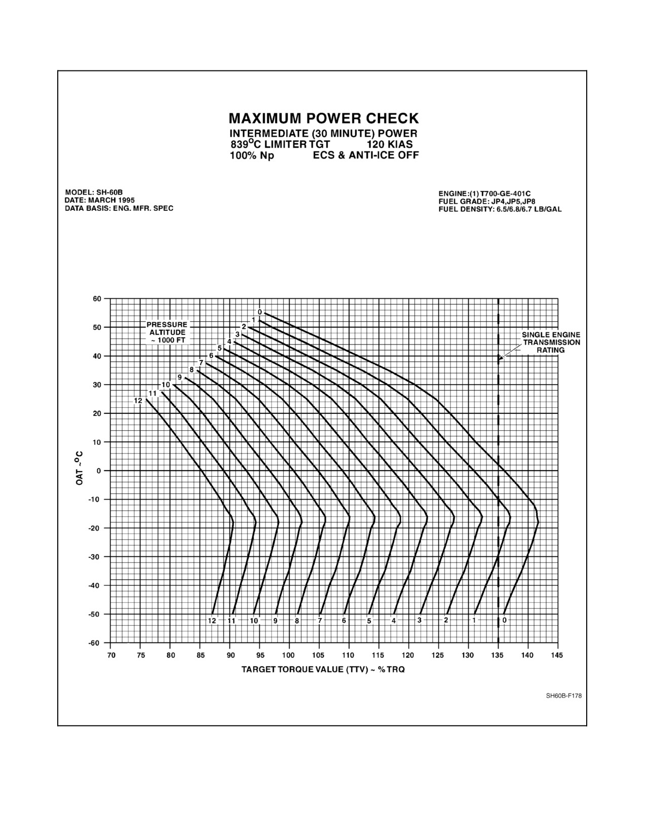
(Figure 10-6) for the OAT and pressure altitude recorded during the maximum power
check.
(3) Specification torque ratio (STR) = TRQADJ ÷ TTV.
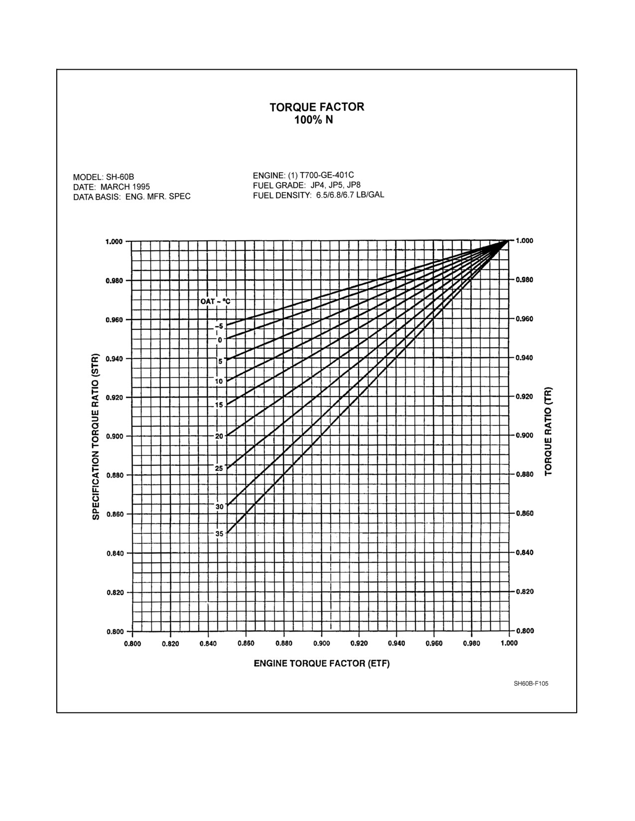
(4) Determine engine torque factor (ETF). Enter Torque Factor Chart (Figure 10-7) with
calculated STR and OAT recorded during maximum power check.
(a) If OAT is below --5 °C, use the -5 °C line.
(b) If OAT is above 35 °C, use the 35 °C line.
(c) If STR is greater than 1.0, then ETF equals 1.0.
(5) IfETFisatorabove.90,engineperformanceissatisfactory.IfETFisbelow.90,engine
performance is unsatisfactory.
(6) Record ETF on FCF record card and HIT/Power Check Log (Figure 10-3).
A B
3.
HIT baseline check (in flight) — AS REQUIRED.
Note
D HIT baseline may be established on deck or in
flight. Subsequent HIT checks should be done
in the same regime as HIT baseline.
D If icing conditions exist, consideration should
be given to performing HIT Check on deck.
D HIT Checks shall be performed on the first
flight of the day and recorded on the
HIT/Power Check Log
(Figure
10-3) for
monitoring trends in engine performance.
10-39
ORIGINAL
A1-H60BB-NFM-000
PROFILE
a.
ENG ANTI--ICE switches — OFF.
CAUTION
If icing conditions exist, do not keep ENG
ANTI--ICE OFF longer than necessary to
perform check.
b.
ECS — OFF.
c.
BAR ALT — SET TO 29.92.
d.
Nr — 100 Percent.
e.
Collective — INCREASE TO MAINTAIN 60 PERCENT TRQ FOR AT LEAST 30
SECONDS.
f.
Record OAT, PA, and TGT.
g.
Repeat steps e. and f. resetting TRQ for a total of three times.
h.
Repeat steps e. to g. for the other engine as required.
i.
Calculate average indicated of three indicated TGT readings.
j.
Determine table TGT from the HIT TGT Reference Table (Figure 10-4) for recorded OAT
and pressure altitude. Record TGT on baseline worksheet.
Note
When using HIT table, round OAT up, and
pressure altitude to the nearest value.
k.
Subtract average indicated TGT from table TGT to establish TGT margin.
l.
Establish TGT upper and lower limits by adding 20 °C to TGT margin and subtracting 20 °C
from TGT margin (step k.). Record upper and lower limits on HIT/Power Check Log
(Figure 10-3) in helicopter ADB.
A B
4.
ENG ANTI--ICE system — CHECK (as required).
a. PCL (engine not being checked) — AS REQUIRED.
Failure of the ENG ANTI--ICE ON advisory to
illuminate when the ENG ANTI--ICE switch is
selected to ON, or when the Ng is below
approximately 88 percent regardless of the
switch position; or constant illumination of the
ENG ANTI--ICE ON advisory with Ng greater
than 90 percent (94 percent if OAT is 15 °C or
greater) and the ENG ANTI--ICE switch OFF
are indicative of a malfunctioning anti--ice/start
bleed valve. This condition may cause engine
flameout during low power settings such as
quick stops and autorotative flight.
ORIGINAL
10-40
A1-H60BB-NFM-000
PROFILE
Note
D Engine Anti--ice Check should be performed
into the wind on deck, in a hover over a suitable
landing pad, or in a stable, level--flight regime.
D On deck or in a hover, it may be necessary to
retard the PCL on the engine not being checked
to prevent a vertical climb.
b.
ENG ANTI--ICE switch (engine being checked) — OFF.
c.
Collective — RAISE TO INCREASE Ng OF ENGINE BEING CHECKED TO
90
PERCENT OR ABOVE. (94 percent or above if OAT is above 15 °C).
d.
ENG ANTI--ICE ON advisory (engine being checked) — OFF.
e.
ENG ANTI--ICE switch (engine being checked) — ON.
Confirm:
(1) ECS SHUTDOWN caution (if ECS on and AIR SOURCE ECS/START
switch — ENG).
Note
ECS will not shut down if AIR SOURCE
ECS/START switch is in APU.
(2) TGT increases 30 ºC to 100 ºC.
(3) ENG ANTI--ICE ON advisory appears.
(4) ENG INLET ANTI--ICE ON advisory:
(a) OAT above 13 ºC — OFF.
(b) OAT above 4 ºC up to 13 ºC — MAY APPEAR.
(c) OAT 4 ºC and below — APPEARS.
A TGT increase greater than 100 ºC and/or
appearance of either ENG INLET ANTI ICE
ON advisory when OAT is above 13 ºC may
result in a loss in available torque at
intermediate power up to 49 percent when the
engine anti--ice system is activated. If any part
of the engine anti--ice check fails, maintenance
action is required prior to flight into icing
conditions.
Note
ENG INLET ANTI--ICE ON advisory
illuminates when engine inlet temperature
reaches 93 ºC which may take approximately
90 seconds.
10-41
ORIGINAL
A1-H60BB-NFM-000
PROFILE
f. ENG ANTI--ICE switch (engine being checked) — OFF.
Confirm:
(1) TGT decreases.
(2) ENG ANTI--ICE ON advisory — DISAPPEARS.
(3) ECS — ON (if ECS on and AIR SOURCE ECS/START switch — ENG).
(4) ENG INLET ANTI--ICE ON advisory — DISAPPEARS (after approximately
90
seconds).
g. PCL (engine not being checked) — Advance to FLY (as required).
h. Repeat steps a. to g. for other engine.
A B
5.
ECS — CHECK.
a.
AIR SOURCE ECS/START switch — ENG.
b.
APU CONTROL switch — OFF.
c.
ECS MODE switch — AUTO.
d.
ECS TEMP knob — COLD. (Cold air should flow from vents.)
e.
ECS TEMP knob — HOT. (Hot air should flow from vents.)
f.
NO. 1 or NO. 2 ENG ANTI--ICE switch — ON.
g.
ECS SHUTDOWN caution — APPEARS. (No airflow from vents.)
h.
ENG ANTI--ICE switch — OFF. (ECS SHUTDOWN caution OUT and hot air
flows from vents.)
i.
ECS MODE switch — MAN.
j.
ECS HOT/COLD switch — COLD. Hold until cold air flows from vents, then switch to
HOT. Hold until hot air flows from vents, then release.
k.
CONTGCY PWR switch — ON.
l.
ECS SHUTDOWN caution and #1 ENG CONT PWR and #2 ENG
CONT PWR advisories — ON. No airflow from vents.
m. CONTGCY PWR switch — OFF. ECS SHUTDOWN caution and #1 ENG CONT PWR
ON and #2 ENG CONT PWR ON advisories OUT. Hot air flows from vents.
n.
ECS MODE switch — AS DESIRED.
A
C
6. Main rotor track and balance (120 KIAS) — AS REQUIRED.
A B C D
7. Vibration analysis (cabin health, nose absorber) (120 KIAS) — AS REQUIRED.
A
C D
8. Stabilator — CHECK.
a. Trim 120 KIAS in level flight.
b. Check stabilator position 1° to 7° trailing--edge down.
c. Enter a sideslip by applying left pedal against trim until ball is displaced one ball width to
the right. Check stabilator position moves down 3° from trimmed position.
ORIGINAL
10-42
A1-H60BB-NFM-000
PROFILE
d. Release pedals and check that ball returns to one--half ball width of center, and helicopter
returns to within ±1° of trimmed heading.
e. Repeat step c. with right pedal and one ball width to the left. Check stabilator position moves
up 3° from trimmed position.
f. With fixed collective in balanced flight and feet off pedals, roll into a 45° AOB turn against
trim. Maintain 120 KIAS (this check will result in a loss of altitude).
Check:
(1) Maneuvering stability - aft cyclic is required to maintain 120 KIAS.
(2) Stabilator position moves 1° down from trim.
g. Release cyclic and allow aircraft to return to straight and level flight.
Check:
(1) No adverse pitch movements.
(2) Stabilator returns to trimmed position.
A
D
9.
AFCS in--flight check.
a.
Trim 120 KIAS in level flight.
b.
SAS check.
Note
D This check should be performed in smooth air.
Cyclic control inputs should be rapid, smooth,
and produce desired attitude change in
approximately
1
second. While guarding
cyclic,makeinputagainsttrimandallowcyclic
to return to trim position.
D Properly functioning SAS will dampen
induced rates, but will not necessarily return
aircraft to trimmed attitude. The tendency to
return to trimmed position should not be
confused with a damped response.
(1)
SAS/BOOST, SAS 1, and TRIM pushbuttons — ON.
(2)
SAS 2 and AUTO PLT pushbuttons — OFF.
(3)
Apply cyclic pulse to induce ±3° pitch attitude changes against trim. Helicopter attitude
should exhibit a damped response.
(4)
Repeat step (3) for 5° roll attitude changes against trim.
(5)
Repeat steps (3) and (4) with SAS 2 pushbutton ON and SAS 1 pushbutton OFF. Note
an improved response with SAS 2 pushbutton ON attributed to the addition of gust
alleviation.
(6)
SAS 1 and AUTO PLT pushbuttons — ON.
10-43
ORIGINAL
A1-H60BB-NFM-000
PROFILE
c.
Autopilot check.
(1)
Attitude and heading retention — CHECK.
Note
Steady state attitude/heading retention
tolerance in smooth air should be ±1° pitch,
roll, and heading. Airspeed retention should be
±10 KIAS.
(a)
Apply a forward cyclic pulse against trim to change pitch attitude 5°.
(b)
Attitude should return to trim with no more than one overshoot.
(c)
Repeat steps (a) and (b) for aft cyclic.
(d)
Apply a right cyclic pulse against trim to change roll attitude 10°.
(e)
Attitude should return to trim with no more than one overshoot.
(f)
Repeat steps (d) and (e) for left cyclic.
(g)
Without pressing trim release switches, press pedals to displace ball one width from
center.
(h)
Release pedals. Ball should return to 1/2 ball width of center and heading should
return within ±1° of trimmed heading.
(i)
Repeat steps (g) and (h) for opposite direction.
(j)
With pedal trim switches depressed and no force on pedals, roll helicopter against
trim into a 30° AOB and release. Helicopter should return to its original attitude
with only a slight overshoot and without adverse pitch.
(k)
Repeat step (j) for opposite direction. Response should be the same.
d.
Coordinated turn check.
(1) With feet off pedals, roll helicopter into a 45° AOB.
(2) Ball should stay within 1/2--width of center.
(3) Roll wings level.
(4) Ball should return to center.
(5) Repeat steps (1) to (4) for opposite direction.
e.
Cyclic and yaw trim check.
(1) Using the four--way trim switch, roll helicopter into 30° AOB.
(2) Roll should be smooth at approximately 6° per second.
(3) Release the four--way trim switch at 30° AOB. Helicopter should retain this AOB with
a slight overshoot, cyclic should return to center, and ball should stay within 1/2
ball--width of center.
(4) Return helicopter to level attitude using four--way trim switch, noting smooth response.
(5) Repeat steps (1) through (4) in opposite direction.
ORIGINAL
10-44
A1-H60BB-NFM-000
PROFILE
(6) Beep cyclic forward for 2 seconds. Airspeed should increase 12 ±5 KIAS.
(7) Beep cyclic aft for 2 seconds. Airspeed should decrease 12 ±5 KIAS.
(8) Apply collective HDG TRIM switch to change helicopter heading 5°. The first degree
should be a flat turn for 1 second. The remaining 4° should be coordinated at 1° per
second.
(9) Repeat step (8) for opposite direction. Response should be the same.
f.
Airspeed hold check.
(1) Trim aircraft to 120 KIAS.
(2) Slowly increase airspeed 10 KIAS by pushing cyclic against trim.
(3) Note force required and release cyclic to trim position.
(4) Airspeed should return to 120 ±5 KIAS with no more than one overshoot.
(5) Decrease airspeed 10 KIAS by pulling slowly aft on cyclic against trim.
(6) Note force required and release cyclic to trim position.
(7) Airspeed should return to 120 ±5 KIAS with no more than one overshoot.
(8) Press cyclic trim release to increase airspeed to 130 KIAS. When airspeed reaches 130
KIAS, release cyclic trim release.
(9) Airspeed should hold at speed when trim release is released.
(10) Repeat steps (8) and (9) decreasing airspeed to 120 KIAS.
g. Barometric and radar altimeter hold/heading hold check.
(1) SAS/BOOST, SAS 1, SAS 2, TRIM, and AUTO PLT pushbuttons — ON.
(2) BAR ALT pushbutton — ON.
(3) Steady--state altitude retention should be ±10 feet.
(4) Enter a standard--rate turn for 180°. Steady--state altitude retention should be ±10 feet
with ±30 foot transient.
(5) Increase AOB to at least 30°. Steady--state altitude retention should be ±30 feet with
±60 foot transient.
(6) Repeat steps (4) and (5) in opposite direction.
(7) With helicopter in trimmed straight and level flight, enter a 500--fpm rate of descent
against collective and release. Heading retention should be ±1°. Helicopter should
return to within ±10 feet of initial altitude.
(8) Repeat step (7) for climb.
(9) Press collective TRIM RELEASE and establish a 500--fpm rate of descent.
(10) Release collective TRIM RELEASE. Note BAR ALT pushbutton is ON and altitude
is within ±10 feet of designated altitude.
(11) BAR ALT pushbutton — OFF, RDR ALT pushbutton — ON.
10-45
ORIGINAL
A1-H60BB-NFM-000
PROFILE
(12) Repeat steps (3) to (10) using RDR ALT hold. Altitude retention tolerances are the same
as with the BAR ALT.
(13) RDR ALT/BAR ALT pushbutton — OFF.
A
C
10. Flight checks (140 KIAS):
a. Increase airspeed to 140 KIAS and stabilize.
b. Airspeed indicators — CHECK. Pilot and copilot indicator difference should not be more
than 5 KIAS. Note difference.
c. Vibrations — NOTE ANY ABNORMAL VIBRATIONS.
A
C
11. Main rotor track and balance (140 KIAS) — AS REQUIRED.
A
C
12. Vibration analysis (4--per, cabin absorbers) (140 KIAS) — AS REQUIRED.
A
C D
13. Flight checks (Vh):
a. Increase airspeed in level flight to Vh (106 percent TRQ or 839 °C ±10 TGT, whichever
occurs first).
(1) Cyclic — CENTERED LATERALLY. (At least 2 inches of forward cyclic should
remain.)
(2) Pedals — RIGHT PEDAL. (Should be no more than 1 inch forward of neutral.)
(3) Collective — Should not be against upper stop.
b. Stabilator position - 0° to 4° — Trailing--edge down.
c. Vibrations — NOTE ANY ABNORMAL VIBRATIONS.
d. Airspeed indicators — CHECK. Pilot and copilot indicator difference should not be more
than 5 KIAS. Note difference.
A
C
14. Main rotor track and balance (Vh) — AS REQUIRED.
A B C D
15. Absorber Tuning — AS REQUIRED.
CAUTION
Do not exceed Torque, Np, or TGT limitations.
Note
Collect ATABS data in accordance with the
A1--H60--CA--VIB--100 Manual.
a. Increase airspeed to 140 KIAS and stabilize.
b. ENG SPD Trim switch — SET Ng to 97 percent.
c. ATABS — Collect Data.
d. Repeat steps b. and c. for 98, 99, 99.5 100 and 100.5 percent Nr.
e. Decrease airspeed to within the calculated single engine envelope.
ORIGINAL
10-46
A1-H60BB-NFM-000
PROFILE
f. ENG SPD trim switch — SET Nr to 98 percent.
Adjustment of the PCLs outside of the
helicopter single engine envelope may result in
an unrecoverable loss of Nr following an
engine malfunction.
g. PCL (engine with lowest ETF) — MOMENTARILY ADVANCE TO LOCKOUT.
RETARD TO SET 100 PERCENT Nr.
h. Increase airspeed to 140 KIAS and stabilize.
i. PCL — ADJUST AS REQUIRED TO MAINTAIN Nr AT 100 PERCENT.
j. ENG SPD Trim switch — SET Nr TO 101 PERCENT.
k. ATABS — COLLECT DATA.
l. Repeat steps j. and k. for 102 percent Nr.
m. Decrease airspeed to within the calculated single engine envelope.
n. PCL (engine in Lockout) — RETARD TO IDLE THEN ADVANCE TO FLY.
o. ENG SPD Trim switch — SET Nr TO 100 PERCENT (as required).
A
D
16. Automatic approach, hover coupler, and departure check.
a. Automatic approach — CHECK.
(1) Automatic Approach Checklist — COMPLETE. HVR ALT rotary knob set to 80 feet,
LONG VEL and LAT VEL controls set to 0, and SAS 2, TRIM, AUTO PLT
pushbuttons — ON.
(2) Trim helicopter for 100 KIAS and 200 feet altitude, heading into wind.
(3) Automatic approach — ENGAGE. Check for steady RDR ALT hold light. Helicopter
should decelerate at 1 knot per second.
(4) As helicopter decelerates below 80 knots groundspeed, radar altitude hold disengages
and a 120 feet--per--minute rate of descent will be commanded.
(5) At 60 KIAS, transition is made from heading hold to Doppler mode, eliminating lateral
drift.
(6) Helicopter should approach a hover at 80 feet and approximately 10 knots longitudinal
groundspeed.
(7) At ±2 feet of HVR ALT setting, RADALT hold engages.
(8) At 1 KGS, HVR mode engages. HVR pushbutton illuminates.
10-47
ORIGINAL
A1-H60BB-NFM-000
PROFILE
Note
If water is smooth, the Doppler may go into
memory mode and deceleration and drift will
have to be controlled manually. As the
helicopter approaches
80
feet, the radar
altimeter hold will engage. When approaching
a hover, the rotor wash will disturb the water
surface enough to receive a Doppler return,
however, pilot must reengage Approach/
Hover.
b.
Hover coupler — CHECK.
(1)
Helicopter should hover within ±4 feet of HVR ALT setting and ±2 KGS with the
LONG VEL and LAT VEL rotary knobs set at 0.
(2)
Start a 10--knot lateral drift against trim. Cross--check with hover bars and Doppler.
Release cyclic.
(3)
Helicopter should return to a stable hover.
(4)
Repeat steps (2) and (3) for opposite lateral and longitudinal drift directions.
(5)
LAT VEL rotary knob — Set to establish a 10--knot drift. Cross--check with hover bars
and Doppler. Return LAT VEL rotary knob to 0. Helicopter should return to and
maintain previously established hover.
(6)
Repeat step (5) for LAT VEL rotary knob in opposite direction.
(7)
Repeat steps (5) and (6) for LONG VEL in forward and aft directions.
(8)
Repeat steps (5) to (7) using four--way TRIM switch. Cross--check with hover bars and
Doppler. Once 10--knot drift is established press cyclic TRIM REL button and release.
Helicopter should return to a stable hover.
(9)
Move collective HDG TRIM switch to L and hold.
(10)
Helicopter should change heading to the left at 3° per second. When switch is released,
helicopter should synchronize on the heading when released within ±2°.
(11)
Repeat steps (9) and (10) to the right.
(12)
Reestablish a stable hover into the wind.
(13)
HVR ALT rotary knob — 150 FT.
(14)
Helicopter should climb to 150 ±4 feet with only one overshoot. Rate of climb should
not exceed 1,000 fpm. Upward collective movement should cease when torque reaches
a maximum of 116 percent; however, transients above 116 percent are possible.
(15)
RADAR ALTIMETER variable index — SET TO 80 FT.
(16)
HVR ALT rotary knob — 70 FT. Check for RAWS tone descending through 80 feet
(check for both pilot and copilot).
(17)
Helicopter should descend to 70 ±4 feet with only one overshoot and torque limits as
shown above. Rate of descent should not exceed 250 fpm.
ORIGINAL
10-48
A1-H60BB-NFM-000
PROFILE
(18) HVR ALT control — 30 feet. Check for continuous RAWS tone and light below 35
feet.
(19) HVR ALT control — RESET to desired altitude.
c.
Crew hover — CHECK.
(1) CREW HVR pushbutton — ON.
(2) HOVER TRIM light on Crew Hover Control Panel should illuminate.
(3) Hover trim grip TRIM switch — PRESS FOR FORWARD DRIFT.
Note
The control authority of the crewman is limited
to 5 knots of groundspeed in longitudinal and
lateral directions in either axis around the
lateral and longitudinal velocity set on the
AFCS control panel. The HOVER TRIM
switch output is pressure sensitive. Increase
pressure to command an increase in
groundspeed.
(4) Release switch pressure. Helicopter should return to stable hover.
(5) Repeat steps (3) and (4) for aft, left, and right.
(6) CREW HVR pushbutton — OFF.
(7) HOVER TRIM light on Crew Hover Control Panel should extinguish.
d.
Departure — CHECK.
(1) HVR pushbutton — ILLUMINATED.
(2) Cyclic DEPART HOVER button — PRESS. DPRT light on AFCS CONTROL panel
should illuminate.
(3) Helicopter should make smooth transition to 480 feet--per--minute rate of climb and 2
knots--per--second acceleration, and fly to 500 feet altitude for RDR ALT hold and 100
KIAS for airspeed hold trimmed.
(4) Automatic Approach — ENGAGE.
(5) During deceleration, beep cyclic aft for 2 seconds to verify deceleration increase of 1
knot/second.
(6) At airspeed less than 50 KIAS, press cyclic DEPART HOVER button.
(7) Prior to reaching 500 feet AGL and 100 KIAS, momentarily press collective TRIM
RELEASE switch and cyclic TRIM RELEASE button. The AFCS should stabilize the
helicopter at the altitude and airspeed at the point of release. RAD ALT hold remains
ON.
A
17. Navigation, mission, and communication equipment — TEST/CHECK OPERATION.
a. UHF--1 and --2.
b. UHF backup (pilot/copilot).
c. HF.
d. TACAN.
10-49
ORIGINAL
A1-H60BB-NFM-000
PROFILE
e. UHF/ADF.
f. Doppler navigation.
g. IFF/interrogator.
h. MAD.
i. RADAR.
j. Equipment status table.
k. GPS.
A
18. Fuel dump — CHECK.
Fuel dumping should be manually terminated
at no less than 600 pounds total fuel. With less
than 600 pounds of fuel, fuel starvation may
occur when balanced flight is not maintained
and/or pitch attitudes exceed 15° nose up or
nose down.
a. Determine the amount of fuel to be dumped.
b. BuNo 162349 and subsequent, FUEL MGT control panel — TRANSFER/MANUAL
OVRD.
c. ALE--39 power — OFF.
d. FUEL DUMP switch — DUMP.
e. FMCP — FUEL DUMP light illuminated, as applicable.
After the desired quantity has been dumped:
f. FUEL DUMP switch — OFF.
Internal wear of the fuel dump switch guard
may not move the switch to the OFF position.
Aircrew must verify switch position when
completing dumping procedures.
g. Observe the fuel readout to ensure that dumping has ceased.
If fuel dumping continues:
h. FUEL DUMP circuit breakers — PULL.
(1) FUEL DUMP NO. 1 (CENTER, NO. 1 AC PRI, ROW 1, CB 13).
(2) FUEL DUMP PUMP (CORNER, NO. 2 AC PRI, ROW 1, CB 1).
(3) FUEL DUMP CONTR (ATO OVERHEAD, DC ESNTL, ROW 3, CB 1).
ORIGINAL
10-50
A1-H60BB-NFM-000
PROFILE
i. FUEL DUMP switch — CYCLE.
j. Land as soon as practical.
A
19. FUEL MGT control panel — CHECK. (Short manual transfer from each auxiliary fuel tank
should be checked if installed. Main fuel level shall be 3,700 pounds or less prior to each
transfer.)
a. FMCP MASTER/MODE switches — TRANSFER/MANUAL OVRD.
b. External AUX tank pushbutton — SELECT.
c. Confirm FMCP FLOW light illuminates for selected tank.
d. FMCP MASTER — STOP FLOW.
e. Confirm FMCP FLOW light extinguishes.
f. Repeat steps a. to e. for remaining AUX tanks.
g. FMCP MASTER/MODE switches — AS REQUIRED.
A
C
20. Autorotation rpm check.
a. Climb to a suitable autorotation altitude.
b. When climbing through check altitude, record OAT, pressure altitude (set 29.92 on BAR
ALT), and gross weight.
c. Level off and stabilize at 75 KIAS.
D Transient Np up--speeds of several seconds
duration are typically encountered during
autorotation entry and recovery. During entry,
the Np should split (decrease) away from Nr
prior to reaching 109 percent and reduce to a
value of 100--103 percent Np (PCLs in FLY).
When the main rotor has split away from Np,
transient values as high as 110--114 percent Np
may be seen when collective pull is initiated.
This behavior is normal. If the Np follows Nr in
a steady manner for Nr values exceeding 109
percent, or recovery Np peak exceeds
114
percent, an LDS malfunction is indicated.
Discontinue further autorotational flight.
Lowering the collective to minimum with an
engine LDS malfunction will cause Np and Nr
to rise rapidly and may cause activation of Np
overspeed resulting in engine shutdown.
D Conduct autorotation rpm check at an altitude
that will allow for power recovery at a safe
altitude. If possible, have a suitable forced
landing area within range.
10-51
ORIGINAL
A1-H60BB-NFM-000
PROFILE
d. Slowly reduce collective to minimum and maintain 75 KIAS in balanced flight.
CAUTION
If Nr is less than 90 percent or greater than 120
percent, initiate a power recovery.
e. Vibrations — NOTE ANY ABNORMAL LEVEL.
f. Airspeed indicators — CHECK. Note difference. Pilot and copilot difference should not
be greater than 5 KIAS.
g. Record Nr when passing through the desired pressure altitude.
h. Execute a power recovery and verify proper Np/Nr response.
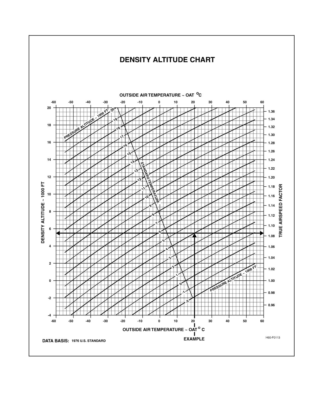
i. Compute DA at which stabilized Nr was recorded (Figure 10-8).
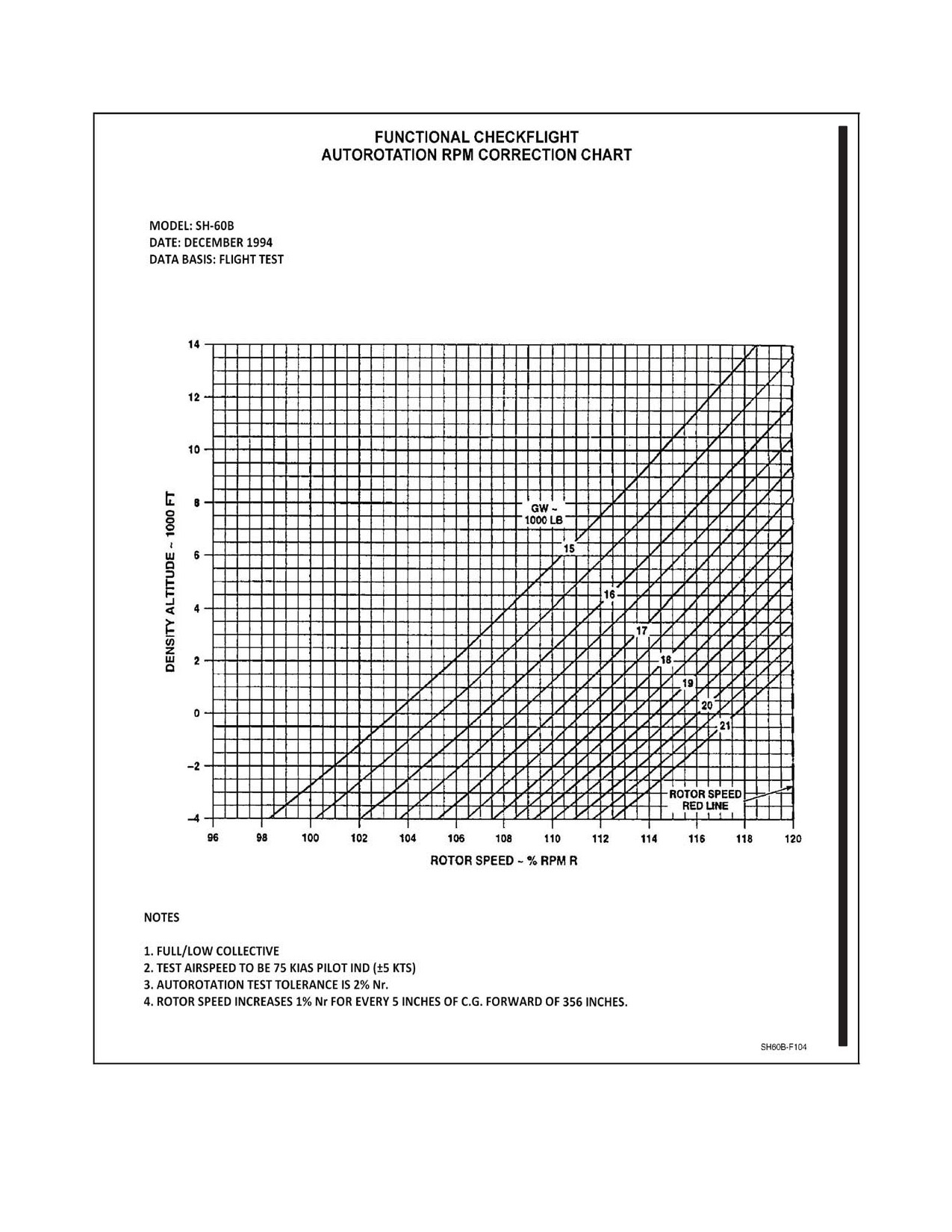
j. Verify autorotational Nr satisfies requirements of Autorotation RPM Correction Chart
within 2 percent (Figure 10-9).
10.2.12 Landing Checklist
1. CONTGCY PWR switch — AS REQUIRED.
2. Lights — AS REQUIRED.
3. Brakes — AS REQUIRED.
4. TAIL WHEEL switch — LOCK.
5. Instruments, Caution/Advisories — CHECK.
6. BAR ALT/RAD ALT — AS REQUIRED.
7. HF Radio — OFF.
8. Armament — SAFE.
9. Harness — LOCKED.
10. Aircrewman Before Landing Checklist — COMPLETE.
11. FLIR — STOW.
12. Return to Force Checklist — AS REQUIRED.
10.2.13 Post Landing Checklist
1. Lights — AS REQUIRED.
2. Tail Wheel/Brakes — AS REQUIRED.
3. CONTGCY PWR switch — OFF.
4. Ordnance pins/covers — DEARM/SAFE/INSTALL (as required).
CAUTION
Install Hellfire missile seeker covers
(if
available) before all ground operations and
before all chock and chain operations.
ORIGINAL
10-52
A1-H60BB-NFM-000
PROFILE
5. M299 launcher SAFE/ARM switch — SAFE.
6. Chocks and Chains — AS REQUIRED.
With missiles uploaded, exercise extreme care
when chocking and chaining to avoid damage
to missile seeker or fins or injury to personnel.
7. Transponder — STBY.
8. ENGINE ANTI--ICE/PITOT HEAT/BLADE DE--ICE — OFF.
Thepitotandstaticportsbecomeextremelyhot
during operation. Care should be taken to
prevent ground personnel from touching these
surfaces. Failure to turn off pitot heat could
burn personnel whenever external
power is
applied.
10.2.14 Shutdown
1.
TAIL WHEEL switch — LOCK.
2.
Parking brake — SET.
3.
Chocks — IN.
4.
APU — START.
a. ECS — OFF.
b. AIR SOURCE ECS/START switch — APU.
c. FUEL PUMP switch — APU BOOST.
d. APU CONTR switch — ON.
5.
APU GENERATOR switch — ON.
6.
IFF MODE 4 CODE — HOLD (as required).
7.
Avionics.
a. DOPPLER — AS REQUIRED.
b. MPDs — AS REQUIRED.
c. SAC power — OFF.
d. FLIR power — OFF.
e. MSN power — OFF.
10-53
ORIGINAL
A1-H60BB-NFM-000
PROFILE
f. RDR — STBY.
g. Data link — STBY.
h. TACAN — OFF.
i. IFF MASTER — OFF.
j. RADALTs — OFF.
8. BACKUP HYD PMP switch — ON.
Note
FLIR EU PWR should be secured prior to
cycling the BACKUP HYD PMP switch
because the associated power surge may cause
a gimbal lock.
9. Flight controls — POSITION AND HOLD.
10. NO. 1 and NO. 2 GENERATOR switches — OFF.
Power transfer from the APU generator to the
NO. 1 generator may cause disengagement of
SAS 1, SAS 2, TRIM, AUTO PLT, and
Stabilator which may cause rotors to dip as low
as 4 feet.
11. ENGINE IGNITION switch — OFF.
12. Lights — AS REQUIRED.
13. PCLs — IDLE.
CAUTION
Enginesshouldbecooledfor2minutesatanNg
of 90 percent or less before moving PCLs to
OFF. If an engine is shut down without being
cooled, it should not be restarted for 4 hours
unless restart is performed within 5 minutes.
14. NO. 2 PCL and fuel selector — OFF.
15. Droop stops — IN.
16. NO. 1 PCL and fuel selector — OFF.
17. Rotor brake — ON (between 30 percent and 50 percent Nr).
18. TGT — MONITOR.
CAUTION
If TGT rises above 540 °C, perform Internal
Engine Fire emergency procedure.
ORIGINAL
10-54
A1-H60BB-NFM-000
PROFILE
A B
19. DECU codes — CHECK.
20. Engine cleaning — AS REQUIRED (see paragraph 7.17.12).
Note
If engine cleaning is required, proceed to step
14 of Engine Cleaning Procedures.
21. Blade fold — AS REQUIRED.
CAUTION
D
Should the blade fold system stall during fold,
cycling the BLADE FOLD switch to SPREAD
should return the rotor blades to the spread
position.
D
Shut down the APU immediately if a rotor
blade remains stalled in the APU exhaust.
D
When the ROTOR SPREAD light is not
illuminated,pressingtheRDRALTpushbutton
during blade fold system operations may cause
failure of the automatic system. Do not press
this pushbutton during blade fold operations.
D
Simultaneous folding of main rotor blades and
tail pylon is prohibited.
Note
Failure to suppress the DECU numerical fault
codes on the PDU will prevent the automatic
blade fold from operating due to the torque
signal being relayed to the AFCS computer.
Codes can be suppressed by pressing either
OVSP TEST A or B buttons for the affected
engine.
a.
Area — CLEAR (wing walkers positioned as required).
b.
BACKUP HYD PMP switch — ON.
c.
STABILATOR AUTO CONTROL — OFF.
d.
SAS 1 and SAS 2 — OFF, TRIM — ON, AUTO PLT — OFF.
e.
SERVO switch — 1ST OFF or 2ND OFF.
f.
BLADE FOLD MASTER switch — ON.
g.
BLADE FOLD switch — FOLD.
h.
Rotor brake — OFF.
i.
ROTOR INDEXED light — ILLUMINATED.
10-55
ORIGINAL
A1-H60BB-NFM-000
PROFILE
Note
Blades may be manually indexed if the main
rotor index actuator/gust lock fails. Cycling the
BLADE FOLD switch OFF, pulling the RTR
HEAD INDEX MOTOR circuit breaker (NO.
2 AC PRI, SO OVHD, ROW 3, CB 5), and
cycling the BLADE FOLD switch to FOLD
may disengage the indexer. Rotate the rotor
system until the INDEXED light illuminates,
then continue with the Blade Fold Checklist.
j.
Rotor brake — APPLY.
k.
BAR ALT — FLASHING.
l.
Collective, cyclic, and pedals — FREE TO POSITION.
Note
If computer is unable to null after 30 seconds,
the AFCS DEGRADED caution will appear.
To attempt another cycle, turn BLADE FOLD
switch OFF, press any FAIL ADVISORY
MODE RESET pushbutton, and repeat blade
fold sequence.
m. BAR ALT pushbutton — PRESS.
Note
Thefollowingbladestatuspanellightsequence
indicates proper operation of the fold cycle:
TRIM light flashing (blades positioned for
pitch lock insertion) and PITCH LOCKED
light illuminated (last pitch lock in). Blades
willbeginfoldingfollowingtheilluminationof
the PITCH LOCKED light. Should the
INDEXED light flicker or extinguish during
folding (indicating a loss of index), the blade
fold sequence will stall. Cycling the BLADE
FOLD switch to SPREAD should clear the
stall. When the SPREAD light illuminates, the
rotor head may be re--indexed and another fold
cycle attempted.
n.
ROTOR FOLDED light — ILLUMINATED.
o.
BLADE FOLD switch — OFF.
p.
BLADE FOLD MASTER switch — OFF.
q.
SERVO switch — CENTER.
22. BACKUP HYD PMP switch — OFF.
23. ECS — OFF.
24. Exterior/interior/NVD lights — OFF.
ORIGINAL
10-56
A1-H60BB-NFM-000
PROFILE
25. APU GENERATOR switch — OFF.
26. APU — SHUTDOWN.
a. AIR SOURCE ECS/START switch — OFF.
b. APU CONTR switch — OFF.
c. FUEL PUMP switch — OFF.
27. BATT switch — OFF.
10.2.15 Post Flight Checks
1. Interior equipment.
2. Tires/struts.
3. Leaks.
4. Missing panels.
10.3
ENGINE POWER CHECKS
The Engine Torque Factor method provides an accurateindication of available power by incorporating
ambient temperature effects into the power available calculation. An in--flight check will be made
under the following conditions:
1. When a new engine is installed.
2. When an engine is reinstalled.
3. When an engine fails the HIT check for other than a faulty anti--icing start/bleed valve or a dirty
compressor.
10.3.1 Torque Factor Terms
The following terms are used when determining the maximum torque available:
1. Torque Ratio (TR): The ratio of torque available to specification torque at the desired ambient
temperature.
2. Engine Torque Factor (ETF): The ratio of an individual engine’s torque available to
specification torque at a reference temperature of 35 °C.
3. Aircraft Torque Factor (ATF): The ratio of an individual aircraft’s power available to
specification power at a reference temperature of 35 °C. The ATF is the average of the ETFs
of both engines.
4. Specification Torque Ratio (STR): The ratio of the adjusted actual torque to the specification
torque or target torque at ambient conditions.
10.3.2 Maximum Power Check Chart
The Maximum Power Check Chart (Figure 10-6) presents the Target Torque Value (TTV) at 120 KIAS
and 100percent Nr for theoperational rangeof PAand OAT.The single-- and dual--enginetransmission
limits for continuous operation are shown and should not be exceeded.
10-57
ORIGINAL
A1-H60BB-NFM-000
PROFILE
10.3.3 Torque Factor Chart
The Torque Factor Chart (Figure 10-7) is used for obtaining the ETF by normalizing the STR to a
referenced temperature of 35 °C. For temperatures below --5 °C use --5 °C, and for temperatures above
35 °C use 35 °C.
10.3.4 Torque Factor TGT Reference
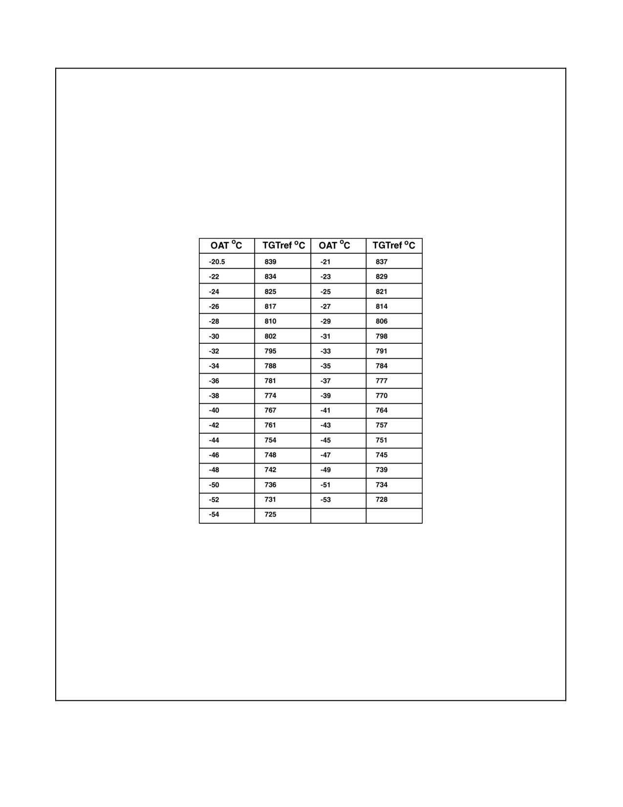
The Torque Factor TGT Reference Chart (Figure 10-5) is used to compute TRQ adjusted when OAT
is below --20 °C.
10.3.5 Torque Factor Procedure
The objective of the torque factor procedure is to obtain an ETF for each engine. This is accomplished
bytakingdataduringanin--flightmaximumpowercheckandthenusingthisdataalongwiththeTorque
Factor charts to calculate an ETF. The ETF is then displayed on the HIT/Power Check Log (Figure
10-3) for use by operational pilots and maintenance personnel.
10.3.6 Torque Factor Procedure In Flight
The inflight check will be conducted to establish/reestablish the ETF and to ensure that the engine
meets minimum power requirements. Performance data will be taken at an engine--limiting condition,
while maintaining constant altitude and adjusting airspeed as required. The ENG ANTI--ICE, ECS, and
AIR SOURCE ECS/START switches must be OFF and the altimeter will be set at 29.92 In--Hg. Data
will be taken one engine at a time. If the maximum power check is being performed because of a single
engine installation/reinstallation or failed HIT check, it is at the maintenance officer’s discretion to
obtain new ETF data for the other engine.
ORIGINAL
10-58
A1-H60BB-NFM-000
PROFILE
10.3.7
Sample Problem 1
1.
Recorded during maximum power check, Ng limited. SH--60B.
a.
PA = 2,000 feet.
b.
OAT = --30 °C.
c.
TGT measured = 790 °C.
d.
TRQ measured = 126 percent.
e.
From Figure 10-6 TTV = 130 percent.
f.
From Figure 10-5 TGT ref = 802 °C.
g.
Calculate TRQ adj:
(1) TRQ adj = TRQ measured + 0.2 (TGT ref) -
0.2
(TGT measured).
(2) TRQ adj = 126 + 0.2 (802-790).
(3) TRQ adj = 126 + 2.4.
(4) TRQ adj = 128.4 percent.
h.
Calculate STR:
(1) STR = TRQ adj/TTV.
(2) STR = 128.4/130.
(3) STR = 0.987.
i.
Determine ETF:
(1) From Figure 10-7 (using -5 °C line) ETF = 0.957 (satisfactory performance).
10.3.8
Sample Problem 2
1.
Recorded during maximum power check, Ng limited. SH--60B.
a. PA = 1,000 feet.
b. OAT = 20 °C.
c. TGT measured = 840 °C.
d. TRQ measured = 112 percent.
e. From Figure 10-6, TTV = 122 percent.
f. Calculate TRQ adj:
(1) TRQ adj = TRQ measured.
(2) TRQ adj = 112.
10-59
ORIGINAL
A1-H60BB-NFM-000
PROFILE
g. Calculate STR:
(1) STR = TRQ adj/TTV.
(2) STR = 112/122.
(3) STR = 0.918.
h. Determine ETF:
(1) From Figure 10-7 (using 20 °C line), ETF = 0.878 (unsatisfactory performance).
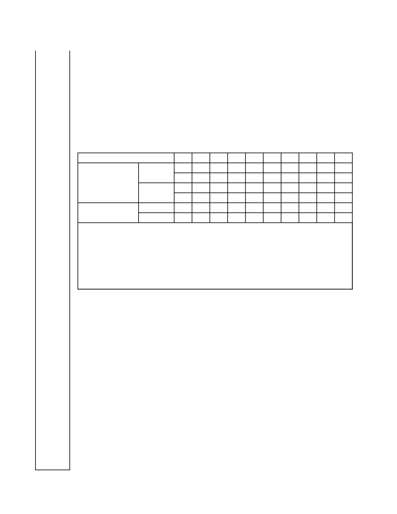
10.4
FUNCTIONAL CHECKFLIGHT CHARTS AND TABLES
TEMPERATURE—°C
-40
-30
-20
-10
0
+10
+20
+30
+40
+50
TIME TO IDLE-
55
49
45
42
40
40
40
40
43
48
SECONDS USING
10,000 FT
*50
*46
*44
MIL-L-23699
(*USING MIL-l-7808)
45
40
36
32
30
30
30
32
34
38
SL
*50
*46
*44
IDLE SPEED
MAXIMUM
66.1
66.7
67.1
67.6
68.0
68.5
68.9
69.4
69.8
70.3
(Ng%)
MINIMUM
63.2
63.7
64.1
64.7
65.1
65.5
65.9
66.2
66.7
67.0
NOTE
D Prior to flight. Idle N
gspeedmustbegreaterthantheminimumvaluelistedforthecurrentOAT.
D This is the maximum time allowed between advancing the PCL to IDLE and N
glevelingoffatidle
speed.
D N
gidlespeedhigherthanthemaximumlimitmaybeanindicationofLDSrollpinfailureormisrigging.
Flight with N
gidlespeedhigherthanthemaximumlimitisauthorizedprovidedthehighNg idlespeed
troubleshooting procedures are completed satisfactorily.
Figure 10-2. Time to Idle/Idle Speed Chart
ORIGINAL
10-60
A1-H60BB-NFM-000
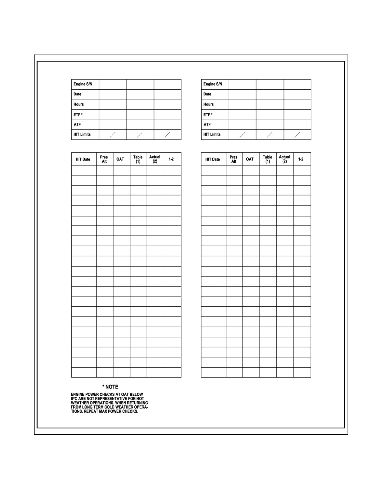
Figure 10-3. HIT/Power Check Log
10-61
ORIGINAL
A1-H60BB-NFM-000
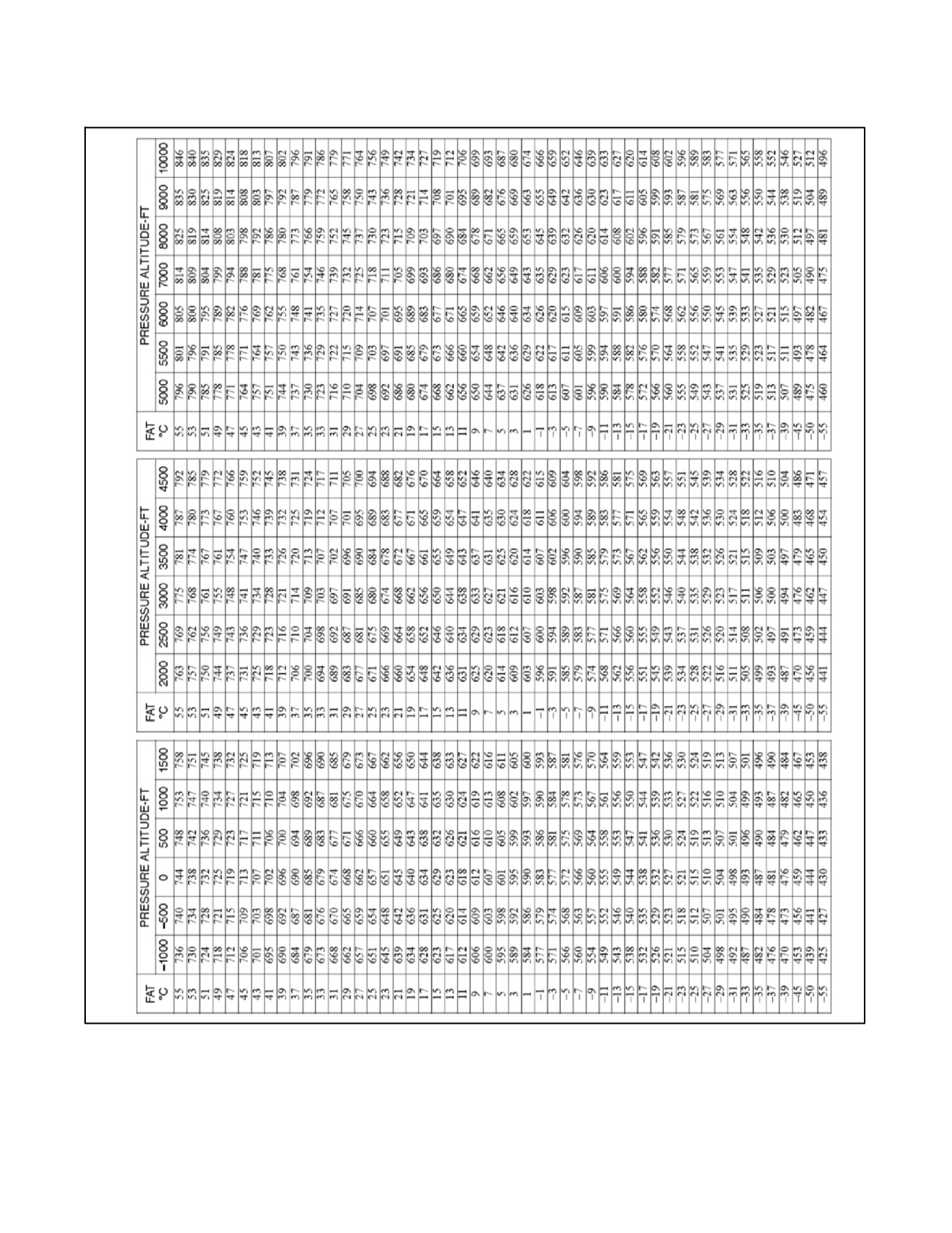
Figure 10-4. HIT TGT Reference Table
ORIGINAL
10-62
A1-H60BB-NFM-000
H60--F0118A
Figure 10-5. Torque Factor TGT Reference Chart
10-63
ORIGINAL
A1-H60BB-NFM-000
Figure 10-6. Maximum Power Check Chart
ORIGINAL
10-64
A1-H60BB-NFM-000
Figure 10-7. Torque Factor Chart
10-65
ORIGINAL
A1-H60BB-NFM-000
Figure 10-8. Density Altitude Chart
ORIGINAL
10-66
A1-H60BB-NFM-000
Figure 10-9. Autorotation RPM Correction Chart
10-67
ORIGINAL W/IC 70
A1-H60BB-NFM-000
10.5
VIBRATION ANALYSIS
GROUND RUNS
FCP
QAR
Date Completed
1. TAIL ROTOR BALANCE
2. TAIL HEALTH (STA.685)
3. AXIAL FAN
4. NO. 1 ENG INPUT MOD
5. NO. 2 ENG INPUT MOD
6. NO. 1 H.S.S. (if required)
7. NO. 2 H.S.S. (if required)
8. RH ENGINE N.S.V.
9. LH ENGINE N.S.V.
10. ALT TOOTH (if required)
INFLIGHT RUNS
1. MAIN ROTOR TRACK &
BALANCE
2. COCKPIT 4 PER
3. ABSORBER TUNING
4. CABIN HEALTH (STA. 347)
ORIGINAL
10-68
A1-H60BB-NFM--000
PART IV
Flight Characteristics
Chapter 11 — Aerodynamic Characteristics and Techniques in Various Regimes
61/(62 blank)
ORIGINAL
A1-H60BB-NFM-000
CHAPTER 11
Aerodynamic Characteristics and
Techniques in Various Regimes
11.1
GENERAL FLIGHT CHARACTERISTICS
The normal speed range extends from a rearward/lateral speed of 35 knots to a maximum forward speed of 180 KIAS.
Normally, with the stabilator in the full trailing--edge--down position, the aircraft will hover approximately 4° to 5°
noseup and 2° to 3° left wing down. During approach or slow flight (approximately 15 knots), a translational
lift--induced vibration will be felt.
11.1.1 Hover/Slow Speed Flight (At or Below Translational Lift)
In a steady, no--wind hover, the main rotor experiences a symmetrical distribution of lift dictated by the rotational
velocity and constant pitch of the rotor blades. The blade tips are moving at 725 feet per second or Mach 0.65 (65
percent of the speed of sound). Since the airflow is subsonic, the movement of the blades through the air is felt
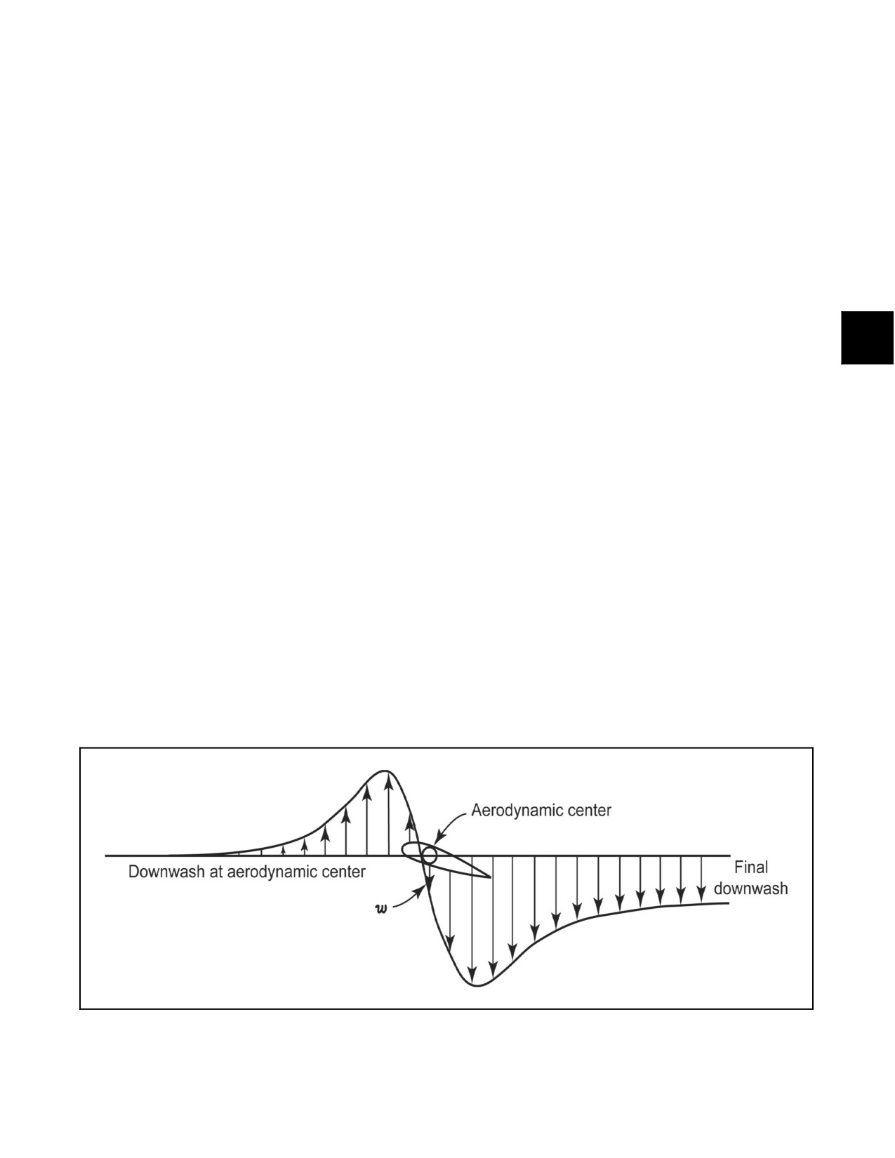
upstream (Figure 11-1), resulting in an upward movement of air prior to coming in contact with the blade. This
induced flow causes the lifting force to be shifted aft, resulting in the generation of a drag component referred to as
induced drag.
11.1.1.1 Ground Effect
A helicopter is said to be in ground effect when the rotor disk is within one rotor diameter of the ground. Ground effect
causes the main rotor thrust vector to shift forward so that it is more vertical (more lift/less induced drag). Therefore,
less power is required to hover in ground effect than at higher altitudes. These effects are strongest close to the ground
and dissipate rapidly as altitude above the ground is increased. The SH--60B is considered to be hovering in ground
effect at radar altimeter altitudes at or below 45 feet.
For an SH--60B at the gross weight of 21,700 pounds on a standard sea level day, downwash below the rotor can
exceed 150 knots. This results in the generation of a ground vortex that surrounds the aircraft just outside the rotor
arc. It is important to consider the effects of rotor downwash and the ground vortex on personnel and other aircraft,
particularly much lighter civil aircraft.
Figure 11-1. Induced Flow
11-1
ORIGINAL
A1-H60BB-NFM-000
11.1.1.2 Transition to Forward Flight
In flight regimes other than a hover, the rotor blades, as they move around the rotor head, experience different relative
velocities. Hence, an asymmetrical distribution of lift is created. To compensate for this dissymmetry, the blades on
theadvancing sideoftherotordisk rise(flaps up), decreasing theAOA and reducing thelift generated. Theretreating
blade flaps down, increasing the AOA and generating additional lift. This process of flapping causes the pitch of the
blade to be continuously changing in a cyclic manner.
The flapping nature of the rotor system results in approximately 90°of phaselag between where inputs are madeand
their effects are felt.
11.1.1.3 Blowback
When hovering in a windless environment, the main rotor disk will be level. If the aircraft is exposed to a headwind
gust, the retreating blade sees less relative wind velocity and the advancing blade sees more relative wind velocity.
This causes the rotor disk to be tilted aft or blown back. Blowback of the main rotor disk tilts the main rotor thrust
vector aft, causing the nose of the helicopter to pitch up. This reaction is countered by pilot input in the long term
and by the hover augmentation and gust alleviation feature of SAS--2, and attitude hold feature of the autopilot, in
the short term. When transitioning to forward flight, blowback results in more forward cyclic being required to
continue helicopter acceleration. The magnitude of blowback is proportional to airspeed and lift.
11.1.2 Slow-Speed Flight
11.1.2.1 Stabilator Effect in a Hover/Slow Speed Flight Below 30 Knots
Below 30 knots, the stabilator is full trailing edge down. Increasing collective in a hover increases the amount of
downwash on the stabilator and pushes the nose up. The effect of varying collective position on nose attitude during
hoveriscompensatedforbycollective--to--longitudinalmechanicalcontrolmixing.Theairspeed,collectiveposition,
lateral acceleration, and pitch rate inputs to the stabilator system have no effect below 30 knots. In transition to
forward flight, the full--down position of the stabilator will cause a nosedown pitch until programming begins at 30
knots. Aft cyclic will be required to counter this pitching moment until programming begins.
11.1.2.2 Translational Lift
Forward flight is initiated by displacing the cyclic forward. This tilts therotor thrust vector forward. Tilting themain
rotor thrust vector forward reduces the vertical lift component. Therefore, additional increase in collective pitch may
benecessary as thehelicopterbegins to translateforward to keep it from descending. With furtherincreasein forward
speed, the mass flow rate of air through the rotor system increases, resulting in greater lift production and a rapid
decrease in induced power required for level flight. Although profile power (power required to spin the blades) and
parasite power (power required to drag nonlifting parts of the helicopter through the air) are both steadily increasing,
the reduction in induced power required results in an overall reduction in total power required. Maintaining hover
power will result in approximately a 500 foot--per--minute rate of climb at 80 KIAS.
As the airspeed reaches approximately 17 knots, a noticeable vibration will be felt as the aircraft encounters its own
ground vortex. The ground vortex is rolled up under the aircraft as speed continues to increase and dissipates as the
aircraft reaches approximately 30 knots.
11.1.2.3 Tail Winds in Transition to Forward Flight
Normally, a helicopter transitioning to forward flight from a hover is moving toward a state of less power required.
This is not the case for an aircraft transitioning to forward flight with a tailwind. When the helicopter is motionless
over a spot, the rotor disk does not care which direction the wind is coming from. Therefore, a helicopter with a
tailwind requires less power to hover than one in calm winds. As the helicopter moves forward, the rotor will reach
a condition of zero relative wind when helicopter speed matches tailwind speed. The helicopter moves into a state
of more power required for level flight. Therefore, even if the aircraft had enough power to hover in a tailwind, it
may not have enough power to continue in forward flight and reach translational lift.
11.1.3 Forward Flight
Following translational lift, the aircraft will accelerate through 30 KIAS, at which point the stabilator will begin
programming the trailing edge upward, requiring forward cyclic movement to continue the helicopter acceleration.
ORIGINAL
11-2
A1-H60BB-NFM-000
When the aircraft passes through 50 KIAS, the DAFCS will level the wings to maintain heading in balanced flight.
Above 50 KIAS, the beeper trim or trim release button must be used to establish the desired forward airspeed. The
directional control pedals will automatically move toward the position required to maintain balanced flight. Forces
opposing incorrect pilot directional flight control input will be felt. An increase in speed is accomplished by using
the beeper trim switch, or depressing the trim release button and displacing the cyclic forward until the desired
airspeed is attained. This, in turn, tilts the rotor disc forward. As it tilts forward, a greater percentage of the lift being
produced by the main rotor is being used to increase the forward airspeed of the helicopter. An increase in power is
required to restore the vertical lift component to maintain altitude. The stabilator programs to counter the nosedown
attitude experienced as the rotor disc and fuselage tilt forward and will maintain an approximately level nose attitude
up to approximately 130 KIAS. The automatic flight control system (AFCS) will maintain theheading, altitude, and
airspeed in balanced flight as selected by the pilot.
11.2
BLADE STALL
11.2.1 Blade Stall Causes
The tendency of the retreating blade to stall in forward flight limits the high--speed potential of the helicopter,
increases component stresses, and decreases component life. The retreating blade has a tendency to stall because the
blade tip is traveling at the rotational velocity minus the forward speed of the helicopter. As the in--air velocity of
the retreating blade decreases, the blade angle of attack must be increased to equalize lift to provide stabilized flight.
As the angle of attack increases, the blade will eventually stall (lost lift and increased drag). The increased drag will
cause loss of rotor speed, unless power is increased. The advancing blade, on the other hand, is traveling at a
substantially higher speed, has relatively uniform low angles of attack, and is not subject to blade stall. Blade stall
will first occur at the blade root and is most likely to occur when operating at high values of speed, gross weight,
density altitude, and power. Any of these conditions is especially aggravated by low rotor rpm. Maneuvers,
acceleration, or turbulent air, all of which increase G--load factors, will induce blade stall by reducing the airspeed
at which blade stall will occur. The blade stall chart in Chapter 22 portrays the airspeeds at various pressure altitudes,
temperatures, gross weights, rotor speeds, and load factors (angle of bank), as limited by blade stall. The blade stall
chart establishes the maximum airspeeds to allow for turbulence, mild maneuvers, and necessary control inputs to
maintain the desired flight attitude. At these speeds, roughness is encountered, but reasonable maneuvers or mild
turbulence can be tolerated. Severe turbulence or abrupt control maneuvers at this point will increase the severity of
the stall, and the helicopter will become more difficult to control. In the blade stall condition, each main rotor blade
will stall as it passes through the stall region and create vibrations per revolution equal to the number of blades. If
a stall is allowed to develop fully, loss of control will be experienced, and the helicopter will pitch upward and to
the left. The use of forward cyclic to control this pitch up is ineffective and may aggravate the stall as it increases
the blade angle of attack of the retreating blade.
11.2.2 Methods of Eliminating Roughness Caused by Blade Stall
If blade stall is causing roughness in the helicopter during high--speed flight or when maneuvering, either condition
may be eliminated by accomplishing one or any combination of the following:
1. Decrease collective pitch.
2. Decrease severity of maneuver.
3. Gradually decrease airspeed.
4. Increase rotor rpm.
5. Decrease altitude.
6. Decrease gross weight.
11-3
ORIGINAL
A1-H60BB-NFM-000
11.3
SH-60B TAIL ROTOR CHARACTERISTICS
11.3.1 Tractor Tail Rotor
A tractor tail rotor is mounted on the side of the vertical fin where the rotor slipstream is directed away from the
vertical fin, thus pulling the tail and providing an antitorque reaction for helicopter directional control. Additionally,
the tail rotor is designed to provide 2.5 percent of the total lift in hovering flight. This is required due to the SH--60B
having a relatively aft center of gravity. Having 2.5 percent of the total lift aft of the center of gravity helps lower
aircraft nose attitude in a hover. To provide this lift, the tail rotor is canted 20° from the vertical plane. The effect of
varying tail rotor thrust on aircraft nose attitude is compensated for by yaw--to--longitudinal control mixing.
11.3.2 Tail Rotor Considerations in Low-Speed Flight
11.3.2.1 Loss of Tail Rotor Authority
Tail rotor authority is limited by the maximum pitch available on the tail rotor, DA and Nr. At high torque settings
and/or high DA, the maximum pitch on the tail rotor blades may only be sufficient to provide sluggish left pedal
response. If Nr droops, the maximum tail rotor thrust available decreases rapidly, potentially leading to uncontrolled
right yaw. Maximum tail rotor authority is proportional to the square of Nr, that is at 90 percent Nr, tail rotor thrust
at maximum pitch/left pedal will be 81 percent of that at 100 percent Nr and maximum pitch/left pedal.
11.3.2.2 Loss of Translational Lift
Loss of translational lift results in increased power demand and additional antitorque requirements. If the loss of
translational lift occurs when the aircraft is in a right turn, the right turn rate will be accelerated if corrective action
is not taken. When operating near maximum power available, the increased power demand could result in rotor rpm
decay. Insufficient attention to wind direction and velocity can lead to unexpected loss of translational lift. Aircraft
heading, ground track, and groundspeed must be evaluated continually.
11.3.2.3 Hover/Air Taxi
Right, sideward flight, oraright crosswind, increases airflow across thetail, resultingin areduction inangleofattack
(AOA) for a set pedal position and a reduction in tail rotor thrust. If increased left pedal is applied, a right yaw will
occur. Yaw rate will be further amplified by increased airflow over the tail pylon, which will tend to streamline the
aircraft. When the aircraft is operated at low wheel heights, main rotor tip vortex can produce an area of downwash
turbulence that may interact with the tail rotor. Tail rotor thrust variations may require rapid pedal inputs to maintain
directional control.
11.3.2.4 Loss of Tail Rotor Effectiveness
Although the SH--60B tail rotor system is a fairly robust rotor against loss of tail rotor effectiveness (LTE), an
understanding of the principles is important to safe helicopter operation and diagnosis of tail rotor system modes of
failure. Tail rotor loss of effectiveness is caused by various relative wind conditions acting on the tail rotor blades.
The regions of tail rotor loss of effectiveness are shown in Figure 11-2 and are described below.
11.3.2.5 Factors Increasing the Likelihood of Loss of Tail Rotor Effectiveness
Recovery from a high yaw rate is more difficult in conditions requiring higher main rotor power (e.g., high gross
weight, high DA, or arresting a high descent rate).
Low airspeeds require more power to maintain flight and increased antitorque requirements. Also, streamlining effect
isreducedatlowerairspeeds.Rapidapplicationofcollectivemaycausetransientrotorrpmdrooptooccur. Adecrease
in main rotor rpm causes a greater proportional decrease in tail rotor rpm/thrust. Low Nr with left pedal application
can cause loss of directional control as tail rotor rpm decays.
ORIGINAL
11-4
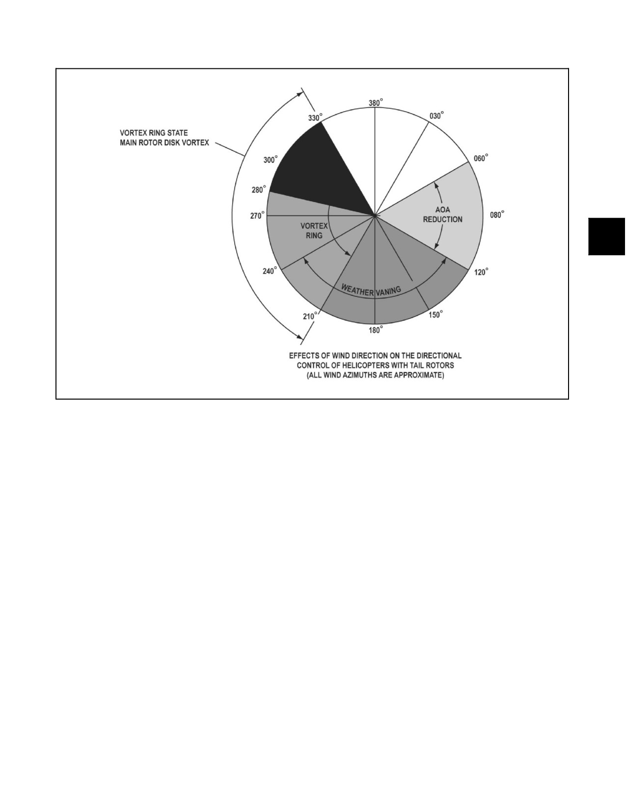
A1-H60BB-NFM-000
Figure 11-2. Wind Effects on the Tail Rotor
11.3.2.6 Recovery from LTE
Should LTE occur, correct and timely response is critical. If the response in incorrect or slow, the yaw rate may
accelerate to a point where it is extremely difficult to recover. One or more complete revolutions may be experienced.
The appropriate responses to LTE can be achieved by:
1. Altitude permitting, lowering the collective to reduce torque and assist in arresting right yaw; however, if a
significant rate of descent is established, the additional power required to arrest the rate of descent may
aggravate or reinitiate loss of tail rotor effectiveness.
2. Using forward cyclic to increase airspeed and, if necessary, turning in the direction of rotation. This results
in a reduction in tail rotor thrust required and produces a streamlining effect.
3. At very low speeds or in a hover, application of full left pedal may arrest the right yaw. Understand that the
control inputs may take several seconds/revolutions to take effect partially due to the effects of momentum
and ambient conditions. Neutralizing the pedals, adding right pedal, or increasing collective will only
accelerate the yaw rate.
11.3.2.6.1 Angle of Attack (AOA)
Reduction region (060° to 120° relative). Relative winds in this region decrease the effective AOA on the tail rotor
blade element, thereby decreasing tail rotor thrust and resulting in the nose spinning to the right. This condition can
bedemonstrated in sideward flight to theright, which requires moreleft pedal input as sideslip speed increases.Also,
the right--wing down attitude required for sideslip makes the plane of the tail rotor blades more vertical so that more
of the relative wind is perpendicular to the tail rotor disk.
11-5
ORIGINAL
A1-H60BB-NFM-000
11.3.2.6.2 Weather Vaning (120° to 240° relative)
Relative winds in this region can blow on the tail pylon and cause the helicopter to spin right or left in an attempt
to place relative wind on the nose. This condition can be demonstrated in rearward flight where the nose appears to
swing randomly left and right and it is difficult to keep heading constant.
11.3.2.6.3 Vortex Ring State (210° to 330° relative)
Relative winds in this region can cause the tail rotor to ingest its own vortex (as in the main rotor at high rates of
descent and low forward airspeed). This causes a loss of tail rotor thrust and the helicopter will spin to the right. The
20° tilt of the tail rotor disk tends to help prevent this problem because the relative wind would need an upward
component to blow the vortex directly on the plane of the blades. This effect is not very apparent in sideward flight
to the left because the left--wing--down attitude required places the plane of the tail rotor blades flatter with respect
to the horizon. The vortex is blown off the right side of the tail rotor disk.
11.3.2.6.4 Main Rotor Disk Vortex (280° to 330° relative)
Relative winds in this region can cause the main rotor disk retreating blade vortex to impinge on the tail rotor blades.
This can result in sudden losses and surges to tail rotor thrust at aconstant pedal setting. It can result in thehelicopter
spinning right without enough left pedal authority to stop it. Surges in tail rotor thrust are easily controlled by
reducing left pedal input during the surge.
11.4
MANEUVERING FLIGHT
11.4.1 Maneuvering Flight Characteristics
Maneuvering flight is accomplished by moving the cyclic in the direction of the desired turn. Above 50 KIAS, the AFCS
will assist in moving the directional control pedals as required to maintain balanced flight. Above 30° angle of bank, aft
cyclic will be required to maintain the desired airspeed. In a decelerating turn, the AFCS will switch from a turn
coordination mode to a heading hold mode as the aircraft passes through 50 KIAS. Normal maneuvers are restricted to
the maneuvers and airspeed limitations as depicted in Chapter 4. A portion of the information in this section particularly
applies to highly dynamic maneuvering flight such as might be executed during evasive maneuvering.
11.4.2 Coordinated Flight
The slip/skid indicator (ball) is designed to indicate lateral acceleration on the aircraft due to sideslip in steady
zero--net--acceleration flight. In slow speed (less than 60 KIAS), high AOB (greater than 25°), nonsteady (transient)
turns, the predominant component of lateral acceleration is the weight vector, not sideslip--induced acceleration.
During slow speed, high AOB, transient turns, balanced flight (minimal sideslip) can best be maintained by
maintaining pedal position that centers the ball. Intentional sideslip within limits is permissible during maneuvering
flight; however, to prevent occurrence of high tail rotor component loads, left pedal application beyond that required
for balanced flight should only be attempted at midposition or lower collective settings.
CAUTION
Centering the ball in slow speed, high AOB, and transient turns induces
large values of aircraft sideslip and may cause high tail rotor component
loads in left turns.
Note
When a requirement to achieve a slow--speed, high--rate turn to the left
exists, such as during evasive maneuvering, lowering the collective may be
necessary to reduce main rotor torque; associated tail rotor antitorque
requirement will greatly facilitate the turn, resulting in higher turn rates.
ORIGINAL
11-6
A1-H60BB-NFM-000
11.4.3 Tail Rotor Spar Loads in Maneuvering Flight
Counterclockwise turning single main rotor helicopters exhibit transient torque increases in forward flight with roll
rates to the left. Left roll rate increases retreating blade AOA, driving torque up, and main rotor precession loads
contribute further to this effect. Left roll rates (above approximately 30° per second in forward flight above 75 KIAS)
can combine with induced tail rotor gyroscopic and flapping loads to cause excessive tail rotor spar loading.
CAUTION
When executing high roll rate maneuvers to the left, collective should be
lowered concurrently with maneuver initiation to control transient torque
increases and reduce high tail rotor spar loads. Left roll rates in excess of
30° per second should be avoided in forward flight above 75 KIAS to
prevent damage to the tail rotor spar.
11.4.4 Main Rotor Vertical 4/Rev Vibration Cueing
During maneuvering flight, main rotor component fatigue damage occurs simultaneously with an increase in main
rotor vertical 4/rev vibration level. As an increasing G level is placed on the aircraft, the 4/rev onset will appear and
is noticed as an increasein aircraft roughness similarto that of the4/rev shudderexperienced when flying theaircraft
through transitional lift. The4/rev vibration onset is an indication that the lift--generating capability ofthe main rotor
has been exceeded and that a main rotor stall region has been created. Further attempts to increase load factor will
only increase the blade stall region, resulting in reduced maneuverability and increased component fatigue damage.
If a noticeable increase in main rotor 4/rev vibration level is observed, relax G level slightly until 4/rev vibrations
decrease to a normal level. The most effective method of reducing the stall--related main rotor 4/rev vibration level
is to reduce collective.
CAUTION
Significant increased main rotor 4/rev vibration level during maneuvering
flight indicates the onset of retreating blade stall. Main rotor component life
is being reduced and aircraft maneuvering performance degraded.
11.4.5 Main Rotor Flapping Margin
Main rotor flapping margin, a measurement of the amount of blade spindle displacement remaining in the flapping
(vertical) axis before blade motion stops are contacted, may be reduced to zero by maneuvers involving large and
rapid application of forward cyclic. Main rotor flapping margin is especially reduced when rapid forward cyclic is
coupled with low collective settings and/or aft longitudinal cg.
CAUTION
Inducement of less than 1 g flight by rapid application of forward cyclic will
result in decreased cyclic authority and may result in exceeding main rotor
flapping margin limits and droop stop pounding.
11.4.6 High AOB Turns
Figure 11-3 shows how the vertical (lift) component of main rotor thrust decreases with increasing AOB. In order
for the aircraft to maintain level flight, main rotor thrust must be increased so that lift will remain equal to weight.
For example, if a pilot does not apply additional collective in a 45° AOB turn at 300 feet, the aircraft will crash in
less than five seconds. Application of additional collective or a reduction of airspeed pitch allows the aircraft to
perform level turns.
11-7
ORIGINAL
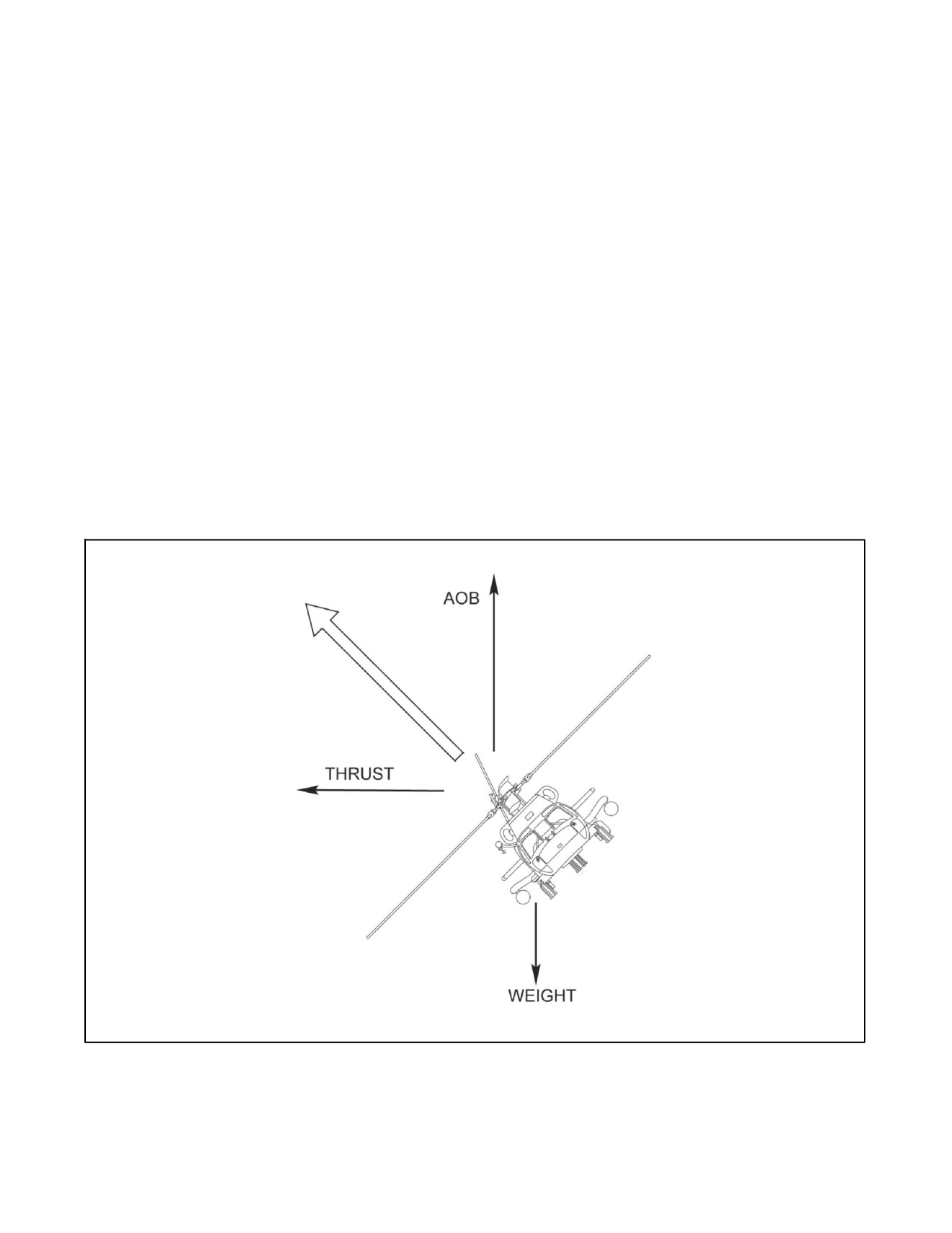
A1-H60BB-NFM-000
11.4.7 G-Loading in Turns
Accelerated or turning flight (G--loads) can be established by using aft cyclic and/or collective control. Cyclic
maneuvering provides a transient maneuvering capability because forward airspeed will decrease. As airspeed
decreases, transient rotor thrust decays as a result of less mass flow through the rotor disk; therefore, there is less
energy to complete the maneuver. Sustained maneuvering must be accomplished by application of collective power
so that theaircraft speed and energy areconserved. Transient G--loads applied using aft cyclic result in airspeed bleed
and eventual flight at speed less than bucket speed. Sustained G--loads applied with collective increase power required
for level flight at that airspeed (due to AOB), which results in a decrease in excess power. Maneuvers at slow speeds
are incapable of resulting in structural damage because the aircraft will encounter an aerodynamic limit of rotor thrust.
High--speed maneuvering can result in main rotor transient (cyclic) and sustained (collective) power exceeding
structural limitations. G--loads encountered in level coordinated turns at various AOB are presented in Figure 11-4.
11.4.8 Rolling Pullouts
Another situation where an aircraft can generate high G--loading is during a rolling pullout (Figure 11-5). Due to
centrifugal acceleration (G--loading), the weight vector of the aircraft increases. Lift produced by the rotor system
must be increased proportionally to the G--load to arrest the descent and establish level flight. Power can be applied
by transient powerinput (aft cyclic)and sustained powerinput (collective). This can resultin asituation wherepower
required for recovery greatly exceeds total power available in the rotor system and “mushing” occurs. During
“mushing,” the aircraft will continue to descend rapidly even though maximum power may be applied; longitudinal
cyclic control will feel sluggish, a noticeable increase in Main Rotor Vertical 4/Rev Vibrations (see paragraph 11.4.4),
and retreating blade stall may occur.
Figure 11-3. Main Rotor Thrust vs. AOB
ORIGINAL
11-8
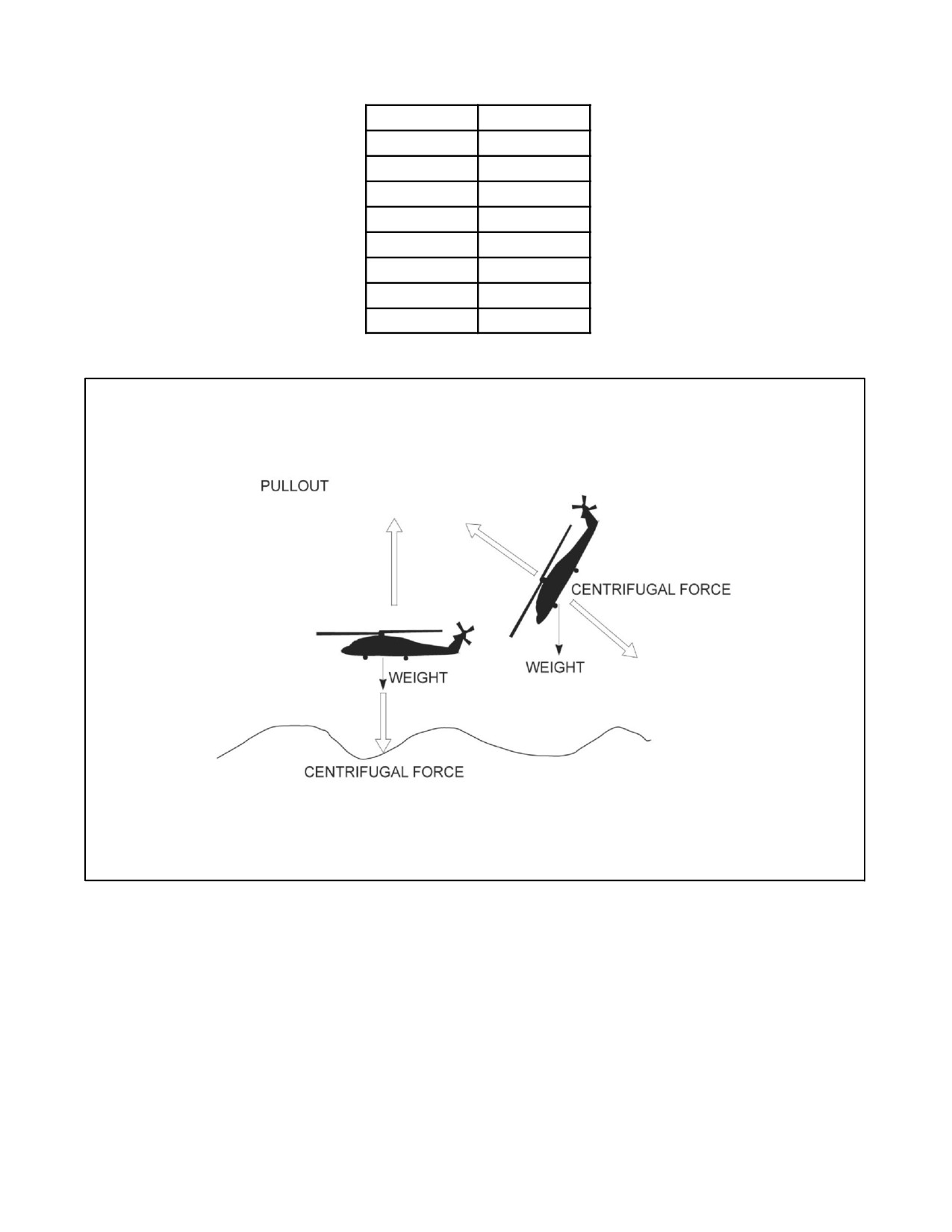
A1-H60BB-NFM-000
AOB (_)
G--Load
0
1.00
10
1.02
30
1.15
45
1.41
60
2.00
75
3.86
85
11.50
99
58.82
Figure 11-4. G-Load while Maintaining Altitude and Airspeed at Listed AOB
Figure 11-5. The Rolling Pullout
11.4.9 High AOB (High-G) Maneuvering Effects on Lateral cg Margin
Helicopter center of gravity limits are based on non--accelerated flight (1 g). This is particularly true of lateral center
of gravity limits. High angle--of--bank turns narrow the lateral cg margin. With an excessive asymmetrical load (i.e.,
all stores and/or auxiliary tank on one side), a high AOB turn into the stores--heavy side can reduce the lateral cg
margin to the point where there is not enough cyclic authority to roll back out of the turn. This can occur even though
the lateral cg position is within static (1 g) limits. The result is an uncontrolled spiral into the deck.
11-9
ORIGINAL
A1-H60BB-NFM-000
In situations where loss of lateral control is experienced in a steep turn and
asymmetrical stores load/shift in lateral cg is the suspected cause,
consideration should be given to jettisoning the stores. This should shift the
lateral cg sufficiently to provide enough control authority to recover from
the turn.
11.4.10 Power Required Exceeds Power Available
At high density altitudes, high gross weights, or when operating with reduced power, power required may exceed
poweravailable.Itmaynotbepossibletomaintainlevelflightduetolackofpower, whichwill causesettling tooccur.
The attendant loss of altitude is of minor consequence except in certain situations where sufficient altitude is not
available to achieve the airspeed necessary to maintain level flight. Careful preflight analysis of engine performance
and hover charts in Chapters 22, 23, 24, 25, 26, and 27 will aid in avoiding extreme situations. To recover from this
condition, complete the Emergency Malfunction In Flight procedures.
Note
The NATOPS density altitude calculation chart and charts indexed for
pressure altitude corrected to nonstandard temperature do NOT account for
the effect of humidity. High humidity has negligible effect on power
available, but a great effect on power required. The effects of humidity on
power required become apparent above 40 percent relative humidity. A
good rule of thumb is to add 100 feet to DA for every 10 percent of relative
humidity above 40 percent. Some weather briefs use “virtual temperature”
or temperature corrected for humidity to calculate density altitude. In this
case, no correction is necessary.
NTRP 3--22.2.4--SH60B contains a detailed description of Energy Maneuverability. Also included are a series of
charts relating speed, bank angle, and rate of climb/descent for various combinations of aircraft weight and
environmental conditions. These charts provide an invaluable preflight guide to maneuvering limitations.
11.5
DESCENDING FLIGHT AND AUTOROTATION
There are four flow states of a rotor system: Normal Thrusting, Vortex Ring, Autorotative, and Windmill Brake. Each
flow state represents a larger rate of descent relative to the induced velocity of the rotor system. In the normal thrusting
state of the rotor system, vortices are concentrated at the blade tips. The velocity profile of air relative to the rotor
is downward across the entire rotor disk. This is the condition encountered in hover, forward flight, climbing flight,
and slow rates of descent.
11.5.1 Vortex Ring State/Power Settling
Vortex ring state describes an aerodynamic condition where a helicopter may be in a vertical descent with maximum
power applied and little or no cyclic authority. The term “power settling” comes from pilot observations that the
helicopter keeps settling even though full engine power is used. In a normal, out of ground effect hover, the helicopter
is able to remain stationary by propelling a large mass of air down through the main rotor. Nearthe tips of theblades,
some of the air is recirculated, curling up from the bottom of the rotor system and rejoining the air entering the rotor
from the top. This phenomenon is common to all airfoils and is known as tip vortices. Tip vortices consume engine
power but produce no useful lift. As long as the tip vortices are small, their only effect is a small loss in rotor
efficiency; however, when the helicopter begins to descend vertically, it settles into its own downwash, which greatly
enlarges the tip vortices. This is the vortex ring state where most power developed by the engines is wasted in
accelerating the air in a doughnut pattern around the rotor while Nr remains at 100 percent.
ORIGINAL
11-10
A1-H60BB-NFM-000
The effect is measurable at descent rates greater than 700 fpm and airspeeds between 0 and 20 KIAS and is the worst
at descent rates of approximately 1,500 fpm with airspeeds of 5 to 10 KIAS. Fully developed vortex ring state is
characterized by an unstable condition where the helicopter experiences uncommanded pitch and roll oscillations,
has little or no cyclic authority, and achieves a descent rate that may approach 6,000 fpm. It is accompanied by
increased levels of vibration.
Flight conditions causing vortex ring state should be avoided at low
altitudes because of the attendant loss of altitude necessary for recovery.
Recovery from fully developed vortex ring state may require entering
autorotation before regaining airspeed.
Note
Vortex ring state may also be entered during any dynamic maneuver which
places the main rotor in condition of high upflow and low longitudinal
airspeed. This condition is frequently seen during “quick stop” type
maneuvers or during autorotational recoveries.
To recover from this condition:
1. Decrease collective pitch.
2. Move cyclic forward.
3. Enter autorotation if altitude permits. A considerable loss of altitude may occur before the condition is
recognized and recovery is completed. During approach for landing, conditions causing vortex ring state
should be avoided.
11.5.2 Autorotative State
The autorotative state of the rotor system results in a lift--producing rotor with sufficient steady--state driving forces.
The autorotative state can be achieved at descent velocities between approximately 3,125 fpm and 4,450 fpm at
19,000 pounds. gross weight. A rotor disk in a steady--state autorotation is shown in Figure 11-6. The prop region
is 30 percent ofthe rotordisk, theautorotative region is 45 percent, and the stall region is 25 percent. The prop region
creates usable lift. The auto region produces forward--tilting force that creates both lift and a pro--rotational force that
overcomes bladedrag and keeps therotorspinning at aconstant rpm. Thestall region creates only drag (Figure11-6).
A steady--state autorotation is a balance between lift, drag, and rotational forces on the rotor system. An autorotation
is a dynamic exchange of potential and kinetic energies. Energy needed to keep the rotor turning at 100 percent Nr
and producing useful lift and rotational forces is gained from a decrease in helicopter potential energy (i.e.,
descending flight).
11.5.3 Autorotational Entry
The major variables affecting autorotational entry are altitude, airspeed, Nr, power state before entry, AOB, balanced
flight, yaw, and rotor inertia. The SH--60B has relatively low rotor inertia. Slow pilot reaction time can lead to Nr
decaying to unrecoverable levels in as little as two seconds. Nr decay rate will be greater when the helicopter is at
a high power condition before entry (i.e., climbing or at high speed). In general, more airspeed on entry is better up
to the maximum autorotational airspeed of 100 KIAS because the kinetic energy of forward flight can be translated
into spinning the rotor system as the aircraft slows down. The higher the altitude, the more time is available to
establish a steady--state autorotation.
11-11
ORIGINAL
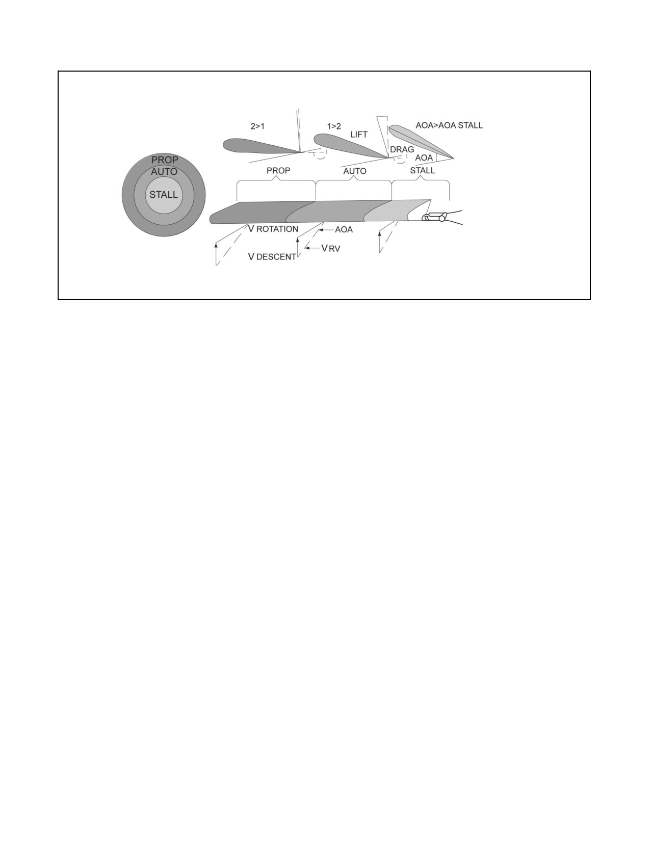
A1-H60BB-NFM-000
Figure 11-6. Stall Region in an Autorotative Descent
11.5.3.1 Autorotational Descent
The major variables affecting autorotational descent are airspeed, Nr, AOB, yaw, gross weight, and density altitude.
Minimum rate of descent airspeed in an autorotation is approximately 75 KIAS. A decrease or increase in airspeed from
this value results in an increase in rate of descent. Increasing airspeed above 75 KIAS increases glide distance up to the
maximum glide airspeed of approximately 95 KIAS. Practice autorotations are typically shot at five knots faster than the
optimum descent and distance values. This allows the aircraft speed to slow toward an ideal condition instead of away
from it. For a given gross weight, there is one ideal rotor rpm that will provide the minimum rate of descent. As rotor
rpm is allowed to build above ideal, rate of descent increases. This is because the increase in rotor speed comes at the
expense of aircraft potential energy (i.e., a higher rate of descent). As rotor rpm decreases from ideal, the rate of descent
increases. A heavy aircraft actually will descend slower in a steady--state autorotation than a lighter one. This is because
a heavier aircraft can have a greater rate of exchange of potential energy (altitude and weight) into kinetic energy (rpm)
of the rotor system. A rotor system with more kinetic energy needs more collective pitch to govern it to the optimum rpm.
More collective pitch means more lift, therefore a smaller rate of decent for heavier aircraft. AOB increases G--loading,
which equates to a larger weight vector. A larger weight vector means that more potential energy can be traded for rotor
system kinetic energy. Rotor rpm will increase in a turn. Governing Nr at optimum will require more collective pitch (more
lift); however, the lift vector is not vertical, so rate of descent will still increase in the turn. Yaw attitude affects autorotation
due to the amount of energy transferred to or taken from the drive system due to relative wind effects on the tail rotor
blades. A higher density altitude allows the blades to spin with less resistance; therefore, more collective pitch is required
to govern to a given rpm at a higher density altitude.
Note
Aircraft descend at a higher rate at lower gross weights. Executing an
autorotation at lower gross weight allows management of momentum
(mass times velocity) during the recovery and lowers the power required
to hover upon completion. A heavier aircraft has more momentum (both
downward and forward) than a lighter aircraft, requiring more power to
arrest aircraft rate of descent and velocity during the final flare and
collective pull, as well as requiring more power to maintain hover at
recovery altitude.
11.5.4 Autorotational Recovery
When executing a flare at the bottom of an autorotation, rotor rpm increases due to the trading of aircraft forward
kinetic energy (airspeed) for rotor system kinetic energy (Nr). This increase in rpm is governed to optimum by
ORIGINAL
11-12
A1-H60BB-NFM-000
adjusting collective pitch. The flare slows the rate of descent and since the rotor is now tilted aft, it helps slow the
forward speed of the aircraft. The aircraft attitude presents a more blunt cross section to the relative wind which also
helps slow the forward speed. In addition, the stabilator programs down, which helps slow the aircraft even more.
Final recovery is made by leveling the aircraft and applying collective pitch to cushion a tail wheel--first landing at
slow to zero groundspeed.
Note
In an actual autorotational flare, the pilot may choose to allow Nr to increase
above optimum for descent. The higher the Nr when executing the final
recovery, the more kinetic energy is available in the rotor system for the
collective pull that will cushion the landing as Nr decays.
11.6
ROLLOVER CHARACTERISTICS
11.6.1 Static Rollover
Static rollover angle is the angle at which the helicopter will tip over on its side if it is parked on a very steep
embankment. The static rollover angle of the SH--60B is approximately 28°. It occurs when the cg of the helicopter
is directly over the longitudinal axis passing through the tail gear and either main gear ground contact points.
11.6.2 Critical Rollover
Critical rollover angle is the maximum lateral angle of slope that can be negotiated in a takeoff or landing. At this
angle, full lateral cyclic input is required to trim the wheels level with the slope without sliding. With left wheel uphill
and brakes on, this angle is approximately 12°.
11.6.2.1 Dynamic Rollover
Dynamic rollover is an insidious dynamic condition that can occur during takeoff or landing with one wheel on the
ground and can result in destruction of the helicopter. It is not definable by a single number, nor is it simply a function
of slope angle or lateral control authority. These will aggravate a rollover condition, but the main contributor to
dynamic rollover is the buildup of angular velocity of the helicopter cg about the wheel touching the ground. When
the angular velocity about the wheel is greater than can becountered with full oppositecyclic, thehelicopter will roll
over. This situation can happen in less than two seconds. This is illustrated in Figure 11-7.
In this condition, the upsetting rolling moment is caused by the helicopter acting about the wheel ground--contact
point. Thus, the wheel restraint converts the lateral translation (drift) into an angular motion (roll rate) or angular
momentum. The roll rate can be very large depending on sink and drift speeds and the degree of wheel restraint. In
addition, a rolling motion to the right will be made worse by the thrust produced from the tail rotor. Conversely, a
roll to the left will decrease as the tail rotor thrust acts to provide deceleration. Upon contact with the ground, the
roll center is transferred from the helicopter cg to the touchdown wheel, resulting in higher roll inertia. The roll inertia
about the ground contact wheel can be five times greater than the roll inertia about the cg. The resulting roll rate can
be checked with opposite lateral cyclic, but lateral control will be only 1/5 of fully airborne, and the aircraft response
will be sluggish and limited by maximum cyclic displacement. If lateral cyclic cannot be displaced far enough to tilt
the rotor lift vector outside the wheel tread, then rotor lift adds to the rolling moment. Since rotor lift opposes the
only restoring force remaining, lift should be reduced.
Note
If encountering a situation where only one wheel is in contact with the
ground and a rolling moment is present, smooth reduction of collective is
the most effective corrective action the pilot can take to prevent dynamic
rollover.
11-13
ORIGINAL
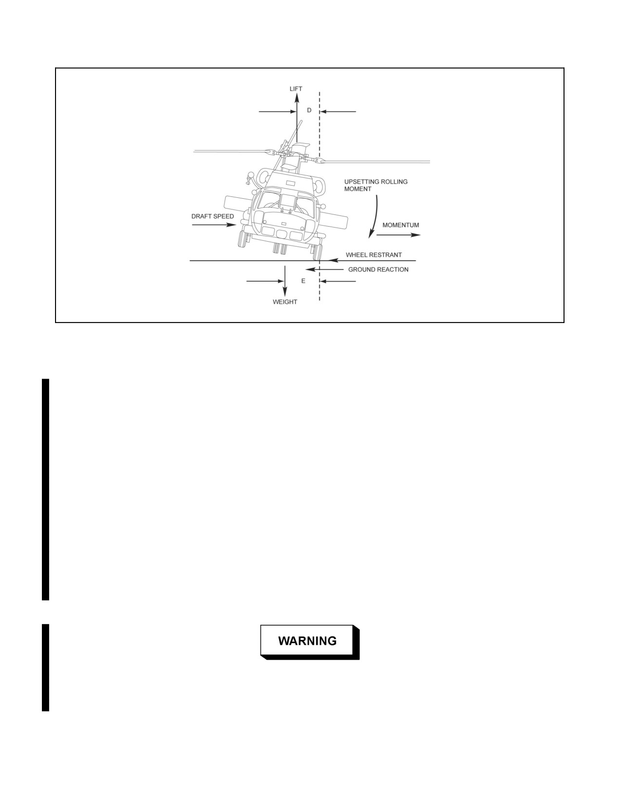
A1-H60BB-NFM-000
Figure 11-7. Dynamic Rollover
11.6.3 Slope Landing/Takeoff Considerations
There are three major forces in slope landings and takeoffs (Figure 11-8). These major forces are helicopter weight,
rotor lift, and ground reaction (normal and friction forces). In general, the helicopter is controlled using collective
to balance weight with rotor lift and tilting the rotor lift into theslope, this adds to wheel friction and prevent sliding.
Slope landings can be grouped into three separate classifications: cross--slope, up--slope and down--slope.
Consideration should be given to setting the parking brake prior to landing. With the parking brake applied, an
increased potential exists for dynamicrollover; without applying theparking brake, increased potential exists forthe
helicopter to slide from the landing site. Fly the appropriate approach to a hover. From a hover the aircrew should
continuously clear and direct the helicopter for landing gear placement. Slope landings should be executed as slow,
controlled, vertical descents. The PAC should descend slowly, placing the up--slope wheel on the ground first.
From the moment the up--slope wheel touches the ground and until it is lifted from the ground, the principal control
is collective. Attempt to maintain the rotor disc level with the horizon throughout the landing and takeoff. As
collective is decreased cyclic must be displaced toward the up--slope side. As collective is increased cyclic must be
moved toward the neutral position. Balance between the two controls is indicated by a rotor disc that is level with
respect to the horizon.
Aft cyclic positions, in conjunction with low or decreasing collective pitch,
may cause rotor blades to contact the tail pylon resulting in loss of tail rotor
drive.
ORIGINAL
11-14
A1-H60BB-NFM-000
Note
D When landing site is a combination of cross--slope and up-- or down--slope,
use the most restrictive slope landing limit. Be prepared to execute a
combination of control inputs to maintain stability.
D Depending on slope and helicopter configuration, the tail wheel may touch
down prior to the up--slope wheel.
11.6.3.1 Cross--Slope Landing
In a cross--slope environment, lateral cyclic still provides roll control, but the control power is reduced to 1/5 of its
airborne value.
Once the up--slope wheel touches the ground slowly lower the collective, coordinating lateral cyclic into the slope
until the down--slope wheel is also on the ground. The controls should always be positioned to keep the helicopter
from drifting. Continue coordinated movement of the collective and lateral cyclic until all of the helicopter weight
is resting firmly on the ground. If lateral cyclic control contacts the stop, or if rotor--to--ground clearance becomes
marginal before the down--slope wheel is firmly on the ground, return to a hover by slowly raising collective and
centering cyclic. Select another landing site with a shallower slope. After the slope landing is completed, ensure that
the helicopter will not slide or sink while smoothly lowering the collective to a full down position. As collective is
lowered, adjust lateral cyclic input to maintain the rotor disc as level as possible. This has the effect of maintaining
the CG on the up--slope side of the helicopter.
During cross--slope landings, rotor clearance is decreased on the up--slope
side. Personnel should traverse the rotor arc on the down--slope side of the
helicopter.
CAUTION
During cross--slope landings, avoid rapid collective reductions to prevent
blades from striking the ground and high roll rates about the up--slope
wheel.
11.6.3.2 Up--Slope Landings
For up--slope landings where main mounts touch first, longitudinal cyclic (either forward or aft) may be required with
coordinated collective movement to safely lower the tail wheel to the ground. If the tail wheel touches down first,
thePACshallmakesmooth,coordinatedcyclicinputssimilartoanormallanding.Amoreforwardthan normalcyclic
position may be required to prevent rolling down the slope backwards. With the tail wheel on the ground, smooth
coordinated cyclic and collective movements are required to control pitch rate and aircraft position until main mounts
are on deck. As the helicopter nears max up--slope nose attitude, the PAC should arrest pitching moment to ensure
limit is not exceeded.
11.6.3.3 Down--Slope Landings
Once the tail wheel touches the ground, slowly lower the collective, coordinating aft cyclic until the main mounts
are on deck.
11-15
ORIGINAL
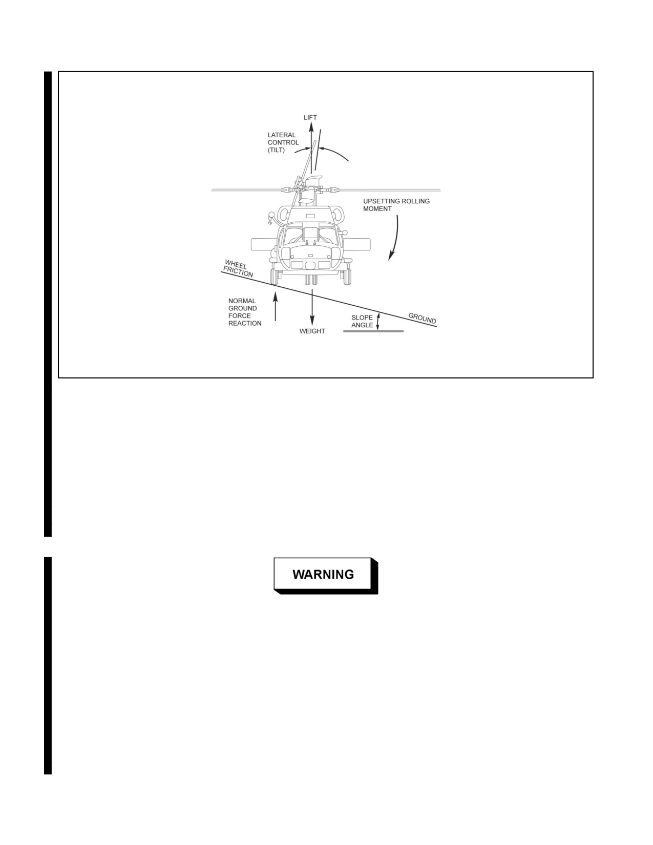
A1-H60BB-NFM-000
Figure 11-8. Slope Landing Takeoff Forces
11.6.3.4 Take Off
Slope take offs should be made by first moving cyclic into the slope to prevent drift. Using coordinated collective
and cyclic, increase power while adjusting cyclic to raise the downhill wheel first until the helicopter becomes level
and lifts off the ground. Avoid large cyclic inputs when the helicopter becomes airborne, because the roll center will
now shift back to the helicopter’s CG and full control authority will be restored. If thehelicopter rolls past level (into
the slope) during takeoff, lower collective rapidly but smoothly to avoid dynamic rollover -- check for a blocked or
hung--up wheel.
When taking off or landing on a sloping or rough surface, the helicopter can
be subjected to conditions which, with the slightest inattention by the pilot
to developing roll rates, can result in almost certaindestruction bydynamic
rollover. Keep the helicopter under control at all times. When landing or
taking off with one wheel touching the ground, use smooth collective
motion to maintain low roll rates.
The following procedures shall be observed to ensure safe landing/take off in a slope environment:
1. Execute all landings/take offs smoothly and maintain low roll rates.
2. Take off slowly so that induced roll rates can be easily controlled.
3. Maintain wheels--level during all landings/take offs.
ORIGINAL
11-16
A1-H60BB-NFM-000
4. Always lift the downhill wheel first during take off.
5. Do not allow helicopter to drift.
6. If lateral control feels sluggish, reduce collective and check for obstructions.
7. To control roll rate, reduce collective smoothly. Avoid fast collective reductions to prevent blade strike or
induced high rates of roll about up--slope wheel.
11.7
SALTWATER POWER DETERIORATION
Salt spray ingestion in the engine may result in a loss in performance. This deterioration will be noticed as an increase
in TGT foragiven torque. The circumstances under which power deterioration may occurduring saltwateroperation
vary with a number of factors. The flight regime, gross weight, wind direction and velocity, pilot technique, duration
of maneuver, salinity of the water, and the relative density of the salt spray all have a bearing on performance
deterioration, though wind velocity and hover altitude have the most significance. Intermittent operation in moderate
salt spray conditions could expose the engines to enough salt spray to cause noticeable performance deterioration.
During prolonged operations, power deterioration will be readily apparent. Maneuvers such as hovering close to the
water in light winds, or low flights at low speeds, will generate maximum rotor downwash spray conditions. The
amount of spray observed on the windshield is the best indication of spray ingestion.
While operating in a salt spray environment for any period of time, a TGT
rise of 20 °C or more for constant torque is an indication of engine
performance degradation and possible salt encrustation. A TGT rise of
greater than
40 °C for a constant torque is an indication of engine
performance degradation which may result in compressor stall(s).
CAUTION
D Take note of windshield spray deposits. The amount of saltwater spray
observed on the windshield is usually the best indication of the salt spray
environment to which the engines are being subjected. If the spray on the
windshield is sufficient to require use of the windshield wipers, the engines
are ingesting a very significant amount of salt water. In this condition, there
is a probability of performance degradation thus, an increase in altitude is
recommended.
D In the event that hovering is necessary in the above conditions, the best
indication of performance loss is the relationship between TGT and torque.
Note
Continued engine operation in clean air may dissipate some of the salt
buildup, but this cannot be assured. Flight through rain may also be
beneficial in reducing salt buildup, thereby improving performance.
11-17
ORIGINAL
A1-H60BB-NFM-000
11.8
FLIGHT WITH EXTERNAL LOADS
It is very important that the pilot know the riding characteristics of certain loads and the associated flight control
applications. All maneuvers that are made with external cargo loads should be gradual and well coordinated. Care
must be taken when flying with external loads that have aerodynamic characteristics (i.e., light aircraft, wings, tail
sections, sheet metal, plywood, etc.). The aerodynamic lift capabilities of these loads may amplify any oscillation
and cause the load to contact the helicopter. Hovering and turns while hovering present no unusual problems;
however, some helicopter oscillation may be noticed with low density bulky cargo when in level flight. This
oscillation can beminimized by the useof smooth control movements. When making turns at higher airspeeds, more
than the normal opposite lateral cyclic displacement is necessary to prevent excessive rolling motion into the
direction of turn. This tendency increases with airspeed and requires a slightly larger turning radius than would be
required at the same gross weight with an internal cargo load. More than normal amounts of cyclic displacement are
necessary to overcome the external cargo inertia when initiating or stopping sideward flight; however, slow steady
sideward flight presents no problems. Experience has shown that for any type of external cargo load, there is an
airspeed best suited for that particular load. This speed may vary from very low speeds with some loads to cruise
speeds or above for others. There is no one rule for flying external loads as the combination of weight, dimension,
and shape all have a direct bearing on the action of the load during flight. Increased power requirements will be
necessary to hover large flat loads that create a vertical drag factor than to hover loads of the same weight but smaller
configuration. However, if control movements are smoothly applied to preclude oscillation, and airspeed is slowly
increased to determine the riding characteristics of the load and the best airspeed for it to be flown, external cargo
can be flown satisfactorily. If high airspeeds or turbulence should cause a load to oscillate, the oscillation can be
reduced by decreasing airspeed and increasing collective.
Note
The parasitic drag of an external load will increase fuel consumption
significantly.
11.9
HELICOPTER VIBRATION
The inherent vibrations in any helicopter are those created by the mechanical functions of the engines and
transmission systems, dynamic action of the main and tail rotors, and aerodynamic effects on the fuselage. The overall
vibration level is influenced by the many individual frequencies of vibration and combinations thereof. Many
multiples of a basic frequency are felt, and often two or more different superimposed frequencies create beats. The
overall magnitude is the resultant of the amplitudes of all the frequencies and it would be difficult for the pilot to
completely separate all the types of vibrations encountered. Generally, these are divided into three categories: low,
medium, and high frequencies. Varying magnitudes of all three types of vibrations are often present in an individual
helicopter. Only through experience will the pilot be able to judge what is normal to the model and what is abnormal
and correctable. Excessive or abnormal vibration levels should be noted on a VIDS/MAF.
11.9.1 Main Rotor Specific Vibrations
11.9.1.1 One-Per-Revolution (4.3 Hz)
This vibration emanates from the main rotor system and is generally caused by main rotor head or blade imbalances.
It produces a rotary excitation of the fuselage which feels like a lateral oscillatory roll to the pilot. At high speeds,
one--per--revolution vibration will most likely be felt as a vertical vibration. The most probable causes are:
1. Main rotor blades out of track. A blade track adjustment is not warranted even though the blades visually
appear to be slightly out of track if a one--per--revolution vibration is not present. Out--of--track condition could
be caused by:
a. Damaged main rotor blade trailing edges.
b. Main rotor blade dynamic balance beyond tolerances.
ORIGINAL
11-18
A1-H60BB-NFM-000
2. Worn or loose control rod end bearings. If the vibration is present in a hover only, the cause could be the same
as above, plus:
a. Main rotor blade static balance beyond tolerances.
b. Rotor head out of balance.
3. Malfunctioning blade damper.
11.9.1.2 Ground One-per-Revolution
This is a one--per--revolution lateral roll of the helicopter which often occurs during rotor engagement and is due to
the in--place misalignment of the main rotor blades, causing an out--of--balance condition in the main rotor system.
When the rotor attains flying speed, centrifugal force normally aligns the blades and the vibrations disappear. If the
vibration continues with the rotor up to speed at flat pitch but disappears when the helicopter is lifted into a hover,
the cause could be one of the following:
1. Static imbalance of the main rotor blades or rotor head.
2. Improper servicing of the landing gear strut.
11.9.1.3 One-per-Revolution (6.5 Hz)
This vibration is most probably caused by an initial aerodynamic upset which is amplified and maintained as a result of
an SAS and pilot--induced oscillation (PIO) in the longitudinal cyclic.
This vibration will most likely be encountered during autorotations over 100 KIAS at approximately 3,500 fpm rate of
descent, turns above 45° AOB, diving recoveries, or sideslips.
11.9.1.4 Four-per-Revolution (17.2 Hz)
This most common inherent vibration is caused by the dynamic response of the main rotor blades to asymmetrical
blade loading. Its intensity is greatest at low--forward speeds and during transition to a hover. It is felt as alateral/roll
shake caused by the main rotor blades traversing the downwash of preceding blades. This vibration normal to the
helicopter when felt at the point where the collective pitch is increased to sustain a hover, or when air taxiing the
helicopter just prior to applying collective pitch, and by planning the approach so that the hover can be attained with
a slow rate of final pitch application. At high speeds, the difference in the lift distribution between the advancing and
retreating main rotor blades results in heavy vibratory loads on the rotor head. It is felt as a combination of vertical
and lateral shake at the same frequency. The primary sources of excessive four--per--revolution vibrations are loose
or worn vibration absorbers, main rotor head pressure plates, swashplate and associated hardware, damper servicing,
loose stabilator, and loose cabin equipment and main landing gear struts (if experienced on deck only).
Note
D Adjusting the engine rpm switch will result in changes to four--per--revolution
vibration levels.
D Alongitudinal reversal ofthecyclicat lowspeeds(60to 90knots) mayresult
in momentary increase in four--per--revolution vibration.
11.9.2 Ground Resonance
Ground resonance is a phenomenon of multibladed helicopters like the SH--60B and is due to the cg of the rotating
blades traversing off center. Typically, it can happen during startup, takeoff, or landing. For the condition to occur,
there must be some abnormal lead/lag blade condition that would cause the cg of the rotors to progress outward,
causing further outward movement of cg. Ground resonance can be caused by a blade being badly out of track, a
peculiar set of landing conditions, or a malfunctioning damper. Ground resonance can be pilot induced and may occur
when a landing is made with a large descent coupled with lateral drift. When a wheel reaction occurs, such as a hard
one--wheel landing that would cause out--of--phase main rotor blades to be aggravated to the point where maximum
lead and lag blade displacement is realized, ground resonance can occur. If ground resonance should occur, primary
consideration should be given to getting the helicopter airborne. If this is impossible, immediately reduce collective
pitch, place the PCLs to OFF, and apply the rotor and wheel brakes.
11-19
ORIGINAL
A1-H60BB-NFM-000
11.9.3 Tail Rotor Specific Vibrations
11.9.3.1 Tail Shake (Five Cycles per Second)
Tail shake is an aerodynamic excitation of the first lateral bending mode of the tail pylon in certain flight regimes.
This vibration will be felt as a random impulse around the yaw axis and may be more apparent with an aft center of
gravity.
11.9.3.2 Tail Rotor Drive Shaft Vibrations (High Frequency)
Generally, these vibrations are caused by an unbalanced drive shaft, bad bearings, or a failing tail/intermediate
gearbox. These vibrations can be identified during a ground run by feeling the tail cone and can also be felt as a buzz
in the pedals or a tickling in the nose similar to that of a feather.
11.9.3.3 One Times Tail Rotor Speed (20 Hz)
This vibration (1,189 cycles per minute at 100 percent) may be due to tail rotor imbalance, damage, loose hardware, pitch
change link bearing wear, or loose tail or intermediate gearbox, and is not easily isolated by the pilot. Since this frequency
is close to four per revolution (1,032 cycles per second), the vibration may be difficult to distinguish from a four per
revolution. Also, they may modulate at a frequency of 170 cycles per minute and be hard to distinguish from a one per
revolution (258 cycles per minute).
ORIGINAL
11-20
A1-H60BB-NFM--000
PART V
Emergency Procedures
Chapter 12 — Emergency Procedures
63/(64 blank)
ORIGINAL