SH-60B HELICOPTER. FLIGHT MANUAL (2008) - page 7
A1-H60BB-NFM-000
OVERLAND PROCEDURES (LANDING)
STATION
ACTION
REPORT
1. PAC
Signify intention to commence an overland rescue.
LANDING CHECKLIST, CREW
RIG FOR RESCUE
2. PNAC
Complete Landing Checklist.
CHECKLIST COMPLETE
3. HOIST
Complete rescue station preparation.
RESCUE STATION MANNED
OPERATOR
AND READY
4. ANY CREWMAN
Locate survivor and landing zone.
SURVIVOR IN SIGHT, ___
O’CLOCK, ___ YARDS
5. ANY CREWMAN
Direct PAC to survivor using SAR ICS terminology.
UTILIZE TERMINOLOGY IN
FIGURE 9--1.
6. PAC
After sighting survivor, mark on top survivor and
SURVIVOR IN SIGHT.
begin zone evaluation.
7. PAC
After marking on top, conduct a power check, wind
ON TOP NOW, NOW, NOW.
finding and zone evaluation (SWEEP checks).
8. PNAC
Compute HOGE torque.
POWER REQUIRED TO HOGE
IS --_______.
9. PAC
Announce type of approach, power available, wave-
POWER AVAILABLE IS _____,
off torque, winds, and waveoff route.
WAVE OFF TORQUE IS ______
WINDS ARE _________, AND
WAVEOFF ROUTE WILL BE
__________.
10. PAC
Set up for an approach into the wind while
ON FINAL FOR A HOVER/NO
maintaining clearance of all obstacles.
HOVER LANDING.
11.
CREWMAN
Conduct ICS check, and provide airframe clear-
RIGHT’S UP/LEFT’S UP
ance.
12. PAC
Announce that the landing zone is disappearing
NOSE IN ZONE
underneath the nose of the aircraft.
13. CREWMAN
Provide final clearance to land. Ensure that aircraft
CLEAR RIGHT, CLEAR LEFT,
will remain clear of all obstacles. To direct PAC to
CLEAR TO LAND OR HOLD
remain clear of obstacles, utilize terminology in FIG
9--1.
14. PNAC
Calls torque, altitude and groundspeed.
15. CREWMAN
Ensure aircraft is established on solid ground after
CLEAR TO REDUCE
touchdown
16. PAC
Reduce collective.
REDUCING
17. CREWMAN
Embark personnel being rescued. When complete,
RESCUE STATION SECURE,
notify PAC.
CLEAR RIGHT, CLEAR LEFT,
CLEAR TO LIFT
18. PAC
Perform final check of instruments and takeoff.
LIFTING
Figure 9-6. Overland Procedures (Landing)
ORIGINAL
9-16
A1-H60BB-NFM-000
OVERLAND PROCEDURES (HOIST)
STATION
ACTION
REPORT
1. ANY CREWMAN
Locate survivor and pickup zone.
SURVIVOR IN SIGHT, ___ O’CLOCK,
___ YARDS
2. ANY CREWMAN
Complete Landing Checklist.
UTILIZETERMINOLOGYINFIGURE.
9--1.
3. PAC
After sighting survivor, mark on top survivor and begin zone
ONTOPNOW,NOW,NOW.
evaluation.
4. PAC
After marking on top, conduct a power check, wind finding
and zone evaluation (SWEEP checks).
5. PNAC
Compute HOGE torque.
POWERREQUIREDTOHOGEIS
--________.
6. PAC
Signify intention to commence an overland hoist rescue.
LANDING CHECKLIST, CREW RIG FOR
RESCUE.
7. PNAC
Complete Landing Checklist. Turn on the Backup Pump
ONTOPNOW,NOW,NOW.
and arm the Rescue Hoist, as required.
8. HOIST OPERATOR
Complete rescue station preparation.
RESCUESTATIONMANNEDAND
READY.
9. PAC
Announce type of approach, power available, waveoff
POWER AVAILABLE IS _____,
torque, winds, and waveoff route.
WAVE OFF TORQUE IS ______
WINDSARE______,AND
WAVEOFF ROUTE WILL BE______.
10. PAC
Set up for an approach into the wind while
ON FINAL FOR A ____ ft HOVER.
maintaining clearance of all obstacles.
11. CREWMAN
Direct PAC to pickup zone and remain clear of obstacles.
UTILIZETERMINOLOGYIN
FIGURE.9--1.
12.
PAC
Establish steady hover. Confirm power required and wave-
STEADY HOVER
off intentions.
13.
PAC
After the steady hover and hover references has been es-
STAND BY TO HOIST RESCUER
tablished.
14.
HOIST OPERATOR
Connect Rescue Aircrewman to double rescue hook.
15.
CREWMAN
Disconnect gunner’s belt.
16.
HOIST OPERATOR
Observe Rescue Aircrewman is clear of the gunner’s belt.
RESCUERSTANDINGBY
17.
HOIST OPERATOR
Check area clear of debris and over pickup spot.
PERMISSIONTOHOISTRESCUER
18.
PAC
Steady hover and instrument check.
HOISTRESCUER
19.
HOIST OPERATOR
Position Rescue Aircrewman into position to be hoisted.
RESCUEROUTSIDEOFCABIN
20.
HOIST OPERATOR
Lower Hoist cable/Rescuer.
HOIST/RESCUERGOINGDOWN
21.
HOIST OPERATOR
Hoist cable/Rescuer on deck.
HOIST/RESCUERONDECK
22.
HOIST OPERATOR
Observe ready for pickup from the rescue aircrewman and
IHAVEAPICKUPSIGNAL
or survivor.
23.
HOIST OPERATOR
Slack in. cable coming out.
STAND BY FOR WEIGHT ON
AIRCRAFT
24.
HOIST OPERATOR
Raise hoist cable.
RESCUEAIRCREWMEN/SURVIVOR
CLEAROFTHEDECK,HALFWAYUP,
AT CABIN DOOR, ABOARD
25.
HOIST OPERATOR
Secure rescue station.
RESCUESTATIONSECURE,
CLEARFORFORWARDFLIGHT
26.
PAC
Perform final check of instruments and takeoff.
DEPARTING
Figure 9-7. Overland Procedures (Hoist)
9-17
ORIGINAL
A1-H60BB-NFM-000
9.3
VERTICAL REPLENISHMENT (VERTREP) OPERATIONS
VERTREP involves the use of helicopters to resupply ships at sea while underway through external cargo transport.
With the external cargo hook installed, the aircraft is capable of rapid transport of cargo. Approved lifting equipment
and associated procedures are described in NA-80T-122, NWP 4-01.4.
The actual payload-lifting capability of the aircraft is a function of prelift gross weight, DA, and prevailing winds.
Power available and maximum payload, using applicable charts, shall be completed prior to commencing external
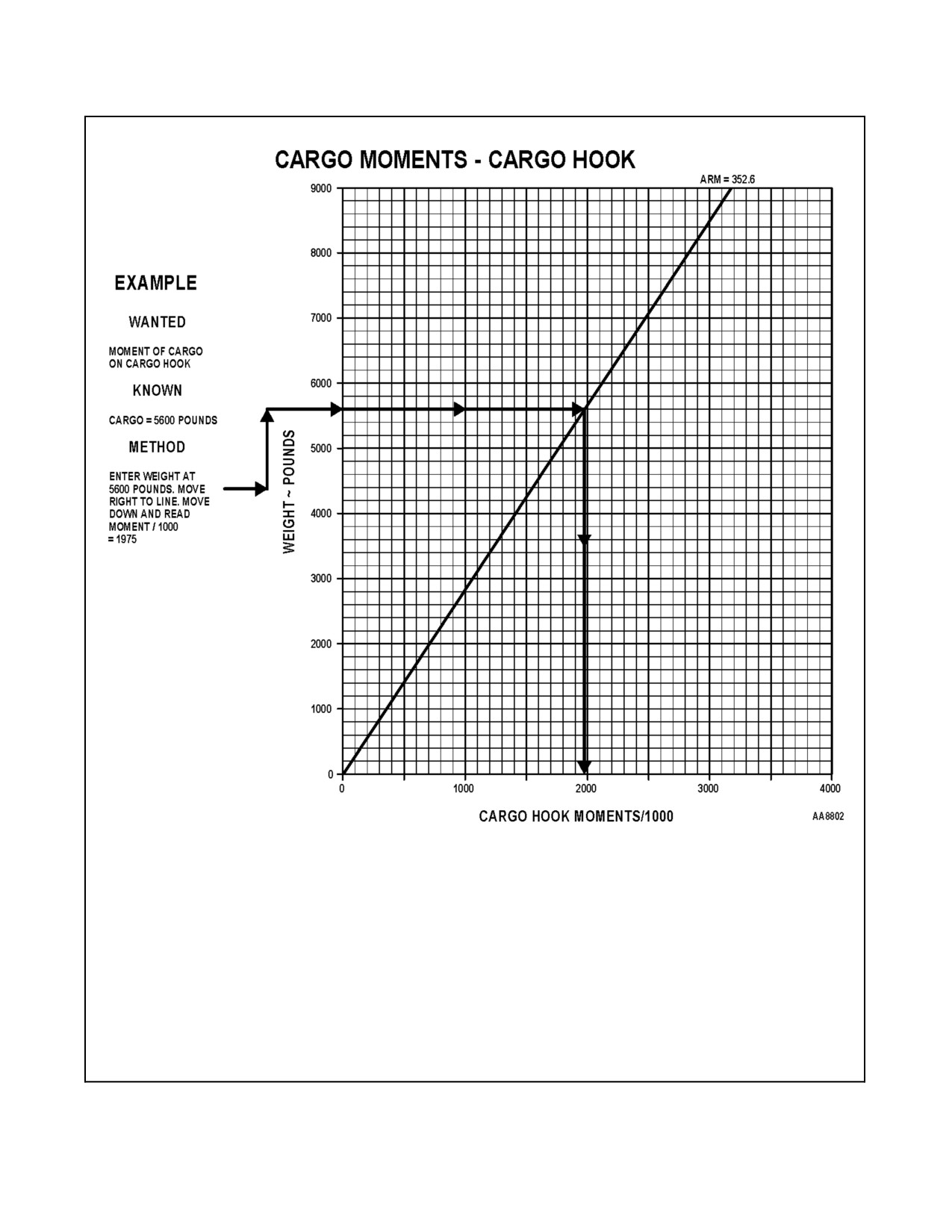
cargo transport. The crew must also be aware of the effect of the load on the moment of the aircraft. Figure 9-8
provides the cargo moments associated with weight on the cargo hook.
Under high power-required conditions, due to flight control mixing, pedal
position is not necessarily indicative of tail rotor authority remaining. In
particular, under high DA and aircraft gross-weight conditions, it is
possible to achieve maximum tail rotor pitch without obvious indications
from pedal position (e.g., relatively neutral pedal position or no contact of
left pedal stop). This condition will manifest in one of two ways: no yaw
response despite left pedal input or uncommanded right yaw.
The PIC shall brief the copilot, crewmen, and, if practicable, hook-up personnel. Hook-up procedures, release
procedures, and any special instructions shall be included in the brief.
D Light or irregularly shaped external loads may swing, oscillate, or "fly"
unpredictably. Should excessive load oscillations develop, an immediate
reduction in airspeed is mandatory to prevent loss of control or imposing
excessive loads on the helicopter. Extreme care must be exercised with such
loads during pickup or delivery to avoid damage to the aircraft or
damage/injury to facilities, equipment, or personnel near the drop zone.
Unstable loads may have to be jettisoned in forward flight because of severe
adverse effects on aircraft flight performance or if loads threaten to impact
the aircraft.
D Avoid overflying buildings, personnel, livestock, vehicles, and aircraft
with an external load attached due to the possibility of inadvertent load
release.
D Particular care must be taken during cargo pickup/drop-off due to the
increased rotor downwash and its effect on loose equipment and debris near
the helicopter. Ground personnel shall wear approved eye protection and
headgear.
CAUTION
D External loads may cause erratic and unreliable radar altimeter indications
while in a hover and low-speed flight.
D While carrying external cargo, monitor the HOOK OPEN annunciator. If
it appears, set the load down as soon as possible and discontinue the
mission.
ORIGINAL
9-18
A1-H60BB-NFM-000
Figure 9-8. Cargo Hook Moments
9-19
ORIGINAL
A1-H60BB-NFM-000
9.3.1 Flight with External Loads
ItisimportantthatthePACknowtheflyingcharacteristicsofvariousloadsandassociatedflightcontrolapplications.
All maneuvers that are made with external cargo loads should be gradual and well coordinated. Care must be taken
when flying with external loads that have aerodynamic characteristics (wings, tail sections, sheet metal, plywood,
etc.). The aerodynamic lift capabilities of these loads may amplify any oscillation and cause the load to contact the
helicopter. Some helicopter oscillation may be noticed with low-density bulky cargo when in level flight. This
oscillation can be minimized by the use of smooth control movements. When making turns at higher airspeeds,
opposite lateral cyclic displacement may be necessary to prevent excessive rolling motion in the direction of turn.
This tendency increases with airspeed and requires a slightly larger turning radius than would be required at the same
grossweightwithaninternalcargoload.More thannormal cyclicdisplacement isnecessary toovercome theexternal
cargo inertia when initiating or stopping sideward flight. Experience has shown that for any type of external cargo
load, there is an airspeed best suited for that particular load. There is no one rule for flying with external loads; the
combinationofweight,dimension,andshapeallhaveadirectbearingontheactionoftheloadduringflight.Increased
power will be required to carry large, flat loads. If control movements are smoothly applied to preclude oscillation
and airspeed is slowly increased to determine the riding characteristics of the load, external cargo can be satisfactorily
flown. If high airspeeds or turbulence should cause a load to oscillate, decreasing airspeed and properly applying
inputs to the flight controls can control the oscillation.
Careful attention to altitude, visual monitoring of the load by the crewman, and crew coordination are necessary to
avoid load impact with obstacles or premature contact with the drop zone surface, especially when using long lifting
slings.
The PAC shall be responsible for observing deck status, LSE signals, and maintaining rotor clearance. The PNAC
shall monitor instruments, actively listen to the radios, and observe rotor clearance.
9.3.2 Cargo Pickup
As the aircraft proceeds inbound for a pickup, the PAC will advise the crew of load position and which pilot (seat)
will be executing the pickup maneuver. The crewman will acknowledge and make the "Hook up" report.
Note
D “HOOK UP AND LOCKED” reports may be made immediately after
latching/relatching or inbound prior to load pickup, according to preflight
brief. In any case, “HOOK UP” checks and reports shall occur between
each hook latch/relatch and the next load pickup.
D The procedures for external cargo pickup and delivery described in this
manual are specified for operations where external load slings are attached
directly to the cargo hook. These procedures may require modification
when load slings are attached to remotely operated extensions from the
cargo hook.
Check windline, helicopter weight, and power required charts prior to pickup. If necessary, a decrease in load or
helicopter internal weight may be required for a safe takeoff. The height and movement to the pickup point will be
determined by visual reference to the load, LSE signals, and crewman calls. The PAC can best control the approach
until the aircraft is at a point (approximately 50 feet from the pickup spot) where the crewman can visually acquire
thepickupspotandcanbegintogivedirectionsutilizingpropervoiceterminology(Figure9-9)todirectthehelicopter
over the load. Extreme caution must be used to avoid hitting the load.
As soon as the load is securely attached to the cargo hook, all personnel on the ground will clear the area directly
beneath the helicopter. The crewman, along with the LSE, will notify the PAC that the load is ready to lift. Lift the
helicopter vertically until the cargo is clear of the deck and the helicopter is in a stable hover. The PNAC will check
Ng, TGT, torque, and Nr prior to transitioning to forward flight. If engines are torque limited and rotor rpm is
drooping, do not attempt forward flight. When the phrase “CLEAR TO GO” is given by the crewman and signaled
by the LSE, a transition to forward flight may be commenced. The PAC must ensure that safe engine limits can be
maintained.
ORIGINAL
9-20
A1-H60BB-NFM-000
The signals received from the LSE and crewman are advisory in nature with the exceptions of “HOLD” and
“WAVEOFF.” The crewman's advisories for positioning the aircraft over the load should take priority over those of
the LSE. Collective and cyclic coordination is essential in maintaining position to ensure that a vertical, no-drift,
no-swing pickup is accomplished.
Extreme care shall be taken to ensure that loads are not flown over aircraft,
lowered elevators, or personnel due to the possibility of inadvertent load
release.
9.3.3 Cargo Delivery
Theproceduresforcargodeliveryaresimilartothoseusedforpickup.Theapproachtothedroppointshouldbehigher
than normal to prevent dragging the load on the deck. The PAC can best control the approach until the aircraft is at
apoint(approximately50feetfromthedropspot)wherethecrewmancanvisuallyacquirethedropspotandcanbegin
to give directions utilizing proper voice terminology (Figure 9-9). The helicopter should come to a hover with the
load approximately 10 feet above the drop spot. A momentary hover will allow the load to stabilize and enable the
crewman to direct the aircraft over the drop spot with precision and without damage to the cargo. Upon instructions
from the crewman that the load is "Over the spot, easy down," reduction of power will allow the load to settle gently
on the deck. Release of the load will be performed by the crewman or PAC electrically, the crewman manually, or,
in case of emergency, by use of the cyclic EMER REL button.
Note
D The crewman shall notify the PAC whenever the load is spinning,
swinging, or trailing aft. The PAC shall position the controls accordingly
until the condition is corrected.
D After the instruction “LOAD ON DECK, HOOK CLEAR, CLEAR TO
GO” is received from the crewman, forward flight may be established.
9.3.3.1 Electrical Release
Normal release of external cargo is accomplished by pressing the CARGO HOOK RELEASE button on the utility
pendant or the CARGO REL button on either cyclic grip after placing the CARGO HOOK CONTR switch to the
ARMED/ALL position. With the CARGO HOOK CONTR switch in the ARMED/CKPT position, only the CARGO
REL button on either cyclic grip will release the cargo hook. A HOOK ARMED advisory will appear informing the
pilots that electrical power is applied to the control circuit.
When the CARGO REL button is pressed and the release solenoid begins to move, a switch activates the HOOK
OPEN annunciator. The load arm will swing open, releasing the cargo. When the load is released from the load beam,
spring tension on the arm will cause the load beam to close and relatch. The normal release system is a one-time cycle;
once the solenoid travel begins and the load arm relatches, the release cycle can again be initiated.
9-21
ORIGINAL
A1-H60BB-NFM-000
9.3.3.2 Manual Release
Manual release of external cargo can be accomplished from the cabin or by ground personnel. Turning the manual
release control on the hook clockwise will cause the latching mechanism to release the load beam. The load beam
will not open unless a downward pressure is exerted. With power applied to the helicopter and the CARGO HOOK
CONTR switch in the ARMED/ALL or ARMED/CKPT position, the HOOK OPEN advisory will appear at the start
of release control turning and will remain until the load beam is closed and latched.
9.3.3.3 Emergency Release
Emergency release of an external cargo load is activated by an electrically fired CAD, initiated from either cyclic
EMER REL button. The emergency release is used when the electrical and manual releases are inoperative, and the
load must be jettisoned. With the CARGO HOOK EMERG REL switch in the NORM position, power will be applied
to the EMER REL button. Depressing the button applies 28 Vdc power to the CAD. A piston in the lock assembly,
driven by high gas pressure, will release the load arm lock. The weight of the load will cause the load arm to open.
Once the emergency release is used, the hook will remain open and the HOOK OPEN advisory will remain until the
CAD is replaced. When the CAD is replaced, the load arm will close, the HOOK ARMED advisory will appear, and
the emergency release mode is returned to operation. Power to operate the emergency release system is provided by
the DC essential bus through a circuit breaker labeled CARGO HOOK EMER RELEASE.
Note
Once the emergency hook release has been activated, the cargo hook cannot
be used until the CAD is replaced, because the hook load beam will not
close and lock.
9.3.3.4 Cargo Hook Preflight
When external loads are to be carried, the following checks shall be performed:
1. Cargo hook — Proper installation and freedom of rotation.
2. CAD installed.
3. Manual release — Ensure no binding in the lever, load beam, or keeper.
ORIGINAL
9-22
A1-H60BB-NFM-000
MEANING
ICS CALL
Discontinue approach.
WAVEOFF**
Immediately stop all movement.
HOLD**
PICK--UP
Pilot reports on approach.
INBOUND FOR RIGHT/LEFT SEAT PICK
Crewman rogers report and acknowledges hook has
ROGER, RIGHT/LEFT SEAT PICK; HOOK UP
been checked up and locked.
AND LOCKED
Pilot reports presence of HOOK ARMED annunciator
HOOK ARMED
Deck in sight, begin voice calls.
DECK IN SIGHT
Move in specific direction.
RIGHT* -- LEFT* -- FORWARD* -- BACK*-- UP* --
DOWN*
Slow rate of movement. (Precedes basic command.)
EASY
Stop movement. (Precedes basic command.)
STOP
Maintain present position.
STEADY
Load is attached. Maintain present position.
LOAD HOOKED UP
Hookup man is in a safe area.
HOOKUP MAN IS CLEAR
Tension is coming on the pendant and aircraft.
WEIGHT COMING ON
Problem with the load. Maintain present position.
LOAD FOULED
Load is clear of the deck.
LOAD IS CLEAR
Load is clear of the deck and obstructions.
CLEAR TO GO
Load is not swinging, shifting, or oscillating.
LOAD RIDING WELL
Load is swinging, oscillating, spinning, or trailing aft.
LOAD UNSTABLE
Jettison immediately. Load endangering safety of
PICKLE, PICKLE, PICKLE
flight.
DROP--OFF
Pilot reports on approach.
INBOUND FOR RIGHT/LEFT SEAT DROP
Crewman Rogers report.
ROGER, RIGHT/LEFT SEAT DROP
Deck in sight, begin voice calls.
DECK IN SIGHT
Move in specific direction.
RIGHT* -- LEFT* -- FORWARD* -- BACK* -- UP*--
DOWN*
Slow rate of movement. (Precedes basic command.)
EASY
Stop movement. (Precedes basic command.)
STOP
Maintain present position.
STEADY
Maintain position, slight tension on pendant.
LOAD ON DECK
Pendant clear of cargo hook.
HOOK CLEAR
Cargo not released from hook.
NO RELEASE
Pilot or copilot -- release the load.
PILOT RELEASE HOOK
Aircraft cleared to depart.
CLEAR TO GO
* Give distance in feet (up 10, right 5, etc.)
** Compliance with call is mandatory
Figure 9-9. VERTREP ICS Terminology
9-23
ORIGINAL
A1-H60BB-NFM-000
9.3.3.5 Crewman Cargo Procedures
1. Remove cargo hatch cover and release hook from stowed position.
2. Direct PAC over the load using standard voice procedures (Figure 9-9).
3. Monitor the hookup and keep the PAC informed of the status.
4. Report when load is clear of the deck.
5. Monitor the load during transit for excessive angle or motion and keep the PAC informed of status.
6. Direct PAC over the spot for drop-off using standard voice procedures (Figure 9-9).
7. Electrically release the load and keep the PAC informed of the status.
8. Utilize manual release as required.
9. Stow cargo hook and replace cargo hatch cover.
Gunners belts have been known to fail. Aircrew and/or passengers shall not
hang feet out of cabin door except when necessitated by mission
requirements. Determination if a mission requirement exists shall be the
responsibility of the aircraft commander.
9.3.3.6 In--flight Procedures
When external loads are to be carried, the following checks shall be performed:
CAUTION
To prevent damage to the cargo hook keeper, the PAC should not exceed
a 30° cone angle with cargo suspended from the cargo hook.
9.3.3.7 90° Sideflare Pattern
1. Once the aircraft is stabilized in a 10-foot hover over the load, the PAC shall follow the directions of the LSE
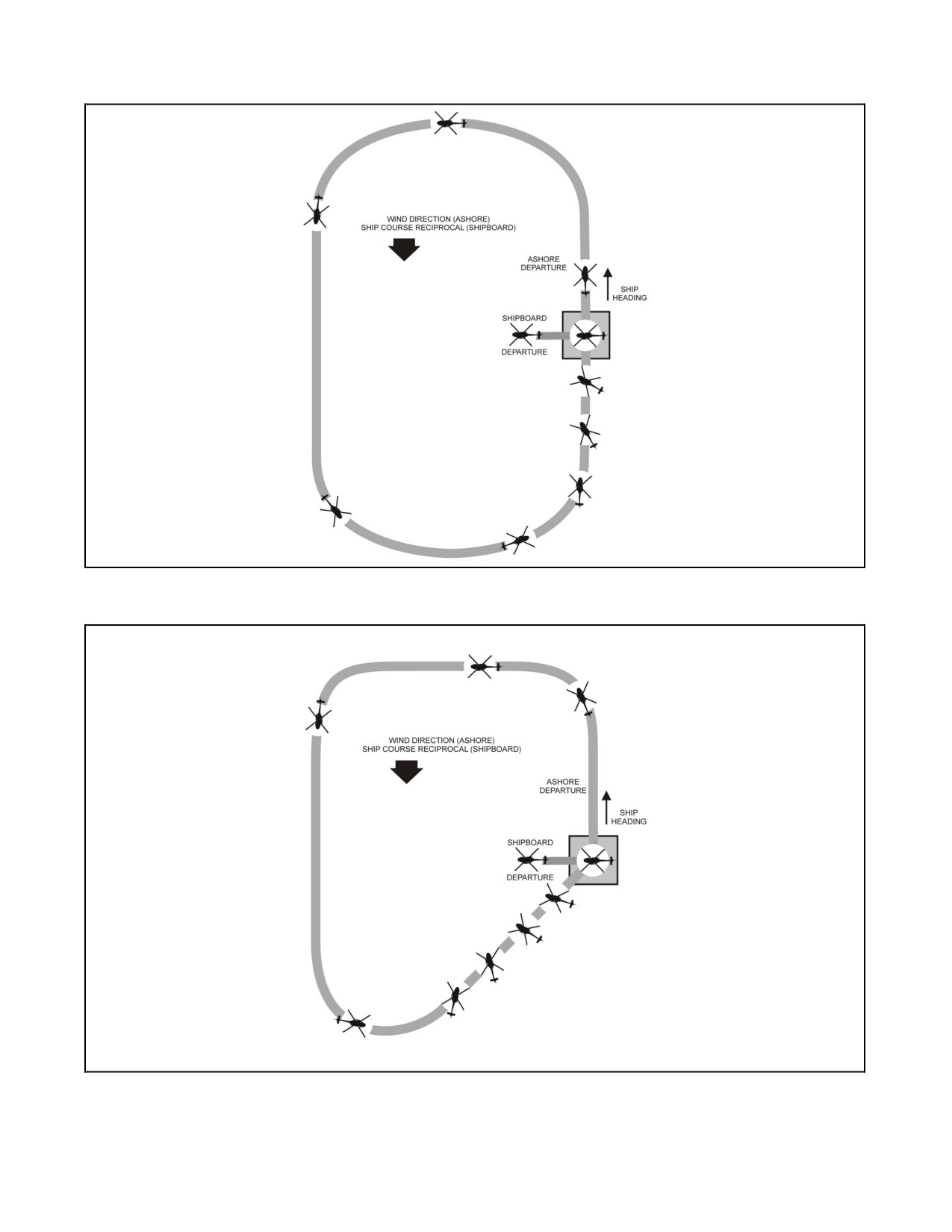
and the crewman to ensure that the hook is centered directly over the load (Figure 9-10).
2. On signal from the LSE and the crewman, the collective shall be increased slowly until tension on the cargo
pendant is felt. This will tend to center the aircraft over the load. At this point, smoothly increase collective
to lift the load off the deck or until reaching a torque 6% less than maximum available. If the load fails to come
off the deck within maximum VERTREP torque limits, maintain the hover and slowly decrease the collective
until the load is on the deck. Loads should never be lifted using maximum allowable torque.
3. After clearing the deck, increase collective and place the nose 5º to 7º below the horizon. The aircraft will be
placedonaclimbscheduleofapproximately1footofaltitudefor1knotofairspeed.Maintainaconstantpower
setting, as necessary to establish the climb. This attitude should be held until the aircraft reaches approximately
60 to 80 KIAS, at which time the nose should be raised to maintain airspeed while climbing to a minimum
altitude of 150 ft AGL.
ORIGINAL
9-24
A1-H60BB-NFM-000
4. A turn downwind shall be made with a shallow angle of bank (Figure 9-10). Abeam the drop point, commence
a turn and slight descent on a racetrack pattern to intercept the final approach course into the wind (directly
astern for shipboard training) at approximately 150 ft AGL and 60 to 80 KIAS.
5. Thefinalapproachistobeflowninsuchamannerastopositiontheaircraftinahoveroverthedropspot.While
on final approach heading, maintain a constant bearing to the intended point of pickup and position the aircraft
on a glide slope approximately 500 ft horizontally from the pickup spot. Reduce collective to maintain glide
slope and raise the nose above the horizon as necessary to dissipate airspeed.
6. As the aircraft reaches approximately 40 KIAS at a position 150 to 200 ft from the spot, begin to turn the aircraft
and execute a 90º sideflare while maintaining a constant bearing and glide slope to the spot. This is
accomplished by applying a small amount of forward and lateral cyclic in the direction of flight and opposite
directional pedal. Do not exceed the 35-knot sideward flight limit. Arrive 25 to 50 ft from the spot with the
aircraft perpendicular to the ship’s centerline and on glideslope. Utilize power in conjunction with lateral cyclic
in order to cross the deck with the load 10 ft above deck height. Altitude in the hover will depend greatly on
the length of the cargo pendant, the height of the cargo, and the height of the obstructions in the vicinity of the
drop spot.
9.3.3.8 45°/135° Sideflare Pattern
This pattern is accomplished in much the same manner as the 90ºsideflare; however, theapproach will be flown from
a wider abeam position on a final course 45º off the windline (ship's course for shipboard training) (Figure 9-11).
1.
Continue the approach past the abeam position and commence a turn to arrive on final approach heading 45º
off the windline at approximately 150 ft AGL and 60 to 80 KIAS. The final approach is to be flown in such
a manner as to position the aircraft in a hover over the drop spot. While on final approach heading, maintain
a constant bearing to the intended point of pickup and position the aircraft on a glide slope approximately 500
feet horizontally from the pickup spot. Reduce collective to maintain glide slope and raise the nose above the
horizon as necessary to dissipate airspeed.
2.
As the aircraft reaches approximately 40 KIAS at a position 150 to 200 feet from the spot, begin to turn the
aircraft and execute a 45º or 135º sideflare while maintaining a constant bearing and glide slope to the spot.
This is accomplished by applying a small amount of forward and lateral cyclic in the direction of flight and
opposite directional pedal. Do not exceed 35-knot sideward flight limit. Arrive 25 to 50 feet from the spot with
the aircraft perpendicular to the ship's centerline and on glideslope. Utilize power in conjunction with lateral
cyclic in order to cross the deck with the load 10 feet above deck height. Altitude in the hover will depend
greatly on the length of the cargo pendant, the height of the cargo, and the height of the obstructions in the
vicinity of the drop spot.
9.3.4
Day VERTREP Operations
1.
Once communications have been established between the receiving ships, transferring ship, and the aircraft;
the receiving ships will set flight quarters as defined in NA-80T-122.
2.
Priortoeachapproachtotheflightdeckforanypickupordrop-off,thefollowingfactorsshouldbeconsidered:
a. Relative winds and flow characteristics around the ship with respect to turbulence and null areas.
b. Path of ship exhaust gases that result in turbulence and warm air.
c. Green deck status light.
d. Appropriate LSE signals.
e. Drop area clear of people and loose gear.
f. Proper placement of load relative to the VERTREP/hover deck markings.
CAUTION
The aircrewman shall ensure proper placement of the load, relative to the
VERTREP hover area markings.
9-25
ORIGINAL
A1-H60BB-NFM-000
Figure 9-10. 90º Sideflare Pattern
Figure 9-11. 45º/135º Sideflare Pattern
ORIGINAL
9-26
A1-H60BB-NFM-000
9.3.4.1 VERTREP Safety
Care must be exercised while conducting VERTREP. Various conditions such as high sea state, over-sized loads,
various length lifting slings, and small drop zones may reduce available visual cues and stability/control of external
loads. Reducing the maximum VERTREP torque further below the 6% margin may provide an extra measure of
control and safety.
D Prior to conducting VERTREP/external lift operations utilizing the
forward TEE VERTREP/external lift line-up line markings, pilots shall
verify with the ship or ships resume that the forward TEE
VERTREP/external lift line-up line markings have been relocated for H-60
T/M/S operations. If the line has not been relocated, refer to
VERTREP/external lift limitations as directed in NA-80T-122.
D Adequate rotor clearance does not exist to stage double stacked loads on
single spot flight decks.
D There are no VERTREP fight deck markings to provide adequate
obstruction clearance on a CV(N), LHA or LHD. Therefore, all hands
participating in a night VERTREP evolution must be particularly alert to
ensure that adequate clearance is maintained between the aircraft and
obstructions in the vicinity of the flight deck. Crews should be aware that
a combination of a staged flight deck, high-velocity and/or gusty winds, and
ship pitch and roll may create less than adequate landing clearance for an
aircraft experiencing an inflight emergency.
Note
During VERTREP, loss of visual contact with the LSE while picking up or
dropping a load requires a hold until visual contact is regained.
9.3.5 Night VERTREP Operations
Due to the hazards associated with night operations and the increased
potential for mishap, night shipboard external cargo operations shall not be
conducted except for reasons of operational necessity.
NightVERTREPisaninherentlydemandingandfatiguingevolutionthatrequiresparticularlyhighlevelsofplanning
andcoordination.OneormoreofthefollowingconditionsshallexistpriortoconductingnightVERTREPoperations:
1. A natural horizon exists.
2. The ships are alongside in connected replenishment (CONREP) position.
3. The drop-off/pickup zone of the receiving/ delivery ship is clearly visible from the cockpit when over the
drop-off/pickup zone of the delivery/receiving ship.
9.3.5.1 Night VERTREP Safety
Particular care must be exercised while conducting night VERTREP. Adverse environmental conditions such as fog,
precipitation, sea state, horizon, and aircrew proficiency, profoundly affect the safe conduct of the mission. Altitude
9-27
ORIGINAL W/IC 70
A1-H60BB-NFM-000
hold shall be used for all night ship flights with the exception of VERTREP operations in the CONREP position. In
the shipboard landing and VERTREP pattern, altitude hold shall be turned off only after the PAC has visual reference
of the landing environment/drop zone. Operational commanders must, whenever necessary, augment published
operating rules with directives addressing local circumstances.
CAUTION
When carrying external loads, erratic radar altimeter indications can result
in an AFCS DEGRADED caution.
9.3.5.2 Procedures
Night VERTREP patterns should be chosen based on the type of loads, the decks that they are being transferred
between, and the distance that they will be carried. The normal pattern will be a racetrack type between the delivery
ship and the receiving ships. Excessive maneuvering should be avoided, when able, to help avoid vertigo inducing
maneuvering. Altitudes and checkpoints should be based on the type of ship being serviced, relative position of ship
being worked, and maintaining safe clearance.
1. On pickup, the PNAC will monitor all instruments and note the torque. The PAC will commence lifting the
load following hand signals from the LSE and voice calls from the crewman.
CAUTION
All night VERTREP climb-outs away from the immediate vicinity of the
flight deck should be conducted on instruments.
2. The PAC will transition to 60 to 80 KIAS and climb to a minimum altitude of 150 ft AGL prior to turning. The
PNAC shall call “POSITIVE RATE OF CLIMB”. The PNAC shall notify the PAC if more than 20º angle of
bank is attained, altitude descends below 100 ft AGL, or a fast rate of descent is not corrected. If the aircraft
descends through 75 ft AGL or a fast rate of descent develops, the PNAC shall assume control of the aircraft
and correct the situation. Control changes should be accomplished with wings level and a positive, verbal
acknowledgement. Both radar altimeters shall be set to illuminate at altitudes determined in the brief, but not
less than 40 feet. Determination of radar altimeter settings should be based upon, but not limited to: type of
ships, relative position of ships, and altitudes required to transition from one ship to another.
Oscillations caused by the load and felt through the rotor blades and/or
fuselage can cause vertigo at night. Should extreme oscillations and/or
unsafe flight due to spatial disorientation/vertigo occur, consideration
should be given to jettisoning the load immediately.
3. When the aircraft is properly positioned to commence an approach, the PNAC should inform the PAC to begin
the turn. The PAC may then turn toward final and begin the descent once established on final. When the PAC
has visually acquired the drop area and established that adequate visual reference exists to afford a safe
approach, the approach is continued to arrive over the drop area. If the PAC has transitioned from instrument
flight to visual flight, a verbal statement to the PNAC is made that there is adequate visual reference to continue
the approach.
9.3.5.3 Lighting
Receiving and transferring ships shall have their decks illuminated to conform with the criteria for certification set
forth by the Shipboard Aviation Facilities Resume.
ORIGINAL W/IC 70
9-28
A1-H60BB-NFM-000
Note
Night VERTREP to ships that do not conform to the minimum certification
criteria set forth in the Shipboard Aviation Facilities Resume shall not be
attempted.
Aircraft lighting configuration is at the discretion of the PIC, but various aspects of aircrew limitations must be taken
into account to allow visual reference with the load and the deck. Additionally, care must be taken to ensure external
lighting does not interfere with the LSE’s ability to see the aircraft and the load.
9.3.6 Lost Communication Procedures with a VERTREP Load
In the event of lost ICS with an external load, the following procedures are recommended:
1. The crewman operating the cargo hook will direct the aircraft via hand signals (Figure 9-12).
Note
At night, it may be necessary to turn on the cabin lights to increase visibility.
2. The PNAC will relay the direction signals to the PAC. The signals may be relayed by utilizing hand signals
or by applying pressure to the PAC's shoulder or elbow in relation to thedesired aircraft movement (i.e., gentle
forward pressure to the back of the PAC's shoulder to indicate FORWARD, gentle pressure to the bottom of
the PAC's elbow to indicate UP, and pushing or pulling on the PAC's shoulder to indicate LEFT or RIGHT).
The following is an alternate method for dropping an external load with lost ICS:
3. The crewman operating the hook will direct the aircraft via hand signals (Figure 9-12).
4. The crewman not operating the cargo hook will take a position forward between the pilot seats and relay the
signals to the PAC by applying pressure to the PAC's shoulder or elbow in relation to the desired aircraft
movement (i.e., gentle forward pressure to the back of the PAC’s shoulder to indicate FORWARD, gentle
pressure to the bottom of the PAC's elbow to indicate UP, and pushing or pulling on the PAC's shoulder to
indicate LEFT or RIGHT).
5. The PNAC will continue the normal scan for VERTREP operations.
Note
Pickups shall not be accomplished during lost ICS situations.
9-29
ORIGINAL
A1-H60BB-NFM-000
HAND SIGNAL FROM
VOICE COMMAND
AIRCREWMAN
LOST ICS SIGNAL FROM PNAC TO PAC
WAVEOFF*
VIGOROUS CROSSING OF HANDS
VIGOROUS CROSSING OF HANDS
HOLD*
DOUBLE CLENCHED FISTS
FIRM GRASP OF SHOULDER
FORWARD
ELBOW BENT 90 DEG FINGERS
FORWARD PRESSURE
EXTENDED POINTING UP
BACK
ELBOW BENT 90 DEG FINGERS
BACK PRESSURE
EXTENDED POINTING DOWN
LEFT
LEFT ARM EXTENDED, FINGERS
LEFT PRESSURE
EXTENDED
RIGHT
ELBOW BENT 90 DEG, FINGERS
RIGHT PRESSURE
EXTENDED UP AND PERFORM
WAVING MOTION
UP
PALM UP MOTIONING UP
UPWARD PRESSURE
DOWN
PALM DOWN MOTIONING DOWN
DOWNWARD PRESSURE
STEADY
CLINCHED FIST
NO PRESSURE
CLEARED TO GO
TAP HELMET, POINT FORWARD
THREE TAPS ON THE SHOULDER
HOIST GOING DOWN
CLINCHED FIST, THUMB DOWN
CLINCHED FIST, THUMB DOWN
HOIST GOING UP
CLINCHED FIST, THUMB UP
CLINCHED FIST, THUMB UP
* Mandatory
Figure 9-12. Lost Communications Procedures
9.4
FORMATION FLYING
9.4.1 General
The following is a general discussion of safe formation flying basics.
Helicopter formation flight is conducted for the following reasons:
1. Improved operational capability. When properly executed, the flight leader can expect complete flexibility of
operation within the limitations of helicopter maneuverability without danger of creating unsafe conditions
within his formation (free cruise) or the encumbrance of delay while intentions are passed, via signal or radio.
2. Mutual safety and accountability. The danger of mid-air collision is greatly reduced when every flight member
knows where they is supposed to be, and remains in their designated space.
Certain helicopter characteristics which should be considered in formation flight are:
1. Formation flying may be performed in a step-up position to avoid rotor-wash, improve visibility, and provide
a greater safety margin between the main rotor and the helicopter ahead. By adjusting altitude to place the top
of the rotor head of thehelicopterinfrontonthehorizon,asufficientstep--upwillbemaintained.Astep--down
position may provide the wingman better visual references at night over well lit populated areas.
2. At night, it is more difficult to ascertain when the lead helicopter changes direction and altitude. (Refer to
NIGHT FORMATION in this chapter.)
ORIGINAL
9-30
A1-H60BB-NFM-000
9.4.2 Formation Composition
9.4.2.1 Section
The section will consist of two helicopters and will constitute the basic unit of a formation.
9.4.2.1.1 Parade
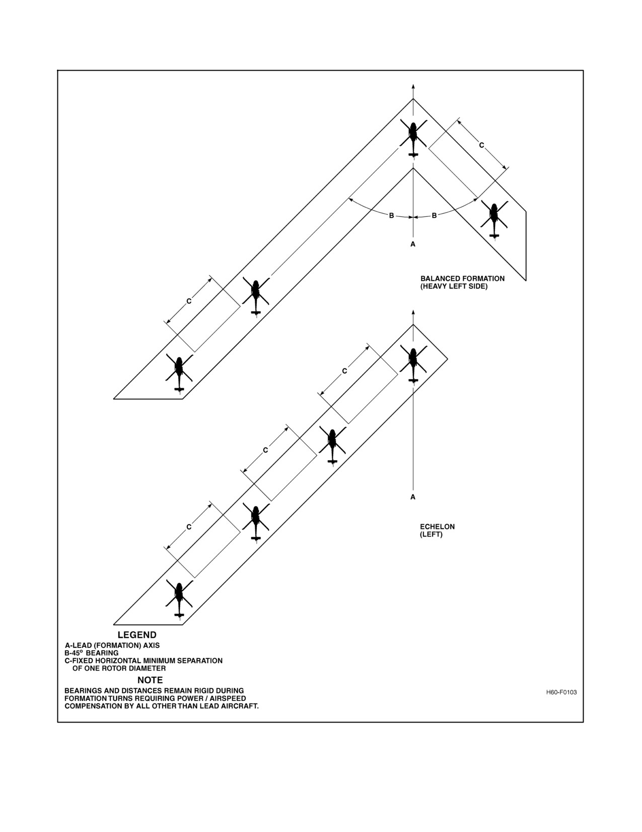
The wing aircraft will fly at a 45° bearing behind and on the appropriate side of the section leader. The horizontal
helicopter--to--helicopter separation will be a minimum of one rotor diameter between rotor tips. The wingman’s
position in the parade section is fixed. (See Figure 9-13.)
9.4.2.1.2 Free Cruise
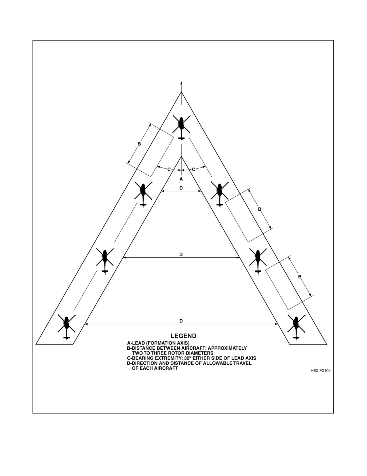
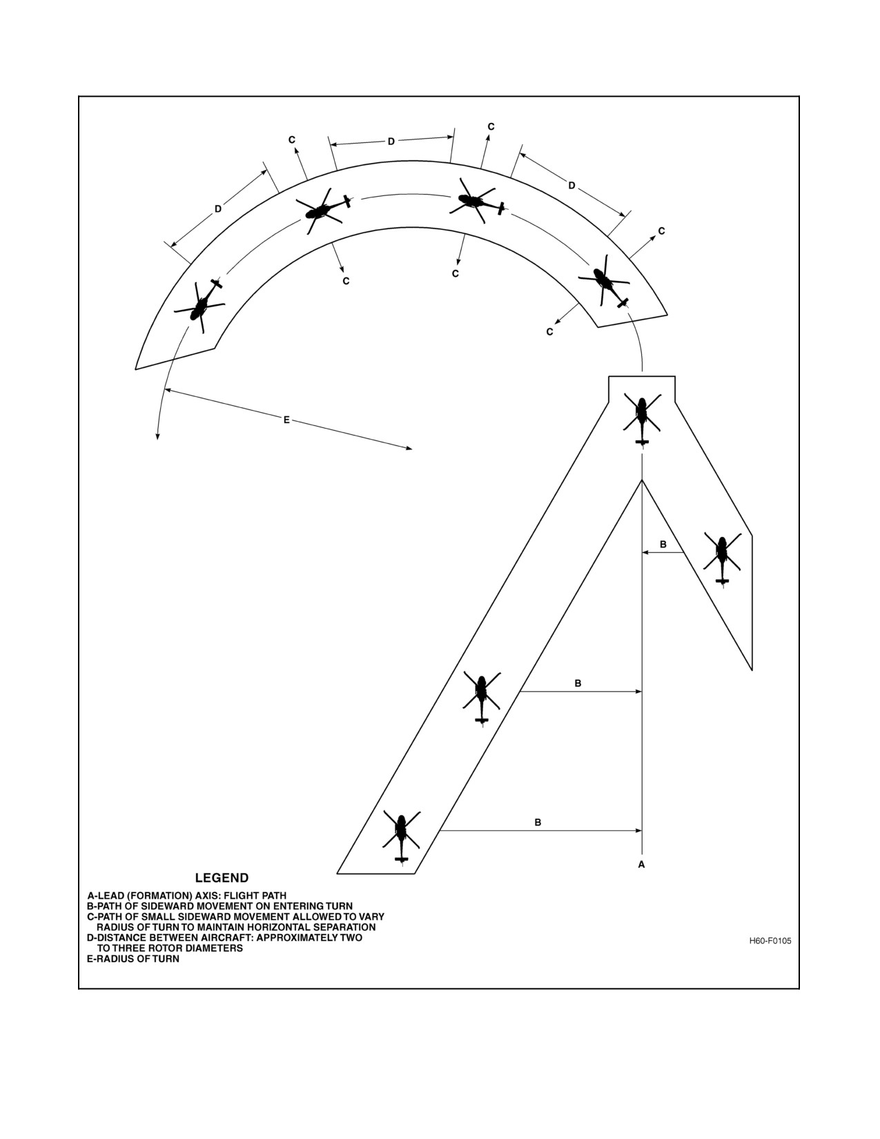
The wingman will fly approximately 60° behind the section leader. The horizontal helicopter--to--helicopter
separation will be approximately two to three rotor diameters. Normally, the free--cruise wing aircraft maintains a
position 60° off the axis of the lead helicopter during straight and level flight. During turns, wing crosses over from
one side of the section leader to the other to maintain position with minimum changes of power. In free cruise,
helicopters in the formation are not to be considered bound to a fixed position. Rather, they are assigned a segment
of airspace behind lead in which they are free to move as necessary to maintain constancy of horizontal and vertical
separation. Wing should avoid continued flight directly behind lead. (See Figures 9-14 and 9-15.)
9.4.2.2 Division
A division will consist of two sections. The general rules applying to section formations may be expanded to apply
to divisions within the limits of safety and capability. The side of the division on which the section is placed will be
known as the heavy side of the formation. When a flight consists of more than four helicopters, any amount over four
will form subsequent divisions. The last division may be comprised of less than four helicopters.
9.4.2.2.1 Parade
The second section lead is the number three aircraft in the division. Parade position may be flown in echelon left/right
or heavy left/right.
9.4.2.2.2 Free Cruise
The second section lead is the number three aircraft in the division. The second section lead is free to cross over the
section from side to side of the division lead to maintain horizontal clearance with minimum changes of power.
9.4.3 Rendezvous
Normally, the running rendezvous will be employed. Lead will fly on course at slow cruise, and the flight will take
position as briefed. When the flight is joined, the lead aircraft will proceed at cruise speed. An orbiting rendezvous
may be used. The lead will fly a right or left circular pattern at normal cruise speed around a designated point until
the flight is joined. In an orbiting rendezvous,helicopters willjoin incolumn formationusing thefree cruiseprinciple
until lead rolls out on departure heading. All rendezvous helicopters should pass across the designated point, pick up
altitude separation, and join on the helicopter ahead. Any overshoot tendency should be taken to the outside of the
turn. Normally, thereafter, the flight will continue to maintain free cruise formation at cruise speed, unless otherwise
directed by the flight lead. Extreme caution should be exercised during night rendezvous, due to reduction of
perception of relative motion.
9-31
ORIGINAL
A1-H60BB-NFM-000
Figure 9-13. Parade
ORIGINAL
9-32
A1-H60BB-NFM-000
Figure 9-14. Free Cruise — Straight and Level
9-33
ORIGINAL
A1-H60BB-NFM-000
Figure 9-15. Free Cruise Turn
ORIGINAL
9-34
A1-H60BB-NFM-000
9.4.3.1 Breakup and Rendezvous Procedures
From a parade position, lead startsa 180° turn away from wing by executing a 30° angle of bank, maintaining altitude
and airspeed. When the wing notes the lead passing through 45 relative degrees of turn, the wing will break the same
directionfor180°usinga30°angleofbankturninitiallyandthenadjustingtheturnratetoarriveapproximately1,000
yards astern of the lead. The wing will then call “IN POSITION.” When the “IN POSITION” call is received, lead
establishes a 10° angle of bank for 180° of turn to a parade position. This turn is conducted in the opposite direction
of the initial 180° turn so that the rendezvous is not conducted by the cross--cockpit pilot. The wing establishes a 15°
to 20° angle of bank turn to close the lead using radius of turn without adjusting airspeed. If the rendezvous cannot
be executed in 180° of turn, wing should inform lead to keep the turn in. Cardinal headings can be used for quick
reference to a 180° position.
9.4.4 Conduct of Flight
Formation flight will be practiced in accordance with this doctrine during all normal, multiple helicopter movements
to improve proficiency. Free cruise formation will be used for most operations. Parade formation is normally used
only for special occasions such as air shows, authorized fly--bys, etc. Nothing in this instruction shall be construed
as prohibiting qualified crews from flying in tactical formation (TACFORM) or performing TACFORM maneuvers.
9.4.5 Responsibility
9.4.5.1 Flight/Form/Division Lead
The flight lead is responsible for the flight brief, formation brief, conduct, and discipline of the flight. Form lead will
normally handle navigation, radio transmissions, and ATC clearances for the flight. Division leaders are responsible
for the conduct of their division. All aircrew are responsible for maintaining positions as outlined. No deviation of
position, such as change of lead, will be made until appropriate signals have been given and acknowledged.
9.4.5.2 Wing
Wing aircraft are responsible for safe flight separation with lead or any other aircraft. In addition, wing aircraft are
responsible for maintaining formation integrity and other tasks that Lead may assign.
9.4.6 Lead Change
When changes of lead are made, the wing will increase horizontal separation to at least two rotor diameters and move
forward to a position abeam the lead. The lead will then be passed by appropriate pre--briefed signal. The new wing
(old lead) will then drift back to the appropriate position on the new formation. Safety will govern all actions.
9.4.7 Night Formation
Night formation should be flown only when complete visual reference between helicopters can be maintained and
in the same manner as day formation. This is normally construed to mean that NVDs are required for safe night
formation flight. Separation between helicopters may be adjusted as deemed prudent by members of the flight and
as directed by visibility conditions. Caution should be exercised to avoid unnecessarily extending the formation to
the extent of limiting its operational capability, mutual safety, or ability to maintain firm visual contact with other
formation members. For wing to accurately verify distance and bearing, TACAN air to air mode, formation
electro--luminescent lights, or installed IR chemical lights should be used. At any time that complete visual contact
cannot be maintained between helicopters or silhouette definition is lost, discontinue the formation flight and execute
pre--briefed lost contact procedures. For normal operations, the last aircraft in the formation should have
anti--collision lights ON.
9-35
ORIGINAL
A1-H60BB-NFM-000
9.4.7.1 Lost Wingman VMC
These procedures should be commenced anytime during VMC flight when a member of the flight loses sight of the
aircraft forward of them or when deemed necessary by the lead. Any member may initiate these procedures by calling
“BLIND”. Lost wingman procedures shall be pre--briefed to all members of the formation and should include:
1. Lead calls base heading and wing aircraft make pre--briefed coordinated turns away from lead.
2. Lead calls base altitude and wing aircraft make pre--briefed coordinated climbs/descents away from lead’s
altitude.
3. All aircraft ensure applicable sensors are operational to assist in vertical and lateral separation.
4. All aircraft make clear and concise communications as to their position, altitude, and intent during the
maneuvers. If any deviations to the pre--briefed plan are made, they shall be communicated over the radio.
If VMC and able to maintain VMC both aircraft should ensure vertical and lateral separation from each other and
coordinate a rendezvous. In all cases clear radio transmissions, air to air TACAN, and/or other sensors should be used
to the maximum extent practicable to avoid collision.
9.4.8 Instrument Flight Conditions In Formation
Normally formation flying will not be flown when the visibility is so low that helicopters are likely to lose sight of
one another. When situations can be anticipated, the leader will take such action as necessary to ensure formation
integrity or safely break apart the formation for IFR flight.
9.4.8.1 Inadvertent IMC Procedures
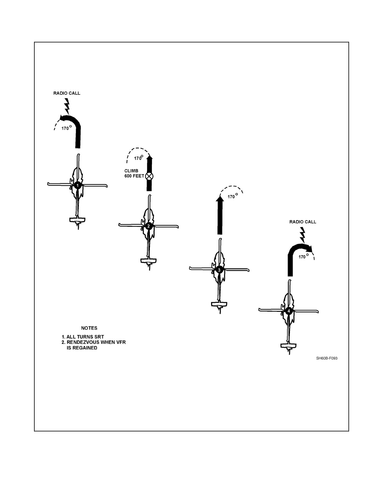
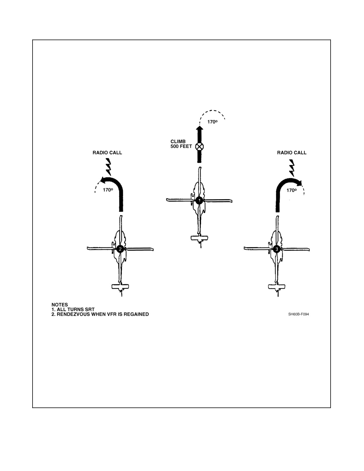
These procedures (Figures 9-16 and 9-17) should be commenced anytime a member of the flight loses sight of the
aircraft directly ahead of them due to IMC or when deemed necessary by the lead. Any member can initiate these
procedures by calling “INADVERTENT IMC” and executing the pre--briefed flight profile. The following options
are not a complete safety net to ensure safe flight in inadvertent IMC conditions, but are intended as a discussion of
known methods to enhance safe flight in an inadvertent IMC situation. Inadvertent IMC procedures shall be
pre--briefed to all members of the formation and should include:
1. Lead calls base heading and wing aircraft make pre--briefed coordinated turns away from lead.
2. Lead calls base altitude and wing aircraft make pre--briefed coordinated climbs/descents away from lead’s
altitude.
3. All aircraft ensure applicable sensors are operational to assist in vertical and lateral separation.
4. All aircraft make clear and concise communications as to their position, altitude, and intent during the
maneuvers. If any deviations to the pre--briefed plan are made, they shall be communicated over the radio.
If either aircraft is able to regain and maintain VMC flight during inadvertent IMC procedure they should maintain
VMC and attempt coordinate Lost Wingman VMC procedures. Extreme caution shall be used when the possibility
exists for IMC conditions to develop in mountains. Inadvertent IMC in mountainous environments is extremely
dangerous and can develop rapidly. In mountainous terrain, it may or may not be possible to climb above the MSA.
The primary concern is for all aircraft to turn away from the rising terrain and fly in a safe direction. Inadvertent IMC
breakup will require lead to provide a detailed brief of procedures and all members to have a thorough understanding
of the expected topography. In addition to the previous discussion on inadvertent IMC procedures, the following
options may assist in safe flight for mountainous environments.
1. Lead and wing execute maximum performance climbs at pre--briefed different airspeeds. Lead should climb
at a faster airspeed than wing to assist in separation.
2. Both aircraft should climb to deconflicted altitudes above the MSA if possible.
3. If the MSA is above operational parameters a detailed understanding of the topography will be required so that
aircraft can execute a turn toward a safe direction that will allow for obstacle clearance.
4. If section or division aircraft are unable to regain VMC and rejoin safely, lead shall ensure all aircraft are
assigned deconflicted altitudes for IFR clearances.
ORIGINAL
9-36
A1-H60BB-NFM-000
Figure 9-16. IMC Breakup Procedures (Four Plane)
9-37
ORIGINAL
A1-H60BB-NFM-000
Figure 9-17. IMC Breakup Procedures (Three Plane)
ORIGINAL
9-38
A1-H60BB-NFM-000
9.5
TERRAIN FLYING
9.5.1 General
Consult appropriate manuals for procedures and techniques for terrain flying. The three types of terrain flying are:
1. Low level flight: Flight at a preselected altitude below 500 feet along a prescribed route, usually in straight line
segments at constant airspeed.
2. Contour flight: Flight at low altitude conforming generally to the contours of the earth, with varying airspeed
and altitude as vegetation and obstacles dictate.
3. Nap of the Earth (NOE) flight: Flight as close to the earth’s surface as vegetation/obstacles permit. NOE is
similar to contour flight but is conducted at lower altitudes and is characterized by airspeeds from a hover/air
taxi to dashes of 60 to 70 Knots Ground Speed (KGS).
The close proximity to obstacles, rapid attitude adjustment, and many power changes with frequent high power
demands,putagreatstressonairframeanddynamiccomponents.Thesesameparametersdemandincreasedattention
from individual crewmembers as well as the crew as a whole. Proper crew coordination is essential. Detailed
individual tasking of duties must be pre--briefed and rigidly enforced. Standard phraseology should be used to avoid
confusion during critical segments of flight. Emergencies are more critical at low altitude and corrective actions must
be completed expeditiously. Aircraft performance should be calculated prior to flight utilizing worst condition
parameters of density altitude, gross weight and winds. The aircraft should be performance checked in flight to ensure
that the calculated performance is available before terrain flying is attempted. Aircraft and pilot reaction times in all
flight regimes must be considered when determining route of flight and altitude.
Note
Terrain following flights shall be accomplished only when properly
scheduled, planned and briefed for that specific mission. When conducted,
they should be flown no lower than is necessary to accomplish the mission.
9.6
SPECIAL WARFARE SUPPORT OPERATIONS
Special warfare support operations require maximum flexibility on the part of the aircrew. A wide variety of methods
and equipment may be used to deploy and recover special warfare personnel. Therefore, it is incumbent upon the
aircraft commander to ensure that all personnel are thoroughly briefed and familiar with a specific operation prior
toitsconduct.Althoughthissectioncoversnumerousoperations,itisnotallinclusive.Operationsnotaddressedmust
be approached with maximum caution and prior planning to ensure a safe evolution. Special warfare equipment
descriptions, authorizations, limitations and rigging procedures are found in NTRP 3--22.2--SH60B and NTRP
3--22.2--SH60B. Additional information concerning special warfare support operations can be found in the Air NTTP
3--22.1--SH60B/Air NTTP 3--22.1--HH60H, Naval Special Warfare Command Air Operations Manual (COMNAV-
SPECWARINST 3000.3) and Special Operations Infiltration/Exfiltration Operations (USSOCOM Manual 350--6),
and appropriate NSAWC publications.
9.7
NIGHT VISION DEVICE (NVD) PROCEDURES
9.7.1 General
Night vision goggles provide a significant increase in visual cues and situational awareness during night operations
while greatly expanding operational capabilities. The benefits of NVDs, however are only maximized through
training, thorough mission planning and proper crew coordination. Competency on NVDs begins with a firm
foundation in the execution of basic helicopter pilotage skills. The importance of good crew coordination cannot be
overemphasized. For additional information on NVDs and their usage, refer to the MAWTS--1 USN/USMC NVD
Manual or NVD operators manual.
9-39
ORIGINAL
A1-H60BB-NFM-000
CAUTION
Do not assume that personnel operating in and around taxiing helicopters
are capable of detecting hazards with the same level of situational
awareness as can be attained with NVDs.
9.7.2 NVD Physiology
Flying with NVDs has a significantimpact onphysiology. Themost obviousvisual limitationof NVDsis thereduced
field of view (FOV). Compared to the 188° field of view normally available, NVD FOV is reduced to 40°. This
reduction necessitates an active and aggressive scan. Additionally, a reduction in visual acuity (resolution) occurs
with NVDs. As a result, the ability to perceive fine details such as electrical power lines, unlighted towers, poles,
antennas, and all types of wires, is significantly degraded. Brownout/Whiteout will greatly degrade visual acuity even
further. Distance estimation is significantly altered with NVDs. This is caused by the inherent reduction in visual
acuity and minification, which may be the result of improper preflight focus procedures. Depth perception is not lost
with NVDs. Wearing NVDs for an extended period of time can cause extreme eye fatigue. This can result in
converging/diverging vision, headache and eyestrain. Proper NVD preflight and adjustment procedures are critical.
Improper focus procedures will compound the adverse effects of NVDs. NVD adjustment and focus procedures shall
be conducted in accordance with the MAWTS--1 USN/USMC NVD Manual or the Operators manual.
Depth perception is adversely affected by NVDs. Weather may appear
much further away than it actually is and closure rates are not immediately
noticeable. Brownout/whiteout will greatly degrade visual acuity which
could result in impact with ground other aircraft.
CAUTION
Flight operations involving NVDs are inherently more stressful and
demanding than day flying and VMC. The resultant fatigue may have a
profound physiological effect upon mission capability. Mission planners
should take this physiological threat into account in making modifications
to normal crew rest/crew day guidelines.
9.7.3 Lighting Considerations
NVD enhancement is inversely proportional to altitude and airspeed, i.e. the lower and slower you fly; the better your
visual acuity. However, in low illumination conditions, the low/slow altitude and airspeed combinations required to
adequately see may prohibit the conduct of safe NVD operations. Haze, smoke, low illumination due to overcast
conditions or lack of cultural lighting can also diminish the effectiveness of NVDs.
9.7.4 NVD Operations Over Water
Procedures for operating on NVDs over water shall be the same as those for operating over water at night unaided
and in accordance with applicable wing directives.
ORIGINAL
9-40
A1-H60BB-NFM-000
9.7.5 NVD Shipboard Operations
All NVD shipboard operations to include takeoff, goggle/degoggle procedures shall be thoroughly briefed and
handled in accordance with applicable directives. When it has been decided to goggle or degoggle, it shall be
completed on deck or in straight and level flight.
9.8
MOUNTAIN TERRAIN FLYING
Many helicopter missions require flight and landing in rough and mountainous terrain. A thorough knowledge of
mountain flying procedure and aircraft performance parameters is essential for successful operations. Along with the
adverse effects of high--density altitudes on helicopter performance, pilots must overcome severe visual illusions and
operate in winds with large vertical components. Mountain winds are dramatically affected by terrain and convection
cooling and heating; it is not unusual to encounter 2,000 -- 5000 fpm up or downdrafts. In non--mountainous flying,
the horizon is the primary spatial reference. In mountain flying, there is often no defined horizon and spatial cues are
derived from vertical and sloping terrain. These two factors, wind and illusion, combined with high--density altitudes
and confined landing sites, make mountain flying a demanding flight regime. Flight in mountainous terrain requires
thorough preflight planning with aircraft performance parameters being carefully calculated for all segments of the
flight.
Power requirements drop quickly with increased wind, especially up--flowing wind; however, local winds are
difficult to predict and it is not advisable to use wind in performance calculations. Predicting winds should be used
in route planning and alternate routes selected in the event adverse winds are encountered. Prior to all landings, the
landing site must be evaluated and winds determined.
9.9
LANDING SITE EVALUATION BRIEF
The five major considerations that the aircrew should use when evaluating a potential landing area are summed up
by the acronym SWEEP.
1. S — Size, slope, suitability, surface (grass, snow, rocks, dust, etc.).
2. W — Winds (Direction, demarcation, turbulence, loss of effect due to obstacles).
3. E — Escape routes (Dropoff, waveoff).
4. E — Elevation of LZ (PA and DA).
5. P — Power (Available vs required. Includes takeoff power after taking on additional weight.)
The transition period is the most difficult part of any approach. As helicopter performance decreases, the transition
period becomes more critical, requiring a shallower, gradual approach. Therefore, as the height of obstacles increases,
larger areas will be required. As wind velocity increases, so does helicopter performance. However, when the
helicopter drops below an obstacle, a loss of lift generally occurs as a result of the aircraft being unable to immediately
negotiate the change. This is prevalent at the upwind side of the landing zone, where a virtual null area exists. This
null area extends toward the downwind side of a clearing and will become larger as the height of obstacles and wind
velocity increases. In the landing phase, it is increasingly important that this null area be avoided if marginal
performance capabilities are anticipated. The null area is of particular concern when performing a takeoff from a
confined area. Under heavy load or limited power conditions, it is desirable to achieve forward velocity and
translational lift before transitioning to a climb so that performance will be improved. If the takeoff is not commenced
from the most downwind portion of the area and translational lift is not achieved before arrival in the null area, a
significant loss in lift may occur during the most critical portion of the takeoff. It must also be noted that in the vicinity
of the null area a nearly vertical downdraft may be encountered, which will further reduce the actual climb rate of
the helicopter. It is feasible that under certain combinations of limited area, high obstacles upwind, and limited power
available, the best takeoff route would be either crosswind or downwind, terrain permitting. The effects of detrimental
wind flow and the requirement to climb may thus be minimized or circumvented. Although this is a departure from
the cardinal rule of takeoff into the wind, it may well be the proper solution when all factors are taken into perspective.
Never plan an approach to a confined area from which there is no reasonable route of departure. The terrain within
the site is determined from an evaluation of vegetation, surface characteristics, and slope. Care must be taken to avoid
placing the rotors in low brush or branches. Obstacles covered by grass may be located by flattening the grass with
rotorwash before landing. Power should be maintained so that an immediate takeoff may be made should the
helicopter begin rolling due to soft earth, a hidden hole, or a depression.
9-41
ORIGINAL
A1-H60BB-NFM-000
CAUTION
Cabin windows shall not be installed or removed in flight, except during
actual aircraft emergencies.
Note
Considerationmaybegiventoremovingtheportcabinwindow,droptanks,
and extended pylon for unprepared landings. This will assist in landing
zone evaluation and obstacle clearance during approach and landing.
9.9.1 Illusions
Mountainous low level flight represents an unusual visual environment. The horizon may not be visible, and we are
surrounded with vertical and sloping visual cues. These visual cues cause illusions that if not recognized lead to:
1. Misjudging the relative height of an LZ due to upsloping or downsloping terrain, resulting in climbing above
or descending below approach glideslope.
2. Climbing and losing airspeed when flying into rising terrain.
3. Descending and accelerating when flying away from falling terrain.
4. Misjudging the relative height of ridges with higher terrain in the background.
Pilots must develop the ability to maintain an instrument scan while flying VFR at low level in rugged terrain. This
skill is essential to maintaining good basic airwork, and mountain flying techniques and procedures cannot be
accomplished without it.
9.9.2 Mountain Winds, Turbulence and Topography
9.9.2.1 Winds
Most pilots’ understanding of wind is limited to movement over a flat surface or at altitude, unobstructed by terrain.
Under these conditions, wind flows horizontally, in one direction, at a relatively constant velocity. In fact, aircraft
performance charts are based on horizontal winds. Prior to each flight, preflight performance calculations are
computed using the prevailing winds as the reference. Mountain winds are three--dimensional; wind not only flows
across mountainous and rough terrain, it also flows up, down, and around terrain and obstacles. The vertical
component can dramatically improve or reduce aircraft performance. A 30--knot wind flowing up a 45º slope can
produce an updraft in excess of 1,500 fpm. Conversely, the same wind flowing down--slope can produce a downdraft
inexcessof1,500fpm. Anothercriticalconceptinmountainflyingisboundarylayerair.Asanairmassmovesacross
rising terrain, a blanket of vertically moving air forms a boundary layer. Mountain operations should be conducted
in this boundary layer in order to optimize the performance capabilities of the helicopter. This is because airflow tends
to be laminar in the boundary layer. The boundary layer normally occurs at altitudes less than 100 feet AGL, but may
extend up to 200 feet AGL in higher wind velocities. An understanding of thetypeof winds associated withmountain
operations,wherethewindswillmostlikelybeencountered,andhowthewindsaffectmountainoperations,iscritical
to the safe completion of mountain flying. The most common winds associated with mountain and rough terrain
operations are prevailing winds and local winds. Local winds are further broken down into local mountain winds,
anabatic, katabatic, and land--sea breezes.
9.9.2.1.1 Prevailing
Prevailing wind is the movement of air from an area of high pressure to an area of low pressure, which is deflected
by the rotation of the earth. Prevailing winds have relatively constant direction and velocity and are associated with
ageographicregion.Whentheboundary layeris formedby lightprevailing winds,strong, steadygradient windsmay
often bend the boundary layer winds as much as 180º.
ORIGINAL
9-42
A1-H60BB-NFM-000
9.9.2.1.2 Local Winds
9.9.2.1.3 Local Mountain Winds
Localmountainwindsarecreatedbytheformationandmovementofhighorlow--pressuresystemsandfrontalwinds.
In the northern hemisphere these systems generally move from west to east. Low--pressure winds are usually
moderate to heavy and move either northeasterly or southeasterly. High--pressure winds are usually light and variable
and circulate in a clockwise direction. These systems usually flow in the opposite direction in the southern
hemisphere. Flying conditions, although poor in low--pressure regions, are always at their optimum when regions
of high pressure are dominant.
9.9.2.1.4 Anabatic
Anabatic winds, also referred to as gradient convection winds, are created as the mountain slopes or valleys are heated
by the sun. As the surface is heated, the resultant warm air rises, causing a gradient of up--flowing wind. As the heated
air rises, cooler air descends and the process repeats. If the rate at which the surface air is being heated is slow, there
willbepausesinthegradientwinds. Duringperiodsofintensesolarheating(mid--afternoon)thesurfaceairisrapidly
heated, producing steady and possibly strong gradient winds. Anabatic winds are strongest from late spring to early
autumn or when a warm high--pressure system dominates a region for a long period of time.
9.9.2.1.5 Katabatic
Katabatic winds, or cool descending gradient winds, are created when cool air descends down gradients, causing cool,
steady, and sometimes gusty gradient winds. Katabatic wind usually occurs during periods when solar heating has
slowed, such as in the evening. It is strongest at the base of glaciers or snowfields situated on a gradient.
9.9.2.1.6 Land--Sea Breezes
Land--sea breezes are breezes that blow due to temperature differences between bodies of water and land. They affect
mountain ranges that are in proximity to large bodies of water. The cooler, heavier air flows toward the warmer water,
creating a land breeze. Conversely, sea breezes occur when the water is cooler than the land surface and the breeze
flows from the water to the land. Sea breezes are common during the day whereas land breezes usually occur at night.
Land--sea breezes will be strongest when the temperature differential is greatest.
9.9.2.2 Turbulence
Turbulence encountered during mountain operations is much different than turbulence encountered at altitude.
Except for sheer--zone turbulence, the topography of mountainous regions and wind results in many different types
oforographicturbulence.Determiningandunderstandingwhereturbulencemayexistandwheresmoothairseparates
from turbulent air, commonly referred to as the demarcation line is critical to the safe completion of mountain
operations. In general, turbulence will always be present under the following conditions: down--flowing air;
up--flowing air associated with mechanical, air mass, or sheer--zone turbulence; and where wind of different
types/directionsmix.Additionally,low--pressuresystemsareoftenturbulentandunstable.Flyingtechniquesthatwill
assist in determining where turbulence may exist will be discussed in the section for procedures and techniques.
Orographic turbulence can be broken down into the following categories: mechanical, down--flow, air--mass, and
sheer--zone turbulence.
9.9.2.2.1 Mechanical
Mechanical turbulence is formed as the wind flows over rugged terrain and obstacles. Ripples of turbulence form on
the leeward side of boulders/rocks and mix with the up--flowing air. As wind velocity increases, the severity of
turbulence increases.
9.9.2.2.2 Convective
Rising air currents created by uneven surface heating forms convective turbulence. Convective turbulence is normally
found at a relatively low height above terrain, generally less than 2,000 feet AGL. Under certain conditions, it may
reach as high as 8,000 feet AGL. It is most prevalent over barren terrain and during periods of low wind conditions.
Pilots should anticipate turbulence when transitioning from these areas to terrain covered by vegetation or snow.
Convective turbulence seldom gets severe enough to cause structural damage.
9-43
ORIGINAL
A1-H60BB-NFM-000
9.9.2.2.3 Down--Flow
Down--flowturbulenceiscreatedbythewindtumbling,onceitbreaksthetopofthehill.Aswindflowsupamountain,
a region of high pressure forms across it. The leeward side is sheltered by the mountain creating an area of lower
pressure. As the wind flows over the mountain, high-pressure air naturally flows toward the area of low pressure
resulting in a downflow of swirling turbulence, which can be extremely dangerous to an aircraft flying in this region.
Again, as wind velocity and terrain gradient increases, the severity of the turbulence increases.
9.9.2.2.4 Backlash
Backlash is similar to down--flow turbulence. It is caused by wind rushing up a steep face with an abrupt,
sharp--cornered top. Backlash can exist at the top of any mountain that has a severe slope with a fairly abrupt top.
In high prevailing wind (above 15 knots), severe backlash can be expected. As the wind velocity increases, the
backlash will move closer to the windward edge of the ledge and its severity will increase.
9.9.2.2.5 Air--Mass
Air mass turbulence is the result of severe high-- or low--pressure systems moving across mountain ranges. As the
air--mass moves over the range, the prevailing wind accelerates as it moves up and down the mountains. The constant
vertical movement of the mountain winds mixes with the prevailing winds at altitude, resulting in turbulence. The
wind continues flowing across the mountain range and carries the turbulence created along its path. Air--mass
turbulence is of concern to pilots because it can exist up to hundreds of miles downwind from a mountain range.
9.9.2.2.6 Sheer Zone
Sheer zone turbulence occurs when two or more winds meet, but are traveling in different directions. A common cause
of this sheer--zone turbulence is a region of low pressure riding over a region of high pressure. A line of turbulence
will exist where the two fronts overlap. The larger the pressure differential between the two regions, the more intense
the turbulence. The most concerning form of sheer--zone turbulence occurs when two local air masses meet (i.e.,
down--flow from a slope converges with perpendicular winds traveling up a valley).
9.9.2.3 Topography
9.9.2.3.1 Ridges
Ridges are crests of mountains that normally run in a straight line parallel to a valley. Usually ridge summits are
rounded, smooth, and barren. In some instances, ridges have narrow, jagged, comb--shaped tops caused by constant
prevailing winds and harsh weather. Pilots can expect up sloping winds on the windward side of a ridge and down
sloping winds on the leeward side. If the wind is strong and the slope is steep and sharp, turbulence can be expected
immediately after the break in the crest.
9.9.2.3.2 Crowns
Crowns are the tops of a round conical hill or ridge and usually have gentle slopes. Wind tends to be up sloping on
the windward side and hug the side slope to the leeward side where down slope air will be encountered.
9.9.2.3.3 Shoulders
Shoulders are protrusions usually found on sloping ridgelines and the side slopes of mountains. Small shoulders on
long side slopes are commonly referred to as nubbins. Shoulders and nubbins often have gentle tapering slopes
surrounding them and often present severe illusions. Winds associated with shoulders may emulate winds associated
with ridges or crowns depending on topography and wind type/velocity.
9.9.2.3.4 Ledges
Ledges are very similar to shoulders in that they are protrusions found on ridges and mountains. Instead of having
agentle, tapering slopesurrounding thearea, ledgeshaveasteep side leading to a nearly vertical step. Likeshoulders,
winds associated with ledges may emulate winds associated with ridges or crowns depending on topography and wind
type/velocity.
ORIGINAL
9-44
A1-H60BB-NFM-000
9.9.2.3.5 Saddles
Saddles are U--shaped passes typically found between adjacent crowns in mountain formations. Saddles are usually
developed through years of glacial and normal erosion. The lay of the terrain and direction of erosion create a grain,
which may indicate a dominant wind direction associated with the saddle. As wind flows through a saddle it is
compressed and accelerated, which may produce a venturi effect. During high wind conditions (in excess of 25 knots),
the venturi effect may create a dangerous situation to aircraft flying on the leeward side of the saddle.
9.9.2.3.6 Canyons and Ravines
Canyons and ravines are long narrow valleys formed by erosion between high steep cliffs and often contain a stream
or creek running through them. In addition to possible up--flowing or down--flowing local mountain winds, anabatic
wind usually flows up canyons, becoming stronger as daytime heating increases. When upper level air cools or a
cooler air mass passes into the region, wind will tend to flow down the canyon.
9.9.2.3.7 Alpine Meadows
Found at high altitudes, alpine meadows occur where the tree line begins thinning out. Vegetation consists of small
bushes, short grass, and sporadic trees. Meadows may be fully confined, partially confined, or wide open with the
terrain; they generally vary from a gentle to medium slope. Winds associated with alpine meadows are dependent
upon the effects of the surrounding topography; however, pilots can usually expect a boundary layer to exist.
9.9.2.3.8 Pinnacles
Pinnacles are steep spires that usually terminate in a small plateau type summit. Pinnacles are the result of years of
glacial erosion and are generally associated with high altitudes. Prevailing or local winds are usually dominant over
pinnacles; however, they may be affected by anabatic wind during periods of daytime heating.
9.9.2.3.9 Cirques
Cirques are recessed, bowl--shaped regions at the head of valleys, created through years of glacial erosion. As a glacier
melts, the coarse erosion causes piles of rock and gravel to remain at the base of the cirque near the headwall. Cirques
are generally found in high altitudes, with bases starting at 6,500 feet and rims rising in excess of 10,000 feet. It is
notuncommontofindrapidvariationsinwinddirectionincirques,especiallyatthebaseand nearthe headwallwhere
landings are expected to be made. Even in moderate winds, severe turbulence can be expected in these regions. If these
conditions are present, landings are not recommended.
9.9.3 Aircraft Performance
Of all the factors to be considered when contemplating mountain/rough--terrain flight, preflight planning is the most
critical. An analysis of ambient conditions at the expected operating altitudes is indispensable in determining the
likelihood of success, operating envelope, and power margins a pilot can expect to encounter. The two methods for
determining power available are:
1. Performance Calculations:
a. Power required vs. Power available.
Consult the appropriate charts (Maximum Power Available, Engine Performance, Ability to Maintain Level Flight,
HIGE, HOGE, and Bladestall) before flight, and then perform power checks to confirm that the power calculated is
actually available. The Maximum Power Available chart determines if the performance of the engine under specified
ambient conditions is acceptable. The Engine Performance illustrates the manufacturer specifications on how the
engine should perform and is not based on flight test data. The Ability to Maintain Level Flight chart is used to
determine the single--engine torque that can be expected at a given gross weight, temperature, airspeed, and altitude.
b. Procedures:
(1) Calculate density altitude at takeoff and at all expected landing elevations. If only takeoff ambient
conditions are available, extrapolate high--altitude temperatures using the standard adiabatic lapse rate
of -2 °C per 1,000 feet.
9-45
ORIGINAL
A1-H60BB-NFM-000
(2) Calculate maximum power available and engine performance for takeoff and all expected landing
density altitudes.
(3) Calculate indicated torque required to hover in and out of ground effect (HIGE and HOGE) at takeoff
and all expected landing density altitudes.
(4) Calculate maximum airspeed as limited by blade stall for expected operating altitudes and angles of
bank.
Use no wind scenario when developing all calculations.
Power available shall be equal to or greater than HIGE power required. HOGE power required shall be less than or
equal to the dual--engine torque transmission limit for the LZ.
9.9.3.1 In Flight Power Available Check
Perform In Flight Power Available Check as follows:
1. ECS/ANTI-ICE and CONTGCY PWR switches — OFF.
2. Stabilize aircraft at intended operating altitude, level the VSI, ball centered, 100 to 130 KIAS. Airspeed is
dependent on environmental conditions and gross weight.
3. Gradually increase collective until Np begins to droop on either engine or maximum dual--engine torque limits
are reached. Stabilize for 5 seconds and record indicated torque.
9.9.3.2 Power Required
1. When making a landing to a surface area smaller than your rotor diameter such as a pinnacle or ridgeline, power
greater than HOGE may be required to arrest descent.
2. When landing to an area where the flat surface is not at least two rotor diameters, power greater than HOGE
may be required to arrest descent.
3. If the chosen path of an approach does not afford a clear escape route, HOGE plus 5 percent may be required.
4. If sufficient power is not available, either lighten the helicopter or locate a more suitable landing site.
9.9.4 Mountain Flying Procedures and Techniques
The best method to avoid terrain--generated turbulence is to acquire sufficient altitude or alter flight plans when
transiting mountainous regions. If a route around or well above the region is impractical due to mission considerations,
certain flying techniques must be used in order to traverse the region. Turbulence will be found near the middle and
downwind side of a canyon or ravine. When a helicopter is operated at or near its service ceiling and a downdraft of
more than 100 fpm is encountered, the helicopter will descend. Although the downdraft does not continue to the ground,
a rate of descent may be established of such magnitude that the helicopter will continue descending and crash even
though the helicopter is no longer affected by the downdraft. Therefore, the procedure for transiting a mountain pass
shall be to fly close aboard that side of the pass or canyon that affords an up sloping wind. This procedure not only
provides additional lift, but also provides a readily available means of exit in case of emergency.
ORIGINAL
9-46
A1-H60BB-NFM-000
CAUTION
D Loss of tail rotor effectiveness is characterized by uncommanded right yaw.
It may be encountered when operating at high--density altitudes in high--
power regimes. Arresting high rates of descent outside translational lift and
attemptingapproachesoutofthewindincreasethelikelihoodofencounter-
ing loss of tail rotor effectiveness. Immediate reduction of collective, selec-
tion of contingency power, and transition to forward flight or a right turn
to drop--off is required to restore directional stability.
D The technique of flying through the middle of a pass or canyon to avoid
mountains invites disaster. This is frequently the area of greatest
turbulence, and in case of emergency, the pilot has little or no opportunity
to turn back because of insufficient turning space.
9.9.4.1 Wind Finding
Determining the direction of the wind is the key to safely executing an approach and landing in mountainous areas.
The most reliable method is the use of smoke generators; however, hand--held day/night distress signals and smoke
hand grenades are a serious fire hazard in areas covered by combustible vegetation. Observation of foliage may
indicate the direction of the wind, but is of limited value in determining wind velocity. The greater the velocity, the
more accurately the direction may be defined. Doppler and instantaneous hover displays in the H--60 will give an
indication of wind direction, velocity, and ground speed. These winds are unreliable in contour and terrain flying due
toverticalandshiftingwindcomponentsandshouldnotbeusedastheprimarymethod ofdetermining winddirection
and velocity.
9.9.4.2 Contour Crawl
The contour crawl is an invaluable flight technique used to determine wind direction within the boundary layer. This
flight technique is accomplished by flying as close to the mountainside as the terrain will safely permit; generally one
to two rotor disks isconsidered optimal.Fly ata constantbarometricaltitudeand indicatedairspeed whilemonitoring
power (torque) settings. The characteristics of the boundary layer wind are determined by comparing torque settings
and observing aircraft crab angles and apparent relative groundspeed. The purpose of the contour crawl is to safely
determine the characteristics of the airflow in the boundary layer for the area in which the aircraft is operating. Flight
shouldbeconductedinup--flowingairtothemaximumextentpossible.Thecontourcrawlprovidesinformationabout
the terrain and boundary layer winds. This information is the building block for landing site reconnaissance. The five
types of landing site reconnaissance are the figure eight, crossover, circle, cirque and canyon recce. It is important
to note that LZs that initially appear to be workable may not be suitable for landing and an alternate LZ selection will
be required.
The contour crawl is flown in the boundary layer at 60 KIAS level and balanced flight. Determine baseline torque
byflyingoutsidetheboundarylayerat60KIASlevelandbalancedflightattheapproximatealtitudeyouplantowork.
Note the indicated torque. The baseline torque is generally between 45 and 55 percent. Begin the contour crawl by
flying inside the boundary layer at 50 to 100 feet below the mountaintop, as close to the terrain as safety will permit.
The boundary layer extends anywhere from one to four rotor diameters (50 to 200 feet), dependent on wind velocity
and terrain. It is recommended that the PAC maintain one to two rotor diameters from terrain to accurately assess its
full effect. Diligently maintain airspeed and altitude; deviations caused by poor airwork will produce erroneous power
settings, making it difficult to determine wind direction. The illusions created by mountainous terrain require a
frequent scan of airspeed and altitude. Compare indicated torque to baseline in order to determine if the aircraft is
in up--flowing air or down--flowing air.
The characteristics of boundary layer air are:
1. UP-FLOWING.
a. Torque settings lower than baseline.
b. Smooth buoyant air.
9-47
ORIGINAL
A1-H60BB-NFM-000
c. The aircraft will have a solid feeling with airspeed easily maintained.
d. At higher wind velocities, the aircraft will crab away from the terrain in balanced flight.
2. DOWN--FLOWING AIR.
a. Torque settings higher than baseline.
b. Turbulent air.
c. At higher wind velocities, the aircraft will crab into the terrain in balanced flight.
9.9.4.3 Mountain Recce
The purpose of the mountain recce procedure is to identify and pinpoint the landing site elevation, touch down
position, and to determine wind direction through torque setting, trim, and a comparison of apparent ground speed.
The type of mountain recce procedure conducted is based on terrain and may require a combination of different recce
passes to determine the safest approach path for the landing site and wind conditions. The standard mountain landing
evolution should consist of a recce procedure, an overshoot approach, and an overshoot approach to landing.
9.9.4.4 Figure Eight Recce
The figure--eight recce is the basic LZ evaluation method. The figure--eight recce can be used to evaluate landings
to ridges, crowns, shallow set saddles, shoulders, ledges, pinnacles, and alpine meadows. The contour crawl provides
a general look at areas that are suitable for landing, determines up--flowing and down--flowing air, and the
approximate elevation of selected zones.
The figure--eight recce consists of a minimum of two 60 KIAS passes in opposite directions with the LZ at eye level.
On the basis of the information gathered in the contour crawl, set up for eye--level passes on the side of the terrain
with up--flowing air and a suitable drop--off. Drop--off is the area below and away from the terrain suitable for the
aircraft to descend and accelerate, returning to a safe flight regime if a power deficit is encountered for any reason.
Eye--level passes must be made at constant indicated airspeed and altitude in balanced flight. Using wing--down/top
rudder will disguise crosswind drift, making it difficult to assess the wind line. Gather information on groundspeed
by looking straight ahead. Throughout the recce make all turns away from the terrain to allow for drop--off.
1. Eye--level pass #1.
a. Fly past the intended landing area at eye level and note the exact barometric altitude.
b. Determine the most level part of the landing area.
c. Pinpoint the LZ and identify references (i.e., trees, rock formations) to mark zone.
d. Evaluate the approach and departure path to the zone.
e. Note torque setting.
f. Note apparent groundspeed.
g. Note crab angle and drift while maintaining balanced flight.
2. Eye--level pass #2.
a. Fly a second pass parallel to the first, in the opposite direction.
b. Note torque setting and compare it to the previous pass.
c. Double check zone elevation (BAR ALT).
d. Note crab angle and drift. Compare with previous pass.
e. Note apparent ground speed relative to last pass. (This will assist in determining the horizontal wind
component.)
f. Estimate the wind direction based on crab angles and apparent relative ground speed.
g. Determine precisely where you intend to place the main mounts in the zone, verbalize for crew concurrence.
ORIGINAL
9-48
A1-H60BB-NFM-000
3. Indications of a downwind recce or approach.
a. Rapid decay in airspeed when deceleration attitude is set.
b. High torque is required over the LZ.
c. Poor airspeed recovery following an overshoot.
d. Difficulty in maintaining basic airwork.
e. Tail--low attitude and fishtailing.
f. High apparent ground speed.
g. Minimum crab angle required to maintain track.
4. Indications of an upwind recce or approach.
a. Smooth decay of airspeed when deceleration attitude is set.
b. Low torque is required over the LZ.
c. Rapid airspeed recovery following an overshoot.
d. Low apparent groundspeed.
9.9.4.5 Crossover Recce
Deep set saddles may not be suited for the figure--eight recce. The crossover recce should be used instead. Helicopters
with multiple aircrewman may use the crossover recce in place of the figure--eight recce.
1. Crossover recce.
a. Contour crawl in the area of the saddle. Determine the up-flowing and down-flowing sides of the saddle
and the elevation of the LZ.
b. Based on relative apparent ground speed, torque settings and crab angles during the contour crawl,
determine the most probable direction of the wind.
c. Fly through the saddle at 150 feet above the LZ from the upflowing side to the downflowing side. Make
the crossover at an angle less than 45° while maintaining drop-off.
d. Make multiple crossover passes until the wind direction has been confirmed by comparing ground speed,
torque, and crab.
9.9.4.6 Circle Recce
The circle recce is suited for no or low wind conditions around prominent crowns, pinnacles or large confined areas
away from higher terrain. Size, slope and suitability are easy to judge but will be seen only out one side of the aircraft
unless the circle recce is flown in both clockwise and counterclockwise.
1. Circle recce.
a. Maintain a 60 KIAS constant distance circle from the LZ at eye level.
b. Wind direction is determined by noting the angle of bank required to maintain constant distance throughout
the circle. The side of the circle with the highest angle of bank required is the downwind side.
Note
It is not recommended that you use the circle recce in high winds, as it may
expose you to unnecessary excessive downflow.
9-49
ORIGINAL
A1-H60BB-NFM-000
9.9.4.7 Cirque Recce
The cirque recce is suited for cirques and confined bowl--shaped terrain where standard figure eight recce passes
would not be effective.
1. Cirque recce.
a. Fly the first pass above the ridge of the cirque checking for obstructions and down--flow conditions within
the cirque.
b. Subsequent passes will utilize modified figure eight recce passes along the sides of the cirque walls to
determine up--flow and down--flow areas.
c. Fly each additional pass by descending 150--300 feet per pass.
d. Maintain drop--off to max extent possible. If the torque margin is minimal and up--flowing air or upwind
approach conditions are not available, consideration should be given to a more suitable landing site.
9.9.4.8 Canyon Recce
When landing in canyons or narrow valleys, the canyon recce should be used. Visual horizons are severely disrupted
in canyons and illusions can present a serious problem. Basic airwork and instrument scan should be emphasized.
Avoid flying in the center of the crevasse so that drop--off can be maintained.
1. Canyon recce.
a. Fly the first pass above the ridge of the canyon checking for wires, trees or other obstructions within the
canyon.
b. The second and subsequent passes will utilize modified figure eight recce passes along both sides of the
canyon walls in order to determine the region of up--flow.
c. Once the up--flow region has been determined the pilot shall fly each additional pass by descending no more
than half the distance to the canyon floor until within 200 ft AGL of the canyon floor.
d. Once the elevation of the landing site can be estimated and the wind direction determined an overshoot pass
shall be conducted to determine landing site suitability and precise elevation.
e. Maintain drop--off to the maximum extent possible. If the torque margin is minimal and up--flowing air or
upwind approach conditions are not available, consideration should be given to finding a more suitable
landing site.
9.9.5 Standard Mountain Approach and Landing
A flat approach with a loaded disk and minimum rate of descent is required in mountainous terrain. Power
requirements are reduced by eliminating the need to arrest a high rate of descent. The mountain approach should be
made to a spot in up--flowing air whenever possible. Up--flowing air in the LZ is generally found at the forward edge
of the zone nearest the windward side of the terrain. Contingency power shall be on for all overshoot approaches.
1. Overshoot approach.
a. Commence approach into the wind at 50 feet above LZ elevation as determined during recce passes with
CONTGY PWR on.
b. Fly a smooth accurate shallow approach simulating an approach to landing to 10--20 feet above LZ. Do not
slow below translational lift (approximately 20 knots).
c. Note crab angle and drift while maintaining balanced flight.
d. Monitor torque throughout the approach.
e. Note relative groundspeed.
f. Ensure your flightpath takes advantage of any drop--off at the terminal stage of the approach to waveoff if
necessary.
g. Multiple overshoot passes should be flown prior to final landing.
ORIGINAL
9-50
A1-H60BB-NFM-000
2. Landing.
a. Fly the overshoot approach to a 2 -- 3 foot hover.
b. From the hover the aircraft should be lowered to touchdown.
c. Once the main mounts are on the deck, slowly reduce collective while ensuring the ability of the terrain to
support the aircraft.
CAUTION
Snow landings at unfamiliar sites should be avoided unless underlying
ground conditions can be determined. If a landing is attempted maintain
sufficient power to remain light on the landing gear. A normal reduction
ofpowermayresultinasuddendropthroughthecrustofthesnowresulting
in damage due to hidden obstacles or sloping terrain.
9.9.6 Mountain Takeoff and Departure
Mountain takeoffs should be executed with no lateral drift and minimum time spent in a hover. Takeoffs with the wind
outside the forward 45° region may be attempted when it is determined that up-flowing air and drop-off will permit
a crosswind or downwind take off. Establish a stable low hover ensuring the wheels are free of rocks, bushes, etc.
Once power is checked, smoothly ease the cyclic forward in the desired takeoff direction. Fly the aircraft in the desired
direction until translational lift is achieved. Steadily increase airspeed until maximum climb airspeed is reached.
When attempting a takeoff from a confined area under a heavy load or limited power conditions, it is desirable to attain
forward velocity and translational lift before transitioning to a climb so that the overall climb performance of the
helicopter will be improved. Never plan an approach to a confined area from which there is no reasonable route of
departure.
9.9.7 Guidelines
The following guidelines are considered to be most important for mountain terrain flying:
1. Make a continuous check of wind direction and estimated velocity.
2. Plan your approach so that an abort can be made downhill and/or into the wind without climbing.
3. If the wind is relatively calm, try to select a hill or knoll for landing in order to take full advantage of any
possible wind effect.
4. The standard mountain landing evolution should consist of a recce procedure, an overshoot approach, and an
overshoot approach to landing.
5. Give all cloud formations a wide berth.
6. When evaluating a landing site in non--combat operations, execute as many passes as necessary (at least one
high and one low) before conducting operations into an unfamiliar landing area.
7. Fly as smoothly as possible and avoid steep turns.
8. Cross mountain peaks and ridges high enough to stay out of downdrafts on the leeward side of the crest at
approximately a 45° angle.
9. Evaluate the obstacles in the landing site and consider possible null areas and routes of departure.
10. Avoid downdrafts prevalent on leeward slopes.
11. Plan your flight to take advantage of the updrafts on the windward slopes.
9-51
ORIGINAL
A1-H60BB-NFM-000
12. Landing site selection should not be based solely on convenience, but consideration should be given to all
relevant factors.
13. Whenever possible, approaches to ridges should be along the ridge rather than perpendicular.
14. Determine ability to hover out of ground effect prior to attempting a landing.
15. Avoid high rates of descent when approaching landing sites.
16. Watch for rpm surges during turbulent conditions. Strong updrafts will cause rpm to increase, whereas
downdrafts will cause rpm to decrease. When heavy turbulence is encountered, a 5 to 15 knot reduction in
airspeed is recommended.
17. Know your route and conduct a thorough brief before flying in these areas. (See Figures 9-18 to 9-21.)
ORIGINAL
9-52
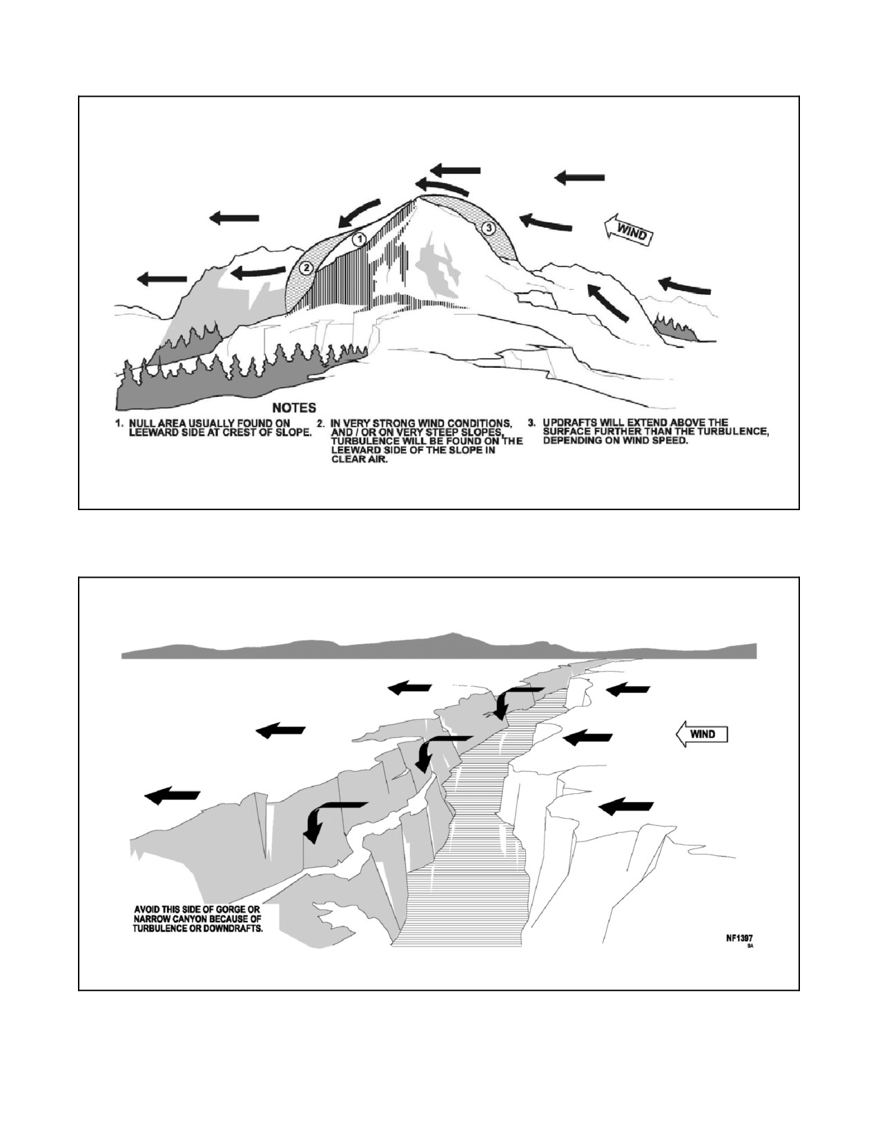
A1-H60BB-NFM-000
Figure 9-18. Windflow Over and Around Peaks
Figure 9-19. Windflow Over Gorge or Canyon
9-53
ORIGINAL
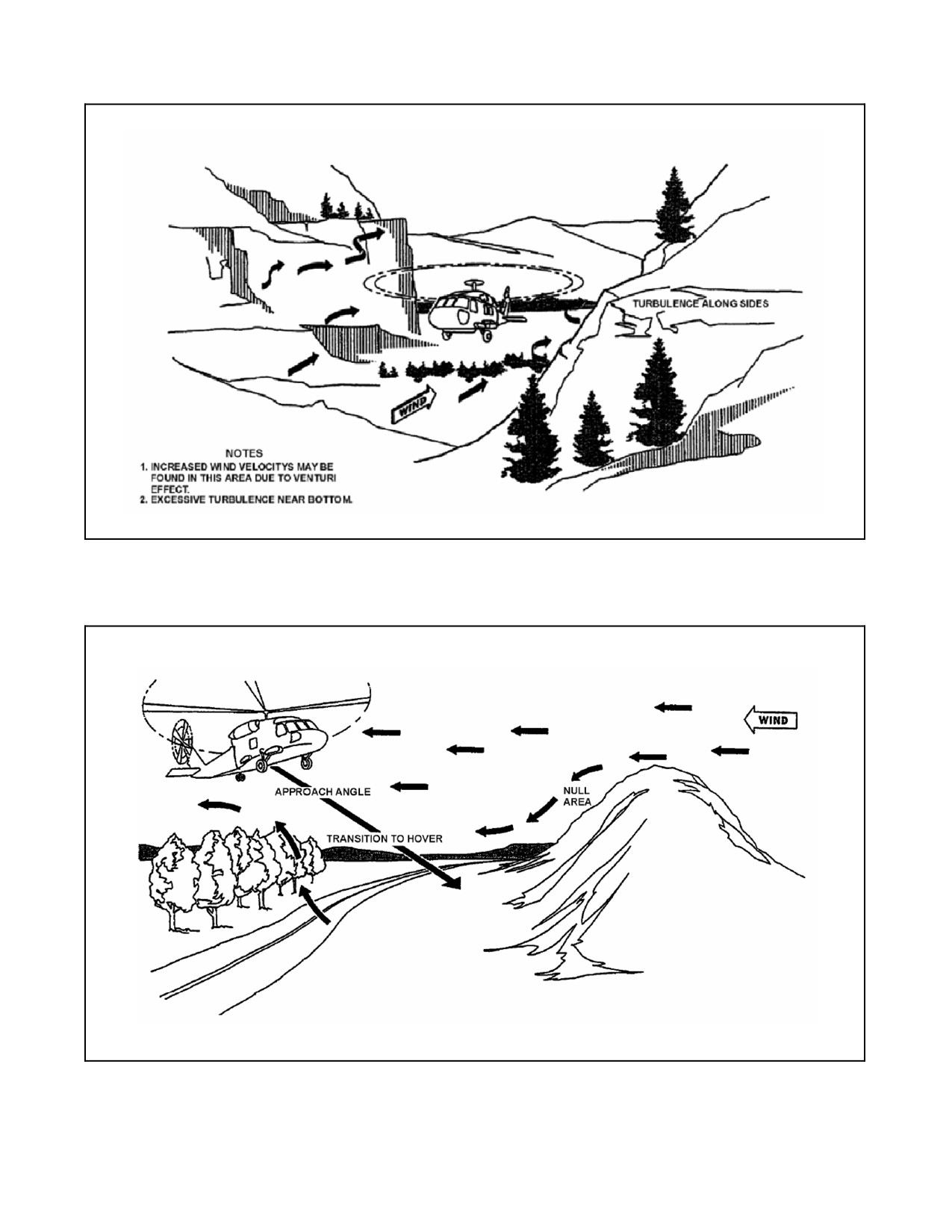
A1-H60BB-NFM-000
Figure 9-20. Windflow in Valley or Canyon
Figure 9-21. Wind Effect in a Confined Area
ORIGINAL
9-54
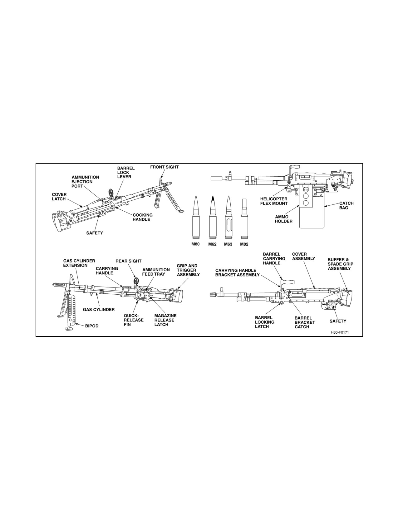
A1-H60BB-NFM-000
9.10
CREW SERVED WEAPON PROCEDURES
9.10.1 M60D/M240D Machine Gun
9.10.1.1 M60D/M240D Aircraft Preparation/Inspection
Each machine gun is air cooled, gas operated, and automatic. They each fire the standard 7.62 mm NATO cartridge
from the open bolt position at firing rates of up to 550 rounds per minute (rpm) for the M60D and 650 to 950 rpm
for the M240D. Barrel headspace and timing of both weapons are fixed, allowing for quick barrel changes for cooling
and maintenance. The M60D incorporates a rear ring and barrel-mounted post sighting system, whereas the M240D
incorporates a rear sight leaf and a barrel-mounted post sighting system. The M60D/M240D machine gun subsystems
(Figure 9-22) are mounted on a pintle mounting system and are held on by a quick-release pin. The weapon mounts
are on rotating arm assemblies which allow the weapons to be locked outboard in the firing position, or stowed inside
the aircraft when the rotating arms are locked in the inboard position. The weapons can be removed easily from the
helicopter and, if needed, may be used for ground defense. For more detail on each weapon, refer to NAVAIR
11-95M60-1 for the M60D and to NAVAIR 11-95M240D1-1 for the M240D.
Figure 9-22. M60D/M240D Machine Gun Components
1. Gun secured to mount.
Note
In order to properly install pintle mount, attach weapon to pintle with
quick-release pin. Secure with an appropriate plastic tie or 0.032 inch safety
wire through the quick-release ring and around the pintle.
2. Ejector control bag installed.
3. Raise cover assembly/feed tray and verify clear of ammunition and links.
4. Place gun in the FIRE (F) position.
5. Pull charging handle rearward and return handle to forward locked position. Place gun in SAFE (S) position.
6. Visually inspect barrel chamber, ammunition feed tray, and inside of receiver. Verify ammunition is not present
in the gun barrel or in position to be fed into the gun barrel.
9-55
ORIGINAL
A1-H60BB-NFM-000
7. Close feed tray and cover assembly.
8. Ensure gun barrel is securely attached and locked to gun receiver.
9. Check weapon for freedom of movement through azimuth, elevation, and depression positions.
10. Pull charging handle rearward, place safety in the (F) position, and ease bolt and operating rod assembly
forward into the battery position.
11. Stow weapon inside cabin.
12. Report weapon status.
CAUTION
D Expended brass and links present a potential FOD hazard. Inspect lower
main landing gear strut cowling and cabin door tracks for expended brass
after a live fire evolution.
D Norestraintisprovidedfor7.62mmammunitionwiththeM240Dfeedcan.
When operating the M240D at maximum depression, loss of 7.62 mm
ammunition from the feed will occur.
9.10.2 M60D/M240D Rigging Procedures
Ensure barrel is positively locked into the receiver assembly before
attempting to fire.
1. Cabin door — Open.
2. Pilot commands — “CLEAR TO RIG.”
3. Crewman pulls detent handle to release, swings mount to extended position, and pushes detent handle to lock
weapon.
Failure to ensure detent handle is locked will result in loss of weapon
controllability.
4. Crewman removes vertical stop pin, places gun in the horizontal position, and replaces vertical stop pin.
5. Crewman reports — “WEAPON RIGGED.”
9.10.3 M60D/M240D Field of Fire Check
1. Safety switch — SAFE.
2. Pintle — OUT and LOCKED.
Note
The field of fire check should be performed with rotors engaged.
3. Position weapon in all extremes of travel — check for rotor or airframe interference.
ORIGINAL
9-56
A1-H60BB-NFM-000
9.10.4 M60D/M240D Lock and Load Procedures
D The weapon shall not be loaded unless cleared by the helicopter aircraft
commander (HAC) and then only in a cleared range or operational area or
during a potentially hostile situation.
D Observe all safety precautions for loading ammunition in accordance with
applicable directives. All loading and clearing shall be done with the
weapon in the rigged position.
1. Pilot commands — “LOCK AND LOAD.”
2. Open feed cover latch and raise feed cover assembly.
3. Open the ejector control bag and pull cocking handle fully to rear.
4. Push cocking handle full forward to locked position.
Cocking handle must be returned to full forward (locked) position before
firing. Always cock the gun underhanded to preclude cutting thumb on the
feed cover.
5. Press safety button to (S) position.
6. Insert link belt with open side of links down on tray assembly.
7. Close feed cover and latch in place.
8. Crewman reports — “WEAPON READY, SAFE.”
9.10.5 M60D/M240D Machine Gun Firing Procedures
D Although stops are provided, extreme care must be taken to prevent firing
the weapon into the rotor blades or airframe.
D Any crewmember may call a cease-fire in an unsafe condition.
CAUTION
Do not fire machine gun unless the ejector control bag is mounted in place
with bottom zipper closed.
9-57
ORIGINAL
A1-H60BB-NFM-000
1. With machine gun positioned, loaded, and aimed, press safety button to firing (F) position.
2. To fire gun automatically, pull trigger fully and hold.
CAUTION
Dumping brass should be conducted while in a hover to prevent possible
damage to aircraft or equipment.
Note
D The M60D/M240D low cyclic rate of fire allows firing of a single round or
short bursts. The trigger must be quickly released for each shot.
D When ammunition is exhausted, the last link will remain in the tray
assembly. The link assembly can be removed by hand after the feed cover
assembly is opened.
9.10.6 M60D/M240D Barrel Change Procedures
1. Ensure weapon is clear of ammunition.
2. Crewman removes vertical stop pin, places gun barrel down, and replaces vertical stop pin.
3. Crewman pulls detent handle to release, swings mount inside cabin, and pushes detent handle to lock weapon.
4. Wearing asbestos gloves, grasp barrel.
Weapon barrel will become very hot. Exercise extreme care while handling
barrel.
5. Pivot barrel release lever up and remove hot barrel.
6. Insert spare barrel and lock in place by pivoting barrel release lever down.
Ensure barrel is positively locked into the receiver assembly before
attempting to fire.
9.10.7 M60D/M240D Stowing Procedures
1. Pilot commands — “STOW WEAPON.”
2. Crewman ensures weapon is clear of ammunition.
3. Crewman removes vertical stop pin, swings gun barrel down, and replaces vertical stop pin.
4. Crewman pulls detent handle to release, swings mount inside cabin, and pushes detent handle to lock weapon.
5. Crewman reports — “WEAPON CLEAR/STOWED.”
9.10.8 Voice Commands
Exact procedures may vary according to the tactical situation; however, the voice commands shown in Figure 9-23
should be used.
ORIGINAL
9-58
A1-H60BB-NFM-000
9.10.9 Hand Signals
In the event of ICS problems, the following hand signals may be used by the pilot to command the crewman to open
fire or cease fire:
1. OPEN FIRE — The pilot extends his hand in the shape of a pistol, index finger extended, thumb pointed up.
2. CEASE FIRE — The pilot extends his hand in the shape of a pistol, index finger extended, thumb pointed
down.
9.11
GAU-16/A MACHINE GUN
The GAU-16/A Airborne Machine gun is a crew-served weapon mounted in the starboard door of the helicopter. The
GAU-16/A has a firing rate of 750 to 850 rounds per minute, 100-round ammunition can supply mount for a
right-hand feed to the weapon, and a flash suppressor which reduces bloom out of the NVD. The GAU-16/A mount
assembly is equipped with a shock absorber that significantly reduces recoil loads transferred to the aircraft. The
adapterassemblyallowstheGAU-16/Atobeplacedintheinboardstowposition,outboardstowposition,orthefiring
position. The inboard stow position allows the cabin door to be closed, whereas the outboard stow position allows
ease of entry and egress.
9.11.1 GAU-16/A Headspace Adjustment
9.11.1.1 Definition
Headspace for the machine gun is the distance between the front of the bolt and the rear end of the barrel. Headspace
is correct when the distance is between 0.202 and 0.206 inch. Unless this distance is properly adjusted, the cartridge,
when chambered, will not be properly seated against the shoulder of the chamber. No procedures for adjustment
without headspace and timing gauge are authorized.
FROM
TO
WHEN
REPORT/VISUAL SIGNAL — RESPONSE
Pilot
Crewman
60 KIAS or below
CLEAR TO RIG — WEAPON RIGGED
Pilot
Crewman
Firing is imminent
LOCK AND LOAD — WEAPON READY,
SAFE
Pilot
Crewman
Helicopter is steady on target
ROLLING ON TARGET — ROGER
bearing
Pilot
Crewman
Permission to unsafe weapon and
OPEN FIRE — ROGER, OPEN FIRE
open fire when target within range
Crewman
Pilot
Target is within range
ON TARGET — ROGER
Crewman
Pilot
Target is out of range
OFF TARGET — ROGER
Crewman
Pilot
Current ammunition can is empty
WEAPONS DRY — ROGER, RELOAD
Crewman
Pilot
All ammunition is expended
WINCHESTER — ROGER, WINCHESTER
Pilot
Crewman
Permission to fire rescinded
CEASE FIRE — ROGER, WEAPON READY,
SAFE
Pilot
Crewman
Firing is no longer probable
CLEAR THE WEAPON — WEAPON CLEAR
Pilot
Crewman
60 KIAS or below
STOW THE WEAPON — WEAPON CLEAR,
WEAPON STOWED
Note
The machine gun can be rigged at any airspeed. The 60 KIAS limitation pertains to the cabin door only.
Figure 9-23. Machine Gun Operations ICS Terminology
9-59
ORIGINAL
A1-H60BB-NFM-000
9.11.2 GAU-16/A Headspace Adjustment Checklist
Improper headspace and timing will cause cartridge round to split and jam
the weapon. Injury or death of crewman may result.
CAUTION
Headspace and timing shall be performed prior to each firing and upon
completion of cleaning weapon to ensure weapon does not malfunction.
Note
No procedures for adjustment without headspace and timing gauge are
authorized.
1. Weapon clear and safe.
2. Retract recoiling parts until barrel extension is separated from trunnion block.
3. Insert the GO end of the headspace gauge into the T-slot between face and bolt and breech end of the barrel.
Adjust as necessary.
Note
This weapon is set up for a right-hand feed; remove the left-hand rear
cartridge stop assembly for ease in screwing the barrel into the barrel
extension.
4. Attempt to adjust the NO-GO end of the headspace gauge in T-slot. Adjust as necessary.
5. If NO-GO required an adjustment, repeat steps 3. and 4. until headspace adjustments are within tolerance.
CAUTION
Never release the firing pin with the headspace and timing gauge in place.
Damage to the firing pin can occur.
6. Remove gauge, place the safe switch to (F) and release the firing pin.
7. Place safety back to (S).
9.11.3 GAU-16/A Timing Adjustment
Timing is the point at which the firing pin is released after the recoiling parts reach the battery position during counter
recoil. This point is determined by measuring the distance between the front face of the barrel extension and the rear
face of the trunnion block. The gun must fire when this distance is between 0.202 and 0.116 inch. Timing must be
checked and adjusted each time headspace is checked and adjusted, and whenever incorrect timing is suspected. If
the timing is early, recoil will start before the extractor is far enough forward to engage the next cartridge in the belt.
In this condition, the gun will stop firing after two rounds. If the timing is late, the barrel extension will strike the
trunnion block as the recoiling parts reach the battery position during counter recoil. The gun will continue to fire,
but the barrel extension will be damaged as it strikes the trunnion block.
ORIGINAL
9-60
A1-H60BB-NFM-000
9.11.3.1 GAU-16/A Timing Adjustment Checklist
Improper headspace and timing will cause cartridge round to split and jam
the weapon. Injury or death of crewman may result.
CAUTION
Headspace and timing shall be performed prior to each firing and upon
completion of cleaning weapon to ensure weapon does not malfunction.
1. Weapon clear and safe.
2. Retract recoiling parts 1/4
inch and insert NO-FIRE gauge between barrel and trunnion block.
3. Allow barrel extension to close slowly until stopped by timing gauge.
4. Pull trigger. Firing pin should not release.
If firing pin does release:
5. Make timing adjustments until firing pin does not release.
If firing pin does not release:
6. Remove gauge and allow recoiling parts to go forward to battery position.
7. Retract recoiling parts until barrel extension is about 1/4
inch from trunnion block.
8. Insert FIRE timing gauge between barrel extension and trunnion block.
9. Allow barrel extension to close slowly until stopped by contracting gauge.
10. Release trigger housing safety. Attempt to release firing pin by operating firing mechanism once. The firing
pin should release with the gauge in place.
If firing pin does not release:
11. Make timing adjustments until firing pin does release.
If firing pin does release:
Bolt shall be in the battery position before back plate is removed. Do not
attempt to release firing pin or charge weapon with the back plate off.
12. Retract recoiling parts, remove the gauge, and cock the weapon.
9.11.3.2 GAU-16/A Rigging Procedures
1. Cabin door — Open.
2. Pilot commands — “CLEAR TO RIG.”
3. GAU-16/A — Rig in firing position.
9-61
ORIGINAL
A1-H60BB-NFM-000
4. Crewman reports — “WEAPON RIGGED.”
The outboard stowed position is not an authorized in-flight position. It is
only authorized for ingress/egress while on the ground or in a hover during
hoisting evolutions.
9.11.3.3 GAU-16/A Lock and Load Procedures
1. Pilot commands — “LOCK AND LOAD.”
2. Safety — SAFE.
3. Ammunition can support lid — Open Tiltstandard100roundammunitioncanforward,slideammunitioncan
forward under lid, and lock support lid.
4. Feed cover assembly — Open.
5. Ammunition — Insert.
6. Feed cover assembly — Close.
7. Weapon — Charge twice to load.
8. Crewman reports — “WEAPON READY, SAFE.”
All loading and clearing shall be done with the weapon in the firing
position.
9.11.3.4 GAU-16/A Firing Procedures
The only authorized position for firing the GAU-16/A is with the
crossbeam secured to both the forward and aft brackets.
1. Pilot commands — “OPEN FIRE.”
a. As required — “CLEARED TO LASE.”
2. Crewman responds — “ROGER, OPEN FIRE.”
a. As required — “ROGER, CLEARED TO LASE.”
3. Safety — FIRE.
4. AN/PEQ-3 laser reducer covers (if required) — Rotate off.
5. AN/PEQ-3 laser mode selector (if required) — ON.
6. AN/PEQ-3 laser deadman switch — Press and hold.
7. Trigger — Pull.
ORIGINAL
9-62
A1-H60BB-NFM-000
9.11.3.5 GAU-16/A Clear Weapon Procedures
D Do not disassemble the GAU-16/A while attempting to clear weapon.
D Barrel must be pointed in a safe, uninhabited direction at all times.
1. Safety — SAFE.
2. PEQ-3 mode selector switch — OFF (if installed).
3. PEQ-3 lens covers — Rotate on (if installed).
4. Feed cover — Open.
5. Ammunition — Remove from feed tray.
6. Feed cover — Close.
7. Charging handle — Charge.
8. Feed cover — Open.
Chamber may be hot. Use caution while inspecting T-slot.
9. Weapon — inspect T-slot/chamber, ensure weapon is clear.
If chamber is not clear, repeat steps 4. through 7. once and remove any
remaining rounds. If unable to clear weapon, execute hung ordnance
procedures in accordance with local directives.
10. Weapon status — Report.
9-63/(9-64 blank)
ORIGINAL
A1-H60BB-NFM-000
CHAPTER 10
Functional Checkflight Procedures
10.1
FUNCTIONAL CHECKFLIGHT
The purpose of an FCF is to determine if the airframe, engines, accessories, and other items of equipment are
functioning in accordance with predetermined requirements while subjected to the intended operating environment.
These flights should normally be conducted within autorotative distance of a landing field when feasible and during
daylight hours under VMC. However, if necessary to accomplish the assigned mission, the unit commander may
authorize functional checkflights under conditions other than the above, if, in the commander’s opinion, the flight
can be conducted with an acceptable margin of safety under the existing conditions. This authority may not be
delegated. Those portions of the flight that are considered critical shall be conducted in the vicinity of a suitable
landing area. At the discretion of commanding officers, or detachment officers--in--charge when deployed, functional
checkflights may be performed in combination with operational flights provided the operational portion is not
conducted until the flight inspection requirements have been satisfied by a designated Functional Check Pilot (FCP).
The appropriate checkflight checklist shall be used. This section contains detailed checkflight procedures, sequenced
in the order in which they should be done. See COMNAVAIRFORINST 4790.2 (series) for additional information.
Note
These procedures are intended for use by designated FCPs only and shall
notbeperformedorusedastroubleshootingproceduresbysquadronpilots.
The FCP shall approach preflight inspections with diligence. Since work
is being checked that directly affects safety of flight, close scrutiny must be
exercised during inspections.
10.1.1 Designation of Pilots
The aircraft maintenance officer shall recommend to the commanding officer, via the operations officer, designated
HACs that have completed the squadron FCP syllabus and meet all applicable OPNAV 3710.7 (series) and
COMNAVAIRFORINST 4790 (series) requirements. The operations officer shall forward recommendations, with
appropriate comments, to the commanding officer.
10.1.2 Ground Checks
Ground checks are defined as checks accomplished on the ground to ensure that equipment has been adjusted,
reassembled, repaired, and inspected satisfactorily. These checks shall be accomplished after the helicopter system
or components have been inspected following maintenance or repair operations.
10.1.3 General Information
This chapter contains detailed checkflight procedures, sequenced in the order in which they should be performed. The
functional checkflight shall be conducted using the checkflight record in conjunction with normal NATOPS
procedures. For the purpose of functional checkflights only, this chapter satisfies all the requirements of the Pilot’s
Pocket Checklist from “Interior Inspection” through “Postflight Checks.” Crew requirements are specified in
Chapter 5.
10-1
ORIGINAL
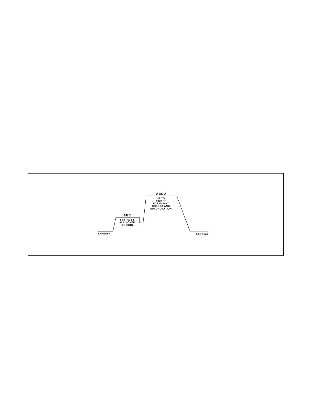
A1-H60BB-NFM-000
10.1.4 Special Instructions
1. Passengers are prohibited on FCFs.
2. Forms and records will be checked before the FCF to determine maintenance performed and the flight profile
required.
3. Record informationwhere indicatedby aline ____________.Where aboxjis shown,use a√ forsatisfactory
or an X for unsatisfactory.
4. Check and go. Combination of an FCF with an operational flight is specifically prohibited when a post--depot
checkflight attesting to the airworthiness of the aircraft has not been previously performed.
10.1.5 FCF Record Cards
A record card shall be used for all FCFs. When an FCF is required to determine if specific equipment or systems are
operating properly, completion of only that portion of the FCF applicable to the specific equipment or systems being
evaluated is required. The FCF record card may be locally reproduced. Continuation sheets may be used when
necessary. Items that prove to be unsatisfactory during flight and require corrective action shall be listed in the remarks
block during flight and transferred to a Visual Discrepancy System/Maintenance Action Form VIDS/MAF
immediately after termination of the flight.
10.1.6 FCF Profile
The FCF altitude profile (Figure 10-1) is recommended for all checkflights.
Figure 10-1. FCF Altitude Profile
A daily and turnaround inspection is required before the checkflight. Perform all normal checklist items for all
checkflights. Perform applicable flight profile checks in accordance with COMNAVAIRFORINST 4790.2 (series)
under the following guidelines:
1. Functional checkflights are conducted when it is not possible to determine proper operation by ground checks
(e.g., aerodynamic reaction, air loading, or signal propagation).
2. Functional checkflights are not required upon the completion of phase inspections, unless the corrective
action(s) resulting from a discrepancy discovered during the inspection requires a checkflight or the item
inspected requires removal, disassembly, adjustment, alignment, reinstallation or reassembly of any items in
the following paragraphs. The maintenance requirement cards (MRC) will indicate the phase packages
requiring a partial system functional checkflight.
ORIGINAL
10-2
A1-H60BB-NFM-000
3. Although the following conditions requiring FCFs are minimal and mandatory, this does not preclude
operational commanders from imposing additional requirements of the scope and frequency deemed
necessary. Perform applicable flight profile associated checks in accordance with COMNAVAIRFORINST
4790.2
(series), NAVAIR A1--H60CA--VIB--100, H--60 (series) IETMS, and applicable Wing directives under
the following checkflight conditions:
a. A PROFILE — Full system checks.
b. B PROFILE — Engine checks.
c. C PROFILE — Controllability/drive train check.
d. D PROFILE — AFCS check.
10.1.7 Limited FCF
A limited FCF is required when it is necessary to prove proper functioning of a specific item or component. Duration
of the FCF need only be enough to verify performance of the item(s) being tested.
10-3
ORIGINAL
A1-H60BB-NFM-000
PROFILE
10.2
FUNCTIONAL CHECKFLIGHT CHECKLIST
10.2.1 Preflight Check
A B C D
1. Exterior.
A B C D
2. Interior.
A
3. Seats, belts, shoulder harnesses, and shoulder harness locks.
a. Tail rotor pedal adjustment — 6 INCHES OF TRAVEL.
b. Seat height adjustment.
c. Seat forward/aft adjustment.
d. Inertia reel check.
A
4. Compass correction cards — CURRENT AND LEGIBLE.
10.2.2 Start Checks
Note
Daggered ([
) steps need not be accomplished
on subsequent flights on the same day.
10.2.2.1 Prestart Checks
CAUTION
Moving flight controls without first or second--
stage pressure on the primary servos may cause
damage to the flight controls.
1.
Seats/belts/pedals/mirrors — ADJUSTED.
2.
Cockpit window emergency release handles — AFT AND SHEARWIRED.
3.
Left collective — EXTENDED AND LOCKED.
4.
Circuit breakers and switches — CHECKED AND OFF.
Switches not having an OFF position should be checked as follows:
a. RDR, DATA LINK — STBY.
b. ATO ICS — NORM.
c. DATA LINK MODE — AUTO.
d. GUARD REC — ON.
e. COMM CONTR mode select — T/R.
f. GUST LOCK — NORM.
g. TAIL SERVO — NORM.
h. Pilot ICS — NORM.
ORIGINAL
10-4
A1-H60BB-NFM-000
PROFILE
i. CARGO HOOK ARMING — SAFE.
j. CARGO HOOK EMER RLSE — OPEN.
k. FIRE DET TEST — OPER.
l. DE--ICE MASTER — MANUAL.
m. MODE 4 AUDIO/LIGHT/OUT — AUDIO.
n. Transponder ANT — DIV.
o. COMP panel — SLAVED, LAT CHECKED.
p. FUEL MGT panel, MASTER/MODE switches — STOP FLOW/AUTO.
q. SERVO SHUTOFF SWITCH — CENTER.
5.
Parking brake — RESET.
6.
TAIL WHEEL — LOCK.
7.
Aircrewman Prestart Checks — COMPLETE.
8.
Engine T-handles — FORWARD.
9.
APU T--handle — IN.
10. Rotor brake — ON.
11. BATT switch — ON. (#1/#2 CONV, AC ESS BUS OFF, STABILATOR, and AFCS
DEGRADED caution, WOW and ROTOR BRAKE advisory lights — ILLUMINATE.)
12. UHF backup — SET.
13. External Power — As required, RESET then ON.
14. Fire detector system — TEST.
15. Fire guard — POSTED, AREA CLEAR.
16. Interior/exterior/NVD lighting — AS REQUIRED.
17. APU — START.
a. ECS — OFF.
b. AIR SOURCE ECS/START switch — APU.
c. FUEL PUMP switch — APU BOOST.
(1) PRIME BOOST PUMP ON advisory light — ON.
d. APU CONTROL switch — ON.
(1) APU ON advisory light — ON.
Note
Do not cycle the BATT switch or turn off the
APU CONTROL switch if the APU shuts down
during start or after it is running. This removes
the cause of the shutdown from the APU BITE
indicator.
10-5
ORIGINAL
A1-H60BB-NFM-000
PROFILE
18. APU GENERATOR switch — ON.
a. APU GEN ON advisory light — ON.
19. External Power — OFF (disconnect as required).
20. ICS/RADIO — CHECK.
21. ECS — AS REQUIRED.
[22. Blade/pylon spread — AS REQUIRED.
a. Area — CLEAR (wing walkers positioned as required).
b. CMPTR PWR/RESET pushbutton — ON.
c. BLADE FOLD MASTER switch — ON.
d. BLADE FOLD switch — SPREAD.
e. PYLON FLIGHT and ROTOR SPREAD lights — ILLUMINATED.
f. RDR ALT pushbutton — PRESS (if flashing).
g. BLADE FOLD switch — OFF.
h. BLADE FOLD MASTER switch — OFF.
i. Proceed to step 24, Head Check.
[23. Lockpins status — CHECK.
a. BLADE FOLD MASTER switch — ON.
b. ROTOR SPREAD and PYLON FLIGHT lights — ILLUMINATED.
c. If ROTOR SPREAD light not illuminated:
(1) CMPTR PWR/RESET pushbutton — OFF.
(2) BACKUP HYD PMP switch — OFF.
(3) BLADE FOLD switch — SPREAD (5 to 7 seconds).
d. If rotor SPREAD light remains off:
(1) BLADE FOLD switch — OFF.
(2) BLADE FOLD MASTER switch — OFF.
(3) Head check — PERFORM.
e. If ROTOR SPREAD light illuminated:
(1) BLADE FOLD switch — OFF.
(2) SPREAD INCOMPLETE caution — DOES NOT APPEAR.
(3) BLADE FOLD MASTER switch — OFF.
ORIGINAL
10-6
A1-H60BB-NFM-000
PROFILE
[24. Head check — AS REQUIRED.
a. Blade lock pins engaged.
b. Pitch lock pins retracted.
c. Gust lock disengaged.
[25. IGB/TGB Oil Level Check — AS REQUIRED (after Pylon Spread).
26. CMPTR PWR/RESET pushbutton — CYCLE, ON.
27. SAS/BOOST pushbutton — ON.
28. BACKUP HYD PMP switch — ON.
Note
If electrical loads are introduced (e.g., backup
hydraulic pump) while operating from APU
generator or external power, an AFCS power
sever may occur, indicated by appearance of the
AFCS DEGRADED caution. To restore AFCS
computer power, press CMPTR PWR/RESET
pushbutton on AFCS CONTROL panel.
10.2.3
Systems Check
[1. DIGITS — ON; CDU and PDU — TEST.
2.
Fuel quantity and readouts — CHECK.
Note
The maximum difference between the fuel
quantity indicators on the VIDS, and total fuel
digital readout shall not be more than 200
pounds.
3.
Caution/advisory/warning lights — CHECK.
a. The following caution/advisory lights should be ON:
(1)
#1 and #2 GEN.
(2)
#1 and #2 FUEL PRESS.
(3)
#1 and #2 ENGINE OIL PRESS.
(4)
#1 and #2 HYD PUMP.
(5) SAS.
(6) AFCS DEGRADED.
(7) MAIN XMSN OIL PRESS.
(8) WOW.
(9) ROTOR BRAKE.
(10) #1 and #2 ENG ANTI-ICE ON.
10-7
ORIGINAL
A1-H60BB-NFM-000
PROFILE
(11) APU ON.
(12) APU GEN ON.
(13) PRIME BOOST PUMP ON.
(14) BACK--UP PUMP ON.
(15) PARKING BRAKE ON.
A
4.
Caution/advisory/warning lights and dimming — CHECK.
a. BRT/DIM - TEST switch — TEST.
b. All caution/advisory lights go on. All warning lights on master warning panels go on and
LOW ROTOR RPM lights flash. Legends on mode selector panels go on. The AFCS
control panel, FUEL MGT panel, STABILATOR panel and BLADE FOLD control panel
lights go on, and RAWS tones audible.
c. BRT/DIM-TEST switch — DIM. All lights on the caution/advisory panel should decrease
in intensity.
d. BRT/DIM-TEST switch — BRT. All lights on caution/advisory panel should return to
normal intensity.
e. While holding BRT/DIM--TEST switch at TEST, turn INST LIGHTS PILOT FLIGHT
CONTROL switch from OFF. All lights should decrease in intensity. Turn INST LIGHTS
PILOT FLIGHT CONTROL switch to OFF. All lights on panel should return to normal
intensity.
f. BRT/DIM-TEST switch — RELEASE. MASTER CAUTION WARNING lights should
flash 16 times. Note that no transmission chip caution lights are on.
A
5.
Photocell sensitivity — CHECK.
a. Lamp test buttons — PRESS AND HOLD.
b. DIM control on CDU — TURN (full clockwise).
c. All segments on CDU and PDU will go to 1/2 intensity.
d. DIM control on CDU — TURN (counterclockwise just below detent).
e. Apply light from outside source (such as utility light) to one photocell at a time. Note
intensity of segments on CDU and PDU increases.
Note
Ifsunlightisshiningononeormorephotocells,
covering those photocells should cause
segment lights to dim.
f. DIM control — ADJUST (to desired intensity).
A
6.
INTERIOR/EXTERIOR LIGHTS — CHECK. Instrument lights, secondary lights, cockpit
flood, and cabin dome lights, landing/hover lights, position and anticollision lights, and
controllable searchlight — CHECK. SET AS DESIRED.
7.
RAD ALT, BAR ALT, clocks — SET.
8.
TACAN — AS REQUIRED.
9.
IFF MASTER — STBY.
ORIGINAL
10-8
A1-H60BB-NFM-000
PROFILE
A
C D
10. Cyclic forward stop — CHECK.
a. SAS 1 and SAS 2 pushbuttons — OFF.
b. Move collective to midposition with full left pedal.
Note
Due to control mixing, maximum forward
cyclic position is achieved with full left pedal
and the collective at midposition.
c. Move cyclic full forward and center laterally against forward stop.
d. Thecyclicshouldnottouchtheinstrumentpanel.(Distancefrom instrumentpanel tocyclic
should be approximately 3/4 to 2-1/4 inches). Cyclic may contact instrument bezel/knobs.
e. Return cyclic to center position and collective to full down.
[11. Primary servos — CHECK.
A
C D
[12. BOOST servos — CHECK.
a. Collective and pedals — MID-POSITION and RIGHT PEDAL SLIGHTLY FORWARD
OF NEUTRAL.
Note
Slight pedal control deflection may be
necessary to prevent excessive collective
movement.
b. SAS/BOOSTpushbutton—OFF.BOOSTSERVOOFFandAFCS DEGRADEDcautions
appear and MASTER CAUTION lights illuminated.
c. Move flight controls through full range of travel. Note increase in control forces (except
lateral). Left/right cyclic force should be about half the fore/aft force for equal
displacement.
d. Check for not more than 1-1/2 inches of free play in controls. If free play is felt, visually
inspect boost servo for failed piston link.
e. Collective and pedals — MID-POSITION AND RIGHT PEDAL SLIGHTLY FORWARD
OF NEUTRAL.
f. SAS/BOOST pushbutton — ON. BOOST SERVO OFF caution disappears.
g. Collective — FULL DOWN.
[13. Tail rotor servo — CHECK.
A
C D
[14. AFCS ground check.
a. SAS — CHECK.
(1) CMPTR PWR/RESET 2--minute warm--up and SAS BOOST pushbuttons — CHECK
ON.
(2) TRIM and AUTO PLT pushbuttons — CHECK OFF.
(3) SAS 1 pushbutton — ON for at least 10 seconds, then OFF. SAS 1 fail advisory light,
SAS and AFCS DEGRADED cautions should not appear during self--test.
10-9
ORIGINAL
A1-H60BB-NFM-000
PROFILE
(4) SAS 1 pushbutton — ON, then OFF. No movement should occur in either main rotor
blades or flight controls.
(5) Repeat step (4) for SAS 2.
(6) SAS 1 and SAS 2 pushbuttons — ON.
(7) Move controls through full range. Check for restrictions, control feedback and rotor
blade chatter. If any are detected, repeat step with each SAS disengaged separately to
determine in which SAS channel and axis discrepancy exists.
(8) SAS 1 and SAS 2 pushbuttons — OFF.
b.
Trim — CHECK.
(1)
TRIM pushbutton — ON, THEN OFF. No movement should occur in flight controls.
(2)
TRIM pushbutton — ON.
(3)
Cyclic Trim — CHECK.
(a) Move cyclic fore, aft, and laterally checking for symmetrical gradient force
increase with control displacement.
(b) Without depressing the cyclic TRIM REL button, displace cyclic from trim
position and release. Cyclic should return to trimmed position.
(c) Depress the cyclic TRIM REL button. Slowly displace cyclic fore/aft and note a
resisting force. Move the cyclic fore/aft at a faster rate and note an increase in
resisting force. Do the same using left/right cyclic movement. Note the
force/velocity characteristics with longitudinal cyclic are twice as great as lateral
cyclic.
(d) Center the pedals and place collective at midposition. Trim cyclic full aft. Using
four--way TRIM switch, move cyclic full travel forward. Operation should be
smooth and full travel should take 15 ±3 seconds. Repeat in opposite direction.
(e) Lower collective, trim cyclic full left. Using four--way TRIM switch, move cyclic
fulltravelright.Fulltravelshouldtake18±3seconds.Repeatinoppositedirection.
(f) Pilot and copilot cyclic four--way TRIM switches — CHECK (fore/aft/lateral).
(4)
Cyclic and collective trim release buttons — CHECK. Move cyclic and collective with
buttons depressed to ensure proper operation.
(5)
Collective trim — CHECK.
(a) Collective — TRIM TO MID-POSITION.
(b) Without pressing collective trim release switch, displace the collective full up
noting increase in gradient force. Release, collective should return smoothly to
mid--position.
(c) Repeat step (b) for collective full down.
(6)
Yaw pedal trim — CHECK.
(a) Pedals — TRIM TO MID-POSITION.
(b) Without pressing pedal trim switch, displace one pedal full forward and release.
Pedals should return smoothly to trimmed position.
ORIGINAL
10-10
A1-H60BB-NFM-000
PROFILE
(c) Repeat step (b) for other pedal.
(d) Move pedals back and forth at a slow constant rate and note a resisting force. Move
pedals at a faster rate and note an increase in resisting force.
c.
Autopilot — CHECK.
(1)
SAS 1, SAS 2 and TRIM pushbuttons — ON.
(2)
AUTO PLT pushbutton — ON, THEN OFF. No movement should occur in flight
controls.
(3)
AUTO PLT pushbutton — ON.
(4)
Move flight controls through full range without depressing cyclic, collective, or pedal
trim switches. Check for restrictions, control feedback, and rotor blade chatter.
Note
If any restricting control feedback or rotor
blade chatter is detected, repeat step with
SAS/Trim/Autopilot individually disengaged
to determine the channel and axis where the
discrepancy exists.
(5)
Press BAR ALT pushbutton — BAR ALT hold should engage.
(6)
Press RDR ALT pushbutton — RDR ALT hold should engage.
(7)
Radar Altimeters — OFF. RDR ALT hold switches to BAR ALT hold, AFCS
DEGRADED caution, CPLR and ALT fail advisory lights, and MASTER CAUTION
lights illuminated.
(8)
BAR ALT pushbutton — PRESS OFF.
(9)
RDR ALT and APPR/HVR pushbuttons — PRESS. RADALT hold and hover coupler
should not engage.
(10)
Radar altimeters — ON.
(11)
Pilot and ATO AFCS RELEASE switch — CHECK. SAS 1, SAS 2, and AUTO PLT
lights OFF. SAS caution light and MASTER CAUTION WARNING lights ON.
(12)
SAS 1, SAS 2, TRIM, AUTO PLT — ON.
[15. Stabilator — CHECK.
A
[16. Rescue Hoist Preoperational Check — AS REQUIRED (see paragraph 7.16.2.1).
A
[17. Cargo Hook Preoperational Check — AS REQUIRED (see paragraph 7.16.2.2).
A
[18. Cargo hook emergency release circuit — TEST.
Personnel shall remain clear of cargo hook
during short and open circuit tests in case of
inadvertent CAD firing.
10-11
ORIGINAL
A1-H60BB-NFM-000
PROFILE
CAUTION
To prevent unintentional discharge of the cargo
hook CAD, the pilot shall call off each proced-
ural step of the emergency release circuit test
before that step is performed. The station being
checked shall reply to each command.
a.
CARGO HOOK EMERG REL TEST light — PRESS (light illuminates).
b.
RESCUE HOIST PWR/ARMED switch — OFF.
c.
EMER RELEASE HOIST CABLE SHEAR circuit breaker (DC ESNTL BUS, OVHD,
ROW 2, CB 2) — PULL.
d.
CARGO HOOK CONTR switch — ARMED/ALL or ARMED/COCKPIT.
e.
SHORT test.
(1) CARGO HOOK EMERG REL switch — SHORT.
(2) Pilot cyclic EMER REL button — PRESS. CARGO HOOK EMERG REL TEST light
illuminates.
(3) ATO EMER REL button — PRESS. CARGO HOOK EMERG REL TEST light
illuminates.
f.
OPEN test.
(1) CARGO HOOK EMERG REL switch — OPEN.
(2) Pilot cyclic EMER REL button — PRESS. CARGO HOOK EMERG REL TEST light
illuminates.
(3) ATO cyclic EMER REL button — PRESS. CARGO HOOK EMERG REL TEST light
illuminates.
g.
EMER RELEASE HOIST CABLE SHEAR circuit breaker — RESET.
h.
CARGO HOOK CONTR switch — SAFE.
A
19. Pitot heat system — CHECK.
a. PITOT HEAT switch — ON. Check both pitot--static tubes and static ports for increasing
temperature.
b. LEFT PITOT HEAT and RIGHT PITOT HEAT cautions do not appear — CHECK.
c. Pull RIGHT PITOT HEATER (NO. 2 AC PRIMARY, CORNER, ROW 3, CB 3) and LEFT
PITOT HEATER (NO. 1 AC PRI, SO’s OVERHEAD, ROW 1, CB 6) circuit breakers —
RIGHT PITOT HEAT and LEFT PITOT HEAT cautions appear.
d. Reset circuit breakers — cautions disappear.
e. PITOT HEAT switch — OFF.
A
20. Airspeed — Red line/slipmarked.
ORIGINAL
10-12
A1-H60BB-NFM-000
PROFILE
A
21. VSI — 0.
A
22. Windshield washer and wipers — CHECK.
CAUTION
To prevent scratching the windshield, do not
operate the wipers on dry glass.
a. WINDSHIELD WASHER switch — ON. Note that washer provides enough water and a
stream is properly directed on windshield.
b. WINDSHIELD WIPER knob — HI. Wiper blades should remain in contact with
windshield over its entire sweep area.
c. WINDSHIELD WIPER knob — LOW. Wiper blades should sweep at a slower speed.
d. WINDSHIELD WASHER switch — OFF.
e. WINDSHIELD WIPER knob — PARK (CONSTANT PRESSURE REQUIRED). Wiper
blades should move to windshield center posts and stop.
f. WINDSHIELD WIPER knob — OFF.
10.2.4
Starting Engines and Rotor Engagement
1.
High Points and Tail Tiedowns — VERIFY REMOVED.
CAUTION
D For shore--based operations only: If the engine
is started with the rotor brake on to facilitate
maintenance, the PCLs should not be advanced
above IDLE. If rotor engagement is required
following the required maintenance checks, the
engine(s) should be shut down from IDLE and
restarted with the rotor brake off to avoid the
possibility of engine power turbine shaft rub.
D Npshaftruboccurswhentheenginesareonline
and the rotor brake is released. The Np shaft
impacts the Ng shaft, which causes the com-
pressor blades to impact the compressor casing.
Over time, this will cause the engine to lose
power and possibly catastrophically fail. The
only way to ensure Np shaft rub will not occur
is to use the No Rotor Brake Start Procedure.
The No Rotor Brake Start Procedure shall be
utilized for routine engine start and rotor
engagement ashore.
10-13
ORIGINAL W/IC
68
A1-H60BB-NFM-000
PROFILE
Note
D After an engine installation, the initial engine
start should be done against the rotor brake to
check for engine leaks. During and after the
run, check for oil and fuel leaks. All subsequent
enginestartsshouldbeconductedwiththerotor
brake off.
D Engine start data collected from either the No
RotorBrakeStartProcedureortheRotorBrake
Start Procedure satisfies applicable FCF re-
quirements. It is not necessary to complete both
types of starts.
10.2.4.1 No Rotor Brake Start Procedure
Note
ThisprocedureshallbeutilizedforroutineFCF
engine start and rotor engagements ashore.
1. Fire guard posted, area clear.
2. Doors, inertia reels — LOCK.
3. SAS 1, SAS 2, TRIM and AUTO PLT pushbuttons — ON.
When AFCS computer power is cycled, trim is
disengaged. An unguarded cyclic will allow the
rotor arc to dip as low as 4 feet above the
ground, without droop--stop pounding, prior to
full control deflection.
A B
4.
Engine control quadrant — CHECK.
a. PCLs — PULL DOWN AND PRESS FORWARD. Note no movement past IDLE detent.
b. Rotor brake interlock override tab — PULL.
c. PCLs — MOVE THROUGH FULL RANGE. Check for no binding, note positive detents,
then OFF.
d. Fuel selectors — DIR, XFD, THEN OFF. Check for no binding and note positive detents.
A B
5.
Engine fuel system priming (if required).
Note
Helicopter prime/boost pump capacity is not
sufficient to primean enginewhen theopposite
engineisrunning.Therefore,enginesshouldbe
primed individually with both engines OFF.
a. Fuel selector — DIR.
b. PCL — HOLD IN LOCKOUT.
c. FUEL PUMP switch — FUEL PRIME. Check FUEL PRIME advisory appears, hold until
plane captain reports steady flow of fuel coming from overboard drain.
ORIGINAL
10-14
A1-H60BB-NFM-000
PROFILE
d. Repeat steps b. and c. with fuel selector in XFD.
e. FUEL PUMP switch — APU BOOST.
f. PCL — OFF.
6.
Rotor brake — Pressure, check 450 psi minimum.
A B
7.
Engine Starter/Air Start Valve/ECS dropout — CHECK.
Note
This check is required whenever a starter motor
or start valve has been replaced. Check should
be performed no less than three times.
a. ENGINE IGNITION switch — OFF.
b. ECS MODE switch — AUTO.
c. PCL — OFF.
d. Engine starter button — PRESS AND HOLD UNTIL Ng BEGINS TO INCREASE. Note
that appropriate STARTER advisory appears.
e. ECS vent airflow — STOPS.
f. Record maximum Ng (minimum Ng should be 24 percent).
g. Abort start by pulling down on PCL.
h. ENG STARTER advisory — DISAPPEARS.
i. Repeat steps c. to h. for other engine as required.
8.
Rotor brake — OFF. Check pressure 0 psi, and ROTOR BRAKE advisory out.
9.
ENGINE IGNITION switch — NORM.
10. Fuel selector — XFD.
11. Lights — AS REQUIRED.
12. Flight controls — POSITION AND HOLD.
a. Cyclic and pedals — CENTERED.
b. Collective — DOWN AND HOLD.
CAUTION
During engine start and runup, adjust the cyclic
as required to maintain the tip path plane in a
neutral position and maintain the collective full
down and the pedals centered until Nr reaches
50 percent minimum to prevent damage to
anti--flap assembly. If droop stop pounding
occurs, raise collective to alleviate this condi-
tion, but not to exceed 1/2 inch. Maintain the
new collective position until Nr reaches 50
percent minimum.
10-15
ORIGINAL
A1-H60BB-NFM-000
PROFILE
13. BACKUP HYD PMP switch — OFF.
A B
14. Engines — START.
CAUTION
If an abnormal or loud whining noise is heard
during engine startup, shut down engineimme-
diately due to impending diaphragm coupling
failure. Maintenance action is required prior to
subsequent engine start.
Note
Checking of time to idle should not be done on
the initial start of a newly installed engine.
a. Monitor Ng and TGT.
b. Record the following:
(1) Time to lightoff (time from PCL to IDLE until first rise in TGT).
(2) Time to idle (time from PCL to IDLE until Ng at ground idle).
(3) Starter dropout speed.
(4) Maximum TGT.
(5) At ground idle note TGT, Ng, oil pressure, and OAT.
c. Verify time to IDLE and minimum idle speed are within parameters (Figure
10-2).
15. Engine oil pressures — CHECK.
16. ENG STARTER advisories — OUT.
17. Engine idle Ngs — CHECK, 63 percent or above and matched within 3 percent.
Ground idle Ng split greater than 3percent isan
indication of possible LDS roll--pin failure. Do
not fly the helicopter until maintenance action
is performed.
18. Check #1 HYD PUMP and #2 HYD PUMP cautions — OUT.
19. XMSN oil pressure — CHECK.
20. Np/Nr — CHECK within limits.
CAUTION
Loss of the collective boost servo through
either intentional shutoff or loss of NO.
2
hydraulic pressure will cause the collective to
move rapidly from the down position to
midposition if it is not held by hand. This
movement can be enough to cause the heli-
copter to become airborne. During ground
operations with engines operating, the flight
controls shall be monitored.
ORIGINAL W/IC 70
10-16
A1-H60BB-NFM-000
PROFILE
21. PCLs — PULL OUT OF IDLE DETENT AND SMOOTHLY ADVANCE TO FLY.
Do not move the PCLs rapidly when the tail
wheel lockpin is not engaged.
22. Droop stops — OUT.
23. PCLs — FLY.
24. Fuel selector — DIR.
25. BACKUP HYD PMP switch — AUTO.
26. TRQs — MATCHED within 5 percent.
27. Np/Nr — 100 percent.
28. NO. 1 and NO. 2 GENERATOR switches — ON.
Power transfer from the APU generator to the
NO. 1 generator may cause disengagement of
SAS 1, SAS 2, TRIM, AUTO PLT, and
Stabilator which may cause rotors to dip as low
as 4 feet.
10.2.4.2 Rotor Brake Start Procedure
1. Fire guard posted — area clear.
2. Doors, inertia reels — LOCK.
3. SAS 1, SAS 2, TRIM and AUTO PLT pushbuttons — ON.
A B
4. Engine control quadrant — CHECK.
a. PCLs — PULL DOWN AND PRESS FORWARD. Note no movement past IDLE detent.
b. Rotor brake interlock override tab — PULL.
c. PCLs — MOVE THROUGH FULL RANGE. Check for no binding, note positive detents,
then OFF.
d. Fuel selector levers — DIR, XFD, THEN OFF. Check for no binding and note positive
detents.
A B
5. Engine fuel system priming (if required).
Note
Helicopter prime/boost pump capacity is not
sufficient to prime an engine when the opposite
engineisrunning.Therefore,enginesshouldbe
primed individually with both engines OFF.
10-17
ORIGINAL
A1-H60BB-NFM-000
PROFILE
a. Fuel selector — DIR.
b. PCL — Hold in LOCKOUT.
c. FUEL PUMP switch — FUEL PRIME; Check FUEL PRIME advisory appears, hold until
plane captain reports steady flow of fuel coming from overboard drain.
d. Repeat steps b. and c. with fuel selector lever in XFD.
e. FUEL PUMP switch — APU BOOST.
f. PCL — OFF.
6.
Rotor brake — CHECK (pressure 450 psi minimum).
A B
7.
Engine starter/air start valve/ECS dropout — CHECK.
Note
This check is required whenever a starter motor
or start valve has been replaced. Check should
be performed no less than three times.
a. ENGINE IGNITION switch — OFF.
b. ECS MODE switch — AUTO.
c. PCL — OFF.
d. Engine starter button — PRESS AND HOLD UNTIL Ng BEGINS TO INCREASE. Note
that appropriate STARTER advisory appears.
e. ECS vent airflow — STOPS.
f. Record maximum Ng (minimum Ng should be 24 percent).
g. Abort start by pulling down on PCL.
h. ENG STARTER advisory — DISAPPEARS.
i. Repeat steps c. to h. for other engine (as required).
8.
ENGINE IGNITION switch — NORM.
9.
Fuel selectors — XFD.
10. Lights — AS REQUIRED.
11. Flight controls — POSITION AND HOLD.
a. Cyclic and pedals — CENTERED.
b. Collective — DOWN AND HOLD.
CAUTION
Loss of the collective boost servo through
either intentional shutoff or loss of NO.
2
hydraulic pressure will cause the collective to
move rapidly to midposition if it is not held
down by hand. This movement can be enough
to cause the helicopter to become airborne.
During ground operations with engines
operating, the flight controls shall be guarded.
ORIGINAL
10-18
A1-H60BB-NFM-000
PROFILE
A B
12. Engines — START.
CAUTION
If an abnormal or loud whining noise is heard
during engine startup, shut down engineimme-
diately due to impending diaphragm coupling
failure. Maintenance action is required prior to
subsequent engine start.
Note
Checking of time to idle should not be done on
the initial start of a newly installed engine.
a. Monitor Ng and TGT.
b. Record the following:
(1) Time to lightoff (time from PCL to IDLE until first rise in TGT).
(2) Time to idle (time from PCL to IDLE until Ng at ground idle).
(3) Starter dropout speed.
(4) Maximum TGT.
(5) TGT, Ng, oil pressure, and OAT at ground idle.
c. Verify time to IDLE and minimum idle speed are within parameters (Figure
10-2).
13. Engine oil pressures — CHECK.
14. ENG STARTER advisories — OUT.
15. Engine idle Ngs — CHECK, 63 percent or above and matched within 3 percent.
Ground idle Ng split greater than 3percent isan
indication of possible LDS roll--pin failure. Do
not fly the helicopter until maintenance action
is performed.
16. Area — CLEAR.
17. Lights — AS REQUIRED.
18. Rotor — ENGAGE.
a. Rotor brake — OFF. Check 0 psi, and ROTOR BRAKE advisory OUT.
b. PCLs — PULL OUT OF IDLE DETENT AND SMOOTHLY ADVANCE TO FLY.
Do not move the PCLs rapidly when the tail
wheel lockpin is not engaged.
c. Check #1 HYD PUMP and #2 HYD PUMP cautions — OUT.
d. XMSN oil pressure — CHECK.
e. Droop stops — OUT.
10-19
ORIGINAL W/IC 70
A1-H60BB-NFM-000
PROFILE
19. PCLs — FLY.
20. Fuel selectors — DIR.
21. BACKUP HYD PMP switch — AUTO.
22. TRQs — MATCHED WITHIN 5 PERCENT.
23. Np/Nr — 100 percent.
24. NO. 1 and NO. 2 GENERATOR switches — ON.
Power transfer from the APU generator to the
NO. 1 generator may cause disengagement of
SAS 1, SAS 2, TRIM, AUTO PLT, and
Stabilator which may cause rotors to dip as low
as 4 feet.
10.2.4.3 Post Engagement Checks
[1. Engine overspeed system and Auto--Ignition — CHECK.
Note
Failure of an engine to automatically relight
when both OVSP TEST A and B are pressed
simultaneously is possible. The engine should
be restarted using normal procedures and the
check should be performed again. If the engine
automatically relights on the second attempt,
the engine is acceptable. If the engine fails the
test twice consecutively, maintenance action is
required.
[2. Contingency power — CHECK.
[3. Hydraulic leak test — CHECK.
[4. Backup tail rotor servo — CHECK.
A B
5.
DECU lockout — CHECK.
Note
D DECU LOCKOUT is recognized by a loss of
torque matching and a rise in Nr and Np above
100 percent. Monitor TGT.
D After an HMU, fuel filter, filter element, fuel
pressure switch, or engine(s) has been replaced
or reinstalled and the installed HMU is manu-
factured by Woodward, perform this check five
times.
ORIGINAL
10-20
A1-H60BB-NFM-000
PROFILE
a. Nr — 100 percent. PARKING BRAKE set and TAIL WHEEL LOCK, or both main mounts
chocked.
b. Momentarily advance PCL to LOCKOUT. Immediately retard PCL to near vertical
(6 o’clock) position. Slowly advance PCL to a position where TRQ is matched at 100
percent Nr. Continue to advance PCL slowly above 100 percent Nr.
c. Reengage DECU by moving the PCL back to IDLE then slowly to FLY, while monitoring
Np/Nr and torque to verify DECU is reengaged.
d. Repeat steps b. and c. for other engine.
A B
6. Acceleration/deceleration — CHECK.
D The tail wheel may slide laterally on wet or icy
surfaces as a result of the engine and rotor surge
encountered during the engine acceleration/
deceleration check. Ensure the helicopter is
clear of ground support personnel/equipment
and the tail wheel is locked or both main
mounts chocked before performing the engine
acceleration/deceleration check.
D Care should be taken not to move the ENG
PCLs rapidly, either forward or rearward, when
the tail wheel lock pin is not engaged. Overly
rapid application of PCLs can result in turning
of the helicopter on spot.
a. PCLs — FLY.
b. NO. 1/NO. 2 Np — 100 percent.
c. Retard PCL of engine being checked to IDLE and rapidly advance it until Ng peaks; then
rapidly retard to IDLE.
d. Check that there is no acceleration or deceleration stall.
e. PCL — FLY.
f. Repeat steps b. to e. for other engine (as required).
A B
7.
ENG SPD TRIM switch — CHECK.
a. Full DECR — Minimum 96 percent to 97 percent Nr.
b. Full INC — Maximum 100 percent to 101 percent Nr.
c. Adjust to 100 percent Nr.
A B
8.
Engine crossbleed start — CHECK.
10-21
ORIGINAL