SH-60B HELICOPTER. FLIGHT MANUAL (2008) - page 6
A1-H60BB-NFM-000
3.
ACRT — Clear EQUIPMENT STATUS TABLE FAULTS/TEST (after system on for 15
seconds).
Note
D Displayed ACRT faults on the equipment status table may cause erroneous
communication between AOP and the AHS.
D Ensure VERSN 2002 is displayed in the equipment status table beside
ACRT/SDC prior to Hellfire launch operations. If VERSN 2002 is not
displayed, initiate AOP test of the ACRT/SDC.
4.
Laser code — ENTER AND SELECT.
5.
VCR — ON and recording.
6.
LEP — VISORS DOWN.
7.
ATO/SO FLIR — SELECT.
8.
FLIR main menu select — Confirm laser code.
9.
LASER — ENABLE.
10.
AN/ASQ-198 WEAPON SELECT switch — NOSE.
Note
Laser will arm if the weapon select switch is in any position other than OFF.
11.
MASTER ARM — ARM.
12.
AOP ARM LRD cue — SELECT YES.
Note
D Certain keyset functions can interrupt live FLIR video. If the laser operator
live FLIR video is interrupted, the laser will be disarmed. Thus, the
MASTER ARM must be cycled (i.e., to SAFE and back to ARM) and the
MPD ARM LRD cue must be selected to YES in order to rearm the laser.
D If repeat other is selected after the LRD is armed, the LRD will temporarily
disarm while the operator is not viewing live FLIR video. In this case,
returning to live FLIR video will automatically rearm the LRD.
13.
AVT — LOCK ON TARGET.
14.
Reticle — POSITION.
15.
Laser status — Ensure LASER ARMED is displayed on the MPD.
16.
Designate target laser trigger to 2nd detent — LASING DES alert is displayed on the MPD.
Ensure the LASING alert disappears when the laser trigger is released. If
the LASING alert remains displayed, refer to Uncommanded Lasing
procedure.
ORIGINAL
7-80
A1-H60BB-NFM-000
Upon completion of lasing:
17. AN/ASQ-198 WEAPON SELECT switch — OFF.
18. MASTER ARM — SAFE.
19. LASER — DISABLE.
20. HELLFIRE PWR — OFF.
7.17.15 MAD Operational Checklists
7.17.15.1 MAD Deployment
CAUTION
MAD operations with FLIR pod mounted on the starboard weapons pylon
are not recommended. Turbulence due to proximity of FLIR pod may
impede safe recovery of magnetic anomaly detector.
1. MAGNETIC DETECTING SET PWR — ON.
2. MAD reeling machine POWER — ON.
3. Verify no fail lights, SYS READY light — ON.
4. Verify straight and level.
5. Verify airspeed 40 to 90 KIAS.
6. Verify altitude 200 feet AGL minimum.
7. Report — “READY TO DEPLOY MAD”.
8.
(When directed) REEL — OUT, commence timing.
9. Observe VEHICLE TRAIL light ON and report — “MARK TIME, VEHICLE TRAIL”.
10. Verify CABLE LIMIT light — ON (within 61 seconds).
If MAD bird is lost in flight, MAD cable shall be cut immediately at the reeling
machine by activation of the EMER REL button.
CAUTION
MAD reeling machine power shall be secured after 61 seconds with no
CABLE/MAD LIMIT light.
Note
D Some pitching and longitudinal surging of the MAD towed body can be
expected within five feet of the pylon.
D If the MAD towed body stops at an intermediate position during
deployment, the CABLE LIMIT light on the MAD reeling machine control
panel and the MAD LIMIT light on the caution/advisory panel should flash
continuously.
D If reeling machine power is lost or secured with MAD towed body
deployed, MAD jettison circuits are inoperative.
7-81
ORIGINAL
A1-H60BB-NFM-000
11. Recenter REEL switch and report — “CABLE LIMIT”.
12. Conduct MAD operations.
7.17.15.1.1 MAD Altitude Compensation Procedure
1. Pilot — Climb to minimum of 2,000 feet.
Note
Higher altitude will produce better results due to less interference from
geological sources.
2. Deploy the MAD.
3. Tune the compensator dial on the MAD amplifier for current part of the world.
4. Set the following controls to the given values:
a. γ FS — 1.
b. BANDPASS settings — .04 and .6.
c. ALT COMP switch — ON.
5. Observe the displayable noise.
6. Make small adjustments to the compensator dial to attain minimum noise.
7. Pilot — Make small altitude excursion (±100 feet) to ensure no excessive noise exists.
8. Retrieve the MAD.
7.17.15.2 MAD Retrieval
1. γ FS — TST.
2. Verify straight and level.
3. Verify airspeed 40 to 90 KIAS (50 to 55 KIAS for last 12 feet).
4. REEL — IN.
5. Verify CABLE LIMIT light — OFF and report -- “RETRIEVING, CABLE LIMIT LIGHT OFF”.
Note
D Some pitching and longitudinal surging of the MAD towed body can be
expected within five feet of the pylon.
D If the MAD towed body stops at an intermediate position during retrieval,
theCABLELIMITlightonthereelingmachinecontrolpanelandtheMAD
LIMIT light on the caution/advisory panel should flash continuously.
6. Verify VEHICLE TRAIL light — OFF.
7. MAD reeling machine POWER — OFF.
8. Report — “MAD STOWED, POWER SECURED”.
9. Secure from MAD operations.
ORIGINAL
7-82
A1-H60BB-NFM-000
7.17.16 Alternate Engine Start Procedures
7.17.16.1 Crossbleed Start
D At 94 percent Ng, the aircraft will be light on it’s wheels. Be vigilant for
signs of dynamic rollover; maintain a centered cyclic and be prepared to
lower collective quickly. Sideward tip path may increase possibility of
dynamic rollover.
D The WOW switch may trigger, enabling AFCS functions associated with
flight; keep collective trim switch depressed. Fuel Dump, Rescue Hoist
shear, and Cargo Hook shear functions are enabled; keep personnel clear
of the aircraft.
D For shipboard operations, request amber deck and slacken Main Landing
Gear chains. Ensure chains do not become taut; dynamic instability may
result.
CAUTION
D When attempting engine crossbleed starts with the engine intake cowling
removed, a hot start may be experienced if the bleed air plug is not installed
in the anti--ice bleed air line.
D Donor Ng less than 94 percent may result in hot starts.
Note
A full fuel load is recommended when conducting a crossbleed start to
mitigate effects of a high power setting on deck.
1.
Fireguard — Posted/area clear.
2.
AIR SOURCE ECS/START switch — ENG.
3.
ENG IGN switch — NORM.
4.
Fuel Selectors — XFD/DIR (as required).
5.
Collective — Increase to set minimum 94 percent Ng on operating engine.
6.
Opposite Eng — START, normal procedures apply.
7.
Collective — FULL DOWN.
8.
PCL — FLY.
9.
Fuel selectors — DIR.
10.
Back up Hyd Pump — AUTO.
11.
Check Torques matched within 5 percent.
12.
Post Engagement — CHECKLIST PERFORM.
7-83
ORIGINAL
A1-H60BB-NFM-000
7.17.17 APU Turn--Up Checklist
1. Circuit breaker and switches — CHECKED AND OFF.
2. Rotor brake — ON.
3. BATT switch — ON.
4. Fire detector system — CHECK.
5. Fire guard posted, area clear.
6. Interior/Exterior/NVD lighting — AS REQUIRED.
7. APU — START.
a. ECS — OFF.
b. AIR SOURCE ECS/START switch — APU.
c. FUEL PUMP switch — APU BOOST.
d. APU CONTR switch — ON.
8. APU GENERATOR switch — ON.
9. Blade/pylon spread — AS REQUIRED.
CAUTION
D Should the blade fold system stall during spread, cycling the BLADE
FOLDswitchtoFOLDshouldreturntherotorbladestothefoldedposition.
D ShutdowntheAPUimmediatelyifarotorbladeremainsstalledintheAPU
exhaust.
D When the ROTOR SPREAD light is not illuminated, pressing the AFCS
CONTROL panel RDR ALT pushbutton during blade fold system
operations may cause failure of the system. Press this pushbutton only if
flashing and after the blade spread evolution has been completed.
a. Area — CLEAR (wing walkers positioned, as required).
b. CMPTR PWR/RESET pushbutton — ON.
c. BLADE FOLD MASTER switch — ON.
d. BLADE FOLD switch — SPREAD.
e. PYLON FLIGHT and ROTOR SPREAD lights — ILLUMINATED.
Illumination of the ROTOR SPREAD light may not be an accurate
indication of the blades being properly spread. Rotor engagement with
improperly spread blades may result in catastrophic rotor failure. A head
check shall be conducted any time the BLADE FOLD switch is moved from
the OFF position.
f. RDR ALT pushbutton — PRESS (if flashing).
Note
If RDR ALT pushbutton is flashing, pressing will update flight control
position to AFCS.
ORIGINAL
7-84
A1-H60BB-NFM-000
g. BLADE FOLD switch — OFF.
h. BLADE FOLD MASTER switch — OFF.
i. IGB/TGB oil levels — Check, after pylon spread.
10. BACKUP HYD PMP switch — AS REQUIRED.
11. Conduct maintenance checks.
12. Blade fold — AS REQUIRED.
CAUTION
D Should the blade fold system stall during fold, cycling the BLADE FOLD
switch to SPREAD should return the rotor blades to the spread position.
D ShutdowntheAPUimmediatelyifarotorbladeremainsstalledintheAPU
exhaust.
D When the ROTOR SPREAD light is not illuminated, pressing the RDR
ALT pushbutton during blade fold system operations may cause failure of
the automatic system. Do not press this pushbutton during blade fold
operations.
D Simultaneous folding of main rotor blades and tail pylon is prohibited.
Note
Failure to suppress the DECU numerical fault codes on the PDU will
prevent the automatic blade fold from operating due to the torque signal
being relayed to the AFCS. Codes can be suppressed by pressing either
ENG OVSP TEST A or B button for the affected engine.
a. Area — CLEAR (wing walkers positioned, as required).
b. BACKUP HYD PMP switch — ON.
c. STABILATOR AUTO CONTROL pushbutton — OFF.
d. SAS 1 and SAS 2 pushbuttons OFF, TRIM pushbutton ON, AUTO PLT pushbutton OFF.
e. SERVO switch — 1ST OFF or 2ND OFF.
f.
BLADE FOLD MASTER switch — ON.
g. BLADE FOLD switch — FOLD.
h. Rotor brake — OFF.
i.
ROTOR INDEXED light — ILLUMINATED.
Note
Blades may be manually indexed if the main rotor indexer/gust lock fails.
Cycling the BLADE FOLD switch OFF, pulling the RTR HD INDEX
MOTOR circuit breaker (NO. 2 AC PRI, SO OVHD, ROW 3 CB 5), and
cycling the BLADE FOLD switch to FOLD may disengage the indexer.
RotatetherotorsystemuntiltheINDEXEDlightilluminates,thencontinue
with the Blade Fold Checklist.
7-85
ORIGINAL
A1-H60BB-NFM-000
j.
Rotor brake — APPLY.
k. BAR ALT pushbutton — FLASHING.
l.
Collective, cyclic, and pedals — FREE TO POSITION.
Note
If computer is unable to null after 30 seconds, the AFCS DEGRADED
caution will appear. To attempt another cycle, turn BLADE FOLD switch
OFF, press any FAIL ADVISORY MODE RESET pushbutton, and repeat
blade fold sequence.
m. BAR ALT pushbutton — PRESS.
Note
The following blade status panel light sequence indicates proper operation
of the fold cycle: TRIM light flashing (blades positioned for pitch lock
insertion) and PITCH LOCKED light illuminated (last pitch lock in).
Blades will begin folding following the illumination of the PITCH
LOCKED light. Should the INDEXED light flicker or extinguish during
folding (indicating a loss of index), the blade fold sequence will stall.
Cycling the BLADE FOLD switch to SPREAD should clear the stall. When
the SPREAD light illuminates, the rotor head may be re--indexed and
another fold cycle attempted.
n. ROTOR FOLDED light — ILLUMINATED.
o. BLADE FOLD switch — OFF.
p. BLADE FOLD MASTER switch — OFF.
q. SERVO switch — CENTER.
13.
BACKUP HYD PMP switch — OFF.
14.
Lights — OFF.
15.
STABILATOR MAN SLEW switch — SLEW TO
0º (as required).
16.
APU GENERATOR switch — OFF.
17.
APU — SHUTDOWN.
a. AIR SOURCE ECS/START switch — OFF.
b. APU CONTR switch — OFF.
c. FUEL PUMP switch — OFF.
18.
BATT switch — OFF.
7.17.18 No APU Shutdown Procedures
1. TAIL WHEEL switch — LOCK.
2. Parking Brake — SET.
3. Chock(s) — IN.
4. BACKUP HYD PMP switch — ON.
5. MSN Power — OFF.
ORIGINAL
7-86
A1-H60BB-NFM-000
If External Power is available:
6. External Power Cord — CONNECT.
7. External Power Source — VERIFY ENERGIZED.
8. External Power Switch — RESET, THEN ON.
Note
If the external power source is energized, and the EXT PWR Switch is
placed to RESET, then ON, the external power circuit will be energized, and
power to the aircraft system busses will be immediately available upon
securing the main generators. External Power will NOT supply power to
any of the aircraft system busses while any source of airframe power is
energized. The EXT PWR CONNECTED Annunciator light only verifies
that an acceptable external power source is connected to the aircraft. There
is no means of verifying the external power circuit is energized prior to
securing main generators.
9. NO. 1 and NO. 2 GENERATOR switches — OFF.
10. Proceed with step 6. of Normal Shutdown Checklist.
If External Power is not available:
11. ECS — OFF.
12. STABILATOR MAN SLEW switch — SLEW to 0 (as required).
13. APU GENERATOR switch — OFF.
14. ENGINE IGNITION switch — OFF.
15. Flight controls — POSITION (as required)
16. Lights — AS REQUIRED.
Note
At night, consideration should be given to configuring battery--powered
lighting in the cockpit before securing interior lights.
17. Area — CLEAR.
18. NO. 1 and NO. 2 GENERATOR switches — OFF.
With no AC Power, AFCS TRIM will be lost. An unguarded cyclic will
allowtherotorarctodipaslowasfourfeetabovetheground,withoutdroop
stoppounding,priortofullcontroldeflection.Thisconditionisexacerbated
at night by the loss of aircraft lighting to aid in tip path placement.
CAUTION
After shutdown of the second engine as Nr drops below approximately
92--97 percent, the main generators will drop off line and the VIDS will not
be available to monitor for Post Shutdown Engine Fire, and engine starter
will be unavailable. Personnel should be standing by with a fire
extinguisher due to this possibility.
7-87
ORIGINAL
A1-H60BB-NFM-000
Note
Duringshutdownatnight,therotorheadlightwillnotbeavailableifbattery
charge is below 35 percent. During shutdown, loss of hydraulic pressure
will occur as Nr decreases resulting in loss of control to the rotor system.
Ensure personnel are well clear prior to commencing shutdown.
19. PCLs — IDLE.
20. NO. 2 PCL and fuel selector lever — OFF.
21. Droop stops — IN.
22. NO. 1 PCL and fuel selector lever — OFF.
23. Rotor brake — ON (between 30 percent and 50 percent Nr).
24. BATT switch — OFF.
7.18
NORMAL MANEUVERS
The AFCS of the SH--60B helicopter is designed to significantly reduce pilot workload in all regimes of flight.
Attitude, altitude, airspeed, and yaw control can be performed by the AFCS, when desired.
7.18.1 Taxi
With the tail wheel unlocked, place the cyclic forward of neutral and increase collective to start forward movement.
Minimize forward cyclic movement to prevent droop--stop pounding. Reduce collective to the minimum required to
maintain forward movement. Soft or rough terrain may require additional collective. Regulate taxi speed with
collective and control heading with pedals while checking heading indicators and turn needles. Cyclic should be
displaced in the direction of turns. Use brakes as required.
7.18.2 Takeoff
The pilot not at the controls (PNAC) shall monitor all systems (e.g., stabilator, engines, transmissions) during takeoff
to alert the pilot at the controls (PAC) of malfunctions.
7.18.2.1 Takeoff to Hover
With cyclic slightly aft of neutral, increase collective until desired hovering altitude is reached (normally a 10--foot
wheel height). Use pedals to maintain heading as collective is increased. The normal hover attitude is 4° to 5° nose
up and 2° to 3° left wing down.
Perform the following checks in a hover:
1. Flight controls — NOTE CORRECT RESPONSE.
2. System and flight instruments — CHECK.
3. Power — CHECK. The power check will determine if enough power is available for the mission. It is
accomplishedbycomparingtheindicatedtorquerequiredtohoverwiththepredictedvaluesfromperformance
charts.
7.18.2.2 Hovering Turns
Hovering turns may be accomplished in one of two ways. The conventional flight control system may be used by
applying pressure on the desired tail rotor pedal to begin the turn, using pressure and counter pressure on pedals as
necessary to hold the desired rate of turn. The pilot may also turn by depressing the HDG TRIM switch in the desired
direction and a turn will be effected at 3 degrees per second. In either case, coordinate cyclic and collective as required
to hold desired attitude and altitude.
ORIGINAL
7-88
A1-H60BB-NFM-000
7.18.2.3 Sideward and Rearward Flight
From a stabilized hover, apply cyclic pressure in the desired direction of flight to begin sideward or rearward
movement. Maintain desired heading with pedals and altitude with collective. To return to a stationary hover, apply
cyclic pressure opposite to the direction of movement by coordinating collective and pedal. The RADALT hold and
heading--hold feature of the AFCS may be used to hold desired altitude and heading.
7.18.2.4 Air Taxi
From a stabilized hover, apply forward cyclic pressure to begin forward movement. Desired heading may be retained
with pedals or the HDG TRIM and altitude with collective. Changes in direction should be made primarily with pedal
control or the HDG TRIM switch, and altitude with collective. Changes in direction should be made primarily with
pedal control or the HDG TRIM switch to avoid excessive bank angles. To stop forward movement, apply aft cyclic
pressure while coordinating collective and pedals to hold desired altitude and heading.
7.18.2.5 Normal Takeoff
Align the helicopter with the desired takeoff course in a stabilized 10--foot hover or an altitude permitting safe obstacle
and terrain clearance. Smoothly apply forward cyclic pressure to begin acceleration into effective translational lift.
As the helicopter transitions from hovering to forward flight, the change in direction of the main rotor thrust vector
will result in a loss of lift, which tends to cause the helicopter to settle. As airspeed increases through translational
lift (approximately 15 knots), the power requirements to maintain level flight will decrease and more power will be
available to climb. Refer to the Height--Velocity Diagrams (Figure 4-4) for avoid areas.
7.18.2.6 Running Takeoff
Running takeoffs should be used under conditions of high--gross weight and high--density altitude where the power
available may not be sufficient to make a vertical takeoff. Contingency power should be selected. Move the cyclic
slightly forward of neutral and apply enough collective to start a forward roll while maintaining heading with pedals.
Maintain cyclic and collective settings until passing through effective translational lift. Apply enough power for the
helicopter to leave the ground. Continue to climb and accelerate, transitioning to a normal climb.
7.18.2.7 Maximum Performance Takeoffs
A takeoff that demands maximum performance from the helicopter may be necessary because of various
combinations of heavy helicopter loads, restricted performance due to high density altitudes, barriers that must be
cleared, and other terrain features. The decision to use the following takeoff techniques must be based on an
evaluation of the conditions and helicopter performance. Contingency power may be selected if required.
7.18.2.7.1 Obstacle Clearance Takeoff
From a hover, a vertical climb is initiated using coordinated cyclic, pedals, and collective up to TGT or torque limiting.
Once the desired altitude is reached, transition to forward flight/climb as desired. Maintaining clearance from
obstacles is the most important aspect of this takeoff, not rapidity. Crewmen should be positioned at the cabin doors
to ensure tail rotor clearance. Do not exceed TGT or torque limitations.
7.18.2.7.2 Maximum Gross Weight Takeoff
The decision to use the following takeoff technique shall be based on an evaluation of the conditions and helicopter
performance. Contingency power should be selected if required. Position aircraft into the wind, and apply power
smoothly by increasing collective pitch to raise the helicopter to a low hovering altitude. While slowly increasing
forward cyclic, maximum power shall be smoothly applied to continue the takeoff, gradually accelerating and
maintaining the low hover altitude. As translational lift isattained, adjust thenose to begin an accelerating climb. The
critical period is over when translational airspeed is attained; accelerated through. However, the climbout should
remain shallow until airspeed has increased to
50 knots KIAS to ensure best single--engine performance
characteristics.
7-89
ORIGINAL
A1-H60BB-NFM-000
7.18.3 Climb Procedures
The procedures for establishing a climb will vary depending on when the climb was initiated (i.e., transition to
forward flight, running takeoff, obstacle clearance). Regardless of the type of climb desired, refer to the climb charts
to obtain the profile that will yield best rate--of--climb speed.
7.18.3.1 Initial Climb to Altitude
This will normally start after the helicopter has transitioned to forward flight and the desired climb speed is
approached. Adjust the collective and cyclic to obtain the airspeed that will produce the best rate of climb for the
specific gross weight, pressure altitude, and OAT conditions. Maintain directional control with the tail rotor pedals.
7.18.3.2 Maximum Performance Climb
The climb is usually made to gain altitude in the least amount of time, or when gross weight and density altitude
prohibit a normal climb with associated power. Apply maximum power while simultaneously applying cyclic to
transition to the airspeed that will produce the best rate of climb for the existing gross weight, pressure altitude, and
OAT. Directional control should be maintained on all maximum performance climbs with tail rotor pedals.
7.18.3.3 Cruise Climb
This type of climb may be varied by sacrificing rate of climb for airspeed, or airspeed for rate of climb, depending
on the time and horizontal distance desired before reaching the newly selected altitude. After determining the desired
rate of climb and associated speed, adjust the collective and cyclic to produce the results for specific gross weight,
pressure altitude, and OAT conditions.
7.18.4 Cruise
To obtain specific power settings and fuel consumption rates, refer to the cruise charts.
7.18.5 Descent
The factors governing the type of descent to be made are gross weight, pressure altitude, OAT, condition of landing
site and terrain, and the amount of time desired in which to accomplish the descent.
7.18.5.1 Cruise Descent
Descents from an established to newly selected altitude are made by lowering the collective to obtain the power
reduction that will produce the desired rate of descent.
7.18.5.2 Autorotative Descent
The autorotative descent is used whenever a rapid descent is desired. An autorotative descent is made by lowering
the collective to minimum and entering autorotation, then using collective to control Nr. 75 KIAS will produce the
minimum sink rate and 95 KIAS will produce the maximum glide distance. To recover, slowly raise the collective
at approximately 200 feet above the selected altitude to resume powered flight and slow the rate of descent, then adjust
the cyclic to resume desired cruise airspeed. The autorotative descent should not be used in Instrument Meteorological
Conditions (IMC) except in an emergency.
Note
AtransientNpriseofupto109 percentfollowing entryinto anautorotation
is possible. This is acceptable as long as it does not exceed the Np
limitations.
To obtain specific power settings and fuel consumption rates, refer to the cruise charts.
ORIGINAL
7-90
A1-H60BB-NFM-000
7.18.6 Night/IMC Descent Over Water
Operational Risk Management (ORM) analysis, Controlled Flight Into Terrain (CFIT) prevention efforts, and mishap
data have identified low altitude night/IMC descents over water as a high--risk maneuver that demands undivided
aircrew attention and precise aircrew coordination. The following procedures are recommended for all night/IMC
descents over water at 1,000 ft AGL and below:
Failure to follow night/IMC descent procedures over water may lead to a
loss of situational awareness and result in water impact.
Note
D Prior to commencing night/IMC descents over water, barometric altimeters
should be synced to the radar altimeter.
D Descents should be commenced and conducted in a wings--level attitude
when circumstances allow.
D Altitude hold shall be used in level flight at 500 ft AGL and below.
D RAWS tones shall be verbally acknowledged by pilot and copilot.
Descent:
1. The PAC reports “ON INSTRUMENTS” and states the leaving altitude, intended altitude, and variable
RAWS/LAWS index position (i.e., set below the intended altitude).
2. The PNAC acknowledges descent commencement, intended altitude, and RAWS variable index position.
3. The aircrewman acknowledges the intended altitude. (During the descent, the aircrewman should monitor the
altitude via the NAV PARAMETERS table or the altitude display, to the maximum extent permitted by the
tactical situation).
Level--off:
1. As the helicopter nears the intended altitude, the PNAC reports “RAWS tones,” 200 ft and 100 ft prior.
2. When level, the PAC reports “LEVEL” and “ALTITUDE HOLD ENGAGED.”
7.18.7 Approach to Landing
An approach should be a precise maneuver. Approaches should not be made so low that the PAC loses sight of the landing
point nor so high that a very low power setting with a high rate of descent is required. Approach speed will depend on weight,
altitude, and wind conditions. Maintain translational lift as long as possible while avoiding excessive flares and abrupt, large
power inputs. The PNAC shall monitor all systems (e.g., stabilator, engines, transmission) during the approach and landing
to alert the PAC of malfunctions.
CAUTION
Nose attitudes in excess of 13° nose--up at altitudes less than or equal to 15
feet will cause the tail bumper/stabilator to impact the ground.
7-91
ORIGINAL
A1-H60BB-NFM-000
7.18.7.1 Normal Approach
Before commencing a normal landing, ensure the Landing Checklist is complete. The landing is approached from an abeam
position of approximately 500 feet AGL at an airspeed of 75 to 100 KIAS, so as to arrive at the 90º position at approximately
300 feet AGL and 60 to 80 KIAS. Continue the descent to roll wings--level into the wind with approximately 1,000 feet of
straightaway at 150 to 200 feet AGL and 50 to 70 KIAS. Initiate a decelerating attitude and maintain this attitude until the
airspeed decreases to 20 KIAS and 30 feet on the radar altimeter.
At 30 feet, adjust the nose attitude (15º nose--up maximum) and increase collective to achieve a hover at approximately 10
feet. Maintain heading and attitude using the tail rotor pedals and cyclic. When transition to a hover is not possible and running
landings are not feasible, normal approach procedures may be used for a no hover landing.
7.18.7.2 Steep Approach
A normal approach is flown until reaching the final inbound course to the landing site. Level off at approximately 200 feet
AGL, transition to approximately 40 KGS, and intercept the glide slope (approximately 20 to 30º). Reduce power to begin
the descent. While descending, do not exceed 700 fpm and maintain translational lift until reaching ground effect. Should
rate of descent become excessive or the approach angle become excessively steep, execute a waveoff. The approach may
be flown to a hover or no--hover landing as desired. Refer to Chapter 11 for a detailed discussion on vortex--ring state and
Chapter 9 for a detailed discussion on mountain and rough--terrain flying.
7.18.8 Landings
Extreme aft cyclic in conjunction with low or decreasing collective settings
maycausedroopstoppounding(DSP)orcontactwiththeALQ--144A/205.
Rapid aft cyclic movement in conjunction with low collective settings may
also cause main rotor blades to strike the tail pylon, resulting in loss of tail
rotor drive.
7.18.8.1 Crosswind Landing
When a crosswind approach is necessary, it is best to bring the helicopter to a hover and perform a hovering turn into
the wind before landing. When this cannot be done, execute a flare and hover as though making a normal approach
into the wind. Arrest all drift before touching down. In strong wind, it will be necessary to hold the helicopter in a
slipusingcrosscontroltotouchdownfirstontheupwindwheelandtail wheel.After touchdown,allow thehelicopter
to settle on the other wheel.
7.18.8.2 Vertical Landing from a Hover
The most important consideration in making a vertical landing is arresting lateral drift. Commence a vertical descent.
The aircraft will touch down tail wheel first, then left main mount, and last, right main mount due to the normal nose
up, left wing down hover attitude. As the collective is lowered, the tip path will tend to move right wing down due
to control mixing.
7.18.8.3 Running Landing
Running landings are usually made from a shallow approach when the helicopter cannot hover due to insufficient
power available or loss of tail rotor control. Adjust collective as necessary to maintain the desired approach angle;
dissipate speed gradually throughout the approach so the landing can be made while maintaining translational lift.
A running landing should not be attempted on rough terrain. Establish a straight track over the ground and a shallow
approach with a slow rate of descent. Use tail rotor pedals to maintain heading in the direction of track and cyclic to
controldrift.Eliminatealllateraldriftbeforetouchdown.Asthehelicopterapproachestheground,increasecollective
slightly to reduce rate of descent and adjust airspeed to a value compatible with gross weight. Do not exceed
groundspeed limitations. As the wheels contact the ground, tail wheel first then main gear, move the cyclic to the
neutral position and slowly decrease collective to minimum. Stop the helicopter with the wheel brakes. Avoid
overbraking, especially at high gross weights.
ORIGINAL
7-92
A1-H60BB-NFM-000
CAUTION
Rapid divergent tail wheel oscillations can occur at certain ground speeds
and collective combinations with a malfunctioning or unlocked tail wheel.
If a running landing is required, maintain 20 KGS or less on touchdown. If
oscillations occur, the aircraft should be brought into a hover or stopped
with minimum collective and maximum braking.
To prevent rotor head damage and to extend dynamic component life, excessive aft cyclic should be avoided after
touchdown. To avoid this during a running landing:
1. Control airspeed prior to the main wheels touching down. Avoid aerodynamic braking with cyclic.
2. Be aware of the tip path plane; excessive aft cyclic will place the tip path unusually high in the field of view.
3. Consciously reposition the cyclic forward prior to lowering collective.
7.18.8.4 No--Hover Landing
A no--hover landing is accomplished in the same manner as a normal approach to a hover. Continue descent through
the hovering altitude to touchdown on the tail wheel with little or no forward roll. Maintain the landing attitude
(approximately 5º nose--up) with collective and aft cyclic until all forward movement is stopped, then lower the main
landing gear to the ground.
7.18.8.5 Unprepared Site Landing
This maneuver may be required under many different circumstances, regardless of the mission. The first step is a
thorough study of the landing environment. Refer to Chapter 9 for a discussion of landing site evaluation.
Once it has been determined that a safe landing can be made, the PIC should decide whether or not to use a no--hover
landing. Although a no--hover landing will minimize brownout/whiteout, a hover to a landing will better afford the
crew the opportunity to clear the aircraft of all obstacles before touchdown. Both options should be considered.
CAUTION
The helicopter shall be continually cleared throughout the approach until
collective reduction after touchdown. Helicopter damage may result after
contact with foreign objects following collective reduction.
7.18.8.6 Confined Area Landing (CAL)
This maneuver is conducted to allow the helicopter to land in a Landing Zone (LZ) not accessible to a standard
tactical/no--hover landing profile due to obstructions. The CAL maneuver will afford the helicopter the safest
available route of approach for landing as well as the capability to safely takeoff and depart the LZ. The maneuver
starts by aligning the aircraft on final approach to the confined area intended for landing. Slow the aircraft to 20 KGS
orlessbythetimeitcrossesthelastobstructionontheapproachendoftheLZ.Whentheaircraftisclearedtodescend,
simultaneously use aft cyclic and decreasing collective to stop forward motion and begin the descent. Drift in both
the fore/aft and left/right directions must be controlled throughout the maneuver.
CAUTION
The helicopter shall be continually cleared throughout the approach until
collective reduction after touchdown. Helicopter damage may result after
contact with foreign objects following collective reduction.
7-93
ORIGINAL
A1-H60BB-NFM-000
7.18.9 Practice Autorotative Approach
Practice autorotations with power recovery below 500 feet AGL shall be accomplished at approved landing areas or
airfields. Always plan an autorotation to an area that will permit a safe landing in the event of an actual emergency;
preferably a hard, flat, smooth surface clear of approach and takeoff obstructions. Practice autorotations should not
be attempted in conditions of high grossweight and critical CG loadings. Under conditions of high gross weight, the
flare is very critical.
Deviations from straight--in autorotations should be practiced to ensure full utilization of the helicopter capabilities
and improve pilot proficiency. These deviations include the use of 100 KIAS autorotations for maximum range and
turns to establish precision maneuvering to arrive over a predetermined spot on the ground. Practice autorotations
should begin at an altitude that will permit a power--off approach to the desired landing spot. The recommended
altitude for practice autorotations is no lower than 500 feet AGL. After the completion of the Landing Checklist and
at selected cruising speed, smoothly bottom the collective. Maintain 100 to 105 percent Nr and 80 KIAS in the descent.
Commence a flare at approximately 200 feet AGL to slow forward airspeed and stop rate of descent. The power
recovery is initiated at the end of the flare no lower than 60 feet AGL by rotating the nose forward to hover attitude
and subsequently increasing the collective to stop the rate of descent by 20 to 30 feet, with 15 to 20 KGS and zero
drift. Avoid abrupt applications of power.
Note
D During practice autorotations, the pilot not at the controls should provide
200 feet AGL altitude calls. Recovery or waveoff shall be initiated prior to
descent below 60 ft AGL.
D AtransientNpriseofupto109percentfollowingentryintoanautorotation
is possible and acceptable as long as Np limitations are not exceeded.
Simulated emergencies over unprepared surfaces may be executed wherein an autorotative state is entered; however,
recovery shall be made at not less than 500 feet AGL and not less than 40 KIAS. These simulated emergencies are
primarily for the purpose of developing sound judgment in the selection of the best available landing site in an
emergency situation.
7.18.10 NOE Quickstop
The NOE quick stop is used to slow or stop the aircraft in the NOE flight regime. If performed properly, the quick
stop effectively slows the helicopter, while balancing the need to maintain safe tail clearance against the tactical
requirement to keep the aircraft masked. The maneuver is a level speed change with the point of rotation about the
tail rotor, not the aircraft’s aerodynamic center.
1. Maneuver description:
a. The PAC announces intention to crew by stating, “QUICK STOP.” The PAC begins the maneuver by
increasingcollectiveslightlywhilepositivelyapplyingaftcyclic.Thiswillinducetheaircraftrotationabout
the tail rotor.
b. Right gunner acknowledges with “TAIL CLEAR” as gunners scan forward and under the aircraft to aid the
PAC in clearing the tail.
c. After initial rotation, PAC reduces the collective to prevent ballooning. If power reduction is too abrupt,
this will tend to build Nr and cause the engines to uncouple. It is imperative to maintain some power on the
aircraft.Sinceuncoupledenginesrequiretimetospoolup,theundesirableresultscanbeNr droop,degraded
aircraft control, and loss of tail rotor effectiveness while attempting to maintain HOGE. If uncoupling
occurs, lead the recovery with collective to re--couple the engines and prevent Nr droop.
d. To complete the maneuver, nose attitude and collective reduction are adjusted dependent on the rate of
deceleration desired.
ORIGINAL
7-94
A1-H60BB-NFM-000
2. Common errors include:
a. An overly aggressive flare, causing ballooning.
b. Failure to lead recovery from the maneuver, causing abrupt power changes or loss of Nr.
c. Not rotating about the tail rotor, allowing the tail to come close to impacting the ground.
d. Not maintaining altitude/allowing the aircraft to settle with a nose--up attitude.
CAUTION
The PAC shall ensure that the engines remain coupled throughout the
maneuverinordertopreventexcessiverotordroopresultinginaltitudeloss
and/or loss of tail rotor effectiveness.
7.18.11 Practice Single--Engine Failure in an HOGE (Cut and Run/Cut Gun)
This maneuver shall be conducted over a prepared surface into the wind. Commence maneuver from a hover with
a minimum altitude of 70 feet AGL. The PAC and PNAC must monitor nose attitude, Nr, torque, rate of descent,
altitude, and airspeed until aircraft reaches safe conditions. If it appears the aircraft is going to make contact with the
ground, the PAC shall take action to ensure the aircraft touches down in a level attitude with no yaw or drift.
If simulating HOGE power sufficient to execute a Cut and Run, PAC should use coordinated cyclic and collective
inputs to transition to forward, descending flight while maintaining heading. The goal is to increase airspeed while
descending into ground effect in order to achieve single--engine airspeed.
If simulating HOGE power not sufficient to execute a Cut and Run (Cut Gun), PAC should arrest drift and adjust
collective as required to preserve Nr while descending into ground effect. This maneuver may be completed by
executing a max gross weight style takeoff from the HIGE.
7-95/(7-96 blank)
ORIGINAL
A1-H60BB-NFM-000
CHAPTER 8
Shipboard Procedures
8.1
GENERAL
This chapter highlights specific shipboard procedures and is not intended to replace procedures found within
respective CV NATOPS, LHA/LHD NATOPS, and NAVAIR 00--80T--122 (Helicopter Operating Procedures for
Air--Capable Ships) manuals. Aviation ships refer to aircraft carriers (CV/CVN) and amphibious assault ships
(LHA/LHD). All other ship classes having the ability to support helicopter operations are referred to as air--capable
ships.
8.1.1 Introduction
Shipboard procedures encompass operations involving all ships having a helicopter landing capability. Ships
utilizing helicopter services normally provide a helicopter landing area, but numerous variations exist with regard
to support facilities such as hangars, unprotected platforms, and nonstandard fuel and power facilities.
PilotsmustrefertotheCVandLHA/LHDNATOPSManualspriortooperationsinvolvingaviationships.Pilotsmust
refer to the Air--capable Ships Helicopter Facilities Resume (NAEC--ENG 7576), Helicopter Operating Procedures
for Air--Capable Ships (NA 00--80T--122), and Helicopter Operations from Ships other than Aircraft Carriers
(HOSTAC APP 2) prior to operations involving air--capable ships. Individual ship procedures are delineated in NA
00--80T--122 and Underway Replenishment (NWP 4.01.4) series.
8.1.2 Shipboard Landing Qualification/Currency
Pilot and aircrew shipboard landing initial qualification, subsequent qualification, and currency requirements are
defined in Chapter 5.
8.2
GENERAL SHIPBOARD OPERATIONS
8.2.1 Flight/Hangar Deck Procedures
8.2.1.1 Movement of Helicopter
Size, weight, and fuselagestructure do not permit safe ground handling ofthe helicopteraboard ships where theonly
available method is to move the aircraft by hand. In the case of an emergency or when the appropriate mechanized
means are not available it may be necessary to move the helicopter by hand while underway. In the event of a situation
that requires the helicopter to be moved by hand, it shall be done IAW the procedures found in this manual and all
applicable pubs
(PLANE CAPTAIN MANUAL A1--H60BB--000, A1--H60BB--GAI--010, CV NATOPS
NAVAIR--00--80T--105, LHA/LPH/LHD NATOPS NAVAIR--00--80T--106, and HELICOPTER OPERATING
PROCEDURES FOR AIR--CAPABLE SHIPS NATOPS MANUAL NAVAIR--00--80T--122).
Helicopter movement by hand, while underway, is inherently dangerous.
Sea state, winds, and unexpected flight deck motion shall all be carefully
evaluated prior to helicopter movement.
Note
If operating from a ship that does not have mechanized means available to
move the helicopter, Squadrons shall coordinate with their Type Wing to
ensure the equipment required to move the aircraft by hand is available.
8-1
ORIGINAL
A1-H60BB-NFM-000
8.2.1.2 Blade/Pylon/Stabilator Folding and Spreading
The maximum safe, non--turbulent wind relative to the helicopter for rotor folding/spreading and for tail
pylon/stabilator folding/spreading is 45 knots, except in emergency situations. The safety nets shall be lowered prior
to fold/spread evolution (as required).
CAUTION
D Unless external power is applied or the BATT switch is ON prior to folding
the tail pylon, the tail rotor indexer will not engage after starting the pylon
fold sequence and uncontrolled tail rotor windmilling may result.
D When connected to host ship’s 400 Hz power only, activation of the B/U
pump may cause a surge in the ship’s power and cause the ship’s converter
box to blow its fuses and damage the helicopter’s external power system.
D At any time blades are to be spread or folded aboard ship, personnel shall
act as blade walkers while the blades are in motion to prevent excessive
blade flapping, which could result in the blade tips striking the deck.
8.2.1.3 Engine Start and Rotor Engagement
Requirements for engine start and rotor engagement consist of the following:
1. Rotor blade restraints removed.
2. Main mount tiedowns secured with 2 to 3 inches of slack and chocks in place.
3. Flight deck area clear of unnecessary personnel.
4. Tail wheel locked, parking brake set.
5. Winds less than 45 knots.
6. Ship maintains steady course throughout engagement/disengagement.
Note
The Rotor Brake Start procedure shall be used for shipboard engine starts
and rotor engagements.
8.2.1.4 General Safety Precautions
1. Secure the helicopter with two chocks and a minimum of four tiedowns. Fueling personnel shall not approach
the helicopter until it is properly chocked and chained.
2. Personnelshallentertherotorarcnearthe9and3o’clockpositionswhendirected.Movementswithin therotor
arc shall be around the nose. Under no circumstances shall personnel work in close proximity to a turning tail
rotor.
3. For air capable ships, helicopter rotors shall not be engaged/disengaged or the aircraft launched/recovered
while the ship is turning.
4. For aviation ships, helicopter rotors should not be engaged/disengaged or the aircraft launched/recovered
while the ship is turning.
ORIGINAL
8-2
A1-H60BB-NFM-000
When the helicopter is on the flight deck with the rotors engaged, the cyclic
should be held in the neutral position. Attempting to maintain the tip--path
plane parallel to the horizon on a rolling, pitching deck can be hazardous
to flight deck personnel and may cause droop stop pounding. Personnel
shall remain outside the rotor arc during engagement/disengagement.
8.2.2 Visual Landing Aids
Signals should be in accordance with the Aviation Signals NATOPS Manual (NAVAIR 00--80T--113). Shipboard
Visual Landing Aid (VLA) lighting equipment consists of a homing beacon, deck edge lights, line--up lights,
floodlights and special lighting for air--capable ships (special--purpose floodlights, extended line--up lights, vertical
drop--line lights, wave--off lights, Horizon Reference Systems [HRS] and a Stabilized Glide Slope Indicator [SGSI]).
Whereas all VLA lighting equipment should be operative for all night operations, night operations in VMC can
continue with some degradation in lighting equipment availability.
8.3
AVIATION SHIP HELICOPTER OPERATIONS
8.3.1 Aviation Ship Launch and Recovery Procedures
1. Each helicopter shall be under the positive control of a director or signalman for all flight deck evolutions.
Standard helicopter signals shall be used and acknowledged.
In crosswind conditions, relative to the ship’s fore and aft axis, the indicated
winds often vary from those winds actually experienced at the flight deck
level. This variance will affect velocity, turbulence, and direction, all of
which are critical for safe launches and recoveries.
2. Optimum wind and deck conditions should be provided. The term takeoff is defined as the action of lifting
from the deck culminating in hovering, forward or sideward flight. The terms takeoff, liftoff, and launch are
synonymous. The term landing is the maneuverof physically positioning thehelicopter on the deck following
forward or hovering flight. The terms landing and recovery are synonymous. The helicopter shall be launched
and recovered within the relative wind limits. The upwind helicopter should be launched first.
3. On launching from a CV, the helicopter should be rolled forward slightly to make sure chocks/tiedowns are
removed. Lift into a hover about 10 feet above the deck, and transition to forward flight. Helicopters should
clear the ship expeditiously to reduce hazards to flight deck personnel.
4. Chocks and tiedowns shall not be installed upon landing without the pilot’s knowledge. Normally, this will
be done by an exchange of signals between the pilot and the LSE.
8.3.2 Shipboard Launch/Recovery Limitations
Wind limitations for launch and recovery operations are defined by ship class and are delineated in the NATOPS
Pocket Checklists. Helicopters shall be launched and recovered within the limits of the prescribed wind envelope to
preclude damage or loss.
8.3.3 Launch and Recovery Signals
Refer to the CV NATOPS, LHA/LHD/MCS NATOPS and NAVAIR 00--80T--113 AIRCRAFT HANDLING
SIGNALS MANUAL for guidance.
All signals from the LSE are advisory in nature except “WAVEOFF” and “HOLD.”
8-3
ORIGINAL
A1-H60BB-NFM-000
8.3.4 Waveoff Procedures
Compliance with a waveoff signal is mandatory at all times. Pilots must use extreme caution to avoid overflying
aircraft parked or turning on deck. Reentry into the landing pattern shall be prescribed by the controlling authority.
8.3.5 Shutdown
After chocks and tiedowns have been attached, the helicopter will be shut down and folded upon signal from the LSE.
8.3.6 Night and IMC Operations
8.3.6.1 Deck Conditions
Standarddeckspotting (centerlineonly)shallbeused.Such spacingshall provideaminimumrotary wingto tailrotor
clearance of 20 feet. Deck edge and centerline lights of required spacing and brilliance are required for unaided
helicopter operations. Night and IMC operations from aviation ships shall be conducted from authorized spots. Aided
departures are permitted from authorized spots with acceptable NVD deck lighting conditions.
Note
Before applying external power or turning the battery switch on, pilots
and/or maintenance personnel shall make sure that all helicopter light
switches are OFF.
8.3.6.2 Night Launches
The radar altimeter variable index should be set 10 to 15 feet above flight deck height to warn of low altitude after
takeoff. Following the night takeoff, the pilot should hold cockpit functions to a minimum until the helicopter is
established in level cruising flight. For CV night launches, aided sidestep departures are permitted from authorized
spots with acceptable NVD deck lighting conditions. The aircraft shall slide out laterally to clear all obstacles before
climbing. Helicopters shall climb straight ahead to at least 150 feet and 60 KIAS before beginning any turn. The
PNAC shall ensure positive rates of climb. Altitude hold is required for all night overwater operations.
8.3.6.3 CV NIGHT APPROACHES
If NVDs are used during a flight, the NVD configuration for landing (goggles on/goggles off) shall be set at least
5 minutes beforecommencing theapproach. Crews aided with NVDs may makea visual approach to spot ratherthan
a Carrier Controlled Approach (CCA) provided they prebrief such an approach, are not IMC, and have sufficient
illumination/visibility.
For NVD centerline visual approaches, during VMC and using NVDs, the PIC may accept a visual approach to the
fantail and proceed along the centerline for landing on authorized spots. After the last fixed wing aircraft on final is
identified by the Air Boss/CATCC, the helicopter will take interval and land visually.
For NVD slide--in visual approaches, at the PIC’s discretion, the helicopter may slide in to a landing on authorized
spots. Visual contact with the ship and NVD usage shall be required.
For mirror/optical landing system approaches, the helicopter should enter the glide path about 2 miles astern of the
carrier, on the landing axis. At about 3/4 of a mile distance astern of the carrier, a speed transition should begin to
arrive at the ramp in a stabilized flight condition with about 10 feet altitude above the flight deck. The helicopter may
then be air--taxied to an assigned spot at a safe closure rate, with pilot reference to visual signals from LSE. Night
and IMC approaches shall be conducted as published in the CV and LHA/LHD/MCS NATOPS Manuals.
8.4
AIR--CAPABLE SHIP HELICOPTER OPERATIONS
Air--capable ships are characterized by significantly smaller flight decks than aviation ships. By the nature of their
size, air--capable ships are also more susceptible to pitch, roll, and turbulence created by wind interaction with the
ship’s superstructure. Additionally, personnel on these ships generally have less operational familiarity and receive
less training than those on aviation ships. Pilot precaution is required during flight operations with air--capable ships,
particularly during night and IMC.
ORIGINAL
8-4
A1-H60BB-NFM-000
8.4.1 Air--Capable Ship Launch and Recovery Procedures
Single--spot shipboard launches should be executed utilizing the following launch procedure to the maximum extent
possible. Intentional deviation shall be thoroughly briefed and assessed utilizing ORM principles. Takeoffs should
normally be performed by the pilot who is nearest the ship’s superstructure, as determined by the relative winds and
the desired takeoff direction.
1. The PAC lifts the aircraft into a stable hover, approximately 10--15 feet above the deck or eye level with the
HARS bar while the PNAC crosschecks all performance instruments and reports good check of gauges.
CAUTION
D Initial hover height over the deck shall be sufficient to provide adequate tail
clearance during heavy seas and to allow sufficient clearance to slide aft.
D During operations from a Flight II DDG, hover height at less than eye level
with the HARS bar may result in a stabilator strike when sliding aft.
2. PAC maneuvers theaircraftaft asrequired toensureobstacleclearance. Helicoptermainmounts shouldremain
over the flight deck. Oncethe helicopteris in a stablehover, thePAC calls nose coming left orright and makes
a pedal turn as required to at least approximately 45 degrees off ship’s heading in direction of relative wind,
and stabilizes. With commencement of pedal turn, PNAC shifts to an instrument scan. The PAC maintains an
outside scan outside to ensure obstacle clearance. Once stabilized, PNAC crosschecks and reports good check
of gauges.
3. PAC reports pulling powerand transitions to forward flight by increasing collective. PNAC reports threerates
of climb. Once a positive rate of climb is attained, and obstruction clearance is assured, PAC transitions to
instrument scan and positions the nose 5 degrees below the horizon.
D Failure to stabilize prior to power pull may result in spatial disorientation
and CFIT.
D Transition from a visual scan to an instrument scan while in a dynamic
flight regime can result in vertigo. The transition of scan from visual to
instrument should take place after obstacle clearance is assured.
D The pilot should avoid multi--axis head movement by using peripheral
vision to ensure obstacle clearance and to reduce susceptibility to vertigo.
CAUTION
On FFG--7 class ships, thetakeoffshould beperformed in the aft part ofthe
flight deck. A pedal turn of at least 45 is required to ensure clearance from
the hangar and aft whip antennas.
4. PAC maintains departure heading until desired altitude and safe single engine airspeed is attained and
RADALT hold is engaged. The crew shall not perform non--emergency checklists or other duties until level
off altitude is reached and RADALT hold is verified to be engaged.
8-5
ORIGINAL
A1-H60BB-NFM-000
5. Once a safe flight regime is established, PAC reports “OPS NORMAL.” Both PAC and PNAC shall maintain
an instrument scan until attaining pre--briefed level off altitude, at which point PAC centers the VSI and PNAC
verifies RADALT is engaged.
Following takeoff, the PAC shall establish single--engine airspeed and climb to a safe operating altitude. The PNAC
shall ensure positive rates of climb. During night VMC, the helicopter should climb to 150 feet AGL and 60 KIAS
prior to commencing a turn. Altitude hold is required for all night over water operations.
Note
Radio transmissions by both the ship and other helicopters should be kept
to a minimum when a helicopter is established in a hover over the flight
deck during launch/recovery until an “OPS NORMAL” report is given or
the helicopter is safely on deck.
8.4.2 Shipboard Launch/Recovery Limitations
Launch and recovery operations, signals, and procedures shall be in accordance with NAVAIR 00--80T--122 and NA
00--80T--117. Wind limitations for launch and recovery operations are defined by ship class and are delineated in the
NATOPS Pocket Checklists, and NAVAIR 00--80T--122. Helicopters shall be launched and recovered within the
limits of the prescribed wind envelope to preclude damage or loss.
8.4.3 Approach Procedures
There are four types of approaches for shipboard landings:
1. Visual approach.
2. Instrument approach.
3. Emergency Low Visibility Approach (ELVA)when theweather is below instrument approach minimums and
the helicopter does not have adequate fuel to bingo to a GCA/CCA--equipped airfield or aviation ship.
4. Offsetapproachorordnancelineupapproach, whenthehelicopterhas ahangfireormisfiremissileemergency.
During day VMC approaches, the PNAC shall back up the PAC in maintaining glide path/altitude control and closure
rate. Throughout all night/IMC approaches, one pilot shall be responsible for maintaining an instrument scan at all
times. Both pilots shall verbally acknowledge their scan responsibility whenever it changes.
During all approaches, the PNAC and the aircrew, as briefed, shall verbally complement the scan of the PAC by
providing altitude, range, lineup, and speed information while on approach. One pilot should maintain an instrument
scan until able to distinguish flight deck features. Closure should be controlled via reference to flight instruments
until it can be judged visually. The PAC must control closure such that when closure does become visually apparent
it is slow enough that a comfortable deceleration can be maintained to arrive in a hover over the flight deck.
D If the SGSI appears amber or green below the minimum altitude for the
corresponding range, disregard the SGSI and continue the approach using
standard altitude vs. range glide path control.
D If the red light on the HRS comes on, the HRS is unreliable or has failed.
Note
At night the searchlight or hover light is flashed on short final to signal the
HCO to set the line--up strobes steady and reduce their intensity.
ORIGINAL
8-6
A1-H60BB-NFM-000
Bothpilotsshouldscantheradaraltimeterforprimary altitudeinformation, evenwhen usingtheSGSIorshipgunfire
control radar for glide path information. The radar altimeter should be continuously crosschecked against the
barometric altimeter. Rate of descent should not exceed 500 fpm throughout the approach. The PNAC should be
prepared to take control of the helicopter in the event that normal altitude/range/rate of descent parameters are
exceeded without sufficient response by the pilot at the controls to verbal warnings.
8.4.3.1 Visual Approach
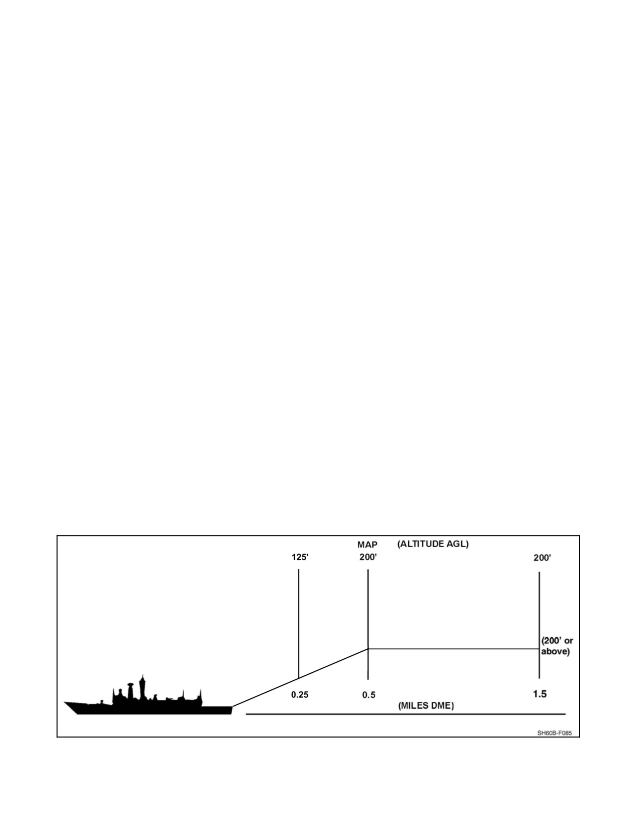
Inbound to the ship, intercept the final approach course at approximately 200 feet and 0.5 nm to achieve 3 degree
glideslope.Maintaintheapproachcourseandglidepath(Figure8-1)usingtheline--upline.Aslowcontrolledclosure
rate is essential in order to maintain obstruction clearance. Begin a coordinated descent and deceleration maintaining
glide slope. The pattern may be adjusted during day VMC to intercept the glide path commensurate with pilot
proficiency and flight deck conditions or as the final part of an instrument approach.
During the visual approach phase, the approach line is maintained using the lineup lines on the ship deck as well as
visual cues from the ship structure and wake. At night, the approach line is maintained using the lighted lineup and
extended lineup lines, vertical dropline lights, and any other available visual cues from the ship lighting.
Note
At night, the lower anti--collision light should be secured, RAST lights on,
and position lights set to dim prior to commencing approach. On those
ships with SGSI, the glide path should be maintained by visual reference
to the tricolor beam and cross--checked with the radar altimeter to ensure
standard altitude vs. range glide path control.
8.4.3.2 Instrument Approach
An instrument approach procedure shall be utilized during IMC until sufficient visual cues are available to proceed
visually (approximately 0.5 DME). Thestandard TACANInstrument ApproachProcedureiscontained inHelicopter
Operating Procedures for Air--Capable Ships NATOPS Manual (NAVAIR 00--80T--122). The Alternate Instrument
Approach Procedure (Figure 8-1) reduces aircrew workload by eliminating the requirement to maintain a constant
rate of descent throughout the approach.
The approach is commenced from a position at least 1.5 miles astern on BRC, at no less than 200 feet AGL and
approximately 80 KIAS. When established on final approach course inbound, a descent and deceleration may be
commenced to arrive at 0.5 DME (MAP) at no less than 200 feet and approximately 50 KIAS. If visual contact is
not made by 0.5 DME, a missed approach shall be executed. If visual contact is established, the descent and
deceleration may be continued utilizing the normal approach profile to arrive approximately 15 feet above the flight
deck with a controlled rate of closure.
Figure 8-1. Visual and Instrument Approach Profile
8-7
ORIGINAL
A1-H60BB-NFM-000
8.4.3.3 Self--Contained Approach Procedures
The systems of the SH--60B enable aircrews to conduct shipboard instrument approaches independent of external
aids to navigation, known as the Self--Contained Approach (SCA). The SCA is specifically for approaches to ships
at night or IMC when TACAN is not available. The SCA is conducted as follows:
Note
Operations to a ship without an operable TACAN are only permitted with
a visible natural horizon.
1.
Establish a refined radar track on ship, ensuring ship’s reported GPS true course and speed through the water
are matched with helo generated track.
Note
Weather conditions permitting, a Mark On Top of vessel may provide the
most accurate position for ship’s track symbology.
2.
Both pilots switch to Computer mode.
3.
ATO establish Fly--to Point slaved to ship’s track.
4.
Fly to arrive 2.0 NM astern the ship at 80 KIAS and 200 feet AGL on Fox Corpen. SO make final update of
radar track.
5.
PAC follow course arrow to FTP. Use Range to FTP in place of TACAN DME to conduct approach.
6.
SO switch MPD to Nav Parameters Table and call closure and monitor altitude for duration of approach.
7.
Fly to arrive at 0.5 NM astern the ship at 50 knots at 200 feet AGL on Fox Corpen. (Missed Approach Point).
8.
Begin descent and deceleration to arrive at .25NM astern the ship at 125 feet AGL on Fox Corpen with closure
rate well under control.
9.
Continue descent and deceleration to arrive approximately 15 feet above the flight deck with a controlled rate
of closure.
D If GPS data or aircraft symbology is suspected to be unreliable,
consideration should be given to securing GPS prior to commencing
approach.
D When able, the PAC must transition to visual cues for the terminal portion
of the approach to landing. The range to FTP in computer mode any not be
as reliable as DME if the same approach were conducted in TACAN mode.
Note
While in computer mode, the course arrow will show course to Fly--to Point
in degrees true. This may differ significantly from the same approach
conducted in TACAN mode.
8.4.3.4 Landing Transition
The transition from the missed approach point (0.5 DME) to landing requires deceleration below minimum power
required airspeed. As the aircraft slows below minimum power required airspeed, more power is needed to maintain
the glide path.
ORIGINAL
8-8
A1-H60BB-NFM-000
Failure to increase power appropriately during the landing transition can
result in high rates of descent at low altitude and potential water impact.
The transition from the approach phase to the landing phase begins at approximately .25 nm from the ship, with the
aircraft at approximately 125 feet and closure rate well under control. The PNAC should call altitude every 10 feet
and advise the pilot of adverse closure rate trends with FAST or SLOW calls.
If a waveoff is initiated during the landing phase, the PAC shall provide obstacle clearance. The PNAC shall resume
a full instrument scan. A waveoff may be initiated at any time prior to landing. Compliance is mandatory. The pilot
shall release the RA cable (if required) and depart the ship when “ALL CLEAR” is received.
Activation of the waveoff lights may temporarily blind both pilots and
could result in spatial disorientation and loss of helicopter. Unless there is
no other method available to communicate the waveoff command, use of
the waveoff lights is not recommended.
The PNAC, Aircrewman, or LSO can provide the PAC with positional information over the RSD (conning).
8.5
RAST EQUIPPED AIR--CAPABLE SHIPS
Flight deck operations on a RAST equipped ship differ from those on a non--RAST ship. RAST flight operations
require an LSO, a Landing Signalman Enlisted (LSE) and two hookup men. During RAST flight deck evolutions,
the LSO controls flight operations with the Helicopter Control Officer (HCO) acting as a safety observer. The LSE
and the hookup men are the only personnel required on deck during the landing sequence, and only for the short time
it takes to connect the messenger cable to the Recovery Assist (RA) cable. Once the aircraft lands and is secured in
the RSD, the LSO will direct the LSE onto the flight deck for aircraft shutdown or personnel transfer. Chocks and
chains are not required when secured in the RSD for personnel transfers, but may be considered, based upon sea state,
winds, ship maneuverings, and length of time on deck. The Flight Deck Director (FDD) will assist the LSO during
straightening and traversing into the hangar; the FDD and the LSO must work as ateam with the FDD being theeyes
on the flight deck.
CAUTION
D No maintenance shall be performed which can change the static vertical
clearance between the external aux fuel tanks and the flight deck. If such
maintenance is necessary, deck clearance shall be checked by appropriate
maintenance personnel before continued operations.
D Pilots and LSO shall exercise due caution when conducting traversing,
straightening, and launch/recovery operations with an external tank
equipped H--60 aircraft in the RSD. Avoid abrupt aircraft and RSD motions
to minimize potential tank/RSD contact.
8-9
ORIGINAL
A1-H60BB-NFM-000
8.5.1 LSO Console Preoperational Checklist
1. RSD — OFF.
2. Tail guide winch (TGW) — UNLOAD.
3. Traverse lever — TRAVERSE SELECT.
4. RA tension lever — RA SELECT.
5. Remote control (in stop position) — Obtain.
Once remote control of the RAST system has been received, the RSD
beams will respond to commands from the LSO station regardless of
START/STANDBY status. Ensure that personnel keep well clear of RSD
beams at all times.
6. LAMP TEST/RA METER TEST — Complete.
7. RAST machinery room — Clear of all personnel.
8. Proper RSD selected — PORT/STBD.
Failure to ensure the proper RSD is selected can lead to activation of the
wrong RSD, which can result in damage to a hangared aircraft or injury to
flight deck personnel.
9. START/STANDBY — As required.
CAUTION
D Pilots and LSOs shall exercise caution when conducting launch/recovery,
straightening, and traversing operations with an external auxiliary
tank--equipped aircraft in the RSD. Avoid abrupt aircraft or RSD motions
to minimize potential for tank/RSD contact.
D If aircraft gross weight exceeds weight at which last vertical clearance was
measured, another measurement must be taken to ensure adequate
tank/RSD clearance.
Note
Engagement of the START/STANDBY pushbutton is not required for
operation of the RSD beams during takeoff and free deck evolutions.
10. RSD pressure light:
a. If START/STANDBY engaged — OFF.
b. If START/STANDBY not engaged — ON.
ORIGINAL
8-10
A1-H60BB-NFM-000
8.5.2 RSD Unlatched Procedure
Toggling the RSD switch from OFF to CLOSED to OFF with the RSD
beams already in the closed position may allow the beams to become
unlatched, potentially resulting in aircraft rollover in heavy seas. If the
beams cannot be visually confirmed latched, perform RSD Unlatched
procedure and visually confirm latched condition.
1. Chocks and chains — On.
2. Beams — Open (verify by OPEN light on console).
3. RSD — CLOSED.
4. Latched condition — Visually verify beams closed conditions.
Note
Beams can be visually confirmed latched by a latched light, witnessing the
RSD flags in the up position, or noting no more than a quarter inch
separation at the ends of the RSD beams.
8.5.3 Traversing Checklist
Toggling the RSD switch from OFF to CLOSED to OFF with the RSD
beams already in the closed position may allow the beams to become
unlatched, potentially resulting in aircraft roll over in heavy seas. If the
beams cannot be visually confirmed latched, chock & chain the A/C, open
the beams fully, (verify by OPEN light on console), select RSD CLOSED
and visually verify beams to be closed with latch light.
Note
Beams can be visually confirmed latched by a latched light, witnessing the
RSD flags in the up position, or noting no more than a quarter inch
separation at the ends of the RSD beams.
1. LSO Console Preoperational Checklist — Complete.
2. FDD communication check — Complete.
3. Traverse clearance — Obtain.
Should the ship maneuver, cease all aircraft movements, call for aircraft
brakes and chains as necessary, to prevent injury to personnel and/or
helicopter damage. Contact the pilot house to resolve the situation.
8-11
ORIGINAL
A1-H60BB-NFM-000
4.
FDD — Confirm:
a. Hangar door — Open and pinned.
b. Track slot seals — Removed.
Note
Track slot seals should be placed in
the
slot
whenever operationally
feasible.
c. Hangar door/deck bridge — Removed (CG).
d. Left--handed extended pylon — Up and pinned.
e. Hangar and flight deck gear — Stowed.
f.
RSD safety bar — Installed.
g. RAST probe to deck clearance — Check.
h. Tail probe — In track slot.
i.
Brakerider — In aircraft.
j.
Tail wheel — LOCKED.
k. Blade/pylon fold restraints — In place.
l.
All access panels/cowling/LHEP — Secure.
m. Bellmouth plug — Removed and stowed.
5.
Control console — Check:
a. Proper RSD — PORT/STBD.
b. RSD lights — CTR, LTCH, BRKE lights on.
c. Traverse lever — TRAVERSE SELECT position.
6.
Chocks/chains — Remove.
7.
Traverse — Select, check TRVS light.
8.
Personnel — Clear of aircraft.
9.
Aircraft brakes — Off.
The FDD shall remain in sight of the LSO at all times while traversing the
aircraft.
ORIGINAL
8-12
A1-H60BB-NFM-000
CAUTION
D
The aircraft should be moved at slow speed when the tail wheel is within
the confines of the hangar.
D
Ship rolls of 16° and above will consistently generate aircraft relative roll
angles of 10° when aircraft is secured only by the RSD. The aircraft will
occasionally reach relative roll angles of 10° with as little as 10° of ship roll.
During traversing on theFFG 7 class, theserelativeroll angles of10°could
result in the forward lower tail rotor blade impacting the port door frame
of either hangar whilethe rescuehoist and outboard main rotor bladecould
impact the starboard door frame of either hangar. During traversing, wait
to obtain a relatively quiescent period (less than 8° of ship roll) or until the
ship is rolling away from the direction of possible impact before moving
the MRB, hoist, or TRB areas past the hangar door frame using fast speed
if required.
D
Ship motion may cause the tail probe to pop out of the RAST track. If this
happens, stop traversing and install chocks and tiedowns. Straightening--
qualified personnel should determine appropriate actions to be taken to
reseat probe in track.
D
During traversing on CG 47 and class ships, traverse slowly over the
elevated hangar door tracks.
D
If the aircraft is to be straightened/traversed with the external power cable
attached, the FDD shall assign a person to tend the power cable and keep
it clear of the aircraft path to prevent damage to the cable.
Note
Sideloads can develop while traversing the helicopter, as evidenced by a
lateral strain on the tires. This can result in the RSD jamming in the track
slot or in excessive side forces applied to the aircraft landing gear. Reverse
the direction of traversing until the sideload dissipates, then continue with
normal procedures.
10.
Traverse lever — Desired direction/speed.
11.
FDD directions — Follow.
Should communication orvisual contact with FDD belost, traversing shall
be stopped immediately.
12. Traversing — Stop.
a. SNUB button — Press, or
b. Traverse lever — TRAVERSE SELECT, or
c. START/STANDBY — Press, or
d. STOP — Press.
8-13
ORIGINAL
A1-H60BB-NFM-000
Note
Traversing may be stopped before the aircraft reaches the takeoff position
to permit tail pylon spread.
13.
Aircraft brakes — Set.
14.
Chocks/chains — As required.
15.
Notify bridge — Deselect TRVS on BIDS.
8.5.4
Prelaunch Checklist
1.
Communication check with HCO, bridge, and CIC — Complete.
2.
FOD walkdown — Complete.
3.
Deck gun mounts (if applicable) — Stowed/secured.
4.
All nets — Down.
5.
LSO Console Preoperational Checklist — Complete.
6.
RSD/aircraft — In takeoff position.
7.
RSD safety bar — Remove.
8.
RSD Chock (If applicable) — Remove.
a. Personnel — CLEAR.
b. RSD Beams — Open.
c. RSD Chock — Remove.
d. Personnel — CLEAR.
e. RSD Beams — Closed.
9.
Tail probe — Manually retract.
10.
HRS and SGSI — As required.
11.
Night lighting — As required.
12.
UHF COMM with HCO or CIC or aircraft (EMCON permitting) — Check.
13.
HELO CRASH alarm — Permission from bridge and check as required.
14.
HCO transfers control to LSO when flight quarters set — Complete.
a. Deck status lights — Obtain from HCO and check.
b. Deck status lights — Red.
c. Helo waveoff lights — Test.
Note
During EMCON thedatalink hardwireorexternal IB may beused fordeck
maneuvers, in addition to deck status and aircraft lights. The LSO should
use wands to communicate visually as necessary.
ORIGINAL
8-14
A1-H60BB-NFM-000
8.5.5 Aircraft Startup
Aircraft Startup
Deck Status
1. Spread clearance — Obtain.
2. Relative wind — Within limits for spread.
3. Spread sequence — Clear FDD to proceed.
4. UHF COMM check with aircraft (EMCON permitting) — Complete
5. Hangar doors — Fully closed.
6. High Points and Tail Tiedowns — Verify removed with LSE.
7. ENGINE START/ENGAGE clearance — Obtain.
Red
8. Aircraft engines started — Notify bridge.
9. Flight deck — Clear except LSE, safety observer, and chock and chain personnel.
10. Relative wind — Within limits for engagement.
11. Aircraft engage (EMCON — Position lights flashing to request).
Amber
12. Engaged — Notify bridge.
Red
Lateral cyclic displacement during high sea states may endanger deck
personnel and will not maintain a level aircraft attitude.
8.5.6 Launch Procedures
Launch Procedures
Deck Status
1.
Main probe — Check position in RSD, inform pilot.
Note
Ensure the main probe tip will clear the inside edges of the RSD and
RSD beams when the beams are opened.
2.
Tail probe — Check up.
3.
Pass to aircraft:
a. Altimeter.
b. True wind.
c. BRC.
d. Pitch.
e. Roll.
f. Relative winds.
4.
Launch clearance — Obtain (EMCON — position lights steady to request).
Amber
5.
Electrical/data link cords/tiedowns — Verify removed.
6.
Aircraft — Signals ready to lift.
a. Pilot — (EMCON) Flash searchlight or hover lights.
7.
Flight deck/Airspace — Clear.
8-15
ORIGINAL W/IC 68
A1-H60BB-NFM-000
Launch Procedures
Deck Status
8. Relative winds — Check within limits for launch.
9. LSO (when deck is steady) RSD beams — Open.
a. RSD red flags — Down.
b. RSD beam position light — Open.
c. RSD BRKE light — ON.
10. LSO — “BEAMS OPEN, GREEN DECK, LIFT”.
Green
11. Aircraft lifts into hover:
a. LSO — “ALL CLEAR,” or
Green
b. LSO — “AIRCRAFT FOULED.”
Amber
12. Ops normal — Received.
Red
13. Post Launch Checklist — Complete.
8.5.7
Post Launch Checklist
1.
After first launch of the day and if immediate landing not intended:
a. Close RSD and check:
(1) OPEN and BRKE lights — Out.
(2) Beams — Close within 4 seconds.
(3) LTCH light — ON.
(4) RSD beam flags — Up.
(5) RSD — OFF; BRKE light — ON.
b. Open RSD and check:
(1) LTCH and BRKE lights — Out.
(2) Beams — Open within 4 seconds.
(3) OPEN light — ON.
(4) RSD beam flags — Down.
(5) RSD — OFF; BRKE light — ON.
c. RSD safety bar — Install if immediate landing not intended.
d. Pull 3 to 4 feet of cable out — Complete (hold RA cable switch to OUT).
(1)
2 FPS light — ON.
(2) Personnel — Clear.
e. Tension lever — RA SELECT.
f. RA SELECT — Select:
(1) STBY light — OUT.
(2) RA light — ON.
(3) Cable reels in at 2 FPS.
(4) When seated — SEAT and STBY LIGHT ON.
g. RSD safety bar — Install.
h. STOP — Press, and go to local control.
8-16
ORIGINAL W/IC 68
A1-H60BB-NFM-000
8.5.8 Recovery Checklist
Toggling the RSD switch from OFF to CLOSED to OFF with the RSD
beams already in the closed position may allow the beams to become
unlatched, potentially resulting in aircraft roll over in heavy seas. If the
beams cannot be visually confirmed latched, chock and chain the A/C, open
the beams fully, (verify by OPEN light on console), select RSD CLOSED
and visually verify beams to be closed with latch light.
Note
Beams can be visually confirmed latched by a latched light, witnessing the
RSD flags in the up position, or noting no more than a quarter inch
separation at the ends of the RSD beams.
Recovery Checklist
Deck Status
1.
Communication check with HCO, bridge, and CIC — Complete.
2.
FOD walkdown — Complete.
3.
Deck gun mounts (if applicable) — Stowed/secured.
4.
All nets — Down.
5.
LSO Console Preoperational Checklist — Complete.
6.
RSD — In landing position or clear of landing area.
7.
RA cable switch — Hold in the OUT position while 20 to 30 feet of cable is faked
in a figure 8 on the inboard side of the RSD.
8.
RSD safety bar — Remove and stow.
Red
9.
HRS and SGSI — As required.
10. Night lighting — Permission from bridge and check as required.
11. UHF communication with HCO or CIC (EMCON permitting) — Check.
12. HELO CRASH alarm — Permission from bridge and check as required.
13. HCO transfers control to LSO when FLT QTRS set — Complete.
a. Deck status lights and BIDS — Obtain from HCO and check.
Red
14. RECOVERY clearance — Obtain.
8-17
ORIGINAL
A1-H60BB-NFM-000
8.5.9
Recovery Assist (RA) Procedures
Note
D
An RA landing can be made with or without the RSD in the landing
position. Landing without the RSD utilizes the same procedure as landing
with the RSD and provides increased safety over normal clear deck
landings. Use clear deck wind envelopes for limitations. The RAST control
panel MASTER switch is in the ON position and the main probe is locked
in the down position as part of the shipboard landing checklist. The pilot
should continue down the approach line and position the aircraft slightly
inboard of the RSD. The aircrewman will then lower the messenger cable.
After allowing some slack to compensate for ship/helicopter movement,
the LSO will signal the aircraft to stop lowering. The messenger cable is
grounded and attached to the RA cable. On signal from the hookup man,
the LSO shall signal the aircraft to raise the messenger. The aircrewman
then raises the messenger while the pilot flying maintains a steady hover.
When the MESSGR CABLE IN and H’DOWN CABLE LKD indications
are present on the RAST control panel, the aircrewman will inform the
pilot, who will then request hover tension. The LSO will apply hover
tension and inform the pilot. The pilot will inform the LSO when he/she
is ready to land. The LSO, aircrewman, orpilot not at thecontrols will give
the pilot the necessary corrections to position the aircraft over the RSD.
When the deck is steady and the aircraft is over the RSD, the LSO will give
the preparatory order LAND NOW, followed by the execution order
DOWN, DOWN, DOWN, while simultaneously increasing tension to
maximum. Once the aircraft is on deck and the main probe is in the RSD,
the LSO will close the RSD beams and inform the pilot TRAPPED.
D
Until the LSO begins conning, the non--flying pilot or the aircrewman will
provide the pilot with conning to maintain position for hookup and
establish a good position for landing.
Once the aircraft is trapped, the RA cable shall be released prior to shutdown or free deck yo--yos. The pilot will call
or signal for release and the LSO will ensure zero tension and clear the pilot to release. For EMCON this may be
arranged on the hardwire/external IC. It is acceptable to use the pickle signal by day (depress thumb on clenched fist).
If NIGHT/EMCON or LOST COMM, alternate red/amber deck status lights.
The RA cable is not designed to secure the aircraft to the flight deck. For
RAs and free deck landings, failure to secure the aircraft with the RSD may
result in the aircraft exceeding dynamic/static rollover limits during a large
ship roll and allow the main rotor blades to impact the flight deck. Both
pilot and LSO shall consider current and transient flight deck conditions
(sea state, wind, ship pitch, and roll) to determine the necessity for securing
the RSD after each recovery.
ORIGINAL
8-18
A1-H60BB-NFM-000
Recovery Assist (RA) Procedures
Deck Status
When the helicopter is using NVDs on short final, to include over the deck, the
waveoff lights shall not be used due to the effects of NVD blooming. The aircrew
will be temporarily blinded and lose sight of the ship.
1. LSO — Green deck for RA Recovery.
Green
a. PORT/STBD RSD.
b. Altimeter.
c. True wind.
d. BRC.
e. Pitch.
f. Roll.
g. Relative wind.
Note
For EMCON recoveries, this information may be passed on data link and
the recovery carried out using light signals.
2. Pilot — Landing Checklist — Complete.
A Degraded Control RA recovery is a technique that may be employed when the aircraft is
suffering from a flying quality degradation such as a main rotor damper system malfunction.
The approach and hookup are the same as for a normal RA recovery. After receiving a report
of three green, the pilot will request MINIMUM TENSION vice HOVER TENSION. The
LSO uses RA Select to place 850 lb of tension on the hauldown cable. The pilot will position
the aircraft over the RSD and will report READY TO LAND. The LSO steadily increases
tension to 4,000 lb. The pilot should refrain from fighting against the centering action of the
tensioned cable and use collective to control rate of descent. Once the aircraft is safe on deck,
proceed with appropriate emergency procedures. Any time that a Degraded Control RA
recovery is considered, the aircrew should weigh the relative merits of a standard clear--deck
or free--deck landing.
3. Pilot — On short final, flash searchlight or hover lights (night).
4. HCO — Line--up lights steady/dim (night).
5. Pilot (crossing deck edge) — LOWER THE MESSENGER.
6. Aircrewman — LOWERING.
7. LSO — STOP LOWERING.
Amber
8-19
ORIGINAL
A1-H60BB-NFM-000
Recovery Assist (RA) Procedures
Deck Status
If a STOP LOWERING command is not received from the LSO after 20
seconds, stop lowering the messenger and verify the messenger status.
8. Aircrewman — STOPPED.
9. LSO — HOOKUP MEN ON DECK.
D One of the hookup men shall maintain eye contact with the aircraft. The
othershall maintain eye contact with theLSO. If, in theiropinion, thedeck
is unsafe or they are signaled by the LSO, they shall clear the deck
immediately.
D Too much slack in the messenger cable may entangle flight deck personnel
and result in serious injury.
10. LSO — PERSONNEL CLEAR, RAISE THE MESSENGER.
Green
11. Aircrewman — RAISING.
Note
If the RA cable falls away from the messenger cable, the LSO should
alternate green/amber deck status lights and call the fall away. If a second
attempt to hook up is possible, a steady green deck status light should be
given and the procedure reverts to step 5. If the hookup is not feasible, but
a safe free deck landing can be made, a steady amber deck status light
should beshown and theprocedures should follow step 4. ofthe FreeDeck
Landing Checklist. If an unsafe deck condition exists, a red deck should be
indicated and a waveoff initiated.
12. Aircrewman — THREE GREEN.
13. Pilot — THREE GREEN, HOVER TENSION.
a. Flash searchlight or hover lights (EMCON).
14. LSO — STANDBY:
a. Check 2 FPS light ON.
b. Activate RA and ensure RA selected.
ORIGINAL
8-20
A1-H60BB-NFM-000
Recovery Assist (RA) Procedures
Deck Status
CAUTION
To prevent the slack RA cable from becoming fouled under the RSD, the
LSO should ensure the aircraft remains in a hover inboard the RSD until
the cable becomes taut. Should the cable become caught under a corner of
the RSD, the LSO shall place the system in standby, change deck status
light to red, and have the pilot release the RA cable and move aft, and have
flight deck personnel clear the cable.
Note
The use of full RA tension in a high density altitude environment may
result in transient Nr drooping and excessive rates of descent.
c. Cable reels in at 2 fps to minimum tension (850 pounds).
d. Select 2,000 pounds.
15. LSO — HOVER TENSION.
Amber
16. Pilot (positions aircraft over RSD) — READY TO LAND.
a. Flash searchlight or hover lights (EMCON).
CAUTION
D The aircraft will translate slightly forward as the nose is lowered for landing
following tail wheel contact during an RA landing. An aft cyclic input to
arrest the perceived forward movement of the aircraft will result in droop
stop pounding of the blade retention assembly and high structural loads on
the rotor head assembly.
D Aircraft rolls up to 17_, in addition to the roll of the ship, can be
experienced while in the RSD due to the RAST probe design.
17. LSO, PNAC, or Aircrewman — Conns aircraft into position.
a. LSO — Select 4,000 pounds. LAND, NOW, DOWN, DOWN, DOWN (until aircraft
Green
is on deck).
b. Verify aircraft in the trap. For mistrap, refer to Mistrap Procedures.
c. If LTCH light fails to illuminate or RSD BEAM LTCH flags do not indicate proper
latching of the RSD beams, refer to RSD Fails to Latch procedure.
d. If conducting consecutive landing practice while attached to the RA cable, refer to
Consecutive Landing Practice (RA Yo-Yos or Free Deck Bounces) procedure.
e. If intentions are to shut down or release RA cable for the purpose of continuing flight
operations:
8-21
ORIGINAL
A1-H60BB-NFM-000
Recovery Assist (RA) Procedures
Deck Status
(1) LSO — IN THE TRAP, HOOKED ON MAX TENSION.
(2) RSD beams — CLOSE.
(3) LTCH light — ON.
(4) BRKE light — ON.
(5) RSD beam flags — UP.
18. LSO — TRAPPED.
Amber
Failure to keep the Officer of the Deck (OOD) informed of the aircraft
status may result in the ship maneuvering prior to chocks and chains being
installed.EnsuretheOOD isawareofwhetherornot theaircraft isproperly
secured. Deck status lights alone do not provide this information.
19. Chocks and chains — Install as required.
Red
20. Pilot — REQUEST ZERO TENSION RELEASE.
(EMCON — Flash searchlight or hover lights).
21. LSO — PREPARE RA CABLE FOR RELEASE:
a. Minimum Tension — Select.
b. Standby — Press. ENSURE ZERO TENSION.
22. LSO — CLEARED FOR ZERO TENSION RELEASE (pickle signal).
Alternate
Red/Amber
23. Pilot — Release RA cable by depressing RAST release button on cyclic.
a. Aircrewman — Verify H’DOWN CABLE OUT light ON.
b. PILOT — SHOW GOOD RELEASE.
24. LSO — Verify cable released:
a. Check for 2 FPS status light illumination.
b. Select RA cable in.
c. Check for SEAT light — On.
CAUTION
Any time the RA cable is released with tension on the
system,
the
machinery room shall be checked for fouled cable prior to reselecting RA.
25. LSO — Inform bridge RECOVERY COMPLETE.
ORIGINAL
8-22
A1-H60BB-NFM-000
8.5.9.1 Mistrap
Mistrap
Deck Status
1. Simultaneously the LSO:
Amber
a. Calls — UP, UP, UP.
b. Minimum tension — Select.
2. Pilot can release RA cable or return to hover while still hooked on.
a. If pilot releases:
(1) LSO — ALL CLEAR.
Green
b. If pilot remains hooked on:
(1) LSO — HOOKED ON, MINIMUM TENSION.
Alternate
Amber/Green
3. LSO awaits pilot request:
a. If hooked on — For hover tension.
b. If not hooked on — Aircraft must clear deck to fake out cable or proceed with free
deck landing procedures.
8.5.9.2 RSD Fails To Latch
RSD Fails to Latch
Deck Status
1. LSO — Maintain 4,000 pounds.
Red
2. LSO — IN THE TRAP MAXIMUM TENSION.
3. RSD beams — CYCLE.
Green
4. If unlatched indication persists, or RSD beams cannot be closed, chocks and chains
shall be applied as soon as possible.
5. RSD — OFF.
8.5.9.3 Airborne Release
Airborne Release
Deck Status
1. Pilot — STANDBY RELEASE, RELEASING NOW, NOW, NOW:
a. Releases on third now.
2. LSO, prior to third now:
a. Minimum tension — Select.
b. Standby — Select.
3. LSO (aircraft clear) — ALL CLEAR.
Green
4. If release was accomplished with Tension on the cable:
a. RAST machinery room — Check prior to further use of any RAST machinery.
8-23
ORIGINAL
A1-H60BB-NFM-000
8.5.9.4 Free Deck Landing
Free Deck Landing
Deck Status
1.
LSO — GREEN DECK FOR FREE DECK RECOVERY.
Green
a. PORT/STBD RSD.
b. Altimeter.
c. True wind.
d. BRC.
e. Pitch.
f. Roll.
g. Relative wind.
2.
Pilot — Landing Checklist — Complete.
Note
For EMCON recoveries, this information may be passed on data link and
the recovery carried out using light signals.
3.
Pilot — On short final flash searchlight or hover lights (night).
4.
HCO — Lineup lights steady/dim (night).
5.
LSO — Aircraft over deck.
Amber
6.
Pilot (positions aircraft over RSD) — READY TO LAND:
a. Searchlight or hover lights — Flash (EMCON).
7.
LSO, PNAC, or Aircrewman — Conns aircraft into position:
a. “LAND NOW, DOWN, DOWN, DOWN” (until aircraft on deck).
Green
8.
LSO — IN THE TRAP.
a. RSD beams — CLOSE.
b. LTCH light — ON.
c. BRKE light — ON.
d. RSD beam flags — UP.
9.
LSO — TRAPPED.
Amber
a. For mistrap, refer to Mistrap Procedures.
ORIGINAL
8-24
A1-H60BB-NFM-000
Free Deck Landing
Deck Status
Failure to keep the Officer of the Deck (OOD) informed of the aircraft
status may result in the ship maneuvering prior to chocks and chains being
installed.EnsuretheOOD isawareofwhetherornot theaircraft isproperly
secured. Deck status lights alone do not provide this information.
10. Once chocked and chained — Inform bridge.
Red
8.5.9.5 Consecutive Landing Practice (RA Yo--Yos or Free Deck Bounces)
Consecutive Landing Practice (RA Yo--Yos or Free Deck Bounces)
Deck Status
Note
D Clearance from the bridge to conduct yo--yos is necessary, but not for each
evolution.
D EMCON yo--yos are performed using normal EMCON procedures.
Preflight briefing or the data link, if available, should be used to coordinate
evolutions.
1. For RA, normal procedures are used except:
a. Aircraft does not need to be secured in the RSD after every landing; however, the
RSD beams should be closed if any delay is anticipated.
b. When not secured with the RSD, maximum tension is left applied and LSO (upon
Amber
landing) calls IN THE TRAP, HOOKED ON MAXIMUM TENSION.
c. Pilot calls — READY TO LIFT, LSO ensures minimum tension selected and
Green
calls — BEAMS OPEN, GREEN DECK, LIFT.
d. Upon takeoff, LSO calls ALL CLEAR. HOOKED ON, MINIMUM TENSION.
2. For free deck, normal procedures are used. The aircraft does not need to be secured in
the RSD after every landing; however, the RSD beams should be closed if any delay
is anticipated.
8.5.9.6 Post Recovery
Post Recovery
Deck Status
1. LSO — Disengagement clearance — Obtain (EMCON — Aircraft position lights
flashing).
2. LSO — Before clearing aircraft to disengage, ensure:
a. LSE — On deck.
b. Relative wind — Within limits.
Amber
3. LSO — Disengagement complete — Notify bridge.
Red
8-25
ORIGINAL
A1-H60BB-NFM-000
8.5.9.7 Straightening Checklist
CAUTION
D The aircraft shall not be straightened with the blades or pylon folded.
D Aircraft should not be refueled until straightening sequence is completed
to reduce loads on the tail landing gear.
D Strong winds and high sea states may exceed tail guide winch cable
authority.
D The aircraft is not to be straightened with the external power cable attached.
D If the aircraft is to be traversed with the external power cable attached, the
FDD shall assign a person to tend the power cable and keep it clear of the
aircraft path to prevent damage to the cable.
Note
If RAST probe slippage occurs during straightening and line--up line mark
does not line up with track slot, consideration should be given to restarting
the straightening procedures.
1.
LSO Console Preoperational Checklist — Complete.
2.
FDD communication check — Complete.
3.
Safety bar (if installed) — Remove.
4.
RSD beams — OPEN.
5.
Main probe to deck clearance and main probe position in RSD — Check.
Note
To ensure receipt of latched light indication and proper alignment of
helicopter during straightening evolutions, main probe should be centered
(as indicated by yellow RSD line--up) in RSD.
If probe needs to be raised or centered in RSD:
a. RSD beams — OPEN
b. Main probe — RAISE, if necessary.
c. Traverse — SELECT, if necessary.
d. Traverse lever — Desired direction to center main probe in RSD, if necessary.
CAUTION
Under certain conditions, the aircraft main probe may contact the deck,
resulting in a small amount of main probe compression. The amount of
compression, if observed in the upper barrel, shall be subtracted from the
1 inch allowable on the upper barrel.
ORIGINAL
8-26
A1-H60BB-NFM-000
Note
If main probe to deck clearance is inadequate, the main probe can be beeped
up a maximum of 1 inch as measured from the bottom of the aircraft to a
point 1 inch down on the upper barrel of the main probe.
6. RSD Chock — INSTALL (if available).
7. RSD beams CLOSED — Check LTCH and BRKE lights.
a. RSD beam flags — UP.
b. LTCH light — ON.
c. BRKE light — ON.
Toggling the RSD switch from OFF to CLOSED to OFF with the RSD
beams already in the closed position may allow the beams to become
unlatched, potentially resulting in aircraft roll over in heavy seas. If the
beams cannot be visually confirmed latched, chock and chain the A/C, open
the beams fully, (verify by OPEN light on console), select RSD CLOSED
and visually verify beams to be closed with latch light.
Note
Beams can be visually confirmed latched by a latched light, witnessing the
RSD flags in the up position, or noting no more than a quarter inch
separation at the ends of the RSD beams.
8. All nets — Down.
9. Brakerider — In aircraft.
10. Flight deck — Clear.
11. Proper RSD — PORT/STBD.
12. Straighten clearance — Obtain.
Should the ship maneuver, cease all aircraft movements, call for aircraft
brakes and chains as necessary, to prevent injury to personnel and/or
helicopter damage. Contact the pilot house to resolve the situation.
13. TGW — UNLOAD.
a. TGW cables — Install.
14. Tail probe — Verify up.
15. TGW cables — Clear.
16. TGW — AUTO.
17. Center probe in RSD — As required.
8-27
ORIGINAL
A1-H60BB-NFM-000
18. Tail wheel — Manually unlock.
19. Safety bar (if installed) — Remove.
20. SEAT light — ON.
21. Chocks/chains — Remove.
22. Aircraft brakes — Off.
23. If main probe is forward of bellmouth:
a. RSD beam brakes — Release position and hold.
CAUTION
Failure to hold the RSD beam brake switch in the release position in
accordance with the Straightening Checklist will result in excessive side
loading of the aircraft.
b. Traverse main probe aft of bellmouth — Complete.
The FDD shall remain in sight of the LSO at all times when traversing the
aircraft.
24. Straightening procedures — Complete.
a. See Figure 8-2 if aircraft main landing gear is on, or starboard of, alignment line.
b. See Figure 8-3 if aircraft main landing gear is port of alignment line.
Ensure all flight deck personnel are clear of TGW cables to prevent injury,
especially in the event of cable failure.
CAUTION
Failure to ensure all slack is removed from the tail guide winch cables
prior to any twisting evolution may cause damage to the fuel dump tube.
ORIGINAL
8-28
A1-H60BB-NFM-000
RSD BRAKE
TRAVERSE
TGW
STEP
SWITCH
LEVER
HANDLE
RESULT
1.
RELEASE position
Fwd (Note)
Twist to
Move main probe to port limit (PORT light
and hold
Port
ON).
2.
ON
Aft
—
Move port aircraft alignment mark over
track slot.
3.
AUTO position and
Fwd (Note)
Twist to STBD Center RSD beams (CTR light ON).
hold
CAUTION
During step 3., failure to limit forward movement to six inches could result in tail
guide wire hooks penetrating the aircraft skin.
4.
ON
Fwd
—
Move tail probe over track slot.
5.
—
—
—
Aircraft brakes — ON.
6.
—
—
—
Install chocks/chains.
7.
—
—
—
Lower tail probe full down.
8.
—
—
—
Remove chocks/chains.
9.
—
—
—
Aircraft brakes — OFF.
10.
—
—
—
Complete Post Straightening checklist.
Note
Traversing provides for tail wheel caster. Limit to six inches.
Figure 8-2. Straightening Procedures, Aircraft Main Landing Gear on Alignment Line or
Starboard of Line
8-29
ORIGINAL
A1-H60BB-NFM-000
RSD BRAKE
TRAVERSE
TGW
STEP
SWITCH
LEVER
HANDLE
RESULT
1.
RELEASE position
Fwd (Note)
Twist to STBD Move main probe to STBD limit (STBD
and hold
light ON).
2.
ON
Aft
—
Move starboard aircraft alignment mark
over track slot.
3.
AUTO position and
Fwd (Note)
Twist to
Center RSD beams (CTR light ON).
hold
PORT
CAUTION
During step 3., failure to limit forward movement to six inches could result in tail
guide wire hooks penetrating the aircraft skin.
4.
ON
Fwd
—
Move tail probe over track slot.
5.
—
—
—
Aircraft brakes — ON.
6.
—
—
—
Install chocks/chains.
7.
—
—
—
Lower tail probe full down.
8.
—
—
—
Remove chocks/chains.
9.
—
—
—
Aircraft brakes — OFF.
10.
—
—
—
Complete Post Straightening checklist.
Note
Traversing provides for tail wheel caster. Limit to six inches.
Figure 8-3. Straightening Procedures, Aircraft Main Landing Gear Port of Alignment Line
8.5.9.8
Post Straightening Checklist
1. Tail wheel — LOCK.
2. START/STANDBY — STBY.
3. Aircraft brakes — ON.
4. Chocks/chains — As required.
CAUTION
Using only the main RAST probe to secure the aircraft in high sea states
may result in damage to the probe.
5. RSD safety bar — Install.
6. TGW — UNLOAD.
7. TGW cables — Remove.
8. TGW — AUTO for stow, then UNLOAD after complete.
9. STOP button — Press to obtain PRESS light.
10. Notify bridge — Straightening complete.
11. Fold blades/pylon — As required.
ORIGINAL
8-30
A1-H60BB-NFM-000
Ensure external power is applied or battery switch is on prior to folding the
tail pylon to ensure the tail index actuator engages immediately after
starting pylon fold sequence. Uncontrolled tail rotor windmilling may
result if tail index actuator is not engaged.
a. Fold clearance — Obtain.
b. Fold cycle — Complete.
CAUTION
Unsecured folded main rotor blades can flap enough in high winds or high
sea states to strike the upper UHF antenna. To prevent damage to the rotor
blades and antenna, blade crutches shall be applied when the blades are
folded and the ambient conditions are conducive to blade flapping.
12. Notify bridge — Fold complete.
8.6
EMITTER HAZARDS
An electromagnetic interference (EMI) hazard exists to all SH--60B aircraft operating in the vicinity of CG--47 or
DDG--51 class ships.
CAUTION
Due to the adverse effects of EMI on aircraft operating in the vicinity of
SPY--1 radar, SH--60B aircraft should not close within 2 nm of CG--47 or
DDG--51 class ships unless SPY--1 is operating at low power, the controller
has broken data link, and the helicopter track has been dropped. Prior to
takeoff on these class of ships, aircraft commanders should ensure that
Hawk Link is in standby (following removal of the hardwire) and not
placed to radiate until the aircraft is 2 nm clear of own ship.
Lot 1 SH--60B aircraft, BuNo 161553 to 161570, not incorporating ECP--3013R5 (AFC--24) shall not approach or
remain within the minimum standoff distances of radiating shipboard and/or shore--based emitters as shown in
Figure 8-4. Lot 1 aircraft carrying torpedoes shall remain outside the standoff distances when operating with ships,
whether emitters are radiating or not. If the aircraft is on the deck, emission restrictions apply only if maintenance
or preflight actions are being performed.
Failure to maintain standoff distances may cause degradation to flight
controls and/or inadvertent actuation of electroexplosive devices.
Note
Transponder MODE IV AUDIO/LIGHT/OUT control may induce static
feedback in ATO and pilot headsets when set to AUDIO in an EMI
environment.
8-31
ORIGINAL
A1-H60BB-NFM-000
EMITTER
STANDOFF
EMITTER
STANDOFF
EMITTER
STANDOFF
HF COMM
55 FT (100 FT FOR CV)
STIR
1500 FT
MK 29
1500 FT
MK 91
1500 FT
MK 92
1500 FT
CCA
2800 FT
EX 3 CWCS
2800 FT
FPN 63
2800 FT
MK X11
2800 FT
MD 15 CLWS
2800 FT
MK 24
2800 FT
MK 37
2800 FT
MK 38
2800 FT
MK 86
2800 FT
SPG 51
2800 FT
SPG 60
2800 FT
SLQ 32
2800 FT
SPN 35
2800 FT
SPN 41 ILS
2800 FT
SPN 41 T--4
2800 FT
SPN 42
2800 FT
SPN 43
2800 FT
SPN 44
2800 FT
SPQ 9
2800 FT
SPS 40
2800 FT
SPS 48
2800 FT
SPS 49
2800 FT
SPS 65
2800 FT
SPS 67
2800 FT
SPY 1A/B
2 NM
Figure 8-4. Emitter Standoff Distances (Lot 1 Aircraft)
8.7
HELICOPTER IN--FLIGHT REFUELING
8.7.1 General
Helicopter In--Flight Refueling (HIFR) is intended to extend the aircraft on--station time. It should be initiated with
sufficient fuel remaining to BINGO to a suitable landing site if unsuccessful. Night HIFR operations are extremely
demanding, and are only permitted for operational necessity.
CAUTION
The PIC shall ensure that the Landing Checklist is completed prior to
commencing an approach, HIFR, transfer, etc., to any aviation/air--capable
ship.
8.7.2 HIFR Systems
All HIFR--capable ships are equipped with one of two different rigs for helicopter inflight refueling.
8.7.2.1 Wiggins/North Island HIFR Rig
The Wiggins/North Island (NI) rig (Figure 8-5) is composed of a ship’s hose (>100 feet in length) and a HIFR
assembly (10--foot section of a 1.5--inch hose outfitted with a saddle for hoisting). Both ends of the HIFR assembly
are equipped with female closed--circuit refueling (CCR) fittings (also referred to as Wiggins fittings). One Wiggins
fitting is connected to the ship’s hose and the other Wiggins fitting is connected to the male Wiggins fitting in the
helicopter. A manual emergency disconnect lanyard (emergency release T--handle) is located near the Wiggins fitting,
which connects to the male Wiggins fitting in the helicopter.
8.7.2.2 NATO--Compatible High Capacity HIFR Rig
The NATO--Compatible High Capacity (NHC) rig (Figure 8-6) features a 2--inch lightweight hose, unisex couplings,
automatic emergency breakaway, and facilitates the use of either a Wiggins nozzle or a Parker nozzle for HIFR
operations. The NHC rig is composed of two major assemblies: the 100--foot HIFR hose and the 10--foot HIFR
assembly.
ORIGINAL
8-32
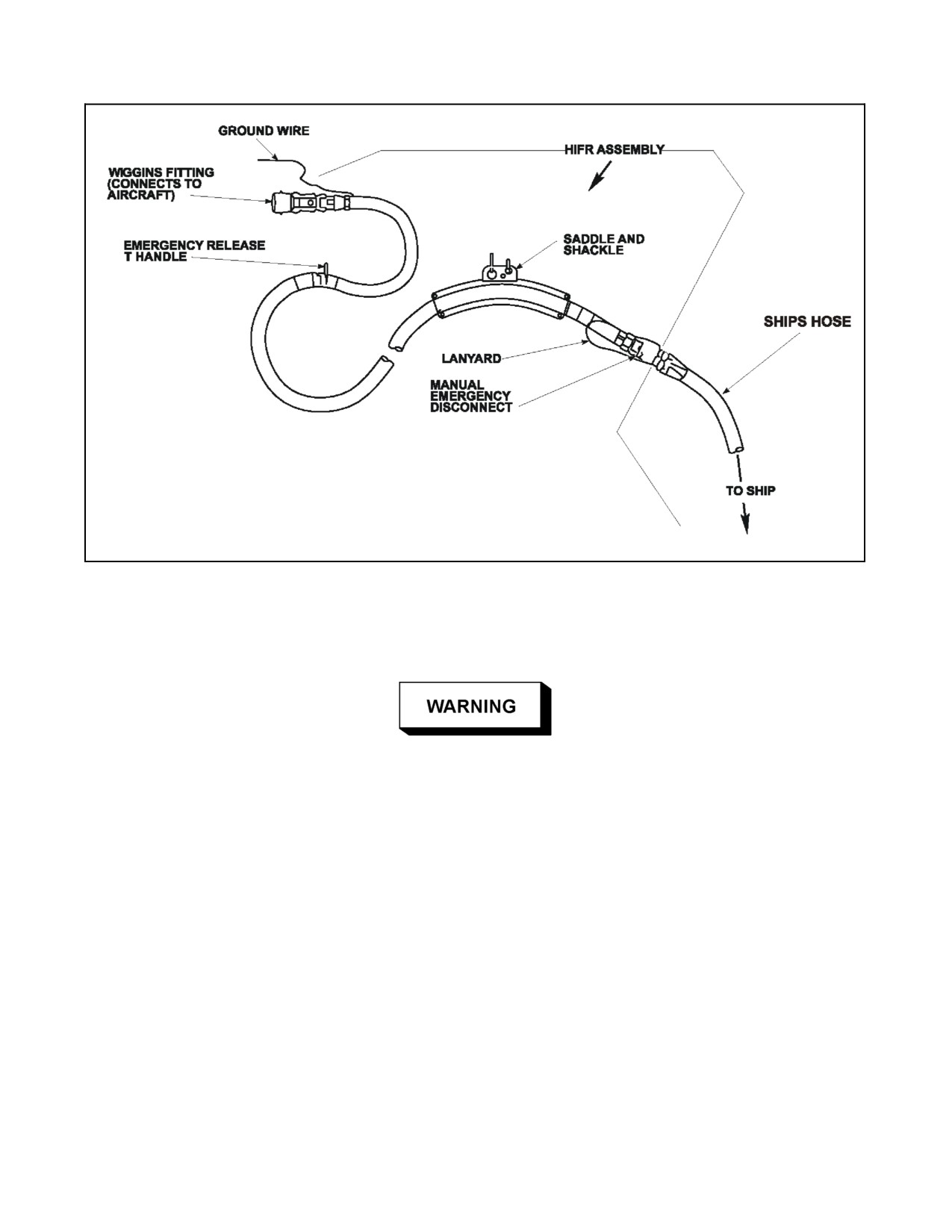
A1-H60BB-NFM-000
Figure 8-5. Wiggins/North Island (NI) HIFR Rig
The NHC nozzle has a built--in 45--psi pressure regulator and an on/off flow control handle. Emergency breakaway
is initiated when 450 +/--50 lbs of straight tensile pull is exerted on the automatic breakaway coupling.
When using an NHC assembly, the hose shall be secured to the deck of the
ship to ensure proper functionality of the break away system.
Note
D Emergency breakaway occurs automatically as the helicopter moves away
from the ship. No action by the aircrew is necessary.
D Most US helicopters are configured with a Wiggins--type connection for
HIFR refueling, while all other NATO countries with HIFR capability use
a Parker connection. If a US helicopter performs a HIFR with the NATO
ship, it will be given a Parker nozzle. An adapter to convert the nozzle to
a Wiggins type connection will be required.
8-33
ORIGINAL
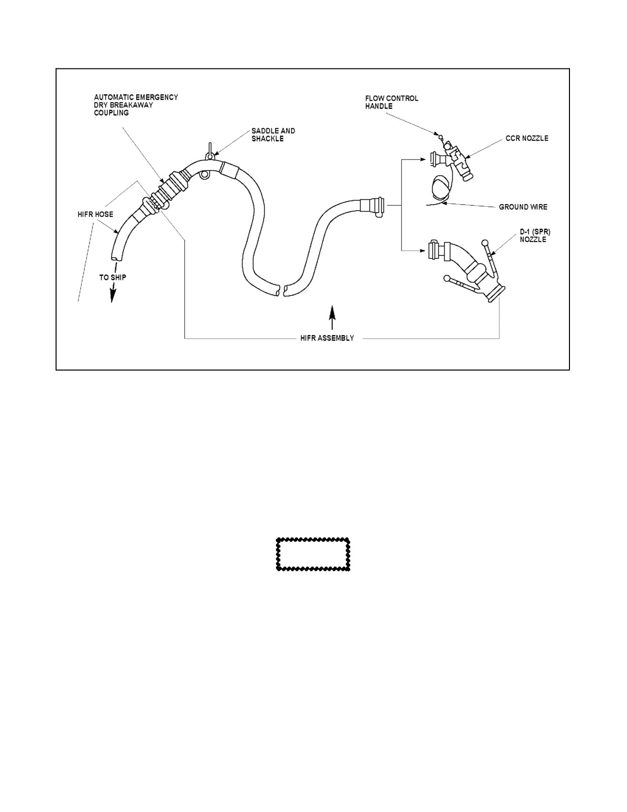
A1-H60BB-NFM-000
Figure 8-6. NATO High Capacity (NHC) HIFR Rig
8.7.3 Normal Operations
The ship’s course and speed should be adjusted to provide relative winds from 10 to 30 knots, 300º to 360º, and
minimum pitch and roll. Higher winds may bedesired in high DA/gross weight/OAT conditions. The helicopterwill
make an approach hovering into the relative wind over the HIFR H deck marking. The fueling hose will be attached
and hoisted aboard under the direction of the helicopter crewman. When the refueling hose is hoisted, the helicopter
will then slide to port. The crewman shall attach the grounding wire to the airframe and the nozzle to the refueling
receptacle. The helicopter will then move to a slightly lower altitude and the crewman will signal to commence
pumping fuel.
CAUTION
A low hover while wind is less than 10 knots may cause excessive salt
spray, which can decrease engine performance and reduce pilot field of
view.
When refueling is complete, the crewman will signal for the pumping to stop and disconnect the hose. The helicopter
will then be repositioned over the deck and the hose will be lowered.
ORIGINAL
8-34
A1-H60BB-NFM-000
8.7.3.1 HIFR Procedure
CAUTION
D Ensure HIFR assembly is grounded to aircraft before connecting hose to
refueling fitting.
D The Wiggins/NI HIFR assembly can be installed backwards. The
aircrewman must ensure the emergency release T--handle is located near the
Wiggins fitting that attaches to the aircraft fitting. Opposite connection is
possible and will force the helicopter to shear the hoist to affect an
emergency breakaway.
1. Landing checklist — Complete.
2. Rescue Hoist Preoperational check — As required.
3. Lower the hoist and obtain fuel sample taken from nozzle of HIFR rig. Confirm fuel is acceptable.
4. Lower hoist cable for pickup of refueling rig.
D Both the NHC and NI HIFR hoses shall be hoisted to the helicopter
unpressurized, but full offuel. Airin theHIFR hosewillcreateanelectrical
charge on the helicopter internal fuel filter elements and may damage
equipment. An NHC hose not filled with fuel poses a hazard to flight deck
crew and the helicopter.
D When using an NHC assembly, the hose shall be secured to the deck of the
ship to ensure proper functionality of the break away system.
5. Raise attached refueling rig to full seated position.
D Should waveoff be required before HIFR rig is connected, the hoist cable
should be cut immediately.
D The HIFR saddle must be raised as near as possible to the hoist seat position
to permit proper and safe operation of the emergency breakaway on either
rig.
6. Check the emergency breakaway handle for correct attachment (if applicable).
7. Connect the grounding wire.
8. Connect Wiggins nozzle (NHC rig) or the Wiggins fitting (NI rig) to the receptacle in the helicopter.
9. Signal ship to start pumping.
10. Depress locking tab on the NHC rig’s SPR nozzle and slowly move the flow control handle to ON (forward)
position.
8-35
ORIGINAL
A1-H60BB-NFM-000
Note
The Wiggins fitting (nozzle) on the NI rig does not have a flow control
handle.
11. Once the hose is pressurized, direct pilot to conduct precheck.
CAUTION
D Flowoffuelwhenprecheckvalveisinprecheck positionindicates ashutoff
system malfunction. If neither precheck switch will secure the fuel flow,
fueling should be continued only if necessary. If fueling is required, pro-
ceed with caution in order to prevent rupture of the main fuel cell. One pilot
shall monitor fuel quantity on the flight or mission displays.
D During HIFR if right cell fills faster than the left cell, monitor the fuel
quantity gauges closely. If the difference in cell quantities persists, stop
refueling before the right cell is full (approximately 1,700 pounds) to
prevent rupture of the fuel cell.
Note
D Low fuel flow may be the result of low pressure from the ship’s pump,
aircraft altitude, or contamination in the HIFR filter canister.
D The crewman has the ability to stop fueling with the flow control handle
on the NHC rig. Additionally, the SPR nozzle will automatically stop flow
and the red pin behind the flow control handle will extend if pressure has
exceeded 45 psi and/or the tanks are full.
D If fuel pumping rate appears to be negligible or too slow, a decrease in
helicopter altitude will increase pumping rate.
12.
Signal ship to stop pumping.
13.
Move NHC SPR nozzle flow control handle to CLOSED (aft) position.
14.
Disconnect NHC Wiggins nozzle or NI Wiggins nozzle/fitting from aircraft fuel fitting.
15.
Remove grounding wire.
16.
Reposition helicopter over flight deck. Lower rig once over deck.
17.
Raise hoist after confirming HIFR assembly is disconnected and report, “CLEAR
FOR FORWARD
FLIGHT.”
Note
D The HIFR fuses in the go/no--go canister should be capable of handling
approximately 10,000 pounds of fuel. The actual capacity of the fuses
depends on the quality of the fuel received. If a pressure differential occurs
across the fuses, fuel will not be taken and the fuse must be replaced. The
HIFR filter should be replaced after each flight involving in--flight
refueling.
D The Go/No--Go canister is sensitive to both water and particulate
contamination.
ORIGINAL
8-36
A1-H60BB-NFM-000
8.7.4 Communications
Signals to start and stop pumping shall be exchanged between the helicopter crewman and the LSE, with the radios
as the backup means of communication. In addition to normal hover positioning reports, standard HIFR terminology
and visual signals shall be used (Figure 8-7). The visual signals will be the same at night, except a red--lens flashlight
shall be used.
FROM
TO
WHEN
REPORT/VISUAL SIGNAL
RESPONSE
Hoist
Pilot
HOIST IS GOING DOWN
HOIST GOING DOWN
Operator
Hoist
Pilot
HOIST IS ON THE DECK
HOIST IS ON DECK
Operator
Hoist
Pilot
HOSE CONNECTED TO
HOSE COMING UP
Operator
HOIST
Hoist
Pilot
HOSE IS IN THE CABIN,
HOSE IS IN THE CABIN, CLEAR
ROGER, SLIDING
Operator
CLEAR TO SLIDE LEFT
TO SLIDE LEFT
LEFT
Hoist
Pilot
HOSE CONNECTED AND
HOSE CONNECTED
ROGER,
Operator
READY TO RECEIVE
COMMENCE
FUEL
PUMPING
Hoist
Ship
DIRECT TO COMMENCE
HOIST OPERATOR MAKES
Operator
PUMPING
CIRCULAR MOTION WITH HAND
Hoist
Pilot
HOSE IS PRESSURIZED
READY FOR PRECHECK
Operator
PAC
Hoist
DESIRED QUANTITY OF
STOP PUMPING
ROGER, STOP
Operator
FUEL HAS BEEN
PUMPING
RECEIVED
Hoist
Ship
STOP FUELING
HOIST OPERATOR MAKES
Operator
CUTTING MOTION ACROSS
THROAT
Hoist
Pilot
FUELING HAS STOPPED,
FUELING STOPPED, HOSE
ROGER, SLIDING
Operator
HOSE DISCONNECTED,
DISCONNECTED, CLEAR TO
RIGHT
CLEAR TO SLIDE RIGHT
SLIDE RIGHT
Hoist
Pilot
READY TO LOWER HOSE
HOSE GOING DOWN
Operator
Hoist
Pilot
HOSE ON DECK
HOSE IS ON THE DECK
Operator
Hoist
Pilot
HOSE DISCONNECTED
HOIST CLEAR
Operator
FROM HOIST AND HOIST
IS BEING RAISED
Hoist
Pilot
SECURED AFT
CLEARED FOR FORWARD
Operator
FLIGHT
Anyone may give the command “BREAKAWAY”. The crewman shall immediately pull the emergency
disconnect lanyard (if installed) and report “HOSE CLEAR”.
Figure 8-7. HIFR Communications
8-37
ORIGINAL
A1-H60BB-NFM-000
8.7.5 HIFR Emergency Procedures
When an emergency condition is observed or when the command BREAKAWAY is received, the following
emergency breakaway procedures should be followed (depending on the type of HIFR rig used):
Note
If emergency breakaway is necessary with either rig attached, the HIFR
assembly, which includes the saddle and 10--foot section of hose, will
remain attached to the helicopter.
1. NI HIFR rig. The crewman shall pull the emergency release T--handle. Allow the released HIFR hose to fall
back to the ship. The PAC then flies away from the ship.
2. NHC HIFR rig. This rig incorporates an automatic emergency breakaway. Crewman action is not necessary
to disconnect system. Once the NHC rig has been attached, the PAC can effect an emergency breakaway at
any time by flying away from the ship.
D All slack hose between aircraft and deck tiedown point near HIFR “H” will
be pulled taut upon flyaway. Injury may result if deck crew becomes
tangled in the HIFR hose.
D If either rig fails to disconnect when an emergency breakaway is attempted,
it will be necessary for the crewman to quickly disengage the nozzle and
grounding wire from the aircraft and cut the hoist cable.
D If the hoist cable is cut with either HIFR rig connected to the aircraft fitting,
the possibility exists that the HIFR rig or aircraft fitting could rupture,
causing pressurized fuel to leak into the cabin.
8.7.6 Night HIFR Procedures
Due to the hazards associated with night operations and the increased
potential for mishap, night HIFR operations shall not be conducted except
for reasons of operational necessity.
Night HIFR employs the same procedures as day HIFR. Use all available navigation and reference aids (TACAN,
ADF, SGSI, etc.) to execute an approach to arrive in a hover positioned into the relative wind over the HIFR H deck
marking. When stabilized in a hover, conduct normal HIFR operations.
Note
D A chemical light should be connected to the hoist during night operations
to provide visual reference to the hook position at all times.
D On final approach to the ship, the lower anticollision light and search/land-
ing lights should be OFF and the position lights set to DIM to prevent
temporarily blinding or disorienting the flight deck crew, LSE, or HCO.
Upon completion of the refueling evolution, make a turn to the left. After receiving a CLEAR FOR FORWARD
FLIGHT report from the crewman, slide clear of the ship to port. Use standard departure procedures to climb to
desired altitude.
ORIGINAL W/IC 70
8-38
A1-H60BB-NFM-000
CHAPTER 9
Special Procedures
9.1
INTRODUCTION
9.1.1 Definitions
The following definitions and general descriptions apply to Chapter 9, Special Procedures. For detailed discussion
of aircrew responsibilities, see Chapter 19, Crew Resource Management.
9.2
SEARCH AND RESCUE (SAR)
The H--60 is capable of a wide variety of Search and Rescue (SAR) missions. Since each SAR mission presents a
different set of circumstances, specific procedures cannot be given to cover all situations. The PIC must assess each
situation and evaluate parameters such as weather, turbulence, sea state, terrain, condition of the survivor, and aircraft
performance capabilities. Often there is no communication with the survivor or ground rescue party to assist in
evaluating the situation. In the face of extreme pressure to complete a difficult rescue, the PIC must exercise caution
and utilize sound judgment to avoid placing the aircraft and crew in an unnecessarily dangerous position.
Good lookout doctrine is mandatory for successful SAR operations. Because the pilots’ primary concern is flight
safety, most of the responsibility lies with the aircrewmen. The crewmen should be assigned specific lookout stations;
one at each side of the aircraft.
9.2.1 SAR Equipment
A complete SAR kit must be readily available. It should be recognized that, because of the limitations imposed by
space available and maximum gross weight, a SAR kit must be tailored to the environment in which the crew
anticipates SAR operations. Helicopters designated as primary SAR vehicles shall carry the equipment required in
NTTP 3--50.1. For specific information regarding SAR equipment refer to NTTP 3--50.1.
9.2.2 Safety Precautions
ICS directing procedures are contained in Figure 9-1. Always try to keep the cockpit informed of the pickup’s position
andanypossibledangertothehelicopter,usingstandardterminologyandanyotherwordsthatareconciseandclearly
understandable.
9.2.3 Rescue Precautions
D Helicopters create static electricity which must be discharged by grounding
the hoist on the surface prior to commencing a pickup. The surface in the
immediate vicinity of a crash site may be covered with fuel. Avoid
discharging static charge or deploying smoke markers in that zone.
D With starboard 120 gallon external fuel tank installed, hoist devices,
including rescue swimmer/survivor and MEDEVAC litter, may contact the
forward part of the fuel tank potentially causing equipment damage and
personnel injury.
D If a parachute remains in the area of the survivor, maintain a minimum of
1
rotor diameter separation between parachute canopy and rotor
downwash.
9-1
ORIGINAL
A1-H60BB-NFM-000
D
The rescue hoist cable must be kept clear of all parts of the aircraft and free
from other external obstacles when operating the hoist. Cable abrasion
during hoist operations can lead to cable failure. If cable contact or
snaggingoccurs,suspendhoistoperationsandinspectthecablefordamage
in accordance with applicable procedures.
D
Swimmer shall not be required to enter the water to affect the recovery of
inanimate objects.
D
There shall be a hoist operator in the cabin if a swimmer is deployed.
D
Personnel hoist shall not be attempted with a damaged hoist cable.
D
The hoist operator shall wear a heavy-duty glove during all rescue hoist
operations.
D
Any time the cabin door is open during flight, all occupants of the cabin
shall wear crewman’s safety harness or remain strapped in a seat. The
crewman’s safety harness must be thoroughly checked for secure attach-
ment to the airframe.
D
The Mk 25 shall not be launched while in hover because of valve plug
possibly striking aircraft or personnel.
D
The red phosphorus composition in the Mk 25/Mk 58 procedures smoke,
which is highly caustic to the moist tissues of the nose and throat. Do not
breathe this smoke.
D
Removal of the marker pull ring from the Mk 58 exposes the battery cavity.
Entrance of seawater in this cavity will immediately activate the marker.
This ring shall not be removed until launching is to be accomplished.
D
After the tear strip is removed from the Mk 58, use care to avoid cutting
hands on the sharp edges of the can.
D
AircraftshouldnotflyatlowaltitudeoveraburningMk58marker.Ignition
of the second candle can be forceful, with flame occasionally ejecting up
to 50 feet.
Note
D
During the pickup phase of a rescue, the PAC shall keep the survivor on the
right side of the aircraft to allow the crewman to complete the pickup.
D
Search and hover altitudes should be determined by existing conditions.
Recommended altitude for hovering is 70 ft. Prolonged low overwater
hover with little or no head--wind shall be avoided due to engine salt
ingestion.
D
If a lost ICS situation occurs during a SAR evolution, the COPILOT shall
benotified viathe cabin tunnel. Alladvisory handsignalsshallbegivenvia
tunnel to the COPILOT/LEFT Seat Pilot.
ORIGINAL
9-2
A1-H60BB-NFM-000
9.2.3.1 Swimmer Deployment and Survivor Assistance
The swimmer shall enter the water and assist the survivor on all rescues except when the PIC determines that
circumstances will unnecessarily expose the swimmer to danger. Conditions existing at the scene of the rescue (water
temperature, sea state, condition of the survivor, proximity of other units, etc.) will dictate procedures to be followed.
Note
In sea states of three or above, it is recommended that the swimmer deploy
on the hoist.
DESIRED PILOT CONTROL INPUT
OR INFORMATION TO PILOT
ICS TERMINOLOGY
LOST ICS*
1.
Slow rate of movement precedes basic command.
EASY
NONE REQUIRED
2.
Direction of movement ⎯ STRAIGHT AHEAD.
FORWARD
ELBOW BENT 90 DEG
FINGERS EXTENDED
POINTING UP
3.
Direction of movement ⎯ STRAIGHT BACK.
BACK
ELBOW BENT 90 DEG
FINGERS EXTENDED
POINTING DOWN
4.
Direction of movement ⎯ RIGHT.
RIGHT
ELBOW BENT 90 DEG,
FINGERS EXTENDED UP
AND PERFORM WAVING
MOTION
5.
Direction of movement ⎯ LEFT.
LEFT
LEFT ARM EXTENDED,
FINGERS EXTENDED
6.
Increase helicopter altitude.
UP
PALM UP MOTIONING UP
7.
Decrease helicopter altitude.
DOWN
PALM DOWN MOTIONING
DOWN
8.
Maintain steady hover.
STEADY
CLINCHED FIST
9.
Hoist cable direction.
HOIST COMING UP/
THUMB UP/ DOWN
DOWN
10. Lost ICS communications
NONE
POINT TO MOUTH/
(NOTIFY PILOT/COPILOT) VIA TUNNEL.
EAR THUMB DOWN
11. I desire crew hover.
REQUEST CREW
TAP HELMET, POINT AFT
HOVER
12. Secure crew hover.
S/S CLEAR OF
TAP HELMET, POINT
WATER
FORWARD
13. READY FOR FORWARD FLIGHT.
S/S ABOARD/
CIRCULAR MOTION,
SECURE
POINT FORWARD
Note
If a lost ICS situation occurs during a SAR evolution, the COPILOT shall be notified via the cabin tunnel. All
advisory hand signals shall be given via tunnel to the COPILOT/LEFT Seat Pilot.
Figure 9-1. SAR ICS Terminology
9-3
ORIGINAL
A1-H60BB-NFM-000
MANUAL APPROACH AND/OR DAY/VMC PROCEDURES
STATION
ACTION
ICS CALL
1.
PAC
Signify intention to commence a manual approach
AUTOMATIC APPROACH
to a hover.
CHECK-LIST, CREW RIG FOR
RESCUE
2.
HOIST
Together with swimmer, prepare for rescue.
UNSTRAPPING
OPERATOR
3.
PNAC
Complete Automatic Approach checklist.
CHECKLIST COMPLETE
4.
HOIST
Complete rescue station preparation, strap into
RESCUE STATION MANNED AND
OPERATOR
gunners belt, ensure swimmer is also strapped in.
READY
5.
ANY
Locate survivor.
SURVIVOR IN SIGHT
CREWMAN
___O’CLOCK, ___YARDS
6.
ANY
Direct PAC to survivor using SAR ICS
(FIGURE 9--1)
CREWMAN
terminology.
7.
PAC
Commence manual approach once survivor is in
SURVIVOR IN SIGHT COM-
sight.
MENCING MANUAL APPROACH
8.
PNAC
Report altitude and groundspeed throughout the
___FEET, ___KTS
approach.
9.
PAC
Continue approach to survivor, wings level on
STANDBY TO DEPLOY
final. At 30 ft AGL, report:
SWIMMER
Hoist operator shall maintain grasp of swimmer’s rescue harness
with one hand and signal swimmer to remove gunners belt with
other hand.
10. HOIST
Tap swimmer once on chest.
OPERATOR
11. SWIMMER
Disconnect gunners belt.
12. HOIST
Observe swimmer is disconnected.
SWIMMER READY
OPERATOR
13. PAC
Confirm a 15--foot/0 KGS hover or 10--foot /10
JUMP, JUMP, JUMP
KGS creep. If confirmed, order swimmer
deployment.
It is extremely difficult to accurately judge height above water;
therefore, the swimmer shall not jump into the water until the PAC
positively gives the JUMP command to the hoist operator.
14. HOIST
Check area clear of debris, tap swimmer on
OPERATOR
shoulder three times, and release hold on
swimmer.
15. SWIMMER
After third tap, jump when clear.
Figure 9-2. Day/VMC SAR Procedures (Manual Approach) (Sheet 1 of 3)
ORIGINAL
9-4
A1-H60BB-NFM-000
MANUAL APPROACH AND/OR DAY/VMC PROCEDURES (cont.)
STATION
ACTION
ICS CALL
To assure safe swimmer deployment, the pilot shall remain at jump
altitude until hoist operator reports swimmer away.
16. HOIST
Observe swimmer deployment and water entry.
SWIMMER AWAY
OPERATOR
17. PAC
Fly the helicopter to the desired hoisting altitude.
ENGAGE HOVER MODE
18. PNAC
Press APPR/HVR pushbutton, observe HVR light.
ENGAGED
19. SWIMMER
Signal condition to hoist operator.
20. HOIST
Observe swimmer signal and report condition.
SWIMMER OKAY or
OPERATOR
SWIMMER IN TROUBLE
21. HOIST
Direct PAC left and aft to maintain visual contact
(FIGURE 9--1)
OPERATOR
with the survivor and swimmer using SAR ICS
terminology.
Do not lose sight of the survivor. Keep pilot informed of swimmer’s
progress, cable position, debris, etc.
22. PNAC
Conduct hover checks.
HOVER CHECKS COMPLETE
23. If crew hover is used:
a. HOIST
Direct PAC to maintain a steady hover.
STANDING BY FOR CREW
OPERATOR
HOVER
b. PAC
maintain steady hover.
ENGAGE CREW HOVER
c. PNAC
Press CREW HVR pushbutton, and observe CREW
ENGAGED
HVR light.
d. HOIST
Observe HOVER TRIM light illuminated on the
I HAVE A LIGHT
OPERATOR
HOVER TRIM CONTROL panel.
e. PAC
Monitor flight controls.
YOU HAVE CONTROL
f. HOIST
Assume control of aircraft and position helicopter
I HAVE CONTROL
OPERATOR
over swimmer/survivor.
(FIGURE 9--1)
24. If crew hover is not used:
a. PAC
Verbally pass directional control.
YOU HAVE VERBAL CONTROL
b. HOIST
Accept verbal control.
I HAVE VERBAL CONTROL
OPERATOR
c. HOIST
Verbally position helicopter over swimmer/survivor.
(FIGURE 9--1)
OPERATOR
25. HOIST
Lower and ground hoist.
HOIST GOING DOWN
OPERATOR
Figure 9-2. Day/VMC SAR Procedures (Manual Approach) (Sheet 2)
9-5
ORIGINAL
A1-H60BB-NFM-000
MANUAL APPROACH AND/OR DAY/VMC PROCEDURES (cont.)
STATION
ACTION
ICS CALL
26. SWIMMER
Signal ready for pickup.
27. HOIST
Acknowledge swimmer’s signal.
I HAVE A PICKUP SIGNAL
OPERATOR
28. If crew hover is used:
a. HOIST
Position helicopter over swimmer/survivor.
(FIGURE 9--1)
OPERATOR
29. If crew hover is not used:
a. HOIST
Verbally position helicopter over
(FIGURE 9--1)
OPERATOR
swimmer/survivor.
30. HOIST
Observe swimmer/survivor approaching hook and
SWIMMER/SURVIVOR AP-
OPERATOR
hooking up.
PROACHING RESCUE HOOK
/HOOKED UP
31. SWIMMER
Signal ready to be hoisted.
32. HOIST
Observe swimmer/survivor giving ready to be
I HAVE A HOIST SIGNAL
OPERATOR
hoisted signal.
33. HOIST
Raise the swimmer/survivor.
SWIMMER/SURVIVOR CLEAR
OPERATOR
OF WATER
34. If crew hover is used:
a. HOIST
Stabilize the aircraft and pass control to pilot.
YOU HAVE CONTROL
OPERATOR
b. PNAC
Press CREW HVR pushbutton and observe
CREW HOVER DESELECTED
CREW HVR light OUT.
c. PAC
Assume control of aircraft.
I HAVE CONTROL
35. HOIST
Continue the hoist evolution.
HALFWAY UP, AT THE CABIN
OPERATOR
DOOR, ABOARD
36. HOIST
Secure rescue station.
RESCUE STATION SECURE,
OPERATOR
CLEAR FOR FORWARD FLIGHT
37. PAC
Disengage coupled hover using DEPART
DEPARTING
pushbutton.
38. PNAC
Observe DPRT light illuminated.
DEPART LIGHT
39. HOIST
Report survivor’s injuries and treat as required.
OPERATOR
Figure 9-2. Day/VMC SAR Procedures (Manual Approach) (Sheet 3)
9.2.3.2 Night/IMC Search and Rescue Procedure
Commence search based on data concerning location, number, and condition of survivors. Wind must be considered
while performing a search, but the pattern entry angle in relation to the wind is not critical. Selection of a rescue
procedure is based on prevailing visibility, winds and sea state, crew training, aircraft systems status, and crew fatigue.
The night/IMC procedure and pattern described below permits the helicopter crew to affect a rescue in minimum time
with proper margins for flight safety. The altitudes and airspeeds shown are not mandatory and may be modified for
the existing conditions.
ORIGINAL
9-6
A1-H60BB-NFM-000
NIGHT/IMC SEARCH AND RESCUE PROCEDURE
STATION
ACTION
ICS CALL
1. PAC
Signify intention to commence an automatic
AUTOMATIC APPROACH CHECK-
approach to a hover.
LIST, CREW RIG FOR RESCUE
2. PNAC
Adjust landing light and searchlight as required.
3. HOIST
Together with swimmer, prepare for rescue.
UNSTRAPPING
OPERATOR
4. PNAC
Complete Automatic Approach checklist.
CHECKLIST COMPLETE
5. HOIST
Complete rescue station preparation (three
RESCUE STATION MANNED AND
OPERATOR
smokes or matrix lights), strap into gunners belt,
READY
ensure swimmer is also strapped in.
The rescue swimmer, rescue strop and rescue hook shall all be
illuminated by a chemical light before lowering.
6.
ANY
Locate survivor.
SURVIVOR IN SIGHT
CREWMAN
___ O’CLOCK, ___YARDS
7.
ANY
Direct PAC over survivor using SAR ICS
(FIGURE 9--1)
CREWMAN
terminology:
ON TOP, NOW, NOW, NOW
8.
HOIST
Deploy the smokes or matrix lights.
SMOKES/MATRIX LIGHTS AWAY
OPERATOR
9.
PAC
Commence wind line rescue pattern.
(FIGURE 9-4 and 9-5)
10. PNAC/HOIST
Indicate survivor/marker relationship using turn
(FIGURE 9--1)
OPERATOR
rate commands.
11. PNAC
Direct PAC as helicopter approaches windline.
STANDBY TO ROLL OUT
12. PNAC
Direct PAC to roll out when lineup is achieved into
ROLL OUT
the windline.
13. PNAC
Verify wings level and into the windline with less
STANDBY FOR AUTOMATIC
than 5° angle of bank.
APPROACH
14. PNAC
Commence automatic approach to arrive in hover
APPROACH ENGAGED
just prior to the smokes/matrix lights, press
APPR/HVR pushbutton, and observe APPR light.
Note
The distance to complete the approach will
vary depending on altitude, ground speed,
and water current
15. PNAC
After aircraft has finished the automatic approach,
HOVER MODE, CONDUCTING
verify the APPR/HVR pushbutton changes to
HOVER CHECKS
HOVER and conduct hover checks.
Figure 9-3. Night/IMC SAR Procedure (Sheet 1 of 4)
9-7
ORIGINAL
A1-H60BB-NFM-000
NIGHT/IMC SEARCH AND RESCUE PROCEDURE (cont.)
STATION
ACTION
ICS CALL
16. PAC
At approximately 50 yards downwind of survivor,
STEADY HOVER, HOVER
establish a steady hover. Verifies hover checks
CHECKS COMPLETE
are completed and aircraft is established in a
steady/stable hover.
17. HOIST
Ensure swimmer is in cabin door, with rescue har-
SURVIVOR IN SIGHT
OPERATOR
ness on and attached to rescue hook. Perform
final check of swimmer’s equipment, tap swimmer
on chest as signal to remove gunners belt:
18. If crew hover is used:
a. HOIST
Request crew hover.
STANDING BY FOR CREW
OPERATOR
HOVER
b. PAC
Order crew hover mode selection.
ENGAGE CREW HOVER
c. PNAC
Press CREW HVR pushbutton and observe
ENGAGED
CREW HVR light.
d. HOIST
Observe CREW HVR TRIM light illuminated on
I HAVE A LIGHT
OPERATOR
the HOVER TRIM CONTROL.
e. PAC
Monitor flight controls while maintaining an
YOU HAVE CONTROL
instrument scan.
f. HOIST
Assume control of aircraft and position helicopter
I HAVE CONTROL (FIGURE
9--1)
OPERATOR
over the swimmer/survivor.
19. If crew hover is not used:
a. PAC
Verbally pass directional control.
YOU HAVE VERBAL CONTROL
b. HOIST
Accept verbal control.
I HAVE VERBAL CONTROL
OPERATOR
c. HOIST
Verbally position helicopter over
(FIGURE 9--1)
OPERATOR
swimmer/survivor.
Once control is established:
20. HOIST
Standby to lower swimmer.
PERMISSION TO LOWER
OPERATOR
SWIMMER
21. PAC
Ensure safe condition.
LOWER SWIMMER
22. HOIST
Place tension on cable and lower swimmer.
LOWERING SWIMMER,
OPERATOR
SWIMMER HALFWAY DOWN,
SWIMMER IN THE WATER
23. SWIMMER
Signal condition.
24. HOIST
Observe swimmer signal and report condition.
SWIMMER OK or
OPERATOR
SWIMMER IN TROUBLE
Figure 9-3. Night/IMC SAR Procedure (Sheet 2)
ORIGINAL
9-8
A1-H60BB-NFM-000
NIGHT/IMC SEARCH AND RESCUE PROCEDURE (cont.)
STATION
ACTION
ICS CALL
25. HOIST
Verbally position helicopter so as not to interfere
(FIGURE 9--1)
OPERATOR
with swimmer while maintaining visual contact.
Keep PAC advised of swimmer’s progress, posi-
tion, etc.
During a night rescue, selection of the FWD or OFF position on
the flood/hover light will permit the hoist operator to cycle the
rescue light in case of lost visual contact with the swimmer and/or
survivor.
Note
In the event of loss of visual contact with swimmer, the hoist
operator shall cycle the rescue light. The swimmer shall illuminate
the strobe light or ignite a flare to aid in reestablishing visual
contact.
26. SWIMMER
Signal ready for pickup.
27. HOIST
Acknowledge swimmer’s signal.
I HAVE A PICKUP SIGNAL
OPERATOR
28. HOIST
Position helicopter over swimmer/survivor
(FIGURE 9--1)
OPERATOR
(verbally or via crew hover).
29. HOIST
Observe swimmer/survivor approaching hook and
SWIMMER/SURVIVOR
OPERATOR
hooking up.
APPROACHING RESCUE HOOK
/HOOKED UP
30. SWIMMER
Signal ready to be hoisted.
31. HOIST
Observe swimmer/survivor giving ready to be
I HAVE A HOIST SIGNAL
OPERATOR
hoisted signal.
32. HOIST
Raise the swimmer/survivor.
SWIMMER/SURVIVOR CLEAR OF
OPERATOR
WATER
33. If crew hover is used:
a. HOIST
Stabilize the aircraft and pass control to PAC.
YOU HAVE CONTROL
OPERATOR
b. PNAC
Press CREW HVR pushbutton and observe
CREW HOVER DESELECTED
CREW HVR light OUT.
c. PAC
Assume control of aircraft.
I HAVE CONTROL
34. HOIST
Continue the hoist evolution.
HALFWAY UP, AT THE CABIN
OPERATOR
DOOR, ABOARD
Figure 9-3. Night/IMC SAR Procedure (Sheet 3)
9-9
ORIGINAL
A1-H60BB-NFM-000
NIGHT/IMC SEARCH AND RESCUE PROCEDURE (cont.)
STATION
ACTION
ICS CALL
If cable oscillation occurs, crewman shall notify the pilots and
stabilize the cable.
35. HOIST
Secure rescue station.
RESCUE STATION SECURE,
OPERATOR
CLEAR FOR FORWARD FLIGHT
36. PAC
Disengage coupled hover using DEPART
DEPARTING
pushbutton.
37. PNAC
Observe DPRT light illuminated and monitor the
DEPART LIGHT, POSITIVE RATE
flight instruments for positive rate of climb.
OF CLIMB
38. HOIST
Report survivor’s injuries and treat injuries as
OPERATOR
required.
Figure 9-3. Night/IMC SAR Procedure (Sheet 4)
ORIGINAL
9-10
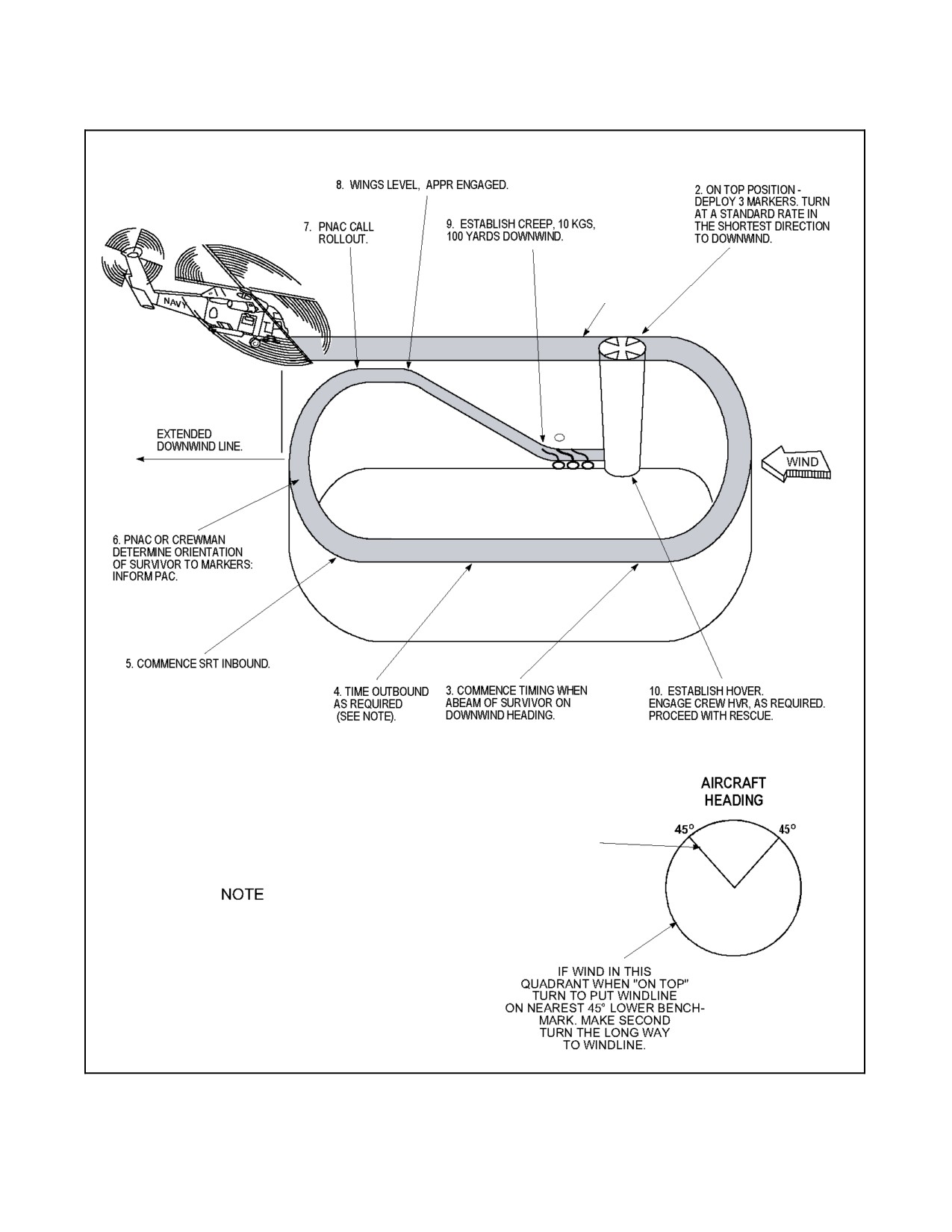
A1-H60BB-NFM-000
1. SEARCH ALTITUDE
AS CALCULATED IN
SAR TACAID
IF WIND IN
THIS QUADRANT WHEN
“ON TOP” TURN
SHORTEST DIRECTION
DOWNWIND. MAKE
SECOND TURN IN SAME
DIRECTION AS
FIRST.
I COMBINATION OF WIND VELOCITY (WV)
AND TIME DOWNWIND TOTALING 30
USUALLY SUFFICES.
EXAMPLES: WV = 0, TIME DOWNWIND = 30 SEC.
WV = 30, TIME DOWNWIND = 0 SEC.
Figure 9-4. Windline (Racetrack) Rescue Pattern
9-11
ORIGINAL
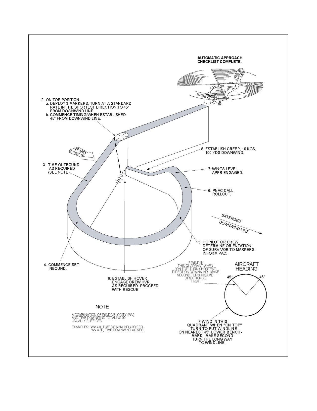
A1-H60BB-NFM-000
1. SEARCH ALTITUDE AS
CALCULATED IN SAR TACAID
Figure 9-5. Windline (Teardrop) Rescue Pattern
ORIGINAL
9-12
A1-H60BB-NFM-000
9.2.4 Overland SAR
While naval SAR--capable units have traditionally operated within the maritime environment, it is becoming
increasingly necessary for those units to also operate inland. Many of the procedures used in the maritime region also
apply when operating inland, however, aircrew must understand and be familiar with the procedures unique to the
inland environment. Prior to executing search and rescue operations in the inland environment, pilots and aircrew
shall be familiar with the appropriate sections of the following documents: SH--60B NFM, NTRP 3--22.4--SH60B,
NTTP 3--50.1, and OPNAV 3130.6 (series).
9.2.4.1 Rescue/Recovery Methods
There are five basic rescue methods that can be utilized in order of preference:
1. Landing to effect a rescue.
2. Rescue via one or two wheels.
3. Rescue via hoist.
4. Rappelling.
5. Direct Deployment.
Power requirements vary significantly based upon winds, escape route and
the size and slope of the landing zone. Power greater than HOGE may be
required to land and takeoff. Utilize appropriate preflight planning and
techniques in this chapter to ensure power margins are maintained.
CAUTION
Loss of tail rotor effectiveness is characterized by uncommanded right yaw.
It is encountered when operating at high density altitudes in high power
regimes. Arresting high rates of descent outside of translational lift and
attempting approaches out of the wind increase the likelihood of
encountering loss of tail rotor effectiveness. Immediate reduction of
collective, selection of contingency power, and transition to forward flight
or a right turn to drop off (if available) is required to restore directional
stability.
9.2.4.2 Landing to Effect a Rescue
Landing to effect a rescue is the preferred method of rescue in the overland environment as it is more expeditious,
reduces pilot/crew fatigue, and is the safest method of recovery. Prior to commencing an approach to a landing zone,
pilots shall complete a SWEEP check, set up for the appropriate approach profile and announce wave off intentions.
Utilize the procedures in Figure 9-6 for overland rescue. Refer to Chapter 11 for a detailed discussion of slope
landing/takeoffs and dynamic rollover.
Aft cyclic positions, in conjunction with low or decreasing collective pitch,
may cause rotor blades to contact the tail pylon resulting in loss of tail rotor
drive.
9-13
ORIGINAL W/IC 70
A1-H60BB-NFM-000
Note
D Whenlandingsiteisacombinationofcrossslopeandupordownslope,use
the most restrictive slope landing limit. Be prepared to execute a
combination of control inputs to maintain stability.
D Depending on slope and helicopter configuration, the tail wheel may touch
down prior to the upslope wheel.
9.2.4.3 Rescue Via One or Two Wheels
Due to the increased pilot workload associated with one or two wheel
landings and the increased potential for mishap, one or two wheel landing
operations shall not be conducted except for reasons of operational
necessity.
When the landing site is not suitable for a normal landing, consideration should be given to performing a one or two
wheel landing. Landing via one or two wheels significantly increases pilot workload and requires increased crew
coordination. Extreme caution must be used as the aircraft is in a dynamic rollover envelope anytime a wheel is in
contact with the ground. Utilize the procedures in Figure 9-6.
9.2.4.3.1 Landing Considerations for One or Two Wheel Landings
When the landing site is not suitable for a normal landing, four landing configurations may be possible. Landings
may be attempted on one main mount, both main mounts, on one main mount and tail wheel, and tail wheel only.
Consideration should be given to CAL, slope landing, and unprepared surface procedures as applicable.
Set the parking brake prior to making a shallow approach into the wind. Make a shallow approach to a hover over
the intended landing area. From a hover, descend slowly making smooth, coordinated control inputs. Aircrewmen
shall maintain sight of the landing area at all times and continuously clear and direct the helicopter for landing gear
placement. The pilot shall treat the helicopter as if it were completely airborne for the entire evolution. The controls
should be continually adjusted to maintain a stable attitude and position.
D When conducting one or two wheel landings, the helicopter can develop
unintentional roll rates. Constant attention by the crew is necessary to
prevent dynamic roll over conditions. When landing or taking off with one
or two wheels touching the ground, use smooth collective motion to
maintain low roll rates. Do not allow the helicopter to drift during ground
maneuvers. Dynamic rollover may result in loss of helicopter and crew.
D If there are no suitable visual references for the PAC, consideration should
be given to selecting an alternate landing site or hover area. This will
prevent unintentional drift into obstacles or obstructions and possible loss
of the helicopter and crew.
ORIGINAL W/IC 70
9-14
A1-H60BB-NFM-000
CAUTION
Depending on the site and the helicopter position, reduced clearances may
cause helicopter components to strike the ground/structure.
Note
If encountering a situation where only one wheel is in contact with the
ground and a rolling moment is present, smooth reduction of the collective
is the most effective corrective action the pilot can take to prevent dynamic
rollover.
The departure should be a smooth, controlled liftoff to a hover followed by the appropriate departure maneuver.
Throughout the evolution the aircrew shall continue clearing the helicopter until clear of all obstacles.
9.2.4.4 Rescue Via Hoist
If unable to land, rescue via the hoist is another option. Rescue via hoist is very similar to overwater rescue techniques.
The aircrew must be aware of hazards and power requirements (to include the weight of the people being rescued)
needed to conduct a rescue via hoisting. Prior to commencing a rescue via hoist, the HAC shall conduct a SWEEP
check and announce waveoff intentions. The aircrewman shall ensure that the aircraft remains clear of all obstacles
throughout the rescue. Utilize the procedures in Figure 9-7 for overland rescue via hoisting.
9.2.4.5 Rappelling
Due to the hazards associated with rappelling and the increased potential
for mishap, rappelling operations shall not be conducted except for reasons
of operational necessity. Rappelling shall only be conducted by a qualified
Helicopter Inland Rescue Aircrewman.
If a landing site is unavailable and the situation does not allow hoisting, consideration should be given to rappelling
the rescuer into the zone. Rappelling allows the rescuer to control his rate of descent to avoid obstacles. Rappelling
also allows the rescuer to quickly disconnect from the line should entanglement occur. Prior to rappelling, the HAC
shall conduct a power check, site evaluation, and announce wave off intentions. The aircrewman shall ensure that
the aircraft remains clear of all obstacles throughout the rescue.
Note
Rigging, ICS voice calls and terminology for Rappelling, Belay, and
Overland Direct Deployment are found in the NTTP 3-50.1. Pilots and
aircrew shall be intimately familiar with these procedures and properly
qualified per OPNAVINST 3130.6 (series) before performing these types
of rescue/recovery methods.
9.2.4.6 Direct Deployment
In certain overland situations when a landing site is unavailable, it may be advisable for the rescuer to remain
connected to the hoist line throughout the rescue. Rescue operations to steep cliffs, canyon walls, towers or balconies
are some examples. In these cases, the rescuer should use direct deployment techniques. The crew shall brief hoist
entanglement procedures thoroughly prior to attempting direct deployment overland. The crew shall set up for the
direct deployment rescue using the same procedures for rescuing via hoist.
9-15
ORIGINAL W/IC 70