SH-60B HELICOPTER. FLIGHT MANUAL (2008) - page 4
A1-H60BB-NFM-000
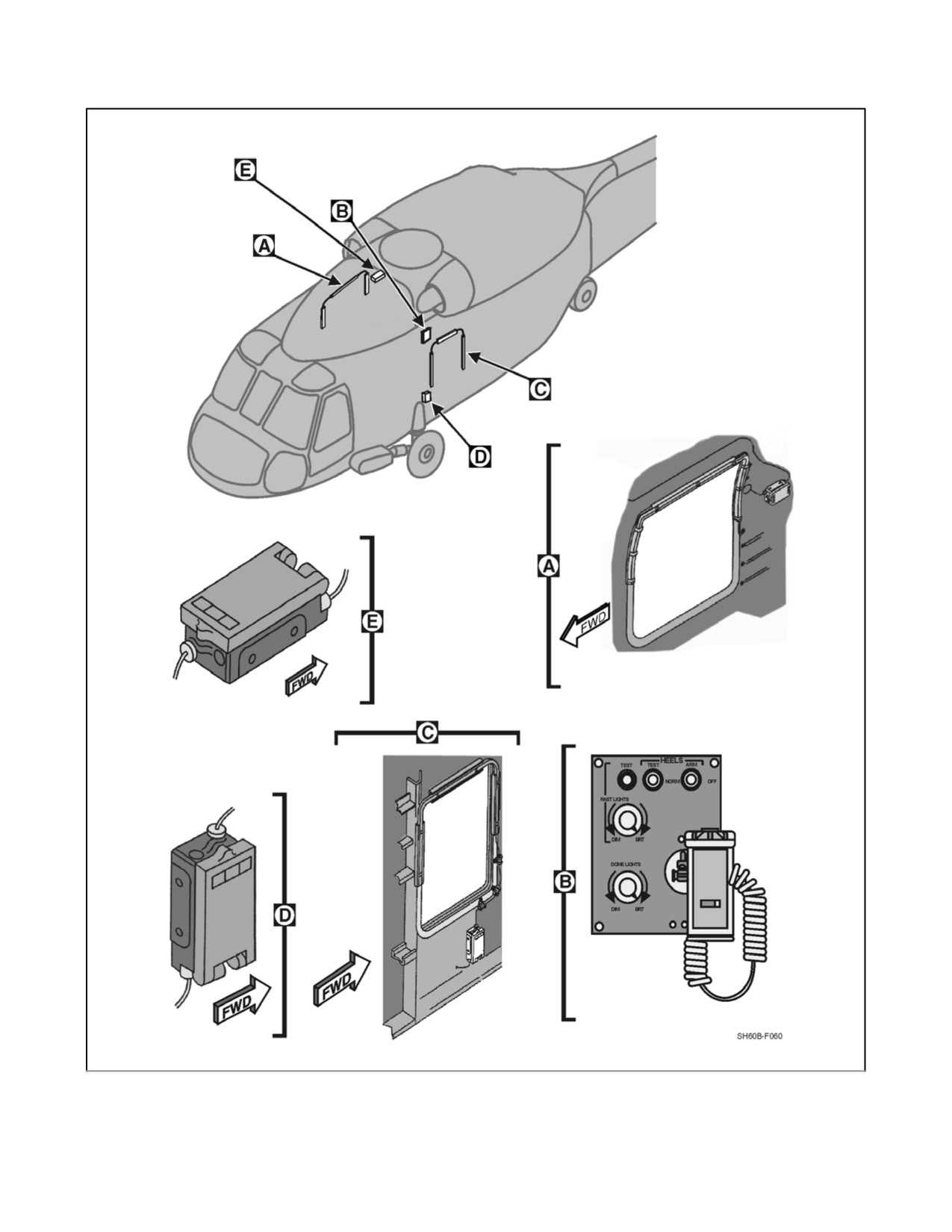
Figure 2-63. HEELS Equipment
ORIGINAL
2-144
A1-H60BB-NFM-000
CHAPTER 3
Servicing and Handling
3.1
SERVICING DATA
Servicing information is given by systems or components. Points used in frequent servicing and replenishment of
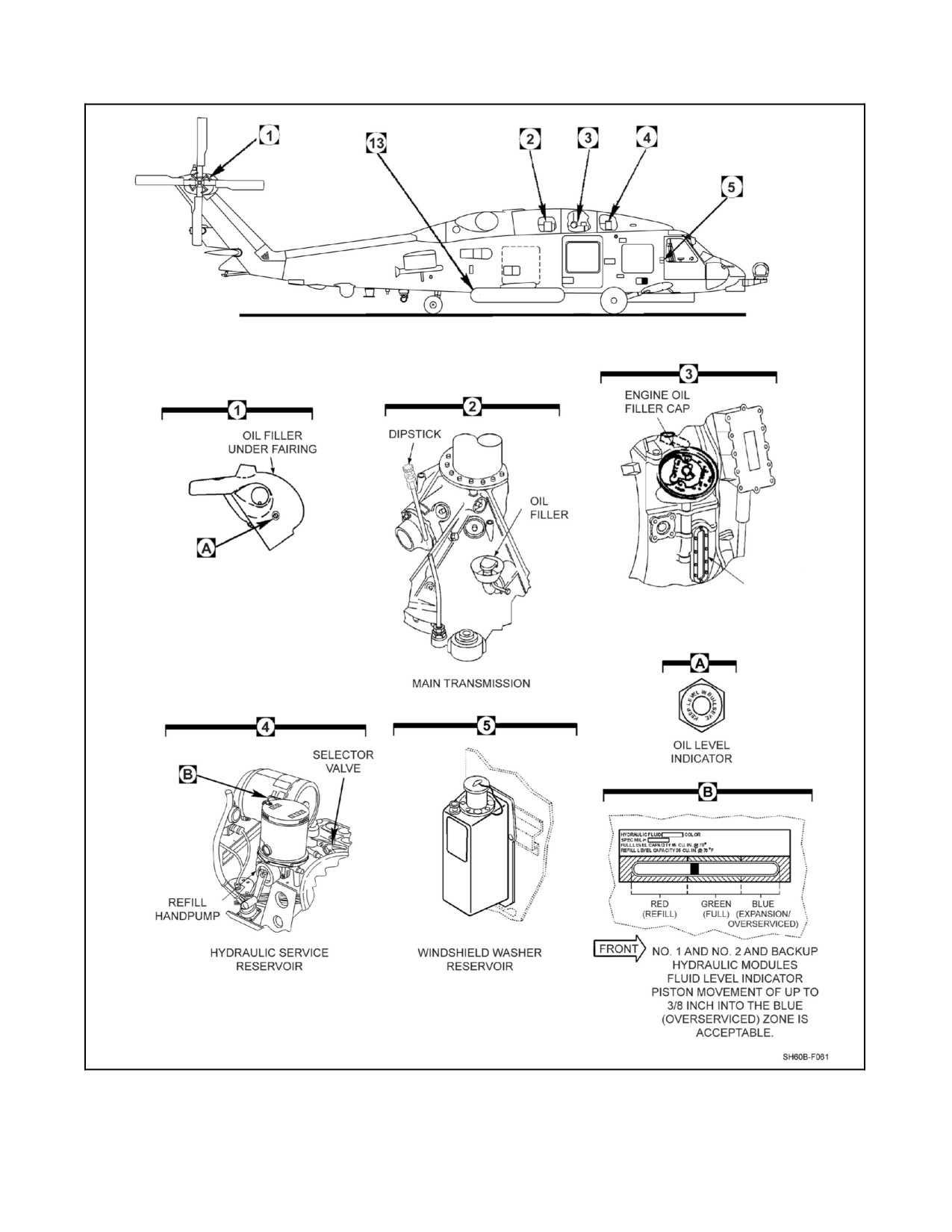
fuel, oil, and hydraulic fluid are shown in Figure 3-1. A listing of acceptable commercial and foreign fuel is shown
in Figure 3-2. Fuel and lubricant specifications and capacities are shown in Figure 3-3.
All PQMs and aircrewmen qualified in model are authorized to perform servicing and handling of the aircraft when
qualified maintenance personnel are not available. All ground/taxi hand signals shall be in accordance with NAVAIR
00--80T--113.
3.2
FUEL SYSTEM SERVICING
Fueling equipment shall be operated only by qualified and authorized personnel. Using loose pyrotechnics, smoking,
striking matches, working on aircraft, or using any device producing flame within 50 feet of the helicopter is strictly
prohibited. The helicopter should not be parked in the vicinity of possible sources of ignition such as blasting,
drilling, or welding operations. A minimum of 50 feet should be maintained from other aircraft or structures, and
75 feet should be maintained from any operating radar set. When the aircraft is being refueled, a check shall bemade
to ensure no electrical extension cords, droplights, floodlights, etc. are in or near the helicopter. Flashlights shall be
used in place of helicopter landing/flood lights for night fueling operations. During all fueling operations, fire
extinguishing equipment shall be readily available. Electrical power will have to be applied to the helicopter to obtain
the fuel quantity gauge readings.
D Flameouts may be encountered on the ground and in flight at certain fuel
temperatures when restricted fuels JP--4 or JET B are used. Nose pitch
attitudes, roll attitudes, and low power operations all contribute to the
formation of vapor bubbles in the fuel lines of SH--60B aircraft due to fuel
boost limitations. Prolonged on--deck operations such as refueling
contribute significantly to this problem when using JP--4/JET B at any
altitude.
D If JP--4 is used, the following operational restrictions apply: All takeoffs shall
stabilize in a hover with no fuel pressure caution lights for a minimum of
10 seconds before commencing transition to forward flight. Single--engine
training operations shall not be conducted while using JP--4/JET B.
D Due to the vapor qualities of mixed JP-- 4/JET B and JP--5/JET A, the next
two refuelings with JP--5 or JET A shall be treated as if it were JP--4/JET B,
that is, the same operational restrictions apply as for JP--4/JET B.
3-1
ORIGINAL
A1-H60BB-NFM-000
OIL SIGHT
GAUGE
Figure 3-1. Aircraft Servicing (Sheet 1 of 3)
ORIGINAL
3-2
A1-H60BB-NFM-000
GAUGE
HYDRAULIC FLUID
NITROGEN CHARGE
LEVEL GAUGE
GAUGE
OIL LEVEL
SIGHT GAUGE
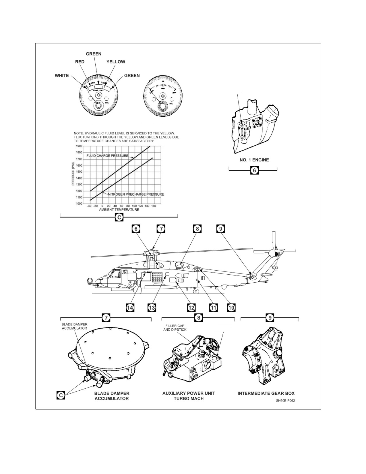
Figure 3-1. Aircraft Servicing (Sheet 2)
3-3
ORIGINAL
A1-H60BB-NFM-000
FIRE EXTINGUISHER
THERMAL EXPANSION
DISCHARGE INDICATOR
FIRE EXTINGUISHER BOTTLES
(FRANGIBLE DISC)
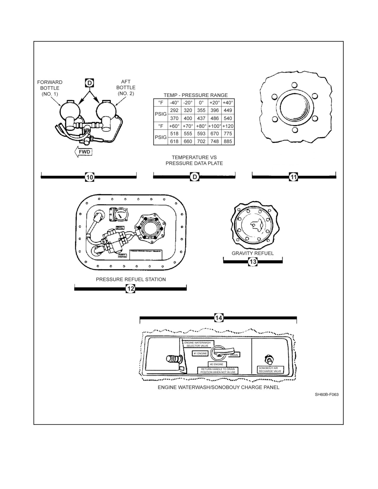
Figure 3-1. Aircraft Servicing (Sheet 3)
ORIGINAL
3-4
A1-H60BB-NFM-000
US
COMMERCIAL
BRITISH
NATO
US MILITARY
WT
MIL
DESIGNATION
DESIGNATION
COMMENTS
CODE
SPECIFICATION
(lbs/gal)
CODE
(SPECIFICATION)
(SPECIFICATION)
DEF STAN 91--86
JP--5
F--44
MIL--DTL--5624
6.8
1A, 2
(AVCAT/FSII)
NONE
DEF STAN 91--87
JP--8
F--34
MIL--DTL--83133
6.7
1A, 2, 5
(AVTUR/FSII)
PRIMARY
JET A--1
DEF STAN 91--91
NONE
F--35
MIL--DTL--83133
6.7
1A, 3, 4, 5
FUELS
(ASTM D--1655)
(AVTUR)
JET A--1
NONE
NONE
NONE
NONE
6.7
1A, 3, 4, 5
(ASTM D--1655)
GOST 10227
NONE
NONE
NONE
NONE
6.7
1A, 3, 4, 5, 6
GRADE TS--1
RESTRICTED
JET B
DEF STAN 91--88
JP--4
F--40
MIL--DTL--5624
6.5
1B, 3, 4, 5, 7, 8
FUELS
(ASTM D--6615)
(AVTAG/FSII)
DEF STAN 91--87
EMERGENCY
JP--8
F--37
MIL--DTL--83133
NONE
(AVTUR/FSII +
6.7
1C, 2, 5, 9, 10
FUELS
+100
S--1749)
IN ORDER TO ENSURE THAT A HELICOPTER CAN BE SAFELY HANGARED
ABOARD SHIP, THE HELICOPTER SHOULD BE FUELED WITH JP--5 (F--44)
PRIOR TO FLYING ABOARD A SHIP. WHEN FUELING WITH JP--5 IS NOT
POSSIBLE, HELICOPTERS SHALL NOT BE HANGARED UNTIL THE
FLASHPOINT OF THE FUEL IN THE HELICOPTER FUEL TANKS IS ABOVE
120 °F.
NOTE
D
FOR PLANNING PURPOSES, A FUEL MIXTURE OF 70% JP--5 (F--44) AND 30%
JP--8
(F--34) OR JET A--1
(F--35) WILL ENSURE THAT THE MINIMUM
FLASHPOINT OF THE FUEL MIXTURE IS ABOVE 120 °F.
D
SHIP’S FUEL PERSONNEL HAVE TEST EQUIPMENT FOR MEASURING FUEL
FLASHPOINT. FIGURE 4 OF MIL--HDBK--844A(AS) (AIRCRAFT REFUELING
HANDBOOK FOR NAVY/MARINE CORPS AIRCRAFT) CAN BE USED WITH THE
MEASURED FLASHPOINT TO DETERMINE MORE ACCURATELY THE
PERCENTAGE OF JP--5 (F--44) REQUIRED TO RAISE THE FLASHPOINT OF
JP--8 (F--34) OR JET A--1 (F--35) ABOVE 120 °F.
D
NAVAIR 00--80T--109 (AIRCRAFT REFUELING NATOPS MANUAL) CONTAINS
PROCEDURES THAT MUST BE FOLLOWED WHEN HANGARING
HELICOPTERS CONTAINING FUEL OTHER THAN JP--5 (F--44).
D
PILOTS/AIRCREW SHALL ENSURE THAT AIRCRAFT MAINTENANCE
DEPARTMENTS ARE INFORMED WHEN AIRCRAFT ARE FUELED WITH THE
EMERGENCY FUEL JP--8+100 (F--37).
D
NAVAIR 00--80T--109 (AIRCRAFT REFUELING NATOPS MANUAL) CONTAINS
SPECIAL PROCEDURES THAT MUST BE FOLLOWED WHEN IT BECOMES
NECESSARY TO DEFUEL AIRCRAFT THAT HAVE BEEN FUELED WITH THE
EMERGENCY FUEL JP--8+100 (F--37). SINCE THERE IS NO VIABLE FIELD
TEST THAT CAN DETECT THE PRESENCE OF JP--8+100
(F--37),
PILOTS/AIRCREW AND AIRCRAFT MAINTENANCE PERSONNEL SHALL
ENSURE THAT FUELS PERSONNEL ARE INFORMED OF AIRCRAFT THAT
HAVE BEEN FUELED WITH THE EMERGENCY FUEL JP--8+100 (F--37).
Figure 3-2. H--60 Series Common Fuel Reference Chart (Sheet 1 of 2)
3-5
ORIGINAL
A1-H60BB-NFM-000
COMMENTS
1.
FUEL DEFINITIONS:
a. PRIMARY FUEL -- A FUEL THAT THE AIRCRAFT IS AUTHORIZED TO USE FOR CONTINUOUS
UNRESTRICTED OPERATIONS.
b. RESTRICTED FUEL -- A FUEL WHICH IMPOSES OPERATIONAL RESTRICTIONS ON THE AIRCRAFT. THESE
FUELS MAY BE USED ONLY IF NO PRIMARY MILITARY OR COMMERCIAL FUELS ARE AVAILABLE.
c. EMERGENCY FUEL -- A FUEL WHICH MAY BE USED FOR A MINIMUM TIME WHEN A PRIMARY FUEL IS
NOT AVAILABLE AND AN URGENT NEED EXISTS (SUCH AS HURRICANE EVACUATION OR URGENT
MILITARY NECESSITY). PILOT APPROVAL SHALL BE OBTAINED BEFORE SERVICING AND THE AIRCRAFT
SHALL BE CONSPICUOUSLY PLACARDED WITH THE EMERGENCY FUEL GRADE WHEN SERVICED.
2.
ALL US MILITARY AND NATO FUELS, EXCEPT F--35, CONTAIN AN ADDITIVE PACKAGE WHICH INCLUDES
FUEL SYSTEM ICING INHIBITOR (FSII).
3.
COMMERCIAL FUELS ARE AVAILABLE WITH AND WITHOUT FSII.
4.
PRIST. A COMMERCIAL FSII ADDITIVE, PRIST, MAY BE USED WITH COMMERCIAL JET FUEL (JET A/JET
A--1/JET B). PRIST IS EQUIVALENT TO THE MILITARY FSII ADDITIVE. IT IS AVAILABLE IN TWO FORMS:
(1) AEROSOL CANS WHICH ARE DISCHARGED INTO THE FUEL AS IT IS PUMPED INTO THE AIRCRAFT AND
(2) PREMIXED INTO THE FUEL. WHEN PRIST IS PREMIXED WITH THE FUEL IT PROVIDES ANTI--ICING
PROTECTION EQUIVALENT TO THAT PROVIDED BY MILITARY JET FUEL AND IS AUTHORIZED FOR USE.
PRIST IN AEROSOL CANS IS NOT AUTHORIZED FOR USE SINCE IT DOES NOT MIX WELL WITH FUEL, HAS A
TENDENCY TO SETTLE TO THE BOTTOM OF FUEL TANKS, AND MAY DAMAGE FUEL SYSTEM SEALS AND
FUEL TANK MATERIALS.
5.
JP--4, JP--8, TS--1, JP--8+100 AND ALL COMMERCIAL JET FUELS SHALL NOT BE DEFUELED INTO SHIPBOARD
JP--5 FUEL STORAGE TANKS BECAUSE THE FLASH POINT OF THESE FUELS IS LESS THAN 140 °F.
6.
TS--1 IS A COMMERCIAL AVIATION KEROSENE MADE TO THE RUSSIAN FUEL SPECIFICATION GOST 10227.
IT IS VERY SIMILAR TO ASTM JET A--1 WITH THE EXCEPTION THAT THE FLASH POINT IS APPROXIMATELY
20 °C LOWER THAN JET A--1. THIS FUEL IS COMMONLY AVAILABLE IN RUSSIA, PARTS OF CENTRAL
EUROPE, THE CENTRAL ASIAN REPUBLICS AND AFGHANISTAN.
7.
JP--4 (F--40) HAS BEEN REPLACED BY JP--8 (F--34) IN US AND NATO SERVICE. JP--4 (F--40) AND JET B ARE
NO LONGER WIDELY AVAILABLE WORLDWIDE BUT MAY STILL BE ENCOUNTERED IN SOME AREAS.
8.
SEE SPECIFIC T/M/S NATOPS MANUALS FOR RESTRICTIONS APPLICABLE TO THE USE OF JP--4
(F--40)/JET B.
9.
JP--8+100 (F--37) CONTAINS A THERMAL STABILITY ADDITIVE THAT AFFECTS THE ABILITY OF THE
COALESCING FILTER--SEPARATORS AND CENTRIFUGAL PURIFIERS (FILTRATION EQUIPMENT USED IN
SHORE STATION AND SHIPBOARD FUEL STORAGE/HANDLING SYSTEMS) TO REMOVE FREE WATER AND
FINE PARTICULATE MATTER FROM FUEL. NAVAIR 00--80T--109 (AIRCRAFT REFUELING NATOPS MANUAL)
CONTAINS ADDITIONAL INFORMATION ON JP--8+100 (F--37).
10.
NO USN/USMC AIRCRAFT ENGINES REQUIRE THE USE OF JP--8+100 (F--37). USN/USMC AIRCRAFT ARE NOT
AUTHORIZED TO USE JP--8+100 (F--37) EXCEPT IN EMERGENCY SITUATIONS.
FOR ADDITIONAL INFORMATION ON AVIATION FUELS, CONSULT THE FOLLOWING:
1. NAVAIR 00--80T--109, AIRCRAFT REFUELING NATOPS MANUAL.
2. MIL--HDBK--844A (AS), REFUELING HANDBOOK FOR NAVY/MARINE CORPS AIRCRAFT.
Figure 3-2. H--60 Series Common Fuel Reference Chart (Sheet 2)
ORIGINAL
3-6
A1-H60BB-NFM-000
PRIMARY PRODUCT
ACCEPTABLE SUBSTITUTE
NATO
NATO
SYSTEM
CAPACITY
MIL SPEC
CODE
MIL SPEC
CODE
ENGINE OIL
7.3 U.S. QUARTS
MIL PRF 23699
O--156
MIL PRF 7808
O--148
(Notes 1, 2)
APU
2.0 U.S. QUARTS
MIL PRF 23699
O--156
None
None
MAIN
7.5 U.S. GALLONS
DOD PRF 85734
None
None
None
TRANSMISSION
INTERMEDIATE
2.75 U.S. PINTS
DOD PRF 85734
None
None
None
GEARBOX
TAIL GEARBOX
2.75 U.S. PINTS
DOD PRF 85734
None
None
None
HYDRAULIC
1.0 U.S. QUART
MIL PRF 83282
H 537
None
None
RESERVOIRS
RESCUE HOIST
1.16 U.S. QUARTS
MIL PRF 23699
O--156
None
None
ENGINE STARTER
200 cc
MIL PRF 23699
O--156
None
None
CAUTION
The engine shall be drained and flushed when changing from
MIL--PRF--23699 to MIL--PRF--7808 prior to operations in ambient
temperatures below --40 °C.
Notes:
1. When starting in ambient temperatures of --40 °C or below, lubricating oil MIL--PRF--7808 shall be used.
2. When adding one authorized oil to another at ambient temperatures above --40 °C, the engine shall be drained.
It is not necessary to flush the engine under these conditions.
Figure 3-3. Lubricants and Hydraulic Fluids Reference Chart
3.2.1 Fueling with Fuel Susceptible to Icing
Utilize the following procedure to keep the bulk fuel temperature above 0 °C and prevent engine flameout caused
by fuel icing:
1. Iftheaircrafthasbeeninheatedhangarareas,theaircraftshouldbelaunchedwithinonehourafterbeingmoved
to the flight deck or towed to a turn--up area.
2. If the aircraft is outside for more than one hour, bulk fuel temperature should be checked by draining aircraft
fuel into a bottle which has been outside approximately 15 minutes, a thermometer inserted, and temperature
read.
3. If fuel is 0 °C or below, aircraft should be hangared until bulk fuel temperature rises above 0 °C or partially
defueled and refueled with warm fuel so that bulk temperature rises above 0 °C.
3-7
ORIGINAL
A1-H60BB-NFM-000
3.2.2 Pressure Refueling
The helicopter fuel tanks arepressure refueled through afitting on the left side ofthe aircraft. Pressure refueling does
not require electrical power. The system should automatically shut off when the tanks are full. Before refueling, the
helicopter and refueling--unit grounding devices should be inspected by fueling personnel for proper ground.
The procedures described in the following paragraphs shall be followed during refueling operations.
Ensure sonobuoy launcher lock pin is in the LOCK position prior to
refueling with sonobuoys loaded and system pressurized.
CAUTION
Fueling pressure shall not exceed 55 psi.
3.2.2.1 Helicopter On Deck
Asterisked (*) items apply only when engines and rotors are operating.
Note
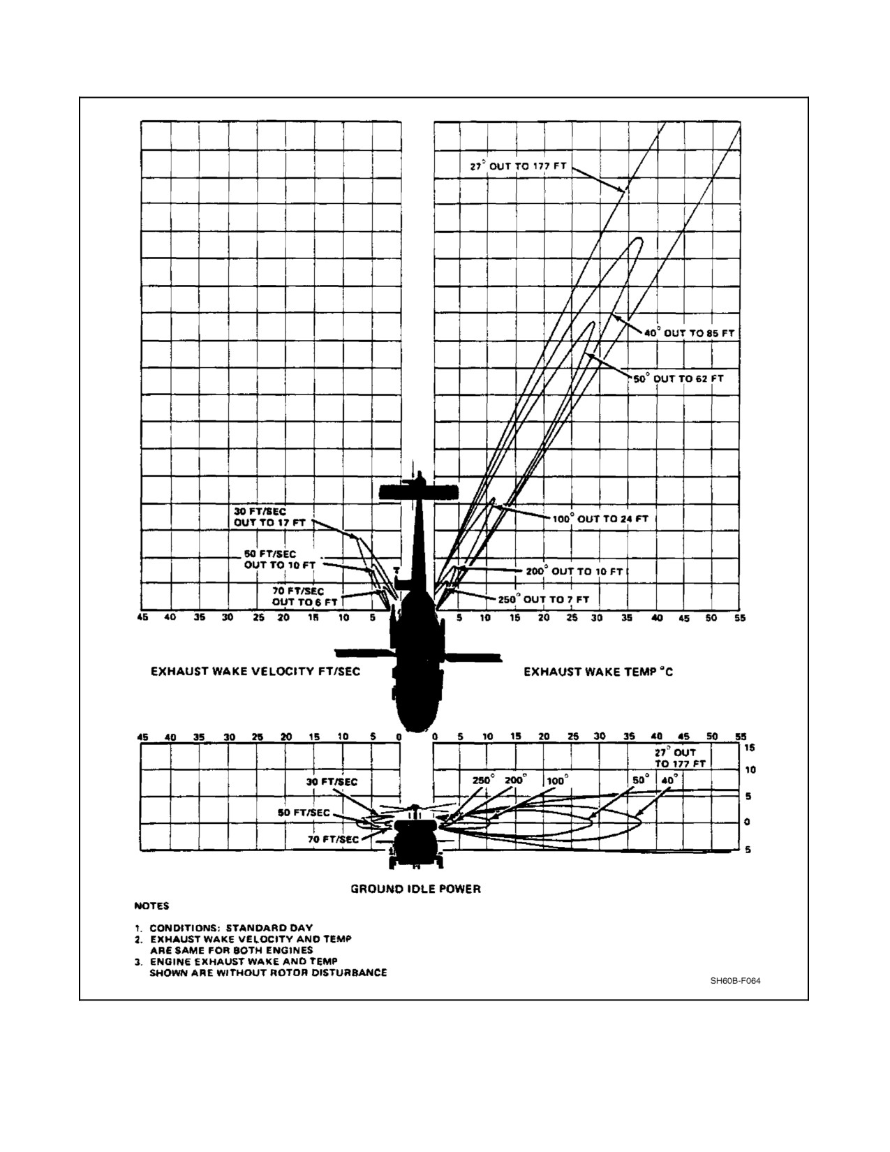
Aircraft exhaust patterns are shown in Figure 3-4.
*1. Pilot maintains UHF communication with LSO, ground, or tower — As applicable.
*2. ALE--39 arming handles (ESP only) — SAFE.
*3. IRCM/HF — OFF.
4. Fuel management panel (BuNo 162349 and subsequent) — REFUEL as required.
5. Helicopter — Ground. Fuel vehicle (ashore only) — Ground to aircraft.
6. Fueling nozzle — Connect.
7. Fuel flow — Start (when directed by the pilot).
CAUTION
D Increase of intertank pressure as indicated by the tank pressure gauge enter-
ing the red band during pressure refueling denotes a clogged vent. Stop re-
fueling immediately and investigate.
D Flowoffuelwhenprecheckvalveisinprecheck positionindicates ashutoff
system malfunction. If both precheck valves fail to stop fuel flow, stop
refueling to prevent overflow from tank vents. As long as one precheck
valve is operative, the aircraft can be refueled safely.
8. Hold precheck valves in precheck position, one at a time — Fuel flow will stop within 10 seconds.
9. Release check valve and continue fueling until fuel flow stops.
10. Fueling nozzle — Disconnect and replace cap, close panel door.
ORIGINAL
3-8
A1-H60BB-NFM-000
Figure 3-4. Aircraft Engine Exhaust Patterns
3-9
ORIGINAL
A1-H60BB-NFM-000
11. All grounding wires — Remove.
*12. IRCM/HF (ESP only) — ON.
*13. ALE--39 arming handles (ESP only) — ARM.
3.2.3 Gravity Fueling
The helicopter main tanks are gravity fueled through a filler cap on the left side of the helicopter. The external
auxiliary fuel tanks are gravity fueled individually. Before fueling, grounding devices on the helicopter and on the
fuel truck will be inspected by fueling personnel to be sure of proper ground. Before using a fuel hose, the hose nozzle
must begrounded to grounding stations aboveorbelow thepressurerefueling station. Beforeremoving thefillercap,
attach the hose nozzle grounding unit into the grounding jack. Replace the filler cap after filling tank.
D Gravity fueling is not authorized with engines or APU operating. In
addition to the hazard caused by the location of the tank openings relative
to the engine exhaust, the rotors constantly build static electricity, creating
an extremely dangerous spark potential.
D Internal tank pressure shall be checked prior to removal of the filler cap to
prevent fuel spills.
3.2.4 Use of Different Fuels
When changing from one type of authorized fuel to another, it is not necessary to drain the fuel system before adding
the new fuel. Fuels having the same NATO code number are interchangeable. Jet fuels conforming to the ASTM
D--1655 specification may be used when MIL--T--5624 fuels are not available. When helicopters using NATO F--44
(JP--5) are refueled with NATO F--40 (JP--4) or commercial ASTM Type B fuels, the operating characteristics may
change in that lower operating temperature, slower acceleration, easier starting, and shorter range may be
experienced. The reverse is true when changing from F--40 (JP--4) fuel to F--44 (JP--5) or commercial ASTM Type
A--l fuels.
3.2.5 RAST Operations for Aircraft Configured with External Auxiliary Fuel Tank
RAST operations may be performed on aircraft configured with a 120 gallon external auxiliary fuel tank provided
the following limits and conditions are met:
1. Main and tail landing gear tires and oleo struts have been serviced prior to flight.
CAUTION
Strut servicing shall not beperformed while theaircraft is over/in theRSD.
2. The static vertical clearance between the deck and the lowest point on the auxiliary fuel tank shell (not
including the fin) shall not be less than 12.0 inches.
Note
Static vertical clearance is measured following any maintenance or
servicing involving main landing gear or oleo struts.
3. Aircraft gross weight during RAST operations shall not exceed the gross weight of the helicopter at the time
of the static vertical clearance measurement.
ORIGINAL
3-10
A1-H60BB-NFM-000
3.3
OIL SYSTEM SERVICING
3.3.1 Engine Oil Servicing
Both engine oil tanks (Figure 3-1) are within the main frame. Add oil if oil level in sight glass is less than halfway
between add and full marks. Service to approximately one inch below the full mark or adjacent to the top set of bolts.
If oil is at operating temperature, wait 20 minutes before checking oil level or servicing engine.
Lubricating oils MIL--L--23699, MIL--L--7808, and DOD--L--85734 con-
tain materials hazardous to health. These lubricating oils can produce
paralysis if swallowed. Long--term contact may irritate the skin. Wash
hands thoroughly after handling as they may burn if exposed to heat or
flames. Use only with proper ventilation.
CAUTION
The helicopter must be level to get accurate oil tank readings. When the
helicopter is parked on a slope, the downslope engine will read a higher oil
level than actual, and the upslope engine will read a lower oil level than
actual.
Note
Commercial oils listed are approved for use in engines and gearboxes
except as indicated.
3.3.2 Main Transmission Oil System Servicing
The transmission oil supply is in the sump case with the filler port and dipstick gauge located on the right rear of the
main module. When filling is required, oil is poured through the filler tube on the main module case. The oil level
is checked by a dipstick, marked FULL and ADD. When the oil level decreases to the ADD mark on the dipstick,
approximately 2 quarts of oil will be needed to return the level to FULL. The dipstick has both hot and cold scales.
3.3.3 Tail and Intermediate Gearbox Servicing
The intermediate gearbox oil level sight gauge (Figure 3-1) is located on the left side of the gearbox. The tail gearbox
oil level sight gauge is on the right side. Each sight gauge contains inner and outer circles. The gearboxes are full
when theoil level is within theinnercirclewhen thepylon is spread. Theoil level should be replenished if thebottom
of the outer circle can be seen. Some aircraft are equipped with improved visibility sight gauges on the tail gearbox.
They are labeled with upper and lower horizontal lines. The gearbox is full when the oil level is between the two lines
when the pylon is spread. The oil level should be replenished if the level is below the lower line.
Note
During shipboard operations, the gearbox oil level sight gauge may not
indicateproperly dueto theslopeoftheflight decks on certain ship classes.
3-11
ORIGINAL
A1-H60BB-NFM-000
3.4
HYDRAULIC SYSTEM SERVICING
Reservoirs (Figure 3-1) for the hydraulic system are on the hydraulic pump modules. Fluid--level sight gauges are
visible on the side of each pump. All hydraulic pump reservoir capacities are 1 U.S. quart at the FULL mark. When
the indicator reaches the refill (red) point, two--thirds of a pint is required to return the indicator to the full (green)
mark. The fluid level indication is the 1/8--inch wide white stripe at the outboard edge of the level piston. To refill
the reservoirs, the fluid is supplied from the manual hand pump. After flight, fluid in hydraulic systems will be hot.
Piston movement of up to 3/8 inch into the blue (overserviced) zone is acceptable. When piston is beyond this limit,
bleed off enough fluid to bring piston back to 3/8 inch above full limit.
Note
After operation, the indicator may show an overserviced condition.
Accurate readings may only be made after fluid temperature has cooled.
To replenish the pump reservoir fluid:
1. Turn the selector valve to the reservoir to be filled. OUT 1 is the left pump module, OUT 2 is the right pump
module, OUT 3 is the backup pump module, and OUT 4 is the rotor brake (stow position).
2. Whileholding theselectorvalvehandledown, crank thehandpump clockwiseand filldesired hydraulicpump
module until the forward end of the reservoir window piston is at the forward end of the green decal on the
reservoir housing. At the same time, push in and turn the bleed valve, and bleed air from the pump module.
Release button when air--free oil shows.
3. Check that reservoirs stay full (forward end of piston at forward end of green decal), with fluid at ambient
temperature 1 hour after flight.
4. Make sure area remains clean during procedure.
5. Stow selector valve handle in OUT 4 position.
6. Turn on electrical power.
7. Check caution panel for #1 RSVR LOW, #2 RSVR LOW, and BACK--UP RSVR LOW lights off.
3.4.1 Hand Pump Reservoir Servicing
Servicing of the refill hand pump (Figure 3-1) is done when fluid level decreases to the refill line on the fluid--level
sight gaugeon thesideofthepump tank. When thefluid level decreases to therefill line, serviceis necessary to avoid
allowing air into the rotor brake hydraulic system.
3.5
BLADE DAMPER ACCUMULATOR
The blade damper accumulator is serviced with a combination of hydraulic fluid and nitrogen. After proper servicing,
the fluid--level gauge (Figure 3-1) should be in the green or yellow area. The nitrogen charge gauge should indicate
the pressure for the ambient temperature (degrees F) listed on the accompanying chart.
3.6
SONOBUOY LAUNCHER PNEUMATIC SYSTEM SERVICING
The sonobuoy launcher pneumatic bottle is serviced from the waterwash/sonobuoy charge panel above the SO
window, located on the left side of the helicopter (Figure 3-1).
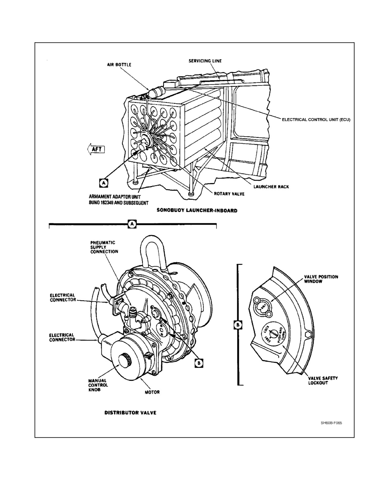
The system shall be disarmed at the control panel in the cockpit and the valve safety lockout engaged in the rotary
valve (Figure 3-5) before starting servicing. Attach a high--pressure air supply hose to the charge valve. Apply 1,200
to 1,250 psi and open thechargevalve. Closethevalvewhen theairbottleis charged. Verify approximately1,200 psi
on supply manifold gauge, and disconnect the supply hose.
ORIGINAL
3-12
A1-H60BB-NFM-000
Figure 3-5. Sonobuoy Launch System Components and Servicing
3-13
ORIGINAL
A1-H60BB-NFM-000
3.7
WINDSHIELD WASHER SYSTEM SERVICING
The windshield washer system is serviced by filling the reservoir, located aft of the pump and behind the pilot seat.
Note
In weather where the temperature is above 0 °C, the reservoir may be
serviced with water. When operating in areas where the temperature is
below 0 °C, service the reservoir with equal parts of water and isopropyl
alcohol.
3.8
FIRE EXTINGUISHER SYSTEM SERVICING
Fire extinguisher bottles that have lost their charge, for any reason, shall be replaced with fully serviced units.
3.9
APU OIL SYSTEM SERVICING
The APU oil supply is in the APU gearbox oil sump. The sump--filler/oil dipstick port (Figure 3-1) is located on the
left side of the gearbox housing. The APU oil level can be accurately checked only by using the dipstick.
Note
The proper level for the Turbomach APU is halfway between full and refill.
Filling the APU to the full line will cause the APU to overheat easily.
3.10
EXTERNAL POWER REQUIREMENTS
The helicopter requires 115/200V, 3 phase, 400 Hz external power. The AC external power receptacle is located on
the right side of the helicopter, forward of the crew door near the main landing gear. The helicopter does not have
a DC external power receptacle.
The following is a partial list of external power sources which provide 115/200V, 3 phase, 400 Hz AC power:
USN
USAF
CANADIAN
NC-2A
B-10
CAN-C (Same as USN NC-5)
NC-5
B-10A
NC-6A
B-10B
NC-7
MD-3
NC-7A
MD-3A
NC-7B
M32A-10
NC-7C
M32A-13
NC-8A
NC-10
NC-10B
NC-12
NC-12A
3.11
AIRCRAFT TOWING
Due to the top--heavy configuration of the helicopter, precautions must be observed during all helicopter movements
to prevent possible damage and dangerous conditions. The helicopter shall be moved with a tractor equipped with
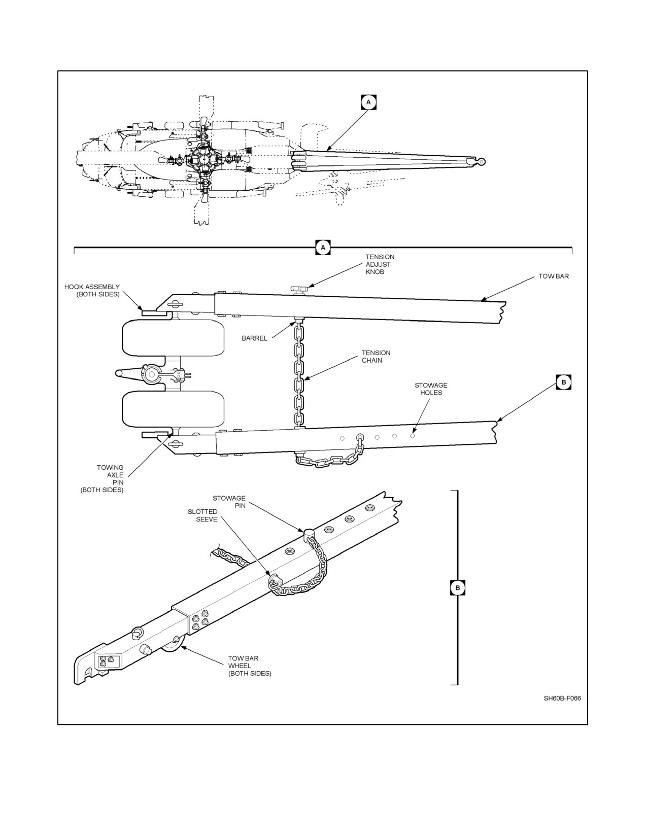
an SH--60 unique tow bar. Towing equipment (Figure 3-6) shall be operated only by qualified personnel who will
be responsible for checking the approved towing couplings before towing. When towing a helicopter, three
wingwalkers and a qualified brakerider shall be used. A wingwalker shall be stationed on each side of the helicopter,
and one will be located near the tail rotor to ensure adequate clearance. In addition, towing shall be supervised by
a director. Each person shall be equipped with a whistle. All stop signals shall be given by a whistle and hand signals.
Whistle signals should be supplemented by hand signals whenever possible. Wheel brakes shall be applied as soon
as a stop signal is received from the director.
ORIGINAL
3-14
A1-H60BB-NFM-000
Figure 3-6. Aircraft Towing
3-15
ORIGINAL
A1-H60BB-NFM-000
D Personnel shall position themselves abeam the mainmount at a distance
greater than their personal height. Personnel shall never position them-
selves in line with the tires.
D Only essential personnel shall remain in an aircraft during ground
movement. All such personnel shall be seated with seatbelts fastened.
Personnel shall not enter or exit aircraft during movement.
D Towing speeds shall not be over 5 mph, and sudden stops and starts shall
be avoided.
D When the tow bar is attached to the tail wheel, the tail wheel should be
unlocked to prevent shearing of the lockpin.
D If pushing the aircraft up or pulling it down a short/steep incline, the nose
may pitch up and cause the aft data link antenna to impact the tow bar.
3.12
PARKING
1.
Short--term parking:
Note
During short--term parking, helicopter should be attended or monitored at
all times.
a. Locate helicopter more than one rotor blade length from other helicopters or objects.
b. With winds 20 knots or more, park helicopter facing into the wind.
c. Lower stabilator to full--down position.
Note
Battery power may be used to lower stabilator.
d. Apply rotor brake.
e. Center tail wheel and place tail wheel lockpin in the LOCKED position.
f. Engage parking brake (handle up) and chock main wheels.
g. Install protective covers.
h. Connect low--resistance ground wire to aircraft.
2.
Long--term parking:
Note
During long--term parking, helicopter will not be attended or monitored.
a. Park helicopter the same as short--term parking.
b. If winds of 45 knots or gusts to 60 knots are expected, fold and secure main rotor blades.
c. Install helicopter and main rotor tiedowns.
ORIGINAL
3-16
A1-H60BB-NFM-000
3.13
AIRCRAFT TIEDOWN/SECURING
3.13.1 Aircraft Tiedown Instructions
1. When possible, head helicopter into wind.
2. Chock main landing gear wheels.
3. When ground tiedown rings are not available, move helicopter to an area where anchors or deadman type
anchors (capable of sustaining a 12,500 pound per cable pull test) may be used.
4. Fasten 12,500 pound pull test chain to tiedown rings (Figure3-7)and extend outward to round mooring points
at 45° angles. Provide enough slack in chain or rope between anchor and tiedown ring to prevent tightening
due to distortion or tire deflation on the opposite side.
CAUTION
Hellfire missile seeker covers should be installed (when available) before
commencement of ground operations and all chocks and chains operations.
Exercise extreme care when applying chocks and chains to the port
mainmount to avoid damage to missile seeker or fins.
5. Install protection covers and plugs.
6. When main rotor blades are spread, engage rotor brake and install blade tiedowns.
7. After winds have subsided, check helicopter for damage from flying objects and buffeting.
3.13.1.1 Aircraft Tiedown Requirements
Aircraft tiedown requirements are divided into three categories as follows:
Deviating from a prescribed tiedown configuration is not authorized, as
deviations may lead to oversight of tiedown removal, which may result in
an attempt to launch with tiedowns attached. This condition may result in
uncontrolled flight, dynamic rollover, or loss of aircraft and aircrew.
1. Initial Tiedown. Consists of four tiedowns, two on each main mount. This requirement exists just prior to and
after shipboard aircraft movement, during shipboard aircraft startup, and immediately after landing aboard
ship.
2. Permanent Tiedown. Consists of 12 tiedowns (two on each attachment point) and is required aboard ship when
not at flight quarters.
3. Heavy Weather Tiedown. Consists of 18 tiedowns (three on each attachment point) and is required with
weather conditions in which surface winds reach an average velocity of 35 knots or greater and/or sea state
of eight feet; or wind over the deck exceeds 60 knots, pitch exceeds 4°, or roll exceeds 12°.
CAUTION
The aircraft should be moved into the hangar prior to the onset of heavy
weather conditions.
3-17
ORIGINAL W/IC 68
A1-H60BB-NFM-000
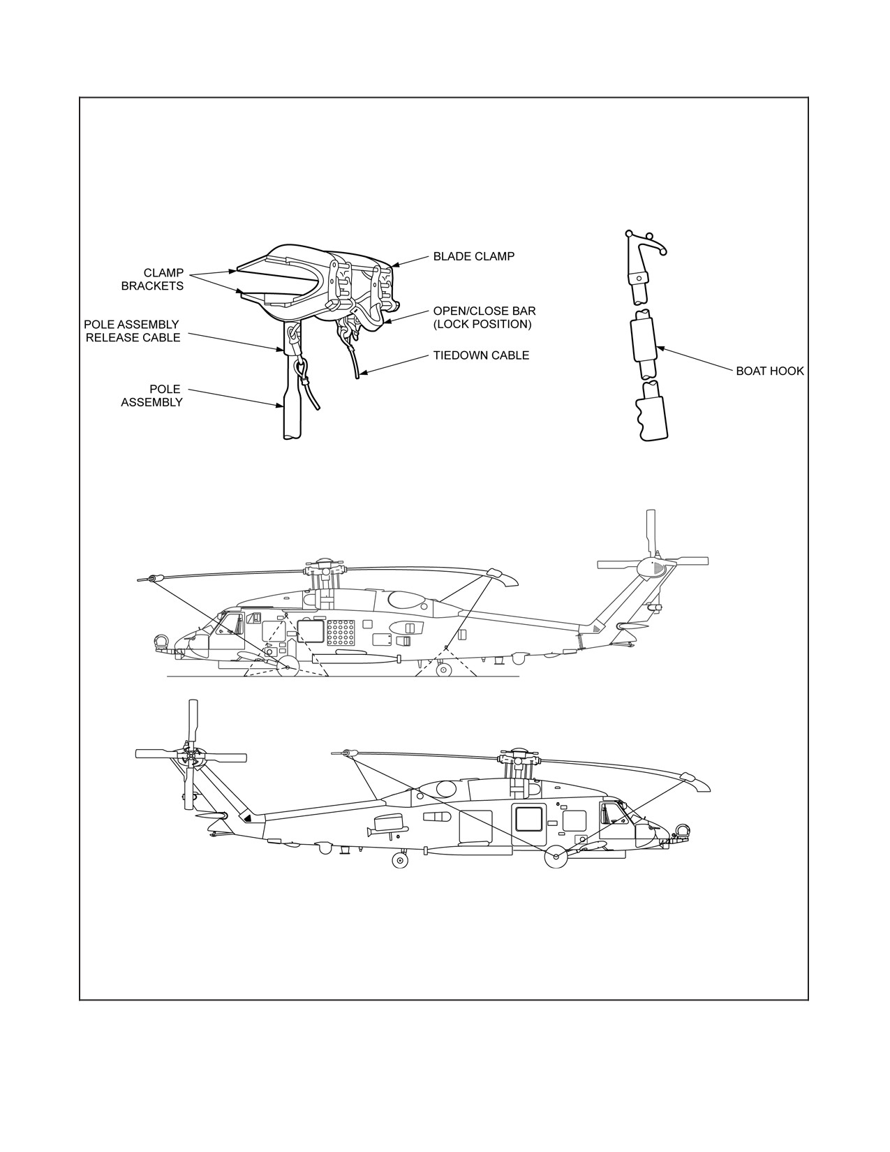
Figure 3-7. Helicopter Tiedown Fittings
ORIGINAL
3-18
A1-H60BB-NFM-000
3.13.1.2 Main Rotor Tiedown
To tie down the Main Rotor Blades in the spread position, do the following:
1. Attach tiedown ropes to blade clamps.
CAUTION
The use of blade boots is NOT authorized. Blade tiedowns may be used
ONLY with the approved blade clamp.
2. Place blade clamps on blades approximately 2 1/2 feet inboard of the blade tip.
3. Turn rotor head to position blades to approximately a 45° angle to centerline of helicopter and engage rotor
brake.
CAUTION
To prevent damage to blades, do not deflect main rotor blade tips below
normal droop position when using tiedowns.
4. Attach tiedown ropes to helicopter as shown in Figure 3-7.
Note
Aft starboard rotor blade will be secured to the starboard main mount.
3.14
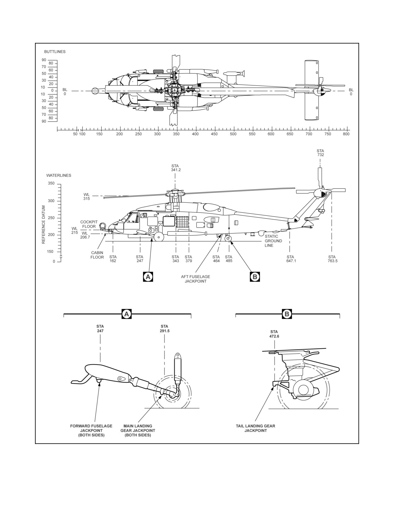
FUSELAGE STATIONS AND JACK POINTS
To assist in locating, dimensioning, and referring to items of structure and equipment, a system of numbering
structural stations is used (Figure 3-8). Those structural stations are the number of inches from a reference datum
located ahead of the nose and designated station “0.” Vertical measurements in inches are referenced to “water line”
positions, again referenced to a datum below the aircraft designated “0.” Horizontal positions are also measured in
inches left or right of the aircraft “butt line” (centerline), which is designated “0.” Jack pads are fittings attached to
the helicopter structure which are used as jack points. There are six jack points on the helicopter: two at the tail wheel
and two at each main landing gear. When landing gear jacking is required, a 5 ton minimum capacity jack shall be
used. When helicopter jacking is required using the three fuselage jack points, three12 ton minimum capacity tripod
jacks shall be used.
3-19
ORIGINAL
A1-H60BB-NFM-000
Figure 3-8. Fuselage Stations and Jack Points
ORIGINAL
3-20
A1-H60BB-NFM-000
CHAPTER 4
Helicopter Operating Limitations
4.1
GENERAL
This chaptercovers all important operatinglimits andrestrictions tobeobservedduring groundand flightoperations.
Limitations in this part are the direct results of design analysis, tests, and operating experience. Compliance with
these will allow the pilot to perform the assigned missions safely and to derive maximum use from the helicopter.
4.1.1 Exceeding Operational Limits
Any time an operational limit is exceeded, an appropriate entry shall be made on a visual discrepancy
system/maintenance action form (VIDS/MAF). Entry shall state what limit or limits were exceeded, range, time
beyond limits, and any additional data that would aid maintenance personnel in the inspection that may be required.
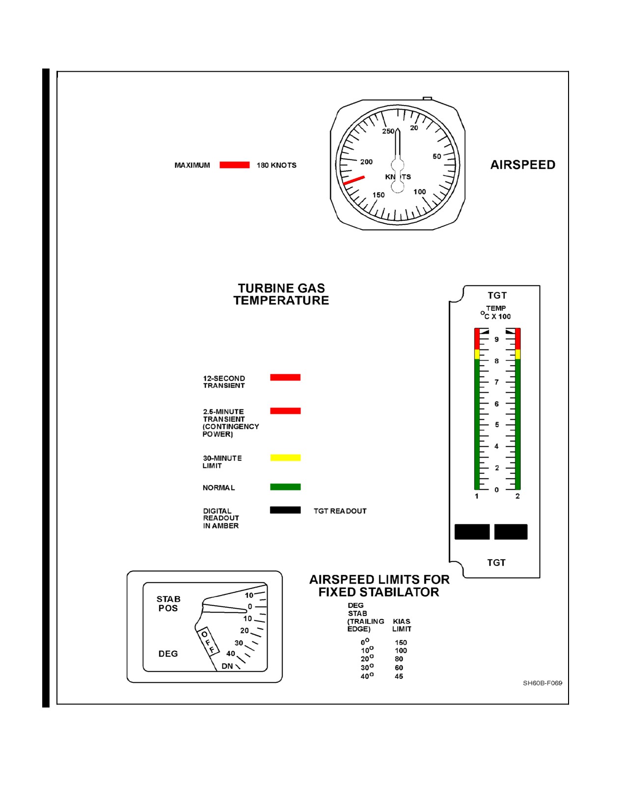
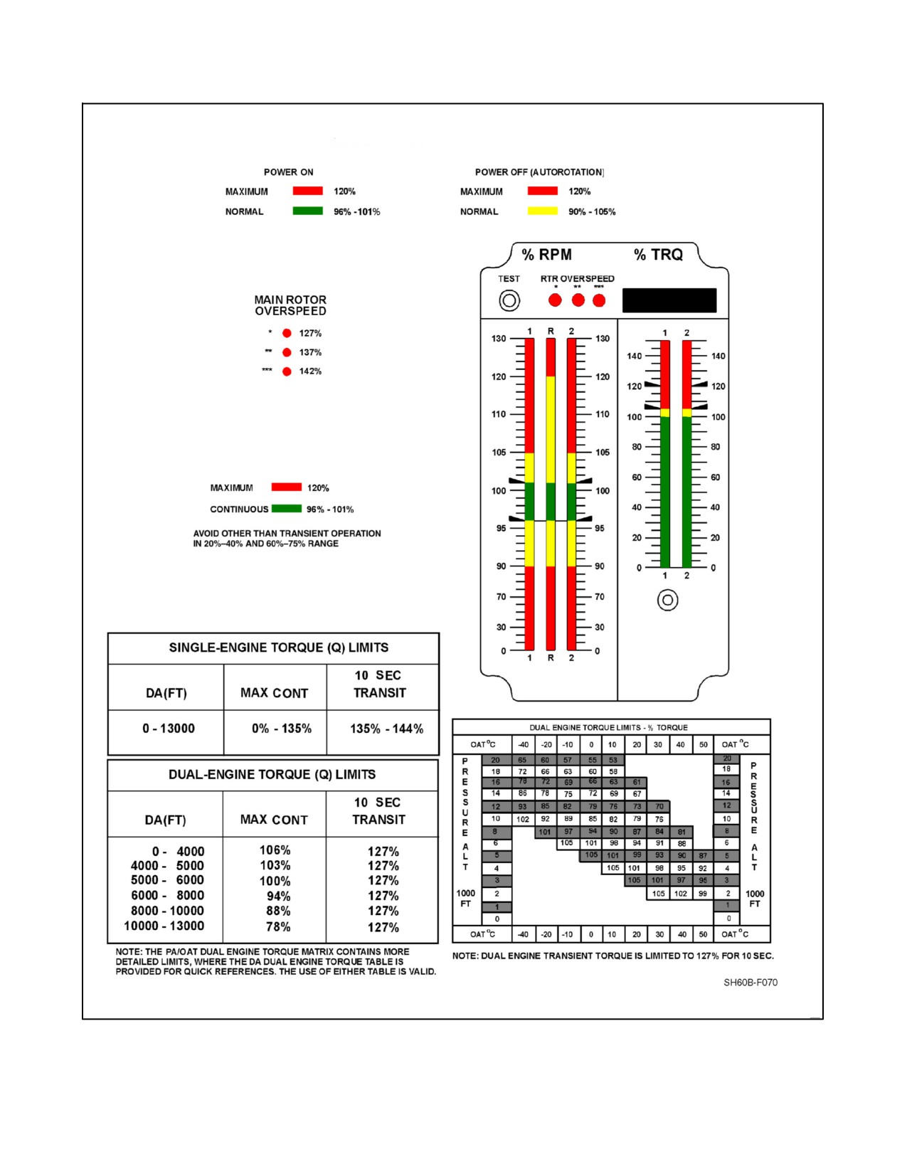
4.1.2 Instrument Range Markings
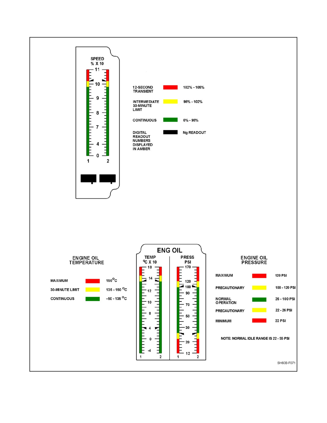
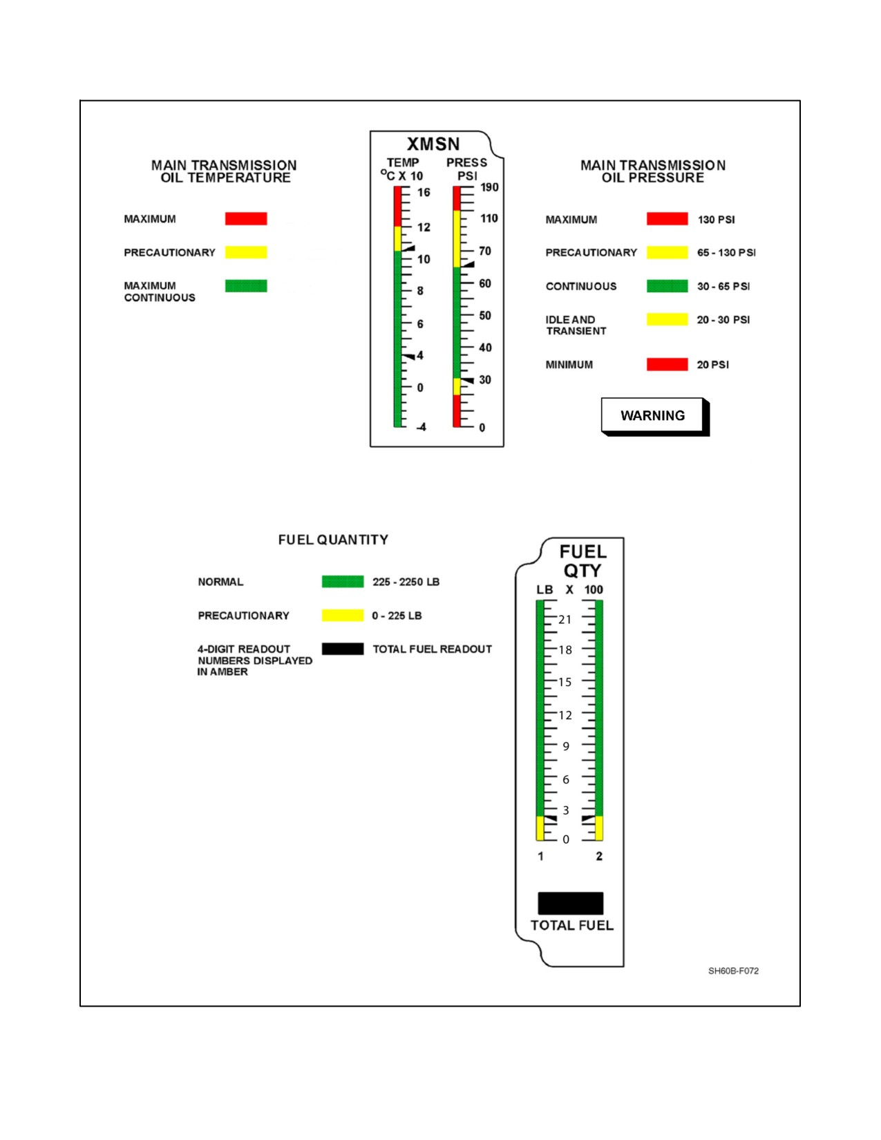
Operating limitations and ranges are illustrated by colored strips located on the instrument faces of engine, flight,
and utility-system instruments (Figure 4-1). RED markings indicate the limit at which continued operation (above
or below as appropriate) is likely to cause damage or shorten component life. GREEN indicates the normal or safe
range of operation. AMBER markings indicate the range when special attention should be given to the operation
covered by the instrument. Operation is permissible in the yellow range, but it is generally time limited.
CAUTION
Operation of the T700-GE-401C engine within the yellow light region of
the VIDS may be limited to 2.5 minutes and operation below the high
temperature level displayed on the VIDS may result in engine overtempera-
ture. Operating temperature limits must be monitored on the digital
readout.
Scales with green-coded light segments and amber-coded or red-coded segments above the green-coded segments
operate in this manner: The segments will light in normal progression and remain on as the received-signal level
increases. Those scales will go off in normal progression as the received-signal level decreases. Scales with red-coded
and/or amber-coded segments below the green-coded segments operate in this manner: When the received signal is
zero or on the bottom scale, the segments will light in a normal progression and will remain on. When the first segment
above the red or amber range goes on, all red-coded or amber-coded segments will go off. These segments will remain
off until the received-signal level indicates a reading at or within the red or amber range. At that time, all red-coded
or amber-coded segments will go on and the scale display will either go on or offin anormal progression, depending
upon the received-signal level. For an increasing indication, using a scale with side arrows, the following applies:
When the first segment for which there is an associated side arrow lighting lights, the corresponding side arrow also
lights. As thesegments go on, thecorresponding arrows will also go on, one at a time. Only theside arrow associated
with the highest percent indication of the corresponding scale will be on.
4-1
ORIGINAL
A1-H60BB-NFM-000
DECU TGT Limiting:
Normal conditions: 839 °C ±10°
With Contingency Power: 891 °C ±10°
903 - 949 °C
851 - 903 °C
810 - 851 °C
0 - 810 °C
Figure 4-1. Instrument Range Markings (Sheet 1 of 4)
ORIGINAL
4-2
A1-H60BB-NFM-000
MAIN ROTOR Nr (% RPM)
ENGINE Np (% RPM)
Figure 4-1 Instrument Range Markings (Sheet 2)
4-3
ORIGINAL
A1-H60BB-NFM-000
Ng
ENGINE Ng (% RPM)
Ng
Figure 4-1 Instrument Range Markings (Sheet 3)
ORIGINAL
4-4
A1-H60BB-NFM-000
120 °C
105-120 °C
105 °C
FORWARD FLIGHT STEADY STATE OIL
PRESSURE SHALL BE 45 TO 60 PSI.
Figure 4-1 Instrument Range Markings (Sheet 4)
4-5
ORIGINAL
A1-H60BB-NFM-000
4.2
SYSTEM LIMITATIONS
4.2.1 Engine Limits
Limits presented in Figure 4-1 represent absolute limitations, regardless of atmospheric conditions. For variations
in power available with temperature and pressure altitude, refer to Figures 4-4, 4-5, and 4-6.
4.2.2 Engine Temperature Limitations
1. Refer to Figure 4-1 for limitations.
2. The following situations can result in overtemperature:
a. Advancing ENG POWER CONT lever to IDLE with TGT above 80 °C.
b. Starter dropout prior to reaching lower starter cutout speed of 52 percent Ng.
c. Operation in DECU LOCKOUT.
d. Crossbleed starts with less than 90 percent Ng on operating engine.
e. Compressor stalls.
4.2.3 Engine Starter Limits
A start cycle is defined as starter initiation, acceleration ofthe output drive, and starter dropout. The 60-second delay
between start attempts is required any time a start is aborted, except in emergencies. The engine starter limits as shown
in Figure 4-2.
AMBIENT TEMPERATURE (°C)
STARTER ON
STARTER OFF
LESS THAN 16
First Cycle
60 Seconds
Second Cycle
60 Seconds
Third Cycle
60 Seconds
Fourth Cycle
30 Minutes
16 TO 52
First Cycle
60 Seconds
Second Cycle
30 Minutes
ANY TEMPERATURE
2 Minutes
5 Minutes
(MOTORING/IGNITION OFF)
2 Minutes
30 Minutes
Note
Times for motoring are cumulative times within a 5-minute period.
Figure 4-2. Engine Starter Limits
4.2.4 Engine Start Limits
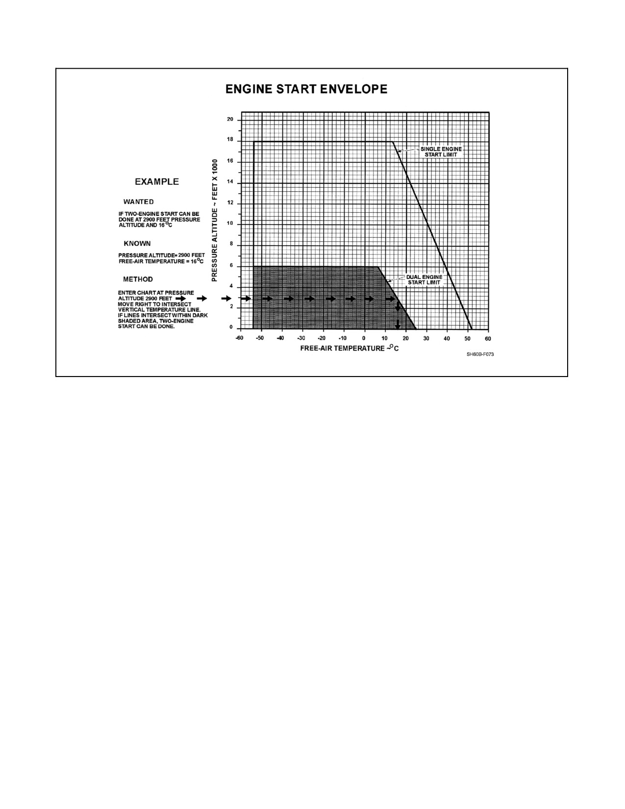
1. Single-engine starts using APU source may be attempted within the ambient conditions shown in Figure 4-3.
When crossbleed starts are attempted, the operating engine must be operating at or above 94 percent Ng and
rotor speed must be 99 to 101 percent Nr. Dual-engine starts using APU source may be attempted when within
the range of outside air temperature (OAT) and pressure altitude of Figure 4-3.
2. Engine start with main rotor blades or tail pylon folded is prohibited.
4.2.5 Engine Idle Limits with Gust Lock Engaged
Engine operating with gust lock engaged is prohibited.
4.3
TRANSMISSION AND ROTOR LIMITS
4.3.1 Main Transmission Module Limitations
The transmission is limited in rpm, torque, oil pressure, and temperature. Operation is governed by whichever is
reached first. If transmission oil pressure and/or temperature is in the precautionary range (amber), the helicopter shall
not be scheduled for additional flights until maintenance action is taken. (Refer to Figure 4-1 for limitations.)
ORIGINAL
4-6
A1-H60BB-NFM-000
Figure 4-3. Engine Start Envelope
Main gearbox torque limitations for maximum service life under steady-state conditions are indicated by the range
markings on the torquemeter; however, transient conditions in excess of the red line may occur during normal
operations. Main gearboxes operated in excess of limits must be inspected by an overhaul facility.
Atransientconditionishereindefinedasatemporarytorquemeterreadingaboveredline.Unlessotherwiseindicated,
all torques referred to are matched engine torques.
Note
Prolonged hovering flight in hot weather 95 °F (35 °C) and higher gross
weight may cause temperatures to rise in the yellow precautionary range.
Hovering operations in the precautionary range for less than 30 minutes in
any one flight under those conditions is considered normal.
4.3.2 Transmission Oil Pressure Limitations
Momentary fluctuations in transmission oil pressure may occur during transient maneuvers (i.e., pitch pulse during
normal hover to check AFCS response or hover in gusty wind conditions), autorotations, or steady noseup hover.
These fluctuations, including momentary drops into the yellow (below 30 psi), and transient drops not to exceed 1
second below 20 psi, are acceptable. The main transmission may be operated up to 30 minutes at a time with pressure
fluctuations when the aircraft is known to be in a noseup attitude (slope landings or hover with extreme aft cg). In
forward flight steady-state conditions, the transmission pressure shall be in the 45 to 60 psi range; fluctuations or
pressure below 45 psi under these conditions requires maintenance action.
4.3.3 Rotor Start and Stop Limits
Maximum wind velocity for rotor start or stop is 45 knots from any direction.
4-7
ORIGINAL
A1-H60BB-NFM-000
4.3.4 Rotor Overspeed
All rotor overspeeds in excess of 120 percent Nr shall be reported on VIDS/MAF. (Refer to Figure 4-1 for additional
overspeed limits.)
4.4
AERODYNAMIC LIMITATIONS
4.4.1 Airspeed Operating Limits
The maximum (redline) airspeed limit is 180 KIAS. Figure 22-3 presents the maximum airspeed as limited by blade
stall. Other airspeed limits are:
1. Maximum airspeed for autorotation is 100 KIAS.
2. Maximum airspeed with one engine inoperative is 150 KIAS.
3. Sideward/rearward flight limit is 35 knots.
4. When stability augmentation system SAS-1 and SAS-2 are inoperative in instrument meteorological
conditions (IMC), the limit is 125 KIAS.
5. When two hydraulic systems are inoperative in IMC, the limit is 125 KIAS.
6. Boost servo off limit is 140 KIAS in VMC, 125 KIAS in IMC.
7. Opening or closing cabin door limit is 60 KIAS.
8. Operation of windshield wipers limit is 130 KIAS.
CAUTION
At airspeeds of 130 KIAS and above, wipers can freeze in position with
motor running, even in heavy precipitation. This condition can result in
overheating of the wiper motor presenting a possible fire hazard.
4.4.2 Controllable Searchlight Airspeed Limits
1. When the searchlight is fixed in any position other than stowed, maximum forward airspeed is limited to
160 KIAS.
2. The maximum forward airspeed to move the searchlight is 100 KIAS.
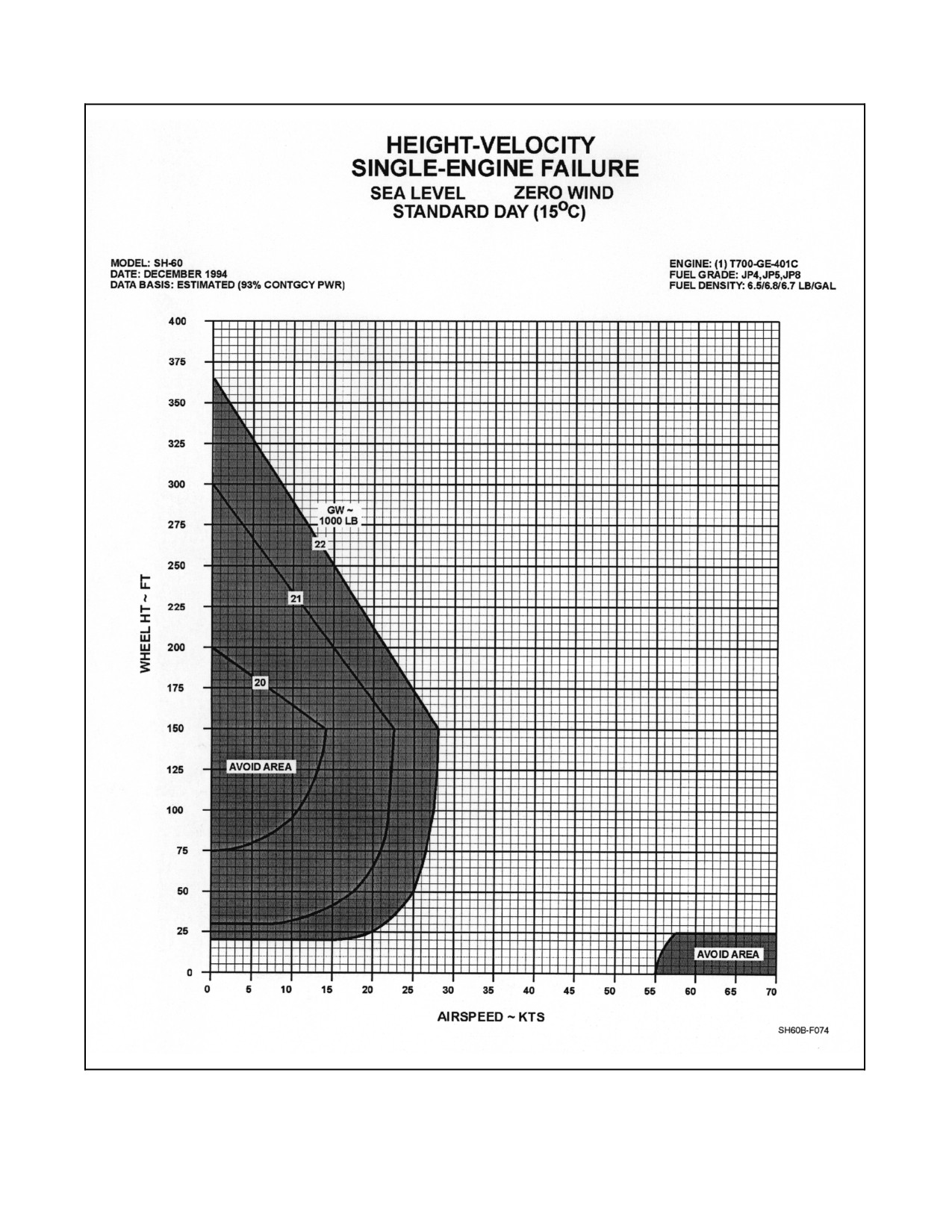
4.4.3 Minimum Height for Safe Landing After Single- or Dual-Engine Failure
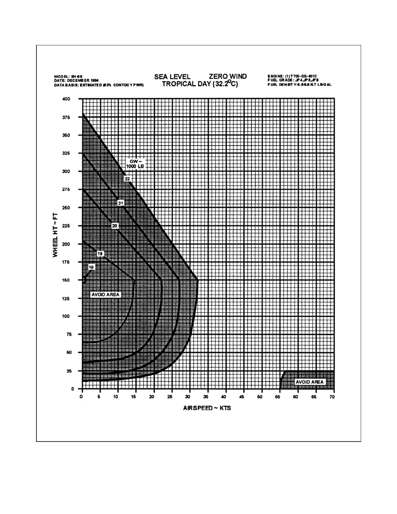
TheHeight-Velocity diagrams (Figure 4-4) show the combinations of speed and wheel height that should beavoided
during normal operations to provide for safe landing if single- or dual-engine failure should occur.
ORIGINAL
4-8
A1-H60BB-NFM-000
Figure 4-4. Height-Velocity Diagrams (Sheet 1 of 3)
4-9
ORIGINAL
A1-H60BB-NFM-000
Height-Velocity, Single-Engine Failure, Tropical
Figure 4-4. Height-Velocity Diagrams (Sheet 2)
ORIGINAL
4-10
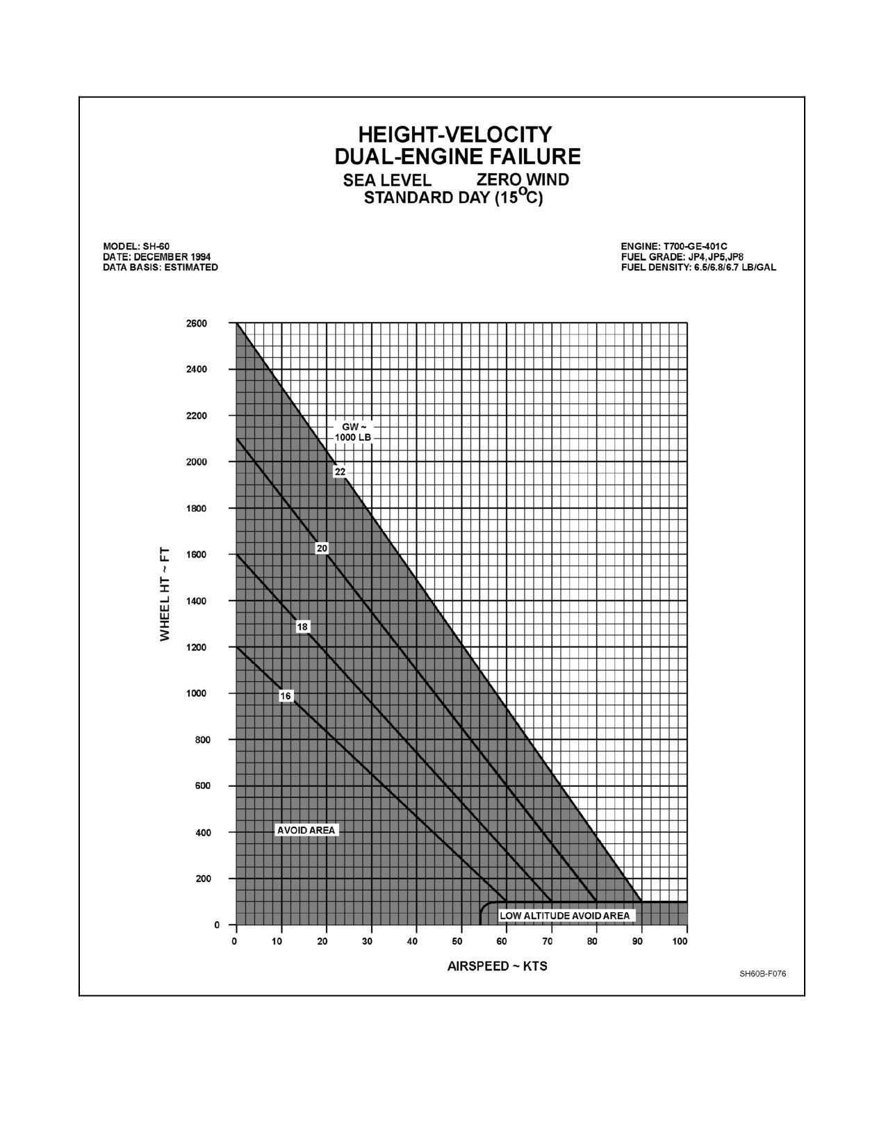
A1-H60BB-NFM-000
Figure 4-4. Height-Velocity Diagrams (Sheet 3)
4-11
ORIGINAL
A1-H60BB-NFM-000
4.4.4 Autorotation
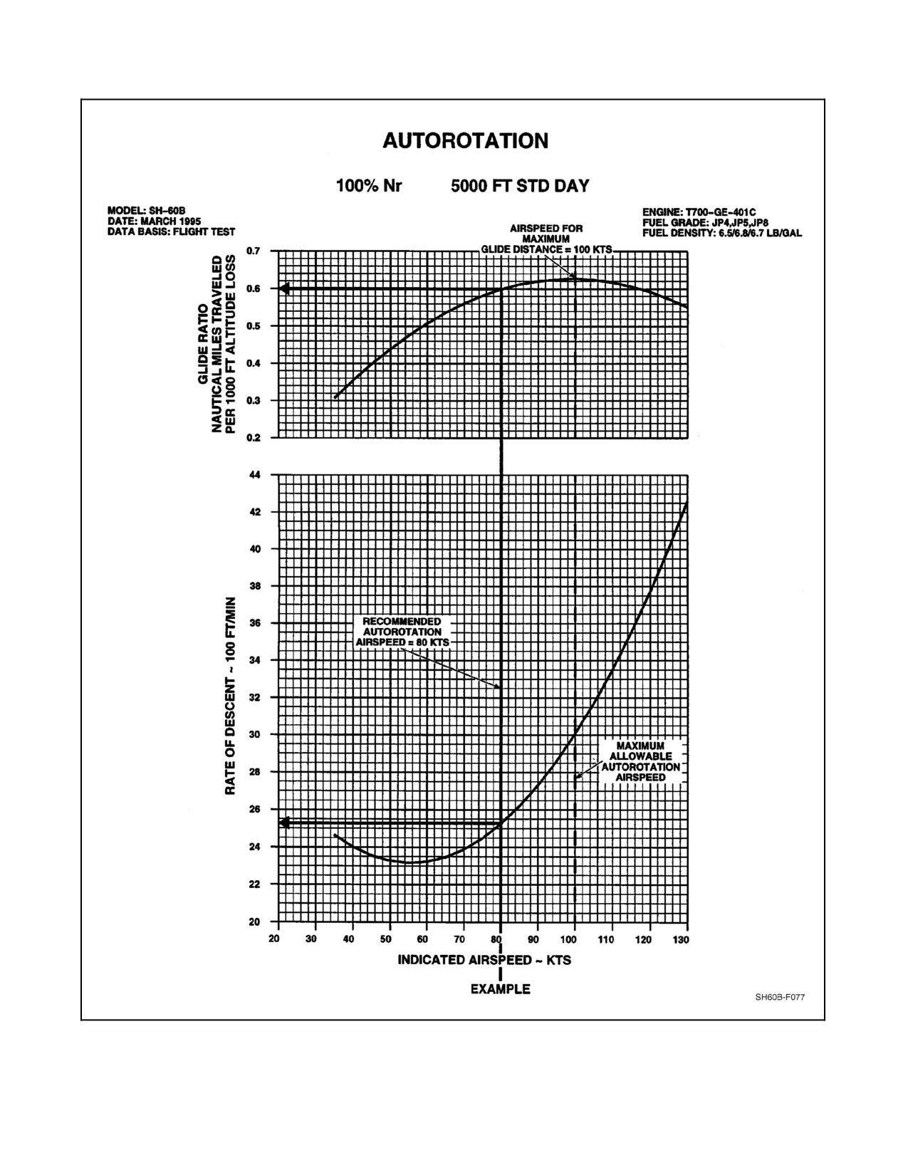
The Autorotation Chart (Figure 4-5) provides rates of descent and glide ratio in nautical miles per 1,000 feet of
altitude loss. Airspeeds for maximum glide distance, maximum glide time, minimum rate of descent, and maximum
allowable autorotation airspeed can be extracted from this chart.
4.5
MANEUVERING LIMITATIONS
Main rotor blade stall is indicated by an increase in 4-per-revolution vibrations and shall be avoided by adhering to
theAirspeed forOnset ofBladeStall Chart (Figure 22-3). This chart is valid only within the guidelines of bladestall,
Chapter 11.
4.5.1 Limitations for Maneuvering with Sling Loads
Refer to Figure 4-6.
4.5.2 Limitations for Maneuvering with Rescue Hoist Loads
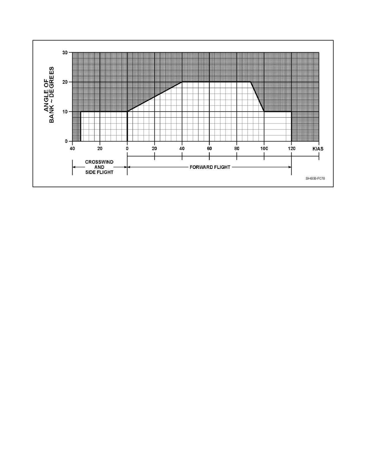
Maneuvering limitations with a rescue hoist load are limited to a maximum of 20° angle of bank in forward flight
(Figure 4-6). Sideward flight is limited by bank angle and is decreased as airspeed is increased. Rate of descent is
limited to 1,000 feet per minute.
4.5.3 Bank Angles Limitation
Bank angles shall be limited to a maximum of 45° in normal operations, 30° when one PRI SERVO PRESS or
BOOST SERVO OFF caution light is on, or above 10,000 feet density altitude.
4.5.4 Hovering
Prolonged rearward flight and downwind hovering should be avoided to prevent accumulation of exhaust fumes in
the helicopter and heat damage to window on the open cargo door. Prolonged hovering in 20-knot, right-side wind
should be avoided.
4.5.5 Altitude Limitation
Maximum operating density altitude is 13,000 feet.
4.5.6 Prohibited Maneuvers
The following maneuvers are prohibited:
1. Aerobatic flight (e.g., rolls, loops, inverted flight).
2. Abrupt movement of the flight controls.
3. Bank angles greater than 45°.
4. Hovering turns at a rate in excess of 30° per second.
5. Practice full-autorotation landings.
6. Practice autorotation descents below 500 feet AGL and less than 40 KIAS over unprepared or rough terrain.
7. Intentional approaches to or inducement of retreating blade stall.
ORIGINAL
4-12
A1-H60BB-NFM-000
Figure 4-5. Autorotation
4-13
ORIGINAL
A1-H60BB-NFM-000
Figure 4-6. Sling/Rescue Hoist Load Maneuvering Limits
4.6
MISCELLANEOUS LIMITS
4.6.1 MAD Reeling Machine Operating Limits
The reeling machine duty cycle is 2 minutes operating and 15 minutes nonoperating.
1.
MAD envelope:
a. Altitude: 200 feet AGL minimum
b. Deployment (cable payout):
Climb — 1,000 fpm; Descent — 0 fpm
Bank Angle — 0°
Airspeed — 40 to 90 KIAS.
2.
Retrieval/docking:
a. For up to last 12 feet of cable: 40 to 90 KIAS in level flight. For last 12 feet of cable: 50 to 55
KIAS in level
flight.
3.
At full trail position:
a. Straight and level — 40 to 150 KIAS.
b. Level turns — Up to 45° angle of bank and between 40 to 120 KIAS.
c. Descents — 80 to 100 KIAS at up to 2,400 fpm.
d. Climbs — 80 to 100 KIAS up to max climb rate.
4.
Recommended jettisoning profile — Straight and level, 0 to 60 KIAS.
4.6.2
Stores Limits
1.
Release of the Mk 46 Torpedo (Mod 5, 5A, and 5A(S)) from the starboard pylon when the MAD is deployed
is restricted to 80 KIAS.
2.
Do not exceed the maximum sonobuoy launcher load weight of 800 pounds.
ORIGINAL
4-14
A1-H60BB-NFM-000
3. Minimum altitude for employment of sonobuoys is 100 feet AGL below 100 knots, or 150 feet AGL above
100 knots.
4. Minimum pressure to jettison all sonobuoys is 900 psi.
4.6.3 Rotor Brake Operating Limits
Maximum rotor speed for rotor brake application is 76 percent Nr. Routine rotor stops shall be done between
30 percent and 50 percent Nr. Routine rotor brake stops should be limited to 180 psi for extended rotor brake life.
4.6.4 Blade, Pylon/Stabilator Fold or Spread
Bladesshouldnotbefoldedorspreadinwindsofover45 knots fromany direction.Allow a10-minutecoolingperiod
between a blade fold and spread evolution before recycling the blade-fold motors. Tail pylon/stabilator fold and
spread operations are limited to a maximum windspeed of 45 knots.
4.6.5 Landing Limitations
Downwind landings should be avoided. Water landings are not permitted, except in an emergency. The following
limitations apply:
1. Maximum rate of descent (sink rate) for level terrain shall not exceed 720 fpm (12 ft/s).
2. Maximum rate of descent for sloped terrain shall not exceed 360 fpm (6 ft/s).
3. Maximum forward touchdown speed shall not exceed 75 knots groundspeed, tail wheel locked, 20 knots with
tail wheel unlocked.
4. Landing gear limitations: Maximum ground taxi speed is limited to 40 knots with aircraft equipped with tail
gear shimmy damper, 20 knots for aircraft without shimmy damper.
5. Slope landing limitations: The following apply regardless of gross weight or cg:
a. 9° noseup slope
b. 6° nosedown slope
c. 12° cross slope.
4.6.6 Shipboard Wind Limitations
Wind limitations for shipboard operation are defined in the Pilot’s Pocket Checklist (NAVAIR Al-H60BB-NFM-500)
and Helicopter Operating Procedures for Air-Capable Ships NATOPS Manual NAVAIR 00-80T-122.
4.6.7 Emitter Hazard and Standoff Distances
See Chapter 8 for emitter hazards and standoff distances.
4.7
WEIGHT LIMITATIONS
4.7.1 Weight Limits
The maximum gross weight of the helicopter is 21,700 pounds. The maximum gross weight internal load limit is
20,800 pounds. Maximum cargo floor loading is 225 pounds/square foot.
4.7.2 Center of Gravity Limitations
To ensure adequate control, the helicopter shall be loaded so that the center of gravity is between stations 346.8 and
364.0. Above 19,462 pounds gross weight, the center of gravity station limitations decrease with increasing weight.
For a chart of these limitations and information on how to determine the center of gravity for any load condition, refer
to the Weight and Balance Manual (NAVAIR 01-1B-40).
4.7.3 Cargo Hook Weight Limitation
The maximum weight that may be suspended from the cargo hook is limited to 6,000 pounds.
4-15
ORIGINAL
A1-H60BB-NFM-000
4.7.4 Rescue Hoist Weight Limitations
The maximum weight that may be suspended from the rescue hoist is 600 pounds.
4.8
MINIMUM EQUIPMENT
An MPD should be installed and functional at the sensor operator’s station for the following operations and/or
environments:
1. Unaided night flights without a visible horizon.
2. Any shipboard environment or operation.
3. AH/DM flights.
4.8.1 Minimum Equipment for Passengers
Flight without a functional seat for each occupant is prohibited, except in emergency situations.
4.8.2 Minimum Aircraft Equipment for Flights Into Forecast or Known Icing Conditions
All installed anti-ice/de--ice equipment (windshield, engine, rotor) shall be operational prior to flight. Refer to
Chapter 14 for specific information on flight in icing conditions.
Helicopters without blade de--ice equipment are prohibited from flight into icing conditions (ambient temperatures
of +5 °C or below in visible moisture).
Helicopters equipped with operable anti-ice/de--ice equipment are permitted flight into forecast or known trace or
light icing conditions.
Flight into forecast or known moderate or severe icing conditions is
prohibited.
4.8.3 Flight in Instrument Meteorological Conditions
The SH-60B is qualified for flight in instrument meteorological conditions (IMC).
4.8.3.1 Minimum Aircraft Equipment for Night or IMC Flight Over Land
1. Flight instruments:
a. Pilot and ATO attitude indicators
b. All pitot-static instruments (airspeed, vertical speed indicator (VSI), barometric altimeter (BARALT))
c. Pitot heat
d. One turn rate gyro
e. Pilot and ATO turn and slip indicators
f. One compass system
g. Standby compass with current calibration card
h. Radar altimeter
i. Clock.
2. All engine and transmission instruments
ORIGINAL
4-16
A1-H60BB-NFM-000
3. Adequate instrument, navigation, landing, cockpit, and cabin lighting
4. Radio equipment:
a. (1) UHF
b. ICS, all crewmembers
c. IFF, as required by Air Traffic Control (ATC) regulations.
5. Navigation systems:
a. NSIU
b. TACAN.
6. SAS-2, trim, autopilot
7. Two generators operable.
4.8.3.2 Minimum Aircraft Equipment for Night or IMC Flight Over Water
In addition to the equipment listed under paragraph 4.8.3.1, the following equipment is required:
1. One of the following navigation systems must be operable:
a. Aircraft search radar
b. Tactical navigation system (SAC-1)
c. UHF/DF
d. Shipboard air search radar
2. Doppler (night SAR only)
3. Altitude hold (RADALT or BARALT).
4.9
ENVIRONMENTAL RESTRICTIONS
4.9.1 Temperature Limitations
Operations at temperatures below --40 °C (--40 °F) or above +60 °C (+140 °F) are prohibited.
4.9.2 Engine and Engine Inlet Anti-Ice Limitations
At engine power levels of 10 percent torque per engine and below, full anti-ice capability cannot be provided, due
to engine bleed limitations. Avoid operation under conditions of extreme low power requirements such as high rate
of descent (1,900 fpm or greater), or ground operation below 100 percent Nr, during icing conditions.
4.9.3 Backup Hydraulic Pump Hot Weather Limitations
Operation of the backup pump, without rotors engaged, is limited when OAT is +33 °C and above as depicted in
Figure 4-7. Limits do not apply to operation with rotors engaged.
OPERATING TIME
COOLDOWN TIME
OAT (°C)
(MINUTES)
(MINUTES)
+33 to +38
24
72
+39 and above
16
48
Figure 4-7. Backup Pump Limits
4.9.4 APU Operating Limitations
To prevent APU overheating, APU operation at ambient temperature of 43 °C and above with engine and rotor
operating is limited to 30 minutes. With engine and rotor not operating, the APU may be operated continuously up
to an ambient temperature of 51 °C.
4-17/(4-18 blank)
ORIGINAL
A1-H60BB-NFM--000
PART II
Indoctrination
Chapter 5 — Aircrew Training, Qualifications, and Requirements
57/(58 blank)
ORIGINAL
A1-H60BB-NFM-000
CHAPTER 5
Aircrew Training, Qualifications,
and Requirements
5.1
FLIGHTCREW QUALIFICATIONS
5.1.1 Qualifications
All aircrew meeting the following minimum qualifications are subject to NATOPS evaluation checks in the SH--60B.
5.1.2 Waiver of Requirements
Squadron Commanding Officers are authorized to grant written waivers of flight and/or training requirements when
an individual’s experience warrents such action.
5.2
PILOT QUALIFICATIONS
Pilots shall bedesignated in writing by thecommanding officerin accordancewith OPNAVINST 3710.7 (series)and
this manual. Pilots shall be designated using the following classifications: H--60 Pilot Qualified in Model, SH--60B
Helicopter Second Pilot, SH--60B Helicopter Aircraft Commander, and SH--60B Functional Checkflight Pilot.
Tactical/mission qualifications shall be attained per applicable instructions.
5.2.1 H--60 Pilot Qualified in Model
In addition to completing the requirements specified in OPNAVINST 3710.7 (series) for personnel authorized to pilot
naval aircraft, an H--60 Pilot Qualified in Model (PQM) shall:
1. Satisfactorily complete an H--60 Fleet Replacement Squadron (FRS) syllabus or other CNO--approved
training syllabus for qualification as an H--60 PQM.
5.2.2 SH--60B Helicopter Second Pilot (H2P)
In addition to the requirements set forth for an H--60 PQM, an SH--60B Helicopter Second Pilot (H2P) shall:
1. Meet the requirements for H2P specified in OPNAVINST 3710.7 (series).
2. Satisfactorily complete an SH--60B Fleet Replacement Squadron (FRS) syllabus or other CNO--approved
training syllabus.
3. Satisfactorily complete an approved SH--60B H2P syllabus.
5.2.3 SH--60B Helicopter Aircraft Commander
In addition to completing the requirements set forth for an SH--60B H2P, an SH--60B Helicopter Aircraft Commander
(HAC) shall:
1. Meet the requirements for HAC specified in OPNAVINST 3710.7 (series).
2. Satisfactorily complete an approved SH--60B HAC PQS syllabus.
Note
Prior SH--60B HACs are not required to complete applicable H2P syllabus.
5-1
ORIGINAL
A1-H60BB-NFM-000
5.2.4 SH--60B Functional Checkflight Pilot
In addition to completing the requirements set forth for an SH--60B HAC, an SH--60B Functional Checkflight Pilot
(FCP) shall:
1. Complete a squadron SH--60B FCP indoctrination program.
2. Be designated in writing by the Commanding Officer.
5.2.5 Airborne Tactical Officer
An ATO shall:
1. Satisfactorily complete an approved FRS SH--60B Airborne Tactical Officer (ATO) training syllabus or an
approved equivalent.
2. Have 30 ATO hours in model and series or in an approved tactical trainer.
3. Satisfy all minimum qualification requirements set forth for pilot qualification in model.
5.2.6 NATOPS Instructor/Assistant NATOPS Instructor
In addition to the requirements set forth for HAC, a NATOPS Instructor/Assistant NATOPS Instructor (NI/ANI)
shall:
1. Complete a squadron NI/ANI indoctrination program.
2. Participate in a TYCOM NATOPS evaluator standardization program where applicable.
3. Be designated in writing by the Commanding Officer.
5.2.7 Night Vision Device Pilot
1. Satisfy all minimum requirements set forth for PQM.
2. Satisfactorily complete a Type--Wing approved Night Vision Device (NVD) Pilot Syllabus.
5.2.8 Night Vision Device Pilot Instructor
1. Satisfy all minimum requirements set forth for PQM.
2. Satisfactorily complete a Type--Wing approved NVD Instructor Pilot Syllabus.
5.2.9 Minimum Pilot Currency Requirements
An SH--60B pilot must meet the following minimum requirements in order to be considered current in model:
1. Maintain a current NATOPS evaluation in model.
2. Maintain a current instrument rating in accordance with OPNAVINST 3710.7 (series).
3. Satisfy night and instrument minimum flying hours as set forth in OPNAVINST 3710.7 (series).
5.2.9.1 Pilot Currency Requirements
If currency has lapsed, currency shall be regained by the non--current pilot flying with a current HAC. At the
discretion of the Commanding Officer, two non--current HACs may fly together to regain currency.
5.2.9.1.1 Night Currency Requirements
To be considered current, pilots shall have flown 2 hours of night time within the past 45 days. If night currency
expires, pilots shall fly 2 hours of night time to regain currency. Unaided or aided night flight is considered night time.
5.3
PILOT SHIPBOARD QUALIFICATIONS
Pilots shall be familiar with the shipboard procedures contained in the CV NATOPS, LHA/LHD NATOPS, and NA
00--80T--122 publications. Initial qualification shall proceed in a build--up fashion. For initial qualification, day
operations shall precede night operations, and unaided operations shall precede NVD operations.
ORIGINAL
5-2
A1-H60BB-NFM-000
5.3.1 Shipboard Landing Qualifications
A DLQ evolution consists of flight at pattern altitude, and approach, a transition to a hover, a landing to a ship deck,
and a departure into the pattern again.
Note
Free deck (FD) landing refers to a landing into the RSD with main probe.
Recovery Assist (RA) landing refers to a landing using the RA cable and
RSD.ClearDeck(CD)landingrefers tolanding aboardeitheranon--RAST
ship or a RAST--equipped ship without utilizing any RAST system
features.
5.3.1.1 Initial Shipboard Landing Qualification
Initial landing qualification requirements are listed in Figure 5-1.
TYPE
DAY
NIGHT (unaided)
NVD
Aviation Ship
3
3
3
Air Capable Ship (clear deck)
6
6
6
Air Capable Ship (free deck)
6
6
6
Air Capable Ship (RA)
2
2
1
Note
D To facilitate completing RA/Free deck initial qualifications the approaches may be cut in half allowing one
approach and two landings.
D Free deck qualification confers clear deck qualification.
D Free deck landings in lieu of RA landings are not acceptable for initial qualification.
D Initial night landing qualification shall be preceded by one day landing within the previous six days.
D At least one RA landing shall consist of a full approach, hookup, hover tension, and landing sequence.
Figure 5-1. Initial Shipboard Landing Qualifications
5.3.1.2 Shipboard Landing Currency and Requalification Requirements
The minimum landing currencies for air capable ships and aviation ships are presented in Figure 5-2. If currency has
lapsed for more than 1 year, the requirements for the initial shipboard landing qualification shall be completed.
TYPE
DAY
NIGHT (UNAIDED)
NVD
Aviation Ship
2/365
2/90
2/90
Air Capable Ship (clear deck)
4/180
4/60
4/90
Air Capable Ship (free deck)
4/180
4/60
4/90
Air Capable Ship (RA)
1/180
1/60
1/90
Note
D Free deck qualification confers clear deck qualification.
D Free deck landings into the RSD are acceptable to maintain currency if RA cable is not available.
D During requalification, night and/or NVD qualification confers day qualification, and air capable ship
qualification confers aviation ship qualification.
Figure 5-2. Shipboard Landing Currency Requirements (Number of DLQ Evolutions
Required/Currency Duration in Days)
5-3
ORIGINAL
A1-H60BB-NFM-000
5.3.2 Pilot VERTREP Qualifications
5.3.2.1 Initial VERTREP Qualification
Initial VERTREP qualification should be attained via a CNO--approved syllabus in the FRS.
5.3.2.2 Shipboard VERTREP Currency and Requalification Requirements
To maintain shipboard VERTREP currency, a pilot shall have completed:
1. Four day shipboard VERTREP evolutions within the last 365 days.
If currency has lapsed for more than 1 year, the requirements for initial VERTREP qualification shall be completed.
Note
During VERTREP requalification, night qualification confers day
qualification.
5.3.3 Landing Safety Officer (LSO)
5.3.3.1 LSO Initial Qualifications
Satisfy the following initial qualification requirements:
1. Straightening/Traversing: Four evolutions.
2. Recoveries:
a. RA — Five Day/five night.
b. FD into the RSD — Five Day/five night.
Note
Qualified personnel authorized to perform traverse operations shall
complete a squadron--approved training syllabus and be designated in
writing by the commanding officer.
5.3.3.2 LSO Currency/Requalification
Two day RA recoveries and two day free deck recoveries are required every 90 days to satisfy day currency
requirements. Two night RA recoveries and two night free deck recoveries are required every 90 days to satisfy night
currency requirements.
If currency expires, requalification shall consist of a minimum of six day and six night recoveries, three of each shall
be free deck into the RSD.
If an LSO has not maintained currency for 12 months or more, requirements for requalification shall be the same as
for initial qualification with the exception of straightening/traversing evolutions not being required. Free deck
landings into the RSD are acceptable as requalification or continuation of qualification if RA cable is not available.
Note
Satisfying night currency/requalification requirements fulfills day and
night currency/requalification requirements.
5.3.3.3 LSO Instruction
If all currency requirements are met, the LSO may act as safety observer to instruct trainees. The LSO acting as safety
observer will be credited for each type of evolution he/she instructs.
ORIGINAL
5-4
A1-H60BB-NFM-000
5.4
AIRCREWMAN QUALIFICATIONS
Helicopter aircrewman shall be qualified in accordance with OPNAVINST 3710.7 (series), NAVPERS INST,
TYPE/WING Commanderinstructions, andpertinent sectionsofthismanual. Allaircrew designationsshall bemade
by squadron Commanding Officers. All crewmembers meeting the following minimum qualifications are subject to
NATOPS evaluation checks in the SH--60B. Aircrewmen are eligible for the following designations once meeting
the listed requirements.
1.
Sensor Operator (SO) LEVEL I.
a. Satisfactorily complete either an approved FRS SH--60B aircrewman or CNO approved equivalent
syllabus.
b. Have a minimum of 50 flight hours actual or simulated experience as an SUW/ASW Sensor Operator.
c. Have a minimum of 20 flight hours actual experience in the SH--60B.
2.
Journeyman Sensor Operator (JSO) LEVEL II.
a. Successfully complete applicable SH--60B PQS or approved Type/Wing equivalent syllabus.
3.
Master Sensor Operator (MSO) LEVEL III.
a. Successfully complete applicable SH--60B PQS or approved Type/Wing equivalent syllabus.
4.
Instructor Sensor Operator (ISO) LEVEL IV.
a. Successfully complete applicable SH--60B PQS or approved Type/Wing equivalent syllabus.
5.
Aerial Door Gunner.
a. Successfully complete applicable SH--60B PQS or approved Type/Wing equivalent syllabus.
6.
Search and Rescue Aircrewman.
a. Be fully qualified as a search and rescue swimmer in accordance with OPNAVINST 3710.7 (series).
7.
Search and Rescue Medical Technician.
a. Be fully qualified Search and Rescue Medical Technician in accordance with OPNAVINST 3730.7 (series),
OPNAVINST 3130.6 (series), and NAVMEDCOMINST 1510.17 (series).
5.4.1
Special Mission/Lookout Non-Aircrewman Initial Qualification
Each squadron is allowed temporary non--crewmember flight orders (TFO) to permit non--SUW/ASW aircrewmen
(e.g., maintenance personnel) to fly as the commanding officer may direct.
1. Complete an approved squadron flight and ground training syllabus.
2. Fully qualify in:
a. Ground/line safety procedures.
b. ICS/radio voice procedures.
c. Lookout/safety procedures.
d. In--flight emergency procedures.
e. Refueling procedures.
f. Use of the pocket checklist.
3. Meet the requirements as set forth in NATOPS General Flight and Operating Instructions
(OPNAVINST 3710.7 series).
4. Log a minimum of 10 flight hours experience in SH--60B.
5. Satisfactorily complete an SH--60B NATOPS evaluation.
5-5
ORIGINAL
A1-H60BB-NFM-000
5.4.2 Night Vision Device (NVD) Aircrewman
1. Must satisfactorily complete a Type--Wing approved NVD Aircrewman Syllabus.
5.4.3 Night Vision Device (NVD) Aircrewman Instructor
1. Must satisfactorily complete a Type--Wing approved NVD Aircrewman Instructor Syllabus.
5.4.4 Aircrew Currency Requirements
Crewmembers meeting the requirements of OPNAVINST 3710.7 series and NTTP 3--50.1 will be considered current
in all respects.
5.4.4.1 Special Mission/Lookout Non-Aircrewman
1. Crewmembers shall meet the requirements of OPNAVINST 3710.7 series while assigned to temporary flight
duty.
2. A NATOPS evaluation will be administered if the individual is assigned temporary flight orders after aperiod
of 120 days or more on non--flight duty.
5.4.5 Qualified Observer
A qualified observer is an individual who has met all of the minimum aeromedical and survival requirements for
indoctrination flights set forth in NATOPS General Flight and Operating Instructions (OPNAVINST 3710.7 series)
and has been thoroughly briefed in accordance with Qualified Observer Brief in Chapter 6.
5.5
GROUND TRAINING REQUIREMENTS
The following minimum requirements are established for qualification in a non--tactical category. Additional
qualification requirements forSurfaceWarfare/Anti--SubmarineWarfare(SUW/ASW)tactical operation shall bethe
approved Fleet Readiness Squadron (FRS) Training Syllabus or an approved equivalent.
5.5.1 Flightcrew Ground Training
1. NAMTD Pilot’s Course (or equivalent).
2. Ground school syllabus.
3. Flight operation lectures.
4. Flight manual and ground school exams.
5.5.2 Aircrewman Ground Training
1. Ground school syllabus.
2. SH--60B familiarization lectures.
3. Helicopter safety and survival equipment.
4. Flight manual and ground school exams.
5.6
MINIMUM FLIGHTCREW REQUIREMENTS
The minimum flightcrew requirements for specific flights and missions are:
1. Non--tactical/Familiarization flights — Two H2Ps or one HAC and a qualified observer.
2. Functional checkflights — One FCP, one qualified observer, and one aircrewman or TFO crewmember.
3. Orientation flights — One HAC, one qualified observer, and one aircrewman.
ORIGINAL
5-6
A1-H60BB-NFM-000
4. Utility missions (passenger and cargo transport, ferry flights, etc.) — One HAC, one PQM, and one utility
aircrewman.
5. SAR missions (One HAC, one PQM, one SH--60B aircrewman, and one H--60 rescue swimmer).
Note
Squadron commanding officers are authorized to grant waivers of aircrew
qualification requirements when the experience of the individual warrants
such action.
5.6.1 SUW/ASW Operational Missions
One HAC, one ATO, and one SUW/ASW sensor operator.
5.6.2 Flights from Air--Capable Ships
Day, VMC — Two H2Ps and one helicopter aircrewman; or one HAC, one qualified observer, and one helicopter
aircrewman.
Night or IMC — One HAC, one PQM, and one helicopter aircrewman.
5.6.3 Instrument Flight
Flightcrew for planned instrument flight shall consist of one HAC and one Designated Naval Aviator (DNA) or two
H2Ps. Flights in which IMC conditions are simulated through visually restrictive devices shall include a qualified
observer in the cabin area. All pilots must hold a valid instrument rating with the exception of the DNA who is
receiving instrument refresher training, or if on an instrument check flight.
5.7
RECOMMENDED REQUIREMENTS FOR TRANSITIONING NAVAL AVIATORS
The requirements for transitioning of non--helicopter designated pilots shall be governed by the provision of
NATOPS General Flight and Operating Instructions (OPNAVINST 3710.7 series).
5.8
PERSONAL FLYING EQUIPMENT REQUIREMENTS
Flight personnel shall be familiar with and utilize those items of flight clothing and survival and rescue equipment
as prescribed in the current NATOPS General Flight and Operating Instructions (OPNAVINST 3710.7 series). In
addition, the pilot in command of an aircraft engaged in carrying crewmen or passengers shall ensure their compliance
with this instruction.
5-7/(5-8 blank)
ORIGINAL
A1-H60BB-NFM--000
PART III
Normal Procedures
Chapter 6 — Flight Preparation
Chapter 7 — Normal Procedures
Chapter 8 — Shipboard Procedures
Chapter 9 — Special Procedures
Chapter 10 — Functional Checkflight Procedures
59/(60 blank)
ORIGINAL
A1-H60BB-NFM-000
CHAPTER 6
Flight Preparation
6.1
MISSION PLANNING
Mission Planning shall be conducted in compliance with OPNAVINST 3710.7 (Series) Publications.
Note
Exact values for each aircraft weight and moment are found on the DD
Form 365--F and shall be used for Flight Planning.
6.2
BRIEFING/DEBRIEFING
6.2.1 General Briefing
Planning and flight briefings will be conducted by the PIC or flight leader. A briefing guide or syllabus card may be
used to conduct the brief. The brief should be clear, concise, and accurate; allowing input from all crewmembers. The
brief shall include, but is not limited to, the following items:
1.
General.
a. Flight crew assignments/currency.
b. Crew/Mission Operational Risk Management (ORM).
c. Aircraft, call sign(s), Aircraft Discrepancy Books (ADB).
d. Timeline (preflight, manning, takeoff, hot seat, land).
2.
Mission.
a. General tasking (FAM/INST/TERF/NSW/etc.).
b. Operating area.
c. Bingo.
d. Terminate/“Knock it off”.
e. SAR capability.
3.
Flight Planning.
a. Weather.
(1) Current conditions.
(2) Forecast (OPAREA/recovery).
b. Abort criteria.
c. Notice To Airmen (NOTAM).
d. Aircraft performance calculations.
e. Fuel availability.
f. Nav--bag/fuel packet/flight gear.
4.
Communication/Navigation.
a. Frequencies/NAVAIDS.
b. Radio procedures.
6-1
ORIGINAL
A1-H60BB-NFM-000
c. Lost Comm.
d. IFF/Air Defense Identification Zone (ADIZ).
5.
Flight Crew Coordination/CRM.
a. Control transfer.
b. Lookout procedures.
c. Night/IMC considerations.
d. Vertigo/disorientation.
e. Altitude/Airspeed warnings.
f. Dual--concurrence/call items.
6.
Emergency Procedures.
a. Aircraft control.
b. IMC/VMC emergencies.
c. Fires.
d. Loss of tail rotor control/drive.
e. Engine Failure Hover/Forward Flight.
f. Ditching/egress.
g. Simulated emergencies.
6.2.2
Mission--Specific Briefing
Conducted, as applicable, when performing a mission.
White
board
brief
may be used to
supplement
the
mission--specific brief for safety of flight issues. The mission--specific brief shall be incorporated for safety of flight
issues and CRM for each applicable mission.
1.
Functional Checkflight.
a. Test requirements (profile/system evaluated).
b. CRM.
2.
Confined Area Landing (CAL)/Landing Zone (LZ).
a. Location (MGRS/lat--long).
b. Depiction (chart/drawing/photo).
c. Site evaluation.
d. Orientation.
(1) Magnetic heading.
(2) Landing point.
e. Markers (panels/smoke).
f. Waveoff procedures.
(1) General heading.
(2) Obstacles.
(3) Effects of wind/dust/snow/debris.
(4) Reentry procedure.
ORIGINAL
6-2
A1-H60BB-NFM-000
3.
Formation.
a. Number of aircraft, call signs.
(1) Flight lead.
(2) Responsibilities.
b. Type of formation (parade/cruise/combat).
c. Positioning requirements (bearing/distance).
(1) Takeoff/landing.
(2) En route.
d. Formation maneuvers.
e. Lead change.
(1) Comm/visual.
(2) Lost comm.
f. Emergency procedures.
(1) Aircraft emergencies.
(2) Inadvertent IMC.
(3) Loss of visual contact.
(4) Waveoff (flight/individual).
4.
Logistics.
a. Cargo/personnel manifest and brief.
b. CG/weight limitations.
c. Internal cargo security/tiedown.
5.
NVDs.
a. Comfort level/safety.
b. Area/route.
c. Light level/weather effects.
d. Minimum altitude.
e. Lighting (internal/external/LZ).
f. Maneuvers.
g. Emergency procedures.
(1) Aircraft emergencies.
(2) NVD Failures.
(3) Inadvertent IMC.
6.
Terrain Flight (TERF).
a. Comfort level/safety.
b. Area/routes/LZ.
c. Light level/effects/weather.
d. Minimum altitude to be flown.
6-3
ORIGINAL
A1-H60BB-NFM-000
e. Airspeed to be flown.
f. Power check requirements.
g. Minimum essential equipment.
h. Lighting (internal/external/LZ).
i. Maneuvers (bunt/roll/externals/guns/Electronic Warfare [EW]/etc.).
j. Low attitude emergencies.
(1) Aircraft emergencies.
(2) Inadvertent IMC.
7.
SAR.
a. Scenario.
b. Lookout.
c. Equipment preparation.
d. Smoke/matrix light use.
e. Hover coordination (crew hover/verbal).
f. Swimmer deployment.
g. Aircraft emergency procedures.
h. Lost ICS procedures.
i. Bingo/Red Light fuel and location.
8.
Shipboard operations.
a. Unit, type, hull number, TACAN, call sign.
b. Certification/compatibility.
c. DLQ patterns.
d. Comm/visual signals.
(1) Waveoff.
(2) Fouled deck.
e. Emergency procedures.
9.
VERTREP.
a. Ship certification/deck utilization.
b. VERTREP patterns.
c. Comm/visual signals.
(1) Waveoff.
(2) Fouled deck/load.
d. External load hookup/release.
e. External load flight (airspeed/bank angle).
f. Emergency procedures.
ORIGINAL
6-4
A1-H60BB-NFM-000
10.
Weapons.
a. Weapon type/configuration.
b. Operating area.
c. Target location/type.
d. Control procedures.
(1) Loading/unloading.
(2) Voice procedures.
(3) Weapon conditions (hold/tight/free).
(4) Release authority.
e. Emergency procedures.
(1) Aircraft emergencies.
(2) Weapon malfunctions.
(3) Lost ICS.
11.
ASW.
a. Environmental conditions.
b. Assets available.
c. Target Characteristics.
d. Weapons/Stores.
e. Tactical coordination.
f. Comm coordination.
g. Tactics.
(1) Search.
(2) Detect.
(3) Attack.
(4) Lost Contact.
h. BHA.
i. Contingencies.
j. Emergency procedures.
12.
ASuW.
a. Environmental conditions.
(1) FLIR performance.
(2) LASER performance.
(3) Other.
b. Assets available.
c. Target Characteristics.
(1) Recognition features.
(2) Aim Points.
6-5
ORIGINAL
A1-H60BB-NFM-000
d. Stand--off ranges.
e. LASER considerations.
(1) Safety.
(2) Octal Codes.
(3) Spot Size.
(4) Backscatter.
f. Weapons/Stores.
g. Weaponeering.
(1) Mission Kill.
(2) Hard Kill.
h. Tactics.
(1) Search.
(2) Detect.
(3) Track.
(4) Attack.
(a) Autonomous.
(b) Remote.
i. BHA.
j. Communication Coordination.
k. Contingencies.
l. Emergency procedures.
13.
Integrated Self--Defense (ISD)/Aircraft Survivability Equipment (ASE) Gear.
a. Hazards/Threats.
b. Defense.
c. Radar Warning System.
(1) Indications.
(2) Setting.
d. Infared Countermeasures (IRCM).
(1) Setting.
e. Chaff/Flare Dispenser.
(1) Setting.
14.
Naval Special Warfare (NSW)/Embarked troop operations.
a. Unit, call sign, frequency.
b. Rendezvous location/operating area.
c. Equipment (Special Purpose Insertion Extraction [SPIE]/Rappel/Combat Rubber Raiding Craft[CRRC]).
d. Aircraft rigging/responsibilities.
e. Embark/debark procedures.
ORIGINAL
6-6
A1-H60BB-NFM-000
f. Troop weapons discipline.
g. Execution.
(1) Altitude.
(2) Airspeed.
(3) Rope length.
(4) Visual signals.
(5) Cabin configuration/coordination.
h. Emergency procedures.
(1) Aircraft emergencies.
(2) Waveoff/abort.
(3) MEDEVAC/CASEVAC.
6.2.3
Gunner Brief
1.
Airborne/en route phase.
a. Position of aircraft in flight.
b. Sectors of fire (primary and secondary locations).
c. Lock and load (geographic location).
d. Test fire (location), if applicable.
e. Types of targets anticipated.
f. Clearance points for WEAPONS FREE, WEAPONS TIGHT, and WEAPONS HOLD.
g. Estimated airspeed and altitude (for lead and lag estimates).
h. Voice calls (e.g., taking fire, small arms).
i. Clearance for troops on board and sectors of fire.
j. Position of escorts.
2.
Landing/assault phase.
a. Sectors of fire (primary and secondary).
b. Landing position (primary and secondary).
c. Last known position of friendly and enemy units.
d. Expected employment of embarked troops (e.g., perimeter around landing zone).
e. Escort procedures while in landing zone.
f. Destruction of weapons if needed.
6.2.4
Qualified Observer Brief
1.
Cockpit procedures.
a. Checklist.
b. Communications (external/internal).
c. Switches and levers (cockpit familiarization).
6-7
ORIGINAL
A1-H60BB-NFM-000
2. Assistance during actual emergencies.
a. Engine failure (hover/forward flight).
b. Engine fire.
c. Tail rotor loss of control/drive.
3. Emergency egress.
6.2.5 Passenger Brief
It shall be the responsibility of the PIC to ensure all passengers are adequately briefed before flight (Figure 6-1).The
brief shall contain the following:
1. Survival equipment (proper wear and use).
2. Entry and exit procedures.
3. Aircraft side number.
4. Hoisting procedures utilizing rescue sling.
5. Gear/equipment stowage.
6. Emergency procedures.
a. Ditching/egress.
(1) Overland.
(2) Overwater.
b. Emergency exits.
(1) Doors.
(2) Jettisonable windows.
6.2.6 Debriefing
A proper debriefing should contain constructive criticism and be conducted in such a manner that all concerned can
participate and present their ideas on the conduct of the flight. Each flight shall be thoroughly debriefed as soon as
practical upon return by the Pilot in Command/Flight Lead. The debrief should contain the following:
1. Roll call.
2. Brief/mission planning.
a. Mission objectives.
b. Smartpack.
c. Intelligence.
d. Items missed in brief.
e. Adequate force composition.
f. Asset positioning and flow.
g. Navigation route.
3. Mission administration.
a. Adequate timeline.
b. Weather.
c. Emergencies/equipment problems.
d. Safety of flight issues.
e. Communications plan.
ORIGINAL
6-8
A1-H60BB-NFM-000
4.
Mission specific (as applicable).
a. CSAR/NSW.
(1) Formation.
(2) Mission profile (tasking/C3).
(3) Search/location/authentication.
(4) Ingress (navigation/altitude/timing).
(5) Objecting area.
(a) Landing zone (selection/approach/landing).
(b) Insertion/extraction method.
(c) Threats.
(6) Egress (navigation/altitude/timing).
(7) Weapons employment (target/BHA).
b. ASW.
(1) Environmental conditions.
(2) Mission profile (tasking/C3).
(3) Datum.
(4) Sensor utilization (sensor depth/type).
(5) Search phase (area assigned/pattern).
(6) Tracking phase.
(7) Attack phase.
(8) Weapons employment (target/BHA).
c. ASuW.
(1) Environmental conditions (effects on FLIR).
(2) Mission profile (tasking/C3).
(3) Search phase.
(4) Location/classification/rigging.
(5) Target characteristics.
(6) LASING procedures.
(7) Weapons employment.
d. SAR.
(1) Notification.
(2) Preparation (Cabin/TACNAV setup).
(3) Search.
(4) Survivor recovery.
(5) Survivor delivery.
5.
Determine mission success.
6-9
ORIGINAL
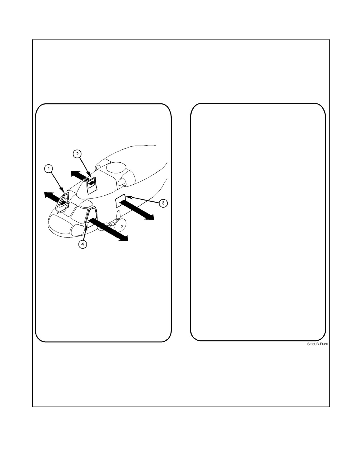
A1-H60BB-NFM-000
1.
KEEP YOUR SEATBELT FASTENED TIGHTLY
UNTIL READY TO DEPART THE AIRCRAFT.
STAY STRAPPED IN UNTIL DIRECTED BY
THE CREWMAN.
2.
KEEP YOUR CRANIAL AND LIFEVEST ON AT
ALL TIMES.
3.
ORIENT YOURSELF WITH RESPECT TO THE
EMERGENCY EXITS IN AIRCRAFT DIAGRAM.
4.
ALL EXITS CAN BE JETTISONED BY
PUSHING FORWARD THE YELLOW HANDLE
EXCEPT THE SENSOR OPERATOR, WHICH
MUST BE PULLED AFT. THE WINDOWS CAN
THEN BE PUSHED OUT.
IN CASE OF A CRASH OR
DITCHING:
1.
REMAIN STRAPPED IN UNTIL ALL MOTION
HAS STOPPED.
2.
IF THE AIRCRAFT REMAINS UPRIGHT,
REMAIN STRAPPED IN AND WAIT FOR
1.
PILOT JETTISONABLE WINDOW — PULL HANDLE
INSTRUCTIONS FROM THE CREW.
FORWARD.
3.
GRAB A REFERENCE POINT.
2.
CABIN DOOR WITH JETTISONABLE WINDOW —
PULL HANDLE FORWARD.
4.
AFTER THE AIRCRAFT ROLLS OVER IN THE
WATER AND ALL VIOLENT MOTION HAS
3.
SENSOR OPERATOR JETTISONABLE WINDOW —
STOPPED, UNSTRAP AND EXIT THE
PULL HANDLE AFT.
AIRCRAFT IMMEDIATELY BY THE NEAREST
EXIT. DO NOT INFLATE YOUR FLOTATION
4.
ATO JETTISONABLE WINDOW — PULL HANDLE
EQUIPMENT UNTIL YOU ARE OUTSIDE THE
FORWARD.
AIRCRAFT. DO NOT KICK.
5.
REMAIN CLEAR AND UPWIND OF THE
HELICOPTER. DON’T PANIC.
Figure 6-1. Passenger Briefing Card
ORIGINAL
6-10
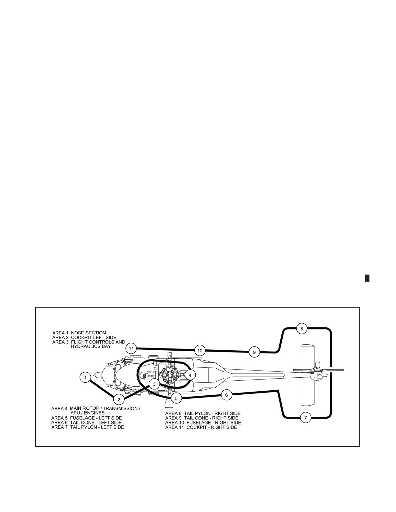
A1-H60BB-NFM-000
CHAPTER 7
Normal Procedures
7.1
LINE OPERATIONS
Observe flight line safety practices in accordance with NAV--SOP--2455 (series).
7.2
FLIGHT SCHEDULING
Specific requirements are listed in OPNAVINST 3710.7 (series).
7.3
PREFLIGHT
Prior to flight, the PIC shall ensure that a complete visual check of the helicopter has been conducted. The preflight
inspection should be divided among the pilot, copilot, and aircrewmen.
7.3.1 General
Note
D In each location (Figure 7-1), inspect for corrosion, Foreign Object Damage
(FOD), condition, and security.
D Check that all securing hardware is safety--wired, cotter--keyed, and/or
slipmarked.
D Plastic caps on avionics present a FOD hazard; check for security.
1. Chocks/Tiedowns — IN PLACE (as required).
2. Underside of all main rotor blades and tip caps.
3. All inlet/exhaust plugs and pitot--static tube covers — REMOVE.
Figure 7-1. Inspection Diagram
7-1
ORIGINAL W/IC 68
A1-H60BB-NFM-000
4. Sonobouy launcher valve safety lockout in the LOCK position. FREE position if no sonobouys installed.
SonobouylaunchervalvesafetylockoutshallbeintheSAFEpositionwhen
sonobouys are installed while in the vicinity of ground personnel.
5. If weapons are loaded, refer to technical manual, Airborne Weapons/Stores Loading Manual (A1--H60BB--
LWS--720), for appropriate weapon preflight instructions.
7.3.2 Nose Section (Area 1)
1. Windshield, wipers, OAT gauges/probes, and pitot tubes.
2. Avionics compartment.
CAUTION
Caremustbetakenwhenopeningthenoseavionicscompartmenttoprevent
water intrusion damage.
a. LASER ENABLE/DISABLE switch — AS REQUIRED.
Note
If LASER ENABLE/DISABLE switch is in the DISABLE position, the
LASER DISABLED advisory will be continuously illuminated.
b. GIMBAL switch — ENABLE (as required).
3.
Antennas.
4.
Searchlight — STOWED.
5.
FLIR (if installed).
a. FLIR turret — STOW POSITION.
b. FLIR turret cables — CONNECTED.
c. FLIR nose mount — SECURE.
d. FLIR nose mount grounding straps — SECURE.
e. Bore sight module — REMOVED.
7.3.3
Cockpit -- Left Side (Area 2)
1.
Door.
2.
Seat and harness.
Do not stow articles or equipment under seats or in seat wells. These objects
can interfere with proper seat stroking and reduce their energy--absorbing
performance during impact.
ORIGINAL
7-2
A1-H60BB-NFM-000
3. Battery/Avionics well.
4. Flight controls.
5. WPS — SELECT A or B.
6. Radar pressure pop--out button — NOT POPPED.
7. FLIR HCU.
8. Verify AN/ASQ--198 weapon type selection switches are in appropriate position for proper ordnance loaded.
If weapon type selection switch does not match actual ordnance loaded,
weapon malfunction may occur.
7.3.4 Flight Controls and Hydraulics Bay (Area 3)
1. Engine inlets.
With gusty or sustained wind conditions in excess of 10 knots, nearby jet
blast or rotor wash, the hydraulics bay cover can be blown off when in
transit or in the open position and may cause loss of the door and/or
personnel injury.
2. Pilot--assist module PDI — FLUSH.
3. Mixing unit.
4. Collective bias tube/LDS cable.
ImproperinstallationoftheLDSrollpinmayresultinanengineoverspeed.
Proper installation is indicated by the LDS roll pin protruding from both
sides of the LDS control cable rod and the collective bias tube with the
safety wire intact.
5. Hydraulic pump modules — FLUID LEVEL, FILTER, PDIs FLUSH AND QUICK DISCONNECT LINES
SECURE.
6. Primary servos.
7. Ensure hydraulic lines are secure by Adel clamps and not contacting each other or any structure of the
helicopter.
8. Accessory and input modules.
9. Generators.
7-3
ORIGINAL
A1-H60BB-NFM-000
10. LDS roll pins and mounts.
Improper LDS installation may result in an engine overspeed or other
engine malfunctions.
11. Hydraulic hand pump service reservoir:
a. Fluid level.
b. Hydraulic service valve selector pointed toward reservoir (#4 position).
c. Cap secure.
7.3.5 Main Rotor/Transmission/APU/Engines (Area 4)
1. Main rotor system, accumulator level/pressure, dampers, blades, BIM® indicators, elastomeric bearings,
droop stops, flap restraints, centering sockets, PCRs and scissor bearings.
D If black is visible on the BIM® indicator, it may be an indication of blade
damage. The cause of the black indication shall be determined prior to
flight.
D Do not exceed open engine cowling work platform weight limits. Excess
weight may cause failure of the composite rib hinge assembly and result in
serious injury to personnel.
2.
MRB lockpins and pitch locks.
a. Blades spread — MRB LOCKPINS ENGAGED, PITCH LOCKS RETRACTED, FLAP RESTRAINT
CAMS DO NOT BIND AND ARE FREE TO ROTATE.
b. Blades folded — MRB LOCKPINS FULLY RETRACTED, PITCH LOCKS ENGAGED.
3.
Engine oil filler caps — SECURE.
4.
NO. 1/NO. 2 engines — OIL LEVEL.
5.
Engine oil/fuel filter PDIs — FLUSH.
6.
Engine compartments.
7.
Deswirl duct clamps — SECURE.
8.
Transmission oil level — CHECK, SECURE DIPSTICK.
9.
Rotor brake/gust lock — CHECK POSITION.
10.
Ensure hydraulic lines are secure by Adel clamps and not contacting each other or any structure of the
helicopter.
11.
APU oil level — CHECK, SECURE DIPSTICK.
12.
ECS compartment — J--TUBE SECURE.
13.
Tail drive shaft/viscous dampers — CONDITION.
ORIGINAL
7-4
A1-H60BB-NFM-000
14. Fire--extinguisher bottles — CORRECT CHARGE.
15. Upper antennas.
16. IRCM Transmitter.
CAUTION
Handling covert windows with bare hands may cause damage to
components.
17. All topside access panels — SECURE.
Failure to properly secure all panels and doors may result in damage to
equipment and catastrophic control failure.
7.3.6 Fuselage -- Left Side (Area 5)
1. Avionics cooling exhaust.
2. Landing gear, step, WOW switch.
3. Position light, grounding wire, float bag fairing, and static port.
4. Tire and brake indicator pins.
5. Junction box panel.
6. Pylon/stores — AS REQUIRED.
CAUTION
Do not attempt to lift LHEP when the M299 Launcher is installed. Damage
to the launcher, pylon, sway braces, or BRU--14/A bomb rack may occur.
a. Left Hand Extended pylon (LHEP) umbilical to M299 launcher — Connected.
(1) Breakaway lanyard for M299 launcher umbilical attached to hard point.
b. M299 launcher.
(1) SAFE/ARM switch — SAFE.
CAUTION
If missile is loaded, missile seeker head covers shall be installed, if
available, during all ground operations and before all chock and chain
operations to prevent damage to the seeker head.
7. Cabin window.
8. Water wash connector access panel.
7-5
ORIGINAL
A1-H60BB-NFM-000
9.
Sonobouy launcher cover/sonobouys — AS REQUIRED.
10.
Fueling compartments.
11.
Fire extinguisher thermal plug — IN PLACE.
12.
ESM antenna housing.
13.
ALQ--205 IR transmitter.
14.
Engine exhaust.
15.
APU exhaust.
16.
Underside of helicopter — ANTENNAS/PANELS.
7.3.7
Tail Cone -- Left Side (Area 6)
1.
Tail wheel.
a. Manual unlock lever — UP POSITION.
b. Slip mark — ALIGNED.
2.
Tail probe — CHECK IN UP POSITION.
3.
Chaff/Flare dispenser — SAFE (note loadout).
4.
Antennas.
5.
Anti--collision light.
6.
Drive shaft cover and hinge pins.
7.
Pylon--fold hinge fittings.
8.
Intermediate gearbox — OIL LEVEL/FILLER CAP.
7.3.8
Tail Pylon -- Left Side (Area 7)
1.
Stabilator locking pin and keeper — FULL EXTENSION AND LOCKED.
2.
Position light.
3.
ASE sensors and housing.
4.
Tail bumper — STRUT EXTENSION, PAD WEAR.
7.3.9
Tail Pylon -- Right Side (Area 8)
1.
Stabilator locking pin and keeper — FULL EXTENSION AND LOCKED.
2.
Tail rotor blades, bonding wires, pitch--change links.
3.
Tail rotor indexer — RETRACTED.
4.
Tail rotor de--ice harness and cannon plugs — SECURE.
5.
Anti--collision light.
6.
Tail gearbox — OIL LEVEL/FILLER CAP.
D Ensure oil filler cap is secure by pulling out on cap while turning clockwise
to ensure it is seated in locked position. Failure to secure properly may
causecaptodepart,causingbindingintailrotorcontrolsand/orlossofTGB
oil.
D An over--serviced TGB and/or a red tint to TGB oil are possible signs of
contamination with hydraulic fluid. Failure of the TGB is possible.
ORIGINAL
7-6
A1-H60BB-NFM-000
7. Tail gearbox cowling — SECURE.
8. Pylon access steps — STOW.
7.3.10 Tail Cone -- Right Side (Area 9)
1. Pylon fold locking pin and keeper — FULL EXTENSION AND LOCKED.
2. Drive shaft sections, viscous dampers, quick disconnect and covers.
3. Chaff/Flare dispenser — SAFE (note loadout).
4. MAD towed body, reeling machine, and support.
7.3.11 Fuselage -- Right Side (Area 10)
1. ECS exhaust/engine exhaust.
2. Antennas.
3. Fuel dump port.
4. Transition section.
a. Avionics.
b. Tail rotor cables — ROUTING AND CHAFFING.
5. Pylon/external stores/FLIR if installed — AS REQUIRED.
6. Cabin door.
7. Rescue hoist.
8. Ice detector.
9. Junction box panel.
10. Landing gear, step.
11. Avionics cooling exhaust/inlet.
12. Position light, grounding wire, float bag fairing, and static port.
13. Tire and brake indicator pins.
14. External power access panel.
7.3.12 Cockpit -- Right Side (Area 11)
1. Door.
2. Seat and harness.
Do not stow articles or equipment under seats or in seat wells. These objects
can interfere with proper seat stroking and reduce their energy--absorbing
performance during impact.
3. Avionics well.
4. Flight controls.
5. ELT — ARM.
6. Windshield washer reservoir — FLUID LEVEL/FILLER CAP.
7. Rotor brake handle lockpin — RELEASE.
7-7
ORIGINAL
A1-H60BB-NFM-000
7.3.13 AGM--114 Hellfire Preflight Checklist
1. Port forward weapons station quick release pins — INSTALLED/HANDLES LOCKED.
2. M299 launcher.
3. M299 umbilical to launcher — Connected.
a. Breakaway lanyard for launcher umbilical attached to hard point.
4. M299 SAFE/ARM switch — SAFE.
5. AGM-114 Hellfire missile (if installed).
a. Correct Hellfire missiles loaded.
b. Missiles correctly loaded.
c. M299 launcher latch handle(s) — AFT. Any excessive movement of latch handle should be reported to
qualified personnel.
CAUTION
Correct missile loading may be tested by grasping the missile just aft of the
seeker head and pulling with both hands. The release handle should be rigid
and the holdback release will be canted aft. If the handle moves freely, the
mechanism is not latched. Notify qualified personnel.
d. Hellfire missile seeker head covers — ON (if available).
7.3.14 Mk 46 Torpedo Preflight Checklist
1.
Armament switches — OFF/SAFE/NORMAL.
2.
Weapon loaded sign — On cyclic stick.
3.
BRU-14 — SAFE.
4.
Weapon — Secure on pylon.
5.
Inboard stations.
a. 42-inch band release wire — Through groove in aft/inboard sway brace pad; connected to snaphook.
b. Arming wire — Connected to tail arming solenoid and seawater battery arming lanyard.
c. Seawater battery arming lanyard — Cut and deburred.
d. Preset cable — Connected; forward slack removed; secured to aft outboard sway brace.
e. Preset cable pullout lanyard — Connected to armament bracket snaphook.
f. Parachute band release wire and static line — Attached to armament bracket snaphook.
g. Snaphook opening — Facing aft.
h. Parachute band release wire — Cut and bent.
6.
Outboard stations.
a. 42-inch release wire — Through groove in aft/inboard sway brace pad; connected to armament bracket
snaphook.
b. Arming wire — Connected to tail arming solenoid and seawater battery lanyard.
c. Seawater battery arming lanyard — Cut and deburred.
ORIGINAL
7-8
A1-H60BB-NFM-000
d. Preset cable — Connected; forward slack removed; secured to aft outboard sway brace.
e. Preset cable pullout lanyard — Connected to swing arm snaphook.
f. Parachute band release wire — Cut and bent.
7. Stabilizer — Not damaged, clamp installed.
8. Nose cover — Installed.
9. All tape — Removed.
10. Pylon door — Secured.
Note
The following steps shall be performed after engine turnup.
11.
(REXTORP/EXTORP) Nose cover, ballast safety strap, and air stabilizer clamp — Remove.
12.
(WARSHOT) Nose cover, air stabilizer clamp — Remove.
7.3.15 Mk 50 Torpedo Preflight Checklist
1.
Armament switches — OFF/SAFE/NORMAL.
2.
Weapon loaded sign — On cyclic stick.
3.
BRU-14 — SAFE.
4.
(WARSHOT) Exploder ARM/SAFE — SAFE.
5.
53-inch release wire — Secured by aft outboard sway brace or inboard of sway brace pad.
6.
Weapon — Secure on pylon.
7.
(EXERCISE) Scuttle safing — ARM.
8.
Arming wire — Connected to tail solenoid and lanyard start assembly.
9.
Lanyard start assembly — Cut at red mark and deburred.
10.
Preset cable — Connected; forward slack removed; secured to aft/outboard sway brace.
11.
(Inboard station) Preset cable pullout lanyard/static line — Connected to aircraft and torpedo.
12.
(Outboard station) Static line — Connected to armament bracket.
13.
(Outboard station) Preset cable pullout lanyard — Connected to swing arm.
14.
Nose cap — Installed; not damaged.
Note
Nose protective cap shall remain installed during flight. It is a breakaway
type and will shatter upon water entry. Do not remove before flight.
15.
All tape — Removed.
16.
Pylon door — Secured.
Note
The following step shall be performed after engine turnup.
17.
(WARSHOT) ARM/SAFE indicator — ARM.
7-9
ORIGINAL