SH-60B HELICOPTER. FLIGHT MANUAL (2008) - page 2
A1-H60BB-NFM-000
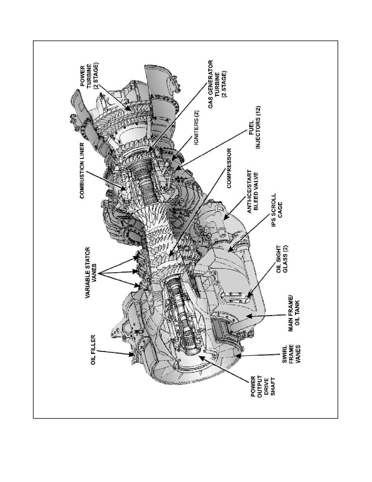
Figure 2-1. Engine, T700-GE-401C Profile (Sheet 3)
ORIGINAL
2-4
A1-H60BB-NFM-000
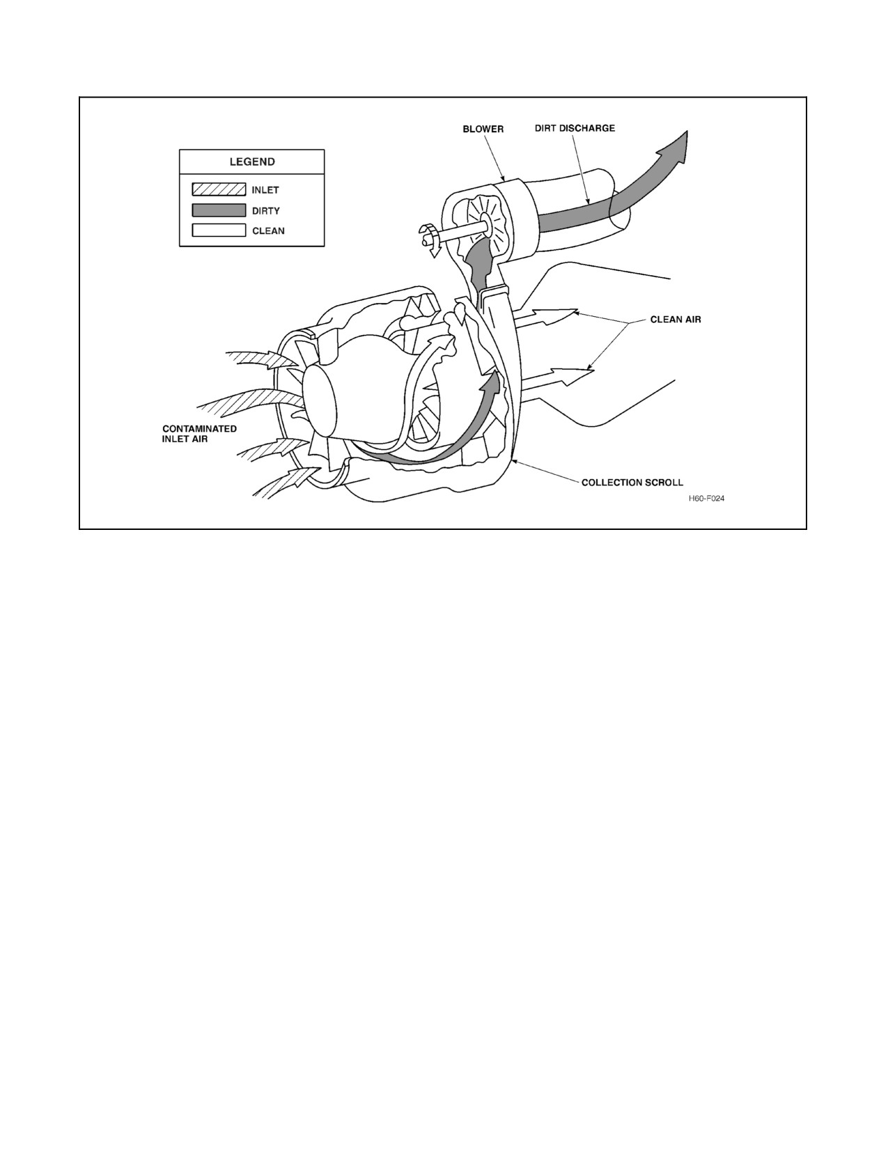
Figure 2-2. Inlet Particle Separator Airflow
2.1.1.7 Power Turbine
The Np turbine has two stages that turn the power turbine drive shaft. The shaft is coaxial, turning inside the
gas--generator turbine drive shaft. It extends through the front of the engine where it connects to the high speed shaft,
which in turn connects to the input module. The power turbine is comprised of the power turbine rotors, power turbine
drive shaft, power turbine case, and exhaust frame. Turbine Gas Temperature (TGT) is sensed between the
gas--generator and power turbine.
2.1.1.8 Engine Airflow
Approximately 30 percent of the total airflow through the engine is used for the combustion process. The remainder
is utilized for the following:
1. Compressor inlet temperature (T2) air.
2. Compressor discharge pressure (P3) air.
3. Combustor and turbine cooling.
4. Engine oil seal pressurization.
2.1.1.9 Main Frame and Accessory Section
The main frame contains the oil tank, oil level sight gauge, and accessory gearbox (AGB) supports. The accessory
section mounts to the rear of the main frame at the 12 o’clock position, above the scroll case. The AGB is driven by
a rotor via a radial drive shaft from the Ng turbine drive shaft. The rear face provides drive pads for the engine starter,
HMU, IPS blower, and overspeed and drain valve (ODV). The front face provides drive pads for the alternator and
engine--driven fuel boost pump. Mounting cavities are provided for the lube and scavenge pump and chip detector.
Face--ported pads are supplied for the oil cooler, fuel filter, and oil filter. Cored passages in the AGB housing convey
fuel and oil between components.
2-5
ORIGINAL
A1-H60BB-NFM-000
2.1.2 Engine Control System
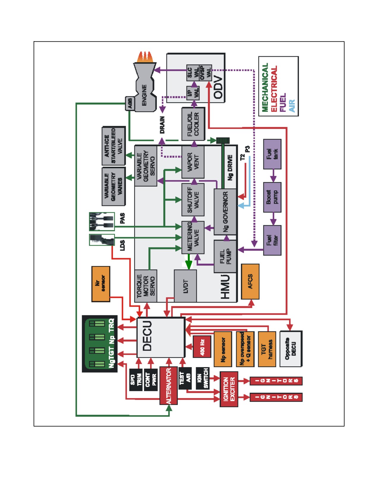
The engine control system (Figure 2-3) includes all control units necessary for the proper and complete control of
the engine to maintain a constant Np/Nr. The major components are the hydromechanical control unit (HMU),
overspeed and drain valve (ODV), digital electronic control unit (DECU), an engine--driven alternator, and a series
of fuel flow control valves. Basic system operation is governed through the interaction of the DECU and HMU. In
general, the HMU provides gas--generator control while the DECU trims the HMU to satisfy the requirements of the
power turbine load and reduce pilot workload. The engine control system functions automatically, with no action
required of the pilot after starting.
2.1.2.1 Engine Control Quadrant
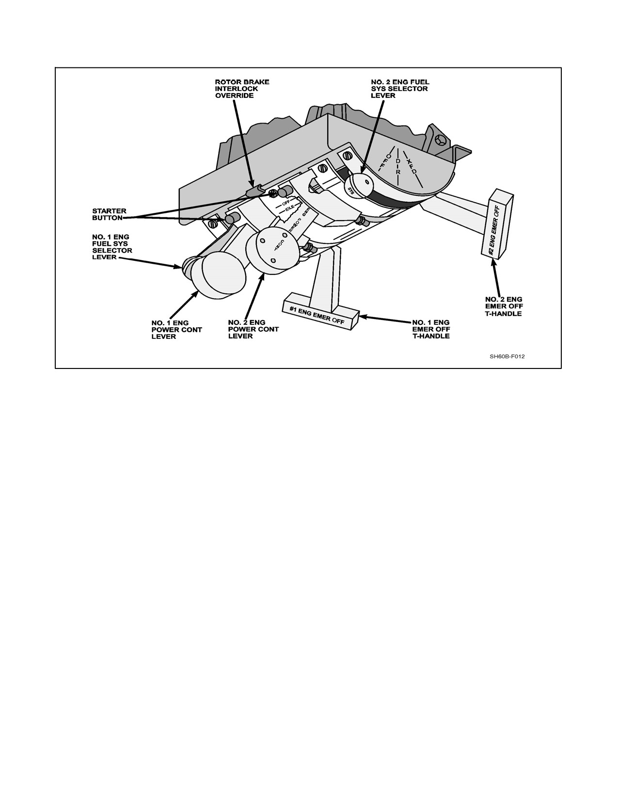
The engine control quadrant (Figure 2-4) consists of two power control levers (PCL), two fuel selectors levers, two
engine T-handles, and a rotor brake interlock. A starter button is located on each PCL. The PCL has four positions
(OFF-IDLE-FLY-LOCKOUT).
With the PCL in the OFF position, the Power Available Spindle (PAS) mechanically shuts off fuel at the shutoff valve,
within the HMU. Once the PCL is moved to the idle position, the HMU automatically controls start sequence fuel
flow allowing the engine to achieve self--sustaining combustion. Placing the PCL in the FLY detent sets the maximum
level of power that could be supplied, if demanded. If the PCL is momentarily advanced to LOCKOUT and then
retarded, the PCL is used to manually control Np and Ng. TGT limiting, Np governing, and load sharing functions
are deactivated and must be manually controlled. The Np overspeed protection system is retained when in LOCKOUT
via a direct link between the DECU and ODV. To return to automatic engine control, the PCL must be moved to IDLE,
then returned to FLY.
A solenoid on the quadrant activates a mechanical locking device to prevent the PCLs from being advanced above
IDLE with the rotor brake on. If the rotor brake is released, the solenoid energizes, and unlocks the PCLs. An override
tab is provided on the quadrant, should the solenoid fail. This allows the PCLs to be advanced above ground idle by
pulling down on the override tab.
2.1.2.2 Load Demand System
With the PCL in FLY, the HMU responds to collective position, through a load demand spindle (LDS) to
automatically control engine speed and to provide required power. When the PCL is moved to LOCKOUT and then
to some intermediate position, the engine will still vary power in response to collective position.
2.1.2.3 Engine Fuel System
The engine fuel system consists of the engine--driven fuel boost pump, fuel filter, HMU, and ODV.
2.1.2.4 Engine-Driven Fuel Boost Pump
The engine-driven fuel boost pump mounted on the forward side of the AGB is designed to:
1. Provide reliable suction feed from the aircraft fuel tank to the engine minimizing vulnerability and fire hazard
in the event of damaged fuel lines.
2. Provide discharge pressure to satisfy the minimum inlet pressure requirement of the HMU or high--pressure
fuel pump.
2.1.2.5 Engine Fuel Filter
The engine fuel filter provides filtration of solid particulate matter, but does not filter water. Fuel enters the filter inlet
ports from the engine--driven fuel boost pump and is then routed to the HMU high--pressure fuel pump.
When a pressure differential across the fuel filter is sensed, the impending bypass pressure differential indicator (PDI)
extends. The impending bypass PDI cannot be reset until the filter element and bowl are removed and the indicator
is reset internally. The electrical bypass switch is activated by a pressure signal as the bypass valve opens. Once the
filter is bypassed, the #1/#2 FUEL FLTR BYPASS caution will appear.
ORIGINAL
2-6
A1-H60BB-NFM-000
Figure 2-3. Engine Control Block Diagram
2-7
ORIGINAL
A1-H60BB-NFM-000
Figure 2-4. Engine Control Quadrant
2.1.2.6 Hydromechanical Control Unit
The Hydromechanical Control Unit (HMU), mounted on the aft center of the AGB, receives filtered fuel through a
cored passage. It contains a high-pressure fuel pump, Ng governor, metering valve, linear variable displacement
transducer (LVDT), torque motor servo, variable geometry vane servo, vapor vent, and shutoff valve.
The fuel enters the high-pressure engine-driven pump in the HMU, which provides high pressure fuel for efficient
engine operation. The fuel leaves the pump and passes through the metering valve and shutoff valve, and is then
directed through an external line to the oil-to-fuel heat exchanger. Some fuel is tapped off to operate various servos
in the HMU for the following:
1. Positioning a metering valve to assure proper flow to the engine.
2. Positioning a servo piston that actuates the variable geometry vane servo and start bleed valve.
3. Amplifying various signals (T2, P3, Ng) which influence fuel flow and variable geometry servo position.
2.1.2.7 Inputs to the HMU
TheHMU responds to two mechanical linkages from thecockpit and oneelectrical signal. Thefirst mechanical input
from the LDS directly coordinates Ng speeds to the approximate power required by the rotor system based on
collective position. The second mechanical input is through the PCL. The position of the PCL manipulates the PAS
at the HMU setting the desired power setting. A third input is in the form of an electrical signal from the DECU which
actuates the torque motor servo in the HMU to precisely trim Ng speed for power turbine control and load sharing.
HMU receives cockpit inputs from the collective via the LDS and the PCL via the PAS. The HMU responds to the
PCL for:
1. Fuel shutoff.
2. Setting engine start fuel flow with automatic acceleration to ground idle.
ORIGINAL
2-8
A1-H60BB-NFM-000
3. Setting permissible Ng up to maximum.
4. Fuel priming.
5. DECU override capability (LOCKOUT).
The HMU also responds to T2, P3, and Ng. These inputs aid the HMU in controlling variable stator vanes and
anti--ice/start bleed valve position during engine start and normal operation, reducing the chance of compressor stall.
2.1.2.8 HMU Operation
The HMU operates as a conventional gas--generator power control when there is no input to the torque motor from
the DECU. The HMU provides fuel scheduling for minimum flow, maximum flow, and variable stator vane control.
Maximum and minimum metering valve stops provide absolute fuel flow limits.
The HMU fuel metering system controls fuel flow to the engine during all operating conditions. Fuel enters the
high--pressure engine--driven fuel pump in the HMU, which provides adequate high pressure fuel for efficient engine
operation. After fuel leaves the high pressure fuel pump, it is routed to the metering valve. The metering valve
schedules engine fuel flow commensurate to current power demand and is trimmed to the required level by the torque
motor servo in response to DECU signals. The HMU, via the LVDT, then provides a feedback signal to the DECU
to null thetorquemotorservoinput, stabilizingmetering valvemovement andpreventing engineoscillation/hunting.
Excess fuel is routed back to the pump inlet.
A nonadjustable topping setting controls maximum Ng during cold ambient operation and maximum TGT in the
event of an electrical control system failure. If the Ng servo within the Ng governor reaches a position, corresponding
to an overspeed, a spring-loaded ball valve ports fuel pressure causing the minimum pressure valve to secure flow
to the engine. The Ng overspeed valve is set to trip at 110 percent ±2 percent Ng.
The PAS sets a maximum available Ng. Placing the PCL in FLY allows Ng to reach a setting that provides intermediate
power. Collective movement adjusts available Ng to a power level approximately equal to the rotor load demand
power. The actual level of engine power in FLY is normally more than required by the helicopter. This schedule is
intentionally placed at a higher-than-required power level for two reasons:
1. Fail-safe to high power. The torque motor, when energized, is designed to reduce the schedule to the desired
powerlevel.Therefore,lossoftorquemotorelectricalcurrentcausesthescheduletoreturntothehighestpower
level. A schedule that is biased high due to engine electrical failure does not cause power limiting and can be
manually retarded to a more desirable level using the PCL. With all engine protection functions in the HMU
operational, neitherenginedamagenorstall canoccurduringorfollowingloss ofelectrical signalto thetorque
motor.
2. Power available with one engine inoperative (OEI). In the event of a failure of one engine, the remaining
engine’s gas generator can increase power sufficiently up to its limit (contingency power) to carry the load at
the given LDS setting. A load demand signal is introduced to the HMU through the LDS. When the LDS is
reduced from its maximum setting by adjusting the collective, the Ng is reset from the PAS setting to provide
immediate and accurate gas generator response. This new Ng setting is trimmed by the DECU to satisfy the
Np governing and load sharing functions.
The HMU provides:
1. Rapid engine transient response through collective compensation.
2. Automatic fuel scheduling for engine start.
3. Ng overspeed protection. The HMU mechanically limits Ng to 110 percent ±2. If the Ng servo, within the Ng
governor, reaches a position corresponding to an overspeed a centrifugal valve secures fuel flow to the engine.
Once the overspeed condition has passed, the valve re--opens, allowing normal operation to resume once the
engine is primed and restarted.
4. Ng governing. The HMU receives T2, P3, and Ng inputs from their respective sensors, which are used to
schedule fuel for minimum flow, maximum flow, and variable geometry vane control.
2-9
ORIGINAL
A1-H60BB-NFM-000
5. Acceleration limiting. The Ng governor ensures any PCL motion will result in safe engine operation and will
not cause engine damage. Except for intentional shutoff of the PCL, an inadvertent shutdown will not occur
during PCL motion.
6. Flameout and compressor stall protection. The HMU adjusts variable--geometry vane position and opens the
anti--ice/start bleed valve to prevent compressor instability.
2.1.2.9 Overspeed and Drain Valve
When the PCL is advanced to IDLE during engine start, the shutoff valve in the HMU opens and allows metered fuel
to flow to the Overspeed and Drain Valve (ODV) inlet. The ODV has four main functions:
1. Provides main fuel flow to the 12 fuel injectors during engine start and operation.
2. Purges the main fuel manifold overboard, after engine shutdown, through a shutoff and drain valve to prevent
coking of the fuel injectors.
3. Traps fuel upstream, which keeps the fuel/oil heat exchanger full, so that system priming is not required prior
to the next start.
4. Returns fuel back to the HMU if the Np overspeed is energized or if the DECU hot start preventer is activated.
2.1.3 Engine Electrical System
2.1.3.1 Alternator
All essential engine electrical functions are powered by the alternator. The engine contains separate windings
providing AC power to the Ignitor assembly, DECU, and Ng signal to the VIDS.
2.1.3.2 Digital Electronic Control Unit
The Digital Electronic Control Unit (DECU) resets the HMU within acceptable engine limits to maintain Np
governing while automatically limiting TGT.
The DECU is mounted below the compressor casing. The forward face of the DECU projects into the collection scroll
case of the IPS where it is cooled by scavenge airflow. Four connectors provide for interconnection with the other
engine control components, airframe systems, and the diagnostic equipment. The control parameters of the DECU
are:
1. Np sensing (governing).
2. Np overspeed and torque sensing (load sharing, cockpit torque indication, and Np overspeed protection).
3. TGT monitoring (temperature-limiting circuit).
The DECU receives the following inputs from the cockpit:
1. ENGINE SPD TRIM switch.
2. CONTGCY PWR switch.
3. ENG OVERSPEED TEST A and B buttons.
The DECU receives the following input signals from the helicopter:
1. Torque from the other DECU.
2. Np demand.
3.
400--Hz backup power.
4. HMU (LVDT).
ORIGINAL
2-10
A1-H60BB-NFM-000
The DECU sends the following signals to the cockpit:
1. Torque.
2. Np.
3. TGT.
4. Contingency power.
2.1.3.3 DECU Operation
During normal operations, the DECU performs the following functions:
1. Np Governing -- The Np sensor located on the left side of the power turbine section provides an Np signal to
the DECU. Actual Np is compared to a reference Np to compute a speed error input signal for use in electrical
control computation.
2. Np Overspeed Protection -- The Np overspeed system is composed of redundant circuits, which rely on a signal
from the Np overspeed and torque sensor located on the right side of the power turbine section. The overspeed
system is actuated at 120 percent Np. When Np exceeds 120 percent, a signal is sent from the DECU to the
ODV, diverting fuel to the inlet of the HMU, causing engine flameout.
A popped NO. 1 ENG OVSP or NO. 2 ENG OVSP circuit breaker shall not
be reset in flight. Resetting a popped NO. 1 or NO. 2 ENG OVSP circuit
breaker may initiate an engine overspeed signal and result in engine failure.
3.
TGT Limiting -- Measured TGT is compared to a fixed reference. When temperature is above the reference,
a signal is generated to reduce fuel flow. When TGT approaches 851 °C, the DECU prevents any further
increase in fuel flow to the engine. The intermediate range power (IRP) limiter will prevent this at
839 °C ±10 °C. If power demand is increased further, Np/Nr will droop below 100 percent; Np governing
will be sacrificed to protect the engine against over temperature.
4.
Engine Load Sharing -- Torque signals are compared between the two engines via the respective DECUs. A
torqueerrorsignal is generated ifoneenginetorqueis less than theother.Thetorquematching systemoperates
by increasing power on the lower torque engine, while not directly affecting the higher torque engine.
5.
Engine Speed Trim -- An ENG SPD TRIM switch, located on the upper console, with positions INCR and
DECR, controls the Np of both engines simultaneously. There is no individual engine trim capability. The ENG
SPD TRIM switch supplies a reference electrical signal to the DECUs for controlling Np as required between
96 percent and 101 percent Np.
6.
Contingency Power -- The TGT limit can be increased by placing the CONTGCY PWR switch on the
collective to the ON position. This sends a signal to the DECU to allow TGT to increase to 903 °C however;
the maximum contingency range power (CRP) limiter will prevent further increase in fuel flow to the engine
at 891 °C ±10 °C. The #1/#2 ENG CONT PWR ON advisories indicate that contingency power has been
selected. Placing the CONTGCY PWR switch to the ON position automatically deactivates the Environmental
Control System (ECS).
7.
Np Overspeed Test -- Thetest modeis activated by theENG OVERSPEED TEST A and B buttons. When both
switches are actuated, the Np overspeed limit is re--referenced to 96 percent Np. If power turbine speed
decreases when either switch is pressed individually, the opposite test switch may be faulty.
8.
DECU LOCKOUT operation capability -- After being moved momentarily to LOCKOUT, the PCL is used
to manually control Ng and Np. As a result, engine power is no longer controlled by the DECU; it is set by
PAS and LDS positions only. With the PCL in LOCKOUT the torque motor servo is disabled therefore
deactivating TGT limiting, Np governing, and load sharing. The Np overspeed protection system is retained
when in LOCKOUT. To regain automatic engine control, the PCL must be moved to IDLE then returned to
FLY.
2-11
ORIGINAL
A1-H60BB-NFM-000
9.
Cockpit Signals -- Provides Np, TGT, and torque signals to SDC for cockpit display.
10.
Hot Start Prevention -- Detects a hot start when TGT exceeds 900 °C with Ng below 60 percent and Np below
50 percent and automatically stops fuel flow by tripping the ODV. Fuel flow is restored when TGT either
decreases to 300 °C or after 25 seconds, whichever occurs first. Hot start prevention can be disabled by pressing
and holding the ENG OVSP TEST A or B button for the duration of the start sequence. A self--test of the
hot--start prevention system is performed while conducting a normal Np overspeed system test.
11.
Fault Diagnostic System -- The DECU incorporates signal validation for selected input signals within the
electrical control system. Signals are continuously validated when the engine is operating. If a failure has
occurred, the failed component or related circuit will be identified by a pre--selected fault code. It is possible
to have more than one fault code detected and each code should be treated as an individual fault. Fault codes
will bedisplayed numerically on theenginetorqueindicator. Codesaredisplayedstarting withthelowestcode
(4 seconds on and 2 seconds off), rotating through all codes, and then repeating the cycle. They can be
suppressed/recalled by depressing either one of the ENG OVSP TEST buttons. Once the problem has been
corrected, the codes will be cleared and may be verified after operating the engine at FLY. The fault codes
displayed for approximately one minute when the following conditions are met:
a. Ng less than 20 percent.
b. Np less than 35 percent.
c. Other engine is shutdown.
d. Aircraft 400 Hz power is available.
Note
If fault codes are not suppressed, DAFCS ground checks and blade fold will
be inoperative.
12.
400--Hz airframe backup power capability -- DECU functions receive 400--Hz AC power from the aircraft
electrical system in the event of an alternator failure. A failure of either power supply by itself will have no
impact on the DECU’s ability to control the engine.
13.
Transient Droop Improvement (TDI) -- The TDI system is designed to initiate power turbine acceleration early
by using anticipator signals from the TDI Nr sensor located on the left accessory module and a collective
position sensor in the mixing unit. Circuits in the DECU increase fuel flow to the engine via the HMU torque
motor servo at low torque settings when collective demand is increased rapidly or in the event of rapid Nr decay.
14.
Auto Ignition System -- When an Np overspeed condition is reached and during the Np Overspeed Test, the
overspeed valve located in the ODV is opened to reroute fuel flow to the HMU inlet. When Np drops below
120 percent, the auto ignition system closes the overspeed valve and turns on the igniters for 5 seconds to
relight the engine. The Np overspeed/auto--ignition system will continue cycling until Np/Nr is controlled. A
yaw kick may be experienced each time engine relights.
15.
Ng Decay Rate Relight Feature -- The auto--ignition system also includes an Ng--decay rate relight feature. If
an engine flames out for any reason and exceeds a specified Ng deceleration rate, the auto--ignition system will
turn on the igniters for five seconds in an attempt to relight the engine. The Ng--decay rate relight feature is
disabled below 62 percent Ng.
2.1.3.4 Ignition System
TheACpoweredignitionsystemincludesanignitionexciterunit,mountedontherightsideoftheenginemainframe,
and two igniter plugs. The ENGINE IGNITION switch, labeled OFF/NORM, is located on the upper console and
serves both engines. When in the NORM position and either starter button depressed, the ignition system operates.
Ignition is automatically shut off after the engine start motor is disengaged at starter dropout speed. In the OFF
position, the system is de--energized, but enginemotoring capability remains. Electrical power to the ignition exciter
assembly is supplied by the engine-driven alternator during engine start or whenever the auto--ignition feature is
activated.
ORIGINAL
2-12
A1-H60BB-NFM-000
2.1.4 Engine Operation Summary
2.1.4.1 Starting and Ground Idle
After engaging the starter, the shutoff valve in the HMU is opened by advancing the PCL to IDLE. Fuel is
automatically scheduled by the HMU to a fixed flow at light--off and then an acceleration fuel flow as a function of
Ng, P3, and T2 to idle. In idle, fuel flow is scheduled automatically. Power turbine speed is not governed with the
PCL in IDLE since the engine will not produce enough power to drive the power turbine to 100 percent.
2.1.4.2 Takeoff and Climb
Before takeoff, the PCL is advanced from IDLE to the FLY detent. This allows the rotor head to accelerate to 100
percent Np/Nr. Ng will increase as the PCL is advanced and will stabilize once the Np governing speed of 100 percent
is reached.
As collective pitch is increased, the LDS rotates within the HMU, demanding an increase in Ng to maintain 100
percent Np/Nr. The DECUs adjust fuel flow to match torques and trim Np/Nr to 100 percent. As Ng increases, the
HMU schedule closes the anti--ice/start bleed valve, and the variable stator vanes open to increase airflow through
the combustorand turbine. If collectivepitch is increased significantly, TGT may approach thelimiting value. When
this occurs, the DECU prevents any further increase in fuel flow to the engine. If the power required is increased
further, Np/Nr will droop below 100 percent; Np governing will be sacrificed to protect the engine against
overtemperature.
2.1.4.3 Cruise and Descent
When collective pitch is reduced, the LDS will reduce fuel flow and Ng. The variable stator vanes will close slightly
tooptimizefuelconsumptionandpreservestallmargin.Uponenteringadescent,thesamesequenceofeventsreduces
Ng to the point that the anti--ice/start bleed valve may begin to open. If the collective is fully lowered (e.g.,
autorotation power-off descent), both engine torque indications drop to zero by intervention of freewheeling units
in the input modules. Once the engines are uncoupled from the rotor, Nr is free to accelerate above 100 percent. Both
engines continue to govern Np at 100 percent, ready to pick up the rotor load when collective is increased.
2.1.4.4 Summary
The engine control system functions automatically, with no action required of the pilot after starting. The system is
functionally split between the HMU and DECU; the HMU provides functions essential to safe engine operation,
while the DECU performs a fine trim to reduce pilot workload.
2.1.5 Engine Oil System
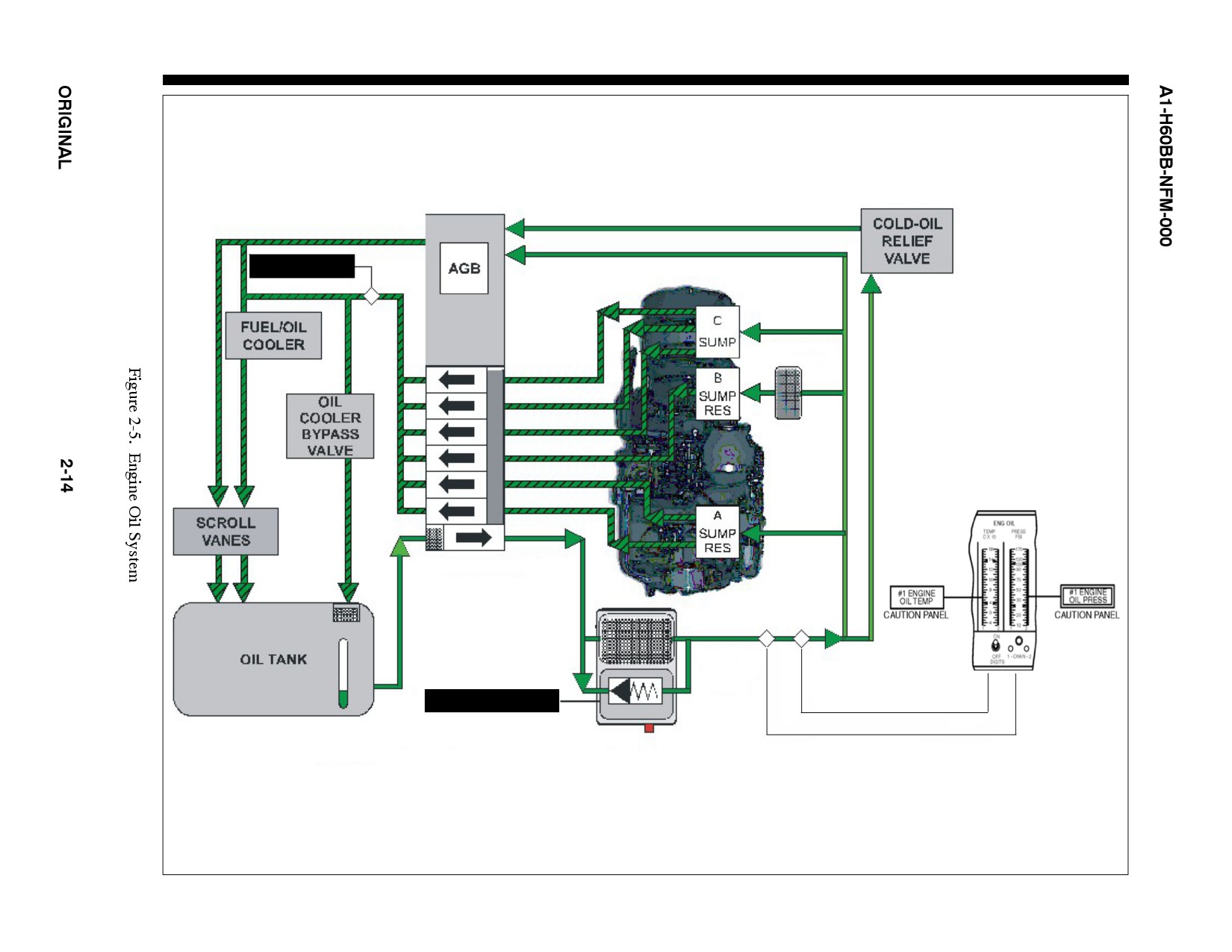
The engine oil system (Figure 2-5) is a self-contained, pressurized, recirculating, dry-sump system. It consists of the
following systems and components:
1. Oil supply and scavenge system.
2. Oil filter and condition monitoring system.
3. Oil Tank.
4. Air/oil cooler (scroll vanes).
5. Fuel/oil cooler.
6. Chip detector.
7. Pressure and temperature indicators.
2.1.5.1 Oil Tank
The filler port is located on the right side of the engine (Figure 2-1). The oil level is indicated by a sight gauge on
each side of the tank. Due to the design of the filler port, over-servicing is not possible. The scavenge pump returns
oil from the sumps and AGB to the oil tank.
2-13
ORIGINAL
CHIP #1 ENGINE
CHECK VALVE
& SCREEN
ENGINE DRIVEN
OIL PUMP
OIL FILTER
BYPASS
VALVE
#1 OIL FLTR BYPASS
Note: The number of scavenge lines do not correlate to the number of bearings per sump.
A1-H60BB-NFM-000
2.1.5.2 Oil Supply and Scavenge System
Oil is picked up by suction created through thepressureelement ofthepump. It is then pressurized and flows through
the oil filter into the passages in the AGB and the six main sump bearings. The engine is designed with two sets of
oil jets to provide each main bearing with oil for lubrication and cooling. This redundancy provides for a brief period
of operation following a malfunction or damage that totally interrupts the normal supply of oil. Scavenge oil flows
through the pump inlet, electrical chip detector, fuel/oil cooler, the main frame, scroll vanes, and into the oil tank.
If the oil pressure drops below limits, a caution, marked #1 or #2 ENGINE OIL PRESS will illuminate.
2.1.5.3 Oil Filter
Oil is discharged from the oil pump and routed to a disposable filter element. As the pressure differential across the
filter increases, the impending bypass PDI will pop out, providing a visual indication that the filter element needs
to be replaced. If the pressure differential continues to increase, the oil filter bypass sensor switch will activate the
#1/#2 OIL FLTR BYPASS caution, indicating an oil filter bypass. When operating with a partially clogged filter,
the high--pressure differential across the filter will cause the bypass valve to open and the caution to appear. The
impending bypass PDIhas athermal lockout below 38 °C to prevent theindicatorfrompopping duringcold--weather
starting.
2.1.5.4 Oil Cooler
Scavenge oil is cooled before it returns to the tank by a fuel/oil cooler mounted on the forward face of the AGB (Figure
2-5). As oil from the chip detector passes through the oil cooler, it is cooled by transferring heat from the oil to fuel.
After passing through the oil cooler, oil enters the top of the mainframe, where it flows through the scroll vanes that
function as an air/oil cooler. This further cools the oil and heats the vanes for full-time anti-icing.
2.1.5.5 Engine Chip Detector
The chip detector consists ofa housing with an integral magnet and electrical connector. Thedetector attracts ferrous
metal particles at a primary chip-detecting gap. Chips are detected when this gap is bridged. A signal is then sent to
the cockpit to illuminate the CHIP #1 ENGINE or CHIP #2 ENGINE caution.
2.1.6 Oil Temperature and Pressure Monitoring System
Engine oil system pressure and temperature sensors are mounted on the left forward face of the AGB. These sensors
provide a signal to the VIDS for oil pressure and temperature indications. The #1/#2 ENGINE OIL PRESS and #1/#2
ENGINE OIL TEMP cautions are activated by the VIDS.
2.1.7 Engine Start System
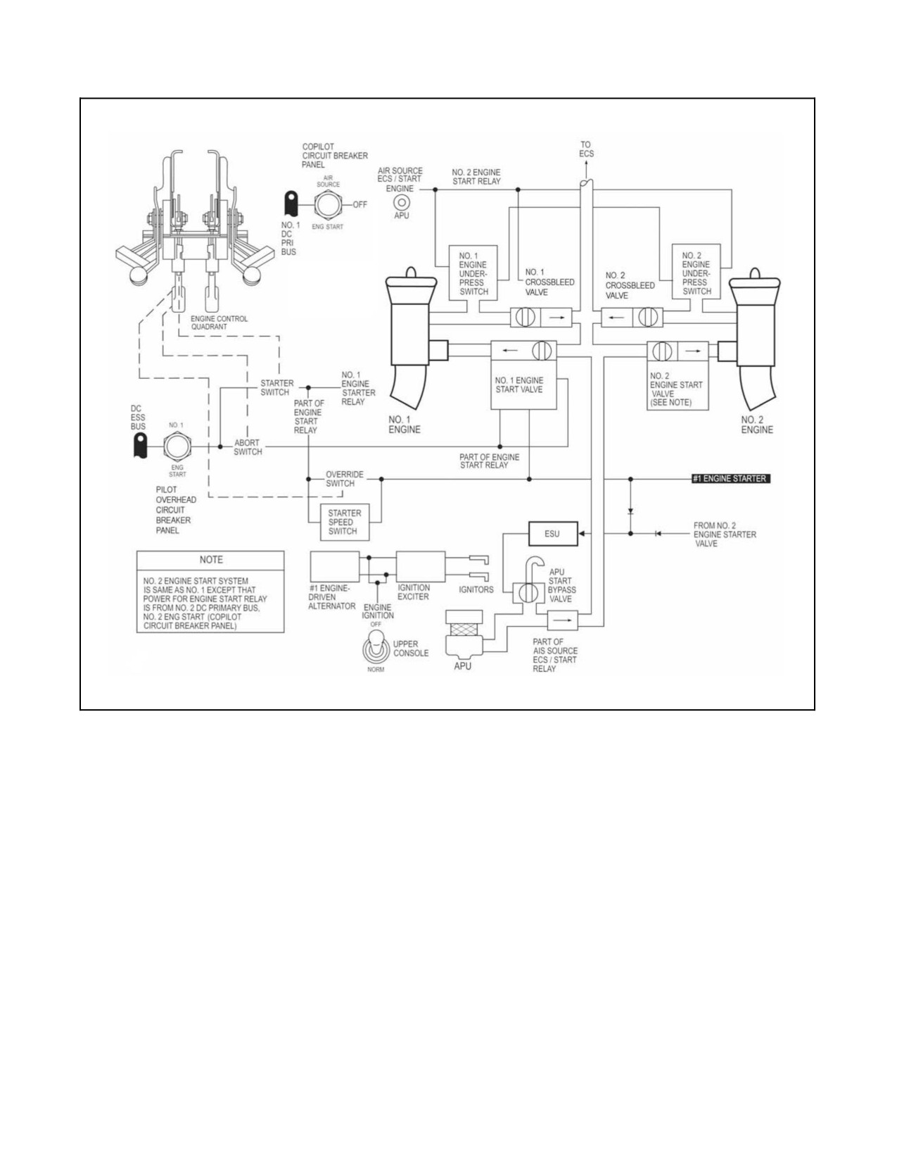
Thepneumaticstartsystem(Figure2-6)usesanairturbineenginestartmotorforenginestarting. Systemcomponents
consist of an engine starter, start valve, check valves, controls, and ducting. One of two pneumatic sources may be
selected as the source of air for engine starts: APU or engine crossbleed air.
The AIR SOURCE ECS/START switch is a three-position toggle switch that selects the source of air pressure for
engine start and ECS operation. When the start button is pressed, air from the selected source is directed through the
start valve to the engine starter. The #1/#2 ENGINE STARTER advisory will go on. The anti--ice/start bleed valve
remains open to reduce backpressure and prevent compressor stall until Ng reaches approximately 90 to 94 percent
(OAT--dependent). The #1/#2 ENG ANTI--ICE ON advisory will remain until the anti--ice/start bleed valve is
energized closed.
As the engine alternator begins to turn, it supplies electrical power to the ignition exciter. Ignition will continue until
starter dropout occurs (52 to 65 percent Ng). Once the starter drops out, the #1/#2 ENGINE STARTER advisory will
disappear. If the starter fails to drop out automatically, it may be disengaged by pulling down on the PCL, pulling
the circuit breaker or removing the air source. A malfunctioning starter may be overridden by manually holding in
the starter button until Ng reaches 52 to 65 percent Ng.
2-15
ORIGINAL
A1-H60BB-NFM-000
2.1.7.1 Engine Start, APU
The APU provides bleed air and electrical power for engine starting. The APU will provide pneumatic power for
engine start regardless of AIR SOURCE ECS/START switch position.
2.1.7.2 Engine Start, Crossbleed
Crossbleed engine starts are used when it is desired to start the other engine with the bleed air from the operating
engine. The AIR SOURCE ECS/START switch must be placed to ENG and the operating engine must be at a
minimumof94percentNg ormaximum Ng that canbesafelyattained. Pressingthestarterbutton willsimultaneously
open the start valve on the engine not operating and the crossbleed valve on the operating engine.
2.1.8 Engine and Inlet Anti-Ice System
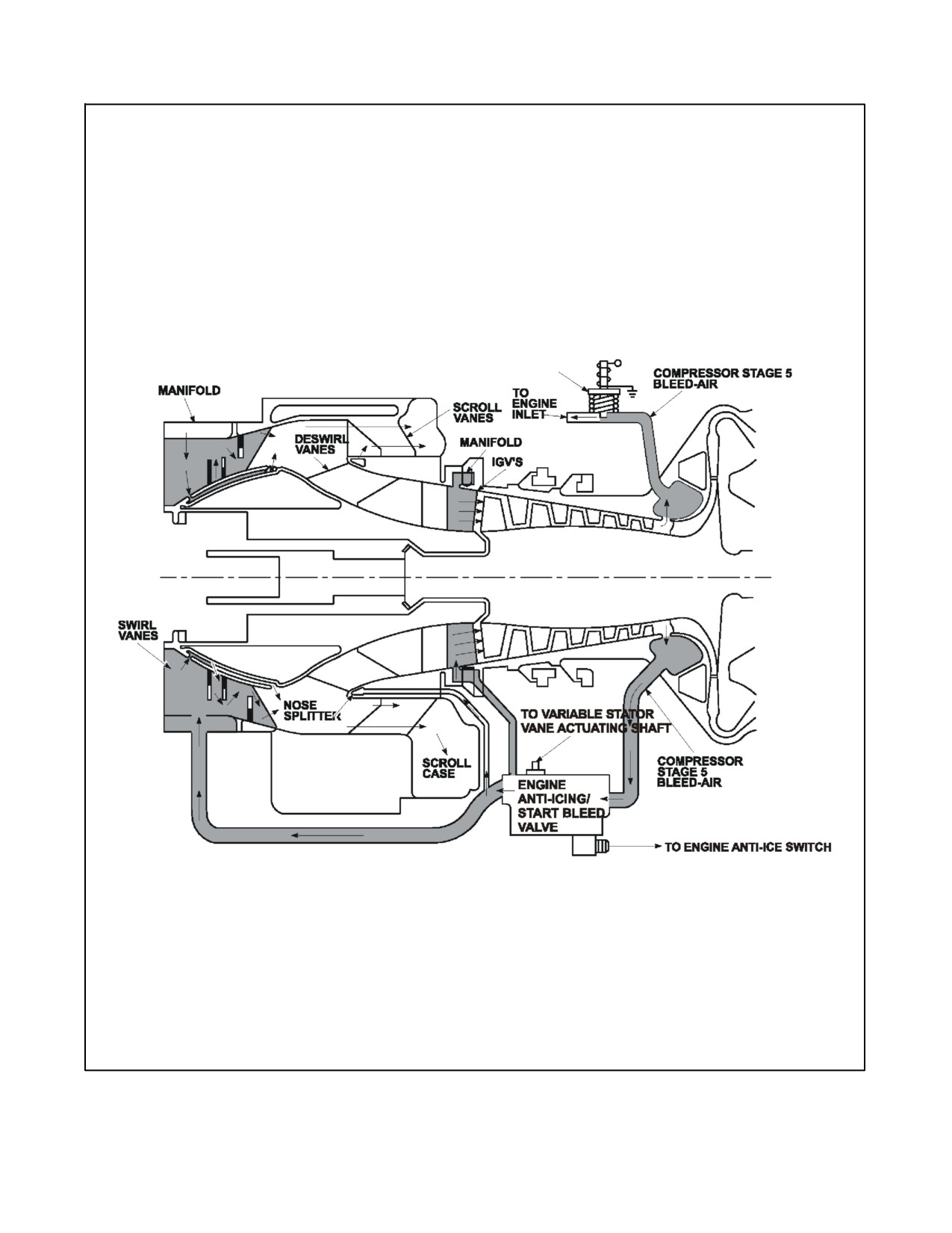
Theengineand inlet anti--icesystem (Figure2-7). prevents icebuildup on thecomponents oftheengineinlet section.
The system consists of the engine anti--ice start/bleed valve, mounted to the bottom of the compressor section, an
inlet anti--ice valve and an inlet thermal switch, contained in the engine inlet cowling.
Hot air flow for anti--icing is distributed through two solenoid operated air valves. Both valves are held closed
electrically and controlled by the ENGINE ANTI--ICE and DE--ICE MASTER switches on the upper console. When
the engine inlet anti--ice valve is de--energized (valve open), bleed air is routed to a separate modulating valve in the
engine inlet. When the DEICE MASTER switch is in the AUTO position, both solenoid valves are controlled by the
ice detector.
There are three ways to anti--ice the engine:
1. Vent bleed airinto theengineswirl vanes and engineinlet guidevanes (IGV)by theengine anti--ice/start bleed
valve.
2. Vent bleed air into the airframe engine inlet by the engine inlet anti--ice valve.
3. Continuously pump engine oil through the scroll vanes.
2.1.8.1 Engine Anti--Ice/Start Bleed Valve
The engine anti--ice/start bleed valve provides 5th stage bleed air to the engine with anti--ice selected ON, and opens
during engine starts. The valve remains open below approximately 90 percent Ng, to prevent compressor instability
during starts. Above approximately 90 percent Ng, the anti--ice/start bleed valve closes, unless anti--ice is selected
on, or the aircraft experiences a loss of electrical power. The temporary hang up of the engine variable geometry (VG)
system at the anti--ice/start bleed valve may cause engine flameouts at low collective settings. The VG system is
activated by fuel pressure from the HMU. To release the VG system quickly from any temporary hang--up condition
while the collective is full down, the HMU will schedule maximum fuel flow to the VG actuator creating a diversion
from the scheduled fuel flow to the engine. During these minimum fuel flow regimes, such as autorotations and quick
stops, this diversion may be sufficient to flame out an engine.
A malfunctioning anti--ice/start bleed valve is indicated by any of the following:
1. Illumination of the ENG ANTI--ICE ON advisory light with above 90 percent Ng or above 94 percent Ng if
OAT is 15° or greater.
2. No illumination of the ENG ANTI--ICE ON advisory light when Ng drops below approximately 88 percent
Ng. (Ng may vary on a sliding scale depending on OAT).
3. No illumination of the ENG ANTI--ICE ON advisory light when the ENG ANTI--ICE switch is selected ON.
4. No rise in TGT when ENG ANTI--ICE switch is selected ON.
Note
With ENG ANTI--ICE ON, max torque available is reduced up to 18
percent per engine.
ORIGINAL
2-16
A1-H60BB-NFM-000
Figure 2-6. Engine Start Pneumatic/Electrical System, Block Diagram
2.1.8.2 Engine Inlet Anti--Ice Valve
The engine inlet anti--ice valve is a solenoid--actuated, modulating valve located in the engine inlet cowling. Bleed
air is routed from the compressor, through the solenoid--actuated inlet anti--ice valve, then routed to the inlet cowling
and inlet fairing.
Theinlet thermal switch, mounted inside theengine inlet cowling, senses the airtemperature insidethe cowling. The
NO. 1 or NO. 2 ENG INLET ANTI--ICE advisory will illuminate when bleed air heats the engine inlet to
approximately 93 °C; however, full inlet anti--ice capability may not be available above 4 °C and will not be available
above 13 °C. The inlet thermal switch does not have any input into or control over the inlet anti--ice valve or the Freon
bellows.
With the NO. 1 and NO. 2 ENGINE ANTI--ICE switches OFF, the solenoid is energized and the valve is closed. With
the NO. 1 and NO. 2 ENGINE ANTI--ICE switches ON, the engine inlet anti--ice valve is variably open based on
OAT. With the NO. 1 and NO. 2 ENGINE ANTI--ICE switches OFF, the DE--ICE MASTER switch in AUTO, and
ice is detected, the engine inlet anti--ice valve is variably open based on OAT.
2-17
ORIGINAL
A1-H60BB-NFM-000
ENGINE INLET
ANTI--ICE VALVE
(SHOWN DEENERGIZED
ENG INLET ANTI--ICE ON)
Figure 2-7. Engine and Inlet Anti-Ice System
ORIGINAL
2-18
A1-H60BB-NFM-000
Though the engine inlet anti--ice valve may be de--energized open, the release of fifth stage compressorbleed airinto
the engine inlet cowling and inlet fairing is ultimately controlled by the Freon--filled bellows, which reacts only to
the ambient temperature. The bellows operates as follows:
1. Less than 4 °C, the valve is open and the ENG INLET ANTI--ICE ON advisories appear when inlet temperature
reaches 93 °C.
2. Between 4 °C and 13 °C, the valve is controlled by a temperature compensating Freon--filled bellows. The
bellows begin closing the valve when the OAT reaches 4 °C and should be completely closed by 13 °C.
3. Above 13 °C, the valve is closed and the ENG INLET ANTI--ICE ON advisories will extinguish when inlet
cowling temperature drops below 93 °C.
Illumination of the ENG INLET ANTI--ICE ON light when OAT is above
13 °C is an indication of a faulty engine inlet anti--ice modulating valve.
The resultant loss of power could be a maximum of 49 percent when the
engine anti--ice system is activated.
2.1.8.3 Engine Oil Circulation Through the Engine Scroll Vanes
An additional method of engine anti--ice protection is provided by the continual circulation of hot engine oil through
the engine scroll vanes. The primary function of this circulation is to cool the hot engine oil providing anti--icing of
the main frame. The air heated by the scroll vanes is vented overboard through the IPS and does not provide anti--ice
protection to the air entering the compressor section of the engine.
2.1.9 Engine Parameter Sensing
2.1.9.1 Np and Torque Sensing
Two Np sensors are located on the top of the exhaust frame. The power turbine shaft is equipped with two pairs of
teeth, which induce electrical pulses in the Np sensors. These teeth permit measurement of the torsion or twist of the
shaft, which is proportional to output torque, by producing a pulse of electrical current each time a shaft or reference
tooth passes. The sensors are identical and interchangeable, but serve different functions. The left sensor provides
an Np signal to the DECU (used by the Np governing circuitry) and the cockpit vertical instrument. The right sensor
feeds the torque computation circuit and the Np overspeed protection system. The electrical signal, which is
conditioned in the DECU, provides a DC voltage proportional to the torque for cockpit indication and use by various
engine subsystems.
2.1.9.2 Ng Sensing
The alternator supplies an Ng signal to the VIDS in the cockpit.
2.1.9.3 Np Sensing
Two sensors are located in the exhaust frame. One sensor provides the Np-governing and tachometer signal to the
ECU. The other sensor feeds the torque computation circuit and the Np overspeed protection system.
2.1.9.4 TGT Sensing
The thermocouple harness consists of seven thermocouples for measuring TGT. The thermocouples are joined in
parallel and provide an average output that is provided to the DECU. The signal is relayed to the TGT VIDS from
the DECU.
The T700--GE--401C engine TGT signal is biased — 71 °C when the engine alternator is operating (above
approximately 28 percent Ng). The bias allows the higher rated T700--GE--401C TGT to be displayed on the VIDS.
2-19
ORIGINAL
A1-H60BB-NFM-000
2.1.10 Engine Instruments
2.1.10.1 Vertical Instrument Display System
The VIDS consists of a CDU and two Pilot Display Units (PDU) located on the instrument panel (Figure 1-8). The
system furnishes all of the engine instrument readouts in the cockpit, including engine oil temperature and pressure,
TGT, Np, Ng, and torque. In addition, the system supplies instrument readouts for fuel quantity, transmission oil
temperature and pressure, and Nr, which are discussed in applicable sections. These readings are shown by ascending
and descending columns of multicolored lights (red, yellow, and green) measured against vertical scales. If the gauge
contains red or yellow lights below the green lights, these lights will extinguish when the system indication reaches
the lower green range segment. If the gauge contains yellow or red lights above the green range, the green as well
as the yellow or red lights will stay illuminated when operating above the green range.
The CDU and PDUs contain photocells which automatically adjust the lighting of the indicators around a variable
level set by the pilot with respect to ambient light level. If any of the three photocells should fail, the lights on the
vertical scales of the PDUs and CDU will go out.
Note
The DIM knob on the CDU has a manual detent which will allow the pilot
to set the lighting level to half intensity.
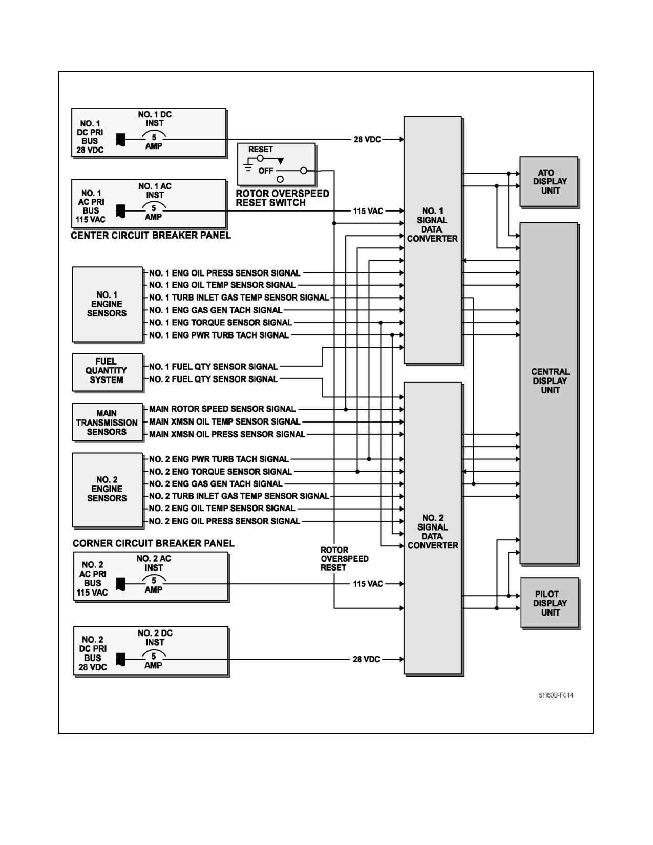
Two SDCs (Figure 2-8) take information from the NO. 1 and NO. 2 engines, Nr, transmission, and fuel quantity. The
NO. 1 SDC receives:
1. NO. 1 engine sensor signals (oil pressure, oil temperature, turbine gas temperature, gas generator tachometer,
torque, power turbine tachometer)
2. NO. 1 fuel quantity sensor signal
3. Main rotor speed sensor signal
4. NO. 2 engine power turbine tachometer signal
5. NO. 2 engine torque sensor signal.
The NO. 2 SDC receives:
1. NO. 2 engine sensor signals (oil pressure, oil temperature, turbine gas temperature, gas generator tachometer,
torque, power turbine tachometer)
2. NO. 2 fuel quantity sensor signal
3. Main rotor speed sensor signal
4. NO. 1 engine power turbine tachometer signal
5. NO. 1 engine torque sensor signal
6. Main transmission oil temperature sensor signal
7. Main transmission oil pressure sensor signal.
Within each SDC, the associated sensor signals, except for NO. 1 and NO. 2 fuel quantity, main transmission oil
temperature, and main transmission oil pressure, are conditioned to a common digital format for multiplexing. The
fuel quantity and main transmission sensor signals are conditioned and multiplexed within the CDU. After the sensor
signals have been conditioned and multiplexed, the sensor data is routed to latching circuits in the CDU and PDU.
The latching circuits retain the last signal data until it is timeto update. During update(twice persecond), thelatches
activate lamp drivers that energize miniature lamps on the edge of the display modules. Light from the lamps is carried
to the display panel face by fiber optic strips, giving visual analog and digital displays corresponding to the level of
the sensed parameter. If either SDC fails, the applicable CHAN light on the CDU will illuminate, the pilot or ATO
PDU will fail, and the corresponding instruments on the CDU will fail.
ORIGINAL
2-20
A1-H60BB-NFM-000
Both SDCs receive Np and torque information from both engines as well as Nr; therefore, if the NO. 1 SDC fails,
the pilot PDU will have Nr, Np, and torque for both engines. The SDC receives DC power from the NO. 1 and NO. 2
DC primary buses through circuit breakers marked NO. 1 and NO. 2 DC INST on the ATO circuit breaker panel and
AC power from the NO. 1 and NO. 2 AC primary buses through circuit breakers marked NO. 1 and NO. 2 AC INST
on the center and the corner circuit breaker panels, respectively.
The following are the controls for the CDU and PDUs (located on the CDU):
1. LAMP TEST. When pressed, all lights on the CDU and the overspeed lights on the PDUs will illuminate, the
digital readouts will display 888, and the 1 CHAN 2 failure lights will illuminate. When released, all lights
and digits return to original readings.
2. DIM. This knob is used to control the intensity of the vertical scales and digits on the CDU and PDUs. It
contains an override switch at the extreme clockwise end of the control range, allowing the pilot to manually
set the CDU and PDUs to half intensity if the auto dim system fails.
3. DIGITS. The DIGITS Control switch, marked ON and OFF, is used to turn on or off the CDU and PDU digital
readouts.
4.
1 C HAN 2. If a failure is detected in either SDC, the corresponding SDC CHAN 1 or 2 fail light will light.
2.1.10.1.1 Central Display Unit
The CDU contains 12 analog displays, 5 digital displays, and 2 failure lights. The CDU receives signal and power
inputs from both the NO. 1 and the NO. 2 SDC. The multiplexed data signals applied from the SDC to the CDU
contain engine oil temperature, engine oil pressure, TGT, and Ng information and are displayed on the CDU gauge.
These parameters are displayed on the CDU analog scales. The TGT and Ng information is also displayed on CDU
digital readouts. NO. 1 and NO. 2 fuel quantity signals from the NO. 1 and NO. 2 SDC, respectively, and main
transmission oil temperature and pressure signals from the NO. 2 SDC are conditioned and multiplexed by the CDU
for display on analog scales. In addition, total fuel quantity information is displayed on a digital readout. The fuel
quantity and transmission temperature and pressure gauges are discussed in applicable sections.
1.
Engine Oil System Gauges. Engine oil temperature and pressure gauges are provided for each engine. The oil
temperature gauge scales are nonlinear and read from --50 to 180 °C. Index marks define the normal operating
range. The oil pressure gauge scales are nonlinear and read from 12 to 170 psi. Index marks define the normal
operating range.
a. Engine Oil Temperature Gauge. The CDU displays oil temperature for both engines under the heading ENG
OIL TEMP. The engine oil temperature gauge receives signals from the oil temperature sensor mounted
on the front of the AGB.
b. Engine Oil Pressure Gauge. The CDU displays oil pressure for both engines under the heading ENG OIL
PRESS. The engine oil pressure gauge receives signals from the oil pressure transmitter mounted on the
front of the AGB.
Note
Theengineoil caution lights aretriggered by the VIDS oil gaugepositions.
Therefore, caution light and gauge indication cannot be used as secondary
indications to each other.
2.
Turbine Gas Temperature Gauge. The CDU displays turbine gas temperature for both engines under the
heading TGT. The two TGT nonlinear gauges indicate the turbine gas temperature of each engine and read from
0 to 950°C. There is an index at 925 °C. At the bottom of each TGT gauge is a digital readout for each engine.
The TGT gauge receives signals from a thermocouple assembly located at the power--turbine inlet section of
the engine.
3.
Gas Generator, Turbine--Speed Gauge. The CDU displays gas generator, turbine--speed for both engines under
the heading Ng SPEED. The gauges are nonlinear and read from 0 to 110 percent. Index marks define the
normal operating range. At the bottom of each Ng gauge, there is a digital readout for each engine. The gas
generator, turbine--speed gauge receives signals from the alternator mounted on the front of the AGB.
2-21
ORIGINAL
A1-H60BB-NFM-000
ATO CIRCUIT BREAKER PANEL
ATO CIRCUIT BREAKER PANEL
Figure 2-8. Signal Data Converter
ORIGINAL
2-22
A1-H60BB-NFM-000
Note
The #1 and #2 ENG OUT warning lights, located on the master warning
panels, are tripped by the Ng VIDS indication automatically when Ng
indication decreases below 55 percent.
The CDU failure lights, CHAN 1 and CHAN 2, are part of the VIDS fault detection circuit. A failure of any SDC
orCDU processing circuit, CDU orPDU display drivermodule, orSDC logicpowersupply willcausetheassociated
display channel to turn off or switch to the remaining SDC and will light the associated CHAN failure light. Failure
of a lamp power supply within an SDC will cause every second display light on the CDU as well as all display lights
on the corresponding PDU to go off.
Power to operate the CDU is provided from the NO. 1 and NO. 2 DC primary buses through circuit breakers, marked
NO. 1 and NO. 2 DC INST; NO. 1 and NO. 2 AC primary buses through the SDCs.
2.1.10.1.2 Pilot Display Units
Two PDUs, each identical and interchangeable, contain indicators that display engine power turbine speed (Np), rotor
speed (Nr), and torque readings (TRQ) for each engine (Figure 1-8).
Each unit contains five analog displays, two digital displays, three RTR OVERSPEED indicator lights, a TEST
switch, and a photocell. Instrument readings are shown by ascending and descending columns of multicolored lights
with tracking arrows along theanalog scales from 96 to 112 percent on thepercent rpm indicator and 0 to 10 percent
on the percent TRQ indicator. The tracking arrows for each display go on one at a time to coincide with analog scale
indication.Asonetrackingarrowlights, theothergoesoff. Thepercent rpmdisplay containsbottom segmentturnoff,
which turns off lower red and yellow lights. When the lowest green segment is reached, all red and yellow segments
below the normal range will go off. Three RTR OVERSPEED lights go on from left to right when rotor speed is over
127 percent, 137 percent, and 142 percent, respectively. The lights are latched on and remain on even if rotor speed
falls below the specified overspeed limits. The latch mechanism, located in the nosebay, is not affected by power loss
or power interruption. The TEST switch on each display unit is used to check all vertical scale lamps and digital
readouts on the associated unit. The photocells on the PDUs are used for automatic light level adjustment. The PDUs
are powered by the NO. 1 and NO. 2 SDCs.
2.2
ROTOR SYSTEMS
The aircraft is configured with a single four--bladed main rotor and a 20° canted, four--bladed tractor tail rotor. The
fully articulated main rotor head incorporates elastomeric bearings. The tail rotor is a hingeless crossbeam rotor of
composite construction. An automatic electrically actuated main rotor blade fold is incorporated.
2.2.1 Main Rotor System
The fully articulated main rotor system consists of four subsystems: main rotor blades, hub, flight controls, and the
bifilar vibration absorber. The four main rotor blades attach to hinged spindles and are retained by elastomeric
bearings contained in a one--piece titanium hub. The elastomeric bearings are laminated rubber and stainless steel
and enable the blades to flap, lead, and lag, and also permit the blade to move about its axis for pitch changes. Two
bearings are used per blade.
The main rotor vibration absorber is mounted on top of the hub and consists of a four--arm plate with attached weights.
Main rotor dampers are installed between each of the main rotor spindle modules and the hub to restrain lead and
lag motions of the main rotor blades during rotation and to absorb rotor head starting loads. Each damper is supplied
with pressurized hydraulic fluid from a reservoir mounted inside the main rotor shaft. The reservoir has indicators
to monitor the fluid level and nitrogen precharge pressure.
2-23
ORIGINAL
A1-H60BB-NFM-000
Rotor control is provided by flight control hydraulic servos tilting the swashplate assembly, which moves control
rods attached to each spindle. When the rotor is not turning, the blades and spindles rest on hub--mounted droop stops.
Upper restraints called antiflapping stops limit flapping motion at low rotor rpm. Both stops engage as the rotor slows
down during engine shutdown. When the main rotor is rotating above 35 percent, centrifugal force pulls the
antiflapping assemblies outward and holds them in that position to permit flapping and coning of the blades. When
the main rotor head is rotating between 55 percent and 60 percent Nr, centrifugal force pulls the droop stops out and
permits increased vertical movement of the blade.
2.2.1.1 Main Rotor Head
The main rotor head (Figure 2-9) transmits the movements of the flight controls to the four main rotor blades. The
main rotor head is supported by the main rotor shaft extension. The lower pressure plate, in conjunction with the main
shaft nut, secures the shaft extension to the main shaft. The lower pressure plate also provides attachment for the
scissors.
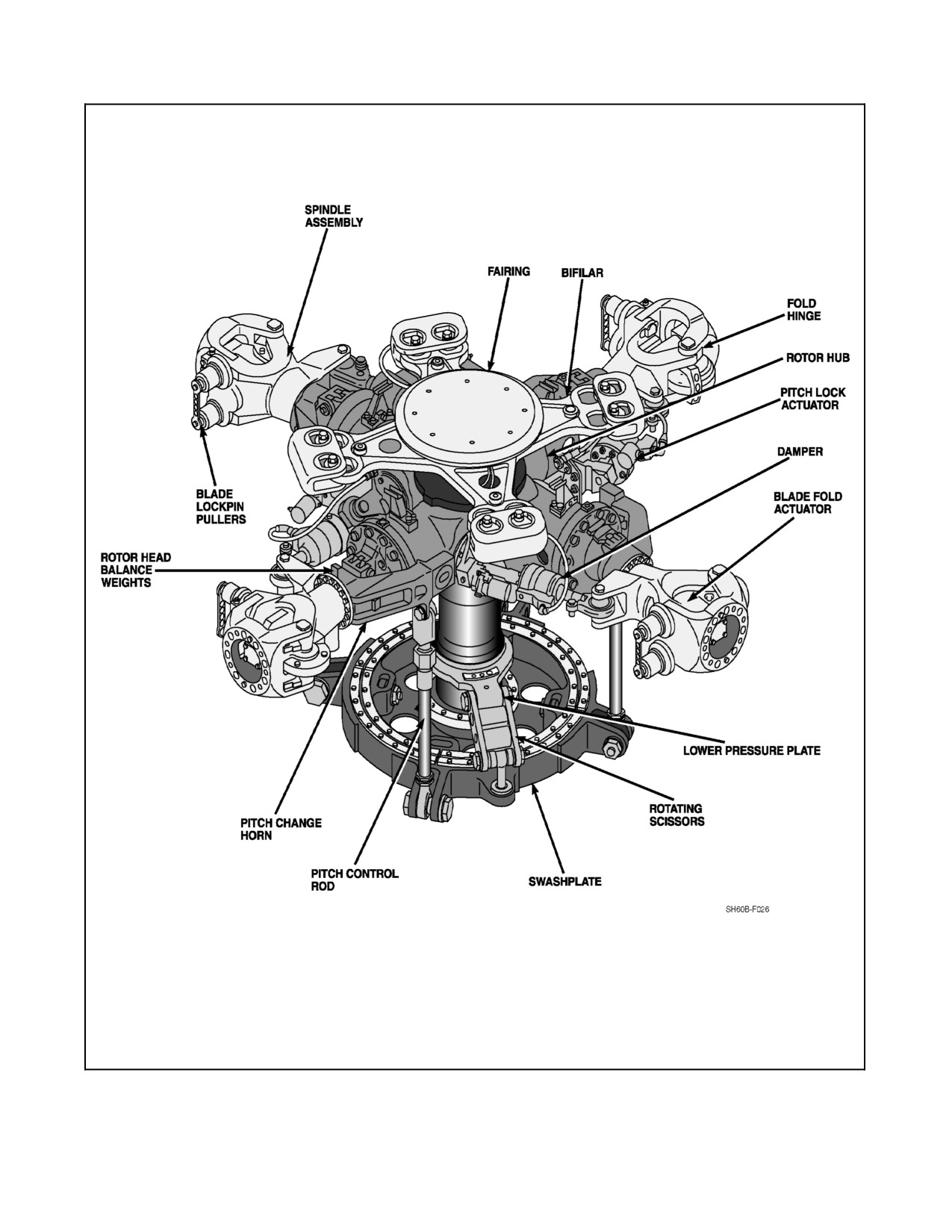
1. Swashplate. Theswashplatehas stationary and rotating discs separated by abearing. It transmits flight control
movement to the main rotor head through the four pitch control rods. The swashplate is permitted to slide on
themainrotorshaftaround theTeflon--coated uniballand tiltin anydirection followingthemotionoftheflight
controls.
2. Pitch Control Rods. Four pitch control rods extend from the rotating swashplate to the blade pitch horn on each
spindle. The pitch control rods transmit all movement of the flight controls from the swashplate to the main
rotor blades. Each rod is ground adjustable for blade tracking.
3. Bifilar Vibration Absorber. This unit absorbs vibrations and stresses. The bifilar vibration absorber is a
cross--shaped aluminum forging. A tungsten weight pivots on two points at the end of each arm. The bifilar
is bolted to the main rotor hub.
2.2.1.2 Main Rotor Blade
Four main rotor blades are installed on the main rotor head. Each blade has a pressurized titanium spar, honeycomb
core, fiberglass graphite skin, nickel and titanium abrasion strips, electrothermal deicing mats, and a removable
swept--back blade tip cap. The 20° swept tips provide both sound attenuation and increased rotor blade efficiency.
An electrothermal blanket is bonded into the leading edge for de--ice protection. A pressure indicator and servicing
valve are installed at the inboard end of the blade. A titanium cuff provides the attachment of the blade to the rotor
head. The spar of the main rotor blade is pressurized with nitrogen. If the blade is damaged, impairing the structural
integrity of the spar or if a seal should leak, nitrogen will escape. The pressure will drop below the minimum and
cause the Blade Inspection Method (BIM®) pressure indicator (Figure 2-10) to show a black or unsafe indication.
The nickel and titanium abrasion strips bonded to the leading edge of the spar extend the useful life of the blades.
Each blade is statically and dynamically balanced. This permits replacement of individual blades. Balance strips
painted around the blade locate the hoisting points.
ORIGINAL
2-24
A1-H60BB-NFM-000
Figure 2-9. Main Rotor Hub Assembly
2-25
ORIGINAL
A1-H60BB-NFM-000
2.2.1.2.1 Pressure Indicator
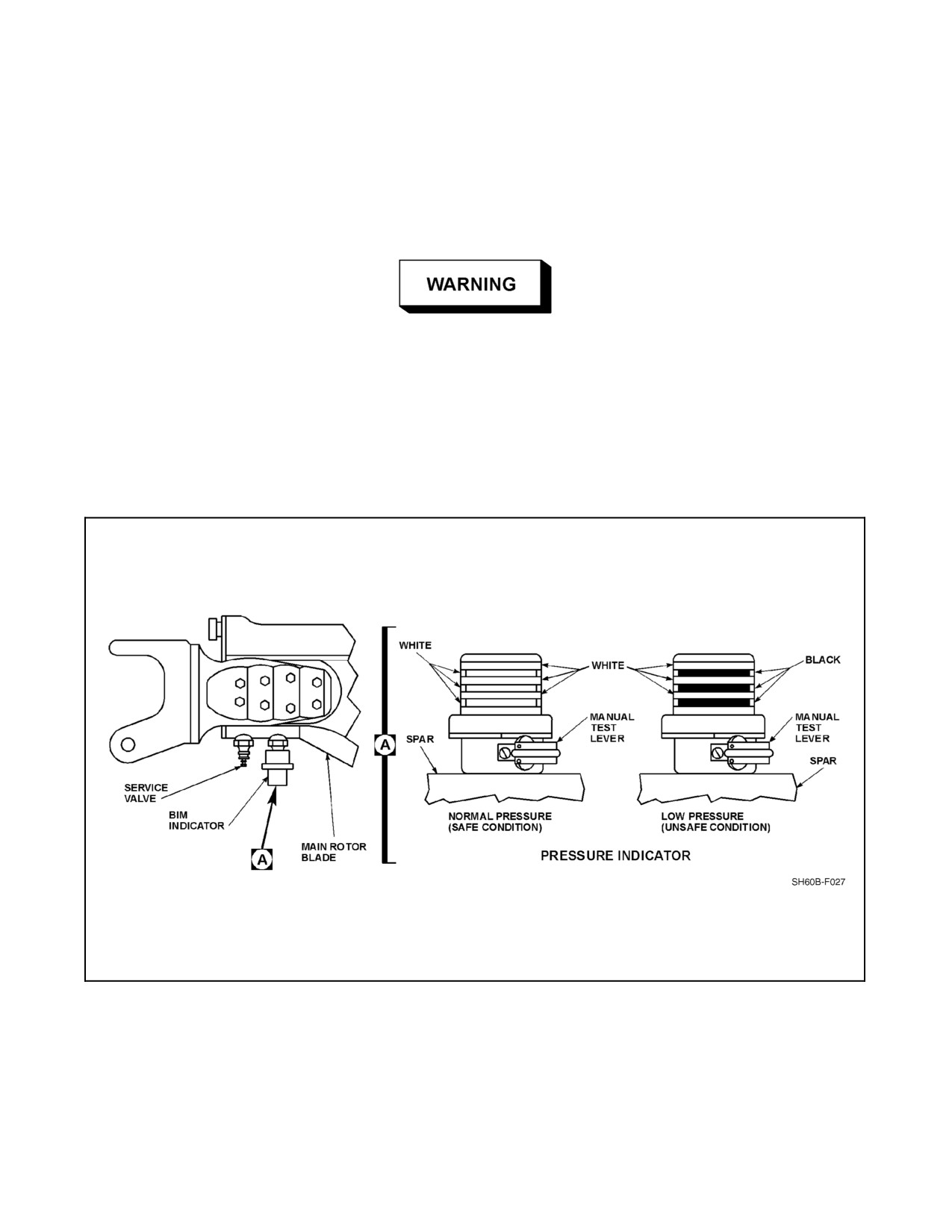
The BIM® indicator (Figure 2-10) is installed in the back wall of the spar at the root of the blade. A color change
indicates an unserviceable blade. The indicator compares a reference pressure built into the indicator with the pressure
in the blade spar. When the pressure in the blade spar is within the required service limits, three white stripes are
visible. If the pressure in the blade spar drops below the minimum permissible service pressure, the indicator will
show three black stripes. A manual test lever is installed on each BIM® indicator to provide a maintenance check.
If black is visible on the indicator, it may be an indication of blade damage
that is a flight hazard. The cause of the black indication shall be determined
prior to flight.
2.2.1.2.2 Blade Retention
Each rotor blade is connected to the rotor head spindle outboard of the blade--fold hinge and is attached by means
of a bolted flange. The blade retention assembly provides means of attachment to the rotor hub, which allows
interchangeability of the rotor blades. The retention assembly does not have to be removed to service or maintain
the main rotor hub.
Figure 2-10. BIM® Indicator
ORIGINAL
2-26
A1-H60BB-NFM-000
2.2.1.2.3 Main Rotor rpm-Indicating System
The Nr gauge is located on each PDU on the instrument panel and indicates the speed at which the main rotor is
turning. Three red warning lights on top of each PDU indicate varying degrees of rotor overspeed. The left light
illuminates at 127 percent Nr, the middle at 137 percent Nr, and the right light at 142 percent Nr. Once the lights
illuminate, they will remain on and must be manually reset on deck. Main rotor rpm is sensed in the right--hand
accessory module of the main transmission and transmits a signal to each PDU which indicates speed in percent Nr.
The Nr gauge is powered by the NO. 1 and NO. 2 DC primary buses through circuit breakers, marked NO. 1 and
NO. 2 DC INST. Both circuit breakers are located on the ATO circuit breaker panel.
2.2.2 Tail Rotor System
A bearingless crossbeam tail rotor blade system provides antitorque action and directional control. The blades are
ofgraphiteand fiberglass construction. Bladeflap and pitch--changemotionareprovidedby deflectionoftheflexible
graphite fiber spar, eliminating all bearings and lubrication. The spar is a continuous member running from the tip
of one blade to the tip of the opposite blade. Electrothermal blankets are bonded into the blade--leading edge for
deicing. The tail rotor head and blades are installed on the right side of the tail pylon, canted 20° upward. In addition
to providing directional control and antitorque reaction, the tail rotor provides 2.5 percent of the total lifting force
in a hover. With a complete tail rotor control failure, a centering spring in the tail rotor control system will provide
a preset spring--loaded position for the tail rotor, equivalent to the antitorque requirements for a midposition collective
power setting.
2.2.2.1 Tail Rotor Quadrant
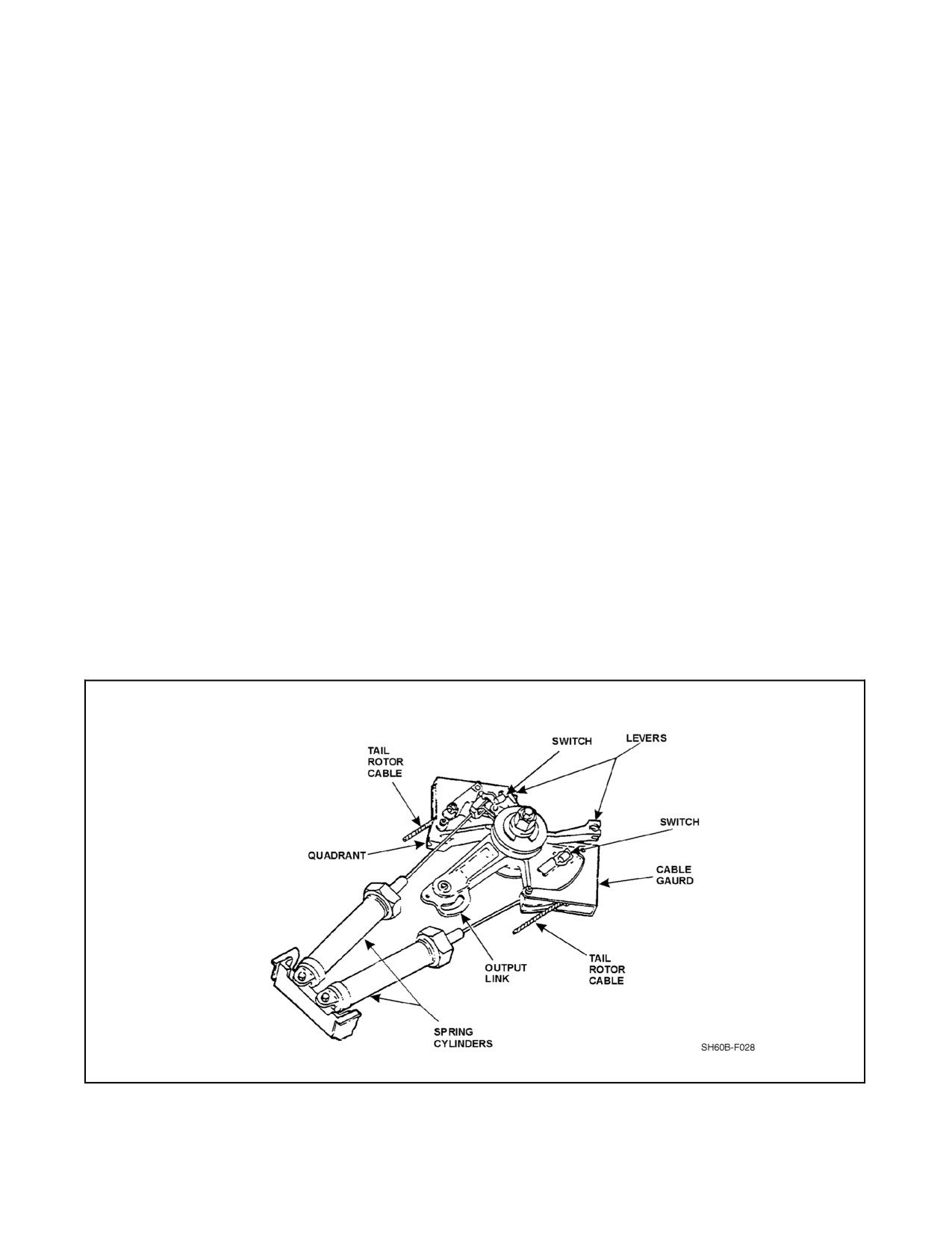
The tail rotor quadrant (Figure 2-11), mounted on the tail gearbox, transmits tail rotor cable movements into the tail
rotor servo. Two spring cylinders are connected to the quadrant. In the event a cable is broken, the spring tension
allows the quadrant to operate normally. If a failure of a cable should occur, the quadrant then controls the opposite
direction against spring tension and the related microswitch mounted on the quadrant will light the TAIL ROTOR
QUADRANT light on the caution panel. The caution system for the tail rotor quadrant is powered by the NO. 1 DC
primary bus through a circuit breaker marked TAIL ROTOR SERVO WARN and located on the ATO circuit breaker
panel.
Figure 2-11. Tail Rotor Quadrant
2-27
ORIGINAL
A1-H60BB-NFM-000
2.2.2.2 Tail Rotor Head
The head consists of two titanium plates. The inboard plate forms a hub that is attached to the gearbox output shaft
and retained by a shaft nut. The hub plates absorb axial thrust loads and bending moments and transmit torque to the
rotor blades. The blade spars are clamped directly between the plates by retaining bolts. The pitch--control crossbeams
are attached to a pitch--change actuating shaft, extending out from the center of the tail gearbox.
2.2.2.3 Tail Rotor Blades
The blades are built around two graphite composite spars, running from tip--to--tip and crossing each other at the
center to form the four blades. The two spars are interchangeable and may be replaced individually. The blade spars
are covered with cross--ply fiberglass to form the airfoil shape. Polyurethane and nickel abrasion strips are bonded
to the leading edge of the blades. Blade--pitch changes are made by twisting the spar.
2.2.3 Rotor Brake System
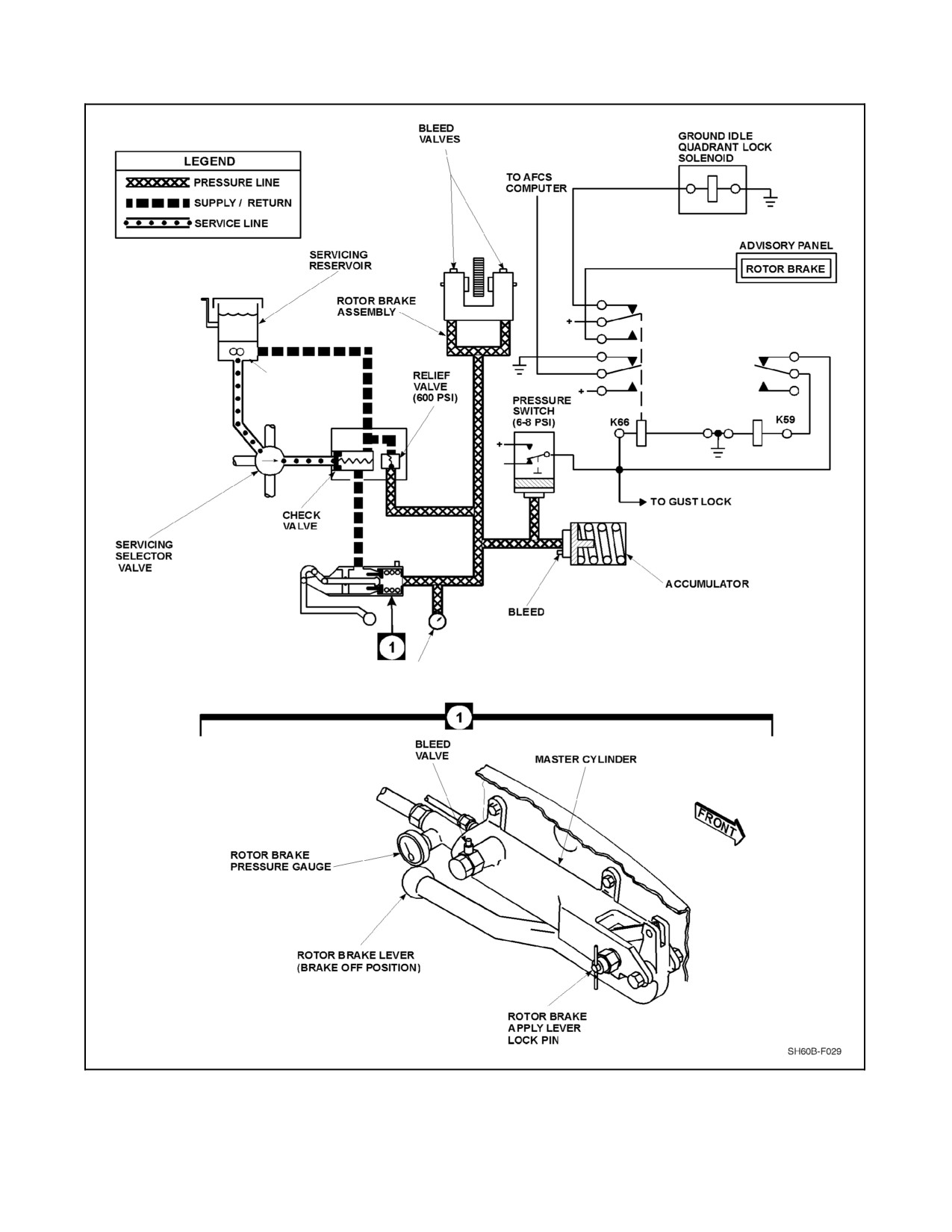
The rotor brake system (Figure 2-12) is designed to hold the rotor during engine starting and with both engines at
IDLE and to provide rotor shutdown. The system consists of a reservoir, master cylinder, gauge, relief valve assembly,
accumulator, pressure switch, rotor brake advisory light, brake assembly, and disc. When the rotor brake is applied,
the rotor brake interlock in the engine control quadrant prevents the ENG POWER CONT levers from being moved
forward of the IDLE detent with the rotor brake on.
When the rotor brake lever is moved toward the apply position, pressure is built up in the lines and applied to the brake
assembly. At the same time, pressure is applied to the rotor brake accumulator and a pressure switch (minimum 6 psi)
to turn on the ROTOR BRAKE advisory light and set the ground IDLE quadrant lock. Back pressure in the accumulator
is held by a spring as long as the rotor brake lever is in the applied position. For limited internal pressure leaks, the
accumulator spring pressure will maintain the applied pressure to the brake pucks until the brake is released by returning
the rotor brake lever to the off position, venting pressure back to the master cylinder reservoir. The rotor brake should
not be applied with engine(s) operating and rotor head turning. The brake disc is mounted on the tail drive shaft output
of the main gearbox. Teeth on the disc are utilized in the positioning cycle of the blade--fold system. The rotor brake
advisory light system is powered by the DC essential bus through a circuit breaker marked ROTOR BRAKE on the
overhead console circuit breaker panel.
2.2.3.1 Rotor Brake Master Cylinder
Therotorbrakemastercylinder, on therightsideoftheoverheadconsole(Figure 2-12),provides pressureto therotor
brake assembly. With the master cylinder in the detent position (rotor brake lever off), the system is vented back to
the reservoir. The hand pump reservoir serves as the rotor brake reservoir. A T--shaped rotor brake lever lock pin is
provided to prevent inadvertent release once the brake has been applied. To set the pin, after the rotor brake lever is
forward, rotate the pin 90° and push the pin inward until it seats into a hole on the lever arm. To release the pin, pull
and rotate 90°. The lever arm is then free to release the pressure on the system.
ORIGINAL
2-28
A1-H60BB-NFM-000
SERVICING
PUMP
GAUGE
Figure 2-12. Rotor Brake System, Block Diagram
2-29
ORIGINAL
A1-H60BB-NFM-000
2.2.3.2 Main Rotor Gust Lock
A gust lock is provided as part of the blade indexing unit which is used in conjunction with the automatic main rotor
blade--fold sequence.
The primary purpose of the gust lock gear is to index the main rotor head during blade--fold sequences. A secondary
purpose is to lock the rotor disk in the spread indexed position. Should the rotor brake hydraulic pressure bleed off
in a blade spread condition Figure 2-41, the gust lock may be engaged manually to act as a lock to hold the rotorhead
in place. This is done by means of the GUST LOCK switch on the miscellaneous switch panel. The GUST LOCK
caution light indicates when the gust lock feature of the blade indexing motor has been engaged. The light will
illuminate automatically during the blade--fold sequence or whenever the gust lock switch is actuated to the engaged
position. The gust lock feature receives power from the DC essential and NO. 2 DC primary buses through circuit
breakers marked RTR HD INDEX ENGAGE, on the overhead circuit breaker panel, and BLADE FOLD CONTR,
on the SO circuit breaker panel.
CAUTION
Should the rotor brake hydraulic pressure bleed off in a blades folded
condition, the gust lock will not prevent the rotor brake disc from turning.
2.3
TRANSMISSION SYSTEM
The primary function of the transmission system is to take the combined power from the two engines, reduce the rpm,
and transfer it to the main and tail rotors. The secondary function is to provide a drive for electrical and hydraulic
power generation. The powertrain (Figure 2-13) consists of the main transmission modules, drive shaft, an oil cooler,
an intermediate gearbox, and a tail gearbox. The tail drive shaft consists of six sections joined by Thomas couplings,
with a disconnect coupling at the fold hinge. Thomas couplings between sections eliminate the need for universal
joints. The shafts are ballistically tolerant and are suspended at four points in viscous--damped bearings. The oil
cooler drive is an integral part of the tail rotor drive shaft system. The intermediate gearbox, located at the base of
the pylon, changes angle of drive and reduces tail drive shaft speed. The tail gearbox changes the angle of drive,
reduces shaft rpm, and supports and drives the tail rotor. The intermediate and tail gearbox components are designed
to be capable of approximately 60 minutes ofoperation without oil. All other transmission components aredesigned
to be capable of approximately 30 minutes of operation without oil.
2.3.1 Main Transmission
The main gearbox drives and supports the main rotor. The main gearbox is of modular design and has a built--in
3° forward tilt.
The main transmission consists of five modules: two accessory modules, two input modules, and a main module.
The left--hand input and accessory modules are identical to the right--hand modules and are interchangeable. A rotor
brake is mounted on the tail takeoff, which provides the capability of stopping the rotor system. The rotor brake disc
is toothed to provide the means for positioning the main rotor head for blade folding. The main gearbox is pressure
lubricated and has oil pressure, oil temperature, low pressure warning, high temperature warning, and chip detector
indicating systems incorporated.
2.3.1.1 Input Module
The input modules are mounted on the left and right front of the main module and support the front of the engines.
They each contain an input bevel--pinion and gear, and a freewheel unit. The freewheeling unit allows engine
disengagement during autorotations. In the case of an inoperative engine, the freewheeling unit allows the accessory
moduletocontinuetobedrivenby themain transmission. Theinputmoduleprovidesthefirstgearreductionbetween
engine and main module.
ORIGINAL
2-30
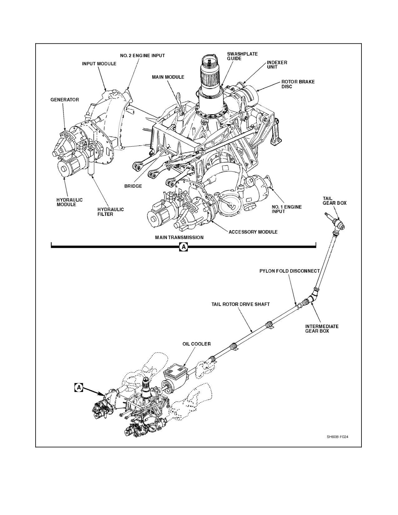
A1-H60BB-NFM-000
Figure 2-13. Powertrain (Sheet 1 of 2)
2-31
ORIGINAL
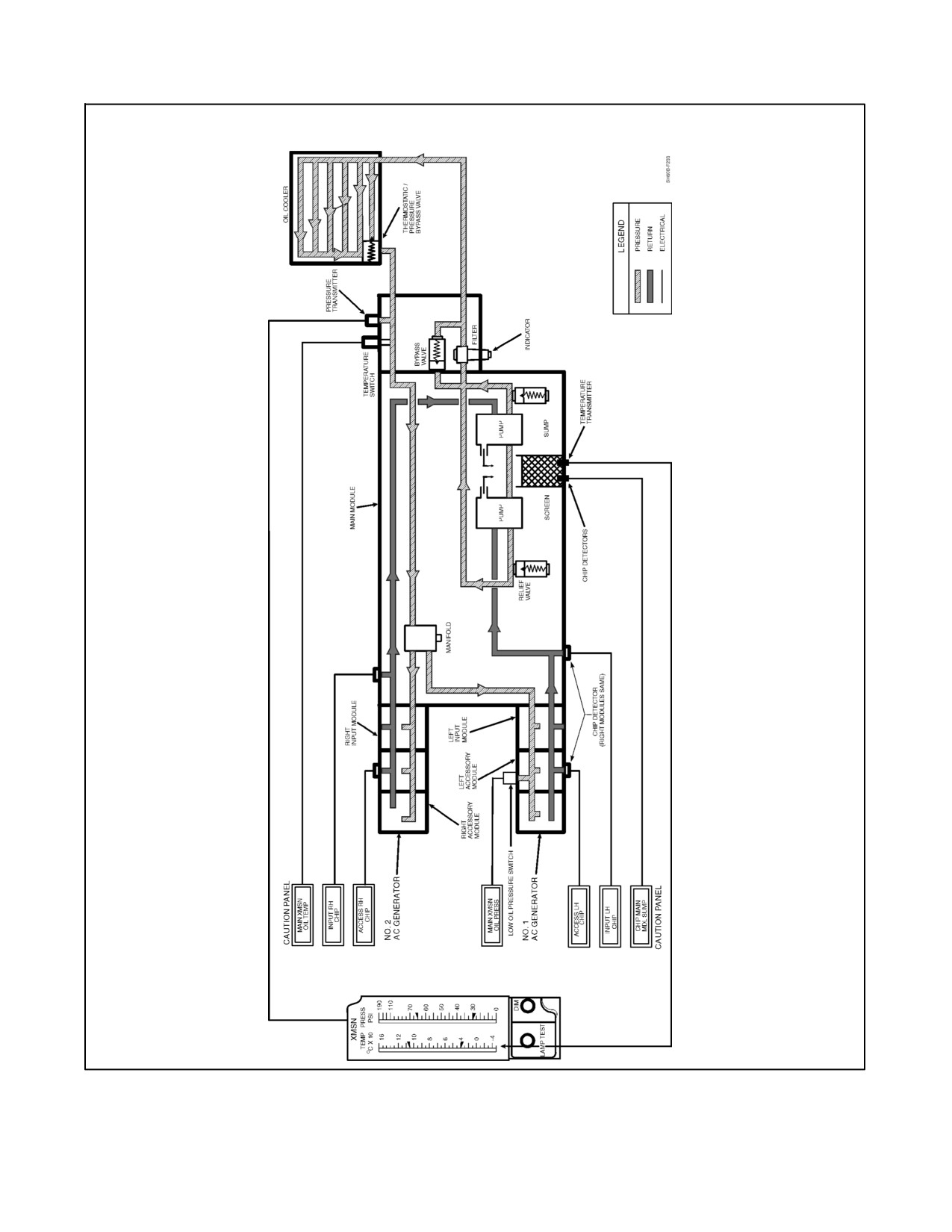
A1-H60BB-NFM-000
Figure 2-13 Powertrain (Sheet 2)
ORIGINAL
2-32
A1-H60BB-NFM-000
2.3.1.2 Diaphragm Coupling and Engine Output Shaft
The engine output shaft provides drive from the engine to the input module via the diaphragm coupling. The
diaphragm coupling is designed to allow for slight angular or axial misalignment of the engine output shaft during
operation.
CAUTION
If an abnormal or loud whining noise is heard during engine startup, shut
down engine immediately due to impending diaphragm coupling failure.
Maintenance action is required prior to subsequent engine start.
2.3.1.3 Accessory Module
One accessory module is mounted on the forward section of each input module. Each accessory module provides
mounting and drive for an AC electrical generator and a hydraulic pump package. A rotor speed sensor is mounted
on the right accessory module and supplies rotor speed information to the VIDS. In aircraft with the helicopter
emergency egress lighting system (HEELS) system, a left--hand sensor is incorporated which provides Nr
information to this system. Additionally, the low oil pressure sensor is mounted on the left accessory module. The
accessory modules are always driven by the main transmission.
2.3.2 Intermediate Gearbox
Mounted at thebaseofthetail pylon is thesplash--lubricated, intermediategearbox (Figure 2-13). It transmits torque
and reduces shaft speed from the main gearbox to the tail gearbox.
2.3.3 Tail Gearbox
The splash--lubricated tail gearbox (Figure 2-13) is located at the top of the tail pylon and transmits torque to the tail
rotor head. The gearbox mounts the tail rotor, changes the angle of drive, and provides gear reduction. It also enables
pitch changes of the tail rotor blades through the flight control system.
2.3.4 Main Transmission Lubrication System
The transmission incorporates an integral wet sump lubrication system (Figure 2-13) that provides cooled, filtered
oil to all bearings and gears. Oil is supplied to the hydraulic pump drive shaft and the AC generators for cooling and
lubrication. Oil under pressure is supplied through internally cored oil lines, except for the pressure and return lines
in and out ofthe oil cooler. Thelubrication system includes two lubrication pumps that arecombination pressureand
scavenge types operating in parallel. Pressure--regulating and bypass valves protect the lubrication system by
returning excess high--pressure oil back to the inlet side of the pump. A two--stage oil filter and various strainers in
the sump prevent contamination. The oil filter has a visual impending bypass indicator (red button) that protrudes
when the first--stage filter becomes contaminated. When the button pops, the filter element must be replaced to reset.
A thermal lockout prevents button popping when oil is cold and thick. The oil cooler uses a blower driven by the tail
rotor drive shaft to cool oil before it enters the various modules. The oil cooler has a thermostatic bypass valve that
directs oil flow around the oil cooler when the oil temperature is below approximately 54 °C, or if the oil cooler
becomes clogged. Other warning and monitoring systems on the main transmission are MAIN XMSN OIL TEMP
and PRESS caution lights and XMSN TEMP and PRESS oil gauges. An oil pressure sensor on the left accessory
module, the farthest point from the pumps, causes the MAIN XMSN OIL PRESS caution light to illuminate when
pressure drops to 14 ±2 psi. The transmission oil temperature warning system is triggered by an oil temperature
sensor at the oil cooler input to the main module, located near the tail takeoff drive shaft flange. A caution light marked
MAIN XMSN OIL TEMP goes on when transmission oil temperature reaches 117 ±4 °C. Temperature for the gauge
is sensed between the sump and the pump. Pressure readings for the gauge are taken at the main module manifold.
Electrical power for the warning systems, except chip detection, is from the NO. 2 DC primary bus through the MAIN
XMSN circuit breaker on the ATO circuit breaker panel.
2.3.5 Transmission Gauges
The main transmission gauge is located on the CDU as part of the VIDS system and is divided into oil temperature
and pressure. The temperature gauge is nonlinear and reads from --50 to 170 °C. An index defines the normal
operating range. The pressure gauge is nonlinear and reads from 0 to 190 psi. An index defines the normal operating
2-33
ORIGINAL W/IC 70
A1-H60BB-NFM-000
range. The transmission gauges are powered by the NO. 1 and NO. 2 DC primary buses through circuit breakers,
marked NO. 1 and NO. 2 DC INST and located on the ATO circuit breaker panel, and by the NO. 1 and NO. 2 AC
primary buses through circuit breakers marked NO. 1 AC INST and NO. 2 AC INST and located on the center and
corner circuit breaker panels, respectively.
2.3.6 Transmission Chip Detector System
The transmission chip detector system (Figure 2-14) consists of fuzz--suppression chip detectors and caution lights,
marked INPUT LH CHIP, INPUT RH CHIP, ACCESS LH CHIP, ACCESS RH CHIP, and CHIP MAIN MDL
SUMP. Five chip detectors provide warning of chips in any of five areas of the main transmission system. Detectors
in each module are wired, in parallel, to constantly monitor for metal contamination. Each chip detector can be
removed for visual inspection without a loss of oil. A fuzz burnoff feature eliminates false warning due to fuzz and
small particles. When a chip is detected and will not burn off, the metal particle triggers the detection system, and
a caution light will illuminate. The fuzz burnoff feature will be deactivated when the gearbox oil temperature is above
140 °C to prevent electrical arcing with oil vapor in the gearbox; however, magnetic detection will remain in the main,
input, and accessory modules. The main module sump chip detector will turn on the CHIP MAIN MDL SUMP
caution light to warn of chips in the main module. The magnetic plugs of the chip detector system will attract ferrous
metal chips at any of the detector locations. Should the chip be washed away from the detector, the light will
extinguish. The chip detector for the main module sump rests in the lowest point of the oil system and incorporates
a 30--second time delay circuit. The accessory module chip detectors are located at the lowest point on the modules
themselves, whereas the input module chip detectors are located on the bottom of the main module adjacent to the
input modules. The system is powered by the DC essential bus through a circuit breaker on the overhead console
circuit breaker panel, marked CHIP DETR.
2.3.7 Intermediate and Tail Gearbox Chip/Temperature Systems
The intermediate and tail gearboxes contain identical chip/temperature sensors that indicate when the gearbox
temperature is too high or a chip is present (Figure 2-14). The chip detectors incorporate a fuzz burnoff feature that
eliminates false warning due to fuzz and small particles. The fuzz burnoff feature will be deactivated when the
gearbox oil temperature light is lighted; however, magnetic detection will remain to light the caution light. When
a chip is detected and will not burn off, a caution indicator on the caution/advisory panel will light, indicating CHIP
INT XMSN or CHIP TAIL XMSN. The oil temperature sensor is a bimetal strip that reacts to temperatures. When
the oil temperature reaches 140 °C, a switch closes to turn on a caution light in the cockpit, marked INT XMSN OIL
TEMP or TAIL XMSN OIL TEMP. Power to operate the chip system is provided from the DC essential bus through
a circuit breaker marked CHIP DETR. Power to operate the oil temperature system is from the NO. 2 DC primary
bus through a circuit breaker marked MAIN XMSN and located on the ATO circuit breaker panel.
2.3.8 Chip-Detector Caution Lights Self-Test
Allthetransmissionmodulesandtheintermediategearboxandtailrotorgearboxchipdetectorshaveself--testcircuits
for the caution lights. The test circuit is activated when the caution/advisory panel BRT/DIM, TEST is released after
thecaution/advisory panel test sequence. The self--test checks forboth short and open circuit faults. If ashort oropen
circuit is present, the appropriate chip caution light will flash at approximately 2 flashes per second for a total of
16 flashes, and the master caution light will remain illuminated. If there is no fault when the test switch is released,
only the master caution capsule will flash.
Note
The self--test checks circuitry up through thefuzz burnoffmodule and does
not check the ability of the detector to detect chips or if a detector is
installed.
2.3.9 Main Gearbox Vibrations
The main gearbox contains many possible sources of high--frequency vibrations, such as the various gearbox--
mounted accessories, the accessory gear train, oil--cooler blower, and the input--bevel gear and freewheeling units.
These vibrations are generally heard rather than felt. Combinations of these high--frequency vibrations in extreme
cases could result in the pilot sensing low-- or medium--frequency vibrations. These would be detected as vibrations
which areaffected only by variation in main rotorspeed and may bejust as apparent in agroundrun asin flight.There
are also numerous gear clash sounds that occur under various conditions, the acceptability of which can only be
determined by experience or measurements with instrumentation.
2-34
ORIGINAL W/IC 70
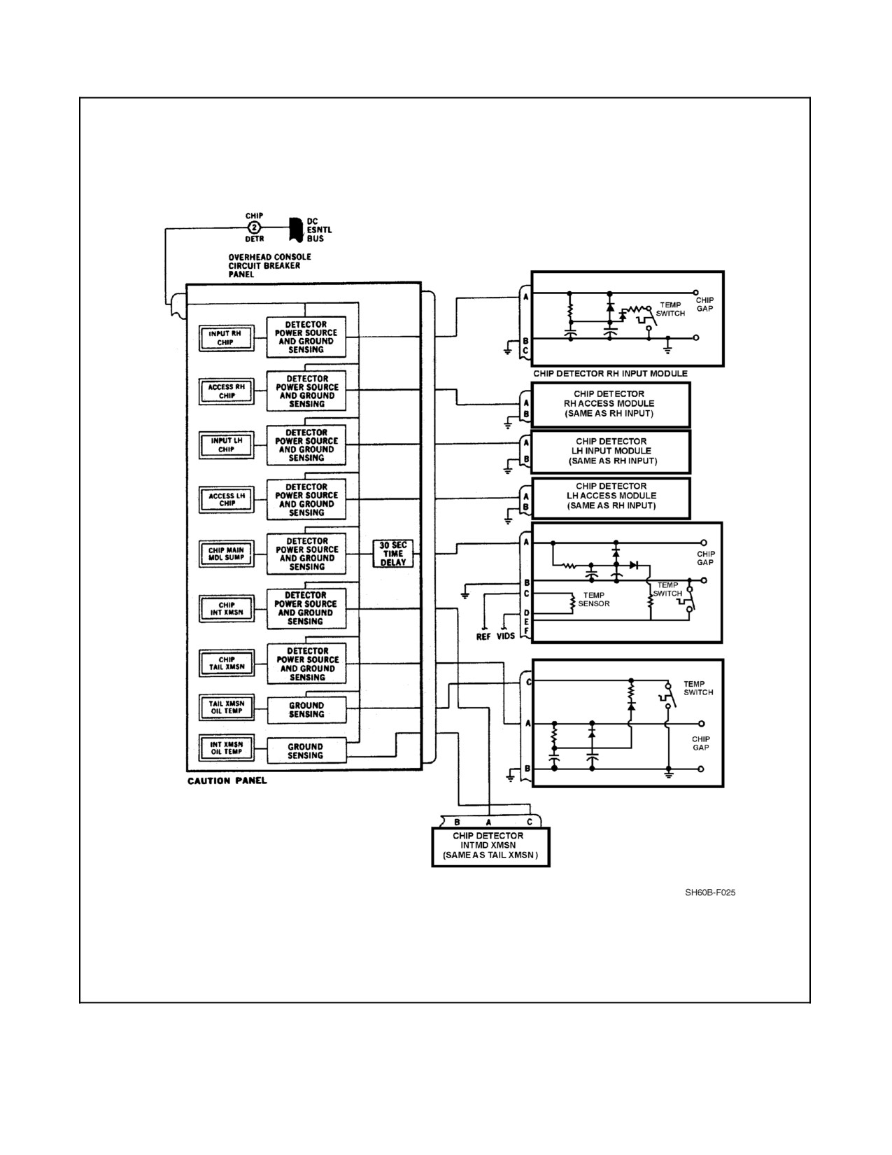
A1-H60BB-NFM-000
Figure 2-14. Powertrain Chip Detector System
2-35
ORIGINAL
A1-H60BB-NFM-000
2.4
FUEL SYSTEM
The fuel supply system (Figure 2-15 prior to BuNo 162349, Figure 2-16 BuNo 162349 and subsequent) is a
crashworthy, suction--type system consisting of two internal main cells interconnected to form a single tank, a fuel
line network, firewall--mounted selector valves, prime/boost pump, engine--driven boost pumps, and engine fuel
filters. The left internal cell has provisions for single--point refuel/defuel, gravity refuel, and the helicopter in--flight
refueling (HIFR) system. It also contains two high--level shutoffs, two check valves, sump drain, and vent. The right
internal cell contains two check valves, a sump drain, a vent, an APU fuel line, and the fuel jettison system. Total
systemcapacity(usable)is590 gallonsinternal.Additionally,BuNo 162349andsubsequentincorporateanauxiliary
fuel system capable of supporting two external auxiliary fuel tanks containing a total of 240 gallons of fuel
(120 gallons in each auxiliary tank).
2.4.1 Main Fuel Supply Operation
The prime/boost pump primes all fuel lines if prime is lost and also acts as an APU boost for APU starts and
operations. A selectorvalve, driven by acablefrom thefuelselectorlever,permits theoperation ofeitherenginefrom
either cell. All lines are routed in the most direct manner and include self--sealing breakaway valves that stop fuel
flow in the event of fuel system damage. Fuel from both cells is drawn by suction to the engine--driven boost pump,
then pumped through the engine fuel filter to the HMU high--pressure pump.
The engine fuel pressure warning system for each engine consists of a pressure switch that illuminates the caution
lights, marked
#1 or #2 FUEL PRESS, when fuel pressure drops below 8 to 10 psi from the respective
engine--driven boost pump. This visually indicates a possible malfunction in the engine--driven fuel boost pump or
an air leak in the fuel system.
The engine fuel--filter bypass warning system for each engine consists of an electrical switch, impending bypass
popout button (located on the filter), and caution lights. Once the filter goes into bypass, the caution lights, marked
#1 or #2 FUEL FLTR BYPASS, will light.
Note
The fuel filters are not sensitive to water contamination. Water--contamin-
ated fuel may cause fluctuations/surges in one or both engines with no
associated FUEL PRESS or FUEL FLTR BYPASS caution light.
The #1 and #2 FUEL FLTR BYPASS and the #1 and #2 FUEL PRESS caution lights are powered by the NO. 1 and
NO. 2 primary DC buses, respectively, through circuit breakers marked NO. 1 ENG and NO. 2 ENG WARN LTS
located on the ATO circuit breaker panel.
2.4.1.1 Fuel Selector Levers
There are two ENG FUEL SYS levers, one for each engine, located outboard of the ENG POWER CONT levers
(Figure 1-6). The fuel selector levers manually position the fuel selector valves to any one of three positions: OFF,
DIR, or XFD. The fuel selectors are connected to the fuel selector valves with low--friction, flexible push--pull cables.
With the selectors at OFF, the fuel selector valves are closed, allowing no fuel to the engines. When the selectors are
moved forward to DIR, the fuel selector valves are opened, providing fuel flow for each engine from its individual
cell. Moving the selector to XFD provides fuel to the engine from the opposite cell through the crossfeed system.
A check valve in each crossfeed line prevents air from the fuel line of an inoperative engine from crossing to the
operating one. When either fire emergency control T--handle, located outboard of the fuel selector levers, is pulled
aft, the respective fuel selector lever will be mechanically placed in the OFF position.
ORIGINAL
2-36
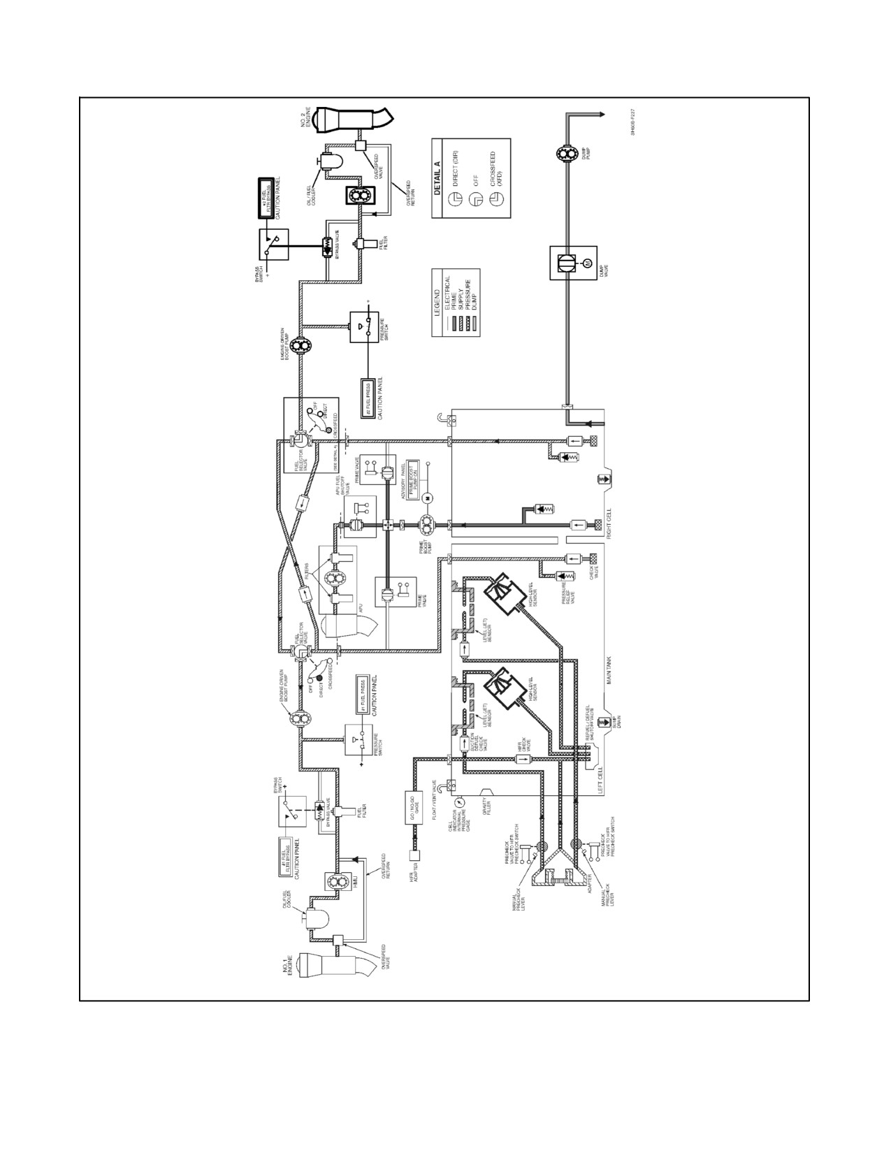
A1-H60BB-NFM-000
Figure 2-15. Fuel System Block Diagram — Prior to BuNo 162349
2-37
ORIGINAL
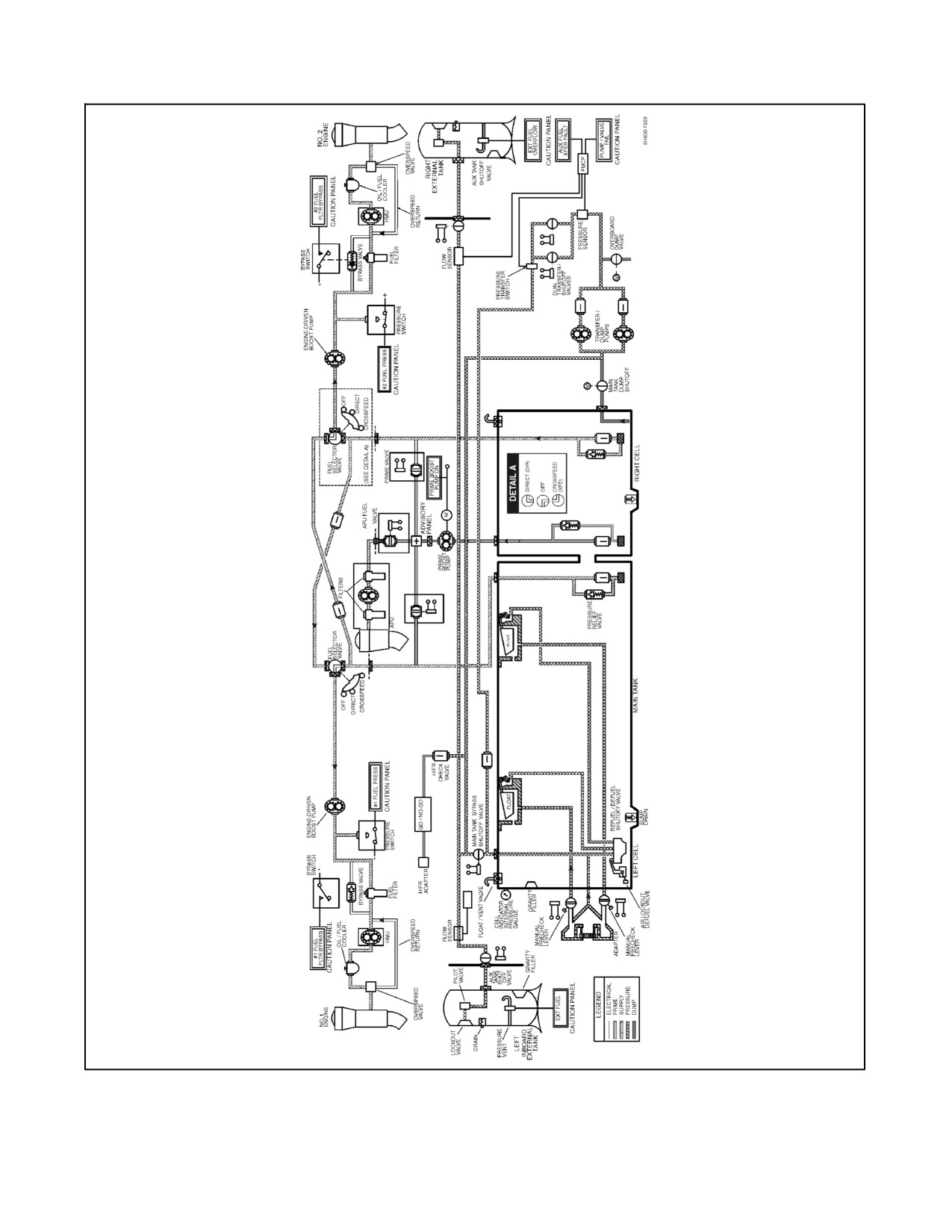
A1-H60BB-NFM-000
Figure 2-16. Fuel System Block Diagram — BuNo 162349 and Subsequent
ORIGINAL
2-38
A1-H60BB-NFM-000
2.4.1.2 Engine/APU Boost/Fuel Prime System
The APU boost and engine prime system consists of a suction line located in the right fuel cell, a prime/boost pump
(which is externally mounted on the tank), APU fuel shutoff valve, two engine fuel prime shutoff valves, and a
selector switch located on the overhead console (Figure 1-6). The FUEL PUMP selector switch is a three--position
switch, marked APU BOOST, OFF, and FUEL PRIME. Activation of the switch illuminates the PRIME BOOST
PUMP ON advisory light. The FUEL PRIME position allows fuel to enter all fuel lines before engine start. Power
to operate the prime--boost pump is from the battery bus through a circuit breaker marked FUEL PRIME BOOST
and located on the center console circuit breaker panel.
2.4.1.2.1 Fuel Prime System Operation
Placing the APU BOOST/FUEL PRIME switch to APU BOOST opens the APU fuel shutoff valve and activates the
fuel prime/boost pump. Placing the APU BOOST/FUEL PRIME switch to FUEL PRIME opens both engine prime
shutoff valves and allows individual priming of the engines with the PCL in lockout.
2.4.2 Main Tanks Fuel Quantity System
The fuel quantity system (Figure 2-17) consists of a fuel probe mounted in each fuel cell and a fuel quantity signal
conditioner. The system interconnects two SDCs to the VIDS CDU.
2.4.2.1 Fuel Low Level Warning System
The fuel low level warning system consists of a dual--channel, low--level warning conditioner; two fuel cell--sensing
units; and associated caution lights. Each cell--sensing unit is placed at approximately the 200 to 225 pound fuel level.
As long as thesensing unit is covered with fuel, the warning conditioner will keep the#1 and #2 FUEL LOWcaution
lights off. As fuel is consumed and its level drops below the200 to 225 pound level, the fuel cell--sensing units sense
the lack of fuel and signal the conditioner of a low fuel state. These lights will continue to illuminate and extinguish
as long as fuel continues to wash on and off the sensors. This system is completely independent of the fuel quantity
system. Theconditionerthen applies powerto theappropriateFUEL LOWcaution and MASTER CAUTION lights.
Power to operate the fuel low level system warning is from the NO. 1 DC primary bus through a circuit breaker
marked FUEL LOW WARN and located on the ATO circuit breaker panel.
2.4.3 Fuel Dump System
A fuel dump system (Figure 2-15 prior to BuNo 162349, Figure 2-16 BuNo 162349 and subsequent) is installed to
allow for emergency rapid dumping of fuel at approximately 836 pounds per minute, but can exceed 1,000 pounds
per minute. The system consists of a FUEL DUMP switch mounted on the lower console EMER panel and a
standpipe and dump port in the right main fuel cell. Aircraft prior to BuNo 162349 have a dump valve and a
pump/motorassemblyinthetransitionsection.AircraftBuNo162349andsubsequenthaveamaintankshutoffvalve,
an overboard dump shutoff valve, two transfer/dump pumps/motors, and Fuel Management Control Panel logic to
control required valves. Power to operate the fuel dump system is from the DC essential bus through a circuit breaker
marked FUEL DUMP CONTR, the NO. 1 AC primary bus through a circuit breaker marked FUEL DUMP PUMP,
and, for BuNo 162349 and subsequent, the NO. 2 AC primary bus through a circuit breaker marked FUEL DUMP
PUMP.
The circuit breakers are located on the overhead circuit breaker panel and the center circuit breaker panel, respectively,
and, for BuNo 162349 and subsequent, the corner circuit breaker panel.
After dumping, observe the fuel readout to ensure dumping has ceased.
Note
Fuel can be dumped when the helicopter is on the ground. The fuel dump
system is not protected by the weight--on--wheels (WOW) switch.
2-39
ORIGINAL
A1-H60BB-NFM-000
2.4.3.1 System Operation
Placing the FUEL DUMP switch to the DUMP position opens the valve and closes the contacts in the pump/motor
relay, operating the pump/motor. Fuel will dump out of both cells down to the level of the cell interconnect. Fuel will
then continue to dump out of the right cell to the level of the standpipe. After total dump, approximately 270 pounds
will remain in the left cell and 140 pounds in the right cell (prior to BuNo 162349). Fuel quantity remaining after
dump can vary depending on aircraft pitch attitude.
2.4.3.2 System Operation (with FMCP)
With the FMCP MASTER and MODE switches set to TRANSFER and MANUAL OVERRIDE, placing the FUEL
DUMP switch on the emergency control panel (Figure 1-7) to the DUMP position signals the FMCP, bypassing all
of the FMCP operating modes. The FUEL DUMP indicatorlight on the FMCP illuminates, theauxiliary tank valves
open, both transfer/shutoff valves close, the main tank bypass shutoffvalve closes, the overboard dump valveopens,
and both fuel transfer/dump pumps begin running. When the auxiliary tanks are empty, each auxiliary tank valve
closes and the main tank dump valve opens.
The fuel transfer/dump pumps continue running and fuel will dump out of both main cells down to the level of the
interconnect (approximately 270 pounds in each cell). Fuel will then continue to dump out of the right cell to the level
ofthelow level sensor(approximately 210 pounds)when thedump signal is interrupted at theFMCP (BuNo 162349
and subsequent). The fuel quantity remaining in the right cell after dump could be lower at noseup attitudes associated
with lower airspeeds. When the dump signal is interrupted, the main tank dump valve closes, the main tank bypass
shutoff valve opens, and both fuel transfer/dump pumps stop. Placing the FUEL DUMP switch to OFF closes the
overboard dump valve and restores FMCP control functions.
Note
D Regardless of FMCP switch positions or whether auxiliary tanks are
installed,selectingFuelDumpon theEmergency ControlPanel willenable
emergency dumping from the main tank. FMCP switches need only be set
to TRANSFER and MANUAL OVERRIDE if pilots desire to dump fuel
from the auxiliary tanks. With no auxiliary tanks installed, fuel may be
dumped from themain tankwith theFMCP inany configuration,including
STOP FLOW.
D For aircraft operating without a functional FMCP, refer to
paragraph 2.4.3.1.
2.4.4 Single-Point Pressure Refueling System
Thesingle--point pressurerefueling system is used to pressurerefuel thefuel tanks on theground. Thefuel tanks may
be serviced without electrical power. On aircraft BuNo 162349 and subsequent, without power applied to the aircraft,
all tank valves are open and fuel enters all tanks randomly until the main tank high level sensor is reached and the
mechanical shutoff float valve closes. During refueling with electrical power on, all auxiliary tank shutoff valves are
closed and the main fuel tank is filled first. When the FMCP is signaled that the main tank is filled, the right inboard
auxiliary and left inboard auxiliary tanks, if sensed as installed, are then filled by the same process in order.
CAUTION
During single--point pressure refueling, if the right cell fills faster than the
left cell, monitor the fuel quantity gauges closely. If the difference in cell
quantitiespersists,stoprefuelingbeforetheright cellis full(approximately
1,700 pounds).
ORIGINAL
2-40
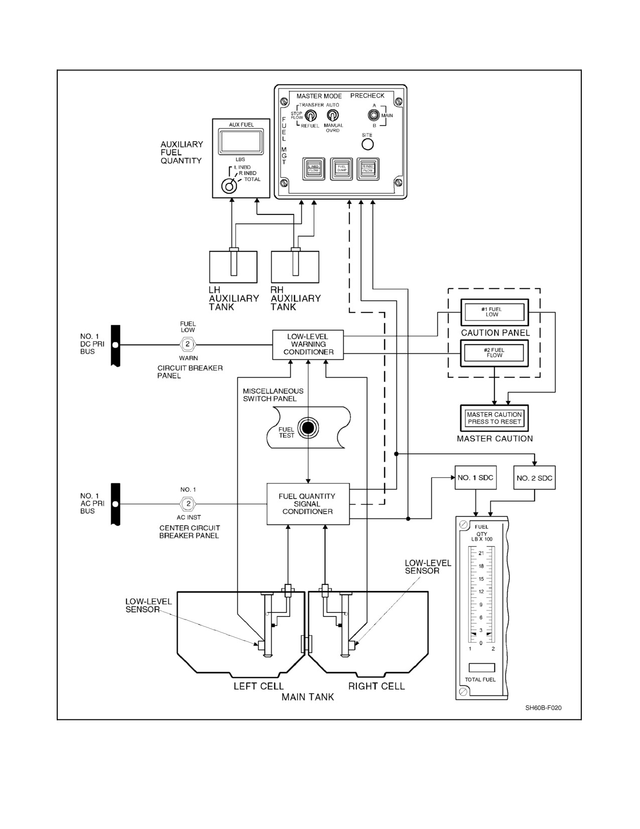
A1-H60BB-NFM-000
Figure 2-17. Fuel Quantity System (with Auxiliary Tanks Installed)
2-41
ORIGINAL
A1-H60BB-NFM-000
Note
Fuel quantity indicators are not operable without AC electrical power and
fuel quantity must be visually checked.
2.4.4.1 Pressure Refueling Panel
The pressure refueling panel (Figure 1-3, index NO. 34), located on the left side of the aft fuselage, provides a single
point for refueling and defueling. The pressure refueling panel contains a connecting adapter, pressure gauge, and
two manually operated precheck valves. Aircraft prior to BuNo 162349 have two jet sensors in the left fuel cell that
will activate their respective shutoff valves when fuel in the cell immerses them. Either or both shutoff valves will
in turn signal the pressure refuel/defuel valve to interrupt normal fueling.
The two high--level sensors in the left cell will cause fuel flow to be reduced to 5 gallons per minute when the cells
are becoming full. When the precheck valves are pressed, jet sensor immersion is simulated and fuel flow is
interrupted to indicate that the system is operating properly. Aircraft BuNo 162349 and subsequent incorporate two
high--level float sensors in the top of the tank that will stop fuel flow when the main tank is full. When the precheck
valves are pressed, fuel is redirected to raise the floats, which then stops the fuel flow to indicate that the system is
operating properly. In all aircraft, the high--level sensors can also be tested during a HIFR from inside the aircraft.
Pressure that may have built up in the tank, due to a clogged or malfunctioning vent, will register on the tank internal
pressure gauge. Specific instructions for conducting a pressure refueling precheck are on a decal below the pressure
refueling adapter and in the servicing chapter (Chapter 3).
2.4.4.2 Gravity Refueling
Gravity fueling ports are available for the main and external auxiliary fuel tanks. Tanks may be gravity fueled in any
order.
2.4.4.3 Suction Defuel
All tanks can besuction defueled from thepressure refueling port, except the 270 pounds in the right main cell below
the tank interconnect, which must be suction defueled through the cell sump drain valve.
2.4.4.4 HIFR Refueling System
The HIFR system (Figure 2-18) consists of a Wiggins quick--disconnect pressure--refueling fitting, a pressure--refuel-
ing precheck switch, and a five--element (fuse) GO/NO--GO canister to pressure refuel the main fuel tanks. The
Wiggins fitting is located above the right--hand fuel cell just forward of the GO/NO--GO canister. The GO/NO--GO
canister is mounted above the right fuel tank and permits only acceptable fuel to pass. The elements are water sensitive
and will shut off fuel flow at a 20 psi differential pressure. Flow is reduced to an extremely low level if the fuel is
contaminated with water and particulate matter above a predetermined level.
Note
If the helicopter must be fueled when the quality of the fuel is in question,
it should be refueled through the HIFR fitting. The HIFR filter is capable
of removing both water and particulate matter from fuel.
Fuel spillage is collected in a drip pan located on top of the fuel tank and then drains overboard. The precheck panel
contains a ground connector and a precheck switch. When the switch is moved to PRECHECK, 28 Vdc power is
applied through the switch to the pressure refuel precheck valve in the refueling line to shut off fuel flow to the
high--level sensor, testing the complete refueling system. Power to operate the precheck system is from the NO. 1
DC primary bus through a circuit breaker marked HIFR TEST and located on the SO circuit breaker panel.
ORIGINAL
2-42
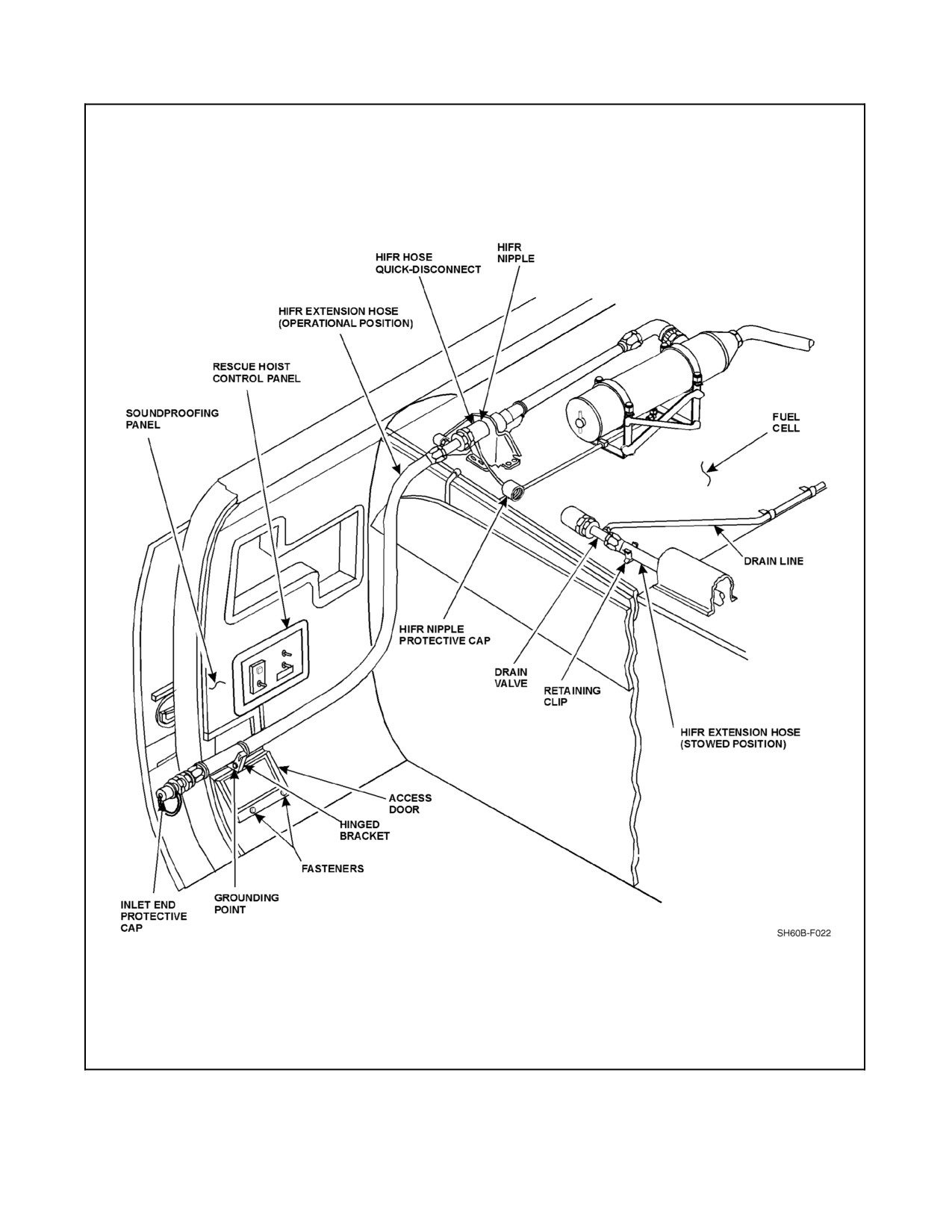
A1-H60BB-NFM-000
Figure 2-18. Helicopter In--Flight Refueling (HIFR) System (Sheet 1 of 2)
2-43
ORIGINAL
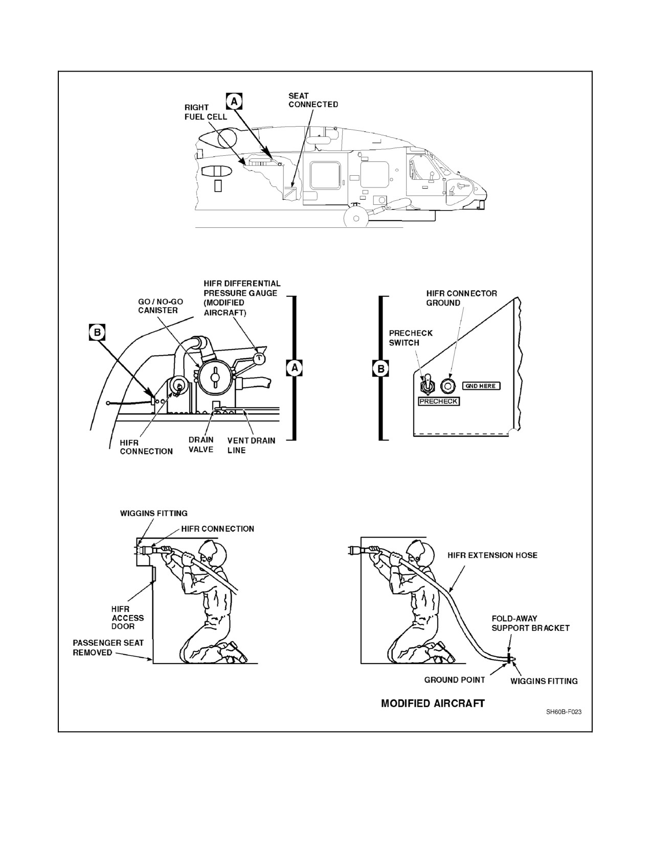
A1-H60BB-NFM-000
Figure 2-18 Helicopter In--Flight Refueling (HIFR) System (Sheet 2)
ORIGINAL
2-44
A1-H60BB-NFM-000
Some aircraft are modified to include a HIFR extension hose and a differential pressure gauge. The extension hose is
stowed on top of the fuel cell and held in place with a retaining clip. For HIFR, the extension hose is connected to the
HIFR connection, routed, and secured to a foldaway support bracket located aft of the personnel door below the rescue
hoist control panel. The refueling hose is then connected to the extension hose Wiggins fitting at the support bracket. A
grounding jack is located on the foldaway support bracket. The differential pressure gauge shows HIFR GO/NO--GO
canister input and output pressure differential. A drain valve can be manually activated to clear the HIFR system of fuel.
If the left tank vent valve should malfunction and remain stuck in the closed position during HIFR, uneven filling
of the main tank cells may occur. Once the fuel level has risen above the interconnect opening (approximately
600 pounds total), trapped air in the left cell will slow the rate at which the left cell fills with fuel to the point that
the level will not rise while the right cell will continue to fill normally. If the fuel level remains below the high level
shutoff sensor located in the left cell, the fuel flow will not stop. The fuel level in the right cell will rise to a level
that will force thevent valveto close, resulting in an overpressurecondition and possible cell rupture. SeeChapter 8,
for HIFR procedure.
CAUTION
During HIFR, if the right cell fills faster than the left cell, monitor the fuel
quantity gauges closely. If the difference in cell quantities persists, stop
refueling before the right cell is full (approximately 1,700 pounds).
2.4.5 Auxiliary Fuel System
The auxiliary fuel system is comprised of two auxiliary tank locations, a fuel management system, and fuel quantity
display information. Management is provided through the FMCP (Figure 2-16 and Figure 2-17). The FMCP receives
the sensor switch signal and provides logic to the control valves and pumps to control auxiliary fuel system functions.
2.4.5.1 Fuel Management Control Panel
The fuel management control panel (FMCP) functions are software controlled. The FMCP panel marked FUEL MGT
is on the center console (Figure 1-7). The MASTER switch is a three--position switch marked TRANSFER, STOP
FLOW, and REFUEL. At T
TRANSFER, the FMCP control logic enables the MODE switch and transfer operation. At STOP FLOW, power is
removed from all FMCP switches, control logic is disabled, and auxiliary fuel system control is stopped, which closes
all auxiliary tank shutoff valves. At REFUEL, when refueling with electrical power on, the aircraft the sequencing
logicturns offall FMCP switches except precheckswitches, allauxiliary tankshutoffvalvesarecloseduntil themain
internal tank is filled, and the auxiliary tank shutoff valves open one at a time to selectively fill the auxiliary tanks.
The fuel system fill sequence is main tank, right inboard auxiliary tank, and left inboard auxiliary tank.
The MODE switch is a two--position switch marked AUTO and MANUAL OVRD. At AUTO, the fuel management
logic is not initiated until the main fuel tank fuel level depletes to 2,700 to 2,580 pounds. If two auxiliary tanks are
installed, the second tank will transfer after the main tank fuel level again drops enough to accommodate the complete
auxiliary tank. When in MANUAL OVRD, auxiliary tank fuel is immediately transferred to the main tank until the
high level sensor is reached, or until the auxiliary tanks are empty. Fuel tank transfer sequence is left inboard auxiliary
tank then right auxiliary tank.
The PRECHECK switch is marked A, MAIN, and B and is spring loaded to the center (MAIN) position. The center
position provides powerto theprecheck valves in themain fuel tank. When moved to A orB, powerto therespective
precheck valve is interrupted and fuel flow during refueling is immediately stopped, and fuel flow indication of the
FMCP FLOW lights will go out.
Note
A malfunctioning FMCP (with electrical power applied) can cause
activation of precheck valves preventing the ability to pressure refuel or
HIFR. The FUEL MGMT circuit breakers on the ATO circuit breaker panel
must be pulled to secure the precheck valves to allow fueling.
2-45
ORIGINAL
A1-H60BB-NFM-000
Three fuel flow indicators/selectors are marked L INBD FLOW, FUEL DUMP, and R INBD FLOW. The FUEL
DUMP indicator lights when the EMER PNL FUEL DUMP switch is activated. The auxiliary tank indicators are
split. L INBD and R INBD show at all times. FLOW lights independently when fuel is sensed flowing into or out
ofrespectiveauxiliary fueltank. TheL INBDand RINBD selectorswitch functionis amomentary pushbuttonwhich
when pressed, and MANUAL OVRD is selected, will initiate appropriate circuits to transfer fuel from an auxiliary
tank to the main tank. When fuel level in the main tank reaches the high level shutoff, all manual transfer commands
are stopped. When a selected auxiliary tank is emptied before the main tank high level shutoff is reached, the transfer
circuits will shut off in 10 seconds.
Power to operate the FMCP is from the NO. 1 and NO. 2 DC primary buses through two circuit breakers marked
FUEL MGMT and located on the ATO circuit breaker panel.
2.4.5.2 Fuel Transfer System
The fuel transfer system is controlled by the FMCP. It provides automatic or manual transfer of fuel from the auxiliary
fuel tanks to the main fuel cells. Dual transfer/dump pumps suck fuel from the auxiliary fuel tanks through shutoff
valves and deliver the fuel to the main tank. Pressure switches are provided as sensors to enable the FMCP to monitor
fuel system operation. Fuel transfer is approximately 285 pounds per minute. When one pump fails to transfer fuel,
and the second pump successfully transfers fuel, the PUMP/VALVE FAIL caution light illuminates. The FMCP
receives fuel quantity status from main and auxiliary systems to properly schedule fuel transfer from auxiliary tanks
to the main tank.
CAUTION
D During transfer of auxiliary fuel, if the right cell fills faster than the left cell,
monitorthefuel quantity gauges closely. Ifdifferencein cell quantitiesper-
sists, stop transferring fuel before the right cell is full (approximately
1,700 pounds).
D Do not initiate unmonitored manual transfer to the main tanks from
auxiliary tanks until main tanks are below 3,200 pounds for an external
auxiliary tank transfer. During manual auxiliary tank transfer, the main tank
high level sensor (float valves) should prevent overflow of the main fuel
tanks.
2.4.5.3 Manual Fuel Transfer Check
When main fuel tank capacity has decreased approximately 300 pounds, check the manual fuel transfer system to
ensure proper transfer. Two short manual transfers will exercise both dual transfer pumps and transfer valves to ensure
proper transfer.
2.4.5.4 Auxiliary Fuel Tanks
Each inboard weapons pylon is configured to accept a 120 gallon drop tank. The fuel level of each auxiliary fuel tank
is internally monitored by a single gauge probe. Each probe provides a fuel quantity signal to the FMCP and the
auxiliary fuel quantity indicator. Each auxiliary tank contains a low--level thermistor sensor which is exposed only
when the tank is empty and then sends a signal to the FMCP. Each external auxiliary tank contains an overflow
thermistor sensor which sends a signal to the FMCP if fuel is sensed in the external tank vent line. When fuel is sensed,
a signal is sent to illuminate the EXT FUEL OVERFLOW caution light. Power to operate the auxiliary fuel tanks
is from the NO. 2 DC primary bus through two circuit breakers marked FUEL LH INBD and FUEL RH INBD and
located on the SO circuit breaker panel.
The auxiliary fuel quantity indicator marked AUX FUEL is on the pilot instrument panel (Figure 1-8). The window
marked LBS provides a digital reading of the fuel quantity for the auxiliary tank or tanks selected with the selector
switch. A selector switch marked L INBD-R INBD-TOTAL selects the fuel quantity in the left or right auxiliary tank
or the total quantity of the two tanks. Power to operate the auxiliary fuel quantity indicator system is from the NO. 2
DC primary bus through a circuit breaker marked FUEL MGMT and located on the ATO circuit breaker panel.
ORIGINAL
2-46
A1-H60BB-NFM-000
Any combination of auxiliary tanks can be installed or removed from the aircraft. The software logic of the FMCP
senses if an auxiliary tank gauge and low--level switch signal is absent. The FMCP commands automatically bypass
an absent auxiliary tank station and go to the next occupied tank station.
APUMP/VALVE FAIL caution light illuminates to show failure ofany element(s)of thedual transfer/shutoffvalves
or dual transfer pumps. Normally, only a single valve and pump of the dual pump/valve system functions when fuel
transfer is activated. Each valve and pump activates alternately with the other valve and pump to spread the use on
the equipment. When a valve or pump fails and fuel flow is stopped, the PUMP/VALVE FAIL caution light will
illuminate after approximately 40 seconds and the alternate valve will open. After an additional 40 seconds, if fuel
flow has not begun, the alternate pump will start. After an additional 40 seconds, if fuel flow has still not started, the
AUX FUEL XFER FAULT caution light illuminates to show total failure of the auxiliary fuel transfer system. The
pressure sensor initiating the PUMP/VALVE FAIL light latches open and the light will not go out until the fault is
repaired. An AUX FUEL XFER FAULT caution light illuminates when a transfer command in the FMCP for transfer
to the main tank is received and auxiliary fuel transfer is not activated within approximately 120 seconds.
2.4.6 External Tank Jettison
The emergency panel marked EMER PNL (Figure 1-7) has a center switch marked ALL STORES SONO under the
heading JETTISON. With weight--off--wheels, activating the switch will electrically fire all BRU--14 squib circuits,
and all pylon external auxiliary bomb racks will release their stores.
2.5
AUXILIARY POWER UNIT SYSTEM
The APU system provides pneumatic power for starting the engines and operating the environmental control system
(ECS). It incorporates a generator for ground and emergency in--flight electrical operations.
2.5.1 APU
The APU (Figure 2-19) is a gas turbine engine consisting of a power section, a reduction gearbox, appropriate
controls, and accessories. The APU accessory gear box provides a mounting pad for the hydraulic starter and an
output driver for the APU fuel assembly, oil pump, and air--cooled AC generator. The APU is lubricated by a
self--contained oil system. Fuel consumption is 150 pounds per hour.
2.5.2 APU Accessories
APU system accessories include a prime/boost pump, hydraulic accumulator (with hand pump), hydraulic starter,
and AC generator. The prime/boost pump is used to prime the engine or APU fuel lines and provides fuel under
pressure to the APU during starting and operations at pressure altitudes at or above 8,000 feet. The hydraulic
accumulator provides the hydraulic pressure for driving the APU starter. The minimum accumulator pressure
required for starting the APU is approximately 2,650 psi. It can be recharged by using the accumulator hand pump.
With AC power available, the accumulator is charged by the backup hydraulic pump.
2.5.3 APU Controls
The APU CONTR switch, located on the upper console. ON opens the APU airframe fuel shutoff valve and sends
a start signal to the APU electronic sequence unit (ESU) or digital electronic sequence unit (DESU). OFF removes
electrical power from the system closing the airframe fuel shutoff valve.
2.5.4 APU Control and Monitoring
The APU is controlled and monitored by the ESU/DESU. If a start sequence fails or a monitored parameter is
exceeded during operation (with the exception of APU OIL TEMP HI), the ESU/DESU will automatically shut down
the APU.
The ESU/DESU displays APU faults using built--in--test (BIT) indicators. The BIT indicators are capable of
displaying start sequence or operation status and specific reasons for APU shutdown. To maintain BIT codes after
failure, DC power is required and the APU CONTR switch must remain in the ON position. Four caution/advisories
(APU ON, APU FAIL, APU OIL TEMP HI, and APU ACCUM LOW) provide monitoring of APU operation. APU
FAIL indicates the APU has failed due to high Ng, low Ng, high TGT, low TGT, low oil pressure, or start sequence
failure. APU OIL TEMP HI indicates the APU has reached the maximum oil temperature for continuous operation.
The DESU for the Turbomach APU has the added capability to control APU overtemps by regulating the main fuel
valve and start bypass valve.
2-47
ORIGINAL
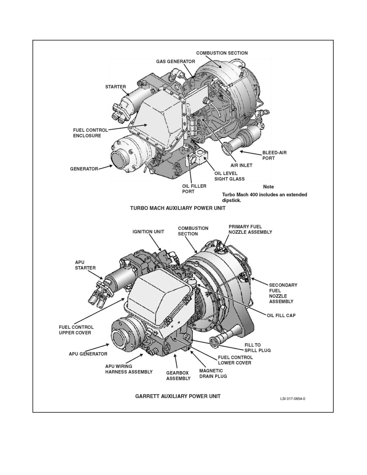
A1-H60BB-NFM-000
Figure 2-19. Auxiliary Power Units
ORIGINAL
2-48
A1-H60BB-NFM-000
2.5.5 APU Start System
With the FUEL PUMP switch in the APU BOOST position, pressurized fuel is supplied from the right fuel tank by
theprime/boost pump.Thefuelcontrol governsand metersfuel flowto theAPU powersection, permittingautomatic
starting under all ambient conditions and constant speed operation once theAPU has accelerated to its normal speed.
Placing the APU CONTR switch to ON initiates the start sequence. The ESU/DESU sends a signal to open the APU
start valve, releasing the hydraulic accumulator charge to the starter. As the accumulator pressure drops below 2,650
psi, the APU ACCUM LOW advisory appears, indicating that the accumulator pressure is low. The APU ON
advisory appears when the APU is on and operating normally. Placing the APU GENERATOR switch to ON makes
electrical power available. If the backup pump is cycled ON then to the OFF or AUTO position, it will remain on
for one cycle of 90 seconds (180 seconds with winterization kit installed). Once the accumulator is recharged, the
APU ACCUM LOW advisory will extinguish.
If the APU does not start and the APU ACCUM LOW advisory is not illuminated, a start may be attempted by
simultaneously moving theAPU CONTR switch to ON and actuating the manual START/OVERRIDE leverlocated
on the accumulator manifold. APU accumulator pressure will be dumped to the starter to turn the compressor until
the APU has reached a self--sustaining speed.
2.6
ELECTRICAL SYSTEM
The primary source of electrical power for the SH--60B is alternating current (AC). There are three AC sources for
the aircraft. The primary sources are the two transmission--driven main generators. The secondary source is the
APU--driven generator. External AC power can also be connected to the helicopter. DC electrical power is obtained
by two converters which convert AC power to DC power and reduce the voltage. A battery is installed for use in
starting the APU and as a secondary source of DC power. AC and DC power are distributed to individual components
by means of a bus distribution system.
2.6.1 AC Electrical System
The primary AC electrical power is supplied by two oil--cooled 30/45 kVA, 115 Vac, 3 phase, 400 Hz brushless
generators, driven by the transmission through the accessory modules. The generators share their oil supply with the
accessory modules, input modules, and main transmission. A secondary electrical power source is supplied by an
air--cooled, 20/30 kVA, 115 Vac, 3 phase, 400 Hz brushless generator mounted on and driven by the APU. The
generators are controlled by generator control units (GCUs). The GCUs regulate generator output and protect against
overvoltage, undervoltage, underfrequency on the ground, and feeder fault for detection of open or short circuited
feeder lines. In flight, the generators will remain online until Nr decreases to approximately 80 percent. A minimum
of 97 percent Nr is required for the GCU to connect the NO. 1 and NO. 2 generators to the AC distribution system.
The external power receptacle, which may be used to supply external AC power to the electrical system, is located
on the right side of the aircraft, forward of the cabin door near the main mount. External power is monitored by the
external power monitor panel located in the right--hand junction box. The external power source is monitored for
phase rotation, overvoltage, undervoltage, underfrequency, and overfrequency to determine if the source is
acceptable.
There are five buses in the AC electrical distribution system: the NO. 1 and NO. 2 AC primary buses (NO. 1/2 AC
PRI BUS), the AC essential bus (AC ESNTL BUS), the AC secondary bus (AC SEC BUS), and theAC monitorbus
(AC MON BUS). AC bus distribution loads are illustrated in (Figure 2-20). With both main generators operating,
the NO. 1 generator powers the NO. 1 AC primary, AC essential, and AC secondary buses, while the NO. 2 AC
generator powers the NO. 2 AC primary and the AC monitor bus. If the APU generator is selected while both main
generators are operating, the APU generator will not be connected to the AC bus distribution system.
Should either main generator fail, automatic bus switching compensates by limiting the AC load to the available
generator output. If combined current demand exceeds the capability of the operating generator(s), the buses are
redistributed to available generators so that major bus loads can be managed as follows:
1. The backup hydraulic pump is the major load for the NO. 1 AC primary bus and has the highest priority.
2. The mission avionics system is the major load on the AC secondary bus and is the next priority. Tail rotor
de--ice power is also supplied from this bus.
2-49
ORIGINAL
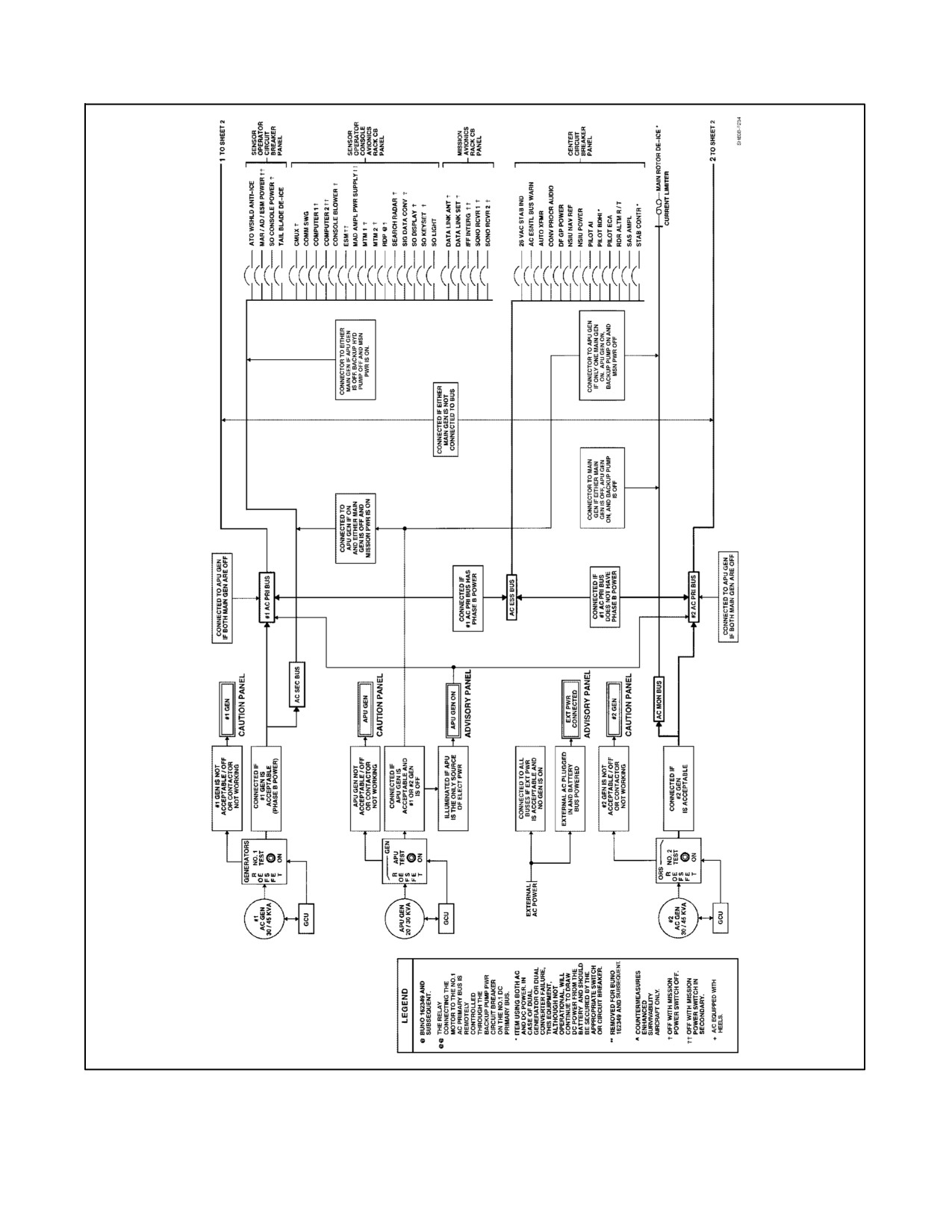
A1-H60BB-NFM-000
Figure 2-20. Electrical System Block Diagram (AC, Sheet 1 of 3)
ORIGINAL
2-50
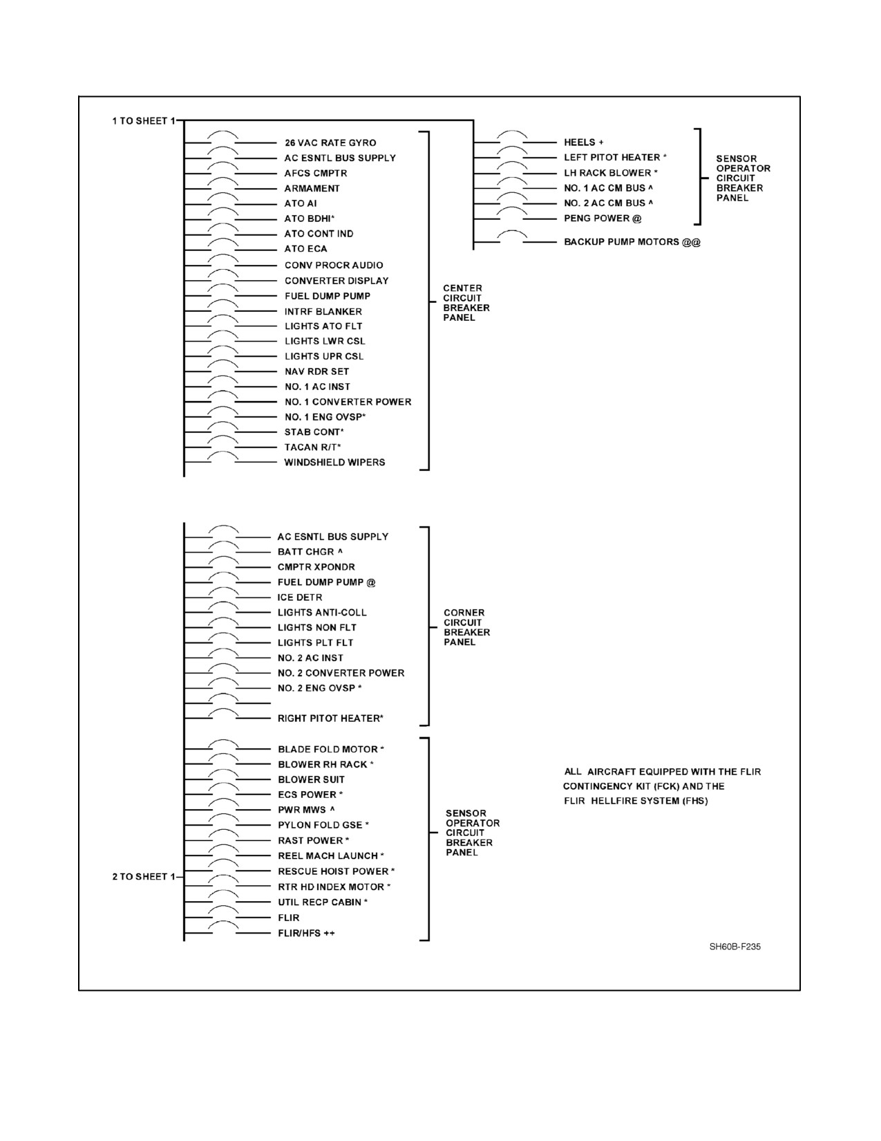
A1-H60BB-NFM-000
PITOT WINDSHIELD ANTI--ICE
Figure 2-20. Electrical System Block Diagram (AC, Sheet 2)
2-51
ORIGINAL
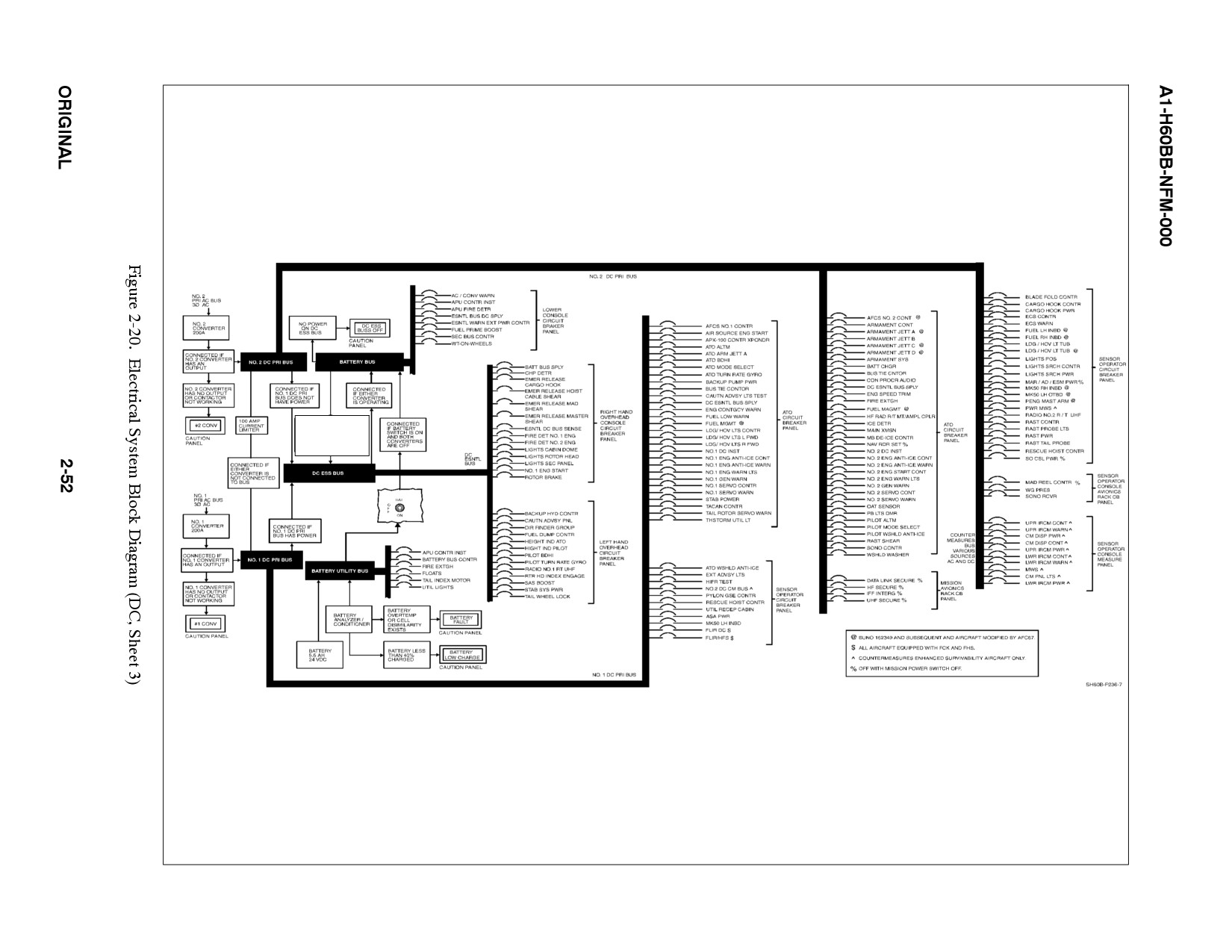
CONNECTED IF BATTERY SWITCH
IS ON AND BOTH CONVERTERS
ARE OFF AND BATTERY IS AT
LEAST 35% CHARGED
A1-H60BB-NFM-000
3. Themain rotorde--ice system is theonly system powered from the AC monitor bus and has the lowest priority
of the major current drawing components. AC bus distribution during normal and degraded modes is
illustrated in Figure 2-21.
Cockpit switches for control of the generators and external power are located in the center overhead console. The
GENERATORS, APU, NO. 1, and NO. 2 switches are three--position switches, labeled ON, RESET OFF, and TEST.
The ON position energizes the generator and permits connection of the generator AC output to the distribution
system. The RESET OFF position deenergizes the generator and permits generator recycling if the generator was
disabled or disconnected from the distribution system. The TEST position permits testing of the AC output of the
generator without connecting it to the distribution system. If generator output is normal, the generator caution light
will not be illuminated. The EXT PWR switch is a three--position switch, labeled ON, OFF, and RESET. The ON
position permits connection of external AC power to the distribution system. The OFF position disconnects external
AC power from the distribution system. The RESET position permits recycling if the AC external source was
unacceptable. External power will automatically be dropped from the aircraft distribution system when either main
generator or the APU generator is brought on line. Mission systems will be lost and secure electrical keys may be
lost with only the APU generator on line.
Illumination of the #1 GEN, #2 GEN, or APU GEN caution light indicates a failure of the respective generator, GCU,
generator contactor, or a fault in the respective distribution system due to an overvoltage, undervoltage,
underfrequency on the ground, or feeder fault. Illumination of the #1 or #2 GEN BRG caution light indicates a worn
or failed main bearing on the respective generator.
If APU is unavailable or external power is not accepted when main
generators are secured, a total loss of AC power will occur. Systems lost
include ICS, VIDS display, and AFCS computer power. When AFCS
computer power is interrupted, trim is disengaged and an unguarded cyclic
will allow the rotor arc to dip to as low as four feet above the deck.
Power to illuminate the generator caution lights is provided from the NO. 1 and NO. 2 DC primary buses through
the NO. 1 GEN WARN and NO. 2 GEN WARN circuit breakers, respectively. Both circuit breakers are on the ATO
circuit breaker panel. Illumination of the AC ESS BUS OFF caution light indicates a power loss on the AC essential
bus. The caution light is powered by any source of DC power through a circuit breaker marked AC ESNTL BUS
WARN and located on the center circuit breaker panel. If the APU is the only source of AC power, illumination of
the APU GEN ON advisory light indicates that the APU--driven generator is on and supplying power to the system.
Illumination of the EXT PWR CONNECTED advisory light indicates that the external power cable is connected to
the helicopter and DC power is on the battery bus. The advisory light is powered by the battery bus through a circuit
breaker on the lower console circuit breaker panel marked ESNTL WARN EXT PWR CONTR.
POWER SOURCE
#1 AC PRI
AC SEC
AC MONITOR
MAJOR LOAD ON BUS
BACKUP PUMP
MISSION POWER
BLADE DE--ICE
External Power
Available
Available
Available
Both Main Generators
Available
Available
Available
1 Main and APU Generator
Note 1
Note 1
Note 1
1 Main Generator
Note 2
Note 2
Not Available
APU Generator
Available
Not Available
Not Available
Notes:
1. Combination of any two.
2. Either system.
Figure 2-21. AC Bus Distribution
2-53
ORIGINAL
A1-H60BB-NFM-000
2.6.2 AC Bus Tie System
The AC bus tie contactor/relay (K4) connects APU power or external power to the primary AC buses. In addition,
theK4 allows theoutput from the#1 generatorto powerthebuses ofafailed #2 generator. Withboth maingenerators
online and supplying output through K1 (#1 Gen) and K2 (#2 Gen), K4 is deenergized. It is by design that when one
generator fails, the operating generator will inherit the required load via a relay. This is accomplished in two ways:
1. In the case of # 1 generator failure, the #2 generator has a direct feed (not K4) straight to the K1 contactor
allowing the #1 generator buses to continue operation despite the failure of the generator.
2. When the #2 generator fails, output from the #1 generator is routed through the AC bus tie (K4), thus keeping
the #2 generator buses powered.
With the loss of the AC bus tie, no caution light nor change in cockpit functionality exists that would alert crews to
identify thefailure. Identification will becomeapparent when asecond failuresuch as a generatoror converterfailure
occurs. The following shows two scenarios:
1. With thefailureofboth theK4 contactorand the#2 AC generator, the#2 primaryAC buswill belost. Allother
bus ties will remain functional.
2. With the loss of both the K4 contactor and the #1 AC generator, all bus ties will remain functional.
Note
In both cases, powering of the APU will result in the pickup of the AC
Monitor bus only.
With the AC bus tie failure, indicated by a failed generator and no load pickup, the perceived correction is to start
the APU and disconnect the operating generator. The perception here is that the APU powers the AC primary buses
through the K4 feeder. If the AC bus fails, then the APU will not connect to the primary buses. Therefore,
disconnecting of an operating generator will only compound the emergency from single generator operations to a
self--induced total AC power failure.
In the event of an AC bus tie failure, starting of the APU and disconnection
of the operating generator has no effect in correcting the malfunction.
Further, should the operating generator be taken off--line, a complete AC
power failure is imminent.
2.6.3 DC Electrical System
DC power is supplied by two converters each rated at 28 Vdc, 200 amps continuous power. NO. 1 and NO. 2
converters are powered by the NO. 1 AC PRI BUS and NO. 2 AC PRI BUS through the NO. 1 CONVERTER
POWER and NO. 2 CONVERTER POWER circuit breakers respectively. The NO. 1 converter is located in the
left--hand junction box and the NO. 2 converter is located in the right--hand junction box. A 24 Vdc, 5.5 amp hours
battery located in the ATO seat well provides a secondary or emergency source of DC power. A battery
analyzer/conditioner located in the ATO seat well monitors the battery system for fault conditions and provides a
battery charging capability. The analyzer system monitors battery charge, internal temperature, and cell conditions
and will automatically disconnect DC loads from the battery or the battery from the charging circuit, as appropriate.
The system charges the battery whenever AC power is available and the battery switch is on.
ORIGINAL
2-54
A1-H60BB-NFM-000
There are five buses in the DC electrical distribution system (Figure 2-20): the NO. 1 and NO. 2 DC primary buses
(NO. 1/2 DC PRI BUS), the DC essential bus (DC ESNTL BUS), the battery bus (BATT BUS), and the battery utility
bus (BATT UTIL BUS). Automatic bus switching provides maximum flexibility should a converter fail. The NO. 1
converter is the source of power for the NO. 1 DC primary bus, the DC essential bus, and the battery bus. The NO. 2
converter powers the NO. 2 DC primary bus. The battery powers the battery utility bus. Failure of one of the
converters results in its loads being picked up by the other converter. If both converters fail, the battery provides a
source of power to the battery utility bus, the battery bus (if the battery switch is on), and the DC essential bus (if
thebattery switch is on and thebattery is abovea35 percent charge)through thecircuit breakermarked ESNTL BUS
DC SPLY and located on the lower console circuit breaker panel. The NO. 1 and NO. 2 DC primary buses are
dropped.
Battery power is controlled by a two--position BATT switch located on the center overhead console labeled BATT
with positions ON and OFF. The ON position connects the DC power output of the battery utility bus to the battery
bus and provides input power to the analyzer/conditioner. When the helicopter converters are operating and BATT
switch is ON, the charging circuit of the analyzer/conditioner receives AC and DC power. DC charging power is
supplied from the NO. 2 DC primary bus through the BATT CHGR circuit breaker on the ATO circuit breaker panel.
AC power is supplied from the NO. 2 AC primary bus through the BATT CHGR circuit breaker on the corner circuit
breaker panel.
Indicator lights on the caution/advisory panel permit cockpit monitoring of the DC electrical system. Illumination
of the #1 CONV or #2 CONV caution light indicates a failure of the respective converter or DC bus contactor. Power
to light the CONV caution lights is provided from the battery bus through a circuit breaker marked ESNTL BUS
AC/CONV WARN and located on the lower console circuit breaker panel. Illumination of the DC ESS BUS OFF
caution light indicates a power loss on the DC essential bus. Illumination of the BATT LOW CHARGE caution light
indicates that the battery is below a 40 percent state of charge. DC essential bus power is required to light this light.
Illumination of the BATTERY FAULT caution light indicates that a battery overtemperature or cell dissimilarity
condition exists. When a battery overtemperature or cell dissimilarity condition exists, the battery is disconnected
from the charging circuit. When the battery drops below a 35 percent state of charge, the DC essential bus will be
disconnected from the battery to allow sufficient charge for APU starting. The DC essential bus will still bepowered
if either converter is on or external power is connected. Power to illuminate the BATTERY FAULT caution light is
provided by the battery bus through the ESNTL WARN PWR CONTR circuit breaker.
With no other source of DC power for the DC ESNTL BUS and the battery
below 35 percent charge, the BATT LOW CHARGE light will not be on,
battery power may not be sufficient to fire the fire extinguisher
cartridge--activated device (CAD), and the fire warning system will not be
operative for the main engines.
2.6.4 DC Bus Tie System
DC bus tie contactor (K7) provides a connection between the NO. 1 and NO. 2 DC primary buses. If one converter
fails, the path is closed from the primary bus of the operating converter to energize the solenoid of the DC bus tie
contactor. The energized contactor connects the output of the operating converter to the primary bus of the failed
converter.
Regardless of the bus tie, no caution light nor change in cockpit functionality exists that would alert crews to identify
the failure. Identification happens when another electrical component fails, such as a generator or converter, where
the electrical load required is not picked up by the operating generator or converter.
2-55
ORIGINAL
A1-H60BB-NFM-000
2.6.5 Circuit Breaker Panels
Nine circuit breaker panels are located in the cockpit and cabin area (Figure 2-22). Two upper console (overhead)
circuit breaker panels contain circuit breakers protecting the DC essential bus. The lower console circuit breaker panel
contains circuit breakers protecting the battery bus and the battery utility bus. The corner circuit breaker panel
contains circuit breakers protecting the NO. 2 AC primary bus. The ATO circuit breaker panel contains circuit
breakers protecting the NO. 1 and NO. 2 DC primary buses. The center circuit breaker panel contains circuit breakers
protecting the NO. 1 AC primary bus and the AC essential bus. The SO circuit breaker panel contains circuit breakers
protecting the NO. 1 AC primary bus, the NO. 2 AC primary bus, the AC secondary bus, the NO. 1 DC primary bus,
and the NO. 2 DC primary bus. The SO console avionics rack and the mission avionics rack circuit breaker panels
contain circuit breakers protecting the AC secondary bus and the NO. 2 DC primary bus. See Figure 2-23 for an
alphabetical list of the circuit breakers.
ORIGINAL
2-56
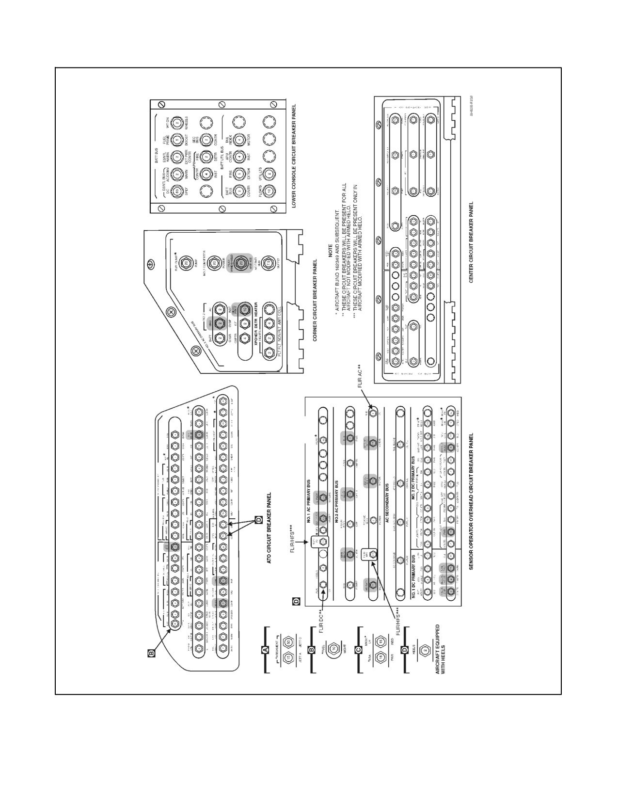
A1-H60BB-NFM-000
Figure 2-22. Circuit Breaker Panels (Sheet 1 of 2)
2-57
ORIGINAL
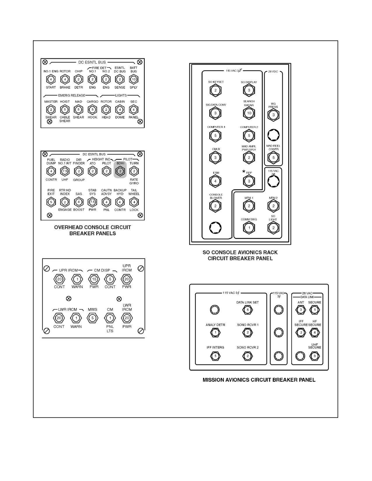
A1-H60BB-NFM-000
COUNTERMEASURES CONSOLE
CIRCUIT BREAKER PANEL
Figure 2-22. Circuit Breaker Panels (Sheet 2)
ORIGINAL
2-58
A1-H60BB-NFM-000
CIRCUIT BREAKER
BUS
LOCATION
AC ESNTL BUS SUPPLY
NO. 1 AC PRI BUS
CENTER
AC ESNTL BUS SUPPLY
NO. 2 AC PRI BUS
CORNER
AC ESNTL BUS WARN
AC ESS BUS
CENTER
AFCS CMPTR
NO. 2 AC PRI BUS
SO OVHD
AFCS CMTPR
NO. 1 AC PRI BUS
CENTER
AFCS NO. 1 CONTR
NO. 1 DC PRI BUS
ATO
AFCS NO. 2 CONTR
NO. 1 DC PRI BUS
ATO
AFCS NO. 2 CONTR
NO. 2 DC PRI BUS
ATO
AIR SOURCE ENG START
NO. 1 DC PRI BUS
ATO
ANALY DETR
AC SEC BUS
MISSION AVIONICS
APU CONTR INST
BATT UTIL BUS
LOWER CONSOLE
APU: CONTR INST
BATT BUS
LOWER CONSOLE
APU: FIRE DETR
BATT BUS
LOWER CONSOLE
APX--100 CONTR XPONDR
NO. 1 DC PRI BUS
ATO
ARMAMENT
NO. 1 AC PRI BUS
CENTER
ARMAMENT: CONTR
NO. 2 DC PRI BUS
ATO
ARMAMENT: JETT A
NO. 2 DC PRI BUS
ATO
ARMAMENT: JETT B
NO. 2 DC PRI BUS
ATO
ARMAMENT: JETT C
NO. 2 DC PRI BUS
ATO
ARMAMENT: SYS
NO. 2 DC PRI BUS
ATO
ASA
NO. 1 DC PRI BUS
SO OVHD
ASA PWR
NO. 1 DC PRI BUS
SO OVHD
ATO BDHI
NO. 1 DC PRI BUS
ATO
ATO WSHLD ANTI--ICE
NO. 1 DC PRI BUS
SO OVHD
ATO WSHLD ANTI--ICE
NO. 2 AC PRI BUS
SO OVHD
ATO:
NO. 1 AC PRI BUS
CENTER
ATO: ALTM
NO. 1 DC PRI BUS
ATO
ATO: ARM JETTA
NO. 1 DC PRI BUS
ATO
ATO: BDHI
NO. 1 AC PRI BUS
CENTER
ATO: CONTRIND
NO. 1 AC PRI BUS
CENTER
AUTO: EC
NO. 1 AC PRO BUS
CENTER
AUTO: MODE SELECT
NO. 1 DC PRO BUS
AUTO
AUTO: TURN RATE GYRO
NO. 1 DC PRO BUS
AUTO
AUTO FEMORA
AC ESS BUS
CENTER
BACKUP HYD CON TR
DC ESTEL BUS
OVHD CONSOLE
BACKUP PUMP PR
NO. 1 DC PRO BUS
AUTO
BATT BUS CON TR
BATT UT IL BUS
LOWER CONSOLE
BATT BUS SPLY
DC ESNTL BUS
OVHD CONSOLE
BATT CHGR
NO. 2 DC PRI BUS
ATO
Figure 2-23. Circuit Breaker List (Sheet
1 of 7)
2-59
ORIGINAL
A1-H60BB-NFM-000
CIRCUIT BREAKER
BUS
LOCATION
BATT CHGR
NO. 2 AC PRI BUS
CORNER
BLADE FOLD CONTR
NO. 2 DC PRI BUS
SO OVHD
BLADE FOLD MOTOR
NO. 2 AC PRI BUS
SO OVHD
BUS TIE CONTR
NO. 1 DC PRI BUS
ATO
BUS TIE CONTR
NO. 2 DC PRI BUS
ATO
CARGO HOOK: CONTR
NO. 2 DC PRI BUS
SO OVHD
CARGO HOOK: PWR
NO. 2 DC PRI BUS
SO OVHD
CAUTN ADVSY LTS TEST
NO. 1 DC PRI BUS
ATO
CAUTN ADVSY PNL
DC ESNTL BUS
OVHD CONSOLE
CHIP DETR
DC ESNTL BUS
OVHD CONSOLE
CM DISP: CONT
NO. 2 DC PRI BUS
SO COUNTERMEASURES
CM DISP: PWR
NO. 2 DC PRI BUS
SO COUNTERMEASURES
CM PNL LTS
NO. 2 DC PRI BUS
SO COUNTERMEASURES
CMPTR XPONDR
NO. 2 AC PRI BUS
CORNER
CMPTR XPONDR
NO. 1 DC PRI BUS
SO OVHD
CMUX
AC SEC BUS
SO CONSOLE AVIONICS RACK
COMM SWG
AC SEC BUS
SO CONSOLE AVIONICS RACK
COMPUTER 1
AC SEC BUS
SO CONSOLE AVIONICS RACK
COMPUTER 2
AC SEC BUS
SO CONSOLE AVIONICS RACK
CONSOLE BLOWER
AC SEC BUS
SO CONSOLE AVIONICS RACK
CONV PROCR AUDIO
NO. 2 DC PRI BUS
ATO
CONV PROCR AUDIO
AC ESS BUS
CENTER
CONV PROCR AUDIO
NO. 1 AC PRI BUS
CENTER
CONVERTER DISPLAY
NO. 1 AC PRI BUS
CENTER
DATA LINK SET
AC SEC BUS
MISSION AVIONICS
DATA LINK: ANT
NO. 2 DC PRI BUS
MISSION AVIONICS
DATA LINK: SECURE
NO. 2 DC PRI BUS
MISSION AVIONICS
DC ESNTL BUS SPLY
NO. 1 DC PRI BUS
ATO
DC ESNTL BUS SPLY
NO. 2 DC PRI BUS
ATO
DF GP PWR
AC ESS BUS
CENTER
DIR FINDER GROUP
DC ESNTL BUS
OVHD CONSOLE
ECS PWR
NO. 2 AC PRI BUS
SO OVHD
ECS: CONTR
NO. 2 DC PRI BUS
SO OVHD
ECS: WARN
NO. 2 DC PRI BUS
SO OVHD
EMERG RELEASE: CARGO HOOK
DC ESNTL BUS
OVHD CONSOLE
EMERG RELEASE: HOIST CABLE
DC ESNTL BUS
OVHD CONSOLE
SHEAR
EMERG RELEASE: MAD SHEAR
DC ESNTL BUS
OVHD CONSOLE
EMERG RELEASE: MASTER SHEAR
DC ESNTL BUS
OVHD CONSOLE
ENG CONTGCY WARN
NO. 1 DC PRI BUS
ATO
Figure 2-23. Circuit Breaker List (Sheet 2)
ORIGINAL
2-60
A1-H60BB-NFM-000
CIRCUIT BREAKER
BUS
LOCATION
ENG SPEED TRIM
NO. 2 DC PRI BUS
ATO
ESM
AC SEC BUS
SO CONSOLE AVIONICS RACK
ESNTL BUS: AC/CONV WARN
BATT BUS
LOWER CONSOLE
ESNTL BUS: DC SPLY
BATT BUS
LOWER CONSOLE
ESNTL DC BUS SENSE
DC ESNTL BUS
OVHD CONSOLE
ESNTL WARN EXT PWR CONTR
BATT BUS
LOWER CONSOLE
EXT ADVSY LTS
NO. 1 DC PRI BUS
SO OVHD
FIRE DET: NO. 1 ENG
DC ESNTL BUS
OVHD CONSOLE
FIRE DET: NO. 2 ENG
DC ESNTL BUS
OVHD CONSOLE
FIRE EXIT
DC ESNTL BUS
OVHD CONSOLE
FIRE EXTGH
NO. 2 DC PRI BUS
ATO
FIRE EXTGH
BATT UTIL BUS
LOWER CONSOLE
FLIR AC
NO. 2 AC PRI BUS
SO OVHD
FLIR DC
NO. 1 AC PRI BUS
SO OVHD
FLIR/HFS
NO. 1 AC PRI BUS
SO OVHD
FLIR/HFS
NO. 2 AC PRI BUS
SO OVHD
FLOATS
BATT UTIL BUS
LOWER CONSOLE
FUEL DUMP CONTR
DC ESNTL BUS
OVHD CONSOLE
FUEL DUMP PUMP
NO. 1 AC PRI BUS
CENTER
FUEL DUMP PUMP
NO. 2 AC PRI BUS
CORNER
FUEL LOW WARN
NO. 1 DC PRI BUS
ATO
FUEL MGMT
NO. 2 DC PRI BUS
ATO
FUEL PRIME BOOST
BATT BUS
LOWER CONSOLE
FUEL: LH INBD
NO. 2 DC PRI BUS
SO OVHD
FUEL: RH INBD
NO. 2 DC PRI BUS
SO OVHD
GPS
NO. 1 AC PRI BUS
SO OVHD
HEELS
NO. 1 AC PRI BUS
SO OVHD
HEIGHT IND: ATO
DC ESNTL BUS
OVHD CONSOLE
HEIGHT IND: PILOT
DC ESNTL BUS
OVHD CONSOLE
HF RAD R/T MT AMPL CPLR
NO. 2 DC PRI BUS
ATO
HF SECURE
NO. 2 DC PRI BUS
MISSION AVIONICS
ICE DETR
NO. 2 DC PRI BUS
ATO
ICE DETR
NO. 2 AC PRI BUS
CORNER
IFF INTERG
AC SEC BUS
MISSION AVIONICS
IFF SECURE
NO. 2 DC PRI BUS
MISSION AVIONICS
INTRF BLANKER
NO. 1 AC PRI BUS
CENTER
JETT D
NO. 2 DC PRI BUS
ATO
LDG/HOV LT TUB
NO. 2 DC PRI BUS
SO OVHD
LDG/HOV LT TUB
NO. 2 DC PRI BUS
SO OVHD
Figure 2-23. Circuit Breaker List (Sheet 3)
2-61
ORIGINAL
A1-H60BB-NFM-000
CIRCUIT BREAKER
BUS
LOCATION
LDG/HOV LTS: CONTR
NO. 1 DC PRI BUS
ATO
LDG/HOV LTS: L FWD
NO. 1 DC PRI BUS
ATO
LDG/HOV LTS: R FWD
NO. 1 DC PRI BUS
ATO
LEFT PITOT HEATER
NO. 1 AC PRI BUS
SO OVHD
LH RACK BLOWER
NO. 1 AC PRI BUS
SO OVHD
LIGHTS: ANTI COLL
NO. 2 AC PRI BUS
CORNER
LIGHTS: ATO FLT
NO. 1 AC PRI BUS
CENTER
LIGHTS: CABIN DOME
DC ESNTL BUS
OVHD CONSOLE
LIGHTS: LWR CSL
NO. 1 AC PRI BUS
CENTER
LIGHTS: NON FLT
NO. 2 AC PRI BUS
CORNER
LIGHTS: PLT FLT
NO. 2 AC PRI BUS
CORNER
LIGHTS: POS
NO. 2 DC PRI BUS
SO OVHD
LIGHTS: ROTOR HEAD
DC ESNTL BUS
OVHD CONSOLE
LIGHTS: SEC PANEL
DC ESNTL BUS
OVHD CONSOLE
LIGHTS: SRCH CONTR
NO. 2 DC PRI BUS
SO OVHD
LIGHTS: SRCH PWR
NO. 2 DC PRI BUS
SO OVHD
LIGHTS: UPR CSL
NO. 1 AC PRI BUS
CENTER
LWR IRCM PWR
NO. 2 DC PRI BUS
SO COUNTERMEASURES
LWR IRCM: CONT
NO. 2 DC PRI BUS
SO COUNTERMEASURES
LWR IRCM: WARN
NO. 2 DC PRI BUS
SO COUNTERMEASURES
MAD AMPL PWR SPLY
AC SEC BUS
SO CONSOLE AVIONICS RACK
MAD REEL CONTR
NO. 2 DC PRI BUS
SO CONSOLE AVIONICS RACK
MAIN XMSN
NO. 2 DC PRI BUS
ATO
MAR/AD/ESM POWER
NO. 2 AC PRI BUS
SO OVHD
MAR/AD ESM PWR
NO. 2 DC PRI BUS
SO OVHD
MB DE--ICE CONTR
NO. 2 DC PRI BUS
ATO
MK50 LH INBD
NO. 1 DC PRI BUS
SO OVHD
MK50 LH OTBD
NO. 2 DC PRI BUS
SO OVHD
MK50 RH INBD
NO. 2 DC PRI BUS
SO OVHD
MK50 RH OTBD
NO. 2 DC PRI BUS
SO OVHD
MTM 1
AC SEC BUS
SO CONSOLE AVIONICS RACK
MTM 2
AC SEC BUS
SO CONSOLE AVIONICS RACK
MWS
NO. 2 DC PRI BUS
SO COUNTER MEASURES
NAV RDR SET
NO. 2 DC PRI BUS
ATO
NAV RDR SET
NO. 1 AC PRI BUS
CENTER
NO. 1 CONVERTER POWER
NO. 1 AC PRI BUS
CENTER
NO. 1 ENG START
DC ESNTL BUS
OVHD CONSOLE
NO. 1 ENG: ANTI--ICE: CONTR
NO. 1 DC PRI BUS
ATO
NO. 1 ENG: ANTI--ICE: WARN
NO. 1 DC PRI BUS
ATO
Figure 2-23. Circuit Breaker List (Sheet 4)
ORIGINAL
2-62
A1-H60BB-NFM-000
CIRCUIT BREAKER
BUS
LOCATION
NO.
1 ENG: WARN LTS
NO.
1 DC PRI BUS
ATO
NO.
1 AC INST
NO.
1 AC PRI BUS
CENTER
NO.
1 DC INST
NO.
1 DC PRI BUS
ATO
NO.
1 ENG OVSP
NO.
1 AC PRI BUS
CENTER
NO.
1 GEN WARN
NO.
1 DC PRI BUS
ATO
NO.
1 SERVO: CONTR
NO.
1 DC PRI BUS
ATO
NO.
1 SERVO: WARN
NO.
1 DC PRI BUS
ATO
NO.
2 CONVERTER POWER
NO.
2 AC PRI BUS
CORNER
NO.
2 ENG: ANTI--ICE: CONTR
NO.
2 DC PRI BUS
ATO
NO.
2 ENG: ANTI--ICE: WARN
NO.
2 DC PRI BUS
ATO
NO.
2 ENG: START CONTR
NO.
2 DC PRI BUS
ATO
NO.
2 ENG: WARN LTS
NO.
2 DC PRI BUS
ATO
NO.
2 AC INST
NO.
2 AC PRI BUS
CORNER
NO.
2 DC INST
NO.
2 DC PRI BUS
ATO
NO.
2 ENG OVSP
NO.
2 AC PRI BUS
CORNER
NO.
2 GEN WARN
NO.
2 DC PRI BUS
ATO
NO.
2 SERVO: CONTR
NO.
2 DC PRI BUS
ATO
NO.
2 SERVO: WARN
NO.
2 DC PRI BUS
ATO
NSIU NAV REF
AC ESS BUS
CENTER
NSIU POWER
AC ESS BUS
CENTER
OAT SENSOR
NO. 2 DC PRI BUS
ATO
P ENG
NO. 1 AC PRI BUS
SO OVHD
PB LTS CMR
NO. 2 DC PRI BUS
ATO
PILOT ECA
AC ESS BUS
CENTER
PILOT: AI
AC ESS BUS
CENTER
PILOT: ALTM
NO. 2 DC PRI BUS
ATO
PILOT: BDHI
AC ESS BUS
CENTER
PILOT: BDHI
DC ESNTL BUS
OVHD CONSOLE
PILOT: MODE SELECT
NO. 2 DC PRI BUS
ATO
PILOT: TURN RATE GYRO
DC ESNTL BUS
OVHD CONSOLE
PILOT: WSHLD ANTI--ICE
NO. 2 DC PRI BUS
ATO
PILOT WINDSHIELD ANTI ICE
NO. 2 AC PRI BUS
CORNER
PYLON FOLD GSE
NO. 2 AC PRI BUS
SO OVHD
PYLON GSE CONTR
NO. 1 DC PRI BUS
SO OVHD
R ENG MAST ARM
NO. 2 DC PRI BUS
SO OVHD
RADIO NO. 1 R/T UHF
DC ESNTL BUS
OVHD CONSOLE
RADIO NO. 2 R/T UHF
NO. 2 DC PRI BUS
SO OVHD
RAST POWER
NO. 2 AC PRI BUS
SO OVHD
RAST SHEAR
NO. 2 DC PRI BUS
ATO
Figure 2-23. Circuit Breaker List (Sheet 5)
2-63
ORIGINAL
A1-H60BB-NFM-000
CIRCUIT BREAKER
BUS
LOCATION
RAST: CONTR
NO. 2 DC PRI BUS
SO OVHD
RAST: PROBE LTS
NO. 2 DC PRI BUS
SO OVHD
RAST: PWR
NO. 2 DC PRI BUS
SO OVHD
RAST: TAIL PROBE
NO. 2 DC PRI BUS
SO OVHD
RATE GYRO 26 VAC
NO. 1 AC PRI BUS
CENTER
RDP
AC SEC BUS
SO CONSOLE AVIONICS RACK
RDR ALTM R/T
AC ESS BUS
CENTER
REEL MACH LAUNCH
NO. 2 AC PRI BUS
SO OVHD
RESCUE HOIST CONTR
NO. 1 DC PRI BUS
SO OVHD
RESCUE HOIST CONTR
NO. 2 DC PRI BUS
SO OVHD
RESCUE HOIST POWER
NO. 2 AC PRI BUS
SO OVHD
RH RACK BLOWER
NO. 2 AC PRI BUS
SO OVHD
RIGHT PITOT HEATER
NO. 2 AC PRI BUS
CORNER
ROTOR BRAKE
DC ESNTL BUS
OVHD CONSOLE
RTR HD INDEX ENGAGE
DC ESNTL BUS
OVHD CONSOLE
RTR HD INDEX MOTOR
NO. 2 AC PRI BUS
SO OVHD
SAS AMPL
AC ESS BUS
CENTER
SAS BOOST
DC ESNTL BUS
OVHD CONSOLE
SEARCH RADAR
AC SEC BUS
SO CONSOLE AVIONICS RACK
SEC BUS CONTR
BATT BUS
LOWER CONSOLE
SIG DATA CONV
AC SEC BUS
SO CONSOLE AVIONICS RACK
SO CONSOLE POWER
NO. 2 AC PRI BUS
SO OVHD
SO CSL PWR
NO. 2 DC PRI BUS
SO OVHD
SO DISPLAY
AC SEC BUS
SO CONSOLE AVIONICS RACK
SO KEYSET
AC SEC BUS
SO CONSOLE AVIONICS RACK
SO LIGHT
AC SEC BUS
SO CONSOLE AVIONICS RACK
SONO CONTR
NO. 2 DC PRI BUS
ATO
SONO RCVR 1
AC SEC BUS
MISSION AVIONICS
SONO RCVR 2
AC SEC BUS
MISSION AVIONICS
STAB CONTR
AC ESS BUS
CENTER
STAB CONTR
NO. 1 AC PRI BUS
CENTER
STAB IND 26 VAC
AC ESS BUS
CENTER
STAB PWR
NO. 1 DC PRI BUS
ATO
STAB SYS PWR
DC ESNTL BUS
OVHD CONSOLE
TACAN CONTR
NO. 1 DC PRI BUS
ATO
TACAN R/T
NO. 1 AC PRI BUS
CENTER
TAIL BLADE DE--ICE
NO. 2 AC PRI BUS
SO OVHD
TAIL INDEX MOTOR
BATT UTIL BUS
LOWER CONSOLE
TAIL ROTOR SERVO WARN
NO. 1 DC PRI BUS
ATO
TAIL WHEEL LOCK
DC ESNTL BUS
OVHD CONSOLE
THSTORM UTIL LT
NO. 1 DC PRI BUS
ATO
UHF SECURE
NO. 2 DC PRI BUS
MISSION AVIONICS
Figure 2-23. Circuit Breaker List (Sheet 6)
ORIGINAL
2-64
A1-H60BB-NFM-000
CIRCUIT BREAKER
BUS
LOCATION
UPR IRCM PWR
NO. 2 DC PRI BUS
SO COUNTERMEASURES
UPR IRCM: CONT
NO. 2 DC PRI BUS
SO COUNTERMEASURES
UPR IRCM: WARN
NO. 2 DC PRI BUS
SO COUNTERMEASURES
UTIL LTS
BATT UTIL BUS
LOWER CONSOLE
UTIL RECP CABIN
NO. 1 DC PRI BUS
SO OVHD
UTIL RECP CABIN
NO. 2 AC PRI BUS
SO OVHD
WG PRESS
NO. 2 DC PRI BUS
SO CONSOLE AVIONICS RACK
WINDSHIELD WIPERS
NO. 1 AC PRI BUS
CENTER
WSHLD WASHER
NO. 2 DC PRI BUS
ATO
WT ON WHEELS
BATT BUS
LOWER CONSOLE
Figure 2-23. Circuit Breaker List (Sheet 7)
2.6.6 Utility and Test Receptacles
The utility and test receptacle panel is located on the left--hand bulkhead below the SO window. The panel contains
28 Vdc and 115 Vac utility power receptacles and the test receptacles for the NO. 1, NO. 2, and APU generators.
2.7
LIGHTING
2.7.1 Exterior Lighting
2.7.1.1 Anticollision Lights
The anticollision light system contains four strobes in two separate units, one beneath the aft fuselage and one on
top of the aft pylon section (Figure 1-3). The lights are controlled by two switches on the overhead console
(Figure 1-6) labeled ANTI COLLISION LIGHTS UPPER, BOTH, LOWER and DAY, OFF, NIGHT. The system
consists of a dual power supply and two interchangeable day/night anticollision lights. The dual supply system
provides separate outputs for the aft fuselage light and the pylon--mounted light. Each anticollision light assembly
contains two lamps, a red lens for night operation, and a clear lens for day operation. The desired strobe(s) is selected
by placing the switch at UPPER, LOWER, or BOTH. To discontinue operation of the anticollision light(s), the
DAY--NIGHT switch is placed to OFF. Power to operate the anticollision light system is provided from the NO. 2
AC primary bus through a circuit breaker marked LIGHTS, ANTI COLL and located on the corner circuit breaker
panel.
2.7.1.2 Position Lights
Position lights (Figure 1-3) are outboard of the left and right landing gear support and on the trailing edge of the tail
vertical fin. The lights are red on the left, green on the right, and white on the tail. Control of the position lights is
through the overhead console panel
(Figure 1-6) containing two switches, marked POSITION LIGHTS,
DIM--OFF--BRIGHT, and STEADY--FLASH. When the intensity switch is placed to DIM or BRIGHT, all three
lights go on at once. If the STEADY--FLASH switch is placed to FLASH, the three lights flash between 70 and
90 times per minute. The STEADY position causes the lights to remain on continuously. Power to operate the
position lights is provided by NO. 2 DC primary bus through a circuit breaker marked LIGHTS POS and located on
the SO circuit breaker panel.
On aircraft BuNo 162349 and subsequent, the left position light functions on the left outboard pylon when it is
installed. When the left pylon and its associated wiring receptacle are removed, the lighting function is automatically
transferred to the left landing gear support.
2.7.1.3 Searchlight
The searchlight (Figure 1-3) is mounted on the right bottom of the nose section and is controlled from either
collective.
2-65
ORIGINAL
A1-H60BB-NFM-000
Except when the pilot SRCH LT switch is in the STOW position, the searchlight may be selected and operated from
either collective regardless of opposite switch position. Selection of the STOW position by the pilot disconnects the
ATO SRCH LT and four--way search light control switches. Should both the pilot and ATO attempt to slew the
searchlight simultaneously, the light will freeze position until one of the four--way search light control switches is
released. The 450 watt light can be moved forward through a 120° arc from the stow position. It can also be turned
360° in either a right or left direction on its axis. The light is operated by a switch labeled SRCH LT ON, OFF, and
STOW. Directional control of the light is provided through the four--position searchlight control switch, labeled EXT
(extend), RET (retract), L (left), and R (right). When the SRCH LT switch is placed ON, the lamp will go on, arming
thecontrolswitch.PlacingthecontrolswitchtoEXTcausesthelightbeamtomoveforwardat arateofapproximately
12° per second. If SRCH LT switch is placed to OFF, the light will extinguish and remain in its present position. If
the switch is held at STOW, the light will retract at a rate of approximately 30° per second to the stowed position in
the searchlight well. When the light is fully retracted, power is automatically removed. Power to light and control
the searchlight is provided from the NO. 2 DC primary bus through circuit breakers, marked LIGHTS SRCH PWR
and SRCH CONTR, located on the SO circuit breaker panel.
2.7.1.4 Landing/Hover Lights
Two 450 watt fixed--position landing/hover lights (Figure 1-3) are installed on the left and right sides beneath the
nosesection, and afixed--position hover/rescuelight is installed on theright sidelowertub below thehoist. All lights
are primarily controlled from the cockpit through the toggle switch, marked HOVER LIGHTS, ALL, OFF, and FWD
(Figure 1-6). In the ALL position, nose hover lights and rescue light are turned on. At FWD, only the nose lights are
turned on. The rescue light may be operated from the crew hover panel through the toggle switch, marked RESCUE
LIGHT, ON, and OFF. The rescue light can be operated from the crew hover panel only when the cockpit switch is
selected to OFF or FWD. Power for the forward hover lights is from the NO. 1 DC primary bus through circuit
breakers marked LDG/HOV LTS CONTR, L FWD, and R FWD and located on the ATO circuit breaker panel. The
rescue hoist light receives power from the NO. 1 DC primary bus through a circuit breaker marked LDG/HOV LT,
CONTR on the ATO circuit breaker panel, and the NO. 2 DC primary bus through a circuit breaker marked
LDG/HOV LT TUB on the SO circuit breaker panel.
2.7.1.5 Rotor Head Light
A light on top of the main transmission cabin fairing illuminates the rotor head droop stops (Figure 1-3). The rotor
head light is controlled by a switch marked RTR HD LIGHTS, OFF, and ON (Figure 1-6). The light allows the
directorto determinetheposition ofthedroop stops during rotorengagement and disengagement. Powerfor thelight
is from the DC essential bus through a circuit breaker marked LIGHTS ROTOR HEAD and located on the overhead
console circuit breaker panel.
2.7.1.6 Recovery Assist Secure and Traverse Lights
Recovery Assist Secure and Traverse (RAST) lights are located forward of the RAST probe. The lights are controlled
by a single two--position switch marked RAST LIGHTS, ON, and OFF and located on the overhead console
(Figure 1-6). Power to operate the RAST lights is provided by the NO. 2 DC primary bus through a circuit breaker
located on the SO circuit breaker panel, under the general heading RAST, marked PROBE LTS.
2.7.2 Interior Lighting
Theinteriorlightingsystemconsistsoftheflightinstrumentandconsolelights,secondarylights,thunderstormutility
lights, utility lights, and cabin dome lights. Both AC and DC sources of electrical power are used to operate the
various interior lights.
2.7.2.1 Flight Instrument and Console Lights
The flight instrument and console lights are the primary means for illuminating cockpit gauges and control indicators.
Theselights consist ofindividual gaugelights andbacklit instrumentpanels. Instrumentlights aregrouped intoflight
and nonflight instruments. The flight instrument lights are divided into pilot and ATO. These lights are controlled
byindividualrotaryintensitycontrols(Figure 1-6)markedINSTLIGHTPILOTFLIGHT,OFF--BRIGHT,andINST
ORIGINAL
2-66
A1-H60BB-NFM-000
LIGHTS ATO FLIGHT, OFF--BRIGHT. The dimming control for the pilot flight instrument lights switches the
caution/advisory panel lights from a bright to dim intensity when the switch is rotated out of the OFF position.
Power for the ATO instrument lights is supplied by the NO. 1 AC primary bus through the LIGHTS ATO FLT circuit
breaker on the center circuit breaker panel. The NO. 2 AC primary bus powers the pilot flight instrument lights and
thenonflightinstrumentlightsthroughcircuitbreakersmarkedLIGHTS,PLTFLT,andNONFLT, respectively.Both
circuit breakers are on the corner circuit breaker panel.
The nonflight and console lights operate in the same manner as theflight instrument lights. Intensity of thenonflight
instrumentlightsiscontrolledbyarotarycontrol,markedINSTLIGHTNONFLIGHT,OFF--BRIGHT.Illumination
of the upper and lower consoles is controlled by two rotary switches marked CONSOLE PANEL LTS UPPER,
OFF--BRIGHT, and LOWER, OFF--BRIGHT. Power to operate the console lights is provided by the NO. 1 AC
primary bus through two circuit breakers marked LIGHTS UPR CSL and LIGHTS LWR CSL, both on the center
circuit breaker panel. Illumination intensity of the backlit pushbutton switches on the AFCS CONTROL panel and
the AI/BDHI mode select control panels (pilot and ATO) is controlled by the CONSOLE PANEL LTS LOWER,
OFF--BRIGHT rotary knob located on the ATO side of the upper console. Power for the lower console light switches
is provided from the NO. 2 DC primary bus through the PB LTS DMR circuit breaker on the ATO circuit breaker
panel.
2.7.2.2 Secondary Lights
Thesecondary lights system consists ofDC powered floodlights that augment theAC powered flight instrument and
console lights. Secondary lights also provide light for gauges and the lower console in the event of a total loss of AC
power. Secondary illumination of the instrument panel is provided by five light fixtures mounted below the glare
shield. Each fixture has a mechanical shade that allows the pilot/ATO to manually dim the light once the light has
been turned on. A rotary knob on the ATO side of the overhead console marked INST PANEL SECONDARY LTS,
OFF--BRIGHT controls the reference brightness of all five light fixtures. A white floodlight located above and behind
thepilot seat provides asecondary means to illuminatethe lowerconsole. This light is controlled by a switch marked
LOWER CONSOLE SECONDARY LT, DIM--OFF or BRT. Power for the secondary lights system is from the DC
essential bus through a circuit breaker marked LIGHTS SEC PANEL and located on the overhead circuit breaker
panel.
2.7.2.3 Thunderstorm Utility Lights
Thethunderstormutilitylightshelppreventpilotdisorientationduring nightflight inthunderstorm conditions.When
set to the BRIGHT position, the THUNDRSTRM/UTILITY LT switch turns on the thunderstorm utility light to its
full intensity and overrides the dimming controls, bringing all other cockpit lights to full intensity. In the DIM
position, the thunderstorm utility light and the other cockpit lighting are set to half intensity. Power to operate the
thunderstorm utility lights is provided by the NO. 1 DC primary bus through a circuit breaker marked THSTORM
UTIL LT and located on the ATO circuit breaker panel.
2.7.2.4 Utility Lights
Portable utility lights with coiled cords are attached to the upper cockpit bulkhead behind the pilot and ATO, and to
the upper cabin bulkhead beside the SO, by removable brackets. The lights may be adjusted on their mountings to
direct the light beams or they may be removed and used portably. The utility lights are controlled by a rheostat or
a pushbutton on the end of each casing. The lens casing of the light may be turned to change from white light to red
and spot to flood. The utility lights operate from the battery utility bus through a circuit breaker marked UTIL LTS
on the lower console circuit breaker panel.
Note
Ensureutility lights areoffwhen not in use to preclude unnecessary battery
drain.
2-67
ORIGINAL
A1-H60BB-NFM-000
2.7.2.5 Cabin Dome Lights
Three cabin dome lights for lighting the cabin section are controlled by a CAB DOME LIGHT panel switch. On
aircraft BuNo 162092 and subsequent, the panel switch has a RED position which turns the forward aisle light to
red. The intensity controls are in the cabin on the crew hover panel and overhead of the SO. The controls are marked
DOME LIGHT, OFF--BRT. The light level control may be adjusted to any position between the two extremes. Power
to operate the cabin dome light system is provided from the DC essential bus through a circuit breaker marked
LIGHTS CABIN DOME and located on the overhead circuit breaker panel.
2.8
HYDRAULIC SYSTEMS
The three hydraulic systems (Figure 2-25) are designed to provide full--flight control pressure (3,000 to 3,100 psi).
The components of the hydraulic systems are threehydraulic pump modules, two transfer modules, a utility module,
three dual--stage primary servos, one dual--stage tail rotor servo, three pilot--assist (boost) servos, four pilot--assist
(SAS) servos, two hydromechanical trim actuators, the rescue hoist, an APU accumulator, an APU hand pump, and
a servicing hand pump (Figure 2-26). There are three hydraulic pressure supply systems: NO. 1, NO. 2, and backup.
All are completely independent, and each is fully capable of providing essential flight control pressure (3,000 to
3,100 psi) for maximum system redundancy. Complete redundancy is accomplished by the backup pump, providing
hydraulic power to both NO. 1 and/or NO. 2 systems if one or both pumps fail. If NO. 1 and NO. 2 systems lose
pressure, there will be a slight restriction in the maximum rate of flight control movement due to the backup pump
supplying both primary stages with hydraulic power. When the SERVO switch, located on the pilot/ATO collective
grips, is moved to the 1st OFF or 2nd OFF position, that stage of the primary servos is turned off. A malfunction in
the other stage will cause the stage that was turned off to automatically come back on, provided the backup pump
does not take over the functions of the lost system. A hydraulic hand pump is provided for APU accumulator
pressurization in the event the backup pump is unavailable.
Note
The caution lights shown below may flicker when the listed switch is
activated (Figure 2-24).
SUBSYSTEM
CAUTION
SAS 1 or SAS 2 switch on
#2 PRI SERVO PRESS
#2 HYD PUMP
BOOST SERVO OFF
SAS/BOOST HYD switch on
#2 PRI SERVO PRESS
#2 HYD PUMP
SAS
TAIL SERVO switch BKUP
#1 PRI SERVO PRESS
#1 HYD PUMP
HYD LEAK TEST switch
#1 and #2 PRI SERVO PRESS #1 and
NORM after RESET
#2 HYD PUMP
Figure 2-24. Hydraulic System Activation
ORIGINAL
2-68
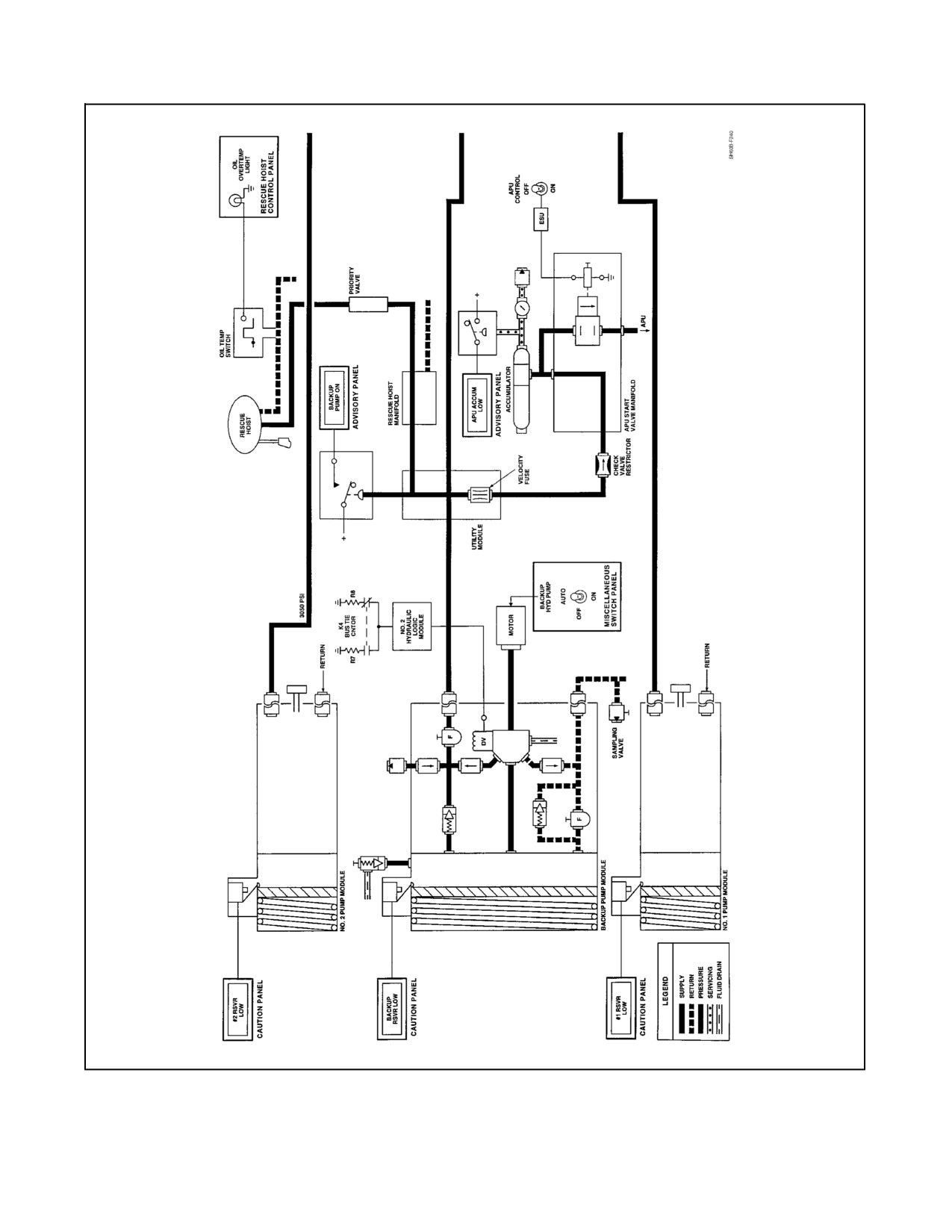
A1-H60BB-NFM-000
Figure 2-25. Flight Control Hydraulic System (Sheet 1 of 3)
2-69
ORIGINAL
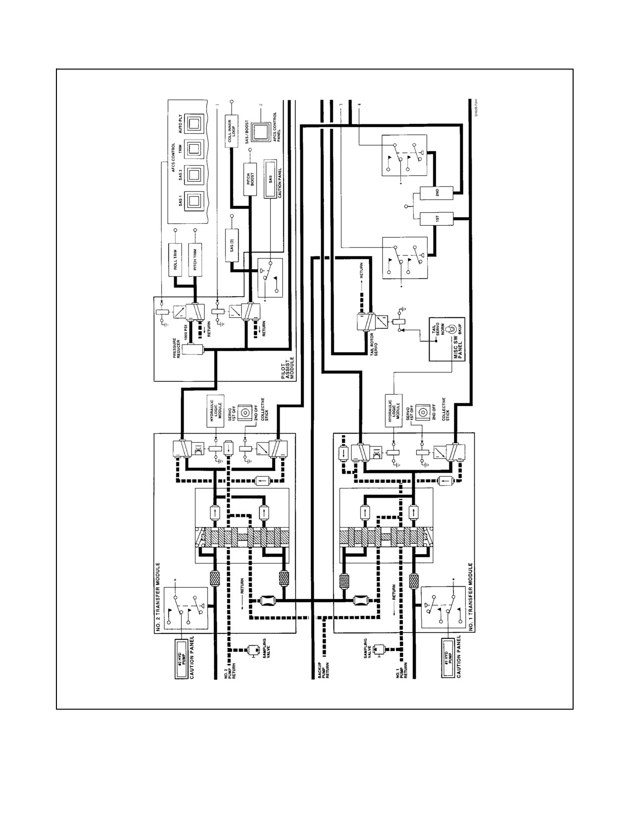
A1-H60BB-NFM-000
Figure 2-25. Flight Control Hydraulic System (Sheet 2)
ORIGINAL
2-70
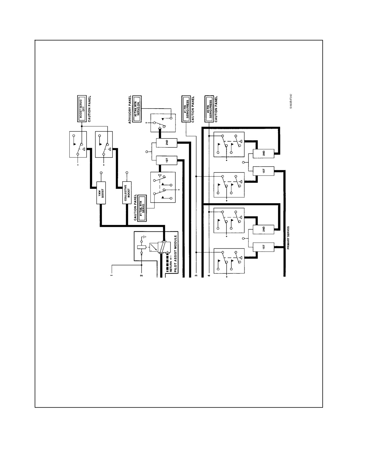
A1-H60BB-NFM-000
Figure 2-25. Flight Control Hydraulic System (Sheet 3)
2-71
ORIGINAL
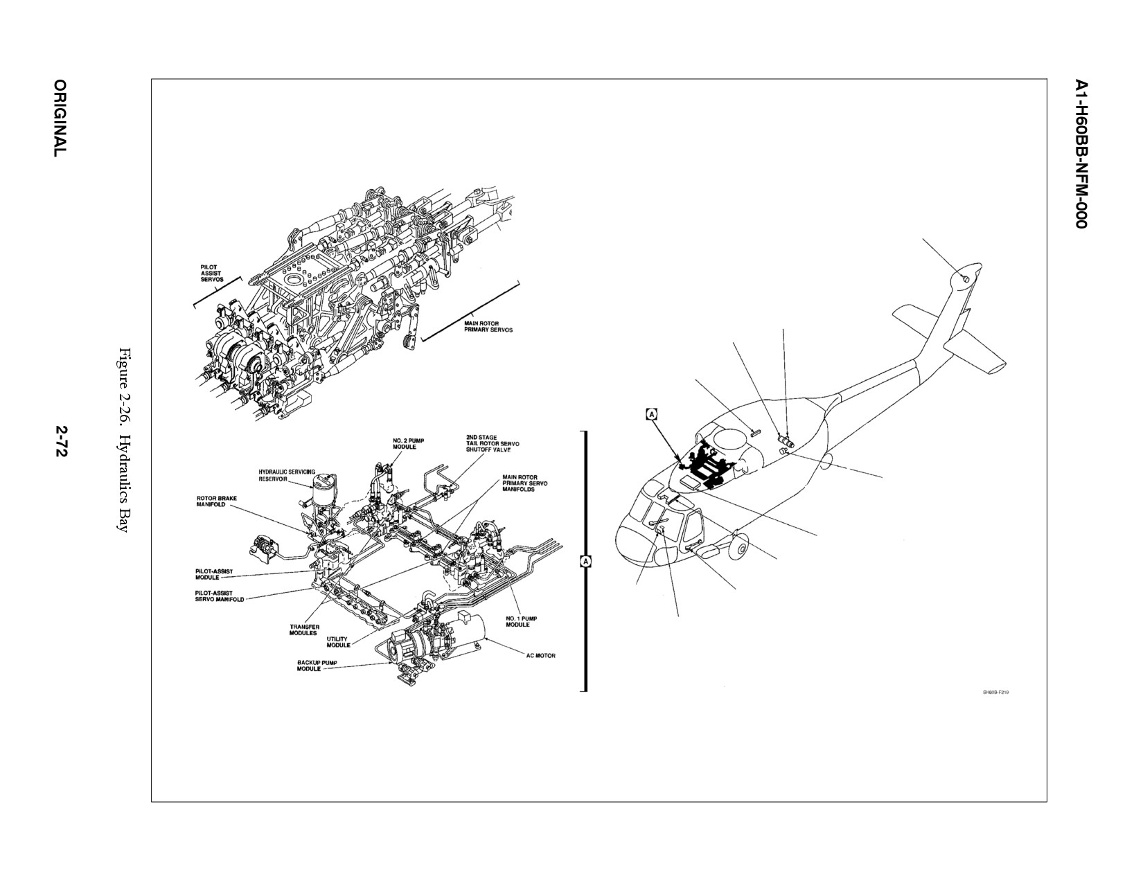
TAIL ROTOR SERVO
APU HYDRAULIC
START VALVE
APU ACCUMULATOR
APU ACCUMULATOR
PRESSURE SWITCH
AND HAND PUMP
ACCUMULATOR
PRESSURE GAUGE
LEAK DETECTION LOGIC MODULES
(MISCELLANEOUS RELAY PANEL
LEAK TEST SWITCH
(UPPER CONSOLE)
CAUTION PANEL
SERVO SHUTOFF SWITCH
(COLLECTIVE STICK GRIPS)
TAIL ROTOR SERVO SWITCH
AND BACKUP PUMP SWITCH
(LOWER CONSOLE)
A1-H60BB-NFM-000
2.8.1 Hydraulic Pump Modules
Thehydraulicpump modules arecombination hydraulicpumps and reservoirs. TheNO. 1, NO. 2, and backup pump
modules are identical and interchangeable. The NO. 1 pump module is mounted on and driven by the left--accessory
module of the main transmission. The NO. 2 pump module is mounted on and driven by the right--accessory
transmission module. The backup pump module is mounted on and driven by an AC electric motor, powered by the
NO. 1 AC primary bus. The reservoir part of each pump module has a level indicator. Markings correspond to
underserviced, normal, and overserviced fluid levels. A pressure relief and bleed valve protects the pump from high
pressure in the return system. Each pump has two filters: a pressure filter and a return filter. A red indicator button
on each filter will pop out when pressure is 70 ±10 psi for the pressure filter, and 100 ±10 psi for the return filter.
The pressure filter has no bypass. The return filter has a bypass valve that opens when return pressure reaches 100
±10 psi. Each pump has three check valves: one at the external ground coupling, one at the pressure side, and one
at the return side. A low level fluid indicator switch, mounted on top of each pump module, senses fluid loss for that
system. When the piston on the pump module reaches the REFILL mark, the piston closes the switch, turning on a
caution light marked RSVR LOW.
2.8.1.1 NO. 1 Hydraulic System
The system operates with the rotor turning and supplies the first stage of all primary servos and the first stage of the
tail rotor servo. The system components are an integrated pump module, a transfer module, first--stage primary servos
and first--stage tail rotor servo. The primary servos are controlled by the SERVO switch, located on the pilot/ATO
collective grips. The switch can turn off either first or second stage of the primary servos, but not both at the same
time. First--stagetail rotorservo can bemanually turned offbyatwo--positionswitch, markedTAIL SERVO,NORM
and BKUP on the miscellaneous switch panel (Figure 1-7).
2.8.1.2 NO. 2 Hydraulic System
The NO. 2 hydraulic system, which also operates with the rotor turning, supplies the second--stage primary servos
and the pilot--assist servos. System components are the integrated pump module, transfer module, second--stage
primary servos, and pilot--assist modules. Second--stage primary servos can be manually turned off by the SERVO
switch.Thepilot--assistservoscannotbeturnedoffcollectively,butSAS,TRIM,andBOOSTservoscanbemanually
turned off by switches on the AFCS CONTROL panel.
2.8.1.3 Backup Hydraulic System
This system supplies emergency pressure to the NO. 1 and/or NO. 2 hydraulic systems whenever a pressure loss
occurs. It also supplies pressure to the NO. 2 stage of the tail rotor servo in case of a loss of pressure in the first stage
ofthetailrotorservoor#1 RSVRLOWindication.Thissystemsuppliesutilityhydraulicpressuretoall flightcontrol
components during ground checkout. The backup system also provides 3,000 to 3,100 psi hydraulic pressure for
recharging of the APU start system accumulator and for rescue hoist operation. The backup hydraulic system pump
module is driven by an electric motor, which can be powered by any adequate three--phase AC power source. An
internal depressurizing valve in the backup pump module reduces the output pressure of the pump to about 700 psi
to aid startup of the electric motor. This valve unloads the electric motor by reducing the torque requirement at low
rpm. After up to 4 seconds on APU or external power or 0.5 seconds with either main generator on, the valve is closed
and 3,000 to 3,100 psi pressure is supplied to the hydraulic system. This sequence reduces the current demand during
backup system startup.
CAUTION
If the BACKUP PUMP PWR circuit breaker is out and a condition exists
which requires the backup pump to operate, then either the hydraulic
system must be configured so that the backup pump will not activate upon
resetting the circuit breaker, or AC power must be secured prior to resetting
the circuit breaker. Damage to the current limiters may occur and will be
indicated by a loss of all loads on NO. 1 AC primary bus.
2-73
ORIGINAL