SH-60B HELICOPTER. FLIGHT MANUAL (2008) - page 3
A1-H60BB-NFM-000
Pressure--sensing switches in the NO. 1 and NO. 2 transfer modules constantly monitor the pressure output of the
NO. 1 and NO. 2 pumps. Loss of pressure initiates the backup operation. The backup pump automatically operates
when the BACKUP HYD PMP switch is in the AUTO position (or in any position while airborne) if any of the
following criteria occurs:
1. NO. 1 hydraulic reservoir low.
2. NO. 1 tail rotor servo inoperative.
3. NO. 1 hydraulic pump failure.
4. NO. 2 hydraulic pump failure.
The system then provides emergency pressure to maintain full--flight control capability. A WOW switch on the left
main landing gear provides automatic operation of the backup pump when the helicopter is in the air, regardless of
BACKUP HYD PMP switch position. A pressure--sensing switch at the tail rotor monitors supply pressure to the
first--stage tail rotor servo. The backup pump can supply pressure to either the first--stage or second--stage tail rotor
servo if the NO. 1 pump loses pressure. This gives the pilot a backup tail rotor servo even with the loss of the primary
hydraulic supply or #1 RSVR LOW. If a leak in a primary servo system depletes thebackup system fluid, thebackup
reservoir--low level fluid indicator switch will turn on the BACK--UP RSVR LOW caution light.
Thebackup pump has athree--position toggleswitch, located on thelower console(Figure 1-7). In the OFF position,
the backup pump is not activated. In the AUTO position, the backup pump automatically maintains pressure in the
NO. 1 or NO. 2 hydraulic systems as required and to the second--stage tail rotor servo. In the ON position with the
NO. 1 and NO. 2 hydraulic modules operating normally, the backup pump recirculates hydraulic fluid to and from
each transfer module and will maintain pressure in the APU accumulator. With the rotors turning and the APU
accumulator low, once the backup pump is turned on it cannot be turned off until the accumulator is charged. With
both hydraulic systems operating normally, once turned on, with the APU accumulator low, the backup pump will
run for at least 90 seconds regardless of switch position (180 seconds with winterization kit installed). When
airborne, with the BACKUP HYD PMP switch in any position, the backup pump maintains pressure in the NO. 1
or NO. 2 hydraulic systems and to the NO. 2 stage of the tail rotor servo as required. In the ON position in flight,
the pump will remain on until secured.
CAUTION
Backup pump initiation with AFCS heading hold engaged
(AFCS
CONTROL TRIM switch ON, pedal microswitch NOT depressed) may
cause AFCS Heading Hold failure, indicated by a compass fail flag, AFCS
CONTROL panel HDG FAIL advisory, and a flashing AFCS DEGRADED
caution light. Should this malfunction occur, system operation can be
restored by pressing one of the fail advisory mode reset switches.
2.8.2 Transfer Modules
The NO. 1 and NO. 2 transfer modules connect hydraulic pressure from the pump modules to the flight control
servos. Each interchangeable module is an integrated assembly of shutoff valves, pressure switches, check valves,
and restrictor.
2.8.2.1 NO. 1 Transfer Module
This module has a transfer valve, a pressureswitch, afirst--stage primary shutoff valve, a first--stagetail rotorshutoff
valve, a restrictor, and check valves. The transfer valve is spring loaded to the open or normal position. If the NO. 1
hydraulic system pressure is lost, the valve automatically transfers backup pump pressure to the NO. 1 system. The
first--stage primary shutoff valve lets the pilot or ATO shut off first--stage pressure to the primary servos and prevents
both stages from being shut off at the same time. The pressure switch lights the #1 HYD PUMP caution light on the
caution/advisory panel when pressure drops to 2,000 psi and also sends a signal to a logic module that pressure is
ORIGINAL
2-74
A1-H60BB-NFM-000
lost in the NO. 1 hydraulic system. The restrictor allows fluid to circulate for cooling under no--flow conditions. If
a fluid leak develops past the transfer module, the check valves prevent fluid loss on the return side of the transfer
module.
2.8.2.2 NO. 2 Transfer Module
This transfer module is like the NO. 1 module, except that it supplies NO. 2 hydraulic system pressure. The
pilot--assist shutoffvalveturns offpressure to the pilot--assist module. Thesecond--stage primary servo shutoffvalve
turns off pressure to the second stage of the primary servos. Thepressure switch turns on the #2 HYD PUMP caution
light on the caution/advisory panel when the system pressure is below 2,000 psi and also sends a signal to a logic
module that pressure is lost in the NO. 2 hydraulic system.
2.8.2.3 Utility Module
The utility module connects hydraulic pressure from the backup pump to the NO. 1 and NO. 2 transfer modules, the
second stage of the tail rotor servo, the rescue hoist, and the APU accumulator. A pressure switch on the module senses
the backup pump operation and turns on the BACK--UP PUMP ON advisory light on the caution/advisory panel. If
the flow rate through the module to the APU accumulator exceeds 1.5 gpm, a velocity fuse shuts off flow.
2.8.3 Primary Servo Shutoff
The purpose of the primary servo shutoff system is to allow the shutoff of an improperly operating servo system
during flight and to test system operation before flight. The system is operated through a servo shutoff switch on each
collective grip.
The system requires DC power for operation. The system is divided into a first--stage servo shutoff system and
second--stage servo shutoff system. The first--stage system has a pressure switch on each first stage of the three
primary servos. The same is true for the second--stage system. Each double--pole pressure switch has one switch for
a caution light and another to route power to a servo system shutoff valve, when OFF is selected. The SERVO OFF
switches on the pilot and ATO collectives do not control the tail rotor servos. The second stage tail rotor servo is
controlled by a switch on the MISC SW panel marked TAIL SERVO, NORM, and BKUP, which should be used in
the event of a mechanical failure of the first stage servo valve or linkage. With both servo systems pressurized, the
pilot or ATO can shut down either servo stage. Due to an electrical interlock, both servo stages cannot be secured
at the same time, nor can one be secured unless normal system conditions exist in the other. If the pilot selects the
first--stage off, electrical power to the first--stage shutoff valve must pass through all three second--stage servo
pressure switches to ensure the second stage is pressurized before shutdown can occur. As the first--stage pressure
drops during shutoff, the first--stage pressure switches react to the decreasing pressure, causing the first--stage servo
pressure caution light to illuminate and the control path for the second--stage shutoff to be interrupted. This prevents
shutoff of the second stage during the time that the first stage is off. A selection of the second--stage off, in this
example, would provide similar results. To close a servo shutoff valve, electrical power must be applied to the valve.
When power is removed, the shutoff valve will open.
2.8.4 Hydraulic Leak-Detection/Isolation (LDI) System
The system protects the flight control hydraulic system by preventing loss of hydraulic fluid. The LDI system uses
pressure switches and fluid level sensors for monitoring pump hydraulic fluid level, and pump pressure for primary,
tail rotor, and pilot--assist servos. When a pump module reservoir fluid level switch detects a fluid loss, the logic
module automatically operates the required shutoff valve(s) to isolate the leak and (with the exception of a leak at
thepilot--assist servos)turns on thebackup pump. In thecockpit, theRSVRLOWcautionlight forthat systemlights.
Backup pump shutoff valve(s) operation is automatic through the logic module. If the leak continues, the pilot must
place the SERVO switch to the appropriate OFF position. The heart of the LDI is composed of two logic modules.
2.8.4.1 Logic Modules
Two logic modules are used to control the operation of the hydraulic systems. The logic modules continually monitor
the operation of the hydraulic systems by inputs received from pressure switches, fluid level switches, and control
switch inputs. The outputs of the logic modules will turn on lights on the caution/advisory panel, notifying the pilot
2-75
ORIGINAL
A1-H60BB-NFM-000
ofafailureand/orturnoffoneormorevalvesduetoasystem malfunctionto isolatealeakand maintainpressurization
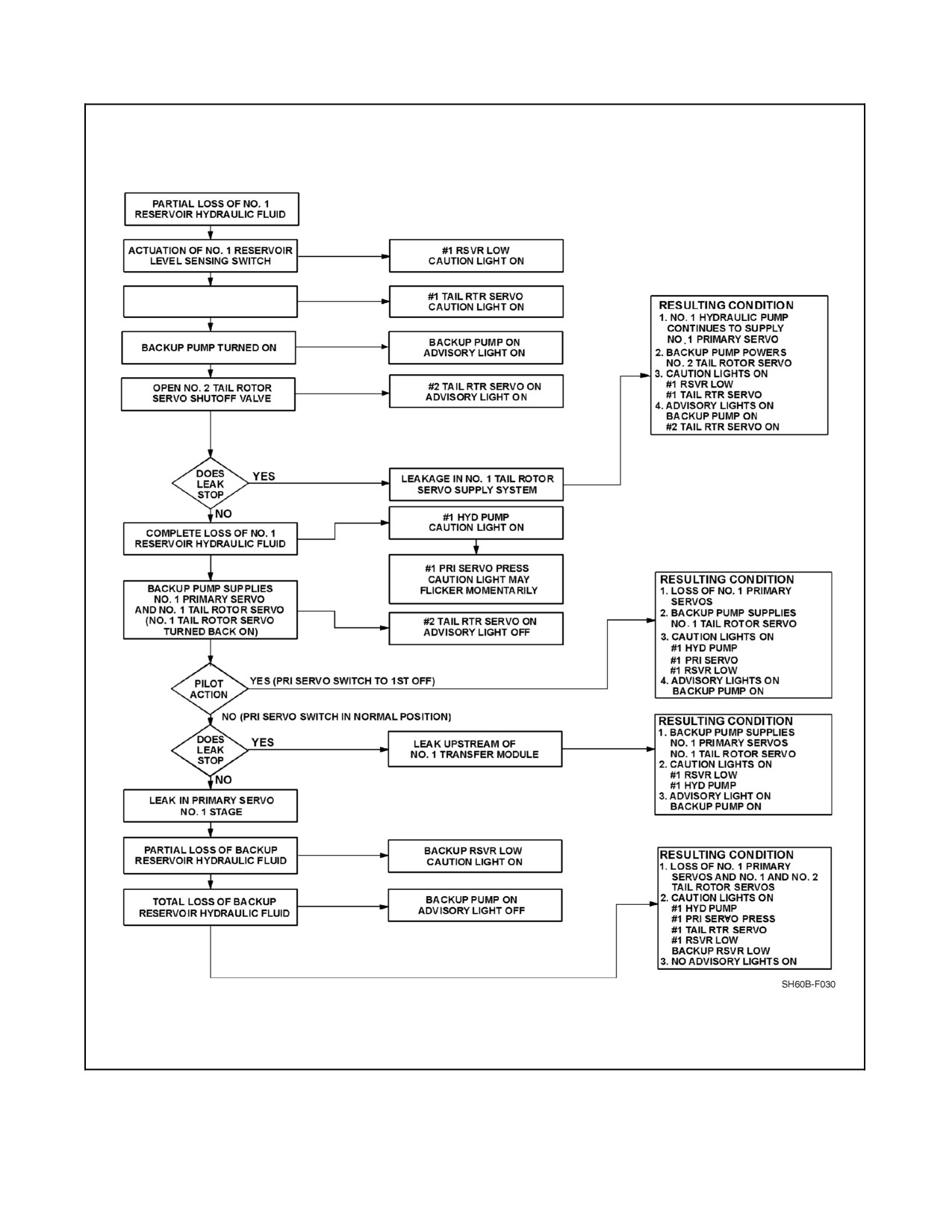
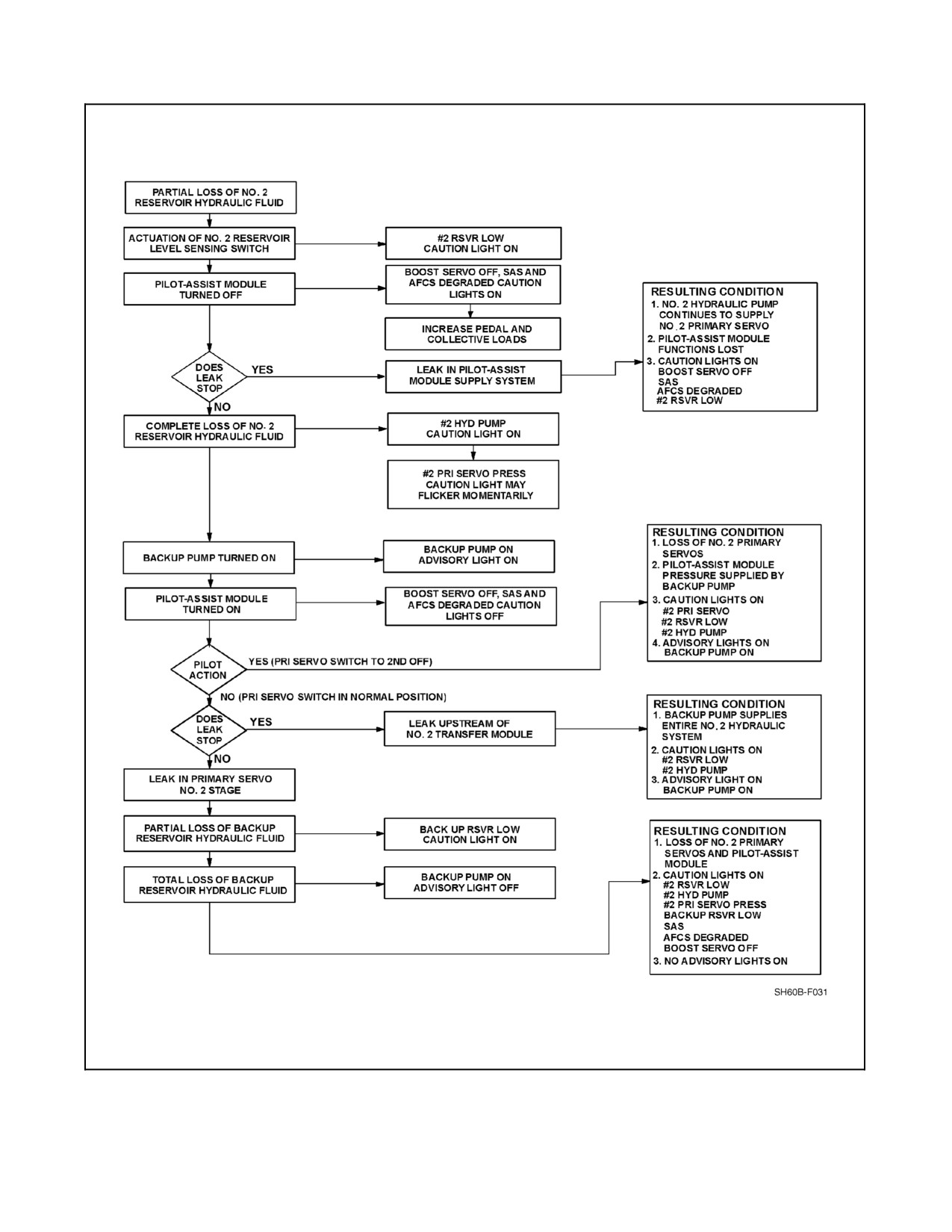
of the flight control system (Figures 2-27 and 2-28). All switching functions of the hydraulic logic modules are
automatic, except as shown by Pilot Action on the logic diagrams.
2.8.4.2 Hydraulic Leak Test
The hydraulic leak test checks the complete hydraulic circuit with the exception of the transfer/shuttle valves. The
HYD LEAK TEST switch is a three--position toggle switch located on the overhead console (Figure 1-6). The
hydraulic leak test is a ground test and the following criteria must be achieved prior to initiating the test:
1. AC power.
2. Backup pump in AUTO position.
3. All hydraulic reservoirs full.
4. WOW.
5. Rotors turning.
The switch positions are TEST, RESET, and NORM. In the TEST position, if the above criteria are met, the test
function activates an electrical signal illuminating the three RSVR low lights. The hydraulic logic modules then take
theirnormal action forthis condition. The following caution/advisory lights will illuminate, indicating asatisfactory
test:
1.
#1 TAIL RTR SERVO.
2. BOOST SERVO OFF.
3. SAS.
4. AFCS DEGRADED.
5.
#1 RSVR LOW.
6.
#2 RSVR LOW.
7. BACK--UP RSVR LOW.
8. BACK--UP PUMP ON.
9.
#2 TAIL RTR SERVO ON.
10. MASTER CAUTION.
After a leak test has been made, the HYD LEAK TEST switch must be moved to RESET momentarily to turn off
caution and advisory lights that were on during the test. Except for the HYD LEAK TEST switch, the hydraulic leak
system consists of components of the NO. 1, NO. 2, and backup hydraulic systems. A WOW switch contact prevents
hydraulic leak tests from being made in flight. Power to operate the hydraulic leak test system is from the NO. 2 DC
primary bus through a circuit breaker located on the ATO circuit breaker panel, marked NO. 2 SERVO CONTR, and
from the DC essential bus through a circuit breaker located on the overhead circuit breaker panel, marked BACKUP
HYD CONTR.
2.8.4.3 Reservoir Fill System
A hand pump and manual selector valve are on the right side, upper deck of the helicopter for system servicing. The
three main hydraulic system reservoir levels can be seen from the fill--pump location. The hand pump reservoir
contains a sight gauge above the hand pump crank. A low--level mark indicates a requirement for refill. The hand
pump reservoir serves as the rotor brake reservoir.
ORIGINAL
2-76
A1-H60BB-NFM-000
NO. 1 TAIL ROTOR SERVO TURNED
OFF
Figure 2-27. Hydraulic Logic Module Functions for a Leak in #1 Hydraulic System
2-77
ORIGINAL
A1-H60BB-NFM-000
Figure 2-28. Hydraulic Logic Module Functions for a Leak in #2 Hydraulic System
ORIGINAL
2-78
A1-H60BB-NFM-000
2.9
FLIGHT CONTROL SYSTEM
The helicopter is controlled by varying and intermixing the control outputs from the cyclic, collective, and tail rotor
pedals. Control movement is accomplished manually by either pilot or automatically by the AFCS. The flight control
system can be divided into three sections:
1. Mechanical control system.
2. Flight control servo system.
3. Automatic flight control system
2.9.1 Mechanical Control System
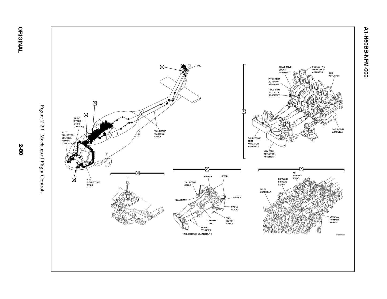
The physical layout of the mechanical flight controls is presented in (Figure 2-29), and a simplified block diagram
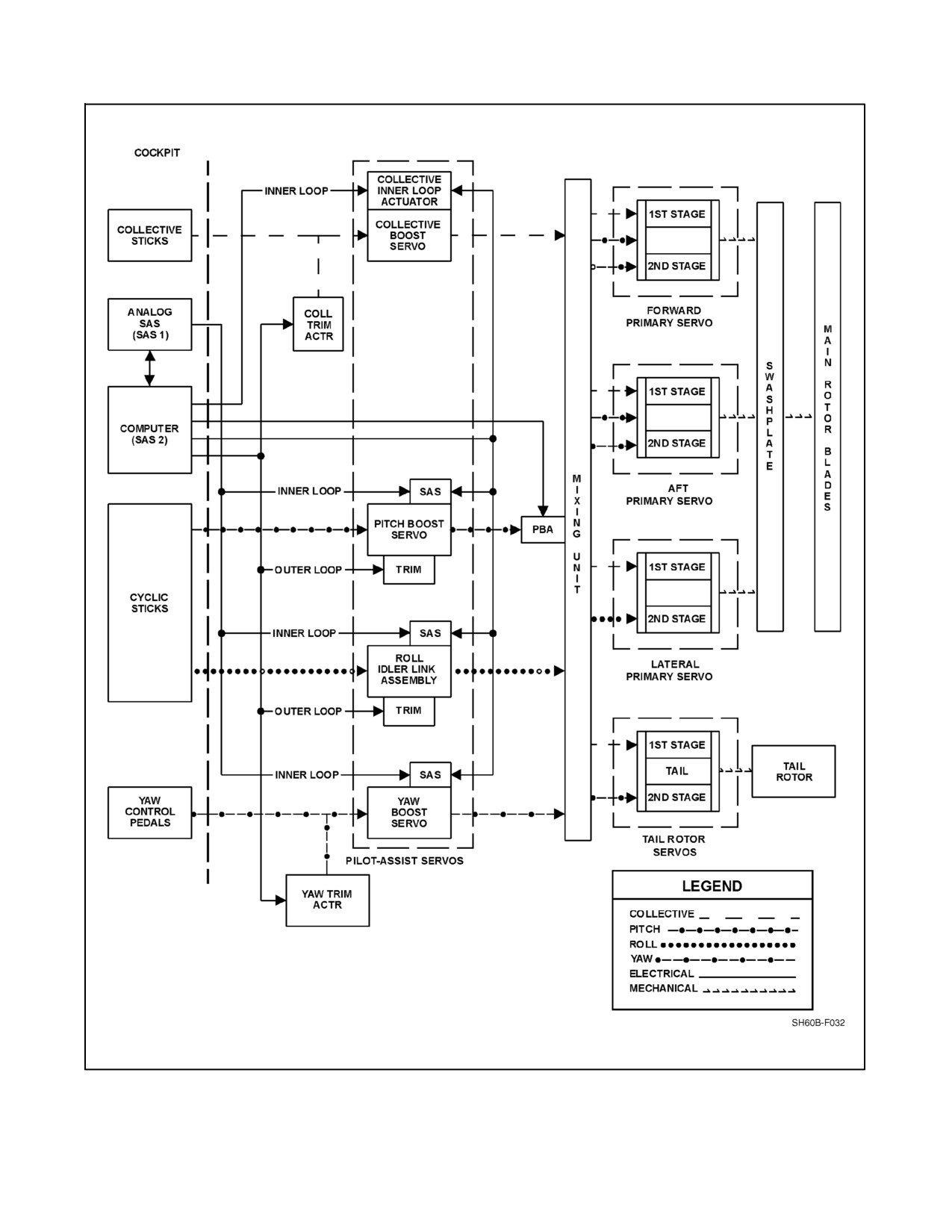
of the flight control system, including the AFCS components, is presented in (Figure 2-30). The cyclic, collective,
and tail rotor pedal flight controls are routed aft and outboard of each pilot seat, vertically up each side of the aircraft,
and are combined for each axis at the overhead torque shafts inside the hydraulics bay. The overhead torque shafts
transfer inputs from the trim servos and flight controls through the pilot assist servos, and the mixing unit. From
the mixing unit, fore, aft, and lateral inputs are transferred to the swashplate assembly via the primary servos and the
bridge assembly. The yaw inputs to the tail rotor servo are transferred from the mixing unit aft to the tail rotor quadrant
through the tail rotor cables.
Both pilot and copilot flight controls, control grips, and control grip function switches are identical and are presented
in Figure 2-29. Thecopilot collectivetelescopes by twisting thegrip and pushing thecollective aft to improveaccess
to the seat.
2.9.1.1 Tail Rotor Control System
The tail rotor control system provides directional control by varying the pitch of the tail rotor blades. The tail rotor
servo is mechanically actuated, but requires hydraulic pressure to operate the pitch change shaft which moves the
tail rotor pitch change beam, changing blade pitch angle through the pitch--change links.
The tail rotor servo is powered by either the NO. 1 hydraulic system or the backup hydraulic system. The tail rotor
quadrant transmits tail rotor cable movement to the tail rotor servo. Two spring cylinders connected to the quadrant,
allows cable tension to be maintained if either tail rotor cable becomes severed. Microswitches activate the TAIL
ROTOR QUADRANT caution when either cable is broken. Directional control of the tail rotor is maintained by the
remaining spring. If both cables are severed, two separate centering springs will counter the tail rotor servo pilot valve
positioning the tail rotor to a neutral setting to provide a fly--home capability.
At the tail pylon fold area, the cables run though a series of pulleys that allow the tail pylon to be folded without
disconnecting the control cables.
2.9.2 Flight Control Servo Systems
Theflight control servo system (Figure 2-30)consists oftheprimary servos, tail rotorservos,and pilot--assistservos.
2.9.2.1 Primary Servos
There are three primary servos located in the hydraulics bay. Each primary servo has two stages that are independent
and redundant with only the input linkage in common. Should one primary servo stage become inoperative due to
pressure loss or a jammed input pilot valve, a bypass valve within the affected stage will automatically open, and
the #1/#2 PRI SERVO PRESS caution will illuminate.
2.9.2.2 Tail Rotor Servo
The tail rotor servo has two independent stages. The first stage is powered by the NO. 1 hydraulic system with the
TAIL SERVO switch in the NORM position. The second stage is powered by the backup hydraulic system with the
TAIL SERVO switch in the BACKUP position. Should the first stage of the TAIL SERVO lose hydraulic pressure,
the backup pump will automatically power the second stage of the tail rotor servo illuminating the #1 TAIL RTR
SERVO caution, the #2 TAIL RTR SERVO ON advisory, and the BACKUP PUMP ON advisory.
2-79
ORIGINAL
PILOT/ATO PEDAL ADJUSTOR
MIXING UNIT AND PRIMARY SERVOS
A1-H60BB-NFM-000
DAFCS
Figure 2-30. Flight Control System
2-81
ORIGINAL
A1-H60BB-NFM-000
2.9.2.3 Pilot Assist Servos
The pilot--assist servo assembly contains the boost servos, SAS actuators, and hydraulic (pitch and roll) trim
actuators. Flight controls are operable without hydraulic pressure to the pilot--assist servos, but collective and yaw
inputs will require considerable pilot effort. Hydraulic power is still required to move the primary servos.
The pilot--assist servos, except pitch and roll trim, are turned on and off by pressing the SAS/BOOST pushbutton
on theAFCS CONTROL panel (Figure 2-31). Hydraulic pressureto thepitch and roll trim actuators is turned on and
off by the TRIM pushbutton on the AFCS CONTROL panel.
2.9.2.3.1 Boost Servos
There are three boost servos (collective, yaw, and pitch) located between the cockpit controls and the mixing unit,
which reduce cockpit control forces and SAS system feedback. All boost servos and the roll channel incorporate a
SAS actuator, which provides rate damping.
2.9.2.4 Control Mixing
The cyclic, collective, and pedal controls are mechanically combined in the mixing unit (Figure 2-32) to produce
uncoupled airframe response characteristics. In addition to mechanical mixing, electrical (collective/airspeed--
to--yaw) mixing is also present when trim is engaged.
ORIGINAL
2-82
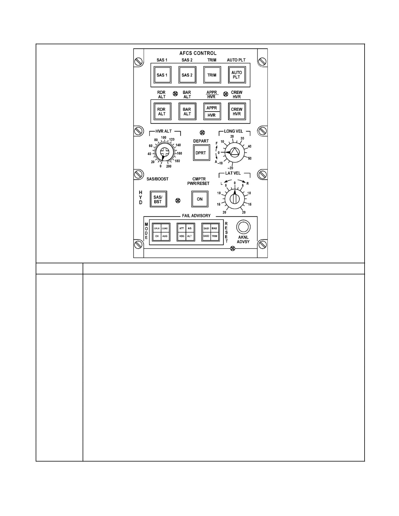
A1-H60BB-NFM-000
CONTROL
FUNCTIONAL DESCRIPTION
SAS 1
Pushbutton that applies electrical power to the SAS 1 system. SAS 1 illuminates when system is on.
SAS 2
Pushbutton that applies electrical power to the SAS 2 system. SAS 2 illuminates when system is on.
TRIM
Pushbutton thatapplies electricaland/orhydraulic powerto allcontroltrimsystems (pitch,roll,yaw, and collect-
ive). TRIM illuminates when trim systems are on.
AUTO PLT
Pushbutton that applies electrical power to the automatic pilot (SAS 1 or SAS 2 and TRIM must also be on).
AUTO PLT illuminates when autopilot is on.
APPR/HVR
Pushbutton that engages either automatic approach or coupled hover mode, depending on flight regime.
CREW HVR
Pushbutton that activates crew hover mode while coupled hover mode is engaged.
DEPART
Light that illuminates when DEPART mode is selected via DEPART HOVER button on the cyclic grip.
LONG VEL
Rotary knob that permits the pilot to set a reference longitudinal velocity in coupled hover mode.
LAT VEL
Rotary knob that permits the pilot to set a reference lateral velocity during coupled hover mode.
CMPTR PWR/
Guarded pushbutton that applies electrical power to the AFCC. Also provides power on/reset capability if the
RESET
computer automatically shuts down due to a self--diagnosed malfunction.
SAS/BOOST
Guarded pushbutton that applies hydraulic power to the SAS actuators and boost servos.
HVR ALT
Rotary knob that permits the pilot to set a reference hover altitude during automatic approach and coupled
hover mode.
RDR ALT
Pushbutton that engages and disengages radar altitude hold system. It is illuminated when engaged and
flashes when the collective TRIM RLSE switch is depressed. Reference altitude is obtained from HVR ALT
rotary knob only when coupled hover mode is on. When coupled hover mode is off, the reference altitude is
established when the pushbutton is engaged and reset when the collective trim switch is depressed and
released.
BAR ALT
Pushbutton that engages and disengages barometric altitude hold.It is illuminated when engaged and flashes
when the collective TRIMRLSE switch is depressed.Altitude is referenced automatically when the pushbutton
is engaged and reset when collective TRIM RLSE switch is depressed and released.
Figure 2-31. Automatic Flight Control System (AFCS) Control Panel
2-83
ORIGINAL
A1-H60BB-NFM-000
COMPENSATION
NAME
COMPENSATION
CAUSE
REQUIREMENT
MECHANICAL COMPENSATION
Collective to yaw
Tail rotor thrust is increased
Main rotor torque
Nose yaws right when
collective is increased
Collective to lateral
Rotor disc is tilted left
Lateral lead (tail rotor
Helicopter drifts right when
propeller effect)
collective is increased
Collective to
Rotor disc is tilted forward
Rotor downwash on
Nose pitches up and
longitudinal
stabilator
helicopter drifts aft when
collective is increased
Yaw to longitudinal
Rotor disc is tilted aft
Tail rotor lift vector
Nose pitches down and
helicopter drifts forward
when left pedal is applied
ELECTRONIC COMPENSATION
Collective/airspeed
A portion of the main rotor torque
Camber of tail rotor
Nose yaws left as airspeed
to yaw
compensation is provided by a trim
pylon varies side load
increases
input that is proportional to collec-
with airspeed
tive position and airspeed. The trim
input is then progressively washed
out as pylon side loads increase
with airspeed.
Figure 2-32. Control Mixing
2.9.3 Automatic Flight Control System (AFCS)
The AFCS is an electrohydromechanical system which provides inputs to the flight control system to assist the pilot
in maneuvering and handling the helicopter. The AFCS is composed of three major subsystems: the SAS, the
stabilator system, and the DAFCS. A schematic of the AFCS is presented in Figure 2-33. All engagement controls
for the three subsystems are contained on the AFCS and stabilator control panels. Each subsystem operates
independently of the other two subsystems and they all complement one another. Autopilot functions are engaged
by the AUTO PLT pushbutton on the AFCS CONTROL panel. The AFCS RELEASE pushbutton on the cyclic will
disengage SAS 1, SAS 2, and autopilot. The AFCS provides the following features:
1. Pitch, roll, and yaw stability augmentation.
2. Stabilator control.
3. Cyclic, collective, and pedal trim.
4. Pitch and roll attitude hold.
5. Airspeed hold.
6. Heading hold.
7. Barometric altitude hold.
8. Radar altitude hold.
9. Pitch and roll hover augmentation/gust alleviation.
10. Turn coordination.
11. Maneuvering stability.
12. Automatic approach to hover.
13. Hover coupler.
14. Automatic depart.
ORIGINAL
2-84
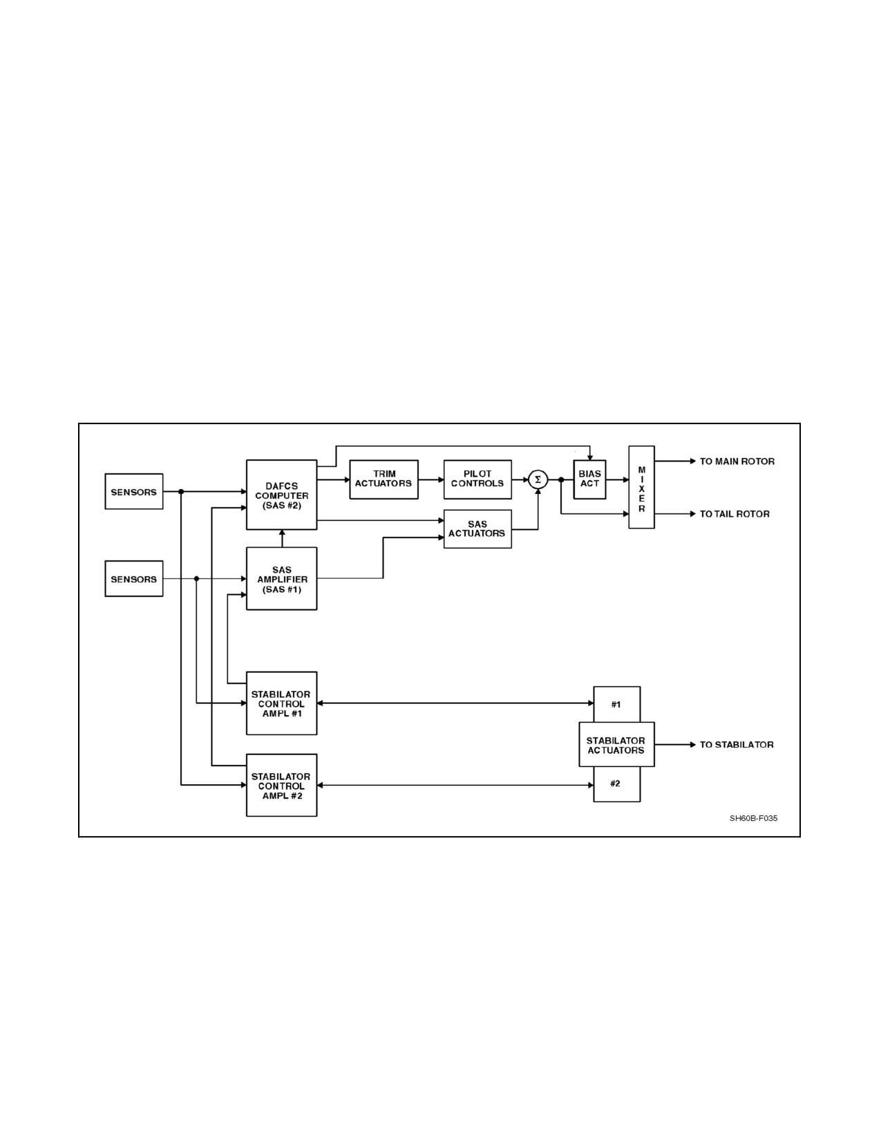
A1-H60BB-NFM-000
15. Crew hover.
16. Longitudinal stick gradient augmentation (pitch bias actuator).
17. Blade fold assist.
18. Automatic preflight check.
19. Diagnostics (mode failure display).
2.9.3.1 AFCS Control Panels
The AFCS is controlled from two panels: the AFCS CONTROL panel and the STABILATOR control panel. Both control
panels are located on the lower console. Controls and functions of the AFCS CONTROL panel are summarized in
Figure 2-31. Functional descriptions of the fail advisory lights displayed on the AFCS CONTROL panel are presented
in Figure 2-34. The STABILATOR control panel contains all the operating controls for the stabilator and is shown in
Figure 2-36. All theotherAFCS controls areon theAFCS CONTROL panel. All detectable AFCS mode failures except
for the stabilator illuminate the AFCS DEGRADED light on the caution/advisory panel and the appropriate mode failure
capsule on the FAILURE ADVISORY section of the AFCS CONTROL panel. Stabilator failures illuminate the
STABILATOR caution light on the caution/advisory panel and generate an aural warning tone in the pilot and ATO
headsets.
Figure 2-33. AFCS Input, Simplified Block Diagram
2-85
ORIGINAL
A1-H60BB-NFM-000
FAIL ADVISORY
LIGHT ON
SYSTEM
FUNCTIONAL DESCRIPTION
CPLR
Approach/Hover Coupler
Approach/hover coupler capability loss. ATT, or A/S, or
ALT light may also be on.
CORD
Turn Coordination
Turn coordination is lost if AUG or SAS 1 and SAS 2 or
A/S light is on.
CH
Crew Hover
Loss of crew hover mode.
AUG
Longitudinal and Lateral Hover
Loss of hover augmentation. A/S, ATT, or SAS 1, and
Augmentation
SAS 2 light may also be on.
ATT
Pitch and Roll Attitude Hold
Pitch or roll autopilot attitude hold has been lost. If TRIM
is also on, both pitch and roll attitude hold have been lost
or malfunctioning. If pitch attitude failure occurs, the A/S
light also goes on, indicating airspeed hold is also not
available.
A/S
Airspeed Hold
Airspeed hold is lost. The autopilot may continue to hold
pitch attitude unless a failure of pitch attitude hold occurs.
In this case, ATT light would go on.
HDG
Heading Hold
Heading hold has been lost or the ability to synchronize
heading hold has been lost, or collective to yaw electrical
coupling has been lost.
ALT
Barometric or Radar Altitude
If barometric altitude hold was engaged, altitude hold is
Hold
lost. If radar altitude hold is desired, it must be selected. If
radar altitude hold was engaged, barometric altitude hold
will automatically engage, unless the type of failure pre-
vents any altitude hold operation.
SAS 1
SAS 1 Pitch,
A malfunction has occurred, causing improper pitch, roll,
SAS 1 Roll,
or yaw SAS 1 operation. SAS 1 should be disengaged to
SAS 1 Yaw
ensure proper SAS 2 operation.
BIAS
Pitch Bias
Loss or modified operation of the pitch bias actuator
occurs, if the BIAS light goes on.
An airspeed transducer failure causes the pitch bias
actuator to move to a position corresponding to 120 KIAS.
The bias actuator continues to function about this
120 knot airspeed reference. The A/S light should also be
on if airspeed is the cause of the BIAS light.
A vertical gyro (pitch) failure causes the bias actuator to
move to a center position. The bias actuator now stays at
this center position. The ATT light should also be on, if
attitude is cause of bias light. A dual pitch rate gyro failure
will cause the bias actuator to lose its ability. However,
the bias actuator will continue to function for attitude and
airspeed inputs. The SAS 1 and SAS 2 lights should also
be on if the pitch rate gyros are the cause of failure.
The pitch bias actuator itself is not responding to com-
puter commands. The bias actuator stops wherever it is
at that time. No other fail advisory lights are coupled with
the BIAS light for this problem.
Figure
2-34.
Fail Advisory Light (Sheet 1 of 2)
ORIGINAL
2-86
A1-H60BB-NFM-000
FAIL ADVISORY
LIGHT ON
SYSTEM
FUNCTIONAL DESCRIPTION
SAS 2
SAS 2 Pitch,
Any combination of SAS 2 axis failure causes the affected
SAS 2 Roll,
axis to be automatically disabled.
SAS 2 Yaw
If SAS 2 and SAS 1 fail advisory lights go on, turn off
SAS 1.
TRIM
Pitch Trim Actuator, Roll Trim
Cyclic pitch or roll trim, yaw pedal trim, or collective trim is
Actuator, Yaw Trim Actuator,
lost or malfunctioning. Any combination of the above will
Collective Trim Actuator
cause the TRIM light to go on.
No fail advisory
Unknown
A degradation has occurred that is not associated with a
light on, AFCS
fail advisory light.
DEGRADED cau-
tion light flashing
No fail advisory
Primary power to the com-
A computer power sever has occurred. All DAFCS com-
light on, AFCS
puter
puter output signals are discontinued. To attempt to
DEGRADED cau-
regain computer operation, press CMPTR PWR/RESET
tion light on steady
switch OFF then ON. Loss of all AFCS functions except
SAS 1, boost, and Stabilator.
Note
D Use the AKNL ADVSY switch to acknowledge the failure of an AFCS system, so that MASTER
CAUTION light will be reset for a subsequent failure.
D To reset the computer for any mode failure (except a power sever), press any one of the three FAIL
ADVISORY MODE RESET switches.
D If the CMPTR PWR/RESET switch is on, and SAS 2 is off, pressing any of the three FAIL ADVISORY
MODE RESET switches will cause SAS 2 to automatically go on. This is a backup means of engaging
SAS.
Figure 2-34. Fail Advisory Light (Sheet 2)
2.9.3.2 DAFCS
The central component of the DAFCS is the digital computer. The computer commands the pitch bias actuator (PBA),
the inner--loop SAS actuators, and the outer--loop trim actuators in all four control channels. A system block diagram of
the DAFCS is presented in Figure 2-35. The computer also provides self--monitoring, fault isolation, and failure advisory.
The DAFCS employs two types of control, identified as inner loop and outer loop. The inner loop (SAS) employs
rate damping to improve helicopter stability. This system is fast in response, limited in authority, and operates without
causing movement of the flight controls.
The outer loop (AUTOPILOT) provides long--term inputs by trimming the flight controls to the position required
to maintain the selected flight regime. It is capable of driving the flight controls throughout their full range of travel
(100 percent authority) at a limited rate of 10 percent per second. Both inner and outer loops allow for complete pilot
override through the normal use of the flight controls.
2-87
ORIGINAL
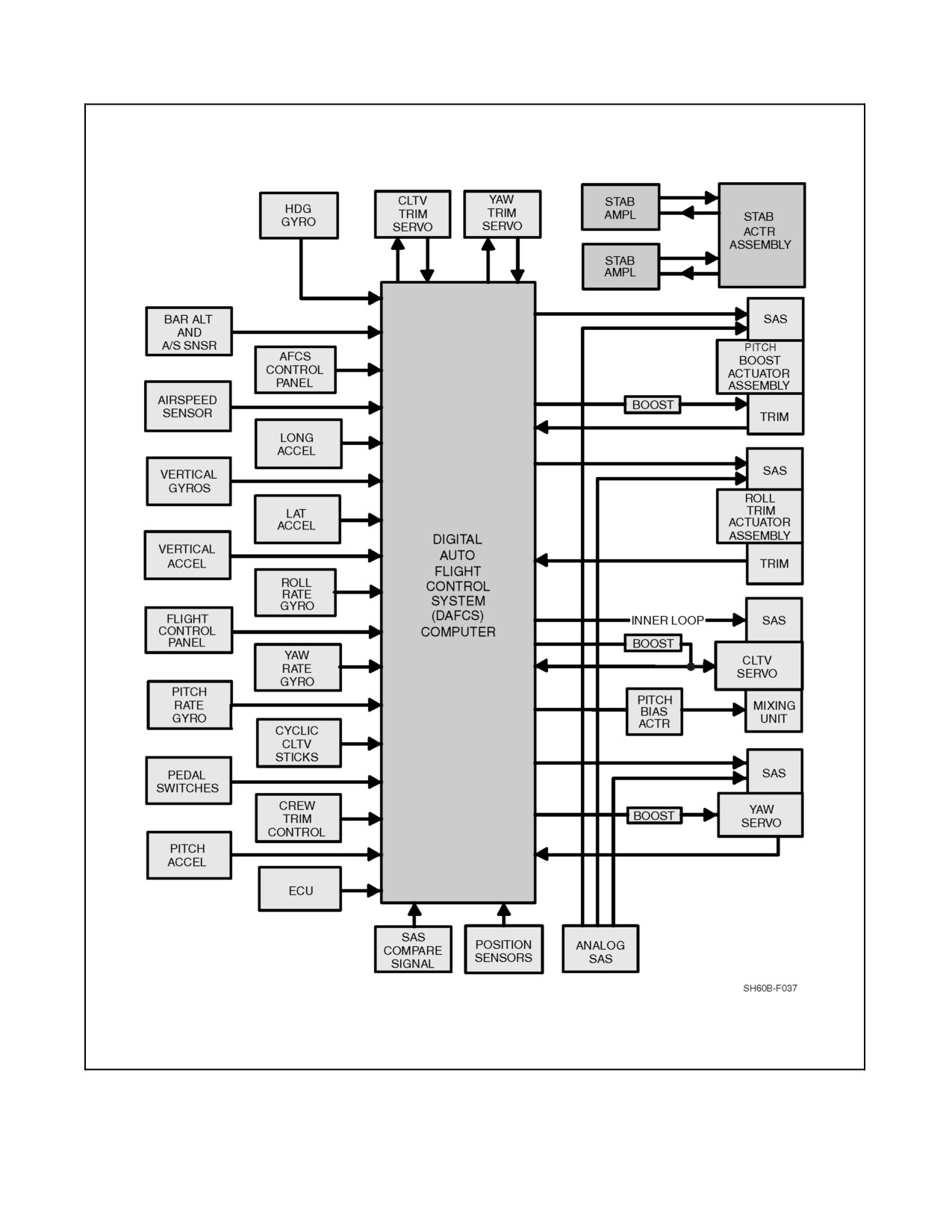
A1-H60BB-NFM-000
Figure 2-35. DAFCS Input/Output Block Diagram
ORIGINAL
2-88
A1-H60BB-NFM-000
D When AFCS computer power is cycled, trim is disengaged and an
unguarded cyclic will allow the rotor arc to dip as low as four feet above
thedeck, priorto full control deflection, without pounding the droop stops.
D AFCS computer power is interrupted with a total AC power failure. After
AC power is restored, AFCS computer power must be cycled before
resetting AFCS functions.
The DAFCS computer processes incoming information from various sensors aboard the aircraft and stores this
information in its memory. Thesensorinformation is used by thecomputercentral processing unit(CPU)tocompute
required correction signals. Inner--loop correction signals are routed to the SAS actuators and outer--loop signals are
routed to trim servos and actuators.
2.9.3.2.1 AFCS Voltage Sensor Relay
The function of the voltage sensor relay (VSR) is to select the source of three--phase, 115 Vac power to be applied
to the DAFCS computer. The voltagesensor also supplies powerto theHeading AttitudeReference System (HARS)
via the ac essential bus relay. Power source selection is a function of the NO. 1 generator output integrity. When 3
phase power from the NO. 1 ac primary bus is sensed in the voltage sensor, the ac essential bus relay is energized
and ac power is routed to the AFCS power switching assembly via the VSR.
When there is a phase disruption or fault occurrence on the NO. 1 ac primary bus supply, the VSR will automatically
switch the power source of the AC Essential bus from the NO. 1 ac primary bus to the NO. 2 ac primary bus to retain
basic HARS, SAS and TRIM functions. If the VSR switches power to the NO.2 AC primary bus, the DAFCS could
fail and the AFCS, SAS and TRIM functions may be required to be reset. A malfunctioning VSR may cause a power
failure of the DAFCS computer, multiple fail advisory lights, tumbling or precessing of either or both pilot or ATO
AI or BDHI, or steady or intermittent OFF flags presented in the pilot or ATO AI or BDHI.
The AFCS voltage sensor is mounted overhead in the forward cabin area. Power to the VSR is supplied from both
the NO. 1 ac primary bus through the AFCS CMPTR CB on the center circuit breaker panel and from the NO. 2
Primary bus through the AFCS CMPTR CB on the sensor operator circuit breaker panel. The voltage sensor for the
VSR is the circuit breaker labeled AC ESNTL BUS SUPPLY (7.5 amp) on the NO. 1 AC Primary bus located on
the center circuit breaker panel. Pulling the VSR CB (i.e. AC ESNTL BUS SUPPLY CB) will cause power to both
the DAFCS and the AC Essential bus to be supplied from the NO. 2 AC Primary side. Caution should be taken to
ensure the AC ESNTL BUS SUPPLY CB on the NO. 2 Primary Side located on the Corner Circuit Breaker Panel
is pressed in before pulling the VSR CB.
2.9.3.3 Stabilator System
The stabilator system optimizes trim attitudes for cruise, climb, and autorotation and provides pitch stability
augmentation to complement the SAS for additional redundancy. The stabilator system is completely independent
of the other two AFCS subsystems except for common airspeed sensors, lateral accelerometers, and pitch rate gyros.
The stabilator control system is a completely automatic fly--by--wire control system with a manual backup slew
control. The primary purpose of the stabilator control system is to eliminate undesirable noseup attitudes caused by
rotor downwash impinging on the horizontal stabilator during transition to a hover and during low--speed flight. The
stabilator panel (Figure 2-36) contains an automatic control (AUTO CONTROL) switch, a TEST pushbutton, and
amanual slew (MAN SLEW) switch. The AUTO CONTROL switch can only be used to engagethe automaticmode
or to reset the stabilator in the event of a stabilator failure. The switch is not an alternate action pushbutton. The pilot
can manually position the stabilator to any position within the stabilator limits by moving the MAN SLEW switch.
The TEST pushbutton, which is operational below 50 knots, is used to check the automatic mode fault detector. The
stabilatoris positioned by two electricjackscrew actuators acting in series. Each actuator provides one--half theinput
2-89
ORIGINAL
A1-H60BB-NFM-000
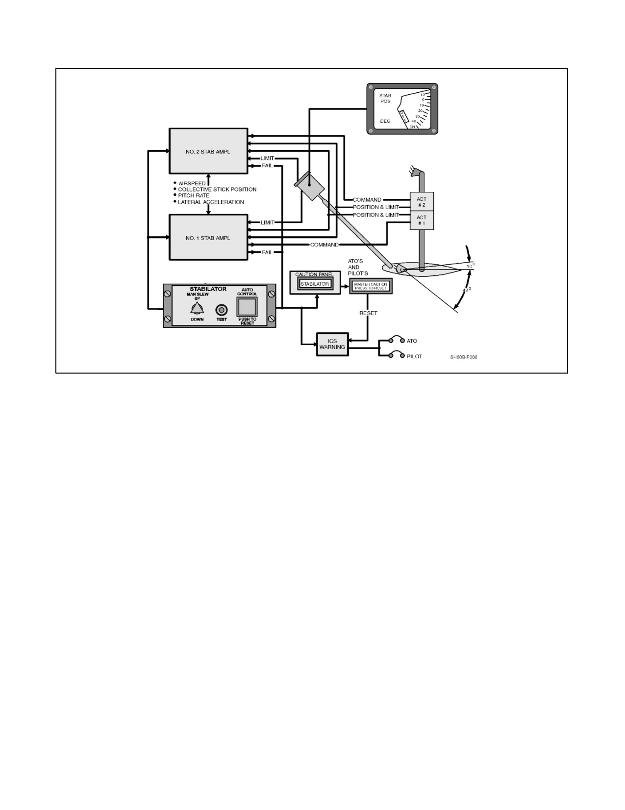
to position thestabilatorand is controlled by aseparateand redundant stabilatoramplifier. Thestabilatortravelsfrom
42° trailing edge down for hover and low--speed flight below 30 knots to 10° trailing edge up for cruise and
maneuvering flight. The stabilator electrical screw actuators receive power from the DC essential bus and NO. 1 DC
primary bus through two circuit breakers marked STAB SYS PWR and STAB PWR, respectively. The circuit
breakers are located on the overhead console and ATO circuit breaker panels, respectively. Four inputs are required
to position the stabilator (Figure 2-37):
1. Airspeed.
2. Collective position.
3. Lateral acceleration.
4. Pitch rate.
The airspeed input aligns the stabilator with the main rotor downwash during slow--speed flight. The collective
position input decouples aircraft pitch attitude with collective position. Pitch rate and lateral acceleration inputs
improve the dynamic response of the aircraft, especially in gusty air conditions. The pitch rate input supplements
the dynamic stability provided by the SAS and DAFCS, and the lateral accelerometer input decouples the aircraft
pitch response with changes in the rotor downwash on the stabilator during out of balanced flight.
Each stabilator amplifier receives these four inputs but receives the inputs from independent sensors. The DAFCS
computer monitors each of these sensors for malfunctions, and the stabilator control system monitors and compares
the position of the two actuators. Any system malfunction caused by a difference between the two stabilatoractuator
positions results in stabilator remaining in the last position, an automatic power shutdown to both actuators, an aural
tone to the pilots, and a STABILATOR caution light on the caution/advisory panel.
It is possible for the stabilator to fail without illumination of the
STABILATOR caution light and associated aural warning tone. In this
case, the first indication of failure will be an uncommanded pitch change.
If a malfunction of the stabilator system occurs, the pilot has the ability to manually position the stabilator with the
manual slew switch on the stabilator control panel. The manual slew switch bypasses the stabilator amplifier
automatic mode and applies power directly to the actuators through relays in the amplifiers. A stabilator position
indicator aids the pilot in positioning the stabilator to any position between the stabilator travel limits. However, the
total travel is restricted if the malfunction is caused by an actuator failure. The stabilator travel is restricted to 35°
if an actuator fails in the full--down position or 30° if an actuator fails in the full--up position. The stabilator control
rate is limited to ±6° per second.
ORIGINAL
2-90
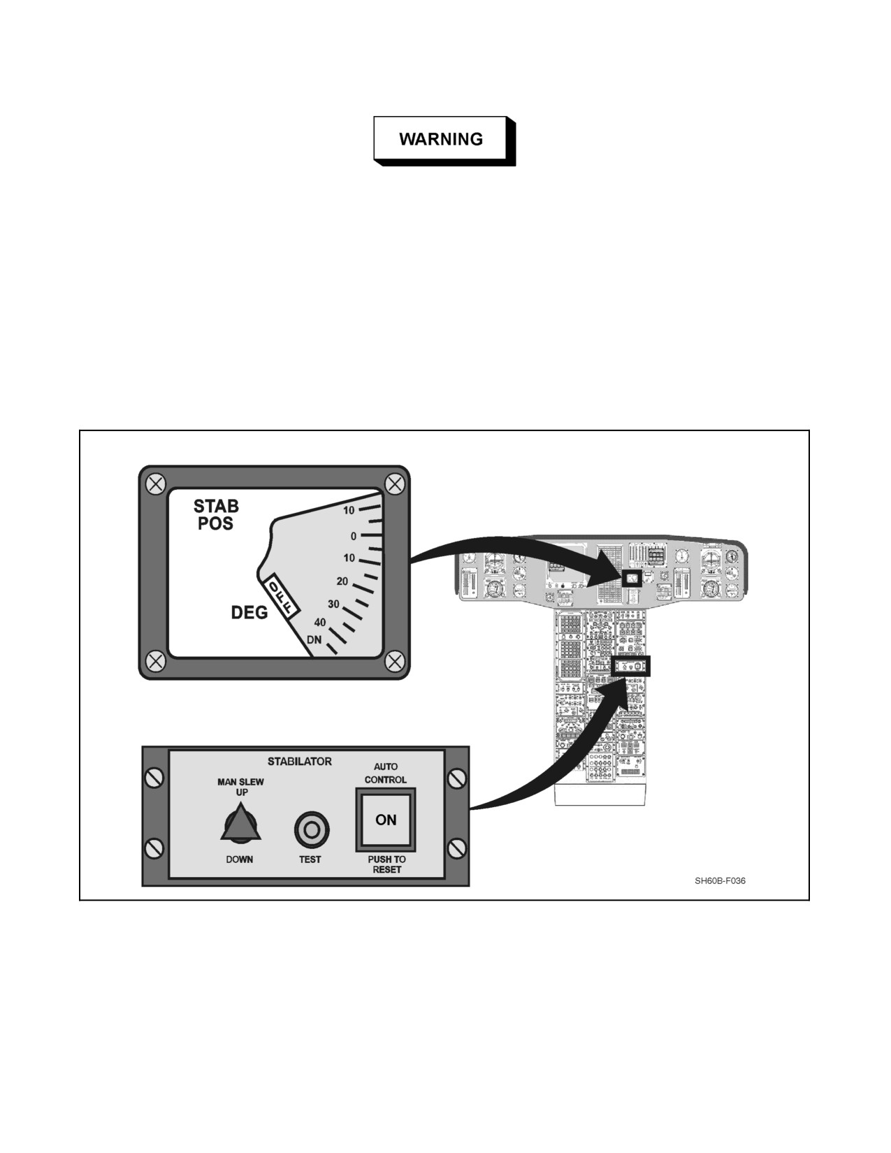
A1-H60BB-NFM-000
Reengagement of the automatic mode after a shutdown occurs results in the
automatic mode operating for one second. If a hardover signal to one
actuator was the cause of the initial shutdown, and reengagement is
attempted, that actuator will again cause the stabilator to move before
another disengagement is commanded. In this case subsequent reengage-
ment shall not be attempted since it may result in additional stabilator
movement.
Note
Due to the loss of automatic fail safe features with the stabilator in the
manual mode, intentional flight in the manual mode is not recommended.
Figure 2-36. Stabilator Control Panel
2-91
ORIGINAL
A1-H60BB-NFM-000
Figure 2-37. Stabilator Block Diagram
2.9.4 Stability Augmentation System
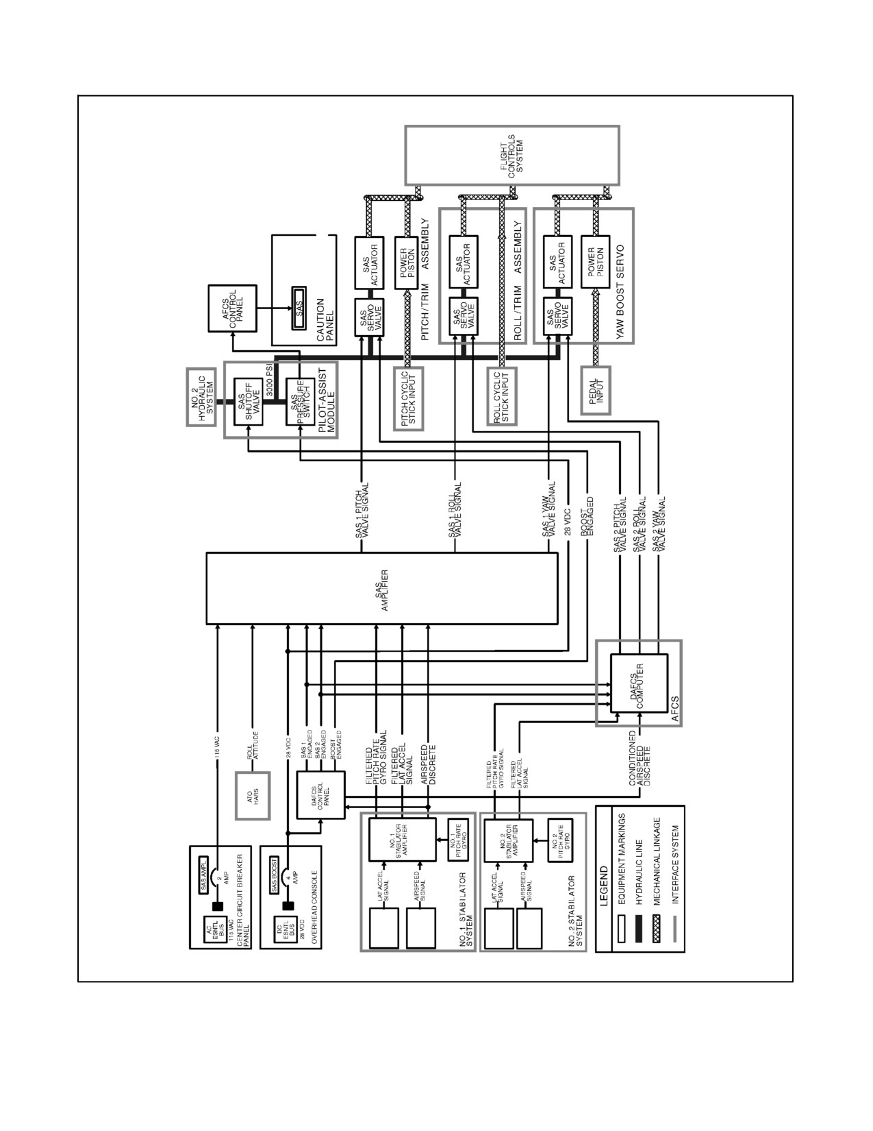
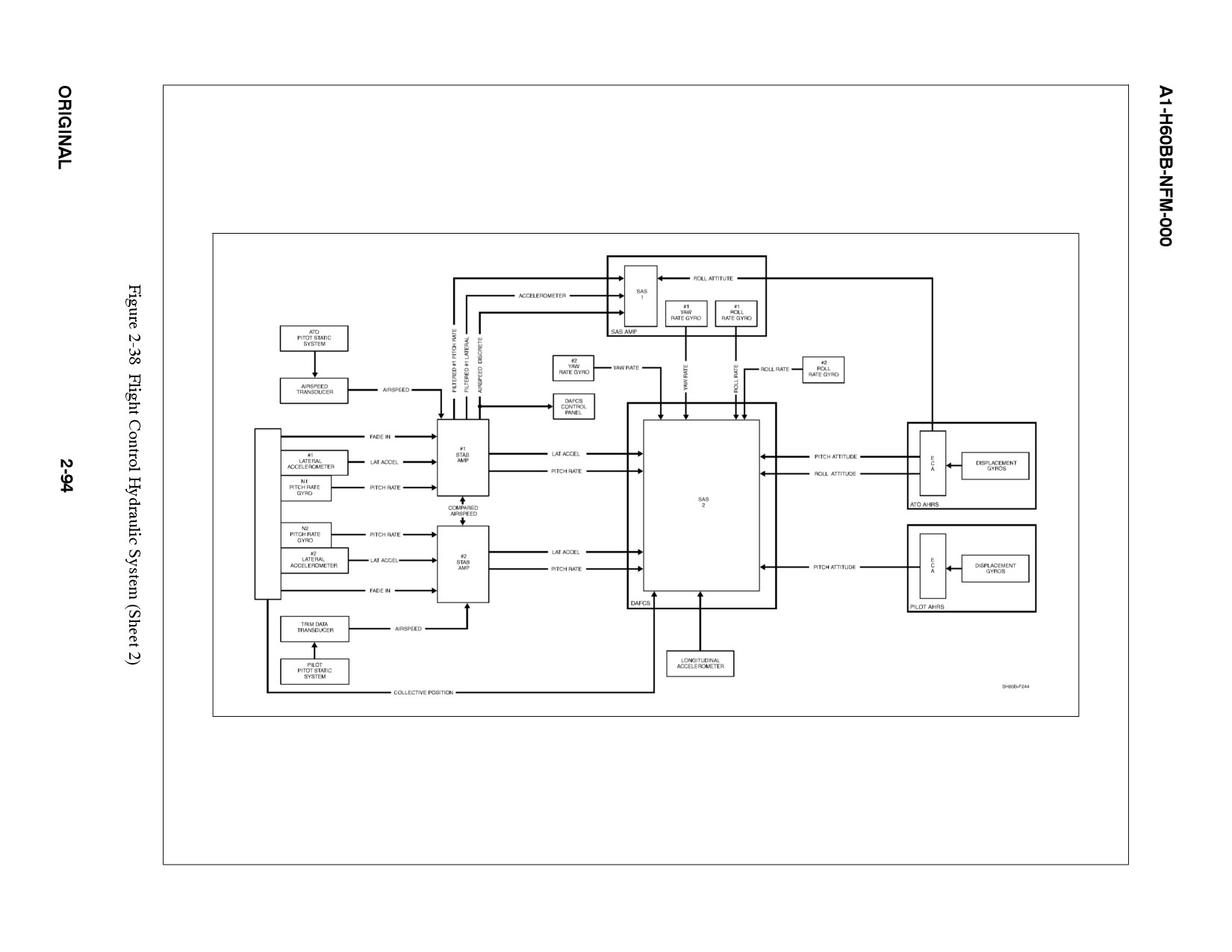
SAS provides improved stability by sensing acceleration in the pitch, roll, yaw and vertical axes, and by applying
a control input to stop the acceleration and maintain a constant rate (Figure 2-38). The SAS is an inner--loop system
with two separate and independent SAS channels. SAS channel NO. 1 is an analog system; SAS channel NO. 2 is
a digital system and is part of the DAFCS computer. Both SAS channel functions are identical except for the hover
augmentation/gust alleviation and hover coupler DAFCS features, which are incorporated only into SAS 2. SAS 2
also complements the DAFCS to provide turn coordination and roll attitude hold. With both channels engaged, the
pitch, roll, and yaw SAS actuators have ±10 percent control authority with each channel providing ±5 percent.
Only SAS 2 commands the collective SAS actuator. The collective SAS only operates in RDR ALT, BAR ALT, APPR
HVR, and DEPART modes and is limited to ±10 percent control authority. A system block diagram of the SAS is
presented in (Figure 2-38). Hydraulic pressure to the SAS actuators is turned on by the SAS/BOOST switch on the
AFCS CONTROL panel. This controls power to the SAS shutoff valve on the pilot assist module. A loss of SAS
actuator pressure is monitored by the SAS pressure switch which lights the SAS caution light. Either SAS 1 or
SAS 2 may be operated separately or simultaneously.
ORIGINAL
2-92
A1-H60BB-NFM-000
Figure 2-38. Flight Control Hydraulic System (Sheet 1 of 2)
2-93
ORIGINAL
C
O
L
L
E
C
T
I
V
E
P
O
S
I
T
I
O
N
A1-H60BB-NFM-000
For each control axis (except vertical), command signals from both SAS channels are applied simultaneously to
separate coils of an electrohydraulic servo valve. The two signals are summed to provide a single input into the flight
control system through a single series SAS actuator. The operation of the SAS channels is continuously monitored
by the DAFCS. If either of the two SAS channels malfunctions, the AFCS DEGRADED caution light on the
caution/advisory panel flashes and the appropriate SAS fail advisory light on the AFCS CONTROL panel is
illuminated. If SAS 2 has failed, the computer will automatically disengage the affected axis. If SAS 1 has failed,
the pilot must disengage the failed SAS 1 channel from the AFCS CONTROL panel. The remaining SAS channel
is limited to ±5 percent authority but operates at twice its normal gain to partially compensate for the failed SAS
channel. Either SAS channel can be disengaged by pressing the appropriate SAS button on the AFCS CONTROL
panel. Both SAS channels are disengaged by pressing the AFCS REL button on the cyclic. If both SAS 1 and
SAS 2 lose power, are manually shut down, or hydraulic pressure is lost to the actuators, the SAS caution light will
illuminate.
2.9.4.1 Trim System
The parallel trim actuator assemblies provide the flight control force gradients and detent positions and the outer--loop
autopilot control functions. The trim actuators command full control authority in all four control channels but are
rate--limited to 10 percent per second. Pressing TRIM REL switch (cyclic trim release, collective trim release, pedal
release) disengages the respective trim function and allows free control motion. Releasing trim release switch
reengages trim if the cyclic stick is not moving. For yaw trim release above 50 knots, the pedal microswitches and
the cyclic trim switch must be pressed. Below 50 knots, only the pedal microswitches have to be pressed. If the trim
system fails, the TRIM fail advisory light on the AFCS CONTROL panel will illuminate and the pilot can
compensate for the failure. The pilot is able to override the trim control forces in all channels.
2.9.4.2 Autopilot
The autopilot maintains helicopter pitch and roll attitude, airspeed, and heading during cruise flight, provides
maneuvering stability, and a coordinated turn feature at airspeeds above 50 KIAS. The autopilot function is engaged
by pressing the control panel SAS 1 or SAS 2 switches, TRIM switch, and then pressing the control panel AUTO
PLT pushbutton. The autopilot may be disengaged by pressing the AUTO PLT pushbutton on the AFCS panel or
pressing the AFCS REL button on the cyclic. When engaged, 28 Vdc is supplied from the control panel to the
computer. The computer also provides command signals to the trim actuators to reposition the flight controls using
the trim system. With SAS 2, TRIM, and autopilot on, all DAFCS functions are available. With SAS 1, TRIM and
autopilot on, all functions remain available except Hover Augmentation/Gust Alleviation and “Collective SAS”
functions (i.e., coupled approach, altitude hold).
2.9.4.3 Attitude and Airspeed Hold
Attitude and airspeed hold are engaged with AUTO PLT. In the pitch channel, at airspeeds less than 50 knots, attitude
changes are commanded by changing the cyclic position with the TRIM REL switch or use of the four--direction
(beeper) TRIM switch. This causes the cyclic to move and the helicopter attitude to change approximately 5° per
second. When cyclic movement is stopped, the autopilot stabilizes the helicopter around the new cyclic position and
attitude. Above 50 knots and bank angles less than 30°, the system becomes airspeed sensitive in pitch. Actuating
the four--direction TRIM switch will cause the cyclic to move and the helicopter to change airspeed reference at the
rate of 6 knots per second. Because of variations in pitot--static systems during gusty conditions, an integrated
longitudinal acceleration input is used for short--term corrections. The airspeed sensor is used for long--term updates
through a 3 second filter. The roll channel autopilot holds roll attitude of the helicopter. Attitude information is
supplied to the computer from the pilot and ATO A/A24G vertical gyros. The command signal is applied to roll
SAS 1 and SAS 2 and the roll trim system. When the pilot actuates the four--direction TRIM switch, the helicopter
roll attitude will change at approximately 6° per second. In addition to the attitude hold feature, an automatic
wing--leveling capability is also included. During transitions from hover to airspeeds above 50 knots, this feature
automatically retrims the aircraft from a left roll attitude in a hover to a wings level attitude at 50 knots. Once a level
attitude is established, the attitude hold feature maintains that attitude until a new roll attitude is commanded by the
pilot.
2-95
ORIGINAL
A1-H60BB-NFM-000
Uninterrupted use of the four--way cyclic TRIM switch to increase speed
may cause the aircraft to enter a descent with altitude hold engaged without
an associated caution light. Manual input is required to arrest the descent.
2.9.4.4 Heading Hold
The yaw channel of the autopilot provides the heading hold feature for hover and forward flight and is engaged
whenever the AUTO PLT pushbutton switch is illuminated. Heading hold is an outer--loop function operating
through the yaw trim actuator, and therefore will only be operational whenever the yaw trim is engaged. Releasing
all pedal switches at a given heading synchronizes the trim system to the established heading. A potentiometer in
the yaw trim actuator applies a trim position feedback signal to the computer and then cancels the drive signal at the
desired position, stopping the motor. The yaw autopilot also uses a collective position sensor to hold reference
heading for yaw excursions caused by main rotor torque changes. The collective position sensor is controlled by an
airspeed signal which reduces its gain as airspeed increases. When heading hold is engaged, the HDG TRIM (slew)
switch on the collective allows the pilot to make heading changes without retrimming. Below 50 KIAS, the aircraft
is slewed at 3° per second. Above 50 KIAS, actuation of the switch.
for less than 1 second provides a 1° heading change and actuation for greater than 1 second provides a 1° per second
coordinated turn. The heading hold is reengaged following a turn when the following conditions are maintained for
2 seconds:
1. Aircraft roll attitude is within 2° of wings level.
2. Yaw rate is less than 2° per second.
The heading hold is disengaged by the WOW switch when the aircraft is on the ground.
2.9.4.5 Altitude Hold
Either barometric or radar altitude hold is selectable from the AFCS CONTROL panel (but not simultaneously).
When the altitude hold mode is selected, the DAFCS computer uses as a reference altitude the existing altitude from
either the air data transducer if barometric altitude hold is selected or the radar altimeter if the radar altitude hold is
selected. The computer commands both the collective SAS actuator and the collective trim actuator to maintain the
reference altitude. The SAS actuator provides fast--response, limited--authority corrections, and the trim actuator
provides limited--response (rate limited), full--authority corrections. The DAFCS computer uses altitude and rate
from the barometric or radar altitude systems (depending on which hold mode is selected) and vertical acceleration
to commandthecollectiveSAS andtrim actuators.Thecomputeralso monitorsenginetorqueto preventdual--engine
torque from exceeding 116 percent whenever the collective trim is positioning the collective. Barometric altitude
hold is engaged at any altitudeand airspeed by depressing theBAR ALT pushbutton switch with SAS 2 andautopilot
engaged. Depressing the collective TRIM REL button temporarily disengages the mode. Upon release of the trim
switch, barometer altitude hold automatically reengages and maintains the altitude at the time of reengagement.
Radar altitude hold is engaged at any altitude from 0 to 5,000 feet AGL and at any airspeed by depressing the RDR
ALT pushbutton with SAS 2 and autopilot engaged.
When in the hover coupler mode, altitude hold is referenced to the altitude selected on the AFCS CONTROL panel
HVR ALT potentiometer. Depressing collective TRIM REL temporarily disengages the mode. Upon release of the
trim switch, radar altitude hold automatically reengages to the altitude selected on the AFCS CONTROL panel HVR
ALT potentiometer. When in the hover coupler mode, transition from one altitude to another is made with the HVR
ALT knob on the AFCS CONTROL panel. Resulting climb/descent rates are limited to 1,000/500 feet per minute,
respectively. If the radar altitude mode fails while engaged, barometric altitude hold is automatically engaged.
2.9.4.6 Hover Augmentation/Gust Alleviation
An additional feature of SAS, provided only through SAS 2, is hover augmentation/gust alleviation. It further
improves aircraft stability at low airspeed using attitude retention and longitudinal and lateral acceleration to
eliminate drift.
ORIGINAL
2-96
A1-H60BB-NFM-000
2.9.4.7 Turn Coordination
Automatic turn coordination is provided at airspeeds greater than 50 knots. Turn coordination allows the pilot to fly
a coordinated turn with directional control provided by the AFCS. The AFCS uses lateral acceleration and roll rate
to determine if the aircraft is out of balanced flight and provides theyaw SAS and yaw trim with the inputs necessary
to maintain an automatic coordinated turn. Automatic turn coordination is engaged and heading hold disengaged
when roll attitude is greater than 1° and any of the following conditions exists:
1. Lateral cyclic force greater than 3.0 percent of cyclic displacement.
2. Cyclic trim release is pressed.
3. Roll attitude is beeped beyond 2.5° bank angle.
2.9.4.8 Maneuvering Stability
Pitch control forces are increased to increase pilot effort required for a given pitch rate at bank angles greater than
30°. The higher pitch control forces help alert the pilot to G--loading during maneuvering flight and are provided
through the longitudinal trim actuator. A linear longitudinal stick force gradient is provided by trimming 1 percent
forward stick for each 1.5° angle of bank between 30° and 75°. At 75° angle of bank, the longitudinal stick force is
equivalent to 30 percent of stick displacement. The maneuvering stability feature is engaged whenever the AUTO
PLT pushbutton on the AFCS CONTROL panel is illuminated.
2.9.4.9 Auto Approach to a Hover
An automatic approach can be initiated from any airspeed and any altitude below 5,000 feet AGL. The approach
should be initiated from level flight into the wind. If the approach is initiated in a banking turn, the AFCS will make
a spiraling approach. Prior to the helicopter slowing to 60 KIAS, the pilot should level the wings and establish the
desired heading.
Initiating an automatic approach while in a trimmed turn may result in a
spiraling approach which will continue through the selected altitude.
Immediate pilot action will be required to avoid water impact.
The DAFCS provides the capability to perform an automatic approach to a zero longitudinal and any lateral
groundspeed selected on the LAT VEL control knob on the AFCS CONTROL panel and to any radar altitude selected
on the HVR ALT control knob, between 40 feet and 200 feet. If the HVR ALT is set below 40 feet, the approach will
be made to 40 feet and then continued to the HVR ALT setting when the mode is switched from APPR to HVR. The
helicopter will be commanded to the LONG VEL setting of the control when the mode is switched from APPR to
HVR. The automatic approach can be initiated with SAS 2, TRIM, and AUTO PLT engaged by activating the
automatic approach pushbutton (APPR/HVR) on the AFCS CONTROL panel. The automatic approach is an outer
loop only function and commands the aircraft to decelerate or descend until the approach profile conditions are met.
If the approach mode is selected when the aircraft conditions are below the approach profile, the DAFCS commands
the aircraft through the longitudinal trim actuator to decelerate at 1 knot/second while in the radar altitude hold mode
untiltheapproachconditions aremet. Iftheapproachmodeisselected whentheaircraftis abovetheapproachprofile,
the DAFCS commands the aircraft through the collective trim actuator to descend at 360 feet/minute while the
aircraft is more than 50 feet above the approach profile or at 120 feet/minute when the aircraft is less than 50 feet
above the profile, using the radar altimeter until the approach profile conditions are met. When the approach profile
conditions are met, the aircraft simultaneously decelerates at 1 knot/second and descends at 120 feet/minute. This
profile is maintained until the aircraft attains 1 knot of Doppler groundspeed and comes to within 1 foot of the
selected radar altitude. If the selected altitude is below 40 feet, the aircraft flies to 40 feet and zero longitudinal
groundspeed and then descends to the selected altitude. When groundspeed equals 1 knot or less and the aircraft
altitude is within 2 feet of the selected altitude, the hover coupler mode automatically engages and the aircraft
2-97
ORIGINAL
A1-H60BB-NFM-000
accelerates to the selected longitudinal groundspeed. In very calm sea conditions where the Doppler return signal is
unreliable and the Doppler goes into memory, a no--Doppler approach is possible. In this condition the pilot flies the
cyclic control, and the AFCS controls the rate of descent. A summary of automatic approach malfunctions is
contained in Figure 2-39.
Certain AFCS fail advisories during an automatic approach will cancel the
automatic approach function. If this occurs when on or above the approach
profile, the aircraft will remain trimmed in a descent with no altitude hold
engaged. Immediate pilot action will be required to avoid water impact (see
Figure 2-39).
2.9.4.10 Hover Coupler
The hover coupler provides longitudinal and lateral groundspeed control and stabilization about the selected
groundspeed, and automatic altitude retention. The longitudinal and lateral groundspeed and the altitude are
selectable on the AFCS CONTROL panel. Longitudinal and lateral groundspeed and the altitude are selectable on
the AFCS and can also be beeped ±10 knots with the cyclic TRIM switch about the groundspeed selected on the
AFCS CONTROL panel. The hover coupler mode is engaged automatically at the termination of the automatic
approach, or can be engaged manually when the aircraft is hovering with less than 5 knots longitudinal groundspeed
by pressing the APPR/HVR button on the AFCS CONTROL panel with SAS 2, TRIM, and AUTO PLT engaged.
After engagement, the aircraft accelerates to the longitudinal and lateral groundspeeds selected on the AFCS
CONTROL panel. Radar altitude hold engages automatically when the aircraft altitude is within 2 feet of the altitude
selected on the HVR ALT control knob. Pressing and releasing the cyclic TRIM REL will remove cyclic trim switch
inputs, returning the aircraft to the LONG VEL and LAT VEL settings on the AFCS CONTROL panel. Because of
the Doppler noise, short--term longitudinal and lateral groundspeed is obtained from integrated longitudinal and
lateral inertial acceleration. Long--term correction is obtained from the Doppler sensor using a 7 second filter. See
paragraph 2.9.4.5 for a description of the altitude hold feature of the hover coupler.
2.9.4.11 Automatic Depart
The departure can be initiated at any time in the approach or from the coupled hover. The aircraft will assume an
approximately 2° nosedown attitude to commence the acceleration.
Note
D The transition from a 5° noseup attitude in the final phases of the approach
to a 2° nosedown attitude for departure acceleration may appear excessive
to the pilot, but is normal and is no cause for concern.
D If yaw rates are in excess of 2.5°/second, AFCS will not roll the wings level
at 60 knots. This is caused by the heading hold feature being unable to
engage. The departure will continue in a flat turn.
The AFCS will initially maintain the track of the helicopter over the ground existing at the time the departure mode
is selected. The AFCS stores the roll attitude occurring at the time the trim release button was last depressed, prior
to or in the automatic approach. If the stored roll attitude is less than 4° angle of bank, the AFCS will level the wings
and maintain heading as the aircraft accelerates through 60 KIAS. If the stored roll attitude is 4° angle of bank or
greater, the AFCS will roll the helicopter to that attitude when 60 KIAS is exceeded and continue the departure in
a spiral. Whether heading hold or coordinated turn mode is active in the departure, the aircraft will climb and
accelerate to 500 feet AGL and 100 KIAS if not interrupted by the pilot.
ORIGINAL
2-98
A1-H60BB-NFM-000
EVENTS
RAD ALT FAILURE
DOPPLER FAILURE
During approach
Aircraft will continue in a descent all the
Approach will continue using airspeed
way to the water (if on or above profile
and altitude. Pilot controls airspeed and
with RDR ALT light off).
wing attitude using beeper trim.
Flashing AFCS caution light and CPLR/
Flashing AFCS caution light. HVR bars
ALT FAIL ADVISORY light. APPR
freeze. DOPP flag appears in .AI CPLR
disengages.
FAIL ADVISORY light.
In a coupled hover or
RDR ALT Hold switches to BAR ALT
Coupled hover disengages. Attitude
below descent Profile
Hold. Automatic approach/coupled
hold RDR ALT hold retained.
(RDR ALT HOLD
hover disengages. Altitude hold
ENGAGED)
retained.
Flashing AFCS caution light and CPLR/
Flashing AFCS caution light. HVR bars
ALT FAIL ADVISORY light.
freeze. DOPP flag appears in AI. CPLR
FAIL ADVISORY light.
During departure
Aircraft will climb through 500 feet. No
Aircraft will climb to 500 feet and RDR
altitude hold will engage. Airspeed will
ALT hold will engage. Airspeed will
accelerate to 100 knots.
increase to approximately 65-75 knots
(dependent upon nose attitude when
failure occurred).
Flashing AFCS caution light and CPLR/
Flashing AFCS caution light. HVR bars
ALT FAIL ADVISORY light.
freeze. DOPP flag appears in AI. CPLR
FAIL ADVISORY light.
Notes:
Doppler degradation can be classified as follows:
1. Doppler power or transmitter fail — Bars center.
2. Doppler memory or receiver fail — Bars freeze.
Figure 2-39. Automatic Approach Malfunction Matrix
The automatic depart mode provides the capability to perform an automatic departure from a coupled hover or from
an automatic approach to a cruise airspeed of 100 KIAS and altitude of 500 feet. If the coupled hover or the automatic
approach feature has already been engaged, the automatic depart mode is engaged by depressing the DEPART HOV
button on the cyclic grip illuminating the green DEPART light on the AFCS CONTROL panel. Depressing the
DEPART HOV button a second time will disengage the automatic depart mode and radar hold, returning aircraft
control to the pilot. Radar altitude hold may be retained by depressing the collective trim switch prior to the second
DEPART HOV button depression. Upon engagement, the aircraft accelerates at 2 knots/second and climbs at
480 feet/minute. During the departure, the DAFCS computer monitors engine torque to ensure it does not exceed
116 percent. At 100 KIAS, the airspeed hold automatically engages, and at a radar altitude of 500 feet, the radar
altitude hold automatically engages. Any alternate cruise airspeed or altitude condition less than 100 KIAS and
500 feet can be attained by depressing the cyclic trim release, collective trim release at the desired airspeed and
altitude respectively. If either TRIM REL button is depressed and released, the hold mode (airspeed or altitude)
associated with that control axis is engaged, and the aircraft continues to follow the depart profile for the other axis
until the final cruise condition for that axis is met.
Automatic depart mode is the outer--loop function operating through the pitch, roll, and collective trim actuators. As
in the automatic approach mode, above 60 KIAS, roll attitude is maintained and below 60 KIAS the DAFCS
commands roll to eliminate lateral drift.
2-99
ORIGINAL
A1-H60BB-NFM-000
D If the DPRT button is not depressed during a waveoff from an automatic
approach or departure from a coupled hover, the automatic approach will
reengage after the cyclic and collective trim switches are released, causing
the aircraft to resume a descending profile.
D It is necessary to depress the DPRT button twice during a manual waveoff
to prevent torque limiting.
2.9.4.12 Crew Hover
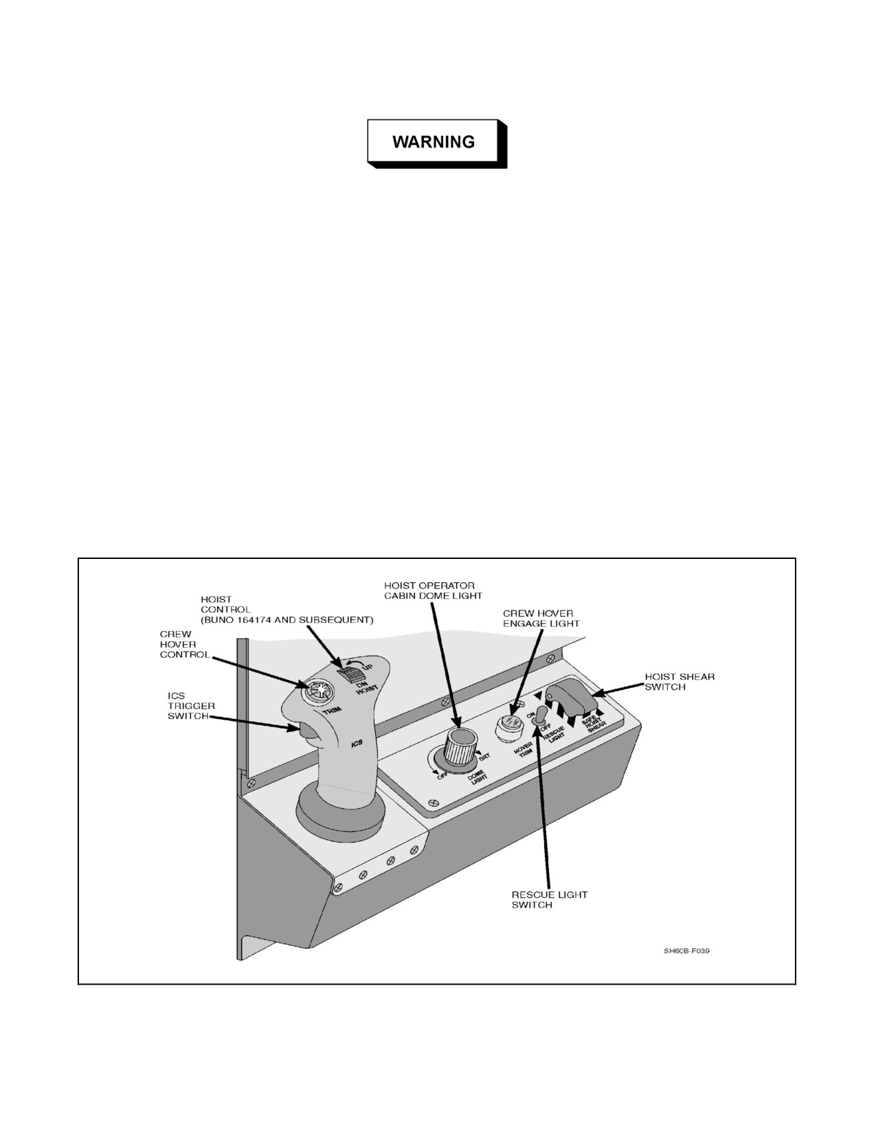
The crew hover feature provides the crewman with the capability to position the helicopter during hoist and rescue
operations. The crewman controls the aircraft from the crew hover--trim control panel. The panel is illustrated in
Figure 2-40. The crew hover controller has a control authority of ±5 knots laterally and longitudinally about the
reference values selected on the AFCS CONTROL panel LONG VEL and LAT VEL control knobs plus the speeds
beeped from the cyclic trim beep switch. The crew hover feature is activated from the AFCS CONTROL panel by
depressing the CREW HVR button and can only be activated if the hover coupler mode is already engaged. If the
automatic depart mode is activated while crew hover is engaged, crew hover will be disengaged and the automatic
depart mode will be engaged.
Figure 2-40. Crew Hover--Trim Control Panel
ORIGINAL
2-100
A1-H60BB-NFM-000
2.9.4.13 Pitch Bias Actuator
The Pitch Bias Actuator (PBA) provides longitudinal cyclic displacement proportional to airspeed. The DAFCS
commands the PBA as a function of pitch attitude, pitch rate, and airspeed. The PBA is an electromechanical series
actuator with ±15 percent control authority and ±3 percent per second rate limit. The PBA functions automatically
upon application of power to the DAFCS computer and is not selectable on the AFCS CONTROL panel. The DAFCS
computer monitors the PBA position to confirm correct response to the input commands. If the PBA fails, the DAFCS
lights the BIAS advisory light on the AFCS CONTROL panel and flashes the AFCS DEGRADED light on the
caution/advisory panel and commands the PBA to a predetermined position depending on the type of failure. PBA
failure modes are:
1. Attitude failure: bias actuator centered.
2. Pitch rate failure: faded out pitch rate component.
3. Airspeed failure: actuator goes to 120 knot position and attitude and rate continues to function.
4. Actuator failure: power removed from actuator.
If the malfunction that caused the shutdown was of an intermittent nature, the actuator operation can be reset by
pressing the appropriate MODE RESET button.
When flying with the BIAS FAIL ADVISORY light on, up to 1 1/2 inches
of forward or aft cyclic control authority may be lost.
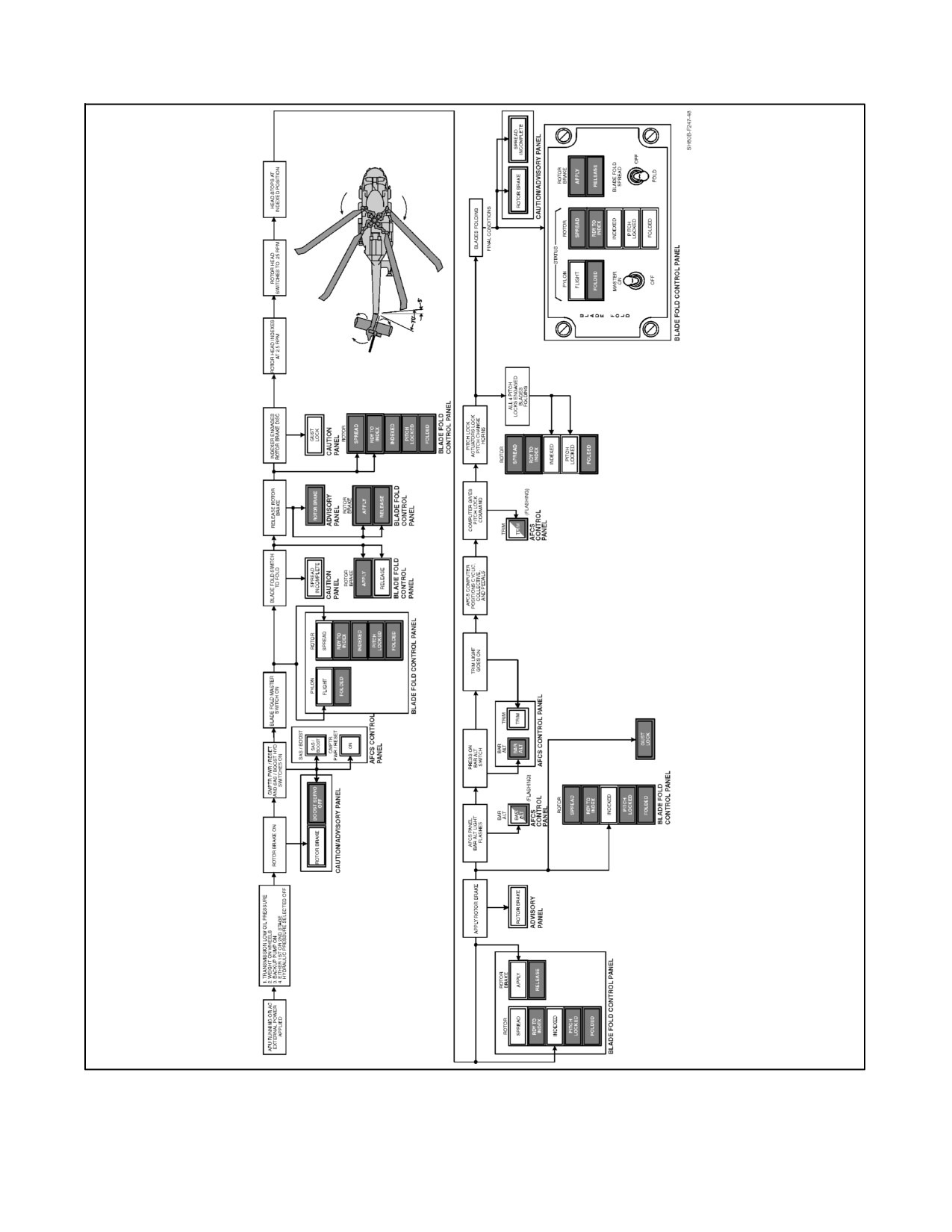
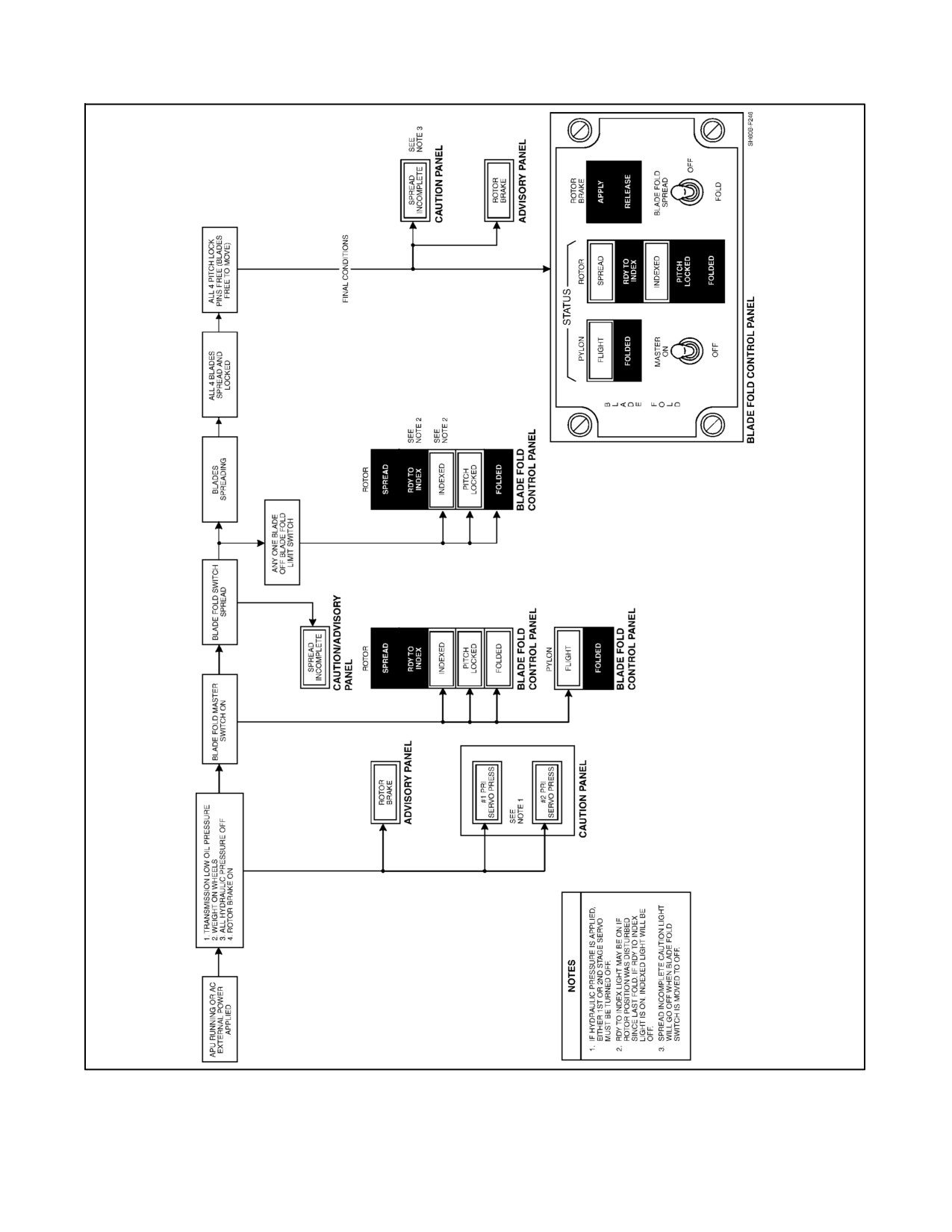
2.9.4.14 Blade Fold System
Automatic blade folding (Figure 2-41) is accomplished by an electromechanical fold mechanism. Pitch locks fix the
pitch of the rotor blades in order to maintain clearance during the fold sequence. Two blade lockpin pullers, lock
and unlock the hinge when folding and spreading the blades. Microswitches provide input signals to the blade fold
electrical control system, which sequences blade folding, and also provides light indications to the BLADE FOLD
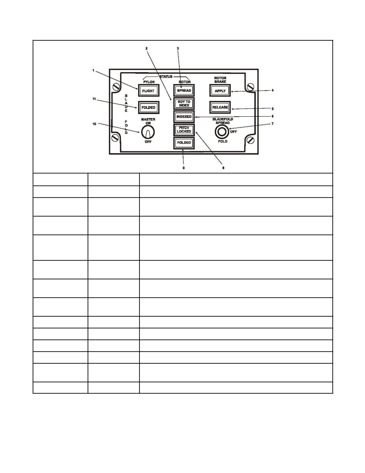
control panel (Figure 2-42).
2.9.4.14.1 Blade Folding
Controlswitchesandindicationsarelocatedon theBLADE FOLDcontrol panel.With theBLADE FOLDMASTER
switch ON, the main rotor head will turn to the indexed position after the BLADE FOLD switch is placed to FOLD
and the rotor brake is released. The INDEXED status light and the ROTOR BRAKE APPLY light will illuminate
upon completion of the indexing cycle. Engaging CMPTR PWR/RESET and TRIM, and applying the rotor brake
will permit the blade fold sequence to continue. The DAFCS commands the trim actuators to position the flight
controls and allows the main rotor head pitch locks to engage. The blades are then permitted to move to their folded
positions.
2.9.4.15 Pylon Fold System
The tail pylon is manually folded and unfolded. PYLON FLIGHT and FOLDED lights, located on the BLADE FOLD
control panel, indicate pylon fold status. There are five microswitches, which set the PYLON FLIGHT light: the pylon
lockpin switch, 5° switch, tail rotor blade indexer switch, and two stabilator lockpin switches. With the BATT switch ON,
the tail rotor will index and lock when the pylon has folded 5°.
2-101
ORIGINAL
A1-H60BB-NFM-000
Figure 2-41. Blade Fold/Spread System (Fold Sequence) (Sheet 1 of 2)
ORIGINAL
2-102
A1-H60BB-NFM-000
Figure 2-41 Blade Fold/Spread System (Spread Sequence) (Sheet 2)
2-103
ORIGINAL
A1-H60BB-NFM-000
INDEX
CONTROL
FUNCTIONAL DESCRIPTION
1
FLIGHT
All blade fold functions completed on tail pylon. Ready to Fly.
2
RDY TO INDEX
Main Rotor index pinion engaged in rotor brake disc. Index motor will
drive rotor to index position when rotor brake is released.
3
SPREAD
Blade lockpins extended with main rotor index pinion retracted. Pitch
locks are retracted.
4
APPLY
Commands rotor brake applied after rotor head is indexed. Blades are
driven to the correct pitch for folding by engaging the CMPTR PWR/
RESET and TRIM pushbuttons.
5
RELEASE
Commands rotor brake released. When released, main rotor rotates to
index position.
6
INDEXED
Rotor head indexed. Main rotor index pinion remains engaged in rotor
brake disc until rotor brake is applied.
7
BLADE FOLD
Selects mode of operation (SPREAD, OFF, FOLD).
switch
SPREAD
Initiates spread sequence.
FOLD
Initiates fold sequence.
8
PITCH LOCKED
Pitch locks engaged.
9
FOLDED
All four main rotor blades are folded.
10
BLADE FOLD
Applies or removes blade-fold power (OFF or ON).
MASTER switch
11
FOLDED
Stabilator lock pins out, tail rotor indexed, pylon folded.
Figure 2-42. Blade Fold Controls
ORIGINAL
2-104
A1-H60BB-NFM-000
CAUTION
Unless external power is applied or the BATT switch is ON prior to folding
the tail pylon, the tail rotor index actuator will not engage after starting the
pylon fold sequence and uncontrolled tail rotor windmilling may result.
Note
Failure to suppress the DECU numerical fault codes on the PDU will
prevent the automatic blade fold from operating due to the torque signal
being relayed to the AFCS computer.
2.9.4.16 Automatic Preflight Checks
The DAFCS provides an automatic preflight check of the SAS components prior to flight. The automatic preflight
is engaged using the SAS 1 switch with the following conditions:
1. Weight on wheels.
2. Rotor brake on.
3. Engine torques equal to zero.
4. CMPTR PWR/RESET engaged for at least 2 minutes (AFCS DEGRADED not illuminated).
Upon engagement, all rate gyros are automatically torqued to predetermined rates and checked for magnitude and
polarity ofrategyro response. Simultaneously, theresponseofSAS 1 to rategyro inputs is compared against adigital
model. Failures are displayed on thefail status panel and stored in a BIT code display. CMPTR PWR/RESET switch
has to be engaged at least 2 minutes to ensure gyros are up to speed. After gyros are up to speed, preflight requires
approximately 10 seconds to complete.
2.10
LANDING GEAR
The landing gear (Figure 1-3) is a fixed main/tail, gear--type configuration. It consists of two single--wheel, main
landing gears and a dual--wheel swivel--type tail gear. The long stroke of both main and tail wheel shock struts is
designed to dissipate high--sink--speed landing energy without exceeding the ship deck strength limits. Wheel brakes
are mounted on each main gear. Axle and high tiedowns are provided at each main gear, fuselage attachments are
provided above the tail gear for tiedown, and connections to the shipboard tail--guide winch system are provided for
RAST straightening and traversing.
Flying with a stuck WOW switch will disable WOW functions including
emergency jettison circuits, radar altimeter low altitude aural warning,
Engine Out, and low rotor rpm lights. Pulling the WOW circuit breaker will
not restore proper operation of some WOW functions in theair. Pulling the
WOW circuit breaker in flight may disable the LOW ROTOR RPM light
and the #1 and #2 ENG OUT warning lights.
2.10.1 Main Landing Gear
Each single--wheel main gear is mounted on a drag strut that trails aft from a pivot point mounted on the fuselage.
A separated air/oil--type shock strut is mounted on the fuselage and to the aft end of the drag strut. A landing gear
2-105
ORIGINAL
A1-H60BB-NFM-000
WOW switch is installed on the left landing gear to prevent or control operation of certain systems when the weight
of the helicopter is on the landing gear. The equipment that uses the WOW switch is shown in Figure 2-44.
2.10.1.1 Wheel Brake System
Main landing gear wheels have self--contained, self--adjusting disc hydraulic brakes (Figure 2-45). The wheel
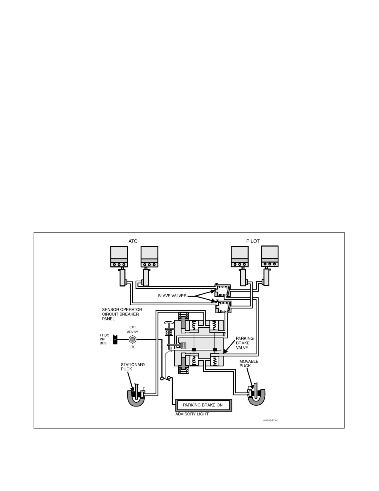
brake system consists of four master cylinder/reservoirs, two slave valves, a parking brake valve, and two wheel
brake assemblies. A master cylinder is connected to each rudder pedal. The purpose of the slave valves is to give
the pilot or ATO the ability to apply the brakes. Each wheel brake consists of a steel rotating disc, brake pucks,
andahousingthatcontainsthehydraulicpistons.Thebrakeshaveavisualbrake--puckwearindicator.Theparking
brake handle, marked PARKING BRAKE, is located on the right side of the center console and allows the brakes
to be locked by either the pilot or ATO after brake pressure is applied. The parking brakes are applied by pressing
the toe brake pedals, pulling the parking brake handle up to its fully extended position, and then releasing the toe
brakes while holding the handle up. The PARKING BRAKE ON advisory light will illuminate. The advisory light
only indicates that the parking brake handle is up. Pressing either the pilot or ATO left brake pedal will release the
parking brakes, the handle will return to the off position, and the advisory light will extinguish. Power is provided
tothisadvisorysystem bytheNO. 1DC primarybus throughacircuitbreakermarkedEXT ADVSYLTS andlocated
on the SO circuit breaker panel.
2.10.2 Tail Landing Gear
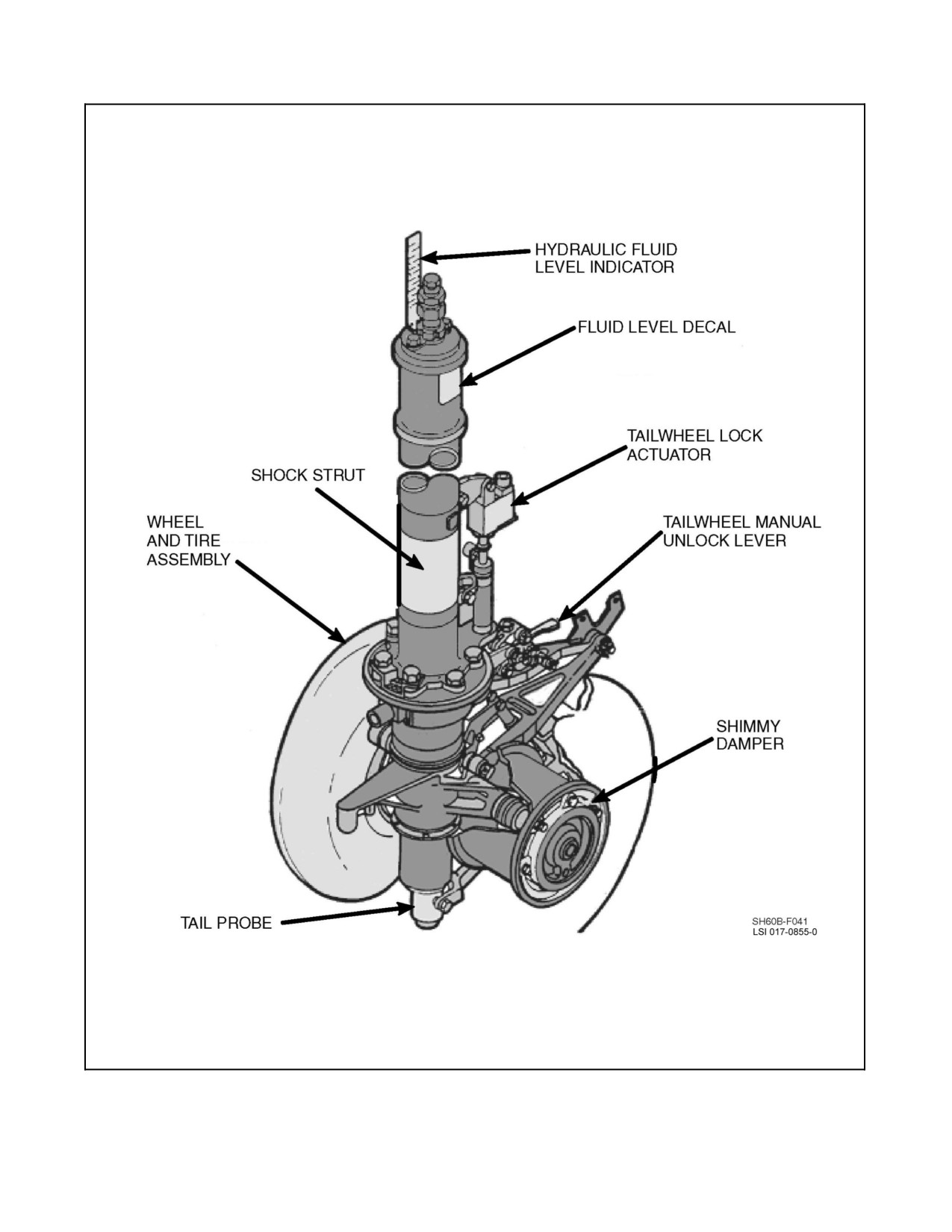
The tail landing gear is of a cantilevered design, with an integral shock strut capable of swiveling 360°. The two tail
gear wheels are mounted on a splined axle incorporated in the shimmy damper (Figure 2-43). The shimmy damper
causes both of the tail gear wheels to rotate at the same rate, preventing aircraft tail oscillations during taxi, takeoff,
and running landings. For helicopter guidance for traversing on the flight deck, a RAST tail probe and probe actuator
are mounted on the tail gear.
2.10.2.1 Tail Wheel Lock
The tail wheel lock is extended and retracted by an electric motor--operated actuator located on the tail wheel shock
strut housing. The tail wheel lock switch is located on the forward side of the parking brake handle in the cockpit.
Unlocking the tail wheel illuminates the TAIL WHEEL UNLOCKED advisory light on the caution/advisory panel
and unlocks the tail wheel lock pin. Power to operate the tail wheel lock motor is provided by the DC essential bus
through a circuit breaker marked TAIL WHEEL LOCK on the overhead console. A manual lock release is located
on the strut. In the down position, the tail wheel is manually unlocked. It cannot be controlled electrically. In the up
position, the tail wheel lock is controlled by the switch on the parking brake handle. There is no manual locking
feature.
2.10.2.2 Tail Bumper
A nitrogen--filled tail bumper (Figure 1-3), mounted on the underside of the tail pylon, prevents the stabilator from
striking the ground when landing with nose--high attitudes.
2.11
RAST SYSTEM
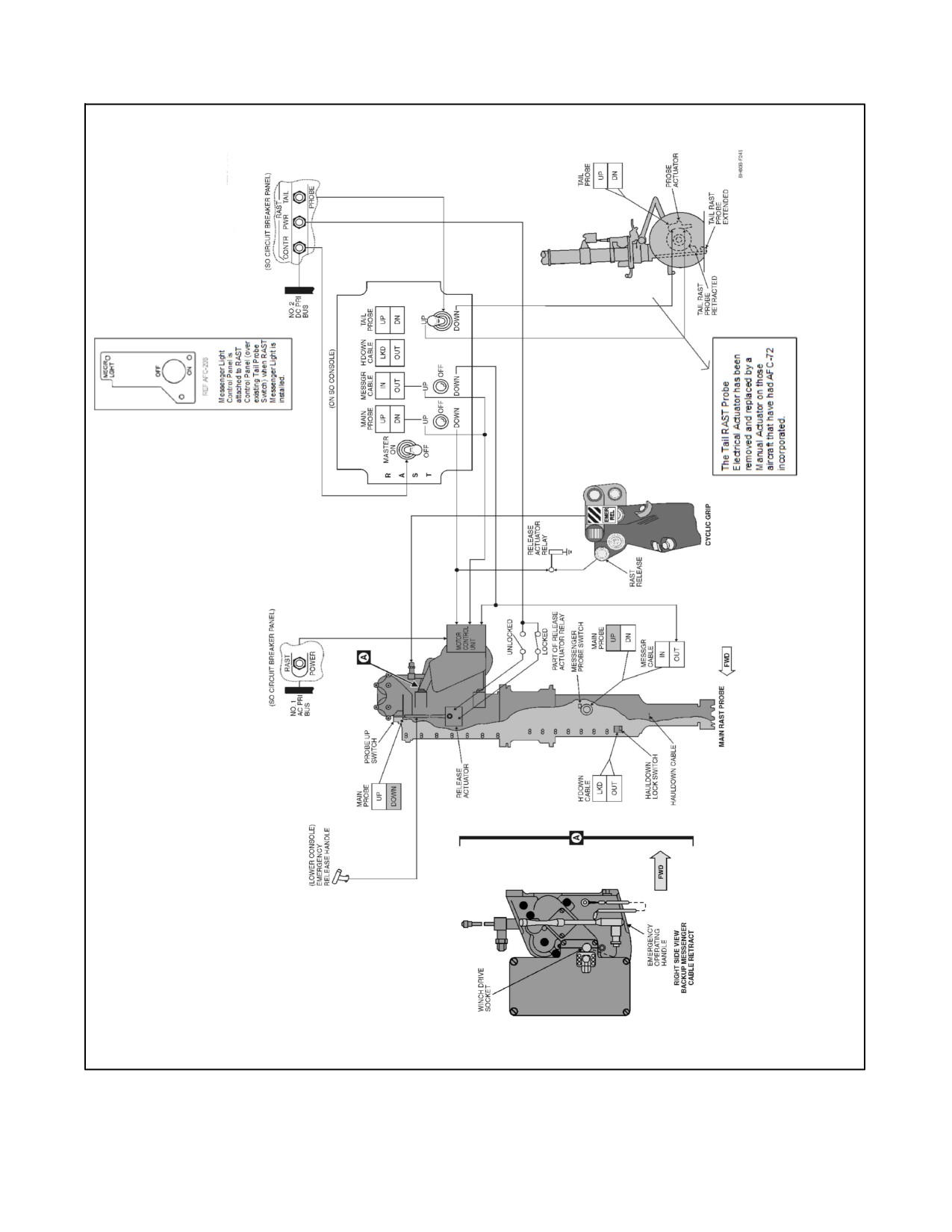
The air vehicle portion of the RAST system (Figure 2-46) comprises a control panel, a main probe assembly, and
a tail probe assembly. RAST is capable of:
1. Assisting the pilot in landing the helicopter on the flight deck.
2. Securing the helicopter to the deck.
3. Straightening the helicopter to a laterally centered position.
4. Traversing the helicopter into and out of the hangar.
ORIGINAL
2-106
A1-H60BB-NFM-000
Figure 2-43. Tail Wheel Assembly
2-107
ORIGINAL

A1-H60BB-NFM-000
INTERFACE
FUNCTION AFFECTED
FLIGHT
GROUND
Blade fold
Blade fold actuators
Disabled
Enabled
AFCS
Pitch hold
Enabled
Disabled
Heading hold
Enabled
Disabled
Automatic preflight checks
Disabled
Enabled
Generator control unit
Underfrequency protection
Disabled
Enabled
Master shear
RAST shear
Enabled
Disabled
Cargo hook emergency release
Enabled
Disabled
MAD shear
Enabled
Disabled
Rescue hoist
Enabled
Disabled
Sonobuoy launcher
Rotary valve to DECU circuitry
Enabled
Disabled
Hydraulics
U-1, U-2 logic modules
Enabled
Enabled with BACKUP HYD
PMP-AUTO
Disabled with BACKUP HYD
PMP-OFF
LDI test
Disabled
Enabled
Master caution panel
Engine out lights
Enabled
Disabled
Low rotor rpm lights
Enabled
Disabled
Tail rotor blade positioner
Tail indexing
Disabled
Enabled
Radar altimeter
Height indicator low altitude aural
Enabled
Disabled
warning
Armament
Master armament and jettison cir-
Enabled
Disabled
cuits
FLIR turret
LRD
Enabled
Disabled
M299 launcher
M299 launcher arming
Enabled
Disabled
SO console
Search radar (cannot be bypassed)
Enabled
Disabled
Mission avionics rack
KIT and KIR zeroize logic
Mechanical hold
Disabled
Enabled
Electrical hold
Enabled
Disabled
Data-link transmitter
Enabled
Disabled
Figure 2-44. Weight--On--Wheels Functions
ORIGINAL
2-108
A1-H60BB-NFM-000
2.11.1 RAST Control Panel Indicators
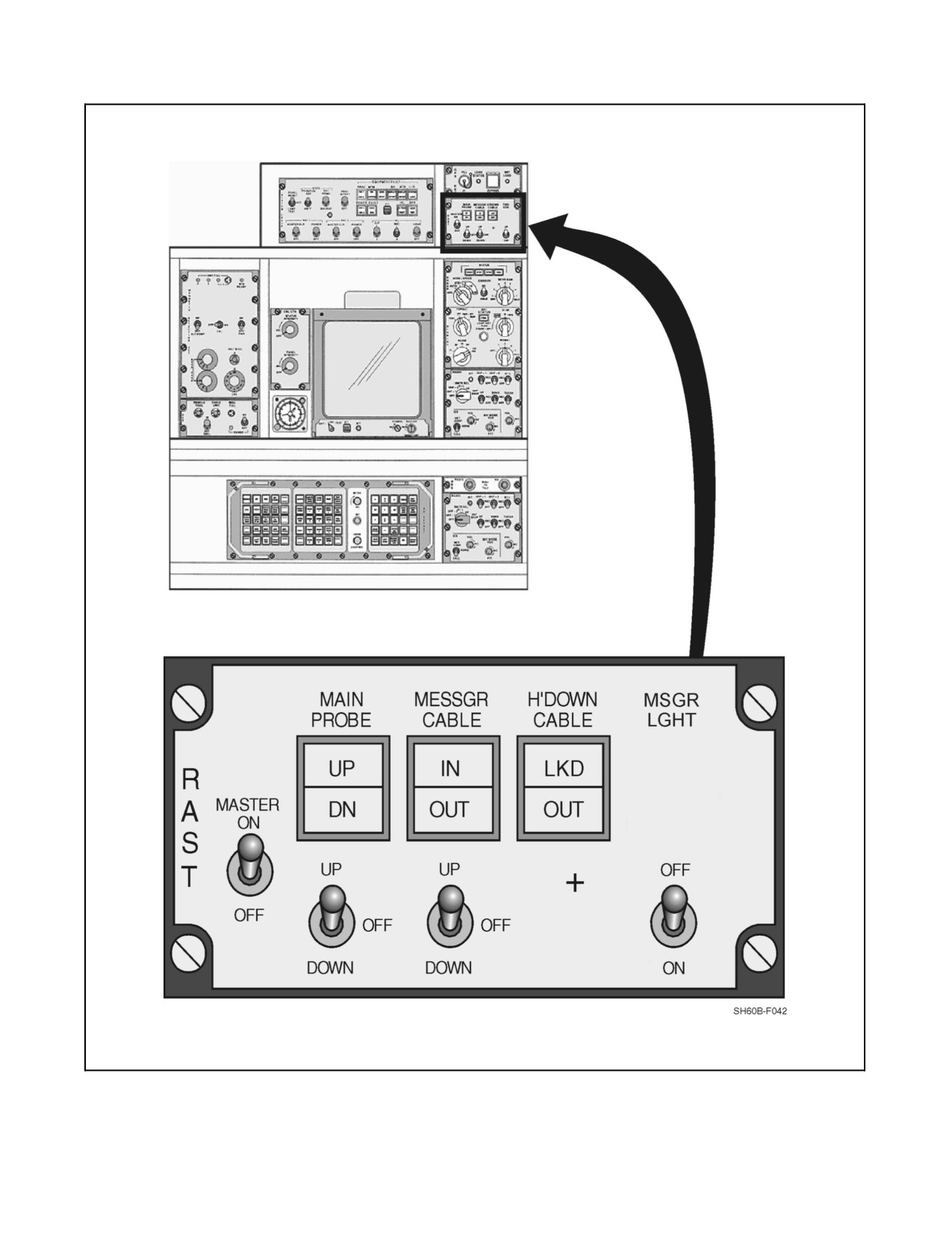
The RAST control panel is located on the SO console above the RADAR/DISPLAY control panel and provides
control and status indication of the system (Figure 2-47). The cyclic grips have an electrical release button to free
the recovery assist (RA) cable from the aircraft. An emergency release (EMER REL) button to shear the main probe
messenger cable is located on the cyclic grip. A mechanical emergency release handle, located on the left side of the
center console, is used to release the RA cable from the probe in the event of electrical release actuator failure.
The MASTER switch is a two--position switch and, when placed in the ON position, supplies power to the control
portion ofthesystem.TheMAINPROBE, UP/DOWNswitch isathree--positionswitch, spring--loadedto thecenter.
The MESSGR CABLE--UP/DOWN switch is spring loaded to the center position. When the switch is placed in the
UP position, the messenger cable is reeled into the aircraft, and when it is placed in the DOWN position, the cable
will reel out from the aircraft. The main probe must be extended before the messenger cable can be reeled out, and
the messenger cable must be seated in order to retract the main probe.
Note
The DOWN light is not a positive down indication for the tail and main
RAST probe (electrically actuated only).
Figure 2-45. Wheel Brake Schematic
2-109
ORIGINAL
A1-H60BB-NFM-000
Figure 2-46. RAST Block Diagram
ORIGINAL
2-110
A1-H60BB-NFM-000
Figure 2-47. RAST Control Panel
2-111
ORIGINAL
A1-H60BB-NFM-000
The MESSGR CABLE light gives the status of the cable. When it displays IN, the messenger cable is retracted fully
into the main probe. When OUT is displayed, the messenger cable is extended. The H’DOWN light gives the status
of the RA cable. A LKD indication is displayed when the RA cable from the surface ship is locked into the main probe.
TheOUT indication is displayed when theRA cableis freeofthemain probe. The main probe (Figure 2-46)contains
a3phase, 115--Vac, 400--Hzelectricallyoperatedhoist, whichlowerstheprobe, reelsout themessengercable,raises
the RA cable, and retracts the probe. The hoist is powered by the NO. 2 AC primary bus through a circuit breaker
marked RAST POWER. This circuit breaker is located on the SO circuit breaker panel. An electrically fired guillotine
is provided to shear the messenger cable in an emergency. The guillotine is powered by the NO. 2 DC primary bus
through a circuit breaker on the ATO circuit breaker panel marked RAST SHEAR. Attached to the probe is a release
actuator, used to release the RA cable from the locks in the probe. It is also used to lock the probe in the retracted
position. Three switches are mounted on the probe: the probe UP switch, the messenger probe switch, and the
H’DOWN LKD switch.
2.11.2 Main RAST Probe
The airborne provision for the RA system is a fully retractable main probe (Figure 2-46). It is mounted on the
centerline of the aircraft near the center of gravity. In a fully retracted position, it is held in an uplock. From there,
it is spring loaded to a fully extended position for landings into the rapid securing device (RSD). The probe has an
electrically powered hoist mounted to its outer housing. The hoist provides the messenger cable, deployed through
the center of the probe, to retrieve the surface ship RA cable. The messenger cable end fitting provides a snap--in
connection for the RA cable. After pulling the RA cable into the locked position, the messenger cable is automatically
disconnected from the RA cable. The lower end of the extended probe is designed to be captured by the RSD after
landing. With the probe secured within the RSD, the helicopter is held against horizontal and/or axial tension loads.
A swiveling crenelated ring on the end of the probe is provided for axial loads. The main probe is powered by the
NO. 2 DC primary bus through a circuit breaker on the SO circuit breaker panel marked RAST PWR.
2.12
FLIGHT INSTRUMENTS
The electrically operated instruments function on alternating current, direct current, or both and are protected by
appropriately marked circuit breakers on the pilot and ATO circuit breaker panels.
2.12.1 Pitot Static System
The pitot--static system provides pressure for the operation of the differential pressure instruments (barometric
altimeters and airspeed indicators). Two pitot tubes are mounted on the nose, forward of the cockpit. Two static ports
are located on the fuselage sides, aft of each cockpit door (Figure 1-3). Each pitot head assembly consists of a
baseplate with a strut and probe tube and an electrical connector, wired to two deicing heaters in the tube. Pitot
pressure is sensed at the opening of the forward end of each tube. Static 1 and static 2 pressures are sensed through
ports aft of the cockpit doors. Pitot pressure is supplied from the pitot tubes to the airspeed indicators, airspeed and
air data transducers, and pitot--drain caps. To obtain a difference in the pressure for operation of the barometric
differential pressureinstruments, staticairpressure(atmosphere)is suppliedthrough thestaticportsto thealtimeters,
airspeed indicators, airspeed and air data transducers, and static drain caps.
2.12.1.1 Airspeed Indicator
Two airspeed indicators are installed on the instrument panel (Figure 1-8) for the pilot and the ATO. The indicators
are differential pressure instruments, measuring the difference between impact pressure and static pressure. System
error is noted on placards located below the instrument panel on each side of the lower console (Figure 1-7).
ORIGINAL
2-112
A1-H60BB-NFM-000
2.12.1.2 Barometric Altimeter/Encoder
The AAU--32/A Altimeter/Encoder functions as a barometric altimeter for the pilot and a pressure altitude sensor
for the AN/APX--100 IFF Transponder. The altimeter/encoder is on the pilot side of the instrument panel
(Figure 1-8). The operating range of the altimeter is from --1,000 to +50,000 feet. The barometric pressure--set knob
permits altimeter settings from 28.10 to 31.00 inches Hg. A window in the lower right section of the altimeter
displays theselected altimetersetting. Thealtimeterisequipped withacontinuouslyoperating DC--poweredvibrator
to improvealtitudeindicating accuracy. The encoderprovides adigital output of pressurealtitude in units of100 feet
to the IFF transponder, with mode C selected, for automatic pressure altitude transmission. The encoder operates
throughout the operating range of the altimeter, but, unlike the altimeter, it reports altitude using a permanent
altimeter setting of 29.92 inches Hg. If there is a loss of 115 Vac, 400 Hz power, the warning flag on the pilot altimeter
indicator, marked CODE OFF, will be displayed. The NO. 2 DC primary bus furnishes power to the pilot altimeter
through a circuit breaker on the ATO circuit breaker panel, marked PILOT ALTM. The NO. 1 DC primary bus
furnishes power to the ATO altimeter through a circuit breaker marked ATO ALTM.
2.12.1.3 Barometric Altimeter
The AAU--31/A Altimeter, installed on the left side of the instrument panel (Figure 1-8), is identical to and operates
in the same manner as the pilot AAU--32/A Altimeter/Encoder, except that there is no encoder associated with the
altimeter, and there is no warning flag on the indicator.
2.12.1.4 Vertical Speed Indicators
Two indicators on the instrument panel (Figure 1-8) indicate vertical speed in thousands of feet per minute. The first
1,000 feet are marked in 100--foot gradations. Each vertical speed indicator (VSI) independently reads static cabin
pressure through a port in the back of each gauge.
Note
D Vertical speed indicators are unreliable during transition to ground effect.
D The VSI may momentarily indicate a false rate of descent while opening
the cargo hatch cover in flight.
2.12.1.5 Attitude Indicator
Identical Attitude Indicator (AIs) are located on the pilot and ATO instrument panel. These indicators furnish a visual
display of aircraft attitude. Figure 2-48 shows the AI and describes the individual indicating elements. Power forthe
pilot AI is supplied from the AC essential bus and for the ATO from the NO. 1 AC primary bus, both through the
center circuit breaker panel, marked PILOT AI and ATO AI, respectively.
2.12.2 Radar Altimeter, AN/APN-194
The radar altimeter (RAD ALT) (Figure 2-49) is a range--tracking radar that provides continuous measurement of
height above land or water. It has a range of 0 feet to 5,000 feet, with an accuracy of ±3 feet or ±4 percent, whichever
is greater; however, only a range of 0 feet to 1,000 feet is indicated on the instrument. Tracking above 1,000 feet is
used by the operational navigation system and the AFCS. On deck, a reading of 0 to 7 on the navigation table is
permissible. Moving either pilot or ATO height indicator control knob out of the OFF position will provide height
indication to both radar altimeters.
2-113
ORIGINAL
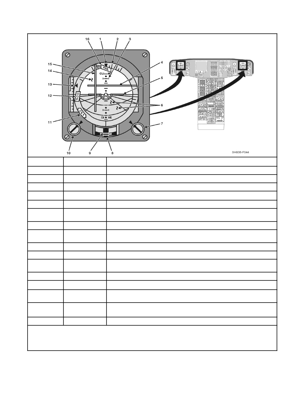
A1-H60BB-NFM-000
INDEX NUMBER
CONTROL
FUNCTIONAL DESCRIPTION
1
Bank pointer
Indicates bank or roll angle.
2
Bank scale
Measure of bank angle. Scale marks indicate 5° each.
3
Pitch reference scale
Measure of pitch angle. Each interval between dot and line is 5°.
4
VHA pointer
Indicates velocity along heading axis. One scale marking = 5 kt (±25 kt full scale).
5
Aircraft reference
Fixed miniature aircraft for attitude orientation reference.
6
Ground perspective
Lines that show perspective of a grid of imaginary lines on the surface of the Earth.
line
7
Pitch trim knob
Adjusts attitude sphere for pitch trim.
8
Turn rate indicator
Indicates rate of turn. A standard rate turn is one needle width with ECP3032 installed and
two needle widths without.
9
Slip/skid indicator
Indicates direction of slip or skid.
10
Roll trim knob
Adjusts attitude sphere for roll trim.
11
OFF flag
Indicates absence of internal power or absence of external ground signal. If received in
flight, select alternate AGCA on mode select panel.
12
Doppler warning flag
Indicates Doppler radar is off or Doppler data not dependable.
13
VZA pointer
Indicates velocity along vertical axis. Each scale marking = 100 fpm (±500 fpm full scale).
14
Attitude sphere
Sphere that moves in two rotational degrees of freedom to indicate attitude of aircraft in
bank and pitch.
15
VDA pointer
Drift velocity pointer. Indicates velocity across track. One scale marking = 5 kt (±25 kt full
scale).
16
FAIL flag
Indicates failure of one or more internal status monitoring tests.
Note
Fast erection for AI is obtained through the ERECT pushbutton on the compass system controller, located on the lower console.
Due to Doppler sensitivities to pitch, VZA provides only coarse rate information and should not be used as a precision hover
reference.
Figure 2-48. Attitude Indicator (AI)
ORIGINAL
2-114
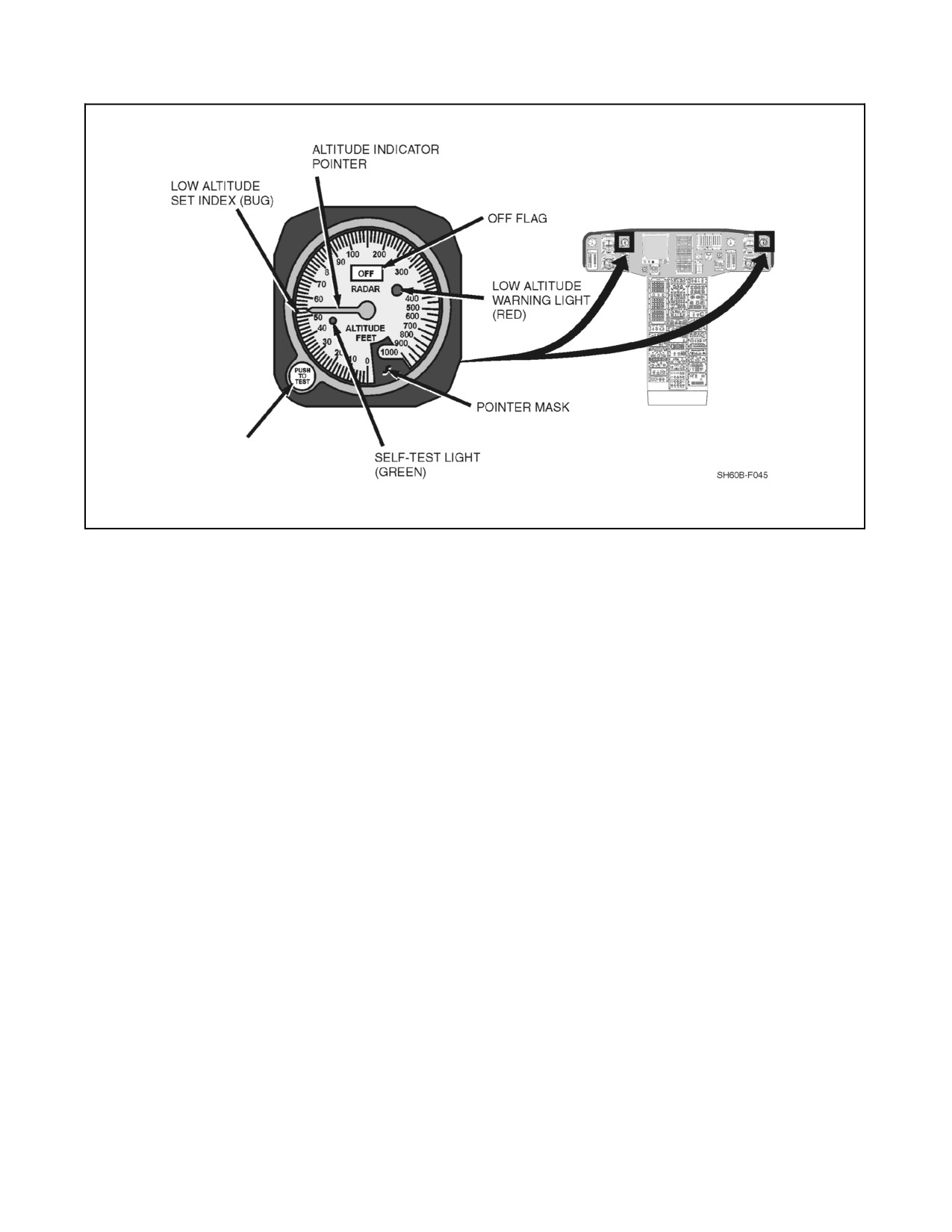
A1-H60BB-NFM-000
INDICATOR CONTROL KNOB
(ON-OFF/SELF TEST/
LOW ALTITUDE SET CONTROL
Figure 2-49. Radar Altimeter (Height Indicator)
The radar altimeter operates in two modes, search and track. In the search mode, the entire altitude range is searched
for a ground return. In the track mode, the set locks onto the ground return and gives continuous altitude information
to the height indicators. In addition, altitude data is sent to the data handling subsystem for processing. Each of the
height indicators contains a complete radar altitude warning system (RAWS) function. The RAWS function provides
a visual warning and an aural tone to the internal communications network. Even with RAD ALT switch off, pressing
the test switch will provide a continuous beep in the headset.
Note
Pressing the RAD ALT TEST button above 5,000 feet activates a
continuous beeping tone in both the pilot and ATO headsets. The tone can
only be deactivated by turning off the RAD ALTs or descending below
5,000 feet AGL.
The RAWS feature of the AN/APN--194 is active when:
1. Fixed high altitudewarning. When descending through 250 feet,thepilotswill hearsix beeps.This isdisabled
only if coupler is engaged.
2. Fixed low altitudewarning (35 feet). When below the setting, the pilots will heara continuous series ofbeeps.
This is enabled only if coupler is engaged.
3. Variable altitude adjust. Each pilot will hear six beeps and the low altitude light will illuminate if the aircraft
descends below his respective variable index.
4. Above 5,000 feet. If return is unreliable, height indicator will display OFF flag.
5. Power source failure to RAD ALT will cause height indicator to display OFF flag with continuous beeping
tone.
The warning consists of a light on the indicator and a tone in the pilot and ATO headsets. The tone is a nominal
1,000--Hz signal, pulsed at a 2 cycle per second rate. Both stations will be alerted for the preset high and low altitude
indices.
2-115
ORIGINAL
A1-H60BB-NFM-000
The electronic altimeter set consists of a receiver/transmitter, height indicators (pilot and ATO) (two), and antennas
(left and right) (two). Power is supplied from the AC essential bus through the center circuit breaker panel marked
RDR ALTM R/T. The pilot and ATO height indicators are powered by the DC essential bus through the overhead
circuit breaker panel, marked HEIGHT IND PILOT and HEIGHT IND ATO, respectively.
Note
The bearing--distance--heading indicators (BDHI) and the compass system
are discussed in Chapter 16.
2.12.3 Miscellaneous Flight Instruments
2.12.3.1 Standby Magnetic Compass
A lighted magnetic compass is installed above the instrument panel on the right--center windshield frame
(Figure 1-5). The compass is used as a standby instrument for heading references. A compass correction card, with
deviation errors, is installed on the forward right of the overhead console (Figure 1-6).
2.12.3.2 Outside Air-Temperature (OAT) Indicator
Anambientair--temperatureindicator(Figure 1-5),markedFREEAIR,extendsthroughtheupper--centerwindshield
panel. The direct reading instrument is marked in degrees Celsius.
2.12.3.3 Clock
Two 8--day clocks are installed on the instrument panel (Figure 1-8). The elapsed time knob is on the upper--right
corner of the clock. The clock is wound and set with a knob on the lower--left corner. The SO is also provided with
a clock.
2.13
WARNING, CAUTION, AND ADVISORIES
2.13.1 Master Warning System
Two amber, master caution warning lights (Figure 1-8), for the pilot and ATO, marked MASTER CAUTION PRESS
TO RESET, are located on the master warning panel. They light whenever a caution light lights. These lights alert
the pilot and direct attention to the caution lights on the caution/advisory panel. During caution/advisory panel test,
when the switch is released from the test position, the master caution lights will flash 16 times to indicate that chip
caution panel circuits are going through self--test. An existing malfunction within those circuits will prevent flashing
of the master caution lights. The master caution warning lights should be reset at onceto providea similarindication
if a second condition or malfunction occurs while the first condition is present. Themaster caution warning light can
be reset from either pilot position. Power for both of the master caution warning lights is provided from the DC
essential bus through a circuit breaker marked CAUTN ADVSY PNL and located on the overhead circuit breaker
panel.
Four red warning lights, also located on the master warning panel, require immediate action if they light. The
markings are #l ENG OUT, #2 ENG OUT, FIRE, and LOW ROTOR RPM. The LOW ROTOR RPM warning light
will flash at a rate of three to five flashes per second if rotor RPM drops below 96 percent. The ENG OUT warning
lights will light at 55 percent Ng speed and below. Refer to Figure 2-50 for a brief description of each fault.
Note
The ENG OUT and the LOW ROTOR RPM warning lights are disabled
with weight on wheels, but may still be tested with the caution/advisory test
switch.
ORIGINAL
2-116
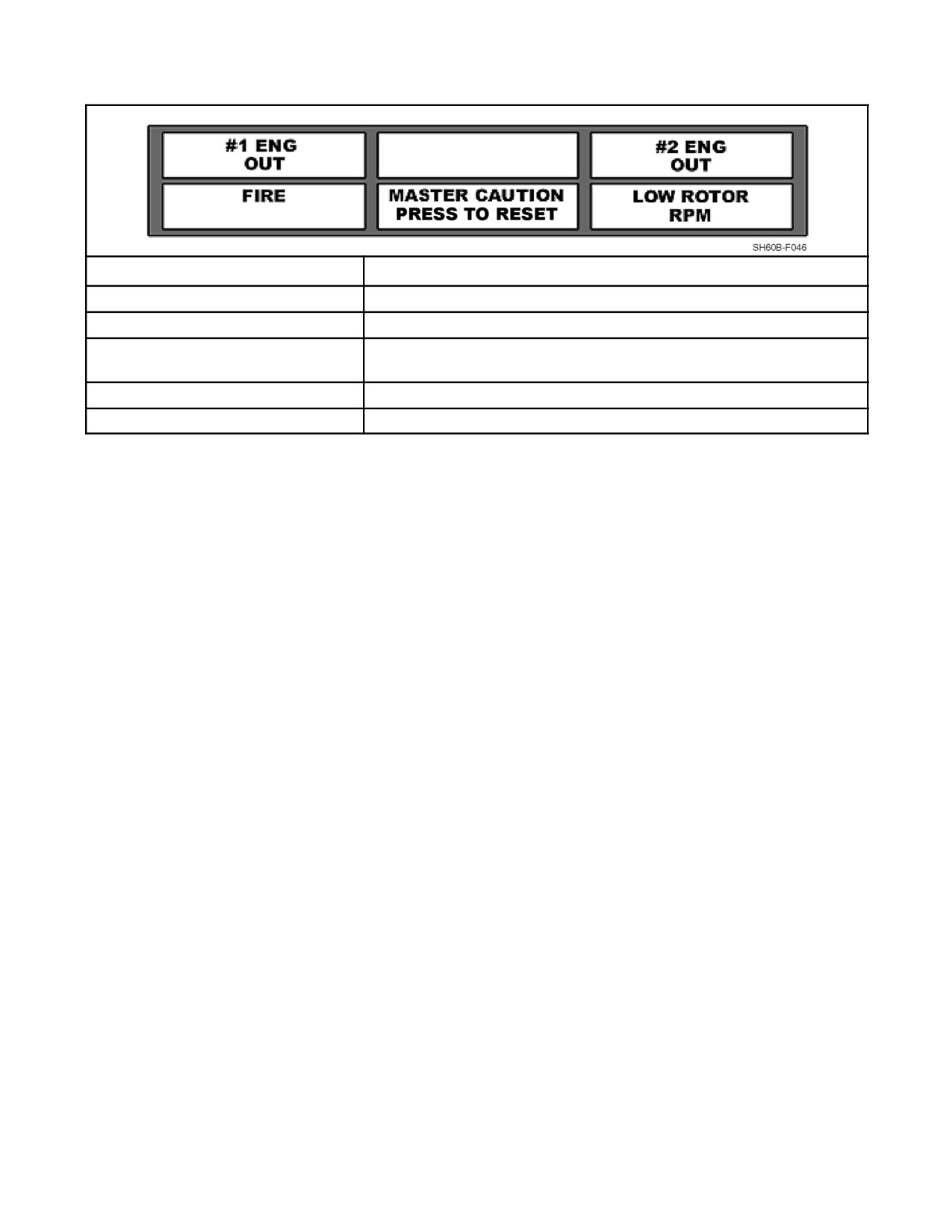
A1-H60BB-NFM-000
LEGEND
LIGHTING PARAMETER OR FAULT
#1 ENG OUT
Indicates that the NO. 1 engine Ng speed is ≤55 percent.
FIRE
Indicates that a fire detector has actuated a fire-warning circuit.
MASTER CAUTION PRESS TO
Indicates that a caution light on the caution panel has been actuated by
RESET
a failed system.
#2 ENG OUT
Indicates that the NO. 2 engine Ng speed is ≤55 percent.
LOW ROTOR RPM
Indicates that the rotor speed is ≤96 percent Nr.
Figure 2-50. Master Warning Panel
2.13.2 Caution/Advisory Light System
The caution/advisory panel (Figure 1-8) is located on the instrument panel. The caution section (the upper
two--thirds) of the panel indicates certain malfunctions or unsafe conditions with amber lights. The advisory section
(the lower one--third) of the panel shows certain noncritical conditions with green lights. Each light has its own
operating circuit and will remain lighted as long as the condition that caused it to light exists. The caution/advisory
panel contains a self--test system for all engine and transmission drivetrain chip detector lights. During
caution/advisory panel test when the switch is released from TEST position, the self--test is activated. If a malfunction
exists in one of the engine and transmission drivetrain chip detect lights within the caution panel, that respective light
will flash. The caution and advisory lights are powered by the DC essential bus through a circuit breaker marked
CAUTN ADVSY PNL on the overhead panel. (Refer to the major systems for a complete description of the
caution/advisory panel lights. (Refer to Chapter 12 for a description of the caution/advisory legend.)
2.14
FIRE-DETECTION SYSTEM
Thefire--detection system (Figure2-51)provides avisual cockpit indication when infrared radiation, caused by afire
or extreme overheating, is detected in either engine compartment or the APU compartment. The system consists of
three control amplifiers located in the left--hand junction box; five sensors (two in each engine compartment and one
intheAPUcompartment);# 1and# 2ENGemergencyoffT--handlefire--warninglightslocatedontheenginecontrol
quadrant; APU FIRE EXT T--handle fire--warning light and FIRE DET TEST switch located on the overhead
console; and two FIRE warning lights on the pilot and ATO master warning panels.
When one of the sensors detects infrared radiation (fire), and no blue light (sunlight), it sends out a voltage to its
associated control amplifier. Sunlight filtered through smoke or haze, or at sunrise or sunset, may trigger the flame
detectors and cause a false fire indication. The control amplifier then provides a voltage to both master warning--panel
FIRE lights and the proper T--handle lights. The FIRE DET TEST switch (Figure 1-6) on the overhead console is
a three--position rotary switch used to check all components of the fire detection system except the flame detector
(which must be tested with red light). In the OPER position, the fire sensors are connected up to their respective
indicators. The NO. 1 test position checks the continuity of the wiring, amplifiers and monitoring lights for the
firewall--mounted detectors, NO. 1 and NO. 2 engines, and the APU compartments. If operating properly, the master
FIRE warning light, both ENG EMER OFF T--handles, and the APU FIRE EXT T--handle will illuminate. The NO. 2
test position checks the continuity of wiring, amplifiers, and monitoring lights for the NO. 1 and NO. 2 engine
deck--mounted sensors. If operating properly, the master FIRE warning light and both ENG EMER OFF T--handles
will illuminate. The APU FIRE EXT T--handle will be off. Electrical power for the engine compartment detectors
is supplied by the DC essential bus through the FIRE DET NO. 1 and NO. 2 ENG circuit breakers on the overhead
circuit breaker panel. The detector in the APU compartment is supplied by the battery bus through the APU FIRE
DETR circuit breaker on the center console circuit breaker panel.
2-117
ORIGINAL
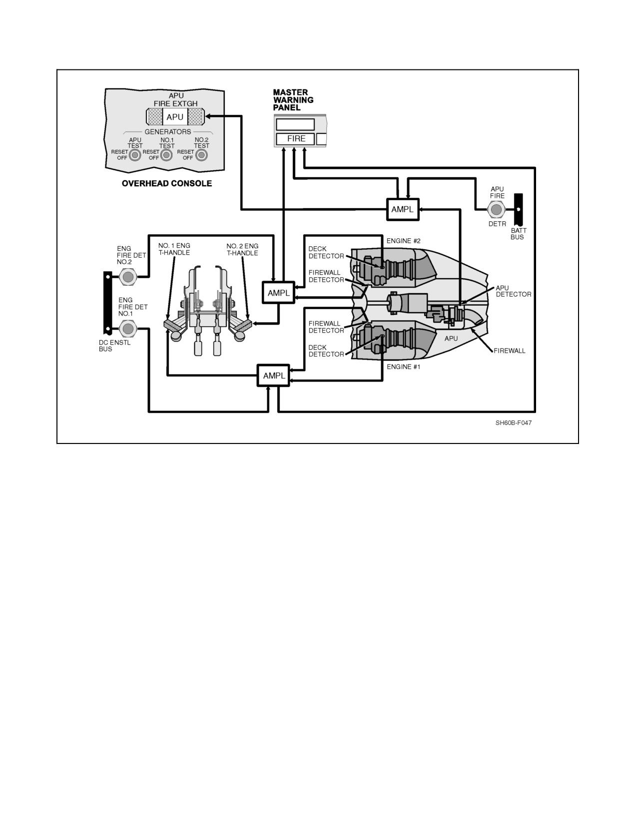
A1-H60BB-NFM-000
Figure 2-51. Fire--Detection System, Block Diagram
2.15
ENGINE/APU FIRE-EXTINGUISHING SYSTEM
The bromotrifluoromethane (CF3 Br) high--rate discharge extinguishing system (Figure 2-52) provides a two--shot
(main and reserve) capability to either the main engine compartments or the APU compartment. The system includes
two containers that are filled with extinguishing agent and charged with nitrogen. The containers are mounted above
the upper deck, aft of the APU compartment. Both containers have dual outlets, each outlet containing its own firing
mechanism and CAD. Each container has a pressure gauge and a thermal discharge relief port. Thermal discharge
is indicated by the loss of a red plastic disc on the left side of the aircraft. Electrical power to operate the system is
supplied by thebattery utility bus, theNO. 2 DC primary, and the DC essential bus through theFIRE EXTGH circuit
breakers on the lower console, the overhead console, and the ATO circuit breaker panels. Three T--shaped handles
select the compartment to which the fire extinguishing agent is to be directed and shut off fuel to that engine or APU.
The FIRE EXT switch on the overhead console has three positions marked RESERVE, OFF, and MAIN. The MAIN
position of the switch sends fire extinguishing agent to NO. 1 engine or APU compartment from the forward fire
extinguishing bottle M1 port. The R2 port is reserve for NO. 2 engine. The aft fire extinguisher bottle M2 port is main
for the NO. 2 engine and the R1 port is reserve for NO. 1 engine or APU. The ports provide a second shot of
extinguishing agent to be used if the actuation is not enough and the bottle was not previously discharged. The fire
extinguisher selector switch is armed after one of the T--handles has been pulled. If two T--handles are pulled,
whichever T--handle is pulled last will be armed. When placed to MAIN or RESERVE, it selects the container to be
discharged.
ORIGINAL
2-118
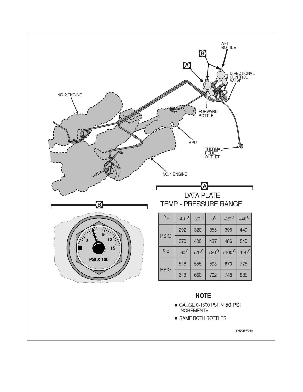
A1-H60BB-NFM-000
Figure 2-52. Fire--Extinguishing System (Sheet 1 of 2)
2-119
ORIGINAL
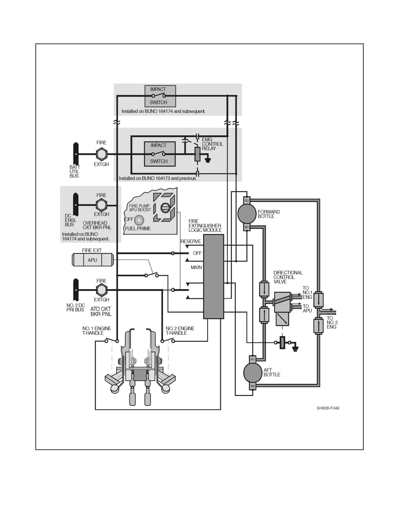
A1-H60BB-NFM-000
Figure 2-52. Fire--Extinguishing System (Sheet 2)
ORIGINAL
2-120
A1-H60BB-NFM-000
Note
D On aircraft BuNo 164173 and previous, if the NO. 2 DC primary bus is not
energized (no AC power), the reserve position must be used to discharge
the agent to the APU or NO. 1 engine compartment. The NO. 2 engine
compartment has no fire extinguisher capability without AC power
available.
D On aircraft BuNo 164174 and subsequent, if the NO. 2 DC primary bus is
not energized (no AC power), the reserve position must be used to
discharge the agent to the APU or NO. 1 or NO. 2 engine compartment.
2.15.1 Fire-Extinguishing System, Impact Switch Operation
A multiple--axis impact (10g) sensor (Figure 2-52), hard mounted to the airframe, will automatically discharge both
fire bottles into both engine compartments when it senses crash forces. When the impact switch closes, power from
thebattery utility bus will beapplied to thefire bottles, discharging theextinguishing agent into theNO. 1 and NO. 2
engine compartments. Electrical power for the impact switch is from the battery utility bus through a circuit breaker,
marked FIRE EXTGH, on the lower console circuit breaker panel.
2.16
ENTRANCE AND EGRESS
A hinged door is located on each side of the cockpit. The sliding door on the right side of the cabin provides an opening
54 inches high by 44 inches wide. Emergency escape can also be accomplished through jettisonable features,
provided on all cockpit and cabin windows.
Each cockpit door is equipped with a jettison system for emergency release of the window. Each window is jettisoned
from inside or outside the cockpit by use of a handle marked EMERG EXIT — PULL. To provide emergency exit
from the cabin, two jettisonable 24 inch by 24 inch windows are installed, one in the cabin door and the other at the
SO station. To release the windows, a handle, marked EMERGENCY EXIT PULL AFT OR FWD, is moved in the
direction of the arrow. The windows can then be pushed out. Exterior release of all windows is accomplished by a
handle, below the window, marked PUSH TO RELEASE & TURN; Refer to Chapter 12 for additional information.
2.17
ENVIRONMENTAL CONTROL SYSTEM
Cabin, cockpit, nose bay, and transition section environments are controlled by the Environmental Control System
(ECS), which provides both heating and air conditioning. The ECS consists of an air--cycle machine (ACM),
bleed--air ducting, necessary controls and valves, water separator, distribution system, air inlet, and heat--exchanger
exhaust duct. The engines or APU can serve as bleed--air sources for the ECS. Air source selection is accomplished
by means of the AIR SOURCE ECS/START switch on the upper console. In the ENG position, engine bleed--air is
selected as the air source. In the APU position, APU bleed--air is used as the air source; however, the APU will provide
bleed air to the ECS regardless of the AIR SOURCE ECS/START switch position if the APU is on.
With the ECS on and the FLOW switch in NORM, maximum torque available is reduced by 4 percent per engine
and fuel flow to each engine will increase by approximately 8 pounds per hour. With the TEMP rotary switch in HOT
and OAT below 15 °C, maximum torque available is reduced by 5 percent per engine. With the FLOW switch in
HIGH, maximum torque available is reduced by 7 percent per engine and fuel flow increases approximately 12
pounds per hour per engine
An overpressure switch, within the ECS, senses high air pressure. When an overpressure condition exists, the
overpressure switch causes the ECS HI PRESS advisory to appear. System shutdown does not occur during an
overpressure; the ECS components are capable of withstanding full bleed--air pressure.
2.17.1 ECS Control Panel
The ECS control panel, located on the lower console, contains three toggle switches and a rotary switch. The MODE
toggle switch controls the ECS operating modes. In OFF, the system is secured. In AUTO, the temperature is set
2-121
ORIGINAL
A1-H60BB-NFM-000
by the rotary temp switch, which can be dialed to any position between COLD to HOT. In MAN, temperature is set
via a toggle switch labeled HOT and COLD, which is spring--loaded to an unlabeled, neutral position. Holding the
switch in the HOT or COLD position causes the temperature control valve to move as long as the switch is held.
The remaining toggle switch is labeled FLOW. The NORM position should be used for regular heating and cooling
functions. The HIGH setting provides an increased volume of air and is used primarily for cooling components and
environmental control.
Note
Use of the manual mode of the ECS requires pulsing of the HOT--COLD
toggle switch followed by a waiting period to judge the magnitude of
temperature change. Excessive manual input may cause ECS shutdown
and/or APU failure.
The ECS will automatically shut down under the following conditions:
1. Engine contingency power is selected by either collective CONTGCY PWR switch.
2. NO. 1 or NO. 2 starter is engaged.
3. An ECS heating duct over--temperature exists.
When the AIR SOURCE ECS/START switch is placed to ENGINE, the ECS will also shut down when:
1. Actuation of IRP limiter (839 ±10 °C).
2. Either ENG ANTI--ICE switch is placed ON.
3. The DE--ICE MASTER switch is placed to AUTO and ice is detected.
4. An ECS underpressure situation exists.
ECS shutdown will be indicated by an ECS SHUTDOWN caution light in all of the above situations except engine
start and ECS underpressure.
2.17.2 Avionics Cooling
The total aircraft avionics system requires the dissipation of approximately 12 kilowatts of heat. Units cooled by the
external air system are maintained at 15 to 27 °C. Units cooled by ambient cabin air require an ambient temperature
below 29 °C.
Two fans provide cooling air for the mission avionics. One fan is located on the right side of the cabin at the base
of the mission avionics rack, and the other is located on the left side of the cabin at the base of the SO console. Fan
control is provided by the mission power (MSN PWR) switch, located on the center console on the mission systems
(MSN SYS) panel (Figure 1-7), and by a 27 °C temperature--sensing switch, located at each fan inlet. When the MSN
PWR switch is placed in either PRI or SEC position and the fan inlet temperature is above 27 °C, the fans run to bring
in outside air for circulation through the respective avionics areas. Backup cooling for the avionics is provided by
the ECS. If the ECS is operating, the modulating valve will automatically go to the full--open position when the
temperature switches at the fan inlets sense a temperature of 55 °C or greater. Conditioned cabin air may be circulated
through the avionics system by removing the thermal/acoustic panels for backup cooling. Power is supplied from
the NO. 1 AC primary bus and NO. 2 AC primary bus through the SO circuit breaker panel (Figure 2-22) by two
circuit breakers marked LH RACK BLOWER and RH RACK BLOWER.
2.18
DE--ICE/ANTI-ICE SYSTEMS
2.18.1 DE--ICE MASTER Switch
The DE--ICE MASTER switch is on the overhead console (Figure 1-6). Placing this switch to AUTO with the ENG
ANTI--ICE switches, WINDSHIELD ANTI--ICE switches, and the BLADE DE--ICE POWER switch at OFF will
automatically turn these systems on when ice accumulation is sensed by the ice detector. Whenever the ice detector
ORIGINAL
2-122
A1-H60BB-NFM-000
senses ice, the ICE DETECTED caution light will illuminate. Placing the DE--ICE MASTER switch to MANUAL
disables the automatic function. In addition, placing the ENG ANTI--ICE switches, WINDSHIELD ANTI--ICE
switches, or the BLADE DE--ICE POWER switch to the ON position with the DE--ICE MASTER switch at AUTO,
disables the automatic function and the appropriate system will operate continuously.
2.18.2 Engine and Inlet Anti--Ice System
Refer to paragraph 2.1.8.
2.18.3 Rotor Blade De--Ice System
The rotor blade de--ice system (Figures 2-53, 2-54, 2-55 and 2-56) consists of the following: system control panel,
test panel, system controller, power distributor, main and tail slip rings, main and tail blade heating elements, caution
lights, outside air temperature (OAT) sensor, a modified ambient sense line and an ice detector/signal converter
subsystem.
The blade de--ice system provides controlled electrical power to integral heating elements in the main and tail rotor
blades,causingtheicebondlayerto weaken,allowing symmetricaliceshedding.Thebladede--icesystem,excluding
an element--on--time (EOT) failure, may be ground--checked with the use of external power. AC power, is supplied
through the blade de--ice distributor.
2.18.3.1 BLADE DE--ICE Control Panel
The controls for operating the rotor blade de--ice system are on the BLADE DE--ICE control panel. Controls are
described in Figure 2-54.
CAUTION
Leaving the blade DE--ICE power switch in the test position can lead to
blade damage.
2.18.3.2 BLADE DE--ICE System Operation
The ice detector, mounted on the NO. 2 engine cowling, senses ice accumulation on a vibrating probe by measuring
the change in probe frequency. When the ice detector senses an accumulation of ice, the ICE DETECTED caution
will be illuminated. Simultaneously, an aspirator heater on the probe is turned on to heat the probe, shed the
accumulated ice and reset it for another cycle. The severity of the icing environment is proportional to the rate at which
the probe heater is cycled. If the BLADE DE--ICE POWER switch is turned on after the ICE DETECTED caution
is illuminated, the caution will remain illuminated as long as there is ice. The OAT sensor, installed below the
windshield, provides a signal to the controller to govern heating element on time (EOT). The lower the OAT the
longerEOTwillbe.Withthemodeselectorswitch setto AUTO,thecontrollerprocesses theiceratesignal toproduce
heater element--off--time, and the OAT signal to produce the heater EOT.
The controller then sends command signals through the main rotor slip rings to the system distributor. The system
distributor then switches power in sequence to the main rotor blade heater zones. To reduce power requirements, the
blades aredeiced in cycles. Tail rotor bladepower is switched directly by thecontroller and sent through the tail rotor
slip rings to the tail rotor blades. A tail rotor blade distributor is not required since the power is applied to the four
tail blades simultaneously (Figure 2-53).
During a single main generator failure, the AC Monitor bus, which contains the Main Rotor Blade De--Ice, will be
dropped until the APU is started and the APU generator is placed on, picking up the AC monitor bus.
Droop stop heaters are provided for each of the four rotor head droop stops. The droop stop heaters supply heat to
the droop stop pins and cams during icing conditions. The droop stops are continuously heated as long as the blade
de--ice control panel power switch is in the POWER ON or TEST position.
2-123
ORIGINAL
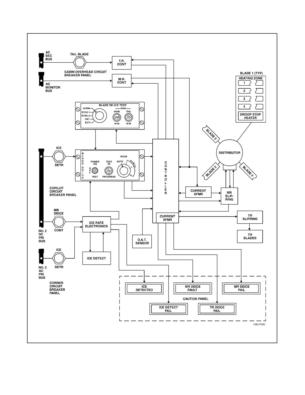
A1-H60BB-NFM-000
Figure 2-53. Blade De--Ice System Block Diagram
ORIGINAL
2-124
A1-H60BB-NFM-000
CONTROL
FUNCTION
POWER SWITCH:
ON
Turns on power to blade de--ice system.
OFF
Turns off de--ice system.
TEST
Electrically tests main and tail rotor de--ice and signal convertor for one test
cycle.
TEST IN PROGRESS LIGHT
Green light goes on during test cycle. At end of test cycle, light should go off.
MODE Selector:
AUTO
System off-time is controlled by ice rate signal.
MANUAL
Gives pilot manual control of system off-time.
T
Trace.
L
Light.
M
Moderate.
Figure 2-54. Blade De--Ice Control Panel Functions
CONTROL
FUNCTION
NORM
Provides a signal path for normal operation.
SYNC 1
Provides a test signal to verify operation of Main Blade De--Ice synchronization
short circuit warning circuitry when POWER switch is at TEST.
SYNC 2
Provides an open circuit to verify operation of Main Blade De--Ice synchronization
open circuit warning circuitry when POWER switch is at TEST.
OAT
Short circuits the OAT sensor to check that BIT circuit senses a fault when
POWER switch is at TEST.
EOT
Disables OAT sensor BIT circuits to simulate defects in primary EOT timing circuit,
when POWER switch is ON and MODE select switch is at M (MODERATE).
PWR MAIN RTR light
Indicates a malfunction has occurred in the main rotor primary power when
POWER switch is at OFF or ON. Also indicates test and normal operation when
POWER switch is at TEST.
PWR TAIL RTR light
Indicates a malfunction has occurred in the tail rotor primary power when POWER
switch is at OFF or ON. Also indicates test and normal operation when POWER
switch is at TEST.
Figure 2-55. Blade De--Ice Test Panel Functions
The system control panel contains a rotary switch, which allows automatic or manual control of blade heater off time.
In AUTO the ice rate signal is passed onto the controller, which results in off--time variations proportional to the icing
rate. In MANUAL, (T, L, or M) fixed signals are transmitted to the controller resulting in fixed off time. One of the
three manual modes should be selected when an icing rate system malfunction is indicated by the illumination of the
ICE DETECT FAIL caution. The MANUAL mode should also be used when there is no indication of failure, but
any of these three conditions has occurred:
1. The pilot has determined by judgment of icing intensity that the ice rate system is inaccurate.
2. Torque required has increased to an unacceptable level.
3. Helicopter vibration has increased to an unacceptable level.
2-125
ORIGINAL
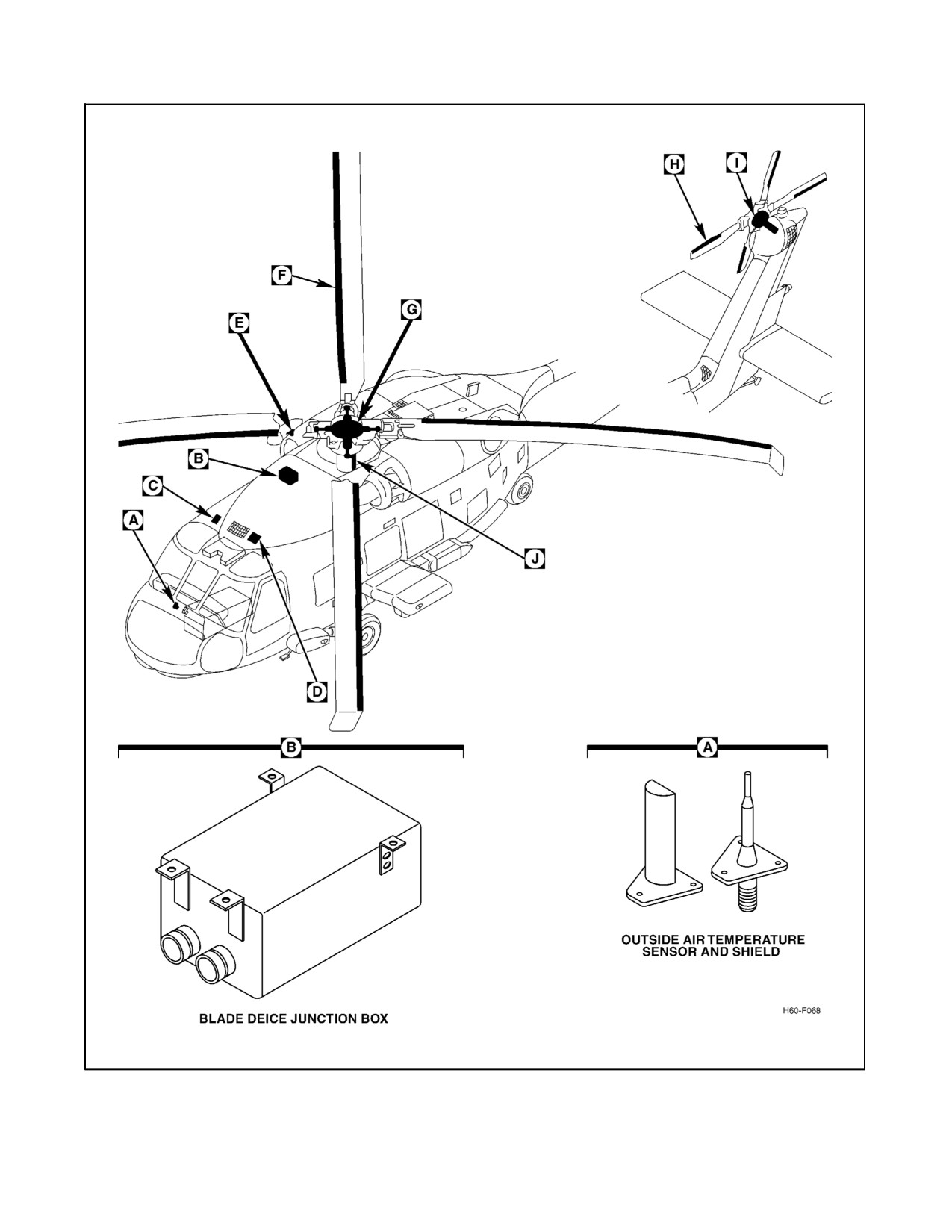
A1-H60BB-NFM-000
Figure 2-56. Blade De--Ice System (Sheet 1 of 2)
ORIGINAL
2-126
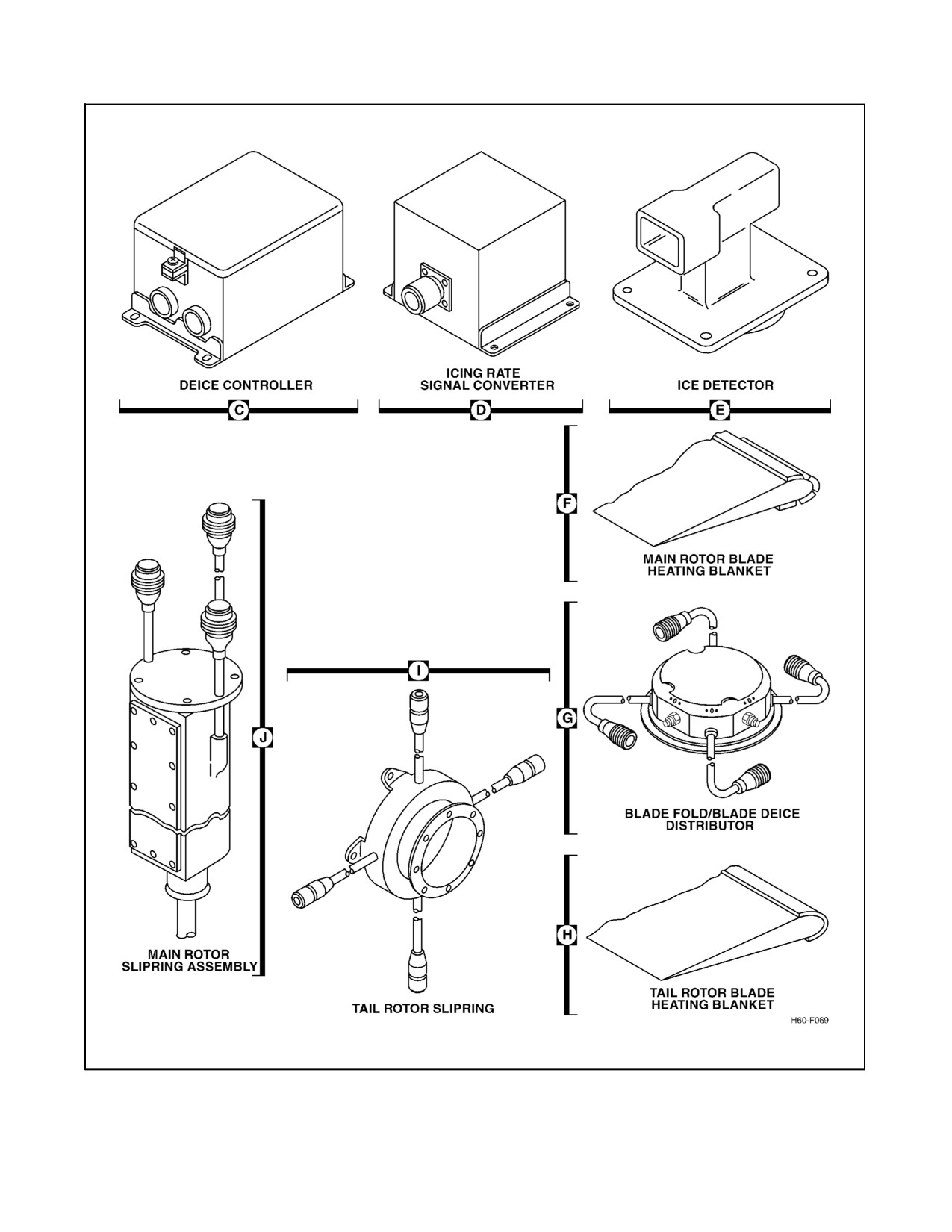
A1-H60BB-NFM-000
Figure 2-56. Blade De--Ice System (Sheet 2)
2-127
ORIGINAL
A1-H60BB-NFM-000
2.18.3.3 BLADE DE--ICE TEST Panel
The control for checking de--ice caution lights and Built--in Test (BIT) circuitry is on the BLADE DE--ICE TEST
panel (Figure 2-53). Two amber PWR lights on the panel warn of power malfunctions of the main and tail rotor de--ice
system.
2.18.3.4 BLADE DE--ICE TEST System Operation
The BLADE DE--ICE TEST panel allows the pilot to check the blade de--ice system for failures that are otherwise
dormant during the normal test mode. The panel accomplishes this by introducing selected failure signals into the
system and requiring the de--ice controller BIT circuitry to function in a specific manner. Blade De--Ice Test Panel
Functions (Figure 2-55) are contained in Chapter 7.
2.18.4 Windshield Anti-Ice System
Thewind--shieldanti--icesystemisusedtopreventiceandfogfromformingon thewindshields. Thepilot andcopilot
windshields are electrically heated safety glass with heating elements and built--in temperature sensors. Both
windshields have their own separate anti--ice system. Each system is operated by a separate switch on the upper
console, (Figure 1-6), marked WINDSHIELD ANTI--ICE, and separate anti--ice controllers in the junction boxes.
Placing either the COPILOT or the PILOT WINDSHIELD ANTI--ICE switch to the ON position sends power to the
windshield--heating elements. Placing the DE--ICE MASTER switch in AUTO will turn both windshield anti--ice
systems on, regardless of WINDSHIELD ANTI--ICE switch position, when the ice detector senses ice formation.
2.18.5 Pitot Heater System
Heaters, located in the pitot tubes and static ports keep ice from forming on the tubes and ports and help keep moisture
out. The pitot--static heaters are controlled by the PITOT HEAT switch, labeled ON and OFF, located on the upper
console. When the PITOT HEAT switch is ON, power is fed to the right and left pitot tube heaters and static ports
causing the heaters to go on. When a low--heat or no--heat condition is sensed with the PITOT HEAT switch ON, the
RIGHT and/or LEFT PITOT HEAT caution(s) will illuminate.
Pitot heat shall be turned on when visible moisture is present and/or the
OAT is 5 °C or below. Failure to turn on pitot heat in these conditions may
result in erratic stabilator programming.
Note
Pitot heaters are not to be used to warm flight equipment.
2.18.6 Windshield Wiper and Washer System
2.18.6.1 Windshield Wiper System
Theelectricallyoperatedwindshieldwipersystemconsists ofatwo--speedmotorandacontrolknob. Therotary--type
knob is marked PARK, OFF, LOW, and HI and is located on the overhead console, marked WINDSHIELD WIPER.
When the knob is placed in the LOW or HI position, the system is actuated, and the desired speed range is selected.
When the knob is placed in the PARK position, the wipers are automatically positioned to the inboard edge of the
windshields.
CAUTION
To prevent possible damage to the windshield surface, do not operate the
windshield wipers on a dry windshield.
ORIGINAL
2-128
A1-H60BB-NFM-000
2.18.6.2 Windshield Washer System
The system consists of a reservoir, windshield washer motor, and a control switch. The reservoir, located to the right
ofthepilot’s seat, gravity--feeds thewindshield washermotor. Thewindshieldwashermotoris controlledby aswitch
on the overhead console, marked WINDSHIELD WASHER ON and OFF. Placing the switch in the ON position
causes the windshield washer motor to pump fluid through the wiper spray bars to the windshield.
2.19
SEATS
2.19.1 Cockpit and Sensor Operator Seats
Each seat is a one--piece aluminum bucket attached to two energy absorption tubes and can be adjusted for leg length
and height. Each seat is positioned on a track with the cockpit seat buckets directly above recesses in the cockpit floor.
Crash loads are reduced by allowing the seat and occupant to move vertically as a single unit. Occupant restraint is
provided by a shoulder harness, lap belts, and a crotch belt.
2.19.1.1 Seat Adjustment
Seat adjustment is controlled by levers on the front of the seat bucket (Figure 2-57). The levers return to the locked
position when released. When thelevers arepulled forward, the seat can move5 inches vertically or horizontally and
be locked at 1/2 inch intervals. Springs are installed to counterbalance the weight of the seat. The seat is designed
to sustain a 14--g deceleration throughout the length of the seat stroke. Length of the stroke is a function of the seat
height and at higher seat--height adjustments, higher crash loads can be absorbed.
2.19.1.2 Seat Belts
The seats each contain a shoulder harness, lap belt, and a crotch strap connected to a common buckle assembly. All
belts and straps have adjustment fittings. The common attachment buckle has a single--point release. When turned
in either direction, it simultaneously releases all belts and straps.
2.19.1.3 Shoulder Harness Lock Lever
A two--position shoulder harness lock lever is on the left side of each seat. When the lever is in the unlocked (rear)
position, the dual--shoulder harness will extend 12 inches to allow the occupant to lean forward. The inertia reel will
automatically lock if a force of 3 g’s is encountered, allowing only harness retraction. When this occurs, the inertia
reel lock will prevent further extension until the lever is cycled. When the lever is placed in the locked (forward)
position, the reel lock prevents extension of the harness (Figure 2-57).
2.19.2 Sensor Operator Instructor and Passenger Seats
An SO instructor seat is provided for use during training or proficiency check flights. A passenger seat is located
against the aft cabin bulkhead. Each seat is a cable--supported, steel--tube assembly with a fire--resistant,
high--strength fabric seat and backrest. Each seat has a complete lap belt and dual torso--restraint shoulder harness,
attached to a rotary release buckle. The seats are designed to protect the occupant in a crash. This is done by an
attenuating system consisting of an energy--absorbing telescopic leg brace, combined with two rotary attenuators on
the seat--back support cables.
2.19.3 RMU-42/A — Mobile Aircrew Restraint System
The mobile aircrew restraint system (MARS) in Figure 2-58 is designed to provide in--flight fall protection and
prevent ejection of cabin aircrew in survivable crashes while minimizing the strike envelope within the cabin and
to improve aircrew mobility while performing mission requirements. The MARS components consist of a webbing
retractor assembly, a webbing strap assembly, and a ceiling retaining plate.
The crewmembers aircraft safety belt backstrap, in conjunction with the webbing strap assembly, will provide the
crewmember with an approximate 7--foot perimeter when fully extended. The crewmembers aircraft safety belt
should be worn over the flight equipment, high up on the chest and should be snug, without discomfort or breathing
restriction. Proper wear of the belt will prevent inadvertent release of the latch mechanism and minimize personal
injury.
2-129
ORIGINAL
A1-H60BB-NFM-000
D Improper positioning of the crewmembers aircraft safety belt
MS16070--21/A when donned could result in personal injury in the event
of an aircraft emergency.
D The MARS is not designed to replace a crashworthy seat during controlled
takeoff and landing. Always strap into the seat in accordance with current
NATOPS procedures.
D Whenever possible, ensure the RMU--42/A retractor is in the locked
position when performing the mission, especially when working in close
proximity to the main cabin door.
2.20
RESCUE HOIST
The rescue hoist system (Figure 2-59) consists of a hoist assembly, hoist control panel, hover trim control panel,
relays, circuit breakers, and necessary electrical wiring. The hoist is hydraulically powered from the backup pump,
and its speed is variable from zero to 215 fpm for Breeze Eastern units or zero to 250 fpm for Lucas Western units.
It is enclosed in a sheet metal fairing and is supported by a fixed tubular strut enclosed in a fiberglass fairing above
thecabindoor.Thestrutisboltedtoasupportfittingonthefuselageatstation335.75.Thehoistandstrutcanbeswung
down as a unit, providing clearance for removal of the right engine intake without hoist disconnection or removal.
The hoist contains 200 usable feet of cable and has a guillotine--type cable cutter and an automatic cable brake. The
first and last 20 feet of the cable are bright orange to warn of end approach. The hoist hook is attached to the cable
end by a ball bearing swivel. The hoist assembly comprises a winch, hydraulic drive motor, heat exchanger, fan, and
control box.
2.20.1 Rescue Hoist Control Panel
The hoist control panel (Figure 2-59) is on the right side of the cabin, aft of the cabin door. It controls backup power,
when needed in an emergency, by means of a BACKUP CONTROL POWER switch which, when pressed, turns on
the switch light, indicating that backup control is activated. The hoist is then controllable by the HOIST UP--DOWN
control switch only, at a fixed speed of 85 fpm. The hoist control panel also contains a NORMAL POWER light as
an indication of power status and a HYD OVERHEAT light to indicate when the hydraulic oil temperature is over
116 °C.
Note
Backlighting for the hoist control panel is controlled by the lower console
panel light rheostat.
2.20.2 Hover Trim Control Panel
The hover trim control panel (Figure 2-59) is in thecabin abovethe hoist control panel. It is used to control thehover
position of the helicopter during a rescue operation within prescribed limits by means of a crewman--operated hand
grip. This hand grip contains a pressure--activated thumb control for helicopter positioning and an ICS switch. The
hand grip also contains a thumbwheel hoist control switch on BuNo 164174 and subsequent to allow coordinated
hover positioning, communication, and hoist control from the hand grip. The panel also contains the crewman hoist
shear switch, rescue light switch, hover trim light, and a rescue station dome light rheostat.
Note
Backlighting for the hover trim control panel is controlled by the lower
console panel light rheostat.
ORIGINAL
2-130
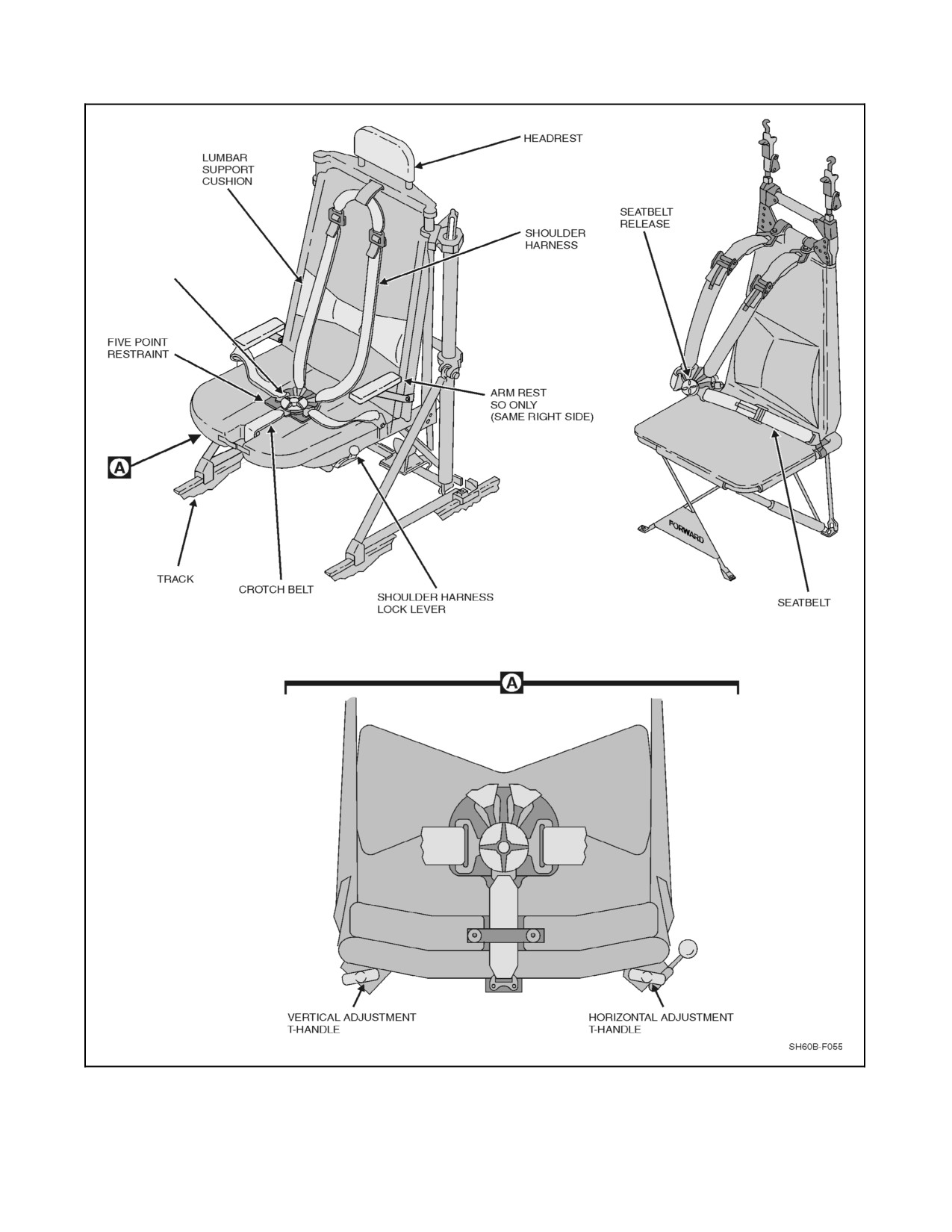
A1-H60BB-NFM-000
SEATBELT
RELEASE
PILOT, ATO, AND SO SEAT
INSTRUCTOR
AND PASSENGER SEAT
FRONT VIEW LOOKING AFT
Figure 2-57. Personnel Seats
2-131
ORIGINAL
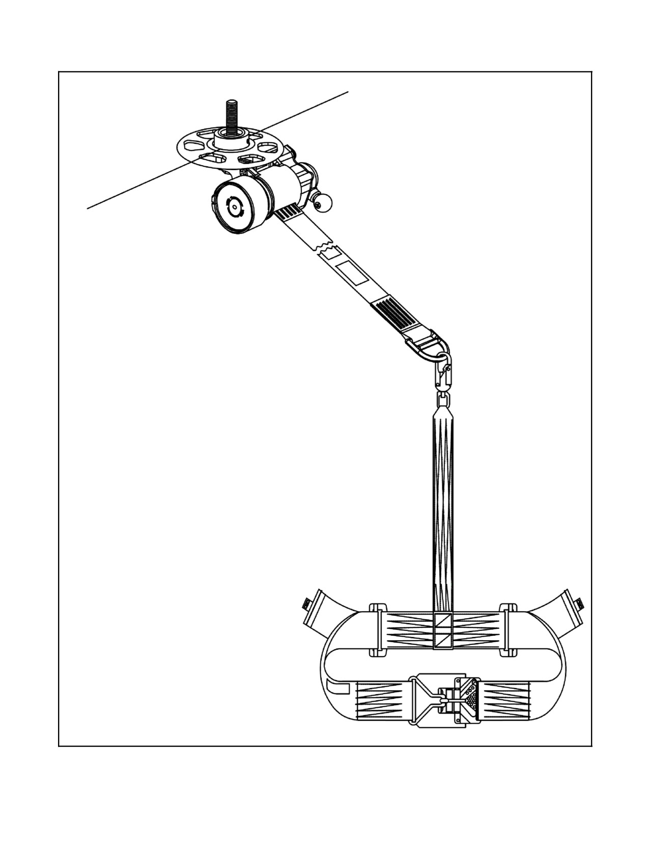
A1-H60BB-NFM-000
Figure 2-58. Mobile Aircrew Restraint System (MARS)
ORIGINAL
2-132
A1-H60BB-NFM-000
2.20.3 Hoist Operation
Hydraulic power at a flow rate of 5.5 gpm (normal) and 2,700 psi (minimum) pressure is supplied to the rescuehoist
from the utility module via the rescue hoist manifold and pressure/return lines routed within the support strut fairing.
The pressure line contains a priority valve that isolates the rescue hoist when hydraulic pressure decreases to
2,050 psi. The return line contains a temperature sensor switch that provides the signal to the HYD OVERHEAT
warning light on the hoist control panel. Operation of the rescue hoist is controlled in either of three ways for
BuNo 164173 and previous or four ways for BuNo 164174 and subsequent:
Note
D Selecting BACKUP HYD PMP ON with the SACs running will cause a
restart of the AOP. The AOP may cause equipment faults to be indicated;
however, no damage to equipment occurs, and the faults may be cleared by
using CLEAR ALERT CUE or INIT TEST.
D Constant tension should be maintained on the hoist cable to prevent
birdcaging.
1. The primary method is from the cabin by means of the crewman pendant.
2. The secondary method is by means of the crewman--operated hand grip (BuNo 164174 and subsequent only).
The pendant contains an ICS switch, a thumbwheel hoist control switch, and a CARGO HOOK RELEASE switch.
The hoist can be raised or lowered at any speed up to 215 fpm, from either the hand grip or the pendant, depending
on the thumbwheel pressure applied. The hoist control switch is spring loaded to the neutral position.
Note
Aircraft equipped with the Lucas--Western hoist are capable of hoist speeds
up to 250 fpm. Lucas--Western hoists can be identified by a completely
enclosed hoist cable drum.
3. The tertiary method is from the cockpit by means of theHOIST switches at thetop ofthe pilot and ATO cyclic
grips. These switches can raise or lower the hoist at a fixed speed of 100 fpm. When this mode is activated,
itwilloverridetheprimarypendantcontrolofthecrewman orthecrewman--operatedhand grip(BuNo 164174
and subsequent only). The cyclic grips also contain the EMER REL switches to shear the hoist.
Power for primary, secondary, and tertiary modes of operation is provided from the NO. 2 DC primary bus through
a circuit breaker marked RESCUE HOIST CONTR on the SO circuit breaker panel and controlled through the
RESCUE HOIST switch on the overhead control panel.
4. The quaternary (emergency) method is from the cabin by means of the RESCUE HOIST BACK--UP
CONTROL POWER switch and HOIST UP--DOWN switch on the hoist control panel. These respectively
provide emergency power and control the direction of the hoist at a fixed speed of 85 fpm. The BACK--UP
CONTROL and HOIST UP--DOWN switches operate emergency up, down, and shutoff valves in the hoist,
overriding failure or seizure on the normal control switches and normal up, down, and shutoff valves in the
hoist.
Power for the backup control mode of operation is provided from the NO. 1 DC primary bus through a circuit breaker
marked RESCUE HOIST CONTR on the SO circuit breaker panel.
2-133
ORIGINAL
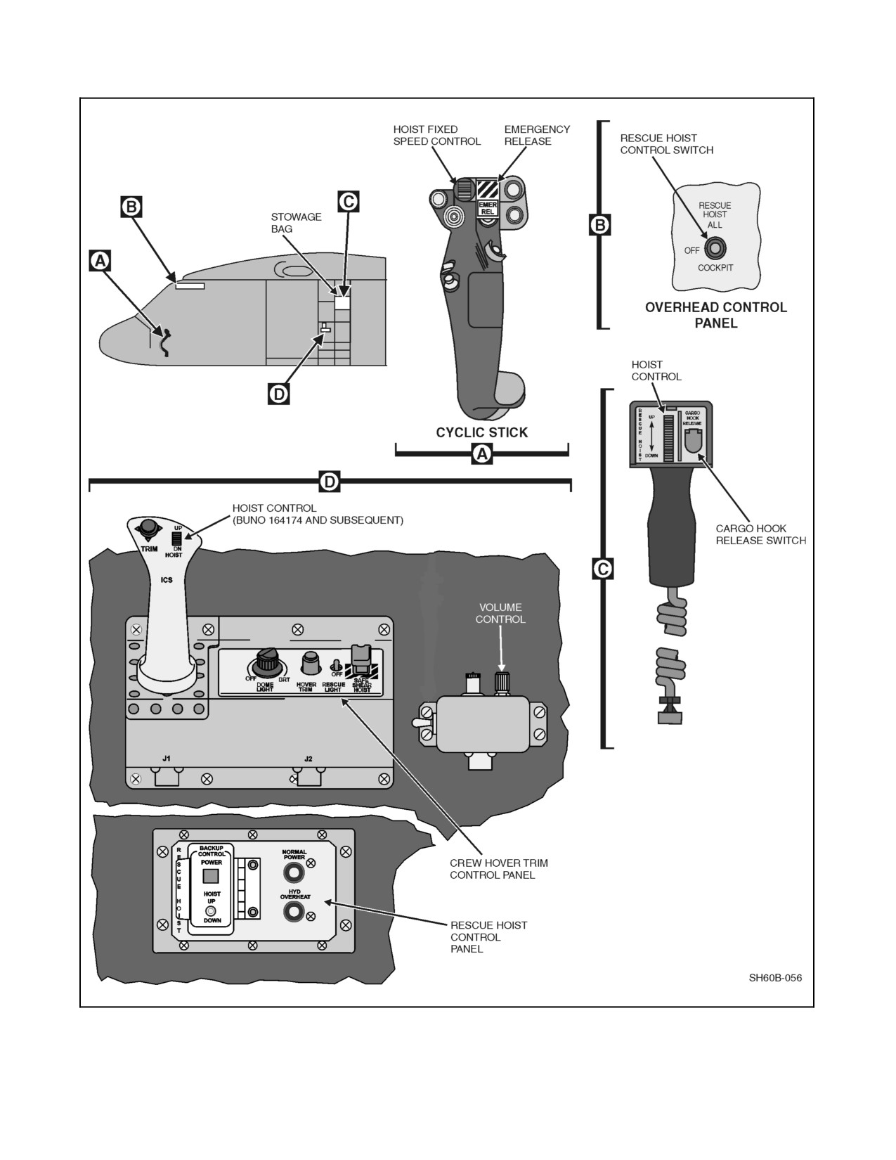
A1-H60BB-NFM-000
Figure 2-59. Rescue Hoist System (Sheet 1 of 2)
ORIGINAL
2-134
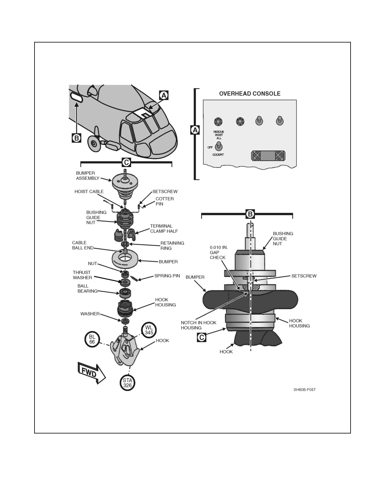
A1-H60BB-NFM-000
Figure 2-59. Rescue Hoist System (Sheet 2)
2-135
ORIGINAL
A1-H60BB-NFM-000
If the overhead control panel RESCUE HOIST switch is OFF, neither the crewman pendant nor the cyclic grip HOIST
controls are operative. If the overhead switch is at COCKPIT or ALL, the crewman pendant hoist switch and the
cyclic grip hoist control switches are operative. The BACKUP CONTROL POWER switch and HOIST UP--DOWN
switches are unaffected by the selection of the overhead control panel switch. When the hoist is being operated by
the pendant switch or a cyclic grip switch, the hoist is automatically stopped at the fully up or fully down position
by internal limit switches. Iftheprimary down limit switch fails, asecond limit switch isactivated. Normaloperation
oftherescuehoistisnolongeravailable.Backup(emergency)operations mustbeselectedto bypassthefailedswitch.
Once the cable has been moved beyond the failed switch, normal hoist operation is available; however, the limit
switches are ineffective when the hoist is being operated by the BACKUP HOIST UP--DOWN switch. When the hoist
is being raised or lowered at a speed exceeding 50 fpm, it will automatically decelerate to 50 fpm at approximately
10 feet from fully up position, or approximately 5 feet from fully lowered position.
CAUTION
When hoisting in backup control, the upper and lower electrical limit
switches are inoperative. Continued operation after the hook is full up can
severely damage the hoist. The cable may become disconnected from the
cable reel when operating the hoist with the cable in the warning range
(painted orange).
2.20.4 Hoist Cable Shear
Hoist cable shearing is by a guillotine cartridge controlled by the rescue hoist shear relay which can be energized
either from the cabin HOVER TRIM panel SHEAR switch or the EMER REL switch on top of the pilot and ATO
cyclic grips, which energizes the master shear relay when helicopter is airborne. When the helicopter weight is on
the wheels, all jettison stations are inoperative. If the overhead RESCUE HOIST control switch is at OFF, neither
the hover trim panel SHEAR HOIST switch nor the cyclic grip EMER REL switches are operative. If the RESCUE
HOIST control switch is in the COCKPIT position, only the cyclic grip emergency release switches are operative.
If the overhead RESCUE HOIST control switch is at ALL, the hover trim panel SHEAR HOIST switch and cyclic
grip EMER REL switch are operative. Power is provided from the DC essential bus through a circuit breaker marked
EMERG RELEASE HOIST CABLE SHEAR and located on the overhead console circuit breaker panel.
CAUTION
If the MAD, RAST, cargo hook, or rescue hoist are on, then their respective
shear circuits are also activated and will fire if the EMER REL switch is
depressed.
2.20.5 Hoist Auxiliary Cooling
The hoist assembly has an integral oil cooler in the aft cowling. Air is forced through by an electrically driven fan
when hoist power is applied.
CAUTION
Failure to secure the RESCUE HOIST switch when not conducting hoist
operations could result in the failure of the rescue hoist auxiliary cooling
fan motor.
ORIGINAL
2-136
A1-H60BB-NFM-000
2.21
CARGO HOOK SYSTEM
The external cargo hook (Figure 2-60) has a rated capacity of 6,000 pounds and has a jaw opening of 2.12 inches. Its
location on the bottom fuselage centerline, just aft of the main rotor centerline, was selected to provide ease of accessibility
and to minimize aircraft pitch and roll reactions to cargo swing. The hook is installed in a semirigid mounting located
in the cargo hook well underneath the cabin floor and below the aircraft center of gravity. When not in use, the hook is
stowed horizontally in the well. Primary electrical release controls are provided for the pilot, ATO, and crew operator
(Figure 2-60). A mechanical release is provided on the hook for groundcrew operation and is accessible from the cabin
for aircrew operation in the event of aircraft electrical malfunction. Emergency release can be initiated from either EMER
REL button located on the cyclic grips. When the CARGO HOOK EMER RLSE switch is in the NORM position and
the CARGO HOOK SAFE/ARMED switch is ARMED, pressing the EMER REL button applies 28 Vdc to an explosive
cartridge in the cargo hook. This causes the lock assembly to open and the weight of the cargo will cause the load arm
to open. The lock assembly must be reset manually and a new explosive cartridge must be installed. Power to operate
the emergency release system is from the DC essential bus through a circuit breaker, marked EMERG RELEASE
CARGO HOOK. The circuit breaker is on the overhead circuit breaker panel.
2.21.1 Cargo Hook Electrical Release
The cargo hook control panel, located on the overhead console (Figure 1-6), consists of an EMER RLSE TEST
switch, a TEST light, a CONTROL station selector switch (labeled COCKPIT and ALL), and an ARMING switch
(marked SAFE and ARMED). Placing the ARMING switch to the ARMED position provides power to the release
circuit and illuminates the HOOK ARMED light on the advisory panel. The pilot and ATO cyclic grip normal release
switches will release the load when the CONTROL switch is at COCKPIT or ALL position. The crewman HOOK
RELEASE switch, located on the crewman hoist pendant, releases the load when the CONTROL switch is at ALL
position. When the load is released, the CARGO HOOK OPEN advisory light goes on. The power for the normal
electrical release is supplied by the NO. 2 DC primary bus through two circuit breakers, marked CARGO HOOK
PWR and CONTR, located on the SO circuit breaker panel.
2.21.2 Cargo Hook Emergency Release Test
The cargo hook emergency--release circuit tester, located on the overhead console, marked CARGO HOOK EMER
RLSE, contains a test indicator and switch (Figure 2-60). The test light, marked TEST, goes on during circuit testing
to indicate that the system is functioning properly.
The tester checks the pyrotechnic squib circuitry for an open circuit at the OPEN position and short circuits at the
SHORT position. Electrical power is supplied by the DC essential bus through a circuit breaker marked EMERG
RELEASE, CARGO HOOK. The circuit breaker is located on the overhead circuit breaker panel.
2.22
EMERGENCY PANEL
The emergency panel (EMER PNL) is located in the center section of the lower console as shown in Figure 2-61.
It provides two separate functions. These are:
1. Fuel dump.
2. Stores jettison.
Fuel dump functions are discussed in this chapter and Chapters 12. The stores jettison function provides a single
point, all stores release feature. Depressing thering--guarded pushbutton activates theall stores jettison function. All
stores jettison will jettison all stores and cycle the sonobuoy launcher through all tubes launching each
sonobuoy/signal underwater sound (SUS) in sequence. Any armed weapon will be set to a safe stateprior to jettison.
The system does not allow jettison isolation of sonobuoys or weapons pylons. Signal inhibit boxes prevent the
jettison of auxiliary fuel tanks when they contain less than approximately 272 pounds of fuel. The jettison operation
is completed within four seconds. The stores jettison function is powered by the NO. 1 DC primary bus through a
circuit breaker on the ATO circuit breaker panel marked ARMAMENT JETT A and by the NO. 2 DC primary bus
through circuit breakers on the ATO circuit breaker panel marked ARMAMENT JETT B and ARMAMENT SYS
on aircraft prior to BuNo 162349. Effective on aircraft BuNo 162349 and subsequent, stores jettison is powered by
the NO. 1 DC primary bus through circuit breakers marked ARMAMENT JETT A and ARMAMENT JETT C, and
by the NO. 2 DC primary bus through circuit breakers marked ARMAMENT JETT B and JETT D on the ATO circuit
breaker panel. These circuit breakers provide dual redundancy in the jettison function of each configuration of the
aircraft.
2-137
ORIGINAL
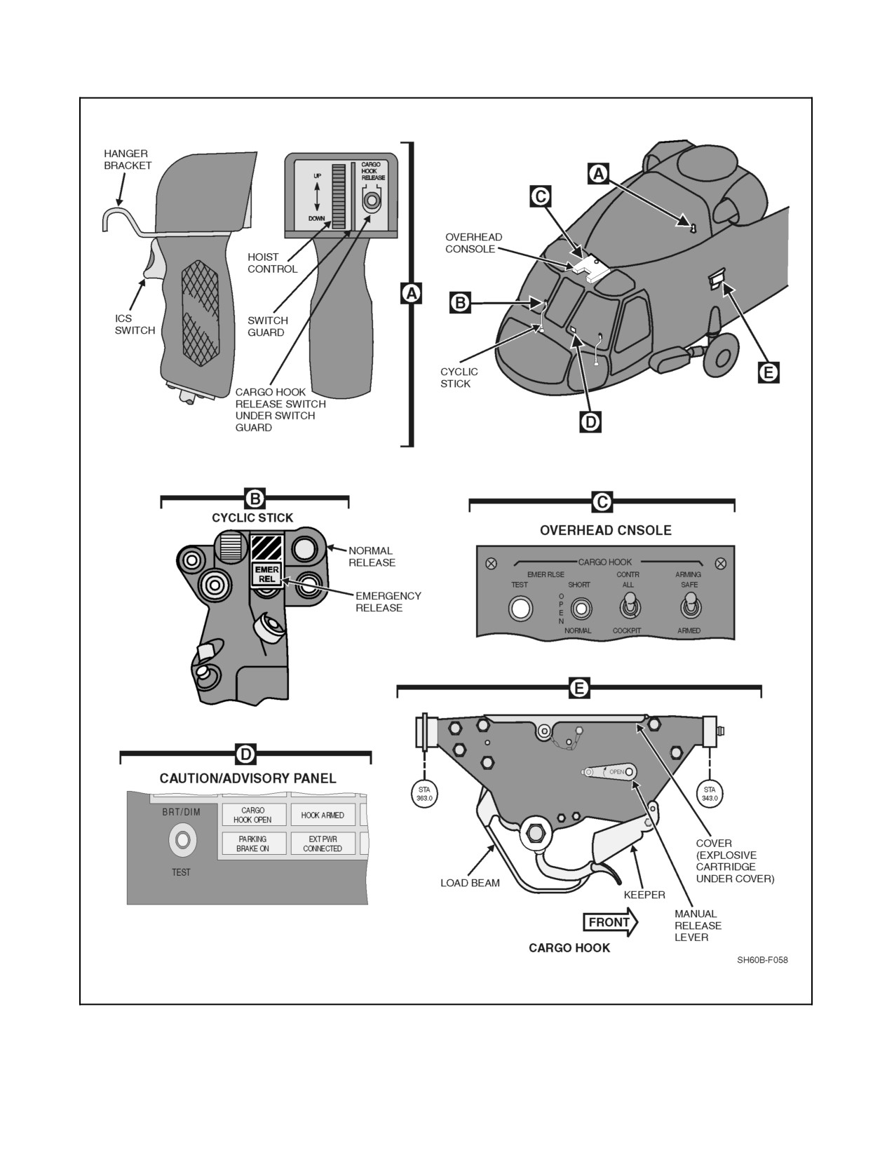
A1-H60BB-NFM-000
CREWMAN PENDANT
Figure 2-60. Cargo Hook System
ORIGINAL
2-138
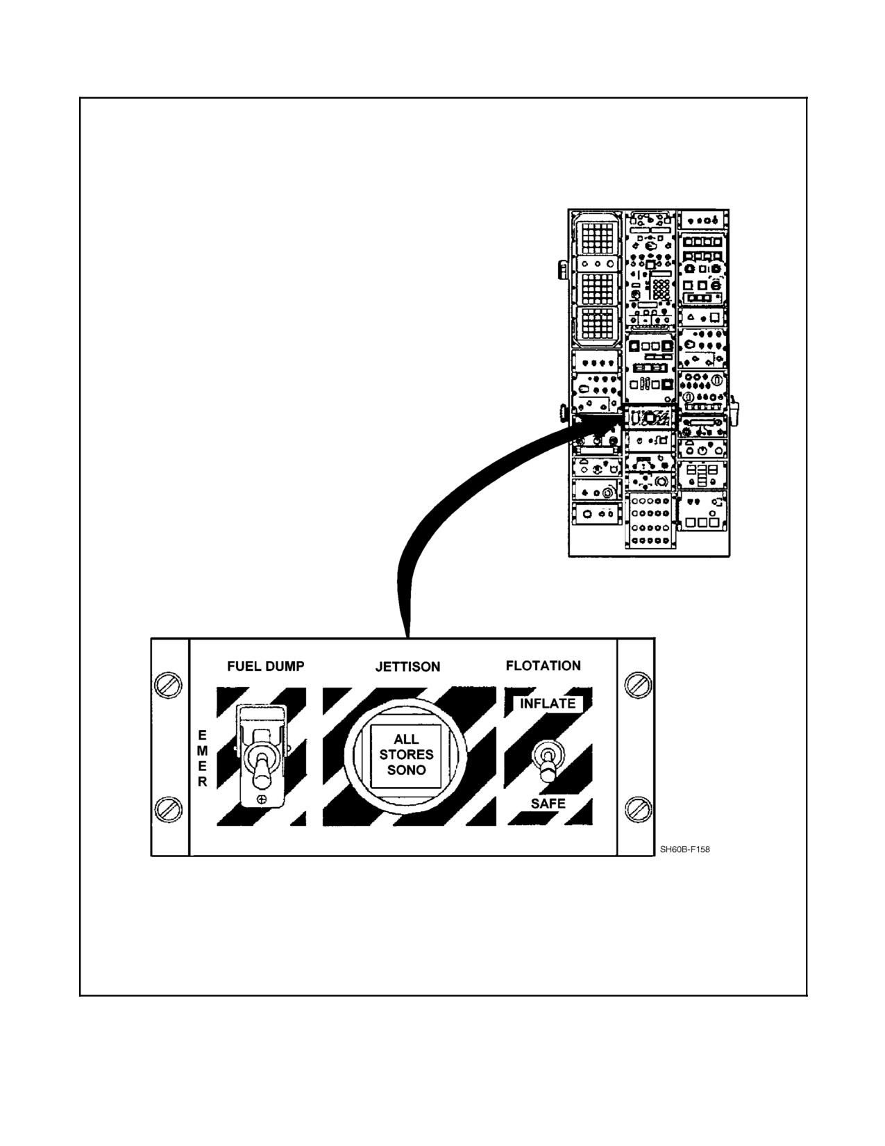
A1-H60BB-NFM-000
Figure 2-61. Emergency Panel (EMER PNL)
2-139
ORIGINAL
A1-H60BB-NFM-000
Note
D In the event of a total electrical failure, stores jettison is inoperative.
D If a weapon has been selected and armed, the jettison system will disarm
the weapon before it is jettisoned.
D The stores may be emergency jettisoned in flight by the jettison system
regardless of the position of the MASTER ARM pushbutton switches. If
pressure is less than 900 psi, all sonobuoys may not jettison.
D The ARA controls port forward jettison regardless of ACI station selection.
The forward station releases one second after the aft stations. The ARA
power utilizes ARMAMENT JETT C and JETT D circuit breakers.
ARMAMENT JETT A and ARMAMENT JETT B support ASDC jettison
of aft stations and sonobuoys.
D The ARA supplies LK/UL status to the ACI.
D The ARA provides default locking of unselected port stations and
simultaneous nose--tail arming for selected portside stations.
2.23
SURVIVAL AND EMERGENCY EQUIPMENT
2.23.1 Survival Equipment
Flight personnel shall be familiar with and utilize those items of flight clothing and survival and rescue equipment
as prescribed in the current NATOPS General Flight and Operating Instructions (OPNAVINST 3710.7 series). In
addition, the pilot in command of an aircraft engaged in carrying crewmen or passengers shall ensure their compliance
with this instruction.
2.23.2 Emergency Equipment
Emergency equipment (Figure 2-62) includes two portablefire extinguishers, two first aid kits, a crash ax, two water
canteens, and an emergency locator transmitter (ELT).
2.23.2.1 Emergency Locator Transmitter Systems
The Emergency Locator Transmitter (ELT) System consists of a transmitter (portable) and two antennas (one
portable, collapsible, vertical monopole antenna and one monopole antenna with an interconnecting coaxial cable
for aircraft antenna feed). The transmitter is mounted on the control--enclosure bulkhead behind the pilot seat. The
transmitter is normally connected to the antenna in the transition section via the coaxial cable, but the collapsible
antenna may be connected for portability. The transmitter is a self--contained, dry--cell, battery--operated unit. When
turned on by an ON--OFF--ARM switch, it simultaneously transmits a distress signal on the international distress
frequencies of 121.5 MHz and 243.0 MHz. The distress signal may travel as far as 100 miles, at a search altitude of
approximately 10,000 feet. When the selector switch is placed to ARM, the transmitter will automatically activate
upon a forward impact force of 5 g’s. With the switch ON, the transmitter is activated. The signal emitted by the
transmitter, when activated, is a tone that varies from l,600 Hz to 300 Hz, at a rate of 2 to 3 times per second.
Testing of the transmitter is done by on--the--air operation in one of the two following methods:
1. A test may be made with a control tower after receiving permission to activate the transmitter. Placing the
selector switch ON for not more than 5 seconds is enough to check operation. The tower will confirm
transmitter operation.
2. A test may also be made with an onboard UHF or VHF radio monitoring GUARD frequency. The selector
switch is placed to ON for 2 to 5 seconds and the radio receiver will confirm locator transmitter operations.
The selector switch shall be returned to ARM if the operational check was satisfactory.
Note
On--air operational checks are to be done as quickly as possible, between
on--the--hour and
5 minutes after--the--hour and for not more than
5 seconds.
ORIGINAL
2-140
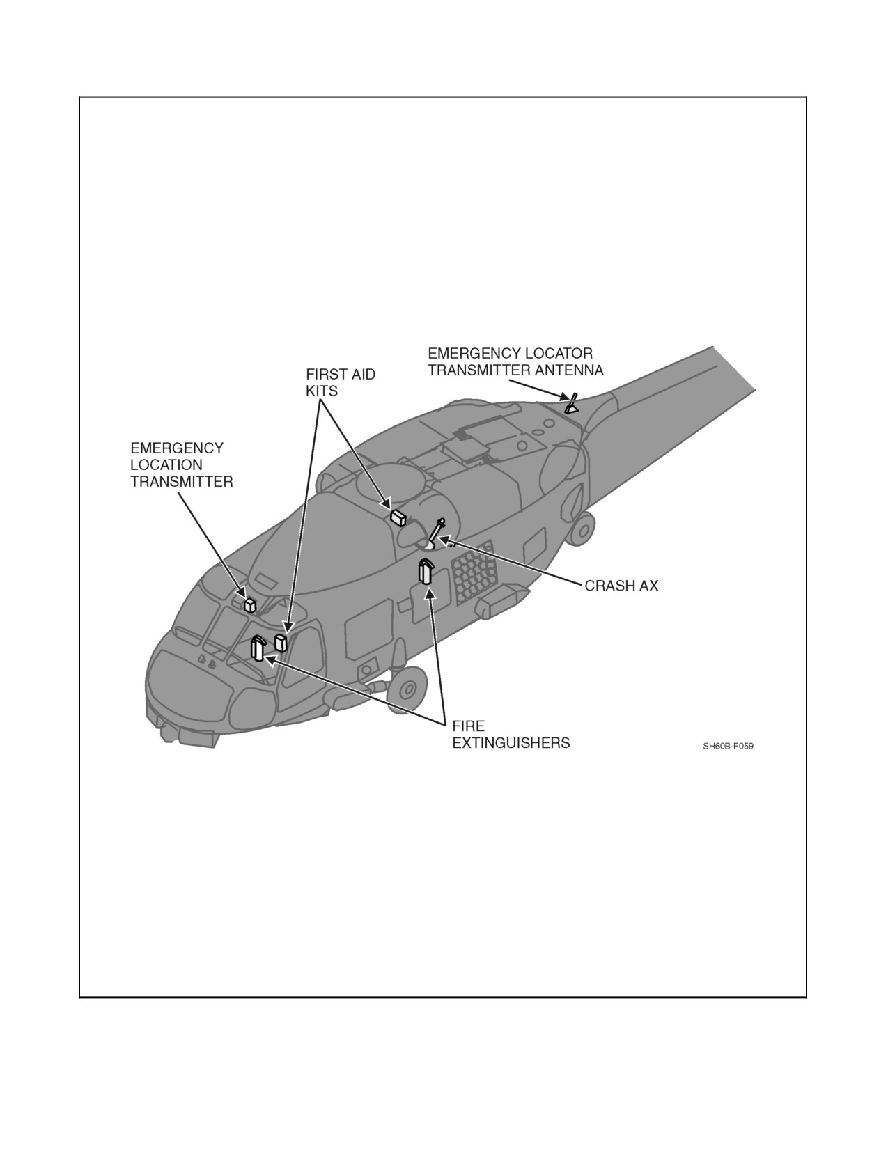
A1-H60BB-NFM-000
Figure 2-62. Emergency Equipment Location
2-141
ORIGINAL
A1-H60BB-NFM-000
2.23.2.2 Helicopter Emergency Egress Lighting System
The HEELS automatically provides emergency lighting of the cabin door and SO window (Figure 2-63). The system
consists of four light tube assemblies, two control unit assemblies, one control panel, a signal conditioner, and an
additional Nr sensor located on the left--hand accessory module. The SO window has one 5 foot light tube strip
forming an inverted U over the window. The cabin door has three 30--inch light tube assemblies mounted on the
sound--proofing arranged around the cabin door as an inverted U.
There are two control units, each containing a battery pack, a test switch, and an indicator light. One control unit is
for the cabin door, and the other is for the SO window. The test switch tests the battery. The battery pack provides
power to light the tubes during emergency operation. When activated, the batteries should illuminate the tubes for
approximately 10 minutes.
CAUTION
HEELS is intended for emergency operation only and shall not be used for
nonemergency lighting.
The arm switch located on the SO utility light panel allows for remote testing and arming of the HEELS. The test
switch is a momentary position switch used in conjunction with the arm switch for preflight testing of the HEELS
(Figure 2-63).
To test the control units, depress the test switch located on each unit for a minimum of 6 seconds. The green LED
next to the test switch will illuminate and maintain intensity as long as the switch is depressed. If the light dims or
does not illuminate, the batteries should be replaced.
The light assemblies are powered by two control units. The control units are activated by loss of an inhibit signal
received from the rotor head speed signal conditioner (total loss of AC power or a drop of rotor Nr below 80 percent).
The system is powered by the NO. 1 DC primary bus 28 Vdc through a circuit breaker on the SO circuit breaker panel
marked HEELS. Anytime the HEELS system is armed, the control units batteries are being charged.
2.23.2.3 Advanced Helicopter Emergency Egress Lighting System
Advanced Helicopter Emergency Egress Lighting System (ADHEELS) automatically provides emergency lighting
of the cabin door and SO window. The system consists of 3 fiber light assemblies, a control module, remote test
assembly, and a crash/inversion sensor. The cabin door control module and crash/inversion sensor are located aft of
therescuestation. TheSO window control moduleand crash/inversion sensorarelocated forward ofthe SO window.
ADHEELS operates independently of aircraft power and is activated when any of the following is detected by the
crash/inversion sensor:
1. Water immersion.
2. Impact force of 11--13 g’s or greater.
3. Attitude changes of 100 ±5° or greater.
When one of the above conditions is met, the control module activates the fiber light assembly, which will remain
illuminated for a minimum of 45 minutes. The ADHEELS system, when inadvertently activated, can be reset by
momentarily depressing the remote test switch.
The remote test switch, when pressed and held in the down position, will perform the system built--in test function
and the light strip assembly will illuminate within 6 seconds. The test switch automatically resets the system when
released.
2.23.2.4 Individual Helicopter Emergency Egress Lighting System
Individual Helicopter Emergency Egress Lighting System (IHEELS) automatically provides emergency lighting of
both the cabin door window and the SO window jettison handles. Each system consists of a light strip containing
ORIGINAL
2-142
A1-H60BB-NFM-000
theinversion sensorandacircuitmodulewhichcontains thebattery packand theimmersion contacts.Each lightstrip
is powered by a battery and activated independently. Activation occurs when the inversion sensor detects one to the
following:
1. Water immersion
2. Attitude changes of 100 ±5° or greater.
When the test button is pressed, a brief flash of the light strip assembly indicates a successful system test. Both the
test and reset buttons must be depressed with a pen--like object. Since a time delay inhibit is built into the system
test circuitry, the operator must wait 5 minutes before performing an additional test.
2.24
MISCELLANEOUS EQUIPMENT
2.24.1 Rearview Mirrors
External rearview mirrors are installed on either side of the cockpit. The mirror permits the pilot to observe the MAD
towed body deployment, recovery/docking, and hoist operations, and the ATO to observe sonobuoy deployment.
2.24.2 Drinking Water Container
Two standard water canteens are provided; one is located in the cockpit on the left side of the center console and
another canteen is located on the port cabin bulkhead.
2.24.3 Crewman Safety Belt Anchor Points
The three crewman safety belt anchor points are located in the cabin overhead. One is above the SO seat and two are
aft at the rescue seat attachment points.
Crewman safety belts do not provide impact protection; therefore, use of
those belts shall be restricted to only those occurrences when mission
accomplishment requires persons to be out of their seats. Such belts shall
not be worn when strapped into a seat.
2.24.4 Litter Installation Equipment
Litter installation equipment is located aft of the SO seat, under the sonobuoy launcher. It provides the necessary
means to secure a litter for transportation of an injured person. The equipment includes the litter support assembly,
the litter tiedown strap assembly, and the rescue equipment net assembly.
2-143
ORIGINAL