SH-60B HELICOPTER. FLIGHT MANUAL (2008) - page 1
A1-H60BB-NFM-000
THE AIRCRAFT
1
INDOCTRINATION
2
NORMAL
3
PROCEDURES
NATOPS FLIGHT MANUAL
NAVY MODEL
FLIGHT
4
SH-60B HELICOPTER
CHARACTERISTICS
EMERGENCY
THIS PUBLICATION SUPERSEDES
5
PROCEDURES
A1-H60BB-NFM-000 DATED 15 JANUARY 2006.
ALL-WEATHER
6
OPERATIONS
COMM/NAV
7
PROCEDURES
MISSION
8
SYSTEMS
CREW RESOURCE
9
MANAGEMENT
DISTRIBUTION STATEMENT C — Distribution authorized to U.S. Government
agencies only and their contractors to protect publications required for official use or
for administrative or operational purposes only (1 April 2008). Other requests for this
document shall be referred to Commander, Naval Air Systems Command
NATOPS
(PMA--299), 47123 Buse Rd., Bldg. 2272, Patuxent River, MD 20670--1547.
10
EVALUATION
DESTRUCTION NOTICE — For unclassified, limited documents, destroy by any
method that will prevent disclosure of contents or reconstruction of the document.
PERFORMANCE
11
DATA
ISSUED BY AUTHORITY OF THE CHIEF OF NAVAL OPERATIONS AND
UNDER THE DIRECTION OF THE COMMANDER,
INDEX
NAVAL AIR SYSTEMS COMMAND.
0801LP1091511
1
(Reverse Blank)
1 APRIL 2008
A1-H60BB-NFM--000
INTERIM CHANGE SUMMARY
The following Interim Changes have been cancelled or previously incorporated into this manual.
INTERIM
CHANGE
NUMBER(S)
REMARKS/PURPOSE
1 thru 63
Previously Incorporated
The following Interim Changes have been incorporated into this Change/Revision.
INTERIM
CHANGE
NUMBER(S)
REMARKS/PURPOSE
64
Misc. H--60 Common Changes
65
Misc. Changes
66
Fuel Prime Checklist Procedure
67
Changes to Practice Autorotative Approach
Interim Changes Outstanding — To be maintained by the custodian of this manual.
INTERIM
CHANGE
ORIGINATOR/DATE
PAGES
NUMBER
(or DATE/TIME GROUP)
AFFECTED
REMARKS/PURPOSE
68
202000Z MAR 09
3--17, 7--1,
Tiedown Requirements
7--21, 7--32,
7--57,
8--15,
10--13, 10--33
69
262003Z AUG 09
10--67
Revised Auto RPM Correct Chart (and re--issue
of IC--68 for the Conference Revision Release).
70
052000Z OCT 09
2--33/34,
New Operational Warnings & Engine Diaphragm
7--21/32,
Coupling Caution, correction of Autorotation RPM
8--38, 9-13/ 14/
Correction Chart.
15/27/28,
10--16/19/67
5/(6 blank)
ORIGINAL
P 052000Z OCT 09
FROM COMNAVAIRSYSCOM PATUXENT RIVER MD//4.0P//
TO ALL SEAHAWK HELICOPTER ACTIVITIES
INFO COMNAVAIRSYSCOM PATUXENT RIVER MD//4.0P/4.1/4.1.1.2/5.0F/5.1//
PEOASWASM PATUXENT RIVER MD//PMA299//
COMNAVAIRFOR SAN DIEGO CA//N455/N3C3/N421L//
COMNAVAIRFORES SAN DIEGO CA//N42/N52/N421D1//
COMNAVSAFECEN NORFOLK VA//11//
COMNAVSURFLANT NORFOLK VA//N42/N420//
COMNAVSURFPAC SAN DIEGO CA//N42//
FLTREADCENSOUTHEAST JACKSONVILLE FL//3.3.3//
HMX ONE QUANTICO VA//C148-11//
MSGID/GENADMIN/COMNAVAIRSYSCOM/4.0P//
SUBJ/SH-60B AIRCRAFT NATOPS PUBLICATIONS INTERIM CHANGE//
REF/A/DESC:DOC/COMNAVAIRFOR/25SEP2009//
REF/B/DESC:DOC/COMNAVAIRSYSCOM/03SEP2009//
REF/C/DESC:NA A1-H60BB-NFM-000/COMNAVAIRSYSCOM/01APR2008//
REF/D/DESC:NA A1-H60BB-NFM-500/COMNAVAIRSYSCOM/01APR2008//
REF/E/DESC:NA A1-H60BB-NFM-700/COMNAVAIRSYSCOM/01APR2008//
NARR/REF A IS SH-60B COG COMMAND CONCURRENCE.
REF B IS AIRS NATOPS-2009-134 & 173.
REF C IS SH-60B NATOPS FLIGHT MANUAL (NFM).
REF D IS SH-60B NATOPS PILOTS POCKET CHECKLIST (PPCL).
REF E IS SH-60B NATOPS FUNCTIONAL CHECKFLIGHT CHECKLIST (FCFCL).//
GENTEXT/REMARKS/1. THIS MESSAGE IS ISSUED IN RESPONSE TO REFS A
AND B. THIS MESSAGE ISSUES INTERIM CHANGE (IC) NUMBER 70 TO REF C,
IC NUMBER 64 TO REF D, AND IC NUMBER 23 TO REF E.
2. SUMMARY.
A. THIS MESSAGE INCORPORATES NEW OPERATIONAL WARNINGS AND
ENGINE DIAPHRAGM COUPLING CAUTIONS IN REFS C AND E. THIS MESSAGE
ALSO MAKES TYPOGRAPHIC (REFS C AND D) AND RPM CHART (REF C)
CORRECTIONS INADVERTENTLY RELEASED WITH THE LAST IC.
B. REPLACEMENT PAGES CONTAINING THESE CHANGES FOR DOWNLOADING
AND INSERTION INTO REFS C, D, AND E WILL BE ATTACHED TO THIS
INTERIM CHANGE MESSAGE WHEN IT IS POSTED ON THE NATEC AND
AIRWORTHINESS WEBSITES (SEE LAST PARA BELOW).
3. THESE CHANGES IMPACT THE FOLLOWING NATOPS CHECK LISTS. THE
REPLACEMENT PAGE PACKAGE INCLUDES THE FOLLOWING PAGES:
A. REF C (SH-60B NFM -000) 5/(6 BLANK),
2-33/34, 7-21/22,
7-31/32, 8-37/38, 9-13 TO 16, 9-27/28, 10-15/16, 10-19/20,
AND 10-67/68.
B. REF D (SH-60B PPCL-500) PAGES B/(C BLANK), 29 AND 30.
C. REF E (SH-60B FCFCL-700) PAGES B/(C BLANK), 1-23 TO 28.
4. POINTS OF CONTACT:
A. SH-60B NATOPS PROGRAM MANAGER:LT JAKE HAFF, HSL-40,
TEL DSN 270-6332, OR COMM (904)270-6332 x222,
EMAIL:JAKE.L.HAFF1@NAVY.MIL.
B. NAVAIR POCS:
(1) MARTY SCANLON, NATOPS IC COORDINATOR, TEL DSN 757-6045
OR COMM (301) 757-6045, EMAIL: MARTIN.SCANLON@NAVY.MIL
(2) LCDR WADE HARRIS, AIR-4.1.1.2, IN-SERVICE H-60 CLASS DESK,
DSN 757-5343 OR (301)757-5343,
EMAIL:BENJAMIN.W.HARRIS@NAVY.MIL.
(3) LCDR BEN KELSEY, 4.0P NATOPS OFFICER, DSN 995-2502,
COM 301-995-2505, EMAIL: BEN.KELSEY@NAVY.MIL.
_______________________________________________________________________
NAVAIR 052000Z OCT 09
Page 1 of 2
A1-H60BB-NFM-000 IC 70
A1-H60BB-NFM-500 IC 64
A1-H60BB-NFM-700 IC 23
(4) AIRWORTHINESS GLOBAL CUSTOMER SUPPORT TEAM,
(301) 757-0187, EMAIL AIRWORTHINESS@NAVY.MIL.
5. OTHER REMARKS:
A. THIS MESSAGE WILL BE POSTED ON THE AIRWORTHINESS WEBSITE,
RELEASE. INTERIM CHANGES MAY BE FOUND IN TWO PLACES ON
THE WEBSITE:
(1) IN THE NATOPS LIBRARY SORTED BY AIRCRAFT PLATFORM AND TMS.
(2) IN AIRS, SEARCH BY AIRS NUMBER FOUND IN REF B ABOVE.
B. THIS MESSAGE WILL ADDITIONALLY BE POSTED ON THE NATEC
WEBSITE, WWW.MYNATEC.NAVY.MIL. IF THE IC MESSAGE INCLUDES
REPLACEMENT PAGES, THEY WILL BE PLACED WITHIN THE MANUAL AND
REPLACED PAGES DELETED. IF UNABLE TO VIEW THIS MESSAGE ON EITHER
THE AIRWORTHINESS OR NATEC WEBSITES, INFORM THE NATOPS GLOBAL
CUSTOMER SUPPORT TEAM AT (301) 342-3276, DSN 342-3276, OR BY
EMAIL AT NATOPS@NAVY.MIL.
C. INFORMATION REGARDING THE AIRWORTHINESS PROCESS, INCLUDING
A LISTING OF ALL CURRENT INTERIM FLIGHT CLEARANCES, NATOPS
AND NATIP PRODUCTS ISSUED BY NAVAIR 4.0P, CAN BE FOUND AT OUR
D. EPOWER FOLDER ID 876128, TRACKING NUMBER 35443.//
BT
#0001
NNNN
BEN KELSEY, NATOPS OFFICER, 4.0P, 10/05/2009
_______________________________________________________________________
NAVAIR 052000Z OCT 09
Page 2 of 2
A1-H60BB-NFM-000 IC 70
A1-H60BB-NFM-500 IC 64
A1-H60BB-NFM-700 IC 23
P 262003Z AUG 09
FROM COMNAVAIRSYSCOM PATUXENT RIVER MD//4.0P//
TO ALL SEAHAWK HELICOPTER ACTIVITIES
INFO COMNAVAIRSYSCOM PATUXENT RIVER MD//4.0P/4.1/4.1.1.2/5.0F/5.1//
PEOASWASM PATUXENT RIVER MD//PMA299//
COMNAVAIRFOR SAN DIEGO CA//N455/N3C3/N421L//
COMNAVAIRFORES SAN DIEGO CA//N42/N52/N421D1//
COMNAVSAFECEN NORFOLK VA//11//
COMNAVSURFLANT NORFOLK VA//N42/N420//
COMNAVSURFPAC SAN DIEGO CA//N42//
FLTREADCENSOUTHEAST JACKSONVILLE FL//3.3.3//
HMX ONE QUANTICO VA//C148-11//
MSGID/GENADMIN/COMNAVAIRSYSCOM/4.0P//
SUBJ/SH-60B AIRCRAFT NATOPS PUBLICATIONS INTERIM CHANGE//
REF/A/DESC:DOC/COMNAVAIRFOR/08JUN2009//
REF/B/DESC:DOC/COMNAVAIRSYSCOM/28APR2009//
REF/C/DESC:DOC/COMNAVAIRSYSCOM/17MAR2009//
REF/D/DESC:DOC/COMNAVAIRSYSCOM/05SEP2008//
REF/E/DESC:NA A1-H60BB-NFM-000/COMNAVAIRSYSCOM/01APR2008//
REF/F/DESC:NA A1-H60BB-NFM-500/COMNAVAIRSYSCOM/01APR2008//
REF/G/DESC:NA A1-H60BB-NFM-700/COMNAVAIRSYSCOM/01APR2008//
REF/H/DESC:NA A1-H60BB-NFM-800/COMNAVAIRSYSCOM/01APR2008//
NARR/REF A IS SH-60B COG COMMAND CONCURRENCE.
REF B IS AIRS NATOPS-2009-059.
REF C IS AIRS NATOPS-2009-051.
REF D IS AIRS NATOPS-2008-136.
REF E IS SH-60B NATOPS FLIGHT MANUAL (NFM).
REF F IS SH-60B NATOPS PILOTS POCKET CHECKLIST (PPCL).
REF G IS SH-60B NATOPS FUNCTIONAL CHECKFLIGHT CHECKLIST (FCFCL).
REF H IS SH-60B NATOPS AIRCREW POCKET CHECKLIST (APCL).//
GENTEXT/REMARKS/1. THIS MESSAGE IS ISSUED IN RESPONSE TO REFS A, B, C,
AND D. THIS MESSAGE ISSUES INTERIM CHANGE (IC) NUMBER 69 TO REF E, IC
NUMBER 63 TO REF F, IC NUMBER 22 TO REF G, AND IC NUMBER 11 TO REF H.
2. SUMMARY.
A. THIS MESSAGE ADDRESSES CHANGES TO THE AUTOROTATION RPM
CORRECTION CHART IN REFS E AND G, AND TO THE SONOBUOY
LOADOUT QUICK MIX TABLE IN REF H.
B. THIS MESSAGE ALSO RE-ISSUES THE TIEDOWN REQUIREMENTS IC
CONTENT RELEASED VIA DTG 202002Z MAR 2009 TO THE POST
CONFERENCE REVISION PUBLICATIONS.
C. REPLACEMENT PAGES CONTAINING THESE CHANGES FOR DOWNLOADING
AND INSERTION INTO REFS E THROUGH H WILL BE ATTACHED TO
THIS INTERIM CHANGE MESSAGE WHEN IT IS POSTED ON THE NATEC AND
NATOPS WEBSITES (SEE LAST PARA BELOW).
3. THESE CHANGES IMPACT THE FOLLOWING NATOPS CHECK LISTS. THE
REPLACEMENT PAGE PACKAGE INCLUDES THE FOLLOWING PAGES:
A. REF E (SH-60B NFM -000) PAGES 5/(6 BLANK), 3-17/18, 7-1/2,
7-21/22, 7-31/32, 7-57/58, 8-15/16, 10-13/14, 10-33/34,10-67,
AND 10-68.
B. REF F (SH-60B PPCL -500) PAGES B/(C BLANK), 11, 12, 29, 30,
33, 34, 45, 46, 223, AND 224.
C. REF G (SH-60B FCFCL -700) PAGES TITLE, A, B/(C BLANK),
1-19/20, 1-45/46, 1-89/(1-90 BLANK), 2-4/5, AND 2-12.
D. REF H (SH-60B APCL -800) PAGES B/(C BLANK) AND 69 THROUGH 70B.
E. TO ENSURE THE PDF PAGES PRINT TO SCALE: SELECT PRINT
_______________________________________________________________________
NAVAIR 262003Z AUG 09
Page 1 of 2
A1-H60BB-NFM-000 IC 69
A1-H60BB-NFM-500 IC 63
A1-H60BB-NFM-700 IC 22
A1-H60BB-NFM-800 IC 11
AND VIEWING PRINT SETUP WINDOW, ENSURE "NONE" IS
SELECTED IN THE PAGE SCALING DROPDOWN.
4. POINTS OF CONTACT:
A. SH-60B NATOPS PROGRAM MANAGER: LT JAKE HAFF, HSL-40, TEL DSN
960-6332, OR COMM (904) 270-6332 X222,MAIL:JAKE.L.HAFF1@NAVY.MIL.
B. NAVAIR POCS:
(1) MARTY SCANLON, NATOPS IC COORDINATOR, TEL DSN 757-6045
OR COMM (301) 757-6045, EMAIL: MARTIN.SCANLON@NAVY.MIL
(2) LCDR WADE HARRIS, AIR-4.1.1.2, IN-SERVICE H-60 CLASS DESK,
DSN757-5343OR(301)757-5343, EMAIL:BENJAMIN.W.HARRIS@NAVY.MIL.
(3) KRISTIN SWIFT, 4.0P NATOPS CHIEF ENGINEER, TEL DSN 995-4193
OR COMM (301) 995-4193, EMAIL: KRISTIN.SWIFT@NAVY.MIL.
(4) LCDR BEN KELSEY, 4.0P NATOPS OFFICER, DSN 995-2502,
COM 301-995-2505, EMAIL: BEN.KELSEY@NAVY.MIL.
(5) AIRWORTHINESS GLOBAL CUSTOMER SUPPORT TEAM, (301)757-0187,
EMAIL AIRWORTHINESS@NAVY.MIL.
5. OTHER REMARKS:
A. THIS MESSAGE WILL BE POSTED ON THE AIRWORTHINESS WEBSITE,
RELEASE. INTERIM CHANGES MAY BE FOUND IN TWO PLACES ON
THE WEBSITE:
(1) IN THE NATOPS LIBRARY SORTED BY AIRCRAFT PLATFORM AND
TMS.
(2) IN AIRS, SEARCH BY AIRS NUMBER FOUND IN REF B ABOVE.
B. THIS MESSAGE WILL ADDITIONALLY BE POSTED ON THE NATEC
WEBSITE, WWW.MYNATEC.NAVY.MIL. IF THE IC MESSAGE INCLUDES
REPLACEMENT PAGES, THEY WILL BE PLACED WITHIN THE MANUAL AND
REPLACED PAGES DELETED. IF UNABLE TO VIEW THIS MESSAGE ON EITHER
THE AIRWORTHINESS OR NATEC WEBSITES, INFORM THE NATOPS GLOBAL
CUSTOMER SUPPORT TEAM AT (301) 342-3276, DSN 342-3276, OR BY
EMAIL AT NATOPS@NAVY.MIL.
C. INFORMATION REGARDING THE AIRWORTHINESS PROCESS, INCLUDING
A LISTING OF ALL CURRENT INTERIM FLIGHT CLEARANCES, NATOPS
AND NATIP PRODUCTS ISSUED BY NAVAIR 4.0P, CAN BE FOUND AT
D. EPOWER FOLDER ID 847995, TRACKING NUMBER 32776.//
BT
#0001
NNNN
Ben Kelsey, NATOPS Officer, 4.0P, 08/27/2009
_______________________________________________________________________
NAVAIR 262003Z AUG 09
Page 2 of 2
A1-H60BB-NFM-000 IC 69
A1-H60BB-NFM-500 IC 63
A1-H60BB-NFM-700 IC 22
A1-H60BB-NFM-800 IC 11
A1-H60BB-NFM--000
Summary of Applicable Technical Directives
Information relating to the following recent technical directives has been incorporated into this manual.
CHANGE
DATE INC.
NUMBER
DESCRIPTION
IN MANUAL
VISUAL IDENTIFICATION
AYC 1345
MISSION FLEXIBILITY KIT,
20 Dec 2005
Incorporation of; (RAMEC CHPT
33--03).
Information relating to the following applicable technical directives will be incorporated in a future change.
CHANGE
DATE INC.
NUMBER
DESCRIPTION
IN MANUAL
VISUAL IDENTIFICATION
7/(8 blank)
ORIGINAL
A1-H60BB-NFM--000
LIST OF EFFECTIVE PAGES
Effective
Page Numbers
Effective
Page Numbers
Pages
Pages
Original
1
(Reverse Blank)
Original
65
(Reverse Blank)
Original
3
(Reverse Blank)
Original
13-1 thru 13-3 (Reverse Blank)
Original
5
(Reverse Blank)
Original
14-1 thru 14-9 (Reverse Blank)
Original
7
(Reverse Blank)
Original
67
(Reverse Blank)
Original
9
(Reverse Blank)
Original
15-1 thru 15-44
Original
11
(Reverse Blank)
Original
16-1 thru 16-24
Original
13 thru 41 (Reverse Blank)
Original
69
(Reverse Blank)
Original
43 thru 53 (Reverse Blank)
Original
17-1 (Reverse Blank)
Original
55
(Reverse Blank)
Original
18-1 (Reverse Blank)
Original
1-1 thru 1-14
Original
71
(Reverse Blank)
Original
2-1 thru 2-144
Original
19-1 thru 19-8
Original
3-1 thru 3-20
Original
73
(Reverse Blank)
Original
4-1 thru 4-17 (Reverse Blank)
Original
20-1 thru 20-29 (Reverse Blank)
Original
57
(Reverse Blank)
Original
75
(Reverse Blank)
Original
5-1 thru 5-7 (Reverse Blank)
Original
59
(Reverse Blank)
Original
21-1 (Reverse Blank)
Original
6-1 thru 6-10
Original
22-1 thru 22-11 (Reverse Blank)
Original
7-1 thru 7-95 (Reverse Blank)
Original
23-1 thru 23-6
Original
8-1 thru 8-38
Original
24-1 thru 24-2
Original
9-1 thru 9-63 (Reverse Blank)
Original
25-1 thru 25-5 (Reverse Blank)
Original
10-1 thru 10-68
Original
26-1 thru 26-2
Original
61
(Reverse Blank)
Original
27-1 thru 27-8
Original
11-1 thru 11-20
Original
28-1 thru 28-25 (Reverse Blank)
Original
63
(Reverse Blank)
Original
Index-1 thru Index-37 (Reverse
Original
12-1 thru 12-101 (Reverse
Blank)
Blank)
11/(12 blank)
ORIGINAL
A1-H60BB-NFM--000
NATOPS Flight Manual
SH--60B
CONTENTS
Page
No.
PART I — THE AIRCRAFT
CHAPTER
1
— GENERAL DESCRIPTION
1.1
THE HELICOPTER
1-1
1.2
DIMENSIONS
1-1
1.3
THE ENGINES
1-4
1.4
GENERAL ARRANGEMENT
1-4
1.4.1
Exterior Arrangement
1-4
1.4.2
Interior Arrangement
1-5
1.5
MISSION OVERVIEW
1-5
1.5.1
Primary Missions
1-8
1.5.2
Secondary Missions
1-8
CHAPTER
2
— SYSTEMS
2.1
POWERPLANT SYSTEMS AND RELATED SYSTEMS
2-1
2.1.1
Engine
2-1
2.1.2
Engine Control System
2-6
2.1.3
Engine Electrical System
2-10
2.1.4
Engine Operation Summary
2-13
2.1.5
Engine Oil System
2-13
2.1.6
Oil Temperature and Pressure Monitoring System
2-15
2.1.7
Engine Start System
2-15
2.1.8
Engine and Inlet Anti-Ice System
2-16
2.1.9
Engine Parameter Sensing
2-19
2.1.10
Engine Instruments
2-20
2.2
ROTOR SYSTEMS
2-23
2.2.1
Main Rotor System
2-23
2.2.2
Tail Rotor System
2-27
2.2.3
Rotor Brake System
2-28
13
ORIGINAL
A1-H60BB-NFM--000
Page
No.
2.3
TRANSMISSION SYSTEM
2-30
2.3.1
Main Transmission
2-30
2.3.2
Intermediate Gearbox
2-33
2.3.3
Tail Gearbox
2-33
2.3.4
Main Transmission Lubrication System
2-33
2.3.5
Transmission Gauges
2-33
2.3.6
Transmission Chip Detector System
2-34
2.3.7
Intermediate and Tail Gearbox Chip/Temperature Systems
2-34
2.3.8
Chip-Detector Caution Lights Self-Test
2-34
2.3.9
Main Gearbox Vibrations
2-34
2.4
FUEL SYSTEM
2-36
2.4.1
Main Fuel Supply Operation
2-36
2.4.2
Main Tanks Fuel Quantity System
2-39
2.4.3
Fuel Dump System
2-39
2.4.4
Single-Point Pressure Refueling System
2-40
2.4.5
Auxiliary Fuel System
2-45
2.4.6
External Tank Jettison
2-47
2.5
AUXILIARY POWER UNIT SYSTEM
2-47
2.5.1
APU
2-47
2.5.2
APU Accessories
2-47
2.5.3
APU Controls
2-47
2.5.4
APU Control and Monitoring
2-47
2.5.5
APU Start System
2-49
2.6
ELECTRICAL SYSTEM
2-49
2.6.1
AC Electrical System
2-49
2.6.2
AC Bus Tie System
2-54
2.6.3
DC Electrical System
2-54
2.6.4
DC Bus Tie System
2-55
2.6.5
Circuit Breaker Panels
2-56
2.6.6
Utility and Test Receptacles
2-65
2.7
LIGHTING
2-65
2.7.1
Exterior Lighting
2-65
2.7.2
Interior Lighting
2-66
2.8
HYDRAULIC SYSTEMS
2-68
2.8.1
Hydraulic Pump Modules
2-73
2.8.2
Transfer Modules
2-74
2.8.3
Primary Servo Shutoff
2-75
2.8.4
Hydraulic Leak-Detection/Isolation (LDI) System
2-75
ORIGINAL
14
A1-H60BB-NFM--000
Page
No.
2.9
FLIGHT CONTROL SYSTEM
2-79
2.9.1
Mechanical Control System
2-79
2.9.2
Flight Control Servo Systems
2-79
2.9.3
Automatic Flight Control System (AFCS)
2-84
2.9.4
Stability Augmentation System
2-92
2.10
LANDING GEAR
2-105
2.10.1
Main Landing Gear
2--105
2.10.2
Tail Landing Gear
2--106
2.11
RAST SYSTEM
2-106
2.11.1
RAST Control Panel Indicators
2-109
2.11.2
Main RAST Probe
2-112
2.12
FLIGHT INSTRUMENTS
2-112
2.12.1
Pitot Static System
2-112
2.12.2
Radar Altimeter, AN/APN-194
2-113
2.12.3
Miscellaneous Flight Instruments
2-116
2.13
WARNING, CAUTION, AND ADVISORIES
2-116
2.13.1
Master Warning System
2-116
2.13.2
Caution/Advisory Light System
2-117
2.14
FIRE-DETECTION SYSTEM
2-117
2.15
ENGINE/APU FIRE-EXTINGUISHING SYSTEM
2-118
2.15.1
Fire-Extinguishing System, Impact Switch Operation
2-121
2.16
ENTRANCE AND EGRESS
2-121
2.17
ENVIRONMENTAL CONTROL SYSTEM
2-121
2.17.1
ECS Control Panel
2-121
2.17.2
Avionics Cooling
2-122
2.18
DE--ICE/ANTI-ICE SYSTEMS
2-122
2.18.1
DE--ICE MASTER Switch
2-122
2.18.2
Engine and Inlet Anti--Ice System
2-123
2.18.3
Rotor Blade De--Ice System
2-123
2.18.4
Windshield Anti-Ice System
2-128
2.18.5
Pitot Heater System
2-128
2.18.6
Windshield Wiper and Washer System
2-128
2.19
SEATS
2-129
2.19.1
Cockpit and Sensor Operator Seats
2-129
2.19.2
Sensor Operator Instructor and Passenger Seats
2-129
2.19.3
RMU-42/A — Mobile Aircrew Restraint System
2-129
15
ORIGINAL
A1-H60BB-NFM--000
Page
No.
2.20
RESCUE HOIST
2-130
2.20.1
Rescue Hoist Control Panel
2-130
2.20.2
Hover Trim Control Panel
2-130
2.20.3
Hoist Operation
2-133
2.20.4
Hoist Cable Shear
2-136
2.20.5
Hoist Auxiliary Cooling
2-136
2.21
CARGO HOOK SYSTEM
2-137
2.21.1
Cargo Hook Electrical Release
2-137
2.21.2
Cargo Hook Emergency Release Test
2-137
2.22
EMERGENCY PANEL
2-137
2.23
SURVIVAL AND EMERGENCY EQUIPMENT
2-140
2.23.1
Survival Equipment
2-140
2.23.2
Emergency Equipment
2-140
2.24
MISCELLANEOUS EQUIPMENT
2-143
2.24.1
Rearview Mirrors
2-143
2.24.2
Drinking Water Container
2-143
2.24.3
Crewman Safety Belt Anchor Points
2-143
2.24.4
Litter Installation Equipment
2-143
CHAPTER
3
— SERVICING AND HANDLING
3.1
SERVICING DATA
3-1
3.2
FUEL SYSTEM SERVICING
3-1
3.2.1
Fueling with Fuel Susceptible to Icing
3-7
3.2.2
Pressure Refueling
3-8
3.2.3
Gravity Fueling
3-10
3.2.4
Use of Different Fuels
3-10
3.2.5
RAST Operations for Aircraft Configured with External Auxiliary Fuel Tank
3-10
3.3
OIL SYSTEM SERVICING
3-11
3.3.1
Engine Oil Servicing
3-11
3.3.2
Main Transmission Oil System Servicing
3-11
3.3.3
Tail and Intermediate Gearbox Servicing
3-11
3.4
HYDRAULIC SYSTEM SERVICING
3-12
3.4.1
Hand Pump Reservoir Servicing
3-12
3.5
BLADE DAMPER ACCUMULATOR
3-12
3.6
SONOBUOY LAUNCHER PNEUMATIC SYSTEM SERVICING
3-12
ORIGINAL
16
A1-H60BB-NFM--000
Page
No.
3.7
WINDSHIELD WASHER SYSTEM SERVICING
3-14
3.8
FIRE EXTINGUISHER SYSTEM SERVICING
3-14
3.9
APU OIL SYSTEM SERVICING
3-14
3.10
EXTERNAL POWER REQUIREMENTS
3-14
3.11
AIRCRAFT TOWING
3-14
3.12
PARKING
3-16
3.13
AIRCRAFT TIEDOWN/SECURING
3-17
3.13.1
Aircraft Tiedown Instructions
3-17
3.14
FUSELAGE STATIONS AND JACK POINTS
3-19
CHAPTER
4
— HELICOPTER OPERATING LIMITATIONS
4.1
GENERAL
4-1
4.1.1
Exceeding Operational Limits
4-1
4.1.2
Instrument Range Markings
4-1
4.2
SYSTEM LIMITATIONS
4-6
4.2.1
Engine Limits
4-6
4.2.2
Engine Temperature Limitations
4-6
4.2.3
Engine Starter Limits
4-6
4.2.4
Engine Start Limits
4-6
4.2.5
Engine Idle Limits with Gust Lock Engaged
4-6
4.3
TRANSMISSION AND ROTOR LIMITS
4-6
4.3.1
Main Transmission Module Limitations
4-6
4.3.2
Transmission Oil Pressure Limitations
4-7
4.3.3
Rotor Start and Stop Limits
4-7
4.3.4
Rotor Overspeed
4-8
4.4
AERODYNAMIC LIMITATIONS
4-8
4.4.1
Airspeed Operating Limits
4-8
4.4.2
Controllable Searchlight Airspeed Limits
4-8
4.4.3
Minimum Height for Safe Landing After Single- or Dual-Engine Failure
4-8
4.4.4
Autorotation
4-12
4.5
MANEUVERING LIMITATIONS
4-12
4.5.1
Limitations for Maneuvering with Sling Loads
4-12
4.5.2
Limitations for Maneuvering with Rescue Hoist Loads
4-12
17
ORIGINAL
A1-H60BB-NFM--000
Page
No.
4.5.3
Bank Angles Limitation
4-12
4.5.4
Hovering
4-12
4.5.5
Altitude Limitation
4-12
4.5.6
Prohibited Maneuvers
4-12
4.6
MISCELLANEOUS LIMITS
4-14
4.6.1
MAD Reeling Machine Operating Limits
4-14
4.6.2
Stores Limits
4-14
4.6.3
Rotor Brake Operating Limits
4-15
4.6.4
Blade, Pylon/Stabilator Fold or Spread
4-15
4.6.5
Landing Limitations
4-15
4.6.6
Shipboard Wind Limitations
4-15
4.6.7
Emitter Hazard and Standoff Distances
4-15
4.7
WEIGHT LIMITATIONS
4-15
4.7.1
Weight Limits
4-15
4.7.2
Center of Gravity Limitations
4-15
4.7.3
Cargo Hook Weight Limitation
4-15
4.7.4
Rescue Hoist Weight Limitations
4-16
4.8
MINIMUM EQUIPMENT
4-16
4.8.1
Minimum Equipment for Passengers
4-16
4.8.2
Minimum Aircraft Equipment for Flights Into Forecast or Known Icing Conditions
4-16
4.8.3
Flight in Instrument Meteorological Conditions
4-16
4.9
ENVIRONMENTAL RESTRICTIONS
4-17
4.9.1
Temperature Limitations
4-17
4.9.2
Engine and Engine Inlet Anti-Ice Limitations
4-17
4.9.3
Backup Hydraulic Pump Hot Weather Limitations
4-17
4.9.4
APU Operating Limitations
4-17
PART II — INDOCTRINATION
CHAPTER 5 — AIRCREW TRAINING, QUALIFICATIONS, AND REQUIREMENTS
5.1
FLIGHTCREW QUALIFICATIONS
5-1
5.1.1
Qualifications
5-1
5.1.2
Waiver of Requirements
5-1
5.2
PILOT QUALIFICATIONS
5-1
5.2.1
H--60 Pilot Qualified in Model
5-1
5.2.2
SH--60B Helicopter Second Pilot (H2P)
5-1
5.2.3
SH--60B Helicopter Aircraft Commander
5-1
5.2.4
SH--60B Functional Checkflight Pilot
5-2
5.2.5
Airborne Tactical Officer
5-2
ORIGINAL
18
A1-H60BB-NFM--000
Page
No.
5.2.6
NATOPS Instructor/Assistant NATOPS Instructor
5-2
5.2.7
Night Vision Device Pilot
5-2
5.2.8
Night Vision Device Pilot Instructor
5-2
5.2.9
Minimum Pilot Currency Requirements
5-2
5.3
PILOT SHIPBOARD QUALIFICATIONS
5-2
5.3.1
Shipboard Landing Qualifications
5-3
5.3.2
Pilot VERTREP Qualifications
5-4
5.3.3
Landing Safety Officer (LSO)
5-4
5.4
AIRCREWMAN QUALIFICATIONS
5-5
5.4.1
Special Mission/Lookout Non-Aircrewman Initial Qualification
5-5
5.4.2
Night Vision Device (NVD) Aircrewman
5-6
5.4.3
Night Vision Device (NVD) Aircrewman Instructor
5-6
5.4.4
Aircrew Currency Requirements
5-6
5.4.5
Qualified Observer
5-6
5.5
GROUND TRAINING REQUIREMENTS
5-6
5.5.1
Flightcrew Ground Training
5-6
5.5.2
Aircrewman Ground Training
5-6
5.6
MINIMUM FLIGHTCREW REQUIREMENTS
5-6
5.6.1
SUW/ASW Operational Missions
5-7
5.6.2
Flights from Air--Capable Ships
5-7
5.6.3
Instrument Flight
5-7
5.7
RECOMMENDED REQUIREMENTS FOR TRANSITIONING
NAVAL AVIATORS
5-7
5.8
PERSONAL FLYING EQUIPMENT REQUIREMENTS
5-7
PART III — NORMAL PROCEDURES
CHAPTER 6 — FLIGHT PREPARATION
6.1
MISSION PLANNING
6-1
6.2
BRIEFING/DEBRIEFING
6-1
6.2.1
General Briefing
6-1
6.2.2
Mission--Specific Briefing
6-2
6.2.3
Gunner Brief
6-7
6.2.4
Qualified Observer Brief
6-7
6.2.5
Passenger Brief
6-8
6.2.6
Debriefing
6-8
19
ORIGINAL
A1-H60BB-NFM--000
Page
No.
CHAPTER
7
— NORMAL PROCEDURES
7.1
LINE OPERATIONS
7-1
7.2
FLIGHT SCHEDULING
7-1
7.3
PREFLIGHT
7-1
7.3.1
General
7-1
7.3.2
Nose Section (Area 1)
7-2
7.3.3
Cockpit -- Left Side (Area 2)
7-2
7.3.4
Flight Controls and Hydraulics Bay (Area 3)
7-3
7.3.5
Main Rotor/Transmission/APU/Engines (Area 4)
7-4
7.3.6
Fuselage -- Left Side (Area 5)
7-5
7.3.7
Tail Cone -- Left Side (Area 6)
7-6
7.3.8
Tail Pylon -- Left Side (Area 7)
7-6
7.3.9
Tail Pylon -- Right Side (Area 8)
7-6
7.3.10
Tail Cone -- Right Side (Area 9)
7-7
7.3.11
Fuselage -- Right Side (Area 10)
7-7
7.3.12
Cockpit -- Right Side (Area 11)
7-7
7.3.13
AGM--114 Hellfire Preflight Checklist
7--8
7.3.14
Mk 46 Torpedo Preflight Checklist
7--8
7.3.15
Mk 50 Torpedo Preflight Checklist
7--9
7.3.16
Cabin Inspection
7-10
7.4
START CHECKLIST
7-12
7.4.1
Prestart Checks
7-12
7.4.2
Systems Checks
7-17
7.4.3
Starting Engines and Rotor Engagement
7-21
7.4.4
Mission/Weapons System Checklist
7-29
7.5
TAXI CHECKLIST
7-32
7.6
TAKEOFF CHECKLIST
7-32
7.7
POST TAKEOFF CHECKLIST
7-33
7.8
TACTICAL/COMBAT CHECKLIST
7-33
7.9
RETURN TO FORCE CHECKS
7-35
7.10
LANDING CHECKLIST
7-35
7.11
POST LANDING CHECKLIST
7-35
7.11.1
Hot Refuel Checklist
7-36
7.12
SHUTDOWN
7-36
7.13
POST FLIGHT CHECKS
7-40
ORIGINAL
20
A1-H60BB-NFM--000
Page
No.
7.14
NVD LIGHTING CHECKLIST
7-40
7.15
WHITE LIGHTING CHECKLIST
7-40
7.16
AIRCREWMAN’S CHECKLISTS
7-41
7.16.1
Aircrewman Prestart Checklist
7-41
7.16.2
Aircrewman’s Utility Systems Checks
7-43
7.16.3
Aircrewman Pretakeoff Checklist
7-44
7.16.4
Aircrewman Post Takeoff Checks
7-47
7.16.5
Aircrewman Before Landing Checklist
7-47
7.16.6
RAST Recovery Checklist
7-48
7.16.7
Aircrewman Post Landing Checks
7-48
7.16.8
Aircrewman Post Flight Checklist
7-49
7.17
SPECIAL PROCEDURES
7-50
7.17.1
Health Indicator Test (HIT) Check
7-50
7.17.2
Automatic Approach Checklist
7-52
7.17.3
Alert Launch Checklist
7-52
7.17.4
Fuel Dump Checklist
7-59
7.17.5
Engine Fuel System Priming Checklist
7-59
7.17.6
Rig for Rescue Checklist
7-60
7.17.7
Litter Platform Setup Procedures
7-60
7.17.8
VERTREP Operations Checklist
7-61
7.17.9
Blade De--Ice System Check
7-61
7.17.10
Engine Anti--Ice Check
7-63
7.17.11
Accelerometer Null Procedures
7-64
7.17.12
Engine Cleaning Procedures
7-64
7.17.13
Sonobuoy Launching
7-68
7.17.14
Torpedo Launching
7-69
7.17.15
MAD Operational Checklists
7-81
7.17.16
Alternate Engine Start Procedures
7-83
7.17.17
APU Turn--Up Checklist
7-84
7.17.18
No APU Shutdown Procedures
7-86
7.18
NORMAL MANEUVERS
7-88
7.18.1
Taxi
7-88
7.18.2
Takeoff
7-88
7.18.3
Climb Procedures
7-90
7.18.4
Cruise
7-90
7.18.5
Descent
7-90
7.18.6
Night/IMC Descent Over Water
7-91
7.18.7
Approach to Landing
7-91
7.18.8
Landings
7-92
21
ORIGINAL
A1-H60BB-NFM--000
Page
No.
7.18.9
Practice Autorotative Approach
7-94
7.18.10
NOE Quickstop
7-94
7.18.11
Practice Single--Engine Failure in an HOGE (Cut and Run/Cut Gun)
7-95
CHAPTER
8
— SHIPBOARD PROCEDURES
8.1
GENERAL
8-1
8.1.1
Introduction
8-1
8.1.2
Shipboard Landing Qualification/Currency
8-1
8.2
GENERAL SHIPBOARD OPERATIONS
8-1
8.2.1
Flight/Hangar Deck Procedures
8-1
8.2.2
Visual Landing Aids
8-3
8.3
AVIATION SHIP HELICOPTER OPERATIONS
8-3
8.3.1
Aviation Ship Launch and Recovery Procedures
8-3
8.3.2
Shipboard Launch/Recovery Limitations
8-3
8.3.3
Launch and Recovery Signals
8-3
8.3.4
Waveoff Procedures
8-4
8.3.5
Shutdown
8-4
8.3.6
Night and IMC Operations
8-4
8.4
AIR--CAPABLE SHIP HELICOPTER OPERATIONS
8-4
8.4.1
Air--Capable Ship Launch and Recovery Procedures
8-5
8.4.2
Shipboard Launch/Recovery Limitations
8-6
8.4.3
Approach Procedures
8-6
8.5
RAST EQUIPPED AIR--CAPABLE SHIPS
8-9
8.5.1
LSO Console Preoperational Checklist
8-10
8.5.2
RSD Unlatched Procedure
8-11
8.5.3
Traversing Checklist
8-11
8.5.4
Prelaunch Checklist
8-14
8.5.5
Aircraft Startup
8-15
8.5.6
Launch Procedures
8-15
8.5.7
Post Launch Checklist
8-16
8.5.8
Recovery Checklist
8-17
8.5.9
Recovery Assist (RA) Procedures
8-18
8.6
EMITTER HAZARDS
8-31
8.7
HELICOPTER IN--FLIGHT REFUELING
8-32
8.7.1
General
8-32
8.7.2
HIFR Systems
8-32
8.7.3
Normal Operations
8-34
ORIGINAL
22
A1-H60BB-NFM--000
Page
No.
8.7.4
Communications
8-37
8.7.5
HIFR Emergency Procedures
8-38
8.7.6
Night HIFR Procedures
8-38
CHAPTER
9
— SPECIAL PROCEDURES
9.1
INTRODUCTION
9-1
9.1.1
Definitions
9-1
9.2
SEARCH AND RESCUE (SAR)
9-1
9.2.1
SAR Equipment
9-1
9.2.2
Safety Precautions
9-1
9.2.3
Rescue Precautions
9-1
9.2.4
Overland SAR
9-13
9.3
VERTICAL REPLENISHMENT (VERTREP) OPERATIONS
9-18
9.3.1
Flight with External Loads
9-20
9.3.2
Cargo Pickup
9-20
9.3.3
Cargo Delivery
9-21
9.3.4
Day VERTREP Operations
9-25
9.3.5
Night VERTREP Operations
9-27
9.3.6
Lost Communication Procedures with a VERTREP Load
9-29
9.4
FORMATION FLYING
9-30
9.4.1
General
9-30
9.4.2
Formation Composition
9-31
9.4.3
Rendezvous
9-31
9.4.4
Conduct of Flight
9-35
9.4.5
Responsibility
9-35
9.4.6
Lead Change
9-35
9.4.7
Night Formation
9-35
9.4.8
Instrument Flight Conditions In Formation
9-36
9.5
TERRAIN FLYING
9-39
9.5.1
General
9-39
9.6
SPECIAL WARFARE SUPPORT OPERATIONS
9-39
9.7
NIGHT VISION DEVICE (NVD) PROCEDURES
9-39
9.7.1
General
9-39
9.7.2
NVD Physiology
9-40
9.7.3
Lighting Considerations
9-40
9.7.4
NVD Operations Over Water
9-40
9.7.5
NVD Shipboard Operations
9-41
23
ORIGINAL
A1-H60BB-NFM--000
Page
No.
9.8
MOUNTAIN TERRAIN FLYING
9-41
9.9
LANDING SITE EVALUATION BRIEF
9-41
9.9.1
Illusions
9-42
9.9.2
Mountain Winds, Turbulence and Topography
9-42
9.9.3
Aircraft Performance
9-45
9.9.4
Mountain Flying Procedures and Techniques
9-46
9.9.5
Standard Mountain Approach and Landing
9-50
9.9.6
Mountain Takeoff and Departure
9-51
9.9.7
Guidelines
9-51
9.10
CREW SERVED WEAPON PROCEDURES
9-55
9.10.1
M60D/M240D Machine Gun
9-55
9.10.2
M60D/M240D Rigging Procedures
9-56
9.10.3
M60D/M240D Field of Fire Check
9-56
9.10.4
M60D/M240D Lock and Load Procedures
9-57
9.10.5
M60D/M240D Machine Gun Firing Procedures
9--57
9.10.6
M60D/M240D Barrel Change Procedures
9-58
9.10.7
M60D/M240D Stowing Procedures
9-58
9.10.8
Voice Commands
9-58
9.10.9
Hand Signals
9-59
9.11
GAU-16/A MACHINE GUN
9-59
9.11.1
GAU-16/A Headspace Adjustment
9-59
9.11.2
GAU-16/A Headspace Adjustment Checklist
9-60
9.11.3
GAU-16/A Timing Adjustment
9-60
CHAPTER
10
— FUNCTIONAL CHECKFLIGHT PROCEDURES
10.1
FUNCTIONAL CHECKFLIGHT
10-1
10.1.1
Designation of Pilots
10-1
10.1.2
Ground Checks
10-1
10.1.3
General Information
10-1
10.1.4
Special Instructions
10-2
10.1.5
FCF Record Cards
10-2
10.1.6
FCF Profile
10-2
10.1.7
Limited FCF
10-3
10.2
FUNCTIONAL CHECKFLIGHT CHECKLIST
10-4
10.2.1
Preflight Check
10-4
10.2.2
Start Checks
10-4
10.2.3
Systems Check
10-7
10.2.4
Starting Engines and Rotor Engagement
10-13
ORIGINAL
24
A1-H60BB-NFM--000
Page
No.
10.2.5
Mission/Weapons Systems Checklist
10-31
10.2.6
Taxi Checklist
10-32
10.2.7
Takeoff Checklist
10-33
10.2.8
Hover Checks
10-34
10.2.9
Climb Checks
10-36
10.2.10
Post Takeoff Checks
10-36
10.2.11
Flight Checks
10-37
10.2.12
Landing Checklist
10-52
10.2.13
Post Landing Checklist
10-52
10.2.14
Shutdown
10-53
10.2.15
Post Flight Checks
10-57
10.3
ENGINE POWER CHECKS
10-57
10.3.1
Torque Factor Terms
10-57
10.3.2
Maximum Power Check Chart
10-57
10.3.3
Torque Factor Chart
10-58
10.3.4
Torque Factor TGT Reference
10-58
10.3.5
Torque Factor Procedure
10-58
10.3.6
Torque Factor Procedure In Flight
10-58
10.3.7
Sample Problem 1
10-59
10.3.8
Sample Problem 2
10-59
10.4
FUNCTIONAL CHECKFLIGHT CHARTS AND TABLES
10-60
10.5
VIBRATION ANALYSIS
10-68
PART IV — FLIGHT CHARACTERISTICS
CHAPTER 11 — AERODYNAMIC CHARACTERISTICS AND TECHNIQUES IN VARIOUS
REGIMES
11.1
GENERAL FLIGHT CHARACTERISTICS
11-1
11.1.1
Hover/Slow Speed Flight (At or Below Translational Lift)
11-1
11.1.2
Slow-Speed Flight
11-2
11.1.3
Forward Flight
11-2
11.2
BLADE STALL
11-3
11.2.1
Blade Stall Causes
11-3
11.2.2
Methods of Eliminating Roughness Caused by Blade Stall
11-3
11.3
SH-60B TAIL ROTOR CHARACTERISTICS
11-4
11.3.1
Tractor Tail Rotor
11-4
11.3.2
Tail Rotor Considerations in Low-Speed Flight
11-4
11.4
MANEUVERING FLIGHT
11-6
11.4.1
Maneuvering Flight Characteristics
11-6
11.4.2
Coordinated Flight
11-6
25
ORIGINAL
A1-H60BB-NFM--000
Page
No.
11.4.3
Tail Rotor Spar Loads in Maneuvering Flight
11-7
11.4.4
Main Rotor Vertical 4/Rev Vibration Cueing
11-7
11.4.5
Main Rotor Flapping Margin
11-7
11.4.6
High AOB Turns
11-7
11.4.7
G-Loading in Turns
11-8
11.4.8
Rolling Pullouts
11-8
11.4.9
High AOB (High-G) Maneuvering Effects on Lateral cg Margin
11-9
11.4.10
Power Required Exceeds Power Available
11-10
11.5
DESCENDING FLIGHT AND AUTOROTATION
11-10
11.5.1
Vortex Ring State/Power Settling
11-10
11.5.2
Autorotative State
11-11
11.5.3
Autorotational Entry
11-11
11.5.4
Autorotational Recovery
11-12
11.6
ROLLOVER CHARACTERISTICS
11-13
11.6.1
Static Rollover
11-13
11.6.2
Critical Rollover
11-13
11.6.3
Slope Landing/Takeoff Considerations
11-14
11.7
SALTWATER POWER DETERIORATION
11-17
11.8
FLIGHT WITH EXTERNAL LOADS
11-18
11.9
HELICOPTER VIBRATION
11-18
11.9.1
Main Rotor Specific Vibrations
11-18
11.9.2
Ground Resonance
11-19
11.9.3
Tail Rotor Specific Vibrations
11-20
PART V — EMERGENCY PROCEDURES
CHAPTER 12 — EMERGENCY PROCEDURES
12.1
INTRODUCTION
12-5
12.1.1
Explanation of Terms
12-6
12.1.2
WARNING, CAUTIONS and ADVISORIES
12-6
12.1.3
Master Caution Light
12-6
12.1.4
Pocket Checklists (PCLs)
12-6
12.1.5
Circuit Breaker Numbering Convention
12-6
12.2
ENGINE MALFUNCTIONS
12-11
12.2.1
Engine Malfunction in Flight
12-12
12.2.2
Engine Power Control Failure
12-12
12.2.3
Engine High Speed Shaft Failure
12-16
12.2.4
Engine Caution Lights
12-19
ORIGINAL
26
A1-H60BB-NFM--000
Page
No.
12.3
ENGINE OIL TEMPERATURE HIGH
12--19
12.3.1
Engine Chip/Engine Oil Pressure Low Caution Lights On
12-20
12.3.2
Abort Start
12-21
12.3.3
Engine Malfunction During Hover/Takeoff
12-21
12.3.4
Dual--Engine Failure in Flight/Hover
12-22
12.3.5
Autorotation
12-22
12.3.6
Single--Engine Failure
12-23
12.3.7
Engine Shutdown In Flight
12-24
12.3.8
Engine Air Restart
12-24
12.3.9
Single-Engine Landing
12-25
12.3.10
Engine Advisories
12-27
12.4
APU EMERGENCIES
12-29
12.4.1
APU Emergency Start
12-29
12.4.2
APU Caution Lights
12-29
12.5
MAIN ROTOR SYSTEM EMERGENCIES
12-30
12.5.1
Unusual Vibrations
12-30
12.5.2
Hung Droop Stop(s)
12-33
12.5.3
Main Rotor Warning Light
12-33
12.5.4
Main Rotor System Caution/Advisory Lights
12-33
12.6
TRANSMISSION SYSTEM MALFUNCTIONS
12-35
12.6.1
Main Transmission Malfunction
12-35
12.6.2
INPUT MODULE CHIP Caution Lights On
12-36
12.6.3
Tail/Intermediate Transmission Malfunction
12-36
12.7
TAIL ROTOR SYSTEM MALFUNCTIONS
12-36
12.7.1
Loss of Tail Rotor Drive
12-36
12.7.2
Loss of Tail Rotor Control Malfunctions
12-38
12.7.3
TAIL ROTOR QUADRANT Caution Light On
12-42
12.8
HYDRAULIC SYSTEM MALFUNCTIONS
12-42
12.8.1
Hydraulic System Caution Lights
12-43
12.8.2
NO. 1 Hydraulic System Malfunction
12-44
12.8.3
NO. 2 Hydraulic System Malfunction
12-46
12.8.4
BACKUP HYD PUMP Fails to Operate
12-49
12.8.5
Boost Servo Hardover
12-50
12.9
AFCS EMERGENCIES
12-50
12.9.1
Coupler Emergencies
12-50
12.9.2
AFCS Caution Lights
12-52
12.9.3
Stabilator Malfunctions
12-54
12.9.4
Unusual Attitude Recovery
12-56
27
ORIGINAL
A1-H60BB-NFM--000
Page
No.
12.10
ELECTRICAL SYSTEM MALFUNCTIONS
12-56
12.10.1
Total AC Power Failure/Dual Generator Failure
12-59
12.10.2
Electrical System Caution Lights
12-60
12.10.3
CONV (#1/#2) Caution Lights
12-61
12.10.4
BATTERY FAULT Caution Light
12-61
12.10.5
BATTERY LOW CHARGE Caution Light
12-62
12.11
DE--ICE MALFUNCTIONS
12-63
12.11.1
PWR MAIN RTR and/or PWR TAIL RTR Light On
12-63
12.11.2
DE--ICE System Caution Lights
12-63
12.12
FUEL SYSTEM MALFUNCTIONS
12-66
12.12.1
Fuel System Caution Lights
12-66
12.12.2
Refueling Hose Jettison (HIFR)
12-68
12.12.3
NO HIFR/Stuck Main Tank Shutoff Valve
12-68
12.12.4
Uncommanded Fuel Dumping
12-69
12.13
FIRE EMERGENCIES
12-69
12.13.1
External Engine Fire
12-69
12.13.2
Internal Engine Fire
12-70
12.13.3
APU Fire
12-70
12.13.4
Cockpit Fire/Cabin Fire
12-71
12.13.5
Sonobuoy Lithium Battery Venting
12-72
12.13.6
Smoke and Fumes Elimination
12-72
12.13.7
Immediate Landing/Ditching
12-73
12.13.8
Planned Ditching
12-77
12.13.9
Emergency Crash Position
12-77
12.13.10
Immediate Landing/Ditching (Pilot)
12-78
12.13.11
Immediate Landing/Ditching (Aircrewmen)
12-79
12.13.12
Lost Aircraft Procedures (Open Ocean)
12-79
12.13.13
Underwater Egress
12-80
12.14
MISSION EQUIPMENT/WEAPON SYSTEM EMERGENCIES
12-81
12.14.1
Cargo Hook Emergency Release
12-81
12.14.2
RAST Main Probe Messenger Failure
12-81
12.14.3
RAST Messenger Jettison
12-82
12.14.4
RAST Backup Messenger Cable Employment
12-82
12.14.5
RAST Cable Emergency Release
12-83
12.14.6
RAST Main Probe Fails to Extend
12-84
12.14.7
RAST Main Probe Fails to Retract
12-85
12.14.8
MAD Reel Failure with Towed Body Deployed
12-86
12.14.9
ASQ--81 Towed Body Down Limit Switch Malfunction
12-87
12.14.10
ASQ--81 Towed Body Fails to Seat Properly
12-87
ORIGINAL
28
A1-H60BB-NFM--000
Page
No.
12.14.11
Rescue Hoist Failure
12-88
12.14.12
Cable Grip Rigging Procedures
12-89
12.15
MISCELLANEOUS CAUTION/ADVISORY LIGHTS
12-90
12.15.1
IFF Flashing Caution
12-90
12.15.2
LEFT or RIGHT RACK FAN Caution Light On
12-90
12.15.3
WOW Advisory Light On in Flight
12-91
12.15.4
Hellfire Missile Emergencies
12-91
12.15.5
Hellfire Missile Aborted Launch
12-91
12.15.6
FLIR Uncommanded Lasing
12-95
12.15.7
Torpedo Emergencies
12-95
12.15.8
Stores Emergencies
12-96
12.16
CREW--SERVED WEAPONS
12-97
12.16.1
M60D/M240D Emergencies
12-97
12.16.2
GAU-16/A Emergencies
12-99
PART VI — ALL-WEATHER OPERATIONS
CHAPTER
13
— INSTRUMENT PROCEDURES
13.1
INSTRUMENT FLIGHT PROCEDURES
13-1
13.1.1
Instrument Takeoff (ITO)
13-1
13.1.2
Instrument Crew Coordination
13-1
13.1.3
Instrument Approach Procedure
13-1
13.2
SIMULATED INSTRUMENT FLIGHTS
13-2
13.2.1
Lookout Procedures
13-2
13.2.2
Safety Precautions
13-2
13.3
UNUSUAL ATTITUDES
13-2
13.3.1
Unusual Attitudes
13-2
13.3.2
Unusual Attitude Recovery
13-2
CHAPTER
14
— EXTREME WEATHER OPERATIONS
14.1
COLD--WEATHER OPERATIONS
14-1
14.1.1
General
14-1
14.1.2
Cold--Weather Preflight Check
14-1
14.1.3
Engine Oil System Characteristics
14-2
14.1.4
Engine Starting
14-2
14.1.5
Before Leaving the Helicopter
14-4
14.2
SNOW PRECAUTIONS
14-4
14.3
ICE PRECAUTIONS
14-5
14.3.1
Engine/Inlet Anti--Icing
14-5
14.3.2
Helicopters Not Equipped with Blade De--Ice
14-6
29
ORIGINAL
A1-H60BB-NFM--000
Page
No.
14.3.3
Ice Rate Detector
14-6
14.3.4
Helicopters Equipped with Blade De--Ice
14-6
14.3.5
Pitot--Static Tube Heater
14-7
14.4
THUNDERSTORMS AND TURBULENCE
14-7
14.4.1
Thunderstorms
14-7
14.4.2
Turbulence
14-7
14.5
RAIN PRECAUTIONS
14-8
14.6
HOT WEATHER AND DESERT OPERATIONS
14-8
14.6.1
Desert Procedures
14-9
14.6.2
Preflight Inspection
14-9
14.6.3
Engine Starting
14-9
14.6.4
Taxi
14-9
14.6.5
Takeoff
14-9
14.6.6
Cruise
14-9
14.6.7
Landing
14-9
14.6.8
Engine Shutdown
14-9
14.6.9
Postflight Inspection
14-9
PART VII — COMMUNICATIONS AND NAVIGATION
CHAPTER
15
— COMMUNICATION EQUIPMENT AND PROCEDURES
15.1
COMMUNICATIONS
15-1
15.1.1
Introduction
15-1
15.1.2
Communications Control Panel
15-3
15.1.3
Radio Control Panels
15-14
15.1.4
Hoist Operator and Maintenance IBs
15-14
15.1.5
Radios
15-14
15.1.6
Intercommunication System
15-27
15.1.7
Speech Security System
15-30
15.1.8
Identification System
15-36
15.1.9
Interference Blanker
15-44
15.1.10
Radio Terminal Set, AN/ARQ-44 or AN/ARQ-44A
15-44
CHAPTER
16
— NAVIGATION
16.1
INTRODUCTION
16-1
16.2
NAVIGATION OPERATIONS
16-1
16.3
COMPONENTS OF THE NAVIGATION SUBSYSTEM
16-1
16.3.1
Navigation Switching Interface Unit
16-1
16.3.2
Compass System
16-4
ORIGINAL
30
A1-H60BB-NFM--000
Page
No.
16.3.3
Radar Navigation Set, AN/APN-217
16-9
16.3.4
TACAN Navigation Set, AN/ARN-118(V)
16-11
16.3.5
Direction Finder Group (DFG), AN/ARA-50
16-16
16.3.6
On-Top Position Indicator Receiver
16-16
16.4
GLOBAL POSITIONING SYSTEM
16-17
16.4.1
Navigation Modes
16-17
16.4.2
GPS Options
16-20
16.4.3
GPS Data Table
16-22
16.4.4
GPS Accuracy Considerations
16-23
PART VIII — MISSION SYSTEMS
CHAPTER 17 — ARMAMENT SYSTEMS
Refer to NTRP 3-22.4-SH60B for applicable armament systems information
17-1
CHAPTER 18 — AIRCRAFT MISSION AVIONICS
Refer to NTRP 3-22.4-SH60B for applicable avionics systems information
18-1
PART IX — CREW RESOURCE MANAGEMENT
CHAPTER
19
— CREW RESOURCE MANAGEMENT
19.1
INTRODUCTION
19-1
19.1.1
Minimizing Errors
19-1
19.2
CRM PROGRAM ADMINISTRATION
19-1
19.3
CRM SKILLS AND BEHAVIORS
19-1
19.3.1
Situational Awareness (SA)
19-1
19.3.2
Assertiveness (AS)
19-2
19.3.3
Decision Making (DM)
19-2
19.3.4
Communication (CM)
19-2
19.3.5
Leadership (LD)
19-3
19.3.6
Adaptability/Flexibility (AF)
19-3
19.3.7
Mission Analysis (MA)
19-3
19.3.8
Factors Affecting CRM
19-4
19.3.9
CRM Attitude
19-4
19.4
OPERATIONAL RISK MANAGEMENT (ORM)
19-4
19.4.1
Five-Step Sequence
19-4
19.4.2
Three Levels of Application
19-4
19.4.3
Four Principles of Application
19-5
19.5
COCKPIT INTERRUPTIONS AND DISTRACTIONS
19-5
19.5.1
Reducing Human Factor Errors
19-5
19.6
AIRCREW DEFINITIONS
19-6
19.7
CREW GENERAL RESPONSIBILITIES
19-6
19.7.1
Dual--Concurrence Items
19-7
31
ORIGINAL
A1-H60BB-NFM--000
Page
No.
19.8
CREW BRIEF AND PREFLIGHT
19-8
19.9
CHECKLIST METHODS
19-8
19.10
AIRCRAFT CONTROL CHANGES
19-8
19.11
SIMULATED EMERGENCIES
19-8
PART X — NATOPS EVALUATION
CHAPTER
20
— NATOPS EVALUATION
20.1
CONCEPT
20-1
20.1.1
Applicability
20-1
20.2
IMPLEMENTATION
20-1
20.2.1
NATOPS Evaluator
20-1
20.2.2
NATOPS Instructor
20-1
20.3
DEFINITIONS
20-1
20.4
MULTI--SERIES QUALIFIED AIRCREW
20-2
20.5
GROUND EVALUATION
20-2
20.5.1
Open--Book Examination
20-2
20.5.2
Closed--Book Examination
20-3
20.5.3
Oral Evaluation
20-3
20.5.4
OFT/WST Procedures Evaluation
20-3
20.5.5
Grading Instructions
20-3
20.6
FLIGHT EVALUATION
20-3
20.6.1
Conduct of the Evaluation
20-3
20.6.2
Safety Considerations During Evaluation Flights
20-4
20.6.3
Flight Evaluation Grading Criteria
20-4
20.7
PILOT GRADING CRITERIA
20-4
20.7.1
Oral Examination and OFT/WST Procedures Evaluation Grading Criteria
20-4
20.7.2
Flight Evaluation
20-5
20.8
AIRCREW GRADING CRITERIA
20-14
20.8.1
Oral Examination Grading Criteria
20-14
20.8.2
Flight Evaluation Grading Criteria
20-14
20.9
FLIGHT EVALUATION GRADE DETERMINATION
20-21
20.10
FINAL GRADE DETERMINATION
20-22
ORIGINAL
32
A1-H60BB-NFM--000
Page
No.
20.11
RECORDS AND REPORTS
20-22
20.12
NATOPS EVALUATION FORMS
20-22
PART XI — PERFORMANCE DATA
CHAPTER
21 — PERFORMANCE DATA INTRODUCTION
21.1
INTRODUCTION
21-1
21.1.1
Sample Problem
21-1
21.2
FACTORS AFFECTING RANGE AND ENDURANCE
21-1
21.3
PLANNING FOR AND TRANSPORT OF CARGO
21-1
CHAPTER
22 — STANDARD DATA
22.1
TEMPERATURE CONVERSION CHART
22-1
22.1.1
Sample Problem for Use of Temperature Conversion Chart
22-1
22.2
DENSITY ALTITUDE CHART
22-1
22.2.1
Sample Problem for Use of Density Altitude Chart
22-1
22.3
BLADE STALL CHART
22-1
22.3.1
Sample Problem for Use of Blade Stall Chart
22-1
22.4
ENGINE PERFORMANCE
22-5
22.4.1
Engine Performance Charts
22-5
22.4.2
Engine Performance Procedures
22-5
22.4.3
Torque Factor Sample Problem
22-11
CHAPTER
23 — TAKEOFF
23.1
HOVER CHARTS
23-1
23.1.1
Indicated Torque Required to Hover Out of Ground Effect
23-1
23.1.2
Indicated Torque Required to Hover 10 Feet In Ground Effect
23-1
23.1.3
Maximum Gross Weight to Hover, Headwind or Ground Effect Influence
23-1
23.1.4
Maximum Gross Weight to Hover Out of Ground Effect
23-2
CHAPTER
24 — CLIMB
24.1
CLIMB PERFORMANCE, DUAL-ENGINE, 30 MINUTE POWER,
ZERO WIND
24-1
24.1.1
Sample Problem for Use of Climb Performance Chart, Dual-Engine,
30 Minute Power, Zero Wind
24-1
33
ORIGINAL
A1-H60BB-NFM--000
Page
No.
CHAPTER
25 — RANGE
25.1
RANGE CHARTS
25-1
25.1.1
Maximum Range, Standard Day Chart
25-1
25.1.2
Bingo Profile, Maximum Range with Dual Engine
25-1
25.1.3
Nautical Miles per Pound of Fuel Conversion Chart
25-1
25.1.4
Single/Dual-Engine Fuel Flow
25-1
CHAPTER
26 — HOVER ENDURANCE
26.1
HOVER ENDURANCE, OUT OF GROUND EFFECT
26-1
26.1.1
Sample Problem for Hover Endurance, Out of Ground Effect
26-1
CHAPTER
27 — EMERGENCY OPERATION
27.1
ABILITY TO MAINTAIN LEVEL FLIGHT, SINGLE ENGINE CHART
27-1
27.1.1
Sample Problem for Use of Ability to Maintain Level Flight, Single Engine Chart
27-1
27.2
CLIMB PERFORMANCE, SINGLE ENGINE, 30 MINUTE POWER
27-1
27.2.1
Sample Problem for Climb Performance, Single Engine, 30 Minute Power Chart
27-1
27.3
RANGE CHART
27-1
27.4
MAXIMUM GROSS WEIGHT TO HOVER IN GROUND EFFECT,
SINGLE ENGINE
27-1
27.4.1
Sample Problem for Maximum Gross Weight to Hover In Ground Effect,
Single Engine
27-2
27.5
SERVICE CEILING, SINGLE ENGINE, INTERMEDIATE (30 MINUTE) POWER
27-2
27.5.1
Sample Problem for Service Ceiling, Single Engine, Intermediate (30 Minute) Power
27-2
CHAPTER
28
— LEVEL FLIGHT PERFORMANCE CHARTS
28.1
SERVICE CEILING, DUAL-ENGINE, INTERMEDIATE (30 MINUTE)
POWER OR TORQUE PLACARD LIMIT
28-1
28.1.1
Sample Problem for Service Ceiling, Dual-Engine, Intermediate (30 Minute)
Power or Torque Placard Limit
28-1
28.2
CRUISE CAPABILITY, TIME, AND RANGE
28-1
28.2.1
Sample Problem for Cruise Capability, Time, and Range Chart
28-1
28.3
AIRSPEED SYSTEM CORRECTION FROM LEVEL FLIGHT CHARTS
28-1
28.3.1
Sample Problem for Airspeed System Correction from Level Flight Charts
28-1
28.4
OPTIMUM ALTITUDE FOR MAXIMUM RANGE
28-2
28.4.1
Sample Problem for Optimum Altitude for Maximum Range
28-2
28.5
LEVEL FLIGHT PERFORMANCE CHARTS
28-2
28.5.1
Description
28-2
28.5.2
Use of Charts
28-2
INDEX
Index--1
ORIGINAL
34
A1-H60BB-NFM--000
LIST OF ILLUSTRATIONS
Page
No.
CHAPTER 1
— GENERAL DESCRIPTION
Figure 1-1.
Principal Dimensions
1-2
Figure 1-2.
Ground Clearance and Turning Radius
1-3
Figure 1-3.
General Arrangement
1-6
Figure 1-4.
Cabin Arrangement
1-9
Figure 1-5.
Pilot Compartment
1-10
Figure 1-6.
Overhead Console
1-11
Figure 1-7.
Lower Console
1-12
Figure 1-8.
Instrument Panel
1-13
Figure 1-9.
SO Console
1-14
CHAPTER 2
— SYSTEMS
Figure
2-1.
Engine, T700-GE-401C Profile
2-2
Figure
2-2.
Inlet Particle Separator Airflow
2-5
Figure
2-3.
Engine Control Block Diagram
2-7
Figure
2-4.
Engine Control Quadrant
2-8
Figure
2-5.
Engine Oil System
2-14
Figure
2-6.
Engine Start Pneumatic/Electrical System, Block Diagram
2-17
Figure
2-7.
Engine and Inlet Anti-Ice System
2-18
Figure
2-8.
Signal Data Converter
2-22
Figure
2-9.
Main Rotor Hub Assembly
2-25
Figure
2-10.
BIM® Indicator
2-26
Figure
2-11.
Tail Rotor Quadrant
2-27
Figure
2-12.
Rotor Brake System, Block Diagram
2-29
Figure
2-13.
Powertrain
2-31
Figure
2-14.
Powertrain Chip Detector System
2-35
Figure
2-15.
Fuel System Block Diagram — Prior to BuNo 162349
2-37
Figure
2-16.
Fuel System Block Diagram — BuNo 162349 and Subsequent
2-38
Figure
2-17.
Fuel Quantity System (with Auxiliary Tanks Installed)
2-41
Figure
2-18.
Helicopter In--Flight Refueling (HIFR) System
2-43
Figure
2-19.
Auxiliary Power Units
2-48
Figure
2-20.
Electrical System Block Diagram
2-50
Figure
2-21.
AC Bus Distribution
2-53
Figure
2-22.
Circuit Breaker Panels
2-57
Figure
2-23.
Circuit Breaker List
2-59
Figure
2-24.
Hydraulic System Activation
2-68
Figure
2-25.
Flight Control Hydraulic System
2-69
35
ORIGINAL
A1-H60BB-NFM--000
Page
No.
Figure
2-26.
Hydraulics Bay
2-72
Figure
2-27.
Hydraulic Logic Module Functions for a Leak in #1 Hydraulic System
2-77
Figure
2-28.
Hydraulic Logic Module Functions for a Leak in #2 Hydraulic System
2-78
Figure
2-29.
Mechanical Flight Controls
2-80
Figure
2-30.
Flight Control System
2-81
Figure
2-31.
Automatic Flight Control System (AFCS) Control Panel
2-83
Figure
2-32.
Control Mixing
2-84
Figure
2-33.
AFCS Input, Simplified Block Diagram
2-85
Figure
2-34.
Fail Advisory Light
2-86
Figure
2-35.
DAFCS Input/Output Block Diagram
2-88
Figure
2-36.
Stabilator Control Panel
2-91
Figure
2-37.
Stabilator Block Diagram
2-92
Figure
2-38.
Flight Control Hydraulic System
2-93
Figure
2-39.
Automatic Approach Malfunction Matrix
2-99
Figure
2-40.
Crew Hover--Trim Control Panel
2-100
Figure
2-41.
Blade Fold/Spread System (Fold Sequence)
2-102
Figure
2-42.
Blade Fold Controls
2-104
Figure
2-43.
Tail Wheel Assembly
2-107
Figure
2-44.
Weight--On--Wheels Functions
2-108
Figure
2-45.
Wheel Brake Schematic
2-109
Figure
2-46.
RAST Block Diagram
2-110
Figure
2-47.
RAST Control Panel
2-111
Figure
2-48.
Attitude Indicator (AI)
2-114
Figure
2-49.
Radar Altimeter (Height Indicator)
2-115
Figure
2-50.
Master Warning Panel
2-117
Figure
2-51.
Fire--Detection System, Block Diagram
2-118
Figure
2-52.
Fire--Extinguishing System
2-119
Figure
2-53.
Blade De--Ice System Block Diagram
2-124
Figure
2-54.
Blade De--Ice Control Panel Functions
2-125
Figure
2-55.
Blade De--Ice Test Panel Functions
2-125
Figure
2-56.
Blade De--Ice System
2-126
Figure
2-57.
Personnel Seats
2-131
Figure
2-58.
Mobile Aircrew Restraint System (MARS)
2-132
Figure
2-59.
Rescue Hoist System
2-134
Figure
2-60.
Cargo Hook System
2-138
Figure
2-61.
Emergency Panel (EMER PNL)
2-139
Figure
2-62.
Emergency Equipment Location
2-141
Figure
2-63.
HEELS Equipment
2-144
ORIGINAL
36
A1-H60BB-NFM--000
Page
No.
CHAPTER 3
— SERVICING AND HANDLING
Figure 3-1.
Aircraft Servicing
3-2
Figure 3-2.
H60 Series Common Fuel Reference Chart
3-5
Figure 3-3.
Lubricants and Hydraulic Fluids Reference Chart
3-7
Figure 3-4.
Aircraft Engine Exhaust Patterns
3-9
Figure 3-5.
Sonobuoy Launch System Components and Servicing
3-13
Figure 3-6.
Aircraft Towing
3-15
Figure 3-7.
Helicopter Tiedown Fittings
3-18
Figure 3-8.
Fuselage Stations and Jack Points
3-20
CHAPTER 4
— HELICOPTER OPERATING LIMITATIONS
Figure 4-1.
Instrument Range Markings
4-2
Figure 4-2.
Engine Starter Limits
4-6
Figure 4-3.
Engine Start Envelope
4-7
Figure 4-4.
Height-Velocity Diagrams
4-9
Figure 4-5.
Autorotation
4-13
Figure 4-6.
Sling/Rescue Hoist Load Maneuvering Limits
4-14
Figure 4-7.
Backup Pump Limits
4-17
CHAPTER 5
— AIRCREW TRAINING, QUALIFICATIONS, AND REQUIREMENTS
Figure 5-1.
Initial Shipboard Landing Qualifications
5-3
Figure 5-2.
Shipboard Landing Currency Requirements (Number of DLQ Evolutions
Required/Currency Duration in Days)
5-3
CHAPTER 6
— FLIGHT PREPARATION
Figure 6-1.
Passenger Briefing Card
6-10
CHAPTER 7
— NORMAL PROCEDURES
Figure 7-1.
Inspection Diagram
7-1
Figure 7-2.
HIT TGT Reference
7-51
Figure 7-3.
AN/ASQ-198 ACI Panel Torpedo Programming Conversion Table
7-72
CHAPTER 8
— SHIPBOARD PROCEDURES
Figure 8-1.
Visual and Instrument Approach Profile
8-7
Figure 8-2.
Straightening Procedures, Aircraft Main Landing Gear on Alignment Line or
Starboard of Line
8-29
Figure 8-3.
Straightening Procedures, Aircraft Main Landing Gear Port of Alignment Line
8-30
Figure 8-4.
Emitter Standoff Distances (Lot 1 Aircraft)
8-32
Figure 8-5.
Wiggins/North Island (NI) HIFR Rig
8-33
Figure 8-6.
NATO High Capacity (NHC) HIFR Rig
8-34
Figure 8-7.
HIFR Communications
8-37
37
ORIGINAL
A1-H60BB-NFM--000
Page
No.
CHAPTER 9
— SPECIAL PROCEDURES
Figure
9-1.
SAR ICS Terminology
9-3
Figure
9-2.
Day/VMC SAR Procedures (Manual Approach)
9-4
Figure
9-3.
Night/IMC SAR Procedure
9-7
Figure
9-4.
Windline (Racetrack) Rescue Pattern
9-11
Figure
9-5.
Windline (Teardrop) Rescue Pattern
9-12
Figure
9-6.
Overland Procedures (Landing)
9-16
Figure
9-7.
Overland Procedures (Hoist)
9-17
Figure
9-8.
Cargo Hook Moments
9-19
Figure
9-9.
VERTREP ICS Terminology
9-23
Figure
9-10.
90° Sideflare Pattern
9-26
Figure
9-11.
45°/135° Sideflare Pattern
9-26
Figure
9-12.
Lost Communications Procedures
9-30
Figure
9-13.
Parade
9-32
Figure
9-14.
Free Cruise — Straight and Level
9-33
Figure
9-15.
Free Cruise Turn
9-34
Figure
9-16.
IMC Breakup Procedures (Four Plane)
9-37
Figure
9-17.
IMC Breakup Procedures (Three Plane)
9-38
Figure
9-18.
Windflow Over and Around Peaks
9-53
Figure
9-19.
Windflow Over Gorge or Canyon
9-53
Figure
9-20.
Windflow in Valley or Canyon
9-54
Figure
9-21.
Wind Effect in a Confined Area
9-54
Figure
9-22.
M60D/M240D Machine Gun Components
9-55
Figure
9-23.
Machine Gun Operations ICS Terminology
9-59
CHAPTER 10
— FUNCTIONAL CHECKFLIGHT PROCEDURES
Figure 10-1.
FCF Altitude Profile
10-2
Figure 10-2.
Time to Idle/Idle Speed Chart
10-60
Figure 10-3.
HIT/Power Check Log
10-61
Figure 10-4.
HIT TGT Reference Table
10-62
Figure 10-5.
Torque Factor TGT Reference Chart
10-63
Figure 10-6.
Maximum Power Check Chart
10-64
Figure 10-7.
Torque Factor Chart
10-65
Figure 10-8.
Density Altitude Chart
10-66
Figure 10-9.
Autorotational RPM Correction Chart
10-67
ORIGINAL
38
A1-H60BB-NFM--000
Page
No.
CHAPTER 11
— AERODYNAMIC CHARACTERISTICS AND TECHNIQUES IN VARIOUS
REGIMES
Figure 11-1.
Induced Flow
11-1
Figure 11-2.
Wind Effects on the Tail Rotor
11-5
Figure 11-3.
Main Rotor Thrust vs. AOB
11-8
Figure 11-4.
G-Load while Maintaining Altitude and Airspeed at Listed AOB
11-9
Figure 11-5.
The Rolling Pullout
11-9
Figure 11-6.
Stall Region in an Autorotative Descent
11-12
Figure 11-7.
Dynamic Rollover
11-14
Figure 11-8.
Slope Landing/Takeoff Forces
11-16
CHAPTER 12
— EMERGENCY PROCEDURES
Figure 12-1.
Caution/Advisory Panel
12-7
Figure 12-2.
Caution Light Matrix
12-8
Figure 12-3.
Advisory Light Matrix
12-10
Figure 12-4.
Master Warning Panel
12-11
Figure 12-5.
Automatic Approach Malfunction Matrix
12-51
Figure 12-6.
Equipment Drawing DC Power from the Battery
12-58
Figure 12-7.
Emergency Exits
12-74
CHAPTER 15
— COMMUNICATION EQUIPMENT AND PROCEDURES
Figure 15-1.
Communications Control Panel (BuNo through 162990)
15-4
Figure 15-2.
Communications Control Panel (BuNo 162991 and Subsequent)
15-9
Figure 15-3.
Radio Control Panel
15-15
Figure 15-4.
CSCG Failure Matrix
15-18
Figure 15-5.
Backup UHF Radio Control Panel (BuNo through 162990)
15-20
Figure 15-6.
ARC--182 Frequency Ranges
15-22
Figure 15-7.
Backup UHF/VHF Radio Control Panel (BuNo 162991 and Subsequent)
15-24
Figure 15-8.
AN/ARC--182 BIT Test
15-26
Figure 15-9.
HF Radio Control Panel
15-28
Figure 15-10.
Intercommunications System (ICS) Controls
15-30
Figure 15-11.
TSEC/KY--58 and Z--AHQ Interface Adapter Controls and Indicators
15-31
Figure 15-12.
KY--58 Aural Tones
15-33
Figure 15-13.
Tactical Speech Security Equipment
15-34
Figure 15-14.
Communications Security Equipment TSEC/KG--45
15-36
Figure 15-15.
IFF Transponder Control Panel
15-37
Figure 15-16.
Transponder Computer KIT--1/TSEC Series, Mode 4
15-41
Figure 15-17.
Interrogator Computer, KIR--1/TSEC Series
15-43
39
ORIGINAL
A1-H60BB-NFM--000
Page
No.
CHAPTER 16 — NAVIGATION
Figure 16-1.
Navigation Subsystem Components Block Diagram
16-2
Figure 16-2.
Navigation Switching Interface Unit (NSIU) Functional Interface
16-3
Figure 16-3.
Compass System Controller
16-6
Figure 16-4.
Bearing--Distance--Heading Indicator
16-8
Figure 16-5.
BDHI Displayed Data as a Function of Selected Mode
16-9
Figure 16-6.
Mode Select Control Panel
16-10
Figure 16-7.
TACAN Control Panel (TCN)
16-13
Figure 16-8.
TACAN Operating Modes and BDHI Indications
16-15
Figure 16-9.
GPS Data Table
16-19
Figure 16-10.
GPS Control Indicator
16-20
Figure 16-11.
Key Status Display Format
16-21
Figure 16-12.
GPS Data Display Satellite Summary Field Definitions
16-23
CHAPTER 20 — NATOPS EVALUATION
Figure 20-1.
Pilot Evaluation Worksheet
20-23
Figure 20-2.
Aircrewman Evaluation Worksheet
20-27
CHAPTER 22 — STANDARD DATA
Figure 22-1.
Temperature Conversion Chart
22-2
Figure 22-2.
Density Altitude Chart
22-3
Figure 22-3.
Airspeed for Onset of Blade Stall Chart
22-4
Figure 22-4.
Engine Performance, Contingency (2.5--Minute) Power Chart
22-6
Figure 22-5.
Engine Performance, Intermediate (30--Minute) Power Chart
22-7
Figure 22-6.
Engine Performance, Maximum Continuous Power Chart
22-8
Figure 22-7.
Torque Factor Chart
22-9
Figure 22-8.
Maximum Power Check Chart
22-10
CHAPTER 23 — TAKEOFF
Figure 23-1.
Indicated Torque Required to Hover Out of Ground Effect Chart
23-3
Figure 23-2.
Indicated Torque Required to Hover 10 Feet in Ground Effect Chart
23-4
Figure 23-3.
Maximum Gross Weight to Hover, with Headwind or Ground
Effect Influence Chart
23-5
Figure 23-4.
Maximum Gross Weight to Hover, Dual Engine, Out of Ground Effect Chart
23-6
CHAPTER 24 — CLIMB
Figure 24-1.
Climb Performance, Dual-Engine, 30 Minute Power, Zero Wind Chart
24-2
ORIGINAL
40
A1-H60BB-NFM--000
Page
No.
CHAPTER 25 — RANGE
Figure 25-1.
Maximum Range, Standard Day, Dual Engine Chart Chart
25-2
Figure 25-2.
Bingo Profile, Maximum Range Dual Engine Chart
25-3
Figure 25-3.
Nautical Miles per Pound of Fuel Conversion Chart
25-4
Figure 25-4.
Single/Dual--Engine Fuel Flow Chart
25-5
CHAPTER 26 — HOVER ENDURANCE
Figure 26-1.
Hover Endurance, Out of Ground Effect Chart
26-2
CHAPTER 27
— EMERGENCY OPERATION
Figure 27-1.
Ability to Maintain Level Flight, Single Engine Chart
27-3
Figure 27-2.
Climb Performance, Single Engine, 30 Minute Power Chart
27-4
Figure 27-3.
Maximum Range, Single Engine, Standard Day Chart
27-5
Figure 27-4.
Bingo Profile, Maximum Range Single Engine Chart
27-6
Figure 27-5.
Maximum Gross Weight to Hover, in Ground Effect, Single Engine Chart
27-7
Figure 27-6.
Service Ceiling, Single Engine, Intermediate (30 Minute) Power Chart
27-8
CHAPTER 28
— LEVEL FLIGHT PERFORMANCE CHARTS
Figure
28-1.
Service Ceiling, Dual--Engine, Intermediate (30 Minute) Power or Torque
Placard Limit Chart
28-4
Figure
28-2.
Cruise Capability, Time, and Range Chart
28-5
Figure
28-3.
Airspeed System Correction from Level Flight Chart
28-6
Figure
28-4.
Optimum Altitude for Maximum Range Chart
28-7
Figure
28-5.
Level Flight Performance (0 Feet, -20, 0 °C) Charts
28-8
Figure
28-6.
Level Flight Performance (0 Feet, 10, 20 °C) Charts
28-9
Figure
28-7.
Level Flight Performance (0 Feet, 30, 40 °C) Charts
28-10
Figure
28-8.
Level Flight Performance (2,000 Feet, -20, 0 °C) Charts
28-11
Figure
28-9.
Level Flight Performance (2,000 Feet, 10, 20 °C) Charts
28-12
Figure
28-10.
Level Flight Performance (2,000 Feet, 30, 40 °C) Charts
28-13
Figure
28-11.
Level Flight Performance (4,000 Feet, -20, 0 °C) Charts
28-14
Figure
28-12.
Level Flight Performance (4,000 Feet, 10, 20 °C) Charts
28-15
Figure
28-13.
Level Flight Performance (4,000 Feet, 30, 40 °C) Charts
28-16
Figure
28-14.
Level Flight Performance (6,000 Feet, -20, 0 °C) Charts
28-17
Figure
28-15.
Level Flight Performance (6,000 Feet, 10, 20 °C) Charts
28-18
Figure
28-16.
Level Flight Performance (6,000 Feet, 30, 40 °C) Charts
28-19
Figure
28-17.
Level Flight Performance (8,000 Feet, -40, -20 °C) Charts
28-20
Figure
28-18.
Level Flight Performance (8,000 Feet, 0, 10 °C) Charts
28-21
Figure
28-19.
Level Flight Performance (8,000 Feet, 20, 30 °C) Charts
28-22
Figure
28-20.
Level Flight Performance (10,000 Feet, -40, -20 °C) Charts
28-23
Figure
28-21.
Level Flight Performance (10,000 Feet, 0, 10 °C) Charts
28-24
Figure
28-22.
Level Flight Performance (10,000 Feet, 20, 30 °C) Charts
28-25
41/(42 blank)
ORIGINAL
A1-H60BB-NFM--000
LIST OF ABBREVIATIONS/ACRONYMS
A
AS. Assertiveness.
A/A. Air-to-air.
ASDC. Armament signal data converter.
A/C. Aircraft.
ASE. Aircraft survivability equipment.
AC. Alternating current.
ASST. Anti-ship surveillance and targeting.
ACIP. Armament control-indicator panel.
ASuW. Anti--surface warfare.
ACP. Audio converter processor.
ASW. Anti-submarine warfare.
ACRT. Armament controller receiver-transmitter.
ATABS. Automated track and balance set.
ACS. Air capable ship.
ATF. Aircraft torque factor.
ADB. Aircraft discrepancy book.
ATO. Airborne tactical officer.
ADF. Automatic direction finder.
AVT. Automatic video tracker.
ADHEELS. Advanced helicopter
B
emergency egress lighting system.
BARALT. Barometric altimeter.
ADIZ. Air defense identification zone.
BDHI. Bearing-distance-heading indicator.
ADS. Analyzer detection set.
BHA. Battle hit assessment.
AF. Adaptability/flexibility.
BIDS. Bridge indication display system.
AFCS. Automatic flight control system.
BIM®. Blade Inspection Method.
AGB. Accessory gear box.
BIT. Built--in--test.
AGCA. Attitude gyroscope control assembly.
BITE. Built-in test equipment.
AGL. Above ground level.
BRC. Base recovery course.
AH SDC. Armed helo signal data converter.
BRKE. Brake.
AHS. Armed helo system.
BRU. Bomb rack unit.
AI. Attitude indicator.
C
ANI. Assistant NATOPS Instructor.
C2W. Command and control warfare.
AOA. Angle of attack.
C3. Command, control and communications.
AOP. Avionics operational program.
CAD. Cartridge activated device.
APU. Auxiliary power unit.
CAL. Confined area landing.
ARA. Armament relay assembly.
CASEVAC. Casualty evacuation.
43
ORIGINAL
A1-H60BB-NFM--000
CATCC. Carrier air traffic control center.
DC. Direct current.
CATM. Captive air training missile.
DFG. Directional finding group, ARA-50.
CB. Circuit breaker.
DECR. Decrease.
CCA. Carrier controlled approach.
DECU. Digital electrical control unit.
DESU. Digital electronic sequence unit.
CCM. Counter-countermeasures.
DLQ. Deck landing qualification.
CCR. Closed--circuit refueling.
DM. Decision making.
CDU. Central display unit.
DME. Distance measuring equipment.
CFIT. Controlled flight into terrain.
DNA. Designated Naval Aviator.
cg. Center of gravity.
DSP. Droop stop pounding.
CHAL. Challenge.
E
CHAL CC. Challenge correct code.
ECA. Electronic control amplifier.
CHAN. Channel.
ECS. Environmental control system.
CIC. Combat information center.
ECU. Electrical control unit.
CIG. Missile cloud ceiling.
EHE. Estimated horizontal error.
CM. Communication.
ELT. Emergency locator transmitter.
COMREL. Communications relay.
ELVA. Emergency low visibility approach.
COMSEC. Communications security.
EMCON. Emissions control.
CONREP. Connected replenishment.
EMI. Electromagnetic interference.
CPU. Central processing unit.
EOD. Explosive ordnance disposal.
CRM. Crew resource management.
EOT. Element-on-time; Blade de--ice system.
CRP. Contingency range power.
ESM. Electronic support measures.
CRRC. Combat rubber raiding craft.
ESP. Enhanced survivability package.
CSAR. Combat search and rescue.
ESU. Electronic sequence unit; APU.
CSCG. Communication system control group.
ETF. Engine torque factor.
D
EW. Electronic warfare.
DA. Density altitude.
F
DAFCS. Digital automatic flight control system.
FCP. Functional Checkflight Pilot.
DAME. Distance azimuth measuring equipment.
FD. Free deck.
ORIGINAL
44
A1-H60BB-NFM--000
FDD. Flight deck director.
HFS. Hellfire system.
FHS. FLIR hellfire system.
HIFR. Helicopter in-flight refueling.
HIGE. Hover in ground effect.
FLIR. Forward-looking infrared.
HIT. Health indicator test.
FMCP. Fuel management control panel.
HMU. Hydromechanical unit.
FOD. Foreign object damage.
HOGE. Hover out of ground effect.
FOV. Field of view.
HRS. Horizon reference system.
fpm.
Feet per minute.
HTW. Helicopter threat warning.
fps.
Feet per second.
I
FRS. Fleet replacement squadron.
IAS. Indicated air speed.
FSII.
Fuel system icing inhibitor.
IB. Interconnecting box.
FTP.
Fly-to-point.
ICS. Intercommunication system.
IDECU. Improved digital electrical control unit.
G
GCA. Ground controlled approach.
IFF. Identification friend or foe.
GCU. Generator control unit.
IFOBRL. In-flight operable bomb rack lock.
IFR. Instrument flight rules.
GPS. Global positioning system.
IGE. In ground effect.
GRP. Grid reference point.
IGV. Inlet guide vanes.
H
IHEELS. Individual helicopter emergency
egress
H2P.
Helicopter Second Pilot.
lighting system.
HABD. Helicopter air breathing device.
IMC. Instrument meteorological conditions.
HAC. Helicopter aircraft commander.
INCR. Increase.
HARS. Heading attitude reference system.
IPL. Initial program load.
HATS. Hover attack torpedo shot.
IPS. Inlet particle separator.
HCU. Hand control unit.
IRCM. Infrared countermeasures.
IRP. Intermediate range power.
HCO. Helicopter control officer.
ISD. Integrated self--defense.
HEELS. Helicopter emergency egress lighting
system.
ISO. Instructor Sensor Operator.
HF. High frequency.
ITO. Instrument takeoff.
45
ORIGINAL
A1-H60BB-NFM--000
J
MLA. Missle launcher assembly.
JETT. Jettison.
MLM. Marine location marker (smoke marker).
JSO. Journeyman Sensor Operator.
MPD. Multipurpose display.
K
MR. Main rotor.
KGS. Knots ground speed.
MRC. Maintenance requirement card.
KIAS. Knots indicated airspeed.
MSO. Master Sensor Operator.
L
MTMU. Magnetic tape memory unit.
LD. Leadership.
MWS. Missile warning system.
LDI. Leak detection/isolation.
N
LDS. Load demand spindle.
NATIP. Naval Aviation Technical
Information Product.
LEP. Laser eye protection.
NATOPS. Naval Air Training and
LHEP. Left hand extended pylon.
Operating Procedures Standardization.
LPU. Life preserver unit.
NAVAIDS. Navigation aids.
LRD. Laser range-finder and designator.
Ng. Gas generator turbine speed.
LSE. Landing signalman, enlisted.
NHC. NATO high capacity.
LSO. Landing safety officer.
NI. NATOPS Instructor.
LTCH. Latch.
NOE. Nap of the earth.
LTE. Loss of tail rotor effectiveness.
NOTAM. Notice to airman.
LVDT. Linear variable displacement transducer.
Np. Power turbine speed.
LZ. Landing zone.
Nr. Main rotor speed.
M
NSFS. Naval surface fire support.
MA. Mission analysis.
NSIU. Navigation switching interface unit.
MAD. Magnetic anomaly detector.
NS-TL. Nose-tail.
MAF. Maintenance action form.
NSV. Non synchronous vibrations.
MAP. Missed approach point.
NSW. Naval special warfare.
MAR. Mission avionics rack.
NTRP. Naval Technical Reference Procedures.
MARS. Mobile aircrew restraint system.
NTTP. Navy Tactics, Techniques, and Procedures.
MEDEVAC. Medical evacuation.
NVD. Night vision device.
ORIGINAL
46
A1-H60BB-NFM--000
O
PPH. Pounds per hour.
OAT. Outside air temperature.
PPS. Precise positioning system.
ODV. Overspeed drain valve.
PQM. Pilot Qualified in Model.
OEI. One engine inoperative.
PRF. Pulse repetition frequency.
OFT. Operational flight trainer.
PRI.
Pulse repetition interval.
OGE. Out of ground effect.
PTT. Push to talk.
OLS. Optical landing system.
R
RA.
Recovery assist.
OOD. Officer of the deck.
RADALT. Radar altimeter.
ORIDE. Override.
RAST. Recovery assist, secure and
ORM. Operational risk management.
traverse system.
ORT. Operational readiness test.
RAWS. Radar altimeter warning system.
OTH. Over the horizon.
RDP. Radar data processor.
OTPI. On-top position indicator.
RF. Radio frequency.
P
RLQ. RAST landing qualification.
P3. Compressor discharge pressure.
RNS. Radar navigation system.
PA. Pressure altitude.
RSC. Remote switching console.
PAC. Pilot at the controls.
RSD. Rapid securing device.
PAS. Power available spindle.
R/T.
Receiver/transmitter.
PBA. Pitch bias actuator.
RTR. Rotor.
PCL. Power control lever.
S
PCR. Pitch change rod.
SA.
Spectrum analyzer.
PDB. Power distribution box.
SAC. Standard airborne computer.
PDI. Pressure differential indicator.
SAD. Safe/arm device.
PDU. Pilot display unit.
SAR. Search and rescue.
PIC. Pilot in command.
SAS. Stability augmentation system.
PIM. Pulse interval modulation.
SCA. Self--contained approach.
PIO. Pilot induced oscillations.
SDC. Signal data converter.
PNAC. Pilot not at the controls.
SDLM. Standard depot level maintenance.
47
ORIGINAL
A1-H60BB-NFM--000
SGSI. Stabilized glide slope indicator.
TTV. Target torque value.
SIF. Selective identification feature.
TU. Turret unit (infrared laser
receiver-transmitter-converter).
SLC. Sonobuoy launch container.
U
SLEP. Service life extension program.
UL. Unlock.
SO. Sensor operator.
USW. Undersea warfare.
SPIE. Special purpose insertion extraction.
V
VATS. Vibration analysis testing system.
SPS. Standard precisioning system.
VCR. Video cassette recorder.
SRT. Standard rate turn.
Vd. Doppler-measured drift velocity, lateral.
STR. Specification torque ratio.
VERTREP. Vertical replenishment.
SUS. Signal underwater sound.
VG. Variable geometry.
SUW. Surface warfare.
Vh. Doppler-measured velocity in the direction of
aircraft heading, longitudinal.
T
T2. Compressor inlet temperature.
VIDS. Vertical instrument display system.
TAS. True air speed.
VIDS/MAF. Visual discrepancy system/maintenance
action form
TDI. Transient droop improvment.
VLA. Vertical launch assembly; visual landing aid.
TERF. Terrain flight.
VMC. Visual meteorological conditions.
TFO. Temporary flight orders.
VNT. Vent.
TGT. Turbine gas temperature.
VSI. Vertical speed indicator.
TGT REF. Turbine gas temperature reference.
VSR. Voltage sensor relay.
TGW. Tail guide winch.
Vz. Doppler-measured vertical velocity.
THP. Tape handling package.
W
WCA. Warning/caution/advisory.
TR. Torque ratio.
WST. Weapon system trainer.
TRQ. Torque.
WPN. Weapon.
TRQ ADJ. Torque adjusted.
WPS. Waveguide pressurization system.
TRQ MEAS. Torque measured.
WOW. Weight-on-wheels.
TRVS. Traverse.
X
TST. Test.
XFD. Crossfeed.
ORIGINAL
48
A1-H60BB-NFM--000
PREFACE
SCOPE
This NATOPS manual is issued by the authority of the Chief of Naval Operations and under the direction of
Commander, Naval Air Systems Command in conjunction with the Naval Air Training and Operating Procedures
Standardization (NATOPS) program. It provides the best available operating instructions for most circumstances,
but no manual is a substitute for sound judgment. Operational necessity may require modification of the procedures
contained herein. Read this manual from cover to cover. It’s your responsibility to have a complete knowledge of its
contents.
APPLICABLE PUBLICATIONS
The following applicable publications complement this manual:
NTRP 3-22.2-SH60B (NATIP)
NTRP 3-22.4-SH60B (NATIP)
NTTP 3-22.5-ASW (ASW Tactical Pocket Guide)
NAVAIR A1-H60BB-NFM-500 (Pilot’s Pocket Checklist)
NAVAIR A1-H60BB-NFM-700 (Functional Checkflight Checklist)
NAVAIR A1-H60BB-NFM-800 (Aircrew Pocket Checklist)
HOW TO GET COPIES
Additionalcopiesofthismanualandchangestheretomaybeprocuredthrough thelocal supplysystem fromNAVICP
Philadelphia via DAAS in accordance with NAVSUP P-409 (MILSTRIP/MILSTRAP), or a requisition can be
submitted to Naval Supply Systems Command via the Naval Logistics Library
(NLL) website,
www.nll.navsup.navy.mil. This publication is also available to view and download from the NATEC website,
AUTOMATIC DISTRIBUTION (with Updates)
This publication and changes to it are automatically sent to activities that are established on the Automatic
Distribution Requirements List (ADRL) maintained by Naval Air Technical Data and Engineering Service
Command (NATEC), in San Diego, CA. If there is continuing need for this publication, each activity’s Central
Technical Publication Librarian must coordinate with the NATOPS Model Manager of this publication to ensure
appropriate numbers of this and associated derivative manuals are included in the automatic mailing of updates to
this publication.
Note
Activities not coordinating with the NATOPS Model Manager unit for
more than 12 months may be dropped from distribution.
UPDATING THE MANUAL
To ensure that the manual contains the latest procedures and information, NATOPS review conferences are held in
accordance with the current OPNAVINST 3710.7 series.
49
ORIGINAL
A1-H60BB-NFM--000
CHANGE RECOMMENDATIONS
Recommended changes to this manual or other NATOPS publications may be submitted by anyone in accordance
with OPNAVINST 3710.7 series.
Change recommendations of any nature, (URGENT/PRIORITY/ROUTINE) should be submitted directly to the
Model Manager via the NATOPS website (https://natops.navair.navy.mil) and the AIRS (Airworthiness Issue
Resolution System) database. The AIRS is an application that allows the Model Manager and the NATOPS Office,
Naval Air Systems Command (NAVAIR) AIR-4.0P to track all change recommendations with regards to NATOPS
products. The Model Manager will be automatically notified via email when a new recommendation is submitted.
A classified side of the website is available to submit classified information via the SIPRNET.
The address of the Model Manager of this aircraft/publication is:
Commanding Officer
ATTN: SH-60B NATOPS Model Manager
HSL-40
P.O. Box 280118
Jacksonville, FL 32228-0118
Commercial 904-270--6322 x222
DSN 960-6332 x222
YOUR RESPONSIBILITY
NATOPS manuals are kept current through an active manual change program. Any corrections, additions, or
constructive suggestions for improvement of its contents should be submitted by urgent, priority or routine change
recommendations, as appropriate.
NATOPS FLIGHT MANUAL INTERIM CHANGES
Interim changes are changes or corrections to NATOPS manuals promulgated by CNO or COMNAVAIRSYSCOM.
Interim changes are issued either as printed pages, or as a naval message. The Interim Change Summary page is
provided as a record of all interim changes. Upon receipt of a change or revision, the custodian of the manual should
check the updated Interim Change Summary to ascertain that all outstanding interim changes have been either
incorporated or canceled; those not incorporated shall be recorded as outstanding in the section provided.
CHANGE SYMBOLS
Revised text is indicated by a black vertical line in either margin of the page, like the one printed next to this paragraph.
The change symbol shows where there has been a change. The change might be material added or information
restated. A change symbol in the margin by the chapter number and title indicates a new or completely revised
chapter.
ORIGINAL
50
A1-H60BB-NFM--000
WARNINGS, CAUTIONS, AND NOTES
The following definitions apply to WARNINGs, CAUTIONs, and Notes found throughout the manual.
An operating procedure, practice, or condition, etc., that may result in
injury or death, if not carefully observed or followed.
CAUTION
An operating procedure, practice, or condition, etc., that may result in
damage to equipment, if not carefully observed or followed.
Note
An operating procedure, practice, or condition, etc., that is essential to
emphasize.
WORDING
The concept of word usage and intended meaning adhered to in preparing this manual is as follows:
1.
“Shall” has been used only when application of a procedure is mandatory.
2.
“Should” has been used only when application of a procedure is recommended.
3.
“May” and “need not” have been used only when application of a procedure is optional.
4.
“Will” has been used only to indicate futurity, never to indicate any degree of requirement for application of
a procedure.
5.
“Land immediately” is self--explanatory.
6.
“Land as soon as possible” means land at the first site at which a safe landing can be made.
7.
“Land as soon as practical” means extended flight is not recommended. The landing and duration of flight is
at the discretion of the pilot in command.
Note
This manual shall be carried in the aircraft at all times.
51
ORIGINAL
A1-H60BB-NFM--000
ORIGINAL
52
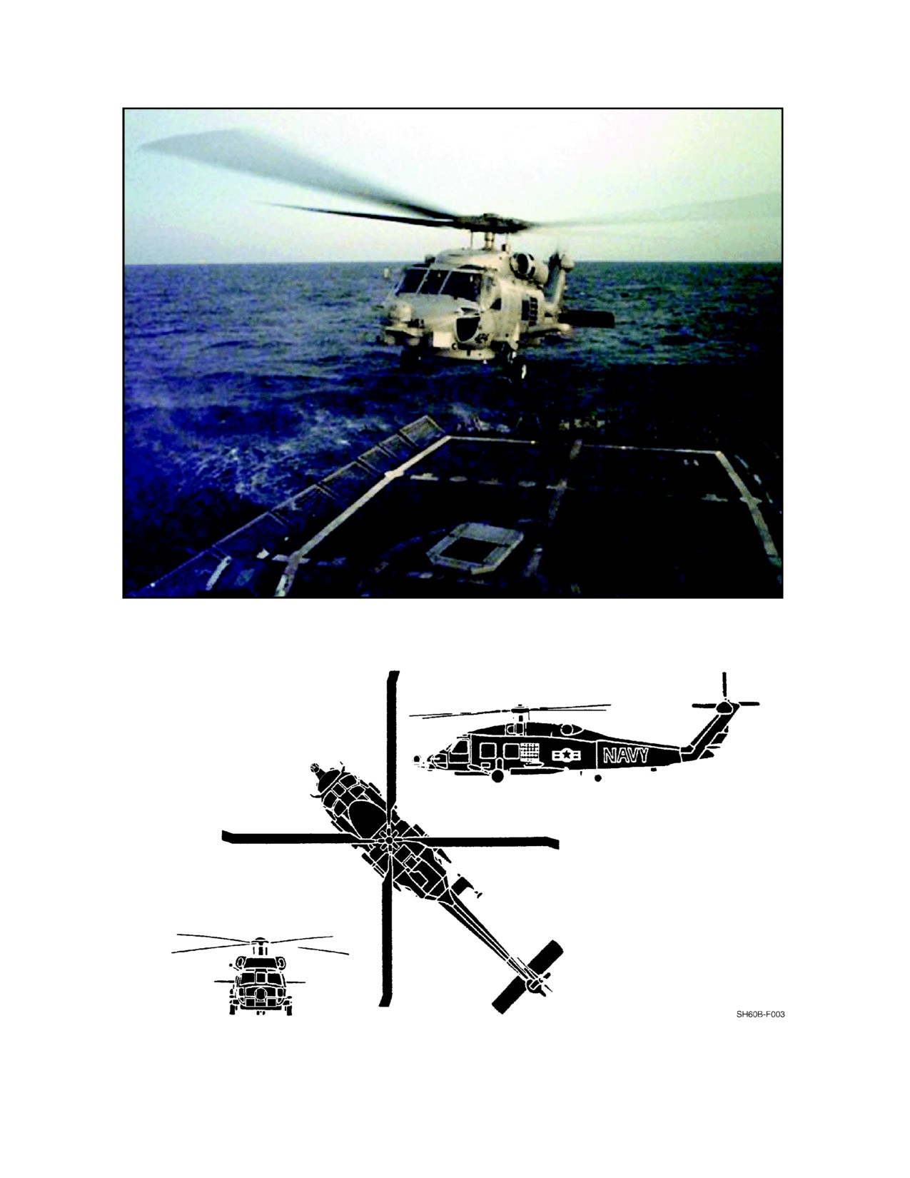
A1-H60BB-NFM--000
53/(54 blank)
ORIGINAL
A1-H60BB-NFM--000
PART I
The Aircraft
Chapter 1 — General Description
Chapter 2 — Systems
Chapter 3 — Servicing and Handling
Chapter 4 — Helicopter Operating Limitations
55/(56 blank)
ORIGINAL
A1-H60BB-NFM-000
CHAPTER 1
General Description
1.1
THE HELICOPTER
The SH--60B (SEAHAWK) is a single main rotor, twin--engine helicopter, manufactured by United Technologies
Corporation, Sikorsky Aircraft Division. The helicopter has a 20° tractor type canted tail rotor, a controllable
stabilator, conventional fixed landing gear, an external cargo hook, a rescue hoist, and bomb racks for carrying and
launching external stores. In addition, it is equipped with a flight--rated auxiliary power unit, a sonobuoy launch
system,ananti--icesystem,afire--extinguishingsystem,anenvironmentalcontrolsystem,anautomaticflightcontrol
system (AFCS), a single--point pressure refueling system, a helicopter in--flight refueling (HIFR) system, and the
necessary avionics and instrumentation for instrument flight and mission accomplishment. The helicopter design is
compatible with ships equipped with a recovery, assist, securing and traversing (RAST) system, and the main rotor
blades and tail pylon can be folded for storage. In addition, the helicopter can operate from non--RAST equipped
combatants and a variety of other naval ships.
1.2
DIMENSIONS
The overall aircraft dimensions and clearances (Figure 1-1 and Figure 1-2) are:
Folded length (rotor/tail pylon)
40 ft, 11 in
Folded length (rotor/tail pylon) (FHS equipped)
42 ft, 10 in
Rotor folded length (pylon flight position)
53 ft, 3 in
Length overall (rotors turning)
64 ft, 10 in
Fuselage length
50 ft, 0 in
Height
17 ft, 0 in
Fuselage width
7 ft, 9 in
Folded width
10 ft, 7 in
Unfolded width (FHS equipped)
13 ft, 0 in
Main rotor diameter
53 ft, 8 in
Tail rotor diameter
11 ft, 0 in
Ground clearance
11.2 in
Ground clearance (FHS equipped)
11 in
Ground to tail rotor clearance
6 ft, 8 in
Turning radius
41 ft, 7 in
Clearance for 180°
84 ft, 0 in
1-1
ORIGINAL
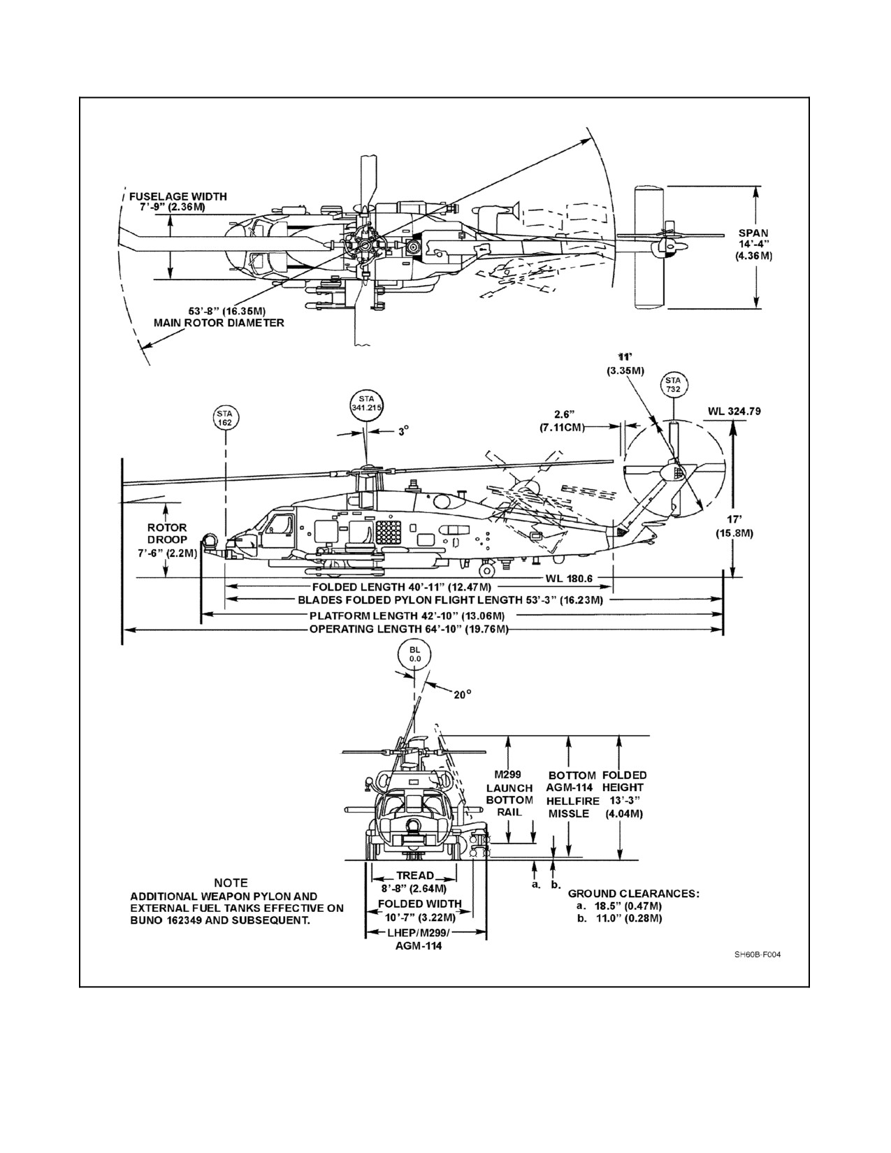
A1-H60BB-NFM-000
Figure 1-1. Principal Dimensions
ORIGINAL
1-2
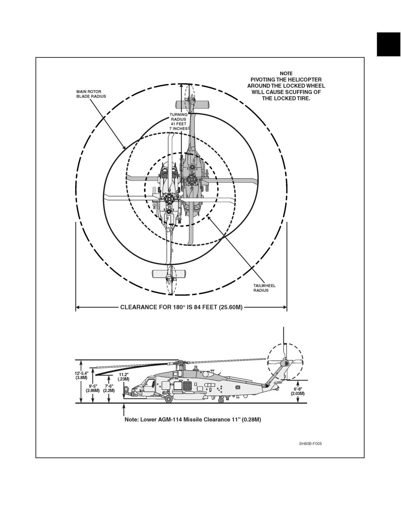
A1-H60BB-NFM-000
Figure 1-2. Ground Clearance and Turning Radius
1-3
ORIGINAL
A1-H60BB-NFM-000
1.3
THE ENGINES
The helicopter is equipped with two T700--GE--401C engines. The T700--GE--401C (Figure 2-1) is a front--drive
turboshaft engine, manufactured by the General Electric Company, Aircraft Engine Group. Some of the features of
theengineincludeanintegralinletparticleseparatorandself--contained systemsincorporating modularconstruction.
At sea level and 59 °F ( 15°C), the T700--GE--401C shaft horsepower ratings are:
Contingency: 2 1/2 Minute Duration
1,940
Intermediate: 30 Minute Duration
1,800
Max Continuous: No limit
1,662
1.4
GENERAL ARRANGEMENT
The following subsections describe the exterior and interior arrangements of the aircraft.
1.4.1 Exterior Arrangement
The exterior arrangement of the aircraft is shown in Figure 1-3. Also shown are thelocations ofthe aircraft antennas.
There are two data link antennas: one forward and one aft on the underside of the aircraft. The search radar antenna
is also located on the underside of the aircraft. Other antennas (UHF/VHF, HF, radar altimeter, TACAN, ESM,
sonobuoy receivers, Doppler, ADF, IFF, and GPS) are located at various points on the helicopter (Figure 1-3).
The left inboard, left outboard, and right weapon pylons accommodate BRU--14/A weapon/stores racks. Fittings for
torpedo parachute release lanyards are located on the fuselage aft of each weapon pylon. Effective on BuNo 162349
and subsequent, the left and right inboard pylons have wiring and tubing provisions for auxiliary fuel tanks. All
pylons have wiring provisions to accommodate the Mk 50 torpedo. A FLIR turret may be mounted on the right hand
pylon or nose mounted bracket. The left outboard weapon pylon can accommodate an M299 Launcher and up to four
AGM--114 Hellfire missiles, or M36E1 CATMs.
The magnetic anomaly detector (MAD) towed body and reeling machine are mounted on a faired structure that
extends from the forward tail--cone transition section on the right side of the aircraft. It is positioned above and aft
of the right weapon pylon.
The sonobuoy launcher is located on the left side of the aircraft, above the left weapon pylon. The sonobuoy launcher
is loaded from ground level outside the aircraft. Sonobuoys are pneumatically launched laterally to the left of the
aircraft.
The airborne RAST system main probe and external cargo hook are on the bottom fuselage centerline, just aft of the
main rotor centerline.
Fuel service connections, for both gravity and pressure refueling, are located on the left side of the aircraft, aft of the
weapon pylons. Dual--engine waterwash is manifolded from a single--point selector valve connector on the left side
of the aircraft above the window of the sensor operator (SO). A connector to service the sonobuoy launcher nitrogen
bottle is located next to the waterwash connector.
The long strokes of both main and tail wheel oleos are designed to dissipatehigh--sink--rate landing energy. Axleand
high--point tiedowns are provided at each main gear. Fuselage attachments are provided above the tail gear for
connection to the RAST tail--guide winch system allowing aircraft maneuvering and straightening aboard ship and
for tail pylon tiedown.
ORIGINAL
1-4
A1-H60BB-NFM-000
1.4.2 Interior Arrangement
Figure 1-4 shows thecockpit and cabin arrangement. Hinged doors on each sideofthecockpit providenormalaccess
to and from that station. A sliding door on the right side of the fuselage provides access to and from the cabin. The
primary emergency escape routes are:
1. Pilot, right--hand jettisonable window.
2. ATO, left--hand jettisonable window.
3. SO, left--hand jettisonable window.
4. Instructor/passenger, jettisonable cabin door window.
The SO console (Figure 1-4) is located in the cabin, as well as provisions for a removable instructor/passenger seat,
a passenger seat, and a litter.
Figure 1-5 shows a diagram of the pilot compartment. The ATO station is located on the left side of the aircraft
cockpit. It is equipped with, or offers access to, a full complement of aircraft flight controls and instruments.
Figure 1-8 illustrates the pilot and ATO instrument panel.
The overhead console (Figure 1-6), located above the pilot and ATO stations, contains aircraft system control panels
involving circuit breakers, console/instrument light controls, external light controls, fire--extinguisher controls,
engine controls, and several miscellaneous controls. The lower console (Figure 1-7) is located in the cockpit between
the pilot and ATO stations. It contains the ATO avionics, AFCS, and communications controls. The lower console is
accessible by either the ATO or the pilot.
The ATO keyset (Figure 1-7) is located on the lower console. The multipurpose display (MPD) is located on the
instrument panel between the ATO flight instrument panel and a caution/advisory panel (Figure 1-8).
The collective on the ATO side telescopes to allow improved cockpit ingress and egress. In addition, locations are
provided in the cabin for two fire extinguishers, two first aid kits, two canteens, a crash ax, a map case, and a backup
messenger kit.
The cabin is arranged with the SO station on the left, facing forward (Figure 1-4). Most of the components of the
avionics system are physically located in the SO console rack, situated aft of the ATO seat, and in the mission avionics
rack (MAR), situated aft of the pilot seat. Figure 1-9 shows the location of the individual panels on the SO console
and the SO keyset. The SO console contains the necessary controls and indicators for the SO to perform the missions
of surface warfare (SUW) and undersea warfare (USW).
To the right of the SO station seat is a seat which accommodates an instructor or a passenger. The primary passenger
seat is in the instructor seat position during single passenger flights. The hoist controls and hover--trim panel are
located adjacent to the cabin door. The cargo hook hatch is located forward of the RAST probe housing.
1.5
MISSION OVERVIEW
LAMPS is the acronym for light airborne multipurpose system. The SH--60B helicopter is configured specifically
in response to the LAMPS requirement of the U.S. Navy. The LAMPS MK III system has been designed to the Navy
sea control mission. In fulfilling the mission, LAMPS MK III will encounter a threat that has many dimensions. The
threat encompasses a hostile submarine fleet and missile--equipped surface ships. The system extends the search and
attack capabilities of LAMPS MK III configured destroyer, frigate, and cruiser platforms, deploying helicopters
directly from these ships.
Theprimary missions oftheLAMPS MK III arethose ofSUW and USW. Aircraft prior to BuNo 162349 arecapable
of theantiship surveillanceand targeting (ASST) and USW roles only. Effectivewith BuNo 162349 and subsequent,
LAMPS MK III Block I aircraft equipped with the FLIR Hellfire system can be used in traditional SUW attack roles.
Secondary missions include search and rescue (SAR), medical evacuation (MEDEVAC), vertical replenishment
(VERTREP), naval surface fire support (NSFS), and communications relay (COMREL). Each of the primary and
secondary missions will be discussed in the following subsections.
1-5
ORIGINAL
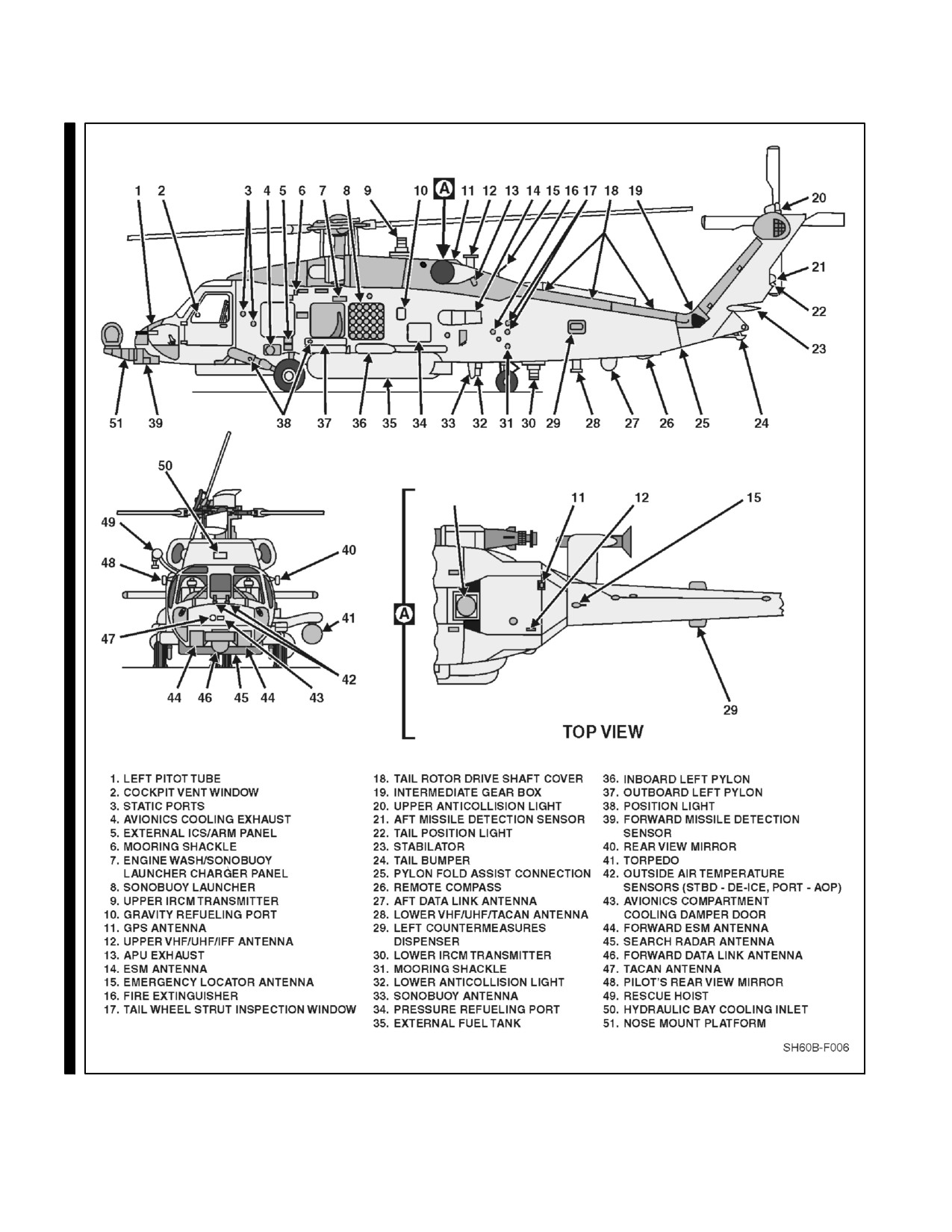
A1-H60BB-NFM-000
9
THERMAL PLUG
Figure 1-3. General Arrangement (Sheet 1 of 2)
ORIGINAL
1-6
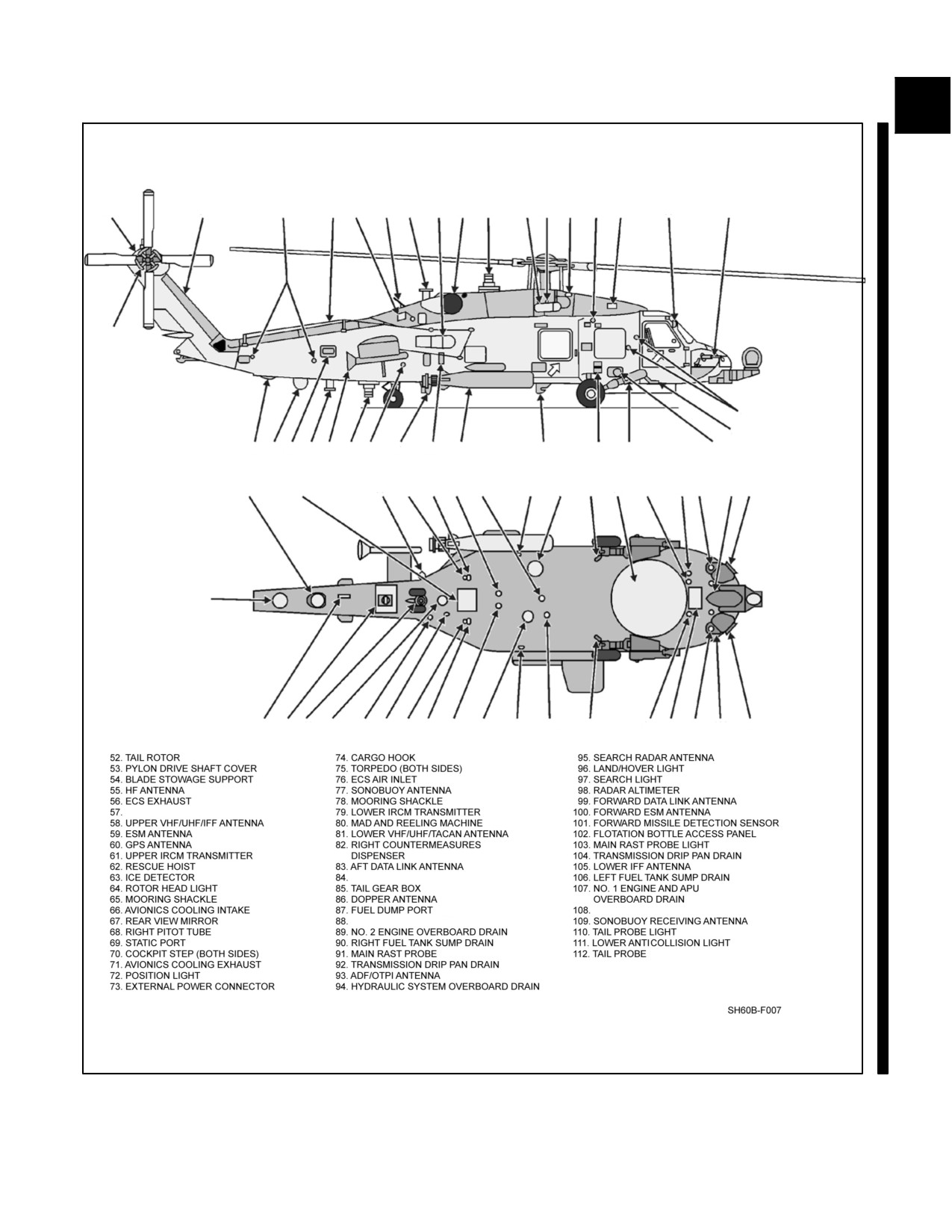
A1-H60BB-NFM-000
52
53
54
5556
5758
59 60
61
626364
65 66
67
68
85
69
70
848382818079
78
77
76
75
74
73
72
71
83
86
87
88 89
90
91
92
93
94
95
96
9798
99
100
84
8179
112 111110 109 108107 106 105
104103
94
96102
98 101 100
EMERGENCY LOCATOR ANTENNA
REMOTE COMPASS
NO. 1 FUEL TANK VENT
NO. 2 FUEL CELL VENT
Figure 1-3. General Arrangement (Sheet 2)
1-7
ORIGINAL
A1-H60BB-NFM-000
1.5.1 Primary Missions
In a USW mission, the aircraft is deployed from the parent ship to classify, localize, and possibly attack a suspected
threat that has been detected by the shipboard towed--array sonar, hull--mounted sonar, or by other internal or external
sources.
When used in an SUW mission, the aircraft provides a mobile, elevated platform for observing, identifying, and
localizing threat platforms beyond the parent shipboard radarand/or electronicsupport measure(ESM) horizon. When
a suspected threat is detected, classification and targeting data are provided to the parent ship via the data link for
surface--to--surface weapon engagement. Hellfire missile equipped aircraft may conduct independent or coordinated
attack, dependent upon the threat and tactical scenario. Refer to NTRP 3--22.4--SH60B for further explanation of
USW and SUW missions.
1.5.2 Secondary Missions
In the VERTREP mission, the aircraft is able to transfer material and personnel between ships, or between ship and
shore. Refer to Chapter 9.
In the SAR mission, the aircraft is designed to search for and locate a particular target/object/ship or plane and to
rescue personnel using the rescue hoist. Refer to SAR Manual (NWP 3--50 Series), JCS 3--50, SAR TACAID
A1--SARBA--TAC--000. Refer to Chapter 9.
In the MEDEVAC mission, the aircraft provides for the medical evacuation of ambulatory and litterbound patients.
In the COMREL mission, the aircraft serves as a receiver and transmitter relay station for over--the--horizon (OTH)
communications between units. Refer to Chapter 15.
In the NSFS mission, the aircraft provides a platform for spotting and controlling naval gunfire from either the parent
ship or other units. Refer to NTTP 3--22.5--ASW.
ORIGINAL
1-8
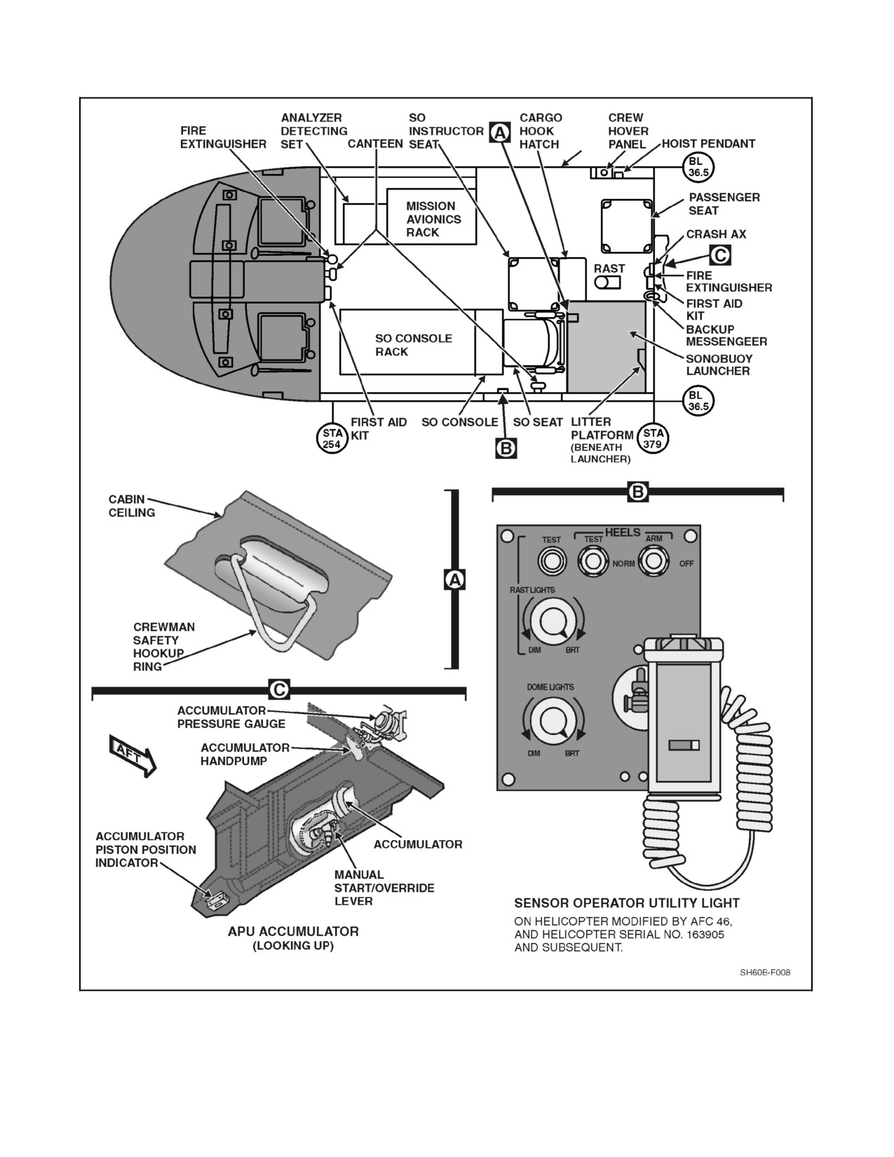
A1-H60BB-NFM-000
DOOR
Figure 1-4. Cabin Arrangement
1-9
ORIGINAL
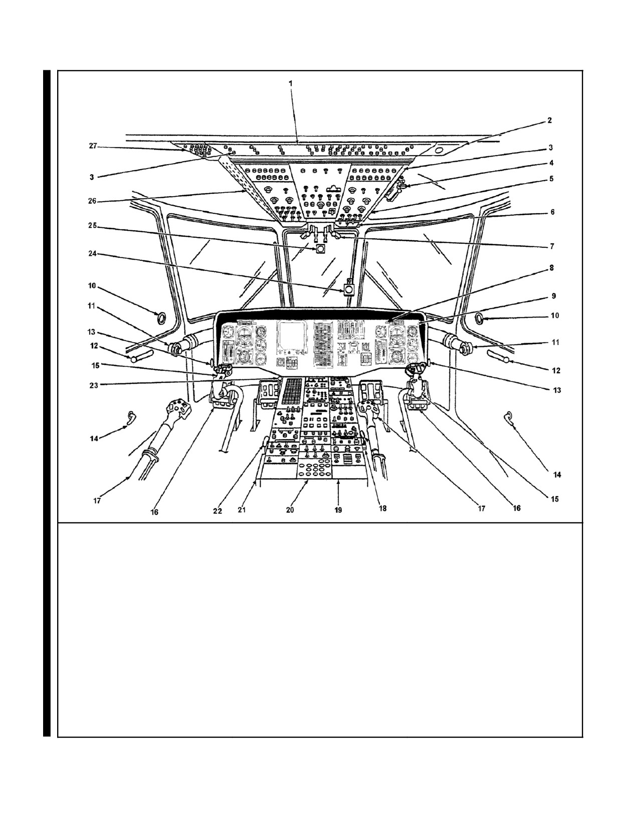
A1-H60BB-NFM-000
1. CENTER CIRCUIT
10. POPOUT AIR VENT
20. BATT UTIL BUS CIRCUIT
BREAKER PANEL
BREAKER PANEL
11. AIRDUCT
2. COCKPIT
21. MAP CASE
12. WINDOW EMERGENCY
SECONDARY/CONSOLE
RELEASE HANDLE
22. RAST EMERGENCY
BREAKER PANEL
RELEASE HANDLE
13. PEDAL ADJUST HANDLE
3. DC ESNTL BUS CIRCUIT
14. INTERIOR DOOR HANDLE
23. NOSE DOOR COOLING
BREAKER PANEL
DAMPER CONTROL
15. CYCLIC GRIP
4. ROTOR BRAKE MASTER
24. STANDBY COMPASS
CYLINDER
16. TAIL ROTOR PEDAL
25. FREE-AIR TEMPERATURE
(TYPICAL)
5. UPPER CONSOLE
INDICATOR
17. COLLECTIVE GRIP
6. STANDBY COMPASS
26. ATO CIRCUIT BREAKER
(TYPICAL)
CORRECTION CARD
PANEL
18. PARKING BRAKE
7. ENGINE CONTROL
27. CORNER CIRCUIT
HANDLE/TAIL WHEEL
QUADRANT
BREAKER PANEL
LOCK SWITCH
8. THREAT INDICATOR
19. LOWER CONSOLE
9. INSTRUMENT PANEL
Figure 1-5. Pilot Compartment
ORIGINAL
1-10
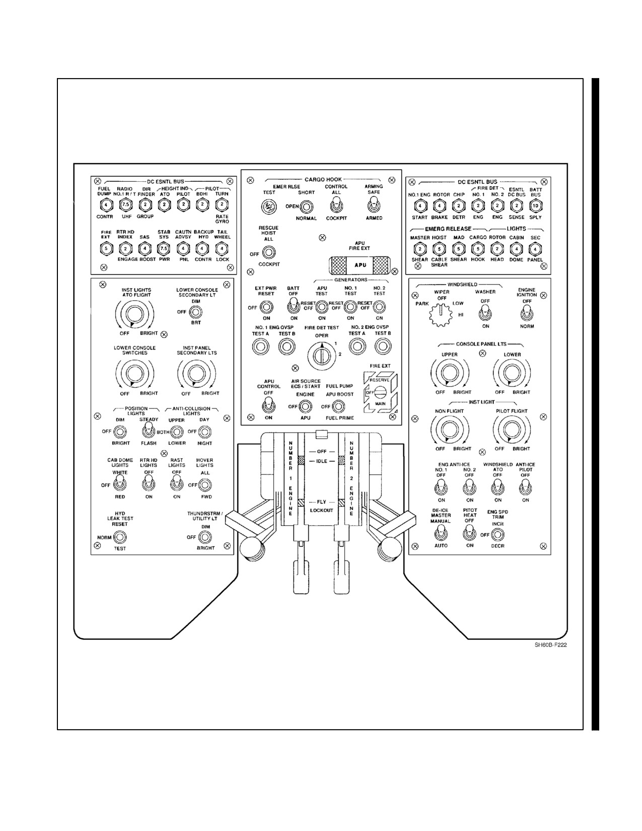
A1-H60BB-NFM-000
Figure 1-6. Overhead Console
1-11
ORIGINAL
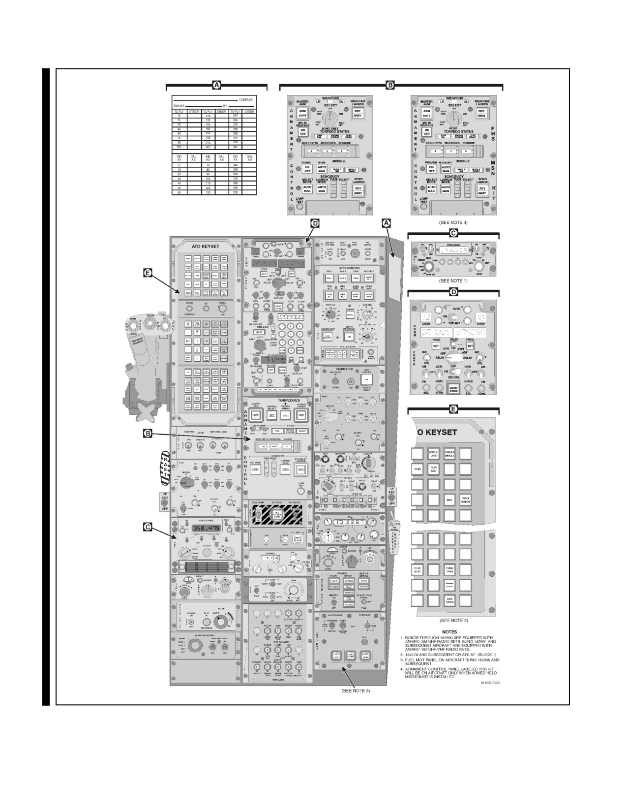
A1-H60BB-NFM-000
Figure 1-7. Lower Console
ORIGINAL
1-12
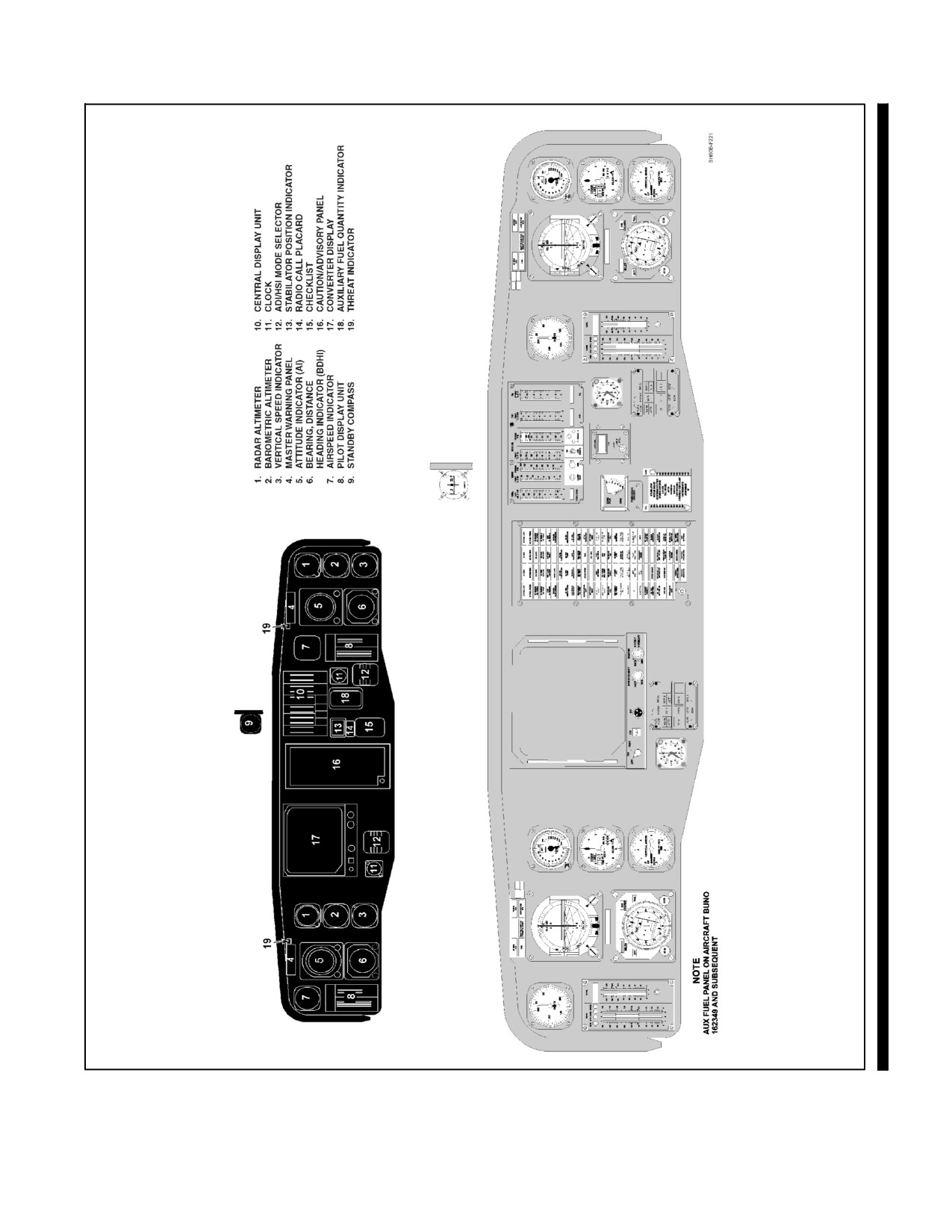
A1-H60BB-NFM-000
Figure 1-8. Instrument Panel
1-13
ORIGINAL
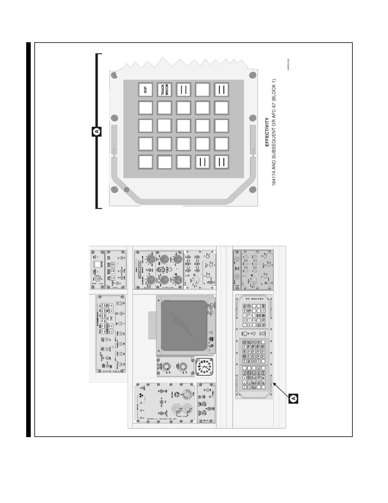
A1-H60BB-NFM-000
Figure 1-9. SO Console
ORIGINAL
1-14
A1-H60BB-NFM-000
CHAPTER 2
Systems
2.1
POWERPLANT SYSTEMS AND RELATED SYSTEMS
2.1.1 Engine
The T700-GE-401C engine (Figure 2-1) is a front-drive, turboshaft engine. It consists of five sections: inlet,
compressor, combustor, turbine, and exhaust. The engine incorporates an integral waterwash manifold, inlet particle
separator (IPS), a top--mounted accessory section, an engine--driven fuel boost pump, a hydro--mechanical control
unit (HMU), an improved digital electronic control unit (DECU), a self--contained lubrication system, engine
condition monitoring and diagnostics provisions.
2.1.1.1 Inlet Section
The inlet section includes the inlet cowling, swirl frame, front frame, main frame, accessory section, and scroll case.
The waterwash manifold is an integral part of the swirl frame, which aims a series of jets into the compressor inlet
area.
2.1.1.2 Inlet Air Flow
Ambient air first passes through the inlet cowling, the inside of which can be heated with fifth stage bleed air via the
inlet anti--ice valve, to prevent ice from forming on the engine inlet. The inlet fairing is also perforated with small
slits, to allow fifth stage bleed air to heat the exposed inlet surface for anti--icing purposes. Next, the intake airflow
passes through the swirl vanes, which impart rotation to the airflow. The swirl vanes are hollow to permit passage
of fifth stage bleed air via the engine anti--ice valve for anti--icing purposes.
2.1.1.3 Inlet Particle Separator
The Inlet Particle Separator (IPS) (Figure 2-2) prevents foreign particles from entering the compressor. The rotation
of the airflow, imparted by the swirl vanes, causes the particles to be thrown outward into the collection scroll. Prior
to being dumped overboard through the blower assembly, the IPS discharge airflow passes over the scroll vanes,
which are contained in the collection scroll.
Clean air, free of foreign particles, then passes through the de--swirl vanes, which remove the rotation imparted by
the IPS, providing smooth airflow to the compressor.
2.1.1.4 Compressor Section
The compressor section consists of a five--stage axial and a single--stage centrifugal rotor/stator assembly.
2.1.1.5 Combustion Section
The combustion section consists of a flow--through, annular combustion chamber, two igniters, and 12 fuel injectors
that receive fuel via the Overspeed and Drain Valve (ODV), supplying atomized fuel for combustion.
2.1.1.6 Gas--Generator Turbine
The Ng turbine drives the compressor and accessory gearbox (AGB). It is a two--stage, air--cooled, high--performance
axial design.
2-1
ORIGINAL
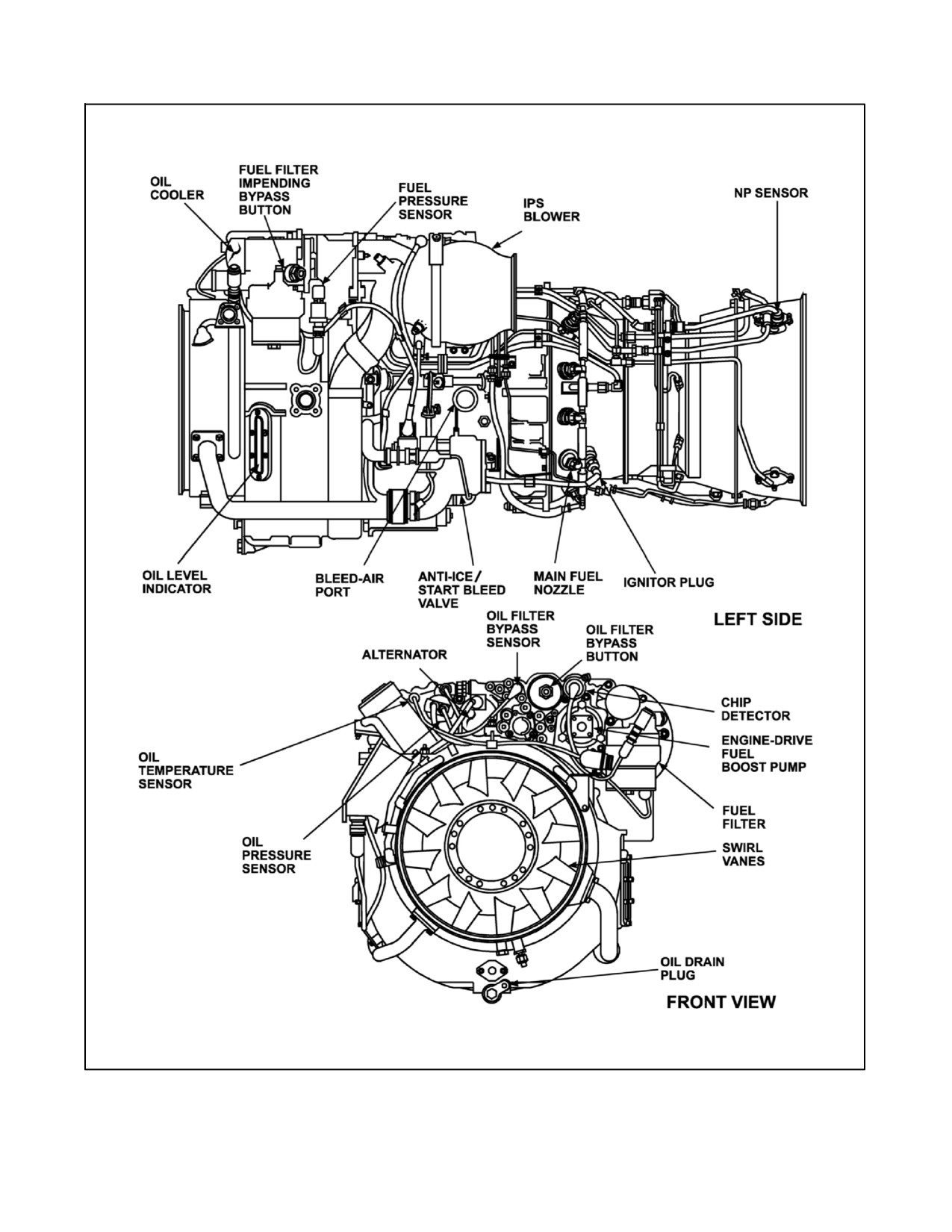
A1-H60BB-NFM-000
Figure 2-1. Engine, T700-GE-401C Profile (Sheet 1 of 3)
ORIGINAL
2-2
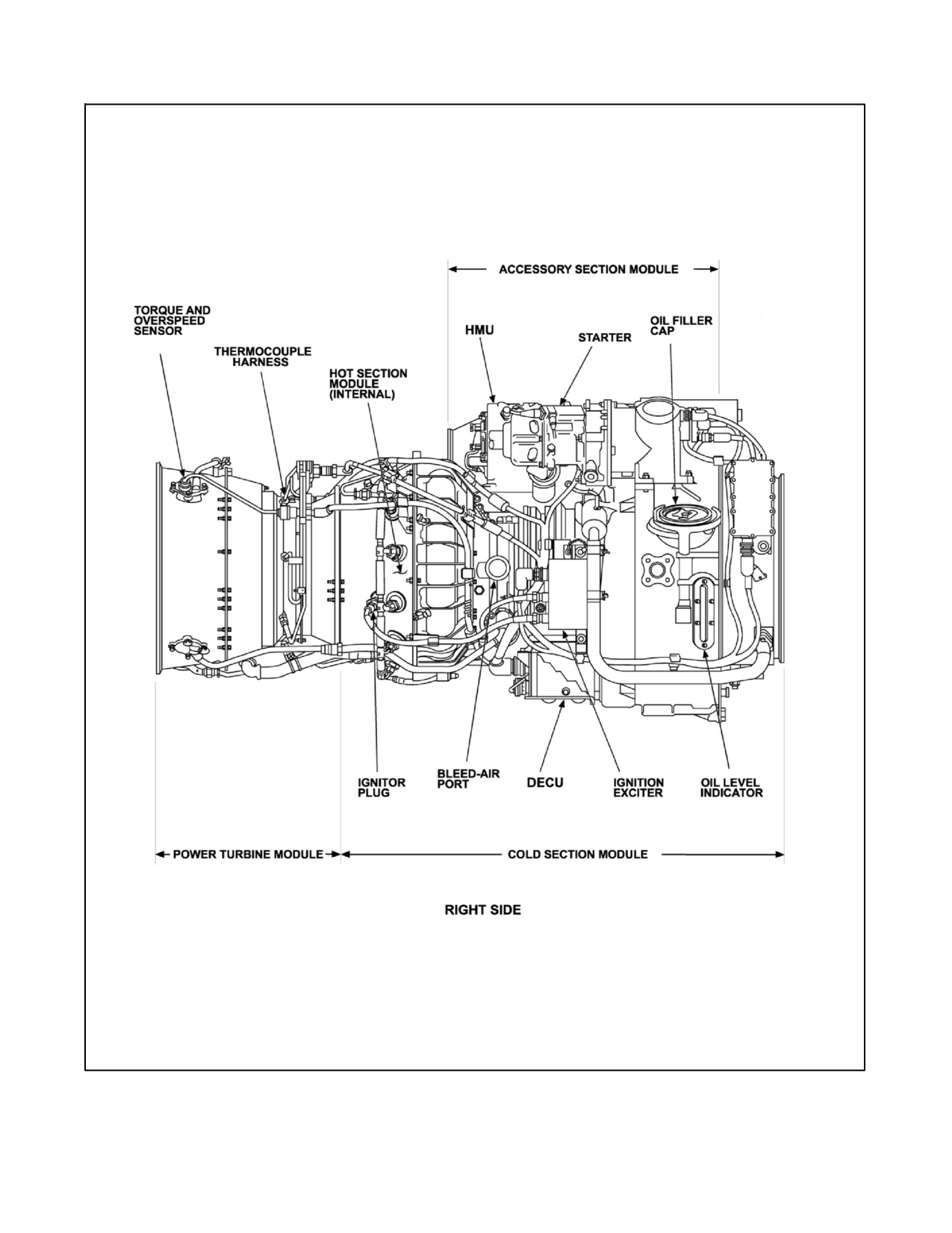
A1-H60BB-NFM-000
Figure 2--1. Engine, T700-GE-401C Profile (Sheet 2)
2-3
ORIGINAL
//////////////////////////