SH-60B HELICOPTER. FLIGHT MANUAL (2008) - page 9
A1-H60BB-NFM-000
CHAPTER 12
Emergency Procedures
WARNINGS
ENG OUT (#1/#2)
12--23
FIRE (#1/#2 ENG)
12--69
FIRE (APU)
12--70
LOW ROTOR RPM
12--33
EMERGENCY PROCEDURES
Abort Start
12--21
AFCS Emergencies
12--50
AN/PEQ--3 Uncommanded Lasing
12--101
APU Emergency Start
12--29
APU Fire
12--70
ASQ--81 MAD Reel Failure with Towed Body Deployed
12--86
ASQ--81 Towed Body Down Limit Switch Malfunction
12--87
ASQ--81 Towed Body Fails to Seat Properly
12--87
Autorotation
12--22
Backup HYD PUMP Fails to Operate
12--49
Boost Servo Hardover
12--50
Cable Grip Rigging Procedures
12--89
Cargo Hook Emergency Release
12--81
Cockpit Fire/Cabin Fire
12--71
Compressor Stall
12--16
Coupler Emergencies
12--50
Crew--Served Weapons
12--97
Damper Failure
12--30
DE--ICE Malfunctions
12--63
Dual--Engine Failure In Flight/Hover
12--22
Electrical System Malfunctions
12--56
Emergency Crash Position
12--77
Engine Advisories
12--27
Engine Air Restart
12--24
Engine Anti--Ice/Start Bleed Valve Malfunction
12--27
Engine Caution Lights
12--19
Engine High--Side Failure In Flight
12--12
Engine High--Side Failure On Deck
12--14
Engine High--Speed Shaft Failure
12--16
Engine Low--Side Failure In Flight
12--14
Engine Malfunctions
12--11
Engine Malfunction During Hover/Takeoff
12--21
Engine Malfunction In Flight
12--12
Engine Oil Temp High
12--19
Engine Power Control Failure
12--12
Engine Shutdown In Flight
12--24
Engine Torque or TGT Spiking/Fluctuations
12--15
Excess Tail Rotor Thrust
12--40
External Engine Fire
12--69
Fire Emergencies
12--69
12-1
ORIGINAL
A1-H60BB-NFM-000
FLIR Uncommanded Lasing
12--95
Fuel System Malfunctions
12--66
GAU--16/A Clear Weapon Procedures
12--101
GAU--16/A Cook--Off
12--99
GAU--16/A Emergencies
12--99
GAU--16/A Jammed Gun
12--99
GAU--16/A Runaway Gun
12--100
Ground Resonance
12--30
Hellfire Missile Aborted Launch
12--91
Hellfire Missile Emergencies
12--91
Hellfire Missile Hangfire
12--92
Hellfire Missile Misfire
12--94
Hellfire Missile Unlatched
12--95
Hung Droop Stop(s)
12--33
Hung Sonobuoy/SLC
12--96
Hung Torpedo
12--95
Hydraulic System Malfunctions
12--42
Immediate Landing/Ditching
12--73
Immediate Landing/Ditching (Aircrewmen)
12--79
Immediate Landing/Ditching (Pilot)
12--78
Insufficient Tail Rotor Thrust
12--39
Internal Engine Fire
12--70
Load Demand System Malfunction
12--17
Loss of Tail Rotor Control
12--41
Loss of Tail Rotor Control Approach and Landing Technique
12--39
Loss of Tail Rotor Control Malfunctions
12--38
Loss of Tail Rotor Drive
12--36
Loss of Tail Rotor Drive Altitude and Airspeed Not Sufficient to
Establish Autorotation
12--38
Loss of Tail Rotor Drive Altitude and Airspeed Sufficient to
Establish Autorotation
12--37
Lost Aircraft Procedures (Open Ocean)
12--79
M60D/M240D Clear Weapon Procedures
12--99
M60D/M240D Cook--Off
12--97
M60D/M240D Emergencies
12--97
M60D/M240D Failure to Fire/Jammed Gun
12--98
M60D/M240D Runaway Gun
12--98
Main Rotor System Emergencies
12--30
Main Transmission Malfunction
12--35
Master Caution Light
12--6,
12--11
Miscellaneous Caution/Advisories
12--90
Mission Equipment/Weapon System Emergencies
12--81
NO. 1 Hydraulic System Malfunction
12--44
NO. 2 Hydraulic System Malfunction
12--46
No HIFR/Stuck Main Tank Shutoff Valve
12--68
Pilot Assist Servo Leak
12--47
Pilot Assist Servo Malfunction
12--48
Planned Ditching
12--77
#1 Primary Servo or #1 Transfer Module Leak
12--45
#2 Primary Servo or #2 Transfer Module Leak
12--47
PWR MAIN RTR and/or PWR TAIL RTR Light On
12--63
ORIGINAL
12-2
A1-H60BB-NFM-000
RAST Backup Messenger Cable Employment
12--82
RAST Cable Emergency Release
12--83
RAST Main Probe Fails to Extend
12--84
RAST Main Probe Fails to Retract
12--85
RAST Main Probe Messenger Failure
12--81
RAST Messenger Jettison
12--82
Refueling Hose Jettison (HIFR)
12--68
Rescue Hoist Cable Cut
12--90
Rescue Hoist Cable Separation
12--90
Rescue Hoist Failure
12--88
Rescue Hoist Fouled Cable
12--89
Restricted Flight Controls
12--39
Rotor Overspeed
12--34
Runaway Hoist
12--89
Selective Jettison of M299 Launcher
12--96
Single--Engine Failure
12--23
Single--Engine Landing
12--25
Smoke and Fumes Elimination
12--72
Sonobuoy Lithium Battery Venting
12--72
Stabilator Auto Mode Failure
12--54
Stabilator Indicating System Failure
12--56
Stabilator Malfunctions
12--54
Stores Emergencies
12--96
Tail/Intermediate Transmission Malfunction
12--36
Tail Rotor Control Cable Failures
12--38
Tail Rotor Servo Failures
12--38
#1 Tail Rotor Servo Leak
12--45
#1 Tail Rotor Servo Leak without #1 RSVR LOW
12--46
Tail Rotor System Malfunctions
12--36
Torpedo Emergencies
12--95
Total AC Power Failure/Dual Generator Failure
12--59
Transmission System Malfunctions
12--35
Uncommanded Fuel Dumping
12--69
Underwater Egress
12--80
Unusual Attitude Recovery
12--56
Unusual Vibrations
12--30
Unusual Vibrations In Flight
12--31
Unusual Vibrations On Deck
12--32
CAUTIONS
AC ESS BUS OFF
12--59
AFCS DEGRADED
12--47
APU FAIL
12--29
APU GEN
12--29
APU OIL TEMP HI
12--30
AUX FUEL XFER FAULT
12--67
BACKUP RSVR LOW
12--44
BATTERY FAULT
12--61
BATTERY LOW CHARGE
12--62
BOOST SERVO OFF
12--47
CHIP ACCESS -- LH/RH
12--35
CHIP INT XMSN
12--36
12-3
ORIGINAL
A1-H60BB-NFM-000
CHIP MAIN MDL SUMP
12--35
CHIP TAIL XMSN
12--36
CONV (#1/#2)
12--59
DC ESS BUS OFF
12--61
ECS SHUTDOWN
12--20
ENG CHIP (#1/#2)
12--20
ENG OIL PRESS (#1/#2)
12--20
ENG OIL TEMP (#1/#2)
12--19
FUEL FLTR BYPASS (#1/#2)
12--66
FUEL LOW (#1/#2)
12--67
FUEL PRESS (#1/#2)
12--66
GEN (#1/#2)
12--60
GEN BRG (#1/#2)
12--60
GUST LOCK
12--33
#2 HYD PUMP
12--47
HYD PUMP FAILURE (#1/#2)
12--43
ICE DETECT FAIL
12--64
ICE DETECTED
12--63
IFF FLASHING CAUTION
12--90
INPUT LH/RH CHIP
12--36
INT XMSN OIL TEMP
12--36
LAUNCH/JETT FAIL
12--97
MAD LIMIT
12--87
MAIN XMSN OIL PRESS
12--35
MAIN XMSN OIL TEMP
12--35
MR DE--ICE FAIL
12--65
MR DE--ICE FAULT
12--65
OIL FLTR BYPASS (#1/#2)
12--19
PITOT HEAT (LFT/RT)
12--64
PRI SERVO PRESS (#1 OR #2)
12--43
PUMP/VALVE FAIL
12--67
RACK FAN (LEFT/RIGHT)
12--90
#1 RSVR LOW
12--45
#2 RSVR LOW
12--47
SAS
12--47
SPREAD INCOMPLETE
12--34
STABILATOR
12--54
TAIL ROTOR QUADRANT
12--42
#1 TAIL RTR SERVO
12--45
#2 TAIL RTR SERVO
12--46
TAIL XMSN OIL TEMP
12--36
TR DE--ICE FAIL
12--65
ADVISORIES
ALT
12--53
BACKUP PUMP ON
12--43
ENG ANTI--ICE ON (#1/#2)
12--27
ENG INLET ANTI--ICE ON (#1/#2)
12--28
ENG STARTER (#1/#2)
12--28
ROTOR BRAKE
12--34
WOW
12--91
#2 TAIL RTR SERVO ON
12--45
ORIGINAL
12-4
A1-H60BB-NFM-000
12.1
INTRODUCTION
The emergency situations and procedures outlined in this chapter cover the common types of emergencies
encountered; however, the procedures used during an actual emergency must result from careful consideration of the
complete situation. Compound emergencies may require departure from the normal corrective procedures set forth
by any specificemergency. Dueto thevaried types ofequipment installed, pilots and aircrewmenmust bethoroughly
familiar with the emergency procedures in this chapter. The terms land as soon as practical, Land As Soon As
Possible, and LAND IMMEDIATELY, refer to the degree of urgency with which a landing must be made and are
not meant to preclude the use of sound judgment during these situations.
The PAC shall complete the immediate action items that do not require releasing the flight controls.
The PNAC shall:
1. Assist in ensuring the continued safe flight of the aircraft.
2. Perform the immediate action items that do not involve the flight controls.
3. Use the pocket checklist to complete non--immediate action items.
4. Troubleshoot as required.
The aircrewman shall:
1. Provide the pilots with verbal calls as necessary to ensure the continued safe flight of the aircraft.
2. Complete the applicable immediate action items.
3. Utilize the pocket checklist to complete the remaining non--immediate action items.
4. Back up the pilots with the pocket checklist to the maximum extent possible.
5. Assist the PNAC with troubleshooting.
Note
The urgency of certain emergencies requires immediate and instinctive
action by the PAC. The most important single consideration is helicopter
control. All procedures are subordinate to this requirement.
The following should be performed for all emergencies:
1. Maintain control of the aircraft.
2. Alert Crew.
3. Determine the precise nature of the problem.
4. Complete the applicable emergency procedure or take action appropriate for the problem.
5. Determine landing criteria and land as required.
Due to possibility of rapid degradation or loss of aircraft control during certain emergencies, the PIC should ensure
all aircrew are strapped into their seats with shoulder harnesses locked at all times during ground or flight operations,
except when release of the seat belt is required to perform mission- or flight-related functions.
12-5
ORIGINAL
A1-H60BB-NFM-000
CAUTION
A thorough analysis should be conducted prior to resetting circuit breakers
in flight. Energizing faulty electrical circuits may induce further
degradation, failure, or loss of flight and mission displays.
Note
In an NVD operating environment, it is recommended that the entire crew
remain goggled and initiate the required immediate action procedures.
12.1.1 Explanation of Terms
Procedures indicated by an asterisk (*) are considered Critical Memory Items (CMIs). These steps must be performed
immediately, without reference to the checklist.
LAND IMMEDIATELY: Execute a landing without delay. The primary consideration is to ensure the survival of
the occupants.
Land As Soon As Possible: Execute a landing at the first site at which a safe landing can be made.
Land as soon as practical: Extended flight is not recommended. The landing site and duration of flight are at the
discretion of the PIC.
12.1.2 WARNING, CAUTIONS and ADVISORIES
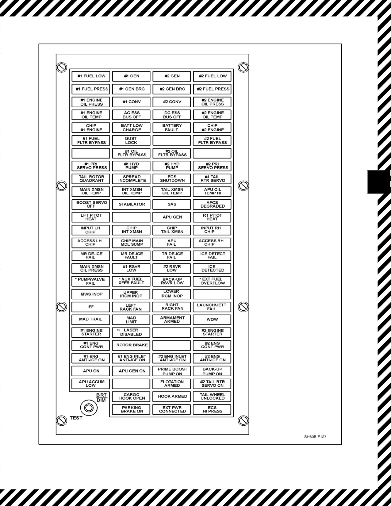
Warning, caution and advisory (WCA) information is provided visually to the pilots by a red warning, amber caution
and green advisory lights. These lights are located on the master warning and caution/advisory panels on the
instrument panel. See Figure 12-1 through Figure 12-4.
12.1.3 Master Caution Light
The MASTER CAUTION light (Figure 12-4) illuminates to alert the pilots of a caution activation. In response to
the light, the pilot will note the applicable caution and press the MASTER CAUTION light to reset it.
Note
D Reset MASTER CAUTION aftereach malfunction to allow the systems to
respond to subsequent malfunctions.
D MASTER CAUTION light illumination with no corresponding caution
light may be an indication of a malfunctioning intermediate transmission
and/or tail gearbox chip detector.
12.1.4 Pocket Checklists (PCLs)
The Pilot PCL (A1--H60BB--NFM--500) and Aircrew PCL (A1--H60BB--NFM--800) include selected emergency
procedures, cautions, and advisories from this chapter. These PCLs contain only the text listed under the LEGEND
column and the CORRECTIVE ACTION columns of this chapter. Text located in the CAUSE/REMARKS column
of this chapter does not appear in the PCLs.
12.1.5 Circuit Breaker Numbering Convention
All circuit breakers referenced in emergency procedures have a labeling convention that reads top to bottom, left to
right with circuit breaker NO. 1. beginning at the left of the respective panel and includes any missing or covered
circuit breaker spaces as part of the count.
ORIGINAL
12-6
A1-H60BB-NFM-000
MWS FAIL
*AIRCRAFT BuNo 162349
AND SUBSEQUENT
**LASER DISABLED
ADVISORY INDICATOR
WILL BE PRESENT ON
AIRCRAFT ONLY WHEN
ARMED HELO
MODIFICATION IS
INSTALLED
Figure 12-1. Caution/Advisory Panel
12-7
ORIGINAL
A1-H60BB-NFM-000
LEGEND
DESCRIPTION
#1 FUEL LOW (or) #2 FUEL LOW
Low fuel state (200 to 225 pounds) in respective fuel cell.
#1 FUEL PRESS (or) #2 FUEL PRESS
Low fuel pressure from respective engine-driven boost pump
(faulty pump or air leak).
#1 FUEL FLTR BYPASS (or) #2 FUEL FLTR
Respective fuel filter is in bypass.
BYPASS
#1 OIL FLTR BYPASS (or) #2 OIL FLTR
Respective engine oil filter is bypassing.
BYPASS
#1 ENGINE OIL TEMP (or) #2 ENGINE OIL
Respective engine oil temperature is high.
TEMP
#1 ENGINE OIL PRESS (or) #2 ENGINE
Low oil pressure at outlet of respective engine oil filter.
OIL PRESS
CHIP #1 ENGINE (or) CHIP #2 ENGINE
Chip or metal particles in respective engine.
APU OIL TEMP HI
APU oil temperature has exceeded limits.
APU FAIL
APU has failed to start due to a start sequence failure or has
automatically shut down due to a monitored parameter being
exceeded during operation with the exception of high oil
temperature or a shorted thermocouple probe.
GUST LOCK
Blade indexing motor has been engaged.
SPREAD INCOMPLETE
SPREAD status light is ON and (1) pylon and/or stabilator panel
not spread and locked and/or (2) tail indexer not retracted and/or
(3) AC power routed to sliprings.
MAIN XMSN OIL PRESS
Main transmission oil pressure is low.
MAIN XMSN OIL TEMP
Main transmission oil temperature is high.
CHIP MAIN MDL SUMP
Chip in main gearbox sump.
ACCESS LH CHIP (or) ACCESS RH CHIP
Chip is detected in applicable accessory module.
INPUT LH CHIP (or) INPUT RH CHIP
Chip is detected in applicable input module.
TAIL ROTOR QUADRANT
One or both cables leading to tail rotor quadrant is broken.
#1 TAIL RTR SERVO
Low pressure at first stage pressure switch on tail rotor servo.
CHIP TAIL XMSN
Chip detected in tail gearbox.
CHIP INT XMSN
Chip detected in the intermediate gearbox.
TAIL XMSN OIL TEMP
High oil temperature in tail gearbox.
INT XMSN OIL TEMP
High oil temperature in the intermediate gearbox.
#1 RSVR LOW (or) #2 RSVR LOW
Fluid level in applicable hydraulic pump module is low.
#1 HYD PUMP (or) #2 HYD PUMP
Low pressure at outlet of applicable hydraulic pump.
BACK-UP RSVR LOW
Fluid level in backup pump module is low.
#1 PRI SERVO PRESS (or) #2 PRI SERVO
Low pressure or servo jam at any or all primary servos of
PRESS
applicable stage.
BOOST SERVO OFF
Collective and/or yaw boost servo pressure is low or boost servo
is jammed.
SAS
Loss of hydraulic pressure to SAS actuators or loss of electrical
power to both SAS-1 and SAS-2.
STABILATOR
Stabilator reverted to manual mode.
AFCS DEGRADED
Failure of one or more modes of DAFCS computer (flashing) or
DAFCS computer power loss (steady).
Figure 12-2. Caution Light Matrix (Sheet 1 of 2)
ORIGINAL
12-8
A1-H60BB-NFM-000
LEGEND
DESCRIPTION
ECS SHUT DOWN
ECS has shut down due to CONTGCY PWR being selected,
heating duct overtemperature, or one of the following with the AIR
SOURCE ECS/START switch in ENGINE position: (1) either
engine TGT approximately 839 ±6 °C, (2) either ENG ANTI-ICE
switch on, (3) ICE detected with DE--ICE MASTER in AUTO, or
(4) when an underpressure situation exists.
#1 GEN (or) #2 GEN (or) APU GEN
Respective generator not supplying power to buses. Operative
generator selected OFF; failure of generator, GCU, contactor, or
wiring fault.
#1 GEN BRG (or) #2 GEN BRG
Generator main bearing is worn or has failed.
AC ESS BUS OFF
AC ESS BUS not powered.
#1 CONV (or) #2 CONV
Failure of AC source(s) or respective converter or DC bus.
DC ESS BUS OFF
DC ESS BUS not powered.
BATT LOW CHARGE
Battery is at or below a 40 percent state of charge.
BATTERY FAULT
Battery overtemperature or cell dissimilarity.
ICE DETECTED
Ice has been detected by ice detector.
ICE DETECT FAIL
Ice detector or icing rate signal converter has failed.
RT PITOT HEAT (or) LFT PITOT HEAT
Low heat or no heat on pitot tubes.
MR DE-ICE FAULT
Loss of electrical power (any phase) or open circuit on any MRB
heating zone element (system will operate in degraded mode).
MR DE-ICE FAIL
Open circuit to any MRB heating element or a short circuit from
phase to phase of the blade de--ice power lines (system will
automatically turn off).
TR DE-ICE FAIL
Total open circuit to TRB heating elements or a short circuit from
phase to phase of the blade de--ice power lines (TR DE--ICE will
automatically turn off).
LEFT RACK FAN (or) RIGHT RACK FAN
High temperature in SO console or in MAR.
LAUNCH/JETT FAIL
Armament component has failed power-on BIT. Armament may
not be able to be armed/launched. Additionally, jettison functions
may also be inoperative.
IFF
Flashing — Transponder has not responded to a valid Mode 4
interrogation.
Steady — KIT 1 series not keyed.
MWS INOP
System not used in this configuration. Illuminates during test only.
UPPER IRCM INOP
Upper ALQ-205 IRCM transmitter is inoperative (ESP only).
LOWER IRCM INOP
Lower ALQ-205 IRCM transmitter is inoperative (ESP only).
MWS FAIL
System not used in this configuration. Illuminates during test only.
PUMP/VALVE FAIL
Failure of element(s) of dual transfer/shutoff valves or dual
transfer pumps.
AUX FUEL XFER FAULT
Total failure of dual transfer/shutoff valves, or dual transfer
pumps, or FMCP logic.
EXT FUEL OVERFLOW
Fuel in external tank vent line.
Figure 12-2. Caution Light Matrix (Sheet 2)
12-9
ORIGINAL
A1-H60BB-NFM-000
LEGEND
DESCRIPTION
MAD TRAIL
Indicates when the MAD towed body is not in the stowed position
(MSN PWR is set to PRI), or when MAD reeling machine control
power switch is set to ON (MSN PWR is set to OFF or SEC).
MAD LIMIT
Steady illumination when the MAD bird is deployed to maximum
limit. Flashes if the MAD stops inadvertently at any intermediate
position. Light is extinguished when the MAD is traveling normally
between limits. The MAD Limit capsule on will appear dimmer
than other capsules when the panel is in DIM mode.
ARMAMENT ARMED
Lighted when aircraft has weight off wheels and MASTER ARM
switch ON.
WOW
Aircraft has weight on wheels.
LASER DISABLED
Indicates the Interlock Switch Assembly LASER ENABLE/
DISABLE switch, located in the nose bay, is in the DISABLE
position.
#1 or #2 ENG CONT PWR
Indicates contingency power has been selected.
ROTOR BRAKE
Rotor brake ON.
#1 or #2 ENG ANTI-ICE ON
The respective engine anti-ice valve has opened. Lights will be on
during start to approximately 90 percent Ng or when ENG
ANTI-ICE switch is turned ON.
#1 or #2 INLET ANTI-ICE ON
Engine bleed air has heated the engine inlet to 93 °C or greater.
#1 or #2 ENGINE STARTER
Respective engine starter valve is open.
APU ON
The APU is ON and operating normally.
APU GEN ON
The APU AC electrical generator is on and operating normally and
is the only supply of power to the AC distribution system.
PRIME BOOST PUMP ON
The FUEL PUMP switch is in the APU BOOST or FUEL PRIME
position.
BACK-UP PUMP ON
Indicates the backup pump is operating and at normal pressure.
APU ACCUM LOW
Indicates the APU accumulator pressure is below 2,650 ±50 psi.
FLOTATION ARMED
System not used in this configuration. Illuminates during test only.
#2 TAIL RTR SERVO ON
The second stage of the tail rotor servo is on and at normal pres-
sure.
CARGO HOOK OPEN
Indicates the cargo hook load beam is not latched.
HOOK ARMED
Indicates the cargo hook electrical release system is armed.
TAIL WHEEL UNLOCKED
Indicates the tail wheel lockpin has disengaged from the tail wheel
lock assembly.
PARKING BRAKE ON
Indicates the parking brake handle has been pulled up.
EXT PWR CONNECTED
Indicates AC external power is connected to the aircraft and DC
power is on the battery bus.
ECS HI PRESS
Indicates the overpressure switch in the bleed-air line is sensing a
high-pressure condition to the air-cycle machine.
Figure
12-3. Advisory Light Matrix
ORIGINAL
12-10

A1-H60BB-NFM-000
LEGEND
LIGHTING PARAMETER OR FAULT
#1 ENG OUT
Indicates the NO. 1 engine Ng speed is ≤55 percent.
FIRE
Indicates a fire detector has actuated a fire-warning circuit.
MASTER CAUTION
Indicates a caution light on the caution panel has been actuated by a failed system.
PRESS TO RESET
#2 ENG OUT
Indicates the NO. 2 engine Ng speed is ≤55 percent.
LOW ROTOR RPM
Indicates the rotor speed is ≤96 percent Nr.
Figure 12-4. Master Warning Panel
12.2
ENGINE MALFUNCTIONS
A thorough preflight brief, discussing immediate actions and engine performance computations, will significantly
increase the flight crew’s ability to respond to an engine malfunction.
The engine instruments often provide ample warning of a malfunction before actual engine failure. Indications of
an engine failure include changes in engine torque, Ng, TGT, Np, and the ENG OUT warning light. Pilot action
following a single--engine malfunction will depend upon altitude, airspeed, gross weight, phase of flight,
single--engine capability, and environmental conditions. The term single--engine condition is defined as a flight
regime that permits sustained flight with one engine inoperative (OEI). Establishing single--engine conditions may
include increasing power available (turning contingency power on and engine anti--ice off), decreasing power
required (dumping fuel and jettisoning cargo), and achieving single--engine airspeed. This envelope must be
maintained until landing.
Additionally, establishing single--engineconditions may requirevarious flight control adjustments as dictated by the
flight regime when the engine malfunction occurs. For example, a high DA/low airspeed flight envelope may require
the collective to be lowered to control Nr.
If an engine fails while hovering in ground effect, the helicopter should be kept in a level attitude with collective
position maintained. Forward flight at low altitudes, where single--engine capability is not possible, may require
setting a decelerating attitude to decrease airspeed and build Nr to cushion the landing. If airspeed is low and altitude
permits, an attempt to achieve single--engine airspeed may be made by lowering the nose; however, extreme nose
low attitudes should be avoided due to the high rates of descent that may develop.
During night overwater operations when adequate altitude or visual cues are lacking, a deliberate water landing may
be preferable to inadvertent impact and should be considered. During flight regimes that permit a significant
reduction in collective, Nr can be restored to 100 percent before landing. Airspeed should be optimized for the existing
conditions (single--engine flight or autorotational descent). Power requirements for level flight are minimized when
the aircraft is established at approximately 70 KIAS in awings--level attitude. Refer to the Height--Velocity Diagram
(Figure 4-4) and the Ability to Maintain Level Flight, Single Engine Chart (Figure 27-1).
Execute the Immediate Landing/Ditching emergency procedure when sustained single--engine flight capability does
not exist.
12-11
ORIGINAL
A1-H60BB-NFM-000
A decrease in Nr will reduce the efficiency of the tail rotor, potentially
resulting in an uncommanded right yaw.
12.2.1 Engine Malfunction In Flight
Any suspected engine malfunction that manifests itself with fluctuations in Np, Nr, and/or torque should be handled
initially with the Engine Malfunction in Flight emergency procedure. Following malfunction identification, refer to
the appropriate emergency procedure. Establishing single--engine conditions involves placing the aircraft in the
optimum configuration and flight regime to operate with one engine inoperative (OEI). This includes, but is not
limited to, establishing single--engine airspeed and reducing angle of bank.
Engine Malfunction In Flight
LEGEND
CAUSE/REMARKS
CORRECTIVE ACTION
Engine
*1. Control Nr.
Malfunction
In Flight
Flying at an airspeed greater than 105 KIAS with one
engine inoperative may result in unrecoverable
decay of Nr in the event of a dual--engine failure.
*2. CONTGCY PWR switch — ON.
*3. Single--engine conditions — Establish.
*4. ENG ANTI--ICE switches — OFF, as required.
With engine anti--ice on, up to 18 percent torque
available is lost. Torque may be reduced as much as
49 percent with improperly operating engine inlet
anti--ice valves.
*5. External cargo/stores/fuel — JETTISON/DUMP,
as required.
*6. Identify malfunction.
12.2.2 Engine Power Control Failure
Engine control system malfunctions may produce high or low torque conditions. This can result in Nr increasing or
decreasing from normal selected speed. It is possible that the malfunction can also result in loss of or erroneous
torque, Ng, TGT and/or Np indication on the malfunctioning engine.
12.2.2.1 Engine High--Side Failure In Flight
If Np and Nr increase above normal selected speed, identify the malfunctioning engine by comparing Ng’s, TGTs,
and torques. It is possible that one or more of these indications may be erroneous or absent. The engine with the higher
Ng, TGT, or torque should be manually controlled using the following procedure.
ORIGINAL
12-12
A1-H60BB-NFM-000
Engine High--Side Failure In Flight
LEGEND
CAUSE/REMARKS
CORRECTIVE ACTION
Engine
*1.
Engine Malfunction in Flight emergency
CAUTION
High--Side Failure
procedure — PERFORM.
In Flight
*2.
PCL (malfunctioning engine) — RETARD TO
If an Np overspeed con-
SET:
dition is reached
(120
a. Torque 10% below good engine or
percent), the overspeed
system will flameout the
b. Matched Ng or
engine and the autoigni-
c. Matched TGT.
tion system will relight the
3.
Land as soon as practical.
engine. If Nr is not
controlled and Np acceler-
ates back to 120 percent,
the Np overspeed system
will flameout the engine
again and the autoignition
system will reset the
ignitor five-second timer.
The Np overspeed/ auto-
ignition system will contin-
ue cycling until Nr/Np is
controlled. A yaw kick
may be experienced each
time the engine relights.
Note
With high collective set-
tings, Nr may increase
slowly, making high--side
failure confirmation difficult.
Reducing collective will re-
veal increasing Nr and verify
high--side failure.
12-13
ORIGINAL
A1-H60BB-NFM-000
12.2.2.2 Engine High--Side Failure On Deck
Engine High--Side Failure On Deck
LEGEND
CAUSE/REMARKS
CORRECTIVE ACTION
Engine High--Side
*1. PCLs — IDLE.
Failure On Deck
12.2.2.3 Engine Low--Side Failure In Flight
If torque of one engine decreases significantly below the torque of the other engine or Nr decreases below normal selected
speed, identify the malfunctioning engine by comparing both engine’s Ng’s, TGTs and torques. One or more of the
indications may be erroneous or absent. If torque is not indicated for both engines, the engine with low Ng should be
controlled manually. The malfunctioning engine should be manually controlled after selecting LOCKOUT to increase
power using the following procedures.
Engine Low-Side Failure In Flight
LEGEND
CAUSE/REMARKS
CORRECTIVE ACTION
Engine
*1. Engine Malfunction in Flight emergency
Low--Side
procedure — PERFORM.
CAUTION
Failure In Flight
2. PCL (malfunctioning engine) — Momentarily
advance to LOCKOUT, then retard to set:
When an engine is manu-
ally controlled with the
a. Torque 10% below good engine or
ENG POWER CONT
lever in LOCKOUT, the
b. Matched Ng or
engine response is much
c. Matched TGT.
faster and the TGT-limit-
ing system is inoperative.
3. Land as soon as practical.
Care must be taken to
prevent exceeding TGT
limits and keeping Nr and
Np in their operating
ranges; however, the Np
overspeed system will still
be operative.
ORIGINAL
12-14
A1-H60BB-NFM-000
12.2.2.3.1 Engine Torque or TGT Spiking/Fluctuations
Various failures/malfunctions in engine electronic circuitry or components may cause fluctuations or spiking in
torque and TGT. Spiking is an instantaneous, momentary excursion of an engine instrument that may or may not be
accompanied by an associated response in Ng, Np, and/or Nr. If one engine appears to be driving the fluctuation or
is exceeding a limitation, treat that engine as the malfunctioning engine. If expeditious identification of the
malfunctioning engine is not possible, treat either engine as the malfunctioning engine.
FluctuationsoftheNr,torque,andNg VIDs,andotherengineinstruments oneitherorboth engines,may beindicative
of water-contaminated fuel. Audible power surges may be observed before power loss. Engine fuel filters are not
water sensitive and will not give any indication in the cockpit of engine malfunction or impending engine flameout.
Engine Torque or TGT Spiking/Fluctuations
LEGEND
CAUSE/REMARKS
CORRECTIVE ACTION
Engine Torque
If an engine instrument is spiking/fluctuating and
or TGT
inducing secondary indications in Ng, Np, and/or Nr:
Spiking/
*1. Engine Malfunction in Flight emergency
Fluctuations
procedure — Perform.
If fuel contamination is suspected:
*2. Land As Soon As Possible.
PCL movement during engine fluctuations may
precipitate an engine failure. Consider performing
APU Emergency Start procedure prior to
manipulating the PCL. Maintaining a low power
setting when moving the PCL will minimize the Nr
decay rate if the malfunctioning engine fails.
If engine electronic circuitry is suspected:
3. PCL (malfunctioning engine) — Momentarily
advance to LOCKOUT, then retard to set:
a. Torque 10 percent below good engine or
b. Matched Ng or
c. Matched TGT.
If fluctuations persist:
4. PCL (engine in LOCKOUT) — Retard to IDLE,
then return to FLY.
5. Repeat steps 3. and 4. for the other engine,
as required.
If an engine instrument is spiking/fluctuating with no
secondary indications:
6. Land as soon as practical.
12-15
ORIGINAL
A1-H60BB-NFM-000
12.2.2.3.2 Compressor Stall
A compressor stall is caused by an aerodynamic disturbance of the smooth airflow pattern through the engine.
Susceptibility to stall is influenced by blade or vane angle and airfoil shapes, which can be distorted by compressor
damage, improper stator vane schedule, compressor fouling, loss of blade or vane material by erosion, salt
encrustation, or ice ingestion. Indications of a stall are: rapid increase in TGT, hang--up or rapid decrease in Ng, loss
of power, or a change in engine noise level varying from barely audible to muffled explosions.
Compressor Stall
LEGEND
CAUSE/REMARKS
CORRECTIVE ACTION
Compressor Stall
*1. Engine Malfunction in Flight emergency
procedure — PERFORM.
CAUTION
*2. PCL (malfunctioning engine) — IDLE.
If the Ng decay relight
If TGT decreases and stall clears:
feature attempts to
3. PCL — SLOWLY ADVANCE TO FLY.
relight
the
engine,
subsequent compressor
If stall remains cleared:
stalls may occur and
4. Land as soon as practical. Avoid rapid
damage the engine. A
collective movement.
yaw kick may be
experienced each time
If TGT continues to rise, Ng decreases below normal idle
the engine relights. The
speed, or any other malfunction is indicated:
engine must be manually
5. Engine Shutdown in Flight emergency
shutdown.
procedure — PERFORM.
12.2.3 Engine High Speed Shaft Failure
An impending high--speed shaft failure may manifest itself as a high--intensity, medium-- to high--frequency vibration
that may be felt throughout the aircraft. A howl may accompany the vibration. The intensity of the vibration and howl
may vary with collective or PCL movement and the resultant loading and unloading of the high--speed shaft. The
aircrewmen can assist in identifying the affected engine by comparing the vibration and noise levels between the two
sides of the aircraft. Cockpit indications may initially remain normal; however, if the high--speed shaft seal at the
input module is damaged and transmission oil is lost, secondary indications of impending failure (transmission oil
pressure and temperature) may be present.
If medium-- to high--frequency vibrations/noises are identified and can be isolated to an impending high speed shaft
malfunction, consideration should be given to securing the engine, thereby precluding catastrophic failure of the
high--speedshaft.Extremecaremustbetakentopositivelydeterminewhichengineismalfunctioning,sinceretarding
the PCL of the unaffected engine may further load the affected shaft and accelerate the shaft failure. The possibility
exists that a high--speed shaft failure may occur with little or no advance warning.
ORIGINAL
12-16
A1-H60BB-NFM-000
Engine High Speed Shaft Failure
LEGEND
CAUSE/REMARKS
CORRECTIVE ACTION
Engine High
Indicates failure
of
the
Speed Shaft
high--speed shaft. Np is greater
CAUTION
Failure
than Nr by more than 3 percent
and engine torque is below 10
percent.
Following a high--speed shaft failure, the engine
will overspeed, the Np over--speed system will
flameout the engine, and the auto--ignition system
will activate the relight feature. The engine Np
governor will eventually bring Np down towards
100 percent. A yaw kick may be experienced each
time the engine relights. The engine must be
manually shut down to prevent further damage.
*1. Engine Malfunction in Flight emergency
procedure — PERFORM.
*2. PCL (malfunctioning engine) — OFF.
3. Land as soon as practical.
Consideration should be given to performing the
following:
4. Engine Shut down in Flight emergency
procedure.
5. Single--Engine Landing emergency procedure.
12.2.3.1 Load Demand System Malfunction
It is possible for a malfunction to occur in the LDS; notably a shear--pin/roll--pin failure or LDS cable malfunction.
A shear--pin/roll--pin failure will result in the maximum LDS input to the HMU, regardless of collective position.
This condition may result in excess power driving the main rotor during an autorotative descent because the DECU
will not have enough down--trimming authority to reduce torque to zero. Depending on the severity of the
malfunction, the DECU’s ability to match engine torques under most flight conditions may conceal the malfunction.
If the collective is raised slowly to lift into a hover, no torque split would be evident. The rate and magnitude of
collective changes will determine the amount of torque split.
In general, in--flight diagnosis of an LDS malfunction is determined by the dynamic response of torque to collective
inputs.Themalfunctioningenginewill lagthegoodengineforseveral seconds.Thelagwill haveagreatermagnitude
and duration at higher rates of collective application or reduction.
A jammed or stuck cable may result in the minimum LDS input to the HMU regardless of collective position. This
condition may restrict maximum power available from the affected engine. Operation in LOCKOUT will not clear
this low--power condition.
12-17
ORIGINAL
A1-H60BB-NFM-000
The following indications are symptomatic of LDS malfunction:
Load Demand System Malfunction Symptoms
CONDITION
ENGINE INDICATIONS
ON DECK
PCLs in IDLE.
Ng of malfunctioning engine 3% to 4% higher than
other engine.
During rotor engagement.
Engine with the failed LDS will indicate a higher torque
as PCLs are evenly advanced to FLY. Good engine
may not indicate any torque until its PCL is in FLY.
PCLs in FLY.
Matched torque (no indications of failure).
IN FLIGHT
Initial collective increase during take--off.
Torque split. Torque of the engine with the failed LDS
will be lower than good engine.
Stable hover.
Matched torques (no indications of failure).
Collective increases (collective below approx 75% of
Torque split. Torque of the engine with the failed LDS
its full up position).
will be lower than good engine.
Collective increases (collective above approx 75% of
No torque split. Both LDS are at their maximum
its full up position).
setting.
Collective decreases (to positions below approx 75%
Torque split. Torque of the engine with the failed LDS
of full up collective).
will be above the good engine.
Stable flight.
Matched torques (no indications of failure).
Autorotation.
Rapid Np/Nr rise. Engine with failed LDS may show a
residual torque of approx 12% with collective full
down.
Load Demand System Malfunction
LEGEND
CAUSE/REMARKS
CORRECTIVE ACTION
Load Demand
On ground:
System
1. Shutdown.
Malfunction
In flight:
2. Land as soon as practical.
3. Perform a normal approach, avoiding
low--power/autorotative descents.
During low--power or autorotative descents with
an engine LDS malfunction, Np/Nr may rise rapidly
and activate Np overspeed protection
(120 percent).
ORIGINAL
12-18
A1-H60BB-NFM-000
12.2.4 Engine Caution Lights
12.2.4.1 #1 or #2 OIL FLTR BYPASS Caution Lights On
Oil Filter Bypass Caution Lights On
LEGEND
CAUSE/REMARKS
CORRECTIVE ACTION
OIL FLTR
Respective engine oil is
1. Engine Malfunction in Flight emergency
BYPASS
bypassing the filter.
procedure — Perform.
(#1/#2)
2. PCL (affected engine) — Retard, then return to
FLY in an attempt to clear.
If secondary indications are present or light does not
clear:
3. Engine Shutdown in Flight emergency
procedure — Perform.
Note
Consideration may be given to restarting the
engine if required for landing.
12.3
ENGINE OIL TEMPERATURE HIGH
Engine Oil Temperature High
LEGEND
CAUSE/REMARKS
CORRECTIVE ACTION
Engine Oil
Engine oil temperature is
1. Land as soon as practical.
Temperature
exceeding limits.
2. Check for secondary indications (caution lights,
High
temperature, pressure, etc.).
ENG OIL TEMP
If secondary indications are present:
(#1/#2)
3. Engine Malfunction in Flight emergency
procedure — Perform.
Note
4. PCL (affected engine) — Idle.
The engine oil pressure
and temperature caution
If indication remains above maximum limit:
lights are triggered by
5. Engine Shutdown in Flight emergency
the vertical instrument.
procedure — Perform.
Therefore, caution light
Note
and gauge indications
Consideration may be given to restarting the
cannot be used as
engine if required for landing.
secondary indications
for each other.
6. Single--Engine Landing emergency
procedure — Perform.
If no secondary indications are present:
7. Monitor affected engine instruments for signs of
failure.
12-19
ORIGINAL
A1-H60BB-NFM-000
12.3.1 Engine Chip/Engine Oil Pressure Low Caution Lights On
Engine Chip/Engine Oil Pressure Low Caution Lights On
LEGEND
CAUSE/REMARKS
CORRECTIVE ACTION
Metal particles or chips
1. Land as soon as practical.
ENG CHIP
detected in respective engine.
(#1/#2)
2. Check for secondary indications (caution lights,
temperature, pressure, etc.).
OR
If secondary indications are present:
Low oil pressure in respective
ENGINE
3. Engine Malfunction in Flight emergency
engine.
OIL PRESS (#1/#2)
procedure — Perform.
Note
If engine failure is imminent:
The engine oil pressure
4. Engine Shutdown in Flight emergency
caution
lights
are
procedure — Perform.
triggered by the vertical
instrument. Therefore,
5. Single--Engine Landing emergency
caution light and gauge
procedure — Perform.
indications cannot be
If no secondary indications are present:
used as secondary
indications for each
6. Monitor affected engine instruments for signs of
other.
failure.
12.3.1.1 ECS Shutdown Caution Light On
ECS Shutdown Caution Light On
LEGEND
CAUSE/REMARKS
CORRECTIVE ACTION
ECS has shut down due to
If ECS SHUTDOWN caution appears due to high TGT:
ECS
CONTGCY PWR being
SHUTDOWN
1. Reduce power requirements (if possible).
selected, heating duct over
temperature, or the AIR
SOURCE ECS/START switch
in ENG position and one of the
following:
1. Either ENG ANTI--ICE
switch ON.
2. Ice detected with DE--
ICE MASTER switch in
AUTO.
3. TGT limiting has been
reached.
ORIGINAL
12-20
A1-H60BB-NFM-000
12.3.2 Abort Start
Abort Start
LEGEND
CAUSE/REMARKS
CORRECTIVE ACTION
Abort Start
Abort engine start if any of the
To abort start:
following limits are exceeded:
*1.
PCL — OFF.
1. Ng does not reach 14 per-
*2.
ENGINE IGNITION switch — OFF.
cent within 6 seconds after
*3.
Starter — Engage.
starter initiation.
4.
Starter — Disengage after
30 seconds and TGT
2. No oil pressure within 30
below 540 °C.
seconds after starter
initiation (Do not motor
engine).
3. No light--off within 30
seconds after moving PCL
to IDLE.
4. ENG STARTER advisory
disappears before reaching
52 percent Ng.
5. TGT reaches 851 °C
before idle is attained.
CAUTION
For aborted starts, fuel flow
must
be
stopped
immediately (PCL — OFF)
to
prevent
engine
overtemperature.
12.3.3
Engine Malfunction During Hover/Takeoff
Engine Malfunction During Hover/Takeoff
LEGEND
CAUSE/REMARKS
CORRECTIVE ACTION
Engine
*1. Control Nr.
Malfunction
*2. CONTGCY PWR switch — ON.
During Hover/
Takeoff
If a suitable landing site exists or unable to transition to
forward flight:
*3. Set level attitude, eliminate drift, cushion landing.
If able to transition to forward flight:
*4. Engine malfunction in Flight emergency
procedure — Perform.
12-21
ORIGINAL
A1-H60BB-NFM-000
12.3.4 Dual--Engine Failure in Flight/Hover
D Rotor rpm decays rapidly following a dual--engine failure or the loss of the
second engine after a single--engine failure. Delay in lowering the
collective will result in loss of rotor rpm and may cause catastrophic failure
of the rotor system due to dynamic instability at low rpm.
D Entering an autorotation at low airspeeds (below 50 KIAS), where the
vertical sink rate is high in proportion to the horizontal speed, will result
in an airspeed indication that is considerably higher than actual. A positive
nosedown attitude should be held until 80 to 85 KIAS is indicated, after
which pitch attitude may be adjusted to maintain the desired airspeed.
D Altitude hold will remain engaged unless deselected. if the collective
TRIM RLSE switch is not depressed, the AFCS will attempt to maintain
aircraft altitude. AFCS commanded collective movement could result in a
catastrophic loss of Nr.
D Flying at an airspeed greater than 105 KIAS, with one engine inoperative,
may result in unrecoverable decay of Nr in the event of a dual--engine
failure.
D If the engine fails in a hover in ground effect, do not decrease the collective.
This will cause the helicopter to settle more rapidly. The helicopter should
be held in a landing attitude. The landing can be cushioned by increasing
the collective as the helicopter approaches the ground.
12.3.5 Autorotation
With a dual--engine failure, rotor rpm will decay rapidly and left yaw may result. At altitude, it is imperative that an
autorotation be established immediately. External cargo/stores should be jettisoned as soon as possible in order to
reduce gross weight and drag, thus improving autorotational performance and decreasing the chance of damage to
the helicopter upon landing. The collective must be reduced immediately to full down in order to regain Nr and then
adjusted to control Nr. Cyclic should be adjusted as necessary to achieve desired airspeed. At airspeeds above 80
KIAS, there is an increase in rate of descent; however, airspeeds up to 100 KIAS will also increase glide distance.
Should both engines fail at altitude, an attempt may be made to restart one or both engines. Approximately 5,000
ft AGL will be required to accomplish an engine restart, based on APU and engine start cycles, and typical
autorotative rates of descent.
Autorotating the helicopter out of balanced flight will increase rate of descent and decrease glide distance. Therefore,
ball control immediately after a dual--engine failure and during the descent is important. Balanced flight should be
maintained, except when a higher rate of descent is required to prevent an overshoot of the intended landing site.
Throughout the descent, adjust collective as necessary to maintain Nr in the normal range. At high gross weights,
the rotor may tend to over--speed and application of collective will be required. Autorotative rpm varies with DA,
gross weight, and airspeed. Adjusting the collective pitch to maintain 100 percent Nr will result in an extended glide.
Nr above 100 percent will result in an increased rate of descent.
Upon reaching an altitude of approximately 200 ft AGL, establish a flare. This decreases both airspeed and rate of
descent, and increases Nr. The amount and rate at which Nr increases will depend upon the amount and rate of the
flare. At approximately 60 ft AGL: set a level attitude, eliminate drift, and cushion the landing.
ORIGINAL
12-22
A1-H60BB-NFM-000
CAUTION
Should the helicopter balloon or level off during the flare, freeze collective
and cyclic positions until the rate of descent increases again. Lowering the
collective could result in an unrecoverable sink rate and a harder than
desired landing.
Note
With both engines secured, the cushioning collective pull at the bottom of
the autorotation will result in left yaw vice the right yaw associated with
practice (power--on) autorotations.
Ground contact should be made with some forward airspeed, terrain permitting. If a rough landing area is selected
or if over water, a steeper flare and a touchdown speed as close to zero KGS as possible shall be used.
12.3.6 Single--Engine Failure
The various conditions under which engine failure may occur prevent a standard procedure. A thorough knowledge
of emergency procedures and flight characteristics will enable the pilot to respond correctly and automatically in an
emergency.
Engine failure accompanied by an explosion or unusual noise indicates
damage to the engine. There is a possibility that any attempt to restart the
engine may result in a fire. Under such circumstances, do not try to restart
the engine unless it is needed to maintain level flight.
Action to be taken after failure of one engine will depend upon altitude, airspeed, gross weight, phase of flight,
single--engine capability, and environmental conditions. In addition, these factors should betaken into consideration
should the functioning engine fail and a dual--engine failure result. The unshaded area of Height -- Velocity Diagram
ofFigure4-4 shows airspeed and wheel height combinations from whichasafelanding canbemadeat differentgross
weights if one or two engines should fail.
Single--Engine Failure
LEGEND
CAUSE/REMARKS
CORRECTIVE ACTION
Single
Warning light is activated by the
*1. Engine Malfunction in Flight emergency
Engine
vertical instrument when Ng
procedure — Perform.
Failure
decreases below 55 percent. In
2. Land as soon as practical.
the event of an isolated Ng signal
ENG OUT
Consideration should be given to performing the
failure, the ENG OUT light will be
(#1/#2)
illuminated with the engine
following:
operating normally.
3. Engine Shutdown in Flight emergency procedure.
4. Engine Air Restart emergency procedure.
5. Single--Engine Landing emergency procedure.
12-23
ORIGINAL
A1-H60BB-NFM-000
12.3.7 Engine Shutdown In Flight
Engine Shutdown In Flight
LEGEND
CAUSE/REMARKS
CORRECTIVE ACTION
Engine
1. Single--engine conditions — Establish.
Shutdown In
2. PCL (malfunctioning engine) — OFF.
Flight
3. Fuel Selector lever (malfunctioning
engine) — OFF.
4. Monitor TGT.
5. Land as soon as practical.
6. Single Engine Landing emergency
procedure — Perform.
12.3.8 Engine Air Restart
An engine restart may be attempted anytime after shutdown, if there is no indication of a mechanical malfunction
or engine fire. If time permits, TGT should be reduced to 80°C before restart by motoring the engine with the PCL
off. If the APU is unavailable and a crossbleed restart is necessary, maximum torque available (good engine) will
be reduced during start.
During adual-enginefailure; without any evidenceofdamage, mechanical failure, orenginefire, anengineairrestart
may be attempted if time and altitude permits. Approximately 5,000 feet will be required based on APU and engine
start cycles and typical autorotative rates of descent. Without other evidence, the most probable cause of a
dual--engine failure is fuel starvation. In this case the fuel system must be primed. If abnormal indications are noted
during the restart attempt, abort the restart immediately.
Note
In the event of an alternator failure, the Ng signal may be unavailable.
Engine start will not be possible without ac power provided to the ignition
exciter.
ORIGINAL
12-24
A1-H60BB-NFM-000
Engine Air Restart
LEGEND
CAUSE/REMARKS
CORRECTIVE ACTION
Engine Air
*1. APU Emergency Start procedure — As required.
Restart
*2. ENGINE IGNITION switch — NORM.
*3. Fuel selector lever(s) — DIR or XFD.
Engine failure accompanied
by an explosion or unusual
*4. PCL(s) — OFF.
noise indicates damage to
*5. Starter(s) — ENGAGE, motor engine.
the engine. There is a
*6. PCL(s) — IDLE (TGT 80 °C or less, if time
possibility that any attempt
permits).
to restart the engine may
result in a fire. Under such
*7. PCL(s) — Advance to FLY after starter dropout.
circumstances, do not try to
restart the engine unless it is
needed to maintain level
flight.
If APU is unavailable, and a crossbleed start is
necessary, maximum torque available will be
reduced during the start sequence. Depending on
CAUTION
operating conditions, level flight may not be possible.
Ensure AIR SOURCE ECS/START switch is in
Engine for Crossbleed starts.
For a crossbleed start, the
good engine should indicate
the maximum Ng safely
obtainable. Ng less than
94% may result in hot starts.
Note
Either
a single
or
dual--engine restart may be
attempted following dual--
engine failure. Decision
should be based on
applicability of respective
start
envelopes
and
considerations of longer
time to idle when executing
a dual--engine restart.
12.3.9
Single-Engine Landing
The helicopter may be flown safely in forward flight and landed with a single engine, provided that proper techniques
and safety precautions are observed. When performing a single--engine landing; maintain single--engine airspeed,
100 percent Nr, and observe single--engine limitations. When the good engine is operating at TGT limiting, further
increase of the collective will only result in Nr decrease. Due to an increase in power required, steep turns should be
avoided, particularly at low altitudes. Under conditions of low gross weight, light fuel load, low DA, and appreciable
winds (10 to 20 knots), a normal approach to a hover and a vertical landing may be made on a single engine. With
conditions of high gross weight, heavy fuel load, high DA, and little or no wind; a running landing must be made
to prevent a high rate of descent. Consideration should be given to dumping fuel to reduceweight. All single--engine
landings should be to a smooth, hard surface. Fly the approach at an airspeed and altitude that places the helicopter
in the safe area of the Height--Velocity Diagram.
12-25
ORIGINAL
A1-H60BB-NFM-000
A single--engine waveoff should be accomplished when a single--engine landing cannot be safely executed. Increase
thecollectivetomaximumpoweravailablewhileplacingthenoseon thehorizon andleveling thewings. Ifnecessary,
trade altitude for airspeed and remain in ground effect until a single--engine climb can be executed.
For landing on a runway, at approximately 150 to 200 feet altitude, reduce airspeed and rate of descent. At
approximately 50 feet, begin a deceleration to touchdown above translational lift.
For landing on a spot, at 150 to 200 feet AGL, reduce airspeed as necessary. Maintain translational lift. At 20 to 30
feet AGL, decelerate to touch down tail wheel first at zero groundspeed.
Single--Engine Landing
LEGEND
CAUSE/REMARKS
CORRECTIVE ACTION
Single--Engine
1.
Landing Checklist — Complete.
Landing
CAUTION
a. CONTGCY PWR — As required.
b. Lights — As required.
D
Nose attitudes in excess
c. Brakes — As required.
of
13° nose--up at
d. Tail wheel — Lock.
altitudes of 15 ft or less
e. Instruments, Cautions, Advisories — Check.
will
cause the tail
bumper/stabilator
to
f. BAR/RADALT HOLD — As required.
impact the ground.
g. HF Radio — OFF.
D
The procedure de--
h. Armament — SAFE.
scribed is for a typical
i. Harnesses — Locked.
single--engine landing
and is also applicable to
j. Aircrewman Landing Checklist — Complete.
single--engine landings
k. FLIR — Stowed.
in confined areas, such
as non--aviation ships
l. Return to force checklist.
with small landing areas
2.
Maximum Power check — Complete.
and unprepared sites.
a. Increase collective until Nr droops 2 percent (do
The
dangers
of
not exceed torque or TGT limits).
excessive
speed,
excessive sink rates,
b. Note torque.
extreme tail wheel low
3.
APU Emergency Start procedure — Perform,
touchdown, and the
as required.
tendency to use aft
4.
Establish a rate of descent not to be over
cyclic
shall
be
1,000 fpm and reduce to 500 fpm on final
emphasized
when
approach.
making landings of this
type.
Note
In order to maximize
single--engine flight cap--
ability at lower airspeeds,
consideration should be
given to jettisoning fuel prior
to landing. However, fuel
dumping prior to assured
landing could result in a
critical fuel situation.
ORIGINAL
12-26
A1-H60BB-NFM-000
12.3.10 Engine Advisories
12.3.10.1 Engine Anti--Ice/Start Bleed Valve Malfunction
The temporary hang--up of the engine variable geometry (VG) system at the engine anti--ice/start bleed valve may
cause engine flameout at low collective settings. The VG system is activated by fuel pressure from the HMU. As the
system is quickly released from any temporary hang--up condition while the collective is full down, the HMU will
schedule maximum fuel flow to the VG actuator, creating a diversion from the scheduled fuel flow to the engine. In
minimum fuel flow flight regimes such as during autorotations and quick stops, this diversion is sufficient to flame
out an engine. The ENG ANTI--ICE advisory lights will normally be on during start to approximately 90 percent,
or when ENG ANTI--ICE is selected ON. Malfunctioning anti--ice/start bleed valve cockpit indications include any
one of the following:
1. Constant illumination oftheENG ANTI--ICE ON advisory light aboveapproximately90 percentNg orabove,
94 percent Ng if OAT is 15 °C or greater.
2. No illumination of the ENG ANTI--ICE ON advisory light when Ng drops below approximately 88 percent
(Ng may vary on a sliding scale depending on OAT).
3. No illumination of the ENG ANTI--ICE ON advisory light with ENG ANTI--ICE selected ON.
4. No rise in TGT when the ENG ANTI--ICE switch is selected ON.
Note
With ENG ANTI--ICE ON, max torque available is reduced up to 18
percent per engine.
Engine Anti--Ice/Start Bleed Valve Malfunction
LEGEND
CAUSE/REMARKS
CORRECTIVE ACTION
Engine Anti--
The respective engine anti--ice/
If a malfunctioning engine anti--ice/start bleed valve is
Ice/Start
start bleed valve has opened.
suspected:
Bleed Valve
Advisories will appear during start
1. Engine Malfunction in Flight procedure — Perform.
Malfunction
to approximately 90 percent Ng or
when the ENG ANTI--ICE switch
2. Avoid low engine power requirements and rapid
ENG
collective movements.
is turned ON.
ANTI--ICE ON
3. Land as soon as practical.
(#1/#2)
Loss of electrical power to
the engine will result in
A malfunctioning engine anti--ice/start bleed valve
engine anti--ice activation
may cause engine flameouts during flight when the
regardless
of
engine
collective is full down, such as during quick stops and
anti--ice or de--ice master
autorotative flight.
switch position, reducing
max torque available by up
to 18 percent.
12-27
ORIGINAL
A1-H60BB-NFM-000
12.3.10.2
ENGINE STARTER #1 or #2 Advisory Light On
Engine Starter #1/#2 Advisory Light On
LEGEND
CAUSE/REMARKS
CORRECTIVE ACTION
The engine start valve is open.
If the ENGINE STARTER advisory remains after 65
ENGINE
percent Ng or appears in flight:
STARTER
(#1/#2)
1. PCL (affected engine) — PULL.
Note
Pulling the ENG START CB
If ENGINE STARTER advisory remains:
will deenergize the engine
2. Affected ENG START CB — Cycle.
ignition system.
a. NO. 1 ENG START. (CENTER, DC ESNTL,
ROW 1, CB 8).
b. NO. 2 ENG START. (ATO, NO. 2 DC
PRI, ROW 1, CB 12).
If ENGINE STARTER advisory remains:
3. AIR SOURCE — Remove.
If crossbleed start:
a. AIR SOURCE ECS/START switch — OFF.
If APU is on:
b. APU CONTR switch — OFF.
If ENG STARTER advisory remains:
4. Land as soon as practical.
12.3.10.3 ENG INLET ANTI--ICE ON (#1/#2) Advisory Light On
ENG INLET ANTI--ICE ON (#1/#2) Advisory Light On
LEGEND
CAUSE/REMARKS
CORRECTIVE ACTION
ENG INLET
Engine bleed air has heated the
If inlet anti--ice malfunction is suspected:
ANTI--ICE
engine inlet to 93 °C or greater.
1. Land as soon as practical.
ON (#1/#2)
Appearance of the ENG INLET ANTI--ICE ON
advisory when OAT is greater than 13 °C is an
indication of a malfunctioning engine inlet anti--ice
valve. The resultant loss of torque could be a
maximum of 49 percent when the anti--ice valves are
open.
ORIGINAL
12-28
A1-H60BB-NFM-000
12.4
APU EMERGENCIES
12.4.1 APU Emergency Start
APU Emergency Start
LEGEND
CAUSE/REMARKS
CORRECTIVE ACTION
APU
*1. ECS — OFF.
Emergency
*2. AIR SOURCE ECS/START switch — APU.
Start
*3. FUEL PUMP switch — APU BOOST.
*4. APU CONTROL switch — ON.
*5. APU GENERATOR switch — ON.
12.4.2 APU Caution Lights
12.4.2.1 APU FAIL Caution Light On
APU FAIL Caution Light On
LEGEND
CAUSE/REMARKS
CORRECTIVE ACTION
APU FAIL
The APU was shut down by the
1. APU — Restart (if required).
ESU.
Note
CAUTION
D In order to check ESU
BIT indicators, do not
To prevent an APU exhaust fire, wait at least
2
secure BATT or APU
minutes after APU shutdown before attempting a
CONTR switches.
restart.
D In orderto restart APU,
BATT and APU
CONTR
switches
should be reset.
12.4.2.2 APU Generator Caution Light On
APU Generator Caution Light On
LEGEND
CAUSE/REMARKS
CORRECTIVE ACTION
APU
May indicate one of the
1. APU GENERATOR switch — RESET, then ON.
Generator
following:
If APU GEN caution remains:
Caution Light
1. Failure of APU generator,
On
2. APU GENERATOR switch — OFF.
GCU, contactor, or wiring
fault.
If APU generator was the only source of AC Power:
APU GEN
2. APU GENERATOR switch
3. All nonessential electrical equipment — OFF.
has been turned off while
4. Land as soon as practical.
APU is operating.
3. APU GENERATOR switch
selected ON, APU started,
but has not reached
operating speed.
12-29
ORIGINAL
A1-H60BB-NFM-000
12.4.2.3 APU OIL TEMP HI Caution Light On
APU OIL TEMP HI Caution Light On
LEGEND
CAUSE/REMARKS
CORRECTIVE ACTION
APU OIL
APU oil temperature has reached
1. APU CONTROL switch — OFF (if not required).
TEMP HI
a prescribed limit, which may be
caused by high ambient
temperature and/or low oil level.
CAUTION
During ground operation at
high ambient temperatures,
the APU OIL HOT caution
may appear. The APU
should be shut down
immediately to prevent
damage. After allowing APU
tocoolfor60minutes, check
oil level. If within limits, APU
may be restarted.
12.5
MAIN ROTOR SYSTEM EMERGENCIES
12.5.1 Unusual Vibrations
The inherent vibrations in any helicopter are those
created by
the mechanical functions of the engines
and
transmission systems, dynamic action of the main and tail rotors, and aerodynamic effects on the fuselage. The overall
vibration level is influenced by the many individual frequencies of vibration and combinations thereof. Many
multiples of a basic frequency are felt, and often two or more different superimposed frequencies create beats. The
overall magnitude is the resultant of the amplitudes of all the frequencies and it would be difficult for the pilot to
completely separate all the types of vibrations encountered. Generally, these are divided into three categories: low,
medium and high frequencies. Varying magnitudes of all three types of vibrations are often present in an individual
helicopter. Only through experience will the pilot be able to judge what is normal to the model and what is abnormal
and correctable. Excessive or abnormal vibration levels should be noted on a VIDS/MAF.
12.5.1.1 Ground Resonance
Ground resonance is a phenomenon of multi--bladed helicopters like the H--60, and is due to the CG of the rotating
blades traversing off center. Typically, it can happen during start--up, takeoff, or landing. For the condition to occur,
there must be some abnormal lead/lag blade condition that would cause the CG of the rotors to progress outward,
causing further outward movement of CG. Ground resonance can be caused by a blade being badly out of track, a
peculiar set of landing conditions, or a malfunctioning damper. Ground resonance can be pilot induced, and may
occur when a landing is made with a large descent coupled with lateral drift. When a wheel reaction occurs, such
as a hard one wheel landing that would cause out--of--phase main rotor blades to be aggravated to the point where
maximum lead and lag blade displacement is realized, ground resonance can occur. If ground resonance should occur,
immediately reduce collective pitch, place the PCLs to OFF, and apply the rotor and wheel brakes.
12.5.1.2 Damper Failure
Malfunction or failure of a rotor damper causes a dynamically unbalanced rotor condition that will be felt as a
low--frequency (1/rev, 2/rev, possible 2 to 3/rev) lateral or vertical vibration. The magnitude of the vibration may
increase with flight time. As hydraulic fluid is depleted from the damper system, the characteristics of the vibration
ORIGINAL
12-30
A1-H60BB-NFM-000
will change. With one damper inoperative, relatively minor vibrations may be experienced. With two or more
inoperativedampers,vibrationsmaybesevereandanengine/rotorsystem interactionmay resultin fluctuatingNp/Nr.
12.5.1.3 Unusual Vibrations In Flight
Pilot landing criteria and technique will vary depending on the flight regime, onset, frequency and severity of the
vibration and/or rotor system instability. The aircraft will be more susceptible to pilot--induced oscillations (PIO)
and the magnitude of the vibration is dependent on flight conditions. The effects of turbulence will increase vibration
as will control inputs. Rotor blades normally stay in track. It is recommended that a landing be made as soon as
practical since the vibration may affect other systems and components. It is desirable to fly the aircraft at an airspeed
that will minimize vibrations (typically 80 KIAS). Select a landing site in the following order of precedence:
1. Runway/pad ashore.
2. Large deck/multi--spot ship.
3. Small deck/single--spot ship.
D A Running Landing is not recommended due to rotor instability and
possible loss of helicopter control.
D Some conditions of severe vibrations may dictate a more timely approach
to a no--hover landing.
12-31
ORIGINAL
A1-H60BB-NFM-000
Unusual Vibrations In Flight
LEGEND
CAUSE/REMARKS
CORRECTIVE ACTION
Unusual
1. Airspeed — Adjust to minimize vibrations
Vibrations In
(approximately 80 KIAS). Use small, smooth
Flight
control inputs.
2. APU Emergency Start procedure — Perform.
3. Land as soon as practical.
4. Landing:
a. Conduct a smooth, controlled approach for
landing.
b. If vibrations become severe, perform a
no--hover landing. If vibrations subside and a
stable hover can be achieved, perform a smooth
vertical descent to land.
For shipboard landing:
c. Obtain minimum wind over deck.
d. Consider RA landing.
CAUTION
Advise LSO to slowly apply tension so as not to
aggravate vibrations.
5. Upon touchdown, shut down engines.
CAUTION
D Some conditions of severe vibrations may
dictate a more timely approach to a no--hover
landing.
D Attempt to use light control grip to reduce the
possibility of PIO.
D Ensure PNAC’s hand is physically on PCLs to
ensure rapid retardation upon touchdown.
D Applying the rotor brake will aggravate lead/lag
conditions and may cause a mechanical failure.
12.5.1.4 Unusual Vibrations On Deck
Unusual Vibrations On Deck
LEGEND
CAUSE/REMARKS
CORRECTIVE ACTION
Unusual
The cause of unusual vibrations
*1. Collective — Lower.
Vibrations On
cannot be discerned. The pilot’s
*2. PCLs — OFF.
Deck
primary concern is to reduce the
*3. Rotor brake — Apply as required.
vibrations. If the vibrations are
severe, the PCLs should be
retarded to OFF.
ORIGINAL
12-32
A1-H60BB-NFM-000
12.5.2 Hung Droop Stop(s)
Hung Droop Stop(s)
LEGEND
CAUSE/REMARKS
CORRECTIVE ACTION
Hung Droop
*1. Re-engage rotor to greater than 75 percent Nr.
Stop(s)
2. Slightly displace cyclic in an attempt to dislodge
the jammed droop stop.
If after several attempts the droop stop(s) do not engage:
3. Cyclic — Neutral position.
4. Engine shutdown — Perform.
If conditions permit:
5. Rotor brake — Do not apply.
12.5.3 Main Rotor Warning Light
12.5.3.1 LOW ROTOR RPM
LOW ROTOR RPM Warning Light On
LEGEND
CAUSE/REMARKS
CORRECTIVE ACTION
Warning light is activated by the
*1. Control Nr.
LOW ROTOR
vertical instrument when Nr is 95
RPM
2. Determine cause of low Nr condition.
percent or less.
12.5.4 Main Rotor System Caution/Advisory Lights
12.5.4.1 Gust Lock
GUST LOCK Caution Light On
LEGEND
CAUSE/REMARKS
CORRECTIVE ACTION
Blade indexing motor has been
1. GUST LOCK switch — UNLK (hold switch for 5
GUST LOCK
engaged.
seconds minimum).
If caution remains:
CAUTION
2. RTR HEAD IDX ENGAGE CB — PULL. (Overhead
Console, DC ESNTL, ROW 4, CB 2).
Whenever locking or
unlocking the gust lock, the
GUST LOCK switch shall be
held in the LKD or UNLK
position for a minimum of 5
seconds to enable the
actuator mechanism to
complete its cycle. Failure to
do so may result in a
partially engaged gust lock
without a GUST LOCK
caution, causing damage
when the rotor is engaged.
12-33
ORIGINAL
A1-H60BB-NFM-000
12.5.4.2 Spread Incomplete Light
SPREAD INCOMPLETE Light
LEGEND
CAUSE/REMARKS
CORRECTIVE ACTION
SPREAD
SPREAD status light on and one
1. BLADE FOLD MOTOR CB — Pull.
INCOMPLETE
of the following conditions exists:
(SO OVHD, NO. 2 AC PRI, ROW 3, CB 4)
1. Pylon of stabilator not
If SPREAD INCOMPLETE caution light remains ON:
spread and locked.
2. Land as soon as practical.
2. Tail rotor indexer not
retracted.
3. AC power routed to
sliprings.
12.5.4.3 Rotor Brake Advisory Light On
ROTOR BRAKE Advisory Caution Light On
LEGEND
CAUSE/REMARKS
CORRECTIVE ACTION
Hydraulic pressure greater than 6
1. ROTOR BRAKE handle — Check in detent.
ROTOR
to 8 psi is registered at pressure
2. Rotor Brake Gauge Pressure — Check zero.
BRAKE
switch.
3. Check for evidence of disk dragging (noise,
Note
smells, smoke, fire).
D Consideration should
If secondary indications are present:
be given to performing
the applicable steps of
4. Land As Soon As Possible.
the Immediate Landing/
If no secondary indication are present:
Ditching
emergency
procedure.
5. Land as soon as practical.
D A minimum--power air--
speed and low--altitude
flight profile is recom--
mended (approximately
80 feet and 80 KIAS) to
permit a quick flare
followed by ditching
should fire occur.
D Secondary indications
include smoke, fire, and
noises.
12.5.4.4 Rotor Overspeed
Rotor Overspeed
LEGEND
CAUSE/REMARKS
CORRECTIVE ACTION
Rotor
Nr greater than 127/137/142.
*1. Land as soon as practical.
Overspeed
ORIGINAL
12-34
A1-H60BB-NFM-000
12.6
TRANSMISSION SYSTEM MALFUNCTIONS
12.6.1 Main Transmission Malfunction
Main transmission malfunctions can be grouped into two categories: chip or lubrication.
If a chip is indicated in one of the modules of the main transmission, consideration should be given to reducing the
load on that module. This could include moving the affected PCL to IDLE to reduce the stress on an input module
or securing a main generator to reduce the load on an accessory module. If a lubrication problem is indicated, the main
generators may be affected since they use transmission oil for cooling. In this case, consideration should be given
to securing the main generators after turning the APU generator on.
An impending failure of an accessory module may be first indicated by an input chip caution light, due to the routing
of the internal transmission oil and the location of the input module chip detectors. An accessory drive failure will
be indicated by loss of the hydraulic pump and generator associated with that module.
Instruments shall be monitored closely for secondary indications such as a pressure and temperature relationship
and/or transmission chip cautions. Abnormal noises, an unusual amount of power required to maintain the same flight
regime, and/or yaw kicks with spiking torque are indications of possible transmission failure.
Main Transmission Malfunction
LEGEND
CAUSE/REMARKS
CORRECTIVE ACTION
Loss of cooling oil supply will lead
If
failure is imminent:
Main
to electrical and/or mechanical
Transmission
*1. LAND IMMEDIATELY.
failure of the main generators. If oil
Malfunction
If
secondary indications are present:
pressure decays slowly, the
generators may fail before the
*2. Land As Soon As Possible.
MAIN XMSN OIL PRESS or MAIN
MAIN XMSN OIL
3. APU Emergency Start
XMSN OIL TEMP caution light
TEMP
procedure — PERFORM.
illuminates. Consideration should
4. NO. 1 and NO. 2 GENERATOR
be given to performing applicable
switches — OFF, AS REQUIRED.
steps of emergency
landing/ditching procedure.
If
no secondary indications are present:
OR
Consideration should be given to
5. Land as soon as practical.
performing applicable steps of
emergency landing/ditching
MAIN XMSN OIL
procedure.
PRESS
Catastrophic transmission failure will result in
High oil temp in the main
loss of helicopter control. Consideration
transmission.
should be given to transiting at minimum power
airspeed and a low altitude flight profile
OR
Low oil pressure in the main
(approximately 80 ft and 80 KIAS) to permit a
quick flare followed by an immediate landing/
transmission.
ditching. Applicable steps of the Immediate
Landing/Ditching emergency procedure
ACCESS LH CHIP
should be completed.
Chip or metal particles detected
OR
in applicable accessory module
or main gearbox sump.
ACCESS RH CHIP
OR
CHIP
MAIN MDL SUMP
12-35
ORIGINAL
A1-H60BB-NFM-000
12.6.2 INPUT MODULE CHIP Caution Lights On
INPUT MODULE CHIP Caution Lights ON
LEGEND
CAUSE/REMARKS
CORRECTIVE ACTION
Chip or metal particles detected
*1. Main Transmission Malfunction emergency
INPUT LH
in applicable input module.
procedure — Perform.
CHIP
If engine secondary indications are present:
Note
OR
2. Engine Malfunction in Flight emergency
Consideration should be
INPUT RH
procedure — Perform.
given to returning the engine
CHIP
to FLY for landing.
3. PCL (engine with affected input module) — Idle.
12.6.3 Tail/Intermediate Transmission Malfunction
When tail and intermediate transmission cautions are accompanied by strong medium--frequency vibrations, hot
metal fumes, or any other associated indications, tail rotor failure is imminent. A running or no--hover landing should
be executed as conditions dictate.
Tail/Intermediate Transmission Malfunction
LEGEND
CAUSE/REMARKS
CORRECTIVE ACTION
Tail/
If failure is imminent:
Intermediate
*1. LAND IMMEDIATELY.
Transmission
Malfunction
If failure is not imminent:
2. Land As Soon As Possible.
OR
CHIP INT
Indication of Metal Particles in
XMSN
respective gearbox.
D High power settings require maximum
OR
performance of the tail rotor drive system and
CHIP TAIL
may precipitate ultimate drive failure.
XMSN
D Consideration should be given to transiting at an
altitude sufficient to enter an autorotation and
OR
High Oil temperature in the
performing the applicable steps of the Immediate
INT XMSN OIL
intermediate gearbox.
Landing/Ditching emergency procedure.
TEMP
High oil temperature in the tail
TAIL XMSN
gearbox.
OIL TEMP
12.7
TAIL ROTOR SYSTEM MALFUNCTIONS
12.7.1 Loss of Tail Rotor Drive
Failure of the tail rotor gearbox, intermediate gearbox, or tail rotor drive shaft will result in a loss of tail rotor thrust.
The nose of the helicopter will yaw right regardless of theairspeed at which thefailure occurs. Continued level flight
may not be possible following this type of failure. Loss of tail rotor thrust at low airspeeds will result in rapid right
yaw. At higher airspeeds, right yaw may develop more slowly but will continue to increase. While the yaw rate may
vary, the immediate recognition of the malfunction is critical, and an autorotation should be entered promptly if
altitude permits. Every effort should be made to establish an autorotative glide at or above minimum rate of descent
ORIGINAL
12-36
A1-H60BB-NFM-000
airspeed. This will maximize the effectiveness of the deceleration during the landing sequence. If autorotation is
delayed, large sideslip angles can develop causing low indicated airspeed with the stabilator programming down.
This can make it more difficult to establish or maintain adequate autorotative airspeed. Airspeed, altitude and terrain
below at the time of failure will determine if an attempt to verify the failure is warranted. A tendency to yaw with
the application of slight right pedal may indicate a functioning tail rotor. Do not confuse the tendency to yaw right
with the pitching moment generated by control mixing. Should a functioning tail rotor be discovered during the
autorotation, apply collective and utilize loss of tail rotor control technique, if required. If the loss of tail rotor drive
is verified, or if environmental conditions preclude an attempt at verification, set up for an immediate landing.
Autorotations should be conducted to minimize descent rate and groundspeed at touchdown. Failure of tail rotor drive
at altitudes and airspeed not sufficient to establish autorotation require immediate reduction in collective to control
yaw rate. Maintain a level attitude and attempt to achieve zero surface speed utilizing flight instruments and visible
horizon. Rateofrotation is directly proportional to main rotortorque, thereforedecreased collectivewill reducemain
rotor torque and thus rate of rotation. At low hover altitudes, an immediate landing to arrest the accelerating rotation
should beconsidered priorto shutting offthePCLs. Experiencehas shown that cockpit centrifugal forces on thepilot
may be of such strength as to make an attempt to secure the PCLs physically impossible. Trying to maintain hover
altitude with an uncontrolled yaw, though possible, might place the aircraft in a more critical flight environment.
If unable to enter autorotation or quickly reduce airspeed/groundspeed to zero, large yaw angles relative to the
aircraft’s flight path will induce extreme pitch and roll deviations which will require large cyclic inputs to control
aircraft attitude. With any amount of airspeed (which may not be indicated due to large sideslip angles), attitude
deviations and control inputs will become more dynamic as the aircraft rotates along its flight path. Attempting to
continue flight with uncontrolled yaw rates and forward speed will result in a total loss of aircraft control regardless
of PAC inputs.
12.7.1.1 Loss of Tail Rotor Drive Altitude and Airspeed Sufficient to Establish Autorotation
Loss of Tail Rotor Drive Altitude and Airspeed Sufficient to Establish Autorotation
LEGEND
CAUSE/REMARKS
CORRECTIVE ACTION
Loss of Tail
Loss of tail rotor drive may be the
*1. PAC call — AUTO, AUTO, AUTO.
Rotor Drive
result of a loss of tail rotor
*2. Autorotation — ESTABLISH. CENTER TAIL
Altitude and
rotation or tail pylon separation
ROTOR PEDALS.
Airspeed
with a possible right rotation.
Sufficient to
Attempt to verify rotation as a
*3. Drive failure — ATTEMPT TO VERIFY.
Establish
result of drive failure rather than
*4. Immediate Landing/Ditching emergency
Autorotation
flight control jam or yaw boost
procedure — PERFORM.
hardover.
*5. PCLs — OFF WHEN DIRECTED (Prior to the
flare).
Altitude hold will remain
engaged unless deselected.
If the collective trim release
button is not depressed, the
DAFCS will attempt to
maintain aircraft altitude
through the collective trim
servo. AFCS commanded
collective movement can
result in an accelerated yaw
rate.
12-37
ORIGINAL
A1-H60BB-NFM-000
12.7.1.2 Loss of Tail Rotor Drive Altitude and Airspeed Not Sufficient to Establish Autorotation
Loss of Tail Rotor Drive Altitude and Airspeed NOT Sufficient to Establish Autorotation
LEGEND
CAUSE/REMARKS
CORRECTIVE ACTION
Loss of Tail
Loss of tail rotor drive may be the
*1. PAC call — HOVER, HOVER, HOVER.
Rotor Drive
result of a loss of tail rotor rotation
*2. Collective — LOWER.
and Airspeed
or pylon separation with a possible
NOT Sufficient
right rotation.
*3. PNAC — HAND ON PCLs.
to Establish
*4. PCLs — OFF WHEN DIRECTED (approximately
Autorotation
20 to 30 feet).
CAUTION
Altitude may have to be
adjusted based on rate of
yaw and/or turn.
12.7.2 Loss of Tail Rotor Control Malfunctions
Tail rotor control malfunctions in the H--60 can generally be grouped into three categories:
1. Tail rotor control cable failures.
2. Tail rotor servo failures.
3. Restricted flight controls.
In general, the first indication of loss of tail rotor control will be an uncommanded yaw of the helicopter, either left
or right, while changing airspeed or collective setting. The aircrew should attempt to diagnose the category of
malfunction, analyze the aircraft’s controllability, and perform an approach and landing as appropriate.
12.7.2.1 Tail Rotor Control Cable Failures
Loss of one tail rotor control cable will be indicated by a caution light, marked TAIL ROTOR QUADRANT. No
change in handling qualities will occur; however, a landing should be made as soon as practical. If both tail rotor
cables fail, tail rotor control will be lost. The tail rotor will assume a preset spring loaded position setting. For a gross
weight of approximately 19,500 pounds, in level flight (not climbing or descending) and for flight out of ground
effect, this fixed pitch setting will provide balanced level flight at about 35 and 133 KIAS. These level flight airspeeds
will vary with gross weight, density altitude, rotor speed, and ground effect. At other airspeeds the helicopter will
yaw either left or right depending on torque and speed. For a gross weight of approximately 19,500 pounds, airspeeds
below 35 KIAS and above 133 KIAS, the tail rotor does not produce enough thrust to counteract main rotor head
torque; therefore, the helicopter will have a tendency to yaw to the right. Right yaw can be controlled by reducing
the collective and/or adjusting airspeed into the appropriate range. For airspeeds between 35 and 133 KIAS, the tail
rotor provides too much thrust for the given rotor torque setting; therefore, the helicopter will have a tendency to yaw
to theleft. Left yaw can becontrolled by increasing collectiveand/or adjusting airspeed toward either balanced flight
airspeed (gross weight dependent).
12.7.2.2 Tail Rotor Servo Failures
Loss of both the NO. 1 hydraulic pump and backup pump results in both stages of the tail rotor servo being
unpressurized. With this malfunction, the yaw boost servo is still pressurized and the mechanical control system is
intact. Normal yaw control is available between approximately 35 and 133 KIAS. At airspeeds lower than 35 and
higher than 133 KIAS, the aerodynamic loads on the tail rotor cannot be overcome by the yaw boost servo. As
airspeed is decreased toward 35 or increased toward 133 KIAS, yaw response at larger pedal inputs will be observed.
Elongation and/or failure of the tail rotor cables may occur if there is no yaw response with pedal inputs. If airspeed
ORIGINAL
12-38
A1-H60BB-NFM-000
decreases below 35 KIAS, a loss of tail rotor control will likely occur. A roll--on landing above 35 KIAS is
recommended for this category of failure. Once the aircraft is on deck and torque is reduced, the aerodynamic loads
on the tail rotor are reduced and yaw control should be regained.
12.7.2.3 Restricted Flight Controls
Mechanical malfunctions may result in varying degrees of restrictions or binding in flight controls. Some examples
are jammed flight controls due to FOD, mechanical failure of the tail rotor servos, or a servo hardover. The
possibilities of failure modes ad aircraft response, based on existing conditions, cannot lead to a single
standardization procedure for executing a safe landing.
If pedal drive, binding, or restriction occurs with no associate caution lights, the cause may not be apparent. A yaw
trim malfunction, induced by the AFCS computer, can produce about 30 pounds of force at the pedal. An internally
jammed yaw trim actuator can produce up to 80 pounds of forced until clutch slippage relieves this force. The pilot
can override and yaw trim force by applying opposite pedal firmly and then turning off trim. A malfunction within
the yaw boost servo or tail servos can produce much higher forces at the pedals. The affected servo must be turned
off. Hardover failure of the yaw boost servo will increase control forces as much as 250 pounds on the pedals. In any
case, the pitch of the tail rotor may become fixed at any position within the range of yaw authority. Depending on
the actual pitch setting at the tail rotor when the failure occurs, the nose of the aircraft may exhibit a tendency to yaw
either left or right.
12.7.2.4 Loss of Tail Rotor Control Approach and Landing Technique
With degraded tail rotor control, landing speed is determined by the tail rotor fixed position and gross weight. For
aloss ofboth tail rotorcables, touchdown speed is dependent on gross weight. Iftailrotorpitchbecomes fixedduring
decreased power situations (right pedal applied) the nose of the helicopter will yaw to the right when power is applied,
possibly even greaterthan acompleteloss oftail rotorthrust. Someconditions may require entry into an autorotation
to control yaw rate. Otherfixed--pitch right conditions may result in a minimum power required situation, which will
require a run--on landing, perhaps as high as the minimum power--required (i.e., bucket) airspeed. Fixed--pitch left
will result in an increase in power required, which allows for slower airspeed or even an approach to a normal hover.
A loss of hydraulic pressure to both tail rotor servos will require a landing above approximately 40 KIAS.
Prior to attempting an approach and landing, controllability checks should be performed at an altitude that will permit
a safe recovery should an undesirable yaw rate develop. To determine the minimum controllable airspeed, establish
alevel--flightcondition.Ifastuck--rightconditionissuspected,slowlyreduceairspeedwhilemaintaininglevelflight.
Note the airspeed at which the nose yaws to the right beyond the balanced flight (ball--centered) airspeed. At this
airspeed, collective and longitudinal cyclic inputs will control the yaw rate and heading. This airspeed is the
approximate minimum speed to be maintained on final approach. The actual landing speed may be slightly lower
due to ground effect, translational lift, and/or wind conditions that differ from the controllability check conditions.
If a stuck--left condition is suspected or evident and a left yaw develops during controllability checks, collective will
have to be increased to control yaw.
With sufficient fuel, multiple practice approaches should be performed to determine the sight picture and control
strategies required to execute a safe touchdown. Additionally, practice approaches determine the aircraft response,
stability characteristics, and control strategies for safely executing a waveoff. During the approach, maintain a
centered pedal position to prevent unwanted pedal inputs from the heading hold function and pitch input from control
mixing.
12.7.2.5 Insufficient Tail Rotor Thrust
During a loss of tail rotor control approach with insufficient tail rotor thrust to achieve a hover, a running landing
techniques is recommended. The precise touchdown speed will vary based on many factors 9the nature of the failure,
gross weight, wind speed/gusts, and th influences of ground effect, translational lift, and the effectiveness of the
vertical pylon, etc.). With tail rotor at the fixed pitch setting (i.e., dual cable failure), analysis indicates touchdown
speeds can rangefrom approximately 10 knots forlight gross weight and steady winds to over50 knots forhigh gross
weight conditions. Other types of failures (i.e., stuck left or right) will require an approach and landing strategy that
is situation dependent. In these cases, the up--and--away controllability checks will help define the aircraft response
12-39
ORIGINAL
A1-H60BB-NFM-000
and techniques required for approach and landing. Therefore, approach and landing techniques cannot be defined by
precise numbers, but rather an adaptive control strategy(namely collective and longitudinal cyclic) to execute a
touchdown aligned with the aircraft’s flight path.
Establish sufficient airspeed to allow for shallow, controlled approach. Once established on glideslope, a left yaw
will be present. the left yaw can be controlled with the addition of collective or a reduction in airspeed. Gradually
reduce the airspeed while increasing collective and controlling descent rate. During deceleration and final approach
to the landing environment, care must be taken to prevent excessive yaw rates to the right, or to allow the airspeed
to become so slow that and uncontrolled right yaw develops.
If an uncontrolled right yaw develops at too low of an airspeed, loss of
waveoff capability may result. Increasing collective may increase the yaw
to unrecoverable rates. Performing loss of tail rotor drive (altitude and
airspeed insufficient to enter an autorotation) procedures may be required.
Asthecollectiveisincreased priorto touchdown,thenoseshould beginto yawright. Carefuladjustment ofcollective
and longitudinal cyclic should allow a tail wheel touchdown with approximate runway alignment. When the landing
is attempted, extreme care must be taken to not lower the collective immediately upon touchdown.
After touchdown, reduction in power, loss of tail rotor lift and thrust effect, and loss of weathervaning effect can
induce yaw incursions. Generally, a reduction in collective will cause the nose to yaw to the left (because the fixed
tail rotor thrust exceeds the antitorque requirement). With the PCLs in FLY, an excessive left yaw can be arrested by
increasing collective; however, care should be taken to avoid excessive right yaw or becoming airborne. With the
main--mounts on the deck, heading can be controlled by gradually retarding the PCLs as the collective is positioned
as required to control yaw (increasing collective will bring the nose right; decreasing collective will cause the nose
toyawleft,possiblybeyondcontrol).ThePNACshould graduallyretard thePCLs asthePACcontinues todecelerate
and carefully position the collective as required to control heading. If necessary, retarding the PCLs to IDLE while
increasing collective will permit torque to be applied to to the airframe at power levels less than required to become
airborne. Close crew coordination is required to ensure that collective and PCL reduction are proportional. Use of
differential braking at lower speeds will also assist in heading control after touchdown.
If stuck--right conditions (including landing at high gross weight) require a landing at higher speeds, a mild flare,
coupled with a slight reduction in collective, may be executed; however, airspeed should not be allowed to decrease
below the airspeed identified during the minimum controllable airspeed check conducted up and away. With higher
landing speeds, aircraft response on roll--out will be even more sensitive to collective reduction.
12.7.2.6 Excess Tail Rotor Thrust
If a tail rotor pitch becomes fixed in a high power situation (let pedal applied), the nose of the helicopter will turn
left when collective is decreased. Under these conditions, powered flight to a prepared landing site may be possible
since the sideslip angle will probably be corrected when power is applied for touchdown. Because the nose will yaw
left with collective reduction, descent rate must be carefully controlled to prevent an uncontrolled left yaw. Except
in extreme cases, however, collective application should always be able to arrest a left yaw. If the tail rotor thrust is
so high that zero groundspeed cannot be achieved without climbing, a reduction in Nr will be required. In this
situation, very close coordination between PCL manipulation by the PNAC a nd collective positioning by the PAC
will be required. Once (or before) a landing is achieved, the PNAC should retard one or both PCLs to IDLE while
the PAC maintains a high collective setting. This will reduce the tendency to yaw left.
ORIGINAL
12-40
A1-H60BB-NFM-000
D
Following the appearance of the #1 TAIL RTR SERVO caution without the
associated BACKUP PUMP ON and #2 TAIL RTR SERVO ON
advisories, the aircraft will demonstrate normal yaw responses in flight
regimes that do not require excessive tail rotor performance. However, at
slower airspeeds, below approximately 40 KIAS, more pronounced effects
of loss of tail rotor control may become more apparent.
D
Servo Hardovers in the yaw channel may result in loss of Tail Rotor
Control. Consideration should be given to securing the SAS/BOOST
and/or TRIM as necessary.
D
After touchdown, rapid reduction of collective or PCLs may cause
excessive and uncontrollable yaw rates.
D
An uncommanded right yaw of at least 20 to 30 degrees will occur when
the tail rotor servo switches from normal to backup in a hover.
12.7.2.7 Loss of Tail Rotor Control
Loss of Tail Rotor Control
LEGEND
CAUSE/REMARKS
CORRECTIVE ACTION
Loss of Tail
*1. Collective/airspeed — Adjust as required to control
Rotor Control
yaw.
CAUTION
2. If hydraulic malfunction is evident:
a. TAIL SERVO switch — BKUP.
If the helicopteris shut down
and/or hydraulic power is
b. BACKUP HYD PMP switch — Check ON.
removed with one tail rotor
cable failure, disconnect of
the other tail rotor cable will
occur when force from the
boost servo cannot react
against control cable quad-
If the tail rotor control cables are damaged, the
rant spring tension. The
hydraulic transients associated with switching the tail
quadrant spring will displace
rotor servo from NORM to BACK UP may cause
the cable and servo piston
catastrophic damage to the tail rotor controls.
enough to unlatch the
3. External cargo/stores/fuel — Jettison/dump, as
quadrant cable.
required.
4. APU Emergency Start procedure — Perform.
5. Land as soon as practical.
6. PCLs — As required.
12-41
ORIGINAL
A1-H60BB-NFM-000
12.7.3 TAIL ROTOR QUADRANT Caution Light On
TAIL ROTOR QUADRANT Caution Light On
LEGEND
CAUSE/REMARKS
CORRECTIVE ACTION
One or both cables leading to tail
1. Check for tail rotor control.
TAIL ROTOR
QUADRANT
rotor quadrant are broken.
If tail rotor control is available:
2. Land as soon as practical.
CAUTION
If tail rotor control is not available:
If the helicopteris shut down
3. Loss of Tail Rotor Control emergency
and/or hydraulic power is
procedure — PERFORM.
removed with one tail rotor
cable failure, disconnect of
the other tail rotor cable will
occur when force from the
boost servo cannot react
against
control
cable
quadrant
spring tension.
The quadrant spring will
displace the cable and servo
piston enough to unlatch the
quadrant cable.
12.8
HYDRAULIC SYSTEM MALFUNCTIONS
The backup hydraulic pump is activated automatically by the Leak Detection/Isolation (LDI) system. If the backup
hydraulic pump fails to come on due to a malfunction of the LDI system or pump circuitry, check BACKUP HYD
PMP ON and circuit breakers in.
CAUTION
If the BACKUP PUMP PWR circuit breaker is out and a condition exists
that requires the backup pump to operate, then either the hydraulic system
mustbeconfiguredsothatthebackup pumpwill notactivateuponresetting
thecircuit breaker, oracpowermust besecured priorto resetting thecircuit
breaker. Damage to the current limiters may occur and will be indicated by
a loss of all loads on NO. 1 AC primary bus.
ORIGINAL
12-42
A1-H60BB-NFM-000
12.8.1 Hydraulic System Caution Lights
12.8.1.1 #1 and #2 HYD PUMP Failure
#1 and #2 HYD PUMP Failure
LEGEND
CAUSE/REMARKS
CORRECTIVE ACTION
Low pressure at outlet of
1. Restrict flight control movement.
#1 HYD PUMP
hydraulic pumps.
2. Land As Soon As Possible.
AND
#2 HYD PUMP
AND
BACK UP
PUMP ON
12.8.1.2 #1 or #2 HYD PUMP Failure
#1 or #2 HYD PUMP Failure
LEGEND
CAUSE/REMARKS
CORRECTIVE ACTION
#1 HYD PUMP
Low pressure at outlet of
If no other hydraulic malfunctions are present:
applicable hydraulic pumps.
1. Land as soon as practical.
OR
#2 HYD PUMP
AND
BACK UP
PUMP ON
12.8.1.3 #1 or #2 PRI SERVO PRESS Caution Light On
#1 or #2 PRI SERVO PRESS Caution Light On
LEGEND
CAUSE/REMARKS
CORRECTIVE ACTION
Low pressure or servo jam at any
1. Pilot and Copilot SERVO switches — Verify
#1 PRI
SERVO
or all primary servos of applicable
centered.
PRESS
stage.
If primary SERVO light remains on:
OR
2. SERVO switch — Turn OFF affected stage.
3. Land as soon as practical.
#2 PRI
SERVO
PRESS
12-43
ORIGINAL
A1-H60BB-NFM-000
12.8.1.4 BACKUP RSVR LOW Caution Light On
BACKUP RSVR LOW Caution Light On
LEGEND
CAUSE/REMARKS
CORRECTIVE ACTION
Fluid in the backup pump module
If no other hydraulic caution lights are present:
BACKUP
RSVR LOW
is low.
1. Stop hoisting as soon as practical.
2. BACKUP HYD PMP switch — OFF.
3. Land as soon as practical.
12.8.2 NO. 1 Hydraulic System Malfunction
When a NO.1 hydraulic system malfunction exists, the first indication is the #1 RSVR LOW caution followed by
the #1 TAIL RTR SERVO caution, BACK--UP PUMP ON advisory, and the #2 TAIL RTR SERVO ON advisory.
If the BACK--UP PUMP ON and the #2 TAIL RTR SERVO ON advisories do not appear, the PAC must execute the
Loss of Tail Rotor Control emergency procedure.
If the hydraulic leak continues, the #1 HYD PUMP cautions will appear. The #1 TAIL RTR SERVO caution and the
#2 TAIL RTR SERVO ON advisory will disappear. To prevent any further fluid loss, the SERVO switch must be
placed to 1ST OFF.
If the SERVO switch is not placed to 1st OFF and the leak continues, the BACK--UP RSVR caution will appear. When
the BACK--UP PUMP ON advisory disappears, the #1 PRI SERVO and #1 TAIL RTR SERVO cautions will appear
and both stages of the tail rotor servo are unpressurized. Loss of both the NO. 1 hydraulic pump and the backup pump
results in both stages of the tail rotor servo being unpressurized. The yaw boost servo is still pressurized to 800 psi
and the mechanical control system is intact, allowing yaw control above approximately 40 KIAS. Be prepared for
loss of tail rotor control below 40 KIAS. A run--on landing above 40 KIAS is recommended.
If a NO. 2 hydraulic system malfunction should occur with depleted NO. 1 and backup hydraulic systems, the result
will be a loss of hydraulic pressure to the primary servos.
Switching the BACKUP PUMP switch to OFF with weight on wheels and
the
#1 HYD PUMP caution present will result in loss of tail rotor
directional control.
ORIGINAL
12-44

A1-H60BB-NFM-000
12.8.2.1 #1 Tail Rotor Servo Leak
#1 Tail Rotor Servo Leak
LEGEND
CAUSE/REMARKS
CORRECTIVE ACTION
#1 Tail
Fluid level in hydraulic pump
1. Land as soon as practical.
Rotor
module is low. Indicates potential
If the #1 HYD PUMP caution appears:
Servo
leak in #1 Hydraulic system.
Leak
2. #1 Primary Servo or #1 Transfer Module Leak
#1 RSVR
Emergency Procedure — PERFORM.
Leak at first stage pressure
LOW
switch on tail rotor servo.
AND
#1 TAIL RTR
The second stage of the tail rotor
SERVO
servo is ON and at the normal
pressure.
AND
#2 TAIL RTR
The leak detection isolation sys--
SERVO ON
tem should continue to operate
normally, powering the #1
AND
hydraulic system with the back up
pump.
BACKUP
PUMP ON
12.8.2.2 #1 Primary Servo or #1 Transfer Module Leak
#1 Primary Servo or #1 Transfer Module Leak
LEGEND
CAUSE/REMARKS
CORRECTIVE ACTION
#1 Primary
After the #1 RSVR LOW caution
*1. SERVO Switch — 1st OFF.
Servo or
light and #1 HYD PUMP caution
*2. Land as soon as practical.
#1 Transfer
light illuminate, the pilot positions
Module
the servo switch to 1st OFF. The
If the BACKUP RSVR LOW caution appears or the backup
servo switch is positioned to 1st
pump fails:
Leak
OFF to prevent any further fluid
#1 RSVR
*3. Land As Soon As Possible.
leakage in the event the leak is in
LOW
NO. 1 primary servos. The LDI
If the #2 PRI SERVO caution and/or HYD warning appears:
system should continue to
AND
operate normally, powering the
*4. LAND IMMEDIATELY.
#1 HYD
NO. 1 hydraulic system with the
PUMP
backup pump.
CAUTION
AND
BACKUP
Switching the BACK UP HYD PMP to OFF with
PUMP ON
weight on wheels and #1 HYD PUMP caution light
illuminated will result in loss of tail rotor directional
control when the backup pump secures.
12-45
ORIGINAL
A1-H60BB-NFM-000
12.8.2.3 #1 TAIL RTR SERVO Leak without #1 RSVR LOW Caution Light
#1 TAIL RTR SERVO Leak without #1 RSVR LOW Caution Light
LEGEND
CAUSE/REMARKS
CORRECTIVE ACTION
#1 TAIL RTR
Low pressure at 1st stage
1. Land as soon as practical.
SERVO Leak
pressure switch on tail rotor
If BACKUP PUMP ON and #2 TAIL RTR SERVO on
without
servo. #1 TAIL RTR SERVO
#1 RSVR LOW
caution and the BACKUP PUMP
advisories do not appear:
Caution Light
ON and #2 TAIL RTR SERVO
2. Loss of Tail Rotor Control emergency
ON advisories appear.
#1 TAIL RTR
procedure — Perform.
SERVO
AND
BACKUP
PUMP ON
AND
#2 TAIL RTR
SERVO ON
12.8.3 NO. 2 Hydraulic System Malfunction
When a NO. 2 hydraulic system malfunction exists, the first indication is the #2 RSVR LOW caution followed by
the BOOST SERVO OFF, SAS, and AFCS DEGRADED cautions.
If the hydraulic leak continues, the #2 HYD PUMP caution and the BACK--UP PUMP ON advisory will appear. The
BOOST SERVO OFF, SAS, and AFCS DEGRADED cautions will disappear.
If the SERVO switch is not placed to the 2nd OFF and the leak continues, the BACKUP RSVR LOW caution will
appear. When the BACKUP PUMP ON advisory disappears, it will result in a loss of the pilot--assist servos.
If a NO. 1 hydraulic system malfunction should occur with a depleted NO. 2 and backup hydraulic systems, the result
will be a loss of hydraulic pressure to the tail rotor servo.
ORIGINAL
12-46
A1-H60BB-NFM-000
12.8.3.1 Pilot Assist Servo Leak
Pilot Assist Servo Leak
LEGEND
CAUSE/REMARKS
CORRECTIVE ACTION
Pilot Assist
Fluid level in hydraulic pump
1. Land as soon as practical.
Servo Leak
module is low. Indicates potential
leak in #2 Hydraulic system.
#2 RSVR
LOW
In conditions where the LDI logicsecures pressureto
AND
the Pilot Assist Servos requiring a boost off landing,
consideration should be given to manually securing
BOOST
the Pilot Assist Servos prior to disengaging rotors.
SERVO OFF
Failure to secure the SAS/BOOST, SAS 1, SAS 2,
and TRIM switches OFF before the #2 HYD PUMP
AND
caution light illuminates upon rotor disengagement
will cause the logic module to sense a drop in
SAS
hydraulic pressure and assume the leak is continu-
ing. The logic module will continue the isolation
AND
sequence to locate the leak. This will reopen the pilot
AFCS
assist servos and thus continue the original leak,
DEGRADED
which will deplete all of the hydraulic fluid from the
NO. 2 and backup systems.
Before rotors are disengaged:
2. SAS/BOOST/SAS 1, SAS 2, and
TRIM switches — OFF.
3. BACKUP PUMP — OFF.
If the #2 HYD PUMP caution appears:
4. #2 Primary Servo or #2 Transfer Module Leak
Emergency Procedure — PERFORM.
12.8.3.2 #2 Primary Servo or #2 Transfer Module Leak
#2 Primary Servo or #2 Transfer Module Leak
LEGEND
CAUSE/REMARKS
CORRECTIVE ACTION
#2 Primary
After the #2 RSVR LOW caution
*1. SERVO Switch — 2nd OFF.
Servo or
light and #2 HYD PUMP caution
*2. Land as soon as practical.
#2 Transfer
light illuminate, the pilot positions
Module Leak
the servo switch to 2nd OFF. The
If the BACKUP RSVR LOW caution also appears or the
servo switch is positioned to 2nd
backup pump fails:
#2 RSVR
OFF to prevent any further fluid
LOW
*3. Land As Soon As Possible.
leakage in the event the leak is in
AND
NO. 2 primary servos. The LDI
If the #1 PRI SERVO caution and/or HYD warning appears:
system should continue to
#2 HYD
operate normally, powering the
*4. LAND IMMEDIATELY.
PUMP
NO. 2 hydraulic system with the
AND
backup pump.
BACKUP
PUMP ON
12-47
ORIGINAL
A1-H60BB-NFM-000
12.8.3.3 Pilot Assist Servo Malfunction
Pilot Assist Servo Malfunction
LEGEND
CAUSE/REMARKS
CORRECTIVE ACTION
Pilot Assist
Collective and/or yaw boost servo
Before rotors are disengaged:
Servo
pressure is low or boost servo is
1. Minimize flight control movement.
Malfunction
jammed. BOOST SERVO OFF,
BOOST
SAS, and AFCS DEGRADED
2. SAS/BOOST — RESET.
SERVO OFF
caution lights with no associated
If
SAS/BOOST is restored:
#2 RSVR LOW caution light may
AND
be an indication of a
3. Continue flight.
SAS
malfunctioning LDI system.
Cycling the HYD LEAK TEST
If
SAS/BOOST is not restored:
AND
switch to RESET may restore the
4. Land as soon as practical.
boost servos/pilot assist module.
AFCS
5. Make a shallow approach to a hover, maximum 15
DEGRADED
A failure of the collective or yaw
knots crosswind. Taxi no more than necessary.
boost servo may result in high
cockpit control forces. The failure
may be a hard over condition or
jammed servo.
Inadvertent selection of the TEST position on the
HYD LEAK TEST switch will result in activation of the
hydraulic leak test upon touchdown.
CAUTION
D Up to 75 pounds of left pedal force will be
required when hovering with boost servos off
with starboard crosswinds. This value is
significantly reduced with port crosswinds.
D Landings with BOOST SERVO OFF on all Air
capable ships should only be attempted if there
is no large landing platform (LPD or larger) or
shore base available.
ORIGINAL
12-48
A1-H60BB-NFM-000
12.8.4 BACKUP HYD PUMP Fails to Operate
BACKUP HYD PUMP Fails to Operate
LEGEND
CAUSE/REMARKS
CORRECTIVE ACTION
BACKUP HYD
1. BACKUP HYD PUMP switch position — Check.
PUMP FAILS
2. BACKUP PUMP PWR
TO OPERATE
(ATO, NO.1 DC PRI BUS, ROW 3, CB 3) and
BACKUP HYD CONTR CB
(ATO OVHD CONS, DC ESENTL, ROW 2,
CB 6) — Check.
CAUTION
If the BACKUPPUMP PWRcircuit breakeris out and
a condition exists that requires the backup pump to
operate, then either the hydraulic system must be
configured so that the backup pump will not activate
upon resetting the circuit breaker, or ac power must
be secured prior to resetting the circuit breaker.
Damage to the current limiters may occur and will be
indicated by a loss of all loads on the NO. 1 AC
Primary bus.
If a BACKUP PUMP PWR CB is out and BACKUP PUMP
is required:
3. BACKUP HYD CONTR CB — Pull.
4. BACKUP HYD PMP switch — OFF.
5. BACKUP PUMP PWR CB — Attempt to reset only
once.
CAUTION
To prevent damage to current limiters, do not hold
BACKUP PUMP PWR CB in while resetting.
6. BACKUP HYD CONTR CB — Reset.
7. BACKUP HYD PMP switch — As required.
Note
Without an operable BACKUP PUMP,
#2
T/R
SERVO will be inoperative and LDI functions will be
degraded.
If operation is not restored:
8. Land as soon as practical.
12-49
ORIGINAL
A1-H60BB-NFM-000
12.8.5 Boost Servo Hardover
Boost Servo Hardover
LEGEND
CAUSE/REMARKS
CORRECTIVE ACTION
Boost Servo
A failure of the collective or yaw
*1. SAS/BOOST pushbutton — OFF.
Hardover
boost servo may result in high
2. Minimize flight control movements.
cockpit control forces. The control
3. Land as soon as practical.
loads resulting from a hard over
4. Make a shallow approach to a hover, maximum 15
condition can be immediately
knots crosswind. Taxi no more than necessary.
eliminated by shutting off the
boost servos. Resulting cockpit
control loads will then be the
same as for inflight boost servos
off. The control freeplay noted will
be about 1/2 inch.
12.9
AFCS EMERGENCIES
12.9.1 Coupler Emergencies
During an IFR coupled approach or hover emergencies, malfunctions (Figure 12-5) must be diagnosed quickly and
correctly. A flashing AFCS DEGRADED light must be thoroughly investigated prior to completing an approach.
A flashing AFCS DEGRADED light with a flashing CPLR and CH light is normal during an approach with little
or no Doppler return. A flashing AFCS DEGRADED light with a flashing ALT light is a serious malfunction and
stepsmustbetakenimmediatelytopreventpossiblewaterimpact.IftheflashingAFCSwithALTlightisexperienced
during approach, the automatic approach will be discontinued, altitude hold released and the aircraft will remain
trimmed in a descent. Unless pilot action is initiated, the aircraft will continue its descent into the water. If the same
conditions occur in a hover, the coupled hover will be disconnected, and altitude hold will switch to BAR ALT. The
aircraft will then be in an uncoupled hover in IFR conditions.
ORIGINAL
12-50
A1-H60BB-NFM-000
EVENTS
RAD ALT FAILURE
DOPPLER FAILURE
During approach
Aircraft will continue in a descent all the
Approach will continue using airspeed
way to the water (if on or above profile
and altitude. Pilot controls airspeed and
with RDR ALT light off).
wing attitude using beeper trim.
Flashing AFCS caution light and CPLR/
Flashing AFCS caution light. HVR bars
ALT FAIL ADVISORY light. APPR
freeze. DOPP flag appears in .AI CPLR
disengages.
FAIL ADVISORY light.
In a coupled hover or
RDR ALT Hold switches to BAR ALT
Coupled hover disengages. Attitude
below descent Profile
Hold. Automatic approach/coupled
hold RDR ALT hold retained.
(RDR ALT HOLD
hover disengages. Altitude hold
ENGAGED)
retained.
Flashing AFCS caution light and CPLR/
Flashing AFCS caution light. HVR bars
ALT FAIL ADVISORY light.
freeze. DOPP flag appears in AI. CPLR
FAIL ADVISORY light.
During departure
Aircraft will climb through 500 feet. No
Aircraft will climb to 500 feet and RDR
altitude hold will engage. Airspeed will
ALT hold will engage. Airspeed will
accelerate to 100 knots.
increase to approximately 65-75 knots
(dependent upon nose attitude when
failure occurred).
Flashing AFCS caution light and CPLR/
Flashing AFCS caution light. HVR bars
ALT FAIL ADVISORY light.
freeze. DOPP flag appears in AI. CPLR
FAIL ADVISORY light.
Notes:
Doppler degradation can be classified as follows:
1. Doppler power or transmitter fail — Bars center.
2. Doppler memory or receiver fail — Bars freeze.
Figure 12-5. Automatic Approach Malfunction Matrix
12-51
ORIGINAL
A1-H60BB-NFM-000
12.9.2 AFCS Caution Lights
12.9.2.1 AFCS DEGRADED Caution Light On
AFCS DEGRADED Caution Light On
LEGEND
CAUSE/REMARKS
CORRECTIVE ACTION
Indicates failure of one or more
If AFCS DEGRADED caution light is flashing:
AFCS
modes of DAFCS computer
DEGRADED
1. FAIL ADVISORY MODE RESET — Press.
operation. If the AFCS
DEGRADED caution light is
If the malfunction is not eliminated, or AFCS DEGRADED
illuminated steady, computer
caution light is steady:
power has been lost.
2. CMPTR PWR/RESET — Cycle.
3. AFCS CMPTR circuit breaker — Check:
a. NO. 1 AC PRIMARY BUS marked AFCS
CMPTR (CENTER, ATO, ROW 1 CB 3).
Certain failure modes of the
AFCS will cause the altitude
4. Accelerometer null — As required.
hold functions to disengage.
If operation is not restored:
After clearing the Fail
Advisory, ensure either
5. Land as soon as practical.
RDR ALT or BAR ALT hold
is engaged as desired.
12.9.2.2 AFCS FAIL Advisory Lights
Figure 2-34 describes the AFCS FAIL ADVISORY lights hierarchy. Pilot action is dependent on associated lights
and system performance.
12.9.2.2.1 Flashing AFCS DEGRADED Caution Light
Flashing AFCS DEGRADED Caution Light (Night/IMC)
LEGEND
CAUSE/REMARKS
CORRECTIVE ACTION
Note
During automatic approach (Night/IMC):
Flashing
AFCS
AFCS DEGRADED caution
*1. Initiate waveoff.
DEGRADED
light will illuminate when
2. AFCS DEGRADED Caution Light On
Caution Light
APPR is engaged with no
procedures— Perform.
Doppler return.
(Night/IMC)
3. Troubleshoot radar altimeter system and Doppler
AFCS
system.
DEGRADED
4. If AFCS DEGRADED light illuminated because of
no Doppler return, a no--Doppler approach may be
attempted.
ORIGINAL
12-52
A1-H60BB-NFM-000
12.9.2.2.2 Flashing AFCS DEGRADED Caution Light with ALT Fail Advisory Light On
Flashing AFCS DEGRADED Caution Light with ALT Fail Advisory Light On (Night/IMC)
LEGEND
CAUSE/REMARKS
CORRECTIVE ACTION
Flashing
In a coupled hover (night/IMC):
AFCS
*1. Initiate a waveoff using ITO technique.
DEGRADED
2. AFCS DEGRADED Caution Light On
Caution Light
procedures— Perform.
with ALT Fail
3. Troubleshoot radar altimeter system.
Advisory
Light On
(Night/IMC)
AFCS
DEGRADED
AND
ALT
12.9.2.3 SAS Caution Light On
SAS Caution Light On
LEGEND
CAUSE/REMARKS
CORRECTIVE ACTION
SAS
Indicates loss of pressure at the
1. SAS 1 — OFF.
SAS actuator(s), loss of electrical
2. Land as soon as practical.
power to both SAS 1 and SAS 2,
erratic flight (loss of damping), or
hardover.
12-53
ORIGINAL
A1-H60BB-NFM-000
12.9.3 Stabilator Malfunctions
12.9.3.1 Stabilator Auto Mode Failure
Stabilator Auto Mode Failure
LEGEND
CAUSE/REMARKS
CORRECTIVE ACTION
Stabilator Auto
Stabilator Reverted to manual
*1. PAC Call — STAB, STAB, STAB.
Mode Failure
mode.
*2. Cyclic — Arrest pitch rate.
STABILATOR
*3. Collective — Do not reduce.
*4. MAN SLEW SWITCH — Adjust to 0°.
D
It is possible for the stabilator
to fail without illumination of
When at a safe altitude and airspeed (below 70 KIAS):
the stabilator caution light
5. Stabilator CBs — CHECK.
and associated aural warning
tone. In this case, the first
a. STAB PWR (ATO, NO. 1 DC PRI, ROW 3,
indication of failure will be an
CB 7).
uncommanded pitch change.
b. STAB SYS PWR (ATO OVHD, DC ESNTL,
D
Re--engagement of the
ROW 2, CB 4.)
automatic mode after a
c. STAB CONTROL (CENTER, NO. 1 AC PRI,
shutdown results in the
ROW 1 CB 10).
automatic mode operating for
one second. If a hard over
d. STAB IND (CENTER, AC ESNTL, ROW 1,
signal to one actuator was the
CB 6).
cause of the initial shutdown,
e. STAB CONT (CENTER, AC ESNTL, ROW 3,
and re--engagement is
CB 6).
attempted, the actuator will
move before another dis--
6. STABILATOR AUTO CONTROL pushbutton
engagement is commanded.
switch — Press once.
In this case subsequent
If automatic control is not regained and manual mode
re--engagement shall not be
is operable:
attempted since it may result
in
additional
stabilator
7. MAN SLEW Switch — Adjust as required. Do
movement. If acceleration is
not exceed Stabilator versus airspeed limits
continued with the stabilator
shown below.
in the full down position,
Note
longitudinal control will be
lost. The stabilator shall be
In Manual Mode, the following are not
slewed to
0° as airspeed
advisable:
increases above 40 KIAS.
D Swimmer deployments lower than 15 feet
AGL.
D Night shipboard takeoffs, approaches, and
landings (except one time landing following
failure).
D Automatic approaches to a hover.
D Practice autorotations.
ORIGINAL
12-54
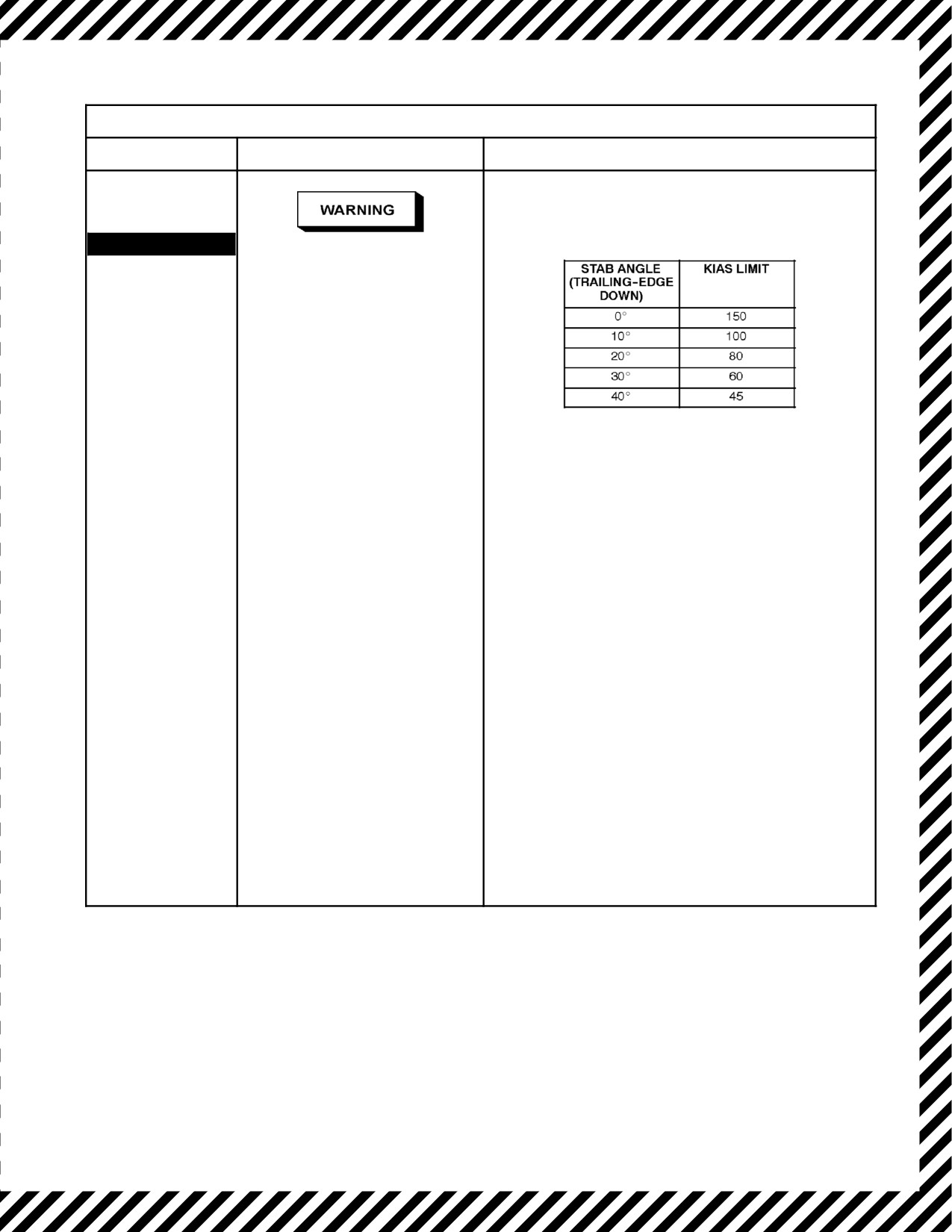
A1-H60BB-NFM-000
Stabilator Auto Mode Failure (cont)
LEGEND
CAUSE/REMARKS
CORRECTIVE ACTION
Stabilator Auto
If automatic control is not regained and manual mode
Mode Failure
is NOT operable:
(Cont.)
8.
Fly at or below speed shown:
STABILATOR
D
With large fixed stabilator
angles, reduction in collective
pitch results in increased aft
cyclic requirements. Collec-
tive reduction during recov-
ery from a trailing edge down
stabilator
flight
condition
should be minimal. If the
stabilator becomes fixed at or
near 0°, nose high attitudes
9.
Land as soon as practical.
may occur at slow speeds.
D
A combination of high
airspeed/low altitude coupled
with a runaway down stabilator
(indicated by a significant
uncommanded nose down
pitch change) will necessitate
immediate pilot action to
maintain control of the aircraft.
Primary consideration is to
disengage the automatic
mode by activating manual
mode slewing as required.
D
At high airspeeds, immediate
recognition and flight control
input are essential to avoid an
unrecoverable attitude. It is
essential for the PNAC to
slew the stabilator to
0°
immediately to gain control of
the aircraft. If acceleration is
continued with the stabilator
in the full down position,
longitudinal control will be
lost.
12-55
ORIGINAL
A1-H60BB-NFM-000
12.9.3.2 Stabilator Indicating System Failure
Stabilator Indicating System Failure
LEGEND
CAUSE/REMARKS
CORRECTIVE ACTION
Stabilator
If stabilator indicating system operation is questionable
Indicating
in the automatic mode:
System Failure
1. Stabilator — Check position visually.
If indication is erratic and/or lost:
2. STABILATOR AUTO CONTROL
pushbutton — Do not disengage.
3. STAB IND CB — Cycle (CENTER, AC ESNTL,
ROW 1, CB 6).
If normal operation is not restored:
4. Land as soon as practical.
12.9.4 Unusual Attitude Recovery
Unusual Attitude Recovery
LEGEND
CAUSE/REMARKS
CORRECTIVE ACTION
Unusual Attitude
Unusual
attitudes
are
*1. Level wings.
Recovery
considered to be attitudes of
*2. Nose on horizon.
over 30° pitch and/or 60° bank.
There are three general
*3. Center ball.
unusual attitudes: nose--low,
*4. Stop rate of climb/descent.
nose--high, and high--bank
*5. Control airspeed.
angles. During all unusual
attitude
recoveries,
the
nose--low attitude is the desired
condition from which to
complete all recoveries.
12.10 ELECTRICAL SYSTEM MALFUNCTIONS
Total loss of AC power will result in the loss of both pilot and copilot attitude indicators and BDHIs. in addition,
the copilot turn needle will be inoperative. All primary cockpit lighting will be inoperative. Only the pilot will have
turnneedle:bothpilotandcopilotwillhaveallbarometricinstruments,secondaryandutilitylights,andwetcompass.
In the event of total loss of AC power, the pilot turn needle will only be available until battery power drops below
35 percent. Aircrews must endeavor to gain VMC as soon as possible. Without the pilot turn needle, the only
instrument available to provide turn rate information will be the wet compass.
ORIGINAL
12-56
A1-H60BB-NFM-000
D During any emergency where generators are secured intentionally or
inadvertently, severe repercussions could result. In any case, actual flight
conditions
(night/IMC/power required) will dictate the immediate
procedures to be followed. It may not be advisable to secure electrical
power, which will result in the loss of AFCS, normal ICS, and flight and
mission displays, prior to achieving VMC or landing/ditching.
D Without electrical power to the dc Primary buses, the engine and inlet
anti--ice valves are automatically opened. With an improperly operating
engine inlet anti--ice system, a loss of up to 49 percent power available per
engine is possible.
A failed main generator could be a preliminary indication of a subsequent transmission malfunction or vice versa.
When dealing with main generator malfunctions, due consideration should be given to actual or potential
transmission chip, oil temperature, or oil pressure lights, and the rate of decay of aircraft systems.
The items listed in Figure 12-6 use both AC and DC power. In case of dual generator or dual converter failure, this
equipment, although not operational, will continue to draw DC power from the battery and should be secured by the
appropriate switch or circuit breaker.
12-57
ORIGINAL
A1-H60BB-NFM-000
CIRCUIT BREAKER
LOCATION
PILOT BDHI
Overhead console circuit breaker panel
STAB PWR
ATO circuit breaker panel
ATO BDHI
TACAN CONTR
MAIN ROTOR DE--ICE
LEFT PITOT HEATER
SO circuit breaker
LH RACK BLOWER
BLADE FOLD MOTOR
RH RACK BLOWER
ECS POWER
PYLON GSE CONTR
RAST POWER
REEL MACH LAUNCH
RESCUE HOIST CONTR (2)
RTR HD INDEX MOTOR
UTIL RECP CABIN (2)
NO. 2 ENG OVSP
Corner circuit breaker
PILOT WINDSHIELD
ANTI--ICE
RIGHT PITOT HEATER
Figure 12-6. Equipment Drawing DC Power from the Battery
ORIGINAL
12-58
A1-H60BB-NFM-000
12.10.1 Total AC Power Failure/Dual Generator Failure
Total AC Power Failure/Dual Generator Failure
LEGEND
CAUSE/REMARKS
CORRECTIVE ACTION
Total AC
Failure of AC source(s) or
*1. Safe Altitude and Airspeed — Establish.
Power
respective converter or DC bus
*2. Stabilator — CHECK POSITION, SLEW
Failure/Dual
connector.
AS REQUIRED.
Generator
Battery life may be no more than
Failure
14 minutes: therefore, the
electrical equipment remaining on
#1 CONV
should be only that required for
AND
Ensure airspeed vs. stabilator angle limits are not
prevailing conditions, e.g. night,
exceeded. Stabilator automatic mode is inoperative.
#2 CONV
IMC.
Note
AND
Note
The stabilator position indicator will be inoperative
The capability of slewing the
with no power to the AC essential bus. Attempt to
AC ESS
stabilator is retained via the
check visually.
BUS OFF
DC Essential bus using
*3. APU Emergency Start Procedure — PERFORM.
battery power. Travel is
AND
limited to 35° if full down or
4. AFCS/SAS — Check Status.
30° if full up when a power
AFCS
If
AC electrical failure:
failure occurs.
DEGRADED
5. NO. 1 and NO. 2 GENERATOR switches —
RESET, THEN ON.
AND
If
DC electrical failure:
STABILTOR
6. Converter CBs — RESET.
a. NO. 1 CONVERTER (ATO, NO. 1 AC PRI,
ROW 1, CB 14).
b. NO. 2 CONVERTER (PILOT, NO. 2 AC PRI,
ROW 2, CB 4).
If
AC and/or DC electrical power is not restored:
7. Land as soon as practical.
8. Nonessential electrical equipment — OFF.
12-59
ORIGINAL
A1-H60BB-NFM-000
12.10.2 Electrical System Caution Lights
#1 or #2 Generator Caution Light
LEGEND
CAUSE/REMARKS
CORRECTIVE ACTION
Respective generator not
1. Affected GENERATOR switch — RESET,
#1 GEN
supplying power to buses.
THEN ON.
Operative generator selected
If caution light remains on:
OR
OFF: failure of generator, GCU,
contactor or wiring fault.
2. Affected GENERATOR switch — OFF.
#2 GEN
If IMC:
3. APU Emergency Start procedure — PERFORM.
If icing conditions encountered/anticipated:
4. BACKUP PUMP — OFF.
5. DE--ICE MASTER — AUTO.
6. ENG ANTI--ICE — ON.
7. PITOT HEAT — CHECK ON.
12.10.2.1 GEN BRG (#1/#2) Caution Lights
GEN BRG (#1 or #2) Caution Lights
LEGEND
CAUSE/REMARKS
CORRECTIVE ACTION
#1 GEN BRG
Generator main bearing worn or
1. Check for transmission secondaries.
has failed.
2. Note time.
OR
If caution remains for more than 1
If caution remains steady on for more than one minute:
minute, a MAF is required. The
generator may continue to
3. Land as soon as practical.
#2 GEN BRG
operate normally for 10 hours.
Note
A mechanical failure of the
generator bearing may
cause transmission chip
cautions to appear.
When the light illuminates, it may
be disregarded if it occurs either
as an intermittent or a steady
(less than 1 minute) light, or as
any combination of the two.
Note
Consideration may be given
to starting the APU and
turning on the APU
generator.
ORIGINAL
12-60
A1-H60BB-NFM-000
12.10.2.2 AC ESS BUS OFF Caution Light
AC ESS BUS OFF Caution Light
LEGEND
CAUSE/REMARKS
CORRECTIVE ACTION
AC ESS
AC essential bus is not powered.
1. AC ESS BUS SPLY CBs — Check.
BUS OFF
a. CENTER, NO. 1 AC PRI, ROW 1, CB 15.
b. CORNER, NO. 1 AC PRI, ROW 4, CB 5.
2. Note lost equipment.
12.10.2.3 DC ESS BUS OFF Caution Light
DC ESS BUS OFF Caution Light
LEGEND
CAUSE/REMARKS
CORRECTIVE ACTION
DC ESS
DC essential bus is not powered.
1. DC ESS BUS SPLY CBs — Check.
BUS OFF
a. ATO, NO. 1 DC PRI, ROW 3, CB 6.
b. ATO, NO. 2 DC PRI, ROW 3, CB 13.
2. Note lost equipment.
12.10.3 CONV (#1/#2) Caution Lights
CONV (#1/#2) Caution Lights
LEGEND
CAUSE/REMARKS
CORRECTIVE ACTION
#1 CONV
Failure of AC source(s) or
1. Affected converter circuit breakers — Reset.
respective converter or DC bus.
a. NO. 1 AC PRIMARY BUS marked NO. 1
OR
CONVERTER POWER
#2 CONV
(CENTER, NO. 1 AC PRI, ROW 1, CB 14).
b. NO. 2 AC PRIMARY BUS marked NO. 2
CONVERTER POWER
(CORNER, NO. 2 AC PRI, ROW 2, CB 4).
If caution light remains on:
2. Land as soon as practical.
12.10.4 BATTERY FAULT Caution Light
BATTERY FAULT Caution Light
LEGEND
CAUSE/REMARKS
CORRECTIVE ACTION
BATTERY
Possible over temperature/
1. BATT switch — Cycle a maximum of two times.
FAULT
internal malfunction.
If light remains on:
Note
2. BATT switch — OFF.
If the APU Generator is the
3. Land as soon as practical.
only source of AC power
and it is secured with the
battery OFF, the APU will
shut down.
12-61
ORIGINAL
A1-H60BB-NFM-000
12.10.5 BATTERY LOW CHARGE Caution Light
BATTERY LOW CHARGE Caution Light
LEGEND
CAUSE/REMARKS
CORRECTIVE ACTION
BATT LOW
Battery is at or below 40 percent
If caution appears on ground after APU start with APU
CHARGE
of a fully charged state.
generator on:
1. BATT switch — Cycle (allow 30 minutes to charge
battery).
Note
With the battery below 35
If caution appears in flight:
percent charge, the DC
2. BATT switch — OFF.
Essential bus will be
3. Circuit breakers — Check.
dropped from the Battery
bus and the BATT LOW
a. BATT CHGR (ATO, NO. 2 DC PRI, ROW 2,
CHARGE light
will
CB 16).
extinguish.
b. BATT CHGR (ATO, NO. 2 AC PRI, ROW 2,
CB 1).
CAUTION
4. BATT switch — ON.
With no other source of DC
power for the DC Essential
bus and the battery below
30 percent charge, battery
power may not be sufficient
to
activate
the
fire
extinguisher CAD.
ORIGINAL
12-62
A1-H60BB-NFM-000
12.11 DE--ICE MALFUNCTIONS
12.11.1 PWR MAIN RTR and/or PWR TAIL RTR Light On
PWR MAIN RTR and/or PWR TAIL RTR Light ON
LEGEND
CAUSE/REMARKS
CORRECTIVE ACTION
PWR MAIN
Indicates a malfunction has
If a rotor power light on the Blade De--Ice Panel is
RTR
occurred in the main rotor and/or
illuminated with the BLADE DE--ICE POWER switch ON:
tail rotor primary power when the
1. BLADE DE--ICE POWER switch — OFF.
power switch is in OFF or ON.
AND/OR
Indicates TEST and NORMAL
If the PWR MAIN RTR light remains illuminated:
operation when power switch is in
2. MR DE--ICE CONTR circuit breaker — PULL.
TEST.
PWR TAIL
(ATO, NO. 2 DC PRI, ROW 2, CB 20)
RTR
If the PWR MAIN RTR monitor light remains illuminated:
3. NO. 1 or NO. 2 GENERATOR switch — OFF.
4. APU GENERATOR switch — OFF (if in use).
5. Land as soon as practical.
Tail:
6. BLADE DE--ICE POWER switch — OFF.
If PWR TAIL RTR monitor light remains illuminated:
7. TAIL BLADE DE--ICE circuit breaker (SO OVHD,
AC Secondary, ROW 1, CB 5) — PULL.
If PWR monitor light remains illuminated:
8. APU Emergency Start Procedure — Complete.
9. NO. 1 and NO. 2 GENERATOR — OFF.
10. Land as soon as practical.
12.11.2 DE--ICE System Caution Lights
12.11.2.1 ICE DETECTED Caution Light
ICE DETECTED Caution Light
LEGEND
CAUSE/REMARKS
CORRECTIVE ACTION
ICE
Ice has been detected by the ice
1. PITOT HEAT switch — ON.
DETECTED
detector. It is possible to receive
2. WINDSHIELD ANTI--ICE — ON.
false ice detector indications due to
3. ENG ANTI--ICE — ON.
blowing sand/dirt entering the ice
detector.
4. BLADE DE--ICE POWER — ON.
5. Monitor surfaces for ice buildup.
12-63
ORIGINAL
A1-H60BB-NFM-000
12.11.2.2 ICE DETECT FAIL Caution Light
ICE DETECT FAIL Caution Light
LEGEND
CAUSE/REMARKS
CORRECTIVE ACTION
ICE
Indicates a failure of the detector
1. BLADE DE--ICE POWER switch — OFF.
DETECT FAIL
unit or the icing rate signal
converter.
2. Torque required and vibration — Monitor.
If torque required and/or vibration increases:
3. MODE —Select higher setting.
If ice buildup continues:
4. Land As Soon As Possible.
12.11.2.3 LEFT or RIGHT PITOT HEAT Caution Lights
LEFT or RIGHT PITOT HEAT Caution Lights
LEGEND
CAUSE/REMARKS
CORRECTIVE ACTION
LFT PITOT
Low heat or no heat in right and/or
1. Stabilator — Check, MANUAL mode as required.
HEAT
left pitot tube.
2. Pitot heat circuit breakers — Check.
OR
a. LFT PITOT HEATER
(SO OVHD, NO. 1 AC PRI, ROW 1, CB 6).
RT PITOT
b. RIGHT PITOT HEATER
HEAT
(CORNER, NO. 2 AC PRI, ROW 3, CB 4).
3. Icing conditions or visible moisture — Exit.
The possibility exists for erratic stabilator
programming due to erroneous indications from the
pitot--static system. If icing conditions exist, expect to
lose respective airspeed indication.
ORIGINAL
12-64
A1-H60BB-NFM-000
12.11.2.4 MR DE--ICE FAIL Caution Light
MR DE--ICE FAIL Caution Light
LEGEND
CAUSE/REMARKS
CORRECTIVE ACTION
MR DE--ICE
Open circuit to any MRB heating
FAIL
element or a short circuit from
phase to phase of the blade de--ice
power lines. System will automat-
Ice accumulation resulting in a 20 percent torque
ically turn off.
increase indicates that normal autorotational rotor
Pilots must be aware of increased
rpm may not be attainable should dual--engine failure
vibration levels and torque
occur.
requirements that could result from
1. DE--ICE MASTER switch — MANUAL.
ice buildup.
2. BLADE DE--ICE POWER switch — OFF, then ON.
3. DE--ICE MASTER switch — AUTO.
If caution remains in icing conditions:
4. Icing conditions — Exit.
If unable to exit icing conditions:
5. Land As Soon As Possible.
12.11.2.5 MR DE--ICE FAULT Caution Light
MR DE--ICE FAULT Caution Light
LEGEND
CAUSE/REMARKS
CORRECTIVE ACTION
MR DE--ICE
Loss of electrical power or open
FAULT
circuit on any Main Rotor Blade
(MRB) heating zone element.
System will operate in degraded
Ice accumulation resulting in a 20 percent torque
mode.
increase indicates that normal autorotational rotor
rpm may not be attainable should dual--engine failure
occur.
Pilots must be aware of increased
vibration levels and torque
1. BLADE DE--ICE POWER switch — OFF, then ON.
requirements that could result from
If caution remains in icing conditions:
ice buildup.
2. Icing conditions — Exit.
If unable to exit icing conditions:
3. Land As Soon As Possible.
12.11.2.6 TR DE--ICE FAIL Caution Light
TR DE--ICE FAIL Caution Light
LEGEND
CAUSE/REMARKS
CORRECTIVE ACTION
TR DE--ICE
Open circuit to Tail Rotor Blade
1. Icing conditions — Exit.
FAIL
(TRB) heating elements or a short
circuit from phase to phase of the
When out of icing conditions:
blade de--ice power lines. Tail rotor
2. BLADE DE--ICE POWER switch — OFF.
de--ice will automatically turn off.
If unable to exit icing conditions:
Main rotor de--ice will remain on.
3. Land As Soon As Possible.
12-65
ORIGINAL
A1-H60BB-NFM-000
12.12 FUEL SYSTEM MALFUNCTIONS
12.12.1 Fuel System Caution Lights
12.12.1.1 #1
or #2 FUEL FLTR BYPASS or #1 or #2 FUEL PRESS Caution Lights
#1 or #2 FUEL FLTR BYPASS or #1 or #2 FUEL PRESS Caution Lights
LEGEND
CAUSE/REMARKS
CORRECTIVE ACTION
#1 FUEL
Fuel Filter is bypassing.
*1. Fuel selector lever (affected engine) — XFD (DIR if
FLTR
currently in XFD).
BYPASS
2. Land as soon as practical.
Low fuel pressure from the
If affected engine indications are abnormal:
OR
respective
engine--driven
3. Engine malfunction in Flight procedure — Perform.
boost pump. Intermittent
#2 FUEL
appearance of a FUEL
FLTR
BYPASS
PRESS caution may be an
indication of air leaking into
the fuel supply lines, which
could cause momentary
OR
fluctuation in engine power
or flameout.
#1 FUEL
Low fuel pressure from the
PRESS
respective
engine--driven
boost pump.
OR
#2 FUEL
PRESS
12.12.1.2 #1 and #2 FUEL FLTR BYPASS or #1 and #2 FUEL PRESS Caution Lights
#1 and #2 FUEL FLTR BYPASS or #1 and #2 FUEL PRESS Caution Lights
LEGEND
CAUSE/REMARKS
CORRECTIVE ACTION
#1 FUEL
Fuel Filter is bypassing.
*1. Land As Soon As Possible.
FLTR
*2. APU Emergency Start procedure — Perform.
BYPASS
AND
Fuel Filter is bypassing. Low
fuel pressure from the
Be prepared for dual--engine failure. Recommended
#2 FUEL
respective
engine--driven
FLTR
airspeed profile is 80 KIAS to minimize Nr droop
BYPASS
boost pump. Intermittent
should dual--engine failure occur.
appearance of a FUEL
Note
OR
PRESS caution may be an
Consideration should be given to performing
indication of air leaking into
applicable steps of the Immediate Landing/Ditching
#1 FUEL
the fuel supply lines, which
emergency procedure.
PRESS
could cause momentary
fluctuation in engine power
AND
or flameout.
#2 FUEL
Low fuel pressure from the
PRESS
respective
engine--driven
boost pump.
ORIGINAL
12-66
A1-H60BB-NFM-000
12.12.1.3 (#1/#2) FUEL LOW Caution Lights
(#1/#2) FUEL LOW Caution Lights
LEGEND
CAUSE/REMARKS
CORRECTIVE ACTION
#1 FUEL LOW
Low fuel state in respective cell.
1. Land as soon as practical.
AND
#2 FUEL
With less than 600 pounds of fuel, fuel starvation may
LOW
occur when balanced flight is not maintained and/or
pitch attitudes exceed 15° noseup or nosedown.
12.12.1.4 AUX FUEL XFER FAULT Caution Light
AUX FUEL XFER FAULT Caution Light
LEGEND
CAUSE/REMARKS
CORRECTIVE ACTION
AUX FUEL
FMCP automatic transfer logic has
1. FMCP circuit breakers — Cycle.
XFER FAULT
failed, both transfer pumps have
failed, or both transfer/shutoff
a. FUEL MGMT (ATO, NO. 1 DC PRI, ROW 1,
CB 1), if installed.
valves have failed.
b. FUEL MGMT (ATO, NO. 2 DC PRI, ROW 3,
CB 23), if installed.
2. FUEL XFER/DUMP circuit breakers — Cycle.
a. FUEL DUMP CONTR (OVERHEAD,
DC ESNTL, ROW 3, CB 1).
b. FUEL DUMP PUMP (CENTER, NO. 1 AC PRI,
ROW 1, CB 13).
c. FUEL DUMP PUMP (CORNER, NO. 2 AC PRI,
ROW 1, CB 1).
3. Fuel XFER mode — MANUAL.
4. Appropriate FMCP fuel flow indicator/selector
switch — Press and hold for a minimum of 10
seconds.
12.12.1.5 PUMP/VALVE FAIL Caution Light
PUMP/VALVE FAIL Caution Light
LEGEND
CAUSE/REMARKS
CORRECTIVE ACTION
PUMP/VALVE
Failure of main transfer valve or
1. Note condition.
FAIL
transfer/dump pumps.
12-67
ORIGINAL
A1-H60BB-NFM-000
12.12.2 Refueling Hose Jettison (HIFR)
Refueling Hose Jettison (HIFR)
LEGEND
CAUSE/REMARKS
CORRECTIVE ACTION
Refueling
Hose Jettison
(HIFR)
Anyone may give the command “BREAKAWAY.” The
crewman shall immediately pull the emergency
disconnects lanyard (NI/Wiggins) and report, “HOSE
CLEAR.”
If a T--handle is present:
*1. When emergency breakaway command is
received — Pull T--handle and report “HOSE
CLEAR.”
If no T--handle is present:
*2. When emergency breakaway command
received — Report “HOSE CLEAR.”
Hose snapback on breakaway may impact the
crewman depending on direction of aircraft motion.
12.12.3 NO HIFR/Stuck Main Tank Shutoff Valve
A stuck main tank shutoff valve will prevent fueling by HIFR when the FMCP is powered. The FMCP controls
sequencing of fuel to the tanks, and the main tanks must be filled first. Removing power to the FMCP will remove
power from the auxiliary tank shutoff valves and place them in the open position. HIFR can then fill the auxiliary
tanks. Returning power to the FMCP will allow fuel to then be transferred manually to the main tanks.
NO HIFR/Stuck Main Tank Shutoff Valve
LEGEND
CAUSE/REMARKS
CORRECTIVE ACTION
NO HIFR/Stuck
If no HIFR due to stuck main tank shutoff valve:
Main Tank Shutoff
1. FUEL MGMT circuit breakers — Pull. FUEL
Valve
MGMT (ATO, NO. 1 DC PRI, ROW 1, CB 1), if
installed FUEL MGMT (ATO, NO. 2 DC PRI,
ROW 3, CB 23), if installed.
2. HIFR — FILL AUXILIARY TANKS.
3. FUEL MGMT circuit breaker — RESET.
4. FMCP transfer of auxiliary tanks —
AS DESIRED.
5. Sequence can be repeated.
ORIGINAL
12-68
A1-H60BB-NFM-000
12.12.4 Uncommanded Fuel Dumping
Uncommanded Fuel Dumping
LEGEND
CAUSE/REMARKS
CORRECTIVE ACTION
Uncommanded
1. FUEL DUMP — Verify OFF.
Fuel Dumping
If fuel dumping continues:
2. FUEL DUMP CBs — PULL.
a. FUEL DUMP PUMP (CENTER, NO. 1
AC PRI, ROW 1, CB 13).
b. FUEL DUMP PUMP (CENTER, NO. 1
AC PRI, ROW 1, CB 1).
c. FUEL DUMP CTRL (OVHD, DC ESNTL,
ROW 3, CB 1).
3. Land as soon as practical.
12.13 FIRE EMERGENCIES
If the helicopter is airborne when a fire occurs, the most important single action that can be taken by the pilot is to
land the helicopter safely as soon as possible. On the ground, it is essential that the engines be shut down, crew and
passengers evacuated, and the fire fighting begun immediately.
12.13.1 External Engine Fire
External Engine Fire
LEGEND
CAUSE/REMARKS
CORRECTIVE ACTION
FIRE (#1/#2
Indicates that a fire detector (#1
*1. Confirm Fire.
ENG)
ENG/#2 ENG) has actuated a fire
*2. Engine Malfunction in Flight emergency
warning circuit. (Note light in
procedure — Perform.
appropriate T--handle). The
*3. PCL (affected engine) — OFF.
safety of the helicopter’s
occupants is the primary
*4. Engine T--Handle (affected engine) — PULL.
consideration when a fire occurs.
*5. FIRE EXT switch— MAIN (RESERVE if required or
If airborne, the most important
AC Power is off).
single action can be taken by the
pilot is to land the helicopter
If airborne and fire continues:
safely.
*6. LAND IMMEDIATELY.
If fire appears extinguished:
Note
*7. Land As Soon As Possible.
HF transmissions, sunlight
8. Single Engine Landing emergency
filtered through smoke,
procedure — Perform.
haze, water, or at sunrise or
sunset may trigger the fire
On ground:
detectors and cause a false
9. Fire Extinguisher — Discharge into engine
fire indication.
compartment.
12-69
ORIGINAL