SH-60B HELICOPTER. FLIGHT MANUAL (2008) - page 13
A1-H60BB-NFM-000
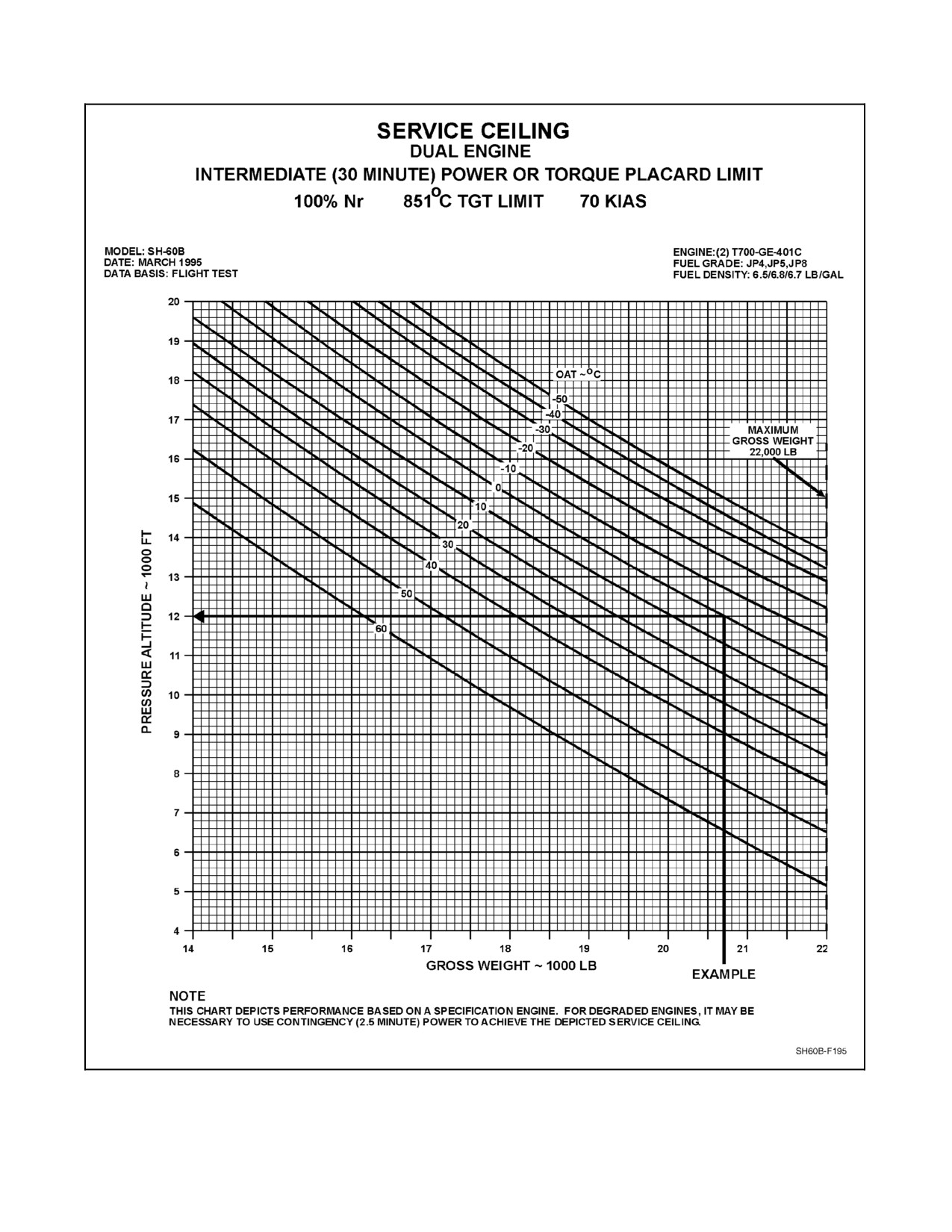
Figure 28-1. Service Ceiling, Dual--Engine, Intermediate (30 Minute) Power or Torque Placard Limit Chart
ORIGINAL
28-4
A1-H60BB-NFM-000
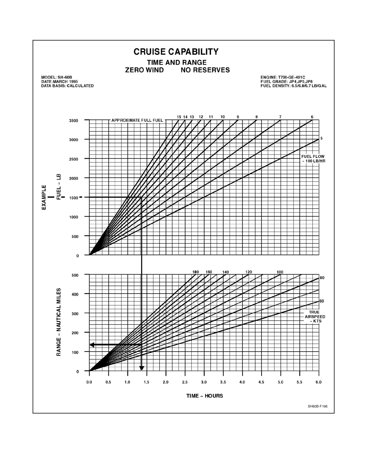
Figure 28-2. Cruise Capability, Time, and Range Chart
28-5
ORIGINAL
A1-H60BB-NFM-000
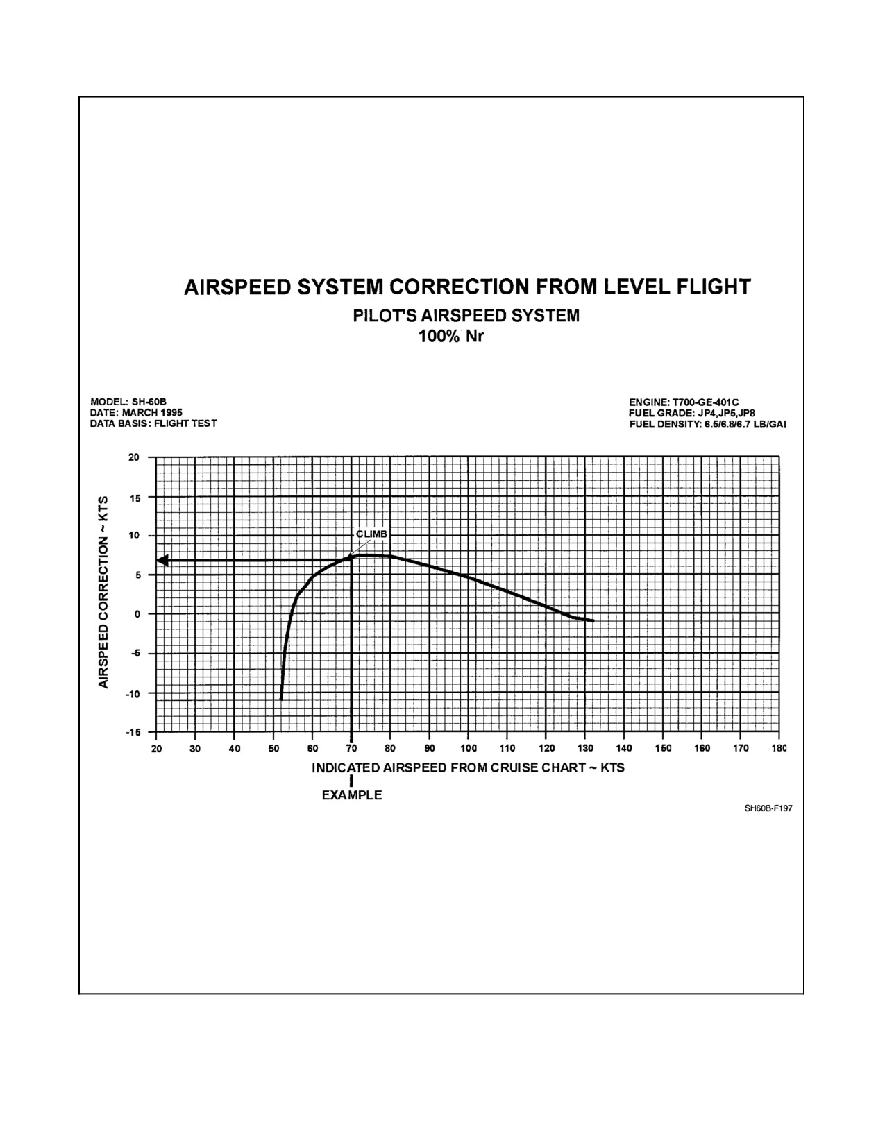
Figure 28-3. Airspeed System Correction from Level Flight Chart
ORIGINAL
28-6
A1-H60BB-NFM-000
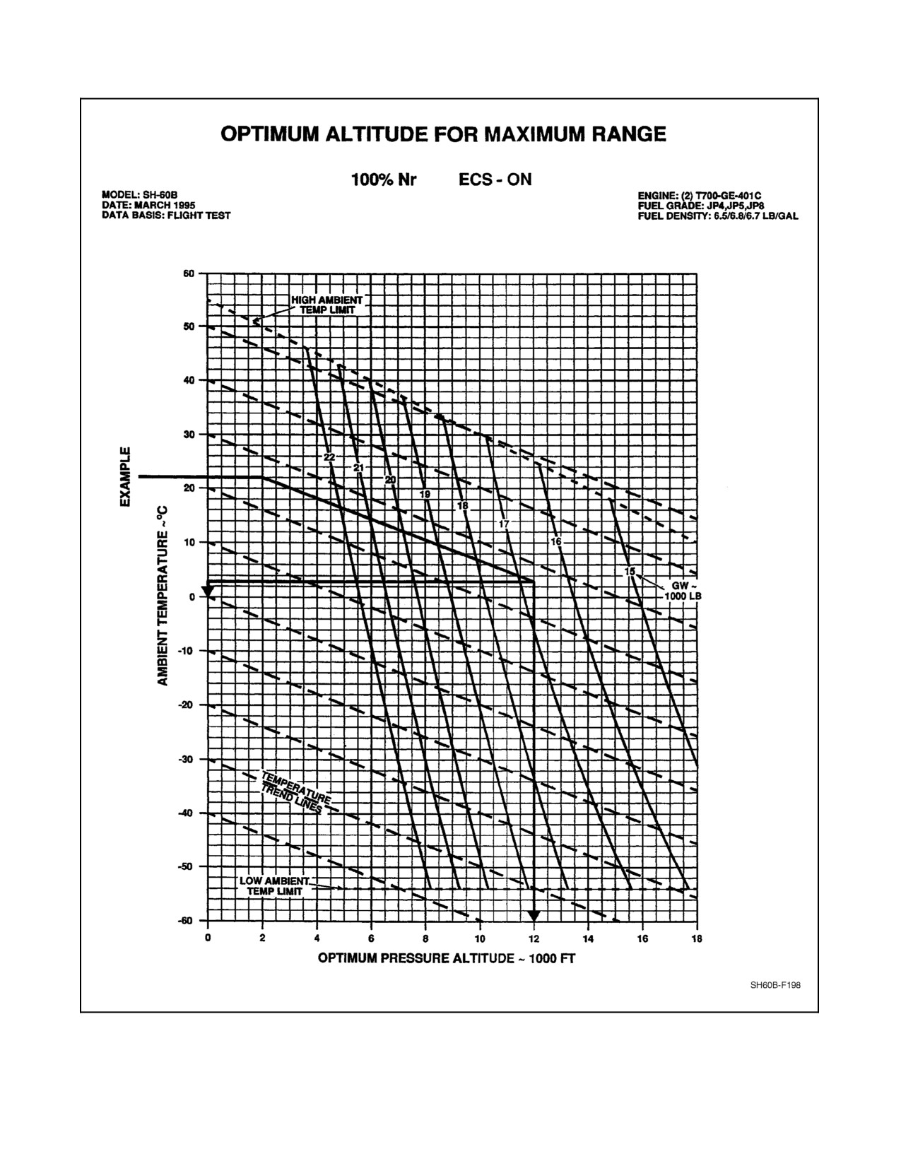
Figure 28-4. Optimum Altitude for Maximum Range Chart
28-7
ORIGINAL
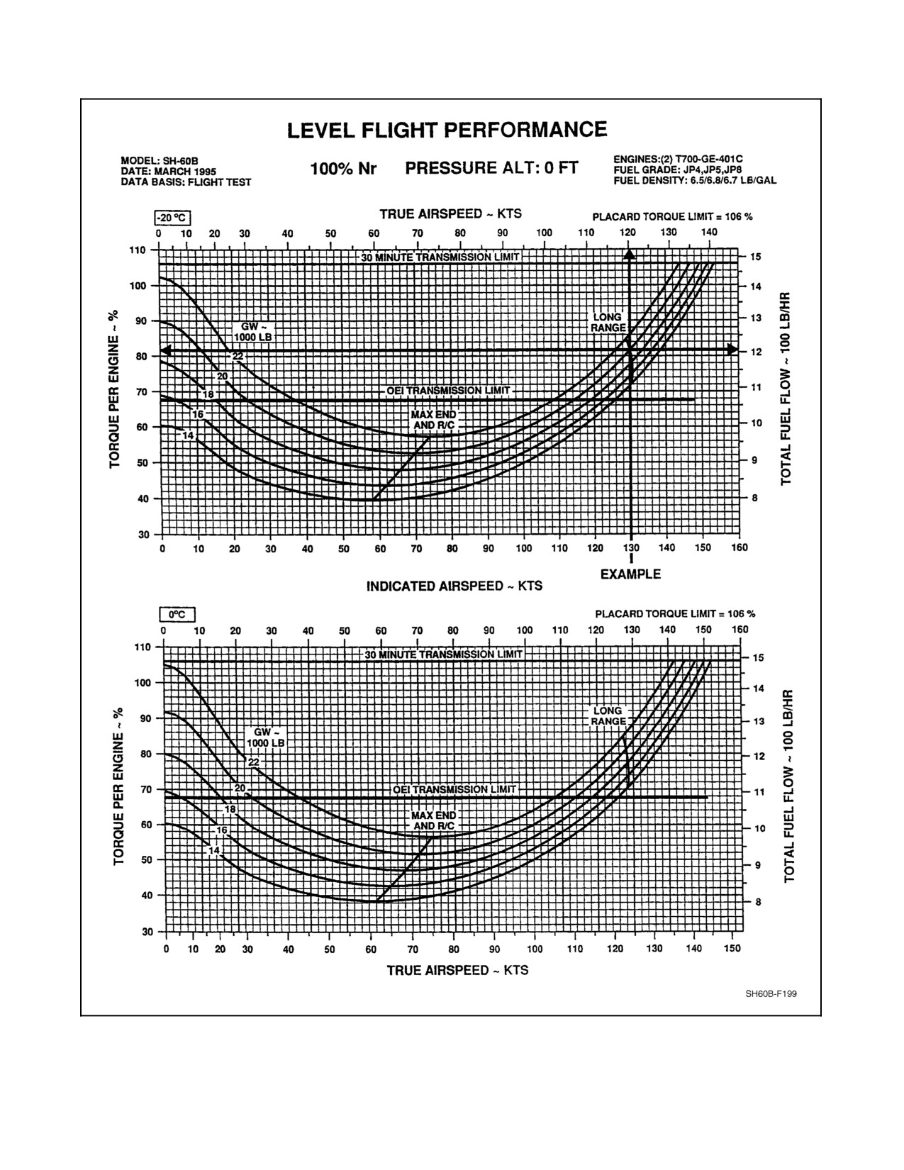
A1-H60BB-NFM-000
Figure 28-5. Level Flight Performance (0 Feet, --20, 0 °C) Charts
ORIGINAL
28-8
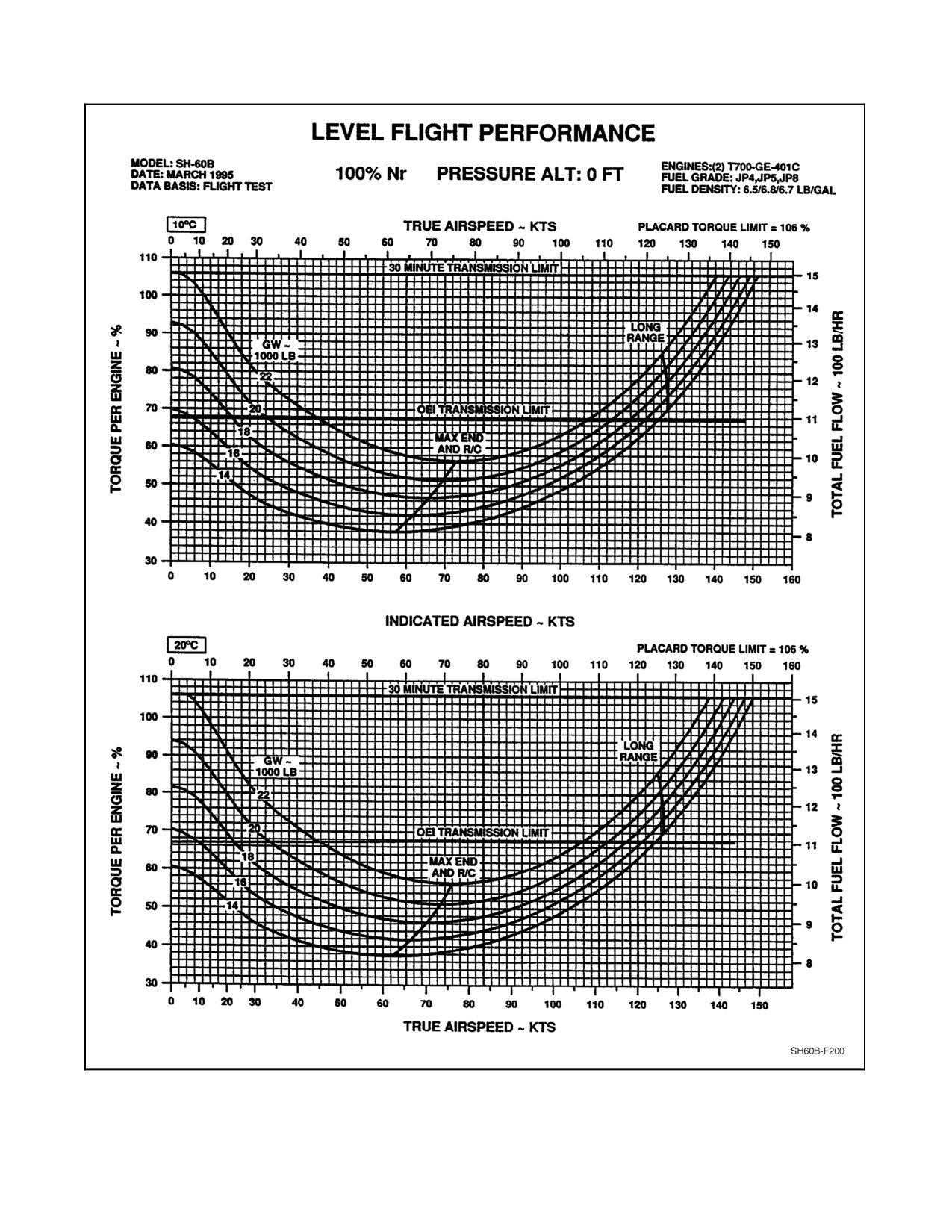
A1-H60BB-NFM-000
Figure 28-6. Level Flight Performance (0 Feet, 10, 20 °C) Charts
28-9
ORIGINAL
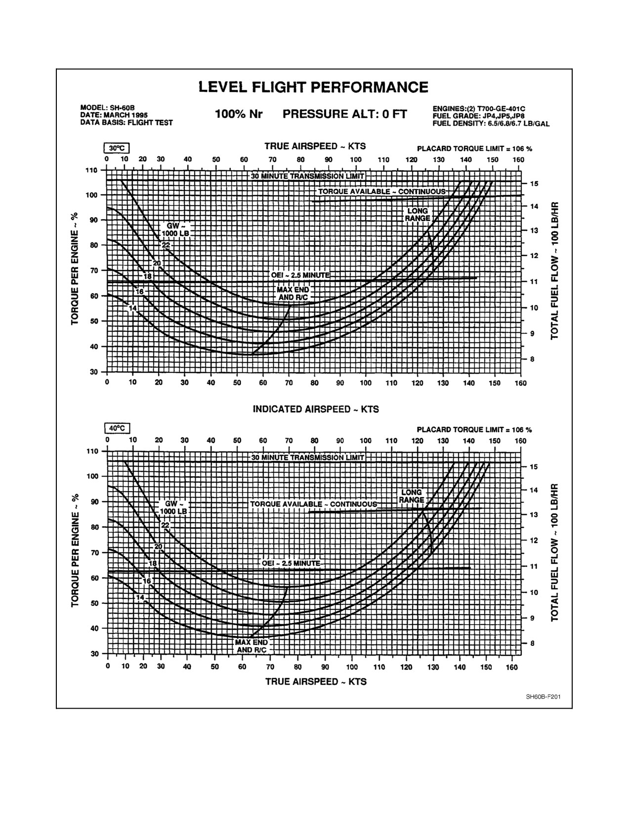
A1-H60BB-NFM-000
Figure 28-7. Level Flight Performance (0 Feet, 30, 40 °C) Charts
ORIGINAL
28-10
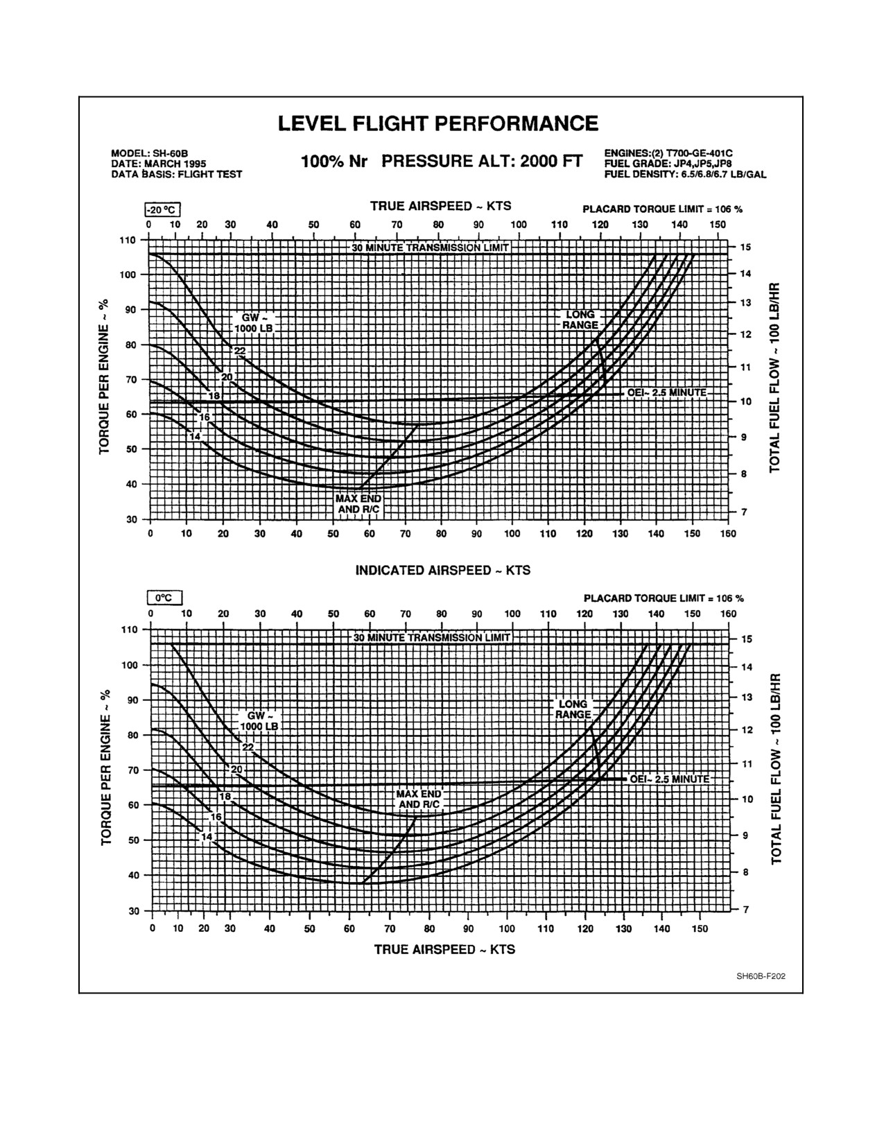
A1-H60BB-NFM-000
Figure 28-8. Level Flight Performance (2,000 Feet, --20, 0 °C) Charts
28-11
ORIGINAL
A1-H60BB-NFM-000
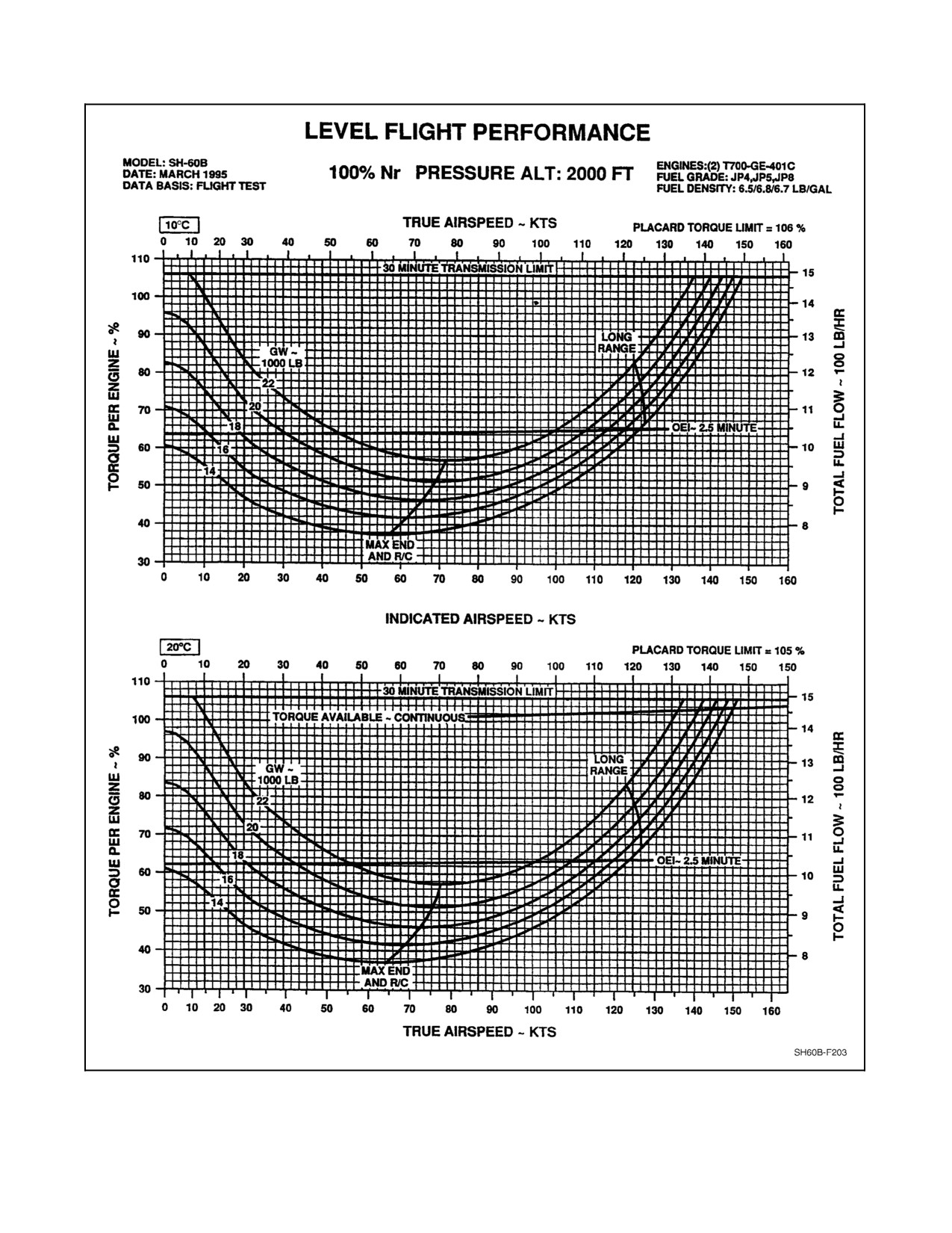
Figure 28-9. Level Flight Performance (2,000 Feet, 10, 20 °C) Charts
ORIGINAL
28-12
A1-H60BB-NFM-000
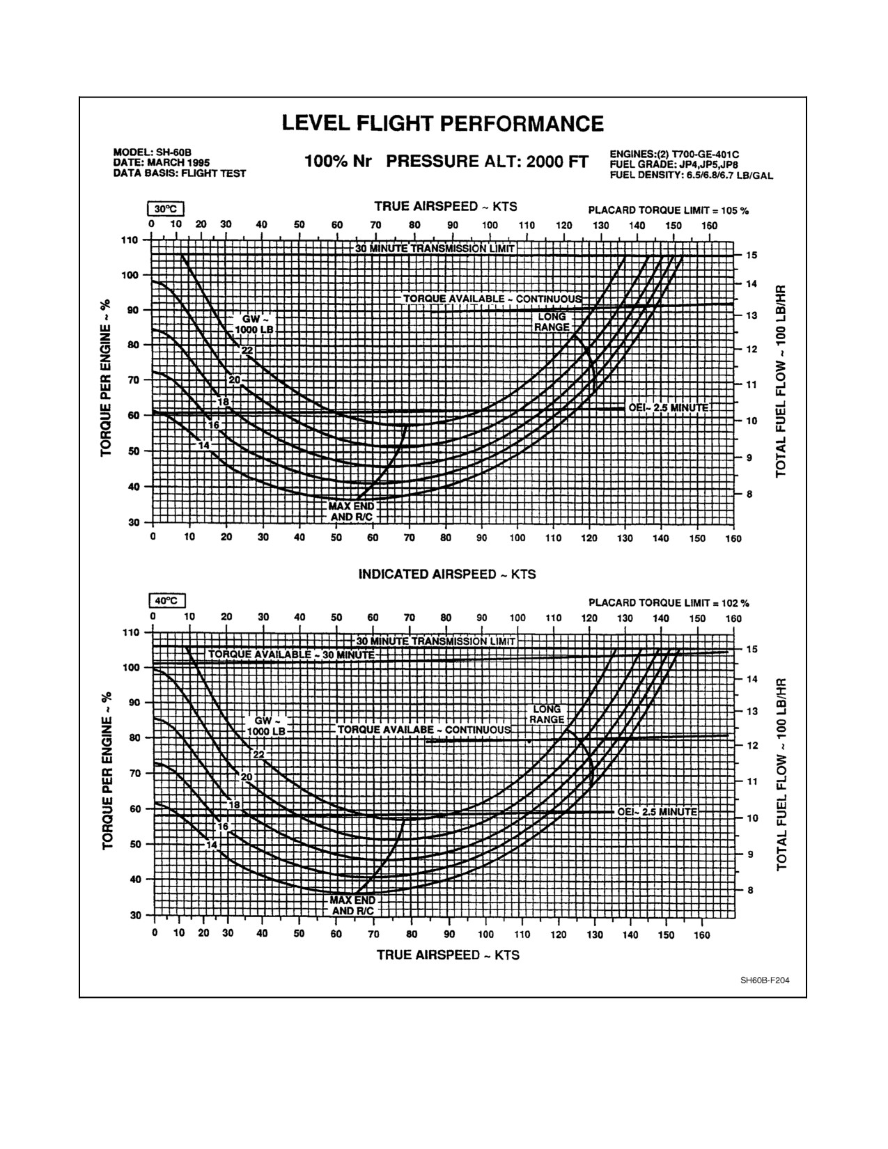
Figure 28-10. Level Flight Performance (2,000 Feet, 30, 40 °C) Charts
28-13
ORIGINAL
A1-H60BB-NFM-000
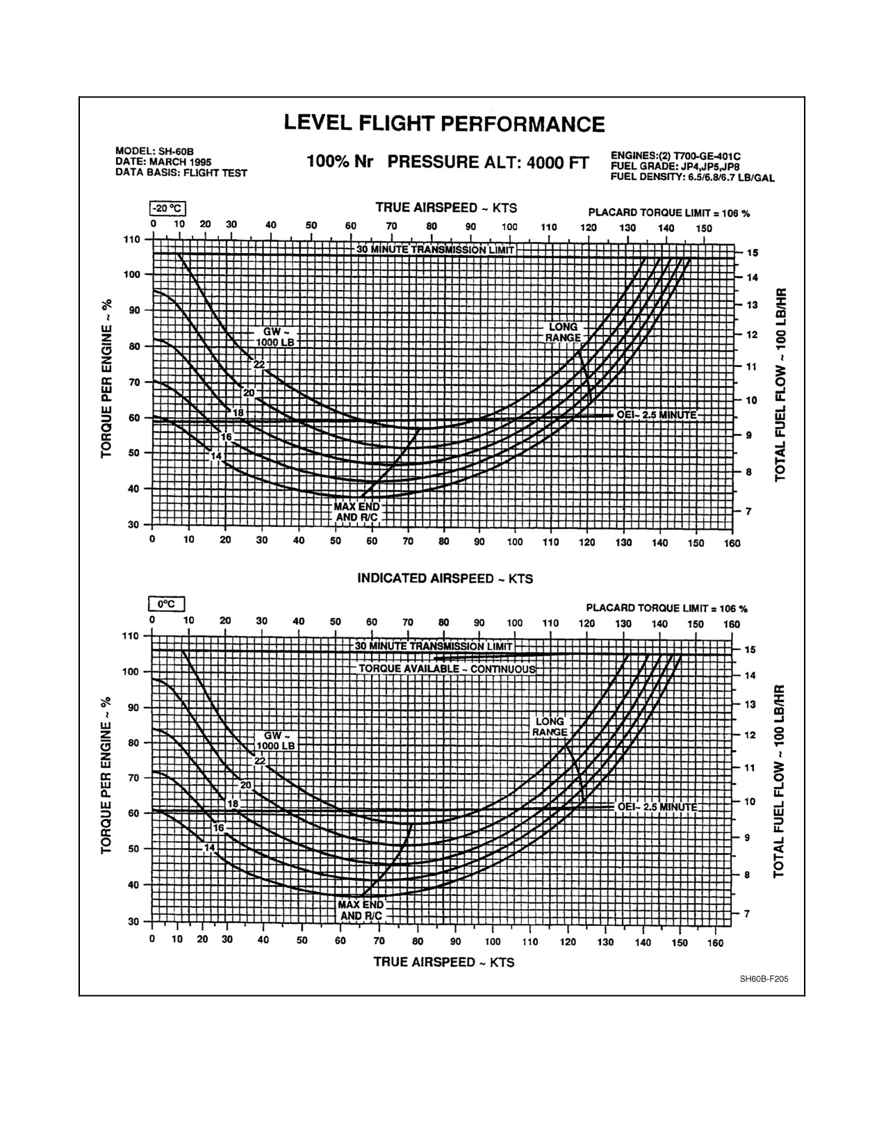
Figure 28-11. Level Flight Performance (4,000 Feet, --20, 0 °C) Charts
ORIGINAL
28-14
A1-H60BB-NFM-000
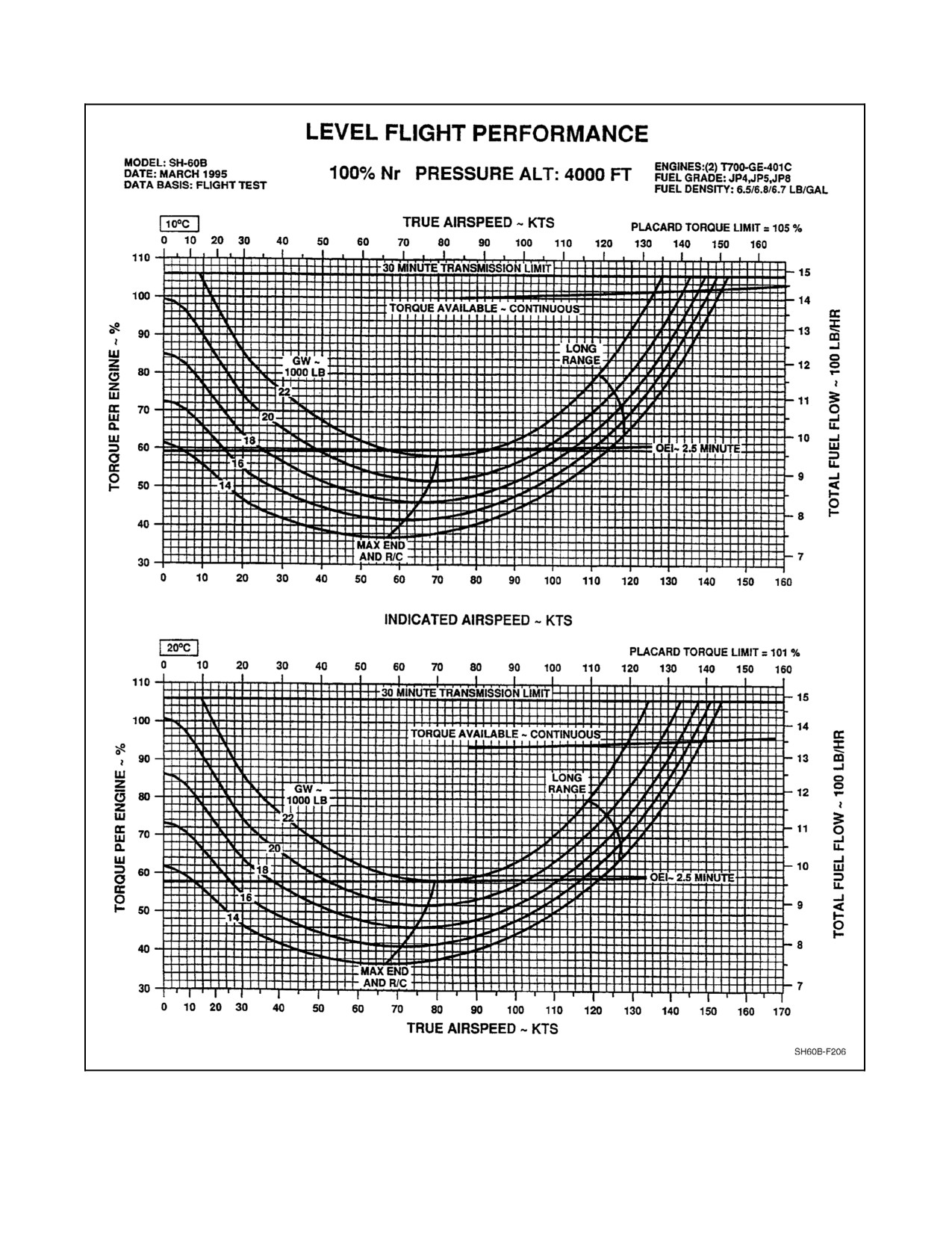
Figure 28-12. Level Flight Performance (4,000 Feet, 10, 20 °C) Charts
28-15
ORIGINAL
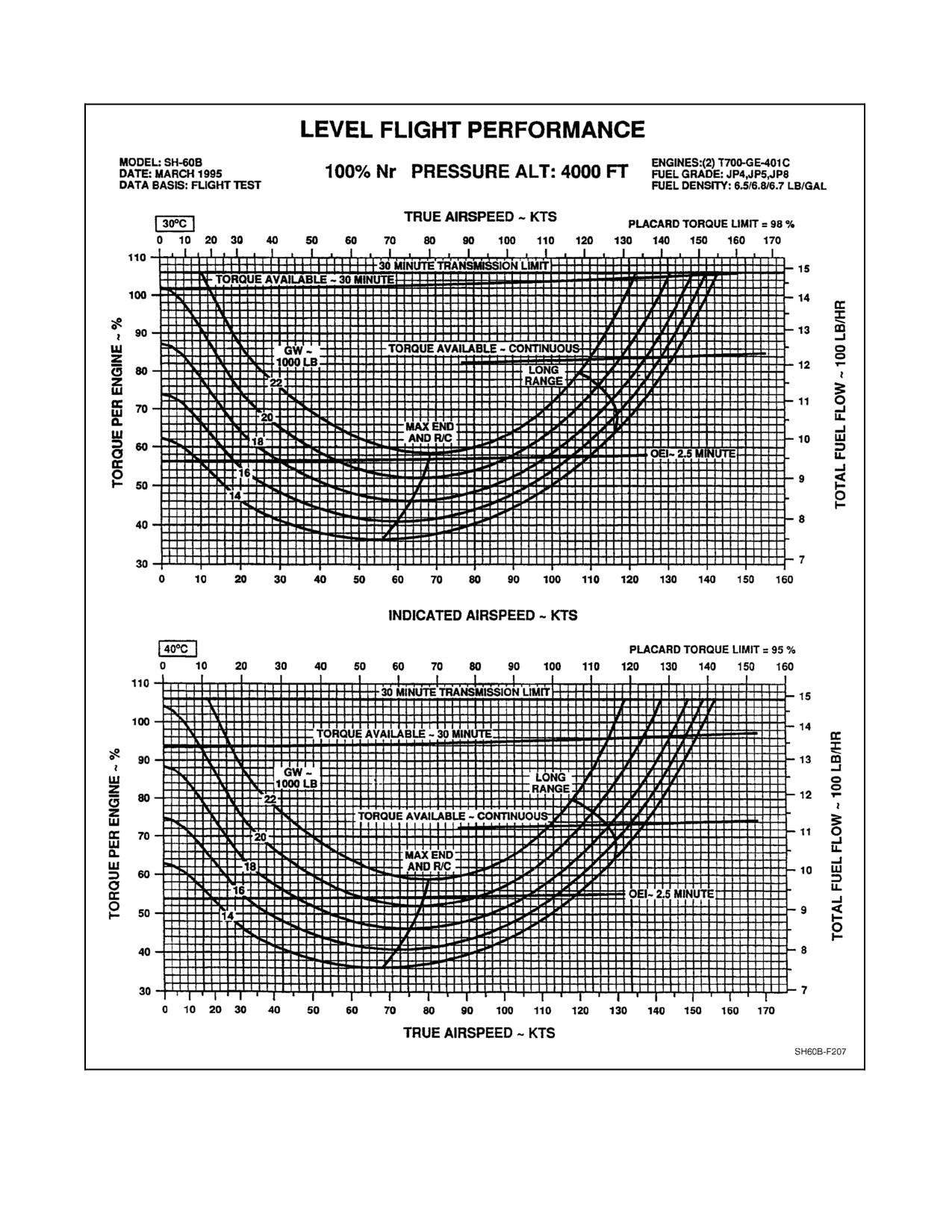
A1-H60BB-NFM-000
Figure 28-13. Level Flight Performance (4,000 Feet, 30, 40 °C) Charts
ORIGINAL
28-16
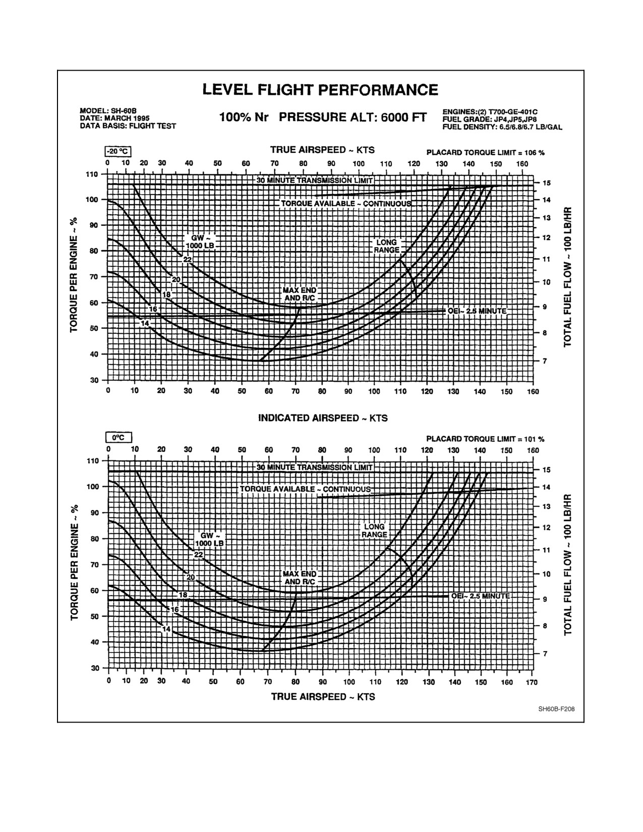
A1-H60BB-NFM-000
Figure 28-14. Level Flight Performance (6,000 Feet, --20, 0 °C) Charts
28-17
ORIGINAL
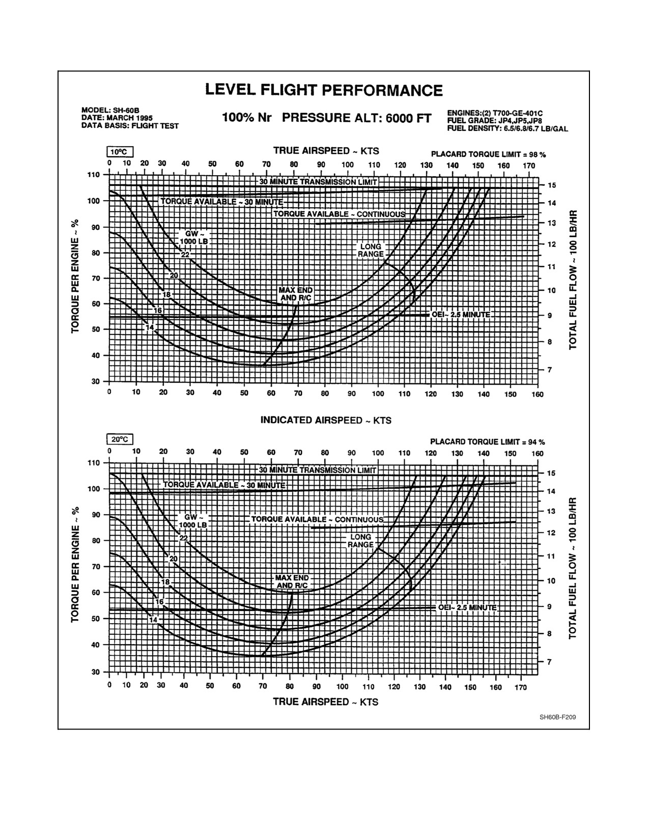
A1-H60BB-NFM-000
Figure 28-15. Level Flight Performance (6,000 Feet, 10, 20 °C) Charts
ORIGINAL
28-18
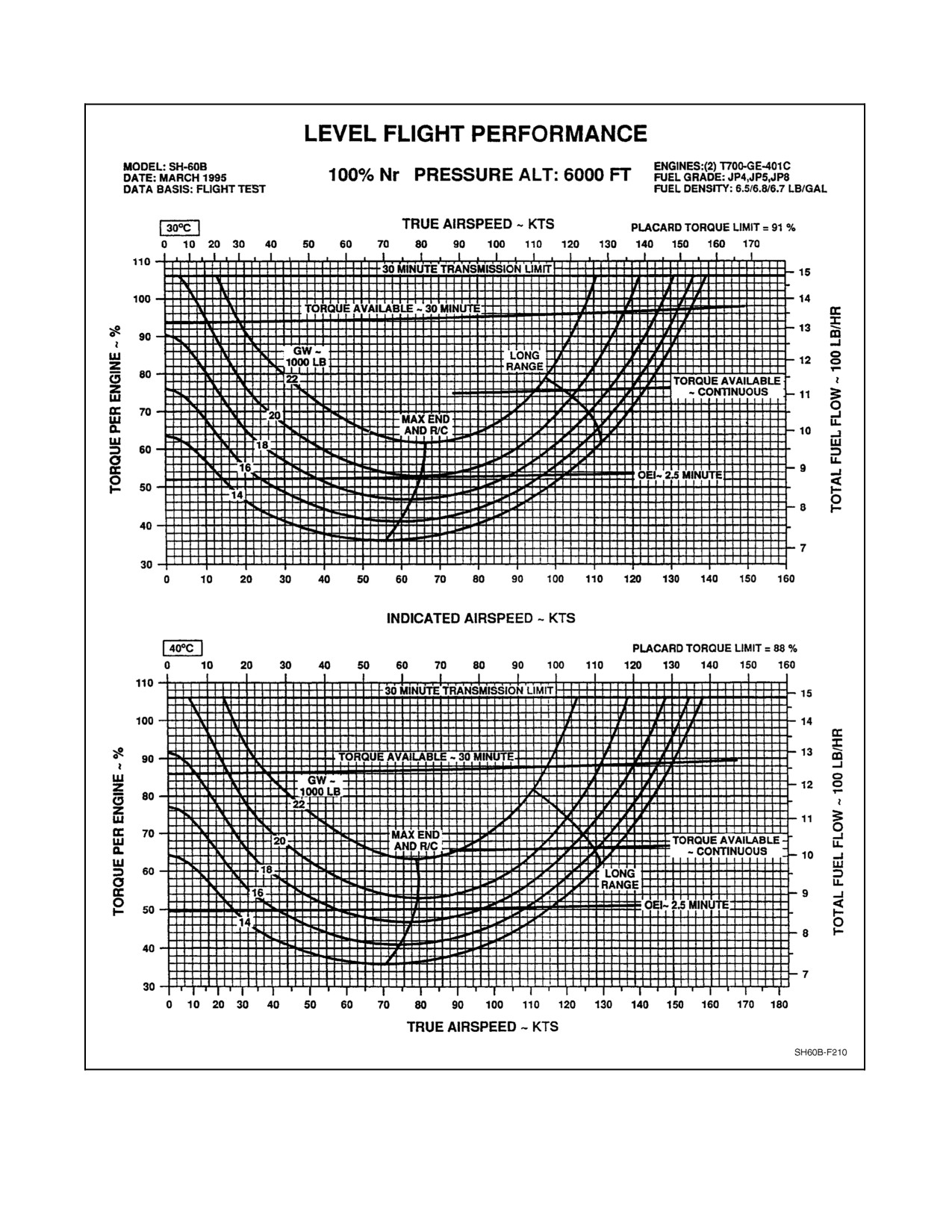
A1-H60BB-NFM-000
Figure 28-16. Level Flight Performance (6,000 Feet, 30, 40 °C) Charts
28-19
ORIGINAL
A1-H60BB-NFM-000
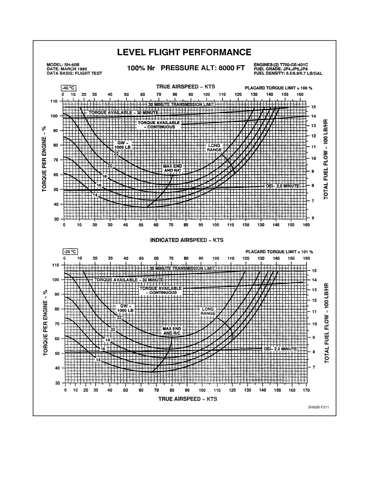
Figure 28-17. Level Flight Performance (8,000 Feet, --40, --20 °C) Charts
ORIGINAL
28-20
A1-H60BB-NFM-000
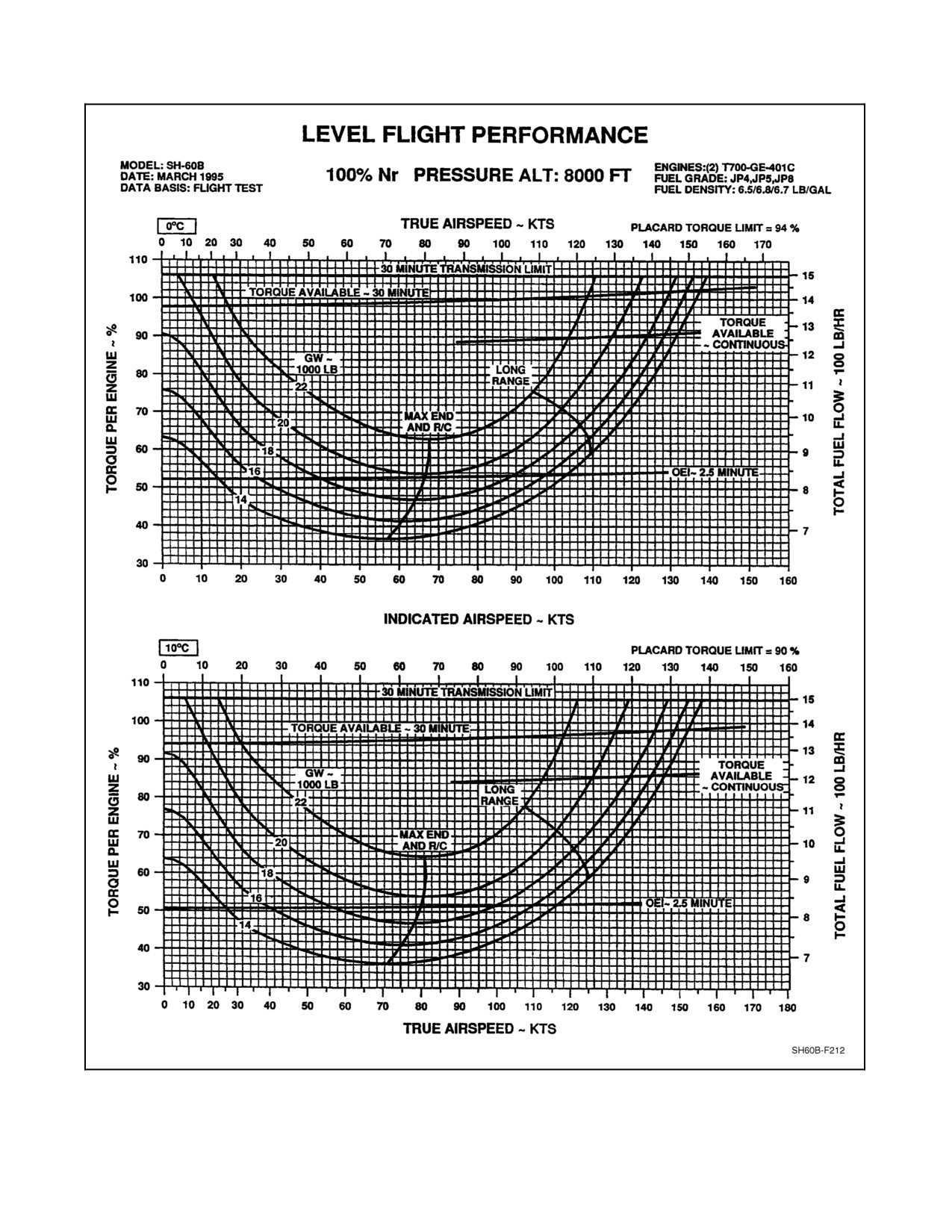
Figure 28-18. Level Flight Performance (8,000 Feet, 0, 10 °C) Charts
28-21
ORIGINAL
A1-H60BB-NFM-000
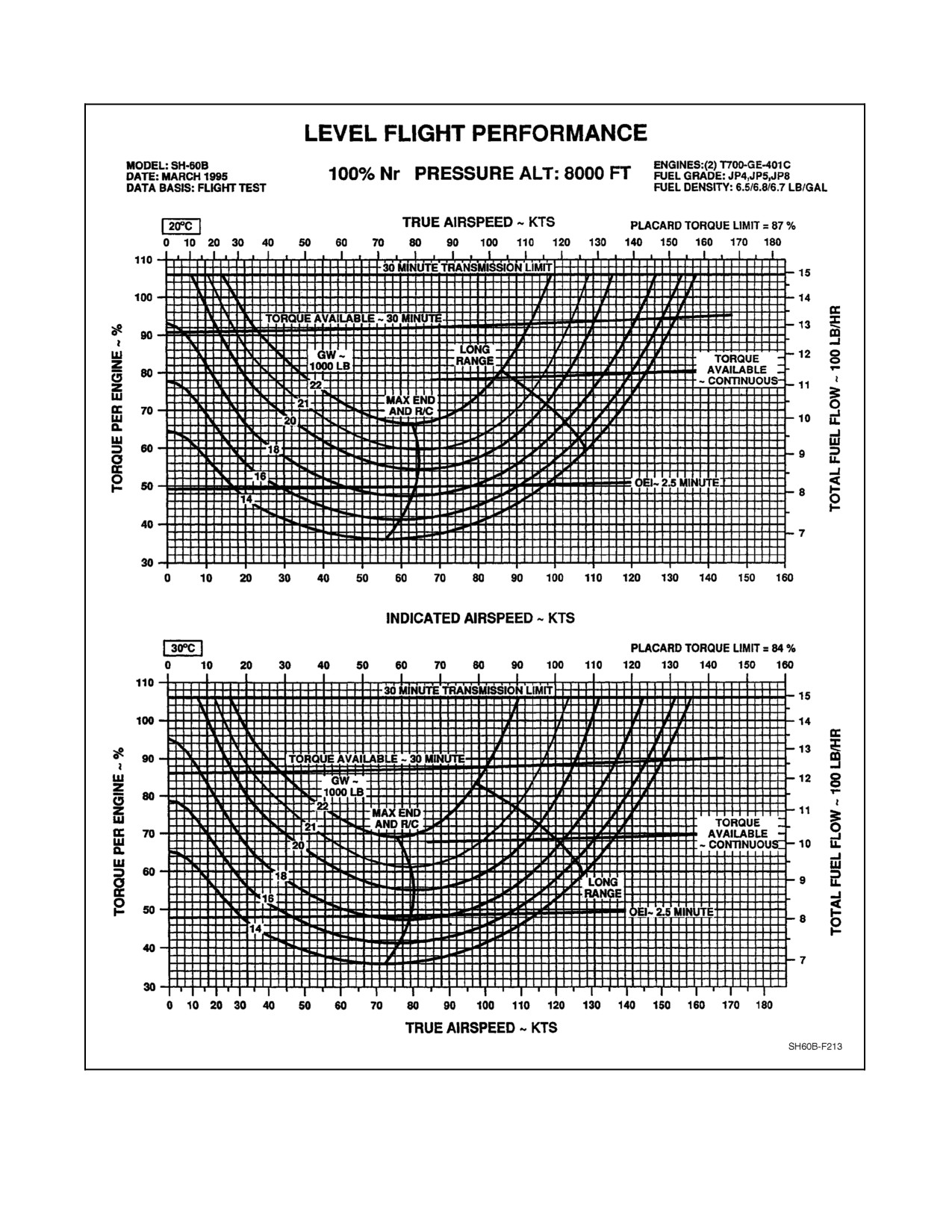
Figure 28-19. Level Flight Performance (8,000 Feet, 20, 30 °C) Charts
ORIGINAL
28-22
A1-H60BB-NFM-000
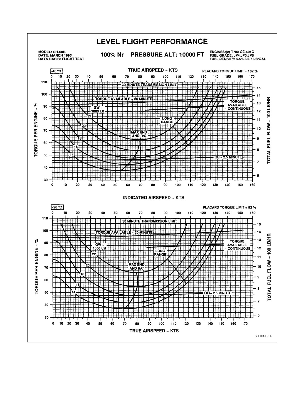
Figure 28-20. Level Flight Performance (10,000 Feet, --40, --20 °C) Charts
28-23
ORIGINAL
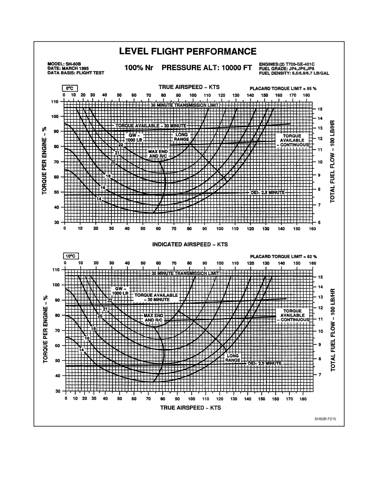
A1-H60BB-NFM-000
Figure 28-21. Level Flight Performance (10,000 Feet, 0, 10 °C) Charts
ORIGINAL
28-24
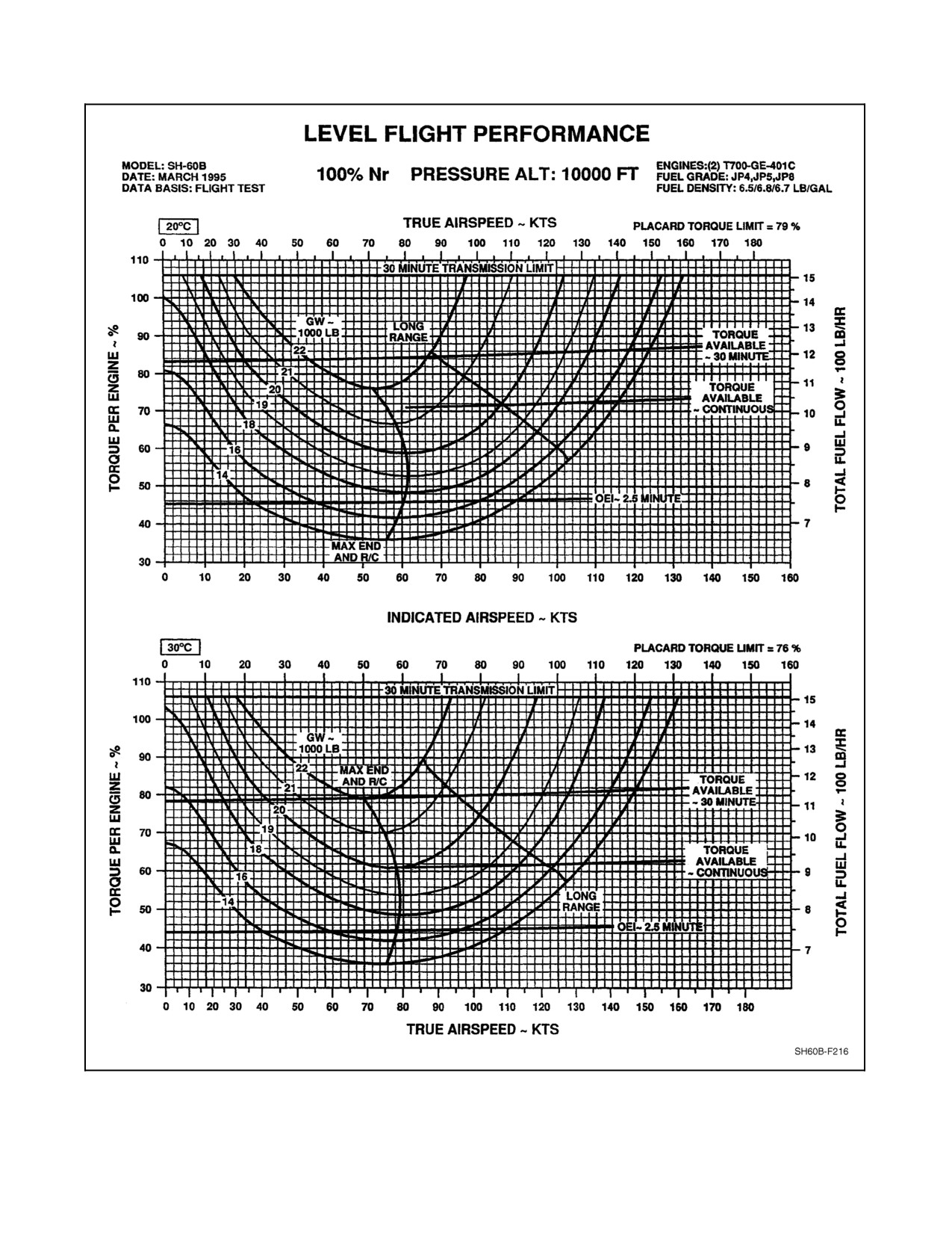
A1-H60BB-NFM-000
Figure 28-22. Level Flight Performance (10,000 Feet, 20, 30 °C) Charts
28-25/(28-26 blank)
ORIGINAL
A1-H60BB-NFM--000
INDEX
Page
Page
No.
No.
A
AGM-114 Hellfire missile
launch/training procedure
7-77
Ability to maintain level flight,
Air taxi
7-89
single engine chart
27-1
Air--capable ship helicopter operations
8-4
Sample problem for use of ability to
Air--capable ship launch and
maintain level flight,
recovery procedures
8-5
single engine chart
27-1
Approach procedures
8-6
Abort start
12-21
Shipboard launch/recovery limitations
8-6
AC bus tie system
2-54
Air--capable ship launch and
AC electrical system
2-49
recovery procedures
8-5
AC ESS bus off caution light
12-61
Air--mass
9-44
Accelerometer null procedures
7-64
Air-to-air receive mode
16-12
Accessory module
2-33
Air-to-air transmit/receive mode
16-16
Adaptability/flexibility
19-3
Airborne release
8-23
Adjustment:
Airborne tactical officer
5-2
GAU-16/A headspace adjustment
9-59
Aircraft control changes
19-8
GAU-16/A headspace adjustment
Aircraft performance
9-45
checklist
9-60
In flight power available check
9-46
GAU-16/A timing adjustment
9-60
Power required
9-46
GAU-16/A timing adjustment checklist
9-61
Aircraft startup
8-15
Seat adjustment
2-129
Aircraft tiedown instructions
3-17
Advanced helicopter emergency
Aircraft tiedown requirements
3-17
egress lighting system
2-142
Main rotor tiedown
3-19
Aerodynamic limitations
4-8
Aircraft tiedown requirements
3-17
Airspeed operating limits
4-8
Aircraft tiedown/securing
3-17
Autorotation
4-12
Aircraft tiedown instructions
3-17
Controllable searchlight airspeed limits
4-8
Aircraft towing
3-14
Minimum height for safe landing
Aircrew currency requirements
5-6
after single- or dual-engine failure
4-8
Special mission/lookout non-aircrewman
5-6
AFCS caution lights
12-52
Aircrew definitions
19-6
AFCS degraded caution light on
12-52
Aircrew grading criteria
20-14
AFCS fail advisory lights
12-52
Flight evaluation grading criteria
20-14
SAS caution light on
12-53
Oral examination grading criteria
20-14
AFCS control panels
2-85
Aircrewman checklists
7-41
AFCS degraded caution light on
12-52
Before landing checklist
7-47
AFCS emergencies
12-50
Post flight checklist
7-49
Coupler emergencies
12-50
Post landing checks
7-48
Stabilator malfunctions
12-54
Post takeoff checks
7-47
Unusual attitude recovery
12-56
Prestart checklist
7-41
AFCS fail advisory lights
12-52
Pretakeoff checklist
7-44
AFCS voltage sensor relay
2-89
RAST recovery checklist
7-48
AGM--114 Hellfire preflight checklist
7-8
Utility systems checks
7-43
Index-1
ORIGINAL
A1-H60BB-NFM--000
Page
Page
No.
No.
Aircrewman ground training
5-6
Practice autorotative approach
7-94
Aircrewman qualifications
5-5
Self--contained approach procedures
8-8
Aircrew currency requirements
5-6
Standard mountain approach and landing . . .
9-50
Night vision device aircrewman
5-6
Steep approach
7-92
Night vision device
Visual approach
8-7
aircrewman instructor
5-6
Approach procedures
8-6
Qualified observer
5-6
Instrument approach
8-7
Aircrewman utility systems checks
7-43
Landing transition
8-8
Cargo hook preoperational check
7-44
Self--contained approach procedures
8-8
Rescue hoist preoperational check
7-43
Visual approach
8-7
Airspeed indicator
2-112
Approach to landing
7-91
Airspeed operating limits
4-8
Normal approach
7-92
Airspeed system correction
Steep approach
7-92
from level flight charts
28-1
APU
2-47
Sample problem for airspeed system
Accessories
2-47
correction from level flight charts
28-1
Control and monitoring
2-47
Alert launch checklist
7-52
Controls
2-47
Engagement
7-57
Oil system servicing
3-14
Starting APU and engines
7-57
Operating limitations
4-17
Alpine meadows
9-45
Start system
2-49
Alternate engine start procedures
7-83
Turn--up checklist
7-84
Crossbleed start
7-83
APU emergencies
12-29
Alternator
2-10
Caution lights
12-29
Altitude hold
2-96
Emergency start
12-29
Altitude limitation
4-12
Fail caution light on
12-29
AN/PEQ-3 uncommanded lasing
12-101
Fire
12-70
Anabatic
9-43
Generator caution light on
12-29
Angle of attack
11-5
Oil temp hi caution light on
12-30
Anti--ice:
Area:
Eng inlet anti--ice on (#1/#2)
Cockpit -- left side (area 2)
7-2
advisory light on
12-28
Cockpit -- right side (area 11)
7-7
Engine and inlet anti--ice system
2-123
Confined area landing
7-93
Engine anti--ice check
7-63
Flight controls and hydraulics bay (area 3) . . .
7-3
Engine inlet anti--ice valve
2-17
Fuselage -- left side (area 5)
7-5
Anticollision lights
2-65
Fuselage -- right side (area 10)
7-7
Applicability
20-1
Main rotor/transmission/
Approach:
APU/engines (area 4)
7-4
Auto approach to a hover
2-97
Nose section (area 1)
7-2
Automatic approach checklist
7-52
Tail cone -- left side (area 6)
7-6
Instrument approach
8-7
Tail cone -- right side (area 9)
7-7
Instrument approach procedure
13-1
Tail pylon -- left side (area 7)
7-6
Loss of tail rotor control approach
Tail pylon -- right side (area 8)
7-6
and landing technique
12-39
ASQ--81 towed body down limit
Normal approach
7-92
switch malfunction
12-87
ORIGINAL
Index-2
A1-H60BB-NFM--000
Page
Page
No.
No.
ASQ--81 towed body fails
Aviation ship launch and
to seat properly
12-87
recovery procedures
8-3
Assembly:
Avionics cooling
2-122
Attitude gyro control assembly (AGCA)
(pilot and ATO)
16-4
B
Main rotor hub
2-25
Backlash
9-44
Assertiveness
19-2
Backup hyd pump fails to operate
12-49
Attitude and airspeed hold
2-95
Backup hydraulic pump
Attitude gyro control assembly
16-4
hot weather limitations
4-17
Attitude indicator
2-113
Backup hydraulic system
2-73
Audio converter-processor
15-2
Backup pump limits
4-17
Auto approach to a hover
2-97
Backup rsvr low caution light on
12-44
Automatic approach checklist
7-52
Bank angles limitation
4-12
Barometric altimeter
2-113
Automatic depart
2-98
Barometric altimeter/encoder
2-113
Automatic flight control system
2-84
Battery fault caution light
12-61
AFCS control panels
2-85
Battery low charge caution light
12-62
DAFCS
2-87
BDHI displayed data as a function
Stabilator system
2-89
of selected mode
16-9
Automatic preflight checks
2-105
Bearing-distance-heading indicators
16-5
Automatic sonobuoy launching
7-68
Before leaving the helicopter
14-4
Autopilot
2-95
Bingo profile, maximum range
Autopilot
2-95
with dual engine
25-1
Autorotation
4-12, 12-22
Blade damper accumulator
3-12
Autorotational descent
7--90, 11-12
Blade de--ice control panel
2-123
Autorotational entry
11-11
Blade de--ice system check
7-61
Autorotational recovery
11-12
Blade de--ice system operation
2-123
Autorotative state
11-11
Blade de--ice test panel
2-128
Aux fuel xfer fault caution light
12-67
Blade de--ice test system operation
2-128
Blade fold system
2-101
Auxiliary fuel system
2-45
Blade folding
2-101
Auxiliary fuel tanks
2-46
Blade retention
2-26
Fuel management control panel
2-45
Blade stall
11-3
Fuel transfer system
2-46
Blade stall causes
11-3
Manual fuel transfer check
2-46
Methods of eliminating
Auxiliary fuel tanks
2-46
roughness caused by blade stall
11-3
Auxiliary power unit system
2-47
Blade stall causes
11-3
Aviation ship helicopter operations
8-3
Blade stall chart
22-1
Aviation ship launch and
Sample problem for use
recovery procedures
8-3
of blade stall chart
22-1
Launch and recovery signals
8-3
Blade, pylon/stabilator fold or spread
4-15
Night and IMC operations
8-4
Blade/pylon/stabilator folding and spreading
8-2
Shipboard launch/recovery limitations
8-3
Blowback
11-2
Shutdown
8-4
Boost servo hardover
12-50
Waveoff procedures
8-4
Boost servos
2-82
Index-3
ORIGINAL
A1-H60BB-NFM--000
Page
Page
No.
No.
Breakup and rendezvous procedures
9-35
Change of scans
13-2
Briefing/debriefing
6-1
Characteristics:
Crew brief and preflight
19-8
Engine oil system characteristics
14-2
Debriefing
6-8
General flight characteristics
11-1
General briefing
6-1
Maneuvering flight characteristics
11-6
Gunner brief
6-7
Rollover characteristics
11-13
Landing site evaluation brief
9-41
SH-60B tail rotor characteristics
11-4
Mission--specific briefing
6-2
Chart(s):
Passenger brief
6-8
Ability to maintain level flight,
single engine chart
27-1
Qualified observer brief
6-7
Blade stall chart
22-1
Density altitude chart
22-1
C
Engine performance charts
22-5
Cabin dome lights
2-68
Engine performance, contingency
Cabin inspection
7-10
(2.5 minute) power chart
22-5
Cable grip rigging procedures
12-89
Engine performance, intermediate
(30 minute) power chart
22-5
Rescue hoist cable cut
12-90
Engine performance, maximum
Rescue hoist cable separation
12-90
continuous power chart
22-5
Rescue hoist fouled cable
12-89
Functional checkflight charts
Runaway hoist
12-89
and tables
10-60
Canyon recce
9-50
Hover charts
23-1
Canyons and ravines
9-45
Maximum power check chart
10-57
Cargo delivery
9-21
Maximum range, standard day chart
25-1
Cargo hook preflight
9-22
Nautical miles per pound of
Crewman cargo procedures
9-24
fuel conversion chart
25-1
Electrical release
9-21
Range chart
27-1
Emergency release
9-22
Sample problem for airspeed system
In--flight procedures
9-24
correction from level flight charts
28-1
Manual release
9-22
Sample problem for climb performance,
Sideflare pattern
9-24, 9-25
single engine, 30 minute power chart
27-1
Cargo hook:
Sample problem for cruise capability,
Electrical release
2-137
time, and range chart
28-1
Emergency release
12-81
Sample problem for nautical miles per
Emergency release test
2-137
pound of fuel conversion chart
25-1
Preflight
9-22
Sample problem for use of ability to
maintain level flight,
Preoperational check
7-44
single engine chart
27-1
System
2-137
Sample problem for use of
Weight limitation
4-15
blade stall chart
22-1
Cargo pickup
9-20
Sample problem for use of density
Caution/advisory light system
2-117
altitude chart
22-1
Cautions
12-19, 12-20, 12-21
Sample problem for use of engine
Center of gravity limitations
4-15
performance, contingency (2.5 minute)
Central display unit
2-21
power, intermediate (30 minute) power
Change of controls
13-2
and maximum continuous power charts . . .
22-5
ORIGINAL
Index-4
A1-H60BB-NFM--000
Page
Page
No.
No.
Sample problem for use of maximum
Straightening
8-26
range, standard day chart
25-1
Tactical/combat
7-33
Sample problem for use of
Takeoff
7-32, 10-33
temperature conversion chart
22-1
Taxi
7-32, 10-32
Service ceiling
28-1
Traversing
8-11
Single/dual--engine fuel flow
25-1
VERTREP operations
7-61
Temperature conversion chart
22-1
White lighting
7-40
Torque factor chart
10-58
Chip-detector caution lights self-test
2-34
Use of charts
28-2
Circle recce
9-49
Checklist(s):
Circuit breaker numbering convention
12-6
AGM--114 Hellfire preflight
7-8
Circuit breaker panels
2-56
Aircrewman
7-41
Cirque recce
9-50
Aircrewman before landing
7-47
Cirques
9-45
Aircrewman post flight
7-49
Climb checks
10-36
Aircrewman prestart
7-41
Climb performance, dual-engine,
Aircrewman pretakeoff
7-44
30 minute power, zero wind
24-1
Alert launch
7-52
Sample problem for use of climb
APU turn--up
7-84
performance chart, dual-engine,
Automatic approach
7-52
30 minute power, zero wind
24-1
Checklist methods
19-8
Climb performance, single engine,
Engine fuel system priming
7-59
30 minute power
27-1
Fuel dump
7-59
Sample problem for climb performance,
single engine, 30 minute power chart
27-1
Functional checkflight
10-4
Climb procedures
7-90
GAU-16/A headspace adjustment
9-60
Cruise climb
7-90
GAU-16/A timing adjustment
9-61
Hot refuel
7-36
Initial climb to altitude
7-90
Maximum performance climb
7-90
Landing
7-35, 10-52
LSO console preoperational
8-10
Clock
2-116
MAD operational
7-81
Closed--book examination
20-3
Mission/weapons system
7-29, 10--31
Cockpit -- left side (area 2)
7-2
Mk 46 torpedo preflight
7-8
Cockpit -- right side (area 11)
7-7
Mk 50 torpedo preflight
7-9
Cockpit and sensor operator seats
2-129
NVD lighting
7-40
Seat adjustment
2-129
Pocket
12-6
Seat belts
2-129
Post landing
7-35, 10-52
Shoulder harness lock lever
2-129
Post launch
8-16
Cockpit fire/cabin fire
12-71
Post straightening
8-30
Cockpit interruptions and distractions
19-5
Post takeoff
7-33
Reducing human factor errors
19-5
Prelaunch
8-14
Cold--weather operations
14-1
RAST recovery
7-48
Before leaving the helicopter
14-4
Recovery
8-17
Cold--weather preflight check
14-1
Remote lasing
7-79
Engine oil system characteristics
14-2
Rig for rescue
7-60
Engine starting
14-2
Start
7-12
General
14-1
Index-5
ORIGINAL
A1-H60BB-NFM--000
Page
Page
No.
No.
Cold--weather preflight check
14-1
Lighting considerations
9-40
Exterior inspection
14-1
Safety considerations during
Interior inspection
14-2
evaluation flights
20-4
Combustion section
2-1
Slope landing/takeoff considerations
11-14
Communication(s)
8-37, 15-1, 19--2
Tail rotor considerations
in low-speed flight
11-4
Control panel
15-3
Contour crawl
9-47
Hoist operator and maintenance ibs
15-14
Control(s):
Identification system
15-36
AFCS control panels
2-85
Intercommunication system
15-27
Aircraft control changes
19-8
Interference blanker
15-44
APU control and monitoring
2-47
Introduction
15-1
APU controls
2-47
Lost communication procedures
Attitude gyro control assembly
with a VERTREP load
9-29
(pilot and ATO)
16-4
Radio control panels
15-14
Automatic flight control system
2-84
Radio terminal set, AN/ARQ-44
Blade de--ice control panel
2-123
or AN/ARQ-44A
15-44
Change of
13-2
Radios
15-14
Communications control panel
15-3
Security equipment, TSEC/KG-45
15-35
Communications system control group
15-2
Speech security system
15-30
Digital electronic control unit
2-10
System control group
15-2
ECS control panel
2-121
Compass system
16-4
Engine control quadrant
2-6
Attitude gyro control assembly
16-4
Engine control system
2-6
Bearing-distance-heading indicators
16-5
Engine power control failure
12-12
Remote compass transmitters
Engine warmup and control exercise
14-3
(pilot and ATO), ML-1(MOD)
16-5
Environmental control system
2-121
Components of the navigation subsystem
16-1
Flight control servo systems
2-79
Compass system
16-4
Flight control system
2-79
Direction finder group AN/ARA-50
16-16
Flight controls and hydraulics
Navigation switching interface unit
16-1
bay (area 3)
7-3
On-top position indicator receiver
16-16
Fuel management control panel
2-45
Radar navigation set, AN/APN-217
16-9
Hover trim control panel
2-130
TACAN navigation set, AN/ARN-118(V)
16-11
Hydromechanical control unit
2-8
Compressor section
2-1
Loss of tail rotor control
12-41
Compressor stall
12-16
Loss of tail rotor control approach
Concept
20-1
and landing technique
12-39
Applicability
20-1
Loss of tail rotor control malfunctions
12-38
Conduct of flight
9-35
Mechanical control system
2-79
Conduct of the evaluation
20-3
Radio control panels
15-14
Confined area landing
7-93
RAST control panel indicators
2-109
Consecutive landing practice
Remote control unit
15-35
(RA yo--yos or free deck bounces)
8-25
Rescue hoist control panel
2-130
Considerations:
Restricted flight controls
12-39
GPS accuracy considerations
16-23
TACAN control
16-12
Landing considerations for one
Tail rotor control cable failures
12-38
or two wheel landings
9-14
Tail rotor control system
2-79
ORIGINAL
Index-6
A1-H60BB-NFM--000
Page
Page
No.
No.
Control mixing
2-82
Leadership
19-3
Controllable searchlight airspeed limits
4-8
Mission analysis
19-3
CONV (#1/#2) caution lights
12-61
Situational awareness
19-1
Convective
9-43
Cross--slope landing
11-15
Coordinated flight
11-6
Crossbleed start
7-83
Coupler emergencies
12-50
Crossover recce
9-49
Crew brief and preflight
19-8
Crosswind landing
7-92
Crew general responsibilities
19-6
Crowns
9-44
Dual--concurrence items
19-7
Cruise
7-90,
14-3, 14-9
Crew hover
2-100
Cruise and descent
2-13
Crew served weapon procedures
9-55
Cruise capability, time, and range
28-1
Hand signals
9-59
Sample problem for cruise capability,
M60D/M240D barrel change procedures
9-58
time, and range chart
28-1
M60D/M240D field of fire check
9-56
Cruise climb
7-90
M60D/M240D lock and load procedures
9-57
Cruise descent
7-90
M60D/M240D machine gun
9-55
CV night approaches
8-4
M60D/M240D machine gun
firing procedures
9-57
D
M60D/M240D rigging procedures
9-56
M60D/M240D stowing procedures
9-58
DAFCS
2-87
Voice commands
9-58
Damper failure
12-30
Crew--served weapons
12-97
Data-link antennas, AS-3273/ARQ-44
15-36
GAU-16/A emergencies
12-99
Day VERTREP operations
9-25
M60D/M240D emergencies
12-97
VERTREP safety
9-27
Crewman cargo procedures
9-24
DC bus tie system
2-55
Crewman safety belt anchor points
2-143
DC electrical system
2-54
Criteria:
DC ESS bus off caution light
12-61
Aircrew grading
20-14
De--ice:
Flight evaluation grading
20-4, 20-14
Blade de--ice control panel
2-123
Oral examination and OFT/WST
Blade de--ice system check
7-61
procedures evaluation grading
20-4
Blade de--ice system operation
2-123
Oral examination grading
20-14
Blade de--ice test panel
2-128
Pilot grading
20-4
Blade de--ice test system operation
2-128
Critical rollover
11-13
Helicopters equipped with blade
14-6
Dynamic rollover
11-13
Helicopters not equipped with blade
14-6
CRM attitude
19-4
CRM program administration
19-1
MR de--ice fail caution light
12-65
CRM skills and behaviors
19-1
MR de--ice fault caution light
12-65
Adaptability/flexibility
19-3
Rotor blade de--ice system
2-123
Assertiveness
19-2
TR de--ice fail caution light
12-65
Communication
19-2
De--ice malfunctions
12-63
CRM attitude
19-4
De--ice system caution lights
12-63
Decision making
19-2
Pwr main RTR and/or
Factors affecting CRM
19-4
pwr tail RTR light on
12-63
Index-7
ORIGINAL
A1-H60BB-NFM--000
Page
Page
No.
No.
De--ice system caution lights
12-63
Desert procedures
14-9
Ice detect fail caution light
12-64
Designation of pilots
10-1
Ice detected caution light
12-63
Digital electronic control unit
2-10
Left or right pitot heat caution lights
12-64
Dimensions
1-1
MR de--ice fail caution light
12-65
Direct deployment
9-15
MR de--ice fault caution light
12-65
Direction finder group AN/ARA-50
16-16
TR de--ice fail caution light
12-65
Display:
De--ice/anti-ice systems
2-122
Central display unit
2-21
De--ice master switch
2-122
Pilot display units
2-23
Engine and inlet anti--ice system
2-123
Vertical instrument display system
2-20
Pitot heater system
2-128
Division
9-31
Rotor blade de--ice system
2-123
Down--flow
9-44
Windshield anti-ice system
2-128
Down--slope landings
11-15
Windshield wiper and washer system
2-128
Drinking water container
2-143
Debriefing
6-8
Dual--concurrence items
19-7
Decision making
19-2
Dual--engine failure in flight/hover
12-22
Deck:
Dynamic rollover
11-13
Consecutive landing practice
(RA yo--yos or free deck bounces)
8-25
E
Deck conditions
8-4
Engine high--side failure on deck
12-14
ECS control panel
2-121
Flight/hangar deck procedures
8-1
ECS shutdown caution light on
12-20
Free deck landing
8-24
Electrical:
Helicopter on deck
3-8
AC electrical system
2-49
Unusual vibrations on deck
12-32
Cargo hook electrical release
2-137
Deck conditions
8-4
DC electrical system
2-54
DECU operation
2-11
Electrical release
9-21
Definitions
9-1, 20-1
Engine electrical system
2-10
Density altitude chart
22-1
Electrical system
2-49
Sample problem for use of density
AC bus tie system
2-54
altitude chart
22-1
AC electrical system
2-49
Descending
14-8
Circuit breaker panels
2-56
Descending flight and autorotation
11-10
DC bus tie system
2-55
Autorotational entry
11-11
DC electrical system
2-54
Autorotational recovery
11-12
Utility and test receptacles
2-65
Autorotative state
11-11
Electrical system caution lights
12-60
Vortex ring state/power settling
11-10
AC ESS bus off caution light
12-61
Descent
7-90
DC ESS bus off caution light
12-61
Autorotational descent
11-12
GEN BRG (#1/#2) caution lights
12-60
Autorotative descent
7-90
Electrical system malfunctions
12-56
Cruise descent
7-90
Battery fault caution light
12-61
Descent
7-90
Battery low charge caution light
12-62
Night/IMC descent over water
7-91
CONV (#1/#2) caution lights
12-61
Description
28-2
Electrical system caution lights
12-60
ORIGINAL
Index-8
A1-H60BB-NFM--000
Page
Page
No.
No.
Emergencies:
Airflow
2-5
AFCS
12-50
Alternate engine start procedures
7-83
APU
12-29
And engine inlet anti-ice limitations
4-17
Coupler
12-50
Anti--ice check
7-63
Fire
12-69
Anti--ice/start bleed valve malfunction
12-27
Bingo profile, maximum range
GAU-16/A
12-99
with dual engine
25-1
Hellfire missile
12-91
Bleed air
22-11
M60D/M240D
12-97
Chip detector
2-15
Main rotor system
12-30
Chip/engine oil pressure
Mission equipment/weapon system
12-81
low caution lights on
12-20
Simulated
19-8
Cleaning procedures
7-64
Stores
12-96
Combustion section
2-1
Torpedo
12-95
Compressor section
2-1
Emergency:
Control quadrant
2-6
Advanced helicopter emergency
External engine fire
12-69
egress lighting system
2-142
Fuel filter
2-6
APU emergency start
12-29
Fuel system
2-6
Cargo hook emergency release
12-81
Fuel system priming checklist
7-59
Cargo hook emergency release test
2-137
Gas--generator turbine
2-1
Crash position
12-77
High--side failure in flight
12-12
Equipment
2-140
High--side failure on deck
12-14
Helicopter emergency egress
Idle limits with gust lock engaged
4-6
lighting system
2-142
Inlet air flow
2-1
HIFR emergency procedures
8-38
Inlet anti--ice valve
2-17
Individual helicopter emergency
Inlet particle separator
2-1
egress lighting system
2-142
Inlet section
2-1
Locator transmitter systems
2-140
Internal engine fire
12-70
Panel
2-137
Limits
4-6
Release
9-22
Low--side failure in flight
12-14
RAST cable emergency release
12-83
Main frame and accessory section
2-5
Malfunction during hover/takeoff
12-21
Survival and emergency equipment
2-140
Malfunction in flight
12-12
Emergency locator transmitter systems
2-140
Maximum gross weight to
Emergency panel
2-137
hover in ground effect, single engine
27-1
Emergency release
9-22
Oil circulation through
Emitter hazard and standoff distances
4-15
the engine scroll vanes
2-19
Emitter hazards
8-31
Oil servicing
3-11
Eng inlet anti--ice on (#1/#2)
Oil system characteristics
14-2
advisory light on
12-28
Performance charts
22-5
Engagement
7-57
Performance, contingency (2.5 minute)
Engine
2-1
power chart
22-5
Ability to maintain level flight,
Performance, intermediate (30 minute)
single engine chart
27-1
power chart
22-5
Advisories
12-27
Performance, maximum
Air restart
12-24
continuous power chart
22-5
Index-9
ORIGINAL
A1-H60BB-NFM--000
Page
Page
No.
No.
Engine (cont):
Hydromechanical control unit
2-8
Power turbine
2-5
Inputs to the HMU
2-8
Sample problem for maximum gross weight
Load demand system
2-6
to hover in ground effect, single engine . . .
27-2
Overspeed and drain valve
2-10
Sample problem for use of ability to
Engine electrical system
2-10
maintain level flight,
Alternator
2-10
single engine chart
27-1
DECU operation
2-11
Sample problem for use of engine
Digital electronic control unit
2-10
performance, contingency (2.5 minute)
Ignition system
2-12
power, intermediate (30 minute) power
Engine high speed shaft failure
12-16
and maximum continuous power charts . . .
22-5
Load demand system malfunction
12-17
Shutdown
14-9
Engine instruments
2-20
Shutdown in flight
12-24
Vertical instrument display system
2-20
Start and rotor engagement
8-2
Engine malfunctions
12-11
Start limits
4-6
Engine caution lights
12-19
Start, APU
2-16
Engine high speed shaft failure
12-16
Start, crossbleed
2-16
Engine malfunction in flight
12-12
Starter #1 or #2 advisory light on
12-28
Engine power control failure
12-12
Starter limits
4-6
Engine oil system
2-13
Starting
14-2, 14-9
Engine chip detector
2-15
Temperature limitations
4-6
Oil cooler
2-15
Torque or TGT spiking/fluctuations
12-15
Oil filter
2-15
Warmup and control exercise
14-3
Oil supply and scavenge system
2-15
Engine advisories
12-27
Oil tank
2-13
Eng inlet anti--ice on (#1/#2)
Engine oil temperature high
12-19
advisory light on
12-28
Abort start
12-21
Engine anti--ice/start bleed
Autorotation
12-22
valve malfunction
12-27
Dual--engine failure in flight/hover
12-22
Engine starter #1 or #2
Engine advisories
12-27
advisory light on
12-28
Engine air restart
12-24
Engine and inlet anti--ice system
2-16, 2-123
Engine malfunction
Engine anti--ice/start bleed valve
2-16
during hover/takeoff
12-21
Engine inlet anti--ice valve
2-17
Engine shutdown in flight
12-24
Engine oil circulation through
Single--engine failure
12-23
the engine scroll vanes
2-19
Single-engine landing
12-25
Engine caution lights
12-19
Engine operation summary
2-13
ECS shutdown caution light on
12-20
Cruise and descent
2-13
Engine chip/engine oil pressure
Starting and ground idle
2-13
low caution lights on
12-20
Summary
2-13
Engine control system
2-6
Takeoff and climb
2-13
Engine control quadrant
2-6
Engine parameter sensing
2-19
Engine fuel filter
2-6
Ng sensing
2-19
Engine fuel system
2-6
Np and torque sensing
2-19
Engine-driven fuel boost pump
2-6
Np sensing
2-19
HMU operation
2-9
TGT sensing
2-19
ORIGINAL
Index-10
A1-H60BB-NFM--000
Page
Page
No.
No.
Engine performance
22-5
Environmental restrictions
4-17
Torque factor sample problem
22-11
APU operating limitations
4-17
Backup hydraulic pump hot
Engine performance procedures
22-5
weather limitations
4-17
Engine bleed air
22-11
Engine and engine inlet
Maximum power check
22-5
anti-ice limitations
4-17
Torque factor method
22-5
Temperature limitations
4-17
Engine power checks
10-57
Equipment:
Maximum power check chart
10-57
Emergency
2-140
Sample problem 1
10-59
Litter installation
2-143
Sample problem 2
10-59
Minimum
4-16
Torque factor chart
10-58
Minimum equipment for passengers
4-16
Torque factor procedure
10-58
Miscellaneous
2-143
Torque factor procedure in flight
10-58
Personal flying equipment requirements
5-7
Torque factor terms
10-57
SAR
9-1
Torque factor TGT reference
10-58
Survival
2-140
Survival and emergency
2-140
Engine power control failure
12-12
Evaluation:
Engine high--side failure in flight
12-12
Conduct of the
20-3
Engine high--side failure on deck
12-14
Flight
20-3, 20-5
Engine low--side failure in flight
12-14
Flight evaluation grade determination
20-21
Engine start system
2-15
Flight evaluation grading criteria . . .
20-4, 20-14
Engine start, APU
2-16
Ground
20-2
Engine start, crossbleed
2-16
Landing site evaluation brief
9-41
Engine starting
14-2, 14-9
NATOPS evaluation forms
20-22
Cruise
14-3
OFT/WST
20-5
Engine warmup and control exercise
14-3
OFT/WST procedures
20-3
Landing
14-4
Oral
20-3
Takeoff
14-3
Oral examination and OFT/WST
Taxiing
14-3
procedures evaluation (if conducted)
20-3
Engine-driven fuel boost pump
2-6
Oral examination and OFT/WST
procedures evaluation grading criteria
20-4
Engine/APU boost/fuel prime system
2-39
Safety considerations during
Engine/APU fire-extinguishing system
2-118
evaluation flights
20-4
Fire-extinguishing system,
Examination:
impact switch operation
2-121
Closed--book
20-3
Engine/inlet anti--icing
14-5
Open--book
20-2, 20-3
Engines:
Oral
20-5
Starting APU and engines
7-57
Oral examination and OFT/WST
Starting engines and
procedures evaluation (if conducted)
20-3
rotor engagement
7-21, 10-13
Oral examination and OFT/WST
The engines
1-4
procedures evaluation grading criteria
20-4
Entrance and egress
2-121
Oral examination grading criteria
20-14
Environmental control system
2-121
Exceeding operational limits
4-1
Avionics cooling
2-122
Excess tail rotor thrust
12-40
ECS control panel
2-121
Explanation of terms
12-6
Index-11
ORIGINAL
A1-H60BB-NFM--000
Page
Page
No.
No.
Exterior arrangement
1-4
FCF record cards
10-2
Exterior inspection
14-1
Figure eight recce
9-48
Exterior lighting
2-65
Final grade determination
20-22
Anticollision lights
2-65
Fire:
Landing/hover lights
2-66
APU fire
12-70
Position lights
2-65
Cockpit fire/cabin fire
12-71
Fire emergencies
12-69
Recovery assist secure and
traverse lights
2-66
Fire extinguisher system servicing
3-14
Rotor head light
2-66
Internal engine fire
12-70
Searchlight
2-65
M60D/M240D field of fire check
9-56
External engine fire
12-69
Fire emergencies
12-69
External power requirements
3-14
APU fire
12-70
Cockpit fire/cabin fire
12-71
External tank jettison
2-47
Emergency crash position
12-77
F
External engine fire
12-69
Factors affecting CRM
19-4
Immediate landing/ditching
12-73
Factors affecting range and endurance
21-1
Immediate landing/ditching
Factors increasing the likelihood of
(aircrewmen)
12-79
loss of tail rotor effectiveness
11-4
Immediate landing/ditching (pilot)
12-78
Failure(s):
Internal engine fire
12-70
Damper
12-30
Lost aircraft procedures
12-79
Dual--engine failure in flight/hover
12-22
Planned ditching
12-77
Engine high speed shaft
12-16
Smoke and fumes elimination
12-72
Engine high--side failure in flight
12-12
Sonobuoy lithium battery venting
12-72
Engine high--side failure on deck
12-14
Underwater egress
12-80
Engine low--side failure in flight
12-14
Fire-detection system
2-117
Engine power control
12-12
Fire extinguisher system servicing
3-14
M60D/M240D failure to
Fire-extinguishing system,
fire/jammed gun
12-98
impact switch operation
2-121
MAD reel failure with towed
Five-step sequence
19-4
body deployed
12-86
Flashing AFCS degraded caution light
12-52
Minimum height for safe landing
Flashing AFCS degraded caution light
after single- or dual-engine
4-8
with alt fail advisory light on
12-53
Practice single--engine failure in
Flight:
an HOGE (cut and run/cut gun)
7-95
Automatic flight control system
2-84
RAST main probe messenger
12-81
Checks
10-37
Rescue hoist
12-88
Stabilator auto mode
12-54
Conduct of
9-35
Stabilator indicating system
12-56
Control servo systems
2-79
Tail rotor control cable
12-38
Control system
2-79
Tail rotor servo
12-38
Controls and hydraulics bay (area 3)
7-3
Fault:
Coordinated
11-6
Aux fuel xfer fault caution light
12-67
Descending flight and autorotation
11-10
Battery fault caution light
12-61
Engine high--side failure in
12-12
MR de--ice fault caution light
12-65
Engine low--side failure in
12-14
FCF profile
10-2
Engine malfunction in
12-12
ORIGINAL
Index-12
A1-H60BB-NFM--000
Page
Page
No.
No.
Engine shutdown in
12-24
Flight in instrument
Evaluation
20-3, 20-5
meteorological conditions
4-16
Minimum aircraft equipment for
Evaluation grade determination
20-21
night or IMC flight over land
4-16
Evaluation grading criteria
20-4, 20-14
Minimum aircraft equipment for
Forward
11-2
night or IMC flight over water
4-17
General flight characteristics
11-1
Flight instruments
2-112
In flight power available check
9-46
Miscellaneous flight instruments
2-116
Instrument
5-7
Pitot static system
2-112
Instrument and console lights
2-66
Radar altimeter, AN/APN-194
2-113
Instrument flight conditions in formation . . .
9-36
Flight scheduling
7-1
Instrument flight procedures
13-1
Flight with external loads
9-20, 11-18
Level flight performance charts
28-2
Flight/form/division lead
9-35
Maneuvering
11-6
Flight/hangar deck procedures
8-1
Blade/pylon/stabilator
Maneuvering flight characteristics
11-6
folding and spreading
8-2
Miscellaneous flight instruments
2-116
Engine start and rotor engagement
8-2
Post flight checks
7-40, 10-57
General safety precautions
8-2
Restricted flight controls
12-39
Movement of helicopter
8-1
Scheduling
7-1
Flightcrew ground training
5-6
Sideward and rearward
7-89
Flightcrew qualifications
5-1
Slow-speed
11-2
Qualifications
5-1
Tail rotor considerations in low-speed
11-4
Waiver of requirements
5-1
Tail rotor spar loads in maneuvering
11-7
Flights from air--capable ships
5-7
Tail winds in transition to forward
11-2
FLIR uncommanded lasing
12-95
Torque factor procedure in
10-58
Flying:
Transition to forward
11-2
Mountain terrain
9-41
Unusual vibrations in
12-31
Terrain
9-39
With external loads
9-20, 11-18
Formation composition
9-31
Division
9-31
WOW advisory light on in
12-91
Section
9-31
Flight control servo systems
2-79
Formation flying
9-30
Control mixing
2-82
Conduct of flight
9-35
Pilot assist servos
2-82
Formation composition
9-31
Tail rotor servo
2-79
General
9-30
Flight control system
2-79
Instrument flight conditions in formation . . .
9-36
Automatic flight control system
2-84
Lead change
9-35
Flight control servo systems
2-79
Night formation
9-35
Mechanical control system
2-79
Rendezvous
9-31
Stability augmentation system
2-92
Responsibility
9-35
Flight evaluation
20-3, 20-5
Forward flight
11-2
Conduct of the evaluation
20-3
Four principles of application
19-5
Flight evaluation grading criteria
20-4
Four-per-revolution (17.2 hz)
11-19
Safety considerations during
Free cruise
9-31
evaluation flights
20-4
Free deck landing
8-24
Index-13
ORIGINAL
A1-H60BB-NFM--000
Page
Page
No.
No.
Fuel:
Fuel system caution lights
12-66
Auxiliary fuel tanks
2-46
Aux fuel xfer fault caution light
12-67
Engine fuel filter
2-6
Fuel low caution lights
12-67
Engine fuel system
2-6
Pump/valve fail caution light
12-67
Engine fuel system priming checklist
7-59
Fuel system malfunctions
12-66
Dump checklist
7-59
Fuel system caution lights
12-66
Dump system
2-39
No HIFR/stuck main tank shutoff valve
12-68
Fueling with fuel susceptible to icing
3-7
Refueling hose jettison
12-68
Low caution lights
12-67
Uncommanded fuel dumping
12-69
Low level warning system
2-39
Fuel system servicing
3-1
Main fuel supply operation
2-36
Fueling with fuel susceptible to icing
3-7
Main tanks fuel quantity system
2-39
Gravity fueling
3-10
Management control panel
2-45
Pressure refueling
3-8
Manual fuel transfer check
2-46
Nautical miles per pound of
RAST operations for aircraft configured
fuel conversion chart
25-1
with external auxiliary fuel tank
3-10
Prime system operation
2-39
Use of different fuels
3-10
RAST operations for aircraft configured
Fuel transfer system
2-46
with external auxiliary fuel tank
3-10
Fueling:
Sample problem for nautical miles
Fueling with fuel susceptible to icing
3-7
per pound of fuel conversion chart
25-1
Gravity fueling
3-10
Selector levers
2-36
Functional checkflight
10-1
Single/dual-engine fuel flow
25-1
Designation of pilots
10-1
System
2-36
FCF profile
10-2
System caution lights
12-66
FCF record cards
10-2
System malfunctions
12-66
General information
10-1
System servicing
3-1
Ground checks
10-1
Transfer system
2-46
Limited FCF
10-3
Uncommanded fuel dumping
12-69
Fuel dump checklist
7-59
Special instructions
10-2
Fuel dump system
2-39
Functional checkflight charts and tables
10-60
System operation
2-40
Functional checkflight checklist
10-4
System operation (with FMCP)
2-40
Climb checks
10-36
Fuel low caution lights
12-67
Flight checks
10-37
Fuel low level warning system
2-39
Hover checks
10-34
Fuel management control panel
2-45
Landing checklist
10-52
Fuel prime system operation
2-39
Mission/weapons systems checklist
10-31
Fuel selector levers
2-36
Post flight checks
10-57
Fuel system
2-36
Post landing checklist
10-52
Auxiliary fuel system
2-45
Post takeoff checks
10-36
External tank jettison
2-47
Preflight check
10-4
Fuel dump system
2-39
Shutdown
10-53
Main fuel supply operation
2-36
Main tanks fuel quantity system
2-39
Start checks
10-4
Single-point pressure refueling system
2-40
Starting engines and rotor engagement
10-13
ORIGINAL
Index-14
A1-H60BB-NFM--000
Page
Page
No.
No.
Systems check
10-7
Global positioning system
16-17
Takeoff checklist
10-33
Navigation modes
16-17
Taxi checklist
10-32
GPS accuracy considerations
16-23
Fuselage -- left side (area 5)
7-5
Runoff error avoidance
16-23
Fuselage -- right side (area 10)
7-7
GPS data table
16-22
Fuselage stations and jack points
3-19
GPS options
16-20
Grading instructions
20-3
Closed--book examination
20-3
G
Open--book examination
20-3
G-loading in turns
11-8
Oral examination and OFT/WST
procedures evaluation (if conducted)
20-3
Gas--generator turbine
2-1
Gravity fueling
3-10
GAU--16/A clear weapon
procedures
9--63, 12-101
Gravity refueling
2-42
Ground:
GAU--16/A cook--off
12-99
Aircrewman ground training
5-6
GAU-16/A emergencies
12-99
Evaluation
20-2
AN/PEQ-3 uncommanded lasing
12-101
Flightcrew ground training
5-6
GAU-16/A firing procedures
9-62
One-per-revolution
11-19
GAU-16/A headspace adjustment
9-59
Resonance
11-19, 12-30
Definition
9-59
Training requirements
5-6
GAU-16/A headspace adjustment checklist . . .
9-60
Ground checks
10-1
GAU--16/A jammed gun
12-99
Ground effect
11-1
GAU-16/A lock and load procedures
9-62
Ground evaluation
20-2
GAU-16/A machine gun
9-59
Closed--book examination
20-3
GAU-16/A rigging procedures
9-61
Grading instructions
20-3
GAU--16/A runaway gun
12-100
OFT/WST procedures evaluation
20-3
GAU-16/A timing adjustment
9-60
Open--book examination
20-2
GAU-16/A timing adjustment checklist
9-61
Oral evaluation
20-3
GEN BRG(#1/#2) caution lights
12-60
Ground one-per-revolution
11-19
General
4-1, 7-1, 8-1, 8-32, 9-30, 9-39, 14-1
Ground resonance
11-19, 12-30
General arrangement
1-4
Ground training requirements
5-6
Exterior arrangement
1-4
Aircrewman ground training
5-6
Interior arrangement
1-5
Flightcrew ground training
5-6
General briefing
6-1
Guidelines
9-51
General flight characteristics
11-1
Gunner brief
6-7
Forward flight
11-2
Gust lock
12-33
Hover/slow speed flight
(at or below translational lift)
11-1
H
Slow-speed flight
11-2
H--60 pilot qualified in model
5-1
General information
10-1
Hand pump reservoir servicing
3-12
General safety precautions
8-2
Hand signals
9-59
General shipboard operations
8-1
Heading hold
2-96
Flight/hangar deck procedures
8-1
Health indicator test check
7-50
Visual landing aids
8-3
Helicopter emergency egress
Generator, APU generator caution light on . . .
12-29
lighting system
2-142
Index-15
ORIGINAL
A1-H60BB-NFM--000
Page
Page
No.
No.
Helicopter in--flight refueling
8-32
Preflight inspection
14-9
Communications
8-37
Takeoff
14-9
General
8-32
Taxi
14-9
Night HIFR procedures
8-38
Hover augmentation/gust alleviation
2-96
Normal operations
8-34
Hover charts
23-1
Helicopter on deck
3-8
Indicated torque required to hover
Helicopter vibration
11-18
10 feet in ground effect
23-1
Ground resonance
11-19
Indicated torque required to hover out
Main rotor specific vibrations
11-18
of ground effect
23-1
Tail rotor specific vibrations
11-20
Maximum gross weight to hover out
Helicopters equipped with blade de--ice
14-6
of ground effect
23-2
Helicopters not equipped with blade de--ice
14-6
Maximum gross weight to hover,
Hellfire missile aborted launch
12-91
headwind or ground effect influence
23-1
Hellfire missile emergencies
12-91
Hover checks
10-34
Hellfire missile hangfire
12-92
Hover coupler
2-98
Hellfire missile misfire
12-94
Hover endurance, out of ground effect
26-1
Hellfire missile unlatched
12-95
Sample problem for hover endurance,
HF radio
15-26
out of ground effect
26-1
Control panel
15-28, 15-29
Hover trim control panel
2-130
HF radio operation
15-26
Hover/air taxi
11-4
HF test
15-27
Hover/slow speed flight (at or below
HIFR emergency procedures
8-38
translational lift)
11-1
HIFR procedure
8-35
Blowback
11-2
HIFR refueling system
2-42
Ground effect
11-1
HIFR systems
8-32
Transition to forward flight
11-2
NATO--compatible high capacity
Hovering
4-12
HIFR rig
8-32
Hovering turns
7-88
Wiggins/North Island HIFR rig
8-32
Hung droop stop(s)
12-33
High AOB (high-G) maneuvering effects
Hung sonobuoy/SLC
12-96
on lateral cg margin
11-9
Hung torpedo
12-95
High AOB turns
11-7
Hydraulic leak test
2-76
HMU operation
2-9
Hydraulic leak-detection/isolation
Hoist auxiliary cooling
2-136
(LDI) system
2-75
Hoist cable shear
2-136
Logic modules
2-75
Hoist operation
2-133
Reservoir fill system
2-76
Hoist operator and maintenance IBS
15-14
Hydraulic pump modules
2-73
Hot refuel checklist
7-36
Backup hydraulic system
2-73
Hot weather and desert operations
14-8
NO. 1 hydraulic system
2-73
Cruise
14-9
NO. 2 hydraulic system
2-73
Desert procedures
14-9
Engine shutdown
14-9
Hydraulic system malfunctions
12-42
Engine starting
14-9
Backup HYD pump fails to operate
12-49
Landing
14-9
Boost servo hardover
12-50
Postflight inspection
14-9
Hydraulic system caution lights
12-43
ORIGINAL
Index-16
A1-H60BB-NFM--000
Page
Page
No.
No.
NO. 1 hydraulic system malfunction
12-44
Indicated torque required to hover
NO. 2 hydraulic system malfunction
12-46
out of ground effect
23-1
Sample problem for use of indicated
Hydraulic system servicing
3-12
torque required to hover out of
Hand pump reservoir servicing
3-12
ground effect
23-1
Hydraulic systems
2-68
Indicator(s):
Hydraulic pump modules
2-73
Airspeed
2-112
Primary servo shutoff
2-75
Attitude
2-113
Transfer modules
2-74
Bearing--distance--heading
16-5
Hydromechanical control unit
2-8
Health indicator test check
7-50
On-top position indicator receiver
16-16
I
Outside air-temperature indicator
2-116
Pressure indicator
2-26
Ice detect fail caution light
12-64
RAST control panel indicators
2-109
Ice detected caution light
12-63
Vertical speed indicators
2-113
Ice precautions
14-5
Individual helicopter emergency egress
Engine/inlet anti--icing
14-5
lighting system
2-142
Initial climb to altitude
7-90
Helicopters equipped with blade de--ice
14-6
Initial shipboard landing qualification
5-3
Helicopters not equipped with
Initial VERTREP qualification
5-4
blade de--ice
14-6
Ice rate detector
14-6
Inlet air flow
2-1
Inlet particle separator
2-1
Pitot--static tube heater
14-7
Inlet section
2-1
Ice rate detector
14-6
Input module
2-30
Identification system
15-36
Input module chip caution lights on
12-36
Transponder computer,
Inputs to the HMU
2-8
KIT-1 TSEC series
15-40
Inspection:
IFF flashing caution
12-90
Cabin
7-10
IFF interrogator
15-42
Exterior
14-1
IFF transponder
15-36
Interior
14-2
Ignition system
2-12
Postflight
14-9
Illusions
9-42
Preflight
14-9
Immediate landing/ditching
12-73
Instrument approach
8-7
Immediate landing/ditching (aircrewmen)
12-79
Instrument approach procedure
13-1
Immediate landing/ditching (pilot)
12-78
Change of controls
13-2
Implementation
20-1
Change of scans
13-2
NATOPS evaluator
20-1
Instrument climbs and descents
13-1
NATOPS instructor
20-1
Instrument crew coordination
13-1
In flight power available check
9-46
Instrument climbs and descents
13-1
In-flight confidence test
16-16
Instrument flight
5-7
In--flight procedures
9-24
Instrument flight conditions in formation
9-36
In turbulent air
14-8
Inadvertent IMC procedures
9-36
Inadvertent IMC procedures
9-36
Instrument flight procedures
13-1
Indicated torque required to hover
Instrument range markings
4-1
10 feet in ground effect
23-1
Instrument takeoff
13-1
Index-17
ORIGINAL
A1-H60BB-NFM--000
Page
Page
No.
No.
Instruments:
No--hover
7-93
Engine instruments
2-20
Post landing checklist
7-35, 10-52
Flight instruments
2-112
Running
7-92
Miscellaneous flight instruments
2-116
Tail landing gear
2-106
Insufficient tail rotor thrust
12-39
Unprepared site landing
7-93
Intercommunication system
15-27
Up--slope landings
11-15
Interference blanker
15-44
Vertical landing from a hover
7-92
Interior arrangement
1-5
Visual landing aids
8-3
Interior inspection
14-2
Landing checklist
7-35, 10-52
Interior lighting
2-66
Landing considerations for one or two
wheel landings
9-14
Cabin dome lights
2-68
Landing gear
2-105
Flight instrument and console lights
2-66
Main landing gear
2-105
Secondary lights
2-67
Tail landing gear
2-106
Thunderstorm utility lights
2-67
Landing limitations
4-15
Utility lights
2-67
Landing safety officer
5-4
Intermediate and tail gearbox chip/
LSO currency/requalification
5-4
temperature systems
2-34
LSO initial qualifications
5-4
Intermediate gearbox
2-33
LSO instruction
5-4
Internal engine fire
12-70
Special mission/lookout non-aircrewman
Interrogator computer, KIR-1/TSEC
15-43
initial qualification
5-5
Introduction
8-1, 9-1,
12-5, 15-1,
Landing site evaluation brief
9-41
16-1, 19-1, 21-1
Aircraft performance
9-45
Guidelines
9-51
J
Illusions
9-42
Jettison:
Mountain flying procedures and
techniques
9-46
External tank jettison
2-47
RAST messenger jettison
12-82
Mountain takeoff and departure
9-51
Refueling hose jettison (HIFR)
12-68
Mountain winds, turbulence and
topography
9-42
Selective jettison of M299 launcher
12-96
Standard mountain approach and
landing
9-50
K
Landing to effect a rescue
9-13
Landing transition
8-8
Katabatic
9-43
Landing/hover lights
2-66
Launch:
L
Alert launch checklist
7-52
Land--sea breezes
9-43
Hellfire missile aborted launch
12-91
Landing
14-4, 14-9
Post launch checklist
8-16
Approach to
7-91
Launch and recovery signals
8-3
Confined area
7-93
Launch procedures
8-15
Cross--slope
11-15
Launch/JETT fail caution light on
12-97
Crosswind
7-92
Lead change
9-35
Down--slope
11-15
Leadership
19-3
Free deck
8-24
Ledges
9-44
ORIGINAL
Index-18
A1-H60BB-NFM--000
Page
Page
No.
No.
Left or right pitot heat caution lights
12-64
Input module chip caution lights on
12-36
Left or right rack fan caution light on
12-90
Landing/hover lights
2-66
Level flight performance charts
28-2
Launch/JETT fail caution light on
12-97
Description
28-2
Left or right pitot heat caution lights
12-64
Use of charts
28-2
Left or right rack fan caution light on
12-90
Light(s):
Main rotor system caution/
advisory lights
12-33
AC ESS bus off caution
12-61
Main rotor warning
12-33
AFCS caution lights
12-52
Master caution
12-6
AFCS degraded caution light on
12-52
Miscellaneous caution/advisory lights
12-90
AFCS fail advisory lights
12-52
MR de--ice fail caution
12-65
Anticollision lights
2-65
MR de--ice fault caution
12-65
APU caution lights
12-29
Position lights
2-65
APU fail caution light on
12-29
Pump/valve fail caution
12-67
APU generator caution light on
12-29
PWR main RTR and/or PWR
APU oil TEMP HI caution light on
12-30
tail RTR light on
12-63
AUX fuel XFER fault caution light
12-67
Recovery assist secure and traverse lights . . .
2-66
Backup RSVR low caution light on
12-44
Rotor brake advisory light on
12-34
Battery fault caution
12-61
Rotor head
2-66
Battery low charge caution
12-62
SAS caution light on
12-53
Cabin dome lights
2-68
Secondary lights
2-67
Caution/advisory light system
2-117
Spread incomplete
12-34
Chip-detector caution lights self-test
2-34
Tail rotor quadrant caution light on
12-42
CONV (#1/#2) caution lights
12-61
Tail RTR servo leak without
De--ice system caution lights
12-63
#1 RSVR low caution
12-46
DC ESS bus off caution
12-61
Thunderstorm utility
2-67
ECS shutdown caution light on
12-20
TR de--ice fail caution
12-65
Electrical system caution lights
12-60
Utility
2-67
ENG inlet anti--ice on (#1/#2)
WOW advisory light on in flight
12-91
advisory light on
12-28
Lighting
2-65, 9-28
Engine caution lights
12-19
Advanced helicopter emergency
Engine chip/engine oil pressure low
egress lighting system
2-142
caution lights on
12-20
Exterior
2-65
Engine starter #1 or #2 advisory
Helicopter emergency egress
light on
12-28
lighting system
2-142
Flashing AFCS degraded caution
12-52
Individual helicopter emergency
Flashing AFCS degraded caution light
egress lighting system
2-142
with ALT fail advisory light on
12-53
Interior
2-66
Flight instrument and console lights
2-66
NVD lighting checklist
7-40
Fuel low caution lights
12-67
White lighting checklist
7-40
Fuel system caution lights
12-66
Lighting considerations
9-40
GEN BRG (#1/#2) caution lights
12-60
Limitation(s):
Hydraulic system caution lights
12-43
Aerodynamic
4-8
Ice detect fail caution
12-64
Altitude
4-12
Ice detected caution
12-63
APU operating
4-17
Index-19
ORIGINAL
A1-H60BB-NFM--000
Page
Page
No.
No.
Limitation(s) (cont):
Lookout procedures
13-2
Backup hydraulic pump hot weather
4-17
Loss of tail rotor authority
11-4
Bank angles
4-12
Loss of tail rotor control
12-41
Cargo hook weight
4-15
Loss of tail rotor control approach and
landing technique
12-39
Center of gravity
4-15
Loss of tail rotor control malfunctions
12-38
Engine and engine inlet anti-ice
4-17
Engine temperature
4-6
Excess tail rotor thrust
12-40
Insufficient tail rotor thrust
12-39
Landing
4-15
Loss of tail rotor control
12-41
Main transmission module
4-6
Loss of tail rotor control approach
Maneuvering
4-12
and landing technique
12-39
Rescue hoist weight
4-16
Restricted flight controls
12-39
Shipboard launch/recovery
8-3, 8-6
Tail rotor control cable failures
12-38
Shipboard wind
4-15
Tail rotor servo failures
12-38
System
4-6
Loss of tail rotor drive
12-36
Temperature
4-17
Loss of tail rotor drive altitude and
Transmission oil pressure
4-7
airspeed not sufficient to establish
Weight
4-15
autorotation
12-38
Limitations for maneuvering with rescue
Loss of tail rotor drive altitude and
hoist loads
4-12
airspeed sufficient to establish
Limitations for maneuvering with
autorotation
12-37
sling loads
4-12
Loss of tail rotor drive altitude and airspeed
Limited FCF
10-3
not sufficient to establish autorotation
12-38
Limits:
Loss of tail rotor drive altitude and airspeed
Airspeed operating
4-8
sufficient to establish autorotation
12-37
Controllable searchlight airspeed
4-8
Loss of tail rotor effectiveness
11-4
Engine
4-6
Loss of translational lift
11-4
Engine idle limits with gust lock engaged . . .
4-6
Lost aircraft procedures (open ocean)
12-79
Engine start
4-6
Lost communication procedures
Engine starter
4-6
with a VERTREP load
9-29
Exceeding operational
4-1
Lost wingman VMC
9-36
MAD reeling machine operating
4-14
Low rotor RPM
12-33
Miscellaneous
4-14
LSO console preoperational checklist
8-10
LSO currency/requalification
5-4
Rotor brake operating
4-15
LSO initial qualifications
5-4
Rotor start and stop
4-7
LSO instruction
5-4
Transmission and rotor
4-6
Weight
4-15
M
Line operations
7-1
Litter installation equipment
2-143
M60D/M240D aircraft preparation/
Litter platform setup procedures
7-60
inspection
9-55
Load demand system
2-6
M60D/M240D barrel change procedures
9-58
Load demand system malfunction
12-17
M60D/M240D clear weapon procedures
12-99
Local mountain winds
9-43
M60D/M240D cook--off
12-97
Local winds
9-43
M60D/M240D emergencies
12-97
Logic modules
2-75
M60D/M240D failure to fire/jammed gun
12-98
ORIGINAL
Index-20
A1-H60BB-NFM--000
Page
Page
No.
No.
M60D/M240D field of fire check
9-56
Main rotor system emergencies
12-30
M60D/M240D lock and load procedures
9-57
Hung droop stop(s)
12-33
Main rotor system caution/
M60D/M240D machine gun
9-55
advisory lights
12-33
M60D/M240D machine gun firing
Main rotor warning light
12-33
procedures
9-57
Unusual vibrations
12-30
M60D/M240D rigging procedures
9-56
Main rotor tiedown
3-19
M60D/M240D runaway gun
12-98
Main rotor vertical 4/rev vibration cueing
11-7
M60D/M240D stowing procedures
9-58
Main rotor warning light
12-33
MAD altitude compensation procedure
7-82
Low rotor RPM
12-33
MAD deployment
7-81
Main rotor/transmission/APU/
MAD operational checklists
7-81
engines (area 4)
7-4
MAD reel failure with towed body
Main tanks fuel quantity system
2-39
deployed
12-86
Fuel low level warning system
2-39
MAD reeling machine operating limits
4-14
Main transmission
2-30
Accessory module
2-33
MAD retrieval
7-82
Input module
2-30
Main frame and accessory section
2-5
Main transmission lubrication system
2-33
Main fuel supply operation
2-36
Main transmission malfunction
12-35
Engine/APU boost/fuel prime system
2-39
Main transmission module limitations
4-6
Fuel selector levers
2-36
Main transmission oil system servicing
3-11
Main gearbox vibrations
2-34
Malfunctions:
Main landing gear
2-105
Engine
12-13, 12-14, 12-16,
Wheel brake system
2-106
12-17, 12-18, 12-21,
Main RAST probe
2-112
12-23, 12-24, 12-25
Engine malfunction in flight
12-12
Main rotor blade
2-24
Single--engine failure
12-23
Main rotor disk vortex
Maneuvering flight
11-6
(280° to 330° relative)
11-6
Coordinated flight
11-6
Main rotor flapping margin
11-7
G-loading in turns
11-8
Main rotor gust lock
2-30
High AOB (high-G) maneuvering
Main rotor head
2-24
effects on lateral cg margin
11-9
Main rotor RPM-indicating system
2-27
High AOB turns
11-7
Main rotor specific vibrations
11-18
Main rotor flapping margin
11-7
Four-per-revolution (17.2 Hz)
11-19
Main rotor vertical 4/Rev vibration cueing
11-7
Ground one-per-revolution
11-19
Maneuvering flight characteristics
11-6
One-per-revolution (4.3 Hz)
11-18
Power required exceeds power available . . .
11-10
One-per-revolution (6.5 Hz)
11-19
Rolling pullouts
11-8
Tail rotor spar loads in maneuvering
Main rotor system
2-23
flight
11-7
Main rotor blade
2-24
Maneuvering flight characteristics
11-6
Main rotor head
2-24
Maneuvering limitations
4-12
Main rotor system caution/advisory lights . . .
12-33
Altitude limitation
4-12
Gust lock
12-33
Bank angles limitation
4-12
Rotor brake advisory light on
12-34
Hovering
4-12
Rotor overspeed
12-34
Limitations for maneuvering with
Spread incomplete light
12-34
rescue hoist loads
4-12
Index-21
ORIGINAL
A1-H60BB-NFM--000
Page
Page
No.
No.
Maneuvering limitations (cont):
Minimum equipment
4-16
Limitations for maneuvering
Flight in instrument meteorological
with sling loads
4-12
conditions
4-16
Prohibited maneuvers
4-12
Minimum aircraft equipment for flights
Maneuvering stability
2-97
into forecast or known icing conditions . . .
4-16
Manual fuel transfer check
2-46
Minimum equipment for passengers
4-16
Manual release
9-22
Minimum flightcrew requirements
5-6
Manual sonobuoy launching
7-68
Flights from air--capable ships
5-7
Instrument flight
5-7
Master caution light
12-6
SUW/ASW operational missions
5-7
Master warning system
2-116
Minimum height for safe landing after
Maximum gross weight takeoff
7-89
single- or dual-engine failure
4-8
Maximum gross weight to hover in
Minimum pilot currency requirements
5-2
ground effect, single engine
27-1
Pilot currency requirements
5-2
Sample problem for maximum gross
weight to hover in ground effect,
Miscellaneous caution/advisory lights
12-90
single engine
27-2
FLIR uncommanded lasing
12-95
Maximum gross weight to hover
Hellfire missile aborted launch
12-91
out of ground effect
23-2
Hellfire missile emergencies
12-91
Sample problem for use of maximum
IFF flashing caution
12-90
gross weight to hover,
Left or right rack fan caution light on
12-90
out of ground effect
23-2
Stores emergencies
12-96
Maximum gross weight to hover,
Torpedo emergencies
12-95
headwind or ground effect influence
23-1
WOW advisory light on in flight
12-91
Sample problem for use of maximum
Miscellaneous equipment
2-143
gross weight to hover, headwind or
Crewman safety belt anchor points
2-143
ground effect influence
23-1
Drinking water container
2-143
Maximum performance climb
7-90
Litter installation equipment
2-143
Maximum performance takeoffs
7-89
Rearview mirrors
2-143
Maximum power check
22-5
Miscellaneous flight instruments
2-116
Maximum power check chart
10-57
Clock
2-116
Maximum range, standard day chart
25-1
Outside air-temperature (OAT) indicator . . .
2-116
Sample problem for use of maximum
Standby magnetic compass
2-116
range, standard day chart
25-1
Miscellaneous limits
4-14
Mechanical
9-43
Blade, pylon/stabilator fold or spread
4-15
Mechanical control system
2-79
Emitter hazard and standoff distances
4-15
Tail rotor control system
2-79
Landing limitations
4-15
Methods of eliminating roughness
caused by blade stall
11-3
MAD reeling machine operating limits
4-14
Minimizing errors
19-1
Rotor brake operating limits
4-15
Minimum aircraft equipment for flights
Shipboard wind limitations
4-15
into forecast or known icing conditions
4-16
Mission analysis
19-3
Minimum aircraft equipment for night or
Mission equipment/weapon system
IMC flight over land
4-16
emergencies
12-81
Minimum aircraft equipment for night or
ASQ--81 towed body down limit switch
IMC flight over water
4-17
malfunction
12-87
ORIGINAL
Index-22
A1-H60BB-NFM--000
Page
Page
No.
No.
ASQ--81 towed body fails to seat
Primary servo or #1 transfer
properly
12-87
module leak
12-45
Cable grip rigging procedures
12-89
Primary servo or #2 transfer
Cargo hook emergency release
12-81
module leak
12-47
MAD reel failure with towed body
Transfer
2-74
deployed
12-86
Utility
2-75
RAST backup messenger cable
Mountain flying procedures and techniques . . .
9-46
employment
12-82
Canyon recce
9-50
RAST cable emergency release
12-83
Circle recce
9-49
RAST main probe fails to extend
12-84
Cirque recce
9-50
RAST main probe fails to retract
12-85
Contour crawl
9-47
RAST main probe messenger failure
12-81
Crossover recce
9-49
RAST messenger jettison
12-82
Figure eight recce
9-48
Rescue hoist failure
12-88
Wind finding
9-47
Mission overview
1-5
Mountain recce
9-48
Primary missions
1-8
Mountain takeoff and departure
9-51
Secondary missions
1-8
Mountain terrain flying
9-41
Mission planning
6-1
Mountain winds, turbulence
Mission--specific briefing
6-2
and topography
9-42
Mission/weapons system checklist
7-29
Topography
9-44
Mission/weapons systems checklist
10-31
Turbulence
9-43
Mistrap
8-23
Winds
9-42
Mk 46 MOD 5A (SW) slep torpedo
Movement of helicopter
8-1
launching (with AN/ASQ-165A)
7-73
MR de--ice fail caution light
12-65
Mk 46 MOD 5A (SW) slep torpedo
launching (with AN/ASQ-198)
7-75
MR de--ice fault caution light
12-65
Mk 46 torpedo preflight checklist
7-8
Multi--series qualified aircrew
20-2
Mk 50 torpedo preflight checklist
7-9
Multiplexer-demultiplexer,
TD-1254/ARQ-44
15-35
Mode:
Air-to-air receive
16-12
Air-to-air transmit/receive
16-16
N
Stabilator auto mode failure
12-54
Module(s):
NATO--compatible high capacity HIFR rig
8-32
Accessory module
2-33
NATOPS evaluation forms
20-22
Hydraulic logic, functions for a leak in
NATOPS evaluator
20-1
NO. 1 hydraulic system
2-77
NATOPS instructor
20-1
Hydraulic logic, functions for a leak in
NATOPS instructor/assistant
NO. 2 hydraulic system
2-78
NATOPS instructor
5-2
Hydraulic pump
2-73
Nautical miles per pound of fuel
Input
2-30
conversion chart
25-1
Input module chip caution lights on
12-36
Sample problem for nautical miles
Logic
2-75
per pound of fuel conversion chart
25-1
Main transmission module limitations
4-6
Navigation:
NO. 1 transfer
2-74
Components of the navigation subsystem . . .
16-1
NO. 2 transfer
2-75
Navigation modes
16-17
Index-23
ORIGINAL
A1-H60BB-NFM--000
Page
Page
No.
No.
Navigation (cont):
NO. 1 transfer module
2-74
Navigation operations
16-1
NO. 2 hydraulic system
2-73
Navigation switching interface unit
16-1
NO. 2 hydraulic system malfunction
12-46
Radar navigation set, AN/APN-217
16-9
Pilot assist servo leak
12-47
Navigation modes
16-17
Pilot assist servo malfunction
12-48
Navigation operations
16-1
Primary servo or #2 transfer
Navigation switching interface unit
16-1
module leak
12-47
Ng sensing
2-19
NO. 2 transfer module
2-75
Night and IMC operations
8-4
NOE quickstop
7-94
CV night approaches
8-4
Normal approach
7-92
Deck conditions
8-4
Normal maneuvers
7-88
Night launches
8-4
Approach to landing
7-91
Night currency requirements
5-2
Climb procedures
7-90
Night formation
9-35
Cruise
7-90
Lost wingman VMC
9-36
Descent
7-90
Night HIFR procedures
8-38
Landings
7-92
Night launches
8-4
Night/IMC descent over water
7-91
Night VERTREP operations
9-27
NOE quickstop
7-94
Lighting
9-28
Practice autorotative approach
7-94
Night VERTREP safety
9-27
Practice single--engine failure in an
Procedures
9-28
HOGE (cut and run/cut gun)
7-95
Night VERTREP safety
9-27
Takeoff
7-88
Night vision device aircrewman
5-6
Taxi
7-88
Night vision device aircrewman instructor
5-6
Normal operations
8-34
Night vision device pilot
5-2
HIFR procedure
8-35
Night vision device pilot instructor
5-2
Normal takeoff
7-89
Night vision device procedures
9-39
Nose section (area 1)
7-2
General
9-39
Np and torque sensing
2-19
Lighting considerations
9-40
Np sensing
2-19
NVD operations over water
9-40
NVD lighting checklist
7-40
NVD physiology
9-40
NVD operations over water
9-40
NVD shipboard operations
9-41
NVD physiology
9-40
Night/IMC descent over water
7-91
NVD shipboard operations
9-41
Night/IMC search and rescue procedure
9-6
No APU shutdown procedures
7-86
O
No HIFR/stuck main tank shutoff valve
12-68
Obstacle clearance takeoff
7-89
No rotor brake start procedure
7-21, 10-14
No--hover landing
7-93
Officer:
Airborne tactical officer
5-2
NO. 1 hydraulic system
2-73
Landing safety officer
5-4
NO. 1 hydraulic system malfunction
12-44
OFT/WST evaluation
20-5
Primary servo or #1 transfer
module leak
12-45
OFT/WST procedures evaluation
20-3
Tail rotor servo leak
12-45
Oil cooler
2-15
Tail RTR servo leak without #1 RSVR
Oil filter
2-15
low caution light
12-46
Oil supply and scavenge system
2-15
ORIGINAL
Index-24
A1-H60BB-NFM--000
Page
Page
No.
No.
Oil system servicing
3-11
Operational risk management
19-4
Engine oil servicing
3-11
Five-step sequence
19-4
Four principles of application
19-5
Main transmission oil system servicing
3-11
Three levels of application
19-4
Tail and intermediate gearbox servicing
3-11
Optimum altitude for maximum range
28-2
Oil tank
2-13
Sample problem for optimum altitude
Oil temperature and pressure
for maximum range
28-2
monitoring system
2-15
Optimum altitude for maximum range chart . . .
28-7
On-top position indicator receiver
16-16
Oral evaluation
20-3
One times tail rotor speed (20 Hz)
11-20
Oral examination
20-5
One-per-revolution (4.3 Hz)
11-18
Oral examination and OFT/WST procedures
One-per-revolution (6.5 Hz)
11-19
evaluation (if conducted)
20-3
Open--book examination
20-2, 20-3
Oral examination and OFT/WST procedures
Operation(s):
evaluation grading criteria
20-4
Air--capable ship helicopter
8-4
OFT/WST evaluation
20-5
Aviation ship helicopter
8-3
Oral examination grading criteria
20-14
Blade de--ice system
2-123
Outside air-temperature (OAT) indicator
2-116
Overland SAR
9-13
Blade de--ice test system
2-128
Direct deployment
9-15
Cold--weather
14-1
Landing to effect a rescue
9-13
Day VERTREP
9-25
Rappelling
9-15
DECU
2-11
Rescue via hoist
9-15
Engine operation summary
2-13
Rescue via one or two wheels
9-14
Fire-extinguishing system, impact
Rescue/recovery methods
9-13
switch
2-121
Overspeed and drain valve
2-10
Fuel prime system
2-39
General shipboard
8-1
P
HF radio
15-26
Panel(s):
Hoist
2-133
AFCS control
2-85
Hot weather and desert
14-8
Blade de--ice control
2-123
Line
7-1
Blade de--ice test
2-128
Main fuel supply
2-36
Circuit breaker
2-56
Navigation
16-1
Communications control
15-3
Night and IMC
8-4
ECS control
2-121
Emergency
2-137
Night VERTREP
9-27
Fuel management control
2-45
Normal
8-34
Hover trim control panel
2-130
NVD operations over water
9-40
Pressure refueling panel
2-42
RAST operations for aircraft configured
Radio control
15-14
with external auxiliary fuel tank
3-10
Rescue hoist control
2-130
Special warfare support
9-39
Parade
9-31
System
2-40
Parking
3-16
System operation (with FMCP)
2-40
Passenger brief
6-8
TACAN
16-12
Personal flying equipment requirements
5-7
Vertical replenishment (VERTREP)
9-18
Pilot assist servo leak
12-47
VERTREP operations checklist
7-61
Pilot assist servo malfunction
12-48
Index-25
ORIGINAL
A1-H60BB-NFM--000
Page
Page
No.
No.
Pilot assist servos
2-82
Post recovery
8-25
Pilot currency requirements
5-2
Post straightening checklist
8-30
Pilot display units
2-23
Post takeoff checklist
7-33
Pilot grading criteria
20-4
Post takeoff checks
10-36
Flight evaluation
20-5
Postflight inspection
14-9
Oral examination and OFT/WAT
Power required
9-46
procedures evaluation grading criteria
20-4
Power required exceeds power available
11-10
Pilot qualifications
5-1
Power turbine
2-5
Airborne tactical officer
5-2
Powerplant systems and related systems
2-1
Minimum pilot currency requirements
5-2
Engine
2-1
NATOPS instructor/assistant NATOPS
Engine and inlet anti-ice system
2-16
instructor
5-2
Engine control system
2-6
Night vision device pilot
5-2
Engine electrical system
2-10
Night vision device pilot instructor
5-2
Engine instruments
2-20
SH--60B functional checkflight pilot
5-2
Engine operation summary
2-13
SH--60B helicopter aircraft commander
5-1
Engine parameter sensing
2-19
SH--60B helicopter second pilot
5-1
Engine start system
2-15
Oil temperature and pressure
Pilot shipboard qualifications
5-2
monitoring system
2-15
Landing safety officer
5-4
Practice autorotative approach
7-94
Pilot VERTREP qualifications
5-4
Practice single--engine failure in an HOGE
Shipboard landing qualifications
5-3
(cut and run/cut gun)
7-95
Pilot VERTREP qualifications
5-4
Preflight
7-1
Initial VERTREP qualification
5-4
AGM--114 Hellfire preflight checklist
7-8
Shipboard VERTREP currency and
Automatic preflight checks
2-105
requalification requirements
5-4
Cabin inspection
7-10
Pinnacles
9-45
Cargo hook
9-22
Pitch bias actuator
2-101
Cockpit -- left side (area 2)
7-2
Pitot heater system
2-128
Cockpit -- right side (area 11)
7-7
Pitot static system
2-112
Cold--weather preflight check
14-1
Airspeed indicator
2-112
Crew brief and
19-8
Attitude indicator
2-113
Flight controls and hydraulics bay (area 3) . . .
7-3
Barometric altimeter
2-113
Fuselage -- left side (area 5)
7-5
Barometric altimeter/encoder
2-113
Fuselage -- right side (area 10)
7-7
Vertical speed indicators
2-113
General
7-1
Pitot--static tube heater
14-7
Main rotor/transmission/
Planned ditching
12-77
APU/engines (area 4)
7-4
Planning for and transport of cargo
21-1
Mk 46 torpedo preflight checklist
7-8
Pocket checklists
12-6
Mk 50 torpedo preflight checklist
7-9
Position lights
2-65
Nose section (area 1)
7-2
Post engagement checks
7-27, 10-20
Tail cone -- left side (area 6)
7-6
Post flight checks
7-40, 10-57
Tail cone -- right side (area 9)
7-7
Post landing checklist
7-35, 10-52
Tail pylon -- left side (area 7)
7-6
Hot refuel checklist
7-36
Tail pylon -- right side (area 8)
7-6
Post launch checklist
8-16
Preflight check
10-4
ORIGINAL
Index-26
A1-H60BB-NFM--000
Page
Page
No.
No.
Preflight inspection
14-9
HIFR
8-35
Prelaunch checklist
8-14
In--flight
9-24
Pressure:
Inadvertent IMC
9-36
Engine chip/engine oil pressure low
Instrument approach
13-1
caution lights on
12-20
Instrument flight
13-1
Indicator
2-26
Launch
8-15
Oil temperature and pressure
Litter platform setup
7-60
monitoring system
2-15
Lookout
13-2
Refueling
3-8
Lost aircraft procedures (open ocean)
12-79
Refueling panel
2-42
Lost communication procedures with
Single-point pressure refueling system
2-40
a VERTREP load
9-29
Transmission oil pressure limitations
4-7
M60D/M240D barrel change
9-58
Pressure indicator
2-26
M60D/M240D clear weapon
12-99
Pressure refueling
3-8
M60D/M240D lock and load
9-57
Helicopter on deck
3-8
M60D/M240D machine gun firing
9-57
Pressure refueling panel
2-42
M60D/M240D rigging
9-56
Prestart checks
7-12, 10-4
M60D/M240D stowing
9-58
Prevailing
9-42
MAD altitude compensation
7-82
Primary missions
1-8
Mountain flying procedures and
Primary servo or #1 transfer module leak
12-45
techniques
9-46
Primary servo or #2 transfer module leak
12-47
Night HIFR
8-38
Primary servo shutoff
2-75
Night/IMC search and rescue
9-6
Primary servos
2-79
Night vision device
9-39
Procedure(s)
9-28
No APU shutdown
7-86
Accelerometer null
7-64
No rotor brake start
7-21, 10-14
AGM-114 Hellfire missile launch/training . .
7-77
OFT/WST procedures evaluation
20-3
Air--capable ship launch and recovery
8-5
Oral examination and OFT/WST
Alternate engine start
7-83
procedures evaluation (if conducted)
20-3
Approach
8-6
Oral examination and OFT/WST
Aviation ship launch and recovery
8-3
procedures evaluation grading criteria
20-4
Breakup and rendezvous
9-35
Recovery assist
8-18
Cable grip rigging
12-89
Rotor brake start
7-24, 10--17
Climb
7-90
RSD unlatched
8-11
Crew served weapon
9-55
Self--contained approach
8-8
Crewman cargo
9-24
Special
7-50
Desert
14-9
Torque factor
10-58
Engine cleaning
7-64
Torque factor procedure in flight
10-58
Engine performance
22-5
Waveoff
8-4
Flight/hangar deck
8-1
Processor
15-35
GAU--16/A clear weapon
9--63, 12-101
Prohibited maneuvers
4-12
GAU-16/A firing
9-62
Pump/valve fail caution light
12-67
GAU-16/A lock and load
9-62
Pwr main RTR and/or PWR tail
GAU-16/A rigging
9-61
RTR light on
12-63
HIFR emergency
8-38
Pylon fold system
2-101
Index-27
ORIGINAL
A1-H60BB-NFM--000
Page
Page
No.
No.
Q
RSD unlatched procedure
8-11
Traversing checklist
8-11
Qualification
5-1
RAST main probe fails to extend
12-84
Initial shipboard landing
5-3
RAST main probe fails to retract
12-85
Initial VERTREP
5-4
RAST main probe messenger failure
12-81
Special mission/lookout
RAST messenger jettison
12-82
non-aircrewman initial
5-5
RAST operations for aircraft configured
Qualified observer
5-6
with external auxiliary fuel tank
3-10
Qualified observer brief
6-7
RAST recovery checklist
7-48
RAST system
2-106
R
Main RAST probe
2-112
RAST control panel indicators
2-109
Radar altimeter, AN/APN-194
2-113
Rearview mirrors
2-143
Radar navigation set, AN/APN-217
16-9
Receiver/transmitter
16-11
Radio(s)
15-14
Receiver/transmitter RT-1275/ARQ-44
15-35
HF
15-26
Recommended requirements for
HF radio operation
15-26
transitioning naval aviators
5-7
UHF radios, AN/ARC-159
15-14
Records and reports
20-22
UHF/VHF radios, AN/ARC-182
15-18
Recovery:
Radio control panels
15-14
Air--capable ship launch and recovery
Radio terminal set, AN/ARQ-44 (data link)
15-35
procedures
8-5
Radio terminal set, AN/ARQ-44 or
Autorotational
11-12
AN/ARQ-44A
15-44
Aviation ship launch and recovery
Rain precautions
14-8
procedures
8-3
Range chart
27-1
Launch and recovery signals
8-3
Range charts
25-1
RAST recovery checklist
7-48
Bingo profile, maximum range with
Unusual attitude
12-56, 13-2
dual engine
25-1
Recovery assist procedures
8-18
Maximum range, standard day chart
25-1
Airborne release
8-23
Nautical miles per pound of fuel
Consecutive landing practice
conversion chart
25-1
(RA yo--yos or free deck bounces)
8-25
Single/dual-engine fuel flow
25-1
Free deck landing
8-24
Rappelling
9-15
Mistrap
8-23
RAST backup messenger cable
Post recovery
8-25
employment
12-82
Post straightening checklist
8-30
RAST cable emergency release
12-83
RSD fails to latch
8-23
RAST control panel indicators
2-109
Straightening checklist
8-26
RAST equipped air--capable ships
8-9
Recovery assist secure and traverse lights
2-66
Aircraft startup
8-15
Recovery checklist
8-17
Launch procedures
8-15
Recovery from LTE
11-5
LSO console preoperational checklist
8-10
Reducing human factor errors
19-5
Post launch checklist
8-16
Refueling:
Prelaunch checklist
8-14
Gravity
2-42
Recovery assist (RA) procedures
8-18
Helicopter in--flight
8-32
Recovery checklist
8-17
HIFR refueling system
2-42
ORIGINAL
Index-28
A1-H60BB-NFM--000
Page
Page
No.
No.
Pressure
3-8
Rescue via one or two wheels
9-14
Pressure refueling panel
2-42
Rescue/recovery methods
9-13
Single-point pressure refueling system
2-40
Reservoir:
Refueling hose jettison (HIFR)
12-68
Hand pump reservoir servicing
3-12
Reservoir fill system
2-76
Remote compass transmitters
(pilot and ATO), ML-1(MOD)
16-5
Responsibility
9-35
Remote control unit
15-35
Flight/form/division lead
9-35
Wing
9-35
Remote lasing checklist
7-79
Restricted flight controls
12-39
Rendezvous
9-31
Return to force checks
7-35
Breakup and rendezvous procedures
9-35
Ridges
9-44
Requirements:
Rig for rescue checklist
7-60
Aircraft tiedown
3-17
RMU-42/A — mobile aircrew restraint
Aircrew currency
5-6
system
2-129
External power
3-14
Rolling pullouts
11-8
Ground training
5-6
Rollover characteristics
11-13
Minimum flightcrew
5-6
Critical rollover
11-13
Minimum pilot currency
5-2
Slope landing/takeoff considerations
11-14
Night currency
5-2
Static rollover
11-13
Personal flying equipment
5-7
Rotor(s):
Pilot currency
5-2
Engine start and rotor engagement
8-2
Recommended requirements for
Excess tail rotor thrust
12-40
transitioning naval aviators
5-7
Factors increasing the likelihood of
Shipboard landing currency and
loss of tail rotor effectiveness
11-4
requalification
5-3
HUB assembly, main
2-25
Shipboard VERTREP currency and
Insufficient tail rotor thrust
12-39
requalification
5-4
Loss of tail rotor authority
11-4
Waiver of
5-1
Loss of tail rotor control
12-41
Rescue hoist
2-130
Loss of tail rotor control approach and
Hoist auxiliary cooling
2-136
landing technique
12-39
Hoist cable shear
2-136
Loss of tail rotor control malfunctions
12-38
Hoist operation
2-133
Loss of tail rotor drive
12-36
Loss of tail rotor drive altitude and
Hover trim control panel
2-130
airspeed not sufficient to establish
Rescue hoist cable cut
12-90
autorotation
12-38
Rescue hoist cable separation
12-90
Loss of tail rotor drive altitude and
Rescue hoist control panel
2-130
airspeed sufficient to establish
Rescue hoist failure
12-88
autorotation
12-37
Rescue hoist fouled cable
12-89
Loss of tail rotor effectiveness
11-4
Rescue hoist preoperational check
7-43
Low rotor RPM
12-33
Rescue hoist weight limitations
4-16
Main rotor blade
2-24
Rescue precautions
9-1
Main rotor disk vortex
Night/IMC search and rescue procedure
9-6
(280° to 330° relative)
11-6
Swimmer deployment and survivor
Main rotor flapping margin
11-7
assistance
9-3
Main rotor gust lock
2-30
Rescue via hoist
9-15
Main rotor head
2-24
Index-29
ORIGINAL
A1-H60BB-NFM--000
Page
Page
No.
No.
Rotor(s) (cont):
Rotor brake system
2-28
Main rotor RPM-indicating system
2-27
Main rotor gust lock
2-30
Main rotor specific vibrations
11-18
Rotor brake master cylinder
2-28
Main rotor system
2-23
Rotor head light
2-66
Main rotor system caution/
Rotor overspeed
4-8, 12-34
advisory lights
12-33
Rotor start and stop limits
4-7
Main rotor system emergencies
12-30
Rotor systems
2-23
Main rotor tiedown
3-19
Main rotor system
2-23
Main rotor vertical 4/rev vibration cueing . . .
11-7
Rotor brake system
2-28
Main rotor warning light
12-33
Tail rotor system
2-27
No rotor brake start procedure
7-21, 10-14
One times tail rotor speed (20 Hz)
11-20
RSD fails to latch
8-23
SH-60B tail rotor characteristics
11-4
RSD unlatched procedure
8-11
Starting
14-8
Runaway hoist
12-89
Starting engines and rotor
Running landing
7-92
engagement
7-21, 10-13
Running takeoff
7-89
Stopping
14-8
Runoff error avoidance
16-23
Tail rotor blades
2-28
Tail rotor considerations in
low-speed flight
11-4
S
Tail rotor control cable failures
12-38
Saddles
9-45
Tail rotor control system
2-79
Safety considerations during
Tail rotor drive shaft vibrations
evaluation flights
20-4
(high frequency)
11-20
Safety precautions
9-1, 13-2
Tail rotor head
2-28
Saltwater power deterioration
11-17
Tail rotor quadrant caution light on
12-42
Sample problem
21-1
Tail rotor servo
2-79
Sample problem 1
10-59
Tail rotor servo failures
12-38
Tail rotor servo leak
12-45
Sample problem 2
10-59
Tail rotor spar loads in maneuvering
Sample problem for airspeed system
flight
11-7
correction from level flight charts
28-1
Tail rotor specific vibrations
11-20
Sample problem for climb performance,
single engine, 30 minute power chart
27-1
Tail rotor system
2-27
Sample problem for cruise capability, time,
Tail rotor system malfunctions
12-36
and range chart
28-1
Tractor tail
11-4
Sample problem for hover endurance,
Transmission and rotor limits
4-6
out of ground effect
26-1
Rotor blade de--ice system
2-123
Sample problem for maximum gross weight
Blade de--ice control panel
2-123
to hover in ground effect, single engine
27-2
Blade de--ice system operation
2-123
Sample problem for nautical miles per
Blade de--ice test panel
2-128
pound of fuel conversion chart
25-1
Blade de--ice test system operation
2-128
Sample problem for optimum altitude
Rotor brake advisory light on
12-34
for maximum range
28-2
Rotor brake master cylinder
2-28
Sample problem for service ceiling,
Rotor brake operating limits
4-15
dual-engine, intermediate (30 minute)
Rotor brake start procedure
7--24, 10-17
power or torque placard limit
28-1
ORIGINAL
Index-30
A1-H60BB-NFM--000
Page
Page
No.
No.
Sample problem for service ceiling, single
Cockpit and sensor operator seats
2-129
engine, intermediate (30 minute) power
27-2
RMU-42/A — mobile aircrew restraint
Sample problem for use of ability to
system
2-129
maintain level flight, single engine chart
27-1
Seat adjustment
2-129
Sample problem for use of blade stall chart
22-1
Seat belts
2-129
Engine performance charts
22-5
Secondary lights
2-67
Secondary missions
1-8
Engine performance, intermediate
Section
9-31
(30 minute) power chart
22-5
Combustion
2-1
Engine performance, maximum
Compressor
2-1
continuous power chart
22-5
Inlet
2-1
Sample problem for use of engine
Main frame and accessory
2-5
performance, contingency (2.5 minute)
Nose section (area 1)
7-2
power, intermediate (30 minute) power
Selective jettison of M299 launcher
12-96
and maximum continuous power charts
22-5
Self--contained approach procedures
8-8
Torque factor terms
22-5
Sensor operator instructor and
Sample problem for use of climb
passenger seats
2-129
performance chart, dual-engine,
Service ceiling, dual-engine, intermediate
30 minute power, zero wind
24-1
(30 minute) power or torque placard limit
28-1
Sample problem for use of
Sample problem for service ceiling,
density altitude chart
22-1
dual-engine, intermediate (30 minute)
Sample problem for use of engine
power or torque placard limit
28-1
performance, contingency (2.5 minute)
Service ceiling, single engine, intermediate
power, intermediate (30 minute) power
(30 minute) power
27-2
and maximum continuous power charts
22-5
Sample problem for service ceiling,
Sample problem for use of indicated torque
single engine, intermediate
required to hover out of ground effect
23-1
(30 minute) power
27-2
Sample problem for use of maximum gross
Servicing:
weight to hover, headwind or ground
APU oil system
3-14
effect influence
23-1
Engine oil
3-11
Sample problem for use of maximum gross
Fire extinguisher system
3-14
weight to hover, out of ground effect
23-2
Fuel system
3-1
Sample problem for use of maximum
Hand pump reservoir
3-12
range, standard day chart
25-1
Hydraulic system
3-12
Sample problem for use of temperature
Main transmission oil system
3-11
conversion chart
22-1
Oil system
3-11
SAR equipment
9-1
Sonobuoy launcher pneumatic system
3-12
Tail and intermediate gearbox
3-11
SAS caution light on
12-53
Windshield washer system
3-14
Search and rescue
9-1
Servicing data
3-1
Overland SAR
9-13
SH--60B functional checkflight pilot
5-2
Rescue precautions
9-1
SH--60B helicopter aircraft commander
5-1
Safety precautions
9-1
SH--60B helicopter second pilot
5-1
Searchlight
2-65
SH-60B tail rotor characteristics
11-4
Seat(s)
2-129
Tail rotor considerations in
ASQ--81 towed body fails to seat
low-speed flight
11-4
properly
12-87
Tractor tail rotor
11-4
Index-31
ORIGINAL
A1-H60BB-NFM--000
Page
Page
No.
No.
Sheer zone
9-44
Sonobuoy launching
7-68
Shipboard landing currency and
Automatic sonobuoy launching
7-68
requalification requirements
5-3
Manual sonobuoy launching
7-68
Shipboard landing qualification/currency
8-1
Sonobuoy lithium battery venting
12-72
Shipboard landing qualifications
5-3
Special instructions
10-2
Initial shipboard landing qualification
5-3
Special mission/lookout non-aircrewman
5-6
Shipboard landing currency and
Special mission/lookout non-aircrewman
requalification requirements
5-3
initial qualification
5-5
Shipboard launch/recovery limitations
8-3, 8-6
Special procedures
7-50
Shipboard VERTREP currency and
requalification requirements
5-4
Accelerometer null procedures
7-64
Shipboard wind limitations
4-15
Alert launch checklist
7-52
Shoulder harness lock lever
2-129
Alternate engine start procedures
7-83
Shoulders
9-44
APU turn--up checklist
7-84
Shutdown
7-36, 8-4, 10-53
Automatic approach checklist
7-52
Sideflare pattern
9-24, 9-25
Blade de--ice system check
7-61
Sideward and rearward flight
7-89
Engine anti--ice check
7-63
Simulated emergencies
19-8
Engine cleaning procedures
7-64
Simulated instrument flights
13-2
Engine fuel system priming checklist
7-59
Lookout procedures
13-2
Fuel dump checklist
7-59
Safety precautions
13-2
Health indicator test (HIT) check
7-50
Single--engine failure
12-23
Litter platform setup procedures
7-60
Single-engine landing
12-25
Single-point pressure refueling system
2-40
MAD operational checklists
7-81
Gravity refueling
2-42
No APU shutdown procedures
7-86
HIFR refueling system
2-42
Rig for rescue checklist
7-60
Pressure refueling panel
2-42
Sonobuoy launching
7-68
Suction defuel
2-42
Torpedo launching
7-69
Single/dual-engine fuel flow
25-1
VERTREP operations checklist
7-61
Situational awareness
19-1
Special warfare support operations
9-39
Slope landing/takeoff considerations
11-14
Speech security equipment, TSEC/KY-58
15-30
Cross--slope landing
11-15
Speech security system
15-30
Down--slope landings
11-15
Radio terminal set, AN/ARQ-44
Take off
11-16
(data link)
15-35
Up--slope landings
11-15
Speech security equipment,
Slow-speed flight
11-2
TSEC/KY-58
15-30
Stabilator effect in a hover/slow
Tactical speech security equipment,
speed flight below 30 knots
11-2
TSEC/KYV-5
15-32
Tail winds in transition to forward flight
11-2
Spread incomplete light
12-34
Translational lift
11-2
Stabilator auto mode failure
12-54
Smoke and fumes elimination
12-72
Snow precautions
14-4
Stabilator effect in a hover/slow speed
flight below 30 knots
11-2
Sonobuoy launcher pneumatic
system servicing
3-12
Stabilator indicating system failure
12-56
ORIGINAL
Index-32
A1-H60BB-NFM--000
Page
Page
No.
No.
Stabilator malfunctions
12-54
Starting rotors
14-8
Stabilator auto mode failure
12-54
Static rollover
11-13
Stabilator indicating system failure
12-56
Steep approach
7-92
Stabilator system
2-89
Stopping rotors
14-8
Stability augmentation system
2-92
Stores emergencies
12-96
Altitude hold
2-96
Hung sonobuoy/SLC
12-96
Attitude and airspeed hold
2-95
Launch/JETT fail caution light on
12-97
Auto approach to a hover
2-97
Selective jettison of M299 launcher
12-96
Automatic depart
2-98
Straightening checklist
8-26
Automatic preflight checks
2-105
Suction defuel
2-42
Autopilot
2-95
Summary
2-13
Blade fold system
2-101
Survival and emergency equipment
2-140
Heading hold
2-96
Emergency equipment
2-140
Hover augmentation/gust alleviation
2-96
Survival equipment
2-140
Hover coupler
2-98
Survival equipment
2-140
Maneuvering stability
2-97
SUW/ASW operational missions
5-7
Pitch bias actuator
2-101
Swimmer deployment and survivor
Pylon fold system
2-101
assistance
9-3
Trim system
2-95
System(s):
Turn coordination
2-97
AC bus tie
2-54
Stall:
AC electrical
2-49
Blade
11-3
Advanced helicopter emergency egress
Blade stall causes
11-3
lighting
2-142
Blade stall chart
22-1
APU start
2-49
Compressor
12-16
Automatic flight control
2-84
Methods of eliminating roughness caused
Auxiliary fuel
2-45
by blade
11-3
Auxiliary power unit
2-47
Sample problem for use of blade
Backup hydraulic
2-73
stall chart
22-1
Blade fold
2-101
Standard mountain approach and landing
9-50
Cargo hook
2-137
Standby magnetic compass
2-116
Caution/advisory light
2-117
Start checklist
7-12
Compass
16-4
Mission/weapons system checklist
7-29
DC bus tie
2-55
Prestart checks
7-12
DC electrical
2-54
Starting engines and rotor engagement
7-21
De--ice/anti-ice
2-122
Systems checks
7-17
Electrical
2-49
Start checks
10-4
Emergency locator transmitter
2-140
Prestart checks
10-4
Engine and inlet anti--ice
2-123
Starting and ground idle
2-13
Engine electrical
2-10
Starting APU and engines
7-57
Engine start
2-15
Starting engines and rotor
Engine/APU boost/fuel prime
2-39
engagement
7-21, 10-13
Engine/APU fire-extinguishing
2-118
No rotor brake start procedure
7-21, 10-14
Environmental control
2-121
Post engagement checks
7-27, 10-20
Fire-detection
2-117
Rotor brake start procedure
7--24, 10-17
Flight control
2-79
Index-33
ORIGINAL
A1-H60BB-NFM--000
Page
Page
No.
No.
System(s) (cont):
Transmission
2-30
Flight control servo
2-79
Transmission chip detector
2-34
Fuel
2-36
Trim
2-95
Fuel dump
2-39
Vertical instrument display
2-20
Fuel low level warning
2-39
Wheel brake
2-106
Fuel transfer
2-46
Windshield anti-ice
2-128
Global positioning
16-17
Windshield washer
2-129
Helicopter emergency egress lighting
2-142
Windshield wiper
2-128
HIFR
8-32
Windshield wiper and washer
2-128
HIFR refueling
2-42
System limitations
4-6
Hydraulic
2-68
Engine idle limits with gust lock engaged . . .
4-6
Hydraulic leak-detection/isolation
2-75
Engine limits
4-6
Engine start limits
4-6
Identification
15-36
Engine starter limits
4-6
Ignition
2-12
Individual helicopter emergency
Engine temperature limitations
4-6
egress lighting
2-142
System operation
2-40
Intercommunication
15-27
System operation (with FMCP)
2-40
Intermediate and tail gearbox chip/
Systems check
7--17, 10-7
temperature
2-34
Main rotor
2-23
T
Main rotor RPM-indicating
2-27
TACAN control
16-12
Main tanks fuel quantity
2-39
TACAN navigation set, AN/ARN-118(V)
16-11
Main transmission lubrication
2-33
Air-to-air receive mode
16-12
Master warning
2-116
Air-to-air transmit/receive mode
16-16
Mechanical control
2-79
In-flight confidence test
16-16
NO. 1 hydraulic
2-73
Receiver/transmitter
16-11
NO. 2 hydraulic
2-73
TACAN control
16-12
Oil supply and scavenge
2-15
TACAN operation
16-12
Pitot heater
2-128
Tactical speech security equipment,
Pitot static
2-112
TSEC/KYV-5
15-32
Powerplant systems and related
2-1
Tactical/combat checklist
7-33
Pylon fold
2-101
Tail and intermediate gearbox servicing
3-11
RAST
2-106
Tail bumper
2-106
Reservoir fill
2-76
Tail cone -- left side (area 6)
7-6
RMU-42/A — mobile aircrew restraint
2-129
Tail cone -- right side (area 9)
7-7
Rotor
2-23
Tail gearbox
2-33
Rotor blade de--ice
2-123
Tail landing gear
2-106
Rotor brake
2-28
Tail pylon -- left side (area 7)
7-6
Single-point pressure refueling
2-40
Tail pylon -- right side (area 8)
7-6
Speech security
15-30
Tail rotor blades
2-28
Stabilator
2-89
Tail rotor considerations in low-speed flight . . .
11-4
Stability augmentation
2-92
Factors increasing the likelihood of
Tail rotor
2-27
loss of tail rotor effectiveness
11-4
Tail rotor control
2-79
Hover/air taxi
11-4
ORIGINAL
Index-34
A1-H60BB-NFM--000
Page
Page
No.
No.
Loss of tail rotor authority
11-4
Running
7-89
Loss of tail rotor effectiveness
11-4
Sideward and rearward flight
7-89
Loss of translational lift
11-4
Takeoff and climb
2-13
Recovery from LTE
11-5
Takeoff checklist
7-32, 10-33
Tail rotor control cable failures
12-38
Takeoff to hover
7-88
Tail rotor control system
2-79
Tank(s):
Tail rotor drive shaft vibrations
Auxiliary fuel tanks
2-46
(high frequency)
11-20
External tank jettison
2-47
Tail rotor head
2-28
Main tanks fuel quantity system
2-39
Tail rotor quadrant
2-27
RAST operations for aircraft configured
Tail rotor quadrant caution light on
12-42
with external auxiliary fuel tank
3-10
Tail rotor servo
2-79
Taxi
7-88, 14-9
Tail rotor servo failures
12-38
Tail rotor servo leak
12-45
Taxi checklist
7-32, 10-32
Tail rotor spar loads in maneuvering flight
11-7
Taxiing
14-3
Tail rotor specific vibrations
11-20
Temperature conversion chart
22-1
One times tail rotor speed (20 Hz)
11-20
Sample problem for use of temperature
Tail rotor drive shaft vibrations
conversion chart
22-1
(high frequency)
11-20
Temperature limitations
4-17
Tail shake (five cycles per second)
11-20
Terrain flying
9-39
Tail rotor system
2-27
General
9-39
Tail rotor system malfunctions
12-36
Test:
Loss of tail rotor control malfunctions
12-38
Cargo hook emergency release
2-137
Loss of tail rotor drive
12-36
Health indicator test (HIT) check
7-50
Tail rotor quadrant caution light on
12-42
HF
15-27
Tail RTR servo leak without #1 RSVR low
caution light
12-46
Hydraulic leak
2-76
Tail shake (five cycles per second)
11-20
In-flight confidence
16-16
Tail wheel lock
2-106
UHF/VHF
15-26
Tail winds in transition to forward flight
11-2
TGT sensing
2-19
Tail/intermediate transmission malfunction . . .
12-36
The engines
1-4
Take off
11-16
The helicopter
1-1
Takeoff
7-88, 14-3, 14-9
Three levels of application
19-4
Air taxi
7-89
Thunderstorm utility lights
2-67
Aircrewman post takeoff checks
7-47
Thunderstorms
14-7
Hovering turns
7-88
Thunderstorms and turbulence
14-7
Instrument
13-1
Tiedown:
Maximum gross weight
7-89
Aircraft tiedown instructions
3-17
Maximum performance
7-89
Aircraft tiedown requirements
3-17
Mountain takeoff and departure
9-51
Main rotor tiedown
3-19
Normal
7--89
Obstacle clearance
7-89
Topography
9-44
Post takeoff checklist
7-33
Torpedo emergencies
12-95
Post takeoff checks
10-36
Hung torpedo
12-95
Index-35
ORIGINAL
A1-H60BB-NFM--000
Page
Page
No.
No.
Torpedo launching
7-69
Main transmission
2-30
AGM-114 Hellfire missile launch/
Main transmission lubrication system
2-33
training procedure
7-77
Tail gearbox
2-33
Mk 46 MOD 5A (SW) SLEP torpedo
Transmission chip detector system
2-34
launching (with AN/ASQ-165A)
7-73
Transmission gauges
2-33
Remote lasing checklist
7-79
Transmission system malfunctions
12-35
Torpedo launching (with AN/ASQ-165A)
Input module chip caution lights on
12-36
except for Mk 46 MOD 5A (SW)
Main transmission malfunction
12-35
SLEP torpedo
7-69
Tail/intermediate transmission
Torpedo launching (with AN/ASQ-198)
malfunction
12-36
except for Mk 46 MOD 5A (SW)
Transponder computer, KIT-1 TSEC series . . .
15-40
SLEP torpedo
7-71
Traversing checklist
8-11
Torque factor chart
10-58
Trim system
2-95
Torque factor method
22-5
Turbulence
9--43, 14-7
Torque factor procedure
10-58
Descending
14-8
Torque factor procedure in flight
10-58
In turbulent air
14-8
Torque factor sample problem
22-11
Starting rotors
14-8
Torque factor terms
10-57, 22-5
Stopping rotors
14-8
Torque factor TGT reference
10-58
When encountering turbulent air
14-8
TR de--ice fail caution light
12-65
Turn coordination
2-97
Tractor tail rotor
11-4
Training:
Aircrewman ground training
5-6
U
Flightcrew ground training
5-6
UHF backup
15-17
Ground training requirements
5-6
UHF radios, AN/ARC-159
15-14
Transfer modules
2-74
UHF/VHF backup
15-23
NO. 1
2-74
UHF/VHF radios, AN/ARC-182
15-18
NO. 2
2-75
UHF/VHF test
15-26
Utility module
2-75
Uncommanded fuel dumping
12-69
Transition to forward flight
11-2
Underwater egress
12-80
Translational lift
11-2
Unit:
Transmission and rotor limits
4-6
Auxiliary power
2-48
Main transmission module limitations
4-6
Auxiliary power unit system
2-47
Rotor overspeed
4-8
Central display
2-21
Rotor start and stop limits
4-7
Hydromechanical control
2-8
Transmission oil pressure limitations
4-7
Navigation switching interface
16-1
Transmission chip detector system
2-34
Remote control
15-35
Transmission gauges
2-33
Unprepared site landing
7-93
Transmission oil pressure limitations
4-7
Transmission system
2-30
Unusual attitude recovery
12-56, 13-2
Chip-detector caution lights self-test
2-34
Unusual attitudes
13-2
Intermediate and tail gearbox chip/
Unusual vibrations
12-30
temperature systems
2-34
Damper failure
12-30
Intermediate gearbox
2-33
Ground resonance
12-30
Main gearbox vibrations
2-34
Unusual vibrations in flight
12-31
ORIGINAL
Index-36
A1-H60BB-NFM--000
Page
Page
No.
No.
Unusual vibrations on deck
12-32
W
Up--slope landings
11-15
Waiver of requirements
5-1
Use of charts
28-2
H--60 pilot qualified in model
5-1
Use of different fuels
3-10
Warning, caution(s), and advisories
2-116, 12--6
Utility and test receptacles
2-65
Caution/advisory light system
2-117
Master warning system
2-116
Utility lights
2-67
Waveoff procedures
8-4
Utility module
2-75
Weather vaning (120° to 240° relative)
11-6
Weight limitations
4-15
V
Cargo hook weight limitation
4-15
Center of gravity limitations
4-15
Valve:
Rescue hoist weight limitations
4-16
Engine anti--ice/start bleed
2-16
Weight limits
4-15
Wheel brake system
2-106
Engine inlet anti--ice
2-17
When encountering turbulent air
14-8
Overspeed and drain
2-10
White lighting checklist
7-40
Vertical instrument display system
2-20
Wiggins/North Island HIFR rig
8-32
Vertical landing from a hover
7-92
Wind:
Vertical replenishment (VERTREP)
Climb performance, dual-engine,
operations
9-18
30 minute power, zero wind
24-1
Cargo delivery
9-21
Sample problem for use of climb
performance chart, dual-engine,
Cargo pickup
9-20
30 minute power, zero wind
24-1
Day VERTREP operations
9-25
Shipboard wind limitations
4-15
Flight with external loads
9-20
Wind finding
9-47
Lost communication procedures
Wind finding
9-47
with a VERTREP load
9-29
Winds
9-42
Night VERTREP operations
9-27
Windshield anti-ice system
2-128
Vertical speed indicators
2-113
Windshield washer system
2-129
Windshield washer system servicing
3-14
VERTREP operations checklist
7-61
Windshield wiper and washer system
2-128
VERTREP safety
9-27
Windshield washer system
2-129
Vibration analysis
10-68
Windshield wiper system
2-128
Visual approach
8-7
Wing
9-35
Visual landing aids
8-3
WOW advisory light on in flight
12-91
Voice commands
9-58
Z
Vortex ring state (210° to 330° relative)
11-6
Vortex ring state/power settling
11-10
Z-AHQ adapter
15-32
Index-37/(38 blank)
ORIGINAL