UH-3H and UH-3H EXECUTIVE TRANSPORT. FLIGHT MANUAL (2000) - page 8
NAVAIR 01-230HLH-1
CHAPTER 18
Flightcrew Coordination
18.1 Introduction
1. Mission Analysis.
Proper crew coordination occurs only when all crew-
members know and execute their duties on any aircraft
2. Decision Making.
mission. It requires a clear division of tasks between
crewmembers to prevent cockpit indecision and
3. Assertiveness.
confusion. Although there is only one pilot in
command, the copilot or air crewman should not allow
4. Communication.
an unsafe situation to exist without taking action. The
PIC shall address the division of responsibilities among
5. Leadership.
the pilot at the controls, the pilot not at the controls, and
the crewchief in the permission brief.
6. Adaptability/Flexibility.
The PAC's primary function is to fly the aircraft. The
7. Situational Awareness.
pilot shall maintain flight parameters that will safely
accomplish the mission. Any cockpit duties that may
Practicing ACT/CRM skills will improve mission
detract from the PAC's ability to maintain flight within
effectiveness and reduce mishaps that result from poor crew
established operational parameters shall be the PNAC's.
coordination.
The PNAC's primary function is to back up the PAC
1. Mission Analysis - Effective mission analysis refers
in the safe and orderly conduct of the flight. Additional
to the ability to make long-term and contingency plans
tasks may be designated by the PIC during the crew
to coordinate, allocate, and monitor crew and aircraft
briefing. The PNAC shall be prepared to assume any
resources.
duties performed by the PAC, including physical
control at any time.
a. Long-term planning deals with preparation for
anticipated problems. Examples of long-term planning
The crewchiefs/aircrewmen perform essential func-
include NATOPS, NAVBAGS, TACAIDs, mission
tions as integral members of the helicopter crew. On all
briefings, and crew briefings. All of these things are an
missions they will act as an observer, always being on
attempt to present a solution to problems that may
the alert for other aircraft or obstacles in flight. They
develop and could impact the mission.
will supervise internal loading under the direction of the
PIC and orally direct the PAC in external cargo pickups
b. Contingency planning is often the response to
and drops. They will supervise the embarkation and
unanticipated problems. The success or failure of a
debarkation of PAX during PAX transports. The
crew to respond to an unanticipated problem requires
crewchiefs/aircrewmen can often detect system failures
experience, skill, and teamwork.
before either pilot and inform them of potential
malfunctions.
2. Decision Making - Effective decision making refers to
the ability to use logical and sound judgment based on
18.2. Crew Coordination Concepts
the information available. Aircraft Commanders should
encourage all crewmembers to participate in the decision
Definition. Flightcrew coordination is the flightcrew
making process. Group decision-making, while preferred,
use and integration of all available skills and resources
may not always be possible. The decision making
to collectively achieve and maintain crew efficiency,
process may be driven by the time available to decide.
situational awareness, safety, and mission effectiveness.
3. Assertiveness
- Effective assertiveness refers to the
18.2.1 Key
Components of Flightcrew
willingness to actively participate and the ability to state
Coordination
and maintain your position until convinced by the facts
that your position is wrong. Each crewmember has an
The seven critical skills of Aircrew Coordination
Training/Crew Resource Management are:
18-1
ORIGINAL
NAVAIR 01-230HLH-1
important role in ensuring the safe completion of a
18.2.2 Loss of Flightcrew Coordination. Loss of
mission and must have the courage to speak up if
flightcrew coordination is identified by the following factors:
they are in doubt of the safe completion of the
mission.
1. Fixation on one task
4.
Communication
- Effective communication
2. Confusion.
refers the ability to (1) clearly and accurately send
and acknowledge information, instructions, or
3. Violation of NATOPS/flight minimums .
commands and
(2) provide useful feedback. The
major barriers that impact crew communications are:
4. Violations of SOP.
a. Sociological - Rank, experience, authority.
5. No one in charge.
b. Psychological - Prejudices, assumptions,
6. No lookout doctrine.
overconfidence.
7. Failure to meet mission/planning milestones.
c. Environment - Workload, noise, climate, comfort
level.
8. Absence of communication.
d. Methodology - Nonstandard terminology,
18.3 DESCRIPTION OF AIRCREW POSITIONS
over/under communication, speech pattern.
1. Helicopter aircraft commander (HAC).
- The pilot
5.
Leadership - Effective leadership refers to the
designated as the mission commander on his particular
ability to direct and coordinate the activities of other
aircraft or the pilot in command.
crewmembers and to stimulate the crew to work
together as a team. If aircrew coordination
2. Copilot (CP).- The pilot not at the controls. During
effectiveness is to be maximized, all crewmembers
start, engagement and taxi implies the pilot in the left
must develop their leadership potential and authority.
seat.
The ultimate responsibility for safety of flight rests
with the pilot in command, but each crew-member
3. Mission commander/flight leader (MC).- Pilot re-
has a responsibility towards safety of flight and
sponsible for safe and effective execution of the
compliance with applicable directives. The two types
mission or formation flight.
of leadership are:
4. Right-seat pilot (RS). - Self-explanatory.
a. Designated
- Position based on rank and
experience that is usually in writing
(i.e.,
5. Left-seat pilot (LS). - Self-explanatory.
designation as HAC, crewchief, etc.).
6. Pilot at controls (PAC). - Self-explanatory.
b. Functional
- Temporary and based on
knowledge or experience with a particular task.
7. Aircrew (AC). - Implies assigned aircrewmen.
6.
Adaptability/Flexibility
- Effective adaptability/
18.4 SPECIFIC RESPONSIBILITIES
flexibility refers to the ability to alter a course of
action to meet situational demands, to maintain
18.4.1 Mission/Flight Planning
constructive behavior under pressure, and to interact
constructively with other crewmembers.
MC: Promulgate all information necessary for effective
completion of assigned mission.
7.
Situational Awareness
- Effective situational
awareness refers to awareness of what is happening in
HAC: When a specific MC is assigned, the HAC assists
the aircraft and in the mission and knowledge of how
as required.
Ensure completion of all required
that compares with what is supposed to be happening.
performance
charts,
flight
logs,
navigation
The entire crew must be kept aware of the situation at
computations, and crew brief for assigned aircraft/crew.
all times. A crew's ability to respond to routine or
emergency situations is dependent upon teamwork
18.4.2 Brief
and accurate information. False assumptions by any
crewmember during any evolution from preflight to
HAC: Ensure that all crewmembers attend proper
postflight can be hazardous.
NATOPS brief. Conduct brief according to Part 3,
including weather, NOTAM information, and ap-
18-2
ORIGINAL
NAVAIR 01-230HLH-1
propriate Parts 5 and 11 chart computations; and
ensure that aircrew conducts appropriate passenger
CP: Back up PAC on performance and flight instruments.
brief.
AC: Back up pilots by scanning those instruments within
18.4.3 Preflight
view. Ensure that crew and passengers remain strapped
in.
HAC: Ensure that crew has properly reviewed ADB
and is familiar with all performance parameters
18.4.7 Departure
calculated for the briefed mission. Ensure that crew
are equipped with all necessary survival gear. Ensure
PAC: Ensure that aircraft achieves and maintains proper
that each pilot understands individual areas of
altitude, airspeed, and heading. Call for appropriate
responsibility during preflight.
checklists.
RS: Should inspect the cockpit, No.2 engine, and
CP: Back up PAC with power calls and confirm
starboard transmission areas.
appropriate rate of climb. Read and ensure completion
of checklists called for by PAC. Monitor compliance
LS: Should inspect the cabin area, No. 1 engine, and
with departure procedures.
port transmission areas.
AC: Execute applicable portions of checklists and report
AC: Shall conduct preflight in accordance with the
completion to pilots. Ensure security of passengers,
NATOPS Crewman's Pocket Checklist.
internal stores, and cargo.
These specific preflight recommendations do not
18.4.8 En Route
override HAC prerogative to reassign individual crew
responsibilities.
PAC: Execute safe control and navigation of aircraft.
Monitor flight performance and fuel usage.
18.4.4 Start and Engagement
CP: Assist PAC in navigation/communications and
RS: Call for checklist and ensure completion of all
monitoring of flight performance and fuel usage.
items. Respond and complete all items in the order
read by the LS.
AC: Maintain lookout for hazards and scan cabin for leaks,
fumes, etc. Ensure that mission-required equipment
LS: Read all appropriate checklist items according
properly tested prior to arriving on station. Assist pilots
to NATOPS Pilot's Pocket Checklist. Assist the RS
as required.
in completion of checklist items as necessary.
18.4.9 Instrument Procedures
AC: Complete all items in NATOPS Aircrew's
Pocket Checklist including hoist checks.
PAC: Maintain control of the aircraft within briefed
parameters. Report when "on gauges." Notify CP if any
18.4.5 Taxi
disorientation is encountered.
RS: Exercise control of the aircraft and call for
CP: Assist PAC in navigation and monitoring of flight
appropriate checklists.
performance and fuel usage. Maintain internal and external
scan. Advise PAC when aircraft is approaching or has
LS: Complete checklists called for by the RS.
exceeded a briefed parameter. In the event PAC
Maintain appropriate lookout.
encounters disorientation or vertigo, verbally assist PAC
or monitor/assume flight controls as briefed.
AC: Ensure that all crew and passengers in cabin
are properly strapped in. Maintain appropriate
AC: Assist pilots as required.
lookout.
18.4.10 Arrival/Return
18.4.6 Takeoff
PAC: Comply with course rules or assigned navigation
PAC: Ensure completion of all pretakeoff and
route.
takeoff checklists. Verify acceptable engine
performance following takeoff.
Comply with
CP: Back up PAC as required with navigation, approach
appropriate departure instructions, course rules, and
procedures, and scan of flight performance instruments
external communications.
and fuel usage.
18-3
ORIGINAL
NAVAIR 01-230HLH-1
18.4.11 Descent /Approach
CP: Assist HAC as required.
PAC: Call for landing and other required check lists.
AC: Assist HAC as required.
Ensure that ATIS or equivalent weather and airport
information is obtained. Comply with approach
18.5 MISSION/SPECIAL CONSIDERATIONS
procedures.
18.5.1 Functional Checkflight Procedures. The
CP: Complete checklists called for by PAC. Brief
HAC shall ensure that the crew is familiar with the specific
PAC on anticipated instrument approach. Monitor
requirements for each flight to be conducted and conduct a
compliance with approach procedures. Copy all
brief that thoroughly covers items discussed in Part
3
information provided by controlling agency and ad-
including anticipated functional checkflight procedures.
vise PAC that all information copied.
AC: Complete and respond to all appropriate
18.5.2 Formation. The MC shall ensure that all planned
checklist items. Ensure that all passengers and cargo
maneuvers are thoroughly briefed and complied with
are secure for landing. Ensure security of all internal
according to Part 3.
stores. Advise pilots to check gear and power on
final.
18.6 TRAINING
18.4.12 Landing
HAC: Ensure that each crewmember is aware of the
parameters within which all training shall be con-
PAC: Execute appropriate landing procedures.
ducted. Brief all crewmembers on required actions
should an emergency occur during a training scenario.
CP: Ensure that all checklist items are complied
with. Monitor flight performance instruments.
18.7 NIGHT / INSTRUMENT FLIGHT RULES
AC: Respond to checklist items as required.
ALTERNATE / AUTOMATIC APPROACHES AND
DEPARTURES
18.4.13 Post-landing/Taxi/Shutdown
PAC: Call for appropriate checklists. Monitor D mode
RS: Call for required checklists. Control aircraft
on the hover indicator. Call for coupler engagement and
during taxi. Comply with and respond to checklist
ensure safe control of the aircraft during descent to a
items called for by LS. Ensure that aircraft is
hover. Stabilize aircraft according to procedures in this
properly chocked and chained (as required) prior to
chapter. Ensure that crew is aware of who has control of
rotor disengagement.
aircraft
(i.e., hover trim, verbal control, etc.). Advise
crew if conducting simulated/hooded instrument flight.
LS: Read and comply with checklists as required.
Assist RS as required.
CP: Complete checklists called for by PAC. Provide
instrument scan backup for PAC. Provide calls to PAC
AC: Comply with and respond to checklist items as
when aircraft approaches or exceeds briefed parameters.
required. Ensure that all passengers remain strapped
Monitor A mode on hover indicator. During hover
in or are clear of rotors prior to disengagement.
departure, back up PAC with call confirming positive
rate of climb on VSI, barometric altimeter, and radar
18.4.14 Postflight
altimeter.
HAC: Comply with postflight requirements according
AC: Report rigged for rescue, as required, during
to Chapter 7.
approach. Confirm acceptance of verbal/hover trim
control from PAC. Keep pilots advised of hoist
CP: Assist HAC as required.
position. Relinquish control when called for by PAC and
report aircraft ready for forward flight.
AC: Shall conduct postflight in accordance with the
Crewman's Pocket Checklist.
18.8 SEARCH AND RESCUE
18.4.15 Debrief
HAC: Collect data concerning assigned SAR mission
and brief CP and aircrew on specific responsibilities per
HAC: Ensure that NAVFLIRS/CANDE and re-
SAR section, paragraph
18.12, NWP
3-22.5-SAR-
quired maintenance action forms are completed.
TAC, and NWP 3-50.1. Continue to update data and
Debrief CP and aircrew on conduct of flight.
inform CP and aircrew of changing requirement
18-4
ORIGINAL
NAVAIR 01-230HLH-1
PAC: Comply with briefed procedures for search
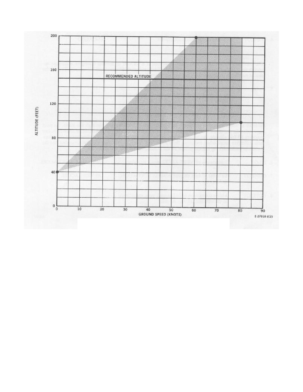
programming, engage the coupler within the shaded area of
and rescue. Monitor flight performance and fuel
Figure 18-1. The recommended start position is about 150
usage.
Comply with requests from on-scene
feet and 40 to 80 knots groundspeed.
commander, as able. Call for appropriate checklists.
CP: Maintain lookout. Back up PAC on flight
performance and fuel usage. Assist PAC with
WARNING
navigation and communication during the search and
rescue phase.
Comply with all checklist
requirements.
The pilot at controls shall call all uncoupled
AC: Assist pilots, as required. Maintain lookout.
descents below
500-foot AGL during
Ready aircraft for rescue according to paragraph
night/IFR conditions. Both pilots shall then
18.12.
monitor flight instruments until level at the
new altitude.
18.9 EMERGENCIES
18.10.1.1 Automatic Approach
PAC: Perform NATOPS immediate action
items.
Call for CP to back up procedure
Note
completion with NATOPS Pilot's Pocket
Checklist.
Ensure that aircrew is aware of
The helicopter will require about 75 +/- 20
emergency and that crew completes all necessary
seconds to achieve a hover commencing
procedures.
from 150 feet and 60 knots groundspeed.
CP:
Back up PAC in the diagnosis of the
The accelerometer nulls cannot be checked adequately
malfunction and in the performance of immediate
aboard ship because of the accelerations generated by ship
action items. Read applicable portions of NATOPS
movement. When setting nulls aboard ship, center DRIFT
Pilot's Pocket Checklist in order to ensure
and SPEED knobs as approximate settings during first
completion of all required actions. Switch IFF to
hover. Speed and drift settings can be effectively nulled
emergency position and make mayday as required.
during a cyclic coupled hover. With the meter selector
Lower landing gear handle in the event of an
switch in coupler, monitor A mode to center both bars with
overland ditching scenario.
the speed and drift pots, while the copilot monitors
helicopter hover stability.
HAC: Ensure that both pilots are aware of who has
positive control of the aircraft following the com-
The helicopter should be headed into the wind at the
pletion of all immediate action items. Ensure that all
proper gate altitude and groundspeed before engaging the
NATOPS Pilot's Pocket Checklist items are properly
coupler. Upon engagement of the coupler, the helicopter
complied with. Ensure that crew is aware of specific
will assume a slightly nose-high attitude. Should either the
responsibilities/required
actions
during
the
existing groundspeed or altitude at gate be other than that
emergency scenario.
previously prescribed but within the limitations delineated
in the approach profile limitations, the coupler will
AC: Comply with all required NATOPS
commence correction to establish the helicopter in the
immediate action items. Assist pilots as required.
proper approach envelope. These corrections normally will
Ensure security of all passengers/cargo. Report
be completed at about 80 feet. A slight delay in descent may
condition of aft station to HAC. Advise pilots to
be experienced at that altitude because of this correction.
check landing gear in the event of an overland
Normally, the helicopter will pass through 80 feet at 30
ditching scenario.
knots ground speed and thereafter follow the programmed
pattern. The tolerances in altitude and attitude that
18.10 APPROACH TO A HOVER
determine if a waveoff is justified during an automatic
approach are a 10-foot undershoot, 4 degrees right roll, 6
18.10.1 GENERAL. Operation of the Doppler system
degrees left roll, and 5 degrees nosedown or 10 degrees
is dependent upon the radar return from the reflecting
noseup.
surfaces beneath the helicopter. When operating over a
smooth sea state, the radar return may not be enough for
18.10.1.2 AUTOMATIC APPROACH
an automatic approach, and an alternate approach must
be made. The automatic approach to a hover can be
1. The automatic approach is a means of transitioning the
done at various combinations of speed and altitude.
helicopter from flight at 150 ft AGL and 40-80 kts ground
To obtain proper
speed to a hover using the coupler/doppler system:
18-5
ORIGINAL
NAVAIR 01-230HLH-1
a. Complete the automatic approach checklist.
Note
b. Establish the aircraft at the “gate” position (150 ft
If the No.
1 generator fails while hovering
AGL, 40-80 kts ground speed, and D-mode vertical
with coupler engaged, transient down signal
bar centered/150 ft AGL, 60 KIAS, and best estimate
may be introduced into the coupler causing a
of windline).
momentary loss of 10 to 12 feet of altitude. If
this condition occurs, do not shut off ASE as
c. When the helicopter is wings level and headed
the No. 2 generator will take over the load and
inbound to the survivor, the copilot reports, “Standby
return the helicopter to the original altitude.
for coupler,” engages coupler, and then reports,
The transient signal will disappear about
2
“Coupler engaged.” The PAC monitors the controls
seconds after the No. 2 generator takes over.
(feet off the pedals), without inhibiting coupler inputs
to the cyclic and collective channels as the coupler
18.10.1.3 Automatic Approach Checklist
system decreases collective, raises the nose, and rolls
the aircraft to fly a programmed approach to a hover
1.
Collective friction - FREE.
d. As the helicopter passes through approx. 60 ft
2.
BAR ALT - ENGAGED.
AGL and 20 kts ground speed, the coupler raises the
collective (to increase power) and coordinates nose
3.
Doppler selector knob - SEA.
and wing positions to continue decelerating on
glidepath to the selected hover height with no lateral
4.
Cyclic coupler switch - DOPPLER.
drift.
5.
ALTITUDE coupler switch - RDR ALT/VA.
e. The tolerances in attitude/altitude which determine
if a wave-off is justified during an automatic
6.
SPEED and DRIFT knobs - SET.
approach are 10 feet of undershoot, 4 degrees right
roll, 6 degrees left, 5 degrees nose down pitch, or 10
7
Altitude knob -40 FEET.
degrees nose-up. The non-flying pilot should monitor
A-mode for ASE pitch and roll saturation.
8.
CG TRIM
- SET
(PITCH BAR CENTERED
TO
LOWER HALF OF CIRCLE).
f. As the helicopter flies the approach to a hover,
direct the pilot not flying the aircraft to use the drift
9.
Radar altimeter limit - 30 FEET.
pot to correct for lateral drift as registered on the D-
mode indicator.
10.
Vertical gyro indicators -SET AND
CROSSCHECKED.
g. As the helicopter arrives in a hover, the coupler
system increases power to stop the descent, rolls the
11.
Pilot hover indicator - D MODE.
wings, and positions the nose to obtain a hover.
Direct the PNAC to adjust the drift/ speed pots to
12.
Copilot hover indicator - A MODE.
correct for any lateral/fore-and-aft drift as noted on
the D-mode presentation.
13.
Speed selectors - CHECKED.
14.
Aft station report - RIGGED FOR RESCUE.
WARNING
15.
Establish condition
- 150 FEET RADAR ALTITUDE,
40 TO 80 KNOTS GROUNDSPEED.
16.
Altimeters
- MATCHED (READJUST CG WHEN
Do not recycle a failed generator in a
INTO THE WIND IF NECESSARY).
hover at night. Depart the hover and
recycle the generator at a safe altitude to
lessen adverse coupler inputs and preclude
the chance of pilot disorientation.
18-6
ORIGINAL
NAVAIR 01-230HLH-1
Figure 18-1. Approach Profile for Automatic Approach to a Hover
Note
18.10.1.4 Alternate Approach
The CG TRIM is set initially (step 8) without
Note
regard to helicopter attitude, groundspeed, or
position relative to the wind. With the hover
Several trim adjustments may be required to
indicator in A mode, move the CG TRIM knob
compensate for the normal stick gradient.
on the ASE control panel in either direction as
Collective to cyclic coupling is apparent at
necessary until the horizontal bar on the hover
low speeds. If the nose of the helicopter is
indicator is approximately centered to lower half
allowed to drop below 5 degrees nose-high
of circle, beeping the cyclic as necessary to
attitude, the collective to cyclic coupling
maintain a constant groundspeed. When
will tend to flatten the attitude, resulting in
established at 150 feet radar altitude and 60 knots
helicopter acceleration. This condition
groundspeed into the wind, readjust the cg as
should be carefully observed during
necessary to approximately center the horizontal
daylight conditions for familiarization
bar on the hover indicator (A mode). Beep the
before night flying.
cyclic as necessary to maintain the
60 knots
ground-speed. Once in a stable Doppler hover,
If flown properly, the approach profile should be similar
consideration should be given to centering the cg
to an automatic approach. The exceptions are a high rate of
to allow maximum ASE range of authority.
descent (500 to 600 fpm) and the loss of about 70 feet of
altitude during the first
10 seconds of the approach.
Alternate approach procedures are necessary if the water
18-7
ORIGINAL
NAVAIR 01-230HLH-1
surface is too smooth for reliable Doppler operation.
copilot airspeed reads high (left drift), beep right. At 10
Indications of insufficient Doppler signal return are the
knots indicated on D mode indicator, check Doppler to
intermittent or sustained memory operation and
ensure out of memory and check the pilot hover indicator to
unreasonable Doppler velocity indications.
ensure that the drift bar is not hardover, then place the CYC
CPLR switch to DOPP. It is important to satisfy the
It is recommended that pilots take advantage of VFR
conditions mentioned previously: pilot hover indicator (D
during poor Doppler conditions to practice alternate
mode) shows no off flag
(out of memory) and hover
approaches. The procedures differ in that the pilot must
indicator (D mode) indicates drift/groundspeed less than 10
manually control the attitude of the helicopter using beeper
knots. If these conditions are not met, uncomfortable
trim to achieve a hover. The automatic altitude and power
attitude changes may occur when the cyclic coupler is
control will be available. In order to preclude conflicting
engaged.
inputs, the CYC CPLR switch is left at OFF until such time
as Doppler return may be obtained from the rotor
Altitude and power are controlled automatically by the
downwash disturbance. During periods that alternate
coupler collective channel.
In these helicopters, the
approach procedures will be required, normal airspeed
Doppler vertical velocity is not used for the approach
indications will be approximate groundspeeds and must be
portion of the maneuver. A substitute vertical velocity
used in lieu thereof.
signal is derived from the vertical accelerometer and is fed
to the coupler collective channel. This is done by selecting
The forward velocity (groundspeed) is controlled by
VERT ACCEL on the ASE control panel. Since the
pitch attitude. Upon initiation of the approach, power will
accelerometer signal is not affected by smooth water,
be reduced automatically by the collective coupler. After
successful alternate approaches can be expected in these
the collective moves down, utilizing beeper trim, beep the
helicopters, regardless of how poor the Doppler return
nose back to approximately a
5 to 10 degree noseup
might be. Just before reaching hover, the Doppler velocities
attitude. The pilot will control the nose attitude by beeping
will become reliable and are then fed to the coupler cyclic
in the required direction to maintain the desired attitude
channel by selecting DOPP with the CYC CPLR switch.
until a stable hover is achieved and CYC CPLR switch is
placed to DOPP. It is difficult to establish an airspeed
18.10.1.5 ALTERNATE APPROACH
versus trim direction for maintaining the 5 degree noseup
attitude. The pilot must simply beep in the required
1. The alternate approach is a maneuver that requires
direction to maintain hover attitude until the CYC
the pilot to manually position the cyclic to control drift
COUPLER switch is placed to DOPP. If the nose is
and rate of deceleration throughout the approach to the
allowed to drop below 5 degrees noseup at about 10 knots,
hover. Altitude and power are controlled automatically
the airspeed immediately increases and it becomes
by the coupler’s collective channel. This approach is
increasingly difficult to maintain the desired attitude. If the
normally used for all Night/IFR scenarios.
pilot and copilot airspeed indications differ, the helicopter
may be drifting and the indicated forward speed on both
a. Complete the alternate approach checklist.
indicators will be incorrect. During the approach, the
copilot hover indicator is in the A mode to monitor ASE. If
b. Establish the aircraft at the
“gate” position (150 ft
ASE saturates, the pilot should be prepared to abort. If the
AGL, 40-80 kts ground speed, and D-mode vertical bar
approach is aborted because of pitch channel saturation,
centered/150 ft AGL,
60 KIAS, and best estimate of
return to 150 feet and 60 KIAS. Note the position of the
windline).
pitch bar and adjust it
(cyclic and CG TRIM) one
additional division opposite to the direction of saturation.
c. When the helicopter is wings level and headed
inbound to the survivor, the PNAC reports, "Standby for
The pilot’s D mode is the primary instrument for
Coupler" engages coupler and reports "Coupler
determining lateral drift during approach. In the event of an
engaged". The PAC places feet on deck (clear of rudder
unreliable Doppler signal, the VGI
(roll attitude with
pedal microswitches) and then beeps the cyclic to
indices centered) and both airspeed indicators are used to
maintain approximately
10 degrees nose-up while
determine lateral drift. If the helicopter is headed directly
maintaining wings level. As the nose comes up, the
into the wind, the drift experienced during the approach
coupler cyclic channel will decrease power and the
will be slight. If the approach is started out of the wind,
helicopter will commence to descend and decelerate. If
the pilot must beep laterally to eliminate drift. In either
the D-mode presentation is reliable, beep the cyclic to
case, the pilot must beep the cyclic laterally to wings level
eliminate lateral drift
(1-3 degrees wing-down should
and maintain this attitude until the Doppler operates
suffice). Beep the cyclic to maintain the nose attitude
reliably. As the helicopter continues to slow and power
and wings level/vertical D-mode bar centered
increases to hover torque, beep the cyclic to assume the
throughout the approach.
hover attitude
(approximately 2 to
3 degrees noseup, 3
degrees left wing low) and keep airspeed matched. If the
d. Use the airspeed presentation to approximate ground
pilot airspeed reads high
(right drift), beep left. If the
speed when the doppler presentation is unreliable.
18-8
ORIGINAL
NAVAIR 01-230HLH-1
e.
At approximately
60 ft AGL, the collective
off-flag). Use other available cues (rotor downwash,
coupler increases collective (power) to slow the rate of
drift, indicated airspeed) to determine doppler reliability
descent preparatory to obtaining a hover. As power
during the approach.
increases, the nose must be beeped down to maintain a
5-8 degrees nose-up attitude.
18.10.1.6 Alternate Approach Checklist
f.
Continue making cyclic adjustments until hover
1. Collective friction - FREE.
indicator D-mode indicates drift and ground speed less
than 10 kts. Ensure:
2. BAR ALT - ENGAGED.
(1) No off-flags in hover indicator D-mode.
3. Doppler selector knob - LAND ALT.
(2) No ASE hardovers in hover indicator A-mode.
4. Cyclic coupler switch - OFF.
g. As these conditions are met, beep the nose and
5. ALTITUDE coupler switch - RDR ALT/VA.
wings to the hover attitude (approximately 2-3 degrees
nose-up and 3 degrees left wing down). When this
Note
attitude is set, call for the non-flying pilot to switch the
cyclic coupler switch to doppler by commanding “On
RAD ALT mode should not be used unless
doppler.”
a proper Doppler return is received.
h. Direct the non-flying pilot to adjust drift and speed
6 SPEED and DRIFT knobs - SET.
pots as necessary to obtain a steady hover (no lateral or
fore-and-aft drift).
7.
Altitude knob - 40 FEET.
i.
The correct response for a subsequent alternate
8.
CG TRIM - SET (PITCH BAR CENTERED TO
approach is,
“Cyclic coupler
- Off, on VA
(or
LOWER HALF OF CIRCLE).
RAD/ALT), pots set, in SEA/LAND ALT”.
9.
Radar altimeter limit - 30 FEET.
j.
If the alternate approach is conducted because of
poor or unreliable doppler return, the doppler must be
10. VGIs - SET AND CROSSCHECKED.
in the
“LAND ALT” position as it will permit
acquisition of the doppler signal created by rotor
11. Pilot hover indicator - D MODE.
downwash as the aircraft approaches the hover. If the
doppler is in the “SEA” position, it will not reacquire a
12. Copilot hover indicator - A MODE.
signal if the aircraft’s ground speed is below 35 kts.
13. Speed selectors - CHECKED.
k. When conducting an alternate approach with good
doppler return, use groundspeed to establish gate
14. Aft station report - RIGGED FOR RESCUE.
airspeed. During the approach, beep cyclic to correct
for drift indicated on the hover indicator in D-mode. If
15. Es tablish condition
-
150 FEET RADAR AL-
poor/unreliable doppler conditions exist, use indicated
TITUDE, 40 to 80 KNOTS GROUNDSPEED.
airspeed to establish gate and maintain wings level
during the approach. Correct for drift after a reliable
16. Altimeters
- MATCHED (READJUST CG WHEN
doppler signal is acquired.
INTO THE WIND IF NECESSARY).
l.
In certain conditions of low winds, glassy sea state,
18.10.1.7 MANUAL APPROACH TO A COUPLED
or a poorly adjusted doppler, the doppler may go into
HOVER (Day VFR)
sidelobe lock-on. While the doppler will appear to be
functioning normally (no memory light, no off-flag on
1.
The manual approach provides the fastest means of
hover indicator), the D-mode bars may be centered (or
positioning the helicopter in a stable hover prior to
pegged) when in reality the aircraft is still in forward
coupler engagement. It is used for Day VFR rescue
flight. These indications may persist throughout the
scenarios.
approach.
a. Complete alternate approach checklist.
m. If a sidelobe lock-on is suspected, cycling the
doppler selector to STANDBY, then back to LAND
b. Determine surface wind speed and direction.
ALT may break the lock or at least provide definite
indications of bad doppler return (memory light on and
18-9
ORIGINAL
NAVAIR 01-230HLH-1
c. Maneuver the helicopter to a point into the wind,
Note
150 ft AGL, 65-70 KIAS, and 200-250 yards downwind
of the intended hover position.
If a memory light illuminates while the
Doppler is in SEA mode, the copilot should
d. Decrease power by 25% torque while raising the
switch to LAND/ALT mode since airspeed
nose to approximately 8-10 degrees nose-up attitude.
will probably be less than 35 knots.
Allow the ASE to hold heading.
18.10.3 Departure From a Coupled Hover. Upon
e. Coordinate power so as to descend through 80 ft
release of the coupler, the pilot should monitor the
AGL at approximately 30 kts ground speed.
collective stick to prevent overtorqueing until the original
cruise altitude of 150 feet is attained. As the helicopter
f. At
60-70 ft AGL, commence increasing power to
reaches 55 to 60 knots, the nose must be beeped back to the
slow the rate of descent. Use visual references and the
60-knot attitude and the climb continued to 150 feet. The
D-mode presentation to determine drift correction and
BAR ALT will maintain
150 feet during subsequent
ground speed. Keep the nose at 8-10 degrees nose-up
acceleration to cruise airspeed without the necessity to reset
attitude.
by use of the momentary BAR ALT release. Small errors in
altitude may be eliminated by use of the momentary BAR
g. On final, at 30 ft altitude, pilot commands, “Standby
ALT release during cruising flight.
to deploy swimmer”.
Note
h. Approaching the smoke marker/survivor, pilot
establishes a
10-ft/10 kts creep or a 15 ft hover and
Should the barometric reference be lost, the
commands, “Jump, Jump, Jump ”.
pilot should be prepared to manually fly the
helicopter to cruising altitude.
i. Pilot shall maintain altitude until the crewman
reports, “Swimmer away, clear to come up.” After the
18.10.3.1 COUPLED HOVER DEPARTURE
rescue swimmer exits the helicopter and the crewman
reports “Swimmer away, clear to come up”, establish a
1. This maneuver is used to transition from a coupled
40 ft hover.
hover to 150 ft AGL and a minimum of 60 KIAS.
j. After crewman reports “swimmer OK”, position the
a. When ready to depart a coupled hover, report, “On D-
helicopter back and left under crewman’s verbal
mode, breaking hover”.
direction. Engage coupler if desired, and pass verbal
control to the crewman.
b. Beep the nose down to the horizon allowing airspeed
to build while the coupler is still engaged. As the
18.10.2 Erroneous Doppler Indicators.
aircraft reaches approximately 10 kts groundspeed (use
D-mode for groundspeed indication), the PAC
This phenomena is best described as erroneous ground-
disengages the coupler and beeps the nose further down
speed and drift indications displayed on the D mode and
to 5-8 degrees below the hover attitude while monitoring
GSDA. It may or may not be a result of "sidelobe lock-on"
the collective to prevent an overtorque condition.
or just inadequate Doppler return, but does pose a problem
that affects mission capabilities.
c. Ensure three positive rates of climb (RAD ALT, BAR
ALT, and VSI).
The problem usually occurs during weather conditions
having a smooth sea state and little or no wind. Sometime
d. Allow the ASE to maintain heading throughout this
during a coupled approach, the D mode and GSDA will
maneuver.
prematurely indicate hover indications. The aircraft,
however, will still be in an approach; noseup, minor drift,
e. Beep the cyclic to maintain wings level throughout
and descending. If night/IFR, the pilot will only have the
the maneuver.
VGIs, radar altimeters, and the airspeed indicators for
approximate aircraft conditions. The approach may be
f. Climb out and accelerate to original cruise altitude.
continued and usually the Doppler will reacquire
(150 ft and 60 KIAS).
approaching a hover. The flood/hover lights or controllable
spotlight may be used for visual reference to attain a hover
g. Primary scan is the VGI while the RAD ALT and
attitude.
torque indicators are secondary. As the collective raises
(power comes in), collective to cyclic coupling will
lower the nose further.
18-10
ORIGINAL
NAVAIR 01-230HLH-1
h. The proper nose and wing attitude must be
g. The freestream is complete when the hoist is
maintained throughout this maneuver.
stowed and the aircraft is at 60 KIAS and 100-150 ft
AGL.
i. When releasing the coupler, monitor the collective
to ensure power increases until approaching 150 ft.
18.11 SAR LOST ICS PROCEDURES
j. As the BAR ALT controller reduces collective to
Note
level off the aircraft at 150 ft AGL; the cyclic must be
beeped forward to maintain airspeed.
· Lost communication procedures require
intense aircrew coordination. Procedures
k. Be aware that the only signal that is causing the
may be tailored by individual pilots and
helicopter to transition to 150 ft AGL is the BAR ALT
aircrew; however, strict adherence to
signal, which was set prior to commencing either the
briefed procedures is critical.
automatic or alternate approach. If this signal is lost,
there will be no “up” signal. Prepare to manually apply
· The swimmer should not be jumped in
collective to reach 150 ft on climb -out.
a lost-ICS scenario. They should be
deployed from a stable
40-foot hover
18.10.4 SAR FREESTREAM RECOVERY
down the rescue hoist.
1. This maneuver is used to safely respond to situations
· Wave-Off is always an option;
where the helicopter must be flown out of a night/IFR
however, consideration should be given to
coupled hover with a person on the rescue hoist.
the phase of the approach in order to
prevent the swimmer from being deployed
a. Situations that require a freestream:
from an unsafe altitude.
(1) Loss of RAD ALT.
· During the SAR portion of the brief,
lost comms should be discussed for the
(2) Loss of ASE.
four different phases of flight to include
Day (Before and After) and Night (Before
(3) Disorientation/unstable hover.
and After) swimmer deployment.
b. Pilot at the controls announces,
“Executing
Recommendations to aid in Lost Communication
freestream recovery”.
Set and maintain hover
scenarios are:
attitude on the VGI. Scan D-mode to control drift.
The AI is the primary scan instrument. The
1.
Troubleshoot: Check switches, cords, ALT 1,2;
crewchief continues to raise the hoist.
UHF radio and ICS Emergency mode.
c. For ASE on freestreams, the pilot at the controls
2.
Continue the approach and establish a 40 foot
disengages coupler, beeps cyclic to maintain hover
coupled hover. Use either hand signals or hover trim to
attitude on the AI, and allows collective to raise,
deploy the swimmer.
thereby increasing power 5% above hover power to
initiate a vertical rate of climb not to exceed 500 fpm.
3.
Wave-off and trouble shoot at altitude before
making the decision to descend to a coupled hover lost
d. During the vertical climb, scan the VGI, RAD
comm. Conducting an aircrew coordination brief prior
ALT, D-mode, BDHI, and torque indicators to
to swimmer deployment is critical for the safety of the
maintain a constant heading vertical climb-out.
swimmer.
e. When the Aft Station reports, “Survivor/swimmer
4.
If ICS is lost in the hover, or if hover was
clear of water”. maintain heading and adjust
established after ICS failure at altitude; establish a
collective to continue climbing to an altitude of 100-
stable coupled hover with cyclic coupler/ doppler
150 ft AGL. If forward airspeed becomes necessary
engaged and proceed as follows:
to maintain controlled flight, do not exceed 40 KIAS
with a survivor/swimmer on the hoist in the trail
a. PNAC engages hover trim and monitors SAR
position.
evolution. When swimmer/survivor are clear of
water, PNAC disengages hover trim.
f. When the Aft Station reports , “Swimmer/survivor
in the door”. beep the nose 5 degrees below the hover
b. If hover trim does not engage, or if unreliable,
attitude and transition to forward flight to attain 60
directional signals from the crewman will be used to
KIAS.
18-11
ORIGINAL
NAVAIR 01-230HLH-1
perform the rescue. Signals should be given inside
18.12.2 Safety Precautions. Helicopters are susceptible
the aircraft; the right seat pilot should take the
to storing up static electricity. Therefore, it is of the utmost
controls. The left seat pilot will observe the hand
importance that before the pickup is commenced the
signals of the crewman through the cabin and relay
crewman shall cause the rescue cable to contact the surface,
these signals to the right seat pilot by
thus discharging static electricity. It may be assumed that
pushing/pulling the right seat pilot’s shoulder. The
the surface in the immediate vicinity of the crash area shall
push/pull will be in the direction the crewman wants
be covered with aviation fuel. Therefore, caution must be
the pilot to fly. No pressure means hold position
taken to discharge static electricity in an area not
(steady).
contaminated with fuel/fumes. The pilot shall keep the
crash scene on his right side to enable the crewman to use
c. Do not depart a hover with lost communications
the hover-trim control capability.
until a crewman indicates that the Aft Station is
ready for forward flight.
18.12 SEARCHES AND RESCUE
WARNING
Note
· Heavy-duty gloves shall be worn during
· For SAR mission and equipment
all rescue hoist operations. Keeping the
information, refer to NWP
3-50.1, Search
swimmer on the hoist cable during a SAR
and Rescue.
mission is extremely hazardous and is not
recommended.
· Wet suit shall be worn by rescue air
crewmen if water temperature is 60
0F or
· Deploying the rescue swimmer among
below and OAT is 32 0F (wind chill factor
pieces of floating composite material
corrected) or below. Wet suit top shall be
wreckage may result in injury to the
worn by rescue aircrewmen on all
swimmer. Deploy the swimmer only as
overwater rescues.
necessary to effect the rescue of personnel.
· Where SAR/plane guard is briefed as a
Note
primary mission or when it becomes pri-
mary mission, the rescue aircrewmen shall
Naval aircraft with composite components
be prepared for immediate water entry.
include the AV-8B, F/A-18, A-6, H-53, H-
60, F-14, S-3, H-46, and V-22.
When an emergency or emergencies occur, the lives and
safety of personnel are often jeopardized unless immediate
18.12.3 Procedures. When ordered to "rig for rescue",
assistance is available. In the event the designated SAR
report, "Unstrapping to rig for rescue". Before opening the
helicopter is unavailable and/or additional assistance is
cargo door, plug into the hoist station ICS and put on the
required, a helicopter equipped with a rescue hoist or
crewman safety belt and heavy-duty glove.
having the capability of emergency water landing may be
directed to perform SAR duties.
1. Open cabin door; maintaining physical control of
the hoist hook, lower the hoist hook into the helicopter
18.12.1 Lookout Doctrine. Good lookout doctrine is
and affix the rescue sling to the hook. When ready,
mandatory for successful search and rescue operations.
report to the pilot, "After station rigged for rescue”.
Because the pilots must involve themselves with the actual
operation of the helicopter, especially at night when actual
instrument flight is required, the efficiency of pilot lookout
doctrine is degraded and the importance of the aircrewman
as lookout becomes paramount. The crewmen should be
assigned specific lookout stations, one at the aft station and
the other at the personnel door or aft port window. Both
crewmen shall use crewman safety belts because an
Opening of the sliding cabin door in excess
inadvertent opening of the personnel door is an ever-
of 90 knots may result in loss of the escape
present possibility. Crewmen must be specifically briefed
window. Once the door is open, observe
as to the nature of the objects for which the search is being
normal airspeed limitations.
conducted.
18-12
ORIGINAL
NAVAIR 01-230HLH-1
Note
WARNING
Rescue hook may be lowered from the
stowed position with the helicopter
traveling in excess of 60 knots as long as
physical control is maintained with the
Practice live hoisting shall be done over the
hoist hook.
water or at no more than 10 feet above a hard
surface, unless safety belay line procedures
2.
When the survivor/signaling device is in sight,
listed in NWP
3-50.1 are utilized. Practice
report to the pilot, "I have the man/signaling device in
live hoists shall not be done using rescue
sight".
hoist manual override valve.
3.
Make manual or hover trim approach.
Note
4.
When the survivor is clear of the water, report,
Rescue swimmer may enter the water during
"Survivor is clear, pilot you have Control".
daylight/VFR simulated rescue operations at
sea with a secondary rescue vehicle
18.12.4 Assisting Survivor. Conditions at the scene of
specifically assigned to the area of
the rescue (i.e., water temperature, sea state, condition of
operations. Consideration must be given to
the survivor, proximity of other units, etc.) will dictate
sea state, water/air temperature, predatory
procedures to be followed and the final decision shall rest
marine life, and other environmental factors.
with the pilot in command.
If the decision is made to perform a water landing,
Where immediate assistance must be provided to the
consideration should be given to having the crewman in the
survivor, the most expeditious procedure may require a
personnel door utilizing a crewman safety belt. The
water landing. If the decision is made to have the crewman
crewman opens the personnel door and utilizes it as a
jump into the water, the following procedures should be
support for recovering the survivor. The crewman will need
used.
the use of the ICS and/or hand signals to effect a rescue
from the personnel door safely. The left seat pilot should
have the controls so that the right pilot can relay hand
signals as needed.
WARNING
18.12.6 Day VFR
1. Pilot in command commands, "Rig for rescue".
The effects of hydrostatic squeeze
(pressure exerted on the body when
2. Copilot completes alternate approach checklist and
submerged in water) allows blood to pool
pilot begins approach into windline to survivor.
in the lower extremities intensifying the
effects of shock and possibly resulting in
3. Rescue swimmer sits in cargo door, crewman safety
death when vertical hoisting
(D-ring,
harness on, while first crewman grasps back of swimmer
rescue strop) is used. The effects and
harness.
potential for death are increased in
hypothermic survivors.
Every effort
4. Crewman reports, "After station rigged for rescue".
should be made to recover the hypothermic
survivor in a horizontal position via the
5. When established on final approach course to the
rescue litter.
survivor at 30 feet, pilot commands, "Stand by to deploy
swimmer".
18.12.5 Manual Approach Procedures. When the
survivor/spot is in sight, report to the pilot, "I have the
survivor/spot in sight." The pilot may continue his
approach without assistance from the crewman until he
WARNING
loses sight of the survivor/spot, at which time pilot will
give crewman verbal control to direct helicopter over
The crewman shall maintain a hold on the
survivor by use of the standard terms listed in paragraph
rescue swimmer harness with one hand as
18.12.7. These directions must be given in a calm, clear
the other hand is used to tap on the swim-
voice, keeping the pilot informed of the situation at all
mer's chest. This is to avoid inadvertent
times. Combinations of terms may be used when making
rescue swimmer deployment.
diagonal approaches, (i.e., forward and right).
18-13
ORIGINAL
NAVAIR 01-230HLH-1
6.
Crewman taps the rescue swimmer on the chest to
Note
signal swimmer that the crewman safety harness will
be removed. Swimmer removes the crewman safety
Do not lose sight of swimmer and survivor.
harness.
13. Attach the desired rescue device to double rescue
7. Crewman reports, "Swimmer ready”.
hook and lower rescue hoist down
(discharge static
electricity).
8. Pilot establishes a l0-foot/l0-knot creep or a 15-foot
hover and commands, "Jump, jump, jump".
14. "Stop left, stop back, steady”.
Note
Keep pilot informed of swimmer progress,
WARNING
cable position, debris, etc.
15. When pilot or hoist operator observes ready for
· It is extremely difficult to accurately
pickup, he reports, "I have a pickup signal".
judge height above the water; the crewman
therefore shall not give the signal to the
16.
Hoist operator directs aircraft, "Forward and right".
swimmer to jump into the water until the
pilot commands, "Jump, jump , jump" over
17.
"Stop forward, stop right, steady".
the ICS. Pilot shall maintain altitude until
the crewman reports, "Swimmer away,
18.
"Swimmer approaching rescue hook".
Clear to come up”!
19.
"Survivor hooked up/swimmer hooked up".
· A weak or fatigued survivor or survivor
without flotation gear may have difficulty
Note
breathing or remaining afloat in rotor
wash.
If second survivor is not in the immediate
vicinity, hoist swimmer and fly or air taxi to
· When a parachute is in the rescue area,
the next pickup point. Swimmer will be
hoisted with last survivor in case of
it shall be approached to keep the para-
multiple rescue situations.
chute outside the rotor wash area. Inflating
the parachute can cause damage to or loss
of aircraft should it blow into the rotor
20.
"Clear of water".
system. Sinking the parachute could result
in the entangled survivor being towed
21.
"Survivor and swimmer halfway up”.
under.
22.
"Approaching aircraft".
9.
On the third jump, crewman simultaneously checks
area clear of debris ; taps the rescue swimmer three times
23.
"Survivor and swimmer aboard".
on the shoulder, releases handhold on rescue harness,
and the rescue swimmer jumps.
24.
"After station secured, ready for forward flight".
25.
Report survivor injuries to pilot and treat for
10.
Pilot shall maintain altitude until the crewman
reports,
“Swimmer away, clear to come up”. After the
shock, bleeding, etc.
rescue swimmer exits the helicopter and the crewman
reports “Swimmer away, clear to come up”. establish a
18.12.7 Standard Terms. The following is a list of
40 ft hover.
standard terms and their meanings. Terms are in relation to
the helicopter axis.
11.
After water entry swimmer signals, "I am all
right".
1. Forward
Direction of movement
-Straight ahead.
12.
Crewman observes "I am all right" signal from the
rescue swimmer and reports, "Swimmer O.K." The
2. Back
Direction of movement
-Straight back.
crewman then directs left and back until rotor wash does
not interfere with the swimmer and survivor.
18-14
ORIGINAL
NAVAIR 01-230HLH-1
3. Right
Direction of movement
18.12.8.1.1 Day
-Slip to the right,
maintain present heading.
Signal
Meaning
4.Left
Direction of movement
1. Raised arm.
I am all right.
- Slip to the left,
maintain present heading.
2. Raised arm,
Move in for
thumb up.
pickup.
5.Up
Direction of movement
- Gain altitude,
3. Vigorous waving
In trouble,
maintain relative position.
of one arm.
need assistance.
6. Down
Direction of movement
4. Clenched fists,
Deploy raft.
Lose altitude,
arms crossed overhead.
maintain relative position.
5. Hand held to ear.
Deploy radio.
7. Steady
Hold present position.
6. Clenched fist, arm
Deploy pneumatic
8. Easy
An indication of rate
pumping motion.
webbing cutter.
of movement - Precedes
the basic command.
7. One arm raised with
Deploy
open palm, fingers extended
rescue litter.
9. Stop
Self-explanatory
other arm raised over swimmer's
-precedes direction of movement.
head and touching first arm at elbow.
Note
8. Both arms raised,
Deploy
palms open, fingers extended
rescue net.
The following terms are used during con-
extended at a 45° angle
fined area, slope, and unprepared terrain
to side of swimmer's head.
landings
AFTER SWIMMER AND SURVIVOR ATTACHED TO
10. Main and tail, clear right:
Rotary wing
HOIST
and rudder tip paths and
A/C, clear on the
9. Arm raised, thumb up.
Ready to be
right side from the
hoisted.
12- to 6-o'clock
position of all
10. Arm raised,
Stop hoisting.
terrain/obstacles.
clenched fist.
11. Main and tail, clear left:
Rotary wing and
11. Arm raised,
Lower cable.
rudder tip paths and
thumb down.
A/C. Clear on the left
side from the 12- to 6-
12. Clenched fist
Failed hoist.
o'clock position of all
over clenched fist,
terrain/obstacles.
thumbs down.
12. Clear to land :
Area below the A/C, rotary
18.12.8.1.2 Night/Low Visibility
wing, and rudder tip paths are
clear of all terrain/obstacles.
SIGNAL
MEANING
1. Swimmer's lighting device
I am all right.
18.12.8 Swimmer Rescue Hand Signals
on, arm raised
18.12.8.1 Rescue Crewman Hand Signals
2. Wave signal device.
Ready for pickup.
3. Blue strobe on .
In trouble, need assistance.
18-15
ORIGINAL
NAVAIR 01-230HLH-1
4. Normal day hand signals are utilized after the
swimmer and survivor are attached to the hoist.
WARNING
18.12.8.1.3 Loss of ICS
Note
Do not ignite flare if fuel is present.
Recommended hand signals are used for
18.12.9 Inform Pilot.
Always try to keep the pilot
relaying interior or exterior signals. The
informed of the pickup position and of any possible danger
right arm is used for exterior signals, left
to the helicopter, using the above terminology and any other
arm for interior. A chemlight is used at
words that are concise and clearly understandable.
night. The HAC shall brief which hand
signals are to be used based on the model
aircraft and/or personal preference.
WARNING
SIGNAL
MEANING
1.
Arm extended, bent
Forward
upward 90 degrees at elbow,
All occupants of the aft station shall be
palm forward, fingers extended,
strapped in a troop seat unless assigned du-
held steady
ties that require freedom of movement.
When not strapped in a troop seat, the
2.
Arm extended, bent
Back
crewman shall utilize the crewman safety
downward 90 degrees at elbow,
belt.
The crewman safety belt must be
palm backward, fingers extended,
thoroughly checked for security of
held steady
attachment to the airframe.
3.
Exterior - Right arm extended
Right
18.12.10 Use of Hot Mike. If hot mike is used, be sure to
straight out, palm forward,
turn the hot mike switch off after the pickup is aboard.
fingers extended, held steady
18.12.11 Jammed Rescue Hoist. For emergency
Interior - Left arm extended
procedures, refer to RESCUE HOIST MALFUNCTION,
bent upward 90 degrees at elbow,
paragraph 12.27.
palm forward, fingers extended,
waving from side to side
18.12.12 Guillotine. The rescue hoist is equipped with a
cartridge-actuated guillotine for emergency use. Cartridge
4.
Exterior - Right arm
Left
information and safety procedures are prescribed in
extended, bent upward 90
NAVAIR OP-2606, the governing directive for such
degrees at elbow, palm forward,
devices.
fingers extended, waving
from side to side
18.12.13 Rescue Situation. The following is a rescue
situation with the reports and action required to make the
Interior - Left arm extended straight
pickup, with or without the use of the hover trim control.
out, palm forward, fingers extended,
held steady
THE SITUATION
THE REPORT
5.
Arm extended, bent upward 90
Steady
Shift Control
“Roger I have control”.
degrees at elbow, clenched fist
Helicopter is to the left
“Easy…Forward”.
and aft of the pickup
Hoist is halfway down
“Hoist is halfway down”.
Hoist is on deck
“Hoist is on deck”.
18-16
ORIGINAL
NAVAIR 01-230HLH-1
Hoist is even but to the
“Easy…Right”.
Copilot: Complete alternate approach checklist.
left of the pickup
“Stop…Right”.
“Steady”.
Pilot:
Hoist is in a good position
“Steady..Steady.
1. Descend to no lower than 150 feet on the RADALT.
Steady”.
Search patterns should be flown at
60 knots
groundspeed and desired ground tracks. Depending on
Survivor is in the sling
“Survivor is in
the search pattern, the first leg should be oriented into
the hoist”.
the wind. Timing must be adjusted on downwind legs
to ensure that aircraft does not drop below 60 KIAS.
Plane is ahead of the pickup
“Easy back…Stop
Altitude may be modified as ceiling and visibility
back, Steady”.
dictate.
Hoist is coming up
“Hoist is coming up”.
2. Commands, "Rig for rescue”.
Swimmer/survivor is clear
“Swimmer/survivor
Crewmen:
is clear”.
1. Comply with briefed lookout doctrine.
Shift control
“Pilot you have control”.
2. Crewmen at cargo door
- Rig after station for
Swimmer/survivor is
"Swimmer/survivor is
rescue and standby with smoke marker(s) or matrix
halfway up
halfway up”.
light(s) to mark survivor immediately upon sighting.
Crew report, “After station rigged for rescue”.
Swimmer/survivor is
“Swimmer/survivor is
safely aboard
safely aboard”.
3. Flood, hover, and controllable spotlights, as desired.
After station secured
“Ready for forward
Note
flight”.
Maximum time for hover/floodlights is 15
18.12.14
Night/IFR
Search and Rescue
minutes. Allow 10 minutes cooling cycle
Procedures. The night/IFR rescue pattern described
after 15 minutes use.
below permits the helicopter crew to effect a rescue in
minimal time and, in addition, provides proper margins for
Commence search in accordance with available reports on
flight safety. So as not to preclude sound judgment on the
location, number, and condition of survivors.
It is
part of the pilot in command and to compensate for varying
recommended that the orientation of the search pattern to the
degrees of adverse weather, the altitude and airspeed
windline be carefully considered before beginning the search
shown for the search phase, as well as entry into the rescue
phase. This will reduce the possibility of irregularities in the
pattern
(150 feet,
60 knots), should be considered a
pattern caused by drift encountered in strong winds. It should
recommended optimum, rather than mandatory.
be noted, however, that pattern entry and in relation to the
wind in the windline rescue procedure is not critical.
Note
18.12.14.2 Night/IFR Rescue Procedure.
Upon
One hundred and fifty feet provides a safe
positive sighting and passing over the survivor
(on-top
altitude from which objects on the surface
position), the following procedures should be followed.
of the sea can still be seen using helicopter
flood/hover lights. Sixty knots indicated
Note
airspeed is within the single-engine
capability of this helicopter yet slow enough
Marking the survivor position in the water
to permit an efficient search.
quickly and accurately is an extremely critical
phase in this or any rescue pattern conducted
Upon notification that a night/IFR search and res-
under night IFR conditions, and crew
cue mission must be performed, the following will be
coordination is of paramount importance. Since
accomplished.
the use of this particular procedure will be
performed under conditions of limited visibility,
18.12.14.1 Night/IFR Search Procedure
it is likely that the helicopter will be very close,
if not directly over the survivor when he is
Pilot: Assume control of helicopter and report on
sighted. The first person to see the survivor,
instruments.
either pilots or crewmen, should immediately
call, “On top, smokes away”.
18-17
ORIGINAL
NAVAIR 01-230HLH-1
1.
Crewman at cargo door releases smoke marker(s)
pilot as to whether more or less turn is required, and
or matrix light(s) to mark the survivor’s position in the
indicates the survivor to marker orientation. The
water.
warning command "Stand by to roll out" shall be given
by the copilot before intercepting the windline. When
orientation and lineup are achieved, the copilot calls to
the pilot, "Roll out".
WARNING
4.
When the helicopter is wings level and headed
inbound to the survivor, the copilot reports, "Stand by
for coupler," engages coupler, and simultaneously
· Anytime there is a chance of igniting
reports, "Coupler engaged." The pilot flies an alternate
aviation fuel that may be in the immediate
approach following the copilot directions. Crewman
area, smoke markers shall not be used to mark
reports, "Survivor in sight," and keeps survivor in sight
survivor position.
awaiting hover trim engagement. Hover altitude should
be attained at a point no less than 100 yards downwind
· Rescue swimmers shall not enter the water
of the survivor to preclude the possibility of
during night/lFR simulated rescue operations
overshooting
(Figure
18-4). Pilot establishes a creep
in an open ocean environment.
(approximately 10 knots groundspeed) following copilot
directions until copilot commands, "Establish steady
2.
Pilot simultaneously turns downwind in the di-
hover." This point is approximately 50 yards downwind
rection requiring the least amount of turn to enter the
of the survivor. Pilot establishes a steady hover and
windline rescue procedure pattern. See example
commands, "On Doppler," the pilot ensures that a steady
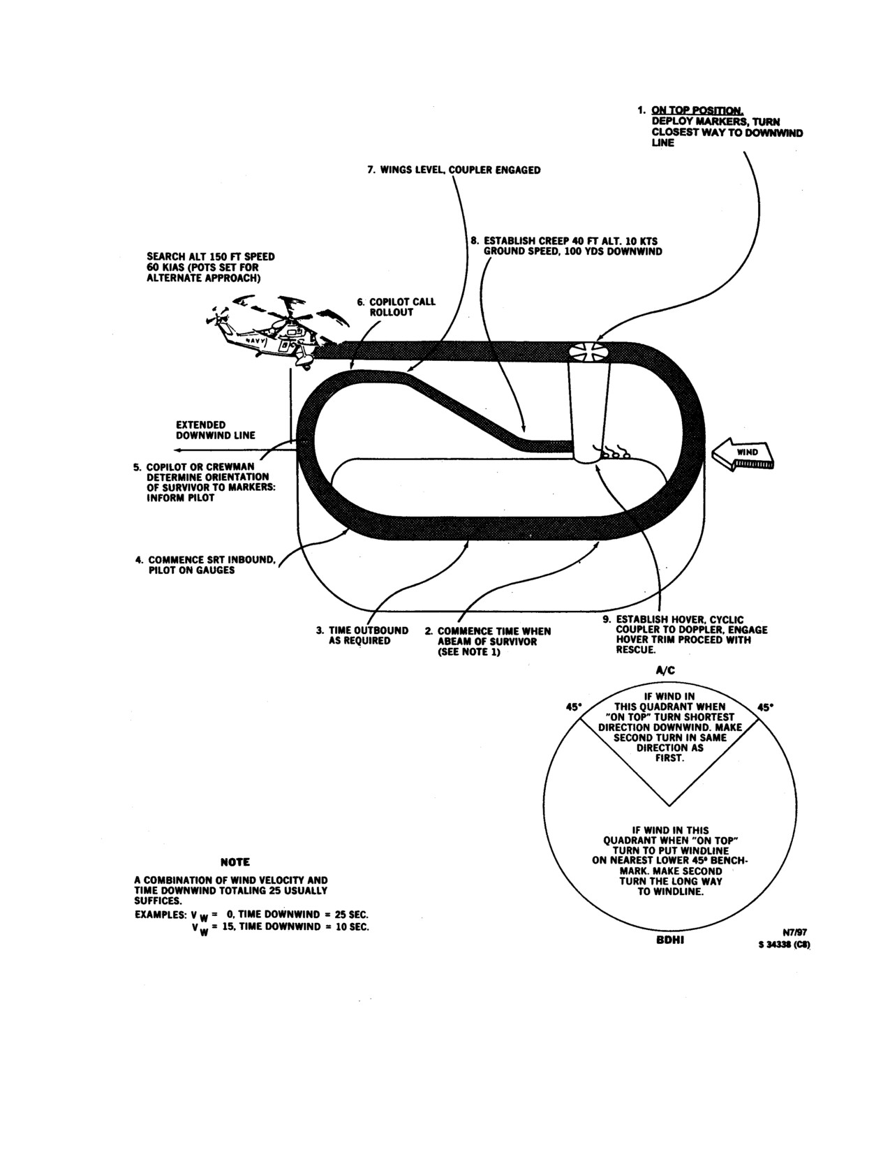
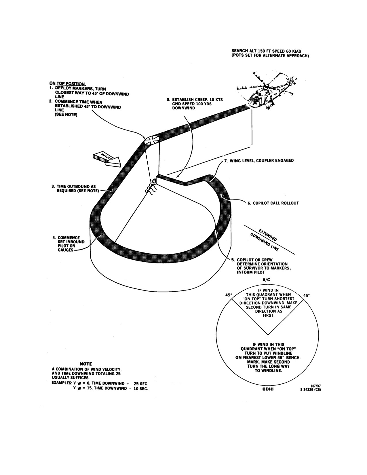
diagrams. At the same time, in the on-top position, the
hover is being maintained and adjusts pilot pots to
copilot marks position on the TACNAV (if navigator
ensure the same. The pilot then commands "Engage
equipped, turn to RUN position). The elapsed time
hover trim" and the first crewman responds "I have a
clock is actuated either when the helicopter is
light". Pilot passes control to the first crewman by
established
45º to the downwind line or abeam the
stating "You have control". The first crewman responds,
survivor heading downwind, depending on the entry
"I have control," then adjusts their BIAS control knobs
angle.
as required and flies the helicopter to a position over the
survivor using standard recovery phraseology and
Note
procedures.
A combination of wind velocity and time
5.
Hoist operator positions helicopter over survivor
downwind totaling 25 usually suffices (i.e.,
and reports, "Permission to lower swimmer".
wind velocity 10 knots, time downwind 15
seconds, and wind velocity
25 knots or
6.
Pilot establishes desired altitude and commands,
greater, maintain a standard rate turn until
"Lower swimmer".
headed into the wind).
7.
Hoist operator taps the rescue swimmer on the chest
Rescue swimmer with a crewmember safety belt on puts
to signal to the swimmer that the safety belt should be
on the rescue strop, attaches it to the hoist hook, and
removed. Rescue swimmer removes the safety belt. The
assumes a sitting position in the doorway.
hoist operator then takes slack out of the cable and
performs final checks of the swimmer equipment and
Note
lights.
The rescue swimmer and the rescue hook
8.
Hoist operator lowers swimmer and reports,
both shall be illuminated by a chemical
"Swimmer on the way down".
light before lowering.
9.
Hoist operator observes swimmer clear of rescue
Crewman reports, “Swimmer ready.”
sling and swimmer lighting device "On," and reports,
"Swimmer OK".
3.
After the proper time has elapsed, the pilot com-
mences a turn inbound to the survivor. Depending on
10. Hoist operator, using hover trim, positions the
the direction of turn, the copilot or crewman keeps sight
helicopter so the rotor wash does not interfere with
of the lights marking the survivor, establishes
swimmer and survivor.
orientation of the survivor to the lights, informs the
18-18
ORIGINAL
NAVAIR 01-230HLH-1
Figure18-2. Windline Rescue Procedure Pattern (Typical) (sheet 1 of 2)
18-19
ORIGINAL
NAVAIR 01-230HLH-1
Figure18-2. Windline Rescue Procedure Pattern (Typical) (sheet 2 of 2)
18-20
ORIGINAL
NAVAIR 01-230HLH-1
18. "Pilot, you have control" - "Roger, I have control".
Copilot cycles cyclic coupler switch off, then back to
WARNING
Doppler.
19. "Man halfway up”.
In the event of loss of visual contact
with swimmer and/or survivor, the
20. "Approaching aircraft".
helicopter aircraft commander shall
cycle the flood/hover lights. The
21. "Survivor and swimmer aboard".
swimmer and/or survivor
shall
illuminate the strobe light or ignite the
22. "Afterstation secure. Ready for forward flight".
Mk 13/Mk 124 Mode 0 flare to aid in
reestablishing visual contact.
23. Report survivor injuries to pilot and treat for
shock/bleeding, etc.
Note
· Keep pilot informed of swimmer
progress, cable position, debris, etc.
WARNING
· Rescue swimmer shall not enter the
water during night/IFR simulated rescue
operations
in
an open ocean
The rescue hoist shall not be operated
environment.
with the Chicago grip installed.
11. Swimmer raises one arm overhead when ready
for pickup for day and waves signal device at night.
18.13 CARGO SLING OPERATIONS
External load operations require either a crewman
aboard, and in verbal control of the aircraft, or a plane
director on the deck to direct the helicopter over the load.
WARNING
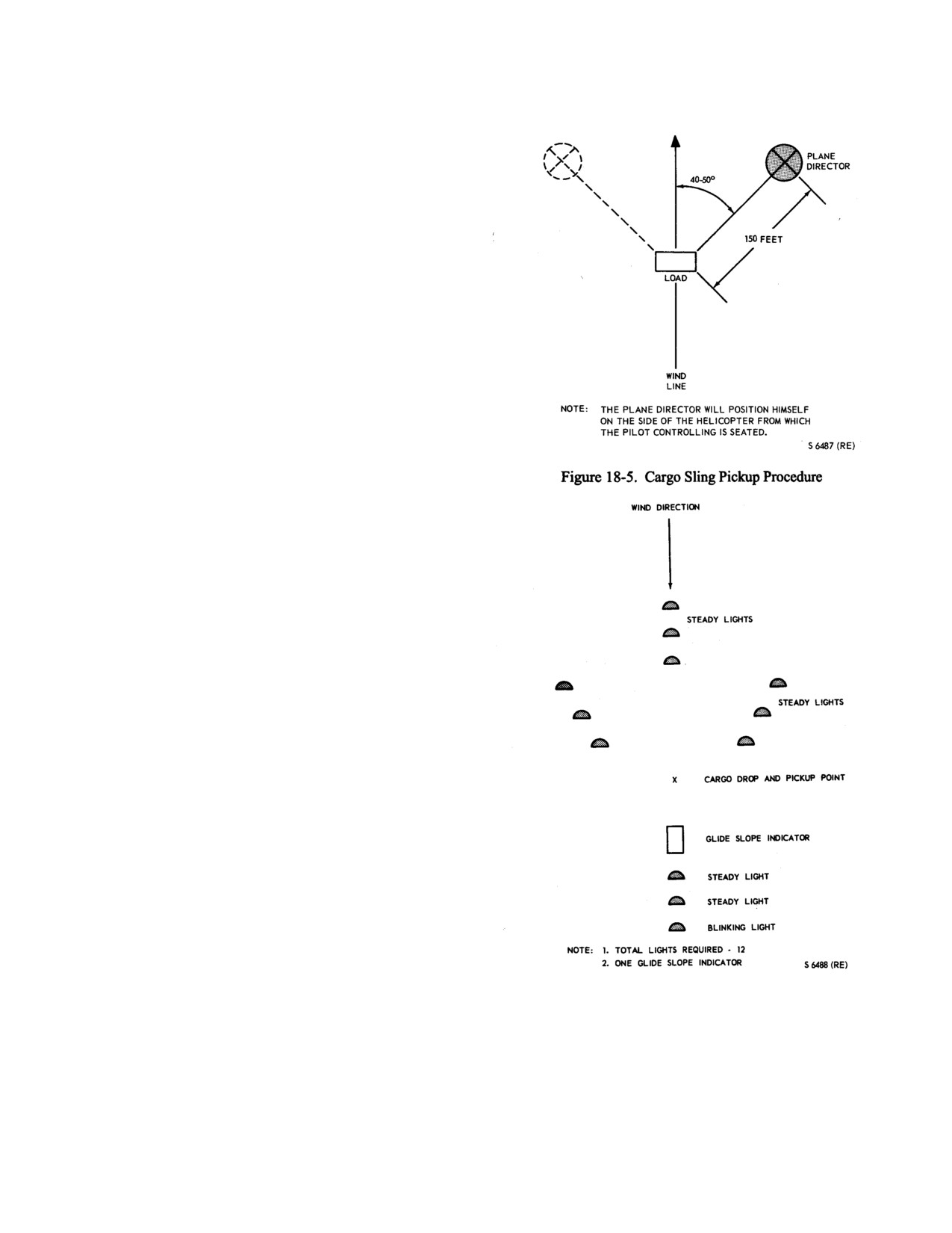
The crewman/plane director shall be in a position to
maintain a clear view of the load and operating zone
during the entire pick up/drop off evolution. Figure 18-5
Do not ignite Mk 13 flare when fuel is
shows a recommended position for the plane director on
present in the water; use chemlight.
deck. Forward flight will be conducted at an airspeed
commensurate with the aerodynamic stability of the load
12. Crewman operates hover trim forward and right.
and effort on flight characteristics.
Flying over
personnel, buildings, or equipment will be avoided when
13. "Stop forward, stop right. Steady".
practical. Lighting for night cargo operations is shown in
Figure 18-6.
14. Swimmer approaching hoist.
15. Swimmer attaches survivor by D-ring or places
survivor in rescue device.
Note
Particular care must be taken during cargo
pickup because of the increased rotor
If second rescue is not in the immediate
downwash and its effect on loose equipment
vicinity, hoist swimmer and fly or air
and debris near the helicopter. It is
taxi to the next pickup point. Swimmer
recommended that ground personnel wear
will be hoisted with the last rescue in
approved-typed goggles to protect the eyes
case of multiple rescue situations.
and ear protective devices.
16. Survivor hooked up/swimmer hooked up.
18.13.1 Cargo Pickup. Check windline, aircraft weight,
and power required curves. If necessary, a decrease in load
17. "Clear of the water".
or aircraft weight may be required for safe takeoff because
of power requirements. Approaches should be made to
18-21
ORIGINAL
NAVAIR 01-230HLH-1
arrive in an air taxi condition short of the pickup point
and into the windline. The heights and movement to
the pickup point will be accomplished by visual
reference to the load and plane director. On entering
the windline, the feet may be held lightly on the rotary
rudder pedals when ASE is engaged. The pilot can best
control the approach until the pickup point can no
longer be observed. When the pickup can no longer be
observed, the plane director will use proper hand
signals to relay the helicopter position, relative to the
pickup point, and direct the pilot to a position to
accomplish the hookup. As soon as the load is securely
attached to the cargo hook, all personnel on the ground
will clear the area directly beneath the helicopter and
the director will notify the pilot that the load is ready to
lift. Lift the aircraft vertically until the weight of the
load is felt, then lift the load vertically until the cargo is
clear of the deck and the aircraft is in a stable hover.
Check engine (NG) percentage, T5, torque, and rotor
(Nr) rpm. If NF/NR are drooping, do not attempt
forward flight. Hover altitude should be approximately
20 to 40 feet depending on load size and shape.
The director will then give the takeoff signal to
indicate to the pilot that the load is clear of the deck and
properly suspended. To transition from a hover to
forward flight, smoothly apply forward cyclic and up
collective and allow the aircraft to fly out of the hover.
Do not use excessive nosedown attitude because of
cargo suspension beneath the helicopter.
18.13.2 Cargo Delivery. The approach to the drop
point should be slightly high to prevent dragging the
load on the ground. The helicopter is hovered when the
cargo is approximately 6 to 8 feet above the ground. A
vertical descent is then made until the load is resting on
the surface; at which time, it is released electrically,
automatically, or in case of emergency, by use of the
mechanical release.
18.13.3 Pilot Procedure for External Cargo
Sling Operation. The following pilot procedures are
for flights involving cargo lifts.
18.13.3.1 Attaching Cargo
1. Release cargo hook from stowed position.
2. CARGO SLING MASTER switch - SLING.
3. Groundcrew attach load to hook or fly hook
through ring attached to load.
Figure 18-6. Cargo Sling Lighting Pattern
4. Fly the mission with the cargo sling master
switch in the SAFE or SLING position until
approaching intended release point.
18-22
ORIGINAL
NAVAIR 01-230HLH-1
18.13.3.5 ICS Voice Signals
TERM
MEANING
WARNING
1.
External cargo operations
a.
Right, left,
Move helicopter in
·External loads may have aerodynamic
forward, back
this direction.
characteristics that cause oscillations to
the extent that the load may oscillate
b.
Easy down
Cargo hook too
into rotor blades and/or fuselage.
high for hookup crew.
·Should excessive load oscillations
c.
Hooked up
Sling pendant
develop, an immediate reduction in
attached.
airspeed is mandatory to prevent loss of
control or imposing excessive loading
d.
Easy up
Long pendant,
of the helicopter. ASE is capable of
keep coming up.
damping most oscillations. Applying
excessive manual control inputs when
e.
Weight coming on
Tension coming
attempting to stabilize oscillations may
on aircraft.
increase their severity.
f.
Load clear
Cargo clear of the
18.13.3.2 Automatic Release of Load
deck and obstructions.
1.
CARGO SLING MASTER switch - AUTO
g.
Down, down, down
Descend quickly (for
(prior to touchdown).
target/weapon recovery).
2.
Descend slowly with no forward speed or drift.
h.
Cleared for
Self -explanatory.
Cargo will release upon ground contact.
forward flight
2.
At delivery point
a.
Spot in sight
Delivery visualized.
When carrying loads of less than 200
b.
Right, left,
Near delivery point,
pounds, the CARGO SLING MASTER
forward, back
move easy in
switch should never be in AUTO
this direction.
position. The cargo sling hook would
open immediately if a gust of air
c.
Easy down
Self-explanatory.
momentarily lightens the load.
d.
Load on deck
Cargo on deck.
18.13.3.3 Normal Release of Load
e.
Release hook
Release pendant.
1. CARGO SLING MASTER switch - SLING.
f.
No release, hold
Cargo not released,
2. CARGO hook release button - Depress (to release
try manual release.
load).
g.
Net fouled
Net is hung up
18.13.3.4 Mechanical Release of Load
on counter-weights,
etc.
1. Cargo release foot pedal - DEPRESS.
h.
Hook clear
Sling pendant and
If pilot releases load or if load is to be released by
cargo clear of hook,
ground personnel, open hook with release arm on hook.
clear to depart.
i. Hook stowed
Self-explanatory.
18-23
ORIGINAL
NAVAIR 01-230HLH-1
j. Cleared for forward
Self-explanatory.
Bucket touching the water with slight forward drift. As
flight
the bucket touches the water, continue to lower the
bucket into the water by descending and at the same time
j. Pickle, pickle, pickle
Immediate
starting a slow creep forward. This will tip the bucket
emergency jettison.
forward allowing the water to fill the bucket and will
expedite the process. This also reduces the twisting
18.14 BAMBI BUCKET OPERATIONS
effect of the bucket. Continue the slow creep forward
until the bucket is full. At that point, begin a very slow
The Bambi Bucket used to fight fires is a
324
climb until the bucket breaks away from the water. If
gallon,
2820 LB heli-borne bucket, when full. It is
this is the initial pickup, you should perform an
attached to the helicopter via the cargo hook utilizing a
operational check of the bucket.
standard shackle attached to the bucket dump valve
control head. Braided steel cables are attached to the
Note
control head, which lead down to the bucket. The
bucket hangs thirty feet below the helicopter. The
Ensure that adequate power is available
dump valve is actuated by a solenoid in the control head
when lifting the bucket out of the water. If
and dump valve support line. Power is provided for the
required, the bucket may be partially filled
solenoid via the aircraft DC electrical system and is
to reduce weight.
actuated with a pickle switch by the aircrewman. The
dump valve opens downward producing a concentrated
column of water. The bucket empties in 3 seconds
when fully loaded. Once the water has passed through
the dump valve, the valve automatically closes.
18.14.1 ATTACHING BUCKET
Continued use of the release switch
(machine gunning) can cause the solenoid to
1.
Release cargo hook from stowed position.
burn out and malfunction.
2.
CARGO SLING MASTER switch - SLING.
18.14.3.2 ZERO AIRSPEED TECHNIQUE
3.
Bucket is attached to the cargo hook prior to
Perform an approach to a hover over the water source.
take off and extended to the right side of the aircraft.
Lower the collective until the bucket sinks and fills. Once
it is full, lift the bucket out of the water and depart.
18.14.2 APPROACH
Note
When performing approach over the ocean, little
consideration need be given to approach and departure
In some instances the spring reel that
obstacles as the pilot has great flexibility in selecting his
rewinds the trip line is not strong enough to
route. Pick-ups from a confined water source require
reseat the valve after a drop. Therefore, if
greater consideration and should be performed to ensure
the bucket is not filling on the pickup, the
that sufficient amount of space is left for the departure.
crewman should push the release button one
Due consideration should be given to the possibility of
time as the bucket is sinking into the water.
vortex ring state, settling with power, and aircraft
The water rushing into the bucket through
malfunctions. Additionally, wave-off capabilities and
the valve will allow the trip line to retract
obstacles must be taken into account just as if a
fully into the control head and reset.
confined area landing were being performed. The
approach should be performed into the wind and over
18.14.4 WATER DROPS
the lowest obstacles with consideration being given to
the size and shape of the lake for the best total
Fighting fires with the Bambi Bucket requires good
combination of all factors.
technique and control to be most effective and remain
safe. Three criteria dictate the method of water drop: type
18.14.3 PICKUP
of substance burning, amount of heat generated, and size
of the burning area.
18.14.3.1 CREEPING PICKUP
Consideration of the effects of rotor wash should be
The approach should terminate with the Bambi
taken into account when planning drop speeds and
18-24
ORIGINAL
NAVAIR 01-230HLH-1
altitudes. In some cases, a low speed drop will
actually spread the fire as the rotor wash scatters the
embers and redirects flames over a wide area. The
addition of fresh air only aggravates the fire. A low
altitude drop may have the same result with the
additional effect of causing a “black out” situation as
ash is blown up by the rotors.
Faster drop speeds will cause a narrow, long drop
pattern with high water dispersion and small droplets.
This is an effective technique for light fuels such as a
grass fire. However, higher altitudes will magnify
this effect and may actually make the drop worthless.
Additionally, wind effects on the water will distort the
pattern due to the decreased density.
The following procedures are recommended:
1. Long and Narrow Flame Front: Low Level, High
Speed: 60-70 ft AGL, 60-70 KIAS.
WARNING
Given the minimum safe ground
clearance, it is incumbent on the aircraft
commander to determine the best
altitude. Recommend no lower than 30
feet AGL
(bucket height).
(This is
about 60-70 feet AGL for the helo).
2. Long and Wide Flame Front: Normal Level,
Normal to High Speed:
100-130 ft AGL,
50-70
KIAS.
Note
The increase in altitude will create a
wider lateral spread of the water to
compensate for the increased width of
the fire line.
The speed, intensity, and fuel of the fire, in
addition to crew experience, will more specifically
dictate the best combination of altitude and airspeed.
Evaluate the effectiveness of each drop and adapt
accordingly. In all cases, the drop will decrease the
load on the helicopter and subsequently cause an
increase in altitude as the water drops. Maintain
altitude by reducing collective in order to ensure the
most effective drop.
18-25
ORIGINAL
NAVAIR 01-230HLH-1
This Page Left Blank Intentionally
18-26
ORIGINAL
NAVAIR-01-230HLH-1
PART X
NATOPS Evaluation
Chapter 19 - NATOPS Evaluation
71
ORIGINAL
NAVAIR-01-230HLH-1
This Page Left Blank Intentionally
72
ORIGINAL
NAVAIR 01-230HLH-1
CHAPTER 19
NATOPS Evaluation
19.1 GENERAL
evaluation was commenced and the date the flight
evaluation is satisfactorily completed.
The standard operating procedures prescribed in this
manual represent the optimum method of operating the
2. NATOPS reevaluation - A partial NATOPS evaluation
helicopter. The NATOPS evaluation is intended to
administered to a flight crew member who has been placed
evaluate compliance with NATOPS procedures by
in an unqualified status by receiving an Unqualified grade
observing and grading individuals and units. This
for any of his ground examinations or the flight evaluation.
evaluation is tailored for compatibility with various
Only those areas in which an unsatisfactory level was
operational commitments and missions of both Navy and
noted need be observed during a reevaluation.
Marine Corps units. The prime objective of the NATOPS
evaluation program is to assist the unit commanding
3. Qualified - That degree of standardization demonstrated
officer in improving unit readiness and safety through
by a very reliable flight crewmember who has good
constructive comment. Maximum benefit from the
knowledge of standard operating procedures and a through
NATOPS program is achieved only through the active
understanding of helicopter capabilities and limitations.
vigorous support of all pilots and flight crewmembers.
4. Conditionally Qualified - That degree of standardization
19.1.1 Implementation. The NATOPS evaluation
demonstrated by a flight crewmember who meets the
program shall be carried out in every unit operating naval
minimum acceptable standards. He is considered safe
helicopters. The various categories of flight crewmembers
enough to fly as a pilot in command or to perform normal
desiring to attain/retain qualification in the helicopter shall
duties without supervision but more practice is needed to
be evaluated in accordance with OPNAVINST
3710.7.
become qualified.
FRSs shall ensure that pilots and naval aircrewmen have
successfully completed a NATOPS evaluation prior to
5. Unqualified - That degree of standardization demonstrated
their completion of the course of instruction. All pilots and
by a flight crewmember who fails to meet minimum
naval aircrewmen must hold a current evaluation in the
acceptable criteria. He should receive supervised instruction
model aircraft. Renewal evaluations may be accomplished
until he achieves a grade of Qualified or Conditionally
within 60 days preceding expiration of a current evaluation
Qualified. Flight crewmembers who receive a grade of
and are valid for 12 months from the last day of the month
Unqualified on a ground or flight evaluation shall be
in which the current evaluation expires.
Otherwise,
allowed 30 days in which to complete a reevaluation.
NATOPS qualifications shall be valid for 12 months from
the last day of the month of the evaluation. Unit NATOPS
6. Area - A routine of ground operations, normal flight
evaluations will be conducted periodically; however,
operations, emergency operations, coupler operations, and
instructions in and observation of adherence to NATOPS
SAR operations.
procedures must be on a daily basis within each unit to
obtain maximum benefits from the program. The NATOPS
7. Subarea
- A performance subdivision within an area
coordinators, evaluators, and instructors shall administer
that is observed and evaluated during an evaluation flight.
the program as outlined in OPNAVINST 3710.7 series.
8. Critical area/subarea - Any area or subarea that covers
19.1.2 Definitions.
The following terms, used
items of significant importance to the overall mission
throughout this section, are defined as to their specific
requirements, the marginal performance of which would
meaning within the NATOPS program.
jeopardize safe conduct of the flight.
1. NATOPS evaluation
- A periodic evaluation of
9. Emergency - A helicopter component, system failure,
individual flight crewmember standardization consisting of
or condition that requires instantaneous recognition,
an open-book examination, a closed-book examination, an
analysis, and proper action.
oral examination, and a flight evaluation. A maximum of
60 days may elapse between the date the initial ground
19-1
ORIGINAL
NAVAIR 01-230HLH-1
10.
Malfunction - A helicopter component or system
evaluation should be kept to a minimum, normally one
failure or condition that requires recognition and analysis,
flight. Not more than one pilot or aircrewman shall be
but that permits more deliberate action than that required
scheduled on the same event for a NATOPS flight
for an emergency.
evaluation. However, combining a pilot and an air-
crewman evaluation on the same event is encouraged. The
19.2 GROUND EVALUATION
flight may be conducted on any operational or training
flight and only those areas observed will be graded. The
The purpose of the ground evaluation is to measure the
grade for the flight evaluation and overall NATOPS
pilot/crewmember knowledge of appropriate publications
evaluation shall be determined as outlined in this section.
and the helicopter. Before beginning the flight evaluation,
(Areas and subareas to be evaluated may be outlined here
an evaluee must achieve a minimum grade of qualified on
with the critical areas/subareas marked by an asterisk).
the open-book and closed-book examinations. The oral
examination is also part of the ground evaluation but may
Note
be conducted as part of the flight evaluation.
The NATOPS instructor/evaluator on flights
19.2.1 Open-Book Examination. The open-book
in which unusual attitudes or simulated
examination shall contain 40 questions.
emergencies are being conducted should be
considered the pilot in command (HAC) and
19.2.2 Closed-Book Examination. The closed-book
sign for acceptance of the aircraft at the
examination shall consist of 80 questions.
discretion of the commanding officer.
19.2.3 Oral Examination. The questions may be taken
19.3.1 Flight Evaluation Grading Criteria. Only
from this manual and drawn from the experience of the
those subareas provided or required will be graded. The
instructor/evaluator. Such questions should be direct and
grades assigned for a subarea shall be determined by
positive and should in no way be opinionated.
comparing the degree of adherence to standard operating
procedures with adjectival ratings listed below.
19.2.4 Operational
Flight
Trainer/Weapon
Momentary deviations from standard operating procedures
Systems Trainer Procedures Evaluation
(If
should not be considered as unqualifying provided such
Applicable). An OFT may be used to assist in measuring
deviations do not jeopardize flight safety and the evaluee
crewmember performance in the execution of prescribed
applies prompt corrective action. An individual shall be
operating procedures and his reaction to emergencies and
considered “qualified” in areas I through V if standard
malfunctions. In areas not served by these facilities, this
NATOPS procedures were executed in accordance with
may be done by placing the crewmember in a helicopter
the provisions of this manual. A grade of Conditionally
and administering appropriate questions.
Qualified or Unqualified shall be assigned utilizing the
guidelines provided for each area.
19.2.5 Grading Instructions. Examination grades
shall be computed on a 4.0 scale and converted to an
19.3.2 Pilot Evaluation
adjective grade of Qualified or Unqualified.
19.3.2.1 Area I - Ground Operations.
19.2.5.1 Open-Book Examination. To obtain a grade
of qualified, an evaluee must obtain a minimum score of
Conditionally Qualified
- Did not fully instruct or debrief
3.5.
the crew. Flight equipment improperly worn or in
marginal condition. Did not fully examine flight
19.2.5.2 Closed-Book Examination. To obtain a
records. Minor omissions or errors on preflight or
grade of qualified, an evaluee must obtain a minimum
postflight. Improper or incomplete use of checklists.
score of 3.3.
Nonstandard
procedures.
Inattention
or
misinterpretation of visual signal. Rough or erratic
19.2.5.3 Oral Examination and OFT Procedure
start, engagement, disengagement, or shutdown.
Check, If Conducted. A grade of Qualified,
Conditionally Qualified, or Unqualified shall be assigned
Unqualified
- Did not conduct brief or debrief. Flight
by the instructor/evaluator.
equipment missing, not worn, or in an unsafe
condition. Failed to sign for aircraft or accepted
19.3 FLIGHT EVALUATION
aircraft with grounding discrepancy. Failed to note or
record downing discrepancy after flight. Any omission
The NATOPS flight evaluation is intended to measure
or error on preflight or postflight that would affect
pilot and crewmember performance with regard to
safety of flight.
Exceeded published limitations
knowledge of and adherence to prescribed procedures. The
during start, engagement, disengagement, or
number of flights required to complete the flight
shutdown. Did not utilize checklist or perform
19-2
ORIGINAL
NAVAIR 01-230HLH-1
required systems checks. Marginal control of
and climb out. Erratic altitude control at 150 ±20 feet.
helicopter while taxiing. Ignored visual signal. Did not
Reacted slowly to emergencies. Unable to fully explain
use pretakeoff checklist.
systems or limitations.
19.3.2.2 Area II - Normal Flight Operations.
Unqualified
- Checklist not used or unsafe/improper
procedures utilized. Allowed aircraft to descend
Conditionally Qualified
- Incomplete use of takeoff; post
through
30 feet in hover without attempting to
takeoff; or landing checklists. Application of power
correct. Made omissions or errors in emergency
erratic but did not exceed limitations. Unable to
procedures that could jeopardize aircraft or crew.
maintain altitude within ±50 feet of assigned altitude.
Attempted to hover downwind without correcting.
Maintained airspeed within
±10 knots. Heading
Unsatisfactory knowledge of systems or procedures.
control varied
±5° between final approach and
Unable to consistently maintain 150 ±30 feet while
landing. Hover altitude 15 ±5 feet. Unable to fully
hooded.
explain aircraft systems or limitations.
19.3.2.5 Area V - Search And Rescue Operations
Unqualified
- Did not use checklist. Did not check
(Hooded).
instruments prior to leaving hover. Failed to use
sufficient power or exceeded aircraft or engine
Conditionally Qualified
- No coordination of visual
limitations. Safety precautions not observed. Leveled
lookout doctrine. Used nonstandard voice, approach,
off in excess of
50 feet from assigned altitude.
pattern, or hoist procedures but none that would
Airspeed tolerance
±10 knots exceeded. Hover in
seriously affect the mission. Did not fully or properly
excess of 15 ±5 feet, excessive nose attitude or lateral
utilize copilot/crew and systems in accomplishing
drift on touchdown. Running landings/takeoffs in
rescue.
excess of 40 knots, yaw in excess of 10° or lateral drift
on touchdown/takeoff. Unsatisfactory knowledge of
Unqualified - Could not follow windline rescue pattern.
aircraft systems or limitations.
Hovered downwind without correcting. Unable to
consistently maintain prebriefed altitude
±30 feet.
19.3.2.3 Area III - Emergency Operations.
Allowed aircraft to descend below
30 feet during
approach/hover without correcting. Exceeded aircraft
Conditionally Qualified
- Did not prebrief copilot on
limitations or procedures that would have jeopardized
autorotations. Airspeed, Nr, and heading control erratic.
aircraft or crew.
Groundspeed exceeded
15 knots or slight drift at
recovery. Did not establish and maintain minimum safe
19.3.3 Pilot Oral Emergency Worksheet.
single-engine speed on landings or wave offs. Minor
difficulty in controlling Nr during single engine. Power,
Note
heading, and altitude control erratic during AUX or ASE
off flight. Did not fully comply with emergency
*Asterisk indicates critical areas.
procedures but did not jeopardize aircraft or crew.
GRADE
Unqualified
- During autorotation did not call for full
power. Airspeed, Nr, and heading control beyond safe
1. Fires
____
limits. Implemented techniques that would have
jeopardized the successful completion and recovery of
the autorotation. Failed to call for full power during
a. Engine fire
* ____
single engine. Failed to note or correct low/unsafe Nr
conditions during single engine. Exceeded rate-of-
b. Fuselage/heater fires
____
descent limits during single-engine approach or engine
limits. ASE off and AUX off flight unsafe or excessive
c. Electrical fires
____
lateral drift/rate of descent on touchdown. Failed to
comply with established emergency procedures that
d. Post shutdown engine fire
____
resulted in jeopardizing aircraft/crew or exceeded
engine/airframe limitations.
2. Fuel systems malfunctions
____
19.3.2.4 Area IV - Coupler Operations (Hooded).
a. Fuel boost pumps
____
Conditionally Qualified
-
Minor deviations from
b. Fuel filter bypass
____
established checklist and voice procedures. Erratic
control of aircraft during automatic, alternate approach,
c. Fuel dump
____
19-3
ORIGINAL
NAVAIR 01-230HLH-1
3.
Engine malfunctions
____
b. Utility pressure loss
____
a. Engine failure
* ____
c. Caution light
____
b. Engine shutdown in flight
____
8. Flight control malfunctions
____
c. Engine restart in flight
____
a. Servo hardover
* ____
d. Compressor stall
____
b. ASE malfunctions
____
e. Loss of Ng signal
____
9. Rotor brake malfunctions
____
f.
Loss of P3 signal
____
a. Caution light
____
g. Lube pump shaft failure
____
b. Manual rotor brake failure
____
h. High speed shaft failure
____
10. Water operations
____
i.
Flexible drive shaft failure
____
a. Ditching
* ____
j.
Fuel control contamination
____
b. Fuel dumping
____
k. Single instrument indications
____
c. Takeoff
____
4.
Main gearbox system malfunctions
____
d. Shutdown/abandon
____
a. Chip light
____
11. Discussion items
____
b. Pressure loss
* ____
a. Settling with power
* ____
c. Emergency lubrication system
____
b. Vortex ring state
* ____
d. Overheat
____
c. Blade stall
* ____
e. Tail takeoff
____
d. Dynamic tip over
* ____
f.
Torque system
____
e. Vibrations
____
5.
Rotary rudder malfunctions
____
f.
Rescue hoist malfunctions
____
a. Tail rotor control loss
* ____
g. Limitations
____
b. Tail rotor drive loss
* ____
h. Systems knowledge
____
c. IGB/TGB chip light
* ____
i.
Other items
____
6.
Electrical malfunctions
____
j.
Cargo sling (as appropriate)
____
a. Generator failure
____
19.3.4
Pilot Evaluation Worksheet
b. Transformer/rectifier failure
____
AREA 1: GROUND OPERATIONS
____
c. Battery overheat
____
1. Brief/debrief/flight gear
____
7.
Hydraulic malfunctions
____
2. Records check
* ____
a. Auxiliary/primary pressure loss
____
3. Preflight/postflight
* ____
19-4
ORIGINAL
NAVAIR 01-230HLH-1
4. Checklist procedures/systems check
____
6. Systems knowledge/usage
____
5. Start/engagement
____
7. General
____
6. Taxi/lookout
* ____
AREA 5: SEARCH AND RESCUE
7. Disengagement/shutdown
____
OPERATIONS
* ____
8. General
____
1. Navigation
____
AREA 2: NORMAL FLIGHT
2. IFR procedures (hooded)
* ____
OPERATIONS
* ____
3. VFR procedures
* ____
1. Checklist procedures
* ____
4. Crew/cockpit coordination
____
2. Transition/climb
____
5. General
____
3. Cruise flight
* ____
19.3.5 Crewman Evaluation
4. Systems knowledge/usage
____
19.3.5.1 Area 1 - Briefing.
5. Normal landings/takeoffs
* ____
Qualified - Arrived at scheduled time for mission planning
and briefing. Obtained all information pertinent to the
6. Hover/low work
____
successful completion of the mission.
7. Shipboard operations (when embarked)
____
Conditionally Qualified
- Met the criteria for qualified
except for minor omissions not affecting successful
8. General
____
completion of the mission.
AREA 3: EMERGENCY OPERATIONS
* ____
Unqualified
- Present, but offered little assistance in
planning. Major omissions that could affect the
1. Autorotations
* ____
successful completion of the assigned mission. Failed to
attend.
2. Single-engine landings/waveoff
* ____
19.3.5.2 Area 2 - Personal Flight Equipment.
3. Auxiliary off landings
____
Qualified
- Crewmember equipped with flight equipment
4. ASE off landings/takeoffs
____
as set forth in OPNAVINST 3710.7. The equipment is
in proper condition and is worn as prescribed.
5. Emergency procedures
* ____
Conditionally Qualified
- All required equipment is worn
6. General
____
or carried but the manner of wearing it is in error or
the condition of equipment is marginal.
AREA 4: COUPLER OPERATIONS
Unqualified
- Crewmember not fully equipped or
(HOODED)
* ____
equipment is in an unsafe condition.
19.3.5.3 Area 3 - Flight Line Procedures.
1. Checklist/voice procedures
____
2. Automatic approach
* ____
Qualified
- Examined and completed NAVFLIRS.
Examined daily preflight inspection sheets. Briefed
utility crewman. Observed flight line safety.
3. Alternate approach
* ____
Conditionally Qualified - Did not fully examine all forms.
4. Climb out
____
Unqualified - Failed to complete Discrepancy portion of
5. Coupler emergencies
* ____
Aircraft Discrepancy Book.
Failed to notice
19-5
ORIGINAL
NAVAIR 01-230HLH-1
grounding discrepancy. Complete lack of concern for
Unqualified - Failed to complete rescue mission. Deviated
line safety.
from standard procedures to the point that safety of
the helicopter or personnel was endangered.
19.3.5.4 Area 4 - Preflight.
19.3.5.8 Area 8 - Prelanding Check.
Qualified - The required inspections accomplished in the
proper sequence as outlined in the NATOPS manual
Qualified
- Secured equipment, and locked shoulder
and pocket checklist without omissions or deviations
harness, all before reporting.
(exterior and interior).
Conditionally Qualified
- Made minor omissions or slow
Conditionally Qualified
- The required inspections
in completing.
accomplished with no more than three minor
omissions or deviations. A minor omission is one that
Unqualified - Made major omissions or failed to complete.
will not tend to jeopardize mission success or safety of
flight even if undiscovered by a later check.
19.3.5.9 Area 9 - Postflight.
Unqualified - The omission of any item or check that will
Qualified - The required inspections were accomplished in
jeopardize the mission success by increasing the
the proper manner as outlined in the NATOPS
possibility of an abort or affecting safety of flight.
manual. Made necessary reports.
More than three minor omissions.
Conditionally Qualified
- Made required inspections with
19.3.5.5 Area 5 - Rescue Hoist/HEELS Check.
minor errors and/or failed to report discrepancies.
Qualified - The required inspections accomplished in the
Unqualified - Failed to inspect equipment. Failed to report
proper sequence as outlined in the NATOPS manual
major discrepancy.
and pocket checklist without omissions or deviations
(exterior and interior.)
19.3.5.10 Area 10 - Safety.
Conditionally Qualified
- The required inspections
Qualified - Paid strict adherence to all prescribed safety
accomplished with no more than three minor
procedures during both ground and flight evolutions.
omissions or deviations. A minor omission is one that
will not tend to jeopardize mission success or safety of
Unqualified - Safety not observed in any one subarea.
flight even if undiscovered by a later check.
Unqualified - The omission of any item or check that will
19.3.5.11 Area 11 - Debrief.
jeopardize the mission success by increasing the
possibility of an abort or affecting safety of flight.
Qualified
- Attended the debrief at scheduled time and
More than three minor omissions.
offered material and data pertinent to the mission.
19.3.5.6 Area 6 - Post takeoff Security Check.
Conditionally Qualified - Attended the debrief but failed to
divulge information or material pertinent to the
Qualified
- Performance checks and inspections as
execution of the mission.
outlined in the NATOPS manual. Made proper
reports.
Unqualified - Failed to attend debrief.
Unqualified - Failure to do inspections. Failed to report.
19.3.6 Crewman Oral Examination
19.3.5.7 Area 7 - Rescue Operations.
Note
Qualified
- Used accepted techniques and procedures
Asterisk (*) indicates critical areas.
outlined in the NATOPS manual and pertinent
survival instructions.
1. General aircraft knowledge
____
Conditionally Qualified
- Completed rescue mission but
2. Aircraft limitations
____
deviated from NATOPS procedures. Excessive delay.
Failed to use the hover trim controls/verbal directions
3. Lookout procedures
____
effectively.
4. Passenger/cargo transfers
____
19-6
ORIGINAL
NAVAIR 01-230HLH-1
AREA 1: BRIEFING
5. Shipboard operations
____
1. Attended
____
6. Fueling/HIFR procedures
____
2. On time
____
7. Fuel dumping responsibilities
____
3. Nearest land
____
8. Rotor brake caution light
* ____
4. Weather/sea state
____
9. Functional checkflight/equipment/procedures
____
5. Units in exercise
____
10. Fires
____
6. Water conditions
____
a. Engine fire
____
7. Layer depth
____
b. Fuselage/heater fires
* ____
8. Predicted ranges
____
c. Electrical fires
* ____
REMARKS:
d. Smoke/fumes/noxious gasses elimination
____
11. Ditching/egress/survival techniques
____
AREA 2: PERSONAL FLIGHT EQUIPMENT
12. Rescue equipment
____
1. Helmet
____
13. Smokes/ordnance
____
2. Flight suit
____
14. Communication
____
3. Flight gloves
____
15. Rescue hoist malfunctions
____
4. Flight boots
____
REMARKS:
5. Exposure suit (as required)
____
19.3.7 Crewman Evaluation Worksheet
6. Flotation equipment/HEEDS bottle
____
Note
7. Identification tags
____
Asterisk (*) indicates critical areas.
8. Survival vest (fully equipped)
____
INSTRUCTION: A complete description of all
9. Flashlight
____
performance during the mission is required. All in-flight
notes to be used for critique and grading will be recorded
10. Pocket checklist
____
on worksheets. The remarks space provided is not to be
regarded as a limit to necessary comments, notes, or
11. Pistol (when required)
____
remarks. Discrepancies will be noted as they occur. Use
this worksheet both in flight and at debrief as a critique
REMARKS:
outline.
Only one aircrewman shall be evaluated per flight. The
AREA 3: FLIGHT LINE PROCEDURES
NATOPS evaluation flight is intended to measure
performance with regard to knowledge of and adherence to
1. Records check (NAVFLIRS)
____
prescribed procedures. Any tendency to extend the
evaluation into areas of aircrew proficiency, weapons
2. Daily preflight (conducted)
____
readiness, or technique must be avoided. Crew Chief or
Utility aircrewman designation flights shall not be
3. Brief (crewman to crewman)
____
confused with nor combined with annual NATOPS
evaluation flights.
REMARKS:
19-7
ORIGINAL
NAVAIR 01-230HLH-1
AREA 6: SECURITY CHECK
AREA 4: HELICOPTER PREFLIGHT
1. Request permission to make check
____
1. Wheel chocks, tiedowns,
and landing gear lockpins
____
2. Security of equipment
____
2. Nose section
____
3. Abnormal vibrations
____
3. Right front of fuselage
____
4. Doors closed and latched
____
4. Right engine
____
5. Hydraulic/oil leaks
____
5. Right transmission, rotor wing head
____
6. Reported condition
____
6. Right bottom hull
____
REMARKS:
7. Right rear of fuselage
____
AREA 7: RESCUE OPERATIONS
8. Right side of tail cone and pylon
____
1. Demonstrated knowledge and
9. Left side of tail cone and pylon
____
use of rescue equipment
____
10. Left rear of fuselage
____
2. Utilized prescribed ICS terminology
____
11. Left bottom hull
____
3.
Demonstrated accepted tech-
niques for verbal approach
____
12. Right engine
____
4. Demonstrated accepted tech-
13. Right transmission, rotary wing head
____
niques for swimmer (day VFR)
deployment
____
14. Left front of fuselage
____
5. Demonstrated accepted tech-
15. Cockpit area
____
niques for hover trim approach
____
16. Cargo area
____
6. Demonstrated accepted tech-
niques for swimmer (night/IFR)
17. SAR checklist
____
deployment
____
18. Tail pylon, rotary rudder cables
____
7. Demonstrated control of situa-
tion with speed and accuracy
____
19. Used checklist
____
8. Observed safety rules
* ____
REMARKS:
9. Completed mission
____
AREA 5: RESCUE HOIST/HEELS CHECK
10. Hoist emergencies
* ____
1. Operation
____
REMARKS:
2. Condition
____
AREA 8: PRELANDING CHECK
3. Used heavy duty glove
* ____
1. Checked prescribed items on checklist
4. Reported completion
____
(a) Harness/lap belts
REMARKS:
(crewman and passengers)
* ____
(b) Landing gear rechecked
* ____
19-8
ORIGINAL
NAVAIR 01-230HLH-1
(c) Reported completion to pilot
____
To determine the numerical grade for each area and the
overall grade for the flight, add all the points assigned to
REMARKS:
the subareas and divide this sum by the number of
subareas graded. The adjective grade shall then be
determined on the basis of the following scale.
AREA 9: POSTFLIGHT
0.0 to 2.19 - Unqualified
1. Equipment security
____
2.2 to 2.99 - Conditionally qualified
2. Equipment condition
____
3.0 to 4.0 - Qualified
3. Report of discrepancies found
during entire flight evolution
____
Example:
(Add subarea numerical equivalents)
REMARKS:
4+2+4+2+4
16
5
= 5 = 3.20 Qualified
AREA 10: SAFETY
Note
1. Observed flight line
safety precautions
____
In areas where numerous checklist items are
involved, the deviation from or omission of
2. Observed safety precautions
three minor checklist items will constitute a
in aircraft
____
conditionally qualified for that area item.
3. Observed personal safety
19.4 FINAL GRADE DETERMINATION
procedures
___
The final NATOPS evaluation grade shall be the same as
the adjective grade assigned to the flight evaluation. An
REMARKS:
evaluee who receives an Unqualified on any ground
examination or the flight evaluation shall be placed in an
AREA 11: Debrief
unqualified status until he achieves a grade of
Conditionally Qualified or Qualified on a reevaluation.
1. Attended
____
19.5 RECORDS AND REPORTS
2. On time
____
A NATOPS evaluation report, OPNAV Form
3710/7
3. Information for NAVFLIRS
___
(Figure 19-1), shall be completed for each evaluation and
forwarded to the evaluee's commanding officer.
4. Completed VIDS/MAFS
____
This report shall be filed in the individual flight training
REMARKS:
record and retained therein in accordance with
OPNAVINST 3710.7. In addition, an entry shall be made
19.3.8 Flight Evaluation Grade
Determination.
in the pilot/NFO flight log book under Qualifications and
The following procedure shall be used in determining the
Achievements as shown in Figure 19-2.
flight evaluation grade. A grade of Unqualified in any
critical subarea will result in an overall grade of
19.5.1 Forms and Records
Unqualified for the flight. Otherwise, flight evaluation (or
area) grades shall be determined by assigning the
19.5.1.1 Worksheets. A worksheet will be used by
following numerical equivalents to the adjective grade for
NATOPS instructors and evaluators to record results of
each subarea. Only the numerals 0, 2, or 4 will be assigned
observed procedures and techniques. Significant
in subareas. No interpolation is allowed.
discrepancies will be recorded on NATOPS evaluation
report form, OPNAV Form 3710/7. Worksheets may then
Unqualified - 0.0
be discarded upon completion of routing of evaluation
report form.
Conditionally qualified - 2.0
Qualified - 4.0
19-9
ORIGINAL
NAVAIR 01-230HLH-1
Figure 19-1. NATOPS Evaluation Report
19-10
ORIGINAL
NAVAIR-01-230HLH-1
PART XI
Performance Data
Chapter 20 - Standard Data
Chapter 21 - Takeoff
Chapter 22 - Climb
Chapter 23 - Range
Chapter 24 - Endurance
Chapter 25 - Emergency Operation
Chapter 26 - Special Charts
73
ORIGINAL
NAVAIR-01-230HLH-1
This Page Left Blank Intentionally
74
ORIGINAL
NAVAIR 01-230HLH-1
CHAPTER 20
Standard Data
20.1
INTRODUCTION
The following factors were
used for sample problem
computations:
The performance section is arranged by type of chart
with each type of chart comprising a separate part of the
TAKEOFF CONDITIONS:
section. Each part and the charts contained within each
part are arranged in the order that reflects the sequence of
Operating weight
16, 475 pounds
operational use. Each part is preceded by a page containing
explanatory text that describes for each chart the functions
Fuel
2,525 pounds
indicated, conditions assumed in chart preparation, and
guidelines to permit adjustments of the solution attained.
Cargo
The sample problem, typical of the normal mission of the
helicopter, includes the sample problem data shown on
Gross weight
19,000 pounds
each chart contained within the part. Each chart, except
those in Emergency Operations, contains a part title
Pressure altitude
Sea level
located under the section designation that identifies the
chart with a particular section. The charts under
OAT
28 °C
Emergency Operation contain a designation, in lieu of the
part title, that identifies the appropriate phase of flight
Headwind
10 knots
applicable to the chart. Each chart under Emergency
Operations is further identified by a broken black border.
EN ROUTE CONDITIONS:
If conditions are less than the lowest value shown on the
chart, use the lowest value shown. Limitations that should
Pressure altitude (cruise)
4,000 feet
not be exceeded are identified on appropriate charts. Part
XI is divided into seven chapters: Chapter 20 contains
OAT
20 °C
information that is needed to enter charts found in
subsequent parts; Chapter
21 provides the necessary
LANDING CONDTIONS:
information concerning takeoff performance; Chapter 22
provides the necessary climb performance; Chapter
23
Pressure altitude
Sea level
presents range data; Chapter 24 presents endurance data;
Chapter
25 provides performance data associated with
OAT
28 °C
emergency or nonstandard conditions; and Chapter 26 in
not applicable.
Headwind
10 knots
20.1.1 Sample Problem. A sample problem typical of
20.1.2 Ice Shield Installation.
Performance charts
normal mission is included with each type chart in
show available power with AFC 321 ice shield installed.
applicable chapters of Part XI. For consistency and
With AFC 247 ice shield installed and based on rated
continuity, the chart values shown on the charts are actual
power, reduce torque values by 2-percent indicated torque.
chart values that are used in the sample problem
explanatory text. The explanatory text for each type chart
20.2
AIRSPEED CALIBRATION CHART
used in computing the sample problem contains a graphic
illustration that explains how that chart is used.
The airspeed calibration chart (Figure 20-1) provides
KCAS when the KIAS is applied to a level flight, climb, or
a descent parameter.
20-1
ORIGINAL
NAVAIR 01-230HLH-1
20.2.1 Sample Problem for Use of Airspeed
20.4.1 Sample Problem for Use of Density
Calibration Chart (Figure 20-1).
Altitude Chart (Figure 20-3).
1. Enter bottom of chart at 109 KCAS (point A), trace
up to level flight time (point B), then trace left to the
indicated airspeed scale (point C) and read 107 KIAS.
1. Enter bottom of chart at 20 °C (point A) and trace
up to 4,000-foot pressure altitude line (point B).
20.3
TEMPERATURE CONVERSION CHART
2. From point B, trace left to the density altitude scale
The temperature conversion chart
(Figure
20-2)
(point C) and read 5,800 feet density altitude.
provides a conversion of temperature scales that will
permit conversion between Fahrenheit and Celsius
3. From point B, trace right to the airspeed conversion
scale and read 1.085.
temperatures.
20.3.1 Sample Problem for Use of Temperature
20.5
TORQUE VERSUS ENGINE
Conversion Chart (Figure 20-2)
HORSEPOWER CHART
The torque versus shaft horsepower chart (Figure 20-
4) provides conversion of indicated torque and shaft
horsepower at 100-percent Nr.
20.5.1 Sample Problem for Use of Torque Versus
Engine Horsepower Chart (Figure 20-4).
1.
Enter left side of chart at 68 °F (point A), then
trace right to the Celsius scale (point B) and read
20 °C.
20.4
DENSITY ALTITUDE CHART
The density altitude chart
(Figure
20-3) provides a
1. Enter bottom of chart at 97-percent torque (point
density altitude when ambient temperature is applied to
A), trace up to 100-percent Nr line (point B), then trace
pressure altitude. The chart also contains an airspeed
left to the shaft horsepower scale and read 1,180 shp.
conversion factor that, when used to multiply a calibrated
airspeed, provides a true airspeed.
20-2
ORIGINAL
NAVAIR 01-230HLH-1
20.6 BLADE STALL CHART
1. Enter chart at 4,000 feet pressure altitude (point A).
The blade stall chart (Figure 20-5) represents speeds
of about 15 knots above blade tip stall. At these speeds,
2. From point A, move horizontally to
20 °C OAT
reasonable maneuvers or mild turbulence can be tolerated.
(point B).
Sever turbulence or abrupt control maneuvers at this point
will increase the severity of the stall and the helicopter will
3. From point B, move downward to datum line, 100-
become more difficult to control. If blade stall is allowed
percent Nr (point C).
to fully develop (about 40 knots beyond blade tip stall), a
complete loss of control will be experienced and the
4. From point C, move parallel to the rotor speed
helicopter will pitch up and to the left. The use of forward
influence lines to 97-percent Nr (point D).
cyclic to correct this pitch up may aggravate the stall as it
increases the angle of attack of the retreating blade.
5. From point D, proceed downward to point E on the
gross weight influence graph.
6. From point E, move parallel to the gross weight
influence lines to 18,000 pounds (point F).
7. From point F, proceed downward to 0° angle of
bank (point G).
8. From point G, move parallel to the angle of bank
influence curves to a 30° angle of bank, (point H).
9. From point H, move downward through calibrated
airspeed scale to indicated airspeed scale (point I).
10. The indicated airspeed for the above conditions
20.6.1 Sample Problem
for
Use
of
Blade Stall
would be 86 knots.
Chart.
20.7
MINIMUM ACCEPTABLE INDICATED
Given:
TORQUE AND ENGINE PERFORMANCE
CHARTS
Gross weight 18,000 pounds
The minimum acceptable indicated torque and the
Angle of bank 30°
engine performance charts (Figure 20-6 and 20-7) provide
a torque at specified T5 temperatures when ambient
Pressure altitude 4,000 feet
temperature is applied to pressure altitude. Engine
limitations that should not be exceeded are appropriately
OAT 20 °C
identified on the charts.
Rotor speed 97 percent
20.7.1 Engine Performance - 727 °C T5 Chart.
See Figure 20-6.
Determine: Maximum recommended indicated airspeed.
20.7.2 Engine Performance - 691 °C T5 Chart.
Solution:
See Figure 20-7.
20-3
ORIGINAL
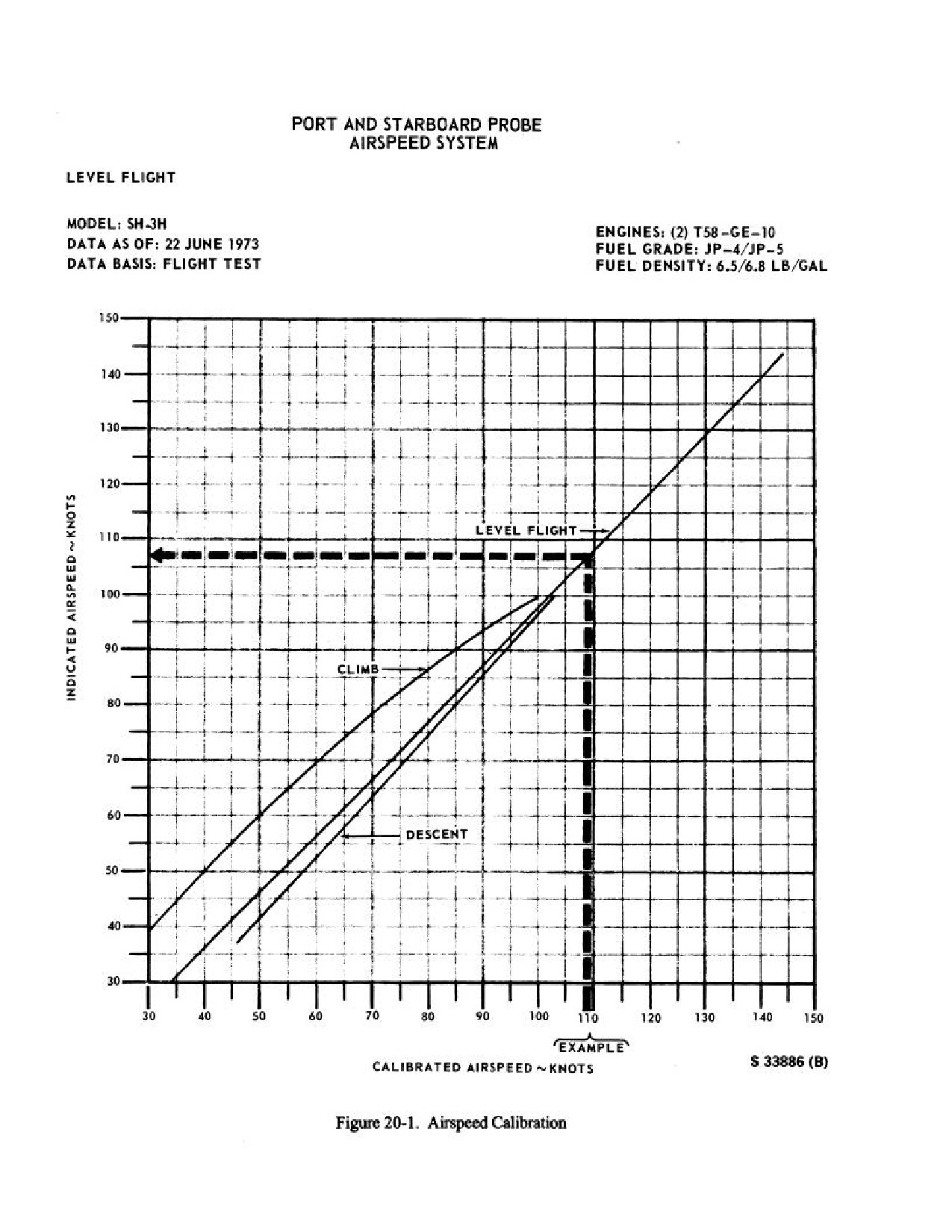
NAVAIR 01-230HLH-1
20-4
ORIGINAL
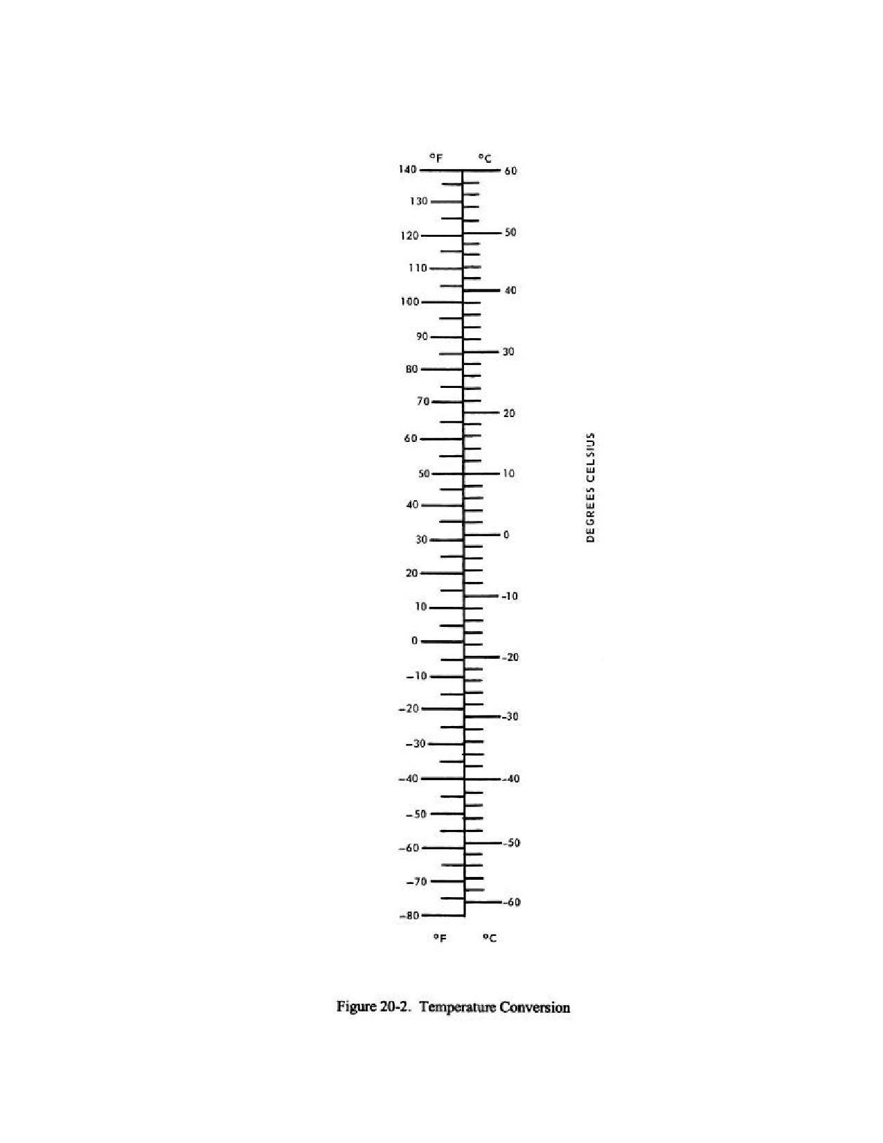
NAVAIR 01-230HLH-1
20-5
ORIGINAL
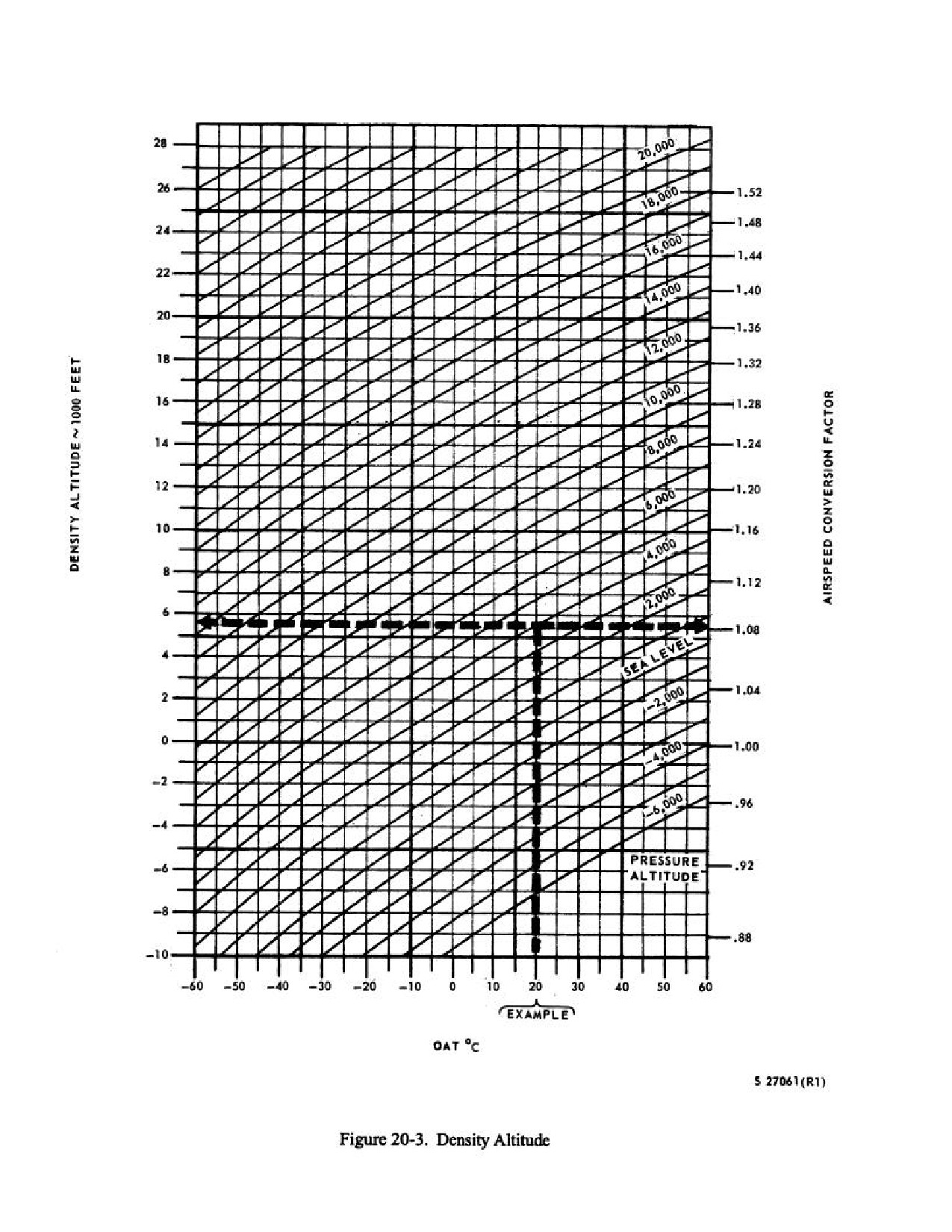
NAVAIR 01-230HLH-1
20-6
ORIGINAL
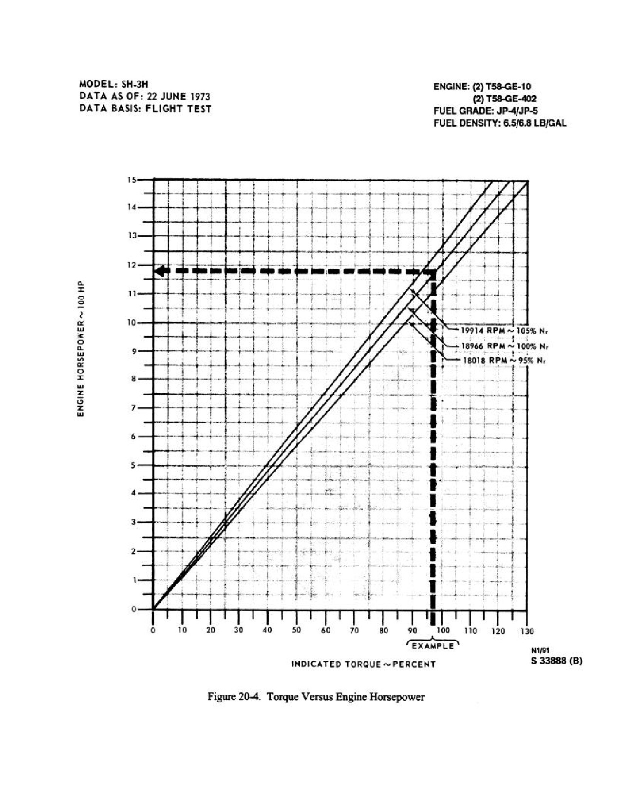
NAVAIR 01-230HLH-1
20-7
ORIGINAL
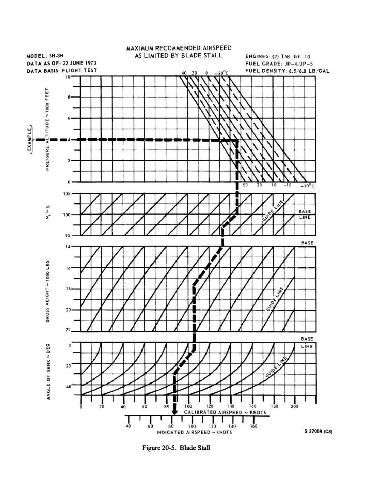
NAVAIR 01-230HLH-1
20-8
ORIGINAL
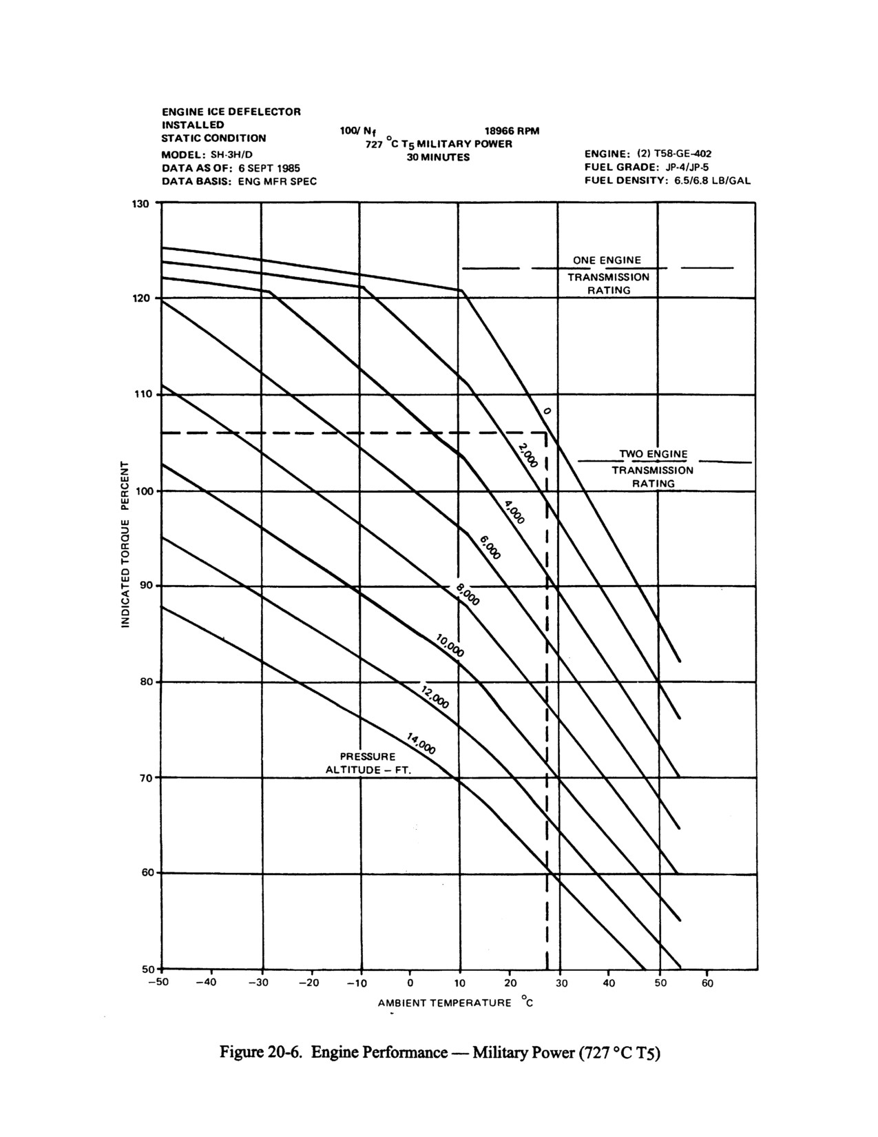
NAVAIR 01-230HLH-1
20-9
ORIGINAL
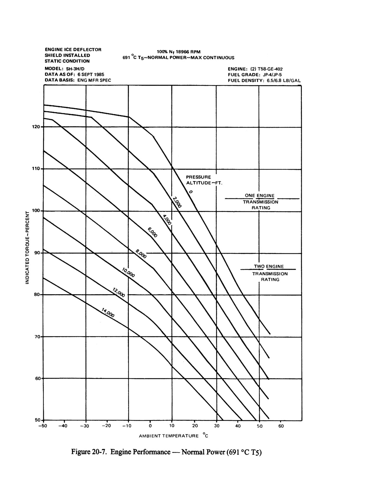
NAVAIR 01-230HLH-1
20-10
ORIGINAL
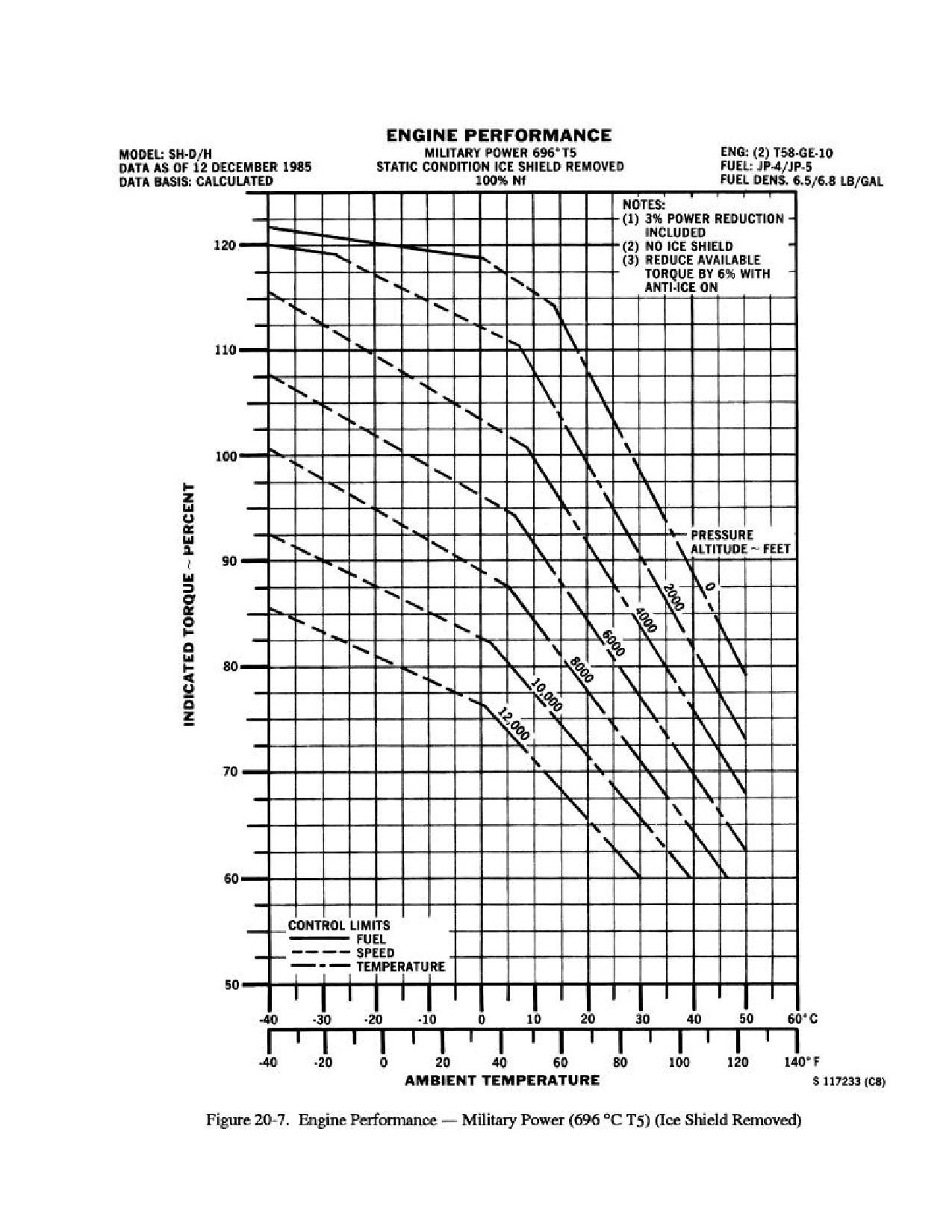
NAVAIR 01-230HLH-1
20-11
ORIGINAL
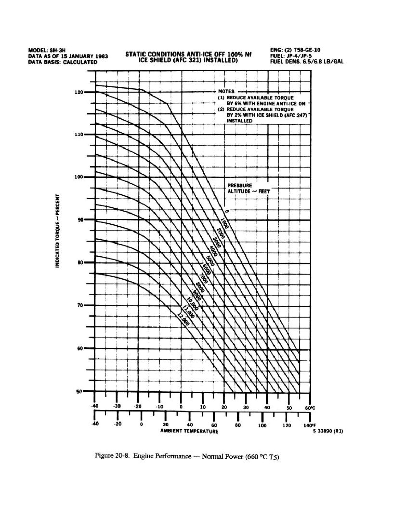
NAVAIR 01-230HLH-1
20-12
ORIGINAL
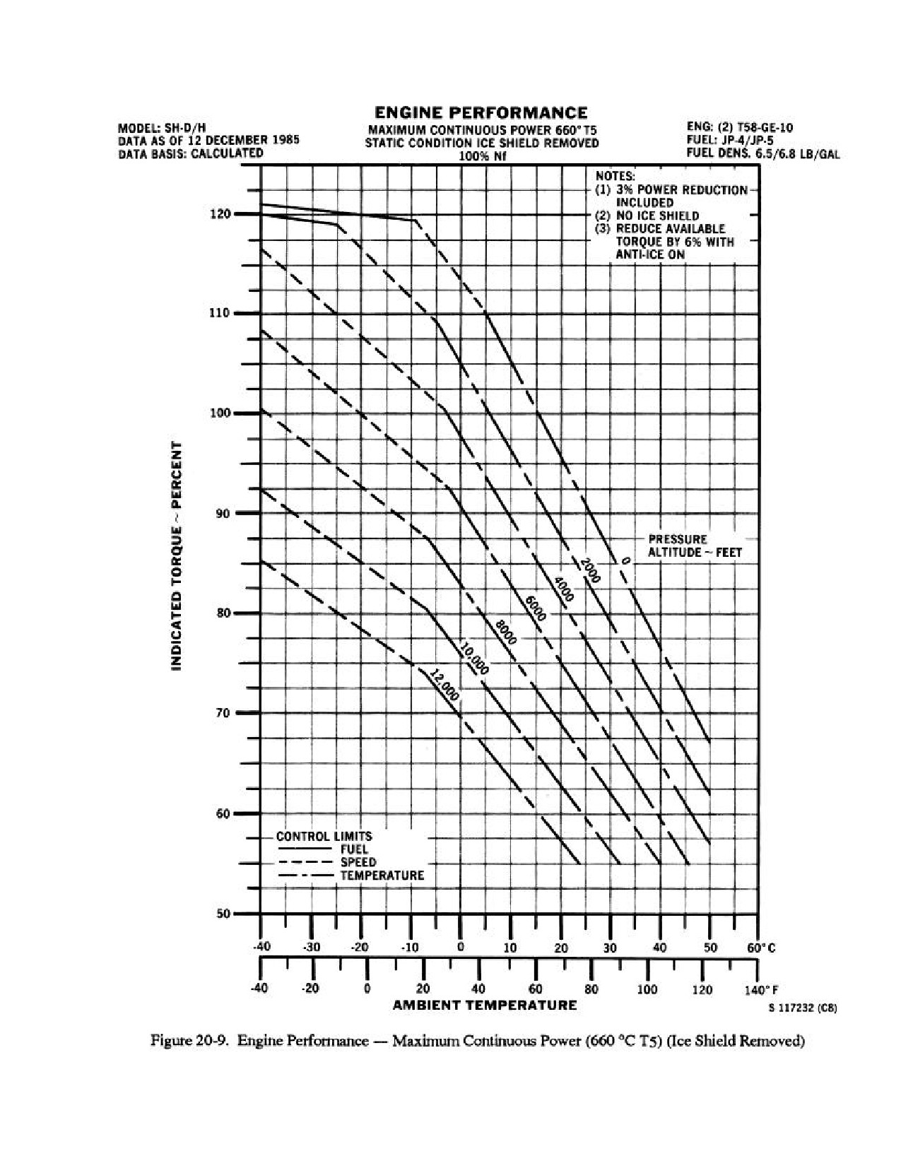
NAVAIR 01-230HLH-1
20-13
ORIGINAL
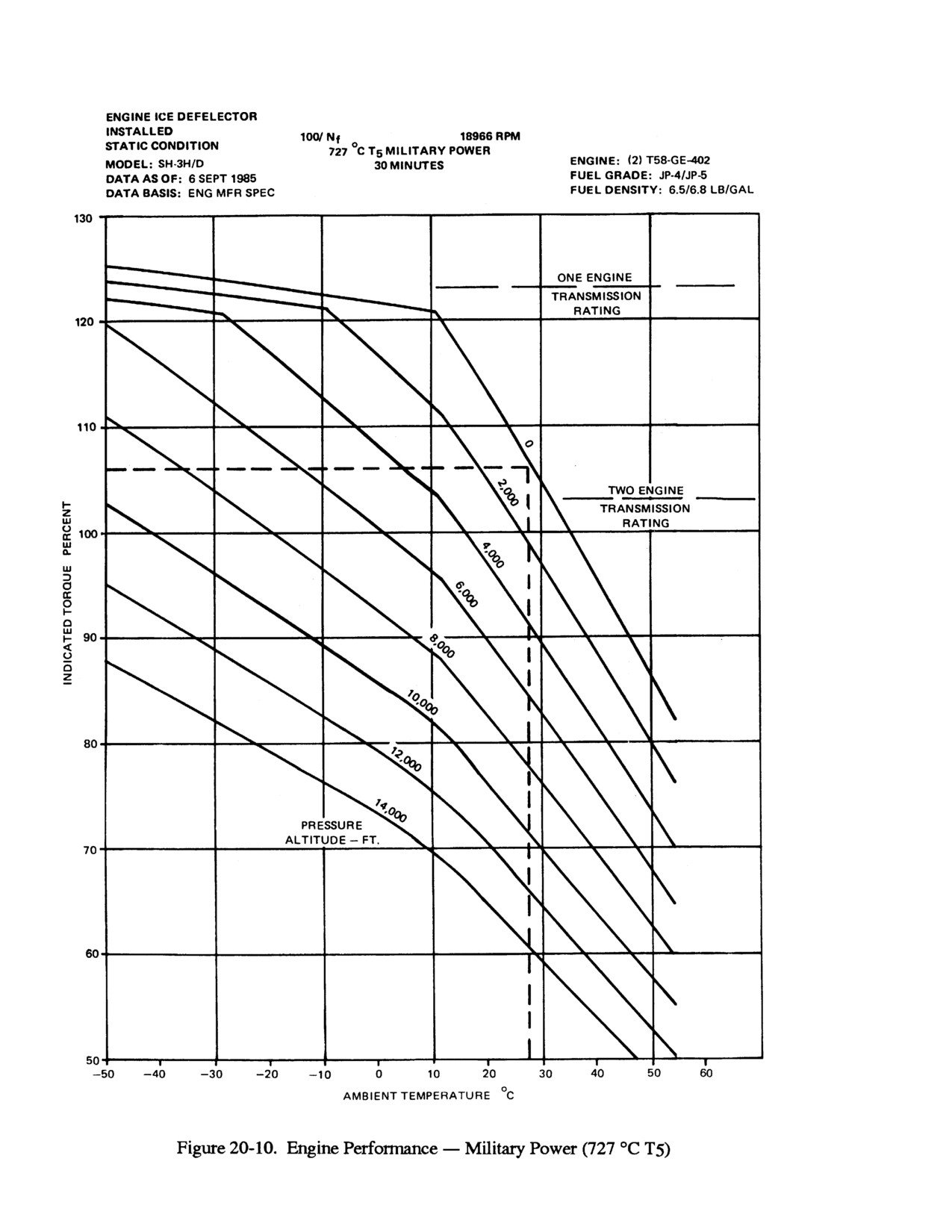
NAVAIR 01-230HLH-1
20-14
ORIGINAL
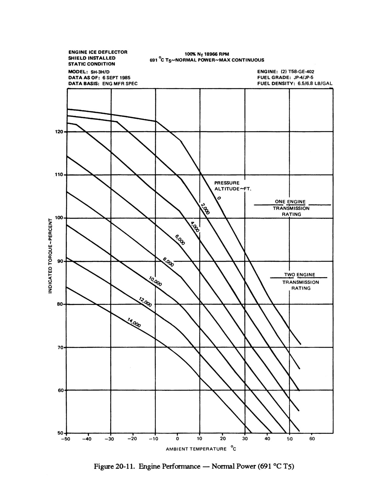
NAVAIR 01-230HLH-1
20-15
ORIGINAL
NAVAIR 01-230HLH-1
This Page Left Blank Intentionally
20-16
ORIGINAL
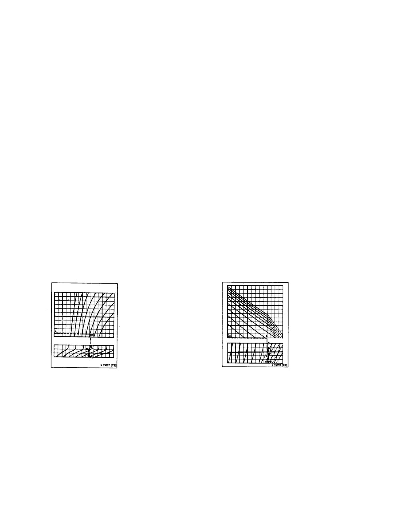
NAVAIR 01-230HLH-1
CHAPTER 21
Takeoff
21.1
HOVER CHARTS
3. From point C, follow the guideline to the 10-knot
headwind line (point D), then trace to the torque scale
The indicated torque required to hover charts (Figure
(point E), and read 77-percent torque.
21-1 and 21-2) provide the indicated torque required to
hover at a 10-foot wheel height and out of ground effect
21.1.2 Indicated Torque Required to Hover Out
when density altitude is applied to gross weight and
of Ground Effect Chart. The indicated torque required
headwind factors. The ability to hover out of ground effect
to hover out of ground effect chart (Figure 21-2) uses like
at various rotor speeds (Nr) chart (Figure 21-3) provides
factors in the same manner as Figure 21-1 to provide the
the gross weight that can be hovered out of ground effect
indicated torque required to hover out of ground effect.
when pressure altitude is applied to OAT and rotor speed
The height established for out of ground effect is about
factors.
100 feet between the wheels and the takeoff surfaces.
21.1.1 Indicated Torque Required to Hover In
21.1.3 Ability to Hover Out of Ground Effect at
Ground Effect - 10-Foot Chart. The indicated torque
Various Rotor Speeds Chart. The ability to hover out
required to hover in ground effect - 10-foot chart (Figure
of ground effect at various rotor speeds (Nr) chart (Figure
21-1) provides the indicated torque required to hover at a
21-3) provides the gross weight that the helicopter can
10-foot wheel height when density altitude is applied to
hover out of ground effect when pressure altitude is
gross weight and headwind factors.
applied to OAT and rotor speed factors.
21.1.1.1 Sample Problem for Use of Indicated
21.1.3.1 Sample Problem for Use of Ability To
Torque Required to Hover In Ground Effect - 10-
Hover Out of Ground Effect at Various Rotor
Foot Chart (Figure 21-1).
Speeds Chart.
1. Enter left side of chart at sea level pressure altitude
1. Enter left side of chart at 800 feet density altitude
(point A), then trace right to 28 °C OAT (point B).
(point A), then trace right to the 19,000-pound gross
weight line (point B).
2. From point B, trace down to the rotor speed
baseline (point C).
2. From point B, trace down to the headwind baseline
(point C).
3. From point C, follow the guideline up to the 103-
percent Nr line (point D), then trace down to the gross
weight scale
(point E), read
19,250 pounds gross
weight.
21-1
ORIGINAL
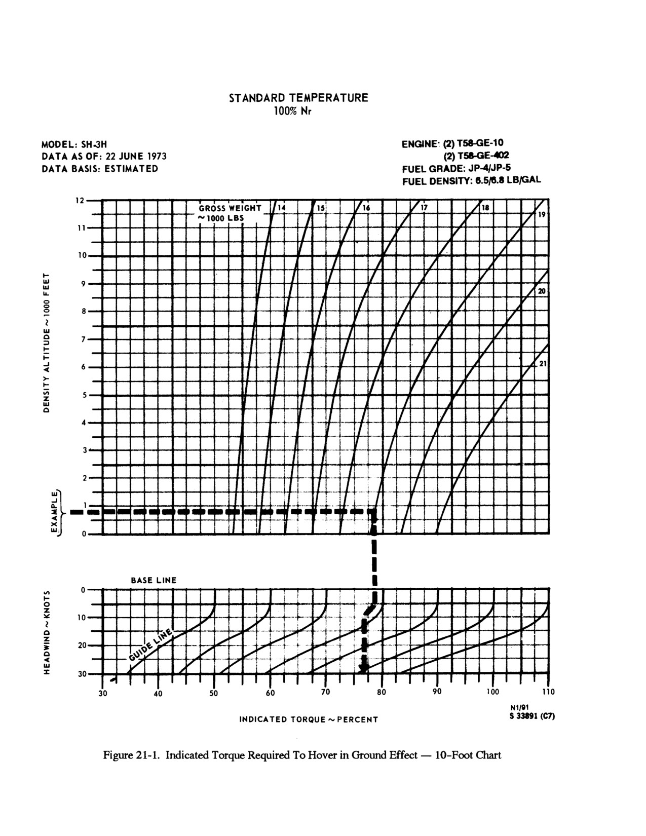
NAVAIR 01-230HLH-1
21-2
ORIGINAL
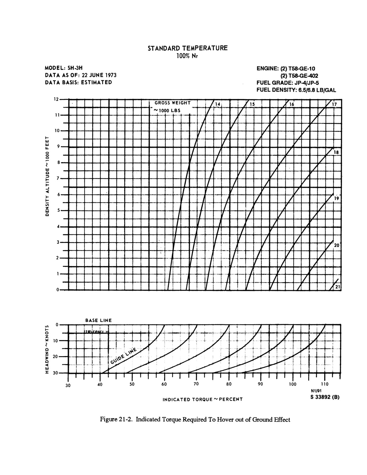
NAVAIR 01-230HLH-1
21-3
ORIGINAL
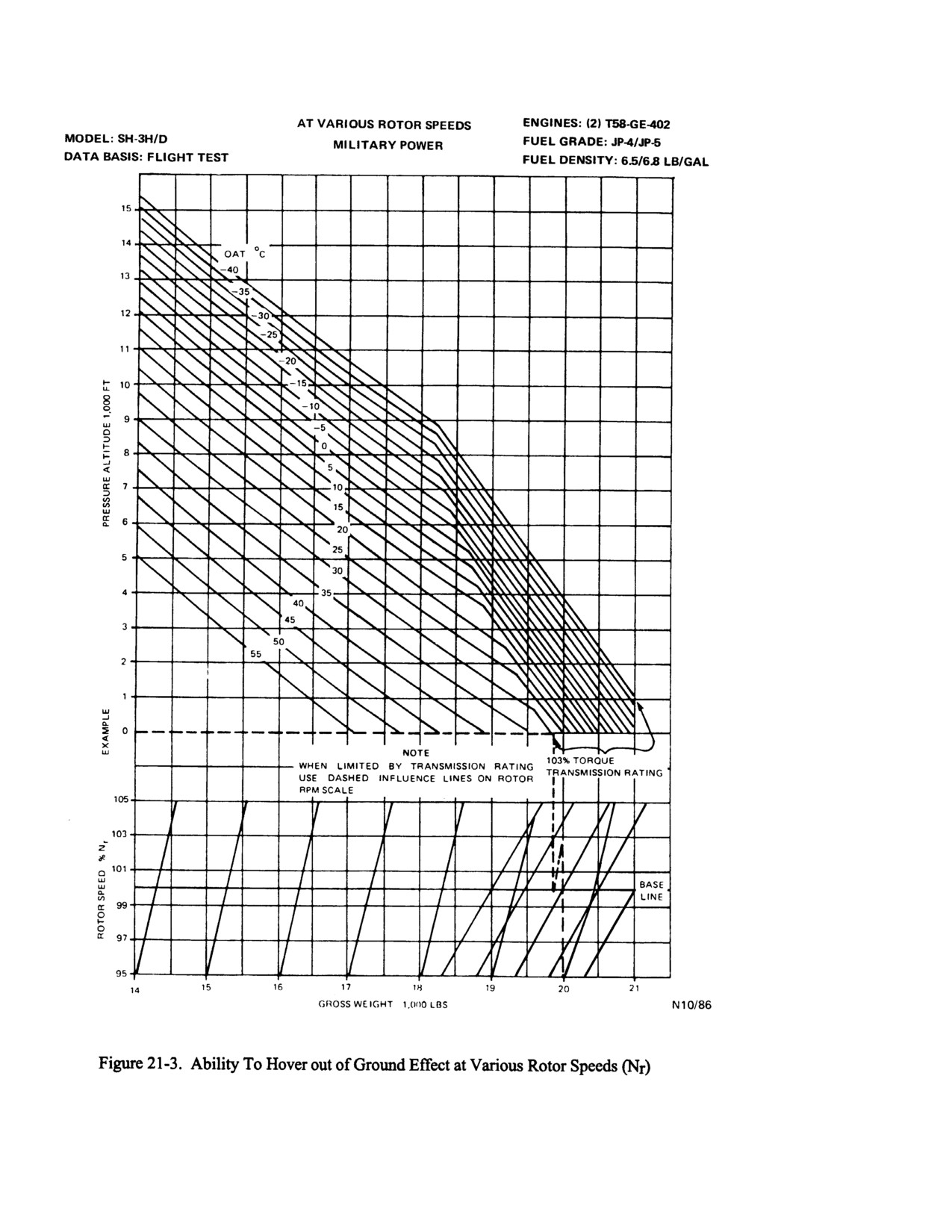
NAVAIR 01-230HLH-1
21-4
ORIGINAL
NAVAIR 01-230HLH-1
CHAPTER 22
Climb
22.1
CLIMB CHARTS
22.1.2.1 Sample Problem For Use of Climb
The climb charts
(Figure
22-1 and 22-2) provide a
Normal Power (Warm Day) Chart (Figure 22-2).
means of computing the time to climb, the horizontal
distance covered, the fuel consumed, and the rate of climb
for various gross weights. These values are computed by
applying the gross weights to various conditions of
pressure altitude and temperature. The fuel used includes
approximately 150 pounds used for warm up and takeoff
from sea level. For takeoffs above sea level, add
150
pounds for warm up, taxi, and climb. Also included is a
climb speed schedule to provide the climb speed for
various pressure altitudes. A temperature scale is also
provided to relate the OAT at various pressure altitudes.
The temperature scale is either based on a warm day (0 to
60 °C) or a cold day (-60 to 0°C).
22.1.1 Climb - Normal Power Chart (Cold Day).
1. Enter bottom of chart at 19,000 pounds gross weight
The climb - normal power (cold day) chart (Figure 22-1)
(point A), trace up to 4,000-foot pressure altitude in the
uses like factors in the same manner as Figure 22-2 to
time parameter block (point B), the trace left to the
provide climb data for the helicopter on a cold day.
temperature baseline (point C). From point C, follow
the influence line to the 20 °C line (point D), then trace
22.1.2 Climb - Normal Power (Warm Day). The
left and note that time to climb to 4,000-foot pressure
climb
- normal power
(warm day) chart
(Figure
22-2)
altitude is 2.7 minutes (point E).
provides the time to climb, horizontal distance covered,
fuel consumed, and rate of climb, at various gross weights
2. Enter bottom of chart at 19,000 pounds gross weight
for the helicopter on a warm day.
(point A), trace up to 4,000-foot pressure altitude in the
distance parameter block (point F), then trace left to the
Note
temperature baseline (point G). From point G, follow
the influence line to the 20 °C line (point H), then trace
When the takeoff is from above a sea-level
left and note that distance covered in a climb to 4,000-
pressure altitude, it will be necessary to
foot pressure altitude is 3nm, (point I).
determine climb data from sea-level
pressure altitude to the takeoff pressure
3. Enter bottom of chart at 19,000 pounds gross weight
altitude and from sea-level pressure altitude
(point A), trace up to 4,000-foot pressure altitude in the
to the cruise-level pressure altitude. The
fuel parameter block (point J), then trace left to the
difference between the data necessary to
temperature baseline (point K). From point K, follow
climb to both altitudes will then be the data
the influence line to the 20 °C line (point L), then trace
necessary to climb from takeoff pressure
left and note that fuel consumed in a climb to 4,000-
altitude to cruise-level pressure altitude.
foot pressure altitude is 220 pounds (point M).
22-1
ORIGINAL
NAVAIR 01-230HLH-1
4. Enter bottom of chart at 19,000 pounds gross weight
available under these conditions. If the value
(point A), trace up to sea-level in the rate-of-climb
is over
86 percent, the climb will be
parameter block
(point N), then trace left to the
transmission limited. On the same chart,
temperature baseline (point O). From point O, follow
locate the intersection of the relevant
the influence line to the 28 °C line (point P), then trace
pressure altitude and the 86-percent torque
left and note 1,450 fpm initial rate of climb (point Q).
lines, then proceed to the bottom and read
Follow the same procedure to determine that the final
the temperature at which the transmission
rate of climb at 4,000-foot pressure altitude and 20 °C
becomes torque limited. With this value,
is 1,125 fpm. The average rate of climb is 1,287 fpm.
return to the rate-of-climb section of the
climb chart and proceed from the
Note
temperature baseline. Parallel the solid
guideline until intersecting the temperature
The rate-of-climb sections of the climb
at which the transmission is limited, then
charts have both solid and dashed guidelines
trace parallel to the dashed line and, on the
with a note indicating the dashed line is to
left side, read the rate of climb.
be used when operating at a transmission
limit. To determine if performance will be
5. Enter the left side of climb speed schedule at 4,000-
limited
by
maximum
continuous
foot pressure altitude (point R), trace right to the best
transmission torque
(86 percent), refer to
climb speed curve (point S), then trace down and read
Figure 20-10, engine performance
- normal
best climb speed of 68 KIAS (point S). Follow the
power
(660° T5). Apply the ambient
same procedures to determine that the best climb speed
temperature to the pressure altitude and
for sea-level pressure altitude is 70 KIAS.
proceed to the left side and read torque
22-2
ORIGINAL
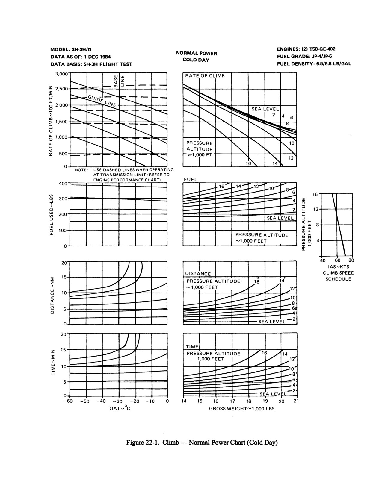
NAVAIR 01-230HLH-1
22-3
ORIGINAL
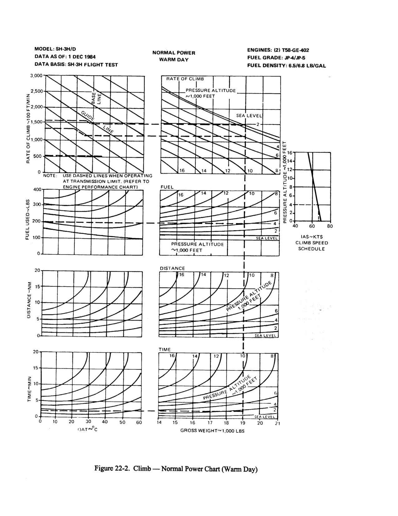
NAVAIR 01-230HLH-1
22-4
ORIGINAL
NAVAIR 01-230HLH-1
CHAPTER 23
Range
23.1
RANGE CHARTS
23.1.3 Unit Range and Fuel Flow Conversion
Chart. The unit range and fuel flow conversion chart
The range charts (Figure 23-1 and 23-2) provide unit
(Figure 23-2) provides the factors necessary to convert unit
range, indicated and calibrated airspeed, and approximate
range to total range and fuel flow to endurance hours. The
torque when gross weight is applied to pressure altitude.
unit range conversion portion of the chart provides total
range, in nautical miles, when unit range is applied to the
23.1.1 Maximum Range
(-10)
- Two-Engine
amount of fuel. The fuel flow conversion portion of the
Chart. The maximum range - two engine chart (Figure
chart provides endurance hours when fuel flow is applied
23-1) provides the unit range, indicated and calibrated
to the amount of fuel.
airspeed, and approximate torque when gross weight is
applied to pressure altitude to produce maximum range for
23.1.3.1 Sample Problem for Use of Unit Range
the helicopter at slower airspeeds than Figure 23-2.
and Fuel Flow Conversion Chart (Figure 23-3).
23.1.1.1 Sample Problem for Use of Maximum
Range (-10) - Two Engine Chart (Figure 23-1).
1. For a range problem, enter bottom of chart at 0.109
nm per pound of fuel (point A), trace up to the 1,525-
pound fuel line (point B), the trace left to the total
range scale (point C) and 165 nm.
2. For an endurance problem, enter bottom of chart at
1. Enter bottom of chart at 18,000 pounds gross weight
870-pph fuel flow (point D), trace up to the
1,525-
(point A), trace up to 4,000 foot pressure altitude line
pound fuel line
(point E), then trace right to the
(point B), then trace left to the unit range scale (point
endurance hours scale (point F) and read 1 hour and 42
C) and read 0.109 nm per pound of fuel.
minutes.
2. From point B, continue to trace the gross weight
23.1.4 Sample Problem for Use of Maximum
line up to the 4,000-foot pressure altitude line in the
Range - (-402) Two-Engine Chart (Figure 23-4).
next block (point D), then trace left to the airspeed
scale (point E) and read 109 KCAS and 107 KIAS.
3. From point D, continue to trace the gross weight
line up to the 4,000-foot pressure altitude line in the
next block (point F), then trace left to the torque scale
(point G), and read 58-percent torque.
23.1.2 Optimum Cross-Country Chart. The
Optimum cross-country chart
(Figure
23-2) uses like
factors in the same manner as Figure
23-1 to produce
maximum range at normal power. This chart will give
higher airspeeds and torque values and less range than
Figure 23-1.
23-1
ORIGINAL

NAVAIR 01-230HLH-1
1. Enter bottom of chart at 18,000 pounds gross weight
for converting unit range, total range, and fuel flow to
(point A), trace up to 4,000 foot pressure altitude line
endurance hours. The unit range conversion portion of the
(point B), then trace left to the unit range scale (point
chart provides total range, in nautical miles, when unit
C) and read 0.116 nm per pound of fuel.
range is applied to the amount of fuel. The fuel conversion
portion of the chart shows endurance hours when fuel flow
2. From point B, continue to trace the gross weight
is applied to amount of fuel.
line up to the 4,000-foot pressure altitude line in the
next block (point D), then trace left to the airspeed
23.1.7 Sample Problem for Use of Unit Range
scale (point E) and read 116 KCAS and 114 KIAS.
and Fuel Flow Conversion Chart.
3. From point D, continue to trace the gross weight
1. For a range problem, enter bottom of chart at 0.109
line up to the 4,000-foot pressure altitude line in the
nm per pound of fuel (point A), trace up to the 1,525-
next block (point F); then trace left to the torque scale
pound fuel line (point B), then trace left to the total
(point G) and read 63-percent torque.
range scale (point C) and read 165 nm.
23.1.5 Maximum Range (-402) - Normal Power
2. For an endurance problem, enter bottom of chart at
Two-Engine Chart. This chart (Figure 23-5) is used like
870-pph fuel flow (point D), trace up to the
1,525-
Figure 23-4 to produce maximum range at normal power.
pound fuel line
(point E), then trace right to the
endurance hours scale (point F) and read 1 hour and 42
23.1.6 Unit Range and Fuel Flow Conversion
minutes.
Chart (-402). This chart (Figure 23-6) shows the factors
23-2
ORIGINAL
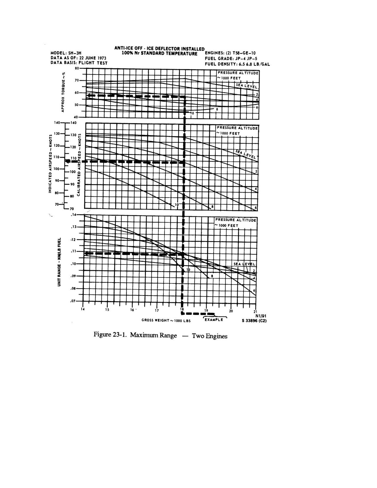
NAVAIR 01-230HLH-1
23-3
ORIGINAL
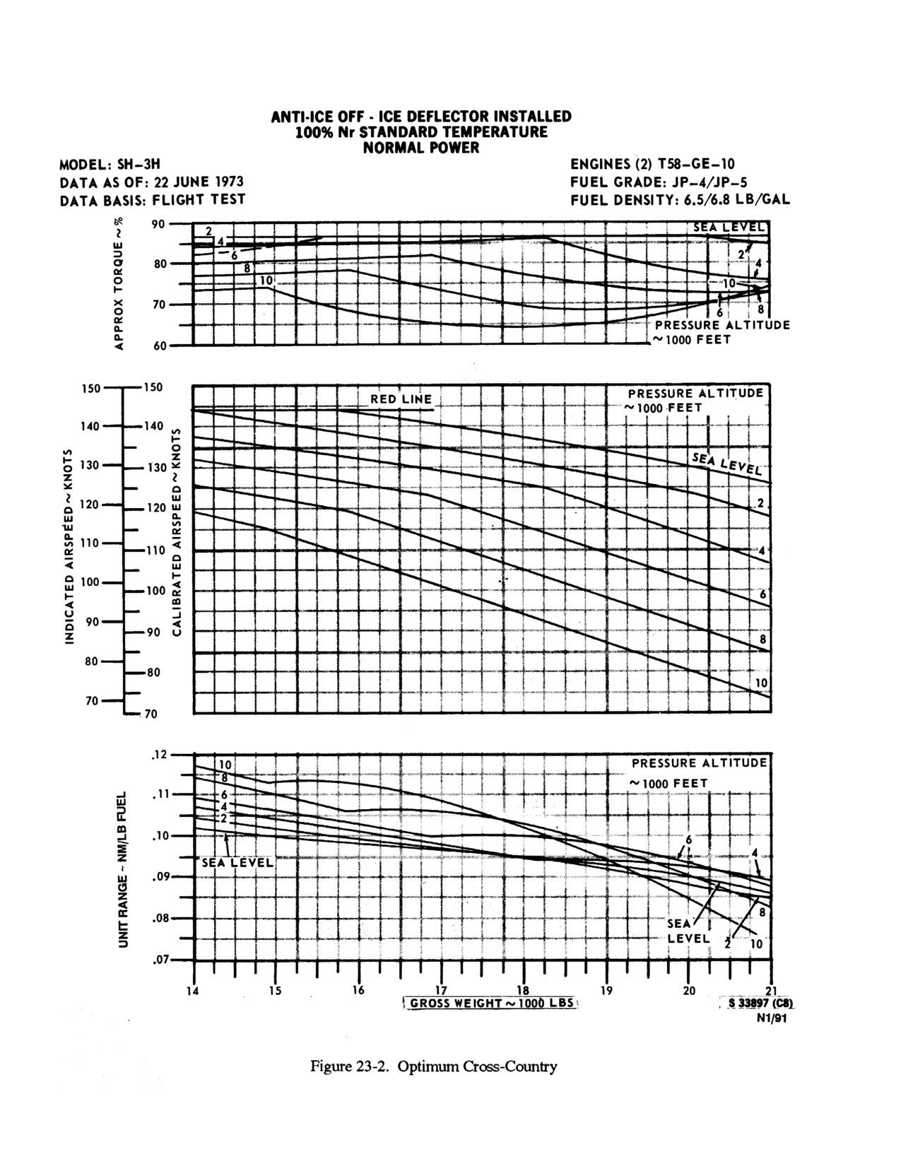
NAVAIR 01-230HLH-1
23-4
ORIGINAL
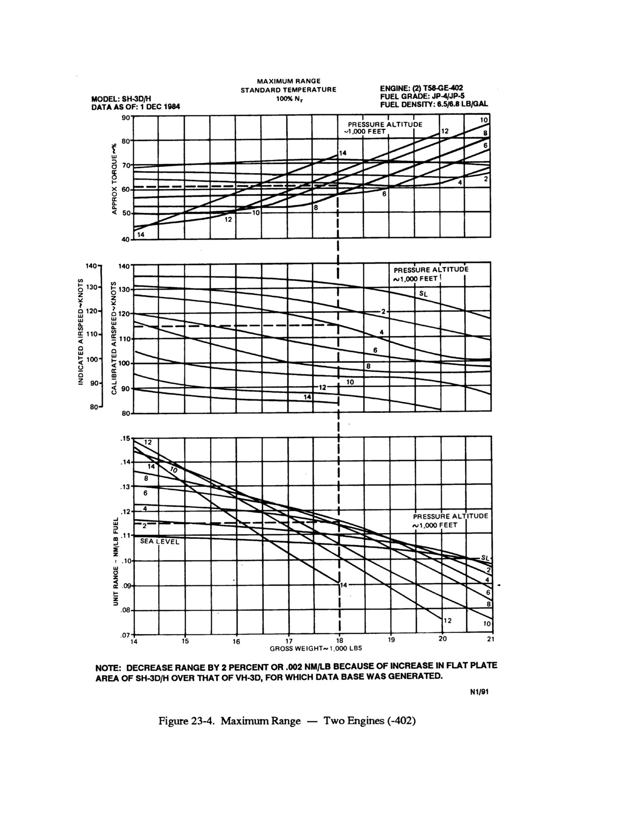
NAVAIR 01-230HLH-1
23-5
ORIGINAL
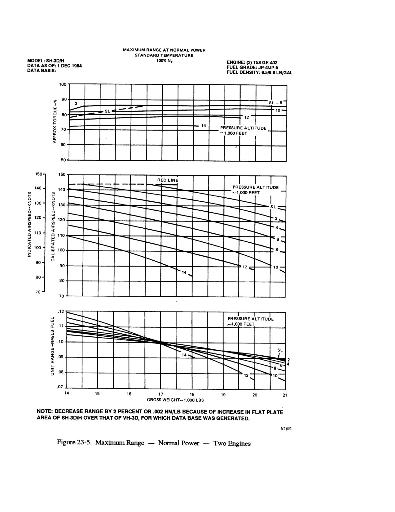
NAVAIR 01-230HLH-1
23-6
ORIGINAL