UH-3H and UH-3H EXECUTIVE TRANSPORT. FLIGHT MANUAL (2000) - page 7
NAVAIR 01-230HLH-1
of the indicator. The SET knob is used to set a course in
adjusts receiver audio level when the function switch is in
the course window at the top of the indicator. The sensing
COMP, and adjusts receiver RF sensitivity when the
window will indicate TO or FROM, depending on whether
function switch is in ANT or LOOP. With the function
the selected course is to or from the tacan station. The
switch in COMP, the set operates as an automatic
vertical bar indicates whether the helicopter has deviated
direction-finder using both the sense and loop antennas.
to the left or right of the course to the station. The relative
The tuning control may be adjusted to give maximum
heading pointer indicates the number of degrees the
indication on the tuning meter for any given station, and
helicopter is heading from the course set in the three-digit
the relative bearing is automatically indicated by the No. 1
course window. Two warning flags marked OFF are on the
single-barred pointer on the RMI. With the function switch
face of the instrument and will appear when tacan signals
at ANT, the set operates as a communications receiver
are weak, unreliable, or nonexistent. The horizontal bar
using the sense antenna only. With the function switch at
marked GLIDE SLOPE and the press-to-test light marked
LOOP, the set operates as a receiver using the loop
MARKER are deactivated on the top course indicator
antenna. The LOOP switch positions the loop antenna
which is used with the tacan. On the bottom indicator,
when the function switch is at either COMP or LOOP. The
which is used with the VOR/ILS, the horizontal bar
BFO switch is used as an aid in the determination of aural
marked GLIDESLOPE and the press-to-test light marked
nulls on either unmodulated or voice-modulated signals.
MARKER are activated.
With the BFO switch ON, place the function switch to
LOOP and press the LOOP switch in the desired direction
15.13 LF AUTOMATIC DIRECTION FINDER
to determine the aural null when the tone drops to
(AN/ARN-59)
minimum. Read the relative bearing of the transmitting
station on the No. 1 single-barred pointer on the RMI. The
LF/ADF (AN/ARN-59) is an airborne radio comp ass
tuning crank tunes the receiver to the desired frequency
system designed to automatically provide a visual
within the selected band.
indication from which an incoming radio RF signal is
received. It provides for the aural reception of AM signals
15.13.2 LF
Automatic
Direction
Finder
from 190 to 1750 kHz in three bands: 190 to 400 kHz, 400
Operation. To turn the set on for use as a conventional
to 840 kHz, and 840 to 1750 kHz. The equipment includes
radio receiver:
a receiver, a loop antenna, a sense antenna, a control panel,
and a dynamotor and utilizes the radio magnetic indicators
1. Volume control - ROTATE CLOCKWISE.
for bearing indications. The dynamotor furnishes 13-volt
100-Hz ac and 125-vdc power to the radio set. The set is
2. Function switch - ANT.
dc powered and is protected by a circuit breaker marked
ADF.
3. Band switch
- SET TO DESIRED OPERATING
BAND.
4. Tuning
control
-
TUNE TO DESIRED
FREQUENCY.
5. Volume control - ADJUST AS NECESSARY.
To turn the set on for use as an automatic direction finder:
1. Volume control - ROTATE CLOCKWISE.
2. Function switch - COMP.
3. Band switch
- SET TO DESIRED OPERATING
BAND.
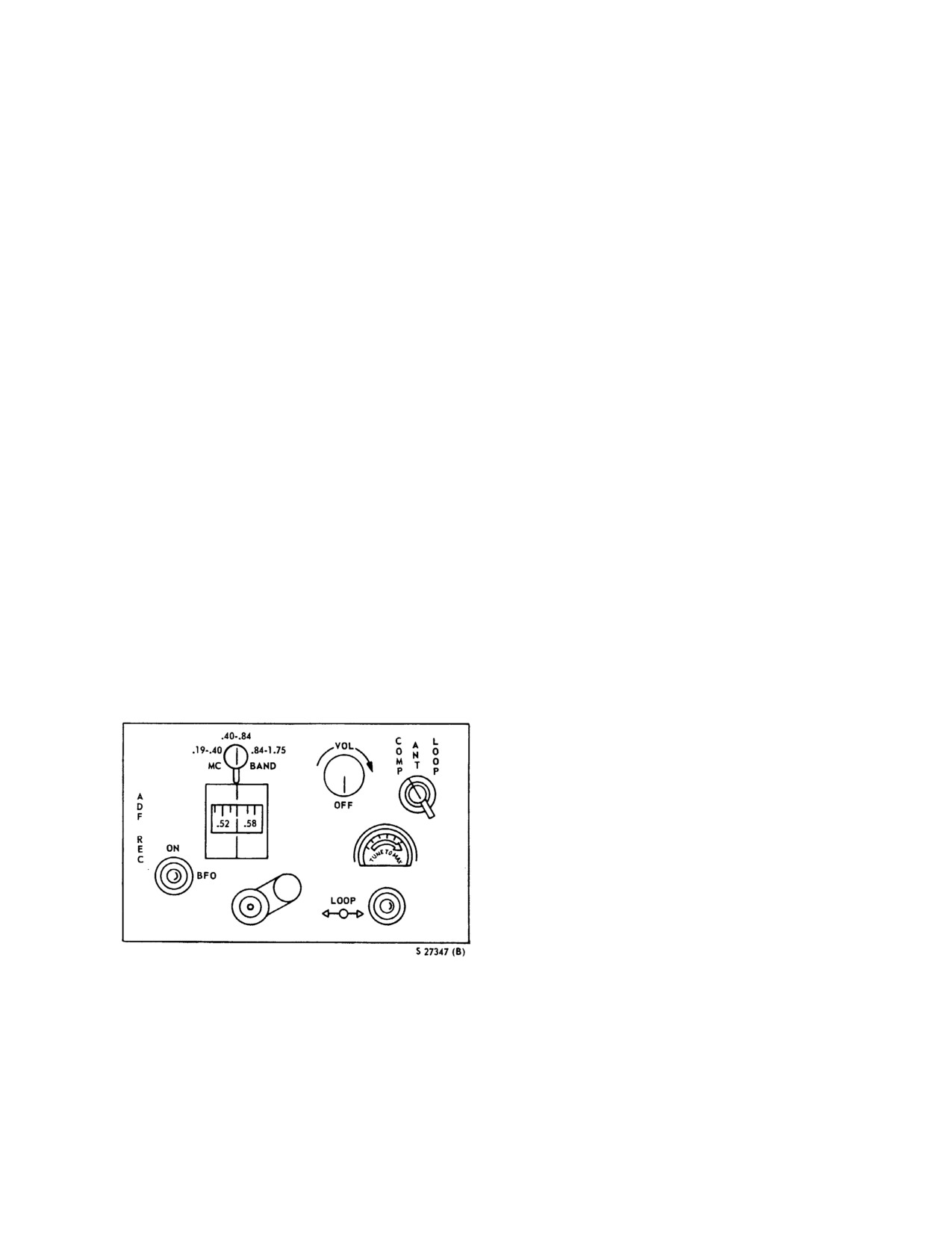
Figure 15-16. LF/ADF Control Panel
4. Tuning
control
-
TUNE TO DESIRED
FREQUENCY.
15.13.1 LF/ADF Control Panel. The automatic
direction-finder set is controlled from a panel (Figure 15-
5. Volume control - ADJUST AS NECESSARY.
16) marked ADF REC on the cockpit console. Controls
include a band switch; a volume control marked VOL-
6. Function switch - COMP.
OFF; a function switch marked COMP, ANT, and LOOP;
a tuning meter; a loop switch marked LOOP; a tuning
control; and a beat frequency oscillator switch marked
BFO-ON. The volume control turns the set on or off,
15-15
ORIGINAL
NAVAIR 01-230HLH-1
Note
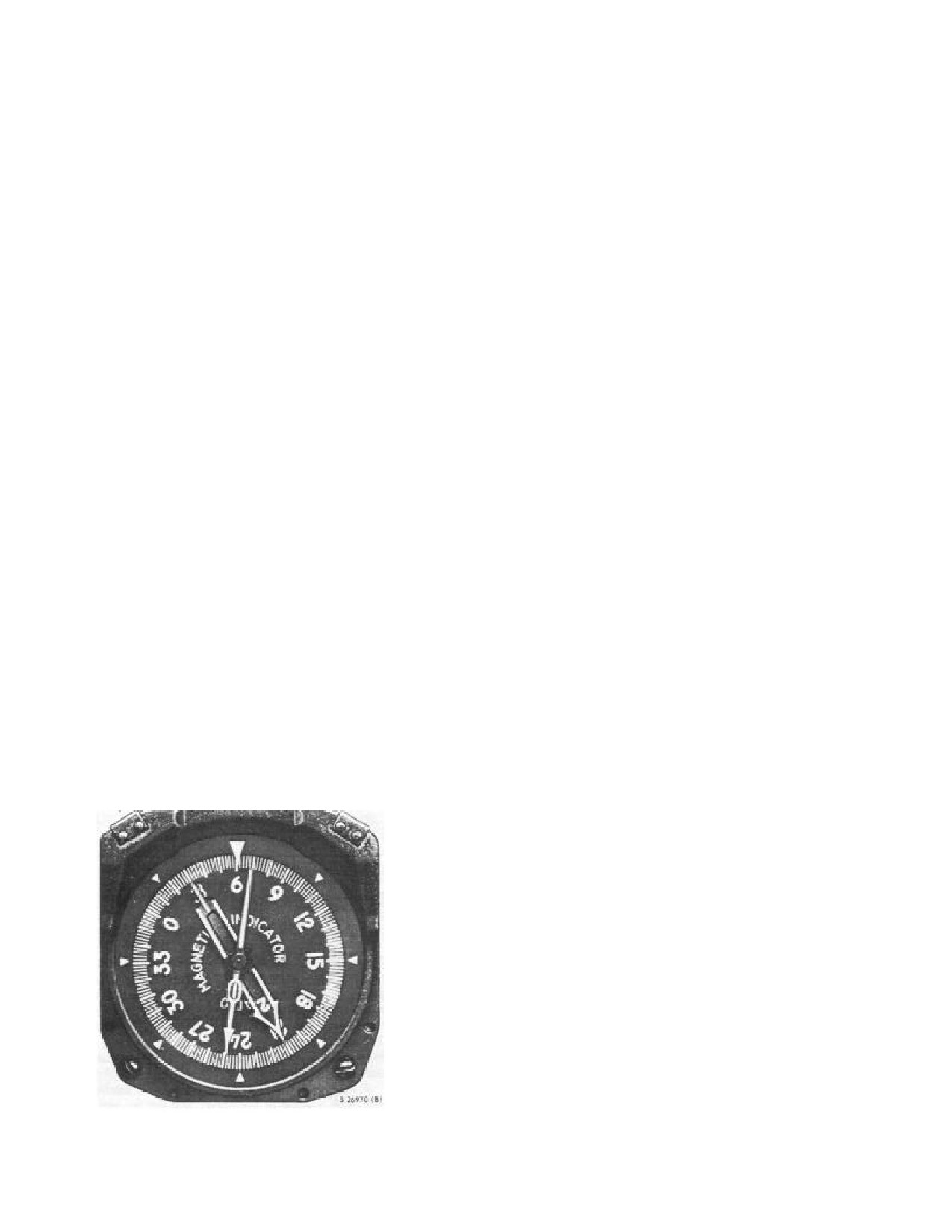
15.14 RADIO MAGNETIC INDICATOR
To find whether the relative bearing on the
The ID-250/ARN RMI indicator (Figure 15-17) located
RMI is accurate when the function switch is
on the instrument panel marked RADIO MAGNETIC
at COMP, throw the LOOP switch to the
INDICATOR, consists of an azimuth scale numerically
right and observe that the pointer rotates
marked in 30° units and linear markings in 20° units, a
clockwise. After approximately
20° of
fixed index at the top of the indicator, a single-barred No.
pointer travel, release the LOOP switch and
1 pointer, and a double-barred No. 2 pointer. The azimuth
note the action of the indicator pointer. If the
scale, coupled to the compass system, turns the compass
signal is normal and reliable, the pointer will
card of the indicator and indicates the magnetic heading of
immediately return to the original reading.
the helicopter on the scale beneath the fixed index at the
top of the indicator. The No. 1 pointer provides bearing
To turn the set on for use as a manual direction finder,
readout for the LF/ADF, UHF-DF sets, and the OTPI
using the LOOP position and with the BFO switch ON,
system. The No.
2 double-barred pointer indicates the
proceed as follows:
magnetic bearing of a station as determined by the tacan
set.
1. Volume control - ROTATE CLOCKWISE.
15.15
AIRBORNE IDENTIFICATION MOBILE
2. Function switch - LOOP.
TRANSPONDER SYSTEM
3. BFO switch - ON.
The AIMS (ATCRBS IFF Mark XII system) transponder
system is capable of automatically reporting coded
4. Band switch
- SET TO DESIRED OPERATING
identification and altitude signals in response to
BAND.
interrogations from surface (or airborne) stations so that
the stations can establish and/or maintain identification
5. Tuning control
-
TUNE TO DESIRED
and/or control of air traffic. The system has five operating
FREQUENCY.
modes (1, 2, 3/A, C, and 4). Modes 1 and 2 are IFF modes,
mode 3 (Civil mode A) and mode C (automatic altitude
6. LOOP switch - PRESS IN DESIRED DIRECTION.
reporting) are primarily air traffic control modes, and
mode 4 is the secure (encrypted) IFF mode. (Mode 4 is not
Rotate the loop until the tone drops to minimum and read
operational unless the system includes a KIT-1A/TSEC
the relative bearing of the transmitting station on the
transponder computer).
indicator.
15.15.1 AIMS Transponder System Components.
To secure the set:
The basic AIMS transponder components are as follows:
1. Volume control - OFF.
1. AIMS transponder set control panel, C-6280A/APX.
2. Transponder, APX-72.
3. Transponder test set, TS-1843/APX.
The AIMS altimetry consists of:
4. AAU-21/A barometric altitude encoder.
The following components provide the secure IFF (mode
4) function:
5. Transponder computer, KIT- 1A/TSEC.
6. IFF caution light.
7. Right main landing gear scissor switch.
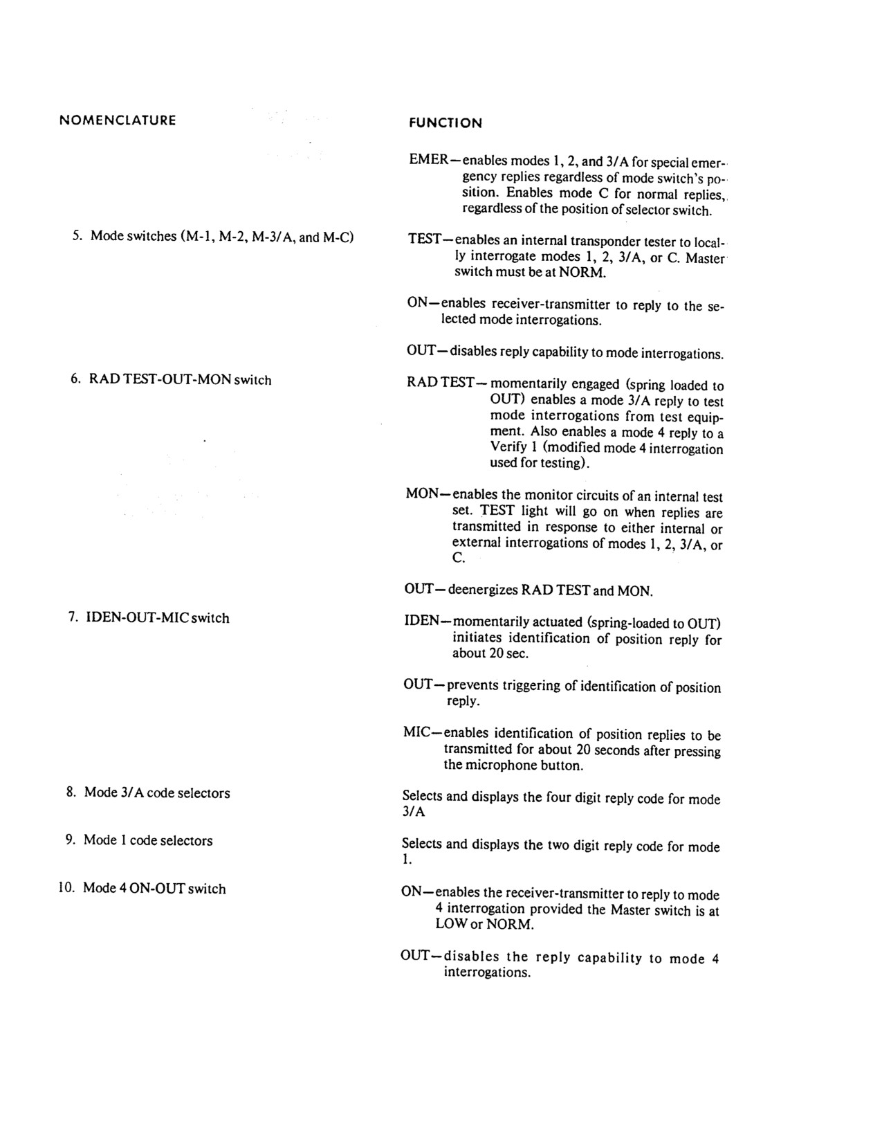
Figure 15-17. Radio Magnetic Indicator
15-16
ORIGINAL
NAVAIR 01-230HLH-1
15.15.2 Transponder Test Set. The integral TS-1843
15.15.3.3 Mode 1, 2, and 3/A CODE Selectors. The
transponder test set provides the self-test and monitor
two MODE
1 thumbwheel selector switches allow
functions for modes
1,
2,
3/A, and C. The TS-1843
selection of mode 1 codes from 00 through 73, and the
accomplishes the self-test functions, when actuated, by
four MODE 3/A thumbwheel selectors allow selection of
interrogating the transponder and monitoring the replies.
mode 3/A codes from 0000 to 7777. The mode 2 selector
The monitor function is accomplished, when selected, by
switches are on the transponder
(in the Doppler
monitoring the replies to external interrogations. The
compartment). The mode 2 code is selected prior to flight
controls for the TS-l843 are included in the IFF control
by ground maintenance personnel.
panel.
15.15.3.4 Mode Switches. The four mode switches (M-
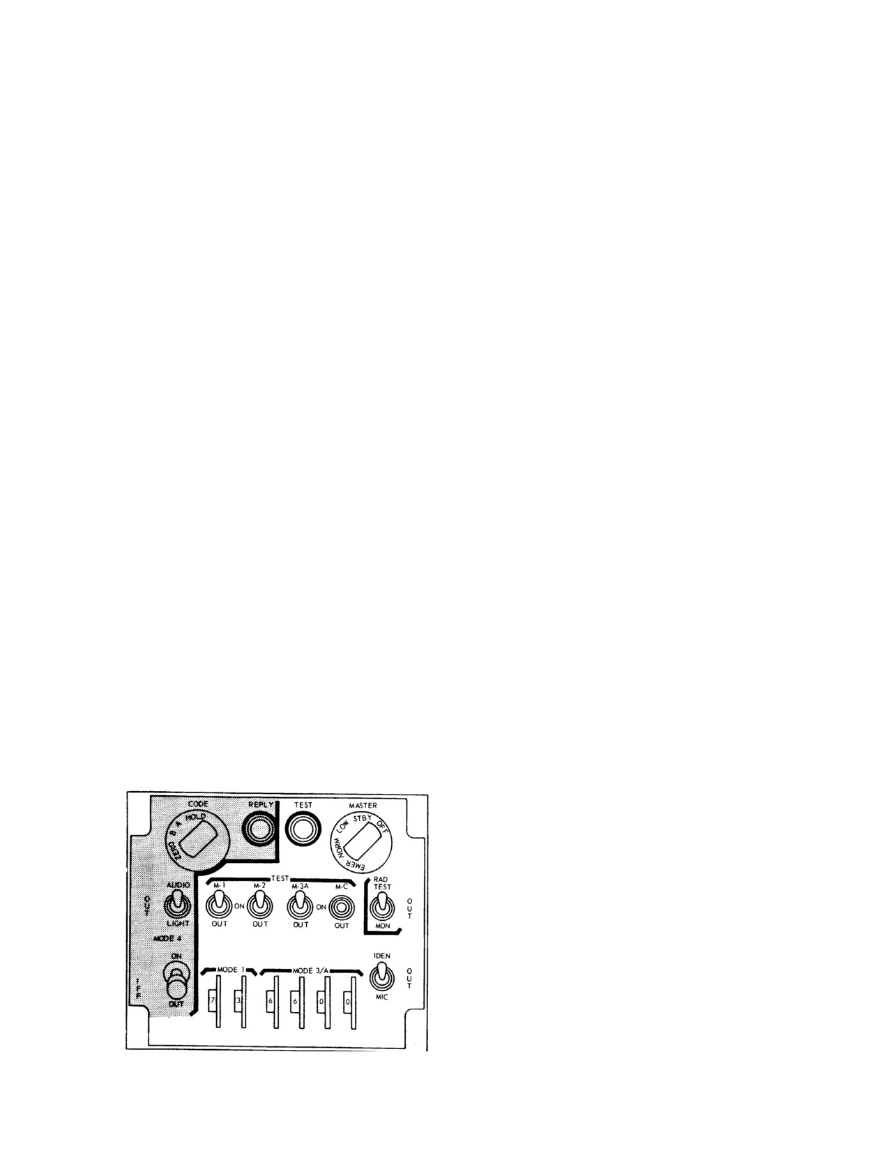
15.15.3 IFF Control Panel. All of the pilots controls
1, M-2, M-3/A, and M-C) each have OUT, ON, and
for the AIMS transponder system are included on the IFF
spring-loaded TEST positions. The center ON position of
control panel
(Figure
15-18). The reply light and the
each switch enables that mode providing the master switch
controls on the left side of the control panel are associated
is in LOW or NORM. To test the transponder, press and
with mode
4 operation. The test light and remaining
hold the mode switch of each mode to the TEST position.
controls are associated with modes, 1,2, 3/A, and C, except
Continuous illumination of the TEST light while the mode
that the MASTER switch controls all modes of operation.
switch is held to the TEST position indicates proper
operation of that mode. Intermittent illumination of the
15.15.3.1 MASTER Switch. The MASTER switch
TEST light indicates improper operation of the respective
applies power to all of the AIMS transponder components
mode. No TEST light indicates failure of the TEST
except the altimetry component. It is a five-position rotary
equipment. The MASTER switch must be set to NORM
switch placarded OFF-STBY-LOW-NORM-EMER. The
for the test function to operate. The mode switches of the
switch must be lifted over a detent to switch to EMER or
modes not being tested should be at OUT when testing on
to OFF, and STBY should be selected for 2 minutes before
the ground to prevent unnecessary interference with nearby
switching to LOW or NORM to allow the transponder to
ground stations.
warm up. At NORM, the system is operational at normal
receiver sensitivity. In the LOW position, the system is
Note
operational but the transponder transmits replies at reduced
intensity to mode 1, 2, and 3/A interrogations. The mode
The TEST light may flash once as each mode
3/A emergency reply includes code 7700. When EMER is
switch is released from the test position, and
selected, modes 1, 2, 3/A, and C are enabled, regardless of
as the RAD TEST-OUT-MON switch is
the position of the selector switches.
moved. This is a characteristic of the TS-1843
transponder test set and is meaningless.
15.15.3.2 IDEN-OUT-MIC Switch. The IDEN-OUT-
MIC switch is a three-position toggle switch. The spring-
15.15.3.5 RAD TEST-OUT-MON Switch. The MON
loaded IDEN position adds an identification of position
position of the RAD TEST-OUT-MON switch is used to
pulse to modes 1, 2, and 3/A replies for a period of 15 to
monitor the operation of modes 1, 2, 3/A, and C. When
30 seconds (nominal 20 seconds). In the MIC position, the
MON is selected, the TEST light will come on for
3
identification of position function is activated for 15 to 30
seconds each time an acceptable response is made to an
seconds each time the UHF microphone button is pressed.
interrogation on a selected mode.
The spring-loaded RAD TEST position is used for
testing. It enables a mode 3/A code reply to a test mode
interrogation from a ramp test set. It also enables a mode 4
reply to a verify 1 interrogation from a surface station of a
ramp test set. A verify 1 interrogation is a modified mode
4 interrogation used for testing.
15.15.3.6 Mode 4 Operation. Mode 4 operation is
selected by placing the Mode
4 toggle switch ON,
provided the master switch is at LOW or NORM. Placing
the mode 4 switch to OUT disables mode 4.
The mode 4 code switch is placarded ZERO, B, A, and
HOLD. The switch must be lifted over a detent to switch
to ZERO. It is spring loaded to return from HOLD to the A
position. Position A selects the mode 4 code for the present
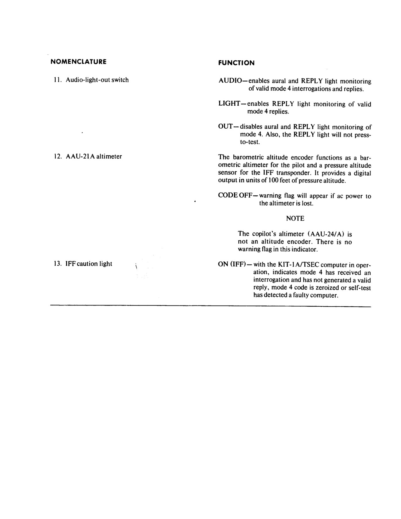
Figure 15-18. IFF Control Panel and Functions
code period, and position B selects the mode 4 code for the
(Sheet 1 of 4)
succeeding period. Both codes are mechanically inserted
15-17
ORIGINAL
NAVAIR 01-230HLH-1
by a code changing key. The codes are mechanically held
If the IFF caution light goes on, switch the MASTER
in the transponder computer, regardless of the position of
switch to NORM (if in STBY) and make sure that the
the MASTER switch or the status of helicopter power,
mode 4 toggle switch is ON. If illumination continues,
until the first time it becomes airborne. Thereafter, the
employ operationally directed flight procedures for an
mode
4 codes will automatically zeroize anytime the
inoperative mode 4 condition.
MASTER switch or helicopter power is turned off. In
order to prevent the mode 4 codes from automatically
The AIMS transponder system uses ac and dc power
zeroizing anytime the master switch or helicopter power is
and is protected by circuit breakers.
turned off, HOLD must be selected after weight on wheels,
at least
15 seconds prior to shutdown. With AFC 446
15.16 BEARING DISTANCE HEADING
incorporated, codes will be retained regardless of flight or
INDICATORS
power conditions and must be manually zeroized to drop
the code. The mode 4 codes can be zeroized anytime the
Note
helicopter power is on and the MASTER switch is not in
OFF by turning the code switch to ZERO.
The RMI always displays tacan azimuth
information whenever a tacan station is selected
An audio signal, the reply light, and the IFF caution
and being received regardless of the selection
light are used to monitor mode 4 operation. The AUDIO-
made on the BDHI selector.
OUT-LIGHT switch controls the audio signal and the
REPLY light, but not the IFF caution light. In the LIGHT
15.16.1 Bearing Distance Heading Indicators.
position, the REPLY light comes on as mode 4 replies are
Two BDHIs are on the instrument panel. The indicator
transmitted. In the AUDIO position, an audio tone in both
(Figure 15-19) has a rotating compass card, driven by the
pilot headsets indicates that valid mode 4 interrogations
compass system, that displays helicopter heading under a
are being received and the REPLY light comes on if mode
lubber index. A double-barred No. 2 pointer and a single-
4 replies are being transmitted. In the OUT position, the
barred No.
1 pointer display bearing information from
audio indications and the REPLY light are inoperative, and
TACNAV or tacan and Doppler respectively. In addition,
the REPLY light does not incorporate a press-to-test
nautical mile distance to a tacan station or TACNAV
function.
destination is furnished by a three-digit counter. A warning
flag will appear over the counter if tacan signals are
Note
erroneous or too weak.
· The audio tone may only be adjusted at
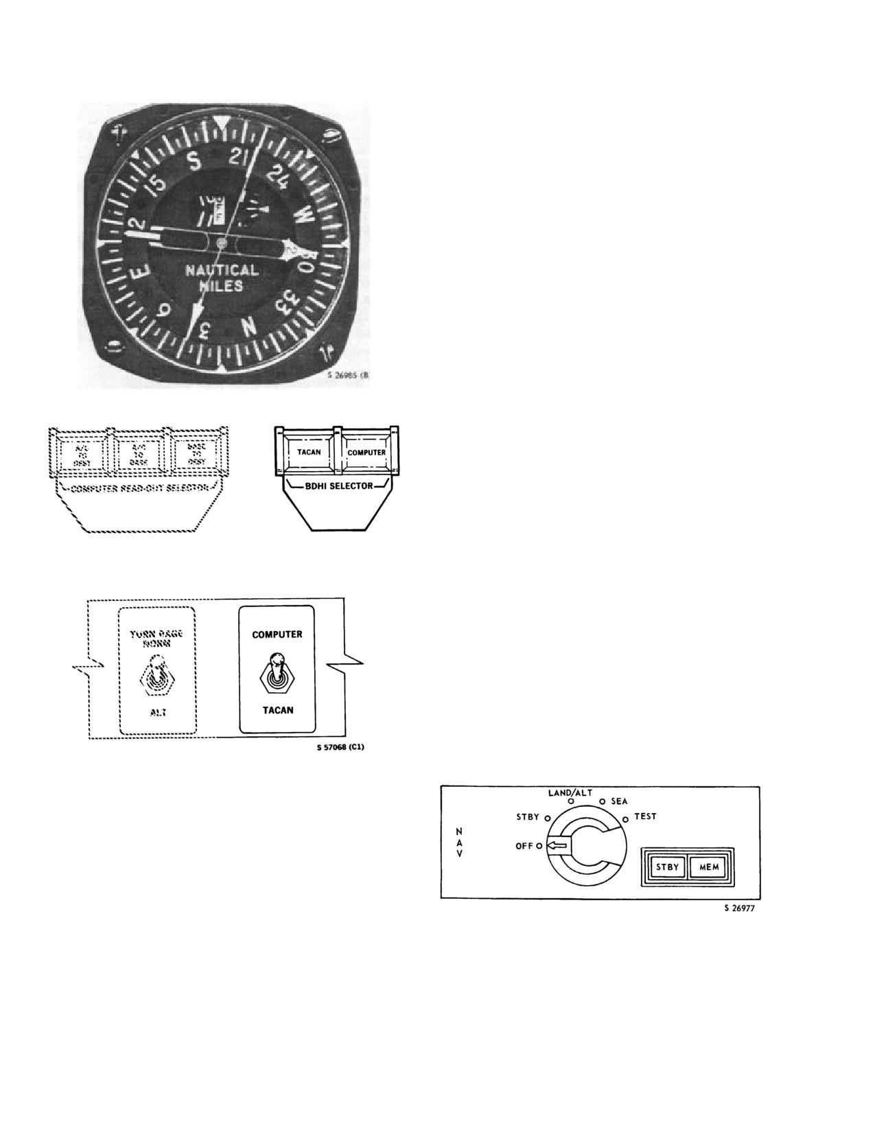
15.16.1.1 BDHI Selectors. Two selector switches
the IFF transponder
(in the Doppler
(Figure 15-21) are on the instrument panel. Either pilot can
compartment). Report any audio tone
independently select TACAN or TACNAV to be displayed
level discrepancies to maintenance per-
on his BDHI. When TACAN is selected, the associated
sonnel.
BDHI No. 2 pointer and digital counter display bearing
and slant range distance to the selected tacan station. When
· The microswitch attached to the scissors
COMPUTER is selected, the associated BDHI No.
2
of the right main landing gear is the
pointer and digital counter display bearing and distance to
airborne/on deck sensor for mode
4
a selected or predicted destination with TACNAV. The
No. 1 pointer on each BDHI automatically displays the
operations.
drift angle when the Doppler is turned on.
15.15.3.7 IFF Caution Light. The IFF caution light
goes on to indicate that mode 4 is inoperative. The light is
operative whenever helicopter power is on and the
MASTER switch is not at OFF. However, the light will not
operate if the KIT-lA/TSEC computer is not physically
installed in the helicopter. Illumination of the IFF caution
light indicates that the mode 4 codes have zeroized, the
self-test function of the KIT-1A/TSEC computer has
detected a faulty computer, or the transponder is not
replying to proper mode 4 interrogations.
15-18
ORIGINAL
NAVAIR 01-230HLH-1
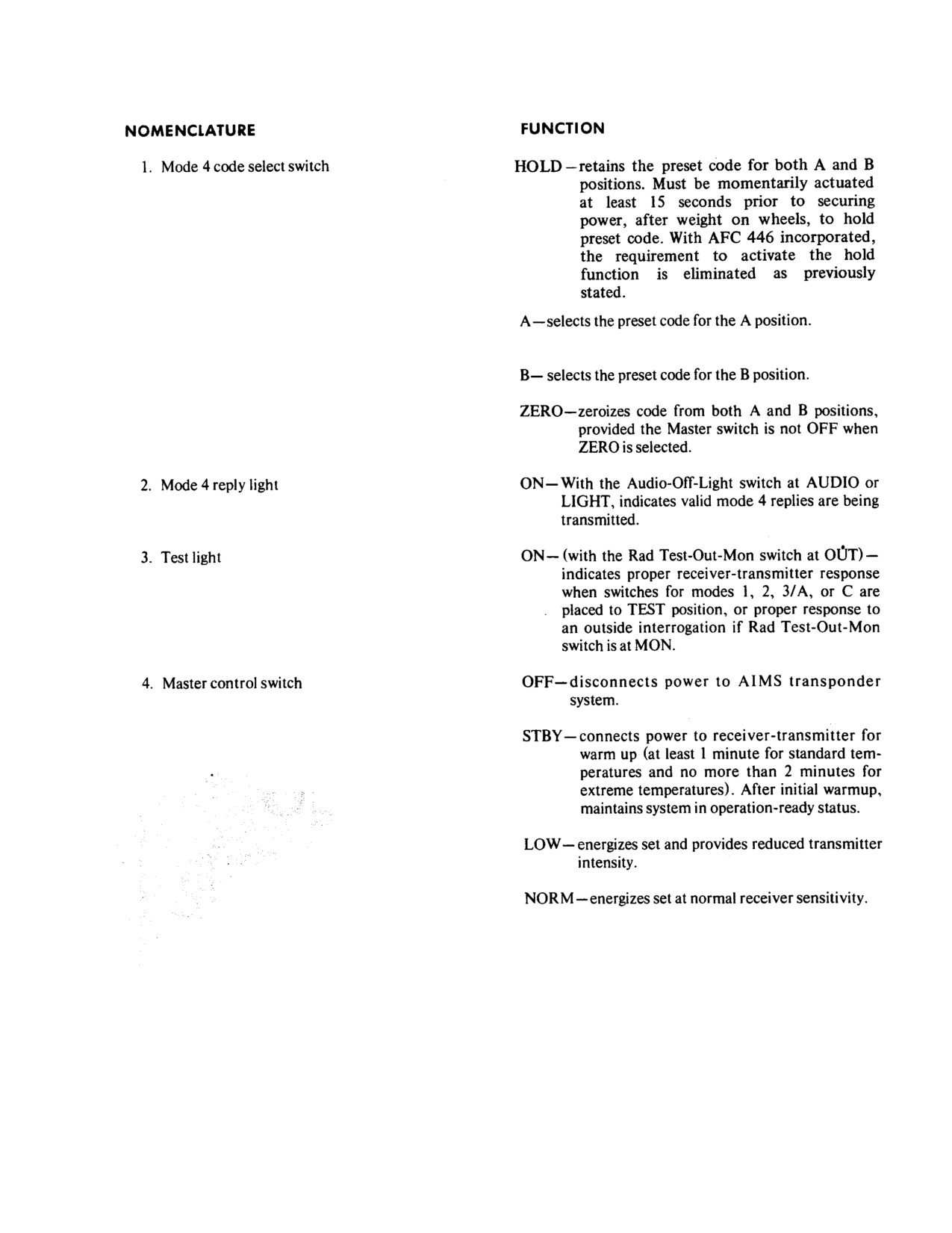
Figure 15-18. IFF Control Panel and Functions (Sheet 2 of 4)
15-19
ORIGINAL
NAVAIR 01-230HLH-1
Figure 15-18. IFF Control Panel and Functions (Sheet 3 of 4)
15-20
ORIGINAL
NAVAIR 01-230HLH-1
Figure 15-18. IFF Control Panel and Functions (Sheet 4 of 4)
15-21
ORIGINAL
NAVAIR 01-230HLH-1
15.17.1 Doppler Control/Indicator Panel. The
Doppler control/indicator panel
(Figure
15-22) marked
NAV on the cockpit console controls the operation of the
Doppler. Operational control and indicators consist of two
amber lights marked MEM and STBY respectively, and a
five-position mode selector switch marked OFF, STBY,
LAND/ALT, SEA, and TEST. Lighting of the MEM light
indicates the Doppler signal is inadequate and the system
is operating in the memory mode. When the hover
indicator in the D mode, the OFF flag will appear
whenever the MEM light is on. Lighting of the STBY light
indicates that the system is operating in the STBY mode.
The STBY position supplies all power to the system except
high voltage to the transmitter. The LAND/ALT position
energizes the system for operation over land or for
operation during an alternate approach. The SEA position
energizes the system for operation over water
(except
alternate approaches). The TEST position energizes the
Figure 15-19. BDHI
built-in test circuitry. The mode selector switch must be
pushed in and then turned to reach TEST.
15.17.2 Doppler System Operation. During normal
flight, the system operates automatically and requires no
operator control. The system provides accurate velocity
information over land and over sea state 1/2 or rougher.
Over glassy smooth sea states, intermittent or sustained
memory can be expected. During memory operation, the
velocity outputs are locked at their last computed values.
Figure 15-20. BDHI Selector Panel
The system should always be operated in the SEA mode
when over water except for the special case of alternate
approach. The selector switch is placed in the LAND/ALT
mode for this maneuver. During the initial phase of the
alternate approach (down to 10 knots), the system will
either be in memory or will be indicating obviously
incorrect velocities
(usually zero). In either case, these
velocity indications are to be ignored. During the
remainder of an alternate approach, the Doppler will come
out of memory and operate normally. See "Approach To
A Hover and Sonar Search," Chapter 18, for a detailed
explanation of the Doppler alternate approach procedure.
Figure 15-21. BDHI Selectors
15.17 (NON-ET) DOPPLER
The
(AN/ARN-182(V)) Doppler is a self-contained
ground velocity sensor that uses continuous-wave radar
energy to automatically measure the heading, drift, and
vertical components of the helicopters motion. These
signals are supplied to the ASE coupler, TACNAV or
navigation system, GSDA, and the hover indicator. The
Doppler consists of a receiver-transmitter, a signal data
Figure 15-22. Doppler Control/Indicator Panel
converter, a power supply, and a control indicator on the
cockpit console. The Doppler operates on ac power and is
Protective circuitry in the SEA mode inhibits the system
protected by a circuit breaker marked DPLR on the copilot
from acquiring Doppler signals below 35 knots. This is to
circuit breaker panel under the general heading RADIO.
prevent the incorrect velocity indications discussed
previously in connection with alternate approach. The
ability of the system to acquire Doppler signals is equal in
15-22
ORIGINAL
NAVAIR 01-230HLH-1
LAND/ALT and SEA modes above 35 knots. The system
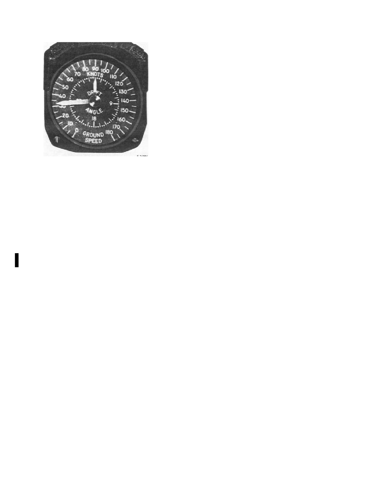
unit. The long pointer indicates speed, and the short
will continue to operate (track) in SEA mode below 35
pointer indicates the drift angle. The GSDA receives its
knots following acquisition of signal at speeds above 35
input directly from the Doppler.
knots. Consequently, if memory should occur while below
35 knots in SEA mode, one of the following should be
15.19 TRUE AIRSPEED TRANSDUCER
accomplished to permit the system to reacquire the
Doppler signal:
The true airspeed transducer is an electromechanical
device forward of the pilot rudder pedals on the deck. It
1. Select LAND/ALT until memory ceases, then
receives pitot and static inputs from the pitot tube and free-
reselect SEA .
air temperature from a shrouded bulb mounted below the
pilot window. Its function is to mechanically compute true
2. Increase groundspeed to above 35 knots.
airspeed from indicated airspeed, pressure altitude, air
temperature, and send to the TACNAV or navigation
In either case, observe that velocity indications are
system an electrical signal proportional to true airspeed.
within reason. If obviously incorrect indications are
displayed, recycle the mode selector switch and allow the
15.20 ASN-123C
TACTICAL
NAVIGATION
system to release itself from the "false-lock" and reacquire
SYSTEM
the correct Doppler signal.
Note
Ascending and descending maneuvers and steady
hovers do not normally produce memory indications. The
For detailed description of TACNAV
Doppler indicates memory only with legitimate signal loss.
operation, consult the TACNAV Rev. F-l
When approaching water from land, care should be taken
Operators Guide
(June
1989), NADEP
to switch from LAND/ALT to SEA well before reaching
Software Support Activity, NAS North
the water. This will preclude any chance of incorrect
Island, CA 92135.
velocity indication that can occur when operating the
LAND/ALT mode over a glassy smooth sea state. If an
The AN/ASN-123 TACNAV system
(Figure
15-24)
incorrect solution should appear, normal operation is
performs navigation dead-reckoning computations to
restored by recycling the system as follows:
provide helicopter and the base ship within a
512-nm
square tactical plot area. The aircraft computations are
1. Set selection switch to STBY until memory occurs.
based on Doppler radar, magnetic heading, and TAS
transducer inputs. The base ship position computations are
2. Set switch to SEA. (Groundspeed must be above 35
provide helicopter and the base ship within a
512-nm
knots to acquire Doppler signal).
square tactical plot area. The aircraft computations are
based on Doppler radar, magnetic heading, and TAS
Note
transducer inputs. The base ship position computations are
based on manually entered values of ship course and
Should the No.
1 generator fail or be
speed. The system also records the positions of contacts to
otherwise secured while the helicopter is in
provide a display that aids in mission planning and
a hover, the Doppler will shift into memory
execution of SAR. Limited access to system memory via
when the generator load is switched. Should
the data extract function is provided to aid in mission
this occur, the Doppler selector switch must
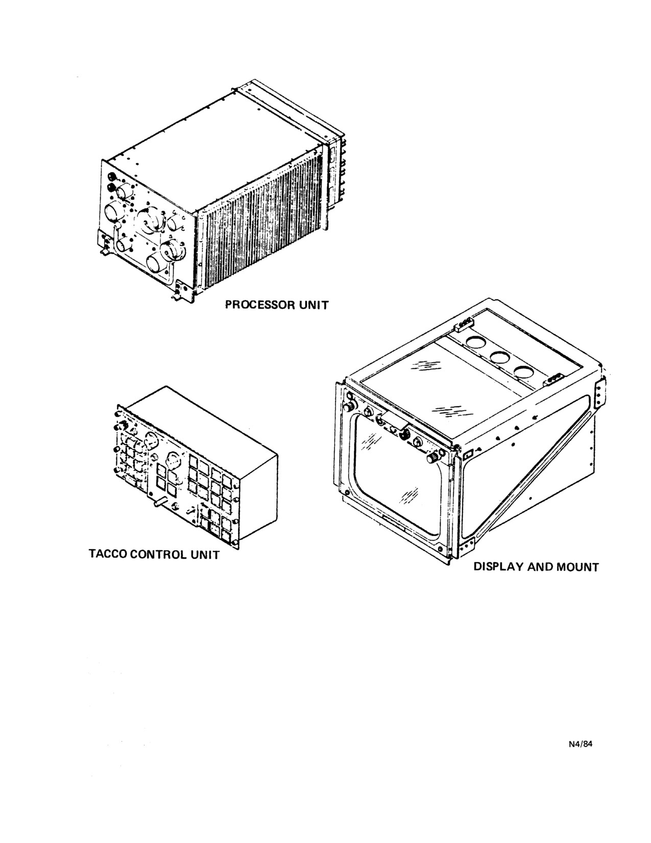
debrief. The system consists of a TACNAV processor, a
be placed to LAND/ALT until the Doppler
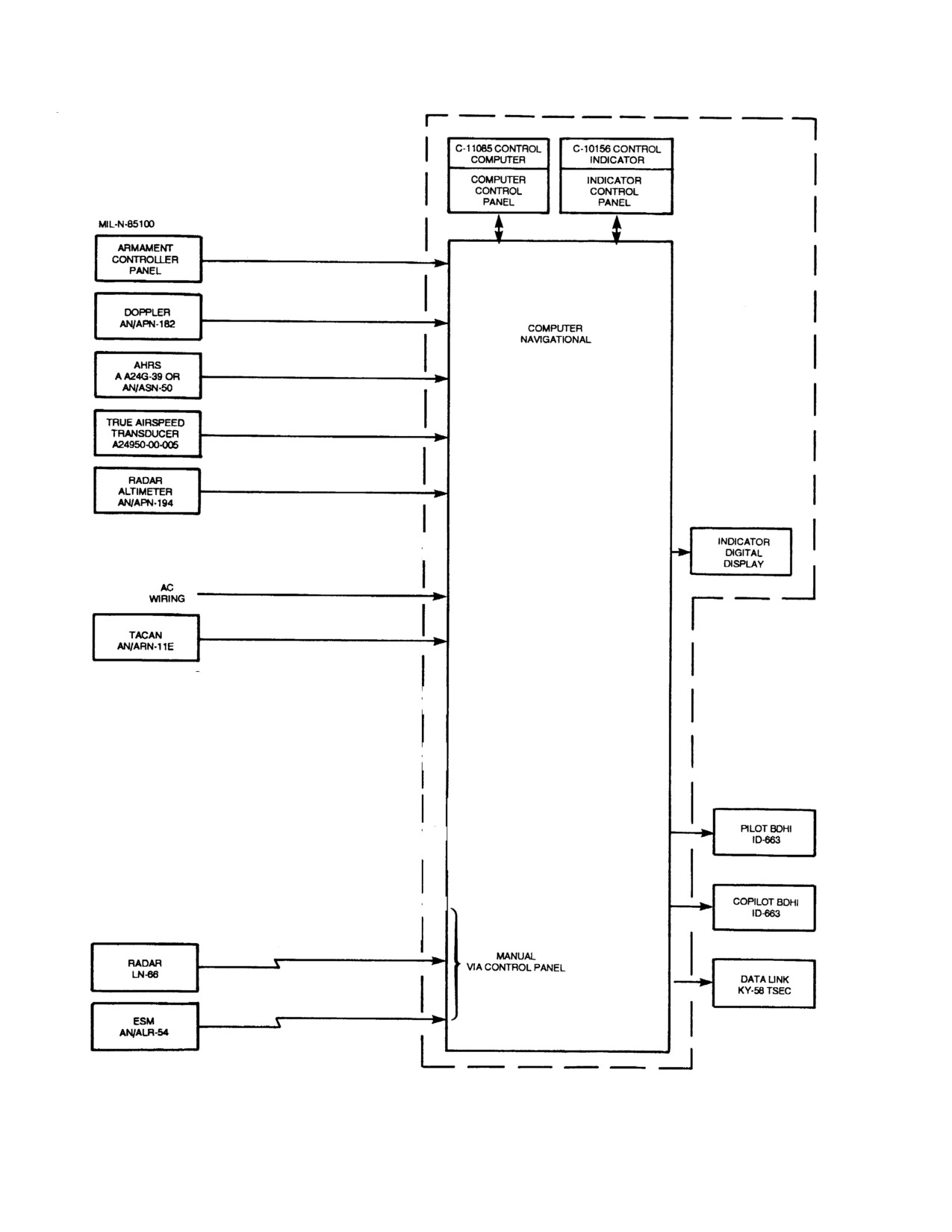
TACCO panel, and a TACNAV display. Avionic
signal is regained. If the selector switch is at
equipment used in conjunction with the TACNAV system
LAND/ALT when the generator load is
is shown in Figure
15-25. The No. 1 primary ac bus
switched, the Doppler will go into memory
furnishes three-phase
115-vac and 26-vac power to the
for about
6 seconds before the Doppler
system through two circuit breaker panels. The primary dc
signal is automatically reacquired.
bus furnishes power to the system through two circuit
breakers marked TACNAV and TACNAV DISPLAY on
15.18 GROUNDSPEED AND DRIFT ANGLE
the pilot circuit breaker panel.
INDICATOR
The GSDA indicator (Figure 15-23) on the instrument
panel has an outer dial marked GROUND SPEED
numerically marked at each 10 knots from 0 to 180 knots
and linear marks at each 5 knots. An inner dial marked
DRIFT ANGLE is numerically marked at 0°, 90°, 180°,
270° with linear marks at each 15° unit, and dots at each 5°
15-23
ORIGINAL
NAVAIR 01-230HLH-1
When the Doppler out-of-memory signal indicates that
the Doppler velocity data is not valid and/or its value is
unreasonable, the TACNAV computer operates in the air
data mode. In the air data mode, the true airspeed signal
from the true airspeed transducer, the last calculated value
of wind velocity, and the true heading signal are processed
by the computer to provide aircraft present position. This
aircraft present position is processed in the same manner as
in the Doppler mode to provide navigation information to
the associated avionics and display.
Note
The TAS transducer is inaccurate at low
speeds; therefore, when there is no Doppler
return, TACNAV will assume a hover at
airspeeds of less than 38 knots.
Figure 15-23. Groundspeed and Drift Angle Indicator
Base ship position is calculated from the manually
15.20.1 Inputs. The UH-3H TACNAV system receives
inserted parameters for ship course and speed. When the
analog inputs from the AN/APN-182 Doppler radar, the
PIM of the ship is entered into the computer using the
A/A24G-39 AHRS, and the TAS transducer. Using
TACCO panel, ship course and speed information is
Doppler-derived ground velocity, magnetic heading, and
applied as entry data to the TACNAV computer. The
computer processes the entered data to produce latitude
true airspeed, the TACNAV processor unit continuously
computes aircraft present position and updates the display.
and longitude information that are supplied to the display
Steering outputs are provided to the pilot BDHIs. BIT and
as display data to update the ship's position. The
self-test functions are also included in the system.
positions of the ship, helicopter, and other symbols may
be changed by the pilot using the symbol position correct
Note
procedures.
On the UH-3H Executive Transport helicopter,
15.20.3 System Tests
the doppler and sonar functions are removed.
15.20.3.1 BIT Signal Processing. The BIT circuits of
the TACNAV set perform operational tests to ensure that
15.20.2 Navigation Processing. When the Doppler
the TACNAV computer is operational. Computer BIT
subprogram routines continuously perform memory
out of memory signal indicates that the Doppler velocity
data is valid and/or its value is reasonable, the TACNAV
checksum, register and instruction, and discrete input and
computer operates in the Doppler (normal) mode. In the
output tests. When one of the tests indicates a failure, the
Doppler mode, the magnetic heading signal from the
BIT circuit provides a signal that causes the computer BIT
A/A24G-39 AHRS compass system and the heading and
indicator to indicate white and the nature of the failure to
drift velocity signals from the Doppler are applied to the
be indicated in the equipment status tableau alert area. If
no failure is detected for one complete cycle of the BIT,
computer for processing. The magnetic heading signal and
the magnetic variation correction signal (inserted into the
the external BIT indicator will be reset by the program.
computer as the entry data from the TACCO panel) are
processed to provide a true heading signal. The true signal
15.20.3.2 Self-Test Signal Processing. When the
is processed with the heading velocity and drift velocity
TACCO panel mode select switch is set to TEST, the
signals to provide display data signal input as the aircraft
TACNAV computer applies test signals as display data to
the display, and TACCO panel. The display prints out the
present position on the display indicator. From the aircraft
present position, the computer derives range, bearing, and
name of each switch indicator of the TACCO panel as
time-to-go data to a specified fly-to point. When the
each switch is pressed. The SENSO panel MAD,
TACNAV computer range and bearing data is valid, the
RADAR, SONAR, and PASSIV indicator triangles, and
fly-to-range and fly-to-bearing signals from the computer
the NUMBER, RNG, BRG, YDS, MILES, RE, and TIME
are applied to the BDHIs. Helicopter present position,
indicator legends illuminate green and the numeric
display digits all indicate 8. The TACCO panel CORR,
range/bearing, and time-to-go information is provided to
the display indicator as display data.
MOT, FTP, COOPD, L/L, ATTACK, SENSO,
BEARING, CONT, BUOY, CIRCLE, VECTOR, MAG,
VERIFY and CLEAR indicator triangles illuminate green.
The MENU indicator triangle illuminates amber.
15-24
ORIGINAL
NAVAIR 01-230HLH-1
Figure 15-24. TACNAV System Components
15-25
ORIGINAL
NAVAIR 01-230HLH-1
Figure 15-25. AN/ASN Navigation Set, Tactical, Block Diagrams
15-26
ORIGINAL
NAVAIR 01-230HLH-1
15.20.4 TACNAV Processor Unit. The TACNAV
switch indicators and the following switch indicators have
processor is in the electronics compartment. It processes
only red-illuminated legends: REDIS, ERASE, MARK,
and stores information furnished by the operator control
DATA, and RCNTR.
panels and sensors. The computer furnishes processed
information for display to the various display indicators
15.20.5.1 DIM Control. The DIM control controls
associated with the system as shown in (Figure 15-25).
intensity of triangular lighting on all switch indicators.
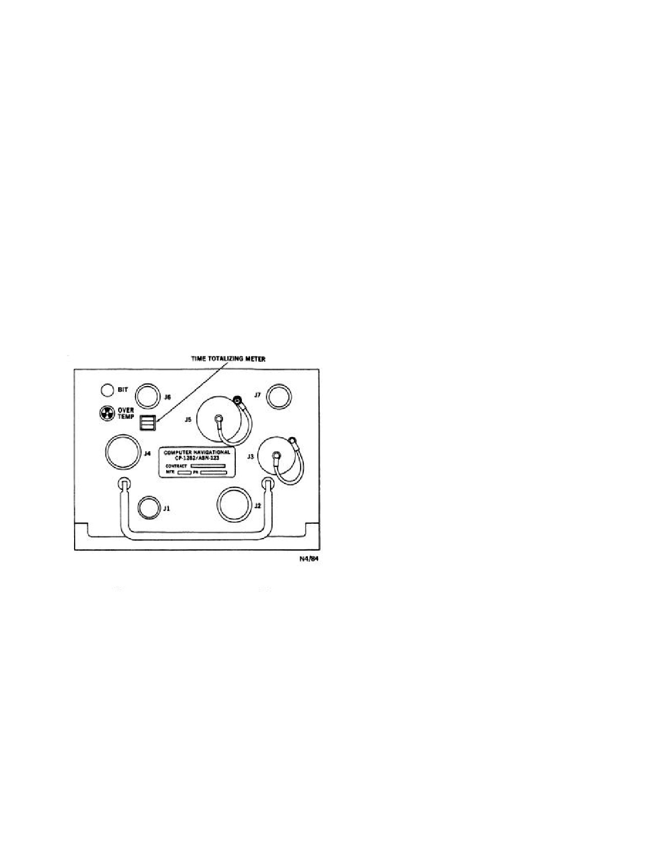
The front panel of the computer (Figure 15-26) contains a
meter that shows the elapsed running time of the computer.
15.20.5.2
Mode Selector Switch.
There is an electrically resettable BIT indicator that shows
white when the computer fails built-in test. The indicator is
15.20.5.2.1 OFF. Removes input power from
electrically reset to all black
(normal) by the program
TACNAV computer, and TACCO panel. All stored data is
when there is no failure. In addition, there is an
retained in core memory and reappears when switch is
OVERTEMP indicator that shows black and white when
returned to ON.
the computer is overheated. It is reset to all black (normal)
by manually rotating the indicator clockwise and releasing.
15.20.5.2.2 ON. Applies input power to computer, and
The computer converts the aircraft power (115/200 and
TACCO panel.
400 Hz, 3 phase) to stabilized dc voltages required to
power the computer. The processor unit performs all of the
15.20.5.2.3 TEST. Initiates self-test, generates system
digital computations required for the TACNAV operation.
test pattern on display, sequences indicators through
illumination
test, and performs digital/synchro and
In addition, the processor unit provides all memory
analog/digital converter BIT function.
functions required for the operation of the display unit.
15.20.5.2.4 RESET. Permanently erases all stored data
displayed data and symbols including the SLT tableau
data; or permanently erases all to the preceding entry data,
as selected by cue. After reset selection is completed,
INITIAL alert appears to advise the operator that the
system must be reinitialized.
15.20.5.3
CLEAR Switch Indicator. Used in
conjunction with DNT switch DECLUTTER positions to
temporarily clear display of selected symbol groups.
Indicator triangle lights when switch indicator is pressed
and remains lighted whenever there are cleared
(decluttered) symbols in the computer.
15.20.5.4 REDIS Switch Indicator. When pressed,
it is used in conjunction with DNT switch DECLUTTER
positions to redisplay cleared symbol groups.
Figure 15-26. TACNAV Time Totalizing Meter
15.20.5.5 Display Selector Switch
(DECLUT-
TER-NORM-TABLEAU (DNT))
15.20.5 TACCO Panel. The TACCO panel is the focal
15.20.5.5.1 DECLUTTER. The six positions are used
point for operating the TACNAV display. Located in the
for thinning out symbols on a cluttered display. Six types
aircraft between the pilot and copilot, it allows either
of symbols and associated data can be removed and kept in
operator to control the TACNAV set and displays.
memory for redisplay if desired: MAD marks, RADAR
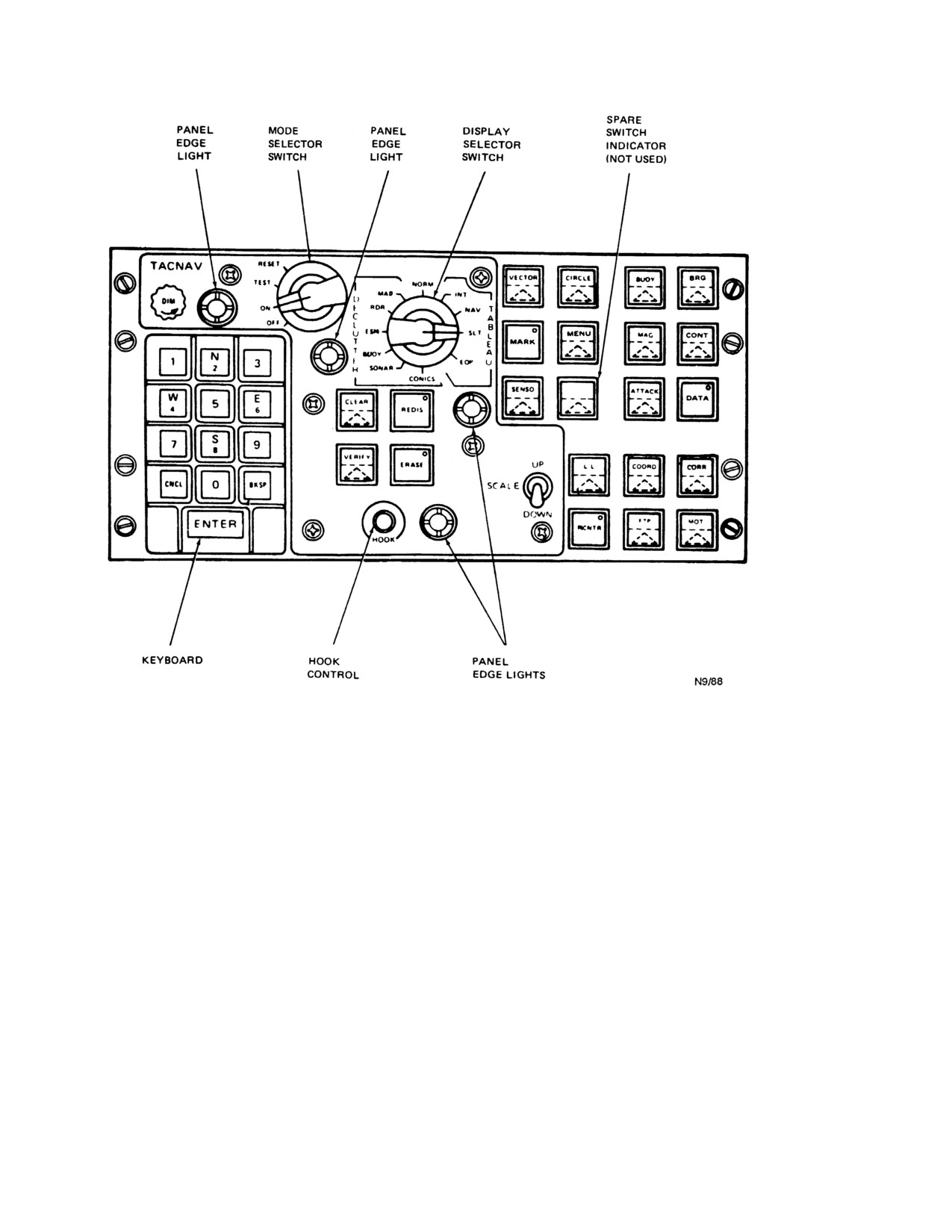
Controls and indicators on the TACCO panel are
contacts, ESM contacts, sonobuoy
(BUOY) symbols,
illustrated in
(Figure
15-27). Legends on all switch
SONAR contacts, and circles and vectors
(CONICS).
indicators of the computer control are illuminated red
These positions are used in conjunction with the CLEAR
whenever input power is connected to the unit (system is
and REDIS switch indicators.
turned on). Some switch indicators have upper-half red and
lower-half green indicators. Whenever the switch function
15.20.5.5.2 NORM. This is the position for normal
of a switch indicator is selected (by depressing the switch
operation of the tactical display.
indicator), the green indicator lights to signify the switch
function is active. Lighting of the green indicator is under
the control of the navigational computer. The keyboard
15-27
ORIGINAL
NAVAIR 01-230HLH-1
Figure 15-27. TACCO Panel Controls
15.20.5.5.3 TABLEAU. These four positions allow
15.20.6
DIM Control. When turned, the DIM
display of either the initialization
(INT), navigation
control varies the intensity of the green lights in the cue
(NAV), sonobuoy launch tube (SLT), or equipment status
indicators, switch indicators, and numeric display.
(EQP) tableaus. Tableaus replace the tactical plot on the
display.
15.20.6.1 NUMBER Cue Indicator. When legend is
illuminated green under control of computer, the number
15.20.5.6
SCALE Switch. The SCALE switch is a
cue indicator informs operator that the computer-assigned
spring-loaded momentary toggle switch. Each UP or
contact number is being displayed in the numeric display.
DOWN switch activation changes the scale by a factor of
two. The TACNAV Set initializes to the 04 nm/inch scale.
15.20.6.2 RNG Indicator. Legend illuminates green
Scales are as follows:
on computer command, cuing operator to enter range of
radar or sonar contact.
0.5 nm/inch
0l nm/inch
15.20.6.3 BRG Indicator. Legend illuminates green
02 nm/inch
on computer command, cuing operator to enter bearing of
04 nm/inch
radar or sonar contact.
08 nm/inch
16 nm/inch
32 nm/inch
15.20.6.4
RADAR Switch Indicator. When pressed,
64 nm/inch
green indicator triangle lights and switch function enables
128 nm/inch
entry of radar range and bearing via keyboard and cue
indicators.
15-28
ORIGINAL
NAVAIR 01-230HLH-1
15.20.6.5
Keyboard
0 Through
9 Switches.
15.20.8 TACNAV Operating Procedures
Pushbutton switches are used to enter numeric data into the
computer.
1.
TACNAV display - ON.
15.20.6.5.1 CNCL (Cancel) Switch. Switch function
2.
TACCO panel mode selector switch
- RESET (if
causes a complete line of entered numbers (up to four
desired).
digits in the numeric display) to be canceled if pressed
before ENTER switch.
3.
TACCO panel mode selector switch - ON.
15.20.6.5.2 BKSP
(Backspace) Switch. Switch
4.
Display selector switch - INT.
function causes the last single data unit to be canceled if
pressed before ENTER switch.
5.
Enter appropriate data in the initialization tableau.
15.20.6.5.3 ENTER Switch. When pressed, the
6.
Display selector switch - NAV.
ENTER switch permits keyed-in SENSO panel data to be
displayed on the TACNAV display for acceptance by the
7.
Enter appropriate data in the navigation tableau.
pilot.
15.20.7 TACNAV Display. The display indicator is
Note
the viewing focal point of system operation, visually
integrating all inputs to display the plot of tactical and
Both the initialization and navigation
navigation data from the TACNAV computer. The display
tableau must be completely filled before
(Figure 15-28) is on the cockpit console and displays the
TACNAV can begin navigation. Data in the
tactical plot from which the mission is controlled. Operator
sonobuoy launch and equipment status
and system inputs are presented on the display to create a
tableau do not affect basic navigation and
tactical plot depicting information required for the mission.
may be entered at any time during a mission.
Control of the display is provided by the TACCO panel.
8.
Display selector switch - NORM.
15.20.7.1
Mode Selector Switch
9.
MOT button - DEPRESS. This will cue TACNAV
15.20.7.1.1 TEST. Applies input power to unit,
to begin navigation.
generates test pattern, and intitates built-in-test. There is a
30-second delay before high voltage is applied to the
TACNAV display.
WARNING
15.20.7.1.2 ON. Applies input power to unit. There is
a 30-second delay before high voltage is applied to the
TACNAV display.
Pilot at controls should guard against
15.20.7.1.3 OFF. Removes input power from the unit.
diverting his attention to the TACNAV
display or TACCO panel.
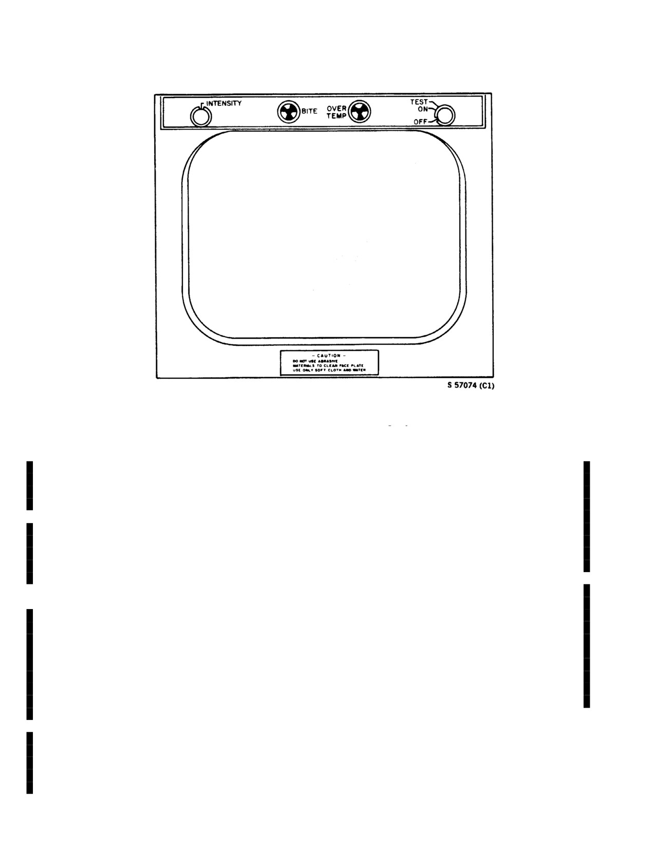
15.20.7.2 OVER TEMP Indicator. Momentary reset-
15.20.8.1
Global Positioning System.
(GPS)
type failure indicator appears black/white when a display
GPS was installed on H-3 aircraft to meet the requirement to
overtemperature condition has occurred, causing automatic
have GPS positioning systems on all Naval aircraft by 2005.
power shutdown. Power is restored when temperature has
been reduced to normal limits. To regain black (normal)
GPS measures the transmission delay of radio signals from
a constellation of satellites in orbit around the earth. Rough
indication, the indicator must be manually reset by rotating
acquisition is accomplished by an internal clock, however,
clockwise and releasing.
reception of multiple GPS signals allows the system to
determine actual time delay with great accuracy. Once in
15.20.7.3 BITE Indicator. Momentary reset-type
synchronization, GPS provides an accurate time source.
failure indicator appears black/white when the display fails
built-in test. Indicator must be manually reset to the black
Two types of GPS position accuracy are available. Standard
Positioning Service
(SPS) is available to military and
(normal) indication by rotating clockwise and releasing.
selected users.
Precise Positioning Service
(PPS) is
available to military and selected Government users through
15.20.7.4 INTENSITY Control. When turned, the
the use of special receivers that utilize both GPS
intensity control varies display brightness from beam
frequencies, and are which keyed with a GPS code to enable
cutoff to full intensity.
15-29
ORIGINAL
NAVAIR 01-230HLH-1
Figure 15-28. TACNAV Display
it to utilize the precise PPS signals.
PPS receivers
15.20.10 Miniature Airborne GPS Receiver.
initially acquire the SPS signals, and use the SPS to
To provide integrated GPS information, an R-2512
obtain a course position, which is used to acquire and
MAGR was installed in H-3 aircraft as part of Airframe
track the PPS signal.
Change AFC 495. The MAGR provides GPS data to the
ASN-123 TACNAV system via a Mil-Std 1553B data
Note
bus. The 1553 data bus also connects a Mission Data
Loader (MDL) to load GPS Precision Positioning System
GPS will not be used as the primary
(PPS) data. Without the PPS code loaded, the GPS is
means of navigation, but as a back-up
unable to utilize the PPS accuracy.
to other existing sources of navigation
information.
The MAGR provides GPS positioning data directly to
the ASN-123. All other ASN-123 functions continue to
15.20.9 Trimble Pack. To comply with mandates to
operate normally. GPS operation is initialized using the
expedite GPS installation on aircraft, particularly
normal TACNAV system initialization and crew-inserted
transport and utility aircraft, a Trimble Model GPS set
data. Data entry is accomplished using the TACCO panel
was temporarily installed as a stop-gap measure. The
controls, and positional data is displayed via the
Trimble Pack, which provides SPS, is temporarily
TACNAV display. The SLT Tableau on the display
attached to the copilot’s glare shield, and the antenna is
provides information on the status of the GPS receiver,
affixed to the windscreen. Waypoint data is entered
and the number and quality of the GPS signals being
directly into, and navigation data is read directly from the
received.
Trimble Pack GPS.
Information on the operation of the Trimble Packs is
available from the commercial operating manuals
provided with each Trimble unit. The Trimble Packs are
being replaced by permanent MAGR installations as part
of Airframe Change AFC 495.
15-30
ORIGINAL
NAVAIR 01-230HLH-1
Note
· Proper operation of the GPS requires the
reception of four or more GPS satellites located at
diverse angular displacement to provide good
GPS accuracy.
During ground operations,
buildings and terrain can block GPS signals,
therefore, to expedite GPS acquisition and
optimum GPS accuracy, Ensure that the aircraft is
in a clear location During GPS start-up.
· The GPS satellite provides ephemeris data on
satellite locations, which the GPS receiver uses to
determine a GPS position solution. This data is
stored in the receiver, and is used to provide a
rapid response solution. If the GPS system has
not been powered up for an extended period, or if
the GPS internal battery is weak, the ephemeris
data is lost or not valid, and the GPS receiver
must reacquire and store the data before it can
provide a GPS solution. This process takes
approximately
12 minutes for the satellites to
transmit the ephemeris data. A planned ground
warm-up time of 12-24 minutes is recommended
to ensure that GPS is able to acquire or update the
ephemeris data.
15.21 VISUAL COMMUNICATION - IN FLIGHT
This helicopter has the capability of signal light
communications by the addition of the portable standard-
type Aldis lamp with detachable colored lens covers. This
lamp is attached by a length of electrical cord to the
receptacle. The Aldis lamp will be used during conditions
of EMCON that prohibit the use of radio
communications. Its use includes plane-to-plane and
plane-to-ship communications.
15-31
ORIGINAL
NAVAIR 01-230HLH-1
This Page Left Blank Intentionally
15-32
ORIGINAL
NAVAIR-01-230HLH-1
PART VIII
Weapons Systems
Chapter 16 - Armament Systems
Chapter 17 - Weapons Recovery
67
ORIGINAL
NAVAIR-01-230HLH-1
This Page Left Blank Intentionally
68
ORIGINAL
NAVAIR 01-230HLH-1
CHAPTER 16
Armament Systems
16.1 Smoke Lights. The point of datum is usually a
The following precautions must be observed when using
fixed point on the ocean surface. To assist the crew in
the Mk 25 marker:
identification, datum must be marked. Smoke lights offer
the best means available for marking the point of datum.
1. The markers are seawater-activated pyrotechnic
The types in common use are the Mk 58 and Mk 25.
devices that do not contain a safety feature after the
base plugs are pushed in and therefore can be
There are several uses for the smoke light other than
hazardous to inexperienced personnel.
marking datum. These include wind direction de-
termination to assist the pilot in maneuvering his
2. Markers that show signs of damage, leakage, or are
helicopter while conducting searches, pinpoint location to
otherwise unserviceable shall be disposed of in
assist a downed pilot by marking his exact location, and
accordance with current regulations for disposal of
marker purposes to indicate the location of practice
pyrotechnic materials.
ordnance so that it can be retrieved.
3. Markers without the adapter installed shall be set on
SAFE until ready for use. This prevents the base plugs
from being pushed in.
WARNING
4. Under no circumstances shall markers with the base
plugs pushed in and the adapter not installed be placed
Anytime there is a chance of igniting
in a position where they can contact water.
aviation fuel that may be in the immediate
area, smoke lights shall not be used to mark
5. Markers with base plugs pushed in must be used or
survivor positions.
disposed of if not stored with the adapter kit assembled
on the marker. Activation is still possible if exposed to
16.1.1 Mk 25 Marine Locator Marker. The marker is
seawater.
an aluminum tube about 18-1/2 inches long and
3-3/4
inches in diameter. It weighs about
4 pounds. When
properly dropped, it will produce a display of white smoke
and yellow flame within
15 seconds after striking the
WARNING
water. The marker will burn for at least 15 minutes. The
marker may be carried in two configurations. The base
cover can be set on safe and the base plugs intact, or it may
Mk 25 markers should not be launched with
be carried with the base cover in the ARMED position, the
helicopter in a hover because of possibility
base plug pushed in and an adapter kit, Marine Marker Mk
of upward ejection of initial plug.
34 Mod 0, attached.
16.1.2 Mk 58 Marine Locator Marker. The marker is
To hand launch the Mk 25 without the Mk 34 adapter
in a tin or tern plate cylindrical can, about 21-1/2 inches
attached, arm the marker by turning the cover clockwise
long and 4-7/8 inches in diameter. This marker is designed
from the SAFE position to the extreme ARMED position.
for day and night use in any condition calling for long
Push the two base plugs into the marker by applying
burning, smoke and flame reference point marking on the
pressure on the base plugs with the thumb and finger. The
ocean surface. It produces yellow flame and white smoke
marker is now ready to be launched upon command. To
for at least 45 minutes and up to 55 minutes that is visible
launch the marker with the Mk
34 adapter installed,
for at least 3 miles under normal conditions.
remove the U-pin that Secures the adapter to the marker.
This permits the spring-loaded adapter to pop off the
marker. The marker has already been ARMED and the
base plugs pushed in. It is now ready to launch.
16-1
ORIGINAL
NAVAIR 01-230HLH-1
This device contains two phosphorus pyrotechnic
candles supported within the marker body by foamed-in-
WARNING
place polyurethane. The first candle is ignited by an
electric squib initiated by a seawater-activated battery.
seawater to the battery. The tape that covers the
When the aluminum-backed tape pull tab is removed and
battery cavity must not be removed except as a
the marker is launched, the battery cavity is exposed to
part of launching procedures. Once the
seawater that serves as an electrolyte to activate the
reinforced adhesive foil over the battery cavity
battery. Current from the battery initiates the electric squib
hole is removed, the marker shall not be
that ignites the starter mix. When the candle is nearly
returned to any type of storage. The marker
burned out, its head ignites the second candle time transfer
must be used or disposed of properly.
fuse that ignites the starter mix. Each candle burns for at
least 20 minutes.
16.2
(NON-ET) M-60-D MACHINEGUN SYSTEM
To launch the marker, pull the marker pull ring
and
The M-60-D is the only authorized machinegun
hand launch the marker from the rear of the helicopter.
for use with the M-93 pintle machinegun mount.
Use of the M-60-A or M-60-B may cause
damage to the trigger guard assembly an/or
injury to firing personnel.
WARNING
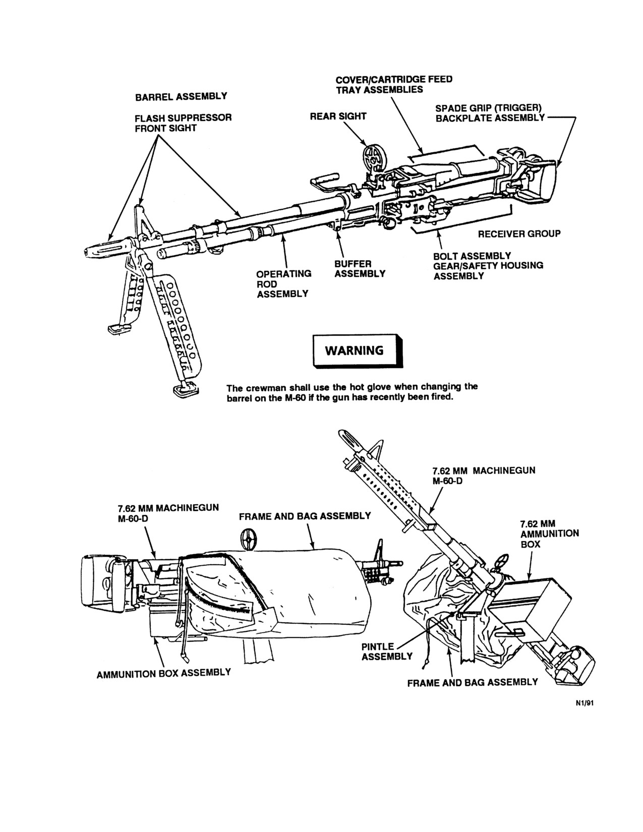
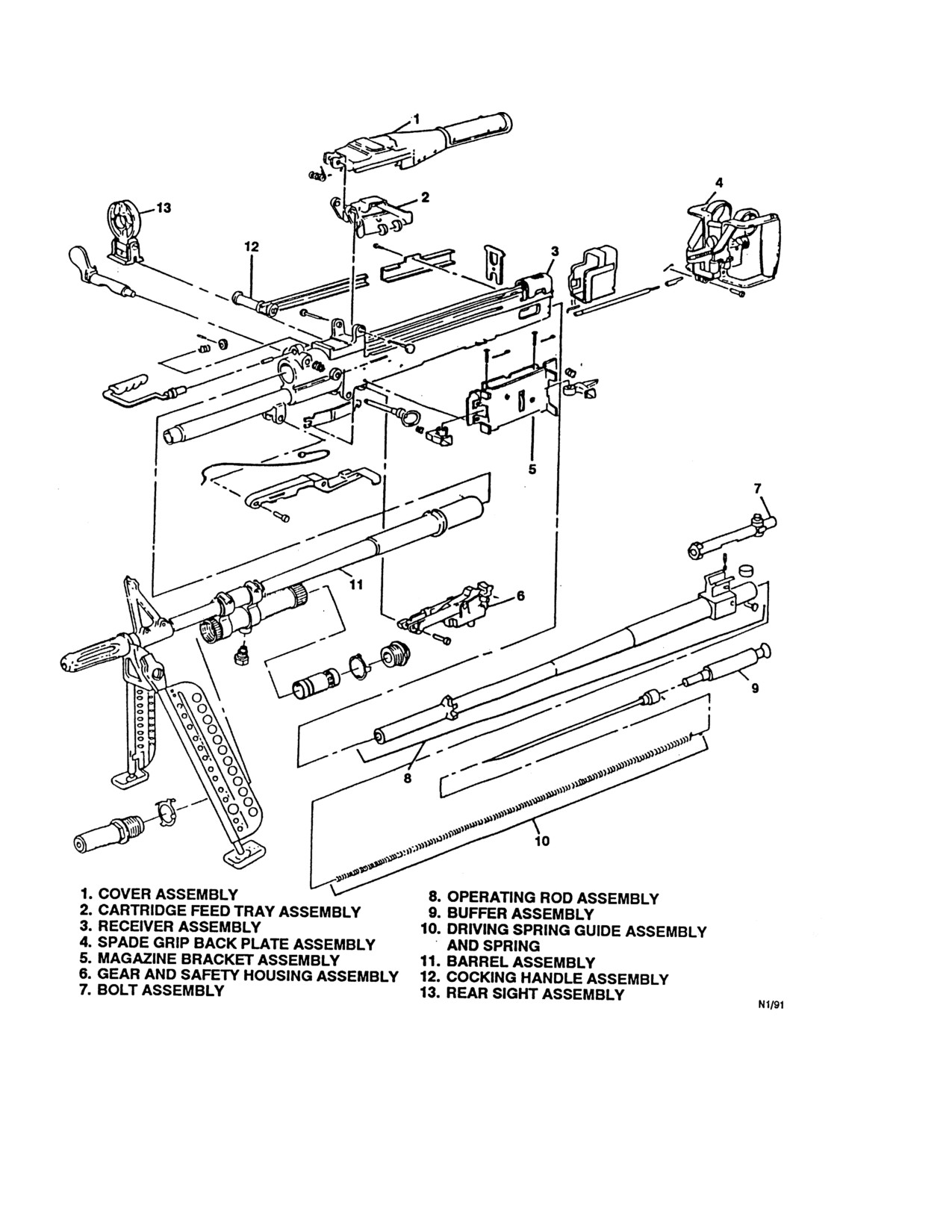
16.2.1 Weapon Description. The M-60-D machinegun
is an air-cooled, link-belt fed, gas-operated,
7.62
A pull on the marker pull ring exposes the
millimeter automatic weapon (Figure 16-1).
battery cavity. Entrance of seawater in this
cavity will immediately activate the marker.
The M-60-D has a front sight permanently affixed to
This ring must not be pulled until launching is
the barrel and a rear ring sight attached to the receiver
to be accomplished.
assembly. The machinegun can be easily installed and
removed from the mount by use of the quick release pins.
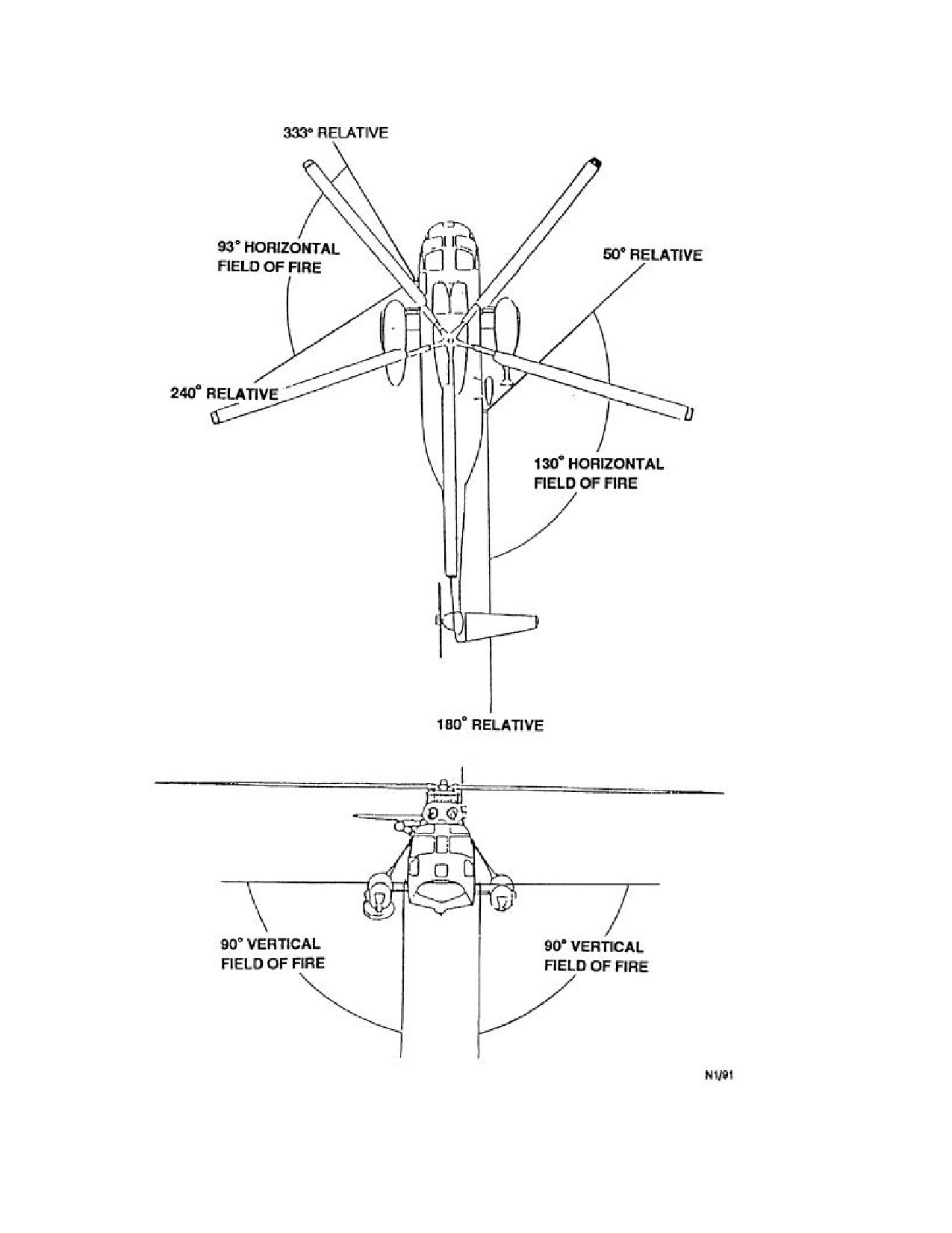
Firing stops are incorporated into the design of the mount
to determine the azimuth and elevation limits of the
machinegun. Figure 16-2 shows machinegun fields of fire.
16.2.1.1 Inventory.
The sea battery cavity must be opened by a
proper pull on the marker pull ring to assure
1. Machinegun with attached barrel, sling, and bipod.
removal of the aluminum-backed tape from the
top of the battery cavity. Failure to open this
2. Equipment kit, including cleaning kit, spare barrel,
battery cavity will result in failure of the
and hot glove.
marker.
The primary weapon controls are the latch lever, barrel
16.1.3 Safety Precautions.
lock lever, cocking handle, safety lever, and trigger.
16.2.1.2 Latch Lever. The latch lever actuates the
cover latch that is spring-loaded and is located at the right
WARNING
rear end of the feed cover. The function of the latch is to
secure the cover in the closed position. When the lever is
vertical, the cover is locked closed. Turning the lever to
· The red phosphorus composition in this
the horizontal position unlocks the cover.
marker produces smoke that is highly caustic to
the moist tissues of the nose and throat. Do not
breathe this smoke.
· The tear strip must not be removed except as a
part of actual preparations for launching.
Removal of this strip destroys the sealed
Do not turn the latch lever more than required to
character of the marker and contributes to its
unlock the cover as damage to the latch spring
possible deterioration and to the possibility of
will result.
accidental ignition through introduction of
16-2
ORIGINAL
NAVAIR 01-230HLH-1
Figure 16-1. (NON-ET) M-60-D Machinegun, 7.62 Millimeter (Sheet 1 of 2)
F
16-3
ORIGINAL
NAVAIR 01-230HLH-1
Figure 16-1. (NON-ET) M-60-D Machinegun, 7.62 Millimeter (Sheet 1 of 2)
16-4
ORIGINAL
NAVAIR 01-230HLH-1
16.2.1.3 Barrel Lock Lever. The barrel lock lever is
16.2.2 Weapon Operating Procedures
located on the right front end of the receiver. The lever is
secured to the barrel-locking shaft and rotates the shaft to
16.2.2.1 Preflight.
lock and unlock the barrel. When the lever is vertical, the
barrel is unlocked. When the lever is horizontal, the barrel
is locked in place.
WARNING
16.2.1.4 Cocking Handle. The cocking handle is
located on the right side of the receiver between the cover
and trigger mechanism. Cocking handle function is to
Weapon shall be treated as loaded at all
charge the weapon manually. When the handle is pulled to
times.
the rear, the bolt is cocked. It shall be returned manually to
its forward position each time the bolt is manually pulled
1. Cargo door - OPEN.
to the rear.
2. Gun - MOUNT AND CHECK.
Check gun for security in proper firing positions and
WARNING
freedom of movement throughout full travel. Refer to
Figure 16-3 for system malfunctions discovered.
Before firing, the handle must be returned to
the forward position.
16.2.1.5 Safety Lever. The safety lever is located on
the gear and safety housing assembly. Safety lever
function is to prevent the weapon from being fired
accidentally. The safety lever has two marked positions: F
Ensure that no portion of the aircraft is in
(firing) and S (safety). In the safe position the bolt cannot
the gun field of fire.
be pulled to the rear or released to go forward.
3. Gun - STOW.
16.2.1.6 Trigger. The trigger is in the spade grip back
4. Ammunition
- CHECK
(TYPE, GRADE, AND
plate assembly, which is located at the end of the receiver
assembly. Trigger function is to control firing of the
QUANTITY).
weapon.
5. Personnel harnesses
- CHECK
(INSTALLED,
The machinegun can be easily installed and removed
FOR SECURITY AND SERVICEABILITY).
from the mount by use of the quick-release pins. Firing
6. Accessories
-
CHECK
(ALL REQUIRED
stops are incorporated into the design of the mount to
determine the azimuth and elevation limits of the
EQUIPMENT, INCLUDING GLOVES, BARRELS,
machinegun. Figure 16-2 shows machinegun fields of fire.
SPRINGS, TOOLS AND BOLTS ARE ABOARD).
16.2.1.7 Weapon Parameters.
16.2.2.2 Arming.
1. Gun - POSITION.
Length
44.88 inches
Weight
23.75 pounds
Place gun on mount, insert lock pin, step on release
bar, and position mount forward until mount locks.
Maximum Range
3,725 meters
Maximum Effective Range
1,100 meters
Ammunition
7.62 millimeter,
ball, tracer, armor-
WARNING
piercing incendiary
and dummy
RATES OF FIRE
Gunner shall visually check chamber empty
Sustained
100 rounds per minute
before dry firing.
Rapid
200 rounds per minute
Cyclic
550 rounds per minute
16-5
ORIGINAL
NAVAIR 01-230HLH-1
Figure 16-2. Fields of Fire
16-6
ORIGINAL
NAVAIR 01-230HLH-1
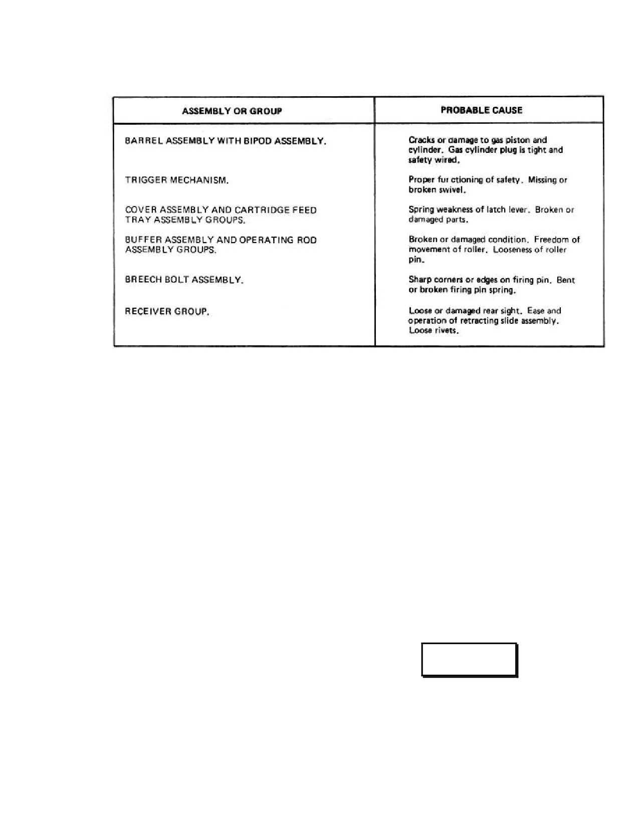
Figure 16-3. M-60 Operator Inspection
2. Gun and operating controls - CHECK (controls for
Note
proper operation and dry fire).
Trigger must be completely released to fire
3. Gunner
- REQUEST PERMISSION TO "LOCK
single rounds or to interrupt firing at any
AND LOAD" WEAPON (arm weapon).
time.
a. Open cover assembly.
16.2.2.4 De-arming.
b. Safety lever - F (fire).
1. Gun - DEARM.
c. Cocking lever
- PULL COCKING LEVER
a. Latch and cover assembly - OPEN.
FULL AFT THEN PUSH FORWARD.
b. Feed tray - RAISE.
d. Safety lever - S (safe).
c. Link belt - REMOVE.
e. Ammunition - POSITION ON FEED TRAY.
d. Gun - CLEAR.
f.
Close cover assembly.
4. Gunner
- REPORT TO PILOT "LOCKED AND
LOADED" (weapon armed).
WARNING
16.2.2.3 Firing.
Gunner shall visually check chamber empty.
1. Gunner
- REQUEST PERMISSION FROM PILOT
TO FIRE.
e. Gun - EASE BOLT ASSEMBLY FORWARD.
2. Safety lever - F (firing).
f.
Gun - S (safe).
3. Gun - FIRE AS NECESSARY.
2. Gun and mount - STOW.
16-7
ORIGINAL
NAVAIR 01-230HLH-1
Step on mount lock release, pull mount back, and
· If the barrel is hot and a misfire stops au-
remove gun from mount.
tomatic operation of the gun, wait 5 seconds
with the round locked in chamber to ensure
16.2.2.5 Postflight.
against hangfire dangers; then extract
immediately by retracting cocking handle to
1. Check aircraft for unfired rounds, brass, and links.
prevent a cookoff.
16.2.2.6 Barrel Changing Procedures.
· If the round cannot be extracted within 10
seconds, it must remain locked in the
1. Ensure that breach is clear. Follow normal dearming
chamber for at least 5 minutes because of
procedures.
the possibility of a cookoff.
2. Lift barrel - LOCKING LEVER.
16.2.3.2 Hangfire. A hangfire is a delay in the function
of the propelling charge. The amount of delay is
unpredictable, but in most cases will fall within the range
of a split second to several seconds. Hangfire cannot be
WARNING
distinguished immediately from a misfire.
16.2.3.3 Cookoff. A cookoff is the firing of the
Because of extreme temperatures involved,
explosive components of a round because of the over-
heavy-duty gloves shall be worn and proper
heated chamber of the weapon and not the actuating of the
handling procedures must be observed in
firing mechanism.
order to prevent burns and fires.
16.2.3.4
Procedures in Case of Failure to Fire.
After failure to fire, the following precautions, as
3. Pull out barrel, place barrel in proper area.
applicable, shall be observed:
4. Insert new barrel.
1. Gun - ON TARGET.
5. Push locking lever to locked position.
Keep gun trained on target, refer to Figure 16-4 for
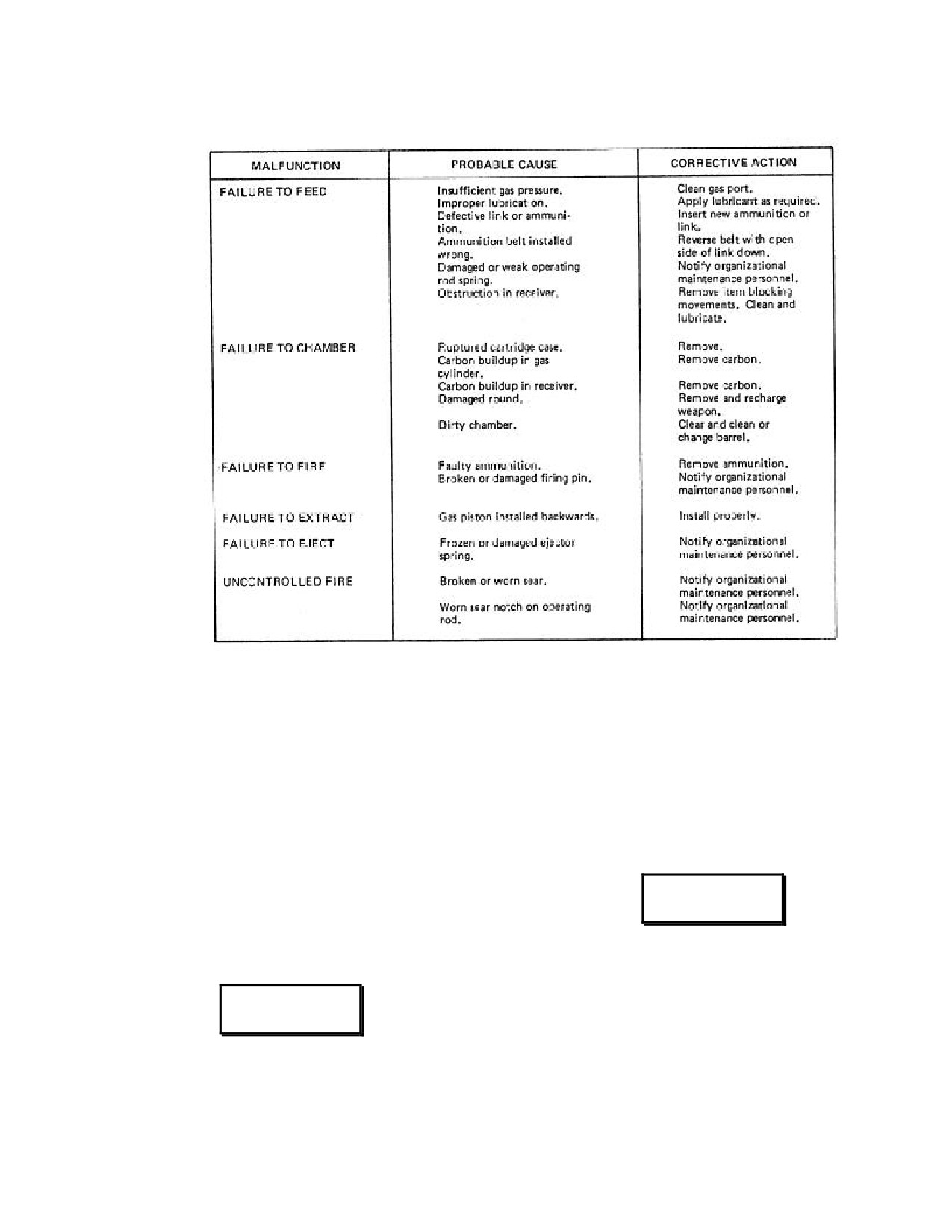
troubleshooting.
6. Rearm as necessary.
2. Cocking handle - AFT.
16.2.2.7 Spent Cartridge Disposition. Aircrew shall
ensure that spent cartridges are collected and disposed of
Pull cocking handle aft to attempt to eject round,
properly because of FOD hazard and accumulation in the
ensuring that operating rod remains to rear. Weapon
bilges.
must be cleared and inspected along with ammunition
to determine cause of stoppage.
16.2.3 Emergency Aircrew Procedures
16.2.3.1 Misfire. A misfire is the complete failure of
the weapon to fire. This is not dangerous but must be
WARNING
treated as a malfunction in the firing mechanism or a faulty
round. A misfire should not be confused with a hangfire.
If the round does not eject, do not attempt to
fire the gun.
WARNING
3.
If round is ejected - RESUME FIRING.
Return cocking handle to forward position, train, and
· Keep the round locked in chamber for 5
attempt to fire.
seconds from the time a misfire occurs to
ensure against an explosion outside of the
4. If round is not ejected
- RAISE COVER AND
gun if a hangfire develops.
REMOVE BELT; SAFETY TO S (SAFE) POSITION.
Remove ammunition and links and inspect the receiver,
chamber, and extractor.
16-8
ORIGINAL
NAVAIR 01-230HLH-1
Figure 16-4. M-60 Operator Troubleshooting
If a round is present in the chamber:
16.2.3.6 Ruptured Cartridge Case. In some cases of
complete rupture of a cartridge case, the forward portion of
5. Close cover
- SAFETY TO F (FIRE), ATTEMPT
the case remains in the chamber and extraction is
TO FIRE.
accomplished only on the rear portion. When a rupture of
this type occurs, a new round will be fed into the chamber.
If weapon fires and ejects, reload, train on target, and
Incomplete chambering may result since the round being
continue to fire. If round fails to fire, inform pilot; if barrel
fed into the chamber cannot be fully seated.
is considered hot enough to cause cookoff (200 rounds
fired within 2 minutes), wait 5 minutes with bolt in the
forward position for possible cookoff before bolt is
WARNING
retracted.
16.2.3.5 Runaway Gun.
· The round may be compressed sufficiently to
cause detonation with possible damage to the
weapon, injury to personnel, or both.
WARNING
· A round may be driven into the ruptured case
without detonation. In this situation crewmen
Do not attempt to put gun on S (safe). Hold
shall follow failure to fire procedures.
the fire on the target until feeding is stopped
or the ammunition is expended.
16.2.3.7 Double Feed. A double feed, with subsequent
possibility of damage to the gun and injury to personnel,
Train the gun on safe area; twist and break the am-
will occur whenever a round is fed into a chambered spent
munition belt.
case or live round.
16-9
ORIGINAL
NAVAIR 01-230HLH-1
16.2.3.8 Double Feed Into Spent Case. When the
16.2.3.11
Lost ICS Hand Signal. Hand signals
gun fails to extract the spent case, the bolt will
may be exchanged either outside or inside the aircraft
automatically recoil, strip the next round from the belt, and
depending on interior configuration.
feed it into the chambered case. The force may compress
the round sufficiently to cause detonation, damage to the
Pilot to Gunner
gun, and injury to personnel.
Signal:
16.2.3.9 Double Feed Into Live Round. When a
Thumb extended upward, index finger extended (toy
round fails to fire, the bolt remains in the forward or closed
pistol) repetitive upward motions of the hand signal.
position. This causes a stoppage, which must be treated as
a hangfire.
Meaning:
OPEN FIRE
Signal:
Inverted Toy pistol gesture with thumb pointed downward,
WARNING
repetitive downward motions of the hand signal.
· If the gun is manually charged and the
Meaning:
CEASE FIRE
trigger is pulled, the next round will be fed into
the primer of the first round causing it to fire.
16.2.3.12 Weapon Control Status.
· At no time will the bolt be retracted and
Note
allowed to go forward if the belted ammunition
is on the feed tray and a live round remains in
The HAC shall ensure that the crew is aware
the chamber of the gun.
of the weapon control status at all times
when the M-60-D is aboard the aircraft.
· Pilots shall notify controlling agencies
(tower, ship) when returning with unexpended
1. Weapons free - Gunners may engage any target not
or jammed rounds in the chamber.
positively identified as friendly. This is the least
restrictive control status. Clearance to fire will be
granted by the HAC at a predetermined phase of flight
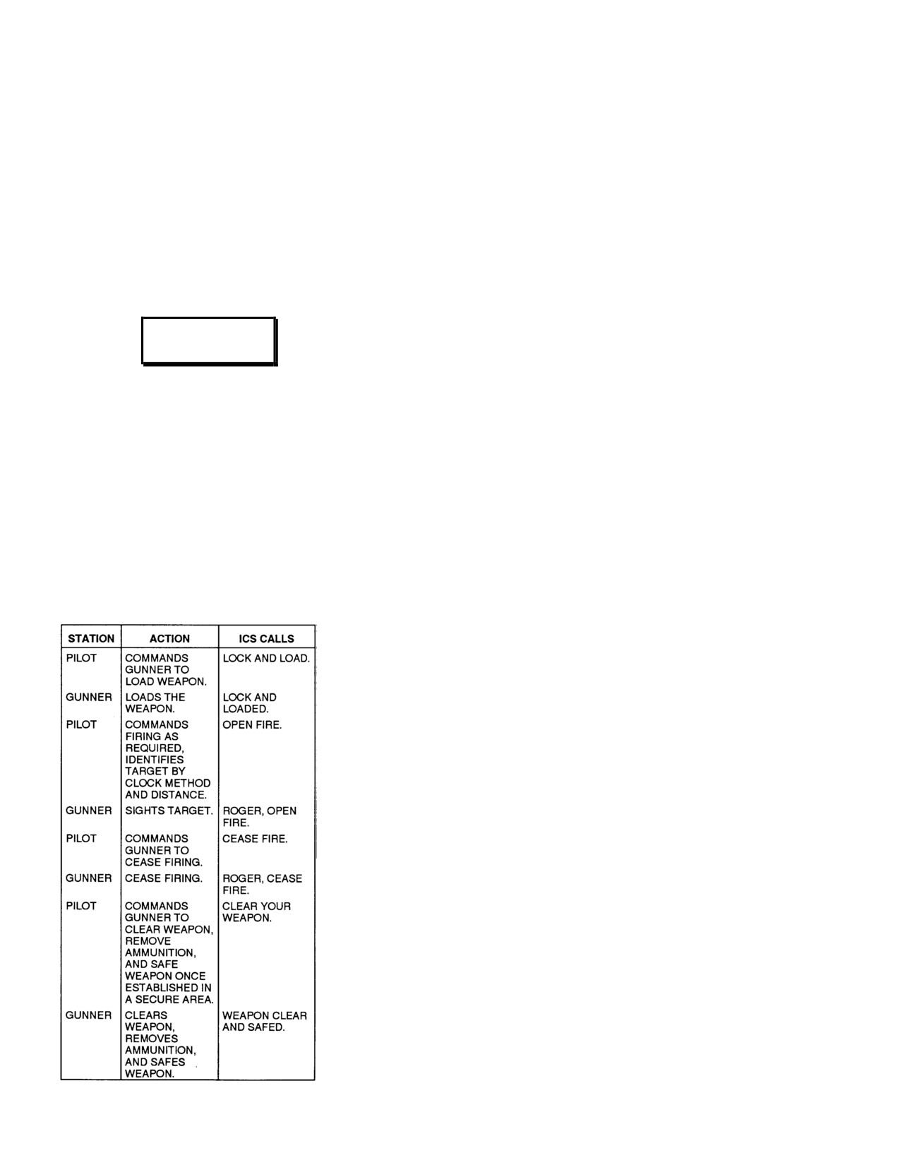
16.2.3.10 ICS Voice Procedures.
based on available intelligence on the position of
friendly troops.
2. Weapons tight
- Fire only at targets positively
identified as hostile. Clearance to fire shall be
requested from the HAC for each target engaged.
3. Weapons hold - Do not fire except in self-defense.
This is the most restrictive weapon control status.
Clearance to fire shall be requested from the HAC for
each engagement.
16-10
ORIGINAL
NAVAIR 01-230HLH-1
CHAPTER 17
Weapon Recovery
17.1 GENERAL DESCRIPTION
Swivel casters are fitted to the bottom of each leg for
ease of ground handling and to allow the launcher to
17.1.1 Purpose This chapter is intended as a
center itself without tipping during lift-off. Pair of 2 foot
reference for operators of the UH-3H helicopter with
by 1-foot trim tabs is attached to the rear legs to improve
special mission requirements such as target launching and
flight characteristics when the launcher is unloaded
weapon and target recovery.
(Figure 17-1).
17.1.2 Background
Prior to the development of
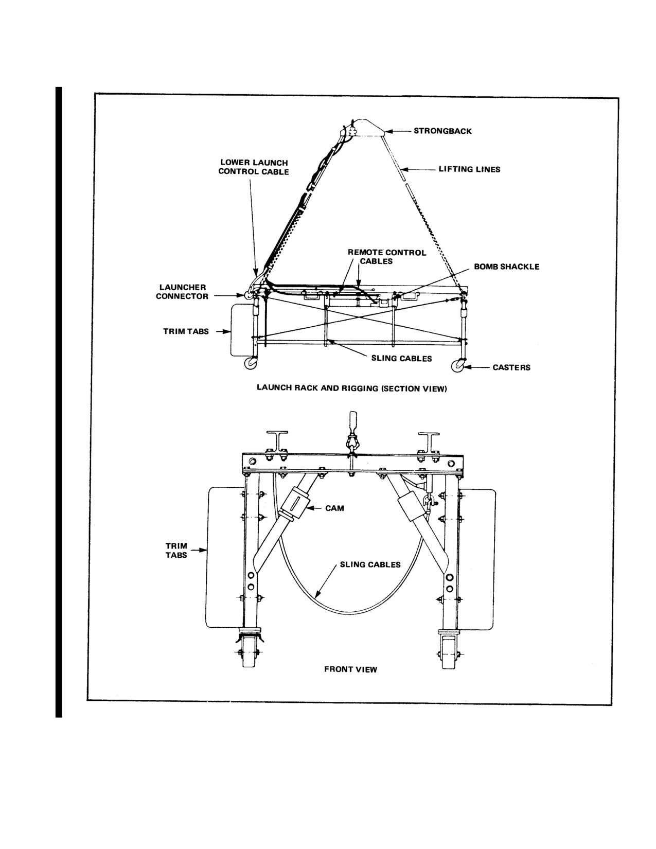
17.2.1.2 Rigging. The system's rigging consists of
helicopter recovery systems, range recovery work was
two 20-foot lengths of double braid nylon. The lines are
normally accomplished by small surface craft. This
attached to the launcher at the middle of the front and rear
method was successful; however, it had many
end beams . The lines are attached at the other end to a
disadvantages such as limited sighting ability and
strongback that fits the helicopter cargo hook.
restricted operations caused by sea state conditions. In
addition, the recoverable equipment was subject to
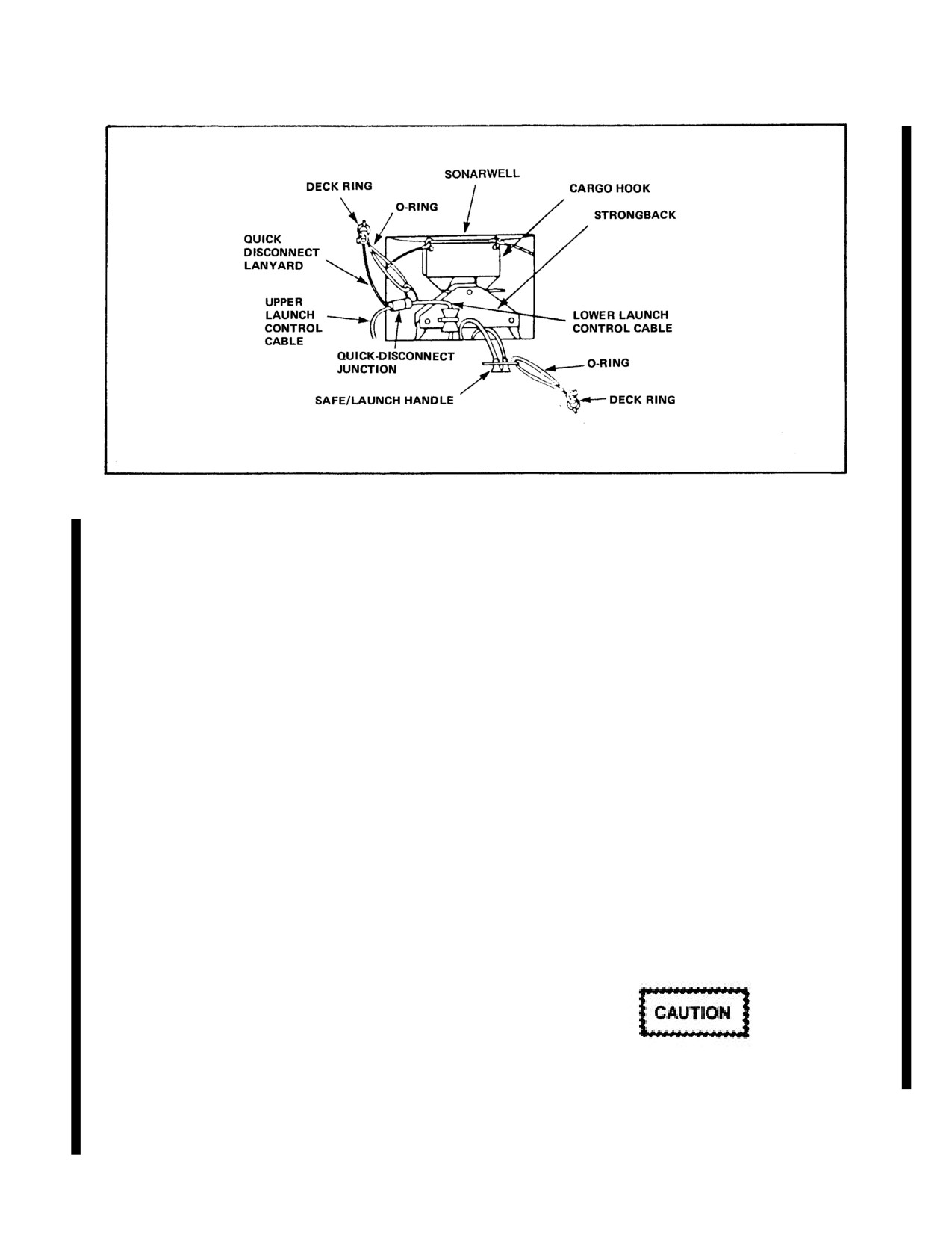
17.2.1.3 Control Cables. The lower launch control
damage during recovery/transport, and possible injury to
cable (Figure 17-1) runs down the rear lifting line to the
personnel was a constant hazard.
launcher connector. A Mk 6 A-cable connects the mobile
target to the launcher connector. A pullaway lanyard is
Helicopter recovery systems were introduced to the
attached to the launch frame at one end and to the A-cable
ranges to overcome the disadvantages encountered
finger at the other end. This lanyard disconnects the A-
during surface craft recovery. The helicopter could locate
cable from the mobile target during launch, preventing
the weapons and targets, recover them, and return them to
damage to the A-cable.
the turnaround facility in a relatively short period of time.
Helicopter weapons/target recovery has demonstrated
The lower launch control cable passes up into the
higher reliability and greater safety than surface craft in
helicopter and mates with the upper launch control cable
open ocean recovery.
(Figure 17-2). For helicopters with no sonarwell, control
cables are routed from the strongback to cargo door
17.2
SYSTEMS
opening. The upper launch control cable connects to the
launch control box. An O-ring provides strain relief to the
17.2.1 MK 146 MOD 0 LAUNCH SYSTEM (USED
lower launch control cable to prevent inadvertent
WITH MK
30 TARGETS) The Mk
146 Mod
0
separation of the quick-disconnect junction. In the event
helicopter launch system for Mk 30 targets consists of
of a jettison, the O-ring will break, the disconnect lanyard
four principal parts (Figure 17-1).
will take up the strain, and the connectors will separate.
1. Launch rack.
The two remote control cables are mounted to the
bomb shackle and routed up the rear lifting line into the
2. Rigging.
helicopter, where the safe/launch handle is connected to a
deck ring via a breakway O-ring. One cable controls the
3. Control cables.
bomb shackle safety pin, and the other cable controls the
bomb shackle release trigger. The control knobs are
4. Launch control box.
coupled together for simultaneous activation.
17.2.1.1 Launch Rack. The launch rack is 8 feet
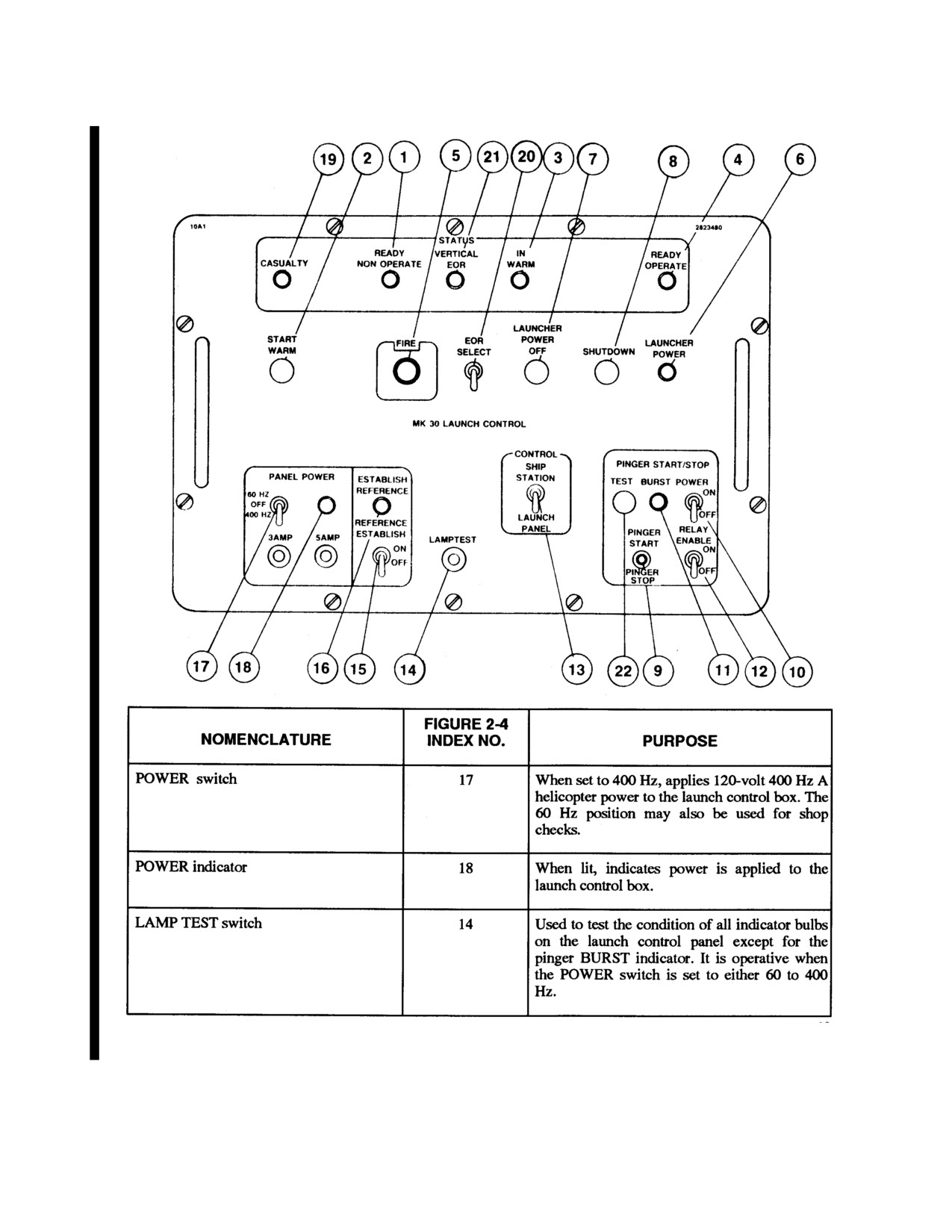
17.2.1.4 Launch Control Box. A launch control box
long, 3 feet wide, 3 feet high, and weighs 280 pounds. It
is required for launch control of Mk 30 targets. (Refer to
consists of two main I-beams bolted to two end I-beams
Figure 17-3).
that rest on and are bolted to four legs, reinforced by
longitudinal and corner braces.
Target warmup, control, and monitor signals are sent to
the mobile target and returned through the A-cable. The
The two main cables sling tightly underneath the
mobile target gyro systems are erected, the pinger is
vehicle and connect to the two suspension lugs of the
activated, and circuit warmup power is applied. Resulting
bomb shackle. A
1/4-inch diameter nylon rope slings
conditions are displayed on the launch control box.
underneath the vehicle at the aft end of the launcher.
17-1
ORIGINAL
NAVAIR 01-230HLH-1
Figure 17-1. Mk 146 Mod 0 Launch Rack and Rigging
17-2
ORIGINAL
NAVAIR 01-230HLH-1
Figure 17-2. Control Cable Connection
When the READY LIGHT or the READY
Note
OPERATE and REFERENCE ESTABLISHED lights are
When the balloon is deployed, the unit is
illuminated, the mobile target is ready for launch. The
not recoverable with Mk 2 Mod 0 cage.
mobile target is first fired electrically by operating the
FIRE button on the launch control box, then the
17.2.1.7 Emergency Shutdown Pinger. The ESP is
SAFE/LAUNCH handle is pulled. The bomb shackle
a portable, self-contained unit that, when submerged in
releases the two main sling cables, and the nylon rope
seawater, generates an acoustic signal that terminates
restrains the rear of the mobile target until it breaks (about
operation of the Mk 30 Mod 1 mobile target vehicle. A
one-fourth second), causing the mobile targets to pitch
tether is provided to facilitate raising and lowering the
down for proper water entry.
ESP into the seawater from the helicopter. The ESP is a
cylindrical unit 6 inches in diameter and 18 inches long,
In an emergency, the mobile target may be jettisoned
weighing approximately 28 pounds (in air weight). When
from the launcher by operating the SAFE/LAUNCH
activated, the ESP repeatedly transmits a paired-tone
handle.
pulse that, when received by the target over its command
link, terminates all target operations and the target floats
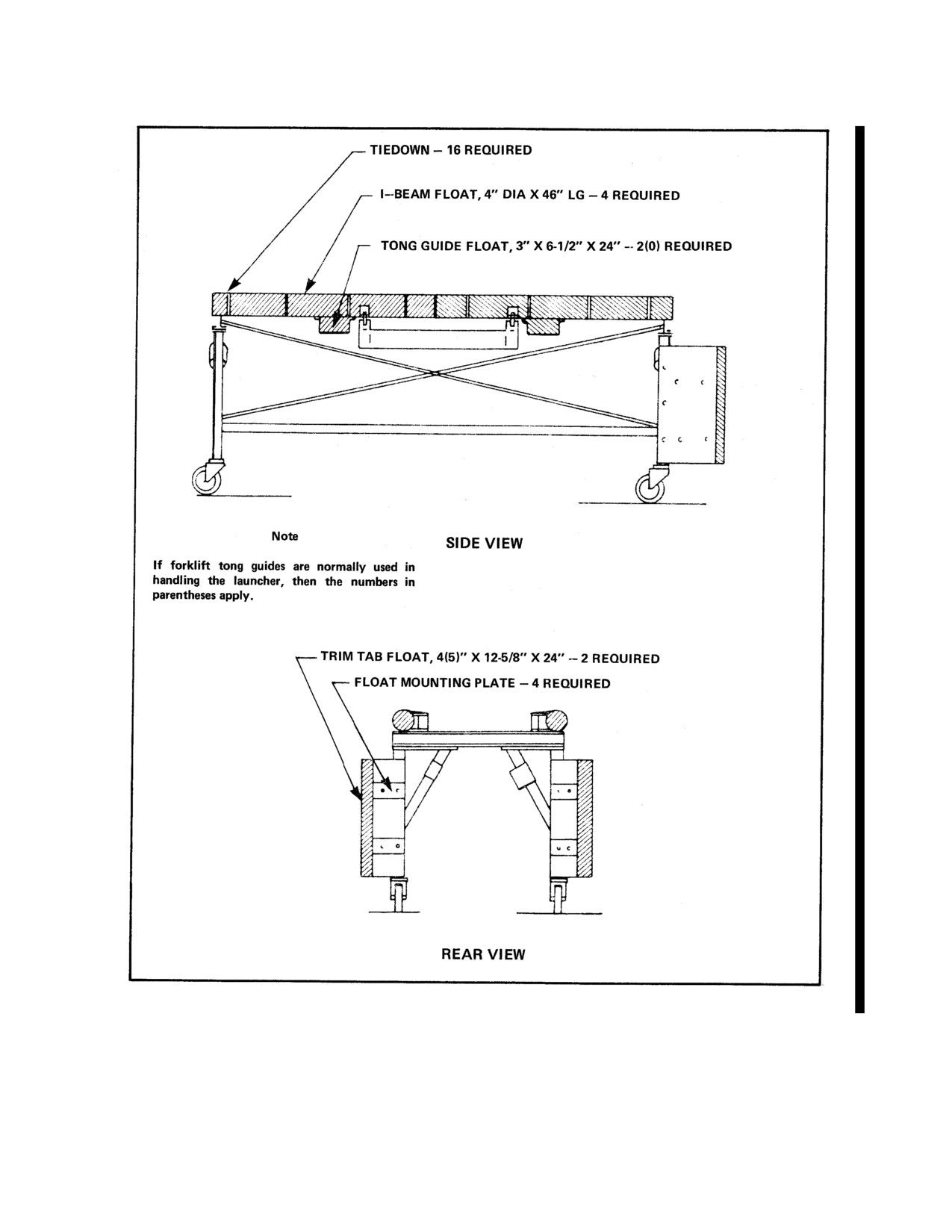
17.2.1.5 Flotation. To prevent sinking of the launcher
to the surface for recovery.
(loaded or empty) in the event of a low-altitude jettison,
rigid foam flotation is mounted to the launcher. Figure 17-
17.2.1.7.1 Emergency Shutdown Pinger Operation.
4 depicts the launcher with flotation. For clarity, all other
Prior to use, inspect condition of the tether and
figures in this manual do not show the flotation.
ensure that the lifting ring is secure and the tether is
securely connected to the lifting ring of the ESP and the
17.2.1.6 Mk
30 Target Description. The Mk 30
aircraft. Once immersed, the ESP will be automatically
mobile ASW target is 21 inches in diameter and weighs
activated causing transmission of the acoustic shutdown
2,700 pounds. The underwater vehicle used to simulate
pulse. The ESP should be removed from the water after
submarines and operates on a programmed pattern. The
the mobile target vehicle floats to the surface.
Mk 30 target responds to both active and passive acoustic
signals and provides signature characteristics for
classification purposes. With speeds of 7 to 30 knots,
maximum endurance ranges from 30 minutes to 6 hours
automatically. The target can be shut down at any time
Ensure ESP is securely connected to a tether
during a run by its acoustic command link using either
prior to lowering.
range UQC or the portable Mk 30 ESP at the end of a run,
a balloon deploys either immediately or after a delay of
90 minutes if EOR select was chosen prior to launch. The
target floats vertically prior to balloon deployment and
horizontally after the balloon deploys.
17-3
ORIGINAL
NAVAIR 01-230HLH-1
Figure 17-3. Mk 30 Launch Control Box Controls and Indicators (Sheet 1 of 3)
17-4
ORIGINAL
NAVAIR 01-230HLH-1
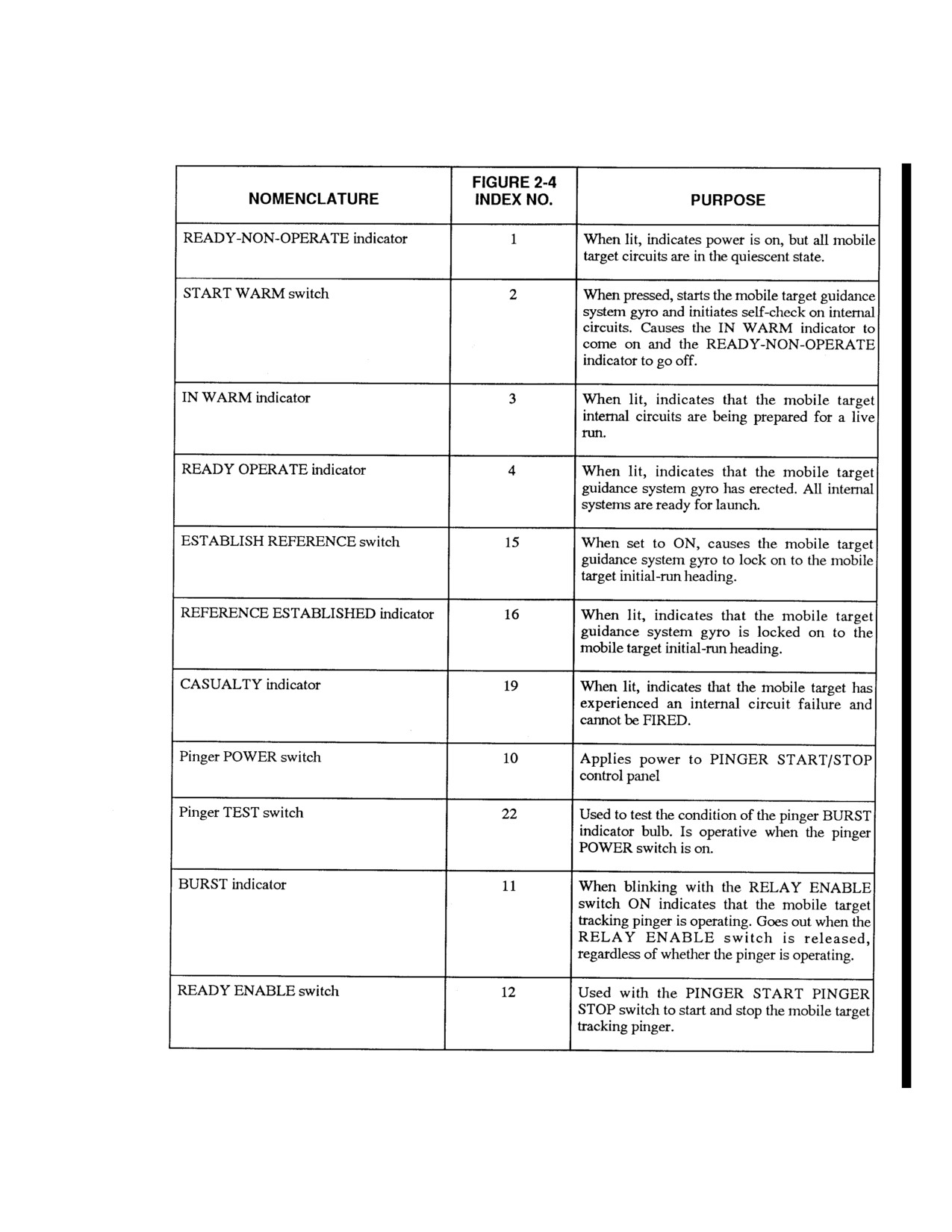
Figure 17-3. Mk 30 Launch Control Box Controls and Indicators (Sheet 2 of 3)
17-5
ORIGINAL
NAVAIR 01-230HLH-1
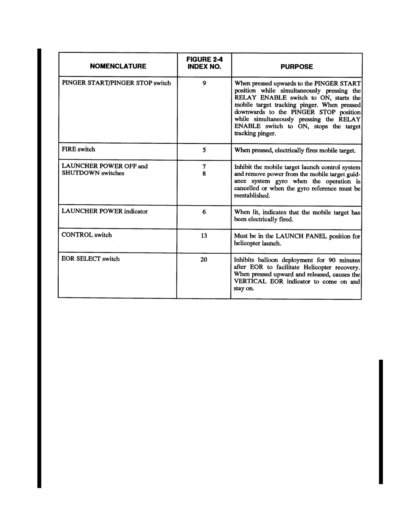
Figure 17-3. Mk 30 Launch Control Box Controls and Indicators (Sheet 3 of 3)
17.2.2 MK
4 MOD 0 HELICOPTER DEPLOYED
17.2.2.1 Rigging. The rigging for this system consists
LIGHTWEIGHT RECOVERY SYSTEM
of two 40-foot lines and one 30-foot main lifting line (see
Figure 17-6). The 40-foot lines are attached at one end to
The helicopter deployed lightweight torpedo recovery
the shackle retainers on the forward end of the cage with
system Mk 4 Mod 0 (Figure 17-5) is used to recover Mk
1/2-inch shackles. The lines are passed through line
46 and Mk 50 torpedoes. This system is capable of safe
guides at the aft end of the cage and connect to a 3/4-inch
and efficient recoveries in seas through sea state 5. An
web shackle. The 30-foot main lifting line is connected to
alternate method for Mk 46/50 torpedo recovery utilizes a
the web shackle and attaches to the helicopter cargo hook.
snare pole and is described later in this section. The
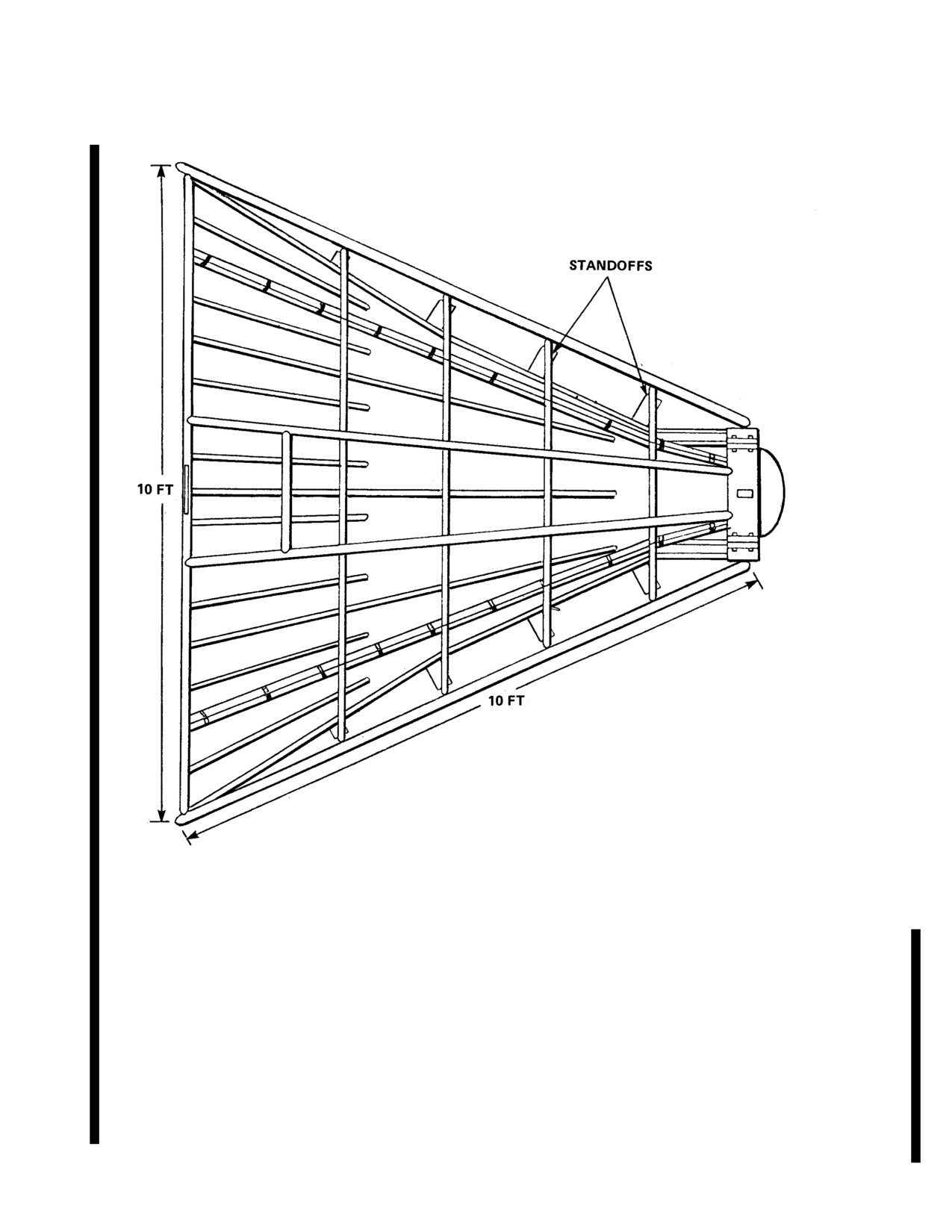
recovery cage is a rigid cone-shaped framework
17.2.2.2 Vehicle Descriptions
constructed of aluminum rods and tubing. The cage is 10
feet long, 2 feet in diameter at the forward end, 10 feet in
17.2.2.3 MK 46 Torpedo. The Mk 46 torpedo (Mods
diameter at the aft end, and weighs 600 pounds. It is made
1,
2 and 5) is
102 inches long and
12.75 inches in
of a nose plate and four sections that are bolted together
diameter. End-of-run weight and float attitude depend on
and can be disassembled for ease of shipping or stowage.
the run time. A non runner floats vertically. A full-runner
The top and bottom sections are landing frames. The port
floats horizontally. Partial runners will fall somewhere
and starboard sections contain line guides.
between these parameters.
17-6
ORIGINAL
NAVAIR 01-230HLH-1
Figure 17-4. Launcher Flotation Components and Assembly
17-7
ORIGINAL
NAVAIR 01-230HLH-1
Figure 17-5. Mk 4 Mod 0 Recovery Cage Side view
17.2.2.4 MK 50 Torpedo. The Mk 50 torpedo is 113
EHCTV. The HWRS Mk 2 Mod 1 (Figure 17-8) is used
inches long and 12.75 inches in diameter. It weighs 750
to recover the TOTEM. The HWRS is capable of safe and
pounds and has a flotation collar that deploys at end-of-
efficient recoveries in seas through sea state
5. The
run to return the torpedo to the surface causing it to float
system is currently certified for use by H-3 helicopters
vertically.
with an external load carrying capability. Detailed
description of equipment, maintenance, and rigging
17.2.3 MK
2 MOD O/1 HELICOPTER WEAPON
requirements are found in NAVSEA manual SW59 1
-
RECOVERY SYSTEM
BOMMO-0 1 0/WPN RECOV SYS/NAVAIR
11-90-2
HWRS Mk 2 Mod 0/1 technical manual.
17.2.3.1 Systems Description. The HWRS Mk 2
Mod 0 (Figure 17-8) is used to recover exercise torpedoes
The recovery cage dimensions and weights for each of
Mk 48 and Mk 48 ADCAP, Mk 30 mobile targets, and the
the three basic configurations are shown in Figures 17-7
and 17-8.
17-8
ORIGINAL
NAVAIR 01-230HLH-1
17.2.3.2 Safety Release System. The SRS consists
cargo hook and the load line is brought into the cargo
of a weak link, a 60-pound anti-flyback weight, and a 25-
door. When established in a hover near the drone
foot pendant. The purpose of the SRS is to prevent rescue
("perched"), the crewmen will start to slide the pole/ snare
hoist cable overload, failure, and resultant recoil into the
out the cargo door and attach it to the clevis end of the
helicopter rotor system in the event of a jettison or
load line. With a BQM-34 on the pole in this
inadvertent cargo hook release. This system is shown in
configuration, the helicopter will require
40 to 45 feet
Figure 17-9.
AGL to lift the drone off the deck. Using the load line
increases flexibility for recovering different targets be-
Lifting line length is
40 feet; refer to tech manual for
cause the right hook/pole snare can be attached or
rigging requirements. Figure
17-10 provides a general
changed after takeoff.
picture of the rigging.
17.2.3.3 Vehicle Description. A detailed description
of procedures is provided below. For simplicity, the
WARNING
vehicle to be recovered is referred to as a torpedo,
although application to other vehicles is the same, unless
otherwise indicated. Refer to the appropriate vehicle
Personnel should remain clear of extra tagline
technical manual for a detailed description.
(rope) to avoid the possibility of entanglement
during emergency or inadvertent jettison.
17.2.4 TARGET TORPEDO DRONE RECOVERY
17.2.4.2 Mk
30 Snare Pole (Figure 17-14). The
17.2.4.1 Equipment Descriptions. The pole hook/
Mk-30 snare pole is a 20-foot hollow pole with a 40-foot
snare drone recovery systems provide a means of
cable. There is a "noose" or loop of rubber-coated cable at
recovering BQM-34 and MQM-74 drones and training
the bridle end. Prior to use, arrange cable in a double
shapes. Additionally these systems may be used in the
wrapped loop up against the inner diameter of the hoop,
recovery of Mk 46 torpedoes. This system is capable of
with only one line crossover point at 12 o'clock position.
safe and efficient recoveries through sea state 4.
Using 1 - inch wide tape, apply two wraps of the tape
around the hoop and the lines at four places: 3, 6, 8:30,
17.2.4.1.1 BQM Hook/Pole
(Figure
17-11). The
and 10:30 clock positions. Make a 3/8-inch deep cut in
BQM 34 hook/pole is a 15- or 20-foot hollow pole with a
both sides of the tape. The tape must be broken by the
24-foot,
3/8-inch cable running through the pole and a
crew later. The noose is slipped over the nose of the
hook permanently attached to the pole. The cable is
recovery object and then pulled tight, breaking the tape.
attached directly to the hook so that the pole itself does
Tension is kept on the snare while weight comes on the
not support the target's weight. The hook is used to snag
cable. In flight, the target's weight keeps the noose tight.
the recovery harness of the BQM-34S or recovery ring of
the BQM-74C (preferred method). The hook features a
1.
With the bridle near the bottom of the pole, connect
spring-loaded gate that prevents the hook from
the bridle to two door edge deck rings at any convenient
unhooking. For training purposes, the gate may be taped
time prior to pole deployment. Pass ONE weak link
to the open position to allow multiple hookups.
through each deck ring far enough to slide the bridle
retainer pin through the weak link, then pull on the bridle
17.2.4.1.2 MQM Snare Pole (Figure 17-12). The
to help secure the pin.
MQM/BQM 74 snare is a T-shaped, 15- or 19-foot hollow
pole with a 24-foot cable. There is a "noose" or loop of
rubber coated cable at the T-end. Prior to use, the noose is
either taped or banded along the crossbar to help keep it
open. Only enough tape is used to ensure the noose stays
WARNING
open. The tape must be broken by the crew later. The
noose is slipped over the nose of the recovery object and
then pulled tight, breaking the tape. Tension is kept on the
Keep hands and fingers 6 to 12 inches clear of
snare with the tagline while weight comes on the cable. In
the bellmouth when feeding out line.
flight, the drone's weight keeps the noose tight.
2.
To deploy the pole, one crewman grabs the top of the
17.2.4.1.3 Shackle/Swivel Assembly (Load line)
pole and line, while the other crewman controls the hoop.
(Figure 17-13). The load line is a 17-foot, 3/8-inch cable
Feed the hoop out the door, continue to feed the entire
with shackle/swivel at one end and a clevis at the other
pole out the door and down through the bridle until the
end. A tagline (rope) with a minimum length of 20 feet or
stop reaches the bridle. Feed the line down the pole to
longer is attached to the clevis end to help maintain
extend the pole to its full length. (Reverse this step if pole
tension on the load line after drone "capture" or hookup.
needs to be brought back abroad for tape repair).
Before takeoff; the swivel end is connected to the external
17-9
ORIGINAL
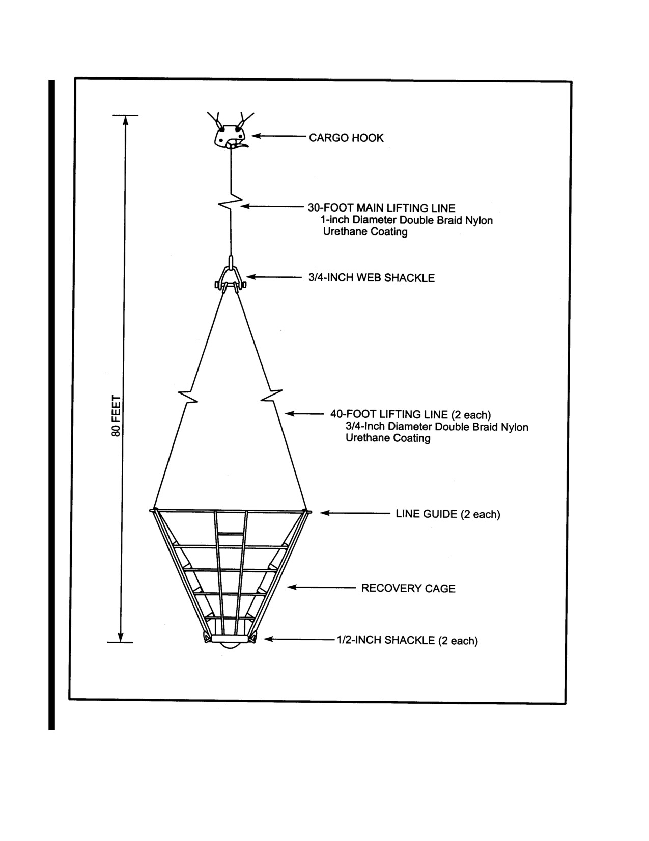
NAVAIR 01-230HLH-1
Figure 17-6. Mk 4 Mod 0 Recovery Cage Rigging
17-10
ORIGINAL
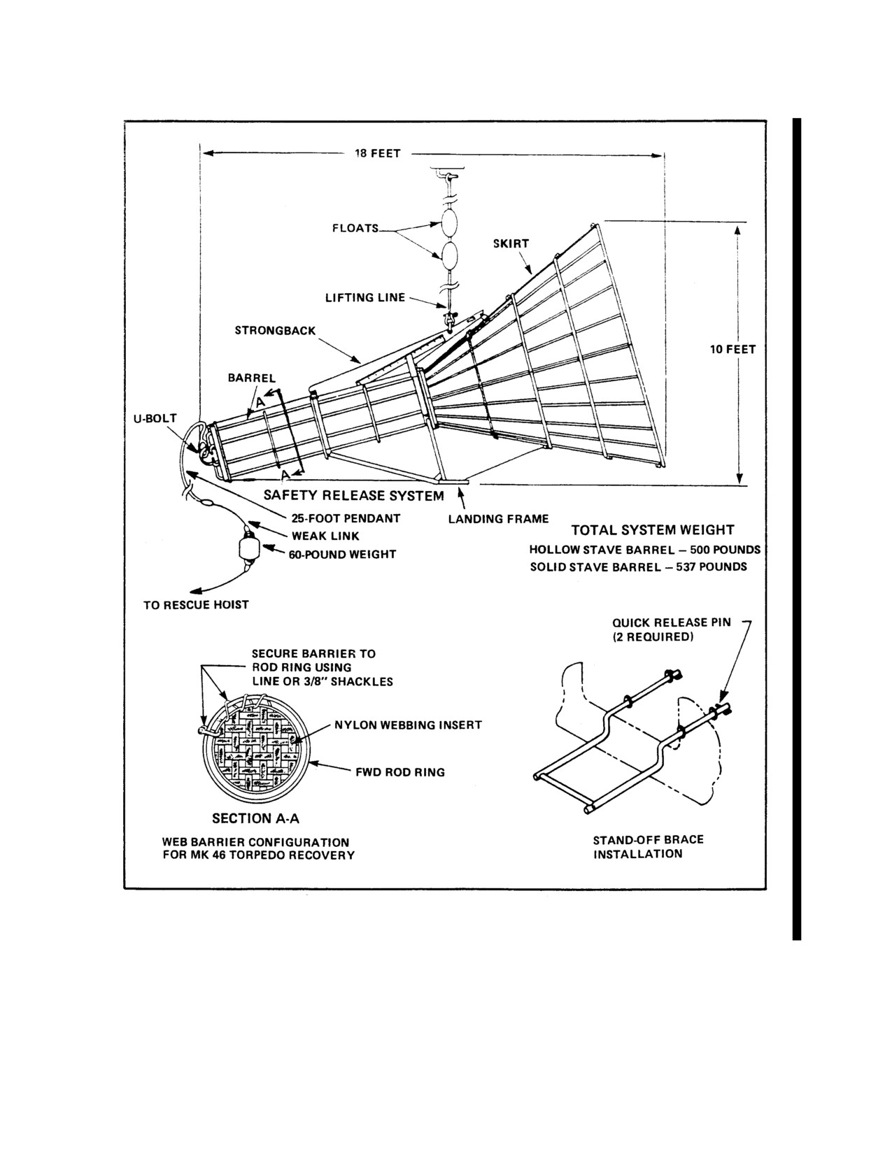
NAVAIR 01-230HLH-1
Figure 17-7. Helicopter Weapon Recovery System Mk 2 Mod 0
17-11
ORIGINAL
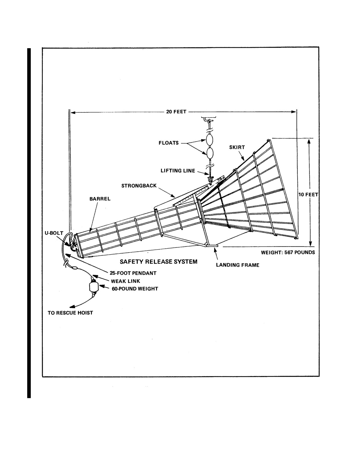
NAVAIR 01-230HLH-1
Figure 17-8. Helicopter Weapon Recovery System Mk 2 Mod 1
17-12
ORIGINAL
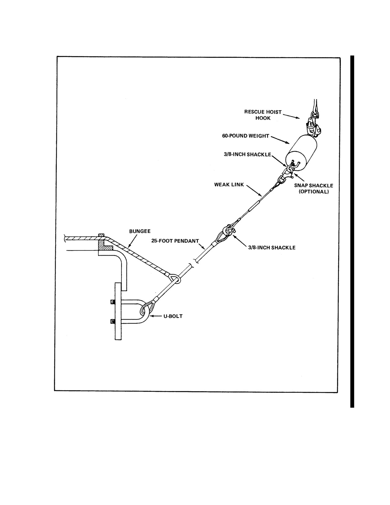
NAVAIR 01-230HLH-1
Figure 17-9. Safety Release System
17-13
ORIGINAL
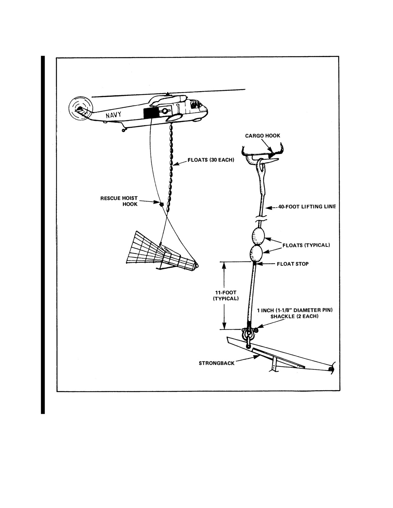
NAVAIR 01-230HLH-1
Figure 17-10. Recovery Cage Rigging (Sheet 1 of 2)
17-14
ORIGINAL
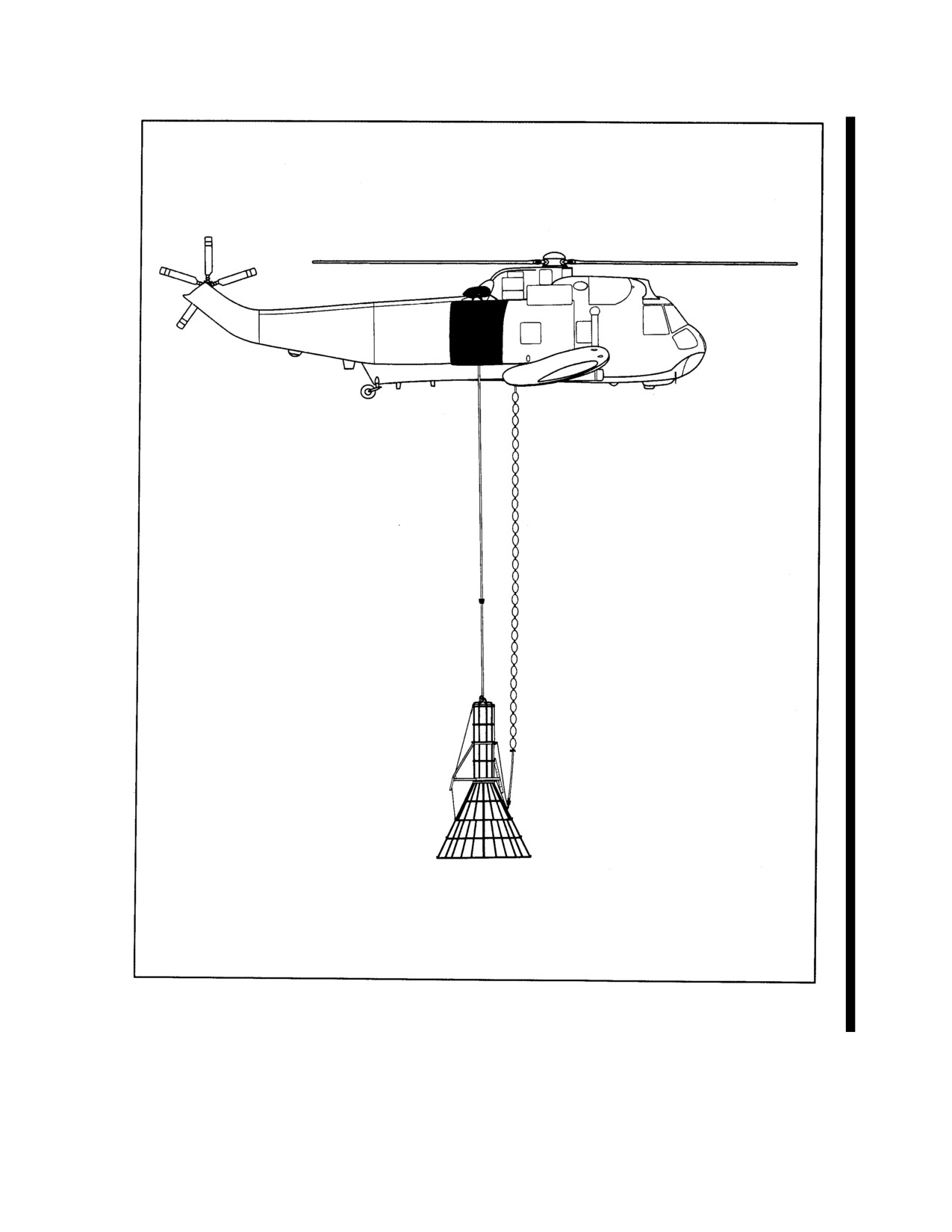
NAVAIR 01-230HLH-1
Figure 17-10. Recovery Cage Rigging (Sheet 2 of 2)
17-15
ORIGINAL
NAVAIR 01-230HLH-1
17.2.4.2.1 Recovery. Perform the following steps to
17.2.4.2.2 Recovery/Flight Limitations.
recover a horizontally floating target Mk 30.
Sea State:
4 (8-foot seas maximum).
1. The talker directs the helicopter pilot while the pole
Airspeed:
90 knots indicated airspeed maximum.
operator controls the pole to pass the hoop over the
Angle of Bank:
30 degrees maximum.
nose of the target. It is recommended that the hoop be
Autorotation Entry:
2 seconds minimum collective
kept just above the water, using line control, until
lowering.
close to the target's nose.
17.2.4.2.3 Delivery. Deliver the target to the soft pad
2. When the hoop is positioned within 3 feet of the
unless directed by range control to deliver it to the TWR.
EOR balloon, the pole operator pulls hard on the line
Set the target down, then slide over and down so the pole
to break the tape and thereby sets the noose. It is
falls harmlessly when the cargo hook is released. For soft
important to confirm that the noose is between the
pad delivery, lower the bagged towed array with the
stoppers. The stoppers are mounted on the forward and
grapnel.
aft target joint bands to prevent the noose from
slipping off the target during transit.
17.2.4.3 Target/Drone Descriptions
17.2.4.3.1 BQM-34 Target Drone (Figure 17-15).
The BQM-34 is a remotely controlled missile target
drone capable of high subsonic speed up to 550 knots and
altitudes of from 50 to 50,000 feet. Recovery sequence is
initiated by means of a parachute system deployed by the
Pull the bridle retainer pins free before the
controller or automatically by failure of the engine or the
helicopter ascends to allow the pole to
remote control system. The drag parachute is
collapse down.
automatically deployed upon initiation of recovery
sequence to decelerate the target. Following deployment,
3. Pull the bridle retainer pins free and then ascend the
the main parachute lowers the target in a horizontal
helicopter slowly to lift the target from the water.
attitude to the surface. The main parachute is released
Ensure that the helicopter hovers directly over or
upon contact with the ground or water by means of an
abeam the target during the ascent to avoid pulling the
impact or saltwater switch. Upon water impact, a dye
noose out of position. After the target is clear of the
marker releases a fluorescent dye to assist in target
water, confirm that a secure grip exists on the target
location.
between stoppers. If the noose is not positioned
The BQM-34 uses a locator beacon with a frequency
between the stoppers, or if the first wrap of the noose
preset by ground personnel prior to launch. The BQM-34,
is seen to come against the stopper any time, return the
MSR configuration only, has a strobe light mounted on
target to the water and release the cargo hook so that
the vertical stabilizer to aid in target location during
the pole falls clear of the target. Return to base for a
periods of low visibility. For further information on
new snare pole and continue with the recovery. If the
BQM-34, refer to NAVAIR 01-1 00TBA-2 manuals.
second snare pole's noose is wrapped over the first
snare pole's line or hoop, the grip is acceptable; if it is
17.2.4.3.2 BQM/MQM-74 Target
(Figures
17-16
wrapped over the pole, it is unacceptable. If the
and 17-17). The BQM/MQM-74 is capable of high-
helicopter crew determines for any reason that the grip
subsonic speed at altitudes from 50 to 30,000 feet and of
is unacceptable, the target should be returned to the
carrying augmentation systems to simulate medium
water. If the crew determines that the target is badly
performance aircraft. The recovery sequence is initiated
fouled and a safe recovery is impossible under the
either by radio command or automatically if the command
present conditions, snare pole recovery attempts should
signal is lost. Upon recovery initiation, a small pilot
be discontinued and the target should be left for TWR
parachute is deployed followed by the larger main
recovery when conditions permit.
parachute. The main parachute lowers the target drone to
the surface and is released upon impact with ground or
4. For delivery to the soft pad, the towed array should
water.
be recovered if possible. It is recommended that this be
Flotation is provided by the nosecone, fuel tank, oil smoke
accomplished in a sheltered area near the delivery site
tank, and an aft flotation bag. Recovery is facilitated if the
to make the recovery easier and to avoid stresses on
target floats horizontally and this is generally achieved by
the towed array because of load oscillations during
means of an aft flotation bag that inflates upon water
transit. Recover the towed array using standard
immersion.
procedures for a HWRS Mk 2 recovery. For delivery
to the TWR, towed array recovery is not required.
17-16
ORIGINAL
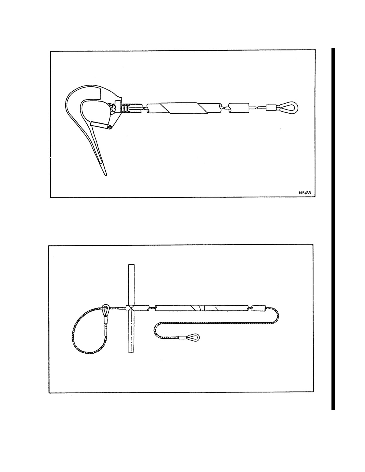
NAVAIR 01-230HLH-1
Figure 17-11. BQM Hook/Pole
Figure 17-12. MQM Snare/Pole
17-17
ORIGINAL
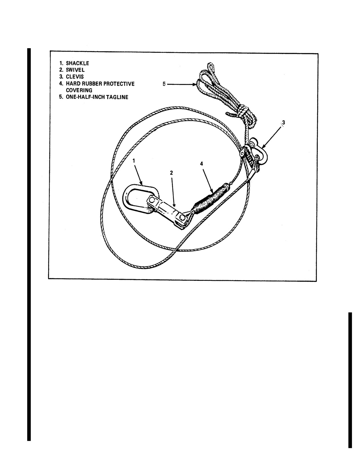
NAVAIR 01-230HLH-1
Figure 17-13. Loadline
A locator beacon in the target emits a radio frequency
17.3 SERVICING
homing signal that can be detected by the AN/ARA-SO
Refer to appropriate technical publications for
automatic direction finder or similar system. The signal is
specific servicing requirements.
transmitted at 235.0 MHz and is activated 1 minute after
17.4 OPERATING LIMITS
recovery is initiated. The beacon will operate up to 10
hours and may be detected at ranges up to 8 nm by a boat
Refer to Chapter 4.
or 40 nm by an aircraft, provided the antenna is not under
17.5 FLIGHTCREW QUALIFICATIONS
water. In addition to the beacon, a dye marker is released
Refer to Chapter 5.
upon the target drone's entry into the water.
17.6 EMERGENCY PROCEDURES
For additional information on MQM-74, refer to
Refer to Chapter 12.
NAVAIR-0 1 -MQM74C-3.
17.7 FLIGHT PREPARATION
The BQM-74C is a modified MQM-740C that has an
air-launch capability and includes special features that
17.7.1 Aircraft Preparation
make the target drone a more realistic threat vehicle for
use by the fleet. These features include a digital avionics
All aircraft preparation should be completed prior to
processor control system and a low altitude radar
scheduled range times. During preflight, particular
altimeter control system.
attention should be paid to the cargo sling and hoist.
These systems must be without discrepancies.
17-18
ORIGINAL
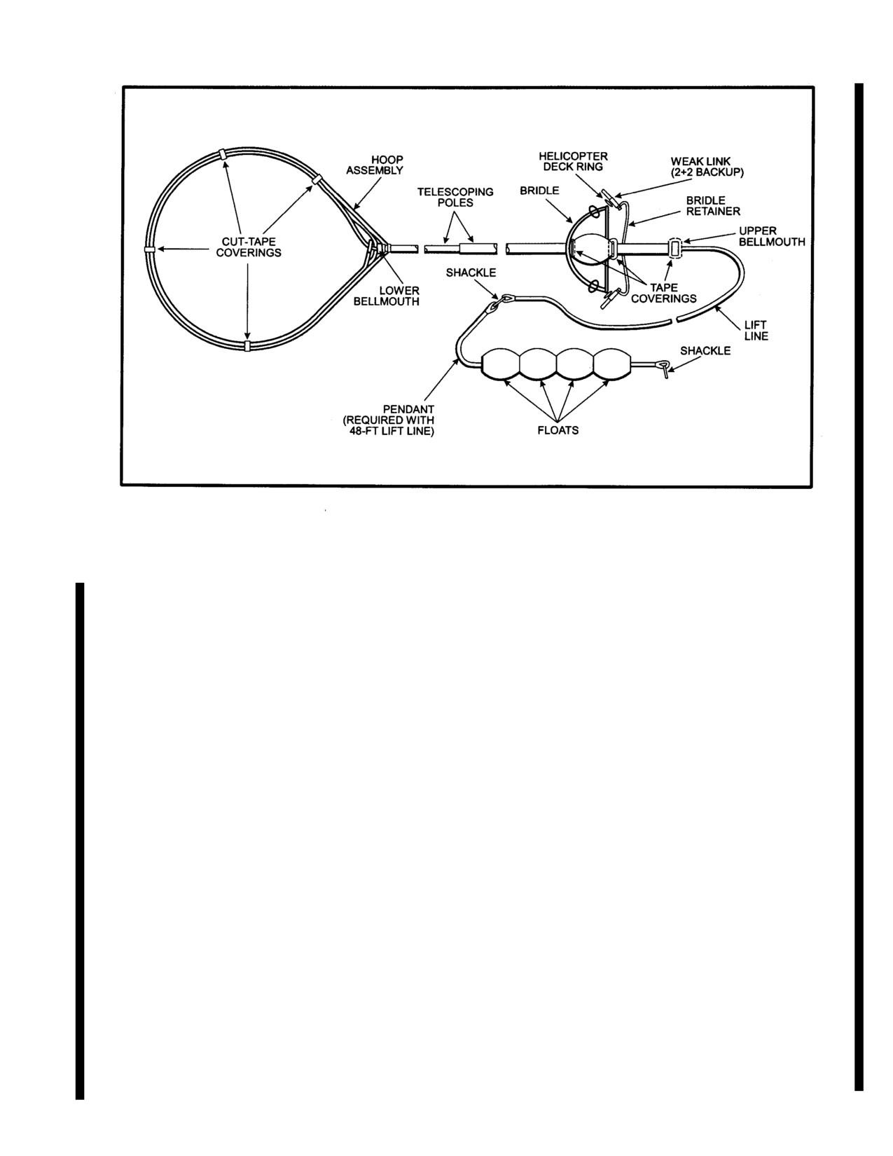
NAVAIR 01-230HLH-1
Figure 17-14. Snare Pole Assembly for Mk 30 Target
17.7.2 Crew Briefing.
Note
In addition to the regular crew brief; the following areas
Shifting the Cargo Sling Master Switch from
are considered to be a minimum brief for external load
"SLING" to "SAFE" position after pickup has
operations:
been known to activate the electrical jettison
resulting in a released load in flight. It also
1. Aircraft performance.
deactivates the electrical releases leaving only
the manual foot release.
2. Weather/sea state limitations.
4. Saltwater encrustation.
3.
Emergency load jettison.
5. Post takeoff weight considerations.
a. Decision to jettison load depends on the nature
of the emergency and is left to pilot discretion.
a.
Helicopter fueling shall be calculated so that
maximum gross weight is not exceeded when the
b. During lift-off; aircrew should watch for
torpedo is recovered.
rigging
(lifting lines) entanglement. A ground
crewman should be on hand to correct any
b.
The combined weight of the Mk 30 target,
problems that might arise.
launcher, and launch control box is 3,030 pounds.
c. Certain external load configurations are prone
6. Unique procedures.
to oscillations during flight. The launcher should
be kept under observation. If oscillations become
a.
External load disentanglement procedures.
severe, immediate action to slow airspeed with a
slow turn to port or starboard should be made.
b.
Damaged target.
The particular circumstances that caused the
oscillation should be noted.
c.
Inverted drone/connected parachute/entangled
drone procedures.
d. The cargo sling master switch should be in
SLING position for pickup and delivery. The
d. Target/drone/cage drop off procedures.
AUTO mode shall not be used.
17-19
ORIGINAL
NAVAIR 01-230HLH-1
7. Specific launch parameters within the approved
1. Inspect barrel rings and visible
(not covered by
window of 10 to 30 foot launcher altitude above
plastic) portion of staves. Inspect all visible welds for
wave crests, and 0 to 25-knot groundspeed are set by
cracks.
the local target IMA.
2. Ensure the interior of cage is completely covered
with cushioning (plastic tubing and cork) such that no
bare metal is exposed. The plastic tubing shall be
attached to cage with ordnance tape. In addition, all
WARNING
gaps in tubing, including tubing ends, shall be covered
with ordnance tape. Ensure skirt tabs are big and are
The potential for the PNAC to inadvertently
covered with tape, and ensure skirt staves are built up
release the external cargo/ load exists if the
with tape where they join the flanged ring.
cargo system is flown in the
“SLING”
position. The PNAC should use extreme
3. Ensure that rubber nose pad is in place and there is
caution if transmitting over the radio with the
nothing protruding past surface.
cyclic switch.
4. Ensure that rubber bumpers are in place on landing
17.7.3 Preflight.
frame feet.
A standard NATOPS preflight inspection shall be
5. Ensure lifting line is attached to the desired/
conducted. Particular attention should be paid to the cargo
required lifting point. Ensure that lifting line shackles
hook assembly, hard points, and the rescue hoist systems.
are tight and safety wired and inspect line for damage.
The following shall be completed during pre-flight
If the urethane coating is damaged, the strength of the
inspection:
rope is not impaired unless the rope underneath is
damaged also.
1. Both manual and electrical release functions of the
cargo hook system shall be checked and fully
6. Check that all cage assembly bolts are in place and
operational prior to attempting recovery.
are securely tightened.
2. Functional check of the rescue hoist and
7. Inspect landing frame for cracks and distortion.
cargo sling.
Ensure cable brace running from nose of barrel to
landing frame is taut.
3.
Standard safety gear shall be available as listed in
paragraph 17.3.5.
8. Inspect strongback for evidence of cracks or metal
fatigue.
4.
A preflight inspection of all recovery equipment
shall be performed. This shall include but not be
9. Ensure that bungee cords are in place.
limited to the overall condition, integrity, and
operation of lines, cables, hooks, hardware, and
10. Inspect weak link and replace if damage is
attachment points. Any cables with broken strands
observed or suspected.
shall be rejected.
11. Inspect nose pendent for damage and corrosion
5. All nonessential troop seats should be folded during
and replace if damage/corrosion is severe. Remove all
snare pole and/or hook recovery operations. All loose
fishhooks. Ensure weak link shackles are tight. Safety
equipment should be secured.
wiring of weak shackles is optional.
6. The pilot shall place the release mode switch to the
cargo sling function prior to taxi or takeoff.
17.7.4 Helicopter Weapons Recovery System
Preflight Procedures.
During ground handling of recovery cage
The HWRS shall be inspected prior to each planned
avoid excessive dragging of cage, which wears
away feet. Also, ensure that the lifting line is
weapon recovery. Preflight inspection procedures for the
not dragged or otherwise abused.
HWRS are basically visual and shall be implemented as
follows:
17-20
ORIGINAL
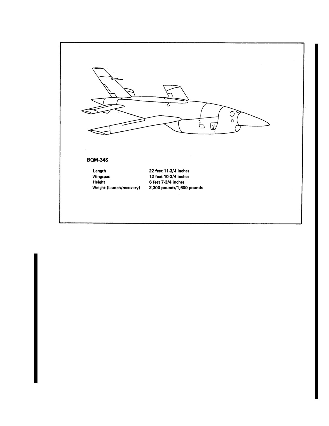
NAVAIR 01-230HLH-1
Figure 17-15. BQM-34 Missile Target
17.7.5 SPECIAL EQUIPMENT REQUIRED
c. Cable protector (12-inch length of plastic
tubing).
The helicopter must be rigged, prior to takeoff; according
to the type of recovery that is to be done.
d. Lowering pole/line.
1. Mk 25/58 marine markers.
17.8 SHORE-BASED PROCEDURES
2. Safety gloves, heavy leather welder type.
17.8.1 Mk 146 Mod 0 Helicopter Launch System
Procedures
3. Launch/recovery system and related cables/ hardware.
17.8.1.1 Pre-hookup. The loaded launcher is
4. Cable cutter, insulated.
positioned beside the helicopter for a cold hookup. For a
hot hookup, the launcher is set down facing into the wind
5. Crewman's safety belts .
and the helicopter taxies beside the launcher. Either way,
the launcher should be positioned on the right side of the
6. Mk 30 specifics.
helicopter, 5 to 8 feet from the sponson, with its cg lined
up with the cargo hook position and launcher brakes
a. Grappling hook and line assembly.
locked.
b. Cable restrainer (O-ring with snap hook).
17.8.1.2 Hookup. After lowering the cargo hook, slip
the strongback onto the hook and verify that the hook is
locked and the retaining latch is down. Ensure that the
lifting lines/cables are not crossed or fouled on the
launcher.
17-21
ORIGINAL
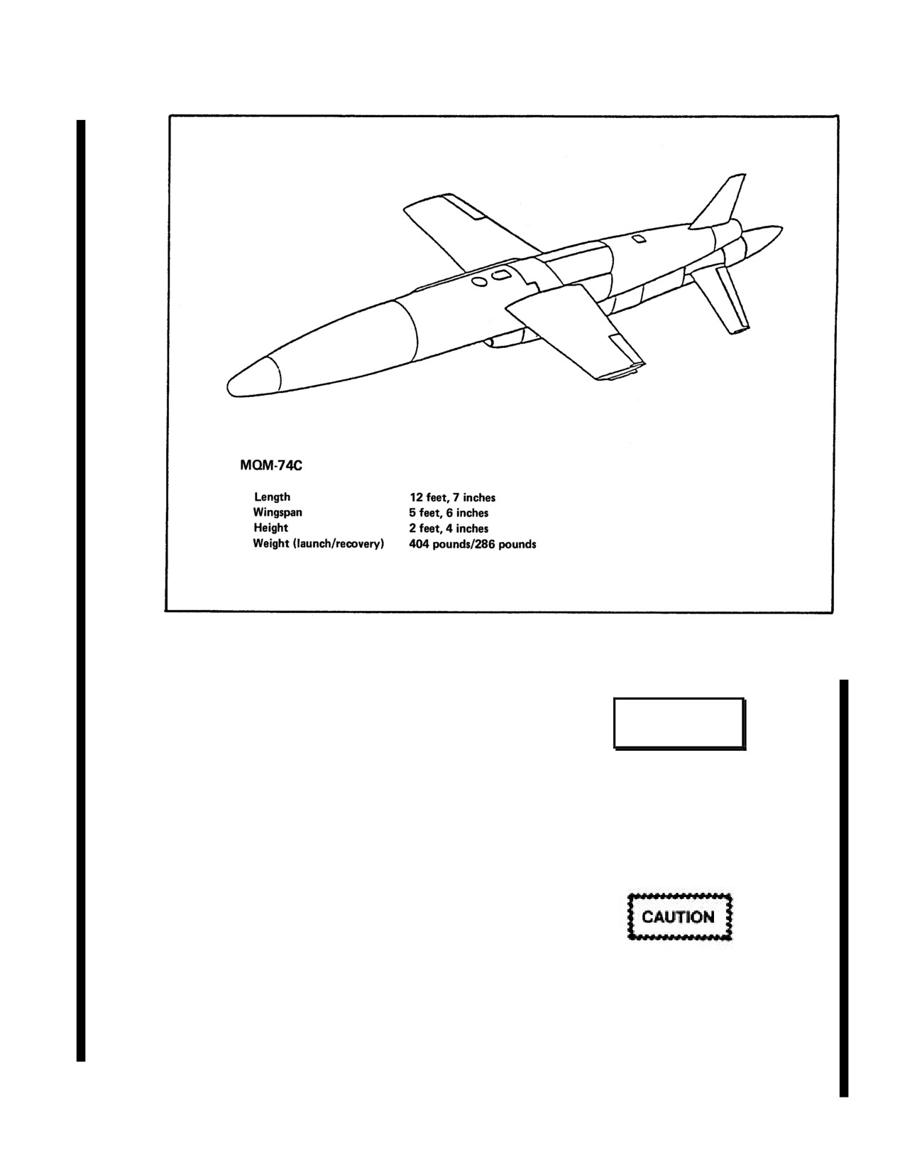
NAVAIR 01-230HLH-1
Figure 17-16. MQM-74C Missile Target
Route the lower launch control cable and the remote
control cables between the two aft cargo hook support
WARNING
cables and up into the helicopter through the sonar well.
If the helicopter has no sonar well, route the cables to the
forward edge of the cargo door opening and into the
To avoid possible electric shock because of in-
helicopter. Connect the strain relief O-rings for the lower
flight static charge buildup on the launcher,
launch control cable and for the remote control cables to
the SAFE/LAUNCH handle assembly and the
deck rings nearest the sonar well (if no sonar well,
launch control box should have electrical
connect O-rings to the nearest deck ring at the forward
contact with the helicopter frame, either by
edge of the cargo door).
direct contact
(on deck) or via a grounding
strap.
Before connecting the Mk
30 launch control box to
helicopter power, ensure initial switch positions are as
follows:
1. PANEL POWER switch - OFF.
After hookup of launcher lifting lines/cables,
2. ESTABLISH REFERENCE switch - OFF.
the crewman shall check for the free
movement of all four-cargo sling swivel
3. CONTROL switch - LAUNCH PANEL.
fittings and that cables are hanging freely. This
will help to preclude the possible hang-up of
4. Pinger power switch - OFF.
cables and the shearing of fuselage hard points
that could result in damage to the aircraft
and/or loss of the target/launcher.
17-22
ORIGINAL
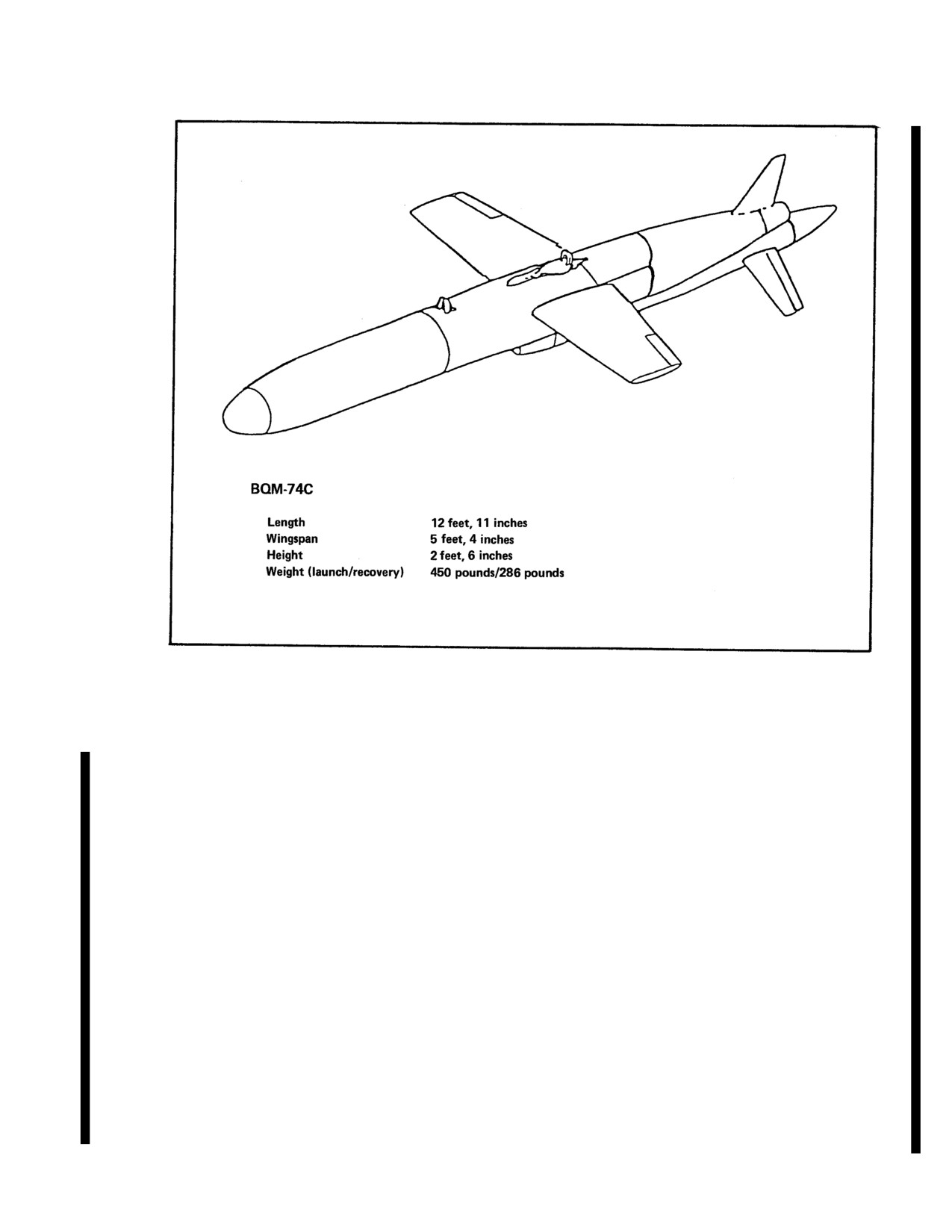
NAVAIR 01-230HLH-1
Figure 17-17. BQM-74C Missile Target
5. Press the pinger RELAY ENABLE switch to ON
17.8.1.3 Mk 30 Flight Procedures
while simultaneously
pressing
the
pinger
START/STOP switch upward to the PINGER START
17.8.1.3.1 Mk 30 Target Warmup Checks. As soon
position
(BURST indicator will flash on and off).
as helicopter power is available, perform the following
Release both switches (BURST indicator will go out).
checks.
6. Place one hand against the pinger transducer cavity
1. Set the launch control box PANEL POWER switch
located on the underside of the mobile target. Verify
to
400 Hz and verify that the PANEL POWER and
pinger is operating.
READY NON OPERATE indicators are illuminated.
7. If pinger is to remain operating during helicopter
2. Press and hold the LAMP TEST switch and verify
transit, set pinger POWER switch to OFF. Otherwise,
that all indicators on the panel are lit except for the
press the pinger relay ENABLE switch to ON while
pinger BURST indicator.
simultaneously pressing the PINGER START/STOP
switch downward to the PINGER STOP position.
3. Press and hold the START WARM switch on
Release both switches. Verify pinger is off by feeling
the launch control box until the IN WARM
pinger transducer on mobile target. Set pinger POWER
indicator comes on. READY NON OPERATE
switch to OFF.
indicator will go out.
Note
4. Turn pinger POWER switch to ON. Press pinger
TEST switch and ensure BURST light illuminates
Decision to have mobile target pinger
brightly.
operating during helicopter transit is a matter
of local target IMA policy.
17-23
ORIGINAL
NAVAIR 01-230HLH-1
8. After a warmup period of not less than
1
PINGER START/STOP switch upward to the PINGER
minute but no more than 7 minutes, if all systems
START position (BURST indicator will flash on and
are functioning satisfactorily press and hold
off). Release both switches
(BURST indicator will go
SHUTDOWN button until IN WARM indicator
out).
has gone off and READY NON OPERATE
indicator comes on. Remove prop lock and set
3. If helicopter recovery is planned, lift and release EOR
control surfaces to neutral. Release launcher
SELECT switch and verify that the VERTICAL EOR
brakes.
indicator comes on. The mobile target will now float with a
vertical attitude for approximately 90 minutes after end of
17.8.1.3.2 Lift-Off. The helicopter is directed up
run.
and to the right by the aircrewman until it is directly
over the launcher. The helicopter slowly ascends,
4. After a warmup period of 7 minutes or less, verify that
lifting the launcher off the ground. At the exact
the READY OPERATE indicator has come on.
moment that the launcher leaves the ground, the
crewman informs the pilot, and the pilot notes the
Note
altimeter reading
(it should be approximately
28
feet).
If the mobile target "Casualty" light illuminates
during IN WARM, press SHUTDOWN button.
Wait 3 minutes before starting IN WARM cycle
again.
5. Reduce speed to allow mobile target to align with the
Failure to ensure that the cargo hook is
helicopter and assume the required heading provided by
lowered prior to hookup can result in
range control for establishing reference.
cable fouling and/or inadvertent release of
external load.
Note
Target must be aligned with and steady on the
Note
helicopter axis prior to setting ESTABLISH
REFERENCE switch to ensure proper course
Careful observation of the lifting lines and
setting.
cables is required during lift-off to avoid
rigging hangups on the launcher or
6. When the mobile target is aligned with the helicopter on
excessive strain on the cable because of
the proper heading, set the ESTABLISH REFERENCE
hangups or inadequate slack.
switch to ON and verify that the REFERENCE
ESTABLISHED indicator illuminates and stays on.
The crewman makes a visual check of the launcher
suspended underneath the helicopter. The helicopter
Note
then makes a smooth transition to forward flight.
Maximum speed is 90 KIAS.
Between READY OPERATE and REFERENCE
ESTABLISHED, the mobile target is susceptible to
17.8.1.3.3 Target Warmup. Not less than 8 or
casualties. Changes in airspeed and heading should
more than 30 minutes from the launch point, prepare
be made smoothly.
the mobile target for launch as follows.
17.8.1.3.4 Launch. A smoke marker may be dropped to
1. Press and hold the START WARM switch on
mark the launch position and provide wind information.
the launch control box until the IN WARM
indicator comes on. READY NON OPERATE
1.
After turning into the wind, the helicopter makes a slow,
indicator will go out.
smooth transition to a hover over the launch point.
2. If mobile target pinger is not already
2.
Target launch altitude should be 10 to 30 feet, which
operating, turn on pinger as follows:
should equate to 38 to 58 feet on the radar altimeter.
a. Turn pinger POWER switch to ON. Press
3.
Launch speed is 0 to 25 knots groundspeed.
pinger TEST switch and ensure BURST light
illuminates brightly.
4.
Remove the SAFE/LAUNCH handle locking pin.
b. Press the pinger RELAY ENABLE switch
to ON while simultaneously pressing the
17-24
ORIGINAL
NAVAIR 01-230HLH-1
WARNING
RAD ALT frequently locks on target
instead of water surface when
approaching a hover, which results in
Avoid electric shock because of static discharge by
erroneous indications. Pilots should
allowing the launcher to contact the ground prior to
rely
on
aircrewman's
verbal
ground personnel touching the launcher.
instructions.
Note
Note
Deposit the empty launcher in a suitable area (e.g.,
The mobile target need not be aligned
grass) so that it will not roll under the influence of
with the helicopter for a hover launch.
the departing helicopter's rotor wash. If this is not
possible, a ground crewman is required to apply
5.
To launch, press the FIRE button, verify
launcher brakes after the launcher touches down.
LAUNCHER POWER indicator illuminates, and
immediately retract the SAFE/LAUNCH handle. If
17.8.1.4.2 Post flight Procedures.
the LAUNCHER POWER indicator does not
illuminate, do not launch mobile target.
1. Connect lowering line to strongback. For cargo door
routing of cables, connect lowering line to launch control
6.
The target must be electrically fired prior to
cable.
mechanical release. Once the FIRE button is pressed,
a limited amount of time exists for launch before the
2. Disconnect the remote control cable strain relief 0-ring
target shuts down automatically. Target requires 20-
from the deck ring, and connect it to the lowering line.
foot depth within
30 seconds. Therefore, it is
desirable to mechanically release the target as soon as
3. Disconnect the lower launch control cable strain relief
possible after the LAUNCHER POWER indicator
0-ring from the deck ring and take the strain on the
illuminates.
lowering pole/line.
7.
The crewman shall notify the pilot when the
4.
The crewman directs the pilot to release the cargo hook
mobile target is launched.
and then gently lowers the strongback to the ground and
throws out the remaining line.
17.8.1.3.5 Post launch.
17.8.1.4.3 Landing With Target in Launcher. For
1. Set the PANEL POWER and ESTABLISH
landing with the target in the launcher, the following
REFERENCE switches to off on the launch
procedures will prevent the target electronics from activating
control box.
at touchdown:
2. The helicopter is now free to return to base,
1. Ensure the SAFE/LAUNCH handle is grounded to the
with a maximum airspeed of
80 KIAS. The
helicopter by physical contact or grounding strap.
launcher should be kept under observation
throughout the flight to avoid severe oscillations
2. The helicopter makes a normal approach to a 40-foot
and/or close proximity to the tail of the aircraft.
hover. At this point, the rescue hoist is lowered to the
ground to dissipate the static charge built up in the
3. Disconnect the lower launch control cable
helicopter. A normal delivery can then be made. The rescue
from the upper launch control cable and install
hoist is raised once the launcher is on the ground.
protective cap on the lower launch control cable.
17.8.2 MK
4 MOD
0 HELICOPTER-DEPLOYED
17.8.1.4 Landing and Postflight Procedures
LIGHTWEIGHT TORPEDO RECOVERY SYSTEM
PROCEDURES
17.8.1.4.1
Landing. A normal external load
approach (approaching landing area into the wind,
17.8.2.1 Hookup. Hookup can be accomplished in one of
making a slow, smooth transition to a 60-foot hover)
two ways, ground hookup or low hover hookup.
is initiated under verbal instructions from the
crewman. With the touchdown point cleared, a slow
vertical descent is made, placing the launcher gently
on the ground.
17-25
ORIGINAL
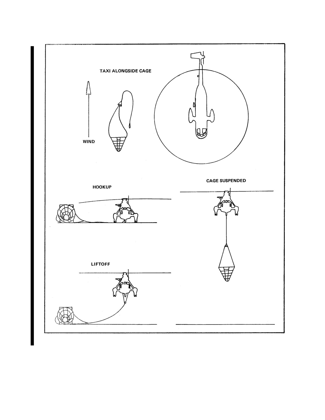
NAVAIR 01-230HLH-1
Figure 17-18. Ground Hookup and Liftoff
17-26
ORIGINAL
NAVAIR 01-230HLH-1
2. Groundcrew attaches the free end of the main lifting line
17.8.2.1.1 Ground Hookup.
to the cargo hook and ensures cargo hook is locked.
1. Position the recovery cage at the side of the
3. The helicopter slowly ascends from this position until
landing pad with the forward end pointing into the
the cage is lifted clear of the ground.
wind. Allow room for the helicopter to taxi to the left
side of the cage (Figure 17-18).
4. The helicopter can proceed to the recovery site at speeds
up to 90 KIAS. The crewman shall keep the cage under
observation throughout the flight.
17.8.2.2 Recovery. There are two methods used for Mk 4
WARNING
Mod 0 cage recovery of Mk 46 and Mk 50 torpedoes. The
drag method is employed for the recovery of Mk 46 torpedoes.
The scoop method is employed when high sea states prevent
the establishment of an effective drag and is the only method
Skirt stands
10 feet high and may fall
used for the recovery of Mk 50 torpedoes.
within rotor tip-path for hookup. Do not
engage/disengage rotor head when cage is
Proceed as follows:
within rotor tip-path. Pilot shall visually
ensure adequate cage-to-rotor clearance
1. Range personnel direct helicopter to recovery site.
during approach and hookup.
2. Establish visual contact with the torpedo.
2. Extend main lifting line to cargo hook and slip
the free end of the line onto cargo hook. Ensure
3. At discretion of the pilot, a Mk 25 marine marker may
that the cargo hook is locked.
be dropped to establish wind direction and to assist in pilot
orientation during recovery.
3. The groundcrew/aircrew directs the helicopter
up and to the right until the helicopter is
17.8.2.2.1 Drag Method. The drag method (Figure 17-
positioned directly over the cage.
19) is the preferred method for recovery of torpedo Mk 46 to
minimize the chances of weapon damage. Proceed as
4. The helicopter slowly ascends from this
follows:
position until the cage is lifted clear of the ground.
1. The aircraft assumes a 90-foot hover about 100 yards
5. The helicopter can proceed to the recovery site
downwind of the torpedo.
at speeds up to 90 KIAS. The crewman shall keep
the cage under observation throughout the flight.
2. The cage is lowered into the water.
17.8.2.1.2 Low-Hover Hookup. Low-hover
3. The aircraft assumes a slow creep toward the torpedo at
hookup is recommended for shipboard operations
5 to 8 knots groundspeed and at an altitude of 30 feet. The
where space is limited. Use of a PVC pipe stiffener at
crewman at the back door provides altitude/groundspeed
the top of the 30-foot main lifting line enables greater
corrections to keep the cage trailing smoothly and in the
helicopter standoff from the deck during low-hover
proper attitude. Figure 17-20 shows proper drag attitude of
hookup. Proceed as follows:
cage.
4. The crewman provides heading corrections to keep the
cage lined up to the torpedo.
WARNING
Note
Because of the phase-lag between helicopter input
1. Direct the helicopter to hover immediately to the
and cage response, more radical corrections
left of the cage.Avoid electric shock because of
become necessary as the cage closes on the torpedo
static discharge by deploying the rescue hoist to
if the lineup is off.
ground the helicopter prior to hookup.
17-27
ORIGINAL
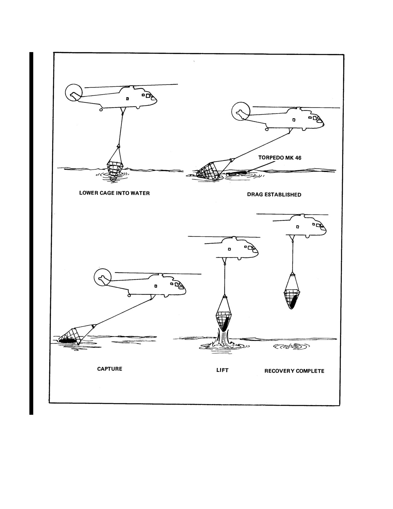
NAVAIR 01-230HLH-1
Figure 17-19. Recovery Sequence for Drag Method
17-28
ORIGINAL
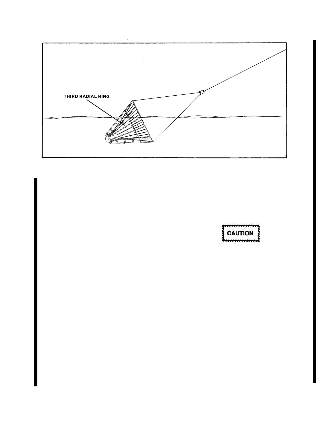
NAVAIR 01-230HLH-1
Figure 17-20. Drag Attitude
5. If the cage misses the torpedo, lift the cage out
17.8.2.2.2 Scoop Method. This method (Figure 17-21) is
of the water and repeat the approach and drag
used for the Mk 50. It should be used for the Mk 46 when in
sequence.
high sea state or when unit floats vertically.
6. After the torpedo has entered the cage and is
1. The aircraft is positioned in a hover at an altitude of 90
fully seated, the crewman directs the aircraft to
feet with the cage at a minimum of 10 feet lateral standoff
ascend slowly while maintaining forward speed to
from the weapon.
ensure that torpedo remains in the cage.
7. If the torpedo is not properly seated, a decision
as to whether the cage should be returned to the
If the Mk 50 flotation collar is damaged by the
water to wash the torpedo into one of the landing
cage, the weapon will sink. Therefore, the required
frame sections or returned as is must be made.
lateral standoff shall be maintained.
Considerations should be based upon the ease of
recovery because of sea state and pilot/crewman
2. Crewman directs the pilot to descend until the cage is
experience. To reseat the torpedo, the aircraft
approximately 10 feet under the surface of the water (use
comes to a hover and lowers cage into the water
markers on the 40-foot lines to determine depth).
until the torpedo is buoyed by the water. The
aircraft then ascends and lifts the cage from the
3. Using the lifting line as a guide for cage position, the
water.
crewman directs the pilot until the cage is directly under
the torpedo.
8. After the cage leaves the water, the crewman
verifies that the weapon is properly seated in the
4. The aircraft ascends to capture the torpedo. Ascent
cage.
should be slow to avoid torpedo hang-up/damage.
Note
5. The torpedo is checked for proper seating in the cage.
A properly seated torpedo is fully in the
cage and leaning against one of the two
6. Lifting lines and cage are checked for damage prior to
landing frame sections.
forward flight.
9. Inspect lifting lines and cage for damage prior
The helicopter can proceed to the reception site at speeds up to
to forward flight. If line or cage is damaged,
100 KIAS. The crewman shall keep the cage and torpedo
evaluate damage and determine if torpedo or
under observation throughout the flight.
emp ty cage can be safely returned to base.
17-29
ORIGINAL
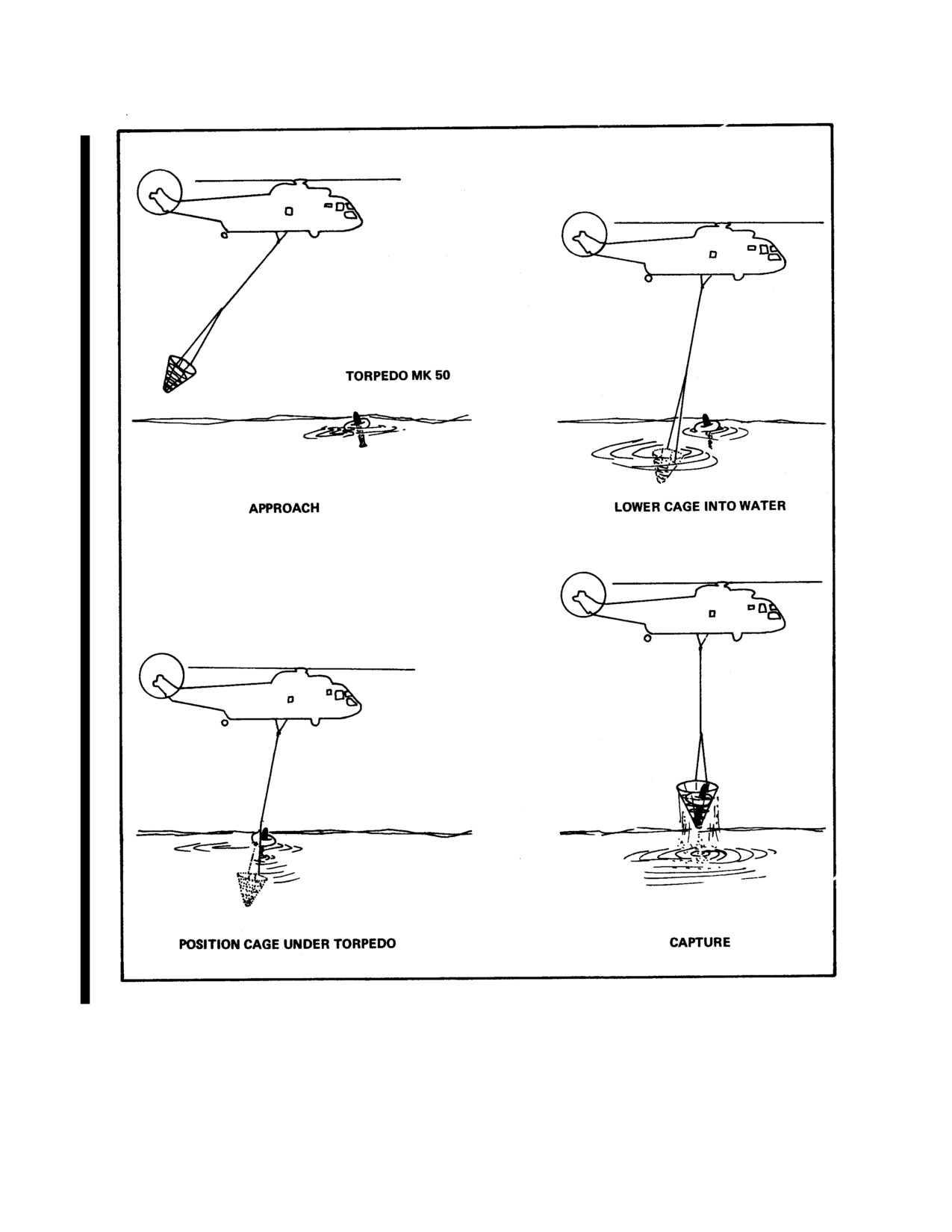
NAVAIR 01-230HLH-1
Figure 17-21. Recovery Sequence for Scoop Method
17-30
ORIGINAL
NAVAIR 01-230HLH-1
17.8.2.3 Reception/Delivery.
may instruct the pilot to jerk the torpedo to set the
snare once it is out of the water. Snared around the
1. Torpedoes can be delivered to either water or land.
tail just forward of the fins is the desired result.
2. Initiate normal external load approach. Approach
d. The small torpedoes are normally aerodynamically
the landing area into the wind making a slow, smooth
stable. Oscillations of torpedoes can be brought
transition to a hover.
under control by slowing down and commencing a
balanced turn. Transit speeds between 60 and 80
3. With touchdown point cleared, begin slow vertical
knots will keep oscillations to a minimum.
descent until the recovery cage is gently placed on
deck, or into the water.
e. Return the torpedo to a soft landing pad for
dropoff. The pilot at the controls passes verbal
4. The cage should be lowered into the water until the
control to the talker on final approach. Once
torpedo is buoyed by the water and the cage is
established in an 80-foot hover, the talker will direct
completely below the water. The aircraft then moves to
the pilot to descend until the torpedo is on the pad.
the side as directed by the crewmen so that the cage is
The helicopter should then be moved to one side in
no longer below the floating torpedo. Once the cage
order to release the snare pole from the cargo hook
is clear of the torpedo, raise the cage from the water the
without damaging the torpedo or the snare pole.
transition to forward flight.
17.8.2.4 Disconnecting Cage. Once the cage is on
the ground, the helicopter moves off to the side and
releases the lifting line.
Water delivery of the Mk 46 torpedo with
17.8.2.5 Daily Postflight Inspection. At the
snare pole attached will cause torpedo to sink.
conclusion of the day's operations, inspect the cage in
accordance with postflight inspection procedures.
17.8.2.7 Mk 30 Target Recovery by Snare Pole
17.8.2.6 Mk 46 Torpedo Recovery by Snare Pole
17.8.2.7.1 Description. An alternate method of Mk
30 target recovery is by snare pole. The snare pole and
17.8.2.6.1 Description. An alternate method of Mk
rigging procedures are listed in paragraph 17.2.4.2.
46 torpedo recovery method is by snare pole. The snare
pole and rigging procedures are similar to that of the
MQM/BQM 74 listed in paragraph 2.4.2.2.
17.8.2.6.2 Procedures.
1. Rigging
- reference MQM/BQM
74 rigging
The target Mk 30 snare pole shall only be used
procedures.
to recover Mk
30 targets modified with
stoppers.
2. Recovery
- reference MQM/BQM
74 recovery
procedures.
17.8.2.7.2 Recovery. Perform the following steps for
targets modified with only the "aft stopper", the snare
a. The lightweight torpedoes are recovered from a
pole must secure the target between the stopper and the
10-foot hover using a 20-foot snare pole.
target cg line. If the target is snared forward of the target
cg line, the target and snare pole shall be returned to the
b. Once established in the 10-foot hover, the HAC
water. The Mk 30 target shall not be carried as an external
passes verbal control to the talker. The talker
load using the snare pole when snared forward of the
positions the helicopter over the torpedo in position
target cg line, and is modified with only the aft stopper. In
so that the crewman handling the pole can snare the
this configuration, should the snare slip, the target could
torpedo.
be lost.
c. When the torpedo is snared, the crewman takes
Mk 30 targets modified with both a forward and an aft
tension on the snare and drops the pole. The talker
stopper, may be carried as an external load when the snare
keeps the pilot over the torpedo and talks the
pole has secured the target between the stoppers. If the
helicopter up. Once the torpedo is clear of the water,
snare has secured the target outside the stoppers, the
the talker informs the pilot where the snare is set. If
target and snare pole shall be returned to the water. The
the snare is not set around the tail of the torpedo, he
Mk 30 shall not be carried as an external load using the
17-31
ORIGINAL
NAVAIR 01-230HLH-1
snare pole when the snare has secured the target outside
the pole falls harmlessly when the cargo hook is released.
the stoppers. In this configuration, should the snare slip,
For the soft pad, lower the bagged towed array with the
the target could be lost. Proceed as follows:
grapnel. For water delivery to the TWRV, release the
towed array into the water.
1. The talker directs the pilot while the pole operator
controls the pole to get the hoop over the nose of the
17.8.3 MK
2 MOD 0/1 HELICOPTER WEAPON
target. It is recommended that the hoop be kept just
RECOVERY PROCEDURES
above the water, using line control, until close to the
target's nose.
17.8.3.1 In-Flight Profile
2. When the hoop is positioned within two feet of the
17.8.3.1.1 Hookup.
E.O.R. balloon, the pole operator pulls hard on the line
to break the tape and set the noose. Confirm noose is
1. The HWRS cage will normally be positioned to the
between the stoppers (for targets modified with both
right side of the helicopter, with the barrel pointing into
forward and aft stoppers) or between stopper and
the wind. Taxi next to the cage so as to split the cage in
target cg line (for targets modified with only the aft
half with blade tip as the reference for lineup. Stop
stopper).
when the right sponson is parallel to the cage.
WARNING
Pull the bridle retainer pins free BEFORE the
helicopter ascends to allow the pole to
Taxiing with the HWRS skirt inside the rotor
collapse down.
arc reduces rotor tip clearance and creates the
possibility of a cage strike resulting in
3. Ascend the helicopter slowly to lift the target from
equipment/aircraft damage and/or personnel
the water. Ensure the helicopter stays directly over or
injury.
abeam the target during the ascent to avoid pulling the
noose out of position. After the target is clear of the
2. The HWRS may also be positioned on the right side
water, confirm a secure grip on the target. If the target
of the helicopter with the barrel pointing at the
is hanging tail down, the target should be delivered to
helicopter. Taxiing next to the cage to split the
the TWRV to avoid landing damage to the target and
strongback of the HWRS with the blade tips will
soft pad.
provide an additional 4 to 5 feet of rotor tip to HWRS
clearance.
4. Recover the towed array using the standard
procedure for Mk 2 HWRS recovery. If the array
3. The helicopter may also be positioned in a low hover
cannot be recovered, the target should be delivered to
above and to the left of the cage, with aircrewman
the TWRV. If TWRV support is not available, the
directing the pilot for proper positioning.
target should be flown to a more sheltered area for
further towed array recovery attempts.
4. The aircrewman will then pay out the hoist cable, and
the groundcrewman will connect the hoist cable to the
flyback weight.
5. After the hoist is connected to the cage the
groundcrewman will attach the lifting line from the
cage to the cargo sling. The aircrewman will then direct
If the towed array cannot be recovered,
the pilot to lift the helicopter vertically until the cage is
transition to forward flight and proceed to
clear of the ground.
reception area. Delivery shall be made using a
slow descent from
200 feet AGL. Lower
6. As the cage leaves the ground, the aircrewmen will
approach altitudes may cause cable to contact
pay out the rescue hoist cable just enough to place the
the ground resulting in damage to cable and
total weight of the cage on the lifting line and notify the
target.
pilot when the weight of the cage is coming on the
aircraft. When clear of the ground he will inform the
17.8.2.7.3 Delivery. Deliver the target as directed by
pilot "Ready for forward flight".
the target representative to the TWRV or to the soft pad.
Set the target down, and then slide over and down so that
17-32
ORIGINAL
NAVAIR 01-230HLH-1
7. The pilot will note the indicated altitude shown on
the radar altimeter when the cage becomes airborne and
5. When the pilot loses sight of the torpedo he will
will set the altimeter bug on this reading for future
inform the aircrewman, who then directs the pilot to
reference. As the cage is lifted, the air-crewman will
position the cage directly over the unit.
check all attachments visually for security and freedom
from entanglements.
6. When the cage is directly over the unit, the crewman
will command, "Down, down, down", and the pilot will
17.8.3.1.2 In Flight.
commence a no-drift descent to 20 to 25 feet on the
radar altimeter. This capture maneuver should be made
1. Smoothly transition to desired airspeed not to exceed
by a positive, though not necessarily rapid, reduction in
limits. Adjust rescue hoist to ensure total weight of cage
collective
pitch.
Excessively
rapid
collective
is on the lifting line.
movements or erratic control must be avoided to
eliminate the possibility of breaking the weak link.
2. The helicopter will normally be vectored to the
recovery area. Altitude flown should be no lower than
7. The crewman must guide the pilot to stop drift and
500 feet above the surface.
allow the unit to seat properly in the barrel section of
the cage.
3. The aircrewman shall continually observe the flight
of the cage to ensure that no dangerous oscillations
8. When the unit is fully seated, the crewman directs
occur, that rearward movement of the cage does not
the pilot to raise the helicopter vertically, during which
bring the cage too close to the tail section of the
time he pays out the rescue hoist cable so that the total
helicopter and that the total weight of the cage remains
weight of the loaded cage is taken up on the lifting line.
on the lifting line.
The cage is then able to rotate under the influence to its
own center of gravity, adopting a slightly nosedown
4. Once above approximately 300 feet AGL, the cargo
attitude.
sling master switch should be placed in the SAFE
position and the rescue master switch turned OFF once
9. When the cage is clear of the water, the crewman
the aircrewman has trimmed the cage for forward flight.
immediately takes up excessive slack in the rescue hoist
cable and when satisfied that the unit is fully seated in
17.8.3.2 Recovery.
the cage, reports to the pilot that he is ready for forward
flight, or, if recovering a Mk 30 target, ready for towed
1. When visual contact has been established with the
transducer recovery.
torpedo, an approach will be executed into the wind. A
smoke may be placed upwind and slightly to the right
10.
If the unit is not adequately seated, the cage
side of the unit to aid the pilot in orientation during the
should be lowered back into the water until fully
recovery operation and to define wind direction.
submerged and an attempt made to reseat the unit.
2. The approach should be made from a downwind
17.8.3.3 Towed Transducer Recovery.
position with a long, straight in final.
1. With the cage suspended approximately 5 feet above
3. When indicated airspeed is below 40 knots, the pilot
the water, the helicopter is transitioned into slow
instructs the aircrewman to rotate the cage into the
forward flight of approximately
5 to
10 knots
capture position by raising the rescue hoist, allowing
groundspeed while the crewman lowers the grappling
the hoist to share the weight of the empty cage with the
hook. This maneuver will stream the transducer and
lifting line (Figure 17-10, Sheet 2).
cable out behind the target and place the grappling hook
alongside the target.
4. Approach to the unit should be accomplished slowly
and with the nose of the helicopter directly into the
2. The crewman will then snag the transducer cable
wind. Altitude on the radar altimeter should be
with the grappling hook. Moving the helicopter in a left
approximately
3 to
5 feet above the bug reference
oblique direction, so that relative movement is forward
altitude as established during the initial lift-off of the
and slightly left, will drag the grappling hook across the
cage. Aircrewman will keep the pilot informed of
streamed out cable enabling the hook to snag the cable.
altitude so as to preclude dragging the cage in the
water. The cage, when properly in capture position,
3. Once the cable is snagged, the crewman hauls up the
should have the (back) lower edge of the cage skirt
grappling hook and the transducer cable, being careful
approximately 2 feet off the water (slightly dragging in
not to damage it by dragging it over the door edge.
the water for smooth sea states and slightly higher for
sea states above 3 to 4).
17-33
ORIGINAL
NAVAIR 01-230HLH-1
Lower approach altitudes may cause cable to
4. As the cable is being brought up, the helicopter
contact ground resulting in damage to cable
continues a slow forward movement. The cable and
and target.
transducer should be stowed in the appropriate
container. Place container near the cargo door so that it
17.8.3.4 Transport to Reception Area.
can exit clearly if jettisoned.
1. Once recovery is comp lete, the helicopter may
proceed to the reception site.
2. Because of the heavy weight of the loaded cage,
WARNING
load oscillation may occur. Load oscillations can be
brought under control by decreasing airspeed and/or
applying "G" loading by simultaneously making a
smooth, coordinated turn either direction.
When hauling in grapnel and towed array
cable, personnel should stay clear of recovered
3. Utilization of cyclic mounted beeper trim to make
portion of rope or cable to avoid possibility of
angle of bank and airspeed changes when carrying the
entanglement during emergency or inadvertent
loaded cage is recommended to reduce the possibility
jettison.
of pilot-induced oscillations.
4. The crewman shall observe the cage and unit during
flight to report oscillations, and tend the rescue hoist to
When transiting with the towed transducer
ensure that the total weight of the loaded cage remains
streaming, the aerodynamic drag on the cable
on the lifting line.
will be applied to the aft section of the target.
If the cage is at a level attitude in flight, this
5. The master cargo sling switch should be placed in
will increase the possibility of the target
the SAFE position following recovery The hoist
sliding aft and departing the cage.
control switch shall be placed in the OFF position
once the crewman is satisfied as to the position of the
5. If a Mk
30 target is being recovered, MAD wire
cage. The hoist control switch may he placed in the
trailing from the transducer should be cut at the
CREW position to adjust cage position in flight as
transducer and discarded.
necessary.
WARNING
Failure to place the hoist control switch to
the off position may allow inadvertent hoist
If target safeguards fail, touching the MAD
actuation and possible loss of the torpedo.
wire may cause electric shock.
17.8.3.5 Delivery at the Reception.
6. Leave some slack in towed array cable to allow for
cage movement.
1. Mk 48 Torpedoes can be delivered to either the
water or to land.
7. Loop cable restrainer onto cable, cinch tight, and
attach snare hook to suitable deck ring (Figure 17-22).
2. A standard external load approach will be
made to the reception area. As the touchdown
8. Install cable protector onto the cable at door’s edge
point is approached, crewman will direct the pilot
(Figure 17-22).
in order to establish a stable hover at
approximately
60 feet above the ground. Care
Note
must be taken during the final stages of the
approach to prevent load Oscillations. Over
If the towed array cannot be recovered,
controlling or rapid deceleration will induce large
transition to forward flight and proceed to
oscillations.
reception area. Delivery shall be made using a
slow descent from approximately
200 feet.
17-34
ORIGINAL
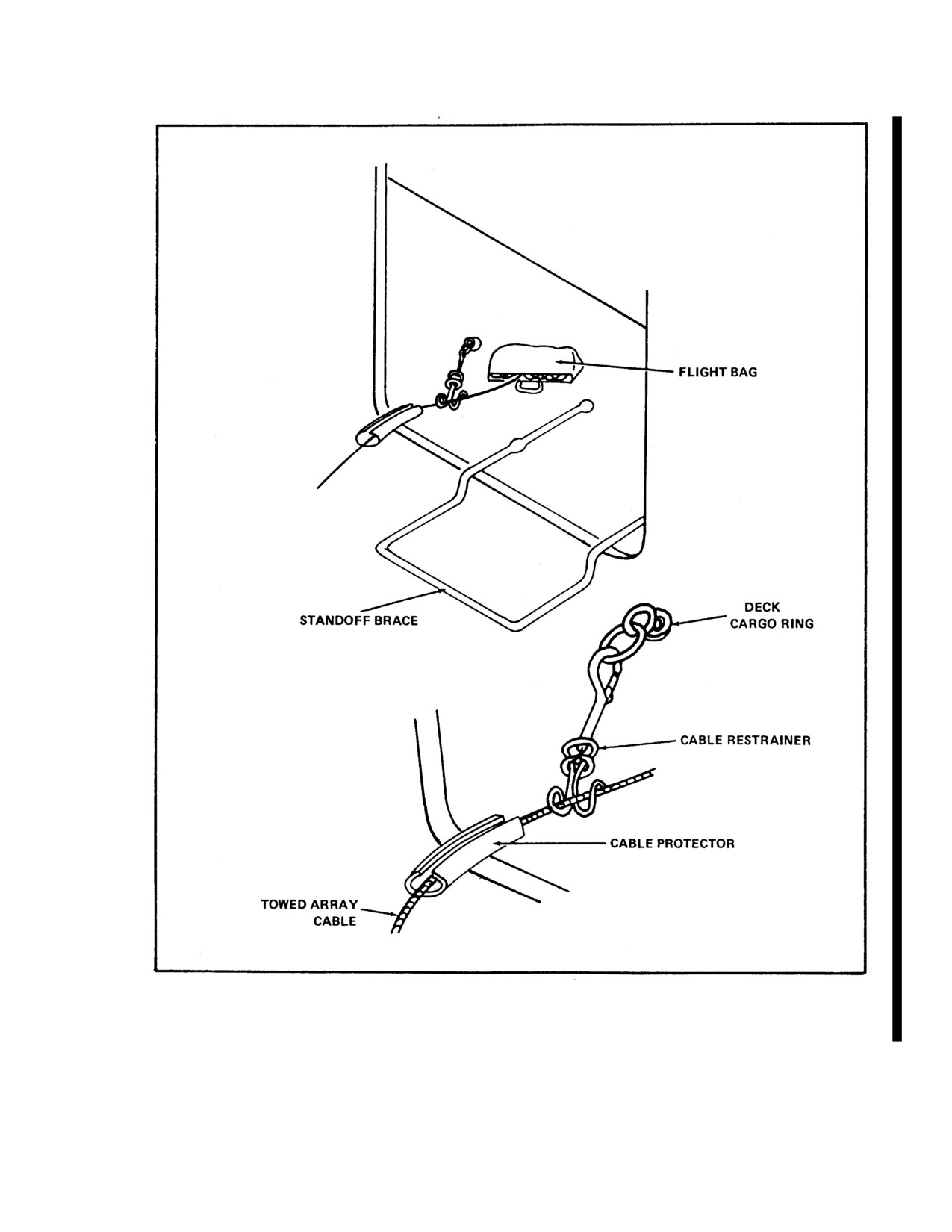
NAVAIR 01-230HLH-1
Figure 17-22. Towed Array Tie off
17-35
ORIGINAL
NAVAIR 01-230HLH-1
3. When the touchdown point is reached, the pilot
1. Method 1
will begin a slow, vertical descent until the
recovery cage is placed gently on the ground, or
a. Remove cable from helicopter after landing.
into the water.
Note
4. The cage should be lowered into the water until
fully submerged. The cage should then be rotated
Ensure there is sufficient slack in towed array cable
to a fully vertical position. When the cage is
to allow helicopter to land at safe distance from
vertical the helicopter should increase its hover
cage.
altitude by
10 feet, leaving the torpedo in the
water. The cage should then be rotated to the
2. Method 2
forward flight position. The helicopter is then
ready for forward flight.
a. Crewman lowers coiled or bagged cable using
grappling hook that may be hauled back into helicopter or
17.8.3.6 Disconnecting Cage. Proceed using
left on deck.
one of following methods:
17.8.4 TARGET DRONE RECOVERY SYSTEM
1.Method 1:
OPERATING PROCEDURES
a. Pilot release lifting line and lauds aircraft
17.8.4.1 Recovery Procedures. Over water retrieval of
alongside cage.
target drones is accomplished by having the target hooked or
snared by helicopter aircrewman utilizing one of the approved
retrieval devices as the helicopter is hovered over the target.
Once the target/drone has been hooked or snared, it becomes
an external load, and the same procedures and precautions will
Lifting line must be slack and not
apply.
over unit before release. Ensure the
60-pound weight is lowered and
17.8.4.2 Recovery Methods. During recovery, one air
placed on ground to avoid hazards to
crewman (the hooker) will be lying on the deck at the cargo
ground crew and equipment.
door in order to hook or snare the target. The other crewman
(the talker) will direct the pilot over the target at the proper
b. Disconnect rescue hoist from weight.
altitude to hook/snare to the target.
c. Reel in rescue hoist, being careful not to
damage the cable and hook.
2. Method 2:
WARNING
a. Pilot releases lifting line.
The helicopter shall not be vectored into an area
Note
where powered aerial targets are being operated.
Helicopters may be vectored into a target recovery
Pay out rescue hoist cable to allow ample
area when targets are known to be in recovery and
clearance between cage and helicopter.
descending via parachute. In such cases, the
helicopter shall remain upwind of the target until
b. Option
1 - Groundcrew disconnects rescue
the target has contacted the surface. Pilots shall
hoist hook from weight, and crewman reels it in.
avoid flying under low clouds with targets in
recovery when the exact location of the chuteborne
c. Option
2 - Crewman directs helicopter into
target is not known. In areas with low cloud
low hover, reels in hoist cable, and disconnects
ceilings, the helicopter shall not proceed into the
weak link from weight. Use of the optional snap
recovery area until the target is known to have
shackle (see Figure
2-10) facilitates release in
contacted the surface.
this case.
Prior to establishing the initial
40-foot hover for target
17.8.3.7 Offloading Towed Array Cable.
retrieval, it may be desirable to make a low, slow pass over the
target to evaluate its condition, i.e., chute attached, inverted,
When recovered vehicle is a target, the towed array
nose low or high, damage, etc. In the event the target's
cable is offloaded as follows (depending on which
presentation in the water is not such that a normal recovery
delivery method was employed).
can be effected, consideration may be given to deploying a
17-36
ORIGINAL
NAVAIR 01-230HLH-1
qualified swimmer in an attempt to return the target
the immediate vicinity. A range safety boat shall
to the normal recovery attitude. An alternate method
detach and recover the parachute.
of returning the drone to the normal recovery attitude
is boat recovery.
Note
Fifteen- and twenty-foot poles or snares may be
used up to and including sea state three. Only 20-
foot poles and snares may be used in sea state four.
WARNING
Target recoveries in sea state five are prohibited.
The hooker will be lying on the deck at the cargo door in order
Deploying a swimmer from the helicopter
to manipulate the recovery device. The talker shall pass the
is neither a normal nor an alternate target
prepared recovery device out the door, hand it to the crewman
recovery procedure. It may be used,
lying down, and connect the pole to the clevis on the loadline.
however, when all other attempts have
The talker should retain control of the tagline. When the talker
failed t o return the target to the normal
reports properly rigged and unit in sight, the pilot at controls -
recovery attitude. The helicopter aircraft
passes verbal control to the talker who directs the pilot over
commander shall be responsible for
the unit for hookup recovery, salt encrustation of the engines
making the decision to deploy a swimmer.
is a possibility.
All other available means of target
preparation for recovery shall be
exhausted prior to deployment of a
swimmer.
WARNING
WARNING
Because of low altitudes required for the recovery,
salt encrustation of the engines is a possibility.
Do not allow the aircraft to become too
low during the recovery evolution. A
wave could make the target/drone ride
upwards causing the pole to strike the
bottom, side, or hoist portion of the
The hook/snare method necessitates a low hover,
aircraft. It also could strike a crewman if
possibility as low as 5 feet. Care should be taken
he/she is still holding onto the pole.
not to get so low as to put the tailwheel in the water
or allow the drone to ride a wave and make contact
1. Prior to establishing a hover, a recovery checklist
with the helicopter.
shall be completed. It shall consist of but not be
limited to:
Pilot then commences a slow creep forward to close the target.
The hooker places the hook in target pickup loop or snares the
a. Shoulder harness - LOCKED.
target at a point approximately 1 foot forward of the leading
edge of the drone wings and then pulls on the cable to tighten
b. Cargo sling master switch - SLING.
the noose.
c. Speed selector - CHECKED.
When using the QD pole, the hooker then releases the hook
from the pole and brings the pole back inside the aircraft.
d. Cargo hook - LOWERED.
When using the fixed pole hook, the hooker releases the pole.
Once the target has been successfully snagged, the talker shall
place tension on the tagline. Once tension is established, the
hooker may release the pole.
WARNING
Recovery shall not be attempted if the
parachute is still attached or is located in
17-37
ORIGINAL
NAVAIR 01-230HLH-1
Note
An undamaged drone will generally present few problems
· The snare will come off the drone if
after initial oscillations have stopped. A drone that is
tension is not kept on the tagline while the
damaged, however, may never completely stabilize
and
weight of the drone comes on the
extreme caution must be exercised.
helicopter.
· The tagline is also used to retrieve the
pole assembly in case a rerig is needed.
The talker directs the helicopter up and over the
WARNING
target slowly to apply tension on the loadline. The
target is lifted clear of the water to allow for water
When recovering damaged drones or drones with
drainage (approximately 15 seconds).
non-faired flight control surfaces, safe flight
parameters may be significantly lower than normal.
Excessive oscillations may occur with high
airspeeds and bank angles. If oscillations do not
WARNING
decrease, consider jettisoning the drone.
Note
· Drone oscillations can be dampened by
· The helicopter must be centered directly
gradually reducing airspeed using beeper trim
over the drone prior to tension being
while maintaining balanced flight with ASE
applied to the loadline. This will eliminate
engaged and avoiding resistive inputs.
any sudden attitude change of the
helicopter because of an off-centered load
· If a drone cannot be stabilized in flight, either
pickup.
set it back in the water, or, if the drone recovery
boat is nearby, consideration should be given to
· Do not secure the tagline to the
dropping the drone next to the boat.
helicopter once the drone has been picked
up as it may be necessary to jettison the
Upon reaching cruise flight, consideration should be given to
drone during an emergency.
placing the cargo sling master switch to SAFE and adjusting
throttles as required. Unless otherwise required, 500 feet is a
· Do not attempt jettisoning the drone if
recommended cruise altitude.
it is flying too close to the rotor system.
Wait for the drone to come back
During transit an aircrewman shall continue to monitor the
downward and call for jettisoning when it
drone for stability. Prior to establishing a hover at
is below the aircraft. If jettison is done
homebase/ship to release drone, ensure cargo sling master
when drone is close to the rotor system, it
switch is in SLING.
can get entangled in the blades with
catastrophic consequences.
Using directional information from the crewman, initiate a
normal external load approach into the wind and make a slow,
smooth transition to a 60-foot hover. Once over the target
area, slowly and gently place the drone on the designated
surface. Release the cargo hook.
When the target is clear of the water, the
crewman shall visually inspect the overall
condition of the target. The pilot must be
aware of any unusual control surface
configuration or damage that may
When releasing the cargo hook, avoid dropping
adversely affect flight.
the target retrieval assembly on the drone.
When target is drained and ready for forward flight,
Stow cargo hook prior to landing/forward flight.
pilot commences a slow, smooth transition utilizing
beeper trim and climbs to
300 feet prior to
commencing a turn.
17-38
ORIGINAL
NAVAIR-01-230HLH-1
PART IX
Flightcrew Coordination
Chapter 18 - Flightcrew Coordination
69
ORIGINAL
NAVAIR-01-230HLH-1
This Page Left Blank Intentionally
70
ORIGINAL