UH-3H and UH-3H EXECUTIVE TRANSPORT. FLIGHT MANUAL (2000) - page 5
NAVAIR 01-230HLH-1
PROFILE
†2. Ignition switches - NORMAL.
†3.
(NON-ET) HEELS switch - ARM.
A CD
4.
Accessory drive/ground idle interlock/override test.
Advance No. 1 speed selector forward of the ground idle detent. Move the accessory
drive switch to FLIGHT and wait 7 seconds. Note that the shift does not occur (accessory
drive red light remains on). Move No. 1 speed selector to GRD IDLE (light remains on).
Move No. 2 speed selector forward of MIN GOV. Accessory drive light should
extinguish
(after approximately
6 to
7 seconds). Move accessory drive switch to
ACCESS DR and both speed selectors to SHUTOFF. When the accessory drive light
illuminates, move the accessory drive switch back to FLIGHT. The accessory drive light
will remain on. Move the override switch to OVRD. The light should extinguish in
approximately 6 to 7 seconds. Return the accessory drive switch to ACCESS DR and
turn the override switch off.
†5.
Accessory drive switch - FORWARD AND LIGHT ON.
†6.
Manual throttles and speed selectors - FREE AND OFF.
†7.
Emergency start switches - OFF.
†8.
Rotor brake - CHECKED (320 PSI MINIMUM).
A
†9.
Fire warning caution and advisory panels.
a. Press lamp test button. All caution and advisory lights should go o n.
b. Press either PRESS-TO-RESET master caution light capsule; both capsules should go
off.
c. Slightly turn the pilot flight instrument lights rheostat. Check that all caution and
advisory lights dim, then turn pilot flight instrument lights rheostat off.
d. Fire warning system.
Move the test switch to FIRE TEST. The two warning lights on the pilot instrument
panel and all four lights in the two FIRE EMERGENCY SHUTOFF SELECTOR
HANDLES should go on.
†10.
Fuel panel/ quantity - CHECKED.
Note
Be sure fuel quantity drops to zero and returns to initial
quantity in about 10 seconds.
† 11. NO. 1 Firewall valve - OPEN.
†12. Battery switch - ON.
†13. Lights-AS REQUIRED.
A C
14. No. 1 engine alternate start.
a. Start mode switch - MANUAL.
10-11
ORIGINAL
NAVAIR 01-230HLH-1
PROFILE
b.
Engage starter normally and advance speed selector to GRD IDLE. Engine
should accelerate normally to ground idle T5 within limits. During the transition to
ground idle, depress the ENG ST button and note that engine accelerates at a slower
rate. Release the ENG ST button and note that engine continues to accelerate
normally to ground idle.
c. Pull down on speed selector when Ng reaches 45 percent and note starter dropout.
d. After starter dropout, a decrease of 20 to 40 °C T5 will be noticed to indicate normal
start bleed valve operation.
e. All gauges - Checked.
f. Boost pumps - OFF.
g. No. 1 engine T-handle shutdown - Pull No. 1 engine fuel valve circuit breaker. Shut
down No. 1 engine from ground idle using fire emergency shutoff selector (T-
handle). Allow engine to operate for at least 1 minute. Reset No. 1 engine fuel valve
circuit breaker. Time required from resetting circuit breaker until first definite drop
in Ng should be less than 1 minute. When flameout occurs, immediately place the
speed selector to shutoff position and reset T-handle to prevent fuel control from
running dry. Begin substep “h.” below at this time.
h. No. 1 engine coastdown time - The engine shall be stabilized at ground idle before
doing this check. Start the clock at the first positive drop of Ng if T-handle
shutdown has been made, or at the moment of placing the speed selector in shutoff
in a normal shut-down. Engine coastdown time should not be less than 40 seconds
to the moment the compressor rotor is stopped, as visually observed at the engine
bellmouth. Listen for any unusual noises. After the compressor rotor has stopped, a
small amount of kickback in the opposite direction should be noted.
A C
15.
No. 1 engine normal start.
a. Start mode switch - NORMAL.
b. Record time to light-off (should be less than 10 seconds).
c. Record time from light-off to ground idle (Figure 10-2).
d. Record Ng at starter drop out.
e. Record maximum T5.
f. At ground idle, record T5, Ng, and OAT (Figure 10-2).
OAT (°C)
-15
-10
-5
0
5
10
15
20
25
30
35
*MAX TIME LIGHT - OFF
29
27
25
23
21
20
20
21
22
24
25
GRD IDLE
GRD IDLE Ng + 3%
52.5
53.0
53.5
54.0
54.5
55.0
56.0
56.5
57.0
57.5
58.0
MAX T5 °C
450
460
475
485
500
510
525
535
550
565
575
** ENG OIL PRESSURE
8 to 20 PSI
10 to 24 PSI
* Add 1 second for each 1,000 feet pressure altitude above sea level.
** After oil temperature has stabilized.
Figure 10-2. Light-Off Time - Ground Idle
10-12
ORIGINAL
NAVAIR 01-230HLH-1
PROFILE
†16. No. 1 Engine - START
†17. All gauges - CHECKED.
†18. Boost pumps - OFF.
†19. No. 1 speed selector - 104-percent Nf.
†20. Generators - ON.
†21. (ET) APU - SECURE :
a. APU generator switch - OFF.
b. APU ON switch - OFF.
†22.
No. 1 overspeed system - CHECK.
†23.
External power - DISCONNECT.
†24.
Servo sensor - CHECKED.
†25.
Area clear - CHECKED.
†26.
Blade fold safety, master, and blades fold/spread switches - OPEN, ON, SPREAD.
A C
27.
Bladefold interlock test: Open the No.
2 firewall fuel valve and attempt a
bladefold/spread (IAW NATOPS Chapter 7.). With the No. 2 firewall valve OPEN, the
interlock feature within the bladefold system will interrupt (if in mid-bladefold/spread) or
make blade folding/spreading impossible. If blades begin to fold, reverse procedure to
return MRH to formerly fully folded or fully spread condition, abort functional check and
troubleshoot IAW applicable MIMs. If check is successful, ensure the following:
a. Rotor brake lever - ON.
b. No. 2 engine fuel firewall valve - CLOSED.
28.
Complete blade spread, fold, then spread cycles in accordance with NATOPS Pilot's
AB D
Pocket Checklist to be sure blade fold system is operating properly.
†29.
Blade fold safety, master, and blades fold/spread switches - CLOSED, OFF, OFF.
†30.
Lights and servo pressure - CHECKED.
31.
Electrical system checks.
A
With the No. 1 engine running, do not secure all electrical power to the
helicopter with the blades folded, to preclude pressurizing the primary
servo.
Note
Make sure all unnecessary electrical equipment is turned off before doing
the following check.
a. With No. 1 engine in accessory drive and operation at 104-percent Nf with the boost
pumps on, turn off the No. 1 generator. The No. 1 generator caution light and both No. 2
boost pump lights should go on. Turn No. 1 generator on and observe lights go off.
10-13
ORIGINAL
NAVAIR 01-230HLH-1
b. Turn off No. 2 generator. The No. 2 generator and No. 2 boost pump
lights should go on. Turn No. 2 generator on and observe lights go off.
c. With the battery switch on, turn both generators off and note that both generator and
transformer-rectifier caution lights go on. Also, be sure the pilot VGI does not go off
until both generators are turned off. Place both generator switches ON.
d. With No. 1 engine in accessory drive, the tail takeoff warning light will go on at 98.5-
percent Nf.
†32. Compass system and IFF console switches - AS REQUIRED.
†33. RAD ALT, BAR ALT, RAWS - TEST, SET, CHECKED.
10.2.5 Systems Checks
†1.
(NON-ET) Hoist, hoist ICS, and HEELS
- CHECKED. Have the air crewmen
simultaneously press and release GEN 1 and GEN 2 switches on PMG control box. All
light tubes will illuminate while both switches are pressed. Press and release GEN 1 and
GEN 2 switches individually. Light tubes will remain off when each switch is pressed.
†2. Flotation gear - CHECKED.
†3. Head check - AS REQUIRED.
AB D
†4. Servo check - Check freedom of movement of all controls through full travel.
a.
Primary servos - Turn off the primary servos; there should be no jump in the controls.
The primary pressure gauge should go to zero and the primary servo pressure caution
light should go on. Actuate the cyclic stick from one extreme to the other in lateral, then
fore-and-aft directions, checking freedom of movement. Turn the primary flight control
servo switch on. The primary servo pressure caution light should go off and pressure
should read normal.
b.
Auxiliary servos
- Turn off the auxiliary servo and note zero pressure and caution
capsule lighting. Collective should be at midposition (approximately 4 inches off bottom
stop) and rotary rudder pedals positioned right pedal slightly forward of left when
making this check. The cyclic should not jump more than one-eighth, and no more than
one-sixteenth inch jump in rotary rudder pedals or collective should be noticed. With the
auxiliary servo off, move the cyclic stick from one extreme to the other in lateral, then
fore-and-aft directions, checking freedom of movement. Full actuation of cyclic in any
direction should be possible with no evidence of binding.
Press left rotary rudder pedal and lift collective. Left rotary rudder pedal should move
aft about 2 inches. Press right rotary rudder pedal and lower collective. Right rotary
rudder pedal should move aft about 2 inches. These characteristics are due to the
collective to yaw coupling through the auxiliary servos that are no longer irreversible
with auxiliary hydraulic pressure off. In addition, the negative force gradient installation
in the rotary rudder control system will cause any movement of the pedals from neutral
to be aided by a spring force proportional to the pedal displacement. Movement of the
rotary rudder pedals toward neutral will be opposed by the same spring force. Turn the
auxiliary servo switch on; auxiliary servo hydraulic pressure should indicate normal and
the caution light should go off.
c.
Stick trim release - With the beeper trim switch on, press the TRIM RELEASE button
10-14
ORIGINAL
NAVAIR 01-230HLH-1
PROFILE
on the pilot cyclic stick; the stick should move freely. Release the button and displace
the stick fore, aft, left, and then right. When released in each case, it should return to the
original position. Check the copilot TRIM RELEASE button in the same manner.
d. Beeper trim - Check that the cyclic stick moves smoothly in the proper direction by
pressing the beeper trim buttons on the pilot and copilot sticks in the fore, aft, left, and
right positions.
e. Collective friction
- Turn the collective friction nut to full increase. It should be
possible to move the collective. Turn the collective friction nut to an intermediate
point between full increase and off; the collective stick should move smoothly. The
force required should be proportional to the amount of friction applied. Turn the
collective friction nut to full off; there should be no evidence of friction applied to the
collective stick.
AB D
5.
ASE.
WARNING
Use of the HARDOVER switches on the ASE CHANNEL MONITOR
panel shall not be made with the blades folded, to preclude damage to the
rotary wing and control linkages. In addition, ASE hardovers shall not be
induced in flight. Repeated use of the HARDOVER switches may cause
ASE valve failure. If an induced hardover should cause an ASE valve
failure, a hydraulic hardover may occur and can be eliminated only by
securing of the auxiliary servo hydraulic system.
Note
All ASE ground checks should be made with the rotary wing blades spread,
rotary wing head disengaged, and the No. 1 engine running in accessory
drive at 104-percent Nf. The hover indicators should be in the A mode and
the METER SELECTOR switch in ASE.
a. CHAN MON TEST switch - TEST.
b. HARDOVER switches - FORWARD.
Note
This check may be done with the ASE engaged or disengaged.
(1) Hover indicator
(NON-ET) or Flight director indicator
(ET) - Monitor
that
horizontal bar is up (pitch channel), vertical bar is left (roll channel), vertical
arrow is up (collective channel), and horizontal arrow is left (yaw channel).
(2) TRIM RELEASE button - Depress and move the cyclic stick from stop to stop.
Control movement aft and right should be slower than movement forward and
left; however, it should be possible to move the cyclic from stop to stop in 1
second. Push the collective pitch lever down. A force of 3 to 5 pounds will be
required to move the collective. Push the right rotary rudder pedal to its extreme
forward position and release. The right pedal will move aft again and a force of
11 to 25 pounds will be required to prevent movement.
10-15
ORIGINAL
NAVAIR 01-230HLH-1
PROFILE
c.
HARDOVER switches - AFT.
(1) Hover indicator (NON-ET) or Flight director indicator (ET) - Monitor that
horizontal bar is down (pitch channel), vertical bar is right (roll channel),
vertical arrow is down (collective channel), and horizontal arrow is right
(yaw channel).
(2) TRIM RELEASE button - Depress and move the cyclic stick from stop to
stop. Control movement forward and left should be slower than movement
aft and right; however, it should be possible to move the cyclic from stop
to stop in 1 second. Raise the collective pitch lever. A force of 3 to 5 pounds
will be required to move the collective. Push left rotary rudder pedal to its
extreme forward position and release. The left pedal will move aft again
and a force of 11 to 25 pounds will be required to prevent movement.
Note
Any resistance, seizing of controls, or excessive pedal force
during the hardover checks indicates improper adjustment
of control linkage or auxiliary servo.
d.
Channel disengage switches - OFF.
Hover indicators (NON-ET) or Flight director indicator (ET)
- Check that all
indicators are centered.
e.
Channel disengage switches - ON.
f.
CHAN MON TEST switch
- Turn off and check hover indicator or flight
director(ET) for normal indications.
g.
All HARDOVER switches - OFF.
h.
Collective clutch - Engage BAR ALT. Raise the collective to its full-up position.
Note that the vertical pointer on the hover indicator
(NON-ET) or the flight
director (ET) moves to its full-down position. Press and release the BAR REL
button on collective. The arrow should center within ±3/4 division. Lower the
collective to the full-down position (the vertical pointer should move to the full-
up position). Press and release BAR REL button. The vertical pointer should
center with ±3/4 divisions.
10-16
ORIGINAL
NAVAIR 01-230HLH-1
PROFILE
†6.
Normal ASE check.
a. CG trim
- Engage ASE and place the cyclic in approximately neutral position. Turn
CG TRIM knob and note that the pitch bar on the hover indicator (NON-ET) or flight
director (ET) moves full travel in each extreme and properly follows the movement
of the CG TRIM knob. When knob is moved to the F position, the pitch bar moves up.
When the knob is moved to the A position, the pitch bar moves down.
b. Yaw proportional band
- Raise collective to midposition and position left pedal
slightly ahead of right. Slowly turn YAW TRIM knob. At initial movement of pedals,
note point on hover indicator (NON-ET) or flight (ET) at which pedals start to move.
This should be between 3/4 and 1-1/2 divisions from center. Press either pedal switch
and observe that yaw piper returns to center. Repeat for opposite rudder and note that
the breakout should be approximately equal in both directions.
c. Yaw cutout switches - Start rotary rudder pedals moving by use of the YAW TRIM
knob. Pressing either pedal switch should disengage the yaw system, causing rotary
rudder pedal motion to cease and the yaw arrow in the hover indicator to center.
Check in the opposite direction. This checks operation of the yaw pedal switches.
d. Pitch and roll response - Move the cyclic forward, aft, left, and right. Note that pitch
and roll bars on the hover indicator follow movement of the cyclic stick. Displace
cyclic stick forward and to extreme left, then return cyclic to neutral position. Note
that the roll bar lags the pitch bar by approximately 1 second. Repeat aft and to right.
This checks proper operation of the dual-channel lag amplifier.
A
7.
(NON-ET)Coupler/Doppler check (NATOPS) .
a. Cyclic beeping
- With the Doppler off, the hover indicator in the A mode, and the
CYC CPLR switch in the DOPP position, engage ASE and place cyclic in the neutral
position with the roll bar centered. Center pitch bar with the CG TRIM knob. Engage
the coupler and slowly increase the SPEED set knob until the cyclic starts to beep
forward; this should occur when the pitch bar is within 2 ±l/2 divisions up. Repeat the
check decreasing the speed set; the cyclic should beep aft when the pitch bar is within
2 ±l/2 divisions down. Repeat the above check, displacing the DRIFT set knob left
and then right. In each case, the cyclic should beep in the proper direction when the
roll bar has displaced 2 ±l/2 divisions.
b. Altitude tracking.
(1) Hover indicators - A MODE.
(2) Radar altimeters - ON AND RELIABLE.
(3) Altitude coupler switch - RAD ALT.
(4) Doppler - STBY.
(5) ALTITUDE set knob - ZERO.
(6) ASE - DISENGAGE.
10-17
ORIGINAL
NAVAIR 01-230HLH-1
PROFILE
(7) Radar altimeter PRESS-TO-TEST and hold. Radar altimeter indicator should read
100 ±l5 feet and hover indicator vertical pointer should go full down.
(8) ALTITUDE set knob - Turn to null vertical pointer. Altitude indicated by set knob
should agree with RAD ALT indicator within ±5 feet.
(9) Radar altimeter- RELEASE PRESS-TO-SET.
c.
Altitude channel tests.
(1) Collective pitch lever - FRICTION OFF.
(2) ALTITUDE set knob - 100 FEET.
(3) METER SELECTOR switch - ASE.
(4) SPEED set knob - ZERO.
(5) ASE and CPLR buttons - Depress; check for a collective rise. While the collective
is rising, check that the vertical pointer on the hover indicator does not oscillate or
exceed one division, indicating collective friction problems. Allow the collective
to rise to the full-up stop and note that the vertical pointer on the hover indicator
now rises full up. Release ASE, lower the collective, and repeat this step for VA.
At the completion of the VA check, do not release ASE, be sure collective pitch
lever is full up, and go to step (6).
(6) CPLR and BAR REL buttons - DEPRESS. Check that the vertical pointer nulls
±3/4 division within 8 seconds.
(7) ALTITUDE set knob - ZERO.
(8) SPEED set knob - 100 KNOTS.
(9) Altitude coupler switch - RAD ALT.
(10) CPLR button
- Depress; check for collective drop as in step (5), only now
pointer will go down. At completion of VA check, do not release ASE. Be sure
collective pitch lever is full down and go to step (11).
(11) CPLR and BAR REL - Depress. Check that the vertical pointer nulls ±3/4
division within 8 seconds.
(12) BAR OFF button - Depress.
d.
(NON-ET) IVSC test.
(1) METER SELECTOR switch - CPLR.
(2) Altitude coupler switch - RAD ALT.
(3) SPEED and DRIFT set knobs - Center pitch and roll bars.
(4) Doppler
- TEST. Copilot sets his hover indicator to D mode and checks that
Doppler signals are correct (1 to 1-1/2 divisions up and right, vertical pointer 1-1/2
to 2-1/2 divisions up.) Pilot checks the pitch and roll bars of his hover indicator
moving slowly up and right (three divisions in about 22 seconds.)
10-18
ORIGINAL
NAVAIR 01-230HLH-1
PROFILE
(5) Doppler - OFF, THEN STBY. Pitch and roll bars on pilot hover indicator should
slowly return to center.
e.
(NON-ET) Cyclic channel test.
(1) CYC CPLR switch - DOPP.
(2) Doppler - TEST.
(3) Copilot hover indicators - Should read as in step d (5). Pilot hover indicator - Pitch
bar 2-1/2 to 3 divisions up, roll bar 3-1/2 ±1/2 divisions right.
(4) Groundspeed indicator - 17 ±2 knots and 225° ±5°.
(5) SPEED and DRIFT set knobs - Null pitch and roll bars on pilot hover indicator.
Drift knob should be at or near the I and SPEED knob about -15 knots.
(6) CPLR button - Depress. Pilot hover indicator vertical pointer should move 3 to 3-
1/2 divisions down. Null SPEED and DRIFT knobs. Cyclic should now beep
forward and right.
(7) ALTITUDE set knob - Null vertical pointer on pilot hover indicator. Knob should
indicate 35 to 40 feet. Reset knob to zero.
(8) Doppler - OFF, THEN STBY.
f.
(NON-ET) VA/Doppler Vh, Vd, Vz nulls.
(1) Doppler - STBY.
(2) METER SELECTOR knob - CPLR.
(3) Hover indicator - A MODE.
(4) CYCL CPLR switch - OFF.
(5) ASE - ENGAGED.
(6) CPLR and BAR ALT - DISENGAGE.
(7) Hover indicator vertical pointer - 1±1/4 divisions up.
(8) SPEED set knobs - Center horizontal bar (±2 knots on knob).
(9) DRIFT set knob - Center vertical bar (between D and T on knob).
(10) CPLR - ENGAGED.
(11) ALT CPLR switch - RAD ALT.
(12) Hover indicator vertical pointer -0±1/4 divisions.
(13) CYCL CPLR - DOPP.
10-19
ORIGINAL
NAVAIR 01-230HLH-1
PROFILE
g.
(NON-ET) Hover trim test.
(1) CPLR button - DEPRESS.
(2) HOV TRIM button - DEPRESS; note ASE control panel light on.
(3) Crewman at the aft station - Report red light on.
(4) Pilot - Relay information to the crewman to enable him to center the bars on the
hover indicator with his PITCH and ROLL bias knobs.
(5) Crewman - Move the control stick forward.
(6) Pilot - Check that the horizontal bar moves up and that the cyclic stick beeps
forward.
(7) Repeat steps (5) and (6) for back, right, and left.
(8) CYC CPLR switch - OFF, THEN ON. Check that the ASE control panel light
goes OFF. Crewman reports the red light OFF in the aft station.
(9) METER SELECTOR switch - ASE.
(10) ASE - RELEASE.
(11) Hover indicators - AS REQUIRED.
(12) ALTITUDE set knob - 40 FEET.
A
†8.
TACNAV - Check for proper operation.
A
9.
(NON-ET) Rescue hoist.
After the crewman has completed a hoist check, place the rescue hoist master switch to
PILOT and operate the hoist down and up, using the hoist control switch on the
collective. Before operating the hoist to full-up position from the cockpit, make certain
the crewman checks the up-limit switch for proper operation to prevent undue stress.
Return the switch to CREW.
10.2.6 No. 2 Engine Checks
A C
1. No. 2 engine start interlocks.
a. Auxiliary servo - Turn off auxiliary servo and place No. 2 engine ignition switch to
TEST. No clicking should be heard.
b. Emergency start switch - Place No. 2 engine emergency start switch ON and the No. 2
engine ignition switch to TEST. Clicking should be heard. Return emergency start
switch to OFF.
c. Auxiliary servo and safety valve
- Turn on auxiliary servo, open safety valve, and
place No. 2 engine ignition switch to TEST. No clicking should be heard. Close the
safety valve.
10-20
ORIGINAL
NAVAIR 01-230HLH-1
PROFILE
Note
The other two interlocks, pylon spread and blade spread,
can be assumed operative if the light indications on the
blade fold panel are proper.
†2.
Ignition switch - NORMAL.
†3.
Start mode switch - NORMAL.
†4.
Fuel Panel - NO. 2 FIREWALL VALVE OPEN.
†5.
Rotor brake - ON.
†6.
Anti-ice - AS REQUIRED.
A C
7.
No. 2 engine alternate start.
a. Start mode switch - MANUAL.
b. Engage starter normally and advance speed selector to GRD IDLE. Engine should
accelerate normally to ground idle T5 within limits. During the transition to ground
idle, depress the ENG ST button and note that engine accelerates at a slower rate.
Release the ENG ST button and note that engine continues to accelerate normally to
ground idle.
c. Pull down on speed selector when Ng reaches 45 percent and note starter dropout.
g. After starter dropout, a decrease of 20 to 40 °C T5 will be noticed to indicate normal
start bleed valve operation.
h. All gauges - Checked.
i. Boost pumps - OFF.
g. No. 2 engine T-handle shutdown - Pull No. 1 engine fuel valve circuit breaker. Shut
down No. 1 engine from ground idle using fire emergency shutoff selector (T-
handle). Allow engine to operate for at least 1 minute. Reset No. 1 engine fuel valve
circuit breaker. Time required from resetting circuit breaker until first definite drop
in Ng should be less than 1 minute. When flameout occurs, immediately place the
speed selector to shutoff position and reset T-handle to prevent fuel control from
running dry. Begin substep “h” at this time.
h. No. 2 engine coastdown time - The engine shall be stabilized at ground idle before
doing this check. Start the clock at the first positive drop of Ng if T-handle
shutdown has been made, or at the moment of placing the speed selector in shutoff
in a normal shutdown . Engine coastdown time should not be less than 40 seconds to
the moment the compressor rotor is stopped, as visually observed at the engine
bellmouth. Listen for any unusual noises. After the compressor rotor has stopped, a
small amount of kickback in the opposite direction should be noted.
8.
No. 2 engine normal start.
A C
a. Start mode switch - NORMAL
b. Record time to light off (should be less than 10 seconds).
10-21
ORIGINAL
NAVAIR 01-230HLH-1
PROFILE
b. Record time from light-off to ground idle ( refer to Figure 10-2 from No. 1 engine
normal start).
c. Record Ng at starter drop out.
d. Record maximum T5.
e. At ground idle, record T5, Ng, and OAT (refer to prior Figure 10-2).
†9.
No. 2 Engine - START.
†10.
All gauges - CHECKED.
†11.
Boost pumps - OFF.
†12.
ASE - OFF.
†13.
Shoulder harness (all stations) - LOCKED.
†14.
Collective - MINIMUM.
†15.
Area clear and engage signal - CHECKED.
†16.
Rotor engagement
- Engage rotors in accordance with NATOPS Flight Manual and
NATOPS Pilot's Pocket Checklist.
†17.
Cyclic stick - Check response at 100 percent.
Prior to taxiing, actuate the cyclic stick a slight amount in all directions and check for
proper response by observing the tip-path plane of the rotary wing blades.
If flight controls do not respond correctly, shut down by
retarding No. 2 speed selector to SHUTOFF and apply the
rotor brake.
A C
†18. No. 2 engine maximum Nf at flat pitch. With collective full down and the No. 2 speed
selector full forward, the No. 2 Nf should be 108 to 112.5 percent.
Note
With Nr above 104 percent, No. 1 engine will sense an
overspeed condition and drop to 60- to 70-percent Nf.
†19. No. 1 speed selector - GRD IDLE.
10-22
ORIGINAL
NAVAIR 01-230HLH-1
PROFILE
If the generator caution lights and/or tail takeoff caution
light go on when the No. 1 engine is retarded to ground idle,
do not switch from ACCESS DR to FLIGHT. Immediately
return the No. 1 speed selector to 104-percent Nf and go
through a normal shutdown. This condition indicates a
possible failure of the tail takeoff freewheeling unit. Under
these conditions, loss of No. 1 engine will result in loss of
all accessories.
†20.
Accessory drive switch - AFT.
a. Accessory drive and blade panel lights - OFF.
†21.
No. 1 engine maximum Nf at flat pitch.
A C
With the collective full down and the No. 1 speed selector full forward, retard the No. 2
speed selector until Nf’s, are split and No. 2 torque is zero. No. 1 Nf should be 108 to
112.5 percent.
22.
Tail takeoff warning system.
A C
With the accessory drive switch at FLIGHT, reduce the rotor rpm and note that the tail
takeoff warning light goes on about 94- to 98-percent Nr.
23.
Generators.
A
a. Underfrequency dropout
- Reduce Nr slowly to 95 percent and wait 3 seconds.
Continue reducing Nr 1 percent at a time, waiting 3 seconds after each reduction until
the generators drop off the line. When the generators drop out, the respective caution
lights should go on.
b. Slowly increase Nr. The generators should cut in within 2 percent of the cutout value.
V/M/T
24. Vibrations (Ground).
WARNING
After tail rotor or high speed shaft vibes run ensure all tail pylon and high
speed shaft tachometers, accelerometers and cables are removed.
a. Highspeed shaft vibrations - set Nf / Nr at 100% (103% Nf / Nr for ET) and collect
highspeed shaft vibrations data IAW applicable MIMS.
10-23
ORIGINAL
NAVAIR 01-230HLH-1
PROFILE
Note
Both engines shall be operated at 100% Nr (103% Nf /Nr for ET) with the
torques matched during engine high speed shaft check for either engines.
b.
TRH vibrations/ smoothing - set Nf / Nr at 100% (103% Nf / Nr for ET) and collect
tail rotor head smoothing data IAW applicable MIMS.
c.
MRH smoothing - set Nf/Nr at 100% (103% Nf/Nr for ET) and collect Main Rotor
Head smoothing data IAW applicable MIMS.
d.
Once the MRH smoothing is within acceptable limits on the ground, with Nf/Nr
matched at
100% (103% Nf / Nr for ET), collect airframes vibration data
IAW
applicable MIMS.
Note
Best track and balance results will be obtained nose into the wind, speed
less then 10kts and gusts of less then 15kts.
†25.
Nf and Nr- 104 PERCENT.
†26.
NAVAIDs - CHECKED.
†27.
Landing gear lockpins/safety pins - SIGHTED.
†28.
HEEDS bottles - ON.
†29.
VLEA control dial - SET.
10.2.7 Taxi
†1. Area - CLEAR.
†2. Lights - AS REQUIRED.
†3. Chocks/tiedowns - REMOVED.
†4. Tailwheel locking handle - UNLOCKED.
†5. Shoulder harness (all stations) - LOCKED.
†6. Parking brake - OFF.
†7. Brakes - CHECKED.
†8. Tailwheel - CHECKED.
9.
Rotary rudder response - CHECK.
AB DE
†10. RMI/BDHI wet compass - CHECK.
†11. Turn-and-slip indicator - CHECK.
10.2.8 Pretakeoff Checks
A C
1. Engine acceleration/deceleration checks.
10-24
ORIGINAL
NAVAIR 01-230HLH-1
PROFILE
a.
Set Nr and both Nf's to 96 percent. Retard No. 1 speed selector until zero torque is
achieved. Slowly advance the No. 1 speed selector until the first indication of torque and
stabilize. Rapidly advance the No. 1 speed selector full forward. Check that No. 1 Ng and T5
increase smoothly with no indications of compressor stall. At No. 1 Ng peak, retard the No. 1
speed selector to GRD IDLE. Cheek that No. 1 engine decelerates smoothly.
Be alert for possible stall on acceleration or deceleration.
This would be shown by excessive rumbling or explosive
noises, and possible rapid rise of T5 above allowable limits.
Do not continue to operate engine if this happens.
b. Place the No. 2 speed selector full forward. Advance the No. 1 speed selector from
GRD IDLE to full forward within 1 second and note time to accelerate to 80-percent
Ng. Note that the time from ground idle to 80-percent Ng should be 8 seconds or less.
When Ng reaches 80-percent Ng, immediately retard the No. l speed selector to GRD
IDLE and note that the engine smoothly decelerates.
It is important to retard speed selector immediately upon
reaching 80-percent Ng to avoid sudden engagement of the
freewheeling unit.
Note
If engine fails to accelerate within the limits while operating
in regions of extremely high OAT, troubleshoot the engine
in accordance with the MIMS and reattempt the check at a
time of day when a cooler OAT is indicated.
c. No. 2 engine - Repeat procedure used for No. 1 engine to check No. 2 engine.
D
2.
Gearbox serviceability check ground run (when required).
Note
For detailed preground and postground run information and
other checks/inspections to be done, refer to Maintenance
Instruction Manuals. An inspection is required before flight.
3.
Rotary wing dampers.
AB DE
If some unusual oscillatory motion (ground roll) is noted during the engine acceleration/
deceleration check or if a damper check is desired for other reasons, proceed as follows:
a. No. 1 engine speed selector - GRD IDLE.
10-25
ORIGINAL
NAVAIR 01-230HLH-1
PROFILE
Note
Before doing the damper check make sure that the tailwheel
is locked and the aircraft aligned nose into the wind. The
pilot should manipulate the speed selectors and monitor the
rotary rudder pedals and cyclic. The copilot should hold the
collective down.
b.
No. 2 engine speed selector - RETARD TO OBTAIN 100-PERCENT Nr.
c.
No. 2 engine speed selector - ADVANCE RAPIDLY TO FULL FORWARD.
d.
No. 2 engine speed selector
- RETARD SMARTLY WHEN Nr APPROACHES ITS
MAXIMUM ACCELERATION (NOT RPM).
e.
Any malfunction or difference in the leading relief valve of a damper or dampers will
result in an in-plane oscillatory motion of the helicopter.
f.
No. 2 engine speed selector
- ADVANCE NORMALLY TO OBTAIN MAXIMUM
Nr.
g.
No. 2 engine speed selector - RETARD RAPIDLY TO OBTAIN 100-PERCENT Nr.
h.
No. 2 engine speed selector
- ADVANCE SMARTLY WHEN Nr APPROACHES
ITS MAXIMUM DECELERATION.
i.
Any malfunction or difference in the lagging relief valve of a damper or dampers will
result in an in-plane oscillatory motion of the helicopter.
AB DE
4.
Servos.
During this check, the copilot should place one speed selector to GRD IDLE and hold the
other speed selector ready to shut down both engines in case of a malfunction.
a. Turn off the primary servo system. Some tip-path plane displacement is allowable but
there should be no jump in flight controls. If any large displacement of the tip-path
plane occurs, turn the servos on and abort the flight; do not turn off the auxiliary
servos. With primary servo system off, move the cyclic and collective sticks in all
directions and observe normal control reaction. Avoid using a circular motion of the
cyclic stick that may induce ground resonance.
b. Turn off the auxiliary servo system. Control jumps should not be over one-eighth inch
for cyclic and one-sixteenth inch for collective and rotary rudder pedals. Move the
cyclic, collective, and rotary rudder pedals in all directions to observe normal reaction.
Center the servo switch; observe that the primary and auxiliary servo pressures are
within the normal range and the caution lights are off. ENSURE BOTH SPEED
SELECTORS ARE ALIGNED, TORQUES MATCHED, AT 104% Nf/Nr.
5. No. 1 engines start auxiliary servo pressure interlock. On the ground with rotors engaged
A C
and accessory drive switch at FLIGHT:
a. Place the No. 1 engine ignition switch to TEST; clicking should be heard.
b. Turn off the auxiliary servo and place the No. 1 ignition switch to TEST; no clicking
should be heard. Turn the auxiliary servo on.
10-26
ORIGINAL
NAVAIR 01-230HLH-1
PROFILE
†6.
Pretakeoff checklist.
†a. RAD ALT, BAR ALT, VGI - TEST, SET, AND CHECKED.
†b. Nr - 104 PERCENT AS REQUIRED.
†c. OAT - CHECKED.
†d. Boost pumps - AS REQUIRED.
†e. Rotor brake - CHECKED.
†f. Instruments/warning lights - NORMAL/CHECK.
†g. Lights - AS REQUIRED.
†7. Takeoff checklist.
WARNING
(ET) The crew chief’s seat is not a crashworthy seat. Do not occupy this
seat during takeoff or landing.
†a. Chocks/tiedowns - REMOVED.
†b. Tailwheel - LOCKED.
†c. Shoulder harness (all stations) - LOCKED.
†d. Doppler/tacan/TACNAV - AS REQUIRED.
†e. ASE/BAR ALT - ENGAGED/AS REQUIRED.
†f. Lights - AS REQUIRED.
†g. Emergency start switches - ON.
†h. Brakes - AS REQUIRED.
†i. Crew - READY FOR TAKEOFF.
a. HEEDS bottle - ON.
b. VLEA control dial - SET.
10.3 FLIGHT CHECKS
10.3.1
Hover Checks
AB DE
1. Controllability.
a. Check ASE off and apply some collective friction. Slowly lift to an approximate 5-foot
hover, checking control positions and response during liftoff and after stabilizing in
hover. Increase altitude to approximately 10 feet. Observe all engine and transmission
10-27
ORIGINAL
NAVAIR 01-230HLH-1
PROFILE
instruments for proper range. Check rotary rudder control by making left and right
turns on the spot. Fly short distances forward, backward, and sideward to check cyclic.
Check collective by making 20- to 30-percent torque changes. Observe tip -path plane.
Note any unusual vibrations. Turn the primary servos off. Note that control will be
sloppy and the blade track may widen with primary servos off. Expect a slight nose-up
pitch in aircraft attitude. Turn the primary servos back on after conducting a
controllability check in the same fashion as with the initial ASE off takeoff.
b. Repeat the preceding step with the auxiliary servos off. With auxiliary servos off,
cyclic and collective control pressures will be heavier and the rotary rudder pedals
will be harder to move. There should be NO INNER-CONTROL feedback with either
system off. After conducting a controllability check, turn the auxiliary servos back
on.
WARNING
When auxiliary servo is secured, if aircraft develops any left
yaw, turn on the auxiliary servo and abort the flight.
Note
With either servo system turned off, there should be no
unusual changes in pitch, roll, or altitude that require large
control inputs to correct. With the auxiliary servo off, the
helicopter MAY develop an accelerated yaw rate to the right
unless corrected with left rudder pressure. If left rudder
pressure required to hold heading exceeds 25 pounds, have
the rigging of the negative force gradient spring checked.
D
2.
Gearbox operation check (when required).
Note
For detailed preflight and postflight/ground run information
and other checks/inspections to be performed, refer to
Maintenance Instruction Manuals. An inspection before
continuation of flight checks is mandatory.
a. Main gearbox
- Hover at the heaviest gross weight within aircraft
weight/torque/engine/transmission limits for
30 minutes and record applicable
temperatures and pressures at
5-minute intervals. This allows construction of a
stabilization curve.
If unusual temperatures, pressures, vibrations, or noises are
noted, immediately terminate the flight and attempt to
determine discrepancy before continuing.
10-28
ORIGINAL
NAVAIR 01-230HLH-1
PROFILE
Note
During carrier or other restricted operations, a
1-hour
ground run may be made in lieu of the hover.
b. Intermediate gearbox
- RUN AT 100% Nf / Nr
(103% Nf/ Nr for ET) FOR
30
MINUTES.
c. Tail rotor gearbox - RUN AT 100% Nf/ Nr (103% Nf/Nr for ET) FOR 30 MINUTES.
A
3. Compasses - During the controllability check, note correct heading information and
proper operation of the all compasses.
AB D
4.
ASE Hover.
Note
The following checks test the operation of ASE. initial
engagement of the ASE should be done with the helicopter
on the ground. Note any large displacement of tip-path
plane and position of bars and pointers on hover indicators
(NON-ET) or flight directors (ET) when ASE is engaged (A
mode selected). Lift off cautiously and note cyclic position
and sensitivity of control.
a.
Hover stability
- Trim the helicopter for hands-off hover. The helicopter should
maintain attitude within ±3° in pitch and roll attitude.
b.
Yaw trim turn - While in a hover on a numbered heading reading on the BDHI, turn
the YAW TRIM knob smoothly a full 360°. The helicopter should follow smoothly
and stop at 72° ±4° from the original heading. Stabilize. Turn the yaw trim one-
quarter turn in less than one-half second. The helicopter should stabilize at a new
heading with no more than one overshoot.
c.
Yaw pedal turn - While hovering into the wind, start a slow turn on the spot, gradually
increasing the turn rate. An opposing force will be felt on the rotary rudder pedals that
should increase with turning rate. Repeat in the opposite direction. Do not exceed
helicopter turn rate limitations.
Note
In winds in excess of 15 KIAS or gusty winds of the same,
yaw pedal turn checks can be conducted turning
approximately 45 degrees either side out of the wind line to
preclude possible over-torque/overturn-rate conditions due to
tail-rotor vortex ring state and fuselage freeboard effect.
d.
Push/pull and release - With the helicopter trimmed for a hands-off hover, push the
stick forward about one-half inch against the force gradient spring, hold for 1 second,
and then release (stick oscillation should be dampened by the pilot). The helicopter
should return to the original attitude within one overshoot attitude oscillation. Repeat
with a one-half inch cyclic pull and release in the aft, right, and left directions.
Recovery should be the same as specified above.
Note
The basic ASE system stabilizes attitude only, not over-
ground position.
10-29
ORIGINAL
NAVAIR 01-230HLH-1
PROFILE.
e. Power change
- Make smooth 30-percent torque increase and hold briefly. The
helicopter transient heading error should not exceed
+10°. From a high hover,
approximately
100 feet AGL, make a smooth
30-percent torque reduction. The
helicopter transient heading error should not exceed -l0°.
WARNING
Ensure on 30% power reduction not to descend at such a
rate as to enter vortex ring state. Power reduction should
be deliberate enough to make the transient heading error
check but power should be reintroduced judiciously as to
arrest aircraft rate of descent to no more than 500 fpm.
f.
Switch gyros - Switch the VERTICAL GYRO selector on the CHANNEL MONITOR
panel to opposite gyro. A slight jump may be felt in the helicopter but hover attitude
stability should be maintained. Return the switch to original gyro.
g.
Collective balance.
(1) With the helicopter established in a stabilized hover, collective friction and BAR
ALT off, check that the collective maintains any position from which it is
released. An upload or download that may be controlled with a control pressure
of one-quarter pound or less is acceptable.
(2) Turn off ASE and repeat the above procedure with AUX OFF. An upload or
download with AUX OFF usually indicates boot strap springs out of adjustment.
h.
Radar altimeter
- With the CPLR mode of the ASE disengaged, depress the PUSH-
TO-TEST control switch at any altitude. A visual indication of 100 ±l5 feet on the
indicator assures satisfactory system operation. Release the PUSH-TO-TEST control
switch to restore normal system operation.
A C
5.
Engine anti-ice (above 93-percent Ng) - ON. CHECK FOR T5 RISE.
A
6.
Generator underfrequency - Establish a hover and reduce Nr to 92 percent. The generators
should not drop off line. The underfrequency protection is bypassed through the landing
gear scissors microswitches when the weight of the helicopter is off the struts.
WARNING
Controlled flight below 91% Nf /Nr is impossible.
M
7. Main Rotor head Track and Balance - Establish an out-of-ground effect hover with the
torque's matched and NF/NR at 100%. Collect main rotor head track and balance data
IAW applicable MIMS.
Note
Allow aircraft to stabilize at each regime for at least one
minute before pressing run and collecting track and balance
data.
10-30
ORIGINAL
NAVAIR 01-230HLH-1
PROFILE
8. Windshield washer and wipers - while in a hover:
A
For helicopters with electrically operated windshield wiper and washer systems, place
WSHLD WASHER switch to ON and a continuous stream of water will be emitted from
each of the holes in the washer tube. Place the WINDSHIELD WIPERS switch to LOW
and HIGH and note change in wiper speed. The wiper movement should be smooth and
touch the windshield over the entire length of sweep and leave no unwiped area. Place
WINDSHIELD WIPER switch to PARK and wipers go to the parked position. Place
WSHLD WASHER switch to OFF and the washers shut off.
To prevent scratching the windshield, do not operate the
wipers on dry glass.
A
9. RAWS - Establish a hover below 30 ±5 feet; the ALTITUDE caution light should flash.
Raise the landing gear; the ALTITUDE caution light should continue to flash and a
beeping aural signal should be heard. With landing gear up, ascend to above 30 feet; both
warning signals should cease at 30 ±5 feet. Lower the landing gear.
A
10. (NON-ET) Cargo sling - This check should be conducted at a neutral cg and a maximum
gross weight of 15,000 pounds. Ensure that the CARGO SLING MASTER switch is in
SAFE position and the RELEASE MODE switch is in the CARGO SLING position.
Hover helicopter and hook up 4,000-pound weight. Raise helicopter until weight clears
ground. Release load utilizing pilot release pedal. Force required to actuate the pedal
should be approximately
40 pounds. The hook UNLOCKED and CARGO SLING
HOOK UNLOCKED lights should illuminate momentarily while hook is open and then
go out. Repeat hookup. Place CARGO SLING MASTER switch to SLING position.
Release load using pilot cyclic cargo hook release button. The CARGO SLING HOOK
UNLOCKED light should be on as long as the button is depressed. Repeat using copilot
release button. Repeat hookup. Put master switch in AUTO position. Allow weight to
touch ground lightly; load should release. Place CARGO SLING MASTER switch in
SAFE position. The HOOK UNLOCKED light and the CARGO SLING HOOK
UNLOCKED light should go out as the hook closes. Have crewman stow the cargo sling.
A C
11.
Mechanical topping/ minimum acceptable torque.
Note
No adjustment to topping is required provided any one of
the following conditions is met:
(1) Ng speed of 103.2% to 103.7% is reached before the T5
limit. The engine is then compressor speed limited.
(2) T5 of 745°C
- 750 °C is reached before the Ng limit is
reached. The engine is then temperature limited
(3) The speed limit and temperature limit are reached
concurrently.
10-31
ORIGINAL
NAVAIR 01-230HLH-1
PROFILE
Ambient Temperature Range
Estimated Minimum Altitude to Check Topping
Above 22 C
Sea Level
18 to 21
500 ft
15 to 18
1000 ft
10 to 15
1500 ft
2 to 10
2000 ft
-5 to 2
2500 ft
-12 to -5
3000 ft
-18 to -12
3500 ft
-23 to -18
4000 ft
Below -23
5000 ft
Figure 10-3. Ambient Temperature Versus Minimum Altitude for Topping Check
Note
· When an engine trim checker is available, it should be used
for the final readings of T5, Ng, and Nf. Before adjustment
procedures, ICS communications shall be established
between the pilot and engine trim checker operator.
· During all fuel control adjustments while using the engine
trim checker, the rotary TEMP switch should be at
COCKPIT to allow simultaneous cockpit monitoring of
torque, T5, and Ng.
· The engine trim checker operator will communicate T5
readings to the pilot when the rotary TEMP switch is at
T.I.T.
a. If ambient temperature is below 22 degrees C, engine may be fuel flow limited and it
will be necessary to climb to the correct altitude listed in figure 10-3 to adjust topping.
b. Turn off engine anti-ice.
c. Advance No. 1 speed selector full forward, observing Ng, T5, and torque of No. 1
engine.
d. Slowly retard the speed selector on the No. 2 engine, observing the corresponding rise
in Ng, T5, and torque on the No. 1 engine as Nf/ Nr droops to 100 percent.
Careful coordination between the trim checker operator and
functional check pilot to ensure single engine limitations are not
exceeded while attempting to configure the engine in a flight
profile for engine topping evaluation.
e. Ng and T5 of the No. 1 engine should stabilize. Do not go over 123-percent torque.
Note the Ng and T5 readings on No. 1 engine. This is the topping reading.
10-32
ORIGINAL
NAVAIR 01-230HLH-1
Note
PROFILE
· When using an engine trim checker after Ng and T5 of the
No. 1 engine no longer increase and Nf starts to droop,
place the engine trim checker TEMP switch to T.I.T and
the RPM switch to GAS GENERATOR. Check T5 on the
T.I.T.
-°C digital display and Ng on the % RPM digital
display. This is the topping reading.
· When the engine trim checker TEMP switch is at T.I.T.,
the power turbine inlet temperature indicator on the
instrument panel is disabled.
· Do not exceed 123-percent torque. On a warm day, T5 red
line will generally be reached first. On a cold day, Ng red
line should be reached first.
f.
If T5 is not between 745 and 750 degrees and/or Ng is not between 103.2% and
103.7% and the engine is not torque or fuel flow limited, adjust topping as follows:
(1) Advance No. 2 speed selector so that No. 1 engine falls off about 5-percent Ng.
Note
· It is not necessary to retard speed selector to make topping
adjustments.
(2) Have the crewman turn the topping adjustments clockwise. One full turn (36
clicks) clockwise increases Ng about 2-1/4 percent. Ten clicks will result in an 11
°C T5 or 0.89-percent Ng change.
g.
Continue steps d through f as necessary until T5 and/or Ng are at the topping limit.
h.
If T5 or Ng are above the topping limit, adjust topping as follows:
(1) Advance No. 2 speed selector so that No. 1 engine falls off about 5-percent Ng.
(2) Have crewman turn the topping adjustment counterclockwise. One full turn (36
clicks) counterclockwise decreases topping
2-1/4-percent Ng . Ten clicks will
result in an 11 °C T5 or 0.89-percent Ng change.
(3) Repeat steps d through h as necessary until T5 and/or Ng are at the topping limit.
i.
Repeat steps a through h for the No. 2 engine.
Note
· An increase in resistance of the topping adjustment indicates
that the topping adjustment screw has bottomed. Do not
attempt further adjustment. Continued turning could cause
failure of internal components of the fuel control.
10-33
ORIGINAL
NAVAIR 01-230HLH-1
PROFILE
· If engine power exceeds allowable gearbox limits
(123-
percent torque), topping will have to be adjusted at a higher
altitude; refer to Engine Operating Limits Chart in Part XI
to determine at what altitude maximum power will not
exceed
123-percent torque. Climb to the appropriate
altitude and go through normal topping adjustment
procedure, being careful to maintain a constant altitude.
Take care not to exceed single-engine transient torque
limits. If abnormal power turbine inlet temperatures have
been observed, integrity of the temperature thermocouples
must be checked before doing the topping check.
i.
Minimum acceptable torque.
(1) Advance No. 1 speed selector full forward and retard No. 2 speed selector until
Nf/ Nr droops to 100 percent.
(2) Record torque and No. 1 engine oil pressure.
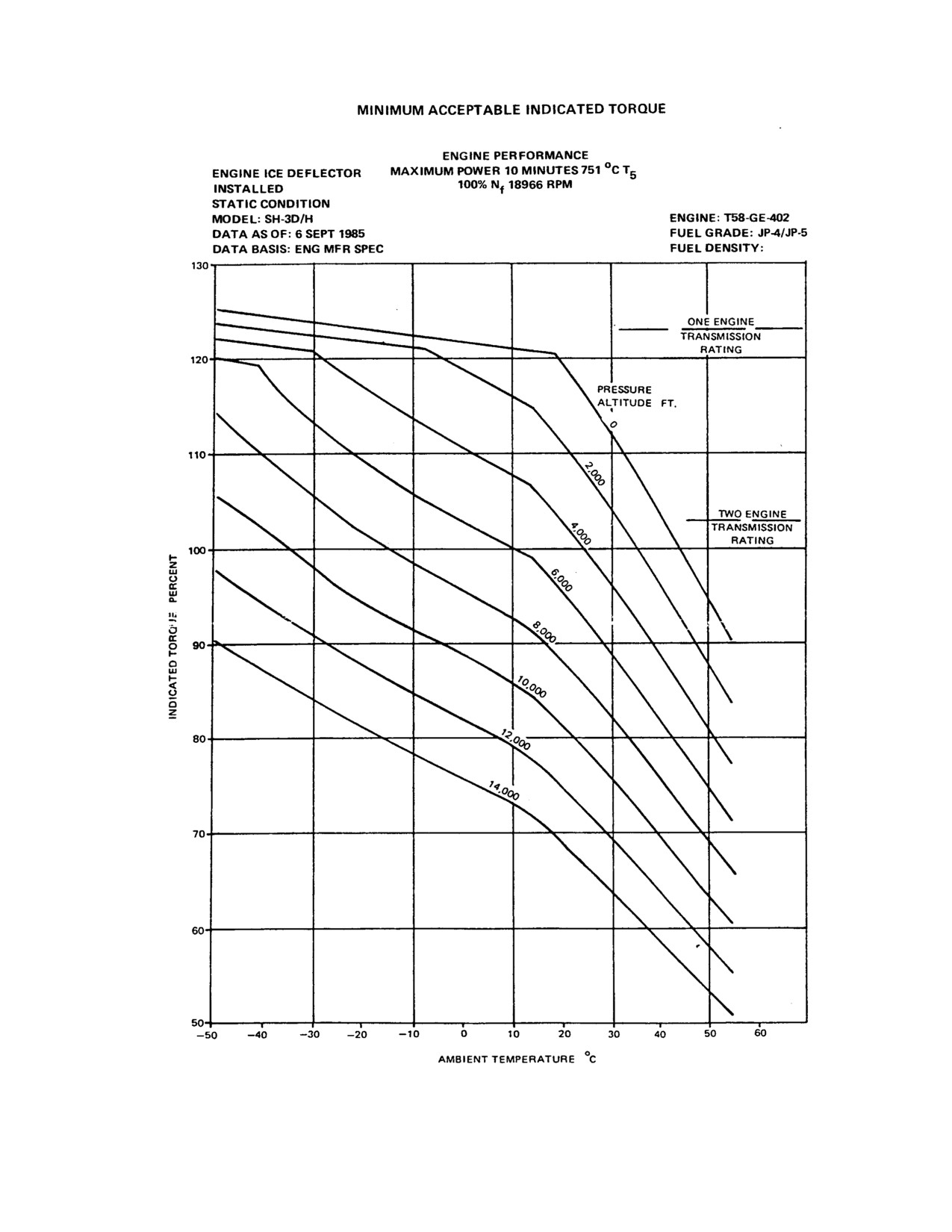
(3) Refer to minimum acceptable indicated torque charts (Figure 10-4) to determine
if the engines are meeting minimum acceptable torque requirements. If direct
reading gauges are available, they should be considered more accurate than
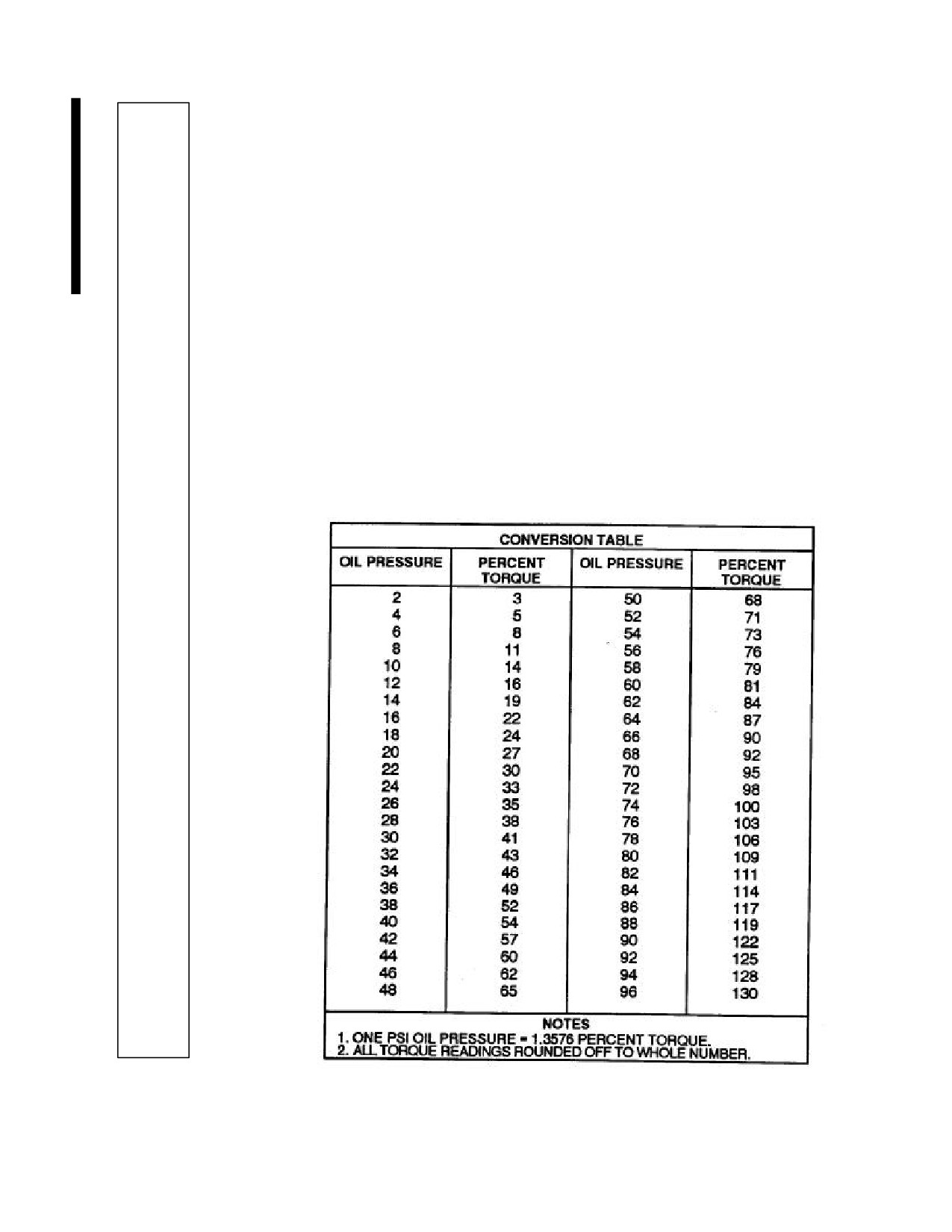
cockpit indications (refer to the conversion table below).
10-34
ORIGINAL
NAVAIR 01-230HLH-1
Figure 10-4. Engine Performance - Maximum Power (10 Minutes) (751°C T5)
10-35
ORIGINAL
NAVAIR 01-230HLH-1
PROFILE
j. Maximum Nf governing.
(1) After topping has been properly set, retard the speed selector on No. 2 engine
until the No. 1 Nf droops to 100 percent.
(2) Slowly advance No. 2 speed selector, watching Ng on No. 1 engine, and maintain
collective setting.
(3) At the point where No. 1 engine Ng just starts to fall off read the No. 1 Nf. This is
the maximum Nf governing on No. 1 engine.
(4) This Nf reading should be 103 percent or above.
Note
When using an engine trim checker, at the point where No.
1 engine Ng just starts to fall off, place the RPM switch to
POWER TURB B and read No. 1 engine Nf on the % RPM
digital display. This is the point of maximum Nf governing
on No. 1 engine.
(5) Maintenance adjustment of any discrepancy noted should be done on the ground
after engine shutdown. The maximum Nf setting should be done in accordance
with the Handbook of Power Plants and Related Systems.
(6) Repeat steps (1) through (5) for No. 2 engine.
k.
Manual throttle.
(1) With the No. 1 engine at topping, advance No. 2 speed selector until No. 1 engine
Ng decreases 4 percent.
(2) Slowly move the No. 1 engine manual throttle toward full open, observing Ng,
T5, and torque. It will often be possible to exceed topping power; however, as a
check of acceptable rigging, it should be possible to increase power to within 2-
percent Ng of topping.
Use of the manual throttle bypasses the automatic fuel
control. Limits must be carefully monitored to avoid
overtemperature, overspeed, or overtorque. Lowering the
collective without or before closing the manual throttle may
result in exceeding aircraft limitations.
(3) Return manual throttle to the full closed position before continuing further
checks.
(4) Repeat steps (1) through (3) for No. 2 engine.
10-36
ORIGINAL
NAVAIR 01-230HLH-1
PROFILE
Note
· If hovering is not feasible or is operationally undesirable,
the above procedures may be done in forward flight
requiring more horsepower than one engine is capable of
delivering. When topping in forward flight, expect an
increase of about 2-percent torque if the ice shield is not
installed.
· Alternately, topping checks may be made on the ground
with one engine at ground idle and at a helicopter weight
to preclude hovering on one engine.
· When topping in forward flight with AFC 321 installed,
use these torque reductions:
IAS-KTS
90
100
110
120
%Q NO. 1 ENG
1.5
2.1
2.8
3.5
%Q NO. 2 ENG
0.5
1.5
1.8
2.3
· When topping in forward flight with AFC 247 installed,
use these torque reductions:
IAS-KTS
90
100
110
120
%Q NO. 1 ENG
2.9
3.7
4.9
5.8
%Q NO. 2 ENG
1.2
2.1
3.6
4.1
l. Engine Ng / T5 Relationship check.
(1)
Record OAT, refer to Figure 10-5, and find the corresponding Ng for existing
OAT.
(2)
Place engine anti-ice switch and cabin heater OFF.
Engine anti-ice should be OFF when making this check as the
range is only valid for conditions where air is not extracted from
the compressor. Care must be exercised when operating the engine
in an icing condition or compressor damage may result.
(3)
Advance No.1 engine manual throttle to the desired Ng.
(4)
Record T5.
(5)
When establishing the “as received” baseline, move across the chart (figure
10-5) from the appropriate Ng to intersect the value closest to the T5 recorded
in step d. Move up the column from this point and determine the “as received”
baseline letter from the appropriate box in the top row. Quality Assurance is
to record this baseline letter in the engine logbook.
10-37
ORIGINAL
NAVAIR 01-230HLH-1
PROFILE
Note
This “as received” baseline letter will be used as the installed
Ng/T5 baseline for the engine checked and shall be recorded in the
engine logbook. This baseline letter will be used when making
subsequent Ng/T5 checks. The baseline letter provides a basis for
determining whether a Ng/T5 shift has taken place and whether
continued engine operation is advisable.
(6)
When making subsequent Ng/T5 checks, proceed as follows:
a. Enter chart (figure10-5) at existing OAT and move across to intersect the
engine’s “as received” baseline letter column to determine baseline T5. Add
an allowable 35 °C T5 shift to the baseline T5 to determine the maximum
allowable T5
b. Perform steps (1) through (4) and check that the T5 recorded in step (4) does
not exceed the maximum allowable T5..
Note
When making subsequent Ng/T5 checks if T5 has shifted
more then 35 °C from the baseline, perform the check again
at the same flight profile as the baseline. This will reduce
errors caused by increased T5 due to readings being taken in
forward flight.
(7) Repeat for the No. 2 engine.
10.3.2
Forward Flight Checks
AB DE
1.
Jump takeoff (heading hold)
- With feet off the rotary rudder pedals, make a jump
takeoff by pulling the collective up smoothly to a maximum of 103-percent torque. The
transient heading error should not be over 10°.
2.
Left pedal control - Make a maximum power takeoff (not to be over 103-percent torque
AB DE
dual engine). There should be enough left pedal to yaw the helicopter slightly to the left.
AB DE
3.
Autorotation rpm - Note total aircraft weight to within 100 pounds. Establish an
autorotation at a sufficient altitude. Retard engine speed selectors if necessary to split
the needles and stabilize airspeed at 70 knots. The referenced altimeter should be set at
29.92 inches Hg. Read OAT, pressure altitude, and percent Nr when all parameters are
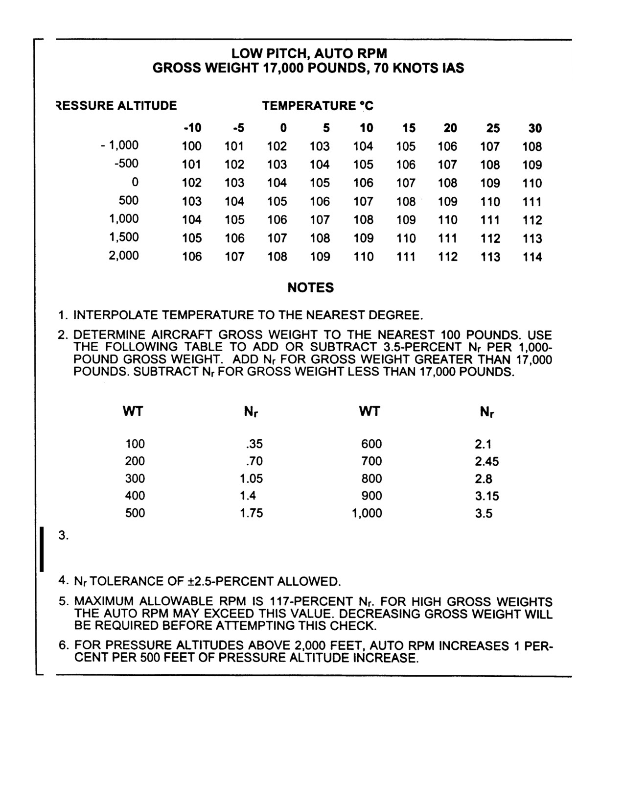
stabilized. Consult the autorotation chart for correct rotor rpm at the existing conditions.
If during autorotation rpm check, rpm is noted to be abnormally high, it is possible that
a rigging problem exists; adjusting the pitch change link rods (push rods) may not
correct. An additional check shall be conducted at this time to be sure there is enough
collective travel to permit attainment of either the main gearbox torque limit or the level
of torque derived from the appropriate engine operating limits chart, whichever is less.
If the collective stop is engaged before reading this torque limit, the possibility exists
that designed maximum rotary wing blade pitch may not be achieved, thus degrading
the ability of the helicopter in slowing or stopping large rates of descent
(i.e.,
autorotations).
10-38
ORIGINAL
NAVAIR 01-230HLH-1
T5 - DEGREES CELSIUS
OAT (C)
Ng% A B C D E
F
G H
I
J
K L
M N
-20
90.0
481
485
490
494
498
503
507
512
516
520
524
529
534
539
-19
90.2
484
488
493
497
501
506
510
515
519
523
528
532
537
542
-18
90.4
487
491
496
500
504
509
513
518
522
527
531
536
541
546
-17
90.6
491
495
500
504
506
513
517
522
526
530
535
539
544
549
-16
90.8
494
496
503
507
511
516
520
525
529
534
538
543
548
553
-15
91.0
497
501
506
510
514
519
523
528
532
537
542
546
551
556
-14
91.2
500
504
509
513
517
522
527
532
536
541
546
550
555
560
-13
91.4
504
506
513
517
521
526
530
535
539
544
549
553
558
563
-12
91.6
507
511
516
520
524
529
534
539
543
548
553
557
562
567
-11
91.8
511
515
520
524
528
533
537
542
546
551
556
560
565
570
-10
92.0
514
518
523
527
531
536
541
546
550
555
560
564
569
574
-9
92.1
516
520
525
529
533
538
543
548
552
557
562
566
571
576
-8
92.2
518
522
527
531
536
541
545
550
554
559
564
569
574
579
-7
92.3
520
525
530
534
538
543
548
553
557
562
567
571
576
581
-6
92.4
522
527
532
536
541
546
550
555
559
564
569
574
579
584
-5
92.5
524
529
534
538
543
548
552
557
561
566
571
576
581
586
-4
92.7
527
532
537
541
546
551
555
560
564
569
574
579
584
589
-3
92.9
530
535
540
545
549
554
559
564
568
573
578
583
588
593
-2
93.1
534
539
544
548
553
558
562
567
571
576
581
586
591
596
-1
93.3
537
542
547
552
556
561
566
571
575
580
585
590
595
600
0
93.5
540
545
550
555
559
564
569
574
578
583
588
593
596
603
1
93.7
543
548
553
558
562
567
572
577
582
587
591
596
601
606
2
93.9
547
552
557
562
566
571
576
581
585
590
595
600
605
610
3
94.1
550
555
560
565
569
574
579
584
589
594
598
603
608
613
4
94.3
554
559
564
569
573
578
583
588
592
597
602
607
612
617
5
94.5
557
562
567
572
576
581
586
591
596
601
605
610
615
620
6
94.7
560
565
570
575
579
584
589
594
599
604
608
613
618
623
7
94.9
563
566
573
578
583
588
593
598
603
607
612
617
622
627
8
95.1
567
572
577
582
586
591
596
601
606
611
615
620
625
630
9
95.3
570
575
580
585
590
595
600
605
610
614
619
624
629
634
10
95.5
573
578
583
588
593
598
603
608
613
617
622
627
632
637
11
95.6
575
580
585
590
595
600
605
610
615
620
625
630
635
640
12
95.7
578
583
588
593
598
603
608
613
618
622
627
632
637
642
13
95.8
580
585
590
595
600
605
610
615
620
625
630
635
640
645
14
95.9
583
588
593
598
603
608
613
618
623
627
632
637
642
647
15
96.0
585
590
595
600
605
610
615
620
625
630
635
640
645
650
16
96.2
588
593
598
603
608
613
618
623
628
633
638
643
648
653
17
96.4
591
596
601
606
611
616
621
626
631
636
641
647
652
657
18
96.6
595
599
605
609
615
620
625
629
635
639
645
650
655
660
19
96.8
598
602
608
612
618
623
628
632
638
642
648
654
659
664
20
97.0
601
605
611
615
621
626
631
635
641
645
651
657
662
667
21
97.1
604
608
614
618
624
629
634
638
644
648
654
660
665
670
22
97.2
606
611
616
621
627
632
637
641
647
651
657
662
667
672
23
97.3
609
613
619
624
629
634
639
644
649
655
660
665
670
675
24
97.4
611
616
621
627
632
637
642
647
652
658
663
667
672
677
25
97.5
614
619
624
630
635
640
645
650
655
661
666
670
675
680
26
97.7
617
622
627
633
638
643
648
653
658
664
669
673
678
684
27
97.9
620
626
630
636
641
646
651
656
661
667
672
677
682
689
28
98.1
624
629
634
639
644
650
655
660
665
671
676
680
685
693
29
98.3
627
633
637
642
647
653
658
663
668
674
679
684
689
698
30
98.5
630
636
640
645
650
656
661
666
671
677
682
687
692
702
31
98.7
633
639
643
648
653
659
664
670
674
680
685
691
696
705
32
98.9
636
642
647
652
657
663
668
673
678
684
689
694
700
708
33
99.1
640
645
650
655
660
666
671
677
681
687
692
698
703
710
34
99.3
643
648
654
659
664
670
675
680
685
691
696
701
707
713
35
99.5
646
651
657
662
667
673
678
684
688
694
699
705
711
716
36
99.6
649
654
660
665
670
676
681
687
691
697
702
708
713
718
37
99.7
651
656
662
667
672
678
683
689
694
700
705
710
715
720
38
99.8
654
659
665
670
675
681
686
692
696
702
707
713
718
723
39
99.9
656
661
667
672
677
683
688
694
699
705
710
715
720
725
40
100.0
659
664
670
675
680
686
691
697
702
708
713
718
722
727
Figure 10-5. Ng/T5 Relationship Check
10-39
ORIGINAL
NAVAIR 01-230HLH-1
CHANGES TO AUTO RPM SHALL BE MADE TO THE PITCH CONTROL RODS IN NO LESS THAN 4
CLICK INCREMENTS (EQUIVALENT TO ABOUT 1.17% NR) ADJUST ALL PITCH CONTROL RODS
IN ORDER TO RETAIN TRACK AND BALANCE CONFIGURATION
Figure 10-6. Low Pitch Autorotative Rpm Chart
10-40
ORIGINAL
NAVAIR 01-230HLH-1
PROFILE
Note
· Torque splits in excess of 30 percent can be expected
during the autorotation check.
· If conducting an autorotational rpm check in conjunction
with main rotor smoothing and/or vibration analysis data
collection, correlation of main rotor rpm as indicated
through the VATS/ATABS tachometer provide the most
accurate means of determining exact Nr.
AB DE
4.
Right pedal control - Enter normal 70 KIAS autorotation. During descent, there should be
enough right rudder pedal remaining to yaw the helicopter to the right.
†5.
Posttakeoff checklist.
a. Landing gear - UP.
b. Lights - AS REQUIRED.
c. IFF/NAVAIDs- CHECK.
AB DE
d. Compass- CHECK.
e. Security check - COMPLETE.
f. Nr AS REQUIRED.
AB DE
6.
Battery absorber tuning
- With the helicopter in stabilized flight at 80 to 90 KIAS,
decrease Nr from 102 percent to 98 percent and note at what Nr five-per-revolution
vibrations are at a minimum. (For ET operation, decrease Nr from 105% Nr to 101%Nr)
If the minimum vibration is other than at 100-percent Nr , note the Nr so the battery
absorber tuning may be corrected.
7.
Controllability and vibration check.
a. Turn off ASE and fly from 40 to 120 KIAS in 20 knot units.
b. Stabilize at each point momentarily and note cyclic position. As airspeed is increased,
the cyclic will have to be moved forward. At 120 knots, there should be some forward
cyclic remaining. If in doubt about cyclic rigging, return to base and refer to
Maintenance Instruction Manuals for detailed instructions regarding loading and
rigging flight checks.
c. Vmax is defined as 120 KIAS in sea level, standard day conditions. To determine Vmax
for other conditions, refer to the blade stall chart, Figure 20-5.
AB DE
d. At 120 knots, note any unusual vibrations. Make turns, climbs, and descents. If an
intermittent vibration of about one-per-revolution is encountered or if pitch lag
instability (two-thirds-per-revolution vibration) is encountered, malfunctioning rotary
wing head dampers are indicated. Upon return to base, perform a damper check as
outlined in paragraph 10.2.8, step 3 (Rotary Wing Dampers).
10-41
ORIGINAL
NAVAIR 01-230HLH-1
PROFILE
8.
Servos.
a. Primary servo off- In flight at an airspeed between 60 and 80 knots, turn off the
primary servo. There should be no large or unusual tip-path or attitude changes. When
the primary servo is turned off at this speed, the normal reaction of the helicopter is to
pitch slightly noseup. One to two inches of forward cyclic should be enough to
maintain attitude. With the primary servo off, make climbs, turns, and descents to
determine that adequate control of the helicopter can be maintained in case of a
primary servo failure. Turn the primary servo on.
b. Auxiliary servo off- Maintain 60 to 80 knots, ASE off, and turn off the auxiliary
servo. The cyclic should jump no more than one-eighth inch and the collective no
more than one-sixteenth inch. There should be no sudden attitude or heading change.
Make climbs, turns, and descents to determine that adequate control of the helicopter
can be maintained in case of an auxiliary servo failure. If aircraft pedals vibrate
excessively (AUX ON or OFF) while accelerating and/or adding power, seized or
improperly greased tail rotor bearing may be indicated.
A
9.
Landing gear - Cycle the landing gear and observe proper operation of the landing gear,
indicators, landing gear downlock lights, and landing gear warning light. The landing gear
downlock lights are the only indications not necessary for a positive down and locked
indication.
Note
Anytime the landing gear is lowered and a positive down and
locked indication is not present, the helicopter should be
hovered and the landing gear lockpins inserted in the drag link
before landing.
A
10.
Heater - During forward flight of over 90 knots, turn on the heater and check operation of
both HI and LOW positions. Check all diffusers for proper operation. Be sure that the
heater is off for 5 minutes before landing.
A
11.
Flight instruments
- Check and compare all instruments for proper operation and
indications.
A
12.
Turn rate indicators.
a. Copilot.
(1) ASE - OFF.
(2) AFCS circuit breakers - PULL.
(3) Copilot turn rate indicator - INOPERATIVE.
(4) Copilot turn rate switch - ALTERNATE.
(5) Copilot turn rate indicator - OPERATIVE.
(6) Copilot turn rate switch - NORMAL.
b. Pilot.
(1) Pilot turn rate switch - ALTERNATE.
10-42
ORIGINAL
NAVAIR 01-230HLH-1
PROFILE
(2) Pilot turn rate indicator - INOPERATIVE.
(3) Pilot turn rate switch - NORMAL.
(4) AFCS circuit breakers - RESET.
(5) ASE ENGAGE.
Note
When the above check is made, the OFF flag will appear in
the preselected VGI.
A
13.
Communication radios.
a. UHF-l - Accomplish with antenna selector at NORMAL, then at ALT. At pilot,
copilot, and all crewmen stations, select UHF with the receiver selectors and place the
transmitter selectors to UHF (only pilot and crewmen may transmit). At a point about
10 nm from and with line-of-sight clearance, contact selected tower from pilot station
and request UHF check. Clear sidetone and tower transmissions should be audible at
all stations (pilot/copilot only for ET). Transmit from the respective stations and use
both T/R and T/R + G positions on the selector switch. Background noise should be
squelched in both positions. Set the tower frequency manually, move the function
switch to MANUAL, and establish communications with the tower. When changing
channels, a momentary 1000-Hz signal should be heard as the set channelizes.
b. UHF-2 - Check in the same manner as for UHF-l with the antenna selector switch at
NORMAL and at ALT.
c. VHF (non-ET only).
A
14.
Navigation radios.
a. UHF/DF(non-ET only)- Fly over a known geographical landmark at about 1,500 feet
with line-of-sight clearance to tower. Fly directly over the landmark on heading to the
tower. Contact tower and request a short count. Place the function switch on the UHF
control panel to DF. The No. 1 pointer on the RMI should indicate the known heading
within ±5 with a maximum of ±5°oscillation.
Note
This check is not accurate with the tower at a bearing other
than directly off the nose of the helicopter.
b. Tacan- Fly over a geographical on the kn own bearing to the station. The No. 2
pointers on the BDHIs and the RMI should indicate the known bearing within ±2 and
the DME should read known distance ±0.5 mile. Turn course selector knob until
vertical bars are centered and ambiguity windows read TO. The course selector should
read known bearing ±2.5°and the relative heading pointer should point straight up
±2 . Maintain heading toward the station.
Turn course selector knob until the vertical bar is on second dot and note course
selected. Turn knob in other direction to place vertical bar on second dot on the other
side and note course selected. There should be a 10° ±3° difference between course
selected. Continue turning the course selector knob until the reciprocal of the known
bearing is selected. The ambiguity window should now read FROM. Select A/A on
10-43
ORIGINAL
NAVAIR 01-230HLH-1
PROFILE
the function selector switch and select a channel 63 channels apart from another aircraft.
Mileage should be ±0.5 mile of distance to other aircraft.
c.
LF/ADF - With the selector switch at ANT and the BFO switch off, tune a station and
check tuning accuracy, satisfactory reception, and adequate control of volume. Repeat
for all bands. Turn the BFO switch on and tune through a station frequency to
establish that the beat frequency is heard. Turn the BFO switch off. Check loop
operation. Fly directly over a geographical landmark on a known bearing to a selected
station. Select COMP; the No. 1 needle on the RMI should indicate known bearing
±5°. Repeat with the station off the tail and 45° left and right of nose and tail.
d.
IFF/SIF - Contact local approach and request IFF/SIF check. Check all functions.
e.
VOR/ILS.
(1) Tune and identify a known VOR station. - Fly over a geographical landmark on
the known bearing to the station. The No. 1 pointer on the RMI should indicate the
known bearing within ±2 . Turn course selector knob on the CDI until vertical bars
are centered and ambiguity windows read TO. The course selector should read known
bearing ±2.5°and the relative heading pointer should point straight up ±2 . Maintain
heading toward the station. Turn course selector knob until the vertical bar is on
second dot and note course selected. Turn knob in other direction to place vertical bar
on second dot on the other side and note course selected. There should be a 10° ±3°
difference between course selected. Continue turning the course selector knob until
the reciprocal of the known bearing is selected. The ambiguity window should now
read FROM.
(2) Using local area ILS and current approach plate tune and identify the localizer
frequency on the VOR. Intercept the localizer and fly inbound at the published
altitude. When the glideslope signals are received, the OFF flags on the CDI should
retract. Fly down localizer making deviations to ensure the glideslope and course
indicator bars will center when the aircraft is on glideslope and lined up with the
centerline of the runway.
A
15.
TACNAV - Check operation inflight.
AB D
16.
ASE.
a. Collective drop
- While in forward flight at 80 knots and with sufficient altitude to
safely perform an autorotative maneuver, smoothly lower the collective to flat pitch
(bottom stop). The transient heading error should not exceed 10°.
b. BAR ALT autorotation
- With ASE engaged, engage the BAR ALT and enter
autorotation, holding the momentary BAR REL button depressed. After rotor rpm
stabilizes, release the momentary BAR REL button, keeping the collective in the full
down position and note rotor rpm; there should be no unusual decrease in rpm. If a
decrease in rotor rpm is noted, release the BAR ALT using the BAR OFF button on
the ASE control panel. If a jump occurs, the collective low pitch stop may require
adjustment.
Note
Do not descend greater than 500 feet per minute with BAR
ALT engaged to preclude possible damage to the BAR ALT
controller.
10-44
ORIGINAL
NAVAIR 01-230HLH-1
PROFILE
c.
Push/pull and release
- Trim the helicopter for hands-off flight at 90 knots. Engage
BAR ALT, and push the cyclic stick forward 1 inch against force gradient spring for
1 second, and release (stick oscillation should be dampened by the pilot). The
helicopter should return to the original attitude within one overshoot and return to the
original airspeed within 5 knots. Repeat this check aft, right, and left.
d.
Stability - Trim the helicopter for hands-off forward flight at 90 knots with the pitch
bar centered. Remove all friction from the collective and engage BAR ALT. Fly with
hands and feet off the controls for about 5 minutes. No undesirable hunting in pitch,
roll altitude, or yaw should be observed. Repeat this check using the opposite gyro.
(A slight jump may occur when switching gyros.) After the check is completed,
return the gyro selector switch to the original position.
e.
Push/pull and hold - Trim the helicopter for 90 knots forward flight, release all collec-
tive friction, and engage BAR ALT. After the helicopter has stabilized, beep the
cyclic forward until
100 KIAS is attained. The helicopter should hold altitude within
±40 feet and should attain the new airspeed without excessive oscillations or
overshoots. The pitch bar should remain within the circle during this maneuver.
Repeat the above procedure beeping from stabilized 90 to 80 knots.
f.
Roll bar
- Trim the helicopter for level flight at 90 knots and observe the roll bar
position. If the roll bar is not within the circle, note the position so that the roll
canceller can be reset.
g.
Manual turn
- Trim the helicopter for 90 knots and engage BAR ALT (collective
friction off). Make a coordinated 180° turn, holding the cyclic stick against the force
gradient spring, then release the controls (stick oscillation should be damped by the
pilot). The helicopter should return to 90 ±5 knots with no more than one overshoot in
pitch and roll.
h.
Trimmed turn - With the helicopter trimmed for 90 knots, engage the BAR ALT, and
beep the helicopter into a l5° to 20° AOB coordinated turn. Fly hands off for 360°;
the helicopter should maintain altitude within
±40 feet and there should be no
undesirable oscillations in pitch or roll.
i. Momentary BAR ALT release - Trim the helicopter for 90 knots and engage the BAR
ALT. Depress the BAR REL button on the collective and establish a descent of about
500 to 1,000 fpm. When the helicopter has descended 200 to 300 feet, reset the
collective to the cruise power setting, note the altitude, and release the BAR REL
button. The helicopter should stabilize on the new altitude within ±40 feet, Repeat this
check for ascending flight.
17.
Main Rotor Head Track and Balance
- Establish desired airspeed (60, 90, 120kts) with
torques matched and Nf/Nr at 100% (103% Nf/Nr for ET),Collect main rotor head track
V/M/T
and balance data IAW applicable MIMS.
Note
Allow aircraft to stabilize at each regime for at least one minute
before pressing run and collecting track and balance data.
Note
If a high vibration is felt during the collection of track and balance data at a flight
regime and the vibration level increases with airspeed to an unacceptable level, run the
remaining flight test regimes at the maximum safe airspeed. This provides the CIPS
with the data required to calculate an adjustment to lower the vibration level.
10-45
ORIGINAL
NAVAIR 01-230HLH-1
PROFILE
V/M/T
18. Autorotation rpm
- Note aircraft gross weight to within 100 pounds. Establish an
autorotation at a sufficient altitude over a prepared surface. Retard engine speed
selectors if necessary to split the needles and stabilize airspeed at 70 knots. The
referenced altimeter should be set at 29.92 inches Hg. Read OAT, pressure altitude, and
percent Nr when all parameters are stabilized. Consult the autorotation chart (Figure 10-
6) for correct rotor rpm at the existing conditions. If during autorotation rpm check rpm
is noted to be abnormally high, it is possible that a rigging problem exists; adjusting the
pitch change link rods (push rods) may not correct. An additional check shall be
conducted at this time to be sure there is enough collective travel to permit attainment of
either the main gearbox torque limit or the level of torque derived from the appropriate
engine operating limits chart, whichever is less. If the collective stop is engaged before
reading this torque limit, the possibility exists that designed maximum rotary wing
blade pitch may not be achieved, thus degrading the ability of the helicopter in slowing
or stopping large rates of descent (i.e., autorotations).
Note
Complete step 18 only if PCR adjustments were made during
Main Rotor Head Track and Balance. If during Main Rotor
Head Track and Balance evolution, blade solutions exceed 8
total turns on both PCL’s or exceed 4 turns on one, perform
autorotational RPM check as described above to ensure proper
Nr available for autorotative maneuvering.
19. Airframe Vibrations
- Once the main rotor track and balance is with in acceptable
V/M/T
limits, collect airframe vibrations data IAW applicable MIMs.
a.
On the ground with Nf/Nr matched at 100% (103% Nf/ Nr for ET), collect
airframes vibrations data (as required).
b.
In a hover with Nf/Nr matched at 100% (103% Nf/Nr for ET) collect airframes
vibrations data
c.
Establish 90kts level flight with Nf/ Nr matched at 100% (103% Nf/Nr, collect
airframes data.
Note
· Allow aircraft to stabilize at each regime for at least 1
minute before pressing run and collecting balance data.
· If aircraft is configured with a main rotor head
tachometer, utilize VATS/ATABS rpm feature to
confirm 100% Nr (103% Nr for ET)
A
20. RAWS.
a. Fly at or slightly below
500-foot altitude and turn off the radar altimeter at each
indicator. The aural and visual warning signals should be noted.
10-46
ORIGINAL
NAVAIR 01-230HLH-1
PROFILE
Note
After turning equipment on, allow about
3 minutes for
system to reach operating temperature. To avoid damage to
system components, do not place system in operation until 3
minutes have elapsed since system was last turned OFF.
(Not required on aircraft modified by AFC 448).
b.
Turn on the radar altimeter and note that while warming up it goes unreliable (pointer
behind the mask). With the gear up, both warning signals should be noted. Lower the
gear. When the gear is down, both signals should disappear. Retract the gear and
commence a climb. As the helicopter ascends through 700 ±200 feet both signals
should be inhibited.
c.
Make an approach using a rate of descent of less than 300 fpm. When passing through
100 ±5 feet indicated on the radar altimeter, the aural and visual warnings should be
observed for 3 seconds (six beeps and six flashes).
d.
(non-ET only) Make two approaches with a slow rate of descent, one with RDR ALT
selected and one with VERT ACCEL selected. In each case as 100 feet of altitude is
approached, engage the coupler and note that no warning signals are observed passing
through 100 feet.
Note
A slow rate of descent must be used when descending through 100
feet, otherwise the observed warning signals will not agree with the
actual altitude at the time the signals are noted.
A
21.
Cruise coupler (non-ET only).
Note
The following check must be made over good Doppler return water.
The following checks may be done to determine proper operation of basic ASE, Doppler,
radar altimeter, and coupler when used as an integrated system.
a. Helicopter trimmed for balanced flight 150 feet and 60-knot groundspeed.
b. Mode select switch - SEA.
c. CYC CPLR - DOPP.
d. Altitude coupler - RDR ALT.
e. Hover indicator - A MODE.
f. METER SELECTOR switch - CPLR.
g. DRIFT knob - TURN TO CENTER VERTICAL BAR.
h. SPEED knob - TURN TO CENTER HORIZONTAL BAR.
i. ALTITUDE set pot -150 FEET.
10-47
ORIGINAL
NAVAIR 01-230HLH-1
PROFILE
j. Coupler - ENGAGED.
Helicopter should remain at approximately the preselected attitude and altitude.
Undesirable changes in pitch, roll, or altitude may indicate inability of the helicopter to
perform an automatic transition.
22.
(NON-ET) Automatic approach - Complete Automatic Approach checklist and engage
coupler at gate.
a. The copilot should commence timing when the coupler is engaged. Groundspeed,
altitude, drift, and roll should be recorded every 10 seconds. The approach profile for
automatic approach chart should then be consulted to ensure correct approach
programming.
b. After completing normal transitions, make one using the VERT ACCEL mode.
Switch from RDR ALT to VERT ACCEL before reaching 60 feet. The switch should
be made when vertical pointer on the hover indicator in D mode is at its maximum
deflection from the null. Expect a slight collective jump. After switching, the
transition will be accomplished but may not behave in the same manner as a normal
transition. Altitude overshoot should not be over 10 feet.
c. Alternate approach - Make at least one approach regardless of the sea state.
(1) Alternate approach predip checklist - COMPLETED.
(2) Coupler - ENGAGED AT GATE. If flown properly, the approach profile should
be similar to an automatic approach. An exception is a high rate of descent (500 to
600 fpm) and loss of about 70 feet of altitude during the first 10 seconds of the
approach.
A
23.
Aft tank float valve - With at least one aft tank boost pump on, note aft tank drops to and
maintain 600 to 900 pounds in the tank until the center tank is empty.
A
24.
Crossfeed:
a. Do this check with the center tank empty. Turn on both forward boost pumps, open
crossfeed, and have one aft boost pump on. Note fuel is used only from the forward
tank. With one forward and both aft boost pumps on, note fuel is used only from the
aft tank.
A
25.
Fuel dumping - While in forward flight, check the forward and aft tank dump systems
individually by monitoring fuel gauges or visually check fuel dumping.
†26.
Before landing checklist.
†a. Landing gear - DOWN AND LOCKED.
†b. Speed selectors - CHECKED.
†c. Cabin heat (NON-ET) or air conditioner (ET) - OFF.
†d. Master Jettison Panel - SAFE.
†e. Lights- SET.
†f. Stores load panel switches (NON-ET) - OFF/SAFE.
10-48
ORIGINAL
NAVAIR 01-230HLH-1
PROFILE
†g. Shoulder harness- LOCKED.
†h. Tailwheel- LOCKED.
†i. Brakes - CHECKED.
†J. CREW - LANDING CHECK LIST COMPLETE.
†27. After final landing.
†a. ASE - OFF.
†b. Emergency start switches - OFF.
†c. Lights- AS REQUIRED.
†d. IFF- STBY.
†e. Doppler (NON-ET) - STBY.
†f. Crossfeed - CLOSED.
†g. Boost pumps - OFF.
†h. Tailwheel - AS REQUIRED.
†28. Taxiing.
†a. Area - CLEAR.
†b. Lights - AS REQUIRED.
†c. Chocks/tiedowns- REMOVED.
†d. Tailwheel locking handle- UNLOCKED.
†e. Shoulder harness (all stations)- LOCKED.
†f. Parking brake- OFF.
†g. Brakes - CHECKED.
†h. Tailwheel - CHECKED.
A
29. Check valves - With the center fuel tank empty, forward tank below 1,000 pounds, and
crossfeed closed, turn off all fuel boost pumps. If the check valve in the ejector line
between the forward and center tank is malfunctioning, the No. 1 engine may flame out.
If the check valve in the ejector line between the aft and center tank is malfunctioning,
the No. 2 engine may flame out. Boost pumps should be OFF for a minimum of 2
minutes.
10.4 SHUTDOWN CHECKS
10.4.1 Shutdown
†1. Collective (copilot monitor) - MINIMUM.
10-49
ORIGINAL
NAVAIR 01-230HLH-1
PROFILE
†2. Brakes and tailwheel - LOCKED.
†3. Landing gear lockpins - IN.
a. Safety pins - AS REQUIRED.
b. Tiedowns - AS REQUIRED.
†4. No. 1 speed selector - GRD IDLE.
†5. Accessory drive switch - FORWARD AND LIGHT ON.
†6. No. 1 speed selector - 104-PERCENT Nf.
†7. Area clear/disengage signal - CHECKED.
†8. No. 2 speed selector - GRD IDLE.
†9. Droop stops - IN.
†10. No. 2 speed selector - SHUTOFF.
†11. Rotorbrake - ON.
†12. No. 2 fuel switch - CLOSED.
†13. No. 2 engine instruments - CHECKED.
†14. All electronic equipment- AS REQUIRED.
†15. Area - CLEAR.
A
†16 Blades - FOLDED.
10.4.2 No. 1 Engine Secure.
†1. No. 1 speed selector - GRD IDLE.
†2. No. 1 speed selector - SHUTOFF.
3. HEELS illuminates during engine coast down (NON-ET) - CHECKED.
†4. Fuel switch - CLOSED.
†5. All engine instruments - CHECKED.
†6. All switches - OFF.
†7. HEEDS bottles - OFF.
10.4.3 Postflight Inspection.
†1. A thorough postflight should be conducted with emphasis on inspecting for hydraulic and
oil leaks.
10-50
ORIGINAL
NAVAIR-01-230HLH-1
PART IV
Flight Characteristics
Chapter 11 - Flight Characteristics
55
ORIGINAL
NAVAIR-01-230HLH-1
This Page Left Blank Intentionally
56
ORIGINAL
NAVAIR 01-230HLH-1
CHAPTER 11
Flight Characteristics
11.1
GENERAL
increase the horizontal velocity of the helicopter. Thus, the
vertical lift component is restored by increasing power to
Since the flight characteristics of a helicopter are
maintain altitude. The ASE acts to overcome erratic
independent of forward speed, a helicopter is able to move
external forces such as gusts, etc., and to maintain the
in any direction at a controlled low speed and still remain
helicopter in the attitude selected by the pilot.
safely airborne. The normal speed range extends from a
rearward speed of about 20 knots to a forward speed of
11.2.2 Ground Resonance. Ground resonance is a
about 120 knots and also includes lateral speeds, either to
self-excited vibration that occurs when a coupling inter-
the left or the right, of
30 knots. The forward safe
action occurs between the movement of the rotary wing
operating speeds are defined in Chapter 4.
blades and the helicopter. For ground resonance to occur,
there must be some abnormal lead/lag blade condition that
11.2
FLIGHT CHARACTERISTICS
would dynamically unbalance the rotor, and a reaction
between the helicopter and ground that could aggravate
and further unbalance the rotor. Ground resonance can be
caused by a blade being badly out of track, a faulty damper
WARNING
tie down chains that are too tight, or a peculiar set of
landing conditions. When a wheel reaction occurs, such as
a hard one-wheel landing, that would cause out-of-phase
rotary wing blades to be aggravated to the point where
The discussions of Settling With Power,
maximum lead and lag blade displacement is realized,
Vortex Ring State, and Blade Stall describe
ground resonance may occur. This helicopter does not
situations that should not occur under
have a history of ground resonance. However, if ground
normal operating conditions with proper
resonance should occur, primary consideration should be
preflight planning.
given to getting the helicopter airborne. If this is impossi-
ble, immediately reduce collective pitch, place engine
11.2.1 Level Flight Characteristics Under Various
speed selectors to SHUTOFF, and apply both the rotor
Speed Conditions. Normally, for hovering, greater
brake and wheelbrakes.
power is required than for forward flight. As the pitch of
the rotor blades is increased, the lift derived from the
11.2.3 Settling With Power. At high density. altitudes,
rotary wing is also increased; however, higher power
high gross weights, or when operating with reduced power,
settings will be required to keep the rotary wing turning at
power required may exceed power available. It may not be
a constant rpm. Forward flight is initiated by moving the
possible to maintain level flight because of the lack of
cyclic stick forward, with a corresponding increase in
power that will cause settling to occur. The attendant loss
collective pitch to simultaneously obtain forward movement
of altitude is of minor consequence except in certain
and an increase in altitude. As the forward speed of the
situations where sufficient altitude is not available to
helicopter increases, the airflow through the rotor system
achieve the airspeed necessary to maintain level flight.
results in translational lift, thereby reducing the amount of
Careful preflight analysis of engine performance and hover
power required. Further increases in airspeeds result in
charts in Part XI will aid in avoiding extreme situations.
increasing translational lift. This condition holds true up to
To recover from this condition:
about 60 knots. As increased speed is desired, increased
power will be required. This increase in speed is
*1. Speed selectors - FULL FORWARD.
accomplished by further displacing the cyclic stick
forward. This in turn increases the angle of the rotary wing
*2. Contain Nr.
plane and the helicopter will assume a nosedown attitude
as the fuselage becomes aligned with the rotor tip-path
*3. Establish single-engine airspeed and level
plane. As this attitude changes, a greater percentage of the
attitude.
lift being produced by the rotary wing is being used to
11-1
ORIGINAL
NAVAIR 01-230HLH-1
*4. Reduce gross weight by dumping fuel and/or
jettisoning stores.
11.2.4 Vortex Ring State. At high density altitudes,
Flight conditions causing vortex ring state
high gross weights, no wind or low forward velocity, and
should be avoided at low altitudes because
certain rates of descent, a critical power settling condition
of the attendant loss of altitude necessary for
may occur resulting in roughness and partial loss of
recovery. Recovery from fully developed
control. The vertical velocity of the downwind airflow
vortex ring state may be made only by
through the main rotor is extremely high while at or near
entering autorotation before regaining
hovering attitude. Under certain power and rate-of-descent
airspeed.
combinations, the downwash from the rotor begins to
recirculate up, around, and back down through the
11.2.4.1 Hovering Over Salt Water. Salt spray
effective outer rim of the rotor disc. The helicopter sinks
ingestion in the engine will result in a loss in performance
into the airmass it has just displaced in trying to obtain lift,
that makes the engine susceptible to stalls, particularly
and the rotary wing blades work continually in their own
during decelerations. As the spray is ingested, salt is
turbulent airstream.
deposited on the compressor blades and stator vanes. The
resulting buildup gradually changes the airfoil sections,
Vortex ring state is likely to occur as a result of any of
which in turn affects performance. This deterioration will
these conditions:
be noticed as an increase in T5 for a given torque. Should
the deterioration reach a point where the compressor
1.
Moderate vertical rates of descent initiated from a
actually stalls, a muffled explosive sound will be heard,
hover.
and T5 will rapidly reach overtemperature while Ng and
torque decrease rapidly. If hovering is an operational
2.
Steep approaches at low airspeeds.
necessity in a salt spray environment, the amount of salt
spray observed on the windshield is usually the best
The vortex ring state phenomenon is not restricted to
indication of the amount of salt to which the engines are
high gross weights or high density altitudes. It may occur
being subjected. Also, a general rule of thumb for
in a variety of conditions. Indications to the pilot may be
maximum allowable deterioration is a T5 increase of 30 to
the following:
50 °C for a given torque setting. In a severe salt spray
environment, the time for a deterioration of this magnitude
1.
Rapid increase in descent rate.
may occur as early as 3 to 4 minutes. Although salt-
encrustation-type stalls generally occur during conditions
2.
Increase in vibrations.
of Ng deceleration, compressor surges can occur at a
steady state power or during acceleration. A surge (partial
3.
Loss of control effectiveness.
stall) is characterized by one or more muffled but quite
discernible bangs or pops without attendant increase of T5
The most reliable indicator is a rapid increase in rate
and loss of power. However, since deceleration
of descent. Loss of cyclic and collective control
precipitates a stall, the most beneficial pilot action would
effectiveness may be hidden by the ASE/servo control
be to increase collective stick and leave hover following a
system. To recover from this condition, proceed as
noise of this type. Then, attempt to make sure that the
follows:
engine does not decelerate, make only minor or slow
power changes, and proceed to a point of intended landing.
*1. Decrease collective pitch.
Note
*2. Increase forward airspeed.
Continued engine operation in clean air may
*3. Enter autorotation if altitude permits. A consid-
dissipate some of the salt buildup but this
erable loss of altitude may occur before the condition
cannot be assured. Flight through rain may
is recognized and recovery is completed. During
also be beneficial in reducing salt buildup,
approach for landing, the condition causing vortex
thereby improving stall margin. Engines
ring state should be avoided.
should be washed after each over-water
flight below 40 feet.
11-2
ORIGINAL
NAVAIR 01-230HLH-1
11.2.5 Blade Stall. Blade stall, the tendency of the
*4. Increase rotor rpm.
retreating blade to stall in forward flight, limits the high
speed potential of the helicopter, increases stresses, and
*5. Reduce altitude - AS NECESSARY.
decreases component life. The retreating blade (the blade
moving away from the direction of flight) has a tendency
11.2.6 Rollover Characteristics. There exists for all
to stall because the blade tip is traveling at the rotational
helicopters both a static and dynamic tipover angle. The
velocity minus the forward speed of the helicopter. As the
static tipover angle is the angle at which the helicopter will
velocity of the retreating blade decreases, the blade angle
turn over on its side if it were mounted on a platform and
of attack must be increased to equalize lift to provide
slowly tilted. This angle is about
37° for the UH-3
stabilized flight. As the angle of attack increases, the blade
helicopter. The dynamic tipover angle, as its name implies,
will stall (lost lift and increased drag). The increased drag
is a dynamic condition of flight, and, although the dynamic
will cause loss of rotor speed unless power is increased.
tipover angle is considered to be around 15°, cases can
The advancing blade (the blade moving into the direction
exist in which the helicopter will turn over from a level
of flight) on the other hand is traveling at a substantially
attitude if high sideward velocity exists at touchdown
higher speed and has relatively uniform low angles of
combined with a solid object to prevent lateral sliding of
attack and is not subjected to blade stall. Blade stall will
the wheel. An explanation is presented below, in
first occur at the blade tip, and is most likely to occur when
conjunction with slope landings, in order to develop a
operating at high values of airspeed, gross weight, density
single set of logical responses for the pilot.
altitude, and power, and especially with low rotor rpm.
Maneuvers, acceleration, or turbulent air, all of which
11.2.6.1 Slope Landing and Takeoff. As shown in
increase g load factors, will induce blade stall by reducing
Figure 11-1 (1), there are only three major forces involved,
the airspeed at which blade stall will occur. The blade stall
assuming the helicopter is maintained in a hover
(no
chart as presented in Figure 20-5 portrays the airspeeds at
longitudinal or lateral drift and no yaw rate). A cross-slope
various pressure altitudes, temperatures, gross weights,
landing should be made by descending slowly, placing the
rotor speeds, and load factors (angle of bank) as limited by
upslope wheel on the ground first. Coordinate reduction of
blade stall. This blade stall chart establishes maximum
collective pitch with lateral cyclic (into the slope) until the
recommended airspeeds to allow for turbulence, mild
downslope wheel touches the ground. The cyclic should
maneuvers, and necessary control inputs to maintain the
always be positioned in order to maintain the rotor lift
desired flight attitude. At these speeds, roughness is
vector Figure
11-1(2) vertical in order to prevent up or
encountered but reasonable maneuvers or mild turbulence
downslope drift. Continue coordinating reduction of
can be tolerated. Severe turbulence or abrupt control
collective pitch and application of cyclic into the slope
maneuvers at this point will increase the severity of the
until all the weight of the helicopter is resting firmly on the
stall and the helicopter will become more difficult to
slope. If the cyclic control contacts the stop or rotor-to-
control. In the blade stall condition, each rotary wing blade
ground clearances become marginal before the downslope
will stall as it passes through the stall region and create
wheel is resting firmly on the ground, return to a hover by
vibrations per revolution equal to the number of blades. If
raising the collective and centering the cyclic. Select a
stall is allowed to fully develop (speeds in excess of those
position where the degree of slope is not so great. After
shown in the blade stall chart Figure 20-5), loss of control
completion of a slope landing and after determining that
will be experienced and the helicopter will pitch upward
the helicopter will maintain its position on the slope, place
and to the left. The use of forward cyclic stick to control
the cyclic stick in neutral position. Reference to Figure 11-
this pitchup is ineffective and may aggravate the stall as it
1 will show that in the cross-slope landing condition, the
increases the blade angle of attack of the retreating blade.
collective in effect becomes a method of roll control and
When severe blade stall is encountered, a VIDS/MAF shall
cyclic is positioned to keep the thrust vector vertical.
be submitted.
Cyclic will still affect roll control, but at a greatly
degraded rate since the roll center has been transferred
11.2.5.1 Methods of Eliminating Roughness
from the cg to the upper wheel, and the roll inertia is
Caused By Blade Stall. If blade stall is causing
greater. Across-slope landings or takeoffs should not be
roughness in the helicopter during high speed flight or
attempted on slopes of higher angle than the lateral control
when maneuvering at lower speeds, either condition may
be eliminated by accomplishing one or any combination of
capability of the helicopter
(±8°). Across-slope takeoffs
the following:
should be made by first positioning the cyclic into the
slope for a vertical lift vector and slowly coordinating
*1. Decrease collective pitch.
raising the collective and centering the cyclic until the
helicopter becomes level and lifts off the ground. If the
helicopter rolls past level and into the slope, lower the
*2. Decrease the severity of the maneuver.
collective to maintain level or set it back down and check
for a stuck or restrained wheel.
*3. Gradually decrease airspeed.
11-3
ORIGINAL
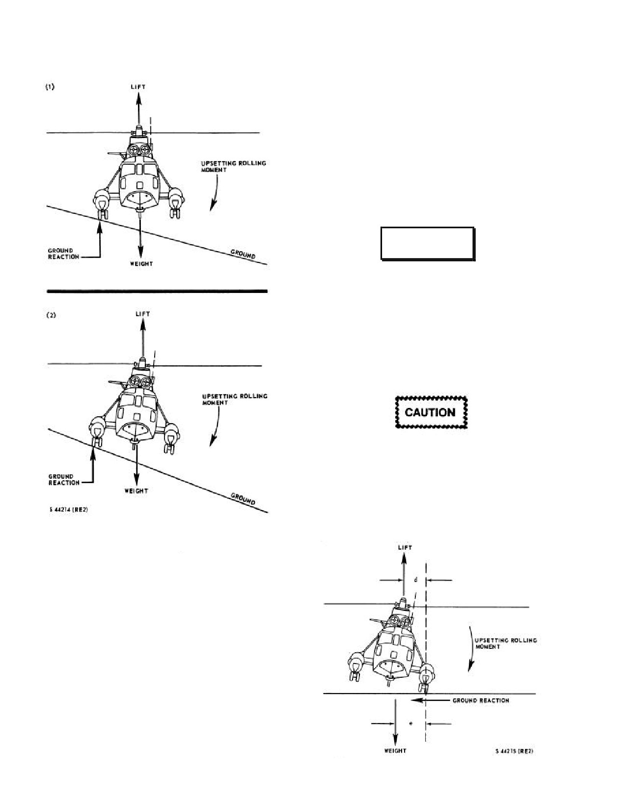
NAVAIR 01-230HLH-1
restoring moment decreases to zero at the static tipover
angle at which the helicopter will tip over. It is important
for the pilot to realize that once the lateral control contacts
the stop, roll angle control can still be effected with the
collective; down collective to level the helicopter and up
collective to roll over. The rate at which the collective
should be lowered depends on the dynamics of the
situation (roll rate at contact of the lateral stop). The pilot
should definitely lower the collective if it appears that
cyclic control is ineffective, even though it has not yet
contacted the stop.
WARNING
If lateral cyclic control becomes sluggish or
ineffectual or contacts the lateral stop or if
bank angle becomes excessive (80 to 100)
with one wheel on the ground and thrust
about equal to the weight, the helicopter will
roll over on its side. Use full cyclic control
and reduce collective to stop the roll, and
then correct the bank angle to wings level.
When landing or taking off, with thrust
about equal to the weight and one wheel on
the ground, keep the helicopter under
control and do not allow drift or yaw rates to
build up. Fly smoothly off
(or onto) the
ground, carefully maintaining a steady
position.
Figure 11-1. Slope Landing/Takeoff
Force Diagram
11.2.6.2 Dynamic Tipover. Figure 11-2 applies to the
dynamic tipover case. In this condition, the upsetting
rolling moment is provided by a side force on the wheel
contacting the ground (analogous to the downslope wheel
in the slope landing discussion) instead of a vertical force
on the upslope wheel. This side force can be extremely
large depending on the degree of restraint of the wheel.
The pilot can correct his roll angle with lateral control, but
it will be sluggish, as described in the previous section,
until the lateral control contacts the stop. Figure 11-2 is
drawn to show a full lateral control position. As in the
slope landing case, the collective is a method of roll
control. Since the cyclic control cannot be moved far
enough to get the main rotor lift line outside of the wheel,
the rotor generates an upsetting moment (Lxd) about the
wheel. The only restoring moment capability is the weight
of the helicopter (W) times the offset distance (e). The
Figure 11-2. Dynamic Tipover Force Diagram
11-4
ORIGINAL
NAVAIR 01-230HLH-1
11.3
Mountain and Rough Terrain Flying
experienced pilots. The accuracy with which wind
direction may be determined through the "drift" method
becomes a function of wind velocity. The greater the wind
value the more closely the direction may be defined.
11.3.2 Landing Site Evaluation. Six major
The transmission oil cooler was designed for
considerations in evaluating the landing area are:
maximum efficiency during sea level
operations. Higher than normal main gear-box
1.
Height of obstacles that determine approach
oil temperatures can be anticipated when
angle.
operating at altitudes above sea level when
combined with high ambient temperatures
2. Size and topography of the landing zone.
and high power settings. The reduced
pressure/density of air passing through the
3. Possible loss of wind effect.
radiator causes a loss in cooling efficiency
of the main gearbox cooler.
4. Power required.
Many helicopter missions require flight and landings
5. Departure route.
in rough and mountainous terrain. Refined flying
techniques along with complete and precise knowledge of
6. Surface composition.
the individual problems to be encountered are required.
Landing site condition, wind direction and velocity, gross
Type of terrain and surface composition may dictate
weight limitations, and effects of obstacles are but a few of
whether a hover-type landing is feasible. When practical,
the considerations for each landing or takeoff. In a great
this type of landing should be accomplished; however,
many cases, meteorology facilities and information are not
high gross weight, density altitude, or presence of loose
available at the site of intended operation. The effects of
sand, soil, or grass may require a no-hover landing. To
mountains and vegetation can greatly vary wind conditions
preclude aircraft damage, groundspeed at touchdown
and temperatures. For this reason, each landing site must
should be minimized. The transition period is the most
be evaluated at the time of intended operation. Altitude and
difficult part of any approach. As helicopter performance
temperature are major factors in determining helicopter
decreases, the transition period becomes more critical, and
power performance. Gross weight limitations under
of necessity approaches must be shallower and transition
specific conditions can be computed from the performance
more gradual.
data in Part XI. A major factor improving helicopter lifting
performance is wind. Weight carrying capability increases
Therefore, as the height of the obstacle increases,
rapidly with increases in wind velocity relative to rotor
larger areas will be required. As wind velocity increases,
system. However, accurate wind information is more
so does helicopter performance; however, when the
difficult to obtain and more variable than other planning
helicopter drops below an obstacle, a loss of wind
data. It is therefore not advisable to include wind in
generally occurs as a result of the airflow being unable to
advanced planning data except to note that any wind
immediately negotiate the change prevalent at the upwind
encountered in the operating area may serve to improve
side of the landing zone where a virtual null area exists.
helicopter performance. In a few cases, operational
This null area extends toward the downwind side of the
necessity will require landing on a prepared surface at an
clearing and will become larger as the height of the
altitude above the hovering capability of the helicopter. In
obstacle and wind velocity increases. It is therefore
these cases, a rolling landing and takeoff will be necessary
increasingly important in the landing phase that this null
to accomplish the mission. Data for these conditions can
area be avoided if marginal performance capabilities are
be computed from the charts in Part XI.
anticipated. The null area is of particular concern in
making a takeoff from a confined area. Under heavy load
11.3.1 Wind Direction and Velocity. There are
or limited power conditions, it is desired to achieve a
several methods of determining the wind direction and
significant value of forward velocity and transitional lift
velocity in rough areas. The most reliable method is by the
prior to transitioning to a climb so that the overall climb
use of smoke generators. However, it must be noted that
performance of the helicopter will be improved. If the
the hand-held day/night distress signal and the standard
takeoff cycle is not commenced from the most downwind
ordnance issue smoke hand grenade are satis factory for
portion of the area and translational velocity is achieved
wind indication but constitute a fire hazard when in areas
before arrival in the null area, a significant loss in lift may
covered with combustible vegetation. Observation of
occur at the most critical portion of the takeoff. It must
foliage will indicate to some degree the direction of the
also be noted that in the vicinity of the null area nearly
wind but is of limited value in estimating wind velocity.
vertical downdraft of air may be encountered, that will
Helicopter drift determined by eyesight without the use of
further reduce the actual climb rate of the helicopter. It is
navigational aids is the first method generally used by
feasible that under certain combinations of limited area,
11-5
ORIGINAL
NAVAIR 01-230HLH-1
high obstacles upwind, and limited power available, the
mountains if there is a surface wind. Orographic
best takeoff route would be either crosswind or downwind,
turbulence is directly proportional to the wind velocity. It
terrain permitting. The effects of detrimental wind flow
is found on the upwind side of slopes and ridges near the
and the requirement to climb may thus be minimized or
tops and extending down the downwind slope (see Figure
circumvented. Even though this is a departure from the
11-3). It will always be found on tops of ridges associated
cardinal rule of takeoff into the wind, it may well be the
with updrafts on the upwind side and downdrafts on the
proper solution when all factors are weighed in their true
downwind side. Its extent on the downwind slope depends
perspective. Never plan an approach to a confined area
on the strength of the wind and the steepness of the slope.
wherein there is no reasonable route of departure. The
If the wind is fairly strong (15 to 20 knots) and the slope is
terrain within site is considered from an evaluation of
steep, the wind will have a tendency to blow off the slope
vegetation, surface characteristics, and slope. Care must be
and not follow it down; however, there will still be some
taken to avoid placing the rotors in low brush or branches.
tendency to follow the slope. In this situation, there will
Obstacles covered by grass may be located by flattening
probably be severe turbulence several hundred yards
the grass with rotor wash before landing. Power should be
downwind of the ridge at a level just below the top. Under
maintained so that an immediate takeoff may be made
certain atmospheric conditions, a lens-shaped cloud may
should the helicopter start tipping from soft earth or a gear
be observed above the ridge. On more gentle slopes, the
dropping into a hidden hole.
turbulence will follow down the slope but will be more
severe near the top. Orographic turbulence will be affected
by other factors. The intensity will not be as great when
climbing a smooth surface as when climbing a rough
surface. It will not follow sharp contours as readily as
WARNING
gentle contours.
Helicopters with wheel-type landing gear
Man-made obstructions and vegetation will also cause
are not well suited to landing in unprepared
turbulence. Extreme care should be taken when hovering
terrain. Landing sites must be chosen with
near buildings, hangars, and similar obstructions. The best
extreme care to avoid damage to helicopter
method to overfly ridgelines from any direction is to
or injury to personnel. Excessive slopes or
acquire sufficient altitude before crossing to avoid leeside
obstacles must be avoided. Be prepared to
downdrafts. If landing on ridge lines (see Figure 11-4), the
effect an immediate takeoff to a hover if the
approach should be made along the ridge in the updraft, or
helicopter settles unevenly or encounters
select an approach angle into the wind that is above the
difficulty while landing.
leeside turbulence. When the wind blows across a narrow
canyon or gorge (see Figure 11-5), it will often veer down
11.3.3 Effects of High Altitude. Engine power
into the canyon.
available at altitude is less, and operations can easily be in
a situation of limited hovering ability. High gross weight at
Turbulence will be found near the middle and
altitude increases the susceptibility of the helicopter to
downwind side of the canyon or gorge. When a helicopter
blade stall. Conditions that contribute to blade stall are
is being operated at or near its service ceiling and a
high forward speed, high gross weight, high altitude, low
downdraft of more than
100 fpm is encountered, the
rpm, induced g loading, and turbulence. Shallower turns at
helicopter will descend. Although the downdraft does not
slower airspeeds are required to avoid blade stall. A
continue to the ground, a rate of descent may be
permissible maneuver at sea level must be tempered at a
established of such magnitude that the helicopter will
higher altitude. Smooth and timely control application and
continue descending and crash even though the helicopter
anticipation of power requirement will do more than
is no longer affected by the downdraft. Therefore, the
anything else to improve altitude performance.
procedure for transiting a mountain pass shall be to fly
close aboard that side of the pass or canyon that affords an
11.3.4 Turbulent-Air Flight Techniques. Helicopter
upslope wind. This procedure not only provides additional
pilots must be constantly alert to evaluate and avoid areas
lift but also provides a readily available means of exit in
of severe turbulence; however, if encountered, immediate
case of emergency. Maximum turning space is available
steps must be taken to avoid continued flight through it to
and a turn into the wind is also a turn to lower terrain. The
preclude the structural limits of the helicopter being
often used procedure of flying through the middle of a pass
exceeded. Severe turbulence is often found in
to avoid mountains invites disaster. This is frequently the
thunderstorms and helicopter operations should not be
area of greatest turbulence (see Figure 11-6), and in case of
conducted in their vicinity. The most frequently
emergency, the pilot has little or no opportunity to turn
encountered type of turbulence is orographic turbulence. It
back because of insufficient turning space. Rising air
can be dangerous if severe and is normally associated with
currents created by surface heating cause convective
updrafts and downdrafts. It is created by moving air being
turbulence. This is most prevalent over bare areas.
lifted by natural or manmade obstructions. It is most
prevalent in mountainous regions and is always present in
11-6
ORIGINAL
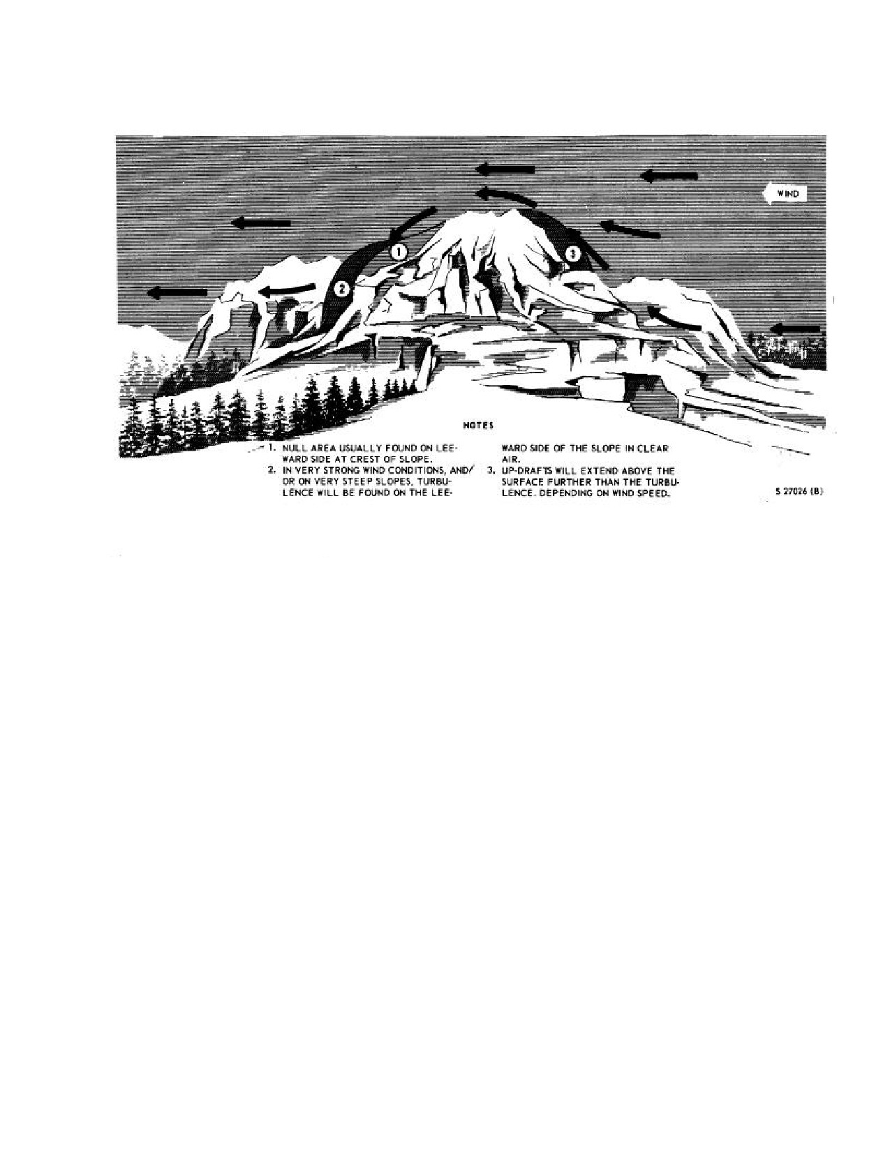
NAVAIR 01-230HLH-1
Figure 11-3. Wind Flow Over and Around Peaks
Convective turbulence is normally found at a
11.3.6 Summary.
The following guidelines are
relatively low height above the terrain, generally below
considered to be most important for mountain and rough
2,000 feet. It may, however, under certain conditions and
terrain flying:
in certain areas, reach as high as 8,000 feet above the
terrain. Attempting to fly over convective turbulence
1.
Make a continuous check of wind direction and
should be carefully considered, depending on the mission
estimated velocity.
assigned. The best method is to fly at the lowest altitude
consistent with safety. Attempt to keep your flightpath
2.
Plan your approach so that an abort can be made
over areas covered with vegetation. Turbulence can be
downhill and/or into the wind without climbing.
anticipated when transitioning from bare areas to areas
covered by vegetation or snow.
3.
If wind is relatively calm, try to select a hill or
knoll for landing so as to take full advantage of any
Convective turbulence seldom gets severe enough to
possible wind effect.
cause structural damage.
4.
When evaluating a landing site, execute as many
11.3.5 Adverse Weather Conditions. When flying in
fly-bys as necessary with at least one high and one
and around mountainous terrain under adverse weather
low pass before conducting operations into a strange
conditions, it should be remembered that the possibility of
landing area.
inadvertent entry into clouds is ever present. Air currents
are unpredictable and may cause cloud formations to shift
5.
Evaluate the obstacles in the landing site and
rapidly. Since depth perception is poor with relation to
consider possible null areas and routes of departure
distance from cloud formation and to cloud movement,
(see Figure 11-7).
low hanging clouds and scud should be given a wide berth
at all times. In addition to being well briefed, the pilot
6. Landing site selection should not be based solely
should carefully study the route to be flown. A careful
on convenience but consideration should be given to
check of the helicopter compass should be maintained in
all relevant factors.
order to fly a true heading if the occasion demands.
11-7
ORIGINAL
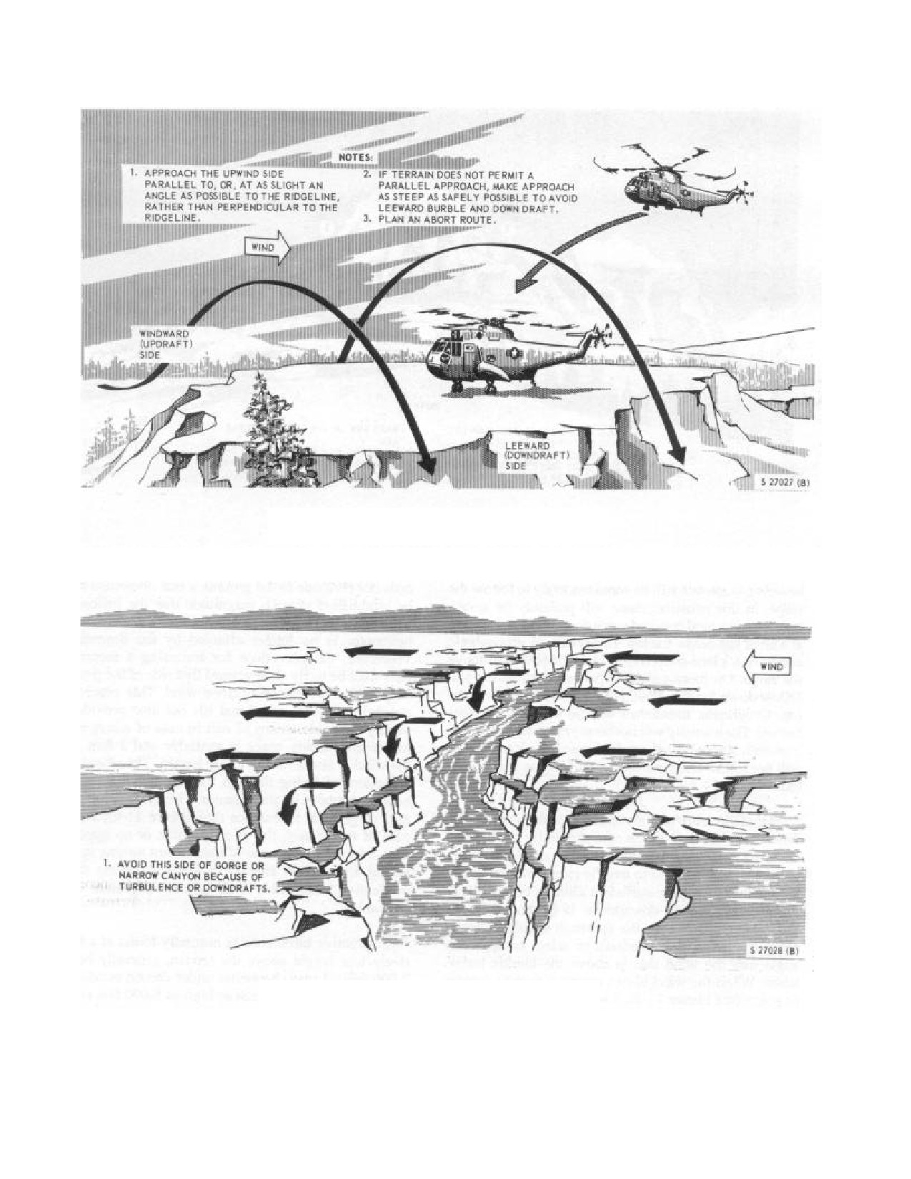
NAVAIR 01-230HLH-1
Figure 11-4. Wind Effect on Ridgeline Approach
Figure 11-5. Windflow Over Gorge or Canyon
11-8
ORIGINAL
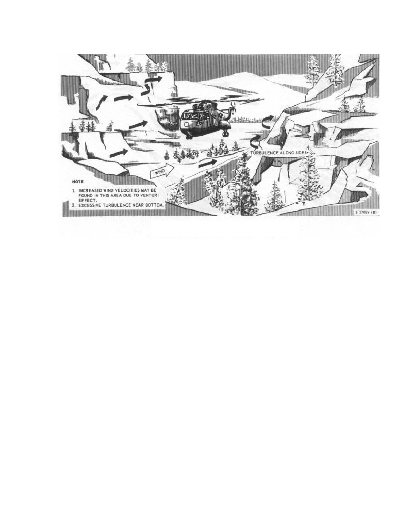
NAVAIR 01-230HLH-1
Figure 11-6. Windflow in Valley or Canyon
Note
Careful preflight analysis of engine
7. Determine ability to hover out of ground effect
performance charts, hovering charts, and
prior to attempting a landing.
blade stall charts will aid in avoiding
extreme situations during mountainous
8. Watch for rpm surges during turbulent conditions.
operations.
Strong updrafts will cause rpm to increase, whereas
downdrafts will cause rpm to decrease.
11.4
Terrain Flying
9. Avoid flight in or near thunderstorms.
11.4.1 General. Terrain following flights shall be
accomplished only when properly scheduled, planned, and
10. Give all cloud formations a wide berth.
briefed for that specific mission. When conducted, they
should be flown no lower than is necessary to accomplish
11. Fly as smoothly as possible and avoid steep turns.
the mission. Consult appropriate manuals for procedures
and techniques for terrain flying to avoid visual and/or
12. Cross mountain peaks and ridges high enough to
electronic detection in a threat environment.
stay out of downdrafts on the leeside of the crest.
1.
Low-level flight
- Flight at a preselected altitude
13. Avoid downdrafts prevalent on leeward slopes.
below 500 feet along a prescribed route, usually in
straight-line segments at constant airspeed.
14. Plan your flight to take advantage of the up-drafts
on the windward slopes.
2.
Contour flight - Flight at low altitude conforming
generally to the contours of the Earth with varying
15. Whenever possible, approaches to ridges should
airspeed and altitude as vegetation and obstacles
be along the ridge rather than perpendicular.
dictate.
16. Avoid high rates of descent when approaching
3.
NOE flight - Flight as close to the Earth's surface
landing sites.
as vegetation/obstacles permit. NOE is similar to
contour flight but is conducted at lower altitudes and
17. Know your route and brief well for flying in these
is characterized by airspeeds from a hover/air taxi to
areas.
dashes of 60 to 70 knots.
11-9
ORIGINAL
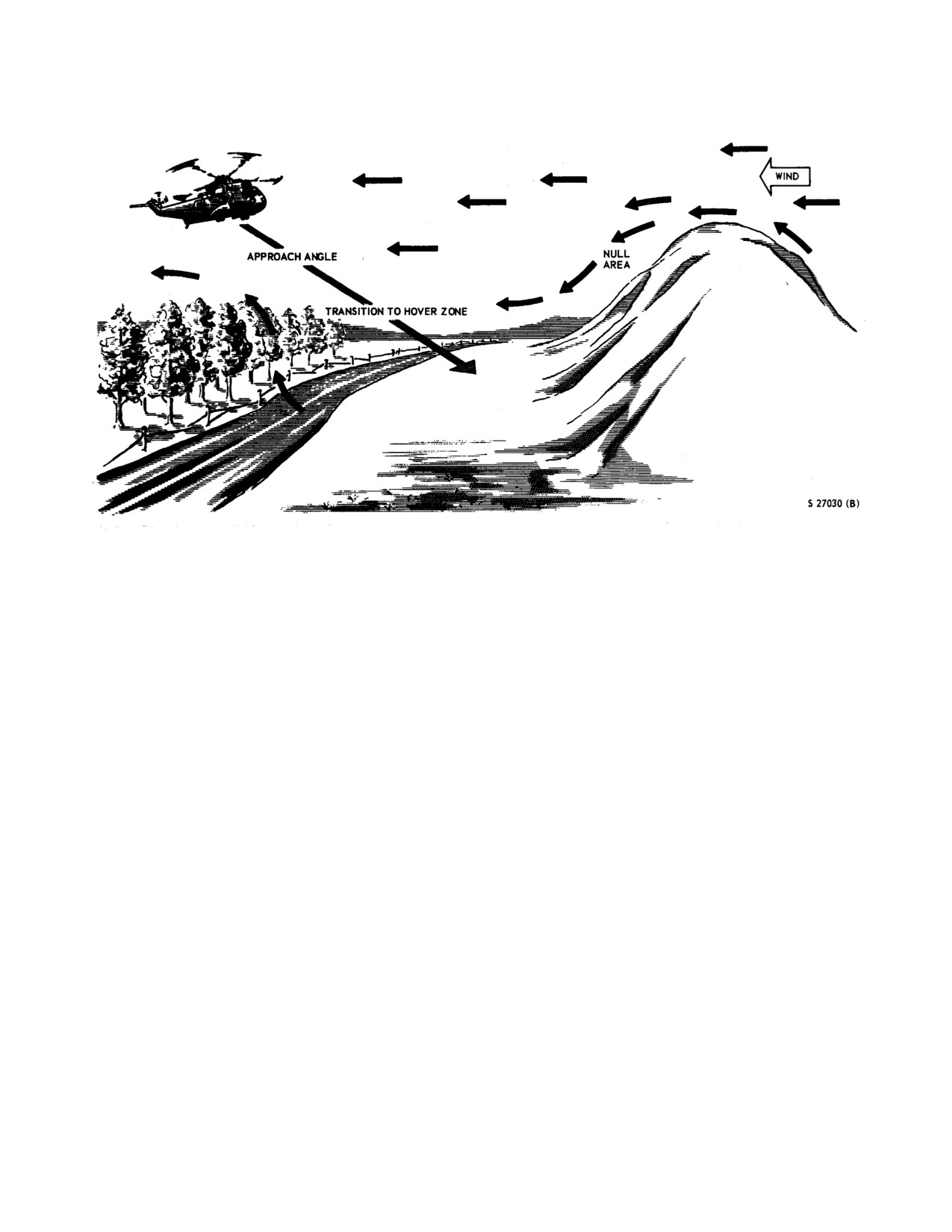
NAVAIR 01-230HLH-1
Figure 11-7. Wind Effect in a Confined Area
terrain flying is attempted. Aircraft and pilot reaction times
Note
in all flight regimes must be known and considered when
determining route of flight and altitude.
Terrain following flights shall be accomplished
only when properly scheduled, planned, and
11.4.2
Crew Coordination. In addition to other
briefed for that specific mission. When
individually assigned duties, all crewmembers are responsible
conducted, they should be flown no lower
for maintaining a visual lookout and recognizing and
than is necessary to accomplish the mission.
communicating obstacles/hazards of flight to the pilot at the
controls. The pilot at the controls is responsible for controlling
Learning terrain flying is a long-term cumulative
the aircraft and avoiding obstacles. His attention must
process. Low level must be mastered before attempting
constantly be outside of the aircraft and he may aid in
contour flying that must precede NOE. Terrain flying is
navigation by reporting prominent landmarks.
very demanding of both crew and aircraft.
The pilot not at the controls will be responsible for
The close proximity to obstacles, rapid attitude
monitoring flight and engine instruments and will be the
adjustment, and many power changes with frequent high-
crewmember primarily responsible for navigation. He should
power demands puts a great stress on airframe and
provide speed and direction of flight recommendations,
dynamic components. These same parameters demand
utilizing clock position or direction of turn rather than
increased attention from individual crewmembers as well
compass headings. He should also assist in determining
as the crew as a whole. Proper crew coordination is
altitude by providing information on obstacles out of the
essential. Detailed individual tasking of duties must be
pilot's field of vision.
prebriefed and rigidly enforced. Standard phraseology
should be developed and used in intercrew
One air crewman will be assigned a lookout station at
communications to avoid confusion during critical
the cargo door. He will be responsible for obstacle
segments of flight. Constant navigation is critical and the
clearance on the starboard side and for clearing the tail,
crewmember navigating should keep the aircraft position
especially during approaches and hovering. The second air
fixed (as accurately as possible). Emergencies are more
crewman will be assigned a lookout station on the port side
critical at low altitude and corrective actions must be
of the aircraft and be responsible for obstruction clearance.
completed expeditiously. Aircraft performance should be
calculated prior to flight, utilizing worst condition
parameters of density altitude, gross weight, and winds.
The aircraft should be performance checked in flight to
ensure that the calculated performance is available before
11-10
ORIGINAL
NAVAIR 01-230HLH-1
WARNING
All crewmembers shall use crewman safety
belts while not in their seats because of the
frequent maneuvering involved.
11.4.3
Summary. The following guidelines are
considered to be most important for terrain flying.
1.
The pilot at the controls must concentrate his
attention out of the cockpit, primarily concerned with
terrain/obstacle avoidance.
2.
The pilot not at the controls must perform all
collateral cockpit functions, monitor gauges, and
navigate.
3.
Crewmembers must be assigned responsibility for
obstacle clearance of specific portions of the aircraft.
4.
Proper scheduling, briefing, preflight planning,
preflight, and crew coordination are essential.
5.
In a terrain flight envelope, emergency
procedures must be known perfectly and responses
must be immediate.
11-11
ORIGINAL
NAVAIR 01-230HLH-1
This Page Left Blank Intentionally
11-12
ORIGINAL
NAVAIR 01-230HLH-1
PART V
Emergency Procedures
CHAPTER 12 - EMERGENCY PROCEDURE
Page No
12.1
GENERAL
12-1
12.2
CRITICAL PROCEDURES
12-1
12.2.1
Recommended Dual Concurrence Items
12-1
12.3
EMERGENCY ROTOR ENGAGEMENT
12-1
12.4
FIRE
12-1
12.4.1
Engine Fire on the Ground
12-1
12.4.2
Engine Fire In Flight
12-2
12.4.3
Fuselage or Electrical Fire
12-2
12.4.4
Heater Fire
12-3
12.4.5
Smoke/Fume/Noxious Gas Elimination
12-3
12.4.6
Postshutdown Engine Fire
12-3
12.5
FUEL SYSTEM FAILURE
12-3
12.5.1
Fuel Boost Pump Failure
12-3
12.5.2
Fuel Crossfeed Malfunctions
12-4
12.5.3
Fuel Filter Bypass
12-4
12.5.4
Inadvertent Fuel Dumping in Flight
12-4
12.6
STARTER HANGUP
12-4
12.7
ENGINE MALFUNCTIONS
12-4
12.8
RAIN INGESTION
12-5
12.9
SINGLE INSTRUMENT INDICATIONS
12-5
12.9.1
Ng Tachometer System Malfunctions
12-5
12.9.2
Ng Tachometer Fluctuations
12-5
12.9.3
Nf Tachometer System Malfunction
12-5
12.9.4
Nf Tachometer Fluctuations
12-6
12.9.5
T5 System Malfunction
12-6
12.9.6
Engine Oil Pressure Fluctuations
12-6
12.9.7
Oil Pressure Failure
12-6
57
ORIGINAL
NAVAIR 01-230HLH-1
Page No
12.9.8
Oil Temperature System Malfunction
12-6
12.9.9
Nr Tachometer System Malfunction
12-7
12.10
FLIGHT CHARACTERISTICS
12-7
12.10.1
Vortex Ring State
12-7
12.10.2
Settling With Power
12-7
12.10.3
Blade Stall
12-7
12.11
ENGINE FAILURE
12-7
12.11.1
Immediate Emergency Procedures
12-7
12.11.2
Single-Engine Failure on Takeoff
12-8
12.11.3
Single-Engine Failure or Loss of Power While Hovering
12-8
12.11.4
Single-Engine Failure in Flight
12-8
12.11.5
Jettison
12-9
12.11.6
Engine Shutdown in Flight
12-9
12.11.7
Single-Engine Restart During Flight
12-9
12.11.8
COMPRESSOR STALL
12-9
12.11.9
LUBE PUMP OR SHAFT FAILURE
12-10
12.11.10
HIGH SPEED SHAFT (POWER TURBINE SHAFT)
12-10
12.11.11
AXIAL DRIVE SHAFT FAILURE
12-11
12.11.12
LOSS OF Ng SIGNAL TO FUEL CONTROL
12-12
12.11.13
LOSS OF P3 SIGNAL TO FUEL CONTROL
12-12
12.11.14
FLEXIBLE DRIVE SHAFT FAILURE
12-13
12.11.15
FUEL CONTROL CONTAMINATION
12-14
12.12
MAXIMUM RANGE
12-14
12.13
SINGLE-ENGINE LANDING (LAND OR SHIP)
12-16
12.13.1
Single-Engine Waveoff
12-16
12.14
DUAL-ENGINE FAILURE
12-16
12.14.1
Dual-Engine Failure While Hovering at Low Altitude
12-18
12.14.2
Dual-Engine Failure During Flight (Autorotative Landing)
12-18
12.15
MAXIMUM GLIDE
12-18
12.16
LANDING IN TREES
12-18
12.17
EMERGENCY DESCENT
12-18
12.18
MAIN GEARBOX SYSTEM FAILURE
12-18
12.18.1
Tail Takeoff Freewheel Unit Caution Light
12-20
12.18.2
Torque Sensing System Failure
12-21
58
ORIGINAL
NAVAIR 01-230HLH-1
Page No
12.19
MAIN ROTOR OVERSPEED
12-21
12.19.1
Blade Pressure Caution Light
12-21
12.20
ROTARY RUDDER SYSTEM FAILURES
12-21
12.20.1
Rotary Rudder Drive System Failure
12-22
12.20.2
Rotary Rudder Drive System Failure While Hovering
12-23
12.20.3
Rotary Rudder Control System Failure
12-23
12.20.4
Impending Rotary Rudder System Failure
12-27
12.20.5
Tail Pylon Unlock Light
12-27
12.21
ELECTRICAL MALFUNCTION
12-27
12.21.1
Alternating Current System Failure
12-27
12.21.2
Direct Current System Failure
12-30
12.22
FLIGHT CONTROL HYDRAULIC SERVO SYSTEM
12-30
12.22.1
Flight Control Malfunction
12-30
12.22.2
Servo Hydraulic Pressure Failure
12-31
12.22.3
Illumination of Servo System Caution Light
12-31
12.23
FLIGHT CONTROLS JAMMED OR RESTRICTED
12-31
12.23.1
On Ground
12-31
12.23.2
In Flight
12-31
12.24
FLIGHT CONTROL SERVO UNIT MALFUNCTION
12-31
12.24.1
Coupled Indications
12-32
12.24.2
Uncoupled Indications
12-32
12.24.3
Hardover in the Fore-and-Aft Primary Servo or Blocked Common Return
12-32
in One Auxiliary Servo
12.24.4
Vibratory Forces
12-32
12.25
AUTOMATIC STABILIZATION EQUIPMENT SYSTEM FAILURE
12-32
12.25.1
Power Supply Failure
12-32
12.25.2
Malfunction
12-33
12.25.3
Beeper Trim Malfunction
12-33
12.26
UTILITY HYDRAULIC SYSTEM FAILURE
12-33
12.27
RESCUE HOIST MALFUNCTION
12-33
12.28
LANDING GEAR FAILURE
12-35
12.28.1
Landing With Wheels Retracted or Improperly Lowered
12-35
12.28.2
Landing Gear Falls to Retract
12-36
12.29
HUNG DROOP STOPS
12-36
59
ORIGINAL
NAVAIR 01-230HLH-1
Page No
12.30
ROTOR BRAKE CAUTION LIGHT
12-36
12.31
ROTOR BRAKE FAILURE
12-36
12.32
COUPLER MALFUNCTIONS
12-37
12.32.1
Loss of Doppler Receiver
12-37
12.32.2
Loss of Doppler Transmitter
12-38
12.32.3
Sidelobe Lock-On
12-38
12.32.4
Loss of Radar Altimeter
12-38
12.32.5
Malfunction of Stick Trim
12-39
12.32.6
Loss of ASE
12-39
12.32.7
Loss of Attitude Indicator
12-39
12.32.8
Sar Freestream Recovery
12-39
12.32.9
Loss of Generator
12-40
12.32.11
Cg Not Within Prescribed Limits
12-40
12.33
EMERGENCY WATER OPERATIONS
12-40
12.33.1
General Information
12-40
12.33.2
Water Taxiing
12-41
12.33.3
Fuel Dumping Afloat
12-41
12.33.4
Flotation Bags
12-41
12.33.5
Dual-Engine Vertical Landing
12-42
12.33.6
Single-Engine Water Landing
12-42
12.33.7
Single-Engine Failure or Loss of Power in an Overwater Hover
12-42
12.34
DITCHING PROCEDURES
12-43
12.34.1
Water Landing (Uncontrolled)
12-43
12.34.2
Water Landing (Controlled)
12-43
12.34.3
After Water Entry
12-43
12.34.4
Dual-Engine Vertical Water Takeoff
12-43
12.34.5
Single-Engine Water Takeoff
12-44
12.34.6
Water Shutdown Procedures
12-46
12.34.7
Abandoning Helicopter
12-46
12.34.8
Emergency Water Towing With Emergency Floats Inflated
12-47
12.35
EMERGENCY ENTRANCES AND EXITS
12-47
12.35.1
Pilot Compartment Jettisonable Window Assembly
12-47
12.35.2
Personnel Door
12-49
12.35.3
Cabin Door
12-49
12.35.4
Cabin Windows
12-49
12.36
INADVERTENT OPENING AND/OR LOSS OF ACCESS PANELS/DOORS
12-50
12.37
UNDERWATER EGRESS
12-50
60
ORIGINAL
NAVAIR 01-230HLH-1
Page No
12.38
AUXILIARY FLOTATION COLLAR
12-50
12 38.1
Application Checklist
12-50
12.39
(NON-ET) WEAPON RECOVERY EMERGENCIES
12-51
12.39.1
Helicopter External Load Jettison
12-51
12.39.2
Emergency Jettison Procedures
12-51
12.39.3
Load Oscillation Techniques
12-52
12.39.4
Mk 2 Mod 0/1 Entanglement Procedures
12-52
12.40
UH-3H EXECUTIVE TRANSPORT EMERGENCY PROCEDURES
12-53
12.40.1
Smoke and Fume Elimination (UH-3H Executive Transport)
12-53
12.40.2
Heater/Air Conditioner Fire (UH-3H Executive Transport)
12-53
12.40.3
APU Fire on the Ground (UH-3H Executive Transport)
12-53
12.40.4
Interior Release Handle
12-53
12.40.5
Exterior Release Handle
12-53
12.41
(ET) Cabin Emergency Exit Hatches
12-54
12.41.1
(ET) Interior
12-54
12.41.2
(ET) Exterior
12-54
61
ORIGINAL
NAVAIR 01-230HLH-1
This Page Left Blank Intentionally
62
ORIGINAL
NAVAIR 01-230HLH-1
CHAPTER 12
Emergency Procedures
12.1 GENERAL
lubrication until the rotary wing has turned through
several revolutions. For this reason, the correct technique
The emergency situations and procedures outlined in
is as follows:
this chapter cover the common types of emergencies
encountered; however, the procedures used in each actual
1. Release the rotor brake and advance the speed
emergency encountered must result from consideration of
selector slightly to allow the rotary wing to begin a
the complete situation. Compound emergencies may
slow acceleration.
require departure from normal corrective procedures set
forth below for any specific emergency. Because of
2. Carefully monitor transmission oil pressure and
varied types of equipment installed, pilots and air
primary and auxiliary servo pressure for a rise. The
crewmen must be thoroughly familiar with the emergency
rotor system should not be accelerated until pressures
procedures in the succeeding paragraphs. A radio call
register normal.
and/or a switching of the IFF to emergency should be
attempted in emergencies requiring forced landing or
3. The cyclic stick and collective must be held
diverting. The terms land as soon as practicable, land
firmly. Slight kicks may feed back into the controls
immediately, and land as soon as possible refer to the
when servo pressures are rising.
degree of urgency with which a landing must be made and
are not meant to preclude the use of sound judgment on
12.4 FIRE
the part of the pilot in command under these conditions.
12.2 CRITICAL PROCEDURES
WARNING
Procedures marked with an asterisk
(*) are
considered critical. Air crewmembers shall be able to
accomplish asterisked procedures without reference to the
It
is
recommended that secondary
checklist.
indications of fire
(smoke, fumes, seeing
the fire) be considered before a decision is
12.2.1 Recommended Dual Concurrence Items.
made to execute emergency procedures.
It is recommended to gain dual concurrence before
manipulating the following items:
12.4.1 Engine Fire on the Ground. .If an engine
fire occurs while on the ground:
a. Accessory Drive
b. T-Handles
*1. Engine speed selectors - SHUTOFF.
c. Manual Throttles
d. Speed Selectors
*2. Engine T-handle - PULL.
e. Fuel Management Panel
f.
Generators at night/IMC
*3. Engine fire extinguisher switch
- MAIN
g.
Fuel Dump Switches
(CIRCUIT BREAKER-CHECK), THEN RESERVE,
IF NECESSARY.
12.3 EMERGENCY ROTOR ENGAGEMENT
*4. Rotor brake - ON.
It may be necessary to engage the rotor with the No.
1 engine and the accessory drive stuck in the FLIGHT
5. Fuel management panel - SECURED.
position or engage the rotor with the No. 2 engine while
the No. 1 engine is shut down or stuck in the FLIGHT
position. There will be no servo pressure and no gearbox
12-1
ORIGINAL
NAVAIR 01-230HLH-1
WARNING
Vapors from the fire extinguisher agent,
bromotrifluoromethane,
while
not
In case of fire in both engines, if reserve
poisonous, can cause asphyxiation through
position was used on the first engine fire in
reduction of oxygen, especially in confined
place of main position, reserve must be
spaces. The liquid can cause low-
used on the second engine fire. There will
temperature burns when in contact with the
be no extinguishing agent available if both
skin. All personnel should stand clear and
main and reserve positions were used on
in the open air. If the helicopter is on the
the first engine fire.
ground, the cabin should be vacated as a
precautionary measure.
Note
6. Battery - OFF.
· The close proximity of both engine
compartment fire detection elements
7. When rotor blades have stopped
- ABANDON
makes it possible for indications of a
AIRCRAFT.
fire to be transmitted from one
compartment to the other, thus
12.4.2 Engine Fire In Flight.
producing false dual-engine fire
indications in the cockpit.
· The fire detection element requires a
WARNING
period of time to cool after the heat has
been removed and may cause the fire
warning lights to remain on for a period
If
dual-engine
fire
occurs,
enter
of time. Realization of this may avoid
the needless use of the reserve fire
autorotation and secure engines.
bottle.
It
should not, however,
Note
discourage use of the reserve bottle if
continued fire is confirmed after using
the main fire extinguisher.
When hovering in low wind conditions
and/or high ambient air temperatures, a fire
9.
Boost pumps and crossfeed - AS REQUIRED.
warning light may go on when fire is not
present. If a fire warning element breaks, it
may cause a fire warning light to go on
10. Determine normal engine’s power available.
when fire is not present.
11. Landing gear - AS REQUIRED.
*1. Confirm Fire.
12. Land as soon as possible.
*2. Speed selectors - FULL FORWARD.
If fire continues, proceed as follows:
*3. Contain Nr.
12. Landing gear - AS REQUIRED.
*4. Establish single-engine airspeed and
level
13. Land immediately.
attitude.
*5. Reduce gross weight, if necessary, by dumping
12.4.3 Fuselage or Electrical Fire.
fuel and/or jettisoning stores.
1. Pilot compartment sliding windows - CLOSED.
*6. Speed selector (bad engine) - SHUTOFF.
2. Cabin doors and hatches - CLOSED.
*7. Engine T-handle - PULL.
3. Ventilation and heating fan switch - OFF.
*8. Engine fire extinguisher switch
- MAIN
(CIRCUIT BREAKER-CHECK), THEN RESERVE,
4. Determine source of fire.
IF NECESSARY.
12-2
ORIGINAL
NAVAIR 01-230HLH-1
a.
If source is known
- turn off affected
SYMPTOMS
equipment and pull affected circuit breakers.
1. T5 rises above 300 °C.
b.
If source is unknown
- secure all
nonessential equipment and pull nonessential
2. Engine smoke.
circuit breakers.
CORRECTIVE ACTION
5. Portable fire extinguisher - USE.
* 1. Check speed selector - SHUTOFF.
6.
If fire goes out
- Land as soon as practicable.
Refer to Smoke/Fume/Noxious Gas Elimination as
*2. Ignition switches - OFF.
required.
*3. Battery - ON.
If fire continues, proceed as follows:
*4. Emergency start switch - ON.
7. Landing gear - AS REQUIRED.
*5. Engine T-handle - PULL.
8. Land immediately.
*6. Starter - ENGAGE.
12.4.4 Heater Fire.
After T5/smoke decreases, disengage starter.
1. Cabin heater switch - SECURE.
7. If fire continues, proceed as follows:
If fire continues, proceed as follows:
a. On the ground, have crewman or lineman
2. Cabin heater fan switch - SECURE.
discharge fire bottle in engine intake while
motoring starter. If fire warning light remains on,
3. Cabin heater circuit breaker - PULL.
fire extinguisher switch
- MAIN
(CHECK
CIRCUIT BREAKER), THEN RESERVE, IF
4. Vents - CLOSE TO CONTAIN FIRE.
NECESSARY.
5. Fight fire using fire extinguisher at heater
fire
12.5 FUEL SYSTEM FAILURE
access port and/or heater ducts.
12.5.1 Fuel Boost Pump Failure.
Note
1. If both fuel boost pumps are lost in one tank, land
Vents should be closed to contain fire and
as soon as practicable.
provide more effective use of fire
extinguisher.
2. If the fuel boost pump warning light goes on
activate the remaining boost pump for that tank before
12.4.5 Smoke/Fume/Noxious Gas Elimination.
securing the affected pump. If the fuel boost pump
Smoke, fume, or noxious gases may be eliminated by
failure light goes off when both pumps are activated,
opening the pilot compartment sliding windows and the
there may be a fuel leak. Instruct the crewman to
cargo doors to get airflow throughout the cabin. Consider
investigate for fuel fumes/leaks. If a leak is detected or
adjustment of the registers and diffusers in the pilot
fuel gauges indicate abnormal consumption, proceed
compartment and cabin. Do not push out the cabin
as follows:
windows or the cabin door emergency escape window
while the helicopter is in flight, because of the possibility
of their being carried into the rotary rudder blades by the
airstream.
WARNING
12.4.6 Postshutdown Engine Fire. A fire may
occur within the combustion chamber after shutdown that
may continue to feed itself unless blown out by
With both boost pumps off in the affected
compressor air.
tank and the crossfeed open, transfer of all
fuel from the good tank will result in dual-
engine flameout.
a. Crossfeed from the good tank.
12-3
ORIGINAL
NAVAIR 01-230HLH-1
WARNING
12.5.4 Inadvertent Fuel Dumping in Flight. In case
of experiencing inadvertent fuel dumping in flight,
b. Land as soon as practicable.
proceed as follows:
Securing both pumps in one tank may cause
1. Fuel dump switches/valves
- CHECK AT OFF
engine flameout.
POSITION.
12.5.2 Fuel Crossfeed Malfunctions. If fuel does
2. Fuel dump pump circuit breakers - PULL.
not crossfeed utilizing normal procedures, proceed as
follows:
3. Crewman visually check fuel dump tube to be sure
fuel dumping has been secured.
1. If no evidence of crossfeed is noted, change pump
usage in the noncrossfeeding tank.
4. Landing criteria predicated upon amount of fuel
remaining.
2. If fuel crossfeed is still not evident, turn on all
boost pumps, open crossfeed switch, and land as soon
as practicable.
WARNING
When the fuel low-level caution lights go
on, attitudes of over 6° noseup should be
avoided because of the possibility of fuel
A malfunctioning transfer check valve can
starvation.
result in air being drawn into the fuel
system from the empty center tank and can
12.6 STARTER HANGUP
result in flameout of the engine serviced by
the fuel tank in which both boost pumps are
If the starter fails to disengage, proceed as follows:
either inoperative or off.
1. Speed selector lever - PULL DOWN.
12.5.3 Fuel Filter Bypass. Contamination of either
airframe fuel line filter will result in the lighting of the
2. If starter still engaged
- PULL STARTER
FWD FUEL BYPASS or AFT FUEL BYPASS caution
CIRCUIT BREAKER.
light. To preclude fuel control contamination and
flameout because of fuel exhaustion or fuel control
3. If starter still engaged - SECURE ENGINES.
malfunction, proceed as follows:
4. Secure electrical power.
12.7
ENGINE MALFUNCTIONS
WARNING
The material contained herein assumes a certain
knowledge of basic engine operation. In regard to cockpit
indications, it is particularly important to consider the
With both boost pumps off, in the affected
relationship of Ng and T5. These two indicators on a
tank and the crossfeed open, transfer of all
properly operating engine will always rise and fall
fuel from the good tank will result in dual-
together as a function of engine power.
engine flameout.
When analyzing any engine malfunction, it is
1. Crossfeed from the good tank.
imperative that corrective action be based on an
intelligent analysis of all indications of engine operation
2. Land as soon as practicable.
and not on any one source, particularly not on torque
indication alone. The list of symptoms that will be given
for each malfunction are only the discrepant indications.
Except where otherwise noted, other cockpit instruments
remain normal.
12-4
ORIGINAL
NAVAIR 01-230HLH-1
CORRECTIVE ACTION
WARNING
1. Continue flight.
With manual throttle actuated, resistance
2. Check engine oil pressure indicator circuit breaker
may occur in the speed selector during
in.
conditions requiring movement at or below
3. Keep torques matched and use other engines Ng
the minimum governing range marking on
tachometer for approximate indication.
the throttle quadrant. Attempts to retard
speed selector beyond the point at which
12.9.2 Ng Tachometer Fluctuations.
this resistance occurs may result in
inadvertent engine shutdown.
SYMPTOMS
12.8 RAIN INGESTION
1. Ng tachometer needle fluctuations of over
±l
percent under normal loads and/or grinding sound
Power loss may be experienced when operating in
from front frame.
heavy rainfall. Fuel requirements become excessively
large as the engine attempts to supply fuel for water
2. Engine oil pressure, T5 and Nf indicate normal.
vaporization. When fuel requirements exceed the capacity
of the fuel control, the engine will decelerate until a
CORRECTIVE ACTION
stabilization point occurs at a lower power setting. The
following procedures apply:
1. Maintain safe single-engine parameters.
1. If a slight loss of Ng occurs, crosscheck
2. Monitor engine oil pressure and torque
for
torquemeters for indicated loss of power. If a
corresponding fluctuations.
substantial power loss occurs, apply manual throttle as
necessary to restore power.
3. Land as soon as practicable.
2. Manual throttle must be retrimmed to avoid
overspeed or overtemperature.
WARNING
WARNING
Ng tachometer fluctuations of over
±1
percent under normal loads and/or grinding
sounds from the front frame could be
A substantial loss of Nr may occur before
indicative of impending engine failure
engine stabilization is attained, resulting in
originating in the front frame accessory
rotor decay. Autorotative flight may be
drive section.
required to effect recovery.
12.9.3 Nf Tachometer System Malfunction.
12.9
SINGLE INSTRUMENT INDICATIONS
SYMPTOMS
In the case of an abnormal indication on only one
instrument, it is possible that an instrument system failure
1. No. 1 or No. 2 Nf tachometer needle on one or
has occurred. Prudence, however, will dictate a cautious
both gauges falls to zero.
approach according to which instrument is used, and the
manner in which it fails.
2. All other indications are normal.
12.9.1 Ng Tachometer System Malfunctions.
CORRECTIVE ACTION
SYMPTOMS
1. If one or both needles on the same gauge fails -
1. Ng tachometer needle falls to zero.
CONTINUE FLIGHT.
2. Engine oil pressure, T5, and Nf indicators normal.
12-5
ORIGINAL
NAVAIR 01-230HLH-1
2. If the same needle on both gauges fails - LAND
exceeding
temperature
versus
time
AS SOON AS PRACTICABLE.
limitations.
3. Keep torques matched and use other engine Nf
12.9.6 Engine Oil Pressure Fluctuations.
tachometer for approximate indication.
SYMPTOM
12.9.4 Nf Tachometer Fluctuations.
Engine oil pressure fluctuates in excess of ±3 psi (6
SYMPTOMS
psi differential) while engine power is at steady state. All
other indications are normal.
1. Nf tachometer needle fluctuations greater than ±l
percent under normal loads and audible engine
CORRECTIVE ACTION
fluctuations.
Land as soon as practicable. If oil pressure falls be-
2. Engine oil pressure, T5 , Ng , and torque indicate
low minimum, engine oil temperature exceeds maximum,
normal.
or abnormal engine noise is heard, secure engine in
accordance with procedures listed under engine
CORRECTIVE ACTION
malfunctions.
1. Maintain safe, single-engine parameters.
12.9.7 Oil Pressure Failure.
2. Monitor torque and Ng for corresponding
SYMPTOMS
fluctuations.
1. Oil pressure decreasing to zero.
3. Land as soon as practicable.
2. Other gauges are normal.
Note
CORRECTIVE ACTION
Rapid Nf fluctuations may be indicative of
any impending flex driveshaft failure,
* 1. Speed selectors - FULL FORWARD.
freewheeling unit failure, other main
gearbox failure, or a faulty Nf tach
*2. Contain Nr.
generator.
*3. Establish single-engine airspeed and level
12.9.5 T5 System Malfunction.
attitude.
SYMPTOMS
*4. Reduce gross weight if necessary by dumping
fuel and/or jettisoning stores.
1. T5 fluctuates, fails to rise and fall in harmony with
Ng, or falls to zero.
5. Check engine oil pressure and inverter circuit
breaker.
2. Other gauges normal.
6. Secure affected engine.
CORRECTIVE ACTION
7. Landing gear - AS REQUIRED.
1. Check the jumper plug on the engine trim checker
panel for proper installation.
8. Land as soon as practicable.
2. Use other engine instruments.
12.9.8 Oil Temperature System Malfunction.
3. Avoid high power settings.
SYMPTOM
4. Land as soon as practicable.
Oil temperature reading fluctuates erratically, pegs,
or falls to zero. All other instruments are normal.
Note
CORRECTIVE ACTION
Proper Ng topping adjustment will normally
prevent overtemperature; however, prolonged
1. Check circuit breaker.
operation at military power can result in
12-6
ORIGINAL
NAVAIR 01-230HLH-1
2. Continue flight, paying close attention to oil
*2. Increase forward airspeed.
pressure. Check cause of discrepancy upon return to
base.
*3. Enter autorotation if altitude permits. A considerable
loss of altitude may occur before the condition is
SYMPTOM
recognized and recovery is completed. During
approach for landing, the condition causing vortex
Oil temperature rises above red line.
ring state should be avoided.
CORRECTIVE ACTION
1. Attain safe single engine flight parameters.
2. Retard speed selector to minimum governing
Flight conditions causing vortex ring state
range.
should be avoided at low altitudes because
of the attendant loss of altitude necessary
3. Land as soon as practicable.
for
recovery. Recovery from fully
developed vortex ring state may be made
only by entering autorotation before
regaining airspeed.
WARNING
12.10.2 Settling With Power. For discussion of
settling with power, refer to paragraph 11.2.3.
Because of the possibility of subsequent
*1. Speed selectors - FULL FORWARD.
engine seizure, a single-engine profile shall
be flown.
*2. Contain Nr.
Note
*3. Establish single-engine airspeed and level attitude.
Speed selector may be advanced into the
governing range for a short duration during
*4. Reduce gross weight by dumping fuel and/or
the landing phase if necessary, if required
jettisoning stores.
for landing.
12.10.3 Blade Stall. For discussion of methods of
12.9.9 Nr Tachometer System Malfunction.
eliminating roughness caused by blade stall, refer to
paragraph 11.2.5. Eliminate blade stall by accomplishing
SYMPTOMS
one or any combination of the following:
1. Nr tachometer needles on one or both gauges fall
*1. Decrease collective pitch.
to zero.
*2. Decrease the severity of the maneuver.
2. Nf indications normal.
*3. Gradually decrease airspeed.
CORRECTIVE ACTION
*4. Increase rotor rpm.
1. If one indicator fails - CONTINUE, FLIGHT.
*5. Reduce altitude - AS NECESSARY.
2. If both indicators fail
- LAND AS SOON AS
PRACTICABLE.
12.11 ENGINE FAILURE
Avoid high Nr regimes.
12.11.1 Immediate Emergency Procedures. In all
malfunctions in which engine power retards or goes to
12.10 FLIGHT CHARACTERISTICS
full power, load sharing is such that the other engine will
show a corresponding decrease or increase in power as
12.10.1 Vortex Ring State. Refer to paragraph
the fuel control of the properly operating engine tries to
11.2.4 for description of vortex ring state.
maintain the selected rpm. In cruise flight there is usually
time to ascertain which engine has malfunctioned. In a
*1. Decrease collective pitch.
hover with loss of rpm imminent or on the deck at flat
pitch with overtemperature or overspeed threatening,
12-7
ORIGINAL
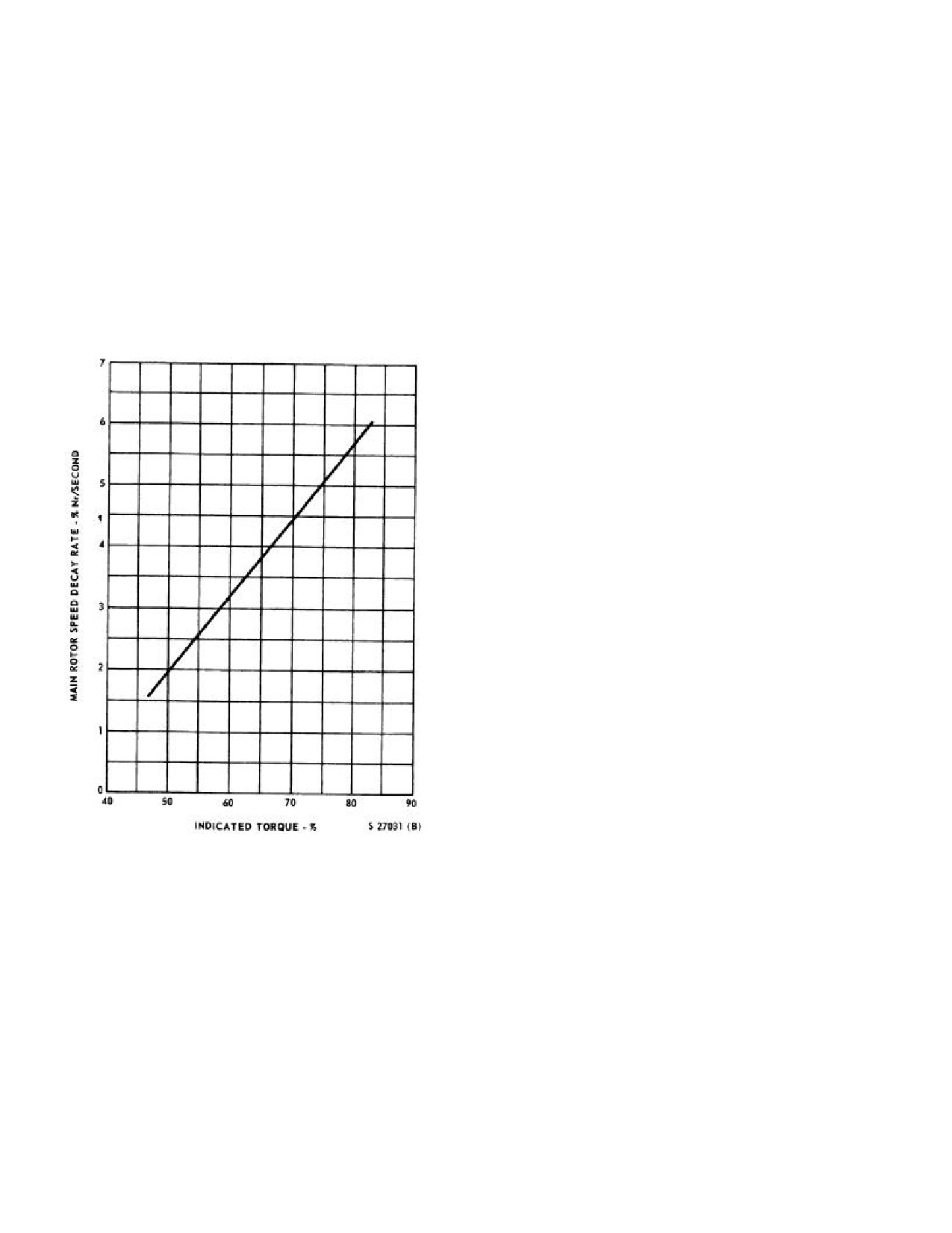
NAVAIR 01-230HLH-1
immediate action may be necessary without time to
*1. Speed selectors - FULL FORWARD.
analyze the situation.
*2. Maintain level attitude.
12.11.1.1 Main Rotor Decay Rate (Figure 12-1).
The main rotor decay rate following single-engine failure
If unable to maintain hover:
is essentially a function of engine torque required at the
time of failure, irrespective of airspeed, turn rate, or climb
*3. Cushion landing with collective.
rate. Flight regimes that require high torque settings will
produce higher main rotor decay rates. As shown, a 5-
If able to maintain stable hover with greater than
92-
percent decay in 1 second can be expected when failure
percent Nr:
occurs in flight regimes requiring
74.5-percent torque.
Rotor speed can be regained satisfactorily by lowering the
4. If necessary, transition to forward flight.
collective.
Note
For single-engine failure or loss of power in
an overwater hover, see paragraph 12.33.7
for further information.
12.11.4 Single-Engine Failure in Flight. Density
altitude, gross weight, and availability of a prepared
landing area will affect the pilot decision to abort or
continue flight.
*1. Speed selectors - FULL FORWARD.
*2. Contain Nr.
a. If Nr is decreasing, lower collective to keep Nr
92 percent or above.
b. If Nr is increasing, raise collective to keep Nr
below 112.5 percent.
*3. Establish single-engine airspeed and level
attitude.
*4. Reduce gross weight, if necessary, by dumping
fuel and/or jettisoning stores.
5. If altitude cannot be maintained, make single-
Figure 12-1. Rotor Speed Decay Rate Following
engine landing.
Single-Engine Failure
12.11.2 Single-Engine Failure on Takeoff.
6. If altitude can be maintained, proceed as follows:
*1. Speed selectors - FULL FORWARD.
a. Analyze source of engine malfunction; restart
engine, secure engine, or use manual throttle as
*2. Contain Nr.
appropriate.
*3. Assume approach attitude/airspeed.
b. Determine power available on properly
operating engine.
*4. Landing gear - AS REQUIRED.
7.
Maintain autorotative altitude/airspeed.
12.11.3 Single-Engine Failure or Loss of Power
While Hovering. A rule of thumb method that may
prove helpful is to check the amount of torque required to
hover on two engines and then to estimate if one engine
could supply the required power.
12-8
ORIGINAL
NAVAIR 01-230HLH-1
3.
Fuel firewall valve - OPEN.
WARNING
4.
Ignition - NORMAL.
When established in single-engine cruise
5.
Emergency start switch - ON.
flight, loss of the remaining operating
engine will cause rapid rotor rpm decay.
6.
Perform start.
Within 3 to 5 seconds, rotor rpm will decay
to an unrecoverable state with resultant loss
Note
of control unless autorotation is entered
immediately.
· If the auxiliary servo has failed or is
secured, both engine safety interlocks
8. Landing gear - AS REQUIRED.
are opened and the emergency start
switch must be used to start the No. 1
9. Land as soon as practicable.
and 2 engines.
12.11.5 Jettison.
· Above
10,000 feet altitude, manual
throttle assist may be necessary during
1. Jettison selector knob - AS DESIRED.
starts below
80 KIAS. If the engine
does not accelerate smoothly after light-
2. Individual RELEASE button - PRESS.
off with the speed selector in GRD
IDLE, carefully advance the manual
Note
throttle to assist engine acceleration.
Monitor turbine inlet temperature
JETTISON ALL switch will jettison all
closely when using manual throttle
external stores.
lever. When engine speed reaches GRD
IDLE, manual throttle should be fully
12.11.6 Engine Shutdown in Flight.
closed and all further engine operation
controlled by the speed selector.
1. Engine speed selector - SHUTOFF.
12.11.8 COMPRESSOR STALL. Compressor stall is
2. Fuel firewall valve - CLOSED.
normally encountered during engine deceleration at the Ng
when the variable vanes begin to close from the full open
3. Boost pumps and crossfeed - AS DESIRED.
position
(about
89% on standard day). Failure of the
variable vanes to close due to either mechanical binding
4. All engine instruments - CHECK.
or fuel control scheduling may result in a decel stall.
Compressor fouling, FOD, erosion and salt encrustation
5. Land as soon as practicable.
will reduce available stall margin, increasing the
possibility of compressor stall.
12.11.7 Single-Engine Restart During Flight
SYMPTOMS
1. T5 increasing, possible overtemperature.
2. Ng decreasing or stabilized below ground idle.
A failed engine should not be started in
3. Torque and Nf decreasing.
flight unless it can be determined that it is
reasonably safe to do so. Before restarting
4. Possible audible rumble or airframe shudder. T5 may
engine in flight, allow
30 seconds of
begin to decrease if thermocouple harness has been
turbine windmilling without energizing
damaged by overtemperature. Since combustor
starter and with engine speed selector in
airflow has been significantly reduced by
SHUT-OFF to purge the engine of fumes
compressor stall, pilot should be alert for evidence
and fuel.
of post shutdown fire in engine.
1. Engine T-handle - IN.
2. Manual throttle - CLOSED.
12-9
ORIGINAL
NAVAIR 01-230HLH-1
CORRECTIVE ACTION
Note
IN FLIGHT
If in a hover, over water, or rough terrain,
continued operation with the affected engine is
*1. Speed selectors - FULL FORWARD.
possible to permit a climb to a safe altitude.
*2. Contain Nr.
CORRECTIVE ACTION
*3. Establish single-engine air- speed and level attitude.
IN FLIGHT
*1. Speed selectors - FULL FORWARD.
*4. Reduce gross weight, if necessary, by dumping fu el
and/or jettisoning stores.
*2. Contain Nr.
5. Secure affected engine if overtemperature is
suspected. If T5 stabilizes at a temperature less than
*3. Establish single-engine airspeed and level attitude.
maximum allowable, normal engine operation may
*4. Reduce gross weight, if necessary, by dumping fuel
be restored by reducing power on the affected
and/or jettisoning stores.
engine to ground idle, then slowly bringing it into
the governing range.
5. Secure affected engine.
6. Determine normal engine’s power available.
7. Landing Gear - AS REQUIRED.
If affected engine is not secured, abrupt
8. Land as soon as practicable.
power and attitude changes must be avoided.
Due to the likelihood of subsequent stalls
ON GROUND
during the landing phase it is recommended
that a single-engine landing profile be flown.
*1. Secure affected engine.
6. Determine normal engine’s power available.
2. Follow up procedure, use checklist.
7. Landing Gear - AS REQUIRED.
12.11.10 HIGH SPEED SHAFT (POWER TURBINE
SHAFT). Impending failure may be recognized by a
8. Land as soon as practicable.
high pitched whine or grinding sound eminating from the
forward section of the main gear box. Failure of the high
ON GROUND
speed shaft will unload the power turbine rotor and result
in a sudden Nf increase. Between 119%-123% Nf, the
*1. Secure affected engine.
fuel control overspeed protection will shut off fuel flow
from the control and flameout the engine. When Nf
2. Follow up procedure, use checklist.
decreases below the overspeed trip point, fuel flow will
again be initiated. If relight occurs, the engine may enter
12.11.9 LUBE PUMP OR SHAFT FAILURE. The
compressor stall, or stabilize at some low power setting.
gear train from the radial shaft to the accessory drive is
divided into two paths. One shaft powers the fuel pump
and fuel control while the other drives the lube pump and
Ng tachometer. Loss of lube pump is indicated by the
following symptoms.
WARNING
SYMPTOMS
Failure of the high speed shaft may result in
1. Ng suddenly d ecreases to zero.
compound emergencies including fuselage
damage, damage to oil and hydraulic lines
2. Oil pressure decreases suddenly.
and/or fire. Damage to the main gearbox could
result in a loss of main gearbox oil and/or
3. Oil temperature may rise.
internal damage with a possible Nr decay.
12-10
ORIGINAL