UH-3H and UH-3H EXECUTIVE TRANSPORT. FLIGHT MANUAL (2000) - page 3
NAVAIR 01-230HLH-1
When placed to NORMAL, the windshield is heated
reel will automatically lock if an impact force of 2 or 3g's
and is capable of keeping the windshield ice-free in
in the fore-and-aft direction is encountered. When this
conditions as severe as ambient temperature of -18 oC.
occurs, the inertia reel will remain locked until the lever is
moved to the locked position and then returned to the
The windshield anti-icing systems operate on ac
unlocked position. When the lever is placed in the locked
power. Single-phase ac powe r provides power to the anti-
(forward) position, the shoulder harness cable is locked so
icing switch. Dc power is used to operate the temperature
that the occupant is prevented from leaning forward. The
controller and is protected by a circuit breaker on the
locked position is used to provide an added safety
center circuit breaker panel.
precaution over that of the automatic lock on the inertia
reel during takeoff and landing, or when a ditching is
2.20 CREWMEMBER SEATS. The pilot, copilot,
anticipated.
and crewmen have crash resistant seats that are similar in
design. The pilot and copilot seats are side by side in the
2.20.4 Variable-Load Energy Absorber Control
pilot compartment and the crewmen’s seats are in the
Dial. The VLEA control dial is mounted on the right side
cabin. Each seat consists of a graphite-fiber bucket with
of each seat. The weight of the crewmember
(crew-
metal structural members, a five-point restraint system,
member plus equipment) is set into the dial to adjust each
and foam-padded seat cushions, headrest, and adjustable
energy absorber and provide maximum protection for the
lumbar support. The five-point restraint system consists
crewmember.
of shoulder harness, lap belt, and lap tiedown strap. The
lap tiedown strap has a rotary buckle to which the
shoulder harness and lap belt fasten. The lumbar support
WARNING
pad is attached by Velcro fastener strips to the seatback
cushion, and is adjustable for maximum crewmember
comfort. Each seat has a vertical adjustment control lever,
Adjustments either higher or lower than
horizontal adjustment control lever, and restraint system
actual crewmember weight will increase the
control lever. In addition, a VLEA control dial is provided
probability of injury in a crash.
that adjusts the VLEA system limits for the individual
crewmember. The VLEA system limits sudden vertical
2.21 TROOP-CARRYING EQUIPMENT
deceleration to acceptable limits.
2.21.1 Troop Seats. A three-man nylon webbed troop
2.20.1 Vertical Adjustment Control Lever. The
seat with safety belts is installed in the cabin opposite the
cabin door. Some models are capable of utility
vertical adjustment control lever is at the right, front
configuration in which five three-man troop seats (Figure
underside of each seat. The lever is pulled forward to
release locking pins, allowing the seat to be adjusted up or
2-54) are installed. The seats may be removed or folded
down at various heights at increments of
0.625 inch.
up against the bulkhead to provide cargo space.
Weight will move the seat downward. When weight on
the seat is reduced, the spring-loaded adjusting mecha-
nism will move the seat to the highest position. Releasing
the lever will set the locking pins and hold the seat at the
desired position.
2.20.2 Horizontal Adjustment Control Lever. The
horizontal control lever is at the left, front underside of
each seat. The lever is pulled forward to release locking
pins, allowing the seat to be moved fore and aft on tracks.
Figure 2-54. Utility Troop Seats
The pilot seats can lock in position at increments of 0..50
2.21.2 Crewmen Safety Belts. The crewmen safety
inch, and the sensor operator seats can lock in position at
belt shall be worn at all times when crewmembers unstrap
increments of 1.00 inch. Releasing the lever will set the
and leave their seats. Attachment points for the safety belt
track locking pins and hold the seat at the desired
are the single hardpoint located on the port bulkhead
position.
under the aft troopseat, troopseat seatbelt rings and the
2.20.3 Restraint System Control Lever. A two-
cargo deck tiedown fittings. It shall not be worn in
position restraint system inertia reel control lever is at the
conjunction with the lap belt/shoulder harnesses. No two
crewmen safety belts shall occupy the same hookup point.
left side of each seat. When the lever is in the unlocked
(aft) position, the shoulder harness cable will extend to
Nor shall they be attached to the shoulder harness straps
allow the occupant to lean forward; however, the inertia
or lap belts on the crewmember seats.
2 - 85
ORIGINAL
NAVAIR 01-230HLH-1
2.21.3.2
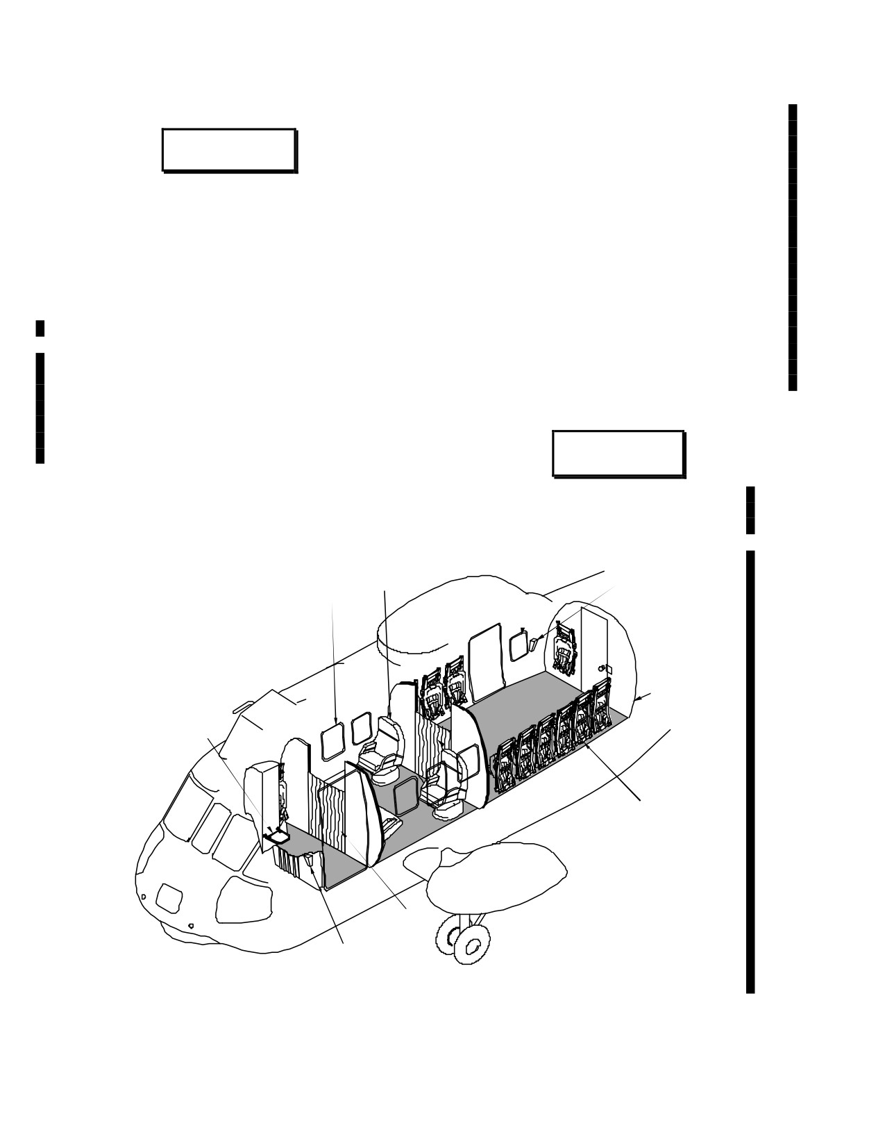
(ET) Executive Seat. Three executive seats
are installed in the forward passenger compartment; one
on the right side, and two on the left side. The executive
WARNING
seats are crashworthy seats consisting of a graphite-fiber
bucket with metal structural members, four-point restraint
system, foam-padded seat cushions and headrest, and
Crewman shall inspect all cargo deck tie-
swiveling base. The seat base is secured to tracks,
down fittings for excessive corrosion and
mounted on a seat pallet. The guided-stroke seat design
proper installation before attaching their
provides maximum retention of the seat to the floor
crewman safety belt to them. Do not use
structure when subjected to loads that are created during
corroded or improperly installed tiedown
crash conditions. A Variable-Load Energy Absorber
fittings.
(VLEA) system limits vertical deceleration in a hard
landing situation to acceptable limits. When the total
weight of the passenger
(weight of passenger plus
2.21.3
(ET) PASSENGER ACCOMMODATIONS
equipment) is dialed into the system by means of the
VLEA control dial mounted on the backside of the seat,
2.21.3.1 (ET) General. Accommodations for the crew
the limit load of each energy absorber is adjusted to
include the pilot’s and copilot’s seats, which are identical
provide maximum protection for the passenger.
to those installed on UH-3H helicopters, a crew chief’s
seat, and a forward-facing crew member’s seat installed at
station
425. Accommodations for passengers include
three executive chairs and inward-facing passenger
(troop) seats mounted along the sides of the cabin.
WARNING
Adjustment either higher or lower
than actual passenger weight will
increase crash hazards.
CRASHWORTHY
AFT
EXECUTIVE
HATCH
ESCAPE
SEAT
AFT CREWMAN’S
ICS PANEL
HATCH
STOWAGE
COMPARTMENT
CREW CHIEF’S
SEAT
CRASHWORTHY
PASSENGER
PRIVACY
(TROOP) SEATS
CURTAIN
PRIVACY
CURTAIN
CREW CHIEF’S
ICS STATION
01771215
Figure 2-54.1 (ET) Passenger Accommodations
2 - 86
ORIGINAL
NAVAIR 01-230HLH-1
2.21.3.3 (ET) Crew Chief’s Seat. The folding crew
back panel is done with pivoting fasteners that connect the
chief’s seat consists of a seat, panel, strut, and seat
back of the seat pan to the bottom of the back panel, and
cushion. The seat panel is constructed of aluminum
nylon webbing connecting the middle sides of the seat pan.
honeycomb sandwiched between aluminum sheets. Hinge
This allows the seat to be folded up into a stowed position.
fittings are bolted to the top surface of the panel, and
channel for the strut wheels is secured to the bottom
2.21.3.5
(ET) Soundproofing. Soundproofing consists
surface. The supporting strut is an aluminum alloy tube
of self-adhesive acoustic material and a thermal barrier.
with fitting at each end. The lower end of the strut is
The acoustic material panels are thin, self-adhesive sheets
secured to an angle fitting secured in the corner formed by
of aluminum that are applied to the inside surfaces of the
the floor and the ASE controls compartment bulkhead.
skin of the helicopter in the cockpit, cabin, and aft
The fitting is a hinged point that allows the strut and seat
compartment. The material is cut to fit between stringers
to fold against the bulkhead. Wheels on the upper end of
and frames. The thermal barrier is installed between the
the strut ride in the channel under the seat when the seat is
cabin and the aft fuselage to muffle sounds from the pylon.
being folded up against the bulkhead. A strap under the
Access to the aft fuselage is through a zippered opening in
seat is used to store the seat against the bulkhead when not
the thermal barrier.
in use. Seat cushions cover the top and bottom surfaces of
the seat panel to provide comfort when the seat is in use
2.21.3.6
(ET) Removable Bulkheads.
The
and protection against personal injury when the seat is
remo vable bulkheads consist of sound-absorbing panels
folded against the ASE controls compartment bulkhead.
that divide the cabin interior into compartments. The
The top cushion of polyurethane foam is held in place by
bulkhead panels are constructed of two face sheets of
the cover. The bottom cushion of Spongex is bonded to
fiberglass cloth-reinforced phenolic laminate over
the seat panel and protected by the cover. The cover is
phenolic-coated, polyamide paper base honeycomb core.
secured with Velcro tape. Seat belt attachment fittings are
The panels match or complement the cabin furnishings. A
secured to the hinge fittings on the ASE controls
wood laminate applied over a formed composite material
compartment bulkhead.
provides a divider between the carpeting on the lower
surface and the upper surface of each interior side panel.
The wood strip is secured to the side panels with hook and
loop tape. The left forward bulkhead of the forward
WARNING
entrance compartment contains passenger instruction lights
and the forward ICS station. A curtain between the
removable bulkheads at station 198 separates the forward
The crew chief’s seat is not a crashworthy
entrance compartment from the forward passenger
seat. Do not occupy this seat during takeoff
compartment providing privacy for the passengers
or landing.
occupying the executive seats. Removable bulkheads and
a curtain at station 293 provide additional privacy for the
2.21.3.4(ET) Passenger MATA (Troop) Seat. There
passengers in the forward passenger comp artment. Arch
are twelve passenger seats installed in the cabin area. Six
assemblies are installed at stations 356 and 390 to support
seats are installed on the left side between stations 295 and
the passenger support unit, and the removable aft bulkhead
414; five seats are installed on the right side, one between
installed at station
425 divides the aft passenger
stations 178 and 197, one between stations 224 and 243,
compartment from the stowage compartment. Instruction
and three between stations
295 and 354; one seat is
lights and fittings for the installation of a passenger seat
installed on the aft bulkhead at station 425. The passenger
are installed on the aft bulkhead and a hinged door on the
seat is a side-facing, energy-attenuating, crashworthy type
aft bulkhead provides for entrance to the stowage
seat mounted to T-fitting and held in place by locking pins.
compartment.
This allows rapid removal of the seat when necessary for
maintenance. The T-fittings are mounted on supports on
2.21.3.7(ET) Overhead Panels. Overhead panels are
the left and right sides of the cabin. The seat consists of a
installed throughout the cabin area. They are hinged
back panel and a seat pan. The back panel contains the
panels that are secured by quick release fasteners. The
structural attachment of the seat to the aircraft, the energy
overhead panels are constructed of two face sheets of
absorption system, the attachments of the restraint system,
fiberglass cloth-reinforced phenolic laminate over
and a nylon duck fabric backrest, which can be adjusted to
phenolic-coated, polyamide paper base honeycomb core.
accommodate each occupant individually. The restraint
system is a three-point, single release system with the
1.21.3.8 (ET) Carpet. The cabin floor is covered with
shoulder strap across the aircraft-forward shoulder. The
carpet that is installed in two sections. One section covers
seat consists of a tubular frame with nylon duck fabric
the floor in the forward entrance compartment, and
attached to the frame to support the occupant. Attachment
another, larger section covers the cabin floor from station
of the seat pan to the
201 through 425. The carpet is made of flame resistant
nylon secured around its edges with hook and pile tape. If
2 - 87
ORIGINAL
NAVAIR 01-230HLH-1
necessary to replace the carpet, remove the rubber backing
2.22.1
(NON ET) Rescue Hoist Master Switch. A
from the carpet in those areas where the self-adhesive
switch marked HOIST with marked positions CREW -
Velcro tape
(hook) will be installed. Install the self-
OFF-PILOT is on the overhead switch panel (Figure 2-9)
adhesive Velcro tape (pile) in a corresponding location on
in the pilot compartment. When the switch is placed to
the aircraft floor.
CREW, the rescue hoist is operated by the hoist operator,
using the switches near the cabin door. When the switch is
2.22 (NON ET) RESCUE HOIST
placed to PILOT, the rescue hoist is operated by the pilot,
using the switch on the pilot collective pitch lever grip.
A 600-pound lifting and 300-pound lowering capacity
When placed OFF, both the pilot and cabin rescue hoist
hydraulic hoist winch, enclosed by a fairing with about
switches are inoperative. A switch marked HOIST-UP-
100 feet of usable cable, is suspended on a fixed truss over
DN on the bottom of the pilot collective pitch lever grip
the cabin door. The winch motor is powered by the utility
(Figure
2-30) controls the rescue hoist. The switch is
pump mounted on and driven by the accessory section of
depressed in the direction indicated by the arrows and UP
the main gearbox. Hydraulic fluid for the rescue hoist
or DN to raise or lower the hoist. When released, the
(Figure 2-55) is supplied from the utility hydraulic system
switch is turned off and the hoist winch stops and locks.
at 1,250 psi. The hoist winch incorporates a load-holding
The switch is inoperative for hoist operations unless the
brake that locks automatically whenever the winch stops,
rescue hoist master switch is placed to PILOT.
and a level wind mechanism that prevents snarling if the
cable is wound rapidly with no load attached to it.
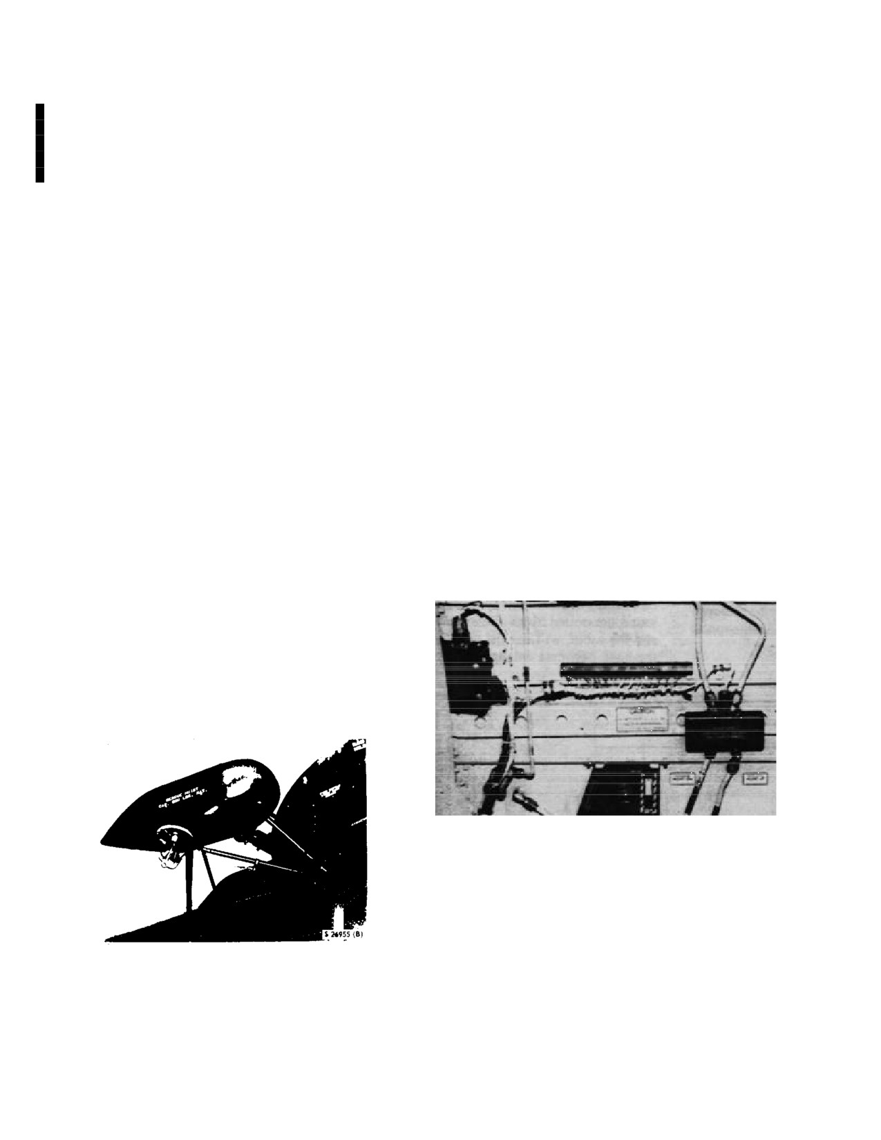
2.22.2 (NON ET) Rescue Hoist Switch Panel. This
Microswitches turn off the hoist winch either when the
cable is reeled completely in or when it is completely
panel is on the panel marked HOIST on the cabin wall
unwound. An electrically operated cartridge-type
above the cabin door
(Figure
2-56). The two-position
guillotine, controlled by switches in the pilot compartment
switch is of the momentary-contact type with marked
and the cabin, will cut the cable at the hoist winch if the
positions UP and DOWN. The switch is pushed in the
hook becomes entangled in an obstruction on the ground
direction indicated, UP or DOWN, to raise or lower the
and cannot be released. A double-throat hook is
hoist. When released, the switch returns to the center
incorporated that may be used for cargo and/or rescue
position and the hoist stops and locks automatically. The
operations. Both throats have a positive locking feature
switch is operative only if the hoist master switch on the
that may be opened manually. The hook incorporates a
overhead switch panel in the pilot compartment is placed
ring-type handhold as an aid to rescued personnel and is
to CREW.
self-stowing when the cable is reeled completely in. The
rescue hoist winch may be controlled from either the pilot
compartment or from the cabin by switches that use dc
power to operate solenoid valves in the hydraulic lines.
The rescue hoist control circuit and cable guillotine circuit
are protected by two circuit breakers on the center circuit
breaker panel (Figures 2-23 and 2-23.1.1) marked HOIST
CABLE and HOIST CONT.
Figure 2-56. Hoist Switches and Override Valve
2.22.3
(NON ET) Crew-Portable Hoist and
Microphone Switch. The pistol-grip or bracket-
mounted type hoist/ICS assembly is connected to the hoist
operator's station to enhance the capability of that station.
The portable hoist switch is OFF when in the center
Figure 2-55. Rescue Hoist
position.
2 - 88
ORIGINAL
NAVAIR 01-230HLH-1
To operate the hydraulic hoist, move the switch to
bumper compression requirements, the hook should be
either of the extreme momentary positions marked UP and
seated to ensure perpendicularity of the cable with respect
DOWN. When released, the switch returns to the OFF
to the cable drum axle. This should be done by positioning
center position. The portable hoist control can be operated
the hook ring in a horizontal plane.
only when the hoist master switch on the pilot main switch
panel is placed to CREW.
WARNING
2.22.4
(NON ET) Normal Operation. To prevent
exceeding the thermal limits of the utility hydraulic
system, rescue hoist operations should be made by using
between 25 and 50 feet of cable, and limiting the number
Completely compressing the hook bumper
of duty cycles as outlined in Figure 2-57.
may damage the hoist cable and cause an
inadvertent hook separation when hoisting
Note
passengers or cargo.
Visual signals between pilot, crewmen and
2.22.5
(NON ET) Rescue Hoist Cable Shear
ground or deck personnel shall be as
Switches. If the hoist becomes entangled in an
outlined in NAVAIR 00-80T-113 and used
obstruction on the ground, a guillotine may be used to cut
as advisory signals only, as when cargo
the cable at the winch. The guillotine is actuated by an
personnel are ready to be winched up.
electrically fired cartridge that may be fired from the pilot
compartment or the cabin. The circuit breakers on the
1.
Rescue hoist master switch - CREW OR PILOT.
center circuit breaker panel must be set or the hoist cable
cannot be guillotined. The cable is guillotined from the
2.
Pilot rescue hoist switch (collective pitch lever
pilot compartment by use of switches on the jettison
grip) or either of the cabin rescue hoist switches DN, UP.
control panel on the cockpit console (Figure
2-5). To
guillotine the cable from the pilot compartment place the
3.
At completion of hoist operations, hold either
jettison selector knob to HOIST and depress the individual
rescue hoist switch at UP until only a few inches of cable
RELEASE button. The cable may be guillotined from the
remain, and then beep the hook into the stowed position.
pilot compartment regardless of the position of the hoist
master switch. The hoist may be guillotined from the cabin
4.
Crewman should check for about 1/8- to 1/2-inch
only when the hoist master switch is placed to CREW.
hook bumper compression. In conjunction with the hook
NO. OF CONTINUOUS
NO. OF CONTINUOUS
CYCLES WITH
PERIOD FOR ADDITIONAL
CYCLES WITH
LOAD AMBIENT TEMPERA-
CYCLES WITHOUT
AMBIENT TEMPERA-
HEIGHT DOWN
UP
TURE 40 oC
EXCEEDING 121.1 oC
TURE 18 oC
25 ft
0
200 lb
4
0.4 min.
UNLIMITED
25 ft
0
600lb
6 (est.)
UNLIMITED
35ft
300 lb
600lb
2
UNLIMITED
50ft
0
200lb
1
1.65 min.
4+
50ft
0
600 lb
2 (est.)
6 (est.)
50ft
300 lb
600lb
2
l0.0min.
1
· Lowering loads shall not exceed 300 pounds due to brake limitations.
· The utility hydraulic system is a variable displacement system; therefore, more work reduces fluid temperature and subsequently
more cycles are permitted with greater loads.
· Cycling the landing gear will help prevent overheating during prolonged hoist operations.
System Thermal Limits of 121.1 oC
Figure 2-57. Rescue Hoist Duty Cycles Without Exceeding Utility Hydraulic
2 - 89
ORIGINAL
NAVAIR 01-230HLH-1
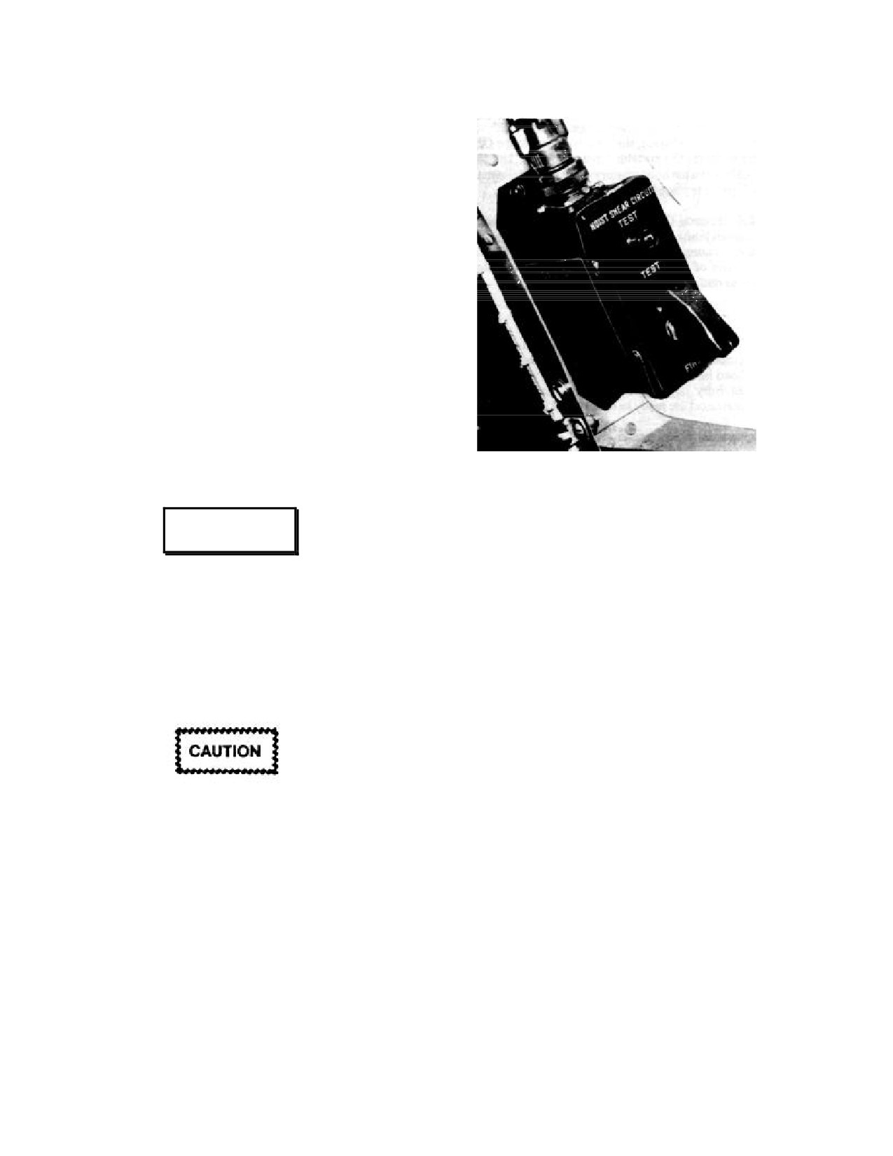
2.22.6 (NON ET) Rescue Hoist Shear Circuit Test
Panel. A hoist shear circuit test panel
(Figure
2-58)
marked HOIST SHEAR CIRCUIT is mounted on the
cabin wall above the cargo door. A light marked TEST is
on the top center of the panel and a guarded switch with
marked positions TEST and FIRE is on the bottom center
of the panel. A decal is on the side of the panel. Testing of
the rescue hoist shear circuit should be accomplished by
qualified maintenance personnel in accordance with the
appropriate maintenance instruction.
2.22.7
(NON ET) Rescue Hoist Manual Override
Valve. A rescue hoist manual override valve (Figure 2-56)
will lower or raise the hoist in case of electrical failures
and should be used for emergency situations only. The
valve operates from the utility hydraulic system.
2.22.7.1
(NON ET) Rescue Hoist Manual
Override Valve Buttons
Figure 2-58. Hoist Shear Circuit Test Panel
2.22.8
(NON ET) Rescue Hoist Assist Handles.
These handles
(Figure
2-56) marked HANDHOLD are
above the cabin door to aid the crewmen during rescue
WARNING
hoist operations.
Whenever using HOIST DN button during
2.23
EMERGENCY EQUIPMENT
manual operation, do not pay out the last 10
feet of cable, as 10 feet of cable is needed on
2.23.1 Fire Extinguishing System. A liquid bro-
the hoist drum to support the design load of
motrifluoromethane
(CF3Br ) fire extinguisher system is
the hoist. During manual operation, there is
installed to enable the pilot to put out an engine fire in
no down-limit protection. As an aid in
either engine compartment during flight. The liquid is
preventing too much payout, the last 10 feet
stored under pressure in two fire extinguisher liquid
of cable is painted red.
spherical containers mounted in the aft section of the
transmission compartment. Each spherical container has
two valves that contain a disc that, when broken by an
explosive cartridge actuated by the engine fire extinguisher
switch, empties its contents into the preselected engine
compartment. Choice of engine compartments is made by
pulling one of the engine fire emergency selector handles.
Do not operate the HOIST UP button
Tubing extends from one valve on each container to the
continuously to its full-up position, because
No. 1 engine compartment and from the other valve on
during manual operation there is no up-limit
each container to the No. 2 engine compartment. Within
protection and severe damage to the hoist
each engine compartment, the tubing divides into four
may result. When nearing the full-up
nozzles that extend along the inboard side of the engine.
position, stop hook assembly about 2 feet
The extinguishing liquid, when released through the
short of the up-limit switch and attach large
nozzles, turns into a vapor that smothers the fire. The
hook to aft upper hoist assembly stanchion.
spherical containers have a pressure gauge and a thermal
discharge valve that will discharge overboard outside of
Two rescue hoist manual override valve buttons are used
the helicopter if the temperature of the sphere reaches 96
to actuate the rescue hoist if electrical failure occurs. The
to 104o C. The engine fire extinguishing system operates
buttons are spring loaded and marked to indicate direction
on dc power through the circuit breakers marked 1 ENG 2
of hoist.
The left button is marked HOIST DN and the
under the general heading FIRE EXTINGUISHER on the
right button is marked HOIST UP.
center circuit breaker panel. Although designed primarily
2 - 90
ORIGINAL
NAVAIR 01-230HLH-1
for combating an engine fire during flight, the fire
fire extinguisher switch is held in MAIN, after the fire
extinguishing system may be used on the ground if other
emergency shutoff selector handle has been pulled, the
firefighting equipment is ineffectual or not available. Be
contents of the fire extinguisher sphere are discharged into
sure all ground personnel are clear before using the
the corresponding engine compartment. When the engine
system.
fire extinguisher switch is held in at RESERVE, after the
fire emergency shutoff selector handle has been pulled and
2.23.1.1 Thermal Discharge Indicator. A safety
the switch has returned from MAIN, the contents of the
outlet in each engine fire extinguisher container is
opposite fire extinguisher sphere are also discharged into
connected to a red THERMAL DISCHARGE
the selected engine compartment. Pulling both engine fire
INDICATOR on the outside of the fuselage to the rear of
emergency shutoff selector handles and placing the fire
the left cabin window. If pressure becomes excessive
extinguisher switch to MAIN discharges the contents of
within the container, a safety outlet opens, the THERMAL
each fire extinguisher sphere into the corresponding engine
DISCHARGE INDICATOR seal is ejected, and the
compartments. When this occurs, there is no reserve of
container’s contents are discharged overboard. The
fire extinguishing fluid. The switch will return t o OFF
thermal discharge indicator is common to both fire
when released.
extinguisher containers.
2.23.2 Portable Fire Extinguisher. A portable fire
On preflight, check the pressure of the container in
extinguisher (Figure 2-1) is on the bulkhead at the entrance
relation to the pressure/temperature chart on the inside of
to the pilot compartment. The CF3Br fog-type extinguisher
the inspection plate.
is held in place by a bracket with a tight-fitting, quick-
release, spring steel clamp. When using the extinguisher,
the nozzle must be held close to the source of the fire, as
the charge has a short duration of about 30 seconds.
WARNING
2.23.3
(NON-ET) Helicopter Emergency Egress
Lighting System. This emergency lighting system is
CF3Br is very volatile but is not easily
installed in UH-3H helicopters modified by AFC 417. The
detected by odor. It is nontoxic and can be
HEEL system automatically provides emergency lighting
of the cabin exits to enable location by personnel inside the
considered to be about the same as other
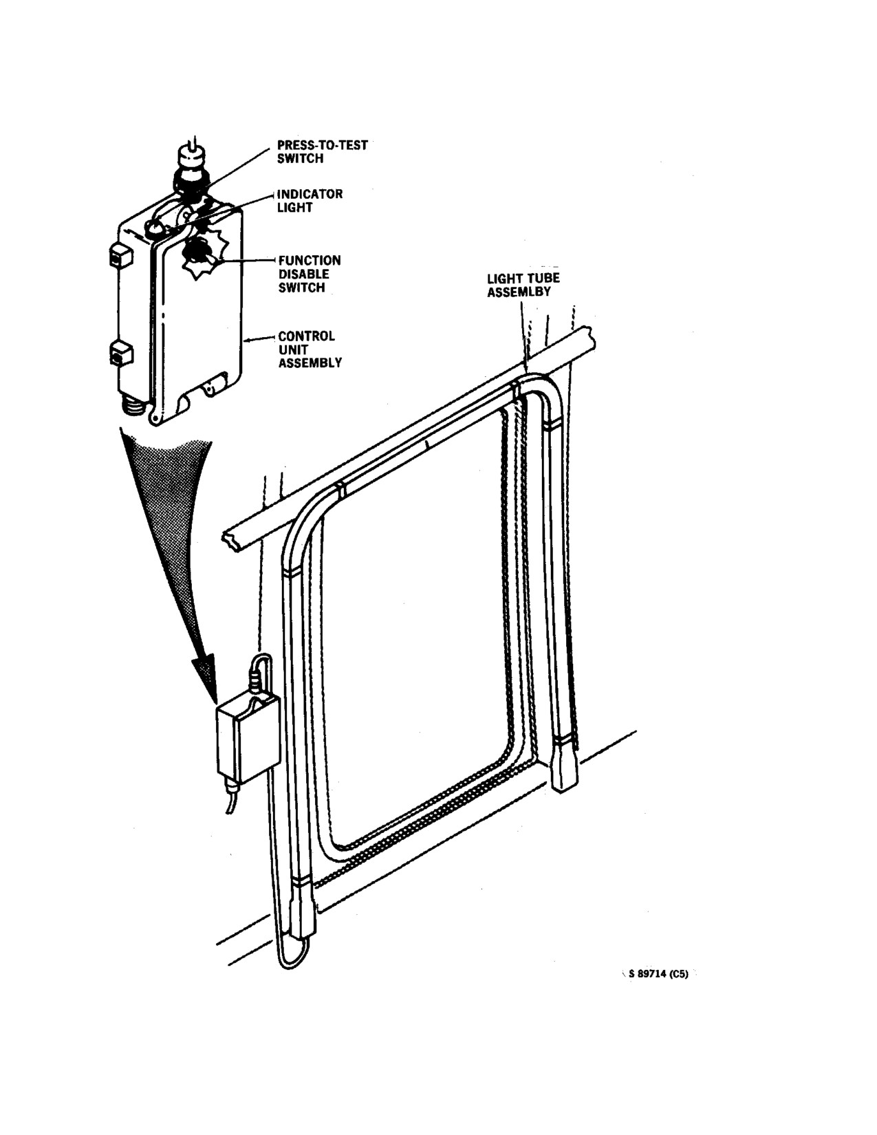
helicopter during an emergency (Figure 2-24). The system
freons and carbon dioxide, causing danger
primarily by reduction of oxygen. The
(Figure
2-59) consists of six light tube assemblies, five
liquid should not be allowed to contact the
control unit assemblies, a PMG control box, and an arming
skin, as it may cause frostbite or low
switch. A light tube assembly is installed around the upper
temperature burns because of its low boiling
portion of the cabin hatch (left personnel door), right cargo
door, and the three separate windows. Each light has a
point.
control unit containing a battery pack, function/disable
2.23.1.2 Engine Fire Emergency Shutoff Selector
switch, press-to-test switch, and indicator light. The
Handles (Engine T-Handles). Two T-shaped handles
battery pack provides power to the light tube during
marked FIRE EMER SHUTOFF SELECTOR are on the
emergency operation.
overhead switch panel (Figure
2-9). The handle marked
NO. 1 ENGINE is for the No. 1 engine compartment and
the handle marked NO. 2 ENGINE is for the No. 2 engine
compartment. When either handle is pulled down, 28-vdc
power actuated the fuel shutoff valve. This closes the fuel
HEELS is intended for emergency operation
lines to the respective engine and selects the engine
only and should not be used for non-emergency
compartment to which the fire extinguisher fluid is to be
lighting.
directed.
It also energizes the circuit to the fire
extinguisher switch. The ends of the handles house fire
The function/disable switch inside the control unit
detector warning lights.
marked FUNCTION-DISABLE must be at FUNCTION
for the light to operate.
2.23.1.3 Engine Fire Extinguisher Switch. This
switch marked FIRE EXT on the overheard switch panel
(Figure
2-9) in the pilot compartment has three marked
positions: RESERVE, OFF, and MAIN. The guarded
switch is operative only after one of the fire emergency
shutoff selector handles has been pulled. When the engine
2 - 91
ORIGINAL
NAVAIR 01-230HLH-1
Figure. 2-59. (NON ET) Helicopter Emergency Egress Lighting System
2 - 92
ORIGINAL
NAVAIR 01-230HLH-1
Note
cylinders mounted horizontally inside each sponson.
These cylinders are reached through the inspection ports
A single light tube may be deactivated
on the top of the sponson. The cylinders are electrically
(switch placed to DISABLE) prior to
dis charged through solenoid -operated valves . A pressure
flight should a hatch be unavailable for
gauge is also mounted on each valve. The gauge is
emergency use because of equipment or
marked from 0 to 3,500 psi in 100 psi units. The gauge
cargo obstruction.
is green-lined for 2,650 to 3,000 psi. If the pressure is
not within the minimum and maximum limits, service
The press-to-test switch tests the charge of the bat-
the air cylinders.
tery pack. The indicator light will light green when the
press-to-test switch is pressed to indicate the battery
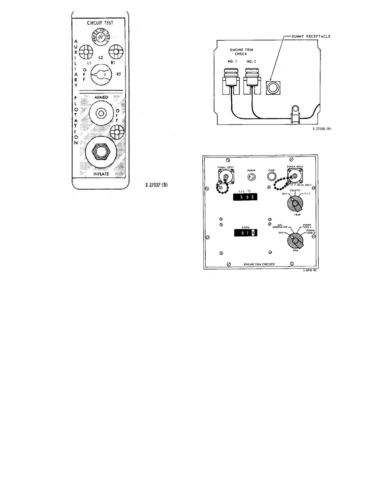
2.23.4.3 Auxiliary Flotation Control Panel. This
pack has sufficient charge to operate for a minimum of
panel
(Figure
2-60) marked AUXILIARY FLOTA-
10 minutes and that the FUNCTION/DISABLE switch
TION is on the lower right side of the cockpit console.
is at FUNCTION.
The panel consists of a rotary selector test switch, indi-
cating light, a two-position lever-lock-type switch, and a
The arming switch on the overhead switch panel
guarded pushbutton. The rotary selector test switch with
(Figure
2-9) is marked HEEL SYSTEM and has posi-
marked positions OFF
-L1
-L2
-R1
-R2 checks the
tions OFF-ARM. The PMG control box on the left cabin
respective circuit continuity to the air cylinders. When
wall senses via signal from the ac generators when the
the switch is placed to either L1, L2, R1, or R2, the
generators are turning, provides dc power to the control
green light will go on if the circuit is functioning
unit assemblies when the arming switch is at ARM, and
properly. The lever-lock switch has marked positions
creates a light inhibit signal. If the PMG senses that the
OFF and ARMED. When the switch is placed to
generators have stopped, the light inhibit signal is
ARMED, dc electrical power is supplied to the system.
removed. The control unit battery packs activate, and the
When the switch is placed OFF, all electrical power to
light tube assemblies illuminate. The PMG control box
the inflation portion of the system s removed. The
has two switches marked GEN 1 and GEN 2 for test
pushbutton-type switch is marked INFLATE. When the
functions of HEELS when ac generators are turning.
switch is pressed, all four air cylinders simultaneously
With the arming switch at OFF, HEEL is disabled.
discharge air into the float chambers if the OFF-
Power for the system is provided through a primary dc
ARMED switch is ARMED. Normally, the bags will
circuit breaker marked HEEL on the pilot circuit breaker
take about 6 to 7 seconds to inflate. After the system has
panel.
been activated, the bags can be deflated only by
maintenance personnel on the ground.
2.23.4 Flotation Gear System. The emergency
flotation gear system provides the helicopter with
2.23.5 Liferaft. Liferafts of sufficient number and
stability on the water with the rotor stopped. The system
capacity to accommodate all occupants of the helicopter
consists of two inflatable bags, four air cylinders, and a
shall be carried on overwater flights. Rafts shall be
control panel. The system operates on 28-vdc current
securely stowed or worn as squadron policy dictates.
and is protected by a circuit breaker marked AUX
FLOAT on the center circuit breaker panel.
2.23.6 Aldis Lamp. An Aldis lamp is provided
primarily for signaling but may be used for emergency
2.23.4.1 Emergency Flotation Gear Bags. The
lighting. The lamp is powered by the
28-vdc utility
emergency flotation gear bags (Figure
2-1) are on the
receptacle in the cockpit or after cabin.
outboard chine of each sponson stowed in a bungee cord
laced canvas enclosure. Each bag is subdivided into two
2.23.7 First-Aid Kits. One kit is mounted in the pilot
chambers having a combined displacement of 35 cubic
compartment on the control enclosure (broom closet). A
feet. The chambers are inflated by individual air
second first-aid kit is in the cabin behind the pilot seat.
cylinders. Although each chamber is inflated by a single
air cylinder, all chambers will inflate simultaneously
2.24 MISCELLANEOUS
upon actuation of the INFLATE switch. The floats are
made of neoprene-coated nylon and are scuff-resistant
2.24.1 Canteen. Provisions for two 1-quart canteens
for durability during adverse conditions. The two
are on the cabin wall.
chamber airbags provide a fail-safe function in that one
chamber per side inflated will provide considerably
improved stability.
2.23.4.2 Emergency Flotation Air Cylinders.
There are two emergency flotation compressed air
2 - 93
ORIGINAL
NAVAIR 01-230HLH-1
Figure 2-61. Engine Trim Checker Receptical Panel
Figure 2-60. Auxiliary Floatation Control Panel
2.24.2 Engine Trim Checker
(H219). The engine
trim checker assists in more efficiently adjusting the
engines by providing remote readings for the gas
generator rpm and the power turbine inlet temperature
and rpm. The checker is a portable hand-carried unit,
equipped with connecting cables to connect the unit to
the engine trim checker panel, that simultaneously dis-
plays T5 and either Nf or Ng readings on digital displays
for individual engines.
The engine trim checker receptacle panel (Figure 2-
61) is mounted overhead in the area of the pilot
Figure 2-62. Engine Trim Checker Control Panel
compartment entrance. The receptacles marked NO. 1
and NO. 2 under the general heading ENGINE TRIM
The panel has a POWER light that will go on
CHECK are associated with respectively numbered
henever operating power is delivered to the engine
engines. These receptacles are each equipped with a
m checker. A FUSE is incorporated in the control
jumper plug that is removed and stowed in the adjacent
nel to protect the circuit. The panel has a T5 digital
dummy receptacle where the signal input connecting
display marked T.I.T-oC that displays turbine inlet
cable to the engine trim checker is connected. The power
temperature. A three-position rotary switch marked
input cable is connected to the ac utility receptacle on
TEMP is associated with the T.I.T oC digital display. In
the right side of the cabin. The engine trim checker
the OFF position, the digital display is not usable. In the
operates on 115 vac from the helicopter electrical system
COCKPIT position, the digital display is not usable and
through connecting power input cable and is protected
the instrument panel T5
indicator is usable; however, a
by a fuse on the engine trim checker control panel.
slight calibration shift will be noted because of the
incorporation of the engine trim checker in the circuit. In
2.24.2.1 ENGINE TRIM CHECKER Control Panel.
the T.I.T position, the digital display will display the
This panel
(Figure
2-62) contains the receptacles,
applicable engine T5 and the instrument panel power
controls, and digital displays necessary for system
turbine inlet temperature indicator is disabled. An
operation. The SIGNAL INPUT and POWER INPUT
Nf/ Ng digital display marked % RPM displays Nf or
receptacles will accommodate only the correct cable for
Ng as selected. The panel has a four-position rotary
the function required
switch marked RPM that is associated with the % RPM
digital display. In the OFF position, the digital display is
not usable. The GAS GENERATOR position displays
the Ng of the applicable engine on the digital display.
2 - 94
ORIGINAL
NAVAIR 01-230HLH-1
The POWER TURB A position has no function. The
Note
POWER TURB B position will display Nf of the
applicable engine on the digital display.
Until step
11 is completed, the No.
1
engine power turbine inlet temperature
2.24.2.2 Engine Trim Checker Operating
indicator on the instrument panel will be
Procedures.
disabled.
To turn equipment on:
11. Remove jumper plug from dummy receptacle
1.
TEMP and RPM switches - OFF.
on ENGINE TRIM CHECKER panel and plug into
NO. 1 ENGINE TRIM CHECK receptacle.
2.
Connect the signal input and power input cables
to
the SIGNAL INPUT and POWER INPUT
12. No. 2 engine is checked as No. 1 is with signal
receptacles on the ENGINE TRIM CHECKER
input cable connected to NO.
2 ENGINE TRIM
control panel.
CHECK receptacle.
3.
Connect the power input cable to the utility
receptacle and check that the POWER light on the
To turn equipment off:
ENGINE TRIM CHECKER control panel goes on.
1.
Disconnect signal input cable from NO. 2 EN-
4.
Remove jumper plug from NO.
1 ENGINE
GINE TRIM CHECK receptacle on ENGINE TRIM
TRIM CHECK receptacle on ENGINE TRIM
CHECKER receptacle panel.
CHECKER receptacle panel and stow on dummy
receptacle.
Note
Note
Until step 2 is completed, No. 2 engine
Until step
5 is completed, the No.
1
power turbine inlet temperature indicator
engine power turbine inlet temperature
on the instrument panel will be disabled.
indicator on the instrument panel will be
disabled.
2.
Remove jumper plug from dummy receptacle
and plug into NO.
2 ENGINE TRIM CHECK
5.
Connect the signal input cable to NO. 1 EN-
receptacle
on ENGINE TRIM CHECKER
GINE TRIM CHECK receptacle.
receptacle panel.
6.
Turn RPM switch on ENGINE TRIM
3.
Disconnect power input cable from utility
CHECKER panel to GAS GENERATOR. Ng for
receptacle.
No. 1 engine is indicated on % RPM digital display.
4.
TEMP and RPM switches - OFF.
7.
Turn RPM switch on ENGINE TRIM
CHECKER control panel to POWER TURB B. Nf
5.
Disconnect signal input and power input cables
for No. 1 engine is now indicated on % RPM digital
from SIGNAL INPUT and POWER INPUT
display.
receptacles on ENGINE TRIM CHECKER control
panel and stow.
8.
Turn TEMP switch on ENGINE TRIM
CHECKER control panel to COCKPIT. A slight
2.24.3 Map Case and Chart Board. A map case
calibration shift will be noted on the instrument
(Figure 2-1) is on the side of the controls enclosure at
panel No. 1 engine T5 gauge. The T.I.T oC digital
the entrance to the pilot compartment. A chart board can
display is not usable.
be stowed behind the map case.
9.
Turn TEMP switch on ENGINE TRIM
2.24.4 Mooring Rings. Nine mooring rings are on the
CHECKER control panel to. T.I.T oC digital display
helicopter. Each main landing gear trunnion assembly
will read No. 1 engine T5, and instrument panel No.
has a mooring
(Figure 2-2) on the inboard and outboard
1 engine T5 gauge will be disabled.
sides. A mooring ring is at the tailwheel housing; four
fuselage tiedown rings are below the transmission
10. Disconnect signal input cable from NO. 1 EN-
service platform.
GINE TRIM CHECK receptacle.
2 - 95
ORIGINAL
NAVAIR 01-230HLH-1
wiper blades. The windshield washer motor is controlled
2.24.4.1
(ET) Mooring. Five mooring rings are
by a switch with marked positions OFF-ON on the
installed on the helicopter. Each main landing gear
overhead switch panel (Figure 2-9). Placing the switch
trunnion assembly has a mooring ring on the inboard and
to ON causes the windshield washer motor to pump fluid
outboard sides. Another mooring ring is located on the
through the wiper spray bars to the windshield. The
tail wheel housing. There are two fuselage mooring ring
windshield washer system is powered from the dc
fittings installed on the aft cabin, below the transmission
primary bus through a circuit breaker marked WSHLD
service platform. If required, rings may be installed on
WASHER on the center circuit breaker panel.
the aft cabin mooring ring fittings.
2.25
(NON ET) CARGO SLING
2.24.5 Relief Tube. A relief tube (Figure 2-1) is on the
side of the controls enclosure at the entrance to the pilot
compartment.
WARNING
2.24.6 Mirrors Rearview. Manually adjustable ex-
ternal rearview mirrors are installed on the pilot and
copilot sides of the cockpit canopy. The dual rearview
Any static electricity that may have been
mirrors provide the pilots with a means of viewing the
generated by the helicopter should be
engine and transmission areas during flight or ground
dissipated prior to attempting a hookup by
operations. The mirrors are mounted so that mirror
ground personnel.
viewing will require the viewer to lean his head slightly
toward the mirror side. This is considered desirable as it
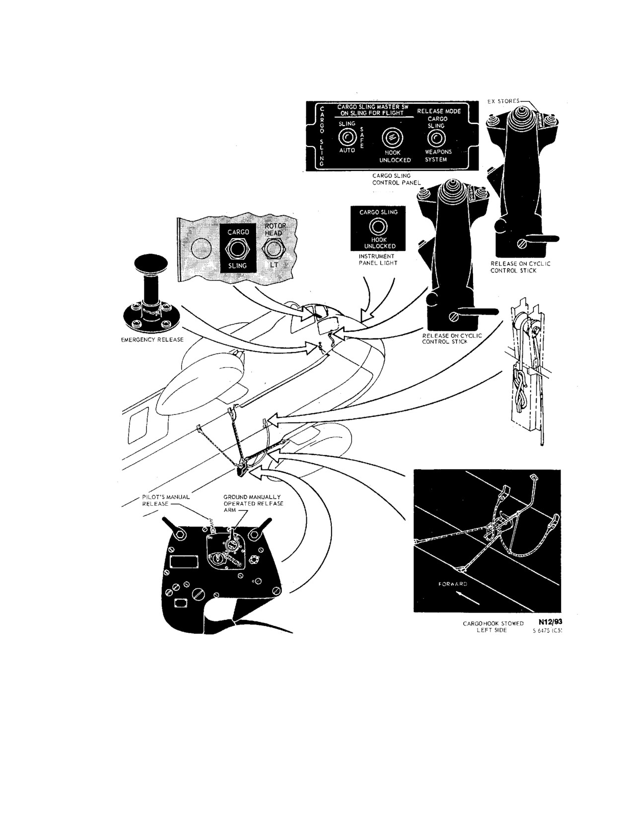
A cargo sling with a 6,000-pound capacity (Figure 2-
prevents mirror reflections from the rotary lights on the
63) is attached below the fuselage at four points. Four cables
helicopter from distracting the pilots while seated in the
extend from the fuselage attaching points to the cargo hook.
normal flight position during night operations.
The cargo hook is designed so that external loads may
normally be released electrically by depressing buttons on
2.24.7 Windshield Wiper System
the pilot and copilot cyclic stick grips. Loads can be
released manually by the manual release foot pedal, on the
pilot right side of the pilot compartment, or automatically
when loads less than 100 pounds are sensed at the hook.
Direct current from the primary bus supplies operating and
control power to the cargo release circuit that is protected by
To prevent scratching windshields, do not
a circuit breaker marked CARGO SLING on the overhead
operate wipers on dry glass.
dc circuit breaker panel. Ground personnel may open the
hook by actuating the manual release lever on the side of the
The electrically operated system consists of a two-
cargo hook. The load beam of the cargo hook will
speed motor, two converters, and a rotary control switch.
automatically return to the closed position after the load is
The windshield wipers are on the pilot and copilot
released. A light, marked HOOK UNLOCKED, on the
windshields. The system is controlled by a rotary-type
CARGO SLING control panel will illuminate anytime the
switch with marked positions PARK-OFF-LOW-HIGH
cargo hook is open. On UH-3H helicopters an additional
on the overhead switch panel
(Figure
2-9) marked
light marked CARGO SLING HOOK UNLOCKED is
WINDSHIELD WIPERS. When the switch is placed to
mounted on the copilot side of the instrument panel. This
LOW or HIGH, the system is actuated and the desired
light will illuminate anytime the cargo hook is open. The
speed range is selected. When the switch is turned to
lights receive electrical power from the primary bus through
PARK, the wipers automatically position to the inboard
a circuit breaker marked PWR under the general heading
edge of the windshields. The wiper arms have high
WARN LTS on the overhead dc circuit breaker panel. For a
tension springs installed to increase visibility by
pickup, the load may be attached to the hook from outside
reducing wiper blade buffeting and lifting at high
the helicopter while in a hover, or the pilot may attach the
speeds. The windshield wiper system receives electrical
load by flying the hook through a ring attached to the load.
power from the No. 1 ac primary bus through a circuit
When the cargo sling is attached, but not in use, it is stowed
breaker marked WSHLD WIPER MOTOR on the
under the fuselage by means of a nylon stowage line.
copilot circuit breaker panel.
2.24.8 Windshield Washer. The system consists of
a reservoir, windshield washer motor/pump, and a
control switch. The reservoir behind the pilot seat holds
4.8 quarts. The windshield washer motor pumps the
fluid through tubing to the spray bars in the windshield
2 - 96
ORIGINAL
NAVAIR 01-230HLH-1
Figure 2-63. (NON-ET) Cargo Sling
2 - 97
ORIGINAL
NAVAIR 01-230HLH-1
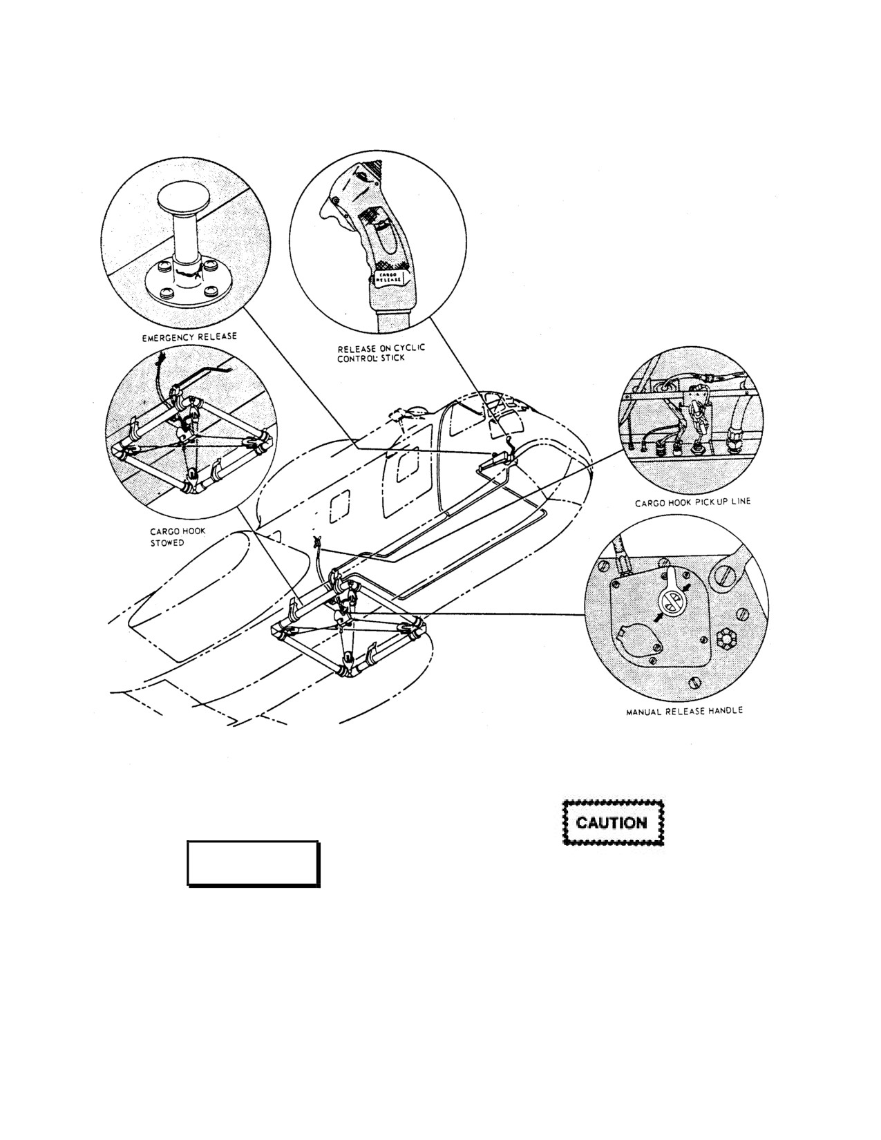
Figure 2-64. Low-Response Cargo Sling System
WARNING
The cargo sling should be stowed before
landing to prevent the hook from striking
the ground. Striking the hook on the
External loads may have aerodynamic
ground can cause damage and subsequent
characteristics that cause oscillations to
failure of the hook.
the extent that the load may oscillate into
the rotor blades and/or fuselage.
2 - 98
ORIGINAL
NAVAIR 01-230HLH-1
2.25.1 Cargo Sling Control Panel. The CARGO
foot pedal on the right side of the pilot compartment is
SLING control panel is located on the pilot's control
connected mechanically by cable to the manual release
console. The panel contains a HOOK UNLOCKED
lever on the cargo hook. The pedal may be depressed to
advisory light and a three-position CARGO SLING
mechanically open the cargo sling hook when the
MASTER SWITCH for the following functions:
electrical release circuit is inoperative. The load will be
released in the air or on the ground regardless of the
1. SLING - for normal operation, energizes the
position of the cargo sling master switch.
CARGO thumb switches on the pilot and copilot
cyclic grips that enable the pilot to electrically
2.25.4 Cargo Hook Stowage Line. The cargo hook
release the load.
stowage line runs from the cargo hook into the fuselage
on the left-hand compartment side panel. The cargo
2. SAFE - disables the system and should be used
hook is stowed by pulling up on the nylon line, from
when loading or during flight to prevent inadvertent
inside the compartment and securing. To release the
discharge of the cargo.
cargo hook from the stowed position, untie the nylon
line and slowly lower the cargo hook. A bungee cord,
3. AUTO
- this position energizes the cyclic
attached from the cargo hook cables to the fuselage,
CARGO switches and the touchdown switch on the
removes the slack from the cables when the hook is
cargo hook. In this mode loads will automatically
stowed.
release when a force of
100 pounds or less is
sensed.
2.25.5 Cargo Hook Manual Release Arm. The
cargo hook may be manually released by ground
personnel by operating the manual release arm on the
cargo hook. A force of 15 to 22 pounds is required to
move the release arm in any upward direction to release
a load beam of 8,000 pounds. With no load, 10 pounds
is maximum required to open load beam.
When carrying loads of less than
200
pounds, the cargo sling master switch
should never be in the AUTO position.
The cargo sling hook would open
immediately if a gust of air momentarily
lightens the load.
The switch should always be returned to the SAFE
The cargo hook should be stowed before
position and the sling stowed after the load has been
landing to prevent the hook from striking the
released.
ground, which can cause damage and
subsequent failure of the hook. Landing on
On UH-3H helicopters the CARGO SLING control
water with an unstowed hook can cause
contains an additional switch labeled RELEASE MODE.
damage by denting or puncturing the hull.
This switch has two marked positions, CARGO SLING
and WEAPONS SYSTEM. This switch must be in the
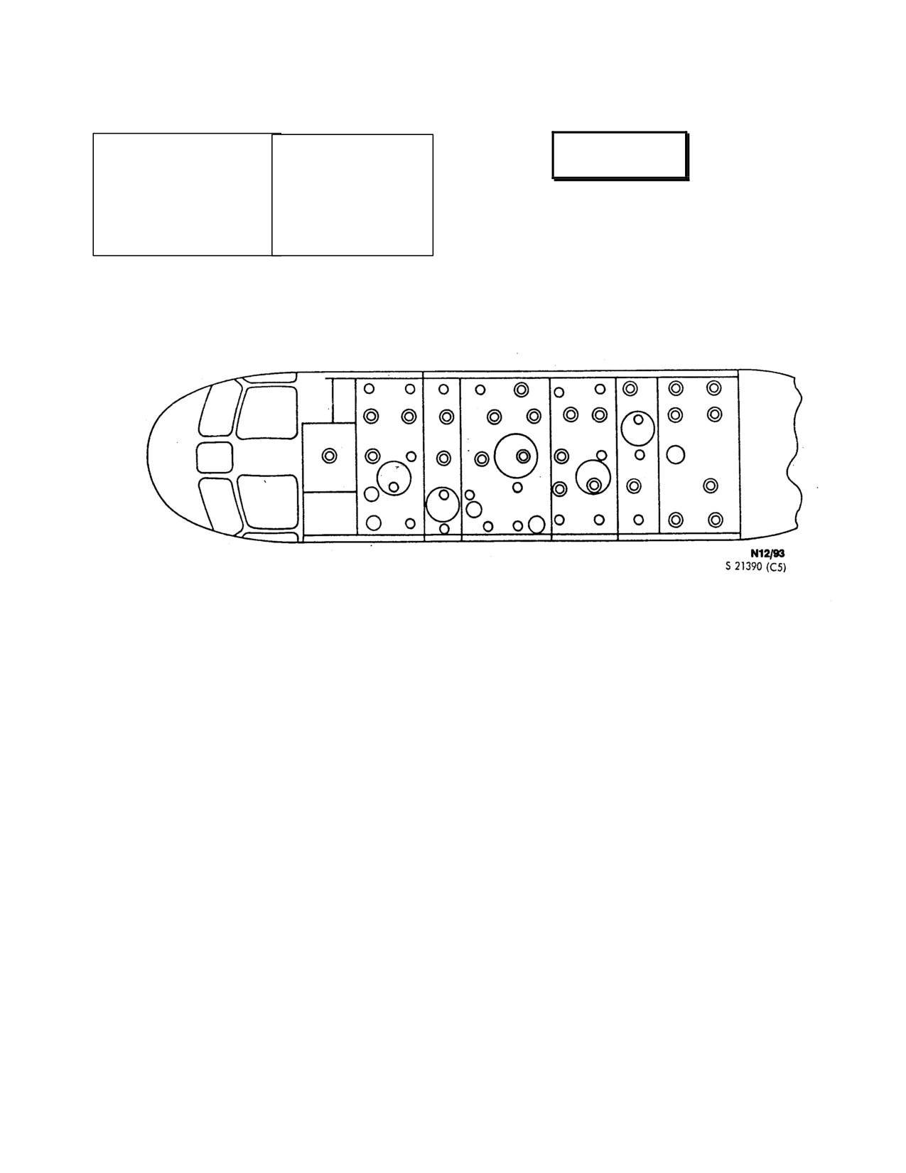
2.25.6 Cargo Deck (UH-3H). In this configuration the
CARGO SLING position before the EX STORES
helicopter is used as a logistical support vehicle for the
buttons on the pilot cyclic grips will open the cargo sling
transportation of personnel and light cargo. For load
hook when depressed.
planning, cargo size and weight limitations, weight and
balance factors and formulas, formula for determining
2.25.2 Cargo Hook Release Buttons. A cargo
center of gravity of a load, shoring requirements, and
hook release button marked EX STORES is on the pilot
restraint criteria, and the Cargo Aircraft Loading and
and copilot cyclic stick grips. Either release button may
Offloading Technical Manual
(NAVAIR 01-20HLC-9)
be depressed to open the cargo sling hook when the
shall be used.
CARGO SLING MASTER SWITCH is in either the
AUTO or SLING position. The RELEASE MODE
The cargo deck
(Figure
2-65) is constructed of
switch must be in the CARGO SLING position as well
honeycomb floor panels supported by traverse bulkheads
as having the CARGO SLING MASTER SWITCH in
and beams and is divided into eight compartments. The
either the AUTO or SLING position before EX
cargo deck strength limits for the various compartments
STORES buttons will open the cargo sling hook when
are as follows:
depressed.
2.25.3 Cargo Release Foot Pedal. A cargo release
2 - 99
ORIGINAL
NAVAIR 01-230HLH-1
Compartment D 8. station 160
186,
200 LBS/SQ FT.
Compartment D 9. station 186
221,
200 LBS/SQ FT.
WARNING
Compartment D10 station 221
243.5,
120 LBS/SQ FT.
Compartment D11 station 243.5
290,
135 LBS/SQ FT.
Compartment D12 station 290
323,
105 LBS/SQ FT.
Compartment D13 station 323
346.5,
200 LBS/SQ FT.
Crewman shall inspect all cargo tiedown
Compartment D14 station 346.5
391,
145 LBS/SQ FT.
fittings for excessive corrosion and proper
Compartment D15 station 391
425,
200 LBS/SQ FT.
installation
before attaching cargo
restraint devices to them. Do not use
corroded or improperly installed tiedown
Fifty-eight combination troopseat studs and cargo
fittings.
tiedown fittings are recessed into the floor. Tiedown
fittings are rated at 1,500 pounds of pull in any direction.
Figure 2-65. Cargo Deck
2 - 100
ORIGINAL
NAVAIR 01-230HLH-1
CHAPTER 3
Servicing
3.1
EXTERNAL POWER REQUIREMENTS
EXT PWR switch located on the overhead control panel.
To apply power to the ac and dc buses, position the EXT
The external power requirements are direct current 28
PWR switch ON. The
#1 GENERATOR and
#2
vdc,
300 amps continuous, and
750 amps intermittent
GENERATOR warning lights on the CAUTION PANEL
(current limited). The alternating current requirements are
go on, indicating neither generator is in the circuit. When
115/200 VAC, and a three-phase rotation 400 Hz, utilizing
28-vdc power is applied to the EXT POWER 28 VOLTS
a standard square six pin lug (wye connection) with a
DC receptacle, all dc buses, certain necessary ac
minimum capacity of 20 kVA.
instruments, and the fire detector system are automatically
energized. The
#1 RECTIFIER and
#2 RECTIFIER
3.1.1 External Electrical Power Connections (See
warning lights on the CAUTION PANEL remain on.
Figure 3-1).
Note
· If dc starts are expected and maintenance
WARNING
has been done on the fuel system, use AC
external power to operate the boost pumps
to prime air-locked fuel lines.
To avoid possible injury to personnel,
damage to helicopter, excessive hydrogen
· Either AC or DC power may be used for
gas, and damage to battery through
engine starts; however, ac power is better
overcharging, turn battery switch OFF when
because of its load-carrying capability.
using external power.
3.1.2 USAF Ground Power Units. When using USAF
Note
ground power units, always place the ac control selector
switch, if incorporated as in the MD-3 and MD-3A
On the UH-3H Executive Transport
generator sets, to the AIRCRAFT position before engaging
helicopters, the BRIGHT/DIM switch on
the cable plug to Navy aircraft ac external power
the CABIN LIGHTS panel should remain
receptacle. If there is no ac control selector switch, request
in the DIM position while operating on
the operator to observe the warning below and then
external power.
temporarily modify the cable wiring of the ground power
unit as in the procedures below or a connector adapter may
In the H-3, the AC external electrical power receptacle
be used, if available. The cable adapter, in effect, removes
is on the left side of the helicopter in the aft cabin at station
E and F cable wires from the terminal block of the ground
359 (approximate), and the dc external electrical power
power unit and ties them together to complete the control
receptacle is on the right side under the pilot sliding
circuit. A Navy cable may be used, if available, negating
window at station 124 (approximate). When 115-/200-volt,
the need to modify the USAF cable.
three-phase,
400-cycle, ac power is applied at the EXT
POWER
115-VOLTS AC receptacle on Group E
To modify the cable wiring proceed as follows:
helicopters, power is automatically applied to all ac and dc
buses. When
115-/200-volt, three-phase,
400-HZ, AC
1 Disconnect the cable terminals E and F from the
power is applied at the EXT POWER 115 VOLTS AC
terminal block of the external power source.
receptacle on Group F and subsequent helicopters, power
is supplied to the EXTERNAL POWER MONITOR
2. Connect cable terminals E and F together and cover
PANEL located in the electrical compartment, and to the
the connection with insulation to prevent grounding the
circuit.
3-1
ORIGINAL
NAVAIR 01-230HLH-1
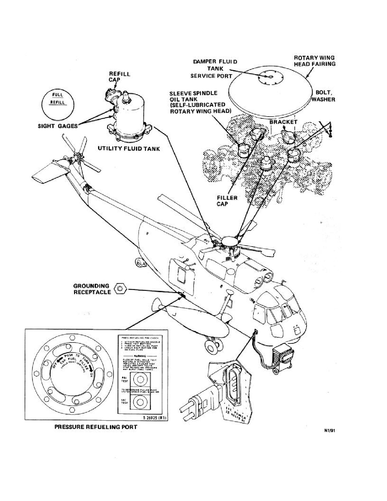
Figure 3-1. Helicopter Servicing Points (Sheet 1 of 2)
3-2
ORIGINAL
NAVAIR 01-230HLH-1
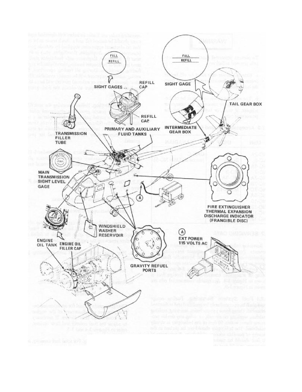
Figure 3-1. Helicopter Servicing Points (Sheet 2 of 2)
3-3
ORIGINAL
NAVAIR 01-230HLH-1
3. Service helicopter using normal procedures.
should be maintained from any operating radar set. Radio
switches and electrical equipment should be turned off and
a check made to be sure that no electrical apparatus,
supplied by outside power (electrical cords, droplights,
WARNING
floodlights, etc.) is in or near the helicopter. Explosive-safe
flashlights shall be used in place of helicopter
landing/floodlights for night-fueling operations. During all
fueling operations, fire extinguishing equipment will be
To prevent personnel shocks and fire
readily available. Electrical power
(battery or external
hazards proceed as follows:
power) will have to be applied to the helicopter to obtain
the fuel quantity gauge readings.
a. External power unit must be off before
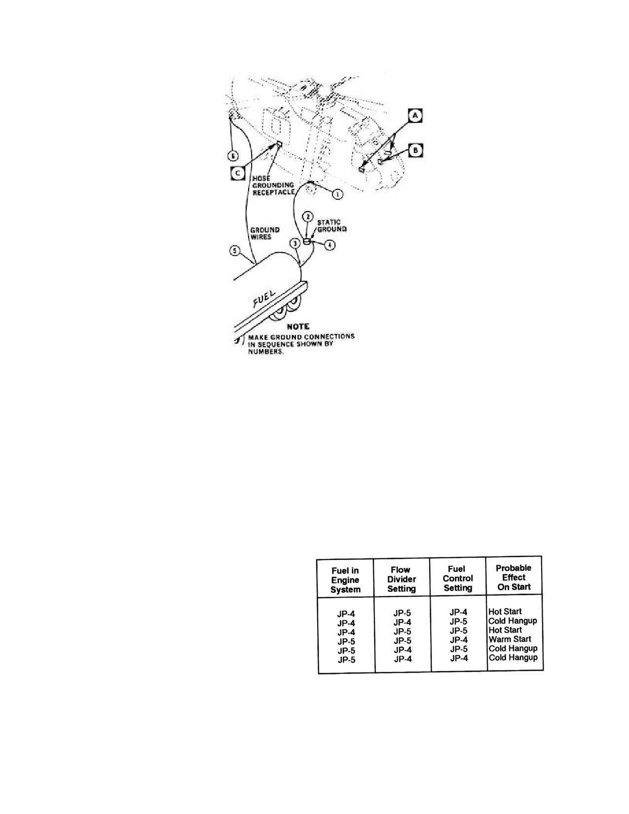
3.2.1.1 Grounding. Before removing the tank filler
connecting or disconnecting the cable from
caps, the hose nozzle grounding attachment must be
the helicopter.
connected to a metal part of the helicopter at a safe
distance from the filter openings and tank vents. Ground
b. The external power unit must be off
devices on hoses, helicopter, and fuel truck or station shall
before installing or removing the connector
be inspected by fueling personnel for proper ground.
adapter, if used, or before modifying the
power unit cable.
3.2.1.2 Fire Extinguishers and Attendant. During
fueling, a secondary operator or assistant plane captain
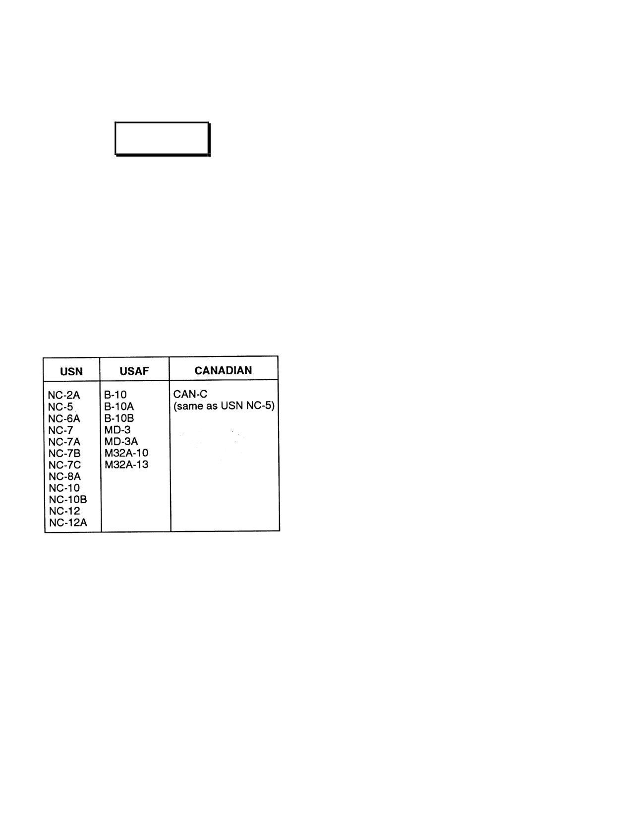
3.1.3 Acceptable Ground Power Units.
shall man an extinguisher with a second extinguisher
readily available.
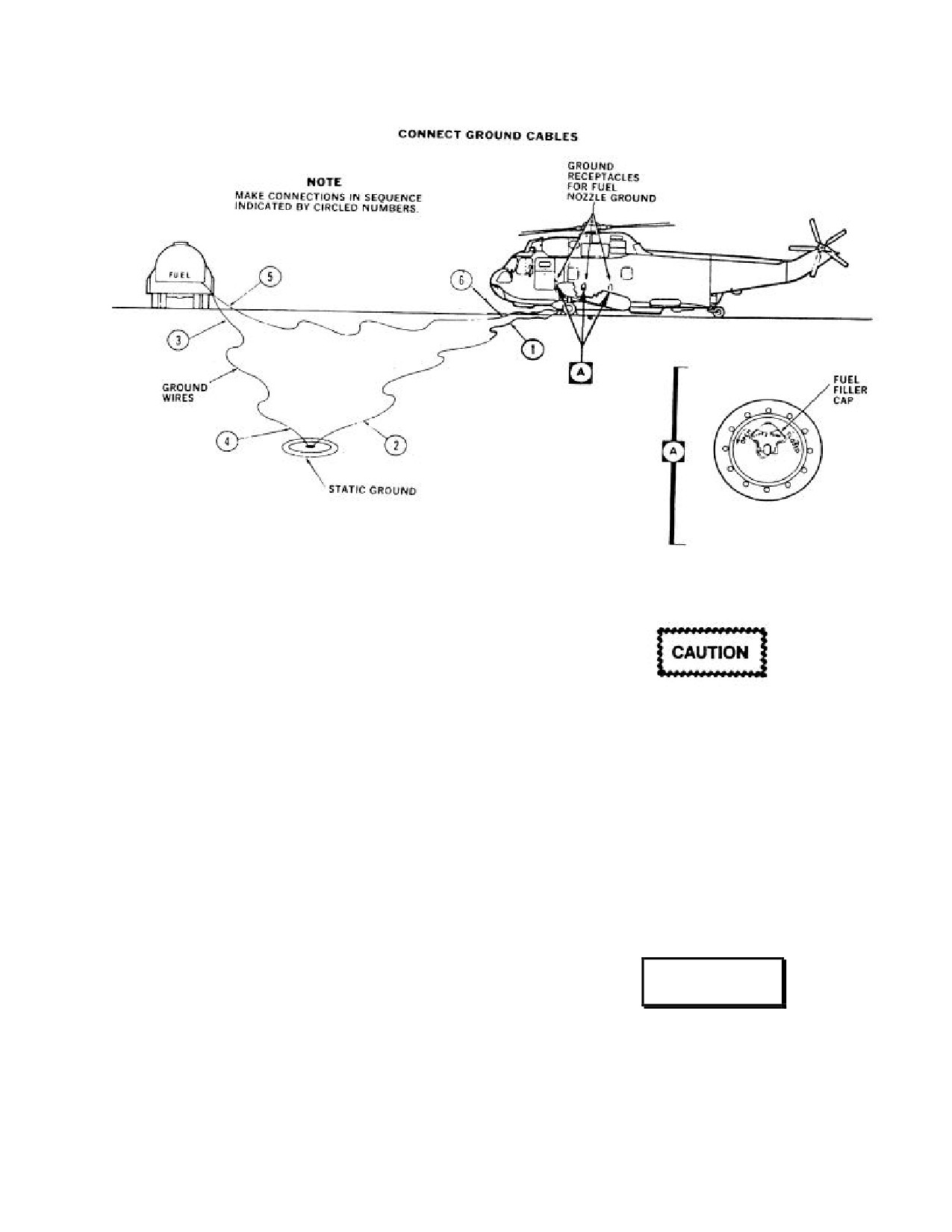
3.2.2 Gravity Refueling Procedures (See Figure 3-
2).
1. Ground helicopter to static ground.
2. Ground truck to static ground.
3. Ground helicopter to truck.
4. Remove fuel tank filler cap. The filler cap of one
fuel tank at a time should be removed. It must be
replaced immediately after that tank is filled and before
removing the cap from another tank.
5. Plug hose nozzle ground into grounding jack near
each refueling receptacle.
3.2
SERVICING DATA
6. Service helicopter.
Servicing information is given by systems
or
components. Points used in frequent servicing and
7. Remove nozzle; close fuel tank filler cap.
replenishment of fuel, oil, and hydraulic fluid are shown in
Figure 3-1. Fuel and lubricant specifications and capacities
Note
are shown in Figures 3-6 and 3-7. A listing of acceptable
commercial and foreign fuel is shown in Figure
3-8.
Changing grade of fuel for an extended
Acceptable commercial oils are shown in Figure 3-9.
period requires an adjustment of the engine
fuel control and flow divider. If necessary to
3.2.1 Fuel System Servicing. Fueling equipment shall
adjust the fuel control and flow divider, refer
be operated only by qualified and authorized personnel.
to Figures 3-4 and 3-5.
Using loose pyrotechnics, smoking, striking matches,
working on aircraft, or using any device producing flame
3.2.2.1 Fuel Capacity. For total fuel capacity, refer to
within 50 feet of the helicopter is strictly prohibited. The
Figure 2-22.
helicopter should not be parked in the vicinity of possible
sources of ignition. A minimum of
50 feet should be
maintained from other aircraft or structures, and 75 feet
3-4
ORIGINAL
NAVAIR 01-230HLH-1
Figure 3-2. Fuel System - Gravity Refueling
3.2.3 Pressure-Refueling Procedures (See Figure
3-3).
Note
During pressure fueling, gravity filler caps
To prevent damage to fuel tanks, cease
may be loosened to prevent damage to tanks
fueling operations immediately if neither
in case of failure of the high-level shutoff
PRI TEST or SEC TEST switch shuts off
valves. As fuel flow commences, test the
fuel flow. If only one switch is operative,
primary and secondary high-level shutoff
pressure fueling may continue with caution.
switches to be sure they will secure the fuel
flow within 30 seconds.
8. Turn on fueling pump. Press and hold PRI TEST
switch. Fuel should stop within 30 seconds. Release
1. Ground helicopter to static ground.
switch.
2. Ground truck to static ground.
9. Press and hold SEC TEST switch. Fuel should stop
within 30 seconds. Release switch.
3. Ground helicopter to truck.
4. Turn on battery and note fuel quantity.
WARNING
5. Loosen gravity-fuel filler caps.
6. Plug hose nozzle ground into grounding jack above
Do not let fuel pressure go over 55 psi or
receptacle.
flow go over 140 gpm because of fuel cell
rupture and possible injury to personnel.
7. Remove dust cover from fueling adapter and
connect nozzle.
3-5
ORIGINAL
NAVAIR 01-230HLH-1
Figure 3-3. Fuel System - Pressure Refueling
10. Service helicopter to desired level or until fuel shuts
fuel shutoff valve can be used to control starting
off automatically.
temperature. If prolonged operations are anticipated with
fuel other than which is set on the flow divider and fuel
11. Turn off fuel pump.
control, adjustments should be reset to the type fuel being
used as shown in Figures 3-4 and 3-5.
12. Remove electrical power from helicopter.
3.2.4.1 Fuel Effect on Engine Start. Fuel in the
13. Tighten gravity-filler caps.
engine system will not change after refueling with a
different density fuel and a normal start can be expected
14. Remove nozzle and replace dust cover.
for the first start after refueling unless the engine fuel
system has been drained. Subsequent starts may have the
Note
following characteristics indicated:
Changing grade of fuel for an extended
period requires an adjustment of the engine
fuel control and flow divider. If necessary to
adjust the fuel control and flow divider, refer
to Figures 3-4 and 3-5.
3.2.3.1 Fuel Capacity. For total fuel capacity, refer to
Figure 2-22.
3.2.4 Adjustment of Fuel System for Different
Fuels. During off-base helicopter operations, it may be
necessary to refuel with different fuel types than were used
during the prior flight. Operation with a fuel or a fuel
mixture that differs from the fuel type set on the flow
divider or fuel control can affect starting and performance
characteristics and should be monitored closely for
possible overtemperature indications. The auxiliary start
3-6
ORIGINAL
NAVAIR 01-230HLH-1
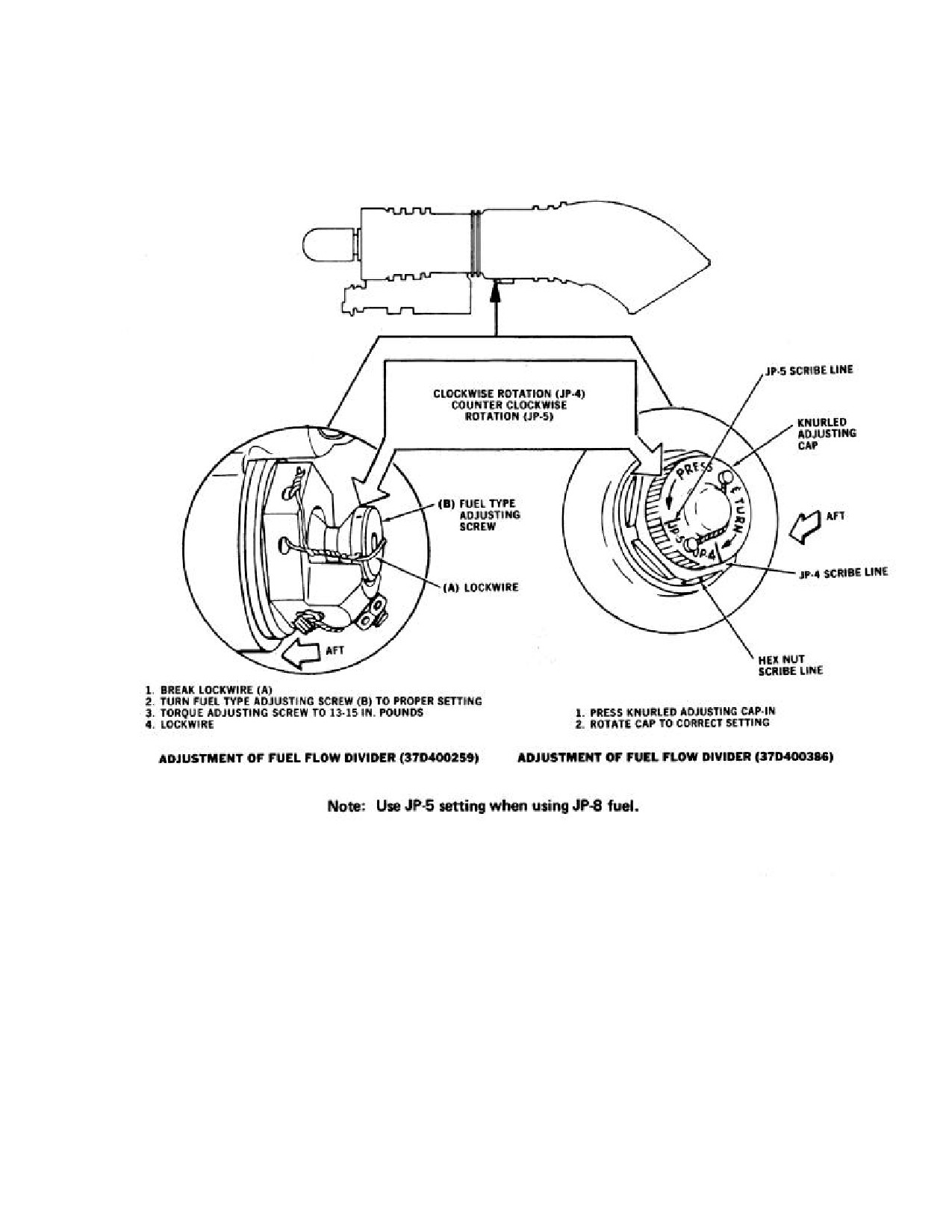
3.2.4.2 Adjustment of Fuel Flow Divider (See Figure 3-4).
Figure 3-4. Fuel Flow Dividers, 37D400259 and 37D400386
3-7
ORIGINAL
NAVAIR 01-230HLH-1
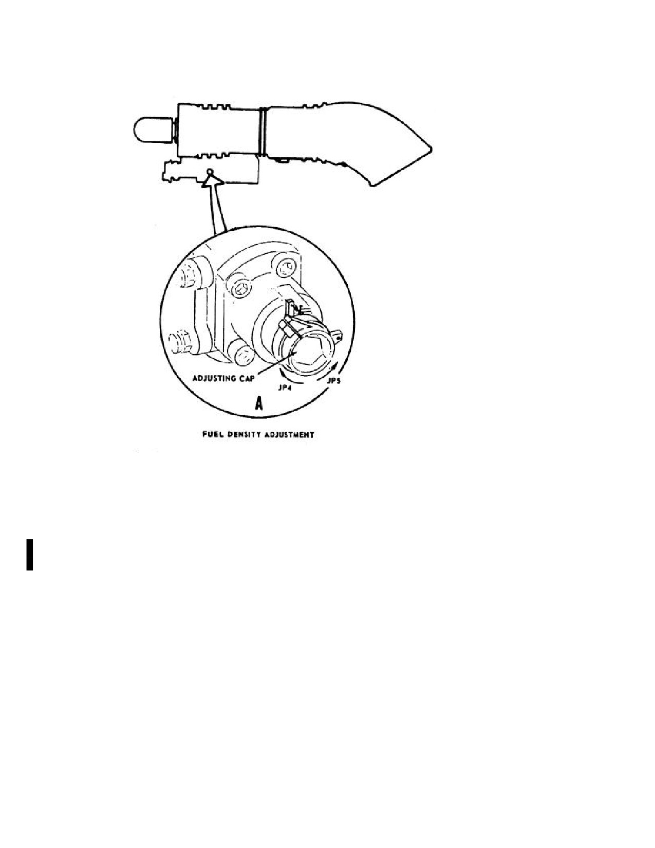
3.2.4.3 Adjustment of Fuel Control (See Figure 3-5).
1.
Break lockwire from arm to stop.
2.
For JP4, rotate cap clockwise.
For JP-5 and JP-8, rotate cap counterclockwise.
3.
Lockwire arm to stop.
Note
· The fuel control on the T58-GE-402 has only two settings, JP-4 (full clockwise) and JP-5 (full counterclockwise). Use
JP-5 fuel control and flow divider settings when using JP-8.
· Changing the setting of the flow divider will have a greater effect on engine start than when changing the setting of the
fuel control.
N8/97
Figure 3-5. Fuel Control
3-8
ORIGINAL
NAVAIR 01-230HLH-1
3.2.5 Engine Oil Servicing (See Figure 3-1).
3.2.9 Sleeve-Spindle Oil Tanks, Self-Lubricated
Rotary Wing Head Servicing (See Figure 3-1).
1. Open and remove oil filler caps.
1. If servicing unit has a flexible neck, it is not
2. Oil tank is filled to capacity when oil covering
necessary to remove rotary wing head fairing;
bottom of filler screen is about 5/8-inch diameter (size
otherwise, unbolt and remove rotary wing head
of dime). Service oil tanks.
fairing.
3. Install oil filler caps.
2. Lift spring-loaded filler cap and insert filler hose.
3. Service tanks (5) as necessary to FULL line on
tank.
4. Remove filler hose and ensure that spring-loaded
filler caps close.
To prevent scoring of oil filler cap, causing
metal chips to drop into oil tank, manually
5. Install rotary wing head fairing.
position hook attaching chain to tab when
closing oil filler cap.
3.2.10 Intermediate Gearbox Servicing
(See
Figure 3-1).
3.2.6 Hydraulic System Fluid Servicing
(See
Figure 3-1).
1. Remove intermediate gearbox oil filler plug.
1. Remove hydraulic tank refill cap.
2. Intermediate gearbox is full when oil level reaches
FULL mark on sight gauge on lower left side of
2. Service primary and auxiliary tanks until FULL on
gearbox center housing. Service intermediate gearbox
sight gauge. Service utility tank until FULL on upper
to FULL mark.
sight gauge if blades are spread and to FULL on lower
sight gauge if blades are folded.
3. Install intermediate gearbox oil filler plug.
3. Install fluid refill caps.
4. Safety wire oil filler plug.
3.2.7 Main Gearbox Oil Servicing (See Figure 3-
3.2.11 Tail Gearbox Servicing (See Figure 3-1).
1).
1. Remove tail gearbox oil filler plug.
1. Lift spring-loaded filler cap and insert filler hose.
2. Tail gearbox is full when oil level reaches FULL
2. Main gearbox is full when oil level is anywhere
mark on sight gauge on lower left side of gearbox
within yellow circle. Refill when oil is at bottom of
center housing. Service tail gearbox to FULL mark.
outer red circle. Service main gearbox to FULL mark
on sight gauge on lower left side of gearbox lower
3. Install tail gearbox oil filler plug.
housing.
4. Safety wire oil filler plug.
3. Remove filler hose, ensure that spring-loaded filler
cap closes.
3.2.12 Windshield Washer Reservoir Servicing
(See Figure 3-1).
3.2.8 Damper Fluid Tank Servicing (See Figure
3-1).
1.
If OAT is less than 0 ºC (32 ºF), mix 50-percent
isopropyl alcohol and 50-percent water. If OAT is above
1. Lift spring-loaded filler cap and insert filler hose.
0 ºC (32 ºF), use unmixed water.
2. Damper tank is full when oil level is within the
2.
Remove filler cap and fill as necessary.
FULL circle. Service damper tank to FULL mark.
3.
Replace filler cap.
3. Remove filler hose and ensure that spring-loaded
filler cap closes.
3-9
ORIGINAL
NAVAIR 01-230HLH-1
3.2.13 Tire Servicing.
5. Install valve stem cap.
1. Remove valve stem cap from tire.
3.2.14 (ET) APU Servicing (See applicable MIMS).
1.
Hinge up APU access door.
WARNING
· To prevent injury, do not use high-
pressure air source or an unregulated
Do not exceed full line on oil fill
air pressure source.
cap dipstick. Overfilling will create
an overheat condition resulting in
damage to the APU.
· Never stand beside tire being serviced.
Stand forward or aft of tire.
2.
Connect source of pressure.
2.
Remove fill-to-spill plug.
3. Service tires to proper pressure with nitrogen.
3.
Remove oil fill cap and dipstick and fill gearbox
until oil comes out fill-to-spill plug opening.
Note
4.
Check dipstick to ensure normal oil level.
· Clean dry compressed air may be
substituted if nitrogen is not available,
5.
Lubricate packing on fill-to-spill plug and install
but reservice with nitrogen as soon as
plug in gearbox. Torque plug 80 to 90 inch-pounds.
practical.
Lockwire plug with lockwire (MS20995NC20).
· Pressure ranges are adequate for all
6.
Close APU access door.
helicopter loadings and for all
anticipated climatic conditions.
4. Remove source of pressure.
3-10
ORIGINAL
NAVAIR 01-230HLH-1
3.2.15 Fluid Servicing and Capacities (See figure 3-6).
TANK CAPACITY
SERVICE LIMIT
SYSTEM
(GALLON)
(GALLON)
ENGINES
2.7
--
MAIN GEARBOX W/ELS
16.6
12.6
INTERMEDIATE GEARBOX
--
0.2
TAIL GEARBOX
--
0.4
PRIMARY HYDRAULIC SYSTEM
--
0.45
AUXILIARY HYDRAULIC SYSTEM
--
0.45
UTILITY HYDRAULIC SYSTEM
--
1.09
DAMPER SYSTEM
38.38 OUNCES
0.14
SLEEVE-SPINDLE WET HEAD
--
8.2 OUNCES
LEFT WHEEL BRAKE SYSTEM
--
5.8 OUNCES
RIGHT WHEEL BRAKE SYSTEM
--
* WINDSHIELD WASHER
ELECTRICAL SYSTEM (RESERVIOR)
4.8 QUARTS
4.8 QUARTS
NITROGEN SERVICING
MAINMOUNT WHEELS
90 TO 95 PSI
TAILWHEEL
70 TO 75 PSI
TAILWHEEL CENTERING CYLINDER
425 ±25 PSI
FLOTATION BAG CYLINDERS
2,650 TO 3,000 PSI
LANDING GEAR EMERGENCY BLOWDOWN
2,500 TO 3,000 PSI
BOTTLES
BLADE FOLD ACCUMULATOR
1,500 PSI MINIMUM BLADES SPREAD
.5
(ET) AUXILIARY POWER UNIT
--
*WEATHER WARMER THAN 0 ºC: WATER.
WEATHER COLDER THAN 0 ºC. 50-PERCENT ISOPROPYL ALCOHOL/50-PERCENT WATER.
Figure 3-6. Fluid Capacities
3-11
ORIGINAL

NAVAIR 01-230HLH-1
3.3 OILS, GREASES, HYDRAULIC FLUIDS LISTING (See Figure 3-7).
Item
Primary
Acceptable
Emergency
Product
Substitute
Substitute
MIL SPEC
NATO
MIL SPEC
NATO
Note
MIL SPEC
NATO
NOTE
Main Gearbox
DOD-L-85734
MILPRF 23699F
0-156
0-149
3
MIL-L-7808G
0-148
1,2
Intermediate
DOD-L-85734
MILPRF 23699F
0-156
0-149
3
MIL-L-7808G
0-148
1,2
Tail Gearbox
DOD-L-85734
MILPRF 23699F
0-156
0-149
3
MIL-L-7808G
0-148
Engines
MILPRF 23699F
0-156
MIL-L-7808G
0-148
2
0-149
5
Self-
MIL-L-21260
C-642
IL-L-2104
4
7
Lubricating
Grade 50
Grade 30
Reservoir
Hydraulic Fluid
MILPRF 83282
*MIL-H-5606
H-515
6
System
Rotor Head
MIL-G-25537
G -366
MIL-G-81322
G -395
Rudder Head
MIL-G-25537
G -366
Damper
MILPRF 83282
Damper
MIL-G-25537
G -366
MIL-G-81322
G -395
G -366
Trunnion
AFC 262 INC.
0-190
MIL-L-7870A
0-142
0-134
Sleeve and
hinge Mating
Lug Surface
Sector Gears,
MIL-G-81827
MIL-G-21164
8
Blade Lock and
Control Lock
pins
Bifilar
Lubricated
630AA
Disconnect Jaws
MIL-G-81827
MIL-G-21164
8
Rescue Hoist
VV-L-800
0-190
MIL-L-7870A
0-142
0-134
0-135
Notes
1.
Primary Product MILPRF 23699F for non 24,000 series MGB.
2.
To be used in extreme low temperature (-400 C).
3.
Up to 50% of 0-149 may be used with 0-148.
4.
Does not have corrosive -prevention characteristics of C-642.
5.
Any SAE 30 weight non-detergent lubricating oil.
6.
Preferred in damp areas or helicopter is idle for long periods.
7.
Any fuild of the same viscosity.
8.
MIL-G-81827 shall not be mixed. Surfaces to be lubricated must be thoroughly cleaned prior to substitution.
* Degrades the fire resistant properties of MILPRF 83282.
Figure 3-7. Acceptable Fluids
3-12
ORIGINAL
NAVAIR 01-230HLH-1
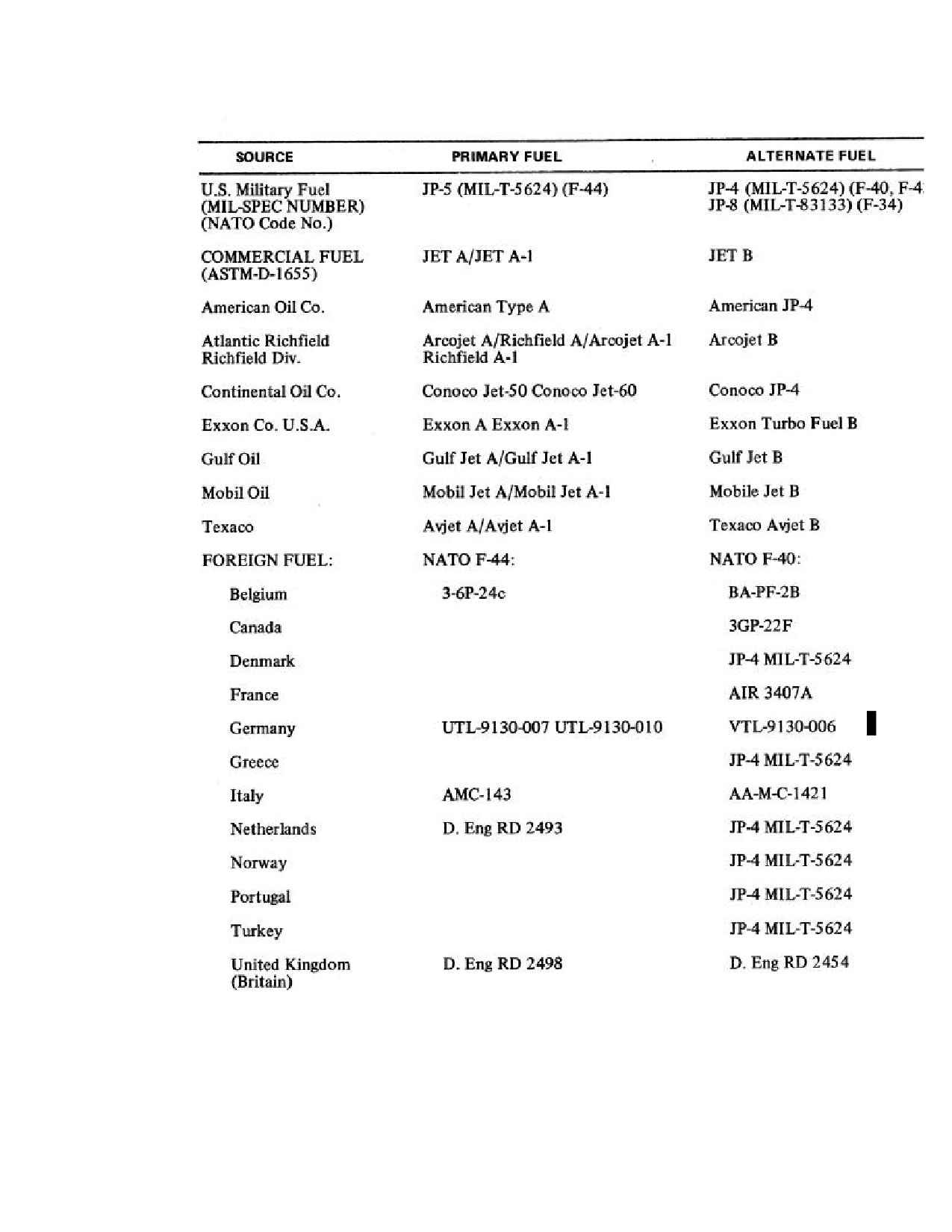
3.4 FUEL CROSS REFERENCE (See Figure 3-8)
Figure 3-8. Fuel Cross-Reference Chart
3-13
ORIGINAL
NAVAIR 01-230HLH-1
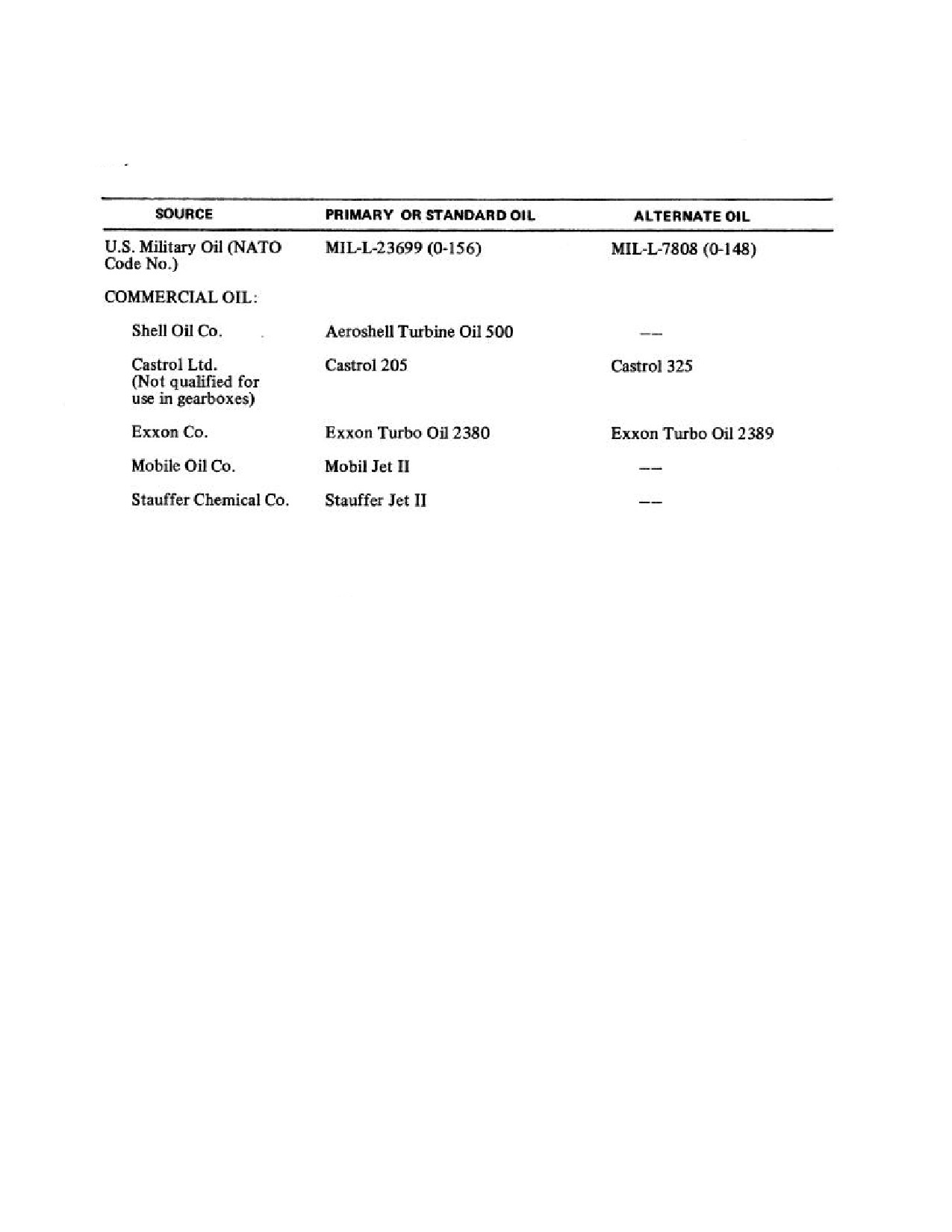
3.5 OIL CROSS-REFERENCE (See Figure 3-9).
Figure 3-9. Oil Cross-Reference Chart
3-14
ORIGINAL
NAVAIR 01-230HLH-1
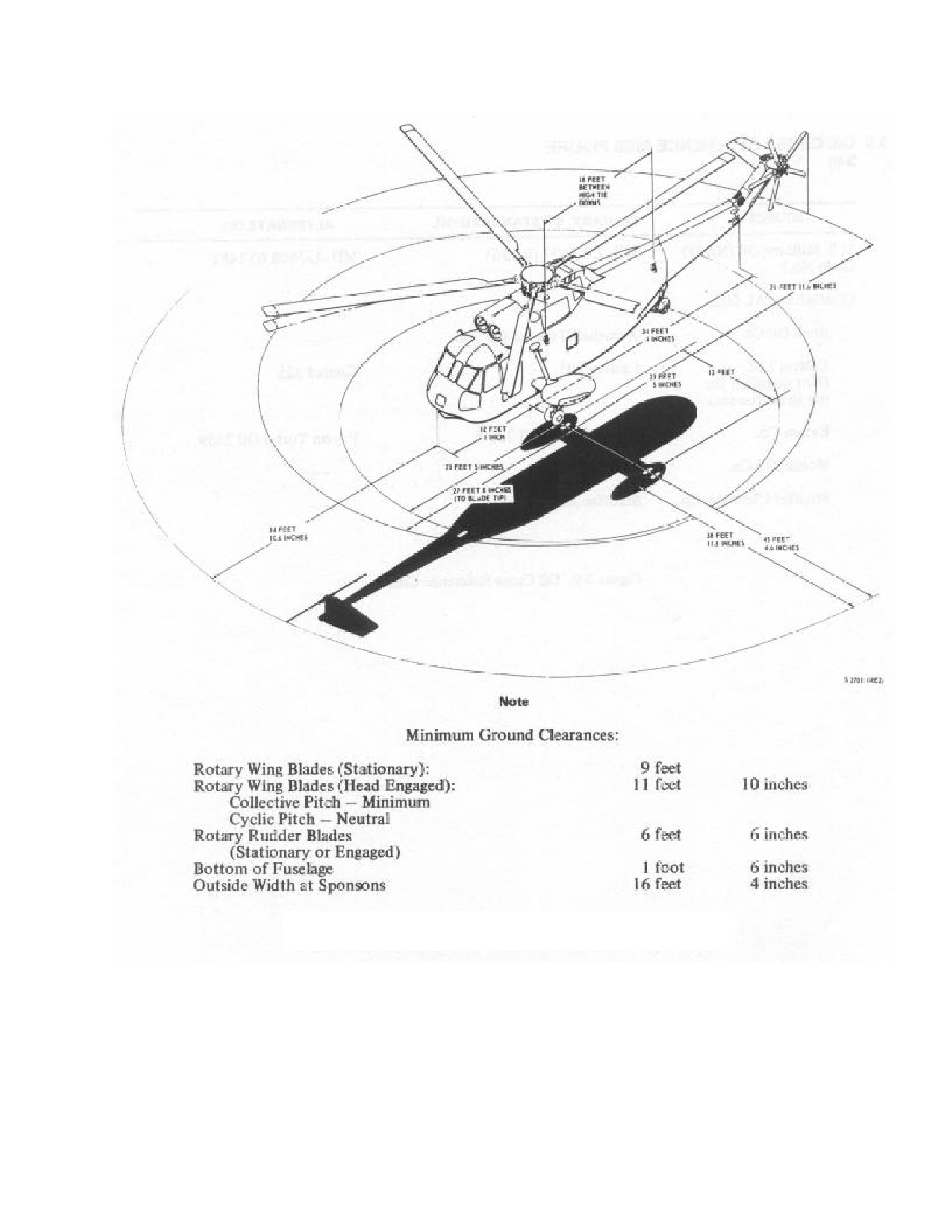
Figure 3-10. Minimum Turning Radius and Ground Clearance
3-15
ORIGINAL
NAVAIR 01-230HLH-1
3.6
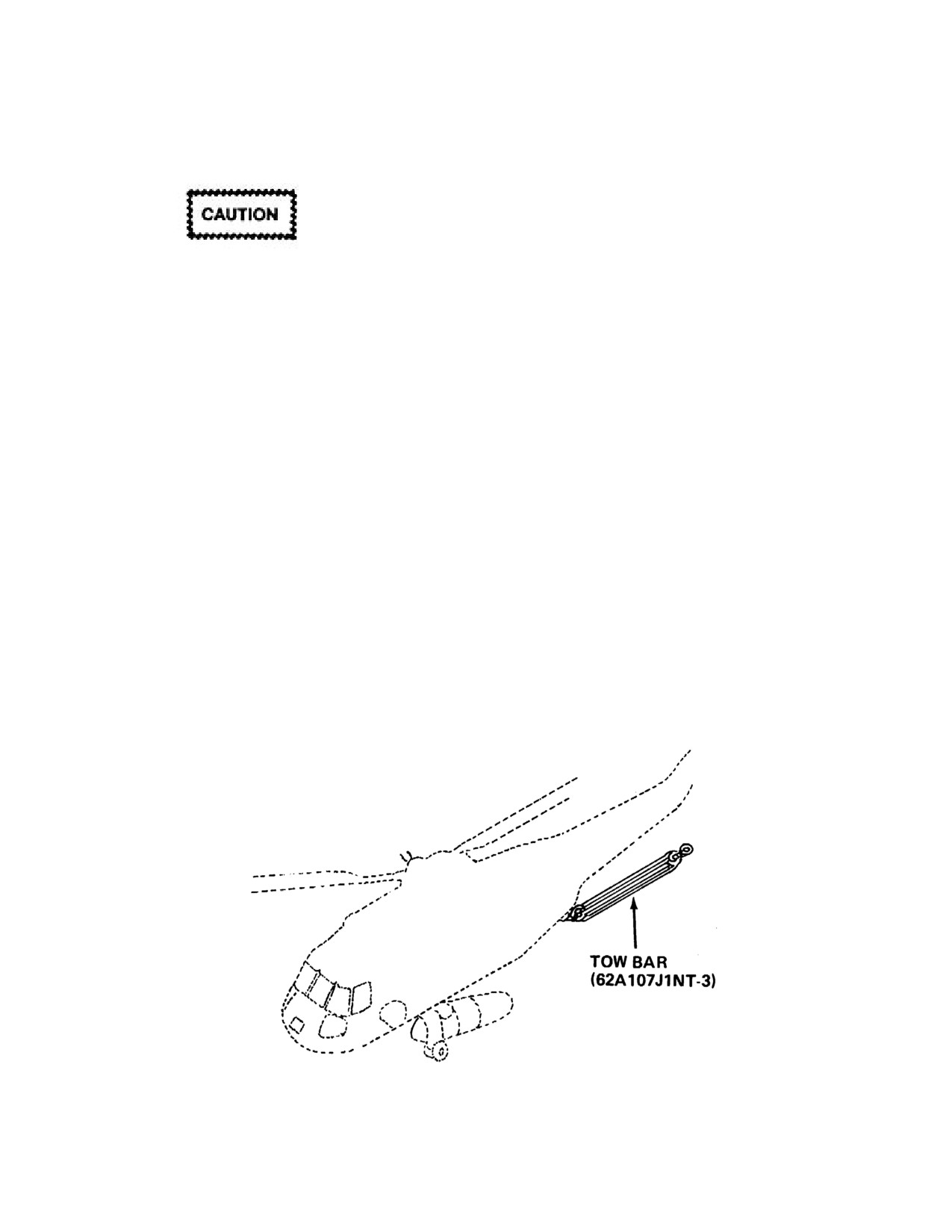
HELICOPTER TOWING (SEE FIGURE 3-11)
3.6.1.1 Safety Checks Prior to Towing.
3.6.1 Safety Precautions
1. Check main landing gear lockpins installed.
2. Check operation of brakes. Do not release parking
brake or remove chocks until tow bar is installed and
attached to tow vehicle.
3. Disconnect grounding wire.
Towing speeds shall not be over 5 mph, and
sudden starts and stops shall be avoided.
4. Station personnel.
3.6.2 Towing Procedures
Because of the top-heavy configuration of the
helicopter, precautions must be observed during all
1. Install tow bar and tighten chain.
helicopter movements to prevent possible damage and
dangerous conditions.
2. Release tailwheel locking handle and move
tailwheel back and forth with bar to remove any side
Towing equipment
(Figure
3-11) shall be operated
load on lockpin and to make sure lockpin is released.
only by qualified personnel who will be responsible for
checking the approved towing coupling before towing.
3. Connect tow bar to tow vehicle.
Towing shall not begin until a qualified individual is in the
cockpit and ready to operate the brakes. When towing a
4. Release parking brake by depressing left toe pedal.
helicopter, three wing walkers shall be used. A wingwalker
shall be stationed on each side of the helicopter, and one
5. Pull chocks.
will be located near the front of the helicopter to assure
adequate clearance. In addition, towing shall be supervised
6. Tow helicopter.
by a director, equipped with a whistle. During night towing
operations, wing walkers shall carry a flashlight or a
7. Lock tailwheel, lock brakes, insert chocks, remove
luminous wand and the helicopter position lights shall be
tow bar from helicopter, and install grounding wire.
turned on. All stop signals shall be given by a whistle or
hand signals. Whistle signals should be supplemented by
hand signals whenever possible. Wheelbrakes shall be
applied as soon as a stop signal is received from the
director.
Figure 3-11. Towing Equipment
3-16
ORIGINAL
NAVAIR 01-230HLH-1
3.7
PARKING
3.8.1 Tiedown Procedures (Shore Based)
3.7.1 Short-Term Parking. During short-term parking,
helicopter should be attended or monitored at all times.
1. When possible, head helicopter into wind. Fold
main rotor blades if wind is expected to reach 45 knots
1. Locate helicopter more than one rotor blade's
or above.
distance from other helicopters or objects, and face
helicopter into the wind if possible.
2. Chock both main landing gear wheels.
2. Lock tailwheel, lock brakes, insert chocks, and
3. Fasten chains to tiedown fittings as shown in
install grounding wire.
Figures 3-12 and 3-13 and extend outward to ground
mooring points at 45º angles.
3. Install protective covers. Secure windows and
doors.
4. Install main rotor blade tiedowns and tail rotor
gustlock.
3.7.2 Long-Term Parking. During long-term parking,
helicopter will not be attended or monitored.
3.8.2 Main Rotor Blade Tiedown. Tiedown of the
main rotor blades should be done anytime the helicopter
1. Park helicopter and secure as in short-term parking.
will be parked for a period of time or when actual or
projected wind conditions warrant.
2. Tie down main rotor blades.
1. Rotate rotor head to position the forward blades to
3. If winds of 45 knots are expected, fold and secure
about a 45° angle to centerline of helicopter and engage
main rotor blades. Attach tail rotor gustlock.
rotor brake.
4. Moor helicopter
(Figures
3-12 and
3-13) as
2. Attach blade boots to each blade tip and secure to
necessary.
the closest tiedown fitting
(main landing gear or
tailwheel strut), but not to the ground mooring point.
3.8
HELICOPTER TIEDOWN AND SECURING
3. Place tension in the tiedown lines, but do not pull
Tiedown fittings are installed at points on the
the blade tips more than 4 feet from original position.
helicopter shown in Figure 3-12 and 3-13. There are four
fittings located on the fuselage, two on each main landing
gear strut and one on the tailwheel strut. These fittings are
used to tie down the helicopter when parked and when
wind conditions require it. The lower tiedown fittings
located on the landing gear struts are also used for securing
the main rotor blades. On the ET the two forward fuselage
tiedown fittings/rings, and the two aft tiedown rings have
been removed.
3-17
ORIGINAL
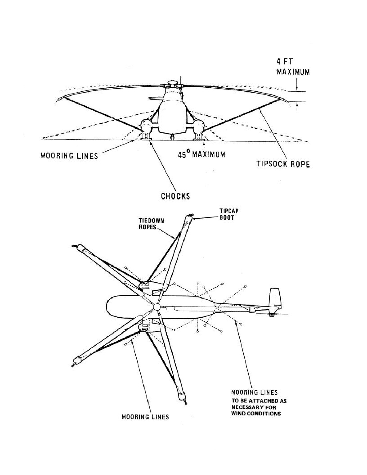
NAVAIR 01-230HLH-1
3.8.3 Helicopter Tiedown and Securing Diagram (See Figures 3-12 and 3-13)
Figure 3-12. Mooring - Blades Spread
3-18
ORIGINAL
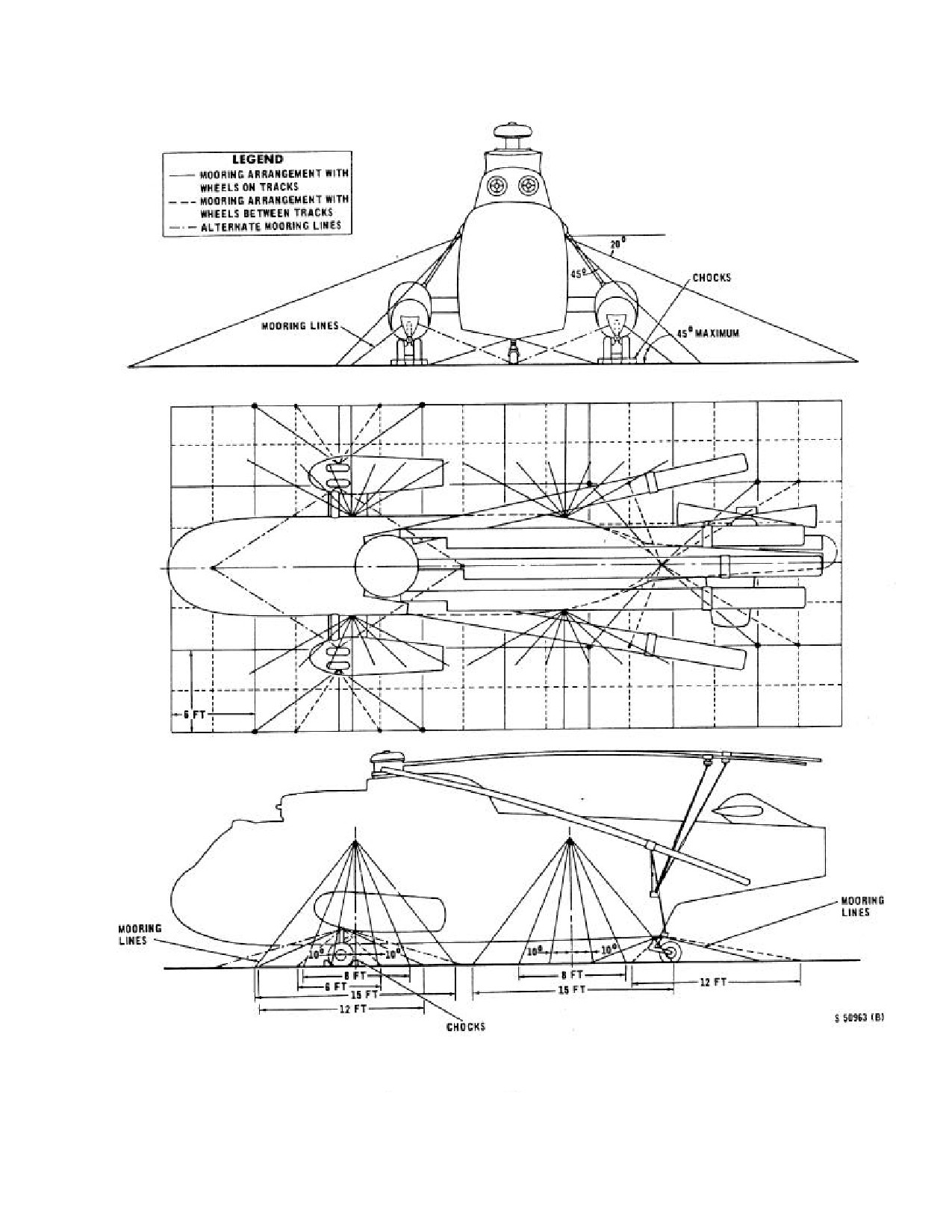
NAVAIR 01-230HLH-1
Figure 3-13. Mooring - Blades Folded
3-19
ORIGINAL
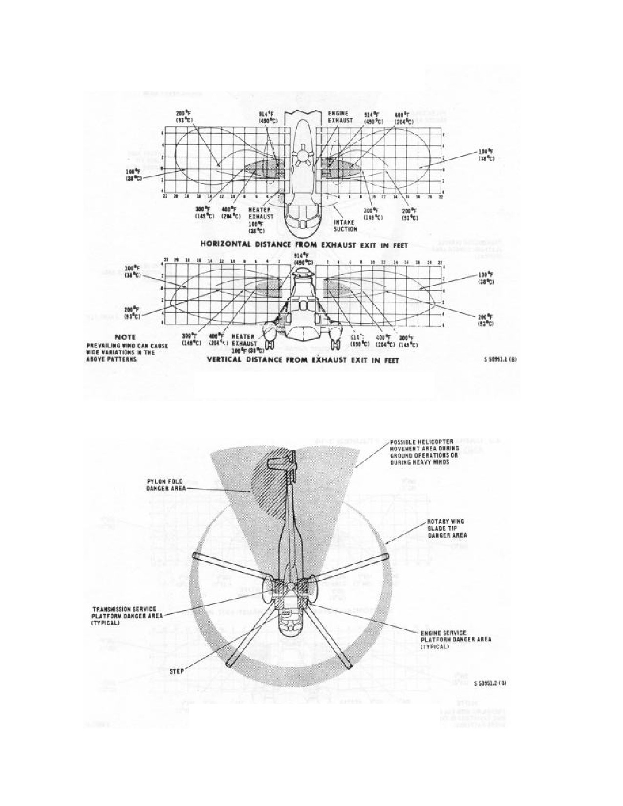
NAVAIR 01-230HLH-1
3.9 DANGER AREAS (See Figures 3-14 and 3-15)
Figure 3-14. Danger Areas - Helicopter Exhaust
Figure 3-15. Danger Areas - Rotor Stand Off
3-20
ORIGINAL
NAVAIR 01-230HLH-1
CHAPTER 4
Operating Limits
4.1 LIMITATIONS
Minimum planned fuel on final landing shall not be
less than 450 pounds total.
These limitations ensure your safety and help to obtain
maximum utilization from the helicopter and its
Maximum for pressure refueling is 55 psi.
equipment. The instruments are marked as shown in Figure
4-2 to serve as a constant reminder of airspeed and engine
During HIFR operations while using the Wiggins
limitations; however, additional limitations on operational
Fitting, a slow pumping rate of less than 100 pounds per
procedures, maneuvers, and loading are given in the
minute may indicate a clogged filter in the receiving
following paragraphs.
system. All five filters shall be replaced when this
indication occurs.
4.1.1 Minimum Crew Requirements. The minimum
crew required to operate the helicopter under normal
4.1.4 Starter Limitations
nontactical conditions is a pilot, copilot, and a crewman.
Additional crewmembers, as required, may be added at the
30 seconds operating per start.
discretion of the commanding officer. For specific crew
3 minutes between starts.
requirements, refer to Chapter 5.
3 starts during any 30-minute period.
4.1.2 Engine Limitations (T58-GE-402). All normal
4.1.5 Transmission Limitations. Operating limitations
engine limitations are shown for T58-GE-402 engines in
of the transmission system are governed by the main
Figure 4-1. Record all speeds above 106- percent Ng and
gearbox oil pressure and temperature.
duration on a VIDS/MAF.
4.1.5.1 Temperature
The maximum oil consumption rate during engine
operation is 12 ounces per hour.
1.
Main gearboxes may operate between 135 to 145
ºC for up to 60 minutes.
Engine operation from
691º to
727º is limited to
30
minutes (military power) in duration and 727º to 750º for
2.
Operation above 145 ºC is an overtemperature.
10 minutes
(topping power) for unscheduled use and
maintenance verification of engine performance.
4.1.3 Fuel System Limitations. One boost pump on
each tank during all flights. All boost pumps shall be
operating:
The transmission oil cooler was designed for
1.
Above 4,000 feet PA.
maximum cooling efficiency during sea
level operations. Higher than normal main
2.
Over 43 ºC OAT.
gearbox oil temperatures can be anticipated
when operating at altitudes above sea level
3.
Less than 600 pounds fuel per tank.
and when combined with high ambient
temperatures and high power settings. The
With the fuel low level caution lights illuminated, do
reduced pressure/density of air passing
not exceed 6º noseup attitude.
through the radiator causes a loss in cooling
efficiency of the main gearbox oil cooler.
4-1
ORIGINAL
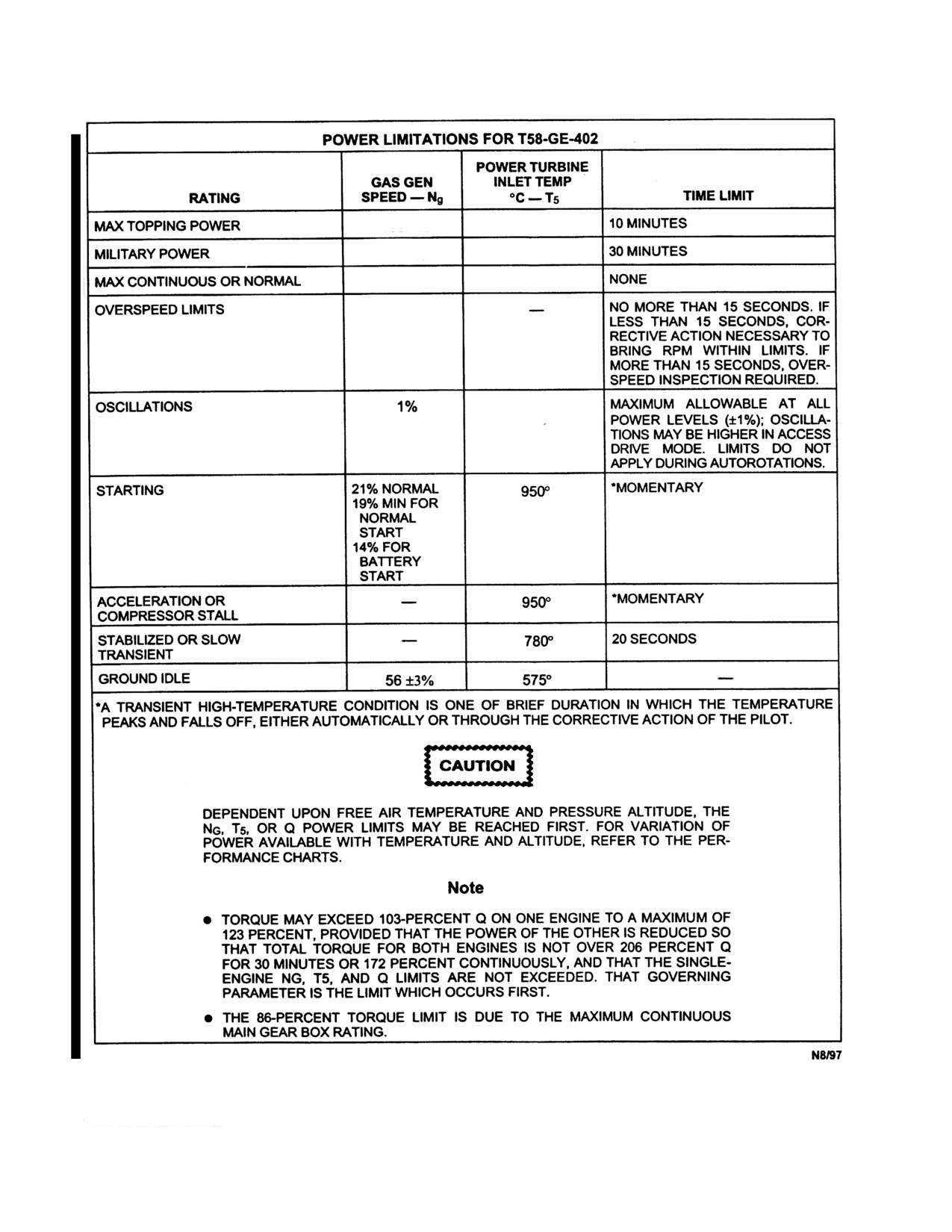
NAVAIR 01-230HLH-1
<103.7
750°
103.7%
727°
101.8%
691°
108%
Figure 4-1. Power Limitations
4-2
ORIGINAL
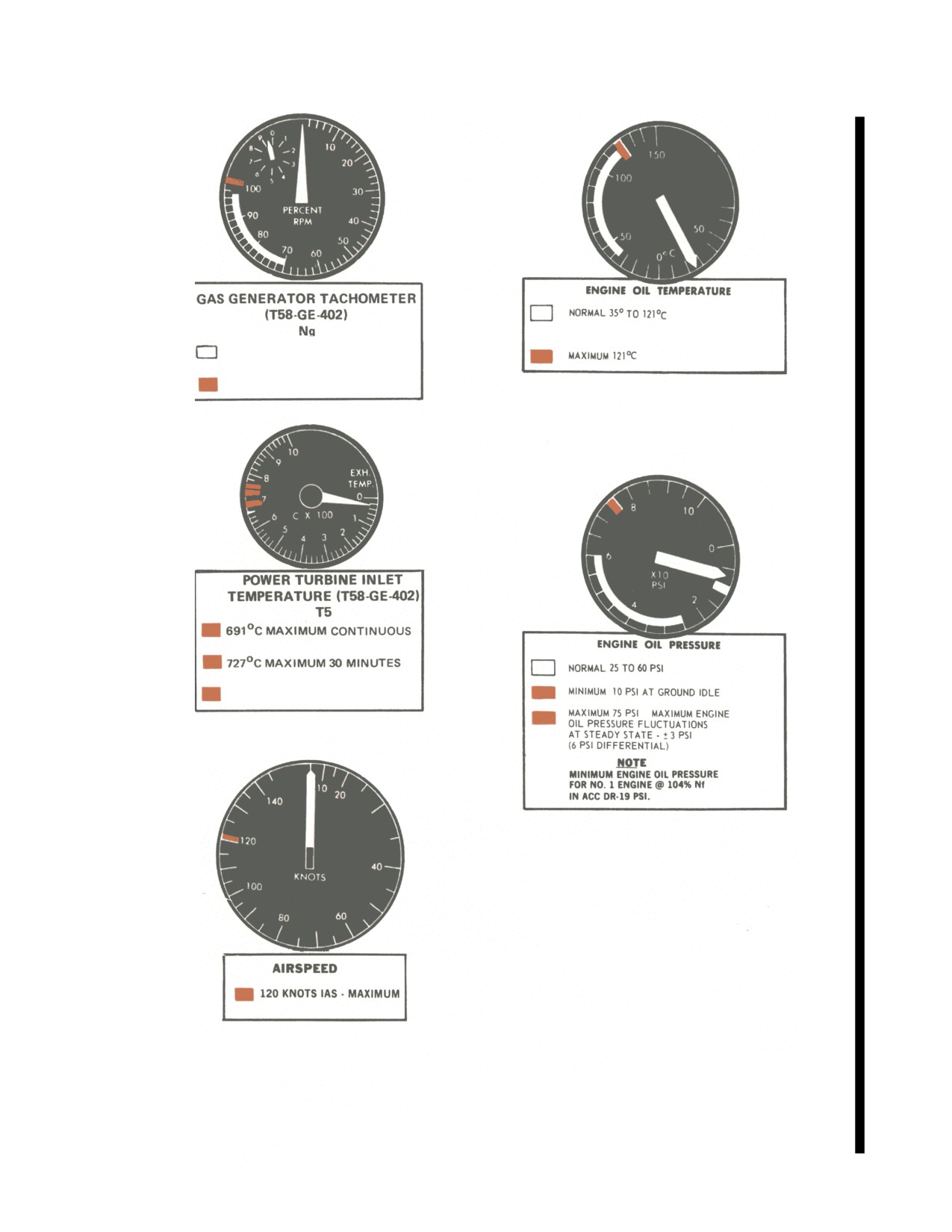
NAVAIR 01-230HLH-1
70% TO101.8% NORMAL
<103.7 % MAXIMUM 30 MINUTES
750 °C MAXIMUM 10 MINUTES
Figure 4-2. Instrument Markings (Sheet 1 of 2)
4-3
ORIGINAL
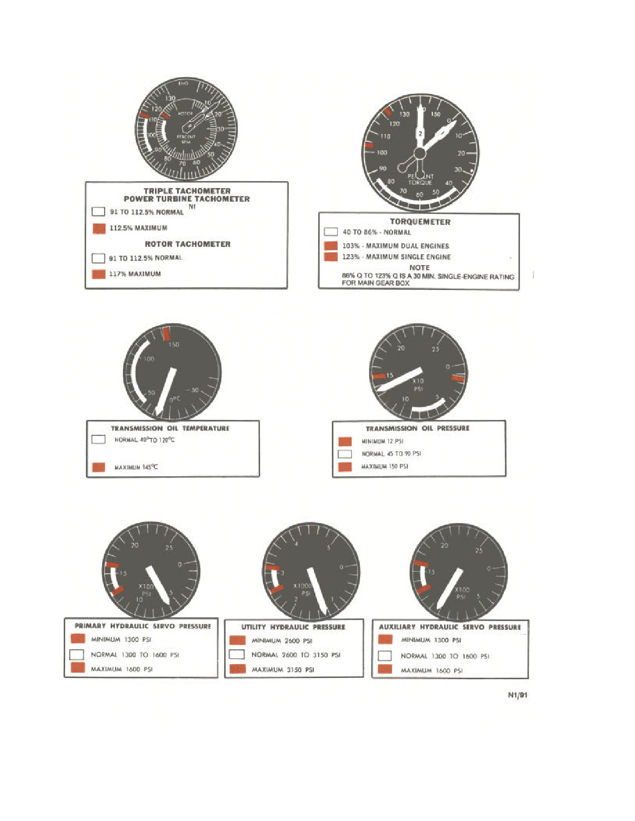
NAVAIR 01-230HLH-1
Figure 4-2. Instrument Markings (Sheet 2 of 2)
4-4
ORIGINAL
NAVAIR 01-230HLH-1
Nine hours shall be considered the maximum
continuous operating time between rotor system
lubrications.
4.1.8 Main Gearbox Torque Limitations. Main
If emergency rotor engagement is made
gearbox torque limitations for maximum service life
when the ambient temperature is
-29ºC or
under steady-state conditions are indicated by the range
less, a VIDS/MAF shall be submitted. The
markings on the torquemeter. However, transient
gearbox may be damaged from lack of
conditions in excess of the red line may occur during
lubrication at these low temperatures.
normal operations. Main gearboxes operated in excess of
limits must be inspected by an overhaul facility. The
following items define allowable operating conditions:
4.1.6 Gearbox Allowable Oil Leakage. Leakage of
main, intermediate, and tail gearboxes may be caused by
1.
During single-engine operation, transient torque-
faulty seals, gaskets, packings, or shims. Total leakage
meter readings between
123 and
150 percent are
from all sources during a period of 10 flight hours should
permissible for periods of no more than 5 seconds.
not be over half the distance from the full to the refill line
for each gearbox.
2.
During single-engine operation, transient
torquemeter readings above
150 percent are not
4.1.7 Maximum Continuous Operating Time
permissible.
4.1.7.1 Servicing. Maximum safe continuous operating
3.
During single-engine operation, the main
time with hot refuelings can vary considerably with
gearbox has a 30-minute rating at 1,500 shp (123-
individual aircraft, crew fatigue, and specific operations.
percent torque) at 100-percent Nf.
Medium frequency vibrations can be expected after 8 to
10 hours of continuous operation. Ten hours should be
4.
During dual-engine operation, transient torque-
considered as the maximum continuous operating time
meter readings between
103 and
120 percent are
with hot refueling until the helicopter is shut down and a
permissible for periods of no more than 5 seconds.
maintenance daily/turnaround conducted.
5.
During dual-engine
operation,
transient
4.1.7.2 Rotor System Limitation. Maximum
torquemeter readings above
120 percent are not
allowable rotor speed is 117-percent Nr.
permissible.
6.
During dual-engine operation, the main gearbox
WARNING
has a
30-minute rating at
2,500 shp
(103-percent
torque) at 100-percent Nf.
4.1.9 Airspeed Limitations. The combination of
If a blade spar pressure indicator shows
airspeed and rotor speed at which blade stall is
black at any time, further flight shall not be
encountered as shown in the blade stall chart in Part XI
attempted until qualified personnel check
should be avoided. The maximum permissible indicated
the integrity of the blade in accordance with
airspeeds are as follows:
applicable maintenance manuals.
Forward flight
120 knots
(For aircraft without IBIS installed.) For early
Sideward flight
30 knots
detection of rotor blade cracks and to preclude crack
Rearward flight
20 knots
propagation to hazardous levels, the operation intervals
between BIM inspections shall not be over 4.5 hours. If
Note
more than 1.0 hour is spent between 20 to 40 KIAS, the
operating limit between BIM inspections shall not be over
For altitude operation, decrease maximum
3.0 hours. If during flight the maximum airspeed is
permissible airspeed
(120 KIAS) by
6
between 101 to 110 KIAS, the operating interval between
KIAS for each additional 1,000 feet above
BIM inspections shall not be over 3.0 hours. If during
4,000-foot MSL.
flight the maximum airspeed is over
110 KIAS, the
operating interval between BIM inspections shall not be
over 2.0 hours. For these restrictions, operating interval is
defined as the elapsed time from lift-off to landing.
4-5
ORIGINAL
NAVAIR 01-230HLH-1
4.1.10 Additional Speed Limits
4.1.16 Weight Limitations. The maximum operating
Condition
Maximum
gross weight is 21,000 pounds.
Run-on landings
40 knots groundspeed
4.1.17
(NON-ET) Rescue Hoist Limitations. The
Flotation bags inflated
60 knots
hoist has a lifting capacity of 600 pounds and a lowering
Rescue hoist below stowed
capacity of 300 pounds.
position uncontrolled
60 knots
Maximum water entry/taxi
15 knots groundspeed
Note
Opening cargo doors
90 knots
Shorthauling Personnel
40 knots
Refer to rescue hoist duty cycles without
External Cargo
exceeding utility hydraulic system thermal
Forward
100 knots
limits of 121.1 ºC (Figure 2-57).
Sideward and Rearward
20 knots
4.1.18 Flotation Bag Limitations
4.1.11 Maneuvers. The following maneuvers are
permitted:
Air bottle serviced 2,650 to 3,000 psi.
Airspeed (deployed) 60 knots.
1.
Angles of bank up to but not exceeding 45º.
Altitude (deployed) 3,000 feet PA.
2.
Hovering turns not beyond a rate of 360º in 15
4.1.19 Flood/Hover Lights. Maximum time for
seconds.
flood/hover lights is
15 minutes. Allow
10 minutes
cooling cycle after 15 minutes of use.
4.1.12 Hovering Limitations. Refer to the hover
charts in Part XI. The helicopter shall not be hovered
4.1.20 (NON-ET) Cargo Door. Opening the cargo door
crosswind when wind velocity is over
30 knots nor
at speeds in excess of 90 knots may result in inadvertent
downwind when wind velocity is over 20 knots.
loss of escape window.
4.1.13 Altitude Limitations
4.1.21 Stores. Unless authorized by the Naval Air
Systems Command (NAVAIR), only the stores shown in
Practice live hoisting
Figure
4-3 may be carried and released singly or in
over hard surface
combination. Basic helicopter operating limitations
unless using safety
without such stores apply unless otherwise noted.
belay line procedures
Authorized variations in stores loading shall not exceed
listed in NWP 3-50. 1.
10 feet max. AGL
established launching rack capabilities.
Normal hover altitude
15 feet AGL
Flotation bags inflated
3,000 feet PA
4.1.22 Shipboard Wind Limits. See Chapter 8 for
shipboard wind limits.
4.1.14 Acceleration Limitations. The maximum
4.1.23 Taxi Limitations. Aircraft shall not be taxied
permissible acceleration shall not be over 1.5g's positive
within 25 feet of an obstruction unless taxi lines/spots or
and 0.5g negative.
other clearance guides are available for adequate
separation.
4.1.15 Center of Gravity Limitations
4.1.24 Cargo Sling Limitations. Maximum allowable
Fuselage station 258.0
Most forward cg
external load is 6,000 pounds. Maximum gross weight is
Fuselage station 276.0
Most aft cg
not to be exceeded
(see weight limitations above).
Maximum angle of bank is 30º.
Note
With ASE off and with cg aft of station
272, reduce the airspeed limits as
determined from the blade stall chart in Part
Flight above
60 knots with the cargo hook
XI by 25 knots.
lowered without an external load may result in
damage to the underside of the fuselage
The center of gravity moves aft about one-half inch
when landing gear is raised. Proper loading shall be
determined by use of the Handbook of Weight and
Balance, NAVAIR 01-1B-40.
4-6
ORIGINAL
NAVAIR 01-230HLH-1
4.1.27.2 MK 4 MOD 0 HELICOPTER DEPLOYED
4.1.25 Tipover Limitations
LIGHTWEIGHT TORPEDO RECOVERY SYSTEM
Dynamic tipover angle is 15º.
1. Carriage
Static tipover angle is 37º.
a. Airspeed -100 KIAS maximum with Mk 46/50
- 90 KIAS maximum empty.
WARNING
b. Angle of bank - 30°.
c. ASE - ON.
If lateral cyclic control becomes sluggish or
d. VMC-ONLY.
ineffectual or contacts the lateral stop, or if
bank angle becomes excessive (8º to 10º)
e. Climb/descent rate - LBA.
with one wheel on the ground and thrust
about equal to the weight, the helicopter will
f. To ensure adequate tail rotor to cage clearance,
roll over on its side. Use full cyclic control
avoid full collective reduction in less than
2
and reduce collective to stop the roll and
seconds. A modified lare technique should be
then correct the bank angle to wings level.
used to decelerate by simultaneously reducing
collective and bringing cyclic aft.
4.1.26 Marine Markers Deployment Limitations
2. Jettison
a. Emergency only - level flight if time/emergency
WARNING
permits.
4.1.27.3 MK 2 MOD 0/1 HELICOPTER WEAPON
Mk
25 marine markers should not be
RECOVERY SYSTEM
launched in a hover because of the possibility
of upward ejection of initial plug.
1. Bank angle-300 maximum.
4.1.27 WEAPON RECOVERY LIMITATIONS
2. Acceleration - LBA (without stores).
4.1.27.1 MK 146 MOD 0 TARGET LAUNCH
3. Climb/descent-LBA.
SYSTEM
4. ASE-ON.
NAVAIR flight clearance limitations for the target
launcher are as follows:
5. Maximum airspeed - see Figure 4-3.
1. Maximum airspeed loaded - 90 KIAS.
4.1.27.3.1 Weight and Balance Information. See
Maximum airspeed empty -80 KIAS.
Figure 4-4.
2. Maximum angle of bank - 30°.
4.1.27.4 MQM-74C/BQM-74C/E/E(ERT)/BQM-34
RECOVERY AND FLIGHT LIMITATIONS
3. Maximum acceleration - LBA.
4.1.27.4.1 Maximum Sea States Authorized for
Recovery by Pole Devices
LENGTH (Feet)
SEA STATE
(Beaufort Scale)
At high airspeed with the empty launcher, full
15
3 (3-5 foot waves)
collective lowering rates of 3 seconds or less
will cause the launcher to approach and
possibly contact the aircraft near the
20
4 (6 foot waves)
tailwheel.
4. ASE - ON.
4-7
ORIGINAL
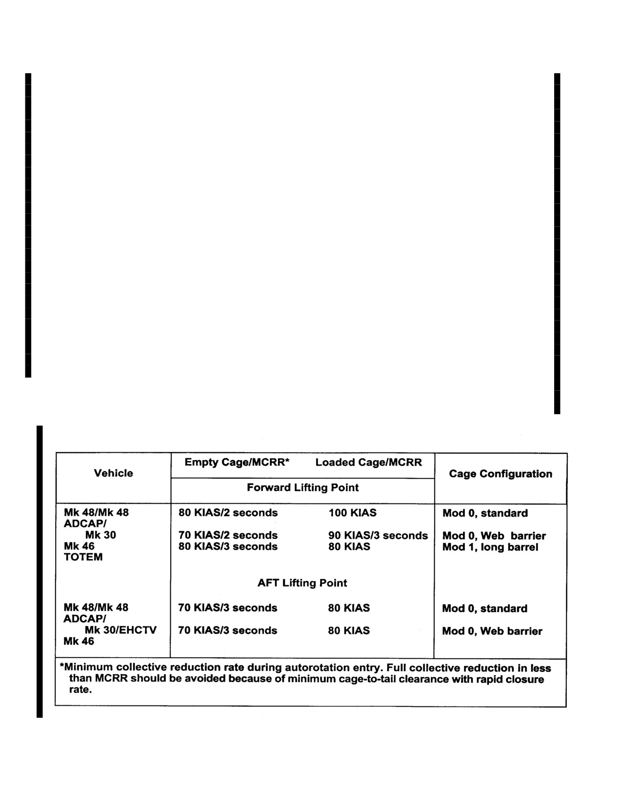
NAVAIR 01-230HLH-1
4.1.27.4.2 Drone Retrieval Not Authorized Under
Note
Following Conditions
·Rate of climb is restricted to 500fpm.
1. Sea states greater than 4 (waves greater than 6 feet).
·When carrying a BQM-74E(ERT) at
altitudes above 1000ft AGL, an unreliable
2. Air temperature less than 4 C.
Rad Alt indication will be present with a
constant RAWS tone.
3. Weather minimum less than 500 foot ceiling and
1 mile visibility.
4.1.27.4.4 Drone Weights
4.IMC at recovery altitude.
TYPE
WEIGHT
LAUNCH / RECOVERY
5. Wind gusts greater than 25 knots.
BQM-34
2,300 POUNDS / 1,600 POUNDS
4.1.27.4.3 Airspeed Limitations with Drones
BQM-74C/E/E(ERT)
650 POUNDS / 250 POUNDS
DRONE
AIRSPEED
BANK ANGLE
(KIAS)
(degrees)
MQM-74
450 POUNDS / 286 POUNDS
MQM-74/
90 knots
15
4.1.27.4.5 Mk 30 Snare/ Pole Recovery and Flight
BQM-74C/E
90 knots
15
Sea State:
4 (8 foot seas maximum)
BQM-34
80 knots
15
Airspeed:
90 knots maximum
BQM74E(ERT)
80 knots
15
Angle of Bank:
30 maximum
Autorotation entry:
2 seconds minimum
collective lowering
Figure 4-3. Mk 2 Mod 0/1 HWRS Airspeed Limitations
4-8
ORIGINAL
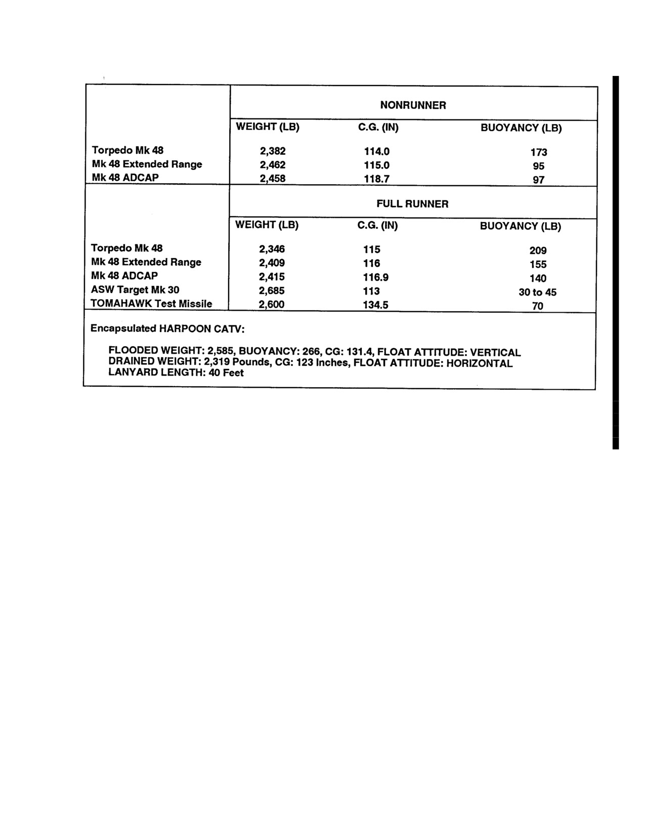
NAVAIR 01-230HLH-1
Figure 4-4. Weight and Balance
4-9
ORIGINAL
NAVAIR 01-230HLH-1
This Page Left Blank Intentionally
4-10
ORIGINAL
NAVAIR-01-230HLH-1
PART II
Indoctrination
Chapter 5 - Indoctrination
51
ORIGINAL
NAVAIR-01-230HLH-1
This Page Left Blank Intentionally
52
ORIGINAL
NAVAIR 01.230HLH-1
CHAPTER 5
Indoctrination
5.1 GROUND TRAINING REQUIREMENTS
b. Qualification in SS does confer qualification in
The following minimum requirements are established
MS. Initial qualification in one category does not
for qualification in a nontactical category.
confer qualification in the other category.
5.1.1 Pilot Ground Training
c. A requalification shall be required when cur-
rency has elapsed.
1. Complete initial or refresher aircrew coordination
training in accordance with OPNAVINST 3710.7 and
d. Commanding officers may waive qualification
1542.7.
requirements in the case of experienced
pilots
where continuing operation is not planned.
2.
FT/WST (if available) - 6 hours.
e. Qualifications
- SS require at least
a
PQM
3.
H-3 flight operation lectures - 6 hours.
qualification.
4.
Helicopter safety and survival equipment - 2 hours.
(1) Initial Qualification.
5.1.2 Crewman Minimum Ground Training Before
Flight
(a) Day - Six landings.
1.
H-3 familiarization lectures - 2 hours.
(b) Night.
2.
Complete initial or refresher aircrew coordination
1) Day qualified within 10 days.
training in accordance with OPNAVINST 3710.7 and
1542.7.
2) Six night landings.
3.
Helicopter safety and survival equipment
-
2
(2) Currency.
hours.
(a) Day- Two day landings within:
5.2
FLIGHTCREW QUALIFICATIONS
MS
SS
5.2.1 Pilot Qualifications. The HAC, H2P, PQM,
6 months
6 months
and pilot in command shall be designated in accordance
with OPNAVINST 3710.7, type commander instructions,
(b) Night.
and pertinent sections of this manual.
1) Day Current.
1.
Shipboard qualification and proficiency require-
ments.
2) Three night landings within:
a. Definitions.
MS
SS
4 months
2 months
(1) Single Spot (SS)
(2) Multi-spot (MS)
5-1
ORIGINAL
NAVAIR 01.230HLH-1
(3)
Requalifications.
2. Current in Basic first-aid and CPR qualifications.
(a) Day - Two day landings.
3. NATOPS qualified.
(b) Night.
4. Designated by unit commanding officer.
1) Day qualified and 1 day landing within
5.2.2.2 Helicopter Crew Chief. The designation granted
10 days.
by the commanding officer to those utility air-crewmen who
have demonstrated a superior level of knowledge and
2) Four night landings.
performance in the operation and required missions of the H-3.
The following minimum requirements are established for
2. Instrument qualification.
designation as helicopter crew chief.
a. In accordance with current OPNAVINST
1. Designated helicopter utility aircrewman by unit
3710.7.
commanding officer.
3. Waivers - In accordance with OPNAVINST 3710.7,
2. Complete parent unit's aircrew training syllabus and
unit commanders are authorized to waive in writing
be fully qualified in the following:
minimum flight hours or training requirements.
a. Current
in
Basic first-aid
and CPR
5.2.2 Crewman Qualification. Helicopter aircrewman
qualifications.
shall be designated in accordance with OPNAVINST
3710.7,
NAVMILPERS instructions,
type/wing
b. Can demonstrate extensive knowledge and
commander instructions, and pertinent sections of this
usage of SAR equipment and procedures.
manual. The qualifications utility aircrewman and crew
chief, as appropriate, will be assigned by squadron
3. Log a minimum of the following:
commanding officers. These designations are a one-time
occurrence (per command tour) and remain in effect until
a. Fifty hours flight time in model.
removed for cause. Annual NATOPS evaluations should
not be confused with or combined with these designations.
b. Twenty successful practice rescues, five of
NATOPS evaluation flights and crew designation flights
which must be simulated rescues using the litter
should be conducted on separate flights. Crew designation
with trail line, and six of which must be live hoists.
flights evaluate material that is beyond the scope of
NATOPS (i.e., information from NWP
3-50.1, survival
4. Helicopter rescue swimmers shall be currently
and first-aid techniques, unit mission and tactics,
qualified in accordance with OPNAVINST 3710.7 and
applicable FXPs/ATPs, PQS, and various maintenance
3130.6.
publications). Qualification and entitlement to wear
aircrew wings for all H-3 air crewmen shall be in
5. Be a qualified plane captain.
accordance with applicable NAVMILPERS and OPNAV
instructions. In accordance with OPNAVINST 3710.7, unit
6. Designated by unit commanding officer.
commanders are authorized to waive in writing minimum
flight hours, training and/or plane captain requirements.
5.2.2.3 SAR Medical Technician. The designation granted
by the commanding officer of SAR units that have hospital
5.2.2.1 Helicopter Utility Aircrewman. The designation
corpsman assigned under aircrew orders. These personnel
granted by the commanding officer to those aircrewmen
perform emergency medical care functions in flight and act as
who have demonstrated an excellent level of knowledge
the medical attendant when transporting patients in the
and performance in the appropriate operations sufficient
MEDEVAC role. These personnel also assist other members of
to meet the unit's requirements. The following minimum
the crew in search and rescue procedures and are trained in
requirements are established for designation as helicopter
aircraft operating and emergency procedures. The following
utility aircrewman:
minimum requirements are established for designation as a
SAR medical technician:
1. Completed H-3 FRS aircrew training syllabus and/or
parent unit syllabus.
1. Successful completion of the H-3 FRS aircrew
training syllabus and/or parent unit syllabus.
5-2
ORIGINAL
NAVAIR 01.230HLH-1
2. Designated helicopter utility aircrewman by unit
c. One designated crewman (cross-country).
commanding officer.
3. Functional checkflights.
3. Fifty hours of flight time in model.
a. Two helicopter pilots, one of whom is a functional
4. NATOPS qualified.
check flight pilot designated by the unit commanding
officer.
5. Qualified in accordance with OPNAVINST 3130.6
and BUMEDINST 1510.17.
b. One crewman designated as a functional
checkflight aircrewman by the commanding officer.
6. Designated SAR medical technician by unit
commanding officer.
5.2.2.5 Minimum Requirements for Combat
NOTE
Search and Rescue
SAR Medical Technicians are required to
apply for Naval Aviation Observer IAW
1. Combat search and rescue shall be designated in
MILPERS Manual.
writing and attend the appropriate CNO-approved
strike rescue school prior to assuming a crew position
5.2.2.3.1
Waiver of Requirements. In accordance
on strike rescue missions.
with OPNAVINST
3710.7, commanding officers are
authorized to grant waivers in writing or flight hours,
a. Day qualifications - Ten hours of flight training
specific training, and crew minimums when the situation
emphasizing crewman responsibilities during low
or crewman's experience warrants such action.
level terrain navigation and obstacle avoidance and
verbal positioning techniques during confined area
5.2.2.4 Minimum Crew Requirements for Specific
landings to unprepared sites.
Operations. Only those personnel considered necessary
to perform the specific mission shall be carried on flights
b. Currency
- Day currency will be maintained
that are determined to be hazardous. Such other personnel
with
1-day terrain flight
(including CALS)
as can be accommodated with approved seats and securing
within 45 days.
devices may be carried during normal operating conditions
when authorized by competent authority. To qualify for
5.2.2.6 Flight Attendant/Crew Chief. The designation
specific operations and flight categories listed below,
granted by the commanding officer to those aircrew
pilots/crewmen must meet listed qualifications. Additional
candidates who have demonstrated a superior level of
or more stringent requirements may be set forth by the
knowledge and performance in the operation and
reporting custodian officer.
employment of all required missions of the UH-3H
Executive
Transport.
The following
minimum
1. Search and rescue, support, utility missions, and
requirements are established for designation as flight
passenger transport.
attendant/Crew Chief.
a. Two helicopter pilots, one of whom is
1.
Complete FRS aircrew training syllabus and/or
designated HAC.
parent unit aircrew training syllabus in accordance
with OPNAVINST 3710.7.
b. One designated helicopter crew chief.
2.
Log a minimum of 50 hours flight time as an
c. One qualified rescue wet swimmer
(SAR
aircrew candidate.
missions).
3.
Current in Basic first-aid and CPR
2. Familiarization flights and cross-country flights.
qualifications.
a. Two helicopter pilots.
4.
Be a qualified plane captain.
Note
5.
Demonstrate an expert knowledge of all survival
equipment in assigned aircraft.
The requirement may be waived by the
commanding officer for indoctrination
6.
Designated by unit commanding officer.
flights provided the pilot in command holds
at least an H2P designation.
7.
NATOPS qualified.
b. One designated aircrewman (FAM flights).
5-3
ORIGINAL
NAVAIR 01.230HLH-1
5.3 NATOPS FLIGHT EVALUATION
3. Waiver of requirements
- In accordance with
OPNAVINST
3710.7, commanding officers are
5.3.1 Pilot Evaluation. All pilots meeting the below
authorized to grant waivers in writing for rescue hoist
listed minimum qualifications shall be liable for a
operation requirements when the crewman experience
NATOPS evaluation check. The ground evaluation will be
warrants such action.
successfully completed in accordance with Chapter
19
before the flight evaluation. Training requirements,
5.4 PERSONAL FLYING EQUIPMENT
checkout procedures, evaluation procedures, and weather
minimums for ferry squadrons are governed by the
The pilot in command shall ensure that the following
provisions contained in OPNAVINST 371076.
equipment is worn by all crewmembers of the helicopter in
accordance with OPNAVINST
3710.7. Consult this
1. Initial flight evaluation criteria. Successfully
instruction for information on passenger flight equipment.
complete the FRS syllabus, or its equivalent. Flight
Items marked with an asterisk (*) are waived for executive
hour minimum previous 6 months):
transport missions not over water.
a. Total in model
- 35 hours or 25 hours using
1.
Protective helmet.
CNO approved 2F64C trainer syllabus.
2.
Flight safety boots.
b. Night time in model - 6 hours or 5 hours using
3.
Flight gloves.
CNO approved 2F64C trainer syllabus.
4.
Fire-resistant flight suit.
c. Instrument time in model - 4 hours.
5.
Identification tags.
2. Minimum requirements for annual NATOPS
evaluation.
*6. Survival knife.
a. Flight hours in model previous 12 months
-60
*7. Personal survival kit.
hours (30 of which were in the previous 6 months).
*8. Signal devices.
b. NAMTD if available or refresher at squadron
9. Flashlight - required for night flights.
level.
*10. Anti-exposure suit as required by
3. Waiver of requirements
- In accordance with
OPNAVTNST 3710.7
OPNAVINST
3710.7, commanding officers are
authorized to grant waivers in writing for flight hours
*11. Personal survival radio (if available).
and NAMTG training when the situation/pilot
experience warrants such action.
*12. Flotation gear (as required).
5.3.2 Crewman Evaluation
*13. HEEDS bottle or HABD (as required).
1. Initial flight evaluation criteria
- Initial NATOPS
14. Pocket checklist.
evaluations will be satisfactorily completed prior to
5.5 CREW REST REQUIREMENTS
designation as a naval aircrewman.
2. Minimum requirements for annual NATOPS
The following crewmember rest requirements
are
evaluation
- Crewmembers meeting the following
considered to be the minimum criteria that will provide an
requirements will be considered current in all respects
optimum level of physical and mental performance during
and shall be given NATOPS evaluations annually.
flight operations:
1. Crews should not be scheduled for more than
9
a. Comp lete a minimum of six live hoists and six
hours of operational flying time per day. This is
simulated rescue operations within last year
(if
normally interpreted to be two operational sorties per
applicable).
day. This limit is raised to 12 hours per day per 24-
hour period for non-operational missions such as cross-
b. Complete the squadron approved training syl-
country flights.
labus in the preceding year.
2.
A minimum of 8 hours of uninterrupted crew rest
c. Current
in
Basic first-aid
and CPR
should be provided per 24-hour period.
qualifications.
5-4
ORIGINAL
NAVAIR 01.230HLH-1
3. Crews should not be scheduled for continuous alert
(1) Equipment:
and/or flight duty (required awake) beyond 18 hours.
(a) Torpedo/drone familiarization.
For waiver to the above requirements commanding
officers shall refer to OPNAVINST
3710.7 for specific
(b) Recovery system familiarization.
guidance.
(c) Recovery system/aircraft Setup.
5.6 FLIGHT TIME SUMMARY
(2) Recovery procedures
An annual flight time summary shall be compiled for
naval aircrewmen at the end of each fiscal year and entered
(3) Load oscillation recovery
into the appropriate section of the NATOPS flight training
jacket
(OPNAV 3760/32). An Enlisted Service Record
(4) Emergency procedures
(page 13) entry shall then be made indicating this total.
(5) Safety considerations
5.7 WEAPON RECOVERY INDOCTRINATION
(6) Flight clearances
5.7.1 Flight Crew Qualifications
5.7.1.4.1 Flight Training
5.7.1.1 Pilot Qualifications. HAC shall be designated
in accordance with the current OPNAVINST 3710.7, type
1. Pilots
commander instructions, and pertinent sections of this
manual prior to being designated in writing as mission
a. Observation of aircrew duties for each tar-
commander for launch/recovery of tar-gets/torpedoes.
get/torpedo (optional)
5.7.1.2 Aircrew Qualifications. Helicopter air
b. Recovery from load oscillation in flight/ hover
crewman shall be designated in accordance with current
OPNAVINST
3710.7, BUPERS/NAVPERS instructions,
c. Launch/recovery
type/wing commander instructions and pertinent sections
of this manual prior to being designated in writing as crew
(1) System hookup
chief for launch/recovery of targets/torpedoes.
(2) Transit
5.7.1.3 Crew Requirements
(3) Launch/recovery:
1. Two helicopter pilots, one of whom is a mission
designated HAC.
(a) Launch
- flight as copilot prior to
performing maneuvers pilot at controls.
2. One crewman who is a mission designated crew chief.
(b) Recovery
- initial qualification; six
3. Two crewmen as mission requires.
recoveries (using certified dummy shapes if
available).
5.7.1.3.1 Qualification. The incorporation of these
procedures into this manual does not constitute
(4) Transit/drop off
authorization for commands to qualify and train aircrews
in them nor to perform them operationally. Specific
2. Aircrewmen
authorization will come from the appropriate type
commander, through the operational chain of command.
a. For each type of torpedo/target:
5.7.1.4 Initial Mission Qualification
(1) Observation of two launches and two
recoveries.
1. Ground training shall include:
(2) Conduct six recoveries. (Using certified dummy
a. Training lectures and hands-on equipment
shapes if available).
training conducted by personnel from cognizant
torpedo/drone custodian for all ground personnel.
5.7.1.5 Proficiency Qualification
b. Ground training conducted by mission qualified
personnel for all flightcrews. This training shall
1. Ground training to be incorporated into the unit's
annual training plan.
include:
5-5
ORIGINAL
NAVAIR 01.230HLH-1
2. Requalification/currency: Two launches or two
recoveries in the last 6 months.
5.7.1.5.1 Waivers. In accordance with OPNAVINST
3710.7, commanding officers may waive in writing
minimum flight hours and training requirements for one
time or short-term operations where pilot/aircrew
experience warrants.
5-6
ORIGINAL
NAVAIR-01-230HLH-1
PART III
Normal Procedures
Chapter 6 - Flight Preparation
Chapter 7 - Shore-Based Procedures
Chapter 8 - Ship-Based Procedures
Chapter 9 - Special Procedures
Chapter 10 - Functional Checkflight Procedures
53
ORIGINAL
NAVAIR-01-230HLH-1
This Page Left Blank Intentionally
54
ORIGINAL
NAVAIR 01-230HLH-1
CHAPTER 6
Flight Preparation
6.1 Mission Planning
of the air decreases, the mass flow of air through a gas
turbine decreases and the efficiency drops off. However,
Helicopter Combat Support mission planning
the gas turbine operates more efficiently at lower
involves consideration of an ever changing variety of
temperatures encountered at high altitudes with the result
situations. Missions of other types must be similarly
that the thrust delivered per pound of air consumed is
coordinated based on the requirements of original mission
higher at high altitudes. Since power output decreases and
authorization. Ultimate success of mission planning is
efficiency increases, specific fuel consumption decreases
dependent upon liaison between controlling authority and
with increased altitude. Thus, a definite advantage is
proper scheduling at squadron level.
gained with gas turbines when operated at high altitudes
since with reduced air density, higher true airspeed will
The rules applicable to range for the helicopter are
result from a given power output. The helicopter,
the same as those rules applicable to multiengine aircraft.
however; is limited in using the gas turbines for fullest
Variables affecting helicopter range are onboard fuel,
efficiency at altitude. This is not because of the engines
wind direction, and velocity. No restrictions should be
but due to the lift capability of the rotor system at high
imposed on the helicopter that would limit its range other
altitudes. For flight planning purposes, consult
than those factors that apply to multiengine aircraft (i.e.,
appropriate charts in Part XI.
NAVAIDs, fuel, wind, etc.).
6.1.1.5 Maximum Range. If there is not enough fuel
6.1.1 Factors Affecting Range and Endurance
remaining aboard to reach a practicable landing site on
two engines, best range may be gained by flying single
6.1.1.1 Weight. As the weight decreases, the power
engine at maximum speed for the single-engine configu-
required to maintain constant airspeed decreases. Heavily
ration
(100 percent Nr). This situation constitutes an
loaded helicopters must fly at a greater power setting than
emergency.
similar helicopters lightly loaded and flying at the same
speed.
6.1.1.6 Minimum Requirements. In no case shall the
planned fuel reserve after final landing at destination, or
6.1.1.2 Temperature. High inlet air temperature (T2)
alternate airport if one is required, be less than the
has a serious adverse effect on gas turbine engines.
minimu m fuel requirement of 450 pounds total.
Temperature at 38°C reduces the available output power
of a gas turbine engine about
20 percent from that
6.2 NAVIGATION
obtained under standard conditions of
15°C. High
ambient air temperature will also increase density altitude
6.2.1 Tactical Navigation System. The TACNAV
that will increase power required to accomplish the
system is used to perform navigation computations and
mission.
furnish helicopter steering information.
6.1.1.3 Humidity. High humidity increases the density
6.3 WEIGHT AND BALANCE
altitude and effectively reduces the efficiency of the rotor
system. For every
10 percent increase in relative
Weight and balance control is necessary for cg lo-
humidity, the density altitude increases approximately 100
cation and weight distribution. For safe and efficient
feet. Thus, a high relative humidity, close to 100 percent,
flight operations, the following weight and balance re-
can effectively increase the density altitude by as much as
quirements are established:
1,000 feet.
1.
Proper loading shall be determined by the use of
6.1.1.4 Altitude. Altitude has a marked effect on the
the Cargo Aircraft Loading and Unloading Technical
performance of all airflow engines. Air density and
Manual (NAVAIR 0l-230HLC-9) and Handbook of
temperature decrease as altitude increases. As the density
Weight and Balance (NAVAIR 01-lB-40).
6-1
ORIGINAL
NAVAIR 01-230HLH-1
2.
During flight, care should be taken to be sure of
and survival equipment. It is recommended that pre-cruise
equal burning of fuel from the forward and aft tanks
liaison between shipboard personnel and the air
to maintain an essentially constant cg throughout the
department/parent helicopter squadron be established and
flight. This is done by use of the crossfeed switch and
helicopter indoctrination and briefings be given before
fuel boost pumps.
actual deployment. Preflight briefings should be made by
the designated shipboard air transfer officer in accordance
3.
Responsibility - Refer to OPNAVINST 3710.7.
with the CV NATOPS manual. Pre-takeoff briefings shall
be the responsibility of the pilot in command and shall be
6.4 BRIEFING/DEBRIEFING RESPONSIBILITIES
given by the helicopter air crewman prior to or upon entry
of the passenger(s) into the helicopter. The following
6.4.1 Formation Leader. The formation leader shall
items shall be included in the brief:
make sure that all members of his flight have received an
adequate and proper briefing. He shall supplement each
1.
Check for fit and adequacy of safety and survival
briefing as necessary.
equipment. The minimum equipment for each
individual shall be according to OPNAVINST
6.4.2 Pilot in Command. The pilot in command shall
3710.7. Any passenger not equipped with the mini-
make sure that his flightcrew is equipped with proper
mum required survival equipment shall not be carried
flight clothing, navigational kits, flight packets, flight
aboard the helicopter. All passengers shall be
plans, and survival equipment, and shall know their
required to wear eye protection while embarking and
ditching procedures as necessary. He shall also make sure
disembarking the helicopter, with rotors turning.
that his crew is fully briefed and prepared for the
scheduled mission. It will be the responsibility of the pilot
in command to make sure that all passengers are
adequately briefed before any flight as to the proper
ditching and evacuation procedures on land or water as
WARNING
applicable, and that passengers are instructed on the use
of land and water survival equipment.
The UH-3H ET, crew chief’s seat
is not a crashworthy seat. Do not
6.4.3 Command Responsibility. The general
occupy this seat during takeoff or
responsibilities of pilots in command of naval aircraft are
landing.
contained in OPNAVINST
3710.7
(current edition).
These responsibilities shall be reviewed and understood
2.
Each occupant of the executive seats will be
by all pilots and controlling authorities.
directed to swivel the seat to its normal forward or aft
facing position during takeoff, landing, or emergency
Note
conditions.
The instructor/evaluator on flights in which
3.
Each passenger will be directed to take a seat,
contour or NOE terrain flying, unusual
and the proper operation of the seatbelt and shoulder
attitudes, or simulated emergencies are
release shall be demonstrated by the helicopter air
being conducted should be considered the
crewman. The crewman shall further make sure that
pilot in command
(HAC) and sign for
each passenger is correctly seated and that his
acceptance of the aircraft at the discretion
harness is locked before takeoff or hover departure.
of the commanding officer.
4.
Each passenger shall be shown an information
6.4.4 Non-operational Briefing. The formation
placard
(see Figure
6-1) with normal, ditching, and
leader may brief training, familiarization, and other
emergency egress routes/exits illustrated. The
similar flights where only NOTAMs, weather, and
crewman shall make sure that each passenger knows
communications information
are
required.
Air
the location of his nearest emergency exit and the
intelligence, navigation, communication, and other
proper operation of the exit release handle.
cognizant officers will make sure that information for
each briefing is current and readily available to the
6.4.5 Briefing Format. Briefs should be conducted as
formation leader. Functional checkflights shall be briefed
assigned prior to launch and should cover the following
according to OPNAVINST 4790.2 series.
items, as applicable.
6.4.4.1 Passenger Briefing.
The transfer of
personnel aboard the helicopter requires careful and
complete passenger briefings on action to be taken during
emergency operations and operation of emergency exits
6-2
ORIGINAL
NAVAIR 01-230HLH-1
6.4.5.1 Mission
6.4.5.6 Datum
*1. Primary.
* 1. Bearing (magnetic).
*2. Secondary.
*2. Distance.
*3. Operating Area.
*3. Time.
*4. Control agency.
*4 Current situation.
6.4.5.2 Communications
6.4.5.7 Flight Planning
1. Channels, frequencies, call signs, and controlling
1. Formation.
authority.
2. Climb out.
2. Navigational aids.
3. Mission planning.
3. Lost Communications.
4. CATCC.
4. Authenticators, codes, and IFF/SIF.
5. Recovery.
5. EMCON conditions.
6.4.5.8 Passenger Briefing
6.4.5.3 Participating Units
1. Normal and emergency egress routes and exits .
1. Call signs and side numbers.
2. Operation of emergency exit releases.
2. Disposition.
3. Operation of flotation equipment and use of survival
3. Utilization.
gear.
6.4.5.4 Weather
4. Action to be taken during controlled and
1. Wind direction/velocity.
uncontrolled ditching.
6.4.5.9 Performance Data
2. Ceiling.
1. Weight and Balance, Form F, or substitute form as
3. Visibility.
required.
4. Sea state and direction.
2. Performance calculations. Use minimum acceptable
indicated torque chart (750 °C) located in Functional
5. Water temperature.
Flight Chapter 10.
6. Air temperature.
6.4.5.10 Emergencies. Standard lost plane, downed
aircraft, and lost communication procedures can be found
7. Density altitude.
in NWP
3-04.lM, NWP
3-50.1, and the FLIP Flight
Information Handbook.
6.4.5.5
(NON-ET) Ordnance
6.4.6 Debriefing Format. Each flight should be
*1. Loading.
thoroughly debriefed immediately upon its return,
normally by the formation leader or pilot in command,
*2. Restrictions on employment.
covering the following:
3. Safety.
1. The success of the mission, including contacts,
action taken, tactics employs, and results.
4. Arming/dearming.
5. Jettison/bomb safe line.
2. Recommendations for improvement of tactics,
procedures, and techniques, flight and radio discipline, etc.
3. Completion of syllabus flights, attainment of crew
qualifications, and results of competitive exercises.
6-3
ORIGINAL
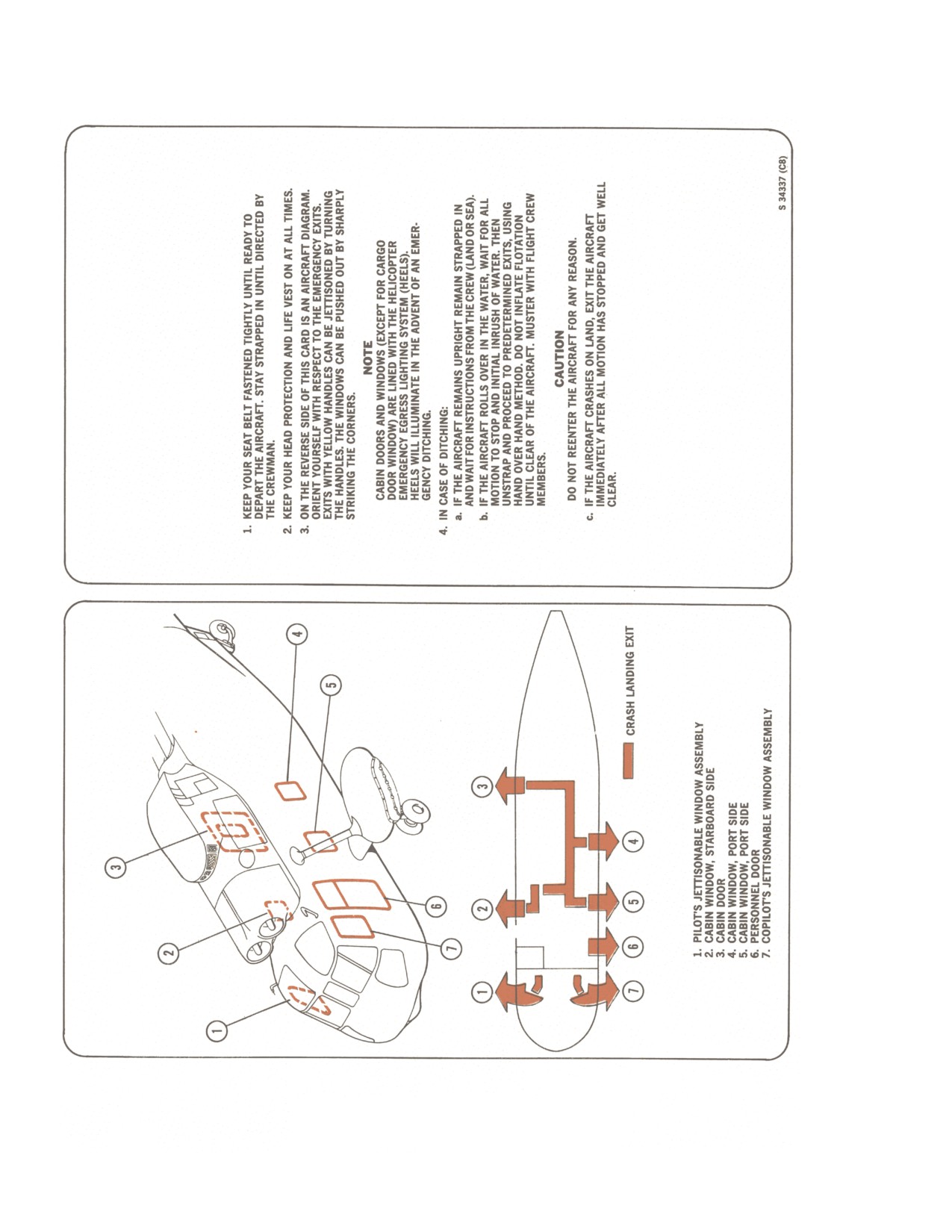
NAVAIR 01-230HLH-1
Figure 6-1. (NON-ET) Passenger Brief Card
6-4
ORIGINAL
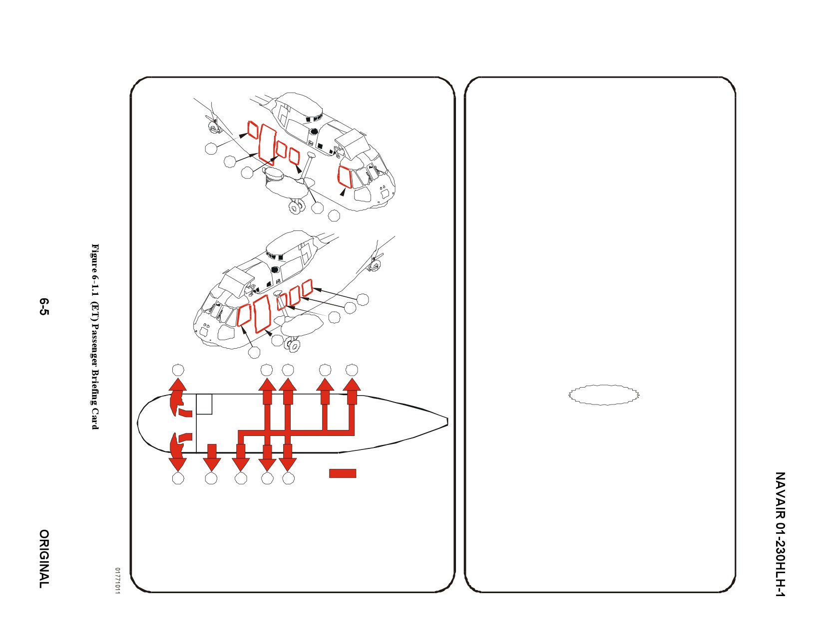
1. KEEP YOUR SEAT BELT FASTENED TIGHTLY UNTIL READY
TO DEPART THE AIRCRAFT. STAY STRAPPED IN UNTIL
DIRECTED BY THE CREWMAN.
2. KEEP YOUR HEAD PROTECTION AND LIFE VEST ON AT ALL
5
TIMES.
4
3. ON THE REVERSE SIDE OF THIS CARD IS AN AIRCRAFT
3
DIAGRAM. ORIENT YOURSELF WITH RESPECT TO THE
EMERGENCY EXITS. EXITS WITH YELLOW HANDLES CAN BE
JETTISONED BY TURNING THE HANDLES. THE WINDOWS
CAN BE PUSHED OUT BY SHARPLY STRIKING THE
2
1
CORNERS.
NOTE
EMERGENCY EXIT LIGHTS ARE LOCATED
ABOVE THE EMERGENCY ESCAPE HATCHES
4. IN CASE OF DITCHING:
a. IF THE AIRCRAFT REMAINS UPRIGHT REMAIN STRAPPED
6
IN AND WAIT FOR INSTRUCTIONS FROM THE CREW
7
(LAND OR SEA).
8
b. IF AIRCRAFT ROLLS OVER IN THE WATER , WAIT FOR ALL
MOTION TO STOP AND INITIAL INRUSH OF WATER. THEN
9
UNSTRAP AN PROCEED TO PREDETERMINED EXITS,
10
USING HAND OVER HAND METHOD. DO NOT INFLATE
FLOTATION UNTIL CLEAR OF THE AIRCRAFT. MUSTER
1
2
3
4
5
WITH FLIGHT CREW MEMBERS.
CAUTION
DO NOT REENTER THE AIRCRAFT FOR ANY REASON.
c. IF THE AIRCRAFT CRASHES ON LAND, EXIT THE
AIRCRAFT IMMEDIATELY AFTER ALL MOTION HAS
STOPPED AND GET WELL CLEAR.
CRASH LANDING EXIT
10
9
8
7
6
1. PILOT’S JETTISONABLE WINDOW ASSEMBLY
2. CABIN EMERGENCY ESCAPE HATCH, STARBOARD SIDE
3. CABIN WINDOW, STARBOARD SIDE
4. AFT PASSENGER DOOR
5. AFT CABIN EMERGENCY ESCAPE HATCH, STARBOARD SIDE
6. CABIN WINDOW, PORT SIDE
7. CABIN EMERGENCY ESCAPE HATCH, PORT SIDE
8. CABIN WINDOW, PORT SIDE
9. FORWARD PASSENGER DOOR
10. COPILOT’S JETTISONABLE WINDOW ASSEMBLY
NAVAIR 01-230HLH-1
This Page Left Blank Intentionally
6-6
ORIGINAL
NAVAIR 01-230HLH-1
CHAPTER 7
Shore-Based Procedures
7.1
GENERAL
7.2.2.4 Rotor Engagement. A qualified helicopter
pilot shall be in the pilot seat at all times when the rotors
Shore-based operations may vary from indoctrination
are engaged. Goggles that provide adequate peripheral
of new pilots to full-scale around-the-clock operations.
vision shall be worn by ground personnel. Before rotor
Many of the procedures required in shore-based operations
engagement is effected, it shall be mandatory that the
are identical with those used in shipboard operations, while
surrounding area be clear of unnecessary personnel,
others vary in major aspects. In this connection, attention
equipment, and obstructions. The pilot must receive and
is directed to Flight Preparation, Chapter
6, and Flight
acknowledge all-clear signals from ground personnel.
Characteristics, Chapter
11. In this section, shore-based
Rotor engagement and disengagement shall not be at-
procedures are discussed to cover as many operational
tempted in wind velocities in excess of those shown in
situations
as possible.
Mission planning and
Figure 8-1 except in an emergency.
briefing/debriefing should be done in accordance with
Chapter 6.
7.2.3 Taxiing
7.2
LINE OPERATIONS
7.2.3.1 Taxi Signals. Only standard taxi signals will be
used.
7.2.1 Line Safety. In accordance with OPNAV Notice
5100 series.
7.2.3.2 Taxi Pilots. No one shall be permitted to taxi a
helicopter except those persons authorized to fly it.
7.2.2 Ground Operation of Helicopter Engines
and Rotors
7.2.3.3 Taxi Director. Enough ground control personnel
must be available for the safe taxiing of helicopters in the
7.2.2.1 Preflight Inspection. Before engaged turn or
vicinity of obstructions or other aircraft.
engine turn, the pilot or nonpilot maintenance personnel
shall conduct a complete visual check of the helicopter.
Note
7.2.2.2 Fireguard. Before starting a helicopter engine,
The taxi director shall position himself in
a qualified fireguard shall be stationed near the engine and
front of and to the right of the helicopter
remain in readiness with the fire bottle until the engine is
centerline. He shall maintain visual contact
operating.
with the pilot in the right seat at all times.
He shall further maintain this position
Note
relative to the helicopter whenever the
helicopter is in motion and under his
The standard fire bottle without the
8-foot
supervision.
extension must be elevated in order to reach
the engine fire access door.
7.2.3.4 Taxiing. All taxiing shall be done at a safe,
slow speed. Extreme caution during night operation must
7.2.2.3 Starting of Engine. A qualified pilot or person
be observed. Air taxiing may be authorized during high-
designated by the commanding officer shall be in the pilot
wind conditions.
seat whenever an engine is started. Starting personnel shall
receive and acknowledge plane captain and fireguard all-
clear signals before starting the engine. Helicopter engines
shall not be started until the helicopter is properly secured
with approved chocks, parking brakes on, and tailwheel
locked. Engines shall not be started in a hangar unless an
emergency situation exists. Chocks and tiedowns will be
removed with utmost caution when engines and/or rotors
are operating, and then only upon the proper signal.
7-1
ORIGINAL
NAVAIR 01-230HLH-1
4. If a crew change is required while the helicopter is
engaged or engine running, the requirement for a
preflight in accordance with Preflight Inspection,
paragraph 7.2.7, by the relieving crew is waived. The
relieving crew shall inspect the helicopter as
Helicopters shall not be ground taxied
thoroughly as possible under existing conditions.
within
25 feet
(rotor tip clearance) of
Additionally, the crew being relieved shall thoroughly
buildings, aircraft, or other obstacles unless
brief the oncoming crew on all aspects of the helicopter
taxi lines/spots or other clearance guides are
that could influence the conduct of the flight.
available for adequate separation.
5. Crew change with rotor disengaged, No. 1 engine in
7.2.4 Towing
accessory drive.
7.2.4.1 Operation of Equipment. Only qualified
a. Pilots shall pick up checklist under NORMAL
personnel shall operate towing equipment. Towing cou-
STARTING PROCEDURES, paragraph
7.4 with
plings shall be inspected before towing. Only approved
Compass system. Console switches
- AS
attachment devices shall be used. Towing shall not begin
REQUIRED.
until a qualified pilot or qualified brake rider is in the
cockpit and ready to operate the brakes.
b. Complete remainder of checklist.
7.2.4.2 Towing Speed. Towing speed shall not be
6. Crew change with rotor engaged, No. 1 engine in
over 5 miles per hour. Sudden stops and starts should be
avoided. Extreme caution should be taken when towing in
flight position.
a congested area.
a. Pilots shall pick up checklist under STARTING
7.2.4.3 Wingwalker. When towing a helicopter near
NO. 2 ENGINE AND ROTOR ENGAGEMENT,
hangars, obstructions, or other aircraft, a wingwalker
paragraph 7.6 with Nf/Nr -104 percent.
equipped with a whistle shall be stationed on each side of
the helicopter to be sure of adequate clearance. When
b. Complete remainder of checklist.
helicopters are being pushed backward, a man shall be
stationed at the tail to be sure of clearance at the rear of the
When a crew change is conducted with the rotors
helicopter. At night the wingwalker shall carry a flashlight
engaged, the landing gear lockpins shall not be installed
or luminous wand and the helicopter position lights shall
unless directed by the pilot. If pins are installed, remove
be turned on.
before flight.
7.2.4.4 Movement. Helicopters may be pushed from
7.2.6 Aircraft Discrepancy Book. The discrepancies
the tail, provided adequate clearance is available and the
of at least the last 10 flights shall be made available to the
helicopter is under positive control of a towing director. A
aircrew for
their
examination. Any additional
towing director equipped with a whistle should be
discrepancies should also be brought to their attention in
positioned to supervise towing.
the form of written notations on appropriate forms.
7.2.5 Helicopter Acceptance. The pilot in command
1. The pilot in command shall ensure that all
shall not accept the helicopter for flight until he is assured
applicable inspections have been completed and that
that the helicopter is satisfactory for safe flight and
the post-flight documentation is completed and in
accomplishment of the assigned mission. The major steps
accordance with OPNAVINST
3710.7 and
4790.2
to be taken before acceptance of the helicopter are the
series.
following:
2. The pilot in command, when satisfied with the
1. Careful examination of the helicopter's recent
Aircraft Discrepancy Book, shall sign applicable
discrepancies contained in the Aircraft Discrepancy
portions of the aircraft inspection and acceptance
Book.
record (OPNAV Form 4790/141) Part A before flight
and shall complete the necessary postflight sections
2. Careful examination of discrepancies listed on the
upon completion of the postflight inspection.
maintenance turnaround and daily cards.
7.2.7 Preflight inspection. The pilot in command shall
3. A thorough preflight inspection in accordance with
ensure that the preflight inspection is accomplished in
the items listed in Preflight Inspection, paragraph 7.2.7.
accordance with the following.
7-2
ORIGINAL
NAVAIR 01-230HLH-1
7.2.7.1 General Walk around Inspection.
2. Ice shield and pitot tube airspeed adapter (if installed).
1. Wheel chocks in place.
3. Starter for security; bellmouth area free of FOD
2. Number and proper adjustment of tiedowns, if
4. Oil tank for leakage, fluid level, and filler cap for
attached.
security.
3. Fuel, oil, and hydraulic fluid leakage.
5. Engine mounts for delamination and cracks.
4. Port stores and/or stores attachment points for
6. Stator vane actuator for alignment/security.
condition and security
(NON-ET); gravity fuel caps
secure.
7. Exhaust casing for cracks, dents, hot spots, and
security.
5. Intermediate gearbox/tail gearbox oil levels, tail
rotor area, pylon hinge, and disconnect jaw teeth for
8. Engine door secure; J-hooks/suitcase latch fastened
wear/excessive grease (if folded).
(if installed).
6. Tail drive shaft covers secured; pressure -fueling cap
7.2.7.4 Left Transmission, Rotary Wing Head.
secure; check cargo door/tracks
(NON-ET) or the
forward air stair passenger door (ET) for security.
1. Input shaft area for wear/leaks, freedom of
movement.
7. Fuel, oil, and hydraulic fluid leakage.
2. Rotary wing head fairing for condition and security.
8. Starboard stores and/or stores attachment points for
condition and security (NON-ET).
3. Damper reservoir for proper level.
7.2.7.2 Interior Inspection.
4. Rotary wing head self-lube oil reservoirs for proper
level.
1. Battery on.
5. Antiflapping and droop restrainers for broken
2. Landing gear handle down; indicators indicate gear
springs.
down.
6. Check Bifilar weights and mount for integrity and
3. Fuel quantity.
lubrication.
4. Tailwheel locking handle locked.
7. BIM indicators for normal indications.
5. Parking brake set and advisory light on.
8. Blades for cracks, dents, and bonding separations.
6. Rotor brake on, pressure up, and caution light on.
9. Servo cylinders for hydraulic leaks; boot strap
springs (left lateral servo) present.
7. Battery off.
10. Transmission mounts for cracks and corrosion.
8. Cockpit windows secure.
11. Main gearbox oil level.
9. ASE compartment for hydraulic leaks, security of
control rods, and auxiliary filter indicator.
12. Check lube pump filter and torque pump filter
PDIs for proper indication.
10. Condition of overhead fuel lines, wires, and tail
rotor cables.
13. Accessory section, links, and wiring for condi-
tion, leaks, and security.
11. Aft cabin/tail cone security; tail rotor cables.
14. Transmission oil cooler, fan, fan belts, and
12. Fuel dump valves closed.
brackets for condition, leaks, and security.
7.2.7.3 Left Engine.
15. Aux manifold hydraulic filter for proper
indication.
1. Pitot cover and intake cover removed.
7-3
ORIGINAL
NAVAIR 01-230HLH-1
15. Primary/auxiliary reservoir fluid levels.
6. Check bifilar weights and mount for integrity and
lubrication.
16. Fire bottle for proper pressure.
7. BIM indicators for normal indications.
17. Tail rotor drive shaft housing for condition and
security.
8. Blades for cracks, dents, and bonding separations.
18. Engine and transmission access doors secure.
9. Servo cylinders for hydraulic leaks, and bootstrap
springs (right lateral servo) present.
10. Transmission mounts for cracks and corrosion.
11. Utility Manifold/Primary Manifold Hydraulic filter
PDIs for proper indication. (3 inlines, 2 manifolds)
On main gearboxes modified by DCC 43, a
bypass indicator on the torquemeter pump
12. No. 2 transmission oil pump filter PDI button.
filter will pop out giving a visible indication
of impending system bypass (filter clogged).
13. Accessory section, lines, and wiring for condition,
If the red button pops out, the filter must be
leaks, and security.
changed. Do not reset the red button without
first changing the filter.
14. Transmission oil cooler, fan, fan belt, and brackets
for condition, leaks, and security.
7.2.7.5. Right Engine.
15. Utility reservoir fluid level.
1. Pitot cover and intake cover removed.
Note
2. Ice shield and pitot tube airspeed adapter for
security and proper installation.
An overfilled utility reservoir may indicate
internal leakage between the damper
3. Starter for security; bellmouth area for FOD.
reservoir and the utility system.
4. Oil tank for leakage, proper level, and security of
16. Fire bottle for proper pressure.
filler cap.
17. Rotary rudder drive shaft housing for condition and
5. Engine mounts for delamination and cracks.
security.
6. Stator vane actuators for alignment and security.
18. Rescue hoist mounts and housing for condition and
security (NON-ET).
7. Exhaust casing for cracks, dents, hot spots, and
security.
19. Engine and transmission access doors secure.
8. Engine door secure; 3-hooks/suitcase latch fastened.
7.2.7.7 Nose Section.
7.2.7.6 Right Transmission Rotary Wing Head.
1. Personnel door and towline for security.
1. Input shaft area for wear/leaks, freedom of
2. All protective covers removed.
movement.
3. Condition of windows, windshields, and windshield
2. Rotor head fairing for condition and security.
wipers.
3. Damper reservoir for proper level.
4. Battery connected and shearwired, door secured,
and vents clear.
4. Rotary wing head self-lube oil reservoirs for proper
levels .
5. Electronics compartment for security; circuit
breakers/switches (L.F. stores switch off for overland
5. Antiflapping and droop restrainers for broken
flights); leaks; door closed, locked, and water tight;
springs.
floodlights for condition.
7-4
ORIGINAL
NAVAIR 01-230HLH-1
6. Condition of UHF, OTPI/ADF.
4. Bottom skin for cracks, corrosion, distortion,
and damaged rivets or screws.
7. Bottom skin for cracks, corrosion, distortion,
and damaged rivets or screws.
5. Cargo door for condition and security of stop,
slide rail, and door (NON-ET).
8. Condition of radar-altimeter antennas.
6. Aft passenger door for security and damage (ET).
7.2.7.8 Right Front of Fuselage.
7. Blades for cracks, dents, and tears.
1. External power receptacle for cleanliness.
8. UHF/COMM antenna for condition and cleanliness.
2. Heater air intake and heater exhaust clear.
9. Pressure-refueling cap for security.
3. Condition and cleanliness of Doppler TACAN and
IFF antennas (NON-ET).
7.2.7.11 Right Side of Tail Cone and Pylon.
4. Condition and cleanliness of TACAN and IFF
1. Tail rotor drive shaft housing for condition and
antennas (ET).
security.
5. Fuel, oil, and hydraulic leakage.
2. Check cotter pin on rotary rudder pitch control rod
7.2.7.9 Right Sponson Area.
3. Pylon hinge for cracks and security.
1. Tires for cuts, blisters, uneven wear, and proper
4. Intermediate and tail rotor gearboxes, cooling air
inflation.
intakes and exhaust openings for condition, over-
heating, obstructions, and leakage.
2. Landing gear system for leaks and loose
connections.
5. LF/ADF loop and sense antennas for security.
3. Sponson attachment points for loose bolts/missing
6. Stabilizer and static wicks for condition and
hardware/cracks.
security.
4. Sponson panels for security; drain screws installed;
7. Skin for cracks, corrosion, distortions, and damaged
and flotation bags secure.
rivets/screws.
5. APU exhaust clear, free from obstruction (ET).
7.2.7.12 Aft Observation.
6. APU fuel lines for leaks and loose connectors (ET).
1. Helicopter attitude/condition, as observed from
behind.
7. Hover light bracket security.
2. Screened area aft of transmission for FOD.
8. Bottom skin for cracks, corrosion, distortion, and
damaged rivets and screws.
3. Anticollision light and clearance lights forcondition.
9. Stores and/or stores attachment points for condition
4. Screened area around the tail rotor gearbox.
and security (NON-ET).
5. Pylon folded
- Inspect tail rotor drive pylon
10. Cargo hook attachment for security and damage,
connector jaws for teeth wear/excessive grease.
condition of manual release cable (NON-ET).
7.2.7.13 Left Side of Tail Cone and Pylon.
7.2.7.10 Right Bottom Hull, Side of Aircraft.
1. Intermediate and tail rotor gearbox and openings for
1. Fuel tank sump drains for leakage.
leakage and obstructions.
2. Fuel tank filter drain for leakage.
2. Rotary rudder head components secure .
3. Access panels for security.
3. Rotary rudder blades for dents or cracks and
direction of rotation.
7-5
ORIGINAL
NAVAIR 01-230HLH-1
4. Gust lock removed.
3. Sponson attachment points for loose bolts, missing
hardware, cracks.
5. Skin for cracks, corrosion, distortions, and damaged
rivets/screws.
4. Sponson panels for security, drain screws installed,
flotation bags, and hover light.
6. Pylon spread, lockpins for positive locking and
ratchet stowed.
5. Cargo hook attachment for condition, damage, and
security of cable; gap on manual release cable one-
7.2.7.14 Left Rear of Fuselage.
eighth inch or greater in sight gate on hook body after
pilot completes foot plunger release, and condition of
1. External ac power receptacle for cleanliness (UH-
hook rubber bumper pad.
3H).
7.2.7.17 Left Front of Fuselage.
2. Bottom skin for cracks, corrosion, distortions, and
damaged rivets/screws.
1. Bottom skin for cracks, corrosion, distortion, and
damaged rivets or screws.
3. Condition of UHF/COMM and HF antennas
(removed by AFC 418).
2. Doppler, TACAN, IFF, and VHF antennas for
condition and cleanliness.
4. Top of tail oleo strut for damage; tailwheel bonding
wire for condition.
3. Fuel filler caps for security.
5. Tailwheel locking pin in place (locked) and cable
4. Fuel, oil, and hydraulic leakage.
for condition.
7.2.7.18 Cabin Interior.
6. Tailwheel oleo strut for leaks and proper extension.
1. NATOPS manual, fire extinguisher, and first aid
7. Tailwheel tire for cuts, blisters, and proper inflation;
kits installed/current.
ground wire for condition and security.
2. Gyro tilt table secure/bonding strap.
8. Fuselage for dents or tears in skin .
3. Emergency air bottle, charged (2,500 to 3,000 psi).
9. Blades for cracks, dents, and tears.
4. ASE compartment for hydraulic leaks, security of
10. Thermal discharge indicator for red seal.
control rods, and auxiliary filter indicator.
7.2.7.15 Left Bottom Hull.
5. Cabin escape hatches/windows secure .
1. Bottom skin for cracks, corrosion, distortions, a n d
6. HEELS
(AFC
417) secure, and press-to-test
damaged rivets or screws.
switches checked (NON-ET).
2. Access panels for security.
7. Transmission area for leaks.
3. Bilge drain plugs and flapper valves for security.
8. Aft cabin for security of SAR/survival gear,
electronic equipment, and gear stowage.
4. Fuel tank filter drains for leakage.
9. Condition of overhead fuel lines, wires, and tail
7.2.7.16 Left Sponson Area.
rotor cables.
1. Tires for cuts, blisters, uneven wear, and proper
10. Condition of ET seats, MATA troop seats,
inflation.
interior executive package. (ET)
2. Landing gear system for leaks and loose
11. Tail cone for rudder cables/bellcrank condition
connections.
and corrosion.
7-6
ORIGINAL
NAVAIR 01-230HLH-1
7.3 BATTERY/DC EXTERNAL POWER START
13. DC External Power Connected - As Required.
NO. 1 ENGINE
1. Circuit breakers and switches - CHECKED.
2. Fuel dump switches - OFF.
Maximum continuous/peak current, for 28-
3. Brakes and tailwheel - LOCKED.
vdc external power is 300/750 Amps. When
28-VDC power is applied to the EXT
4. Beeper trim switch - ON.
POWER 28 VOLTS DC receptacle, all dc
buses, certain necessary ac instruments, and
5. Ignition switches - NORMAL.
the fire detector system are automatically
energized. The EXT PWR switch does not
6. HEELS switch - ARMED (NON-ET).
control 28-vdc power.
7. Manual throttles and speed selectors - FREE AND
Note
OFF.
Momentarily cycling the battery switch
8.
Emergency start switches - OFF.
will verify DC EXT Power is properly
applied to the aircraft.
9.
Rotor brake - CHECKED (320 psi minimum).
14. Landing gear - CHECK.
15. Fire warning, caution, and advisory panels
-
CHECK.
WARNING
16. Accessory drive switch - FORWARD, LIGHT
The rotor brake will not prevent rotor
movement with the No. 1 engine in flight
ON.
position above ground idle or with the No. 2
17. No. 1 engine - START.
engine above ground idle. Personnel injury
and/or helicopter damage may occur as a
To start the engine, hold the speed selector at
result of inadvertent rotor engagement.
SHUTOFF and momentarily press the starter button.
When the engine has accelerated to 14-percent Ng (19
percent with external dc power), T5 below 100 °C, and
positive indication of oil pressure is noted, advance the
speed selector to the idle detent.
If low rotor brake pressure requires
a. ENG ST switch
- DEPRESS AS NECESSARY
recycling manual rotor brake with blades
TO CONTROL T5. When engine light-off is
folded, personnel should be placed on either
evident, press the ENG ST switch on the cyclic
side of the helicopter holding the blades in
stick grip. Hold the switch pressed as necessary
order to prevent shifting of head while the
until T5 stabilizes.
manual rotor brake is off.
Note
10. No. 1 firewall valve - OPEN.
Compressor stalls may occur if Ng is allowed
11. Start mode switch
- MANUAL (Normal for 28
to decelerate.
VDC external power).
18. At
45-percent Ng, starter
- DISENGAGE AS
12. Battery switch - ON.
REQUIRED.
Disengage starter by pulling down on the speed
selector lever.
19. All gauges - CHECK.
7-7
ORIGINAL
NAVAIR 01-230HLH-1
20. Speed selector - 104-percent Nf.
7.4 NORMAL STARTING PROCEDURES
21. Generator switches - ON.
The No. 1 engine is started first to provide power for
accessory drive section. The No. 1 engine may be started
using either ac or dc external power, APU
(ET) or if
22. Lights - AS REQUIRED.
neither is available, by using the battery. After the No. 1
engine is started and run up above generator cut-in speed,
23. Blade panel, hoist, crew ICS - CHECK.
generator power can be used to start the No. 2 engine. A
fireguard shall be standing by when starting engines.
Note
1. Circuit breakers and switches - CHECK.
The normal light indications on the blade
fold panel when the blades are folded are
2. Fuel dump switches - OFF.
safety valve warning light, control lockpins
advance light, and blades folded light. When
3. Brakes and tailwheel - LOCKED.
the blades are spread, normal light
indications are blade spread light and flight
4. External power - CONNECTED.
position light on. Abnormal indications must
be noted or corrected, as appropriate.
24. No. 1 overspeed system - CHECK.
WARNING
a. An overspeed may be simulated with the No. 1
engine in accessory drive by advancing the No. 1
speed selector to achieve approximately
108-
(ET) The APU is intended for ground
percent Nf. The Nf will then begin to cycle about
operations
only
(minimal
lighting,
±2-percent Nf.
instrumentation, and air conditioner operation).
It does not have a fire warning or suppression
b. Retard the No. 1 speed selector to 104-percent
system and therefore should not be used in
Nf.
flight.
25. DC External Power - Disconnect As Required.
Note
26. Anti-ice - CHECK.
·
On the executive transport helicopters (ET),
the BRIGHT/DIM switch on the CABIN
27. Fuel quantity - CHECK.
LIGHTS panel should remain in the DIM
position while operating on external power.
28. Compass system, console switches
- AS
REQUIRED.
·
On executive transport helicopters, if the APU
is used instead of external power; omit steps 4
29. RAD ALT, BAR ALT, RAWS
- SET AND
and 6.
TEST.
5.
APU æ START (ET).
30. Start mode switch - NORMAL.
31. Servo sensor
- CHECK (only required the first
a. APU ON switch æ ON.
flight of the day).
(1) FUEL PUMP ON light æ ON.
a. Servo switch - AUX OFF.
(2) STARTER ON light æ ON (OFF after
If auxiliary servo pressure drops, the primary servo
starter drops out).
sensor is malfunctioning.
(3) OIL TEMP HI light æ OFF.
Note
(4) APU FAIL light æ OFF.
Proceed with systems checklist.
7-8
ORIGINAL