UH-3H and UH-3H EXECUTIVE TRANSPORT. FLIGHT MANUAL (2000) - page 4
NAVAIR 01-230HLH-1
(5) APU ON light æ ON.
10. Anti-ice switch - AS REQUIRED.
b. APU generator switch æ RESET THEN ON
Note
(after APU engine comes to operating speed).
No. 1 engine anti-ice switch on (below 10
°C OAT if visible moisture is present).
(1) GEN FAIL light æ OFF.
11. Ignition switches - NORMAL.
(2) GEN ON light æ ON.
a. Cabin heater/air-conditioner (ET) - On as
12. HEELS switch - ARMED (NON-ET).
Desired.
13. Accessory drive switch
- FORWARD, LIGHT
Note
ON.
If the No.
1 or No.
2 engine/inlet anti-ice
14. Manual throttles and speed selectors
-
FREE
switches are in the ON position, the air-
AND OFF.
conditioner will not operate.
15. Emergency start switches. - OFF.
a. HEATER/AIR COND SELECTOR æ AS
REQUIRED.
16. Rotor brake - CHECKED (320 psi minimum).
b. CABIN AIR TEMPERATURE æ AS
REQUIRED.
WARNING
6.
External power switch - RESET, THEN ON.
7.
Landing gear - CHECK.
The rotor brake will not prevent rotor
movement with the No. 1 engine in flight
a. Indicators - DOWN.
position above ground idle or with the No. 2
engine above ground idle. Personnel injury
b. Landing gear actuating lever - DOWN.
and/or helicopter damage may occur as a
result of inadvertent rotor engagement.
c. Landing gear warning light - PRESS TO TEST.
d. Emergency landing gear extension handle
-
DOWN, FORE, AND AFT; AND SHEAR-
WIRED.
If low rotor brake pressure requires
e. Emergency landing gear release lever
- AFT
recycling manual rotor brake with blades
AND SHEARWIRED.
folded, personnel should be placed on either
side of the helicopter, holding the blades in
8.
Start mode switch - AS REQUIRED.
order to prevent shifting of head while the
manual rotor brake is off.
9.
Blade panel, hoist, beeper trim, and crew ICS
CHECK.
17. Fire warning, caution, and advisory panels
-
CHECK.
Note
18. No. 1 firewall valve - OPEN.
The normal light indications on the blade
fold panel when the blades are folded are
19. Fuel quantity - TEST.
safety valve warning light, control lockpins
advance light, and blades folded light. When
Depress fuel gauge test button. Verify all fuel gauges
the blades are spread, normal light
drop to zero and then return to original position when the
indications are blade spread light and flight
button is released.
position light on. Abnormal indications must
be noted or corrected, as appropriate.
7-9
ORIGINAL
NAVAIR 01-230HLH-1
20. Battery switch - ON.
starter should be capable of motoring the
engine to
19-percent Ng. Failure to do so
may result in hot starts. If power turbine
inlet temperature
(T5) rises abnormally or
reaches 840 °C, immediately shut down the
engine. If T5 continues to rise above 840 °C,
note time above
840
°C and indicated
Failure to have battery switch on with No. 1
maximum temperature. If engine fire
engine running and blades folded may result
follows, as may be indicated by a
in damage to the swashplate and rotary wing
continuous temperature in excess of 300 °C,
head with inadvertent loss of external
engage the starter without ignition and
power.
motor it until the temperature drops to
acceptable limits. Refer to Part V,
21. Lights - AS REQUIRED.
POSTSHUTDOWN ENGINE FIRE.
22. No. 1 engine - START.
23.
All gauges - CHECKED.
To start the No.
1 engine, hold the speed selector
SHUTOFF position and momentarily depress the starter
button. As the engine accelerates to 19-percent Ng, T5 is
below 100 °C, and positive indication of oil pressure is
noted, turn boost pumps ON and advance the speed
selector to GRD IDLE. When the engine lights off and
Upon initial indication of a lack of accessory
accelerates to about 45-percent Ng and the normal start
drive when operating in accessory, the
mode is being used, the current sensitive holding coil in
engine should be shut down immediately
the automatic dropout relay automatically cuts off
and not restarted. Continued operation could
electrical power to the starter, the ignition systems, and the
cause severe damage to the main
auxiliary start fuel shutoff valve switch. Do not pull down
transmission. Lack of accessory drive is
on the speed selector since this will cut out the starter. If
indicated by the loss of hydraulic (primary,
start is aborted inadvertently, return speed selector to
auxiliary, and utility) pressure, and
SHUTOFF. Normal starts are characterized by 700 to 750
transmission oil pressure.
°C T5 in 3 seconds. (Use of ENG ST switch will aid in
limiting excessive T5.) Abort start if T5 reaches 840 °C.
24.
Boost pumps - OFF.
Power turbine overtemperature during start is T5
is
in
excess of 950 °C.
Note
Boost pumps should be off to check for
engine flameout because of possible air leak
in a fuel line. If airframe fuel filters have
been changed just before the flight, the
boost pumps should be left on for about 1
Power turbine inlet temperature (T5) should
minute after starting engine to purge air
be less than 100 °C before advancing the
from fuel lines, to preclude engine flameout.
engine speed selector to GRD IDLE. If
engine light-off does not occur within 10
25. Speed selector - 104-percent Nf.
seconds after the engine speed selector has
been advanced to GRD IDLE, abort the start
26. Generators - ON.
by pulling the speed selector down and
returning it to SHUTOFF. Move the boost
27. APU -. SECURE (UH-3H Executive Transport).
pump switches to OFF. Do not operate
a. APU generator switch - OFF.
starter continuously for more than
30
b. APU ON switch - OFF.
seconds except in an emergency. Do not
c. If APU used, omit step 29.
attempt more than three starts in any 30-
minute period. In the event of starter
hangup, comply with procedures in Part V.
Before attempting another start, allow the
engine to stop rotating and wait 3 minutes
for fuel to drain from the manifolds,
combustion chambers, and exhaust hood
before repeating starting procedures. The
7-10
ORIGINAL
NAVAIR 01-230HLH-1
28.
No 1. Overspeed System - CHECK
7.5 SYSTEMS CHECKLIST
a. On aircraft modified by AFC 399, an overspeed
1.
Area clear - CHECKED.
may be simulated with the No.
1 engine in
accessory drive by advancing the No.
1 speed
2.
Blades - SPREAD.
selector to achieve approximately 108-percent Nf.
The Nf will then begin to cycle about ±2-percent
Nf.
29.
External power - DISCONNECTED.
The primary servo is not normally
(Initiate checklist here for crew change with rotor
pressurized when the blades are folded but
disengaged, No. 1 engine in accessory drive.)
will pressurize if all electrical power to the
helicopter is lost or secured, or if an open
30.
Compass system. Console switches
- AS RE-
circuit develops in the safety valve switch.
QUIRED. (On aircraft with the A/A24G-39 AHRS, set the
Pressurization of the primary servo when the
latitude and hemisphere switches to the local latitude.)
blades are folded will put undue stress on
control linkages and may damage the
31.
RAD ALT, BAR ALT, RAWS - SET AND TEST.
control lockpins.
32.
Servo sensor - CHECK (only required the first flight
Note
of the day).
·
Spread/fold power will not be available
a.
Blades spread.
if the No. 2 engine fuel firewall valve
switch is open.
(1)
Safety switch - OPEN.
·
The ASE should be off during blade
(2)
Blade fold MASTER switch - ON.
spreading to prevent inadvertent control
inputs.
(3)
Servo switch - AUX OFF, ON.
If servo pressure drops, the primary servo sensor
is
a.
SAFETY VALVE switch - OPEN.
malfunctioning.
b.
Blade fold MASTER switch - ON.
(4)
Safety Switch - CLOSED.
(1) Fold power indicator light - ON.
(5)
Blade fold MASTER switch - OFF.
(2) No. 1 blade position light - ON.
b. Blades folded.
c.
BLADES FOLD-SPREAD switch - SPREAD.
(1)
Servo switch - AUX OFF, ON.
(1) BLADES FOLDED light - OFF.
If servo pressure drops, the primary servo sensor
is
malfunctioning.
When first blade moves.
(2) Control lockpins advance light - OFF.
When pins are disengaged.
(3) BLADES spread light - ON.
Operating time in accessory drive should not
exceed 30 minutes. With rotors disengaged,
d.
SAFETY VALVE switch - CLOSED.
the oil cooler blower does not operate and a
rapid rise in main gearbox oil temperature to
(1) SAFETY VALVE warning light - OFF.
above the red line is possible.
(2) Fold power indicator light - OFF.
(3) Primary servo hydraulic pressure
- 1,500
PSI.
7-11
ORIGINAL
NAVAIR 01-230HLH-1
e. Rotor brake - 320 PSI MINIMUM.
Collective pitch lever - ACTUATE FULL UP.
f.
Blade fold MASTER switch - OFF.
d. Actuate cyclic stick from one extreme to the
other in lateral, then fore-and-aft directions. Repeat
(1)
No. 1 blade position light - OFF.
cyclic stick movements with collective down.
(2) Flight position light - ON.
e. Flight control servo switch - ON.
g. BLADES FOLD-SPREAD switch - OFF.
f.
Flight control servo switch - AUX OFF.
h. Lights and servo pressure - CHECKED.
Auxiliary servo hydraulic pressure indicator should
indicate a drop to zero and caution light should go
on.
Note
When turning auxiliary servo off, note that
Check with ground crewman to be sure that
stick jump does not exceed one-eighth of an
blades are in proper spread position and that
inch in cyclic and one-sixteenth of an inch
the blade lockpins are securing the blades in
in rudder and collective to be sure of proper
place.
rigging of auxiliary servo pilot valve.
Collective should be at midposition
3. Hoist, hoist ICS, HEELS, and IBIS
(NON-ET)
-
(approximately
4 inches off bottom stop)
CHECKED.
and rotary rudder pedals positioned right
pedal slightly forward of left when making
4.
Flotation gear - CHECKED.
this check. If excessive reactions are
encountered, repeat the check when
a. Arming switch - OFF.
hydraulic temperatures are normal (about 12
to 15 minutes).
b. Rotary selector test switch - L1, L2, R1, and
R2.
g. Trim release button (on cyclic stick) - PRESS.
c. Indicating light - ON, IN EACH POSITION.
Collective pitch lever - ACTUATE FULL UP.
d. Rotary selector test switch - OFF.
Actuate cyclic stick from one extreme to the other
5.
Head check - AS REQUIRED.
in lateral, then fore-and-aft directions. Repeat
cyclic stick movements with collective down.
h. Press left rudder pedal and lift collective to full-
WARNING
up position. Note left rudder pedal rearward
movement of about 2 inches because of collective
to yaw coupling. Press right rudder pedal and lower
Personnel injury may occur if controls are
collective to full-down position. Note right rudder
moved without knowledge of the man on the
pedal rearward movement of about
2 inches
rotor head.
because of collective to yaw coupling.
6.
Servos - CHECKED.
Note
a. Auxiliary and primary servo hydraulic pressure
· Full actuation of flight controls can
indicators - NORMAL RANGE.
be made in any one direction in 1
second with no evidence of binding.
b. Flight control servo switch - PRI OFF.
Should binding in the controls be
Primary servo pressure indicator should indicate a
encountered, maintain that control
drop to zero and caution light should go on.
position where the binding occurred
until the system can be checked by
c. Trim release button
(on cyclic stick)
-
maintenance personnel.
DEPRESS.
7-12
ORIGINAL
NAVAIR 01-230HLH-1
· If cyclic drives excessively during
collective/pedal checks, primary
servos could be incorrectly timed.
WARNING
i.
Flight control servo switch - ON.
Use of the hardover switches on the ASE
Auxiliary servo hydraulic pressure indicator should
channel monitor panel shall not be made
indicate normal pressure, and caution light should
with the blades folded to preclude damage to
go off.
the rotary wing and control linkages. In
addition, ASE hardovers shall not be in-
7.
Basic ASE - CHECKED.
duced in flight. Repeated use of the
hardover switches may cause ASE valve
a. Initial warmup time is 3 minutes ±30 seconds.
failure. If an induced hardover should cause
an ASE valve failure, a hydraulic hardover
b. ASE - ENGAGE.
may occur and can be eliminated only by
securing of the auxiliary servo hydraulic
c. Hover indicator
- A MODE(NON-ET) or flight
system.
director (ET) A MODE.
(1) ASE, BAR ALT, CPLR, and HOVER
d. CG TRIM - Move CG TRIM knob and note
TRIM engage buttons (CYC CPLR switch must
that the pitch bar on the hover indicator (NON-ET)
or flight director (ET) can be moved full travel in
be in DOPP to engage hover trim) - PRESS.
each extreme and follows movement of trim knob.
(2) Pilot CPLR, BAR ALT, and ASE release
Reposition pitch bar to center, cyclic stick centered.
buttons
(collective, cyclic stick)
- PRESS
INDIVDUALLY AND IN ORDER. Check that
e. Pitch and roll valve check
- Move cyclic stick
all release buttons function and all engage
to forward left quadrant. Recenter the cyclic and
note that the pitch bar precedes the roll bar to the
button lights go off.
center. Repeat step to aft right quadrant. Normal
(3) ASE, BAR ALT, CPLR, and HOVER
deflection of the pitch bar with cg bar centered
TRIM engage buttons - PRESS.
should be
2-1/2
±l/2 divisions. In each case,
observe that the pitch bar precedes the roll bar to
(4) Copilot CPLR, BAR ALT, and ASE
the center of the hover indicator (NON ET) or flight
director (ET). This assures proper operation of the
release buttons
(collective, cyclic stick
)
-
PRESS INDIVIDUALLY AND IN ORDER.
dual-channel lag amplifier.
Check that all release buttons function and all
engage button lights go off.
f.
Yaw trim - CHECK PROPORTIONAL BAND.
Raise collective to midposition and position pedals
8. Coupler/Doppler checks (if desired) (NON-ET).
left pedal slightly forward of right. Slowly turn yaw
trim knob. At initial movement of pedals, note
a. Altitude channel test.
point on hover indicator (UH-3H) or flight director
(UH-3H Executive Transport) at which pedals start
(1) Radar altimeters - ON AND RELIABLE.
to move. This should be between 3/4 and 1-1/2
divisions from center. Press either pedal switch and
(2) Collective friction - OFF.
observe that the yaw piper returns to center. Repeat
for opposite rudder and note that the breakout
(3) ALTITUDE set knob - 100 FEET.
should be approximately equal in both directions.
(4) Altitude coupler switch - RAD ALT.
Note
(5) ASE and CPLR buttons
- DEPRESS; CHECK
If the above check is unsatisfactory,
repeat the check when hydraulic
FOR COLLECTIVE RISE.
temperatures are normal (about 12 to 15
minutes).
g. ASE engage/disengage check.
7-13
ORIGINAL
NAVAIR 01-230HLH-1
(6) Altitude coupler switch - WHEN COLLECTIVE
Note
STARTS TO RISE, SWITCH TO VA.
COLLECTIVE SHOULD CONTINUE TO RISE IN
The accelerometer nulls cannot be checked
EACH POSITION. (On helicopters with AFC 396,
adequately aboard ship because of the
disregard mention of CABLE ALT position.)
accelerations generated by ship movement.
When setting nulls aboard ship, center
(7) Collective pitch lever - UP.
DRIFT and SPEED knobs as approximate
settings during first hover. Speed and drift
(8) CPLR REL and BAR REL buttons -DEPRESS;
settings can be effectively nulled during a
CHECK VERT POINTER NULL ±3/4 DIVISIONS.
cyclic coupled hover. With the meter
selector switch in coupler, monitor A mode
(9) ALTITUDE set knob - ZERO.
to center both bars with the speed and drift
pots while the copilot monitors aircraft
(10) SPEED set knob - 100 KNOTS.
hover stability.
(11) CPLR button
- DEPRESS; CHECK FOR
COLLECTIVE DROP.
c.
Hover trim check - IF DESIRED.
(12) Altitude
coupler
switch
- WHEN
(1) ASE, BAR ALT, coupler - ENGAGE.
COLLECTIVE STARTS TO DROP, SWITCH TO
VA, THEN RAD ALT. COLLECTIVE SHOULD
(2) CYC CPLR switch - DOPP.
CONTINUE TO DROP IN EACH POSITION.
(3) HOVER TRIM - ENGAGE.
(13) Collective pitch lever - DOWN.
(4) Crewman at the aft station
- REPORT RED
(14) CPLR REL and BAR REL buttons
-
LIGHT ON.
DEPRESS; CHECK VERTICAL POINTER NULL
±3/4 DIVISION.
(5) Pilot
-
RELAY INFORMATION TO
CREWMAN TO ALLOW HIM TO CENTER
(15) BAR OFF button - DEPRESS.
BARS ON HOVER INDICATOR WITH HIS
PITCH AND ROLL BIAS KNOBS.
b.
VA/Doppler Vh, Vd, and Vz nulls.
(6) Crewman
-
MOVE CONTROL STICK
(1) Doppler - STBY.
FORWARD.
(2) METER SELECTOR knob - CPLR.
(7) Pilot
- CHECK THAT HORIZONTAL BAR
MOVES UP AND THAT CYCLIC STICK BEEPS
(3) Hover indicator - A MODE.
FORWARD.
(4) CYC CPLR switch - OFF.
(8) Repeat steps (6) and (7) for back, right, and
left.
(5) ASE - ENGAGED.
(9) CYC CPLR switch
- OFF, CHECK THAT
(6) SPEED set knob
- CENTER HORIZONTAL
HOVER TRIM LIGHT ON ASE PANEL GOES
BAR (±2 knots on knob).
OFF.
(7) DRIFT set knob
- CENTER VERTICAL BAR
d.
Cyclic channel tests.
(between D and T on knob).
(1) Pilot hover indicator - D MODE.
(8) Hover indicator vertical pointer
-
1
±l/4
divisions up.
(2) Copilot hover indicator - A MODE.
(9) Altitude coupler switch - RAD ALT.
(3) Doppler selector switch - TEST.
(10) CPLR - ENGAGED.
(4) CYC CPLR switch - DOPP.
(11) Hover indicator pointer - 0 ±l/4 division.
(5) Pilot hover indicator
-
1 TO 1-1/2 DIVISIONS
UP AND RIGHT, VERTICAL POINTER 1-1/2 TO
2-1/2 DIVISIONS UP.
7-14
ORIGINAL
NAVAIR 01-230HLH-1
(6) Copilot hover indicator
-
2-1/2 TO
3-1/2
5. No. 2 engine - START.
DIVISIONS UP AND RIGHT, VERTICAL
POINTER
3 TO
3-1/2 DIVISIONS DOWN
Note
FROM VZ NULL.
Engine start limitations are the same as No.
Step 11 of accelerometer nulls.
1 engine.
(7) Groundspeed indicator - 17 ±2 KNOTS
6. All gauges - CHECKED.
and 225° ±5°.
7. Boost pumps - OFF.
(8) Cyclic stick
- CHECK BEEPING FORWARD
AND RIGHT.
8 ASE - OFF.
(9) Doppler selector switch - RESET TO STBY.
9. Shoulder harness (all stations) - LOCKED.
(10) Hover indicators - RESET.
10. Collective - MINIMUM.
(11) METER SELECTOR knob - ASE.
Copilot monitor until taxi.
(12) ASE - OFF.
11. Area clear, engage signal - CHECK.
9.
TACNAV equipment check (if desired).
WARNING
10. Cargo hook releases - CHECKED (as desired) (NON-
ET).
a. Crewman should check for activation of cargo hook
Before rotor engagement, be sure personnel
release for both pilot and copilot electrical release
are clear of the rotary wing and the rotary
button.
rudder blades. For ground clearances, see
Figure 3-10.
b. Check for activation of cargo hook release for pilot
manual release foot plunger.
12. Rotor - ENGAGE.
Advance No. 2 speed selector for a 2-percent Ng in-
crease, place rotor brake in detent, checks rotor brake
pressure zero, caution light off, and ensure that Nf and
Nr are advancing together. Maintain torque values
between 40 and 60 percent. Antiflapping restrainers
If foot plunger does not return to the full up
should release at about 25- to 30-percent Nr. Droop
position after manual activation, subsequent
stops should release at about 65- to 75-percent Nr.
inadvertent release of an external load is
possible.
7.6 STARTING NO.
2 ENGINE AND ROTOR
ENGAGEMENT
1. Start mode switch - NORMAL.
The rotors should not be engaged in winds
above 45 knots because of excessive rotary
2. Fuel panel - No. 2 FIREWALL VALVE OPEN.
wing blade flapping. When engaging the
rotor in high or gusty winds, the rotor should
3. Rotor brake - ON.
be accelerated as rapidly as possible without
exceeding torque limits of 60 percent. Refer
4. Anti-ice switch - AS REQUIRED.
to FIG. 8-1 for Engagement Wind Limits
Note
13. Cyclic stick
- CHECK RESPONSE AT
100
PERCENT.
No. 2 engine anti-ice switch on (below 10
°C OAT if visible moisture is present).
7-15
ORIGINAL
NAVAIR 01-230HLH-1
Actuate cyclic stick a slight amount in all directions
16.
Accessory drive switch
- AFT, ACCESSORY
and cheek for proper response by observing tip-path
DRIVE AND BLADE PANEL LIGHTS OFF.
plane of rotary wing blades.
14. No. 2 engine flat pitch - CHECKED.
Normally power turbine speed
(Nf) is
108 to 112.5
· After placing the accessory drive switch to
percent for single engine with maximum travel on the
the aft position, if the accessory drive light
speed selector. Normal deterioration of engine
remains on or there is any other indication
performance may result in flat pitch readings below
that the transmission did not actually shift to
108-percent Nf. If this flat pitch is the result of normal
the flight mode, return the accessory drive
deterioration of engine performance, the engine may be
switch to the forward position before moving
accepted for flight provided the reading is not below
the No.
1 engine speed selector from the
105-percent Nf. If the pilot is unable to determine that
GRD IDLE position.
a reading between 105 and 108 percent is the result of
normal deterioration of engine performance, the engine
shall be checked for serious fuel control malfunction
· If the input freewheeling unit fails to engage
despite positive indications of a successful
before flight.
shift from accessory drive to flight position,
Note
the accessory drive switch should be returned
to the accessory drive position, and a normal
shutdown performed.
With AFC 399 and Nr above 104 percent,
No.
1 engine will sense an overspeed
condition and drop to 60- to 70-percent Nf.
· Lack of electrical overspeed protection may
result in destructive overspeed in the event of
15. No. 1 speed selector - GRD IDLE.
a flex drive shaft failure while on the deck
with the main gearbox accessory drive switch
in the flight position.
· Rapid movement of No. 1 Speed selector to
the maximum position can cause premature
Failure/damage to the main gearbox No. 1
If the generator caution lights and/or tail
freewheeling unit. Gradually bring the No. 1
takeoff caution light go on when the No. 1
engine Nf up to approximately
90 to
95
engine is retarded to ground idle, do not
percent, pause momentarily, then smoothly
switch from ACCESS DR to FLIGHT.
marry No. 1 Nf to Nr without any "clunking"
Immediately return the No. 1 speed selector
of the input freewheeling unit or Nf
to 104-percent Nf and go through a normal
overshoot. If "clunking" or overshoot does
shutdown. This condition indicates a
occur during normal engagement of the No. 1
possible failure of the tail takeoff
engine, it may indicate a worn freewheeling
freewheeling unit. Under these conditions,
unit that should be further investigated.
loss of No. 1 engine will result in loss of all
accessories.
· On helicopters modified by AFC 401, if the
speed selectors are in the proper position (No.
1 - GRD IDLE, No. 2
- 102-percent Nf or
above) but the linear actuator will not transfer
from accessory drive to flight, you can
bypass the speed selector microswitches by
placing the accessory drive override switch to
Before switching accessory drive switch to
OVRD. Selecting OVRD when No. 1 engine
FLIGHT, a verbal challenge and reply
Nf is greater than No.
2 engine Nf can
exchange shall be made between the pilots
damage main gearbox because of suddenly
to be sure the No. 1 engine is at GRD IDLE
applied loading. A verbal challenge and reply
and No. 2 engine is at 102-percent Nf/Nr or
exchange shall be made between the pilots to
above. Selecting FLIGHT when No.
1
be sure the No. 1 engine is at GRD IDLE and
engine Nf is greater than No. 2 engine Nf can
No. 2 engine is at 102-percent Nf prior to
damage main gearbox because of suddenly
selecting OVRD. The accessory drive light
applied loading.
will remain on 6 to 7 seconds after selecting
OVRD.
7-16
ORIGINAL
NAVAIR 01-230HLH-1
17. No. 1 engine flat pitch - CHECKED.
3. Chocks/tiedowns - REMOVED.
a. No. 1 speed selector - MAXIMUM.
4. Tailwheel locking handle - UNLOCKED.
b. No. 2 speed selector
-
100-percent Nf, ZERO
5. Shoulder harness (all stations) - LOCKED.
TORQUE.
18. Nf and Nr - 104 PERCENT.
WARNING
(Initiate checklist here for crew change with rotor
engaged).
The crew chief’s seat is not a crashworthy
19. NAVAIDs - CHECKED.
seat. Do not occupy this seat during takeoff
or landing.
20. Landing gear lockpins/safety pins - SIGHTED.
6.
Parking brake - OFF.
21. HEEDS bottle - ON.
7.
Brakes - CHECKED.
22. VLEA control dial (helicopters modified by AFC
407) - SET.
WARNING
7.7 TAXIING
If the wheelbrakes bind or lock up, or
WARNING
helicopter is inadvertently taxied into a hole
or obstruction, the nose will pitch down and
an immediate lift-off may be required to
The tip-path height forward of the helicopter
prevent damage to the helicopter. During all
must be monitored to prevent endangering
phases of ground taxi, pilots must be
taxi directors and line personnel.
constantly alert for the necessity of lift-off
and all occupants must remain securely
7.7.1 Taxiing Procedure. Taxiing is a coordinated
strapped in until cleared to leave their seats
maneuver utilizing collective to control taxi speed and
by the pilot.
rotary rudder thrust to control heading. In addition, the toe
brakes are utilized for slowing/stopping the aircraft. The
8.
Tailwheel - CHECKED.
toe brakes shall only be applied with collective in the full-
down position. Cyclic is normally displaced slightly
forward and into the wind.
All ground taxiing in congested areas shall be done
under positive control of a qualified taxi director. Use his
Do not place tailwheel lock handle to
signals as an aid; however, remember that the pilot and not
LOCKED during ground turns. Helicopter
the lineman is responsible for the safety of the helicopter.
must be rolling in a relatively straight line
when tailwheel is LOCKED to prevent
The copilot shall give the lineman the pull-chocks
shearing of lockpin.
sign. The pilot and copilot shall then check their respective
sides of the helicopter for removal of chocks, tiedowns,
Note
obstructions, and loose gear. The copilot shall report his
side clear, and the pilot shall acknowledge and report his
To allow the tailwheel lockpin to release, do
side clear. All stations should report shoulder harness
this:
locked. The copilot shall monitor the collective while the
pilot unlocks the tailwheel.
a. Allow helicopter to taxi forward a few
feet to relieve possible binding of the
7.7.1.1 Taxi CheckIist.
lockpin because of tailwheel tire side
loading.
1. Area - CLEAR.
2. Lights - AS REQUIRED.
7-17
ORIGINAL
NAVAIR 01-230HLH-1
b. Exert rotary rudder pedal pressure
4. Boost pumps - AS REQUIRED.
(normally left) in varying amounts to
balance inherent torque that may prohibit
5. Rotor brake - CHECKED.
disengagement of tail-wheel lockpin during
step 4.
Rotor brake handle is in detent, the rotor brake caution
light is off, and that rotor brake pressure is 0 psi.
Use rotary rudder pedals cautiously to prevent
swerving. Maintain 104-percent Nr so that an immediate
6. Instruments/warning lights - NORMAL/ CHECK.
takeoff can be accomplished if a crosswind should tilt
helicopter. When taxiing crosswind, hold cyclic stick
7. Lights - AS REQUIRED.
slightly into wind.
7.9
TAKEOFF CHECKLIST
Taxi speed is controlled with coordinated
use of cyclic, collective, and toe brakes.
The crew of the helicopter must maintain
Rapid application of excessive aft cyclic
constant vigilance outside of the cockpit to
without enough load on the rotor system
avoid the possibility of striking another
may cause the retreating blade to strike the
aircraft or other obstacles.
tail cone.
1. Chock/tiedowns - REMOVED.
9. RMI/BDHIs/wet compass - CHECK.
2. Shoulder harness - LOCKED.
10. Turn-slip-Indicator - CHECK.
3. Doppler/tacan/TACNAV
- AS REQUIRED (NON-
7.7.2 Air Taxiing. Air taxiing should not be used in the
ET).
vicinity of parked aircraft or debris that will be displaced
by rotor wash. Extreme care shall be taken when air
4. ASE/BAR ALT - ENGAGE/AS REQUIRED.
taxiing. The pilot, copilot, and crewman shall act as
vigilant lookouts. Taxiing altitude shall be high enough to
5. Lights - AS REQUIRED.
clear all obstructions and to prevent dust, dirt, and debris
from blowing into the helicopter.
6. Emergency start - ON.
7.8 PRETAKEOFF
7. Tailwheel - LOCKED.
1. Radar and barometric altimeters, VGI
- TEST, SET,
8. Brakes - AS REQUIRED.
AND CHECKED.
9. Crew - READY FOR TAKEOFF.
2. Nr - 104 PERCENT AS REQUIRED.
a. Heed bottles - ON.
3. OAT - CHECKED.
b. VLEA control dials - SET.
Check OAT and turn on pitot heat if required. Engine
anti-ice switches on at 10 °C OAT or below if visible
7.9.1 Takeoff Procedures. Because of the versatility
moisture is present.
of the helicopter and its ability to takeoff from small areas,
the governing factors in the type of takeoff to be used are
gross weight, density altitude, wind velocity and direction,
and size and condition of the takeoff area. The following
WARNING
paragraphs describe the types of takeoff to be made under
various conditions. The normal vertical takeoff is the most
common type of takeoff and should be used whenever
If windshield anti-ice is to be used, the
possible. Normal vertical takeoffs can be made at moderate
LOW position should be selected before
altitudes and with normal gross weight, as shown in
selecting NORMAL. Personnel in the
Chapter 21. This type of takeoff provides a high safety
vicinity of the helicopter should be warned
factor, as the helicopter is lifted vertically to a height of 15
of a possible missile hazard in case of
feet where flight and engine instruments and controls may
damaged or arcing heating elements.
7-18
ORIGINAL
NAVAIR 01-230HLH-1
be checked for normal operation before continuing flight.
contact with the ground. As groundspeed increases,
At high altitudes, when a vertical takeoff can be made but
sufficient lift will be developed to accomplish a takeoff.
hovering out of ground effect is not possible, the helicopter
Do not attempt to rush the forward movement, as settling
may be accelerated forward in level flight with the wheels
into the ground will result. Utilize rotary rudder and wing-
clear of the ground until climbing airspeed is obtained.
down methods of control as necessary to maintain a
Conditions requiring an accelerating run in level flight are
straight track over the ground with no drift. As the
shown in Chapter
21. Maximum performance takeoffs
helicopter becomes airborne, establish a shallow climb and
permit the helicopter to take off from restricted areas under
gradually displace the cyclic control forward to increase
high gross weight and high-altitude conditions. Maximum
airspeed to 70 knots while maintaining necessary torque to
performance takeoffs are used to accelerate the helicopter
obtain normal acceleration. Do not exceed maximum dual-
from a standing position on the ground without hovering
engine torque. When comfortably airborne, adjust
into forward flight with a concurrent climb. Running
collective as necessary for climbing. Throughout the
takeoffs are used under certain conditions of high gross
maneuver, the required torque will be less than that
weight and high-density altitude where there may not be
required to hover.
enough power developed by the engines and lift developed
by the rotary wing blades for a vertical takeoff. Conditions
7.9.1.3 Crosswind Takeoffs. Crosswind takeoff
requiring a running takeoff are shown in Chapter 21.
procedures are the same as into-the-wind-vertical or
running-takeoff procedures with the exception of the
required cyclic displacement into the wind. These takeoffs
are prohibited in winds exceeding 30 knots.
WARNING
7.9.1.4 Maximum
Performance
Takeoff
(Restricted Area). The maximum performance takeoff is
(ET) The APU is intended for ground
required when operating from restricted areas where
operations only
(minimal lighting,
obstructions surround the site. This type of takeoff can
instrumentation, and air conditioner
usually be accomplished when there is sufficient power to
operation).
It does not have a fire
hover out of ground effect. It may be necessary to climb
warning or suppression system and
vertically or nearly vertical, as dictated by surrounding
therefore should not be used in flight.
obstacles. Set speed selectors full forward. Maximum
performance takeoffs are used to take off from restricted
7.9.1.1 Normal Vertical Takeoff. After the helicopter
areas and to accelerate the helicopter from a standing
has been taxied to the takeoff spot and headed into the
position on the ground into a climb and forward flight
wind, the takeoff checklist shall be completed including a
without hovering. Check wind direction and area clear.
request for takeoff clearance.
Increase collective pitch smoothly to maximum power,
being careful not to exceed gearbox limitations, and
Set pilot hover indicator (NON-ET) or flight director
simultaneously increase airspeed to the extent consistent
(ET) to A mode (D mode in instrument conditions), check
with safely clearing the obstacles until best climb speed
collective pitch lever at minimum pitch setting, set engine
can be attained and climbout continued. Every effort
speed selectors, and increase collective pitch steadily as
should be made to minimize operating time in the avoid
helicopter leaves the ground.
sections of the height velocity charts found in Chapter 25.
Rise vertically to about 15 feet as indicated by the
radar altimeter, maintaining hover altitude and steady
position with cyclic stick. Check all engine and flight
instruments and check for clear area before transition to
forward flight.
At high gross weights, it may not be
possible to make a safe landing in the event
7.9.1.2 Running Takeoffs. Running takeoffs should
of engine failure. Consequently, this
never be attempted over rough terrain. Under conditions
maneuver should only be practiced at low
requiring a running takeoff, it is necessary to increase lift
gross weights.
through forward motion before becoming airborne. With
the helicopter lined up on desired takeoff heading,
7.9.2 Hovering. Hovering this helicopter is basically
smoothly increase collective pitch and at the same time
the same as hovering any other single rotor helicopter.
move the cyclic control forward to commence forward
Proficiency in hovering the helicopter is most important,
motion over the ground. As the helicopter becomes light
since this is the maneuver whereby the helicopter has most
on the landing gear, the combinations of the nosedown
of its designed missions. Hovering should be done at 100-
attitude to roll forward and the collective to cyclic
percent Nr. Height above the deck should be about 15 feet
coupling may tend to pitch the helicopter forward and
over a paved surface and 40 feet over water or unpaved
possibly bring the ARA-25 antenna and rotating beacon in
7-19
ORIGINAL
NAVAIR 01-230HLH-1
surfaces. When hovering crosswind, the cyclic control
Note
should be displaced into the wind to avoid drifting.
Hovering crosswind in winds of over 30 knots shall not be
While operating at or above 104-percent
attempted. Downwind hovers are seldom used
Nr, the tail takeoff freewheel unit warning
operationally and should be attempted only under
system will not function because of high
controlled conditions of wind and terrain. This maneuver
generator frequency output.
should only be practiced over terrain suitable for landing.
During extended downwind hovering, close cabin and
7.12 CRUISE CHECKS/FUEL MANAGEMENT
cockpit hatches and turn on the ventilating fan to prevent
too much exhaust gas concentrations in the cockpit and
1. For cruise power settings, refer to Part XI.
cabin. Hovering downwind in winds of over 20 knots is a
prohibited maneuver.
Note
7.10 TRANSITION TO CLIMB
The automatic navigation system accuracy
and the electronics equipment reliability is
When transitioning to forward flight, lower nose
dependent upon operation at 100-percent
approximately 5° to 8° below hover attitude and increase
Nr. The vibration absorber also is adjusted
torque approximately 15 percent above hover torque. If
for best operation at 100-percent Nr. For
engine power, rotary wing rpm, and collective pitch
optimum electronic and automatic
remain constant, a momentary settling will be noted when
navigation system performance and lowest
the cyclic stick is moved forward, tilting the tip-path plane
vibration levels, the helicopter should be
to obtain forward speed. As the helicopter accelerates
flown at 100-percent Nr.
forward through translational lift, less power is required
because of the increased airmass contacted by the rotary
2. Engine anti-ice switches
- ON (at 10 °C OAT or
wing. At this time, the cyclic stick should be repositioned
below if visible moisture is present).
to maintain the nosedown attitude.
3. Fuel boost pumps - AS DESIRED.
As forward speed is attained, the aircraft will begin to
climb; torque values established by the original collective
The four submerged-type, fuel boost pumps installed
position will decrease with the increase of translational lift
will not provide enough fuel pressure to operate the
but should be maintained above
65 percent. Normally,
engines in case of failure of the engine-driven fuel
transition should be programmed to attain
70 knots
pump. They will, however, assure a head of fuel is
airspeed between
150 and
200 feet. A normal climb
delivered to the centrifugal fuel purifier and counteract
airspeed should be maintained at 70 knots and will result
any vapor lock that might otherwise form in the
in a near level attitude. For recommended speeds, climb
helicopter fuel system.
rates, and fuel consumption for climbs refer to Chapter 22.
a. During normal operations, at least one boost
7.11 POSTTAKEOFF
pump shall be on in the forward and aft tanks.
After a normal vertical takeoff check all engine and
flight controls and complete the following:
1. Landing gear - UP.
Use of boost pumps for engine feed is
2. Lights - AS REQUIRED.
required whenever the center tank is
empty. A malfunctioning transfer check
3. IFF/NAVAIDs - CHECK.
valve can result in air being drawn into
the fuel system from the empty center
4. Compass - CHECK.
tank. The above condition can result in
flameout of the engine serviced by the
5. Security check - COMPLETE.
fuel tank, in which case both boost
pumps are either inoperative or off.
6. Nr -AS REQUIRED.
7. Adjust CG Trim - As Required.
7-20
ORIGINAL
NAVAIR 01-230HLH-1
b. Use of all fuel boost pumps is mandatory
3. Fuel dump switch - AS REQUIRED.
during the following conditions:
4. Fuel dump switch - OFF.
(1) When flying at pressure altitudes of 4,000
feet and above.
5. Boost pumps - AS REQUIRED.
(2) During operations in temperatures of 43 °C,
Note
OAT, and above.
Under certain extreme conditions, other
(3) When fuel level indicates less than 600
equipment should be removed in conjunction
pounds in either the forward or aft tank.
with the fuel.
4. BAR ALT engage button - DEPRESS if automatic
7.12.4 Turns Using Automatic Stabilization
altitude control is desired after leveling off and
Equipment. By using the yaw trim knob for turns while
stabilizing airspeed.
hovering, turn the knob left or right slowly and smoothly
to produce the turn desired. With forward speed, this
7.12.1 Fuel Crossfeed. Fuel crossfeed may be
control will be very convenient for small turns of from 1°
utilized during normal operations to assist in fuel
to
5°. Large turns can be made but will cause the
management. To accomplish fuel crossfeed, do the
helicopter to skid unless they are made very slowly or the
following:
pilot banks the helicopter while the knob is turned.
1. Crossfeeding tank - BOTH BOOST PUMPS ON.
7.13 BEFORE LANDING CHECK
2. Noncrossfeeding tank - ONE PUMP ON.
1. Landing gear - DOWN AND LOCKED.
3. Crossfeed switch - OPEN.
Check landing gear position indicators. Warning light
in lever knob should go on and then go out when
Note
landing gear is down and locked. Landing gear should
extend in about 5 seconds.
It is possible that differential fuel pressure
may prevent the system from crossfeeding.
2. Speed selectors - CHECKED.
If no evidence of crossfeeding is noted,
change pump usage in the noncrossfeeding
Note
tank.
When established in a landing pattern, only
7.12.2 To Secure Crossfeed
item 1 needs to be checked for subsequent
touch and go landings. The landing gear
1. Crossfeed switch - CLOSED.
shall not be retracted when another landing
is intended.
2. Boost pumps - AS DESIRED.
3. Cabin heat/air conditioning (ET)- OFF.
7.12.3 Fuel Dumping in Flight. If fuel dumping is
necessary to reduce gross weight for hovering or landing,
Five minutes before landing to allow heater fan to
perform the following procedures:
continue to operate and lower duct air temperature
before landing.
1. All fuel boost pumps - ON.
4. Jettison, HF (if installed) - SAFE.
2. Crossfeed switch - CLOSED.
5. Lights - SET.
6. Stores load panel switches (NON-ET)- OFF/SAFE.
WARNING
To preclude possible flameout, do not open
the crossfeed valve. Fuel dumping should be
done utilizing the failed engine's fuel dump
system. Cg trim should not be affected
seriously from fuel imbalance.
7-21
ORIGINAL
NAVAIR 01-230HLH-1
7. Shoulder harness - LOCKED.
tion. To prevent this, avoid abrupt
movements of the collective and cyclic
controls while the wheels are in contact with
the ground.
WARNING
· When landing with an extreme aft cg
setting and maintaining level attitude with
The crew chief’s seat is not a
cyclic, the helicopter will move forward on
crashworthy seat. Do not occupy this
landing. The cyclic should not be moved aft
seat during takeoff or landing.
to stop the forward motion, as the rotor
blades may strike the tail pylon.
Check all helicopter stations.
After attaining a hover over the spot of intended
8. Tailwheel - LOCKED.
landing, decrease the collective pitch to a vertical descent,
maintaining position over the ground with cyclic stick and
9. Brakes - CHECKED.
directional control with the rotary rudder pedals. Smooth
reduction of collective pitch will limit directional control
Check for pressure and set as desired.
problems. Under normal wind conditions, the helicopter
will touch down tailwheel first, followed in a nearly level
10. Crew
- Crew landing checklist complete/Hook
attitude by both main landing gears. Upon firm contact
stowed.
with the surface, decrease collective pitch slowly and
smoothly, simultaneously applying forward cyclic; stop
7.14 LANDING
any forward rolling motion with wheelbrakes, not aft
cyclic. A bias in the collective to cyclic pitch (fore and aft)
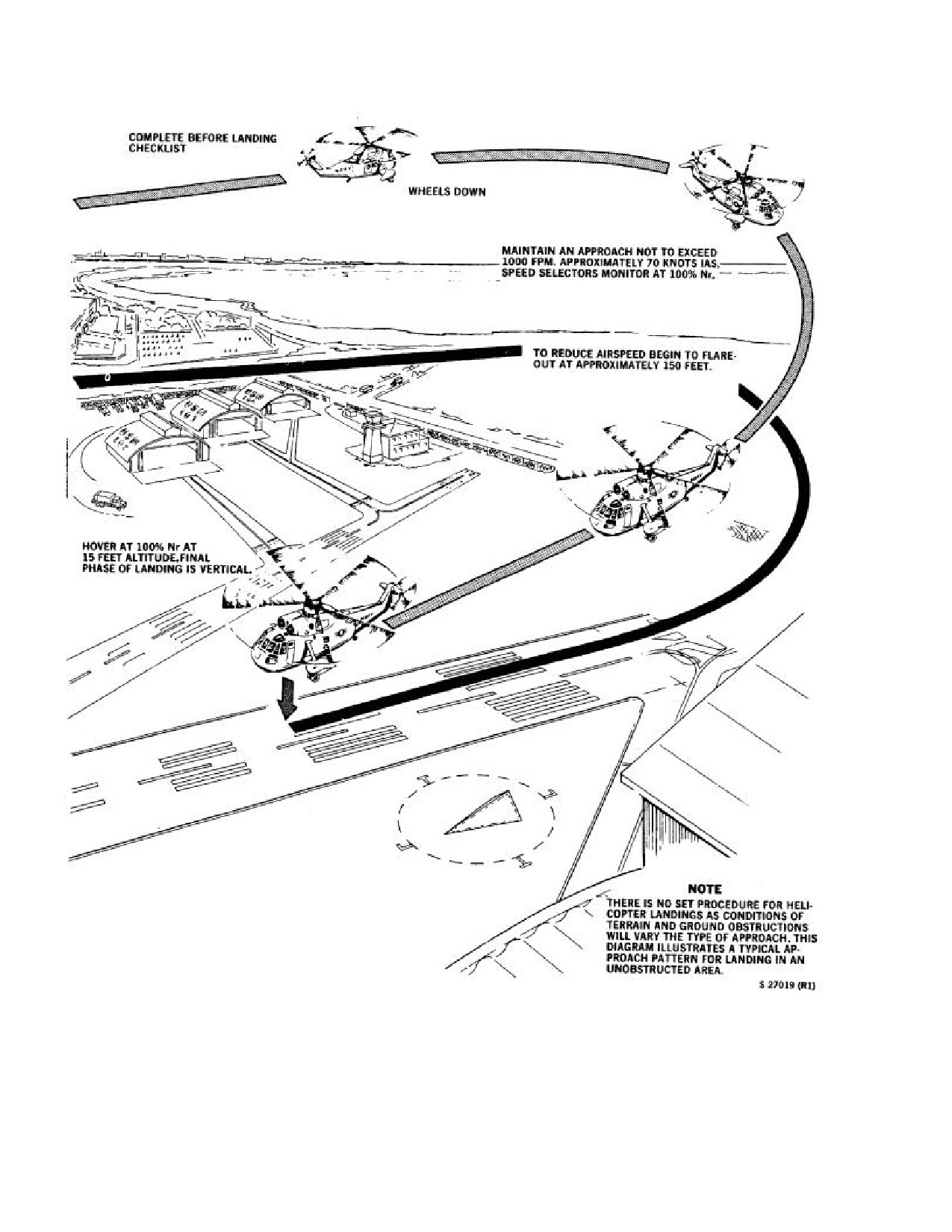
7.14.1 Dual-Engine Landing Approach and
coupling is incorporated in the mixing unit to apply
Transition to a Hover
(Figure
7-7). The proper
automatic noseup pitching correction when the collective
position to begin a normal approach is abeam the landing
is lowered. The pilot must counteract this automatic aft tilt
spot, heading downwind at a recommended
500-foot
of the rotor path when the collective is lowered by
altitude and 70-knot airspeed. Complete the landing check
application of forward cyclic. The technique is imperative
list before reaching the 180° position. When turning base,
to prevent the rotary wing blades from operating in
check wheels down and locked and notify the tower. Begin
proximity to or flexing downward upon landing impact
approach by reducing collective to about 25-percent torque
and possibly striking the tail cone. To aid smooth landings
and establish a rate of descent of 500 to 1,000 fpm while
and avoid undue stresses on the landing gear, all sideward
turning toward the landing area. Vary the power as
or rearward drift should be eliminated before touchdown.
necessary to maintain the desired rate of descent at 70
When conditions will allow, a smoother landing is
knots. Increased right rotary rudder pressure will be
sometimes accomplished by moving forward over the deck
required to maintain balanced flight. At about
150-foot
at
1 or
2 knots on touchdown. Stop the rolling with
altitude, apply back cyclic to decelerate. Plan the approach
wheelbrakes, not aft cyclic. If a soft surface is
and apply power as necessary so that the helicopter
unintentionally encountered and the wheels begin to settle,
simultaneously arrives at zero groundspeed and zero rate
add collective pitch immediately and become airborne.
of descent over the landing site in a near level attitude at
This helicopter does not have a history of susceptibility to
15 feet. If excessive groundspeed is present at the end of
ground resonance; however, if any unusual vibration or
an approach, come to a hover beyond the spot or take a
unbalanced condition is experienced during landing,
waveoff. Any tendency to correct this condition by placing
execute an immediate takeoff. Normal vertical landings on
the helicopter in an abrupt tail-low attitude near the ground
land should be made with tailwheel locked. Changes in the
should be avoided.
rotary wing torque may cause a slight swerve if the
tailwheel is unlocked.
7.14.2 Landing After Attaining a Hover.
7.14.3 Run-On Landings. Run-on landings should be
practiced to simulate the method of landing a helicopter
that cannot be hovered because of a high gross weight or
high altitude. Under those conditions, it is necessary to
maintain the added lift provided by forward motion until
the wheels are on the ground. Practice run-on landings
· During landings and ground operations, it
should be made with feet on the rotary rudder pedals,
is possible by abrupt movement of the col-
tailwheel locked, wheelbrakes off, and on approved
lective pitch lever to the down position and
landing sites. The helicopter is flown in a normal approach
the cyclic stick to the aft position to cause
down to the straightaway position. In the straightaway,
the rotary wing blades to strike the tail sec-
cyclic control is used to control descent while maintaining
7-22
ORIGINAL
NAVAIR 01-230HLH-1
a torque value less than hover power to simulate heavy
7.15
AUTOROTATIONS
load conditions; utilize wing-down, top rotary rudder
methods of control as necessary to maintain a straight track
7.15.1 Practice Autorotation.
over the ground with no drift. A normal rolling touchdown
will be made in a level attitude (maximum pitch 1° to 2°
Note
nose high) at a ground-speed not over 40 knots. Attitude
and rate of descent shall be controlled with cyclic and
During practice autorotations, BAR ALT
collective pitch, not to exceed preestablished torque
shall be disengaged.
values. Following touchdown collective will be gently
lowered in conjunction with forward movement of cyclic.
Autorotations should be practiced only at designated
Wheelbrakes should be used to slow groundspeed. Run-on
areas where there are no obstructions and where crash and
landings should not be made with the tailwheel unlocked.
firefighting facilities are available. At least one normal
approach shall be made before attempting a practice
7.14.4 Crosswind Landings. Crosswind landing
autorotation to determine the required torque, Ng, gross
procedures are the same as into-the-wind vertical landing
weight, and density altitude conditions. Autorotations may
procedures with the exception of the required cyclic
be practiced only with an HAC or an H2P aboard. Pilots
displacement into the wind. This cyclic displacement
should be particularly alert to observe and report any
should not be released upon touchdown, as this will reduce
engine or rotor overspeeds and torque values that exceed
the force holding the helicopter in a vertical position and
the limits. Any unusual phenomena encountered during an
under extreme conditions could result in the helicopter
execution and recovery from an autorotation shall be
being overturned. It is most important to have no sideward
recorded on a VIDS/MAF.
drift when making crosswind landings. These landings are
prohibited in winds above 30 knots.
Practice basic autorotations shall be made using a
minimum of 70 knots from a starting point of 500 feet or
7.14.5 Practice Single-Engine Approach. This
above for every 90° of turn. Recovery will simulate ground
practice maneuver should be initiated by retarding one
level at about 15 feet with a touchdown groundspeed of
speed selector to no less than
96-percent Nf. Perform
about 15 knots. After mastering the basic autorotation,
critical memory item steps related to engine loss to keep
pilots are encouraged to perform various altitude, airspeed,
the aircraft in a safe flight envelope. Upon determination
and flare and recovery techniques
(i.e.,
100 knots
that flight can be maintained, check all gauges to
maximum glide, confined area, etc).
determine which engine has malfunctioned and what
action to take. Once it has been determined that the engine
The sequence of procedures for an autorotation is:
has failed, perform a topping check of the good engine to
determine single-engine capabilities. Perform topping
1. Adjust Nf/ Nr to 98 percent.
checks by drooping Nr to 100 percent and noting available
torque. Call for checklist as backup. A single-engine
2. Enter autorotation by smoothly lowering collective
approach to a pad or single-engine run-on landing should
to full-down position. Nf and Nr should separate and
be made depending on the available landing platform.
torque will indicate zero percent, both indications of
During a single-engine run-on landing, a normal
autorotative flight.
touchdown should be made in a level attitude (maximum
pitch 1° to 2° nose high) at a groundspeed not over 40
3. Establish glide of 70 knots.
knots, ensuring that 1,000-fpm rate of descent during the
pattern and
500-fpm rate of descent on final is not
4. Adjust collective to maintain
104-percent Nr.
exceeded. During a single-engine approach to a pad, fly a
Forward cyclic, negative g, up collective, or left rudder
normal approach profile ensuring that rate of descent does
application will cause a decrease in Nr, and conversely,
not exceed 500 fpm on final. At 30 feet and below, avoid
aft cyclic, positive g, down collective, or right rudder
nose attitudes in excess of 10° up. At 10-foot AGL, nose
will cause an increase in Nr.
attitude should not exceed 5° noseup. Touchdown should
be level.
5. Begin flare based on visual reference, meteoro-
logical conditions, aircraft instrumentation, and pilot
experience (normally 150 to 200 feet). The purpose of
the flare is to reduce the rate of descent and increase Nr
while slowing groundspeed to
15 knots or below.
Improper choice of initial flare altitude may be
compensated for by increasing or decreasing cyclic
If at any time during the approach unusual engine
flare rate. Ensure that Nr does not exceed 117 percent.
performance is noted, advance both speed
selectors to the full forward position, perform
normal landing, and analyze malfunction.
7-23
ORIGINAL
NAVAIR 01-230HLH-1
Figure 7-7. Power-On Vertical Landing (Typical)
7-24
ORIGINAL
NAVAIR 01-230HLH-1
For successful completion of a safe autorotation, it is
imperative that the helicopter be flown on a straight
heading with no sideward drift. In case of a crosswind, the
wing-down method to control helicopter heading and drift
should be used. Autorotations may be practiced over water
Rapid application of aft cyclic will result in
as authorized by the squadron commanding officer for test
a premature or excessive decrease in rate of
and standardization flights under the following conditions:
descent resulting in a high recovery or a
vertical descent that could result in major
1. VFR with a recovery reference other than water,
damage in the case of actual autorotative
such as a ship, reef, island, or prominent channel buoy.
landing.
2.
Recovery must be completed above 50 feet.
6. Speed selectors full forward
- As the flare is
commenced, the speed selectors shall be advanced to
Note
full forward
(maximum 112.5-percent Nf) in response
to the command, "FULL POWER."
Practice full autorotation to a landing shall
not be executed in this helicopter. In
This step shall be completed prior to simulated
addition, practice autorotations shall not be
touchdown. If speed selectors are advanced too rapidly
executed at night.
during the flare, torque will increase and the helicopter
will enter the powered flight regime that is of little value in
7.16
NIGHT FLYING
autorotative technique practice.
7. Simulate touchdown at 15 feet/less than 15 knots
groundspeed. In approaching the simulated touchdown
point, the nose-high attitude shall be reduced so as to
WARNING
arrive at a level to slightly nose-high attitude as the
collective is smoothly increased to simulate cushioning
the landing.
For flight safety, the barometric altitude
controller should be kept ON while in the
Note
night landing pattern ashore or while em-
barked and should not be shut off until in
It is not necessary or desirable to lower the
visual contact with the desired landing spot;
nose attitude to the horizon before collective
however, intermittent operation may be
application, as the normal collective to pitch
obtained by pressing the momentary BAR
coupling will tend to bring the nose to the
REL button on the collective stick during
level position as the collective is raised.
pattern descents.
Level nose attitude will cause the aircraft to
accelerate.
7.16.1 Familiarization.
Simulated touchdown in excess of 5° noseup should
7.16.1.1 General. A night flying briefing folder or its
not be made. For successful completion of a safe
equivalent shall be used before all night operations. In
autorotation, there should be no sideward drift. To
congested areas, all ground taxiing shall be under the
comp ensate for crosswind, the wing-down method is
supervision of a qualified taxi director equipped with
recommended.
lighted wands. Practice autorotation approaches shall not
be executed.
7.16.1.2
Helicopter
Operating
Equipment
WARNING
Minimums.
1. Flight instruments (pilot and copilot): Attitude and
If at any point it is considered necessary, the
turn-and-slip indicator, airspeed indicator, altimeters
autorotation shall be waved off by smoothly
(radar and barometric), compass system, standby
adding collective while advancing speed
compass, vertical speed indicator, and clock.
selectors and adjusting nose/wing attitude to
commence level off and return to powered
2. All engine and systems instruments.
flight. The aircraft shall not be allowed to
descend below 30 feet with a noseup attitude
in excess of 10° and Nf/ Nr not married.
7-25
ORIGINAL
NAVAIR 01-230HLH-1
3. All instrument, navigation, landing, cockpit, and
a. Ready to start engines - Aft anticollision light
cabin lights.
on, signal with red flashlight.
4. Radio equipment: UHF, ICS, and appropriate
b. Ready to engage
- Exterior position lights
navigation equipment.
flashing dim, rotor head light on.
5. ASE.
c. Ready for taxi - Exterior position lights steady
dim.
6. Low altitude overwater operations, the RAWS and
BAR ALT controller shall be operating.
d. After takeoff
- Exterior position lights, anti-
collision light, and beacon as desired.
7.16.2 Approaches. The copilot shall go over the
landing checklist and report completion to the pilot. Before
e. Recovery - Exterior position lights steady dim.
each approach, the pilot and copilot shall visually check
the landing gear as being down. The same type of
f.
Disengage - Exterior position lights flashing dim,
approach that was used for day operations should be used
rotor head light on.
at night. A recheck of the landing gear between the pilots
and aircrewmen shall be made before each touchdown.
g. Rotor stopped - Exterior position lights off.
7.17 HELICOPTER LIGHTING
7.17.3
Carrier-Based. Light signals and helicopter
lighting shall be as promulgated in NWP 3-04.1 and the
7.17.1 Land-Based (Day). For turn-up, launch, and
CV NATOPS Manual.
recovery:
7.18
AFTER FINAL LANDING
1. Ready to start engines - Aft anticollision light on.
2. Ready to engage - Exterior position lights flashing
WARNING
bright.
3. Ready for taxi
- Exterior position lights steady
bright.
All crewmembers must remain strapped in
their seats until the helicopter has been
4. After takeoff - Exterior position lights, anticollis ion
chocked and the rotor systems stopped. If
light, and beacon as desired.
they are required to assist in parking the
helicopter or the disengagement of the rotor
5. Recovery - Exterior position lights steady bright.
system, they should unstrap and exit the
helicopter only upon command of the pilot.
6. Disengage - Exterior position lights flashing bright.
If crewman reenters the helicopter, he shall
be strapped in before rotor disengagement.
7. Rotor stopped - Exterior position lights off.
1.
ASE-OFF.
7.17.2 Land-Based (Night).
2.
Emergency Start Switches - OFF.
1. After preflight and upon entering the helicopter,
have crewman check operation of internal cabin lights.
3.
Lights - AS REQUIRED.
2. Before starting No.
1 engine
(external power
4.
IFF-STANDBY.
required), check the illumination of all lighting. The
pilot shall receive an affirmative signal from the plane
5.
Doppler - STANDBY.
director indicating that all lights are operative.
6.
Crossfeed - Closed.
3. Pre-position the landing light about 45° below the
horizontal and about 5° to the right of the nose of the
7.
Boost pumps - OFF.
helicopter, which will provide best lighting in case of
an emergency.
8
Tailwheel - AS REQUIRED.
4. Turnup, launch, and recovery.
7-26
ORIGINAL
NAVAIR 01-230HLH-1
7.19 PRESSURE REFUELING WITH ROTORS
ENGAGED ASHORE
WARNING
During shore-based operations, tactical situations may
require the helicopter to be refueled with both engines
running and the rotors engaged. When performing the
evolution, the following procedures will be used.
Only pressure refueling is authorized with
engine(s) running. Engines shall be secured
7.19.1 General Safety Precautions.
for gravity refueling.
1. All fueling personnel must know the contents of
7.19.2 Duties of Personnel
NAVAIR 00-80T-109, Ashore Refueling Manual.
7.19.2.1 Fueling Station Operator.
2. The helicopter shall be securely chocked.
1. Energize and deenergize the fueling station upon
3. All movement from one side of the helicopter to the
signal of the LSE.
other shall be at the nose. No personnel will work in
close to the tail rotor.
2. Continuously watch the LSE for signals.
4. All personnel working within the rotor arc shall
7.19.2.2 Helicopter Director.
exercise extreme caution.
1. In charge of the refueling party.
5. Refueling shall be secured when any fuel spillage is
noted and shall not be continued until spillage is wiped
2. Position himself outside of rotor diameter where he
up.
can see the pilots, fueling station operator, and the
nozzle connect/disconnect man.
6. The fueling hose shall be evacuated before
connecting it to or disconnecting it from the helicopter.
3. Make sure that the pressure-refueling nozzle is
connected and that all personnel are ready for pressure
7.
Before entering the hot refueling area:
refueling. He must get a thumbs up from the pilot,
nozzleman, and fire extinguisher operator before
a. Secure all unnecessary electrical and avionics
signaling the fueling station operator to energize the
equipment. Radio transmissions should be made
fueling station.
only in an emergency.
4. Closely monitor the refueling operation and secure
b. All ordnance shall be safed.
refueling upon the first indication that an unsafe
condition exists. Refueling will normally be secured
c. Helicopter and fueling system checks shall be
when the high-level shutoff valve is actuated or when
completed, including a fuel sample if required by
the prebriefed amount of fuel has been added.
the aircraft commander or air crewman. Fuel
samples shall not be taken while the helicopter is in
5. Signal the fuelin g station operator to evacuate the
the refueling station.
hose and deenergize the fueling station.
d. The area shall be cleared of loose objects.
6. Upon completion of step 4, signal the nozzleman to
unplug the pressure-refueling nozzle.
e. Ground crews shall wear proper eye and ear
protection.
7. Be sure all refueling personnel, equipment, and
chocks are clear before giving the taxi, signal to the
f.
When taxiing into the refueling station, the
pilot.
helicopter shall be under the guidance of a taxi
director.
7.19.2.3 Nozzle Connect/Disconnect Man.
1. Stand by the fueling station to assist the hoseman in
pulling the refueling hose to the helicopter.
2. Attach the nozzle to the pressure -refueling
connection.
7-27
ORIGINAL
NAVAIR 01-230HLH-1
3. When he is ready in all respects to commence the
b. Monitor engine instruments for any unusual
pressure refueling, he will signal the helicopter
indications. If anything is noticed that would
director.
jeopardize the safety of the refueling operation, he
will notify the pilot in the right seat.
4. As the hose is pressurized, he activates the flow
control handle. As fuel flow commences, he will test
2.
Pilot in the right seat:
the primary and secondary high-level shutoff switches
to be sure they will secure the fuel flow. If neither
a. When ready for refueling to commence, the
switch will secure the fuel flow, then pressure refueling
pilot shall ensure the window is closed and signal
must be discontinued at once. If one of the switches
the helicopter director.
will secure the fuel flow, then pressure refueling may
be continued with caution being exercised.
b. Watch the helicopter director for an emergency
cut signal.
5. When the refueling is completed, he will close the
flow control handle upon signal from the plane
c. Signal the helicopter director if the prebriefed
director. Secure the helicopter pressure-refueling
amount of fuel has been added.
connection cover and lay the nozzle under the fuselage.
d. If he receives an emergency cut signal, he will
6. He will help the hoseman retrieve the hose and
secure both speed selectors, apply the rotor brake,
secure it at the fueling station.
instruct the crew to abandon the helicopter, and
secure all electrical power in the helicopter.
7.19.2.4 Fire Extinguisher Operator.
3.
Crewmembers:
1. Stand by with appropriate firefighting equipment.
a. After chocks are in place and upon order of the
2. Attach the grounding wire to the helicopter.
helicopter commander, the crewman shall ensure
the cabin door is closed and open the personnel
3. When the refueling hose is brought to the aircraft,
door.
he will take his station near the pressure refueling
panel.
b. When not involved elsewhere in the helicopter
(monitoring the refueling evolution, checking
4. Signal to the helicopter director when he is ready
equipment, etc.), remain strapped in and ready to
for the pressure refueling to commence.
abandon the helicopter upon direction.
5. At the first sign of a fire, he will activate the fire
c. When refueling is completed, crewman shall
extinguisher and direct it on the fire.
check that pressure-refueling cap is secured.
6. Remain at his station until the hose is disconnected
7.20
SHUTDOWN
and removed from the vicinity of the helicopter;
disconnect the grounding wire from the helicopter and
1.
Collective (copilot monitor) - MINIMUM
remove the fire extinguisher bottle.
PITCH.
7.19.2.5 Hoseman.
2.
Brakes and tailwheel - LOCKED.
1. Stand by the refueling station to take the hose to the
3.
Landing gear lockpins and chocks - IN.
helicopter.
a. Safety pins - AS REQUIRED.
2. Remain at his station until the refueling is
completed and, then with the help of the nozzleman, he
b. Tiedowns - AS REQUIRED.
will remove the hose to the fueling station.
4.
No. 1 speed selector - GRD IDLE.
7.19.2.6 Helicopter Crewmembers.
1. Pilot in the left seat:
a. Monitor the collective and the cyclic.
7-28
ORIGINAL
NAVAIR 01-230HLH-1
7.20.1
Rotor Disengagement.
1. Area clear/disengage signal - CHECK.
2. No. 2 speed selector - GRD IDLE.
Before switching the accessory drive switch
to ACCESS DR, a verbal challenge and
3. Droop stops
- IN (approximately 50- to 60-percent
reply exchange shall be made between the
Nr).
pilots to be sure the No. 2 engine is driving
the rotors between 102- to 104-percent Nr,
the No. 1 speed selector is at GRD IDLE,
and No. 1 Nf is less than 70 percent.
5. Accessory drive switch - FORWARD, LIGHT
ON.
· If one or more droop stops fail to go in,
reengage the rotor, taking care not to over-
torque the main gearbox. Repeat the rotor
disengagement procedure, slightly displacing
the cyclic in an attempt to dislodge the
jammed droop stop. If the droop stop does
· On helicopters modified by AFC 401, the
not go in after repeated disengagement
accessory drive light may remain off 6 to 7
attempts, the area should be cleared of all
seconds.
unnecessary
personnel
and
close
coordination should be established between
· If accessory drive light does not go on,
the
LSE and the pilot. During
proceed as follows:
disengagement, the rotor system should be
allowed to coast down to that Nr at which
a. No. 2 engine - 104-PERCENT Nf/ Nr .
the rotor blade starts to droop. Maximum
rotor brake pressure must be applied when
b. No. 1 engine - GRD IDLE DETENT.
the low blade is seen passing over the tail
pylon. To prevent striking the tail pylon, the
c. Check ACCESS DRIVE circuit breaker,
rotor blades must be stopped immediately.
If out - RESET AND CONTINUE WITH NORMAL
· In an emergency, the engine may be shut
CHECKLIST.
down immediately, observing power turbine
inlet temperature
(T5) for indication of
If in
- RETURN ACCESS DR SWITCH TO
postshutdown fire. However, indiscriminate
FLIGHT.
use of emergency shutdown procedure from
high-performance conditions will increase
d. No. 1 engine - SECURE.
the possibility of engine seizure and
decrease the useful life of the engine.
e. Rotor disengagement checklist - COMPLETE.
Note
f.
No. 2 engine - SECURE.
To obtain the most efficient cooling of the
6.
No. 1 speed selector - 104-PERCENT Nf.
No. 2 engine, maintain a constant T5 for 1
minute at minimum collective pitch.
Note
4. No. 2 Speed Selector - Off.
On helicopters modified by AFC
401, if
after shifting to the accessory drive position
5. Rotor brake below 45-percent Nr - ON.
the No. 1 Nf does not respond to speed
selector advancement, return the No.
1
For normal shutdown, the rotor brake should be applied
speed selector to the GROUND IDLE
firmly and smoothly. As rotation nears complete
position and retard the No. 2 speed selector
deceleration, rotor brake pressure should be reduced in
back to 102- to 104-percent Nr . This will
order to ease rotor blades to a stop, precluding any
ensure that the No.
2 engine is in the
tendency of whip action.
governing range and allow the No. 1 engine
to advance normally.
7-29
ORIGINAL
NAVAIR 01-230HLH-1
Note
(1)
Dampers position all blades against their
autorotation stops.
If the rotor brake is weak, it is necessary to
place the handle in the full-up position and
Note
then reapply the rotor brake. This may have
to be repeated until enough pressure is built
Check visually that the two forward blades
up to slow the main rotor.
are positioned an equal distance from the
centerline of the helicopter. If the blades are
6. No. 2 fuel switch - CLOSE.
not in the correct position, refer to Manual
Folding Procedures, paragraph 7.20.2.
7. No. 2 engine instruments - CHECKED.
(2)
CONT LOCK PINS ADV indicator light
8. All electronic equipment - AS REQUIRED.
– ON. BLADE SPREAD indicator light - OFF
as soon as one flight control lockpin advances.
With the No. 2 engine shut down and the No. 1 engine in
accessory drive, proceed as follows:
After fold cycle is initiated and until blades
LSE shall visually check droop stops in
are spread, do not move the controls, as
prior to commencement of folding
damage to control lockpins will result.
sequences.
Note
9. Area - CLEAR.
It may be necessary to reposition the cyclic
10. Blades - FOLDED.
stick very slightly to seat all the lockpins.
a. Collective pitch lever - MINIMUM PITCH.
h. BLADES FOLDED indicator amber light
-
ON. When all blades are folded.
b. Cyclic stick - NEUTRAL . Depress trim release
to center.
(1)
If folding cycle should stall at any point,
proceed as follows:
c. SAFETY VALVE switch
- OPEN. SAFETY
VALVE OPEN red warning light
- ON and
(a) BLADES FOLD-SPREAD switch
-
FLIGHT POS green light - OFF.
OFF.
(1) Blade fold MASTER switch - ON. FOLD
(b) BLADES FOLD-SPREAD switch
-
PWR red light will go ON, primary servo
SPREAD.
pressure will drop to zero, and caution panel
PRI SERVO PRESS light - ON.
Until BLADES SPREAD amber light goes
ON.
d. Rotor brake lever - OFF.
(c) BLADES FOLD-SPREAD switch
-
e. BLADES FOLD-SPREAD switch - FOLD.
FOLD.
Observe this sequence:
i.
SAFETY VALVE switch -CLOSED.
(1) ROTOR BRAKE caution light - OFF.
SAFETY VALVE red warning light remains ON,
blades fold MASTER switch - OFF, and BLADES
(2) No. 1 blade positions aft.
FOLD-SPREAD switch - OFF.
f.
No. 1 BLADE POS indicator light - ON.
7.20.2 Manual Blade Folding Procedures.
(1) ROTOR BRAKE caution light - ON.
7.20.2.1 Improper Blade Positioning. If improper
blade positioning is experienced during automatic blade
g. Rotor brake lever - ON (320 PSI MINIMUM)
folding and it is necessary to complete blade folding,
proceed as follows:
7-30
ORIGINAL
NAVAIR 01-230HLH-1
1. Blade fold master switch - OFF.
3. Speed selector
- SHUT OFF, after Ng is less than
2. Rotor brake lever - OFF.
60 percent.
3. No. 1 blade - AFT (position manually).
4. Fuel switch CLOSE.
4. Blade fold master switch
- ON (proceed with
5. All engine instruments - CHECK.
automatic operations).
6. All switches - OFF.
7.20.2.2 Manual Folding. If necessary to fold the
blades manually, proceed as follows:
7. HEEDS bottles - OFF.
1. Rotor brake lever - OFF.
7.21 POSTFLIGHT
2. No.1 blade - DIRECTLY AFT.
1. Visually check for external hydraulic/oil leaks.
3. Rotor brake lever - ON.
2. Visually check main and tail rotor blades.
4. Servo switch - PRI OFF.
3. Check ground wire to be sure helicopter is properly
grounded.
5. Collective pitch lever - MINIMUM PITCH.
4. Check helicopter for any missing panels.
6. Cyclic stick
- NEUTRAL (HAVE GROUND-CREW
CHECK CONTROL LOCKPIN ALIGNMENT).
Tripping the fold manual override will cause
the blades to fold, regardless of the position
of the No. 1 blade and regardless of whether
the rotor brake is on or off. Close
coordination is required between personnel
in the cockpit, the line director, and the
person actuating the FOLD manual override
switch.
7. Safety valve switch
- OPEN (WARNING LIGHT
ON).
8. Trip fold manual override and observe this
sequence:
a. Dampers position.
b. Control locks engage.
c. Blade lockpins retract.
d. Blades fold.
9. Safety valve switch - CLOSED.
7.20.3 No. 1 Engine Secure
1. HEELS system switch (NON-ET) - OFF.
2. Speed selector - GRD IDLE.
7-31
ORIGINAL
NAVAIR 01-230HLH-1
This Page Left Blank Intentionally
7-32
ORIGINAL
NAVAIR 01-230HLH-1
CHAPTER 8
Ship-Based Procedures
8.1 CV OPERATIONS
director, indicating that the blade walkers
are in position and the area is clear. The
8.1.1 General. Shipboard procedures in general are
blade walkers should be equipped with red
explained in the CV NATOPS Manual, NWP 3-04.1M, and
flashlights.
NAVAIR 00-80T-113. This chapter deals only with those
areas where amplification of or deviation from those
8.2.3.2 Rotor Engagement. Rotors shall be engaged
procedures is necessary.
only on signal from an LSE and under the positive control
of primary flight control.
8.2 FLIGHT/HANGAR DECK PROCEDURES
Mandatory requirements for engagement of the rotor
Basic operating procedures outlined in Chapter 7, the
consist of the following items:
CV NATOPS Manual, and NWP 3-04.l M shall be adhered
to except as modified in this chapter.
1. Tail and mainmount tiedowns secured with 2 to 3
inches slack and chocks in place.
8.2.1 Hangar Deck. During periods of prolonged
storage, blade racks should be used.
2. Flight deck area clear of unnecessary personnel.
8.2.2 Hangar Flight Deck
3. Tailwheel locked, parking brake on.
8.2.2.1 Movement of Helicopters. Because of the
4.Winds for engagement/disengagement in accordance
top-heavy configuration of the helicopter precautions must
with Figure 8-1.
be observed in all movements to preclude possibility of
damage to the relatively light structural members and rotor
When gusty winds are involved, the velocities shown
blades. Helicopters shall not be respotted on the deck with
in Figure 8-1 should be reduced, depending on the gust
the rotors engaged.
magnitude. When directed by primary flight control
following an up status signal from the pilot, tiedowns will
8.2.3 Flight Deck
be removed. It is mandatory that the ship and the squadron
establish procedures that will permit the helicopter
8.2.3.1 Blade Folding/Spreading. Blade folding/
commander to determine that all tiedowns have been
spreading should be accomplished with the No. 1 engine
removed. The helicopter aircraft commander is responsible
operating at
104-percent Nf in accessory drive. The
to assure complete removal of tiedowns before takeoff.
maximum safe non-turbulent wind relative to the
Helicopters should be launched in order from forward to
helicopter for rotor folding/spreading is limited to 45 knots
aft. Helicopters shall not be launched over other aircraft.
except in an emergency situation.
With rotors engaged on the flight deck,
At any time blades are to be spread or folded
disengage the ASE. This is extremely
aboard ship, two persons shall act as blade
important, especially when the carrier is
walkers while the Nos. 3 and 4 blades are in
turning, as the turn will be resisted by the
motion to prevent excessive blade flapping
automatic stabilization directional channel
that could result in the blade tips striking the
and cause the helicopter to turn in relation to
deck. At night, blades should be spread or
the deck of the carrier.
folded upon signal from the flight deck
8-1
ORIGINAL
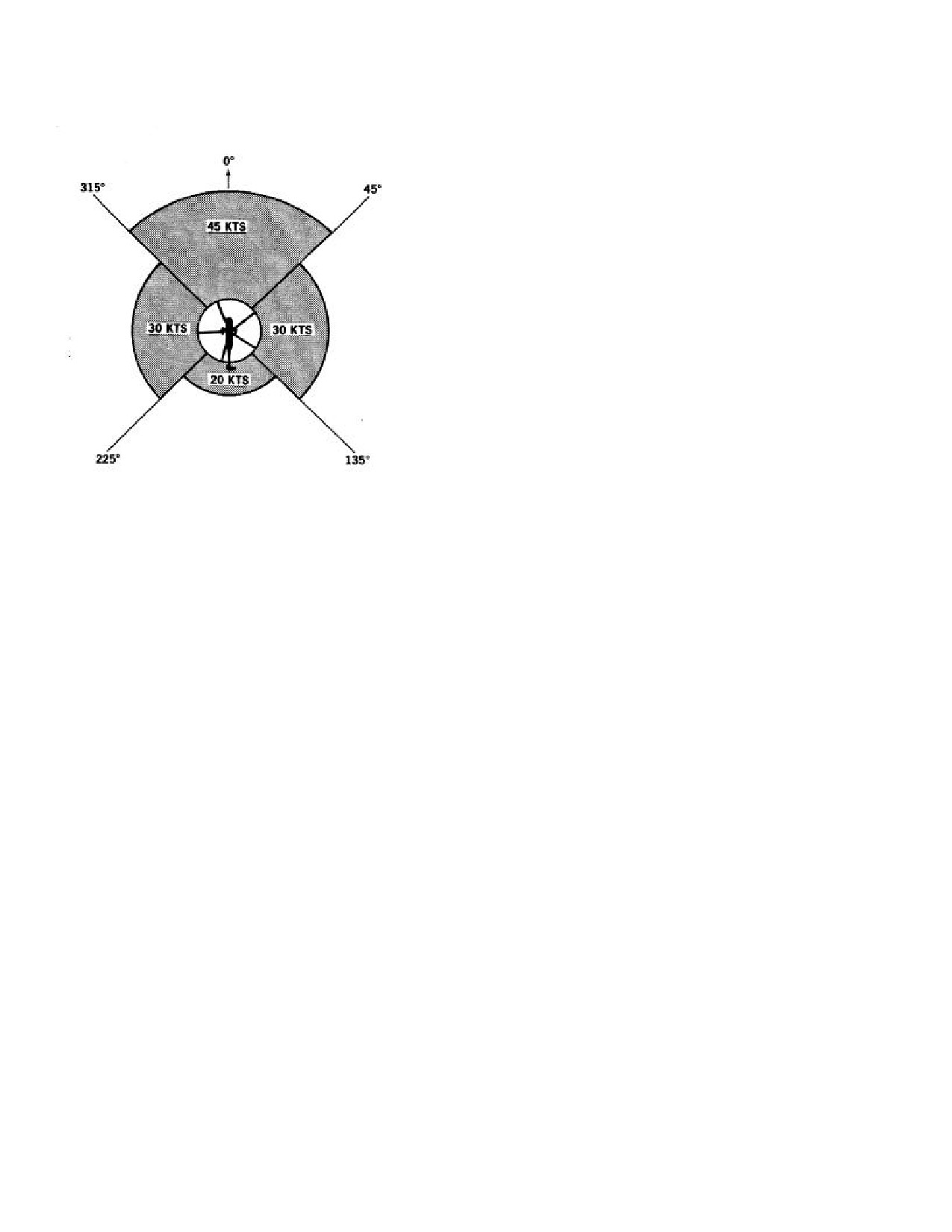
NAVAIR 01-230HLH-1
ROTOR ENGAGEMENT AND DISENGAGEMENT
3.
All movements from one side to the other shall be
via the nose. Under no circumstances will any
personnel work in close proximity of the rotary
rudder.
4.
All personnel working under the main rotors are
to use extreme caution.
5.
Refueling shall be secured when any fuel spill-
age is noted and not commenced until the spillage is
wiped up.
6.
The fueling hose shall be connected and discon-
nected from the helicopter with the hose in an
evacuated condition.
8.2.4.2 Duties of Personnel
1. Fueling station operator.
NOTES
a. Energize and deenergize the fueling station
1.
LIMITING VELOCITIES OF THE SHADED AREA
upon signal of the LSE.
REPRESENT MAXIMUMS FOR STEADY STATE,
NONTURBULENT WINDS WHEN TURBULENCE OR
b. Continuously watch the LSE for signals.
PITCHING DECK CONDITIONS EXIST WHICH MAY IN
ANY WAY JEOPARDIZE THE SAFETY OF THE
HELICOPTER OR FLIGHT DECK PERSONNEL. THESE
2. LSE.
MAXIMUMS WILL BE REDUCED ACCORDINGLY
WITH GUSTS OF 10 KNOTS OR MORE. REDUCE THE
a. In charge of the refueling party.
MAXIMUM WINDS BY
10 KNOTS IN ALL
DIRECTIONS.
b. Position himself outside of rotor diameter
2.
ROTOR ENGAGEMENT IN WIND VELOCITIES NEAR
where he can see the pilots, fueling station operator,
THE LIMITING VALUES SHOULD BE MADE AS
and the nozzle connect/disconnect man.
RAPIDLY AS POSSIBLE USING APPROXIMATELY 60%
TORQUE.
c. Make sure that the pressure -refueling nozzle is
3.
ROTOR DISENGAGEMENT IN WIND VELOCITIES
connected and that all personnel are ready for
NEAR THE LIMITING VALUES SHOULD BE MADE AS
pressure refueling. He must get a thumbs up from
RAPIDLY AS POSSIBLE APPLY BRAKE FIRMLY AND
the pilot, nozzleman, and fire extinguisher operator
SMOOTHLY.
before signaling the fueling station operator to
Figure 8-1. Maximum Wind Velocities
energize the fueling station.
d. Closely monitor the refueling operation and
8.2.4 Pressure Refueling Aboard Ship With the
secure refueling upon the first indication that an
Rotors Engaged. During shipboard operations, tactical
unsafe condition exists. Refueling will normally be
situations may arise that will require the helicopter to be
secured when the high-level shutoff valve is
refueled with both engines running and the rotors engaged.
actuated or when the prebriefed amount of fuel has
The following procedures will be used to accomplish this
been added.
evolution. Hand signals shall be used in accordance with
CV NATOPS Manual and NAVAIR 00-80T-113.
e. Signal the fueling station operator to evacuate
the hose and deenergize the fueling station.
8.2.4.1 General Safety Precautions
f.
Upon completion of step e above, signal the
1.
Secure the helicopter with two chocks and initial
nozzleman to unplug the pressure-refueling nozzle.
four point tiedown. Fueling personnel shall not approach
the helicopter until it is properly chocked.
g. Be sure all refueling personnel, equipment,
chocks, and tiedowns are clear before giving the
2.
All fueling personnel must be thoroughly
launch signal to the pilot.
indoctrinated in the contents of the following
procedures, pertinent type commander instructions,
and carrier refueling instructions.
8-2
ORIGINAL
NAVAIR 01-230HLH-1
3.
Nozzle connect/disconnect man.
5.
Hoseman.
a. Stand by the fueling station to assist the hose-
a. Stand by the refueling station to take the hose
man in pulling the refueling hose to the
to the helicopter.
helicopter.
b. Pass the hose under the fuselage to the noz-
b. Attach the nozzle to the pressure -refueling
zleman.
connection.
c. Remain at his station until the refueling is
c. When he is ready in all respects to commence
completed and then with the help of the nozzle-
the pressure refueling, he will signal the LSE.
man he will remove the hose to the fueling
station.
d. As the hose is pressurized, he activates the
flow control handle. As fuel flow commences, he
6.
Plane crewmembers.
will test the primary and secondary high-level
shutoff switches to be sure they will secure the
a.
Pilot in the left seat.
fuel flow. If neither switch will secure the fuel
flow, then pressure refueling must be discontin-
(1) Monitor the collective and the cyclic.
ued at once. If one of the switches will secure the
fuel flow, then pressure refueling may be contin-
(2) Monitor engine instruments for any
ued with caution being exercised.
unusual indications. If anything is noticed
that would jeopardize the safety of the
e. When the refueling is completed, he will
refueling operation, he will notify the pilot in
close the flow control handle upon signal from
the right seat.
the LSE, secure the helicopter pressure-refueling
connection cover, and lay the nozzle under the
b.
Pilot in the right seat.
fuselage.
(1) When ready for refueling to commence,
f.
He will help the hoseman retrieve the hose
the pilot shall ensure the window is closed
and secure it at the fueling station.
and signal the LSE.
4.
Fire extinguisher operator.
(2) Watch the LSE for an emergency cut
signal.
a. Stand by with two
5-pound CO2 fire
extinguishers.
(3) Signal the LSE if the prebriefed amount
of fuel has been added.
b. Attach the grounding wire from the helicopter to
the flight deck.
(4) If he receives an emergency cut signal,
he will secure both speed selectors, apply the
c. When the refueling hose is brought to the air-
rotor brake, instruct the crew to abandon the
craft, he will take his station near the pressure-
helicopter, and secure all electrical power in
refueling panel.
the helicopter.
d. Signal to the LSE when he is ready for the
c.
Crewmembers.
pressure refueling to commence.
(1) After tiedowns are a t t a c h e d and chocks
e. At the first sign of a fire, he will activate the
are in place and upon order of the helicopter
fire extinguisher and direct it on the fire.
commander, the crewman shall ensure the
cabin door is closed and open the personnel
f.
Remain at his station until the hose is discon-
door.
nected and removed from the vicinity of the
helicopter, disconnect the grounding wire be-
(2) When not involved elsewhere in the
tween the helicopter and the flight deck, and
aircraft
(monitoring the refueling evolution,
remove the fire extinguisher bottles.
checking equipment, etc.), remain strapped in
and ready to abandon the helicopter upon
direction.
8-3
ORIGINAL
NAVAIR 01-230HLH-1
(3) When refueling is completed, crewman shall
WARNING
check that pressure-refueling cap is secured.
· In crosswind conditions, relative to the
WARNING
carrier fore and aft axis, the indicated
winds in primary flight often vary from
those winds actually experienced at the
After refueling has been completed and the
flight deck level. This variance will af-
fuel hose has been removed from the vicin-
fect velocity, turbulence, and direction,
ity of the helicopter and before signaling
all of which are critical for safe launches
ready for launch, the plane commander shall
and recoveries.
make sure that all hatches and the personnel
door are secure and the Takeoff Checklist
· To avoid the possibility of helicopter
has been completed.
damage or personnel injury, the ship
should not change course or speed
8.3
LAUNCHING AND RECOVERY
during launch/recovery or during
PROCEDURES
engagement/disengagement. Emergency
conditions may preclude adherence to
the above, in which case immediate
notification to the pilot is mandatory.
WARNING
2.
Optimum wind and deck conditions should be
provided. The term takeoff is defined as the action of
Power required to hover both in and out of
lifting from the deck culminating in hovering,
ground effect (Figures 21-1 and 21-2) shall
forward, or sideward flight. The terms takeoff, liftoff,
be used to calculate performance for all
and launch are synonymous. The term landing is the
shipboard launches and landings.
maneuver of physically positioning the helicopter on
the deck following forward or hovering flight. The
terms landing and recovery are synonymous. The
helicopter shall be launched and recovered on all
daylight VFR flights within the relative wind limits as
prescribed in Figure
8-2 to derive the maximum
The plane commander shall make sure that
aerodynamic capability of the rotary wing and rotary
the Landing Checklist is completed (includ-
rudder and to lessen power required to maintain
ing lowering the landing gear) before
directional control.
commencing any approach (HIFR, transfers,
etc.) to any ship to preclude a gear-up
Night and IFR launches and recoveries shall be made
landing in case of an emergency or other
with the nose of the helicopter oriented forward and
unscheduled landing.
parallel to the centerline of the angle or axial deck. The
relative winds shall not exceed the parameters set forth in
Note
Figure
8-2. Except in unusual situations, the upwind
helicopter shall be launched first.
During shipboard operations after becoming
airborne, the compass system should be
3.
When launching with Doppler in SEA mode, it is
reset when free of local magnetic distur-
normal for the system to be in memo ry until helicopter
bance. Resetting will provide more accurate
speed is above 35 knots. This can be avoided by first
readouts sooner than if the system were
selecting LAND/ALT for a few seconds until memory
allowed to slave by itself.
ceases and then selecting SEA before takeoff. During
shipboard operation, the compass system must be reset
1.
Each helicopter shall be under the positive control
after becoming airborne when free of local magnetic
of a director or signalman for all flight deck evolutions.
disturbance. Resetting will provide more accurate
Standard helicopter signals shall be used and
readouts sooner than if the system were allowed to
acknowledged.
slave by itself free of local magnetic disturbance.
8-4
ORIGINAL
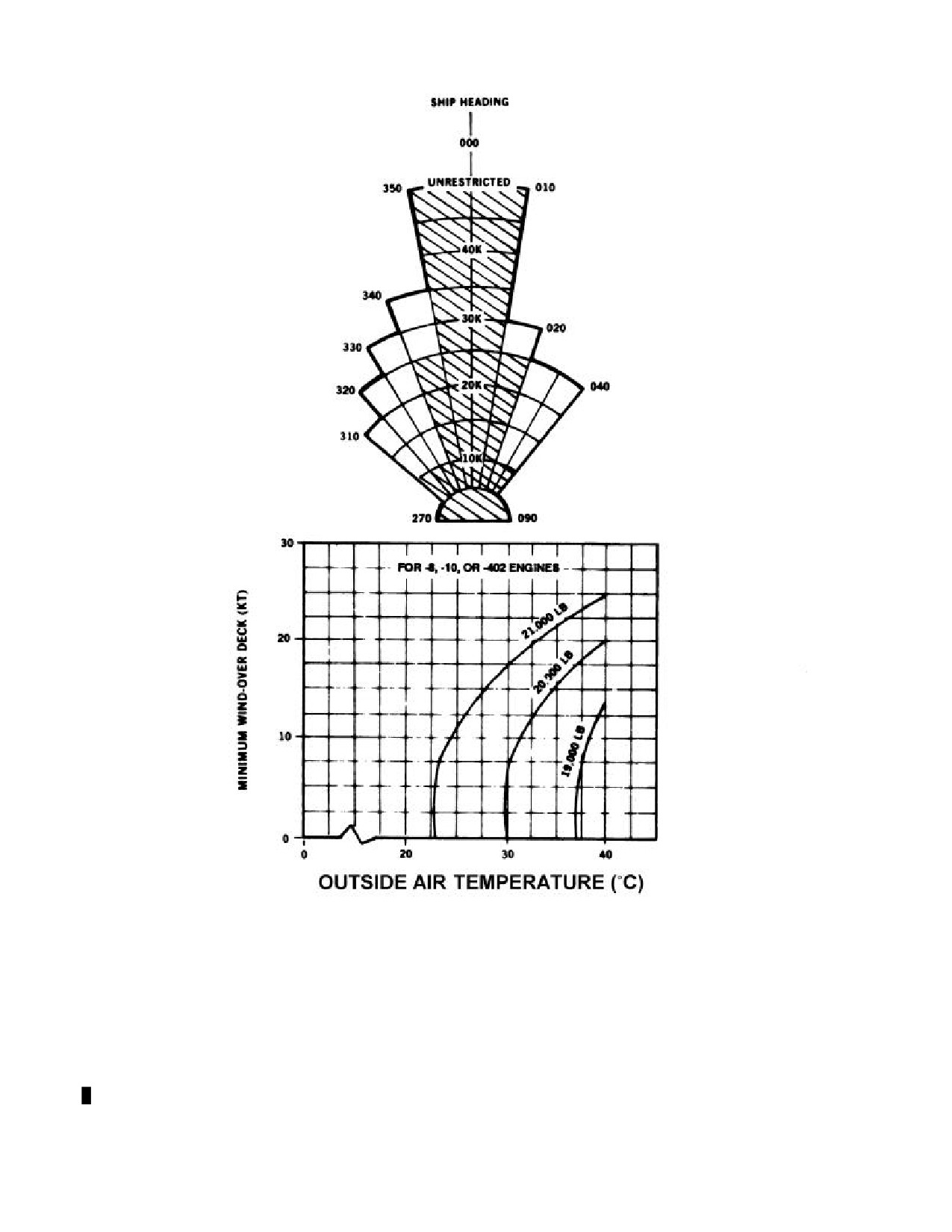
NAVAIR 01-230HLH-1
NOTE
· DAY OPS:
USE ENTIRE ENVELOPE. ENVELOPE APPLIES TO FIRST TWO BOW SPOTS AND THIRD
ANGLE SPOT.
· NIGHT OPS: USE ONLY HATCHED ENVELOPE. HATCHED ENVELOPE APPLIES ONLY TO THIRD
ANGLE SPOT.
Figure 8-2. CV/CVN Class Ships Launch and Recovery Wind Limits (Sheet 1 of 5)
8-5
ORIGINAL
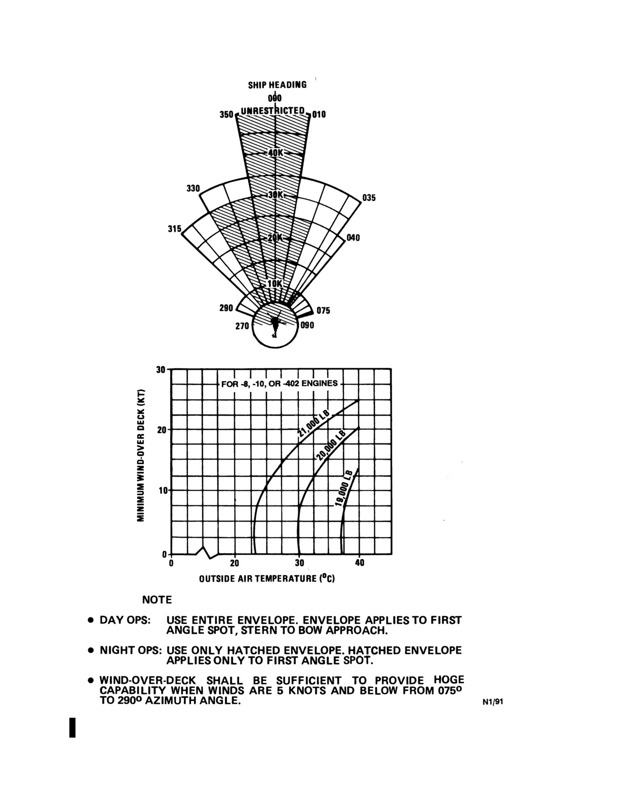
NAVAIR 01-230HLH-1
Figure 8-2. CV/CVN Class Ships Launch and Recovery Wind Limits (Sheet 2 of 5)
8-6
ORIGINAL
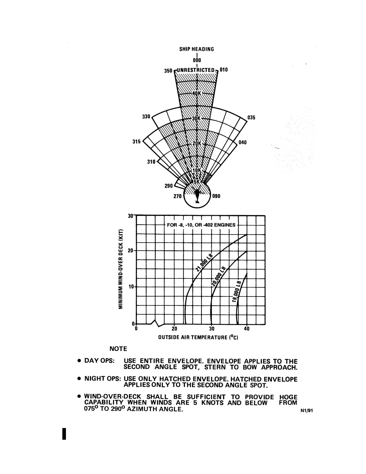
NAVAIR 01-230HLH-1
Figure 8-2. CV/CVN Class Ships Launch and Recovery Wind Limits (Sheet 3 of 5)
8-7
ORIGINAL
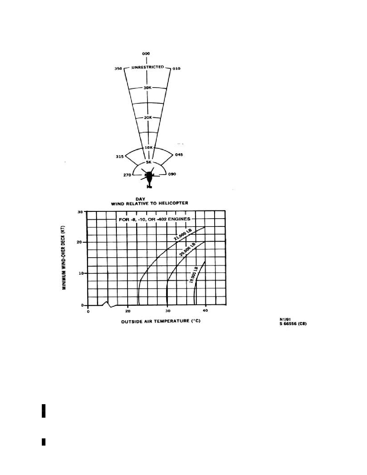
NAVAIR 01-230HLH-1
NOTE
DAY OPS ONLY: CROSSDECK USE ENTIRE ENVELOPE. ENVELOPE APPLIES TO FIRST TWO BOW
SPOTS AND FIRST THREE ANGLE SPOTS.
ALSO PRESENTS WIND LIMITS FOR AIR CAPABLE SHIPS WHEN NO LIMITS ARE SPECIFIED IN
NWP 3-04.1.
Figure 8-2. CV/CVN Class Ships Launch and Recovery Wind Limits (Sheet 4 of 5)
8-8
ORIGINAL
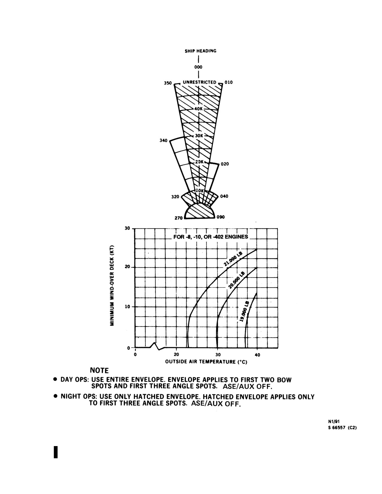
NAVAIR 01-230HLH-1
Figure 8-2. CV/CVN Class Ships Launch and Recovery Wind Limits (Sheet 5 of 5)
8-9
ORIGINAL
NAVAIR 01-230HLH-1
4.
On launching, the helicopter may be moved
Figure 8-2 (sheets 1, 2, and 3 of 5) presents the normal
forward slightly to make sure chocks/tiedowns are
day/night launch and recovery wind limits for CV/CVN
removed. Lift into a hover about 15 feet above the
class ships. Winds are relative to ship heading. For first
deck and transition to forward flight. Helicopters
two bow spots, align helicopter with axial deck, nose
should clear the ship expeditiously to reduce the
toward bow. Do not use this figure for crossdeck
hazard to flight deck personnel. Helicopters shall not
operations. The proper takeoff technique for this envelope
cross the bow or stern within
1 mile unless
is as follows:
specifically directed to do so or in an emergency. VFR
departures should be conducted on the search course
a. Winds within envelope.
or departure vector.
b. Lift into 15-foot hover.
c. Transition to forward flight.
d. Maintain helicopter heading from lift-off through
transition to forward flight.
Sonic booms are capable of ejecting windows
and damaging cargo doors. When notified of an
Do not lift off outside the envelope and then turn on
impending sonic boom, all windows and doors
the spot to obtain winds inside the envelope. Do not lift off
shall be open to minimize potential damage.
inside of envelope and then turn out of the envelope. Ship
roll angles beyond 3o were not tested.
Note
Figure 8-2 (sheet 4 of 5) presents crossdeck launch
Pilots should be aware when operating in
and recovery wind limits for CV/CVN class ships and also
vicinity of island/bridge structures that
presents wind limits for nonaviation ships when no limits
airframe vibrations and rumbling noises may
are specified in NWP
3-04.1. Winds are relative to
be induced throughout the flight controls
helicopter. A lift-off and transition to forward flight in a
and airframe by ship foghorns.
direction other than forward along the axial or angle deck
may at times be required by operational necessity. Under
5.
Downwind approaches shall not be made except
these unusual circumstances, this chart shall be used.
under emergency conditions.
Helicopter heading shall remain constant from lift-off
through out transition to forward flight. A lift-off out of the
6.
Helicopters should not cross the deck edge on an
envelope with a turn on the spot is not authorized. A lift-
approach until cleared to do so by the LSE.
off within the envelope with a turn out of the envelope is
also not authorized. Operations with the helicopter aligned
7.
Chocks and tiedowns shall not be installed upon
with the axial or angle deck are preferred over crossdeck
landing without pilot knowledge. Normally, this will
operations. Crossdeck operations should only be attempted
be done by an exchange of signals between the pilot
when axial/angle deck alignment is not feasible or because
and LSE.
of operational necessity.
8.3.1 Shipboard Wind Limits. Figure 8-2 presents
Figure 8-2 (sheet 5 of 5) presents the ASE OFF or
the maximum safe launch and recovery wind limits for
AUX OFF recovery wind limits for CV/CVN class ships.
CV/CVN class ships. The end points for the wind
All winds are relative to ship heading. Align the helicopter
azimuth/velocity envelopes define wind conditions where
with angle or axial deck. Do not use this figure for
less than 10-percent tail rotor authority remains or when
crossdeck operations. Wind limits for other emergency
the pilot workload is unacceptably high. As part of the
conditions
(single engine, chip lights, etc.) were not
limits, the figures also present the minimum safe WOD for
developed. Ship roll angles beyond 3o were not tested.
a particular temperature and gross weight. Use of this
minimum WOD chart is mandatory and ensures that the
8.3.2 Traffic Patterns. Traffic patterns and IFR or night
helicopter will have a
10-percent torque margin. The
approaches shall be conducted in accordance with the CV
minimum WOD chart is derived entirely from the
NATOPS Manual. Marshall points, holding and approach
performance charts in Part XI and is based on HIGE
patterns, as well as distance and altitudes shall be as
conditions. Launching or recovering through jet exhaust
prescribed in the CV NATOPS Manual as modified by the
may degrade helicopter performance.
ship CATCC instruction. Holding should be flown at 80
knots.
8-10
ORIGINAL
NAVAIR 01-230HLH-1
8.3.2.1 Departures. Instrument flight rule departures
4.
Radio equipment: UHF, ICS, and appropriate
shall be executed in accordance with the CV NATOPS
navigation equipment.
Manual as modified by the CATCC procedures. Departure
frequencies shall be set in while on deck and this setting
5.
ASE and RAWS.
should be maintained until departing the carrier control
zone. Helicopters shall climb straight ahead to at least 300-
6.
Coupler/Doppler for SAR.
foot altitude and 60 KIAS before beginning any turn.
8.3.3 Night and IFR Operations
8.3.3.3 Night Launches. The radar altimeter limit
should be set at 15 feet above the flight deck height to
8.3.3.1 Deck Conditions. Standard deck spotting
visually warn of low altitude after takeoff from the flight
(centerline only) shall be used. Such spacing shall provide
deck. The BAR ALT hold should be engaged on deck and
a minimum rotary wing to rotary rudder clearance of 20
the temporary release button held from takeoff until
feet. Minimum deck lighting should consist of red deck
reaching the desired altitude to provide the pilot with an
edge or flood lighting. Deck edge and centerline lights of
altitude hold preselected if disorientation occurs.
required spacing and brilliance for helicopter operations
Following the night takeoff, the pilot should hold cockpit
are required for CV/LHA/LPH class ships. Night and IFR
functions to a minimum until the helicopter is established
operations from these class ships shall have a minimum of
in level cruising flight. Helicopters shall climb straight
125 feet of visual reference to the flight deck forward of
ahead to at least
300-foot altitude and 60 KIAS before
the cockpit. Centerline and/or deck edge lighting shall be
beginning any turn.
used to assist in providing this required visual reference to
the flight deck. When 125 feet of visual reference to the
flight deck is not available forward of the cockpit, night
and IFR helicopter operations shall not be conducted with
WARNING
less than 175 feet of deck edge lighting forward of the
cockpit. Night operations are not authorized from the first
two bow spots.
· With the landing gear down, the RAWS
Note
will not provide an indication of an
unreliable radar altimeter. Therefore, the
Before applying external power or turning the
landing gear should be raised as soon as
battery switch on, pilots and/or maintenance
practicable after clearing the ship deck
personnel shall make sure that all helicopter
edge.
switches are OFF.
· Because of loss of RAWS aural and visual
8.3.3.2 Minimum Operating Equipment
for
warning of unreliable radar altimeter and
Night/IFR Shipboard Operations.
absence of 30-foot aural RAWS, night/IFR
overwater operations below 150 feet shall
1.
Flight instruments (pilot and copilot).
not be conducted with landing gear down.
a. Attitude and turn -and-slip indicator.
8.3.3.4 Night and IFR Approaches. Night and IFR
approaches should be conducted under control of the ship
b. Airspeed indicator.
CATCC and by pilot reference to the mirror/optical
landing system, if installed. Marshal points, holding and
c. Altimeters (barometric and radar).
approach patters, as well as distances and altitudes shall be
flown as published in the ship CV NATOPS Manual. The
d. Compass system.
holding pattern, unless briefed otherwise, should be flown
at
80 knots. Relative wind for approaches and landings
e. Standby compass.
shall not go over the parameters set forth in Figure 8-2.
f.
Vertical speed indicator.
g. Clock.
2.
All engine and systems instruments.
3.
All instrument, navigation, landing, cockpit, and
cabin lights.
8-11
ORIGINAL
NAVAIR 01-230HLH-1
8.3.4 Mirror/Optical Landing System Approach.
8.3.8 Shutdown. After chocks and tiedowns have been
The radar altimeter should be set at 15 feet above the flight
attached, the helicopter will be shut down upon signal
deck height to visually warn of low altitude prior to
from the flight deck director.
crossing the flight deck edge. The helicopter should enter
the glidepath about 2 miles astern of the carrier on the
8.3.9 Hand Signals. Considering the hazards of FOD
landing axis. The helicopter should be flown down the
ingestion into the T-58 jet engines, paddles, wands,
glideslope at 90 to 100 KIAS. At about three-quarters of a
flashlights, or plain hand signals may be substituted for the
mile distance astern of the carrier, a speed transition
hand flag signals prescribed in NAVAIR 00-80T-113.
should begin to arrive at the ramp in a stabilized flight
condition with about 15-foot altitude above the flight deck.
The helicopter may then be air-taxied to an assigned spot
at a safe closure rate, with pilot reference to visual signals
WARNING
from the LSE.
8.3.5 Recovery Signals. Helicopter recovery signals
Only two hand signals are mandatory:
are as follows:
waveoff and hold. All others are advisory in
nature.
1. Voice: Charlie (number), meaning length of time in
minutes before carrier will be able to take helicopters
8.4 AIR-CAPABLE SHIP OPERATIONS
aboard. Upon receipt of Charlie
(n u mb e r), all
helicopters in the holding pattern VFR will establish
8.4.1 Flight/Hangar Deck Procedures
proper interval for landing. This procedure will reduce
the time the carrier must remain into the wind and
8.4.1.1 Helicopter Movement
expedite the recovery.
1.
OOD approval is required prior to helicopter
Flag: Hotel at the dip.
movement. Timely requests for permission to move
the helicopter are necessary so that the OOD can
2. Voice: Charlie, meaning land helicopters.
maneuver the ship to achieve the most stable deck.
Flag: Hotel closeup.
2.
A minimum of 15 men for manual moves is
required as follows:
3. Hotel at the dip indicates the ship is preparing to
conduct helicopter operations. Hotel closeup indicates
a. Director (1).
the ship is conducting helicopter operations and
constitutes a Charlie signal during periods of radio
b. Brake rider (1), strapped in.
silence. The Charlie signal should also be passed by
flashing light to helicopters that are not in a position to
c. Tailwheel steering bar (1).
observe the flag hoist. Receipt of either signal
constitutes pilot authority to commence a landing
d. Mainmount chock/chain men (2).
approach.
e. Tailwheel chain men (2).
Primary flight control should designate numbered
deck spots to be used before Charlie. LSE thus will be
f. Pushers (8).
readily sighted and landing interval may be reduced.
3.
Whenever the officer in charge of the helicopter
8.3.6
Waveoff Procedures. A waveoff signal is
detachment determines that because of weather and/or
mandatory at all times. Pilots must use extreme caution to
ship roll/pitch more personnel are required to move
avoid overflying other helicopters and fixed-wing aircraft
the helicopter, he shall request additional assistance
parked or turning up on deck while executing a waveoff.
from the ship force. However, additional personnel will
The landing gear should not be retracted. Re-entry into a
significantly increase the supervisory requirements.
landing pattern shall be prescribed by the controlling
authority.
4.
During high sea states, safety nets may be raised
prior to helicopter movement.
8.3.7 Landing Considerations. Helicopters should
be landed within l0° of the relative wind. The pilot should
cross the deck edge at least 15 feet above the flight deck to
compensate for the pitch and/or roll of the deck and the
ever-present turbulence in this area.
8-12
ORIGINAL
NAVAIR 01-230HLH-1
5.
The director should maneuver the aircraft into/out
d. Winds for engagement in accordance with
of the hangar at a slow and controllable rate of speed.
Figure 8-1.
When the ship is unstable, consideration should be
given to alternately attaching and removing the chains
e. Helicopter rotors shall not be engaged (or
during helicopter movement. A brake check shall be
disengaged), nor shall the helicopter be launched
performed immediately after initial helicopter
(or recovered) while the ship is tuning.
movement. When positioning the helicopter for
takeoff, the main landing gear should be in the center
of the landing circle and the tailwheel on the desired
lineup line.
When the helicopter is on the flight deck
6.
The helicopter should always be properly secured
with the rotors engaged, the cyclic stick
unless it is being positioned for launch, at which time
should be held in the neutral position. At-
two tiedowns are to be attached to each main landing
tempting to maintain the tip-path plane
gear and one tiedown to each side of the tailwheel.
parallel to the horizon on a rolling, pitching
deck can be hazardous to flight deck per-
7.
The movement is not complete until the director
sonnel and may cause unnecessary stresses
notifies the OOD of helicopter ultimate position and
on the droop stops.
security.
8.
At night, all available lighting should be used
8.4.2 Launch and Recovery Procedures
during helicopter movements.
WARNING
The tail pylon should be folded/spread in the
Power required to hover both in and out of
lee of the hangar to reduce the chances of a
ground effect (Figures 21-1 and 21-2) shall
runaway tail rotor.
be used to calculate performance for all
shipboard launches and landings.
8.4.1.2 Starting the Helicopter
Note
1.
Starting will normally be accomplished only upon
a signal from the LSE and clearance by the OOD. The
During shipboard operations, after becoming
helicopter normally uses ac external power for
airborne, the compass system should be reset
starting. The aircraft may be started with ac or dc
when free of local magnetic disturbance.
power.
Resetting will provide accurate readouts
sooner than if the system were allowed to
2.
The rotor blades will be spread, after starting the
slave by itself.
No.1 engine only upon signal of the LSE. Blade
walkers shall be used to prevent the No. 3 or No. 4
8.4.2.1 Operating Conditions
blade from striking the flight deck, safety nets, or
other obstructions. The safety nets shall be lowered
1.
Air-capable ship flight operations present problems
prior to spread/fold evolution.
not generally associated with other aviation ships. The
small deck area, pitch and roll, obstructions, and wind
8.4.1.3 Rotor Engagement
turbulence combine to make these operations
hazardous. Furthermore, ground handling poses an
1.
Rotors shall be engaged only on signal from the
additional hazard to the aircraft and personnel.
LSE. Mandatory requirements for engagement of
rotors shall consist of the following items:
2.
Launch and recovery operations, signals, and
procedures shall be in accordance with NWP 3-04.l M
a. Tail and mainmount tiedowns secured with 2
and NAVAIR 00-80T-l13.
to 3 inches of slack and with chocks in place.
b. Flight deck clear of unnecessary personnel.
c. Tailwheel locked and parking brakes on.
8-13
ORIGINAL
NAVAIR 01-230HLH-1
3.
Wind limitations for launch and recovery
Note
operations are defined by ship class in NWP 3-04.1M.
The helicopter shall be launched and recovered within
During night/IMC operations, landing gear
the limits of the prescribed wind envelope to preclude
should be raised as soon as possible to
damage or loss. Launch and recovery shall not be
enable the RAWS aural warning system.
attempted while the ship is turning.
4.
When safely airborne and established on the
4.
In selecting optimum wind conditions, several
departure heading, an "OPS normal" report should be
factors must be considered: turbulence, pitch and roll,
given to helicopter control. Unless the urgency of the
pilot experience, minimum wind over deck for hover
situation dictates otherwise, the ship should not make
out of ground effect, and minimum safe single-engine
radio calls to the helicopter during the departure until
speed. A turbulent wind is more hazardous than a
this report is received. All other reports will be in
nonturbulent wind, even though the latter may be of
accordance with the tactical reference manuals and the
high velocity. Turbulence can result from an otherwise
prelaunch brief. The ship should remain at flight
smooth wind flowing over and around the ship
quarters until the "OPS normal” report has been
superstructure.
received.
8.4.2.2 Day/Night Launches
8.4.3 Approach/Landing Procedures
1.
For takeoffs, the helicopter shall be spotted along
the lineup to assure maximum obstruction and landing
WARNING
gear clearance. The centerline of the helicopter must
be parallel to the lineup line to provide an adequate
tailwheel landing area. During takeoff, the pilot
nearest the hangar face should be at the controls and
Power required to hover both in and out of
the parking brakes shall be set. After the tiedowns
ground effect (Figures 21-1 and 21-2) shall
have been removed, the pilot should be prepared for
be used to calculate performance for all
an immediate takeoff in case the helicopter starts to
shipboard launches and landings.
slide on deck. Normally, the pilot should wait for a
level-ship attitude before lift-off.
8.4.3.1 General. Because of the reduced obstruction
2.
On launching, the helicopter should be raised to
clearances and pilot restricted field of view, the pilot
approximately 15 feet above deck and flown laterally,
nearest the hangar face should be at the controls for
so that the pilot at the controls keeps the flight deck
landing.
environment in sight to a position at least one rotor
diameter clear of all obstacles. The pilot should
8.4.3.2 Day Visual Meteorological Condition.
transition to forward flight on a path parallel to the
Inbound to the ship, intercept the approach line at
painted lineup line, ensuring that the helicopter
approximately 200 feet and 0.5 nm to achieve a 3° slope.
remains well clear of the ship superstructure.
Maintain this approach line and glidepath using the lineup
line on the ship deck (and the GSI) as visual cues until in
3.
During night and IMC, the pilot shall transition to
close, at which point the landing phase commences.
forward flight using instrument takeoff procedures.
The wings shall be maintained in a level attitude with
8.4.3.3 Landing Phase
reference to the attitude indicator and the nose should
be beeped to an attitude approximately 5o nose low as
1.
The pilot should begin to stabilize the helicopter
the collective is simultaneously being raised as
in an air taxi short of the flight deck. A slow and
necessary. Continue to lower the nose to
5o to 8o
controlled closure rate close to the flight deck is
below the hover attitude and increase collective within
essential to maintain obstruction clearance. The pilot
transmission torque limits. No turns will be
should not necessarily enter a stabilized hover short of
commenced until an altitude of at least 300 feet is
the flight deck. The crewman shall report, "deck in
reached. The D mode position of the hover indicator
sight." The pilot not at the controls shall back up the
should be monitored because at low airspeeds it will
pilot scan and monitor performance instruments. The
be the only cockpit indication of drift. The pilot not on
crewman should give advisory commands using
the controls raises the gear when directed; monitors
standard terms found in Chapter 18. The pilot shall
attitude, departure heading, rate of climb, and
monitor LSE signals and verbal advisories from the
airspeed; and maintains
(if conditions permit) an
crewman. The pilot shall receive signals to land from
outside lookout.
both the LSE and crewman prior to landing the
helicopter. Refer to Figure 8-3.
8-14
ORIGINAL
NAVAIR 01-230HLH-1
2.
After landing, the pilot not at the controls signals
for chocks and tiedowns and completes the After
Landing Checklist if performing multiple landings, the
pilot not at the controls ensures completion of the
Takeoff Checklist.
8.4.3.4 Night or IMC.
1.
At night or during IMC, the aircraft will marshal
as assigned. At the expected approach time or when
cleared, complete Landing Checklist and commence
the instrument approach. Descent to published minimums
should be completed prior to 1 nm in order to see the
GSI and deck landing environment.
2.
The left-seat pilot should fly the helicopter during
the instrument procedure portion of the approach.
When the right-seat pilot has visually acquired the
lineup light and GSI and is capable of continuing the
approach visually, he should notify the left-seat pilot
and take control of the aircraft. The left-seat pilot
should secure the forward anti-collision light, switch
position lights to dim, and resume his instrument scan.
Note
If the ship is below instrument minimums
with no available divert field or ship, the
aircraft commander may deviate from these
procedures. The crew should consider the
following options:
a. Use the coupler to descend to VMC.
b. Establish an air taxi at a slow closure rate and
continue the approach from directly astern the ship.
c. Request the ship to drop smoke markers astern.
3.
The right-seat pilot should utilize the GSI and
deck lineup lights as visual cues until in close, at
which point the landing phase
(see Day Visual
Meteorological Condition, paragraph 8.4.3.2) commences.
8.4.4 ASE/AUX OFF Approaches and Landings to
Restricted Decks. In the event of a flight control
malfunction, the pilot in command should determine if
extended flight is feasible that would permit a landing
ashore or aboard a larger ship (such as CV, LPH).
8-15
ORIGINAL
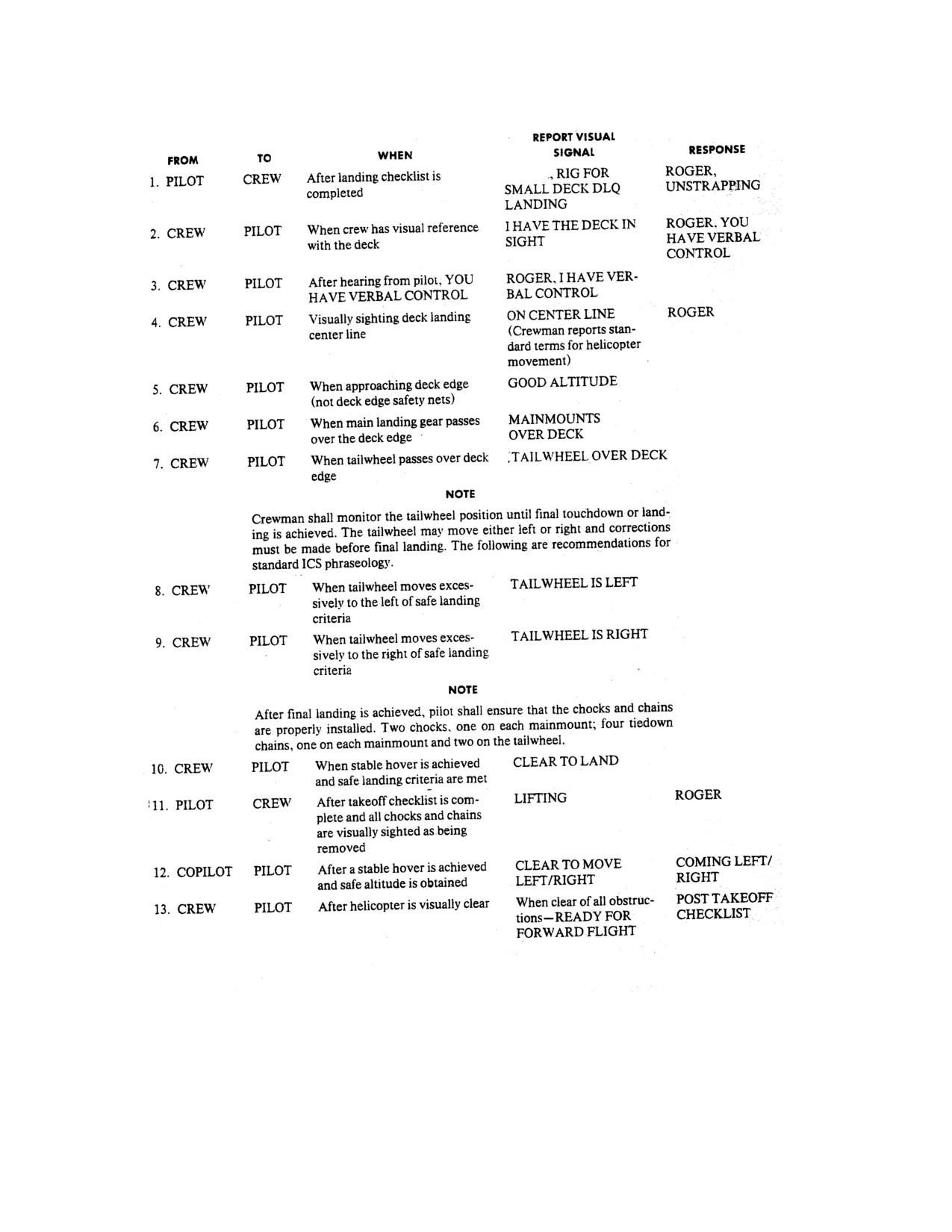
NAVAIR 01-230HLH-1
Figure 8-3. SS or MS Communications
Brief
8-16
ORIGINAL
NAVAIR 01-230HLH-1
CHAPTER 9
Special Procedures
9.1 FORMATION/TACTICS
9.1.1 Formation Composition.
See Figures 9-1, 9-2, and 9-3.
Helicopter formation flight is conducted to provide
improved operational capability, mutual safety and
9.1.1.1 Section. The section will consist of two
accountability, and esprit de corps. When properly
helicopters and will constitute the basic unit of a
executed, the formation leader can expect complete
formation.
flexibility of operation within the limitations of helicopter
maneuverability without danger of creating unsafe
9.1.1.1.1 Parade. The wingman will fly at a 45o bearing
conditions within his formation (free cruise) or delay while
abaft the beam on the appropriate side of the section
intentions are passed via signal or radio. The danger of
leader. The horizontal helicopter-to-helicopter separation
midair collision is greatly reduced when every flight
will be one rotor diameter minimum between rotor tips.
member knows where he is supposed to be and remains in
The vertical separation (step-up) will be 10 feet between
his designated space. The formation leader, by checking
closest components of helicopters. The wingman position
positions, can account at a glance for any missing aircraft.
in the parade section is fixed.
Few factors can create a greater pride in a unit than a
sharp, correctly executed formation doctrine. Few factors
9.1.1.1.2 Free Cruise. The wingman will fly within
can destroy unit pride more thoroughly than a poor
bearings about 60° abaft the beam of the section leader.
formation capability. Certain helicopter characteristics that
The horizontal helicopter-to-helicopter separation will be
should be considered in formation flight are the following:
about two to three rotor diameters. The vertical separation
(1) Formation flying is done in a step-up position to avoid
(step-up) will be 10 feet between closest components of
rotor wash and improve visibility and to provide a greater
helicopters. Normally, the free cruise wingman maintains a
safety margin between the rotary wing and the helicopter
position
30° off the axis of the lead helicopter during
ahead;
(2) there is no wing to observe to indicate
straight and level flight. During turns, he crosses over from
movement and changes of direction (at night it is difficult
one side of the section leader to the other to maintain
to ascertain when the lead helicopter changes direction and
position with minimum changes of power. Normally, when
altitude) (refer to Night Formation, paragraph 9.1.7); and
straight and level, a position on the outward extremity of
(3) loss of both helicopters in case of midair collision is
this segment is assumed in order that the leader may have
probable.
ready visual accountability and for avoidance of turbulence
or downwash problems.
Section and division leaders must endeavor to fly as
smoothly and as steadily as possible. It is imperative that
9.1.1.2 Division. A division will consist of two sections
their power settings remain as near constant as possible.
and be considered the main unit of a formation.
Constancy of heading and altitude should be a rule of
flight insofar as considered practical and within the
9.1.1.2.1 Parade. The second section leader is the
mission requirements. Quick stops in any formation or
number three man in the division. His position is opposite
rendezvous are strictly forbidden. Illustrations of free
of the wingman of section one. Section two wingman
cruise and parade formations can be found in Figures 9-1
always views both his section leader and division leader in
and 9-3. In judging altitude separation between helicopters,
line from his position. Normally, the number two
the horizon is considered level with the eye.
helicopter flies on the leader's starboard side.
9-1
ORIGINAL
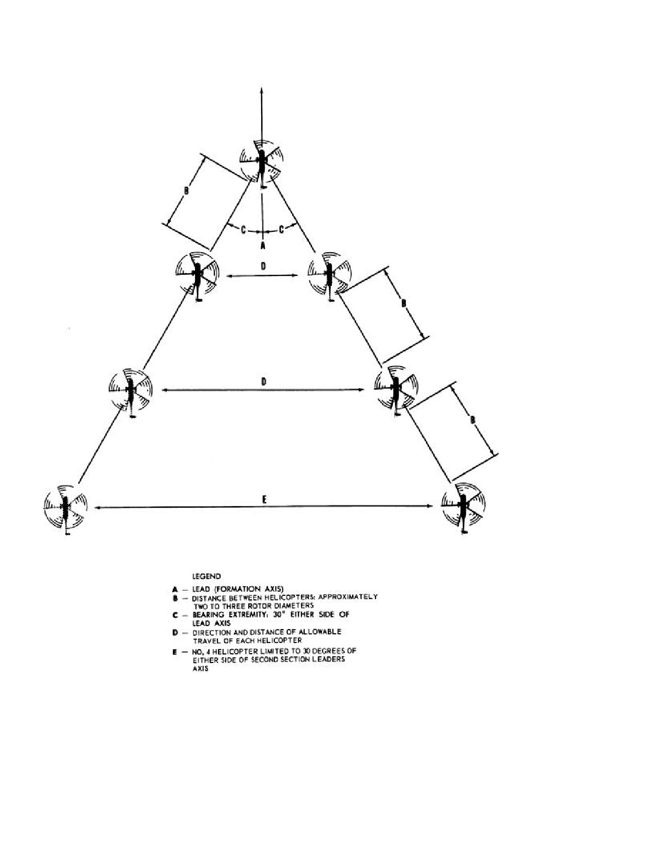
NAVAIR 01-230HLH-1
Figure 9-1. Free Cruise - Straight and Level
9-2
ORIGINAL
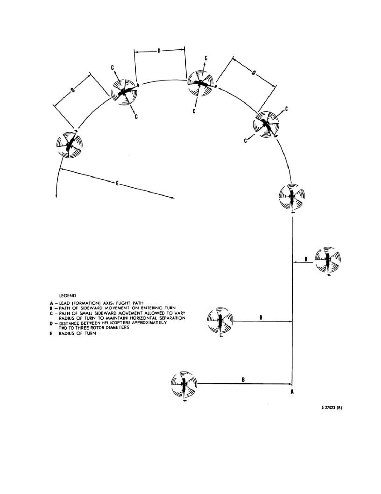
NAVAIR 01-230HLH-1
Figure 9-2. Free Cruise Turn
9-3
ORIGINAL
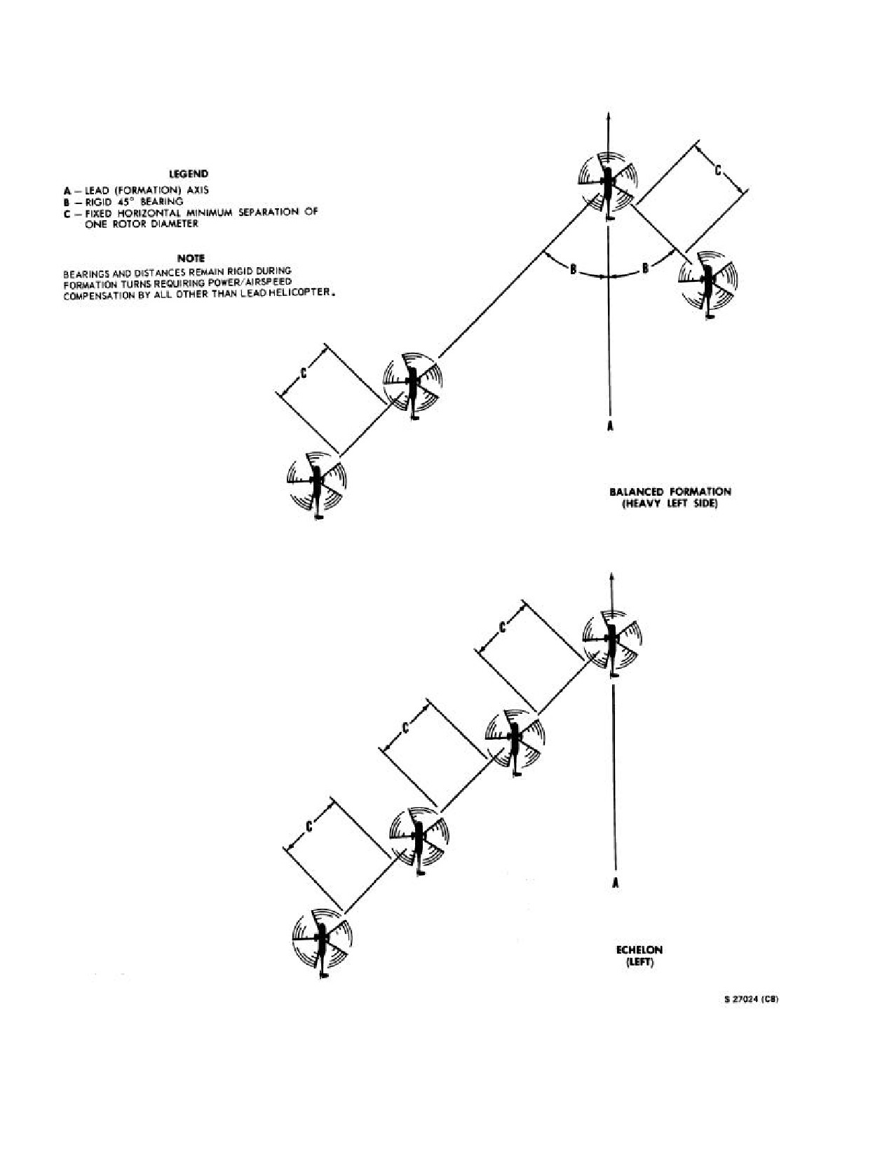
NAVAIR 01-230HLH-1
Figure 9-3. Parade
9-4
ORIGINAL
NAVAIR 01-230HLH-1
9.1.1.2.2 Free Cruise . The section leader will fly a
proficiency. Free cruise formation should be used for most
bearing about 60o abaft the beam of the division leader
operations. Parade formation is normally used only for
when in straight-and-level flight. The horizontal and
flyover of ships or base. Unless otherwise specified, the
vertical clearance will be about two to three rotor
formation leader should fly the lead from number one
diameters and
10 feet between closest components of
position. A change of lead should be passed only when the
helicopters respectively, from the section one wingman.
flight is in echelon and when positive change of lead is
During turns, the second section leader is free to cross over
indicated by visual or radio communications.
his section from side to side of the division leader to
maintain horizontal clearance with minimum changes of
9.1.4 Responsibility. The formation leader is
power. The second section leader's wingman will conform
responsible for flight briefing, conduct, and discipline of
to the requirements in the preceding paragraph. When a
flight. He should normally handle radio transmissions for
flight consists of more than four helicopters, any amount
the flight, including takeoff and landing clearances.
over four will form subsequent divisions. The last division
Division and section leaders are, responsible for main-
may be comprised of less than four helicopters. The
taining position and should be prepared to assist the lead
general rules applying to individual helicopters in
when required. All pilots are responsible for maintaining
formation may be expanded to apply to divisions of
positions as outlined, bearing in mind the necessity for
helicopters within the limits of safety and capability. The
being in view of lead plane when not maneuvering in free
side of the division on which the section is placed will be
cruise formation. No deviation of position, such as change
known as the heavy side, and the side of the leader's
of lead, shall be made until appropriate signals have been
wingman the light side.
given and acknowledged. When changes of lead are made,
the lead helicopter shall drift slightly away from the
9.1.1.3 Scouting Line. The scouting line formation is
echelon until safely clear, and then assume position on the
normally used, day or night, for flights proceeding to and
new formation. Safety shall govern all actions. Wingmen
from datum and for VFR cross-country navigation. This
must avoid flying behind leaders in straight-and-level
formation provides the best means for all helicopters in the
flight.
flight to conduct visual search and navigation en route,
while still affording the formation leader the means to
9.1.5 Briefing. Briefing for a formation flight is the
control the flight. The formation leader must always be
responsibility of the formation leader. The briefing shall
aware that relative motion is difficult to immediately
include the following information:
discern at these distances and any course changes,
especially at night, must be preceded by a radio call or
1. Rendezvous (type, area, altitude, positions, speed,
other prearranged signal.
and other pertinent data).
9.1.1.4 Other. Variations from the standard two-plane
2. Position of each helicopter in the flight.
section and four-plane division are authorized.
3. Communications
(whether by radio or hand
9.1.2 Rendezvous. Normally, the running rendezvous
signals).
should be employed. The leader should fly on course at
slow cruise and the flight should take positions as briefed.
4. Review of signals .
When the flight is joined, the leader should proceed at
cruise speed. An orbiting rendezvous may be used. The
5. Conduct of flight
(what maneuvers will be
leader should fly a right or left circular pattern at normal
accomplished, whether there will be changes of lead
cruise speed around a designated point until the flight is
within the section or within the division, etc.).
joined. In an orbiting rendezvous, helicopters should join
in column formation using the free cruise principle until
9.1.6 Signals. The following signals shall be used in
the leader rolls out. On departure heading. All rendezvousing
formation flying:
helicopters should pass across the designated point, pickup
altitude separation, and join on the helicopter ahead. Any
overshoot tendency should be taken to the outside of the
turn. There after, the flight should continue to maintain
free cruise formation at cruise speed unless otherwise
directed by the formation leader. The flight positions are as
briefed. Extreme caution should be taken during night
rendezvous because of reduction of perception of relative
motion.
9.1.3 Conduct of Flight. Formation flight should be
practiced in accordance with this doctrine during all
normal multiple helicopter movements in order to improve
9-5
ORIGINAL
NAVAIR 01-230HLH-1
9.2.1 Lost Sight During IFR Flight Procedures.
The reversal base course will be the reciprocal of the
MANEUVER
SIGNAL
flight's present heading.
DAY
NIGHT
Upon signal, the helicopters will acknowledge and
Join up
Radio and/or zoom
Radio
take the following action:
(fore-and-aft
movement of
Right
cyclic)
Radio or R
1.
Helicopters 1 and 4 will commence a standard
echelon
(.---.) on lights.
rate level turn away from the flight. They will call
(wingman)
Right arm up
passing 90o of turn and turn 170 o.
2.
Helicopter 2 will maintain heading and altitude;
Left echelon
Radio or K
(wingman)
(---,---) on
upon call from helicopter 1 passing through the 90o
Left arm up
lights.
position, it will reverse course 170o toward helicopter
1.
Echelon
Radio
3.
Helicopter
3 will maintain heading and im-
Pumping arm
mediately climb 500 feet; upon receiving the radio call
signal or radio
Break-up
Blink lights,
from helicopter 4 passing through the 90o position, it
Vertical rotary
then switch
will reverse course 170o toward helicopter 4.
motion on hand,
lights to bright
pass leads, and
to bright Radio.
It is essential that all helicopters maintain the airspeed
of the flight when the dispersal was commenced. The
kiss off. Radio.
flight will regroup when in a clear area.
9.1.7 Night Formation. Night formation should be
9.3 ADVANCED INSTRUMENT FLYING
flown in the same manner as day formation only when
complete visual reference between the helicopters can be
9.3.1 Instrument Check. Before leaving the ground or
maintained. Separation between helicopters may be
deck on an instrument flight, all instruments must be
adjusted as deemed prudent by members of the flight and
checked for proper operation. In addition, special emphasis
as directed by visibility conditions. Caution shall be taken
must be placed on checking for instrument calibration,
to avoid unnecessarily extending the formation to the
standby compass, gyro-stabilized compass, and all
extent of limiting its operational capability, mutual safety,
receivers and navigational equipment for proper operation.
or ability to maintain firm visual contact with other
Check proper settings for attitude indicators, altimeters,
formation members. At any time firm and complete visual
etc. The following airspeeds for the various conditions of
contact, cannot be maintained between helicopters, or
flight are designated as standard for the helicopter:
silhouette definition is lost, discontinue the formation
flight. Helicopters in formation at night should have
position lights on STEADY, DIM, or BRIGHT
(as
MANEUVER
SPEED
required) with the rotating Grimes light OFF, with the
Slow cruise
70 knots
exception of the last helicopter in each division turning
Normal cruise
100 knots
lights on STEADY BRIGHT and actuating its rotating
Fast cruise
120 knots
beacon.
9.3.2 Straight-and-Level Flight With Power
9.2 INSTRUMENT FLIGHT CONDITIONS IN
Changes. Straight-and-level flight is said to be the
FORMATION (Figure 9-4)
easiest to master for only one reason. It is a steady-state
maneuver and requires a minimum of cross-checking or
Normally formation flying will not be flown when the
scanning. However, in order to sustain this regime of
visibility is so low that helicopters are likely to lose sight
flight, a pilot must be quick to recognize any deviation of
of one another. When situations can be anticipated, the
his aircraft through the primary instruments, in this case,
leader will take such action as necessary to ensure
airspeed, altitude, and slaved compass. The attitude
formation integrity. Flight conditions permitting, the
indicator, if cross-checked properly, will greatly reduce the
formation should be maintained intact, return to a clear
normal scan time. When holding a steady airspeed with
area, and either land or file an IFR flight plan.
constant altitude and heading, the end result can only be
straight-and-level flight. At any given airspeed, the power
setting determines whether the helicopter is in level flight,
9-6
ORIGINAL
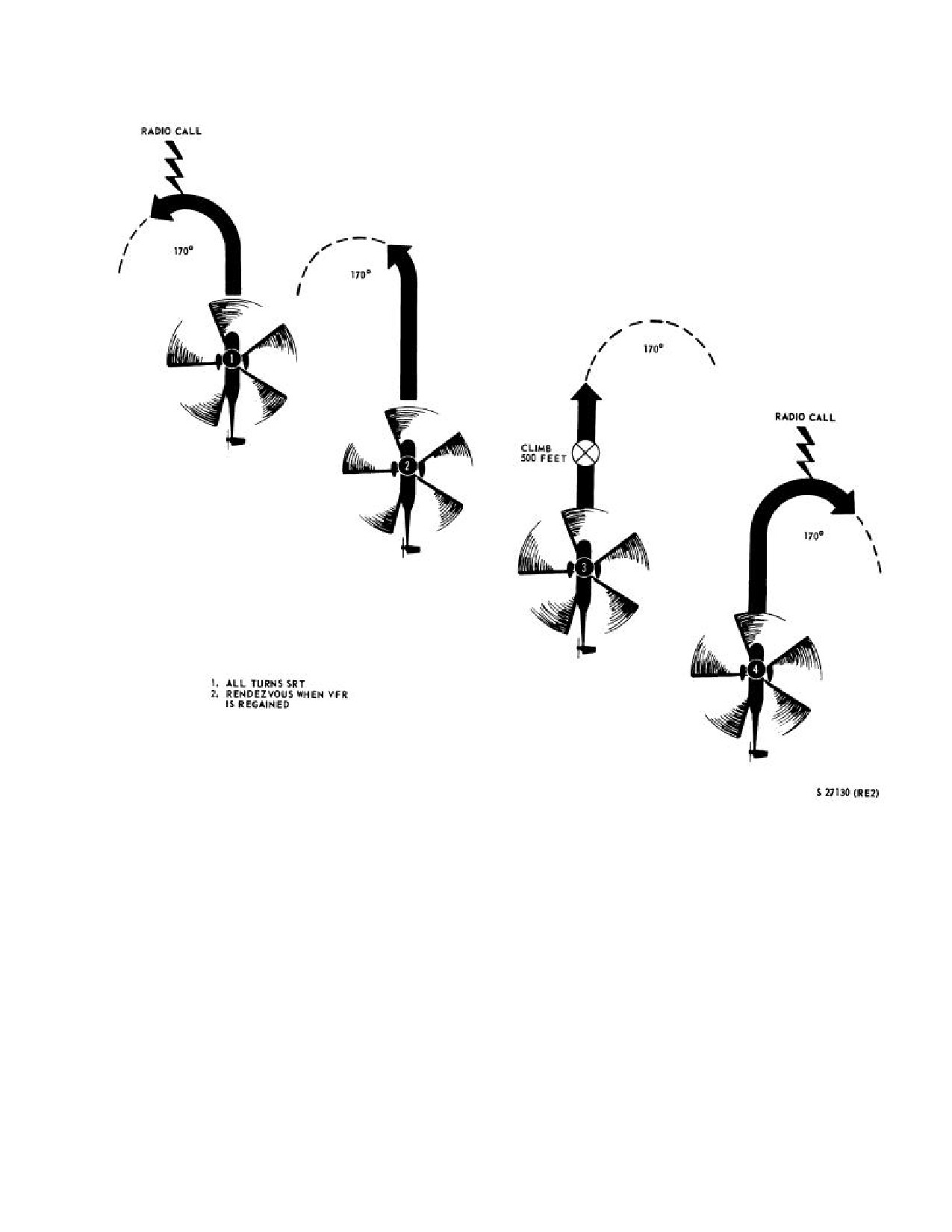
NAVAIR 01-230HLH-1
Figure 9-4. Four Plane Echelon IFR Dispersal
9-7
ORIGINAL
NAVAIR 01-230HLH-1
a climb, or descent. Airspeed shall be maintained during
conduct a good programmed descent with small power
climb and descent with very little movement of the cyclic
changes. The level off from a climb must be started before
control. Because of collective cyclic coupling, minor
reaching the desired altitude. Although the necessary
cyclic adjustments must be made to maintain constant
amount of lead varies with the helicopter and pilot
airspeed. When there is a reduction in power at low
technique, the most important factor is the vertical
airspeeds, the helicopter tends to pitch noseup; the
velocity. Normally, the lead for each 500 foot-per-minute
response is less noticeable at higher airspeeds. It will be
rate of climb will be 40 to 50 feet.
noted in single rotor configured helicopters that when
increasing power, the nose will yaw to the right Rudder
9.3.5 Unusual Attitudes. The importance of cross
changes are less necessary in this helicopter with power
checking the attitude indicator must be stressed. The
changes because of the collective yaw coupling.
attitude indicator is a nontumbling attitude indicator. If the
pilot uses the information presented by it correctly, he can
9.3.3 Turns. A turn made by reference to instruments
execute a recovery very easily. Airspeed should be
should be made at a definite rate. Except for practicing
checked simultaneously with the attitude indicator.
basic attitude maneuvers, a 3º per-second turn is usually
Checking the airspeed will also give an instant indication
used in programming precision instrument turns, as
of pitch attitude. As soon as the airspeed is adjusted, the
indicated by the turn-and-bank and attitude indicator.
altimeter becomes the primary pitch instrument. The angle
Airspeed determines the angle of bank necessary to
of bank and power should then be corrected. When a
maintain a standard rate turn. The standard rate turn is a
diving spiral is experienced, too much aft cyclic may
single needle width turn. Combining bank and pitch
aggravate the maneuver, will tighten the turn, and may
control requires a more rapid cross-check, and
result in a blade stall. It must be emphasized that when
interpretation must be accurate. This rapid cross-check
flying at mission altitude (150 feet and below) and at low
should be practiced until it has become second nature to
speeds, the attitude indicator will only give attitude and
the pilot, and as a result will allow him to direct more
rate of turn and will not present any information on rate of
attention to the other matters in the more advanced phase.
descent or accent. High sink rate can be experienced with
In entering a level turn, the attitude indicator is the primary
no change in attitude; therefore, radar altitude and rate
pitch attitude instrument, and the airspeed indicator is the
instruments should be given strong emphasis. While
primary power control instrument. During entry into the
reducing speed, the only possible way to expedite the
turn, increase power to compensate for loss of vertical lift
recovery is to level the wing attitude or at least decrease
caused by the banking of the helicopter. Remember not to
the angle of bank while simultaneously applying back
apply any corrective action until the flight instruments
cyclic. Do not chase the vertical speed indication on
indicate a deviation from the desired condition of flight.
recovery from any maneuver. This is a rate instrument and
Only experience in the helicopter can teach the pilot to
is fairly reliable in a steady-state but should be disregarded
anticipate certain conditions. Although there is no lag in
after a pitch change is made. Abrupt right and left inputs in
the slaved compass system, a lead should be established in
yaw will cause static instruments to indicate climb or dive,
rolling out of a turn. The amount of lead is determined by
respectively.
the individual pilot technique. A good rule of thumb is
one-third the degree of bank used in the turn; for example,
9.4
HELICOPTER
IN-FLIGHT
REFUELING
if you are using a
12º bank, then your rollout should
PROCEDURES (HIFR)
commence at a 4º lead. This lead will serve as an aid in
keeping the rollout smooth with less chance of an over-
9.4.1 General. HIFR is done to extend the on-station
shoot.
time and should be initiated with enough fuel remaining to
"bingo" to the nearest land base or carrier, if it is not
9.3.4 Constant Airspeed Climbs
- Descents and
possible to in-flight refuel.
Level-Offs. For any power setting and load condition,
there is only one airspeed that will give the most efficient
Daylight VFR refueling operations can be executed in the
rate of climb. In a climb at any predetermined constant
same manner as normal utility transfers of mail, cargo, or
airspeed and power setting, the pilot must accept whatever
personnel. Night in-flight refueling is an extremely
vertical velocity results. The entry to either is made by first
demanding operation and should be scheduled only as
adjusting the collective pitch and power to the desired
operational necessity requires. Hot refueling while rotors
power setting. The pitch attitude may be changed
are turning) is preferable to night in-flight refueling.
momentarily to hold the desired airspeed during the entry
or level-off; however, once the descent or climb has been
established and the airspeed stabilized, the pitch attitude
will remain constant. Use the vertical speed indicator only
after it is stabilized to maintain a standard rate of climb or
descent. By continuous cross-check, you will be able to
9-8
ORIGINAL
NAVAIR 01-230HLH-1
9.4.2 HIFR Systems. All HIFR-capable ships are
9.4.3 Normal Operation. For day and night HIFR
equipped with one of two different rigs for HIFR:
operations, the helicopter shall be positioned into the
relative wind over the HIFR deck marking. The wind
1.
Wiggins/North Island HIFR Rig - This rig has a ship's
should be 330o to 355o relative to the ship heading at a
hose (> l00 feet in length and all HIFR assembly that is a
velocity of 15 to 20 knots. Density altitude and true wind
10-foot section of 1-1/2 inch hose outfitted with a saddle
velocity will dictate whether a higher relative wind
for hoisting the HIFR assembly and hose to the aircraft.
velocity will be required to hover. During high true wind
Both ends of the HIFR assembly are equipped with female
conditions, the most stable hover with the least amount of
CCR fittings
(also referred to as Wiggins fittings). A
turbulence is normally encountered when the ship is at a
manual emergency disconnect lanyard (emergency release
speed slightly above that required to maintain steerageway.
"T" handle) is located near the Wiggins fitting on the HIFR
The ship speed should be adjusted to minimize the pitching
assembly that connects to the male Wiggins fitting in the
and rolling of the transferring ship in high seas.
helicopter. The second Wiggins fitting connects the HIFR
Assembly to the ships hose.
Note
WARNING
The Wiggins rig incorporates a manual
breakaway that requires a helicopter crew
The plane commander should ensure that a
member to pull an emergency disconnect
fuel sample is taken and is visually in-
lanyard to effect breakaway.
spected by a crewmember before fueling is
commenced.
2.
NATO Compatible High Capacity (HIFR
-This new
rig features a 100-foot long 2-inch lightweight hose, unisex
couplings, automatic emergency breakaway and facilitates
the use of either a CCR nozzle or a D-1 nozzle (SPR) for
HIFR operations. The NHC also has two major assemblies
The plane commander shall make sure that
- the 100-foot HIFR hose and the l0-foot HIFR assembly.
the Landing Checklist (including lowering
During routine HIFR operations, H-3 aircraft will receive
the landing gear) is completed before be-
the CCR nozzle attached to the HIFR assembly. This
ginning any approach (HIFR, transfer, etc.)
nozzle has a built-in
45-psi pressure regulator and an
to any ship to preclude a gear-up landing in
on/off flow control handle that allows the crewman to turn
case of an emergency or other unscheduled
on and off the fuel flow. Emergency breakaway is initiated
landing.
when 450 ±50 pounds of straight tensile pull is extended
on the automatic breakaway coupling. The mount for the
To request in-flight refueling, the pilots shall contact
hoist cable has been designed for self-alignment between
the refueling ship and request HI-DRINK, specifying type
the winch and deck tiedown to assure straight pull.
nozzle, and the amount of fuel in pounds required. Two
types of refueling nozzles are used:
Note
1.
The Parker nozzle (also referred to as the Dl/SPR
· Emergency breakaway is accomplished
nozzle) that is attached to the normal pressure-
automatically as the pilot pulls the
refueling receptacle on the starboard side of the
helicopter away from the ship. No
helicopter.
action by an air crewman is necessary.
2.
The Wiggins fitting (also referred to as the CCR
· Most U.S. helicopters are configured
nozzle) is attached to a receptacle in the aft cabin
with a CCR-type connection for HIFR
floor, or starboard side, aft of the cargo door, behind
refueling while all other NATO
the thermal barrier. When equipped with a Wiggins
countries with HIFR capability use an
fitting, any member of the crew may give the
SPR connection. Therefore, if a U.S.
command, "Break away." The crewman will
helicopter is HIFR’ed by another
immediately pull the emergency disconnect lanyard
member country's ship, it will be given
and report, "Hose clear."
an SPR nozzle and must carry an
adapter to convert it to a CCR-type
connection.
Further information on both HIFR rigs can found in
NWP 3-04.1.
9-9
ORIGINAL
NAVAIR 01-230HLH-1
Note
Note
· If the Wiggins fitting is not properly
The NI rig incorporates a manual emergency
seated, it will unseal when the fueling
breakaway system. An aircrewman must
hose is pressurized. The fueling hose
pull the emergency release "T" handle to
must be depressurized and partially
effect safe breakaway.
sucked back before it can be properly
resealed.
6.
Raise hoist to near seat position.
· When equipped with a Wiggins fitting, a
Note
slow pumping rate of less than
100
pounds per minute total for both tanks
The HIFR saddle must be raised as near as
may indicate a clogged fuel filter in the
possible to the hoist seat position to permit
helicopter receiving system. All five
proper and safe operation of the emergency
filters should be replaced with this
breakaway on either rig.
indication. Before attempting to replace
the filters, ensure that adjustments in the
7.
Signal ship to pressurize hose.
aircraft altitude and sufficient fueling
hose pressure do not correct the problem.
8.
Depress locking tab on the NHC rig's CCR nozzle
and slowly move the flow control handle into the on
or forward position.
· A light should be connected to the hoist
hook during night operations to give
Note
visual reference to hook position at all
times.
The Wiggins fitting (nozzle) on the NI rig
9.4.4 Communications. Signals to start and stop
does not have a flow control handle.
pumping shall be exchanged between the helicopter
crewman and the ship director with the radios as the
9.
Monitor fueling. Signal ship to shut off fuel be-
fore exceeding maximum gross weight or internal
backup means of communication. In addition to the normal
weight limits (or when pilot commands).
hover positioning reports, refer to Figure 9-5 for Standard
Terms.
Note
9.4.5 HIFR Procedures
Crewman has ability to stop fueling with flow control
handle on the NHC rig's CCR nozzle. In addition, this
1.
Lower the hoist and obtain fuel sample taken
CCR nozzle will automatically stop flow and the red
from nozzle of HIFR rig and confirm fuel is
acceptable.
pin behind the flow control handle will extend under
the following conditions: Pressure has exceeded 45
psi; tanks are full.
2.
Lower hoist cable for pick up of refueling rig.
10. Move NHC CCR nozzle flow control handle into
Note
closed or off position.
Should waveoff be required before either
HIFR rig is connected, the hoist cable
11. Signal ship to turn off pump.
should be cut immediately.
12. Disconnect NHC CCR nozzle or NI Wiggins
fittings from aircraft fuel fitting.
3.
Disconnect nozzle from hoist (or saddle).
4.
Connect the grounding wire.
13. Remove grounding wire.
5.
Connect CCR nozzle (NHC rig) or Wiggins fit-
14. Signal to move over flight deck and lower rig
ting (NI rig) to the receptacle in the aircraft. When
once over deck.
using the NI rig, crewman shall place one hand on the
emergency release "T" handle and keep it there until
15. Raise hoist after confirming HIFR disconnected
fueling is complete and the NI Wiggins nozzle has
and report to pilot, "Clear for forward flight."
been disconnected from the aircraft receptacle.
9-10
ORIGINAL
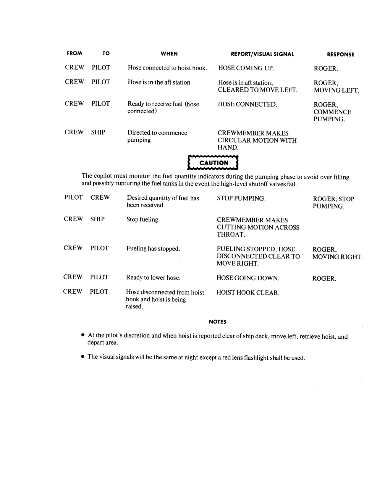
NAVAIR 01-230HLH-1
Figure 9-5. HIFR Communications
9-11
ORIGINAL
NAVAIR 01-230HLH-1
9.4.5.1 HIFR Emergency Procedures. During
Note
HIFR, when an emergency conditions is observed, or
when the command "Breakaway" is received the fol-
Be prepared for collective jumps when the
lowing emergency breakaway procedures should be
radar altimeter coupler acquires or loses the
followed depending on the type of HIFR rig being used:
height of the ship fantail.
1.
NI HIFR Rig - The crewman, with his hand on
3.
Once the HIFR hose has been picked up, the
the emergency release "T" handle, must pull the
aircraft should be positioned to receive fuel.
device, thus, releasing the HIFR hose and letting it fall
Recommended position for HIFR is rotors clear of the
back to the ship. The pilot then flies away from the
ship and a hover altitude of 40 feet. While hovering
ship.
alongside the ship, the coupler system should be used.
On pilot command "Coupler," the copilot engages the
2.
NHC HIFR - This rig incorporates an automatic
coupler, reports, "Engaged," and makes adjustments as
emergency breakaway. No crewman action is
directed by the pilot.
necessary to disconnect system. Once the NHC rig has
been attached, the pilot can effect emergency
4.
Once refueling is completed, the coupler should
breakaway at anytime by flying away from the ship.
be disengaged prior to recrossing the deck. Departure
from the HIFR ship shall be conducted using the
If either rig fails to disconnect when an emergency
procedures for night launches from air-capable ships.
breakaway is attempted, it will be necessary for the
crewman to quickly dis engage the nozzle and grounding
5.
Upon completion of the refueling evolution, make
wire from the aircraft and cut the hoist cable.
a 20° turn to the left and after receiving a "ready for
forward flight" report from the crewman, slide clear of
the ship to port. Use standard automatic hover
departure procedures to climb to
150 feet. The
anticollision light and exterior position lights reset as
desired either before the departure or upon completion
If the hoist cable is cut with either HIFR rig
of the climbout.
connected to the aircraft fitting, the
possibility exits that the HIFR rig or aircraft
9.5
ENGINE GASPATH PROCEDURES
fitting could rupture, causing pressurized
fuel to leak into the cabin.
Engine gaspath is a procedure designed to reduce
corrosion of the engines because of the saltwater
9.4.6 Night/Low Visibility HIFR Approach
environment in which the helicopter is operated. This
procedure is normally carried out after flights over water
1.
The Approach/Landing Procedures, paragraph
during which hovering was conducted, or as required.
8.4.3, described for night or IMC approaches to air-
capable ships shall be used for HIFR. Hose pickup
will be accomplished instead of landing.
2.
Prior to commencing the approach, complete the
Alternate Approach Checklist. When a green deck
If conditions prevent spreading the rotor
signal is received from the ship and the helicopter is
blades for No. 2 engine start, ensure a mini-
ready to come over the stern, the copilot will secure
mum of 400 psi rotor brake pressure. If rotor
the forward rotating anticollision light about 100 yards
brake must be pumped up, make sure that
astern of the ship. The pilot takes control of the
ground personnel are available to hold the
aircraft and completes the approach visually. The pilot
blades.
in the left seat should adjust the ALTITUDE set pot as
directed by the pilot in the right seat to maintain
minimum safe altitude for desired obstruction clearance.
9-12
ORIGINAL
NAVAIR 01-230HLH-1
9.5.1 Freshwater Wash
water valve. As wash cycle continues, do not
allow Ng to decrease below 15 percent with water
Note
valve open. Secure water wash 5 seconds before
securing starter. Do not exceed 30-second starter
· Allow engine to cool for
10
limitation.
minutes after shutdown.
20.
No. 2 engine emergency start - ON.
· If ambient temperature is below 5
oC
(40oF), P3 line shall be
21.
No. 2 engine - ENGAGE STARTER.
disconnected from fuel control.
Motor until Ng peaks (19-percent minimum), open
1.
Preflight helicopter.
wash cart valve, and introduce water. When Ng
decreases to 15 percent, close valve. Wait until Ng
2.
Circuit breakers and switches - CHECKED.
accelerates to 19 percent before reopening water
valve. As wash cycle continues, do not allow Ng
3.
Brakes and tailwheel - CHECKED.
to decrease below 15 percent with water valve
open. Secure water wash
5 seconds before
4.
FUEL DUMP switches - OFF.
securing starter. Do not exceed 30-second starter
limitation.
5.
External power - CONNECTED.
22. No. 2 engine emergency start - OFF.
6.
External power switch - RESET, THEN ON.
9.5.2 No. 1 Engine. Burnout. Operate engines
7.
Landing gear - CHECKED.
for 3 to 5 minutes to dry out residual water.
8.
Start mode switch - NORMAL.
Note
9.
Blade panel, hoist, and trim, CREW
If engines cannot be started, go to
ICS - CHECKED/ON.
Engines Gaspath Procedures, paragraph
9.5.7.
10. Anti-ice - CHECKED AS REQUIRED.
1. Ignition switches - NORMAL.
11. Ignition switches - OFF.
2.
Emergency start switches - OFF.
12. Accessory drive switch - FORWARD, LIGHT
ON.
3.
Rotor brake - 320 PSI MINIMUM.
13. Manual throttles and speed selectors -FREE,
4.
No. 1 firewall valve - OPEN.
OFF.
5.
Battery - ON.
14. Emergency start switches - OFF
6.
No. 1 engine - START.
15. Rotor brake
-
CHECKED
(320 PSI
MINIMUM).
7.
All gauges - CHECKED.
16. Fire warning, caution, and advisory panels -
8.
Speed selector - 104-percent Nf.
CHECKED.
9.
Boost pumps - OFF.
17. Fuel panel/quantity - OFF/CHECKED.
10. Generators - ON.
18. Lights - AS REQUIRED.
11. External power - DISCONNECTED.
19. No.1 engine - ENGAGE STARTER.
9.5.3
Blade Spread. Only required ashore.
Motor until Ng peaks
(19-percent minimum),
open wash cart valve, and introduce water. When
1.
Servo sensor - CHECKED.
Ng decreases to 15 percent, close valve. Wait until
2.
Area clear - CHECKED.
Ng accelerates to 19 percent before reopening
9-13
ORIGINAL
NAVAIR 01-230HLH-1
3.
SAFETY VALVE switch - OPEN.
9.5.5 Automatic Blade Fold
4.
Blade fold MASTER switch - ON.
1.
Droop and flap restrainers - IN PLACE.
5.
BLADES FOLD-SPREAD switch - SPREAD.
2.
No. 1 blade position - CHECKED.
6.
BLADE SPREAD light - ON.
3.
No. 1 engine speed selector - 104-percent Nf.
7.
SAFETY VALVE switch - CLOSED.
4.
Rotor brake lever - ON.
8.
Rotor brake - 320 PSI MINIMUM.
5.
No. 2 engine fuel firewall valve - CLOSE.
9.
Blade fold MASTER switch - OFF.
6.
Automatic stabilization equipment (ASE) -
10.
BLADES FOLD SPREAD switch - OFF.
OFF.
11.
Blade fold panel lights - CHECKED.
7.
Area - CLEAR.
12.
Servo pressure - CHECKED.
8.
Collective pitch lever - MINIMUM PITCH.
9.5.4
No. 2 Engine Burnout
9.
Cyclic stick - NEUTRAL.
1.
Start mode switch - NORMAL.
10. SAFETY VALVE switch - OPEN.
2.
No. 2 firewall valve - OPEN.
11. Blade fold MASTER switch - ON.
3.
Anti-ice - AS REQUIRED.
12. Rotor brake lever OFF.
4.
Rotor brake
-
CHECKED
(400
psi
13. BLADES FOLD-SPREAD switch - FOLD.
minimum).
14. Rotor brake lever (No. 1 position light on) -
5. No. 2 engine - START.
ON.
6.
All gauges - CHECKED.
15. BLADE FOLD light - ON.
7.
Boost pumps - OFF.
16. SAFETY VALVE switch - CLOSED.
8.
Allow both engines to operate for 3 to 5
17. Blade fold MASTER switch - OFF.
minutes (No. 1 at 104-percent Nf, No. 2 at GRD
IDLE).
18. BLADES FOLD-SPREAD switch - OFF.
9.5.6 No.1 Engine Secure
WARNING
1. Speed selector - GRD IDLE.
The rotor brake will not prevent rotor
2. Speed selector
(less than
60-percent Ng)
-
movement with the No. 1 engine in
SHUT OFF.
flight position above ground idle or
with the No. 2 engine above ground
3. Fuel switch - CLOSE.
idle. Personnel injury and/or helicopter
damage may occur as a result of
4. All engine instruments - CHECKED.
inadvertent rotor engagement.
5. All switches - OFF.
9.
No. 2 speed selector - SHUTOFF.
10. No. 2 fuel switch - CLOSED.
11. No. 2 engine instruments - CHECKED.
9-14
ORIGINAL
NAVAIR 01-230HLH-1
9.5.7 Engine Gaspath Procedures
18. Lights - AS REQUIRED.
Note
19. No. 1 engine - ENGAGE STARTER.
· Allow engine to cool for
10
Motor engine until Ng peaks (19-percent mini-
minutes after shutdown.
mum). Introduce gaspath mixture while
continuing to motor starter until Ng drops to 15
· P3 line shall be disconnected at the
percent or 30-second starter limitation is reached,
2-o'clock
position
on
the
whichever comes first. Secure gaspath injection
compressor rear frame at all
and starter simultaneously.
temperatures whenever soap or
solvent is sprayed into the engine.
20. No. 2 engine emergency start - ON.
Whenever water is sprayed into the
engine, the P3 line shall, be
21. No. 2 engine - ENGAGE STARTER.
disconnected at the
2-o'clock
position on the compressor rear
Motor engine until Ng peaks
(19-percent
frame if ambient temperature is
minimum). Introduce gaspath mixture while
below 5 0C (40 0F).
continuing to motor starter until Ng drops to 15
percent or 30-second starter limitation is reached,
1.
Preflight helicopter.
whichever comes first. Secure gaspath injection
and starter simultaneously.
2.
Circuit breakers and switches - CHECKED.
22. No. 2 engine emergency start - OFF.
3.
Brakes and tailwheel - CHECKED.
Note
4.
FUEL DUMP switches - OFF.
Allow cleaner to soak for 15 to 20
5.
External power - CONNECTED.
minutes. Rinse within 30 minutes.
6.
External power switch - RESET, THEN ON.
9.5.8 Gaspath Engine Rinse
7.
Landing gear - CHECKED.
1.
Do steps
1 to
25 of Freshwater Wash
procedures checklist.
8.
Start mode switch - NORMAL.
9.5.9 Gaspath Engine Burnout
9.
Blade panel, hoist, trim, and crew ICS
-
CHECKED/ON.
Note
· Allow engine to air dry 5 minutes
10. Anti-ice - CHECKED AS REQUIRED.
before burnout.
11. Ignition switches - OFF.
· If engine cannot be started, motor
starter for 30 seconds.
12. Accessory drive switch - FORWARD, LIGHT
ON.
1.
Do steps 1 to 12 of No. 1 Engine Burnout
Checklist and steps
1 to 10 of No. 2 Engine
13. Manual throttles and speed selectors -FREE,
Burn-out Checklist.
OFF.
2.
Blades must be spread ashore.
14. Emergency start switches - OFF.
Note
15. Rotor brake
- CHECKED (320 PSI
MINIMUM).
Reconnect P3 line to fuel control if
necessary.
16. Fire warning, caution, and advisory panels -
CHECKED.
17. Fuel panel/quantity - OFF CHECKED.
9-15
ORIGINAL
NAVAIR 01-230HLH-1
9.6
ADDITIONAL MISSIONS/STATIC
a. Interior.
DISPLAYS
(1)
Switches/control positions.
The helicopter can be used for the following
utility missions: personnel and mail transfers, plane
(2)
Foreign objects.
guard for carrier air operations, SAR, torpedo/rocket
firing spotting and drop evaluation, and other support
(3)
Rudder control cable security.
operations.
(4)
Cleanliness.
9.6.1 Static Displays. The following safety
procedures shall be closely adhered to when
b.
Exterior.
displaying UH-3 helicopters to the general public:
(1)
Antennas.
1.
Helicopter shall be chocked and all safety
pins installed.
(2)
Panels .
2. Battery shall be disconnected and door
(3)
Foreign objects.
secured.
(4)
Refueling and defueling systems.
3. All marine smoke markers PDCs shall be
removed from interior of the helicopter.
(5)
Areas around helicopter
for
clearance and cleanliness.
4.
CADs shall be removed from rescue hoist.
5.
Thermal barrier will be secured.
6.
Blades should be spread; however, if folded,
boots shall be attached.
7.
A rope-type barrier should be used around
the helicopter to control entry and exit point.
8.
Visitors will enter and depart from personnel
door unless an appropriate platform is available
for cargo door use.
9.
No more than four visitors should be
allowed in the helicopter at one time.
10. All visitors shall be escorted while inside the
helicopter, and a watch shall be posted to
observe visitors around the exterior of the
helicopter.
11. No visitors shall be allowed on the engine or
transmission deck.
12. Upon completion of static display, the
helicopter shall receive a thorough inspection,
paying particular attention to the following areas:
9-16
ORIGINAL
NAVAIR 01-230HLH-1
9.7
SPECIAL CHECKLISTS (ET)
9.7.1 Mission Checklist. The Mission Checklist is designed to safely shut down the main rotor head and reduce noise
levels when the executive transport mission requires expeditious arrival and departure with minimal noise and rotor wash. Its
use is at the discretion of the helicopter commander.
9.7.1.1 Shutdown.
After Landing:
1.
APU æ START.
2.
APU generator æ ON.
3.
ASE æ OFF.
4.
Tailwheel æ LOCKED.
5.
Brakes æ ON.
6.
No. 1 speed selector æ GROUND IDLE.
7.
Accessory drive switch æ FWD, LIGHT ON.
8.
No. 2 speed selector æ GROUND IDLE.
9.
Droop stops æ IN.
10.
No. 2 speed selector æ SHUT OFF.
11.
Rotor brake æ ON (less than 45-percent Nr).
12.
No. 2 engine instruments æ CHECKED.
9.7.1.2
Start.
1.
Rotor brake æ CHECKED.
2.
No. 2 engine æ START.
3.
All gauges æ CHECKED.
4.
Boost pumps æ OFF.
5.
ASE æ OFF.
6.
Shoulder harness (all stations) æ LOCKED.
7.
Collective æ MINIMUM, COPILOT MONITOR.
8.
Area æ CHECK CLEAR.
9.
Rotor æ ENGAGE.
10.
Nr æ 102 PERCENT.
11.
No. 1 speed selector æ GROUND IDLE.
9-17
ORIGINAL
NAVAIR 01-230HLH-1
12.
Accessory drive switch æ AFT, LIGHT OUT.
13.
Nr and torques æ 104 PERCENT MATCHED.
14.
Generators æ RESET.
15.
APU æ SECURE.
9.7.2 Alert Checklist. The Alert Checklist may be used when a mission requirement exists to expeditiously start,
engage, and prepare for takeoff. The Alert Checklist shall not be used on a routine basis to avoid system checks. The
Normal Checklist, through systems checks, shall be completed prior to using the Alert Checklist.
9.7.2.1
Cockpit Setup.
1.
Anticollision light switch æ ON.
2.
Other light switches æ AS DESIRED.
3.
Radio masters æ ON.
4.
Beeper trim æ ON.
5.
Ignition switches æ ON.
6.
Accessory drive switch æ ACCESS DR.
7.
Engine speed selectors æ SHUT OFF.
8.
Emergency start switches æ OFF.
9.
Start mode switch æ NORMAL.
10.
Rotor brake lever æ CHECKED (320 psi minimum).
11.
Fuel shutoff valves æ CLOSED.
12.
Crossfeed æ OFF.
13.
Boost pumps æ OFF.
14.
UHF, VHF, ICS, RAD ALT, NAVAIDS æ AS DESIRED.
15.
All other switches æ OFF.
9.4.7.2.2
Start.
1.
Battery æ ON.
2.
APU æ START.
3.
APU generator æ ON.
4.
Fuel valves (both) æ OPEN.
5.
No. 1 engine æ START.
9-18
ORIGINAL
NAVAIR 01-230HLH-1
6.
All gauges æ CHECK.
7.
Rotor brake lever æ CHECKED (320 psi minimum).
8.
No. 2 engine æ START.
9.
All gauges æ CHECK.
9.7.2.3 Engagement.
1.
Area æ CLEAR.
2.
Collective æ MINIMUM (copilot monitor).
3.
Rotor æ ENGAGE, SET 102-PERCENT Nr.
4.
Accessory drive switch æ AFT, LIGHT OUT.
5.
No. 1 engine æ ADVANCE 104-PERCENT Nr. TORQUES MATCHED.
6.
Generators æ ON.
7.
APU æ SECURE.
8.
Landing gear lockpins, chocks æ REMOVED.
9-19
ORIGINAL
NAVAIR 01-230HLH-1
This Page Left Blank Intentionally
9-20
ORIGINAL
NAVAIR 01-230HLH-1
CHAPTER 10
Functional Checkflight Procedures
10.1 FUNCTIONAL CHECKFLIGHT
PROCEDURES
10.1.3 Designation of Functional Checkflight
Aircrewman. The unit's aircrew training and
The functional checkflight procedures listed herein are
qualification instruction shall dictate the requirements as
for the purpose of promulgating standard criteria for
developed by the quality assurance officer and/or the
ground and flight functional checks for this helicopter. All
crewchief recommendation board.
functional checkflights shall be flown by qualified
functional checkpilots designated in writing by the unit
10.1.4 Qualifications for Functional Checkflight
commander. The pilot seat shall be occupied by a
Aircrewman. The following shall be considered the
functional check pilot designated by the squadron
minimum requirement for qualification as a functional
commander. The copilot seat shall be occupied by a
checkflight aircrewman:
qualified helicopter pilot. The flight shall be conducted
with the minimum crew necessary, and the crew shall be
1. Designated utility aircrewman or special mission
fully equipped for flight. Functional checkflights shall he
crewman.
in accordance with OPNAVINST 3710.7 and 4790.2.
2. Complete NAESU VATS training course.
10.1.1 Designation of Pilots. The helicopter
maintenance officer shall recommend designated
3. Complete local FCF training syllabus and FCF
helicopter commanders who have completed the
checkride.
indoctrination program to the commanding officer, via the
operations officer, for designation as functional checkflight
4. Be designated functional checkflight aircrewman by
pilots. The operations officer shall forward such
the unit commanding officer.
recommendations with appropriate comments to the
commanding officer.
10.1.5 Conditions Requiring Functional Checkflight.
Functional checkflights are required under the following
10.1.2 Functional Checkflight Pilot Qualification.
conditions, after the necessary ground check and before
The following shall be considered minimum for functional
release of the helicopter for operational or training flights:
checkflight pilot qualification:
A. Functional checkflights shall be accomplished at the
1. Functional checkflight pilot ground and flight
completion of helicopter rework before acceptance
checkout.
and/or transfer of helicopters. All checklist items
required are prefixed A.
2. Read and initial functional checkflight pilot folder.
B. Controllability checkflights shall be accomplished
3. Read pertinent sections of the Maintenance
whenever the helicopter has been rerigged. Minimum
Instruction Manuals.
checklist items required are prefixed B.
4. Read applicable general engine bulletins.
C. Engine change and/or fuel control adjustment
checkflights shall be done whenever an engine or fuel
5. Maintain familiarity with this flight manual
control has been replaced and/or a stator vane actuator
(particularly Chapter 10).
adjustment has been performed and are prefixed C.
6. Completion of a locally prepared ground training
D. Gearbox serviceability and/or overhaul check-
syllabus for prospective functional check-flight pilots.
flights shall be done as required in the Maintenance
Instruction Manuals. Minimum checklist items
required are prefixed D.
10-1
ORIGINAL
NAVAIR 01-230HLH-1
E. To be completed subsequent to the following
level is influenced by the many individual frequencies of
maintenance actions:
vibration and combinations thereof. Many multiples of a
basic frequency are felt, and often two or more different
1. Removal and installation/replacement or adjustment
superimposed frequencies create beats. The overall
of these items:
magnitude is the result of the amplitudes of all the
frequencies. It would be difficult for the pilot to completely
a. Rotary wing head.
separate all the types of vibrations encountered. Generally,
these are divided into low, medium, and high frequencies.
b. Swashplate.
Varying magnitudes of all three types of vibrations are
often present in an individual helicopter. Only through
c. Rotary rudder head.
experience will the pilot be able to judge what is normal to
the model and what is abnormal and correctable. Figure
d. Pitch change beam.
10-1 is a reference for post maintenance vibration analysis.
e. Any pitch change rod/link.
10.1.7.1
Low-Frequency Vibrations.
2. Removal and replacement of main rotary wing
10.1.7.1.1 One Times Main Rotor Speed (One Per
blade.
Revolution). This vibration emanates from the rotary
wing system and is generally caused by rotary wing head
3. Removal and replacement of rotary rudder blade
or blade imbalances. It produces a rotary excitation of the
(auto rpm check not required).
fuselage that feels like a lateral oscillatory roll or wallow
to the pilot on deck. In flight, it feels like a vertical bounce.
Vibration Analysis/Main Rotor Track Balance/Tail
If this vibration is present in all regimes of flight,
Rotor track and balance
(VMT). To be completed
troubleshoot rotary wing blades. The most probable causes
when vibration analysis is required in conjunction with
are the following:
another profile. (Figure 10-1)
1. Rotary wing blades out of track. A blade track ad-
10.1.5.1
General Functional Checkflights.
justment is not warranted even though the blades
General functional checkflights shall include such items as
appear to be slightly out of track if a one-per-revolution
blade change, tail rotor control cable replacement, dual-
vibration is not present. When using the electronic
gyro change, horizontal stabilizer replacement, and other
blade tracking equipment, if one or two blades are
circumstances as directed by the maintenance officer based
more than three-fourths inch out of track, as compared
on the scope of maintenance accomplished and the effect
to blade No. 1, or if any three blades are not within
of such maintenance on safety and reliability of operation.
one-half inch spread, troubleshoot in accordance with
Before such flight a determination shall be made by the
the tracking procedures. Out-of-track condition could
maintenance officer along with the quality assurance
be caused by damaged rotary wing blade trailing edges,
officer as to which items on the functional checkflight card
or rotary wing blade static balance beyond tolerances.
shall be done for the proper and safe functioning of the
helicopter.
2. Worn or loose control rod end bearings. If the
vibration is present in a hover only, the cause could be
10.1.6 Blade Tracking. Whenever a track is required
item 1 above as well as rotary wing blade dynamic
and there is no intent to fly, the cockpit shall be manned by
balance beyond tolerances.
a designated HAC. If there is intent to fly, then the cockpit
shall be manned by a designated functional checkflight
10.1.7.1.2 Ground Roll. This is a one-per-revolution
pilot
lateral roll of the helicopter that often occurs during rotor
engagement and is due to the in-plane misalignment of the
Note
rotary wing blades causing an out-of-balance condition in
the main rotor system. When the rotor attains flying speed,
All personnel in the helicopter shall be
centrifugal force normally aligns the blades and the
strapped
in
securely
during each
vibration disappears. If the vibration continues with the
engagement.
rotor up to speed at flat pitch, but disappears when the
helicopter is lifted into a hover, then the cause could be
10.1.7 Vibration Troubleshooting. The inherent
static balance of rotary wing blades or the landing gear
vibrations in any helicopter are those created by the
struts need servicing.
mechanical functions of the engines and transmission
systems, dynamic action of the main and tail rotors, and
aerodynamic effects on the fuselage. The overall vibration
10-2
ORIGINAL

NAVAIR 01-230HLH-1
VIBRATION ANALYSIS MATRIX
V
B
N
I
L
O
B
A
T
R
D
E
A
E
S
T
I
T
O
R
N
A
V-INDICATES VIBRATION ANALYSIS REQUIRED AS PER NOTES
S
C
M- INDICATES MAIN ROTOR TRACK/BALANCE
K
T-INDICATES TAIL ROTOR TRACK/BALANCE
ACCEPTANCE INSPECTION
V
M/T
9
AIRCRAFT NOT FLOWN IN EXCESS OF 30 DAYS
V
10
ENGINE REMOVAL / REPLACEMENT / REINSTALL
V
1
ENGINE H.S.S. REMOVAL / REPLACEMENT / REINSTALL
V
1
ENGINE H.S.S. DISCONNECT / ROTATION
V
1
ENGINE INBD MOUNT REMOVAL / REPLACEMENT / REINSTALL
V
1
ENGINE OUTBD MOUNT REMOVAL / REPLACEMENT / REINSTALL
V
1
MAIN GEAR BOX REMOVAL / REPLACEMENT / REINSTALL
V
M
1,7,8
TAIL GEAR BOX REMOVAL/ REPLACEMENT / REINSTALL
V
T
3
IGB REMOVAL / REPLACEMENT / REINSTALL
V
3
MAIN GEAR BOX INPUT SEAL REPLACEMENT
V
1
TAIL TAKEOFF DRIVE SEAL REPLACEMENT
V
4
IGB INPUT / OUTPUT SEAL REPLACEMENT
V
3
TGB INPUT SEAL REPLACEMENT
V
3
TGB PITCH CONTROL SHAFT SEAL REPLACEMENT
V
3
REPORTED AIRFRAME VIBRATION / SHUFFLE
V
M/T
10
PITCH LINK REPLACEMENT / ADJUSTMENT
V
T
3
PITCH CONTROL ROD REPLACEMENT / ADJUSTMENT
M
MAIN ROTOR BLADE REMOVAL / REPLACEMENT / REINSTALL
M
TAIL DRIVE SHAFT / THOMAS COUPLING REMOVAL /
V
10
REPLACEMENT REINSTALL / DISCONNECT / ADJUSTMENT
TAIL DRIVE SHAFT #2 BEARING DISCONNECT/ REMOVAL /
V
4
REPLACEMENT / REINSTALL
VISCOUS DAMPED BEARING REMOVAL / REPLACEMENT / INSTALL
V
2
MAIN ROTOR HEAD REMOVAL / REPLACEMENT / REINSTALL
V
M
7
TAIL ROTOR HEAD REMOVAL / REPLACEMENT / REINSTALL
V
T
3
TAIL ROTOR PITCH BEAM REPLACEMENT
V
T
3
TAIL ROTOR BLADE REMOVAL / REPLACEMENT
V
T
3
TAIL DISCONNECT JAW REMOVAL / REPLACEMENT / REINSTALL
V
3
MAIN ROTOR FLIGHT CONTROLS RIGGING
M
TAIL ROTOR FLIGHT CONTROLS RIGGING
T
PHASE A
V
M/T
3,7,8
PHASE B C D
V
3,7,8
NOTES:
1) HIGH SPEED SHAFT GROUND ONLY
2) STATION 391 GROUND ONLY
3) STATION 649 GROUND ONLY
4) STATIONS 290 AND 391 GROUND ONLY
5) STATIONS 391 AND 649 GROUND ONLY
6) STATIONS 290, 391, AND 649 GROUND ONLY
7) STATION 290 GROUND, HOVER, AND FORWARD FLIGHT
8) STATION 391 GROUND, HOVER, AND FORWARD FLIGHT
9) HIGH SPEED SHAFT, STATION 649 (GROUND ONLY), STATIONS 290 AND 391 GROUND,
HOVER AND FORWARD FLIGHT
10) AS APPROPRIATE FOR RELATED MAINTENANCE ACTION REQUIRED / PERFORMED
Figure 10-1. VIBRATION ANALYSIS MATRIX
10-3
ORIGINAL
NAVAIR 01-230HLH-1
10.1.7.1.3 Two-Thirds Times Main Rotor Speed
heavy vibratory loads on the rotor head as the spanwise
(Two-Third Per Revolution). In flight conditions that
center of lift of each blade moves in and out. It is felt as a
result in high rotary wing blade flapping angles, a
combination of vertical and lateral shake at the same
condition of negative pitch lag coupling can occur in
frequency with the vertical being the most noticeable. The
which the capability of rotor system damping is exceeded.
battery vibration absorber is designed to minimize the
This condition called pitch lag oscillation is felt as a heavy
vertical portion of this vibration. The battery absorber is
lateral rotary oscillation that can become increasingly
"tuned" to operate best at
100-percent Nr. If five-per-
violent if airspeed is allowed to build up or Nr is further
revolution vibration is excessive at high forward speeds,
decreased. It is not desirable to remain in this condition.
do this: check the battery mechanical vibration absorber.
Immediate corrective action is to lower the collective,
Check for improper torque on main gearbox tiedown bolts.
increase rotor speed, and reduce airspeed and/or the
severity of the maneuver.
10.1.7.2.2 One Times Tall Rotor Speed. This
vibration (1,243 cycles per minute at 100-percent Nr) is
Pitch lag oscillation may be encountered during flight
usually due to rotary rudder blade pattern dissymmetries
at forward cg helicopter loadings with high forward speeds
and is not easily identifiable by the pilot because of its
or right sideward flight or hovering in a right crosswind. It
proximity to five times rotary wing frequency. It is
can also be encountered at any cg loading at forward
evidenced by an increase in overall helicopter vibration.
speeds that exceed the allowable limit, high gross weight;
Since this frequency is close to five-per-revolution (1,015
low rotor speed; steep, level, or climbing turns; gusty wind
per minute), the two frequencies sometimes modulate
conditions; or during abrupt pullup from a dive. If two-
(beat) at a frequency of 228 cycles per minute that is felt as
thirds-per-revolution vibrations should be experienced
a shudder throughout the helicopter hard to distinguish
within the normal flight envelope, inspect the rotary wing
from one-per-revolution (203 cycles per minute). When
head dampers.
excessive vibration is suspected in all regimes of flight,
check the rotary rudder.
10.1.7.1.4 Tail Shake. Tail shake, sometimes
erroneously referred to as two-per-revolution vibration, is
10.1.7.3 High-Frequency Vibrations. These vi-
an aerodynamic effect of the rotary rudder passing through
brations may be felt as a tingling sensation in the soles of
the disturbed air of the rotary wing system in certain flight
the feet or a tickling in the nose, In extreme cases, the
regimes. This vibration will be felt in all helicopters to a
instrument needles will appear to be fuzzy. They will
certain extent as a random impulse around the yaw axis.
normally emanate from the engine, main gearbox input
The trailing position of the rotary rudder relative to the
section, or rotary rudder drive system and are often equally
rotary wing head resulting from flying the helicopter in a
apparent in a ground run as in flight. However, by far the
right slip can induce this vibration in the speed range of 50
most important cue to high-frequency vibration will be the
to 80 knots, especially with an aft cg loading. The rotary
associated sounds.
wing beanie-type fairing reduces this vibration
considerably. This aerodynamic tail shake should not be
10.1.7.3.1 Rotary Rudder Drive Shaft Vibrations.
confused with ASE yaw kicks that can be observed on the
Generally caused by an unbalanced drive shaft or bad
yaw indicator.
bearings, this vibration can be identified during ground run
by feeling the tail cone.
10.1.7.2 Medium-Frequency Vibrations.
10.1.7.3.2 Main Gearbox Vibrations. The main
10.1.7.2.1 Five Times Main Rotor Speed
(Five-
gearbox contains many possible sources of high-frequency
Per-Revolution). This most common inherent vibration
vibrations, such as the various gearbox-mounted
is caused by the dynamic response of the rotary wing
accessories, the accessory gear train, oil cooler blower and
blades to asymmetrical aerodynamic blade loading. Its
the input bevel gear and freewheeling units that are
intensity is greatest at high forward speeds and during
generally heard rather than felt in the airframe.
transition to a hover. It is felt in transition to a hover as a
Combinations of these high frequencies in extreme cases
steady vertical shake caused by the rotary wing blades
could result in the pilot sensing low or medium
traversing the downwash of preceding blades. This is
frequencies. These would be detected as vibrations that are
normal to the helicopter when felt at the point where the
affected only by variation in rotary wing speed and may be
collective pitch is increased to sustain the hover, or when
just as apparent in a ground run as in flight. There are also
hover taxiing the helicopter into and out of translational
numerous gear clash sounds that occur under various
lift. The effect can be reduced in transition to hover by
conditions, the acceptability of which can only be
leveling the helicopter just before applying collective pitch
determined by experience or measurement by
and by planning the approach so that final pitch application
instrumentation.
at a slow rate will be enough to attain the hover. At high
speeds, the difference in the lift distribution between the
advancing and retreating rotary wing blades results in
10-4
ORIGINAL
NAVAIR 01-230HLH-1
10.1.7.3.3 Engine Vibrations.
The engine gas
10.1.8.2 Functional
Checkflights.
Functional
generator or power turbine will normally beat together at
checkflights are flights performed to determine if the
various Ng and Nf combinations or with Nf split off from
airframe, powerplant, accessories, and items of equipage
Nr. To the pilot, the only obvious evidence of excess
are functioning in accordance with predetermined
vibrations will be greatly increased high pitch noise levels.
requirements while subjected to the intended operating
If the magnitude appears abnormal, it is well to check
environments. Such flights are conducted when it is not
alignment of the power turbine or high-speed main
feasible to determine safe and/or required functioning by
gearbox input shaft and condition of engine mounts. It is
means of a ground check or shop tests. The following
often possible to reduce this vibration by turning the
items provide a detailed description of the checks, se-
engine main drive shaft in relation to the main gearbox
quenced in the order in which they should be performed. In
input shaft in 90° units until in a ground run the vibration
order to complete the required checks in the most efficient
is diminished. If the noise level of one engine seems
and logical order, a flight profile has been established. A
excessive compared to the other engine at the same power
letter designation has been established for each checkflight
condition and if the excessive noise varies with Ng or Nf
condition and prefixes each applicable check item in the
changes and is perhaps accompanied by a tingling
following text and the functional checkflight checklist.
vibration in the engine control levers, then a bad engine
Items not prefixed by a letter designation are normal
bearing or rubbing compressor blades may be indicated.
procedure checks and will be accomplished on all flights.
Listen carefully to that engine during normal shutdown.
checkflight personnel will familiarize themselves with
Any unusual noises during coast-down after the speed
these requirements before the flight. NATOPS procedures
control has been shut off might require an engine change.
will apply during the entire checkflight unless specific
Normal engine coastdown time from idle to stop is 40 to
deviation is required by the checkflight to record data or be
65 seconds. Trouble shoot the engine.
sure of proper operation within the approved aircraft
envelope.
Functional checkflight requirements and
10.1.8 Definitions
applicable minimums are described herein. When a
conflict in the limits or procedures occurs between MIMs
10.1.8.1 Ground Checks. Ground checks are defined
and NATOPS, the values and procedures specified in
as checks accomplished on the ground to be sure that
MIMs shall apply. A daily inspection is required before
equipment so checked has been adjusted, reassembled,
the checkflight.
repaired, and inspected satisfactorily. These checks shall
be accomplished after the helicopter system or components
Note
have been inspected following routine maintenance or
repair operations.
· The functional checkflight pilot shall
approach preflight inspections differently
than an average pilot. Since he is
checking work that directly affects safety
of flight, much closer scrutiny must be
exercised during inspections.
· A (†) indicates normal checklist items.
10-5
ORIGINAL
NAVAIR 01-230HLH-1
PROFILE
10.2
PREFLIGHT CHECKS
ABCDE
10.2.1 Exterior Perform normal preflight exterior inspection, paying particular attention to
those components repaired, reworked, or replaced.
10.2.2 Interior
A
1. Personnel and cabin doors - CHECK FOR PROPER OPERATION.
A
2. Survival equipment
- PROPERLY LOCATED, SECURED, AND NOT OVERDUE FOR
INSPECTION.
A
3. HEEL system
(AFC
417)
- LIGHTS SECURE AND PRESS-TO-TEST SWITCHES
CHECKED. (UH-3H)
A
4. Ditching bills - INSTALLED AND LEGIBLE.
A
5. Cockpit windows - CHECK FOR PROPER OPERATION.
A
6. Seats, seatbelts, shoulder harnesses, and shoulder harness lock levers
- CHECK ALL
STATIONS FOR PROPER OPERATION.
A
7. Seat and pedal adjustments - CHECKED.
A
8. Instrument range markings
- CHECK ALL INSTRUMENT RANGE MARKINGS IN
ACCORDANCE WITH CHAPTER 4, OPERATING LIMITATIONS.
A
9. Compass and airspeed correction cards - CHECK.
10.2.3 Prestart Checks
†1. Circuit breakers and switches - CHECKED.
†2. FUEL DUMP switches - OFF.
†3. Brakes and tailwheel - CHECKED.
WARNING
(ET) The APU is intended for ground operations only (minimal
lighting, instrumentation, and air conditioner operation). It does
not have a fire warning or suppression system and therefore should
not be used in flight.
Note
On UH-3H Executive Transport aircraft, if the APU is used instead
of external power; omit steps 5 through 7.
10-6
ORIGINAL
NAVAIR 01-230HLH-1
PROFILE
A
†4.
(ET) APU - START.
a.
Battery switch - ON.
b.
APU ON switch - ON.
Observe the following:
(1) FUEL PUMP ON light - ON.
(2) STARTER ON light - ON (OFF after starter drops out).
(3) OIL TEMP HI light- OFF.
(4) APU FAIL light - OFF.
(5) APU ON light - ON.
c. APU generator switch - RESET THEN ON (after APU engine comes to operating
speed).
Observe the following:
(2) GEN FAIL light - OFF.
(3) GEN ON light - ON.
†5.
External power - CONNECTED.
A
6.
External power advisory light - ON.
†7.
External power switch - RESET, THEN ON. (with ET APU power as well)
†8.
Landing gear - CHECKED.
A
9.
Firewall valves - Place firewall valve switches to OPEN, then CLOSE, listening in each
case for a clicking sound indicating the valves are opening and closing. If the clicking
cannot be heard from the cockpit, have someone listen from a position just aft of the
auxiliary servo compartment.
A
10. Engine T-handles - Place firewall valve switches to OPEN, then pull T-handles down
and listen for clicking sound in the same manner as when checking firewall valves.
A
11. Crossfeed valve - Place crossfeed switch to OPEN and CLOSE and listen for clicking
sound in the same manner as when checking firewall valves.
A
12. Fuel boost pumps/check valves.
a. Speed selectors - SHUTOFF.
b. FIREWALL VALVE switches - OFF.
c. No. 1 fuel boost pump switch - ON. The pump failure light should go on, then go off.
If the failure light remains on, have crewman check for sound of boost pump running.
If pump is running with light on, it may indicate check valve failure.
10-7
ORIGINAL
NAVAIR 01-230HLH-1
PROFILE
d. No. 1 fuel boost pump switch - OFF.
e. Repeat steps c and d for remaining boost pumps.
†13. Start mode switch - NORMAL.
†14. Blade panel, hoist, trim, and crew ICS - CHECKED/ON.
15. Helicopter lighting.
A
a. Exterior - CHECK FOR PROPER OPERATION.
b. Cabin interior - CHECK FOR PROPER OPERATION.
c. Cockpit interior - CHECK FOR PROPER OPERATION.
16. Engine speed selector rigging.
A C
Make sure that the fuel firewall valves are closed. Move the speed selectors through their full
travel, checking for freedom of movement. At the full forward position, speed levers should be
approximately matched. Check for smooth operation with the vernier controls. At some position
above GRD IDLE, check for deadband play in each direction, with a light spring force tending to
return the lever to the center of play. Retard the selectors toward GRD IDLE. A high load region
that feels like a bind in the speed selector will be noticed just prior to reaching the ground idle
detent. Further retard the speed selector to GRD IDLE; it should freely latch in that position.
Return the selector to SHUTOFF.
A C
17. Starter and abort microswitches.
a. Be sure that the ignition switches and boost pumps are off and fuel firewall valves
closed. Hold the No. 1 speed selector about 3° forward of the SHUTOFF position and
depress the starter button; the starter should not energize. Hold the speed selector at
SHUTOFF, and momentarily depress the starter button; the starter should energize
and remain energized. Pull down on the speed selector; the starter should deenergize.
Listen for any unusual coastdown noises.
b. Repeat all of the above on the No. 2 engine with the emergency start switch on.
Return emergency start switch to OFF.
Do not motor the engine in the absence of fuel in the fuel
control for any prolonged periods.
A
18. Windshield anti-ice.
Check the windshield anti-ice system by placing the ice protection windshield switch to
LOW. Feel the windshield to determine that it becomes warm. Place the switch to NORMAL
and check the windshield for an increase in temperature. After check, turn off switch.
10-8
ORIGINAL
NAVAIR 01-230HLH-1
PROFILE
19. Pitot heat.
A
Turn on pitot heat and check that pitot tubes become hot. Turn off pitot heat after check.
20.
(NON-ET) Cabin heater.
A
Place the fan switch ON. Check for airflow through all diffusers. Turn the fan switch off.
Place cabin heater switch to LOW. Check all diffusers for warm airflow. Place heater
switch to HIGH and check that airflow temperature from diffusers increases. Turn the
heater switch off and note that the fan continues to operate until heater cools and then
shuts off automatically.
21. (ET) Environmental Air System.
A
a. Place the VENT AIR switch on the AIR COND CONTROL panel in the ON position
and check for airflow through the cockpit and cabin floor diffusers. Place the EVAP
BLO switch in the ON position and check for airflow through cockpit and cabin
gasper outlets. Place both switches in the OFF position.
b. Place the HEAT MODE selector switch to AUTO and t h e HEATER/AIR COND
SELECTOR switch to HEATER. Position the CABIN AIR TEMPERATURE
selector on the air crewman control panel to WARM. Check cockpit and cabin floor
diffusers for warm air. Place the HEATER/AIR COND SELECTOR switch to OFF.
Note
The heater fan will continue to run until the temperature in
the plenum chamber reaches a safe level.
c. Place the HEATER/AIR COND SELECTOR switch on the AIR COND CONTROL
panel to the AIR COND position. Rotate the CABIN AIR TEMPERATURE selector
on the air crewman control panel to COLD. Check for illumination of the COMPR
light on the air crewman receiver selector panel. Check cabin diffusers and cockpit
and cabin gasper outlets for cold airflow.
Note
If the No. 1 or No. 2 engine/inlet anti-ice switches are in the
ON position, the air-conditioner will not operate.
22.
Engine/inlet anti-ice system.
A
Place Nos. 1 and 2 engine anti-ice switches ON. The Nos. 1 and 2 engine anti-ice
advisory lights should go on. This indicates that the solenoid valve controls the 10th
stage anti-icing bleed air has been deenergized to the open position. In addition, the Nos.
1 and 2 inlet anti-ice cautions lights may go on. The caution lights will remain on until
the inlet has heated to 38 °C and the thermal switch opens.
10-9
ORIGINAL
NAVAIR 01-230HLH-1
PROFILE
Note
In extremely hot weather, there is a possibility the inlet
temperature will be above 38°C before turning on the anti-
ice system. In this case, the caution light will not go on and
the system will have to be checked when cooler ambient
conditions prevail.
†23.
Anti-ice - AS REQUIRED.
A
24.
AN/AIC-14 interphone (ICS) all stations.
a. Establish communications from the pilot station to all other stations with the AMPL
SEL knob in the NORM, ALT-1, and ALT-2 positions. Return the AMPL SEL knob
to NORM and place the MIC SEL switch to HOT. Communications should be
possible without keying the cyclic mike switch.
b. Turn the VOX knob clockwise and determine that the microphone is energized when
the operator talks in a normal tone and deenergized when the operator stops talking.
Continue rotating the VOX knob clockwise and note that the sound level necessary to
key the microphone decreases. Turn the VOX off.
c. Place the MIC SEL switch to CALL. All stations should be able to communicate
without keying their mike buttons. Check operation of ICS volume control knob.
Have one station select CALL on the MIC SEL switch and check that the ICS OFF is
overridden at all stations. Repeat the above checks at all stations.
d. Place the SONAR INTERCOM switch on the overhead switch panel OFF and have
the sonar operator select ICS. The pilot ICS should be isolated from the sonar operator
ICS with these conditions set. Check that communications between pilots and
crewmen may be established by depressing the SONAR CALL switch on the
collective simultaneously with the mike button. Check that the hoist operator can
select either pilot or sonar ICS.
10.2.4 No. 1 Engine Checks
A C
1. No. 1 engine start interlocks.
a. Place accessory drive switch to FLIGHT and No. 1 engine ignition switch to TEST;
no clicking should be heard. Place No. 1 engine emergency start switch ON and No. 1
engine ignition switch to TEST; clicking should be heard. Return emergency start
switch to OFF.
b. Place accessory drive switch to ACCESS DR and the SAFETY VALVE switch on the
blade fold panel to OPEN. Release the rotor brake and place No. 1 engine ignition
switch to TEST; no clicking should be heard. Reengage the rotor brake and place No.
1 engine ignition switch to TEST; clicking should be heard. Close the SAFETY
VALVE switch.
Do not do step b in high or gusty winds.
10-10
ORIGINAL