UH-3H and UH-3H EXECUTIVE TRANSPORT. FLIGHT MANUAL (2000) - page 2
NAVAIR 01-230HLH-1
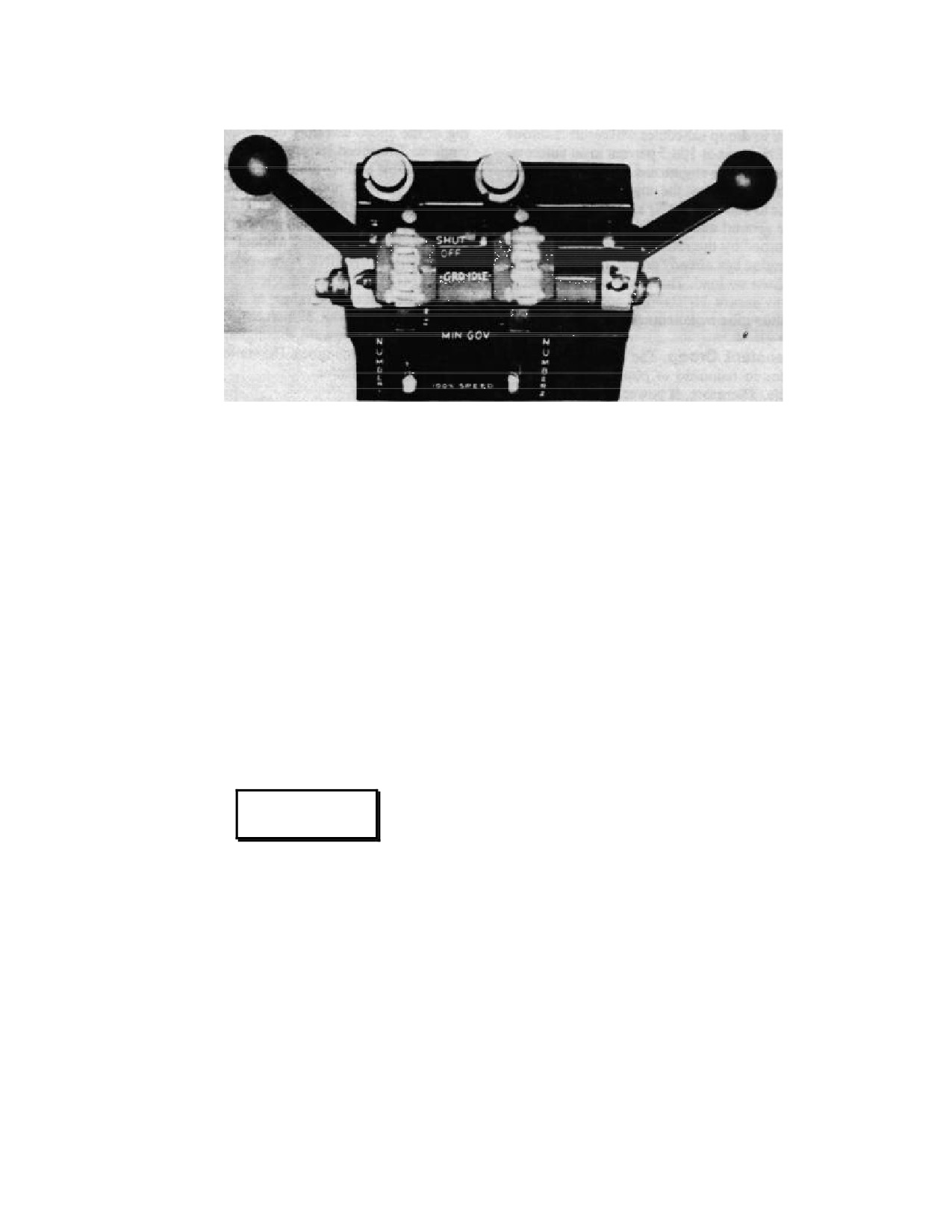
Figure 2-6. Overhead Engine Controls
extreme caution as it has a positive influence on fuel flow, and
2.1.6 Engine Instruments
misuse can cause engine overspeed or overtemperature. The
lever is mechanically connected to a cam within the fuel control
2.1.6.1 Power Turbine Inlet Temperature Indicators.
that contacts the fuel metering valve. The initial position of the
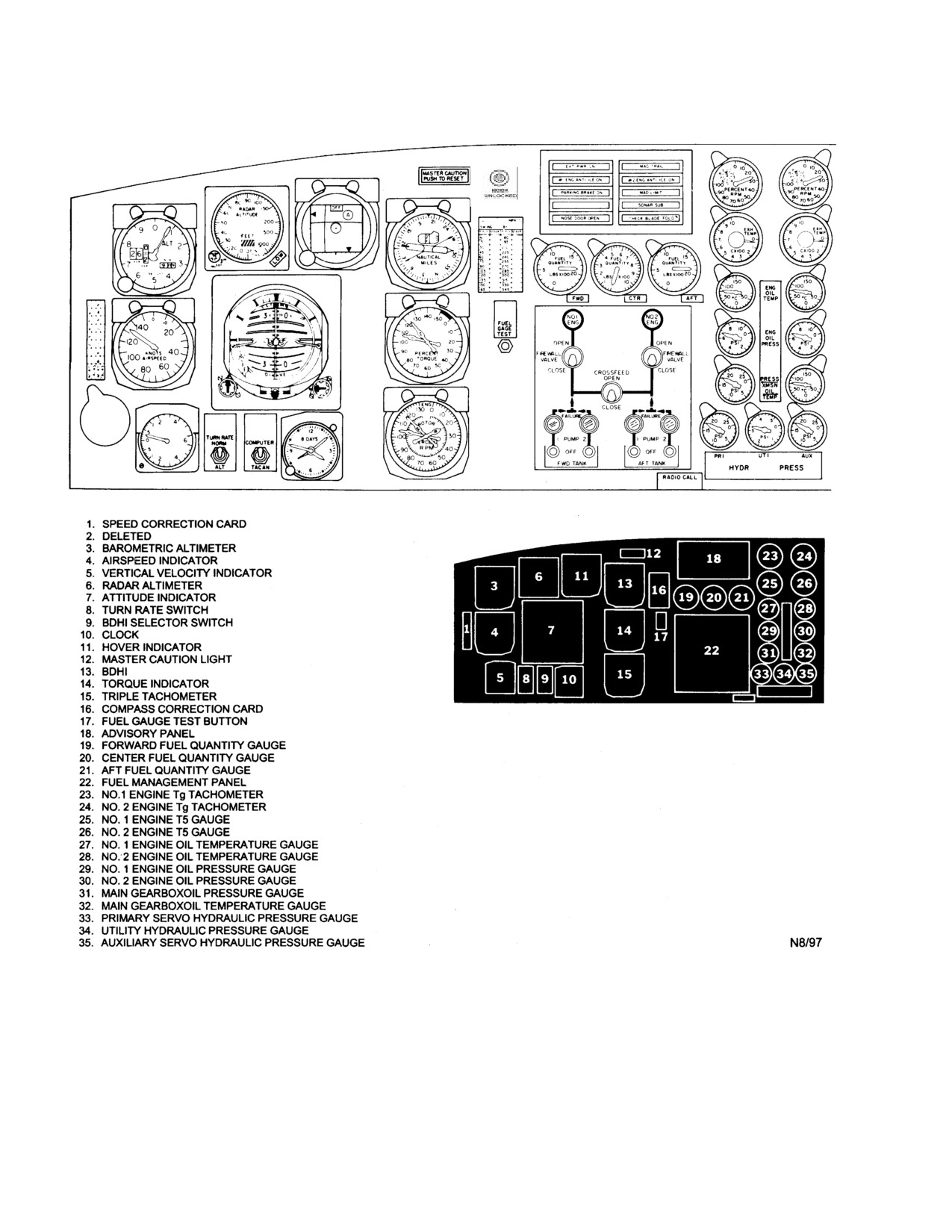
Two of these indicators (Figure 2 - 7) marked EXH TEMP
fuel metering valve is dependent upon the automatic features of
indicate engine power turbine inlet air temperatures in degrees
the control as established by the setting of the speed selector.
celsius and are on the instrument panel. The indicators operate
The cam, when actuated by advancing the manual throttle,
from thermocouples forward of the power turbine in the
contacts the fuel metering valve. Once contact is established,
second-stage turbine casing on each engine. When the
further advancement of the manual throttle will manually
dissimilar metals of the thermocouples in the engine are heated,
control fuel flow that in turn regulates engine power output.
an electromotive force (independent of the helicopter electrical
The manual throttle is unable to reduce the position of the
system) is created and a resulting current flow through a known
metering valve below that called for by the speed selectors.
resistance of the thermocouple circuit deflects the indicator
Control below this point will depend upon the type of
needle that is read in degrees celsius. The pilot has no direct
malfunction encountered. In all instances of manual throttle
control for regulating the power turbine inlet temperatures;
operation, it must be remembered that the speed selectors
however, limited control for lowering these temperatures can be
should not be retarded beyond GRD IDLE.
indirectly achieved by reducing collective pitch or power
demand.
2.1.6.2 Oil Pressure Indicators. Two of these indicators
WARNING
(Figure 2-7), one for each engine, are on the instrument panel
and indicate oil pressure in pounds per square inch. The
indicators are powered by 26 vac and each is protected by
With manual throttle actuated, resistance may
circuit breakers.
occur in the speed selector during conditions
requiring movement at or below the minimum
2.1.6.3 Oil Temperature Indicators. Two of these
governing range marking on the throttle
indicators (Figure 2 - 7), one for each engine, are on the
quadrant. Attempts to retard speed selector
instrument panel and indicate engine oil temperature in
beyond the point at which this resistance occurs
degrees celsius. The engine oil temperature bulb in the
may result in inadvertent engine shutdown.
bottom of the tank transmits indications to the respective
temperature indicators. The indicators are powered by 28
The fuel stopcock is downstream of the metering valve
vdc and protected by circuit breakers marked 1 ENG 2
and is actuated by the speed selectors. Placing the speed
under the general heading OIL TEMP on the center circuit
selector to SHUTOFF will stop engine fuel flow regardless of
breaker panel.
manual throttle control lever position.
2-15
ORIGINAL
NAVAIR 01-230HLH-1
Figure 2-7. Instrument Panel (Typical) (Sheet 1 of 2)
2.1.6.4 Gas Generator Tachometers. Two engine gas
left-hand position of the tachometer indicate gas generator
generator tachometers (Figure 2-7), one for each engine, are
speed from 0 to 10 in units of 1 percent. The gas generator
on the instrument panel. The gas generator tachometer
tachometer-generator is driven by the engine lube pump on
indicates the speed of the gas generator in percent of total rpm.
which it is mounted. The electrical power produced by the gas
Each tachometer has two dials and pointers. The outer dial and
generator tachometer-generator is proportional to gas
pointer indicate 0- to 100-percent gas generator speed in units
generator rpm. A 100-percent gas generator speed (100-
of 2 percent, and the small vernier dial and pointer in the upper
percent Ng) is 26,300 rpm.
2-16
ORIGINAL
NAVAIR 01-230HLH-1
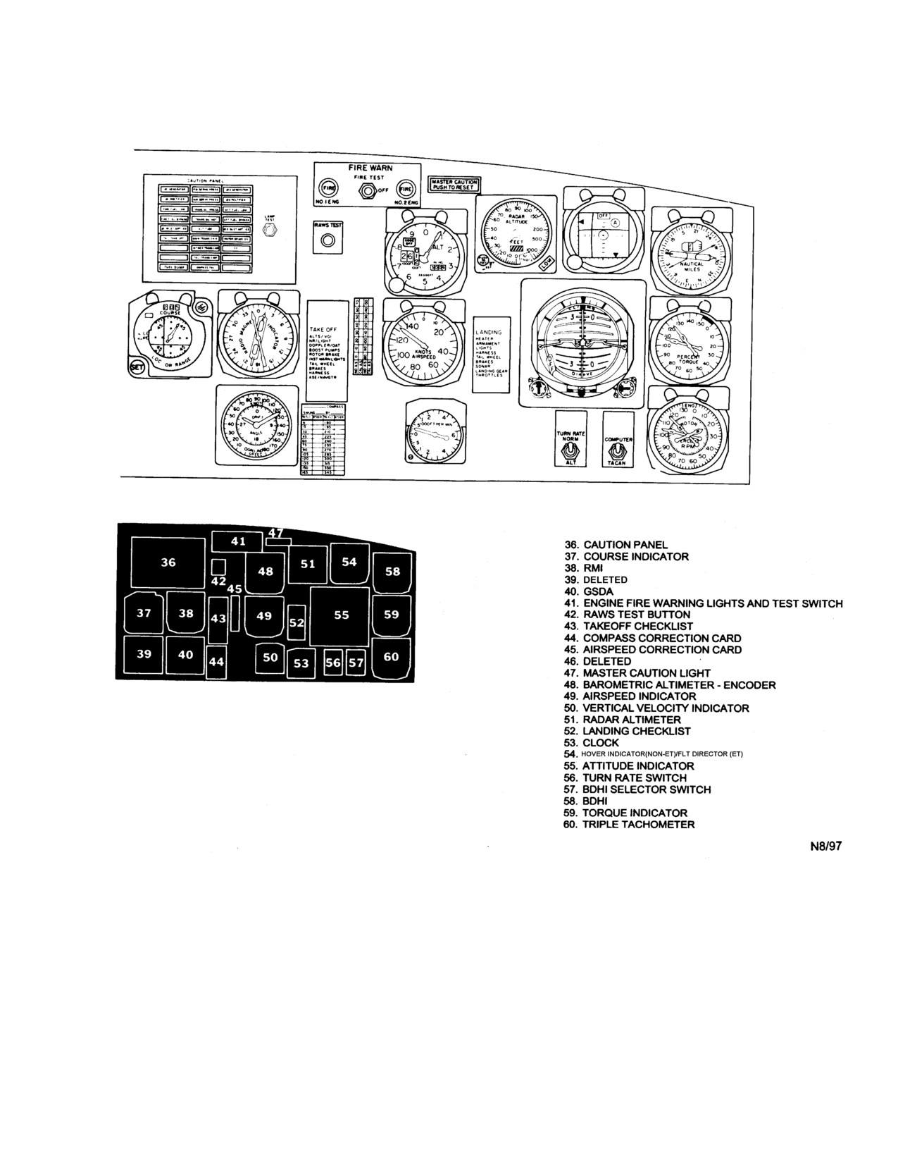
Figure 2-7. Instrument Panel (Typical) (Sheet 2 of 2)
2.1.6.5 Triple Tachometers. Two triple tachometers
in the fuel control. The rotary wing tachometer is powered by
(Figure 2-7), one for the pilot and one for the copilot, are on the
its own tachometer-generator geared to and driven by the main
instrument panel. Each tachometer contains three pointers: the
transmission output shaft for the No. 1 section of the tail rotor
No. 1 pointer indicates power turbine speed of the No. 1 engine,
drive. The tachometers are read in percent of total rpm. A 100-
the No. 2 pointer indicates the power turbine speed of the No. 2
percent turbine speed is 18,966 power turbine rpm (100-percent
engine, and the pointer marked R indicates the rotary wing rpm.
N f ), and 100-pcrcent rotary wing speed is 203 rotor rpm (100-
The power turbine (Nf) tachometers are powered by their own
percent Nr).
tachometer-generators that are driven by the power turbine
radial drive shaft via the flexible drive shaft to internal gearing
2-17
ORIGINAL
NAVAIR 01-230HLH-1
2.1.7 Starter System. The system consists of a starter,
2.1.7.2 Start Bleed Valve. The start bleed valves, one on
starter relay, start bleed valve, fuel shutoff valve, starter buttons,
each engine, operate automatically during the start cycle and
mode selector switch (manual or normal modes only), an abort
require no specific pilot action. The function of the valve is to
switch, start bleed valve actuating switches, and an emergency
raise the compressor stall line during the start cycle in order to
start switch. The system operates on dc power and is protected
increase the reliability of the normal start system. This is done
by circuit breakers marked STARTER 1 ENG 2 on the center
by bleeding compressor discharge air during start. The valve
circuit breaker panel. The engine starting system (FO-3)
closes at the point where the starter, ignition circuit, and valve
consists of three modes of operation: normal, manual, or
circuit are deenergized simultaneously. The valve remains fully
emergency. The normal mode provides a completely automated
closed during all regimes of engine operation except during
start that includes automatic starter dropout and increased start
starting.
reliability through a start bleed valve. The manual mode
provides an alternate means of starting, using external electrical
2.1.7.3 Starter Buttons. Two starter buttons, one for each
power or the battery. In this mode, the starter relay dropout
engine, are above the speed selectors. The starter is energized
feature is bypassed. This permits the starter to motor the engine
by holding the speed selectors at SHUTOFF and momentarily
continuously until the starter abort switch is actuated by pulling
depressing the starter button. This energizes the starter relay and
down on the speed lever. An electrically operated solenoid
completes the circuit to the starter. When using the normal
valve aids in controlling overtemperature conditions. When the
starting mode, after the engine fires and the electrical power
valve is actuated by the pushbutton-type switch mounted on
load to the starter decreases, the starter relay will automatically
the cyclic stick, auxiliary start fuel flow is blocked from
drop out, deenergizing the starter. In the manual mode, when
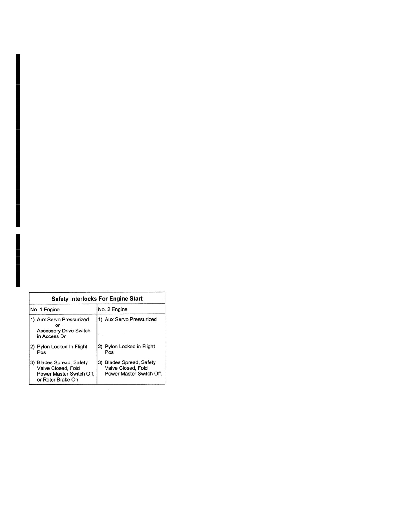
entering the fuel flow divider. A series of safety interlocks in
Ng reaches about 45 percent, the respective speed selector must
the normal or manual control circuit to each engine starter
be pulled down to actuate the abort switch that in turn drops out
prevents the starter relay from closing should an unsafe
the starter.
condition exist.
2.1.7.4 Starter Abort Switch. A starter abort switch is in
For engine starts during flight or for starting the No. 1
each speed selector. The switch is actuated by pulling down on
engine when the tail pylon is folded, an emergency start
the speed selector. This action breaks electrical circuit
switch provides a means of bypassing all safety interlocks,
continuity to the ignition system and the starter relay.
thus allowing either a manual or normal start. Before
starting, check that the
10-ampere blade fold circuit
2.1.7.5. Mode Selector Switch. This switch with marked
breaker marked BLADE FOLD on the center circuit
positions MANUAL and NORMAL under the general heading
breaker panel is in.
START MODE is on the overhead dome light panel. When
the switch is placed to NORMAL, the automatic dropout
function of the starter relay is energized, allowing the starter to
motor the engine to about 45-percent Ng. When the switch is
placed to MANUAL, the automatic dropout feature of the
starter relay is bypassed, allowing the starter to remain engaged
until the abort switch is actuated. The switch operates on 28-
vdc power.
2.1.7.6 Auxiliary Start Fuel Shutoff Valves. Two of these
valves, one for each engine, are installed in the engine
compartment between the engine fuel control and flow divider.
When the valve is actuated during the start of either engine, the
flow of auxiliary bypass starting fuel is blocked. This blockage
decreases the total amount of fuel flow during starting, thus
diminishing the possibility of an overtemperature condition
2.1.7.1 Starter Dropout. Starter operation and dropout
because of excessive fuel flow. The valves operate on dc power
may be monitored by noting the magnetic compass heading
and are protected by the main starting circuit breakers.
before engine start. When the starter is energized, the compass
will swing to a new heading. When the normal start circuit is
2.1.7.7
Auxiliary Start Fuel Shutoff Valve Switch.
used, the starter will drop out at 45-percent Ng. The compass
This pushbutton-type switch marked ENG ST is on each cyclic
should then swing back to its original heading, signifying the
stick. In addition to pressing the switch, the starter relay for the
starter has dropped out. When the manual start circuit is used,
engine to be started must be closed before the valve will
the starter will drop out only when the abort switch is actuated.
operate. Either the pilot or copilot switch will control the
operation of both valves. The switch operates on dc power.
2-18
ORIGINAL
NAVAIR 01-230HLH-1
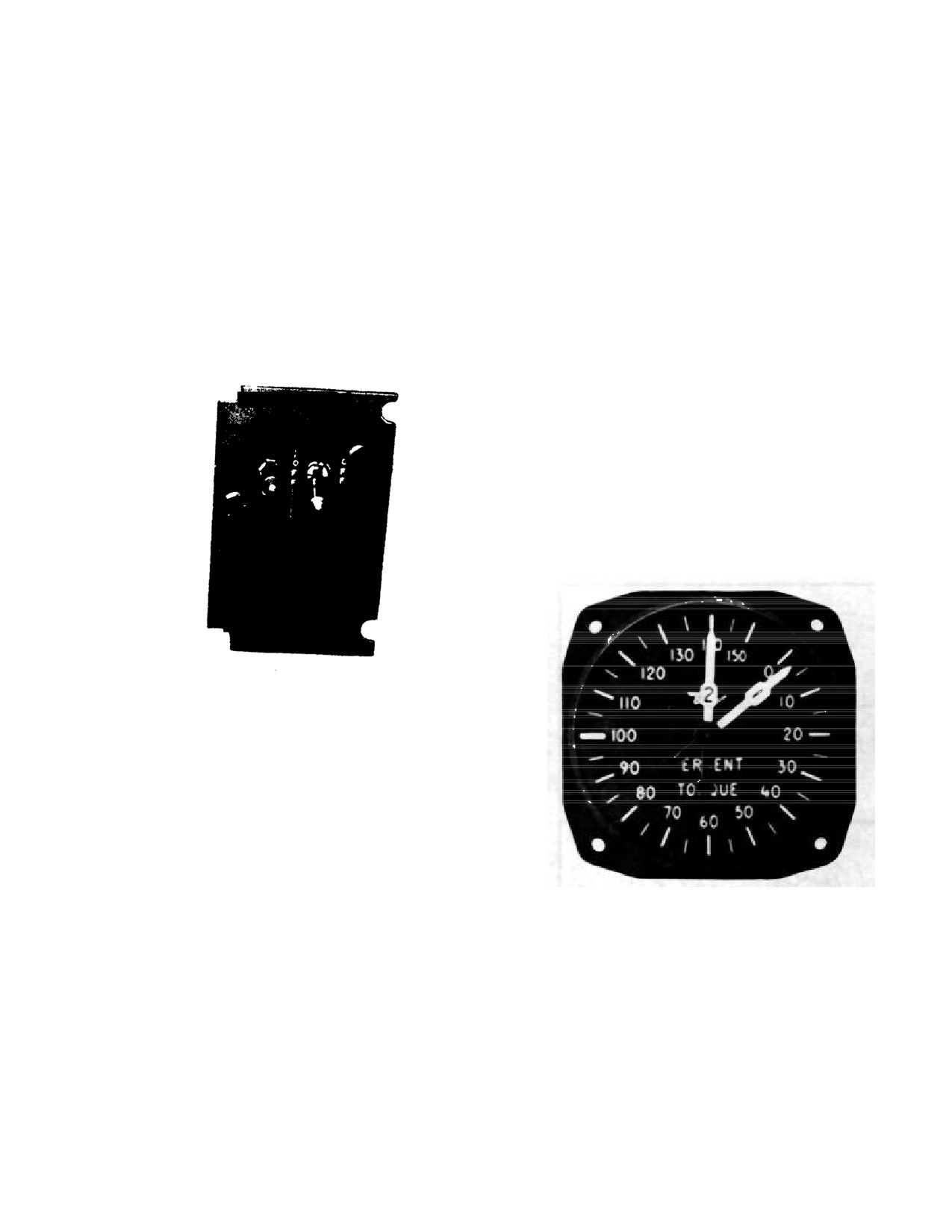
2.1.7.8 Emergency Start Switch. Two switches (Figure 2-
at NORM. When the switch is at NORM with the starter
8) marked EMER START 1 ENG 2 are on the overhead
engaged, the ignition unit is energized. Holding the switch at
control panel to the right of the engine speed selectors. The
the spring-loaded TEST position energizes the ignition unit
switches have two marked positions, ON and OFF. Normally
only. TEST is used (for ground operation only) without the
the switches remain OFF and starting is done through the
starter to test the ignition circuit. A clicking noise can be heard
normal control circuit. When the switches are placed ON, the
when the switch is placed to TEST. When the switch is OFF,
normal control circuit with its safety interlocks is bypassed.
the ignition unit is deenergized. OFF is used to motor the
Power from the primary dc bus is fed directly to the starter
engine, using the starter without ignition. The ignition switches
button and a normal starting procedure is followed. Placing
are powered by dc current.
either engine emergency starter switch ON permits starting of
that engine in flight should any of the safety interlocks fail to
2.1.9 Torque Sensing System.
This system
remain in the closed position when deenergized. The
determines input torque at the main gearbox and transmits
emergency starter switches also permit intentional interlock
this information to torquemeter indicators. Each
bypassing for maintenance purposes.
torquemeter indicator presents this information in terms of
percent of engine power being delivered to the main
transmission. Components of the systems include two
pressure chambers, two balancing valves, two pressure
EMER START
transmitters, one high-pressure oil pump, and two dual-
1 ENG 2
needle torquemeter indicators. The system is designed to
measure the oil pressures required to react against the
forward displacement of the main gearbox second-stage
helical gear as a result of the input shaft torque of each
engine. These oil pressures, required to react against the
forward movement of the second-stage helical gear, are
sensed by two pressure transmitters that send electrical
signals to the torquemeter indicators.
Figure 2-8. Engine Emergency Start Switches
2.1.7.9 Engine Starting. During start, as the engine speed
selector is advanced to GRD IDLE, the stopcock opens and
allows fuel to pass through the flow divider and to enter the No.
1 (low pressure) manifold to the nozzles where it is mixed with
compressor-discharge air. As fuel-air mixture leaves the
nozzles, it is ignited by the two igniter plugs in the combustion
chamber and enters a sustained combustion process.
2.1.8 Ignition System. The ignition system consists of a
sealed ignition unit and two igniter plugs on each engine that
provide a spark to ignite the fuel-air mixture. The ignition unit
is on the lower right side of the compressor casing. The ignition
Figure 2-10. Torquemeter
system provides ignition during starting with the ignition switch
at NORM. When gas generator speed increases and the starter
2.1.9.1 Torquemeter Indicators. Two torquemeter
circuit load drops, the automatic dropout relay releases,
indicators (Figure 2-10), one for the pilot and one for the
deenergizing the starter and ignition systems, and combustion is
copilot, are on the instrument panel. Each dual-needle
self-sustained.
indicator marked PERCENT TORQUE contains two
pointers marked
1 and 2 that indicate input torque in
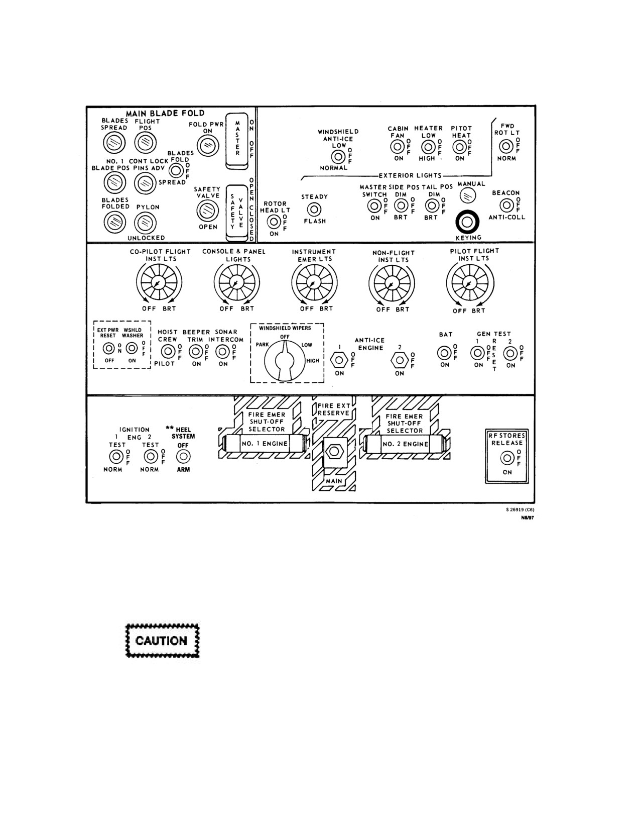
2.1.8.1 Ignition Switches. Two ignition switches, one for
percent of maximum engine power output of each engine.
each engine, on the overhead switch panel (Figure 2-9) are
The electrical pressure torquemeter indicator dials marked
marked IGNITION 1 ENG 2. Each switch has marked
percent torque are marked in units of 5 percent from 0
positions TEST, OFF, and NORM. The switches are normally
percent to 150 percent. The torquemeter indicators operate
2-19
ORIGINAL
NAVAIR 01-230HLH-1
Figure 2-9. Overhead Switch Panel
on 26 vac and are protected by circuit breakers marked
protection is provided by a shutoff valve that is
TORQUE SENSOR.
incorporated in the fuel control.
This prevents a
destructive overspeed in the event of a complete loss of
2.1.10 Overspeed Protection System
load, such as a high-speed shaft failure. Under such a
condition, the acceleration rate of the power turbine is so
great that fuel control would not react in time without the
shutoff valve. The valve is attached to the Nf governor
servo piston and closes at about 119-to 123-percent Nf.
Any increase in power turbine speed moves the Nf servo
piston and the shutoff valve with it. Motion beyond the
In case of flexible drive shaft failure, no me-
normal control range causes the shutoff valve to bottom
chanical overspeed protection is available.
against the casing and cutoff discharge fuel.
The Nos. 1 and 2 engines are each equipped with an
2.1.10.1 Engine Overspeed Protection System.
overspeed protection system that is available through all
The No. 1 engine is equipped with an engine overspeed
regimes of engine operation. The mechanical overspeed
protection system effective only when operating in
2-20
ORIGINAL
NAVAIR 01-230HLH-1
accessory drive. When an overspeed condition occurs, a
The APU fuel system is independent of the helicopter fuel
frequency signal from the No.
1 PMG will actuate a
system, except that it receives its fuel supply from the
solenoid that bleeds compressor discharge pressure (P3)
aircraft’s fuel system. The fuel shutoff valve, a motor-
sensed by the fuel control. With the No.
1 engine in
operated gate valve, is in the right sponson. Normal fuel
accessory drive, two situations will cause activation of this
flow to the APU is accomplished by positioning the APU
ON switch, on the cockpit APU control panel, to ON,
overspeed system. Either No. 1 Nf at approximately 108
which opens the fuel shutoff valve.
percent or Nr at approximately 104 percent or above will
cause the Nf to oscillate. Nr reduction to less than 104
2.1.11.5
(ET) APU Generator System. The APU
percent will restore normal No.
1 engine operation.
generator system, tied into the ac power supply system
(Mechanical engine overspeed protection is not affected by
through the APU generator control unit, supplies power to
AFC 399.)
all components operating off the No.
1 and No.
2
generators. In addition, to preventing paralleling of the
Note
APU generator with the generator in the basic ac power
system, an APU interlock relay is provided.
With AFC 399, Nr above 104 percent, and
in accessory drive No. 1 engine should sense
2.1.11.6
(ET) APU Operation. Positioning the APU
an overspeed condition and drop to 60- to
CONTROL switch, on the APU control panel, to ON sends
70- percent Nf.
a 28 vdc signal from the battery bus to the ESU. A start
command from the ESU sends 28 vdc to the APU starter
2.1.11
(ET) AUXILIARY POWER UNIT
(APU)
relay and causes the STARTER ON warning light to
SYSTEM. The auxiliary power unit system provides an
illuminate. The ESU also controls ignition and signals the
external source of 115/200 volts, three-phase, 400 Hz, ac
fuel solenoid valve to open. This accelerates the APU to
electrical power in the same manner as an external power
100% speed. When speed reaches 70%, the ESU turns off
unit. The system consists basically of an auxiliary power
the APU starter by transmitting a discrete dc signal closing
unit, an Electronic Sequence Unit (ESU), a control panel,
the APU starter relay. The starter relay drops out and the
an APU fuel system, and a generator system. The APU
STARTER ON warning light goes off. At
95% the
ignition unit is deenergized and after a time delay the APU
system supplies power for instrumentation, minimal
is at 100% speed. The APU ON light will illuminate. The
lighting, and ground operation of the environmental
helicopter’s electrical requirements are supplied when the
control system.
GEN ON switch is positioned ON, and the GEN ON light
illuminates.
2.1.11.1 (ET) Auxiliary Power Unit (APU). The APU,
mounted in a pod attached to the right sponson, supplies
2.2
ENGINE OIL SYSTEM (F0-4)
power to operate the APU generator system. The APU is a
small gas-turbine engine capable of producing
90
horsepower. It is controlled by the ESU.
Each engine has an independent oil tank and dry sump
full scavenge oil system. Oil is gravity-fed from the tank to
2.1.11.2
(ET) Electronic Sequence Unit (ESU). The
the engine-driven oil pump mounted on the forward right-
ESU is the control element for the APU. The ESU is a
hand side of the engine. The engine-driven pump
microprocessor-based electronic component that monitors
distributes the oil under pressure through a filter to
and controls all APU operations. It monitors speed and
accessory gears and engine bearings. The oil serves both
temperature and outputs signals to control APU functions.
lubricating and cooling purposes and is a completely
The ESU also shuts down the APU when monitored values
automatic system requiring no control action by the pilot.
exceed established operating parameters. Advisory lights
The scavenge side of the pump returns oil through an oil
on the APU control panel indicate system status.
cooler to the oil tank.
2.1.11.3
(ET) APU Control Panel. The control panel
The oil cooler is an oil-to-fuel heat exchanger with an
(Figure 2-5.1), on the cockpit console, contains all of the
associated oil bypass valve. The oil flow through the
controls necessary for APU operation. It consists of an
cooler depends on oil temperature. At lower temperature,
APU ON switch, GEN ON/OFF/RESET switch, GEN ON
the pressure differential across the cooler causes most of
indicator light, FUEL PUMP ON indicator light, and five
the oil to flow through the bypass valve. At higher
warning and indicating lights.
temperatures, the lower viscosity reduces the pressure
differential that closes the bypass valve and causes all of
2.1.11.4
(ET) APU Fuel System. The fuel system
the oil to flow through the cooler. Each engine oil system
supplies fuel to the APU from the helicopter forward fuel
tank. The APU fuel system consists of a APU fuel shutoff
has a 2.7-U.S. gallon capacity tank. The circular tanks are
valve, fuel boost pump, and the necessary tube and hose
around the forward section of each engine. For oil
specification and grade, see Figure 3-7.
lines to convey fuel from the main fuel line to the APU.
2-21
ORIGINAL
NAVAIR 01-230HLH-1
2.3 ROTOR SYSTEMS
stainless steel bonded to the leading edge. The tip caps
have hard nickel bonded to the leading edge.
The rotor systems consist of a single main lifting
rotary wing and an antitorque rotary rudder. Both systems
2.3.1.1 Blade Inspection Method Indicators
are driven by the two engines through the transmission
system and are controlled by the flight controls.
2.3.1 Rotary Wing System. The rotary wing system
WARNING
consists of the rotary wing head assembly and the rotary
wing blades. The rotary wing head assembly, mounted
directly above the main gearbox, consists of a hub
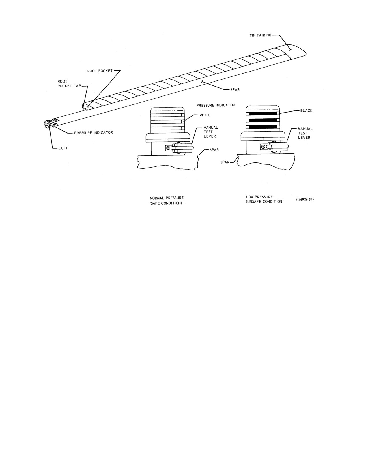
When black is visible in the indicator, it may
assembly and a star assembly. The hub assembly,
be an indication of blade damage that is a
consisting of five sleeve-spindle assemblies and five
flight hazard. The cause of the black
hydraulic dampers clamped between two parallel plates, is
indication shall be determined before flight.
splined to the rotary wing drive shaft. The root ends of the
five rotary wing blades are attached to the sleeve-spindle
A cylindrical BIM indicator (Figure
2-11) is in the
assemblies that permit each blade to flap vertically, hunt
root end plate of each main blade, an air valve is in the
horizontally, and rotate on their spanwise axis to change
backwall of the spar. The pressure indicator has a
the angle of incidence. Antiflapping restrainers limit the
transparent cover through which color indication can be
upward movement of the blades. Droop stops limit the
observed to determine blade serviceability. The indicator
downward position of the blades. Both are in operation
that is compensated for temperature changes compares a
when the blades are stopped or turning at low speed. When
reference pressure built into the indicator with the pressure
the rotor system is accelerated, centrifugal force
in the blades spar. When the pressure in the blade spar is
automatically releases the antiflapping restrainers at about
within the required service limits, indicating the blade is
25 to 30 percent and the droop stops at about 65- to 75-
serviceable, three white stripes show in the indicator. If the
percent rotary wing speed. During rotor deceleration, the
structural integrity of the spar is impaired, nitrogen
droop stops will seat at about 50 to 60 percent and the
pressure will decrease. If the pressure in the blade spar
antiflap restrainers at about 30-percent rotary wing speed.
drops below the minimum permissible service pressure,
The hydraulic dampers lessen hunting movement of the
the indicator will be actuated and will show three black
blades about the vertical hinges as they rotate, prevent
stripes. To check the integrity of the BIM indicator,
shock to the blades when the rotary wing is started or
depress the manual test lever until a black indication
stopped, and aid in the prevention of ground resonance.
appears, and then release the lever.
The angle of incidence (or pitch) of the rotary wing blades
is controlled by the rotary wing flight control system that
2.3.1.2 IBIS
(In-Flight Blade Inspection System).
is connected to the blades through a swashplate assembly
The IBIS system consists of the five main rotor blade spars
below the hub assembly. The swashplate assembly consists
(individually pressurized with nitrogen), a pressure
of an upper (rotating) swashplate that is driven by the
indicator
(with radioactive source) on the root of each
rotary wing hub, and a lower (stationary) swashplate that is
blade spar, a radiation detector on the main rotor fairing
secured by a scissors to the main gearbox. Both
assembly, a signal processor with a test panel in the
swashplates are mounted on a ball-ring and socket
baggage compartment, and an amber blade pressure
assembly that keeps them parallel at all times but allows
caution light located on the caution panel. The nitrogen
them to be tilted, raised, or lowered simultaneously by
with each main rotor blade spar is pressurized to
components of the rotary wing flight control system that
approximately 10 psi at an ambient temperature of 10 to 24
connect to arms on the lower
(stationary) swashplate.
degrees. The associated spar pressure indicator displays
Cyclic or collective pitch changes introduced at the
two white stripes when the pressure is safe. If the spar
stationary swashplate are transmitted to the blades by
pressure drops to below the safe range, two black stripes
linkage on the rotating swashplate. The five all-metal
will display in the spar pressure indicator windows,
rotary wing blades are made of aluminum alloy, with the
indicating that nitrogen is escaping through a crack in the
exception of the forged steel cuffs on the blades that attach
spar or through a faulty seal.
the blades to the sleeve-spindle assemblies on the rotary
wing hub assembly. The main spar of the blade is a
hollow aluminum alloy extrusion that forms the leading
edge of the blade. Individual pockets constructed of sheet
aluminum alloy form the trailing edge of the blades. The
pockets are bonded to the spar. The rotary wing blades
have an abrasion/erosion strip of hard nickel-plated
2-22
ORIGINAL
NAVAIR 01-230HLH-1
to-test pushbutton on the test panel will result in the
following indications:
WARNING
Note
When black is visible in a spar pressure
indicator, hazardous blade damage may
In each bit switch mode, the press-to-test
exist. The unsafe blade shall be removed
pushbutton must be held down for a
from service until the cause of the unsafe
minimum of 5 seconds to allow the signal
indicator is positively found and corrected.
processor to stabilize.
A spar pressure indicator displaying two white (safe)
a.
Selecting DET with the bit switch and pressing
stripes can be checked by pressing the manual test
the press-to-test pushbutton simulates the
pushbutton in the indicator, which causes two black stripes
detectors normal sensing of its own low radiation
(unsafe indication) to be displayed. Once two black stripes
rate and illuminates the green safe light. This is
are displayed, regardless of the cause, the reset button on
an operational checkout of the detector.
the spar pressure indicator must be pressed with the clear
plastic test/shipping cover in place over the spar pressure
b.
Selecting LOW WARN and pressing the
indicator to prevent the escape of radiation.
pushbutton simulates loss of the detectors own
radiation rate and lights the blade pressure caution
The radioactive source is shielded when the spar
light and the red warning light. This is a
pressure indicator displays white
(safe).
When the
functional checkout of the signal processor.
indicator moves to the black
(unsafe) position, the
radioactive source moves out of the shielded position and
c.
Selecting safe and pressing the pushbutton
is exposed. As the rotating unsafe blade then passes over
simulates the detectors normal sensing of its own
the radiation detector, the rays released by the blades’
low radiation rate and illuminates the green safe
radioactive source are sensed by the detector, which sends
light. This is a functional checkout of the signal
an electrical signal to the signal processor, which in turn
processor.
deenergizes a relay in the processor and causes the blade
pressure caution light to illuminate.
d.
Selecting HIGH WARN and pressing the
pushbutton simulates the detector sensing a high
To ensure that the radiation detector is capable of
radiation rate from a spar pressure low indicator
detecting radiation, a small radioactive source incorporated
with low pressure. The blade pressure caution
in the detector continuously emits radiation at a lower rate
light illuminates and the red warning light
than the radioactive source in the spar pressure indicator.
illuminates. This is a functional checkout of the
The radiation detector continuously senses its own
signal processor.
radiation and sends a signal to the signal processor to
energize a relay that extinguishes the BIM caution light.
The No. 2 primary ac and the No. 2 primary dc buses
2.3.2
Bifilar Absorber. The main rotor system has a
furnish power to the system through two circuit breakers,
bifilar
absorber assembly (helicopters modified by AFC
both marked blade pressure, on the pilot circuit breaker
403) to reduce fatigue stress and improve the overall
panel. In addition to damage causing a loss of pressure in
vibration comfort level throughout the helicopter. The
the spar, failure of the signal processor, or loss of 115-vac
bifilar absorber assembly secured to the main rotor hub
power will each result in illumination of the BIM caution
consists of a five-pointed, star-shaped, aluminum forging
light.
with a 17-pound weight attached to each star point.
2.3.1.3 IBIS Test Panel. An IBIS test panel is mounted
2.3.3 Rotary Rudder System. The system consists
on the signal processor, which is located on the left-hand
of the rotary rudder assembly and rotary rudder blades.
side of the cabin wall. The test panel is used for built-in
The rotary rudder assembly mounted at the upper end of
tests (bits) to verify operation of the radiation detector and
the pylon consists of a rotary rudder hub and the pitch-
the signal processor. A bit selector switch, a press-to-test
changing mechanism. The splined hub is supported and
pushdown, a red warning light, a green safe light, and a
driven by the horizontal output shaft of the tail gearbox.
decal that lists the bit procedures and associated light
The five rotary rudder blades are attached to the rotary
indications are mounted on the panel. Pressing the press
rudder hub by flapping hinges and spindles so that they are
2-23
ORIGINAL
NAVAIR 01-230HLH-1
Figure 2-11. BIM Indicator
free to flap and rotate about their spanwise axis for pitch
2.4
TRANSMISSION SYSTEM
variation. The blade pitch-changing mechanism transmits
rotary rudder control pedal movements to the rotary rudder
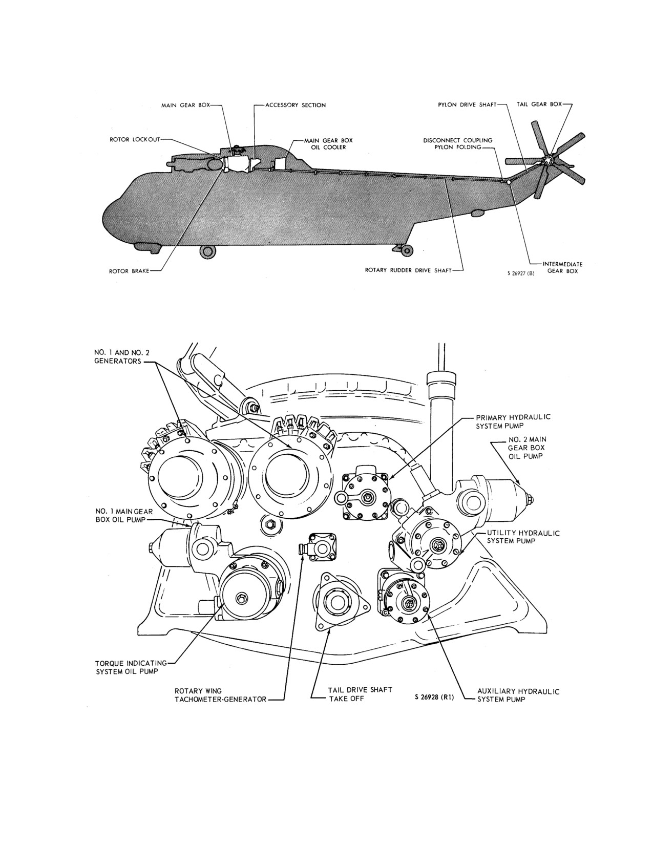
The transmission system
(Figure
2-12) consists of
blades through the hollow horizontal output shaft of the
three gearboxes that transmit power to the rotary wing and
tail gearbox. The five all-metal rotary rudder blades are
rotary rudder. The three gearboxes are the main gearbox,
constructed of a single aluminum pocket bonded to a C-
intermediate gearbox, and the tail rotor gearbox.
shaped spar. The rotary rudder negative force gradient
system is installed to relieve the pilot of rotary rudder
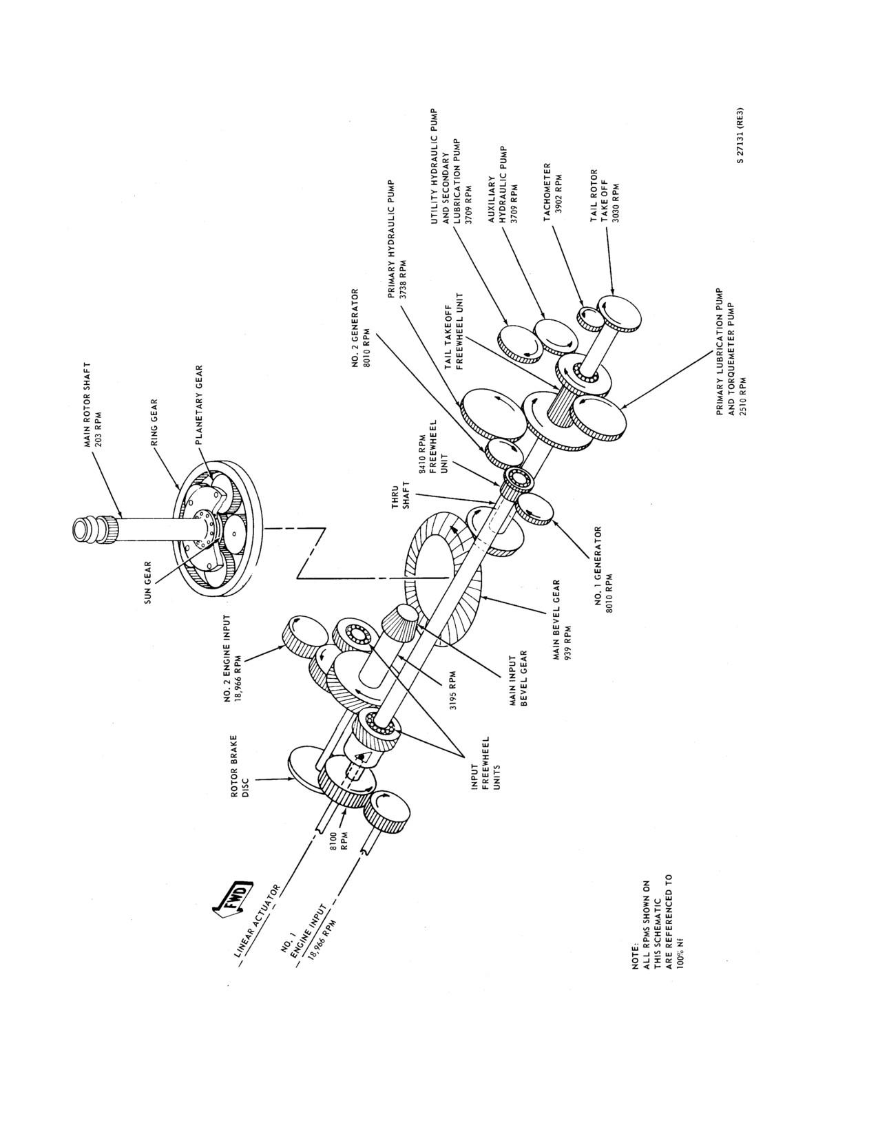
2.4.1 Main Gearbox.
The MGB
(Figure
2-13),
forces created by aerodynamic loads when the auxiliary
mounted above the cabin an of the engines, interconnects
servo system is inoperative. The system applies a force to
the two engines through a main gearbox to the rotary wing.
cancel the aerodynamic loads only when the rotary rudder
Gearing reduces engine rpm at a ratio of approximately 93
is operating at normal speeds. Because of this, when the
to
1 for driving the rotary wing. Engine torque is
system is checked on the ground with rotary rudder
transmitted by the main gearbox to the rotary wing drive
stationary and the auxiliary servo off, a negative spring
shaft to drive the rotary wing, and aft to the intermediate
centering effect is created. The tendency of the pedals is
gearbox and then to the rotary rudder gearbox to drive the
then to go normally to either extreme. Under these
rotary rudder. The main gearbox accessory section (Figure
conditions, considerable force is required to push the
2-14) at the rear of the main gearbox lower housing drives
rotary rudder pedals from the extreme positions; however,
the primary, utility, and auxiliary hydraulic pumps, the
the forces will decrease as the positions approach neutral.
high-pressure torquemeter oil pump; and the two
The initial force to move the pedals toward the right from a
generators. Dual oil pumps are installed on the accessory
full left position is between 30 and 40 pounds. With the
section. These pumps increase reliability through better
primary servo ON, auxiliary servo OFF, and the rotary
lubrication and permit flight to be continued if one pump
wing head stationary, pedal motion will cause the col-
fails. A freewheeling unit at each engine input to the main
lective pitch lever to move up for a right pedal motion and
gearbox permits the rotary wing to autorotate without
down for a left pedal motion.
engine drag in case of engine (or engines) failure, or when
engine rpm decreases below the equivalent of rotor rpm.
2-24
ORIGINAL
NAVAIR 01-230HLH-1
Figure 2-12. Transmission System
Figure 2-14. Main Gearbox Accessory Section
2-25
ORIGINAL
NAVAIR 01-230HLH-1
Figure 2-13. Main Gearbox Accessory Section
2-26
ORIGINAL
NAVAIR 01-230HLH-1
2.4.1.1 Accessory Drive Rotor Lockout System.
This system permits the pilot to use engine power to drive
the accessory section
(hydraulic pumps, oil pumps,
generators, etc.) of the main gearbox on the ground
without rotating the rotary wing head. No. 1 engine is
used to drive the accessories without turning the rotary
wing head. A switch allows the pilot to position the linear
actuator and divert power to either the accessory section
or rotary wing.
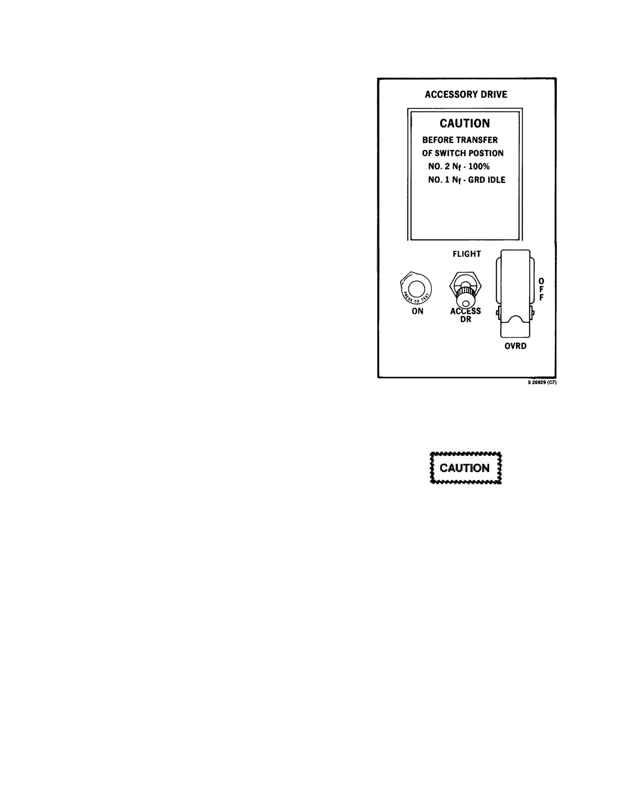
2.4.1.2 Accessory Drive Panel. This panel (Figure 2-
15) is beside the engine control quadrant. The accessory
drive switch with marked positions FLIGHT and
ACCESS DR is a lever-lock switch that must be pulled
out before it can be moved from one position to the other.
It allows the No. 1 engine to drive the accessory section
of the main gearbox before starting the No. 2 engine and
engaging the rotary wing head and/or when No. 2 engine
rpm is lower than No. 1 engine rpm. Prior to starting the
No.
1 engine, placing the switch to ACCESS DR
positions the rollers in the input freewheel unit, permitting
the No. 1 engine to drive the accessory section of the
main gearbox. Also, at this time, the accessory drive
(rotor lockout) warning light marked ON will go on and
will remain on until the rollers are repositioned to drive
the rotary wings. (On helicopters modified by AFC 401,
the linear actuator will take 6 to 7 seconds to complete
shift. Confirmation is provided by the appropriate light
indicator on the accessory drive panel.) When both
Figure 2-15. Accessory Drive Switch Panel
engines are operating and the rotor is being driven by the
No. 2 engine, No. 1 engine speed should be reduced to
2.4.1.3 Accessory Drive Warning Light
GRD IDLE. When these conditions have been met,
placing the accessory drive switch to FLIGHT energizes
an actuator that repositions the input freewheel unit
rollers, permitting the No. 1 engine to also drive the rotary
wing shaft. An accessory drive limit switch is incorporated
in the ground idle range of the speed selection. This limit
switch prevents switching from ACCESS DR to FLIGHT
On helicopters modified by AFC 401, when
utilizing the override switch to reposition
without first retarding the No. 1 engine speed selector
the actuator, the No.
2 engine must be
lever to the GRD IDLE range. After the rollers are
repositioned, the accessory drive (rotor lockout) warning
driving the rotors at 102- to 104-percent Nr
and the No.
1 speed selector must be
light will go off. (On helicopters modified by AFC 401,
positioned at GRD IDLE to prevent
two interlocks prevent the linear actuator from
repositioning. The No. 2 engine must be driving the rotors
damage to the MGB. Use of this override
switch is not a normal procedure.
at 102- to 104-percent Nr and the No. 1 speed selector at
ground idle. A guarded two-position override switch is
also provided.) The accessory drive switch circuit
Note
operates on dc power and is protected by a circuit breaker
In the event of an input freewheeling unit
marked ACCESS DRIVE on the center circuit breaker
panel (Figures 2-23 and 2-25).
failure while shifting from accessory drive
to flight position on the No. 1 engine (with
a positive indication of successful shift), no
indication of torque on No.
1 eng. Nf
marrying with Nr will be evident after the
shift, regardless of speed selector lever
position.
2-27
ORIGINAL
NAVAIR 01-230HLH-1
This light (Figure
2-15) is on the accessory drive
2.4.4 Intermediate and Tail Gearbox Oil
panel. It will light when the rollers in the freewheel unit
Systems. Both the intermediate and the tail gearboxes
have been positioned to permit the No. 1 engine to drive
are splash-lubricated from individual sump systems.
the accessory section of the main gearbox. When No. 1
Internal spiral channels ensure oil lubrication to all
engine power is diverted to drive the rotary wing shaft,
bearings. An oil filter plug, drain plug, and oil level
the warning light will go off. The accessory drive warning
window are in each gearbox casting. Oil capacity for the
light on is the only positive indication of the input
intermediate gearbox is about 0.2 gallon and for the tail
freewheeling unit in the accessory drive position, and the
gearbox, 0.4 gallon. For oil specification and grade, see
accessory drive warning light off is the only positive
Figure 3-7.
indication of the input freewheeling unit in the flight
position. The press-to-test light operates on dc power and
2.4.5 Chip Detector Caution Lights. These lights
is protected by the circuit breakers marked PWR and
marked MAIN TRANS CHIP, INTMED TRANS CHIP
TEST in the center circuit breaker panel (Figures
2-23
and TAIL TRANS CHIP are on the CAUTION PANEL
and 2-25) under the general heading of WARNING LTS.
(Figure 2-49). The MAIN TRANS CHIP light serves a
single function in that it visually indicates that one or both
2.4.1.4 Tail Takeoff Freewheel Unit Caution Light.
of the magnetic chip detectors in the main gearbox has
The light marked TAIL TAKEOFF is on the caution
picked up and retained metal particles or chips in the oil.
panel (Figure 2-49). The caution light indicates failure of
The INTMED TRANS CHIP and TAIL TRANS CHIP
the tail takeoff freewheel unit in the main gearbox
lights, when on, indicate that the gearboxes have
accessory drive train. When this failure occurs, the
overheated or the magnetic chip detectors have picked up
accessory section is being driven by the No. 1 engine
and held chips or metallic particles in the oil. The
through-shaft at reduced rpm. No. 1 generator output is
presence of either of these conditions could cause ex-
normally used to sense this reduction in rpm that results in
cessive wear and/or premature failure of the gearboxes.
a reduction in generator frequency. In case the No. 1
The system operates on dc power and is protected by a
generator has failed, the No. 2 generator output is used to
circuit breaker marked CHIP DET on the center circuit
sense this rpm reduction. When the generator frequency is
breaker panel.
reduced to less than that produced through the freewheel
unit drive, the caution light will go on. Failure of the No.
2.4.6 Transmission Oil Systems
1 engine subsequent to the caution light going on would
result in loss of the equipment driven by the accessory
2.4.6.1 Main Gearbox Oil System (FO-5). Primary
section. The system operates on dc power. The sensing
and secondary oil pumps are for lubrication. The primary
unit is in the electronics compartment.
oil pump is mounted on a common shaft between the
torque indicating system oil pump and the transmission
rear cover. The secondary oil pump is mounted on a
Note
common shaft between the utility hydraulic pump and the
transmission rear cover
(Figure
2-14). Oil is pumped
Flight regimes above 100-percent Nr may
from the gearbox sump through a hose to an oil cooler
preclude detection of an actual tail takeoff
behind the main gearbox. If oil from the sump is less than
freewheel unit failure.
70o C, the thermostatic bypass valve in the oil cooler
opens and the oil bypasses the radiator and goes directly
2.4.2 Intermediate Gearbox. This gearbox
(see
to the jets. If the oil temperature is over 70oC, the valve
Figure
2-12) at the base of the rotary rudder pylon
closes, directing oil through the oil cooler to be cooled
contains a bevel gear direct-drive system to change the
before going to the jets. Cooling air enters the forward
direction of the shafting that transmits engine torque to
end of the main gearbox fairing through a screened main
the tail gearbox. The intermediate gearbox is splash-
gearbox cooling air intake
(Figure
2-2) and is forced
lubricated. Screened intermediate gearbox cooling air
through the oil cooler by a blower driven by belts from
inlets (Figure 2-2) in the pylon fairing permit the gearbox
the tail drive shaft. The air is then exhausted through a
to be cooled by the rotary wing downwash.
screened transmission accessories cooling air outlet at the
rear of the fairing. After passing through the oil cooler;
2.4.3 Tail Gearbox. This gearbox (see Figure 2-12)
the oil returns to the main gearbox where it is sprayed
at the upper end of the rotary rudder pylon contains a
onto the gears and bearings through jets built into the
bevel gear reduction-drive system to transmit engine
gearbox castings. An oil filler, reached from the left side
torque to the rotary rudder. The tail gearbox also contains
of the rotary wing fairing, is on the left side of the
part of the pitch change linkage that extends through the
gearbox. A window in the gearbox below the oil filler
hollow horizontal output shaft to the rotary rudder hub.
provides a sight check for the oil level in the main
The tail gearbox is splash lubricated.
gearbox. Oil tank capacity is
16.6 gallons; normal
servicing is 12.6 gallons.
2-28
ORIGINAL
NAVAIR 01-230HLH-1
2.4.6.2 Main Gearbox Oil Pressure Indicator and
2.4.6.4 Main Gearbox Oil Temperature Indicator
Caution Light. The main gearbox oil pressure indicator
and Caution Light. The main gearbox oil temperature
(Figure 2-7) is on the instrument panel. The indicator is
indicator (Figure
2-7) marked XMSN OIL TEMP on the
marked in pounds per square inch, and is activated by a
instrument panel is graduated in degrees Celsius. The
pressure transmitter connected to the gearbox inlet
indicator is connected by direct current from the primary
lubrication line. The main gearbox oil pressure indicator
bus to an oil temperature bulb next to the main gearbox
operates on 26 vac and is protected by a circuit breaker
oil outlet port and is protected by a circuit breaker marked
marked XMSN OIL PRESS. The main gearbox oil low-
XMSN OIL TEMP. The main gearbox oil temperature
pressure caution light marked TRANS OIL PRESS is on
caution light is on the caution panel and is activated by a
the CAUTION PANEL (Figure 2-49) and is actuated by a
temperature sensor on the inlet lubrication line. The
pressure switch in the forward part of the main gearbox.
amber caution light operates on dc power and is protected
The amber caution light operates on dc power and is
by a circuit breaker marked WARNING LTS PWR on the
protected by a circuit breaker marked WARNING LTS
center circuit breaker panel
(Figures
2-23). The
PWR on the center circuit breaker panel. The light will
transmission oil temperature caution light will go on when
go on when the main gearbox oil pressure drops below 3-
the transmission oil temperature at the oil cooler exit is
1/2 ±1 psi at the pressure switch at the forward right
over 120o C. The different locations of the temperature
corner of the main gearbox at the point furthest from the
sensors for the gauge and light allow the pilot to monitor
pressure pumps. The different locations of the pressure
the gearbox operation by means of the gauge and the oil
sensors for the gauge and caution lights were incorporated
cooler operation by means of the caution light. Thus, if a
to warn the pilot of an oil blockage within the gearbox
malfunction occurs in the oil cooler (blockage, fan belt
that may not be indicated on the pressure gauge.
failure, etc.), the caution light will go on before the
gearbox oil temperature rises to a dangerous level. The
2.4.6.3 Main Gearbox Emergency Lubrication
120o C for the caution light limitation is sensed after the
System. The ELS will permit continued main gearbox
oil cooler, and the
145oC limitation noted on the oil
operation for a limited time following failure of the main
temperature indicator is sensed before the oil cooler.
lubrication system. The ELS was designed to allow
continued flight for up to 30 minutes following a failure
2.4.7 Rotor Brake. A hydraulically activated rotor brake
of the main lubrication system. In the event of a sudden
mounted on a brake shaft forward of the main gearbox
massive loss of lubricating oil, vibrations and/or other
stops the rotation of the rotor system and prevents its
secondary indications that require immediate action may
rotation when the helicopter is parked. The rotor brake
occur within 2 minutes. The exact duration of safe flight
consists of a hydraulic cylinder and lever pressure gauge
using ELS will vary depending upon various conditions,
hydraulic brake cylinders, and a brake disc. The rotor
including but not limited to, mode of main lube failure,
brake hydraulic cylinder and lever on the pilot
aircraft weight, aircraft pitch attitude, balanced flight
compartment ceiling operate independently from the
condition, and power requirements. An enlarged sump at
hydraulic systems. A spring-loaded accumulator
the base of the main gearbox provides an additional 1.6
connected to the rotor brake hydraulic lines at the forward
gallons of oil for the ELS. Upon a malfunction of the
end of the transmission compartment assures continuous
main lubrication system, a pressure-sensitive valve will
hydraulic pressure after the rotor brake lever is applied.
activate when the oil pressure at the input sleeve bearings
The rotor brake hydraulic cylinder is gravity-fed with
in the high-speed section of the main gearbox falls below
hydraulic fluid from the utility hydraulic system reservoir.
12 to 15 psi that corresponds to 20 to 25 psi on the oil
In case of a broken or leaking hydraulic line from the
pressure gauge. This valve directs the ELS oil to the
utility hydraulic system reservoir, the rotor brake
sleeve bearings as well as the torque system. ELS oil
hydraulic cylinder contains enough fluid for braking the
pressure is provided by the torquemeter pump at the rate
rotary wing system. The hydraulic brake cylinder is on
of 0.7 gpm. Although the pressure -sensitive check valve
supports attached to the main gearbox. The brake disc
prevents oil from the torquemeter pump from being
positioned on the input shaft of the main gearbox has a
supplied to other parts of the transmission, the ELS is not
toothed edge that is engaged by the blade positioner drive
a closed-loop system. ELS system oil returning from the
unit to turn the rotary wing in the blade positioning cycle.
input shaft bearing passes through the main sump on its
way to the ELS sump. When a leak occurs in the main
lube oil system, the primary and secondary lube oil
pumps, if operating, will deplete a portion of the
remaining ELS oil as it passes through the main sump.
While the ELS operates, oil pressure, oil temperature, and
the torque indicator will not register accurately. A low
but steady torque reading rather than zero torque reading
will confirm that the ELS is operating.
2-29
ORIGINAL
NAVAIR 01-230HLH-1
2.4.7.2 Rotor Brake Pressure Gauge. The hy-
draulically actuated gauge is to the rear of the rotor brake
lever (Figure 2-16) on the pilot compartment ceiling. The
WARNING
reading that is indicated by the needle indicates psi X 100.
A decal, marked ROTOR BRAKE PRESS.,
ACTUATING RANGE 350-500 PSI., ENGINE START
The rotor brake will not prevent rotor movement
320 PSI. MIN., PARKED POS., and RANGE 250/600
with the No.
1 engine in flight position above
PSI., is next to the rotor brake pressure gauge. A pressure
ground idle or with the No. 2 engine above ground
of 320 psi or more is needed before an engine start can be
idle. Personnel injury and/or helicopter damage
initiated with the blades folded.
may occur as a result of inadvertent rotor
engagement.
2.4.7.3 Rotor Brake Caution Light. This light on the
CAUTION PANEL indicates that either the manual or
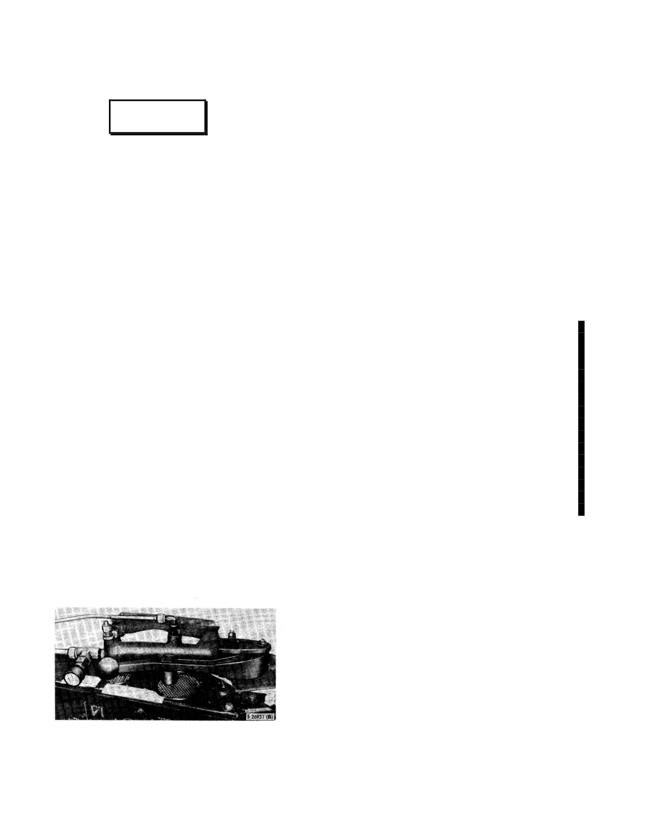
2.4.7.1 Rotor Brake Cylinder and Lever. A rotor
automatic rotor brake is on; however, the automatic rotor
brake lever (Figure 2-16) is connected directly to the rotor
brake is not applied until the blade fold master switch is
brake hydraulic cylinder to the right and forward of the
activated. The light will go off when the rotor brake is
disengaged.
overhead switch panel on the pilot compartment ceiling.
The rotor brake is applied by pulling down and forward as
indicated on the decal aft of the lever on the upper
2.5
FUEL SYSTEM
structure. The decal is marked TO ENGAGE ROTOR
BRAKE PUSH LEVER FORWARD. The decal also has
2.5.1 Internal Fuel System. These helicopters are
an arrow pointing forward. When actuated, a lock-lever at
equipped with two pressure-type fuel systems (FO-7). The
forward tank system supplies fuel to the No. 1 engine and
the forward outboard side of the cylinder locks the brake
lever in the applied (forward) position. To release the
the aft tank system supplies fuel to the No. 2 engine. On
rotor brake, reposition the lock-lever aft and swing the
the ET the forward tank also supplies fuel to the auxiliary
rotor brake lever aft and up against the bottom of the
power unit (APU). The forward and aft systems each
cylinder until it snaps into place. The lockpin may be
consist of a tank with two bladder type cells, a collector
made inoperative by turning it until it remains in the OUT
can equipped with two boost pumps, an ejector system
that continually fills the collector can with a boost pump
position. For normal shutdown, the rotor brake should be
applied firmly and smoothly. As rotor rpm approaches
on, a main line filter, and a firewall shutoff valve. The
zero, rotor brake pressure should be reduced in order to
collector can boost pump and ejector arrangement provide
ease rotor blades to a stop, precluding any tendency of
for a minimum of unusable fuel. A crossfeed line between
whip stopping. When the rotary wing blades are folded,
the two pressure-type systems permits fuel from both the
the rotor brake lever must be on to open interlock for a
forward and aft tanks to be directed to one engine during
single-engine operation, or fuel from one tank to supply
normal start. For emergency shutdown, the rotor brake
lever may be forced forward into the full ON position
both engines.
after closing the engine speed selectors. In case of an
emergency, the rotor brake, when fully applied, is
The center tank replaces consumed fuel in the forward
designed to stop the rotors from
77-percent Nr in 14
and aft tanks. The center tank consists of a single
seconds with engines at idle and from 91 percent in 20
bladder-type cell, two ejectors, and a common opening
between the forward and center tanks. The opening
seconds with engines at idle.
allows fuel to spill freely into either tank. One center tank
ejector is associated with the forward tank and the other
with the aft tank. The center tank ejector associated with
the forward tank will pump fuel into the forward tank
when one or two forward tank boost pumps are on. This
is the only means of transferring fuel from the center to
forward tank once the fuel level drops below the common
opening level. The center tank ejector associated with the
aft tank will pump fuel into the aft tank when one or two
aft tank boost pumps are on and the float valve in the aft
tank is open. The aft tank float valve opens when the aft
tank fuel level drops below 600 to 900 pounds.
Figure 2-16. Rotor Brake Lever
When the aft tank fuel system is operating and the aft
tank float valve is closed, fuel flow from the aft tank
system to the center tank aft ejector transfers fuel from the
aft tank into the center tank. To prevent overfilling the
2-30
ORIGINAL
NAVAIR 01-230HLH-1
center and forward tanks, a float shutoff valve is
Placing the switch in the OPEN position electrically
incorporated in the center tank aft ejector line. The fuel
opens the crossfeed valve that connects the systems. The
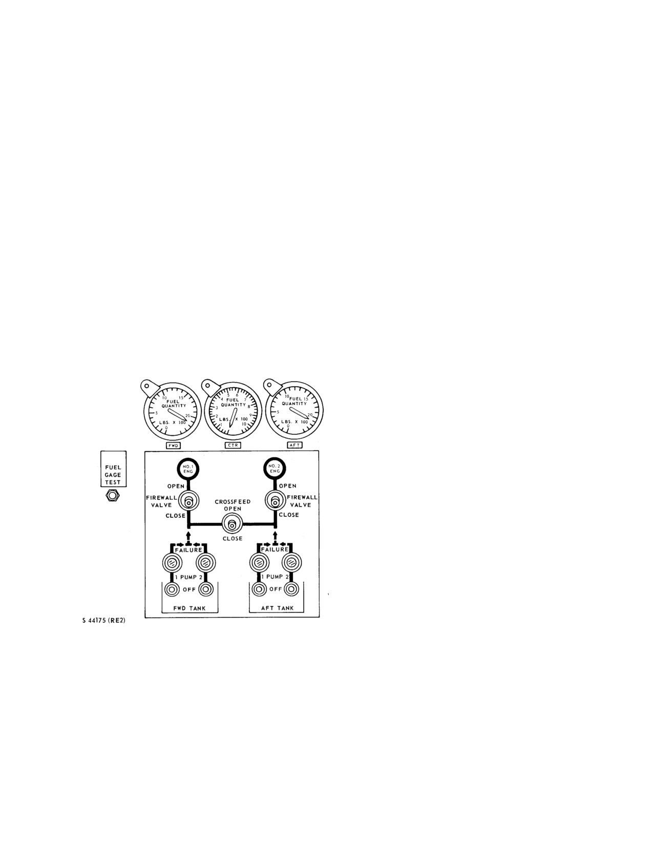
management panel (Figure 2-17) on the instrument panel
crossfeed system may be used to supply fuel under
contains the four fuel boost pump switches, the boost
pressure from both tanks to any one or both engines. The
pump failure warning lights, the crossfeed switch, and the
crossfeed system does not transfer fuel between tanks.
two firewall shutoff switches. The tanks may be filled by
either a pressure-refueling system or the conventional
2.5.1.3 Fuel Boost Pumps. Two boost pumps in each
gravity feed through the filler necks. Each tank has a fuel
collector can in the fuel tanks supply fuel under pressure
quantity gauge that indicates the quantity of fuel in
to the two independent fuel systems. Normally, fuel flows
pounds. See Figure 2-22 for fuel quantity data and Figure
from the tanks through a fuel filter, check valve, and
3-7 for fuel specification and grade.
firewall shutoff valve to the engine driven fuel pump and
then to the engine fuel control unit. Should to engine-
2.5.1.1 Fuel Shutoff Valve Switches. Two fuel
driven fuel pump fail, the engine will fail because of fuel
shutoff valve switches marked FIREWALL VALVE with
starvation.
the marked positions OPEN and CLOSE are on the fuel
management panel. These switches control the fuel
2.5.1.4 Fuel Boost Pump Operation
shutoff valves overhead in the cabin in front of the engine
compartment. Placing the switches in the CLOSE
Note
position shuts off the flow of fuel to the engines. In case
of electrical failure, the valves will remain in the last
When starting No. 1 engine with an exter-
energized position. The switches and valves are powered
nal dc power source or the battery, the
by the primary bus, and protected by circuit breakers on
boost pumps will be inoperative because of
the center circuit breaker panel marked 1 ENG 2 under
their ac power source requirement. If all
the general headings FUEL SYSTEM and VALVES.
fuel lines to the engine are full, the engine-
driven fuel pumps will be capable of
supplying sufficient fuel for starting.
2.5.1.5 Fuel Boost Pump Switches. Four boost
pump switches on the fuel management panel control the
fuel flow to the engine. The switches are in sets of two;
those for the forward tank are marked FWD TANK while
the two for the aft tank are marked AFT TANK. Above
each switch is a number 1 or 2 to designate the pump in
the tank controlled by that switch. Each switch has two
marked positions: PUMP (ON position) and OFF. The
boost pumps in the collector can in the forward cell of
each fuel tank supply fuel to the engine-driven pump
when the switches are in the PUMP position
(FWD
TANK and AFT TANK). The pump switches are
controlled by dc power and are protected by four circuit
breakers on the center circuit breaker panel. The boost
pumps are operated on ac power with each pump pro-
tected by a circuit breaker.
2.5.1.6 Fuel Boost Pump Failure Warning Lights.
Four pressure switches, two installed in each tank, are
Figure 2-17. Fuel Management and Fuel Quantity
connected to the pressure feed line from each boost pump.
Panel
The pressure switches are connected by direct current
through the warning light circuit breaker on the center
2.5.1.2 Crossfeed Switch. A fuel crossfeed switch
circuit breaker panel and are marked PWR and TEST
marked CROSSFEED is on the fuel management panel.
under the general heading WARNING LTS. When the
The switch has marked positions CLOSE and OPEN and
boost pumps are first turned on or the boost pump
actuates a valve that operates on dc power and is
switches are tested, the fuel pump failure warning lights
protected by a circuit breaker marked X FEED on the
will go on and then off. They are lit until pressure is built
center circuit breaker panel under the general headings
up in the system. The switches close if the pumps fail, and
FUEL SYSTEM and VALVES. Normally, the switch is
the warning lights marked PUMP FAILURE on the fuel
in the CLOSE position. With the switch in the CLOSE
management panel will light. Pressure must decrease to
position, the No. 1 engine receives fuel from the forward
approximately 16-1/2 psi to energize the warning circuit.
tank and the No. 2 engine receives fuel from the aft tank.
2-31
ORIGINAL
NAVAIR 01-230HLH-1
2.5.1.9 Fuel Filter Bypass Caution Lights. The fuel
WARNING
filter bypass caution lights will light whenever fuel bypass
is imminent. This normally occurs when a pressure
differential of approximately 1.1 to 1.7 psi is sensed at the
filter. As the contamination increases and the pressure
If a fuel boost pump failure warning light
differential increases to 1.9 to 2.3 psi, the bypass valve
goes on, activate the remaining boost pump
opens and, at this point, the filter is being bypassed. The
for that tank before securing the affected
caution lights are marked FWD FUEL BYPASS and AFT
pump. If the fuel boost pump failure
FUEL BYPASS, indicating which fuel system is in a
warning light goes off when both pumps
condition of impending filter bypass. The lights operate
are activated, there may be a fuel leak.
on dc power and are protected by the WARNING LTS
PWR circuit breaker on the center circuit breaker panel.
2.5.1.7 Fuel Low-Level Caution Lights
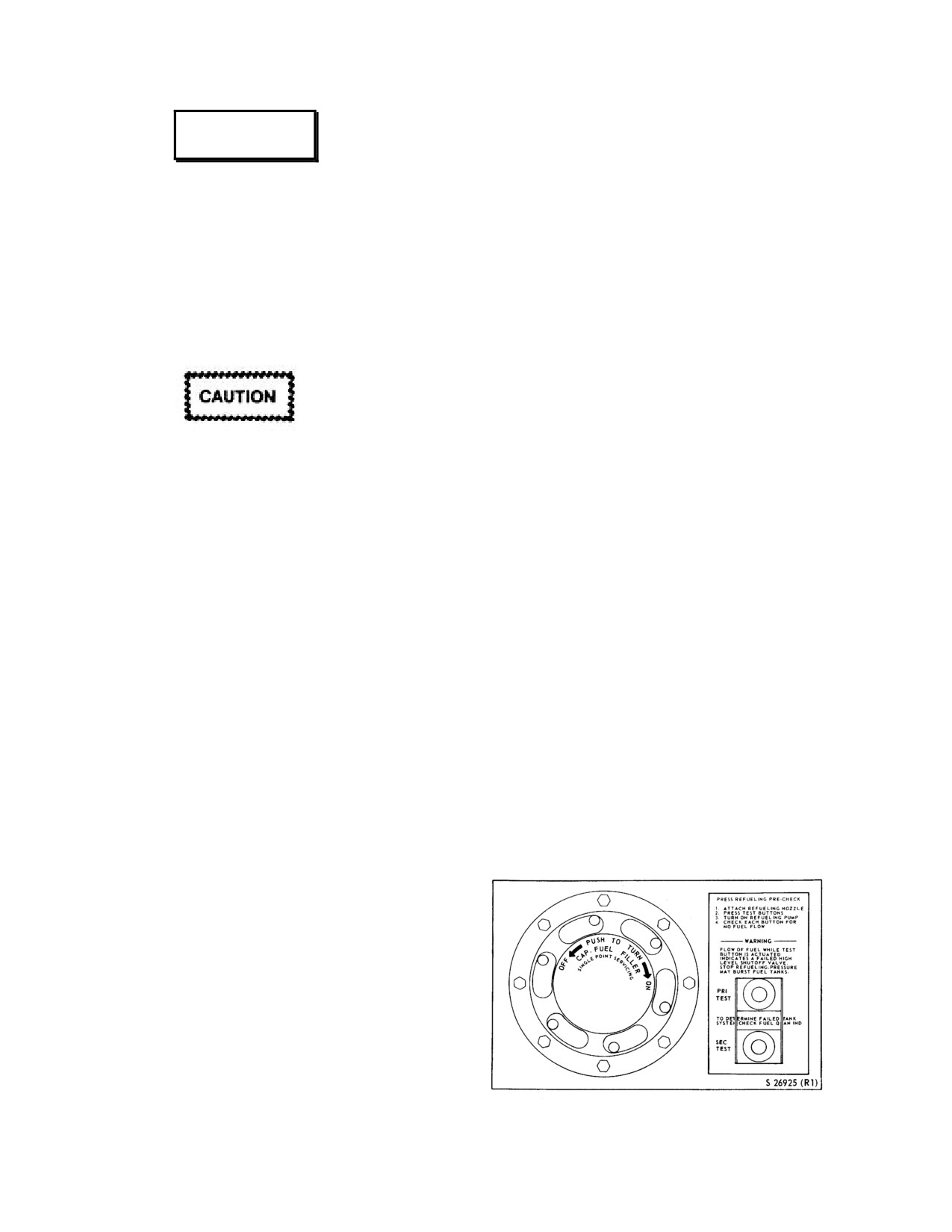
2.5.1.10 Pressure Fueling-Defueling System. The
system is a single-point fueling-defueling system. The
pressure-refueling filler cap (Figure
2-18) is on the right
side of the fuselage, inside the step below the cargo door.
The filler cap is marked CAP-FUEL FILLER SINGLE
POINT SERVICNG. To fill the fuel tanks, the refueling
When the fuel low-level caution lights go
nozzle is connected to the adapter connection and fuel is
on, attitudes of over
6o noseup should be
pumped through the fuel lines and the fueling and
avoided because of the possibility of fuel
defueling valves in the forward and aft fuel tanks. The
starvation.
fueling and defueling valves are normally closed; for
refueling, the valves open with pressure at the inlet until
The low-level caution lights are on the CAUTION
high-level shutoffs close the valves. The high-level
PANEL on the instrument panel. The caution lights,
shutoff valve for the forward tank is in the center tank.
operating on dc power, are tested by the master TEST
This allows both the forward and center tanks to fill
button on the caution panel and are protected by circuit
simultaneously through the common opening. When the
breakers marked LOW LEVEL FWD and AFT on the
center tank is full, the refueling process is stopped for
center circuit breaker panel.
those tanks. For defueling, the valves open with vacuum
at the inlet until the low-level shutoffs close the valves.
On UH-3H helicopters, the FWD FUEL LOW and
The low-level shutoffs are only in the forward and aft
AFT FUEL LOW caution lights for the forward and aft
tanks.
tanks will go on when approximately 210 to 280 pounds
per tank remain in a
3o nosedown attitude, or between
2.5.1.11 Pressure-Refueling
Switches.
The
170 and 200 pounds per tank remain when in a hover.
switches marked PRI TEST and SEC TEST are on a panel
(Figure
2-18) marked PRESS REFUELING PRECHECK
2.5.1.8 Fuel Quantity Gauges and Test Switch.
next to the refueling-defueling adapter connection. The
The fuel quantity gauges on the instrument panel above
switches are used to check the reliability of the fuel high-
the fuel management panel indicate the fuel quantity in
level shutoffs. The panel contains information on the
each tank in pounds. UH-3 helicopters have three quantity
refueling precheck that must be followed prior to using
gauges for the forward, center, and aft tanks, respectively.
the pressure refueling system.
The tank unit capacitance system used in this helicopter is
practically unresponsive to volumetric changes resulting
from various temperatures. The dielectric between the two
electrodes will vary as the fuel varies. The fuel quantity
gauges are calibrated to measure this voltage differential
in pounds of fuel. Fuel quantities are shown in the fuel
quantity data tables. The fuel quantity indicating system
may be tested by pressing the fuel quantity gauge test
switch marked FUEL GAGE TEST to the left of the fuel
management panel. Pressing the button-type switch will
induce a current reversal that causes the needles to turn to
zero. Upon release of the test switch, the normal current
should cause the needles to return to the previous reading.
This test shows that the fuel quantity indicating system is
operating correctly. The fuel quantity indicating system
Figure 2-18. Single-Point Servicing Panel
operates on ac power and is protected by circuit breakers.
2-32
ORIGINAL
NAVAIR 01-230HLH-1
2.5.2
(NON ET) Helicopter In-Flight Refueling
level at which the aft tank float valve opens (600 to 900
System
(HIFR). Helicopters are equipped with a
pounds), the center tank aft ejector starts to transfer fuel
system for refueling from a surface vessel while in flight.
into the aft tank.
Fuel is pumped on board the helicopter under pressure
through a Wiggins quick-disconnect nipple. The Wiggins
For operation under unusual conditions, the fuel
quick-disconnect nipple is in the cabin floor near the
quantity in the tanks can be equalized by operating both
sliding cabin door. The nipple is provided with a cover
engines from either the forward or aft tank systems. This
marked REPLACE COVER AFTER FILLING.
A
can be done by opening the crossfeed and turning on both
separate grounding receptacle is provided at this station.
boost pumps in the tank system being used, and one boost
A filter is incorporated in the system to prevent
pump on in the tank system not being used. The tank
contaminated fuel from entering the helicopter. In
with two boost pumps on will supply fuel to both engines,
addition, the station is equipped with a dome light with a
because of the greater pressure furnished by the two
control switch. See Chapter 9 for Helicopter In-Flight
pumps that close the check valve downstream of the tank
Refueling Procedures.
with only one pump operating.
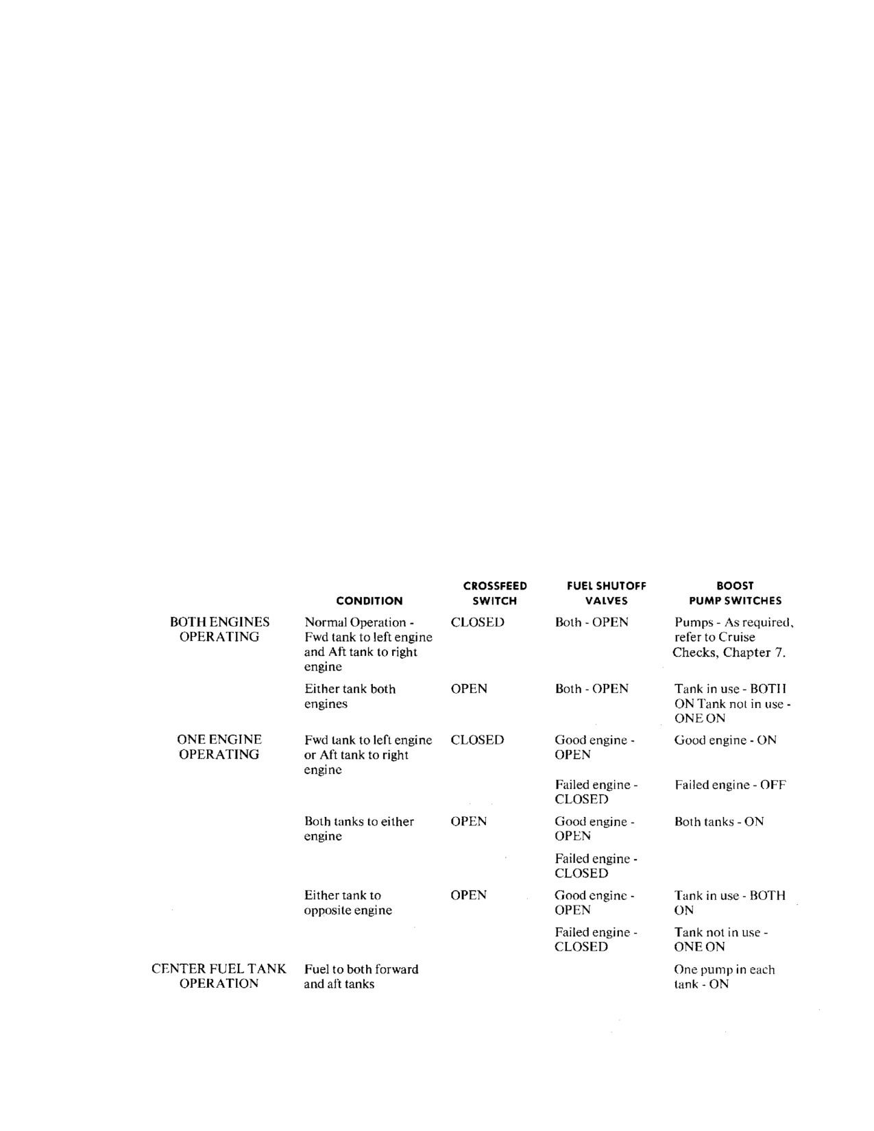
2.5.3 Fuel System Management. For normal
2.5.4 Fuel Dump System. This system will dump fuel
operation of UH-3 helicopters (Figure
2-19) with cross-
from a single tank at a rate of 400 to 500 pounds per
feed closed and one boost pump on in each tank, the
minute, and simultaneously from both tanks at approxi-
forward and center tank will furnish fuel to the No. 1
mately 800 pounds per minute. Fuel will stop dumping in
engine and the aft tank will furnish fuel to the No. 2
either tank when the associated tank's fuel low caution
engine. This causes the aft tank quantity gauge to drop
light goes on, since the caution light sensor and the dump
more rapidly than the forward and center tank gauges. In
standpipe are at approximately the same level. The tank's
addition, as long as the center tank float shutoff valve is
dump pump should be turned off at this time to prevent
open and the aft tank float valve is closed, fuel will be
the pump from overheating. If the pump is not turned off,
transferred at a low rate from the aft tank to the center and
a thermal device in the pump will automatically turn it off
forward tanks. This also causes the aft tank quantity
and the pump will have to be removed to reset the thermal
gauge to drop more rapidly than the center and forward
device.
tank gauges. Once the aft tank fuel is depleted below the
Figure 2-19. Fuel System Management
2-33
ORIGINAL
NAVAIR 01-230HLH-1
The system
(FO-7) uses the center point
2.6 ELECTRICAL POWER SUPPLY SYSTEM
pressure-fueling plumbing to dump fuel overboard
(FO-8)
through a tube near the right side of the tailwheel. The
forward and aft tanks each have a dump pump and dump
Two ac generators supply power to the electrical
valve that are off and closed respectively when not
system. Four transformers provide 26-volt single-phase ac
dumping. A system dump valve incorporated in the center
power. Two rectifiers provide
28-vdc control and
point fueling system is closed when not dumping to
operating power. One inverter supplies 115-vac power.
prevent dumping when pressure fueling. When dumping,
One battery supplies 24-vdc power.
the high-level shutoff sensor is actuated and closes the
fueling/defueling valve to prevent dump fuel from
2.6.1 Alternating Current Power Supply System.
reentering the tank.
Ac power is supplied by two generators designated as
Nos.
1 and
2. Associated system components are
The primary dc bus furnishes control power to the
designated in a similar manner. System operation is
tank dump systems through two FUEL SYSTEM circuit
automatic; control switches on the overhead switch panel
breakers on the center circuit breaker panel marked FWD
and monitoring light capsules on the caution and advisory
and AFT above the general heading DUMP. The forward
panels are provided. Normally, associated primary bus
tank dump pump operating power is furnished by the No.
loads are assumed by each generator and the monitored
1 primary ac bus through a circuit breaker on the copilot
bus load is powered by the No. 2 generator. Primary bus
circuit breaker panel marked DUMP FWD under the
loads are those that are essential for night and/or
general heading FUEL PUMP. The aft tank dump pump
instrument flight and for operation of equipment
operating power is furnished by the No. 2 primary ac bus
necessary for mission requirements. The monitor bus load
through a circuit breaker on the pilot circuit breaker panel
is not essential for this type of flight. If either generator
marked DUMP AFT under the general heading FUEL
fails, its primary bus load is automatically transferred to
PUMP. The system dump valve is controlled by primary
the remaining generator. With a failed generator, the
dc bus power through a FUEL SYSTEM circuit breaker
monitor bus load is automatically dropped. An external ac
on the center circuit breaker panel marked FUEL SYSEM
power receptacle permits use of an external ac power unit
above the general heading DUMP.
for ground power application.
2.5.4.1 FUEL DUMP Control Panel. The panel
2.6.1.1 Generators. Two
115-/200-volt, three-phase,
marked FUEL DUMP (Figure 2-20) is on the cockpit
400-Hz, brushless PMGs are mounted on and driven by
console. There are two guarded switches on the panel, one
the accessory section of the main gearbox. Generator
with marked positions FWD and OFF and the other AFT
output varies with temperature and altitude. Generator ac
and OFF. Placing the forward tank switch to FWD opens
voltage is delivered to the associated supervisory panel
the tank dump valve, turns the dump pump on, actuates
and generator contactor relay. The permanent magnet
the high-level shutoff to close the fueling/defueling valve,
sections of the generators develop ac power that is
and opens the system dump valve. The aft tank switch
rectified to dc power in the supervisory panel to be used
operates the same way.
in the control circuits.
2.6.1.1.1 (ET) APU Generator. One 115-/200-volt, 3-
phase, 400-Hz generator is mounted on the APU and is
used for instrumentation, minimal lighting, and ground
WARNING
operation of the air conditioning system. The generator
output varies
with temperature and altitude.
Electrical malfunction in either the forward
(Approximately 32 kVA at sea level.)
or aft dump valves or both may cause
inadvertent fuel dumping without pilot
2.6.1.2 Supervisory Panels. The supervisory panels
knowledge. If this happens, rapid fuel loss
designated Nos. 1 and 2 provide control for relays in the
will result.
electrical system. When the No. 1 generator is developing
normal ac power and the generator switch is placed ON,
PMG ac power from the same generator rectified to dc
power by its associated supervisory panel will be used by
the supervisory panel to close the generator contactor
relay. Closing the No. 1 generator contactor relay permits
the No. 1 generator to power the No. 1 primary ac bus and
the supervisory panel to deliver 28 vdc to the ac monitor
bus relay. In addition, it opens the No. 1 generator caution
light circuit causing the light to go off. The No.
2
Figure 2-20. Fuel Dump Panel
supervisory panel operates the same way to power the No.
2-34
ORIGINAL
NAVAIR 01-230HLH-1
2 primary ac bus and to turn off the No. 2 caution light.
range. If any of the monitored conditions are not normal,
Dc power from the No. 2 supervisory panel also closes
the generator contactor relay will open, taking the
the ac monitor bus control relay that permits 28 vdc from
associated generator off the line, deenergizing the ac and
the No. 1 supervisory panel to close the dc monitor bus
dc monitor buses, and lighting the associated generator
relay and the ac monitor bus contactor relay. Therefore,
caution light. In case of a generator failure, primary ac
28-vdc power is required from both the Nos. 1 and 2
bus loads will be switched automatically to the remaining
supervisory panels to energize the ac and dc monitor
generator.
buses. If either generator fails to produce PMG ac power,
the primary dc bus supplies backup dc voltage to each
2.6.1.3 Generator Switches. These switches are on
supervisory panel through circuit breakers on the center
the overhead switch panel (Figure 2-9) under the general
circuit breaker panel marked 1 and 2 under the general
heading 1 GEN 2 and have the marked positions ON,
heading PMG BACK-UP. The supervisory panels provide
OFF-RESET, and TEST. Placing the switch ON puts the
protection for the electrical system. Three-phase AC
respective generator on the line by closing the generator
power delivered to the panel from its associated generator
contactor relay. The OFF-RESET position turns the
is monitored by the panel at all times for open phase,
generator off and resets the cycle. When the generators
overvoltage, and undervoltage. The panel monitors for
drop off the line because of an overvoltage or
underfrequency (Figure
2-21) when the helicopter is on
undervoltage they will have to be reset; however, when
the ground with its main landing gear struts compressed.
the generators drop off the line because of an
In flight, the underfrequency protection is eliminated by
underfrequency, they will come back on automatically.
action of the microswitch attached to the scissors of each
The TEST position is used for maintenance.
landing gear. In this condition, the generators will remain
on the line throughout the entire normal rotary wing speed
FLIGHT POSITION
ACCESSORY DRIVE POSITION
PERCENT
GENERATOR
PERCENT
GENERATOR
Nf or Nr
FREQ
Nf
Nr
FREQ
95
380.0
99
0
380.0
100
400.5
104
0
400.0
105
420.0
109
0
420.0
FLIGHT POSITION
NOTES
1.
Under frequency protection is locked out during flight.
1.
Generator should pickup (come on the line) between 92.1% and 96.8% Nf/Nr and should drop out
within minus 2% of the pickup value. (These figures assume a 2% tachometer system accuracy.)
ACCESSORY DRIVE POSITION
NOTES
1.
During ground operation frequency is set at 377-383 Hz for pickup, 374-380 Hz for dropout.
2.
Generator should pick up (come on the line) between 95.8% and 101.3% Nf and should dropout
within minus 2% of the pickup value. (These figures assume a 2% tachometer system accuracy.)
Figure 2-21. Generator Frequency at Various Rotor and Power Turbine Speeds
2-35
ORIGINAL
NAVAIR 01-230HLH-1
(JP-4 AT 15.6oC)
GRAVITY REFUELING
FORWARD TANK
CENTER TANK
AFT TANK
TOTAL FUEL
GALLONS POUNDS GALLONS POUNDS GALLONS POUNDS GALLONS POUNDS
UNUSABLE
2.65
17.2
.83
5.4
2.65
17.2
6.13
39.8
USABLE
344.35
2238.3
147.17
956.6
350.35
2277.3
841.87
5472.2
FULLY
347.00
2255.5
148.00
962.0
353.00
2294.5
848.00
5512.0
SERVICED
PRESSURE REFUELING
UNUSABLE
2.65
17.2
.83
5.4
2.65
17.2
6.13
39.8
USABLE
338.35
2199.3
145.17
943.6
341.35
2218.8
824.87
5316.7
FULLY
341.00
2216.5
146.00
949.0
344.00
2236.0
831.00
5401.5
SERVICED
1. Data basis 0o fuselage attitude.
2. Fuel density JP-4 = 6.5 pounds per gallon.
(JP-5 AT 15.6oC)
GRAVITY REFUELING
FORWARD TANK
CENTER TANK
AFT TANK
TOTAL FUEL
GALLONS POUNDS GALLONS POUNDS GALLONS POUNDS GALLONS POUNDS
UNUSABLE
2.65
18.1
.83
5.6
2.65
18.1
6.13
41.8
USABLE
344.35
2341.6
147.17
1000.8
350.35
2382.4
841.87
5724.8
FULLY
347.00
2359.7
148.00
1006.4
353.00
2400.5
848.00
5766.6
SERVICED
PRESSURE REFUELING
UNUSABLE
2.65
8.1
.83
5.6
2.65
18.1
6.13
41.8
USABLE
338.35
2300.7
145.17
987.2
341.35
2311.1
824.87
5599.0
FULLY
341.00
2318.8
146.00
992.8
344.00
2339.2
831.00
5640.8
SERVICED
1.
Data basis 0o fuselage attitude.
2.
Fuel density JP-5 = 6.8 pounds per gallon.
Figure 2-22. Fuel Quantity Data
2-36
ORIGINAL
NAVAIR 01-230HLH-1
2.6.1.4 Generator Caution Lights. Two generator
2.6.1.8 External Ac Power Receptacle. The
caution lights marked
#1 GENERATOR and #2 GEN-
external ac power receptacle is mounted on the left aft
ERATOR, respectively, are on the caution panel. These
side of the fuselage. This receptacle is used to introduce
lights will go on whenever the associated generator is
115-/200-volt, three-phase,
400-Hz ac power into the
taken off the line by the opening of the generator
helicopter electrical system.
contactor relay that causes the caution light circuit to be
completed. The generator caution lights are powered by
Note
the primary dc bus and protected by circuit breakers Nos.
1 and 2 under the general headings GENERATOR and
On the UH-3H Executive Transport
WARNING LTS on the center circuit breaker panel.
helicopters, the BRIGHT/DIM switch
on the CABIN LIGHTS panel should
2.6.1.5 Inverter. A
100-volt ampere, 115-volt inverter
remain in the DIM position while
is incorporated in the electrical system to provide ac
operating on external power.
power to the fire detection system, fuel quantity
indicating system, electrical autotransformer, and the
An external power monitor panel monitors external
isolation transformer. The inverter is automatically turned
power voltage level, frequency, and phase rotation. If
on when ac power is not present in the helicopter, and the
these are correct, dc power will pass through the external
primary dc bus is activated by an external dc power unit,
power monitor panel and energize the external power
or the battery switch is turned on. Primary dc bus
contactor relay, introducing external three-phase power
operating power for the inverter is protected by a circuit
into the electrical system. A switch marked RESET-ON-
breaker marked INV on the center circuit breaker panel.
OFF under the heading EXT PWR on the overhead switch
Inverter ac power is protected by two circuit breakers on
panel (Figure
2-9) must be ON to allow power to pass
the copilot circuit breaker panel marked PWR A and
through the power monitor panel. At OFF, ac power is
PWR C under the general heading INVERTER.
removed by the power monitor panel. If ac power voltage
level, frequency, and phase rotation are not correct, 28-
2.6.1.6 Transformers. Four transformers in the ac
vdc power will not energize the external power contactor.
system convert 115-volt power from the primary ac buses
When the fault in the external ac power source is cor-
to 26 volts. The Nos. 1 and 2 radio autotransformers are
rected, the EXT PWR switch must be momentarily placed
powered by the No. 1 primary ac bus. The No. 1 radio
to RESET to reactivate the external power monitor panel.
autotransformer supplies power to the TACNAV or
Dc control power is protected by a circuit breaker on the
navigation system, LF/ADF, BDHIs, TCDI, and GSDA.
center circuit breaker panel marked EXT PWR. The EXT
PWR ON advisory light will go on when the ac power
The No. 2 radio autotransformer supplies power to the
receptacle door is open.
tacan, UHF-DF, and compass system. The radio
autotransformers are protected by two circuit breakers on
2.6.1.9 External Power Advisory Light. This light
the copilot circuit breaker panel under the general heading
on the advisory panel marked EXT PWR ON will go on
AUTO XMFR and are marked 1 and 2, respectively. The
when the ac external power door is open or when external
electrical autotransformer is powered by the No.
1
dc power is being supplied to the helicopter.
primary ac bus or the inverter and supplies power to the
No.
1 engine oil pressure indicator, primary servo
2.6.1.10 Ac Circuit Breakers. Ac circuit breakers are
hydraulic pressure indicator, utility hydraulic pressure
on the pilot and copilot circuit breaker panels (Figure 2-
indicator, and the No. 1 engine torquemeter. The elec-
23).
trical autotransformer is protected by a circuit breaker on
the copilot circuit breaker panel marked AUTO XMFR 0
2.6.2 Direct Current Power Supply System.
C. The isolation transformer is powered by the No. 2
Dc power is supplied by two rectifiers, designated as Nos.
primary ac bus or the inverter and supplies power to the
1 and 2 that are powered by the Nos. 1 and 2 primary ac
No. 2 engine oil pressure indicator, the auxiliary servo
buses, respectively. The dc system operation is automatic;
hydraulic pressure indicator, main gearbox oil pressure
control switches and rectifier caution lights are provided.
indicator, and the No. 2 engine torquemeter. The isolation
Normally, primary and monitor bus loads are assumed by
transformer is protected by a circuit breaker on the pilot
both rectifiers. Primary bus loads are those loads essential
circuit breaker panel marked XMFR NO.2 Ø C.
for flight under night instrument conditions and for
operation of equipment necessary for mission
2.6.1.7 Utility Ac Power Receptacle. There are one
requirements. The monitor bus loads are those not
or two
115-/200-vac utility receptacles on the sensor
essential for this type of flight. If one rectifier fails, the
operator console. There is one ac utility receptacle at the
associated reverse current cutout relay will remove the
No. 2 hoist operator station.
failed rectifier from the primary dc bus. The remaining
rectifier will assume the primary dc bus loads and the
monitored dc bus load will be dropped. The battery can
2-37
ORIGINAL
NAVAIR 01-230HLH-1
provide power to the primary dc bus when no other source
2.6.2.3 Battery. A
24-volt,
20-ampere hour, nickel
is available. The external dc power receptacle and
cadmium battery in the nose section forward of the pilot
associated circuitry permit use of an external power unit
compartment is reached from outside the helicopter.
for ground power application.
Battery power is used for limited ground operations when
no external power is available and as an emergency
2.6.2.1 Rectifers. Two
200-ampere,
28-vdc rectifiers
source of power to the primary dc bus. The transformer-
are incorporated in the system. The rectifiers require an ac
rectifiers supply charging current for the battery.
input from the generators or from an external ac power
source. The rectifiers are designated as Nos. 1 and 2, and
2.6.2.4 Battery Switch. The battery switch is on the
the associated components are designated in a similar
overhead switch panel (Figure
2-9) in the cockpit. The
manner. Both rectifiers normally supply power to the
switch is marked BAT and has marked positions OFF and
primary dc bus. The primary dc bus supplies power to the
ON. The ON position energizes the battery relay that
monitor dc bus. The No. 1 rectifier receives three-phase
connects the battery to the primary dc bus.
power from the No. 1 primary ac bus, and the No. 2
rectifier receives three-phase power from the No.
2
2.6.2.5 Utility Dc Power Receptacles. One utility dc
primary ac bus. The ac input is stepped down, rectified,
power receptacle is on the pilot overhead control panel
and filtered within each rectifier; the dc output is fed to
and another is on the right side of the cabin at the No. 2
the associated reverse current cutout relay. During normal
hoist operator station. These receptacles are powered by
operation, dc power from the reverse current cutout relay
the monitor dc bus and protected by two circuit breakers
is fed to the primary dc bus. The reverse current cutout
on the pilot circuit breaker panel under the general
relay prevents current flow from the primary dc bus to a
heading UT RECP and marked CKPT and CAB,
failed rectifier. The monitor dc bus will be dropped from
respectively.
the line if the ac monitor bus relay is open. The dc
monitor bus relay must be closed for the monitor bus to
2.6.2.6 External Dc Power Receptacle. The 28-volt
receive power. Power to close this relay comes from the
external dc power receptacle is on the right side of the
primary dc bus and is routed through the No. 2 and the
helicopter below the pilot window. External power can be
No. 1 reverse current cutout relays. If either the rectifier,
connected and used for all ground operation until the
reverse current cutout relay, or ac generator is inoperative,
generators are in operation. As soon as external power is
the monitor dc bus will be dropped from the line and the
connected, the external power relay is energized, external
appropriate caution light/lights will go on. The No.
1
power is supplied to the primary dc bus, the EXT PWR
rectifier is protected by a circuit breaker on the copilot
ON advisory light goes on, and the monitor bus relay is
circuit breaker panel marked RECTIFIER NO. 1. The No.
energized to permit the primary dc bus to furnish power to
2 rectifier is protected by a circuit on the pilot circuit
the monitor dc bus. The dc external power unit to be used
breaker panel marked RECTIFIER NO. 2.
for starting should provide
28 vdc,
300 amperes
continuous, and 750 amperes current limited.
2.6.2.2 Rectifier Caution Lights. Two rectifier
caution lights are on the caution light panel marked #1
RECTIFIER and #2 RECTIFIER. Failure of a rectifier or
reverse current cutout relay will light the associated
caution light.
2-38
ORIGINAL
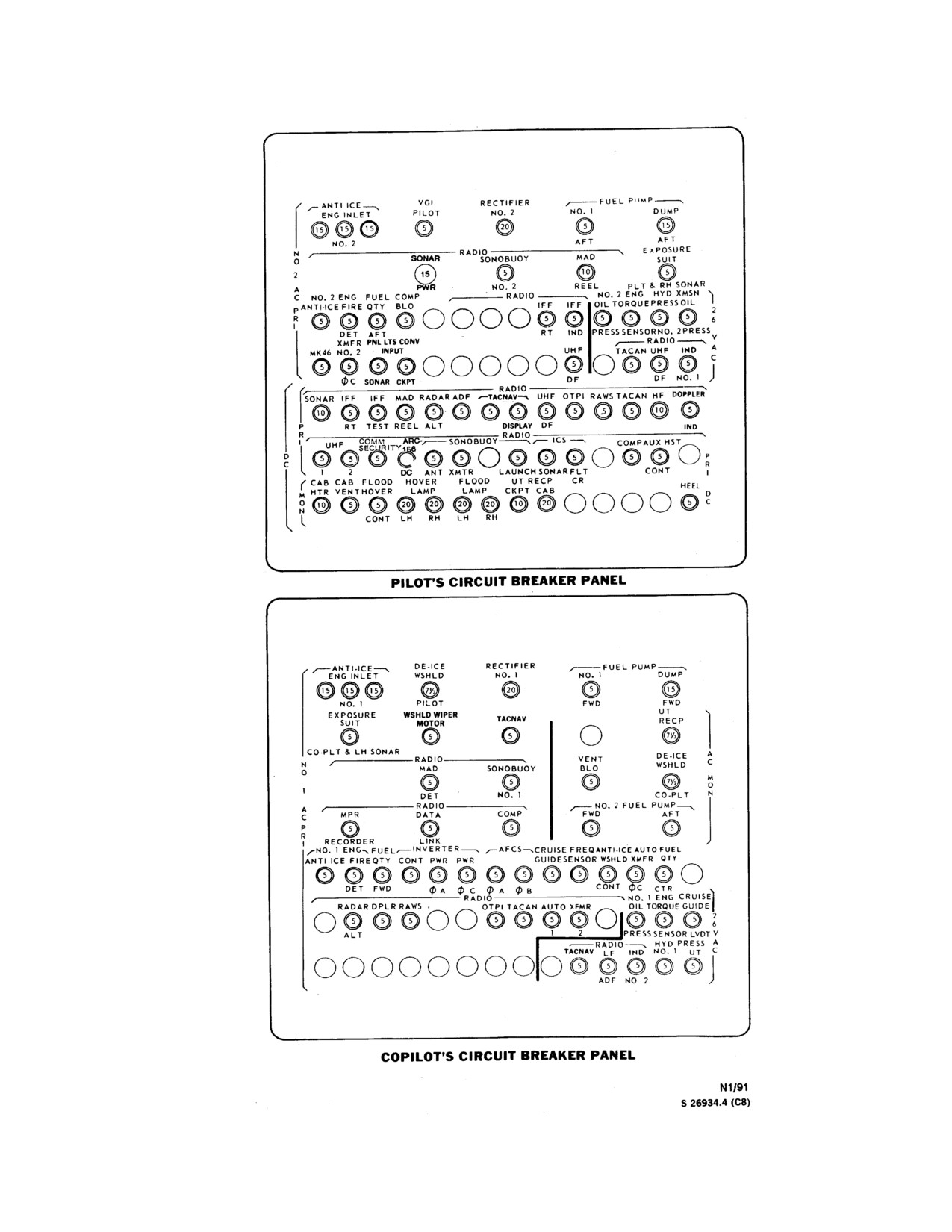
NAVAIR 01-230HLH-1
Figure 2-23. Circuit Breaker Panels (Typical) (Sheet 1 of 2)
2-39
ORIGINAL
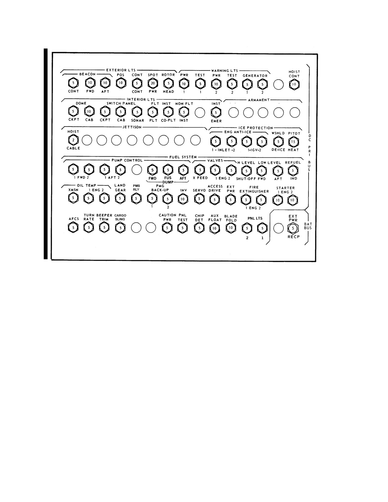
NAVAIR 01-230HLH-1
Center Circuit Breaker Panel
Figure 2-23. Circuit Breaker Panels (Typical) (Sheet 2 of 2)
2-40
ORIGINAL
NAVAIR 01-230HLH-1
ANTI-ICE
VGI
RECTIFIER
FUEL PUMP
ENG INLET
PILOT
NO.2
NO. 1
DUMP
15
15
15
5
20
5
15
NO. 2
AFT
AFT
N
O
2
A
NO.2 ENG
BLADE
NO.2 ENG
C
FUEL
COMP
HYD
XMSN
ANTI-ICE
FIRE
QTY
BLO PRESS
IFF
IFF
OIL
TORQUE
PRESS
OIL
P
R
I
5
5
5
5
5
5
5
5
5
5
5
2
DET
AFT
RT
IND
PRESS
SENSOR
NO.2
PRESS
6
XFMR
PNL LTS
VHF
RADIO
V
NO. 2
CONV INPUT
MAGR
UHF
NAV
TACAN
UHF
IND
A
C
5
5
1
5
5
5
5
5
OC
CKPT
DF
AN/ARN
DF
NO. 1
126
IFF
IFF
RADAR
ADF
TACNAV
UHF
OTPI
RAWS
TACAN
5
5
5
5
5
5
5
5
5
5
RT
TEST
ALT
DISPLAY
DF
P
R
COMM
VHF
CAB
CAB
UHF/VHF
I
SECURITY
ICS
NAV
COMP
HTR
VENT
D
5
5
5
5
2
5
10
5
C
1
2
FLT
AN/ARN
CR
126
FLOOD
HOVER
FLOOD
UT RECP
HOVER
LAMP
LAMP
CKPT
CAB
MDL
M
O
20
20
20
20
20
10
20
1
N
CONT
LH
RH
LH
RH
PILOT’S CIRCUIT BREAKER PANEL
UH-3H EXECUTIVE TRANSPORT
01771226
Figure 2-23.1.1 (ET) Circuit Breaker Panels (Sheet 1 of 3)
2-41
ORIGINAL
NAVAIR 01-230HLH-1
ANTI-ICE
DE-ICE
RECTIFIER
FUEL PUMP
ENG INLET
WSHLD
NO. 1
NO. 1
DUMP
15
15
15
7
1/2
20
5
15
PILOT
FWD
FWD
WSHLD WIPER
AIR COND
UT
MOTOR
TACNAV
COMPR MOTOR
RECP
5
5
35
7
1/2
AIR COND
AIR COND
DE-ICE
HEATER
BLO
VENT BLO
CONDENSER
WSHLD
A
C
5
15
25
71/2
M
O
CO-PLT
N
NO. 2 FUEL PUMP
COMP
FWD
AFT
N
5
5
5
O
1
NO. 1 ENG
FUEL
INVERTER
AFCS
FREQ
ANTI-ICE
AUTO
FUEL
A
ANTI-ICE
FIRE
QTY
CONT PWR
PWR
SENSOR
WSHLD
XMFR
QTY
C
P
5
5
5
5
5
5
R
I
DET
FWD
O A
O C
O A
O B
CONT
O C
CTR
NO. 1
ENG
RADAR
RAWS
OTPI
TACAN
AUTO
XMFR
OIL
TORQUE
5
5
5
5
5
5
5
5
2
ALT
1
2
PRESS
SENSOR
6
CEILING
RADIO
HYD
PRESS
V
LTS
TACNAV
LF
IND
NO. 1
UT
A
C
5
5
5
5
5
5
5
O A
O B
ADF
NO. 2
CO-PILOT’S CIRCUIT BREAKER PANEL
UH-3H EXECUTIVE TRANSPORT
01771228
Figure 2-23.1.1 (ET) Circuit Breaker Panels (Sheet 2 of 3)
2-42
ORIGINAL
NAVAIR 01-230HLH-1
EXTERIOR LTS
WARNING LTS
BLADE
BEACON
POS
CONT SPOT
ROTOR
PWR
TEST
PWR
TEST
GENERATOR
PRESS
5
10
10
10
5
20
5
10
5
10
5
5
5
5
CONT
FWD
AFT
CONT
PWR
HEAD
1
1
2
2
1
2
INTERIOR LTS
DOME
SWITCH PANEL
CEILING
FLT INST
NON FLT
READ
INST
PNL LTS
COURTESY
INSTR
5
10
5
5
5
5
5
5
10
5
5
5
10
5
CKPT
STOW
CKPT
CAB
CAB
PLT
CO-PLT
INST
LTS
EMER
2
1
LTS
LTS
D
ICE PROTECTION
C
ENG ANTI-ICE
WSHLD PITOT
P
R
5
5
5
5
5
15
I
B
1-INLET-2
1-IGV-2
DE-ICE
HEAT
U
FUEL SYSTEM
S
PUMP CONTROL
VALVES
H LEVEL
LOW LEVEL
REFUEL
5
5
5
5
5
5
5
5
5
5
5
5
5
5
5
1
FWD
2
1
AFT
2
APU
FWD
FUS
AFT
X-FEED
1
ENG
2
SHUT-OFF
FWD
AFT
IND
BOOST
DUMP
OIL TEMP
LAND
WSHLD
PMG
ACESS
EXT
FIRE
STARTER
XMSN
1
ENG
2
GEAR
WASHER
BACK-UP
INV
SERVO
DRIVE
POWER
EXTINGUISHER
1
ENG
2
5
5
5
5
5
5
5
10
5
5
5
5
5
10
10
1
2
1
ENG
2
TURN
BEEPER
APU
CAUTION
PNL
CHIP
AUX
BLADE
EMER
EMER
APU
EXT
AFCS
RATE
TRIM
CONT PWR
TEST
DET
FLOAT FOLD
LTS
LTS
CONTROL
PWR
BAT
5
5
5
4
5
5
5
10
10
5
5
4
5
BUS
2
1
RECP
OVERHEAD CIRCUIT BREAKER PANEL
01771230
Figure 2-23.1.1 (ET) Circuit Breaker Panels (Sheet 3 of 3)
2-43
ORIGINAL
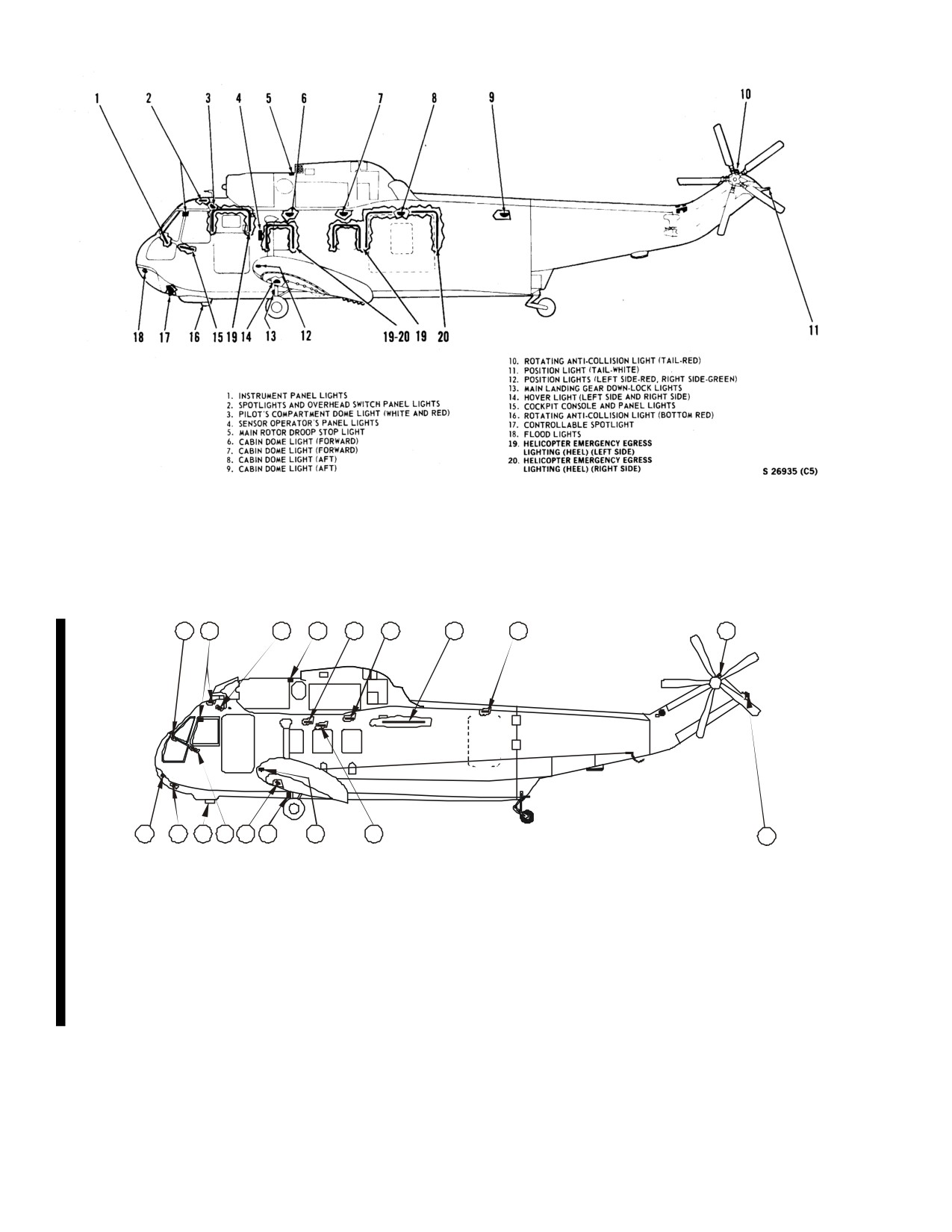
NAVAIR 01-230HLH-1
Figure 2-24. (NON-ET) Lighting System
1
2
3
4
5
6
7
8
9
18
17
16 15
14
13
12
11
10
1. INSTRUMENT PANEL LIGHTS
10. POSITION LIGHT (TAIL - WHITE)
2. SPOTLIGHTS AND OVERHEAD SWITCH PANEL LIGHTS
11. EMERGENCY EXIT LIGHT
3. PILOT'S COMPARTMENT DOME LIGHT (WHITE AND RED)
12. POSITION LIGHTS (LEFT SIDE - RED, RIGHT SIDE - GREEN)
4. MAIN ROTOR DROOP STOP LIGHT
13. MAIN LANDING GEAR DOWN - LOCK LIGHTS
5. READING LIGHTS (8 EACH - RIGHT SIDE)
14. HOVER LIGHT (LEFT SIDE AND RIGHT SIDE)
6. READING LIGHTS (8 EACH - LEFT SIDE)
15. COCKPIT CONSOLE AND PANEL LIGHTS
7. CEILING LIGHTS (9 EACH)
16. ROTATING ANTI - COLLISION LIGHT (BOTTOM RED)
8. EMERGENCY EXIT LIGHT
17. CONTROLLABLE SPOTLIGHT
9. ROTATING ANTI-COLLISION LIGHT (TAIL - RED)
18. FLOOD LIGHTS
01771105
Figure 2-24.1. (ET) Lighting System
2-44
ORIGINAL
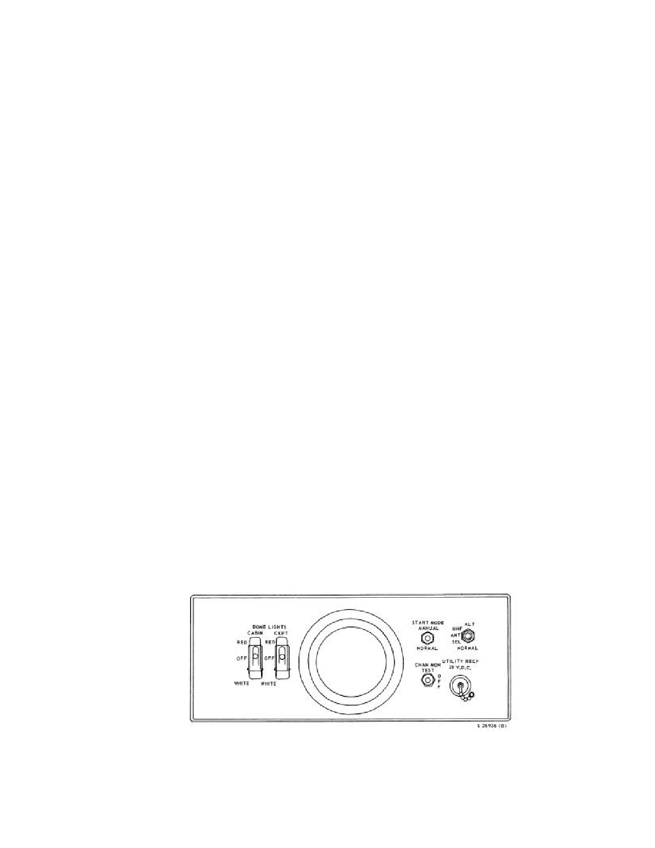
NAVAIR 01-230HLH-1
2.7 LIGHTING EQUIPMENT
2.7.1.3 Console and Panel Lights. The lights on the
All lights operate on direct current and are protected
cockpit console, the overhead switch panel, the pilot right
by circuit breakers. Switches and rheostats for operating all
console, and the copilot interphone control panel are
lights, except, cabin dome light, flood-hover lights, and
controlled by a rheostat marked CONSOLE & PANEL
spotlight, are on the overhead switch panel.
LIGHTS with marked position OFF and BRT on the
overhead switch panel. The cockpit console and panel
2.7.1 Interior Lights
lights operate from the primary dc bus and are protected by
a circuit breaker marked CKPT under the general heading
2.7.1.1 Pilot and Copilot Flight Instrument Lights.
SWITCH PANEL on the center circuit breaker panel. On
The pilot and copilot flight instrument panel lights (Figure
UH-3H helicopters, the console and panel lights also
2-24) are individually controlled by rheostats marked
require power from the No. 2 primary ac bus. They are
PILOT FLIGHT INST LIGHTS and COPILOT FLIGHT
protected by a circuit breaker marked CKPT under the
INST LIGHTS, both with marked positions OFF and BRT
general heading PNL LTS CONV INPUT on the pilot
on the overhead switch panel (Figure 2-9). The intensity
circuit breaker panel.
of the flight instrument light may be varied by turning each
rheostat. When the pilot flight instrument light rheostat is
2.7.1.4 Instrument Emergency Light. This light is
moved out of the OFF position, it automatically dims the
controlled by the rheostat marked INSTRUMENT EMER
master reset light, caution panel, advisory panel, landing
LTS with marked positions OFF and BRT on the overhead
gear warning light, and fuel boost pump failure warning
switch panel. The intensity of the instrument emergency
lights. The pilot and copilot flight instrument lights operate
light that is a red light in the pilot compartment dome light
from the primary dc bus and are protected by circuit
(Figure 2-25) may be varied by turning the rheostat on the
breakers marked PLT and CO-PLT under FLT INST on
overhead switch panel. The instrument emergency light
the center circuit breaker panel and overhead control panel
operates on dc power, and it is protected by a circuit
(Figures 2-23).
breaker marked INST EMER on the center circuit breaker
panel.
2.7.1.2 Nonflight Instrument Lights. These lights on
the instrument panel are controlled by a rheostat marked
2.7.1.5 Pilot Compartment Dome Light. This light
NON-FLIGHT INST LIGHTS with marked positions OFF
(Figure
2-25) is controlled by a guarded switch marked
and BRT on the overhead switch panel. The intensity of
DOME LIGHTS - CKPT with marked p o s it i o n s RED,
the engine instrument lights, the hydraulic pressure gauge
OFF, and WHITE on the pilot compartment dome light
lights, the fuel management panel lights, the fuel quantity
panel. The dome light has a red and white lamp. The red
lights, and the engine and transmission oil pressure and
light may also be turned on by adjusting the instrument
temperature lights may be varied by turning the rheostat.
emergency light rheostat. The white light may be turned on
The nonflight instrument lights operate from the primary
only if the guard is lifted to permit moving the switch to
dc bus and are protected by a circuit breaker marked NON-
the white position. The white light in the pilot
FLT INST on the center circuit breaker panel and overhead
compartment dome light operates on dc power and is
control panel (Figure 2-23).
protected by a circuit breaker.
Figure 2-25. Pilot Compartment Dome Light Panel
2-45
ORIGINAL
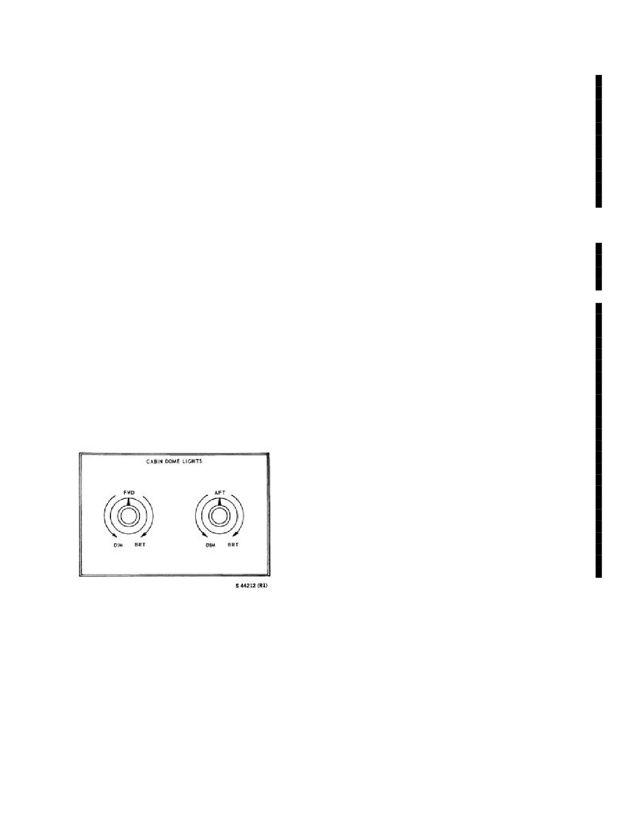
NAVAIR 01-230HLH-1
2.7.1.6 Pilot Compartment Spotlights. Two
2.7.1.9
(ET) Ceiling Lights. The ceiling lights are
portable spotlights (Figure 2-24) with coiled cord are se-
mounted overhead in the cabin. The ceiling lights are
cured one on each side of the overhead switch panel. Two
controlled from either the forward bulkhead, STA 160, or
additional spotlights are installed, one on each side of the
aft bulkhead, STA 425, when the overhead control panel
compartment mounted on the window frame alongside
CABIN LTS MASTER switch is ON. Each station is
each pilot. The lights may be adjusted on their mountings
equipped with a pair of toggle switches. One switch for
to direct the light beams where required, or they may be
ON/OFF operation and the other for BRIGHT/DIM
removed and used as portable spotlights. The spotlights
operation. The lights receive power from the primary ac
are controlled either by rheostat with marked positions
bus and are protected by circuit breakers marked
OFF and BRT, or the pushbutton on the end of the
CEILING LTS fA and CEILING LTS fB on the
spotlight casing. The lens casing of the light may be
copilot’s circuit breaker panel.
turned to focus the beam and to position a red filter
converting the white light to a red light. The pilot
Note
compartment spotlights operate on dc power and are
protected by a circuit breaker.
On the UH-3H Executive Transport helicopters,
the BRIGHT/DIM switch on the CABIN
2.7.1.7 Cabin Dome Lights. These lights (Figure 2-
LIGHTS panel should remain in the DIM
24) are controlled by a guarded switch marked DOME
position while operating on external power.
LIGHTS - CABIN with marked positions RED, OFF, and
WHITE on the pilot compartment dome light panel
2.7.1.10
(ET) Reading. Reading lights are mounted
(Figure 2-25). The cabin dome lights have a red and white
overhead in the cabin. The CABIN LTS MASTER
lamp. The white light may be turned on only if the guard
switch must be ON to activate the individual pushbutton
is lifted. The intensity of the cabin dome lights may be
controls. The lights are powered by the primary dc bus
and are protected by a circuit breaker marked READING
varied by turning the rheostat marked CABIN DOME
on the overhead circuit breaker panel.
LIGHTS (Figure 2-26) at the sensor operator station. On
UH-3H helicopters, the panel contains two knobs marked
2.7.1.11
(ET) Instruction. The instruction lights
FWD and AFT, respectively, each with the marked
provide NO SMOKING and FASTEN SEAT BELT
positions DIM and BRT. The FWD knob controls the
information to the cockpit and cabin areas. In the cockpit
forward pair of dome lights, and AFT knob controls the
the information is displayed on the advisory panel. In the
aft pair of dome lights.
cabin area it is displayed on the forward bulkhead, STA
160, and aft bulkhead, STA 425. The information lights
are controlled by the PASSENGER INSTRUCTION
LIGHT switch located on the overhead control panel.
Circuit protection is provided by a circuit breaker marked
INST LTS on the overhead circuit breaker panel.
2.7.1.12
(ET) Emergency Exit. There are three
emergency exit lights. One located over each cabin
emergency escape hatch. The lights are operated by the
EMERGENCY LIGHTS switch. The lights receive
power from the primary dc bus and are protected by
circuit breakers marked EMER LTS 1 and EMER LTS 2.
Figure 2-26. Cabin Dome Light Panel
2.7.1.8 Cabin Panel Lights. These lights are con-
trolled by a panel at the hoist operator station, marked
CABIN PANEL LIGHTS with a knob marked DIM and
BRT to control light intensity. The cabin panel lights
operate from the primary dc bus and are protected by a
circuit breaker marked CAB under the general heading
SWITCH PANEL on the center circuit breaker panel.
2-46
ORIGINAL
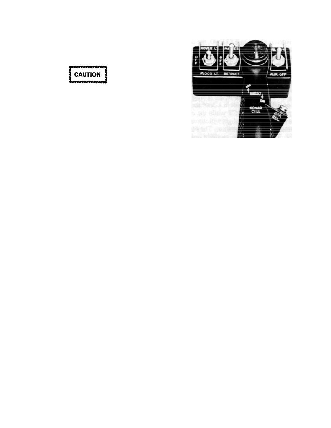
NAVAIR 01-230HLH-1
2.7.2 Exterior Lights
2.7.2.1 Flood-Hover Lights
The flood-hover lights should not be on for
more than 15 minutes at a time to prevent
overheating. Allow a
10-minute cooling
period.
The floodlights
(Figure
2-24 and
2-24.1(ET)) are
on the electronics compartment door. A hover light is on
the lower leading edge of each stub wing. The flood-
hover lights are controlled by a switch (Figure 2-27) with
Figure 2-27. Flood, Hover, and Spotlight Control
marked positions HOVER LT, OFF, and FLOOD LT on
Switches
the pilot collective pitch lever grip. When the switch is
placed to FLOOD LT, the floodlights on the electronics
2.7.2.4 Anticollision Lights. These lights (Figure
compartment door light an area forward of the helicopter.
2-24), one on top of the tail pylon and the other on the
When the switch is placed to HOVER LT, the hover
bottom of the ARA-25A antenna, are controlled by two
lights on each wing section and the floodlights light an
switches. The aft two-position switch marked OFF and
area below and forward of the helicopter. Placing the
NORM on the overhead switch panel controls the forward
switch to the OFF centered position turns off the flood-
anticollision light. The forward three-position switch
hover lights. The flood-hover lights operate from the
marked BEACON, OFF, and ANTI-COLL on the
monitored dc bus and are protected by circuit breakers.
overhead switch panel controls the aft anticollision light
and beacon. When the forward switch is placed to the
2.7.2.2 Exterior Lights MASTER SWITCH. This
BEACON position, an aft white strobe light is activated.
switch marked MASTER SWITCH with marked positions
When the forward switch is placed to the ANTI-COLL
ON and OFF is on the overhead switch panel (Figure 2-
position an aft red strobe is activated. When the aft switch
9). The MASTER SWITCH must be placed ON before
is placed to the NORM position, the forward red
any of the position lights and rotating anticollision lights
anticollision light illuminates and rotates. The rotating
will operate. The tail beacon light may be operated with
anticollision light switch is inoperative until the exterior
the exterior lights MASTER SWITCH OFF.
light MASTER SWITCH is turned on. The forward
anticollision light will not operate unless the aft
2.7.2.3 Position Lights. The side position lights
anticollision light is turned on. The anticollision lights
(Figure 2-24) on the sponsons are controlled by a switch
operate from the primary dc bus. The control circuit is
marked SIDE POS with marked positions DIM, OFF, and
protected by a circuit breaker on the center circuit breaker
BRT on the overhead switch panel. The tail position light
panel. The anticollision lights are protected by circuit
on the tip of the tail pylon is controlled by a switch
breakers marked FWD and AFT under the general
marked TAIL POS with marked positions DIM, OFF, and
heading BEACON on the center circuit breaker panel. For
BRT on the overhead switch panel. The keyer operates
day operations, the white beacon is recommended; for
only when the position light switches are at either OFF or
night, ground, and shipboard operations, the red
DIM. A switch marked STEADY and FLASH is on the
anticollision lights are recommended.
overhead switch panel to permit automatic flashing of the
position lights. The position light switches are inoperative
2.7.2.5 Controllable Spotlight. Two spotlight control
until the exterior light MASTER SWITCH is turned on.
switches on the pilot collective pitch lever grip (Figure 2-
The position lights operate on dc power and are protected
27) control a swivel-type controllable spot-light (Figure
by a circuit breaker.
2-24) on the bottom right side of the fuselage aft of the
electronic compartment door opening. The left switch is
marked CONT SPOT LT with marked positions
MASTER, OFF, and RETRACT. The right switch is a
spring-loaded four-position thumb switch, center position
OFF, with marked positions EXTEND-RETRACT-L-R.
2-47
ORIGINAL
NAVAIR 01-230HLH-1
Placing the left switch to MASTER lights the controllable
continuity of the direct control linkage is maintained from
spotlight and furnishes power to the right switch to
the controls in the pilot compartment through the
control the spotlight. When the right switch is placed to
auxiliary and the primary servos to the rotary wing blades
EXTEND, the controllable spotlight is extended and may
except for a slight amount of end play at each servo unit
be stopped by releasing the switch to direct the light beam
to permit the pilot valves to move before the direct control
at any vertical angle between the stowed position to about
linkage. Normally, both servo systems are in operation at
30o above the horizon. By placing the switch to
all times.
RETRACT, the light beam may be directed at a
progressively decreasing angle until the spotlight is in the
2.8.1 Primary Flight Control Servo System. The
fully stowed position. By placing the switch to L or R,
system consists of three hydraulic servo units that connect
the spotlight will turn to the right or left to any point in a
the flight control linkage to the stationary swashplate of
360 o arc. If the left switch is placed to RETRACT while
the rotor wing assembly. The servos provide the power
the controllable spotlight is extended, the spotlight will
necessary for operation of the rotary wing flight control
automatically go out and retract to the stowed position.
system only. The three servo units of the primary servo
The switch is then placed OFF. The controllable spotlight
systems are at the stationary swashplate. All three servo
operates from the primary dc bus and is protected by
units respond simultaneously and move in the same
circuit breakers.
direction in response to movements of the collective pitch
lever. Two of the servo units (lateral servo units) respond
2.7.2.6 Landing Gear Downlock Lights. These
simultaneously, but move in opposite directions in
lights
(Figure
2-24) on the main strut of each main
response to lateral movements of the cyclic stick. One of
landing gear provide additional landing gear position
the servo units (fore-and-aft servo unit) responds to fore-
information for an outside observer. Electrical power for
and-aft movements of the cyclic stick. Since all three
the lights is supplied by the primary dc bus through
movements can occur simultaneously through the action
contacts of the LDG GEAR DOWN LIGHT relay. The
of the mixing unit, the position of any primary servo unit
relay is energized whenever the exterior lights MASTER
is the result of the combined input of the cyclic stick and
SWITCH is placed in the ON position; however the
collective pitch lever. This results in a primary servo
circuit is not completed, thus preventing the lights from
system in which any one servo has an effect on both
going on until the landing gear is down and locked.
collective pitch and cyclic (lateral or fore and aft) pitch.
The primary servo hydraulic pump is driven by the
2.7.2.7 Droop Stop Light. The light (2-24) inside the
accessory section of the main gearbox. The primary
forward edge of the transmission fairing provides a means
hydraulic system reservoir (Figure
3-1), mounted aft of
of determining the position of the droop stops at night
the main gearbox, has a capacity of about 0.45 gallon of
during rotor shutdown. The droop stop light is controlled
hydraulic oil. The PRI SERVO PRESS caution light will
by the ROTOR HEAD LT switch with marked positions
go on when the primary servo pressure drops below 1,000
OFF and ON on the overhead switch panel. The light is dc
psi or is turned off.
powered and is protected by a circuit breaker marked
ROTOR HEAD on the center circuit breaker panel.
2.8.2 Auxiliary Flight Control Servo System. The
four servo units of the auxiliary servo systems are
2.8 FLIGHT CONTROL SERVO HYDRAULIC
between the mixing unit and the flight controls. Each
SYSTEMS
control input acts independently on the corresponding
servo. The rotary rudder pedals position the yaw servo.
The flight control servo hydraulic systems (FO-10)
The collective pitch lever positions the collective servo.
consists of a primary and an auxiliary flight control servo
The cyclic stick positions either the fore-and-aft servo, the
system. The servo systems are required for a power boost
lateral servo, or both. The auxiliary flight control servo
for the pilot to operate the controls. The servos also
system receives corrective signals from the ASE and
prevent feedback of vibratory loads to the control sticks
automatically introduces these into the flight control
and rudder pedals. Both servo systems operated from
system. It provides for controlled flight if the primary
independent hydraulic systems and both use similar servo
servo fails. The auxiliary servo hydraulic pump is driven
hydraulic units to vary the rotary wing and rudder blade
by the main gearbox accessory section. The auxiliary
pitch through the mechanical linkage of the regular flight
hydraulic reservoir
(Figure
3-1), aft of the primary
control system. Each servo unit consists of a bypass
hydraulic system reservoir, has a capacity of about 0.45
valve, sloppy link, power piston, pilot valve, and the ASE
gallon of hydraulic oil.
The AUX SERVO PRESS
valve in the auxiliary servo units only. The flight control
caution light will go on when the auxiliary servo pressure
system actuates the pilot valve that admits hydraulic oil
drops below 1,000 psi or is turned off.
into the servo unit. The servo output is connected to the
flight control linkage to provide the power boost. The
2-48
ORIGINAL
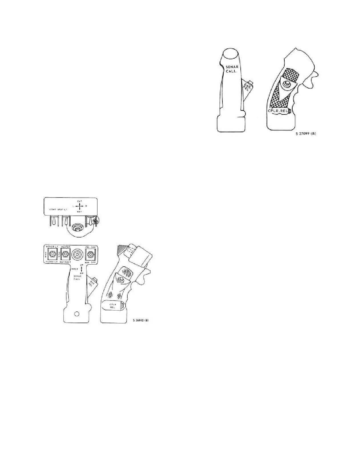
NAVAIR 01-230HLH-1
2.8.3 Flight Control Servo Switch. Both the primary
and auxiliary flight control servo systems are controlled
by the same three-position flight control servo switch on
the collective pitch grip lever (Figures
2-28 and 2-29).
The marked switch positions are PRI OFF and AUX OFF.
The flight control servo switch is protected by a dc circuit
breaker marked SERVO on the center circuit breaker
panel.
Both servo systems are normally in operation with
the switch in the unmarked center (ON) position. To turn
off the primary servo, the switch is placed to the forward
PRI OFF position; to turn off the auxiliary servos, the
switch is placed to the aft AUX OFF position. Stronger
cyclic, collective, and rotary rudder pedal forces and the
absence of pedal damping will be encountered with
auxiliary servos inoperative. The systems are
Figure 2-29. Copilot Collective Pitch Lever Grip
interconnected electrically in such a way that, regardless
of the switch position, it is impossible to turn either one
2.9 FLIGHT CONTROL SYSTEM
off unless there is 1,000 psi in the remaining system for
proper operation. The servo shutoff valves operate on dc
The flight control system is divided into three systems as
power.
follows: the rotary wing flight control system, the rotary
rudder flight control system, and the flight control
hydraulic power supply system with the three following
unique characteristics: (1) the collective to yaw coupling,
(2) the collective to the cyclic coupling, and
(3) the
negative force gradient installation. An ASE and coupler
system is installed, that, when engaged, provides
corrections of limited authority to the flight control
system to cause the helicopter to respond in a stable
manner to the maneuver referenced by the positions of the
flight controls. This equipment also provides automatic
cruising flight and constant altitude. The description and
operation of the ASE are included in the AUTOMATIC
STABILIZATION EQUIPMENT AND COUPLER
SYSTEM, paragraph
2.10. A beeper trim system is
installed to provide cyclic stick feel and to aid hands-off
control with the ASE and coupler system in operation.
2.9.1 Rotary Wing Flight Control System. This
system provides both vertical control and directional
control. Vertical control is accomplished by changing the
collective pitch of the rotary wing blades to increase or
decrease the angle of attack and consequently the lift
Figure 2-28. Pilot Collective Pitch Lever Grip
developed by the blades. Directional control is
accomplished by changing the pitch of each blade
2.8.4 Servo Hydraulic Pressure Indicators. The
individually as it rotates. The change in pitch causes the
primary and auxiliary servo pressure indicators operate on
blades to rise and fall as they rotate through 360o, tilting
26 vac and are protected by circuit breakers. If either
the tip-path plane of the rotation of the rotary wing
servo system malfunctions, the malfunctioning system
blades, thereby obtaining a horizontal, as well as a
may be turned off and the helicopter flown on the other
vertical, component of thrust. The horizontal component
servo system. If the pressure in either the primary or the
of thrust moves the helicopter horizontally in whichever
auxiliary system drops below 1,000 psi, a pressure switch
direction the tip-path plane of rotation is tilted. Control
prevents the other system from being shut off regardless
motions from the collective pitch lever for vertical control
of the position of the servo switch.
and from the cyclic stick for directional control are
combined in a mixing unit in the ASE control
compartment aft of the pilot seat, and are transmitted to
2-49
ORIGINAL
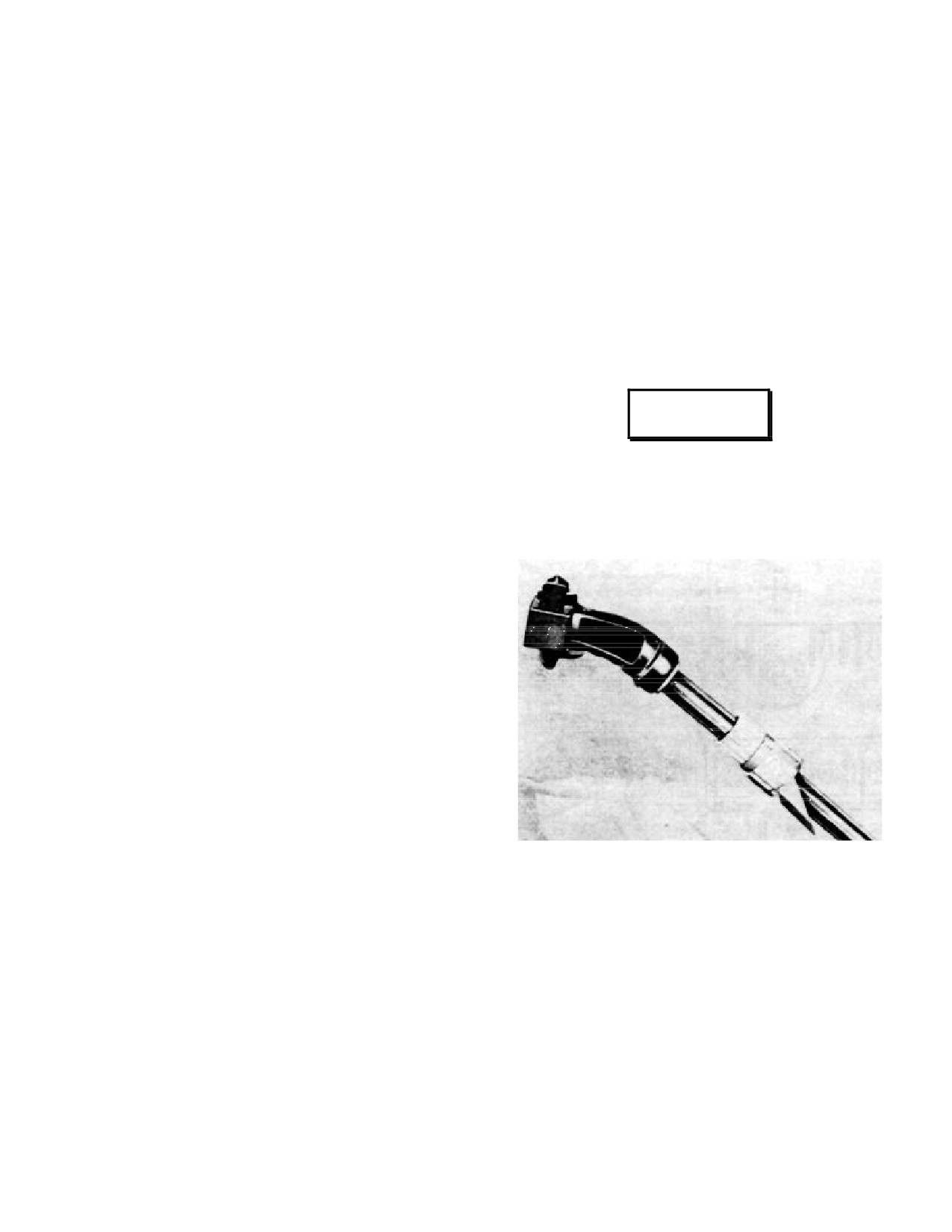
NAVAIR 01-230HLH-1
the rotary wing assembly by mechanical linkage. Control
lowered. This provides attitude control during transitions
action is assisted by two hydraulically-operated flight
especially during ASE transitions while operating in
control servo systems. The rotary wing flight controls
coupler mode.
terminate at the stationary swashplate of the rotary wing
head. Control action is transmitted through the rotary
2.9.1.3 Collective Pitch Levers. Two collective pitch
swashplate and linkage on the rotary wing hub to the
levers (Figure 2-30) are in the pilot compartment, one to
blades.
the left of the pilot seat and the other to the left of the
copilot seat. Both levers operate simultaneously to change
2.9.1.1 Collective to Yaw Coupling. When the
the collective pitch of the rotary wing blades. A nut on the
auxiliary servo is pressurized, there is a proportional but
pilot collective pitch lever marked COLLECTIVE PITCH
irreversible transfer of collective pitch motion into the
LOCK with an arrow pointing left marked INCREASE
rotary rudder blade angle (collective pitch motion will act
FRICTION can be turned to apply friction to prevent the
to displace the rotary rudder but rotary rudder pedal motion
collective pitch lever from creeping while in flight.
will not affect rotary wing collective pitch blade angle).
This coupling provides automatic rotary rudder pitch
changes to compensate for collective pitch changes.
Rotary rudder blade angle changes result from both
WARNING
collective pitch lever and rotary rudder pedal inputs.
Any combination of collective pitch lever position
and rotary rudder pedal position, wherein the total would
The collective friction nut should not be
exceed the system limits, is nonattainable during flight.
completely disengaged from the friction
The collective pitch lever has overriding authority and
block, as this may result in the collective
therefore is always free to move within its full travel. If a
stick binding or jamming.
collective pitch lever position, added to the rotary rudder
pedal position, creates a rotary rudder blade angle equal to
the system limits, additional collective pitch lever motions
to exceed the limits is only possible at the sacrifice of
rotary rudder pedal position; the pedals will be forced to
move but the blade angle remains at the limit. With
auxiliary servo on, collective pitch lever low, and rotary
rudder pedal full left, raising the collective pitch lever to
high will be accompanied by pedal motion to the right.
With the collective pitch lever high and rotary rudder
pedal full right, reducing collective pitch lever to low will
be accompanied by pedal motion to the left. With the
auxiliary servo switch OFF, the operation is the same
except the irreversibility is not effective. Therefore, when
the combination of collective and pedal positions reaches
the system limit, additional collective motion is possible
by sacrificing pedal position. This trading of motion is not
Figure 2-30. Collective Pitch Lever
likely to occur but may be noted during ground check
with the auxiliary servo off. During rapid rotary rudder
pedal motions on the ground, noise can be heard aft of the
2.9.1.4 Cyclic Sticks. The cyclic stick in front of each
pilot seat provides directional control of the helicopter.
pilot seat when the pedals reach their right or left limits.
Moving the cyclic stick in any direction tilts the tip-path
The sound is created by the system stops and indicates
that the collective pitch and the pedals have reached the
plane of rotation of the rotary wing blades in that
direction and moves the helicopter in the same direction.
limits of the rotary rudder control. Additional rotary
The stick grip (Figure
2-31) contains pushbutton and
rudder pedal motion is possible by reciprocal motion of
the collective pitch lever.
thumb -operated switches for controlling various
equipment installed in the helicopter.
2.9.1.2 Collective to Cyclic Pitch Coupling. A bias
in the collective to cyclic pitch (fore and aft) coupling is
incorporated in the mixing unit to apply a nosedown
pitching correction automatically when the collective
pitch lever is raised and noseup when the collective is
2-50
ORIGINAL
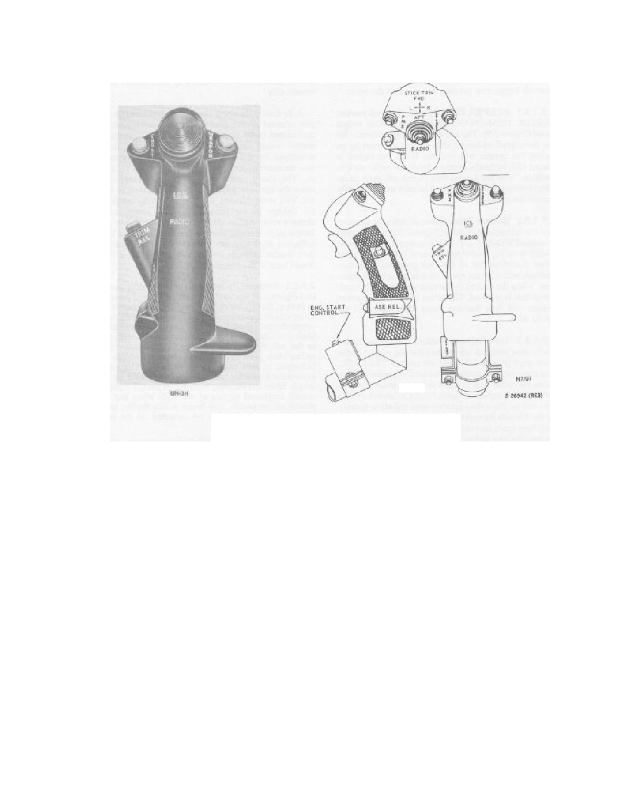
NAVAIR 01-230HLH-1
Figure 2-31. Pilot and Copilot Cyclic Stick Grip
2.9.1.5 Force Gradient-Beeper Trim System.
trimmed reference point. The force gradient-beeper trim
The system permits a fine degree of adjustment of the
system will operate as long as there is both dc power and
cyclic stick and provides cyclic stick feel. When used with
auxiliary hydraulic pressure to the actuators. With the loss
the ASE engaged, the system permits hands-off flight by
of auxiliary hydraulic pressure only, the cyclic stick may
holding the stick in a selected trim position. The system
be repositioned by depressing either trim release button,
consists of two electrically controlled hydraulic actuators,
moving the cyclic to desired position, and releasing the
one mounted on the fore-and-aft channel of the auxiliary
trim release button. The cyclic will then be held in its new
servo and one on the lateral channel of the auxiliary servo.
position by hydraulic fluid trapped on both sides of the
Additional components of each trim actuator consist of the
actuator trim piston. In each case, the effect of the force
following: trim valve, force gradient spring, trim release
gradient spring will be felt when the cyclic is displaced
button, beeper trim button, and master beeper trim switch.
without pressing the trim release button. With system
The system is supplied with 28-vdc power and is protected
electrical failure, the pilot must manually override beeper
by a circuit breaker marked BEEPER TRIM on the center
trim pressure to reposition the cyclic.
circuit breaker panel. Hydraulic pressure for operation of
the system is supplied by the auxiliary hydraulic system at
2.9.1.5.1 BEEPER TRIM Switch. A switch marked
a reduced pressure of 60 psi. The cyclic stick may be
BEEPER TRIM-ON-OFF is on the overhead switch panel
manually displaced without disengaging the trim system
(Figure 2-9). The switch is the master control for the force
by applying about 1 to 1-1/2 pounds of pressure to the
gradient-beeper trim system and must be on before the
cyclic in the desired direction. A resistance force, caused
system will operate. When the switch is placed ON,
by force gradient spring compression, will increase about
hydraulic pressure holds the cyclic stick in position. With
1/2 pound for each additional inch of cyclic stick displace-
the beeper trim switch off, there is no force holding the
ment. When the pressure on the cyclic stick is released, the
cyclic stick. The pilot must manually control the cyclic.
spring compression will return the stick to its original
2-51
ORIGINAL
NAVAIR 01-230HLH-1
2.9.1.5.2 Beeper Trim. These switches on the pilot and
2.9.2.1 Rudder Pedals. The rotary rudder pedals (see
copilot cyclic stick grips
(Figure
2-31) have marked
Figure 2-3), one set in front of the pilot and the other in
positions FWD-AFT-L-R. This four-way thumb-operated
front of the copilot, change the pitch and thrust of the
switch is spring loaded to the center (off) position and
rotary rudder and consequently the heading of the heli-
when placed to any of the four positions, hydraulic
copter. Pressing the left pedal increases the rotary rudder
pressure will drive the cyclic stick in the selected direction.
blade pitch that increases thrust and turns the helicopter to
When the desired cyclic stick position is obtained, the
the left. Pressing the right pedal decreases rotary rudder
switch is released. The action of the force gradient system
blade pitch that decreases thrust and allows the helicopter
will then function about this location of the cyclic stick.
to turn to the right. Rotary rudder pedal adjustment knobs
are used to adjust the pedals for leg length. Electrical
2.9.1.5.3 Trim Release Button. The spring-loaded
switches mounted on the UH-3 pedals cancel directional
pushbutton switches are on the pilot and copilot cyclic
signals of the ASE when feet are placed on the pedals. Toe
stick grips (Figure 2-31) and are marked TRIM REL. The
brake pedals for the main landing gear wheelbrakes are
trim release buttons may be used to manually reposition
mounted on the pilot rotary rudder pedals.
the cyclic stick to a new reference point. Pressing either
switch applies dc power to the solenoids of both trim
Rotary rudder control pedal movements are
valves. The valves are then open and allow hydraulic fluid
transmitted to the rotary rudder by a series of mechanical
to pass through the return port. Both trim pistons may then
linkages and cables. Control inputs are transmitted from
move unrestricted within their cylinders. Releasing the
the pilot's and copilot's rudder pedals to the auxiliary servo
trim button deenergizes the solenoids, and the trim
by linkages and bellcranks and from the auxiliary servo by
actuators will then maintain the new cyclic stick reference.
two steel cables. These cables are routed through a series
of pulleys in the overhead of the cabin. Forward of the
2.9.2 Rotary Rudder Flight Control System.
tailfold hinge, the tail rotor control cables are attached to a
The functions of this system are to compensate for rotary
bellcrank that is attached to a series of control rods that
wing torque and to permit changing the heading of the
transmit control inputs to the tail rotor pitch beam (star).
helicopter. The torque developed by the rotary wing
blades turning counterclockwise tends to turn the fuselage
A rotary rudder NFG spring is installed parallel to the
in a clockwise direction. Gross weight, altitude, rate of
center pylon control rod at the top of the tail pylon just
climb, airspeed and the corresponding power settings, and
below the tail gearbox. The NFG spring is designed to
collective pitch will vary the amount of rotary wing torque.
relieve the pilot of rotary rudder forces created by
To compensate for torque variations, the pitch and
aerodynamic and inertia loads when the auxiliary hydraulic
resulting thrust of the rotary rudder blades can be increased
servo is inoperative, imparting a force into the flight
or decreased. Turns are accomplished by increasing rotary
control system against the rotary rudder aerodynamic
rudder thrust that overcompensates for rotary wing torque
forces.
and changes the heading of the fuselage to the left, or by
decreasing the rotary rudder thrust that undercompensates
Because of the rocker assembly bellcrank connecting
for the rotary wing torque and changes the heading of the
the NFG spring to the center pylon control rod, the spring
fuselage to the right. Rotary rudder control pedal
acts as an anticentering device that attempts to drive the
movements are transmitted to the rotary rudder assembly
tail rotor pitch and pedals away from the center (neutral
by mechanical linkage and cables. Control action is
pedal) position to maximum pitch in either direction. With
assisted by the auxiliary servo system only.
the main rotor static, when the auxiliary servo is secured
and the rudder pedals are displaced from neutral, the
A hydraulic damping device, incorporated in the yaw
spring will drive the tail rotor to either the full left or full
channel of the auxiliary servo, prevents abrupt movements
right pedal position depending on the direction of the
of the rotary rudder pedals. These movements would cause
initial pedal displacement.
sudden changes in thrust developed by the rotary rudder
with resulting rapid yaw acceleration and possible damage
2.9.2.2 Rudder Pedal Adjustment Knobs. These
to the helicopter. The rotary rudder pedal damper is
knobs are on each side of the cockpit, just forward of the
inoperative when the auxiliary servo system is inoperative
ashtrays. The adjustment knobs are connected to
or shut off. Yaw compensation is accomplished by
mechanical linkage that provide for fore-and-aft
mechanical linkage in the mixing unit that automatically
adjustment of the rotary rudder pedals. The knobs are
changes rotary rudder blade angles for changes in col-
turned to the right, as indicated by the arrow marked FWD,
lective pitch without moving the pedals, unless both
for forward adjustments and to the left, as indicated by the
collective pitch and rotary rudder blade angle are at their
arrow marked AFT, for the aft adjustment.
maximum limits, in which case the pedal will be forced back
with collective pitch change.
2-52
ORIGINAL
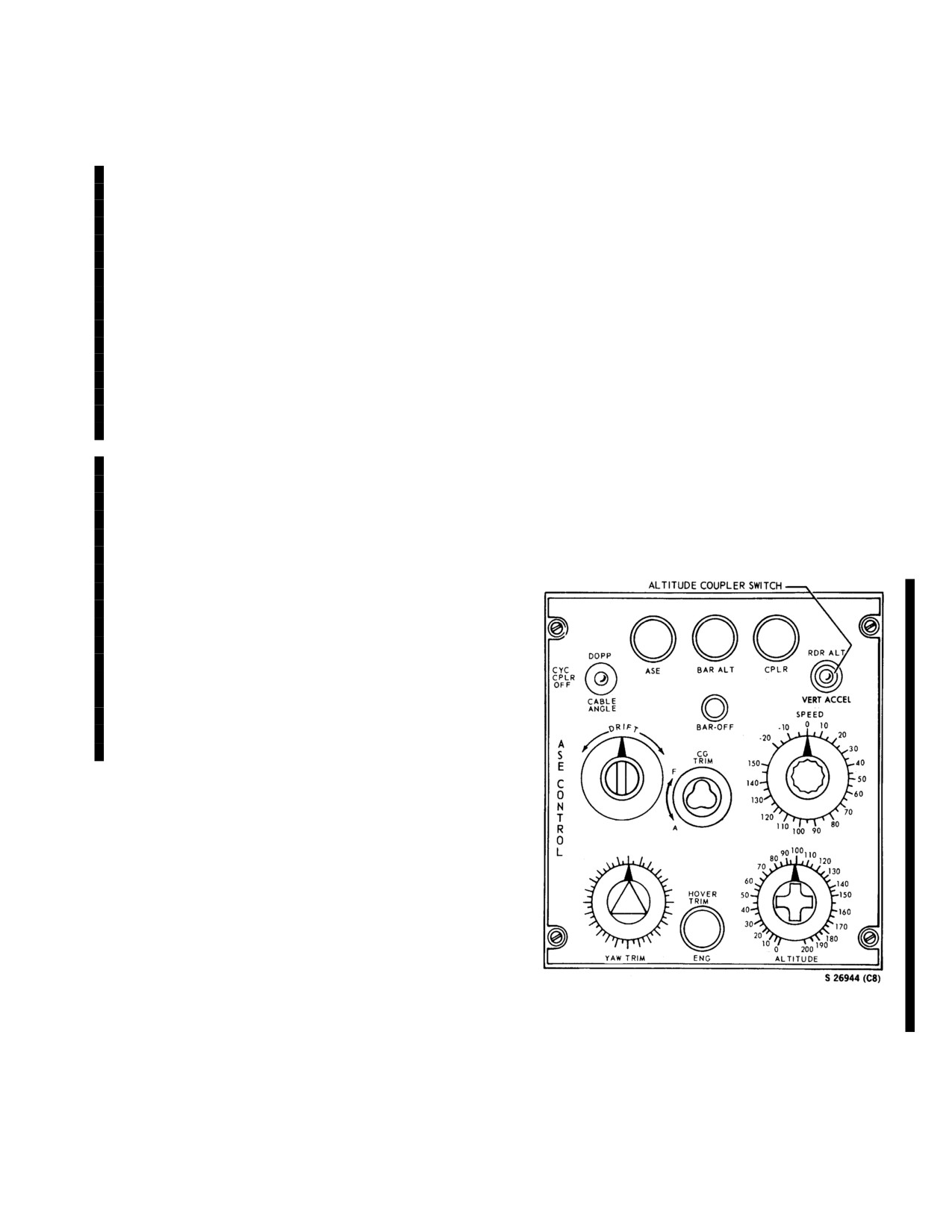
NAVAIR 01-230HLH-1
2.10
AUTOMATIC STABILIZATION EQUIPMENT
is placed in a synchronizing mode (no heading correction
(ASE) COUPLER SYSTEM
signal is developed) until his feet are removed from the
pedal switches. During the synchronizing mode, the yaw
The ASE provides added attitude and directional
rate gyro develops a signal proportional to the manual
stabilization and barometric hold. On UH-3H aircraft, an
heading displacement rate of the helicopter. This signal
SIU installed between the AHRS pitch and roll output and
initiates an open-loop spring condition that produces a
the ASE enhances transitions to automatic approach in the
proportional feedback force at the pedals. As the pilot
RAD ALT and the VERT ACCEL modes of the ASE
presses either pedal, he feels the proportional feedback
coupler. The coupler system is used with the ASE for the
force opposing the pedal pressure applied. The feedback
following: automatic approaches and doppler hovers using
force remains until the pilot has established the new
signals from the Doppler, radar altimeter, and
reference heading. Heading stability correction occurs
accelerometers. These signals are processed by the IVSC.
anytime the helicopter is displaced from the desired
The auxiliary servo system provides the means for
reference heading. In the collective channel, the altitude of
introducing ASE signals to the flight controls. UH-3H
the helicopter is held constant by signals developed from
Executive Transport helicopters do not use the Doppler or
the barometric altitude controller that senses changes in
sonar cable altitude signals. AC power supplies excitation
barometric pressure from the engage point. Automatic
and reference voltage for the ASE. The system is protected
barometric altitude stability correction occurs anytime the
by the three circuit breakers: two ac circuit breakers and
helicopter is displaced up or down from the reference
one dc circuit breaker.
altitude. The ASE may be engaged 3 minutes after power
has been applied to the system.
2.10.1 Automatic Stabilization Equipment. The
ASE improves the handling characteristics of the
2.10.1.1 ASE CONTROL Panel (BASIC ASE).
helicopter and permits hands-off automatic flight. The
The ASE CONTROL panel (Figure
2-32) is on the center
ASE may be engaged at all times, has less control
console.
authority than the primary flight control system, and may
be easily overridden through normal use of the flight
controls. The pilot has direct control of the ASE at all
times and can engage or disengage the entire system or any
channel as desired by means of switches on the ASE
CONTROL panel, CHANNEL MONITOR panel, cyclic
sticks, and collective levers. The hover indicators (UH-3H
helicopters) or flight directors
(UH-3H Executive
Transport helicopters) visually provide all ASE signals
into the pilot and copilot. The hover indicators visually
indicate all ASE signals to the pilot and copilot. The ASE
has attitude and directional stabilization and barometric
altitude hold modes of operation.
Attitude and directional stabilization are controlled
through the pitch, roll, and yaw channels; and barometric
altitude hold is controlled through the collective channel.
The ASE is capable of maintaining the barometric altitude
of the helicopter during normal flight, or when hovering
out of ground effect by using barometric altitude reference.
In the pitch and roll channels, the fuselage attitude is held
constant by comparing the actual attitude signal received
from the vertical gyro with the reference attitude trim
s ignal provided by the cyclic stick position sensor.
Automatic pitch and roll attitude stability correction occurs
anytime the helicopter is displaced from the trimmed
attitude. Pitch and roll gyro information source is selected
on the CHANNEL MONITOR panel. In the yaw channel,
Figure 2-32. ASE CONTROL Panel
the helicopter is held constant by comparing actual
heading signals received from the compass system with
reference heading signals received from the YAW TRIM
knob and the yaw synchronizer. While the pilot establishes
a reference heading by use of the pedals, the yaw channel
2-53
ORIGINAL
NAVAIR 01-230HLH-1
2.10.1.2 ASE Button. Pressing the ASE button will
The pitch and roll channels are identical in their
engage the pitch, roll, and yaw channels of the ASE and
operation.
The altitude channel has two modes of
the button will light. Once the ASE is engaged, the only
operation: radar altitude, and vertical accelerometer. The
noticeable difference in flight is that the helicopter is
vertical accelerometer mode is used when collective
dynamically stable.
pumping is experienced and for alternate approaches. The
ASE must be engaged before operating the coupler. Raw
2.10.1.3 Barometric Altitude Button. Pressing the
Doppler signals are used in the Doppler mode. When
BAR ALT button engages the barometric altitude
operating in the DOPP mode, the pilot selects the fore-and-
controller and the button will light. Engaging the altitude
aft groundspeed and drift groundspeed at which he desires
controller provides altitude hold. Once the BAR ALT
to fly. This is done through the use of the SPEED and
button is engaged, the pilots can momentarily release the
DRIFT set knobs, on the ASE CONTROL panel. The
altitude hold with the BAR REL button on both collectives
Doppler signals that are proportional to selected speed and
(Figures
2-28 and
2-29). For proper operation, it is
drift of the helicopter are compared to the output of these
important that BAR ALT be engaged at a zero vertical
controls and will maintain the helicopter at the selected
velocity and at the selected forward speed.
speed. The helicopter groundspeed and attitude are
controlled by the position of the cyclic stick, and the ASE
2.10.1.4 Barometric Altitude Off Button. Pressing
couplers operate around the cyclic stick position.
the BAR OFF button on the ASE control panel disengages
Therefore, if the cyclic stick is moved, the ASE and
the collective channel and the barometric altitude
coupler operating reference will move with it. If the
controller (BAR ALT) if the coupler is not engaged.
coupler is engaged and a coupled error signal exists, the
beeper circuit develops an electrical signal that actuates the
2.10.1.5 YAW TRIM Knob. The triangle-shaped YAW
appropriate hydraulic beeper valve to automatically
TRIM knob is used for small trim changes in forward
reposition the cyclic stick. It is through this operation that
flight and small turns while hovering without disengaging
the ASE maintains its authority.
the yaw channel. A large heading change with the YAW
TRIM knob during forward flight will result in a flat turn.
The radar altitude, ALTITUDE set potentiometer
For large heading changes, the pilot operates the cyclic and
controller knob (POT), and the Doppler vertical position
rotary rudder pedals in the normal manner.
signal (Vz) develop signals for the RDR ALT mode of
operation. The radar altimeter, ALTITUDE set POT, and
2.10.1.6 CG TRIM Knob. The cloverleaf-shaped CG
the vertical accelerometer (VA) develop signals for the VA
TRIM knob is used to compensate for changes in the
mode of operation. When operating in any of the coupler
center of gravity. The pilot should adjust the cg trim
modes, the pilot selects the altitude at which he desires to
whenever the hover indicator (NON-ET) or flight indicator
fly with the ALTITUDE set knob on the ASE CONTROL
(ET) indicates a need for adjustment. With the hover
panel. In the RDR ALT mode, the signal from the radar
indicator operating in the A mode and the METER
altimeter that is directly proportional to the absolute
SELECTOR switch on the CHANNEL MONITOR panel
altitude over the surface is compared to the output of the
in the ASE position, there may be a tendency for the pitch
ALTITUDE set knob, and the result will maintain the
bar to remain above or below the centerline. Such a condition
helicopter at the selected altitude.
The METER
indicates the need for cg adjustments. Maladjustment of the
SELECTOR switch on the CHANNEL MONITOR panel
CG TRIM knob reduces the efficiency of the pitch
(Figure
2-33) must be at ASE to present a proper
stabilization and may make the helicopter unstable in
indication.
pitch.
2.10.2.1
(NON ET) ASE CONTROL Panel
2.10.1.7 Automatic Stabilization Button. The AUTO
(Coupler). The automatic stabilization equipment must
STAB RELEASE button on the pilot and copilot cyclics
be engaged before engaging the coupler.
will disengage all ASE modes when depressed.
2.10.2.2
(NON ET) Coupler Button. Pressing the
2.10.2 (NON ET) Coupler System. The coupler
CPLR button engages the coupler; and the button lights
enables the helicopter to seek and retain selected absolute
whenever the coupler is engaged. Engagement of the
altitudes,
fore-and-aft
groundspeeds,
and drift
CPLR automatically engages BAR ALT. The BAR ALT
groundspeeds. The coupler will maintain a constant
cannot be disengaged with the BAR REL buttons on the
absolute altitude over the water. To do this, the coupler
collective sticks or with the BAR OFF button on the ASE
must control the helicopter in absolute altitude and the
CONTROL panel.
longitudinal and lateral axes. The pitch, roll, and altitude
channels of the coupler provide the signals that will control
the helicopter in the three axes needed for coupler
operation.
2-54
ORIGINAL
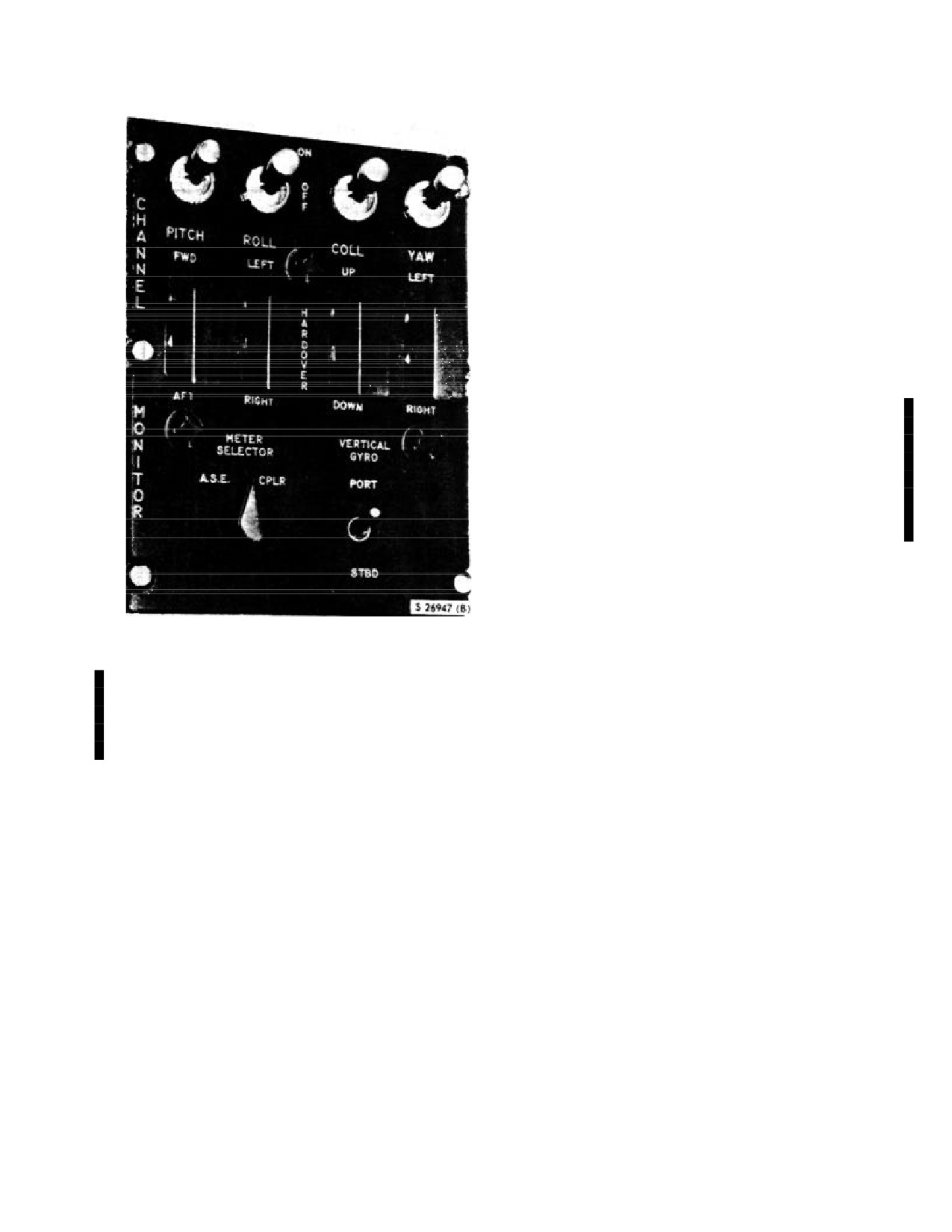
NAVAIR 01-230HLH-1
2.10.2.7
(NON ET) ALTITUDE Knob. The cross-
shaped absolute ALTITUDE set knob permits the pilot to
preselect accurate absolute altitudes from 0 to 200 feet
with the ASE and altitude coupler engaged. The
ALTITUDE set knob is scaled from 0 to 200 feet.
2.10.2.8 (NON ET) Hover Trim Engage Button. The
HOVER TRIM ENG button transfers doppler groundspeed
and drift control to the crewman at the hoist station for
positioning the helicopter during hoisting or rescue
operation. The HOVER TRIM ENG button lights when
engaged and can only be engaged when the CYC CPLR
switch is at DOPP.
2.10.3 Hover Indicators.
2.10.3.1 Pilot Hover Indicators. The pilot hover
indicators (Figure 2-34), mounted on the instrument panel,
is a four-axis indicator and has two modes of operation
that are selected by a knob on the face of the indicator. A
single OFF flag is used in both modes of operation. In the
A mode, it will retract when the ASE is engaged. In D
mode, the flag appears when the system is off or in
memory C mode is disabled.
2.10.3.2 A Mode. The A mode monitors the ASE or
coupler, depending on the position of the METER
SELECTOR switch. With the METER SELECTOR
switch on the CHANNEL MONITOR panel in the ASE
Figure 2-33. Channel Monitor Panel
position, the hover indicator will operate as a null
indicator, indicating the input to the ASE servo valves. The
2.10.2.3 (NON ET) Cyclic Coupler Switch. The CYC
hover indicator horizontal bar is used to monitor the pitch
CPLR switch OFF position makes it possible to disable the
channel; the vertical bar is used to monitor the roll
cyclic coupler even though the altitude coupler is working.
channel; the vertical pointer is used to monitor the altitude
The DOPP position selects the Doppler radar input for
channel; and the horizontal pointer is used to monitor the
automatic cruise, transition, and hover.
yaw channel. The hover indicator scale factor in this mode
is a
2-milliampere per division of servo valve differential
2.10.2.4 (NON ET) Altitude Coupler Switch.
current with 8 milliamperes considered as a hardover. The
The RAD ALT and VA positions of the altitude
A mode with the METER SELECTOR switch at CPLR, is
coupler switch engage the appropriate altitude channel
used to monitor coupler output.
sensors for absolute altitude reference.
The VERT
ACCEL position engages the vertical accelerometer mode
2.10.3.3 D Mode. The D mode connects the hover
to eliminate collective pumping over high sea states. The
indicator to the Doppler. In this mode, the horizontal bar
CYC CPLR need not be engaged in order to engage the
indicates fore or aft velocity, the vertical bar indicates left
RAD ALT or VA modes of the altitude coupler.
or right drift, the vertical pointer indicates vertical
velocity, and the horizontal pointer is inoperative. The
2.10.2.5
(NON ET) DRIFT Knob. The bar-shaped
scale factor for the D mode is 10 knots per division on
DRIFT groundspeed set knob permits the pilot to preselect
horizontal and vertical bars for groundspeed. To maintain
the lateral drift of the helicopter to be maintained by the
a Doppler hover, the pilot can assume the cyclic stick is in
cyclic coupler.
the center of the indicator. If the horizontal bar moves
upward, the pilot should move the cyclic toward the bar or
2.10.2.6 (NON ET) SPEED Knob. The indented circle-
in a forward direction. The pilot flies the helicopter to the
shaped, fore-and-aft ground SPEED set knob permits the
bars. The vertical pointer can be used as a vertical velocity
indicator with each division equal to 250 fpm.
pilot to preselect fore or aft groundspeed to be maintained
by the cyclic coupler.
2-55
ORIGINAL
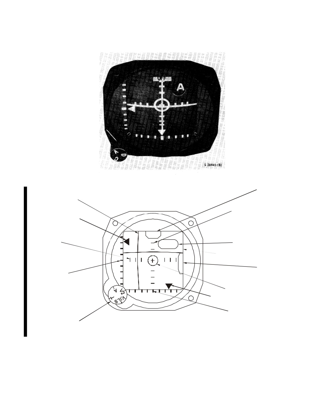
NAVAIR 01-230HLH-1
Figure 2-34. Hover Indicator
WARNING FLAG
VERTICAL BAR (ROLL
CHANNEL-TACAN-VOR)
HORIZONTAL BAR
VERTICAL ARROW
UP AND DOWN
(COLLECTIVE CHANNEL)
25% DISPLACEMENT
DIVISION MARKS
FROM SELECTED ALTITUDE
OFF
VERTICAL BAR
MODE INDICATOR WINDOW
ASE
RIGHT AND LEFT
25% DISPLACEMENT
HORIZONTAL BAR (PITCH CHANNEL
DIVISION MARKS
O
GLIDE SCOPE)
F
F
WARNING FLAG
VERTICAL ARROW
UP AND DOWN
25% DISPLACEMENT
DIVISION MARKS
NULL (CENTER INTERSECTION)
FROM SELECTED ALTITUDE
HORIZONTAL ARROW (YAW CHANNEL)
HORIZONTAL ARROW
LEFT AND RIGHT
MODE SELECTOR KNOB
25% DISPLACEMENT
DIVISION MARKS
FROM SELECTED DIRECTION
01771026
Figure 2-34.1. (ET) Flight Director
2-56
ORIGINAL
NAVAIR 01-230HLH-1
2.10.3.4 (ET) Flight Director
The flight director (Figure
selected course is a bearing to or from a surface navigation
2-34.1), on the instrument panel, allows the pilot and/or copilot
beacon. When the knob is at T, power for warning flag
to visually monitor composite information from the ASE, VOR
operation is supplied from the TACAN set. Exact bearing
#1, and VOR #2 receivers, glideslope receiver, and TACAN
information is available on the TACAN course indicator that is
set. It has four modes of operation that are determined by the
connected in parallel with the flight director. Since there are
position of the mode selector knob. The pilot and copilot can
two completely independent VOR receivers, separate operating
monitor the same mode or any combination of modes by
modes are available to the flight director. When the VOR #1
placing either knob in the A, T, V1, ILS, or V2 position. The
receiver is turned on and the knob is at V1, ILS, the indicator
mode indicator window in the upper right quadrant of the face
monitors lateral deviation from a VOR course that was selected
indicates ASE, TAC, VOR 1, ILS, or VOR 2 depending upon
on the VOR #1 course indicator, and longitudinal deviation
which mode has been selected. With ASE engaged and the
from a corresponding glideslope signal. The top center
knob at A
(ASE visible in mode indicator window), the
warning flag on the flight director disappears when the radio is
indicator monitors output signals from the pitch, roll,
turned on and the bearing signal received is reliable. The right
collective, and yaw ASE channels. Each output signal
middle warning flag disappears when the glideslope signal
represents the amount of differential current flow to the servo
received is reliable. The flight director does not indicate if the
valve in a particular channel. The warning flags disappear
lateral position deviation from a selected course is a bearing to
when ASE is engaged. During ASE mode of operation, all
or from an omnidirectional range source. Power for the
meter movements are used. The horizontal bar monitors signal
warning flag during VOR #1 operations is supplied from the
output from the pitch channel and indicates forward or aft
VOR #1 receiver. Exact bearing information is available on
displacement from selected attitude. The vertical bar monitors
the VOR #1 course indicator that is connected in parallel with
signal output from the roll channel and indicates left or right
the flight director. With the VOR #2 receiver turned on and the
displacement from selected attitude.
The vertical arrow
knob at V2, the entire operation is identical to VOR
#1
monitors signal output from the collective channel and
operation except that glideslope information will not be
indicates up or down displacement from selected attitude. The
displayed
horizontal arrow monitors signal output from the yaw channel
and indicates left or right displacement from selected direction.
2.10.4 HOVER TRIM Control Panel. The panel is
All ASE signal inputs to the indicator are routed through the
mounted just forward of the cabin door. The hover trim stick is
channel monitor control panel. Power for warning flag
mounted on the panel in the center of a diamond-shaped outline
operation is supplied from the AUTO STABE circuit breaker
marked R (right), L (left), F (forward), and A (aft) directional
through the ASE ENG button. The warning flag in the top
control. To use the hover trim stick, the coupler must be
center of the face indicates when the indicator is operating or is
functioning in the DOPP mode and the HOVER TRIM ENG
turned off for a particular mode of operation. The flight
depressed. The red engage light on the tip of the stick will go
director has four-meter movements consisting of two bars and
on when the hover trim controls are ready for use. Two knobs
two arrows. The horizontal bar deflects up and down along a
on the panel are marked ROLL BIAS and PITCH BIAS. The
straight line of parallel reference marks on the vertical axis.
ROLL BIAS knob has direction-indicating arrows marked
The vertical bar deflects left and right along a straight line of
RIGHT and LEFT and the PITCH knob has arrows marked
parallel reference marks on the horizontal axis. The horizontal
FWD and AFT. The use of these knobs permits trimming for an
and vertical reference marks intersect and form a cross within a
accurate hover when the hover stick is centered by permitting
circle. This intersection point is the center, or null, of the
the aircrewman to introduce signals into the amplifier to correct
horizontal and vertical bars. The vertical arrow deflects up and
any slight drifting while hovering in the Doppler mode.
down along a straight line of parallel reference marks that are
perpendicular to the vertical reference edge. The horizontal
2.10.4.1 Hover Trim Stick. The hover trim stick (Figure 2-
arrow deflects left and right along a straight line of parallel
35) has been incorporated to give the crewman longitudinal and
reference marks that are perpendicular to the horizontal
lateral control of the helicopter. The 6-inch stick is mounted on
reference edge. The reference marks (divisions) are speeds
the HOVER TRIM control panel and is used in the same
equal to 0, 25, 50, 75, and 100 percent of full-scale deflection
manner as the cyclic stick. The HOVER TRIM control panel
in either direction. When the TACAN set is turned on and the
allows the operator to control the helicopter drift from 0 to 11
mode selector knob is at T (TAC), the Indicator monitors
±4-1/2 knots. When the hover stick is centered, the ROLL
lateral deviation from the selected course, relative to a surface
BIAS and PITCH BIAS knobs allow trimming for an accurate
navigation beacon. The center warning flag disappears when
hover by allowing the hoist operator to induce signals into the
the TACAN set is turned on and the bearing signal received is
amplifier to correct any slight drifting of the helicopter while
reliable. During TAC mode of operation, only the vertical bar
hovering in the Doppler mode. The hover trim stick can only be
is used. The vertical bar monitors signals received from the
engaged by the pilot during the Doppler mode of operation.
indicator coupler and indicates lateral position deviation from
the selected course on the TACAN course indicator. The flight
director does not indicate if the lateral position deviation from a
2-57
ORIGINAL
NAVAIR 01-230HLH-1
starboard gyro for ASE pitch and roll reference; however,
PORT is the preferred position. Electrical power for the
CHANNEL MONITOR panel is supplied from the primary bus
and is protected by a circuit breaker.
2.10.6 Channel Monitor Test Switch. The CHAN MON
test switch on the pilot compartment dome light panel (Figure
2-25) has two marked positions, TEST and OFF. OFF disables
all hardover switches but does not affect any of the other
switches. TEST permits use of the hardover switches by
maintenance personnel for testing.
2.10.7 Vertical Gyros. The 1080Y starboard gyro always
provides pitch and roll information to the pilot vertical gyro
indicator and also to the ASE when the VERTICAL GYRO
switch on the CHANNEL MONITOR panel is at STBD. The
compass system always provides pitch and roll information to
the copilot attitude indicator and also to the ASE when the
VERTICAL GYRO selector switch is at PORT. Power failure
flags will be displayed on the pilot attitude indicators whenever
a power failure is sensed or an imbalance in the ac power
applied to the vertical gyros is sensed.
2.11 UTILITY HYDRAULIC SYSTEM. The utility hydraulic
system (FO-11) provides hydraulic pressure for all hydraulic
Figure 2-35. Hover Trim Stick
equipment not included in the flight control servo and ASE
systems. The utility hydraulic system reservoir (Figure 3-1), aft
2.10.5
CHANNEL MONITOR Panel. The
CHANNEL
of the main gearbox, supplies hydraulic fluid to the utility
MONITOR panel (Figure 2-33) on the pilot console has four
system. In addition, the rotor brake hydraulic cylinder is
ASE channel disengage switches mounted across the top of the
gravity-feed with hydraulic fluid from the utility reservoir. The
panel. Directly beneath the channel disengage switches are four
utility hydraulic reservoir has a capacity of
1.09 gallons of
associated guarded hardover switches marked PITCH, ROLL,
hydraulic oil. The utility hydraulic pump on the accessory drive
COLL, and YAW.
section of the main gearbox provides
3,000-psi hydraulic
pressure. Equipment operated by the utility hydraulic system
2.10.5.1 Channel Disengage Switches. These switches
includes the main landing gear, rescue hoist, and fold system.
with marked positions ON and OFF allow the pilot to
On UH-3H Executive Transport the rescue hoist and sonar
disengage individual channels as desired.
reeling machine have been removed.
2.10.5.2 Hardover Switches. These switches permit
2.11.1 Utility Hydraulic Pressure Indicator. The utility
maintenance personnel to introduce hardover signals to
hydraulic pressure indicator
(Figure
2-7) on the instrument
individual channels of the ASE for testing. The hardover
panel operates on 26-vac power and is protected by a circuit
PITCH switch has marked positions FWD and AFT; the
breaker. The gauge marked UTI indicates pressure in the utility
hardover ROLL switch has marked positions LEFT and
hydraulic system in psi.
RIGHT; the hardover COLL switch has marked positions UP
and DOWN; and the hardover YAW switch has marked
2.12 LANDING GEAR SYSTEM. The landing gear system
positions LEFT and RIGHT.
consists of sponsons, retractable main landing gear assemblies,
a hydraulic system, and a fixed tailwheel. The main landing
2.10.5.3
(ET) METER SELECTOR Switch. The METER
gear consists of dual wheels, equipped with hydraulic brakes,
SELECTOR switch permits either ASE or CPLR inputs to be
that are attached to the sponsons by retractable oleo shock
monitored on the hover indicators
(UH-3H helicopters) or
struts. The main landing gear is equipped with a one-shot
flight directors (UH-3H Executive Transport helicopters) when
pneumatic emergency blowdown feature that permits lowering
the mode selector knob is in the A mode
the main landing gear. The main landing gear hydraulic system
(FO-12) operates on
3,000-psi hydraulic pressure from the
2.10.5.4 VERTICAL GYRO Selector Switch. The
utility hydraulic system. The system is actuated by dc electrical
VERTICAL GYRO selector switch with marked positions
power and is protected by a circuit breaker (marked LAND
PORT and STBD allows the pilot to select either the port or
GEAR on the center circuit breaker panel). The tailwheel
2-58
ORIGINAL
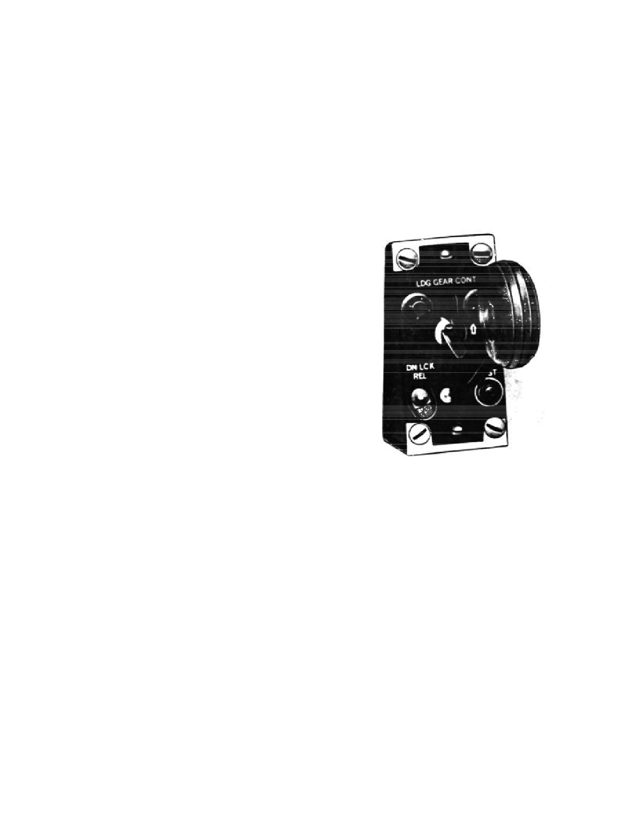
NAVAIR 01-230HLH-1
beneath the tail fin is full swiveling and self-centering and may
The main landing gear warning light in the landing gear
be locked in the center position. The sponsons are fixed,
actuating lever knob goes on whenever the actuating handle is
hollow, outrigger-type floats attached to the fuselage that
moved and the landing gear is in transit to the up or down
enable the helicopter to maintain a level, upright position in the
position. The intensity of the landing gear warning light is
water. The landing gear control panel (Figure
2-36) marked
controlled by the pilot flight instrument lights rheostat on the
LDG GEAR CONT is on the copilot side of the cockpit
overhead switch panel. When the rheostat is OFF, the light
console. The landing gear actuating lever, the warning light test
will be on at full strength, but as the rheostat is moved from
button marked HDL LT TEST, and the downlock release
OFF, the landing gear warning light will go to the dim position.
marked DN LCK REL are on the panel.
When the landing gear is locked in either UP or DOWN, the
light will go off. The warning light operates on dc power and is
2.12.1 Landing Gear Actuating Lever. The landing gear
protected by a circuit breaker marked LAND GEAR on the center
actuating lever on the landing gear control panel marked LDG
circuit breaker panel.
GEAR CONT has a wheel-shaped knob and marked positions
UP and DN, with directional arrows. The lever is actuated to
raise or lower the main landing gear and to energize or
deenergize the armament release. When at UP, the armament
release is energized, and when at DN, the armament release is
deenergized. A red warning light in the wheel-shaped knob is
on when the landing gear is cycling. An electrically actuated
downlock solenoid locks on the actuating lever in the DN
position when the weight of the helicopter is on the landing
gear. After becoming airborne, the lock is automatically
released that permits the actuating handle to be moved to UP.
Should the downlock solenoid electrical circuit become
inoperative, a mechanical downlock release marked DN LCK
REL can be actuated to mechanically release the landing gear
actuating lever from the DN position. Placing the actuating
lever to UP opens an electrically operated solenoid valve,
allowing hydraulic fluid to pass through a two -way restrictor
valve to the main landing gear cylinder, forcing the piston in
the cylinder into the up position. The main landing gear, when
fully raised, is held in position by a mechanical uplock. A
hydraulically operated uplock cylinder or a mechanical release
must be a actuated to release the mechanical uplock. Placing
Figure 2-36. Landing Gear Control Panel
the actuating lever to DN opens an electrically operated
solenoid valve, allowing hydraulic fluid to release the
2.12.3.1 Landing Gear Warning Light Test Button. A
mechanical uplock and to force the piston in the main landing
landing gear actuating lever warning light test button marked
gear cylinder to the down position. A limit switch will be
HDL LT TEST is on the landing gear control panel on the pilot
actuated when the main landing gear is fully extended or
compartment console. Pressing the button tests the warning
retracted and the electrically operated solenoid valve will return
light in the landing gear actuating lever knob. The warning
to the trail position.
light test button operates on dc power and is protected by
circuit breakers.
2.12.2 Down-Limit Release
(Scissors) Switch. One
down-limit release switch is attached to the scissors of each
2.12.4 Landing Gear Position Indicators. The indicators
main landing gear. With the weight of the helicopter on the
are on the cockpit console. The indicators read UP only if the
wheels, the main landing gear strut is compressed and the
landing gear wheels are in the up and locked position, and
scissors switch is electrically open. As the main landing gear
show pictures of landing gear wheels only if the wheels are in
strut extends, the scissors switch closes and the 28-vdc circuit
the down and locked position. During landing gear extension or
is completed, allowing the down-lock solenoid to disengage,
retraction (when the landing gear is neither up and locked nor
disabling underfrequency protection for the aircraft electrical
down and locked) and whenever electric power is not available,
system and enabling the jettison control panel.
the indicators show black and white diagonal lines. The
indicators operate on direct current and are protected by a circuit
2.12.3 Landing Gear Warning Light. When the landing
breaker marked LAND GEAR on the center circuit breaker
gear is fully extended, the red indicator pin in the center of the
panel.
drag link should be in.
2-59
ORIGINAL
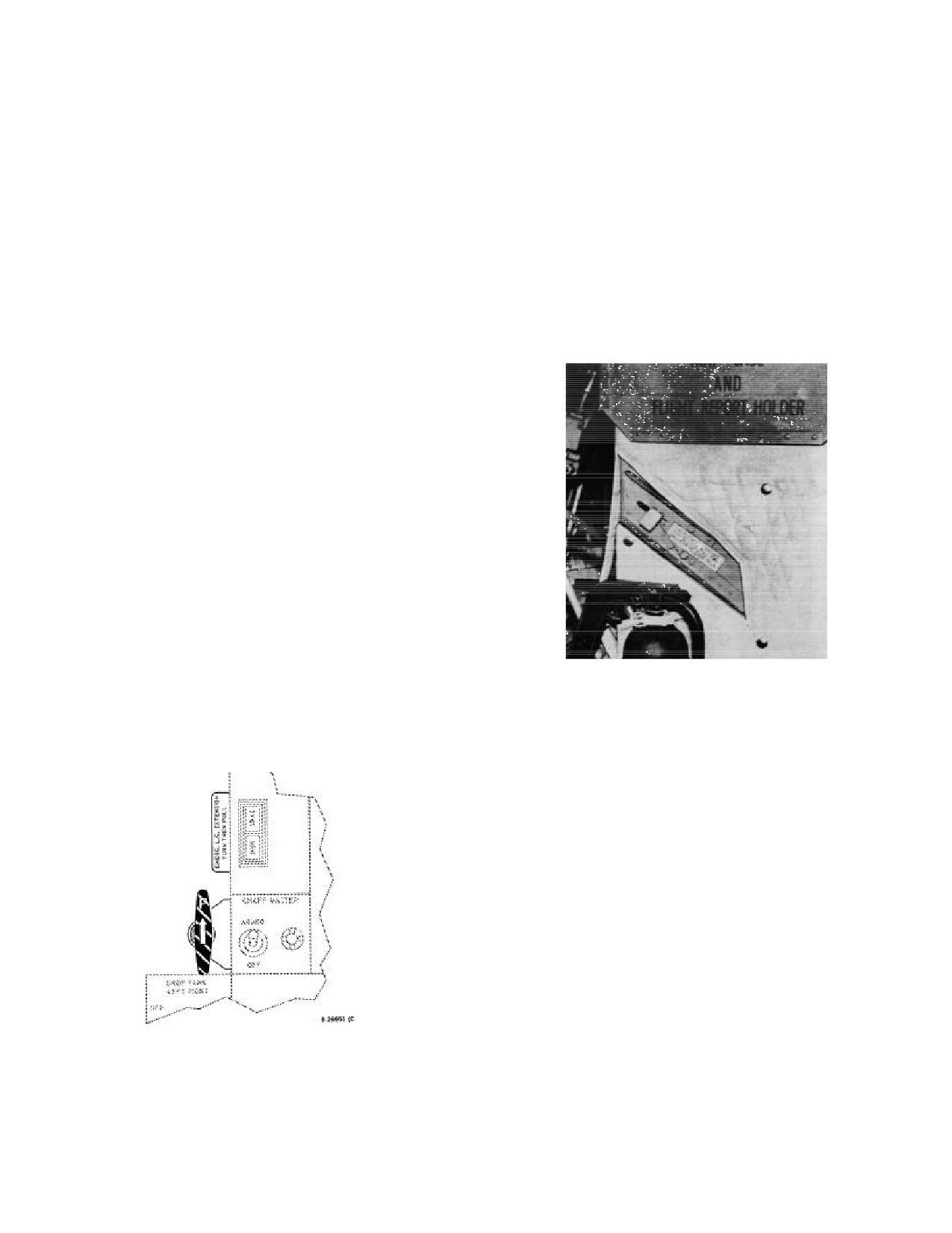
NAVAIR 01-230HLH-1
2.12.5 Landing Gear Emergency System. The system
2.12.5.2 Emergency Landing Gear Release Lever. The
is used to lower the main landing gear pneumatically if the
lever
(Figure
2-38) marked EMERGENCY LANDING GEAR
hydraulic system fails. The landing gear emergency system
RELEASE PULL FWD, ONLY IF AIR RELEASE FAILS is
consists of a 50-cubic inch, 3,000-psi maximum capacity air
behind the pilot seat on the broom closet. Pulling the
bottle in the auxiliary servo controls enclosure (broom closet)
emergency landing gear release lever manually actuates the
immediately aft of the pilot, an emergency landing gear
emergency bypass valve, allowing hydraulic fluid trapped in
extension handle on the copilot side of the cockpit console, and
the uplines to be vented to the hydraulic system. Gravity will
an emergency landing gear release lever on the side of the auxiliary
then lower the landing gear to the down position. The emer-
servo controls enclosure. A gauge, visible through a window on
gency landing gear release lever should be pulled only after the
the control enclosure door indicates the nitrogen pressure in the
emergency landing gear extension handle has been pulled and
air bottle. Nitrogen pressure must be 2,500 to 3,000 psi for the
the landing gear still does not lower. Do not attempt to reset the
system to function. An air bottle filler cap is behind a hinged
lever after it has been placed to the forward or emergency
panel marked EMERGENCY LANDING GEAR RELEASE
position.
AIR CHARGING CONNECTION on the side of the auxiliary
servo controls enclosure.
2.12.5.1 Emergency Landing Gear Extension Handle.
The handle (Figure 2-37) painted with orange-yellow and black
diagonal stripes is on the copilot side of the cockpit console.
The emergency landing gear extension handle is used to lower
the main landing gear in case of failure of the normal system.
The handle must be turned and pulled to withdraw the
emergency uplock release pins, release air into the landing gear
system, and pneumatically actuate the emergency bypass valve
to vent hydraulic fluid from the uplines, forcing the landing
gear to the down and locked position. The emergency bypass
valve displaced by the air charge and actuated by the
emergency landing gear extension handle must be manually
reset before the landing gear can be retracted or the air bottle
recharged. An instruction plate marked EMER L.G.
EXTENSION, TURN THEN PULL is beside the handle. When
the emergency landing gear release system has been actuated,
Figure 2-38. Emergency Landing Gear Release Lever
the warning light on the landing gear actuating lever will go on
whenever the landing gear is in transit, regardless of lever
2.12.6 Tailwheel Lock Handle. The handle, next to a decal
position. The landing gear position indicator will indicate down
marked TAILWHEEL LOCK - PULL TO LOCK, is on the
or unsafe only.
right side of the cockpit console. Pulling the handle out permits
a spring-loaded lockpin to engage at the swivel joint after the
tailwheel is centered. Pushing the handle in releases the lock
and allows the tailwheel to swivel. There are positive detents in
the LOCK and UNLOCK positions. To UNLOCK the tail-
wheel, depress the button in the center of the handle to release
the handle from the upper detent, then depress the handle fully
down. It is not necessary to continue to depress the center
button, as the handle will automatically remain in the down
position when it engages the lower detent. The tailwheel
maybe unlocked before taxi since the tailwheel will not
actually unlock until all side loads on the lockpin are relieved.
To lock the tailwheel, depress the button in the handle. This
will allow the handle to rapidly spring out to the locked
position. The tailwheel should be locked only for straight
takeoffs and landings. During maneuvers on the ground, the
tailwheel should be unlocked to reduce strain on the pylon and
Figure 2-37. Emergency Landing Gear Extension Handle
the possibility of shearing the tailwheel lockpin. If any side
loads are imposed on the tailwheel, the lockpin will not
disengage.
2-60
ORIGINAL
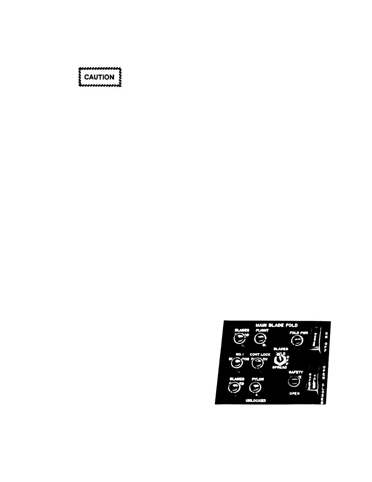
NAVAIR 01-230HLH-1
2.12.7 Wheelbrake System
allowing the pilot to see the marking CHECK BLADE FOLD. The
system is protected by a circuit breaker marked BLADE FOLD
on the center circuit breaker panel.
2.13.1 Rotary Wing Blade Folding. The rotary wing blades
may be folded by a full automatic operation that is controlled
by either the pilot or copilot. The operation may be halted at
any stage of the folding or spreading cycle and reversed if so
The parking brake can be set for one wheel
desired. Hydraulic power from the utility hydraulic system is
without the other which could be hazardous
used in conjunction with hydraulic and electrical sequencing.
during night carrier operations. Make sure that
Power is supplied by a variable delivery pump on the accessory
both rudder pedals are pressed firmly when
drive of the main gearbox. The folding is done by actuating the
setting the parking brake.
proper switches on the blade fold control panel (Figure
2-39)
on the overhead switch panel and observing the blade
Note
positioning and folding in conjunction with appropriate lights
on the panel. The No. 1 engine should be running at 104-
The advisory light only indicates that the parking
percent Nf for blade folding. The No. 1 blade positions directly
brake handle is up. It does not infer the
aft and does not fold. After the rotary wing blades are folded
wheelbrake system is pressurized.
and stowed, the tail pylon may be manually folded without any
interference. The blade positioner control valve is a four-way
The main landing gear wheels have hydraulic brakes
trail position solenoid-operated valve mounted on the upper
operated by toe pedals on the pilot rotary rudder pedals. The
right side of the main gearbox input housing. It controls the
fluid for these brakes is self-contained within the master
operation of the positioning units. When the folding switch is
cylinders. A parking brake handle operates a hydraulic valve to
placed to FOLD, a solenoid energizes the control valve that
lock the wheel-brakes. A light on the advisory panel goes on
directs hydraulic fluid to engage the rotor brake disc teeth and
whenever power is applied to the helicopter, allowing the pilot
position the No. 1 blade aft. After positioning the blades, the
to see the marking PARKING BRAKE ON.
control valve is energized by the other solenoid to direct
hydraulic fluid to disengage the rotor blade positioners and,
2.12.8 Brake Pedals. The main landing gear wheels are
through a pressure reducer, to engage the automatic rotor
individually braked by pressing the corresponding toe brake
brake. When the folding switch is placed to SPREAD, the
pedals (Figure 2-3) mounted above the pilot rotary rudder pedals.
control valve is energized to direct hydraulic fluid to ensure
The brakes operate on hydraulic pressure developed by
disengagement of the positioner from the rotor brake disc and,
pressing the brake pedals.
through a pressure reducer, to engage the rotor brake.
2.12.9 Parking Brake Handle. The handle (Figure
2-3)
Note
marked PARKING BRAKE is on the right side of the cockpit
console. A decal next to the parking brake handle is marked
A manual blade fold procedure is described in
ON-DEPRESS TOE BRAKE THEN PULL, OFF-DEPRESS
Chapter 7.
TOE BRAKE. The parking brake is applied by first pressing
the toe brake pedals and then pulling the parking brake handle
out. Pressing the left brake pedal will release the parking brake,
causing the parking brake handle to return to OFF.
2.13 AUTOMATIC BLADE FOLD SYSTEM
The automatic blade fold system positions the rotary wing
blades into the proper radial position for blade folding, extends
the dampers and turns the blades a full 3o forward on the drag
hinges, locks the rotary wing controls when the blades are
folded, provides a means of applying the rotor brake auto-
matically, and automatically disengages the blade lockpins.
Controls for the system are grouped on a panel marked MAIN
BLADE FOLD on the cockpit overhead switch panel. The
blade fold system is a part of the utility hydraulic system. A
Figure 2-39. Blade Fold Control Panel
light on the advisory panel goes on when dc power is applied
and the blade fold interlock system is not in flight condition,
2-61
ORIGINAL
NAVAIR 01-230HLH-1
2.13.2 Blade Fold Control Panel. The panel (Figure 2-
locking pin is properly positioned, safety valve is closed, and
39) marked MAIN BLADE FOLD on the overhead switch
master switch is off. When the safety valve switch is open and
panel contains all control switches for the blade fold system
the master switch is on, the flight position indicator light will
and the warning and indicator lights that show the sequence of
go off, SAFETY VALVE and FOLD POWER lights will
operation during the folding and spreading of the rotary wing
illuminate, primary pressure will drop to zero, primary servo
blades. Three switches are marked MASTER, SAFETY
caution light will go on, automatic rotor brake will come on,
VALVE, and BLADES with marked positions FOLD,
and rotor brake caution light will remain on.
SPREAD, and OFF. The indicator lights are marked BLADES
SPREAD, FLIGHT POS, NO. 1 BLADE POS, CONT LOCK
2.13.2.6 No. 1 Blade Position Indicator Light.
PINS ADV BLADES FOLDED, and PYLON UNLOCKED.
An amber light marked NO. 1 BLADE POS on the blade fold
Two warning lights are marked SAFETY VALVE OPEN and
control panel will go on during the folding cycle after the
FOLD PWR ON. The lights may be dimmed by turning the caps.
rotary wing head positions with the No. 1 blade directly aft.
2.13.2.1 SAFETY VALVE Switch. A guarded switch
2.13.2.7 Control Lockpins Advanced Indicator Light.
marked SAFETY VALVE with positions OPEN and CLOSED
An amber light marked CONT LOCK PINS ADV on the blade
is on the blade fold control panel. A red warning light to the
fold control panel will go on during the folding cycle as soon as
left of the safety valve switch indicates the OPEN position. The
one flight control lockpin moves forward. It will remain on
switch operates a motor-driven, three-way, two-position,
until all the flight control lockpins are fully disengaged at the
selector valve on the bulkhead on the right side of the cabin
end of the spreading cycle.
next to the gearbox and prevents inadvertent application of
hydraulic pressure to the blade fold system and automatic rotor
2.13.2.8 Blades Folded Indicator Light. An amber light
brake during flight. When the safety valve switch is turned to
marked BLADES FOLDED on the blade fold control panel
OPEN, the safety valve red warning light will go on and the
will go on when all blades are folded. During the spreading
FLIGHT POS green indicator light will go off.
cycle, the BLADES FOLDED indicator light will go off when
any blade moves forward. The blade fold accumulator located
2.13.2.2 Blade Fold MASTER Switch. The switch marked
in the No. 1 main rotor blade sleeve spindle is a piston-type
MASTER with two positions ON and OFF on the blade fold
oleo-pneumatic system designed to maintain hydraulic pressure
control panel completes the circuit to furnish electrical power
in the blade fold system when the blades are folded and power
to actuate the hydraulic sequences for automatic blade folding.
is off the system. By maintaining pressure on the system, the
The master switch will not furnis h electrical power to the blade
blade damper-positioners are maintained in the extended
fold system to fold the blades if the pylon is folded, accessory
position, locking the blades in the folded position. Addition-
drive switch is in FLIGHT, No. 2 engine fuel firewall valve is
ally, the blade fold accumulator compensates for expansion and
open, or safety valve is closed. A red indicator light marked
contraction of trapped hydraulic fluid because of temperature
FOLD PWR ON indicates that the folding power is available.
changes and helps dampen out pressure surges during the
fold/spread cycle. A pressure gauge on the No. 1 blade sleeve
2.13.2.3 Blades FOLD Spread Switch. A three-position
spindle indicates accumulator pressure. Normal pressure
BLADES switch marked FOLD, SPREAD, and OFF on the
indication is 1,500 psi with the blades spread.
blade fold control panel is used to select the folding cycle that
consists of rotary wing head positioning cycle, blade folding
2.14
PYLON FOLDING
cycle, or the spread cycle.
The tail pylon may be folded forward, parallel to the fuselage,
so the helicopter can be parked in a small area. The pylon is
2.13.2.4 Blades Spread Indicator Light. An amber light
attached to the tail cone at four points just forward of the
marked BLADES SPREAD on the blade fold control panel is
intermediate gearbox. The two right-hand points form a hinge
actuated when the blade lockpins are engaged and the control
(Figure 2-2) about which the pylon folds forward against the
lockpins are completely disengaged. The blade spread indicator
right side of the tail cone. A locking strut holds the pylon in the
light will go off when the accessory drive switch is placed to
folded position (Figure 2-40). A pylon hinge lock locks the left
FLIGHT. The BLADES SPREAD light will go off as soon as
side of the pylon to the tail cone in the spread position.
any control lockpin starts to advance or any blade lockpin
Retractable lockpins are actuated in and out of hinge-like lugs
retracts.
by a ratchet wrench that is secured against the tail cone when
not in use. The rotary rudder pedals should be centered before
2.13.2.5 Flight Position Indicator Light. A green light on
the pylon is folded to assure minimum rotary rudder pitch
the blade fold control panel marked FLIGHT POS indicates
change as the pylon is swung forward. A red lockpin position
that the rotary wing blades are in the flight position. The flight
flag-type indicator, operated mechanically, extends from the
position indicator light will go on, primary hydraulic pressure
left side of the tail cone whenever the pylon lockpins are not
will rise to 1,300 to 1,600 psi, and the primary servo caution
fully seated.
light will go off when the blades are completely spread, pylon
2-62
ORIGINAL
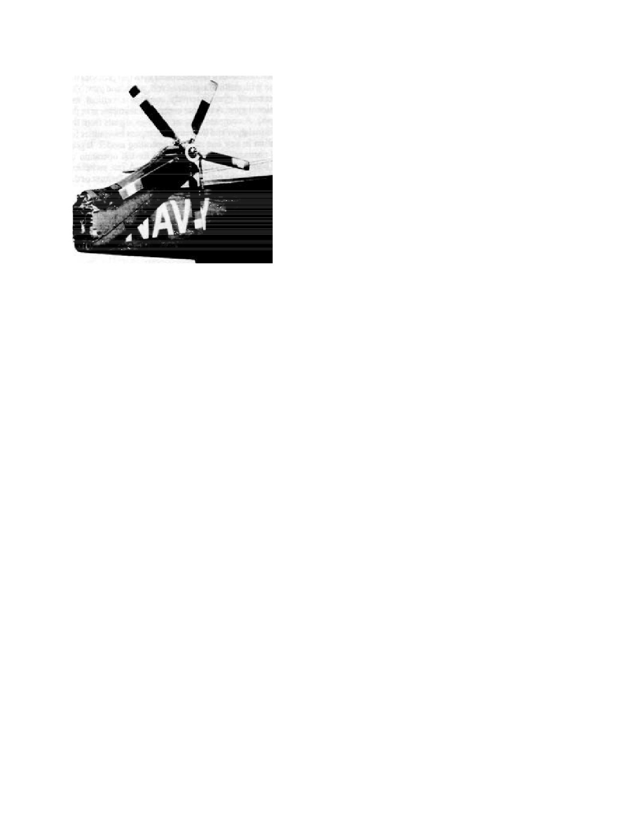
NAVAIR 01-230HLH-1
2.15.5 Attitude and Heading Reference System
(A/A24G-39 AHRS). This system provides PORT GYRO
attitude information (pitch and roll) for display on the copilot
instrument panel, attitude indicator, and the ASE when in the
PORT VERTICAL GYRO mode. (A separate Model 1080Y
vertical gyroscope provides STARBOARD GYRO attitude
information for display on the pilot instrument panel, attitude
indicator, and pitch/roll to the ASE when in the STBD VERTI-
CAL GYRO mode.) The A/A24G-39 AHRS is the only
source of heading information for the ASE yaw channel and the
aircraft avionics systems (tacan, TACNAV, and cockpit BDHI,
RMI, and course indicator displays).
The source of the magnetic heading information used by
the AHRS is a remote compass transmitter unit located within
the aft tail cone area. Loss of reliable attitude and/or heading
from the AHRS is evidenced by illumination of the COMPASS
Figure 2-40. Pylon Folded
FAIL light on the caution panel, and display of the OFF flag on
the copilot attitude indicator. The standby compass located on
2.15 FLIGHT INSTRUMENTS
the cockpit instrument panel glareshield is a completely
separate backup wet compass provided for instances of
2.15.1 Standby Compass. A magnetic standby compass is
complete loss of AHRS heading information or aircraft
at the top center of the instrument panel. A standby compass
electrical power.
correction card is on the pilot side of the instrument panel.
Electrical power to the AHRS may be controlled only by
2.15.2 Free-Air Temperature Gauge. A bimetallic free-air
engaging or disengaging the circuit breakers. Power for the
temperature gauge is on the centerline of the helicopter on the
COMPASS FAIL caution panel light is supplied by the COMP
windshield glass panel.
dc breaker located in the pilot circuit breaker panel (Figure 2-
23). Power for the AHRS is supplied by the COMP ac breaker
2.15.3 Clocks. Two
8-day,
12-hour, elapsed time clocks
located in the copilot circuit breaker panel (Figure 2-23).
(Figure 2-7) are installed on the instrument panel. The control
knob for the elapsed time mechanism is at the upper right
Prior to application of power to the AHRS, adjust the two
corner of the clock face. The clock is stem wound and stem set
copilot attitude indicator trim knobs so that each knob arrow
with a knob in the lower left corner of the clock face.
points to the black reference dot (Figure
2-43). After initial
power application, a
2-minute warmup and gyro erection
2.15.4 Pitot-Static System. Two pitot tubes with static
period is required before reliable attitude information is
ports are mounted over the cockpit, one on the right side and
available.
(During this period, the COMPASS FAIL caution
the other on the left side of the helicopter, forward of the engine air
light and the copilot attitude indicator flag are visible.) Any re-
intakes. The lines carrying static pressure from both pitot-static
sidual attitude errors remaining after warmup can be eliminated
tubes are connected together so that the pilot and copilot
by depressing the ERECT button located on the AHRS control
airspeed and vertical velocity indicators, the TAS transducer,
panel (Figure 2-44) until the copilot attitude indicator displays
and BAR ALT controller are fed from a common static line.
satisfactory pitch and roll values. (If erected with the UH-3H
The starboard pitot pressure line feeds the pilot airspeed
on a flat and level ramp, the copilot attitude indicator will
indicator and the TAS transducer. The port pitot pressure line
display level roll attitude and a slight noseup attitude in pitch.)
feeds only the copilot airspeed indicator. A restrictor is
Attitude correction can also be performed during straight and
installed in the static pressure line to the BAR ALT controller
level flight by use of the ERECT button.
sensing unit to filter transient pressure changes, thereby
contributing to a more stable flight-path. The TAS transducer
Note
converts pitot-static airspeed information to an electronic TAS
signal that is fed to the TACNAV or navigation system.
· The quality of electrical power available at ship
Sleeves are installed on both pitot tubes to ensure correct
flight deck launch spots is so poor that AHRS
airspeed readings and to prevent erroneous inputs to the BAR
reliability can be severely degraded. COMPASS and
ALT controller when the ice shield is installed. Both pitot tube
PHASE B (ÆB) circuit breakers should be pulled
heads may be heated to prevent icing. Refer to Pitot Heaters,
when the UH-3H has deck edge power applied, and
paragraph 2.18.5.
engaged only with another source of external power
or after operating on helicopter power.
2-63
ORIGINAL
NAVAIR 01-230HLH-1
· When operating aboard ship, the deck
Note
motion in pitch, roll, and yaw will be reflected
in the AHRS outputs.
The SYNC meter needle does not function when
helicopter accelerations exceed preset values,
· Use of the ERECT button should be
such as during turns. In these flight conditions,
limited to a maximum period of 3 minutes to
the needle is stowed in the center of the meter
avoid thermal reliability problems. After a 1-
and no needle oscillations are seen. This stowed
minute wait, the ERECT button may be used
needle condition during maneuvers should not be
again.
mistaken for properly synchronized AHRS
heading operation.
· Because of the high inertia of the AHRS
Note
gyro, it is still spinning down for 20 minutes
after electrical power is removed, and is
vulnerable to reliability problems if the
During flight, the COMPASS FAIL advisory
helicopter is moved in an erratic fashion or if
light will occasionally illuminate momentarily as
electrical power is reapplied before rundown is
part of the normal AHRS operation. This will
usually occur upon rolling out of turns or upon
completed. To minimize AHRS gyro failures,
selecting the SLAVED mode if the DG or
avoid reapplying electrical power to the gyro
once 45 seconds have elapsed. Also, minimize
EMERG modes have been in use. Brief heading
the severity of helicopter towing impulses
fluctuations may also be seen on the cockpit
using steady and smooth starting and stopping
instruments during mode changes.
techniques.
The DG mode of operation is normally used when the
Earth's magnetic field is an unreliable reference (i.e., in polar
SLAVED is the UH-3H helicopter primary mode of AHRS
heading operation. In this mode, heading is furnished by a
regions or when the remote compass transmitter has failed).
directional gyro that is continually corrected for magnetic
Aircraft heading is furnished only by the directional gyro and is
heading by the remote compass transmitter (e.g., the gyro is
subject to error buildup if the correct latitude and hemisphere
slaved in the raw magnetic heading source). For this normal
are not inserted into the LAT and N/S controls located on the
control panel (Figure 2-44). The DG mode allows the pilot to
mode of operation, set the mode selection switch on the com-
set the AHRS heading to any selected reference by pushing and
pass control panel (Figure
2-44) to the SLAVED position for
the entire mission. Verify that the hemisphere switch is set to
turning the HDG PUSH knob until the desired heading is
the N position if in the northern hemisphere or S if operating in
displayed on the cockpit indicators and TACNAV. In polar
southern latitudes. Set the LAT control to the approximate
regions, the DG mode heading estimate should be based on the
average latitude expected for the mission. Hemisphere and
best available information to avoid large navigation errors.
latitude settings are especially important for minimizing
The EMERG mode of operation is used only when the
heading error buildup during sustained periods of helicopter
maneuvering (such as starboard delta patterns).
normal heading information from the AHRS is unreliable.
Magnetic information is passed directly from the remote
After AHRS warmup is completed and the COMPASS
compass transmitter for use until the AHRS can be replaced.
FAIL advisory light has extinguished, the directional gyro must
However, the magnetic heading information in the EMERG
mode is not as accurate and is not damped by the directional
be synchronized to the remote compass transmitter by
gyro. Since no automatic reversion to the mode occurs for
depressing the HDG PUSH knob until the SYNC meter needle
is centered (Figure 2-44). After takeoff (when at altitude with
AHRS gyro failures (COMPASS FAIL light or copilot altitude
a straight and level attitude), check the SYNC meter again to
indicator flag visible), the EMERG mode must be selected
determine whether initial magnetic heading errors because of
manually.
ship or helicopter launch pad magnetic fields have biased the
AHRS initial synchronization. If the needle is not centered,
push the HDG PUSH knob to remove the errors. To avoid
TACNAV navigation error buildup, the SYNC meter needle
should be checked periodically.
Because of the oscillatory nature of the compass
information in the EMERG mode, the pilot
should immediately discontinue the use of the
ASE yaw channel.
2-64
ORIGINAL
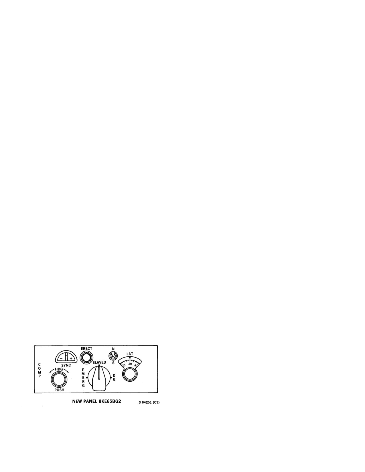
NAVAIR 01-230HLH-1
Note
2.15.7 Attitude Indicators. Two attitude indicators (Figure
2-43) on the instrument panel visually indicate the helicopter
If it is necessary to troubleshoot the system when
attitude. The indicator face consists of a stationary miniature
in the EMERG mode with the yaw channel
aircraft representing the helicopter, a bank angle scale, bank
engaged, follow these procedures to avoid
index, and a moving two-colored sphere with a distinct white
driving rudder pedal forces when returning to the
horizontal line dividing the two colors, white above and black
SLAVED mode. Place feet on rudder pedals and
below. A warning flag marked OFF will appear in the face of
disengage the yaw channel. Switch to the
the indicator when the indicator is inoperative. The warning
SLAVED mode. Synchronize the compass
flag will appear until about 68 seconds after ac power has been
heading by pressing the HDG PUSH knob until
applied to the circuit, when any unbalance of the three phases
the SYNC needle is centered. Cheek that the
of ac power occurs, or the directional gyro system for the
BDHI/ RMI compass card and standby compass
indicator has failed. Two trim adjustment knobs are on the
are within ±5o of each other (if not, repeat the
front of the attitude indicators, one at the lower left of the panel
procedure until they are). Engage the yaw
for adjusting roll, and the other at the lower right of the panel
channel and remove feet from rudder pedals.
for adjusting pitch. The pilot attitude indicator operates on ac
power and is protected by a circuit breaker. The copilot attitude
2.15.6 Compass System Control Panel. This panel
indicator operates on ac power and is protected by circuit
(Figure 2-44) is on the center console. When in the SLAVED
breakers.
mode, pressing and holding down the HDG PUSH knob
automatically causes synchronization of heading outputs of the
Each attitude indicator also has a turn-and-slip indicator
directional gyro with the compass transmitter heading. In the
mounted on the bottom that visually indicates the helicopter
DG mode, the HDG PUSH knob may be pushed and turned
rate of turn and flight condition.
clockwise or counterclockwise to set the heading on the BDHIs
and RMI, and the system works with the directional gyro.
Note
In the SLAVED mode, the SYNC window indicates
The warning flag marked OFF on the copilot gyro
synchronization of the directional gyro in the compass
will appear momentarily when the helicopter is in a
transmitter heading. The EMERG position provides emergency
high vibratory flight regime. This may be when the
operation using only the compass transmitter and is used when
helicopter is entering a hover or in any situation of
a directional gyro failure has occurred.
impending translational lift. The warning flag will
disappear when the helicopter leaves the high
The N/S switch selects polarity of latitude correction
vibratory flight regime.
signal: N for northern hemisphere and S for southern
hemisphere. The LAT knob selects latitude of flight (0o to 90o)
2.15.8 Turn Rate Switches. Two turn rate switches (Figure
to correct for heading gyro drift because of Earth rotation. The
2-7), one each for the pilot and copilot, are on the instrument
N/S switch and LAT knob must be set for the SLAVED mode
panel. The switches are marked TURN RATE and have marked
as well as DG mode since the system automatically switches
positions NORM and ALT. When the switches are placed to
from SLAVED to DG mode whenever the helicopter is in a
NORM, the copilot indicator receives rate of turn information
turn.
from the ASE rate gyro amplifier demodulator, and the pilot
indicator receives rate of turn information from the dc powered
The ERECT pushbutton, when pressed, increases the roll
rate gyro transmitter. This system remains operative when the
erection rate of the vertical gyro.
OFF flag in the attitude indicator appears, provided dc power is
available. When either switch is placed to ALT, that indicator
receives rate of turn information from the other system.
Figure 2-44. Compass System Control Panel
2-65
ORIGINAL
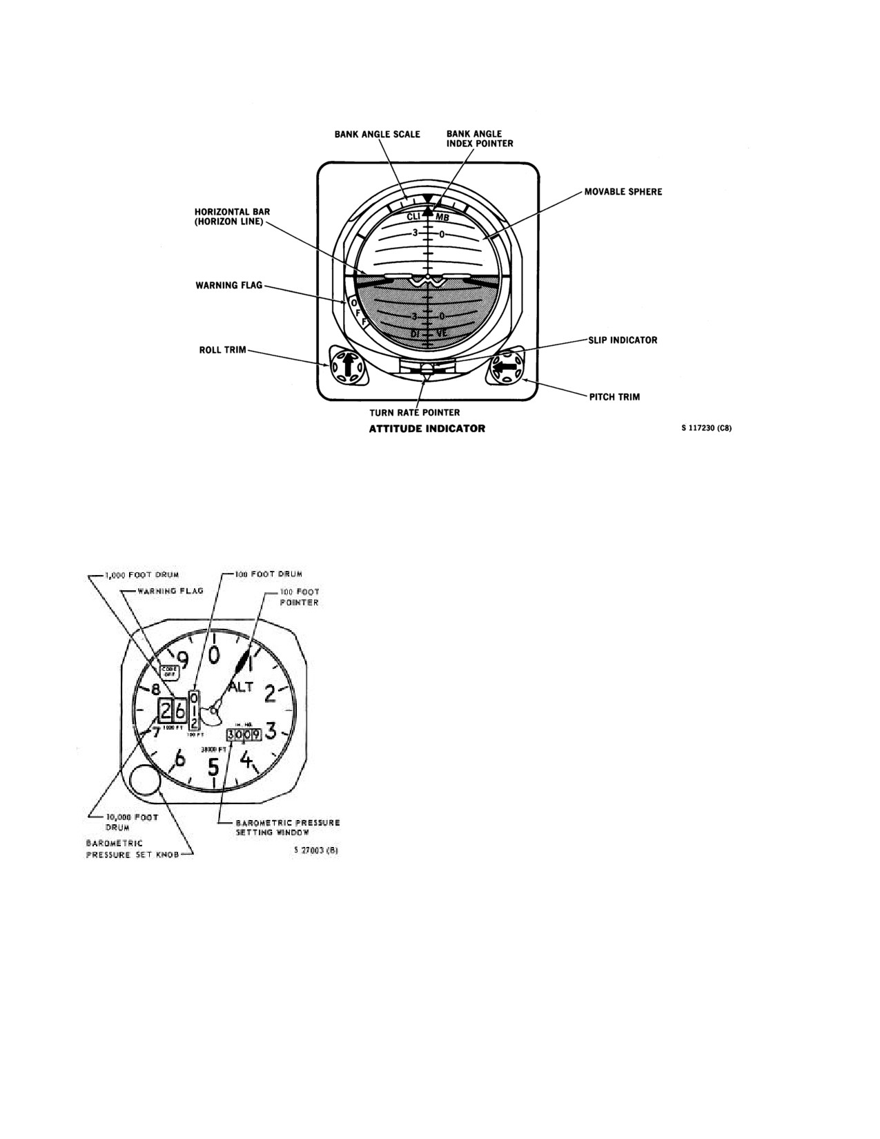
NAVAIR 01-230HLH-1
Figure 2-43. Attitude Indicator
2.15.9 Altitude Encoder. The altitude/encoder (Figure
foot change in altitude and drives a drum that also
2-45) functions as a barometric altimeter for the pilot and
indicates altitude in hundreds of feet. The
100-foot drum
a pressure altitude sensor for the AN/APX-72 IFF
will cause the 1,000-foot drum to index one digit when it
transponder.
moves through the short period between 9 and 0, and the
1,000-foot drum actuates the 10,000-foot drum in a similar
manner. During the long period between
0 and 9, the
1,000- and 10,000-foot drums are locked in position. In the
space corresponding to zero, the
10,000-foot drum is
marked with striped lines. The pointer acts as a vernier of
the 100's drum as well as being an indication of trend
information. The barometric set knob permits altimeter
setting from 28.10 to 31.00 inches Hg and these settings
will be displayed by the barometric pressure setting
window. The combined readings of the drums and pointer
indicate an altitude measurement in thousands and
hundreds of feet based on the selected altimeter setting.
Two techniques may be used to read indicated altitude
on the drum and pointer-type altimeter. Read the drums
without referring to the 100-foot pointer as a direct digital
readout of both thousands and hundreds of feet, or read the
digital readout in thousands without referring to the 100-
foot drum, and then add the 100-foot pointer indication.
Figure 2-45. Altitude Encoder
The 100-foot pointer serves as a precise readout of values
less than 100 feet required for determining lead points for
2.15.9.1 Altimeter. The AAU-21/A altitude indicator
level-off altitudes, maintaining level flight, and during
(Figure 2-7) is on the pilot side of the instrument panel.
instrument approaches. The system is equipped with a
The altimeter operating range is from -1,000 to +38,000
continuously operating vibrator to improve altitude
feet. The face of the instrument indicates readings in feet
measuring accuracy. Power to operate the vibrator is
in 50-foot units with the numerals representing hundreds
furnished through a dc circuit breaker marked IFF TEST.
of feet. The pointer makes one revolution for every 1,000-
2-66
ORIGINAL
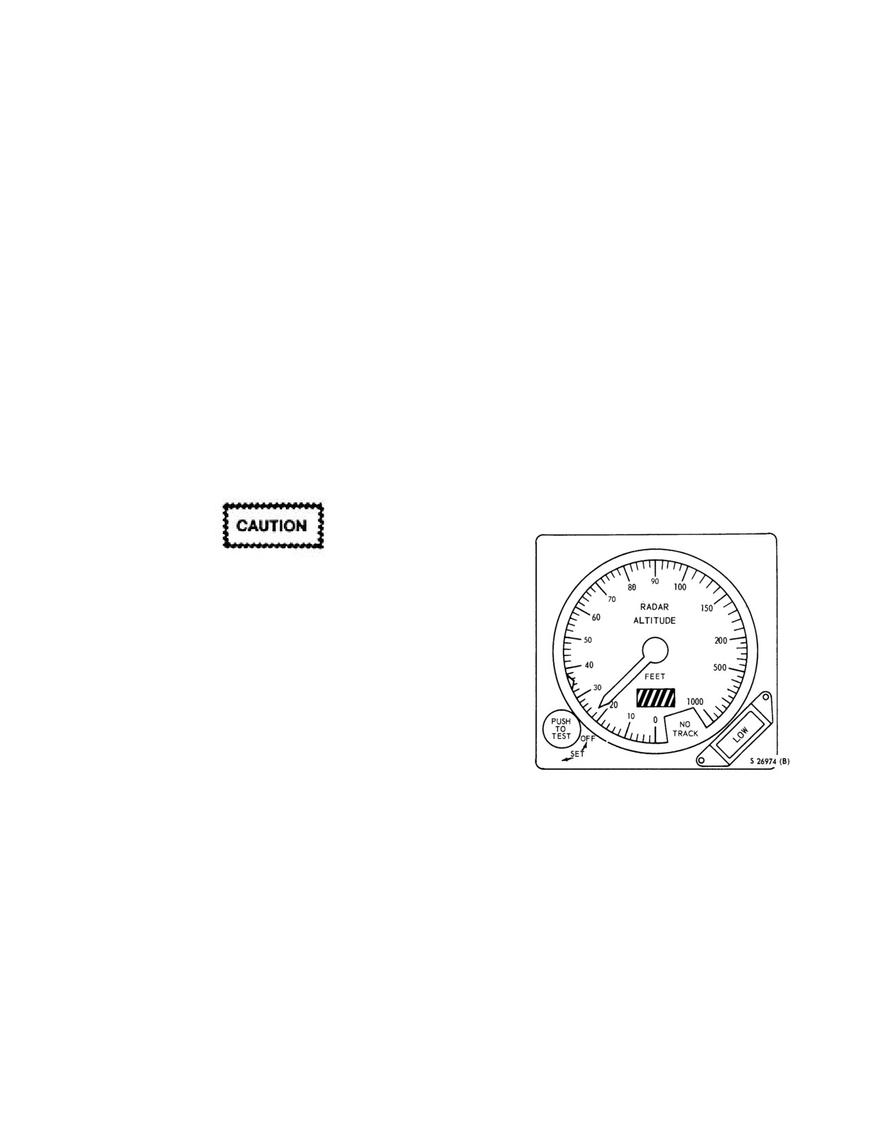
NAVAIR 01-230HLH-1
2.15.9.2 Encoder. The AAU-21/A encoder provides a
warning index marker on the indicator. Depressing the
digital output of pressure altitude in units of 100 feet to the
PUSH-TO-TEST control knob provides a testing feature of
AN/APX
72 IFF transponder for automatic pressure
the system at any time and altitude, provided the CPLR
altitude transmission. The encoder's operating range is
mode of ASE is disengaged. When the PUSH-TO-TEST
from - 1,000 to +38,000 feet and has a permanent altimeter
control knob is depressed, a visual indication of 100
±15
setting of 29.92. Loss of 115-vac, 400-Hz power will cause
feet on the indicator indicates satisfactory system
the warning flag marked CODE OFF on the pilot altimeter
operation. Releasing the PUSH-TO-TEST control knob
indicator to be displayed. Power to operate the encoder is
restores the system to normal operation. A low-level
furnished through an ac circuit breaker marked IFF IND.
warning light on the lower right corner of the indicator will
light and show the marking LOW anytime the helicopter is
Note
at or below the low-altitude limit that has been selected.
Loss of system power or tracking condition will be
Only when the altimeter is set to 29.92 will
indicated by a black and yellow striped flag that appears in
the transmitted altitude be the same as the
the indicator window on the lower center portion of the
displayed altitude.
indicator. If the system should become unreliable, the black
and yellow striped flag will appear and the indicator
2.15.9.3 Altimeter
(AAU-24/A). The altimeter (Figure
pointer will go behind a mask marked NO TRACK to
2-7), mounted on the copilot side of the instrument panel,
prevent erroneous readings. While hovering at low
is identical to and operates in the same manner as the pilot
altitudes over smooth surfaces, fluctuations of about ±1.5
AAU-21/A altitude encoder except that there is no warning
feet can be expected for altitudes under 100 feet. During
flag on the indicator.
normal flight operations above
1,000 feet, the altimeter
indicates an unreliable condition.
2.15.10 Radar Altimeter
The system requires both ac and dc power for
operation and is protected by a circuit breaker.
After turning equipment on, allow about 3
minutes for systems to reach operating
temperature. To avoid damage to system
components, do not place system in
operation until 3 minutes have elapsed since
system was last turned OFF.
The radar altimeter system
(AN/APN-171(V))
provides instantaneous indication of actual clearance
between the helicopter and terrain from 0 to 1,000 feet.
Altitude in feet is indicated by the two radar altimeter
indicators on the instrument panel in front of the pilot and
copilot. The radar altimeter
(Figure
2-46) contains a
Figure 2-46. Radar Altimeter
pointer that indicates altitude on a linear scale from 0 to
100 feet in
2-foot units, 100 to 200 in 10-foot units, and
2.15.11 Radar Altitude Warning System. The
200 to 1,000 in 50-foot units. A control knob on the lower
AN/APQ-107 RAWS provides the pilot and copilot with
left corner of the indicator combines functions to serve as a
aural and/or visual warning signals of low-altitude con-
test switch, a low-level warning index set control, and an
ditions and/or failure of the radar altimeter. The visual
on/off power switch. The system is turned on by turning
indication is provided by a pulsating ALTITUDE light on
the control knob marked PUSH-TO-TEST clockwise from
the caution panel. The aural tone is channeled through the
OFF, and is the only control necessary for equipment
intercommunications system to pilot and copilot headsets.
operation. Operation of the control knob on either indicator
These signals are triggered under any of the following
will turn the system on; however, both control knobs must
conditions:
(1) Whenever the radar altimeter decreases
be turned fully counterclockwise to turn the system OFF.
Continued clockwise turning of the control knob toward
through 100
±5 feet when the coupler is not engaged or
the SET position will permit the pilot to select any desired
reaches 30 ±5 feet with the landing gear up, (2) When the
low-altitude limit that will be indicated by the low-level
radar altimeter output signals are unreliable and if
2-67
ORIGINAL
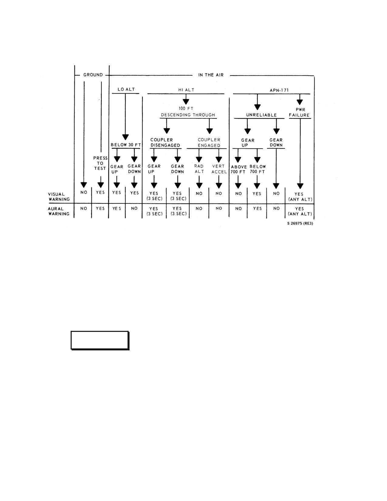
NAVAIR 01-230HLH-1
Figure 2-47. RAWS Warning - All Conditions
electrical power to the radar altimeter fails (Figure
2-47).
circuit, to indicate a particular system is in operation or an
A test switch marked RAWS TEST is on the instrument
unsafe condition exists. When a system is in operation or
panel to the right of the caution panel. To test system
an unsafe flight condition exists, the advisory light for that
reliability, make certain that the radar altimeter is
particular system or condition comes on and remains on
energized and ac and dc power is being supplied, and then
until the system is turned off or the unsafe flight condition
depress the test button. The aural and visual warning
is corrected. Pressing the switch marked TEST on the
signals should occur simultaneously. The system operates
caution panel tests lights of both the caution and advisory
on
115-vac power and
28-vdc power. The system is
panel.
protected by circuit breakers.
2.16.1.1 Advisory Panel Lights. Refer to Figure 2-48
for a detailed description of the advisory panel.
WARNING
2.16.2 Caution Panel. The caution panel (Figure
2-
49) marked CAUTION PANEL is on the pilot side of the
instrument panel. The caution panel gives the pilot visual
With the landing gear down, the RAWS will
indication of failure or unsafe conditions of certain critical
not provide an indication of an unreliable
power equipment in the helicopter. The caution panel
radar altimeter.
contains placard-type amber caution lights, each having its
own operating circuit, to indicate a particular condition in
2.16 WARNING, CAUTION, AND ADVISORY
the helicopter. If a failure or unsafe condition occurs in one
LIGHTS
of the systems, the caution light for that particular
condition remains on until the failure or unsafe condition is
2.16.1 Advisory Panel. The advisory panel (Figure 2-
corrected. A master light marked MASTER CAUTION
-
48) marked ADVISORY PANEL is on the copilot side of
PUSH TO RESET is on either side of the instrument panel.
the instrument panel. The advisory panel gives the pilots
The master light goes on when any of the caution panel
visual indication of certain operating conditions in flight or
lights are energized by a malfunction. The master light will
while on the ground. The advisory panel contains placard-
type green advisory lights, each having its own operating
2-68
ORIGINAL
NAVAIR 01-230HLH-1
remain on until the malfunction is corrected or until
panel. The circuit breaker marked PWR provides electrical
deenergized by the pilot. Pressing the light deenergizes the
power for the normal operation of the caution lights and
master light, permitting the master light to indicate a
the circuit breaker marked TEST provides power for the
second malfunction if one should occur while the first
test circuit only.
malfunction is still present. The MASTER CAUTION
lights are simultaneously dimmed when the caution panel
2.16.2.1 Caution Panel Lights. Refer to Figure 2-49
is dimmed. This is done using the PILOTS FLIGHT INST
for a detailed description of the caution panel.
LTS rheostat on the overhead switch panel. The caution
lights operate through circuit breakers marked WARNING
LTS PWR and TEST that are on the center circuit breaker
A
D
EXT PWR ON
V
I
#1 ENG ANTI-ICE ON
S
#2 ENG ANTI-ICE ON
O
R
PARKING BRAKE ON
Y
P
A
N
NOSE DOOR OPEN
E
CHECK BLADE FOLD
L
01771122
ADVISORY LIGHTS
INDICATION
CONDITION
ACTION
EXT PWR ON
AC power receptacle door
Light will extinguish when
is open.
door is secured.
# 1 ENG ANTI-ICE ON
No. 1 anti-ice switch is on.
Light will extinguish when
# 2 ENG ANTI-ICE ON
No. 2 anti-ice switch is on.
engine anti-ice switch is
placed off.
PARKING BRAKE ON
Parking brake handle not
Reset and release parking
fully retracted.
brake.
NOSE DOOR OPEN
Electronic compartment
Check door security.
door is open or not fully
secure.
CHECK BLADE FOLD
DC power is applied and
If blade spread, call trouble -
blade fold interlock
shooter.
system is not in flight
condition.
Figure 2-48. (NON-ET) Advisory Light Panel
2-69
ORIGINAL
NAVAIR 01-230HLH-1
A
D
EXT PWR ON
V
I
#1 ENG ANTI-ICE ON
S
#2 ENG ANTI-ICE ON
O
R
PARKING BRAKE ON
Y
NO SMOKING
P
FASTEN SEATBELTS
A
N
NOSE DOOR OPEN
E
CHECK BLADE FOLD
L
01771122
ADVISORY LIGHTS
INDICATION
CONDITION
ACTION
EXT PWR ON
AC power receptacle door
Light will extinguish when
is open.
door is secured.
# 1 ENG ANTI-ICE ON
No. 1 anti-ice switch is on.
Light will extinguish when
# 2 ENG ANTI-ICE ON
No. 2 anti-ice switch is on.
engine anti-ice switch is
placed off.
PARKING BRAKE ON
Parking brake handle not
Reset and release parking
fully retracted.
brake.
NOSE DOOR OPEN
Electronic compartment
Check door security.
door is open or not fully
secure.
Passenger instruction light
NO SMOKING
Light will extinguish when
switch is on.
passenger instruction is
placed off.
FASTEN SEATBELTS
Passenger instruction light
Light will extinguish when
switch is on.
passenger instruction is
placed off.
CHECK BLADE FOLD
DC power is applied and
If blade spread, call trouble -
blade fold interlock
shooter.
system is not in flight
condition.
Figure 2-48.1. (ET) Advisory Light Panel
2-70
ORIGINAL
NAVAIR 01-230HLH-1
CAUTION PANEL
#1 GENERATOR
PRI SERVO PRESS
#2 GENERATOR
#1 RECTIFIER
AUX SERVO PRESS
#2 RECTIFIER
FWD FUEL LOW
TRANS OIL PRESS
AFT FUEL LOW
LAMP
TEST
FWD FUEL BYPASS
TRANS OIL HOT
AFT FUEL BYPASS
#1 INLET ANTI-ICE
ALTITUDE
#2 INLET ANTI-ICE
TAIL TAKE OFF
MAIN TRANS CHIP
ROTOR BRAKE ON
INTMED TRANS
IFF
TAIL TRANS CHIP
FUEL DUMP
COMPASS FAIL
BLADE PRESS
CAUTION LIGHT
CAUSE/ DESCRIPTION
ACTION*
#1 GENERATOR
Associated generator contactor relay
Recycle generator; if recycle fails, -
#2 GENERATOR
opens and falls off line.
LAND AS SOON AS PRACTICAL.
If both fail, - LAND AS SOON AS
POSSIBLE.
#1 RECTIFIER
Failure of rectifier or associated reverse
Single rectifier - LAND AS SOON
#2 RECTIFIER
current cutout relay.
AS PRACTICAL. Both rectifiers -
LAND AS SOON AS POSSIBLE.
PRI SERVO PRESS
Pressure falls below 1,000 psi or 1,000
LAND AS SOON AS POSSIBLE. If
AUX SERVO PRESS
psi switch failure.
pressure is below normal, secure
affected system.
FWD FUEL LOW
210 to 280 pounds per tank 30 nose
Avoid altitudes above 60 nose up,
AFT FUEL LOW
down - 170 to 200 pounds per tank in a
crossfeed, land as fuel remaining
hover.
permits.
FWD FUEL BYPASS
Pressure drop of 1.1 to 1.7 psi at the
Crossfeed from the good tank. -
AFT FUEL BYPASS
fuel filter.
LAND AS SOON AS PRACTICAL.
TRANS OIL PRESS
Main gearbox oil pressure is below 3.5
LAND AS SOON AS PRACTICAL.
psi at the forward right corner of the
Check for other indications.
main gearbox.
TRANS OIL HOT
Main gearbox oil temperature above
LAND AS SOON AS PRACTICAL.
1200 at oil cooler outlet.
Check for other indications.
* Procedures contained in the action column of this matrix shall not supersede the more detailed EMERGENCY
PROCEDURES of chapter 12.
Figure 2-49. Caution Light Panel (Typical) (Sheet 1 of 2)
2-71
ORIGINAL
NAVAIR 01-230HLH-1
CAUTION LIGHT
CAUSE/DESCRIPTION
ACTION*
MAIN TRANS CHIP
Metallic particles in main gearbox oil.
LAND AS SOON AS PRACTICAL.
Check for other indications.
INTMED TRANS CHIP
Metallic particles or over heat condition
LAND AS SOON AS POSSIBLE.
TAIL TRANS CHIP
in the associated gearbox oil.
Check for other indications.
#1 INLET ANTI-ICE
Anti-ice system failure or inability to
Check circuit breaker; continue flight
#2 INLET ANTI-ICE
maintain 380 inlet temperature.
as conditions permit.
ALTITUDE
Activation of the RAWS.
Check altitude.
TAIL TAKE OFF
1.
Tail takeoff free wheel unit
Check Nr. -LAND AS SOON AS
failure.
POSSIBLE. (Except for low Nr).
2.
Tail takeoff warning system
failure.
3.
Nr at 96 percent or below.
ROTOR BRAKE ON
Manual or automatic rotor brake
On deck - secure both speed selectors.
pressurized.
In flight - LAND AS SOON AS
POSSIBLE.
IFF
1.
Mode 4 code zeroized.
1.
MASTER SWITCH to
2.
Transponder is not replying to
NORM.
Mode 4 interrogations.
2.
Check Mode 4 toggle is on.
COMPASS FAIL
1.
A/24g compass has failed.
Switch to STBD VERTICAL GYRO
2.
Synchro interface unit (SIU)
on CHANNEL MONITOR panel to
has failed.
preclude erroneous ASE inputs.
3.
VERTICAL GYRO in the fast
erect mode.
FUEL DUMP
Fuel dump valve is open.
Monitor fuel remaining.
1. Airspeed - 80 KIAS, minimize
BLADE PRESS
Loss of blade pressure.
maneuvering.
2. Altitude - Minimum safe.
3. Blade Pressure Circuit Breaker -
Check in.
4. LAND AS SOON AS
PRACTICABLE
* Procedures contained in the action column of this matrix shall not supersede the more detailed EMERGENCY
PROCEDURES of chapter 12.
Figure 2-49. Caution Light Panel (Typical) (Sheet 2 of 2)
2-72
ORIGINAL
NAVAIR 01-230HLH-1
CAUTION PANEL
#1 GENERATOR
PRI SERVO PRESS
#2 GENERATOR
LAMP
#1 RECTIFIER
AUX SERVO PRESS
#2 RECTIFIER
TEST
FWD FUEL LOW
TRANS OIL PRESS
AFT FUEL LOW
FWD FUEL BYPASS
TRANS OIL HOT
AFT FUEL BYPASS
#1 INLET ANTI-ICE
ALTITUDE
#2 INLET ANTI-ICE
TAIL TAKE OFF
MAIN TRANS CHIP
ROTOR BRAKE ON
FWD DOOR OPEN
INTMED TRANS
IFF
AFT DOOR OPEN
TAIL TRANS CHIP
FUEL DUMP
COMPASS FAIL
BLADE PRESS
CAUTION LIGHT
CAUSE/DESCRIPTION
ACTION
FWD DOOR OPEN
Forward door is open or
Check door security.
not fully secure.
AFT DOOR OPEN
Aft door is open or not
Check door security.
fully secure.
Figure 2-49.1. (ET) Caution Light Panel
2.17 FIRE DETECTOR SYSTEM
2-9). A light on the instrument panel and a light in either
the No. 1 or No. 2 engine fire emergency shutoff selector
Two fire detector systems (one for each engine) are
handle will go on in case of a fire in the corresponding
installed to warn the pilot of an engine fire. Three
engine compartment. To test the engine fire detector
hermetically sealed temperature sensitive sensing loops
system, place the spring-loaded switch to the up FIRE
and two interconnecting cables that have no heat sensing
TEST position. The fire warning lights on the instrument
function are in each engine compartment. They are wired
panel and in the fire emergency shutoff selector handle
into a closed series loop connected to a control unit that
will go on. The switch will return to OFF when released,
turns on warning lights in the pilot compartment in case
and the lights will go off.
of a fire. The engine fire detector systems operate on ac
power. The Nos. 1 and 2 fire detector systems receive
2.18 HEATING SYSTEM
power from the inverter when the generators are
inoperative.
The heating system (Figure 2-50) consists of a fan, an
internal combustion heater, a plenum chamber, and ducts
2.17.1 Fire Warning Lights and Test Switch. Two
that run along the right side of the cabin wall and into the
red engine fire warning lights and test switch (see Figure
pilot compartment. A fire access port is in the aft heater
2-7) are on a plate marked FIRE WARN on the pilot side
duct aft of the broom closet on the starboard bulkhead. In
of the instrument panel. The lights are marked NO. 1
addition, a spring-loaded fire extinguisher door is in the
ENG and NO. 2 ENG. The switch has two marked
heater compartment access cover on the aft side of the
positions FIRE TEST and OFF. In addition, four red
ASE compartment. The heater unit in the heater
engine fire warning lights, two for each engine, are in the
compartment next to the control enclosure in the cabin
engine fire emergency shutoff selector handles marked
operates on fuel pumped from the forward fuel tank by a
FIRE EMER SHUTOFF SELECTOR NO.
1 ENGINE
heater fuel pump cycling valve to the heater unit, where it
and NO. 2 ENGINE on the overhead switch panel (Figure
is ignited by a spark plug. Fuel consumption of the heater
2-73
ORIGINAL
NAVAIR 01-230HLH-1
unit, operating continuously in the HIGH position, is 1.2
2.18.3 Heating and Ventilating Diffusers. A heater
gallons
(8 pounds) per hour. The spark plug operates
diffuser and register are in each heater duct that extends
electrically on
28-vdc current from the monitored bus,
along the outside of the pilot compartment, just above the
boosted by the heater ignition unit mounted in the heater
floor. Four diffusers are in the heater duct that extends
compartment. Air is drawn into the heater intake port on
along the right side of the cabin on the floor. Knobs
the fuselage above and to the rear of the pilot window,
marked OPEN and CLOSED are used to regulate the flow
and then through a heat exchange unit surrounding the
of warm air through the diffusers. The diffusers and fan
combustion unit. Heated air is then blown into the plenum
are also used as a ventilating system.
chamber, the cabin heater duct containing four diffusers,
and the pilot compartment heater ducts, each containing
2.18.4 Normal Operation.
two diffusers. The fan also supplies air to the heater
combustion chamber.
1. Heater switch - HIGH OR LOW.
2.18.1 Cabin Heater Switch. The heating system is
operated by a switch, marked CABIN HEATER with
three marked positions LOW, OFF, and HIGH on the
WARNING
overhead switch panel (Figure
2-9). The heater switch
controls the heater fuel pump and cycling valve and the
ignition unit. When the switch is at LOW, the heater will
Hot exhaust from the heater may burn
maintain a temperature of about 65oC in the ducts. When
personnel in the vicinity of the heater
the switch is at HIGH, the heater will automatically
exhaust.
maintain a temperature of about 149 oC in the ducts. An
overheat switch will shut off the heater if for any reason
2. Heater diffusers- ADJUST AS DESIRED.
the heat in the plenum chamber rises to 177oC. During
the start sequence of the heater, if the fuel does not ignite
within 40
±5 seconds, the thermal switch in the exhaust
tube will not actuate, causing the overheat relay circuit to
be completed through the contacts of the time delay relay.
These contacts close after 40
±5 seconds, shutting off
electrical power and fuel flow to the heater. The heater
Before operating heater, check all heater
may be restarted by recycling the HEATER HEAT circuit
outlets for clearance from luggage,
breaker
(CAB HTR UH-3H) with the heater control
clothing, inflatable equipment, and other
switch OFF. The heater will also shut off if the fan fails to
gear that might be damaged by heat.
operate. The heater switch is energized by the 28-vdc
monitored bus and is protected by a circuit breaker.
Note
2.18.2 Cabin Heater Fan Switch. The switch marked
The heater is shut off by moving the heater
FAN and mounted on the overhead switch panel (Figure
switch OFF. The fan will continue to
2-9) has two positions marked OFF and ON. The fan
operate after the heater is shut off until the
switch controls a relay connecting 115-vac power to the
temperature in the plenum chamber drops
heater fan (blower) in the upper part of the heater unit.
to
49oC. If the temperature in the plenum
The fan switch is energized by the 28-vdc monitored bus
chamber should rise to 49oC during hot
and is protected by a circuit breaker. Placing the cabin
weather, the fan will begin to operate
heater fan switch ON without operating the cabin heater
whenever the monitored bus is actuated.
switch will draw outside air into the heater system and
ventilate the pilot compartment and cabin.
2.18.5 Pitot Heaters. A pitot heater switch marked
PITOT HEAT with marked position ON is on the over-
head switch panel (Figure
2-9). When placed ON, an
electric heater in each pitot head is turned on to prevent
ice formation in the pitot head. Each pitot heater operates
on dc power and is protected by a circuit breaker marked
PITOT HEAT on the center circuit breaker panel.
2-74
ORIGINAL
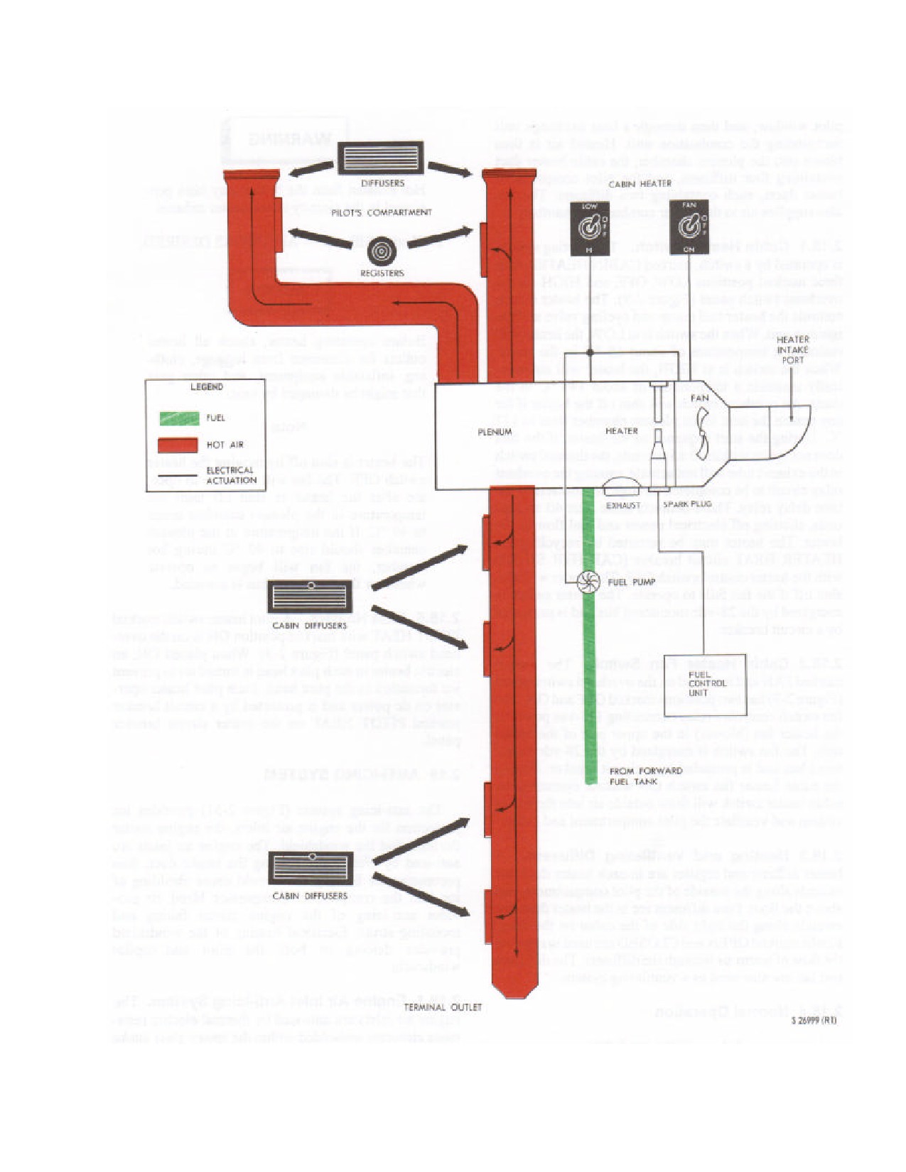
NAVAIR 01-230HLH-1
Figure 2-50. (NON-ET) Heating System
2-75
ORIGINAL
NAVAIR 01-230HLH-1
2.18.6
(ET) ENVIRONMENTAL AIR SYSTEM
system includes the heater and basic controls for
The environmental air system provides for the
manual or thermostatically controlled operation as
heating, cooling, or ventilating of the cockpit and
well as associated fuel and air systems. The air
cabin (Figure
2-50.1).
52,000 BTU/hour of cooling
conditioning system includes the air conditioner
is provided at the evaporator outlet throughout the
comp onents and basic controls to thermostatically
aircraft flight profile and during ground operation.
cool or ventilate the cockpit or cabin. The air
The system may also be operated prior to engine start
conditioning system requires 115/200 volt, 3 phase,
through the use of the sponson-mounted auxiliary
400 Hz alternating current for operation. Electrical
power unit. The system is divided into functional
power for the control circuitry is supplied by the
sections of temperature control, distribution, heating,
monitored bus at 28 volts dc through the HEATER
and air-conditioning. The temperature control system
HEAT and CABIN VENT circuit breakers on the No.
includes the components that automatically control
1 junction box. The No. 1 generator, at 200 volts ac
heater or air-conditioner operation to maintain the
through the AIR COND CONDENSER circuit
desired temperature. The monitored dc bus supplies
breaker, supplies electrical power for the condenser
electrical power for control circuitry.
The
motor. Electrical power for the compressor motor,
distribution system directs heated air to the cockpit
air conditioner vent blower, and the heater vent
and cabin diffusers, and cooled or ventilated air to
blower is supplied by the No. 1 generator through the
both diffusers and gaspers in the cockpit and cabin.
AIR COND COMPR MOTOR, HEATER BLOWER,
The heating system includes the heater and basic
and the AIR COND VENT BLO circuit breakers.
controls for manual or thermostatically controlled
The air conditioning system provides cool air to the
operation as well as associated fuel and air systems.
cockpit and cabin compartments. The system is
In manual operation, the heater is operated
charged with HFC 134a that is readily vaporized or
continuously; while during automatic operation, the
changed back to a liquid at low temperatures and
cabin heat level and air-conditioning heat-loss level is
pressures.
When the system is operating, the
controlled
by setting
the
CABIN AIR
refrigerant is compressed, which reduces the overall
TEMPERATURE rheostat at the crew chief’s ICS
volume. The heat of compression is given up to the
station. The air-conditioning system includes air-
outside air as the high-pressure vapor passes through
conditioner components and basic controls to
the condenser, which is cooled by the condenser
thermostatically cool the cockpit and cabin. The
blower. This heat transfer changes the vapor into a
ventilation system utilizes the distribution system and
high-pressure liquid, which is collected in the filter
the heater or air conditioner blower to provide
drier. The liquid is subjected to a condition of
ventilated air to the diffusers and gaspers in the
reduced pressure and increased surface area upon
cockpit and cabin.
passing through the expansion valve into the coils of
the evaporator. The liquid vaporizes in the coils.
2.18.6.1 (ET) Air Conditioning System. The
The heat necessary for vaporization is taken from the
air conditioning system equipment is divided into
air that is to be cooled. The vaporized liquid is then
functional
sections
of temperature control,
passed back into the motor-compressor, where the
distribution, heating, and air conditioning.
The
process begins again.
temperature control system consists of an AIR
COND CONTROL panel, a CABIN AIR
2.18.6.2
(ET) Manual Operation. When all
TEMPERATURE rheostat, sensing elements, and a
heater/air conditioner system circuit breakers are
control unit.
These units provide an automatic
engaged and the SELECTOR switch is positioned to
thermostatically controlled temperature in the cockpit
HEATER, electrical power energizes the heater
and cabin. The heating system can be operated
blower relay and air conditioner blower relay and the
manually or automatically, and the blowers may be
blowers start. When the heater blower has delivered
operated without the heater or air conditioner system
sufficient air to the heater combustion chamber, the
to ventilate the cockpit or cabin. The air conditioner
air pressure switch closes, directing electrical power
system is operated automatically to cool the cockpit
through the overheat relay to operate the master fuel
and cabin. In manual operation, the heater is
valve and the ignition unit. When the HEAT MODE
operated continuously, while during automatic
switch is positioned to MAN OVRD, a circuit
operation, setting the CABIN AIR TEMPERATURE
through the 140.6°C (285°F) cycling thermal switch
rheostat on the control panel, at the crew chief’s ICS
and the HEAT MODE switch opens the fuel control
station, controls the cabin heat level and the air
unit solenoid valve, passing fuel to the heater. When
conditioning heat-lost level. The distribution system
the ignition unit and the fuel valve are energized, the
directs heated, cooled, or ventilated air to the
45-second time delay relay is simultaneously
diffusers in the cockpit and cabin. The heating
energized through the 93.3°C (200°F) exhaust
2-76
ORIGINAL
NAVAIR 01-230HLH-1
thermal switch. If exhaust temperature does not reach
drops.
The sensing elements or the temperature
93.3°C (200°F) within
45 seconds after starting the
selector then unbalance the heater control unit bridge to
heater, the time delay relay closes and energizes the
start the heater. If the heater control unit should
176.7°C (350°F) overheat relay, which interrupts power
malfunction when the heater system is operating, the
to the fuel valve and ignition unit and shuts off the
140.6°C (285°F) thermal switch will cycle the heater as
heater. Cycling the SELECTOR switch on the control
during manual operation. The thermal switch will start
panel may then restart the heater. With the air fuel
the heater when the temperature falls below 140.6°C
mixture and ignition spark being supplied, the heater
(285°F), and shut the heater off when the temperature
operates, supplying heated ventilating air for the
exceeds
140.6°C
(285°F).
If the plenum chamber
cockpit and cabin and discharging exhaust gases
approaches an unsafe temperature, the 176.7°C (350°F)
overboard. The heater continues to operate until the
normally closed thermal switch will open and de-
140.6°C (285°F) normally closed thermal switch opens
energize the overheat relay circuit to stop fuel and
and de-energizes the fuel control unit solenoid valve to
ignition. The blower will continue to operate to provide
shut off fuel supply. The blower continues to operate
safe cooling of the heater and proper exhaust of
until the plenum chamber temperature drops, and the
combustion gases.
140.6°C (285°F) thermal switch closes to resume heater
operation. If air in the plenum chamber approaches
2.18.6.4 (ET) Air Conditioning Operation. When
unsafe temperatures, the
176.7°C
(350°F) normally
all air conditioning circuit breakers are engaged and the
open thermal switch closes and energizes the overheat
SELECTOR switch is positioned to AIR COND,
relay. The overheat relay opens the heating system
electrical power energizes the air conditioning blower
circuit to stop fuel flow and ignition to the heater, while
relay to start the blower.
Electrical power
the blower continues to operate to bring the plenum
simultaneously flows to the sensing elements, the
chamber temperature down to safe limits. Under these
control unit
bridge and the CABIN AIR
circumstances, or when the HEAT MODE switch is
TEMPERATURE rheostat. The compressor motor,
OFF, the blowers, powered through the normally open
which is an integral part of the motor-compressor, and
48.9°C (120°F) thermal switch, will continue operating
the condenser motor, which is an integral part of the
regardless of the position of the selector switch. The
condenser, are started by action of their respective
thermal switch circuit bypasses the VENT AIR and the
relays when the SELECTOR switch, on the AIR COND
SELECTOR switches to continue blower operation
CONTROL panel in the cockpit, is positioned to AIR
until the plenum chamber temperature is below 48.9°C
COND. A COMPR light, on the crewman’s radio
control panel, illuminates while the motor-compressor
(120°F), to provide safe cooling of the heater and
proper exhaust of combustion gases.
The air
is running and goes out when the motor compressor
conditioner blower operates whenever the heater blower
stops. The motor-compressor and the condenser motor
is operating, to provide ventilating air in the upper ducts
relay energizing circuits are interlocked with the engine
which is controlled by gaspers in the ducts.
anti-ice system to prevent simultaneous operation of the
engine anti-ice system and the air conditioning system.
The air conditioning system supplies cooled air to the
2.18.6.3 (ET) Automatic Operation. When all
heater/air conditioner system circuit breakers are
cabin until the compartment sensing elements or the
engaged and the SELECTOR switch s at HEATER,
CABIN AIR TEMPERATURE rheostat balances the
power energizes the heater blower relay and air
control unit bridge. Once the bridge is balanced, the
conditioning blower relay and the blowers start. When
motor-compressor relay de-energizes and shuts off the
sufficient air is being delivered to the heater
motor-compressor. The motor-compressor also shuts
off when the pressure switch senses the pressure is
combustion chamber, the air pressure switch closes.
This causes power to be supplied through the overheat
below 10 psi or above 270 psi. A time delay relay in
relay to operate the master fuel valve and ignition unit.
the system prevents the compressor from coming on
When the HEAT MODE switch is positioned to AUTO,
until 15 seconds have elapsed since compressor shut-
off. The system is protected against extremely high
a circuit through the
140.6°C (285°F) cycling thermal
pressure by a relief valve set at
320 psi. When
switch and the HEAT MODE switch opens the fuel
maximum cooling of the cabin is desired, the CABIN
control unit solenoid valve, passing fuel to the heater.
AIR TEMPERATURE rheostat is turned to the
The air-fuel mixture and ignition spark assures heater
RECIRCULATE position and electrical power flows to
operation, thus supplying heated air for the cockpit and
the damper actuator relay, energizing the damper
cabin. The heater continues to operate until the sensing
actuator and closing the outside air duct. This allows
elements or the rheostat balances the heater control unit
the cabin air to recirculate through the air conditioning
bridge to shut the heater off. The blower continues to
operate until the plenum chamber or cabin temperature
2-77
ORIGINAL
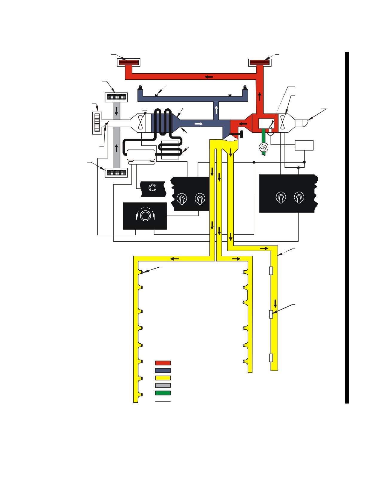
NAVAIR 01-230HLH-1
COCKPIT
DIFFUSER
COCKPIT DIFFUSER
COCKPIT RETURN
COCKPIT GASPER
SPARK PLUG
OUTLET (TYPICAL)
HEATER BLOWER
AIR COND/VENT
HEATER/VENT
AIR CONDITIONER
AIR CONDITIONER
AIR INTAKE
AIR INTAKE
BLOWER
EVAPORATOR
FUEL CONTROL
MANUAL
CONDENSE
SELECTOR
AUTOMATIC DAMPER
HANDLE
MOTOR/COMP
FWD TANK
CABIN RETURN
AIR CREWMANS
RECEIVER/SELECTOR
PANEL
HEAT
VENT
SELECTOR
EVAP
A
C
BLO
MODE
I
O
AIR
MAN
ON
HEATER
R
N
ON
COMP
OVD
C
T
O
R
AIR CREWMANS PANEL
N
O
CABIN AIR TEMP
D L
OFF
AIR
AUTO
COND
COLD
WARM
RECIRCULATE
AUTO
CABIN FLOOR
DISTRIBUTION
DUCT
CABIN OVERHEAD
GASPER OUTLET
(TYPICAL)
CABIN FLOOR
REGISTER
(TYPICAL)
LEGEND
WARM AIR
COLD AIR
WARM OR COLD AIR
RETURN AIR
FUEL
ELECTRICAL ACTUATION
01771013
Figure 2-50.1. (ET) Environmental Air System
2-78
ORIGINAL
NAVAIR 01-230HLH-1
system, cooling the air quickly.
Positioning the
thermistors, a fan, and a radio noise filter. One
SELECTOR switch to OFF will shut off the air
thermistor in each cabin air-sensing element is not used.
conditioning system.
The outside air temperature sensing element has one
thermistor and the air conditioning discharge sensing
2.18.6.5 (ET) Air Conditioner Control Panel. The
element has two thermistors. The heater discharge-
air conditioner control panel (Figure
2-50.2) contains
sensing element has two thermistors. One of the heater
the necessary switches and relays to control heating, air
discharge sensing thermistors is connected in series
conditioning, or ventilating operations.
The
with the outside air temperature sensing element, the
SELECTOR and the HEAT MODE switches control
cabin sensing elements, and one of the air conditioning
manual or automatic cycling of the heater. When the
discharge thermistors, through the control unit control
SELECTOR switch is positioned to HEATER,
relay. The other heater discharge sensing thermistor is
electrical power flows to the HEAT MODE switch,
connected in series with the CABIN AIR
sensing elements, control unit, CABIN AIR
TEMPERATURE rheostat through the control unit
TEMPERATURE rheostat, heater master fuel valve,
control relay and is also connected in series with the
and ignition unit. At this time, the heater may be
compartment sensing thermistor. The resistance in the
operated manually by positioning the HEAT MODE
sensing elements will vary to unbalance the control unit
switch to MAN OVRD, or automatically by positioning
bridge to start the heating or air conditioning system.
the HEAT MODE switch to AUTO. With the HEAT
MODE switch in the manual position, the heater will be
2.18.6.8
(ET) Heater Control Unit. The heater
cycled by the 140.6°C (285°F) thermal switch. With
control unit is located in the electronics compartment.
the HEAT MODE switch positioned to AUTO, the
It operates in conjunction with the CABIN AIR
heater will be cycled by the sensing elements, the
TEMPERATURE rheostat, AIR COND CONTROL
control unit, and the CABIN AIR TEMPERATURE
panel, and sensing elements to provide thermostatic
rheostat. The air conditioning system will start when
control of the cockpit and cabin temperature. The
the selector switch is positioned to AIR COND. The
control unit incorporates a bridge circuit, polarized
VENT AIR switch controls operation of the heater
switch, control relay, heat relay, and cooling relay. The
blower and air conditioning blower. When the VENT
temperature selector and the sensing elements vary the
AIR switch is positioned to ON, both blowers will
resistance to energize or de-energize the fuel control
circulate air through the cabin. The heater relay and the
solenoid valve. With the heating system operating, the
damper relay are also in the control panel. The
CABIN AIR TEMPERATURE rheostat or the sensing
SELECTOR switch actuates the heater relay, which
elements unbalance the bridge and actuate the polarized
energizes the heater blower relay and air conditioning
switch. At this time, the control relay is de-energized,
blower relay to start the blowers. The damper relay is
permitting current to flow through the CABIN AIR
energized to close the damper when the CABIN AIR
TEMPERATURE rheostat, the heater discharge sensing
TEMPERATURE rheostat is in RECIRCULATE
element, the outside air temperature sensing element,
the cabin sensing elements, and the heat relay,
2.18.6.6
(ET)
Cabin Air Temperature
bypassing the air conditioning discharge sensing
Control. The cabin air temperature control panel
element. When the bridge is balanced, the polarized
(Figure 2-50.2) is mounted on the bulkhead behind the
switch is de-energized, cutting power to the control unit
copilot. It is a variable resistor which varies the
heat relay, which, in turn, de-energizes the fuel control
resistance to unbalance the control unit bridge until the
valve solenoid to stop the heater. When the bridge is
desired cockpit and cabin temperature is achieved. For
unbalanced, current flow across the bridge energizes the
maximum cooling, the knob may be rotated to
polarized switch allowing electrical power to flow to
RECIRCULATE. This closes the outside air damper
the heat relay, which in turn energizes the fuel control
and recirculates the cabin air through the air conditioner
valve solenoid, starting the heater cycle. With the air
system.
conditioning system operating, the control relay
energizes and unbalances the bridge. At this time, the
2.18.6.7
(ET) Sensing Elements. Five sensing
energized control relay cuts current to the heater
elements form part of the control unit bridge circuit.
discharge sensor and permits current flow through the
These elements include: two cabin sensing elements in
CABIN AIR TEMPERATURE rheostat, outside air
the cabin; a heater discharge sensing element on the
temperature sensing element, cabin sensing elements,
plenum chamber; an outside air temperature sensing
and the air conditioning sensing element. When the
element in the heater intake duct; and an air conditioner
bridge is unbalanced, the polarized switch is energized,
discharge sensing element in the air conditioner duct
allowing electrical power to flow to the motor-
which extends through the cabin floor at station 180.
compressor.
Each compartment-sensing element includes two
2-79
ORIGINAL
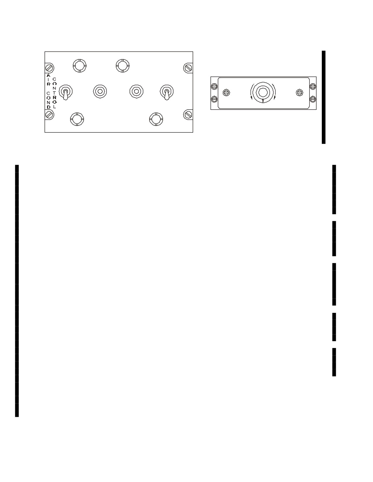
NAVAIR 01-230HLH-1
HEAT
VENT
EVAP
MODE
AIR
SELECTOR
BLO
MAN
HEATER
OVRD
CABIN AIR TEMPERATURE
ON
ON
O
F
F
COLD
WARM
OFF
AIR
AUTO
RECIRCULATE
COND
01771028
Figure 2-50.2. (ET) Air Conditioning Control and Cabin Air Temperature Controls
2.18.6.9(ET) Air Distribution System. The distribution
2.18.6.10 (ET) Heating System. The heating
system consists of a manually operated damper, electrically
system is similar to that installed on the UH-3H
operated damper, actuator, automatic damper, air
helicopters, except that it can operate as an automatic
conditioning blower, heater blower, diffusers and registers,
thermostatically controlled system.
Refer to the
plenum chamber, transition duct, and the necessary heating
following subparagraphs for specific differences. Refer
and ventilating ducts to conduct the flow of air through the
to NAVAIR
01-230HLH-2-1.1 for complete system
cockpit and cabin area. A manually operated damper
description and theory of operation.
governing air conditioning or ventilating air for the cabin is
mounted on the ductwork, under the one-place seat, on the
2.18.6.10.1
(ET) Heater. The heater is similar to
right side of the forward entrance compartment. The
that installed on the UH-3H helicopters, except that it is
electrically operated damper, controlled by the actuator, is
a 200,000 BTU heater, the exhaust is on the bottom of
in the forward tub compartment and is a normally open
the heater instead of at the center, and the spark plug is
damper. During recirculation of interior air, the damper
at a 90-degree angle to the ground electrode.
remains in the closed position. The automatic damper, in
the forward tub compartment, automatically controls the
2.18.6.10.2
(ET) Plenum Chamber. The plenum
flow of either heated air or air-conditioned air into the cabin
chamber is similar to that of the heater installed on the
area, depending upon which system is in operation. The air-
UH-3H helicopters, except that the
65.6°C
(150°F)
conditioning blower, in the forward tub compartment, draws
thermal switch has been removed and the heater
outside air into the helicopter for the air conditioning system
discharge-sensing element has been installed in its
through an intake vent forward of the forward passenger
place.
door. The blower is also utilized to recirculate interior air,
at which time the electrically operated damper is closed.
2.18.6.10.3
(ET) Thermal Switches. The thermal
The heater blower draws outside air and forces it through
switches are similar to those of the heater installed on
the otherwise inoperative heating system and into the
the UH-3H helicopters, except that the 65.6°C (150°F)
helicopter. The overhead ducts, on both sides of the cabin
switch is not installed.
ceiling, include individual units called gaspers. The gaspers
control the flow of ventilating or air conditioning air into the
2.18.6.11
(ET) Air Conditioning S ystem. The
cabin for individual passenger comfort. Two heating,
air conditioning system is a vapor cycle system that
ventilating, and air conditioning ducts, connected to the
provides a comfortable environment for crew members
manually operated damper, run forward under the cockpit
and passengers.
floor to registers and diffusers on both sides of the cockpit.
A single heating, ventilating, and air conditioning duct,
connected to the plenum chambers by a transition duct, runs
aft along the right-hand side of the cabin. Two circular
adjustable and eight nonadjustable diffusers in the cabin
disperse heated, ventilated, and air conditioned air.
2-80
ORIGINAL
NAVAIR 01-230HLH-1
2.18.6.11.1 (ET) Evaporator Pallet Assembly. The
duct. The demister assembly consists of an aluminum
evaporator pallet assembly is an aluminum honeycomb
housing, a fine aluminum wire mesh demister pad mounted
pallet located below the cabin floor at station
180,
between a screen and two mounting brackets, and a drain
horizontally-mounted on the centerline of the aircraft.
tube for the removal of condensation. The demister
Major components mounted to the pallet are:
removes moisture from the conditioned air. The moisture
condenses and collects on the wires of the demister pad
1.
Compressor/motor Assembly
forming droplets. The droplets are pulled by gravity down
2.
Evaporator Fan
to the drain pan where they are then dumped overboard
3.
Inlet Transition Duct
through the drain tubes.
4.
Heat Exchanger
5.
Demister Assembly
2.18.6.11.1.6
(ET) Low Temperature Switch. The
6.
Temperature Sensors
low temperature switch is mounted on the aft side of the
7.
Hot Gas Bypass Valve
demister housing. The low temperature switch will trip the
low temp fault indicator and disengage the compressor if the
2.18.6.11.1.1(ET) Compressor/motor
Assembly.
evaporator outlet temperature drops below -1.1 - 4.4°C (30-
The compressor/motor, mounted in the forward tub
40°F). The system will automatically resume normal operation
compartment, compresses and circulates the refrigerant in
when the temperature rises to 12.8°C (55°F).
the air conditioner system. The compressor/motor assembly
is a single, hermetically sealed unit, requiring 115/200-volt,
2.18.6.11.1.7
(ET) Hot Gas By-pass Valve. The hot
400 Hz, three-phase ac current for operation. A thermally
gas by-pass valve is located on the evaporator pallet next to
protected six horsepower motor is mounted vertically over a
the heat exchanger. The valve provides regulation of the
vane rotary type pump that compresses and circulates
evaporator outlet air temperature. By adjusting the cockpit
refrigerant throughout the system.
Mounted on the
temperature control, through the temperature controller in
aluminum compressor/motor housing is a connector for the
the electronic box, the hot gas by-pass valve will discharge
electrical power, refrigerant discharge and suction ports, and
hot refrigerant gas from the compressor discharge tube
an oil level sight glass. The No. 1 generator, through the
directly into the heat exchanger. The valve receives input
35-ampere AIR COND COMPR MOTOR circuit breaker on
from the low temperature switch mounted on the demister
the copilot’s circuit breaker panel, provides power for the
housing and the temperature controller. The valve bypasses
motor-compressor.
the expansion valve with hot gas regulating the evaporator
pressure; with an increase in refrigerant pressure the
2.18.6.11.1.2 (ET) Evaporator Fan. The evaporator fan
temperature is also increased.
is a
6-inch diameter, two-stage axial vane type fan with
internal motor windings, and an explosion proof housing. It
2.18.6.11.1.8
(ET) Thermal Electric Expansion
requires
115/200-volt ac, three-phase,
400 Hz power for
Valve. The thermal electric expansion valve meters the
operation. The fan draws return air from the cabin interior
refrigerant flow into the evaporator heat exchanger during
and circulates it through the evaporator heat exchanger. The
the air conditioner operation. The orifice flow of the valve
fan is located between the cabin return duct and the inlet
is controlled by voltage applied to the electrical terminals on
transition duct.
the valve head. The valve incorporates a resistance wire on
the valve head. The valve incorporates a resistance wire-
wound, bimetal motor. The valve is operated by, and
2.18.6.11.1.3
(ET) Inlet Transition Duct. The inlet
responds to, low voltage electrical power. The amount of
transition duct is located between the evaporator and the
electrical power applied to the valve controls the degree of
heat exchanger. The duct directs the flow of air from the
valve opening. At zero voltage, the valve is closed. As
fan outlet to the heat exchanger inlet. It is constructed of
voltage is applied, heat deflects the bimetal motor causing
three layers of epoxy impregnated fiberglass laminate.
the valve needle to follow.
2.18.6.11.1.4
(ET) Evaporator Heat Exchanger.
2.18.6.11.1.9
(ET) Liquid Sensing Thermister.
The evaporator heat exchanger is located between the inlet
The liquid sensing thermister is located in the evaporator
transition duct and the demister assembly. It is of a plate fin
suction line and regulates the voltage to the thermal electric
design and constructed of aluminum. The heat exchanger
expansion valve. The thermister reacts to the refrigerant,
transfers heat from the cabin air to the refrigerant.
increasing or decreasing the voltage to the valve, depending
on the state of the refrigerant exiting the evaporator. Liquid
2.18.6.11.1.5
(ET) Demister Assembly.
The
closes the valve and gas opens the valve.
demister assembly is mounted on the outlet of the heat
exchanger and provides a mounting surface for the outlet
2 - 81
ORIGINAL
NAVAIR 01-230HLH-1
2.18.6.11.2
(ET) Condenser Assembly.
The
2.18.6.11.3.1
(ET) Filter Dehydrator. The filter
condenser assembly is mounted horizontally in the left
dehydrator is mounted on the auxiliary service pallet in the
sponson. Refrigerant, after being heated and brought to a
high pressure (liquid) refrigerant line between the condenser
high pressure by the compressor, passes through the
and the expansion valve. Contaminants and moisture are
condenser where cooling air condenses the gas. Major
removed from the refrigerant through the filter dehydrator’s
components of the condenser assembly are as follows:
molded porous core.
2.18.6.11.3.2
(ET) Refrigerant Liquid Line
1.
Heat Exchanger
Indicator. The liquid line indicator, or sight glass, is
2.
Transition Duct
located in the liquid line between the condenser heat
3.
Condenser Fan
exchanger outlet and the filter/dehydrator. Its primary
4.
Check Valve
purpose is to allow visible evidence of liquid
clear) or
5.
High Pressure Relief Valve
vapor (bubbles) in the liquid line to determine the state of
the system’s refrigerant charge. The sight glass is not used
2.18.6.11.2.1
(ET) Heat Exchanger.
The heat
to determine the adequacy of the refrigerant charge. The
exchanger is located in the aft portion of the left sponson. It
liquid line indicator also contains a moisture indicator. The
is of a plate fin design and constructed of aluminum to
indicator turns yellow if moisture is in the system refrigerant
minimize weight. The heat exchanger transfers heat from
and green when the system is dry.
the refrigerant to the ambient air.
2.18.6.11.3.3.
(ET) High Pressure Switch. The
2.18.6.11.2.2
(ET) Transition Duct. The transition
high-pressure switch will disengage the compressor if
duct connects the heat exchanger and fan. It is attached to
system refrigerant pressure reaches
350 ± 20 psi. The
flanges on the components and is supported by brackets.
compressor will reengage as refrigerant pressure decreases
to 150 psig. The high-pressure switch is mounted on the
2.18.6.11.2.3
(ET) Condenser Fan. The condenser
refrigerant servicing manifold on the auxiliary service
fan draws ambient air through the heat exchanger and
pallet.
exhausts it overboard. The 12-inch axial vane fan motor
requires
115/200 volts,
400 Hz, three-phase electrical
2.18.6.11.3.4
(ET) Low Pressure Switch. The low-
current for operation. The fan is explosion proof and
pressure switch, in the event of complete refrigerant loss,
thermally protected.
will disengage the compressor when the system pressure
drops below 50 ± 3 psig. When the system pressure rises
2.18.6.11.2.4
(ET) Check Valve. The check valve is
above 65 psig, the compressor will reactivate. The low-
mounted on the refrigerant inlet port of the heat exchanger.
pressure switch is mounted on the refrigerant-servicing
It is a poppet-type valve that prevents a back flow of
manifold on the auxiliary service pallet.
refrigerant when the system is shut down.
2.18.6.11.4
(ET)
Electrical
Control
Box
2.18.6.11.2.5
(ET) High Pressure Relief Valve.
Assembly. The electrical control box contains all the
The high pressure relief valve is located in the high pressure
major electrical components necessary for air conditioning
liquid line and is designed to vent refrigerant from the
operation. The control box is mounted in the forward tub
system in the event that the high pressure switch fails and
compartment and includes the following components:
the system refrigerant pressure exceeds 475 psig. The valve
vents refrigerant overboard. As pressure decreases below
1.
Control Relays
475 psig, the valve will automatically reseal and normal air
2.
Time Delays
conditioning operation will continue.
3.
Temperature Controller
4.
Fault Indicator Panel
2.18.6.11.3
(ET) Auxiliary Servicing Pallet. The
auxiliary servicing pallet is an aluminum honeycomb pallet,
2.18.6.11.4.1
(ET) Control Relays. The three phase
located in the forward tub compartment under the cabin
electrical power is controlled by power contactor type
floor. Major components of the auxiliary servicing pallet
relays.
One relay is used for each of the major air
are:
conditioning system components.
1.
Filter Dehydrator
2.18.6.11.4.2
(ET) Time Delays. Two time delays are
2.
Refrigerant Liquid Line Indicator (Sight Glass)
used in the control of the air conditioning system to prevent
3.
High Pressure Switch
all of the electrical loads from starting simultaneously,
4.
Low Pressure Switch
thereby reducing the electrical surge. A five-second-time
5.
Refrigerant Servicing Ports
2 - 82
ORIGINAL
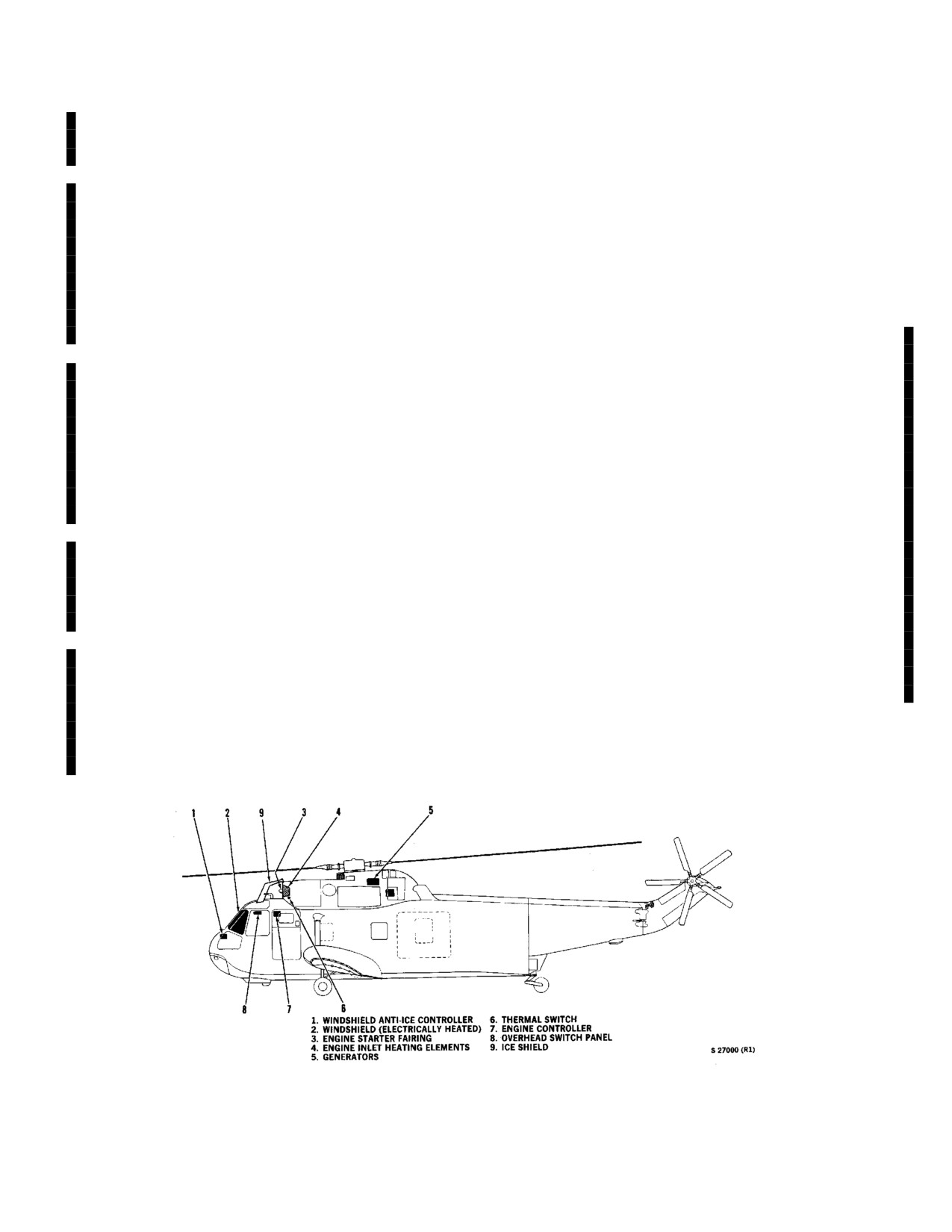
NAVAIR 01-230HLH-1
delay controls the power contactor for the condenser fan. A
2.19 ANTI-ICING SYSTEM
ten-second-time delay relay controls the power contactor for
the compressor.
The anti-icing system
(Figure
2-51) provides ice
protection for the engine air inlets, the engine starter
2.18.6.11.4.3
(ET) Temperature Controller. The
fairings, and the windshield. The engine air inlets are anti-
temperature control unit contains solid-state circuits
iced by electrically heating the intake duct, thus preventing
necessary for thermostatic temperature control of the air
ice buildup that would cause shedding of ice into the
conditioning system. The controller requires two inputs for
compressor. Compressor bleed air provides anti-icing of the
operation; one input from the rotary temperature selector set
engine starter fairing and mounting struts. Electrical heating
at the desired cabin temperature and one input from the
of the windshield provides deicing of both the pilot and
supply air temperature sensor. In the air conditioning mode
copilot windshield.
the temperature controller cycles the hot gas bypass valve
on and off to control the outlet temperature.
2.19.1 Engine Air Inlet Anti-Icing System. The engine
air inlets are anti-iced by thermal electric resistance
2.18.6.11.4.4
(ET) Fault Indicator Panel. The fault
elements embedded within the epoxy glass intake ducts.
indicator is mounted in the electrical control box cover to
Electrical current is applied to the resistance elements to
indicate extremes in either pressure or temperature during
heat the duct skin higher than the temperature at which ice
air conditioning operation. The panel consists of three one-
will form for OATs above -18o C. The engine air inlet anti-
amp circuit breakers. The fault indicators are labeled High
icing system should be turned on when operating in
Pressure, Low Pressure, and Low Temperature. The system
conditions of 10oC OAT and below where visible moisture
will automatically resume operation after a fault condition
(rain, fog, clouds, etc.), ice, or snow accumulation is noted
subsides. The affected circuit breaker should be reset prior
on the helicopter. Significant locations to be observed for
to the next flight.
ice or snow accumulation include the windshield wipers, the
pitot tubes, and the stub wings. The engine air inlet anti-ice
2.18.6.11.5
(ET) Remote Service Manifold. The
should remain off when flying in dry snow and no
remote service manifold assembly is installed at station 155
accumulation is noted on the helicopter. The engine anti-ice
on the left side of the aircraft. Removal of an external
switches (Figure 2-52) on the overhead switch panel (Figure
access panel permits external servicing of the air
2-9) turn the system on. The inlet temperature is limited to a
conditioning system.
maximum of 93o C by an overheat sensor, embedded in the
intake duct, and recycled on at a minimum of 81oC by the
2.18.6.11.6
(ET) Ventilating System.
A
engine controller. The resistance elements of the Nos. 1 and
ventilating system is incorporated in the heating and air
2 engines are operated by ac power and 28 vdc provides
conditioning system. It provides circulation of outside air
control.
throughout the inside of the helicopter. Positioning the
VENT AIR switch, on the air conditioning control panel, to
ON actuates the system. This energizes the air conditioning
and heater blower relays that start the blowers.
Figure 2-51. Anti-Icing System
2 - 83
ORIGINAL
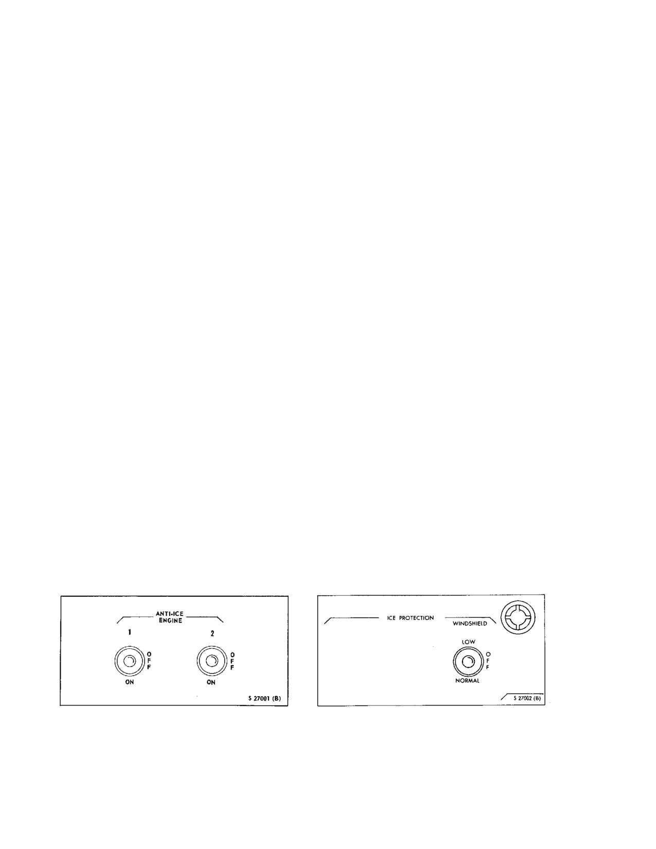
NAVAIR 01-230HLH-1
The thermal switch in the air inlet duct closes to connect
closed
(energized) position by
28-vdc power. This
6-
dc power to the CAUTION PANEL, lighting the #1 INLET
percent loss will occur only if the engine is operating at
ANTI-ICE and/or #2 INLET ANTI-ICE when the air inlet
topping power. With complete dc power failure, the
temperature drops below 38oC with the ENGINE ANTI-
solenoid valve will open but the advisory panel light will
ICE switch ON. If OAT is -18 oC or above, and the engine
not go on.
anti-icing system is on, the CAUTION PANEL lights
coming on will indicate anti-ice system failure. If OAT is
2.19.3 Engine Anti-Ice Switches. Two engine anti-
-18o C or below and the engine anti-ice system is on, the
ice switches (Figure
2-52) marked ANTI-ICE ENGINE 1
CAUTION PANEL lights will go on, indicating no anti-ice
and 2 with marked positions OFF and ON are on the
protection, as electrical heating is not enough to maintain
overhead switch panel
(Figure
2-9). ON energizes the
38oC under these ambient conditions. However, as previously
engine air inlet anti-icing system and activates the engine
mentioned, the engine air inlet anti-icing system should not
anti-icing system. OFF turns the anti-icing systems off. If
be turned on unless there is a visible moisture or ice or
the ambient temperature is
38o C or below, placing the
snow accumulation. (For a more detailed discussion refer
engine anti-ice switches ON turns on the engine anti-ice
to Extreme Weather Operations, Chapter 14.)
and engine air inlet anti-ice systems and lights the #1
INLET ANTI-ICE and
#2 INLET ANTI-ICE caution
2.19.2 Engine Anti-Icing System. The engine starter
lights and the advisory panel lights marked #1 ENG ANTI-
fairing (Figure 2-51), the inlet guide vanes, and the top,
ICE and #2 ENG ANTI-ICE. When the engine air inlet
right, and left struts of the front frames of each engine are
anti-icing system has increased the duct air temperature to
anti-iced by diverting engine tenth-stage compressor air to
38 oC, the caution panel lights will go off.
heat them. Actuating the engine anti-ice switch (Figure 2-
52) on the overhead switch panel (Figure 2-9) deenergizes
2.19.4 Windshield Anti-Ice System. The pilot and
an engine-mounted solenoid valve to the open position,
copilot windshields are anti-iced by an electric current that
allowing hot compressor air to flow through the engine
passes through a transparent resistant film on the inner
front frame to the inside of the starter fairing and the inlet
surface of the outer pane of the windshield (Figure 2-51).
guide vanes. When the engine solenoid is deenergized,
The windshield anti-icing system consists of the treated
lights are illuminated on the advisory panel, displaying to
windshields, a windshield anti-ice controller, transformers,
the pilot the markings #1 ENG ANTI-ICE ON and/or # 2
and a switch on the overhead switch panel. The windshield
ENGINE ANTI-ICE ON. The engine anti-icing system is
anti-icing also serves to defog the windshield.
turned on simultaneously with the engine air inlet anti-
icing system. If the engine anti-ice advisory light on the
2.19.4.1 Windshield Anti-Icing Switch. This switch
advisory panel lights during flight when the engine anti-ice
(Figure
2-53) marked WINDSHIELD with marked
switches are OFF and the anti-icing system is not in
positions LOW, OFF, and NORMAL is on the overhead
operation, it indicates that the engine anti-ice solenoid
switch panel
(Figure
2-9). When placed to LOW, the
valve has opened
(deenergized) because of electrical
windshield controller is energized, current heats the
failure and that a loss of about
6-percent engine
windshield. The low temperature setting is used for
horsepower will occur. The solenoid valves are held in the
defogging and light icing conditions.
Figure 2-52. Engine Anti-Ice Switches
Figure 2-53. Ice Protection Switches
2 - 84
ORIGINAL