UH-3H and UH-3H EXECUTIVE TRANSPORT. FLIGHT MANUAL (2000) - page 1
THE
NAVAIR 01-230HLH-1
AIRCRAFT
INDOCTRI-
NATION
NORMAL
PROCEDURES
NATOPS FLIGHT MANUAL
FLIGHT
NAVY MODEL
CHARAC
UH-3H and UH-3H
EMERGENCY
PROCEDURES
EXECUTIVE TRANSPORT
AIRCRAFT
ALL-WEATHER
OPERATIONS
COMM
PROCEDURES
WEAPON
SYSTEMS
FLIGHTCREW
COORD
DISTRIBUTION STATEMENT C
- Distribution authorized to U.S. Government agencies and
their
contractors to protect publications required for official use or for administrative or operational purposes only
(15 September 1988). Other requests for this document shall be referred to Commanding Officer, Defense
NATOPS
Distribution Depot Susquehanna Pennsylvania, Building 05, 5450 Carlisle Pike, Mechanicsburg, PA 17055-
0789.
EVAL
DESTRUCTION NOTICE - For unclassified, limited documents, destroy by any method that will
PERFORM
prevent disclosure of contents or reconstruction of the document.
DATA
ISSUED BY AUTHORITY OF THE CHIEF OF NAVAL OPERATIONS
AND UNDER THE DIRECTION OF THE
INDEX &
COMMANDER, NAVAL AIR SYSTEMS COMMAND
FOLDOUTS
0801LP1005326
(Reverse Blank)
9 JUNE 2000
1
ORIGINAL
NATEC ELECTRONIC MANUAL
NAVAIR-01-230HLH-1
UH-3H, UH-3H ET
NATOPS Flight Manual
CONTENTS
Page No
PART I
The Aircraft
CHAPTER 1
General Description
1.1
THE HELICOPTER
1-1
1.1.1
Performance
1-1
1.1.2
Engine Ratings
1-2
1.1.3
Dimensions
1-2
CHAPTER 2
Systems
2.1
POWER PLANT SYSTEMS
2-1
2.1.1
Gas Generator Compressor Speed (Ng)
2-1
2.1.2
Free Turbine Speed (Nf)
2-1
2.1.3
Engine Fuel System
2-1
2.1.4
Engine Control System
2-12
2.1.5
Engine Controls
2-14
2.1.6
Engine Instruments
2-15
2.1.7
Starter System
2-18
2.1.8
Ignition System
2-19
2.1.9
Torque Sensing System
2-19
2.1.10
Overspeed Protection System
2-20
2.1.11
AUXILIARY POWER UNIT (APU) SYSTEM (UH-3H Executive Transport)
2-21
2.2
ENGINE OIL SYSTEM
2-21
2.3
ROTOR SYSTEMS
2-22
2.3.1
Rotary Wing System
2-22
2.3.2
Bifilar Absorber
2-23
2.3.3
Rotary Rudder System
2-23
2.4
TRANSMISSION SYSTEM
2-24
2.4.1
Main Gearbox
2-24
2.4.2
Intermediate Gearbox
2-28
2.4.3
Tail Gearbox
2-28
2.4.4
Intermediate and Tail Gearbox Oil Systems
2-28
2.4.5
Chip Detector Caution Lights
2-28
2.4.6
Transmission Oil Systems
2-28
2.4.7
Rotor Brake
2-29
5
ORIGINAL
NAVAIR-01-230HLH-1
Page No
2.5
FUEL SYSTEM
2-30
2.5.1
Internal Fuel System
2-30
2.5.2
Helicopter In-Flight Refueling System
2-33
2.5.3
Fuel System Management
2-33
2.5.4
Fuel Dump System
2-33
2.6
ELECTRICAL POWER SUPPLY SYSTEM
2-34
2.6.1
Alternating Current Power Supply System
2-34
2.6.2
Direct Current Power Supply System
2-37
2.7
LIGHTING EQUIPMENT
2-45
2.7.1
Interior Lights
2-45
2.7.2
Exterior Lights
2-47
2.8
FLIGHT CONTROL SERVO HYDRAULIC SYSTEMS
2-48
2.8.1
Primary Flight Control Servo System
2-48
2.8.2
Auxiliary Flight Control Servo System
2-48
2.8.3
Flight Control Servo Switch
2-49
2.8.4
Servo Hydraulic Pressure Indicators
2-49
2.9
FLIGHT CONTROL SYSTEM
2-49
2.9.1
Rotary Wing Flight Control System
2-49
2.9.2
Rotary Rudder Flight Control System
2-52
2.10
AUTOMATIC STABILIZATION EQUIPMENT COUPLER SYSTEM
2-53
2.10.1
Automatic Stabilization Equipment
2-53
2.10.2
Coupler System
2-54
2.10.3
Hover Indicators
2-55
2.10.4
HOVER TRIM Control Panel
2-57
2.10.5
CHANNEL MONITOR Panel
2-58
2.10.6
Channel Monitor Test Switch
2-58
2.10.7
Vertical Gyros
2-58
2.11
UTILITY HYDRAULIC SYSTEM
2-58
2.11.1
Utility Hydraulic Pressure Indicator
2-58
2.12
LANDING GEAR SYSTEM
2-58
2.12.1
Landing Gear Actuating Lever
2-59
2.12.2
Down-Limit Release (Scissors) Switch
2-59
2.12.3
Landing Gear Warning Light
2-59
2.12.4
Landing Gear Position Indicators
2-59
2.12.5
Landing Gear Emergency System
2-60
2.12.6
Tailwheel Lock Handle
2-60
2.12.7
Wheelbrake System
2-61
2.12.8
Brake Pedals
2-61
2.12.9
Parking Brake Handle
2-61
6
ORIGINAL
NAVAIR-01-230HLH-1
Page No
2.13
AUTOMATIC BLADE FOLD SYSTEM
2-61
2.13.1
Rotary Wing Blade Folding
2-61
2.13.2
Blade Fold Control Panel
2-62
2.14
PYLON FOLDING
2-62
2.15
FLIGHT INSTRUMENTS
2-63
2.15.1
Standby Compass
2-63
2.15.2
Free-Air Temperature Gauge
2-63
2.15.3
Clocks
2-63
2.15.4
Pitot-Static System
2-63
2.15.5
Attitude and Heading Reference System (A/A24G-39 AHRS
2-63
2.15.6
Compass System Control Panel
2-65
2.15.7
Attitude Indicators
2-65
2.15.8
Turn Rate Switches
2-65
2.15.9
Altitude Encoder
2-66
2.15.10
Radar Altimeter
2-67
2.15.11
Radar Altitude Warning System
2-67
2.16
WARNING, CAUTION, AND ADVISORY LIGHTS
2-68
2.16.1
Advisory Panel
2-68
2.16.2
Caution Panel
2-68
2.17
FIRE DETECTOR SYSTEM
2-73
2.17.1
Fire Warning Lights and Test Switch
2-73
2.18
HEATING SYSTEM
2-73
2.18.1
Cabin Heater Switch
2-74
2.18.2
Cabin Heater Fan Switch
2-74
2.18.3
Heating and Ventilating Diffusers
2-74
2.18.4
Normal Operation
2-74
2.18.5
Pitot Heaters
2-74
2.18.6
(ET) Environmental Air System
2-76
2.19
ANTI-ICING SYSTEM
2-83
2.19.1
Engine Air Inlet Anti-Icing System
2-83
2.19.2
Engine Anti-Icing System
2-84
2.19.3
Engine Anti-Ice Switches
2-84
2.19.4
Windshield Anti-Ice System
2-84
2.20
CREWMEMBER SEATS
2-85
2.20.1
Vertical Adjustment Control Lever
2-85
2.20.2
Horizontal Adjustment Control Lever
2-85
2.20.3
Restraint System Control Lever
2-85
2.20.4
Variable-Load Energy Absorber Control Dial
2-85
2.21
TROOP-CARRYING EQUIPMENT
2-85
2.21.1
Troop Seats
2-85
7
ORIGINAL
NAVAIR-01-230HLH-1
Page No
2.21.2
Crewmen Safety Belts
2-85
2.21.3.
(ET) Passenger Accommodations
2-86
2.21.3.1
(ET) General
2-86
2.21.3.2
(ET) Executive Seat
2-86
2.21.3.3
(ET) Crew Chief’s Seat
2-87
2.21.3.4
(ET) Passenger (Troop) Seat
2-87
2.21.3.5
(ET) Soundproofing
2-87
2.21.3.6
(ET) Removable Bulkhead
2-87
2.21.3.7
(ET) Overhead Panels
2-87
2.21.3.8
(ET) Carpet
2-87
2.22
RESCUE HOIST
2-88
2.22.1
Rescue Hoist Master Switch
2-88
2.22.2
Rescue Hoist Switch Panel
2-88
2.22.3
Crew-Portable Hoist and Microphone Switch
2-88
2.22.4
Normal Operation
2-89
2.22.5
Rescue Hoist Cable Shear Switches
2-89
2.22.6
Rescue Hoist Shear Circuit Test Panel
2-90
2.22.7
Rescue Hoist Manual Override Valve
2-90
2.22.8
Rescue Hoist Assist Handles
2-90
2.23
EMERGENCY EQUIPMENT
2-90
2.23.1
Fire Extinguishing System
2-90
2.23.2
Portable Fire Extinguisher
2-91
2.23.3
Helicopter Emergency Egress Lighting System
2-91
2.23.4
Flotation Gear System
2-93
2.23.5
Liferaft
2-93
2.23.6
Aldis Lamp
2-93
2.23.7
First-Aid Kits
2-93
2.24
MISCELLANEOUS
2-93
2.24.1
Canteen
2-94
2.24.2
Engine Trim Checker (H219)
2-94
2.24.3
Map Case and Chart Board
2-95
2.24.4
Mooring Rings
2-95
2.24.5
Relief Tube
2-96
2.24.6
Mirrors Rearview
2-96
2.24.7
Windshield Wiper System
2-96
2.24.8
Windshield Washer
2-96
2.25
CARGO SLING
2-96
2.25.1
Cargo Sling Control Panel
2-99
2.25.2
Cargo Hook Release Buttons
2-99
2.25.3
Cargo Release Foot Pedal
2-99
2.25.4
Cargo Hook Stowage Line
2-99
2.25.5
Cargo Hook Manual Release Arm
2-99
2.25.6
Cargo Deck (UH-3H)
2-99
8
ORIGINAL
NAVAIR-01-230HLH-1
Page No
CHAPTER 3
Servicing
3.1
EXTERNAL POWER REQUIREMENTS
3-1
3.1.1
External Electrical Power Connections
3-1
3.1.2
USAF Ground Power Units
3-1
3.1.3
Acceptable Ground Power Units
3-4
3.2
SERVICING DATA
3-4
3.2.1
Fuel System Servicing
3-4
3.2.2
Gravity Refueling Procedures
3-4
3.2.3
Pressure-Refueling Procedures
3-5
3.2.4
Adjustment of Fuel System for Different Fuels
3-6
3.2.5
Engine Oil Servicing
3-9
3.2.6
Hydraulic System Fluid Servicing
3-9
3.2.7
Main Gearbox Oil Servicing
3-9
3.2.8
Damper Fluid Tank Servicing
3-9
3.2.9
Sleeve-Spindle Oil Tanks, Self-Lubricated Rotary Wing Head Servicing
3-9
3.2.10
Intermediate Gearbox Servicing
3-9
3.2.11
Tail Gearbox Servicing
3-9
3.2.12
Windshield Washer Reservoir Servicing
3-9
3.2.13
Tire Servicing
3-10
3.2.14
(ET) APU Servicing
3-10
3.2.15
Fluid Servicing and Capacities
3-11
3.3
OILS, GREASES, HYDRAULIC FLUIDS LISTINGS
3-12
3.4
FUEL CROSS-REFERENCE
3-13
3.5
OIL CROSS-REFERENCE
3-14
3.6
HELICOPTER TOWING
3-16
3.6.1
Safety Precautions
3-16
3.6.2
Towing Procedures
3-16
3.7
PARKING
3-17
3.7.1
Short-Term Parking
3-17
3.7.2
Long-Term Parking
3-17
3.8
HELICOPTER TIEDOWN AND SECURING
3-17
3.8.1
Tiedown Procedures
3-17
3.8.2
Main Rotor Blade Tiedown
3-17
3.8.3
Helicopter Tiedown and Securing Diagram
3-18
3.9
DANGER AREAS
3-20
9
ORIGINAL
NAVAIR-01-230HLH-1
Page No
CHAPTER 4
Operating Limits
4.1
LIMITATIONS
4-1
4.1.1
Minimum Crew Requirements
4-1
4.1.2
Engine Limitations (T58-GE-402)
4-1
4.1.3
Fuel System Limitations
4-1
4.1.4
Starter Limitations
4-1
4.1.5
Transmission Limitations
4-1
4.1.6
Gearbox Allowable Oil Leakage
4-5
4.1.7
Maximum Continuous Operating Time
4-5
4.1.8
Main Gearbox Torque Limitations
4-5
4.1.9
Airspeed Limitations
4-5
4.1.10
Additional Speed Limits
4-6
4.1.11
Maneuvers
4-6
4.1.12
Hovering Limitations
4-6
4.1.13
Altitude Limitations
4-6
4.1.14
Acceleration Limitations
4-6
4.1.15
Center of Gravity Limitations
4-6
4.1.16
Weight Limitations
4-6
4.1.17
Rescue Hoist Limitations
4-6
4.1.18
Flotation Bag Limitations
4-6
4.1.19
Flood/Hover Lights
4-6
4.1.20
Cargo Door
4-6
4.1.21
Stores
4-6
4.1.22
Shipboard Wind Limits
4-6
4.1.23
Taxi Limitations
4-6
4.1.24
Cargo Sling Limitations
4-6
4.1.25
Tipover Limitations
4-7
4.1.26
Marine Markers Deployment Limitations
4-7
4.1.27
Weapon Recovery Limitations
4-7
PART II
Introduction
CHAPTER 5
Introduction
5.1
GROUND TRAINING REQUIREMENTS
5-1
5.1.1
Pilot Ground Training
5-1
5.1.2
Crewman Minimum Ground Training Before Flight
5-1
5.2
FLIGHTCREW QUALIFICATIONS
5-1
5.2.1
Pilot Qualifications
5-1
5.2.2
Crewman Qualification
5-2
5.3
NATOPS FLIGHT EVALUATION
5-4
5.3.1
Pilot Evaluation
5-4
5.3.2
Crewman Evaluation
5-4
10
ORIGINAL
NAVAIR-01-230HLH-1
Page No
5.4
PERSONAL FLYING EQUIPMENT
5-4
5.5
CREW REST REQUIREMENTS
5-4
5.6
FLIGHT TIME SUMMARY
5-5
5.7
Weapon Recovery Indoctrination
5-5
5.7.1
Flight Crew Qualifications
5-5
PART III
Normal Procedures
CHAPTER 6
Flight Preparation
6.1
MISSION PLANNING
6-1
6.1.1
Factors Affecting Range and Endurance
6-1
6.2
NAVIGATION
6-1
6.2.1
Tactical Navigation System
6-1
6.3
WEIGHT AND BALANCE
6-1
6.4
BRIEFING/DEBRIEFING RESPONSIBILITIES
6-2
6.4.1
Formation Leader
6-2
6.4.2
Pilot in Command
6-2
6.4.3
Command Responsibility
6-2
6.4.4
Non-operational Briefing
6-2
6.4.5
Briefing Format
6-2
6.4.6
Debriefing Format
6-3
CHAPTER 7
Shore-Based Procedures
7.1
GENERAL
7-1
7.2
LINE OPERATIONS
7-1
7.2.1
Line Safety
7-1
7.2.2
Ground Operation of Helicopter Engines and Rotors
7-1
7.2.3
Taxiing
7-1
7.2.4
Towing
7-2
7.2.5
Helicopter Acceptance
7-2
7.2.6
Aircraft Discrepancy Book
7-2
7.2.7
Preflight Inspection
7-2
7.3
BATTERY/DC EXTERNAL POWER START NO. 1 ENGINE
7-7
7.4
NORMAL STARTING PROCEDURES
7-8
7.5
SYSTEMS CHECKLIST
7-11
11
ORIGINAL
NAVAIR-01-230HLH-1
Page No
7.6
STARTING NO. 2 ENGINE AND ROTOR ENGAGEMENT
7-15
7.7
TAXIING
7-17
7.7.1
Taxiing Procedure
7-17
7.7.2
Air Taxiing
7-18
7.8
PRETAKEOFF
7-18
7.9
TAKEOFF CHECKLIST
7-18
7.9.1
Takeoff Procedures
7-18
7.9.2
Hovering
7-19
7.10
TRANSITION TO CLIMB
7-20
7.11
POSTTAKEOFF
7-20
7.12
CRUISE CHECKS/FUEL MANAGEMENT
7-20
7.12.1
Fuel Crossfeed
7-21
7.12.2
To Secure Crossfeed
7-21
7.12.3
Fuel Dumping in Flight
7-21
7.12.4
Turns Using Automatic Stabilization Equipment
7-21
7.13
BEFORE LANDING CHECK
7-21
7.14
LANDING
7-22
7.14.1
Dual-Engine Landing Approach and Transition to a Hover
7-22
7.14.2
Landing After Attaining a Hover
7-22
7.14.3
Run-On Landings
7-22
7.14.4
Crosswind Landings
7-23
7.14.5
Practice Single-Engine Approach
7-23
7.15
AUTOROTATIONS
7-23
7.15.1
Practice Autorotation
7-23
7.16
NIGHT FLYING
7-25
7.16.1
Familiarization
7-25
7.16.2
Approaches
7-26
7.17
HELICOPTER LIGHTING
7-26
7.17.1
Land-Based (Day)
7-26
7.17.2
Land-Based (Night)
7-26
7.17.3
Carrier-Based
7-26
7.18
AFTER FINAL LANDING
7-26
7.19
PRESSURE REFUELING WITH ROTORS ENGAGED ASHORE
7-27
7.19.1
General Safety Precautions
7-27
7.19.2
Duties of Personnel
7-27
12
ORIGINAL
NAVAIR-01-230HLH-1
Page No
7.20
SHUTDOWN
7-28
7.20.1
Rotor Disengagement
7-29
7.20.2
Manual Blade Folding Procedures
7-30
7.20.3
No. 1 Engine Secure
7-31
7.21
POSTFLIGHT
7-31
CHAPTER 8
Ship-Based Procedures
8.1
CV OPERATIONS
8-1
8.1.1
General
8-1
8.2
FLIGHT/HANGAR DECK PROCEDURES
8-1
8.2.1
Hangar Deck
8-1
8.2.2
Hangar Flight Deck
8-1
8.2.3
Flight Deck
8-1
8.2.4
Pressure Refueling Aboard Ship With the Rotors Engaged
8-2
8.3
LAUNCHING AND RECOVERY PROCEDURES
8-4
8.3.1
Shipboard Wind Limits
8-10
8.3.2
Traffic Patterns
8-10
8.3.3
Night and IFR Operations
8-11
8.3.4
Mirror/Optical Landing System Approach
8-12
8.3.5
Recovery Signals
8-12
8.3.6
Waveoff Procedures
8-12
8.3.7
Landing Considerations
8-12
8.3.8
Shutdown
8-12
8.3.9
Hand Signals
8-12
8.4
AIR-CAPABLE SHIP OPERATIONS
8-12
8.4.1
Flight/Hangar Deck Procedures
8-12
8.4.2
Launch and Recovery Procedures
8-13
8.4.3
Approach/Landing Procedures
8-14
8.4.4
ASE/AUX OFF
8-15
CHAPTER 9
Special Procedures
9.1
FORMATION/TACTICS
9-1
9.1.1
Formation Composition
9-1
9.1.2
Rendezvous
9-5
9.1.3
Conduct of Flight
9-5
9.1.4
Responsibility
9-5
9.1.5
Briefing
9-5
9.1.6
Signals
9-5
9.1.7
Night Formation
9-6
9.2
INSTRUMENT FLIGHT CONDITIONS IN FORMATION
9-6
9.2.1
Lost Sight During IFR Flight Procedures
9-6
13
ORIGINAL
NAVAIR-01-230HLH-1
Page No
9.3
ADVANCED INSTRUMENT FLYING
9-6
9.3.1
Instrument Check
9-6
9.3.2
Straight-and-Level
9-6
9.3.3
Turns
9-8
9.3.4
Constant Airspeed Climbs
9-8
9.3.5
Unusual Attitudes
9-8
9.4
HELICOPTER IN-FLIGHT REFUELING PROCEDURES (HIFR)
9-8
9.4.1
General
9-8
9.4.2
HIFR Systems
9-9
9.4.3
Normal Operation
9-9
9.4.4
Communications
9-10
9.4.5
HIFR Procedures
9-10
9.4.6
Night/Low Visibility HIFR Approach
9-12
9.5
ENGINE GASPATH PROCEDURES
9-12
9.5.1
Freshwater Wash
9-13
9.5.2
No. 1 Engine. Burnout
9-13
9.5.3
Blade Spread
9-13
9.5.4
No. 2 Engine Burnout
9-14
9.5.5
Automatic Blade Fold
9-14
9.5.6
No.1 Engine Secure
9-14
9.5.7
Engine Gaspath Procedures
9-15
9.5.8
Gaspath Engine Rinse
9-15
9.5.9
Gaspath Engine Burnout
9-15
9.6
ADDITIONAL MISSIONS/STATIC DISPLAYS
9-16
9.6.1
Static Displays
9-16
9.7
SPECIAL CHECKLISTS (UH-3H EXECUTIVE TRANSPORT)
9-17
9.7.1
Mission Checklist
9-17
9.7.2
Alert Checklist
9-18
CHAPTER 10
Functional Checkflight Procedures
10.1
FUNCTIONAL CHECKFLIGHT PROCEDURES
10-1
10.1.1
Designation of Pilots
10-1
10.1.2
Functional Checkflight Pilot Qualification
10-1
10.1.3
Designation of Functional Checkflight Aircrewman
10-1
10.1.4
Qualifications for Functional Checkflight Aircrewman
10-1
10.1.5
Conditions Requiring Functional Checkflight
10-1
10.1.6
Blade Tracking
10-2
10.1.7
Vibration Troubleshooting
10-2
10.1.8
Definitions
10-5
10.2
PREFLIGHT CHECKS
10-6
10.2.1
Exterior
10-6
10.2.2
Interior
10-6
14
ORIGINAL
NAVAIR-01-230HLH-1
Page No
10.2.3
Prestart Checks
10-6
10.2.4
No. 1 Engine Checks
10-10
10.2.5
Systems Checks
10-14
10.2.6
No. 2 Engine Checks
10-20
10.2.7
Taxi
10-24
10.2.8
Pretakeoff Checks
10-24
10.3
FLIGHT CHECKS
10-27
10.3.1
Hover Checks
10-27
10.3.2
Forward Flight Checks
10-38
10.4
SHUTDOWN CHECKS
10-49
10.4.1
Shutdown
10-49
10.4.2
No.1 Engine Secure
10-50
10.4.3
Post flight Inspection
10-50
PART IV
Flight Characteristics
CHAPTER 11
Flight Characteristics
11.1
GENERAL
11-1
11.2
FLIGHT CHARACTERISTICS
11-1
11.2.1
Level Flight Characteristics Under Various Speed Conditions
11-1
11.2.2
Ground Resonance
11-1
11.2.3
Settling With Power
11-1
11.2.4
Vortex Ring State
11-2
11.2.5
Blade Stall
11-3
11.2.6
Rollover Characteristics
11-3
11.3
MOUNTAIN AND ROUGH TERRAIN FLYING
11-5
11.3.1
Wind Direction and Velocity
11-5
11.3.2
Landing Site Evaluation
11-5
11.3.3
Effects of High Altitude
11-6
11.3.4
Turbulent-Air Flight Techniques
11-6
11.3.5
Adverse Weather Conditions
11-7
11.3.6
Summary
11-7
11.4
TERRAIN FLYING
11-9
11.4.1
General
11-9
11.4.2
Crew Coordination
11-10
11.4.3
Summary
11-11
15
ORIGINAL
NAVAIR-01-230HLH-1
Page No
PART V
Emergency Procedures
CHAPTER 12
Emergency Procedures
12.1
GENERAL
12-1
12.2
CRITICAL PROCEDURES
12-1
12.2.1
Recommended Dual Concurrence Items
12-1
12.3
EMERGENCY ROTOR ENGAGEMENT
12-1
12.4
FIRE
12-1
12.4.1
Engine Fire on the Ground
12-1
12.4.2
Engine Fire In Flight
12-2
12.4.3
Fuselage or Electrical Fire
12-2
12.4.4
Heater Fire
12-3
12.4.5
Smoke/Fume/Noxious Gas Elimination
12-3
12.4.6
Postshutdown Engine Fire
12-3
12.5
FUEL SYSTEM FAILURE
12-3
12.5.1
Fuel Boost Pump Failure
12-3
12.5.2
Fuel Crossfeed Malfunctions
12-4
12.5.3
Fuel Filter Bypass
12-4
12.5.4
Inadvertent Fuel Dumping in Flight
12-4
12.6
STARTER HANGUP
12-4
12.7
ENGINE MALFUNCTIONS
12-4
12.8
RAIN INGESTION
12-5
12.9
SINGLE INSTRUMENT INDICATIONS
12-5
12.9.1
Ng Tachometer System Malfunctions
12-5
12.9.2
Ng Tachometer Fluctuations
12-5
12.9.3
Nf Tachometer System Malfunction
12-5
12.9.4
Nf Tachometer Fluctuations
12-6
12.9.5
T5 System Malfunction
12-6
12.9.6
Engine Oil Pressure Fluctuations
12-6
12.9.7
Oil Pressure Failure
12-6
12.9.8
Oil Temperature System Malfunction
12-6
12.9.9
Nr Tachometer System Malfunction
12-7
12.10
FLIGHT CHARACTERISTICS
12-7
12.10.1
Vortex Ring State
12-7
12.10.2
Settling With Power
12-7
12.10.3
Blade Stall
12-7
16
ORIGINAL
NAVAIR-01-230HLH-1
Page No
12.11
ENGINE FAILURE
12-7
12.11.1
Immediate Emergency Procedures
12-7
12.11.2
Single-Engine Failure on Takeoff
12-8
12.11.3
Single-Engine Failure or Loss of Power While Hovering
12-8
12.11.4
Single-Engine Failure in Flight
12-8
12.11.5
Jettison
12-9
12.11.6
Engine Shutdown in Flight
12-9
12.11.7
Single-Engine Restart During Flight
12-9
12.11.8
COMPRESSOR STALL
12-9
12.11.9
LUBE PUMP OR SHAFT FAILURE
12-10
12.11.10
HIGH SPEED SHAFT (POWER TURBINE SHAFT)
12-10
12.11.11
AXIAL DRIVE SHAFT FAILURE
12-11
12.11.12
LOSS OF Ng SIGNAL TO FUEL CONTROL
12-12
12.11.13
LOSS OF P3 SIGNAL TO FUEL CONTROL
12-12
12.11.14
FLEXIBLE DRIVE SHAFT FAILURE
12-13
12.11.15
FUEL CONTROL CONTAMINATION
12-14
12.12
MAXIMUM RANGE
12-14
12.13
SINGLE-ENGINE LANDING (LAND OR SHIP)
12-16
12.13.1
Single-Engine Waveoff
12-16
12.14
DUAL-ENGINE FAILURE
12-16
12.14.1
Dual-Engine Failure While Hovering at Low Altitude
12-18
12.14.2
Dual-Engine Failure During Flight (Autorotative Landing)
12-18
12.15
MAXIMUM GLIDE
12-18
12.16
LANDING IN TREES
12-18
12.17
EMERGENCY DESCENT
12-18
12.18
MAIN GEARBOX SYSTEM FAILURE
12-18
12.18.1
Tail Takeoff Freewheel Unit Caution Light
12-20
12.18.2
Torque Sensing System Failure
12-21
12.19
MAIN ROTOR OVERSPEED
12-21
12.19.1
Blade Pressure Caution Light
12-21
12.20
ROTARY RUDDER SYSTEM FAILURES
12-21
12.20.1
Rotary Rudder Drive System Failure
12-22
12.20.2
Rotary Rudder Drive System Failure While Hovering
12-23
12.20.3
Rotary Rudder Control System Failure
12-23
12.20.4
Impending Rotary Rudder System Failure
12-27
12.20.5
Tail Pylon Unlock Light
12-27
12.21
ELECTRICAL MALFUNCTION
12-27
12.21.1
Alternating Current System Failure
12-27
17
ORIGINAL
NAVAIR-01-230HLH-1
Page No
12.21.2
Direct Current System Failure
12-30
12.22
FLIGHT CONTROL HYDRAULIC SERVO SYSTEM
12-30
12.22.1
Flight Control Malfunction
12-30
12.22.2
Servo Hydraulic Pressure Failure
12-31
12.22.3
Illumination of Servo System Caution Light
12-31
12.23
FLIGHT CONTROLS JAMMED OR RESTRICTED
12-31
12.23.1
On Ground
12-31
12.23.2
In Flight
12-31
12.24
FLIGHT CONTROL SERVO UNIT MALFUNCTION
12-31
12.24.1
Coupled Indications
12-32
12.24.2
Uncoupled Indications
12-32
12.24.3
Hardover in the Fore-and-Aft Primary Servo or Blocked Common Return in
12-32
One Auxiliary Servo
12.24.4
Vibratory Forces
12-32
12.25
AUTOMATIC STABILIZATION EQUIPMENT SYSTEM FAILURE
12-32
12.25.1
Power Supply Failure
12-32
12.25.2
Malfunction
12-33
12.25.3
Beeper Trim Malfunction
12-33
12.26
UTILITY HYDRAULIC SYSTEM FAILURE
12-33
12.27
RESCUE HOIST MALFUNCTION
12-33
12.28
LANDING GEAR FAILURE
12-35
12.28.1
Landing With Wheels Retracted or Improperly Lowered
12-35
12.28.2
Landing Gear Falls to Retract
12-36
12.29
HUNG DROOP STOPS
12-36
12.30
ROTOR BRAKE CAUTION LIGHT
12-36
12.31
ROTOR BRAKE FAILURE
12-36
12.32
COUPLER MALFUNCTIONS
12-37
12.32.1
Loss of Doppler Receiver
12-37
12.32.2
Loss of Doppler Transmitter
12-38
12.32.3
Sidelobe Lock-On
12-38
12.32.4
Loss of Radar Altimeter
12-38
12.32.5
Malfunction of Stick Trim
12-39
12.32.6
Loss of ASE
12-39
12.32.7
Loss of Attitude Indicator
12-39
12.32.8
SAR Freestream Recovery
12-39
12.32.9
Loss of Generator
12-40
12.32.11
Cg Not Within Prescribed Limits
12-40
18
ORIGINAL
NAVAIR-01-230HLH-1
Page No
12.33
EMERGENCY WATER OPERATIONS
12-40
12.33.1
General Information
12-40
12.33.2
Water Taxiing
12-41
12.33.3
Fuel Dumping Afloat
12-41
12.33.4
Flotation Bags
12-41
12.33.5
Dual-Engine Vertical Landing
12-42
12.33.6
Single-Engine Water Landing
12-42
12.33.7
Single-Engine Failure or Loss of Power in an Overwater Hover
12-42
12.34
DITCHING PROCEDURES
12-43
12.34.1
Water Landing (Uncontrolled)
12-43
12.34.2
Water Landing (Controlled)
12-43
12.34.3
After Water Entry
12-43
12.34.4
Dual-Engine Vertical Water Takeoff
12-43
12.34.5
Single-Engine Water Takeoff
12-43
12.34.6
Water Shutdown Procedures
12-46
12.34.7
Abandoning Helicopter
12-46
12.34.8
Emergency Water Towing With Emergency Floats Inflated
12-46
12.35
EMERGENCY ENTRANCES AND EXITS
12-47
12.35.1
Pilot Compartment Jettisonable Window Assembly
12-47
12.35.2
Personnel Door
12-49
12.35.3
Cabin Door
12-49
12.35.4
Cabin Windows
12-49
12.36
INADVERTENT OPENING AND/OR LOSS OF ACCESS PANELS/DOORS
12-50
12.37
UNDERWATER EGRESS
12-50
12.38
AUXILIARY FLOTATION COLLAR
12-50
12 38.1
Application Checklist
12-50
12.39
(NON-ET) WEAPON RECOVERY EMERGENCIES
12-51
12.39.1
Helicopter External Load Jettison
12-51
12.39.2
Emergency Jettison Procedures
12-51
12.39.3
Load Oscillation Techniques
12-52
12.39.4
Mk 2 Mod 0/1 Entanglement Procedures
12-52
12.40
UH-3H EXECUTIVE TRANSPORT EMERGENCY PROCEDURES
12-53
12.40.1
Smoke and Fume Elimination (UH-3H Executive Transport)
12-53
12.40.2
Heater/Air Conditioner Fire (UH-3H Executive Transport)
12-53
12.40.3
APU Fire on the Ground (UH-3H Executive Transport)
12-53
12.40.4
Interior Release Handle
12-53
12.40.5
Exterior Release Handle
12-53
12.41
(ET) Cabin Emergency Exit Hatches
12-54
12.41.1
(ET) Interior
12-54
12.41.2
(ET) Exterior
12-54
19
ORIGINAL
NAVAIR-01-230HLH-1
Page No
PART VI
All-Weather Operations
CHAPTER 13
Instrument Procedures
13.1
GENERAL
13-1
13.2
SIMULATED INSTRUMENT PROCEDURES
13-1
13.2.1
Safety Precautions
13-1
13.3
INSTRUMENT FLIGHT PROCEDURES
13-1
13.3.1
On Entering Helicopter
13-1
13.3.2
Instrument Takeoff
13-2
13.3.3
Instrument Climb
13-2
13.3.4
Instrument Cruising Flight
13-2
13.3.5
Holding
13-3
13.3.6
Instrument Descent
13-3
13.3.7
Instrument Approaches
13-3
CHAPTER 14
Extreme Weather Operation
14.1
ICE, RAIN, AND SNOW
14-1
14.1.1
Flight With Ice Shield
14-1
14.1.2
Before Entering the Helicopter
14-2
14.1.3
On Entering Helicopter
14-2
14.1.4
Warmup and Ground Check
14-2
14.1.5
Taxiing
14-2
14.1.6
Before Takeoff
14-2
14.1.7
After Takeoff
14-3
14.1.8
During Flight
14-3
14.1.9
Before Leaving Helicopter
14-3
PART VII
Communications-Navigation-Identification Systems
CHAPTER 15 Communications-Navigation-Identification Systems
15.1
INTRODUCTION
15-1
15.2
COMMUNICATION AND ASSOCIATED ELECTRONIC EQUIPMENT
15-1
15.2.1
Radio Operating Controls
15-1
15.3
INTERPHONE-RADIO CONTROL SYSTEM (ICS)
15-4
15.3.1
Interphone Control Panels
15-4
15.3.2
Interphone Operation
15-5
15.4
UHF/COMM SET (AN/ARC-159)
15-8
15.4.1
UHF/COMM (AN/ARC-159)
15-8
20
ORIGINAL
NAVAIR-01-230HLH-1
Page No
15.4.2
UHF Antenna Selector Switch
15-9
15.5
UHF/VHF/COMM SET (AN/ARC-182 (UH-3H))
15-9
15.5.1
UHF/VHF/COMM (AN/ARC-182)
15-9
15.6
KY-58 SPEECH SECURITY SYSTEM
15-10
15.6.1
First Start (KY-58)
15-10
15.7
UHF/ADF GROUP
15-10
15.8
UHF/ADF GROUP OPERATION
15-11
15.9
VHF/COMM SET (AN/ARC-186(V))
15-11
15.9.1
VHF/COMM SET (AN/ARC-186(V))
15-11
15.9.2
VHF/COMM Operation
15-12
15.10
VHF Radio Receiver
15-12
15.11
TACAN SET (AN/ARN-118(V))
15-12
15.11.1
TACAN Control Panel
15-13
15.11.2
Tacan Navigation Set (AN/ARN-118(V)) Operation
15-14
15.11.3
VHF/NAV SET (AN/ARN-126)
15-14
15.11.4
VHF/NAV SET (AN/ARN-126) Control Panel
15-14
15.11.5
Normal Operation of the VHF Navigation Receiver
15-14
15.12
COURSE INDICATOR (ID-387/ARN)
15-14
15.13
LF AUTOMATIC DIRECTION FINDER (AN/ARN-59)
15-15
15.13.1
LF/ADF Control Panel
15-15
15.13.2
LF Automatic Direction Finder Operation
15-15
15.14
RADIO MAGNETIC INDICATOR
15-16
15.15
AIRBORNE IDENTIFICATION MOBILE TRANSPONDER SYSTEM
15-16
15.15.1
AIMS Transponder System Components
15-16
15.15.2
Transponder Test Set
15-17
15.15.3
IFF Control Panel
15-17
15.16
BEARING DISTANCE HEADING INDICATORS
15-18
15.16.1
Bearing Distance Heading Indicators
15-18
15.17
DOPPLER
15-22
15.17.1
Doppler Control/Indicator Panel
15-22
15.17.2
Doppler System Operation
15-22
15.18
GROUNDSPEED AND DRIFT ANGLE INDICATOR
15-23
15.19
TRUE AIRSPEED TRANSDUCER
15-23
21
ORIGINAL
NAVAIR-01-230HLH-1
Page No
15.20
ASN-123C TACTICAL NAVIGATION SYSTEM
15-22
15.20.1
Inputs
15-24
15.20.2
Navigation Processing
15-24
15.20.3
System Tests
15-24
15.20.4
TACNAV Processor Unit
15-27
15.20.5
TACCO Panel
15-27
15.20.6
DIM Control
15-28
15.20.7
TACNAV Display
15-29
15.20.8
TACNAV Operating Procedures
15-29
15.20.9
Trimble Pack
15-30
15.20.10
Miniature Airborne GPS Receiver
15-30
15.21
VISUAL COMMUNICATION - IN FLIGHT
15-31
PART VIII
Weapons Systems
CHAPTER 16 Armament Systems
16.1
Smoke Lights
16-1
16.1.1
MK25 Marine Locator Marker
16-1
16.1.2
MK58 Marine Locator Marker
16-1
16.1.3
Safety Precautions
16-2
16.2
M-60-D MACHINEGUN SYSTEM
16-2
16.2.1
Weapon Description
16-2
16.2.2
Weapon Operating Procedures
16-5
16.2.3
Emergency Aircrew Procedures
16-8
CHAPTER 17 Weapon Recovery
17.1
GENERAL DESCRIPTION
17-1
17.1.1
Purpose
17-1
17.1.2
Background
17-1
17.2
SYSTEMS
17-1
17.2.1
MK 146 MOD 0 LAUNCH SYSTEM (USED WITH MK 30 TARGETS)
17-1
17.2.2
MK 4 MOD 0 HELICOPTER DEPLOYED LIGHTWEIGHT RECOVERY SYSTEM
17-6
17.2.3
MK 2 MOD 0 HELICOPTER WEAPON RECOVERY SYSTEM
17-8
17.2.4
TARGET TORPEDO DRONE RECOVERY
17-9
17.3
Servicing
17-18
17.4
Operating Limits
17-18
17.5
Flight Crew Qualification
17-18
17.6
Emergency Procedures
17-18
22
ORIGINAL
NAVAIR-01-230HLH-1
Page No
17.7
Flight Preparation
17-18
17.7.1
AIRCRAFT PREPARATION
17-18
17.7.2
CREW BRIEFING
17-19
17.7.3
PREFLIGHT
17-20
17.7.4
HELICOPTER WEAPONS RECOVERY SYSTEM PREFLIGHT PROCEDURES
17-20
17.7.5
SPECIAL EQUIPMENT REQUIRED
17-21
17.8
Shore-Based Procedures
17-21
17.8.1
MK 146 MOD 0 HELICOPTER LAUNCH SYSTEM PROCEDURES
17-21
17.8.2
MK 4 MOD 0 HELICOPTER-DEPLOYED LIGHTWEIGHT TORPEDO
17-25
RECOVERY SYSTEM PROCEDURES
17.8.3
MK 2 MOD 0/1 HELICOPTER WEAPON RECOVERY PROCEDURES
17-32
17.8.4
TARGET DRONE RECOVERY SYSTEM OPERATING PROCEDURES
17-36
PART IX
Flightcrew Coordination
CHAPTER 18 Flightcrew Coordination
18.1
INTRODUCTION
18-1
18.2
CREW COORDINATION CONCEPTS
18-1
18.2.1
Key Components of Flightcrew Coordination
18-1
18.2.2
Loss of Flightcrew Coordination
18-2
18.3
DESCRIPTION OF AIRCREW POSITIONS
18-2
18.4
SPECIFIC RESPONSIBILITIES
18-2
18.4.1
Missi on/Flight Planning
18-2
18.4.2
Brief
18-2
18.4.3
Preflight
18-3
18.4.4
Start and Engagement
18-3
18.4.5
Taxi
18-3
18.4.6
Takeoff
18-3
18.4.7
Departure
18-3
18.4.8
En Route
18-3
18.4.9
Instrument Procedures
18-3
18.4.10
Arrival/Return
18-3
18.4.11
Descent /Approach
18-4
18.4.12
Landing
18-4
18.4.13
Post-landing/Taxi/Shutdown
18-4
18.4.14
Postflight
18-4
18.4.15
Debrief
18-4
18.5
MISSION/SPECIAL CONSIDERATIONS
18-4
18.5.1
Functional Checkfllght Procedures
18-4
18.5.2
Formation
18-4
18.6
TRAINING
18-4
23
ORIGINAL
NAVAIR-01-230HLH-1
Page No
18.7
NIGHT/INSTRUMENT FLIGHT RULES ALTERNATE/AUTOMATIC
18-4
APPROACHES AND DEPARTURES
18.8
SEARCH AND RESCUE
18-4
18.9
EMERGENCIES
18-5
18.10
APPROACH TO A HOVER
18-5
18.10.1
GENERAL
18-5
18.10.2
Erroneous Doppler Indicators.
18-10
18.10.3
Departure From a Coupled Hover
18-10
18.10.4
SAR FREESTREAM RECOVERY
18-11
18.11
SAR LOST ICS PROCEDURES
18-11
18.12
SEARCH AND RESCUE
18-12
18.12.1
Lookout Doctrine
18-12
18.12.2
Safety Precautions
18-12
18.12.3
Procedures
18-12
18.12.4
Assisting Survivor
18-13
18.12.5
Manual Approach Procedures
18-13
18.12.6
Day VFR
18-13
18.12.7
Standard Terms
18-14
18.12.8
Swimmer Rescue Hand Signals
18-15
18.12.9
Inform Pilot
18-16
18.12.10
Use of Hot Mike
18-16
18.12.11
Jammed Rescue Hoist
18-16
18.12.12
Guillotine
18-16
18.12.13
Rescue Situation
18-16
18.12.14
Night/IFR Search and Rescue Procedures
18-17
18.13
CARGO SLING OPERATIONS
18-21
18.13.1
Cargo Pickup
18-21
18.13.2
Cargo Delivery
18-22
18.13.3
Pilot Procedure for External Cargo Sling Operation
18-22
18.14
BAMBI BUCKET OPERATIONS
18-24
18.14.1
Attaching Bucket
18-24
18.14.2
Approach
18-24
18.14.3
Pickup
18-24
18.14.4
Water Drops
18-24
PART X
NATOPS Evaluation
CHAPTER 19 NATOPS Evaluation
19.1
GENERAL
19-1
19.1.1
Implementation
19-1
24
ORIGINAL
NAVAIR-01-230HLH-1
Page No
19.1.2
Definitions
19-1
19.2
GROUND EVALUATION
19-2
19.2.1
Open-Book Examination
19-2
19.2.2
Closed-Book Examination
19-2
19.2.3
Oral Examination
19-2
19.2.4
Operational Flight Trainer/Weapon Systems Trainer Procedures Evaluation 19-2
19.2.5
Grading Instructions
19-2
19.3
FLIGHT EVALUATION
19-2
19.3.1
Flight Evaluation Grading Criteria
19-2
19.3.2
Pilot Evaluation
19-2
19.3.3
Pilot Oral Emergency Worksheet
19-3
19.3.4
Pilot Evaluation Worksheet
19-4
19.3.5
Crewman Evaluation
19-5
19.3.6
Crewman Oral Examination
19-6
19.3.7
Crewman Evaluation Worksheet
19-7
19.3.8
Flight Evaluation Grade Determination
19-9
19.4
FINAL GRADE DETERMINATION
19-9
19.5
RECORDS AND REPORTS
19-9
19.5.1
Forms and Records
19-9
PART XI
Performance Data
CHAPTER 20
Standard Data
20.1
INTRODUCTION
20-1
20.1.1
Sample Problem
20-1
20.1.2
Ice Shield Installation
20-1
20.2
AIRSPEED CALIBRATION CHART
20-1
20.2.1
Sample Problem for Use of Airspeed Calibration Chart
20-2
20.3
TEMPERATURE CONVERSION CHART
20-2
20.3.1
Sample Problem for Use of Temperature Conversion Chart
20-2
20.4
DENSITY ALTITUDE CHART
20-2
20.4.1
Sample Problem for Use of Density Altitude Chart
20-2
20.5
TORQUE VERSUS ENGINE HORSEPOWER CHART
20-2
20.5.1
Sample Problem for Use of Torque Versus Engine Horsepower Chart
20-2
20.6
BLADE STALL CHART
20-3
20.6.1
Sample Problem for Use of Blade Stall Chart
20-3
25
ORIGINAL
NAVAIR-01-230HLH-1
Page No
20.7
MINIMUM ACCEPTABLE INDICATED TORQUE AND ENGINE
20-3
PERFORMANCE CHARTS
20.7.1
Engine Performance - 727 °C T5 Chart
20-3
20.7.2
Engine Performance - 691 °C T5 Chart
20-3
CHAPTER 21
Takeoff
21.1
HOVER CHARTS
21-1
21.1.1
Indicated Torque Required to Hover In Ground Effect - 10-Foot Chart
21-1
21.1.2
Indicated Torque Required to Hover Out of Ground Effect Chart
21-1
21.1.3
Ability to Hover Out of Ground Effect at Various Rotor Speeds Chart
21-1
CHAPTER 22
Climb
22.1
CLIMB CHARTS
22-1
22.1.1
Climb - Normal Power Chart (Cold Day)
22-1
22.1.2
Climb - Normal Power (Warm Day)
22-1
CHAPTER 23
Range
23.1
RANGE CHARTS
23-1
23.1.1
Maximum Range (-10) - Two-Engine Chart
23-1
23.1.2
Optimum Cross-Country Chart
23-1
23.1.3
Unit Range and Fuel Flow Conversion Chart
23-1
23.1.4
Maximum Range (-402) - Two-Engine Chart
23-1
23.1.5
Maximum Range (-402) - Normal Power Two-Engine Chart
23-2
23.1.6
Unit Range and Fuel Flow Conversion Chart (-402)
23-2
23.1.7
Sample Problem for Use of Unit Range and Fuel Flow Conversion Chart
23-2
CHAPTER 24 Endurance
24.1
ENDURANCE CHARTS
24-1
24.1.1
Maximum Endurance - Two-Engine Chart
24-1
24.1.2
Hover Endurance - Two-Engine Chart
24-1
CHAPTER 25 Emergency Operation
25.1
HEIGHT VELOCITY DIAGRAMS
25-1
25.1.1
Height Velocity Diagram - Two-Engine Failure Chart
25-1
25.1.2
Height Velocity Diagram - One-Engine Failure Chart
25-1
25.2
CLIMB CHARTS
25-1
26
ORIGINAL
NAVAIR-01-230HLH-1
Page No
25.3
ABILITY TO MAINTAIN LEVEL FLIGHT - ONE-ENGINE CHART
25-1
25.3.1
Sample Problem for Use of Ability To Maintain Level Flight - One-Engine
25-1
Chart
25.4
ABILITY TO MAINTAIN 70 KNOTS AT VARIOUS ROTOR SPEEDS - ONE
25-2
ENGINE CHART
25.4.1
Sample Problem for Use of Ability To Maintain 70 Knots at Various Rotor
25-2
Speeds - One-Engine Chart
25.5
RANGE CHART
25-2
25.6
ENDURANCE CHART
25-2
25.7
LANDING DISTANCE GROUND ROLL - POWER-OFF
25-2
25.7.1
Sample Problem for Use of Landing Distance Ground Roll - Power-Off
25-2
Chart
CHAPTER 26 SPECIAL CHARTS
Engine Cut-Away View
FO-1
Engine Fuel System
FO-2
Starting System Diagram
FO-3
Engine Oil System
FO-4
Main Gearbox Oil System
FO-5
Helicopter Fuel System
FO-7
Electrical Power System
FO-8
Flight Control Servo Hydraulic System
FO-10
Utility Hydraulic System
FO-11
Landing Gear Hydraulic System
FO-12
27
ORIGINAL
NAVAIR-01-230HLH-1
This Page Left Blank Intentionally
28
ORIGINAL
NAVAIR-01-230HLH-1
UH-3H, UH-3H ET
NATOPS Flight Manual
LIST OF ILLUSTRATIONS
Page No
CHAPTER 1
GENERAL DESCRIPTION
Figure 1-1
Dimension Diagram
1-3
CHAPTER 2
SYSTEMS
Figure
2-1
General Arrangement - Interior
2-2
Figure
2-1.1
(ET) General Arrangement - Interior
2-3
Figure
2-2
General Arrangement - Exterior (Sheet 1 of 2)
2-4
Figure
2-2
General Arrangement - Exterior (Sheet 2 or 2)
2-5
Figure
2-2.2
(ET) General Arrangement - Exterior
2-6
Figure
2-3
Pilot Compartment (Typical) (Sheet 1 of 2)
2-7
Figure
2-3
Pilot Compartment (Typical) (Sheet 2 of 2)
2-8
Figure
2-4
Pilot Console
2-9
Figure
2-5
Cockpit Console
2-10
Figure
2-5.1
(ET) Cockpit Console
2-11
Figure
2-6
Overhead Engine Controls
2-15
Figure
2-7
Instrument Panel (Sheet 1 of 2)
2-16
Figure
2-7
Instrument Panel (Sheet 2 of 2)
2-17
Figure
2-8
Engine Emergency Starting Switches
2-19
Figure
2-9
Overhead Switch Panel
2-20
Figure
2-10
Torquemeter
2-19
Figure
2-11
BIM Indicator
2-24
Figure
2-12
Transmission System
2-25
Figure
2-13
Main Gearbox Accessory Section
2-26
Figure
2-14
Main Gearbox Accessory Section
2-25
Figure
2-15
Accessory Drive Switch Panel
2-27
Figure
2-16
Rotor Brake Lever
2-30
Figure
2-17
Fuel Management and Fuel Quantity Panel
2-31
Figure
2-18
Single-Point Servicing Panel
2-32
Figure
2-19
Fuel System Management
2-33
Figure
2-20
Fuel Dump Panel
2-34
Figure
2-21
Generator Frequency at Various Rotor and Power Turbine Speeds
2-35
Figure
2-22
Fuel Quantity Data
2-36
Figure
2-23
Circuit Breaker Panels (Sheet 1 of 2)
2-39
Figure
2-23
Circuit Breaker Panels (Sheet 2 of 2)
2-40
Figure
2-23.1
(ET) Circuit Breaker Panels (Sheet 1 of 3)
2-41
Figure
2-23.1
(ET) Circuit Breaker Panels (Sheet 2 of 3)
2-42
Figure
2-23.1
(ET) Circuit Breaker Panels (Sheet 3 of 3)
2-43
Figure
2-24
Lighting System
2-44
29
ORIGINAL
NAVAIR-01-230HLH-1
Page No
Figure
2-24.1
(ET) Lighting System
2-44
Figure
2-25
Pilot Compartment Dome Light Panel
2-45
Figure
2-26
Cabin Dome Light Panel
2-46
Figure
2-27
Flood, Hover, and Spotlight Control Switches
2-47
Figure
2-28
Pilot Collective Pitch Lever Grip
2-49
Figure
2-29
Copilot Collective Pitch Lever Grip
2-49
Figure
2-30
Collective Pitch Lever
2-50
Figure
2-31
Pilot and Copilot Cyclic Stick Grip
2-51
Figure
2-32
ASE Control Panel
2-53
Figure
2-33
Channel Monitor Panel
2-55
Figure
2-34
Hover Indicator
2-56
Figure
2-34.1
(ET) Flight Director
2-58
Figure
2-35
Hover Trim Stick
2-58
Figure
2-36
Landing Gear Control Panel
2-59
Figure
2-37
Emergency Landing Gear Extension Handle
2-60
Figure
2-38
Emergency Landing Gear Release Lever
2-60
Figure
2-39
Blade Fold Control Panel
2-61
Figure
2-40
Pylon Folded
2-63
Figure
2-43
Attitude Indicator
2-66
Figure
2-44
Compass System Control Panel
2-65
Figure
2-45
Altitude Encoder
2-66
Figure
2-46
Radar Altimeter
2-67
Figure
2-47
RAWS Warning - All Conditions
2-68
Figure
2-48
Advisory Light Panel
2-69
Figure
2-48.1
(ET) Advisory Light Panel
2-70
Figure
2-49
Caution Light (Typical) (Sheet 1 of 2)
2-71
Figure
2-49
Caution Light (Typical) (Sheet 2 of 2)
2-72
Figure
2-49.1
(ET) Caution Light Panel
2-73
Figure
2-50
Heating System
2-75
Figure
2-50.1
(ET) Environmental Air Control
2-78
Figure
2-50.2
Air Conditioning Control and Cabin Air Temperature Controls
2-80
Figure
2-51
Anti-Icing System
2-83
Figure
2-52
Engine Anti-Ice Switches
2-84
Figure
2-53
Ice Protection Switches
2-84
Figure
2-54
Utility Troop Seats
2-85
Figure
2-54.1
Passenger Accommodations
2-86
Figure
2-55
Rescue Hoist
2-88
Figure
2-56
Hoist Switches and Override Valve
2-88
Figure
2-57
Rescue Hoist Duty Cycles
2-89
Figure
2-58
Hoist Shear Circuit Test Panel
2-90
Figure
2-59
(NON ET) Helicopter Emergency Egress Lighting System
2-92
Figure
2-60
Auxiliary Floatation Control Panel
2-94
Figure
2-61
Engine Trim Checker Receptical Panel
2-94
Figure
2-62
Engine Trim Checker Control Panel
2-94
Figure
2-63
(NON ET) Cargo Sling
2-97
Figure
2-64
Low Response Cargo Sling
2-98
Figure
2-65
Cargo Deck
2-100
30
ORIGINAL
NAVAIR-01-230HLH-1
Page No
CHAPTER 3
SERVICING
Figure 3-1
Helicopter Servicing Points (Sheet 1 of 2)
3-2
Figure 3-1
Helicopter Servicing Points (Sheet 2 of 2)
3-3
Figure 3-2
Fuel System - Gravity Refueling
3-5
Figure 3-3
Fuel System - Pressure Refueling
3-6
Figure 3-4
Fuel Flow Dividers, 37D400259 and 37D400386
3-7
Figure 3-5
Fuel Control
3-8
Figure 3-6
Fluid Capacities
3-11
Figure 3-7
Acceptable Fluids
3-12
Figure 3-8
Fuel Cross-Reference Chart
3-13
Figure 3-9
Oil Cross-Reference Chart
3-14
Figure 3-10
Minimum Turning Radius and Ground Clearance
3-15
Figure 3-11
Towing Equipment
3-16
Figure 3-12
Mooring - Blades Spread
3-18
Figure 3-13
Mooring - Blades Folded
3-19
Figure 3-14
Danger Areas - Helicopter Exhaust
3-20
Figure 3-15
Danger Areas - Rotor Stand Off
3-20
CHAPTER 4
OPERATING LIMITS
Figure 4-1
Power Limitations
4-2
Figure 4-2
Instrument Markings (Sheet 1 of 2)
4-3
Figure 4-2
Instrument Markings (Sheet 2 of 2)
4-4
Figure 4-3
Mk 2 Mod 0/1 HWRS Airspeed Limitations
4-8
Figure 4-4
Weight and Balance
4-9
CHAPTER 5
INDOCTRINATION
CHAPTER 6
FLIGHT PREPARATION
Figure 6-1
Passenger Briefing Card
6-4
Figure 6-1.1
(ET) Passenger Briefing Card
6-5
CHAPTER 7
SHORE-BASED PROCEDURES
Figure 7-7
Power-On Vertical Landing (Typical)
7-24
CHAPTER 8
SHIP-BASED PROCEDURES
Figure 8-1
Maximum Wind Velocities
8-2
CV/CVN Class Ships Launch and Recovery Wind Limits (Sheet 1 of
Figure 8-2
5)
8-5
CV/CVN Class Ships Launch and Recovery Wind Limits (Sheet 2 of
Figure 8-2
5)
8-6
CV/CVN Class Ships Launch and Recovery Wind Limits (Sheet 3 of
Figure 8-2
5)
8-7
CV/CVN Class Ships Launch and Recovery Wind Limits (Sheet 4 of
Figure 8-2
5)
8-8
CV/CVN Class Ships Launch and Recovery Wind Limits (Sheet 5 of
5)
8-9
Figure 8-3
SS/MS Communications Brief
8-16
31
ORIGINAL
NAVAIR-01-230HLH-1
Page No
CHAPTER 9 SPECIAL PROCEDURES
Figure 9-1
Free Cruise - Straight and Level
9-2
Figure 9-2
Free Cruise Turn
9-3
Figure 9-3
Parade
9-4
Figure 9-4
Four Plane Echelon IFR Dispersal
9-7
Figure 9-5
HIFR Communications
9-11
CHAPTER 10 FUNCTIONAL CHECKFLIGHT PROCEDURES
Figure 10-1
Vibration Analysis Matrix
10-3
Figure 10-2
Light-Off Time - Ground Idle
10-12
Figure 10-3
Sea Level Ambient Temperature vs Minimum Altitude for Maximum
10-32
Gas Generator Speed Check
Figure 10-4
Engine Performance - Maximum Power (10 Minutes) (751 C T5)
10-35
Figure 10-5
Ng/T5 Relationship Check
10-39
Figure 10-6
Low Pitch Autorotative RPM Chart
10-40
CHAPTER 11
FLIGHT CHARACTERISTICS
Figure 11-1
Slope Landing/Takeoff Force Diagram
11-4
Figure 11-2
Dynamic Tipover Force Diagram
11-4
Figure 11-3
Wind Flow Over and Around Peaks
11-7
Figure 11-4
Wind Effect on Ridgeline Approach
11-8
Figure 11-5
Windflow Over Gorge or Canyon
11-8
Figure 11-6
Windflow in Valley or Canyon
11-9
Figure 11-7
Wind Effect in a Confined Area
11-10
CHAPTER 12
EMERGENCY PROCEDURES
Figure 12-1
Rotor Speed Decay Following Single-Engine Failure
12-8
Figure 12-3
Engine Shaft Diagram
12-15
Figure 12-4
Single Engine Landing (Typical)
12-17
Figure 12-5
Electrical System Malfunction Data
12-29
Figure 12-6
Rotor Brake Accumulator
12-37
Figure 12-7
Single Engine Water Takeoff Chart
12-45
Figure 12-8
Emergency Routes of Escape and Exits
12-47
Figure 12-8.1
(ET) Emergency Routes of Escape and Exits
12-48
CHAPTER 13
INSTRUMENT PROCEDURES
Figure 13-1
Ground Control Approach (Typical)
13-3
Figure 13-2
ADF Approach (Typical)
13-4
CHAPTER 14
EXTREME WEATHER OPERATION
CHAPTER 15
COMMUNICATION-NAVIGATION-IDENTIFICATION SYSTEMS
Figure 15-1
Communication and Associated Electronic Equipment
15-3
Figure 15-2
Antennas
15-4
Figure 15-2.1
(ET) Antennas
15-2
Figure 15-3
Intercommunications System
15-6
32
ORIGINAL
NAVAIR-01-230HLH-1
Page No
Figure 15-3.1
(ET) Intercommunication System
15-7
Figure 15-4
ICS Master Control Panel
15-5
Figure 15-5
Transmitter Selector Control Panel
15-5
Figure 15.5.1
(ET) Transmitter Selector Control Panel
15-8
Figure 15-6
Receiver Selector Control Panels
15-8
Figure 15-7
Receiver Selector Control Panel Function
15-8
Figure 15-8
ICS Mixer Control Panel
15-8
Figure 15-9
UHF/COMM Control Panel (AN/ARC-159)
15-9
Figure 15-10
UHF 2 Selector Switch
15-9
Figure 15-11
AN/ARC-182 UHF/VHF AM-FM Control Panel
15-10
Figure 15-12
ARC-186 Radio Set Control Panel
15-11
Figure 15-13
OTPI Control Panel and Transfer Switch
15-11
Figure 15-14
TACAN Navigation Set AN/ARN-118(V)
15-12
Figure 15-15
Course Indicator
15-12
Figure 15-16
LF/ADF Control Panel
15-15
Figure 15-17
Radio Magnetic Indicator
15-16
Figure 15-18
IFF Control Panel and Functions (Sheet 1 of 4)
15-17
Figure 15-18
IFF Control Panel and Functions (Sheet 2 of 4)
15-19
Figure 15-18
IFF Control Panel and Functions (Sheet 3 of 4)
15-20
Figure 15-18
IFF Control Panel and Functions (Sheet 4 of 4)
15-21
Figure 15-19
BDHI
15-22
Figure 15-20
BDHI Selector Panel
15-22
Figure 15-21
BDHI Selectors
15-22
Figure 15-22
(NON ET) Doppler Control/Indicator Panel
15-22
Figure 15-23
Groundspeed and Drift Angle Indicator
15-24
Figure 15-24
TACNAV System Components
15-25
Figure 15-25
AN/ASN Navigation Set, Tactical, Block Diagrams
15-26
Figure 15-26
TACNAV Time Totalizing Meter
15-27
Figure 15-27
TACCO Panel Controls
15-28
Figure 15-28
TACNAV Display
15-30
CHAPTER 16
ARMAMENT SYSTEMS
Figure 16-1
M-60-D Machinegun, 7.62 Millimeter (Sheet 1 of 2)
16-3
Figure 16-1
M-60-D Machinegun, 7.62 Millimeter (Sheet 2 of 2)
16-4
Figure 16-2
Fields of Fire
16-6
Figure 16-3
M-60 Operator Inspection
16-7
Figure 16-4
M-60 Operator Troubleshooting
16-9
CHAPTER 17
WEAPON RECOVERY
Figure 17-1
Mk 146 Mod 0 Launch Rack and Rigging
17-2
Figure 17-2
Control Cable Connection
17-3
Figure 17-3
Mk 30 Launch Control Box Controls and Indicators (Sheet 1 of 3)
17-4
Figure 17-3
Mk 30 Launch Control Box Controls and Indicators (Sheet 2 of 3)
17-5
Figure 17-3
Mk 30 Launch Control Box Controls and Indicators (Sheet 3 of 3)
17-6
Figure 17-4
Launcher Floatation Components and Assembly
17-7
Figure 17-5
Mk 4 Mod 0 Recovery Cage Sideview
17-8
33
ORIGINAL
NAVAIR-01-230HLH-1
Page No
Figure 17-6
Mk 4 Mod 0 Recovery Cage Rigging
17-10
Figure 17-7
Helicopter Weapon Recovery System Mk 2 Mod 0
17-11
Figure 17-8
Helicopter Weapon Recovery System Mk 2 Mod 1
17-12
Figure 17-9
Safety Release System
17-13
Figure 17-10
Recovery Cage Rigging (Sheet 1 of 2)
17-14
Figure 17-10
Recovery Cage Rigging (Sheet 2 of 2)
17-15
Figure 17-11
BQM Hook/Pole
17-17
Figure 17-12
MQM Snare/Pole
17-17
Figure 17-13
Loadline
17-18
Figure 17-14
Snare Pole Assembly for Mk 30 Target
17-19
Figure 17-15
BQM-34 Missile Target
17-21
Figure 17-16
MQM-74C Missile Target
17-22
Figure 17-17
BQM-74C Missile Target
17-23
Figure 17-18
Ground Hookup and Liftoff
17-26
Figure 17-19
Recovery Sequence for Drag Method
17-28
Figure 17-20
Drag Attitude
17-29
Figure 17-21
Recovery Sequence for Scoop Method
17-30
Figure 17-22
Towed Array Tieoff
17-35
CHAPTER 18
FLIGHTCREW COORDINATION
Figure 18-1
Approach Profile for Automatic Approach to a Hover
18-7
Figure 18-2
Windline Rescue Procedure Pattern (Sheet 1 of 2)
18-19
Figure 18-2
Windline Rescue Procedure Pattern (Sheet 2 of 2)
18-20
Figure 18-5
Cargo Sling Pick Procedures
18-22
Figure 18-6
Cargo Sling Lighting Pattern
18-22
CHAPTER 19
NATOPS EVALUATION
Figure 19-1
NATOPS Evaluation Report
19-10
CHAPTER 20
STANDARD DATA
Figure 20-1
Airspeed Calibration
20-4
Figure 20-2
Temperature Conversion
20-5
Figure 20-3
Density Altitude
20-6
Figure 20-4
Torque Versus Engine Horsepower
20-7
Figure 20-5
Blade Stall
20-8
Figure 20-6
Engine Performance - Military Power (727 C T5)
20-9
Figure 20-7
Engine Performance - Normal Power (691 C T5)
20-10
Figure 20-7
Engine Performance - Military Power (696 C T5) (Ice Shield Removed)
20-11
Figure 20-8
Engine Performance - Normal Power (660 C T5) (Ice Shield Removed)
20-12
Figure 20-9
Engine Performance - Maximum Continuous Power (660 C T5) (Ice Shield 20-13
Removed
Figure 20-10
Engine Performance - Military Power (727 C T5)
20-14
Figure 20-11
Engine Performance - Normal Power (691 C T5)
20-15
34
ORIGINAL
NAVAIR-01-230HLH-1
Page No
CHAPTER 21
TAKEOFF
Figure 21-1
Indicated Torque Required To Hover in Ground Effect - 10-Foot Chart
21-2
Figure 21-2
Indicated Torque Required To Hover out of Ground Effect
21-3
Figure 21-3
Ability To Hover out of Ground Effect at Various Rotor Speeds (Nr)
21-4
CHAPTER 22
CLIMB
Figure 22-1
Climb - Normal Power Chart (Cold Day)
22-3
Figure 22-2
Climb - Normal Power Chart (Warm Day)
22-4
CHAPTER 23
RANGE
Figure 23-1
Maximum Range - Two Engines
23-3
Figure 23-2
Optimum Cross-Country
23-4
Figure 23-4
Maximum Range - Two Engines (-402)
23-5
Figure 23-5
Maximum Range - Normal Power - Two Engines
23-6
Figure 23-6
Unit Range and Fuel Flow Conversion
23-7
CHAPTER 24
ENDURANCE
Figure 24-1
Maximum Endurance - Two Engines
24-2
Figure 24-2
Hovering Endurance - Two Engines
24-3
CHAPTER 25
EMERGENCY OPERATION
Figure 25-1
Height Velocity Diagram - Two-Engine Failure
25-3
Figure 25-2
Height Velocity Diagram - One-Engine Failure
25-4
Figure 25-3
Climb - Military Power - One Engine (Cold Day)
25-5
Figure 25-4
Climb - Military Power - One Engine (Warm Day) (Sheet 1 of 2)
25-6
Figure 25-4
Climb - Military Power - One Engine (Warm Day) (Sheet 2 of 2)
25-7
Figure 25-5
Ability To Maintain Level Flight - One Engine
25-8
Figure 25-6
Ability To Maintain 70 Knots at Various Rotor Speeds (Nr) - One Engine
25-9
Figure 25-7
Maximum Range - One Engine
25-10
Figure 25-8
Maximum Endurance - One Engine
25-11
Figure 25-9
Landing Distance Ground Roll - Power-Off
25-12
FOLDOUTS
Engine Cut-Away View
FO-1
Engine Fuel System
FO-2
Starting System Diagram
FO-3
Engine Oil System
FO-4
Main Gearbox Oil System
FO-5
Helicopter Fuel System
FO-7
Electrical Power System
FO-8
Flight Control Servo Hydraulic System
FO-10
Utility Hydraulic System
FO-11
Landing Gear Hydraulic System
FO-12
35
ORIGINAL
NAVAIR-01-230HLH-1
This Page Left Blank Intentionally
36
ORIGINAL
NAVAIR01-230HLH-1
LIST OF EFFECTIVE PAGES
TOTAL NUMBER OF PAGES IN THIS DOCUMENT IS 614, CONSISTING OF THE FOLLOWING:
Page Number.
Change
1 to 50
0
1-1 to 1-4
0
2-1 to 2-100
0
3-1 to 3-20
0
4-1 to 4-10
0
51 to 52
0
5-1 to 5-6
0
53 to 54
0
6-1 to 6-6
0
7-1 to 7-32
0
8-1 to 8-16
0
9-1 to 9-20
0
10-1 to 10-50
0
55 to 56
0
11-11 to 11-12
0
57 to 62
0
12-1 to 12-54
0
63 to 64
0
13-1 to 13-4
0
14-1 to 14-4
0
65 to 66
0
15-1 to 15-32
0
67 to 68
0
16-1 to 16-10
0
17-1 to 17-38
0
69 to 70
0
18-1 to 18- 26
0
19-1 t0 19-10
0
73 to 74
0
20-1 to 20-16
0
21-1 to 21-4
0
22-1 to 22-4
0
23-1 to 23-8
0
24-1 to 24-4
0
25-1 to 12
0
75 to 76
0
FO-1 to FO-8
0
Index 1 to 18
0
37
NAVAIR01-230HLH-1
RECORD OF CHANGES
Change No. and
Date of
Page Count Verified by
Date of Change
Entry
(Signature)
38
NAVAIR 01-230HLH-1
INTERIM CHANGE SUMMARY
The following Interim Changes have been canceled or previously incorporated in this manual:
INTERIM
CHANGE
REMARKS/PURPOSE
NUMBER(S)
The following Interim Changes have been incorporated in this Change/Revision:
INTERIM
CHANGE
REMARKS/PURPOSE
NUMBER(S)
Interim Changes Outstanding - To be maintained by the custodian of this manual:
INTERIM
ORIGINATOR/DATE
PAGES
CHANGE
REMARKS/PURPOSE
(or DATE/TIME GROUP)
AFFECTED
NUMBER(S)
39
ORIGINAL
NAVAIR 01-230HLH-1
This Page Left Blank Intentionally
40
ORIGINAL
RAAUZYUW RUENAAA0053 2961343-UUUU--RUENCGU.
ZNR UUUUU
R 231343Z OCT 02 ZYB
FM CNO WASHINGTON DC//N789J3//
TO ALL SEAKING HELICOPTER ACTIVITIES
INFO RUCTPOH/NAVOPMEDINST PENSACOLA FL//06//
RHMFIUU/NAVOPMEDINST PENSACOLA FL//06//
RHFJJBF/NAVAIRDEPOT JACKSONVILLE FL//3.3.3//
RHMFIUU/NAVAIRDEPOT JACKSONVILLE FL//3.3.3//
BT
UNCLAS //03711//
MSGID/GENADMIN/CNO WASHINGTON DC/-/OCT//
SUBJ/INTERIM CHANGES TO UH-3H - UH-3H ET AND VH-3A AIRCRAFT NATOPS
/FLIGHT PUBLICATIONS -- SAFETY OF FLIGHT//
REF/A/DOC/NAVAIR 01-230HLH-1/YMD:20000609//
REF/B/DOC/NAVAIR 01-230HLY-1/YMD:19930601//
REF/C/DOC/NAVAIR 01-230HLH-1B/YMD:20000609//
REF/D/DOC/NAVAIR 01-230HLY-1B/YMD:19930601//
REF/E/DOC/NAVAIR 01-230HLH-1F/YMD:20000609//
REF/F/DOC/NAVAIR 01-230HLY-1F/YMD:19930601//
NARR/REF A IS UH-3H AND UH-3H EXECUTIVE TRANSPORT (ET) NATOPS FLIGHT
MANUAL (NFM). REF B IS VH-3A NFM. REF C IS UH-3H/UH-3H ET PILOT'S
POCKET CHECKLIST (PPCL). REF D IS VH-3A PILOT'S/CREWMAN'S POCKET
CHECKLIST (PCPCL). REF E IS UH-3H/UH-3H ET FUNCTIONAL CHECKFLIGHT
CHECKLIST (FCFCL). REF F IS VH-3A FCFCL.//
RMKS/1. THIS IS INTERIM CHANGE (IC) NUMBER 42 TO REF A (UH-3H/UH-3H
ET NFM), IC NUMBER 14 TO REF B (VH-3A NFM), IC NUMBER 14 TO REF C
(UH-3H/UH-3H ET PPCL), IC NUMBER 1 TO REF D (VH-3A PCPCL), IC
NUMBER 2 TO REF E (UH-3H/UH-3H ET FCFCL), AND IC NUMBER 3 TO REF F
(VH-3A FCFCL).
2. SUMMARY. ADDS CHECKS TO ENSURE THAT BRAKES AND TAILWHEEL ARE SET
AND LOCKED AS PART OF NORMAL AND FUNCTIONAL CHECKFLIGHT STARTING
ENGINE AND ROTOR ENGAGEMENT PROCEDURES IN REFS A THROUGH F.
3. CHANGE REF A (UH-3H/UH-3H ET NFM), AND REF B (VH-3A NFM) AS
FOLLOWS:
A. UH-3H/UH-3H ET NFM ONLY: PAGE 39 INTERIM CHANGE SUMMARY, IN TOP
SECTION OF PAGE MARKED "THE FOLLOWING INTERIM CHANGES HAVE BEEN
CANCELED OR PREVIOUSLY INCORPORATED IN THIS MANUAL:", IN INTERIM
CHANGE NUMBER(S) COLUMN:
(1) DELETE: NA
(2) ADD:
1 THRU 41
B. UH-3H/UH-3H ET NFM PAGES 7-15 THROUGH 7-17, PARAGRAPH 7.6
STARTING NO.2 ENGINE AND ROTOR ENGAGEMENT (VH-3A NFM PAGES 7-11
THROUGH 7-13, PARAGRAPH 7.7):
(1) DELETE: NA
(2) ADD (INSERT) NEW STEP 1:
1. BRAKES AND TAILWHEEL -- SET AND LOCKPIN VISUALLY CHECKED.
WARNING
FAILURE TO ENSURE THAT BRAKES AND TAILWHEEL ARE
LOCKED PRIOR TO NO.2 ENGINE START COULD RESULT IN
UNCOMMANDED YAW DURING ROTOR ENGAGEMENT.
(3) RENUMBER OLD STEPS 1 THROUGH 22 AS NEW STEPS 2 THROUGH 23,
RESPECTIVELY.
________________________________________________________________________
CNO 231343Z OCT02
Page 1 of 3
NA 01-230HLH-1
IC 42
NA 01-230HLH-1B
IC 14
NA 01-230HLH-1F
IC
2
NA 01-230HLY-1
IC 14
NA 01-230HLY-1B
IC
1
NA 01-230HLY-1F
IC
3
C. UH-3H/UH-3H ET NFM PAGES 10-20 THROUGH 10-24, PARAGRAPH 10.2.6
NO.2 ENGINE CHECKS (VH-3A NFM PAGES 10-17 THROUGH 10-20):
(1) DELETE: NA
(2) ADD (INSERT) NEW STEP 2:
(DAGGER)2. BRAKES AND TAILWHEEL -- SET AND LOCKPIN VISUALLY
CHECKED.
WARNING
FAILURE TO ENSURE THAT BRAKES AND TAILWHEEL
ARE LOCKED PRIOR TO NO.2 ENGINE START COULD
RESULT IN UNCOMMANDED YAW DURING ROTOR
ENGAGEMENT.
(3) UH-3H/UH-3H ET ONLY: RENUMBER OLD STEPS 2 THROUGH 29 AS NEW
STEPS 3 THROUGH 30, RESPECTIVELY.
(4) VH-3A ONLY: RENUMBER OLD VH-3A STEPS 2 THROUGH 28 AS NEW
STEPS 3 THROUGH 29, RESPECTIVELY.
(5) NOTE - "(DAGGER)" BESIDE THE STEP NUMBER IN SUBPARA 3.C(2)
ABOVE INDICATES A NORMAL PROCEDURE CHECKLIST ITEM.
4. CHANGE REF C (UH-3H/UH-3H ET PPCL) AND REF D (VH-3A PCPCL), AS
FOLLOWS:
A. UH-3H/UH-3H ET PPCL ONLY:
(1) DELETE: NA
(2) ADD INSERT A NEW IC SUMMARY AS PAGE 3A, SHOWING IC'S 1
THROUGH 13 AS HAVING BEEN PREVIOUSLY INCORPORATED. NEW PAGE B
HAS BEEN PREPARED FOR DOWNLOADING AND INSERTION INTO REF C
AND IS INCLUDED IN THE IC PACKAGE PLACED ON THE NATEC
WEBSITE (SEE PARA 7 BELOW).
B. UH-3H/UH-3H ET PPCL PAGES 44 AND 45, AND VH-3A PCPCL PAGES 69
AND 71, STARTING NUMBER TWO ENGINE AND ROTOR ENGAGEMENT
PROCEDURE, AS FOLLOWS:
(1) DELETE: NA
(2) ADD NEW STEP 1:
1. BRAKES AND TAILWHEEL -- SET AND LOCKPIN VISUALLY CHECKED.
(3) RENUMBER OLD STEPS 1 THROUGH 22 AS NEW STEPS 2 THROUGH 23,
RESPECTIVELY.
5. CHANGE REF E (UH-3H/UH-3H ET FCFCL) AND REF F (VH-3A FCFCL), AS
FOLLOWS:
A. UH-3H/UH-3H ET FCFCL ONLY: PAGE A INTERIM CHANGE SUMMARY, IN TOP
SECTION OF PAGE MARKED "THE FOLLOWING INTERIM CHANGES HAVE BEEN
CANCELED OR PREVIOUSLY INCORPORATED IN THIS MANUAL:", IN INTERIM
CHANGE NUMBER(S) COLUMN:
(1) DELETE: NA
(2) ADD:
1
B. UH-3H/UH-3H ET FCFCL PAGES 10 THROUGH 12, AND VH-3A FCFCL PAGES
11 THROUGH 13, NUMBER TWO ENGINE CHECKS PROCEDURE:
(1) DELETE: NA
(2) ADD (INSERT) NEW STEP 2:
(DAGGER)2. BRAKES AND TAILWHEEL -- SET AND LOCKPIN VISUALLY
CHECKED.
(3) UH-3H/UH-3H ET ONLY: RENUMBER OLD STEPS 2 THROUGH 29 AS NEW
STEPS 3 THROUGH 30, RESPECTIVELY.
(4) VH-3A ONLY: RENUMBER OLD VH-3A STEPS 2 THROUGH 28 AS NEW
STEPS 3 THROUGH 29, RESPECTIVELY.
(5) NOTE - "(DAGGER)" BESIDE THE STEP NUMBER IN SUBPARA 5.B(2)
________________________________________________________________________
CNO 231343Z OCT02
Page 2 of 3
NA 01-230HLH-1
IC 42
NA 01-230HLH-1B
IC 14
NA 01-230HLH-1F
IC
2
NA 01-230HLY-1
IC 14
NA 01-230HLY-1B
IC
1
NA 01-230HLY-1F
IC
3
ABOVE INDICATES A NORMAL PROCEDURE CHECKLIST ITEM.
6. IF QUESTIONS, CONTACT HC-2 H-3 NATOPS PROGRAM MANAGER, LT JOHN
COMPTON AT DSN 565-4730 EXTN 338 OR 332 OR COMM (757)445-4730 EXTN
338 OR 332, EMAIL JCOMPTON@NSN.CMAR.NAVY.MIL.
7. THIS MSG WILL BE POSTED ON THE NATEC WEBSITE, WWW.NATEC.NAVY.MIL,
WITHIN 15 DAYS OF RELEASE. NEW NATOPS IC MSGS MAY BE FOUND IN TWO
PLACES ON THIS WEBSITE; (1) IN THE NATOPS IC DATABASE FOUND UNDER
THE TMAPS OPTION, AND (2) IN THE AFFECTED PUBLICATION(S) JUST AFTER
THE INTERIM CHANGE SUMMARY PAGE. THEY ARE NORMALLY POSTED IN THE
DATABASE BEFORE APPEARING IN THE PUBLICATION. IF UNABLE TO VIEW
THIS MESSAGE ON THE NATEC WEBSITE, INFORM THE CNO NATOPS OFFICE AT
DSN 664-7763/7719 OR COMM (703)604-7763/7719.//
BT
________________________________________________________________________
CNO 231343Z OCT02
Page 3 of 3
NA 01-230HLH-1
IC 42
NA 01-230HLH-1B
IC 14
NA 01-230HLH-1F
IC
2
NA 01-230HLY-1
IC 14
NA 01-230HLY-1B
IC
1
NA 01-230HLY-1F
IC
3
NAVAIR 01-230HLH-1B
INTERIM CHANGE SUMMARY
The following Interim Changes have been canceled or
Previously incorporated in this manual.
INTERIM
CHANGE
REMARKS/PURPOSE
NUMBER(S)
1 Thru 13
Previously incorporated
The following Interim Changes have been incorporated in
this Change/Revision
INTERIM
CHANGE
REMARKS/PURPOSE
NUMBER
Interim Changes Outstanding - To be maintained by the
Custodian of this manual
INTERIM
CHANGE
ORIGINATOR/DATE
PAGES
NUMBER
(or DATE/TIME GROUP)
AFFECTED
REMARKS/PURPOSE
Adds starting #2 Eng
14
CNO 231343Z OCT 02
44 - 45
tailwheel locked step.
INTERIM CHANGE 14
3A
NAVAIR 01-230HLH-1
AIRFRAME CHANGE SUMMARY
The following Airframe Changes are those not incorporated on all aircraft. When all aircraft are modified,
the Airframe Change will be deleted from this list.
CHANGE
ISSUE
NUMBER
SUBJECT
DATE
ISSUE
398
AN/ARC-186 VHF Radio Installation
3 Mar 86
Routine
399
Service Life Extension Program (SLEP)
2 Oct 1989
Routine
401
Main Trans Shaft
29 Jan 1992
Routine
402
Rotor Head Compatibility
12 May 1988
Routine
403
Rotor Head Compatibility Changes
12 May 1988
Routine
405
AN/APN-182(V) Doppler Radar System; mod
3 Mar 1986
Routine
419
AN/APN-182(V) TACAN Navigation Set, Installation of
15 Dec 1987
Routine
420
Installation of Improved AN/ASN-123C
1 Nov 1986
Routine
Tactical Navigation (TACNAV) System
424
AN/ASN-123C Tactical Navigation Set
1 Mar 1987
Routine
Interface Wiring
431
AN/ARN-126 VHF Radio Nav Sys
30 Nov 1993
Routine
433
C7821/A Torpedo Presetter and Jumper
8 May 1992
Routine
448
AN/APN-171(V) Radar Altimeter
20 Mar 1992
Routine
450
T58-GE-402 Engine Install Provisions
21 Aug 1989
Routine
453
Vertical Speed Indicator (VSI), Relocation
01 May 89
Routine
455
AQS-13 Wiring Change in SH-3H
13 Nov 1989
Routine
459
Inst Panel Map Case Relocation
11 Nov 1990
Routine
463
AN/APN-182(V) RF Absorbent Material, Removal of
28 Nov 1990
Routine
464
Pri, Aux and Util Panel Package Filter
30 Nov 1990
Routine
465
SH-3H Three Man Troops Seat Install
30 Aug 1991
Routine
466*
Ics Relocation
Prelim
Routine
467*
Floorboard Mods and Structure Upgrade
30 Nov 1993
Routine
468
AN/ARS-6 Downed Aircrew Locator Sys
10 Jan 1991
Urgent
469
Aviators Night Vision Imaging Systems
11 Dec 1991
Urgent
(ANVIS) Compatible Lighting Install
41
ORIGINAL
NAVAIR 01-230HLH-1
470
Trimble Trimpack (GPS) Install
22 Jan 1991
Urgent
471*
Cargo Hook and Sling Install
29 Oct 1993
Routine
474*
ASW Equipment; Removal
Prelim
Routine
475
Special Warfare Support, Incorp of
30 Apr 1993
Routine
478
Utility Hydraulic Bypass Restrictor
12 Mar 1992
Routine
480
Negative Force Gradient (NFG) Spring Cylinder Assembly
28 May 1993
Routine
483
AN/ARC-182
1 Dec 1994
Routine
484
Tacnav Writing
24 Sept 92
Routine
487
Helo Trimpack, GPS
1 Apr 1994
Routine
492
Installation of 566359-849 ASE Amplifier
493
AN/AIC-14 ICS Bleedthru Correction
495
AN/ASN-163 Satellite Signals Navigation Set
In the UH-3H Aircraft, Incorporation of
501
Rotary Wing Blade, H-3 In-flight Blade Inspection
System (IBIS), Installation of
* UH-3H conversion requirements
42
ORIGINAL
NAVAIR01-230HLH-1
LIST OF ABBREVIATIONS/ACRONYMS
FLIP
Flight Information Publication.
A
AC
Aircrew, Armament Control.
FOD
Foreign Object Damage.
ADF
Automatic Direction Finder.
FPM
Feet Per Minute.
AGC
Automatic Gain Control.
FRD
Fleet Readiness Department.
AGL
Above Ground Level.
FPS
Feet Per Second.
AHRS
Altitude Heading Reference System.
FTP
Fly To-Point.
AIMS
Airborne Identification Mobile System.
G
AMPS
Amperes.
GPM
Gallons Per Minute.
ASE
Automatic Stabilization Equipment.
GSDA
Groundspeed Drift Angle.
ASMD
Anti-Ship Missile Defense.
GSI
Glideslope Indicator.
B
H
BDHI
Bearing Distance Heading Indicators.
H2P
Helicopter Second Pilot.
BIM
Blade Inspection Method.
HAC
Helicopter Aircraft Commander.
BITE
Built-In-Test Equipment
HEED
Helicopter Emergency Escape Device.
C
HEEL
Helicopter Emergency Egress Lighting.
CAD
Cartridge Activated Device.
HF
High Frequency.
CATCC
Carrier Air Traffic Control Center.
HIFR
Helicopter In-Flight Refueling.
CF3BR
Bromotrifluoromethane.
HIGE
Hover In Ground Effect.
CG
Center Of Gravity.
HP
Horsepower.
CP
Copilot.
I
CPR
Cardiopulmonary Resuscitation.
ICS
Intercommunication System
CQ
Carrier Qualification.
IFF
Identification Friend Or Foe.
CRT
Cathode Ray Tube.
IFR
Instrument Flight Rule(S).
D
IMC
Instrument Meteorological Conditions.
DC
Direct Current.
IVC
Inertial Velocity Computer.
DG
Directional Gyro.
IVD
Inertial Velocity Detector.
DLQ
Deck Landing Qualification
IVSC
Inertial Velocity Systems Computer.
DME
Distance Measuring Equipment
K
E
KIAS
Knots Indicated Airspeed.
ELS
Emergency Lubrication System
KVA
Kilovolt Amperes.
EMCON Emission Control.
KYD
Kiloyard.
ESM
Electronic Warfare Support Measures.
L
ET
UH-3H Executive Transport
LF
Low Frequency.
F
LS
Left-Seat Pilot.
FAM
Familiarization.
LSE
Landing Signalman Enlisted.
43
ORIGINAL
NAVAIR01-230HLH-1
M
R
MC
Mission Commander.
RADALT
Radar Altimeter.
MGB
Main Gearbox.
RLAWS
Radar Altitude Warning System
MIM
Maintenance Instruction Manual.
RF
Radio Frequency.
MS
Multi Spot Ship
RMI
Radio Magnetic Indicator.
MSL
Mean Sea Level.
RO
Range Only.
MTI
Moving Target Indicator.
RPM
Revolutions Per Minute.
RS
Right-Seat Pilot
N
S
NAMTD
Naval Air Maintenance Training
Detachment.
SAR
Search And Rescue.
NAMTG
Naval Air Maintenance Training Group.
SHP
Shaft Horsepower.
NAVAIDS
Navigation Aids.
SLQ
Ship Landing Qualification.
NEC
Naval Enlisted Classification Code.
SPR
Single-Point Refueling.
Nf
Free Turbine Speed.
SS
Single Spot Ship
Ng
Gas Generator Compressor Speed.
T
NHC
Nato Compatible High Capacity.
T2
Ambient Air Temperature.
NOE
Nap Of The Earth.
T5
Power Turbine Inlet Temperature.
NON-ET
UH-3H not modified as Executive Transport
TACNAV
Tactical Navigation.
NOTAMS
Notices To Airmen.
TAS
True Airspeed.
Nr
Rotary Wing Speed.
U
NVD
Night Vision Devices.
UHF
Ultrahigh Frequency.
O
V
OAT
Outside Air Temperature.
VAC
Volts Alternating Current.
OCE
Officer Conducting The Exercise.
VDC
Volts Direct Current.
OFT
Operational Flight Trainer.
VERT ACCEL Vertical Accelerometer.
OOD
Officer Of The Deck.
VFR
Visual Flight Rules.
OTC
Officer In Tactical Command.
VGI
Vertical Gyro Indicator.
OTPI
On Top Position Indicator.
VHF
Very High Frequency.
P
VIDS/MAF Video Information Display
P3
Compressor Discharge Pressure.
System/Maintenance Action Form
PAC
Pilot At Controls.
VLEA
Variable Load Energy Absorber.
PIM
Planned Intended Movement.
VMC
Visual Meteorological Conditions.
PMG
Permanent Magnetic Generator.
VSI
Vertical Speed Indicator.
PPH
Pounds Per Hour.
W
PQM.
Pilot Qualified In Model.
Wf.
Fuel Flow.
PQS
Personnel Qualification Standards.
WOD Wind Over Deck.
PSI
Pounds Per Square Inch.
WST
Weapon System Trainer.
Q
QRA
Quick Replaceable Assembly.
44
ORIGINAL
NAVAIR01-230HLH-1
PREFACE
SCOPE
Commanding Officer
NATEC,
The NATOPS flight manual is issued by the
Attn: Code 3.3A83
authority of the Chief of Naval Operations and under
P. O. Box 357031
the direction of Commander, Naval Air Systems
San Diego, CA 92135-7031
Command in conjunction with the Naval Air
Training and Operating Procedures Standardization
requesting assignment of a distribution account
(NATOPS) Program. This manual contains
number (if necessary) and automatic mailing of
information on all aircraft systems, performance
future issues of the publications needed.
data, and operating procedures required for safe and
effective operations. However, it is not a substitute
Note
for sound judgment. Compound emergencies,
available facilities, adverse weather or terrain, or
The ADRL floppy disk can be used only to
considerations affecting the lives and property of
place an activity on the mailing list for
others may require modification of the procedures
automatic distribution of future issues of the
contained herein. Read this manual from cover to
publications. It cannot be used to make one
cover. It is your responsibility to have a complete
time orders of publications from current stock.
knowledge of its contents.
To get publications from stock, see One Time
Orders above.
APPLICABLE PUBLICATIONS
Once established on automatic distribution for
The
following
applicable
publications
this or any other NAVAIR technical publication, an
complement this manual:
activity must submit an ADRL report on floppy disk
at least once every 12 months to update or confirm
NAVAIR 01-230HLH-1B - UH-3H (NATOPS
their automatic distribution requirements.
Pilot's Pocket Checklist)
NAVAIR 0l-230HLH-l.2B (NATOPS
Note
UH-3H Crewman's Pocket Checklist)
Activities not submitting an ADRL report on
NAVAIR 0l-230HLH-lF (NATOPS
Functional Checkflight Checklist)
floppy disk for more than 12 months may be
dropped from distribution of all NAVAIR
HOW TO GET COPIES
technical publications.
One Time Orders
UPDATING THE MANUAL
If this publication is needed on a one time basis
To ensure that the manual contains the latest
(without future updates), order it from stock by send-
procedures and information, NATOPS review
ing an electronic DD 1348 requisition in accordance
conferences are held in accordance with the current
with NPFC Publication 2002D.
OPNAVINST 3710.7.
Automatic Distribution (With Updates)
CHANGE RECOMMENDATIONS
This publication and changes to it are
Recommended changes to this manual or other
automatically sent to activities that are established on
NATOPS publications may be submitted by anyone
the Automatic Distribution Requirements List
in accordance with the current OPNAVINST 3710.7.
(ADRL) maintained by Naval Air Technical Data
and Engineering Service Commad, NATEC), San
Routine change recommendations are submitted
Diego, CA. If there is a continuing need for this
directly to the model manager on OPNAV 3710/6 (4-
publication, each activity's Central Technical
90) shown herein. The address of the model manager
Publication Librarian must send a revised ADRL
of this aircraft is:
report on floppy disk to NATEC. If an activity does
not have a library, then send a letter to:
45
ORIGINAL
NAVAIR01-230HLH-1
46
ORIGINAL
NAVAIR01-230HLH-1
Commanding Officer
WARNING
Helicopter Combat Support Squadron Two
564 A Street
Norfolk, VA 23511-4010
Explanatory information about an operating
(COMM: (757) 445-4820
procedure practice, or condition, etc., that
DSN:
565-4820)
may result in injury or death if not carefully
observed or followed.
Change recommendations of an URGENT nature
(safety of flight, etc.) should be submitted directly to
the NATOPS Advisory Group Member in the chain of
command by priority message.
YOUR RESPONSIBILITY
Explanatory information about an operating
NATOPS flight manuals are kept current through
procedure, practice, or condition, etc., that
an active manual change program. Any corrections,
may result in damage to equipment if not
additions, or constructive suggestions for improve-
carefully observed or followed.
ment of its content should be submitted by routine or
urgent change recommendation, as appropriate, at
Note
once.
Explanatory information about an operating
NATOPS FLIGHT MANUAL INTERIM CHANGES
procedure, practice, or condition, etc., that
is essential to emphasize.
Flight manual interim changes are changes or cor-
rections to the NATOPS flight manuals promulgated
WORDING
by CNO or NAVAIRSYSCOM. Interim changes are
listed either as printed pages or as a naval message.
The concept of word usage and intended meaning
The Interim Change Summary Page is provided as a
that has been adhered to in preparing this manual is as
record of all interim changes. Upon receipt of a
follows:
change or revision, the custodian of the manual should
check the updated Interim Change Summary to ascer-
"Shall" has been used only when application
tain that all outstanding interim changes have been
of a procedure is mandatory.
either incorporated or canceled; those not incorporated
shall be recorded as outstanding in the section
"Should" has been used only when
provided.
application of a procedure is recommended.
CHANGE SYMBOLS
"May" and "need not" have been used only
when application of a procedure is optional.
Revised text is indicated by a black vertical line in
either margin of the page, adjacent to the affected text,
"Will" has been used only to indicate futurity,
like the one printed next to this paragraph. The change
never to indicate any degree of requirement
symbol identifies the addition of either new informa-
for application of a procedure.
tion, a changed procedure, the correction of an error,
or a rephrasing of the previous material. A change
"Land Immediately" is self-explanatory.
symbol in the margin by the chapter number and title
indicates a new or completely revised chapter.
"Land as Soon as Possible" means land at the
first site at which a safe landing can be made.
WARNINGS, CAUTIONS, AND NOTES
"Land as Soon as Practicable" means ex-
The following definitions apply to "WARNING's,"
tended flight is not recommended, the landing
"CAUTION's," and "Note's" found throughout the
site and duration of flight is at the discretion
manual.
of the pilot in command.
Note
This manual shall be carried in the
aircraft at all times.
47
ORIGINAL
NAVAIR01-230HLH-1
This Page Left Blank Intentionally
48
ORIGINAL
NAVAIR-01-230HLH-1
PART I
The Aircraft
Chapter 1 - General Description
Chapter 2 - Systems
Chapter 3 - Servicing
Chapter 4 - Operating Limitations
49
ORIGINAL
NAVAIR-01-230HLH-1
This Page Left Blank Intentionally
50
ORIGINAL
NAVAIR 01-230HLH-1
CHAPTER 1
General Description
1.1
THE HELICOPTER
to drive the tail rotor. Directly below the engine and
transmission compartments is the cabin.
The model UH-3H helicopter is manufactured by
Sikorsky Aircraft, Division of United Technologies,
The cabin is 19 feet 3 inches long, 6 feet 6 inches
Stratford, Connecticut
06615. The helicopter is a
wide, and 5 feet 10 inches high. The cabin may be
Class 1B aircraft, designed for both shore and ship-
entered either through the sliding cabin door on the
based operations to provide logistic support and a
right aft side of the cabin or through a hinged
search and rescue capability as required. The crew
personnel door on the left side of the cabin. Entrance
consists of a pilot, copilot, and two utility
to the pilot compartment is through the cabin. A well
aircrewmen.
in the cabin floor is empty. The tail cone section
extends aft from the rear cabin bulkhead. The tail
The UH-3H Executive Transport basic airframe
pylon is attached to the rear of the tail cone. A
is manufactured by Sikorsky Aircraft Corporation, a
horizontal stabilizer is installed on the upper right-
subsidiary of United Technologies Corporation,
hand side of the pylon. The intermediate gearbox is
Stratford, CT.,
06615. It is a Class
1B aircraft,
installed on the lower portion of the pylon with a
designed for shore and ship based operations to
shaft extending upward to the rotary rudder gearbox
provide executive transportation and logistic support.
at the top of the pylon. The five-blade rotary rudder
The crew consists of a pilot, copilot, and aircrew
is splined to the rotary rudder gearbox. To permit
member.
storing on an elevator 48 feet 6 inches (14.78 m) by
17 feet 8 inches (5.38 m), the five rotary wing blades
Configuration is a single rotary wing, twin turbine
are folded parallel to the fuselage and the pylon is
powered helicopter with emergency amphibious
folded forward along the right side of the tail cone.
capabilities. The emergency amphibious landing gear
is composed of a flying boat type hull and two
The UH-3H Executive Transport cabin is 19 feet
outrigger sponsons, into which the dual main landing
3 inches (5.87 m) long, 6 feet 6 inches (1.98 m) wide,
wheels can retract. A fixed tailwheel is on the aft end
and 5 feet
10 inches (1.78 m) high. The cabin may
of the hull. The fuselage is all-metal, semimonocoque
be entered either through the left forward or right aft
construction and consists of the forward fuselage
passenger doors. Entrance to the pilot compartment
section, the hull, the aft fuselage section, the tail cone
is through the cabin. The ET helicopter cabin area
section, and the pylon.
contains various seats, carpeting, soundproofing,
cabin lighting, windows, emergency escape hatches,
The forward fuselage section and hull consist of
and a storage compartment for executive
the pilot compartment, engine compartment,
transportation.
transmission compartment, cabin, and fuel tanks. The
electronics-radio compartment is in the forward
The UH-3H Executive Transport has an auxiliary
portion of the hull. Above the electronics-radio
power unit, mounted above the right sponson, used to
compartment and forward of the cabin, is the pilot
provide power for instrumentation, minimal lighting,
compartment that is entered from the cabin. The
and ground operation of the air conditioning system.
engine compartment is above the forward portion of
The air conditioner system is designed to maintain a
the cabin. Both turbine engines are mounted side by
constant temperature at all times.
side in the engine compartment with the engine shafts
pointed aft into the main gearbox. Directly aft of the
1.1.1 Performance. The helicopter is capable of
engine
compartment
is
the
transmission
airspeeds up to
120 KIAS. Endurance will vary
compartment, housing the main gearbox. The rotary
between
3-1/2 and
5-1/2 hours depending upon
wing assembly, to which the five rotary wing blades
model aircraft and amount of time spent hovering.
are attached, is splined to the main gearbox drive
Fuel consumption is approximately 1,200 pph in all
shaft. Shafting extends aft from the main gearbox
flight regimes. The maximum gross weight, that is
lower housing to the intermediate and tail gearboxes
the maximum allowable weight of the helicopter;
1-1
ORIGINAL
NAVAIR 01-230HLH-1
including all its contents is
21,000 lbs. For a most
forward cg loading of
258.0, the load upon the
tailgear is 11 percent of the gross weight while each
main gear supports 44.5 percent of the gross weight.
For a most aft cg of 276.0, the load upon the tailgear
is
18 percent of the gross weight while each main
gear supports 41 percent of the gross weight. These
wheel reaction loads are based on a static condition in
a level attitude.
1.1.2 Engine Ratings. The T58-GE-402 engine
has the following ratings: Military power: 1,500 shp,
30 minutes standard day at sea level. Maximum
continuous: 1,300 shp, standard day at sea level.
1.1.3 Dimensions (See Figure 1-1).
LENGTH:
Maximum, rotary wing
72 feet 10.67 inches
blades extended
Minimum, rotary wing
47 feet 3 inches
blades and pylon folded
HEIGHT:
Maximum to top of rotary
17 feet 2 inches
rudder, blade vertical
Minimum, pylon folded
16 feet 2 inches
Minimum rotary rudder
6 feet 6 inches
ground clearance
Main landing gear tread
13 feet
WIDTH:
Maximum, rotary wing
62 feet 0 inches
blades extended
Minimum, rotary wing
16 feet 4 inches
blades and pylon folded
Minimum rotary wing
12 feet 1 inch
ground clearance (tip
clearance-forward section)
Minimum rotary wing
18 inches
ground clearance when
folding (static)
1-2
ORIGINAL
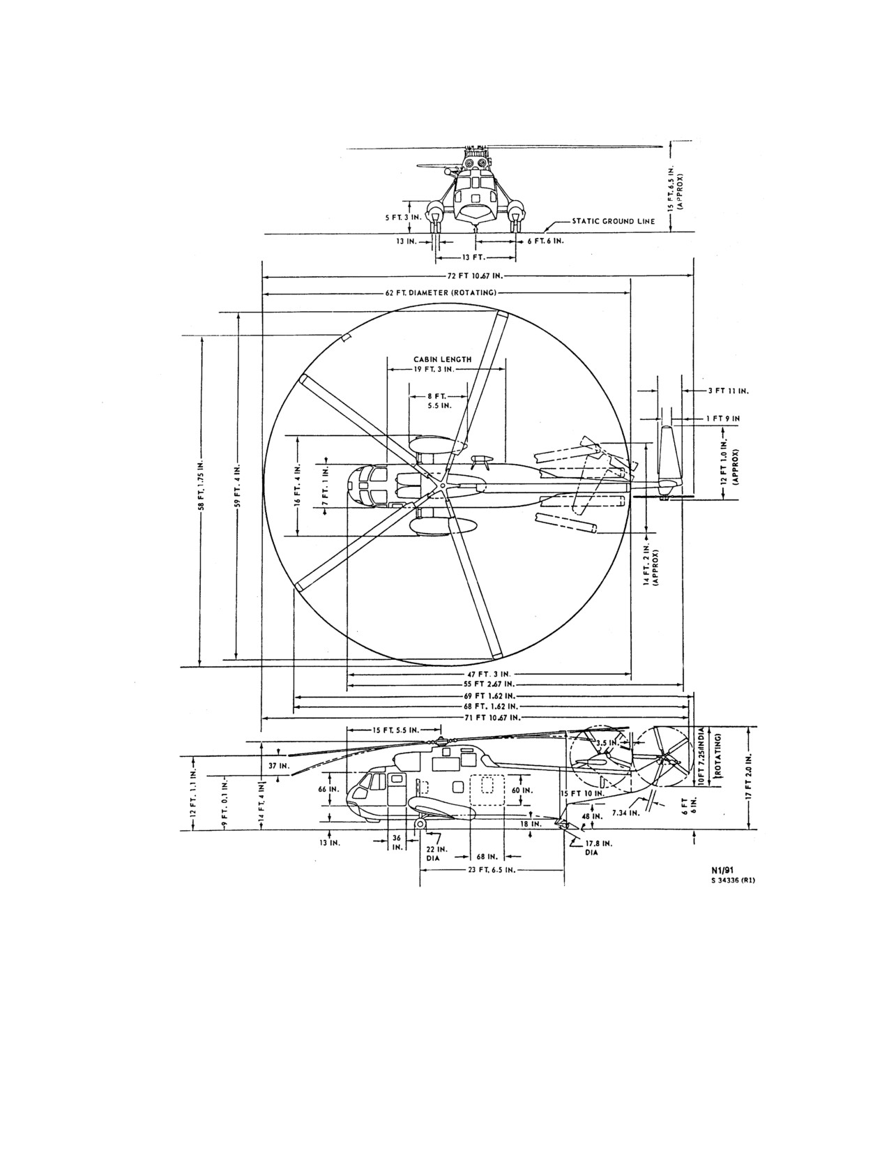
NAVAIR 01-230HLH-1
Figure 1-1. Dimension Diagram
1-3
ORIGINAL
NAVAIR 01-230HLH-1
This Page Left Blank Intentionally
1-4
ORIGINAL
NAVAIR 01-230HLH-1
CHAPTER 2
Systems
2.1 POWER PLANT SYSTEMS
The principal purpose of monitoring free turbine speed is
to regulate fuel flow to maintain an essentially constant
The helicopter is powered by two General Electric
turbine speed for a given control input shaft position.
T58-GE-402 axial flow gas turbine engines (Figure 2 - 1)
of the turboshaft type, side by side above the cabin,
2.1.3 Engine Fuel System. The engine fuel systems
forward of the main gearbox. A removable foreign object
(FO-2), one for each engine, consist of a filter screen,
deflector (ice shield) (Figure 2 - 2) is installed to prevent
dynamic filter, two-stage main fuel pump, fuel control
chunks of ice from breaking off the top of the fuselage and
unit, static filter, an oil cooler, flow divider, and
2 fuel
being ingested by the engines. The ice shield kit contains a
manifolds containing 16 nozzles. The fuel control unit is
sleeve for each pitot tube that shall be installed whenever
supplied fuel from the engine-driven fuel pump. Metered
the ice shield is mounted. This is to prevent erroneous
fuel from the engine fuel control unit is piped through an
inputs to the barometric altitude controller and incorrect
oil-fuel heat exchanger and then enters the flow divider
airspeed indications. Each engine (FO-1) consists of the
connected directly to the fuel manifolds on the engine. For
following major components: an axial flow compressor, a
normal flight, rotor speed is selected by positioning the
combustion chamber, a two-stage turbine that drives the
engine speed selectors, and the engine fuel controls will
compressor, and a free power turbine that is mechanically
meter fuel to maintain the selected rotor speed.
independent of the two-stage turbine. The compressor and
its two-stage turbine is referred to as the gas generator.
2.1.3.1 Fuel Pumps, Engine-Driven. A dual-stage
The main advantage is a constant free turbine speed output
engine-driven fuel pump is mounted on each engine,
that results in a constant rotor rpm. Variations in power
consisting of a positive displacement gear stage and a low-
requirements to maintain constant free turbine speed are
pressure centrifugal boost element. Power for these pumps
done by automatic increases or decreases in gas generator
is furnished from the engine accessory drive section. The
speed. The engine fuel control system delivers atomized
shaft driving these pumps also transmits compressor speed
fuel in controlled amounts to the combustion chamber. The
information to the engine fuel control units.
fuel flow must vary readily in volume
(with related
variation in pressure) in response to the range of power
2.1.3.2 Fuel Control Units. The engine fuel control
requirements encountered during flight. Flow of fuel and
air through the combustion chamber is continuous, and
units, one on each engine, are hydromechanical units that
once the mixture is ignited a continuous flame is sustained.
modulate engine fuel flow to maintain a constant, selected,
Changes in air pressure, air temperature, and helicopter
free power turbine speed and thus maintain a constant
velocity affect engine performance.
helicopter rotor speed. Fuel from the engine fuel pump
enters the fuel control unit through the inlet and passes
2.1.1 Gas Generator Compressor Speed (Ng). Ng
through the fuel filter. Major fuel control elements consist
is primarily dependent upon fuel flow and is monitored by
of a metering valve and a pressure-regulating valve. The
the engine fuel control unit. The principal purpose of
pressure regulating valve maintains a constant pressure
monitoring compressor speed is to control acceleration and
across the main metering valve bypassing excess fuel back
deceleration characteristics, prevent overspeed, and
to the engine fuel pump inlet. The metering valve is
establish a minimum idle setting. Compressor speed
positioned in response to speed selector position, T2, Ng,
controls mass airflow pumped through the engine and
Nf, and P3, and meters fuel to the engine as a function of
consequently the power available to the power turbine.
these integrated signals.
2.1.2 Free Turbine Speed (Nf). The Nf is dependent
upon engine control input shaft position and rotor load.
2-1
ORIGINAL
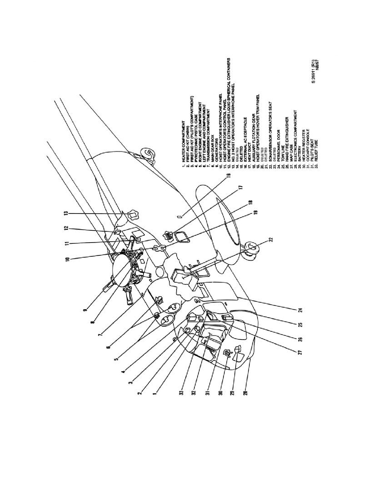
NAVAIR 01-230HLH-1
Figure 2-1. General Arrangement - Interior
2-2
ORIGINAL
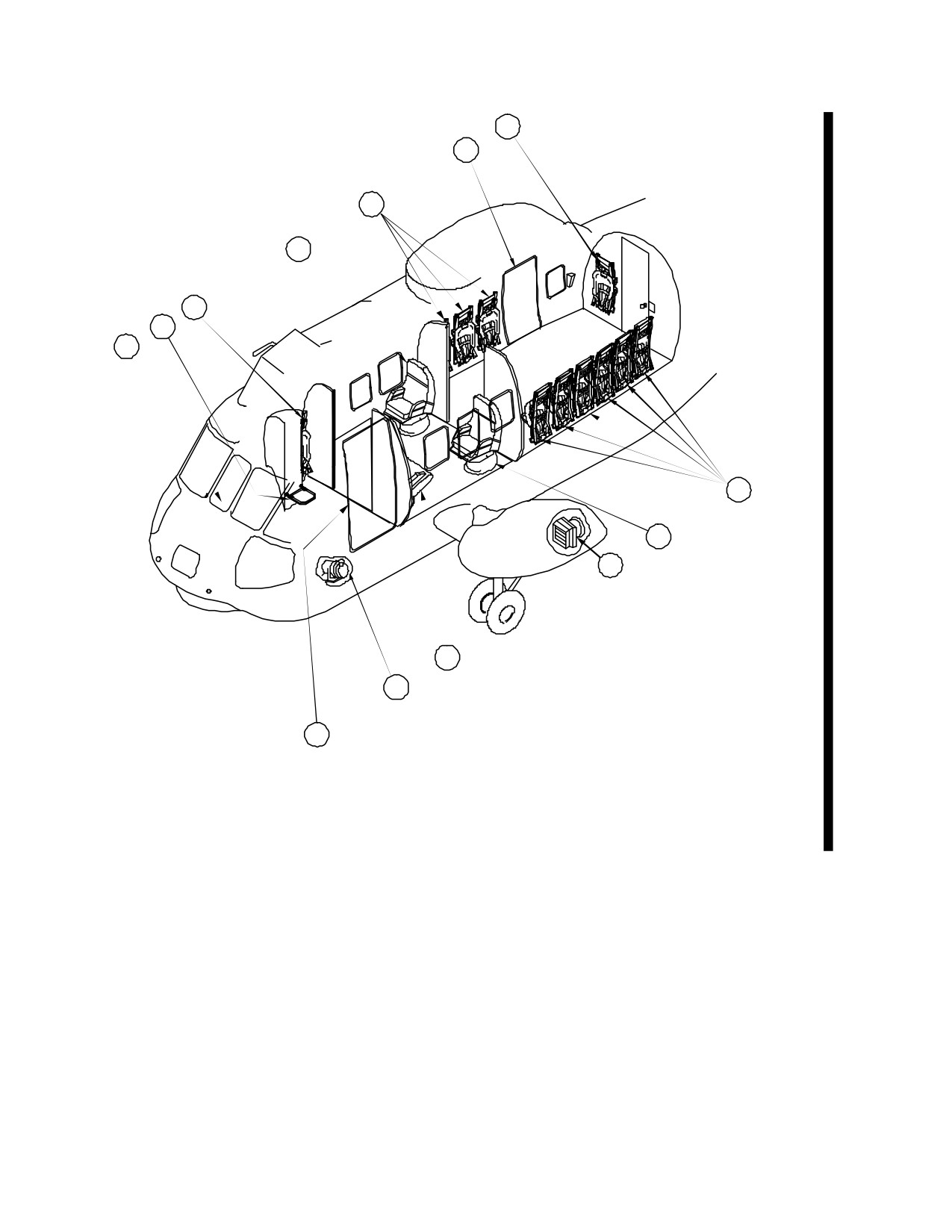
NAVAIR 01-230HLH-1
7
6
5
4
3
2
1
8
9
10
1. COCKPIT
2. CREW CHIEF'S SEAT
11
3. PASSENGER SEAT
4. EXECUTIVE SEAT
12
5. PASSENGER SEAT
6. AFT PASSENGER DOOR
7. AFT CREWMAN'S SEAT
13
8. PASSENGER SEAT
9. EXECUTIVE SEAT
10. AIR CONDITIONING CONDENSOR
11. EXECUTIVE SEAT
12. AIR CONDITIONING COMPRESSOR
13. FORWARD PASSENGER DOOR
01771108
Figure 2-1.1 (ET) General Arrangement æ Interior
2-3
ORIGINAL
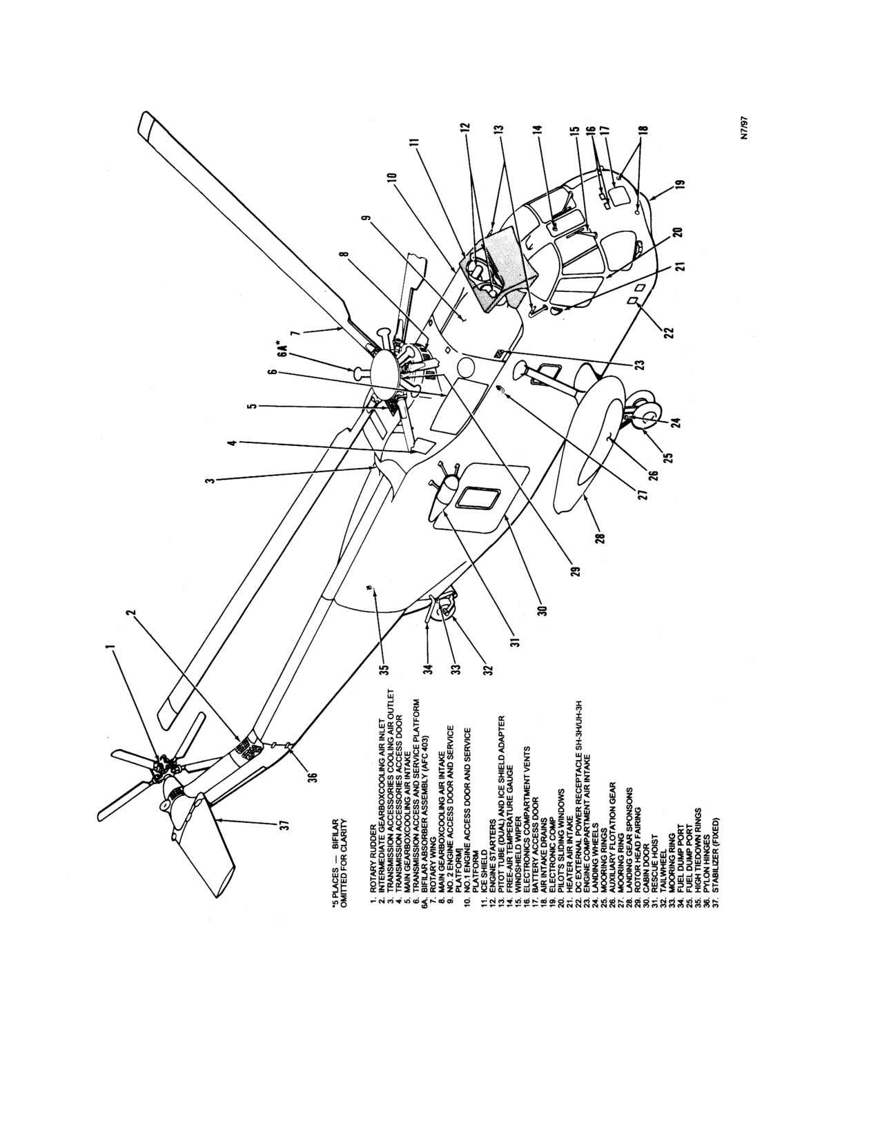
NAVAIR 01-230HLH-1
Figure 2-2. General Arrangement - Exterior (Sheet 1 of 2)
2-4
ORIGINAL
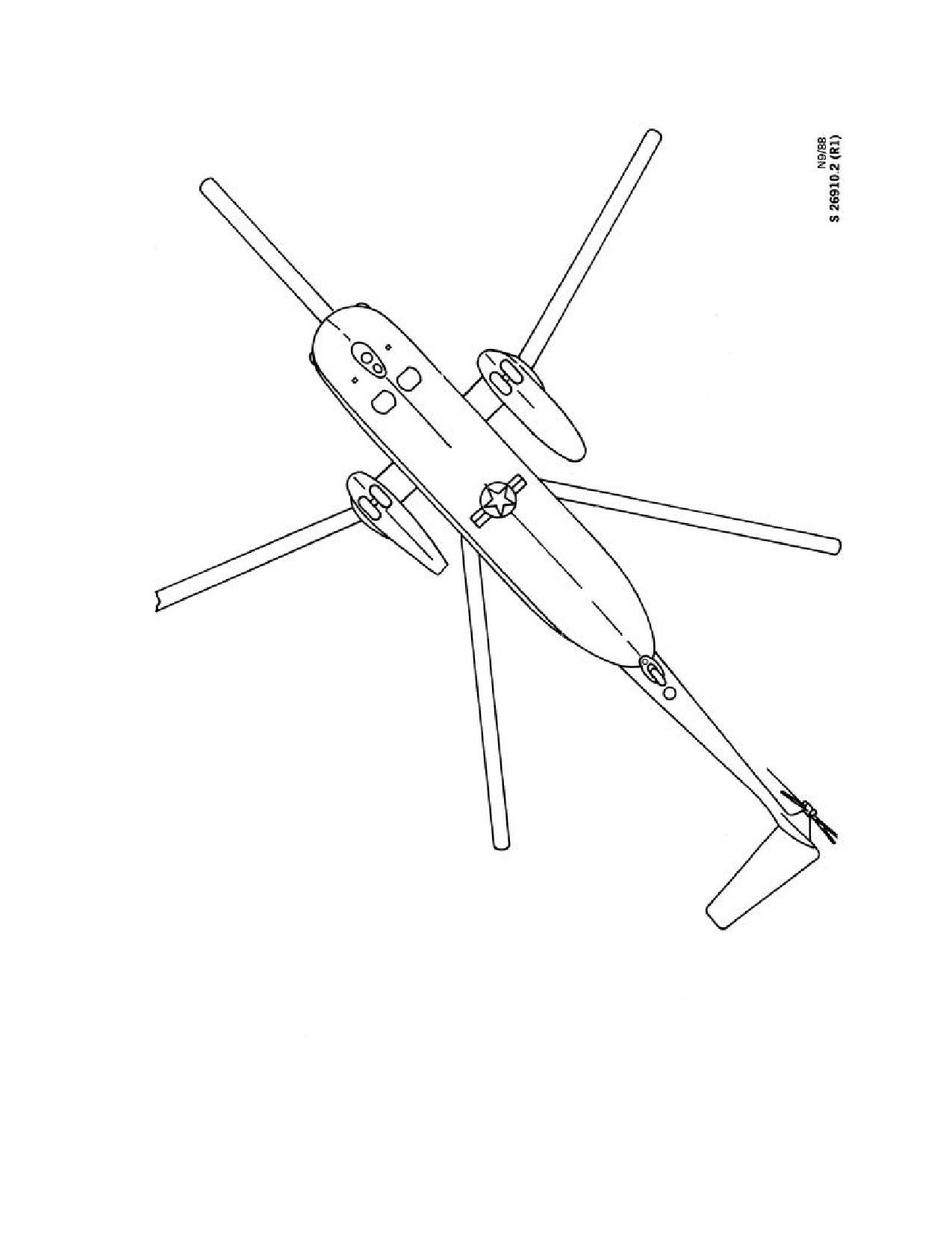
NAVAIR 01-230HLH-1
Figure 2-2. General Arrangement - Exterior (Sheet 2 of 2)
2-5
ORIGINAL
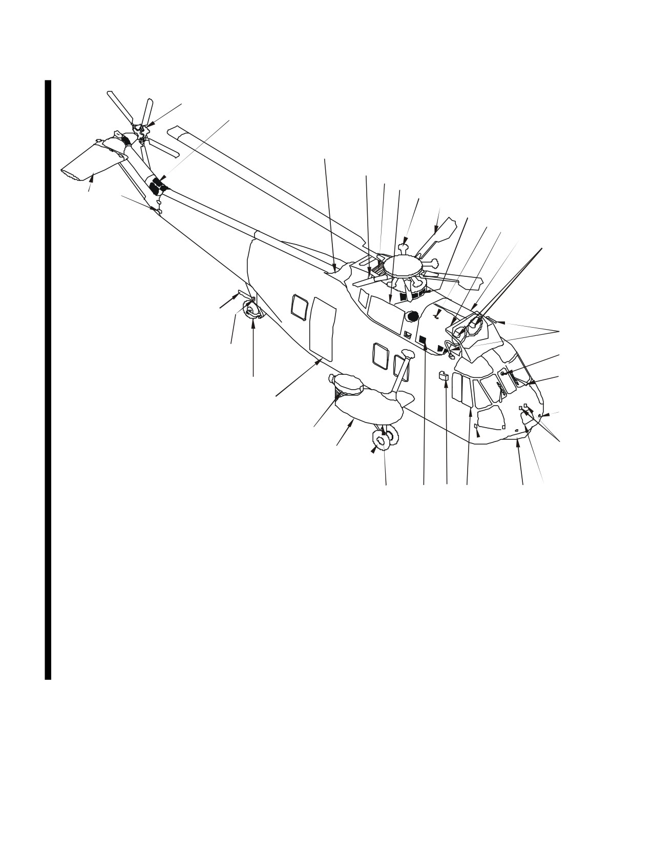
NAVAIR 01-230HLH-1
1
2
3
4
5
6
34
33
7*
8
9
*5 PLACES-ONE BIFILAR
10
11
OMITTED FOR CLARITY
12
13
1. ROTARY RUDDER
2. INTERMEDIATE GEAR BOX
COOLING AIR INLET
3. TRANSMISSION ACCESSORIES
COOLING AIR OUTLET
4. TRANSMISSION ACCESSORIES
ACCESS DOOR32
32
5. MAIN GEAR BOX COOLING
AIR INTAKE
14
6. TRANSMISSION ACCESS AND
SERVICE PLATFORM
31
7. BIFILAR ABSORBER
15
ASSEMBLY (AFC 403)
8. ROTARY WING
16
9. MAIN GEAR BOX COOLING
30
AIR INTAKE
10. NO.2 ENGINE ACCESS DOOR
29
11. ICE SHIELD
17
12. NO.1 ENGINE ACCESS DOOR
13. ENGINE STARTERS
28
14. PITOT TUBE (DUAL) (AIRSPEED
18
ADAPTER IF ICE SHIELD IS
27
INSTALLED)
15. FREE-AIR TEMPERATURE GAUGE
26
16. WINDSHIELD WIPER
17. AIR INTAKE DRAINS
25
24
23
22
21
20
19
18. ELECTRONIC COMPARTMENT VENTS
19. BATTERY ACCESS DOOR
20. ELECTRONICS COMPARTMENT
21. DC EXTERNAL POWER RECEPTACLE
22. PILOT’S SLIDING WINDOW
23. HEATER AIR INTAKE
24. ENGINE COMPARTMENT AIR INTAKE
25. MOORING RINGS
26. LANDING WHEELS
27. LANDING GEAR SPONSON
28. AUXILIARY POWER UNIT
29. AFT PASSENGER DOOR
30. TAIL WHEEL
31. MOORING RING
32. FUEL DUMP PORT
33. PYLON HINGE
34. STABILIZER
01771009
Figure 2-2.2 (ET) General Arrangement æ Exterior
2-6
ORIGINAL
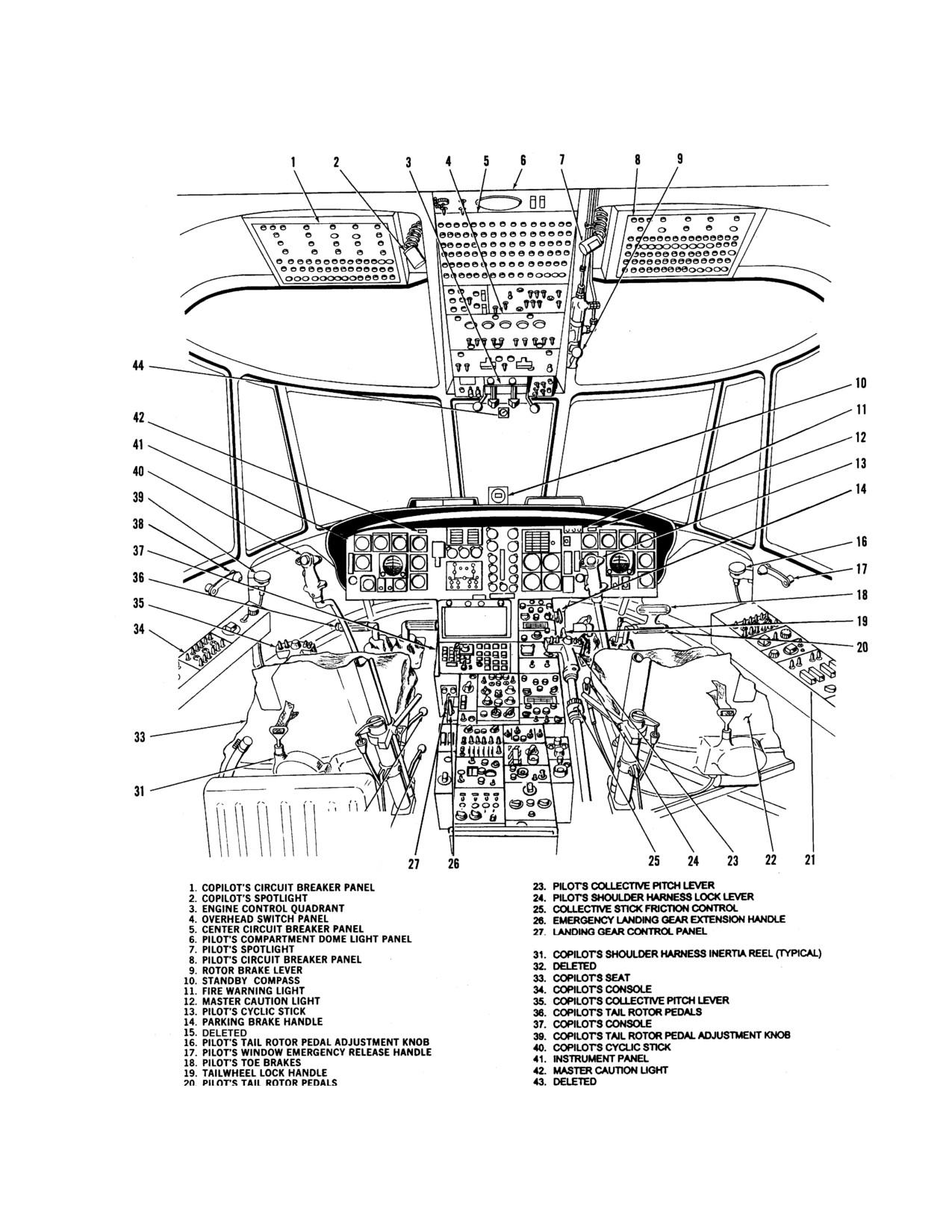
NAVAIR 01-230HLH-1
Figure 2-3. (NON-ET) Pilot Compartment (Typical) (Sheet 1 of 2)
2-7
ORIGINAL
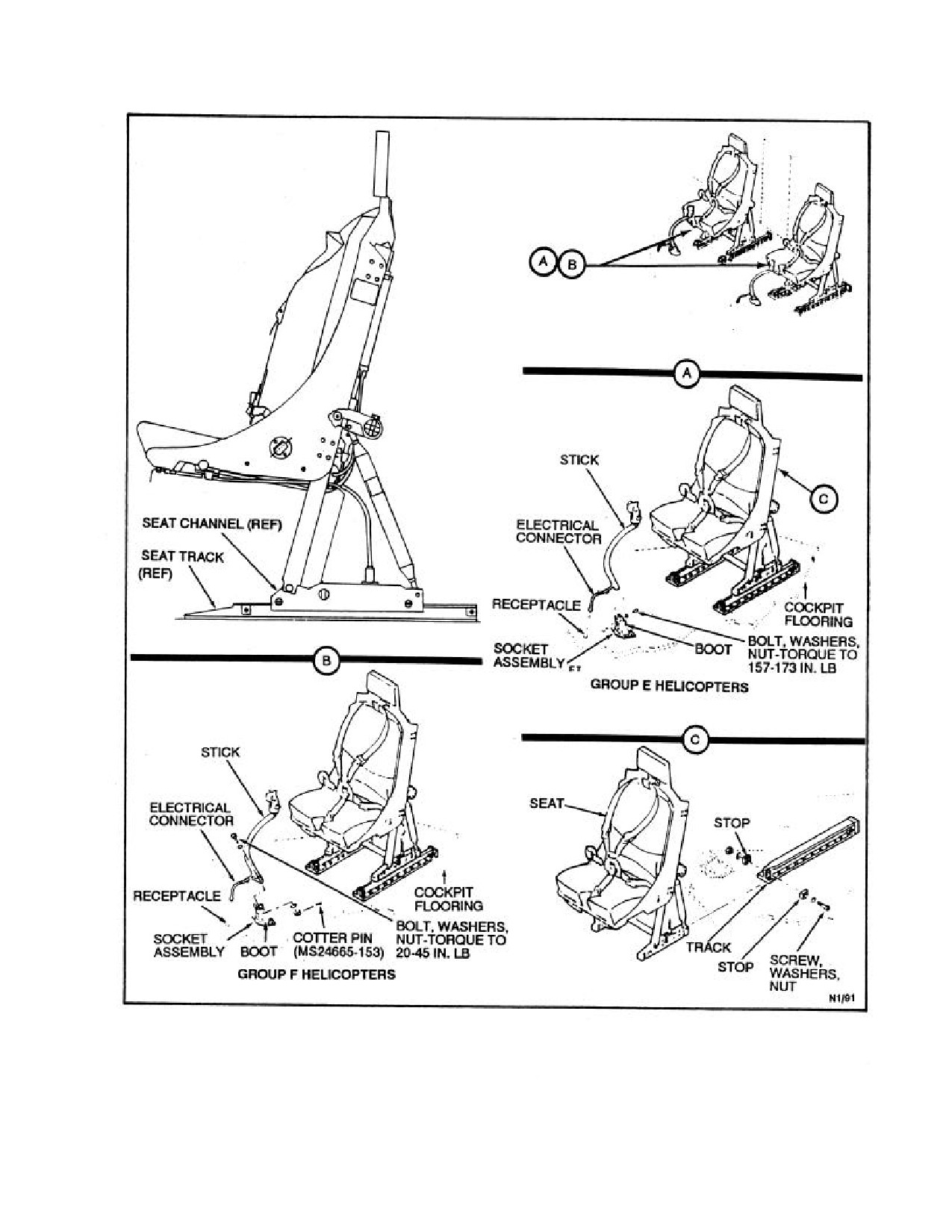
NAVAIR 01-230HLH-1
Figure 2-3. Pilot Compartment (Typical) (Sheet 2of 2)
2-8
ORIGINAL
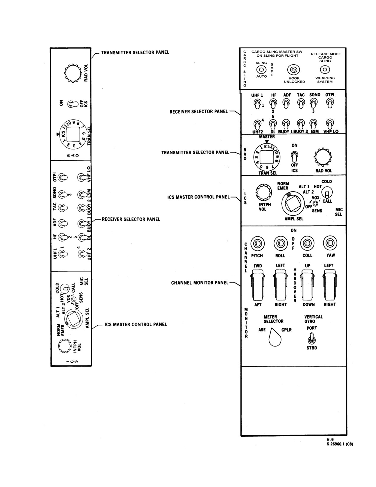
NAVAIR 01-230HLH-1
Figure 2-4. Pilot Console (Typical)
2-9
ORIGINAL
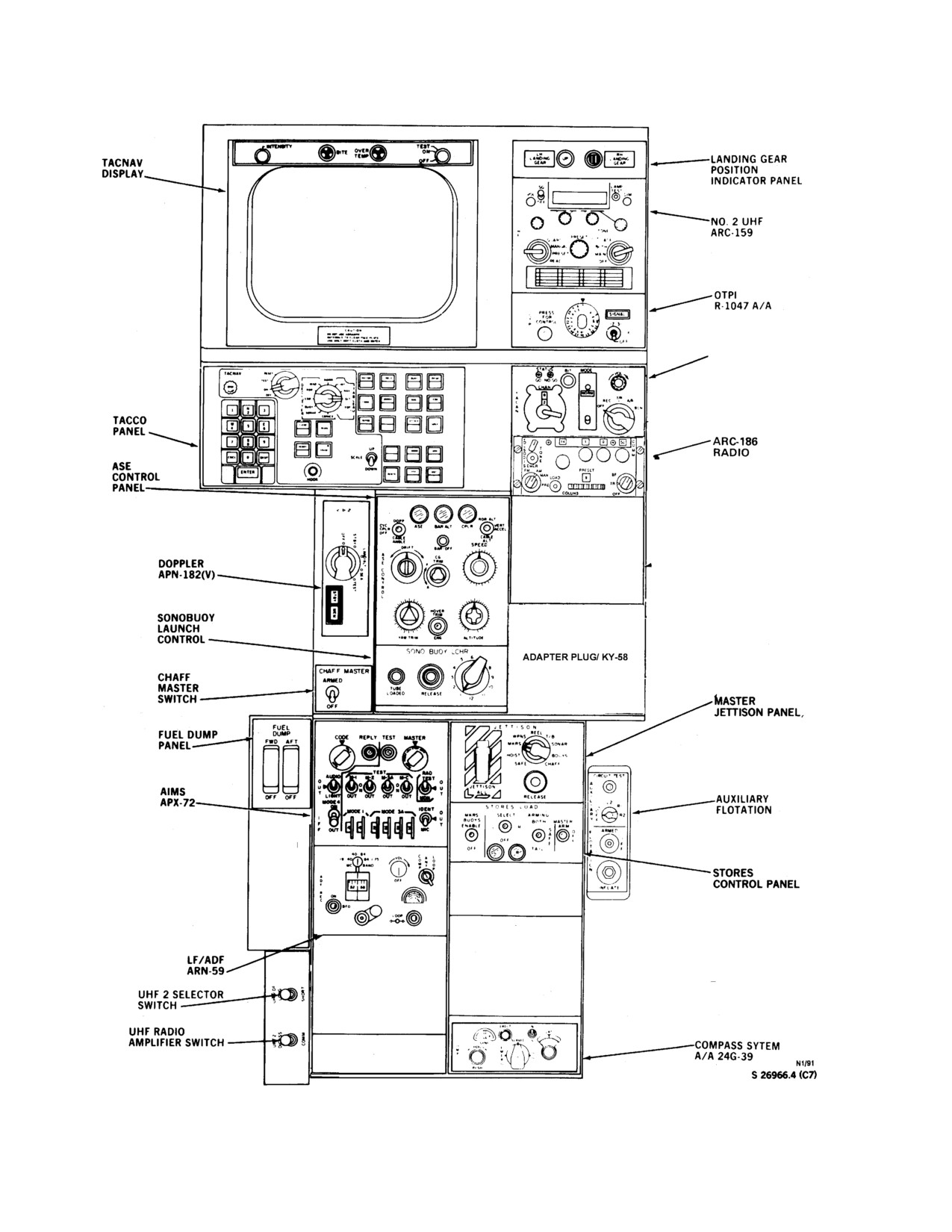
NAVAIR 01-230HLH-1
TACAN
ARN-118
Figure 2-5. Cockpit Console (Typical)
2-10
ORIGINAL
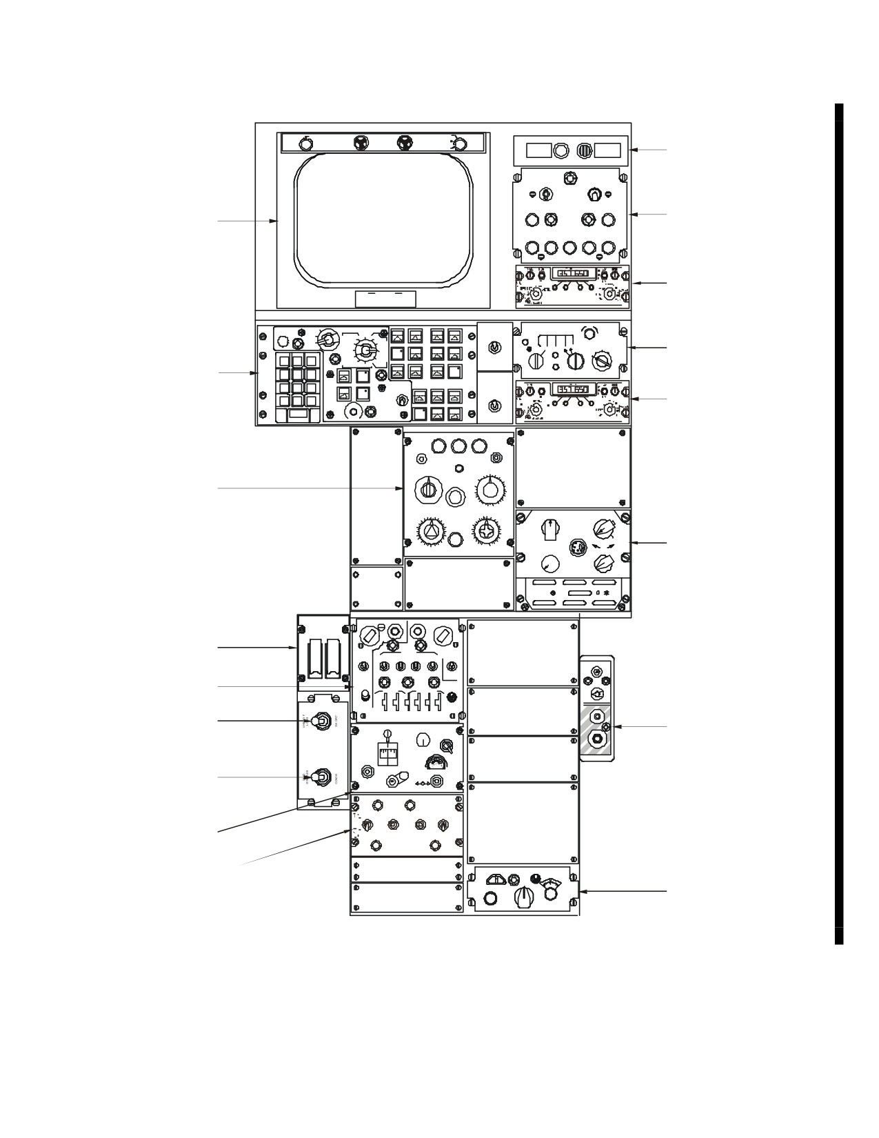
NAVAIR 01-230HLH-1
INTENSITY
TEST
BITE
OVERTEMP
ON
LH
RH
OFF
LANDING
LANDING
GEAR
GEAR
LANDING GEAR
POSITION
APU
INDICATOR PANEL
ON
APUON
OFF
A
RESET
P
APU
GEN
U
ON
ON
APU CONTROL
TACNAV
DISPLAY
STARTERON
TEMP HI
OIL
APUON
APUFAIL
GENFAIL
ARC-182
DO NOT USE ABRASIVE
CAUTION
RADIO 2
MATERIALS TO CLEAN FACE PLATEUSE ONLY SOFT CLOTH AND WATER
RESET
VOL
TACNAV
VECTOR
CIRCLE
BUOY
BRG
CHANNEL
TEST
D
NORM
DIPHASE
DIM
E
MAP
INT
T
ON
CL
RDR
NAV
A
T
A
54 X
OFF
U
ESM
SLTL
B
C
REC
T/R
A/A REC
T
E
MARK
MENU
MAG
CONT
A
OFF
A/A T/R
TACAN
TE
BUOY
EQP
A
N
1
N2
3
R SONAR
U
BASE BAND
TEST
CONICS
SENSO
ATTACK
ARN-84
E
CLEAR
DATA
TACCO
W
4
5
6
REDIS
ARC 182
7
S
9
ANT
PANEL
8
VERIFY
UP
L'L
COORD
CORR
SELECT
ERASE
UPR
CNCL
0
BKSP
SCALE
ARC-182
DOWN
FTP
MOT
ENTER
RCNTR
LWR
RADIO 1
HOOK
DOPP
ASE
CYCCPLR
ASE
BARALT
CPLR
VERT
OFF
ACCEL
CABLE
ALT
CABLE
ANGLE
SPEED
DRIFT
BAROFF
-10
0
10
A
-20
20
30
SE
CGTRIM
150
40
F
50
ASE
C
140
60
O
130
70
CONTROL
NT
120
80
R
A
110
100
90
O
100
LOAD
PANEL
L
8090
110
120
C
3
4
60
70
130
P
U
4
HOVERTRIM
50
140150
NV
1
6
40
160
FILL
2
30
170
1-3
ALL
20
10
180
YAW TRIM
ENG
0
2
00
190
PULL
TSEC/KY-58
ALTITUDE
VOLUME
IU
ON
OFF
1
2
3
BAT
AUDIO
INSTL
IN
4
5
6
FUELDUMP
CODE
REPLY
TEST
MASTER
FWD
AFT
FUEL DUMP
TEST
RAD
AUDIO
M-1
M-2
M-3A
M-C
TEST
PANEL
O
O
CIRCUIT TEST
U
ON
ON
U
T
LIGHT
OUT
OUT
OUT
OUT
MON
T
A
OFF
OFF
MODE 4
UX
I
L1
L2
R1
AIMS
ON
MODE 1
MODE 3 A
IDENT
LA
O
I
O
R
F
R2
FF
UT
Y
F
APX-72
OUT
4
4
2
3
3
3
MIC
ARMED
FL
OT
OF
UHF 2
A
F
.40-.84
C
L
T
.19-.40
.84-1.75
VOL
OM
AN
OO
IO
AUXILIARY
SELECTOR
MC
BAND
P
T
P
N
A
FLOTATION
SWITCH
DF
OFF
INFLATE
.52
.58
RE
ON
C
BFO
UHF RADIO
LOOP
AMPLIFIER SWITCH
HEAT
VENT
EVAP
MODE
AIR
SELECTOR
BLO
MAN
ON
HEATER
ON
OVRD
O
F
F
LF/ADF
OFF
AIRCOND
AUTO
ARN-49
AIR CONDITIONING
ERECT
N
LAT
CONTROL
-
+
C
SLAVED
S
20
OM
HDG
E
P
ME
D
COMPASS SYSTEM
R
G
PUSH
G
A/A 24G-39
01771106
Figure 2-5.1 (ET) Cockpit Console
2-11
ORIGINAL
NAVAIR 01-230HLH-1
During the start cycle, the auxiliary metering valve
input shaft signal, working to satisfy the speed setting
provides additional fuel through the flow divider. This fuel
called for regardless of load demand. The engine fuel
may be shut off by means of the auxiliary start shutoff
control shaft at the engine can be turned through a 120o
valve to prevent T5 overtemperature. The engine fuel
arc. In the 0 o position, the stopcock in the fuel control is
closed, preventing any fuel from entering the engine. At
control prevents compressor stall, turbine over
3o, the stopcock starts to open, and at 6o it is fully open.
temperature, rich or lean flameouts, governs gas generator
From l5o to 47o, the gas generator operates on deadband
idle speed, and schedules inlet guide and stator vane
idle. From 47o to 69o, the control operates in a transition
positions to provide optimum compressor performance.
region. Power turbine speed is governed in the 70o to 120o
range. The normal operating range of the engine is above
2.1.4 Engine Control System. The power available
the 70o position, and power turbine speed increases in an
from the engine is directly determined by and in proportion
essentially linear manner at a rate of 56 rpm per degree of
to the T5. It is therefore desirable to operate the engine at
control shaft rotation.
the highest turbine inlet temperature consistent with the
physical limitations of the engine components. The engine
2.1.4.3 Fuel-Air Ratio Limits. Maintenance of a
control does this by maintaining operation within its own
continuous flame within the gas generator combustor
limits. The engine accelerates and decelerates according to
depends on proper mixture of fuel and air. As performance
preset schedules incorporated in the computing section of
factors change, the values of both will change. The
the engine control. These schedules are designed to
proportion between the two, however, must be controlled
prevent overspeed and overtemperature conditions.
within limits or the flame will be lost (flameout). During
Therefore, engine response to a new power or speed
deceleration, if fuel flow
(which is decreasing) drops
setting is not instantaneous; a few seconds must be allowed
below a given amount, a lean flameout may occur; during
for the engine to stabilize at the new condition.
acceleration, if fuel flow (which is increasing) rises above
Acceleration because of increased power requirements or
a given amount, a rich flameout may take place.
control lever movement is limited by the maximum ratio of
fuel flow to compressor discharge pressure (Wf /P3) or by
2.1.4.4 Stator Vane Actuating System. The purpose
topping.
Deceleration because of decreased power
of the stator vane actuating system is to control the
requirements or control lever movement is limited by the
direction and velocity of the air leaving the stator vanes so
minimum ratio of fuel flow to compressor-discharge
that the proper angle of attack is preserved with respect to
pressure, the negative feedback, or bottoming. Selected
the compressor rotor blades. The inlet guide vanes and the
steady-state conditions are stabilized at optimum
first, second, and third stage stator vanes are varied in
efficiency by a lead-lag servo system that dampens the
pitch by a hydraulic servo mechanism powered by engine
effect of power transients and maintains power turbine
fuel pressure and controlled by the gas generator governor
speed within the specified 8.5-percent droop at 120o fuel
section of the fuel control. The variable vanes that are
control input shaft position.
closed during engine starting begin to open at about 60-
percent Ng, depending on outside air temperature.
2.1.4.1 Fuel
Flow Compressor Discharge
Pressure Ratio. The fuel control does not monitor
2.1.4.5 Temperature Limits. The amount of heat that
power turbine inlet temperature directly; it monitors
engine components
(particularly turbine buckets and
compressor-discharge pressure and adjusts fuel flow to
turbine nozzles) can withstand without structural damage
maintain engine temperatures within safe predetermined
limits the amount of heat energy that can be released by
limits. The ratio of fuel to be burned to the amount of air
burning fuel. Temperature is controlled by limiting the
available for both combustion and cooling directly
maximum fuel flow at any speed and inlet condition or, at
determines the temperature of the combustion gases (and
full power conditions, by limiting the maximum gas
power available) at any point in a turboshaft engine.
generator speed.
Therefore, the ratio of fuel flow to compressor-discharge
pressure has been selected as the most convenient absolute
2.1.4.6 Idle to Transition Range. A small advance of
value for determining engine potential for any given
the engine speed selector will cause the engine to
condition.
accelerate to the transition range. As the engine speed
selector is advanced, T5 will advance fairly rapidly as the
2.1.4.2 Engine Control Input Shaft. The position of
fuel flow/comp ressor discharge pressure ratio increases
the engine fuel control input shaft determines the power
until it is limited by the lever position. At this point, the
turbine speed and hence the helicopter rotor speed. The
feedback function of fuel lever will decrease the Wf /P3
remaining parameters supplement the engine fuel control
2-12
ORIGINAL
NAVAIR 01-230HLH-1
ratio, lowering T5 until a new steady-state operation is
2.1.4.12 Shutdown. When the engine speed selector is
attained. During this time, Ng should show steady increase.
moved to the closed position, the stopcock shuts off all
Prolonged operation of the engine in the transition range is not
fuel flow to the engine. The speed selectors can be
recommended.
immediately shut down from any operating condition in an
emergency.
2.1.4.7 Idle to Normal Operating (Nf Governing)
Range. As the engine speed selector is advanced from the
2.1.4.13 Engine Power. In the power regime, the engine
GRD IDLE position into the normal operating range, T5 and Nf
drives the helicopter rotary wing at the speed and power level
will advance rapidly as the Wf /P3 ratio increases until it
selected by the pilot. For normal operation, a power turbine
reaches the maximum acceleration schedule. Fuel flow will
speed within the range of 91 to 112.5 percent is selected. The
engine control system maintains this selected speed by varying
continue to increase in proportion to N g according to the
gas generator speed to meet the different power requirements
maximum acceleration schedule until the engine tops out. At
this point, the Wf /P3 ratio and T5 will decrease along the
produced by a change in the helicopter blade pitch angles,
topping schedule as Ng increases to a new steady-state
forward speeds, and atmospheric conditions. As blade pitch an-
condition.
gle is increased, the engine fuel control increases gas generator
speed until the maximum gas generator speed is reached. If the
blade pitch angle is increased when the maximum gas generator
2.1.4.8 Increasing Engine Load. Increasing engine load
speed is reached, a reduction in rotary wing speed will occur.
causes the gas generator to accelerate. During acceleration,
maximum fuel flow is delivered to the engine with the rate of
increase limited by the 3D cam contours to avoid compressor
2.1.4.14 Compressor Stall Limit. Stall designates reversals
stall, rich or lean flame-out, or turbine overtemperature. When
of flow within the compressor. The severity of stall depends
the gas generator speed required to match output power to the
upon the number of reversals that take place per second.
Compressor stall will result in most cases with the engine in a
new load is reached, fuel flow decreases to the level necessary
decelerating condition. The primary indication of a stall is a rise
to maintain the new steady-state speed.
in T5 and other engine parameters decreasing. It may or may
2.1.4.9 Decreasing Engine Load. Decreasing engine load
not be accompanied by audible rumbling or other engine noise.
causes the gas generator to decelerate. During deceleration, the
Each compressor has a maximum pressure ratio for every speed
engine fuel control supplies the minimum fuel flow that will
at which it operates. The maximum pressure ratio sets a limit on
the compressor discharge that can result from rotating the
maintain combustion until the gas generator approaches the
compressor at a particular speed. As long as the pressure at the
speed that will match output power to the new load. The engine
fuel control then supplies the fuel flow necessary to maintain
compressor discharge equals or is below this limit, the
compressor will deliver air smoothly; however, if this limit is
this speed.
exceeded, flow will be reduced and there will be some reverse
2.1.4.10 Retarding Engine Speed Selector. Slightly
flow through the compressor. If it were not for the engine fuel
control system, stall could occur during an attempt to
retarding the engine speed selector under normal or military
accelerate the engine. A sudden and excessive increase in
load conditions so that Ng does not drop below 80-percent Ng
will yield a deceleration not affected by feedback. The Wf /P3
fuel flow might generate a volume of gas that would create an
excessive backpressure at the compressor discharge, and
ratio decreases to the limit set by the new engine speed selector
position and remains constant as the engine decelerates to the
compressor stall would result. Because each compressor speed
new steady-state condition.
has its own maximum compressor ratio, each must have its
own stall point (the point at which stall begins). Stall is avoided
by limiting fuel flow during engine acceleration as a function of
2.1.4.11 Deceleration to Idle. Retarding the engine speed
selector from the normal operating range to GRD IDLE
inlet air temperature, gas generator speed, and compressor dis-
charge pressure.
decreases fuel flow until the minimum Wf /P3 stop is reached.
The gas generator slows down on a minimum Wf /P3
schedule until it reaches about 80-percent speed. At this
2.1.4.15 Permanent Droop. Power turbine speed, minus
point, the negative feedback function of the engine fuel control
droop, is maintained within the governed range (91 - to 112.5
percent Nf ) as selected by the speed selectors. Droop is a
starts increasing the Wf /P3 ratio until the bottoming schedule
is reached. The gas generator then decelerates with an
characteristic built into the engine control system that
increasing Wf /P3 ratio determined by the bottoming schedule
establishes a permanent decrease in power turbine governed
until idle speed is reached.
speed from that set at zero load as engine power increases to
maximum load. This droop is 5 to 8.5 percent from no load to
full load with proportional decreases at intermediate power
settings. This difference in droop schedules will result in torque
2-13
ORIGINAL
NAVAIR 01-230HLH-1
splits. Thus, if Nf is set at 108.5 percent in an autorotation with
the No. 1 speed selector. This limit switch prevents switching
no load on the engine and speed selectors are not moved during
from accessory drive to flight without first retarding the
recovery, the engine and rotor speed would decrease to 100-
NUMBER 1 ENGINE speed selector lever to GRD IDLE.
percent Nf as engine reaches full power. On the ground and
MIN GOV on the speed selector is the point where the
at flat pitch, approximately 400 hp is absorbed by the rotor at
governing range of the power turbine is entered, and is about
100- to 108-percent Nr; thus the engine has already drooped
89-percent Nf . When the speed selector is at full forward, the
approximately
5-percent Nf from no load. This droop
engine is producing maximum power turbine speed. The starter
characteristic is incorporated to ensure Nf stability and provide
abort switches are in each speed selector.
load sharing in multiengine installations.
2.1.5.3 Engine Vernier Knobs. A vernier knob (see
2.1.4.16 Transient Droop. The engine accelerates and
Figure 2-6) above each engine speed selector pro vides vernier
decelerates in response to power demands on a preset schedule.
control of the engine speed selectors. An arrow on the face of
Therefore, if power is demanded at a rate exceeding engine
each knob is marked INC to indicate the direction of turning to
ability to accelerate, an additional momentary droop in Nf /Nr
increase rpm. Turning the knob in a clockwise direction
will be experienced, called transient droop. As the engine
mechanically moves its respective speed selector to increase
accelerates, transient droop is eliminated.
rpm. Turning the knob in a counterclockwise direction
decreases rpm.
2.1.4.17 Speed Limits. The gas generator and the power
turbine have maximum speeds that cannot be exceeded
2.1.5.4 Emergency Fuel Control Levers (Manual
without danger or damage. These limits are established in
Throttles)
Chapter 4. These are steady state speeds of 26,220 rpm 101.8
percent max continuous for the gas generator, and 21,275 rpm
112.5 percent for the power turbine.
2.1.5 Engine Controls
· At higher power settings, considerable dead band
2.1.5.1 Engine Fuel Control System Operation. The
travel will normally be encountered before the
engine fuel control system must schedule fuel flow and variable
emergency fuel control contacts the metering
vane position during four general operating conditions. These
valve lever. This will be felt as a slight restriction
conditions are starting, ground idle, minimum governing, and
in control movement. When this is felt, the
100-percent speed. The regimes of these conditions are related
control will be very sensitive and care should be
to the various engine speed selector settings.
taken not to exceed T
5 and Ng limits.
2.1.5.2 Engine Speed Selectors. Two engine speed
selectors marked NUMBER 1 ENGINE and NUMBER 2
· The fuel control will not operate on manual
ENGINE are on the overhead engine control quadrant (Figure
throttle if the speed selector is stopcocked.
2-6). Markings on the overhead quadrant are SHUT OFF,
GRD IDLE, MIN GOV and 100% SPEED. When the engine
· To prevent stall, movement of manual throttle
speed selectors are at SHUTOFF, fuel flow to the fuel nozzles
out of GRD IDLE should be slo wer than
is stopped by means of a stopcock. This prevents fuel from
movement in the governing range.
entering the combustion chambers during coastdown of the
engine gas generators or during operation of fuel boost pumps
Two emergency fuel control levers (hereafter referred to
with the engine shutdown. The stopcock is directly actuated by
as manual throttles) (see Figure 2-6), one for each engine,
the position of the engine speed selector. It is open whenever
marked EMERGENCY FUEL CONTROL with marked
the engine speed selector position is
6o or more from
positions OPEN and CLOSE are on each side of the overhead
SHUTOFF and is closed when the selector is 3 o or less from
quadrant. The manual throttles operate independently and are
SHUTOFF. The GRD IDLE position schedules fuel flow to
used in case of fuel control unit failure. Each manual throttle
produce a gas generator speed of about 56 ±3-percent Ng. Gas
has positive open and closed stops and is connected directly to
generator idle speed will vary with inlet air temp erature. A
the main metering valve in each engine fuel control unit by a
limit stop at GRD IDLE prevents inadvertent retarding of the
flexible cable and linkage. The primary function of the manual
speed selectors below the idle speed of the engines. The speed
throttle is to manually override the automatic features of the
selectors may be retarded from the limit stop by pulling the
fuel control. This may become necessary under some starting
control out of the detent and exerting upward pressure. An
situations and during any fuel control malfunction that causes
accessory drive limit switch is incorporated at GRD IDLE on
erratic engine operation. The manual throttle must be used with
2-14
ORIGINAL
//////////////////////////