UH-3H and UH-3H EXECUTIVE TRANSPORT. FLIGHT MANUAL (2000) - page 6
NAVAIR 01-230HLH-1
SYMPTOMS
CORRECTIVE ACTION
IN FLIGHT
IN FLIGHT
*1. Speed selectors - FULL FORWARD.
1.
Loud sound from transmission area.
*2. Contain Nr.
2.
Rapid rise in Nf, peak Nf dependent upon engine
*3. Establish single-engine airspeed and level attitude.
power before shaft failure.
*4. Reduce gross weight, if necessary, by dumping fuel
3.
Torque drop, if engine relights and stabilizes some
and/or jettisoning stores.
residual torque may be indicated on the torque
gauge.
5. Secure affected engine.
4.
Rapid engine deceleration as fuel flow is shut off.
6. Determine normal engine’s power available.
5.
Possible compressor stall if engine relights. The
7. Landing Gear - AS REQUIRED.
possibility exists that the engine may stabilize at
some lower power range attempting to maintain the
8. Land as soon as practicable.
Nf selected in the normal range. The free turbine
(Nf), on the affected engine, will probably stabilize
ON GROUND
at some value higher than normal (110%
- 114%)
and can be recognized by a Nf, Nr split with Nf
*1. Secure affected engine.
stabilizing above the Nr.
2. Follow up procedure, use checklist.
6.
Possible transmission chip detection light, if break
occurred at the sleeve bearing or inside the main
12.11.11 AXIAL DRIVE SHAFT FAILURE. In-flight
gear box.
symptoms are identical to fuel pump drive or radial
accessory drive failure. If shaft failure occurs during
7.
Possible main gear box oil leak and hydraulic leaks,
engine motoring or start, all starter drive will be
possible smoke, fumes or fire from oil or hydraulic
transmitted to accessories with an immediate increase in
fluid leaking on hot surfaces.
Ng and oil pressure.
8.
Possible illumination of engine fire warning light (s)
SYMPTOMS
if exhaust casing or firewall is damaged.
STARTING
9.
Possible illumination of ROTOR BRAKE caution
light resulting from friction caused by damage to
1. Sudden rise in Ng above 23%.
the rotor brake assembly.
2. Increase in engine oil pressure.
10. Possible Nr decay caused by increased friction as a
result of above listed collateral damage.
3. Compressor not turning or coast down audible.
STARTING
4. If compressor drive is lost after light-off, but before
starter dropout, compressor stall may occur.
1. No. 1 engine.
CORRECTIVE ACTION
a. No rise in transmission oil pressure or
hydraulic system pressure.
*1. Secure affected engine.
2. No. 2 engine
2. Do not attempt restart.
a. Nf rises above Nr as engine accelerates.
3. Follow up procedure, use checklist.
b. No torque increase.
12-11
ORIGINAL
NAVAIR 01-230HLH-1
Note
5. Securing the engine is at the discretion of the pilot.
Securing the No.
1 engine is not recommended
Axial drive shaft failure in flight will result in
because of the possible subsequent failure of the tail
engine flameout due to loss of drive to engine
takeoff freewheeling unit.
accessories. Follow procedures for engine
failure. No corrective action is available to the
6. Do not attempt use of the manual throttle.
pilot.
7. Nf/ Nr as required.
12.11.12 LOSS OF Ng SIGNAL TO FUEL CONTROL.
The Ng speed signal is transmitted to the fuel control via
8. Determine normal engine’s power available.
the front frame accessory drive and fuel pump gear train.
Loss of the coupling between the fuel pump and fuel
9. Landing Gear - AS REQUIRED.
control will allow continued engine operation. However,
the fuel control sensing Ng at “0” will completely close
10. Land as soon as practicable.
the variable stator vanes, causing a power loss. The 3D
cam in the control, which translates as a function of Ng,
ON GROUND
will become immobile. Thus, the 3D cam contours, which
schedule engine acceleration, topping, ground idle and
*1. Secure affected engine.
variable vane angle, no longer function.
2. Follow up procedure, use checklist.
Use of manual throttle will cause T5 overtemp
since variable vanes remain closed, restricting
Loss of Ng governor drive may be difficult to
airflow.
differentiate from certain P3 losses and other
fuel control malfunctions. Loss of drive is
IN FLIGHT
indicated by retarding the speed selector to
ground idle with no reduction in Ng.
1. Torque and Nf decrease. Engine power output be-
comes essentially that normally produced at ground
12.11.13 LOSS OF P3 SIGNAL TO FUEL
idle.
CONTROL. Reduction of the compressor discharge
pressure (P3) sensed by the fuel control will result in a
2. Ng stabilizes at about 80%.
comparable decrease in fuel flow. Complete loss of the P3
signal (fuel control now sensing ambient pressure) will
3. Engine does not respond to speed selector
result in engine operation below ground idle. Most P3
movement.
malfunctions are characterized by partial reduction of
pressure due to a loose P3 line fitting or contamination in
STARTING
the line. Use of manual throttle will regain normal engine
operation.
Engine will light off and accelerate to about 80% and
stabilize. Engine does not maintain ground idle (about
SYMPTOMS
56% Ng) and will not respond to speed selector
movement.
STARTING-ON GROUND
IN FLIGHT
1. Slow engine acceleration and possible Ng hangup
below ground idle.
*1. Speed selectors - FULL FORWARD.
2. Engine acceleration time is over 8 secs. from ground
*2. Contain Nr.
idle to 80% Ng.
*3. Establish single-engine air- speed and level attitude.
IN FLIGHT
*4. Reduce gross weight, if necessary, by dumping fuel
1. Reduction in Ng , T5, Nf and torque dependent upon
and/or jettisoning stores.
the magnitude of the P3 leak.
12-12
ORIGINAL
NAVAIR 01-230HLH-1
CORRECTIVE ACTION
Note
ON GROUND
· Loss of flexible drive shaft will result in loss of
mechanical overspeed protection.
*1. Secure engine.
· Close coordination between the pilot and copilot
IN FLIGHT
with regard to manual throttle/collective action is
mandatory.
*1. Speed selectors - FULL FORWARD.
SYMPTOMS
*2. Contain Nr.
IN FLIGHT
*3. Establish single-engine airspeed and level attitude.
1. Nf to zero on affected engine.
*4. Reduce gross weight, if necessary, by dumping fuel
and/or jettisoning stores.
2. Ng, T5, and torque to topping power indications.
5. Analyze -Check Nr.
3. Engine does not respond to speed selector movement
in Nf governing region.
a. Slowly
advance
manual throttle
on
malfunctioning engine until a rise in Ng or T5 is
Note
noted or full travel is reached, whichever is
first.
The opposite engine will retard in power
correspondingly as its Ng governing system
b. Slowly reduce engine speed selector to ground
attempts to prevent any increase in Nf.
idle or binding. Make sure manual throttle is
functioning.
ON START
c. Adjust power with manual throttle.
Danger of overspeed does not exist until the speed
selector is moved out of ground idle since the effect of the
d. Allow normal engine to do governing.
Nf governing section is not felt in the fuel control until the
speed selector is moved forward to the transition range.
6.
Landing gear - AS REQUIRED.
Any attempt to move the speed selector out of ground idle
will result in the following:
7.
Land as soon as practicable.
1. No.
1 engine
(in accessory drive)
- Starting
12.11.14 FLEXIBLE DRIVE SHAFT FAILURE. This
indications for the No. 1 engine will be Nf not rising
shaft and its drive gearing, including the power turbine
and remaining at zero. If the speed selector is moved
radial shaft, provide the Nf signal for both the actual Nf to
out of ground idle, the engine will accelerate rapidly
the fuel control and the cockpit tachometer indication.
until the overspeed limiting system actuates at about
The fuel control, attempting to maintain selected Nf, and
108% Nf (±3%), at which point erratic cycling of the
never “seeing” it, calls for full power. This discrepancy is
engine will occur. Nf will remain at zero.
distinguishable from all other malfunctions in that the Nf
on the high torque engine drops to zero.
2. No. 2 engine
- Engine light-off will be normal and
there will be no abnormal indications prior to
engagement. During engagement, Nr will advance
without an indication of Nf on either triple tach. If
the SSL is advanced into the governing range, a
rapid increase in torque will commence.
Upon encountering flexible drive shaft failure
CORRECTIVE ACTION
in high speed cruising flight, reduction of
collective and/or aft cyclic movement may
IN FLIGHT
result in rapid acceleration of the rotor system
leading to overspeed and/or compressibility
*1. Speed selectors - FULL FORWARD.
effects.
*2. Contain Nr.
12-13
ORIGINAL
NAVAIR 01-230HLH-1
*3. Establish single engine flight airspeed and level
CORRECTIVE ACTION
attitude.
IN FLIGHT
4. Analyze -Check Nf.
*1. Speed selectors - FULL FORWARD.
a. Slowly
advance
manual throttle
on
malfunctioning engine until a rise in Ng or T5 is
*2. Contain Nr.
noted or full travel is reached, which ever is
first.
*3. Establish single-engine airspeed and level attitude.
b. Slowly reduce engine speed selector to ground
*4. Reduce gross weight, if necessary, by dumping fuel
idle or binding. Make sure manual throttle is
and/or jettisoning stores.
functioning.
5. Analyze - Ng and T5.
c. Adjust power with manual throttle.
a. Slowly
advance
manual
throttle
on
d. Allow normal engine to do governing.
malfunctioning engine until a rise in Ng or T5 is
noted or full travel is reached, whichever is first.
5.
Landing gear - AS REQUIRED.
b. Slowly reduce engine speed selector to ground
6.
Land as soon as practicable.
idle or binding. Make sure manual throttle is
functioning.
ON GROUND
c. Adjust power with manual throttle.
*1. On ground, both speed selectors to ground idle.
d. Allow normal engine to do governing.
*2. Secure affected engine.
6. Landing gear - AS REQUIRED.
3. Follow-up procedures, use checklist.
7. Land as soon as practicable.
12.11.15 FUEL CONTROL CONTAMINATION. Fuel
contamination may disrupt the normal operation of the
ON GROUND
fuel control. Although control malfunction depends upon
where contamination finally lodges, unstable engine
*1. Secure engine.
operation may be observed before power loss. Unstable
engine operation may also be caused by Nf flex shaft
2. Follow up procedure, use checklist.
s lippage before failure. In either situation, use of
emergency throttle will stabilize engine oscillations and
12.12 MAXIMUM RANGE
lessen potential malfunction.
Should the condition arise where fuel remaining
SYMPTOMS
aboard may not be enough to reach a practicable landing
site on two engines, best range may be gained by flying
1. Oscillations of Ng , T5 and Nr during steady state
single-engine at maximum speed for the single-engine
engine operation, Ng cycling is greater than ±1%.
configuration (100-percent Nr). This situation constitutes
an emergency.
Note
Fuel control caused engine oscillations are
normal
during
autorotations.
Engine
oscillations should only be checked when
engine is driving rotor.
12-14
ORIGINAL
NAVAIR 01-230HLH-1
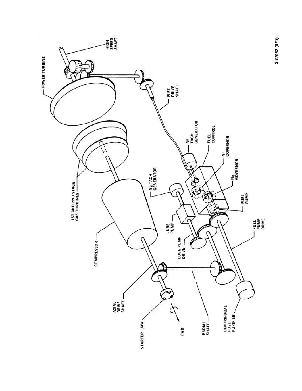
Figure 12-3. Engine Shaft Diagram
12-15
ORIGINAL
NAVAIR 01-230HLH-1
12.13 SINGLE-ENGINE LANDING
(LAND OR
SHIP)
8. Ground contact.
During single-engine operation, fuel may be used
a. Attitude
- LEVEL TO SLIGHTLY NOSE
from the forward and aft tank systems or from one tank
HIGH (MAXIMUM 1° TO 2°).
system at a time. When using fuel from both tank
systems, it is possible that fuel will actually be supplied
b. Collective pitch lever
- REDUCE SLOWLY,
from one tank system only. This can occur if the difference
SIMULTANEOUSLY MOVING CYCLIC STICK
in the normal operating pressure of the boost pumps in one
SLIGHTLY FORWARD OF NEUTRAL.
tank is enough to close the check valve, downstream of the
weaker pumps. Therefore, the fuel quantity gauges should
9. Apply wheelbrakes to lessen ground roll; do not use
be monitored; if fuel is being consumed at an unequal rate,
cyclic for aerodynamic braking.
use crossfeed procedures to adjust tank quantities.
The helicopter may be flown safely in forward flight
and landed on a single engine, provided that the proper
techniques and safety precautions are observed (see Figure
12-4). Under conditions of a single engine, advance the
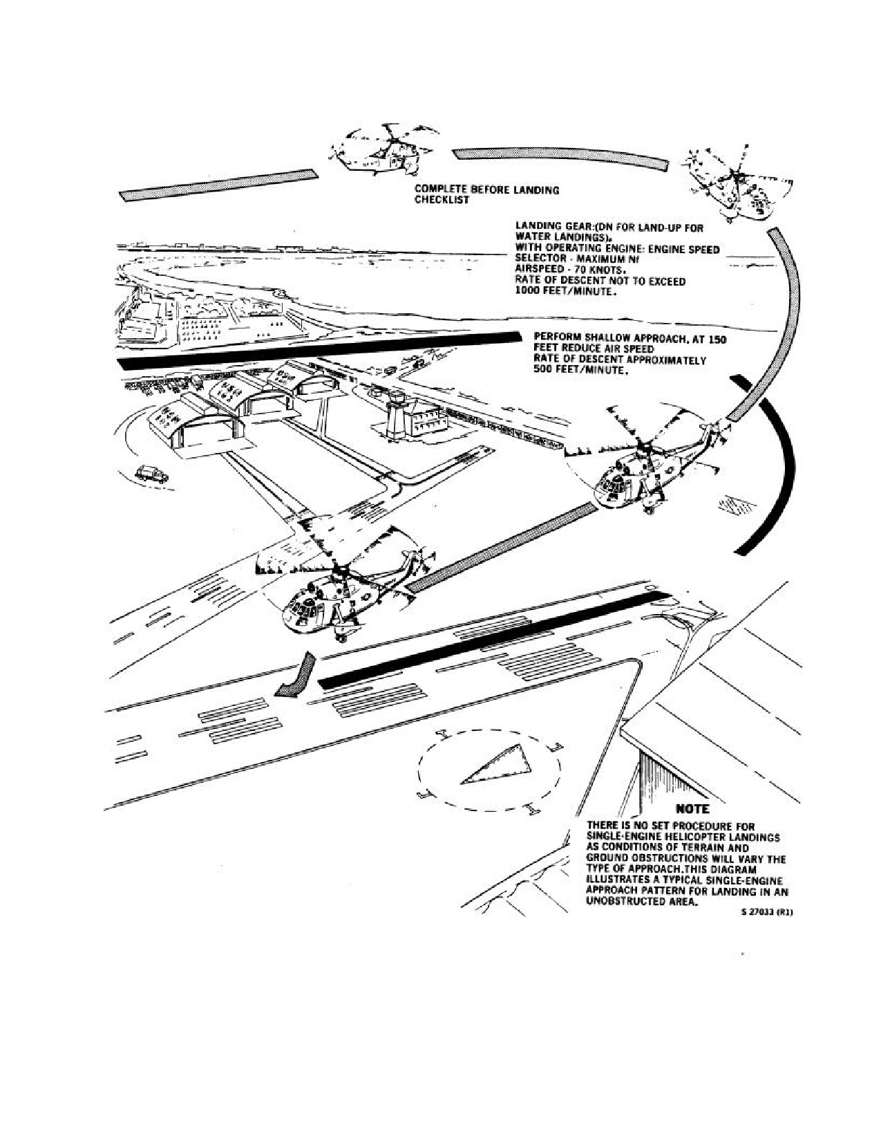
The procedure described is for a typical
engine speed selector full forward and attempt to maintain
single-engine landing and is also applicable
70 KIAS and
100-percent Nr. Observe single-engine
to single-engine landings in confined areas,
limitations. When the good engine is operating at topping,
such as nonaviation ships with small landing
further increasing the collective will only result in rotor
areas and unprepared sites. The dangers of
rpm decreasing. Because of a loss of lift in a turn, steep
excessive speed, excessive sink rates,
turns should be avoided, particularly at a low level during
extreme tailwheel low touchdown, and the
an approach for landing. Under conditions of low gross
tendency to use aft cyclic shall be
weight, light fuel load, low density altitude, and
emphasized when making landings of this
appreciable winds (10 to 20 knots), a normal approach to a
type. Maximum control of the helicopter is
hover and a vertical landing may be made on a single
required to perform this maneuver. Avoid
engine. However, with conditions of high gross weight,
abrupt control movements of either the
medium to heavy fuel load, fairly high density altitude, and
cyclic or collective and be especially aware
little or no wind, a run-on landing must be made to prevent
of the attitude and groundspeed on
a high rate of descent. All single-engine landings should be
touchdown.
on a smooth, hard surface area. The following procedures
are indicated:
12.13.1 Single-Engine Waveoff.
1. Before landing check - COMPLETED.
*1. Contain Nr utilizing ground effect as necessary.
2. Engine speed selector
(for operative engine)
-
*2. Lower nose to horizon to accelerate to 60 KIAS.
FULL FORWARD.
*3. Resume normal climb attitude of 2° to 3° noseup.
3. Approach airspeed - 70 KNOTS.
12.14 DUAL-ENGINE FAILURE
4. Establish a rate of descent not to be over 1,000 fpm
and reduce to 500 fpm on straightaway.
Failure of both engines requires immediate action if a
safe power-off landing is to be accomplished. The altitude
5. At about 150 feet altitude, reduce airspeed and rate
and airspeed at which a two-engine failure occurs will
of descent.
dictate the action to be taken. Immediately upon a two-
engine failure, rotary wing rpm will decay and the
6. Continue approach so as to arrive at an attitude not
helicopter will yaw to the left. Collective pitch must be
to be over 5° nose high about 10 feet above the deck
immediately educed to prevent excessive loss of rotary
and 0 to 40 knots groundspeed.
wing rpm, and right rotary rudder should be applied to
compensate for loss of torque to control heading.
7. Increase collective pitch slightly to cushion the
landing.
12-16
ORIGINAL
NAVAIR 01-230HLH-1
Figure 12-4. Single-Engine Landing (Typical)
12-17
ORIGINAL
NAVAIR 01-230HLH-1
If at low airspeed and high power setting, apply
airspeed combination and the in-flight altitude is sufficient
forward cyclic stick in an attempt to regain airspeed
to permit selection of a suitable landing area.
(minimum of 70 knots). This action normally requires 400
to 500 feet of altitude if the recovery is initiated at zero
*1. Autorotate.
airspeed.
*2. Jettison External Load as required.
In a condition of high power and high airspeed, a
moderate flare will reduce loss of altitude while making a
*3. Landing gear as required.
recovery and entry into autorotation. At high airspeeds if a
constant airspeed is maintained while normal recovery
*4. Harness locked.
procedures are being used, a loss of about 300 to 500 feet
of altitude will result. The altitude loss may be reduced by
*5. Mayday/IFF.
simultaneously applying aft cyclic stick as the collective
pitch is reduced. Judicious use of collective pitch during
12.15 MAXIMUM GLIDE
the flare to keep rotary wing rpm within limits also reduces
the loss.
Maximum autorotative gliding distance is obtained at
100 KIAS and about 104-percent rotary wing speed. The
rate of descent will be about 2,400 fpm. Increased rotary
wing speed above these values will result in a greater rate
WARNING
of descent, resulting in reduced gliding distances.
12.16 LANDING IN TREES
Rotor rpm will decay to an unrecoverable
state with resultant loss of control unless
A power-off landing into a heavily wooded area can
autorotation is entered immediately.
be made by executing a normal autorotative approach and
full flare. The flare should be executed so as to reach zero
rate of descent and zero groundspeed as close to the top of
trees as possible. As the helicopter settles, increase
collective pitch to maximum and allow the helicopter to
descend vertically through the trees.
Avoid abrupt control movements during
12.17 EMERGENCY DESCENT
high-speed autorotation to preclude rotor
overspeed and/or blade stall. Blade stall is
During an extreme emergency, the condition or type
more likely to be encountered when
of landing area may determine the type of emergency
operating in rough air.
descent to be made. If a long distance must be covered to a
selected landing site, a dive with power would be most
12.14.1 Dual-Engine Failure While Hovering at
feasible. A normal power-on vertical landing may be made
Low Altitude. Settling will be so rapid if both engines
when the landing site is reached. If a short distance must
fail at low altitude that little can be done to avoid a hard
be covered to a selected landing site, attaining a rapid rate
landing. The landing can be cushioned somewhat by
of descent with no power, minimum pitch, and slow
increasing collective pitch as the helicopter settles to the
forward speed is the most practical means of
ground. Do not reduce collective pitch as in normal
accomplishing an emergency descent.
procedures in case of both engines failing at higher
altitude. In this case, a reduction of pitch would cause the
12.18 MAIN GEARBOX SYSTEM FAILURE
helicopter to settle more rapidly. The helicopter should be
held in a level attitude and, when contact is made with the
When massive loss of MGB oil occurs, an immediate
ground, the cyclic stick should be moved slightly forward
landing should be made. Continuing to fly the helicopter,
of the neutral position. Regardless of the force with which
even for a short time, will further jeopardize the helicopter
the helicopter strikes the ground, damage will be much less
and crew.
if it strikes level. After contact with the ground is made,
reduce collective pitch to minimum, apply rotor brake, and
If an abnormal gearbox noise is heard, check all
secure engines.
instruments. If the noise persists, monitor the instruments
for an adverse indication. If an adverse condition is
12.14.2 Dual-Engine Failure During Flight
indicated, land as soon as possible or make an immediate
(Autorotative Landing). In case of a dual-engine failure
landing.
during flight, a safe autorotative landing can be made
provided the helicopter is being flown at a safe altitude
12-18
ORIGINAL
NAVAIR 01-230HLH-1
Note
immediately: TRANS OIL PRESS caution light ON,
transmission oil pressure indicator below low-limit red
Loss of the primary transmission oil pump
line, torque needles for both engines fluctuating or
will be accompanied by malfunctioning
indicating zero, yaw kicks, and a possible indication of
torque indications if the common drive shaft
high transmission oil temperature.
has failed. Failure of the secondary
transmission oil pump will also result in a
pressure decrease and may be accompanied
by failure of the utility hydraulic pump. In
either case, safe flight may be continued
WARNING
since one oil pump will adequately lubricate
the main gearbox. Land as soon as
practicable.
In the event of a transmission oil loss
situation with the emergency lubrication
If any one of the following conditions occurs, land as soon
system functioning, it is critical to maintain
as practicable.
balanced flight and to avoid excessive air-
craft attitudes. Proper operation of the ELS
1. TRANS OIL PRESS caution light ON and
is attitude-dependent and the aircraft should
indicated pressure within limits.
be maintained as level as possible in
balanced flight to minimize oil loss.
2. TRANS OIL HOT caution light ON and indicated
temperature within limits.
3. Helicopters modified by AFC 368 (the emergency
lubrication system) may continue flight for a limited
3. CHIP DETECTOR caution light ON.
time to reach a safe landing site. The emergency
lubrication system may become inoperative within 2
4. Unreliable
MGB temperature or pressure
minutes following a rupture in either the main system
indications not supported by respective caution light.
or ELS (i.e., to a filter assembly or to the torquemeter
filter bowl) that results in the sudden massive loss of
If the following occurs, land as soon as possible.
all gearbox oil. The ELS activates when oil pressure at
the input sleeve bearings falls below 20 to 25 psi on the
1. Indication of low pressure plus an indication of
oil pressure gauge. Upon complete failure of the main
high temperature.
lubrication system the oil pressure falls to zero, the oil
pressure caution light goes on, and the oil temperature
2. The MGB oil temperature rises above the red line.
indicator gives an erroneously low temperature. During
If in a hover, an emergency action may be averted by
ELS operation, indicated torque reading will be lower
entering forward flight when a rising temperature
than normal for any given power setting because of oil
condition is observed.
flow to the sleeve bearing as well as the torque system.
Torque readings will decrease steadily as the oil
3. If the MGB oil temperature hot light goes on and
changes viscosity because of the rising oil temperature.
the MGB oil temperature (gauge) rises toward the red
When continued flight is necessary, the following will
line (145°), and in the pilot's judgment will exceed this
allow the system to operate most effectively:
limit.
a. If in a hover over water or over a surface to
4. CHIP DETECTOR caution light on if accompanied
which a safe landing cannot be made, and with
by any other indication of MGB failure.
confirmed low pressure
(warning light on and
gauge confirmation) or if a substantial oil loss is
*If any of the following conditions occur, make an
observed and reported by the crew, transition to
immediate landing.
forward flight immediately.
1. TRANS OIL PRESS caution light ON and pres-
b. Reduce helicopter weight.
sure indicator below low limit red line.
c. Maintain level attitude. A mild right turn will
2. When it is suspected that all main gearbox oil is
minimize oil loss should a rupture in the oil system
lost or when a filter assembly or main oil line ruptures
occur. ELS operation is optimized by
resulting in sudden and massive loss of transmission
oil, complete catastrophic main gearbox failure is
imminent, and the following indications are noted
12-19
ORIGINAL
NAVAIR 01-230HLH-1
maintaining pitch limits of
3° noseup and
6°
condition. When complete loss of
nosedown and roll limits of 2° left and 4° right,
lubrication occurs, fluid ceases to pass
while keeping aircraft in balanced flight
(ball
over the temperature sensor; a rise in
centered).
temperature of the surrounding metal may
not register immediately.
d. Maintain speed at
70 to 90 KIAS to obtain
desired range and endurance.
12.18.1 Tail Takeoff Freewheel Unit Caution Light.
If the tail takeoff caution light goes on during flight, use
e. Flight
at
minimum safe altitude is
this procedure:
recommended to minimize the time required to
execute an immediate landing should it be required.
1. Speed selectors - FULL FORWARD.
Note
3. Land as soon as possible.
When terrain, obstacle clearance, and
visibility permit, descent to below 100 feet
AGL is recommended.
WARNING
f. Avoid abrupt input power or rotor load changes.
g. Decrease power smoothly and maintain level
Under no conditions should the No. 1 speed
attitude for approach and landing.
selector be retarded to shutoff during flight
when failure of the tail takeoff is indicated.
(1)
Plan to execute a roll-on landing, as 3°
In case of a No. 1 engine failure, controlled
flight would no longer be possible.
noseup attitude may not provide sufficient
deceleration to terminate in a hover.
Note
(2)
If a hover termination is required
(i.e.,
shipboard landing) and
3° noseup provides
If, after placing speed selectors to full for-
insufficient deceleration, minimize the time
ward, the TAIL TAKEOFF caution light
stays on, this indicates a failure of the tail
above the pitch limit by employing a sharp but
effective flare just prior to landing.
takeoff warning system. If the light goes out,
this indicates an actual tail takeoff free-
h. Land as soon as possib le.
wheeling unit failure.
i.
If ELS operation (as indicated by a low and
3. If caution light goes out, retard speed selectors until
TAIL TAKEOFF caution light reilluminates.
steady torque) is accompanied by loud noises from
the transmission or if either engine fails, land
immediately.
4. After landing, perform normal shutdown.
j.
Fluctuating torque readings or a zero torque
reading is indication of imminent sleeve bearing
seizure. If
either
indication occurs, land
WARNING
immediately.
Note
The No. 1 engine shall not be shut down
before stopping the rotor to preclude loss of
In the above situation, the transmission
servo pressures.
oil temperature indicator may not
immediately indicate
the
adverse
12-20
ORIGINAL
NAVAIR 01-230HLH-1
12.18.2
Torque Sensing System Failure
12.19.1 Blade Pressure Caution Light.
If the blade pressure caution light illuminates, the blade
pressure circuit breaker should be checked in. Because of
the sensitivity of the system, the caution light may
illuminate because of electromagnetic interference (EMI),
giving the pilot a false indication of impending spar
failure. If the blade pressure caution light remains on with
the blade pressure circuit breaker in and EMI is not
verified:
In flight:
*1. Airspeed - 80 KIAS, minimize maneuvering.
*2. Altitude - Minimum safe.
*3. Blade Pressure Circuit Breaker - Check in.
*4. Land as soon as practicable. Do not exceed 2
hours unless necessary to reach a safe landing
site.
On ground:
If all spar pressure indicators are white, but the blade
pressure caution light remains illuminated or the IBIS
caution bit is unsatisfactory, a malfunction in the radiation
detector of the signal processor is indicated.
The
helicopter may then be flown in either of the following
profiles before landing for a visual inspection of the spar
pressure indicators.
Profile A - For all gross weights up to 20,500 pounds:
Max Airspeed Required Inspection
Interval (Hours)
(KIAS)
100 Percent Nr
103 Percent Nr
80
4
4
90
3
4
100
2
2
110
1
1.5
Note
120
0.75
1.0
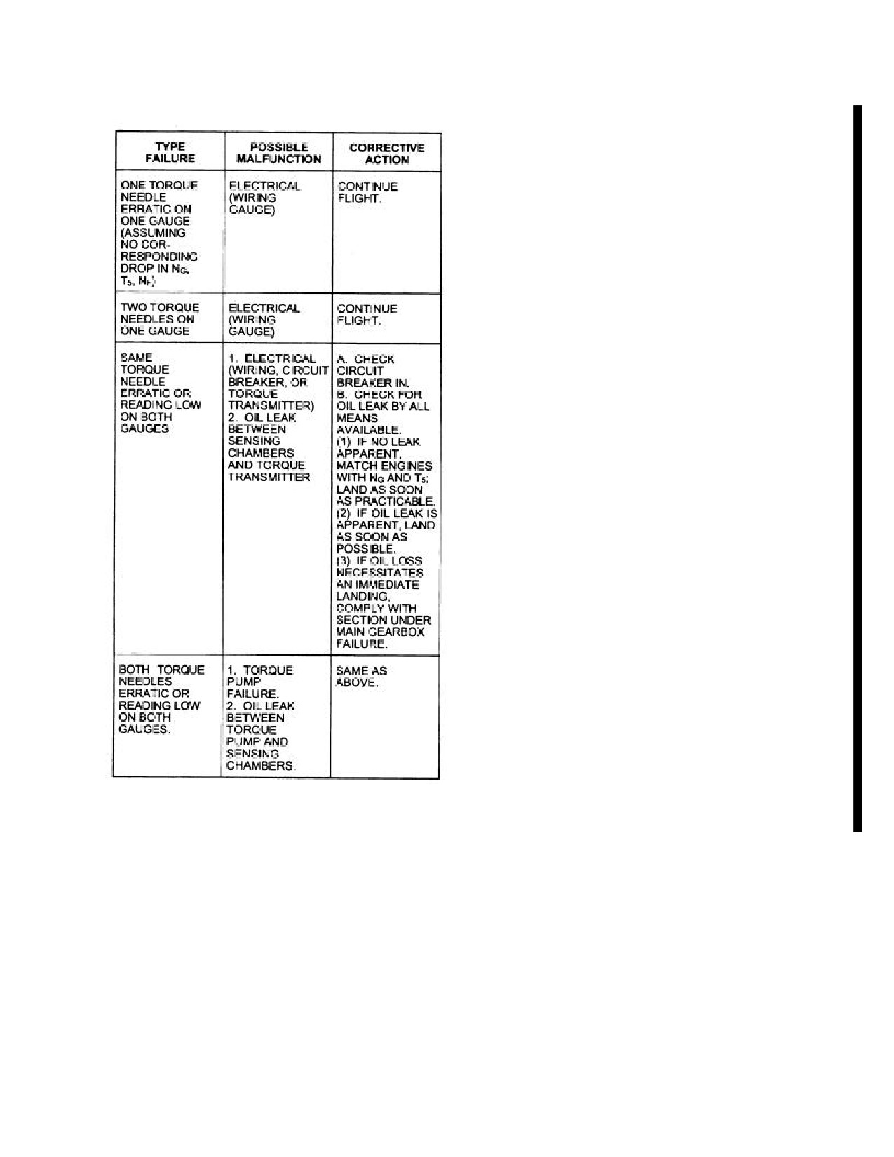
The preceding malfunctions assume torque
12.20 ROTARY RUDDER SYSTEM FAILURES
needle
fluctuations
only with no
corresponding fluctuations on any other
Rotary rudder system failures can be generally
engine instrument.
classified as drive system failure or as control system
failure. The information that follows is based on flight
12.19 MAIN ROTOR OVERSPEED
tests in which a drive system failure resulting in loss of the
rotary rudder thrust was simulated. In either case, very
If Nr exceeds 117 percent, land as soon as practicable.
little factual data can be drawn from this experience.
Consequences of rotary rudder failure may vary widely
and will require the utmost in pilot technique. The case of
a control system failure is believed to be less critical than
drive system failure and was not covered during the tests.
12-21
ORIGINAL
NAVAIR 01-230HLH-1
WARNING
50° can be expected. Immediate entry into autorotation
will reduce the yaw angle.
Impending rotary rudder system failure may
be indicated by a loud "thump", "bang",
*1. Autorotate.
"whine", or "grinding" appearing to emanate
from the aft section of the main
*2. Jettison External Load as required.
transmission. Secondary indications may
include torque fluctuations of up to 15 per-
*3. Landing gear - AS REQUIRED.
cent
(without corresponding Ng or T5
fluctuations),
and/or airframe shuffle.
*4. Harness - LOCKED.
Imminent failure may be indicated by an
increase in the noise level from the
*5. Mayday/IFF.
accessory section or an undetermined
location within the transmission. Land
*6. Proceed as follows:
immediately.
a. If enough altitude is present at time of
Note
autorotation, the pilot can minimize helicopter yaw
to near balanced flight by assuming a new
Rotary rudder servo failure may give a
flightpath based upon helicopter heading after
hardover input in either direction and could
initial yaw. Initiate a flare at about
150 feet to
be confused with rotary rudder system
reduce rate of descent and groundspeed.
failure. If the rudder pedals cannot be moved
then, turning the auxiliary servo pressure off
b. If enough altitude is not present at the time of
may restore manual control.
autorotation to assume a new helicopter flight-
path, the pilot may be forced to fly in a sideslip
12.20.1 Rotary Rudder Drive System Failure.
condition. Because of this, higher rates of descent
will be experienced and the pilot will be required to
initiate a moderate sideways flare at about 200 feet
to reduce rate of descent and groundspeed.
WARNING
*6. When desired, pilot at controls gives
the
command, “Speed selectors off”.
Extended flight is not possible after rotary
rudder drive system failure. Autorotation
Note
must be entered immediately.
·
Maintain 65 to 75 KIAS. The airspeed
A rotary rudder drive system failure, whereby rotary
indicator, although in error, will indicate
rudder rpm and thrust are lost, may be caused by fracture
the approximate airspeed.
of the shaft, coupling, or gearbox, or separation of the
rotary rudder assembly from the helicopter. Rotary rudder
·
Recovery from a rotary rudder drive
separation from the helicopter is usually caused by severe
failure in forward flight at altitudes of
vibration that has been induced by the fracture of a rotating
150 feet or below can be safely
component. A drive system failure is the most difficult
completed by executing the remaining
type for the pilot to cope with as it is accompanied by the
portion of the autorotation profile.
loss of the rotating disc area that would normally assist as
a stabilizing fin in forward flight.
·
Ground contact speed must be held to a
minimum, as a sideslip condition may
Since rotary rudder drive system failure at high speeds
cause roll over on touchdown.
is expected to produce violent helicopter response,
recognition of impending failure is extremely important.
·
Loss of tail rotor authority may be
Excessive vibration or noise in the tail section usually
misinterpreted as rotary rudder drive
precedes rotary rudder drive system failure. Therefore,
system failure. This condition could be
when this occurs, airspeed should be reduced immediately
encountered because of combination of
to the best autorotational speed. A rotary rudder drive
drift, turn rate, low Nr, and torque values
system failure is always accompanied by loss of
exceeding dual-engine limitations. If
directional control and a sharp yaw to the right. The rate
under these conditions directional
and amount of yaw are governed by the power applied and
instability with right rotation of the
the airspeed. The yaw tendency can only be reduced by
helicopter is encountered, immediately
immediate reduction in power. Yaw angles in excess of
reduce collective and transition into
12-22
ORIGINAL
NAVAIR 01-230HLH-1
forward flight to restore directional
CORRECTIVE ACTION
stability.
Control inputs using both sets of rudder pedals should
12.20.2 Rotary Rudder Drive System Failure
be attempted. It is possible that only one pilot's controls are
While Hovering.
ineffective. If neither pilot's rudder pedals are effective,
collective to yaw mixing and ASE yaw trim should be
*1. Collective
- DECREASE TO DESCEND AND
available. The collective to yaw mixing will provide the
REDUCE RATE OF HELICOPTER ROTATION.
pilot with limited control of the tail rotor pitch through the
mechanical mixing of the collective and tail rotor controls
*2. Maintain attitude and attempt to achieve zero
that increases tail rotor pitch when collective is raised and
surface speed.
reduces tail rotor pitch when the collective is lowered. Use
ASE yaw trim to make heading changes and land as
*3. Reduce gross weight if necessary by jettisoning
practical. Readjust ASE yaw trim as necessary with
external loads.
changes in collective.
*4. At approximately 10 feet, pilot at controls gives
12.20.3.2 Rotary Rudder Control Failure at the
the command, "Speed selectors off".
Auxiliary Servo.
*5. Collective
- INCREASE AS NECESSARY TO
SYMPTOMS
CUSHION LANDING.
Rudder pedals lock up and will not respond to in-
puts, or rudder pedals go hard over in either direction and
will not respond to input in the opposite direction.
WARNING
CORRECTIVE ACTION
If the rudder pedals lock up there will be some initial
Rate of rotation is directly proportional to
confusion as to whether the malfunction is the result of an
main rotor torque; therefore, decreased
auxiliary hydraulic servo failure or a mechanical jam in the
collective will reduce main rotor torque and
flight controls. To troubleshoot the problem, secure the
thus rate of rotation. Cutting engines above
auxiliary servo. If the jam or hardover is corrected, follow
10 feet will result in very hard landings on
the procedures for flight control servo unit malfunction
land or sea and may cause loss of the
and land as soon as possible. If the jam remains, turn the
helicopter. A slower rate of descent allows
auxiliary servo back on and refer to the tail rotor control
more time to bring surface speed to zero.
cable or rod jam procedures. With the auxiliary servo off
and the cables jammed, the ASE, rotary rudder, and pedal
12.20.3 Rotary Rudder Control System Failure. A
damper are inoperative.
rotary rudder control system failure is a serious emergency
and will result in a loss of rotary rudder response. These
12.20.3.3 Rotary Rudder Control Failure Aft of
failures can be divided into three major categories:
the Auxiliary Servo. Landing the aircraft with a tail
rotor control problem aft of the auxiliary servo is difficult.
1. Failure forward of the auxiliary servo.
The ability of the pilot to control the aircraft is dependent
upon a number of factors:
2. Failure at the auxiliary servo.
1. Type of malfunction.
3. Failure aft of the auxiliary servo.
2. Weight of aircraft.
12.20.3.1 Rotary
Rudder Control Failure
Forward of the Auxiliary Servo. Rotary rudder control
3. Ambient conditions (wind, temperature, D.A.).
failure forward of the auxiliary servo occurs when the
rudder pedal linkage becomes disconnected from the
4. Tail rotor pitch when the malfunction occurred.
auxiliary servo.
5. Power required for level flight/hover.
SYMPTOMS
For the malfunction that will be discussed, the pilot
Sloppiness in rudder pedal controls; helicopter does
should troubleshoot the problem to the fullest extent
not respond to pilot/copilot rudder inputs. Helicopter may
possible and perform an aircraft controllability check. In
maintain heading at time of failure.
forward flight, the aircraft should be decelerated and
accelerated to determine what torque/airspeed combinations
12-23
ORIGINAL
NAVAIR 01-230HLH-1
give balanced flight. Also, determine the slowest airspeed
2. If aircraft is yawed to the left
- STUCK LEFT
at which the aircraft's yaw rate can be controlled. Perform
CONTROL.
simulated approaches at an altitude (500 feet AGL) that
will allow the pilot to waveoff using the cyclic to
3. If aircraft is yawed to the right - STUCK RIGHT
accelerate the aircraft and reduce aircraft yaw and yaw rate
CONTROL.
without large collective increases.
Crewmen may be able to visually check for cable
After the aircraft controllability check has been per-
movement for the following:
formed and the pilot has determined how the aircraft will
respond when a landing is attempted, the pilot should
1. Left pedal operable - BROKEN RIGHT CABLE.
determine which runway and wind combination will aid
him the most. Usually, for a left yaw condition, a right
2. Right pedal operable - BROKEN LEFT CABLE.
crosswind is desired and for a right yaw condition, a left
crosswind is desired.
WARNING
WARNING
Excessive motion of the right pedal with a
broken left cable may drive the negative
When operating in the shipboard
force gradient spring to its full right position
environment, there is the possibility that the
inducing an unrecoverable flight condition.
aircraft will veer off to either side of the
flight deck when a landing is attempted. The
3. Both pedals inoperable
- DUAL CABLE/ TOTAL
ship should maneuver to obtain maximum
CONTROL FAILURE.
winds down the centerline of the ship.
Note
The basic rule to follow when troubleshooting and
landing the aircraft is the following:
Separation of a single cable can become a
stuck cable condition because of the
1. To yaw the aircraft right, raise the collective
tendency of the steel cable to "bird nest".
RAISE RIGHT.
HOVER
2. To yaw the aircraft left, lower the collective
LOWER LEFT.
1. Remain in hover.
Failures aft of the auxiliary servo are divided into
2. Use forward flight troubleshooting techniques.
three categories:
12.20.3.3.2
Stuck/Jammed Flight Control
1. Control cable or control rod jam.
Cable/Rod. If a jam occurs in any part of tail rotor
control system aft of the mixing unit, the pilot will have no
2. Total control failures - Either dual-cable separation
control of the tail rotor pitch. Collective to yaw mixing and
or control tube failure.
rudder pedals will be ineffective. The torque and flight
regime where the jam occurred should be noted. Most
3. Single control cable separation.
likely, the approach and landing will have to be attempted
at this same combination of airspeed and torque. The pitch
12.20.3.3.1 Troubleshooting. If possible, perform
at which the jam occurs is directly related to the difficulty
troubleshooting in the flight regime where the malfunction
of controlling and safely landing the aircraft. Extreme
occurred. If in a hover, do not transition to forward flight -
difficulty will be encountered landing the aircraft during
LAND AS SOON AS POSSIBLE. When troubleshooting,
stuck conditions at both extremely high (left pedal) and
leave ASE on with the ASE yaw channel off. Troubleshoot
low (right pedal) values of pitch. For stuck tail rotor
as follows:
control that occurs at high torque and airspeed conditions,
it may be necessary to maneuver the aircraft to less than 40
FORWARD FLIGHT
KIAS using a cyclic flare in order to fly the aircraft in near
balanced flight at a combination of slow airspeed and high
1. Fly 80 KIAS level flight.
torque/power setting.
12-24
ORIGINAL
NAVAIR 01-230HLH-1
Note
lowered, the aircraft will yaw left. On roll-out, a
coordinated reduction in Nr and adjustment of the
Testing has shown that in forward flight for
collective will be necessary to control aircraft heading
stuck control conditions, changes in Nr
until brake control becomes effective.
within NATOPS limits has minimal effect
on aircraft sideslip and yaw rate.
5. Waveoff is possible using minimal power changes.
Stuck tail rotor control full right is a more serious
12.20.3.3.4 Stuck Right. The amount of right pitch
emergency condition than tail drive shaft failure. If a tail
determines the severity of the emergency. For a stuck right
drive shaft failure occurs, the yawing moment from the
condition it should be possible to execute multiple practice
main rotor to the aircraft can be removed by lowering the
approaches at altitude. The approaches should be made at
collective and entering an autorotation. During a stuck full
successively slower airspeeds to determine the slowest
right control condition, the yawing moment from the tail
airspeed and minimum rate of descent at which the aircraft
rotor cannot be removed. Entering an autorotation and
can be leveled off and controllable flight maintained. The
securing the aircraft's engines will not remove the yawing
altitude to which these approaches are made must be
moment that the fixed pitch of the tail rotor is applying to
sufficient enough to permit waveoff by increasing airspeed
the aircraft.
and making minimal power changes. The following
procedures apply to all gross weights; however, a lighter
12.20.3.3.3 Stuck Left. For a stuck left condition it
gross weight is desirable.
should be possible to execute multiple practice approaches
at altitude above the selected landing area. These
approaches are made at successively slower airspeeds to
determine what the slowest airspeed and minimum rate of
WARNING
descent at which the aircraft can be leveled off and
controllable flight maintained. The altitude to which these
approaches are made must be sufficient enough to permit
waveoff by increasing airspeed and making minimal power
During landing, if collective is applied to
changes. If running landing is attempted, aligning the
decrease the aircraft sink rate, the aircraft
aircraft with the runway and maintaining aircraft sideslip
will
yaw right and may become
in touchdown will be difficult. Waveoff is possible with
unrecoverable.
small power changes. Avoid excessive delays in executing
a landing. The following procedures apply to all gross
1. Execute practice approaches to determine the
weights; however, a higher gross weight is desirable.
airspeeds/torque combination that gives minimum sink
rate and the smallest possible aircraft sideslip.
1. Execute practice approaches at successively slower
airspeeds to determine lowest airspeed and rate of
2. Plan the approach to arrive at the intended point of
descent combination.
landing at the minimum power and airspeed required
for flight
(usually best single-engine airspeed
-
70
2. Plan approach to arrive at the intended point of
KIAS).
landing at the minimum airspeed and rate of descent
determined during practice approaches. It may be
3. Expect a high rate of descent on touchdown.
necessary to use a cyclic only climb to slow the aircraft
while maintaining constant collective.
4. After touchdown, smoothly lower the collective and
retard speed selectors to GRD IDLE.
5. Waveoff is possible using minimal power changes.
WARNING
12.20.3.3.5 Stuck Pedal
- Hover. In a stuck pedal
condition, expect the aircraft to develop a slow yaw.
Reducing collective with a stuck left pedal
1. Left yaw - Keep engine on.
condition may induce an unrecoverable left
yaw.
2. Right yaw
- If it cannot be controlled with
collective, shut engines down and handle like loss of
3. Use “raise-right and lower-left” method to align the
tail drive.
aircraft with the runway.
3. Attempt landing on a flat open surface.
4. After touchdown, use brakes and small collective
inputs to control aircraft yaw. If collective is rapidly
12-25
ORIGINAL
NAVAIR 01-230HLH-1
4. Expect to land with a yaw rate. Use cyclic to
If landing from a hover, close coordination is required
minimize drift.
between
pilot
and
copilot.
Each collective
increase/decrease will need to be countered by speed
5. After touchdown, use cyclic to maintain aircraft
selector adjustments. Advancing speed selectors will yaw
upright and brakes to stop yaw.
the aircraft right, retarding them will yaw the aircraft left.
12.20.3.3.6 Dual Cable/Total Tail Rotor Control
5. After touchdown, use brakes to slow any yaw rate
Failure. With a dual cable/total tail rotor control failure
and follow aircraft with cyclic to reduce drift. Aircraft
the tail rotor will seek a balance point of blade pitch that is
heading may be maintained with coordinated use of
the result of the combination of NFG spring forces, tail
collective and Nr control.
rotor blades, blade aerodynamic forces, and blade inertial
forces (streamlining of the tail rotor blades). The aircraft
12.20.3.3.7 Single Cable Failure. The pilot will still
can be flown in forward flight in this condition between 30
have either left or right pedal, depending on which cable
and 120 knots and at near balanced flight at 70 to 90 knots.
failed. Failed cable could become stuck cable because of
bird nesting. Tail rotor will seek the same pitch as with
LANDING TECHNIQUE
total control failure.
Note
BROKEN RIGHT
Lighter gross weights are recommended.
If right cable is broken, you will have tail rotor control
from approximately midtravel to full left pedal. High gross
1. Initiate an approach at airspeed greater than the
weights are desirable and planning the approach to make
minimum airspeed determined at altitude.
left turns will aid in a safe landing.
2. Approaching the intended point of landing, begin to
1. Plan a long, shallow 70-knot approach.
decelerate towards the established minimum airspeed
as the copilot retards the speed selectors toward 94-
2. Prior to reaching the intended point of landing,
percent Nr.
decrease airspeed using cyclic only and maintain power
setting.
3. As airspeed decreases toward the hover, follow the
ensuing left turn with cyclic. Expect a higher than
WARNING
normal hover.
4. From a high hover, make small collective changes
If airspeed is allowed to decrease below the
to decrease altitude.
minimum determined during practice
approaches, waveoff may not be possible.
5. On deck, execute a normal shutdown.
3. Touch down at the minimum speed at which the
6. Waveoff will be possible.
yaw control can be maintained.
BROKEN LEFT
4. If yaw rate becomes excessive and a safe running
landing or waveoff is not possible, entering a hover is
Broken left cable range of control will be from
the best course of action.
approximately midpitch to full right pedal.
WARNING
WARNING
Retarding the speed selectors below
92-
Excessive motion of the right pedal can
percent Nr may result in loss of control.
cause a stuck full right pedal situation, an
unrecoverable flight condition, necessitating
Note
a full autorotation.
It may be possible to hover with no yaw at
Best recovery situation is with lighter gross weights.
94-percent Nr.
Use minimal power and fast landing speeds (up to 80
12-26
ORIGINAL
NAVAIR 01-230HLH-1
KIAS). Waveoff is not an option, you have only one
rudder pedals. Secondary indications may
chance. Successful landing rollout is possible using small
include torque fluctuations, yaw kicks,
collective changes, pedals, and differential braking. During
and/or airframe shuffle.
a running landing, aircraft will veer when collective is
lowered.
12.20.5 Tail Pylon Unlock Light.
Note
SYMPTOM
After careful consideration of available
Flickering or steady pylon unlock light.
landing areas and speed at which a running
landing will be attempted, best course of
action may be a full autorotation.
CAUSE
12.20.4 Impending Rotary Rudder System
A steady or flickering pylon unlock light may
Failure. Illumination of either the intermediate or tail
illuminate in flight if one of the tail pylon hinges fail. The
gearbox chip lights on the caution panel is an indication of
indicator may go on during high-power regimes and go off
metallic particles on the gearbox sump plugs or an
during lower-power regimes; thus, a flickering may occur.
overheat condition in the gearbox and might be indicative
of a forthcoming rotary rudder drive system failure. If
CORRECTIVE ACTION
either intermediate or tail gearbox chip light should go on,
this action should be taken by the pilot:
*1. Avoid high power regimes.
1. Land as soon as possible. Descent and approach
*2. Land as soon as possible.
should be made with minimum power to aid entry into
autorotation if rotary rudder drive failure occurs. A
*3. If secondary indications exists
- LAND
running or no-hover landing using minimum power
IMMEDIATELY.
should be executed as conditions dictate.
12.21 ELECTRICAL MALFUNCTION
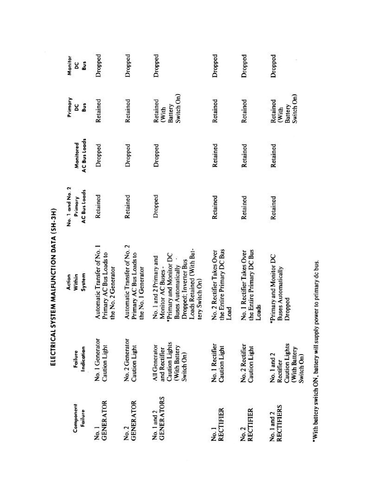
See Figure 12-5.
WARNING
12.21.1 Alternating Current System Failure. The
ac system is powered by two ac generators. If either
generator fails, its primary bus load is automatically
High power settings require maximum
transferred to the remaining generator. With a failed
performance of the rotary rudder drive
generator, all monitor bus loads (ac and dc) are automat-
system and may precipitate ultimate drive
ically dropped. For indications of malfunctions in the ac
failure.
electrical system, see Figure 12-5.
2. At night, over water or rough terrain where a
Note
suitable landing site is not immediately available, attain
a safe autorotation altitude and airspeed. Use
Gauges powered by ac electrical current
flood/hover/spotlights as necessary.
tend to freeze when electrical power has
been interrupted. Indicator needle can move
3. If, along with the chip light going on, there are
from the vertical position in either direction,
strong intermediate frequency vibrations, hot metal
with time and vibration. Erroneous indications
fumes in the pylon or after station area, or any other
should be expected.
indications of impending rotary rudder failure, land
immediately.
12.21.1.1 Generator Failure. If No. 1 and/or No. 2
generator caution light is ON:
1. Move generator switch corresponding to the
generator caution light to OFF/RESET; then on and
WARNING
release.
Impending rotary rudder system failure may
be indicated by "grinding" or vibrations
from the tail section and may be felt on the
12-27
ORIGINAL
NAVAIR 01-230HLH-1
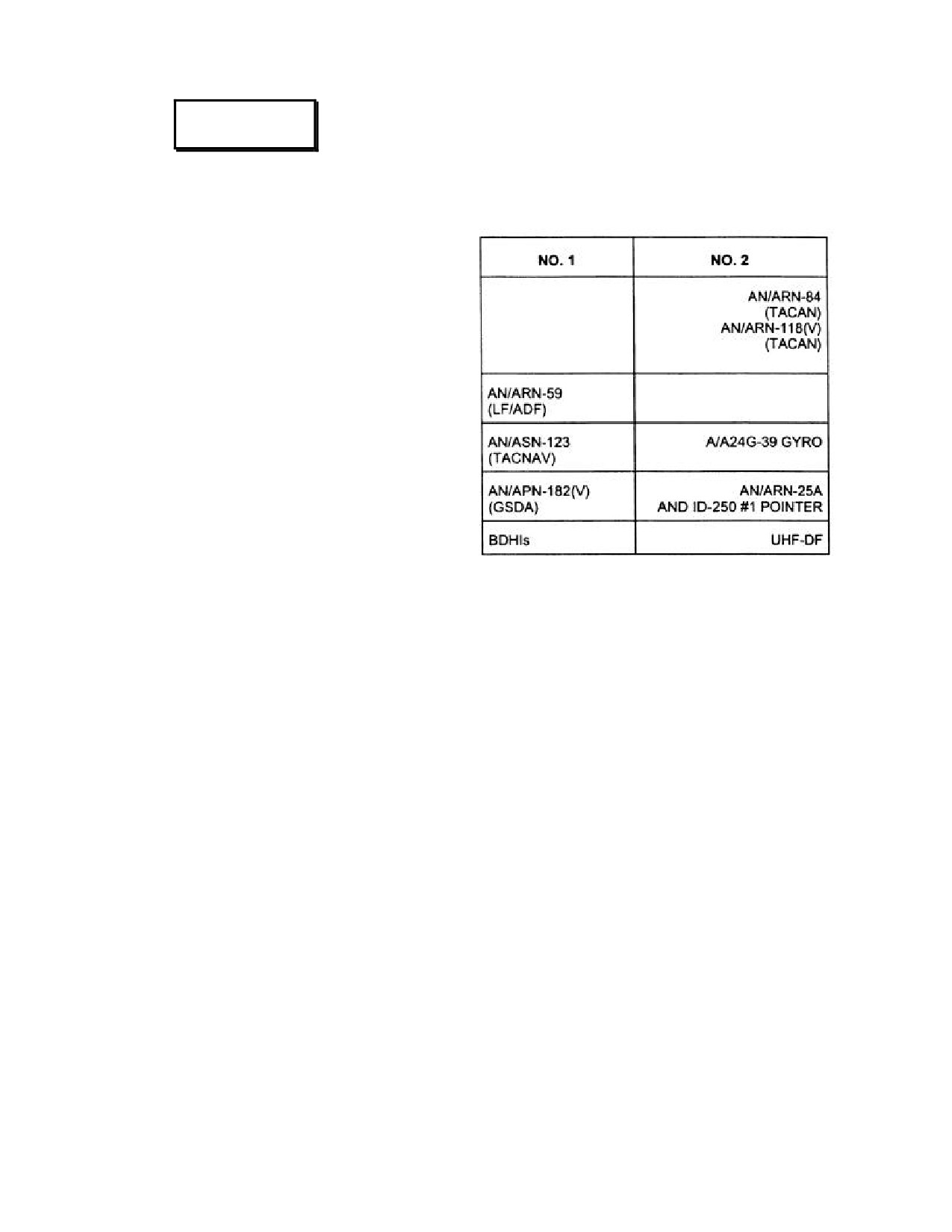
12.21.1.2 Radio Transformer Failure. Two 26-vac
WARNING
radio transformers, designated Nos. 1 and 2, are powered
by the No. 1 ac primary bus and protected by circuit
· Generator failure, if caused by a
breakers marked AUTO XMFR 1 and 2 under the general
mechanical malfunction of the generator,
heading RADIO on the copilot circuit breaker panel. The
can become a potential fire hazard.
transformers supply power to these systems:
· Do not recycle a failed generator in a
coupled hover at night IMC. Depart the
hover and recycle the generator at a safe
altitude to lessen adverse coupler inputs
and preclude the chance of pilot
disorientation.
2. If generator output is not restored, cycle switch to
OFF, secure unnecessary equipment, and land as soon
as practicable.
3. If both generators fail and output cannot be re -
stored, cycle switches to OFF, secure unnecessary
equipment, and land as soon as possible.
Note
·
If either generator should fail while the
heater is on, the heater blower will be
dropped. A presence of heater exhaust
Failure of the equipment associated with a respective
fumes and fuel odor in the cabin or cock-
transformer is an indication of failure of the transformer or
pit may be noted.
that the circuit breaker has opened. Attempt to restore
operation of the transformer by resetting the circuit
·
If the No.
1 generator fails while
breaker.
hovering with coupler engaged, a
transient down signal may be introduced
12.21.1.3 Electrical Transformer Failure. The
into the coupler causing a momentary
electrical autotransformer powered by the No. 1 ac primary
loss of 10 to 12 feet of altitude. If this
bus is protected by a circuit breaker marked AUTO XMFR
condition occurs, do not shut off ASE as
phase C on the copilot circuit breaker panel. This
the No. 2 generator will take over the
transformer supplies power to the No.
1 torquemeter
load and return the helicopter to the
indicator, No.
1 engine oil pressure indicator, primary
original altitude. The transient signal will
hydraulic pressure indicator, and utility hydraulic pressure
disappear about 2 seconds after the No. 2
indicator. Failure of all of the above indicators is an
generator takes over.
indication of failure of the transformer or that the circuit
breaker has opened. Attempt to restore operation of the
transformer by resetting the circuit breaker.
The isolation transformer powered by the No. 2 ac
primary bus is protected by a circuit breaker marked
XMFR No. 2 phase C on the pilot circuit breaker panel.
This transformer supplies power to the No. 2 torquemeter
indicator, No. 2 engine oil pressure indicator, transmission
oil pressure indicator, and auxiliary hydraulic pressure
indicator. Failure of all of the above indicators is an
indication of failure of the transformer or that the circuit
breaker has opened. Attempt to restore operation of the
transformer by resetting the circuit breaker.
12-28
ORIGINAL
NAVAIR 01-230HLH-1
Figure 12-5. Electrical System Malfunction Data
12-29
ORIGINAL
NAVAIR 01-230HLH-1
12.21.2 Direct Current System Failure. Direct
· If both generators fail, equipment using
current is supplied to the dc primary and monitor buses by
ac and dc will not be operational but
two rectifiers. The system is so designed that failure of
will continue to draw dc power. If both
either rectifier will be indicated by lighting of the
rectifiers fail, equipment using ac and dc
respective caution light and will cause the dc monitor bus
power will be operational until battery
to be dropped from the system. If both rectifiers fail, the
exhaustion.
primary bus will be powered by the battery only. For
indications of malfunctions in the dc electrical system, see
12.21.2.2 Battery Overheat. An overheated NI-CD
Figure 12-5.
aircraft battery is generally signaled by one of the
following conditions: smoke or fumes emanating from the
12.21.2.1 Rectifier Failure. If No.
1 or No. 2
battery compartment or battery vent tubes, sound de-
rectifier caution light is ON:
scribed as a "bang" or "thud" coming from the battery
compartment, or electrolyte leakage in the battery
1. Check rectifier circuit breaker.
compartment area or from the battery vent tubes. If any of
these conditions occur, secure the battery from the
2. Land as soon as practicable.
charging source by placing the battery switch off. If on the
deck, the helicopter should be secured and the crash crew
If Nos. 1 and 2 rectifier caution lights are ON:
alerted. If airborne, the helicopter should land as soon as
practicable and the crash crew should be alerted.
1. Check rectifier circuit breakers.
2. Secure u n necessary electrical equipment; land as
soon as possible.
WARNING
Note
· When both generators or rectifiers fail, the
battery is the only source of dc power available,
In no case should a C02 fire extinguisher be
and, accordingly, all equipment not absolutely
directed into a battery compartment to effect
necessary should be turned off by pulling the
cooling or to displace explosive gases. The
applicable circuit breakers. Under normal
static electricity generated by the discharge
conditions, the battery will provide enough power
of
the
extinguisher
could explode
to operate essential equipment required for flight
hydrogen/oxygen gases
trapped in the
for about 15 minutes. The following equipment
battery compartment. Use water fog for
requires ac and dc power:
cooling and displacement of explosive
gases. C02 is an acceptable fire extinguisher
NO. 1 FUEL PUMP
CREW ICS
agent once a fire has developed.
ADF
CONTROL FWD TANK
12.22 FLIGHT CONTROL HYDRAULIC SERVO
AFCS
NO. 1 FUEL PUMP
HEATER
SYSTEM
CONTROL AFT TANK
FUEL DUMP
NO. 2 ENG INLET ANTI-ICE
WINDSHIELD
12.22.1 Flight Control Malfunction. Indications of
PUMP
DEICE
flight control problems may be the result of one of many
IFF RT
NO. 2 ENG IGV ANTI-ICE
RAD ALT
different systems failures or malfunctions. Gyro failure
may cause deviations in roll and pitch, and ASE failure or
OTPI
NO. 1 ENG ANTI-ICE
TACNAV
malfunction may cause partial or full hardovers in pitch,
MK 46
NO. 1 ENG INLET ANTI-ICE
TACAN
roll, yaw, and collective pitch. Auxiliary hydraulic servo
system failure or malfunction may cause partial or full
lockup in pitch, roll, yaw, or collective. Primary servo
system failure or malfunction may cause partial or full
lockup in pitch, roll, and collective. It is most important
that the pilot be able to recognize impending failure,
distinguish between types of malfunctions, and take
immediate corrective action. It is possible that in some
cases the ASE could mask a malfunction in the auxiliary
servo system. When experiencing a flight control
malfunction and not able to make an immediate
determination of cause, the most prudent action, flight
12-30
ORIGINAL
NAVAIR 01-230HLH-1
regime permitting, would be to secure the auxiliary servo.
12.22.3 Illumination of Servo System Caution
Once the auxiliary servo is secured, investigate for further
Light.
control malfunctions.
1. Affected system, press circuit breaker - IN.
12.22.1.1 System Failure. Control of the helicopter
can be maintained through either the primary or the
2. Affected system pressure gauge - CHECK.
auxiliary flight control hydraulic servo system if one or the
other should fail; however, prolonged operation on one
If pressure is below normal:
servo system is not recommended. This is a serious
emergency because control is impossible with both servo
3. System - SECURE.
systems inoperative; a flight condition and flight route
should be chosen so as to make an immediate landing if
4. Land as soon as possible.
warranted. If the conditions do not warrant an immediate
landing, land as soon as possible. With the auxiliary servo
If pressure is normal:
system inoperative, the automatic stabilization equipment
and rotary rudder pedal damper becomes inoperative.
3. Land as soon as possible.
12.22.2 Servo Hydraulic Pressure Failure. Loss of
hydraulic pressure of either the primary or auxiliary servo
systems will be indicated by the lighting of either of the
servo hydraulic low-pressure caution lights and/or lower
WARNING
than normal operating pressure on the corresponding servo
hydraulic pressure gauge. When this condition occurs,
proceed as follows:
Illumination of the light is provided by the
1,000-psi switch that interconnects the two
*1. Position the flight control servo switch to turn off
servo systems. Failure of one servo system
the affected system.
1,000-psi switch would preclude securing
the second system in case of subsequent
*2. If the system does not secure, check servo cir-
failure.
cuit breaker IN.
Note
3. Land as soon as possible because of the serious
control problems that would arise should the
re-
Because of the pressure switch interlock, it
maining servo fail.
is impossible to turn off one servo system
when the pressure in the other servo system
If additional malfunctions exist:
is below 1,000 psi.
4. Land immediately.
12.23 FLIGHT
CONTROLS JAMMED
OR
RESTRICTED
12.23.1 On Ground.
WARNING
1. Leave controls in position where restriction or jam
occurs.
If all generated power is lost or secured
2. Request inspection by qualified technician.
subsequent to securing a malfunctioning
hydraulic system, the battery switch should
12.23.2 In Flight.
remain ON. This will retain the electrically
operated hydraulic valve in the close
1. Land as soon as possible.
position and keep the malfunctioning servo
off the line. Because of the critical nature of
12.24 FLIGHT CONTROL SERVO UNIT
such losses, the pilot should land as soon as
MALFUNCTION
possible.
Malfunction of the rotary wing or rotary rudder servo units
during flight will result in erratic behavior of the
helicopter, roughness, uncontrollable maneuvers, or
locking of the cyclic stick and collective pitch lever.
Sometimes it is difficult to determine whether the auxiliary
12-31
ORIGINAL
NAVAIR 01-230HLH-1
or primary servo system is causing the trouble. Whenever
Another case where a servo malfunction may be
a servo unit malfunction is encountered, control difficulties
misinterpreted is the case of a blocked common return in
may be eliminated by turning off the system containing the
one channel of the auxiliary servo. Since the return line is
malfunctioning unit.
The indications of servo unit
common to all four channels, a blocked return would give
malfunction can be divided into two categories: coupled
a coupled reaction although it may not necessarily involve
indications and uncoupled indications.
the collective with pitch or roll. For example, it could
affect the pitch and yaw. A rule of thumb method for
12.24.1 Coupled Indications. Coupled indications
identifying a malfunctioning servo is as follows:
are felt in both collective pitch and one cyclic pitch
direction
(either fore and aft or lateral). Coupled
*1. If a single or uncoupled force (either collective
indications identify a malfunction in a primary servo unit
pitch or cyclic stick) is felt at the pilot controls without
or in the control linkage between the mixing unit and the
vibrations, shut off the auxiliary servo system. Check
primary servo units. For example, if the fore-and-aft
servo circuit breaker in if system does not secure.
primary servo unit should jam, cyclic stick motion (fore
and aft) as well as collective pitch lever motion would be
*2. If vibratory force with or without a coupled
free to move within the limits of the auxiliary servo sloppy
indication is felt in the flight controls, then turn off the
link but additional control movement would be possible
primary servo system. Check servo circuit breaker in if
only by trading off cyclic stick fore-or-aft motion for
system does not secure.
collective pitch lever motion. Should control difficulty
occur in collective pitch plus one channel of cyclic pitch,
*3. If unusual forces are felt in the pedals that can-
place the flight control servo switch to PRI OFF.
not be eliminated by turning off the ASE or turning off
the yaw channel, turn off the auxiliary servo system.
12.24.2 Uncoupled Indications. Uncoupled indications
Check servo circuit breaker in if system does not
are felt either in yaw, collective pitch, or one cyclic pitch
secure.
direction
(either fore and aft or lateral). Uncoupled
indications identify a malfunction in an auxiliary servo
Note
unit or in the linkage between the flight controls in the
cockpit and the auxiliary servo units. For example, a
Once a malfunctioning servo has been
hardover in the fore-and-aft auxiliary servo unit will drive
identified and corrective action is taken, an
the cyclic stick to one extreme position (either fore or aft),
airspeed of approximately
70 knots will
and a hardover in the collective auxiliary servo unit will
minimize the control forces. However,
drive the collective pitch lever to an extreme position, or a
slower airspeeds and low altitude may be
hardover in the yaw auxiliary servo unit will drive the
dictated.
pedals to an extreme position. There is no interaction
between cyclic and collective pitch. Should control
12.24.4 Vibratory Forces.
difficulty occur in either yaw, collective pitch, or in one
channel of cyclic pitch, place the flight control servo
A malfunction in a primary servo unit or in the control
switch to AUX OFF.
linkage between the mixing unit and the primary servos
will generally be accompanied by severe vibratory forces.
12.24.3 Hardover in the Fore-and-Aft Primary
In addition, if a primary servo is displaced to an extreme
Servo or Blocked Common Return in One
position, the cyclic will move in the corresponding
Auxiliary Servo. One exception to the rule for coupled
direction and may cause movement of the collective pitch
and uncoupled indication will be a hardover in the primary
lever. The vibratory forces associated with a primary servo
servo that will overpower the auxiliary servo and drive the
malfunction are caused by the rotary wing reacting against
cyclic stick (longitudinal direction) to an extreme. At the
a frozen servo with no dampening affect. These vibrations
same time, because of the action of the mixer, a force will
will be transmitted throughout the airframe and the
be applied to the collective channel of the auxiliary servo.
controls. Should a control difficulty occur accompanied by
However, the force output of this channel is enough to
strong vibratory forces, place the servo switch to PRI OFF.
withstand the applied force and the effect will not be felt at
the collective stick. The end result is symptomatic of an
12.25 AUTOMATIC STABILIZATION EQUIPMENT
auxiliary servo hardover, but in this case is actually caused
SYSTEM FAILURE
by a primary servo malfunction. If the pilot reacted to the
situation by turning off the auxiliary servo, he would
12.25.1 Power Supply Failure. The automatic
immediately know that he had made the wrong choice
stabilization equipment and coupler system will become
since the collective stick would now be forcibly moved.
inoperative regardless of the switch positions in case of
The corrective action at this point is to shut off the primary
failure of the auxiliary servo system or both generators.
system.
12-32
ORIGINAL
NAVAIR 01-230HLH-1
12.25.2 ASE Malfunction
Should the ASE malfunction during instrument flight,
the pilot must decide whether the degree of failure
necessitates complete disengagement or whether partial
disengagement of the ASE is desirable with the pilot flying
the failed channel. Instrument flight at reduced airspeed
WARNING
(approximately 70 knots) and mildly banked turns (10° to
15°) can be made with a partial ASE malfunction. If the
ASE completely fails, the instrument flight should
be
If erratic attitude changes of increasing
terminated as soon as practical.
amplitude occur and cannot be controlled by
manual inputs, secure the auxiliary servo
Note
before securing the ASE.
With ASE off and an extreme aft cg, reduce
If automatic stabilization signals cause the helicopter to
the airspeed limits as determined from the
oscillate in pitch, roll, or yaw, or barometric altitude
Blade Stall Chart, Figure 20-5, by 25 knots.
retention is erratic, the system may be rendered inoperative
as follows:
12.25.3 Beeper Trim Malfunction.
1. Check cg trim (pitch only).
Beeper trim fails to respond, proceed as follows:
2. Check the ASE CHAN MON (hardover power)
1. Beeper trim fails to respond, proceed as follows:
switch - OFF.
a. BEEPER TRIM switch - CHECK ON.
3. Pitch or roll hardover - SWITCH GYROS.
b. BEEPER TRIM circuit breaker - CHECK IN.
a. If
hardover
remains
-
DISENGAGE
RESPECTIVE CHANNEL.
c. Landing criteria predicated on mission
or
meteorological conditions.
4. Yaw or collective hardover
- DISENGAGE
RESPECTIVE CHANNEL.
2. Beeper trim runaway in pitch or roll, proceed
as
follows:
Note
a. BEEPER TRIM switch - OFF.
· Pressing the button marked CPLR REL
will disengage the coupler.
b. Landing criteria predicated on mission
or
meteorological conditions.
· Pressing BAR OFF will release BAR
ALT if the coupler is not engaged.
12.26 UTILITY HYDRAULIC SYSTEM FAILURE
· Pressing the AUTO STAB RELEASE
The main landing gear, rescue hoist, and automatic
blade fold system will be inoperative in case of failure of
button will disengage all four channels
of the ASE system.
the utility hydraulic pump. Land as soon as practicable.
12.27 RESCUE HOIST MALFUNCTION
· Placing the flight control servo switch
in the AUX OFF position will render
In case of a malfunction of the rescue hoist, stop
ASE inoperative.
hoisting and inform the pilot. Attempt to determine the
cause of the malfunction. Check the circuit breakers,
Since the authority of the automatic stabilization
electrical switches, and connections; check the cable level
equipment on all channels is limited to a fraction of total
wind and takeup drum; and ensure utility hydraulic
control travel, any attempted emergency override of a
malfunction may normally be achieved by introducing a
pressure. Hoisting evolutions may continue if the cause of
the malfunction is positively determined to be electrical. If
control correction. The possibility of a failure that would
the malfunction cannot be identified and depending upon
not be entirely eliminated by pressing the AUTO STAB
the urgency of the hoisting evolution, the decision shall be
RELEASE button is extremely remote. When the
made by the pilot either to continue hoisting by means of
automatic stabilization equipment is nulled mechanically,
the manual hydraulic override valve or to secure hoisting.
by using the AUTO STAB RELEASE button on either
cyclic stick, all values will be centered immediately.
The manual hydraulic override should be used for
emergency situations only.
Unlike a servo malfunction, an ASE hardover in a cyclic
channel will not result in stick movement or pressure.
12-33
ORIGINAL
NAVAIR 01-230HLH-1
4. If decision is made not to lower back to the deck or
water, the Chicago grip shall be installed.
If bird's-nest does not exist:
In the manual hydraulic override mode, no
5. Check:
limit switches are operative. Do not lower
the cable past the last 10 feet as indicated by
a. Hoist master switch - CREW POSITION.
red paint.
b. Hoist circuit breaker - IN.
If the malfunction has been determined to be a jammed
cable, as with a broken level wind assembly or no utility
c. Utility hydraulic pressure - NORMAL.
hydraulic pressure, stop hoisting and secure the hoist to the
helicopter by means of the Chicago grip and crewman
d. Rescue hoist switch
(coolie hat)
- FOR
safety belt attached to the rescue hoist frame. Apply
OPERATION.
tension to the crewman safety belt, being sure to take the
strain off the cable takeup drum. In case of a personnel
e. Hoist master switch - PILOT POSITION (while
transfer, the pilot may elect to lower the helicopter and
pilot controls hoist functions, the crewman relays
deposit the individual. In case of a hook separation or
verbal commands and tends cable as normal).
broken cable, depending on the urgency of the situation,
use of the quick splice may become necessary.
f. If all checks do not correct problem, request
permission from the pilot to use manual hydraulic
override valve.
SYMPTOM
WARNING
Runaway hoist.
The quick splice will not engage upper limit
CORRECTIVE ACTION
switch; separation of the quick splice is
possible when cable reaches upper limit.
*1. Crewman…………………….Inform pilot.
*2. Pull Hoist Circuit Breaker.
Note
Note
For proper quick splice and safety belt
procedures, refer to NWP 3-50.1.
Runaway hoist malfunctions are usually
electrical in nature.
SYMPTOM
*3. Press both the up and down manual hydraulic
Hoist has stopped.
override valve buttons to ensure that valve is not
stuck open. If this step corrects function, proceed
CORRECTIVE ACTION
with hoisting using normal procedures.
1. Inform pilot.
4. If hoist cable stops once fully deployed:
2. Inspect hoist for a "bird's -nest condition”.
a. Hand-over-hand cable into afterstation and
close cargo door if possible.
Note
b. Guillotine cable, as required.
Hoisting shall be discontinued if a bird's-
nest condition exists.
Note
If bird's-nest condition exists:
The circuit breakers on the center circuit
breaker panel must be set or the hoist
3. Lower aircraft, thereby lowering personnel/cargo
cable cannot be guillotined.
back to deck or into water.
12-34
ORIGINAL
NAVAIR 01-230HLH-1
Rescue Hoist Cable Shearing:
5. Emergency landing gear release lever
- PULL
FORWARD.
*1. Cabin Door…………… CLOSE.
This will allow the up-line fluid to return to the
*2. Shear switch guard…… Lift.
reservoir without passing through the solenoid valve
(landing gear control handle), thus allowing the air
*3. Shear switch………….. SHEAR Position.
pressure in the landing gear actuating cylinder to force the
gear into the down and locked position.
12.28 LANDING GEAR FAILURE
If air pressure has been lost, this will allow the landing
In case of failure of the utility hydraulic system or if
gear to drop by force of gravity (indicators should show
the electrical circuit to the landing gear fails, the landing
down and looked). If the landing gear does not fall free to
gear cannot be retracted; however, it can be lowered by use
the down and locked position:
of the blowdown emergency landing gear pneumatic
system. A light in the landing gear actuating lever or
6. Hover the helicopter and have ground personnel
failure of the landing gear indicators to match the position
move the gear into locked position. Ensure that
of the lever requires use of the procedure outlined below.
helicopter is grounded before allowing ground
personnel to inspect landing gear or insert lock pins.
WARNING
WARNING
This procedure should not be used until a
Do not attempt to reset the landing gear
hover preparatory to landing to lessen
circuit breaker once the emergency gear
potential compounding of the emergencies.
bottle has been actuated. If attempts to lower
the landing gear by action of the landing
1. Landing gear actuating lever - DOWN.
gear emergency system are unsuccessful, it
may be possible to jar the gear loose by an
2. Check circuit breaker - IN.
abrupt increase in collective pitch after a
shallow dive.
3. Emergency landing gear extension handle - TURN
90° AND PULL.
12.28.1 Landing With Wheels Retracted or
Improperly Lowered. By proper selection of a landing
site and careful hovering and letdown, it is possible to land
Note
with minimum danger to personnel or damage to the
helicopter. Landings with both wheels retracted or with
A strong pull may be required to release
one or both wheels down but not locked may be made by
both actuating pins.
placing soft objects, such as mattresses, under the
malfunctioning landing gear and the bottoms of the
This action withdraws the emergency uplock release
fuselage, as required, just before touchdown. Ground
actuating pin and also releases air into emergency landing
personnel should direct the pilot when a landing is made
gear system forcing the landing gear into the down and
under these conditions.
locked position. Position indicators should indicate down.
If gear indicates down and locked, proceed as follow:
1. After attaining a hover, perform a vertical landing
with no drift.
4. Emergency landing gear extension handle
- PUSH
DOWN (ONLY IF THE GEAR INDICATES DOWN
2. As soon as the wheels (or wheel) touch, they may
AND LOCKED).
be pushed backward as in partial retraction. The
helicopter will settle on the hull.
This repositions the air emergency release valve and
the air pressure will escape from the starboard side of the
3. Reduce rotor speed slowly to note which way, if
fuselage.
any, the helicopter will tilt. The greatest damage with
nonwheel landings that may occur will be to the rotary
If the landing gear does not extend after actuating the
wing head and blades if the helicopter tips to one side
emergency air bottle, the following procedure will be
and the blades strike the ground. The blades may
applied. The landing gear actuating lever must be down.
possibly touch the ground even if the helicopter rests
on the hull.
12-35
ORIGINAL
NAVAIR 01-230HLH-1
4. Maintain control as long as possible with the cyclic
4. Pilot - ROTOR BRAKE FULL ON.
stick as the rotary wing blades slow down.
5. Secure aircraft in accordance with the checklist.
5. Apply the rotor brake gradually when control is no
longer effective and the helicopter starts to tip.
12.30 ROTOR BRAKE CAUTION LIGHT
12.28.2 Landing Gear Fails to Retract. If the
SYMPTOM
landing gear fails to retract completely or will not raise,
leave the gear in a down-and-locked position.
Rotor brake caution light goes on.
CORRECTIVE ACTION
* 1. Check manual rotor brake seated.
WARNING
If light remains illuminated, proceed as follows:
Because of loss of the RAWS aural and
Over water:
visual warning of unreliable radar altimeter
and absence of
30-foot aural RAWS,
*2. Immediately descend to hover/air taxi.
night/IFR overwater operations below
150
feet shall not be conducted with landing gear
*3. If secondary conditions exist, land immediately.
down.
4. If no secondaries exist for 15 minutes, land as soon
12.29 HUNG DROOP STOPS
as possible.
In the event a droop stop fails to seat, the LSE shall notify
Over land:
the pilots by giving the hung droop stop signal. The pilot
shall reengage the rotor and reattempt disengagement.
*2. Land as soon as possible.
*3. If safe landing site is not available, proceed as if
over water.
On deck
WARNING
*2. Secure both speed selectors.
It is recommended to reposition the aircraft
3. Rotor brake as required
to preclude injury to personnel and/or
damage to aircraft and equipment in the
Note
event of a tail pylon strike.
If necessary, the crewman may eliminate
Note
pressure on the rotor brake by removing the
cotter pin and actuating the lever on the
Slight displacement of the cyclic while
rotor brake accumulator. If the cotter pin
disengaging may dislodge a jammed droop
cannot easily be removed, a flat-tipped
stop. If after several attempts the droop stop
screwdriver can be inserted in between the
fails to seat, reengage the rotor and perform
lever and the accumulator itself to alleviate
the following steps.
pressure (Figure 12-6). The pressure switch
cylinder is on the port side cabin overhead,
1. LSE shall position himself forward and right of the
adjacent to the left sonar seat.
aircraft outside of the rotor arc and clear all
unnecessary personnel from the area.
12.31 ROTOR BRAKE FAILURE
2. Pilot shall proceed with rotor disengagement.
In case of failure of the manual rotor brake, the rotary
wing may be stopped by using the automatic rotor brake
3. When, in the judgment of the LSE, the blade will
incorporated in the automatic blade fold system. After
no longer clear the tail pylon, he shall give the rotor
shutting down the number two engine and determining that
brake signal.
the manual rotor brake has failed, do this:
12-36
ORIGINAL
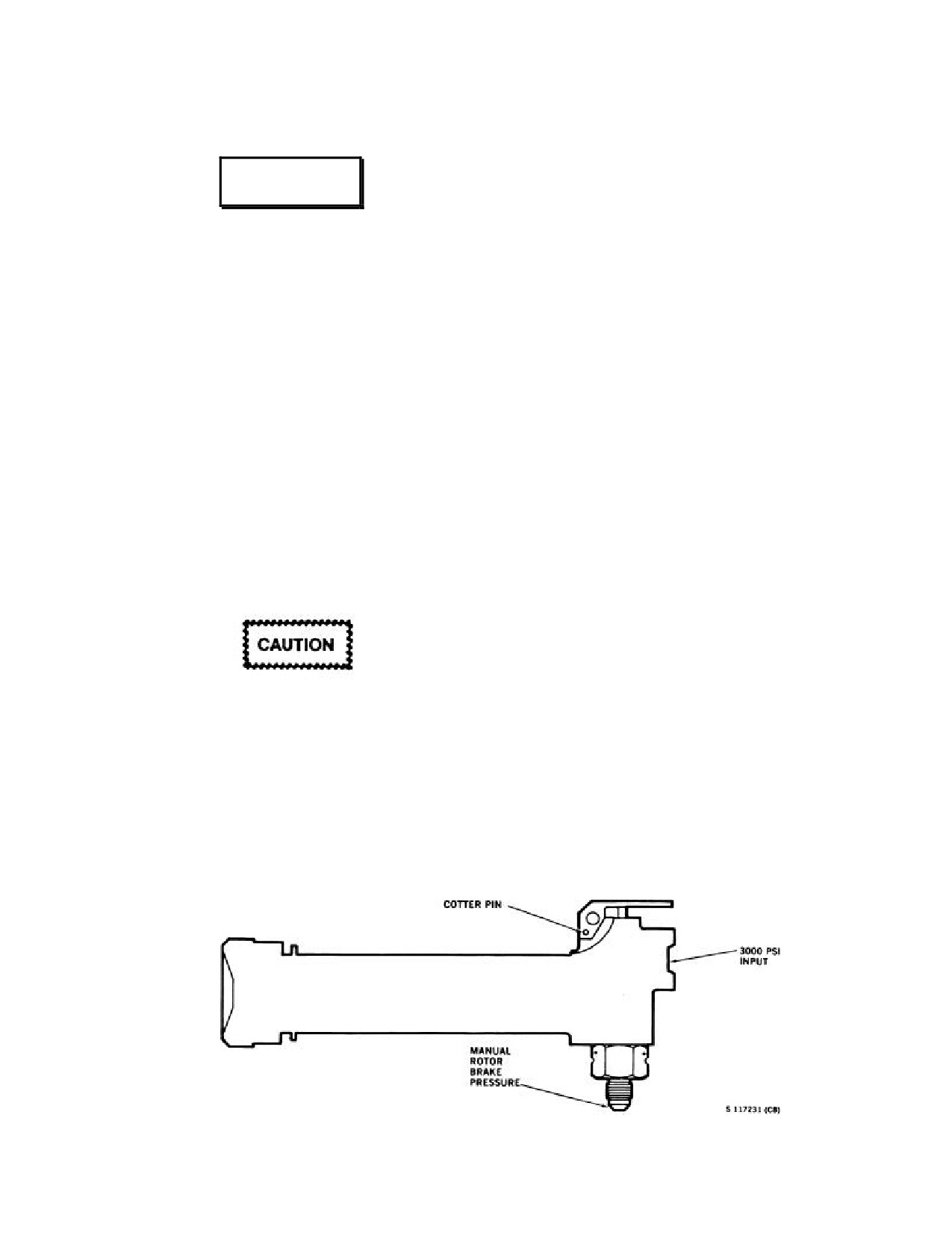
NAVAIR 01-230HLH-1
12.32 COUPLER MALFUNCTIONS
Note
WARNING
Flight conditions that determine the
corrective action are assumed to be
night/IFR.
The automatic rotor brake should not be
used if there is evidence of a hydraulic leak
12.32.1 Loss of Doppler Receiver.
in the area of the rotor brake. If a ruptured
line exists, actuation of the automatic rotor
INDICATIONS
brake may spray fluid causing a fire.
1. OFF flag in D mode.
1. Manual rotor brake - OFF.
2. MEMORY light on.
2. No. 2 firewall valve - OPEN.
3. Incorrect indications of groundspeed and drift on
3. Allow Nr to decrease as low as is safe and
GSDA and D mode indicators.
comfortable. (This will depend on wind conditions).
Note
4. SAFETY VALVE switch - OPEN.
Receiver loss may be caused by either a
5. MASTER switch - ON.
poor Doppler signal return because of a low
sea state or by an internal failure of the
If the automatic rotor brake appears to be slowing the
Doppler receiver.
rotary wing too rapidly, the master switch may be cycled
on and off.
EFFECT
1. In an approach with altitude coupler in RAD ALT,
a high sink rate may develop. With altitude coupler in
VA, there will be no noticeable effect on the approach.
Cyclic coupler inputs are in relation to incorrect
Doppler information as displayed by D mode.
Make sure that the BLADES FOLD-
SPREAD switch is OFF until the rotary
2. In a hover, complete loss of coupler inputs to
wing has come to a complete stop.
beeper trim resulting in the helicopter drifting from
Inadvertent actuation of the BLADES
original hover position.
switch to FOLD could cause premature
engagement of the positioning unit if the No.
2 firewall valve is closed.
Figure 12-6. Rotor Brake Accumulator
12-37
ORIGINAL
NAVAIR 01-230HLH-1
CORRECTIVE ACTION
12.32.3 Sidelobe Lock-On.
In an approach:
INDICATIONS
1. Check Doppler control panel for light indications.
1. D mode drift bars frozen, usually in center.
MEM light indicates loss of Doppler receiver. STBY
light indicates loss of transmitter.
2. No OFF flag in D mode.
2. If conducting an automatic approach, switch the
3. No MEM or STBY light on Doppler panel.
Doppler selector from SEA to LAND/ALT to reacquire
the Doppler signal. If the signal is reacquired (OFF flag
EFFECTS
disappears and MEM light goes off) continue the
approach. If the Doppler signal is not reacquired, abort
1. Erratic or incorrect inputs to cyclic coupler.
the approach or switch the cyclic coupler to OFF and
proceed with an alternate approach.
2. Incorrect indications of groundspeed and drift on
GSDA and D mode.
3. If conducting an alternate approach because of low
sea state, ensure that the Doppler selector is in
CORRECTIVE ACTION
LAND/ALT. If the Doppler signal is not acquired after
passing through translational lift, abort the approach.
If sidelobe lock-on is suspected, beep the aircraft to a
nose-level attitude. If the groundspeed on D mode/GSDA
In a hover:
does not increase, do the following:
1. If disorientation occurs, execute a free-stream
1. If conducting an automatic approach, select
recovery, Figure 12-7.
LAND/ALT and switch cyclic coupler to OFF. Proceed
with an alternate approach.
12.32.2 Loss of Doppler Transmitter.
2. If conducting an alternate approach, switch the
INDICATIONS
Doppler selector to STBY until the Doppler enters
memory (OFF flag in D mode and MEM light). Return
1. OFF flag in D mode.
the Doppler selector to LAND/ALT to acquire a valid
signal.
2. Lighting of both MEM light and STBY lights.
3. If a valid signal cannot be acquired, abort the
3. Incorrect indications of groundspeed and drift on
approach.
GSDA and D mode indicators.
12.32.4 Loss of Radar Altimeter.
EFFECT
INDICATIONS
1. In an approach - Same as loss of Doppler receiver.
RAWS warning, both aural and visual, and the RAD
2. In a hover - Same as loss of Doppler receiver.
ALT will show a yellow striped flag.
CORRECTIVE ACTION
EFFECT
1. If disorientation occurs in the hover, execute a free-
1. Approach - Helicopter will return to 150 feet or
stream recovery.
level off.
2. If Doppler transmitter failure is noted, abort the
2. Hover - Helicopter will normally remain in hover.
approach.
CORRECTIVE ACTION
3. Once the helicopter is at a safe altitude, check the
Doppler circuit breaker IN.
1. Approach - ABORT.
12-38
ORIGINAL
NAVAIR 01-230HLH-1
2. Hover:
12.32.7 Loss of Attitude Indicator.
a. On RAD ALT or VA - Abort and recover by
INDICATION
free-stream recovery.
OFF flag in the attitude indicator.
3. When established in flight at a safe altitude, check
the circuit breakers.
EFFECT
12.32.5 Malfunction of Stick Trim.
1. Copilot Attitude Indicator - Loss of copilot attitude
reference, and when gyro processes, hardovers in pitch
INDICATIONS
and roll will result.
1. No trim - Cyclic stick will have no "feel".
2. Stuck valve - Unable to release artificial "feel".
WARNING
3. In either case the coupler will not control the
helicopter in pitch and roll.
In the event of an AHRS failure, the left-
seat pilot will have no attitude reference and
EFFECT
there will be no reliable heading reference in
the cockpit
(RMI and BDHIs will be
Loss of coupler control in pitch and roll.
unreliable). Executing a free-stream recovery
under these conditions will be extremely
CORRECTIVE ACTION
difficult. Close cockpit coordination and use
of the turn needle and wet compass are
1. Approach - ABORT.
required. Consideration should be given to
switching the compass control panel to
2. Hover - Abort and recover by free streaming, if
COMP (old panel) or EMERG (new panel)
disorientation occurs.
at the first reasonable opportunity.
3. When established in forward flight at a safe
CORRECTIVE ACTION
altitude, check the circuit breakers.
1. Release ASE if hardovers give control problems.
12.32.6 Loss of ASE.
2. If copilot's fails, ensure that gyro selection switch is
INDICATIONS
in STBD.
Loss of artificial stability and programmed approach.
3. Abort approach.
EFFECT
4. Hover- abort by free streaming.
Loss of coupler control and helicopter stability.
5. When established in flight at a safe altitude, check
the circuit breakers.
CORRECTIVE ACTION
12.32.8 SAR FREESTREAM RECOVERY.
1. Approach - ABORT.
If a stable coupled hover cannot be maintained because
2. Hover - Abort by free streaming.
of a malfunction and/or vertigo, an emergency departure
should be executed.
3. When established in flight at a safe altitude, check
the circuit breakers.
*1. Alert the crew.
Note
*2. Level aircraft to hover attitude and establish zero
drift.
A complete loss of ASE/COUPLER will
occur if the auxiliary servo fails or both
*3. Disengage coupler
- start a
100- to
500-fpm
generators fail.
vertical climb. Continue hoisting swimmer/survivor if
on hook.
12-39
ORIGINAL
NAVAIR 01-230HLH-1
*4. When passing thru 100 feet, adjust nose attitude
12.32.10 Cg Not Within Prescribed Limits. If the cg
to attain 60 to 70 KIAS.
trim is not set within the prescribed limits, the ASE may
run out of authority and the helicopter will go to an
*5. Level off at a safe altitude and troubleshoot
extreme nosedown or noseup attitude.
malfunction.
CORRECTIVE ACTION
Release coupler and manually control attitude.
12.33 EMERGENCY WATER OPERATIONS
WARNING
This helicopter in its normal configuration is not an
Until rescue swimmer and survivor are in aft
amphibious helicopter and will under no conditions other
station, airspeed shall be kept below
40
than that of an emergency be landed on the water.
KIAS.
12.33.1 General Information. The helicopter, when
12.32.9 Loss of Generator.
landed on the water, will eventually acquire water
internally through various antenna and drainage points. If
INDICATIONS
the helicopter is capable of further flight with both engines
operating, a normal vertical takeoff may be executed. If
1. Caution light.
power is reduced because of partial or complete loss of one
engine, the helicopter under certain gross weights may be
2. Loss of ac- and dc-monitored bus.
flown from the water, usin g a running takeoff technique.
If neither type of takeoff can be executed, the helicopter
EFFECT
may possibly be taxied to a shoreline or salvage area. Due
consideration should first be given to flying the helicopter
1. No. 2 generator - Loss of ac- and dc-monitored bus.
from the water whenever possible. Should circumstances
exist that would preclude a takeoff because of excessive
2. No. 1 generator
- Loss of ac- and dc- monitored
gross weights but that would allow a takeoff at lower gross
bus. Helicopter will drop rapidly but briefly until the
weights, initial consideration should be given to lightening
shift of loads is complete. The helicopter will then
the helicopter by dumping fuel.
return to its original hovering altitude.
When operating on or near the surface of salt water, the
Note
turbine compressor blades will acquire salt encrustation.
Encrustation buildup will result in compressor stall of the
Should the No.
1 generator fail or be
engine. The acquisition rate of salt within the engine is
otherwise secured while the helicopter is in
proportional to the spray ingested. The rate of such
a hover, the Doppler will shift into memory
ingestion increases rapidly with increases of power;
when the generator load is switched. Should
therefore, hovering close to the water or holding too much
this occur, the Doppler selector switch must
power when on the surface should be minimized whenever
be placed to LAND/ALT until the Doppler
possible. Ingestion rates will decrease slightly with
signal is regained. If the selector switch is at
increased wind conditions. Stability of the helicopter on
LAND/ALT when the generator load is
the water must be maintained by the pilot in control at all
switched, the Doppler will go into memory
times. Although the static helicopter without emergency
for about
6 seconds before the Doppler
flotation gear can right itself from a roll of several degrees,
signal is automatically reacquired.
wind and water conditions higher than sea state one may
cause excessive rolling and capsizing will probably occur.
CORRECTIVE ACTION
However, a helicopter with emergency flotation gear
inflated can right itself from a roll in seas up to sea state
1. Approach - Abort.
three. Frequently, when operating on the surface, visual
reference to the horizon will be lost. In such cases, the
2. Hover - Wait until load shift is complete and then
VGls should be employed to maintain the helicopter in a
depart the hover. When established in flight at a safe
level attitude. Windshield wipers should be employed,
altitude, recycle the generator. If the output of the
particularly when attempting to take off or in sea states
generator is not restored, turn the switch off and land as
that cause water to splash onto the windshield. Before
soon as practicable.
water operation of any nature, the landing gear should be
checked in the UP position. The helicopter should not be
taxied down swell above sea state three, as the rotary
rudder may contact the water.
12-40
ORIGINAL
NAVAIR 01-230HLH-1
the cyclic in conjunction with slight up collective.
Additional speed may be obtained by increasing either but
is normally a result of increasing collective position. It
must be remembered, however, that raised collective
WARNING
positions increase salt ingestion within the engines. In
higher sea states, it may be necessary to reduce taxi speeds
and to maintain partial up collective in order to lessen
· In moderate to high sea states, taxiing
wave impact on the front of the fuselage. At all times the
the helicopter in any direction not
helicopter must be kept level, using the cyclic control and
directly into the waves (particularly at
referring to the VGIs if necessary. Turns should be made
night) may be disorienting, cause increased
using the rudder pedals for steering control. Two factors,
instability, and result in uncommanded
the high cg and the large sail area, will normally affect list
roll of the helicopter.
of the helicopter while taxiing. Normal taxi speeds will be
associated with a prominent bow-wave effect that in calm
· The cockpit windows are more difficult
water will splash against the lower panels of the
to jettison when the helicopter is inverted
windshield at deck level. Taxi speed of over 15 knots may
than when upright because of interaction
cause the nose to tuck. Should this occur, the collective
between the window frame pins and the
should be immediately lowered to the minimum position
airframe. The cockpit windows should
and the forward movement stopped. Sideward and
be jettisoned in anticipation of capsizing,
rearward taxiing may be made by use of the cyclic and
if possible.
collective but is not recommended.
Note
Do not panic if it appears that the helicopter
is taking on water. The initial gush of water
WARNING
up the sonar funnel has been a factor in
previous accidents where the pilot has made
a premature decision to abandon the
In moderate to high sea states, taxiing the helicopter
helicopter with resultant loss of the
in any direction not directly into the waves
helicopter.
(particularly at night) may be disorienting, cause
increased instability, and result in uncommanded
Following engine shutdown, the rotor brake should be
roll of the helicopter.
applied only when rotor decay without braking action
would create a more hazardous condition. Torque resulting
12.33.3 Fuel Dumping Afloat.
from rotor brake application will cause the helicopter to
rotate in the water and possibly capsize. If both engines
1. Determine the amount of fuel to be offloaded. To
fail or an uncontrollable fire is experienced, the decision to
determine gross weight for takeoff, refer to the
abandon the helicopter must be made quickly. Attempts to
performance charts in Figure 12-9.
lower the landing gear and deploy the sea anchor, if
equipped, should be made to stabilize the helicopter as
2. Taxi slowly upwind or crosswind.
much as possible while preparations are being made to
abandon. If time permits, secure all power and fuel
3. Crossfeed - CLOSED.
switches. The signal to abandon helicopter will be given
by the plane commander, and all personnel on board shall
4. All fuel boost pumps - ON.
evacuate with their individual survival equipment.
5. Fuel dump switches - AS REQUIRED.
12.33.2 Water Taxiing. Water taxiing procedures
follow the same basic procedures as those specified for
6. After desired quantity dumped, fuel dump switches
taxi operations ashore. Water taxi should be thought of as
- OFF.
an air taxi with reduced gross weight. Balanced flight
should be maintained as much as possible while in the
12.33.4 Flotation Bags. The emergency flotation
water. When the collective is reduced to the flat pitch
bags are installed to improve helicopter stability on the
condition, stability becomes marginal. As the sea state
water with the rotary wing shut down. It is only necessary
increases, instability increases accordingly. Therefore,
to inflate the bags if the rotary wing must be shut down.
while water taxiing, a slight amount of collective is
The bags will maintain the stability of the helicopter for
necessary to maintain positive stability. Initiation of
subsequent rescue and/or salvage operations. With the
forward speed is a result of slight forward displacement of
rotary wing turning and under control, sufficient flotation
12-41
ORIGINAL
NAVAIR 01-230HLH-1
and stability is available to carry out any maneuver
as necessary. If the nose attitude is lowered to less than 2°
previously described.
to 3°, the possibility of acceleration before touchdown is
present. This, coupled with the flat attitude, may cause
If the emergency flotation bags were inflated, maintain
possible damage to the electronics compartment door at
airspeeds of less than 60 knots and pressure altitudes of
touchdown and/or possible flameout of operating engine
less than 3,000 feet. No degradation of handling qualities
because of water ingestion. Conversely, excessive attitudes
will be noted when flying with the bags inflated.
at touchdown if coupled with high sink rates and/or high
speeds may cause the tailwheel to sink too deeply, thereby
Upon return to the ship or base, the helicopter should
subjecting the rotary rudder to possible damage. The
be landed vertically if possible and the bags deflated
accompanying pitching forward tendency may cause
before moving. If the helicopter is taxied with bags
serious damage to the electronics compartment door, the
inflated, they will scuff and probably tear. If it is necessary
wind screen area, and the engines. Under no conditions
to taxi with the bags inflated, a rope should be tied around
should the speed at touchdown be over 15 knots. Once
the bags to hold them up against the sponsons.
established on the water, collective pitch should be
reduced to the minimum required for taxi and the
helicopter maintained in a level attitude.
12.33.7 Single-Engine Failure or Loss of Power
in an Overwater Hover. It is most unlikely that the
helicopter can be flown from a coupled hover following an
If flotation bags are inflated while airborne,
engine failure. Because of the low altitude, reaction to a
the possibility of tearing a bag on a
complete single-engine failure must be instantaneous.
subsequent rough water landing is highly
Since average pilot reaction time is
1.8 seconds,
likely, resulting in the hydrostatic characteristics
correlation with the rotor decay chart (Figure 12-1) shows
of the helicopter being greatly reduced.
that available Nr remaining before reaction begins is less
than 90 percent from an engine loss in an over-water hover
12.33.5 Dual-Engine Vertical Landing. A vertical
where dual-engine torque was about
80 percent. The
water landing with both engines operating should be
decision should be made to land in the water with the
approached in the same manner as a vertical landing over
primary concern being the preservation of enough rotor
an unprepared surface. If available, visual reference to
rpm to cushion the landing. Since the attendant loss of Nr
floating objects in the water will aid as a reference during
is over 10 percent before pilot reaction begins, there will
the descent. During the descent, a slight amount of forward
also be an attendant loss of altitude because of the rotor
speed (1 to 2 knots) is desired during the landing phase.
becoming less efficient. With the coupler engaged, the
This can best be accomplished by setting a nose-level
pilot will first notice a rise in collective caused by the
attitude using the VGI passing through 8 to 10 feet on the
coupler system trying to maintain its preselected altitude.
RAD ALT. As the helicopter comes to rest, the collective
This upload must be overcome to avoid further rotor speed
pitch should be reduced to the minimum required for taxi
decay. However, since the helicopter would probably be
and, simultaneously, the helicopter maintained in a wings-
below 40 feet because of rotor speed decay, any excessive
level attitude. In calm water with collective pitch at
reduction in collective would be disastrous. Collective
minimum, the water level will appear to be slightly more
should be lowered only as altitude permits and then only
than a foot below the cockpit deck. Because of the 3°
slightly to retard Nr decay. Avoid abruptness if possible.
inclination of the rotor mast, the helicopter will have a
Nose attitude is another critical factor in achieving a safe
tendency to move forward in the water. In calm water with
water entry. At the time collective is lowered, the nose
the forward movement stopped, the helicopter will move
attitude should be lowered so that the nose is slightly
sideward at a speed of about one-half knot because of
above the horizon, ideally about 2° above to impart a slight
thrust of the rotary rudder.
forward velocity and to preclude backing down.
Cushioning should be started about 8 to 10 feet above the
water, with the nose attitude no lower than the horizon
12.33.6 Single-Engine Water Landing. The approach
because of collective to cyclic coupling. Aft cyclic
to a single-engine water landing should employ the
displacement under impact loads may produce contact
standard techniques used during single-engine approaches
between rotary wing blades and the tail pylon. Excessively
ashore. During the initial stages of the approach (150 feet
high nose attitudes at touchdown, particularly in high seas,
and below), nose attitude and power adjustments should be
may cause loss of the rotary rudder because of surface
made in order to arrive at
5 feet and
5 knots of
contact.
groundspeed before water entry. Nose attitudes and power
required to attain this 5 feet and 5 knots will be dependent
Time is a crucial consideration. A simple application of
on helicopter gross weight, density altitude, and surface
up collective and forward cyclic should be enough to avoid
wind conditions. At this time, the nose should be adjusted
injury in a power loss situation but will likely result in a
to 2° to 3° above the horizon and the helicopter cushioned
hard landing and possible helicopter damage prohibiting a
12-42
ORIGINAL
NAVAIR 01-230HLH-1
single-engine water takeoff. Neither engine should be
secured until careful analysis can be made of the
8. Land on top of swell
- HEAD INTO WAVES, 0
malfunction.
TO 15 KNOTS GROUNDSPEED.
If after experiencing a power loss the helicopter settles
but still remains airborne, a
“creep out” can be
accomplis hed. If the Nr is above
92 percent, a slow,
smooth transition to forward flight can be made. With Nr
WARNING
stabilized below 92 percent and with the helicopter still
airborne, judicious use of the manual throttle is an
alternative to increase Nr allowing a transition to forward
In moderate to high sea states, taxiing the
flight.
helicopter in any direction not directly into
the waves
(particularly at night) may be
disorienting, cause increased instability, and
result in uncommanded roll of the
helicopter.
12.34.3 After Water Entry. Unless obviously sinking
· Monitor Ng, T5, Nf, and Nr to avoid
and the decision has been made to remain on the water, the
exceeding engine limitations when
following checklist should be used by the crew as a guide
possible. Maintain topping power setting
to enhance helicopter and crew survivability. Do items that
only as long as necessary to become
were not completed in Water Landing
(Controlled)
safely airborne.
Checklist.
1. External and internal stores/windows - JETTISON.
12.34 DITCHING PROCEDURES
2. Helicopter integrity - CHECK.
12.34.1 Water Landing (Uncontrolled).
3. UHF antenna selector
- UPPER ANTENNA.
*1. Alert crew.
Broadcast MAYDAY.
*2. Lock shoulder harness.
If water takeoff is not to be attempted, comply with
Water Shutdown Procedures, paragraph 12.34.6.
*3. Mayday/IFF.
12.34.4 Dual-Engine Vertical Water Takeoff.
12.34.2 Water Landing (Controlled).
Procedures for the dual-engine water takeoff except for the
initial stages are the same as when executed from a hard
*1. Speed selector(s) - FULL FORWARD.
surface. To preclude the possibility of excessive salt
ingestion when taking off, an exaggerated rate of climb is
*2. Alert crew.
performed until clear of salt spray. When the decision has
been made to take off, firmly and smoothly apply power.
*3. Harnesses - LOCKED.
As the helicopter clears the water, continue to apply power
until an altitude clear of water spray is attained. At this
*4. Mayday/IFF.
time, the transition to forward flight should be commenced
in the normal manner.
*5. External stores - JETTISON.
Note
6. Execute single-engine approach profile.
Windshield wipers are recommended
7. Jettison windows during landing flare.
because of the heavy amount of spray that
may be encountered.
12.34.5 Single-Engine Water Takeoff. Because of
the salt ingestion of the engines, the associated loss of
power, and the acquisition of water through the various
openings along the bottom of the helicopter, it is essential
Jettisoning pilot compartment windows
in
that the single-engine takeoff be attempted as soon as
high-speed flight may result in damage to
possible (Figure 12-7).
the rotary wing blades or the rotary rudder
blades.
12-43
ORIGINAL
NAVAIR 01-230HLH-1
Note
11. Collective - RAISED FOR TAKEOFF.
The various voids in the helicopter will the
Note
hold upwards to 2,000 pounds of water. The
rate of water intake will vary with different
If single-engine takeoff is not possible using
helicopters, but the helicopter will normally
the above procedures, increase the
acquire this amount of water in about 15 to
mechanical topping adjustment of operating
45 minutes. Execute single-engine water
engine to full increase and attempt another
takeoff as follows.
takeoff.
1. Conduct integrity check for airframe damage.
12. Accelerate to and maintain normal single-engine
flight.
Note
13. Manual throttle
- OFF WHEN ESTABLISHED
Should an excessive rate of water leakage
IN CLIMB OR ON WATER REENTRY.
appear in the cargo or pylon area after a
water landing, the possibility exists that
14. Fuel dump - SECURED.
structural damage has occurred to the
underside of the fuselage section or pylon.
An integrity check for damage to the
helicopter should be completed before
executing a single-engine water takeoff.
WARNING
2.
External and internal stores/smokes/
windows - JETTISON.
Mechanical overspeed protection can be actuated from
119- to
123-percent Nf. In moderate to high sea states,
3.
Crossfeed - CLOSED.
judicious use of collective will be required to prevent
Nf/Nr, overspeed.
4.
All fuel boost pumps - ON.
Tip-path plane should be adjusted forward and power
5.
Fuel dump switches - ON AS NECESSARY.
initially adjusted to about 50- to 55-percent torque (single
engine) to attain maximum forward taxi speed. As the
Note
leading edge of the bow wave becomes visible through the
pilot windshield (maximum taxi speed), continue to apply
Fuel quantity should be monitored because
power to become airborne to an altitude of about 5 feet
of high dump rate.
above the water. It is essential that a nose position on the
horizon be maintained. As the helicopter clears the surface
6.
Speed selector - FULL FORWARD.
of the water, rotor rpm will decay to some lesser value,
but should stabilize at 92 percent or above. If the altitude
7.
Collective - RAISED.
and attitude remain as outlined above and Nr has
stabilized at
92 percent or above, the helicopter will
8.
Manual throttle - TOPPING.
accelerate. As the helicopter reaches 45 KIAS, the nose
position should be adjusted to 1° to 2° noseup and Nr
allowed to increase to
96 percent, or if the Nr has
stabilized at a higher value, then it should be maintained.
A perceptible rate of climb will occur and acceleration
will continue. When the indicated airspeed reaches 65
Monitor Ng, T5, Nf, and Nr to avoid
knots, set the attitude and Nr to the normal single-engine
unnecessarily exceeding engine limitations.
climb parameters. If the Nr cannot be stabilized at 92
Limitations imposed by topping adjustments
percent, then reland as outlined in single-engine water
do not exist while using manual throttle.
landing section. At this time, the pilot must decide either
Manual throttle should be used only long
to attempt another takeoff immediately or to further
enough to become safely airborne.
reduce weight by dumping fuel or other means available
before takeoff.
9.
Collective - LOWER TO 117-PERCENT Nr.
10. Cyclic
- FORWARD FOR MAXIMUM
TAXI
SPEED AT 117-PERCENT Nr.
12-44
ORIGINAL
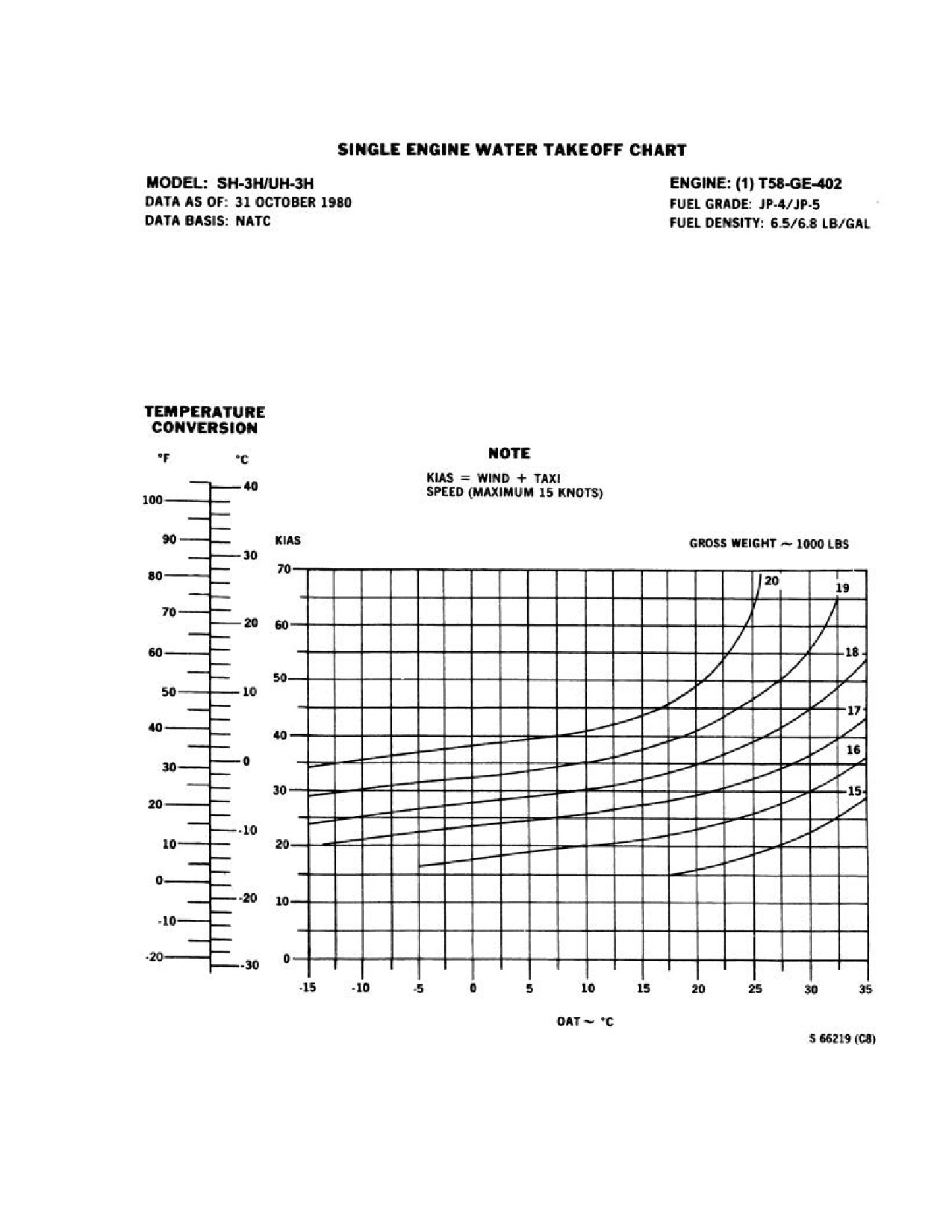
NAVAIR 01-230HLH-1
Figure 12-7. Single-Engine Water Takeoff Chart
12-45
ORIGINAL
NAVAIR 01-230HLH-1
12.34.6 Water Shutdown Procedures.
2. Secure helicopter - AS NECESSARY.
1. Crew alerted.
3. Deploy raft - UPON COMMAND.
2. Landing gear - DOWN.
Note
Landing gear should be lowered prior to
securing engines. Lowering the landing gear
· When launching a life raft, be sure that
will aid in attaching the emergency flotation
the raft does not become fouled on parts
collar.
of the helicopter.
3. Raft/first-aid kit/matrix light/buoy
- POSITION
4. Abandon helicopter - UPON COMMAND.
FOR LAUNCH.
12.34.7.1 Towing Helicopter.
4.
Flotation bags - DEPLOYED.
1. Secure tow ship line to the nose tow ring.
a. Arming switch - ARMED.
2. Maximum speed 4 to 5 knots in moderate sea and 1
b. Inflate switch - DEPRESS.
to 2 knots in heavy sea.
5.
Shoulder harness all stations - LOCKED.
Note
If situation warrants, use normal shutdown
checklist to place No. 1 engine in ACCESS
· Under no circumstances shall the
DR to provide power for continued use of
helicopter be towed by the tailwheel
communication/lighting equipment.
while in the water. Towing the helicopter
from any point other than the nose tow
6.
Speed selector(s) - SECURE AS APPROPRIATE.
ring may result in loss of the helicopter.
12.34.8 Emergency
Water Towing With
Emergency Floats Inflated. When towing the
WARNING
helicopter under emergency conditions in water, secure the
tow ship line to the nose tow ring. If the sea anchor is
being used, the tow ship should retrieve the parachute and
Judicious use of rotor brake during shut-
disconnect it; then connect its towline at the point where
down is recommended. Torque resulting
the parachute was removed. Tow tension should be
from rotor brake application will cause the
increased gradually and initiated in line with the heli-
helicopter to rotate and possibly capsize.
copter longitudinal axis.
7.
Rotor brake - AS NECESSARY.
Before abandoning helicopter, consider the following:
1. Condition of helicopter.
2. Environmental conditions.
Under no circumstances shall the helicopter
be towed by the tailwheel while in the water.
3. Condition of crew.
The center of gravity shifts forward and
forces one sponson under the water. Towing
4. Time to rescue.
the helicopter from any point other than the
nose tow ring may result in loss of the
12.34.7 Abandoning Helicopter.
helicopter.
1. Rotor brake - ON.
12-46
ORIGINAL
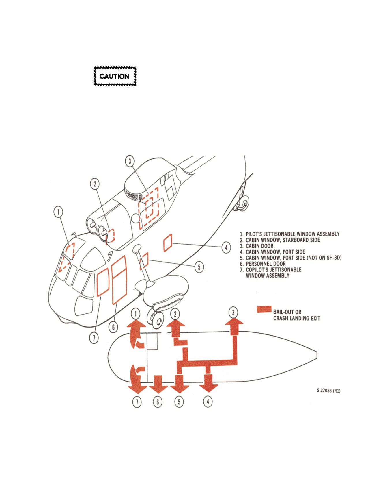
NAVAIR 01-230HLH-1
12.35 EMERGENCY ENTRANCES AND EXITS
12.35.1.1 Interior Release Handle. The window
(Figure 12-8)
emergency release handle for each window assembly is
below the window. The handle marked EMER RELEASE
is pulled up to release the window assembly.
12.35.1.2 Exterior Release Handle. The exterior
window handle marked EMER EXIT RELEASE, PUSH
TURN is pressed in on one end which causes the handle to
Jettisoning the pilot compartment windows
extend outward, then the handle is turned downward to
in high-speed flight may result in damage of
release the window assembly. After the window has been
the rotary wing or rotary rudder blades.
released, it will have to be manually pushed out.
12.35.1 Pilot Compartment Jettisonable Window
Assembly.
Figure 12-8. (NON-ET) Emergency Routes of Escape and Exits
12-47
ORIGINAL
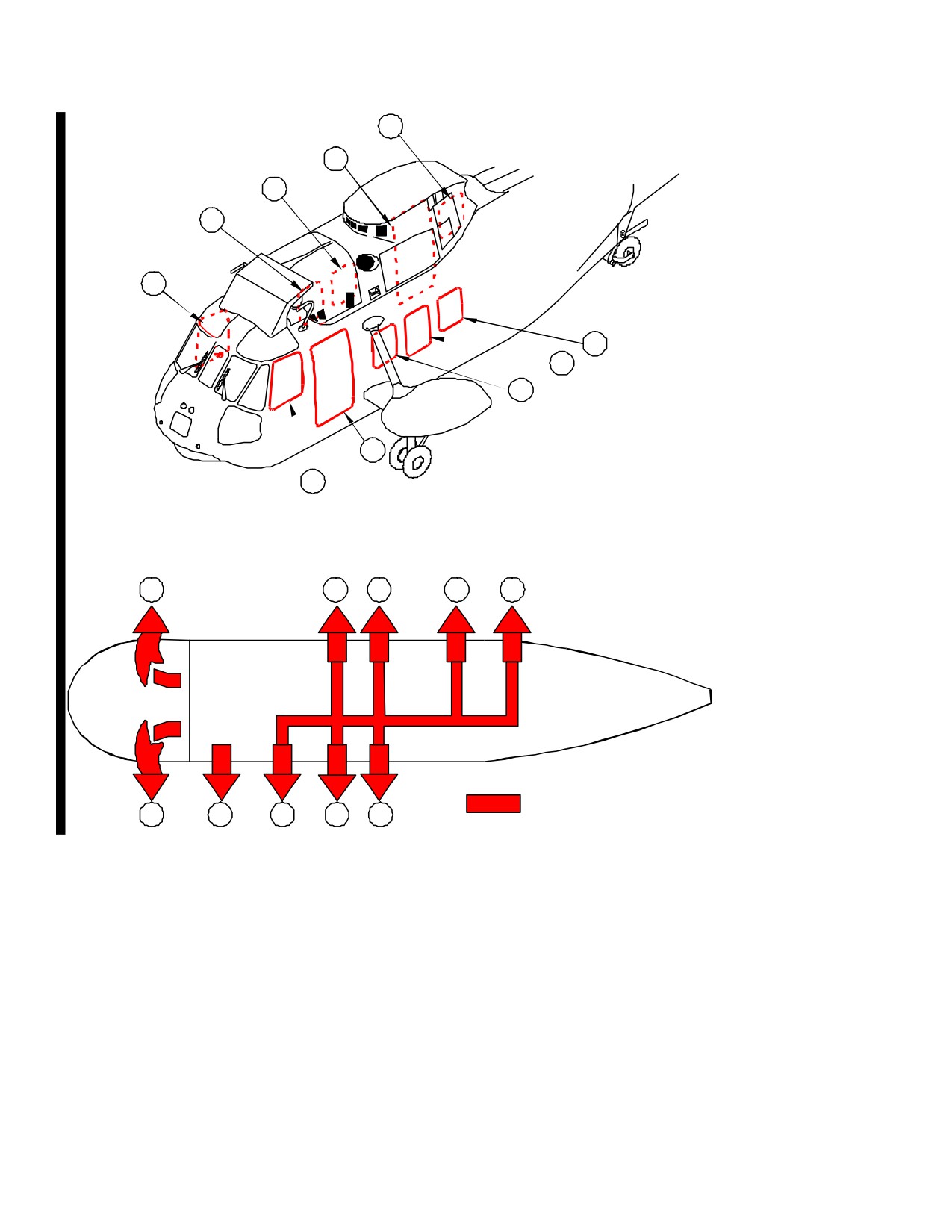
NAVAIR 01-230HLH-1
5
4
3
2
1
6
7
8
1. PILOT’S JETTISONABLE WINDOW ASSEMBLY
9
2. CABIN EMERGENCY ESCAPE HATCH, STARBOARD SIDE
3. CABIN WINDOW, STARBOARD SIDE
4. AFT PASSENGER DOOR
10
5. AFT CABIN EMERGENCY ESCAPE HATCH, STARBOARD SIDE
6. CABIN WINDOW, PORT SIDE
7. CABIN EMERGENCY ESCAPE HATCH, PORT SIDE
8. CABIN WINDOW, PORT SIDE
9. FORWARD PASSENGER DOOR
10. COPILOT’S JETTISONABLE WINDOW ASSEMBLY
1
2
3
4
5
CRASH LANDING EXIT
10
9
8
7
6
01771012
Figure 12-8.1 (ET) Emergency Routes of Escape and Exits
12-48
ORIGINAL
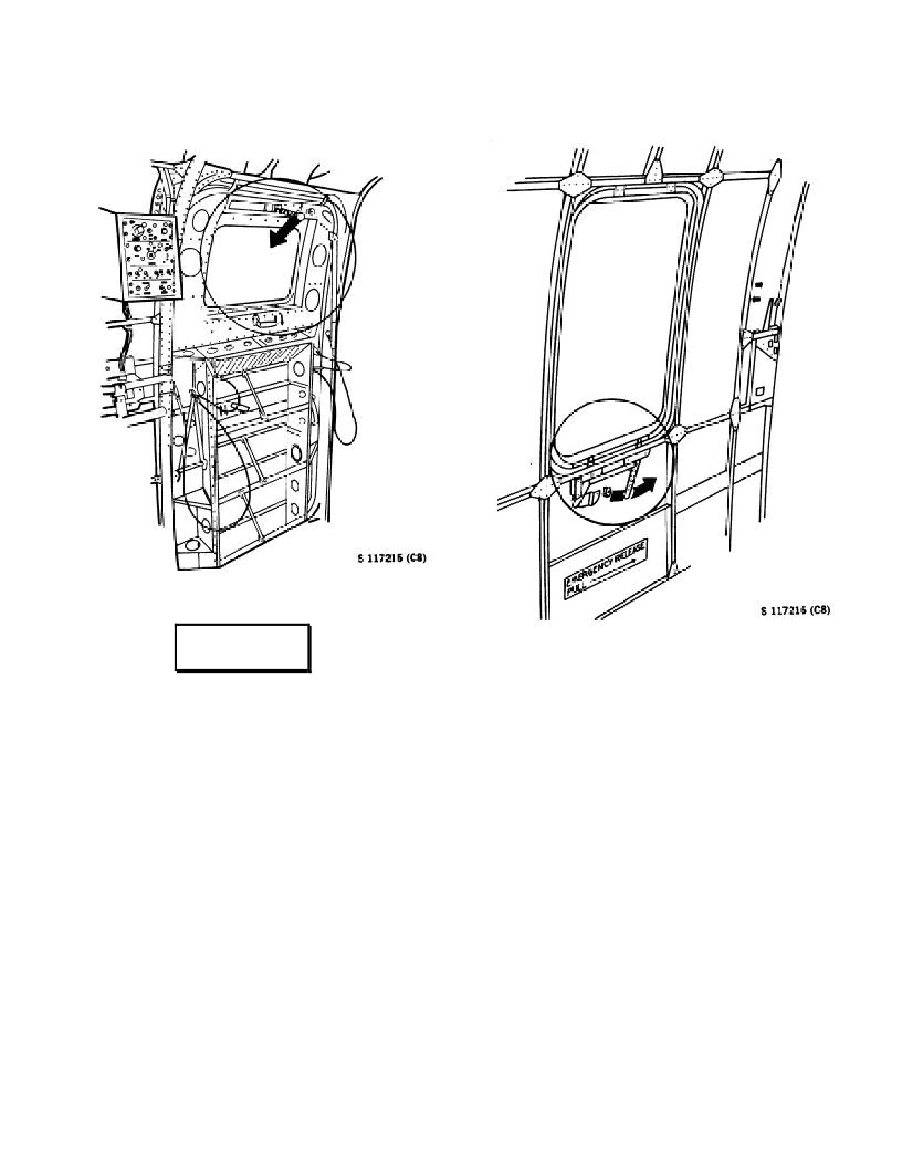
NAVAIR 01-230HLH-1
12.35.2 Personnel Door.
12.35.3 Cabin Door.
WARNING
12.35.3.1 Interior Release Handle. A handle marked
EMERGENCY EXIT, TURN is below the window. A self-
luminous marker is mounted below the handle to indicate its
Wrapping the support cables for the lower
location. To open the emergency escape window, the handle
personnel door around the latch located at the
is pulled aft and the window is pushed out.
top center of the lower door or around the
latch below the window on the upper
12.35.3.2 Exterior Release Handle. A handle
personnel door will prevent use of this exit
marked EMERGENCY EXIT, TURN is on the outside of
during an emergency egress and shall be
the cabin door at the lower aft comer of the window. This
avoided.
handle is moved clockwise, and the window is pulled out for
emergency entrance or exit.
12.35.2.1 Interior Release Handle. Pull down on the
yellow knobbed handle marked EXIT RELEASE, TURN
12.35.4 Cabin Windows.
that is centered on the door frame above the window in the
upper door. Pull the lower end of the support tube from the
12.35.4.1 Interior. The three cabin windows, one on the
fitting on the forward portion of the fuselage and push
starboard side and two on the port side of the cabin, may be
outward. A self-luminous marker mounted next to this
pushed out by sharply striking the corner to provide
handle indicates its location. The lower half of the door can
additional
emergency exits.
EMERGENCY EXIT
be opened by turning the latch at the top center of the door
WINDOW, PUSH OUT is stenciled above each window on
and pushing outward.
the inside.
12.35.2.2 Exterior Release Handle. The upper door
may be opened by pulling the handle marked EXIT
RELEASE, TURN. The handle is centered on the door
frame above the window. The lower half of the door may be
opened by turning the latch marked EXIT RELEASE,
PUSH, TURN at the center of the door.
12-49
ORIGINAL
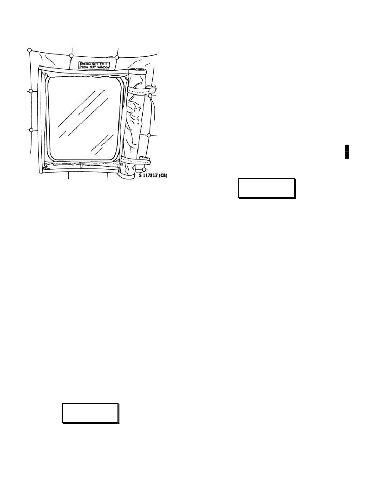
NAVAIR 01-230HLH-1
AFTER WATER ENTRY
*2. Window - JETTISON.
*3. Grip HEED/HABD mouthpiece with teeth and take
a breath to ensure function. Breathe through nose until
submerged to conserve air.
*4. Reference point - GRASP.
*5. Helmet cord - DISCONNECT.
*6. Lap belt - RELEASE.
*7. Egress.
(Breathe through HEED/HABD as
necessary.)
12.35.4.2 Exterior. Each of the cabin windows is
WARNING
equipped with a pull tab in the outside for emergency
entrance at the lower aft corner marked PULL TAB EXIT
Holding a breath taken at depths as shallow as
RELEASE, by which the locking strip may be pulled out of
4 to 6 feet may result in a gas embolism. If
the rubber seal surrounding the window pane. The panes
breathing is initiated underwater, breathe
may then be removed to provide emergency openings.
continuously during egress and ascent. If air
is exhausted prior to surfacing, exhale
12.36 INADVERTENT OPENING AND/OR LOSS
continuously until surface is reached.
OF ACCESS PANELS/DOORS
*8. Once you are well clear of the aircraft, inflate the
Loss of an access panel or door in flight will generally
LPU. Allow natural buoyancy of initiated LPU to float
dictate a slowing of the helicopter and landing as soon as
you to the surface.
practicable to inspect for further damage.
12.38 AUXILIARY FLOTATION COLLAR
However, severe vibrations or control difficulties may
indicate damage to control surfaces. Land as soon as
12 38.1 Application Checklist.
possible.
Note
Note
Should a panel or door open in flight and
· Position aircraft downwind of the stricken
remain attached to the helicopter, abrupt
aircraft
(maximum 50 yards/ minimum 50
feet) to prevent capsizing of ditching
attitude changes must be avoided to reduce
aircraft.
wind flow changes on the access panel or
door. Landing criteria are as the situation
dictates.
· All swimmers, including the team leaders,
are suited out in appropriate SAR gear.
12.37 UNDERWATER EGRESS
· Team leader takes PRC-90 radio for
communications with airborne helicopter.
· Standard rescue swimmer hand signals
WARNING
apply as per NWP
3-50.1, Navy Search
and Rescue (SAR) Manual.
Inflating flotation equipment inside aircraft
1. Fiberglass containers
- Check for proper air bottle
may impede egress.
pressure through the plastic see-through windows (3,000
psi).
* 1. Reference point - LOCATE.
12-50
ORIGINAL
NAVAIR 01-230HLH-1
2. Bundle strap
- Check for security and determine
10. Inflation preparation
- Port/starboard swimmers pull
starboard/port bag.
safety pins from inflation cylinders and proceed to the nose
of the aircraft at a 45° angle with heaving rings in hand.
3. Method of deployment
-
40-foot hover, down the
hoist.
11. Bag inflation
- Upon command from team leader,
port/starboard swimmers pull sharply on heaving rings to
4. Order of deployment:
actuate inflation valves.
a. Team leader.
12. Strap adjustment - As required.
b. Starboard bag .
12.39
(NON-ET) WEAPON RECOVERY
EMERGENCIES
c. Starboard swimmer.
12.39.1 Helicopter External Load Jettison.
d. Port bag .
If jettisoning becomes necessary under controlled
e. Port swimmer.
conditions, the jettison area will be over water, well clear of
equipment, vessels, etc. Jettisoning will be accomplished at
a slow cruise speed and at as low an altitude as determined
safe by the pilot. If using the hoist, guillotining of the hoist
cable is not necessary because of a weak link; however, in a
controlled jettison, it is desired to prevent flyback of the
cable.
Upon completion of auxiliary flotation collar
deployment, the delivery aircraft should
At any time the pilot considers the load a jeopardy to the
reposition as to not interfere with swimmer
safety of the aircraft, it will be jettisoned clear of the surface
operations.
craft, or inhabited areas without delay.
5.
Team leader - Assume position off nose of aircraft and
Note
establish communications with airborne helicopter via PRC-
90.
Single engine circumstances that are not
complicated by compound emergencies will not
6. Sponson attachment
- Port/starboard swimmers connect
automatically require immediate jettisoning of the
auxiliary flotation collar to aircraft main landing gear
load unless altitude cannot be maintained on one
attachment points.
engine.
Note
12.39.2 Emergency Jettison Procedures.
If landing gear is down, attach to the mooring
The emergency procedures to be followed depend on the
rings; if up, attach to the no picketing point.
nature of the emergency and are left to the discretion of the
pilot. The following guidelines are suggested:
7. Nose strap attachment - Connect starboard "V" ring to
port "J" hook and attach to towline eyelet.
1.
A critical emergency is one in which the helicopter
and personnel are in immediate danger. Emergency
8. Tail strap attachment
- Connect starboard "V" ring to
jettison utilizing either cyclic switch or manual release
port "J" hook and attach to tailwheel mooring ring.
pedal will release the external loads as a unit.
Note
2.
A noncritical emergency is one which there is no
immediate danger to the helicopter or personnel. The
If aircraft is upright, tail strap shall be for-
survival of the target then becomes a priority. If possible,
ward of the tailwheel yoke assembly. If
separate the target from the helicopter at the lowest
inverted, tail strap shall be passed through the
acceptable airspeed and altitude. This will minimize
tailwheel yoke assembly.
damage to the external load. Shallow water depths may
permit post jettison recovery if the external load sinks.
9. Sponson attachment recheck - Port/starboard swimmers
change sides of aircraft and recheck sponson hookups.
12-51
ORIGINAL
NAVAIR 01-230HLH-1
12.39.3 Load Oscillation Techniques.
Load oscillations can be caused by such factors as
inherent load instability, wind conditions, and aircraft
WARNING
maneuvers. In most cases, the oscillations dampen on their
own if the ASE is engaged and resistive control inputs are
avoided. In some cases, the oscillations continue to build
If hoist cable above the weak link is wrapped
until the helicopter becomes uncontrollable, in which case
around the lifting line, the safety release system is
jettison of the load may be necessary. Close observation
bypassed and cargo hook release may result in
plus timely and proper corrective action
(reduction of
hoist cable failure and snapback.
forward airspeed with slow turn to port or starboard) is
therefore required to dampen increasing oscillations before
Under normal circumstances, a wrap will occur below
they become unmanageable and jettisoning the load
the weak link and thus does not constitute a safety hazard.
becomes the only option.
With a loaded cage, the wrap can be left in place with no
adverse effect. With an empty cage, the lines will unwrap
If the target fails to separate from the launcher after
after the cage is raised to capture position, although raising
retracting the SAFE/LAUNCH handle, perform the
the hoist with a wrap in the line might cause damage to the
following steps:
lifting line. Therefore, it is important to prevent wraps at
lift-off by keeping the nose of the cage high until the cage
1.
Immediately slide off the handle and pull the SAFE
stabilizes in forward flight.
knob out fully.
A “nuisance failure” of the weak link is more likely to
occur if rescue hoist adjustments (starting/stopping) are with
2. If no response, ensure LAUNCH knob is fully out and
the weight of the empty cage on the hoist. If the weak link
cycle SAFE knob in and out once.
fails with the cage empty, the helicopter must proceed to the
nearest landing site to replace it, or the special grapple can
3. If no response, return the LAUNCH and SAFE knobs
be used to retrieve the nose pendant and continue the
to secured (fully in) positions. If the SAFE knob can be
recovery. If the weak link fails with the cage loaded, the
fully secured, the helicopter can return to base under
cage may be flown up to established limits.
normal conditions.
12.39.4.2 Disentanglement. Disentanglement of hoist
4. If the SAFE knob cannot be secured, the helicopter
and lifting lines can be accomplished by any of four
must return to base or an alternate site in a “low and
methods:
slow” condition. The altitude and groundspeed chosen
will depend upon the transit distance, fuel remaining, and
1. Helicopter follows landing procedures after untangling
aircraft safety margin considerations. Deposit the launcher at
lines. This is recommended for two or more wraps.
the water’s edge.
2. Helicopter descends slowly until HWRS is on the
ground and then maintains hover. Groundcrew then
disconnect rescue hoist cable, disentangles it, and then
reconnects it.
3. Bring helicopter to 40-foot hover over water. Bring
Do not fly over land with an unsecured
empty cage to capture position. As tension comes on
SAFE knob.
hoist cable, the lines will begin to unwrap. As the cage
starts to rotate, the crewman operating the hoist may aid
12.39.4 Mk 2 Mod 0/1 Entanglement Procedures.
by pulling hoist cable inside standoff brace perimeters.
Once cage becomes free of wraps, lower hoist back to
12.39.4.1
Rigging Entanglement. In a hover, the
flight position.
cage has a tendency to spin if the hoist cable is slack,
causing the nose cable to wrap around the lifting line.
4. If wind conditions allow, helicopter lowers HWRS to
the ground and performs pedal turn on the spot until lines
are disentangled.
12-52
ORIGINAL
NAVAIR 01-230HLH-1
12.40
(ET) UH-3H EXECUTIVE TRANSPORT
12.40.2
(ET) Heater/Air Conditioner Fire.
EMERGENCY PROCEDURES
1. Cabin heater/air conditioner switches
SECURE.
12.40.1 (ET) Smoke and Fume Elimination.
If fire continues, proceed as follows:
Smoke, fume, and noxious gases may be eliminated by:
2. Cabin heater/air conditioner fan switch
SECURE.
1.
Pilot’s compartment sliding windows
Open.
3. Cabin heater/air conditioner circuit breakers
PULL.
2.
Aft Cabin emergency escape hatch
Open.
4. Vents
CLOSED TO CONTAIN FIRE.
5. Fight fire using fire extinguisher at heater/air conditioner
access ports and/or heater/air conditioner ducts.
WARNING
Note
Vents should be closed to contain fire and
Do not push out the emergency escape
provide more effective use of fire extinguisher.
windows while the helicopter is in flight
because of the possibility of their being
12.40.3
(ET) APU Fire on the Ground.
carried into the rotary rudder blades by the
airstream.
1. APU
SECURE.
3.
Vent air switch
On.
a.
APU generator switch
OFF.
4.
Evap Blow switch
On.
b.
APU ON switch
OFF.
5.
Registers and diffusers
Open.
2. APU circuit breakers
PULLED.
6.
Ensure the cabin air temperature control is NOT in
3. Fight fire using fire extinguisher.
RE-CIRCULATE.
If fire does not go out:
7.
Foyer Curtains
Open.
4. Speed selectors
SHUT OFF.
If smoke and fumes are not illuminated:
5. Rotor brake
ON.
8.
Land as soon as possible.
6. Fuel management panel
SECURE.
If smoke and fumes are inhibiting cockpit visibility and
safe control of the aircraft, the following may be
considered:
7. Battery
OFF.
9.
Slow aircraft below 25 knots, level flight.
When rotors stop:
10. Emergency escape hatches jettison.
9. Aircraft
ABANDON.
11. Yaw aircraft to ventilate fuselage.
12.40.4
(ET) Interior Release Handle. The door can be
opened by turning the latch at the top center of the door and
12. Land immediately.
pushing it outward.
12.40.5
(ET) Exterior Release Handle. The door can be
opened by turning the latch marked EXIT RELEASE, TO
OPEN, TURN, located at the center of the door.
12-53
ORIGINAL
NAVAIR 01-230HLH-1
12.41 (ET) Cabin Emergency Exit Hatches.
12.41.1
(ET) Interior. There are three jettisonable
emergency exit hatches, one on each side of the cabin and
one located aft of the starboard personnel door. The exit
release handle button is depressed and the handle is turned
upward to release the hatch. The hatch may be pushed out
after it has been released. The aft emergency exit hatch is
hinged and must be lifted off the hinge to remove the hatch.
12.41.2
(ET) Exterior. An exterior emergency release
handle is located at the bottom of each jettisonable
emergency exit hatch for emergency entrance or exit. The
release handles are painted yellow for easy identification.
The handles are otherwise unmarked. The exit release
handle button is depressed and the handle turned upward to
release the hatch.
12-54
ORIGINAL
NAVAIR-01-230HLH-1
PART VI
All-Weather Operations
Chapter 13 - Instrument Procedures
Chapter 14 - Extreme Weather Operation
63
ORIGINAL
NAVAIR-01-230HLH-1
This Page Left Blank Intentionally
64
ORIGINAL
NAVAIR 01-230HLH-1
CHAPTER 13
Instrument Procedures
13.1 GENERAL
2.
The lookout shall be indoctrinated thoroughly in
the nature and importance of his duties and should be
The helicopter is capable of operating under full
selected from air crewmen currently receiving flight
instrument conditions within the limitations specified in
orders.
Extreme Weather Operations, Chapter
14, and in
turbulence not over prescribed g loading. The automatic
3.
The safety pilot shall observe the performance of
stabilization equipment permits automatic cruising and
the lookout carefully and will be responsible for him.
hands-off flight. Normal airways flight may be
No lookout shall be permitted to read or otherwise be
accomplished within the limitation of the navigation
distracted from his duty. The safety pilot keeps the
equipment installed in the helicopter. As with all
lookout informed when approaching congested areas.
instrument flying, careful preflight planning is mandatory.
13.3
INSTRUMENT FLIGHT PROCEDURES
Note
13.3.1 On Entering Helicopter. Normal preflight
Under instrument conditions, when the flight
procedures as prescribed in Part III will be adhered to. In
controls are manned from the copilot
addition, the following areas should be carefully checked
position to prevent a dual failure (ASE and
before takeoff:
attitude indicator) associated with a GYRO
or power excitation malfunction, the vertical
1.
Compass system checked for stabilization of
GYRO selector switch should be placed to
needle and check for 180o ambiguity against standby
STBD. When the flight controls are manned
compass 3 to 4 minutes after power has been turned
by the pilot, the switch should be placed to
on.
the normal PORT position.
2.
Vertical velocity indicator checked for zero
13.2 SIMULATED INSTRUMENT
reading.
PROCEDURES
3.
Pitot heat operation checked by plane captain.
The seriousness of a midair collision requires con-
tinuous caution on the part of all pilots and crewmen
4.
Radio communication. Check all frequencies
engaged in simulated instrument flights. When a device is
possible that are anticipated.
used to obstruct pilot vision, the area of surveillance for
which he is responsible must be covered by another person
5.
Clock set.
familiar with aviation, instructed in his duties, and
provided with direct communication with the safety pilot.
6.
Altimeter checked with control tower.
13.2.1 Safety Precautions. When engaged in simulated
Note
instrument flights, the pilots and air crewmen involved are
responsible for the knowledge of and compliance with the
Do not accept helicopter for instrument
following safety precautions:
flight if altimeter is off ±75 feet.
1.
Communications shall be tested between all
7.
Windshield wipers - as required.
stations and when such communications cannot be
effected with the pilots, simulated instrument flight
8.
Monitor magnetic bearings on RMI to selected
shall not be attempted.
station during taxi turns.
9.
Plane captain check operation of exterior lights.
13-1
ORIGINAL
NAVAIR 01-230HLH-1
13.3.2 Instrument Takeoff. If visibility will allow a
13.3.4.2 Level Turn. Level turns during low-level
normal hover, the safety checks of flight controls, engines,
instrument flying should be made by overcoming the stick
and ASE should be accomplished. When a normal hover is
trim pressure for the following reasons:
not possible the helicopter may be flown off the deck and
into a normal climb without any outside reference. In the
1.
The pitch attitude, as referenced by a fixed fore-
case of full instrument takeoff
(when outside visual
and-aft cyclic position, will be retained.
reference cannot be maintained at hover altitudes), the D-
mode position of hover indicator (NON-ET) must be used
2.
Level roll attitude will be preserved in the
for stability of vertical position. The Doppler velocities
trimmed position of the cyclic.
displayed on the hover indicator (NON-ET) must be used
until airspeed and vertical speed indicators become
3.
An excess rate of roll is retarded.
reliable. The collective should be increased steadily as the
helicopter leaves the ground. A level attitude must be
4.
A quick recovery is provided.
maintained with reference to the attitude indicator. As
altitude increases through 15 feet as indicated on the radar
13.3.4.3 Attitude Changes. Attitude changes during
altimeter, the nose should be beeped to an attitude
the low-level night mission should be made with the
approximately 5o nose low or 5o to 8 o below the hover
beeper valve. Changes in airspeed are comparatively more
attitude. Simultaneously, the collective should be increased
permanent than changes in banks for turns. Therefore,
as necessary within transmission torque limitations. Until a
overcoming trim pressure is not recommended.
normal climb airspeed of 70 knots is attained, climbout
should be maintained by a combination of attitude and
Note
power. Airspeed indications are usually unreliable at
speeds below 60 knots, and reliance on indications below
In changes in either bank or pitch during the
60 knots may result in premature level-off airspeeds.
night instrument mission, the use of the
TRIM RELEASE button should be avoided.
13.3.3 Instrument Climb. Climb under instrument
If a pilot is distracted while the button is
conditions is similar to the climb technique and procedure
depressed, inadvertent and undesired cyclic
prescribed for normal climb.
movements may take place, resulting in
changes in helicopter attitude. These
13.3.4 Instrument Cruising Flight.
changes may be undetected beyond a
reasonable time if pilot attention is attracted
outside of the cockpit.
13.3.4.4 Barometric Altitude Control.
The transmission oil cooler was designed for
maximum efficiency during sea-level
WARNING
operations. Higher than normal main gear-
box oil temperatures can be anticipated
when operating at altitudes above sea level
For flight safety, the barometric altitude
when combined with high ambient temper-
controller should be maintained ON while in
atures and high power settings. The reduced
the night landing pattern ashore or while
pressure/density of air passing through the
embarked and should not be shut off until in
radiator causes a loss in cooling efficiency
visual contact with the desired landing spot;
of the main gearbox cooler.
however, intermittent operation may be
obtained by depressing the momentary BAR
13.3.4.1 Speed Range. Performance data must be
REL button on the collective stick during
checked before flight for accurate airspeed limitations
pattern descents.
based on proposed cruising altitudes at various
temperatures and gross weights. Reduce the maximum
After leveling off and stabilizing airspeed and power,
airspeed by 6 knots for each thousand feet of altitude
the BAR ALT channel may be engaged. Under smooth air
above
4,000 feet MSL. Airspeed limitations at altitude
conditions, collective friction is not necessary. If operating
must be considered when accepting changes in cruising
in turbulence with the BAR ALT channel engaged, a slight
altitudes on airway instrument flight plans.
amount of collective friction is required to reduce random
movement of the collective caused by the turbulence. The
BAR ALT control shall be used at all times while
performing the low-level instrument mission.
13-2
ORIGINAL
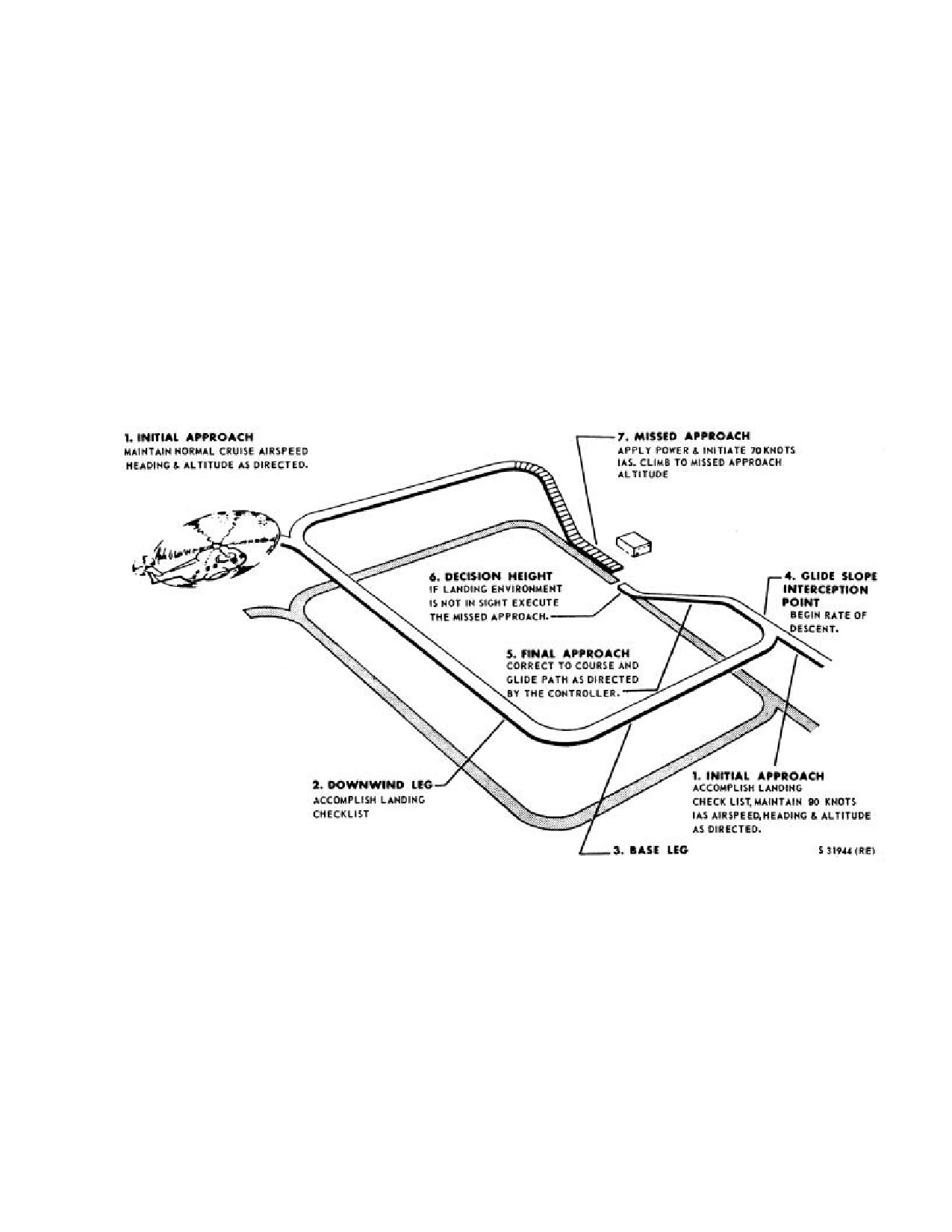
NAVAIR 01-230HLH-1
13.3.5 Holding. A maximum endurance airspeed of
13.3.7 Instrument Approaches. Instrument approaches
approximately 70 knots can be easily maintained during
are made using standard instrument approach procedures.
normal holding and presents no fuel problem. However, a
By using cruising speed during the entire approach, the
navigational problem will be present while attempting to
pilot can reduce the effect of wind on the track and
maintain a pattern in high winds. For normal shipboard
groundspeed of the helicopter and be able to fly a more
holding procedures, the CV NATOPS Manual should be
precise approach. During the final approach, it is important
consulted. Drift correction angles of 30o are as common to
that the airspeed be held constant to control drift and
the helicopter as
10o corrections are to a fixed-wing
ground speed. Small changes in heading may be made by
aircraft.
turning the YAW TRIM knob of the ASE. Refer to Figures
13-1 and 13-2 for typical instrument approaches.
13.3.6 Instrument Descent. Normal descents are
made by reducing power until the desired rate of descent is
accomplished. En-route descents are normally made at
cruising airspeed. Emergency descent can be made by
entering autorotation.
Figure 13-1. Ground-Controlled Approach (Typical)
13-3
ORIGINAL
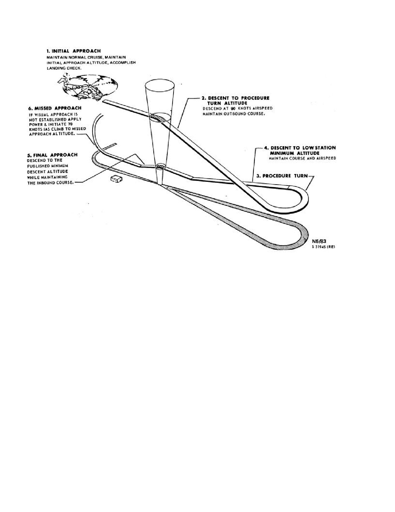
NAVAIR 01-230HLH-1
Figure 13-2. ADF Approach (Typical)
13-4
ORIGINAL
NAVAIR 01-230HLH-1
CHAPTER 14
Extreme Weather Operation
14.1
ICE, RAIN, AND SNOW
Takeoffs into fog or low clouds when the temperature
is at or near freezing could result in engine air inlet icing.
Takeoff is prohibited with snow and ice on the
Climbs should be made at higher than normal rates of
helicopter. Failure to remove snow and ice accumulated
climb under such conditions. Engine air inlet icing does
while on the ground can result in serious aerodynamic and
not necessarily occur with blade icing.
structural effects when flight is attempted. Takeoff,
hovering, and climbout performance as well as stall speeds
14.1.1 Flight With Ice Shield.
and handling characteristics can be adversely affected.
Unbalanced loads of snow and ice will result in heavy
vibration in flight, causing severe structural damage. The
rotary wing head, rotary wing blades, rotary rudder, and
flight controls should be thoroughly inspected and be free
· The auxiliary pitot static tube sleeves
from ice and snow.
shall be installed when the ice shield is
installed and removed when the ice
shield is not installed to prevent
excessive airspeed indicator error.
WARNING
· Engine power loss will occur with the
This helicopter shall not fly through areas of
ice shield installed.
forecast icing unless the weather has not
Note
developed as forecast. When icing
conditions, except dry snow, are inadvertently
Because of change of airflow around the
encountered, immediately turn on the
pitot tubes, a reduced effectiveness in the
engine/inlet and windshield anti-icing
systems. With dry snow present, use of the
barometric altitude hold system may be
experienced.
anti-icing system may result in melting of
the snow on the intake ducts and subsequent
refreezing and ice accumulation at the
Helicopters modified by either AFC 247 or AFC 321
have a removable ice shield installed forward of the
engine front frame. Under such conditions,
engines to prevent engine ice ingestion. The AFC 321 ice
use of the inlet anti-icing system is not
recommended.
shield is identified by a smooth contoured ramp directing
airflow into the engine. The AFC 247 ice shield does not
have the flow director.
Some significant locations to observe for ice or snow
accumulation are the windshield wipers, pitot tubes, and
Operating procedure with ice shield installed is as
wing stubs. If snow or ice accumulates during flight, a
follows:
precautionary landing should be made to remove the
accumulation. If a landing is not possible, change altitude
1.
Flight operators may be conducted when icing
to leave icing environment. Continued flight may cause ice
conditions are forecast. However, known areas of
ingestion in the engine from areas forward of the inlet.
Icing of the air inlet area is an ever present possibility
icing shall be avoided.
when operating in weather with temperatures of 10 oC and
2.
If icing conditions are encountered in flight,
below with visible moisture with the exception of dry
snow. Snow below a temperature of -4 oC can be assumed
immediately leave area where icing exists.
to be dry if there is no accumulation on the helicopter.
3.
Do not hover in freezing mist conditions.
14-1
ORIGINAL
NAVAIR 01-230HLH-1
A loss of gas generator speed
(no mechanical
14.1.3 On Entering Helicopter. Check the electrical
difficulties present) and a rise in power turbine inlet
and radio equipment with external power source
temperature may indicate engine icing. If power turbine
connected.
inlet temperature increases, retard engine speed selector to
maintain normal power turbine inlet temperatures. Engine
14.1.4 Warmup and Ground Check.
failure may occur rapidly because of overheating
of
turbine and exhaust area.
1.
Turn on cabin heater and windshield ice
protection systems, as required, immediately
after
engine start.
WARNING
WARNING
·Whenever the helicopter is to be
operated where temperatures of
-28 oC
are expected to be encountered, the
rotary rudder cables should be tensioned
· Hot exhaust from the heater may burn
in accordance with the Manual
personnel in the vicinity of the heater
exhaust.
Maintenance Instruction, NAVAIR
01-
230HLH-2-3.9.
· If windshield anti-ice is to be used, the
·When operating in cold temperatures,
LOW position should be selected before
flight control movements during servo
selecting NORMAL. Personnel in the
checks should be completed slowly at
vicinity of the helicopter should be
first to avoid damage to the control
warned that a possible missile hazard
exists in case of a defective or arcing
linkages and servos.
heating elements.
·While still a factor for successful cold-
2.
Check transmission oil temperature.
weather operation, cold-weather preflight
preparation is not generally as critical in
turbine-powered helicopter operation as
in
reciprocating engine helicopter
operation because there is not need for
oil dilution, etc. In order to expedite
preflight
inspection
and ensure
If an emergency rotor engagement is made
satisfactory operation for the next flight,
when the ambient temperature is -29 oC or
normal operating procedures outlined in
less, a VIDS/MAF shall be submitted. The
Part III should be adhered to with the
gearbox may be damaged from lack of
following additions and exceptions.
lubrication at these low temperatures.
14.1.2 Before Entering the Helicopter.
3.
Check the flight controls for proper operation.
1.
Check lower section of the engine air inlets for
Note
evidence of ice. Moisture collected on previous flights
can accumulate in the lower section between the front
Cycle the flight control on each servo
stator and rotor blades and freeze. An attempted
system.
engine start will result in starter failure. If ice is
suspected, check the engine for freedom to rotate,
14.1.5 Taxiing. Avoid taxiing in deep snow, as taxiing
external heat must be applied to forward engine
and steering are extremely difficult and frozen brakes are
section to permit thawing. Start engine as soon as
likely to result.
possible after heat application to remove all moisture
before refreezing can occur.
14.1.6 Before Takeoff.
2.
Check that all protective covers have been
1.
Check that windows, cabin doors and passenger
removed.
doors (ET) are fully closed.
3.
Check that the helicopter, including surfaces,
controls, ducts, oleo shock struts, drains, etc., has been
cleared of all snow, frost, and ice.
14-2
ORIGINAL
NAVAIR 01-230HLH-1
2.
Turn the pitot heater switch ON just before
moving into position for takeoff.
14.1.7 After Takeoff.
1.
After takeoff from water, wet snow, or slush
covered field, operate the landing gear through several
complete cycles to prevent freezing in the retracted
position.
2.
Check instruments.
14.1.8 During Flight. Use cabin heater, engine air inlet
anti-icing, and windshield ice protection systems, as
required.
14.1.9 Before Leaving Helicopter.
1.
Release brakes after wheels are chocked.
2.
Whenever possible, leave helicopter parked with
full fuel tanks. Every effort should be made during
servicing to prevent moisture from entering the fuel
system.
3.
Check that the battery is removed when the heli-
copter is parked outside for any extended period of
time.
4.
Check that all protective covers have been in-
stalled. (Engine exhaust and air inlet protective covers
should not be installed until after engine cooldown).
14-3
ORIGINAL
NAVAIR 01-230HLH-1
This Page Left Blank Intentionally
14-4
ORIGINAL
NAVAIR-01-230HLH-1
PART VII
Communications-Navigation-
Identification Systems
Chapter 15 - Communication-Navigation-Identification Systems
65
ORIGINAL
NAVAIR-01-230HLH-1
This Page Left Blank Intentionally
66
ORIGINAL
NAVAIR 01-230HLH-1
CHAPTER 15
Communication-Navigation-
Identification Systems
15.1 INTRODUCTION
15.2.1 Radio Operating Controls. A three-position
microphone trigger switch marked ICS and RADIO, and
The role of communications is to provide an effective
spring-loaded to the off position on the pilot and copilot
means of control and coordination. It is of primary
cyclic stick grip connects their respective microphones to
importance that all transmissions be as brief and accurate
the interphone transmission circuit when held in the ICS
as possible. To accomplish this without overloading the
position and to the radio transmission circuit when held in
tactical circuits requires strict adherence to proper voice
the RADIO position. When the pilot or copilot desires to
procedures and radio discipline. Brevity code words will
communicate with the crewmen when they are on SONAR
be used whenever appropriate.
INTERCOM, the pilot or copilot must ensure that the
HOIST select switch on the overhead switch panel is at
15.2 COMMUNICATION
AND ASSOCIATED
OFF or CREW and depress the HOIST/SONAR CALL
ELECTRONIC EQUIPMENT
switch to the UP hoist position on his collective pitch stick
grip, or place the switch marked SONAR INTERCOM
The
intercommunication
system
provides
with marked positions OFF and ON on the overhead
intercommunication for the pilot, copilot, crew, and the
switch panel to ON. The HOIST/SONAR CALL switch
hoist operator when those stations are manned. Two
on the collective pitch grip is of the momentary-contact
communications stations are provided in the pilot
type and connects the intercommunication system only
compartment, one each for the pilot and copilot. Each
when depressed. The SONAR INTERCOM switch
station is equipped with headset and microphone
provides for continuous intercommunications between
connections, microphone switches, and interphone control
pilot, copilot, and crew.
panels. Three other communication stations are in the
cabin: one for the cabin; one for the hoist operator at the
Foot switches are mounted on the deck at the pilot and
cargo door; and one at the No. 2 hois t operator station aft
copilot stations that can be used in place of the microphone
of the cargo door. Each station is equipped with headset
trigger switch. The floor switches will key either ICS or
jacks and microphone connections, a microphone switch,
radios depending on which one is selected on the
and intercommunication controls. The hoist operator
transmitter selector panel.
stations
also
have facilities
on the radio
intercommunication panel for monitoring radio signals.
The ICS and LF/ADF are operated on dc power only.
The communication and associated electronic equipment
All other radio equipment require both ac and dc power for
installed in the helicopter is listed in Figure
15-1. The
operation.
equipment is connected to the helicopter electrical systems
at the circuit breaker panels. Operating controls for all the
15.3 INTERPHONE-RADIO CONTROL SYSTEM
equipment are at the various crew stations. Indicators used
(ICS)
in conjunction with the navigation sets are on the
instrument panel. The location of antennas is shown in
The AN/AIC-l4 ICS (Figure 15-3 (NON-ET) or Fig.
Figure
15-2.
The intercommunication system
(ET)
15-3.1
(ET) amplifies inter-phone and received radio
provides intercommunication for the pilot, copilot, crew
signals and provides control for ICS isolation between
chief, and aft crewman. The pilot and copilot stations are
crewmen and pilots, crew radio transmission (HF and UHF
equipped with headset and microphone connections,
on frequency set in by pilot), and ON-OFF selection of
microphone switches, and interphone control panels. The
radio receivers.
crew chief, station 160, and aft crewman, station 425, are
each equipped with headset and microphone connections
and an interphone control panel.
15-1
ORIGINAL
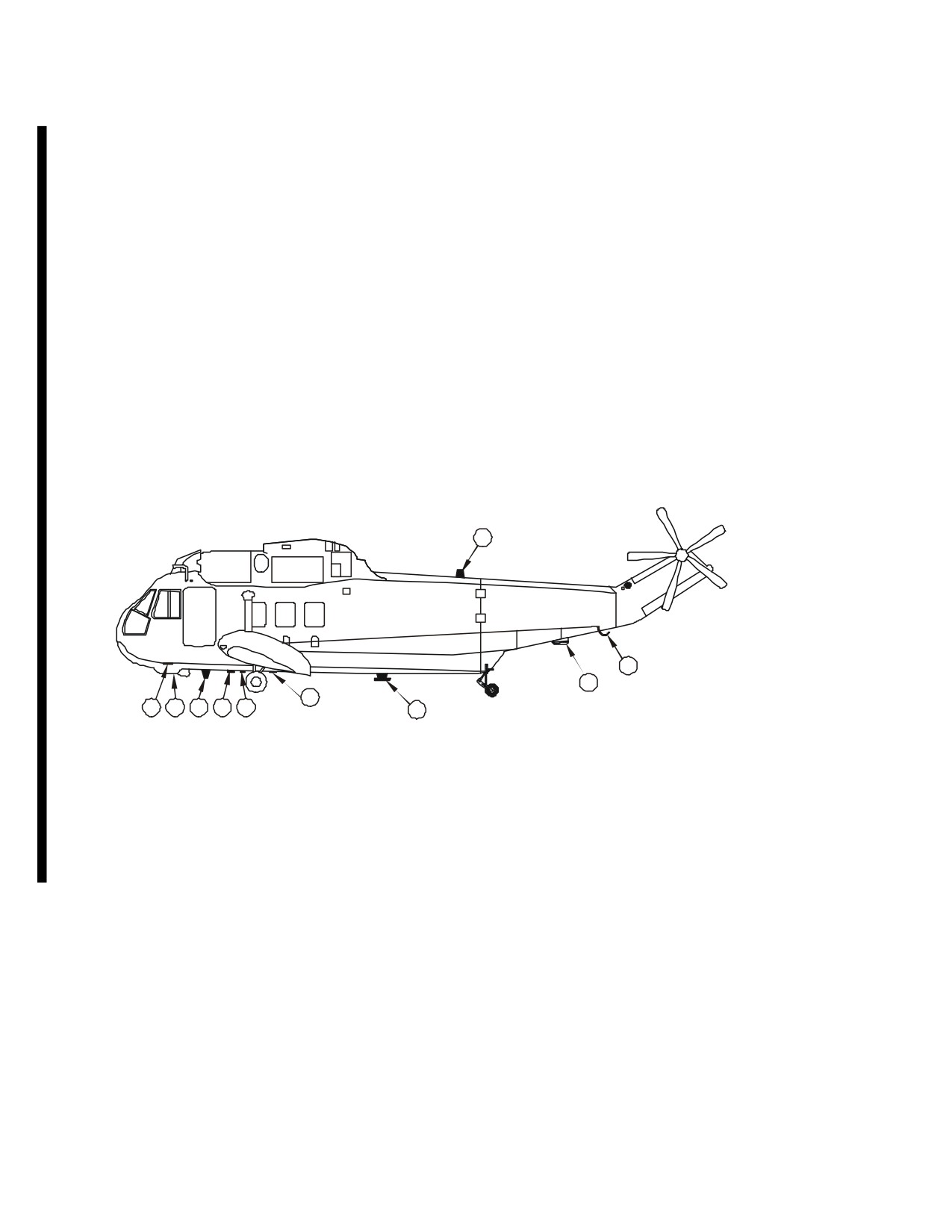
NAVAIR 01-230HLH-1
PRIMARY
LOCATION
TYPE
DESIGNATION
FUNCTION
OPERATOR
RANGE
OF CONTROLS
No. 1 UHF/
AN/ARC-159
Short range two- Pilot or
Line of sight
Cockpit console
COMM
(NON-ET)
way voice
Copilot
VHF
ARC-186
Two-way
Pilot or
Line of sight
Cockpit console
Transmitter
(NON-ET)
communication
Copilot
Receiver
UHF/VHF/COMM AN/ARC-182(V)
Two-way
Pilot or
Line of sight
Cockpit console
No. 1
communication
Copilot
UHF/VHF/COMM AN/ARC-182(V)
Two-way
Pilot or
Line of sight
Cockpit console
No. 2
(UH-3H Executive
communication
Copilot
Transport)
1
2
3
5
9
8
10
7
6
4
1. UHF/VHF/COMM (UPPER)
7. TACAN
2. LF/ADF-LOOP
8. UHF-ADF/OPTI
3. LF/ADF-SENSE (WIRE)
9. RADAR ALTIMETER
4. UHF/VHF/COMM (LOWER)
10. VHF/COMM
5. UHF/COMM (NORMAL)
6. IFF
01771019
Figure 15-2.1. (ET) Antennas
15-2
ORIGINAL
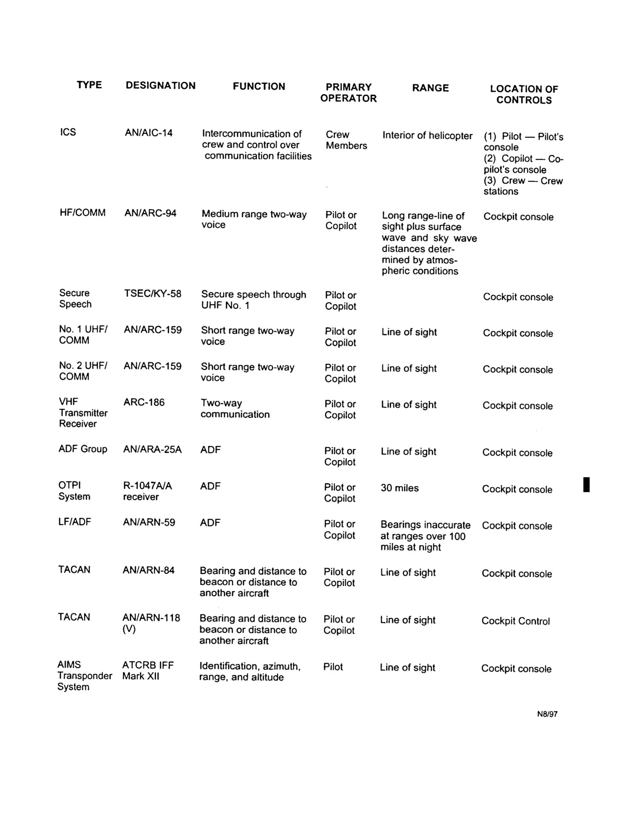
NAVAIR 01-230HLH-1
Figure 15-1. Communication and Associated Electronic Equipment
15-3
ORIGINAL
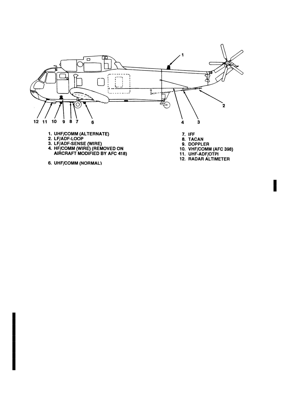
NAVAIR 01-230HLH-1
Figure 15-2. (NON-ET)Antennas (Typical)
15.3.1 Interphone Control Panels. Each crew-
TACAN. There is an external ICS jack installed forward
member has an individual ICS master control panel,
of the port passenger door.
transmitter selector panel, and a radio receiver selector
panel. The crewmen each have an ICS master control
The hoist operator can select either the pilot or the crew
panel, a receiver selector panel, and a transmitter selector
ICS. The pilot interphone can be connected with the crew
panel. The hoist operator has a radio receiver and
interphone by either the SONAR CALL switch on the
transmitter selector panel, an ICS master control panel, and
collective pitch lever grip or the SONAR INTERCOM
an ICS mixer control panel. The No.
2 hoist operator
ON-OFF switch on the overhead switch panel.
station is also equipped with a radio receiver selector
panel, an ICS master control panel, and an ICS mixer
15.3.1.2 ICS Master Control Panel. Interphone
control panel. The system operates on direct current and is
master control panels (Figure 15-4) at each station contain
protected by two circuit breakers. The system is operative
isolation and microphone amplifiers and are the master
when the battery switch is turned ON or an external source
controls for the interphone radio control system for that
is plugged in. The pilot, copilot, and forward crewman are
location (see Figure 15-3). Each panel marked ICS consists
provided with adio communication. The pilot, copilot,
of an amplifier selector switch marked AMPL SEL, a
and crewmen are provided with audio signal reception
VOX sensitivity control, a microphone selector switch
from automatic direction finder ADF. The pilot and
marked MIC SEL, and an interphone volume control knob
copilot are provided with audio signal reception from
marked INTPH VOL. The amplifier selector switch is a
tacan.
The set provides separate interphone
four-position, rotary-type switch with positions marked
communications between the pilot and the copilot
EMERG, NORM, ALT 1, and ALT 2. When the amplifier
independent of interphone communications between the
selector switch at any station is turned to EMERG and the
sensor operators.
corresponding sonar ICS switch is switched from L-OPR
or R-OPR ICS to TRANS, as in the failure of both
15.3.1.1
Interphone Control Panels (ET). The
amplifiers, the headset is connected directly to any of the
pilot and copilot each have an individual ICS master
first three switches of the receiver selector panel at that
control panel, transmitter selector panel, and a radio
station. No interphone operation is possible when the
receiver selector panel. The crew chief and aft crewman
amplifier selector switch is at EMERG. Under these
are equipped with individual ICS master control panels.
conditions, communications are possible only by using
The system is operative when the battery switch is turned
radio sidetone (HF (if installed) and UHF). In the ALT 1
ON or an external source is plugged in. The pilot and
position, the isolation amplifier transfers its load to the
copilot are provided with radio communication on HF and
microphone amplifier. Normal ICS is possible at ALT 1 or
UHF. The pilot and copilot are provided with audio signal
ALT 2 positions, using the corresponding amplifier. The
reception from the automatic direction finder ADF and
microphone selector switch has three positions: COLD that
is used in normal operations and that requires use of the
15-4
ORIGINAL
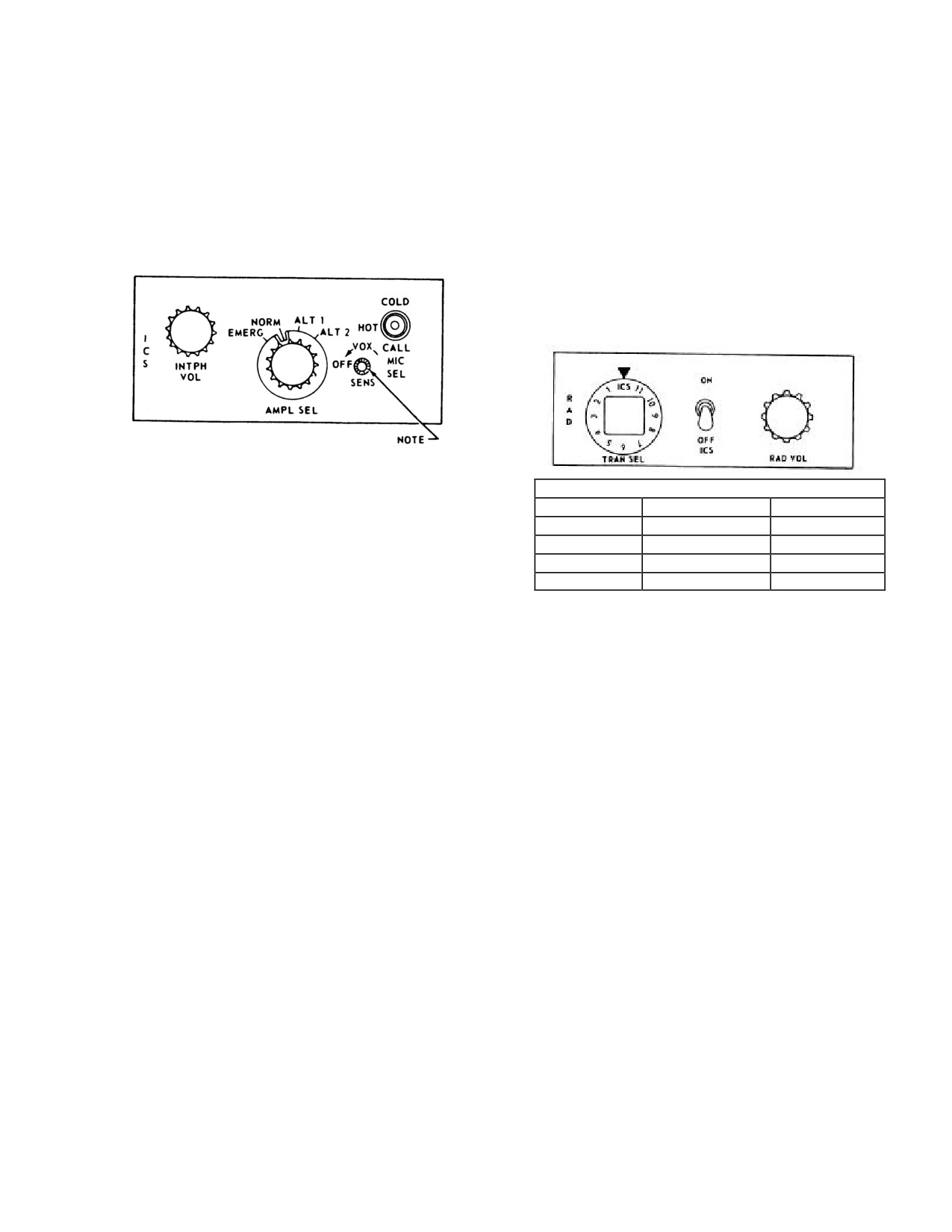
NAVAIR 01-230HLH-1
microphone trigger switch; HOT that gives the operator
master control panel. When the ICS ON and OFF switch is
continuous microphone, hands-off operation; and CALL, a
placed OFF, only radio signals can be heard. If the MIC
spring-loaded override position that allows ICS to all
SEL switch on the ICS master control panel at any of the
interphone stations regardless of their switch positions.
crew stations is placed to CALL, the ICS ON and OFF
Upon releasing the MIC SEL switch from CALL, the
switch is bypassed. The transmitter selector switch
microphone selector switch will return to HOT and only
positions are 1 (UHF 1), 4 (UHF 2), and 6 (VHF). The
the station that has initiated the call circuit will have a hot
volume control adjusts the level of the received radio
microphone.
signals. On UH-3H Executive Transport helicopters, two
transmitter selector control panels (Figure 15-5.1) enable
the pilot and copilot to turn the interphone set on or off, to
select the transmitter to which audio and keying circuits
are connected, and to adjust the radio receiver volume.
Figure 15-4. ICS Master Control Panel
The CALL position will cancel the SONO DIR mode
TRANSMITTER SELECTED
selected on the sensor operator receiver selector panel. The
SW POS
Pilot / Copilot
Crewmen
knob marked VOX (voice operated switch) is to the right
1
UHF 1
of the AMPL SEL rotary switch and has a marked position
4
UHF 2
OFF, plus an arrow in a clockwise direction. Operation of
6
VHF
the VOX function is as follows. The system is energized
2,3,5,7-11
NOT USED
NOT USED
by turning the knob clockwise out of the OFF detent. The
Figure 15-5. Transmitter Selector Control Panel
ICS should be keyed by placing the MIC SEL switch to
HOT. The VOX knob should now be adjusted so that the
15.3.1.4 Hoist Operator ICS Mixer Control
microphone is energized when the operator talks in a
Panels. The hoist operator ICS mixer control panels
normal tone and deenergized when the operator stops
(Figure
15-8) consist of a PILOTS ICS
- SONAR ICS
talking. Turning the knob clockwise decreases the sound
switch and RAD VOL control. The PILOTS ICS
-
level necessary to key the microphone. On helicopters
SONAR ICS switch permits the hoist operator to
equipped with VOX, only the interphone will be keyed
communicate with the pilot and copilot, and forward
through the VOX system. Helicopters not equipped with
crewman. The RADIO VOLUME control is used with the
VOX-MIC SEL-HOT switch position will key the
selected receiver on the radio receiver and transmitter
interphone system. The knob marked INTPH VOL is used
selector panel.
to adjust the level of the incoming signal as well as the
sidetone level.
15.3.2 Interphone Operation
15.3.1.3 Transmitter Selector Control Panels.
1. AMPL SEL switch (master control panel) - NORM.
Four transmitter selector control panels
(Figure
15-5)
All stations.
enable the pilot, copilot, sensor operators, and forward
crewman to turn the interphone set on or off, to select the
2. MIC SEL switch
(master control panel)
- AS
transmitter to which audio and keying circuits are
DESIRED.
connected, and to adjust the radio receiver volume. The
panel is marked RAD and consists of an ICS control
3. TRANS SEL switch (transmitter selector panel) -
switch with positions ON and OFF; a twelve-position
DESIRED TRANSMISSION. Pilot and crew.
transmitter selector-switch marked TRANS, SEL, ICS, and
1 through 11; and a volume control marked RAD VOL.
4. ICS ON-OFF switch (transmitter selector panel)
-
The ICS ON and OFF switch controls the incoming
ON. Pilot and crew.
interphone signals and is used in conjunction with the ICS
15-5
ORIGINAL
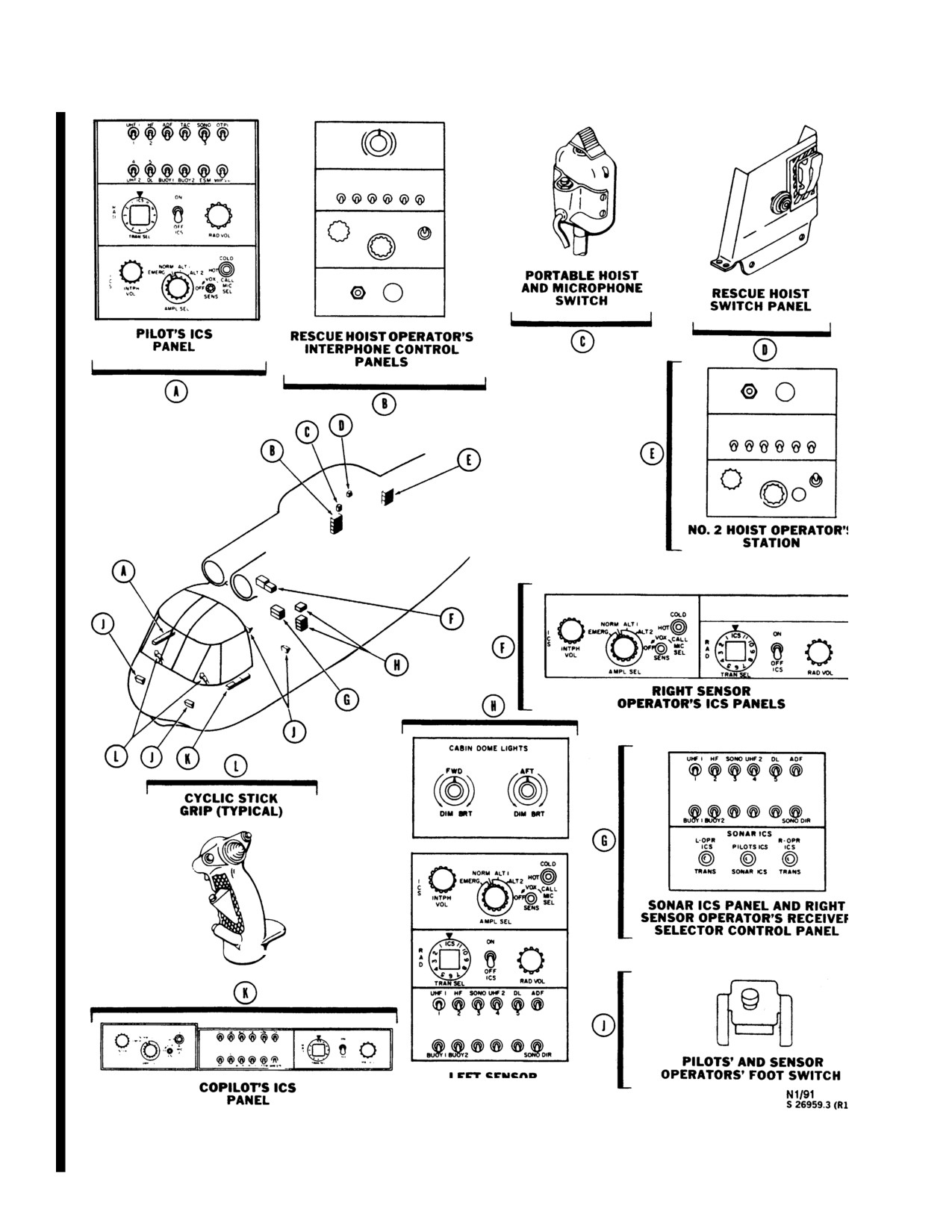
NAVAIR 01-230HLH-1
CABIN ICS
PANELS
Figure 15-3. Intercommunication System
15-6
ORIGINAL
NAVAIR 01-230HLH-1
UHF 1
HF ADF TAC SONO OTPI
1
2
3
4
5
UHF 2
DL BUOY
1 BUOY 2
ESM
VHF 1n
COLD
NORM
ALT 1
I
EMERG
ALT 2
HOT
ICS
ICS
C
VOL
CALL
R
S
NTPH
OFF
MIC
A
VOL
SEL
D
SENS
OFF
AMPL SEL
TRAN SEL
OFF
RAD VOL
COLD
AFT
NORM ALT 1
I
EMERG
ALT 2
HOT
C
VOL
CALL
CREWMAN'S
S
NTPH
MIC
OFF
SEL
VOL
SENS
PANEL
AMPL SEL
C
PILOT'S AND COPILOT'S
PILOT'S ICS
FOOT SWITCH
PANEL
A
B
C
B
D
COLD
A
NORM ALT 1
I
EMERG
ALT 2
HOT
C
VOL
CALL
S
NTPH
OFF
MIC
VOL
SEL
SENS
AMPL SEL
CREW CHIEF'S
D
PANEL
F
E
A
F
E
NORM
ALT 1
COLD
UHF 1
HF
ADF
TAC
SONO
OTPI
EMERG
ALT 2
HOT
ICS
C
VOL
CALL
R
ICS
S
INTPH
OFF
MIC
1
2
3
A
VOL
SENS
SEL
4
5
D
OFF
AMPLSEL
TRAN SEL
OFF
RAD VOL
UHF 2
DL
BUOY 1BUOY 2
ESM
VHF1n
COPILOT'S ICS
PANEL
CYCLIC STICK
GRIP (TYPICAL)
01771107
Figure 15-3.1. (ET) Intercommunication System
15-7
ORIGINAL
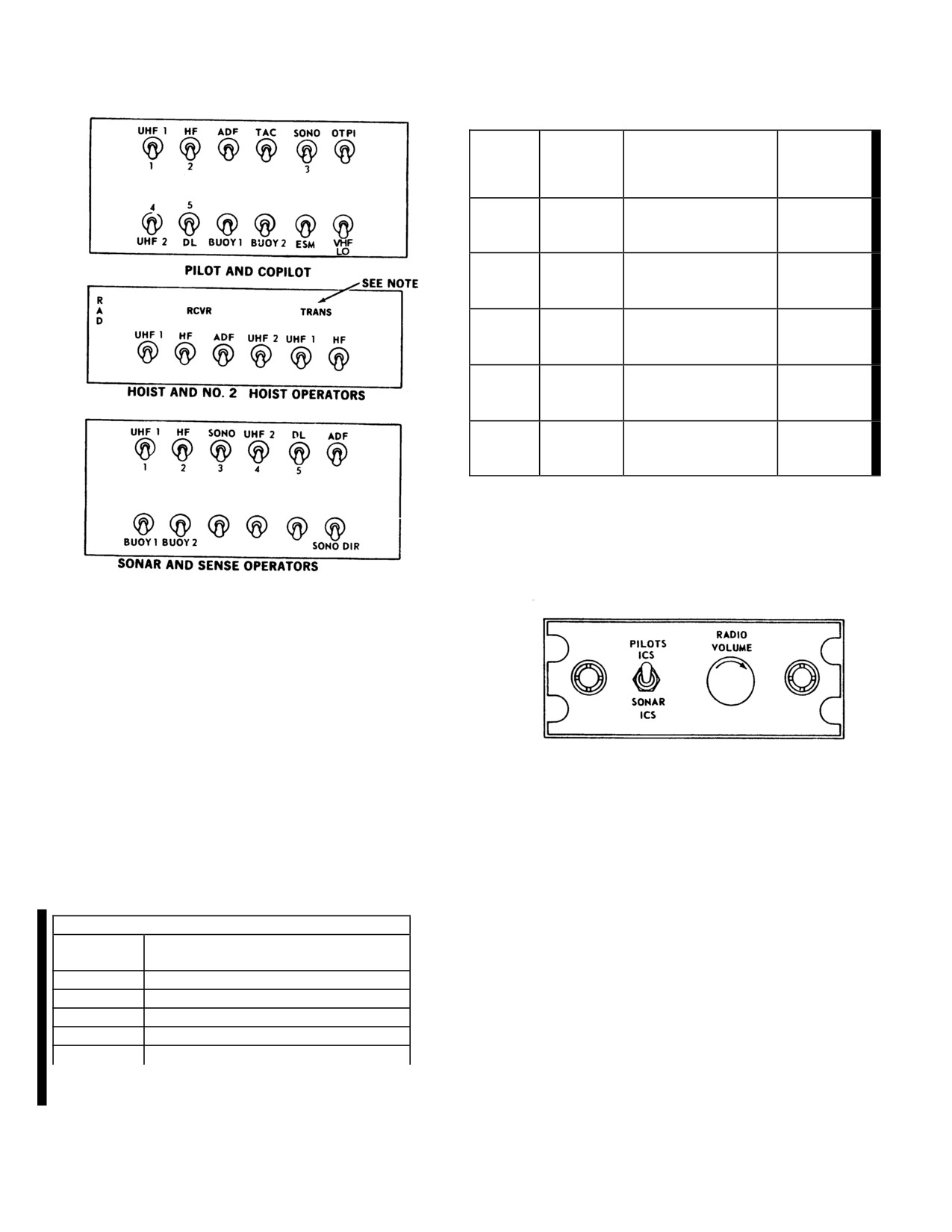
NAVAIR 01-230HLH-1
SEL.
SIGNAL
SIGNAL
SIGNAL
FUNC
SOURCE
INFORMATION
DISTRB.
VHF /
PILOT /
VHF
COMMUNICATION
COMM
COPILOT
COMMUNICATION
UHF /
PILOT /
UHF 1
S AND ADF
COMM
COPILOT
IDENTIFICATION
COMMUNICATION
UHF /
PILOT /
UHF 2
S AND ADF
COMM
COPILOT
IDENTIFICATION
ALL
ADF
LF / ADF
IDENTIFICATION
STATIONS
PILOT
TAC
TACAN
IDENTIFICATION
AND
COPILOT
Figure 15-7. Receiver Selector Control Panel Function
Figure 15-8. ICS Mixer Control Panel
Note
Not on hoist operators panel
Figure 15-6. Receiver Selector Control Panels
To transmit:
15.4 UHF/COMM SET (AN/ARC-159)
5. COLD MIC/microphone switch
- DEPRESS;
The helicopters are equipped with one AN/ARC-159
pilot/copilot cyclic trigger switch, pilot/copilot
UHF/COMM sets
that
provide two-way voice
foot switch, sensor operator foot switch (for use
communication. This can be accomplished on any one of
of foot switch, ICS must be selected on the
20 preset frequencies or manual selection of any one of
TRANS SEL switch), hoist operator portable
7,000 channels within the equipment frequency range of
hoist, and microphone switch. HOT MIC/VOX -
225.00 to 399.975 MHz. The set includes a guard receiver
VOICE ACTIVATED.
that permits continuous monitoring of the guard frequency
whenever the main transmitter-receiver is tuned to a
TRANSMITTER SELECTED
tactical frequency. The radio set also provides automatic
SW
PILOT, COPILOT
direction finding in conjunction with the UHF-OTPI/ADF
POS
group. Relative and magnetic bearing will be displayed by
1
UHF/VHF
the No. 1 pointer on the RMI. In addition, the No. 1 UHF/
2
NOT USED
COMM is used in conjunction with the TSEC/KY-58
3
NOT USED
secure speech set as a speech security system.
4
UHF
5-11
NOT USED
15.4.1 UHF/COMM
(AN/ARC-159) Control Panel.
The control panel (Figure 15-9) is on the cockpit console.
Figure 15-5.1 (ET) Transmitter Selector Control Panel
The function selector has four positions. At OFF, all power
is removed from the equipment. The MAIN position
energizes the receiver-transmitter. The BOTH position
energizes the receiver-transmitter and guard receiver
15-8
ORIGINAL
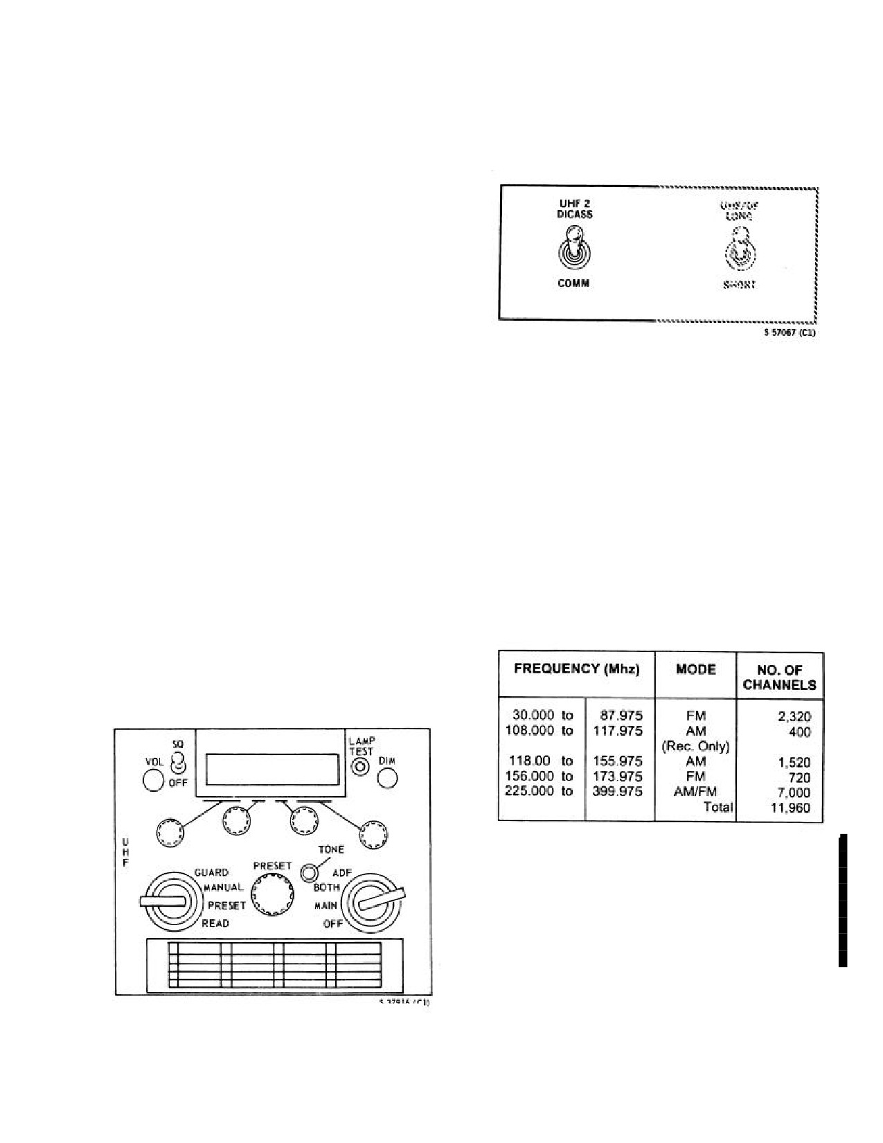
NAVAIR 01-230HLH-1
At ADF, the UHF-OTPI/ADF group is engaged to provide
The radio set is powered by the primary dc bus through
automatic direction-finding operation. The mode selector has
a circuit breaker marked UHF
1 or UHF 2 under the
four positions. The PRESET position permits selection of
general heading RADIO on the pilot circuit breaker panel.
one of 20 preset channels by means of the preset channel
control. At MANUAL, any one of 7,000 frequencies may be
selected by use of the manual frequency selectors. The
GUARD position selects the preset guard frequency for the
transmitter and receiver with the function selector set to
MAIN. The READ position will display the preset frequency
of the preset channel selected on the preset
channel/frequency indicator. Setting the function selector to
BOTH with the mode selector set at GUARD turns the guard
receiver on and places the transmitter, guard receiver and
main receiver on the guard frequency. The PRESET channel
control selects any one of the 20 preset channels. The preset
channel/frequency indicator displays the preset channel.
Figure 15-10. UHF 2 Selector Switch
Frequency selectors provide manual frequency selection
when the mode selector is set at MANUAL and the
frequencies are displayed in the preset channel/frequency
Note
indicator. The VOL control adjusts the audio level of the
receiver. The SQ/OFF switch has two positions, SQ and
UHF communications may be degraded
OFF. At OFF, the receiver squelch is disabled; at SQ
when using the upper antenna between
position, the receiver squelch circuit is unaffected. The
relative azimuth 5° right and 10° left.
TONE button, when pressed, transmits a continuous tone.
The LAMP TEST button, when pressed, displays a series of
15.5 UHF/VHF/COMM SET
(AN/ARC-182
(NON-
digit eights in the preset channel/frequency indicator to check
ET))
operation of the indicator.
UH-3H helicopters are equipped with an AN/ARC-182
15.4.2 UHF Antenna Selector Switch. UHF antenna
UHF/VHF, AM-FM, two-way communication system for
selector switch marked UHF ANT SEL on the dome light
normal or secure voice. The system can be tuned to any of
panel has marked positions NORMAL and ALT. With the
11,960 channels spaced 25 kHz apart within the frequency
switch at NORMAL, the lower antenna will provide for two-
bands shown below:
way communication from the No. 1 UHF/COMM set, and
the upper antenna will provide for two-way communication
from the No. 2 UHF/ COMM set. With the switch at ALT,
the UHF/COMM sets are reversed.
The four guard frequencies
(40.500 Mhz FM,
121.500
Mhz AM, 156.800 Mhz FM, and 243.000 Mhz AM) are
automatically tuned for the band selected. Power to
operate the AN/ARC-182 radio set is obtained from the
28-vdc primary bus through the
5 ampere UHF/VHF
circuit breaker on the pilot's circuit breaker panel. On UH-
3H Executive Transport helicopters, a second AN/ARC
182 is installed.
15.5.1 UHF/VHF/COMM
(AN/ARC-182) Control
Panel. The UHF/VHF control panel (Figure 15-11) is
Figure 15-9. UHF/COMM Control Panel
located in the center console. The control panel contains
(AN/ARC - 159)
the mode selector, frequency controls, channel selector
controls, and squelch and volume controls.
15-9
ORIGINAL
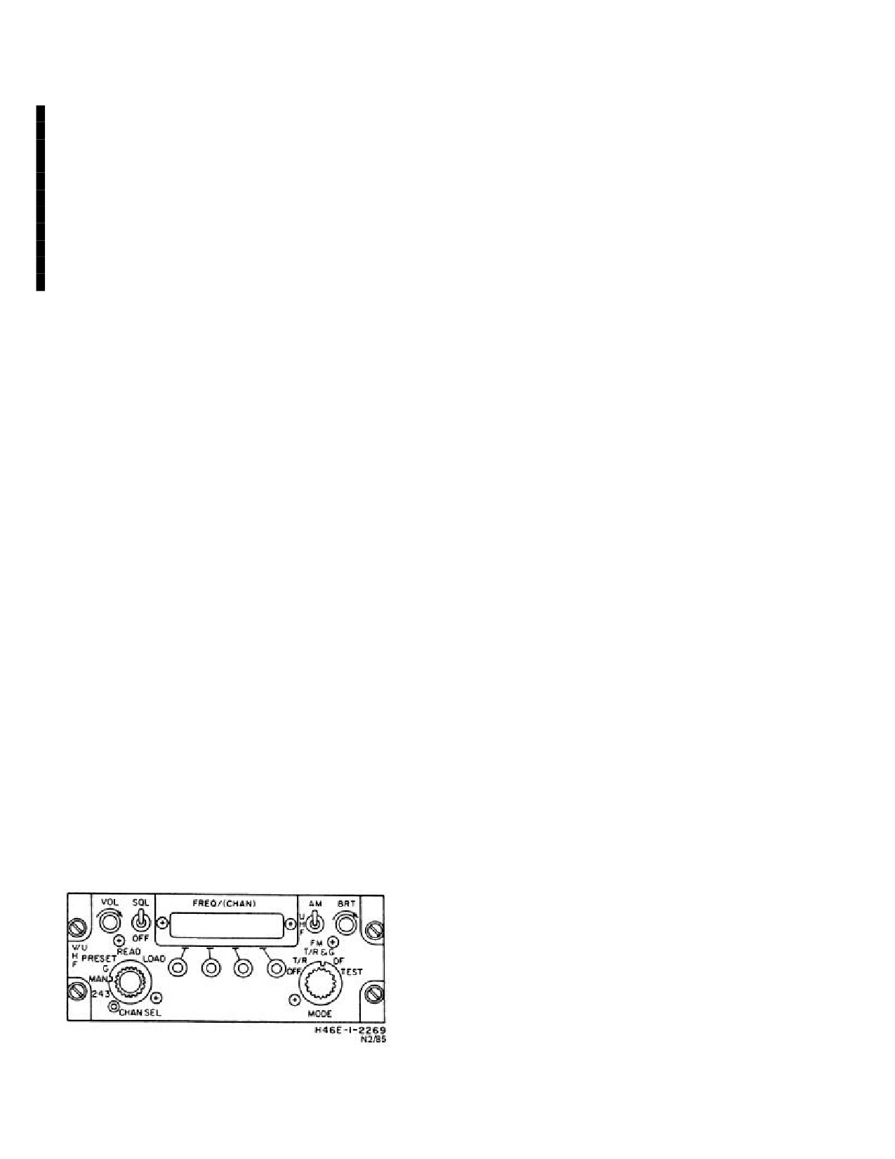
NAVAIR 01-230HLH-1
The five-position mode selector allows the operator to
Note
select one of the following operational modes: (1) OFF
-
Shuts off equipment unless function selector is set to 243;
·
For
subsequent
secure
voice
(2) T/R - Enables main receiver and transmitter; (3) TR&G
transmissions utilizing the KY-58. First
- Enables guard receiver, main receiver, and transmitter;
start assumes secure voice equipment
(4) DF
(Direction Finder)
- Enables direction finding
previously keyed. If start does not
equipment, main receiver, guard receiver, and transmitter;
proceed as outlined, and corrective
(5) TEST - Initiates 14-second built -in test of radio unless
action cannot be taken, see local remedy
function selector is set to 243. Test results are displayed on
of minor problems as follows:
the FREQ (CHAN) display. All 8's on the display indicates
that the radio set is functional.
a. If continuous beep occurs after
release of MIC switch, repeat turn-on
15.6 KY-58 SPEECH SECURITY SYSTEM
procedures. If problem persists, switch to
plain uncovered voice.
The TSEC/KY-58 is a small, lightweight, wideband
secure speech digital communications unit designed for
b. If a continuous tone occurs, load KY-
panel or console mount. The equipment operates half-
58 with a new cryptovariable. If problem
duplex push to talk at a 15 kb rate and is used with the No.
persists, switch to plain uncovered voice.
1 AN/ARC- 159 UHF radio.
c. If the problem continues after
On aircraft with H-3 AFC
428 incorporated, the
troubleshooting, turn secure voice off
TSEC/KY-58 speech security unit is located in the center
and use first start procedures again.
console. On aircraft without H-3 AFC 428 incorporated,
the TSEC/KY-58 speech security unit is located in a Z-
d. In case of emergency, press zeroize
AHQ adapter which is installed in the KY-28 mount
switch to automatically erase the key
located on the aft electronics rack.
setting.
15.6.1 First Start (KY-58)
·
Classified information will not be
discussed on ICS or radios operating in a
1. KY-58 power switch - ON.
secure mode while other radios are
transmitting in clear mode. Conversely,
2. Mode switch to C cipher.
no radio will transmit in clear mode
while classified information is being
3. Fill switch to desired channel.
discussed on ICS or other radio is
transmitting in secure mode.
4. Set volume control.
·
The KY-58 has plain text override
5. Switch toggle switch to C cipher.
capability that allows crews to monitor
all
plain text transmissions while
a. Get a continuous beeping tone with background
operating in cypher text mode. Pilots
noise.
must ensure that the KY-58 is in cypher
mode in both aircraft when discussing
6. Key UHF momentarily.
classified
material
via
UHF
transmissions.
7. Ready for secure operations.
15.7
UHF/ADF GROUP
The UHF/ADF group
(AN/ARA-25A) is used
in
conjunction with the No. 1 UHF/COMM set, the No. 2
UHF/COMM set, and the OTPI system to indicate the
bearing of radio signal sources on the No. 1 pointer of the
RMI. The operating frequency range is the same as the
UHF/COMM sets and the OTPI system. When a UHF
signal is being received, a 100-Hz tone is heard; when a
VHF (OTPI) signal is being received, a 400-Hz tone is
heard. The system is controlled either by the UHF/COMM
Figure 15-11. AN/ARC - 182 UHF/VHF AM-FM
sets function switch at ADF or by turning on the OTPI
system. Precedence for the No. 1 needle of the RMI from
Control Panel
15-10
ORIGINAL
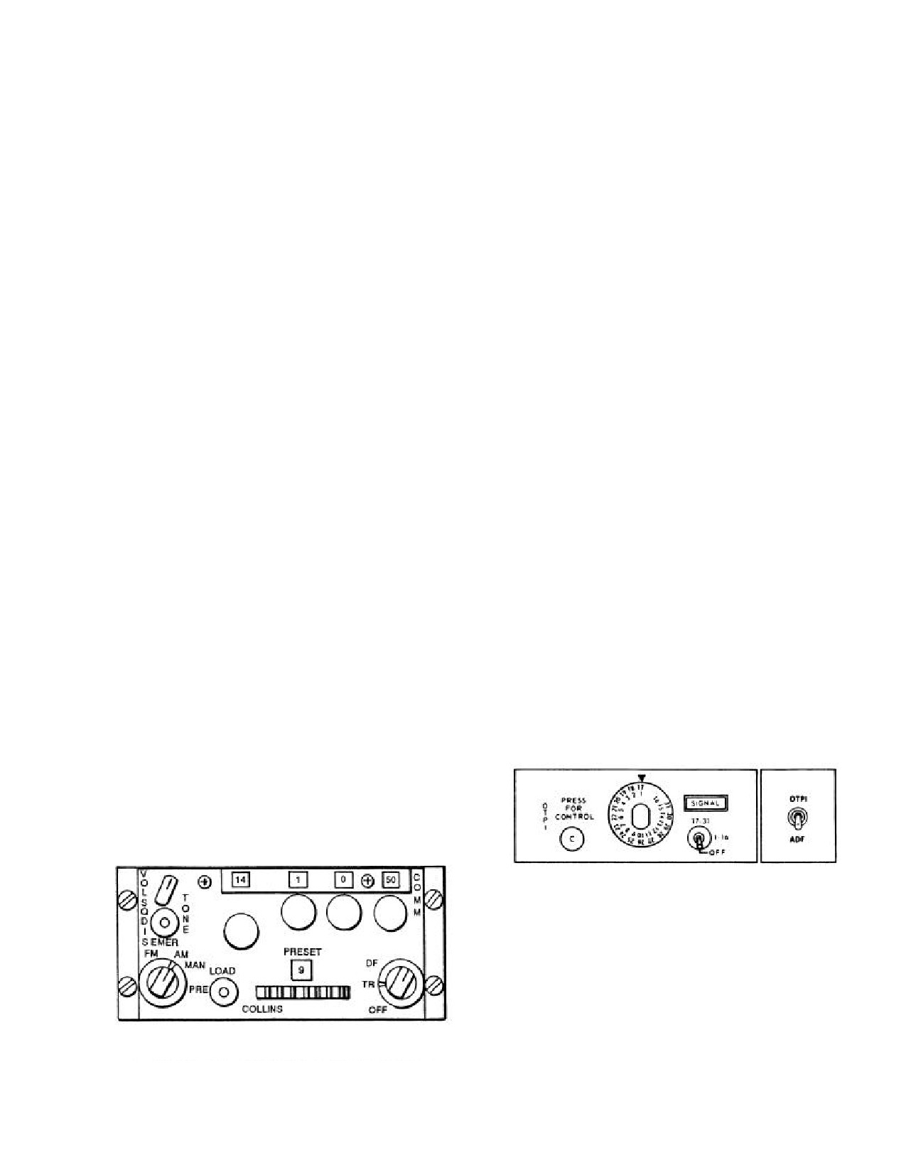
NAVAIR 01-230HLH-1
highest to lowest is: OTPI, No.
1 UHF/ADF, No.
2
15.9 VHF/COMM SET (AN/ARC-186(V))
UHF/ADF, and LF ADF. The ADF group is powered by
the primary dc bus through a circuit breaker marked UHF
H-3 helicopters modified by AFC 398 are equipped
DF under the general heading RADIO on the pilot circuit
with one AN/ARC-186(V) VHF/COMM set (Figure 15-
breaker panel. Twenty-six vac power is received from the
12) that provides two-way voice communication in both
No. 2 radio transformer to power the No. 1 RMI pointer
the AM and FM bands. This can be accomplished on any
and is protected by a circuit breaker marked UHF DF
one of 20 preset frequencies or manual selection of any
under the general heading RADIO on the pilot circuit
one of
4,358 frequencies. Selection of any frequency
breaker panel. Helicopters are furnished with additional
within
the range of
30.00 to
87.975 MHz will
power from the No. 2 ac primary bus through a circuit
automatically result in transmission/ reception in the FM
breaker marked UHF DF under the general heading
band. Selecting a frequency between 116.00 and 151.975
RADIO on the pilot circuit breaker panel.
MHz results in transmitting/ receiving in the AM band.
15.8 UHF/ADF GROUP OPERATION
15.9.1
VHF/COMM SET
(AN/ARC-186(V))
Control Panel. The control panel (Figure 15-12) is on
To operate the set, proceed as follows:
the cockpit console. The mode select switch has three
positions. At OFF, all power is removed from the
1. OTPI - OFF.
equipment.
The TR position energizes the
receiver/transmitter and allows two-way communication.
2. Receiver selector panel - UHF.
The DF position is not enabled in the AFC
398
configuration. The frequency control emergency select
3. UHF/COMM panel - SELECT FREQUENCY.
switch has four positions. At MAN, any one of 4,358
frequencies may be selected by use of the manual
4. Function switch (UHF/COMM panel) - ADF.
frequency selectors. The PRE position permits selection
of one of 20 preset channels (AM or FM) by means of the
To secure the set, proceed as follows:
preset channel control. The switch has two positions
under the EMER heading. In the AM position, the radio
1.
Function switch (UHF/COMM panel) - OFF.
will receive and transmit on the prestored AM guard
channel
(121.5 MHz). The FM position selects
40.500
Note
MHz. The squelch disable/tone switch has three positions.
In the SQ DIS position, the receiver squelch is disabled.
To call a station and request transmission of
The center position enables squelch. Holding the switch
a homing signal, it is necessary to turn the
in the tone position will transmit a 1000 Hz tone on the
function switch
(UHF/COMM panel) to a
selected frequency. The switch is spring loaded to return
transmitting position (T/R or T/R+G).
to the center position from the tone position. The VOL
control adjusts the audio level of the receiver. The radio
To DF on guard frequency
(243.0), the
set is powered by the primary dc bus through the ARC-
channel selector switch must be placed in
186 dc circuit breaker on the pilot circuit breaker panel.
the guard transmit position or manually
select 243.0 since the direction- finder group
only receives audio information from the
main receiver unit and not the separate UHF
guard receiver incorporated in the
transceiver unit.
Figure 15-13. OTPI Control Panel and
Transfer Switch
Note
The crewmen ICS stations can monitor VHF
transmissions but cannot transmit (with AFC
398 part 4).
Figure 15-12. ARC-186 Radio Set Control Panel
15-11
ORIGINAL
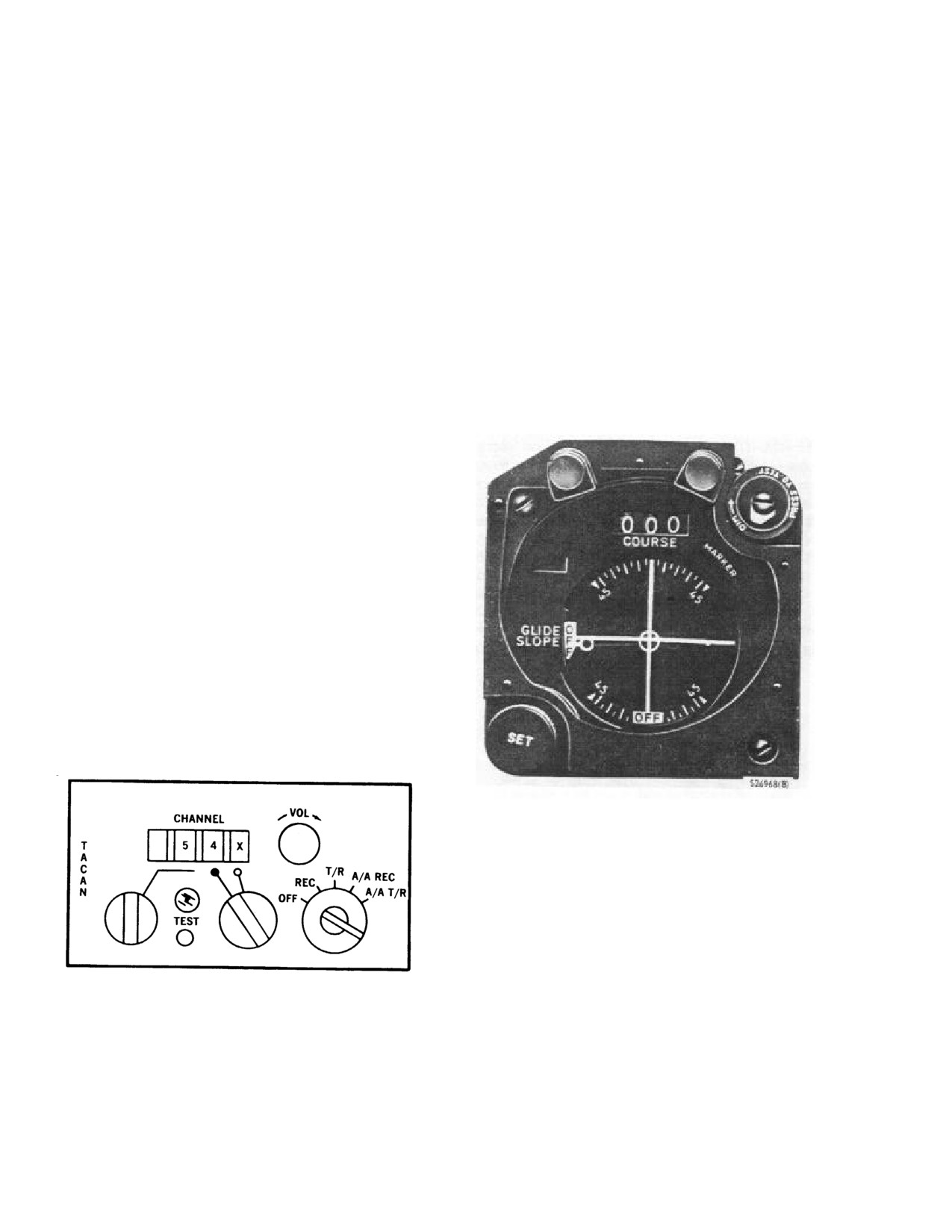
NAVAIR 01-230HLH-1
15.9.2 VHF/COMM Operation.
and shipboard tacan stations are considered surface
stations and supply both bearing and distance to the
1. ICS transmitter selector switch - 6.
helicopter. An airborne station without a bearing
transmitter only supplies distance information. An airborne
2. ICS receiver selector panel - VHF LO.
station with a bearing transmitter supplies bearing and
distance information.
3. Mode select switch (VHF/COMM panel) - TR.
This installation is not capable of transmitting bearing
4. Volume control - AS DESIRED.
information but does supply distance information when
interrogated. Although maximum range of station
5. Frequency control switch - AS DESIRED.
reception is governed by line-of-sight considerations, the
maximum operating range of the set is 390 nm when the
6. Preset/manual frequency selectors - AS DESIRED.
selected tacan station is a surface station, and
200 nm
when the selected station is an airborne station. The tacan
7. To transmit
- PRESS MICROPHONE TRIGGER
navigation set has provisions for 126 X channels and 126
SWITCH ON CYCLIC STICK GRIP TO RADIO
Y channels. The X channels are those presently in use by
POSITION OR PRESS FOOT SWITCH AND SPEAK
surface stations. The Y channels differ from the X
INTO MICROPHONE.
channels in frequency assignment and pulse spacing.
15.10 VHF Radio Receiver. The VHF radio receiver
converts the AN/ARA-25 ADF group radio navigation aid
into a VHF sonobuoy on-top position indicating beacon
locator. When the AN/ARA-25 is transferred from the
ADF mode to the OTPI mode, only the frequency range is
changed. The receiver operates in the frequency range of
162.25 to
173.50 MHz that permits selection of
31
channels. In the ADF mode, it functions normally as a
direction finder. However; in the OTPI mode, the range of
operation is shortened and the over-the-top capability is
used to locate the exact reference point over the marker
beacon. When the helicopter passes directly over the
marker beacon, the receiver seeks a null position. This
null will be indicated by the number one pointer of the
RMI ID-250/ARN. The pointer will move to a new
position 180° opposite to its previous position prior to
passing over the marker beacon.
Figure 15-15. Course Indicator.
Note
The Y channels were developed to alleviate
congestion of the X channels, but have not
yet been implemented in ground stations.
They are, however, available for use in the
A/A modes. Use of the Y channels in the
Figure 15-14. TACAN Navigation Set
A/A mode is encouraged to eliminate
AN/ARN-118(V)
possible interference with ground stations.
15.11 TACAN SET (AN/ARN-118(V))
The magnetic bearing of a selected tacan station is
indicated by the No. 2 double-barred pointer on the pilot
The AN/ARN-118(V) tacan set is a polar coordinate
and copilot BDHIs (Figure 15-20) and the RMI (Figure 15-
17). The distance to the tacan station is indicated by the
navigation system that is used to determine the magnetic
bearing and slant line distance from the aircraft to a
BDHIs range indicator. A course to or from the tacan
selected tacan station. The selected tacan station can be
station may be set in the pilot course indicator (Figure 15-
ground, shipboard, or airborne tacan station. The ground
15) COURSE selected window. The course i n d i c a t o r
15-12
ORIGINAL
NAVAIR 01-230HLH-1
ambiguity window shows whether the selected course is to
The tacan navigation set requires a 90-second warmup
or from the tacan station. The course indicator CDI and the
period, regardless of the position selected by the function
BDHI range indicator have warning flags that appear when
selector knob.
unreliable signals below minimum usage are received.
When correct bearing information cannot be determined,
15.11.1.2 Channel Selector Knobs. The tens
the BDHI No. 2 pointer will search or turn in a manner that
channel selector and units channel selector switches are
prevents the pilot from deriving improper information
rotary knobs that tune the tacan navigation set to any of
from it.
126 tacan channels. The X,Y channel selector, a movable
ring around the units channel selector knob, selects either
The tacan is powered by the No. 1 primary ac bus through
the X set of 126 channels or the Y set of 126 channels.
the circuit breaker marked tacan under the general heading
RADIO on the copilot circuit breaker panel, and from the
primary dc bus through the circuit breaker marked
TACAN under the general heading RADIO on the pilot
circuit breaker panel.
26-vac power is received from the
No.
2 radio transformer to power the indicating
The units channel selector knob contains a
instruments and is protected by a circuit breaker marked
built-in mechanical stop to prevent turning
TACAN on the pilot circuit breaker panel.
past the nine position. Do not attempt to
override this mechanical stop. Direction of
15.11.1 TACAN Control Panel. The control panel
knob must be reversed when the stop is
(Figure 15-14) marked TACAN is on the cockpit console.
reached.
The controls include a function selector switch, tens
channel selector switch, units channel selector switch, X/Y
15.11.1.3 Volume Control Knob. The volume control
channel selector; volume control knob, and self-test button.
knob marked VOL varies the volume of the audio signals.
The control panel also contains a test indicator light and a
channel digital display.
15.11.1.4 Self-Test Button. The manual self-test
button marked TEST provides a test of the complete tacan
15.11.1.1 Function Selector Knob. A five-position
system except for the antennas when pressed.
(OFF-REC-T/R-A/A REC-A/A-T/R) function selector
knob selects the mode of operation. OFF removes power
15.11.1.5 Manual Self-Test. To initiate the self-test,
from the set. The REC position allows only bearing
select T/R and set a course of 180° in the pilot course
information to be received from a surface station. The T/R
indicator window. Press the TEST button and observe that
position allows both bearing information and distance data
the test indicator light goes on for about 1 second, the
to be received from a surface station. The A/A REC
BDHI and CDI flags come into view for about 7 seconds,
position allows only bearing information to be received
and the No. 2 pointers of the pilot BDHI indicate 270°. For
from a suitably equipped cooperating aircraft. In the A/A
the next 15 seconds, the flags go out of view, the range
T/R position, both bearing and distance information are
indicator displays 000.0 ±0.5, the No. 2 pointer indicates
received from another aircraft. If the cooperating aircraft is
180° ±3°,the CDI centers to within one-half dot, and the
not equipped to transmit bearing signals, only the distance
ambiguity window indicates TO. When the self-test is
will be received in this mode.
complete, all indicators return to the indications displayed
prior to the initiation of self-test. A failure is recorded if
Note
the test indicator light remains on during the test and/or the
indicators are out of limits. The test can be done again in
Operation in the air-to-air mode requires
the REC mode, and if the indicator light does not go on,
prearrangement with a cooperating aircraft.
the malfunction is isolated to the transmitter section and
The second aircraft must be equipped with
the bearing information is valid.
an air-to-air tacan that is set to the air-to-air
mode of operation and is set to a channel 63
15.11.1.6 Automatic Self-Test. To be sure that the
channels away from the channel setting of
tacan system is operating properly, an automatic self-test
the tacan in the first aircraft. One aircraft
occurs when the receiver signal becomes unreliable or the
may reply to as many as five others, but it
signal is lost. The results of the automatic self-test are the
will only display the distance to the nearest
same as for the manual self-test except that the BDHI and
aircraft.
CDI flags remain in view throughout the test.
15-13
ORIGINAL
NAVAIR 01-230HLH-1
OFF flag at the bottom of the CDI and by loss of bearing
information on the RMI. When the ARN-126 is used for
Instrument Landing System (ILS) approaches, information
is displayed on the CDI only. The glideslope and localizer
functions are selected by tuning a valid localizer frequency
Bearing and/or distance indications may still
in the range
108.10 to
111.95 MHz. Each localizer
be present when the TEST lamp is on. Such
frequency is automatically paired to a corresponding
indications could be either partially usable
glideslope frequency in the range of
329.15 to
335.00
or grossly inaccurate. They should be cross-
MHz. The vertical bar on the CDI indicates aircraft
checked using every available means. Be
position relative to the glideslope beam (glideslope). An
prepared for the possibility of tacan
invalid glideslope signal is indicated by the OFF flag on
equipment failure if the test indicator light
the left side of the CDI. An invalid localizer signal is
goes on.
indicated by the OFF flag at the bottom of the CDI.
15.11.2 Tacan Navigation Set
(AN/ARN-118(V))
15.11.4 VHF/NAV SET
(AN/ARN-126) Control
Operation
Panel The control panel is on the cockpit console. The
radio set contains all control necessary for VHF/NAV
15.11.2.1 To Operate the Set.
system operation. The radio set is powered by No. 2 AC
primary bus through the 5 amp VHF/NAV AN/ARN-126
1. Channel selector knobs
- SELECT DESIRED
circuit breaker on the pilot’s circuit breaker panel at 26
CHANNEL.
VAC.
2.
Function selector
- REC, T/R, A/A REC OR A/A
15.11.5 Normal Operation of the VHF Navigation
T/R
Receiver.
3.
Volume control knob
- ADJUST TO DESIRED
1.
Place the Power Test switch to the ON position.
VOLUME IF FUNCTION SELECTOR KNOB IS AT
EITHER REC OR T/R.
2.
Select the desired operating frequency. Turn either
the left knob (selects 1-MHz steps) or the right knob
15.11.2.2 To Secure the Set.
(selects 50 or 25 kHz).
1. Function selector knob - OFF.
3.
Both knobs rotated clockwise for an increase in
frequency.
15.11.3 VHF/NAV SET
(AN/ARN-126)
UH-3H
helicopters modified by AFC 431 Part 2 are equipped with
4.
The selected frequency is displayed on the digital
one AN/ARN-126 VHF/NAV SET. This system is needed
counter.
for helicopters operating with VHF Navigation Ground
Stations. The system consists of an AN/ARN-126 Radio
To turn the receivers off.
Navigation Receiver with glideslope, Control Panel, ID-
250 A/ARN Radio Magnetic Indicator
(RMI), Course
5. Place the Power/Test switch to the OFF position.
Deviation Indicator (CDI), two VOR/LOC antennas and a
glideslope antenna. The VOR antennas operate over the
Note
108.00 to 122.00 MHz frequency band and are mounted
The AN/ARN-126 system has the capability
horizontally opposite each other on the side of the
of testing all of its own instrumentation
helicopter at fuselage station FS 149, waterline WL 94.
circuits through a self test feature.
The glideslope antenna operates over the 328.6 to 335.4
MHz frequency band is mounted horizontally on the nose
15.12 COURSE INDICATOR (ID-387/ARN)
of the helicopter at FS 90 and WL 136. The CDI and RMI
are located in the cockpit instrument panel. The RMI is
The course indicators (ID-387/ARN) (Figure 15-15) on
used with the VOR function of the ARN-126 only. Both
the pilot side of the instrument panel consists of a knob
needles point to the VOR station when a valid VOR
marked SET in the lower corner, a press-to-test light
frequency is selected on the control panel. VOR stations
marked MARKER in the upper right corner, a three-digit
operate in the frequency range from
108.00 to
117.95
counter window marked COURSE, a vertical bar and a
MHz. When a VOR station is tuned, the CDI displays
horizontal bar marked GLIDE SLOPE, a scale at the top
only the horizontal bar to indicate deviation from a
and bottom of the indicator with linear markings each 100
selected VOR radial.
The relative heading pointer
and numerical markings at 450 to the left and right of the
indicates the number of degrees of deviation from the
center line, a relative heading pointer with a circle at the
course selected in the CDI window. Loss of a VOR signal
center and the tip, and a sensing window in the upper left
is indicated by an
15-14
ORIGINAL