NAVAIR 00-80T-112 NATOPS INSTRUMENT FLIGHT MANUAL (15 NOVEMBER 2006) - page 4
NAVAIR 00-80T-112
LOCALIZER
D
B
C
F
E
A
NOTE: NOT TO SCALE
GLIDESLOPE
C
D
A
B
F
E
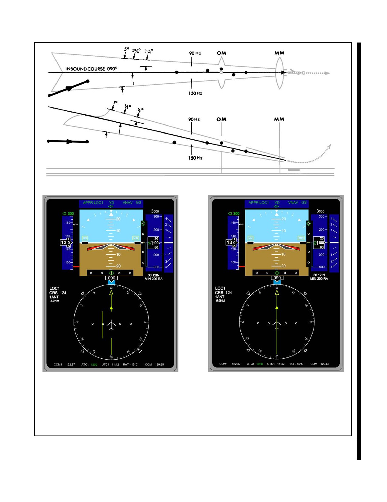
A Front Course Approach − Turningto intercept the ILS Localizer
B Rolling out — on course,
glideslope above aircraft.
Figure 24-3. Course Indicator Presentation (Front Course) (Sheet 1 of 2)
24-7
ORIGINAL
NAVAIR 00-80T-112
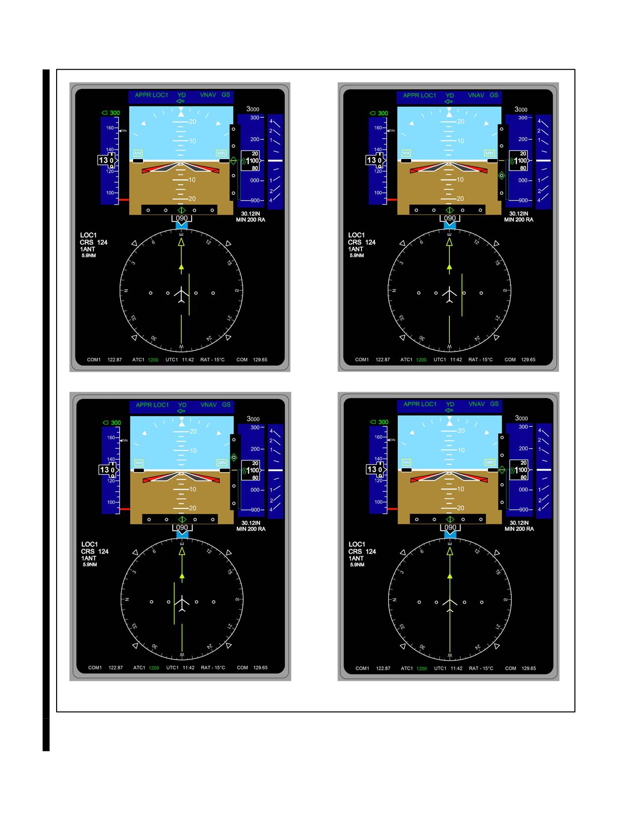
C Left of course,
D Left of course, correct right,
on glideslope.
glideslope below aircraft.
E Right of course, correct left,glideslope above aircraft.
F On course.
On glideslope.
Figure 24-3. Course Indicator Presentation (Front Course) (Sheet 2 of 2)
ORIGINAL
24-8
NAVAIR 00-80T-112
The most common tendency when flying an ILS approach is to “fly” the CDI and GSI. An ILS approach is a basic
instrument maneuver similar to a radar approach. Immediate and smooth corrections should be made on the control
instruments based on aircraft and flightpath performance indications. The importance of precise aircraft control
cannot be overemphasized. Lateral distances in relation to CDI displacement can be considerable, especially at
installations where the distance from the localizer transmitter at minimum altitude may be more than 2 miles. For
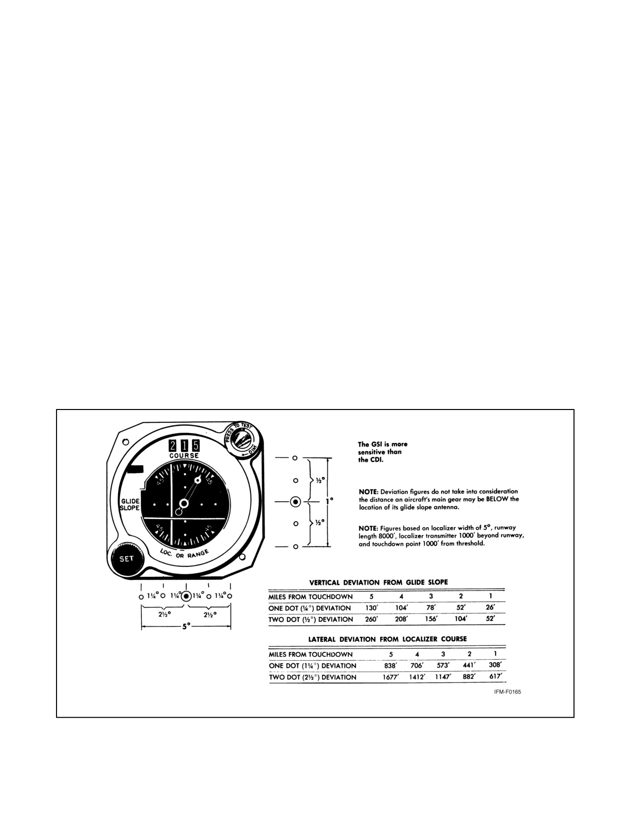
example, in the lateral deviation chart of Figure 24-4, a full-scale deviation at 1 mile from touchdown places the
aircraft 617 feet from the centerline. If the CDI was deflected 2_ at a missed approach point 1/2 nm from the end of
this runway, the aircraft would be approximately 400 feet from the centerline. Do not attempt to fly the final approach
with full-scale deflection on the CDI or GSI, as obstruction clearance will not be assured; consideration should be
given to executing a missed approach.
The most critical period of the approach occurs while the pilot is busy maintaining course, glidepath, and airspeed,
and is approaching the published DH. Ensure the altimeter is being included in the cross-check. The DH is the lowest
altitude at which a missed approach will be initiated if sufficient visual reference with the runway environment has
not been established. Perform the missed approach when:
1. At the DH and visual reference with the runway environment is insufficient to complete the landing (runway
or runway/approach lights).
2. Instructed by the controlling agency.
3. A safe landing is not possible.
Figure 24-4. Course and Glideslope Deviation vs. Actual Displacement from Touchdown
24-9
ORIGINAL
NAVAIR 00-80T-112
If the course warning flag is displayed during the final approach, initiate the
missed approach procedure. If the glideslope warning flag is displayed, the
approach should be flown no lower than the published localizer-only
altitude or, if not published, no lower than circling-minimum altitude for the
aircraft category. Localizer-only approaches are planned for and flown as
a nonprecision approach.
24.3.2 Localizer Approaches
Most Navy aircraft do not have glideslope capability, but may execute an ILS approach as a localizer approach. In
this case, proceed as outlined for a full ILS approach. A localizer approach is a nonprecision approach and the pilot
should execute a missed approach when he has reached the missed approach point and the runway environment is
not in sight.
Note
Many ILS missed approach procedures require the use of VOR; hence,
pilots may have to retune their VOR receiver.
The Localizer-type Directional Aid (LDA) is of comparable utility and accuracy to a localizer, but is not part of a
complete ILS. The LDA will not be aligned with the runway, but the angle of divergence will not exceed 30_.
24.3.3 Simplified Directional Facility (SDF)
The Simplified Directional Facility (SDF) provides a final approach that is similar to that of the ILS localizer and
LDA; however, the SDF may have a wider course width of 6_ or 12_. It does not provide glideslope information. The
SDF transmits on frequencies 108.10 to 111.95 MHz. For the pilot, the approach techniques and procedures used in
the performance of an SDF instrument approach are essentially identical to those employed in executing a standard
no-glideslope localizer approach, except that the SDF course is seldom aligned with the runway and the course may
be wider, resulting in less precision.
24.3.4 Radar Vectors
When being radar vectored to an ILS final, the pilot should retain the radar service until established at a point where
a transition to the published procedure can be made. The controller should establish the aircraft with a 30_ or less
intercept angle to the localizer course at an altitude that will intercept the glideslope before the final approach fix.
When the controller issues the final vector, altitude, and clearance for the approach, the pilot must know his position
in relation to the airfield. If the aircraft is at a range beyond the coverage of the approach chart, maintain the last
assigned ATC altitude until within the area depicted on the approach chart. When within the area depicted on the
approach chart and after intercepting the localizer, the pilot may follow those altitudes depicted on the approach chart
at the specified fixes. Query the controller if there is any doubt concerning position or altitude clearance.
Note
Use radar monitoring service, when available, as an additional source of
information.
ORIGINAL
24-10
NAVAIR 00-80T-112
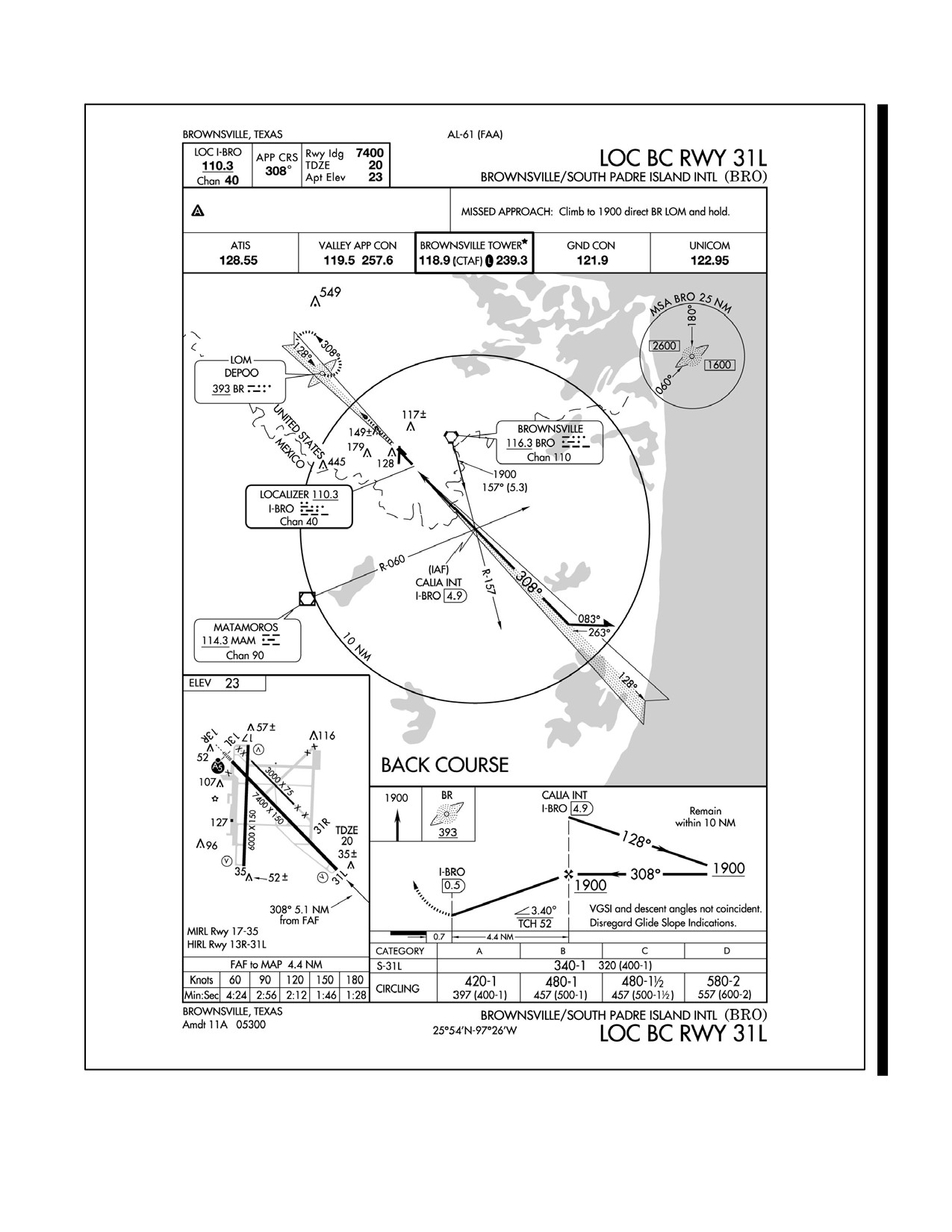
24.3.5 Localizer (LOC) Back Course Approach
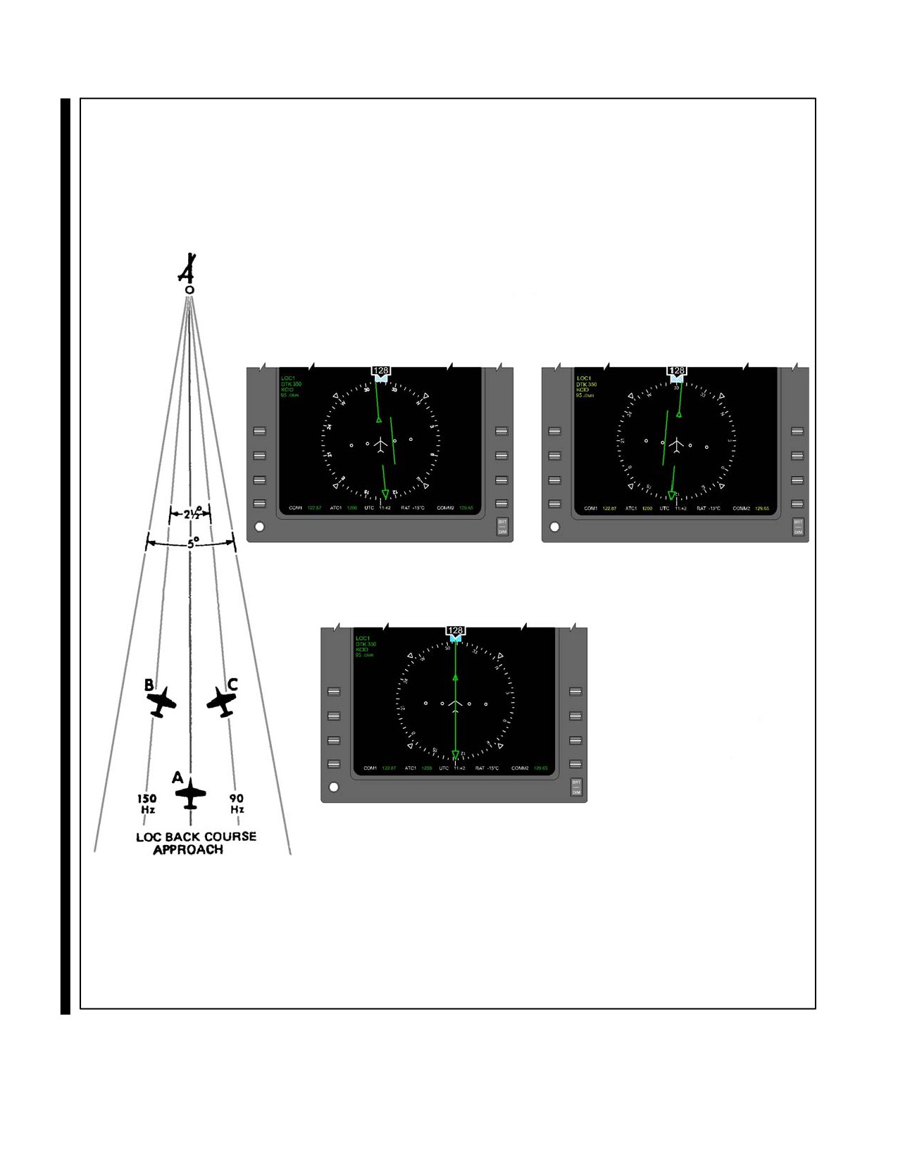
Localizer (LOC) back course (Figures 24-5 and 24-6) approaches are nonprecision approaches and glideslope
information is not provided. To maintain the proper aircraft heading/localizer course relationship, set the published
front course in the course selector window. When inbound on the back course or outbound on the inbound course,
the heading pointer will be in the bottom half of the course indicator. Turning to place it toward the CDI in the lower
half of the instrument case will correct the aircraft toward course. Back course approaches are flown using techniques
similar to those for localizer approaches.
24-11
ORIGINAL
NAVAIR 00-80T-112
B
C
PUBLISHED FRONT COURSE
SET IN COURSE SELECTOR
WINDOW.
A
Figure 24-5. Course Indicator Presentations
ORIGINAL
24-12
NAVAIR 00-80T-112
Figure 24-6. LOC Back Course Approach
24-13/(24-14 blank)
ORIGINAL
NAVAIR 00-80T-112
CHAPTER 25
Radar Approaches
25.1
INTRODUCTION
The word radar is derived from the words radio detection and ranging. Radar equipment determines the distance and
direction of objects by transmission and return of radio waves.
Radar is used in many ways to increase operational effectiveness. One of its principal uses is to provide a precision
approach system for aircraft landing during conditions of restricted visibility and/or low ceilings.
25.1.1 Principles of Radar
The basic principle of radar may be stated in a a single word — reflection. An echo is a simple demonstration of the
reflection of sound waves. A radiated noise strikes a reflecting surface and is returned to its source. The time lag
between the original sound and its echo is directly proportional to the distance the sound must travel. This same
principle applies in the use of radio waves.
The frequency band used contains very short radio waves of ultrahigh or super-high frequency that travel, essentially,
in a straight line and are easily reflected from objects in their path.
Longer radio waves are not as easily reflected; they continue around obstacles and tend to follow the curvature of the
Earth.
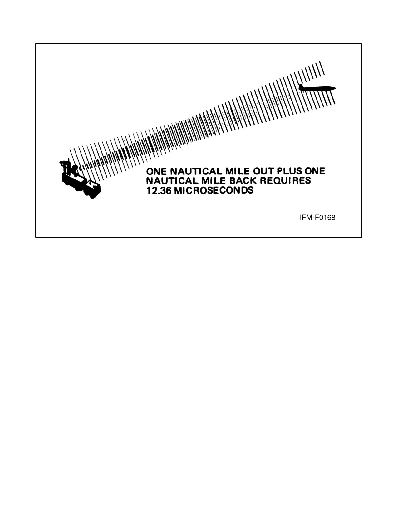
A very short radio wave is produced and transmitted in a certain direction in the form of a short pulse lasting from
one-half to several microseconds (millionths of a second). When this pulse strikes a reflecting surface, some of the
reflected waves return to the point of origin, where the energy is picked up by a receiver. Multiplying the time interval
by the velocity of the radio waves and dividing the product by two gives the distance to the reflecting object
(Figure 25-1).
The best means of presenting the return of the echo is by use of cathode-ray tubes, commonly called scopes. With
this type presentation, the object (aircraft) reflecting the radio wave appears as a pip on a scope. Through scope
interpretation, the radar controller determines position, range, and also elevation of the aircraft during a precision
approach.
25.1.2 Radar Traffic Information Service
Radar Traffic Information Service advises pilots of any radar target observed in the proximity that warrants attention.
This service does not relieve pilots of their responsibility to see and avoid. The surveillance radar used by Air Traffic
Control (ATC) does not provide altitude information on aircraft that are not equipped with Mode C. Several factors
influence the availability of radar traffic information services (e.g., weather, controller workload, and traffic volume).
Traffic information is provided to all aircraft operating on an IFR Flight Plan, unless operation in Class A airspace
or the pilot declines service. When receiving Visual Flight Rules (VFR) advisory service, pilots should monitor the
assigned frequency at all times and advise the controller when changing VFR cruising altitude. When the service is
no longer required, advise ATC and change transponder code to 1200.
25-1
ORIGINAL
NAVAIR 00-80T-112
Figure 25-1. Radio Wave Reflection
25.2
RADAR EQUIPMENT AND OPERATION
25.2.1 Equipment
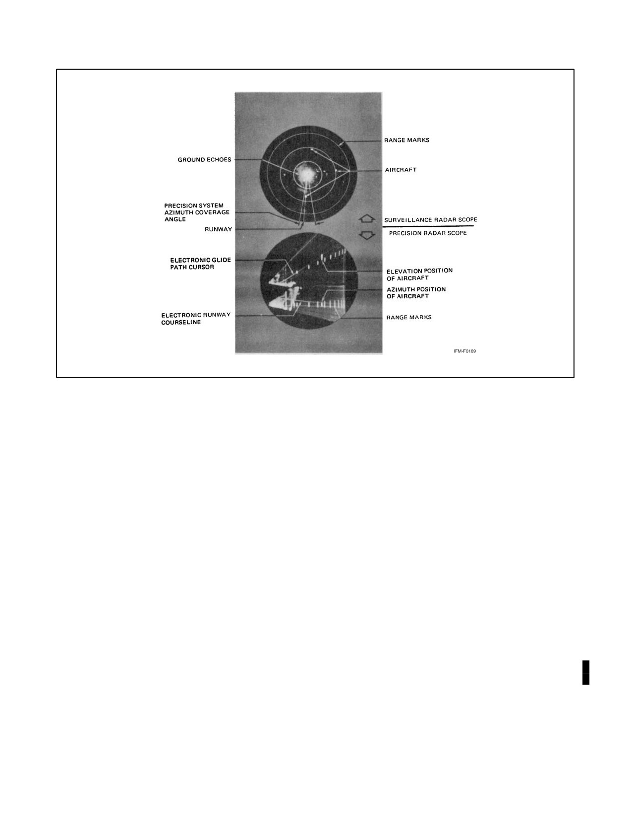
The precision radar approach system displays azimuth, elevation, and range information on the same scope and
enables one operator to closely observe aircraft position during the approach. The scope used for this presentation
is called AZ-EL, for azimuth and elevation. The elevation presentation appears on the upper portion of the scope, the
azimuth on the lower portion. In addition to the glidepath and the runway course-line cursors, range marks are also
electronically traced on the AZ-EL display. These range marks, occurring at
1-mile intervals, are spaced
approximately in logarithmic relationship. The first mile from touchdown on the display occupies a greater distance
than the second mile, and so forth. This has the effect of expanding the display as the aircraft approaches the runway
and provides the controller with increasingly precise indications of the aircraft flightpath.
Most radar units incorporate a Moving Target Indicator (MTI) that is adjustable, allowing only moving targets above
a certain velocity to appear on the scope.
In addition to the radar facility, a complete Precision Approach Radar (PAR) system will have an approved approach
light system, which is necessary to support lowest minimums (Figure 25-2).
25.2.1.1 Limitations of Radar
Radar sets using MTIs are susceptible to radar cancellation speed, commonly called blind speed. This phenomenon
causes momentary loss of the target.
Jet aircraft having small reflective surfaces are difficult to track unless transponders (e.g., IFF) are used.
ORIGINAL
25-2
NAVAIR 00-80T-112
Figure 25-2. Typical Radarscopes
Because of the short wavelength used by radar, rain droplets, snow, and the like cause scope clutter. This makes scope
interpretation difficult during heavy rain or other heavy precipitation. Later model radar sets use circular polarization
(a grid placed over the antenna) to help eliminate clutter caused by precipitation. The radar controller uses circular
polarization only if there is a possibility of losing the target in precipitation clutter. With circular polarization, the
controller might unknowingly vector an aircraft through areas of intense precipitation, so the pilot will be advised
of possible flight through precipitation not visible on the radarscope.
25.3
RADAR APPROACH PROCEDURES
25.3.1 Radar Approaches
Radar control is one of the most precise methods used for accomplishing an instrument approach. A radar approach
system consists of Airport Surveillance Radar (ASR) and/or Precision Approach Radar (PAR), controllers, and
associated communication equipment. Controllers interpret radar displays and transmit course and glideslope
information to the pilot. As directed, the pilot maneuvers the aircraft to a position from which it can safely land.
Information as to radar availability, frequencies, minimums, glideslope angle, and type of approach can be found in
Flight Information Publications (FLIP). The FLIP terminal approach charts provide runway and airfield pictorial
presentations (i.e., obstructions, approach lighting, length and width of runways, and the relative positions of
navigational aids). When planning for a radar approach, check the en route supplement, terminal charts, and Notices
to Airmen (NOTAMs).
There are three basic types of approaches: the precision approach, the nonprecision (surveillance) approach, and the
Automated Carrier Landing System (ACLS) automatic approach. The precision approach provides the pilot with
precise course, glideslope, and range information. The surveillance approach provides only course and range
information and is classified as a nonprecision approach. Both the precision and nonprecision approaches are divided
25-3
ORIGINAL
NAVAIR 00-80T-112
into two segments: transition to final, and the final approach segment. The ACLS approach is discussed in the
appropriate NATOPS manual.
25.3.1.1 Transition to Final
The transition to final segment of the approach is controlled by surveillance radar equipment. This segment includes
all maneuvering up to a point where the aircraft is inbound on the final approach course and approximately 8 nm from
touchdown. During the transition to final, the radar controller directs heading and altitude changes as required to
position the aircraft on final approach. Turns and descents should be initiated immediately after instructions are
received. Perform turns by establishing an angle of bank on the attitude indicator, which will approximate a standard
rate turn for the True Airspeed (TAS) flown (not to exceed 30_ of bank). When the aircraft or mission characteristics
dictate very low turn rates, it is advisable to inform the controller. The controller uses this information to assist in
determining lead points for turns and/or corrections.
As lost communication instructions must be noted and understood, and they are not generally available to the pilot
in published form, the controller transmits them. In addition, the controller gives changes in current weather, direction
of landing, runway information, and the latest altimeter setting.
While transitioning to final, at NAS, the pilot is advised to perform a prelanding cockpit check. Perform the check
and review approach minimums, lost communications procedures, final approach airspeed, and approximate initial
rate of descent desired (consider glideslope angle and groundspeed of the aircraft). In addition, use all navigational
receivers to remain position oriented and/or ready to comply with lost communications procedures. Throughout this
segment, the controller will periodically advise you of the aircraft position relative to the airfield. Do not hesitate to
request additional information.
25.3.1.2 Precision Final Approach
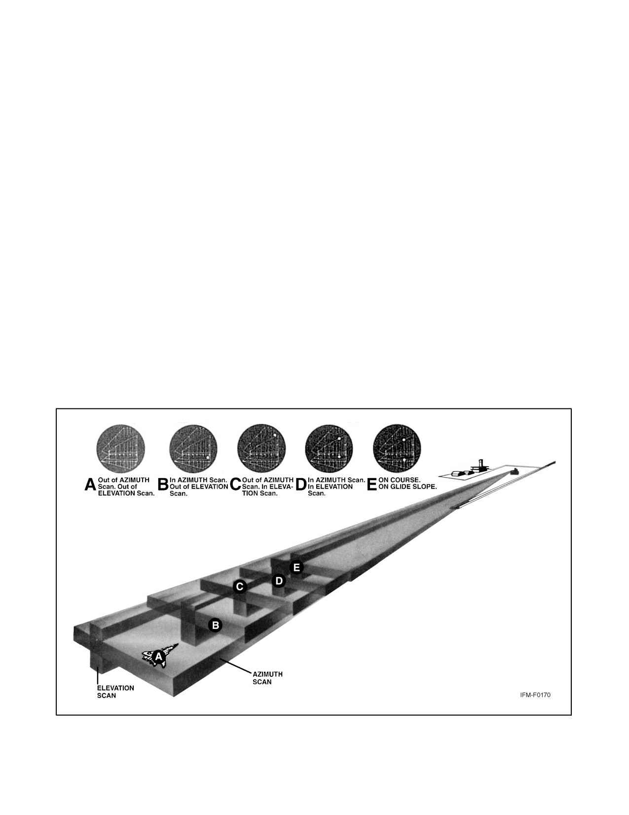
The precision final approach starts when the aircraft is within range of the precision radar and contact is established
with the final controller. A precision approach radar system includes two antennas, one scanning vertically and the
other scanning horizontally. The range is limited to 10 miles, azimuth to 20 degrees, and elevation to 7 degrees. The
initial call to the final controller should include the last assigned heading, altitude, and the current status of the gear,
if applicable. The required final approach airspeed and configuration should be set prior to glideslope interception,
and the landing checklist completed in accordance with the appropriate NATOPS flight manual. The controller will
advise the pilot of any change in lost communications procedures. These procedures must be noted and understood.
Upon request, the controller will furnish the pilot with the published decision height.
When the controller advises that the aircraft is intercepting glideslope, adjustment of the power and/or drag devices
is required to establish the predetermined rate of descent. Adjust the pitch attitude on the attitude indicator to maintain
the final approach speed. When the airspeed and glidepath are being maintained, note the power, attitude, and vertical
velocity. Use the values as guides during the remainder of the approach.
If the aircraft is observed to deviate above or below the glidepath, the pilot is given the relative amount of deviation
by use of terms “slightly” or “well” and asked to adjust the rate of descent to return to the glidepath. Correct these
deviations with coordinated pitch and power changes. Maintain a constant airspeed during the approach. When power
changes are required, avoid excessive throttle movements. Corrections should be made immediately after instructions
are given or when deviations from established attitude or performance indications are desired to return the aircraft
to the glidepath.
Accuracy of heading is important for runway alignment during the final approach phase. When instructed to make
heading changes, make them immediately. Instructions to turn are preceded by the phrase “turn right” or “turn left.”
To prevent overshooting, the angle of bank should approximate the number of degrees to be turned, not to exceed a
1/2 standard rate turn. At high final approach speeds, a larger angle of bank may be required to prevent a prolonged
correction, but do not exceed the 1/2 standard rate turn. After a new heading is directed, the controller assumes it is
being maintained. Additional heading corrections will be based on the last assigned heading.
ORIGINAL
25-4
NAVAIR 00-80T-112
If an aircraft is observed by the controller to proceed outside of specified safety zone limits in azimuth and/or elevation
and continue to operate outside these prescribed limits, the pilot will be directed to execute a missed approach or to
fly a specified course unless the pilot has the runway environment (runway, approach lights, etc.) in sight.
Navigational guidance in azimuth and elevation is provided to the pilot until the aircraft reaches the published
Decision Height (DH) (Figure 25-3).
Note
After reaching DH, the precision final controller will continue to provide
course and flightpath information until the aircraft passes over the landing
threshold. The information is strictly advisory in nature.
A missed approach shall be initiated immediately when any of the following occurs:
1. Upon reaching DH with runway environment not in sight.
2. When instructed by the controller when runway environment is not in sight.
3. When directed by the tower, wheels watch, or runway duty officer.
4. When a safe landing cannot be made.
Note
A pilot may execute a missed approach at his/her own discretion at any
time.
Figure 25-3. Precision Approach
25-5
ORIGINAL
NAVAIR 00-80T-112
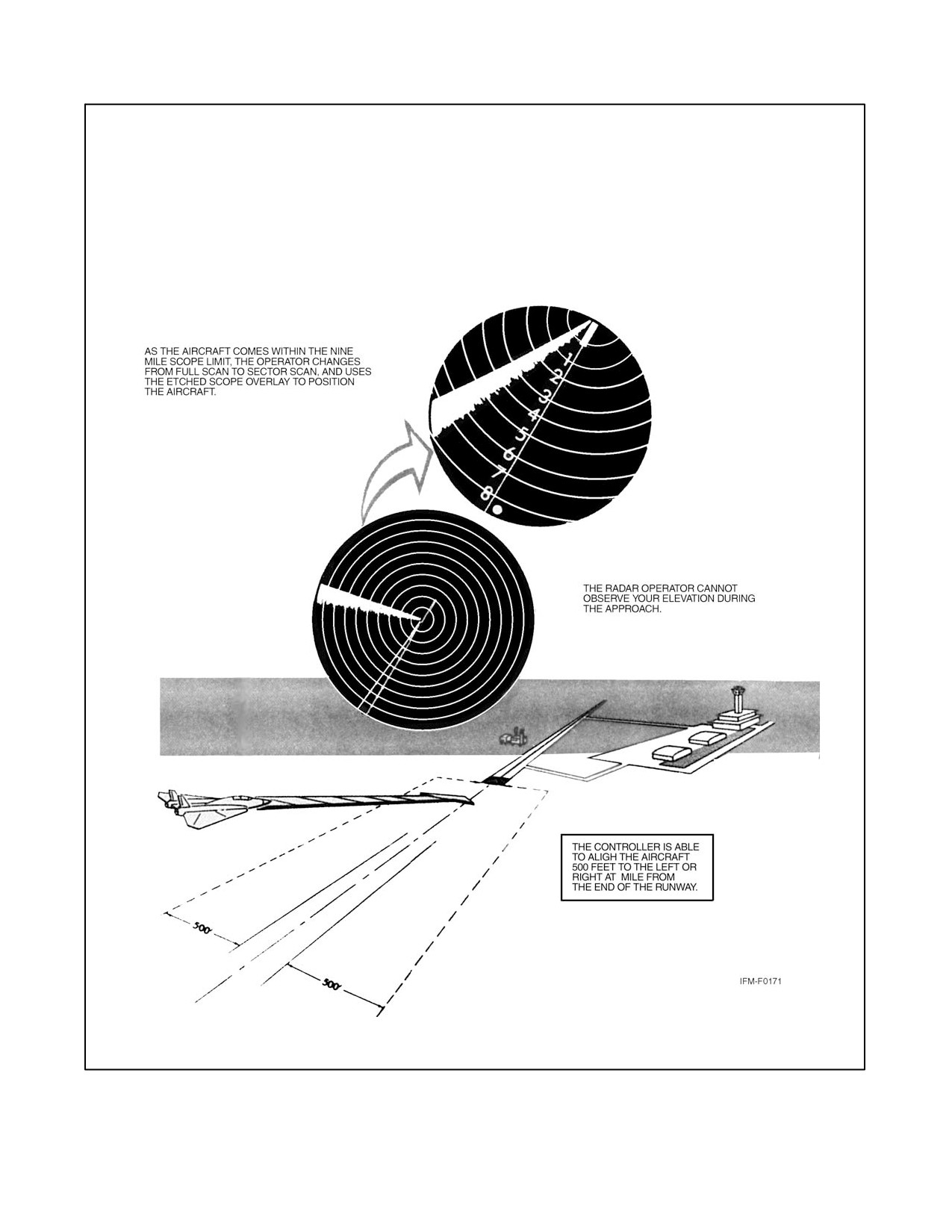
25.3.1.3 Surveillance Final Approach
There may be times when the precision radar equipment is inoperative or not available for the landing runway. Under
these conditions, surveillance radar is used to furnish information required to align the aircraft with the approach
runway. As surveillance radar is not as accurate as precision radar and does not provide elevation data, the landing
weather minimums are higher than for precision approaches (Figure 25-4).
Course corrections are not as accurate as those given during a precision approach because of less precise radarscope
presentations. At 1 mile from the landing threshold, the controller will advise the pilot to report the runway in sight
or to perform the missed approach. It is important to remember that the controller cannot observe aircraft elevation
during the surveillance approach.
Surveillance final approach instructions are similar to those received during the precision approach to the point of
establishing the descent. Although no elevation information is provided, on pilot request the controller will give
recommended altitudes each mile. Recommended altitudes decrease 300 feet per mile (approximates a 3_ glideslope).
The pilot should establish a rate of descent that will ensure reaching the Minimum Descent Altitude (MDA) at or
before the Missed Approach Point (MAP). If the MDA is reached before the missed approach point, fly the aircraft
at this altitude until the controller advises the pilot the aircraft has reached the missed approach point. Perform the
missed approach when:
1. Visual reference with the runway environment at the MAP is insufficient for landing.
2. Instructed by the controller when the runway is not in sight.
3. A safe landing is not possible.
4. Directed by the tower.
Note
The DH, MDA, and weather minimums for the PAR and ASR approach are
published in the FLIP Terminal Publication. When available, use the
Runway Visual Range (RVR) as the visibility value for straight-in
approaches. Prevailing Visibility (PV) is always used as the visibility value
for circling approaches.
25.3.1.4 No Gyro Approach (Heading Indicator Inoperative)
If the heading indicator should fail during flight, advise the radar controller and request no gyro approach. Perform
turns during the transition to final by establishing an angle of bank on the attitude indicator that will approximate a
standard rate turn (not to exceed 30_ of bank). Perform turns on final approach by establishing an angle of bank on
the attitude indicator that will approximate a 1/2 standard rate turn. If unable to comply with these turn rates, advise
the controller so that the controller may determine lead points for turns and heading corrections. Execute turns
immediately upon hearing the words “turn right” or “turn left.” Stop the turn on receipt of the words “stop turn.”
25.3.1.5 Voice Procedures
The radar approach is predicated entirely upon voice instructions from the controller. During an approach, repeat all
headings, altitudes, and altimeter settings; acknowledge all other instructions unless otherwise advised. During
high-density radar operations, a limiting factor is the communication time available. Keep transmissions brief and
specific, commensurate with safety of flight. Never sacrifice aircraft control to acknowledge receipt of instructions.
ORIGINAL
25-6
NAVAIR 00-80T-112
Figure 25-4. Surveillance Approach
25-7/(25-8 blank)
ORIGINAL
NAVAIR 00-80T-112
CHAPTER 26
Global Positioning System (GPS)
26.1
INTRODUCTION
The Global Positioning System
(GPS) is a space-based navigation system that provides highly accurate
three-dimensional navigation information to an infinite number of equipped users anywhere on or near the Earth. The
typical GPS integrated system will provide position, velocity, time, altitude, steering information, groundspeed,
ground track error, heading, and variation.
26.2
SYSTEM OVERVIEW
26.2.1 Signal Accuracy
GPS measures distance by timing a radio signal that starts at the satellite and ends at the GPS receiver. The signal
carries with it data that discloses satellite position and time of transmission and synchronizes the aircraft GPS system
with satellite clocks. There are two levels of accuracy available: Standard Positioning Service (SPS) and Precise
Positioning Service (PPS). Coarse Acquisition (C/A) data can be received by anyone with a GPS receiver. Until
recently, the accuracy of this signal was degraded through the use of Selective Availability (SA). (SA was set to zero
on 1 May 2000, thus greatly improving the accuracy of GPS for civilian [SPS] users.) It has been reported that current
accuracy for SPS users is better than 10 meters horizontal. Precision (P) data can be received only by authorized users
(PPS) in possession of the proper codes. The design specification for PPS GPS dictates 6 meters of accuracy but
specific testing has indicated greater accuracy.
26.2.2 GPS Segments
GPS is composed of three major segments: space, control, and user.
26.2.2.1 Space Segment
The GPS constellation is composed of multiple satellites, the orbits and spacing of which are arranged to optimize
the GPS coverage area.
26.2.2.2 Control Segment
The control segment includes a number of monitor stations and ground antennas located throughout the world. The
monitor stations use GPS receivers to track all satellites in view and accumulate ranging data from the satellite signals.
The information from the monitor stations is processed at the Master Control Station (MCS) and is used to manage
the satellite system.
26.2.2.3 User Segment
The user segment consists of GPS equipment used in a variety of ways: aircraft avionics, surveying equipment,
handheld GPS receivers, etc. GPS equipment uses data transmitted by the satellites to provide instantaneous position
information.
26.2.3 Integrated Systems
Integration of GPS into each aircraft navigation system will vary depending on the mission of the aircraft. GPS can
greatly enhance the performance of an Inertial Navigation System (INS), and the INS, in turn, increases the usefulness
26-1
ORIGINAL
NAVAIR 00-80T-112
of GPS equipment. INS has the ability to accurately measure changes in position and velocity over short periods of
time using no external signal; however, errors are cumulative and increase with time. GPS can provide a continuous
position update, which allows the INS to calculate error trends and improve its accuracy as time increases. The INS
aids the GPS receiver by improving GPS position predictions between position updates as well as improving system
anti-jam performance. When GPS is not available (due to mountain shadowing of satellites, jamming, or high
dynamic maneuvers), the improved INS will provide the integrated navigation system with accurate position
information until the satellites are back in view or the jamming is over. GPS can also provide in-flight alignment
capability for the INS.
26.2.4 Flight Management System (FMS)
An FMS is an integrated suite of sensors, receivers, and computers, coupled with a navigation database. These
systems generally provide performance and Area Navigation (RNAV) guidance to displays and automatic flight
control systems. Inputs can be accepted from multiple sources such as GPS, Distance Measuring Equipment (DME),
VHF Omnidirectional Range (VOR), Localizer (LOC), and Inertial Reference Unit (IRU). These inputs may be
applied to a navigation solution one at a time or in combination. Some FMSs provide for the detection and isolation
of faulty navigation information. When appropriate navigation signals are available, FMSs will normally rely on GPS
and/or DME/DME (i.e., the use of distance information from two or more DME stations) for position updates. Other
inputs may also be incorporated based on FMS system architecture and navigation source geometry.
26.2.5 Required Navigation Performance (RNP)
RNP is intended to provide a single performance standard for aircraft manufacturers, airspace designers, pilots,
controllers, and international aviation authorities. Some RNP procedures will take advantage of improved navigation
capabilities and will result in increased flight path predictability and repeatability. Typically, various sensor inputs
are processed by an RNAV system to arrive at a position estimate having a high statistical degree of accuracy and
confidence. When RNP is specified, a combination of systems may be used, provided the aircraft can achieve the
required navigation performance. Although it has been a goal for RNP to be sensor-generic, this goal is unachievable
as long as the aircraft capability is in any way dependent on external signals. The aircraft navigation system always
consists of specific sensors or sensor combinations and the navigation infrastructure consists of specific systems. The
RNP capability of an aircraft will vary depending upon the aircraft equipment and the navigation infrastructure. For
example, an aircraft may be equipped and certified for RNP 1.0, but may not be capable of RNP 1.0 operations due
to limited Navigation Aid (NAVAID) coverage.
26.2.5.1 RNP Levels
An RNP “level” or “type” is applicable to a selected airspace, route, or procedure. The International Civil Aviation
Organization (ICAO) has defined RNP values for the four typical navigation phases of flight: oceanic, en route,
terminal, and approach. The RNP level or type is a value typically expressed as a distance in nautical miles from the
intended centerline of a procedure, route, or path. RNP applications also account for potential errors at some multiple
of RNP level. U.S. standard values supporting typical RNP airspace are as specified in Figure 26-1. Other RNP levels
as identified by ICAO, other states, and the Federal Aviation Administration (FAA) may also be used. The applicable
RNP level will be depicted on affected charts and procedures.
ORIGINAL
26-2
NAVAIR 00-80T-112
Segment
RNP Level
Primary Route Width (nm) −
Centerline to Boundary
En Route
2.0
8.0 nm (+4.0)
Initial
1.0
4.0 nm (+2.0)
Intermediate
1.0
4.0 nm (+2.0)
Final
0.3
1.2 nm (+0.6)
Missed Approach
1.0
4.0 nm (+2.0)
Departure
1.0
4.0 nm (+2.0)
Figure 26-1. U.S. Standard RNP Levels
26.2.6 Waypoints
RNAV (GPS) approaches make use of both fly-over and fly-by waypoints. Fly-by waypoints are used when an aircraft
should begin a turn to the next course prior to reaching the waypoint separating the two route segments. This is known
as turn anticipation and is compensated for in the airspace and terrain clearances. Approach waypoints, except for
the Missed Approach Waypoint (MAWP) and the Missed Approach Holding Waypoint (MAHWP), are normally
fly-by waypoints. Fly-over waypoints are used when the aircraft must fly over the point prior to starting a turn.
Fly-over waypoints are depicted as a circled waypoint symbol. Overlay approach charts and some early stand-alone
GPS approach charts may not reflect this convention. A Computer Navigation Fix (CNF) is point used for the purpose
of defining the navigation track for an airborne computer system (i.e., GPS or FMS). CNFs are assigned five-letter
names and charted on aeronautical products. These CNFs are not to be used for any Air Traffic Control (ATC)
application, such as holding for which the fix has not already been assessed. CNFs will be charted to distinguish them
from conventional reporting points, fixes, intersections, and waypoints. The CNF name will be enclosed in
parentheses, and the name will be placed next to the CNF it defines. If the CNF is not at an existing point defined by
means such as crossing radials or radial/DME, the point will be indicated by an “X.” The CNF name will not be used
in filing a flight plan or in aircraft/ATC communications. Use current phraseology (e.g., facility name, radial,
distance) to describe these fixes. Unnamed waypoints in the database will be uniquely identified for each airport but
may be repeated for another airport. The runway threshold waypoint, which is normally the MAWP, will be coded
as RW##. The runway threshold waypoint is also used as the center of the Minimum Safe Altitude (MSA) on most
GPS approaches. MAWPs not located at the threshold will have a five-letter identifier.
26.2.7 RNAV Leg Types
A leg type describes the desired path preceding, following, or between waypoints on an RNAV procedure. Leg types
are identified by a two-letter code that describes the path (e.g., heading, course, track, etc.) and the termination point
(e.g., the path terminates at an altitude, distance, fix, etc.). Leg types used for procedure design are included in the
aircraft navigation database, but not normally provided on the procedure chart. The narrative depiction of the RNAV
chart describes how a procedure is flown. The “path and terminator concept” defines that every leg of a procedure
has a termination point and some kind of path into that termination point. Some of the available leg types are described
below.
26.2.7.1 Initial Fix
An Initial Fix leg is used only to define the beginning of a route or procedure.
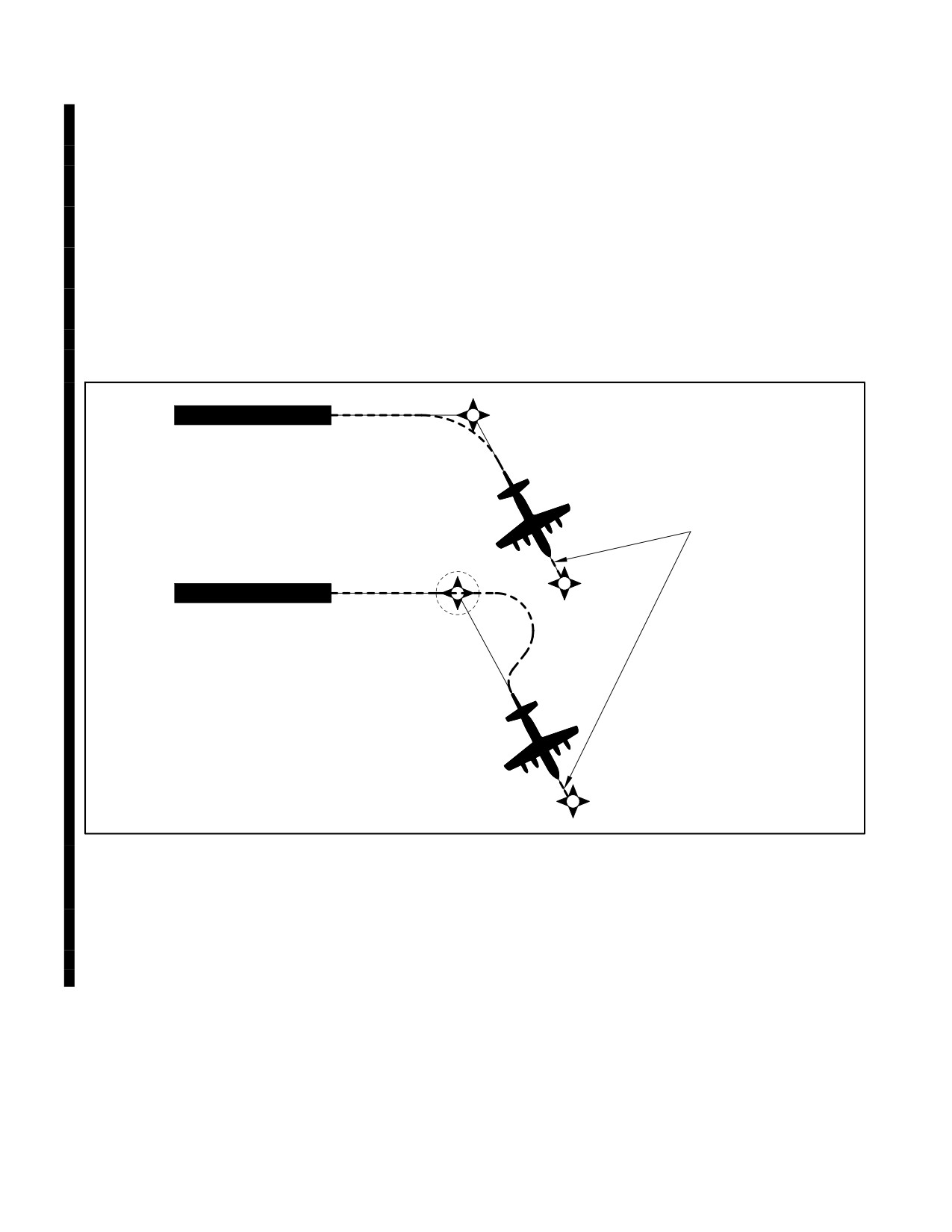
26.2.7.2 Track to Fix
A Track to Fix (TF) leg is intercepted and acquired as the flight track to the following waypoint. Track to Fix legs
are sometimes called point-to-point legs for this reason (Figure 26-2).
26-3
ORIGINAL
NAVAIR 00-80T-112
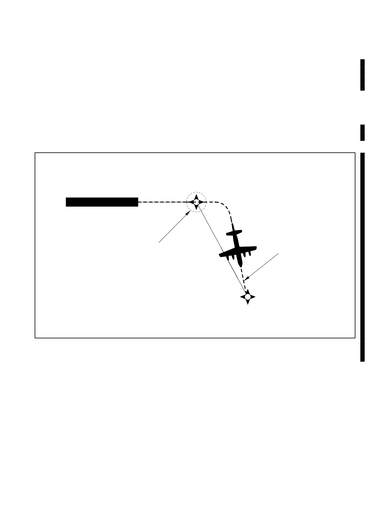
26.2.7.3 Direct to Fix
A Direct to Fix (DF) leg is a path described by an aircraft’s track from an initial area direct to the next waypoint
(Figure 26-3).
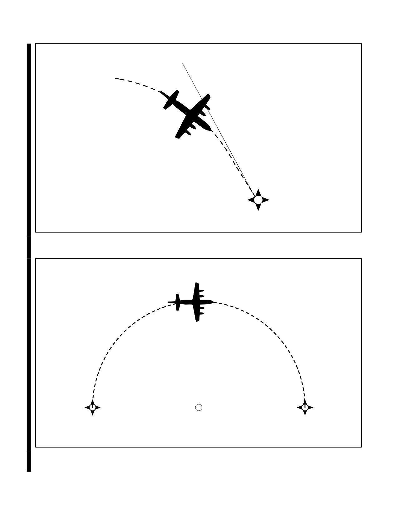
26.2.7.4 Course to Fix
A Course to Fix (CF) leg is a path that terminates at a fix with a specified course at that fix (Figure 26-4).
26.2.7.5 Radius to Fix
A Radius to Fix (RF) leg is defined as a constant radius circular path around a defined turn center that terminates at
a fix (Figure 26-5).
ALPHA
FLY-BY
TRACK TO FIX
ALPHA
BRAVO
FLY-OVER
BRAVO
Figure 26-2. Track to Fix Leg Type
26.2.7.6 Heading
A Heading leg may be defined as, but not limited to, a Heading to Altitude (VA), Heading to DME range (VD), and
Heading to Manual Termination, that is, Vector (VM).
26.2.8 Course Sensitivity
The Course Deviation Indicator (CDI) sensitivity related to GPS equipment varies with the mode of operation and
the type of equipment. (Refer to your flight manual.) Unlike traditional ground-based NAVAIDs, GPS course
sensitivity is normally linear regardless of the distance from the waypoint. Typically, the following modes provide
the indicated CDI scaling:
ORIGINAL
26-4
NAVAIR 00-80T-112
26.2.8.1 En Route Mode
En route phase, prior to the execution of the instrument approach, the display sensitivity full-scale deflection is 1 times
the RNP value either side of centerline. En route obstacle clearance area is based on the RNP value. Aircrews shall
not assume the primary protected containment for the route of flight en route is ±10 nm (refer to specific aircraft
NATOPS or FMS user’s manual).
26.2.8.2 Terminal Approach Mode
Upon activation of the approach mode, the display sensitivity should smoothly transition from a full-scale deflection
of en route RNP to terminal RNP by 30 nm from the destination airport. Aircrew are reminded that the obstacle
clearance area reduces as the RNP value transitions from en route to terminal. The approach mode must be active to
proceed past the final approach fix on a nonprecision approach.
ALPHA
FLY-OVER WP
DIRECT TO FIX LEG
BRAVO
Figure 26-3. Direct to Fix Leg Type
26-5
ORIGINAL
NAVAIR 00-80T-112
COURSE 150
ALPHA
Figure 26-4. Course to Fix Leg Type
ARC CENTER POINT
ALPHA
BRAVO
Figure 26-5. Radius to Fix Leg Type
ORIGINAL
26-6
NAVAIR 00-80T-112
26.2.8.3 Final Approach Mode
At a distance of 2 nm inbound to the Final Approach Fix (FAF) waypoint, the display sensitivity begins to transition
to a full-scale deflection of 0.3 nm either side of centerline. Some GPS avionics may provide an angular display
between the FAF and Missed Approach Point (MAP) that approximates the course sensitivity of the localizer portion
of an Instrument Landing System (ILS).
26.2.8.4 Missed Approach Mode
When navigation to the missed approach holding point is activated, the CDI display sensitivity transitions back to
terminal area sensitivity (±1 nm).
26.2.9 Navigation Database
Navigation databases supporting GPS equipment certified for en route and terminal operations contain, as a
minimum, all airports, VORs, VORTACs, Non-Directional Beacons (NDBs), and all named waypoints and
intersections shown on en route and terminal area charts, Standard Instrument Departures (SIDs), and Standard
Terminal Arrivals (STARs).
In the terminal area, the database will include waypoints for SIDs and STARs as well as other flight operations from
the beginning of a departure to the en route structure or from an en route fix to the beginning of an approach procedure.
All named waypoints are identified with a five-letter alpha character name provided by the National Flight Data
Center (NFDC). Waypoints unnamed by the NFDC, such as a DME fix, are assigned a five-letter alphanumeric coded
name in the database. (As an example, D234T — This coded waypoint represents a point located on the 234 radial
of XYZ VORTAC at 20 nm. The letter T is the twentieth letter of the alphabet and is used to indicate a distance of
20 nm.)
26.3
RESTRICTIONS ON THE USE OF GPS
26.3.1 Specific Capabilities and Restrictions
Specific GPS equipment capabilities vary widely from aircraft to aircraft; therefore, all pilots must be thoroughly
familiar with the GPS equipment installed in their aircraft, its authorized use, and its limitations. Some USN aircraft
are not capable of performing all of the activities described in this chapter. Aircrews must consult OPNAV 3710.7
series, this manual, wing directives, and the aircraft NATOPS manual to fully determine the capabilities of the aircraft
GPS equipment and restrictions on its use. As per OPNAV 3710.7 series, hand-held GPS receivers shall not be used
for instrument navigation.
26.3.2 Use of GPS Outside of the U.S. National Airspace System (NAS)
GPS use may be further restricted depending on the area of operation. Flight using GPS is not authorized in some
countries. If you plan to use GPS outside the National Airspace System (NAS), check for additional restrictions in
Flight Information Publications (FLIP) General Planning (GP) and Area Planning (AP) documents in your area of
intended operation. The aircrew shall ensure all non-DoD-approved approaches flown outside the U.S. and Canada
using GPS for primary navigation are approved by the Naval Flight Information Group (NAVFIG).
26.3.3 Receiver Autonomous Integrity Monitoring (RAIM)
GPS equipment certified for Instrument Flight Rules (IFR) use must have the capability of verifying the integrity of
the signals received from the GPS constellation. Loss of satellite reception and Receiver Autonomous Integrity
Monitoring (RAIM) warnings may occur due to aircraft dynamics (changes in pitch or bank angle). Antenna location
on the aircraft, satellite position relative to the horizon, and aircraft attitude may also affect reception of one or more
26-7
ORIGINAL
NAVAIR 00-80T-112
satellites. As the relative positions of the satellites are constantly changing, prior experience with the airport does not
guarantee reception at all times, and RAIM availability should always be checked. The integrity of the GPS signal
is verified by determining if the integrity solution is out of limits for the particular phase of flight, if a satellite is
providing corrupted information, or if there is an insufficient number of satellites in view. When the integrity of the
GPS information does not meet the integrity requirements for the operation being performed, the aircraft GPS
avionics will provide a warning in the cockpit. A GPS integrity warning in the cockpit is equivalent to an OFF flag
on your Horizontal Situation Indicator (HSI); your GPS navigation information may no longer be reliable. Refer to
the aircraft NATOPS for specific information regarding your GPS avionics.
26.3.4 Database Requirements
To use GPS for IFR navigation in the terminal area or for GPS nonprecision approaches, the aircraft GPS equipment
must include an updatable navigation database. GPS airborne navigation databases may come from the National
Geospatial-Intelligence Agency (NGA) via the mission planning system or from an approved commercial source.
26.3.4.1 Manual Database Manipulation
Manual entry/update of the validated data in the navigation database is not possible; however, this requirement does
not prevent the storage of user-defined data within the equipment.
26.3.5 RNAV in the Terminal Area
Some GPS equipment will provide the capability to use RNAV procedures in the terminal area. Using GPS equipment
as the primary navigation source for RNAV in the terminal area is only permitted if all of the waypoints defining the
route of flight can be retrieved from the aircraft GPS navigation database. GPS primary-source navigation using
user-defined waypoints may not be used after the Initial Approach Fix (IAF) or prior to the termination point of a SID.
GPS equipment may be used to identify the IAF on Instrument Approach Procedures (IAPs) and the termination point
on SIDs.
26.3.6 GPS Approach Restrictions
There are several important operating restrictions when using GPS to fly approaches.
26.3.6.1 Database Restrictions
Instrument approaches must be accomplished in accordance with approved instrument approach procedures that are
retrieved from the FMS database using the current update cycle.
Aircrew should not manually adjust designed RNP values (retrieved from
database), unless operational requirements dictate. Aircrew shall not use
manual RNP values in terminal mode of flight. RNP values other than
standard RNP will be noted on the terminal procedure. Failure to adhere to
design RNP values (retrieved from database) in the terminal mode may
result in a flight violation or mishap.
26.3.6.2 Integrity Monitoring
Instrument approaches must be conducted in the FMS Approach mode, and GPS integrity monitoring (RAIM) must
be available at the final approach fix, as indicated to the pilot by the INTG annunciator being extinguished.
ORIGINAL
26-8
NAVAIR 00-80T-112
26.3.6.3 Alternate Navigation Equipment
The aircraft must have other approved navigation equipment installed and functioning appropriate for the route to
the destination airport and any required alternate. Ground-based facilities necessary for these routes must also be
operational. GPS-overlay and GPS stand-alone approaches may be flown without the need to tune, ident, or monitor
any other NAVAID (though this is not recommended).
26.3.6.3.1 RNAV Procedural Speed Restrictions
Some arrival and departure procedures will have speed restrictions on a specific segment(s) or the entire procedure.
These restrictions ensure the aircraft remains within the obstacle clearance area or has proper track stabilization prior
to the next programmed waypoint.
26.3.6.4 Scaling and Alerting
The GPS navigation system used for the approach shall use scaling and alerting criteria no less restrictive than
RNP 0.3 prior to continuing past the final approach fix. The RNP criteria shall remain for the entire approach.
26.3.6.5 Multiple GPS Receivers
On aircraft equipped with multiple (installed) GPS receivers the aircrew shall use the integrity function for the GPS
receiver being used for navigation. The integrity function of other installed GPS (SPS or PPS) receivers shall not be
used to indicate the integrity of the GPS receiver being used for navigation.
26.3.7 Alternate Airport Restrictions
When an alternate airport is required, it must be served by an approach based on other-than-GPS navigation, the
aircraft must have operational equipment capable of using that navigation aid, and the required navigation aid must
be operational.
26.4
GPS APPROACH NOMENCLATURE
26.4.1 GPS Stand-Alone Approaches
GPS stand-alone approaches are constructed specifically for use by GPS and do not have a traditional underlying
procedure. GPS stand-alone approaches are identified by the absence of other NAVAIDs in the approach title (e.g.,
GPS RWY 35). Current stand-alone approaches will be renamed over time as RNAV (GPS) approaches (e.g., RNAV
RWY [GPS] 35). The Straight-In Minimums on current GPS charts correspond to the Lateral Navigation (LNAV)
Minimums on RNAV charts.
26.4.2 GPS Overlay Approaches
GPS overlay approaches permit pilots to use GPS avionics under IFR to fly existing instrument approach procedures.
Overlay approaches can be identified by the use of “GPS” in the title (e.g., “VOR or GPS RWY 24”).
26.4.2.1 GPS Not in the Title
Some approaches (typically VORs and NDBs) do not have GPS in the title, yet they are coded into the aeronautical
database used by the GPS and are retrievable. These approaches do not qualify as “overlay” approaches, since “OR
GPS” is not in the title. They can, however, be used as a situational awareness tool to back up the pilot at the controls
while flying a conventional approach.
26-9
ORIGINAL
NAVAIR 00-80T-112
26.4.3 RNAV (GPS) Approaches
The GPS “Stand-alone” and GPS “Overlay” approaches are being replaced by the RNAV (GPS) approach format.
The RNAV (GPS) format is known as a performance-based procedure. The RNP accuracy required to fly these
approaches is RNP 0.3. The minimums section is broken down into sections of LNAV, LNAV/Vertical Navigation
(VNAV), Localizer Performance with Vertical Guidance (LPV), and GNSS Landing System (GLS). The LNAV
approaches generally (but not always) have the highest minimums and are flown to a Minimum Descent Altitude
(MDA) much like a traditional VOR or Tactical Air Navigation (TACAN). The LNAV/VNAV section of the
minimums designates the Decision Altitude (DA) and visibility for aircraft approved for Barometric Vertical
Navigation (BARO-VNAV). The LPV section of the minimums designates the Decision Altitude for equipment
performing to the level of Wide Area Augmentation System (WAAS) specifications. The GLS section of the
minimums is currently designated “N/A” as a placeholder for the GLS. LPV is the only system authorized to occupy
the GLS line.
26.4.4 RNAV (RNP) Approaches
The latest addition to the GPS approach family is the RNAV (RNP) approach also known as Special Aircraft and
Aircrew Authorization Required (SAAAR). These approaches are commonly used to avoid prohibited areas, terrain,
and noise-sensitive areas that require certified aircraft and specific aircrew training. The RNP level required varies
from RNP 0.11 to RNP 0.15 to RNP 0.3. The Naval Flight Information Group is developing SAAAR approaches on
a limited basis for Navy and Marine Corps installations.
26.5
AIRCREW ACTIONS
26.5.1 Preflight
In addition to being intimately familiar with operation of their GPS equipment, pilots need to accomplish several
additional actions prior to flight using GPS.
26.5.1.1 Check NOTAMs
Review Notices to Airmen (NOTAMs) by referring to the installation NOTAMs for your destination and any
alternates. GPS satellite outages are issued as GPS NOTAMs using Pseudo Random Noise (PRN) number or Satellite
Vehicle Number (SVN) and can be accessed using the identifier KGPS. It is important to deselect the affected satellite
on your FMS/GPS. This ensures the particular satellite deselected is not used for the navigation solution, RAIM
calculations, or RAIM prediction.
Receiver manufacturers and/or database suppliers may supply “NOTAM” type information concerning database
errors. Pilots should check these sources, when available, to ensure that they have the most current information
concerning their electronic database.
26.5.1.2 File the Appropriate Equipment Suffix
Aircraft navigating using GPS are considered to be RNAV-equipped aircraft and the appropriate equipment suffix
should be included on the flight plan.
26.5.1.3 GPS Equipment Checks
Check GPS ground equipment by following the specific startup and self-test procedures for the GPS receiver or FMS
as outlined in the aircraft NATOPS manual. Check the currency of your database and predicted RAIM available status
for the approach you plan to fly at your Estimated Time of Arrival (ETA).
26.5.2 Terminal Area Operations and Departure
26.5.2.1 Load SID
If a SID is to be flown, load the appropriate SID by retrieving the route from the navigation database. If the SID cannot
be retrieved from the database, then you may not use RNAV procedures to fly it prior to the SID termination point.
ORIGINAL
26-10
NAVAIR 00-80T-112
26.5.2.2 Terminal Sensitivity
When flying a SID using GPS, the pilot must ensure the terminal sensitivity mode is selected to ensure the correct
scaling of the CDI (±1 nm).
26.5.3 En Route Operations
26.5.3.1 Use of Predictive Integrity
While you are en route to your destination, check the expected integrity (RAIM availability) for the planned approach.
If your check indicates the appropriate integrity for the planned operation may not be available, develop an alternate
plan for landing at the airfield or proceed to your alternate.
26.5.4 Prior to Descent
26.5.4.1 GPS Approach Briefing
Thoroughly brief the entire GPS instrument approach procedure including the missed approach instructions.
Compare the approach retrieved from the GPS navigation database to the instrument approach procedure published
on your approach plate. Should differences between the approach chart and database arise, the published approach
chart, supplemented by NOTAMs, takes precedence.
26.5.4.2 Develop a Backup Plan
Develop a backup plan to use in case of GPS or GPS integrity failure. Pay particular attention to ground-based
NAVAIDs, which can be used to help maintain position awareness. Be sure to consider the possibility of equipment
failure past the FAF.
26.5.4.3 Load STAR
If a STAR is to be flown, load the appropriate STAR by retrieving the route from the navigation database. If the STAR
cannot be retrieved from the database, then you may not use RNAV procedures to fly the procedure. Additionally,
terminal area routing that cannot be retrieved from the navigation database may not be used.
26.5.5 Terminal Area Operations and Arrival
26.5.5.1 Maintain Situational Awareness
As you prepare to enter the busy environment of the terminal area, it is important to maintain a high level of situational
awareness using all available means. Monitor all ground-based NAVAIDs that are available to you (bearing pointers,
DME, etc.), as GPS approaches are flown point to point. With GPS selected, the bearing pointer on your HSI and
distance measurement (DME readout) may be to the next waypoint, not necessarily to the field.
26.5.6 Be Prepared to Use Traditional NAVAIDs
Experience has shown situational awareness can deteriorate when flying GPS approaches if the sequence of events
does not go as planned. Be prepared to go to your backup plan if you become disoriented while flying the GPS
approach.
26.5.6.1 Be Wary of “Heads-Down”
Operating with GPS in the terminal area tends to be more “heads-down” than normal, especially when things do not
go as planned. Being intimately familiar with your GPS equipment and thoroughly preparing for the approach will
allow you more time to clear for other traffic.
26-11
ORIGINAL
NAVAIR 00-80T-112
26.5.6.2 GPS is a New Form of Flying
Flying GPS approaches involves a new way of flying for most military pilots. Setting up a GPS receiver for an
approach usually involves many more operations than are required to configure traditional navigation equipment. The
sequence of events is critical to success. Setup routines are not always intuitive, requiring pilots to be thoroughly
familiar with their equipment before flying GPS approaches in Instrument Meteorological Conditions (IMC). Once
the equipment is properly configured for the approach, the GPS-based approach is much easier and safer to fly than
a terrestrial-based (e.g., VOR, TACAN, etc.) nonprecision approach.
26.5.7 Approach Procedures
Flying a GPS approach is much like flying any other nonprecision approach. For procedures regarding equipment
specifics and setup, reference NATOPS and your FMS/GPS Operator’s Manual. Incorrect inputs into the GPS
receiver are especially critical during approaches. In some cases, an incorrect entry can cause the receiver to leave
the approach mode.
26.5.7.1 Prior to the IAF
Some GPS equipment will automatically “Arm” once the aircraft is within 30 nm from the airfield. Other equipment
will present a pilot selectable function when within 30 nm that requires the pilot to “Arm” the approach (refer to the
specific aircraft NATOPS). If manual arming is required by the equipment, then the aircrew shall “Arm” the approach
mode prior to the IAF. Arming the approach mode will allow your GPS equipment to automatically change from en
route RNP to terminal RNP.
26.5.7.1.1 Inside of 30 nm
If you do not arm the approach mode prior to 30 nm from the airport, your GPS equipment will generate a warning
once your aircraft is 30 nm from the airport. If the system automatically arms, there will be no annunciation at 30 nm.
26.5.7.1.2 3 nm Prior to the FAF
Approximately 3 nm prior to the FAF, your equipment will alert you that display sensitivity is about to change again.
At 3 nm, if you still have not armed the approach mode, it will give you another warning.
26.5.7.1.3 Ramp Down
Beginning 2 nm prior to the FAF, your equipment will (if previously armed) automatically scale from terminal
integrity performance (±1 nm) to approach integrity performance (±0.3 nm). This change in sensitivity is called
ramping down, and depending on your equipment, will occur between 2 nm prior to the FAF and the FAF. After
ramping down, the equipment is considered to be in approach mode.
Aircrew must ensure the equipment has switched from the armed mode to
the active mode by the time the aircraft reaches the FAF. Aircrew shall not
descend below the FAF altitude unless the equipment is in approach mode.
The aircraft may not remain within primary obstacle clearance area of the
instrument approach procedure. Transition to your backup approach (if
available) or proceed to the MAP along the final approach course and
execute the missed approach or comply with ATC instructions.
ORIGINAL
26-12
NAVAIR 00-80T-112
CAUTION
Failure to ramp down to approach mode may be an indication of integrity
failure, failure to arm, the aircraft did not enter the capture gate, or some
other type of failure.
26.5.7.1.4 Two Nautical Mile (2 nm) Lockout
At 2 nm, if you still have not armed the approach mode, your equipment will not let you fly the approach. Your
equipment will flag, and GPS navigation guidance will not be provided beyond the FAF.
26.5.7.1.5 GPS Integrity Warning Prior to FAF
If a GPS integrity warning occurs prior to the FAF, the pilot should not descend to the MDA, but should proceed to
the MAP via the FAF, perform a missed approach, and notify ATC as soon as practical. Alternatively, the pilot may
continue, provided a backup approach is available using another approved source of navigation.
26.5.7.2 Final Approach
The inbound course displayed on the GPS between the FAF and the MAP may be slightly different than that printed
on the approach chart and should not affect approach performance. This is due to the way the GPS connects the
approach waypoints.
26.5.7.2.1 Stepdown Waypoints
Stepdown waypoints in the final approach segment of RNAV (GPS) approaches are named in addition to being
identified by Along Track Distance (ATD). Most RNAV avionics currently do not accommodate waypoints between
the FAF and MAP. Stepdown waypoints may not appear in the sequence of waypoints in the navigation database.
Aircrew can determine the location of stepdown waypoints and visual descent points (if published) by using ATD.
26.5.7.2.2 GPS Integrity Warning After the FAF
A GPS integrity warning occurring after the FAF is a serious situation and pilots must be prepared to take immediate
action. Transition to your backup approach (if available) or proceed to the MAP along the final approach course and
execute the missed approach via the route and altitudes specified in the published missed approach procedure or
comply with ATC instructions.
26.5.7.3 Performing the Published Missed Approach Procedure
26.5.7.3.1 Missed Approach Point (MAP)
The designated MAP will vary depending on the type of approach minimums selected. The MAP for LNAV will be
the runway threshold or a named waypoint. The MAP for LNAV/VNAV will be at the published DA.
26.5.7.3.2 Select Missed Approach Mode
At the MAP, most equipment will not automatically sequence to the next required waypoint; therefore, the pilot must
manually sequence the GPS equipment to the next waypoint (refer to specific aircraft NATOPS).
26.5.7.3.3 Performing the Missed Approach
If the missed approach is initiated prior to the MAP, proceed to the MAP along the final approach course and then
via the route and altitudes specified in the published missed approach procedure or comply with ATC instructions.
If the missed approach procedure includes a turn, do not begin the turn prior to the MAP. The obstacle clearance area
provided for the missed approach is predicated upon the missed approach being started at the MAP.
26-13
ORIGINAL
NAVAIR 00-80T-112
Note
The GPS/FMS may or may not provide proper guidance along the missed
approach path; therefore, it is imperative to review the missed approach
procedure fully prior to flying it.
26.5.7.3.4 Missed Approach Climb Gradient
Regardless of the method used to navigate the missed approach procedure, the pilot is still responsible for terrain and
obstacle avoidance as well as any ATC-required climb gradients. In order to avoid obstacles, pilots must plan to climb
at a minimum gradient of 200 feet per nm unless a higher gradient is published.
26.6
GPS NAVIGATION TRAINING
26.6.1 General
Aircrew should practice GPS approaches under Visual Flight Rules (VFR) until thoroughly proficient with all aspects
of their equipment (receiver and installation) prior to attempting flight under IFR in IMC. Many GPS receivers
provide a simulation mode that can be used to become familiar with receiver operations prior to actual flight
operations. Proper training of GPS navigation in controlled airspace will enhance safety and awareness when using
PPS for combat operations. GPS training will be developed, with assistance from Naval Air Systems Command
PMA-170, by the respective TYCOM/FRS/Type Wing.
26.6.2 Ground Instruction
The use of GPS for flight in controlled airspace requires a thorough knowledge of the terms and nomenclature used
to describe and depict GPS navigation processes. The charting of GPS procedures does not follow the convention
described by previous training. Some of the areas that GPS training should cover are:
1. The meaning and proper use of Aircraft Equipment/Navigation Suffixes.
2. Procedure characteristics as determined from chart depiction and textual description.
a. Depiction of waypoint types (fly-over and fly-by) and path terminators as well as associated aircraft flight
paths.
b. Published material for RNAV routes, SIDs, STARs, and GPS approaches.
3. Utilizing the RAIM prediction function.
4. RNAV/GPS system-specific information.
a. Levels of automation, mode annunciations, changes, alerts, interactions, reversions, and degradation.
b. Functional integration with other aircraft systems.
c. The meaning and appropriateness of route discontinuities as well as related flightcrew procedures.
d. Monitoring procedures for each phase of flight (e.g., monitor PROG or LEGS page).
e. Types of navigation sensors (e.g., IRU, EGI, GEM, MAGR2K) utilized by the RNAV system and associated
system prioritization/weighting/logic.
f. Turn anticipation with consideration to speed and altitude effects.
ORIGINAL
26-14
NAVAIR 00-80T-112
g. Interpretation of electronic displays and symbols.
h. Verify currency of aircraft navigation data.
i. Verify successful completion of RNAV system self-tests.
5. Crew coordination and FMS/CDU etiquette.
6. Using the FMS/CDU/displays to maximize situational awareness.
7. Using the FMS/CDU for visual approaches.
8. Extending a point for interception.
9. Intercepting a route between two points.
10. Conditional waypoints and FMS-generated waypoints.
26.6.3 GPS Navigation Flight Training
The amount and type of flight training should be sufficient to expose the flightcrew to the displays, autopilot use (if
applicable), and aircraft performance when using GPS for navigation.
1.
Proceeding direct to a waypoint in the flight plan and not in the flight plan.
2.
Inserting an instrument Departure Procedure (DP) into the flight plan, including setting terminal CDI
sensitivity, if required, and the conditions under which terminal RAIM is available for departure.
3.
Inserting the destination airport in a flight plan.
4.
Determining the correct IAF to proceed to when entering a Terminal Arrival Area (TAA) and determining the
correct altitudes within a TAA.
5.
Executing overlay approaches (especially procedure turns and arcs).
6.
Changing to another approach after selecting an approach.
7.
Executing “direct” missed approaches where the route is direct to the first waypoint after the MAWP.
8.
Executing “routed” missed approaches where the route is not direct to a waypoint from the MAWP, particularly
where a course must be manually inserted and flown. This procedure may vary with installation of the receiver.
9.
Entering, flying, and exiting holding patterns “manually” (e.g., non-charted holding, holding following a
procedure turn, and holding with a second waypoint in the holding pattern).
10.
Flying a “route” from a holding pattern.
11.
Executing an approach with radar vectors to the final segment.
12.
Actions required for RAIM failure both before and after the Final Approach Waypoint (FAWP).
13.
Programming a radial and distance from a VOR.
14.
Recovering from sequencing past a waypoint at which holding was intended.
26-15
ORIGINAL
NAVAIR 00-80T-112
15. Operator-recommended levels of automation for phase of flight and workload, including methods to minimize
cross-track error to maintain procedure centerline.
16. Crew coordination and FMS/CDU etiquette.
17. Using the FMS/CDU to maximize situational awareness.
18. Using the FMS/CDU for visual approaches.
19. Extending a point for interception.
20. Intercepting a route between two points.
21. Conditional waypoints and FMS-generated waypoints.
26.7
FUTURE IMPROVEMENTS TO GPS
26.7.1 Wide Area Augmentation System (WAAS)
The Wide Area Augmentation System (WAAS) is a critical component of the FAA strategic objective of a seamless
satellite navigation system for civil aviation. This system will improve the accuracy, availability, and integrity of GPS,
thereby improving the capacity and safety currently provided by the National Airspace System. Ultimately, WAAS
will allow GPS to be used as a primary means of navigation from takeoff through Category I precision approach.
WAAS will provide vertical guidance procedures to achieve an operational capability similar to an instrument landing
system, where suitable airport conditions exist.
Unlike traditional ground-based navigation aids, WAAS will cover a more extensive service area. Wide-Area Ground
Reference Stations (WRSs) have been linked to form a U.S. WAAS network. Signals from GPS satellites are received
by these precisely surveyed ground reference stations and any errors in the signals are identified. Each station in the
network relays the data to one of two Wide-Area Master Stations (WMSs), where correction information for specific
geographical areas is computed. A correction message is prepared and uplinked to a geostationary communications
satellite (GEO) via a Ground Uplink Station (GUS). This message is broadcast on the same frequency as GPS (L1,
1575.42 MHz) to future GPS/WAAS receivers onboard aircraft flying within the broadcast coverage area of WAAS.
Other modes of transportation also benefit from the increased accuracy, availability, and integrity that WAAS will
deliver. The WAAS broadcast message improves GPS signal accuracy from 100 meters to approximately 7 meters.
Planned expansion of the U.S. network will include Canada, Iceland, Mexico, and Panama, and has the potential to
expand to other countries as well. Additionally, Japan and Europe are building similar systems that are planned to
be interoperable with the U.S. WAAS. The merging of these systems will create a worldwide seamless navigation
capability similar to GPS, but with greater accuracy, availability, and integrity.
On March 7, 2006, the FAA declared that WAAS was performing to the level necessary to allow approaches to 200
feet DA. WAAS has provided coverage to 99 percent of the continental U.S. and has an availability rate of 99.87
percent. The FAA is commissioning 300 approaches per year that are WAAS capable. The addition of WAAS
capability will be shown in the minimums section of the approach chart as “LPV.” The LPV minimums shall only
be flown by properly certified aircraft.
ORIGINAL
26-16
NAVAIR 00-80T-112
26.7.2 Local Area Augmentation System (LAAS)
The Local Area Augmentation System (LAAS) will augment the Global Positioning System to provide an all-weather
approach, landing, and surface navigation capability. LAAS focuses its service on a local area (approximately a 20
to 30 mile radius), such as an airport, and broadcasts its correction message via a Very High Frequency (VHF) radio
data link from a ground-based transmitter. LAAS will have a profound impact on aviation navigation. LAAS will
yield the extremely high accuracy, availability, and integrity necessary for Category I, II, and III precision approaches.
It is expected that the end-state configuration will pinpoint the aircraft position to within one meter or less with a
significant improvement in service flexibility and user operating costs. Curved approach paths, not possible using
the current instrument landing systems, will be possible for Category I, II, and III precision approaches. Approaches
will be designed to avoid obstacles, restricted airspace, noise-sensitive areas, or congested airspace. Unlike current
landing systems, LAAS will provide multiple precision approach capabilities to runways within the LAAS coverage
area. Duplication of equipment solely for the purpose of serving multiple runways can be eliminated. Also, airports
with the need for precise surface area navigation may use the accuracy of LAAS for the position determination of
aircraft. Using this capability, controllers will know the location of all airport service vehicles and taxiing aircraft to
assist in the prevention of runway incursions in low visibility conditions. Furthermore, aircraft operators will benefit
from the reduction of expenses associated with purchasing a variety of radio navigation equipment. Potentially,
WAAS and LAAS could use the same aircraft avionics to accomplish both the WAAS and LAAS missions, reduce
avionics maintenance costs, and realize savings in aircrew training.
The FAA has already successfully demonstrated the feasibility of GPS-based Category III precision approaches and
has completed the proposed architecture for LAAS. This architecture was successfully presented and approved by
the International Civil Aviation Organization (ICAO) Global Navigation Satellite System (GNSS) Panel in February
1997. To ensure LAAS will be compatible with international standards, participation in the International Civil
Aviation Organization (ICAO) Global Navigation Satellite System Panel (GNSS-P) has been ongoing. Initial FAA
Category I LAAS is scheduled to be operational by September 2003. Federal Category II/III development is
scheduled to begin in FY03 with production in FY06. The FAA and the Government-Industry Partnership (GIP)
partners will continue working toward a private/public use certified LAAS Category I system with the goal of
transitioning to the Federal Category I procurement as soon as possible.
26-17/(26-18 blank)
ORIGINAL
NAVAIR 00-80T-112
PART VII
Instrument Flight
Chapter 27 — Flight Planning
Chapter 28 — Flight Clearance
Chapter 29 — En Route Procedures
Chapter 30 — Terminal Procedures
79/(80 blank)
ORIGINAL
NAVAIR 00-80T-112
CHAPTER 27
Flight Planning
27.1
PREFLIGHT PREPARATION
Every pilot is required to obtain a preflight weather briefing, review all applicable Notices to Airmen (NOTAMs),
and file a flight plan. The weather briefing should consist of the latest or most current weather, airport, and en route
Navigation Aid (NAVAID) information. Weather briefing services should be obtained at a DoD weather forecasting
office. Weather minimums for naval aviators are defined in OPNAV 3710.7 series.
27.2
WEATHER BRIEFING, SUPPORT PRODUCTS, AND SEVERE WEATHER RESTRICTIONS
AND PRODUCTS
Navy and Marine Corps Meteorology and Oceanography (METOC) activities are tasked with providing METOC
support to the operating forces of the Navy and Marine Corps. These activities are equipped and staffed to provide
full spectrum METOC support products to naval aviators.
27.2.1 Weather Briefing
Pilots are responsible for reviewing and being familiar with weather conditions for the area in which flight is
contemplated. Before obtaining a flight clearance, a pilot must receive a weather briefing where services are
available; the briefing shall be conducted by a qualified meteorological forecaster. These briefings may be conducted
in person, or when available, via weathervision, telephone, or by autographic means. Additionally, a DD Form 175-1
(Flight Weather Briefing) shall be completed for all flights in accordance with OPNAVINST 3710.7 series.
Due to the perishable nature of meteorological data, and in an effort to ensure aviators have the most up-to-date
information, all weather briefings will be assigned a briefing void time. The briefing void time shall not exceed the
“weather briefed” time by more than 3 hours, and it shall never exceed the planned departure time by more than
30 minutes. This time may be extended when, in the opinion of the meteorologist, conditions are such that a review
of the initial form and the deletion/addition of pertinent data is such that a formal rebriefing is not required. When
extending void times, the rule stated above applies with the exception that the “weather rebriefed at” time is used as
the base time.
Flights departing after void time expiration are in violation of OPNAVINST 3710.7 series because, for record
purposes, the briefing never took place, as the official record of the briefing is no longer valid. Requests for extensions,
and proper planning, will eliminate this situation.
As a minimum, terminal forecasts entered on the DD Form 175-1 shall be valid for a period of 1 hour before, until
1 hour after, the planned arrival time at destination(s) and alternates. In the event a pilot is departing from an airfield
with no weather briefing facility, telephone briefings are available from both military and civilian facilities.
Telephone numbers for military briefing facilities are listed in the Flight Information Publications (FLIP). These
facilities may be called collect. The pilot receiving a weather briefing must ensure all essential weather elements have
been included and adequately covered in the briefing. Meteorological forecasters serve as advisors to the aviator;
therefore, pilots should not hesitate to request clarification or additional information when doubt exists. The ease with
which all-weather flights are completed successfully is directly proportional to the pilot’s preparation and
understanding of the environment in which the flight operates.
27.2.2 Support Products
In addition to the DD Form 175-1, there are other weather-related products that are readily available to aviators that
actively support safe and successful mission accomplishment.
27-1
ORIGINAL
NAVAIR 00-80T-112
27.2.2.1 Optimum Path Aircraft Routing System (OPARS)
Optimum Path Aircraft Routing System (OPARS) is a service that combines the latest forecast environmental wind
data fields with the most fuel-efficient flight profile for specific aircraft. A minimum of 2 to 3 hours is required for
submission of OPARS requests and return receipt of the completed product. The OPARS product is constructed
utilizing a database that contains aircraft performance characteristics, high-altitude airways, NAVAIDs, waypoints,
all airports with runways of 5,000 feet or longer (in the Northern Hemisphere), and restricted area information. The
environmental database contains wind data from 1,000 to 53,000 feet out to 48 hours, which is updated every 12 hours.
A typical OPARS flight plan will contain summarized flight times and distances, takeoff and landing weight, as well
as time, distance, airspeed, groundspeed, and fuel usage between NAVAIDs. It will accept any mission with up to three
legs, along standard jet routes from NAVAID point to NAVAID point, rhumbline with checkpoints every 5_ latitude
or longitude, or along great circle routes, and select the optimum path. The aviator selects these options before the
flight plan is submitted. OPARS will route at the most efficient flight level, or between any upper and lower flight
level. For further information on this program, refer to the Aviator’s Guide to OPARS Flight Planning (September
1998), or contact the nearest Naval Oceanography Command Activity.
27.2.2.2 Flight Weather Packets
When available, pilots are encouraged to request a flight weather packet when contemplating extended flights,
especially those flights that will be conducted on long overwater routes. As a minimum, in addition to a
DD Form 175-1, these packets contain surface and upper air charts, a Horizontal Weather Depiction (HWD) chart,
and, for overwater flights, altimeters and ditch headings. Additional charts/data tailored to meet special mission
needs, such as D values, OPARS data, etc., are also available. When considering the preparation time involved, and
the amount of data that must be accumulated and reviewed, every attempt should be made to give a minimum 2 hours
advance notice for this product. While en route, pilots should make every attempt to validate the data contained in
the packet. Upon arrival at destination, the packet should be provided to the local weather activity for review and
forwarding to the forecasting activity that prepared the packet.
27.2.3 Severe Weather Restrictions and Products
Whenever practical, flights shall be planned to circumvent areas of forecasted atmospheric icing and thunderstorm
activity.
27.2.3.1 Aviation Severe Weather Watch Bulletins (WWs)
The National Weather Service (NWS) issues unscheduled Severe Weather Watch Bulletins (WWs) whenever there
is a high probability of severe weather. These WWs are issued for a designated area and for a specified time period.
WWs are used by Naval Oceanography Command activities for forecasting hazardous flying conditions. Except for
operational necessity, emergencies, and flights involving all-weather research projects or weather reconnaissance,
pilots shall not file into or through areas where the National Weather Service has issued a WW unless one of the
following exceptions applies:
1. Performance characteristics of the aircraft permit an en route flight altitude above existing or developing severe
storms; or
2. Storm development has not progressed, as determined by a qualified meteorological forecaster, for the planned
route. In such situations:
a. Visual Flight Rules (VFR) filing is permitted if existing and forecast weather for the planned route permits
such flights.
b. Instrument Flight Rules (IFR) flight may be permitted if aircraft radar is installed and operative, thus
permitting detection and avoidance of isolated thunderstorms.
c. IFR flight is permissible in positive control areas if visual meteorological conditions can be maintained, thus
enabling aircraft to detect and avoid isolated thunderstorms.
ORIGINAL
27-2
NAVAIR 00-80T-112
Note
In most cases, WWs are not issued specifically for immediate coastal
waters or adjacent oceanic areas; however, in some situations, the weather
associated with the WW will also be present over said areas. When dealing
with such a situation, pilots should request evaluation of the maritime area
by a forecaster to ensure WW conditions are not present.
27.2.3.2 Military Weather Warning Advisories (MWWAs)
The U.S. Air Force issues these graphical advisories, which provide an estimate of the weather-producing potential
of existing airmasses. These advisories are used whenever a WW is not in effect, and they are also useful for planning
purposes. MWWAs are posted in all Naval Weather Offices. A MWWA Bulletin that forecasts severe weather does
not constitute a WW.
27.2.3.3 Significant Meteorological Information
(SIGMETs) and Airmen’s Meteorological
Information (AIRMETs)
These advisories are prepared by the National Weather Service and broadcast by Flight Service Stations (FSSs) on
VHF Omnidirectional Range (VOR) facilities.
27.2.3.3.1 SIGMETs
These advisories include weather phenomena potentially hazardous to all categories of aircraft. SIGMETs fall under
two categories: convective and nonconvective.
27.2.3.3.2 Convective SIGMETs
Since thunderstorms are the reason for issuing convective SIGMETs, severe or greater turbulence, severe icing, and
low-level windshear associated with thunderstorm activity are implied. The criteria for issuing convective SIGMETs
are as follows:
1. Tornadoes.
2. Line of thunderstorms.
3. Embedded thunderstorm(s).
4. Thunderstorm areas greater than or equal to thunderstorm intensity level 4 with an area coverage of 4/10 (40
percent) or more.
5. Hail equal to or greater than 3/4 inch diameter.
Three convective SIGMET bulletins specifying Eastern (E), Central (C), and Western (W) U.S. will be issued, when
required, on a scheduled basis hourly at 55 minutes past the hour, and as specials on an unscheduled basis. They are
valid for 1 to 2 hours. It should be noted that although Air Route Traffic Control Centers (ARTCCs) may not give
the content of SIGMETs, they do alert IFR traffic that one is being broadcast and provide the identification of the
NAVAID to monitor.
27.2.3.3.3 Nonconvective SIGMETs
The criteria for issuing nonconvective SIGMETs are as follows:
1. Severe and extreme turbulence.
2. Severe icing.
3. Widespread duststorms/sandstorms that lower visibility to less than 3 miles.
27-3
ORIGINAL
NAVAIR 00-80T-112
27.2.3.3.4 AIRMETs
These advisories will only be issued to amend an Aviation Area Forecast (FA) and relate to weather phenomena that
may be potentially hazardous to aircraft concerning the following:
1. Moderate icing.
2. Moderate turbulence.
3. Sustained winds of 30 knots or more at the surface.
4. Widespread areas of ceilings less than 1,000 feet and/or visibility less than 3 miles.
5. Extensive mountain obscurement.
It should be noted that if the above phenomena are adequately forecast in the FA, an AIRMET will not be
issued.
Applicable NOTAMs must be checked before every flight for your departure field, destination, possible alternates,
and the airspace in between. NOTAM information is available from the U.S. NOTAM System (USNS) via the
Defense Internet NOTAM Distribution System (DINS). Further explanation and definitions for all seven types of
NOTAMs can be found in the Aeronautical Information Manual (AIM).
File the DD-175 with the clearing authority at least 30 minutes prior to Estimated Time of Departure (ETD) in
accordance with OPNAV Instruction 3710.7 series and FLIP. If departing from a civil field, follow the procedure
outlined in FLIP. Weight and balance form and passenger manifest, if required, will be submitted with the flight plan.
Instructions for completing the Federal Aviation Administration (FAA) Form 7233-1 flight plan can be found in the
AIM.
Pilots shall use only the latest issue of aeronautical charts in planning and conducting flight operations. Aeronautical
charts are revised and reissued on a regular scheduled basis to ensure that depicted data are current and reliable. In
the conterminous U.S., Sectional Charts are updated every 6 months, IFR En Route Charts every 56 days, and
amendments to civil IFR Approach Charts are accomplished on a 56-day cycle with a change notice volume issued
on the 26-day midcycle. Charts that have been superseded by those of a more recent date may contain obsolete or
incomplete flight information.
FAA by 14 Code of Federal Regulations (CFR) Part 93, Subpart K, has designated High Density Traffic Airports
(HDTAs) and has prescribed air traffic rules and requirements for operating aircraft (excluding helicopter operations)
to and from these airports.
In addition to the filing of a flight plan, if the flight will traverse or land in one or more foreign countries, it is
particularly important that pilots leave a complete itinerary with someone directly concerned and keep that person
advised of the flight progress.
27.3
FOLLOW IFR PROCEDURES EVEN WHEN OPERATING VFR
To maintain IFR proficiency, pilots are urged to practice IFR procedures whenever possible, even when operating
VFR.
Simulated IFR flight is recommended (under the hood); however, pilots are cautioned to review and adhere to the
requirements specified in 14 CFR Section 91.109 before and during such flight.
When flying VFR at night, in addition to the altitude appropriate for the direction of flight, pilots should maintain
an altitude that is at or above the Minimum En Route Altitude (MEA) as shown on charts. This is especially true in
mountainous terrain, where there is usually very little ground reference. Do not depend on your eyes alone to avoid
rising unlighted terrain, or even lighted obstructions such as TV towers.
ORIGINAL
27-4
NAVAIR 00-80T-112
27.3.1 Flight Plan — VFR Flights
Except for operations in or penetrating a Coastal or Domestic Air Defense Identification Zone (ADIZ) or Distant
Early Warning Identification Zone (DEWIZ), a flight plan is not required by the FAA for VFR flight. Local
requirements may differ.
It is strongly recommended that a flight plan (for a VFR flight) be filed. This will ensure you receive VFR Search
and Rescue Protection.
On pilot’s request, at a location having an active tower, the aircraft identification will be forwarded by the tower to
the FSS for reporting the actual departure time for the military arrival notification.
Although position reports are not required for VFR flight plans, periodic reports to FAA FSSs along the route are good
practice. Such contacts permit significant information to be passed to the transiting aircraft and also serve to check
the progress of the flight should it be necessary for any reason to locate the aircraft.
Pilots not operating on an IFR flight plan and when in level cruising flight are cautioned to conform with VFR cruising
altitudes appropriate to the direction of flight.
When filing VFR flight plans, indicate aircraft equipment capabilities by appending the appropriate suffix to aircraft
type in the same manner as that prescribed for IFR flight.
27.3.2 Flight Plan — Defense VFR (DVFR) Flights
VFR flights into a Coastal or Domestic ADIZ/DEWIZ are required to file Defense VFR (DVFR) flight plans for
security purposes. Detailed ADIZ procedures are found in the AIM, National Security and Interception Procedures.
(See 14 CFR Part 99.)
27.3.3 Composite Flight Plan (VFR/IFR Flights)
Flight plans that specify VFR operation for one portion of a flight, and IFR for another portion, are referred to as
Composite Flight Plans. If VFR flight is conducted for the first portion of the flight, pilots should report their departure
time to the FSS with whom the VFR/IFR flight plan was filed and, subsequently, close the VFR portion and request
Air Traffic Control (ATC) clearance from the FSS nearest the point at which change from VFR to IFR is proposed.
Regardless of the type facility with which you are communicating (FSS, center, or tower), it is the pilot’s
responsibility to request that facility to “CLOSE VFR FLIGHT PLAN.” The pilot must remain in VFR weather
conditions until operating in accordance with the IFR clearance.
When a flight plan indicates IFR for the first portion of flight and VFR for the latter portion, the pilot will normally
be cleared to the point at which the change is proposed. After reporting over the clearance limit and not desiring further
IFR clearance, the pilot should advise ATC to cancel the IFR portion of the flight plan. Then, the pilot should contact
the nearest FSS to activate the VFR portion of the flight plan. If the pilot desires to continue the IFR flight plan beyond
the clearance limit, the pilot should contact ATC at least 5 minutes prior to the clearance limit and request further IFR
clearance. If the requested clearance is not received prior to reaching the clearance limit fix, the pilot will be expected
to enter into a standard holding pattern on the radial or course to the fix unless a holding pattern for the clearance limit
fix is depicted on a U.S. Government or commercially produced (meeting FAA requirements) low or high altitude
en route, area, or Standard Terminal Arrival (STAR) chart. In this case, the pilot will hold according to the depicted
pattern.
27.3.4 Flight Plan — IFR Flights
27.3.4.1 General
Prior to departure from within, or entering into, controlled airspace, a pilot must submit a complete flight plan and
receive an air traffic clearance if weather conditions are below VFR minimums. Instrument flight plans are normally
27-5
ORIGINAL
NAVAIR 00-80T-112
submitted through base operations, but can also be submitted to the nearest FSS or Airport Traffic Control Tower
(ATCT) either in person or by telephone (or by radio if no other means are available). Pilots should file IFR flight
plans at least 30 minutes prior to ETD to preclude possible delay in receiving a departure clearance from ATC. In order
to provide FAA traffic management units strategic route planning capabilities, nonscheduled operators conducting
IFR operations above Flight Level (FL) 230 are requested to voluntarily file IFR flight plans at least 4 hours prior
to ETD. To minimize your delay in entering Class B, Class C, Class D, and Class E surface areas at destination when
IFR weather conditions exist or are forecast at that airport, an IFR flight plan should be filed before departure.
Otherwise, a 30 minute delay is not unusual in receiving an ATC clearance because of time spent in processing flight
plan data. Traffic saturation frequently prevents control personnel from accepting flight plans by radio. In such cases,
the pilot is advised to contact the nearest FSS for the purpose of filing the flight plan.
Note
There are several methods of obtaining IFR clearances at nontower,
non-FSS, and outlying airports. The procedure may vary due to
geographical features, weather conditions, and the complexity of the ATC
system. To determine the most effective means of receiving an IFR
clearance, pilots should ask the nearest FSS the most appropriate means of
obtaining the IFR clearance.
When filing an IFR flight plan for a Traffic Alert and Collision Avoidance System (TCAS)/ heavy equipped aircraft,
add the prefix T for TCAS, H for heavy, or B for both TCAS and heavy to the aircraft type.
When filing an IFR flight plan for flight in an aircraft equipped with a radar beacon transponder, Distance Measuring
Equipment (DME), Tactical Air Navigation (TACAN)-only equipment, Global Navigation Satellite System (GNSS),
or a combination of any of these types of equipment, identify the equipment capability by adding a suffix, preceded
by a slant, to the aircraft type.
It is recommended that pilots file the maximum transponder or navigation capability of their aircraft in the equipment
suffix. This will provide ATC with the necessary information to utilize all facets of navigational equipment and
transponder capabilities available.
Note
The suffix is not to be added to the aircraft identification or be transmitted
by radio as part of the aircraft identification.
27.3.4.2 Airways and Jet Routes Depiction on Flight Plan
It is vitally important that the route of flight be accurately and completely described in the flight plan. To simplify
definition of the proposed route, and to facilitate ATC, pilots are requested to file via airways or jet routes established
for use at the altitude or flight level planned.
If flight is to be conducted via designated airways or jet routes, describe the route by indicating the type and number
designators of the airway(s) or jet route(s) requested. If more than one airway or jet route is to be used, clearly indicate
points of transition. If the transition is made at an unnamed intersection, show the next succeeding NAVAID or named
intersection on the intended route and the complete route from that point. Reporting points may be identified by using
authorized name/code as depicted on appropriate aeronautical charts. The following two examples illustrate the need
to specify the transition point when two routes share more than one transition fix.
The route of flight may also be described by naming the reporting points or NAVAIDs over which the flight will pass,
provided the points named are established for use at the altitude or flight level planned.
When the route of flight is defined by named reporting points, whether alone or in combination with airways or jet
routes, and the navigational aids (VOR, VORTAC, TACAN, Non-Directional Beacon [NDB]) to be used for the flight
are a combination of different types of aids, enough information should be included to clearly indicate the route
requested.
ORIGINAL
27-6
NAVAIR 00-80T-112
When filing IFR, it is to the pilot’s advantage to file a preferred route. These routes can be found in FLIP publications.
ATC may issue a DP or a STAR, as appropriate.
Note
Pilots not desiring a DP or STAR should so indicate in the remarks section
of the flight plan as “no DP” or “no STAR.”
27.3.4.3 Direct Flights
All or any portions of the route that will not be flown on the radials or courses of established airways or routes, such
as direct route flights, must be defined by indicating the radio fixes over which the flight will pass. Fixes selected to
define the route shall be those over which the position of the aircraft can be accurately determined. Such fixes
automatically become compulsory reporting points for the flight, unless advised otherwise by ATC. Only those
navigational aids established for use in a particular structure (e.g., in the low or high structures) may be used to define
the en route phase of a direct flight within that altitude structure.
The azimuth feature of VOR aids and that azimuth and distance (DME) features of VORTAC and TACAN aids are
assigned certain frequency-protected areas of airspace that are intended for application to established airway and
route use, and to provide guidance for planning flights outside of established airways or routes. These areas of airspace
are expressed in terms of cylindrical service volumes of specified dimensions called class limits or categories.
An operational service volume has been established for each class in which adequate signal coverage and frequency
protection can be assured. To facilitate use of VOR, VORTAC, or TACAN aids, consistent with their operational
service volume limits, pilot use of such aids for defining a direct route of flight in controlled airspace should not
exceed the following:
1. Operations above FL 450 — Use aids not more than 200 nm apart. These aids are depicted on en route high
altitude charts.
2. Operation off established routes from 18,000 feet Mean Sea Level (MSL) to FL 450 — Use aids not more than
260 nm apart. These aids are depicted on en route high altitude charts.
3. Operation off established airways below 18,000 feet MSL — Use aids not more than 80 nm apart. These aids
are depicted on en route low altitude charts.
4. Operation off established airways between 14,500 feet MSL and 17,999 feet MSL in the conterminous U.S.
— (H) facilities not more than 200 nm apart may be used.
Increasing use of self-contained airborne navigational systems that do not rely on the VOR/VORTAC/TACAN
system has resulted in pilot requests for direct routes that exceed NAVAID service volume limits. These direct route
requests will be approved only in a radar environment, with approval based on pilot responsibility for navigation on
the authorized direct route. Radar flight following will be provided by ATC for ATC purposes.
At times, ATC will initiate a direct route in a radar environment that exceeds NAVAID service volume limits. In such
cases, ATC will provide radar monitoring and navigational assistance as necessary.
Airway or jet route numbers, appropriate to the stratum in which operation will be conducted, may also be included
to describe portions of the route to be flown.
Note
When route of flight is described by radio fixes, the pilot will be expected
to fly a direct course between the points named.
27-7
ORIGINAL
NAVAIR 00-80T-112
Pilots are reminded that they are responsible for adhering to obstruction clearance requirements on those segments
of direct routes that are outside of controlled airspace. The MEAs and other altitudes shown on low altitude IFR en
route charts pertain to those route segments within controlled airspace, and those altitudes may not meet obstruction
clearance criteria when operating off those routes.
27.3.4.4 Area Navigation (RNAV)
Random RNAV routes can only be approved in a radar environment. Factors that will be considered by ATC in
approving random RNAV routes include the capability to provide radar monitoring and compatibility with traffic
volume and flow. ATC will radar monitor each flight; however, navigation on the random RNAV route is the
responsibility of the pilot.
To be certified for use in the National Airspace System, RNAV equipment must meet the specifications outlined in
AC 90-45. The pilot is responsible for variations in equipment capability and must advise ATC if a RNAV clearance
cannot be accepted as specified. The controller need only be concerned that the aircraft is RNAV equipped; if the flight
plan equipment suffix denotes RNAV capability, the RNAV routing can be applied.
Pilots of aircraft equipped with operational area navigation equipment may file for random RNAV routes throughout
the National Airspace System, where radar monitoring by ATC is available, in accordance with the following
procedures:
1. File airport-to-airport flight plans prior to departure.
2. File the appropriate RNAV capability certification suffix in the flight plan.
3. Plan the random route portion of the flight plan to begin and end over appropriate arrival and departure
transition fixes or appropriate navigation aids for the altitude stratum within which the flight will be conducted.
The use of normal preferred departure and arrival routes (DP/STAR), where established, is recommended.
4. File route structure transitions to and from the random route portion of the flight.
5. Define the random route by waypoints. File route description waypoints by using degree-distance fixes based
on navigational aids that are appropriate for the altitude stratum.
6. File a minimum of one route description waypoint for each ARTCC through whose area the random route will
be flown. These waypoints must be located within 200 nm of the boundary of the preceding center.
7. File an additional route description waypoint for each turn point in the route.
8. Plan additional route description waypoints as required to ensure accurate navigation via the filed route of
flight. Navigation is the pilot’s responsibility unless ATC assistance is requested.
9. Plan the route of flight so as to avoid prohibited and restricted airspace by 3 nm unless permission has been
obtained to operate in that airspace and the appropriate ATC facilities are advised.
Pilots of aircraft equipped with latitude/longitude coordinate navigation capability, independent of VOR/TACAN
references, may file for random RNAV routes at and above FL 390 within the conterminous U.S. using the following
procedures:
1. File airport-to-airport flight plans prior to departure.
2. File the appropriate RNAV capability certification suffix in the flight plan.
3. Plan the random route portion of the flight to begin and end over published departure/arrival transition fixes
or appropriate navigation aids for airports without published transition procedures. The use of preferred
departure and arrival routes, such as DP and STAR where established, is recommended.
ORIGINAL
27-8
NAVAIR 00-80T-112
4. Plan the route of flight so as to avoid prohibited and restricted airspace by 3 nm unless permission has been
obtained to operate in that airspace and the appropriate ATC facility is advised.
5. Define the route of flight after the departure fix, including each intermediate fix (turn point) and the arrival
fix for the destination airport in terms of latitude/longitude coordinates plotted to the nearest minute. The
arrival fix must be identified by both the latitude/longitude coordinates and a fix identifier.
6. Record latitude/longitude coordinates by four figures describing latitude in degrees and minutes followed by
a solidus and five figures describing longitude in degrees and minutes.
7. File at FL 390 or above for the random RNAV portion of the flight.
8. Fly all routes/route segments on great circle tracks.
9. Make any in-flight requests for random RNAV clearances or route amendments to an en route ATC facility.
Note
Use NAVAIDs or waypoints to define direct routes and radials/bearings to
define other unpublished routes.
A description of the International Flight Plan Form is contained in the FLIP or the International Flight Information
Manual (IFIM).
27.4
IFR OPERATIONS TO HIGH-ALTITUDE DESTINATIONS
Pilots planning IFR flights to airports located in mountainous terrain are cautioned to consider the necessity for an
alternate airport even when the forecast weather conditions would technically relieve them from the requirement to
file one.
The FAA has identified three possible situations where the failure to plan for an alternate airport when flying IFR to
such a destination airport could result in a critical situation if the weather is less than forecast and sufficient fuel is
not available to proceed to a suitable airport:
1. An IFR flight to an airport where the Minimum Descent Altitudes (MDAs) or landing visibility minimums for
all instrument approaches are higher than the forecast weather minimums specified in 14 CFR Section
91.167(b). For example, there are 3 high-altitude airports in the U.S. with approved instrument approach
procedures where all of the MDAs are greater than 2,000 feet and/or the landing visibility minimums are
greater than 3 miles: Bishop, California; South Lake Tahoe, California; and Aspen-Pitkin Co./Sardy Field,
Colorado. In the case of these airports, it is possible for a pilot to elect, on the basis of forecasts, not to carry
sufficient fuel to get to an alternate when the ceiling and/or visibility is actually lower than that necessary to
complete the approach.
2. A small number of other airports in mountainous terrain have MDAs that are slightly (100 to 300 feet) below
2,000 feet AGL. In situations where there is an option as to whether to plan for an alternate, pilots should bear
in mind that just a slight worsening of the weather conditions from those forecast could place the airport below
the published IFR landing minimums.
3. An IFR flight to an airport that requires special equipment (e.g., DME, glideslope, etc.) in order to make the
available approaches to the lowest minimums. Pilots should be aware that all other minimums on the approach
charts may require weather conditions better than those specified in 14 CFR Section 91.167(b). An in-flight
equipment malfunction could result in the inability to comply with the published approach procedures or,
again, in the position of having the airport below the published IFR landing minimums for all remaining
instrument approach alternatives.
27-9
ORIGINAL
NAVAIR 00-80T-112
27.5
FLIGHTS OUTSIDE THE U.S. AND U.S. TERRITORIES
When conducting flights, particularly extended flights, outside the U.S. and its territories, full account should be taken
of the amount and quality of air navigation services available in the airspace to be traversed. Every effort should be
made to secure information on the location and range of navigational aids, availability of communications and
meteorological services, the provision of air traffic services, including alerting service, and the existence of search
and rescue services.
Pilots should remember that there is a need to continuously guard the VHF emergency frequency 121.5 MHz when
on long overwater flights, except when communications on other VHF channels, equipment limitations, or cockpit
duties prevent simultaneous guarding of two channels. Guarding of 121.5 MHz is particularly critical when operating
in proximity to Flight Information Region (FIR) boundaries (e.g., operations on Route R220 between Anchorage and
Tokyo), as it serves to facilitate communications with regard to aircraft that may experience in-flight emergencies,
communications, or navigational difficulties.
The filing of a flight plan, always good practice, takes on added significance for extended flights outside U.S. airspace
and is, in fact, usually required by the laws of the countries being visited or overflown. It is also particularly important
in the case of such flights that pilots leave a complete itinerary and schedule of the flight with someone directly
concerned and keep that person advised of the flight progress. If serious doubt arises as to the safety of the flight, that
person should first contact the appropriate FSS. Round Robin flight plans to Mexico are not accepted.
All pilots should review the foreign airspace and entry restrictions published in the IFIM, FLIP, and Foreign Clearance
Guide during the flight planning process. Foreign airspace penetration without official authorization can involve both
danger to the aircraft and the imposition of severe penalties and inconvenience to both passengers and crew. A flight
plan on file with ATC authorities does not necessarily constitute the prior permission required by certain other
authorities. The possibility of fatal consequences cannot be ignored in some areas of the world.
Current NOTAMs for foreign locations must also be reviewed. The publication Notices to Airmen,
Domestic/International, published biweekly, contains considerable information pertinent to foreign flight. Current
foreign NOTAMs are also available from the U.S. International NOTAM Office in Washington, D.C., through any
local FSS.
When customs notification is required, it is the responsibility of the pilot to arrange for customs notification in a timely
manner. The following guidelines are applicable:
1. When customs notification is required on flights to Canada and Mexico and a predeparture flight plan cannot
be filed or an Advise Customs message (ADCUS) cannot be included in a predeparture flight plan, call the
nearest en route domestic or International FSS as soon as radio communication can be established and file a
VFR or DVFR flight plan, as required, and include as the last item the advise customs information. The station
with which such a flight plan is filed will forward it to the appropriate FSS, who will notify the customs office
responsible for the destination airport.
2. If the pilot fails to include ADCUS in the radioed flight plan, it will be assumed that other arrangements have
been made and FAA will not advise customs.
3. The FAA assumes no responsibility for any delays in advising customs if the flight plan is given too late for
delivery to customs before arrival of the aircraft. It is still the pilot’s responsibility to give timely notice even
though a flight plan is given to FAA.
4. Air Commerce Regulations of the Bureau of Immigration and Customs Enforcement require all private aircraft
arriving in the U.S. via:
a. The U.S./Mexican border or the Pacific Coast from a foreign place in the Western Hemisphere south of 33
degrees north latitude and between 97 degrees and 120 degrees west longitude; or
ORIGINAL
27-10
NAVAIR 00-80T-112
b. The Gulf of Mexico and Atlantic Coasts from a foreign place in the Western Hemisphere south of 30 degrees
north latitude, shall furnish a notice of arrival to the Customs service at the nearest designated airport. This
notice may be furnished directly to Customs by:
(1) Radio through the appropriate FAA Flight Service Station.
(2) Normal FAA flight plan notification procedures (a flight plan filed in Mexico does not meet this
requirement due to unreliable relay of data); or
(3) Directly to the district Director of Customs or other Customs officer at place of first intended landing
but must be furnished at least 1 hour prior to crossing the U.S./Mexican border or the U.S. coastline.
c. This notice will be valid as long as actual arrival is within 15 minutes of the original Estimated Time of
Arrival (ETA); otherwise, a new notice must be given to Customs. Notices will be accepted up to 23 hours
in advance. Unless an exemption has been granted by Customs, private aircraft are required to make first
landing in the U.S. at one of the following designated airports nearest to the point of border of coastline
crossing.
27.6
CHANGE IN FLIGHT PLAN
In addition to altitude or flight level, destination and/or route changes, increasing or decreasing the speed of an aircraft
constitutes a change in a flight plan; therefore, at any time the average true airspeed at cruising altitude between
reporting points varies or is expected to vary from that given in the flight plan by plus or minus 5 percent, or 10 knots,
whichever is greater, ATC should be advised.
27.7
CHANGE IN PROPOSED DEPARTURE TIME
To prevent computer saturation in the en route environment, parameters have been established to delete proposed
departure flight plans that have not been activated. Most centers have this parameter set so as to delete these flight
plans a minimum of 1 hour after the proposed departure time. To ensure a flight plan remains active, pilots whose
actual departure time will be delayed 1 hour or more beyond their filed departure time are requested to notify ATC
of their departure time.
Due to traffic saturation, control personnel frequently will be unable to accept these revisions via radio. It is
recommended that you forward these revisions to the nearest FSS.
27.8
CLOSING VFR/DVFR FLIGHT PLANS
A pilot is responsible for ensuring that his/her VFR or DVFR flight plan is canceled. You should close your flight
plan with the nearest FSS or, if one is not available, you may request any ATC facility to relay your cancellation to
the FSS. Control towers do not automatically close VFR or DVFR flight plans because they do not know if a particular
VFR aircraft is on a flight plan. If you fail to report or cancel your flight plan within 1/2 hour after your ETA, search
and rescue procedures are started.
27.9
CANCELING IFR FLIGHT PLAN
14 CFR Sections 91.153 and 91.169 include the statement “When a flight plan has been activated, the
pilot-in-command, upon canceling or completing the flight under the flight plan, shall notify an FAA Flight Service
Station or ATC facility.”
An IFR flight plan may be canceled at any time the flight is operating in VFR conditions outside Class A airspace
by pilots stating “CANCEL MY IFR FLIGHT PLAN” to the controller or air/ground station with which they are
communicating. Immediately after canceling an IFR flight plan, a pilot should take the necessary action to change
to the appropriate air/ground frequency, VFR radar beacon code, and VFR altitude or flight level.
27-11
ORIGINAL
NAVAIR 00-80T-112
ATC separation and information services will be discontinued, including radar services (where applicable).
Consequently, if the canceling flight desires VFR radar advisory service, the pilot must specifically request it.
Note
Pilots must be aware that other procedures may be applicable to a flight that
cancels an IFR flight plan within an area where a special program, such as
a designated Terminal Radar Service Area (TRSA), Class C airspace, or
Class B airspace, has been established.
If a DVFR flight plan requirement exists, the pilot is responsible for filing this flight plan to replace the canceled IFR
flight plan. If a subsequent IFR operation becomes necessary, a new IFR flight plan must be filed and an ATC
clearance obtained before operating in IFR conditions.
If operating on an IFR flight plan to an airport with a functioning control tower, the flight plan is automatically closed
upon landing.
If operating on an IFR flight plan to an airport where there is no functioning control tower, the pilot must initiate
cancellation of the IFR flight plan. This can be done after landing if there is a functioning FSS or other means of direct
communications with ATC. In the event there is no FSS and/or air/ground communications with ATC is not possible
below a certain altitude, the pilot should, weather conditions permitting, cancel the IFR flight plan while still airborne
and able to communicate with ATC by radio. This will not only save the time and expense of canceling the flight plan
by telephone but will quickly release the airspace for use by other aircraft.
ORIGINAL
27-12
NAVAIR 00-80T-112
CHAPTER 28
Flight Clearance
28.1
CLEARANCE
A clearance issued by Air Traffic Control (ATC) is predicated on known traffic and known physical airport conditions.
An ATC clearance means an authorization by ATC, for the purpose of preventing collision between known aircraft,
for an aircraft to proceed under specified conditions within controlled airspace. IT IS NOT AUTHORIZATION FOR
A PILOT TO DEVIATE FROM ANY RULE, REGULATION, OR MINIMUM ALTITUDE NOR TO CONDUCT
UNSAFE OPERATION OF THE AIRCRAFT.
14 Code of Federal Regulations (CFR) Section 91.3(a) states: “The pilot-in-command of an aircraft is directly
responsible for, and is the final authority as to, the operation of that aircraft.” If ATC issues a clearance that would
cause a pilot to deviate from a rule or regulation, or in the pilot’s opinion, would place the aircraft in jeopardy, IT IS
THE PILOT’S RESPONSIBILITY TO REQUEST AN AMENDED CLEARANCE. Similarly, if a pilot prefers to
follow a different course of action, such as make a 360-degree turn for spacing to follow traffic when established in
a landing or approach sequence, land on a different runway, take off from a different intersection, take off from the
threshold instead of an intersection, or delay operation, THE PILOT IS EXPECTED TO INFORM ATC
ACCORDINGLY. When the pilot requests a different course of action, however, the pilot is expected to cooperate
so as to preclude disruption of traffic flow or creation of conflicting patterns. The pilot is also expected to use the
appropriate aircraft call sign to acknowledge all ATC clearances, frequency changes, or advisory information.
Each pilot who deviates from an ATC clearance in response to a Traffic Alert and Collision Avoidance System
resolution advisory shall notify ATC of that deviation as soon as possible.
When weather conditions permit, during the time an Instrument Flight Rules (IFR) flight is operating, it is the direct
responsibility of the pilot to avoid other aircraft, as Visual Flight Rules (VFR) flights may be operating in the same
area without the knowledge of ATC. Traffic clearances provide standard separation only between IFR flights.
28.2
CLEARANCE PREFIX
A clearance, control information, or a response to a request for information originated by an ATC facility and relayed
to the pilot through an AG communication station will be prefixed by “ATC clears,” “ATC advises,” or “ATC
requests.”
28.3
CLEARANCE ITEMS
ATC clearances normally contain the following:
28.3.1 Clearance Limit
The traffic clearance issued prior to departure will normally authorize flight to the airport of intended landing. Under
certain conditions, at some locations a short-range clearance procedure is utilized whereby a clearance is issued to
a fix within or just outside of the terminal area and pilots are advised of the frequency on which they will receive the
long-range clearance direct from the center controller.
28.3.2 Departure Procedure
Headings to fly and altitude restrictions may be issued to separate a departure from other air traffic in the terminal
area. Where the volume of traffic warrants, DPs have been developed.
28-1
ORIGINAL
NAVAIR 00-80T-112
28.3.3 Route of Flight
Clearances are normally issued for the altitude or flight level and route filed by the pilot; however, due to traffic
conditions, it is frequently necessary for ATC to specify an altitude or flight level or route different from that requested
by the pilot. In addition, flow patterns have been established in certain congested areas or between congested areas
whereby traffic capacity is increased by routing all traffic on preferred routes. Information on these flow patterns is
available in offices where preflight briefing is furnished or where flight plans are accepted.
When required, air traffic clearances include data to assist pilots in identifying radio reporting points. It is the
responsibility of pilots to notify ATC immediately if their radio equipment cannot receive the type of signals they must
utilize to comply with their clearance.
28.3.4 Altitude Data
The altitude or flight level instructions in an ATC clearance normally require that a pilot maintain the altitude or flight
level at which the flight will operate when in controlled airspace. Altitude or flight level changes while en route should
be requested prior to the time the change is desired.
When possible, if the altitude assigned is different from the altitude requested by the pilot, ATC will inform the pilot
when to expect climb or descent clearance or to request altitude change from another facility. If this has not been
received prior to crossing the ATC facility area boundary and assignment at a different altitude is still desired, the pilot
should reinitiate the request with the next facility.
The term cruise may be used instead of maintain to assign a block of airspace to a pilot from the Minimum IFR Altitude
(MIA) up to and including the altitude specified in the cruise clearance. The pilot may level off at any intermediate
altitude within this block of airspace. Climb/descent within the block is to be made at the discretion of the pilot;
however, once the pilot starts descent and verbally reports leaving an altitude in the block, the pilot may not return
to that altitude without additional ATC clearance.
28.3.5 Holding Instructions
Whenever an aircraft has been cleared to a fix other than the destination airport and delay is expected, it is the
responsibility of the ATC controller to issue complete holding instructions (unless the pattern is charted), an Expected
Further Clearance Time (EFC), and a best estimate of any additional en route/terminal delay.
If the holding pattern is charted and the controller does not issue complete holding instructions, the pilot is expected
to hold as depicted on the appropriate chart. When the pattern is charted, the controller may omit all holding
instructions except the charted holding direction and the statement “AS PUBLISHED” (e.g., “HOLD EAST AS
PUBLISHED”). Controllers shall always issue complete holding instructions when pilots request them.
Note
Only those holding patterns depicted on U.S. government or commercially
produced charts that meet Federal Aviation Administration
(FAA)
requirements should be used.
If no holding pattern is charted and holding instructions have not been issued, the pilot should ask ATC for holding
instructions prior to reaching the fix. This procedure will eliminate the possibility of an aircraft entering a holding
pattern other than that desired by ATC. If unable to obtain holding instructions prior to reaching the fix (due to
frequency congestion, stuck microphone, etc.), hold in a standard pattern on the course on which you approached the
fix and request further clearance as soon as possible. In this event, the altitude/flight level of the aircraft at the
clearance limit will be protected so that separation will be provided as required.
When an aircraft is 3 minutes or less from a clearance limit and a clearance beyond the fix has not been received, the
pilot is expected to start a speed reduction so that the aircraft will cross the fix, initially, at or below the maximum
holding airspeed.
When no delay is expected, the controller should issue a clearance beyond the fix as soon as possible and, whenever
possible, at least 5 minutes before the aircraft reaches the clearance limit.
ORIGINAL
28-2
NAVAIR 00-80T-112
Pilots should report to ATC the time and altitude/flight level at which the aircraft reaches the clearance limit and report
leaving the clearance limit.
Note
In the event of two-way communications failure, pilots are required to
comply with 14 CFR Section 91.185.
28.4
AMENDED CLEARANCES
Amendments to the initial clearance will be issued at any time an air traffic controller deems such action necessary
to avoid possible confliction between aircraft. Clearances will require that a flight hold or change altitude prior to
reaching the point where standard separation from other IFR traffic would no longer exist.
Note
Some pilots have questioned this action and requested traffic information
and were at a loss when the reply indicated no traffic report. In such cases,
the controller has taken action to prevent a traffic confliction that would
have occurred at a distant point.
A pilot may wish an explanation of the handling of the flight at the time of occurrence; however, controllers are not
able to take time from their immediate control duties nor can they afford to overload the ATC communications
channels to furnish explanations. Pilots may obtain an explanation by directing a letter or telephone call to the chief
controller of the facility involved.
Pilots have the privilege of requesting a different clearance from that issued by ATC if they believe they have
information that would make another course of action more practical or if aircraft equipment limitations or company
procedures forbid compliance with the clearance issued.
28.5
SPECIAL VFR CLEARANCES
An ATC clearance must be obtained prior to operating within a Class B, Class C, Class D, or Class E surface area
when the weather is less than that required for VFR flight. A VFR pilot may request and be given a clearance to enter,
leave, or operate within most Class D and Class E surface areas and some Class B and Class C surface areas in special
VFR conditions, traffic permitting, and providing such flight will not delay IFR operations. All special VFR flights
must remain clear of clouds. The visibility requirements for special VFR aircraft (other than helicopters) are:
1. At least 1 statute mile flight visibility for operations within Class B, Class C, Class D, and Class E surface areas.
2. At least 1 statute mile ground visibility if taking off or landing. If ground visibility is not reported at that airport,
the flight visibility must be at least 1 statute mile.
3. The restrictions in subparagraphs 1 and 2 do not apply to helicopters. Helicopters must remain clear of clouds
and may operate in Class B, Class C, Class D, and Class E surface areas with less than 1 statute mile visibility.
When a control tower is located within the Class B, Class C, or Class D surface area, requests for clearances should
be to the tower. In a Class E surface area, a clearance may be obtained from the nearest tower, FSS, or center.
It is not necessary to file a complete flight plan with the request for clearance, but pilots should state their intentions
in sufficient detail to permit ATC to fit their flight into the traffic flow. The clearance will not contain a specific
altitude, as the pilot must remain clear of clouds. The controller may require the pilot to fly at or below a certain
altitude due to other traffic, but the altitude specified will permit flight at or above the minimum safe altitude. In
addition, at radar locations, flights may be vectored if necessary for control purposes or on pilot request.
Note
The pilot is responsible for obstacle or terrain clearance.
28-3
ORIGINAL
NAVAIR 00-80T-112
Special VFR clearances are effective within Class B, Class C, Class D, and Class E surface areas only. ATC does not
provide separation after an aircraft leaves the Class B, Class C, Class D, or Class E surface area on a special VFR
clearance.
Special VFR operations by fixed-wing aircraft are prohibited in some Class B and Class C surface areas due to the
volume of IFR traffic. A list of these Class B and Class C surface areas is contained in 14 CFR Part 91, Appendix
D, Section 3. They are also depicted on sectional aeronautical charts.
ATC provides separation between Special VFR flights and between these flights and other IFR flights.
Special VFR operations by fixed-wing aircraft are prohibited between sunset and sunrise unless the pilot is instrument
rated and the aircraft is equipped for IFR flight.
Pilots arriving or departing an uncontrolled airport that has automated weather broadcast capability (Automated
Surface Observing System/Automated Weather Observing System [ASOS/AWOS]) should monitor the broadcast
frequency, advise the controller that they have the one-minute weather and state intentions prior to operating within
the Class B, Class C, Class D, or Class E surface areas.
28.6
PILOT RESPONSIBILITY UPON CLEARANCE ISSUANCE
28.6.1 Record ATC Clearance
When conducting an IFR operation, make a written record of your clearance. The specified conditions that are a part
of your air traffic clearance may be somewhat different from those included in your flight plan. Additionally, ATC
may find it necessary to ADD conditions, such as particular departure route. The very fact that ATC specifies different
or additional conditions means that other aircraft are involved in the traffic situation.
28.6.2 ATC Clearance/Instruction Readback
Pilots of airborne aircraft should read back those parts of ATC clearances and instructions containing altitude
assignments or vectors as a means of mutual verification. The readback of the numbers serves as a double check
between pilots and controllers and reduces the kinds of communications errors that occur when a number is either
misheard or is incorrect.
1. Include the aircraft identification in all readbacks and acknowledgments. This aids controllers in determining
that the correct aircraft received the clearance or instruction. The requirement to include aircraft identification
in all readbacks and acknowledgements becomes more important as frequency congestion increases and when
aircraft with similar call signs are on the same frequency.
2. Read back altitudes, altitude restrictions, and vectors in the same sequence as they are given in the clearance
or instruction.
3. Altitudes contained in charted procedures, such as DPs, instrument approaches, etc. should not be read back
unless they are specifically stated by the controller.
It is the responsibility of the pilot to accept or refuse the clearance issued.
28.7
IFR CLEARANCE VFR-ON-TOP
A pilot on an IFR flight plan operating in VFR weather conditions may request VFR-on-top in lieu of an assigned
altitude. This permits pilots to select an altitude or flight level of their choice (subject to any ATC restrictions).
Pilots desiring to climb through a cloud, haze, smoke, or other meteorological formation and then either cancel their
IFR flight plan or operate VFR-on-top may request a climb to VFR-on-top. The ATC authorization shall contain either
a top report or a statement that no top report is available and a request to report reaching VFR-on-top. Additionally,
the ATC authorization may contain a clearance limit, routing, and an alternative clearance if VFR-on-top is not
reached by a specified altitude.
ORIGINAL
28-4
NAVAIR 00-80T-112
A pilot on an IFR flight plan, operating in VFR conditions, may request to climb/descend in VFR conditions.
ATC may not authorize VFR-on-top/VFR conditions operations unless the pilot requests the VFR operation or a
clearance to operate in VFR conditions will result in noise abatement benefits where part of the IFR departure route
does not conform to an FAA-approved noise abatement route or altitude.
When operating in VFR conditions with an ATC authorization to maintain VFR-on-top/maintain VFR conditions,
pilots on IFR flight plans must:
1. Fly at the appropriate VFR altitude as prescribed in 14 CFR Section 91.159.
2. Comply with the VFR visibility and distance from cloud criteria in 14 CFR Section 91.155 (Basic VFR Weather
Minimums).
3. Comply with instrument flight rules that are applicable to this flight (e.g., minimum IFR altitudes, position
reporting, radio communications, course to be flown, adherence to ATC clearance, etc.).
Note
Pilots should advise ATC prior to any altitude change to ensure the
exchange of accurate traffic information.
ATC authorization to maintain VFR-on-top is not intended to restrict pilots so that they must operate only above an
obscuring meteorological formation (layer). Instead, it permits operation above, below, between layers, or in areas
where there is no meteorological obscuration; however, it is imperative that pilots understand that clearance to operate
VFR-on-top/VFR conditions does not imply cancellation of the IFR flight plan.
Pilots operating VFR-on-top/VFR conditions may receive traffic information from ATC on other pertinent IFR or
VFR aircraft; however, aircraft operating in Class B airspace/Terminal Radar Service Areas (TRSAs) shall be
separated as required by FAA Order 7110.65, Air Traffic Control.
Note
When operating in VFR weather conditions, it is the pilot’s responsibility
to be vigilant so as to see and avoid other aircraft.
ATC will not authorize VFR or VFR-on-top operations in Class A airspace.
28.8
VFR/IFR FLIGHTS
A pilot departing VFR, either intending to or needing to obtain an IFR clearance en route, must be aware of the
position of the aircraft and the relative terrain/obstructions. When accepting a clearance below the Minimum En
Route Altitude (MEA)/MIA/Minimum Vectoring Altitude (MVA)/Off-Route Obstruction Clearance Altitude
(OROCA), pilots are responsible for their own terrain/obstruction clearance until reaching the
MEA/MIA/MVA/OROCA. If pilots are unable to maintain terrain/obstruction clearance, the controller should be
advised and pilots should state their intentions.
Note
OROCA is an off-route altitude that provides obstruction clearance with a
1,000-foot buffer in nonmountainous terrain areas and a 2,000-foot buffer
in designated mountainous areas within the U.S. This altitude may not
provide signal coverage from ground-based navigational aids, air traffic
control radar, or communications coverage.
28.9
ADHERENCE TO CLEARANCE
When air traffic clearance has been obtained under either visual or instrument flight rules, the pilot in command of
the aircraft shall not deviate from the provisions thereof unless an amended clearance is obtained. When ATC issues
28-5
ORIGINAL
NAVAIR 00-80T-112
a clearance or instruction, pilots are expected to execute its provisions upon receipt. ATC, in certain situations, will
include the word “IMMEDIATELY” in a clearance or instruction to impress urgency of an imminent situation and
expeditious compliance by the pilot is expected and necessary for safety. The addition of a VFR or other restriction
(e.g., climb or descent point or time, crossing altitude, etc.) does not authorize a pilot to deviate from the route of flight
or any other provision of the ATC clearance.
When a heading is assigned or a turn is requested by ATC, pilots are expected to initiate the turn promptly, complete
the turn, and maintain the new heading unless issued additional instructions.
The phrase “AT PILOT’S DISCRETION” included in the altitude information of an ATC clearance means that ATC
has offered the pilot the option to start climb or descent when the pilot wishes and the pilot is authorized to conduct
the climb or descent at any rate and to level off temporarily at any intermediate altitude as desired; however, once
the aircraft has vacated an altitude, it may not return to that altitude.
When ATC has not used the phrase “AT PILOT’S DISCRETION” nor imposed any climb or descent restrictions,
pilots should initiate climb or descent promptly on acknowledgement of the clearance. Descend or climb at an
optimum rate consistent with the operating characteristics of the aircraft to 1,000 feet above or below the assigned
altitude, and then attempt to descend or climb at a rate of between 500 and 1,500 fpm until the assigned altitude is
reached. If at any time the pilot is unable to climb or descend at a rate of at least 500 fpm, advise ATC. If it is necessary
to level off at an intermediate altitude during climb or descent, advise ATC, except when leveling off at 10,000 feet
Mean Sea Level (MSL) on descent, or 2,500 feet above airport elevation (prior to entering a Class B, Class C, or Class
D surface area), when required for speed reduction.
Note
Leveling off at 10,000 feet MSL on descent or 2,500 feet above airport
elevation (prior to entering a Class B, Class C, or Class D surface area) to
comply with 14 CFR Section 91.117 airspeed restrictions is commonplace.
Controllers anticipate this action and plan accordingly. Leveling off at any
other time on climb or descent may seriously affect air traffic handling by
ATC. Consequently, it is imperative that pilots make every effort to fulfill
the above expected actions to aid ATC in safely handling and expediting
traffic.
If the altitude information of an ATC DESCENT clearance includes a provision to “CROSS (fix) AT” or “AT OR
ABOVE/BELOW (altitude),” the manner in which the descent is executed to comply with the crossing altitude is at
the pilot’s discretion. This authorization to descend at pilot discretion is only applicable to that portion of the flight
to which the crossing altitude restriction applies, and the pilot is expected to comply with the crossing altitude as a
provision of the clearance. Any other clearance in which pilot execution is optional will so state “AT PILOT’S
DISCRETION.”
In case emergency authority is used to deviate from provisions of an ATC clearance, the pilot in command shall notify
ATC as soon as possible and obtain an amended clearance. In an emergency situation that does not result in a deviation
from the rules prescribed in 14 CFR Part 91 but requires ATC to give priority to an aircraft, the pilot of such aircraft
shall, when requested by ATC, make a report within 48 hours of such emergency situation to the manager of that ATC
facility.
The guiding principle is that the last ATC clearance has precedence over the previous ATC clearance. When the route
or altitude in a previously issued clearance is amended, the controller will restate applicable altitude restrictions. If
altitude to maintain is changed or restated, whether prior to departure or while airborne, and previously issued altitude
restrictions are omitted, those altitude restrictions are canceled, including departure procedures and Standard
Terminal Arrival (STAR) altitude restrictions.
Pilots of turbojet aircraft equipped with afterburner engines should advise ATC prior to takeoff if they intend to use
afterburning during their climb to the en route altitude. Often, the controller may be able to plan traffic to
accommodate a high-performance climb and allow the aircraft to climb to the planned altitude without restriction.
ORIGINAL
28-6
NAVAIR 00-80T-112
If an expedite climb or descent clearance is issued by ATC, and the altitude to maintain is subsequently changed or
restated without an expedite instruction, the expedite instruction is canceled. Expedite climb/descent normally
indicates to the pilot that the approximate best rate of climb/descent should be used without requiring an exceptional
change in aircraft handling characteristics. Normally controllers will inform pilots of the reason for an instruction to
expedite.
28.10 IFR SEPARATION STANDARDS
ATC effects separation of aircraft vertically by assigning different altitudes; longitudinally by providing an interval
expressed in time or distance between aircraft on the same, converging, or crossing courses; and laterally by assigning
different flight paths.
Separation will be provided between all aircraft operating on IFR flight plans except during that part of the flight
(outside Class B airspace or a TRSA) being conducted on a VFR-on-top/VFR conditions clearance. Under these
conditions, ATC may issue traffic advisories, but it is the sole responsibility of the pilot to be vigilant so as to see and
avoid other aircraft.
When radar is employed in the separation of aircraft at the same altitude, a minimum of 3 miles separation is provided
between aircraft operating within 40 miles of the radar antenna site, and 5 miles between aircraft operating beyond
40 miles from the antenna site. These minimums may be increased or decreased in certain specific situations.
Note
Certain separation standards are increased in the terminal environment
when Center Radar Approach Control (CERAP) is being utilized.
28.11 SPEED ADJUSTMENTS
ATC will issue speed adjustments to pilots of radar-controlled aircraft to achieve or maintain required or desired
spacing.
ATC will express all speed adjustments in terms of knots based on Indicated Airspeed (IAS) in 10-knot increments
except that at or above Flight Level (FL) 240, speeds may be expressed in terms of Mach numbers in 0.01-Mach
increments. The use of Mach numbers is restricted to turbojet aircraft with Mach meters.
Pilots complying with speed adjustments are expected to maintain a speed within plus or minus 10 knots or 0.02 Mach
number of the specified speed.
Unless pilot concurrence is obtained, ATC requests for speed adjustments will be in accordance with the following
minimums:
1. To aircraft operating between FL 280 and 10,000 feet, a speed not less than 250 knots or the equivalent Mach
number.
2. To turbine-powered aircraft operating below 10,000 feet:
a. A speed not less than 210 knots, except:
b. Within 20 flying miles of the airport of intended landing, a speed not less than 170 knots.
3. Reciprocating engine or turboprop aircraft within 20 flying miles of the runway threshold of the airport of
intended landing, a speed not less than 150 knots.
4. To departing aircraft:
a. Turbine-powered aircraft, a speed not less than 230 knots.
b. Reciprocating engine aircraft, a speed not less than 150 knots.
28-7
ORIGINAL
NAVAIR 00-80T-112
When ATC combines a speed adjustment with a descent clearance, the sequence of delivery, with the word then
between, indicates the expected order of execution.
Note
The maximum speeds below 10,000 feet as established in 14 CFR Section
91.117 still apply. If there is any doubt concerning the manner in which such
a clearance is to be executed, request clarification from ATC.
If ATC determines (before an approach clearance is issued) that it is no longer necessary to apply speed adjustment
procedures, they will inform the pilot to resume normal speed. Approach clearances supersede any prior speed
adjustment assignments, and pilots are expected to make their own speed adjustments, as necessary, to complete the
approach;however under certain circumstances, it may be necessary for ATC to issue further speed adjustments after
approach clearance is issued to maintain separation between successive arrivals. Under such circumstances,
previously issued speed adjustments will be restated if that speed is to be maintained or additional speed adjustments
are requested. ATC must obtain pilot concurrence for speed adjustments after approach clearances are issued. Speed
adjustments should not be assigned inside the final approach fix on final or a point 5 miles from the runway, whichever
is closer to the runway.
The pilots retain the prerogative of rejecting the application of speed adjustment by ATC if the minimum safe airspeed
for any particular operation is greater than the speed adjustment.
Note
In such cases, pilots are expected to advise ATC of the speed that will be
used.
Pilots are reminded that they are responsible for rejecting the application of speed adjustment by ATC if, in their
opinion, it will cause them to exceed the maximum indicated airspeed prescribed by 14 CFR Section 91.117(a), (c)
and (d). IN SUCH CASES, THE PILOT IS EXPECTED TO SO INFORM ATC. Pilots operating at or above 10,000
feet MSL who are issued speed adjustments that exceed 250 knots IAS and are subsequently cleared below 10,000
feet MSL are expected to comply with 14 CFR Section 91.117(a).
Speed restrictions of 250 knots do not apply to U.S. registered aircraft operating beyond 12 nautical miles from the
coastline within the U.S. Flight Information Region, in Class E airspace below 10,000 feet MSL; however, in airspace
underlying a Class B airspace area designated for an airport, or in a VFR corridor designated through such as a Class
B airspace area, pilots are expected to comply with the 200-knot speed limit specified in 14 CFR Section 91.117(c).
For operations in a Class C and Class D surface area, ATC is authorized to request or approve a speed greater than
the maximum indicated airspeeds prescribed for operation within that airspace (14 CFR Section 91.117(b)).
Note
Pilots are expected to comply with the maximum speed of 200 knots when
operating beneath Class B airspace or in a Class B VFR corridor (14 CFR
Section 91.117(c) and (d)).
When in communications with the Air Route Traffic Control Center (ARTCC) or approach control facility, pilots
should, as a good operating practice, state any ATC-assigned speed restriction on initial radio contact associated with
an ATC communications frequency change.
28.12 RUNWAY SEPARATION
Tower controllers establish the sequence of arriving and departing aircraft by requiring them to adjust flight or ground
operation as necessary to achieve proper spacing. They may HOLD an aircraft short of the runway to achieve spacing
between it and an arriving aircraft; the controller may instruct a pilot to EXTEND DOWNWIND in order to establish
spacing from an arriving or departing aircraft. At times, a clearance may include the word IMMEDIATE (e.g.,
CLEARED FOR IMMEDIATE TAKEOFF). In such cases, IMMEDIATE is used for purposes of air traffic
separation. It is up to the pilot to refuse the clearance if, in the pilot’s opinion, compliance would adversely affect the
operation.
ORIGINAL
28-8
NAVAIR 00-80T-112
28.13 VISUAL SEPARATION
Visual separation is a means employed by ATC to separate aircraft in terminal areas and en route airspace in the NAS.
There are two methods employed to effect this separation:
1. The tower controller sees the aircraft involved and issues instructions, as necessary, to ensure the aircraft avoid
each other.
2. A pilot sees the other aircraft involved and, upon instructions from the controller, provides separation by
maneuvering the aircraft to avoid it. When pilots accept responsibility to maintain visual separation, they must
maintain constant visual surveillance and not pass the other aircraft until it is no longer a factor.
Note
Traffic is no longer a factor when, during approach phase, the other aircraft
is in the landing phase of flight or executes a missed approach; during
departure or en route, traffic is no longer a factor when the other aircraft
turns away or is on a diverging course.
A pilot acceptance of instructions to follow another aircraft or provide visual separation from it is an acknowledgment
that the pilot will maneuver the aircraft as necessary to avoid the other aircraft or to maintain in-trail separation. In
operations conducted behind heavy jet aircraft, it is also an acknowledgment that the pilot accepts the responsibility
for wake turbulence separation.
Note
When a pilot has been told to follow another aircraft or to provide visual
separation from it, the pilot should promptly notify the controller if visual
contact with the other aircraft is lost or cannot be maintained or if the pilot
cannot accept the responsibility for the separation for any reason.
Scanning the sky for other aircraft is a key factor in collision avoidance. Pilots and copilots (or the right seat
passenger) should continuously scan to cover all areas of the sky visible from the cockpit. Pilots must develop an
effective scanning technique that maximizes their visual capabilities. Spotting a potential collision threat increases
directly as more time is spent looking outside the aircraft. One must use timesharing techniques to scan the
surrounding airspace effectively while monitoring instruments as well.
Since the eye can focus only on a narrow viewing area, effective scanning is accomplished with a series of short,
regularly spaced eye movements that bring successive areas of the sky into the central visual field. Each movement
should not exceed 10 degrees, and each area should be observed for at least 1 second to enable collision detection.
Although many pilots seem to prefer the method of horizontal back-and-forth scanning every pilot should develop
a scanning pattern that is not only comfortable but assures optimum effectiveness; however, pilots should remember
that they have a regulatory responsibility (14 CFR Section 91.113(a)) to see and avoid other aircraft when weather
conditions permit.
28.14 USE OF VISUAL CLEARING PROCEDURES
28.14.1 Before Takeoff
Prior to taxiing onto a runway or landing area in preparation for takeoff, pilots should scan the approach areas for
possible landing traffic and execute the appropriate clearing maneuvers to provide them a clear view of the approach
areas.
28.14.2 Climbs and Descents
During climbs and descents in flight conditions that permit visual detection of other traffic, pilots should execute
gentle banks, left and right, at a frequency that permits continuous visual scanning of the airspace about them.
28-9
ORIGINAL
NAVAIR 00-80T-112
28.14.3 Straight and Level
Sustained periods of straight-and-level flight in conditions that permit visual detection of other traffic should be
broken at intervals with appropriate clearing procedures to provide effective visual scanning.
28.14.4 Traffic Pattern
Entries into traffic patterns while descending create specific collision hazards and should be avoided.
28.14.5 Traffic at VHF Omnidirectional Range (VOR) Sites
All operators should emphasize the need for sustained vigilance in the vicinity of VORs and airway intersections due
to the convergence of traffic.
28.14.6 Training Operations
Operators of pilot training programs are urged to adopt the following practices:
1. Pilots undergoing flight instruction at all levels should be requested to verbalize clearing procedures (call out
clear left, right, above, or below) to instill and sustain the habit of vigilance during maneuvering.
2. High-wing airplane: Momentarily raise the wing in the direction of the intended turn and look.
3. Low-wing airplane: Momentarily lower the wing in the direction of the intended turn and look.
4. Appropriate clearing procedures should precede the execution of all turns including chandelles, lazy eights,
stalls, slow flight, climbs, straight and level, spins, and other combination maneuvers.
28.15 TRAFFIC ALERT AND COLLISION AVOIDANCE SYSTEM (TCAS I AND II)
TCAS I provides only proximity warning to assist the pilot in the visual acquisition of intruder aircraft. No
recommended avoidance maneuvers are provided nor authorized as a direct result of a TCAS I warning. It is intended
for use by smaller commuter aircraft holding 10 to 30 passenger seats and general aviation aircraft.
TCAS II provides Traffic Advisories (TAs) and Resolution Advisories (RAs). Resolution advisories provide
recommended maneuvers in a vertical direction (climb or descend only) to avoid conflicting traffic. Airline aircraft,
and larger commuter and business aircraft holding 31 passenger seats or more, use TCAS II equipment.
1. Each pilot who deviates from an ATC clearance in response to a TCAS II RA shall notify ATC of that deviation
as soon as practical and expeditiously return to the current ATC clearance when the traffic conflict is resolved.
2. Deviations from rules, policies, or clearances should be kept to the minimum necessary to satisfy a TCAS II
RA.
3. The serving IFR air traffic facility is not responsible to provide approved standard IFR separation to an aircraft
after a TCAS II RA maneuver until one of the following conditions exists:
a. The aircraft has returned to its assigned altitude and course.
b. Alternate ATC instructions have been issued.
TCAS does not alter or diminish the pilot’s basic authority and responsibility to ensure safe flight. Since TCAS does
not respond to aircraft that are not transponder equipped or aircraft with a transponder failure, TCAS alone does not
ensure safe separation in every case.
At this time, no air traffic service nor handling is predicated on the availability of TCAS equipment in the aircraft.
ORIGINAL
28-10
NAVAIR 00-80T-112
CHAPTER 29
En Route Procedures
29.1
AIR ROUTE TRAFFIC CONTROL CENTER (ARTCC) COMMUNICATIONS
29.1.1 Direct Communications, Controllers and Pilots
Air Route Traffic Control Centers (ARTCCs) are capable of direct communications with Instrument Flight Rules
(IFR) air traffic on certain frequencies. Maximum communications coverage is possible through the use of Remote
Center Air/Ground (RCAG) sites comprised of both VHF and Ultrahigh Frequency (UHF) transmitters and receivers.
These sites are located throughout the U.S. Although they may be several hundred miles away from the ARTCC, they
are remoted to the various ARTCCs by landlines or microwave links. Since IFR operations are expedited through the
use of direct communications, pilots are requested to use these frequencies strictly for communications pertinent to
the control of IFR aircraft. Flight plan filing, en route weather, weather forecasts, and similar data should be requested
through FSSs, company radio, or appropriate military facilities capable of performing these services.
An ARTCC is divided into sectors. Each sector is handled by one or a team of controllers and has its own sector
discrete frequency. As a flight progresses from one sector to another, the pilot is requested to change to the appropriate
sector discrete frequency.
29.1.2 Air Traffic Control (ATC) Frequency Change Procedures
The following phraseology will be used by controllers to effect a frequency change:
Example:
(Aircraft identification) contact (facility name or location name and terminal function) (frequency) at (time, fix, or
altitude).
Note
Pilots are expected to maintain a listening watch on the transferring
controller frequency until the time, fix, or altitude specified. ATC will omit
frequency change restrictions whenever pilot compliance is expected upon
receipt.
The following phraseology should be utilized by pilots for establishing contact with the designated facility:
1. When operating in a radar environment:
a. On initial contact, the pilot should inform the controller of the aircraft assigned altitude preceded by the
words “LEVEL,” or “CLIMBING TO,” or “DESCENDING TO,” as appropriate, and the aircraft present
vacating altitude, if applicable.
Examples:
(Name) CENTER, (aircraft identification), LEVEL (altitude or flight level).
(Name) CENTER, (aircraft identification), LEAVING
(exact altitude or flight level), CLIMBING TO or
DESCENDING TO (altitude of flight level).
29-1
ORIGINAL
NAVAIR 00-80T-112
Note
Exact altitude or flight level means to the nearest 100-foot increment. Exact
altitude or flight level reports on initial contact provide ATC with
information required prior to using Mode C altitude information for
separation purposes.
2. When operating in a nonradar environment:
a. On initial contact, the pilot should inform the controller of the aircraft present position, altitude, and time
estimate for the next reporting point.
Example:
(Name) CENTER, (aircraft identification), (position), (altitude), ESTIMATING (reporting point) AT (time).
b. After initial contact, when a position report will be made, the pilot should give the controller a complete
position report.
Example:
(Name) CENTER, (aircraft identification), (position), (time), (altitude), (type of flight plan), (Estimated Time of
Arrival (ETA) and name of next reporting point), (the name of the next succeeding reporting point), AND (remarks).
At times, controllers will ask pilots to verify they are at a particular altitude. The phraseology used will be: “VERIFY
AT (altitude).” In climbing or descending situations, controllers may ask pilots to “VERIFY ASSIGNED ALTITUDE
AS (altitude).” Pilots should confirm that they are at the altitude stated by the controller or the assigned altitude is
correct as stated. If this is not the case, they should inform the controller of the actual altitude being maintained or
the different assigned altitude.
CAUTION
Pilots should not take action to change their actual altitude or different
assigned altitude to the altitude stated in the controller’s verification request
unless the controller specifically authorizes a change.
29.1.3 ARTCC Radio Frequency Outage
ARTCCs normally have at least one backup radio receiver and transmitter system for each frequency, which can
usually be placed into service quickly with little or no disruption of ATC service. Occasionally, technical problems
may cause a delay, but switchover seldom takes more than 60 seconds. When it appears the outage will not be quickly
remedied, the ARTCC will usually request a nearby aircraft, if there is one, to switch to the affected frequency to
broadcast communications instructions; therefore, it is important that the pilot wait at least 1 minute before deciding
that the ARTCC has actually experienced a radio frequency failure. When such an outage does occur, the pilot should,
if workload and equipment capability permit, maintain a listening watch on the affected frequency while attempting
to comply with the following recommended communications procedures:
1. If two-way communications cannot be established with the ARTCC after changing frequencies, a pilot should
attempt to recontact the transferring controller for the assignment of an alternative frequency or other
instructions.
2. When an ARTCC radio frequency failure occurs after two-way communications have been established, the
pilot should attempt to reestablish contact with the center on any other known ARTCC frequency, preferably
that of the next responsible sector, when practicable, and ask for instructions; however, when the next normal
frequency change along the route is known to involve another ATC facility, the pilot should contact that facility,
if feasible, for instructions. If communications cannot be reestablished by either method, the pilot is expected
to request communications instructions from the FSS appropriate to the route of flight.
ORIGINAL
29-2
NAVAIR 00-80T-112
Note
The exchange of information between an aircraft and an ARTCC through
an FSS is quicker than relay via company radio because the FSS has direct
interphone lines to the responsible ARTCC sector. Accordingly, when
circumstances dictate a choice between the two, during an ARTCC
frequency outage, relay via FSS radio is recommended.
29.2
POSITION REPORTING
The safety and effectiveness of traffic control depends to a large extent on accurate position reporting. In order to
provide the proper separation and expedite aircraft movements, ATC must be able to make accurate estimates of the
progress of every aircraft operating on an IFR flight plan.
29.2.1 Position Identification
When a position report is to be made passing a VHF Omnidirectional Range (VOR) radio facility, the time reported
should be the time at which the first complete reversal of the TO-FROM indicator is accomplished.
When a position report is made passing a facility by means of an airborne ADF, the time reported should be the time
at which the indicator makes a complete reversal.
When an aural or a light panel indication is used to determine the time passing a reporting point, such as a fan marker,
Z marker, cone of silence, or intersection of range courses, the time should be noted when the signal is first received
and again when it ceases. The mean of these two times should then be taken as the actual time over the fix.
If a position is given with respect to distance and direction from a reporting point, the distance and direction should
be computed as accurately as possible.
Except for terminal area transition purposes, position reports or navigation with reference to aids not established for
use in the structure in which flight is being conducted will not normally be required by ATC.
29.2.2 Position Reporting Points
Code of Federal Regulations (CFRs) require pilots to maintain a listening watch on the appropriate frequency and,
unless operating under the provisions of subparagraph c, to furnish position reports passing certain reporting points.
Reporting points are indicated by symbols on en route charts. The designated compulsory reporting point symbol is
a solid triangle
and the “on request” reporting point symbol is an open triangle . Reports passing an “on request”
reporting point are only necessary when requested by ATC.
29.2.3 Position Reporting Requirements
29.2.3.1 Flights Along Airways or Routes
A position report is required by all flights regardless of altitude, including those operating in accordance with an ATC
clearance specifying “VFR-on-top,” over each designated compulsory reporting point along the route being flown.
29.2.3.2 Flights Along a Direct Route
Regardless of the altitude or flight level being flown, including flights operating in accordance with an ATC clearance
specifying “VFR-on-top,” pilots shall report over each reporting point used in the flight plan to define the route of
flight.
29-3
ORIGINAL
NAVAIR 00-80T-112
29.2.3.3 Flights in a Radar Environment
When informed by ATC that their aircraft are in “RADAR CONTACT,” pilots should discontinue position reports
over designated reporting points. They should resume normal position reporting when ATC advises “RADAR
CONTACT LOST” or “RADAR SERVICE TERMINATED.”
29.2.4 Position Report Items
Position reports should include the following items:
1. Identification.
2. Position.
3. Time.
4. Altitude or flight level (include actual altitude or flight level when operating on a clearance specifying
VFR-on-top).
5. Type of flight plan (not required in IFR position reports made directly to ARTCCs or approach control).
6. ETA and name of next reporting point.
7. The name only of the next succeeding reporting point along the route of flight.
8. Pertinent remarks.
29.3
ADDITIONAL REPORTS
The following reports should be made to ATC or FSS facilities without a specific ATC request:
29.3.1 At All Times
1. When vacating any previously assigned altitude or flight level for a newly assigned altitude or flight level.
2. When an altitude change will be made if operating on a clearance specifying VFR-on-top.
3. When unable to climb/descend at a rate of at least 500 feet per minute.
4. When approach has been missed. (Request clearance for specific action [e.g., to alternative airport, another
approach, etc.].)
5. Change in the average true airspeed (at cruising altitude) when it varies by 5 percent or 10 knots (whichever
is greater) from that filed in the flight plan.
6. The time and altitude or flight level upon reaching a holding fix or point to which cleared.
7. When leaving any assigned holding fix or point.
Note
The reports in steps 6 and 7 may be omitted by pilots of aircraft involved
in instrument training at military terminal area facilities when radar service
is being provided.
ORIGINAL
29-4
NAVAIR 00-80T-112
8. Any loss, in controlled airspace, of VOR, Tactical Air Navigation (TACAN), ADF, low-frequency navigation
receiver capability, Global Positioning System
(GPS) anomalies while using installed IFR-certified
GPS/GNSS receivers, complete or partial loss of ILS receiver capability, or impairment of air/ground
communications capability. Reports should include aircraft identification, equipment affected, degree to which
the capability to operate under IFR in the ATC system is impaired, and the nature and extent of assistance
desired from ATC.
Note
D Other equipment installed in an aircraft may effectively impair safety
and/or the ability to operate under IFR. If such equipment (e.g., airborne
weather radar) malfunctions and in the pilot’s judgment either safety or IFR
capabilities are affected, reports should be made as above.
D When reporting GPS anomalies, include the location and altitude of the
anomaly. Be specific when describing the location and include duration of
the anomaly if necessary.
9. Any information relating to the safety of flight.
29.3.1.1 When Not in Radar Contact
1. When leaving final approach fix inbound on final approach (nonprecision approach) or when leaving the outer
marker or fix used in lieu of the outer marker inbound on final approach (precision approach).
2. A corrected estimate at any time it becomes apparent that an estimate as previously submitted is in error in
excess of 3 minutes.
Pilots encountering weather conditions that have not been forecast, or hazardous conditions which have been forecast,
are expected to forward a report of such weather to ATC.
29.4
AIRWAYS AND ROUTE SYSTEMS
Two fixed route systems are established for air navigation purposes: the VOR and Low/Medium Frequency (L/MF)
system, and the jet route system. To the extent possible, these route systems are aligned in an overlying manner to
facilitate transition between each.
1. The VOR and L/MF Airway System consists of airways designated from 1,200 feet above the surface (or in
some instances higher) up to but not including 18,000 feet Mean Sea Level (MSL). These airways are depicted
on en route low altitude charts.
Note
The altitude limits of a Victor airway should not be exceeded except to
effect transition within or between route structures.
a. Except in Alaska and coastal North Carolina, the VOR airways are predicated solely on VOR or VORTAC
navigation aids; are depicted in blue on aeronautical charts; and are identified by a V (Victor) followed by
the airway number (e.g., V12).
Note
Segments of VOR airways in Alaska and North Carolina (V56, V290) are
based on L/MF navigation aids and charted in brown instead of blue on en
route charts.
(1) A segment of an airway that is common to two or more routes carries the numbers of all the airways
that coincide for that segment. When such is the case, pilots filing a flight plan need to indicate only
that airway number for the route filed.
29-5
ORIGINAL
NAVAIR 00-80T-112
(2) With respect to position reporting, reporting points are designated for VOR Airway Systems. Flights
using Victor airways will report over these points unless advised otherwise by ATC.
b. The L/MF airways (colored airways) are predicated solely on L/MF navigation aids; are depicted in brown
on aeronautical charts; and are identified by color name and number (e.g., Amber One). Green and red
airways are plotted east and west. Amber and blue airways are plotted north and south.
Note
Except for G13 in North Carolina, the colored airway system exists only in
the state of Alaska. All other such airways formerly so designated in the
conterminous U.S. have been rescinded.
2. The jet route system consists of jet routes established from 18,000 feet MSL to Flight Level (FL) 450 inclusive.
a. These routes are depicted on en route high altitude charts. Jet routes are depicted in black on aeronautical
charts and are identified by a J (Jet) followed by the airway number (e.g., J12). Jet routes, as VOR airways,
are predicated solely on VOR or VORTAC navigation facilities (except in Alaska).
Note
Segments of jet routes in Alaska are based on L/MF navigation aids and are
charted in brown color instead of black on en route charts.
b. With respect to position reporting, reporting points are designated for jet route systems. Flights using jet
routes will report over these points unless otherwise advised by ATC.
29.4.1 Area Navigation (RNAV) Routes
1. RNAV is a method of navigation that permits aircraft operations on any desired course within the coverage of
station-referenced navigation signals or within the limits of a self-contained system capability or combination
of these.
2. Fixed RNAV routes are permanent, published routes that can be flight planned for use by aircraft with RNAV
capability. A previously established fixed RNAV route system has been terminated except for a few high
altitude routes in Alaska.
3. Random RNAV routes are direct routes, based on area navigation capability, between waypoints defined in
terms of latitude/longitude coordinates, degree-distance fixes, or offsets from established routes/airways at a
specified distance and direction. Radar monitoring by ATC is required on all random RNAV routes.
Operation above FL 450 may be conducted on a point-to-point basis. Navigational guidance is provided on an area
basis utilizing those facilities depicted on the en route high altitude charts.
29.4.2 Radar Vectors
Controllers may vector aircraft within controlled airspace for separation purposes, noise abatement considerations,
when an operational advantage will be realized by the pilot or the controller, or when requested by the pilot. Vectors
outside of controlled airspace will be provided only on pilot request. Pilots will be advised as to what the vector is
to achieve when the vector is controller initiated and will take the aircraft off a previously assigned nonradar route.
To the extent possible, aircraft operating on RNAV routes will be allowed to remain on their own navigation.
When flying in Canadian airspace, pilots are cautioned to review Canadian Air Regulations.
1. Special attention should be given to the parts that differ from U.S. CFRs.
a. The Canadian Airways Class B airspace restriction is an example. Class B airspace is all controlled low level
airspace above 12,500 feet MSL or the Minimum En Route Altitude (MEA), whichever is higher, within
which only IFR and controlled Visual Flight Rules (VFR) flights are permitted. (Low level airspace means
an airspace designated and defined as such in the Designated Airspace Handbook.)
ORIGINAL
29-6
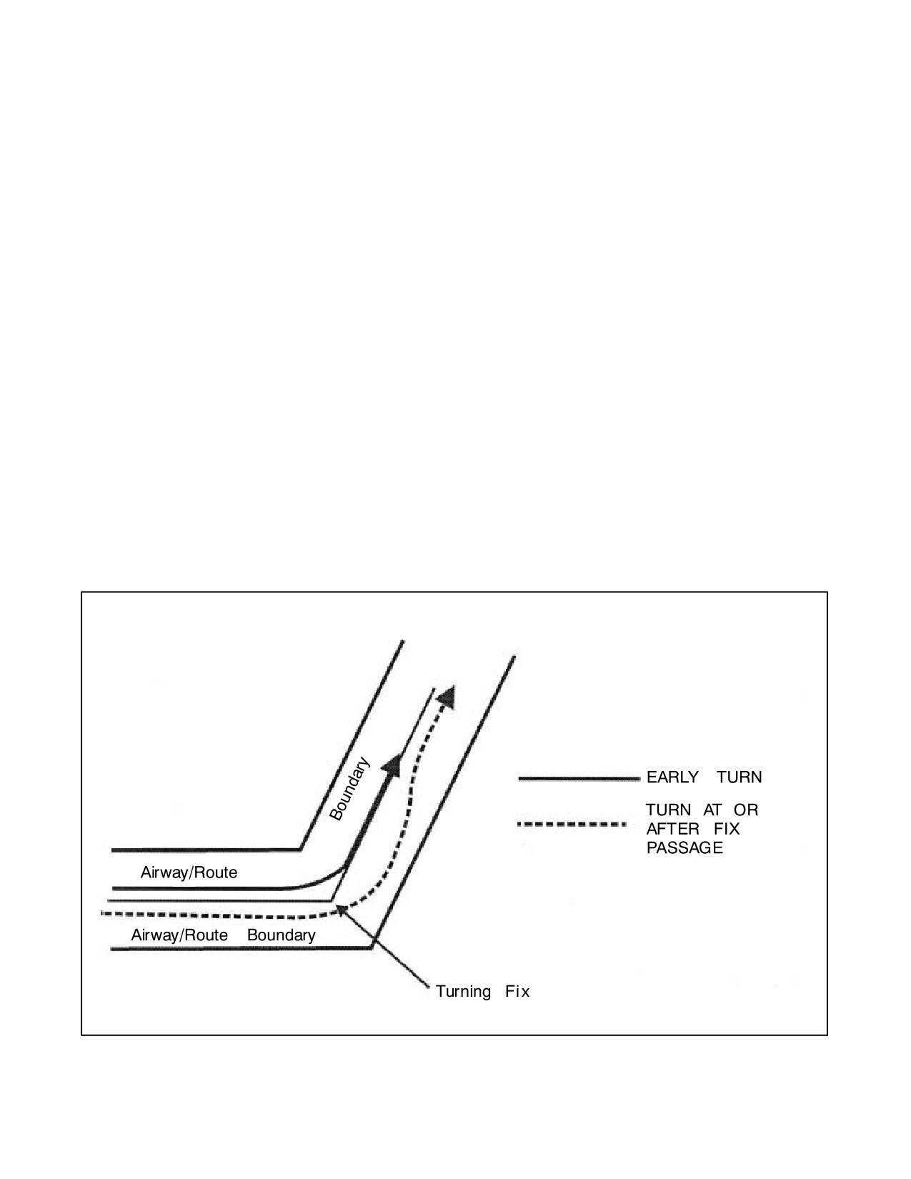
NAVAIR 00-80T-112
b. Regardless of the weather conditions or the height of the terrain, no person shall operate an aircraft under
VFR conditions within Class B airspace except in accordance with a clearance for VFR flight issued by
ATC.
c. The requirement for entry into Class B airspace is a student pilot permit (under the guidance or control of
a flight instructor).
d. VFR flight requires visual contact with the ground or water at all times.
2. Segments of VOR airways and high level routes in Canada are based on L/MF navigation aids and are charted
in brown color instead of blue on en route charts.
29.5
AIRWAY OR ROUTE COURSE CHANGES
Pilots of aircraft are required to adhere to airways or routes being flown. Special attention must be given to this
requirement during course changes. Each course change consists of variables that make the technique applicable in
each case a matter only the pilot can resolve. Some variables that must be considered are turn radius, wind effect,
airspeed, degree of turn, and cockpit instrumentation. An early turn, as illustrated in Figure 29-1, is one method of
adhering to airways or routes. The use of any available cockpit instrumentation, such as Distance Measuring
Equipment (DME), may be used by the pilot to lead the turn when making course changes. This is consistent with
the intent of 14 CFR Section 91.181, which requires pilots to operate along the centerline of an airway and along the
direct course between navigational aids or fixes.
Turns that begin at or after fix passage may exceed airway or route boundaries. Figure 29-1 contains an example flight
track depicting this, together with an example of an early turn.
Without such actions as leading a turn, aircraft operating in excess of 290 knots True Airspeed (TAS) can exceed the
normal airway or route boundaries depending on the amount of course change required, wind direction and velocity,
Figure 29-1. Adhering to Airways or Routes
29-7
ORIGINAL
NAVAIR 00-80T-112
the character of the turn fix (DME, overhead navigation aid, or intersection), and the pilot technique in making a
course change. For example, a flight operating at 17,000 feet MSL with a TAS of 400 knots, a 25-degree bank, and
a course change of more than 40 degrees would exceed the width of the airway or route (e.g., 4 nautical miles each
side of centerline); however, in the airspace below 18,000 feet MSL, operations in excess of 290 knots TAS are not
prevalent and the provision of additional IFR separation in all course change situations for the occasional aircraft
making a turn in excess of 290 knots TAS creates an unacceptable waste of airspace and imposes a penalty upon the
preponderance of traffic that operates at low speeds. Consequently, the Federal Aviation Administration (FAA)
expects pilots to lead turns and take other actions they consider necessary during course changes to adhere as closely
as possible to the airways or route being flown.
Due to the high airspeeds used at 18,000 feet MSL and above, FAA provides additional IFR separation protection
for course changes made at such altitude levels.
29.6
CHANGEOVER POINT (COP)
Changeover Points (COPs) are prescribed for Federal airways, jet routes, area navigation routes, or other direct routes
for which an MEA is designated under 14 CFR Part 95. The COP is a point along the route or airway segment between
two adjacent navigation facilities or waypoints where changeover in navigation guidance should occur. At this point,
the pilot should change navigation receiver frequency from the station behind the aircraft to the station ahead.
The COP is normally located midway between the navigation facilities for straight route segments or at the
intersection of radials or courses forming a dogleg in the case of dogleg route segments. When the COP is not located
at the midway point, aeronautical charts will depict the COP location and give the mileage to the radio aids.
COPs are established for the purpose of preventing loss of navigation guidance, to prevent frequency interference
from other facilities, and to prevent use of different facilities by different aircraft in the same airspace. Pilots are urged
to observe COPs to the fullest extent.
29.7
REDUCED VERTICAL SEPARATION MINIMUMS (RVSM)
Reduced Vertical Separation Minimums (RVSM) reduce the vertical separation between FL 290 to 410 from 2,000
feet to 1,000 feet and make six additional FLs available for operation. The additional FLs enable more aircraft to fly
more time/fuel efficient profiles and provide the potential for enhanced airspace capacity. RVSM operators must
receive authorization from the appropriate civil aviation authority. RVSM aircraft must meet required equipage and
altitude-keeping performance standards. Operators must operate in accordance with RVSM policies/procedures
applicable to the airspace where they are flying. Additional information is found in the Aeronautical Information
Manual/Federal Aviation Regulation (AIM/FAR).
29.8
HOLDING
Whenever an aircraft is cleared to a fix other than the destination airport and delay is expected, it is the responsibility
of the ATC controller to issue complete holding instructions (unless the pattern is charted), an EFC, and best estimate
of any additional en route/terminal delay.
Note
Only those holding patterns depicted on U.S. government or commercially
produced (meeting FAA requirements) low/high altitude en route, area, or
Standard Terminal Arrival (STAR) charts should be used.
If the holding pattern is charted and the controller does not issue complete holding instructions, the pilot is expected
to hold as depicted on the appropriate chart. When the pattern is charted, the controller may omit all holding
instructions except the charted holding direction and the statement “AS PUBLISHED” (e.g., “HOLD EAST AS
PUBLISHED”). Controllers shall always issue complete holding instructions when pilots request them.
ORIGINAL
29-8
NAVAIR 00-80T-112
If no holding pattern is charted and holding instructions have not been issued, the pilot should ask ATC for holding
instructions prior to reaching the fix. This procedure will eliminate the possibility of an aircraft entering a holding
pattern other than that desired by ATC. If unable to obtain holding instructions prior to reaching the fix (due to
frequency congestion, stuck microphone, etc.), enter a standard pattern on the course on which the aircraft approached
the fix and request further clearance as soon as possible. In this event, the altitude/flight level of the aircraft at the
clearance limit will be protected so that separation will be provided as required.
When an aircraft is 3 minutes or less from a clearance limit and a clearance beyond the fix has not been received, the
pilot is expected to start a speed reduction so that the aircraft will cross the fix, initially, at or below the maximum
holding airspeed.
When no delay is expected, the controller should issue a clearance beyond the fix as soon as possible and, whenever
possible, at least 5 minutes before the aircraft reaches the clearance limit.
Pilots should report to ATC the time and altitude/flight level at which the aircraft reaches the clearance limit and report
leaving the clearance limit.
When holding at a VOR station, pilots should begin the turn to the outbound leg at the time of the first complete
reversal of the TO-FROM indicator.
Patterns at the most generally used holding fixes are depicted (charted) on U.S. Government or commercially
produced (meeting FAA requirements) low/high altitude en route, area, and STAR charts. Pilots are expected to hold
in the pattern depicted unless specifically advised otherwise by ATC.
Note
Holding patterns that protect for a maximum holding airspeed other than
the standard may be depicted by an icon, unless otherwise depicted. The
icon is a standard holding pattern symbol (racetrack) with the airspeed
restriction shown in the center. In other cases, the airspeed restriction will
be depicted next to the standard holding pattern symbol.
An ATC clearance requiring an aircraft to hold at a fix where the pattern is not charted will include the following
information (Figure 29-2):
1. Direction of holding from the fix in terms of the eight cardinal compass points (e.g., N, NE, E, SE, etc.).
2. Holding fix (the fix may be omitted if included at the beginning of the transmission as the clearance limit).
3. Radial, course, bearing, airway or route on which the aircraft is to hold.
4. Leg length in miles if DME or RNAV is to be used (leg length will be specified in minutes on pilot request or
if the controller considers it necessary).
5. Direction of turn if left turns are to be made, the pilot requests, or the controller considers it necessary.
6. Time to expect further clearance and any pertinent additional delay information.
29-9
ORIGINAL
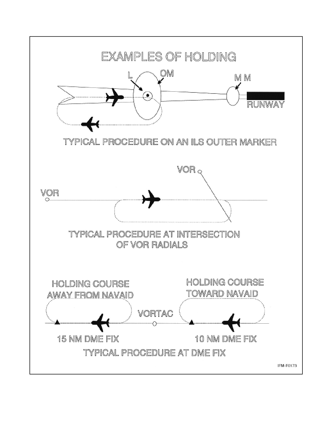
NAVAIR 00-80T-112
Figure 29-2. Holding Patterns
ORIGINAL
29-10
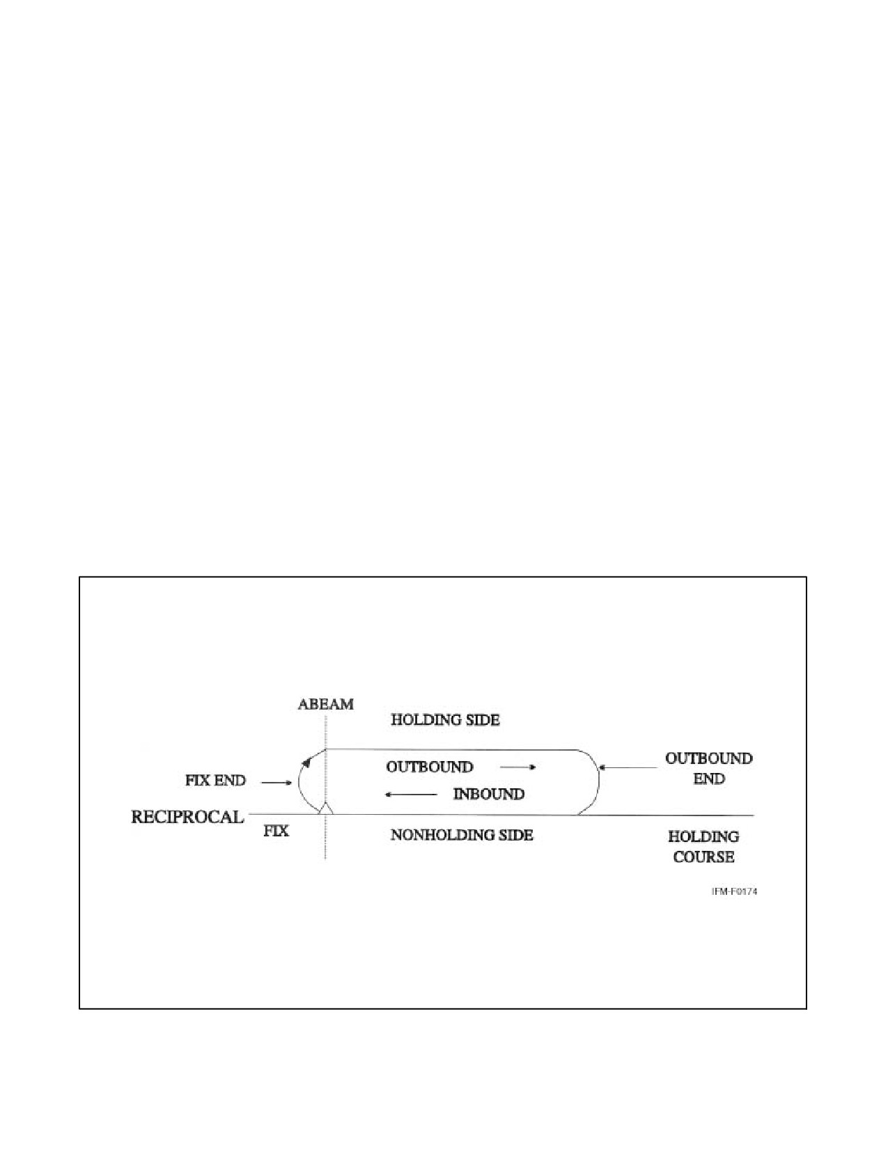
NAVAIR 00-80T-112
Holding pattern airspace protection is based on the following procedures.
29.8.1 Descriptive Terms
29.8.1.1 Standard Pattern
Right turns (Figure 29-3).
29.8.1.2 Nonstandard Pattern
Left turns.
29.8.2 Airspeeds
All aircraft may hold at the following altitudes and maximum holding airspeeds:
Altitude (MSL)
Airspeed (KIAS)
Minimum Holding Altitude (MHA) to 6,000 feet
200
6,001 feet to 14,000 feet
230
14,001 feet and above
265
The following are exceptions to the maximum holding airspeeds:
1. Holding patterns from 6,001 to 14,000 feet may be restricted to a maximum airspeed of 210 Knots Indicated
Airspeed (KIAS). This nonstandard pattern will be depicted by an icon.
Figure 29-3. Holding Pattern Descriptive Terms
29-11
ORIGINAL
NAVAIR 00-80T-112
2. Holding patterns may be restricted to a maximum airspeed of 175 KIAS. This nonstandard pattern will be
depicted by an icon. Holding patterns restricted to 175 KIAS will generally be found on Instrument Approach
Procedures (IAPs) applicable to Category A and B aircraft only.
3. Holding patterns at United States Air Force (USAF) airfields only — 310 KIAS maximum, unless otherwise
depicted.
4. Holding patterns at Navy fields only — 230 KIAS maximum, unless otherwise depicted.
5. When a climb-in hold is specified by a published procedure (e.g., “Climb-in holding pattern to depart XYZ
VORTAC at or above 10,000” or “All aircraft climb-in TRUCK holding pattern to cross TRUCK Int at or above
11,500 before proceeding on course”), additional obstacle protection area has been provided to allow for
greater airspeeds in the climb for those aircraft requiring them. The holding pattern template for a maximum
airspeed of 310 KIAS has been used for the holding pattern if there are no airspeed restrictions on the holding
pattern as specified in step 2 of this section. Where the holding pattern is restricted to a maximum airspeed of
175 KIAS, the 200 KIAS holding pattern template has been applied for published climb-in hold procedures
for altitudes 6,000 feet and below and the 230 KIAS holding pattern template has been applied for altitudes
above 6,000 feet. The airspeed limitations in 14 CFR Section 91.117, Aircraft Speed, still apply.
The following phraseology may be used by an ATCS to advise a pilot of the maximum holding airspeed for a holding
pattern airspace area:
PHRASEOLOGY — (AIRCRAFT IDENTIFICATION) (holding instructions, when needed) MAXIMUM
HOLDING AIRSPEED IS (speed in knots).
29.8.3 Entry Procedures
(Figure 29-4.)
29.8.3.1 Parallel Procedure
When approaching the holding fix from anywhere in sector (a), the parallel entry procedure would be to turn to a
heading to parallel the holding course outbound on the nonholding side for 1 minute, turn in the direction of the
holding pattern through more than 180 degrees, and return to the holding fix or intercept the holding course inbound.
29.8.3.2 Teardrop Procedure
When approaching the holding fix from anywhere in sector (b), the teardrop entry procedure would be to fly to the
fix, turn outbound to a heading for a 30-degree teardrop entry within the pattern (on the holding side) for a period
of 1 minute, then turn in the direction of the holding pattern to intercept the inbound holding course.
29.8.3.3 Direct Entry Procedure
When approaching the holding fix from anywhere in sector (c), the direct entry procedure would be to fly directly
to the fix and turn to follow the holding pattern.
Although other entry procedures may enable the aircraft to enter the holding pattern and remain within protected
airspace, the parallel, teardrop, and direct entries are the procedures for entry and holding recommended by the FAA.
29.8.4 Timing
29.8.4.1 Inbound Leg
1. At or below 14,000 feet MSL: 1 minute.
2. Above 14,000 feet MSL: 1-1/2 minutes.
ORIGINAL
29-12
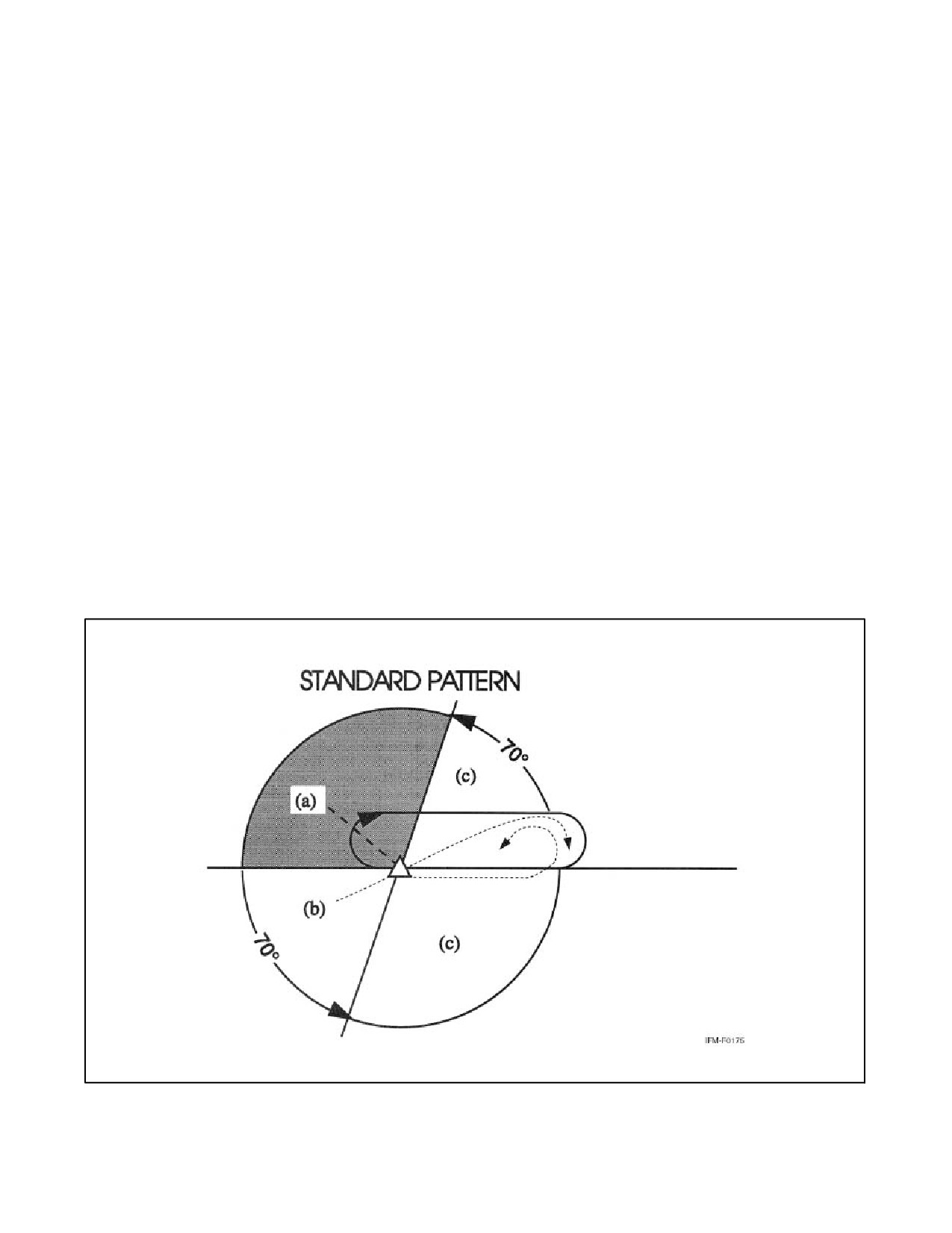
NAVAIR 00-80T-112
Note
The initial outbound leg should be flown for 1 minute or 1-1/2 minutes
(appropriate to altitude). Timing for subsequent outbound legs should be
adjusted, as necessary, to achieve proper inbound leg time. Pilots may use
any navigational means available (e.g., DME, RNAV, etc.), to ensure the
appropriate inbound leg times.
29.8.4.2 Outbound Leg
Timing begins over or abeam the fix, whichever occurs later. If the abeam position cannot be determined, start timing
when turn to outbound is completed.
29.8.5 Distance Measuring Equipment (DME)
DME holding is subject to the same entry and holding procedures except that distances (nautical miles) are used in
lieu of time values. The outbound course of a DME holding pattern is called the outbound leg of the pattern. The length
of the outbound leg will be specified by the controller. The end of the outbound leg is determined by the odometer
reading (Figures 29-5 and 29-6).
Note
D When the inbound course is toward the Navigation Aid (NAVAID), the fix
distance is 10 nm, and the leg length is 5 nm, the end of the outbound leg
will be reached when the DME reads 15 nm.
D When the inbound course is away from the NAVAID, the fix distance is
27 nm, and the leg length is 8 nm, the end of the outbound leg will be
reached when the DME reads 20 nm.
Figure 29-4. Holding Pattern Entry Procedures
29-13
ORIGINAL
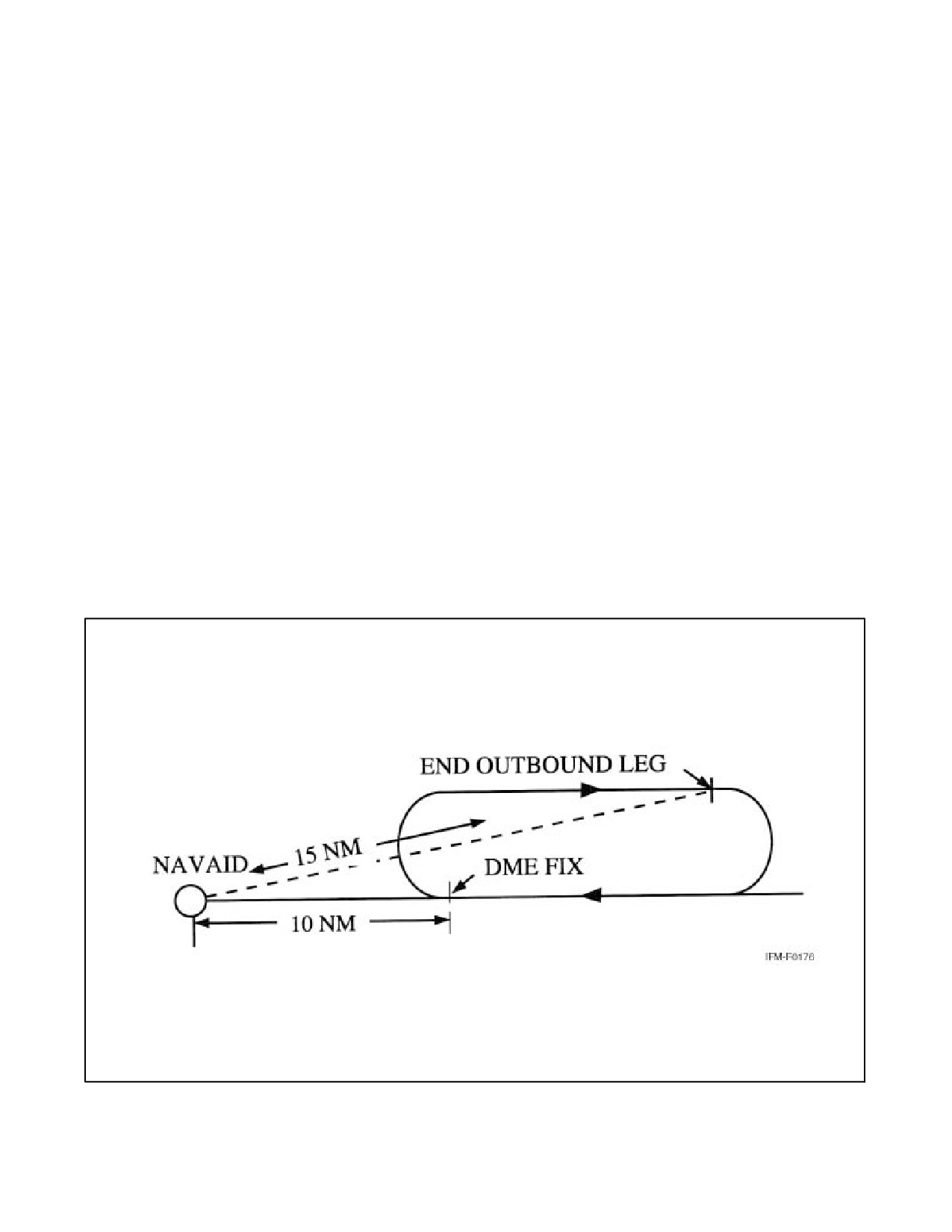
NAVAIR 00-80T-112
29.8.6 Pilot Action
Start speed reduction when 3 minutes or less from the holding fix. Cross the holding fix, initially, at or below the
maximum holding airspeed.
Make all turns during entry and while holding at:
1.
3 degrees per second; or
2.
30-degree bank angle; or
3.
25-degree bank, provided a flight director system is used.
Note
Use whichever requires the least bank angle.
Compensate for wind effect primarily by drift correction on the inbound and outbound legs. When outbound, triple
the inbound drift correction to avoid major turning adjustments (e.g., if correcting left by 8 degrees when inbound,
correct right by 24 degrees when outbound).
Determine entry turn from aircraft heading upon arrival at the holding fix; ±5 degrees in heading is considered to be
within allowable good operating limits for determining entry.
Advise ATC immediately what increased airspeed is necessary, if any, due to turbulence, icing, etc., or if unable to
accomplish any part of the holding procedures. When such higher speeds become no longer necessary, operate
according to the appropriate published holding speed and notify ATC.
29.8.7 Nonstandard Holding Pattern
Fix end and outbound end turns are made to the left. Entry procedures to a nonstandard pattern are oriented in relation
to the 70-degree line on the holding side just as in the standard pattern.
Figure 29-5. Inbound Leg Toward NAVAID
ORIGINAL
29-14
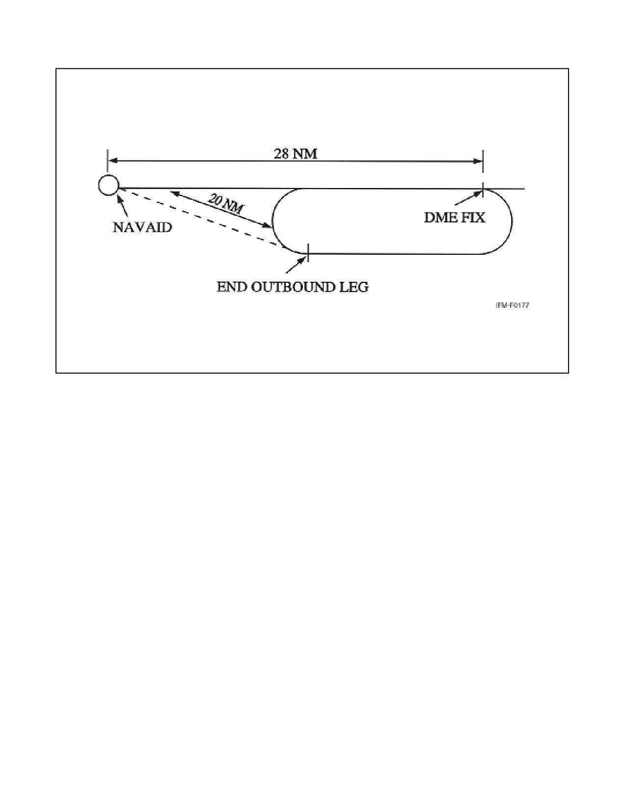
NAVAIR 00-80T-112
Figure 29-6. Inbound Leg Away from NAVAID
When holding at a fix and instructions are received specifying the time of departure from the fix, the pilot should
adjust the aircraft flightpath within the limits of the established holding pattern in order to leave the fix at the exact
time specified. After departing the holding fix, normal speed is to be resumed with respect to other governing speed
requirements, such as terminal area speed limits, specific ATC requests, etc. Where the fix is associated with an
instrument approach and timed approaches are in effect, a procedure turn shall not be executed unless the pilot advises
ATC, as aircraft holding are expected to proceed inbound on final approach directly from the holding pattern when
approach clearance is received.
Radar surveillance of outer fix holding pattern airspace areas.
1. Whenever aircraft are holding at an outer fix, ATC will usually provide radar surveillance of the outer fix
holding pattern airspace area, or any portion of it, if it is shown on the controller radar scope.
2. The controller will attempt to detect any holding aircraft that stray outside the holding pattern airspace area
and will assist any detected aircraft to return to the assigned airspace area.
Note
Many factors could prevent ATC from providing this additional service,
such as workload, number of targets, precipitation, ground clutter, and radar
system capability. These circumstances may make it unfeasible to maintain
radar identification of aircraft to detect aircraft straying from the holding
pattern. The provision of this service depends entirely upon whether
controllers believe they are in a position to provide it and does not relieve
pilots of their responsibility to adhere to an accepted ATC clearance.
29-15
ORIGINAL
NAVAIR 00-80T-112
3. If an aircraft is established in a published holding pattern at an assigned altitude above the published Minimum
Holding Altitude (MHA) and subsequently cleared for the approach, the pilot may descend to the published
minimum holding altitude. The holding pattern would only be a segment of the IAP if it is published on the
instrument procedure chart and is used in lieu of a procedure turn.
For those holding patterns where there are no published minimum holding altitudes, the pilot, upon receiving an
approach clearance, must maintain the last assigned altitude until leaving the holding pattern and established on the
inbound course; thereafter, the published minimum altitude of the route segment being flown will apply. It is expected
that the pilot will be assigned a holding altitude that will permit a normal descent on the inbound course.
29.9
UPDATING OF WEATHER DATA
Pilots shall periodically determine that their intended route of flight remains clear of aviation Severe Weather Watch
Bulletins (WWs) and that weather forecasts for each successive intermediate destination and alternate, when required,
continue to satisfy the minimums established for the aircraft and the filing status (IFR/VFR). These updates are
readily available from U.S. Navy, Marine Corps, and Air Force weather activities through use of the Pilot-to-Metro
Service (PMSV), Automatic Terminal Information Service (ATIS) broadcasts, selected VOR and low-frequency
NAVAIDs, and data provided by Air Route Traffic Control Centers (ARTCCs) and Flight Service Stations (FSSs)
in the form of weather advisory broadcasts and Hazardous In-Flight Weather Advisory Services (HIWAS). When
dealing with situations where adverse weather is involved, such as weather associated with Significant
Meteorological Information (SIGMETs) or WWs, pilots need to obtain more specific guidance or further technical
evaluation of meteorological conditions that could affect the flight. When faced with this situation, the pilot should
initiate communications with one of the activities listed below (in order of preference):
1. Military Pilot-to-Metro Service (PMSV).
2. FAA En Route Flight Advisory Service (EFAS).
3. The nearest FSS.
When utilizing full-service PMSV or EFAS, the pilot will have access to a qualified meteorological forecaster. Most
PMSVs and FSSs are 24 hour facilities, but EFAS runs for specific daytime hours and pertains only to the en route
portion of flight. EFAS is still the preferred method of obtaining en route hazardous weather information if the pilot
cannot utilize PMSV because, unlike FSSs, EFASs are dedicated specifically to weather updates.
ORIGINAL
29-16
NAVAIR 00-80T-112
CHAPTER 30
Terminal Procedures
30.1
STANDARD TERMINAL ARRIVAL (STAR), FLIGHT MANAGEMENT SYSTEM PROCEDURES
(FMSP) FOR ARRIVALS
A Standard Terminal Arrival (STAR) is an Air Traffic Control (ATC) coded IFR arrival route established for
application to arriving Instrument Flight Rules (IFR) aircraft destined for certain airports. FMSPs for arrivals serve
the same purpose but are only used by aircraft equipped with a Flight Management System (FMS). The purpose of
both is to simplify clearance delivery procedures and facilitate transition between en route and instrument approach
procedures.
1. STARs/FMSPs may have mandatory speeds and/or crossing altitudes published. Other STARs may have
planning information depicted to inform pilots what clearances or restrictions to “expect.” “Expect”
altitudes/speeds are not considered STAR/FMSP crossing restrictions until verbally issued by ATC.
Note
The “expect” altitudes/speeds are published so that pilots may have the
information for planning purposes. These altitudes/speeds should not be
used in the event of lost communications unless ATC has specifically
advised the pilot to expect these altitudes/speeds as part of a further
clearance.
2. Pilots navigating on a STAR/FMSP shall maintain last assigned altitude until receiving authorization to
descend so as to comply with all published/issued restrictions. This authorization will contain the phrase
“DESCEND VIA.”
a. A “descend via” clearance authorizes pilots to navigate vertically and laterally, in accordance with the
depicted procedure, to meet published restrictions. Vertical navigation is at pilot discretion; however,
adherence to published altitude crossing restrictions and speeds is mandatory unless otherwise cleared.
(Minimum En Route Altitudes [MEAs] are not considered restrictions; however, pilots are expected to
remain above MEAs.)
b. Pilots cleared for vertical navigation using the phrase “descend via” shall inform ATC upon initial contact
with a new frequency.
Pilots of IFR aircraft destined to locations for which STARs have been published may be issued a clearance containing
a STAR whenever ATC deems it appropriate.
Use of STARs requires pilot possession of at least the approved chart. As with any ATC clearance or portion thereof,
it is the responsibility of each pilot to accept or refuse an issued STAR. Pilots should notify ATC if they do not wish
to use a STAR by placing “NO STAR” in the remarks section of the flight plan or by the less desirable method of
verbally stating the same to ATC.
STAR charts are published in the Terminal Procedures Publications (TPPs) and are available on subscription from
the National Aeronautical Charting Office, AVN-500.
30-1
ORIGINAL
NAVAIR 00-80T-112
30.2
LOCAL FLOW TRAFFIC MANAGEMENT PROGRAM
This program is a continuing effort by the Federal Aviation Administration (FAA) to enhance safety, minimize the
impact of aircraft noise, and conserve aviation fuel. The enhancement of safety and reduction of noise is achieved
in this program by minimizing low altitude maneuvering of arriving turbojet and turboprop aircraft weighing more
than 12,500 pounds and by permitting departure aircraft to climb to higher altitudes sooner as arrivals are operating
at higher altitudes at the points where their flightpaths cross. The application of these procedures also reduces
exposure time between controlled aircraft and uncontrolled aircraft at the lower altitudes in and around the terminal
environment. Fuel conservation is accomplished by absorbing any necessary arrival delays for aircraft included in
this program operating at the higher and more fuel-efficient altitudes.
A fuel-efficient descent is basically an uninterrupted descent (except where level flight is required for speed
adjustment) from cruising altitude to the point when level flight is necessary for the pilot to stabilize the aircraft on
final approach. The procedure for a fuel-efficient descent is based on an altitude loss that is most efficient for the
majority of aircraft being served. This will generally result in a descent gradient window of 250 to 350 feet per nautical
mile.
When crossing altitudes and speed restrictions are issued verbally or are depicted on a chart, ATC will expect the pilot
to descend first to the crossing altitude and then reduce speed. Verbal clearances for descent will normally permit an
uninterrupted descent in accordance with the procedure as described above. Acceptance of a charted fuel-efficient
descent (Runway Profile Descent) clearance requires the pilot to adhere to the altitudes, speeds, and headings depicted
on the charts unless otherwise instructed by ATC.
Note
Pilots receiving a clearance for a fuel-efficient descent are expected to
advise ATC if they do not have runway profile descent charts published for
that airport or are unable to comply with the clearance.
30.3
APPROACH CONTROL
Approach control is responsible for controlling all instrument flight operating within its area of responsibility.
Approach control may serve one or more airfields, and control is exercised primarily by direct pilot and controller
communications. Prior to arriving at the destination radio facility, instructions will be received from the Air Route
Traffic Control Center (ARTCC) to contact approach control on a specified frequency.
30.3.1 Radar Approach Control
1. Where radar is approved for approach control service, it is used not only for radar approaches (Airport
Surveillance Radar [ASR] and Precision Approach Radar [PAR]) but is also used to provide vectors in
conjunction with published nonradar approaches based on radio Navigation Aids (NAVAIDs) (Instrument
Landing System
[ILS], Microwave Landing System
[MLS], VHF Omnidirectional Range
[VOR],
Non-Directional Beacon [NDB], Tactical Air Navigation [TACAN]). Radar vectors can provide course
guidance and expedite traffic to the final approach course of any established Instrument Approach Procedure
(IAP) or to the traffic pattern for a visual approach. Approach control facilities that provide this radar service
will operate in the following manner:
a. Arriving aircraft are either cleared to an outer fix most appropriate to the route being flown with vertical
separation and, if required, given holding information or, when radar handoffs are effected between the
ARTCC and approach control, or between two approach control facilities, aircraft are cleared to the airport
or to a fix so located that the handoff will be completed prior to the time the aircraft reaches the fix. When
radar handoffs are utilized, successive arriving flights may be handed off to approach control with radar
separation in lieu of vertical separation.
ORIGINAL
30-2
NAVAIR 00-80T-112
b. After release to approach control, aircraft are vectored to the final approach course (ILS, MLS, VOR, ADF,
etc.). Radar vectors and altitude or flight levels will be issued as required for spacing and separating aircraft;
therefore, pilots must not deviate from the headings issued by approach control. Aircraft will normally be
informed when it is necessary to vector across the final approach course for spacing or other reasons. If
approach course crossing is imminent and the pilot has not been informed that the aircraft will be vectored
across the final approach course, the pilot should query the controller.
c. The pilot is not expected to turn inbound on the final approach course unless an approach clearance has been
issued. This clearance will normally be issued with the final vector for interception of the final approach
course, and the vector will be such as to enable the pilot to establish the aircraft on the final approach course
prior to reaching the final approach fix.
d. In the case of aircraft already inbound on the final approach course, approach clearance will be issued prior
to the aircraft reaching the final approach fix. When established inbound on the final approach course, radar
separation will be maintained and the pilot will be expected to complete the approach utilizing the approach
aid designated in the clearance (ILS, MLS, VOR, radio beacons, etc.) as the primary means of navigation;
therefore, once established on the final approach course, pilots must not deviate from it unless a clearance
to do so is received from ATC.
e. After passing the final approach fix on final approach, aircraft are expected to continue inbound on the final
approach course and complete the approach or effect the missed approach procedure published for that
airport.
2.
ARTCCs are approved for and may provide approach control services to specific airports. The radar systems
used by these centers do not provide the same precision as an ASR/PAR used by approach control facilities
and towers, and the update rate is not as fast; therefore, pilots may be requested to report established on the
final approach course.
3.
Whether aircraft are vectored to the appropriate final approach course or provide their own navigation on
published routes to it, radar service is automatically terminated when the landing is completed or when
instructed to change to advisory frequency at uncontrolled airports, whichever occurs first.
30.4
ADVANCE INFORMATION ON INSTRUMENT APPROACH
When landing at airports with approach control services and where two or more IAPs are published, pilots will be
provided in advance of their arrival with the type of approach to expect or informed that they may be vectored for
a visual approach. This information will be broadcast either by a controller or on Automatic Terminal Information
Service (ATIS). It will not be furnished when the visibility is 3 miles or better and the ceiling is at or above the highest
initial approach altitude established for any low-altitude IAP for the airport.
The purpose of this information is to aid the pilot in planning arrival actions; however, it is not an ATC clearance or
commitment and is subject to change. Pilots should bear in mind that fluctuating weather, shifting winds, blocked
runway, etc. are conditions that may result in changes to approach information previously received. It is important
that pilots advise ATC immediately if they are unable to execute the approach ATC advised will be used or if they
prefer another type of approach.
Aircraft destined to uncontrolled airports, which have automated weather data with broadcast capability, should
monitor the (Automated Surface Observing System/Automated Weather Observing System [ASOS/AWOS])
frequency to ascertain the current weather for the airport. Pilots shall advise ATC when They have received the
broadcast weather and state their intentions.
When making an IFR approach to an airport not served by a tower or FSS, after ATC advises “CHANGE TO
ADVISORY FREQUENCY APPROVED,” you should broadcast your intentions, including the type of approach
being executed, your position, and when over the final approach fix inbound (nonprecision approach) or when over
the outer marker or fix used in lieu of the outer marker inbound (precision approach). Continue to monitor the
appropriate frequency (e.g., UNICOM) for reports from other pilots.
30-3
ORIGINAL
NAVAIR 00-80T-112
30.5
INSTRUMENT APPROACH PROCEDURE CHARTS
14 Code of Federal Regulations (CFR) Section 91.175(a), Instrument Approaches to Civil Airports, requires the use
of Standard Instrument Approach Procedures (SIAPs) prescribed for the airport in 14 CFR Part 97 unless otherwise
authorized by the Administrator (including ATC). 14 CFR Section 91.175(g), Military Airports, requires civil pilots
flying into or out of military airports to comply with the IAP and takeoff and landing minimums prescribed by the
authority having jurisdiction at those airports.
1.
All IAPs (standard and special, civil and military) are based on joint civil and military criteria contained in the
U.S. Standard for Terminal Instrument Procedures (TERPS). The design of IAPs based on criteria contained
in TERPS takes into account the interrelationship between airports, facilities, and the surrounding
environment, terrain, obstacles, noise sensitivity, etc. Appropriate altitudes, courses, headings, distances, and
other limitations are specified and, once approved, the procedures are published and distributed by government
and commercial cartographers as instrument approach charts.
2.
Not all IAPs are published in chart form. Radar IAPs are established where requirements and facilities exist
but they are printed in tabular form in appropriate U.S. Government Flight Information Publications.
3.
Straight-in IAPs are identified by the navigational system providing the final approach guidance and the
runway to which the approach is aligned (e.g., VOR RWY 13). Circling only approaches are identified by the
navigational system providing final approach guidance and a letter (e.g., VOR A). More than one navigational
system separated by a slash indicates more than one type of equipment must be used to execute the final
approach (e.g., VOR/Distance Measuring Equipment (DME) RWY 31). More than one navigational system
separated by the word “or” indicates either type of equipment may be used to execute the final approach (e.g.,
VOR or GPS RWY 15). In some cases, other types of navigation systems may be required to execute other
portions of the approach (e.g., an NDB procedure turn to an ILS or an NDB in the missed approach). Pilots
should ensure the aircraft is equipped with the required NAVAID(s) in order to execute the approach, including
the missed approach. The FAA will initiate a program to provide a new notation for Localizer (LOC)
approaches when charted on an ILS approach requiring other navigational aids to fly the final approach course.
The LOC minimums will be annotated with the NAVAID required (e.g., “DME Required” or “RADAR
Required”). During the transition period, ILS approaches will still exist without the annotation. The naming
of multiple approaches of the same type to the same runway is also changing. New approaches with the same
guidance will be annotated with an alphabetical suffix beginning at the end of the alphabet and working
backward for subsequent procedures (ILS Z RWY 28, ILS Y RWY 28, etc.). The existing annotations such as
ILS 2 RWY 28 or Silver ILS RWY 28 will be phased out and eventually replaced with the new designation.
Category II and III ILS procedures are not subject to this naming convention. Wide Area Augmentation System
(WAAS), Lateral Navigation/Vertical Navigation (LNAV/VNAV), and Global Positioning System (GPS)
approach procedures will be charted as RNAV RWY (Number) (e.g., RNAV RWY 21). VOR/DME Area
Navigation (RNAV) approaches will continue to be identified as VOR/DME RNAV RWY (Number) (e.g.,
VOR/DME RNAV RWY 21).
4.
Approach minimums are based on the local altimeter setting for that airport, unless annotated otherwise (e.g.,
Oklahoma City/Will Rogers World approaches are based on having a Will Rogers World altimeter setting).
When a different altimeter source is required, or more than one source is authorized, it will be annotated on
the approach chart (e.g., use Sidney altimeter setting; if not received, use Scottsbluff altimeter setting).
Approach minimums may be raised when a nonlocal altimeter source is authorized. When more than one
altimeter source is authorized, and the minimums are different, they will be shown by separate lines in the
approach minimums box or a note (e.g., use Manhattan altimeter setting; when not available, use Salina
altimeter setting and increase all Minimum Descent Altitudes [MDAs] 40 feet). When the altimeter must be
obtained from a source other than air traffic, a note will indicate the source (e.g., obtain local altimeter setting
on Common Traffic Advisory Frequency [CTAF]). When the altimeter setting(s) on which the approach is
based is not available, the approach is not authorized.
ORIGINAL
30-4
NAVAIR 00-80T-112
5. A pilot adhering to the altitudes, flightpaths, and weather minimums depicted on the IAP chart or vectors and
altitudes issued by the radar controller is assured of terrain and obstruction clearance and runway or airport
alignment during approach for landing.
6. IAPs are designed to provide an IFR descent from the en route environment to a point where a safe landing
can be made. They are prescribed and approved by appropriate civil or military authority to ensure a safe
descent during instrument flight conditions at a specific airport. It is important that pilots understand these
procedures and their use prior to attempting to fly instrument approaches.
7. TERPS criteria for the following type of instrument approach procedures:
a. Precision approaches where an electronic glideslope is provided (PAR, ILS, Tactical Landing System
[TLS], and MLS).
b. Precision approaches when vertical guidance is provided (Localizer Performance with Vertical Guidance
[LPV], GNSS Landing System [GLS], and Special Category 1 Differential GPS [SCAT-1]).
c. Nonprecision approaches when vertical guidance is provided (LNAV/VNAV).
d. Nonprecision approaches when no vertical guidance or glidepath is provided (all except for those listed in
subparagraphs a to c above).
The method used to depict prescribed altitudes on instrument approach charts differs according to techniques
employed by different chart publishers. Prescribed altitudes may be depicted in three different configurations:
minimum, maximum, and mandatory. The U.S. Government distributes charts produced by National
Geospatial-Intelligence Agency (NGA) and FAA. Altitudes are depicted on these charts in the profile view with
underscore, overscore, or both to identify them as minimum, maximum, or mandatory.
1. Minimum altitude will be depicted with the altitude value underscored. Aircraft are required to maintain
altitude at or above the depicted value.
2. Maximum altitude will be depicted with the altitude value overscored. Aircraft are required to maintain altitude
at or below the depicted value.
3. Mandatory altitude will be depicted with the altitude value both underscored and overscored. Aircraft are
required to maintain altitude at the depicted value.
Note
The underscore and overscore to identify mandatory altitudes and the
overscore to identify maximum altitudes are used almost exclusively by
NGA for military charts. With very few exceptions, civil approach charts
produced by FAA utilize only the underscore to identify minimum
altitudes. Pilots are cautioned to adhere to altitudes as prescribed because,
in certain instances, they may be used as the basis for vertical separation of
aircraft by ATC. When a depicted altitude is specified in the ATC clearance,
that altitude becomes mandatory as defined above.
30.5.1 Minimum Safe Altitude (MSA)
Minimum Safe Altitudes (MSAs) are published for emergency use on IAP charts. For conventional navigation
systems, the MSA is normally based on the primary omnidirectional facility on which the IAP is predicated. The MSA
depiction on the approach chart contains the facility identifier of the NAVAID used to determine the MSA altitudes.
For RNAV approaches, the MSA is based on the runway waypoint for straight-in approaches, or the airport waypoint
30-5
ORIGINAL
NAVAIR 00-80T-112
for circling approaches. For GPS approaches, the MSA center will be the Missed Approach Waypoint (MAWP).
MSAs are expressed in feet above mean sea level and normally have a 25-nm radius; however, this radius may be
expanded to 30 nm if necessary to encompass the airport landing surfaces. Ideally, a single sector altitude is
established and depicted on the plan view of approach charts; however, when necessary to obtain relief from
obstructions, the area may be further sectored and as many as four MSAs established. When established, sectors may
be no less than 90° in spread. MSAs provide 1,000 foot clearance over all obstructions but do not necessarily ensure
acceptable navigation signal coverage.
30.5.2 Terminal Arrival Area (TAA)
1.
The objective of the Terminal Arrival Area (TAA) is to provide a seamless transition from the en route structure
to the terminal environment for arriving aircraft equipped with an FMS and/or GPS navigational equipment.
The underlying instrument approach procedure is an Area Navigation (RNAV) procedure described in
paragraph 30.5.8. The TAA provides the pilot and air traffic controller with a very efficient method for routing
traffic into the terminal environment with little required air traffic control interface and with minimum altitudes
depicted that provide standard obstacle clearance compatible with the instrument procedure associated with
it. The TAA will not be found on all RNAV procedures, particularly in areas of heavy concentration of air
traffic. When the TAA is published, it replaces the MSA for that approach procedure.
2.
The RNAV procedure underlying the TAA will be the “T” design (also called the “Basic T”), or a modification
of the “T.” The “T” design incorporates from one to three Initial Approach Fixes (IAFs): an Intermediate Fix
(IF) that serves as a dual purpose IF (IAF), a Final Approach Fix (FAF), and a Missed Approach Point (MAP)
usually located at the runway threshold. The three IAFs are normally aligned in a straight line perpendicular
to the intermediate course, which is an extension of the final course leading to the runway, forming a “T.” The
initial segment is normally from 3 to 6 nm in length, the intermediate 5 to 7 nm, and the final segment 5 nm.
Specific segment length may be varied to accommodate specific aircraft categories for which the procedure
is designed; however, the published segment lengths will reflect the highest category of aircraft normally
expected to use the procedure.
a. A standard racetrack holding pattern may be provided at the center IAF and, if present, may be necessary
for course reversal and for altitude adjustment for entry into the procedure. In the latter case, the pattern
provides an extended distance for the descent required by the procedure. Depiction of this pattern in U.S.
Government publications will utilize the “hold-in-lieu-of-PT” holding pattern symbol.
b. The published procedure will be annotated to indicate when the course reversal is not necessary when flying
within a particular TAA area (e.g., “NoPT”); otherwise, the pilot is expected to execute the course reversal
under the provisions of 14 CFR Section 91.175. The pilot may elect to use the course reversal pattern when
it is not required by the procedure, but must inform air traffic control and receive clearance to do so
(Figures 30-1 and 30-2).
3.
The “T” design may be modified by the procedure designers where required by terrain or ATC considerations.
For instance, the “T” design may appear more like a regularly or irregularly shaped “Y,” or may even have one
or both outboard IAFs eliminated, resulting in an upside-down “L” or an “I” configuration (Figures 30-3 and
30-4). Further, the leg lengths associated with the outboard IAFs may differ (Figures 30-5 and 30-6).
4.
Another modification of the “T” design may be found at airports with parallel runway configurations. Each
parallel runway may be served by its own “T” IAF, IF (IAF), and FAF combination, resulting in parallel final
approach courses (Figure 30-4). Common IAFs may serve both runways; however, only the intermediate and
final approach segments for the landing runway will be shown on the approach chart (Figures 30-5 and 30-6).
ORIGINAL
30-6
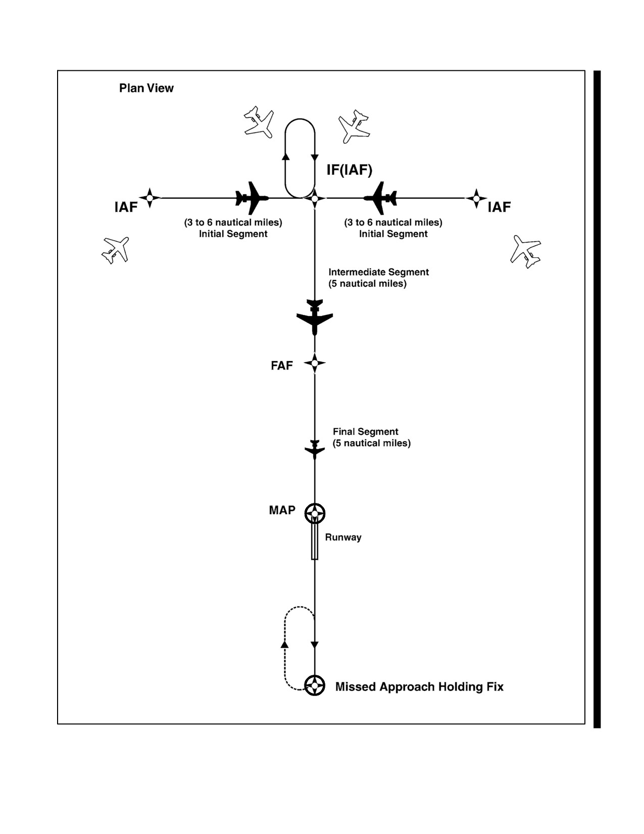
NAVAIR 00-80T-112
Figure 30-1. Basic “T” Design
30-7
ORIGINAL
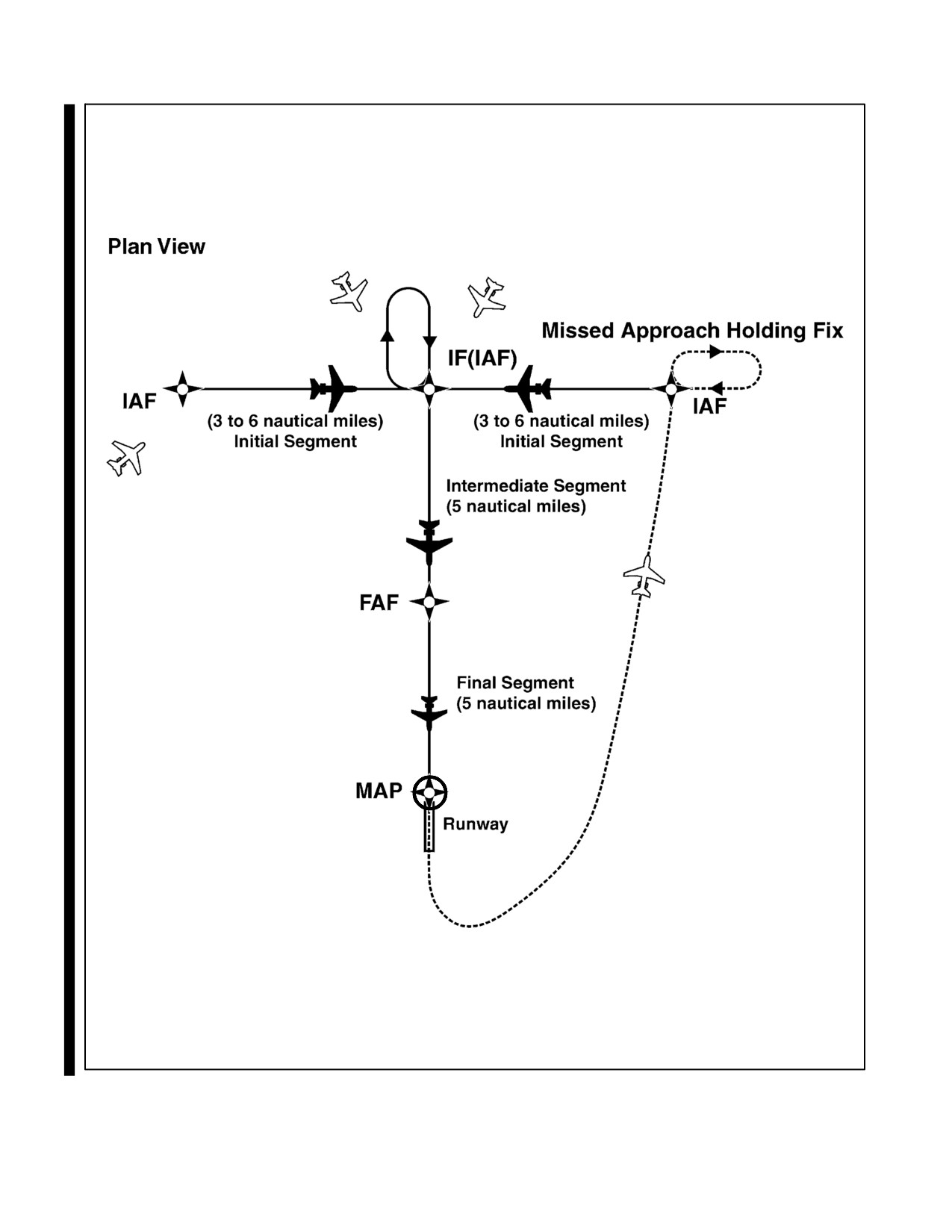
NAVAIR 00-80T-112
Figure 30-2. Basic “T” Design
ORIGINAL
30-8
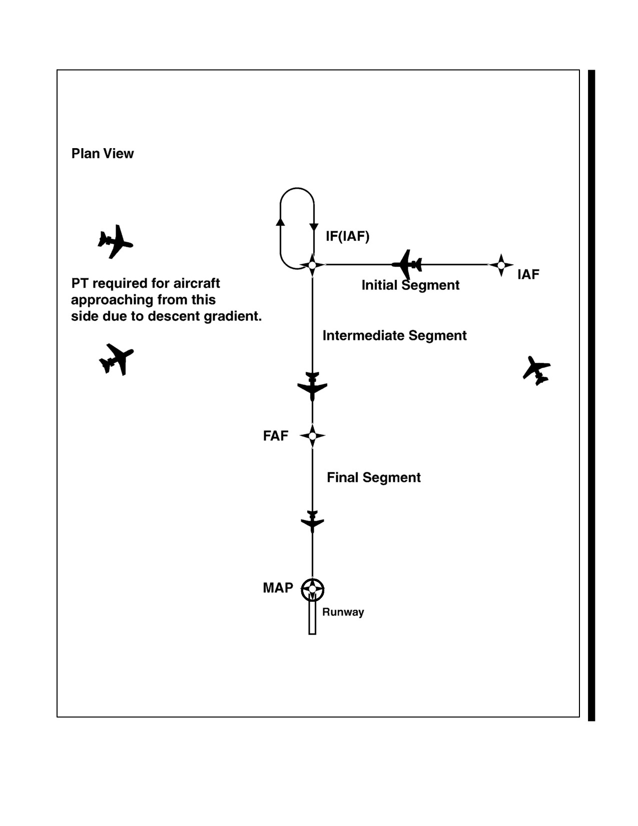
NAVAIR 00-80T-112
Figure 30-3. Modified Basic “T”
30-9
ORIGINAL
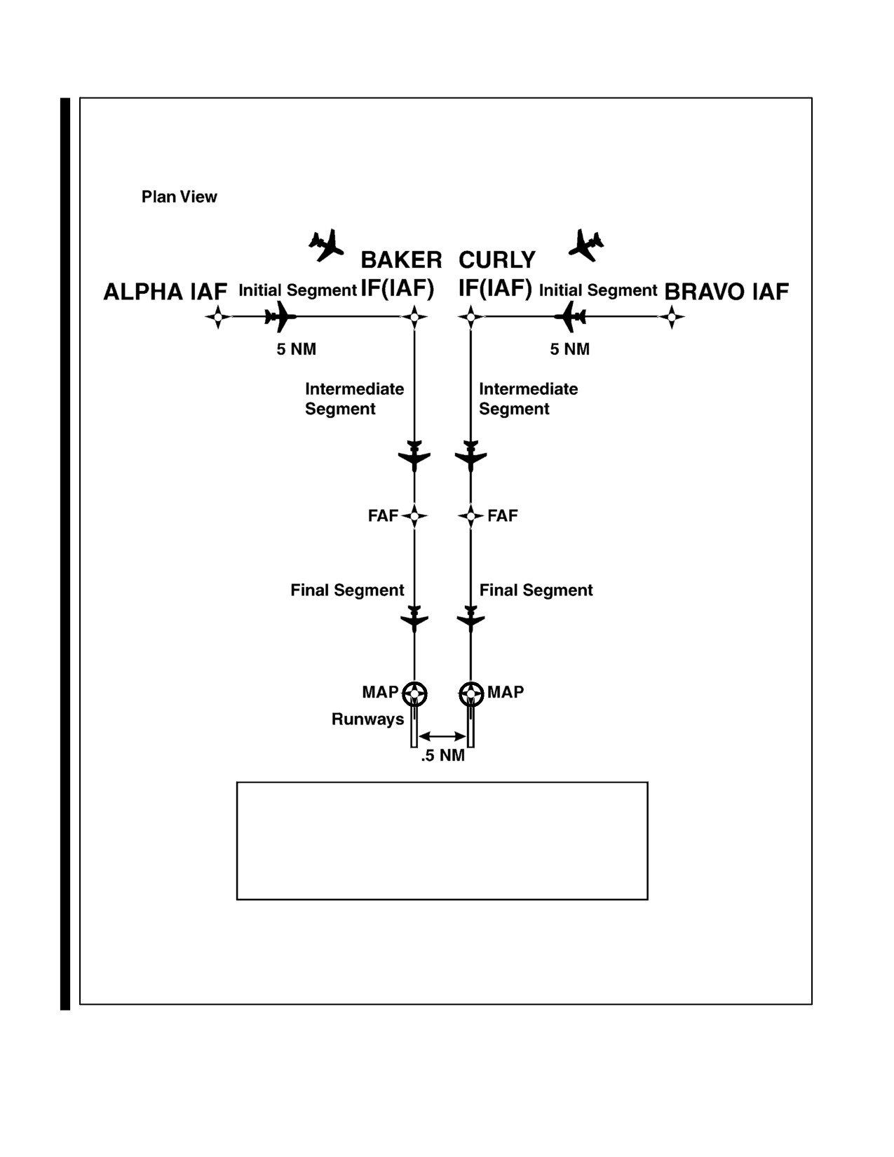
NAVAIR 00-80T-112
The normal “T” IAFs all parallel runways.
Each runway will require separate IF(IAF).
Only one initial, intermediate and final
segment combination will be depicted on
the approach chart.
Figure 30-4. Modified “T” Approach to Parallel Runways
ORIGINAL
30-10
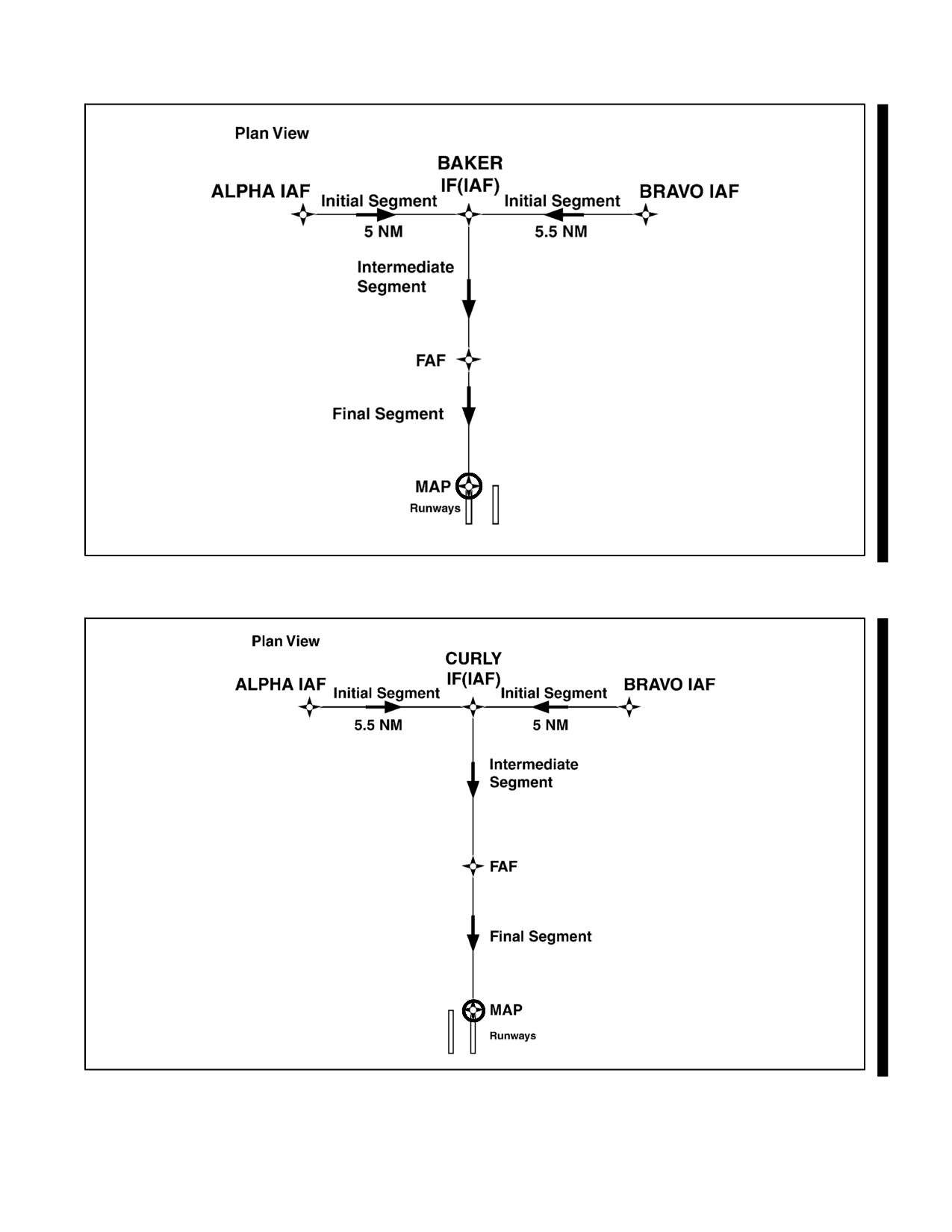
NAVAIR 00-80T-112
Figure 30-5. “T” Approach with Common IAFs to Parallel Runways
Figure 30-6. “T” Approach with Common IAFs to Parallel Runways
30-11
ORIGINAL
NAVAIR 00-80T-112
5.
The standard TAA consists of three areas defined by the extension of the IAF legs and the intermediate segment
course. These areas are called the straight-in, left-base, and right-base areas (Figure 30-7). TAA area lateral
boundaries are identified by magnetic courses to the IF (IAF). The straight-in area can be further divided into
pie-shaped sectors with the boundaries identified by magnetic courses to the IF (IAF) and may contain
stepdown sections defined by arcs based on RNAV distances (DME or Along Track Distance [ATD]) from the
IF (IAF). The right/left-base areas can only be subdivided using arcs based on RNAV distances from the IAF
for those areas. Minimum Mean Sea Level (MSL) altitudes are charted within each of these defined
areas/subdivisions that provide at least 1,000 feet of obstacle clearance or more, as necessary, in mountainous
areas.
a. Prior to arriving at the TAA boundary, the pilot can determine which area of the TAA the aircraft will enter
by selecting the IF (IAF) to determine the magnetic bearing to the IF (IAF). That bearing should then be
compared with the published bearings that define the lateral boundaries of the TAA areas. This is critical
when approaching the TAA near the extended boundary between the left- and right-base areas, especially
where these areas contain different minimum altitude requirements.
b. Pilots entering the TAA and cleared by air traffic control are expected to proceed directly to the IAF
associated with that area of the TAA at the altitude depicted, unless otherwise cleared by air traffic control.
Pilots entering the TAA with two-way radio communications failure (14 CFR Section 91.185, IFR
Operations: Two-Way Radio Communications Failure), must maintain the highest altitude prescribed by
Section 91.185(c)(2) until arriving at the appropriate IAF.
c. Depiction of the TAA on U.S. Government charts will be through the use of icons located in the plan view
outside the depiction of the actual approach procedure (Figure 30-8). Use of icons is necessary to avoid
obscuring any portion of the “T” procedure (altitudes, courses, minimum altitudes, etc.). The icon for each
TAA area will be located and oriented on the plan view with respect to the direction of arrival to the approach
procedure and will show all TAA minimum altitudes and sector/radius subdivisions for that area. The IAF
for each area of the TAA is included on the icon where it appears on the approach to help the pilot orient
the icon to the approach procedure. The IAF name and the distance of the TAA area boundary from the IAF
are included on the outside arc of the TAA area icon. Examples here are shown with the TAA around the
approach to aid pilots in visualizing how the TAA corresponds to the approach and should not be confused
with the actual approach chart depiction.
d. Each waypoint on the “T,” except the missed approach waypoint, is assigned a pronounceable five-character
name used in air traffic control communications, that is found in the RNAV databases for the procedure.
The missed approach waypoint is assigned a pronounceable name when it is not located at the runway
threshold.
6.
Once cleared to fly the TAA, pilots are expected to obey minimum altitudes depicted within the TAA icons,
unless instructed otherwise by air traffic control. In Figure 30-9, pilots within the left-base area are expected
to maintain a minimum altitude of 10,000 feet once within 30 nm and a minimum altitude of 9,600 feet once
within 30 nm in the right-base area. Pilots approaching from the northeast are expected to maintain a minimum
altitude of 11,400 feet once within 30 nm, and when within 12 nm of the IF (IAF), descend to a minimum
altitude of 9,100 feet MSL until reaching the IF (IAF).
ORIGINAL
30-12
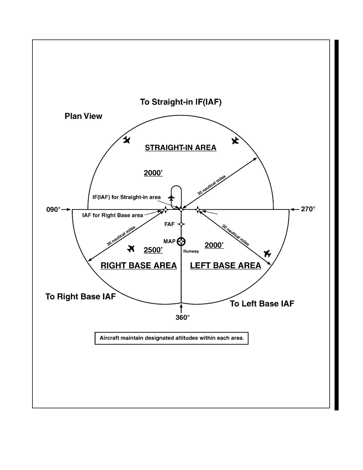
NAVAIR 00-80T-112
IAF for Left Base area
Figure 30-7. TAA Areas
30-13
ORIGINAL
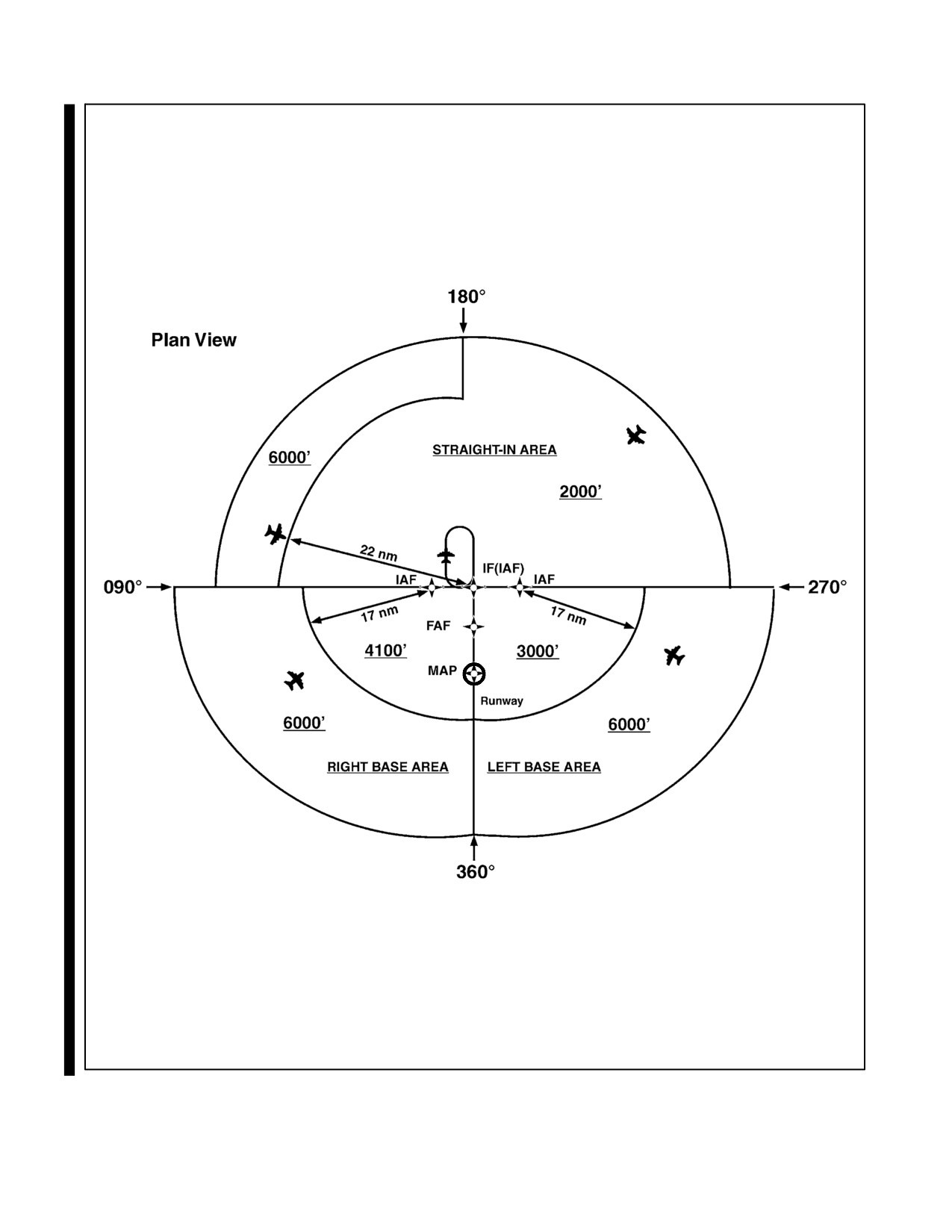
NAVAIR 00-80T-112
Figure 30-8. Sectored TAA Areas
ORIGINAL
30-14
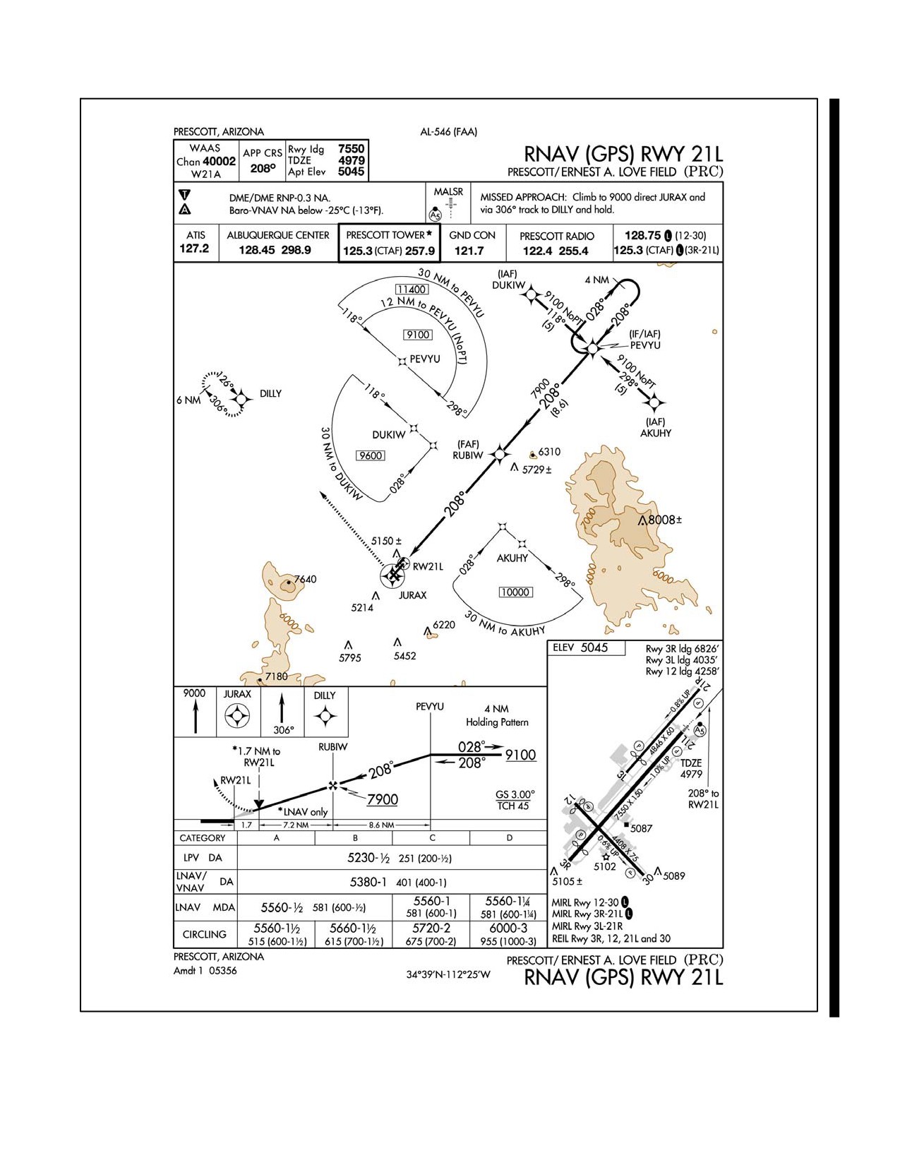
NAVAIR 00-80T-112
Figure 30-9. RNAV Approach Chart
30-15
ORIGINAL
NAVAIR 00-80T-112
7. Just as the underlying “T” approach procedure may be modified in shape, the TAA may contain modifications
to the defined area shapes and sizes. Some areas may even be eliminated, with other areas expanded as needed.
Figure 30-10 is an example of a design limitation where a course reversal is necessary when approaching the
IF (IAF) from certain directions due to the amount of turn required at the IF (IAF). Design criteria require a
course reversal whenever this turn exceeds 120 degrees. In this generalized example, pilots approaching on
a bearing to the IF (IAF) from 300° clockwise through 060° are expected to execute a course reversal. The term
NoPT will be annotated on the boundary of the TAA icon for the other portion of the TAA.
8. Figure 30-11 depicts another TAA modification that pilots may encounter. In this generalized example, the
right-base area has been eliminated. Pilots operating within the TAA between 360° clockwise to 060° bearing
to the IF (IAF) are expected to execute the course reversal in order to properly align the aircraft for entry onto
the intermediate segment. Aircraft operating in all other areas from 060° clockwise to 360° bearing to the IF
(IAF) need not perform the course reversal, and the term “NoPT” will be annotated on the TAA boundary of
the icon in these areas.
9. When an airway does not cross the lateral TAA boundaries, a feeder route will be established to provide a
transition from the en route structure to the appropriate IAF. Each feeder route will terminate at the TAA
boundary and will be aligned along a path pointing to the associated IAF. Pilots should descend to the TAA
altitude after crossing the TAA boundary and cleared by air traffic control (Figure 30-12).
30.5.3 Minimum Vectoring Altitude (MVA)
The Minimum Vectoring Altitude (MVA) is established for use by ATC when radar ATC is exercised. MVA charts
are prepared by air traffic facilities at locations where there are numerous different minimum IFR altitudes. Each
MVA chart has sectors large enough to accommodate vectoring of aircraft within the sector at the MVA. Each sector
boundary within 40 miles of the radar is at least 3 miles from the obstruction determining the MVA. Each sector
boundary 40 miles or more from the radar is at least 5 miles from the obstruction determining the MVA. To avoid a
large sector with an excessively high MVA due to an isolated prominent obstruction, the obstruction may be enclosed
in a buffer area. This is done to facilitate vectoring around the obstruction (Figure 30-13).
1. The minimum vectoring altitude in each sector provides
1,000 feet above the highest obstacle in
nonmountainous areas and 2,000 feet above the highest obstacle in designated mountainous areas. Where
lower MVA are required in designated mountainous areas to achieve compatibility with terminal routes or to
permit vectoring to an IAP, 1,000 feet of obstacle clearance may be authorized with the use of Airport
Surveillance Radar (ASR). The minimum vectoring altitude will provide at least 300 feet above the floor of
controlled airspace.
Note
The Off-Route Obstruction Clearance Altitude (OROCA) is an off-route
altitude that provides obstruction clearance with a 1,000-foot buffer in
nonmountainous terrain areas and a
2,000-foot buffer in designated
mountainous areas within the U.S. This altitude may not provide signal
coverage from ground-based navigational aids, air traffic control radar, or
communications coverage.
2. Because of differences in the areas considered for MVA, those applied to other minimum altitudes, and the
ability to isolate specific obstacles, some MVA may be lower than the nonradar MEAs, Minimum Obstruction
Clearance Altitudes (MOCAs)or other minimum altitudes depicted on charts for a given location. While being
radar vectored, IFR altitude assignments by ATC will be at or above MVA.
ORIGINAL
30-16
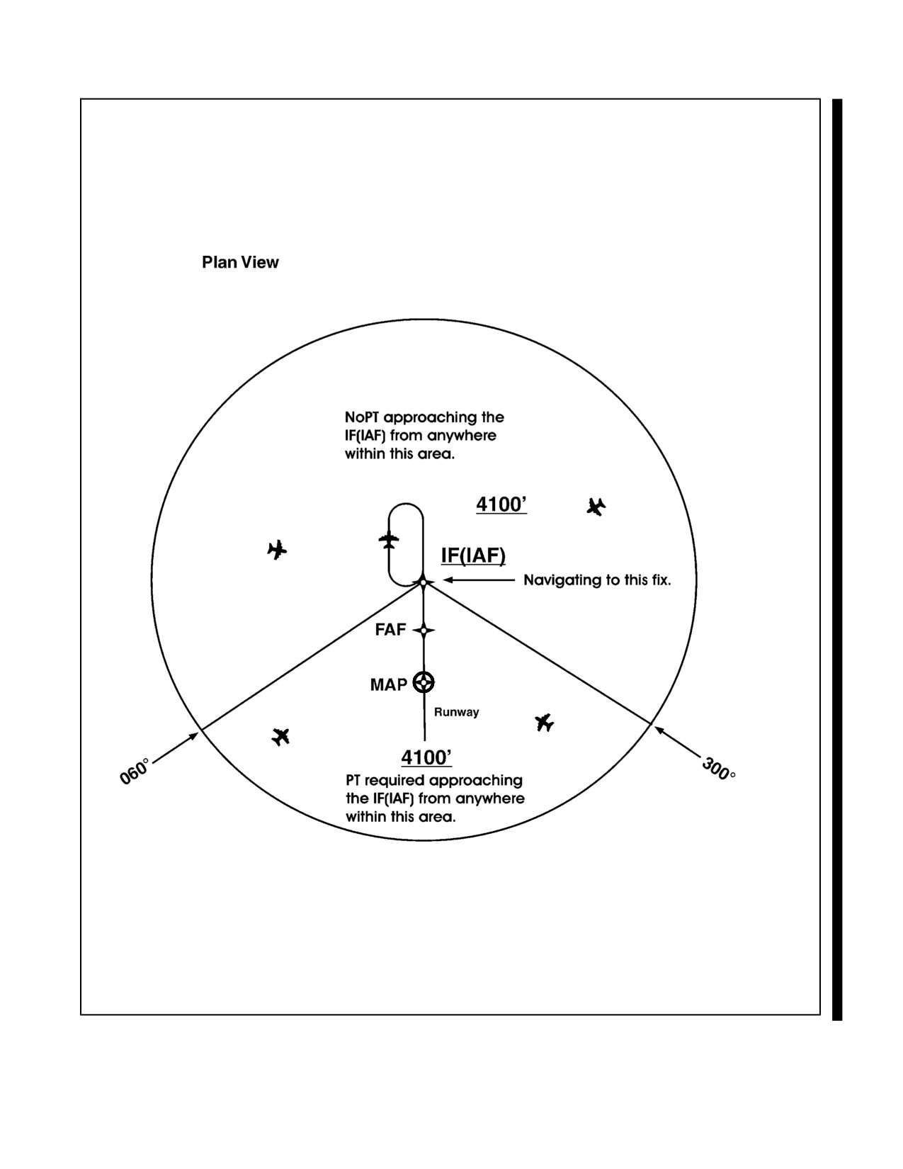
NAVAIR 00-80T-112
Figure 30-10. TAA with Left- and Right-Base Areas Eliminated
30-17
ORIGINAL
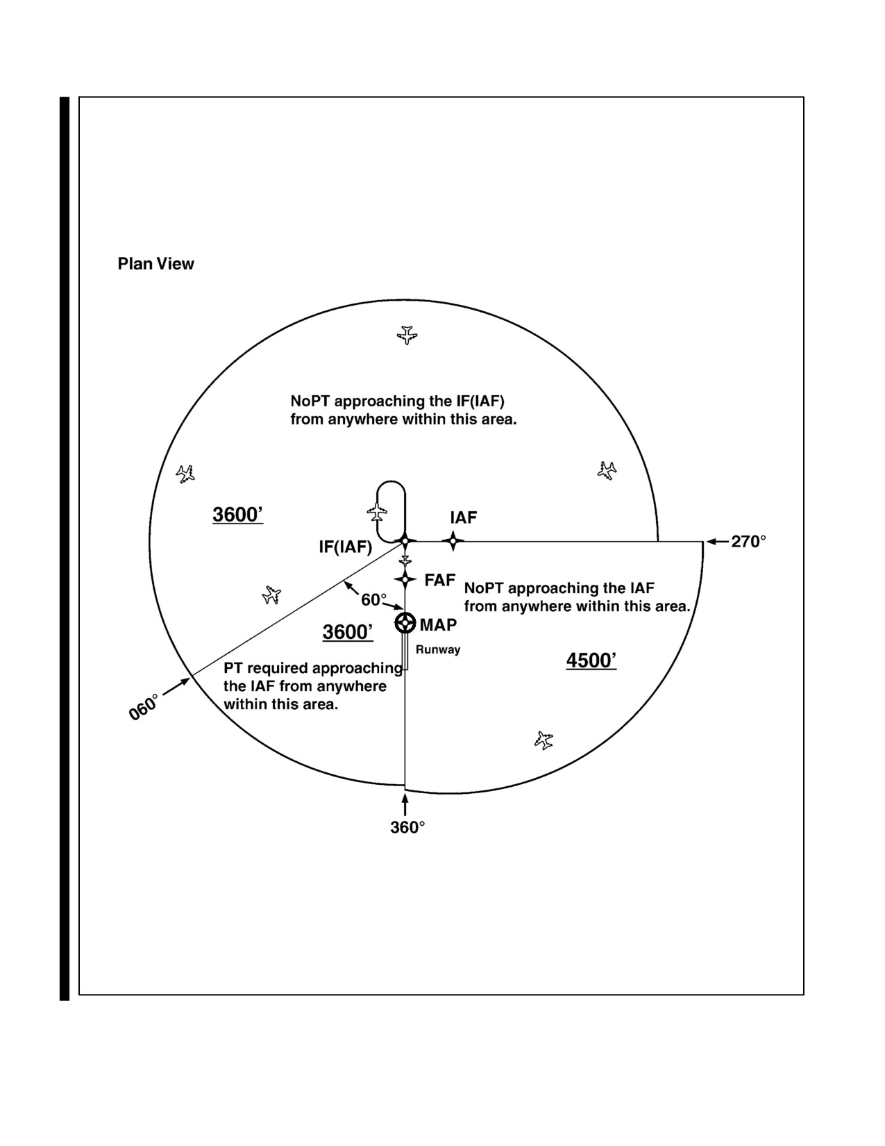
NAVAIR 00-80T-112
Figure 30-11. TAA with Right Base Eliminated
ORIGINAL
30-18
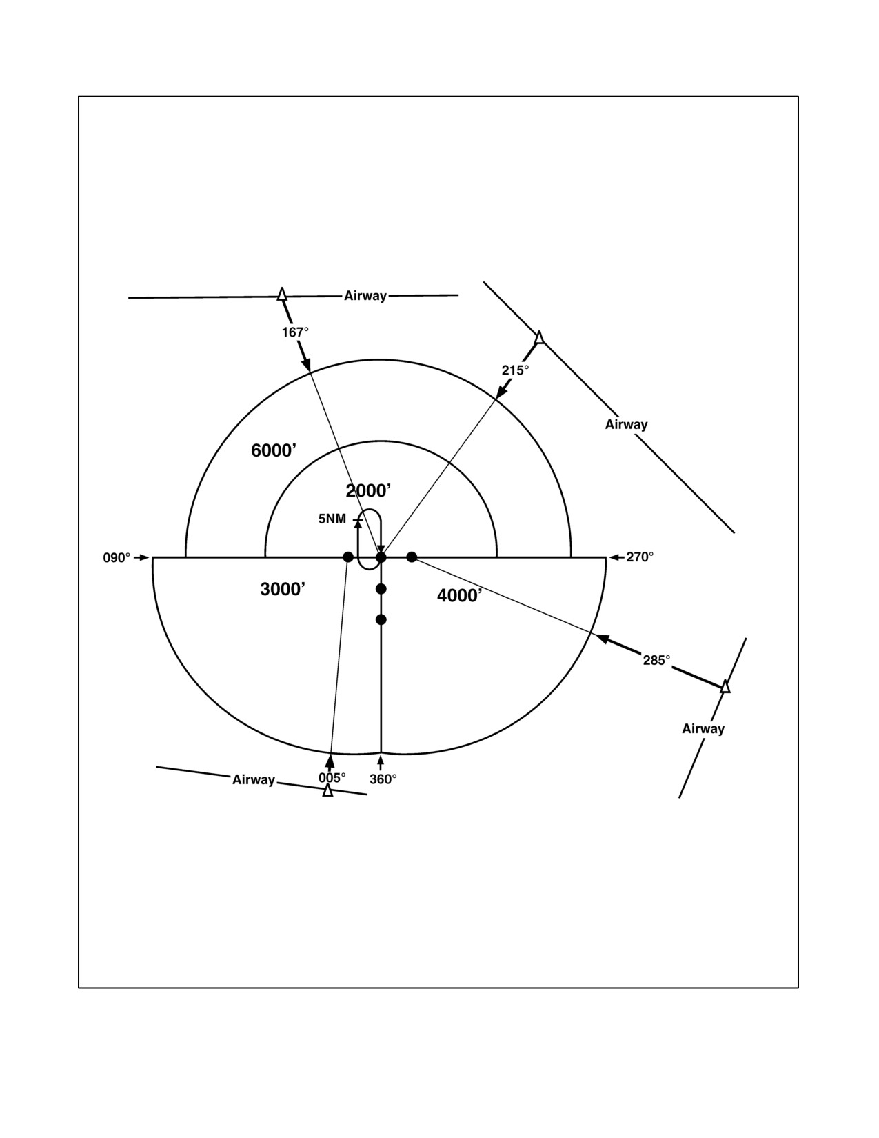
NAVAIR 00-80T-112
NoPT approaching the fix from
anywhere in this area.
NoPT approaching the
NoPT approaching the
fix from anywhere in
fix from anywhere in
this area.
this area.
Figure 30-12. Examples of a TAA with Feeders from an Airway
30-19
ORIGINAL
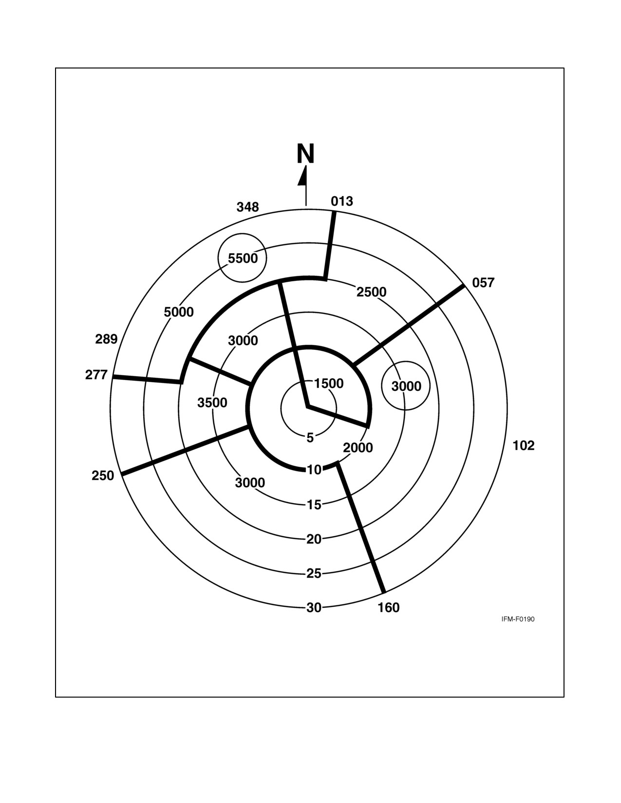
NAVAIR 00-80T-112
Figure 30-13. Minimum Vectoring Altitude Charts
ORIGINAL
30-20
NAVAIR 00-80T-112
30.5.4 Visual Descent Point (VDP)
VDPs are being incorporated in selected nonprecision approach procedures. The VDP is a defined point on the final
approach course of a nonprecision straight-in approach procedure from which normal descent from the MDA to the
runway touchdown point may be commenced, provided visual reference required by 14 CFR Section 91.175(c)(3)
is established. The VDP will normally be identified by DME on VOR and LOC procedures and by a long track
distance to the next waypoint for RNAV procedures. The VDP is identified on the profile view of the approach chart
by the symbol V.
1. VDPs are intended to provide additional guidance where they are implemented. No special technique is
required to fly a procedure with a VDP. The pilot should not descend below the MDA prior to reaching the VDP
and acquiring the necessary visual reference.
2. Pilots not equipped to receive the VDP should fly the approach procedure as though no VDP had been
provided.
30.5.5 Visual Portion of the Final Segment
Instrument procedures designers perform a visual area obstruction evaluation off the approach end of each runway
authorized for instrument landing, straight-in, or circling. Restrictions to instrument operations are imposed if
penetrations of the obstruction clearance surfaces exist. These restrictions vary based on the severity of the
penetrations and may include increasing required visibility, denying VDPs, and prohibiting night instrument
operations to the runway.
30.5.6 Vertical Descent Angle (VDA) on Nonprecision Approaches
Descent angles are currently being published on selected nonprecision approaches. The FAA intends to eventually
publish Vertical Descent Angles (VDAs) on all nonprecision approaches. Published along with the VDA is the
Threshold Crossing Height (TCH) (i.e., the height of the descent angle above the landing threshold). The descent
angle describes a computed path from the FAF and altitude to the runway threshold at the published TCH. The
optimum descent angle is 3.00 degrees; whenever possible, the approach will be designed to accommodate this angle.
1. The VDA provides the pilot with information not previously available on nonprecision approaches. It provides
the means for the pilot to establish a stabilized approach descent from the FAF or stepdown fix to the TCH.
Stabilized descent along this path is a key factor in the reduction of Controlled Flight Into Terrain (CFIT)
incidents. Pilots can use the published angle and estimated/actual groundspeed to find a target rate of descent
from a rate of descent table published with the instrument approach procedures.
2. Normally, the VDA will first appear on the nonprecision approach chart as the procedure is amended through
the normal process; however, in some cases, pilots can expect to see this data provided via a NOTAM(D).
3. Pilots should be aware that the published angle is for information only — it is strictly advisory in nature. There
is no implicit additional obstacle protection below the MDA. Pilots must still respect the published MDA
unless the visual cues stated in 14 CFR Section 91.175 are present. In rare cases, the published procedure
descent angle will not coincide with the Visual Glideslope Indicator (VGSI), Visual Approach Slope Indicator
(VASI) or Precision Approach Path Indicator (PAPI). In these cases, the procedure will be annotated: “VGSI
and descent angle not coincident.”
30.5.7 Pilot Operational Considerations When Flying Nonprecision Approaches
The MAP on a nonprecision approach is not designed with any consideration to where the aircraft must begin descent
to execute a safe landing. It is developed based on terrain, obstructions, NAVAID location, and possibly air traffic
considerations. Because the MAP may be located anywhere from well prior to the runway threshold to past the
30-21
ORIGINAL
NAVAIR 00-80T-112
opposite end of the runway, the descent from the MDA to the runway threshold cannot be determined based on the
MAP location. Descent from MDA at the MAP when the MAP is located close to the threshold would require an
excessively steep descent gradient to land in the normal touchdown zone. Any turn from the final approach course
to the runway heading may also be a factor in when to begin the descent.
1. Pilots are cautioned that descent to a straight-in landing from the MDA at the MAP may be inadvisable or
impossible, on a nonprecision approach, even if current weather conditions meet the published ceiling and
visibility. Aircraft speed, height above the runway, descent rate, amount of turn, and runway length are some
of the factors that must be considered by the pilot to determine if a landing can be accomplished.
2. Visual Descent Points (VDPs) provide pilots with a reference for the optimal location to begin descent from
the MDA, based on the designed VDA for the approach procedure, assuming required visual references are
available. Approaches without VDPs have not been assessed for terrain clearance below the MDA and may
not provide a clear vertical path to the runway at the normally expected descent angle; therefore, pilots must
be especially vigilant when descending below the MDA at locations without VDPs. This does not necessarily
prevent flying the normal angle; it only means that obstacle clearance in the visual segment could be less and
greater care should be exercised in looking for obstacles in the visual segment. Use of VGSI systems can aid
the pilot in determining if the aircraft is in a position to make the descent from the MDA; however, when the
visibility is close to minimums, the VGSI may not be visible at the start descent point for a normal glidepath
due to its location down the runway.
3. Accordingly, pilots are advised to carefully review approach procedures, prior to initiating the approach, to
identify the optimum position(s), and any unacceptable positions, from which a descent to landing can be
initiated (in accordance with 14 CFR Section 91.175(c)).
30.5.8 Area Navigation (RNAV) Instrument Approach Charts
Reliance on RNAV systems for instrument approach operations is becoming more commonplace as new systems such
as GPS, Wide Area Augmentation System (WAAS), and Local Area Augmentation System (LAAS) are developed
and deployed. In order to foster and support full integration of RNAV into the National Airspace System (NAS), the
FAA has developed a new charting format for RNAV IAPs (Figure 30-8). This format avoids unnecessary duplication
and proliferation of instrument approach charts. The approach minimums for unaugmented GPS (the present GPS
approaches) and augmented GPS (WAAS and LAAS when they become operational) will be published on the same
approach chart. The approach chart will be titled RNAV (GPS) RWY XX. The first RNAV approach charts may
appear as stand-alone “GPS” procedures, prior to WAAS becoming operational. Accordingly, the minimums line
associated with WAAS may be marked NA until the navigation system is operational. The chart may contain as many
as four lines of approach minimums: Global Navigation Satellite System (GNSS) Landing System (GLS), LPV,
Lateral Navigation/Vertical Navigation (LNAV/VNAV), LNAV, and CIRCLING. GLS includes WAAS and LAAS.
LNAV/VNAV is a new type of instrument approach with lateral and vertical navigation. During a transition period
when GPS procedures are undergoing revision, the new title RNAV (GPS) approach charts and formats will be
published. ATC clearance for the RNAV procedure will authorize a properly certified pilot to utilize any landing
minimums for which the aircraft is certified. The RNAV (GPS) chart will include formatted information required for
quick pilot or flightcrew reference located at the top of the chart. This portion of the chart, developed based on a study
by the Department of Transportation, Volpe National Transportation Systems Center, is commonly referred to as the
pilot briefing, or EZ Brief.
1. New minimums lines will be:
a. GLS. “GLS” is the acronym for GNSS Landing System; GNSS is the acronym for Global Navigation
Satellite System. The minimums line labeled GLS will accommodate aircraft equipped with precision
approach capable WAAS receivers operating to their fullest capability. WAAS, as its name implies,
augments the basic GPS satellite constellation with additional ground stations and enhanced
position/integrity information transmitted from geostationary satellites. This capability of augmentation
ORIGINAL
30-22
NAVAIR 00-80T-112
enhances both the accuracy and integrity of basic GPS and may support precision (GLS) approach
minimums as low as 200-foot Height Above Touchdown (HAT) and 1/2 statute mile (SM) visibility.
Publication of the lowest GLS minimums requires that certain interrelated conditions of satellite availability
and runway landing environment are met. The suitability of the landing environment to support the lowest
landing minimums is determined by the degree of airport compliance with AC 150/5300-13, Airport
Design. Precision runway and airport compliance factors include runway marking and lighting, obstacle
clearance surfaces, runway length, approach lighting, taxiway layout, etc. Pilots will be informed that all
the requirements of the precision runway landing environment are satisfied by the notation GLS PA (GNSS
Landing System Precision Approach) on the first line of minimums in U.S. Government Terminal
Procedure Publication charts. Pilots will be informed that not all of the precision runway requirements are
met by the notation GLS without the letters “PA” on the first line of minimums. In this latter case, the
airborne WAAS receiver may be operating in the most capable mode, but because the landing environment
does not support the low-visibility operations, minimums no lower than 300-foot HAT and 3/4 SM visibility
will be published. Since computed glidepath guidance is provided to the pilot, procedure minimum altitude
will be published as a Decision Altitude (DA).
b. LNAV/VNAV identifies minimums developed to accommodate an RNAV IAP with vertical guidance, but
with integrity limits larger than a precision approach. LNAV stands for Lateral Navigation; VNAV stands
for Vertical Navigation. Aircraft using LNAV/VNAV minimums will descend to landing via an internally
generated descent path based on satellite or other approach approved VNAV systems. WAAS equipment
may revert to this mode of operation when the signal does not support the highest level of accuracy and
integrity. Since electronic vertical guidance is provided, the minimums will be published as a DA. Other
navigation systems may be specifically authorized to use this line of minimums; see Section A,
Terms/Landing Minimums Data, of the U.S. Terminal Procedures books for a more detailed explanation.
c. LNAV. This minimum is for lateral navigation only, and the approach minimum altitude will be published
as an MDA because vertical guidance is not provided. LNAV provides the same level of service as the
present GPS stand-alone approaches. LNAV minimums support the following navigation systems: WAAS
(when the navigation solution will not support vertical navigation) and GPS navigation systems which are
presently authorized to conduct GPS approaches. The LNAV line on the RNAV chart will allow the present
approach certified receivers to fly the new approaches. Existing GPS approaches will be converted to this
format. (The receiver must be approved for approach operations in accordance with: AC 20-138,
Airworthiness Approval of Global Positioning System [GPS] Navigation Equipment for Use as a Visual
Flight Rules [VFR] and IFR Supplemental Navigation System, for stand-alone TSO-C128 Class A(1)
systems; or AC 20-130A, Airworthiness Approval of Navigation or Flight Management Systems
Integrating Multiple Navigation Sensors, for GPS as part of a multisensor system, qualify for this
minimum.)
2.
Other systems may be authorized to utilize these approaches. See the description in Section A of the U.S.
Terminal Procedures books for details. Through a special authorization, aircraft equipped with other IFR
approach approved RNAV systems may fly to the LNAV/VNAV and/or LNAV minimums described above.
These systems may include aircraft equipped with an FMS that can file /E or /F. Operational approval must
also be obtained for Barometric Vertical Navigation (BARO-VNAV) systems to operate to the LNAV/VNAV
minimums. BARO-VNAV may not be authorized on some approaches due to other factors. Pilots are directed
to their local Flight Standards District Office (FSDO) for additional information.
Note
RNAV and BARO-VNAV systems must have a manufacturer-supplied
electronic database that shall include the waypoints, altitudes, and vertical
data for the procedure to be flown. The system shall also be able to extract
the procedure in its entirety, not just as a series of waypoints.
30-23
ORIGINAL
NAVAIR 00-80T-112
3.
Required Navigation Performance (RNP).
a. With the widespread deployment of RNAV systems, the advent of GPS, and the imminent implementation
of WAAS, greater flexibility in route, procedure, and airspace design is now possible, with an associated
increase in navigation accuracy and flight safety. To capitalize on the potential of RNAV systems, the FAA
and the International Civil Aviation Organization (ICAO) are effecting a shift toward a new standard of
navigation and airspace management called RNP.
b. Navigation systems have typically been described as being sensor specific, such as VOR, NDB, and ILS
systems. When RNP is specified, it does not matter what the underlying navigation system or combination
of systems is used, provided the aircraft can achieve the required navigation performance. Typically, various
sensor inputs are processed by the RNAV system to arrive at a position estimate having a high statistical
degree of accuracy and confidence. RNP is intended to provide a single performance standard that can be
used and applied to aircraft and aircraft equipment manufacturers, airspace, planners, aircraft certification
and operations, pilots and controllers, and international aviation authorities. RNP can be related to obstacle
clearance or aircraft separation requirements to ensure a consistent level of application.
c. An RNP level or type is applicable to a selected airspace, route, or procedure. The applicable RNP is
expressed as a value that represents a distance in nautical miles from the intended position to the actual
position of an aircraft. It is within this distance that an aircraft would normally be expected to operate. For
general RNAV approach procedures, RNP 0.3 is required.
d. Pilots are advised to refer to the “TERPS/LANDING MINIMUMS DATA” (Section A) of the U.S.
Government Terminal Procedures books for aircraft approach eligibility requirements by specific RNP
level requirements. Aircraft meeting RNP criteria will have an appropriate entry, including special
conditions and limitations, if any, in the Aircraft Flight Manual (AFM) or its supplement. This will only
occur when it has been determined that the aircraft complies with the appropriate provisions of certification.
e. Some aircraft have RNP approval in their AFM without a GPS sensor. The lowest level of sensors that the
FAA will support for RNP service is DME/DME; however, necessary DME NAVAID ground infrastructure
may or may not be available at the airport of intended operations. For those locations having an RNAV chart
published with LNAV/VNAV minimums, a procedure note may be provided (e.g., DME/DME RNP 0.3
NA; this means that RNP aircraft dependent on DME/DME to achieve RNP 0.3 are not authorized to
conduct this approach). Where FAA flight inspection successfully determines the availability and geometry
of DME facilities will support RNP 0.3 and the DME signal meets inspection tolerances, a note such as
“DME/DME RNP 0.3 Authorized” will appear on the chart. Where DME facility availability is a factor,
the note may read “DME/DME RNP 0.3 Authorized; ABC and XYZ Required,” meaning that ABC and
XYZ facilities have been determined by flight inspection to be required in the navigation solution to ensure
RNP 0.3.
4.
Chart terminology will change slightly to support the new procedure types.
a. Decision Altitude (DA) replaces the familiar term Decision Height (DH). DA conforms to the international
convention where altitudes relate to MSL and heights relate to Above Ground Level (AGL). DA will
eventually be published for other types of instrument approach procedures with vertical guidance as well.
DA indicates to the pilot that the published descent profile is flown to the DA (MSL), where a missed
approach will be initiated if visual references for landing are not established. Obstacle clearance is provided
to allow a momentary descent below DA while transitioning from the final approach to the missed approach.
The aircraft is expected to follow the missed instructions while continuing along the published final
approach course to at least the published runway threshold waypoint or MAP (if not at the threshold) before
executing any turns.
b. Minimum Descent Altitude (MDA) has been in use for many years and will continue to be used for the
LNAV only and circling procedures.
ORIGINAL
30-24
NAVAIR 00-80T-112
c. Threshold Crossing Height (TCH) has been traditionally used in precision approaches as the height of the
glideslope above threshold. With publication of LNAV/VNAV minimums and RNAV descent angles,
including graphically depicted descent profiles, TCH also applies to the height of the descent angle, or
glidepath, at the threshold. Unless otherwise required for larger type aircraft that may be using the IAP, the
typical TCH is 30 to 50 feet.
5.
The minimums format will also change slightly.
a. Each line of minimums on the RNAV IAP will be titled to reflect the RNAV system applicable (e.g., GLS,
LNAV/VNAV, and LNAV). Circling minimums will also be provided.
b. The minimums title box will also indicate the nature of the minimum altitude for the IAP. For example:
(1) DA will be published next to the minimums line title for minimums supporting vertical guidance such
as for GLS or LNAV/VNAV.
(2) MDA will be published where the minimums line supports only lateral guidance. Descent below the
MDA, including during the missed approach, is not authorized unless the visual conditions stated in
14 CFR Section 91.175 exist.
(3) Where two or more systems, such as GLS and LNAV/VNAV, share the same minimums, each line of
minimums will be displayed separately.
6.
Chart symbology will change slightly to include:
a. Descent Profile. The published descent profile and a graphical depiction of the vertical path to the runway
will be shown. Graphical depiction of the RNAV vertical guidance will differ from the traditional depiction
of an ILS glideslope (feather) through the use of a simple vertical track (no feather).
(1) It is FAA policy to design IAPs with minimum altitudes established at fixes/waypoints to achieve
optimum stabilized (constant rate) descents within each procedure segment. This design can enhance
the safety of the operations and contribute toward reduction in the occurrence of Controlled Flight Into
Terrain (CFIT) accidents. Additionally, the National Transportation Safety Board (NTSB) recently
emphasized that pilots could benefit from publication of the appropriate IAP descent angle for a
stabilized descent on final approach; therefore, the new RNAV IAP format will include the descent
angle to the hundredth of a degree (e.g., 3.00 degrees). The angle will be provided in the graphically
depicted descent profile.
(2) The stabilized approach may be performed by reference to vertical navigation information provided by
WAAS or LNAV/VNAV systems, or for LNAV-only systems, by the pilot determining the appropriate
aircraft attitude/groundspeed combination to attain a constant rate descent that best emulates the
published angle. To aid the pilot, U.S. Government Terminal Procedures Publication charts publish an
expanded Rate of Descent Table on the inside of the back hard cover for use in planning and executing
precision descents under known or approximate groundspeed conditions.
b. Visual Descent Point (VDP). VDPs are published on most RNAV (GPS) IAPs. VDPs apply only to aircraft
utilizing LNAV minimums, not GLS or LNAV/VNAV minimums.
c. Missed Approach Symbology. In order to make missed approach guidance more readily understood, a
method has been developed to display missed approach guidance in the profile view through the use of quick
reference icons. Due to limited space in the profile area, only four or fewer icons can be shown; however,
the icon may not provide representation of the entire missed approach procedure. The entire set of textual
missed approach instructions is provided at the top of the approach chart in the pilot briefing (Figure 30-8).
30-25
ORIGINAL
NAVAIR 00-80T-112
d. Waypoints. All RNAV or GPS stand-alone IAPs are flown using data pertaining to the particular IAP
obtained from an onboard database, including the sequence of all WPs used for the approach and missed
approach. Included in the database, in most receivers, is coding that informs the navigation system of which
Waypoints (WPs) are fly-over or fly-by. The navigation system may provide guidance appropriately,
including leading the turn prior to a Fly-By Waypoint (FBWP), or causing overflight of a Fly-Over
Waypoint (FOWP). Where the navigation system does not provide such guidance, the pilot must accomplish
the turn lead or waypoint overflight manually. Chart symbology for the FBWP provides pilot awareness of
expected actions. Refer to the legend of the U.S. Terminal Procedures books.
e. TAAs are described in paragraph 30.5.2. When published, the new RNAV chart will depict the TAA areas
through the use of icons representing each TAA area associated with the RNAV procedure. These icons will
be depicted in the plan view of the approach chart, generally arranged on the chart in accordance with their
position relative to the aircraft arrival from the en route structure. The WP, to which navigation is
appropriate and expected within each specific TAA area, will be named and depicted on the associated TAA
icon. Each depicted named WP is the IAF for arrivals from within that area. TAAs may not be depicted on
all RNAV procedures because of the inability for ATC to accommodate the TAA due to airspace congestion.
f.
Cold Temperature Limitations. A minimum temperature limitation will be published for each procedure for
which BARO-VNAV operations are authorized. This temperature represents the airport temperature below
which use of the BARO-VNAV will not be authorized to the LNAV/VNAV minimums. An example
limitation will read: “BARO-VNAV NA below -20 °C (-4 °F).” This information will be found in the upper
left-hand box of the pilot briefing.
g. WAAS Channel Number/Approach ID. The WAAS Channel Number is an equipment optional capability
that allows the use of a five-digit number to select a specific instrument approach procedure. The Approach
ID is a unique four-letter combination for verifying selection of the correct procedure. The WAAS Channel
Number and Approach ID will be displayed prominently in the approach procedure pilot briefing. The
WAAS Channel Number and Approach ID provide one method available to the pilot for selecting and
verifying the approach procedure for the runway of intended landing from the onboard databases. Some
equipment may utilize a menu selection method.
(1) The Menu Method. In general, although the steps may vary among equipment types, the pilot first
selects the airport of intended landing using the airborne equipment control panel. From a menu that
is presented for this airport, the pilot then selects the approach runway. Selecting, from the menu, the
Approach ID that matches the Approach ID printed on the approach chart then makes selection of the
specific approach procedure. Finally, the pilot activates the procedure by selecting the IAF with which
to begin the approach.
(2) Five-Digit Channel Number Method. The pilot enters the unique five-digit number provided for the
approach chart, and the receiver recalls a specific approach procedure from the aircraft database. A list
of information including the Approach ID and available IAFs is displayed. The pilot confirms the
correct procedure is selected by comparing the Approach ID listed with that printed on the approach
chart. Finally, the pilot activates the procedure by selecting the appropriate IAF with which to begin the
approach.
30.6
APPROACH CLEARANCE
An aircraft that has been cleared to a holding fix and subsequently “cleared . . . approach” has not received new
routing. Even though clearance for the approach may have been issued prior to the aircraft reaching the holding fix,
ATC would expect the pilot to proceed via the holding fix (the last assigned route) and the feeder route associated
with that fix (if a feeder route is published on the approach chart) to the IAF to commence the approach.
ORIGINAL
30-26