NAVAIR 00-80T-112 NATOPS INSTRUMENT FLIGHT MANUAL (15 NOVEMBER 2006) - page 2
NAVAIR 00-80T-112
PART III
Physiology of Instrument Flight
Chapter 7 — Introduction to Instrument Flight Physiology
Chapter 8 — Spatial Disorientation
Chapter 9 — Factors That Increase the Potential for Spatial Disorientation
Chapter 10 — Medications, Alcohol, and Nutrition
Chapter 11 — Prevention of Spatial Disorientation
Chapter 12 — Overcoming Spatial Disorientation
71/(72 blank)
ORIGINAL
NAVAIR 00-80T-112
CHAPTER 7
Introduction to Instrument
Flight Physiology
7.1
GENERAL
Spatial disorientation is a condition that exists when a pilot does not correctly perceive his/her position, attitude, or
motion relative to the Earth. During flight, the sense of sight is used to determine the aircraft attitude in relation to
the surface of the Earth. In visual flight conditions, aircraft attitude is determined by reference to the horizon of the
Earth and flight instruments. During instrument flight conditions when the horizon is not visible, aircraft attitude must
be determined by reference to the aircraft attitude indicator and other flight instruments. Under instrument flight
conditions, the visual sense may disagree with supporting senses, resulting in a conflict between what the pilot sees
on his/her flight instruments and what he/she “feels” his/her attitude in space to be. It is this conflict that may lead
to spatial disorientation and loss of aircraft control.
Sensory illusions can occur regardless of the pilot’s experience or proficiency; however, the effects of spatial
disorientation may be decreased, provided the pilot believes his/her instrument indications and maintains proficiency
in instrument flight. In addition, an understanding of the physiological basis of various illusions, the flight conditions
where these illusions may be expected, and ways to prevent or overcome an episode of spatial disorientation
effectively is of great importance.
7.2
YOUR SENSES
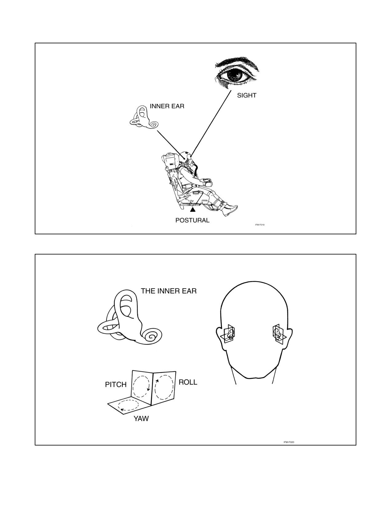
The ability to maintain equilibrium and orientation depends on sensations or signals from three sources. These
sensations come from the motion-sensing organs of the inner ear (vestibular system); the postural senses of touch,
pressure, and tension (proprioceptive system); and the sense of sight. In the absence of good visual references, the
ability to maintain equilibrium and orientation based on the other senses is markedly reduced.
The three sensory systems function adequately for normal earthbound activities, but when a person is subjected
to the flight environment, these organs may relay false information, resulting in spatial disorientation or vertigo
(Figure 7-1).
7.2.1 Motion (Inner Ear)
The sense of motion originates in the inner ear. The motion-sensing organs are the otolith organs and semicircular
canals (Figure 7-2).
7.2.2 Semicircular Canals
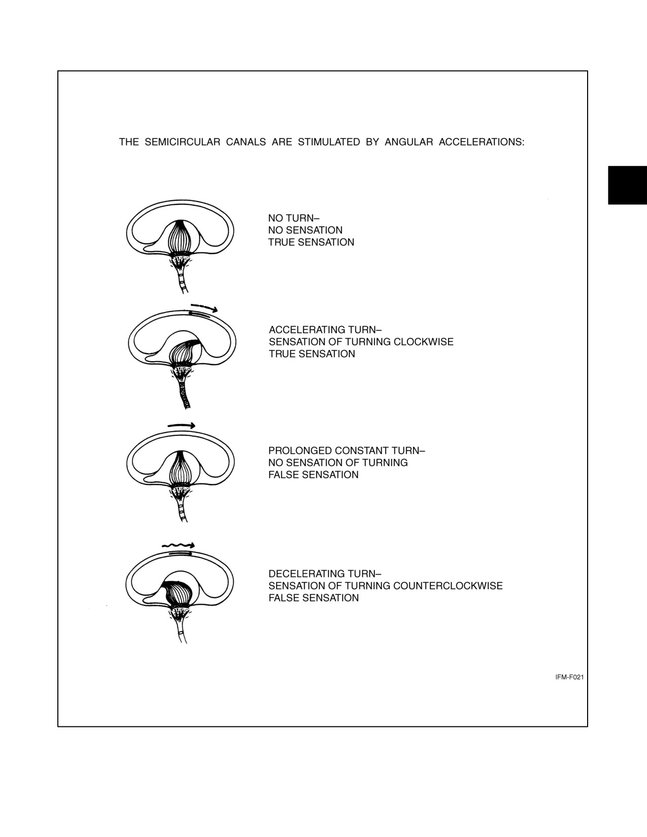
The semicircular canals register rotational acceleration. They can detect turns, slips, and skids during flight.
This organ consists of three canals oriented at right angles to each other so that angular accelerations in the pitch, yaw,
and roll planes can be detected. The canals are filled with fluid that moves when angular accelerations are applied
to the head. The movement bends the sensory hairs, which result in nerve impulses being sent to the brain. The pilot
interprets this as rotary motion. If the fluid catches up to the canal walls, such as in a prolonged turn, the sensory hairs
are no longer bent and no motion is perceived. Also, very small or short-lived angular accelerations may not be
perceived; thus, patterns of acceleration experienced in flight are different from those experienced on the ground. This
can result in an erroneous perception of position in flight (Figure 7-3).
7-1
ORIGINAL
NAVAIR 00-80T-112
Figure 7-1. Senses Used for Maintaining Equilibrium and Orientation
Figure 7-2. The Inner Ear
ORIGINAL
7-2
NAVAIR 00-80T-112
Figure 7-3. Semicircular Canals
7-3
ORIGINAL
NAVAIR 00-80T-112
7.2.3 Otolith Organs
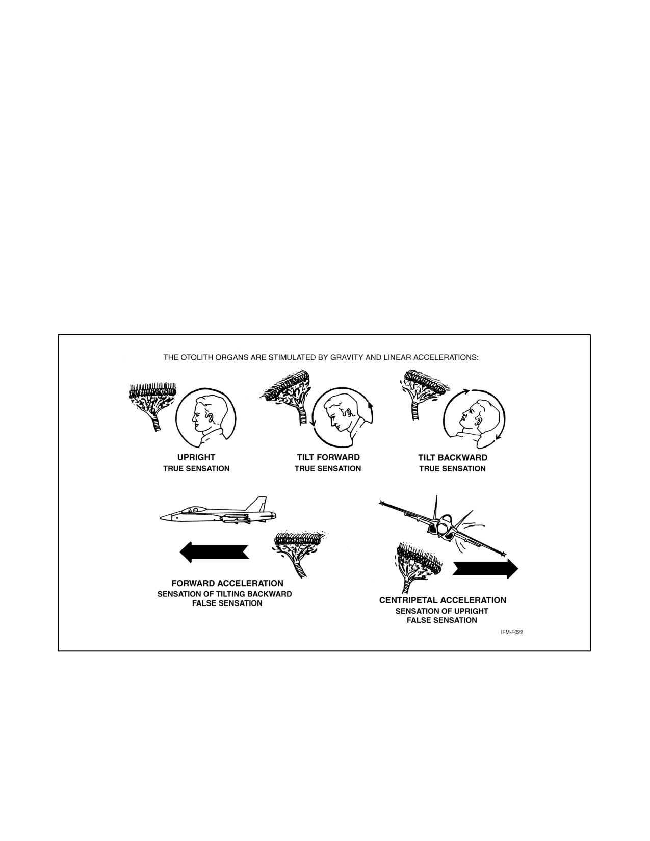
The otolith organs are stimulated by linear accelerations or gravity force. These organs consist of sensory hairs
projecting into a gel on which rest small crystals (otoliths). When the head is tilted with respect to gravity, the crystals
move and bend the hairs, creating the sensation of tilting the head or body in relation to the true vertical (gravity).
During flight, inertial forces are combined with the force of gravity. The resultant force that acts upon the otolith organ
is almost never the direction of the true vertical. The brain monitors this and determines which way is “down”;
therefore, the brain will be deceived much of the time in flight (Figure 7-4).
7.2.4 Postural (Seat of the Pants)
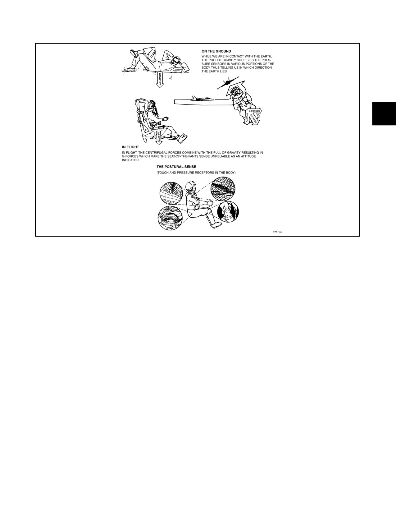
The postural sense derives its sensations from the expansion and contraction of muscles and tendons and from touch
and pressure. This is the so-called seat-of-the-pants sense not considered reliable in flying. A greater increase in this
pressure occurs in climbing, and any maneuver that produces pressure against the seat may be interpreted as climbing;
therefore, without visual aid, this sense often interprets centrifugal force as a false climb or descent. Without visual
reference to the natural horizon or flight instruments, a steep turn could be interpreted as a steep climb and a shallow,
descending turn could be perceived as straight-and-level flight; therefore, the postural senses, like those of the inner
ear, are unreliable without visual aid. Pilots are aware that they cannot fly by feel alone but must subordinate these
false sensations to their flight instruments (Figure 7-5).
Figure 7-4. Otolith Organs
ORIGINAL
7-4
NAVAIR 00-80T-112
Figure 7-5. Postural (Seat-of-the-Pants) Sense
7.2.5 Sight
The only reliable information for a pilot to maintain spatial orientation is provided by the visual system. On a clear
day when adequate visual reference is available, spatial disorientation is unlikely to happen despite the presence of
linear or angular accelerations. Any false sensory inputs from the inner ear and postural senses are naturally and easily
suppressed and ignored. Recent studies have postulated that the principal functions of the semicircular canals must
be to stabilize the eyes in space during head movement and the otolith to provide a sense of direction at the resultant
G vector.
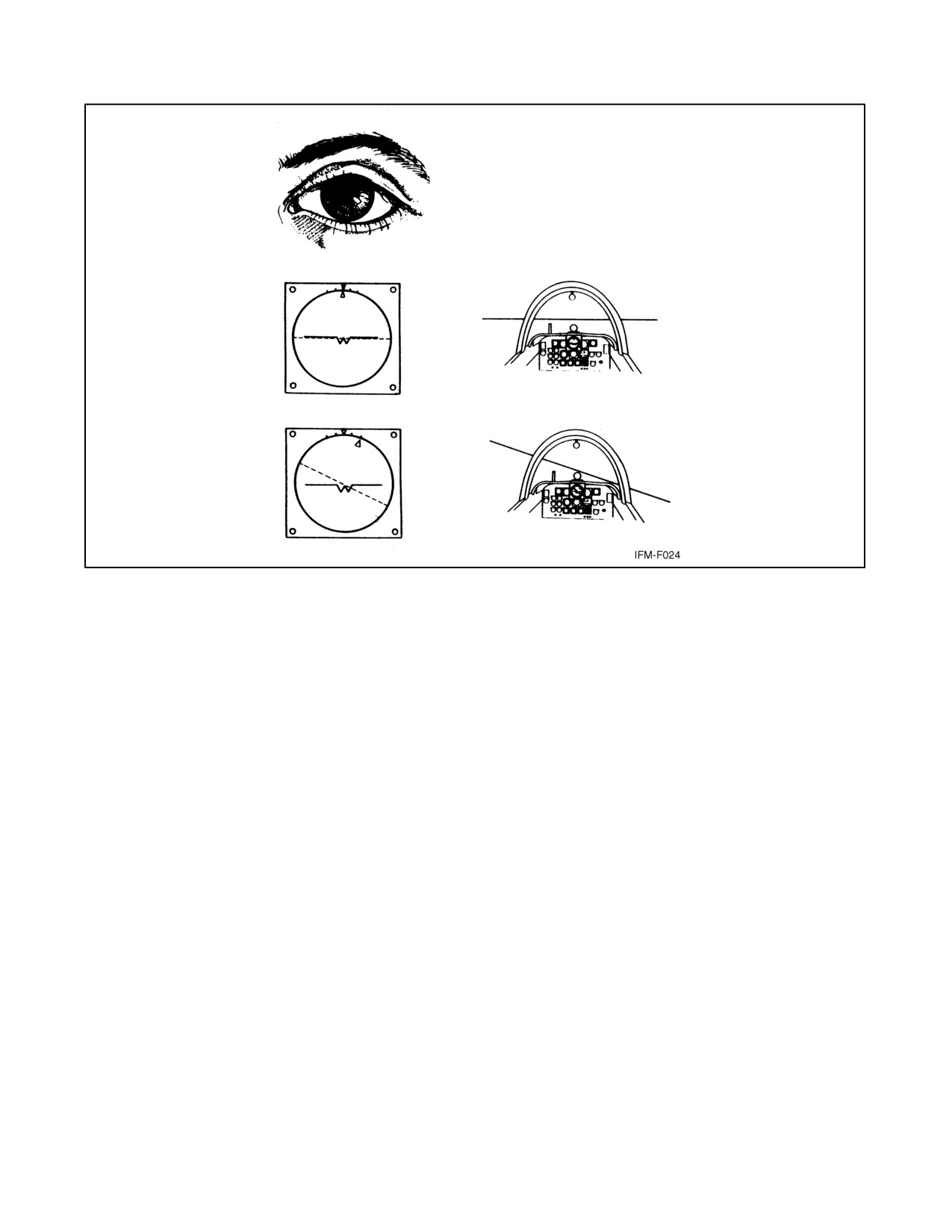
At night or in IFR conditions, a pilot should be aware that what is seen outside the aircraft may be confusing and can
potentially lead to sensory conflicts. One must maintain visual dominance solely by reference to aircraft instruments.
Chief among those instruments is the attitude indicator, which provides a representation of aircraft attitude in relation
to the Earth. Other instruments give valuable supporting information. Instrument proficiency with an efficient
instrument cross-check will make it possible for a pilot to maintain visual dominance and to ignore potentially
disorienting sensory data (Figure 7-6).
7-5
ORIGINAL
NAVAIR 00-80T-112
THE PILOT MUST RELY ON
THE SENSE OF SIGHT TO
INTERPRET FLIGHT
INSTRUMENTS PROPERLY.
Figure 7-6. The Sense of Sight
ORIGINAL
7-6
NAVAIR 00-80T-112
CHAPTER 8
Spatial Disorientation
8.1
FALSE PERCEPTION (GENERAL)
8.1.1 Illusions: Primarily Inner Ear
Illusions related to the inner ear can result from semicircular canal stimulation (angular motion) and from otolith
organ stimulation (linear motion).
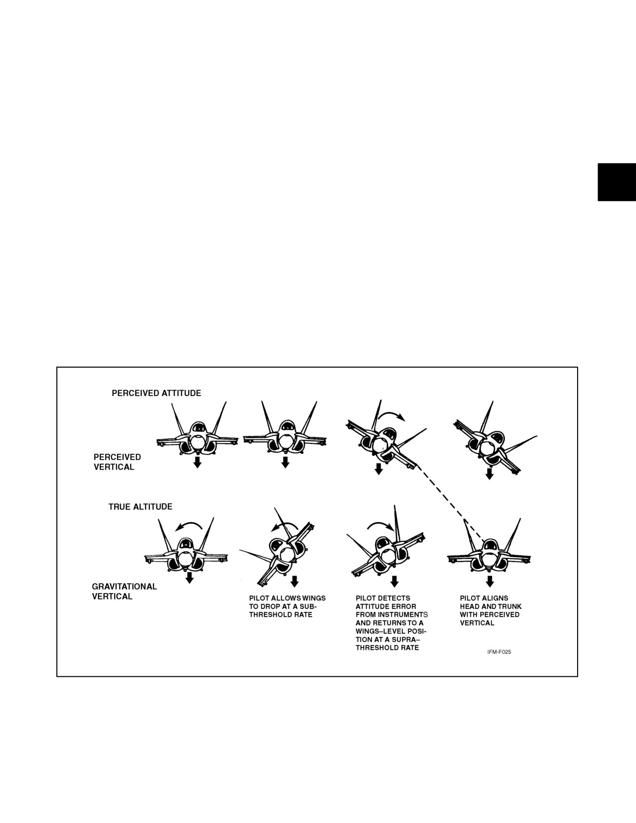
8.1.1.1 The Leans
This is a common illusion and is caused by rolling or banking the aircraft after the pilot establishes a false impression
of the true vertical. In a prolonged turn, the semicircular canals may perceive a roll to wings level as a turn in the
opposite direction. This causes pilots to lean in an attempt to assume what they think is a true vertical posture. Should
a pilot establish a very subtle roll to the left that does not stimulate the semicircular canals and then roll rapidly to
level flight, the pilot may retain the false impression of only having rolled to the right. Again, the pilot may fly
adequately in spite of this illusion, although the pilot may lean to assume a false vertical posture (Figure 8-1).
Figure 8-1. The Leans
8-1
ORIGINAL
NAVAIR 00-80T-112
8.1.1.2 A False Sensation of Rotation (Somatogyral Illusion)
This condition can occur when the semicircular canals are abnormally stimulated by certain turning maneuvers and
the resulting angular acceleration. Examples include the following:
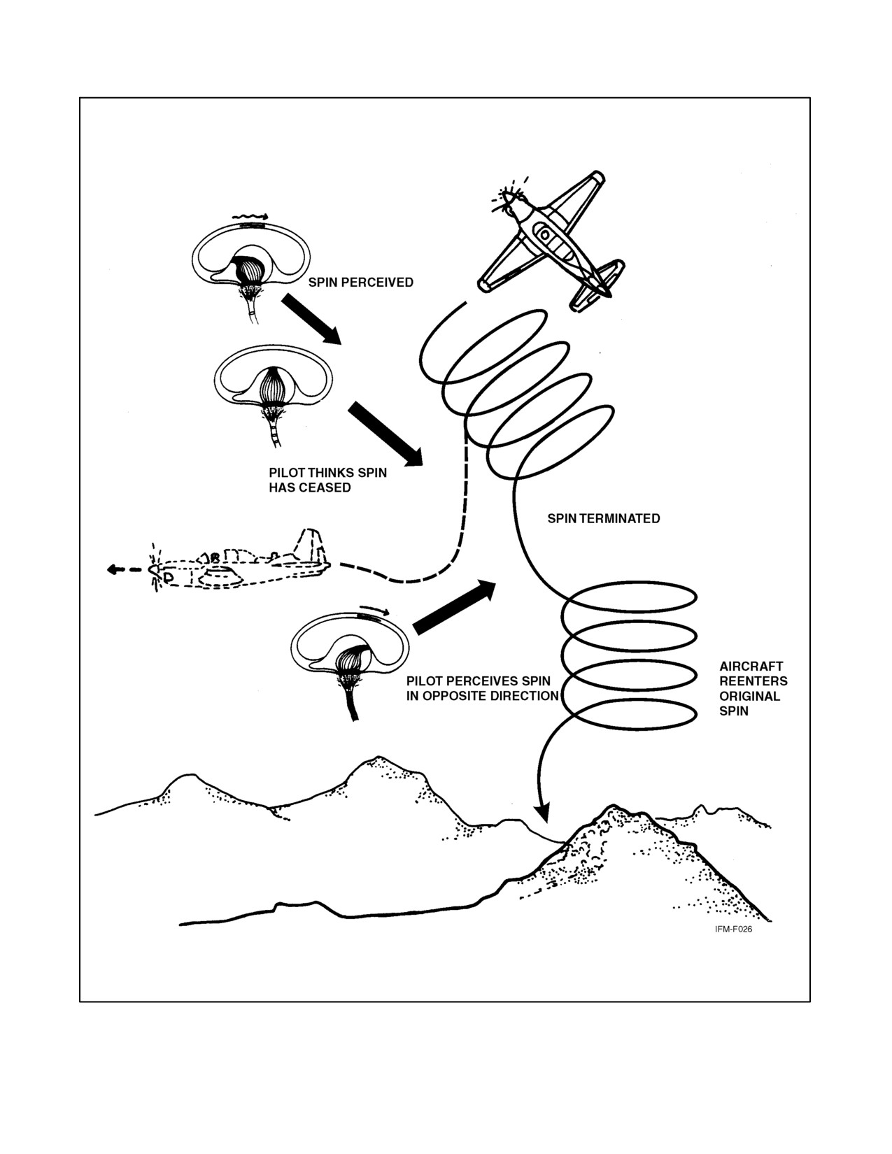
8.1.1.2.1 Graveyard Spin
When the semicircular canals are stimulated by the angular acceleration produced by the spin entry, the first
impression of the pilot is accurate (i.e., a spin is perceived). After approximately 10 to 20 seconds, the fluid in the
canals reaches a constant speed and the sensing mechanism returns to the resting position, whereupon, the sensation
of spinning is replaced by one of no rotary motion despite the fact the spin continues. If the spin is then terminated,
an angular deceleration is produced, which acts upon the semicircular canals to cause a sensation of spinning the
opposite direction. Suffering from the illusion of spinning in the opposite direction, the pilot may try to correct for
this false impression by putting the aircraft back into the original spin (Figure 8-2).
8.1.1.2.2 Graveyard Spiral
This maneuver is similar to the graveyard spin except the aircraft is in a descending turn rather than a stalled condition.
The constant rate of turn causes one to lose the sensation of turning after a period of time. The pilot, noting the loss
of altitude, may pull back on the stick or perhaps add power in an attempt to gain the lost altitude. Unless the sink
attitude is first corrected, such actions can only serve to tighten a downward spiral. Once the spiral has been
established, the pilot will suffer the illusion of turning in the opposite direction after the turning motion of the aircraft
stops. Under these circumstances, the wrong corrective action may be taken, which will result in reestablishment of
the spiral.
8.1.1.3 Coriolis Illusion
The coriolis illusion is perhaps the most dangerous of the inner ear illusions because it causes an overwhelming
disorientation of the pilot, which can be extremely dangerous at low altitudes. This reaction is most apt to occur when
a pilot is in a constant-rate turn, such as in a penetration turn or holding pattern. When the body is in a prolonged turn,
the fluid in those canals that were stimulated by the onset of the turn eventually come up to speed with the canal walls.
If the head is then tipped, the angular momentum of the fluid causes it to move again relative to the canal walls. The
resulting sensation is one of rotation in the plane of the new position of the canal even though no actual motion has
occurred in that plane; thus, abrupt head movements may cause false sensations of angular motion and erroneous
perceptions of attitude. An attempt to correct for this is likely to result in a loss of aircraft control. To prevent this
reaction, pilots should avoid sudden extreme head movements, especially while making turns. The head movement
often results in an overwhelming sensation of a roll coupled with a climb or dive. Correction for this apparent unusual
attitude should be made on the aircraft attitude indicator and not by reflex action. The solution is simple: minimize
head movement.
8.1.1.4 Nystagmus
Nystagmus often accompanies coriolis illusion. During and immediately after maneuvers resulting from particularly
violent angular accelerations such as spins and rapid aileron rolls, the eyes can exhibit an uncontrollable oscillatory
movement called nystagmus. This eye movement generally results in an inability to focus either on flight instruments
or on outside visual references. Rolling maneuvers are especially likely to result in visual blurring because of
nystagmus. Normally, nystagmus ceases several seconds after termination of angular acceleration, but under
conditions of inner ear dominance and high task loading, nystagmus and blurring of vision can persist much longer
— long enough to prevent recovery.
ORIGINAL
8-2
NAVAIR 00-80T-112
Figure 8-2. The Graveyard Spin
8-3
ORIGINAL
NAVAIR 00-80T-112
8.1.1.5 Pressure Vertigo
This condition is also of inner ear origin, although the exact mechanism is not understood. Symptoms include blurring
of vision, nystagmus, and illusory sensations of turning. These symptoms occur more commonly and more severely
when there is an explosive increase in middle ear pressure (e.g., with the Valsalva maneuver), although they can occur
with gradual increases in middle ear pressure (such as with aircraft ascent). Pressure vertigo usually occurs when there
is some difficulty or hesitation in “clearing the ears,” especially if the individual has a cold or flu.
8.1.1.6 Illusion of Attitude Change (Somatogravic Illusion)
This illusion can occur when the otolith organs are abnormally stimulated by linear acceleration. Examples include
the following:
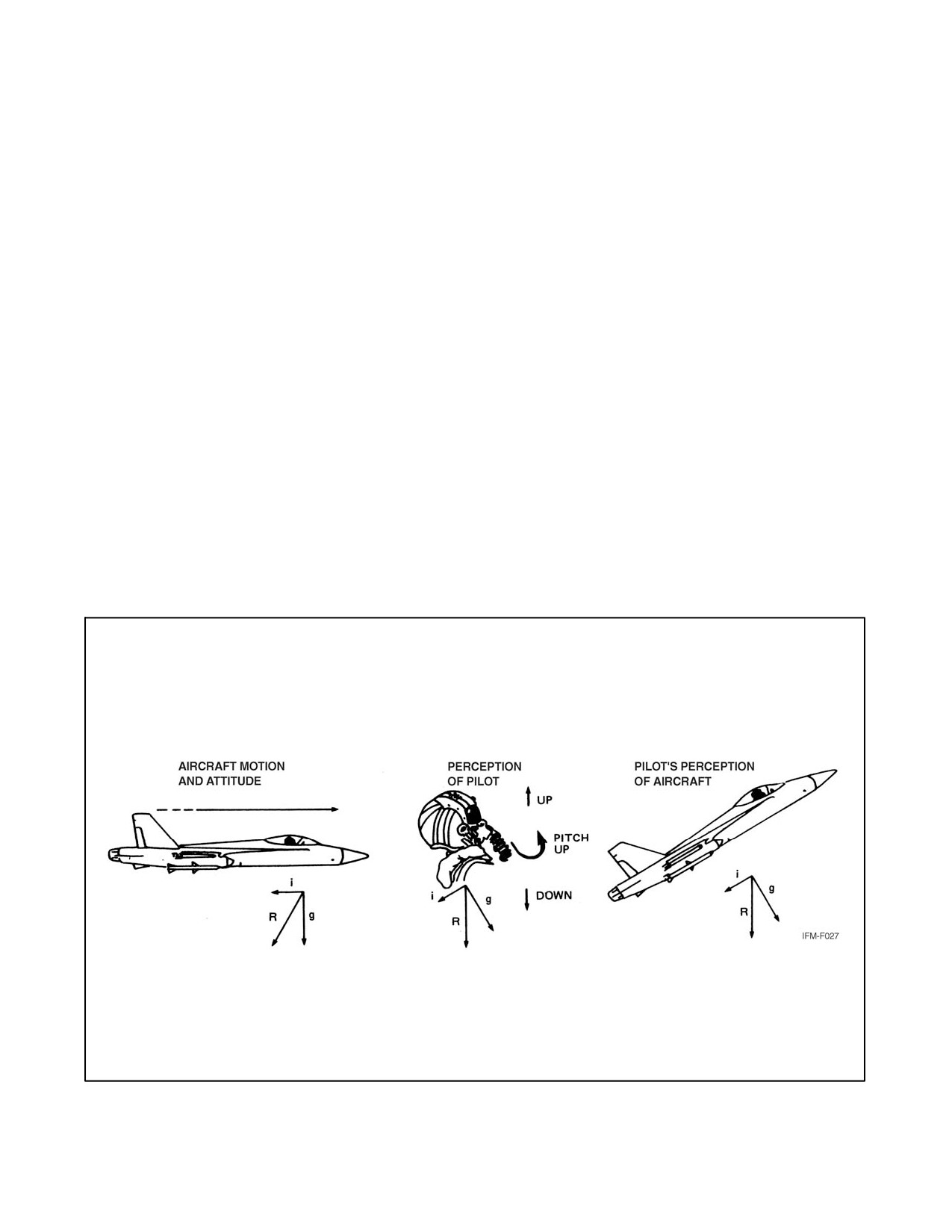
8.1.1.6.1 Illusion of Noseup
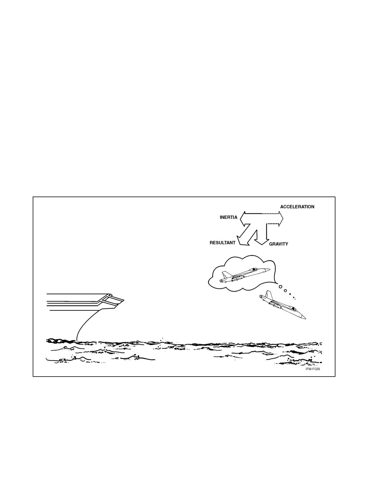
This illusion can occur when an aircraft accelerates forward while in level flight and gives the pilot the sensation of
being in a noseup attitude. This may occur as a result of a missed approach or during takeoff. The chest-to-spine
acceleration experienced by the pilot is vectored with gravity, and the combined gravitational-inertial acceleration
vector is increased in length and rotated as the acceleration continues (Figure 8-3). This can generate both visual and
postural illusions. The visual illusion causes objects to appear to rise above their true physical positions, and the
postural illusion causes the pilot to feel that his/her body is being tilted backwards. Because of these illusions, the
pilot can become disoriented; the entire array of cockpit instruments may appear to rise, and the pilot may feel that
his/her aircraft is climbing in an excessively high, noseup attitude. If a pilot were to correct for this illusion, he/she
might inadvertently dive the aircraft.
Figure 8-3. Forward Acceleration Illusion of Noseup
ORIGINAL
8-4
NAVAIR 00-80T-112
This type of illusion can be extremely dangerous during catapult launching of carrier-based aircraft and deserves
special mention here. When an aircraft is launched from the deck of a carrier, the pilot is exposed to a sudden and
dramatic change in the accelerative forces acting on his/her body. The pilot is pushed sharply back into his/her seat
as the aircraft hurtles forward, accelerating rapidly to attain adequate airspeed. Although the acceleration is of brief
duration, lasting for only 2 to 4 seconds, it is of sufficient intensity that the pilot may be disoriented during its
application and for some time after the catapult launch accelerations have been terminated. The visual impression
of a noseup attitude can lead to control errors, especially on a moonless, starless, black, overcast night when there
is little opportunity for external visual cues to override the illusion; thus, if the pilot was deprived of appropriate
information concerning the true pitch attitude, the natural tendency would be to reduce the illusory excessive noseup
attitude of the aircraft by easing forward on the stick. This could result in a fatal water collision accident (Figure 8-4).
Although flight instruments can help the pilot to overcome disorientation, the value of the instruments depends
critically on how closely they are monitored, how accurately they are interpreted, and how well they provide the pilot
with information needed to control the aircraft. The prescribed technique in instrument flight immediately following
a catapult launching at night is for the pilot to scan the cockpit instruments continuously, making certain that the end
airspeed is sufficiently high to support flight, a positive rate of climb is established, the angle of attack and the pitch
attitude of the aircraft are appropriate, adequate airspeed is maintained, and altitude is increasing. Instrument
scanning should be continued throughout the entire climbout procedure, and trim, stick, and rudder adjustments
should be made to keep all flight variables within general specified limits. Clearly, the pilot’s workload during the
climbout procedure is high, and lapses in performance can hold fatal consequences.
Figure 8-4. Noseup Illusion During Catapult Launch
8-5
ORIGINAL
NAVAIR 00-80T-112
8.1.1.6.2 Illusion of Nosedown
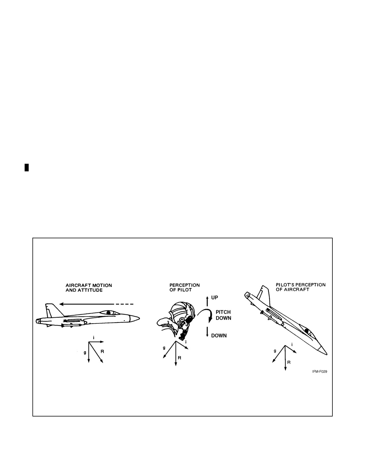
The opposite illusion of nosedown attitude may occur as a result of deceleration (Figure 8-5). If a pilot were to correct
for the illusion of nose-low pitch caused by deceleration on final approach, the corrective action might result in a low
altitude stall. Although this type of illusion is of greatest magnitude in high-performance aircraft, it can occur in all
aircraft. A pilot can readily overcome the illusion by giving attention to distinct, valid references or to flight attitude
instruments.
8.1.1.6.3 False Perception of Attitude
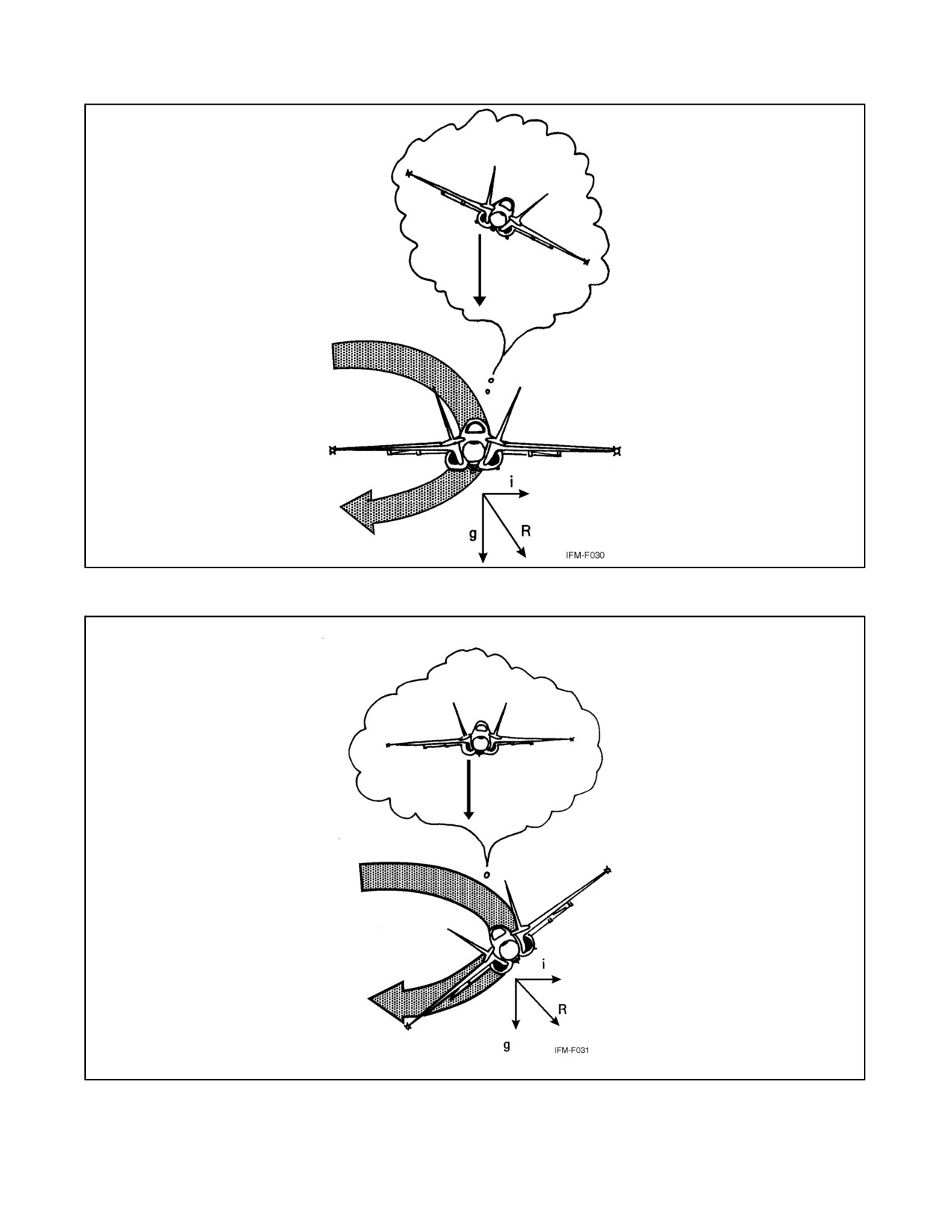
False perception of attitude can also occur during a flat or coordinated turn. The pilot can equate the sustained resultant
(R) with the vertical (gravity); therefore, in a flat turn (Figure 8-6), the pilot may feel as if rolled out of the turn. In
a coordinated turn (Figure 8-7), the resultant is aligned with the pilot’s axis, and there will be no sensation of a banked
attitude.
8.1.1.7 Inversion Illusion
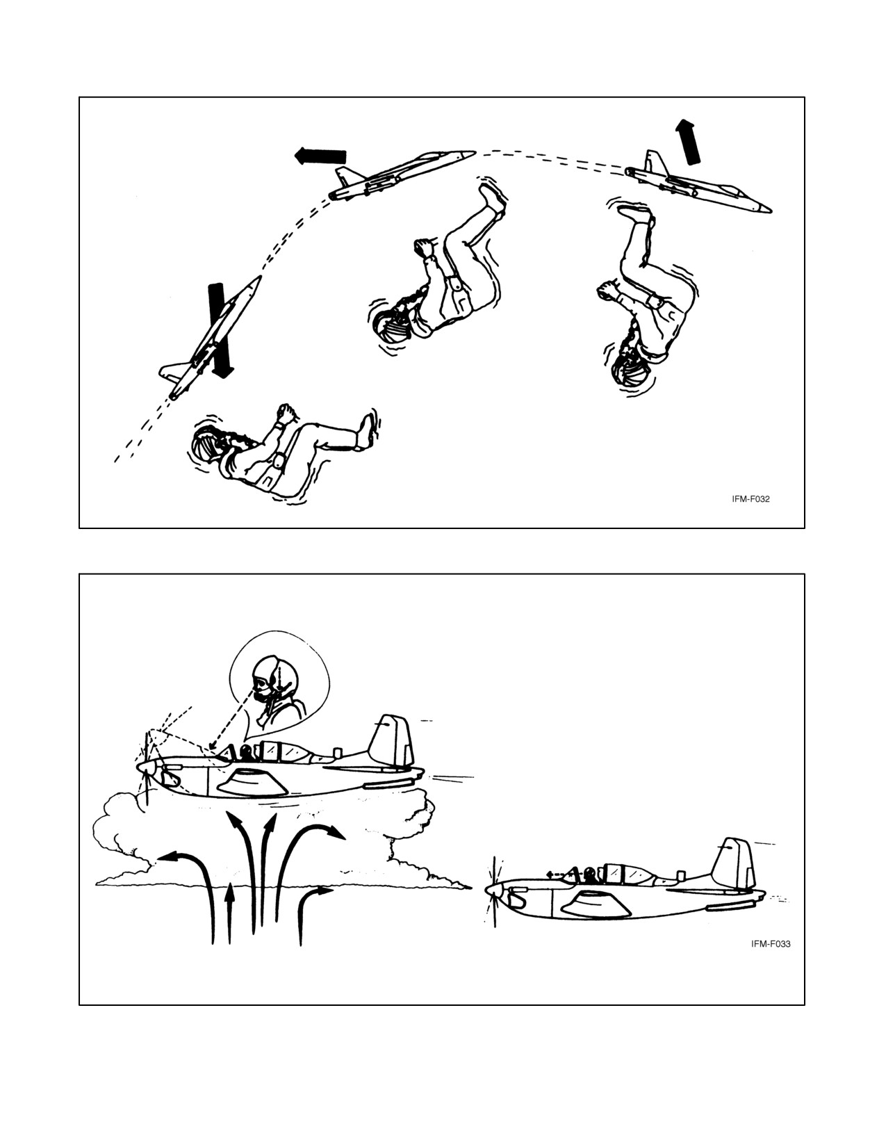
Inversion illusion can occur during an abrupt pushover from a climb into level flight (Figure 8-8). The abrupt aircraft
attitude change and consequent negative g force acting on the otolith organs cause a sensation of being inverted.
Reflex action can cause the pilot to correct for this illusion by pushing the nose of the aircraft abruptly downward,
thus intensifying the illusion.
8.1.1.8 Elevator Illusion
Elevator illusion results from stimulation of otolith organs by an increase in gravity (Figure 8-9). If an upward linear
acceleration occurs while the aircraft wings are level, as in a sudden updraft, the pilot’s eyes reflexly move downward.
The illusory upward motion of the immediate surroundings can give the pilot the impression that the aircraft is
climbing and cause the pilot to reflexly place the aircraft into a dive.
Figure 8-5. Deceleration Illusion of Nosedown
ORIGINAL
8-6
NAVAIR 00-80T-112
Figure 8-6. False Perception of Attitude During Flat Turn
Figure 8-7. False Perception of Attitude During Coordinated Turn
8-7
ORIGINAL
NAVAIR 00-80T-112
Figure 8-8. The Inversion Illusion
Figure 8-9. The Elevator Illusion
ORIGINAL
8-8
NAVAIR 00-80T-112
The opposite of the elevator illusion (oculoagravic illusion) can occur during a sudden downdraft. The eyes will react
with an upward shift, resulting in apparent downward shift of objects interpreted as a nosedown aircraft attitude. The
pilot may react by pulling back on the stick, and enter an unperceived climb.
8.1.2 Visual Illusions and Problems
The aircraft instruments are extensions of the pilot’s senses. As long as the pilot correctly interprets and uses the
instruments when deprived of external visual references, orientation will remain; however, there are certain
conditions encountered during VFR and formation flight that may cause confusion, illusions, and spatial
disorientation.
8.1.2.1 Confusion of Ground Lights with Stars
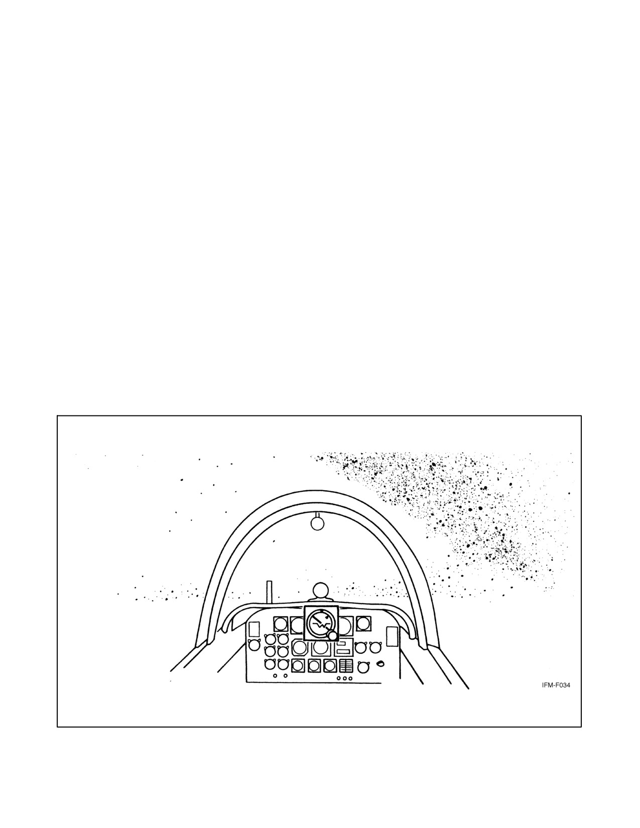
Confusion of ground lights with stars is a common problem associated with night flying (Figure 8-10). Incidents have
been recorded where pilots have put their aircraft into very unusual attitudes to keep some ground lights above
because they believed the lights were stars. Sometimes pilots have mistaken certain geometric patterns of ground
lights, such as freeway lights, with runway and approach lights, or assumed a line of ground lights represented the
horizon. In doing so, the possibility exists of flying into the ground because the perceived horizon is below the actual
one. Sometimes pilots confuse unlighted areas of the Earth with an overcast night sky. They are likely to perceive
certain ground features such as a seashore as the horizon and fly into the unlighted water or the terrain above it.
8.1.2.2 False Vertical and Horizontal Cues
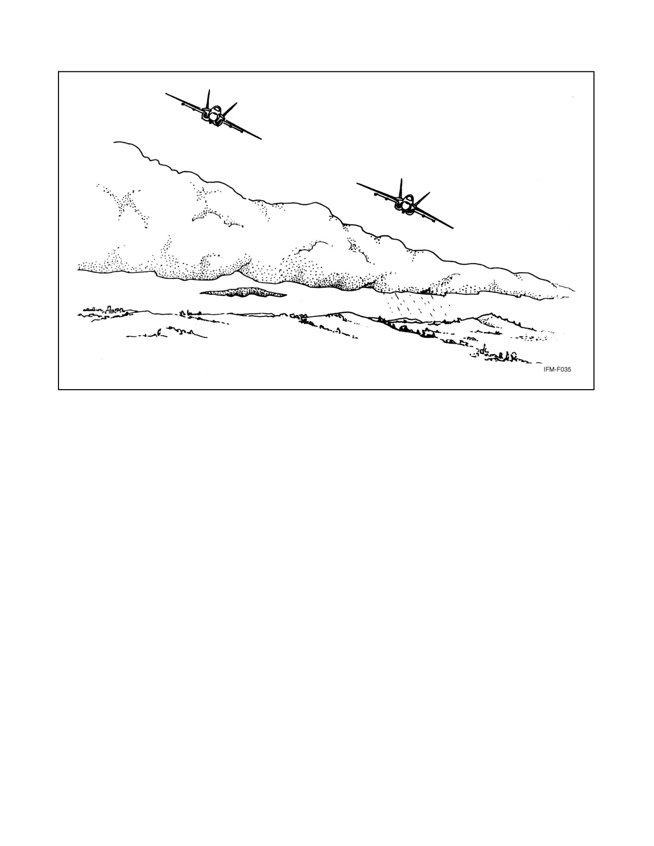
False vertical and horizontal cues can occur while flying over sloping cloud decks or land that slopes gradually
upward into mountainous terrain (Figure 8-11). Pilots are often compelled to fly with their wings parallel to the slope
rather than straight and level. A related phenomenon is the disorientation caused by the aurora borealis, in which false
vertical and horizontal cues generated by the aurora result in attitude confusion in pilots trying to fly formation or
refuel at night in northern regions.
Figure 8-10. Confusion of Ground Lights with Stars
8-9
ORIGINAL
NAVAIR 00-80T-112
Figure 8-11. Sloping Cloud Decks
8.1.2.3 Visual Autokinesis
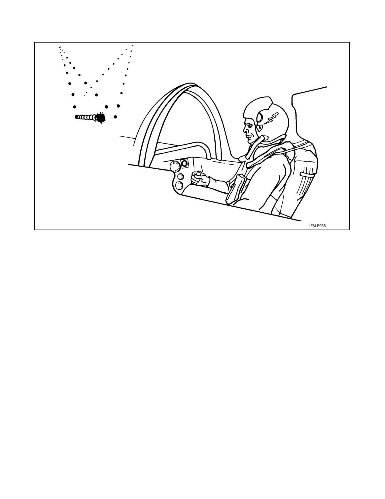
A stationary light stared at for several seconds in the dark will appear to move (Figure 8-12). This phenomenon can
cause considerable confusion in pilots flying formation at night. Increasing the brilliance, size, or number of lights,
or causing the lights to flash on and off, will diminish the effect of this phenomenon.
8.1.3 False Perceptions During Helicopter Flights
The problem of illusions in helicopter pilots is not totally understood due to various complicating factors: the
fundamental difference between a helicopter and other aircraft, the complexity of its piloting, its instability in flight,
and excessive noises and vibrations. All of these probably have definite effects on the pilot’s spatial orientation and
at the same time may promote the development of false perceptions.
Poorly developed habits of instrument flying are the most frequent cause of false perceptions, especially during flights
with limited visibility and few definite clouds, when the pilot is distracted from instrument flying and tries to orient
him/herself visually. Illusions develop under conditions hampering orientation in space, such as flights over the sea
on moonless starry nights, in calm twilight, or when caught in thickly falling snow. Other factors contributing to
illusions are poor rest before flight, fatigue during lengthy flights, indulgence in alcohol on the eve of the flight, and
poor adjustment to instrument flight.
8.1.3.1 Illusion of Banking
This illusion is connected with the persistent tendency of helicopters to bank during flight. The inhibitory processes
in the pilot’s brain are intensified under the influence of noise and vibration, especially if the pilot has had insufficient
preflight rest, use of alcohol on the eve of flight, or recent cold or flu. The false perception can hold for a few seconds
or as long as 15 minutes.
ORIGINAL
8-10
NAVAIR 00-80T-112
Figure 8-12. Visual Autokinesis
When this illusion develops, the pilot should concentrate all attention on the instruments. If the false perception does
not pass, it is necessary to transfer the control to the copilot and rest awhile. After this, the illusion generally
disappears. In certain instances, the illusion ceases after the helicopter is positioned by the second pilot.
8.1.3.2 Illusion of Deviation
During entry into clouds, or during a flight through occasional clouds, pilots can experience the illusion that the
helicopter deviates from its course. This can occur if the pilot has not completely switched to instrument flying.
Oncoming clouds, flowing around the helicopter, swerve to the side, creating the impression that the helicopter is
deviating from the course. As the pilots are seated at the sides of the helicopter, they only see the part of the oncoming
cloud flow that bypasses at their side; thus, in pilots sitting at the left, an illusion develops that the helicopter is
diverging to the right, and in the pilots sitting at the right, this deviation seems to be to the left. The illusion can last
from 1 to 1.5 minutes and disappears as soon as the pilot completely switches to instruments.
8.1.3.3 Illusion of Pivoting on Longitudinal Axis
Weak instrument technique causes this illusion, which can appear in dense masses of homogeneous clouds. The
motion of an approaching mass of clouds is least marked but, instead, a downward flow directed by the shape of the
supporting structure is distinctly apparent. This creates the impression that the front portion of the helicopter is rising
and the tail girder dropping. The helicopter seems to pivot on its longitudinal axis. The pilot feels as if he/she were
not sitting but lying on his/her spine. This illusion lasts for a few seconds to 1 minute. Switching attention completely
to instruments, or the appearance of varied density or illumination of the clouds, brings about cessation of the illusion.
8-11
ORIGINAL
NAVAIR 00-80T-112
8.1.3.4 Illusion of Vertical Flight
This illusion is caused by simultaneous excitation of the receptors of the inner ear and visual analyzers. A change in
body position and simultaneous observations of uniformly moving background (in particular the flow of clouds
downward from the rotors) give rise to false impressions as to the position and direction of the helicopter. An
impression is created that the helicopter has turned 90° downward on its longitudinal axis and is flying vertically. This
illusion can appear in pilots at the moment of forward acceleration with the sudden increase in the angle formed by
the horizontal and longitudinal axis of the helicopter (angle of pitch) while the pilot is at the same time watching the
downward flow of the cloud stream from the rotors. With a change of no more than 5° in the angle formed by the
longitudinal axis of the helicopter and the horizontal, the illusory perception of angle change may reach 90°. The
illusion lasts 20 to 30 seconds and disappears completely.
8.1.3.5 Flicker Vertigo
This term refers to the feelings of dizziness that may be accompanied by nausea caused by intermittently flickering
lights. Sources of flickering lights include sunlight through rotor blades, windshield wipers, or reflection of
anticollision lights off clouds. Turning off distracting lights or changing direction may help reduce flicker vertigo.
8.1.3.6 Preventive Measures
The study and awareness of illusions by flight personnel have definite value in prevention. All flight personnel should
be acquainted during flight briefings with the flight conditions and the possibility of false perceptions arising during
one or another portion of the flight. If the pilot would be aware beforehand of what might be encountered, this could
help forestall illusions. A strict regime of work and rest should be observed. When fatigued during a flight, the pilot
should pass the control to the copilot. Instruments should be trusted and the aircraft flown to make them read correctly.
8.2
SPATIAL MISORIENTATION
Unlike spatial disorientation, spatial misorientation occurs unrecognized by the pilots and aircrew. Spatial
misorientation mishaps are characterized by controlled, 1-G collisions with the ground or obstacles on the ground.
Terms that have been used to describe symptoms of spatial misorientation include unrecognized spatial
disorientation, task overload, task saturation, loss of situational awareness, fixation, distraction, or preoccupation.
Typically, a pilot who experiences spatial misorientation is mistakenly comfortable with the attitude or flightpath of
the aircraft, or is distracted from monitoring flight instrument cross-checks. The pilot unconsciously accepts
peripheral visual cues such as outside horizons, cloud banks, etc. for attitude flying, instead of central visual cues such
as cockpit instruments. Factors that prevent or distract a pilot from utilizing central visual cues for cross-checking
flight/attitude instruments are numerous, but are especially present during times of high pilot workload, fatigue, and
night flying. Preflight considerations should take into account the type of mission, anticipated workloads, time of day,
etc., which might distract a pilot from using visual cues for cross-checking flight/attitude instruments.
ORIGINAL
8-12
NAVAIR 00-80T-112
CHAPTER 9
Factors That Increase the Potential for
Spatial Disorientation
9.1
GENERAL
There are a number of factors that will increase the potential for spatial disorientation. Some of these are personal
in nature whereas others are external and related to the flying environment and various phases of flight. Pilot and
supervisor awareness may reduce the risks associated with these factors.
The key to success in instrument flying is an efficient instrument cross-check. Any situation or factor that interferes
with this flow of information will increase the potential for disorientation.
9.2
PERSONAL FACTORS
A pilot who is mentally stressed, preoccupied with personal problems, fatigued, ill, or taking unprescribed medication
is at increased risk. A pilot preoccupied with significant family problems may not be able to fully concentrate on the
tasks related to flying duties. Any of these factors may be detrimental to an effective instrument cross-check and can
adversely affect the pilot’s ability to interpret and process information provided by aircraft instruments.
9.3
ENVIRONMENTAL FACTORS
Certain environmental factors and situations, when the visual system becomes compromised, can reduce a pilot’s
ability to maintain spatial orientation. Some of these factors include:
1. Weather. In particular, transfer from external visual to instrument cues.
2. Night. Isolated light sources can enhance the probability of sensory illusions. Confusing ground lights with
stars can also occur.
9.4
FACTORS RELATED TO TYPE OR PHASE OF FLIGHT
Prolonged linear acceleration or deceleration, prolonged angular motion, subthreshold changes in attitude, or ascent
or descent are flight maneuvers that can precipitate an episode of spatial disorientation. Specific types and phases of
flight are described in the following paragraphs.
9.4.1 Takeoff and Landing Phases
Spatial disorientation mishaps have occurred after takeoff, in the initial climbout following takeoff, during the
penetration, following a penetration turn, or in the transition to final approach and landing. The takeoff and landing
phases of flight are dynamic, demanding environments. Aircraft acceleration, speed, trim requirements, rate of
climb/descent, and rate of turn are flight parameters undergoing frequent change. The aircraft may pass in and out
of Visual Meteorological Conditions (VMC) and Instrument Meteorological Conditions (IMC). At night, ground
lights may add confusion. Radio channel or Identification Friend or Foe/Selective Identification Feature (IFF/SIF)
changes may be directed during a critical phase of flight while close to the ground. Unexpected changes in climbout
or approach clearances may increase workload and interrupt an efficient instrument cross-check. An unexpected
requirement to make a missed approach or a circling approach at night or in IMC conditions is particularly demanding.
At a strange field with poor runway lighting, this may be especially dangerous.
9-1
ORIGINAL
NAVAIR 00-80T-112
9.4.2 ACM or Air-to-Ground Ordnance Deliveries
A critical phase of flight with a high potential for spatial disorientation is the maneuvering associated with Air Combat
Maneuvering (ACM) or air-to-ground ordnance deliveries during night or periods of reduced visibility. Under such
conditions, the only reliable information related to aircraft attitude is provided by the flight instruments. Because of
the nature of the mission, the pilot’s attention is directed outside the cockpit. Potential for distraction is great. Failure
to scan an important instrument parameter such as bank or pitch attitude, airspeed, or vertical velocity during a critical
phase of the weapons delivery may occur. These factors can lead to spatial disorientation or to a “lack of situational
awareness” in which the pilot inadvertently places the aircraft into a position from which recovery may be impossible.
Distraction, lack of situational awareness, and spatial disorientation are not the same, but the root causes of each are
related (i.e., failure to maintain an effective instrument cross-check). One can lead to the other and any one of the three
may result in a fatal mishap.
9.4.3 Formation Flight
The most critical situation for developing spatial disorientation is night or weather formation flights. Formation flying
can present special problems to the pilot in maintaining spatial orientation. First and most important, the pilot flying
wing cannot maintain visual dominance during orientation-information processing and is deprived of any reliable
visual information concerning aircraft attitude related to the surface of the Earth. The pilot cannot see the true horizon
and has little or no time to scan the aircraft instruments. Under these conditions, it becomes difficult to suppress
information provided by unreliable sources such as the inner ear. Illusions are almost inevitable. A pilot’s
concentration on maintaining proper wing position may be diverted by what the pilot “feels” the aircraft attitude to
be. Lack of confidence in the lead will increase tension and anxiety. An inexperienced, rough flight lead will most
certainly aggravate the situation. Poor in-flight communications and the lack of specific procedures (properly briefed)
to recover a disoriented wingman will increase the potential for an aircraft mishap.
ORIGINAL
9-2
NAVAIR 00-80T-112
CHAPTER 10
Medications, Alcohol, and Nutrition
10.1
GENERAL
Self-medication in aviation is a common and potentially dangerous act. With the increasing medical sophistication
of the general public through media advertising, there is a definite possibility of self-diagnosis and self-prescription.
Self-medication and taking medicine in any form while flying can be extremely hazardous to a pilot. Even simple,
over-the-counter remedies may seriously impair judgment and coordination, adversely affect the pilot’s ability to
interpret and process information provided by aircraft instruments, or produce inner ear effects that may precipitate
or intensify experiences of vertigo in aircraft. OPNAVINST 3710.7 series prohibits the use of all drugs by flight
personnel unless specifically approved by a flight surgeon, aviation medical examiner, or aviation medical officer.
The adverse effects of drugs on the human body are further complicated by the complex interactions that occur in
the body between drugs, between drugs and alcohol, and between drugs and food additives, including caffeine and
nicotine. Adverse drug effects are additive but can be synergistic, where the resulting effect is greater than the sum
of the individual effects.
The insidious incapacitation that may result from the effects of drugs and alcohol is increased when the pilot is
fatigued, frustrated, or in a state of mild hypoxia. In addition, it is an even greater problem when a drug is used over
a period of several days, weeks, or even longer. Never take medication before flying except on the advice of a flight
surgeon.
10.2
NUTRITION
All flight and ground support personnel shall be provided a positive program of information for the establishment
and maintenance of good dietary habits. Failure to eat within 12 hours preceding end of flight may impair performance
and ability to control aircraft adequately. Reducing diets should be under strict supervision of a flight surgeon.
10.3
EXERCISE
Planned physical fitness programs promote health. All levels of command are encouraged to establish approved
physical fitness programs for all personnel in accordance with OPNAVINST 6110.1. Due consideration must be given
to avoiding contact sports, skiing, etc. Adequate rest periods must be provided for aviators before flying following
participation in competitive or particularly tiring sports activity. Twelve hours should normally be adequate.
10.4
DRUGS
Drugs are defined as any chemical that when taken into the body causes a physiological response. All flight and
support personnel shall be provided appropriate information by a command drug abuse education program.
1. Legal drugs are those medically prescribed or legally purchased for treatment of illness.
a. Prescription drugs — Taking drugs prescribed by competent medical authority shall be considered
sufficient cause for recommendation of grounding unless their use is specifically approved by a flight
surgeon, or a waiver of specific drug use has been granted by Chief of Naval Personnel or the Commandant
of the Marine Corps. Consideration shall be given to the removal of ground support personnel from critical
duties, for the duration of the drug effects, if appropriate. Medicines such as antihistamines, antibiotics,
tranquilizers, sleeping pills, etc. obtained by prescription shall be discarded if all are not used during the
period of medication.
b. Over-the-counter drugs — Because of the possibility of adverse side effects and unpredictable reactions,
the use of over-the-counter drugs by flight personnel is prohibited unless specifically approved by a flight
surgeon. Ground support personnel shall be briefed on the hazards of self-medication and should be
discouraged from using such drugs.
10-1
ORIGINAL
NAVAIR 00-80T-112
c. Alcohol — The well-recognized effects (i.e., intoxication and hangover) are detrimental to safe operations.
Consumption of any type of alcohol is prohibited within 12 hours of flight planning. Adherence to the letter
of this rule does not guarantee a crewmember will be free from the effects of alcohol after a period of
12 hours. Alcohol can adversely affect the vestibular system for as long as 48 hours after consuming, even
when blood-alcohol content is zero. Special caution should be exercised when flying at night, over water,
or in Instrument Meteorological Conditions (IMC). In addition to abstaining from alcohol for 12 hours prior
to flight planning, flightcrews shall ensure they are free of hangover effects prior to flight. Detectable blood
alcohol or symptomatic hangover shall be cause for grounding of flight personnel and the restriction of the
activities of aviation ground personnel.
d. Tobacco — Smoking has been shown to cause lung disease and impair night vision, dark adaptation, and
increase susceptibility to hypoxia. Smoking is hazardous to nonsmokers, as the effects occur whether smoke
is inhaled directly or secondarily. Persons desiring to smoke shall show due consideration for the desires
of nonsmokers in the vicinity and abstain from smoking if asked. Further guidance on smoking is contained
in OPNAVINST 3710.7 series.
e. Caffeine — Excessive intake of caffeine from coffee, tea, cola, etc. can cause excitability, sleeplessness,
loss of concentration, decreased awareness, and dehydration. Caffeine intake should be limited to not more
than 450 mg per day, or 3 to 4 cups of coffee.
2. The use of illicit drugs is prohibited.
10.5
ILLNESS
Acute minor illnesses such as upper respiratory infections, vomiting, or diarrhea can produce serious impairment of
flight personnel. All illnesses shall be evaluated by competent medical authority. Recommendations for grounding
shall be accomplished by the submission of a grounding notice
(NAVMED 6410/1). Clearance notices
(NAVMED 6410/2) shall be issued only by a flight surgeon. Where a flight surgeon is not available, clearance notices
shall be handled in accordance with BUMEDINST 6410.5. Flight personnel who are hospitalized shall be evaluated
in accordance with BUMED directives and a clearance notice issued prior to flight. Ground support personnel should
be similarly monitored. Aircrew shall not fly for at least 48 hours after general, spinal, or epidural anesthetic. Return
to flying status thereafter shall be upon the recommendation of a flight surgeon and at the discretion of the
commanding officer.
10.6
DENTAL CARE
Dental procedures that involve the use of injectable drugs (e.g., novocaine) shall be cause for grounding for a period
of 24 hours.
10.7
IMMUNIZATION/INJECTIONS
Flight personnel shall not participate in flight duties for 12 hours after receiving an immunization or injection unless
cleared sooner by a flight surgeon. Those showing protracted or delayed reaction shall be grounded until cleared by
a flight surgeon.
10.8
BLOOD DONATION
Although blood donated in small quantities is quickly replaced and does not adversely affect ground activities, the
hazards of hypoxia and reduced barometric pressure make it desirable to limit such donations by flight personnel in
accordance with the following:
1. Flight personnel shall not be regular blood donors.
2. Flight personnel in combat or flying in a shipboard environment shall not donate blood within 4 weeks prior
to such flying.
3. Flight personnel shall not participate in flight duties or perform low-pressure chamber runs for 4 days following
donation of 450 cc of blood (1 pint).
ORIGINAL
10-2
NAVAIR 00-80T-112
CHAPTER 11
Prevention of Spatial Disorientation
11.1
GENERAL
In the prevention of spatial disorientation, there are primarily two aspects: training and experience.
11.2
TRAINING
The training aspect includes lectures and reading material on the unreliability of bodily senses in flight and factors
favoring disorientation. Most important are the training and qualifications of learning to fly by instruments and
maintaining proficiency in instrument flight.
Training in controlled spatial disorientation situations is also helpful. A number of maneuvers can be used to
demonstrate spatial disorientation. Each maneuver normally creates a specific reaction; however, any reaction
resulting in a false sensation is effective. The purpose of these maneuvers is to help pilots understand how susceptible
the human system is to disorientation. They demonstrate that interpretations of aircraft attitudes from bodily
sensations are frequently false and unrealistic and provide a better understanding of how disorientation relates to
aircraft motion and head movement. They instill in the pilot a greater confidence in flight instrument interpretation
by the sense of sight to determine the aircraft attitude.
The following spatial disorientation maneuvers are selected because of their relationship with normal instrument
and/or turbulent flight. Other maneuvers, more violent and prolonged, may have a disorienting effect; however, they
are not the type of maneuver or situation likely to be inadvertently encountered.
Note
The following maneuvers should be simulated and practiced only under
direct supervision. They should not be accomplished in single-place
aircraft.
11.2.1 Sensation of Climbing During a Turn
This sensation can be induced by having the pilot close his/her eyes while the aircraft is in a straight-and-level attitude.
The supervisory pilot should execute, with a relatively slow entry, a well-coordinated 90° turn using approximately
1-1/2 positive g’s. While the aircraft is turning under the effect of positive g and with the pilot’s eyes still closed, the
supervisory pilot should ask the pilot his/her version of the aircraft attitude. The usual sensation is that of a climb.
When the pilot responds, have him/her open his/her eyes. The pilot can then see that a slowly established coordinated
turn produces a climb sensation from the action of centrifugal force on the equilibrium organs.
11.2.1.1 Correlation Under Actual Instrument Conditions
If the aircraft enters a slight, coordinated turn in either direction while the eyes are diverted away from the instruments,
the sensation of a noseup attitude may occur. The instantaneous application of similar forces may create this same
illusion without the aircraft actually turning.
When a change of direction in any one of the three planes of motion occurs and the rate of angular acceleration in
the turn is 2_ per second per second or less, the body cannot detect this motion without some positive visual reference;
consequently, the positive g applied during the turn is the only motion perceived. Positive g is usually associated with
a climb. This association is an unconscious habit developed through experience with g forces, as well as a conscious
feeling of climbing because of the effect of gravity on the inner ear mechanism.
11-1
ORIGINAL
NAVAIR 00-80T-112
11.2.2 Sensation of Diving During Recovery From a Turn
This sensation can be created by repeating the turning procedure described in paragraph 11.2.1, except that the pilot
keeps his/her eyes closed until the recovery from the turn is approximately one-half completed. While the recovery
is being executed and with the pilot’s eyes still closed, the supervisory pilot should note the pilot’s version of the
aircraft attitude. The usual response is that the aircraft is descending. This false sensation is apparent when the pilot
opens his/her eyes while the aircraft is still recovering from the turn.
11.2.2.1 Correlation Under Actual Instrument Conditions
If the eyes are diverted from the instruments during a turn under instrument conditions, a slow, inadvertent recovery
will cause the body to perceive only the decrease in positive g forces. This sensation causes the pilot to believe he/she
has entered a descent.
11.2.3 False Sensations of Tilting to Right or Left
This sensation may be induced from a straight-and-level attitude with the pilot’s eyes closed. The supervisory pilot
should maintain wings level and use right rudder to produce a slight skid to the left. The usual sensation is that of being
tilted to the right. This false sensation is the effect of side-to-side accelerative forces on the organs of equilibrium.
11.2.3.1 Correlation Under Actual Instrument Conditions
If the eyes are momentarily diverted from the instruments as a skid to one side occurs, a false sensation of tilting the
body to the opposite side may occur.
11.2.4 False Sensation of Reversal of Motion
This false sensation can be demonstrated in any one of the three planes of motion. The pilot should close his/her eyes
while in straight-and-level flight. The supervisory pilot should roll the aircraft to between 30° and 45° of bank. The
roll should be stopped abruptly and the bank attitude held. The usual reaction is a sense of rapid rotation in the opposite
direction. After this false sensation is noted, the supervisory pilot should have the pilot open his/her eyes and observe
the attitude of the aircraft. The false sensations produced from stopping the roll abruptly may result in a strong urge
to apply reverse aileron pressure for recovery.
11.2.4.1 Correlation Under Actual Instrument Conditions
If the aircraft rolls or yaws with an abrupt stop while the eyes are diverted from the instruments, a sensation of rolling
or yawing to the opposite direction may occur; therefore, the natural response to this false sensation would result in
a reentry or an increase of the original roll or yaw. This response is a common error in rolls or spins when the visual
references are poor. The sense of sight is the only sense that should be relied upon for correct recovery techniques.
11.2.5 Sensation of Diving or Rolling Beyond the Vertical Plane
This maneuver should be started from straight-and-level flight while the pilot sits normally and either closes his/her
eyes or lowers his/her gaze to the floor. The supervisory pilot should start a normal coordinated turn to between 30°
and 45° angle of bank. As the aircraft is turning, have the pilot lean forward and turn his/her head to either side, then
rapidly resume the normal upright position. The supervisory pilot should time the maneuver so that the turn is stopped
just as the pilot resumes his/her normal position.
11.2.6 Sensation of Climbing During Straight-and-Level Flight
This maneuver may be demonstrated by starting from straight-and-level flight at the aircraft normal final approach
airspeed. While the pilot closes his/her eyes, the supervisory pilot should increase the airspeed and maintain
straight-and-level flight. During the latter part of the airspeed increase, the supervisory pilot should ask the pilot,
whose eyes are still closed, what is his/her sensation of the aircraft attitude. The usual sensation perceived without
visual reference is that the aircraft is climbing.
ORIGINAL
11-2
NAVAIR 00-80T-112
11.2.6.1 Correlation Under Actual Instrument Conditions
This sensation may be very strong during an instrument missed approach. The false sensation of an excessive climb
is produced by the change in aircraft attitude and aircraft acceleration. This sensation may occur prior to the climb
and after level-off. The use of afterburners usually increases this illusion. The degree of disorientation and physical
response is dependent upon the attitude change and the rate of aircraft acceleration.
This maneuver usually produces an intense disorientation by giving the sensation of falling in the direction of roll
and downward. The sensation is so strong and rapid that it may result in a quick and forcible movement upward and
backward in the opposite direction. The marked physical response associated with this type of sensation can be very
dangerous if it occurs at low altitude.
11.2.6.2 Correlation Under Instrument Conditions
Severe spatial disorientation may result when the aircraft enters a turn while the pilot’s head is moved down and
sideways and then suddenly returned to the upright position. The usual reflex and almost uncontrollable urge to move
physically in the opposite direction may be transferred to the aircraft controls. If this reflex is not controlled, it could
easily cause exaggerated aircraft attitudes and further disorientation. Cockpit duties and/or distractions most likely
to create this sensation under actual instrument conditions are changing radio frequencies, reaching for maps or
charts, studying terminal instrument approach procedures, looking for obscure switches or controls, etc. The degree
of disorientation and physical response is dependent upon the motion of the aircraft, the motion of the head, and the
time element.
Extreme care should be taken to limit rapid head movements during
descents and turns, particularly at low altitudes. Cockpit duties should be
subordinate to maintaining aircraft control. If possible, these duties should
be delegated to other crewmembers so that sufficient attention can be given
to the attitude indicator and other flight instruments.
11.3
EXPERIENCE
Through experience, the pilot learns to recognize those factors that favor an episode of spatial disorientation. Most
of these are related to situations in which the visual system is compromised in its ability to provide orientation
information. Most important is the experience of flying by instruments. Inexperienced pilots with little actual
instrument time are particularly susceptible to spatial disorientation. It takes time and experience to “feel”
comfortable in a new aircraft system and develop a solid, effective instrument cross-check. Pilots who still must
search for switches, knobs, and controls in the cockpit have less time to concentrate on their flight instruments and
may be distracted during a critical phase of an instrument flight. The cockpit chores and workload associated with
single-seat fighter aircraft are particularly significant for the recent pilot graduate or pilots new to these systems. A
second crewmember is not available to change radio channels, set up navigational aids, and share other cockpit
chores. The potential for spatial disorientation during the transition phase into these new aircraft is great.
Total flying time does not protect an experienced pilot from spatial disorientation. More important is current
proficiency and the number of flying hours or sorties in the past 30 days. Aircraft mishaps due to spatial disorientation
almost always involve a pilot who has very few flying hours in the past 30 days. Instrument flying proficiency is
directly related to overall general flying proficiency. Flying proficiency deteriorates rapidly after 3 or 4 weeks out
of the cockpit. Vulnerability to spatial disorientation is high for the first couple of flights following a significant break
in flying duties.
11-3/(11-4 blank)
ORIGINAL
NAVAIR 00-80T-112
CHAPTER 12
Overcoming Spatial Disorientation
12.1
GENERAL
Some general suggestions for overcoming an episode of spatial disorientation include:
1. Get on instruments. They are supplying correct information about the aircraft position.
2. Believe the instrument indications. The pilot must be able to know that the instruments are correct, even if
his/her sensations are indicating a different aircraft position or attitude.
3. Make the instruments read correctly by controlling the aircraft.
4. Minimize head movements.
5. Fly straight and level, if permissible, to allow the sensations of disorientation to dissipate.
6. Seek help if severe disorientation persists. Call ground controller or other aircraft. If flying with another
aircraft, the other pilot may be able to talk the disoriented pilot into believing his/her instruments by describing
his/her aircraft attitude to him/her over the radio.
7. Transfer control to copilot or autopilot (in dual-piloted aircraft) until disorientation is overcome.
8. Egress. If control cannot be regained, abandon aircraft with safe ground clearance according to the procedures
outlined by the aircraft NATOPS manual. Do not leave it too late!
Crewmembers must have an established set of procedures to follow in the event they experience spatial disorientation.
Specific procedures may differ depending on whether the aircraft system is a single-seat fighter, dual-seat fighter, or
multicrewed aircraft. Additional procedures should be established for formation flight. Commands should ensure
specific procedures are established for aircraft systems under their control. A few general principles are stated in the
following paragraphs.
12.2
SINGLE-SEAT AIRCRAFT
1. If a pilot begins to feel disoriented, the key is to recognize the problems early and take immediate corrective
actions before aircraft control is compromised.
2. Actions are directed at reestablishing visual dominance. The pilot should keep his/her head in the cockpit, defer
all cockpit chores that are not essential, and concentrate solely on flying basic instruments. Frequent reference
should be made to the attitude indicator, which is the primary instrument in establishing and maintaining visual
dominance. Do not rely on the Heads-Up Display (HUD)!
3. If the symptoms do not improve after 30 to 60 seconds or if they get worse, the pilot should bring the aircraft
to straight and level using the attitude indicator. Maintain straight and level until the symptoms abate. Declare
an emergency if necessary (clearance limits) and advise Air Traffic Control (ATC) of the problem.
4. If action is not taken early, the pilot may not be able to resolve the sensory conflict. It is possible for spatial
disorientation to proceed to a point (a true state of “panic”) where the pilot is unable to either see, interpret,
or process information from the flight instruments. Further, the pilot may not be able to hear or respond to
verbal instructions. Aircraft control in such a situation is obviously impossible. The pilot must recognize this
and eject.
12-1
ORIGINAL
NAVAIR 00-80T-112
12.3
DUAL-SEAT AIRCRAFT
1.
Principles outlined previously also apply here. A second crewmember is generally available to share the
cockpit workload. The second crewmember can assist the pilot by copying clearances, changing radio/IFF
channels, and acquiring information from flight publications.
2.
The division of workload between the crewmembers should be clearly understood and covered in the preflight
briefing.
3.
During a penetration or en route descent and approach, the second crewmember should closely monitor and
call out altimeter settings, altitudes, and airspeeds.
4.
If the pilot experiences spatial disorientation to a degree that interferes with maintaining aircraft control, then
control of the aircraft should be transferred to the second crewmember if that crewmember is able to control
the aircraft safely.
5.
The second crewmember should be specifically tasked to monitor aircraft airspeed, altitude, and attitude while
maneuvering on range missions at night or during periods of reduced visibility.
12.4
MULTICREWED AIRCRAFT
1.
Principles outlined previously also apply to multiengine, multicrewed aircraft systems.
2.
The potential for spatial disorientation is less in these systems because of the difference in maneuverability.
Additional crewmembers are available to reduce pilot workload. Illusions and sensory conflicts are possible
and do occur. Illusions that are experienced are more likely to be visual in origin rather than vestibular.
3.
Weather- and night-related mishaps do occur in these systems, but the cause is usually related to either
distraction or poor crew coordination during an approach to a strange field, generally with a poor runway
lighting system. Fatigue and circadian rhythm problems may be aggravating factors on long flights in
cargo-type aircraft.
4.
Specific procedures concerning division of workload and crew coordination should be covered in the preflight
briefing.
12.5
FORMATION FLIGHTS IN NIGHT OR WEATHER
1.
The potential for spatial disorientation is greatest for formation flights during night or weather conditions.
2.
Night joinups are dangerous, particularly when conducted at low altitude over dark terrain or water under an
overcast. Alternative profiles such as a trail departure and climbout should be selected if possible.
3.
Pilots scheduled for formation flights in night/Instrument Meteorological Conditions (IMC) conditions should
be current and proficient in instrument, night, and formation flying. Particular attention should be directed to
the number of sorties and flying hours in the past 30 days.
4.
The flight leader in the preflight briefing should cover specific procedures to manage a disoriented wingman.
Note
Lost wingman procedures are designed to ensure safe separation between
aircraft in a flight when a wingman loses sight of the lead. Lost wingman
procedures are not for the purpose of recovering a wingman with severe
spatial disorientation. Precise execution is required to execute lost
wingman procedures, which a severely disoriented pilot will not be able to
accomplish.
ORIGINAL
12-2
NAVAIR 00-80T-112
5.
There are two essential requirements for safe formation flight in weather. First, the flight leader must be
experienced, competent, and smooth. Second, the wingman must be proficient in formation flying. The
wingman must have total confidence in the lead and concentrate solely on maintaining a proper wing position.
6.
If the weather encountered during a formation flight is either too dense or turbulent to ensure safe flight, the
flight leader should separate the aircraft under controlled conditions. This would be better than having a
wingman initiate lost wingman procedures at a time that may be inopportune or, worse yet, losing sight of the
wingman who may be severely disoriented.
7.
Flight lead should encourage the wingman to advise when the wingman begins to feel disoriented. Early, a few
words from the lead may reassure the wingman and help the wingman form a mental picture of the wingman’s
position in space. For example, “TWO, WE ARE LEVEL AT 20,000 FEET IN A 30° LEFT TURN AT 300
KNOTS.” This may be all that is necessary. Simply calling “ROLLING OUT” when rolling out of a turn will
help minimize disorientation for a wingman at night or in weather.
8.
If the wingman continues to have problems, lead should bring the flight to straight and level and advise the
wingman, “TWO, WE ARE STRAIGHT AND LEVEL AT 20,000 FEET, 300 KNOTS.” Maintain straight and
level for at least 30 seconds (60 seconds, if possible). Generally, the wingman’s symptoms will subside in 30
to 60 seconds. Advise ATC if necessary.
9.
If the preceding procedures are not effective, the lead should consider transferring the flight lead position to
the wingman while straight and level:
“TWO, WE ARE STILL STRAIGHT AND LEVEL, TAKE THE
LEAD NOW.”
Note
The wingman should be briefed to go straight to the attitude indicator and
maintain straight-and-level flight for 60 seconds before initiating turns,
climbs, or descents. The objective is for the wingman to reestablish visual
dominance as quickly as possible. Again, a wingman who is severely
disoriented should not elect or be directed to “go lost wingman.” The
wingman will be unable to accomplish these procedures precisely or safely.
10.
At this point, the mission should be terminated and the flight recovered by the simplest and safest means
possible. The safest method to recover flight formations in IMC conditions is a single-frequency straight-in
penetration or en route descent to the Final Approach Fix (FAF). Teardrop penetrations and arc approaches
greatly task the skills of a wingman.
12-3/(12-4 blank)
ORIGINAL
NAVAIR 00-80T-112
PART IV
Aircraft Flight/Navigational Instrumentation
Chapter 13 — Introduction to Aircraft Flight Instruments
Chapter 14 — Attitude Instruments
Chapter 15 — Performance Instruments
Chapter 16 — Position Instruments
73/(74 blank)
ORIGINAL
NAVAIR 00-80T-112
CHAPTER 13
Introduction to Aircraft Flight Instruments
13.1
GENERAL
Aircraft flight instruments are divided into three categories according to their specific function. The attitude
instrument indicates the aircraft attitude in relation to the surface of the Earth.
The position instruments convey the aircraft location in space and the performance instruments indicate how the
aircraft is performing as a result of attitude changes.
For information concerning a specific aircraft instrument, consult the applicable NATOPS flight manual.
13-1/(13-2 blank)
ORIGINAL
NAVAIR 00-80T-112
CHAPTER 14
Attitude Instruments
14.1
GENERAL
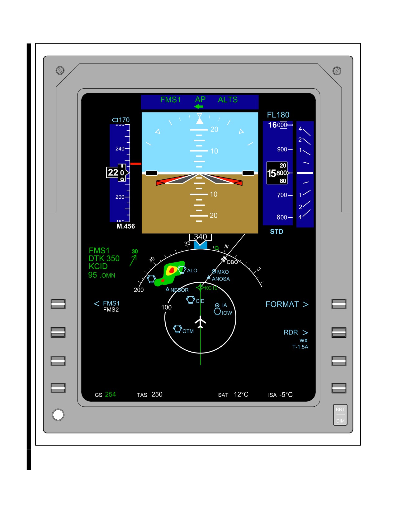
The primary flight instrument in all naval aircraft is the attitude indicator. It provides the pilot with a substitute for
the Earth’s horizon as a reference in instrument flight. The instrument shows a horizontal bar representing the horizon,
upon which a miniature aircraft is superimposed. There are graduated scales on the instrument face to indicate angles
of bank and pitch. The combined indications provide a constant visual presentation of the flight attitude of the aircraft
as to longitudinal, vertical, and horizontal information. Some aircraft installations may have additional information
displayed on the instrument, such as heading, glideslope information, turn and bank, and yaw and course deviation.
The pilot should refer to the appropriate NATOPS flight manual for detailed operation of a particular system
(Figure 14-1).
14.2
HEADS-UP DISPLAY
Heads-Up Displays (HUDs) are electronic instruments with a centralized means of displaying a large amount of
information. They can be used for display of attitude, performance, and position depending on the aircraft and its
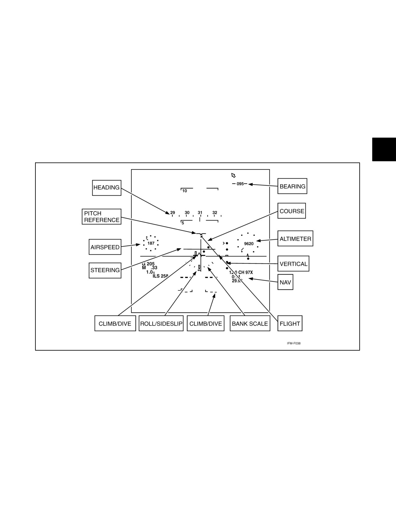
technology. Figure 14-2 shows a typical HUD configuration and some of the terms for its symbology. The pilot should
refer to the appropriate NATOPS flight manual for detailed operation of a particular system.
14.2.1 HUD Limitations
HUDs not endorsed as a Primary Flight Reference (PFR) may be integrated into the normal instrument cross-check,
but concerns about insidious failures and its use in maintaining attitude awareness and recovering from unusual
attitudes preclude its use as a sole-source instrument reference. Improvements in information integrity and failure
indications have increased confidence in the reliability of HUDs; however, the combination of symbology and
mechanization enabling their use as a sole-source attitude reference has not been incorporated into all HUDs.
14.2.2 Global Orientation
Many HUDs are incapable of providing intuitive global orientation information because of the small sections of space
that they represent. Also, because many HUDs provide only a partial picture of the aircraft attitude, a pilot who tries
to use the HUD to confirm an unusual attitude may see only a blur of lines and numbers. In a fast-moving environment,
the pilot may not be able to differentiate or recognize the difference between the solid climb lines from the identical,
but dashed, dive lines in the flightpath scale. Any confusion or delay in initiating proper recovery inputs may make
recovery impossible.
Unless your HUD is endorsed as a PFR, do not use it when spatially
disoriented, for recovery from an unusual attitude, or during lost wingman
situations; use the heads-down display anytime an immediate attitude
reference is required. Typically, heads-down displays are inherently easier
to use in these situations because of the larger attitude coverage, color
asymmetry between the solid ground and sky, and reduced interference
from the outside visual scene (glare, optical illusions, etc.).
14-1
ORIGINAL
NAVAIR 00-80T-112
Figure 14-1. Attitude Indicator
ORIGINAL
14-2
NAVAIR 00-80T-112
14.2.3 HUD Field of View
HUD symbology may also obscure objects within the HUD field of view. When nonessential HUD information is
displayed or when the HUD brightness level is excessive, the probability of obscuration is dramatically increased.
Proper HUD settings (including elimination of non-task-essential information and adjusting the brightness to the
proper level) are imperative to prevent potential hazards to safe flight.
14.2.4 Conventional Cross-Check
Pilots should remain proficient in the conventional instrument cross-check for their specific aircraft. Regardless of
the type HUD you have, it is important to fly an instrument approach or accomplish a level-off occasionally without
using the HUD so you retain your proficiency in the event of a HUD malfunction. Using HUD information incorrectly
or at the wrong time can actually increase pilot workload, but timely, proper use of it can help you fly more precise
instruments on a routine basis.
Figure 14-2. Heads-Up Display (HUD)
14-3/(14-4 blank)
ORIGINAL
NAVAIR 00-80T-112
CHAPTER 15
Performance Instruments
15.1
COMPASSES
Compasses provide Magnetic Heading (MH) information. Some magnetic compasses are not gyro-stabilized and are
subject to some errors, whereas the gyro-stabilized compasses largely eliminate these errors. Only nongyro-stabilized
(standby) compasses will be discussed in this section. Gyro-stabilized compasses are discussed in paragraph 16.3.
15.1.1 Standby Magnetic Compass
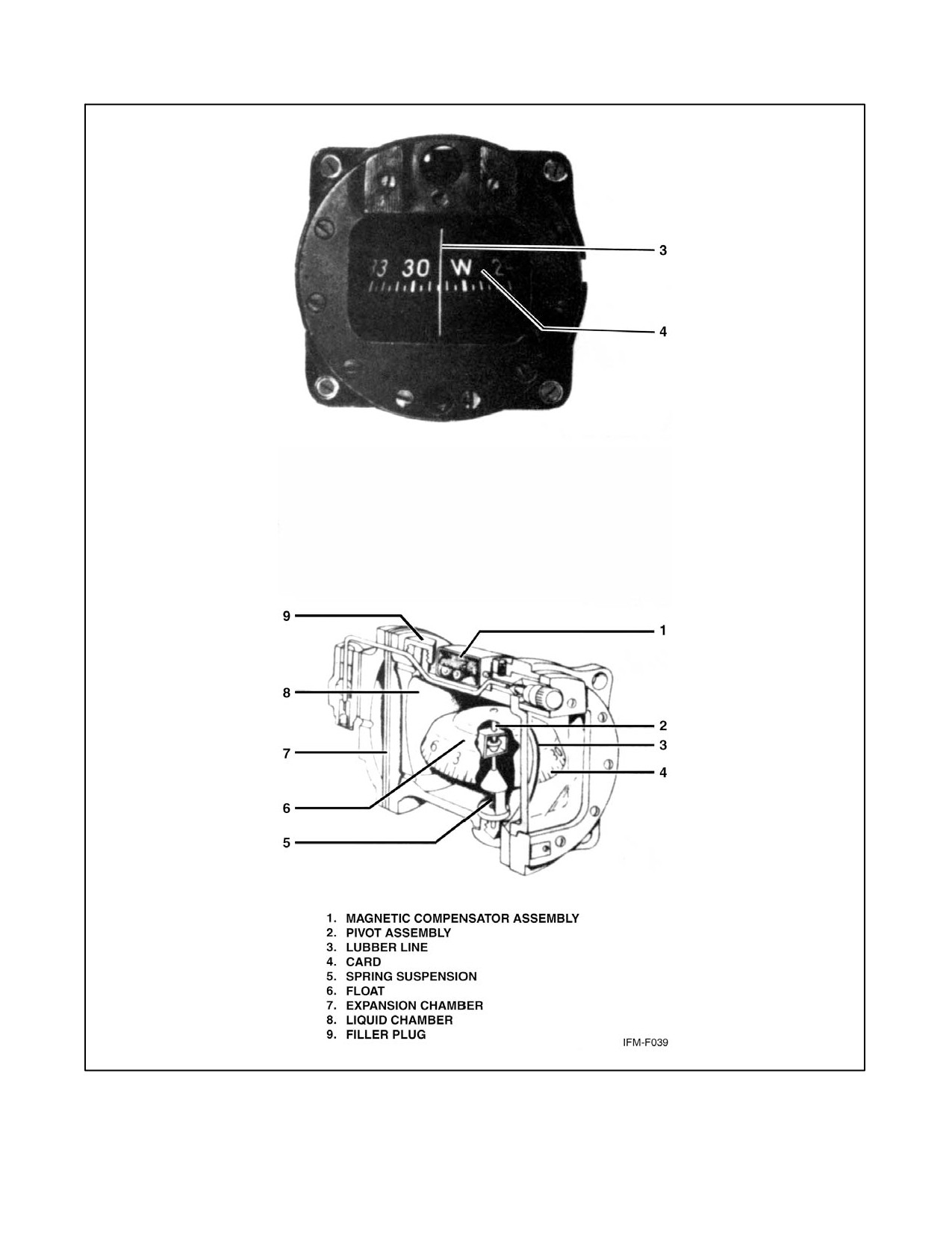
The standby magnetic compass is simple in construction. It contains two steel magnetized needles mounted on a float,
around which is mounted the compass card. The needles are parallel, with their north-seeking ends pointed in the same
direction. The needles react to the Earth’s magnetic field and cause the compass card to indicate magnetic heading
relative to magnetic north. The compass card has letters for cardinal headings and numbers every 30° in between. The
last zero of the degree indication is omitted. Between these numbers, the card is graduated for each 5° (Figure 15-1).
The float assembly, comprised of the magnetized needles, compass card, and float, is housed in a bowl filled with
acid-free white kerosene. This liquid dampens out excessive oscillations of the compass card, and its buoyancy
relieves part of the weight of the float from the bearings.
Mounted behind the compass glass face is a lubber or reference line by which compass indications are read. If the
face is broken, the fluid is lost and the compass becomes inoperative.
The standby compass is used for training or cross-check purposes and when any kind of failure renders the
gyro-stabilized compass useless. One of the principal reasons for the reduced importance of the standby compass is
the large and variable amount of deviation present. Variable electrical loads, armament, and the position of the nose
landing gear create deviation errors for which compass correction cards cannot provide sufficient tolerance. The
gyro-stabilized compasses largely eliminate these errors.
The standby compass is so mounted that when the aircraft is in straight-and-level unaccelerated flight, the vertical
component of the Earth’s magnetic field has no effect on the compass indication; however, when the aircraft is banked,
on or near a heading of north or south, or when it is accelerated or decelerated on or near east or west headings, the
compass indications are erroneous. Because of this dip error, precision flying without the use of a gyro-stabilized
heading indicator is difficult, especially in rough air. Another disadvantage is that the fluid in which the panel compass
is immersed to dampen oscillation is subject to swirl, which may create noticeable error. Additionally, the
comparatively small size of the compass bowl restricts the use of efficient dampening vanes.
In extreme latitudes (near the North or South Poles), the standby magnetic compass is useless because of the proximity
to the magnetic poles. This may cause the compass to spin erratically or display other incorrect indications.
The following are descriptions of the various standby magnetic compass errors:
15.1.2 Variation
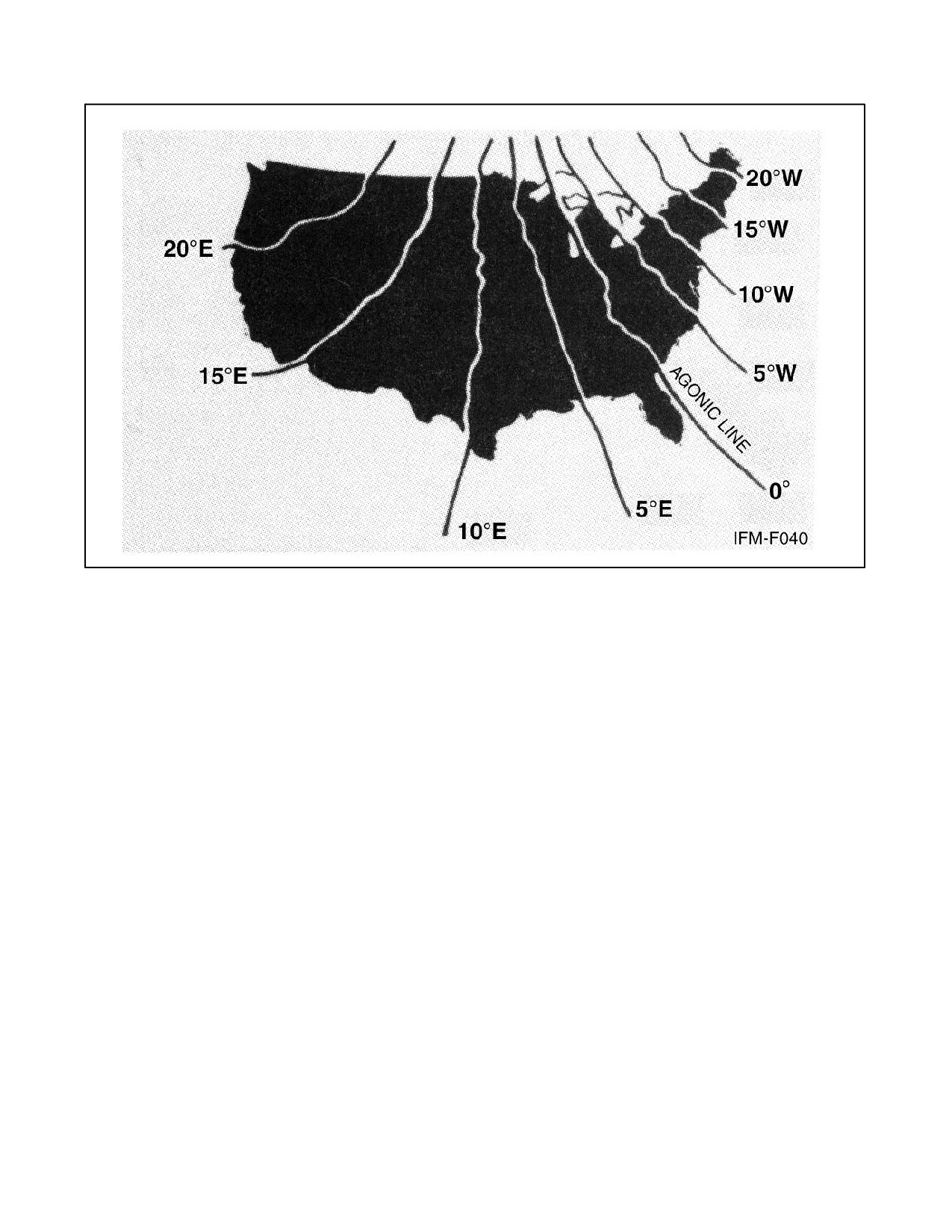
The angular difference between true and magnetic north is known as variation. It is different for different spots on
the Earth. Lines of equal magnetic variation are called isogonic lines and are plotted on aeronautical charts with the
amounts shown in degrees of variation east or west (Figure 15-2). A line connecting the 0° points of variation is termed
the agonic line. These lines are replotted periodically to take care of any change that may occur as a result of the
shifting of the pole.
15-1
ORIGINAL
NAVAIR 00-80T-112
Figure 15-1. Magnetic Standby Compass
ORIGINAL
15-2
NAVAIR 00-80T-112
Figure 15-2. Lines of Equal Magnetic Variation in the United States
15.1.3 Deviation
Electrical equipment mounted in the aircraft and accessories made of iron or steel, such as guns and armor plate, may
affect the reading of the magnetic compass. The difference between the indications of a compass on a particular
aircraft and the indications of an unaffected compass at the same point on the Earth’s surface is called deviation.
Deviation may change for each piece of electrical equipment turned on. In addition, the magnetism of the aircraft itself
may change as a result of severe jolts; therefore, it is necessary to swing the compass periodically and prepare a new
correction card. Because deviation also changes with latitude, the compass should be swung on arrival at a new base
of materially different latitude from the old base.
15.1.4 Magnetic Dip
The tendency of the magnetic compass to point down as well as north in certain latitudes is known as magnetic dip.
This is responsible for the northerly and southerly turning error as well as the acceleration and deceleration error on
headings of east and west. At the magnetic equator, the vertical component of the Earth’s magnetic field is zero and
the magnetic compass is not disturbed by this factor. As you fly from the magnetic equator to the higher latitudes,
the effect of the vertical component of the Earth’s magnetic field becomes pronounced. The tendency is not noticed
in straight-and-level unaccelerated flight because the compass card is mounted in such a way that its center of gravity
is below the pivot point and the card is well balanced in the fluid; however, when the aircraft is banked, the compass
card banks too, as a result of the centrifugal force acting on it. While the compass card is in this banked attitude in
northern latitudes, the vertical component of the Earth’s magnetic field causes the north-seeking ends of the compass
to dip to the low side of the turn, giving the pilot an erroneous turn indication. This error, called northerly turning error,
is most apparent on headings of north and south. In a turn from a heading of north, the compass briefly gives an
indication of a turn in the opposite direction; in a turn from a heading south, it gives an indication of a turn in the proper
direction, but at a more rapid rate than is actually the case. In southern latitudes, all these errors are reversed and are
called southerly turning error.
15-3
ORIGINAL
NAVAIR 00-80T-112
15.1.5 Acceleration Error
Acceleration error is also due to the action of the vertical component of the Earth’s magnetic field. Because of its
pendulous-type mounting, the compass card is tilted during changes of speed. This deflection of the card from the
horizontal results in an error that is most apparent on headings of east and west. When the aircraft is accelerating or
climbing on either of these headings, the error is in the form of an indication of a turn to the north; when the aircraft
is decelerating or descending, the error is in the form of an indication of a turn to the south. Acceleration error is
constantly present during climb and descent.
15.1.6 Oscillation Error
This error is due to the erratic swinging of the compass card, probably the result of rough air or rough pilot technique.
The fluid serves to reduce this oscillation. When the errors and characteristics of the magnetic compass are thoroughly
understood, it offers a reliable means of determining the direction in which the aircraft is headed. When reading the
compass to determine direction, make certain the aircraft is as steady as possible; is not in a turn, climb, or dive; and
is flying at a constant airspeed.
15.2
AIRSPEED INDICATOR
An airspeed indicator is a presentation of the forward velocity in knots of the aircraft through the surrounding airmass.
Components within the instrument case react to the difference between ram and static pressure inputs, causing a
mechanically linked pointer to indicate the airspeed on a graduated scale. As the ram/static pressure differential
changes, the pointer indicates a change in airspeed. Depending upon the type instrument, the airspeed depicted may
be either in terms of indicated, true, or displayed as a Mach number (Figure 15-3).
15.3
VERTICAL SPEED INDICATOR (VSI/VVI)
The Vertical Speed Indicator (VSI) or Vertical Velocity Indicator (VVI) (Figure 15-4) measures change of aircraft
altitude in feet per minute (fpm). It indicates the rate of climb or descent by measuring the rate of change in
atmospheric pressure. This information is valuable in maintaining specific rates of descent during instrument
approaches or for maintaining and correcting to a desired altitude.
15.3.1 VSI Error
Vertical speed indicators are subject to two types of error: lag and reversal. After entering or completing an altitude
change, approximately 6 seconds is required for the pressure differential within the instrument itself to equalize. This
time delay is an inherent error called lag. The vertical speed indicator is also subject to reversal error. This error is
caused by inducing false static pressure in the static system and normally occurs during sudden or abrupt pitch
changes. The reversal error is not synonymous with lag error; however, both may occur simultaneously. The
magnitude of this error varies with the aircraft and the abruptness of pitch changes. The reversal error can be
minimized by making small and/or smooth pitch changes.
15.3.2 Dial Calibration
The vertical speed indicator uses a single pointer to indicate rate of altitude change on a fixed circular scale. The scale
is calibrated in 1,000-foot increments. Between 0 and 1, the scale is graduated in 100-foot increments with a
0.5 (500-foot) reference for ease of interpretation. The 100-foot increments are beneficial in maintaining a glideslope
and to indicate trends from level flight. Beyond the 1,000 fpm indications, the scale markings vary; some are
graduated in 200-foot increments and others use 500-foot increments. The pointer will not indicate rates of altitude
change in excess of 6,000 fpm.
15.4
TURN AND SLIP INDICATOR
Cockpit instrumentation includes a rate of turn indicator and a slip indicator. Though these are usually integrated in
one instrument, they will be discussed separately.
ORIGINAL
15-4
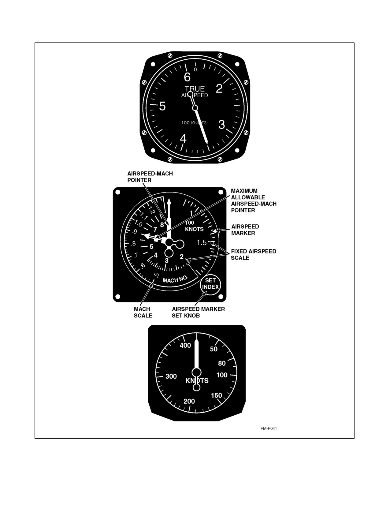
NAVAIR 00-80T-112
Figure 15-3. Airspeed Indicators
15-5
ORIGINAL
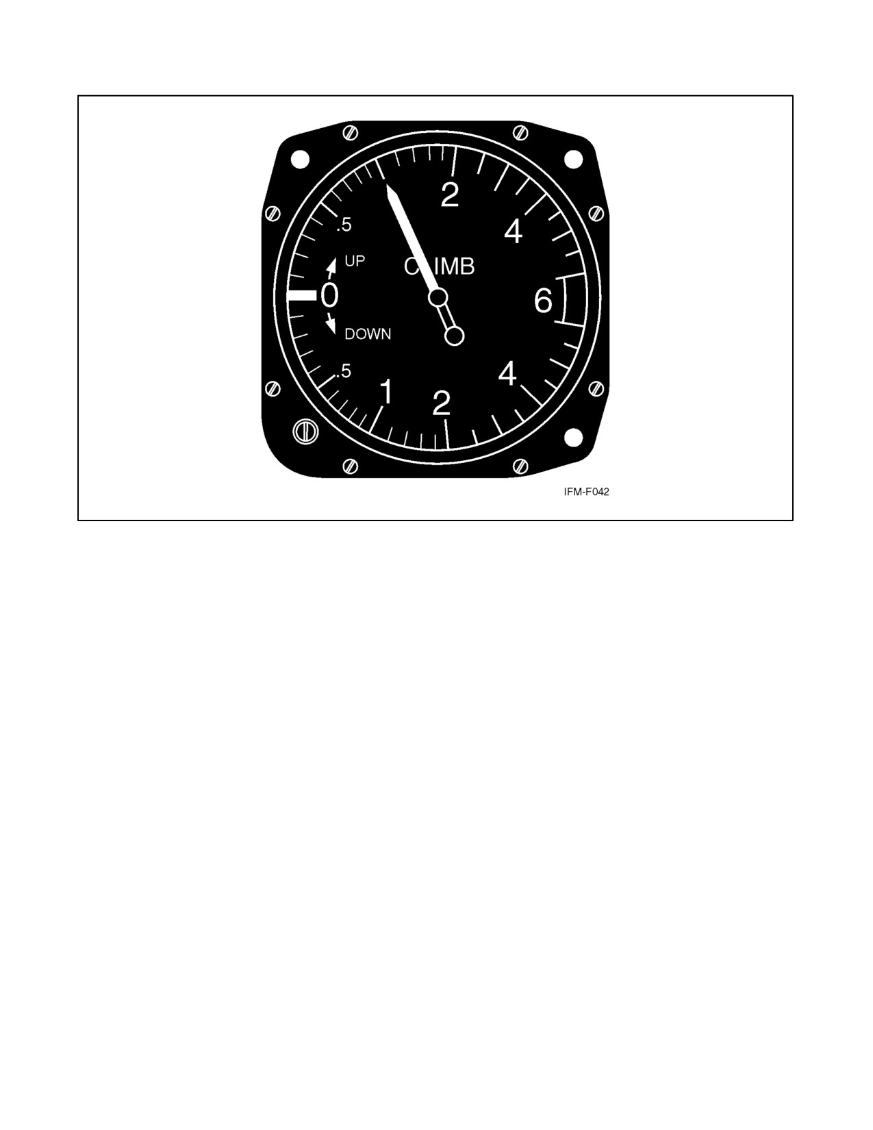
NAVAIR 00-80T-112
Figure 15-4. Vertical Speed Indicator
15.4.1 Turn Indicator (Needle)
The turn indicator is a vertical needle pointer or, in some aircraft, a miniaturized horizontal sliding bar on the attitude
indicator. A gyroscope is used in its operation. Though some turn indicators still use vacuum-driven gyros, most are
now electrically powered.
The primary function of the turn indicator is to measure the rate at which the aircraft is turning. A secondary function
is to provide an indication of bank as a backup for the attitude indicator.
The needle on the turn indicator is designed to deflect, in the direction the aircraft is turning, one needle width to
indicate a turn at the rate of 360° every 2 or 4 minutes. A single needle width deflection on a 2-minute turn needle
indicates the aircraft is turning 3° per second. A single needle width deflection on a 4-minute turn needle indicates
the aircraft is turning 1-1/2° per second.
15.4.2 Slip Indicator (Ball)
The slip indicator, called the ball, is a simple inclinometer. It consists of a marble in a slightly curved clear tube
containing a liquid. The ball indicates the relationship between the angle of bank and the rate of turn. The forces acting
on the ball are gravity and centrifugal force. During a coordinated turn, these forces are in balance and the ball will
remain centered (Figure 15-5). When the forces acting on the ball become unbalanced, the ball moves away from
center, indicating uncoordinated flight — a skid or slip (Figure 15-6). In a skid, the rate of turn is too large for the
angle of bank, and the excessive centrifugal force causes the ball to move to the outside of the turn. Correcting to
coordinated flight requires increasing the angle of bank or decreasing the rate of turn using less rudder or a
combination of both. In a slip, the rate of turn is too slow for the angle of bank, and the lack of centrifugal force causes
the ball to move to the inside of the turn. Correcting to coordinated flight requires decreasing the angle of bank or
increasing the rate of turn using more rudder or a combination of both.
ORIGINAL
15-6
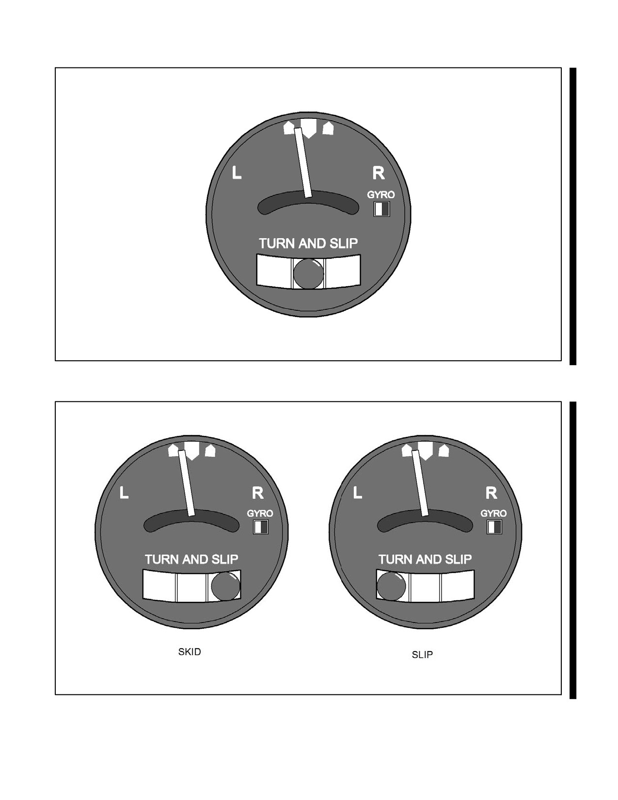
NAVAIR 00-80T-112
Figure 15-5. Coordinated Single Needle Width Turn Indicator
Figure 15-6. Unbalanced Flight
15-7
ORIGINAL
NAVAIR 00-80T-112
15.5
ANGLE OF ATTACK INDICATOR
Angle of attack is the angle between the mean aerodynamic chord of the wing of a moving aircraft and the relative
wind. The angle of attack instrument is a visual indication of aircraft performance. If the angle of attack is used to
set the aircraft up for a phase of flight (e.g., maximum range cruise, best rate of climb, optimum landing speed), many
airspeed calculations can be saved. Optimum angle of attack for any phase of flight does not vary with gross weight,
bank angle, or density altitude (as does airspeed).
Angle of attack is measured by a sensor on the outside of the aircraft. The sensor aligns itself with the relative wind
and transmits an electric signal to the cockpit instrument (Figure 15-7), which is a pointer needle against a fixed dial.
The instrument displays the angle of attack in numerical units, degrees, or symbols.
15.6
HOVER INDICATOR
The hover indicator (Figure 15-8) operates on information provided from a Doppler radar unit. The Doppler radar
employs continuous wave Doppler radar to measure automatically, continuously, and accurately horizontal and
vertical components of the helicopter velocity. Output of the Doppler radar is fed to the hover indicator and is
displayed as deflection of horizontal and vertical bars as well as a vertical pointer. To indicate fore and aft flight, the
horizontal bar will move opposite to the direction of flight; to indicate drift, the vertical bar will move in a direction
opposite to the direction of drift; therefore, the pilot flies toward the bars for correction to a hover. The vertical pointer
indicates vertical velocity in either direction and is centered in level flight. The hover indicator provides information
in terms of Groundspeed (GS), drift, and rate of climb or descent. It is used by HS/HC aircraft for instrument takeoffs
and to determine zero groundspeed for rescue or Antisubmarine Warfare (ASW) sonar operations.
15.7
CLOCK
A mechanical clock is installed in the instrument presentation, and hours, minutes, and seconds can be read from the
dial. Some aircraft are equipped with clocks that have an elapsed time counter feature.
15.8
OUTSIDE AIR TEMPERATURE GAUGE
Outside Air Temperature (OAT) (free air temperature) is indicated in the cockpit of many aircraft. The temperature
of the airmass surrounding the aircraft is shown in either degrees Celsius (°C) or Fahrenheit (°F). Regardless of the
scale used, a conversion table will frequently be necessary as temperatures aloft are given in °C and surface
temperatures are given in °F. This information is useful for, but not limited to, determining true airspeed, true altitude,
power required, and power available.
ORIGINAL
15-8
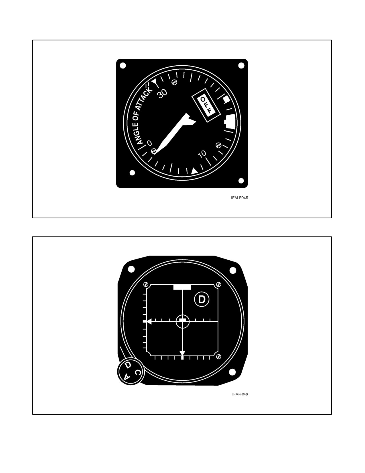
NAVAIR 00-80T-112
Figure 15-7. Angle of Attack Indicator
Figure 15-8. Hover Indicator
15-9/(15-10 blank)
ORIGINAL
NAVAIR 00-80T-112
CHAPTER 16
Position Instruments
16.1
ALTIMETERS
An altimeter is a flight instrument that measures the height of the aircraft above a given reference and displays it on
a calibrated dial (Figures 16-1 and 16-2). The reference may either be barometric (pressure altimeters) or absolute
(radio/radar altimeters).
16.1.1 Pressure Altimeter
Atmospheric pressure decreases with altitude, causing the pressure altimeter (which is a simple barometer, measuring
the weight of the air above it) to indicate altitude (in feet) above the preset reference (altimeter setting).
16.1.1.1 The Altimeter Setting
The altimeter setting is a correction for nonstandard surface pressure only. Atmospheric pressure is measured at each
ground station and the value obtained is corrected to sea level according to the surveyed field elevation. The altimeter
setting, then, is a computed sea level pressure and should be considered valid only in close proximity to the station
and the surface. It does not reflect nonstandard temperatures (Figure 16-3) nor distortion of atmospheric pressure at
higher altitudes; however, except for terrain clearance, the pilot should disregard nonstandard atmospheric effect for
air traffic control purposes. All pressure altimeters within close proximity of one another react to these effects in the
same way; thus, normal vertical separation is provided.
During instrument flight below the transition level (18,000 feet in Continental United States [CONUS]), the
importance of obtaining the latest altimeter setting cannot be overemphasized, particularly when flying from an area
of high pressure into a low-pressure area. Refer to Figure 16-4. Above the transition altitude (18,000 feet in CONUS),
pressure altitude is used because it is not as important to maintain true altitude as it is indicated altitude. (Midair
collision is a more serious problem than terrain clearance.) Therefore, for high-altitude flights, the altimeter shall be
set at 29.92 inches of mercury climbing through 18,000 feet Mean Sea Level (MSL). The current local altimeter
setting shall be set prior to descent through the lowest usable Flight Level (FL) as defined in the current Flight
Information Publications (FLIP), Section II.
Altimeters not equipped with mechanical stops near the barometric scale
limits can inadvertently be set with a 10,000-foot error; therefore, when
setting the altimeter, ensure the 10,000-foot pointer is reading correctly.
16-1
ORIGINAL
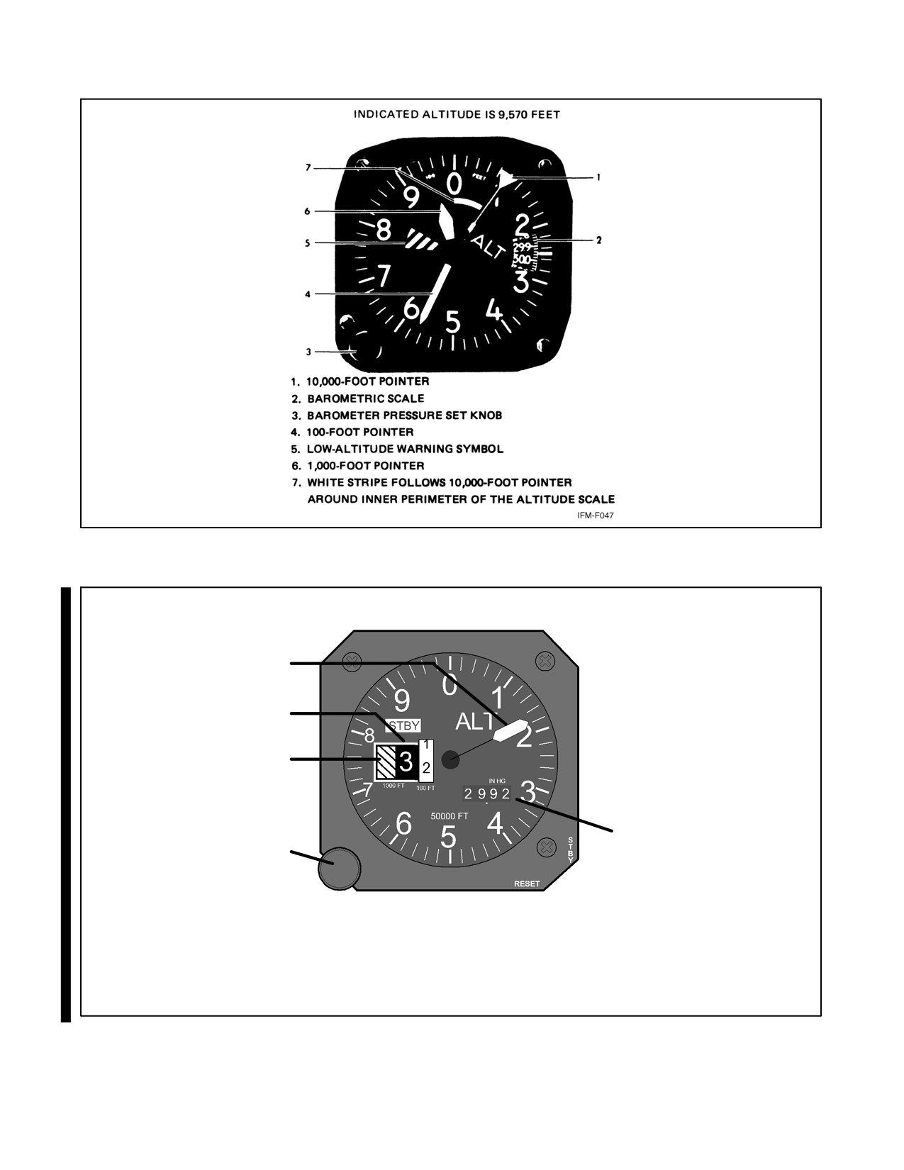
NAVAIR 00-80T-112
Figure 16-1. Three-Pointer Altimeter
INDICATED ALTITUDE IS 3,200 FEET
5
4
3
1
2
1. BAROMETRIC SCALE
2. BAROMETRIC PRESSURE SET KNOB
3.
10,000-FOOT COUNTER AND LOW
ALTITUDE WARNING SYMBOL
4.
1,000-FOOT COUNTER
5.
100-FOOT COUNTER
Figure 16-2. Altimeter
ORIGINAL
16-2
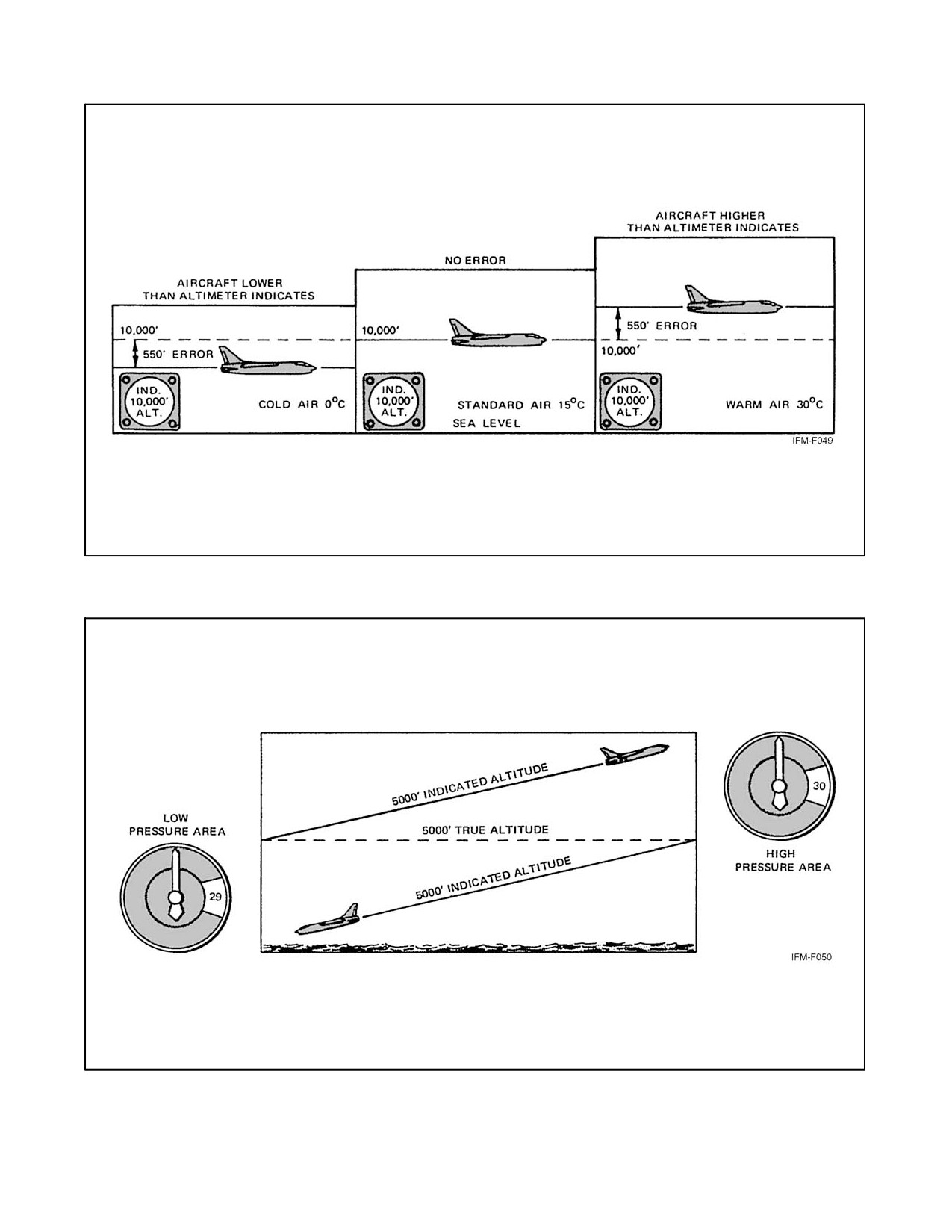
NAVAIR 00-80T-112
Figure 16-3. Effect of Temperature on Altitude
Figure 16-4. Inherent Altimeter Error Due to Pressure Changes
16-3
ORIGINAL
NAVAIR 00-80T-112
16.1.1.2 Setting the Pressure Altimeter
The barometric scale located on the face of the altimeter is calibrated in inches of mercury and is used to set a reference
plane into the instrument. Setting the barometric scale to the altimeter setting causes the altimeter to read indicated
altitude. If the altimeter setting is given in millibars, an appropriate conversion table must be used.
Each 0.01 change on the barometric scale is equivalent to 10 feet of indicated altitude.
The altimeter must be checked and set prior to each flight. This is accomplished thusly:
1. Dial the current altimeter setting into the barometric scale.
2. Note the difference between the indicated altitude and the known field elevation.
3. If the difference is greater than 75 feet, the altimeter is not acceptable for Instrument Flight Rules (IFR) flight.
Note
IFR flight may be conducted if an aircraft has but one usable pressure
altimeter.
16.1.1.3 Types of Altitude
(Figure 16-5.)
16.1.2 Radio/Radar Altimeters
Basically, both the radio and radar altimeters (Figure 16-6) measure altitude electronically by determining how long
it takes for a transmitted signal to be reflected back to a receiver antenna. Both types are similar in principle of
operation and cockpit presentation and measure absolute altitude. Radio/radar altimeters are FM/CW (frequency
modulation/continuous wave) type, and radar altimeters are of the pulse type. Both indicate terrain clearance with
increments that vary from small scale at low levels through larger scales at higher levels. Pilots should refer to the
appropriate NATOPS flight manual for the system used in their type aircraft.
16.2
RANGE INDICATOR
The range indicator (Figure 16-7), the Distance Measuring Equipment (DME) readout, displays slant range distance
from the aircraft to a selected ground station in nautical miles. The presentation may be separate or integrated with
a bearing instrument. The aircraft DME transmitter sends an interrogating pulse, which triggers a ground station
response pulse. The distance measuring equipment of the aircraft measures round-trip time and converts it to a display
representing nautical mileage on the range indicator. The interrogation/reply cycle is continuous, and the indicator
constantly shows slant range. When the aircraft is overhead the ground station, altitude is shown in nautical miles.
DME should be considered unusable unless it tests within one-half nautical mile (nm) or 3 percent of the distance
to the station, whichever is greater. The appearance of the warning bar/flag signifies an unusable or unreliable signal
and value.
ORIGINAL
16-4
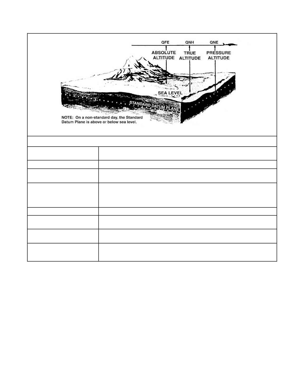
NAVAIR 00-80T-112
TYPES OF ALTITUDE
Altitude
The vertical distance of a level, a point, or an object considered as a point,
measured from a given surface.
Absolute Altitude
The altitude above the terrain directly below the aircraft. (QFE)
Pressure Altitude
The altitude above the standard datum plane. This standard datum plane is
where the air pressure is 29.92 inches of mercury (corrected to +15 °C). (QNE)
Density Altitude
Pressure altitude corrected for temperature. Pressure and density altitudes are
the same when conditions are standard (refer to standard atmosphere table).
As the temperature rises above standard, the density of the air decreases,
hence an increase in density altitude.
Indicated Altitude
Altitude displayed on the altimeter.
Calibrated Altitude
Indicated altitude corrected for installation error. If an altimeter correction card
is available, this definition may include scale error.
True Altitude
Calibrated altitude corrected for nonstandard atmospheric conditions. Actual
height above mean sea level. (QNH)
Flight Level
A surface of constant atmospheric pressure related to the standard datum
plane. In practice, a calibrated altitude maintained with a reference of 29.92
inches of mercury on the barometric scale. (QNE)
Figure 16-5. Types of Altitude
16-5
ORIGINAL
NAVAIR 00-80T-112
16.3
BEARING INDICATORS
Current typical navigational bearing displays are discussed in the following paragraph.
16.3.1 Radio Magnetic Indicator (RMI)
The RMI displays aircraft heading with navigational bearing data. It consists of a rotating compass card and two
bearing pointers. The compass card is actuated by the aircraft compass system so that it continually displays aircraft
magnetic heading. The aircraft current magnetic heading is displayed on the compass card beneath the top index
(Figure 16-8).
The bearing pointers display Automatic Direction Finder (ADF), VOR, or Tactical Air Navigation (TACAN)
magnetic bearings to the selected navigational station. Radial position is displayed under the tail of the bearing
pointers.
Note
Bearing pointers do not function in relation to ILS signals.
Unlike the ADF pointer, the VOR and TACAN bearing pointers do not “point” to an area of maximum signal
strength. VOR and TACAN navigation receivers electronically measure the magnetic course/bearing for display
bythebearingpointers;therefore,ifthereisamalfunctioninthecompasssystemorcompasscard,theADFbearing
pointerwillcontinuetopointtothestation,butdisplaysrelativebearingonly.Inthesamecompassfailuresituation,
the VOR or TACAN bearing pointers do not point to the station; however, they may still indicate proper magnetic
bearings.
When a compass malfunction is known or suspected to exist, the VOR and
TACAN radial displays must be considered unreliable until verified by
other means.
When navigating with TACAN, distance from the ground station is displayed on a range indicator (DME)
(Figure 16-7).
16.3.2 Bearing-Distance-Heading Indicator (BDHI)
The BDHI displays aircraft heading with navigational bearing data and range information. Except for the range
indicator, the BDHI is similar in appearance and function to the RMI described in paragraph 16.3.1.
The BDHI consists of a rotating compass card, two bearing pointers, a range indicator, and a range warning flag
(Figure 16-8). Some BDHIs also have a heading marker, a heading set knob, and a power warning flag.
The compass card is activated by the aircraft master compass system, and it continually displays aircraft heading. The
BDHI compass card can be operated in various slaved and nonslaved (DG) modes.
The heading marker, if incorporated, may be positioned on the compass card by use of the heading set knob. Once
positioned, the marker remains fixed relative to the compass card. When the aircraft is on the selected heading, the
heading marker is aligned beneath the top index.
Bearing pointer and range information function identically as described under range indicator and Radio Magnetic
Indicator (RMI) (Figure 16-9).
16.3.3 Horizontal Situation Indicator (HSI)
The HSI displays navigation information to the pilot as though the pilot were above the aircraft looking down. It is
essentially a combination of a rotating compass card (actuated by the aircraft master compass system), a radio
magnetic indicator, course indicator, and range indicator (Figure 16-10).
ORIGINAL
16-6
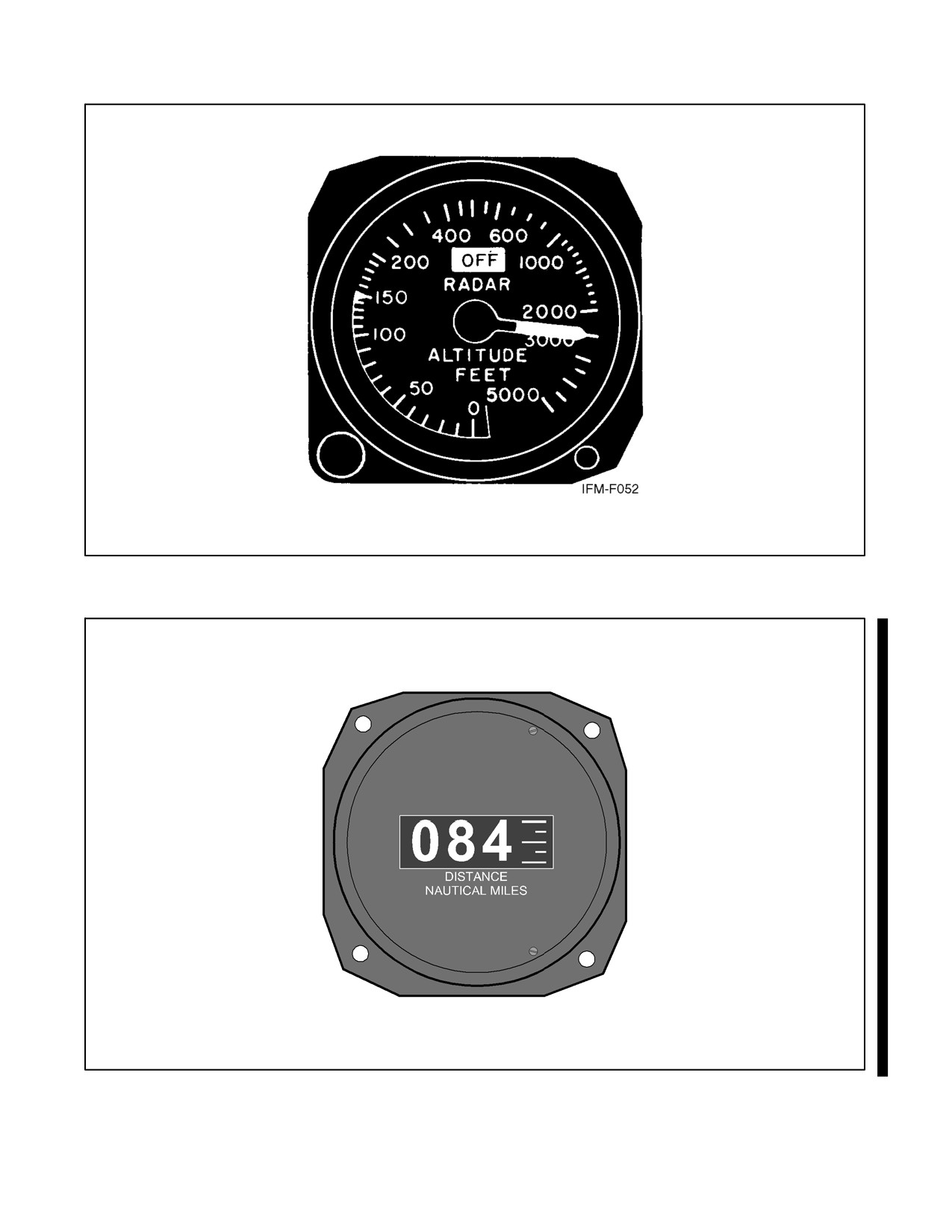
NAVAIR 00-80T-112
Figure 16-6. Typical Radar Altimeter
Figure 16-7. Range Indicator
16-7
ORIGINAL
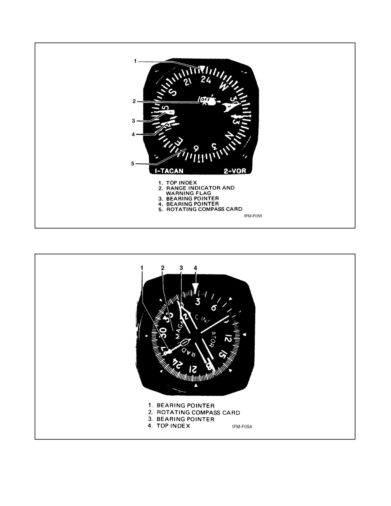
NAVAIR 00-80T-112
Figure 16-8. Bearing-Distance-Heading Indicator (BDHI)
Figure 16-9. Radio Magnetic Indicator (RMI)
ORIGINAL
16-8
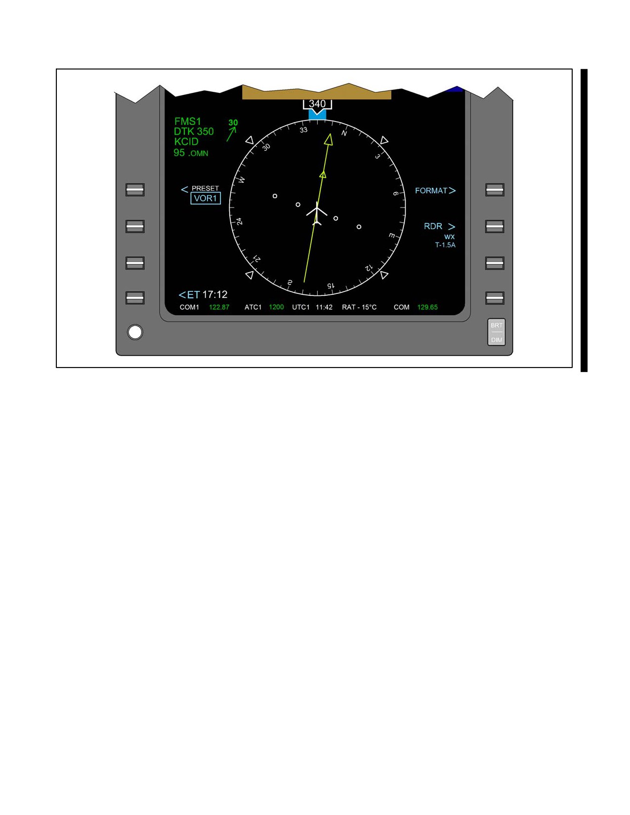
NAVAIR 00-80T-112
Figure 16-10. Horizontal Situation Indicator (HSI)
The aircraft heading is displayed on the rotating compass card under the top index lubber line.
The bearing pointer indicates the magnetic bearing from the aircraft to the navigation aid selected (VOR, TACAN,
or ADF) while the radial position of the aircraft is indicated by the tail of the same bearing pointer. When selecting
a course with the course selector knob, a digital display of the course selected will appear in the course selection
window, while a graphic relationship between the course selected and the present heading will be shown by the course
arrow. The TO-FROM indicator displays whether the course selected, when intercepted and flown, will direct the
aircraft to or from the navigation station selected by the relationship of that station to the fixed aircraft symbol. The
purpose of the course deviation indicator (bar) shows the relative position of the radial/course desired (selected in
the course selector window) and the fixed aircraft symbol. The series of four dots in the gauge center are scaled to
represent distance off course in degrees. The exact calibration varies between models of aircraft.
The function and use of the heading set and course set knobs are explained fully in applicable NATOPS flight manuals.
When range information is available through DME, the distance to the TACAN station or VOR-DME station is
displayed in nautical miles.
If the aircraft is not receiving a usable DME signal, the range indicator will be obscured. Loss of bearing information
will be indicated by an OFF flag appearing near the top of the rotating compass card.
The pilot may select the type of magnetic bearing information desired for display on the bearing pointer.
Note
The bearing pointer will not function in relation to ILS signals.
When ADF bearing information is displayed, the bearing pointer will point to the area of maximum signal strength;
however, when either VOR or TACAN bearing information is displayed, the bearing pointer will not point to the area
16-9
ORIGINAL
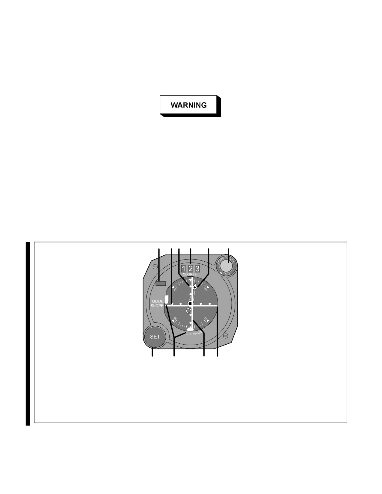
NAVAIR 00-80T-112
of maximum strength. VOR and TACAN navigation receivers electronically measure the magnetic course/bearing
for display by the bearing pointer; therefore, if there is a malfunction in the compass system or compass card, and
ADF bearing information is being displayed, the pointer will continue to point to the navigation aid but displays
relative bearing only. In the same compass failure situation, when either VOR or TACAN bearing information is
displayed, the bearing pointer will not point to the navigation aid; however, it may still indicate the proper magnetic
bearing to that station.
When a compass malfunction is known or suspected to exist, the VOR and
TACAN bearing displays must be considered unreliable until verified by
other equipment.
16.4
COURSE INDICATOR
The course indicator displays aircraft heading and position relative to a selected VOR/TACAN course. When used
in conjunction with an Instrument Landing System (ILS) localizer and glideslope, the course indicator displays lateral
(course) and vertical (glideslope) position relative to a desired instrument approach path (Figure 16-11). Aircraft
heading has no relation to the Course Deviation Indicator (CDI). When the CDI is centered, the aircraft is on the
selected course, either TO or FROM as indicated, regardless of aircraft heading.
1
2
3
4
5
6
O
F
F
OFF
10
9
8
7
1. TO-FROM INDICATOR
2. COURSE DEVIATION SCALE
3. GLIDESLOPE DEVIATION SCALE
4. COURSE SELECTOR WINDOW
5. HEADING POINTER
6. MARKER BEACON LIGHT
7. GLIDESLOPE INDICATOR
8. COURSE DEVIATION INDICATOR (CDI)
9. COURSE AND GLIDESLOPE WARNING FLAGS
10. COURSE SET KNOB
Figure 16-11. Course Indicator
ORIGINAL
16-10
NAVAIR 00-80T-112
16.4.1 VOR/TACAN Display
When the course indicator is used to display VOR or TACAN information, the desired course is set in the course
selector window with the course set knob. The heading pointer, connected to the course set knob and the compass
system, displays aircraft heading relative to the selected course. When the aircraft heading is the same as the course
selected, the heading pointer indicates 0° of heading deviation at the top of the course indicator. The heading deviation
scales at the top and bottom of the course indicator are scaled in 5° increments up to 45°.
Airborne and ground VOR checkpoints and VOR test procedures are listed in FLIP Planning Section II.
TACAN/DME checkpoints are normally established on the ground at most airfields. Should a position indication
error exist in excess of ±4° through use of a ground check or ±6° using an airborne check, the gauge should not be
considered as acceptable for IFR flight.
The TO-FROM indicator shows whether the course selected, if intercepted and flown, will lead the aircraft to or from
the selected navigation system. The CDI bar displays the position of the selected course relative to the actual path
of flight of the aircraft. Turning the aircraft until the heading pointer points toward the CDI will correct the aircraft
heading toward the selected course. The four dots on the course deviation scale are used in conjunction with the course
deviation indicator bar to signify a specific number of degrees right or left of the course. The exact calibration varies
between models of aircraft. A course OFF flag will appear at the top of the gauge whenever the course information
signal is too weak or unreliable to provide accurate course, or course deviation, information. Should the course
deviation information presented on the course indicator vary from that course information presented by the bearing
pointers on the RMI, BDHI, or HSI (whichever is in use), the bearing pointer should be considered to be more
accurate.
16.4.2 ILS Display
When the course indicator is used to display ILS signals, the course indicator provides precise ILS localizer course
and glideslope information for a specific approach. The following information pertains to course indicator functions
and display when used on an ILS approach:
1. The TO-FROM indicator is blank.
2. Full-scale deflection on the course indication scale represents approximately 2-1/2° of localizer course
deviation.
3. The course set knob and the course selected have no effect on CDI display. The CDI displays only whether the
aircraft is on course or right or left of course, based upon signal information from a specific selected localizer
transmitter; however, even though the course selected has no effect on the CDI, always set the published
inbound front course of the ILS in the course selector window. This enables you to interpret aircraft position
through use of the heading pointer in the same manner described for VOR/TACAN course and position
determination.
The Glideslope Indicator (GSI) displays glideslope position in relation to the actual position of the aircraft. For
example, if the GSI bar is above the center of the gauge, the glideslope is above the aircraft. Each of the four dots
in the vertical row represents approximately 1/4° of deviation from the glideslope.
Note
ILS course and glideslope displays are reliable only if their warning (OFF)
flags are not in view and the aural ILS identification is being received.
The marker beacon light(s) on the course indicator lights to indicate proximity to a 75-MHz marker beacon (e.g., ILS
outer or middle marker). As the aircraft flies through the marker beacon signal pattern, the light flashes in Morse code,
indicating the type of beacon being overflown. The marker beacon light is not used in conjunction with VOR or
TACAN.
16-11
ORIGINAL
NAVAIR 00-80T-112
16.5
FLIGHT DIRECTOR SYSTEM
Flight Director Systems (FDS) are essentially practical arrangements or groupings of various flight instruments such
as an attitude indicator (director), a position indicator, and a computer. The flight director computer receives position
information from the navigation systems and attitude information from the attitude gyro. Depending upon the modes
available and selected, the computer supplies pitch and/or bank commands to the pitch/bank steering bars of the
attitude indicator. The functions of the computer vary with the systems used and the number of inputs provided
(Navigation Aids [NAVAIDs], data link, Doppler) and may be processed electronically by the system. Refer to the
appropriate NATOPS flight manual for the specific capabilities of the system installed in your aircraft.
16.6
OTHER POSITION INSTRUMENTS
Modern naval aircraft are tending toward more sophisticated instruments for determining aircraft position. Some of
these systems include radar, inertial, and computerized visual displays. These systems are explained in appropriate
NATOPS flight manuals.
ORIGINAL
16-12
NAVAIR 00-80T-112
PART V
Attitude Instrument Flight
Chapter 17 — Attitude Instrument Flying
Chapter 18 — Instrument Flight Maneuvers
Chapter 19 — Instrument Patterns and Confidence Maneuvers
Chapter 20 — Unusual Attitudes
75/(76 blank)
ORIGINAL
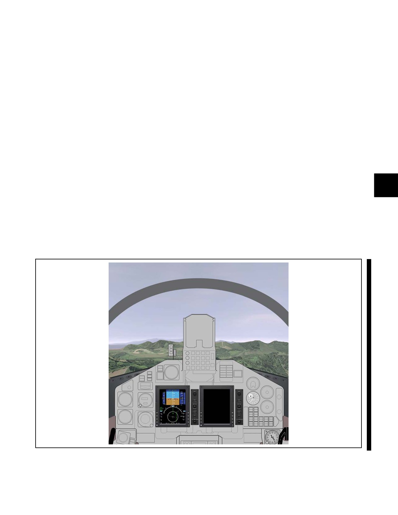
NAVAIR 00-80T-112
CHAPTER 17
Attitude Instrument Flying
17.1
GENERAL
Attitude instrument flying (Figure 17-1), like visual flying, uses reference points to determine the attitude of the
aircraft. When flying by visual reference to the Earth’s surface, the attitude of the aircraft is determined by observing
the relationship between the nose and wings of the aircraft and the natural horizon. When flying by reference to flight
instruments, the attitude of the aircraft is determined by observing indications on the instruments. These indications
give essentially the same information as obtained by visual reference to the Earth’s surface. The same control
techniques are employed during attitude instrument flying that are used in visual flying. The largest learning factor
in attitude instrument flying is correctly interpreting the indications of the various instruments to determine the
attitude of the aircraft.
17.2
AIRCRAFT CONTROL
Aircraft control consists of controlling the aircraft about its three axes (pitch, roll, and yaw) and maintaining the power
(thrust) at the desired level. Pitch is the movement of the aircraft about its lateral axis. Roll is the movement of the
aircraft about its longitudinal axis. Yaw is the movement of the aircraft about its vertical axis. Power control is the
adjustment of engine or accessory controls to alter thrust and, therefore, the thrust/drag relationship. When necessary,
the appropriate control is applied by reference to the power indicator(s) in the cockpit. Power is not generally affected
by such factors as turbulence, improper trim, or inadvertent aircraft control pressures (Figure 17-2).
Figure 17-1. Attitude Instrument Flying
17-1
ORIGINAL
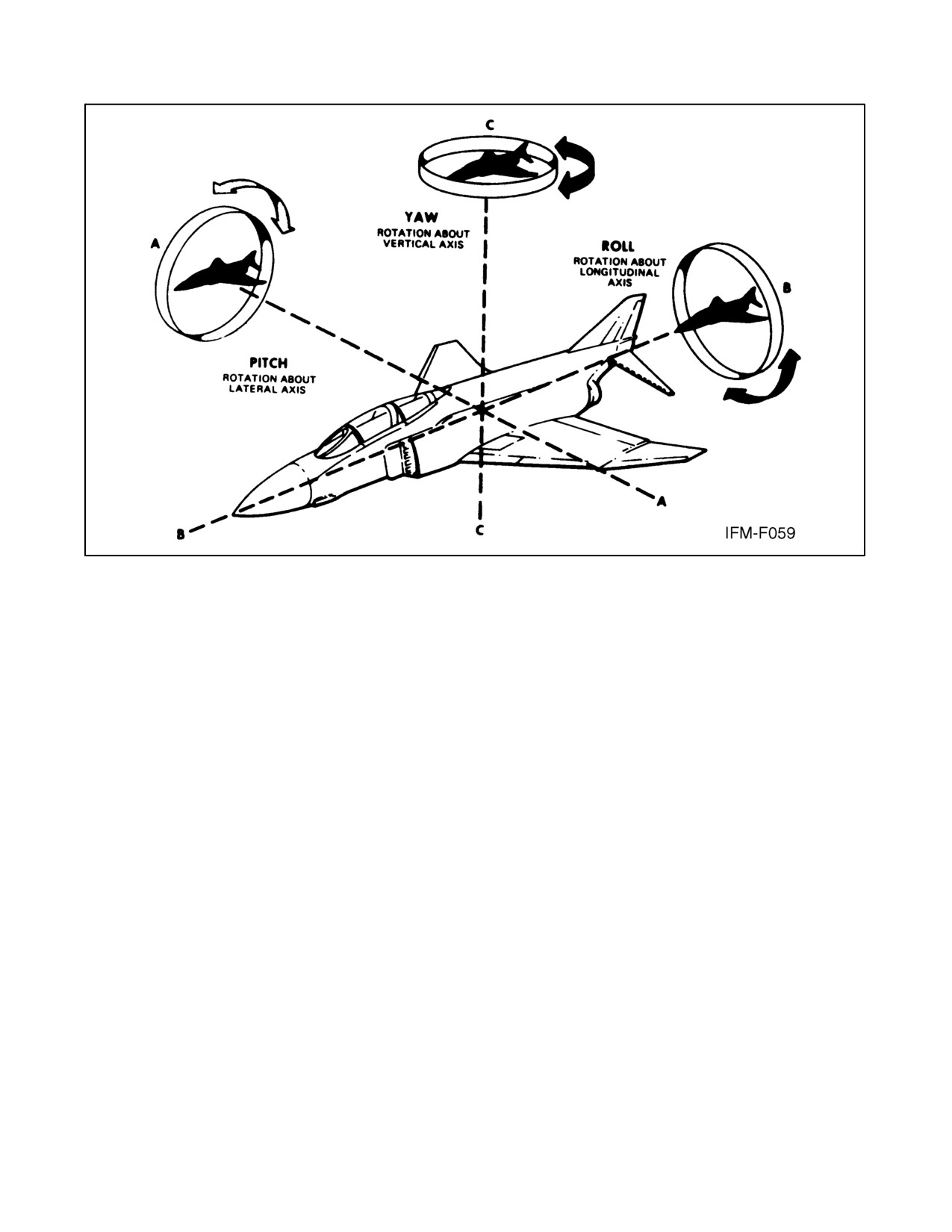
NAVAIR 00-80T-112
Figure 17-2. Control Axes of an Aircraft
After interpreting the pitch, bank, or yaw attitude from the applicable instruments, control pressures are exerted to
attain the desired attitude.
17.2.1 Attitude Control
Proper control of aircraft attitude is the result of maintaining a constant attitude, smoothly changing the attitude a
definite amount, and knowing when and how much to change the attitude. Aircraft attitude control is accomplished
by proper use of the attitude indicator. The attitude indicator provides an immediate, direct, and corresponding
indication of any change in aircraft pitch or bank attitude. In addition, by means of the attitude indicator, small pitch
or bank changes are easily seen and changes of any magnitude can readily be accomplished.
17.2.1.1 Pitch Control
Pitch changes are accomplished by changing the pitch attitude of the miniature aircraft or fuselage dot definite
amounts in relation to the horizon bar. The fuselage dot is generally referred to as the pipper, and pitch changes are
referred to as pipper widths, or fractions thereof, and/or degrees depending upon the type of attitude indicator
(Figure 17-3).
17.2.1.2 Bank Control
Bank changes are accomplished by changing the bank attitude or bank pointer(s) definite amounts in relation to the
bank scale. The bank scale is graduated at 0°, 10°, 20°, 30°, 60°, and 90°. This scale is located at the bottom of some
attitude director indicators (Figure 17-4).
17.2.1.3 Yaw Control
Yaw changes are made with the rudder pedals. Yaw control in conjunction with bank control is used to maintain the
aircraft in balanced flight (centered ball on the turn and slip indicator).
ORIGINAL
17-2
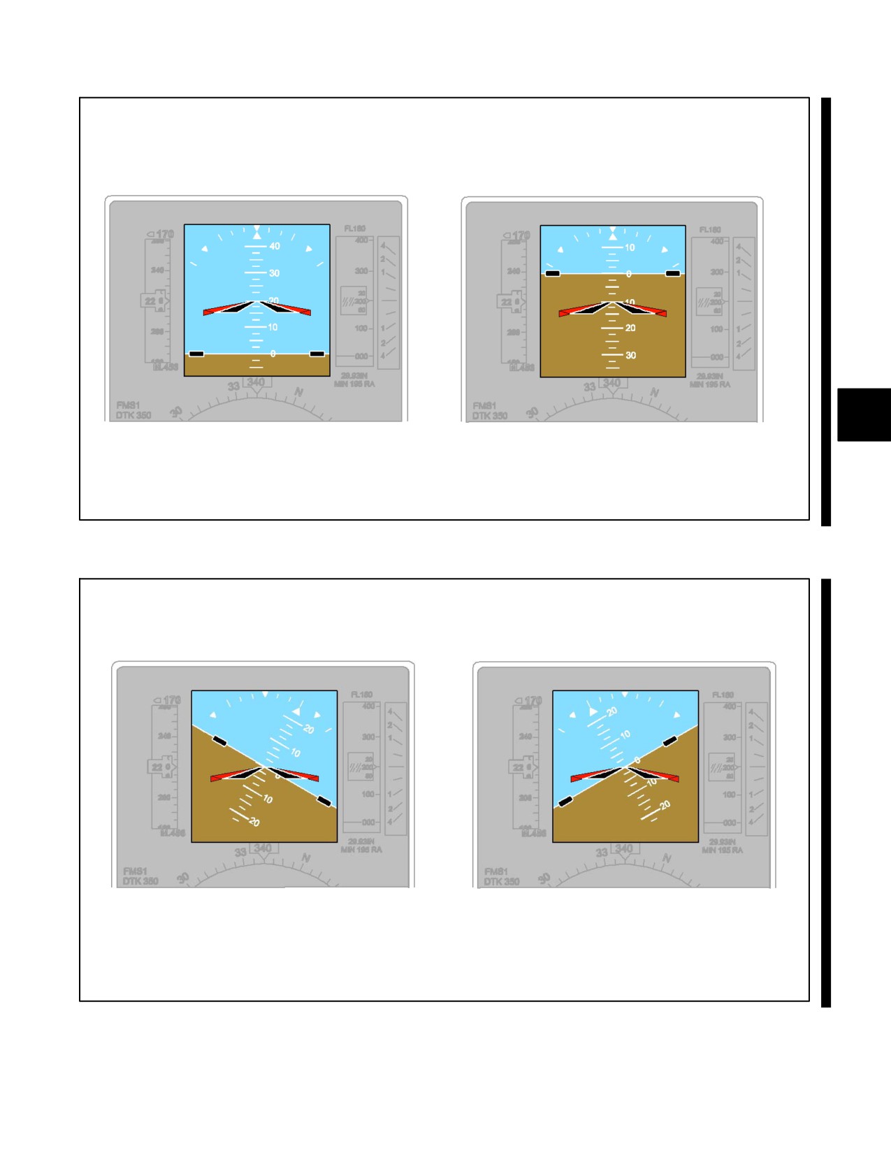
NAVAIR 00-80T-112
20° CLIMB
10° DIVE
Figure 17-3. Pitch Attitude Indications
30° LEFT BANK
30° RIGHT BANK
Figure 17-4. Bank Attitude Indications
17-3
ORIGINAL
NAVAIR 00-80T-112
17.3
INSTRUMENT GROUPINGS
17.3.1 Control Instruments
Power and attitude indicators are termed control instruments. A proper combination of pitch, roll, yaw, and power
control will achieve the desired aircraft performance (Figure 17-5).
17.3.2 Performance Instruments
The performance of the aircraft is determined by reference to the vertical speed indicator; heading indicator;
airspeed/Mach indicator; Angle of Attack (AOA) indicator; clock, turn, and slip indicator (needle and ball indicator);
and, in some cases, the altimeter. Although the altimeter is primarily a position instrument, in some maneuvers it can
be used as a cross-check on aircraft performance. These instruments are termed performance instruments and indicate
the aircraft performance, regardless of whether the pilot is referring to the Earth’s horizon, the attitude indicator, or
both, to control the aircraft attitude (Figure 17-5).
17.3.3 Position Instruments
The aircraft position is determined by a third group of instruments termed position instruments. These instruments
include various types of course indicators, range indicators, glideslope indicators, and altimeter and bearing pointers.
By knowing the aircraft position, the pilot can determine what control changes are required to achieve desired aircraft
performance (Figure 17-5).
17.3.4 Instrument Scan
During instrument flight, the pilot’s attention must be divided between the control, performance, and position
instruments. Proper division of attention and the sequence of checking the instruments (scan) varies among pilots and
throughout various phases of flight. There is no one set order for scanning the instruments, as it depends on the type
of maneuver to be executed as to which instruments are of prime importance; however, the pilot should become
familiar with the factors to be considered in dividing attention between instruments properly. The pilot should also
know the symptoms that enable recognition of correct and incorrect scan technique. These factors and symptoms are
discussed in the following paragraphs.
As an example of how improper scanning occurs, consider the case of a pilot attempting to reduce the airspeed and
hold straight-and-level flight. As the power is reduced, the pilot observes the engine performance gauge so closely,
in order to make the proper adjustments, that the pilot neglects to observe the additional instruments that would
indicate a deviation from straight-and-level flight. This failure to maintain a systematic and effective instrument scan
is one of the major causes of poorly executed flight maneuvers.
17.3.5 Functions of Instruments — Full Panel Scan
The combination of a particular power setting and aircraft attitude will deliver a specific performance. In simple
terms:
Power + Attitude = Performance.
A thorough understanding of this principle is essential to building an efficient scan pattern. Although the Vertical
Speed Indicator (VSI), altimeter, heading indicator, airspeed indicator, and turn needle ball are referred to as the
position or performance instruments, depending on aircraft maneuver, it should be understood that the specific
function of these instruments in a full panel scan depends on the maneuver being completed.
ORIGINAL
17-4
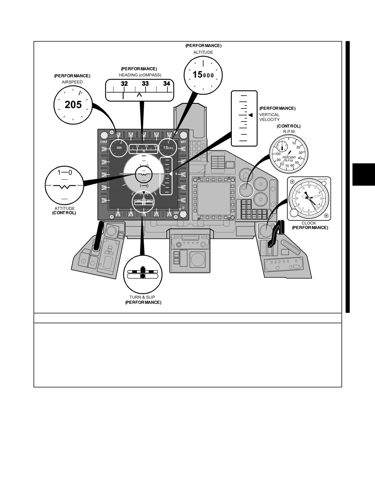
NAVAIR 00-80T-112
CONTROL AND PERFORMANCE CONCEPT
Procedural Steps:
1. Establish an attitude and/or power setting on the control instrument(s) which should result in the desired
performance.
2. Trim until control pressures are neutralized.
3. Crosscheck the performance instruments to determine if the established attitude and/or power setting are
providing the desired performance.
4. Adjust the attitude and power setting on the control instruments if a correction is necessary.
Figure 17-5. Position, Control, and Performance Instrument Groupings
17-5
ORIGINAL
NAVAIR 00-80T-112
For every full panel maneuver, the attitude gyro is the primary reference instrument for both nose and wing attitude;
however, the instruments comprising the performance group are used to verify the desired attitude and performance
of an aircraft and to detect any deviation from them. Thus, the performance instruments also function as attitude
cross-checks; for example, in straight-and-level flight, the altimeter and VSI function as nose attitude cross-checks,
and the heading indicator serves as the wing attitude cross-check (i.e., the altimeter and VSI are checked to verify
a constant altitude, and the heading indicator is checked to verify constant heading). The airspeed indicator is the only
one of the so-called performance instruments that is actually being scanned for performance (desired airspeed) during
straight-and-level flight (Figure 17-6).
Nose Attitude
Wing Attitude
Basic Attitude
Cross Check
Cross Check
Performance
Supporting
Maneuver
Instrument
Instruments
Instruments
Instruments
Instruments
Straight and level
Attitude gyro
Altimeter, VSI
Heading indicator,
Airspeed
Power,
Needle ball
indicator
Angle of attack
Constant airspeed
Attitude gyro
Airspeed
Heading indicator,
Altimeter
Power,
climbs and descents
indicator
Needle ball
Angle of attack
Constant rate
Attitude gyro
Airspeed
Heading indicator,
Altimeter,
Power,
climbs and descents
indicator
Needle ball
Clock, VSI
Angle of attack
Constant angle of
Attitude gyro
Altimeter, VSI
Heading
Needle Ball,
bank turns (level)
indicator,
Power
Airspeed
indicator
Constant rate turns
Attitude gyro
Altimeter, VSI
Needle ball
Heading
Power
(level)
indicator,
Airspeed
indicator
Climbing or
Attitude gyro
Airspeed
Needle ball
Heading
Power,
descending turns at a
indicator
indicator, Clock,
Angle of attack
constant rate
VSI, Altimeter
Hovering
Attitude gyro
Hover indicator
Hover indicator,
Radar altimeter,
Power
Needle ball
Heading
indicator;
See Note
Note
The inherent lag and relatively large scaling of pressure-sensitive instruments precludes their use as
performance instruments while hovering in close proximity to the surface.
Figure 17-6. Function of Instruments (Full Panel)
17.3.6 Scan Technique
A major factor influencing scan technique is the characteristic manner in which instruments respond to attitude and
power changes. The control instruments provide a direct and immediate indication of attitude and power changes,
but indications on the performance instruments lag and must be accepted as an inherent factor. Lag will not
appreciably affect the tolerances within which the pilot controls the aircraft; however, at times, a slight, unavoidable
delay in knowing the results of attitude and/or power changes will occur.
When the attitude and power are smoothly controlled, the lag factor is negligible and the indications on the
performance instruments will stabilize or change smoothly. Do not make abrupt control movements in response to
the lagging indications on the performance instruments without first checking the control instruments. Failure to do
so leads to erratic aircraft maneuvers, which will cause additional fluctuations and lag in the performance instruments.
Frequent scanning of the control instruments assists in maintaining smooth aircraft control.
ORIGINAL
17-6
NAVAIR 00-80T-112
The attitude indicator is the instrument that should be used to develop all maneuvering attitudes and should be scanned
most frequently. This is shown by the following description of a normal scan: A pilot glances from the attitude
indicator to a performance instrument; back to the attitude indicator; then a glance at another performance instrument;
back to the attitude indicator; and so on.
It is often necessary to compare the indications of one performance instrument against another before knowing when
or how much to change the attitude or power. An effective scan technique may require that the attitude indicator be
scanned between glances at the performance instruments being compared (Figure 17-7).
17.3.7 Scan Analysis
An incorrect scan technique may be recognized by analyzing certain symptoms. If the correct attitude and power
indications are not established and maintained, and other instrument indications fluctuate erratically, the pilot is
probably fixating on a single instrument or not scanning the control instruments often enough. This is usually
accompanied by lack of precise aircraft control.
Too much attention being devoted to the control instruments, although rarely encountered, is normally caused by a
pilot’s desire to maintain performance indications within close tolerances. If the pilot has a smooth, positive, and
continuous control over the indications of the control instruments, but large deviations are observed to occur on the
performance instruments, a more frequent scan of the performance instruments is required.
An incorrect scan can result in the omission of, or insufficient reference to, one or more instruments during the
scanning process. For example, during a climb or descent, a pilot may become so engrossed with pitch attitude control
that he/she fails to observe an error in the aircraft heading. A 4° heading change is not as eye-catching as a 300- to
400-fpm change on the vertical speed indicator.
Through deliberate effort and proper habit, the pilot must ensure all the instruments are included in his/her scan.
Continuous analysis of a pilot’s scan technique will assist in early recognition and correction of errors or omissions
and will result in improved aircraft control.
17.3.8 Use of Angle of Attack
Angle of attack information is most valuable during an instrument approach. In the event of airspeed indicator failure,
angle of attack information can be used throughout a flight if equivalent values are known. As with the other flight
instruments, the angle of attack indicator and components should be checked for proper alignment and calibration
and freedom of movement prior to takeoff.
During takeoff, the airspeed indicator may be used to determine acceleration speed, takeoff speed, minimum control
speed, etc.; however, the angle of attack indicator should be used in conjunction with the attitude indicator to establish
the proper angle of attack for takeoff. Angle of attack information may also be used to varying degrees to establish
best climb angles, maximum endurance, long-range cruise, glides, and other flight maneuvers. The final approach
airspeed given in the NATOPS flight manual is based on a given constant angle of attack. Because the angle of attack
during the approach phase of flight remains the same regardless of weight, it is a more direct indication of best final
approach speed than indicated or Calibrated Airspeed (CAS).
During an approach, the landing configuration and approach angle of attack should be established prior to
commencing the final approach descent. To establish the approach angle of attack, reduce airspeed and maintain
altitude until the desired indications are established on the angle of attack indicator/indexer. The resulting airspeed
will be the best final approach for that weight; thus, the airspeed and angle of attack indicators may be used to
supplement one another.
Control of angle of attack and rate of descent require coordinated power and pitch changes. If the aircraft is above
the glideslope with the desired angle of attack, the pilot should decrease power to increase rate of descent and adjust
the nose to maintain the desired angle of attack, the pilot should increase power to decrease the rate of descent and
adjust the nose to maintain the desired angle of attack.
17-7
ORIGINAL
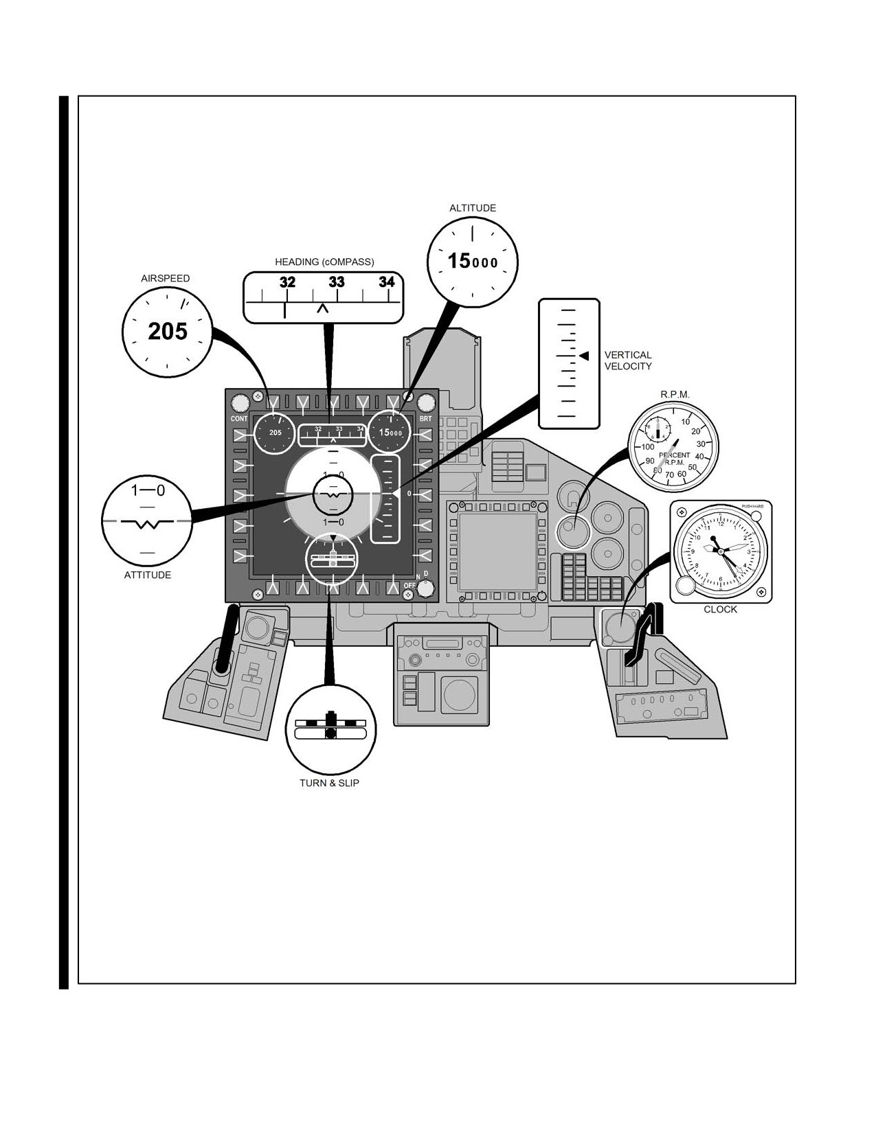
NAVAIR 00-80T-112
Primary instrument scan should focus on the attitude indicator, with periodic
scans to airspeed, heading, altitude, VVI, turn & slip, and engine indications.
Figure 17-7. Instrument Scan Technique
ORIGINAL
17-8
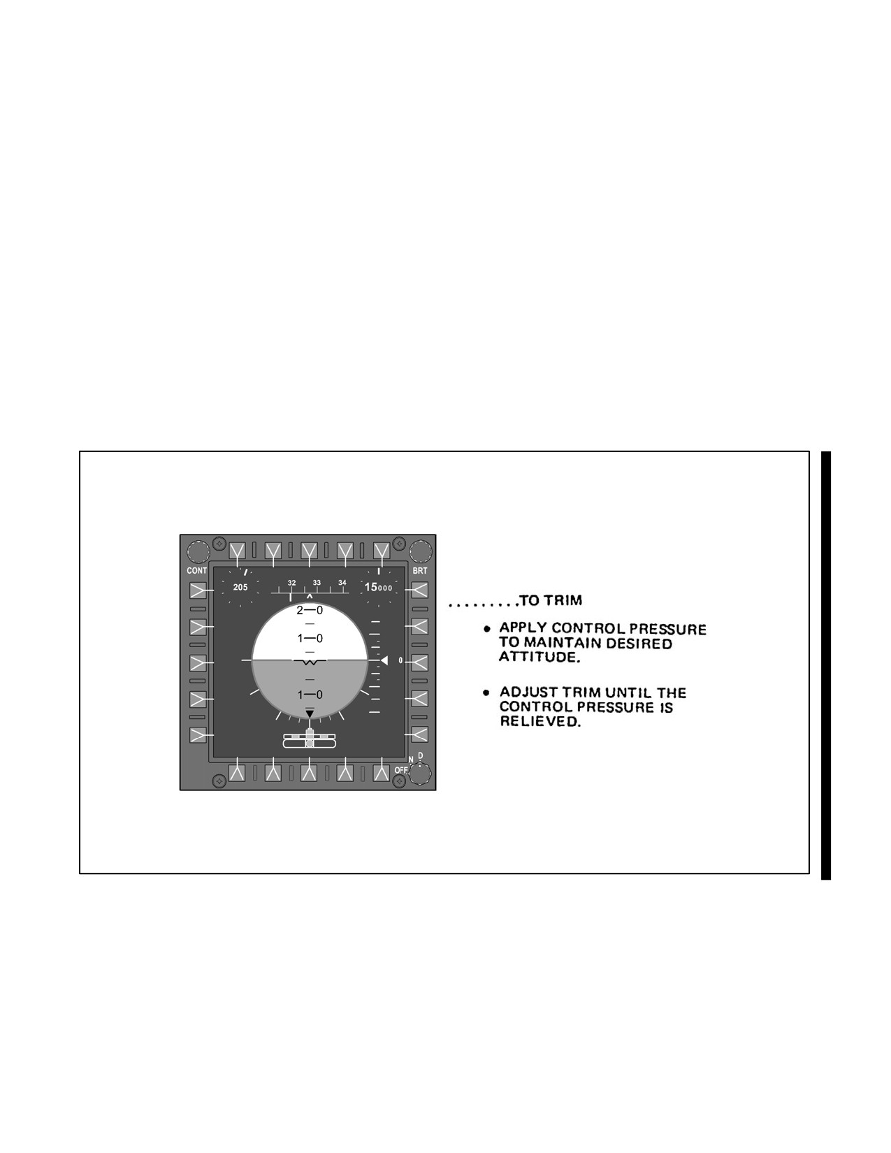
NAVAIR 00-80T-112
17.4
AIRCRAFT TRIM
The aircraft is correctly trimmed when it is maintaining a desired attitude with all control pressures neutralized. By
relieving all control pressures, the pilot will find that it is much easier to hold a given attitude. Also, more attention
can be devoted to the navigation instruments and additional cockpit duties. Proper trim technique is essential for
smooth and precise aircraft control during all phases of flight.
An aircraft is placed in trim by applying control pressure(s) to establish a desired attitude and then adjusting the trim
so that the aircraft will maintain that attitude when the flight controls are released. The aircraft should be trimmed
for coordinated flight by first centering the ball on the turn and slip indicator, followed by trim corrections to the
elevator and aileron controls. On multiengine aircraft, where differential power control is possible, balanced
power/thrust will aid in maintaining coordinated flight. Changes in attitude, power, or configuration may require a
trim adjustment. Use of trim to change the aircraft attitude will probably lead to erratic aircraft control. Smooth and
precise attitude changes are best attained by a combination of control pressures and trim adjustments (Figure 17-8).
Note
The preceding concepts of attitude instrument flying apply to helicopters
authorized for instrument flight; however, power changes are normally
made with collective pitch, and attitude changes with cyclic stick.
Figure 17-8. Trim Technique
17-9
ORIGINAL
NAVAIR 00-80T-112
17.5
INSTRUMENT HOVERING
Many Search and Rescue (SAR) and Antisubmarine Warfare (ASW) helicopters are equipped with Doppler radar
hover instruments (as described in paragraph 15.6), which allows the pilots to accomplish a hover without visual
reference to the surface. As with all instrument flight, this is a full panel maneuver and must include a scan of all flight
instruments. The primary scan instrument should be the attitude gyro, while the hover indicator should be used as
the nose and wing attitude cross-checks.
The demanding nature of this maneuver, particularly in an uncoupled environment, requires a very rapid scan. Every
effort should be made to determine a stable hover reference position on the attitude gyro and all hover corrections
should be made back to this position. The hover indicator is commonly mistaken for the primary scan instrument,
but because of the inherent lag of this indicating system, it is better used as a cross-check instrument. For specific
flight procedures, consult the applicable aircraft NATOPS manuals.
ORIGINAL
17-10
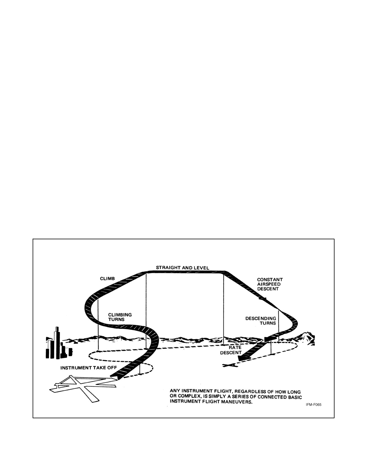
NAVAIR 00-80T-112
CHAPTER 18
Instrument Flight Maneuvers
18.1
APPLICATION
The maneuvers described in this chapter are those most commonly used during instrument flight. Additional
maneuvers or some modification of these maneuvers may be required for specific unit training requirements. The
degree of proficiency attained in accomplishing these maneuvers will assist the pilot in adapting to actual instrument
flight.
An instrument flight, regardless of its length or complexity, is a series of connected basic instrument flight maneuvers
(Figure 18-1). Failure to consider each portion of the flight as a basic instrument maneuver often leads to erratic
aircraft control.
18.1.1 Planning
The information received from the navigational instruments or an air traffic controller should be considered as
advising the pilot what maneuver to perform, when to perform it, or what adjustments, if any, are required. Terminal
approach charts and similar publications should be considered as pictorial presentations of a series of connected
instrument flight maneuvers. Keeping these considerations in mind and calling upon previous practice, the pilot will
find that he/she is always performing a familiar maneuver. By visualizing the next maneuver, the pilot can plan ahead
and know exactly what cross-check and aircraft control techniques to employ at the time of entry into the maneuver.
Figure 18-1. Typical Instrument Flight
18-1
ORIGINAL
NAVAIR 00-80T-112
18.2
INSTRUMENT TAKEOFF (ITO)
18.2.1 Pretakeoff Procedures
The ITO procedures and techniques are an invaluable aid during takeoffs at night, toward and over water or deserted
areas, and during periods of reduced visibility. These takeoffs are accomplished by combined use of outside visual
reference and the flight instruments. The amount of attention given to each ITO varies with the individual, the type
of aircraft, and existing weather. As the ITO is a composite visual/instrument takeoff, it should not be confused nor
used interchangeably with hooded takeoffs.
Prior to commencing an instrument flight, the pilot shall check the flight and navigation instruments and the required
publications. This check will be made in accordance with the NATOPS flight manual and must include all control,
performance, and position instruments. Many airdromes display navigational data on a sign near the end of the runway
for checking the navigational equipment and altimeter. After this pretakeoff check is complete, select the navigational
aids to be used for the departure and set the navigational instruments and switches as required.
The air traffic control clearance and departure procedures must be thoroughly understood prior to takeoff. The
appropriate instrument approach charts shall be readily available in the event that an instrument approach becomes
necessary immediately after takeoff.
18.2.1.1 ITO Procedures (Fixed Wing)
The ITO for specific aircraft is discussed in the applicable NATOPS flight manual. Use pitot heat and other anti-ice
equipment as appropriate. When cleared, align the aircraft with the runway centerline and complete any remaining
checklists. Pay special attention to the heading and attitude indicators for any errors induced by turning while taxiing.
When directed, select the assigned departure frequency and monitor Guard frequency during takeoff.
When cleared for takeoff, release the brakes simultaneously to minimize initial directional control difficulties.
Directional control immediately following brake release should be accomplished predominantly by outside visual
references (Figure 18-2). As the takeoff progresses, the pilot’s scan should transition from outside references to the
heading, airspeed, angle of attack, and attitude indicators. The rate of transition is directly proportional to the rate at
which the outside reference deteriorates. It is essential that the pilot establish his/her instrument scan prior to losing
all visual reference.
The takeoff attitude will normally be established on the attitude indicator at rotation or just prior to reaching takeoff
airspeeds. Pilots should know the takeoff attitude indicator picture required for their aircraft. The takeoff attitude
should be maintained as the aircraft leaves the ground. If available, the angle of attack indicator should be used to
cross-check the attitude indicator for optimum takeoff performance. Check the vertical speed indicator and altimeter
for positive climb indications and comply with the applicable NATOPS flight manual for specific aircraft before
retracting the gear and wing flaps. While the gear and flaps are being retracted, maintain or adjust the pitch attitude
as necessary to ensure the desired climb.
Note
Some attitude indicators are susceptible to precession errors due to aircraft
acceleration. This phenomenon causes the horizon bar to lower slightly and
appears as an increased pitch attitude. To avoid lowering the nose
prematurely, the pilot must cross-check the vertical speed, angle of attack
indicator, and altimeter throughout this phase of flight to ensure proper
climb performance.
After the gear and flaps are retracted, the pitch attitude should be controlled to provide an increase in airspeed while
climbing until the normal climb schedule is reached.
ORIGINAL
18-2
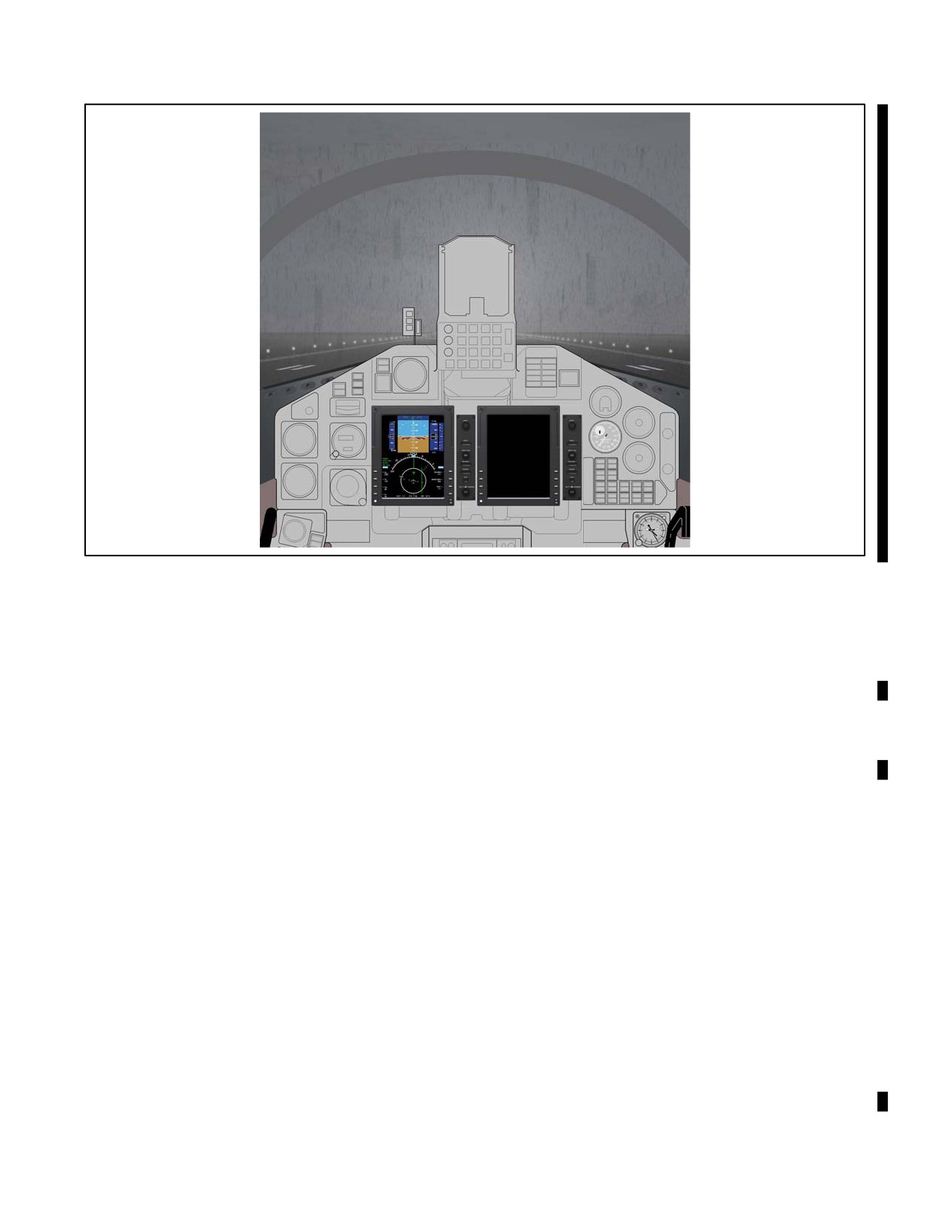
NAVAIR 00-80T-112
Figure 18-2. Instrument Takeoff
18.2.1.2 Rotary Wing ITO
If visibility will permit, establish a normal hover to perform the safety checks of flight controls, engines, and
automatic stabilization equipment. When a normal hover is not possible, the helicopter may be flown off the deck
and into a normal climb without any outside reference. In the event of full instrument takeoff when outside visual
reference cannot be maintained at hover altitudes, use the hover indicator, when available, to determine a positive
rate of climb, indicate sideward drift, and indicate fore and aft groundspeed prior to reliable airspeed indications.
Heading control may be maintained with the yaw stabilization channel of the automatic stabilization equipment.
Steadily increase collective as the helicopter lifts off. Maintain level attitude on the attitude indicator.
Note
To maintain a stable hover with no sideward drift, it may be necessary in
some helicopters to hover with a slight wing-down attitude.
As altitude increases through approximately 15 feet, use the radar altimeter and lower the nose to approximately 5°
below hover attitude. (See applicable NATOPS flight manuals for variations.) Simultaneously increase the collective
to the best climb setting and adjust the nose attitude to accelerate to the recommended climbing airspeed.
Note
When passing through translational lift, the nose attitude may require
readjustment to maintain the attitude desired.
18.2.1.3 Night (Instrument) Catapult Launch
The night (instrument) launch from a carrier deck differs considerably from an ITO in that it is a demanding maneuver
performed entirely on instruments. Prior to taxiing from a deck spot to the catapult, it is absolutely essential that all
aircraft systems communication and navigation equipment be checked for proper operation and set on the desired
18-3
ORIGINAL
NAVAIR 00-80T-112
frequency. At night, the exterior lights should be set up in accordance with the CV NATOPS manual. The aircraft
should also be configured (flaps set) for catapult launch in accordance with the applicable NATOPS flight manual
for the launch gross weight and Wind-Over-Deck (WOD).
En route to the catapult, performance and position instruments should be checked for proper operation (turn needle,
Horizontal Situation Indicator [HSI], wet compass, Tactical Air Navigation [TACAN]). While being spotted on the
catapult, pilot attention must necessarily be outside the cockpit; however, once the signal to “TAKE TENSION” is
given, the pilot is from that time on instruments. The desired departure course should be checked and set in, the
Bearing-Distance-Heading Indicator (BDHI) heading cross-checked with the Base Recovery Course (BRC), and the
attitude instrument(s) should be checked for proper operation and alignment. When satisfied that you and the aircraft
are ready for launch, the appropriate signal is given.
The primary instrument during the catapult stroke is the attitude gyro. At the end of the catapult stroke, the desired
climb attitude is established on the attitude indicator and then cross-checked with the vertical speed indicator and
altimeter for a positive climb indication while maintaining launch heading. Once comfortably established in a climb,
the gear can be raised and an airborne radio transmission can be made. After accelerating to the airspeed/altitude
prescribed for the type aircraft, a transition to a clean/cruise configuration can be effected. During the transition from
launch to cruise configuration, the angle of attack should be checked to ensure optimum attitude performance is being
maintained. Normal Case II or III departure procedures should be complied with during climb to en route operating
altitude.
The standby attitude gyro should be illuminated with a flashlight during
catapult launch. Failure to do so could result in the loss of attitude
information in the event of a generator failure and cause subsequent loss of
the aircraft.
Radio frequency changes should not be attempted until above 2,500 feet unless level flight for an extended period
of time is planned.
18.2.1.4 Rotary Wing Night (Instrument) Shipboard Takeoffs
During night shipboard operations, instrument takeoffs should be utilized any time weather is less than 1,000 feet
ceiling and 3 miles visibility or there is no visible horizon. When flight deck conditions permit, takeoffs should be
made utilizing available flight deck during transition to forward flight. Both pilots must closely monitor initial rate
of climb utilizing both radar altimeter and Vertical Speed Indicator (VSI). Descent or lack of climb during takeoff
requires immediate corrective action. Heading, radio frequency, and control changes should not be initiated prior to
200 feet.
18.3
STRAIGHT-AND-LEVEL FLIGHT
Straight-and-level unaccelerated flight consists of maintaining a constant altitude, heading, and airspeed. Bank is
used with yaw to maintain balanced flight and to maintain or adjust the heading. Pitch and power control should not
be considered independently because coordinated control of both is necessary to maintain or adjust altitude or
airspeed.
18.3.1 Maintaining a Desired Altitude
Maintaining a desired altitude requires the ability to maintain a specific pitch attitude and, when necessary, to
smoothly and precisely adjust this attitude. This ability is developed through proper use of the attitude indicator and
is simplified by good trim techniques. The pilot must recognize and understand the application of these requirements.
The pilot should also be thoroughly familiar with the procedures in attitude instrument flying.
ORIGINAL
18-4
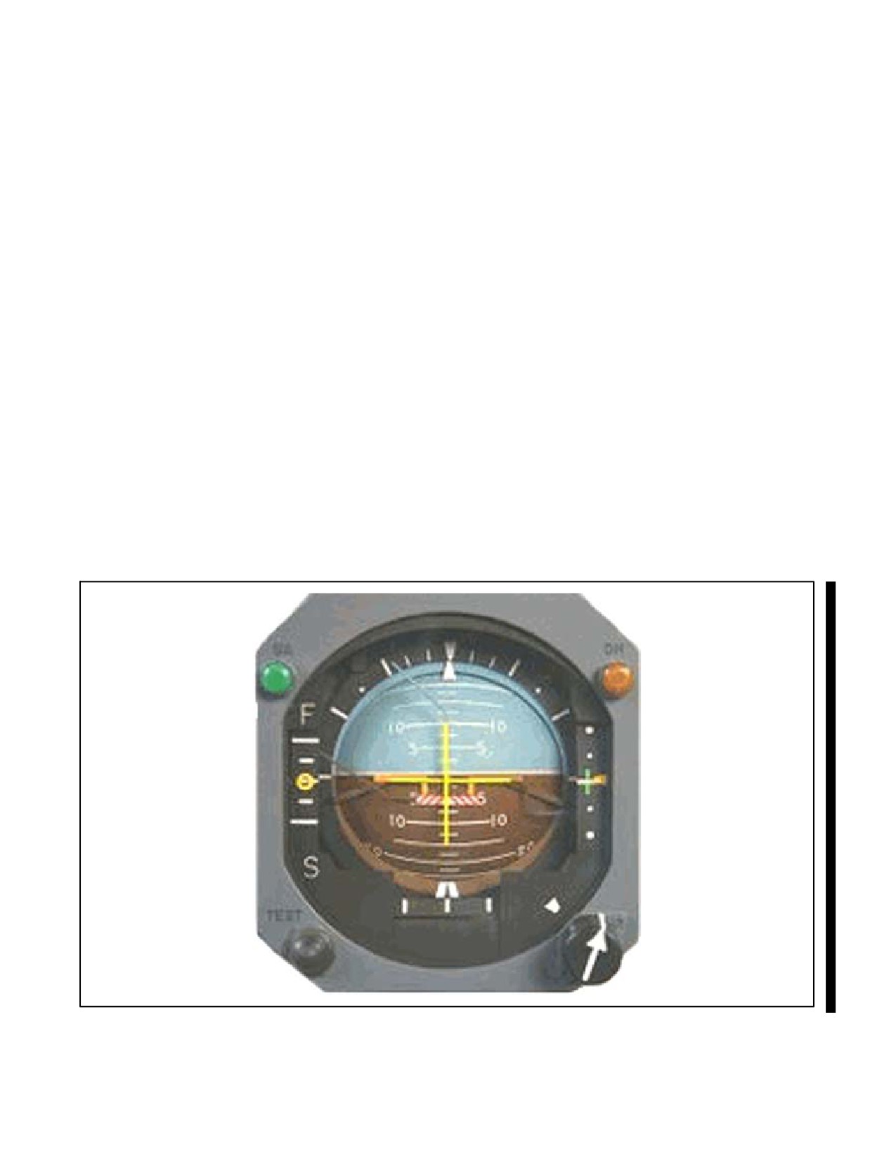
NAVAIR 00-80T-112
After leveling off at cruise airspeed, adjust the pitch trim knob on the attitude indicator so that the miniature aircraft
is aligned with the horizon bar. This will aid in observing small pitch changes. Subsequent readjustments may be
required because of changes in aircraft gross weight and cruise airspeeds (Figure 18-3).
The first indication of altitude deviation normally appears on the vertical speed indicator. By observing the initial rate
of movement, the pilot may estimate the amount of pitch change required on the attitude indicator and prevent large
altitude deviations. If the estimated pitch change was correct, the vertical speed will return to zero with a negligible
change of indicated altitude on the altimeter.
The small pitch corrections required to maintain a desired altitude are made in fractions of pippers or in degrees. The
pilot should become familiar with the vertical speed changes that result when specific pitch adjustments are made
at various airspeeds and configurations; thus, the pilot can determine what nose attitude adjustment is required to
produce the desired rate of correction when an altitude deviation is observed.
When the pilot makes these pitch adjustments, the altimeter and vertical speed indications will lag behind changes
of pitch attitude on the attitude indicator. This lag should be recognized and accepted as an inherent error in the
differential pressure instruments. The error is even more pronounced at supersonic airspeeds. Because of this error,
the pilot must maintain the adjusted pitch attitude on the attitude indicator while waiting for changes on the altimeter
and vertical speed to occur. The pilot must not make a snap decision that the adjusted pitch change is ineffective and
be lured into overcontrolling the nose attitude.
With experience, the pilot can usually estimate the suitability of a pitch adjustment by noting the initial rate of
movement of the vertical speed indicator. For example, assume a pitch adjustment has been made that is expected
to result in a 200- to 300-feet-per-minute rate of climb. If the initial rate of movement on the vertical speed indicator
is rapid and obviously will stabilize at a rate greater than desired, the pitch change was too large. Readjust the pitch
attitude rather than wait for a stabilized indication on the vertical speed indicator.
Figure 18-3. Adjusting the Attitude Indicator
18-5
ORIGINAL
NAVAIR 00-80T-112
When a deviation from the desired altitude occurs, exercise good judgment in determining a rate of correction. The
correction must not be too large and cause the aircraft to overshoot the desired altitude, nor should it be so small that
it is unnecessarily prolonged. As a guide, the pitch attitude change on the attitude indicator should produce a rate of
vertical speed approximately twice the size of the altitude deviation. Usually pitch changes are made in fractions (1/4,
1/2,
3/4, etc.) of pippers or degrees. For example, if the aircraft is
100 feet off the desired altitude, a
200-feet-per-minute rate of correction would be a suitable amount. By knowing the present rate of climb or descent
and the results to be expected from a pitch change, the pilot can closely estimate how much to change the pitch attitude.
Initially, this pitch change is an estimated amount; therefore, the adjusted pitch attitude must be held constant until
the rate of correction is observed on the vertical speed indicator. If it differs from that desired, further adjustment of
the nose attitude is required (Figure 18-4).
When approaching the desired altitude, determine a lead point on the altimeter for initiating a level-off pitch attitude
change. A suitable lead point prevents overshooting and permits a smooth transition to level flight. The amount of
lead required varies with pilot technique and rate of correction. As a guide, the lead point on the altimeter should be
approximately 10 percent of the vertical speed. For example, if the rate of correction to the desired altitude is 300 feet
per minute, initiate the level-off approximately 30 feet before reaching the desired altitude (Figure 18-5).
Devoting too much attention to the vertical speed indicator can lead to “chasing” its indications and result in erratic
nose attitude control; although the vertical speed indicator is an important performance instrument, limitation such
as oscillation in rough air, lag, etc. should be thoroughly understood to prevent overcontrolling the pitch attitude. For
this reason, the pilot must recognize and understand that sufficient reference to the attitude indicator is necessary to
ensure smooth and precise pitch adjustments for effective altitude control.
18.3.1.1 Maintaining a Desired Heading
Maintaining a desired heading is accomplished by maintaining a wings-level attitude in balanced flight. By observing
the heading indicator, the pilot determines if the desired heading is being maintained. Heading deviations are not
normally as eye-catching as altitude deviations; therefore, be aware of this characteristic and develop a habit of
cross-checking the heading indicator frequently to prevent significant heading deviations.
When a deviation from the desired heading occurs, refer to the attitude indicator and smoothly establish a definite
angle of bank that will produce a suitable rate of return. As a guide, the angle-of-bank change on the attitude indicator
should equal the heading deviation in degrees. For example, if the heading deviation is 10°, then 10° of bank on the
attitude indicator would produce a suitable rate of correction (Figure 18-6). This guide is particularly helpful during
instrument approaches at relatively slow airspeeds. At higher true airspeeds, a larger angle of bank may be required
to prevent a prolonged correction. Proper pitch and bank attitude control requires the pilot to recognize the effects
of gyroscopic precession on attitude indicators. This precession is most noticeable following a turn or change of
airspeed. As a result, small altitude and heading deviations may occur when a wings-level attitude is established on
the attitude indicator following these maneuvers; therefore, the pilot may have to establish temporarily a pitch or bank
attitude other than that ordinarily expected. For example, to maintain straight-and-level flight on the performance
instruments after completing a normal turn, the attitude indicator may depict a slight turn, climb or descent, or a
combination of both. The attitude indicator will gradually resume its normal indications as the erection mechanism
automatically corrects these errors. When these errors occur, apply the basic cross-check procedure (Figure 18-7).
18.3.1.2 Establishing and Maintaining Airspeed
Establishing or maintaining an airspeed is accomplished by referring to the airspeed and/or Mach indicator and
adjusting the power and/or aircraft attitude. A knowledge of the approximate power required to establish a desired
airspeed will aid in making power adjustments. After the approximate power setting is established, a cross-check of
the airspeed indicator will indicate if subsequent power adjustments are required. The pilot should make it a point
to learn and remember the approximate power settings and attitudes for the aircraft at various airspeeds and
configurations used throughout a normal mission.
ORIGINAL
18-6
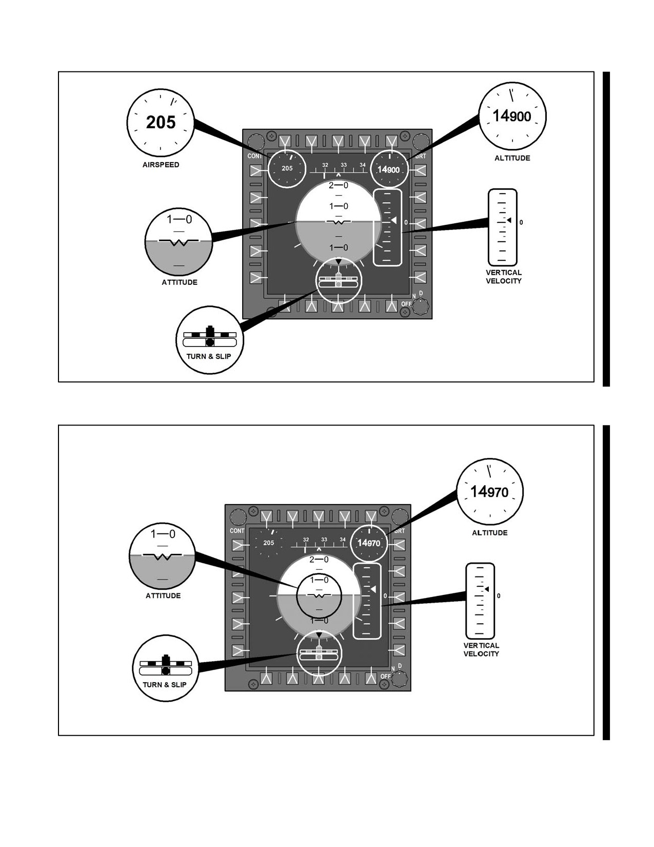
NAVAIR 00-80T-112
YOU SEE THAT THE AIRCRAFT IS
100 FEET BELOW THE DESIRED
ALTITUDE AND DECIDE THAT YOU
SHOULD CLIMB BACK AT 200 FPM.
WITH PRACTICE YOU
YOU NOTE THAT YOU
CAN CLOSELY ESTIMATE
ARE DESCENDING AT
THE AMOUNT OF PITCH
300 FPM.
CHANGE REQUIRED TO
RETURN TO THE
DESIRED ALTITUDE.
Figure 18-4. Correcting to the Desired Altitude
LEAD THE
ALTITUDE
30 FEET.
Figure 18-5. Leading the Level-Off
18-7
ORIGINAL
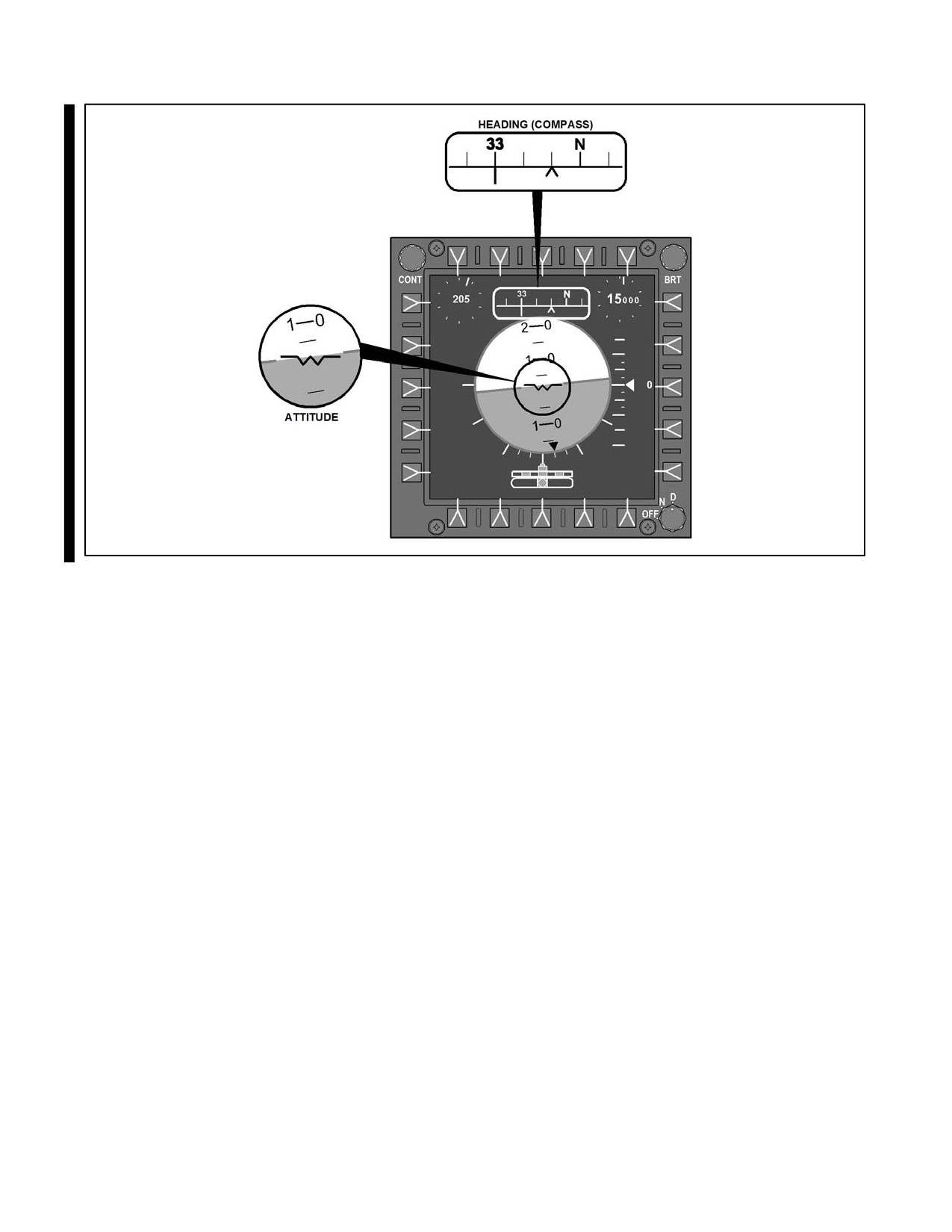
NAVAIR 00-80T-112
Figure 18-6. For Turns 30° or Less, Limit the Angle of Bank to the Number of Degrees to be Turned
When an airspeed deviation is observed, a power or pitch adjustment, or a combination of both, may be required to
correct back to the desired airspeed; however, check the altimeter and vertical speed before making a power
adjustment. If below the desired altitude with a higher-than-desired airspeed, a small pitch adjustment may regain
both the desired airspeed and altitude. Conversely, when maintaining the desired airspeed, a pitch adjustment will
induce the need for a power adjustment.
Changes of airspeed in straight-and-level flight are accomplished by adjusting the power and/or drag devices. To
increase the airspeed, advance the power beyond the setting required to maintain the new desired airspeed. As the
airspeed increases, the aircraft gains lift and will have a tendency to climb. Adjust the nose attitude as required to
maintain altitude. When the airspeed approaches the desired indication, reduce the power to an estimated setting that
will maintain the new airspeed. To reduce the airspeed, reduce the power below the setting estimated for maintaining
the new desired airspeed. As the airspeed decreases, the aircraft loses lift and will have a tendency to descend. Adjust
the nose attitude as required to maintain altitude. When the airspeed approaches the desired indication, advance the
power to an estimated setting that will maintain the new airspeed (Figure 18-8). If available, drag devices may be used
for relatively large or rapid airspeed reductions. If used, it is normally best to reduce the power to the estimated setting
that will maintain altitude at the new airspeed and then extend the drag device(s). Extending or retracting the drag
devices may induce a pitch change. To overcome this tendency, note the nose attitude on the attitude indicator just
before operating the drag devices and then maintain that attitude constant as they are extended or retracted. When
approaching the new airspeed, retract the drag devices and adjust power if required.
18.3.2 Level Turns
Many of the pitch, bank, and power principles discussed in maintaining straight-and-level flight apply while
performing level turns. Performing a level turn requires an understanding of several factors: how to enter the turn;
how to maintain bank, altitude, and airspeed during the turn; and how to recover from the turn.
ORIGINAL
18-8
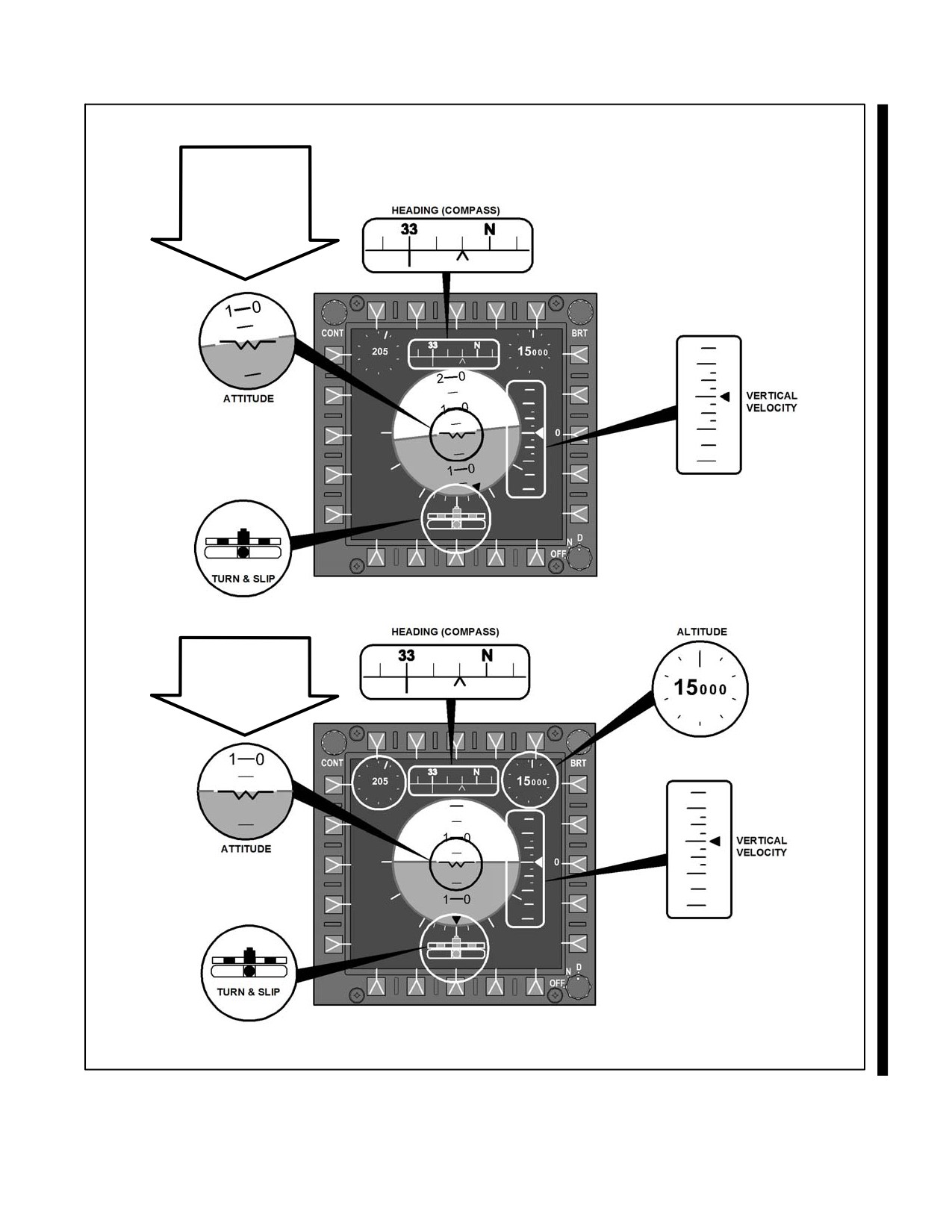
NAVAIR 00-80T-112
IMMEDIATELY
AFTER TURNING
It may be necessary
to maintain this
indication due to
precession.
ATTITUDE
INDICATION
PRIOR TO TURN
Figure 18-7. Effects of Precession on Attitude Indicators
18-9
ORIGINAL
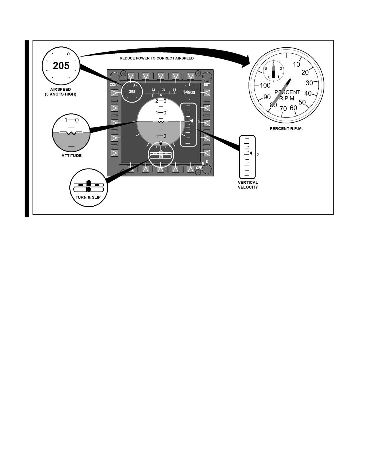
NAVAIR 00-80T-112
Figure 18-8. Use of Power
18.3.2.1 Bank Control
Prior to entering a turn, the pilot should decide upon an angle of bank to be used. Factors to consider are True Airspeed
(TAS) and the desired rate of turn. A slow turn rate may unnecessarily prolong the turn, whereas a high rate of turn
may cause overshooting of the heading and difficulty with nose attitude control. As a guide for small turns (30° or
less), the angle of bank used should approximate the number of degrees to be turned. For turns of more than 30°, a
bank angle of 30° is normally used. High true airspeed and/or flight manual procedures for the equipment being used
may require other angles of bank.
To enter a turn, the pilot should refer to the attitude indicator while applying smooth and coordinated control pressures
to establish the desired angle of bank. Bank control should then be maintained throughout the turn by reference to the
attitude indicator. Cross-check the heading indicator and/or turn needle to determine if the angle of bank is satisfactory.
Trim may be helpful during prolonged turns to assist in aircraft control. To enter a turn, the pilot should refer to the
attitude indicator while applying smooth and coordinated control pressures to establish the desired angle of bank. Bank
control should then be maintained throughout the turn by reference to the attitude indicator. Cross-check the heading
indicator and/or turn needle to determine if the angle of bank is satisfactory. Trim may be helpful during prolonged turns
to assist in aircraft control.
To roll out of a turn on a desired heading, a lead point must be used. The amount of lead required depends upon the
amount of bank used for the turn, the rate the aircraft is turning, and the rate at which the pilot rolls out. As a guide,
a lead point on the heading indicator equal to approximately one-third the angle of bank may be used. With experience
and practice, a consistent rate of rollout can be developed. A lead point can then accurately be estimated for any
combination of angle of bank and rate of turn. Make a note of the rate of movement of the heading indicator during the
turn. Estimate the lead required by comparing this rate of movement with angle of bank being used and the rate of
rollout (Figure 18-9).
ORIGINAL
18-10
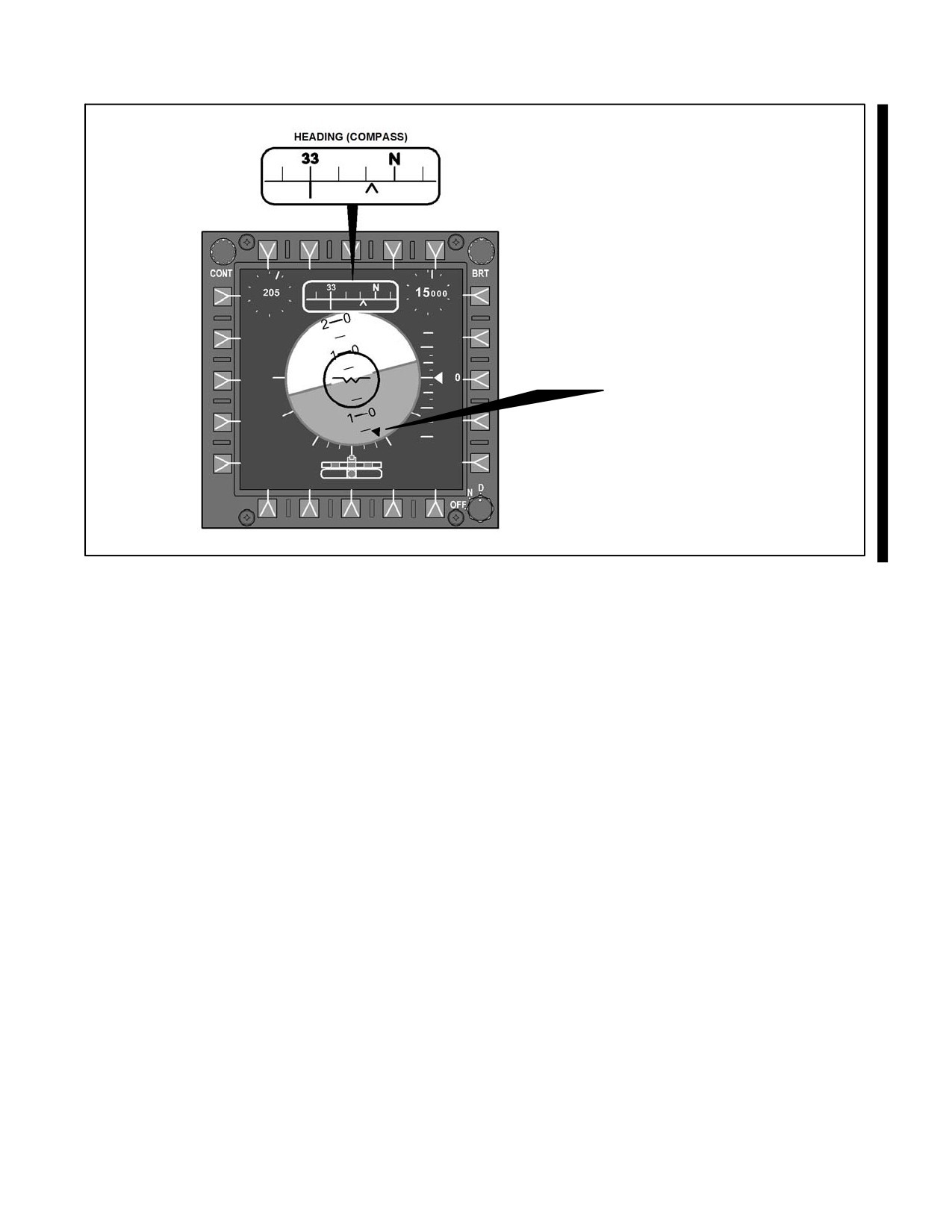
NAVAIR 00-80T-112
LEAD ROLLOUT HEADING
BY 1/3 ANGLE OF BANK (8°)
Figure 18-9. Leading the Rollout
18.3.2.2 Altitude Control
The techniques for maintaining a constant altitude during a turn are similar to those used in maintaining
straight-and-level flight. During the initial part of the roll-in, hold the same pitch attitude as was used to maintain
altitude with the wings level. As the bank is increased, the pilot should anticipate a tendency for the aircraft to lose
altitude because of the loss of vertical lift. Adjust the nose attitude as necessary by reference to the pipper of the
miniature aircraft relative to the horizon bar. After the turn is established, small pitch adjustments may be
required to maintain the desired altitude because of pitch errors in the attitude indicator as a result of precession.
When rolling out of a turn, anticipate a tendency for the aircraft to gain altitude. This results from a combination
of an increase in the vertical component of lift and a failure to compensate for trim or backpressure used during the
turn; therefore, be aware of these factors, anticipate their effects, and monitor the pitch attitude during the rollout
in the same manner as during the roll-in.
18.3.2.3 Airspeed Control
The power control techniques for maintaining airspeed during a turn are similar to those used during
straight-and-level flight. Anticipate a tendency for the aircraft to lose airspeed in a turn. This is caused by induced
drag resulting from the increased nose attitude required to compensate for loss of vertical lift. The increased drag
will require additional power to maintain airspeed during a turn. The additional power required will be less at high
true airspeeds than at low true airspeeds. At low airspeeds, particularly in jet aircraft, a large power change may
be required. If pilot response to this power change is slow, the airspeed may decrease rapidly to the point where
a descent is required to regain the desired airspeeds; therefore, at low airspeeds, it may be desirable to add an
estimated amount of power as the turn is established rather than waiting for the first indication of a loss in airspeed.
Accomplish changes of airspeed during a turn as described under straight-and-level flight, paragraph 18.3.
18-11
ORIGINAL
NAVAIR 00-80T-112
18.3.2.4 Turning Performance
When an aircraft is flown in a steady, coordinated turn at specific values of bank angle and velocity, the turn rate
and turn radius are fixed and independent of aircraft type. As an example, an aircraft in a steady, coordinated turn
at a bank angle of 30° and a velocity of 300 knots TAS would have a rate of turn of 2.10° per second and a turn radius
of 13,800 feet, or approximately 2-1/4 nm.
It is desirable for pilots to learn the approximate turning performance for the normal operating airspeeds and angles
of bank of their aircraft. A desired rate of turn is best flown by establishing a specific angle of bank on the attitude
indicator; therefore, it is desirable to know the approximate angle of bank required. Also, a knowledge of turn radius
will aid in planning turns requiring accurate aircraft positioning (Figure 18-10).
18.4
CLIMBS AND DESCENT
Climbing and descending maneuvers are classified into two general types: constant airspeed or constant rate. The
constant airspeed maneuver is accomplished by maintaining a constant power indication and varying the nose attitude
as required to maintain a specific airspeed (Figure 18-11). The constant-rate maneuver is accomplished by varying
power as required to maintain constant vertical speed and nose attitude to maintain a constant airspeed. Either type
of climb or descent may be performed while maintaining a constant heading or while turning. These maneuvers
should be practiced using airspeeds, configurations, and altitudes corresponding to those that will be used in actual
instrument flight.
18.4.1 Constant Airspeed Climbs and Descents
Before entering the climb or descent, decide what power setting is to be established and estimate the amount of pitch
attitude change required to maintain the airspeed. Normally, the pitch and power changes are made simultaneously.
The power change should be smooth, uninterrupted, and at a rate commensurate with the rate of pitch change. In some
aircraft, even though a constant throttle setting is maintained, the power may change with altitude; therefore, it may
be necessary to cross-check the power indicator(s) occasionally.
While the power is being changed, refer to the attitude indicator and smoothly accomplish the estimated pitch change.
As smooth, slow power applications will also produce pitch changes, only slight control pressures are needed to
establish the pitch change. Also, very little trim change is required, as the airspeed is constant. With a moderate
amount of practice, the pitch and power changes can be properly coordinated so the airspeed will remain within close
limits as the climb or descent is entered.
Remember, the initial nose attitude change was an estimated amount to maintain the airspeed constant at the new
power setting. The airspeed indicator must be cross-checked to determine the need for subsequent pitch adjustments.
When making a pitch adjustment to correct for an airspeed deviation, the airspeed indicator will not reflect an
immediate change. The results of pitch attitude changes can often be determined more quickly by referring to the
vertical speed indicator. For example, while climbing, a pilot notes that the airspeed is remaining slightly high and
realizes that a small pitch adjustment is required. If the pitch adjustment results in a small increase of vertical speed,
the pilot knows, even though the airspeed may not yet show a change, that the pitch correction was approximately
correct.
In a similar manner, the vertical speed indication will help a pilot note that an inadvertent change in pitch attitude has
been made. For example, assume that the desired airspeed and the vertical speed have been remaining constant, but
then, inadvertently, the pitch attitude is allowed to change. The vertical speed indicator will generally show the result
of this inadvertent pitch change more quickly than the airspeed indicator; therefore, the vertical speed indicator is an
excellent aid in maintaining the airspeed constant.
ORIGINAL
18-12
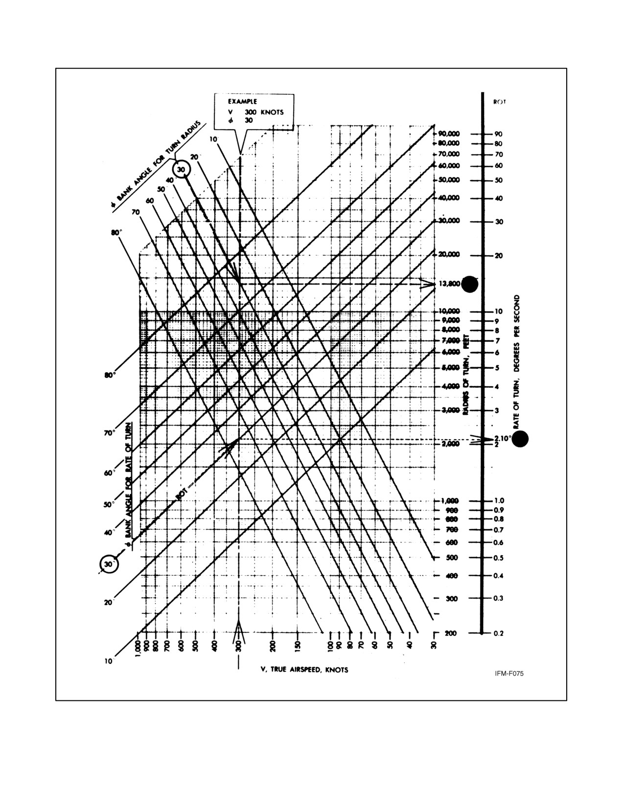
NAVAIR 00-80T-112
Figure 18-10. General Turning Performance (Constant Altitude, Steady Turn)
18-13
ORIGINAL
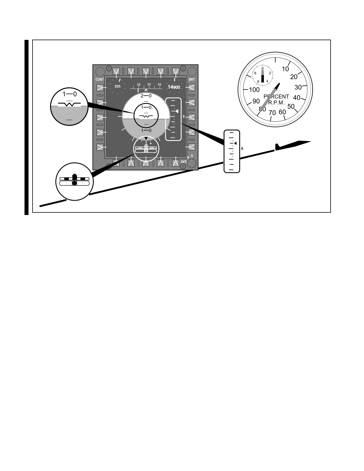
NAVAIR 00-80T-112
POWER IS
CONSTANT
PITCH ATTITUDE
DETERMINES
AIRSPEED
ATTITUDE
PERCENT R.P.M.
VERTICAL
VELOCITY
TURN & SLIP
Figure 18-11. Constant Airspeed Maneuver
Upon approaching the desired altitude, select a predetermined level-off lead point on the altimeter. As a guide, use
10 percent of the vertical speed. Smoothly adjust the power to an approximate setting required for level flight, and
simultaneously change the nose attitude to the level flight attitude.
18.4.2 Constant-Rate Climbs and Descents
Constant-rate climbs and descents are accomplished by maintaining a constant vertical speed as well as constant
airspeed. They are proficiency maneuvers for practicing the techniques involved during precision instrument
approaches. Nose attitude control is coordinated with power changes or adjustments to establish and maintain the
desired vertical speed and airspeed. The relationship between airspeed and pitch control in high-performance aircraft
is especially important at relatively low airspeeds such as when operating at normal final approach airspeed and near
stall or minimum control speeds. The resulting high angle of attack and low airspeeds may reach a point where pitch
and power changes will not produce the desired vertical speed changes. This condition is termed the region of reverse
command, commonly known as being behind the power curve.
Prior to initiating a climb or descent, estimate the amount of power required to produce the desired vertical speed and
the amount of pitch change required to maintain a constant airspeed. Enter the climb or descent by adjusting the pitch
and power. Scan the performance instruments to determine the resultant changes (Figure 18-12).
Cross-check the vertical speed indicator to determine if there is a need for power adjustments. A cross-check of the
airspeed will indicate the need for pitch adjustments. The climb or descent is terminated by using normal level-off
procedures when approaching the desired altitude.
ORIGINAL
18-14
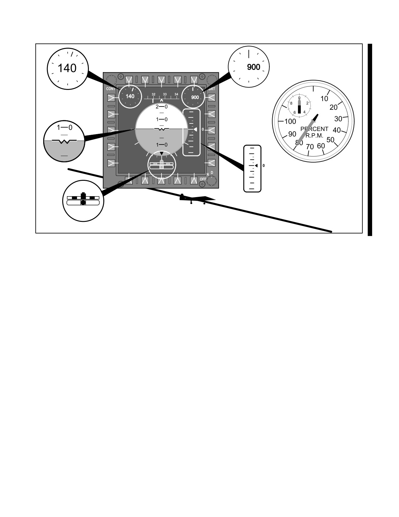
NAVAIR 00-80T-112
ALTITUDE
AIRSPEED
PITCH ATTITUDE
CONTROLS
AIRSPEED
ATTITUDE
PERCENT R.P.M.
POWER
CONTROLS
RATE
VERTICAL
VELOCITY
TURN & SLIP
Figure 18-12. Constant-Rate Maneuver
18.4.2.1 Climbing and Descending Turns
When constant-rate climbs and descents are accomplished during a turn, a decrease in the aircraft vertical lift
component affects nose attitude control. For example, when entering a turn after a constant airspeed climb has already
been established, the nose attitude will have to be decreased slightly to maintain constant airspeed. When entering
a turn while performing a constant-rate descent, be prepared to raise the nose of the aircraft slightly to maintain the
airspeed and add power to maintain the vertical speed.
18.5
ROTARY-WING INSTRUMENT FLYING
The principles of fixed-wing aircraft basic instrument maneuvers generally apply to rotary-wing aircraft as well;
however the basic differences in the aerodynamics of the two types require some consideration. Most helicopters are
equipped with Automatic Stabilization Equipment (ASE)/Automatic Flight Control System (AFCS) and artificial
cyclic stick trim to compensate for their inherent instability. The ASE/AFCS provides stabilization in the pitch, roll,
and yaw axis. Altitude retention may also be incorporated.
18.5.1 Attitude Stabilization
The ASE/AFCS receives pitch and roll information from the vertical gyro. Corrections are automatically applied to
maintain the attitude selected by the pilot with the cyclic stick. Electrical trim is provided to give an artificial feel
similar to that experienced in fixed-wing aircraft trimmed for a condition of flight. Any neutral cyclic stick position
can be selected with the electrical trim and that attitude will be maintained by the ASE without control pressure. The
electrical trim can be overcome with slight control pressure and will return to the original position when the pressure
is released.
18-15
ORIGINAL
NAVAIR 00-80T-112
18.5.2 Yaw Stabilization
The yaw channel on the ASE/AFCS receives information from the compass system and provides corrections to the
rotary rudder to maintain heading. Balanced flight is achieved through coordinated use of the cyclic stick and rudder
pedals.
18.5.3 Altitude Stabilization
The altitude channel of the ASE/AFCS receives information from the barometric altitude controller. The altitude
channel may be engaged or disengaged at will, whenever the ASE/AFCS is engaged, and will maintain or correct to
the altitude at which it was engaged. During climbs or descents, the altitude channel must momentarily be disengaged
until reaching the desired altitude and then engaged.
18.5.4 Attitude Control
Attitude control is achieved through control of the tip path plane by cyclic control over the pitch of the individual
blades. Aircraft reactions to pitch and roll movements of the cyclic stick are similar to those experienced in fixed-wing
aircraft and manifest themselves in the same way on the attitude indicator and performance instruments.
18.5.5 Power Control
The amount of lift produced by the rotor system is dependent on two controllable factors: rotary wing rpm and pitch
of the blades. Since the rotary wing operates efficiently only in a narrow range of rpm, power must be supplied in
sufficient quantities to drive the rotor within the normal range. The second controllable factor is the collective pitch
of the blades. This is controlled from the cockpit with the collective pitch lever. Any change in the collective pitch
of the blades will change the requirement for power to maintain rotor rpm. Mechanical or electrical linkages between
the collective pitch lever and the power plant(s) compensate, at least in part, for these changes. Adjustments, if
required, may be made manually. For purposes of this manual, power control is defined as collective pitch control.
For simplicity, consider the force generated by the rotor disc to be exerted perpendicular to the plane of rotation. This
is the result of the thrust and lift components. In effect, horizontal velocity is achieved by tilting the rotor disc in the
desired direction and creating a thrust component. The magnitude of the thrust component (airspeed) is controlled
by the degree of tilt (pitch attitude). Adjustment of pitch attitude has an immediate effect on airspeed equilibrium.
It also has an immediate, but much less pronounced, effect on altitude equilibrium. The effect of forces in forward
flight is nearly vertical; therefore, change in its magnitude (collective pitch) has a pronounced effect on the lift
component (altitude). The effect on thrust (airspeed) is much less significant.
18.5.6 Altitude Control
Minor corrections to maintain a desired altitude at a constant airspeed are accomplished with adjustments of collective
pitch.
Any change in nose attitude will result in a change of airspeed. Climbs and descents may be accomplished by
increasing or decreasing the collective pitch. Airspeed changes to achieve the recommended climbing or descending
airspeed should be initiated as the maneuver is commenced. Constant-rate climbs and descents are accomplished at
a constant nose attitude by varying the collective pitch setting.
18.5.7 Airspeed Control
Airspeed control is achieved by control of nose attitude. Except for minor airspeed corrections, an adjustment of
collective pitch will be necessary to maintain altitude, rate of climb, or descent during the change.
ORIGINAL
18-16
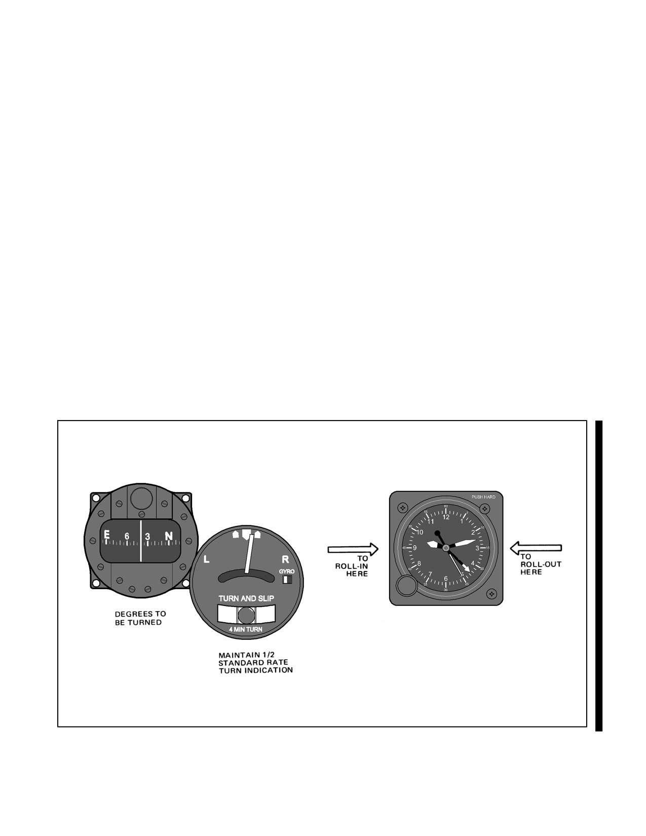
NAVAIR 00-80T-112
18.6
PARTIAL PANEL FLIGHT
18.6.1 Heading Indicator Failure
Heading indicator failure may require use of the magnetic compass for heading information. Remember that this
instrument provides reliable information only during straight-and-level unaccelerated flight. Due to this limitation,
timed turns are recommended when making heading changes by reference to the magnetic compass. This is an
emergency condition and should be treated as such.
A timed turn is accomplished by establishing a bank attitude on the attitude indicator that will result in a desired rate
of turn as shown by the turn needle. If the attitude indicator has failed (following paragraph), the rate of turn should
be maintained by proper positioning of the turn needle. In order to turn to a particular heading, divide the number of
degrees to turn by the rate of turn (1-1/2° per second [1/2 standard rate turn] or 3° per second [standard rate turn])
and turn for the required number of seconds. Roll-in and rollout should be commenced on time.
In this case, 30 seconds should lapse from the time control pressures were applied to enter the turn until control
pressures are applied when rolling out of the turn (Figure 18-13).
Although timed turns are preferred when using the magnetic compass as a heading reference, an alternate method
may be used. Turns to headings can be made by applying control pressures to roll out of a turn when reaching a
predetermined lead point on the magnetic compass. When using the magnetic compass in this manner, the aircraft
angle of bank should not exceed 15° in order to minimize dip error. Dip error must also be considered in computing
the lead point at which to begin rolling out of a turn. This is particularly noticeable when turning to a heading of north
or south. For example, turns to north require a normal lead point plus a number of degrees equal to the flight latitude.
Turns to south require turning past the desired heading by a number of degrees equal to the flight latitude minus the
normal lead. This error is negligible when turning to east or west; therefore, use the normal amount of lead when
turning to either of these headings.
START
STOP
TURN
TURN
Figure 18-13. Performing the Timed Turn
18-17
ORIGINAL

NAVAIR 00-80T-112
18.6.2 Attitude Indicator Failure
The attitude indicator is the single most important instrument required for instrument flight. Since failures of the
attitude gyro do occur, all pilots must be proficient at controlling the aircraft under instrument conditions without the
use of this instrument. The primary attitude control (nose and wing) in partial panel will consist of one instrument
for the primary nose attitude indication and another for wing attitude. Figure 18-14 shows the function of the
instruments in a scan pattern with the attitude gyro inoperative. The table is applicable to all Navy aircraft for general
instrumentation. When flying under partial panel conditions, the pilot should anticipate the desired indications on the
performance instruments due to the slight lag inherent in these instruments. Failure to do so will usually result in
overcontrol of the aircraft.
Primary
Attitude
Attitude
Cross-Check
Performance
Supporting
Maneuver
Attitude
Instrument
Instrument
Instruments
Instruments
Nose
Altimeter,
Straight and
Airspeed
Power,
VSI
level
Magnetic
Wing
Needle-ball
Heading
Compass
indicator
Level turns
Nose
Altimeter,
Airspeed,
Power,
VSI
Heading indicator,
Magnetic
Wing
Needle-ball
Clock
Compass
Nose
Airspeed
Straight climbs
Altimeter,
Power,
and descents
VSI
Magnetic
Wing
Needle-ball
Heading
Compass
indicator
Climbing or
Nose
Airspeed
Altimeter,
Power,
descending
VSI,
Magnetic
turns
Wing
Needle-ball
Heading indicator
Compass
Figure 18-14. Function of Instruments — Partial Panel
ORIGINAL
18-18
NAVAIR 00-80T-112
CHAPTER 19
Instrument Patterns and
Confidence Maneuvers
19.1
PURPOSE
Present missions require some aircraft to be flown at all attitudes under instrument conditions. Instrument patterns
incorporate fundamental airwork into a sequence wherein the pilot is faced with continuous changes of attitude and
speed. Confidence maneuvers are basic aerobatic maneuvers developed for increasing confidence in the use of
attitude indicators in attitudes of extreme pitch and bank. Practice of these maneuvers develops good timing precision
and smoothness in aircraft control and increases the speed of scanning. Mastery of these maneuvers also will aid the
pilot in recovery from unusual attitudes. Prior to flight, the pilot should consult the NATOPS flight manual for
additional maneuvers, performance characteristics, and limitations.
19.2
INSTRUMENT PATTERNS
19.2.1 Vertical S-1, S-2, S-3, S-4
The vertical S maneuvers are proficiency maneuvers designed to improve a pilot’s cross-check and aircraft control.
There are four types: the 1, 2, 3, and 4.
19.2.1.1 Vertical S-1
The vertical S-1 maneuver (Figure 19-1) is a continuous series of rate climbs and descents flown on a constant
heading. The altitude flown between changes of vertical direction and rate of vertical speed must be compatible with
aircraft performance.
The vertical S-1 should be flown at a constant airspeed.
19.2.1.2 Vertical S-2
The vertical S-2 is the same as a vertical S-1 except that a 1/2 Standard Rate Turn (SRT) is maintained during the climb
and descent.
The turn is established simultaneously with the initial climb or descent (Figure 19-2).
19.2.1.3 Vertical S-3
The vertical S-3 (Figure 19-3) is the same as a vertical S-2 except that the direction of turn is reversed at the beginning
of each descent. Enter the vertical S-3 in the same manner as the vertical S-2 (Figure 19-2).
19.2.1.4 Vertical S-4
The vertical S-4 (Figure 19-3) is the same as the vertical S-3 except that the direction of turn is reversed
simultaneously with each change of vertical direction. Enter the vertical S-4 in the same manner as the vertical S-2
or S-3.
Any of the vertical S maneuvers may be initiated with a climb or descent. Conscientious practice of these maneuvers
will greatly improve the pilot’s familiarity with the aircraft, instrument scan, and overall aircraft control during
precision instrument approaches. For this reason, the maneuvers should be practiced at approach speeds and
configurations, and at low altitudes, as well as at cruise speeds, clean, and at higher altitudes.
19-1
ORIGINAL
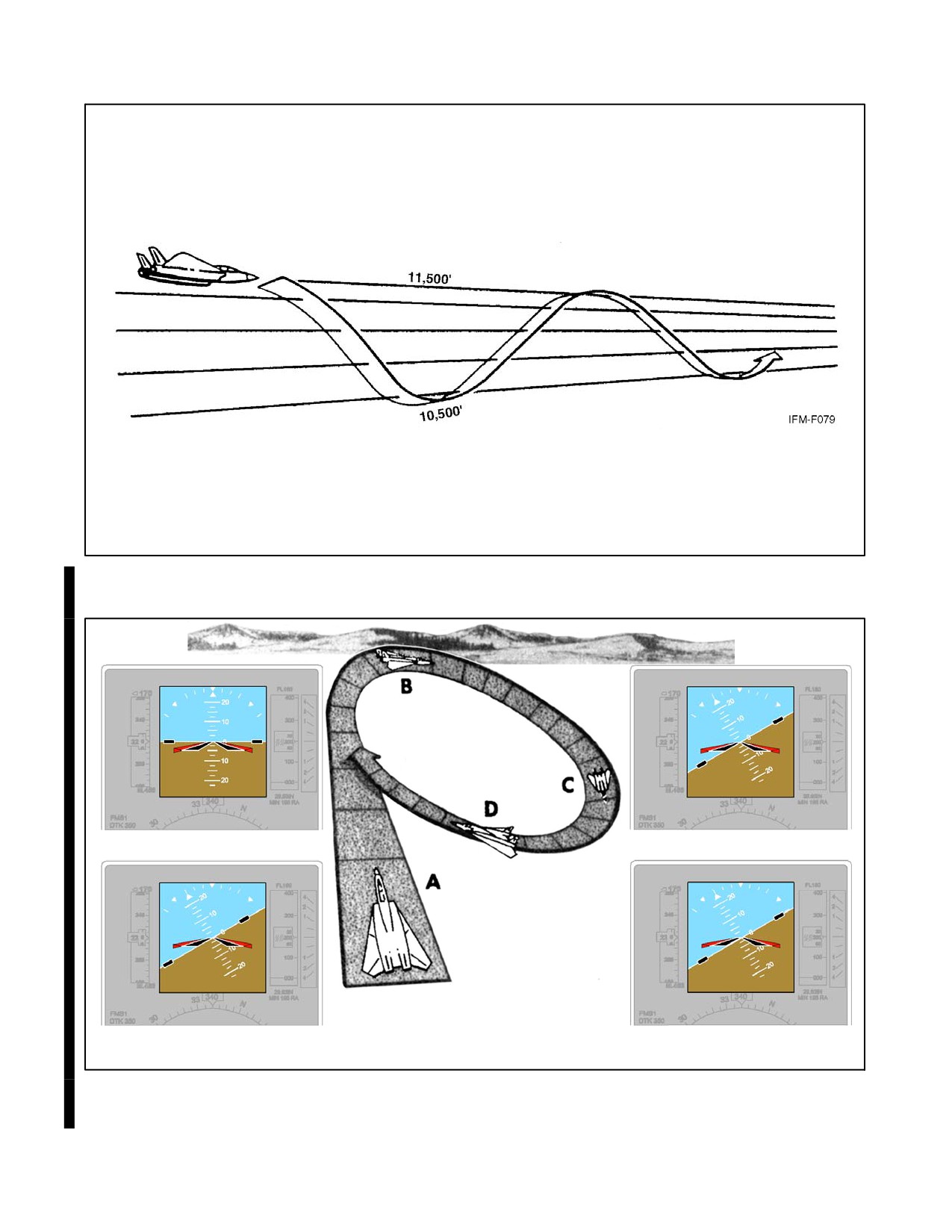
NAVAIR 00-80T-112
Figure 19-1. Vertical S-1
CHANGE OF VERTICAL DIRECTION
A LEVEL FLIGHT
C
CONSTANT BANK AND DESCENT
CONSTANT BANK AND CLIMB
D
B
Figure 19-2. Vertical S-2
ORIGINAL
19-2
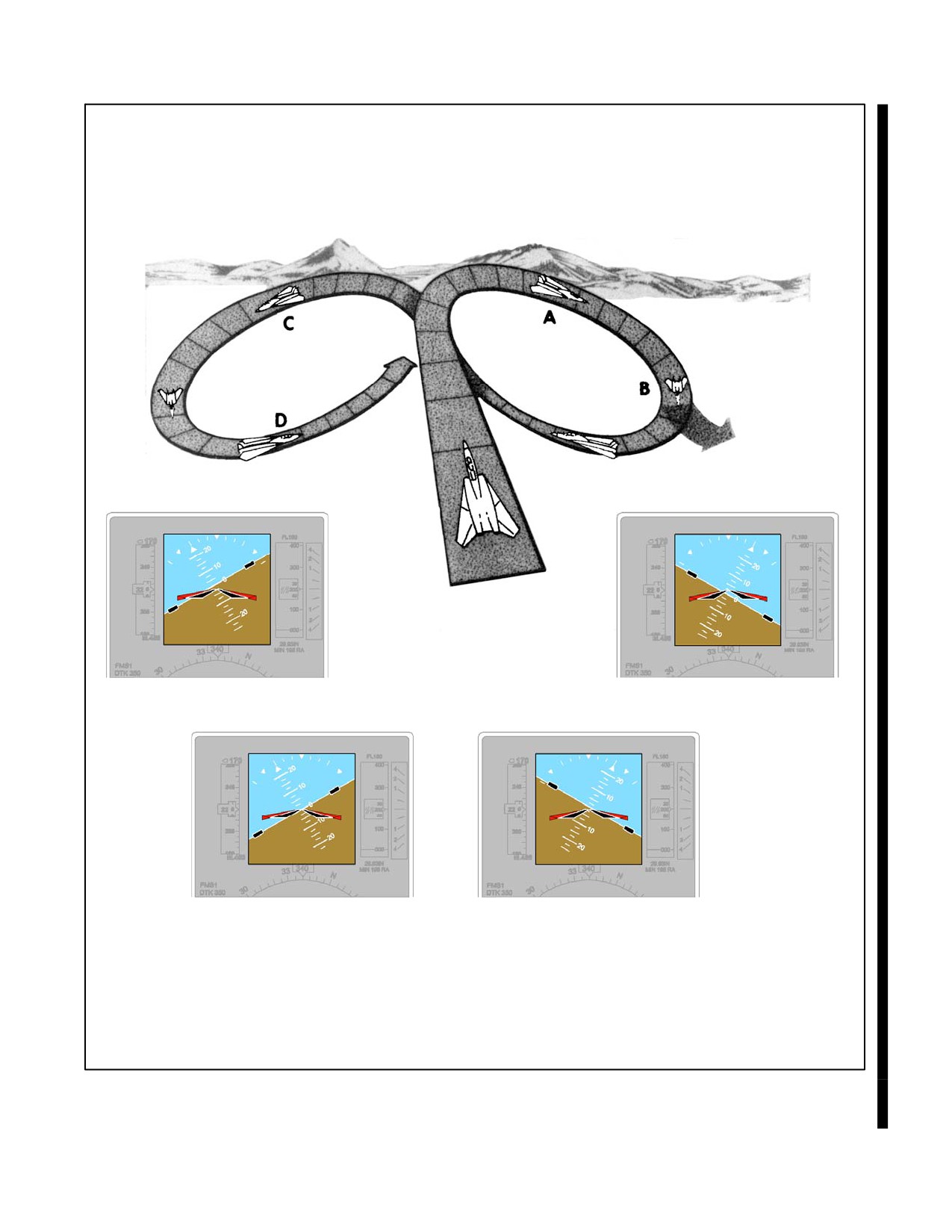
NAVAIR 00-80T-112
FOR S-4
REVERSE BANK
AT EACH
CHANGE OF
VERTICAL
DIRECTION
CONSTANT BANK AND CLIMB
A CONSTANT BANK AND DESCENT
D
CHANGE OF VERTICAL DIRECTION
CONSTANT BANK AND DESCENT
B
C
Figure 19-3. Vertical S-3 and S-4
19-3
ORIGINAL
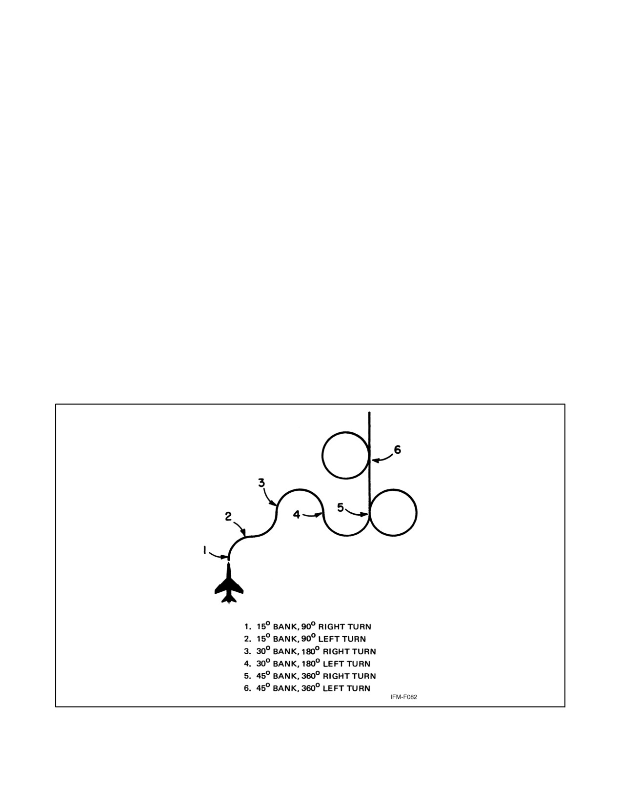
NAVAIR 00-80T-112
19.2.2 Steep Turns
A steep turn is one in which the angle of bank used is larger than that required for normal instrument flying. In most
aircraft, 30_ is the normal maximum angle of bank used because of the ease of control and precision afforded.
Entry into a steep turn is accomplished the same as for a normal turn. As the bank is increased past normal, greater
loss of vertical lift occurs, requiring more pitch adjustment. The use of trim in steep turns varies with individual
aircraft characteristics and pilot technique. Additional power will be required to maintain airspeed as the bank is
increased.
Bank should be held constant because varying the angle of bank during the turn contributes significantly to difficulty
in pitch control. Precession error in the attitude indicator is more pronounced during steep turns. If altitude deviation
becomes excessive, reduce the angle of bank as necessary to regain positive pitch control.
When rolling out of a steep turn, be alert to correct for the higher-than-normal pitch attitude and power used during
the turn. Roll out at the same rate used with normal turns. The performance instruments should be scanned closely
during rollout, as the attitude indicator may have considerable precession error (Figure 19-4).
19.2.3 OSCAR Pattern
OSCAR pattern (Figure 19-5) is entered in the following sequence:
1. Enter pattern on base altitude at normal cruise.
2. Climbing left SRT, gain 1,000 feet.
3.
1 to 2 minutes straight and level at slow cruise.
Figure 19-4. Steep Turn Pattern
ORIGINAL
19-4
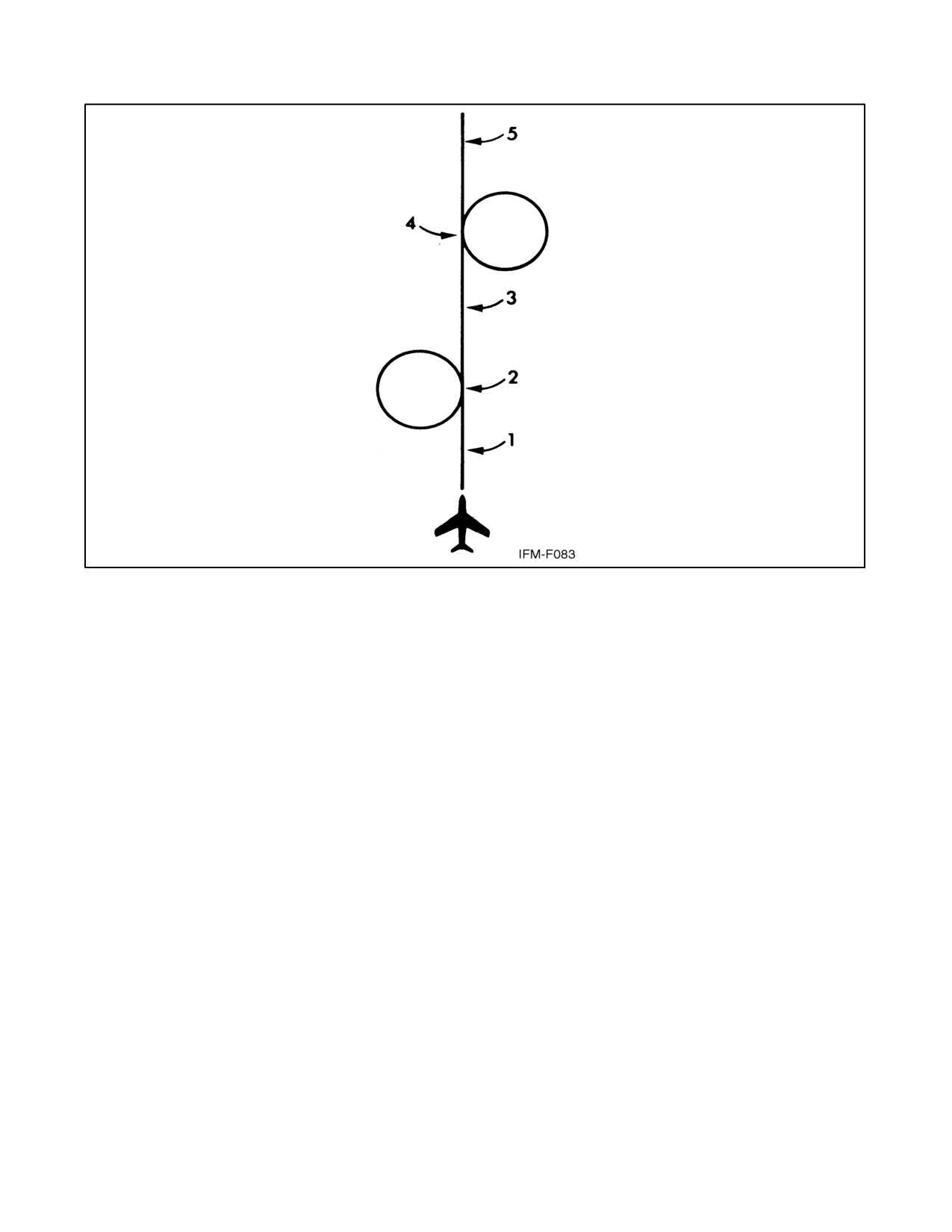
NAVAIR 00-80T-112
Figure 19-5. OSCAR Pattern
4. Descending right SRT, lose 1,000 feet.
5. Recover straight and level; return to normal cruise.
19.2.4 CHARLIE Pattern
CHARLIE pattern (Figure 19-6) is entered in the following sequence:
1. Start straight and level 2 minutes normal cruise.
2. Climb 667 feet per minute, SRT for 270_, gain 1,000 feet.
3. Fast cruise 2 minutes, straight and level.
4. Reduce power and slow first 90_ of turn, then descend standard rate 360_.
5. Commence standard rate climb; 2 minutes gain 1,000 feet.
6. Level off, left SRT for 270_, accelerate to normal cruise.
7. Climb standard rate, straight, for 2 minutes.
8. Lower wheels going into right SRT, descend 800 fpm.
9. Recover at starting altitude, at normal cruise.
19-5
ORIGINAL
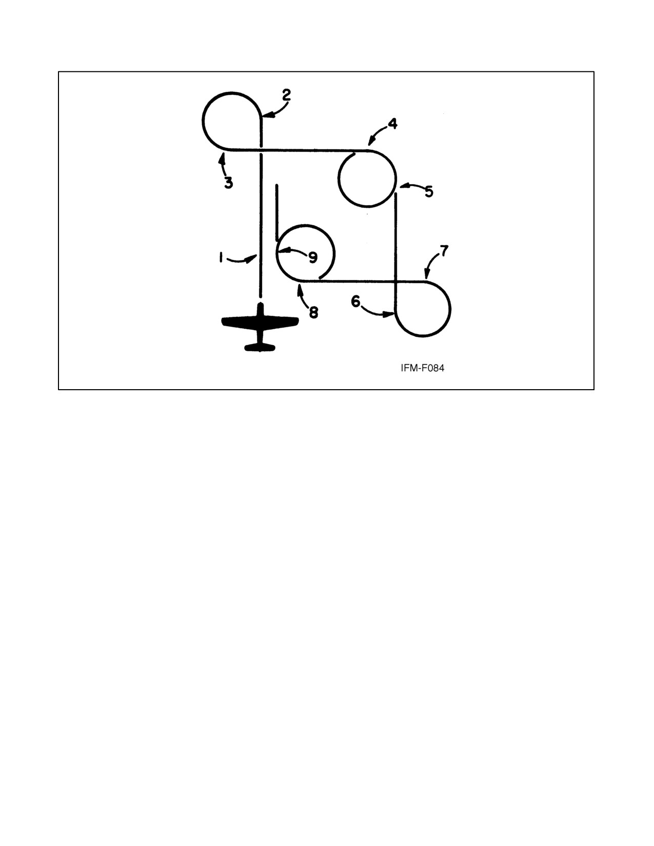
NAVAIR 00-80T-112
Figure 19-6. BRAVO/CHARLIE Pattern
19.2.5 BRAVO Pattern
A BRAVO pattern is the same as the CHARLIE pattern with the following exceptions:
1. Maintain a constant altitude and normal cruise.
2. All legs 1 minute.
19.2.6 YANKEE Pattern
YANKEE pattern (Figure 19-7) is entered in the following sequence:
1. Start 4,000 to 6,000 feet per minute descent, speed brakes out, 1 minute.
2. Commence 1/2 SRT for 180_.
3. Level off at one-half starting altitude.
4. Straight and level 1 minute.
5. Commence 1/2 SRT, 45_.
6. Assume landing configuration straight and level 1 minute.
7. Commence SRT 180_.
8. Transition to desired approach speed straight and level 30 seconds.
9. Commence recommended rate of descent 2 minutes.
10. Wave off.
ORIGINAL
19-6
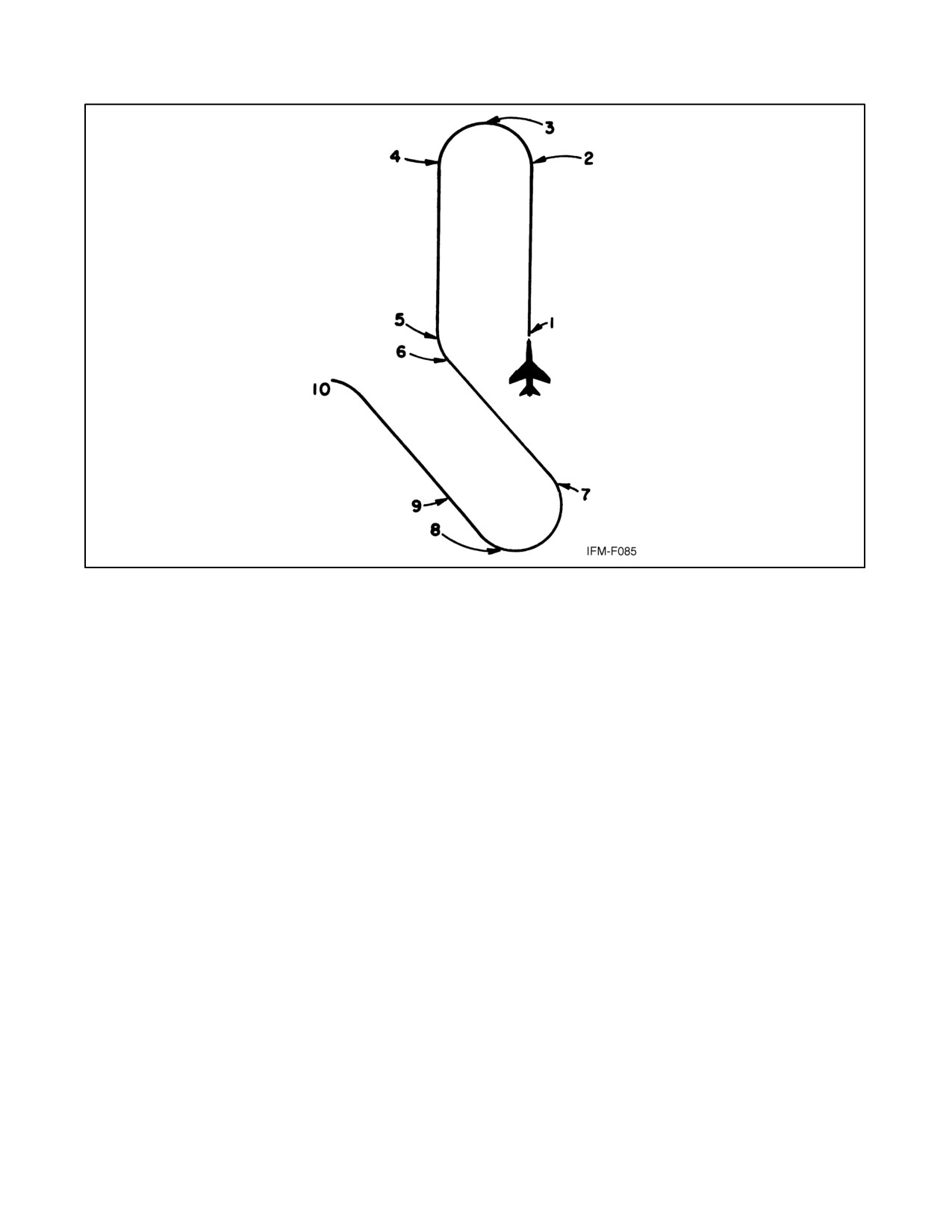
NAVAIR 00-80T-112
Figure 19-7. YANKEE Pattern (High-Performance Aircraft)
19.3
CONFIDENCE MANEUVERS
Note
The following maneuvers are not applicable to rotary-wing aircraft.
19.3.1 Wingover
The wingover is a combination climbing and diving turn with approximately 180_ of heading change (Figure 19-8).
The maneuver is commenced from straight-and-level flight after obtaining the desired airspeed. Start a steep climbing
turn in either direction so that the heading of the aircraft has changed approximately 90_ as the aircraft approaches
90_ angle of bank. When the angle of bank reaches 90_, allow the nose of the aircraft to start down. As the nose of
the aircraft passes through the horizon, smoothly decrease the angle of bank to a wings-level attitude. The rate of roll
during the recovery should be the same as the rate of roll used during the entry.
19.3.2 Barrel Roll
The barrel roll is a combination climbing and diving maneuver that is accomplished by smoothly rolling the aircraft
about a point 45_ off the aircraft heading on the horizon. The maneuver is accomplished by commencing a
simultaneous climb and roll at a rate that will achieve a 90_ change of heading as the aircraft completes 180_ of roll
(inverted flight). The nose should reach a point about 45_ above the horizon as 90_ of roll is completed. As the nose
drops below the horizon, the roll should be continued and backpressure increased as necessary to place the aircraft
straight and level at the completion of the roll (Figure 19-9).
Note
This maneuver should be attempted only in aircraft equipped with the
three-axis Attitude Direction Indicator (ADI).
19-7
ORIGINAL
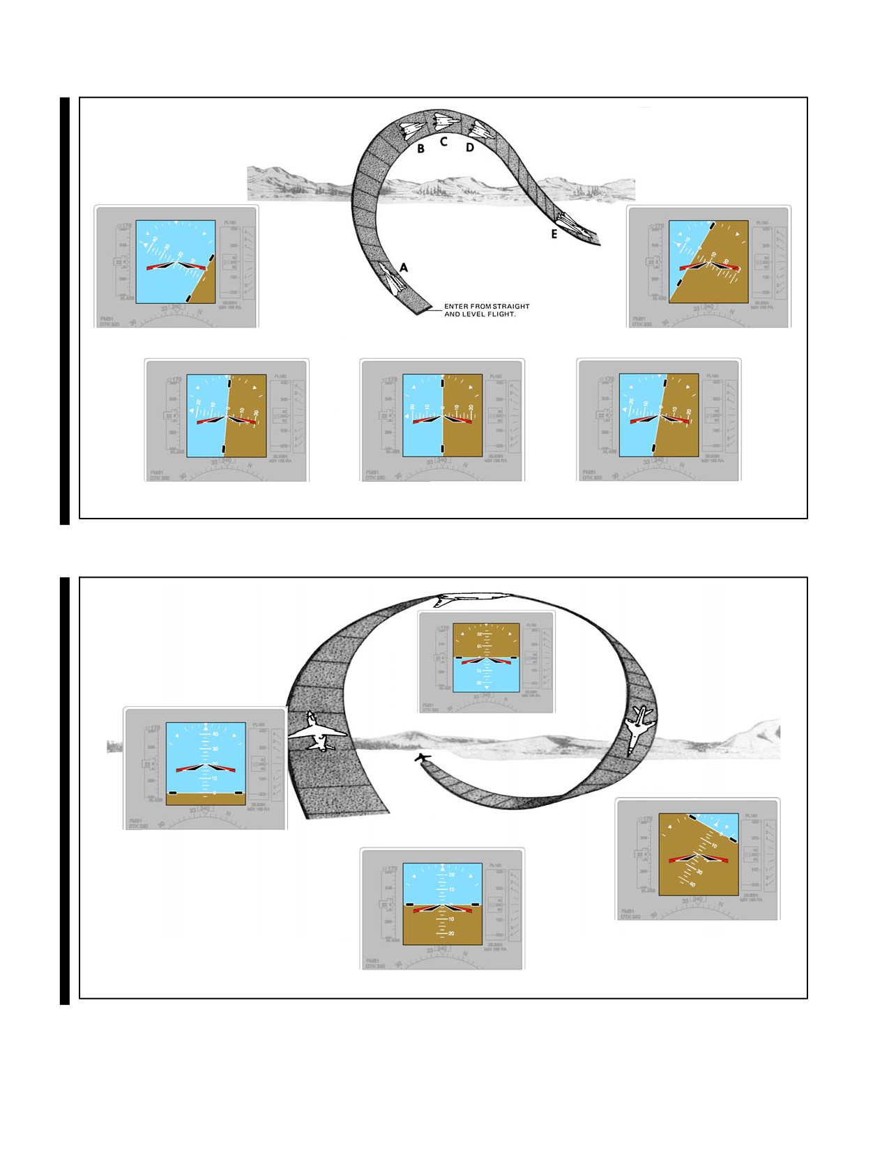
NAVAIR 00-80T-112
60° BANK RECOVERING
A60° BANK
E
BANK INCREASING TO 90°
90° BANK
BANK DECREASING
B
C
D
(NOSE COMING DOWN)
(NOSE LOW)
Figure 19-8. Wingover
B
A
B180° OF ROLL (INVERTED)
90° CHANGE OF HEADING
C
D
A BEGIN ROLL
C RECOVERING
D RECOVERY
Figure 19-9. Barrel Roll
ORIGINAL
19-8