NAVAIR 00-80T-112 NATOPS INSTRUMENT FLIGHT MANUAL (15 NOVEMBER 2006) - page 1
INTRODUCTION
1
NAVAIR 00-80T-112
METEOROLOGY
2
PHYSIOLOGY OF
3
NATOPS
INSTRUMENT FLIGHT
INSTRUMENT FLIGHT MANUAL
AIRCRAFT FLIGHT/
4
NAVIGATIONAL INSTR
ATTITUDE
5
INSTRUMENT FLIGHT
NAVAIDS/FACILITIES &
THIS PUBLICATION SUPERSEDES NAVAIR 00-80T-112
6
PROCEDURES
DATED 15 OCTOBER 2002.
INSTRUMENT
7
FLIGHT
DISTRIBUTION STATEMENT C
— Distribution authorized to U.S.
Government agencies only and their contractors to protect publications
required for official use or for administrative or operational purposes only
INDOCTRINATION &
(15 November 2006). Other requests for this document shall be referred to
8
FLIGHT EVALUATION
Commander, Naval Air Systems Command (PMA-251), RADM William A
Moffett Bldg, 47123 Buse Rd, Bldg 2272, Patuxent River, MD 20670-1547.
APPENDICES
DESTRUCTION NOTICE — For unclassified, limited documents, destroy by
& INDEX
any method that will prevent disclosure of contents or reconstruction of the
document.
ISSUED BY AUTHORITY OF THE CHIEF OF NAVAL OPERATIONS AND
UNDER THE DIRECTION OF THE COMMANDER,
NAVAL AIR SYSTEMS COMMAND.
0800LP1063562
1 (Reverse Blank)
15 NOVEMBER 2006
NAVAIR 00-80T-112
NATOPS INSTRUMENT FLIGHT MANUAL
Contents
Page
No.
PART I — INTRODUCTION
CHAPTER 1 — INTRODUCTION
1.1
PURPOSE
1-1
1.2
SCOPE
1-1
1.3
GENERAL
1-1
1.4
RESPONSIBILITIES
1-1
1.4.1
NATOPS Advisory Group
1-1
1.4.2
NATOPS Cognizant Command
1-1
1.4.3
NATOPS Model Manager
1-2
1.4.4
Commanding Officers
1-2
1.5
TRAINING
1-2
1.6
WAIVERS
1-2
PART II — METEOROLOGY
CHAPTER 2 — CONCEPT
2.1
METEOROLOGY FOR NAVAL AVIATORS
2-1
CHAPTER 3 — AIRMASSES
3.1
CONCEPT
3-1
3.1.1
Airmass Classification
3-1
3.1.2
Airmass Development
3-1
3.1.3
Airmass Modification
3-1
3.1.4
Airmass Weather
3-2
CHAPTER 4 — FRONTS
4.1
INTRODUCTION
4-1
4.2
RELATION OF FRONTS TO CYCLONES
4-1
4.3
RELATION OF FRONTS TO AIRMASSES
4-1
4.3.1
Cold Fronts
4-1
4.3.2
Warm Fronts
4-3
4.3.3
Occluded Fronts
4-5
4.3.4
Stationary Fronts
4-5
4.4
PRESSURE AT FRONTS
4-7
9
ORIGINAL
NAVAIR 00-80T-112
Page
No.
4.5
FRONTAL MOVEMENT
4-7
4.5.1
Speed
4-7
4.5.2
Modifications
4-7
CHAPTER 5 — TROPICAL METEOROLOGY
5.1
INTRODUCTION
5-1
5.2
TROPICAL WAVES
5-1
5.2.1
Stable Wave
5-1
5.2.2
Neutral Wave
5-1
5.2.3
Unstable Wave
5-1
5.3
INTERTROPICAL CONVERGENCE ZONE
5-2
5.4
CONVERGENCE ZONES
5-2
5.5
SHEAR LINES
5-3
CHAPTER 6 — WEATHER HAZARDS TO FLIGHT
6.1
THUNDERSTORMS
6-1
6.1.1
Thunderstorm Development
6-1
6.1.2
Thunderstorm Weather
6-3
6.1.3
Thunderstorm Classification
6-3
6.2
SQUALL LINES
6-4
6.3
TORNADOES AND WATERSPOUTS
6-4
6.4
TURBULENCE
6-6
6.4.1
Mountainous Terrain
6-6
6.4.2
Clear-Air Turbulence
6-7
6.5
FOG
6-7
6.5.1
Radiation Fog
6-7
6.5.2
Advection Fog
6-8
6.5.3
Frontal Fog
6-8
6.5.4
Arctic Fog
6-8
6.6
AIRCRAFT ICING
6-9
6.6.1
Structural Icing
6-9
6.7
STRUCTURAL DEICING
6-10
6.7.1
Airfoil
6-10
6.7.2
Propeller
6-10
6.7.3
Pitot-Static/Angle of Attack (AOA) Systems
6-11
6.7.4
Structural Icing Precautions
6-11
6.7.5
Aircraft Engine Icing
6-11
6.8
LOW-LEVEL WINDSHEAR
6-11
6.8.1
Convective Windshear
6-12
6.8.2
Nonconvective Windshear
6-12
6.9
MICROBURSTS
6-12
ORIGINAL
10
NAVAIR 00-80T-112
Page
No.
PART III — PHYSIOLOGY OF INSTRUMENT FLIGHT
CHAPTER 7 — INTRODUCTION TO INSTRUMENT FLIGHT PHYSIOLOGY
7.1
GENERAL
7-1
7.2
YOUR SENSES
7-1
7.2.1
Motion (Inner Ear)
7-1
7.2.2
Semicircular Canals
7-1
7.2.3
Otolith Organs
7-4
7.2.4
Postural (Seat of the Pants)
7-4
7.2.5
Sight
7-5
CHAPTER 8 — SPATIAL DISORIENTATION
8.1
FALSE PERCEPTION (GENERAL)
8-1
8.1.1
Illusions: Primarily Inner Ear
8-1
8.1.2
Visual Illusions and Problems
8-9
8.1.3
False Perceptions During Helicopter Flights
8-10
8.2
SPATIAL MISORIENTATION
8-12
CHAPTER 9 — FACTORS THAT INCREASE THE POTENTIAL FOR
SPATIAL DISORIENTATION
9.1
GENERAL
9-1
9.2
PERSONAL FACTORS
9-1
9.3
ENVIRONMENTAL FACTORS
9-1
9.4
FACTORS RELATED TO TYPE OR PHASE OF FLIGHT
9-1
9.4.1
Takeoff and Landing Phases
9-1
9.4.2
ACM or Air-to-Ground Ordnance Deliveries
9-2
9.4.3
Formation Flight
9-2
CHAPTER 10 — MEDICATIONS, ALCOHOL, AND NUTRITION
10.1
GENERAL
10-1
10.2
NUTRITION
10-1
10.3
EXERCISE
10-1
10.4
DRUGS
10-1
11
ORIGINAL
NAVAIR 00-80T-112
Page
No.
10.5
ILLNESS
10-2
10.6
DENTAL CARE
10-2
10.7
IMMUNIZATION/INJECTIONS
10-2
10.8
BLOOD DONATION
10-2
CHAPTER 11 — PREVENTION OF SPATIAL DISORIENTATION
11.1
GENERAL
11-1
11.2
TRAINING
11-1
11.2.1
Sensation of Climbing During a Turn
11-1
11.2.2
Sensation of Diving During Recovery From a Turn
11-2
11.2.3
False Sensations of Tilting to Right or Left
11-2
11.2.4
False Sensation of Reversal of Motion
11-2
11.2.5
Sensation of Diving or Rolling Beyond the Vertical Plane
11-2
11.2.6
Sensation of Climbing During Straight-and-Level Flight
11-2
11.3
EXPERIENCE
11-3
CHAPTER 12 — OVERCOMING SPATIAL DISORIENTATION
12.1
GENERAL
12-1
12.2
SINGLE-SEAT AIRCRAFT
12-1
12.3
DUAL-SEAT AIRCRAFT
12-2
12.4
MULTICREWED AIRCRAFT
12-2
12.5
FORMATION FLIGHTS IN NIGHT OR WEATHER
12-2
PART IV — AIRCRAFT FLIGHT/NAVIGATIONAL INSTRUMENTATION
CHAPTER 13 — INTRODUCTION TO AIRCRAFT FLIGHT INSTRUMENTS
13.1
GENERAL
13-1
CHAPTER 14 — ATTITUDE INSTRUMENTS
14.1
GENERAL
14-1
14.2
HEADS-UP DISPLAY
14-1
14.2.1
HUD Limitations
14-1
14.2.2
Global Orientation
14-1
14.2.3
HUD Field of View
14-3
14.2.4
Conventional Cross-Check
14-3
ORIGINAL
12
NAVAIR 00-80T-112
Page
No.
CHAPTER 15 — PERFORMANCE INSTRUMENTS
15.1
COMPASSES
15-1
15.1.1
Standby Magnetic Compass
15-1
15.1.2
Variation
15-1
15.1.3
Deviation
15-3
15.1.4
Magnetic Dip
15-3
15.1.5
Acceleration Error
15-4
15.1.6
Oscillation Error
15-4
15.2
AIRSPEED INDICATOR
15-4
15.3
VERTICAL SPEED INDICATOR (VSI/VVI)
15-4
15.3.1
VSI Error
15-4
15.3.2
Dial Calibration
15-4
15.4
TURN AND SLIP INDICATOR
15-4
15.4.1
Turn Indicator (Needle)
15-6
15.4.2
Slip Indicator (Ball)
15-6
15.5
ANGLE OF ATTACK INDICATOR
15-8
15.6
HOVER INDICATOR
15-8
15.7
CLOCK
15-8
15.8
OUTSIDE AIR TEMPERATURE GAUGE
15-8
CHAPTER 16 — POSITION INSTRUMENTS
16.1
ALTIMETERS
16-1
16.1.1
Pressure Altimeter
16-1
16.1.2
Radio/Radar Altimeters
16-4
16.2
RANGE INDICATOR
16-4
16.3
BEARING INDICATORS
16-6
16.3.1
Radio Magnetic Indicator (RMI)
16-6
16.3.2
Bearing-Distance-Heading Indicator (BDHI)
16-6
16.3.3
Horizontal Situation Indicator (HSI)
16-6
16.4
COURSE INDICATOR
16-10
16.4.1
VOR/TACAN Display
16-11
16.4.2
ILS Display
16-11
16.5
FLIGHT DIRECTOR SYSTEM
16-12
16.6
OTHER POSITION INSTRUMENTS
16-12
13
ORIGINAL
NAVAIR 00-80T-112
Page
No.
PART V — ATTITUDE INSTRUMENT FLIGHT
CHAPTER 17 — ATTITUDE INSTRUMENT FLYING
17.1
GENERAL
17-1
17.2
AIRCRAFT CONTROL
17-1
17.2.1
Attitude Control
17-2
17.3
INSTRUMENT GROUPINGS
17-4
17.3.1
Control Instruments
17-4
17.3.2
Performance Instruments
17-4
17.3.3
Position Instruments
17-4
17.3.4
Instrument Scan
17-4
17.3.5
Functions of Instruments — Full Panel Scan
17-4
17.3.6
Scan Technique
17-6
17.3.7
Scan Analysis
17-7
17.3.8
Use of Angle of Attack
17-7
17.4
AIRCRAFT TRIM
17-9
17.5
INSTRUMENT HOVERING
17-10
CHAPTER 18 — INSTRUMENT FLIGHT MANEUVERS
18.1
APPLICATION
18-1
18.1.1
Planning
18-1
18.2
INSTRUMENT TAKEOFF (ITO)
18-2
18.2.1
Pretakeoff Procedures
18-2
18.3
STRAIGHT-AND-LEVEL FLIGHT
18-4
18.3.1
Maintaining a Desired Altitude
18-4
18.3.2
Level Turns
18-8
18.4
CLIMBS AND DESCENT
18-12
18.4.1
Constant Airspeed Climbs and Descents
18-12
18.4.2
Constant-Rate Climbs and Descents
18-14
18.5
ROTARY-WING INSTRUMENT FLYING
18-15
18.5.1
Attitude Stabilization
18-15
18.5.2
Yaw Stabilization
18-16
18.5.3
Altitude Stabilization
18-16
18.5.4
Attitude Control
18-16
18.5.5
Power Control
18-16
18.5.6
Altitude Control
18-16
18.5.7
Airspeed Control
18-16
18.6
PARTIAL PANEL FLIGHT
18-17
18.6.1
Heading Indicator Failure
18-17
18.6.2
Attitude Indicator Failure
18-18
ORIGINAL
14
NAVAIR 00-80T-112
Page
No.
CHAPTER 19 — INSTRUMENT PATTERNS AND CONFIDENCE MANEUVERS
19.1
PURPOSE
19-1
19.2
INSTRUMENT PATTERNS
19-1
19.2.1
Vertical S-1, S-2, S-3, S-4
19-1
19.2.2
Steep Turns
19-4
19.2.3
OSCAR Pattern
19-4
19.2.4
CHARLIE Pattern
19-5
19.2.5
BRAVO Pattern
19-6
19.2.6
YANKEE Pattern
19-6
19.3
CONFIDENCE MANEUVERS
19-7
19.3.1
Wingover
19-7
19.3.2
Barrel Roll
19-7
19.3.3
Aileron Roll
19-9
19.3.4
Loops
19-9
19.3.5
Immelmann
19-11
19.3.6
Half Cuban Eight
19-11
CHAPTER 20 — UNUSUAL ATTITUDES
20.1
INTRODUCTION
20-1
20.2
ATTITUDE INTERPRETATION
20-2
20.3
RECOVERY PROCEDURES
20-2
20.3.1
Nose-High Recovery
20-2
20.3.2
Nose-Low Recovery
20-4
20.3.3
Partial Panel Unusual Attitudes
20-4
PART VI — NAVIGATIONAL AIDS/FACILITIES AND PROCEDURES
CHAPTER 21 — VHF OMNIDIRECTIONAL RANGE (VOR)
21.1
INTRODUCTION
21-1
21.2
EQUIPMENT AND OPERATION
21-1
21.2.1
Equipment
21-1
21.2.2
Operation
21-3
15
ORIGINAL
NAVAIR 00-80T-112
Page
No.
21.3
PROCEDURES
21-4
21.3.1
Proceeding Direct to Station
21-4
21.3.2
Course Interceptions
21-4
21.3.3
Inbound Procedures
21-6
21.3.4
Outbound Procedures — Immediately After Station Passage
21-6
21.3.5
Outbound Procedures
21-16
21.3.6
Completing the Intercept
21-17
21.3.7
Estimating Drift Correction
21-17
21.3.8
Homing
21-17
21.3.9
Time-Distance Check
21-21
21.3.10
30˚ Method
21-23
21.3.11
Station Passage
21-23
21.3.12
Holding
21-27
CHAPTER
22
— TACTICAL AIR NAVIGATION (TACAN)
22.1
INTRODUCTION
22-1
22.2
EQUIPMENT AND TRANSMISSION PRINCIPLES
22-1
22.2.1
Ground Equipment
22-2
22.2.2
TACAN Characteristics
22-5
22.2.3
TACAN Procedures
22-7
22.2.4
TACAN Approach Procedures
22-18
CHAPTER
23
— ADF, UHF/ADF, MARKER BEACONS
23.1
AUTOMATIC DIRECTION FINDING (ADF)
23-1
23.1.1
Automatic Direction Finding (ADF) Procedures
23-1
23.1.2
UHF Nondirectional Radio Beacon (Homer)
23-11
23.2
MARKER BEACONS
23-14
CHAPTER
24
— INSTRUMENT LANDING SYSTEM (ILS)
24.1
INTRODUCTION
24-1
24.2
EQUIPMENT AND OPERATION
24-1
24.2.1
Ground Equipment
24-1
24.2.2
Airborne Equipment
24-4
24.3
ILS PROCEDURES
24-5
24.3.1
Performing the ILS Approach
24-5
24.3.2
Localizer Approaches
24-10
24.3.3
Simplified Directional Facility (SDF)
24-10
24.3.4
Radar Vectors
24-10
24.3.5
Localizer (LOC) Back Course Approach
24-11
ORIGINAL
16
NAVAIR 00-80T-112
Page
No.
CHAPTER 25 — RADAR APPROACHES
25.1
INTRODUCTION
25-1
25.1.1
Principles of Radar
25-1
25.1.2
Radar Traffic Information Service
25-1
25.2
RADAR EQUIPMENT AND OPERATION
25-2
25.2.1
Equipment
25-2
25.3
RADAR APPROACH PROCEDURES
25-3
25.3.1
Radar Approaches
25-3
CHAPTER 26 — GLOBAL POSITIONING SYSTEM (GPS)
26.1
INTRODUCTION
26-1
26.2
SYSTEM OVERVIEW
26-1
26.2.1
Signal Accuracy
26-1
26.2.2
GPS Segments
26-1
26.2.3
Integrated Systems
26-1
26.2.4
Flight Management System (FMS)
26-2
26.2.5
Required Navigation Performance (RNP)
26-2
26.2.6
Waypoints
26-3
26.2.7
RNAV Leg Types
26-3
26.2.8
Course Sensitivity
26-4
26.2.9
Navigation Database
26-7
26.3
RESTRICTIONS ON THE USE OF GPS
26-7
26.3.1
Specific Capabilities and Restrictions
26-7
26.3.2
Use of GPS Outside of the U.S. National Airspace System (NAS)
26-7
26.3.3
Receiver Autonomous Integrity Monitoring (RAIM)
26-7
26.3.4
Database Requirements
26-8
26.3.5
RNAV in the Terminal Area
26-8
26.3.6
GPS Approach Restrictions
26-8
26.3.7
Alternate Airport Restrictions
26-9
26.4
GPS APPROACH NOMENCLATURE
26-9
26.4.1
GPS Stand-Alone Approaches
26-9
26.4.2
GPS Overlay Approaches
26-9
26.4.3
RNAV (GPS) Approaches
26-10
26.4.4
RNAV (RNP) Approaches
26-10
26.5
AIRCREW ACTIONS
26-10
26.5.1
Preflight
26-10
26.5.2
Terminal Area Operations and Departure
26-10
26.5.3
En Route Operations
26-11
26.5.4
Prior to Descent
26-11
26.5.5
Terminal Area Operations and Arrival
26-11
26.5.6
Be Prepared to Use Traditional NAVAIDs
26-11
26.5.7
Approach Procedures
26-12
17
ORIGINAL
NAVAIR 00-80T-112
Page
No.
26.6
GPS NAVIGATION TRAINING
26-14
26.6.1
General
26-14
26.6.2
Ground Instruction
26-14
26.6.3
GPS Navigation Flight Training
26-15
26.7
FUTURE IMPROVEMENTS TO GPS
26-16
26.7.1
Wide Area Augmentation System (WAAS)
26-16
26.7.2
Local Area Augmentation System (LAAS)
26-17
PART VII — INSTRUMENT FLIGHT
CHAPTER 27 — FLIGHT PLANNING
27.1
PREFLIGHT PREPARATION
27-1
27.2
WEATHER BRIEFING, SUPPORT PRODUCTS, AND SEVERE WEATHER
RESTRICTIONS AND PRODUCTS
27-1
27.2.1
Weather Briefing
27-1
27.2.2
Support Products
27-1
27.2.3
Severe Weather Restrictions and Products
27-2
27.3
FOLLOW IFR PROCEDURES EVEN WHEN OPERATING VFR
27-4
27.3.1
Flight Plan — VFR Flights
27-5
27.3.2
Flight Plan — Defense VFR (DVFR) Flights
27-5
27.3.3
Composite Flight Plan (VFR/IFR Flights)
27-5
27.3.4
Flight Plan — IFR Flights
27-5
27.4
IFR OPERATIONS TO HIGH-ALTITUDE DESTINATIONS
27-9
27.5
FLIGHTS OUTSIDE THE U.S. AND U.S. TERRITORIES
27-10
27.6
CHANGE IN FLIGHT PLAN
27-11
27.7
CHANGE IN PROPOSED DEPARTURE TIME
27-11
27.8
CLOSING VFR/DVFR FLIGHT PLANS
27-11
27.9
CANCELING IFR FLIGHT PLAN
27-11
CHAPTER 28 — FLIGHT CLEARANCE
28.1
CLEARANCE
28-1
28.2
CLEARANCE PREFIX
28-1
28.3
CLEARANCE ITEMS
28-1
28.3.1
Clearance Limit
28-1
28.3.2
Departure Procedure
28-1
28.3.3
Route of Flight
28-2
28.3.4
Altitude Data
28-2
28.3.5
Holding Instructions
28-2
28.4
AMENDED CLEARANCES
28-3
ORIGINAL
18
NAVAIR 00-80T-112
Page
No.
28.5
SPECIAL VFR CLEARANCES
28-3
28.6
PILOT RESPONSIBILITY UPON CLEARANCE ISSUANCE
28-4
28.6.1
Record ATC Clearance
28-4
28.6.2
ATC Clearance/Instruction Readback
28-4
28.7
IFR CLEARANCE VFR-ON-TOP
28-4
28.8
VFR/IFR FLIGHTS
28-5
28.9
ADHERENCE TO CLEARANCE
28-5
28.10
IFR SEPARATION STANDARDS
28-7
28.11
SPEED ADJUSTMENTS
28-7
28.12
RUNWAY SEPARATION
28-8
28.13
VISUAL SEPARATION
28-9
28.14
USE OF VISUAL CLEARING PROCEDURES
28-9
28.14.1
Before Takeoff
28-9
28.14.2
Climbs and Descents
28-9
28.14.3
Straight and Level
28-10
28.14.4
Traffic Pattern
28-10
28.14.5
Traffic at VHF Omnidirectional Range (VOR) Sites
28-10
28.14.6
Training Operations
28-10
28.15
TRAFFIC ALERT AND COLLISION AVOIDANCE SYSTEM
(TCAS I AND II)
28-10
CHAPTER 29 — EN ROUTE PROCEDURES
29.1
AIR ROUTE TRAFFIC CONTROL CENTER (ARTCC) COMMUNICATIONS
29-1
29.1.1
Direct Communications, Controllers and Pilots
29-1
29.1.2
Air Traffic Control (ATC) Frequency Change Procedures
29-1
29.1.3
ARTCC Radio Frequency Outage
29-2
29.2
POSITION REPORTING
29-3
29.2.1
Position Identification
29-3
29.2.2
Position Reporting Points
29-3
29.2.3
Position Reporting Requirements
29-3
29.2.4
Position Report Items
29-4
29.3
ADDITIONAL REPORTS
29-4
29.3.1
At All Times
29-4
29.4
AIRWAYS AND ROUTE SYSTEMS
29-5
29.4.1
Area Navigation (RNAV) Routes
29-6
29.4.2
Radar Vectors
29-6
29.5
AIRWAY OR ROUTE COURSE CHANGES
29-7
19
ORIGINAL
NAVAIR 00-80T-112
Page
No.
29.6
CHANGEOVER POINT (COP)
29-8
29.7
REDUCED VERTICAL SEPARATION MINIMUMS (RVSM)
29-8
29.8
HOLDING
29-8
29.8.1
Descriptive Terms
29-11
29.8.2
Airspeeds
29-11
29.8.3
Entry Procedures
29-12
29.8.4
Timing
29-12
29.8.5
Distance Measuring Equipment (DME)
29-13
29.8.6
Pilot Action
29-14
29.8.7
Nonstandard Holding Pattern
29-14
29.9
UPDATING OF WEATHER DATA
29-16
CHAPTER 30 — TERMINAL PROCEDURES
30.1
STANDARD TERMINAL ARRIVAL (STAR), FLIGHT MANAGEMENT
SYSTEM PROCEDURES (FMSP) FOR ARRIVALS
30-1
30.2
LOCAL FLOW TRAFFIC MANAGEMENT PROGRAM
30-2
30.3
APPROACH CONTROL
30-2
30.3.1
Radar Approach Control
30-2
30.4
ADVANCE INFORMATION ON INSTRUMENT APPROACH
30-3
30.5
INSTRUMENT APPROACH PROCEDURE CHARTS
30-4
30.5.1
Minimum Safe Altitude (MSA)
30-5
30.5.2
Terminal Arrival Area (TAA)
30-6
30.5.3
Minimum Vectoring Altitude (MVA)
30-16
30.5.4
Visual Descent Point (VDP)
30-21
30.5.5
Visual Portion of the Final Segment
30-21
30.5.6
Vertical Descent Angle (VDA) on Nonprecision Approaches
30-21
30.5.7
Pilot Operational Considerations When Flying Nonprecision Approaches
30-21
30.5.8
Area Navigation (RNAV) Instrument Approach Charts
30-22
30.6
APPROACH CLEARANCE
30-26
30.7
INSTRUMENT APPROACH PROCEDURES
30-27
30.8
PROCEDURE TURN
30-28
30.8.1
Limitations on Procedure Turns
30-29
30.9
TIMED APPROACHES FROM A HOLDING FIX
30-30
ORIGINAL
20
NAVAIR 00-80T-112
Page
No.
30.10
RADAR APPROACHES
30-30
30.11
RADAR MONITORING OF INSTRUMENT APPROACHES
30-33
30.12
PARALLEL ILS/MLS APPROACHES (DEPENDENT)
30-34
30.13
SIMULTANEOUS PARALLEL ILS/MLS APPROACHES (INDEPENDENT)
30-35
30.13.1
System
30-35
30.13.2
Radar Monitoring
30-36
30.14
SIMULTANEOUS CLOSE PARALLEL ILS PRM APPROACHES
(INDEPENDENT)
30-37
30.14.1
System
30-37
30.14.2
Requirements
30-37
30.14.3
Radar Monitoring
30-37
30.14.4
Differences Between ILS and ILS PRM Approaches of Importance to the Pilot
30-38
30.15
SIMULTANEOUS CONVERGING INSTRUMENT APPROACHES
30-39
30.16
SIDESTEP MANEUVER
30-39
30.17
APPROACH AND LANDING MINIMUMS
30-39
30.17.1
Landing Minimums
30-39
30.17.2
Published Approach Minimums
30-40
30.17.3
Obstacle Clearance
30-40
30.17.4
Straight-In Minimums
30-40
30.17.5
Sidestep Maneuver Minimums
30-40
30.17.6
Circling Minimums
30-40
30.17.7
Instrument Approach at a Military Field
30-42
30.18
MISSED APPROACH
30-42
30.19
VISUAL APPROACH
30-42
30.19.1
Operating to an Airport Without Weather Reporting Service
30-42
30.19.2
Operating to an Airport With an Operating Control Tower
30-45
30.19.3
Separation Responsibilities
30-45
30.20
CHARTED VISUAL FLIGHT PROCEDURE (CVFP)
30-45
30.21
CONTACT APPROACH
30-46
30.22
LANDING PRIORITY
30-46
30.23
OVERHEAD APPROACH MANEUVER
30-46
30.24
APPROACH LIGHT SYSTEM (ALS)
30-47
21
ORIGINAL
NAVAIR 00-80T-112
Page
No.
30.25
VISUAL GLIDESLOPE INDICATORS
30-49
30.25.1
Visual Approach Slope Indicator (VASI)
30-49
30.25.2
Precision Approach Path Indicator (PAPI)
30-49
30.25.3
Tricolor Systems
30-49
30.25.4
Pulsating Systems
30-52
30.25.5
Alignment of Elements Systems
30-53
30.26
RUNWAY END IDENTIFIER LIGHTS (REIL)
30-53
30.27
RUNWAY EDGE LIGHT SYSTEMS
30-53
30.28
IN-RUNWAY LIGHTING
30-54
30.28.1
Runway Centerline Lighting System (RCLS)
30-54
30.28.2
Touchdown Zone Lights (TDZL)
30-54
30.28.3
Taxiway Lead-Off Lights
30-54
30.28.4
Land and Hold Short Lights
30-55
30.29
CONTROL OF LIGHTING SYSTEMS
30-55
30.30
PILOT CONTROL OF AIRPORT LIGHTING
30-55
30.31
AIRPORT/HELIPORT BEACONS
30-57
30.32
TAXIWAY LIGHTS
30-57
30.32.1
Taxiway Edge Lights
30-57
30.32.2
Taxiway Centerline Lights
30-58
30.32.3
Clearance Bar Lights
30-58
30.32.4
Runway Guard Lights
30-58
30.32.5
Stop Bar Lights
30-58
PART VIII — INDOCTRINATION AND FLIGHT EVALUATION
CHAPTER 31 — THE INSTRUMENT FLIGHT EVALUATION
31.1
PURPOSE OF THE INSTRUMENT FLIGHT EVALUATION
31-1
31.2
REQUIREMENTS FOR INSTRUMENT FLIGHT EVALUATIONS
31-1
31.3
THE INSTRUMENT FLIGHT EVALUATION PROCESS
31-1
31.3.1
Instrument Ground Training
31-1
31.3.2
Instrument Ground Evaluation
31-1
31.3.3
Instrument Flight Evaluation
31-2
31.4
FLIGHT EVALUATION GRADING CRITERIA
31-3
31.4.1
Basic Instrument Flying (Part One) Grading Criteria
31-3
31.4.2
Instrument Flight in Controlled Airspace (Part Two) Grading Criteria
31-4
31.4.3
Flight Evaluation Grade Determination
31-6
ORIGINAL
22
NAVAIR 00-80T-112
Page
No.
31.5
INSTRUMENT EVALUATION FINAL GRADE DETERMINATION
31-6
31.6
RECORDS AND REPORTS
31-6
31.7
MAINTAINING ALL-WEATHER READINESS
31-6
APPENDIX A — REFERENCES
A.1
PURPOSE
A-1
INDEX
Index-1
23/(24 blank)
ORIGINAL
NAVAIR 00-80T-112
LIST OF ILLUSTRATIONS
Page
No.
CHAPTER 3 — AIRMASSES
Figure 3-1
Air Mass Source Regions
3-2
CHAPTER 4 — FRONTS
Figure 4-1
Frontal System (Without Clouds Shown)
4-2
Figure 4-2
Vertical Cross Section of a Slow-Moving Cold Front
4-2
Figure 4-3
Vertical Cross Section of a Fast-Moving Cold Front
4-3
Figure 4-4
Vertical Cross Section of a Warm Front
4-4
Figure 4-5
Vertical Cross Section of a Warm-Type Occlusion
4-5
Figure 4-6
Vertical Cross Section of a Cold-Type Occlusion
4-6
Figure 4-7
Occlusions (in the Horizontal) and Associated Upper Front
4-6
Figure 4-8
Effect of Adiabatic Heating
4-8
Figure 4-9
Effect of Mountains on a Cold Front
4-10
Figure 4-10
Effect of Mountains on a Warm Front
4-11
CHAPTER 5 — TROPICAL METEOROLOGY
Figure 5-1
Vertical Cross Section of a Stable Easterly Wave
5-2
Figure 5-2
Weather Conditions in an Active Portion of the ITCZ
5-3
CHAPTER 6 — WEATHER HAZARDS TO FLIGHT
Figure 6-1
Thunderstorm Development
6-2
Figure 6-2
Squall Line Thunderstorms
6-5
Figure 6-3
A Tornado
6-5
Figure 6-4
A Waterspout
6-6
Figure 6-5
Profile of a Microburst
6-13
CHAPTER 7 — INTRODUCTION TO INSTRUMENT FLIGHT PHYSIOLOGY
Figure 7-1
Senses Used for Maintaining Equilibrium and Orientation
7-2
Figure 7-2
The Inner Ear
7-2
Figure 7-3
Semicircular Canals
7-3
Figure 7-4
Otolith Organs
7-4
Figure 7-5
Postural (Seat-of-the-Pants) Sense
7-5
Figure 7-6
The Sense of Sight
7-6
25
ORIGINAL
NAVAIR 00-80T-112
Page
No.
CHAPTER 8 — SPATIAL DISORIENTATION
Figure 8-1
The Leans
8-1
Figure 8-2
The Graveyard Spin
8-3
Figure 8-3
Forward Acceleration Illusion of Noseup
8-4
Figure 8-4
Noseup Illusion During Catapult Launch
8-5
Figure 8-5
Deceleration Illusion of Nosedown
8-6
Figure 8-6
False Perception of Attitude During Flat Turn
8-7
Figure 8-7
False Perception of Attitude During Coordinated Turn
8-7
Figure 8-8
The Inversion Illusion
8-8
Figure 8-9
The Elevator Illusion
8-8
Figure 8-10
Confusion of Ground Lights with Stars
8-9
Figure 8-11
Sloping Cloud Decks
8-10
Figure 8-12
Visual Autokinesis
8-11
CHAPTER 14 — ATTITUDE INSTRUMENTS
Figure 14-1
Attitude Indicator
14-2
Figure 14-2
Heads-Up Display (HUD)
14-3
CHAPTER 15 — PERFORMANCE INSTRUMENTS
Figure 15-1
Magnetic Standby Compass
15-2
Figure 15-2
Lines of Equal Magnetic Variation in the United States
15-3
Figure 15-3
Airspeed Indicators
15-5
Figure 15-4
Vertical Speed Indicator
15-6
Figure 15-5
Coordinated Single Needle Width Turn Indicator
15-7
Figure 15-6
Unbalanced Flight
15-7
Figure 15-7
Angle of Attack Indicator
15-9
Figure 15-8
Hover Indicator
15-9
CHAPTER 16 — POSITION INSTRUMENTS
Figure 16-1
Three-Pointer Altimeter
16-2
Figure 16-2
Altimeter
16-2
Figure 16-3
Effect of Temperature on Altitude
16-3
Figure 16-4
Inherent Altimeter Error Due to Pressure Changes
16-3
Figure 16-5
Types of Altitude
16-5
Figure 16-6
Typical Radar Altimeter
16-7
Figure 16-7
Range Indicator
16-7
Figure 16-8
Bearing-Distance-Heading Indicator (BDHI)
16-8
Figure 16-9
Radio Magnetic Indicator (RMI)
16-8
Figure 16-10
Horizontal Situation Indicator (HSI)
16-9
Figure 16-11
Course Indicator
16-10
ORIGINAL
26
NAVAIR 00-80T-112
Page
No.
CHAPTER 17 — ATTITUDE INSTRUMENT FLYING
Figure 17-1
Attitude Instrument Flying
17-1
Figure 17-2
Control Axes of an Aircraft
17-2
Figure 17-3
Pitch Attitude Indications
17-3
Figure 17-4
Bank Attitude Indications
17-3
Figure 17-5
Position, Control, and Performance Instrument Groupings
17-5
Figure 17-6
Function of Instruments (Full Panel)
17-6
Figure 17-7
Instrument Scan Technique
17-8
Figure 17-8
Trim Technique
17-9
CHAPTER 18 — INSTRUMENT FLIGHT MANEUVERS
Figure 18-1
Typical Instrument Flight
18-1
Figure 18-2
Instrument Takeoff
18-3
Figure 18-3
Adjusting the Attitude Indicator
18-5
Figure 18-4
Correcting to the Desired Altitude
18-7
Figure 18-5
Leading the Level-Off
18-7
Figure 18-6
For Turns 30° or Less, Limit the Angle of Bank to the Number of Degrees
to be Turned
18-8
Figure 18-7
Effects of Precession on Attitude Indicators
18-9
Figure 18-8
Use of Power
18-10
Figure 18-9
Leading the Rollout
18-11
Figure 18-10
General Turning Performance (Constant Altitude, Steady Turn)
18-13
Figure 18-11
Constant Airspeed Maneuver
18-14
Figure 18-12
Constant-Rate Maneuver
18-15
Figure 18-13
Performing the Timed Turn
18-17
Figure 18-14
Function of Instruments — Partial Panel
18-18
CHAPTER 19 — INSTRUMENT PATTERNS AND CONFIDENCE MANEUVERS
Figure 19-1
Vertical S-1
. . . . . . . . . . . . . . . . . . . . . . . . . . . . . . . . . . . . . . . . . . . . . . . . . . . . . . . . . . . . 19-2
Figure 19-2
Vertical S-2
. . . . . . . . . . . . . . . . . . . . . . . . . . . . . . . . . . . . . . . . . . . . . . . . . . . . . . . . . . . . 19-2
Figure 19-3
Vertical S-3 and S-4
19-3
Figure 19-4
Steep Turn Pattern
19-4
Figure 19-5
OSCAR Pattern
19-5
Figure 19-6
BRAVO/CHARLIE Pattern
19-6
Figure 19-7
YANKEE Pattern (High-Performance Aircraft)
19-7
Figure 19-8
Wingover
19-8
Figure 19-9
Barrel Roll
19-8
Figure 19-10
Aileron Roll
19-9
Figure 19-11
Loop
19-10
Figure 19-12
Immelmann Recovery
19-11
Figure 19-13
Half Cuban Eight
19-12
27
ORIGINAL
NAVAIR 00-80T-112
Page
No.
CHAPTER 20 — UNUSUAL ATTITUDES
Figure 20-1
Unusual Attitude
20-1
Figure 20-2
Bank Attitude Interpretation
20-3
CHAPTER 21 — VHF OMNIDIRECTIONAL RANGE (VOR)
Figure 21-1
Radials
21-1
Figure 21-2
Signal Phase Angle Relationship
21-2
Figure 21-3
Control Panel
21-3
Figure 21-4
Proceeding Direct to Station
21-5
Figure 21-5
Inbound Course Interception (RMI Only)
21-7
Figure 21-6
Inbound Course Interception (Course Indicator and RMI)
21-9
Figure 21-7
Inbound Course Interception (CDI Only)
21-11
Figure 21-8
Course Interception Immediately After Station Passage (Course
Indicator and RMI)
21-13
Figure 21-9
Outbound Course Interception — Away from the Station (RMI Only)
21-15
Figure 21-10
Outbound Course Interception — Away from the Station (Course
Indicator and RMI)
21-18
Figure 21-11
Outbound Course Interception (CDI Only)
21-20
Figure 21-12
Maintaining Course
21-22
Figure 21-13
Curved Flightpath as a Result of Homing with a Crosswind Condition
21-24
Figure 21-14
Time — Distance Check
21-25
Figure 21-15
Bow-to-Beam Bearing Time/Distance Check
21-26
Figure 21-16
Double-the-Angle-on-Bow Time/Distance Check
21-26
Figure 21-17
30° Turn Method of Time/Distance Check
21-27
Figure 21-18
Typical Procedure on an ILS Outer Marker
21-28
Figure 21-19
Typical Procedure at Intersection of Radio Range Courses
21-28
Figure 21-20
Typical Procedure at Intersection of VOR Radials
21-29
Figure 21-21
Typical Procedure at DME Fix
21-29
Figure 21-22
Descriptive Terms
21-30
Figure 21-23
Standard Pattern
21-30
Figure 21-24
DME Holding
21-31
Figure 21-25
VOR Non-DME Teardrop High-Altitude Approach
21-35
Figure 21-26
Dual VOR High-Altitude Approach
21-37
Figure 21-27
VOR Low-Altitude Straight-in Approach
21-38
Figure 21-28
VOR Low-Altitude Approach, Procedure Turn Type
21-40
Figure 21-29
VOR Low-Altitude Approach, Teardrop Required
21-41
Figure 21-30
VOR Low-Altitude Approach, Holding Type
21-43
ORIGINAL
28
NAVAIR 00-80T-112
Page
No.
CHAPTER 22 — TACTICAL AIR NAVIGATION (TACAN)
Figure 22-1
Determining Aircraft Position by TACAN
22-1
Figure 22-2
TACAN Ground Beacon Antenna
22-2
Figure 22-3
TACAN Antenna Pattern
22-3
Figure 22-4
Combined Course and Fine Bearing Signals
22-4
Figure 22-5
Interrogation and Reply Pulses for DME
22-4
Figure 22-6
Slant Range Distance
22-5
Figure 22-7
TACAN Control Panel
22-8
Figure 22-8
Groundspeed Check
22-9
Figure 22-9
Indication of Station Passage
22-9
Figure 22-10
Intercepting an Arc from a Radial
22-11
Figure 22-11
Correcting to Maintain the Arc
22-12
Figure 22-12
Intercepting a Radial from an Arc (No Wind)
22-13
Figure 22-13
Visualize Problem after Turning to Computed Heading
22-15
Figure 22-14
The Technique of Proceeding Direct Between TACAN Fixes
22-16
Figure 22-15
The Direction of TACAN Holding is Relative to the Holding Fix, Not the Station
22-17
Figure 22-16
Typical TACAN Approaches
22-19
Figure 22-17
TACAN Approach
22-21
Figure 22-18
TACAN Low-Altitude Approaches
22-22
CHAPTER 23 — ADF, UHF/ADF, MARKER BEACONS
Figure 23-1
Effects of Volume Control on Null Width
23-3
Figure 23-2
Inbound Course Interception Less Than 45°
23-4
Figure 23-3
Inbound Course Interception Greater Than 45° (Timed Distance Method)
23-5
Figure 23-4
Course Interception Immediately After Station Passage
23-8
Figure 23-5
Time-Distance Check
23-11
Figure 23-6
Maintaining Course Inbound
23-12
Figure 23-7
Maintaining Course Outbound
23-12
Figure 23-8
Curved Flightpath as a Result of Homing with a Crosswind Condition
23-13
Figure 23-9
Automatic Direction Finding Signal Pattern
23-14
Figure 23-10
Typical ADF High-Altitude Penetration and Approach
23-16
Figure 23-11
Typical ADF Low-Altitude Approach
23-17
CHAPTER 24 — INSTRUMENT LANDING SYSTEM (ILS)
Figure 24-1
Instrument Landing System
24-2
Figure 24-2
Typical ILS Approach
24-6
Figure 24-3
Course Indicator Presentation (Front Course)
24-7
Figure 24-4
Course and Glideslope Deviation vs. Actual Displacement from Touchdown
24-9
Figure 24-5
Course Indicator Presentations
24-12
Figure 24-6
LOC Back Course Approach
24-13
29
ORIGINAL
NAVAIR 00-80T-112
Page
No.
CHAPTER 25 — RADAR APPROACHES
Figure 25-1
Radio Wave Reflection
25-2
Figure 25-2
Typical Radarscopes
25-3
Figure 25-3
Precision Approach
25-5
Figure 25-4
Surveillance Approach
25-7
CHAPTER 26 — GLOBAL POSITIONING SYSTEM (GPS)
Figure 26-1
U.S. Standard RNP Levels
26-3
Figure 26-2
Track to Fix Leg Type
26-4
Figure 26-3
Direct to Fix Leg Type
26-5
Figure 26-4
Course to Fix Leg Type
26-6
Figure 26-5
Radius to Fix Leg Type
26-6
CHAPTER 29 — EN ROUTE PROCEDURES
Figure 29-1
Adhering to Airways or Routes
29-7
Figure 29-2
Holding Patterns
29-10
Figure 29-3
Holding Pattern Descriptive Terms
29-11
Figure 29-4
Holding Pattern Entry Procedures
29-13
Figure 29-5
Inbound Leg Toward NAVAID
29-14
Figure 29-6
Inbound Leg Away from NAVAID
29-15
CHAPTER 30 — TERMINAL PROCEDURES
Figure 30-1
Basic “T” Design
30-7
Figure 30-2
Basic “T” Design
30-8
Figure 30-3
Modified Basic “T”
30-9
Figure 30-4
Modified “T” Approach to Parallel Runways
30-10
Figure 30-5
“T” Approach with Common IAFs to Parallel Runways
30-11
Figure 30-6
“T” Approach with Common IAFs to Parallel Runways
30-11
Figure 30-7
TAA Areas
30-13
Figure 30-8
Sectored TAA Areas
30-14
Figure 30-9
RNAV Approach Chart
30-15
Figure 30-10
TAA with Left- and Right-Base Areas Eliminated
30-17
Figure 30-11
TAA with Right Base Eliminated
30-18
Figure 30-12
Examples of a TAA with Feeders from an Airway
30-19
Figure 30-13
Minimum Vectoring Altitude Charts
30-20
Figure 30-14
Timed Approaches from a Holding Fix
30-31
Figure 30-15
Parallel ILS Approaches
30-34
Figure 30-16
Staggered ILS Approaches
30-35
Figure 30-17
Simultaneous Parallel ILS Approaches
30-36
Figure 30-18
ILS PRM Approaches
30-38
ORIGINAL
30
NAVAIR 00-80T-112
Page
No.
Figure 30-19
Final Approach Obstacle Clearance
30-41
Figure 30-20
Circling and Missed Approach Obstruction Clearance Areas
30-43
Figure 30-21
Missed Approach
30-44
Figure 30-22
Overhead Maneuver
30-47
Figure 30-23
Precision and Nonprecision Configuration (Lighting)
30-48
Figure 30-24
28-Bar VASI
30-50
Figure 30-25
3-Bar VASI
30-50
Figure 30-26
VASI Variations
30-51
Figure 30-27
Precision Approach Path Indicator (PAPI)
30-51
Figure 30-28
Tricolor Visual Approach Slope Indicator
30-52
Figure 30-29
Pulsating Visual Approach Slope Indicator
30-53
Figure 30-30
Alignment of Elements
30-54
Figure 30-31
Runways with Approach Lights
30-55
Figure 30-32
Runways without Approach Lights
30-56
APPENDIX A — REFERENCES
Figure A-1
Other Publications Related to Instrument Flight
A-1
31/(32 blank)
ORIGINAL
NAVAIR 00-80T-112
Bibliography
1.
AFMAN Instrument Flight Manual.
2.
Cohen, M. M., et al., “Disorienting Effects of Aircraft Catapult Launchings,” Aerospace Med. 44(1): 37-39,
1973.
3.
Cohen M. M., “Disorienting Effects of Aircraft Catapult Launchings: II. Visual and Postural Contributions.”
Aviat. Space Environ. Med. 47(1):39-41, 1976.
4.
Cohen, M. M., “Disorienting Effects of Aircraft Catapult Launchings: III. Cockpit Displays and Piloting
Performance.” Aviat. Space Environ. Med. 48(9):797-804, 1977.
5.
Cutting, W. C., Guide to Drug Hazards in Aviation Medicine. Federal Aviation Agency, U.S. Government
Printing Office, Washington, D.C., 1962.
6.
Dhenin, G. (Ed.), Aviation Medicine — Physiology and Human Factors. Tri-Med Books Limited, London,
1978, p 405-467.
7.
Flying Training
— Instrument Flying. AF Manual 51-37,
15 October
1982, Chapter
7,
“Spatial
Disorientation,” p.7-1 to 7-14.
8.
Gillingham, K. K. and Krutz, R. W., Effects of the Abnormal Acceleratory Environment of Flight.
Aeromedical Review 10-74, SAM-TR-74-57, p. 55-82.
9.
Lawrence, F. H. and Dully, F. E., Jr., “An Aviators Guide to Self-Destruction.” Approach, May 1979.
10.
Malcolm, R., “Pilot Disorientation and the Use of a Peripheral Vision Display,” The 1983 Annual Harry G.
Armstrong Lecture; Aviat. Space Environ. Med. 1984 55(3):231-38.
11.
Malov, I. S., “False Perceptions in Flyers During Helicopter Flights.” J. Milit. Med., Vol. #9, Moscow, 1964.
12.
“Medication and Alcohol.” Flying Safety, December 1981.
13.
NAVTOPS Instrument Flight Manual, Department of the Navy, Office of Naval Operations, 15 June 1972.
14.
OPNAV INSTRUCTION 3710.7S, 15 Nov 2001.
15.
Spence, AERONAUTICAL INFORMATION MANUAL 2002.
16.
U.S. Naval Aerospace Physiologist’s Manual, NAVAIR 00-80T-99, Bio Technology, Inc., September 1972.
17.
U.S. Naval Flight Surgeon’s Manual, 2nd ed., Bio Technology, Inc., 1978.
18.
Voge, V. M., “Aha! It’s the tonic water, after all!” Approach, October 1981.
19.
“Weight Loss and Decongestants,” Weekly Summary of Aircraft Mishaps No. 40-81 (27 September − 3
October 1981).
33/(34 blank)
ORIGINAL
NAVAIR 00-80T-112
GLOSSARY
A
identification and frequencies of radio aids,
selected airports, minimum en route and
absolute altitude. The altitude above the terrain
minimum obstruction clearance altitudes, airway
directly below the aircraft.
distances, reporting points, restricted areas, and
related data. Area charts, which are a part of this
aeronautical chart. A map used in air navigation
series, furnish terminal data at a larger scale in
congested areas.
containing all or part of the following: topographic
features, hazards and obstructions, navigation aids,
5.
En route high altitude charts. Provide
navigation routes, designated airspace, and airports.
aeronautical information for en route instrument
Commonly used aeronautical charts are:
navigation (IFR) in the high altitude stratum.
Information includes the portrayal of jet routes,
identification and frequencies of radio aids,
1.
Sectional aeronautical charts
(1:500,000).
selected airports, distances, time zones, special
Designed for visual navigation of slow- or
use airspace, and related information.
medium- speed aircraft.
Topographic
information on these charts features the portrayal
6.
Instrument Approach Procedure
(IAP)
of relief and a judicious selection of visual
charts. Portray the aeronautical data that is
checkpoints for VFR flight. Aeronautical
required to execute an instrument approach to an
information includes visual and radio aids to
airport. These charts depict the procedures,
navigation, airports, controlled airspace,
including all related data, and the airport
restricted areas, obstructions, and related data.
diagram. Each procedure is designated for use
with a specific type of electronic navigation
2.
VFR terminal area charts (1:250,000). Depict
system including NDB, TACAN, VOR,
Class B airspace, which provides for the control
ILS/MLS, and RNAV. These charts are identified
or segregation of all the aircraft within Class B
by the type of navigational aid(s) that provide
airspace. The charts depict topographic
final approach guidance.
information and aeronautical information, which
7.
Instrument
Departure
Procedure
(DP)
includes visual and radio aids to navigation,
charts. Designed to expedite clearance
airports, controlled airspace, restricted areas,
delivery and to facilitate transition between
obstructions, and related data.
takeoff and en route operations. Each DP is
presented as a separate chart and may serve a
3.
World
Aeronautical
Charts
(WACs)
single airport or more than one airport in a given
(1:1,000,000). Provide a standard series of
geographical location.
aeronautical charts covering land areas of the
world at a size and scale convenient for
8.
Standard
Terminal
Arrival
(STAR)
navigation by moderate- speed aircraft.
charts. Designed to expedite air traffic control
Topographic information includes cities and
arrival procedures and to facilitate transition
towns, principal roads, railroads, distinctive
between en route and instrument approach
landmarks, drainage, and relief. Aeronautical
operations. Each STAR procedure is presented as
information includes visual and radio aids to
a separate chart and may serve a single airport or
navigation, airports, airways, restricted areas,
more than one airport in a given geographical
obstructions, and other pertinent data.
location.
4.
En route low altitude charts. Provide
9.
Airport taxi charts. Designed to expedite the
aeronautical information for en route instrument
efficient and safe flow of ground traffic at an
navigation (IFR) in the low altitude stratum.
airport. These charts are identified by the official
Information includes the portrayal of airways,
airport name (e.g., Ronald Reagan Washington
limits of controlled airspace, position
National Airport).
35
ORIGINAL
NAVAIR 00-80T-112
10.
Operational Navigation Chart
(ONC). The
helicopter operations, tactical and close-air
ONC is the standard worldwide small-scale
support. Elevation values are given in feet.
(1:1,000,000) aeronautical chart series, and
contains cartographic data with an aeronautical
13. Jet Navigational Chart (JNC). The JNC is a
overprint depicting obstructions, aerodromes,
standard worldwide small-scale aeronautical
special use airspace, navigational aides,
chart series published by NGA. These charts are
Maximum Elevation Figures
(MEFs), and
on a scale of
1:2,000,000 and intended for
related data. Because of scale, some features,
high-altitude, high-speed, extended long-range
including obstructions, are generalized in
navigation and bombing by strategic aircraft,
developed regions. A Military Grid is
pre-flight mission and operational planning. The
overprinted for interoperability, especially in
charts show principal towns, drainage, primary
regions of no TPC coverage. Designed for
roads and railroads, prominent culture, shaded
medium altitude high-speed visual and radar
relief, and spot elevations. The series comprises
navigation. Also used for mission planning/
complete world coverage at 122 charts.
analysis and intelligence briefings, and as source
14. Global Navigational Chart (GNC). The GNC
for navigational filmstrips, special purpose, and
is a worldwide series of aeronautical charts
cockpit/ visual display products.
produced by NGA. These charts are on a scale of
1:5,000,000 and intended for high-altitude,
11.
Tactical Pilotage Chart (TPC). The TPC is the
standard worldwide medium-scale aeronautical
high-speed, extended long-range navigation and
chart series (1:500,000) produced by NGA. The
flight planning. The charts show principal towns,
drainage, primary roads and railroads, prominent
TPC is designed to provide an intermediate scale
culture, shaded relief, and spot elevations.
translation of cultural and terrain features for
pilots/navigators flying at very low altitudes
air defense identification zone. The area of
(below 500 feet above ground level) through
airspace over land or water, extending upward from
medium altitudes or low altitude, high speed
the surface, within which the ready identification, the
operations. TPCs provide essential cartographic
location, and the control of aircraft are required in the
data appropriate to scale, and are overprinted
interest of national security.
with stable aeronautical information such as
contour lines, aerodromes, obstructions, special
1. Domestic Air Defense Identification Zone. An
use air-space, navigational aids, and related data.
ADIZ within the United States along an
Cartographic data with aeronautical overprint
international boundary of the United States.
depicting obstructions, MEFs, special use
airspace, navigational aids and related data.
2. Coastal Air Defense Identification Zone. An
Because of scale, some features, including
ADIZ over the coastal waters of the United
obstructions, are generalized in developed
States.
regions. A Military Grid is overprinted for
interoperability. Designed for very low-altitude
3. Distant Early Warning Identification Zone
through medium-altitude high-speed visual and
(DEWIZ). An ADIZ over the coastal waters of
radar navigation. TPCs are also used for mission
the state of Alaska.
planning/analysis and intelligence briefings, and
are source for navigational filmstrips, special
air route traffic control center. A facility
purpose, and cockpit/visual display products.
established to provide traffic control service to
Instrument Flight Rules
(IFR) flights operating
12.
Joint Operations Graphic (JOG). The JOG is a
within controlled airspace and principally during the
standard large-scale series modified for
en route phase of flight.
aeronautical use (1:250,000). The JOG displays
topographic data and aeronautical overprint
air traffic clearance. An authorization by air
depicting obstructions, aerodromes, special use
traffic control for the purpose of preventing collision
airspace, navigational aids and related data. The
JOG supports tactical and other air activities
between known aircraft, for an aircraft to proceed
including low altitude visual navigation,
under specified traffic conditions within controlled
ORIGINAL
36
NAVAIR 00-80T-112
airspace. The pilot in command of an aircraft may not
minimums when circling to land. The categories are
deviate from the provisions of a Visual Flight Rules
as follows:
(VFR) or Instrument Flight Rules (IFR) air traffic
clearance except in an emergency or unless an
1. Category A. Speed less than 91 knots.
amended clearance has been obtained. Additionally,
2. Category B. Speed 91 knots or more but less
the pilot may request a different clearance from that
than 121 knots.
issued by Air Traffic Control (ATC) if information
3. Category C. Speed 121 knots or more but less
available to the pilot makes another course of action
than 141 knots.
more practicable or if aircraft equipment limitations
or company procedures forbid compliance with the
4. Category D. Speed 141 knots or more but less
clearance issued. Pilots may also request
than 166 knots.
clarification or amendment, as appropriate, any time
5. Category E. Speed 166 knots or more.
a clearance is not fully understood or considered
aircraft classes. For the purposes of Wake
unacceptable because of safety of flight. Controllers
Turbulence Separation Minimums, ATC classifies
should, in such instances and to the extent of
aircraft as Heavy, Large, and Small as follows:
operational practicality and safety, honor the pilot’s
request. 14 CFR Part 91.3(a) states: “The pilot in
1. Heavy. Aircraft capable of takeoff weights of
command of an aircraft is directly responsible for,
more than 255,000 pounds whether or not they
and is the final authority as to, the operation of that
are operating at this weight during a particular
aircraft.” THE PILOT IS RESPONSIBLE TO
phase of flight.
REQUEST AN AMENDED CLEARANCE if ATC
2. Large. Aircraft of more than 41,000 pounds,
issues a clearance that would cause a pilot to deviate
maximum certificated takeoff weight, up to
from a rule or regulation or, in the pilot’s opinion,
255,000 pounds.
would place the aircraft in jeopardy.
3. Small. Aircraft of
41,000 pounds or less
maximum certificated takeoff weight.
air traffic control clearance. Authorization by
air traffic control, for the purpose of preventing
AIRMET advisory. AIRMETs (WAs) are issued
collision between known aircraft, for an aircraft to
separately by the National Weather Service to amend
proceed under specified traffic conditions within
relevant portions of Aviation Area Forecasts (FAs)
controlled airspace.
whenever the phenomena are not adequately forecast
in the FA. The purpose of this service is to notify en
air traffic control service. A service provided for
route pilots of weather phenomena that may be
the purpose of promoting the safe, orderly, and
potentially hazardous to aircraft. Although the
expeditious plan of air traffic including airport,
criteria for AIRMETs (see Chapter 27) are not as
approach, and en route air traffic control service.
hazardous as that used for SIGMETs, they are still
worthy of evaluation by the pilot in regard to the
aircraft approach category. A grouping of
operational limits of his/her aircraft.
aircraft based on a speed of 1.3 times the stall speed in
airport. A defined area on land or water (including
the landing configuration at maximum gross landing
any buildings, installations, and equipment) intended
weight. An aircraft shall fit in only one category. If it
to be used either wholly or in part for the arrival,
is necessary to maneuver at speeds in excess of the
departure, movement, and servicing of aircraft.
upper limit of a speed range for a category, the
minimums for the next higher category should be
airport advisory area. The area within 10 statute
used. For example, an aircraft that falls in Category
miles of an uncontrolled airport on which is located a
A, but is circling to land at a speed in excess of
flight service station so depicted on the appropriate
91 knots, should use the approach Category B
sectional aeronautical chart.
37
ORIGINAL
NAVAIR 00-80T-112
airport advisory service. A service provided by
angle of attack. The angle at which an airfoil meets
flight service stations located at airports not serviced
the relative wind, measured between the chordline of
by a control tower. This service consists of providing
the wing and the direction of aircraft movement.
information to arriving and departing aircraft
approach control. A term used to indicate an air
concerning wind direction and speed, favored
traffic control facility providing approach control
runway, altimeter setting, pertinent known traffic,
service.
pertinent known field conditions, airport taxi routes
and traffic patterns, and authorized instrument
approach control service. Air traffic control
approach procedures. This information is advisory in
service, provided by a terminal area traffic control
nature and does not constitute an ATC clearance.
facility, for arriving and/or departing IFR flights and,
on occasion, VFR flights.
airport surface detection equipment. A
short-range radar for a panoramic presentation of all
approach sequence. That order in which aircraft
aircraft and vehicles, moving or stationary, on an
are positioned while awaiting approach clearance or
aerodrome for use by air traffic controllers for
while on approach.
expeditious movement of surface aircraft on the
area navigation. A method of navigation that
ramp, taxiway, and runway.
permits aircraft operations on any desired course
within the coverage of station-referenced navigation
airport surveillance radar. Radar providing
signals or within the limits of self-contained system
position of aircraft by azimuth and range data
capability.
without elevation data.
automatic direction finder. A type of radio
airport traffic. All traffic on the maneuvering area
compass that, when properly tuned to a transmitting
of an airport and all aircraft flying in the vicinity.
station, automatically indicates the direction of the
station in relation to the heading of the aircraft.
airport traffic control tower. A unit established to
provide air traffic control service to airport traffic.
automatic terminal information service. The
The term “airport traffic control tower” is normally
continuous broadcast of recorded noncontrol
used in areas under FAA control.
information in selected high activity terminal areas.
Its purpose is to improve controller effectiveness and
alert area. An airspace that may contain a high
to relieve frequency congestion by automating the
volume of pilot training activities or an unusual type
repetitive transmission of essential but routine
of aerial activity, neither of which is hazardous to
information.
aircraft.
B
alternate airport. An airport specified in the flight
plan to which an aircraft may proceed when landing
back-taxi. A term used by air traffic controllers to
at the intended destination becomes inadvisable.
taxi an aircraft on the runway opposite to the traffic
flow. The aircraft may be instructed to back-taxi to
altitude. The vertical distance of a level, a point, or
the beginning of the runway or at some point before
an object considered as a point, measured from a
reaching the runway end for the purpose of departure
given surface.
or to exit the runway.
altitude reservation. The prior approval by the
braking action (good, fair, poor, or nil). A
appropriate air traffic control agencies of flight
report of conditions on the airport movement area
plans, requesting use of certain airspace for the
providing a pilot with a degree/quality of braking that
purpose of expediting mass movement of aircraft, or
he/she might expect. Braking action is reported in
other special air operations.
terms of good, fair, poor, or nil.
ORIGINAL
38
NAVAIR 00-80T-112
C
2. Locator Middle Marker (LMM). A compass
locator installed at the site of the middle marker
calibrated airspeed. Airspeed corrected for
of an instrument landing system.
installation error.
contact approach. An approach wherein an
aircraft on an IFR flight plan, having an air traffic
calibrated altitude. Indicated altitude corrected
control authorization, operating clear of clouds with
for static-pressure error, installation error, and
at least
1 mile flight visibility and a reasonable
instrument error.
expectation of continuing to the destination airport in
those conditions, may deviate from the instrument
ceiling. The height above the surface of the Earth of
approach procedure and proceed to the destination
the lowest layer of clouds or obscuration phenomena
airport by visual reference to the surface. This
that is reported as
“broken,”
“overcast,” or
approach will only be authorized when requested by
“obscuration” and not classified as
“thin” or
the pilot and the reported ground visibility at the
“partial.” As applied to TERPS, a ceiling is
destination airport is at least 1 statute mile.
expressed in feet above the published airport
elevation and is equal to or greater than the height of
controlled airspace. An airspace of defined
the associated Decision Height (DH) or Minimum
dimensions within which air traffic control service is
Descent Altitude (MDA).
provided to IFR flights and to VFR flights in
accordance with the airspace classification.
circle-to-land maneuver. A maneuver initiated
by the pilot to align the aircraft with a runway for
1.
Controlled airspace is a generic term that covers
landing when a straight-in landing from an
Class A, Class B, Class C, Class D, and Class E
instrument approach is not possible or is not
airspace.
desirable. At tower-controlled airports, this
maneuver is made only after ATC authorization has
2.
Controlled airspace is also that airspace within
been obtained and the pilot has established required
which all aircraft operators are subject to certain
visual reference to the airport.
pilot qualifications, operating rules, and
equipment requirements in 14 CFR Part 91 (for
specific operating requirements, refer to
clearance limit. The fix to which an aircraft is
14 CFR Part 91). For IFR operations in any class
issued an air traffic clearance.
of controlled airspace, a pilot must file an IFR
flight plan and receive an appropriate ATC
codes. The numbers assigned to the multiple pulse
clearance. Each Class B, Class C, and Class D
reply signals transmitted by Air Traffic Control
airspace area designated for an airport contains at
Radar Beacon System
(ATCRBS) and SIF
least one primary airport around which the
airspace is designated (for specific designations
transponders.
and descriptions of the airspace classes, refer to
14 CFR Part 71).
compass locator. A low-power, Low- or
Medium-Frequency (L/MF) radio beacon installed at
3.
Controlled airspace in the United States is
the site of the outer or middle marker of an
designated as follows:
Instrument Landing System (ILS). It can be used for
navigation at distances of approximately 15 miles or
a. Class A. Generally, that airspace from
as authorized in the approach procedure.
18,000 feet MSL up to and including FL 600,
including the airspace overlying the waters
within 12 nautical miles of the coast of the
1. Locator Outer Marker
(LOM). A compass
48 contiguous states and Alaska. Unless
locator installed at the site of the outer marker of
otherwise authorized, all persons must
an instrument landing system.
operate their aircraft under IFR.
39
ORIGINAL
NAVAIR 00-80T-112
b. Class B. Generally, that airspace from the
entering the airspace and thereafter maintain
surface to 10,000 feet MSL surrounding the
those communications while in the airspace.
busiest airports of the nation in terms of
No separation services are provided to VFR
airport operations or passenger enplanements.
aircraft.
The configuration of each Class B airspace
e. Class E. Generally, if the airspace is not
area is individually tailored and consists of a
Class A, Class B, Class C, or Class D, and it
surface area and two or more layers (some
is controlled airspace, it is Class E airspace.
Class B airspace areas resemble upside-down
Class E airspace extends upward from either
wedding cakes) and is designed to contain all
the surface or a designated altitude to the
published instrument procedures once an
overlying or adjacent controlled airspace.
aircraft enters the airspace. An ATC clearance
When designated as a surface area, the
is required for all aircraft to operate in the
airspace will be configured to contain all
area, and all aircraft that are so cleared receive
instrument procedures. Also in this class are
separation services within the airspace. The
Federal airways, airspace beginning at either
cloud clearance requirement for VFR
700 or 1,200 feet AGL used to transition
operations is “clear of clouds.”
to/from the terminal or en route environment,
en route domestic, and offshore airspace areas
c. Class C. Generally, that airspace from the
designated below 18,000 feet MSL. Unless
surface to
4,000 feet above the airport
designated at a lower altitude, Class E
elevation (charted in MSL) surrounding those
airspace begins at
14,500 MSL over the
airports that have an operational control
United States, including that airspace
tower, are serviced by a radar approach
overlying the waters within 12 nautical miles
control, and have a certain number of IFR
of the coast of the 48 contiguous states and
operations or passenger enplanements.
Alaska, up to, but not including, 18,000 feet
Although the configuration of each Class C
MSL, and the airspace above FL 600.
area is individually tailored, the airspace
usually consists of a surface area with a 5
cruise. A word used in an ATC clearance to
nautical-mile (nm) radius, an outer circle with
authorize a pilot to conduct flight at any altitude from
a 10 nm radius that extends from 1,200 feet to
the Minimum En Route Altitude/Minimum
4,000 feet above the airport elevation, and an
Obstruction Clearance Altitude (MEA/MOCA) up to
outer area. Each person must establish
and including the altitude specified in the clearance.
two-way radio communications with the ATC
The pilot may level off at any intermediary altitude
facility providing air traffic services prior to
within this block of airspace. Climb/descent within
entering the airspace and thereafter maintain
the block is to be made at the discretion of the pilot;
those communications while within the
airspace. VFR aircraft are only separated from
however, once the pilot starts descent and reports
IFR aircraft within the airspace.
leaving an altitude in the block, he/she may not return
to that altitude without additional ATC clearance.
d. Class D. Generally, that airspace from the
Further, it is approval for the pilot to proceed to and
surface to
2,500 feet above the airport
make an approach at destination airport, and can be
elevation (charted in MSL) surrounding those
used in conjunction with:
airports that have an operational control
tower. The configuration of each Class D
1. An airport clearance limit at locations with an
airspace area is individually tailored and when
approved/prescribed
instrument
approach
instrument procedures are published, the
procedure. The FARs require that if an
airspace will normally be designed to contain
instrument letdown to an airport is necessary, the
the procedures. Arrival extensions for
pilot shall make the letdown in accordance with
instrument approach procedures may be Class
an approved/prescribed instrument approach
D or Class E airspace. Unless otherwise
procedure for that airport, or
authorized, each person must establish
two-way radio communications with the ATC
2. An airport clearance limit at locations that are
facility providing air traffic services prior to
within/below/outside controlled airspace and
ORIGINAL
40
NAVAIR 00-80T-112
without an approved/prescribed instrument
incorporated in DoD FLIP for use in the National
approach procedure. Such a clearance is not
Airspace System (NAS).
authorization for the pilot to descend under IFR
conditions below applicable MEA/MOCA nor
domestic airspace. Airspace that overlies the
does it imply ATC is exercising control over
continental land mass of the United States plus
aircraft in uncontrolled airspace; however, it
Hawaii and U.S. possessions. Domestic airspace
provides a means for the aircraft to proceed to
extends to 12 miles offshore.
destination airport and descend and land in
accordance with applicable FARs governing
downburst. A strong downdraft that induces an
VFR flight operations. Also, this provides search
outburst of damaging winds on or near the ground.
and rescue protection until such time as the IFR
Damaging winds, either straight or curved, are highly
flight plan is closed.
divergent. The sizes of downbursts vary from ½ mile
D
or less to more than 10 miles. An intense downburst
often causes widespread damage. Damaging winds,
decision height. The height, specified in MSL,
lasting 5 to 30 minutes, could reach speeds as high as
above the highest runway elevation in the touchdown
120 knots.
zone at which a missed approach shall be initiated if
the required visual reference has not been
due regard. A phase of flight wherein an aircraft
established. This term is used only in procedures
commander of a state-operated aircraft assumes
where an electronic glideslope provides the
responsibility to separate his/her aircraft from all
reference for descent, as in ILS or Precision
other aircraft.
Approach Radar (PAR).
E
defense visual flight rules. Special visual flight
emergency safe altitude. An altitude expressed
rules applicable to those flights that operate within or
in
100-foot increments providing
1,000 feet of
penetrate an ADIZ.
clearance (2,000 feet in designated mountainous
areas) over all obstructions/terrain within 100 miles
density altitude. Pressure altitude corrected for
of the navigational aid on which the instrument
existing free air temperature.
approach (AL/JAL) chart is centered.
departure control. Air traffic control service
equivalent
airspeed. Calibrated
airspeed
provided to pilots departing an airport.
corrected for compressibility error.
distance measuring equipment. Electronic
expected further clearance time. The time at
navigation equipment for finding the slant range
which it is expected that additional clearance will be
distance in nautical miles between an aircraft and a
issued to an aircraft.
ground station by measuring time interval between
expedite. Used by ATC when prompt compliance is
pulses from an airborne radar and the reception of
required to avoid the development of an imminent
answering pulses from a transponder at the ground
situation. Expedite climb/descent normally indicates
station.
to a pilot that the approximate best rate of
climb/descent should be used without requiring an
DoD FLIP. Department of Defense Flight
Information Publications used for flight planning, en
exceptional
change in aircraft
handling
route, and terminal operations. FLIP is produced by
characteristics.
the National Geospatial-Intelligence Agency (NGA)
F
for worldwide use. United States Government Flight
Information Publications
(en route charts and
federal airway. Airspace of defined dimensions in
instrument approach procedure charts) are
which certain additional rules apply (described in
41
ORIGINAL
NAVAIR 00-80T-112
FAR Part 71) and depicted as a colored or VOR
ATC directs a lower altitude, the resultant lower
airway that extends upward from 700 or 1,200 feet
intercept position is then the FAF.
AGL to, but not including, 18,000 feet MSL except
global positioning system. A space-based radio
that Federal airways for Hawaii have no upper limit.
positioning, navigation, and time-transfer system.
final approach — IFR. The flightpath of an aircraft
The system provides highly accurate position and
that is inbound to the airport on an approved final
velocity information, and precise time, on a
instrument approach course, beginning at the point of
continuous global basis, to an unlimited number of
interception of that course and extending to the
properly equipped users. The system is unaffected by
airport or the point where circling for landing or
weather and provides a worldwide common grid
missed approach is executed.
reference system. The GPS concept is predicated
upon accurate and continuous knowledge of the
flight level. A level of constant atmospheric
spatial position of each satellite in the system with
pressure that is related to the standard pressure datum
respect to time and distance from a transmitting
of 29.92 inches of mercury.
satellite to the user. The GPS receiver automatically
selects appropriate signals from the satellites in view
flight plan. Specified information provided to air
and translates these into three-dimensional position,
traffic service units, relative to the intended flight of
velocity, and time. System accuracy for civil users is
an aircraft.
normally 100 meters horizontally.
flight service station. Air traffic facilities that
go around. Instructions for a pilot to abandon
provide pilot briefing, en route communications and
his/her approach to landing. Additional instructions
VFR search and rescue services, assist lost aircraft
may follow. Unless otherwise advised by ATC, a
and aircraft in emergency situations, relay ATC
VFR aircraft or an aircraft conducting visual
clearances, originate Notices to Airmen, broadcast
approach should overfly the runway while climbing
aviation weather and NAS information, receive and
to traffic pattern altitude and enter the traffic pattern
process IFR flight plans, and monitor NAVAIDs. In
via the crosswind leg. A pilot on an IFR flight plan
addition, at selected locations, FSSs provide En route
making an instrument approach should execute the
Flight Advisory Service (Flight Watch), take weather
published missed approach procedure or proceed as
observations, issue airport advisories, and advise
instructed by ATC; for example, “GO AROUND”
Customs and Immigration of transborder flights.
(additional instructions if required).
flight watch. A shortened term for use in air-ground
ground controlled approach. A radar approach
system operated from the ground by air traffic
contacts to identify the flight service station
control personnel transmitting instructions to the
providing En route Flight Advisory Service (e.g.,
pilot by radio.
“Oakland Flight Watch).”
groundspeed. True airspeed corrected for wind
G
effects.
glideslope intercept altitude. The minimum
H
altitude to intercept the glideslope/path on a
precision approach. The intersection of the published
heading. The direction in which the longitudinal
intercept altitude with the glideslope/path,
axis of an aircraft is pointed, usually expressed in
designated on government charts by the lightning
degrees from North (true, magnetic, or compass).
bolt symbol, is the precision Final Approach Fix
(FAF); however, when the approach chart shows an
height above airport. Indicates the height of the
alternative lower glideslope intercept altitude, and
MDA above the published airport elevation. Height
ORIGINAL
42
NAVAIR 00-80T-112
Above Airport
(HAA) will be published in
indicated altitude. Altitude as shown by a pressure
conjunction with all circling minimums.
or barometric altimeter uncorrected for instrument
error and uncompensated for variations from
height above touchdown. Indicates the height of
standard atmospheric conditions.
the DH or MDA above the highest runway elevation
in the touchdown zone. Height Above Touchdown
indicated Mach number. Mach number displayed
(HAT) will be published in conjunction with all
on the Mach indicator.
straight-in minimums.
initial approach. That part of an instrument
approach procedure consisting of the first approach
helipad
(touchdown area). That part of the
to the first navigational facility associated with the
landing and takeoff area where it is preferred that the
procedure or to a predetermined fix.
helicopter alight.
instrument approach procedure. A series of
heliport. An area, either at ground level or elevated
predetermined maneuvers for the orderly transfer of
on a structure, that is used or intended to be used for
an aircraft under instrument flight conditions from
the landing and takeoff of helicopters and includes
the beginning of the initial approach to a landing or to
some or all of the various facilities useful to
a point from which a landing may be made visually. It
helicopter operation such as helicopter parking,
is prescribed and approved for a specific airport by
waiting room, fueling, and maintenance equipment.
competent authority.
helistop. A heliport, either at ground level or
instrument landing system. A precision
elevated on a structure, for the landing and takeoff of
instrument approach system that normally consists
helicopters, but without auxiliary facilities such as
of the following electronic components and visual
waiting room, hangar parking, maintenance, or
aids:
fueling equipment.
1. Localizer.
holding fix. A specified fix used as a reference point
in establishment of and maintaining the position of
2. Glideslope.
an aircraft while holding.
3. Outer marker.
holding procedure. A predetermined maneuver
4. Middle marker.
that keeps an aircraft within a specified airspace
while awaiting further clearance.
5. Approach lights.
I
instrument
meteorological
conditions.
Meteorological conditions expressed in terms of
IFR aircraft. An aircraft conducting flights in
visibility, distance from clouds, and ceiling less than
accordance with the instrument flight rules.
the minimums specified for visual meteorological
IFR flight. Flight conducted in accordance with the
conditions. Instrument Meteorological Conditions
instrument flight rules.
(IMC) exist anytime a visible horizon is not
distinguishable.
immediately. Used by ATC or pilots when such
international civil aviation organization. A
action compliance is required to avoid an imminent
situation.
specialized agency of the United Nations whose
objective is to develop the principles and techniques
indicated airspeed. The airspeed displayed by the
of international air navigation and to foster planning
airspeed indicator.
and development of international civil air transport.
43
ORIGINAL
NAVAIR 00-80T-112
There are seven ICAO regions that are described in
designated ATC facility that may authorize transit of
the DoD FLIP General Planning and Area Planning
a restricted area.
publications.
K
international flight information manual. A
knot. One nautical mile (6,076.1033 feet) per hour.
publication designed primarily as a pilot’s preflight
L
planning guide for flights into foreign airspace and
for flights returning to the U.S. from foreign
land and hold short operations. Operations that
locations.
include simultaneous takeoffs and landings and/or
simultaneous landings when a landing aircraft is able
interrogator. The ground-based surveillance radar
and is instructed by the controller to hold short of the
beacon transmitter/receiver that scans in
intersecting
runway/taxiway or designated
synchronism with a primary radar, transmitting
hold-short point. Pilots are expected to inform the
discrete radio signals that repetitiously request all
controller promptly if the hold-short clearance
transponders on the mode being used to reply. The
cannot be accepted.
replies received are then mixed with the primary
landing minimums. The minimum visibility
radar video to be displayed on the plan position
prescribed for landing a civil aircraft while using an
indicators.
instrument approach procedure. The minimum
applies with other limitations set forth in 14 CFR
J
Part 91 with respect to the Minimum Descent
Altitude (MDA) or Decision Height (DH) prescribed
jet routes. A high-altitude route system at
in the instrument approach procedures as follows:
18,000 feet MSL to flight level 450, inclusive. Jet
routes are predicated on high-altitude navigational
1. Straight-in landing minimums. A statement of
aids.
MDA and visibility, or DH and visibility,
required for a straight-in landing on a specified
joint military/civil airport. An airport owned by
runway, or
the military or a community, or both, where an
2. Circling minimums. A statement of MDA and
agreement exists for joint civil/military, fixed-based
visibility required for the circle-to-land
aviation operations.
maneuver.
Note
joint use restricted area. An area wherein an
aircraft may operate if prior permission has been
Descent below the established MDA or DH
is not authorized during an approach unless
granted by either the restricted area “using agency”
the aircraft is in a position from which a
or the “controlling agency.” (1) The using agency
normal approach to the runway of intended
organization, or military command whose activity
landing can be made and adequate visual
within a restricted area necessitated the area being so
reference to required visual cues is
designated; except that, in the case of those restricted
maintained.
area/military climb corridors that do not have a
localizer. The component of an ILS that provides
designated controlling agency, the using agency is a
course guidance to the runway.
military air traffic control facility that may be
contacted for transit through the climb corridor. The
localizer-type directional aid. A facility of
using agency notifies the controlling agency
comparable utility and accuracy to a localizer but
whenever permission may be granted by the
which is not part of a complete ILS and will not be
controlling agency for transit of, or flight within, a
aligned with the runway. Localizer-type Directional
restricted area.
(2) The controlling agency is a
Aid (LDA) is more accurate than SDF.
ORIGINAL
44
NAVAIR 00-80T-112
lost communications. Loss of the ability to
only for those special military operations that are
communicate by radio. Aircraft are sometimes
specified in a letter of agreement or other appropriate
referred to as NORDO (No Radio). Standard pilot
FAA or military documents.
procedures are specified in 14 CFR Part 91. Radar
minimum
altitude
(instrument
controllers issue procedures for pilots to follow in the
approach). MSL altitude vertical to a geographic
event of lost communications during a radar
location below which an aircraft may not descend
approach when weather reports indicate an aircraft
during an instrument approach until after passing the
will likely encounter IFR weather conditions during
location. The requirement for a minimum altitude
the approach.
may be created by obstruction clearance criteria or
M
airspace separation criteria. On the approach plates, a
minimum altitude will be depicted as an underlined
Mach number. A number expressing the ratio of the
number.
speed of a body or of a point on a body with respect to
minimum crossing altitude. The lowest altitude
the surrounding air or other fluid, or speed of a flow,
at certain radio fixes at which an aircraft must cross
to the speed of sound in the medium. Thus, a Mach
when proceeding in the direction of a higher
Number of 1.0 indicates a speed equal to the speed of
minimum en route IFR altitude.
sound.
minimum descent altitude. An altitude, specified
maintain. The altitude/flight level instructions in an
in feet above MSL, below which descent will not be
ATC clearance normally require that a pilot
made until visual reference has been established with
“maintain” the altitude/flight level at which the flight
the runway environment and the aircraft is in a
will operate when in controlled airspace.
position to execute a normal landing. Minimum
Altitude/flight level changes while en route should
descent altitudes apply to nonprecision, straight-in,
be requested prior to the time the change is desired.
and circling approaches.
mandatory
altitude
(instrument
minimum en route altitude. The altitude
approach). The MSL altitude vertical to a
established between navigational aids or reporting
graphic location that an aircraft must maintain during
points on airways, air routes, or advisory routes, that
a portion of an instrument approach. The
will meet obstruction clearance requirements and
requirement for such may be created by airspace
will also ensure acceptable navigational signal
separation criteria or airspace separation criteria in
coverage unless otherwise indicated.
conjunction with obstruction clearance criteria. A
mandatory altitude will be depicted as an underlined
minimum fuel. Indicates that an aircraft’s fuel
number with a line above it.
supply has reached a state where, upon reaching the
destination, it can accept little or no delay. This is not
maximum authorized altitude. A Maximum
an emergency situation but merely indicates an
Authorized Altitude (MAA) is the highest altitude at
emergency situation is possible should any undue
which adequate reception of navigational aid signals
delay occur.
is assured. The establishment of an MAA at 40,000
feet MSL means that adequate reception on a jet route
minimum IFR altitudes. Minimum altitudes for
so designated is assured up to, and including, 40,000
IFR operations as prescribed in 14 CFR Part 91.
feet MSL.
These altitudes are published on aeronautical charts
and prescribed in 14 CFR Part 95 for airways and
military assumes responsibility for separation
routes and in 14 CFR Part 97 for standard instrument
of aircraft. Military Assumes Responsibility for
approach procedures. If no applicable minimum
Separation of Aircraft (MARSA) shall be authorized
altitude is prescribed in
14 CFR Part
95 or
45
ORIGINAL
NAVAIR 00-80T-112
14 CFR Part 97, the following minimum IFR
within a
100-mile radius of the navigation
altitude applies:
facility upon which the procedure is predicated
and normally used only in military procedures.
1. In designated mountainous areas,
2,000 feet
These altitudes are identified in published
procedures as “Emergency Safe Altitudes.”
above the highest obstacle within a horizontal
distance of 4 nautical miles from the course to be
minimum vectoring altitude. The lowest
flown; or
altitude, expressed in feet above mean sea level, that
2. Other than mountainous areas, 1,000 feet above
aircraft will be vectored by a radar controller. This
the highest obstacle within a horizontal distance
altitude ensures communications and radar coverage
of 4 nautical miles from the course to be flown;
and meets obstruction clearance criteria.
or as otherwise authorized by the Administrator
or assigned by ATC.
missed approach.
minimum obstruction clearance altitude. The
1. A maneuver conducted by a pilot when an
specified altitude in effect between radio fixes on
instrument approach cannot be completed to a
VOR/TACAN/LF airway, off-airway routes, or route
landing. The route of flight and altitude are
segments, that meets obstruction clearance
shown on instrument approach procedure charts.
requirements for the entire route segment and
A pilot executing a missed approach prior to the
Missed Approach Point (MAP) must continue
ensures acceptable navigational signal coverage only
along the final approach to the MAP. The pilot
within 22 nautical miles of a VOR.
may climb immediately to the altitude specified
in the missed approach procedure.
minimum reception altitude. The lowest altitude
required to receive adequate signals to determine
2. A term used by the pilot to inform ATC that
specific VOR/VORTAC/TACAN fixes.
he/she is executing the missed approach.
minimum safe altitude. Altitudes depicted on
At locations where ATC radar service is provided, the
pilot should conform to radar vectors when provided by
approach charts that provide at least 1,000 feet of
ATC in lieu of the published missed approach
obstacle clearance for emergency use within a
procedure.
specified distance from the navigation facility upon
which a procedure is predicated. These altitudes will
missed approach point. A point prescribed in
be identified as Minimum Sector Altitudes or
each instrument approach procedure at which a
Emergency Safe Altitudes and are established as
missed approach procedure shall be executed if the
follows:
required visual reference does not exist and/or a safe
landing cannot be made.
1. Minimum sector altitudes. Altitudes depicted
on approach charts that provide at least
mode. The number or letter referring to the specific
1,000 feet of obstacle clearance within a 25-mile
pulse spacing of the signal transmitted by an
radius of the navigation facility upon which the
interrogator. (See radar beacon.)
procedure is predicated. Sectors depicted on
approach charts must be at least 90 degrees in
N
scope. These altitudes are for emergency use
NAVAID classes. VOR, VORTAC, and TACAN
only and do not necessarily ensure acceptable
navigational signal coverage.
aids are classed according to their operational use.
The three classes of NAVAIDs are:
2. Emergency safe altitudes. Altitudes depicted
1. T. Terminal.
on approach charts that provide at least
1,000 feet
of
obstacle
clearance
in
2. L. Low altitude.
nonmountainous areas and 2,000 feet of obstacle
clearance in designated mountainous areas
3. H. High altitude.
ORIGINAL
46
NAVAIR 00-80T-112
nautical mile. A unit of distance equal to 1 minute
the use of radar
(e.g., vertical, lateral, or
of a great circle (6,076.1033 feet).
longitudinal separation).
notice to airmen. A notice containing information
nonjoint use of restricted area. For restricted
(not known sufficiently in advance to publicize by
areas that are not joint use, or for areas not controlled
other means) concerning the establishment,
by Air Traffic Service (ATS), the pilot filing an IFR
condition, or change in any component (facility,
or VFR-on-top flight plan must obtain clearance
service, or procedure of, or hazard in, the National
from the using activity. Failure to advise ATS that
Airspace System) the timely knowledge of which is
clearance has been obtained will result in ATS
essential to personnel concerned with flight
routing to avoid the area. An exception applies to
operations.
aircraft flying in accordance with an approved
Altitude Reservation (ALTRV). When flying VFR,
1. NOTAM(D). A NOTAM given (in addition to
the pilot is responsible for obtaining approval from
local dissemination) distant dissemination
the using or controlling agency prior to penetration or
beyond the area of responsibility of the flight
transit of a restricted area.
service station. These NOTAMs will be stored
and available until canceled.
nonprecision approach procedure. A standard
instrument approach procedure in which no
2. NOTAM(L). A NOTAM given local
dissemination by voice and other means, such as
electronic glideslope is provided.
telautograph and telephone, to satisfy local user
requirements.
nonradar. Precedes other terms and generally
means without the use of radar, such as:
3. FDC NOTAM. A NOTAM regulatory in
nature, transmitted by a U.S. NOTAM Facility
1.
Nonradar approach. Used to describe
(USNOF) and given system-wide dissemination.
instrument approaches for which course
O
guidance on final approach is not provided by
ground-based precision or surveillance radar.
option approach. An approach requested and
Radar vectors to the final approach course may or
conducted by a pilot that will result in a
may not be provided by ATC. Examples of
touch-and-go, missed approach, low approach,
nonradar approaches are VOR, NDB, TACAN,
stop-and-go, or full stop landing.
and ILS/MLS approaches.
overhead maneuver. A series of predetermined
2.
Nonradar approach control. An ATC facility
maneuvers prescribed for aircraft
(often in
providing approach control service without the
formation) for entry into the Visual Flight Rules
use of radar.
(VFR) traffic pattern and to proceed to a landing. An
3.
Nonradar arrival. An aircraft arriving at an
overhead maneuver is not an Instrument Flight Rules
airport without radar service or at an airport
(IFR) approach procedure. An aircraft executing an
served by a radar facility and radar contact has
overhead maneuver is considered VFR and the IFR
not been established or has been terminated due
flight plan is canceled when the aircraft reaches the
to a lack of radar service to the airport.
initial point on the initial approach portion of the
4.
Nonradar route. A flight path or route over
maneuver. The pattern usually specifies the
which the pilot is performing his/her own
following:
navigation. The pilot may be receiving radar
separation, radar monitoring, or other ATC
1. The radio contact required of the pilot.
services while on a nonradar route.
2. The speed to be maintained.
5.
Nonradar separation. The spacing of aircraft in
accordance with established minimums without
3. An initial approach 3 to 5 miles in length.
47
ORIGINAL
NAVAIR 00-80T-112
4. An elliptical pattern consisting of two
(elevation), and the distance
(range) from the
180-degree turns.
touchdown point on the runway as displayed on the
radarscope.
5. A break point at which the first 180-degree turn
is started.
Note
The abbreviation PAR is also used to denote
6. The direction of turns.
preferential arrival routes in Air Route
Traffic Control (ARTCC) computers.
7. Altitude (at least 500 feet above the conventional
pattern).
pressure altitude. The altitude above the standard
datum plane. This standard datum plane is where the
8. A rollout on final approach not less than ¼ mile
air pressure is 29.92 inches of mercury (corrected to
from the landing threshold and not less than 300
feet above the ground.
+15 °C).
P
procedure turn inbound. That point of a
procedure turn maneuver where course reversal has
penetration. That portion of a published high
been completed and an aircraft is established
altitude terminal instrument approach procedure that
inbound an intermediate approach segment or final
prescribes a descent path, from the fix on which the
approach course. A report of PROCEDURE TURN
procedure is based, to a fix or altitude from which an
INBOUND is normally used by ATC as a position
approach to the airport is made.
report for separation purposes.
pilot-to-dispatcher. A communication facility
prohibited area. A specified area within the land
established to enable pilots to transmit non-ATC
areas of a state, or territorial waters adjacent thereto,
information
(e.g., servicing, maintenance, VIP
through which the flight of aircraft is prohibited.
information, etc.) to base operations.
Q
pilot’s discretion. When used in conjunction with
altitude assignments, means that ATC has offered the
QNE. The barometric pressure used for the standard
pilot the option of starting climb or descent whenever
altimeter setting (29.92 inches Hg).
he/she wishes and conducting the climb or descent at
any rate he/she wishes. He/she may temporarily level
QNH. The barometric pressure as reported by a
off at any intermediate altitude; however, once
particular station.
he/she has vacated an altitude, he/she may not return
R
to that altitude.
radar. A device that, by measuring the time interval
precision approach radar. Radar equipment in
between transmission and reception of radio pulses
some ATC facilities operated by the FAA and/or the
and correlating the angular orientation of the radiated
military services at joint-use civil/military locations
antenna beam or beams in azimuth and/or elevation,
and separate military installations to detect and
provides information on range, azimuth, and/or
display azimuth, elevation, and range of aircraft on
elevation of objects in the path of the transmitted
the final approach course to a runway. This
pulses.
equipment may be used to monitor certain nonradar
approaches, but is primarily used to conduct a
1. Primary radar. A radar system in which a
precision instrument approach (PAR) wherein the
minute portion of a radio pulse transmitted from
controller issues guidance instructions to the pilot
a site is reflected by an object and then received
based on the position of the aircraft in relation to the
back at that site for processing and display at an
final approach course
(azimuth), the glidepath
air traffic control facility.
ORIGINAL
48
NAVAIR 00-80T-112
2. Secondary radar/radar beacon (ATCRBS). A
deviations from its authorized flightpath, airway,
radar system in which the object to be detected is
or route. As applied to the monitoring of
fitted with cooperative equipment in the form of
instrument approaches from the final approach
a radio receiver/transmitter (transponder). Radar
fix to the runway, it also includes the provision of
pulses transmitted from the searching
advice on position relative to approach fixes and
transmitter/receiver
(interrogator) site are
whenever the aircraft proceeds outside the
received in the cooperative equipment and used
prescribed safety zones.
to trigger a distinctive transmission from the
transponder. This reply transmission, rather than
2. Radar navigation guidance. Vectoring aircraft
a reflected signal, is then received back at the
to provide course guidance.
transmitter/receiver site for processing and
display at an air traffic control facility.
3. Radar separation. Radar spacing of aircraft in
radar advisory. Term used to indicate that the
accordance with established minimums.
provision of advice and information is based on radar
observation.
4. Radar surveillance. The radar observation of a
given geographical area for the purpose of
performing some radar function.
radar contact. The term air traffic controllers use to
indicate that an aircraft is identified on the radar
5. Radar vector. A heading issued to an aircraft to
display and that radar service can be provided until
provide navigational guidance by radar.
radar identification is lost or radar service is
terminated; when the aircraft is informed of RADAR
radial. A radial is a magnetic bearing extending from
CONTACT, it automatically discontinues reporting
a VOR, VORTAC, or TACAN.
over compulsory reporting points.
radio magnetic indicator. A radio-navigation
radar flight following. The general observation of
instrument coupled with a gyrosyn compass or the
the progress of identified aircraft targets to retain
like that indicates magnetic heading and bearing with
their identity sufficiently or the observation of the
respect to a transmitting station.
movement of specific radar targets.
reduced
vertical
separation
radar handoff. That action whereby radar
minimums. Reduced Vertical Separation
identification of, radio communications with, and,
Minimums (RVSM) reduce the vertical separation
unless otherwise specified, control responsibility for
between Flight Level (FL) 290 to 410 from 2,000 feet
an aircraft is transferred from one controller to
to 1,000 feet and make six additional FLs available
another without interruption of radar flight
for operation. The additional FLs enable more
following.
aircraft to fly more time/fuel efficient profiles and
radar identification. The process of ascertaining
provide the potential for enhanced airspace capacity.
that a radar target is the radar return from a particular
RVSM operators must receive authorization from the
aircraft.
appropriate civil aviation authority. RVSM aircraft
must meet required equipage and altitude-keeping
radar service. A term that encompasses one or
performance standards. Operators must operate in
more of the following services, based on the use of
accordance with RVSM policies/procedures
radar, which can be provided by a controller to a pilot
applicable to the airspace where they are flying.
of a radar-identified aircraft:
Additional information is found in the AIM/FAR.
reporting point. A specified geographic location in
1. Radar monitoring. The radar flight-following
of an aircraft, the primary navigation of which is
relation to which the position of an aircraft can be
being performed by its pilot, to observe and note
reported.
49
ORIGINAL
NAVAIR 00-80T-112
rescue coordination center. A center established
ZERO OR CLIMB TO EIGHT THOUSAND
within an assigned search and rescue area to promote
IMMEDIATELY).
efficient organization of search and rescue.
SIGMET advisory. These advisories are issued by
the National Weather Service and are identified as
restricted area. A specified area within the land
either Nonconvective-WS or Convective-WST.
areas of a state, or territorial waters adjacent thereto,
These advisories are issued individually and their
designated for other than air traffic control purposes,
information may be included in relevant portions of
over which the flight of aircraft is restricted in
Aviation Area Forecasts (FAs). Normally, WSs and
accordance with certain specified conditions.
WSTs are issued separately and will automatically
amend the relevant portion of the FA for the period of
runway
condition
reading. Numerical
the advisory. The purpose of this service is to notify
decelerometer reading provided by air traffic
en route pilots of the possibility of encountering
controllers at USAF bases for use by the pilot in
hazardous flying conditions that may not have been
determining runway braking action. The Flight
provided in preflight weather briefings. Refer to
Information Handbook supplement provides a
Chapter 27 for SIGMET criteria.
suggested table of equivalents for use by naval
aviators in converting these readings to a comparable
simplified directional facility. A facility of
braking action description.
comparable utility and accuracy to a localizer, but
that is not part of a complete ILS and will not be
S
aligned with the runway. An approach facility similar
to a localizer, except it may be offset up to 3 degrees
safety alert. A safety alert issued by ATC to aircraft
from runway and the course may be wider. Less
under their control if ATC is aware the aircraft is at an
accurate than LDA.
altitude that, in the controller’s judgment, places the
single-frequency approach. A service provided
aircraft in unsafe proximity to terrain, obstructions,
under a letter of agreement to military single-piloted
or other aircraft. The controller may discontinue the
turbojet aircraft that permits use of a single UHF
issuance of further alerts if the pilot advises he/she is
frequency during approach for landing. Pilots will
taking action to correct the situation or has the other
not normally be required to change frequency from
aircraft in sight.
the beginning of the approach to touchdown except
that pilots conducting an en route descent are
1. Terrain/obstruction alert. A safety alert issued
required to change frequency when control is
by ATC to aircraft under their control if ATC is
transferred from the air route traffic control center to
aware the aircraft is at an altitude that, in the
the terminal facility. The abbreviation to SFA in the
controller’s judgment, places the aircraft in
DoD FLIP IFR Supplement
under
unsafe proximity to terrain/obstructions (e.g.,
“Communications” indicates this service is available
LOW ALTITUDE ALERT, CHECK YOUR
at an aerodrome.
ALTITUDE IMMEDIATELY).
single-piloted aircraft. Any aircraft that has only
2. Aircraft conflict alert. A safety alert issued by
one set of flight controls or any aircraft that has two
ATC to aircraft under their control if ATC is
sets of flight controls and instruments and is being
aware of an aircraft which is not under their
operated by only one pilot who meets the
control at an altitude which, in the controller’s
requirements of the NATOPS manual for that model
judgment, places both aircraft in unsafe
proximity to each other. With the alert, ATC will
aircraft.
offer the pilot an alternate course of action when
feasible
(e.g., TRAFFIC ALERT, ADVISE
skid. A sidewise movement of an aircraft toward the
YOU TURN RIGHT HEADING ZERO NINER
outside of the turn.
ORIGINAL
50
NAVAIR 00-80T-112
slip. A sidewise movement of an aircraft toward the
6. Warning area. A warning area is airspace of
inside of the turn.
defined dimensions extending from 3 nautical
miles outward from the coast of the United States
that contains activity that may be hazardous to
special use airspace. Airspace of defined
nonparticipating aircraft. The purpose of such
dimensions identified by an area on the surface of the
warning area is to warn nonparticipating pilots of
Earth wherein activities must be confined because of
the potential danger. A warning area may be
their nature and/or wherein limitations may be
located over domestic or international waters or
imposed upon aircraft operations that are not a part of
both.
those activities. Types of special use airspace are:
special VFR conditions (special VFR minimum
1.
Alert area. Airspace that may contain a high
weather conditions). Weather conditions that
volume of pilot training activities or an unusual
are less than basic VFR weather conditions and that
type of aerial activity, neither of which is
permit flight in a control zone clear of clouds with 1
hazardous to aircraft. Alert areas are depicted on
mile visibility.
aeronautical charts for the information of
nonparticipating pilots. All activities within an
special VFR operations. Aircraft operating in
alert area are conducted in accordance with
accordance with clearances within control zones in
Federal aviation regulations, and pilots of
weather conditions less than the basic VFR weather
participating aircraft as well as pilots transiting
minimums.
the area are equally responsible for collision
avoidance.
standard instrument departure. A preplanned,
coded air traffic control IFR departure routing,
2.
Controlled firing area. Airspace wherein
preprinted for pilot use in graphic and textual or
activities are conducted under conditions so
textual form only.
controlled as to eliminate hazards to
nonparticipating aircraft and to ensure the safety
standard rate turn. A turn in an aircraft in which
of persons and property on the ground.
the heading changes at the rate of 3° per second.
3.
Military Operations Area (MOA). A MOA is
airspace established outside of Class A airspace
standard terminal arrival route. A preplanned,
area to separate or segregate certain
coded air traffic control IFR arrival routing,
nonhazardous military activities from IFR traffic
preprinted for pilot use in graphic and textual or
and to identify for VFR traffic where these
textual form only.
activities are conducted.
surveillance approach. An instrument approach
4.
Prohibited area. Airspace designated under
conducted in accordance with directions issued by a
14 CFR Part 73 within which no person may
operate an aircraft without the permission of the
controller referring only to the surveillance radar
using agency.
display.
5.
Restricted area. Airspace designated under
T
14 CFR Part 73, within which the flight of
aircraft, though not wholly prohibited, is subject
TACAN. An ultrahigh frequency tactical air
to restriction. Most restricted areas are
navigation system combining the functions of the
designated joint use and IFR/VFR operations in
omnidirectional radio range and distance measuring
the area may be authorized by the controlling
equipment to indicate the distance and bearing of an
ATC facility when it is not being utilized by the
aircraft from a transmitting station.
using agency. Restricted areas are depicted on en
route charts. Where joint use is authorized, the
name of the ATC controlling facility is also
TACAN-only aircraft. An aircraft possessing
shown.
TACAN but no VOR navigational system capability.
51
ORIGINAL
NAVAIR 00-80T-112
terminal radar service area. Airspace
separation of aircraft based on IFR, VFR, and/or
surrounding designated airports wherein ATC
weight, and sequencing of VFR arrivals to the
primary airport(s).
provides radar vectoring, sequencing, and separation
on a full-time basis for all IFR and participating VFR
track. The projection on the surface of the Earth of
aircraft. The AIM contains an explanation of
the path of an aircraft, the direction of which at any
Terminal Radar Service Area (TRSA). TRSAs are
point is usually expressed in degrees from North
depicted on VFR aeronautical charts. Pilot
(true or magnetic).
participation is urged but is not mandatory.
transition.
terminal VFR radar service. A national program
1. The general term that describes the change from
instituted to extend the terminal radar services
one phase of flight or flight condition to another
provided to Instrument Flight Rules (IFR) aircraft to
(e.g., transition from en route flight to the
Visual Flight Rules (VFR) aircraft. The program is
approach or transition from instrument flight to
visual flight).
divided into four types service referred to as basic
radar service, TRSA service, Class B service, and
2. A published procedure (DP Transition) used to
Class C service. The type of service provided at a
connect the basic DP to one of several en route
airways/jet routes, or a published procedure
particular
location
is
contained in the
(STAR Transition) used to connect one of several
Airport/Facility Directory.
en route airways/jet routes to the basic STAR.
(Refer to DP/STAR charts.)
1.
Basic radar service. These services are
transitional airspace. That portion of controlled
provided for VFR aircraft by all commissioned
terminal radar facilities. Basic radar service
airspace wherein aircraft change from one phase of
includes safety alerts, traffic advisories, limited
flight or flight condition to another.
radar vectoring when requested by the pilot, and
sequencing at locations where procedures have
transponder. Airborne radar beacon receiver/
been established for this purpose and/or when
transmitter that automatically receives radio signals
covered by a letter of agreement. The purpose of
from all interrogators on the ground and selectively
this service is to adjust the flow of arriving IFR
replies with a specific reply pulse or pulse group only
and VFR aircraft into the traffic pattern in a safe
to those interrogations being received on the mode to
and orderly manner and to provide traffic
which it is set to respond.
advisories to departing VFR aircraft.
tricolor visual approach slope indicator. The
2.
TRSA service. This service provides, in
tricolor approach slope indicator normally consists
addition to basic radar service, sequencing of all
of a single light unit projecting a three-color visual
IFR and participating VFR aircraft to the primary
approach path into the final approach area of the
airport and separation between all participating
runway upon which the system is installed. In all of
VFR aircraft. The purpose of this service is to
provide separation between all participating
these systems, a below glidepath indication is red, or
VFR aircraft and all IFR aircraft operating within
amber, and the on path indication green.
the area defined as a TRSA.
true airspeed. Equivalent airspeed corrected for air
3.
Class C service. This service provides, in
density error.
addition to basic radar service, approved
separation between IFR and VFR aircraft,
true altitude. Calibrated altitude corrected for
sequencing of VFR aircraft, and sequencing of
nonstandard atmospheric conditions. Actual height
VFR arrivals to the primary airport.
above mean sea level.
4.
Class B service. This service provides, in
true Mach number. Mach corrected for installation
addition to basic radar service, approved
error.
ORIGINAL
52
NAVAIR 00-80T-112
U
altitude (as specified in 14 CFR and as restricted by
ATC). A pilot receiving this authorization must
united states standard for terminal instrument
comply with the VFR visibility, distance from cloud
procedures. The approved criteria for
criteria, and the minimum IFR altitudes specified in
formulating instrument approach procedures.
14 CFR Part 91. The use of this term does not relieve
controllers of their responsibility to separate aircraft
urgency. A condition of being concerned about
in Class B and Class C airspace or TRSAs as required
safety and of requiring timely but not immediate
by FAAO 7110.65.
assistance; a potential distress condition.
visibility. The ability, as determined by atmospheric
V
conditions and expressed in units of distance, to see
and identify prominent unlighted objects by day and
vertical speed indicator. A flight instrument that
prominent lighted objects by night. Visibility is
indicates the rate of climb or rate of descent of an
reported as statute miles, hundreds of feet, or meters.
aircraft in any convenient unit (e.g., feet per minute).
VFR aircraft. An aircraft conducting flight in
1.
Flight
visibility. The
average forward
accordance with visual flight rules.
horizontal distance, from the cockpit of an
aircraft in flight, at which prominent unlighted
VFR conditions. Weather conditions equal to or
objects may be seen and identified by day and
prominent lighted objects may be seen and
better than the minimum for flight under visual flight
identified by night.
rules. The term may be used as an ATC
clearance/instruction only when:
2.
Ground visibility. Prevailing
horizontal
visibility near the surface of the Earth as reported
by the United States National Weather Service or
1. An IFR aircraft requests a climb/descent in VFR
an accredited observer.
conditions.
3.
Prevailing visibility. The greatest horizontal
2. The clearance will result in noise abatement
visibility equaled or exceeded throughout at least
benefits where part of the IFR departure route
half the horizon circle, which need not
does not conform to an FAA-approved noise
necessarily be continuous.
abatement route or altitude.
4.
Runway Visibility Value (RVV). The visibility
3. A pilot has requested a practice instrument
determined for a particular runway by a
approach and is not on an IFR flight plan.
transmissometer. A meter provides a continuous
indication of the visibility (reported in miles or
fractions of miles) for the runway. RVV is used
in lieu of prevailing visibility in determining
VFR flight. A flight conducted in accordance with the
minimums for a particular runway.
visual flight rules. (See OPNAVINST 3710.7 series.)
5.
Runway Visual
Range
(RVR). An
VFR not recommended. An advisory provided by
instrumentally derived value, based on standard
calibrations, that represents the horizontal
a flight service station to a pilot during a preflight or
distance a pilot will see down the runway from
in-flight weather briefing that flight under visual
the approach end. It is based on the sighting of
flight rules is not recommended. To be given when
either high-intensity runway lights or on the
the current and/or forecast weather conditions are at
visual contrast of other targets, whichever yields
or below VFR minimums. It does not abrogate the
the greater visual range. RVR, in contrast to
pilot’s authority to make his/her own decision.
prevailing or runway visibility, is based on what
a pilot in a moving aircraft should see looking
VFR-on-top. ATC authorization for an IFR aircraft
down the runway. RVR is horizontal visual
to operate in VFR conditions at any appropriate VFR
range, not slant visual range. It is based on the
53
ORIGINAL
NAVAIR 00-80T-112
measurement of a transmissometer made near the
clearly visible to the aircrew. Aircrew should not
touchdown point of the instrument runway and is
descend below the MDA prior to reaching the VDP
reported in hundreds of feet. RVR is used in lieu
and acquiring the necessary visual reference.
of RVV and/or prevailing visibility in
determining minimums for a particular runway.
visual meteorological conditions. Basic
weather conditions prescribed for flight under visual
a. Touchdown RVR. The RVR visibility
flight rules.
readout values obtained from RVR equipment
serving the runway touchdown zone.
visual separation. A means of separating IFR,
b. Mid-RVR. The RVR readout values
DVFR, and, where special programs are in effect,
obtained from RVR equipment located
VFR aircraft in terminal areas wherein either of the
midfield of the runway.
following methods is applied:
c. Rollout RVR. The RVR readout values
obtained from RVR equipment located
1. The tower controller sees the aircraft involved
nearest the rollout end of the runway.
and issues information and instructions, as
visual approach. An approach wherein an aircraft
necessary, to ensure the aircraft avoid each other.
on an IFR flight plan, operating in VFR conditions
2. The pilot sees the other aircraft involved and,
and having received an air traffic control
upon instructions from the controller, provides
authorization, may deviate from the prescribed
his/her own separation by maneuvering his/her
instrument approach procedures and proceed to the
aircraft as necessary to avoid it. This may involve
airport of destination by visual reference to the
following in-trail behind another aircraft or
surface.
keeping it in sight until it is no longer a factor. A
pilot’s acceptance of traffic information and
visual approach slope indicator. A lighting
instructions to follow another aircraft or provide
system usable at night, or in limited visibility, that
visual separation from it is considered to
aids the pilot in maintaining a predetermined
constitute acknowledgement that he/she sees the
glidepath on final approach. The lights are visible up
other aircraft and will avoid it.
to 15 miles at night and 5 miles by day. Each unit is
W
equipped with a high-beam white light and a
low-beam red filter that enables the pilot, when on
wake turbulence. Phenomena resulting from the
the proper glidepath, to see the front row of lights as
passage of an aircraft through the atmosphere. The
white and the back row of lights as red on both sides
term includes vortices, thrust stream turbulence, jet
of the runway. If glidepath is too high, both rows of
blast, jet wash, propeller wash, and rotorwash both
lights show white; if too low, they show red.
on the ground and in the air.
visual descent point. A defined point on the final
waypoint. A predetermined geographical position
approach course of a nonprecision straight-in
used for route/instrument approach definition,
approach procedure from which normal descent
progress reports, published VFR routes, visual
from the MDA to the runway touchdown point may
reporting points or points for transitioning and/or
be commenced, provided the approach threshold of
circumnavigating controlled and/or special use
that runway, or approach lights, or other markings
airspace, that is defined relative to a VORTAC
identifiable with the approach end of that runway are
station or in terms of latitude/longitude coordinates.
ORIGINAL
54
NAVAIR 00-80T-112
List of Abbreviations and Acronyms
A
ASR. Airport Surveillance Radar.
AAS. Airport Advisory Service.
ASW. Antisubmarine Warfare.
ACLS. Automated Carrier Landing System.
ATC. Air Traffic Control.
ACM. Air Combat Maneuvering.
ATCRBS. Air Traffic Control Radar Beacon
System.
ADCUS. Advise Customs (message).
ATCT. Airport Traffic Control Tower.
ADF. Automatic Direction Finder/Finding.
ATD. Along Track Distance.
ADI. Attitude Direction Indicator.
ATIS. Automatic Terminal Information Service.
ADIZ. Air Defense Identification Zone.
ATS. Air Traffic Service.
ADRL. Automatic Distribution Requirements List.
AWOS. Automated Weather Observing System
AFCS. Automatic Flight Control System.
(broadcasts).
AFM. Aircraft Flight Manual.
AZ-EL. Azimuth/Elevation Scope Presentation.
AGL. Above Ground Level.
B
BARO-VNAV. Barometric Vertical
(altitude)
AIM. Aeronautical Information Manual.
Navigation.
AIRMET. Airmen’s Meteorological Information.
BDHI. Bearing-Distance-Heading Indicator.
AL. Low-Altitude Approach.
BRC. Base Recovery Course.
ALS. Approach Light System.
C
ALSF. Approach Light System with Sequential
C/A. Coarse Acquisition (GPS).
Flashing Lights.
CAS. Calibrated Airspeed.
ALTRV. Altitude Reservation.
CAT. Clear Air Turbulence.
AOA. Angle of Attack.
CDI. Course Deviation Indicator.
AP. Area Planning (FLIP).
CERAP. Center Radar Approach Control.
ARTCC. Air Route Traffic Control Center.
CF. Course to Fix. (GPS).
ASDE. Airport Surface Detection Equipment.
CFIT. Controlled Flight Into Terrain.
ASE. Automatic Stabilization Equipment.
CFR. Code of Federal Regulations.
ASOS. Automated Surface Observing System (WX
broadcasts).
CONUS. Continental United States.
55
ORIGINAL
NAVAIR 00-80T-112
COP. Changeover Point.
FAF. Final Approach Fix.
CTAF. Common Traffic Advisory Frequency.
FAR. Federal Aviation Regulation.
CV. Aircraft Carrier.
FAWP. Final Approach Waypoint (GPS).
CVFP. Charted Visual Flight Procedure.
FBWP. Fly-By Waypoint (GPS).
D
FDC. Flight Data Center (FAA).
DA. Decision Altitude.
FDS. Flight Director System.
DEWIZ. Distant Early Warning Identification Zone.
FIR. Flight Information Region.
DF. Direct to Fix (GPS).
FL. Flight Level.
DG. Directional Gyro.
FLIP. Flight Information Publications.
DH. Decision Height.
FM. Frequency Modulation.
DINS. Defense Internet NOTAM Distribution
FM/CW. Frequency Modulation/Continuous Wave.
System.
FMS. Flight Management System.
DME. Distance Measuring Equipment.
FMSP. Flight Management System Procedure.
DoD. Department of Defense.
FOWP. Fly-Over Waypoint (GPS).
DP. Departure Procedure.
FSDO. Flight Standards District Office.
DVFR. Defense VFR.
FSS. Flight Service Station.
E
G
EAS. Equivalent Airspeed.
GCA. Ground Controlled Approach.
EFAS. En Route Flight Advisory Service.
GEO. Geostationary Satellite.
EFC. Expected Further Clearance Time.
GIP. Government-Industry Partnership (GPS).
EGT. Exhaust Gas Temperature.
GLS. GNSS Landing System (GPS).
ESA. Emergency Safe Altitude.
GLS PA. GNSS Landing System Precision
ETA. Estimated Time of Arrival.
Approach (GPS).
ETD. Estimated Time of Departure.
GNC. Global Navigational Chart.
ETE. Estimated Time En Route.
GNSS. Global Navigation Satellite System (GPS).
F
GP. General Planning (FLIP).
FA. Aviation Area Forecast.
GPS. Global Positioning System.
FAA. Federal Aviation Administration.
GS. Groundspeed.
ORIGINAL
56
NAVAIR 00-80T-112
GSI. Glideslope Indicator.
ITO. Instrument Takeoff.
GUS. Ground Uplink Station (GPS).
J
H
JAL. High-Altitude Approach.
HAA. Height Above Airport.
JNC. Jet Navigational Chart.
HAT. Height Above Touchdown.
JOG. Joint Operations Graphic.
HDTA. High Density Traffic Airport.
K
HIRL. High Intensity Runway Lighting.
KIAS. Knots Indicated Airspeed.
L
HIWAS. Hazardous In-Flight Weather
Advisory
Service.
L/MF. Low/Medium Frequency (NAVAIDs).
HSI. Horizontal Situation Indicator.
LAAS. Local Area Augmentation System (GPS).
HUD. Heads-Up Display.
LAHSO. Land And Hold Short Operations.
HWD. Horizontal Weather Depiction.
LDA. Localizer-type Directional Aid.
I
LF. Low Frequency.
IAF. Initial Approach Fix.
LFM. Low-Power Fan Marker.
IAP. Instrument Approach Procedure.
LIRL. Low Intensity Runway Lighting.
IAS. Indicated Airspeed.
LMM. Locator Middle Marker.
IAWP. Initial Approach Waypoint (GPS).
LNAV. Lateral Navigation (GPS).
ICAO. International Civil Aviation Organization.
LOC. Localizer.
IF. Intermediate Fix.
LOM. Locator Outer Marker.
IFF. Identification Friend or Foe.
LPV. Localizer Performance with Vertical Guidance.
IFIM. International Flight Information Manual.
M
IFR. Instrument Flight Rules.
MAA. Maximum Authorized Altitude.
ILS. Instrument Landing System.
MAHWP. Missed Approach Holding Waypoint
(GPS).
IM. Inner Marker.
MALSF. Medium Intensity Approach Light System
IMC. Instrument Meteorological Conditions.
with Sequential Flashing Lights.
IMN. Indicated Mach Number.
MALSR. Medium Intensity Approach Light System
IPA. Initial Penetration Altitude.
with Runway Alignment Indicator Lights.
ITCZ. Intertropical Convergence Zone.
MAP. Missed Approach Point.
57
ORIGINAL
NAVAIR 00-80T-112
MARSA. Military Assumes Responsibility
for
NAVICP. Navy Inventory Control Point.
Separation of Aircraft.
NDB. Non-Directional Beacon.
MAWP. Missed Approach Waypoint (GPS).
NFDC. National Flight Data Center.
MCA. Minimum Crossing Altitude.
NFO. Naval Flight Officer.
MDA. Minimum Descent Altitude.
NGA. National Geospatial-Intelligence Agency.
MDF. Manual Direction Finder.
NM. Nautical Mile(s).
MEA. Minimum En Route Altitude.
NORDO. No Radio.
MEF. Maximum Elevation Figure.
NOTAM. Notice to Airmen.
MF. Medium Frequency.
NTSB. National Transportation Safety Board.
MH. Magnetic Heading.
NTZ. No-Transgression Zone.
MHA. Minimum Holding Altitude.
NWS. National Weather Service.
MIA. Minimum IFR Altitude.
O
MIRL. Medium Intensity Runway Lighting.
OAT. Outside Air Temperature.
MLS. Microwave Landing System.
ODALS. Omnidirectional Approach Lighting
MN. Mach Number.
System.
MOA. Military Operations Area.
ONC. Operational Navigation Chart.
MOCA. Minimum Obstruction Clearance Altitude.
OPARS. Optimum Path Aircraft Routing System.
MRA. Minimum Reception Altitude.
ORM. Operational Risk Management.
MSA. Minimum Safe Altitude.
OROCA. Off-Route
Obstruction
Clearance
Altitude.
MSL. Mean Sea Level.
P
MTI. Moving Target Indicator.
PAPI. Precision Approach Path Indicator.
MVA. Minimum Vectoring Altitude.
PAR. Precision Approach Radar.
MWWA. Military Weather Warning Advisory.
PFR. Primary Flight Reference.
N
PIREP. Pilot Report.
NAS. National Airspace System/Naval Air Station.
PMSV. Pilot-to-Metro Service.
NATOPS. Naval Aviation Training and Operating
Procedures Standardization.
PPS. Precise Position Service (GPS).
NAVAID. Navigation Aid.
PRM. Precision Runway Monitor.
ORIGINAL
58
NAVAIR 00-80T-112
PRMS. Precision Runway Monitor System.
RVSM. Reduced Vertical Separation Minimums.
PRN. Pseudo Random Noise.
RVV. Runway Visibility Value.
S
PT. Procedure Turn.
SA. Selective Availability (GPS).
PTD. Pilot-to-Dispatcher.
SAAAR. Special
Aircraft
and
Aircrew
Q
Authorization Required.
QFE (ICAO). A pressure type altimeter with a QFE
SAR. Search and Rescue.
Setting indicates altitude above the aerodrome
providing the setting (Absolute Altitude).
SCAT-1. Special Category 1 Differential GPS.
QNE (ICAO). The QNE Setting is the Standard
SDF. Simplified Directional Facility.
Altimeter Setting of
29.92 inches. It shows the
altitude above the Standard Datum Plane (Pressure
SFA. Single-Frequency Approach.
Altitude).
SFL. Sequenced Flashing Lights.
QNH (ICAO). A pressure type altimeter with a QNH
SIAP. Standard Instrument Approach Procedure.
Setting indicates altitude above mean sea level (true
altitude).
SID. Standard Instrument Departure.
R
SIF. Selective Identification Feature.
RA. Resolution Advisory (TCAS II).
SIGMET. Significant Meteorological Information.
RAIM. Receiver Autonomous Integrity Monitoring
SM. Statute Mile(s).
(GPS).
SPS. Standard Positioning Service (GPS).
RCAG. Remote Center Air/Ground (ARTCC).
SRT. Standard Rate Turn.
RCLS. Runway Centerline Lighting System.
SSALR. Simplified Short Approach Light System
with Runway Alignment Indicator Lights.
RCR. Runway Condition Reading.
STAR. Standard Terminal Arrival.
REIL. Runway End Identifier Lights.
SVN. Satellite Vehicle Number (GPS).
REILL. Low-Intensity REIL.
T
RF. Radio Frequency/Radius to Fix (GPS).
TA. Traffic Advisory (TCAS).
RMI. Radio Magnetic Indicator.
TAA. Terminal Arrival Area.
RNAV. Area Navigation.
TACAN. Tactical Air Navigation.
RNP. Required Navigation Performance.
TAS. True Airspeed.
RPM. Revolutions Per Minute.
TCAS. Traffic Alert and Collision Avoidance
RVR. Runway Visual Range.
System.
59
ORIGINAL
NAVAIR 00-80T-112
TDZL. Touchdown Zone Lights.
VGSI. Visual Glideslope Indicator.
TERPS. Terminal Instrument Procedures.
VHF. Very High Frequency.
TF. Track to Fix (GPS).
VMC. Visual Meteorological Conditions.
TLS. Tactical Landing System.
VNAV. Vertical Navigation (GPS).
TMN. True Mach Number.
VOR. VHF Omnidirectional Range.
TPC. Tactical Pilotage Chart.
VORTAC. VOR and TACAN Navigation Facilities
Co-located.
TPP. Terminal Procedures Publication (FAA).
VSI. Vertical Speed Indicator.
TRSA. Terminal Radar Service Area.
VVI. Vertical Velocity Indicator.
TWEB. Transcribed Weather Broadcast.
W
U
WA. AIRMET.
UHF. Ultrahigh Frequency.
WAAS. Wide Area Augmentation System (GPS).
USAF. United States Air Force.
WAC. World Aeronautical Chart.
USNOF. U.S. NOTAM Facility.
WMS. Wide-Area Master Station (GPS).
USNS. U.S. NOTAM System.
WOD. Wind-Over-Deck.
V
WP. Waypoint.
VASI. Visual Approach Slope Indicator.
WRS. Wide-Area Ground Reference Station (GPS).
VASIL. Low-Intensity VASI.
WS. SIGMET.
VDA. Vertical Descent Angle.
WST. Convective
SIGMET Meteorological
VDP. Visual Descent Point.
Information.
VFR. Visual Flight Rules.
WW. Severe Weather Watch Bulletin.
ORIGINAL
60
NAVAIR 00-80T-112
PREFACE
SCOPE
NATOPS manuals are issued by the authority of the Chief of Naval Operations and under the direction of the
Commander, Naval Air Systems Command in conjunction with the Naval Air Training and Operating Procedures
Standardization (NATOPS) program. NATOPS publications provide the best available operating instructions for
most circumstances. However, no manual can cover every situation or be a substitute for sound judgment; operational
situations may require modification of the procedures contained therein. Read these publications from cover to cover.
It is your responsibility to have a complete knowledge of their contents.
Note
See Chapter 1 for more information on the scope and purpose of this
manual, and for any special requirements or procedures that compliment
those contained in this preface.
DETERMINING THE CURRENT VERSION OF THIS PUBLICATION
The current versions of NATOPS publications are listed in the NATOPS Status Report which is available online at
https://airworthiness.navair.navy.mil. Upon receiving a copy of a NATOPS, consult the NATOPS Status Report to
determine its current configuration (through the latest revision, change, and interim change). Before using this
publication, users shall ensure that they have the current version of it.
OBTAINING COPIES OF THIS PUBLICATION
One-Time Orders
Copies of this publication and the current changes thereto may be ordered from the Naval Logistics Library (NLL)
using NAVICP Pub 2003, which is available online at https://nll.ahf.nmci.navy.mil, or procured through the supply
system in accordance with NAVSUP P-409 (MILSTRIP/MILSTRAP). This manual is also available in pdf format
and may be viewed on, and downloaded from, the NATEC or AIRWORTHINESS websites, www.natec.navy.mil or
https://airworthiness.navair.navy.mil, respectively.
Note
D When the current revision of a publication is ordered through NLL or
NAVSUP, copies of all active changes to the publication will be forwarded
along with it. The printed changes to a revision need not be ordered in
addition to ordering the revision.
D An order for a publication that exceeds the maximum order quantity posted
on the NLL website will be filled not to exceed the maximum order
quantity. Additional orders will be required in order for an activity to
receive more than the posted maximum order quantity of a publication.
D Interim changes to NATOPS publications are not stocked within the NLL
or NAVSUP systems and must be obtained separately. Active interim
changes to NATOPS publications are published in electronic media only
and most are available online at www.natec.navy.mil and
https://airworthiness.navair.navy.mil for viewing and downloading.
61
ORIGINAL
NAVAIR 00-80T-112
AUTOMATIC DISTRIBUTION
NATEC automatically sends copies of new revisions and changes to users whose NAVAIR publication requirements
are maintained within its Automatic Distribution Requirements List (ADRL) database. Detailed procedures for
establishing and maintaining an ADRL account are contained in NAVAIR technical manual 00-25-100 work package
(WP) 017-00, which is available online at www.natec.navy.mil.
Note
D When a user’s ADRL account has not been updated within the last 12
months, all automatic distribution to the user will be suspended until the
account has been updated.
D To avoid the gross cost and delivery inefficiencies that have resulted from
excessive or insufficient distributions, the NATOPS Program Manager has
been granted authority to adjust the automatic distribution quantities of
NATOPS publications. Units requiring large or unusual distribution
quantities of NATOPS publications should confirm them with the
NATOPS Program Manager in advance of distribution to ensure that the
quantities they will receive will be acceptable.
KEEPING THIS PUBLICATION CURRENT
To be effective, NATOPS publications must be kept current through an active manual change program. Corrections,
additions to, deletions from, and suggestions for improvement of contents should be submitted as NATOPS change
recommendations as soon as possible after discovery. Suggestions for improvement should avoid vague and
generalized language and shall be worded as specifically as possible. Detailed standards for NATOPS publications
are found in MIL-DTL-85025B(AS), which is available online at https://airworthiness.navair.navy.mil. Change
recommendations may be submitted by anyone in accordance with OPNAVINST 3710.7 series. All users are
encouraged to contribute to the currency, accuracy, and usefulness of this and other NATOPS publications by
submitting timely change recommendations for these publications.
SUBMITTING CHANGE RECOMMENDATIONS
Types of Change Recommendations
Change recommendations should be submitted as URGENT, PRIORITY or ROUTINE. Urgent and Priority change
recommendations are changes that cannot be allowed to wait for implementation until after the next review
conference. These usually involve safety-of-flight matters. Some priority change recommendations may be upgraded
to URGENT by NATOPS Program Manager, Program Class Desk, or NAVAIR (AIR 4.0P) following receipt and
initial review.
Submitting Change Recommendations to NATOPS Publications
While each type of change recommendation is processed and approved differently, the preferred means of submitting
all of them is through the Airworthiness Issue Resolution System (AIRS) which may be accessed online at
https://airworthiness.navair.navy.mil, or on SIPRNET at https://airworthiness.navair.navy.smil.mil for classified or
otherwise sensitive change recommendations. AIRS provides the fastest and most efficient means of processing and
resolving NATOPS change recommendations. It expedites distribution of the URGENT and PRIORITY change
recommendations to those who need to act on them and compiles the ROUTINE change recommendations into their
respective review conference agenda packages.
ORIGINAL
62
NAVAIR 00-80T-112
In the event that a worldwide web connection to AIRS is not available, PRIORITY change recommendations may
be submitted via Naval message in accordance with OPNAVINST 3710.7 series. When AIRS is not accessible,
ROUTINE change recommendations may be submitted on a NATOPS/Tactical Change Recommendation (Form
OPNAV 3710/6), a copy of which is contained within the preface of this manual. The completed change
recommendation forms for changes to this manual should be sent by U.S. Mail to the NATOPS Model Manager of
this publication at:
Message PLAD:
TRARON THREE ONE CORPUS CHRISTI TX(UC)
Address:
Commanding Officer Training Squadron 31
ATTN: IFM NATOPS Evaluator
501 Bataan St., Suite B,
NAS Corpus Christi,
Texas 78419
Telephone:
Commercial (361) 961-2876
DSN 861-2876
Email:
v31_co−xo@navy.mil
ISSUING UPDATES TO NATOPS PUBLICATIONS
Interim Changes
Approved NATOPS urgent and priority change recommendations are issued via Naval messages and may involve
making pen-and-ink entries and/or replacing pages. Copies of interim change messages and their replacement pages
are posted on the NATEC website at www.natec.navy.mil, https://airworthiness.navair.navy.mil, or
https://airworthiness.navair.navy.smil.mil for viewing and downloading. Interim change replacement pages are
always issued in electronic format and are not distributed in paper format except under unusual circumstances.
Following the incorporation of an interim change into this publication, its entry shall be recorded on the Interim
Change Summary page within this publication.
Revisions, Changes and Errata
Routine change recommendations are compiled into a conference agenda and held for review at the next NATOPS
review conference for this publication. Change recommendations approved by the review conference are published
by the NATOPS Model Manager in a review conference report and then incorporated into a revision or change to this
manual, copies of which are mailed on paper and/or electronic media to users that have a listed requirement for it
in the NATEC ADRL system database. Copies of most unclassified publications are also posted on the NATEC and
Airworthiness websites. When printing errors are found in publications, errata may also be prepared and posted
and/or distributed in electronic or paper form in the same manner as for revisions and changes. After incorporating
a change or errata into this publication, you should page check and record its entry on the Record of Changes page
within this publication.
CHANGE SYMBOLS
Revised text is indicated by a black vertical line in the outside margin of the page, like the one printed next to this
paragraph. The change symbol shows where there has been a change. The change might be material added or
information restated. A change symbol in the margin by the chapter number and title indicates a new or completely
revised chapter.
63
ORIGINAL
NAVAIR 00-80T-112
Form OPNAV 3710/6
ORIGINAL
64
NAVAIR 00-80T-112
SPECIAL TERMINOLOGY IN NATOPS PUBLICATIONS
The following special terminology and meanings apply to the contents of this and other NATOPS publications:
Warnings, Cautions, and Notes
The following definitions apply to WARNINGS, CAUTIONS, and Notes:
An operating procedure, practice, or condition, etc., that may result in
injury or death, if not carefully observed or followed.
CAUTION
An operating procedure, practice, or condition, etc., that may result in
damage to equipment, if not carefully observed or followed.
Note
An operating procedure, practice, or condition, etc., that is essential to
emphasize.
Requirement for compliance.
The concept of word usage and intended meaning adhered to in preparing this manual is as follows:
“Shall” is used only when application of a procedure is mandatory.
“Should” is used only when application of a procedure is recommended.
“May” and ”need not” are used only when application of a procedure is optional.
“Will” is used only to indicate futurity, and never to indicate any degree of requirement for applicability of
a procedure.
Requirement for landing aircraft.
“Land immediately” means execute a landing without delay. The primary consideration is to ensure the
survival of the occupants. (Applicable to helicopters and other VTOL aircraft).
“Land as soon as possible” means land at the first landing site at which a safe landing may be made.
“Land as soon as practical” means extended flight is not recommended. The landing and duration of flight is
at the discretion of the pilot in command.
65/(66 blank)
ORIGINAL
NAVAIR 00-80T-112
PART I
Introduction
Chapter 1 − Introduction
67/(68 blank)
ORIGINAL
NAVAIR 00-80T-112
CHAPTER 1
Introduction
1.1
PURPOSE
This manual presents an overview of information required for flying U.S. Navy and Marine Corps aircraft under
Instrument Flight Rules (IFR) and conditions in various operating environments. It has been prepared for use as a
reference for U.S. Navy and Marine Corps Aircrew preparing for their annual instrument flight evaluations,
especially those unable to attend instrument ground training. It also provides guidance and standardization for
instrument flight evaluators and aircrews on criteria for evaluating the instrument flying abilities and proficiency of
aircrew members and conducting NATOPS Instrument Flight Evaluations.
1.2
SCOPE
This manual is intended as a general reference for those aviators and evaluators reviewing the information and
procedures and preparing for instrument flights, and/or for aviators receiving and evaluators performing instrument
flight evaluations. It contains information on the spectrum of subjects that provide the necessary background of
information for those planning and executing flights under instrument flight rules. This manual includes a review
of meteorology and of the physiological factors that may arise during flights under instrument conditions, as well
as the procedures for countering their effects. It addresses aircraft instrumentation, and communications and
navigation equipment and use. It discusses aircraft attitude instrument flying, aircraft navigational aids, Air Traffic
Control (ATC) facilities, and the procedures for using them. It also describes the procedures for planning, filing and
executing an IFR flight from takeoff through landing within the air traffic control system. The last part in this manual
complements OPNAVINST 3710.7 series instrument flight evaluation policy and requirements by providing
standards for content, conduct and grading criteria or instrument flight evaluations. This manual shall be used in the
renewal of instrument ratings by and for designated Naval Aviators only. Initial instrument ratings shall only be
granted by authority of Commander, Navy Air Training Command.
1.3
GENERAL
If conflicts develop between the contents in this manual and OPNAVINST 3710.7 series, the requirements in
OPNAVINST 3710.7 series shall take precedence.
1.4
RESPONSIBILITIES
1.4.1 NATOPS Advisory Group
NATOPS Advisory Group member relationships, responsibilities and procedures are contained in OPNAVINST
3710.7 series.
In accordance with OPNAVINST 3710.7 series, each commander shall designate his NATOPS Advisory Group
representative in writing and forward copies of this correspondence to NAVAIR (AIR 4.0P), and CNAF(N455), and
CNATRA (N7) on each occasion when a new representative is assigned.
1.4.2 NATOPS Cognizant Command
Commander, Naval Air Training Command is assigned as the NATOPS Cognizant Command and is responsible for
the contents and maintenance of this manual in accordance with OPNAVINST 3710.7 series.
1-1
ORIGINAL
NAVAIR 00-80T-112
1.4.3 NATOPS Model Manager
The NATOPS Model Manager for this manual is listed in the Preface of this manual.
1.4.4 Commanding Officers
Commanding Officers are responsible for ensuring assigned aircrew are familiar with this publication and its
contents.
1.5
TRAINING
Training requirements for aircrew instrument flight evaluations are contained in Part VIII of this manual.
1.6
WAIVERS
There are no waivers authorized for the provisions contained in this manual. Grading criteria for instrument flight
evaluations are contained in Part VIII of this manual. Instrument evaluation policy, requirements and administrative
procedures are contained in OPNAVINST 3710.7. Procedures for extensions of instrument flight ratings and
qualification, restrictions on instrument ratings, and revocation of instrument ratings are all contained in
OPNAVINST 3710.7.
ORIGINAL
1-2
NAVAIR 00-80T-112
PART II
Meteorology
Chapter 2 — Concept
Chapter 3 — Airmasses
Chapter 4 — Fronts
Chapter 5 — Tropical Meteorology
Chapter 6 — Weather Hazards to Flight
69/(70 blank)
ORIGINAL
NAVAIR 00-80T-112
CHAPTER 2
Concept
2.1
METEOROLOGY FOR NAVAL AVIATORS
Meteorology for Naval Aviators, NAVAIR 00-80U-24, looks into the fundamentals of meteorology and how it can
be applied to aviators. In today’s Navy, the concept of Operational Risk Management (ORM) is not only a buzzword,
it is a way of life that is both paramount and mandatory. Naval aviators and flightcrews must become thoroughly
familiar with the above document and be able to apply the concept of ORM for each and every flight.
The following chapters, though short and basic in discussion, provide naval aviators with weather information that
is designed to alert you to the possible consequences of misunderstanding Mother Nature. Each of the following
chapters provides fundamental weather information only. As a result, all aviators and crewmen are encouraged to
learn as much as possible about aviation meteorology.
These chapters deal primarily with aviation weather and the potential impact to flight. It is important to note that
preflight planning is an integral part of all missions, especially where weather is involved. Short discussions include
airmasses, fronts, cloud types/recognition, basic radar and satellite interpretation, tropical meteorology, and conclude
with weather hazards to flight.
2-1/(2-2 blank)
ORIGINAL
NAVAIR 00-80T-112
CHAPTER 3
Airmasses
3.1
CONCEPT
The airmass concept is one of the most important developments in the history of meteorology. By definition, an
airmass is a large body of air whose physical properties, particularly temperature and moisture distribution, are nearly
homogeneous, level for level. Forecasting is largely a matter of recognizing various airmasses, determining their
characteristics, predicting their behavior/modification, and identifying their boundaries.
3.1.1 Airmass Classification
Airmasses are classified geographically and thermodynamically.
The geographical classification, which refers to the source region of the airmass, is divided into four basic categories:
these are arctic or antarctic (A), polar (P), tropical (T), and equatorial (E). The first three of these are further
subdivided into maritime (m) and continental (c). An airmass is considered to be maritime if its source of origin is
over an oceanic surface. If the airmass originates over a land surface, it is considered to be continental. It should be
noted that maritime arctic/antarctic airmasses are rare because there is a predominance of landmass or icefields in
the polar regions. On the other hand, virtually all equatorial airmasses are considered to be maritime in origin.
Additionally, there is one other airmass classification that is sometimes used in addition to the four basic categories
mentioned above. This airmass is called a superior (S) airmass. A superior airmass is extremely dry and is generally
found aloft over the southwestern United States. On occasion, this airmass does appear at or near the surface.
The thermodynamic classification applies to the relative warmth or coldness of the airmass. A warm airmass (w) is
one that is warmer than the underlying surface; a cold airmass (k) is one that is colder than the underlying surface.
3.1.2 Airmass Development
The airmass source region is the area where the airmass initially develops. The conditions that are ideal for the
development of an airmass are the stagnation of air over a surface (water, land, or icecap) of uniform temperature and
humidity. While the airmass is stagnant over the source region, it acquires definite properties and characteristics from
the surface up and becomes virtually homogeneous throughout; its properties become uniform at each level. It should
be noted that in the middle latitudes, the land and sea areas are generally not homogeneous enough to serve as a source
region; therefore, these areas act as transitional (modification) zones for airmasses after they leave their source
regions.
The source regions for airmasses are depicted in Figure 3-1. Note the uniformity of the underlying surfaces; also note
the relatively uniform climatic conditions in the various source regions such as the southern North Atlantic and Pacific
Oceans for maritime tropical air (mT), and the deep interiors of North America and Asia for continental polar air (cP).
3.1.3 Airmass Modification
As soon as an airmass begins to leave its source region, it undergoes modification. When changes in the physical
properties of an airmass take place, they usually start in the lower levels and travel upward. The changes to the airmass
depend greatly on the nature of the surface over which it travels, the difference between the original properties and
those of the surface, its speed of movement, and the time that has elapsed since it left its source region. For example,
if a warm, moist airmass moves over cold, dry land, its characteristics are modified in that moisture is lost and the
temperature is lowered. It must be remembered that this process is not necessarily rapid and that time away from the
original source region is important. If an airmass has recently left its source region, it will not become as modified
as another similar airmass that has been removed from its source region for a longer period of time.
3-1
ORIGINAL
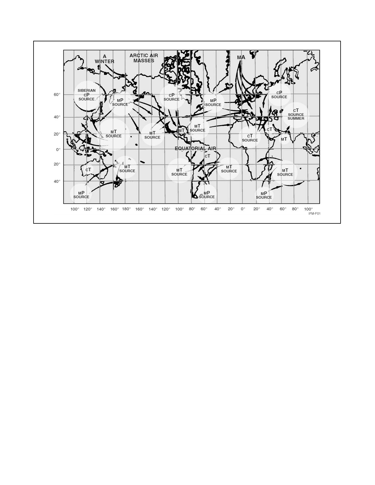
NAVAIR 00-80T-112
Figure 3-1. Air Mass Source Regions
3.1.4 Airmass Weather
With an airmass, weather is controlled primarily by the moisture content of the air, the relationship between the
surface temperature and temperature of the airmass, and the terrain over which it is located or passing (upslope or
downslope). Rising air is cooled, whereas descending air is warmed. Condensation takes place when the air is cooled
to its dewpoint. A cloud warmed above its dewpoint temperature will evaporate and dissipate. Stability tends to
increase if the surface temperature is lowered or if the temperature of the air at higher levels is increased while the
surface temperature remains the same. Stability tends to be reduced if the surface temperature remains the same and
the temperature aloft is lowered.
An airmass that has a cyclonic trajectory will be predominantly unstable in the lower layers, whereas an airmass with
an anticyclonic trajectory will be stable in the lower layers.
Smooth stratiform clouds are associated with stable air, whereas convective clouds and thunderstorms are associated
with unstable air.
ORIGINAL
3-2
NAVAIR 00-80T-112
CHAPTER 4
Fronts
4.1
INTRODUCTION
Because most major changes in the weather are associated with fronts, it is essential that aviators be totally familiar
with them. This requires a thorough understanding of the relationship of fronts to cyclones and airmasses, their
characteristics, and the weather phenomena associated with the various types of fronts.
4.2
RELATION OF FRONTS TO CYCLONES
A cyclone is defined as a low pressure system around which the air flows in a counterclockwise motion (in the
Northern Hemisphere). In most cases, frontal activity is associated with low pressure systems. Normally, low pressure
systems are associated with bad weather, and the fronts branching out from the system are also zones of bad weather.
4.3
RELATION OF FRONTS TO AIRMASSES
A front is defined as a boundary or line of discontinuity separating two different airmasses. When viewing a surface
map, a front would only be indicated as a line separating the two airmasses. Viewing fronts in this manner does not
give the true picture because airmasses have vertical extent (Figure 4-1). For example, a cold airmass, being heavier,
tends to underrun a warm airmass; thus, the cold air is below and the warm air is above the surface of discontinuity.
This vertical line of discontinuity is called the frontal slope. The average slope of a cold frontal surface is usually 1:50
(1 mile vertical for 50 miles horizontal), whereas the slope of a warm frontal surface is 1:300 (1 mile vertical for 300
miles horizontal). The slope of a front is of considerable importance in visualizing and understanding the weather
along the front. In general, all cross sections of fronts as shown in this chapter summarize pictorially all the pertinent
features of all types of fronts under average conditions.
4.3.1 Cold Fronts
A cold front is the line of discontinuity along which a wedge of cold air is underrunning and displacing a warmer
airmass.
There are certain weather characteristics and conditions that are typical of cold fronts. In general, with the passage
of a cold front, the temperature and humidity decrease, the pressure rises, and, in the Northern Hemisphere, the surface
wind usually veers from the southwest to the northwest. Visibilities improve considerably, and the ceiling increases
almost immediately. The distribution and type of cloudiness and the intensity and distribution of precipitation, along
and in advance of the cold front, depend primarily on the vertical velocity within the warm airmass. On the basis of
this factor, these fronts are classified as either slow-moving or fast-moving cold fronts. When viewing a cold frontal
system, it is important that they be characterized as either a slow-moving or fast-moving system.
4.3.1.1 Slow-Moving Cold Fronts
A slow-moving cold front is defined as a cold front with an average speed of 15 knots or less and an average slope
of 1:100; however, near the surface, the slope is much steeper than in the upper atmosphere. The cloud and
precipitation areas associated with this type front are extensive, with showers, thunderstorms, and squalls that persist
for hundreds of miles along the front. Additionally, extensive cloud cover and precipitation extend for several hundred
miles behind the front. The development of convective activity is largely dependent on the original instability
characteristics of the warm airmass. Within the cold airmass there may be some stratified clouds in the rain area, but
there are no clouds in the cold air beyond this area unless the cold airmass in unstable. See Figure 4-2 for a cross section
of a typical slow-moving cold front.
4-1
ORIGINAL
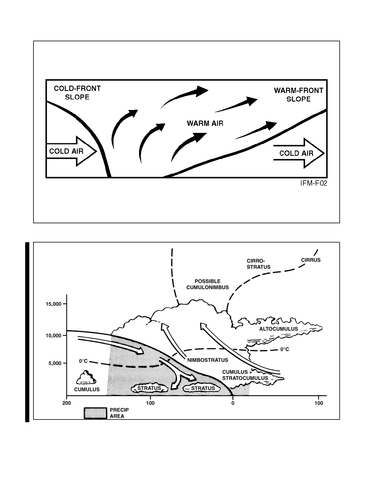
NAVAIR 00-80T-112
Figure 4-1. Frontal System (Without Clouds Shown)
FEET
MILES
Figure 4-2. Vertical Cross Section of a Slow-Moving Cold Front
ORIGINAL
4-2
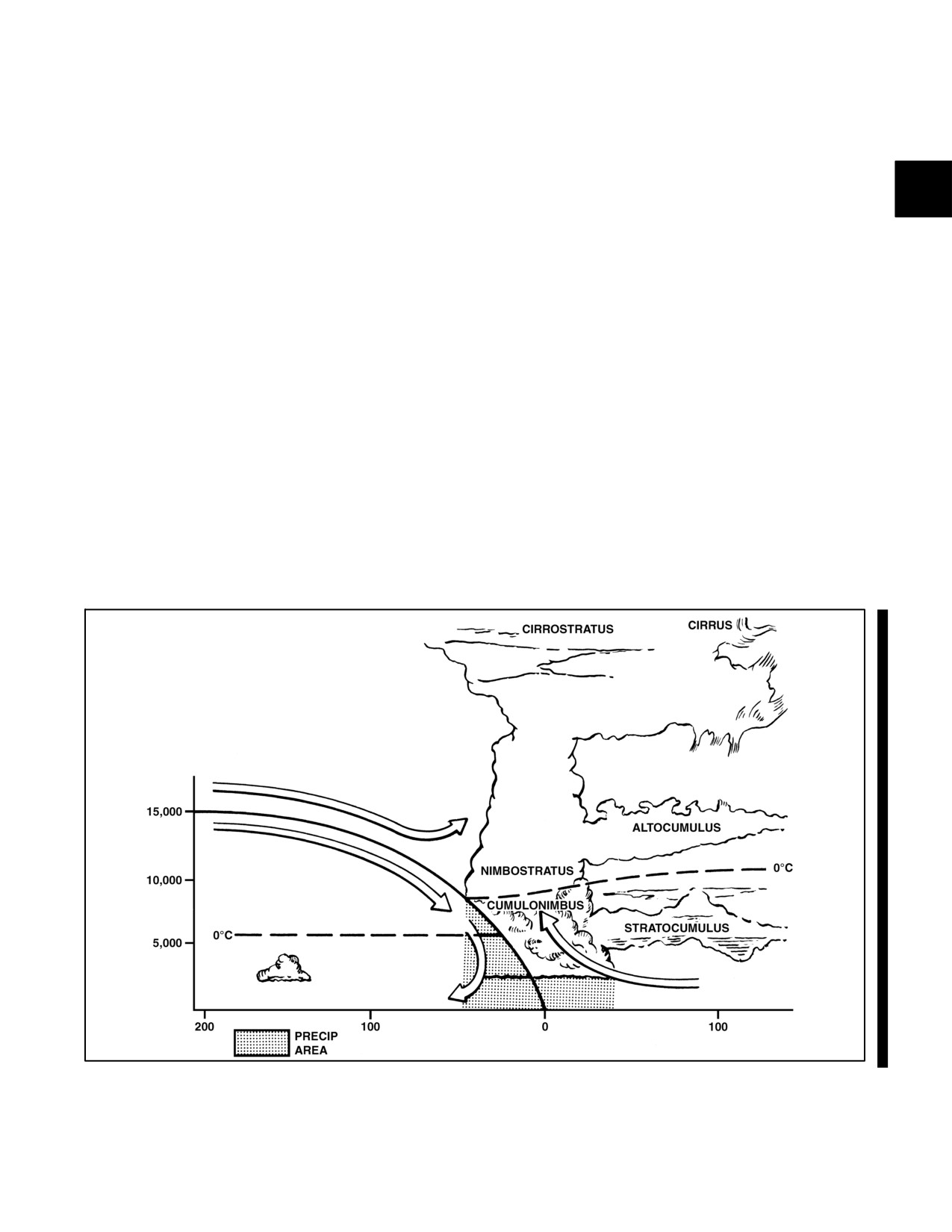
NAVAIR 00-80T-112
4.3.1.2 Fast-Moving Cold Fronts
These types of cold fronts are very important in that they move very rapidly and normally are associated with violent
weather. Their adverse slope is 1:40 to 1:80, with an average speed of 25 to 30 knots. The development of squall lines,
and in some situations, tornado activity, are not uncommon with these systems. Normally, after the passage of a
fast-moving cold front, rapid clearing will take place. Figure 4-3 shows a typical cross section of a fast-moving cold
front.
4.3.2 Warm Fronts
A warm front is the line of discontinuity where the forward edge of an advancing mass of warm air is replacing a
retreating colder airmass. As in the case of the cold front, the term is used inexactly when referring to a warm frontal
surface.
Certain characteristics and weather conditions are associated with warm fronts. The winds shift from southeast to
southwest or west, but the shift is not as pronounced as with the cold front. The average slope of a warm front is 1:150.
A characteristic phenomena of a typical warm front is the sequence of cloud formation. This cloud formation is
noticeable in the following sequence: cirrus, cirrostratus, altostratus, nimbostratus, and stratus. With a typical warm
front, cirrus clouds may appear 700 to 1,000 miles ahead of the surface front, followed by cirrostratus at about 600
miles, altostratus at 500 miles, and nimbostratus and stratus clouds within 300 miles of the actual frontal surface. As
stated earlier, convective activity is frequently embedded along and in advance of the frontal surface. Clearing usually
occurs after the passage of a warm front; however, under certain conditions, drizzle and fog may occur within the
warm sector of the frontal system. Figure 4-4 shows a typical cross section of a warm front.
FEET
MILES
Figure 4-3. Vertical Cross Section of a Fast-Moving Cold Front
4-3
ORIGINAL
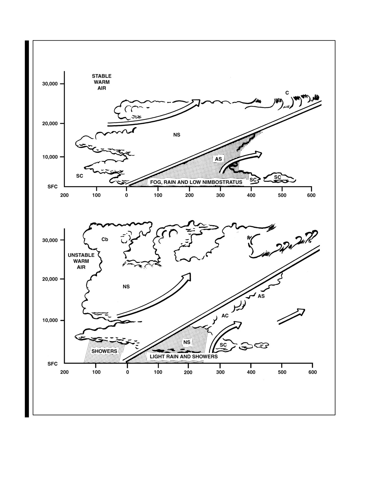
NAVAIR 00-80T-112
FEET
MILES
FEET
MILES
Figure 4-4. Vertical Cross Section of a Warm Front
ORIGINAL
4-4
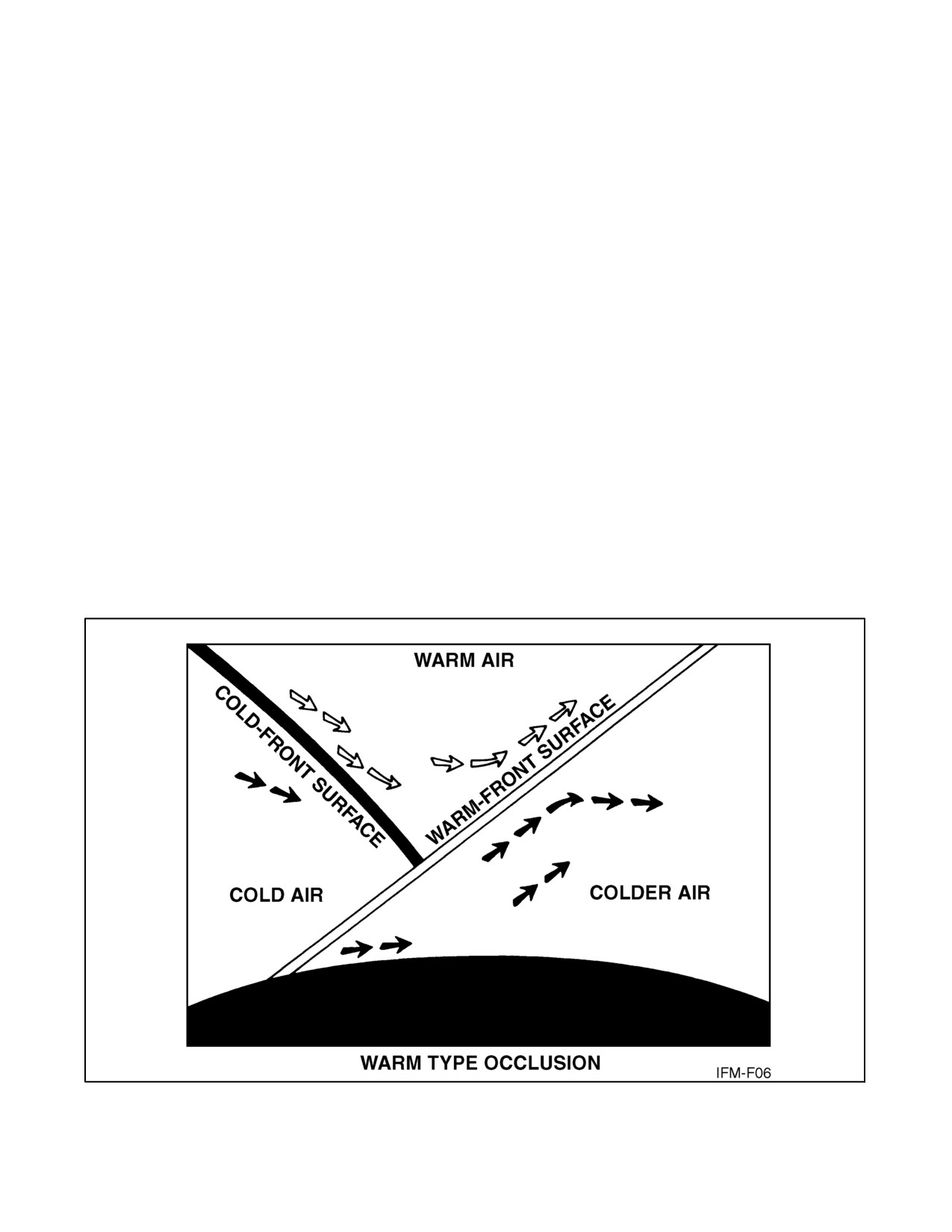
NAVAIR 00-80T-112
4.3.3 Occluded Fronts
An occluded front occurs when the cold front overtakes the warm front, and one of the two fronts is forced aloft,
thereby creating a situation where the warm air between the fronts is displaced above the surface. Occluded fronts
either display a combination of both warm and cold frontal type weather or a predominate weather pattern that is more
relative to either a warm or cold frontal system. When dealing with an occluded front, the zone of the most adverse
weather is located near the apex of the warm and cold frontal surfaces. Figures 4-5 and 4-6 provide a vertical cross
section of warm and cold type occlusions, respectively, and Figure 4-7 provides occlusions in the horizontal and
associated upper front.
4.3.4 Stationary Fronts
When a front is stationary, the cold airmass, as a whole, does not move either toward or away from the front. In terms
of wind direction, this means that the wind above the friction layer blows neither toward nor away from the front,
but parallel to it. It follows that the isobars, too, are nearly parallel to a stationary front. This characteristic makes it
easy to recognize a stationary front on a weather map.
The frictional inflow of warm air toward a stationary front causes a slow upglide of air on the frontal surface. As the
air is lifted to and beyond its lifting condensation level, clouds form in the warm air above the front.
If the warm air in a stationary front is stable, the clouds are stratiform. Drizzle may then fall; and as the air is lifted
beyond the freezing level, icing conditions develop and light rain or snow may fall. At very high levels above the top
of the front, ice clouds are present.
If the warm air is conditionally unstable and sufficient lifting occurs, the clouds are then cumuliform or stratiform
with cumuliform protuberances. If the energy release is great (warm, moist, unstable air), thunderstorms result.
Rainfall is generally showery.
Figure 4-5. Vertical Cross Section of a Warm-Type Occlusion
4-5
ORIGINAL
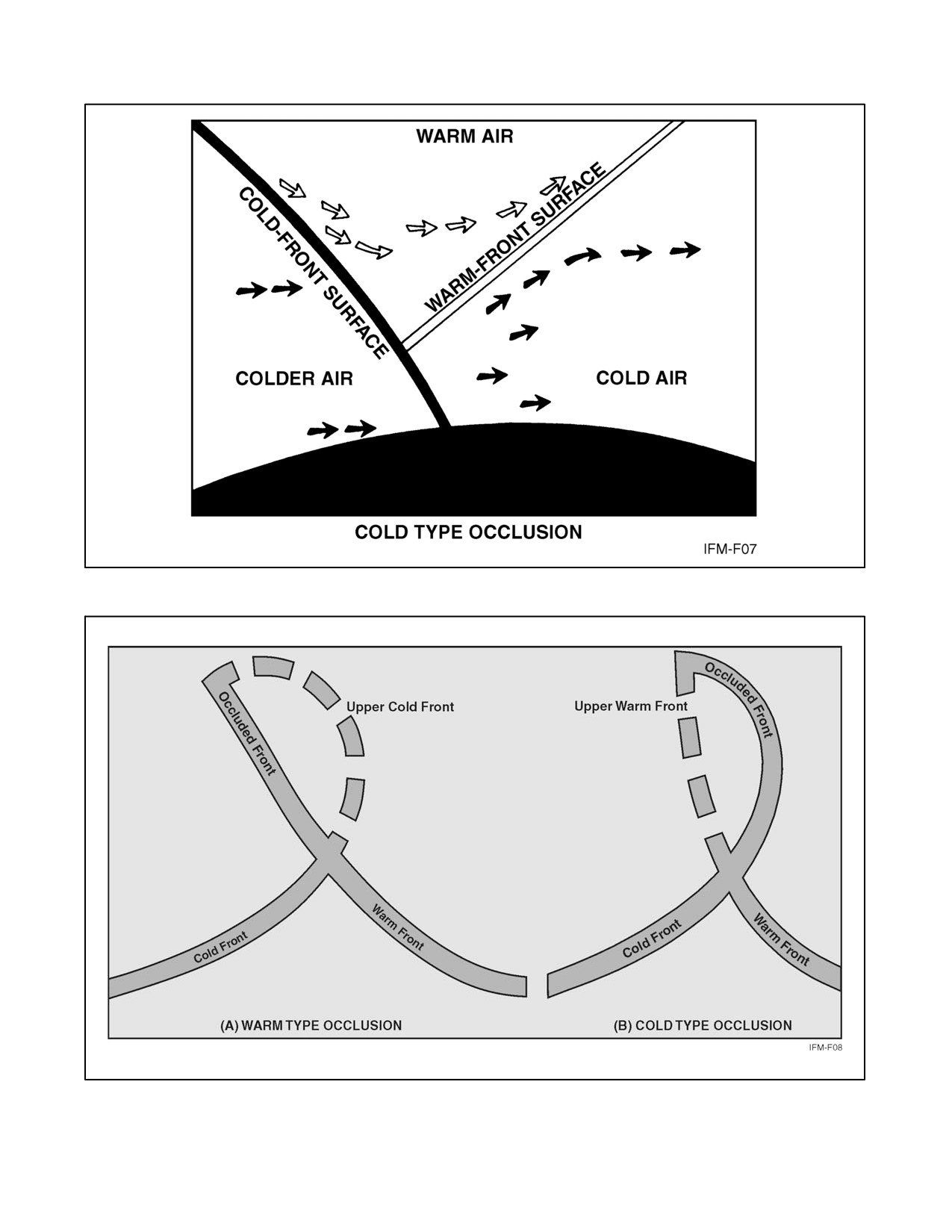
NAVAIR 00-80T-112
Figure 4-6. Vertical Cross Section of a Cold-Type Occlusion
Figure 4-7. Occlusions (in the Horizontal) and Associated Upper Front
ORIGINAL
4-6
NAVAIR 00-80T-112
Within the cold airmass, extensive fog and low ceiling may result, where the cold air is saturated by warm rain or
drizzle falling through it from the warm airmass above. If the temperature is below 32 _F, icing may occur, but
generally is light.
The width of the band of precipitation and low ceiling varies from 50 miles to approximately 200 miles, depending
upon the slope of the front and the temperatures of the airmasses. One of the most annoying characteristics of a
stationary front is that it may greatly hamper and delay air operations by persisting in the area for several days.
4.4
PRESSURE AT FRONTS
One of the important characteristics of all fronts is that on both sides of a front, the pressure is higher than at the front.
This is true even though one of the airmasses is relatively warm and the other is relatively cold; hence, there is always
a net movement of air upward in the region of a front. This is another important characteristic of fronts, as the lifting
of the air causes condensation, clouds, and weather.
Whereas air motion within an area of high pressure is downward and outward (divergence), motion in a frontal zone
is inward and upward (convergence).
4.5
FRONTAL MOVEMENT
The weather is greatly affected by the movement of frontal systems. From the time the front develops until it passes
out of the weather picture, it is watched closely. The speed at which it travels and the modifications that it undergoes
are important considerations in analyzing and forecasting the weather.
4.5.1 Speed
The speed of the movement of frontal systems is an important determining factor of weather conditions. Rapidly
moving fronts usually cause more severe weather than slower-moving fronts. For example, fast-moving cold fronts
often cause severe prefrontal squall lines, which are extremely hazardous to flying. The fast-moving front does have
the advantage of moving across the area rapidly, permitting the particular locality to enjoy a quick return of good
weather. Slow-moving fronts, on the other hand, may cause extended periods of unfavorable weather. A stationary
front, which may bring bad weather, can disrupt flight operations for several days in succession.
4.5.2 Modifications
There are many factors that can modify the movement of frontal systems. In this section, only a few of the more
important factors are considered.
4.5.2.1 Effect of Mountains
Mountain ranges affect the speed, the slope, and the weather associated with a front. The height and horizontal
distance of the mountain range, along with the angle of the front along the mountain range, are the influencing factors.
The effect of mountain ranges differs in regard to cold fronts and warm fronts.
As a cold front approaches a mountain range, the lower portion of the front is retarded as the upper portion pushes
up and over the mountain. On the windward side of the mountain, precipitation is increased due to the additional lift
as the warm air is pushed up along the mountain slope. After the front reaches the crest of the mountain, the air behind
the front commences to flow down the leeward side of the range. If the air on the leeward side of the mountain is
warmer than the air in the rear of the cold front, the warmer air is forced away and replaced by the colder airmass.
As the cold air descends the lee side of mountain, the air warms adiabatically (Figure 4-8) and clearing occurs within
it; however, because the cold air is displacing warm air, typical cold frontal clouds and precipitation may occur within
the warm air if the warm air is sufficiently moist and conditionally unstable. In some cases, maritime polar air that
has crossed the Rockies is less dense then maritime tropical air from the Gulf of Mexico, which may lie just east of
4-7
ORIGINAL
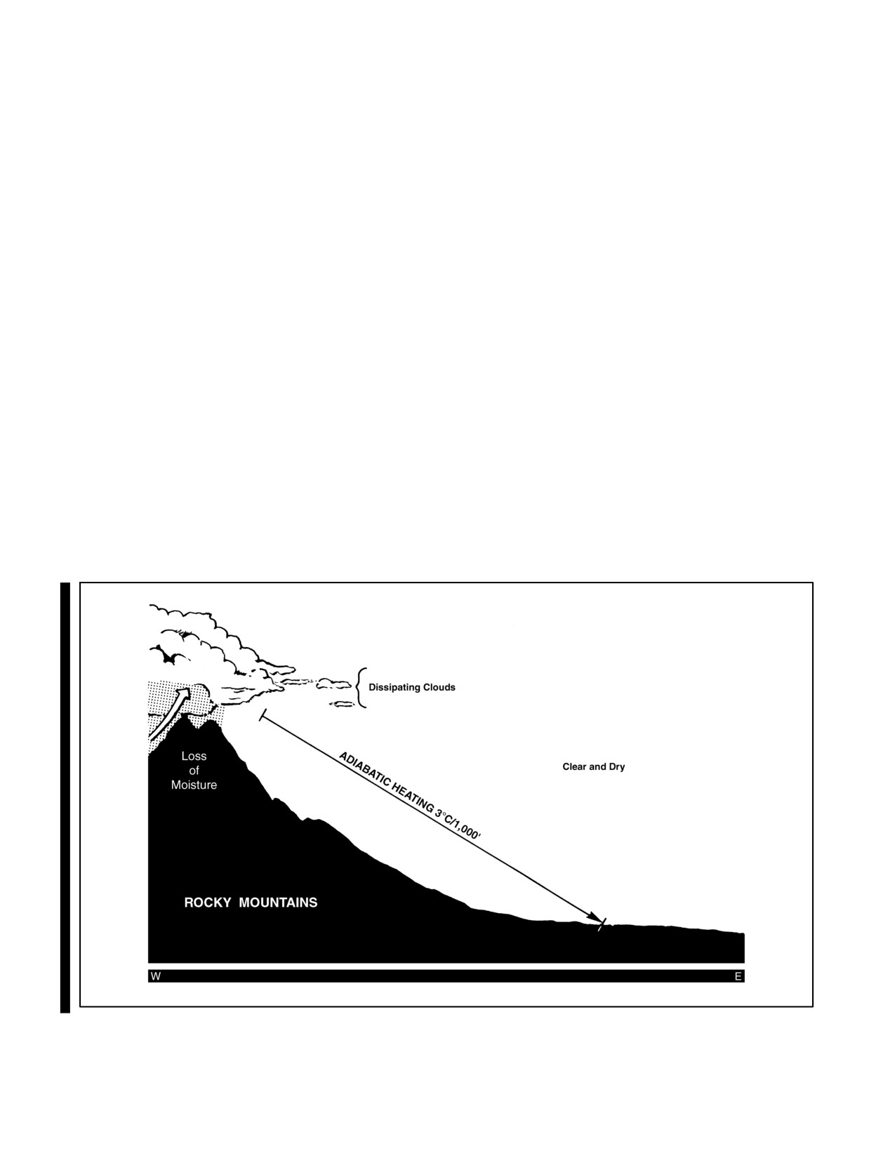
NAVAIR 00-80T-112
the mountains. If the maritime polar air is moving with a strong westerly wind current, the maritime polar air is moving
with a strong westerly wind current, and the maritime tropical air is moving with a strong southerly wind current, the
maritime polar air may overrun the maritime tropical air. This results in extremely heavy showers and violent
thunderstorms and is one of the conditions under which tornadoes occur.
If colder stagnant air lies to the lee side of the mountain range, the cold front, on passing over the range, does not reach
the surface and travels as an upper cold front. Under this condition, frontal activity is at a minimum. This situation
does not continue indefinitely; either the stagnant air mixes with the air above and the surface of separation becomes
spread out, or the cold front breaks through to the ground with the development of thunderstorms and squalls.
As a cold front passes a mountain range, it may develop a bulge or a wave as a portion of the front is retarded. In the
case of an occlusion, a new and separate cyclone circulation may occur at the peak of the warm sector as the occluded
front is retarded by a mountain range.
In general, it may be said that the area of precipitation is widened as the front approaches the range and that there is
increased intensity of the precipitation area and cloud system on the windward side of the range and a decrease on
the leeward side (Figure 4-9).
Consider the effect of a mountain range on a warm front. When a warm front approaches a mountain range, the upper
section of the frontal surface is above the effects of the mountain range and does not come under its influence. As
the lower portion of the frontal surface approaches the range, the underlying cold wedge is cut off, forming a more
or less stationary front on the windward side of the range. The inclination of the frontal surface above the range
decreases and becomes more horizontal near the mountain surfaces, but the frontal surface maintains its original slope
at higher altitudes. Whereas the stationary front on the windward side of the range may be accompanied by prolonged
precipitation, the absence of ascending air on the leeward side of the range causes little or no precipitation. The warm
air descending the leeward side of the range causes the cloud system to dissipate and the warm front to travel as an
upper front.
11,000’ -20 _C
1,000’ )10 _C
Figure 4-8. Effect of Adiabatic Heating
ORIGINAL
4-8
NAVAIR 00-80T-112
Frontogenesis (the formation of a new front or the regeneration of an old front) may occur in the pressure-trough area
that accompanies the front. The frontal surface then gradually forms downward as the frontal system moves away
from the mountain, and it extends to the surface of the Earth again; therefore, the effect of the mountain range on
a warm front is to widen and prolong the precipitation on the windward side of the range, while on the leeward
side the precipitation band is narrowed and weakened, or dissolved (Figure 4-10).
Mountain ranges have much the same effect on occluded fronts as they do on warm and cold fronts. Cold-type
occlusions behave as cold fronts and warm-type occlusions behave as warm fronts. The occlusion process is
accelerated when an open wave approaches a mountain range because the warm front is retarded whereas the cold
front continues its normal movement until is reaches the mountain range.
4.5.2.2 Effect of Ocean Currents
Ocean currents have a modifying effect on frontal movement. To understand why ocean currents have such an effect,
it is necessary to consider the movement of the currents.
In middle latitudes, ocean currents carry warm water away from the equator along the eastern coasts of continents
and carry cold water toward the equator along the western coasts of continents. The most active frontal zones of the
winter season are found where cold continental air moves over warm water off eastern coasts. This situation is
noticeable over the Atlantic Ocean off the east coast of the United States. As a cold front moves off the coast and over
the Gulf Stream, it becomes intensified, causing wave development to occur near the Cape Hatteras area. This gives
the east coast of the United States much cloudiness and precipitation. A similar situation occurs off the east coast of
Japan. That area in the Pacific generates more cyclones than any other area in the world.
4.5.2.3 Other Effects
The movement of a frontal system from one area to another often has a great modifying effect, causing the front to
be regenerated in some instances and to be dissipated in others. Transition affects waves and cyclones as well as fronts.
When dissipating, extratropical cyclones enter regions of frontogenesis and cyclogenesis; they are frequently
regenerated into active disturbances. This is usually caused by an influx of warm, moist air to the east and cold air
to the west of the center. In a situation in which a well-defined cyclone, associated with a front (or fronts), moves
eastward over the Rocky Mountains, the frontal system is usually weakened by the time it descends the eastern slopes.
If there is an influx of warmer moist air from the Gulf of Mexico, the frontal system is regenerated as it moves
eastward. If the circulation to the east of the mountain range is such that no moist air is drawn into the cyclone or frontal
system, frontolysis (the process of a front weakening or dissolving) takes place.
Frontal systems moving from water to land areas tend to weaken if an influx of moist air is not brought into the
situation; on the other hand, a frontal system moving from land areas to water areas is generally regenerated by the
influx of moist air. For example, a frontal system may become quasi-stationary in the vicinity of the east coast of the
United States. This frontal system is usually oriented in a northeast-southwest direction and occurs mostly during the
summer and autumn months, when outbreaks of continental polar air (cP) move southeastward over the states. These
fronts usually lose their intensity over the southern states and movement ceases. Frequently, stable waves develop
and travel along this frontal system, causing unfavorable weather conditions. When these waves move out to sea and
warmer moist air is brought into them, they become unstable waves and are regenerated as they move across the ocean.
4-9
ORIGINAL
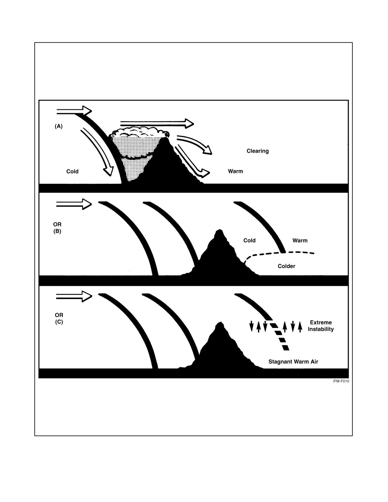
NAVAIR 00-80T-112
Figure 4-9. Effect of Mountains on a Cold Front
ORIGINAL
4-10
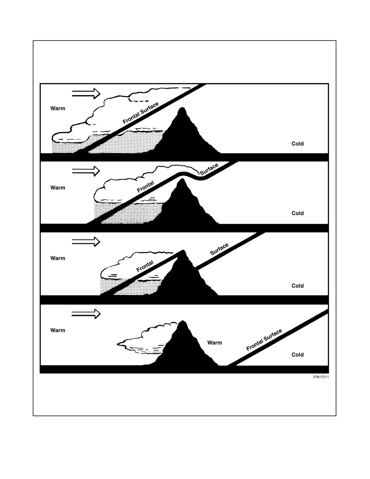
NAVAIR 00-80T-112
Figure 4-10. Effect of Mountains on a Warm Front
4-11/(4-12 blank)
ORIGINAL
NAVAIR 00-80T-112
CHAPTER 5
Tropical Meteorology
5.1
INTRODUCTION
With the advent of satellite data and the application of high-speed computers, the quality of forecasts for tropical
regions has improved greatly. The most effective rule of thumb used in forecasting in the tropics is to identify areas
where a change in the normal weather pattern(s) is taking place, then determining what atmospheric feature is
inducing said change. When viewing tropical weather in general, significant weather may occur over, or adjacent to,
land areas or in areas affected by certain atmospheric features. Two significant features that are worthy of discussion
are tropical waves and areas of converging wind flow, such as the Intertropical Convergence Zone (ITCZ).
5.2
TROPICAL WAVES
A tropical wave, more commonly known as an easterly wave, is defined as a wavelike disturbance that moves from
east to west in the tropical easterlies (Northern Hemisphere). When viewed in a vertical plane, the wave appears as
an inverted trough that will slope to the east, west, or be nearly vertical (no slope). The slope of a wave may change
with time. Adverse weather associated with a tropical wave is an indication of the slope of the wave. Weather
associated with waves is showery precipitation and thunderstorms. Cloud patterns usually consist of cumulus
congestus and cumulonimbus, arranged in parallel bands, with layers of altocumulus and altostratus clouds along with
higher layers of cirrus clouds associated with convective activity. Embedded thunderstorms may also be present in
areas of extensive cloud precipitation areas. Tropical waves also support the development of haze conditions; this
haze normally reduces visibility and will be present in advance of the wave.
There are three types of tropical waves: stable, neutral, and unstable.
5.2.1 Stable Wave
This type of wave slopes to the east with height. To the west of the trough line, winds at the surface and aloft are
predominantly northeasterly. This area experiences falling pressures, but because of divergence at all levels, fair
weather prevails. East of the trough line, the surface and upper air winds veer to the southeast. The intense
convergence found in this area produces widespread cloudiness and shower activity. This is the most common
type of easterly wave (Figure 5-1).
5.2.2 Neutral Wave
With a neutral wave, the bad weather is symmetrical around the trough line, with the most intense weather occurring
along the trough line. This type of wave is vertical (no slope) and is typical of a wave that is intensifying.
5.2.3 Unstable Wave
This type of wave has the most violent weather and is often associated with the development of typhoons and
hurricanes. The weather associated with the unstable wave is ahead of the trough line, and the wave slopes to the west
with height.
5-1
ORIGINAL
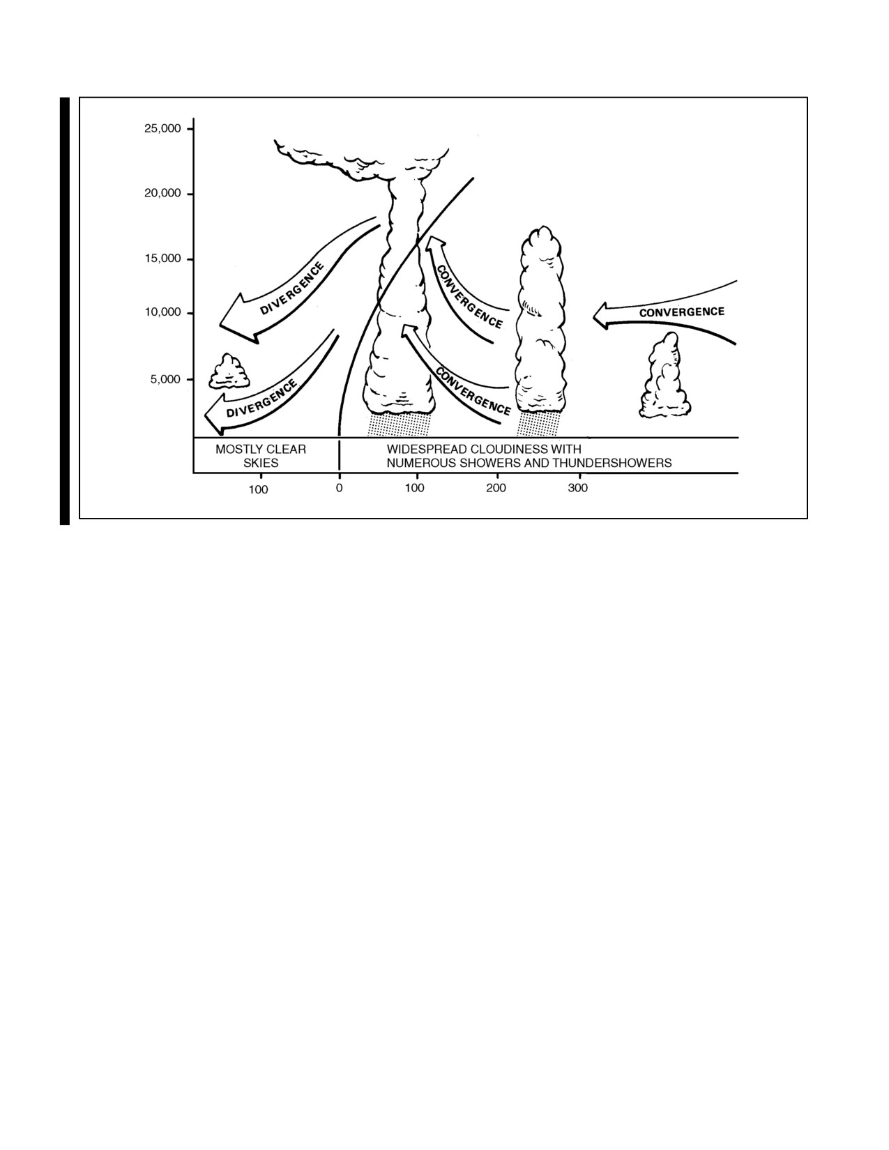
NAVAIR 00-80T-112
FEET
MILES
Figure 5-1. Vertical Cross Section of a Stable Easterly Wave
5.3
INTERTROPICAL CONVERGENCE ZONE
The ITCZ appears as an extensive band of clouds and weather that is caused by the convergence of the northeast trade
winds of the Northern Hemisphere and the southeast trade winds of the Southern Hemisphere. In most cases, the ITCZ
has no sharp frontal discontinuity, and its width may vary from 50 to 400 miles.
As the intensity of the converging wind fields may vary from place to place, the extent of the weather associated with
the zone will vary correspondingly in width and intensity.
The ITCZ is a migratory zone that reaches it northernmost position in February and its southernmost position in
August. In the Atlantic and Eastern Pacific oceans, the ITCZ normally remains north of the equator year round,
whereas in the Indian Ocean and Western Pacific, the zone will lie south of the equator during the Northern
Hemisphere winter.
The intensity of the weather within the ITCZ depends on the level of instability and the extent of convergence
that is present. Weather within the zone may vary between an area of solid cumulonimbus clouds with many thick
cloud layers at several levels and an area of broken to overcast cloud layers, with little or no convective activity
(Figure 5-2).
At times, fractures along the zone will occur. In some cases these fracture zones may spawn a hurricane or typhoon.
5.4
CONVERGENCE ZONES
On occasion, converging windflow in areas other than the ITCZ will produce cloud conditions that would not be
present under normal conditions. Although convective activity is not normally encountered in convergence zones
unless they are associated with major features such as tropical waves, the presence of clouds above the freezing level,
or convergence zones of intensities within a relatively shallow layer within the atmosphere, will produce icing or
turbulence, respectively.
ORIGINAL
5-2
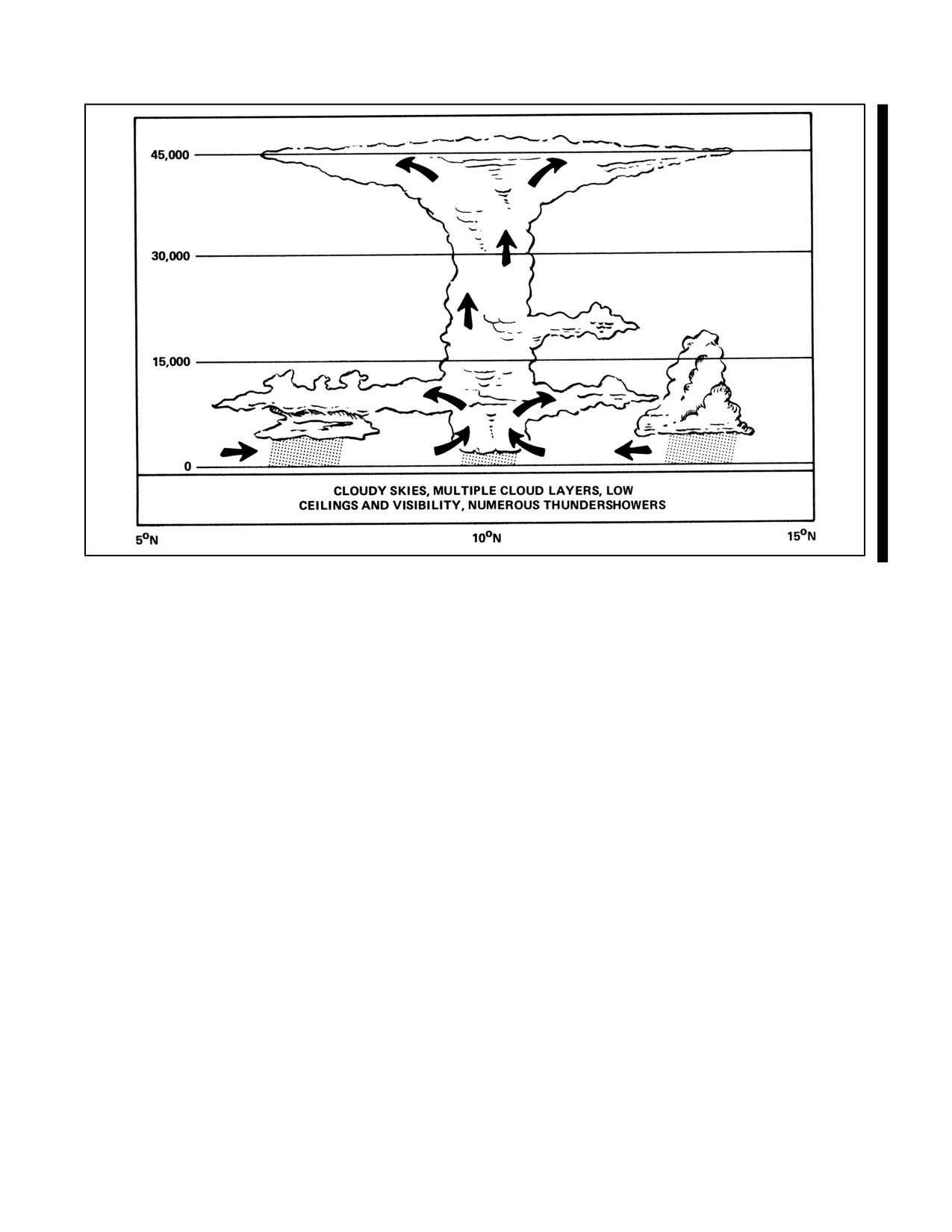
NAVAIR 00-80T-112
FEET
Figure 5-2. Weather Conditions in an Active Portion of the ITCZ
5.5
SHEAR LINES
A shear line is defined as a line or narrow zone across which there is an abrupt change in the horizontal wind
component parallel to said line. It most commonly refers to lines of cyclonic shear. Monsoon and upper tropospheric
troughs, as well as remnants of cold fronts, are examples of shear lines.
It has been known for many years that cold fronts from midlatitude penetrate deep into the tropics and occasionally
move across the equator. The leading edge of the front is usually marked by a pronounced line of convection and a
series of convecting lines oriented parallel to the front (and to the wind) may occur on the poleward side of the main
line. The average tops in these shear lines are usually not high (10,000 to 15,000 feet), but the associated low ceilings
and rainfall along the line may cause poor terminal weather conditions, especially with orographic effects.
5-3/(5-4 blank)
ORIGINAL
NAVAIR 00-80T-112
CHAPTER 6
Weather Hazards to Flight
6.1
THUNDERSTORMS
It is estimated that more than 44,000 thunderstorms occur daily over the surface of the Earth. The frequency with
which these destructive storms occur, the quantity of energy they release, and the variety of forms this energy may
take — hail, lightning, strong gusty winds, abundant rainfall, and, on occasion, tornadoes — mark thunderstorms as
the most serious threat to the safe and successful accomplishment of the naval aviation mission.
6.1.1 Thunderstorm Development
A certain combination of atmospheric conditions is necessary for the formation of a thunderstorm to take place. These
conditions are an unstable temperature lapse rate, high moisture content, and some type of lifting action. The lifting
action may be caused by heating, terrain, fronts, or converging wind fields.
The fundamental structural element of the thunderstorm is the unit of convective circulation known as a convective
cell. A mature thunderstorm contains several of these cells, which vary in diameter from 1 to 6 miles, and it has been
determined that, generally, each cell is independent of surrounding cells of the same storm. Each cell progresses
through a cycle that lasts from 1 to 3 hours. In the initial stage, the cloud consists of a single cell, but, as the
development progresses, new cells form and older cells dissipate. The life cycle of the thunderstorm consists of three
distinct stages (Figure 6-1).
6.1.1.1 Cumulus Stage
Although most cumulus clouds do not become thunderstorms, the initial stage of a thunderstorm is always a cumulus
cloud. The distinguishing feature of this cumulus (building) stage is the presence of an updraft, which prevails
throughout the entire cell. These updrafts may vary from a few fpm to as much as 6,000 fpm in cells approaching the
mature stage (Figure 6-1).
When transiting through an area where the rate of cumulus development is such that potential exists for further
development to thunderstorm intensity, aircraft should make every effort to circumnavigate or overfly these cells,
rather than fly through or under the cells. The reason for such action is that because the point where the cell will reach
the mature stage cannot be predicted, aircraft flying through or under these cells could be exposed to unexpected
downdrafts that could produce disastrous effects, especially when operating at low altitudes or involved in the landing
or approach phases of flight.
6.1.1.2 Mature Stage
The mature stage is often called the precipitation or hail stage. This stage begins when precipitation from the cell first
reaches the ground. The beginning of this surface rain also indicates the presence of both updrafts and downdrafts
within and adjacent to the cell. Normally, a cell that has reached the mature stage will have reached a height of 20,000
feet Above Ground Level (AGL) or more. As raindrops begin to fall within the cell, the frictional drag between the
drops and the surrounding air causes the air to begin a downward motion. The descending saturated air eventually
reaches a level where it is colder and denser than the surrounding air. Consequently, its rate of downward motion is
accelerated, thus creating a downdraft. Shortly after rain initially starts to fall, the updraft within the cell will reach
its maximum speed. The speed of updrafts increases with altitude, whereas downdrafts are usually strongest at the
middle and lower levels. The mature stage of a thunderstorm is the most dangerous of development in that all hazards
may be found in this stage.
6-1
ORIGINAL
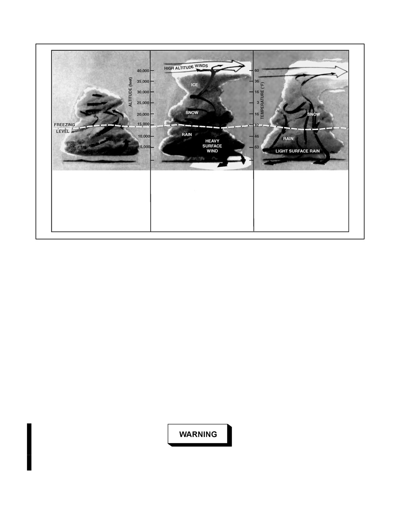
NAVAIR 00-80T-112
Centered on converging surface
Rain and snow begin to fall within
Eventually the downdraft destroys
winds, an updraft drives warm,
the cloud and an ice phase appears
the parent cell. As surface winds
moist air past condensation levels,
in the towers. The formation and
shift from convergent to divergent,
where Cumulus clouds form.
precipitation of solid or liquid
the updraft is cut off from its source
Vertical development is aided by air
particles marks the thunderstorm’s
of energy, precipitation weakens,
entering from sides, heat energy
mature stage, when a downdraft
stops, and the downdraft ceases.
released by condensing water
joins the updraft and lightning
vapor, and outflow aloft.
begins.
Figure 6-1. Thunderstorm Development
6.1.1.3 Dissipating Stage
Also known as the anvil stage, the dissipating stage is characterized by the gradual spreading of the downdrafts as
they take the place of dissipating updrafts. As this process continues, the entire lower portion of the cell becomes an
area of downdrafts. At this point, the high winds aloft have now carried the upper section of the cloud into an anvil
form, thus indicating that gradual dissipation is occurring.
Thunderstorms have been accurately measured as high as 67,000 feet. In some cases, the tops of some severe
thunderstorms have attained a height greater than 70,000 feet. Normally, the maximum height of a thunderstorm will
be between 40,000 and 45,000 feet. In general, airmass thunderstorms extend to greater heights than frontal types.
6.1.1.4 Severe Thunderstorms
Less frequently encountered, but far more dangerous, severe thunderstorms are capable of producing surface wind
gusts in excess of 50 knots, hail three-fourths of an inch or greater, and, in some cases, tornadoes. They are normally
found within squall lines, or in airmass situations, either singularly or embedded in lines or clusters, primarily during
the spring and summer in the midwestern and southeastern United States. Severe thunderstorms often reach massive
proportions, covering an area of hundreds of square miles, and produce an extensive cirrus shield, from their anvil
top, which may spread over an area of nearly 1,000 square miles. A confrontation with a severe thunderstorm should
be avoided at all costs.
The penetration of a thunderstorm, regardless of its stage of development,
or level of intensity, should never be attempted.
ORIGINAL
6-2
NAVAIR 00-80T-112
6.1.2 Thunderstorm Weather
6.1.2.1 Precipitation
Liquid precipitation may be ascending, if encountered in a strong updraft; it may be suspended, seemingly without
motion, yet extremely concentrated; or it may be falling to the ground. Rain is found in almost every case below the
freezing level. The greatest incidence of heavy rain occurs in the middle and lower levels of the storm. Frozen
precipitation is found in the form of snow and hail. The maximum frequency of moderate to heavy snow occurs
several thousand feet above the freezing level. Snow, mixed in many cases with supercooled rain, may be encountered
in updraft areas at all altitudes above the freezing level. This type of action will cause wet snow to become packed
on the leading edge of the aircraft wings, resulting in the formation of rime ice. Hail, if present, is most often found
in the mature stage and it is normally found at more than one or two levels within the cell. The maximum occurrence
of hail is at middle levels.
6.1.2.2 Turbulence
Within the thunderstorm cell, there is a definite correlation between turbulence and precipitation. The intensity of
turbulence, in most cases, varies proportionately with the intensity of the precipitation.
6.1.2.3 Icing
This phenomenon may be encountered at any level where the temperature is below freezing. Both rime and clear ice
occur, with rime predominate in regions of snow and mixed rain and snow, and clear ice more predominant at levels
where supercooled water droplets (temperature of −4 to −8 °C) are present. As the freezing level is also the zone of
strongest precipitation and turbulence, this altitude is considered to be the most hazardous.
6.1.2.4 Lightning
There are four types of lightning associated with thunderstorms: (1) cloud to ground, (2) cloud to cloud, (3) cloud
discharges (lightning that takes place within the cloud), and (4) air discharges (discharges that pass from the cloud
to the air, but do not strike the ground or reach to another cloud). Lightning will occur in, near, or over the top of a
storm area, and has been known to strike objects as far as 35 miles from the convective cell.
6.1.3 Thunderstorm Classification
All thunderstorms are similar in their physical makeup. Their classification is based on the type of weather situation
that generates them; therefore, there are two basic classifications of thunderstorms: airmass or frontal.
6.1.3.1 Airmass Thunderstorms
These thunderstorms are subdivided into several types.
6.1.3.1.1 Convective Thunderstorms
Convective thunderstorms are a form of airmass thunderstorm that may occur over land or water almost anywhere
in the world. They are generated within a large airmass of moist, unstable air. Their formation is caused by solar
heating of various areas of the land or sea, which in turn provides heat to the air above. The type of convective
thunderstorms that forms over land normally develops during the afternoon hours and usually begins to dissipate
during the early evening hours. These thunderstorms are usually scattered over a broad area; however, these
thunderstorms have been known to form in large groups (clusters), especially where a unique topographical feature
is present. Convective thunderstorms also form over bodies of water in the same manner as those over land, except
they form during the evening hours and dissipate by late morning. The coastal areas of Florida, Cuba, and the
Philippines are perfect examples of areas where both the land and water area types of convective thunderstorms are
common.
6-3
ORIGINAL
NAVAIR 00-80T-112
6.1.3.1.2 Orographic Thunderstorms
Orographic thunderstorms are triggered when the air is lifted over terrain that slopes upward, such as mountains and
hills. This type of thunderstorm forms on the windward side of the topographical feature and at times may form a long
unbroken line of storms that will be similar to a cold front. Orographic thunderstorms will persist as long as the
circulation continues to produce an upslope motion. When approaching from the lee side, an orographic barrier along
which thunderstorms are developing, the outline of each storm is normally plainly visible; however, when
approaching from the windward side, it may be difficult to identify storms or individual cells because they may be
obscured by other clouds. Orographic thunderstorms, almost without exception, will enshroud mountain peaks or
hills.
6.1.3.2 Frontal Thunderstorms
These thunderstorms are associated with either warm, cold, occluded, or stationary frontal systems.
6.1.3.2.1 Warm Front Thunderstorms
The warm front thunderstorm is caused when warm, moist, unstable air is forced aloft over the colder (denser),
retreating air. Warm front thunderstorms are generally scattered and they are difficult to identify because they are
frequently embedded within other cloud layers. The use of radar is extremely helpful when dealing with warm front
thunderstorms.
6.1.3.2.2 Cold Front Thunderstorms
The cold front thunderstorm is caused by the forward motion of a wedge of cold air into a body of warm, moist,
unstable air. This type of thunderstorm is normally positioned along the frontal surface in what appears to be a
continuous line. Cold fronts normally have rapid movement and a steep frontal slope. Although the line of
thunderstorms is relatively narrow, 50 to 100 miles wide, the line may extend for hundreds of miles with scarcely a
break between the cells. The density of these storms presents a serious hazard to aviation operations. In a few cases,
squall lines may be associated with cold fronts, and more frequently with fast-moving cold fronts.
6.1.3.2.3 Occluded and Stationary Fronts
Thunderstorms are also encountered with occluded and stationary fronts. The occluded front is actually a combination
of a cold front and a warm front. When penetrating such a weather system, the pilot can expect to experience weather
patterns synonymous with both types of fronts. The most severe weather associated with an occluded front is normally
found near the apex of the system (the point where the cold front meets the warm front at the surface). Whenever this
situation exists, the flight should be planned to avoid this area, if at all possible.
6.2
SQUALL LINES
Squall lines (Figure 6-2) are generally associated with fast-moving cold fronts. They are a line of prefrontal
thunderstorms that develop when surface friction retards the forward motion of the cold air at the surface to an extent
that the cold air aloft is advanced many miles ahead of the surface front; therefore, this action causes the warm air
ahead of the front to rise at a greater distance ahead of the front. Squall lines will normally form at ranges from 50
to 100 miles in advance of a cold front. These systems are very violent, produce widespread low cloudiness, and
support the development of tornadic activity.
6.3
TORNADOES AND WATERSPOUTS
A tornado (Figure 6-3) may occur in association with severe squall line conditions. A tornado is a violent whirlpool
of air with an average diameter of approximately 250 yards. Within its funnel-shaped cloud, winds are estimated at
100 to more than 300 knots, making it the most violent of all storms. Not only is it small in area, but usually it wears
itself out in an hour. Nobody has ever flown into a tornado and survived.
ORIGINAL
6-4
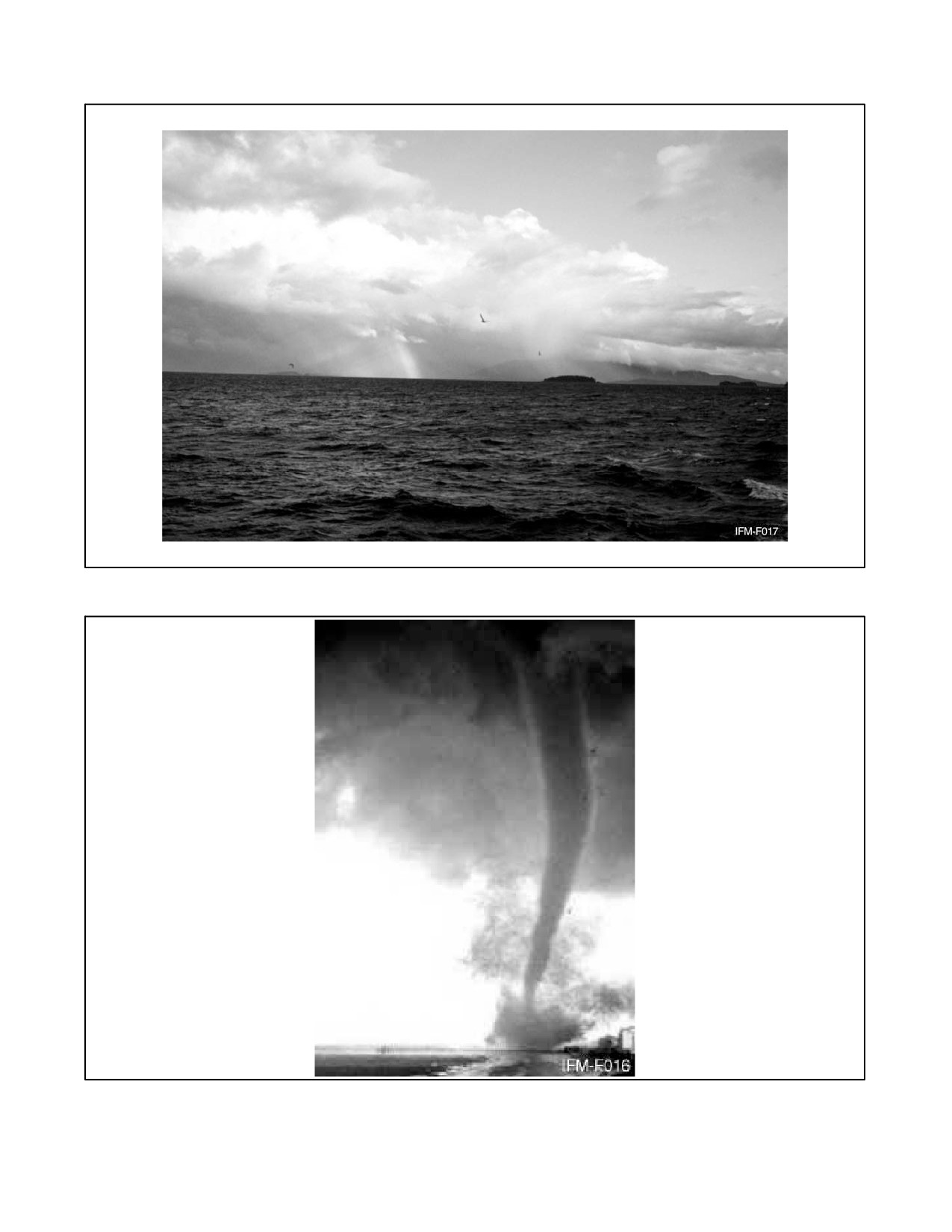
NAVAIR 00-80T-112
Figure 6-2. Squall Line Thunderstorms
Figure 6-3. A Tornado
6-5
ORIGINAL
NAVAIR 00-80T-112
Waterspouts (Figure 6-4) are much the same, but waterspouts occur over the ocean and contain much moisture,
whereas the tornado contains much dust and debris from the surface.
6.4
TURBULENCE
6.4.1 Mountainous Terrain
Flight in mountainous terrain must take account of altimeter errors, turbulence, thunderstorm development, and
frontal modifications over large continental ridges. The following factors must also be considered during flight over
mountainous terrain:
1. Windward approach — An aircraft approaching a ridge from windward is lifted over the ridge by the airstream
blowing up the slope.
2. Leeward approach — An aircraft approaching a ridge while flying into the wind will experience difficulty in
maintaining altitude in the downdraft and eddies on the leeward slopes.
3. Eddy pattern — In rough, mountainous terrain, the complex eddy pattern will cause turbulence. The amount
of turbulence will increase with the windspeed and the roughness of the terrain.
Extreme caution should be exercised for the following factors:
4. Strong winds — Strong winds blowing around and over peaks cause a deflection of the airstream similar to
the flow over the leading edge of an airfoil. Pressure is locally lowered by this distortion of the airstream.
5. Low pressure — An aircraft flying in the low pressure caused by the deflected airstream will have an altimeter
indication showing the aircraft considerably above the actual height.
Figure 6-4. A Waterspout
ORIGINAL
6-6
NAVAIR 00-80T-112
6.4.2 Clear-Air Turbulence
One of the major hazards to modern, high-performance aircraft is the problem of Clear Air Turbulence (CAT) — a
rough cobblestone type of bumpiness experienced in cloudless portions of the sky. This bumpiness, occurring without
visual warning, may be violent enough to disrupt tactical operations and possibly cause serious aircraft stresses. The
turbulent areas are both patchy in space and variable in time. Most cases of pronounced clear air turbulence can be
associated with the jetstream, or more specifically with abrupt vertical windshears (increases or decreases of wind
velocity with altitude), and are experienced more frequently during the winter months when jetstream winds are
strongest. Statistically, this type of turbulence usually occurs with windshears in excess of 8 knots per 1,000 feet.
Because of its random and transient nature, exact locations of clear air turbulence are extremely difficult to forecast.
6.5
FOG
Fog is a restriction to visibility caused by moisture condensing in the atmosphere and forming a cloud at the surface
of the Earth. Fog is reported when the horizontal visibility at an air terminal is reduced to less than 5/8 mile (1
kilometer). Fog is formed when the atmosphere is saturated by the air being cooled to the dewpoint temperature or
the addition of sufficient moisture to raise the dewpoint to the temperature of the atmosphere.
Radiation and advection fogs are examples of the former; frontal, steam, and arctic-ice fogs are examples of the latter
means of saturating the air.
Being formed by different conditions, the various types of fog are characteristically found in particular areas of the
world. The pilot should be aware of the natural processes working in his/her area that could result in fog formation
and dissipation.
Although fog often forms very quickly and can cover large areas, formation is seldom without warning. The pilot must
be alert for the indicators that foretell the formation of fog. He/she must also recognize the more vexing and dangerous
situation when fog has not formed, though conditions are favorable for its imminent formation. This situation is
precarious because the tendency may be to ignore the potential hazard that ceiling and visibility could very quickly
go from that which is completely adequate for normal operations to zero-zero. The general indicators for the pilot
to carefully watch for fog formation are dewpoint spread and wind direction and speed. The following paragraphs
contain a short description of the four primary categories of fog, the conditions necessary for their formation, and the
areas in which they are most likely to occur.
Note
When filing to an area where fog is present, the pilot should request that the
forecaster identify what type of fog condition is present, either advection
or radiation.
6.5.1 Radiation Fog
Radiation fog or ground fog is formed on clear, relatively calm nights when the surface cools by radiating its heat
to a deep layer of the atmosphere. If there is sufficient cooling to reduce the air temperature to the dewpoint at the
surface and a very light breeze to stir the saturated air, fog will form. A wind of more than 8 knots will stir the air to
a greater depth and inhibit the formation of fog, although it may lead to the formation of low stratus clouds. Cloud
cover will also inhibit radiation fog formation by acting as a blanket and keeping the heat of the Earth in the lower
layers of the atmosphere. This usually prevents the temperature from approaching the dewpoint.
Theoretically, the relative humidity should be 100 percent for the formation of fog, but in actuality it is normally
something less due to impurities in the atmosphere that absorb moisture at humidities less than saturation. Visibility
will start to deteriorate at temperature dewpoint spreads of 5 to 8 °F. In industrial areas, fog can form at even greater
temperature dewpoint spreads because of large amounts of the products of combustion in the air, which have a strong
affinity for moisture. In this case, the visibility reduction is actually because of a combination of smoke and fog and
is called “smog,” a familiar term in many large cities.
6-7
ORIGINAL
NAVAIR 00-80T-112
Radiation fog normally reaches its greatest intensity shortly after sunrise, which is because of the increased mixing
in the lowest layers of the atmosphere by the initial heating of the sun. This same heating will normally dissipate the
fog within 1 to 4 hours after sunrise.
6.5.2 Advection Fog
Advection fog is formed when moist air moves over a surface that is cool enough to reduce the temperature in the
lower levels of the airmass to the dewpoint. This type of fog is often found in coastal regions and can blanket very
large geographic areas. An example is the winter fogs over the eastern United States formed by Gulf air moving north
over progressively cooler land. These fogs have at times virtually stopped all aircraft operations east of the Mississippi
River.
Advection fogs are common over land areas during the late winter months along the receding edge of the continental
snow cover. In these areas, the melting of the snow maintains a temperature of 32 °F at the surface; thus, warm air
moving northward over the snow is both cooled and saturated, forming fog.
Both the North Atlantic and North Pacific have large areas often covered by advection fogs where warm, moist air
moves out of the regions of subtropical high pressure across cool Arctic Ocean currents. The most common areas for
these sea fogs are off the maritime provinces of Canada and near the Aleutian Islands. Unlike radiation fog, which
is normally dispersed by wind greater than 10 knots, the density of advection fog will often increase with increasing
windspeeds. This is especially true of sea fogs, which can persist for long periods with winds of 40 knots or greater.
Another type of advection fog is upslope fog. This type of fog is common along the windward slopes of mountain
ranges and in some cases can be produced by rather modest topography. It is formed when gently moving moist air
is forced aloft by the topographic slope of the land and is cooled to condensation. The altitude at which the fog forms
is a function of the temperature dewpoint spread. The wider the dewpoint spread, the farther up the slope the fog will
form.
Note
Forecasting the dissipation of advection fog is extremely difficult, even for
the most seasoned forecaster; therefore, pilots should ensure that when
dealing with a situation that involves advection fog, whenever possible, the
aerodrome selected as the alternate field should be outside the geographic
area being influenced by the advection fog.
6.5.3 Frontal Fog
Frontal fogs are a result of precipitation falling from the warm air aloft through the wedge of cold air and saturating
it by evaporation. In the case of a warm front, where most of the weather precedes the passing of the surface front,
it is called prefrontal fog. This type of fog can precede the surface front by as much as 200 miles, although it is usually
much less. Postfrontal fog follows a surface cold front and, again, is the result of precipitation evaporating in the
wedge of cold air, causing saturation. Due to the narrow band of weather normally associated with a cold front,
postfrontal fogs are much less common than prefrontal fog.
6.5.4 Arctic Fog
Two types of fog are common to arctic regions: steam fog and ice fog. Steam fog, often called sea smoke, forms when
very cold air blows over warmer water in the presence of an inversion aloft. Moisture evaporating from the water is
immediately condensed by the cold air and it takes on the appearance of wisps of smoke. Sea smoke can become quite
dense and reach altitudes as high as 500 feet. The principal hazard to aviation caused by sea smoke occurs when it
is formed in the vicinity of carrier operations or near a land area where it can be advected over an airfield.
Ice fogs form in the regions of the Arctic and Antarctic ice cap under very cold temperatures. They are caused by
moisture changing directly into ice crystals and remaining suspended in the atmosphere. Many ice fogs form around
ORIGINAL
6-8
NAVAIR 00-80T-112
regions of human habitation during periods of very light winds when the products of combustion and melted snow
act as a moisture source. Ice fogs can also form as a result of moist air being advected into an arctic region. These
fogs can cover a large geographic region and have been known to extend to altitudes as high as 8,000 feet.
6.6
AIRCRAFT ICING
Aircraft icing creates many hazards to the safe operation of aircraft. Ice on the airframe can alter or destroy the
effectiveness of airfoils, load an aircraft beyond its weight-carrying ability, reduce the effectiveness of
communications antennae, create serious cockpit visibility problems, and introduce large errors in air
pressure-actuated flight instruments. Structural icing occurs only in clouds or precipitation. Engine icing can occur
in clear air as well as in the clouds. Under certain conditions, it can reduce the available power output of either turbine
or piston engines and, in some cases, cause their complete failure. Because of the different conditions under which
they form, structural icing and engine icing will be treated separately.
6.6.1 Structural Icing
Structural icing will only form when two conditions are met: the aircraft must be flying through liquid moisture in
the form of clouds or precipitation, and the temperatures must be below freezing. Structural icing is possible in the
temperature range between 0 and −40 °C; however, very little icing occurs at the colder temperature due to the
infrequent occurrence of supercooled water droplets at those temperatures. Structural icing occurs most frequently
between 0 and −17 °C, with the majority of cases falling in the temperature range between −3 and −12 °C. Avoid flying
in clouds at those temperatures. There are three basic types of structural ice: rime ice, clear or glaze ice, and frost.
The rate of accumulation and the type of ice collected are dependent on many conditions.
6.6.1.1 Rime Ice
Rime ice is the result of many small, supercooled moisture droplets freezing instantly as they strike an aircraft and
forming a milky white agglomeration of small ice particles. It is usually porous and brittle and collects on any part
of the aircraft that offers an impact area to particles in the airstream. This includes the leading edge of airfoils, the
nose and windscreen of the aircraft, propellers and prop hubs, antennae, and even rivet heads. Rime ice is most
commonly encountered in stable clouds containing small, supercooled water droplets. It is also formed in unstable
clouds at temperatures colder than −15 °C.
6.6.1.2 Clear Ice
Clear ice is a mass of clear, solid ice. It is far more dangerous than rime ice because of its greater weight, the difficulty
of removing it, and its tendency to spread along the skin of the aircraft beyond the operating areas of deicing
equipment. Clear ice forms when the aircraft encounters large water droplets under subfreezing conditions in unstable
(cumuliform) clouds. The larger droplets do not freeze instantly as in rime ice formation, but spread back across the
airfoils and fuselage as they freeze, causing the buildup of a large mass of solid ice.
Clear ice can also form as a result of freezing rain. This occurs when cold air is overlain by warm air (as in a warm
front) and rain falls into freezing temperatures. When the rain strikes the cold surface of an aircraft, it spreads, cools,
and freezes, adhering to the surface. Freezing rain is one of the most hazardous conditions encountered in aviation
and should always be avoided. If a pilot finds him/herself encountering freezing rain he/she should, as soon as
possible, climb to a higher altitude into the warmer air above.
The most common temperature range for the formation of clear ice is between 0 and −8 °C. Under certain conditions,
at temperatures below −8 °C in unstable clouds, a mixture of clear and rime ice will form on the airframe.
6.6.1.3 Frost
When encountered in flight, frost is only considered a hazard in that it restricts visibility by covering the windscreen
and windows of the aircraft. Frost is somewhat more of a hazard on the ground. A light coating of frost, though
seemingly insignificant, can sufficiently disrupt the airflow over wings and control surfaces to alter the takeoff
characteristics of an aircraft. A takeoff should never be attempted under such conditions.
6-9
ORIGINAL
NAVAIR 00-80T-112
The rate of ice accumulation on an aircraft is dependent on several factors: the temperature, the liquid moisture
content of the air, the airspeed, and the airfoil shape. The relationship between icing rate and liquid water content of
the air is obvious. The higher the water content, the greater the ice accumulation rate. The same holds true for airspeed.
A higher airspeed causes the aircraft to encounter a greater amount of moisture in a given period of time, resulting
in a greater ice accumulation rate. Although the rate of ice accumulation is less at low airspeeds, the underside area
of the aircraft exposed to moisture particles is greatly increased because of the increased angle of attack required for
slow flight; thus, in very slow flight at high angles of attack, the aircraft may actually pick up a greater load of ice
then at cruising airspeeds where the angle of attack is slight and only the leading edge of airfoils and fuselage is
exposed to ice accumulation.
The airfoil shape determines deflection characteristics. A thick airfoil found on most propeller-driven aircraft will
cause a large deflection in the air passing the airfoil. This in turn deflects much of the moisture around the leading
edge. A thin airfoil, more common to jet aircraft, causes only a small deflection in the air passing it; hence, the water
drops are much more likely to impinge on the leading edge. Fortunately, for jet aircraft, most icing occurs in the lower
and middle flight altitudes, and only a small percentage at jet cruising levels. The principal icing danger to jet aircraft
occurs during approach and landing.
6.7
STRUCTURAL DEICING
The following discussion is general in nature. In all cases of discussion of techniques, the NATOPS procedures for
the aircraft in question should be followed. Most aircraft are equipped with means either to prevent or remove ice
from critical areas of the aircraft. These areas are the leading edge of airfoils, radomes, propellers, windshields, and
the pitot-static air system. Notable exceptions to this rule are attack and fighter-type jet aircraft and most training
aircraft. The design of high-performance jet aircraft is not readily adaptable to deicing gear, and in the normal
operation of this type of aircraft, little time is spent at the lower, more potential icing altitudes.
Note
Preventive icing systems are not designed to remove ice and should be used
when icing is anticipated.
6.7.1 Airfoil
Airfoil deicing is accomplished by inflatable boots. Between 1/4 and 1/2 inch of ice is allowed to build up on the boot
prior to inflating it to break the ice off. The inflation cycle, once activated, is automatic to give the optimum breaking
action. If the boot is activated with less than 1/8 inch of ice, the ice sometimes breaks up in small pieces, some of them
adhering to the boot and collecting further ice that cannot readily be removed.
Hot wing anti-icers deliver heat to the leading edge of wings and empennage to prevent ice formation. Airfoil heaters
may be activated prior to entry into icing conditions to be used effectively as an anti-icing system. If operated after
a significant amount of ice has accumulated, the airfoil heaters will often only melt a cavity under the ice. The air (or
water vapor) in this cavity acts as an insulator and prevents the heat from melting further ice, rendering the anti-icing
system ineffective. Some aircraft must use airfoil heaters as a deicing system because of a problem of runback of
melted ice off the leading edge, which could freeze farther back on the airfoil surface, or possibly build up on flap
and control surfaces, which have no anti-ice/deice capability. In these aircraft, the procedure is to let a certain amount
of ice build up and then heat the leading edge, loosening the inner layers of ice and allowing the airstream to blow
the ice off the leading edge.
6.7.2 Propeller
Propeller anti-icing is accomplished by electrically produced heat on the leading edge or alcohol that is sprayed on
the base of the propeller and forced out along the leading edge by centrifugal force. Both systems are designed to be
preventive but can serve to remove ice if necessary. Propeller ice can seldom be identified visually except on the prop
hub; however, its presence may be inferred by the formation of ice on other parts of the aircraft and by vibration from
unbalanced propellers.
ORIGINAL
6-10
NAVAIR 00-80T-112
6.7.3 Pitot-Static/Angle of Attack (AOA) Systems
The pitot-static and Angle of Attack (AOA) systems are anti-iced by electric heating elements in the pitot tube or AOA
probe that provide sufficient heat to prevent the formation of ice, or melt ice that has already formed. Static ports are
normally located in areas of the fuselage where the formation of ice is unlikely and where there is no deicing system.
Some aircraft are equipped with an alternate static air inlet in case there is a failure of the static air system.
6.7.4 Structural Icing Precautions
The following procedures are recommended when structural icing is encountered or expected:
1. Avoid prolonged operations in weather conditions that could lead to the formation of structural ice. Monitor
the outside air temperature gauge.
2. Increase airspeed when climbing or descending through icing conditions. This accomplishes a threefold
purpose: It decreases the length of time spent in icing conditions; the decreased angle of attack reduces ice
accumulation on the underside of the airfoils, control surfaces, and fuselage; and the increased speed is
necessary during approach and landing due to the increased stall speed caused by an ice buildup.
3. Do not lower flaps or landing gear until needed. Ice collects rapidly on flaps and landing gear. This adds to the
weight of the aircraft and can possibly cause structural damage if the flaps or landing gear are retracted when
covered with ice.
4. Keep controls moving to keep ice from jamming the control surfaces. This is also true of trim tabs and
governors. Both should be cycled occasionally to ensure they remain free.
5. Climb to escape freezing rain.
6. Sleet particles are frozen raindrops that indicate a layer of freezing rain above. In sleet, it it best to maintain
altitude, as sleet will not adhere to the aircraft.
7. After takeoff from a slush- or snow-covered runway, either leave the landing gear extended or recycle them
to alleviate the possibility of the landing gear freezing in the wheel wells.
6.7.5 Aircraft Engine Icing
6.7.5.1 Turbine Icing
Turbine engines, whether prop or pure jet, are subject to structural ice that obstructs engine air intakes. This reduces
the volume of air available to the engine and shows up on the instrument panel as a loss in rpm and an increase in
exhaust gas temperature or a loss of power. The conditions that lead to jet engine intake icing are the same as those
that cause other structural icing, as described in previous paragraphs.
When in icing conditions in jet aircraft, and a combination of Exhaust Gas Temperature (EGT) rise and rpm drop is
noted, suspect engine icing and land at the nearest suitable airfield. Refer to the appropriate NATOPS flight manual
for the type of anti-icing/deicing equipment used.
6.8
LOW-LEVEL WINDSHEAR
In the past, low-level windshear has been proven as the cause of several major mishaps as documented by flight data
recorders. Windshear is defined as a change in wind direction and/or speed over a relatively short distance in the
atmosphere. As the atmosphere is very dynamic, pure speed shears or pure directional shears are rare; most shears
involve a change in both direction and speed. A common result of this phenomena is known as clear air turbulence.
6-11
ORIGINAL
NAVAIR 00-80T-112
Low-level windshear is defined in the same manner stated above with the exception that it relates to the atmosphere
below 1,500 feet AGL. Low-level windshear can adversely affect an aircraft performance during the landing and
takeoff phases of flight.
An aircraft experiences hazardous low-level windshear when the change in direction or speed takes place faster than
the airplane can accelerate or decelerate to compensate for the change in forces.
Low-level wind shear is categorized into two types: convective and nonconvective.
6.8.1 Convective Windshear
This phenomena is produced by downdrafts spreading outward from the bottom of a cumulonimbus cloud. The most
common type of this windshear is the first gust front associated with thunderstorms, which will normally extend
outward to 10 to 15 miles. The speed of the first gust is normally the highest gust recorded during storm passage. The
wind direction in a first gust can vary as much as 180° from the previously prevailing surface wind. First gust
windspeeds in excess of 75 knots have been recorded. In nearly all cases, forecasters are readily capable of accurately
forecasting this phenomena, however, there are other types of convective windshear, such as microbursts and
downbursts, which are less frequent, nearly impossible to forecast, yet are capable of producing far more severe
conditions. These phenomena are discussed in paragraph 6.9.
6.8.2 Nonconvective Windshear
Development of this type of shear is related to synoptic patterns, major topographical features, or local terrain.
Examples of situations that produce nonconvective windshear are (1) frontal shear; (2) low-level jets caused by
radiation inversions; (3) funnelling, which may be induced by local terrain or, in some cases, surface obstructions such
as large hangars; (4) land and sea breezes; and (5) mountain waves.
As there is no existing instrumentation that will effectively detect and measure windshear, there are no foolproof
procedures for forecasting this phenomena within an acceptable level of accuracy. The disastrous effect windshear
can have on aircraft during the approach and departure phases of flight cannot be overly stressed. Increased
monitoring of cockpit indicators, whenever the potential for shear exists, is the most prudent procedure to follow.
The best indication that an aircraft is experiencing low-level windshear is a fluctuation in Indicated Airspeed (IAS)
and the rate of descent/ascent. The relationship is a simple one; for example, if a decrease in airspeed is experienced
during approach, then the Vertical Speed Indicator (VSI) rate of descent will increase; if a decrease in airspeed occurs
during takeoff, then the rate of ascent decreases. The converse is true for increases of airspeed. The best rule of thumb
is that whenever strong surface winds or convective activity is present, the pilot can expect to encounter some type
of shear situation.
6.9
MICROBURSTS
By definition, a microburst is a small-sized downburst of air from the base of a cumulonimbus cloud that is capable
of producing peak winds of more than 135 knots. Microbursts will normally last for 2 to 5 minutes. Some microbursts
occur as large-scale downbursts. These are called macrobursts. An intense macroburst will often cause widespread
tornado-like damage, last for a period of 5 to 20 minutes, and produce a peak wind in excess of 135 knots.
There are no set patterns associated with the development or occurrence of microbursts. Not all severe thunderstorms
produce microbursts; likewise, some small-to-moderate thunderstorms have produced this phenomena. The most
recent theory on how microbursts occur is that the high pressure dome at the center of the downburst is surrounded
by a low pressure ring toward which the outward flowing winds are accelerated (Figure 6-5).
Microbursts may either be wet (associated with heavy rainfall) or classified as dry, when only virga (rain evaporating
prior to reaching the surface) is present.
ORIGINAL
6-12
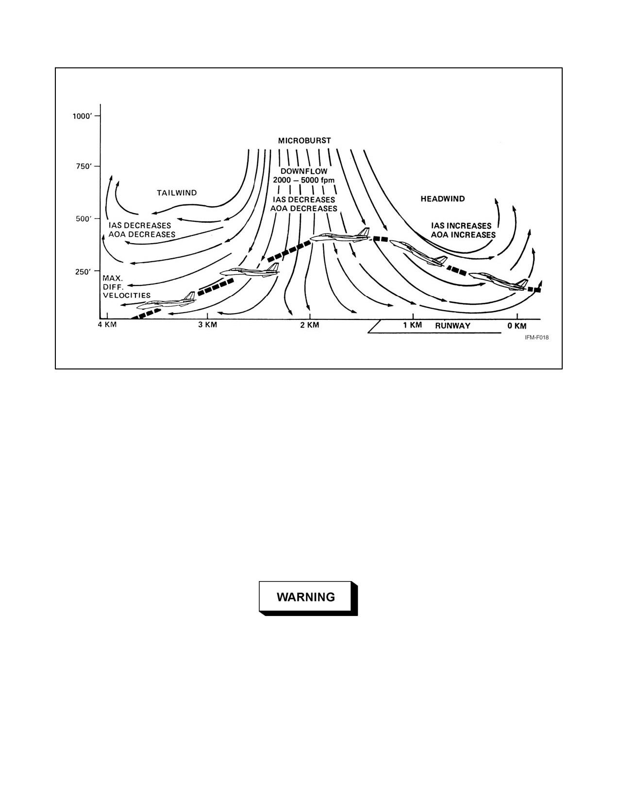
NAVAIR 00-80T-112
Figure 6-5. Profile of a Microburst
Research in the area of microbursts indicates there are some visual indicators that frequently occur when a microburst
is taking place. These indicators are virga (a pronounced rain shaft reaching the ground), dust rings (circular areas
of dust near convective activity), or lines of cumulus clouds spreading outward from the convective activity. The fact
that there are no proven observation or forecasting methods available to predict microbursts cannot be overly stressed.
In most cases, the presence of a microburst is not detected until it actually occurs.
From the cockpit of an aircraft, a microburst may look like a local shower, either light or heavy in intensity; however,
there is no proven method by which the pilot can visually determine that a microburst will take, or has taken, place.
When an aircraft is approaching an area of convective activity, at or below the base of the clouds, the pilot should
look for an unusual increase in the airspeed and lift (increase in altitude) of the aircraft, which will indicate the onset
of the microburst. If this scenario takes place, the pilot must take prompt and appropriate measures to deal with the
rapid onset of a downflow, tailwind, crosswind, or a combination of said elements.
Microbursts pose a serious threat to aircraft, especially those conducting the
arrival or departure phase of flight, or operating at low altitudes adjacent
to areas of convecting activity. The rapid onset of dangerous downflow and
tailwind shear must be met with quick responsive action by the pilot. The
only safe way to deal with a microburst is to avoid flying in areas where
microbursts may develop. Specifically, pilots should delay takeoffs,
approaches, and/or landings when operating near convective activity until
the convective activity has moved safely away from the flightpath.
6-13/(6-14 blank)
ORIGINAL
//////////////////////////////////////////