NAVAIR 00-80T-112 NATOPS INSTRUMENT FLIGHT MANUAL (15 NOVEMBER 2006) - page 3
NAVAIR 00-80T-112
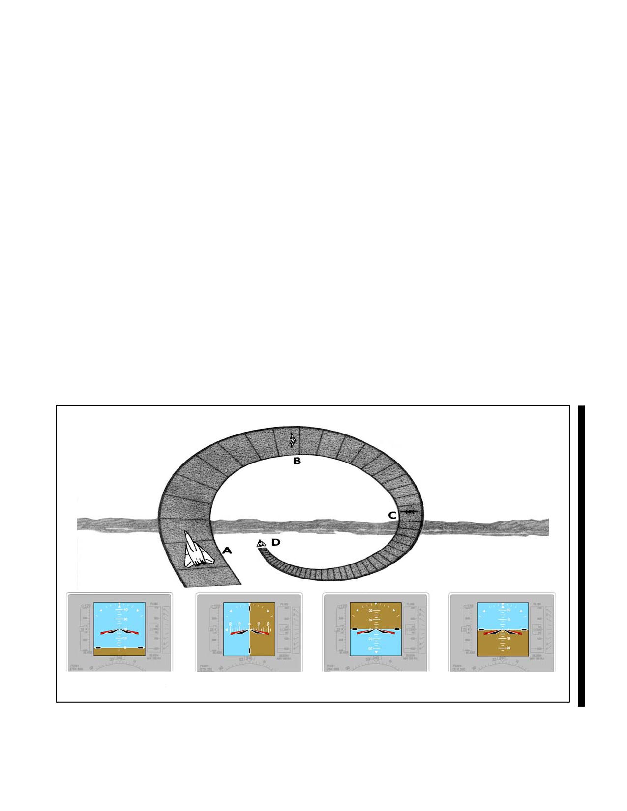
19.3.3 Aileron Roll
Begin the maneuver from straight-and-level flight after obtaining the desired airspeed. Smoothly increase the pitch
attitude with the wings level and as directed by the applicable NATOPS flight manual. Start a roll in either direction
and adjust the rate of roll so that, when inverted, the wings will be level as the fuselage dot of the miniature aircraft
passes through the horizon bar. Continue the roll and recover in a nose-low, wings-level attitude (Figure 19-10). The
entire maneuver should be accomplished by reference to the attitude indicator. The rate of roll should be constant and
continuous throughout the maneuver.
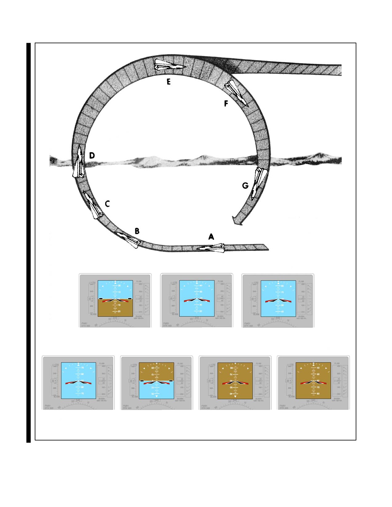
19.3.4 Loops
Advance the power and lower the nose to attain a desired entry airspeed compatible with aircraft performance. Refer
to the attitude indicator and smoothly raise the nose to the horizon with the wings level. Upon reaching the horizon,
increase back-pressure, ensuring sufficient g’s are applied to pull the aircraft up through the vertical and over the top
of the loop without exceeding aircraft limitations (Figure 19-11).
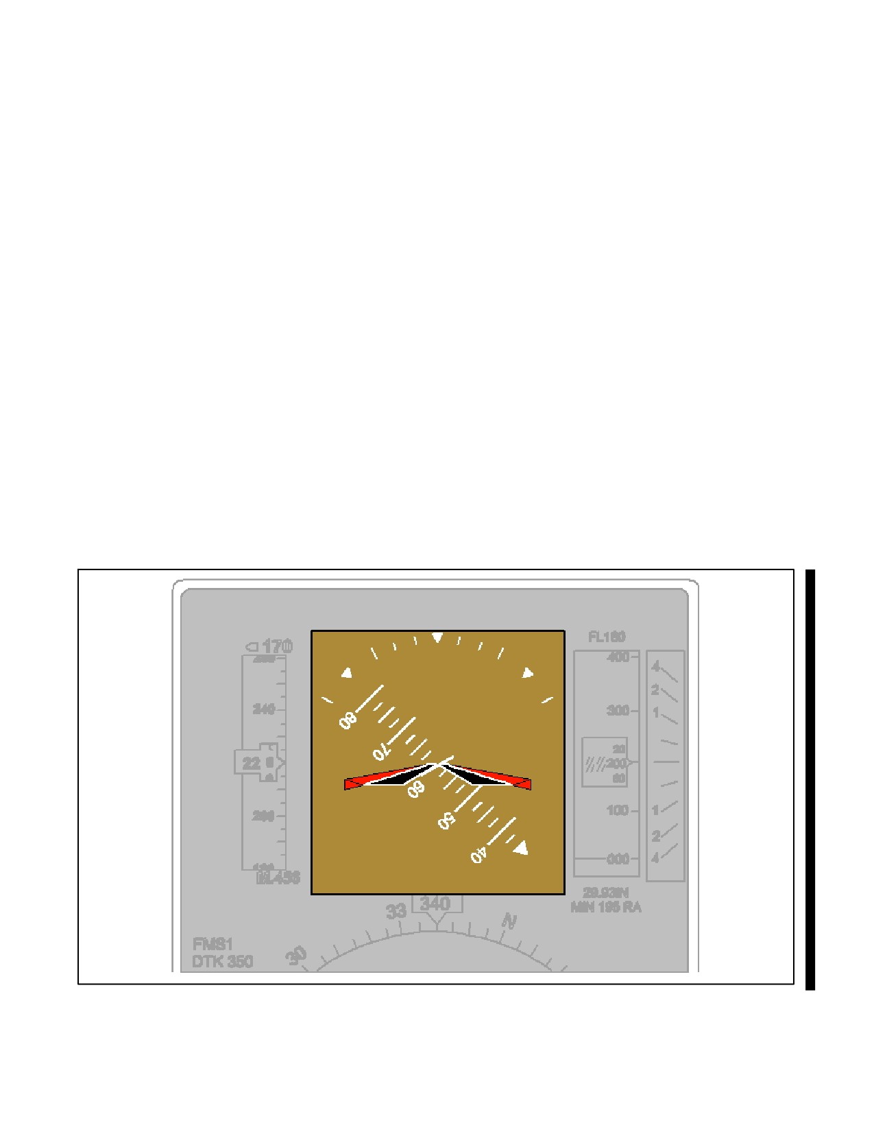
Bear in mind that some attitude indicators reverse themselves by controlled precession as the aircraft passes through
a vertical attitude. It is essential that the aircraft wings are level prior to and after this reversal. An easy method of
keeping the wings level is to keep the bank pointer centered at the top of the attitude indicator prior to reversal and
then keeping it centered at the bottom after reversal. Be alert to recognize and then disregard the attitude indications
during this short period of controlled precession.
As the airspeed decreases in the pullup, pitch control may become less effective and further backpressure may be
required to maintain constant g force. As the airspeed drops to the point where the g can no longer be maintained in
the control region without stalling, release some backpressure.
90° OF ROLL
INVERTED
RECOVERY
A BEGIN ROLL
B
C
D
Figure 19-10. Aileron Roll
19-9
ORIGINAL
NAVAIR 00-80T-112
40° CLIMB
60° CLIMB
A LEVEL FLIGHT
B
C
INVERTED
INVERTED DIVE
DIVE
D90° CLIMB
E
F
G
Figure 19-11. Loop
ORIGINAL
19-10
NAVAIR 00-80T-112
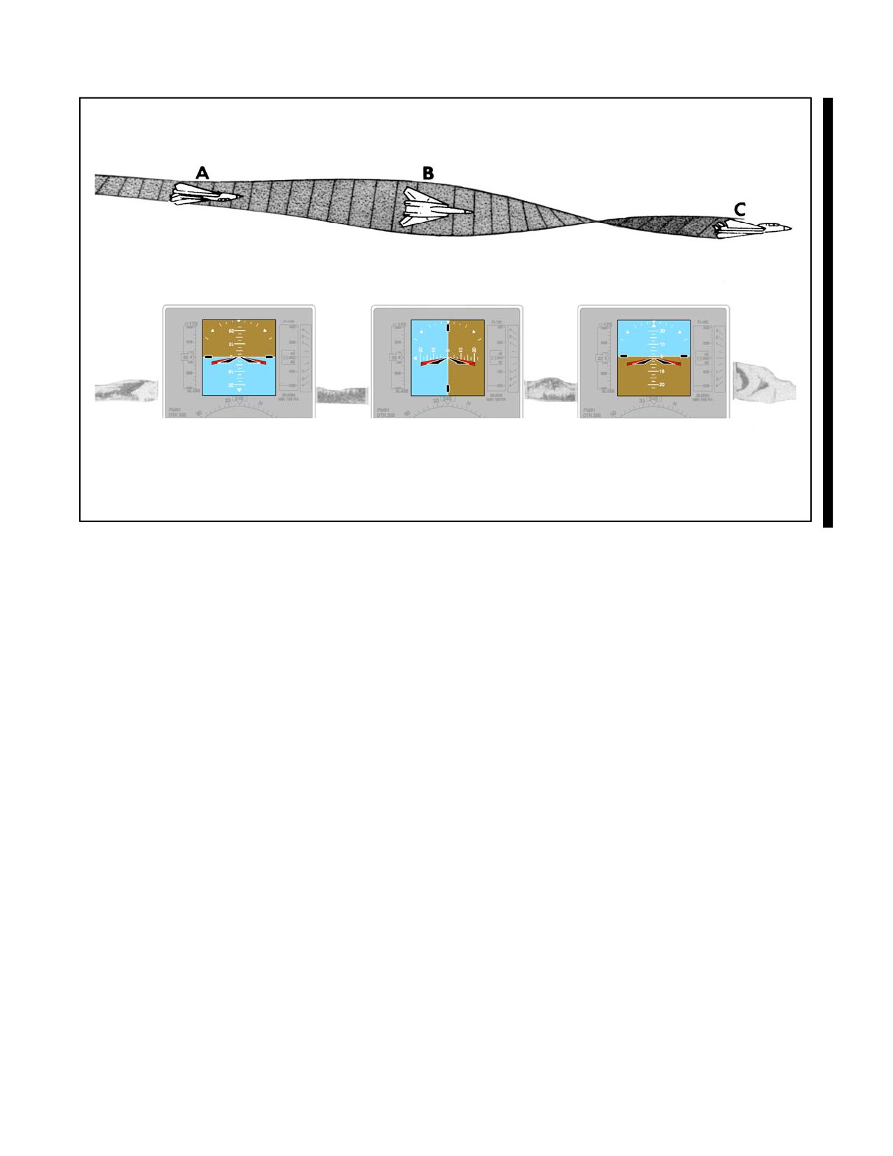
90° OF ROLL
RECOVER
A INVERTED (NOSE SLIGHTLY BELOW
B
C
HORIZON, BEGIN ROLLOUT)
(NOSE LOW)
Figure 19-12. Immelmann Recovery
Ensure sufficient backpressure remains to fly the aircraft through the top of the loop with a safe margin of airspeed
above the stall. In some aircraft, rudder application may be necessary to maintain balanced flight throughout the
maneuver.
After passing through the inverted attitude at the top of the loop, gradually increase the backpressure as the airspeed
increases. Recover from the resultant dive, being alert for controlled precession on the attitude indicator as the aircraft
passes through the vertical attitude. Keep the aircraft wings level throughout the maneuver, being careful not to
exceed any aircraft limitations.
Note
Considering varying load conditions with resultant accelerated stall speeds
and feel/buffet changes, reference to the angle of attack indicator in aircraft
so equipped is recommended during critical segments of the loop.
19.3.5 Immelmann
The Immelmann (Figure 19-12) is executed in the same manner as the first half of a loop followed by a half roll to
an upright attitude. Maintain inverted flight through the top of the maneuver until just before the fuselage dot of the
miniature aircraft passes through the horizon bar. Release backpressure upon approaching the horizon and roll to an
upright level attitude. Do not reduce power until the maneuver is completed.
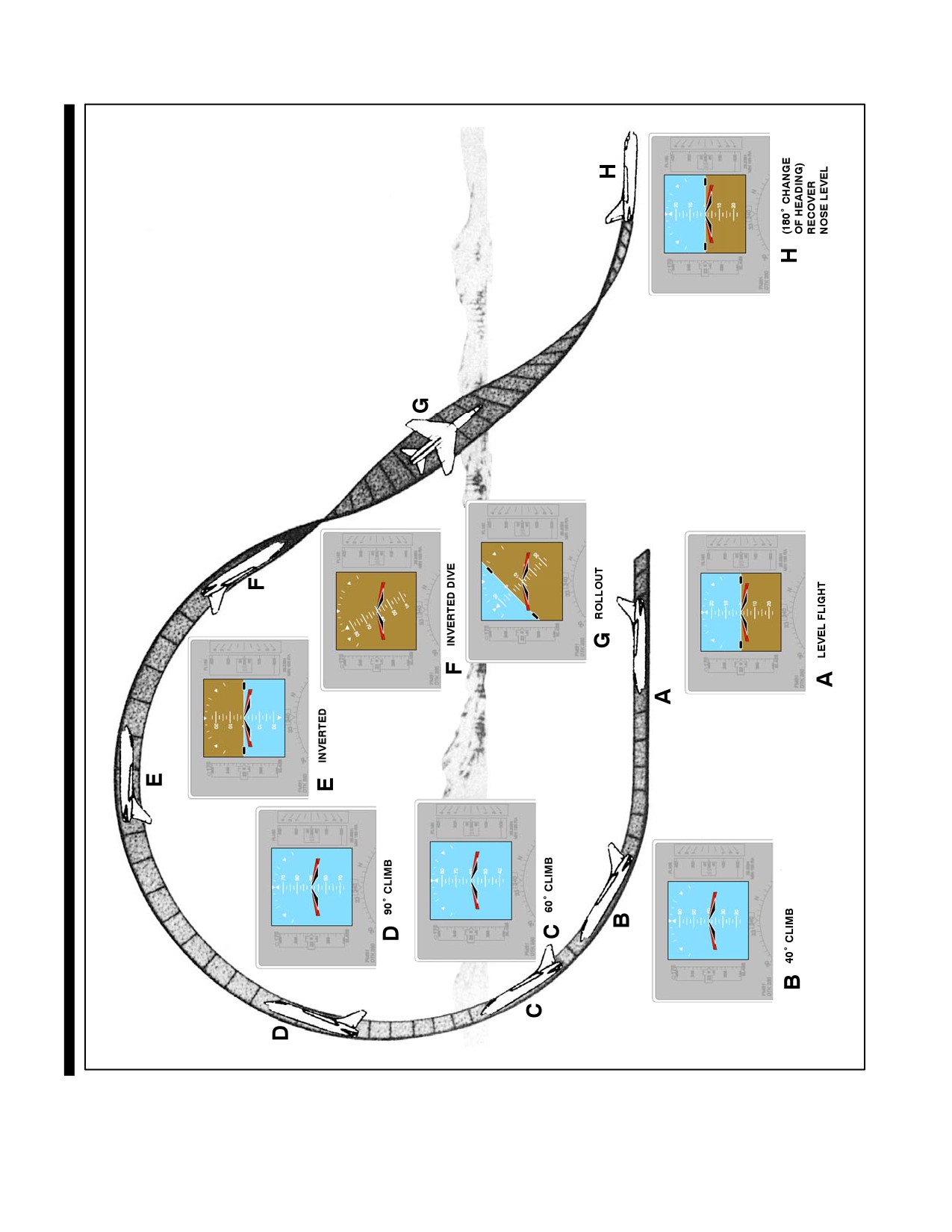
19.3.6 Half Cuban Eight
The Half Cuban Eight is the first half of a loop with a rollout from the inverted nosedown attitude, resulting in a 180_
heading change. It differs from the Immelmann turn in that the rollout is in a nose-low attitude rather than a level
attitude. This maneuver is practiced to develop the pilot’s confidence in the attitude indicator (Figure 19-13).
19-11
ORIGINAL
NAVAIR 00-80T-112
Figure 19-13. Half Cuban Eight
ORIGINAL
19-12
NAVAIR 00-80T-112
CHAPTER 20
Unusual Attitudes
20.1
INTRODUCTION
An unusual attitude is an aircraft attitude occurring inadvertently (Figure 20-1). It may result from one factor or a
combination of several factors such as turbulence, distraction of cockpit duties, instrument failure, inattention, spatial
disorientation, etc. In most instances, these attitudes are mild enough for the pilot to recover by reestablishing the
proper attitude for the desired flight condition and resuming a normal cross-check.
Techniques of recovery should be compatible with the severity of the unusual attitude, the characteristics of the
aircraft, and the altitude available for the recovery. The procedures outlined in this chapter are not designed to recover
from controlled tactical maneuvers. They are applicable to unusual attitudes wherein recovery can be accomplished
before entering areas of critical aerodynamics peculiar to a specific type of aircraft.
1. Decreasing the angle of bank in a dive should assist pitch control.
2. Increasing the angle of bank in a climb may assist pitch control.
3. In most aircraft, a decrease of angle of attack is an acceptable recovery technique (near zero g), and in some
aircraft this is the only acceptable technique, as an increase of bank will aggravate the recovery (refer to
applicable NATOPS flight manual).
4. Power and drag devices used properly will assist airspeed control.
Figure 20-1. Unusual Attitude
20-1
ORIGINAL
NAVAIR 00-80T-112
20.2
ATTITUDE INTERPRETATION
Normally, an unusual attitude is recognized in one of two ways: an unusual attitude picture on the attitude indicator
or unusual performance on the performance instruments. Regardless of how the attitude is recognized, verify an
unusual attitude exists by comparing control and performance instrument indications prior to initiating recovery on
the attitude indicator. This precludes entering an unusual attitude as a result of making control movements to correct
for erroneous instrument indications. During this process, the attitude must correctly be interpreted. Additional
attitude indicating sources (standby attitude indicator, copilot attitude indicator, etc.) should be used. If there is any
doubt as to proper attitude indicator operation, recovery should be made using attitude indicator inoperative
procedures.
The following techniques will aid aircraft attitude interpretation on the attitude indicator:
1. For attitude indicators with a single bank pointer and bank scale at the top, the bank pointer can be considered
a sky pointer. It always points up and should be in the upper half of the case. Rolling toward the bank pointer
to place it in the upper half of the case will correct an inverted attitude.
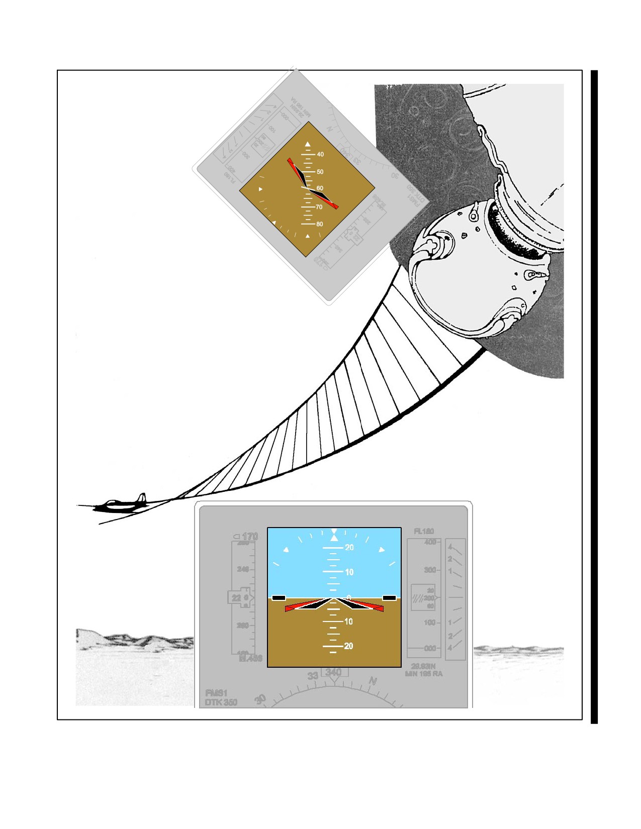
2. For those attitude indicators with the bank scale at the bottom, rolling in the direction that will place the pitch
reference scale right-side up will correct an inverted attitude (Figure 20-2).
Ease of pitch interpretation varies with the type of attitude indicator installed. Attitude indicators having pitch
reference scales in degrees and grey/black attitude spheres can easily be interpreted for climb or dive indications. For
those aircraft not so equipped, the airspeed indicator, altimeter, or vertical speed indicator generally present the most
easily interpreted indications of a climb or a dive. Attitude interpretation is a skill that must be highly developed by
practice in flight or on the ground in simulators or with mockups.
20.3
RECOVERY PROCEDURES
Unusual attitudes are generally classified as nose high or nose low. Each has distinct recovery techniques that are
generally applicable to all aircraft. Refer to the NATOPS flight manual for specific recovery procedures.
20.3.1 Nose-High Recovery
Factors to consider in nose-high recoveries are pitch attitude and airspeed. If the pitch attitude is not extreme and
airspeed is not approaching the stall ranges, recovery can be considered to be a normal nose-high attitude.
To recover from a normal nose-high unusual attitude, use power as necessary, and smoothly lower the nose toward
the level flight attitude. As the nose approaches the level flight attitude, level the wings and readjust power as
necessary.
If the pitch attitude is extreme or airspeed is approaching the stall range, recovery can be considered to be for an
extreme nose-high attitude.
To recover from an extreme nose-high unusual attitude, roll the aircraft in the shortest direction toward the wingover
position. As the nose falls through the horizon, level the wings and raise the nose to the level flight attitude. Use power
as necessary throughout the recovery.
Note
For swept-wing aircraft, the wingover recovery method is not acceptable.
Instead, a decrease in angle of attack (zero g) is used until sufficient
airspeed is gained to prevent an accelerated stall or spin condition. For
further information, consult the applicable NATOPS flight manual.
ORIGINAL
20-2
NAVAIR 00-80T-112
ADI
ROLLING TO PLACE THE PITCH
REFERENCE SCALE “RIGHT SIDE UP”
WILL CORRECT AN INVERTED ATTITUDE.
Figure 20-2. Bank Attitude Interpretation
20-3
ORIGINAL
NAVAIR 00-80T-112
20.3.2 Nose-Low Recovery
Factors to be considered in recovering from nose-low unusual attitudes are altitude and g loading during pullout. If
altitude permits, avoid rolling pullouts, as allowable stresses in an angle of bank are considerably lower than those
allowed in a wings-level pullout.
To recover from a nose-low unusual attitude, roll to a wings-level upright position, then raise the nose to the level
flight attitude. Adjust power and/or drag devices as appropriate.
During unusual attitude recoveries, the pilot should coordinate the amount of bank and power used with the rate at
which airspeed and pitch are being controlled. Bank and power used must be compatible with aircraft and engine
characteristics.
Note
For helicopters encountering blade stall, in a nose-high attitude, collective
pitch (power) must be reduced before applying attitude corrections. To
avoid blade stall when recovering from steep diving attitudes, reduce
collective pitch and bank attitude before initiating a pitch change. In all
cases, avoid abnormal positive g loads; prevent negative g loads and
inverted flight.
20.3.3 Partial Panel Unusual Attitudes
With an inoperative attitude indicator, successful recovery from unusual attitudes depends greatly on pilot proficiency
and early recognition of attitude indicator failure. For example, attitude indicator failure should immediately be
suspected if control pressures were applied for a turn without corresponding attitude indicator changes. Another
example would be satisfactory performance instrument indications that contradict the picture on the attitude indicator.
20.3.3.1 Recovery Procedures — Partial Panel
Should an unusual attitude be encountered with an inoperative attitude indicator, determine whether the aircraft is
in a climb or a dive by reference to the airspeed, altimeter, and vertical speed indicators.
If nose low, roll to center the turn needle and recover from the dive. Adjust power and/or drag devices as appropriate.
If nose high, use power as required. Apply controls as necessary to decrease the aircraft g to not less than zero g. After
reaching level flight and if the aircraft is in a turn, smoothly roll to center the turn needle; reversal of the altimeter
and vertical speeds tends to indicate passage of a level flight attitude. (Refer to the appropriate NATOPS flight manual
for detailed aircraft limitations.)
As the level flight attitude is approached, as indicated by the decrease in rate of change of airspeed and altitude, a
correction will be required to prevent chasing the vertical speed indicator. For example, in recovery from a nose-low
unusual attitude, once the turn needle has been centered, back stick pressure is applied until the performance
indicators show the approach of level flight. Because of the slight lag inherent in these instruments, the pilot should
anticipate the performance instruments and apply opposite pressure as the indicators show the approach of the level
flight attitude. Failure to do so will usually result in the progressing from one unusual attitude to another (in this
example, from nose low to nose high).
Spatial disorientation may become severe during the recovery from
unusual attitudes with an inoperative attitude indicator. Extreme attitudes
may result in an excessive loss of altitude and possible loss of aircraft
control; therefore, the pilot should decide upon an altitude at which
recovery attempts will be discontinued and the aircraft abandoned.
ORIGINAL
20-4
NAVAIR 00-80T-112
PART VI
Navigational Aids/Facilities and Procedures
Chapter 21 — VHF Omnidirectional Range (VOR)
Chapter 22 — Tactical Air Navigation (TACAN)
Chapter 23 — ADF, UHF/ADF, Marker Beacons
Chapter 24 — Instrument Landing System (ILS)
Chapter 25 — Radar Approaches
Chapter 26 — Global Positioning System (GPS)
77/(78 blank)
ORIGINAL
NAVAIR 00-80T-112
CHAPTER 21
VHF Omnidirectional Range (VOR)
21.1
INTRODUCTION
The VHF Omnidirectional Range (VOR) is a radio facility that eliminated many of the difficulties previously
encountered when navigating with the radio compass. VOR course information is not affected by weather or other
factors common to ADF. With a course indicator, it is possible to select and precisely fly any 1 of 360 courses to or
from a VOR.
21.2
EQUIPMENT AND OPERATION
21.2.1 Equipment
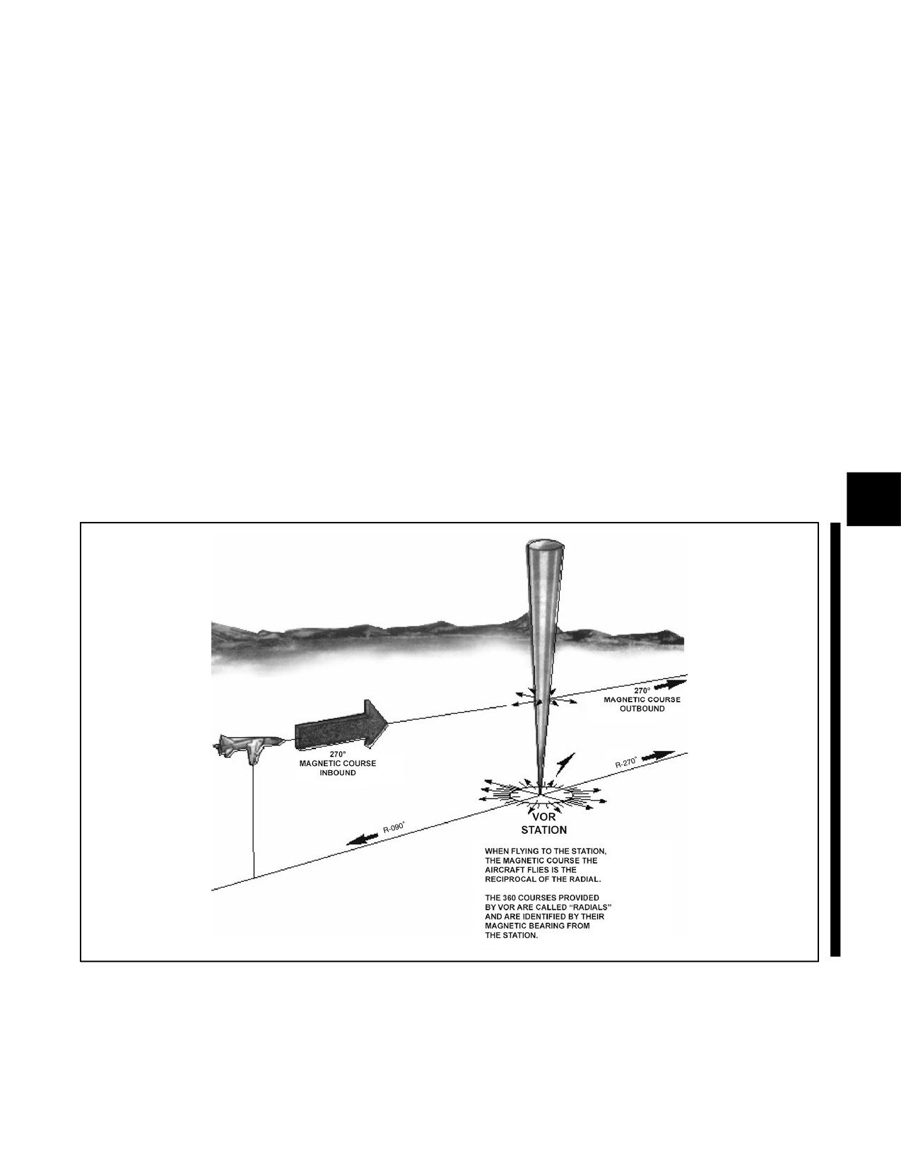
TheVORprovides360coursesthatradiatefromthestationlikespokesfromthehubofawheel.Thesecourses,known
as radials, are identified by their magnetic bearing from the station; thus, regardless of heading, an aircraft on the 90_
radial is physically located due east of the station. Flying to the station on this radial, the magnetic course is 270_.
As the transmitting equipment is in the VHF band, the signals are free of atmospheric disturbances but subject to
line-of-sight reception. Reception range varies according to the altitude of the aircraft (Figure 21-1).
Figure 21-1. Radials
21-1
ORIGINAL
NAVAIR 00-80T-112
21.2.1.1 Principle of Operation
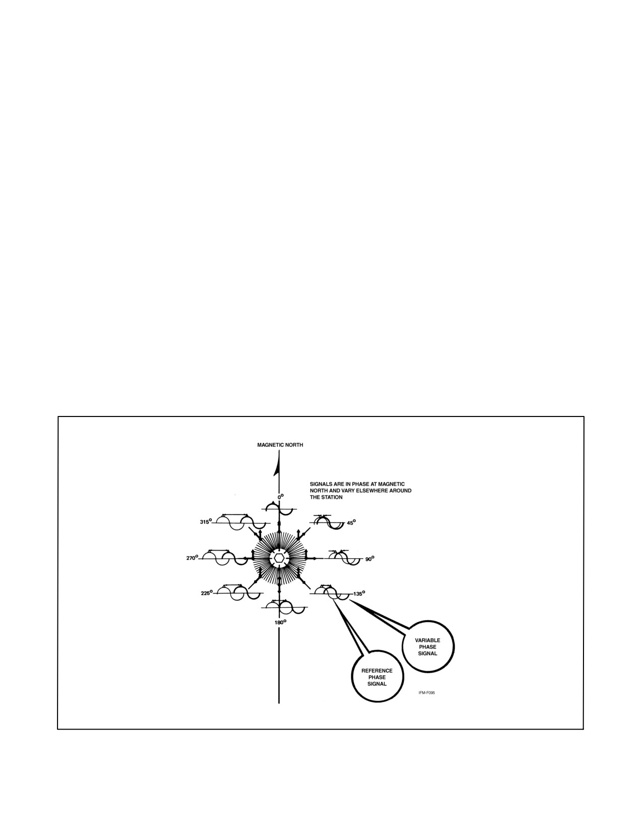
The transmission principle of the VOR is based on the creation of a phase difference between two signals. One of
these signals, the reference phase, is omnidirectional and radiates from the station in a circular pattern. The phase of
this signal is constant throughout 360_. The other signal, the variable phase, rotates uniformly at 1,800 rpm, which
causes its phase to vary at a constant rate.
Magnetic north is used as the baseline for electronically measuring the phase relationship between the reference and
variable phase signals. At magnetic north, the signals are exactly in phase; however, a phase difference exists at any
other point around the station. This phase difference is measured electronically by the aircraft receiver and displayed
on the navigation instruments (Radio Magnetic Indicator [RMI], course indicator, etc.) (Figure 21-2).
21.2.1.2 Control Panel
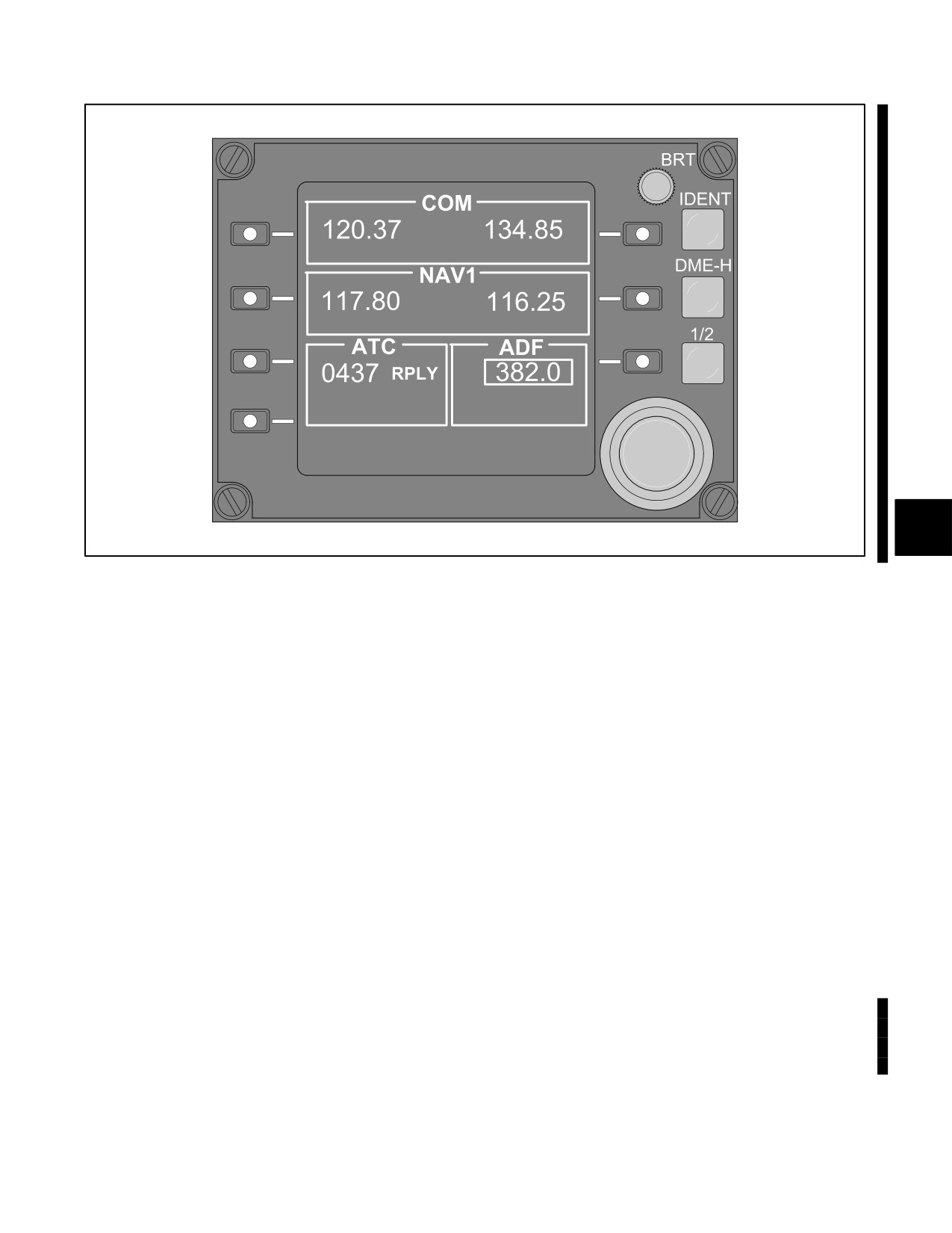
Typical VOR control panels contain a power switch, frequency selector knobs, a frequency window, and a volume
control (Figure 21-3).
The VHF navigation frequency band is as follows:
1. ILS — 108.1 to 111.9 MHz (odd tenths).
2. VOR — 108.0 to 117.95 MHz.
Figure 21-2. Signal Phase Angle Relationship
ORIGINAL
21-2
NAVAIR 00-80T-112
Figure 21-3. Control Panel
Since a large portion of the frequency band overlaps into the VHF communication band (108.0 to 135.9 MHz), the
VOR receiver may be used as a secondary VHF communication receiver.
The volume control knob controls the level of the signals going into the headset only. It has no effect on the signal
reception of the VOR receiver.
21.2.2 Operation
21.2.2.1 Tuning
To tune the VOR equipment, flip the power switch ON, select the desired frequency, and identify the station. The
station identification may be a three-letter Morse code, a recorded voice, or a combination of both. The voice
announcement alternates with the usual Morse code identification. If no air/ground communications facility is
associated with the VOR, the phrase “UNATTENDED VOR” (VORTAC) precedes the station name. Positively
identify the selected station. Through human error or equipment malfunction, it is possible that the station intended
to be selected is not the one being received. This may occur as the result of failing to select the correct frequency or
failure of the receiver to channel to the new frequency.
After identifying the VOR station, an unreliable signal can be identified on the instrument (refer to specific aircraft
NATOPS). Some VOR stations transmit Transcribed Weather Broadcasts (TWEBs), Hazardous In-Flight Weather
Advisory Service
(HIWAS), Airmen’s Meteorological Information
(AIRMETs), Significant Meteorological
Information (SIGMETs), and possibly communications from air traffic control.
Note
During periods of maintenance, the coded identification is removed.
21-3
ORIGINAL
NAVAIR 00-80T-112
After the set is tuned, check the bearing pointer, Course Deviation Indicator (CDI), and TO-FROM indicator for
proper operation. The bearing pointer should point to the magnetic bearing to the station. The CDI should center when
this bearing is set in the course selector window, and the TO-FROM indicator should indicate TO.
Note
Although the RMI is used with the course indicator in the accompanying
text and illustrations, the Bearing-Distance-Heading Indicator (BDHI)
display of bearing information is identical.
21.2.2.2 VOR/DME Paired Frequencies
Distance Measuring Equipment (DME) consists of airborne and ground equipment, usually co-located. The DME
provides distance (and in some systems groundspeed) information only from the ground facility. DME operates in
the Ultrahigh Frequency (UHF) band; however, its frequency can be “paired” with VOR or Instrument Landing
System (ILS) or Localizer (LOC) frequencies. The receiving equipment in most aircraft provide for automatic DME
selection through a coupled VOR/lLS receiver. Selection of the appropriate VOR or ILS frequency automatically
tunes the DME. Some equipment then allows the user to manually tune another VOR/ILS frequency and keep the
DME paired to the previously selected VOR/ILS frequency. The UHF/VHF paired frequency chart can be found in
the Flight Information Handbook.
21.3
PROCEDURES
21.3.1 Proceeding Direct to Station
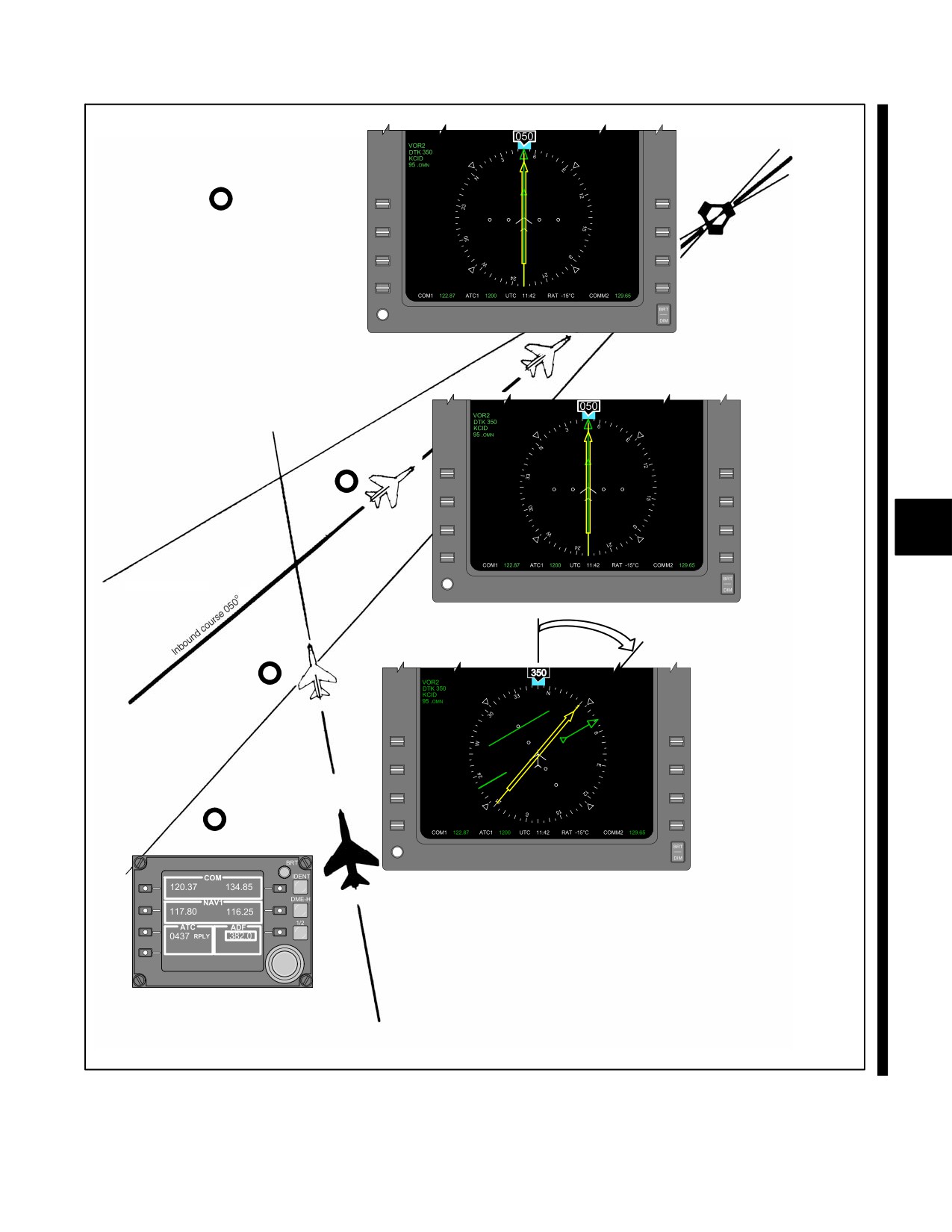
To proceed directly to the station, turn the aircraft in the shorter direction to place the bearing pointer under the top
index of the RMI. Set the bearing read under the head of the bearing pointer into the course selector window. If this
does not center the CDI exactly, rotate the course set knob until the CDI does center. Maintain this course to the station.
If either the compass card or the bearing pointer is inoperative, the course indicator may be used to determine the
bearing to the station by rotating the course set knob until the CDI centers and TO is read in the TO-FROM indicator.
The magnetic bearing from the aircraft to the station then appears in the course selector window (Figure 21-4).
21.3.2 Course Interceptions
Course interceptions are performed in most phases of instrument navigation. The equipment used varies, but an
intercept heading must be flown that results in an angle or rate of intercept sufficient to solve a particular problem.
Rate of intercept, seen by the pilot as bearing pointer or CDI movement, is a result of the following factors:
1. The angle at which the aircraft is flown toward a desired course (angle of intercept).
2. True airspeed and wind (groundspeed).
3. Distance from the station.
The angle of intercept is the angle between the heading of the aircraft (intercept heading) and the desired course.
Controlling this angle by selection and/or adjustment of the intercept heading is the easiest and most effective way
to control course interceptions. Angle of intercept must be greater than the degrees from course, but should not exceed
90_. At 90_, rate of intercept is the maximum possible. Within this limit, adjust to achieve the most desirable rate
of intercept.
When selecting an intercept heading, the key factor is the relationship between distance from the station and degrees
from the course. Each degree, or radial, is 1 nm wide at a distance of 60 nm from the station. Width increases or
decreases in proportion to the 60 nm distance. For example, 1_ is 2 nm wide at 120 nm and 1/2 nm wide at 30 nm.
For a given groundspeed and angle of intercept, the resultant rate of intercept varies according to the distance from
the station.
ORIGINAL
21-4
NAVAIR 00-80T-112
4
MAINTAIN COURSE
INBOUND TO THE
STATION.
3
ROTATE COURSE
SET KNOB TO
CENTER THE CDI.
2
TURN TO PLACE
BEARING POINTER
UNDER TOP INDEX.
1
TUNE TO NEW FREQUENCY.
Figure 21-4. Proceeding Direct to Station
21-5
ORIGINAL
NAVAIR 00-80T-112
When selecting an intercept heading to form an angle of intercept, consider the following factors:
1. Degrees from course.
2. Distance from the station.
3. True airspeed and wind (groundspeed).
21.3.3 Inbound Procedures
To intercept a radial while flying to a station, a number of varying methods may be employed. Generally, setting up
a 45_ angle of intercept is recommended; 30_ angle of intercept is equally correct, as is the double the angle off the
bow method if the number of radials to be crossed is not in excess of 45. The double-the-angle-off-the-bow method
is described in detail in Chapter 22, as is the timed distance method for radial changes in excess of 45_.
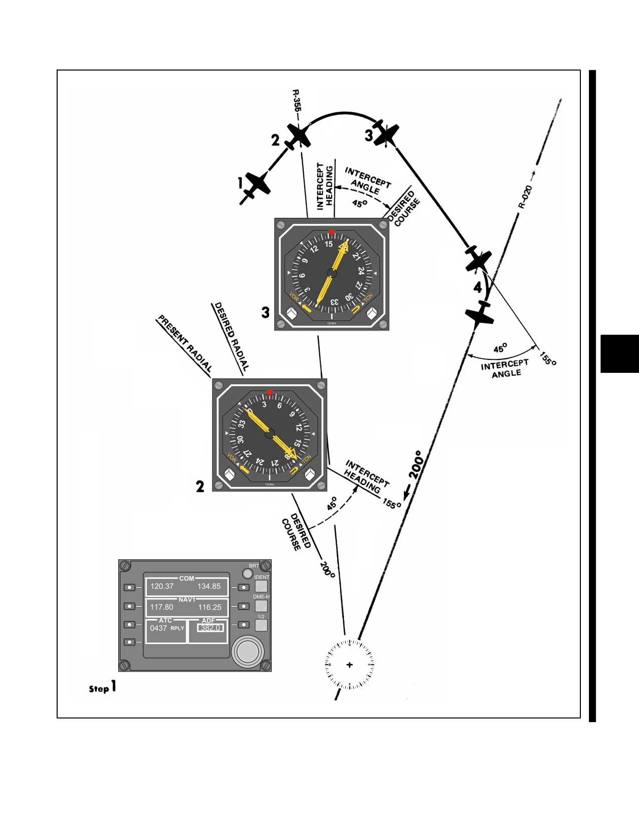
21.3.3.1 RMI Only
Inbound course interceptions utilizing only the RMI are described in detail in Figure 21-5. The essential element is
to visualize the problem utilizing the RMI center as the station and the tail of the bearing pointer as the present aircraft
position. Then a pilot can visualize the new radial that the pilot wants to intercept as is done in Tactical Air Navigation
(TACAN) point to point. As distances are not known, a standard 45_ angle of intercept is recommended. It is
important to disregard aircraft heading until the intercept heading is computed. Then, turn in the shortest direction
to that heading.
21.3.3.2 RMI and CDI
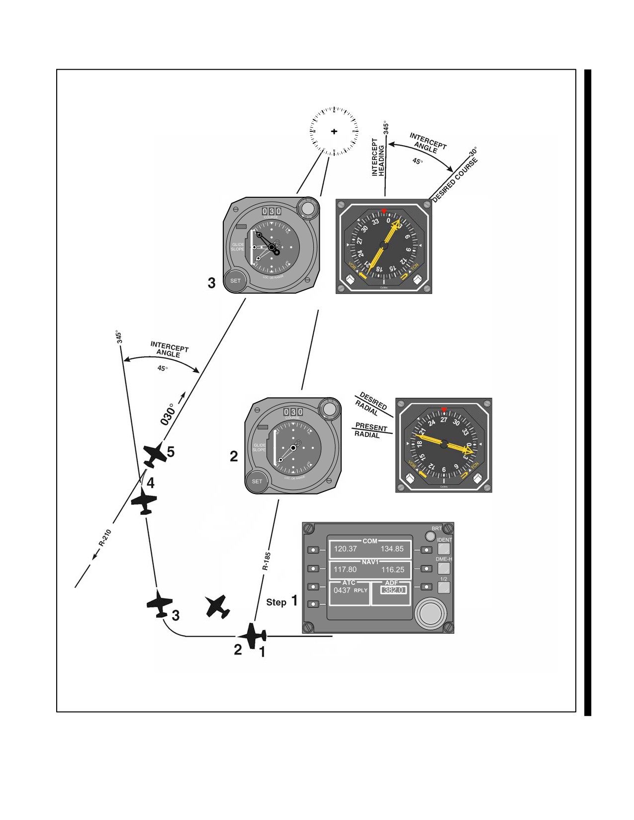
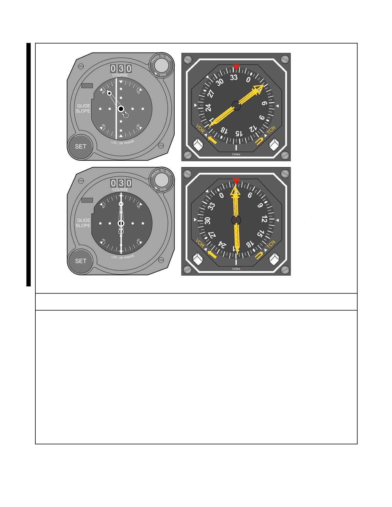
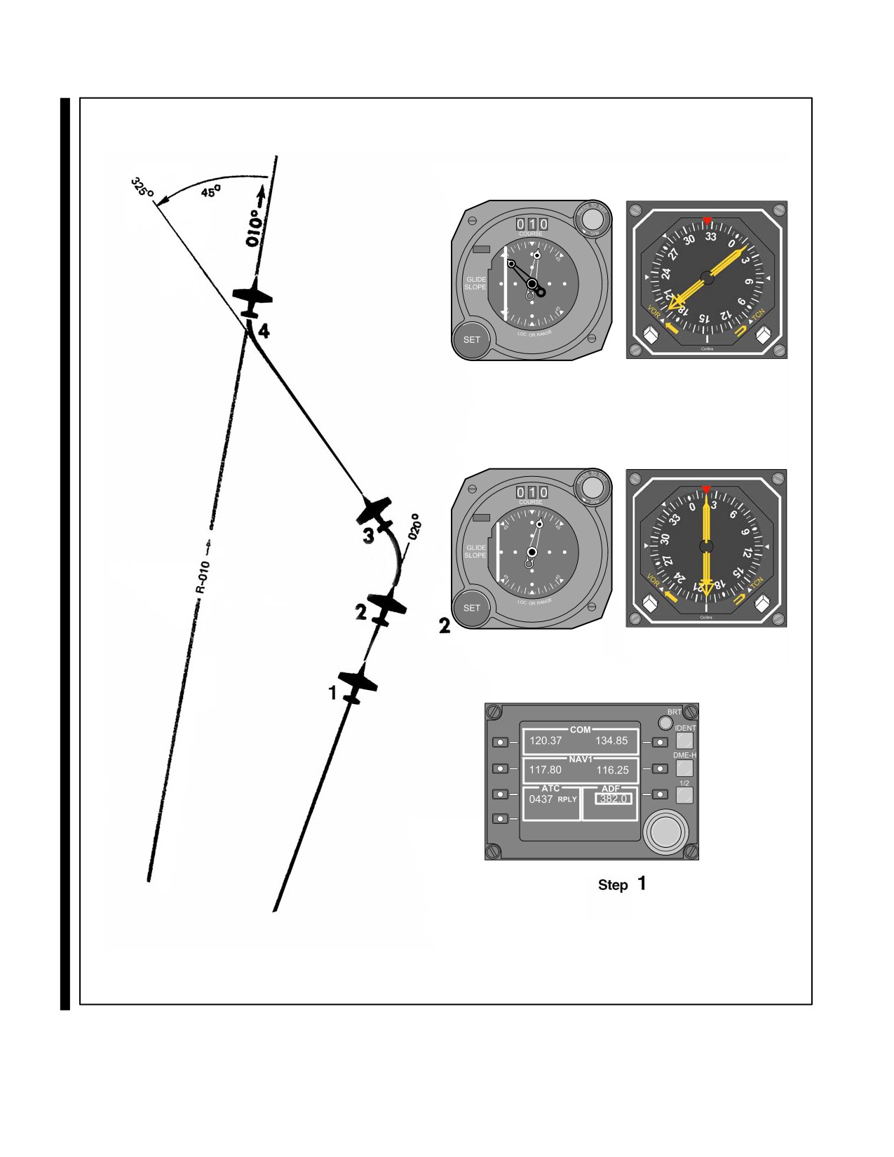
Inbound course interceptions utilizing RMI and CDI are described in detail in Figure 21-6. Essentially these can be
accomplished exactly as under RMI only with the additional aid of using the CDI in the final phase.
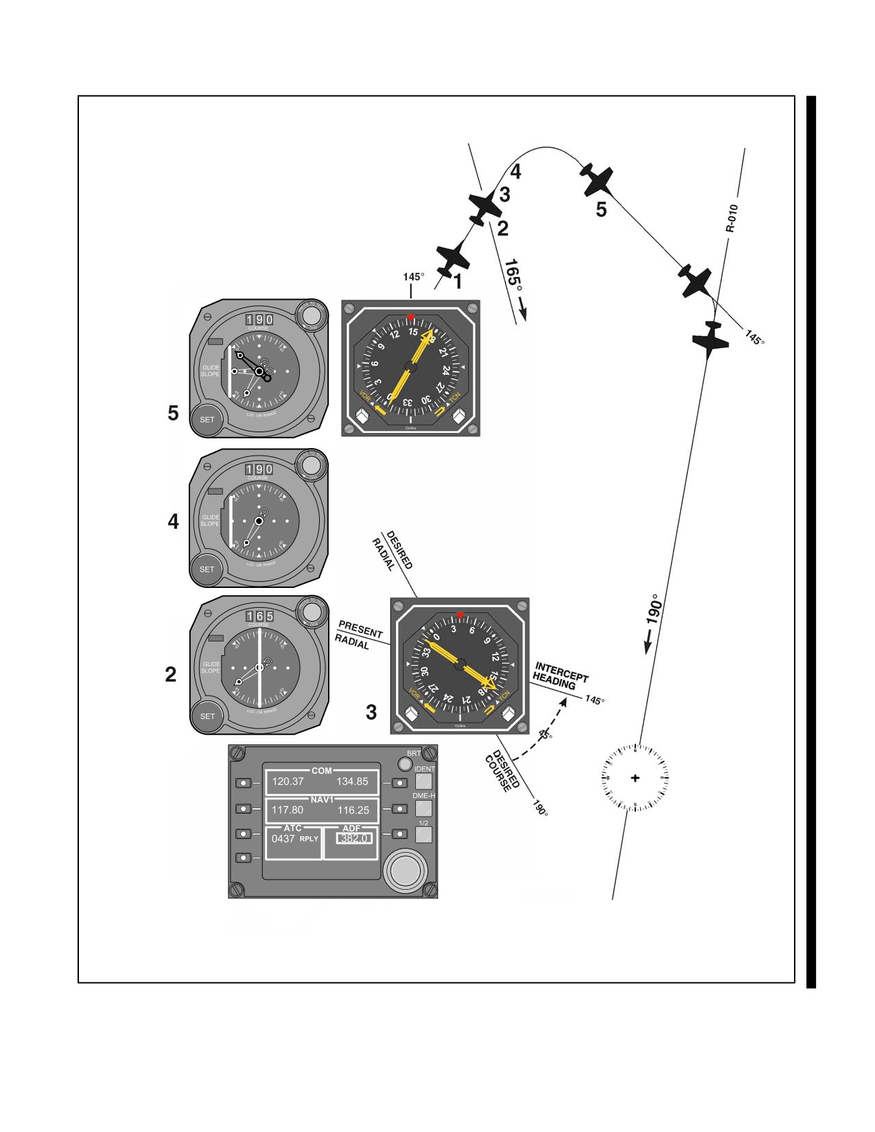
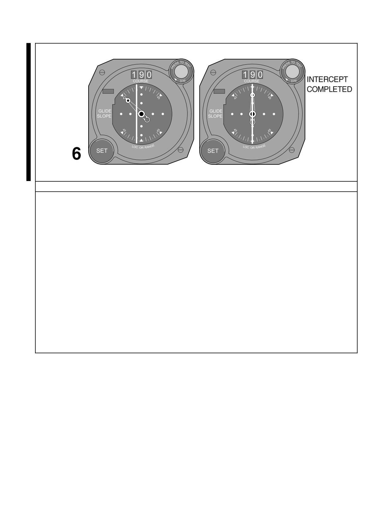
21.3.3.3 CDI Only
Inbound course interceptions utilizing the CDI only are described in detail in Figure 21-7. The essential element is
to visualize the problem on an RMI or on any compass card and then proceed as under RMI and CDI. Some CDIs
do not have heading pointers and some VOR sets do not employ a bearing pointer. In these cases, it is essential to
disregard aircraft heading until the intercept heading is determined. Then, turn in the shortest direction to that heading
(utilizing a timed turn if all compass cards are inoperative).
21.3.4 Outbound Procedures — Immediately After Station Passage
Intercepting courses immediately after station passage does not require large intercept angles. Because of radial
convergence, actual aircraft displacement from course is relatively small compared to bearing pointer or CDI
indications. For example, a 30_ off-course indication when 2 nm from the station represents approximately 1 nm off
course.
Paralleling the desired outbound course while allowing the bearing pointer or CDI to stabilize is acceptable. If this
method is utilized, proceed as outlined below for outboard course interceptions.
Continuing to turn to intercept the outbound course may be preferred in order to expedite the intercept. This method
is described in Figure 21-8.
Utilize the RMI or CDI as available. Use an angle or intercept equal to the number of degrees of radial change desired;
however, to prevent overshooting, do not turn more than 45_ beyond the heading required to parallel course.
ORIGINAL
21-6
NAVAIR 00-80T-112
Figure 21-5. Inbound Course Interception (RMI Only) (Sheet 1 of 2)
21-7
ORIGINAL
NAVAIR 00-80T-112
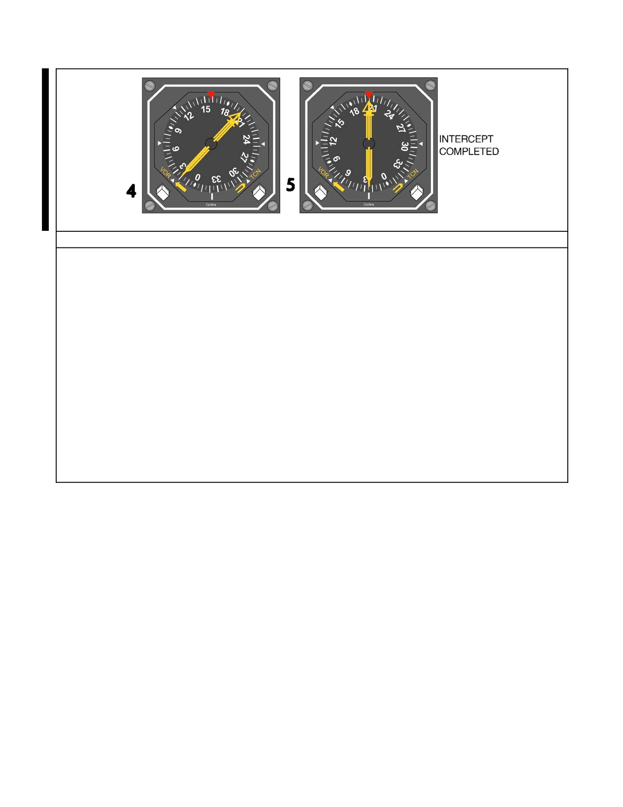
Inbound Procedural Steps — RMI Only
1. Tune and identify the VOR station.
The bearing pointer will then point to the magnetic course to the station as it appears on the RMI;
heading has nothing to do with the radial the aircraft is on. The aircraft can be visualized on the tail of the
bearing pointer with the station at the center of the RMI.
2. Determine intercept heading.
Determine which radial the aircraft is on by noting the tail of the bearing pointer. Determine the required
direction of turn to the new radial. An intercept angle is formed when the head of the bearing pointer is
between the desired course and the top index of the RMI.
3. Determine and set in the new course.
4. Turn in the shortest direction to the intercept heading.
Set up a 45-degree, 30-degree, or double-the-angle-off-the-bow intercept.
5. Maintain the intercept heading until a lead point is reached, then complete the intercept.
Lead point depends on bearing pointer rate of movement and the time required to turn on course.
Figure 21-5. Inbound Course Interception (RMI Only) (Sheet 2 of 2)
ORIGINAL
21-8
NAVAIR 00-80T-112
TO
TO
Figure 21-6. Inbound Course Interception (Course Indicator and RMI) (Sheet 1 of 2)
21-9
ORIGINAL
NAVAIR 00-80T-112
TO
4
TO
INTERCEPT
COMPLETED
5
Inbound Procedural Steps — Course Indicator and RMI
1. Tune and identify the VOR station.
The bearing pointer will function as described in Figure 21-5.
2. Set the desired inbound course in the course selector window and check for a TO indication.
3. Determine intercept heading as described in Figure 21-5.
4. Turn in the shortest direction to the intercept heading.
The CDI heading pointer should be positioned on the upper half of the CDI when established in the
intercept heading. Both the heading pointer and course bar must be on the same side of the CDI while
intercepting the desired course. The CDI heading pointer should be deflected in a manner that
corresponds to the angle of intercept.
5. Maintain the intercept heading until a lead point is reached, then complete the intercept.
Lead point depends on bearing pointer/CDI rate of movement and the time required to turn on course.
Figure 21-6. Inbound Course Interception (Course Indicator and RMI) (Sheet 2 of 2)
ORIGINAL
21-10
NAVAIR 00-80T-112
6
TO
TO
TO
Step 1
Figure 21-7. Inbound Course Interception (CDI Only) (Sheet 1 of 2)
21-11
ORIGINAL
NAVAIR 00-80T-112
TO
TO
Inbound Procedural Steps — Course Indicator Only
1. Tune and identify the VOR station.
2. Center the CDI with TO in the TO-FROM indicator.
Note the course displayed in the course selector window and visualize on any compass card a bearing
pointer pointing to the course displayed and the desired inbound radial.
3. Determine an intercept heading using RMI only procedures.
4. Set the desired inbound course in the course selector window and check for a TO indication.
5. Turn to the intercept heading.
Turn in the shortest direction to the intercept heading. If a CDI heading pointer is installed, ensure the
pointer is positioned in the upper half of the CDI when established on the intercept heading.
Note
If all compass cards are inoperative, make a timed turn to the intercept heading using
the magnetic compass.
6. Maintain the intercept heading until a lead point is reached, then complete the intercept.
Lead point depends on the CDI rate of movement and the same required to turn on course.
Figure 21-7. Inbound Course Interception (CDI Only) (Sheet 2 of 2)
ORIGINAL
21-12
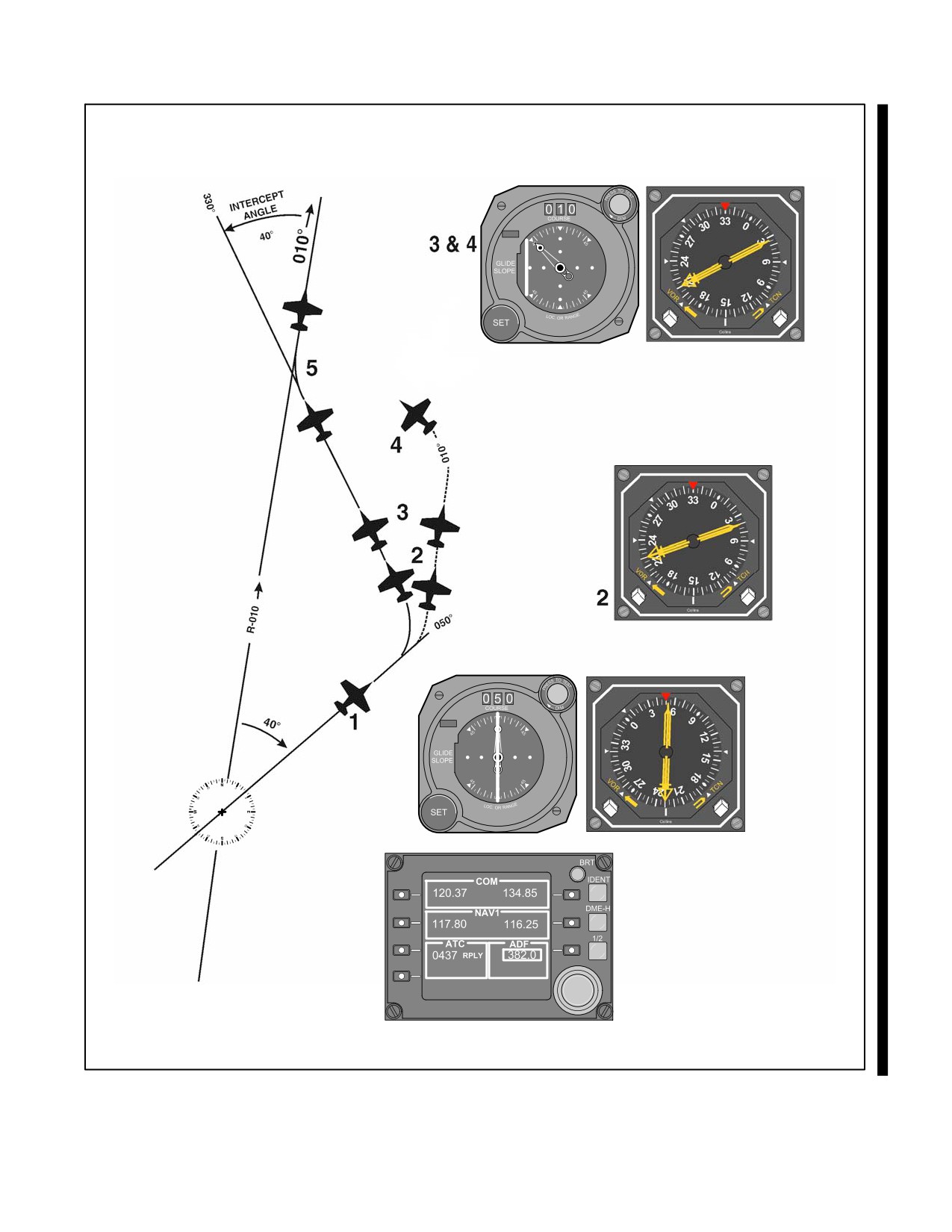
NAVAIR 00-80T-112
FROM
FROM
Step 1
Figure 21-8. Course Interception Immediately After Station Passage (Course Indicator and RMI) (Sheet 1 of 2)
21-13
ORIGINAL
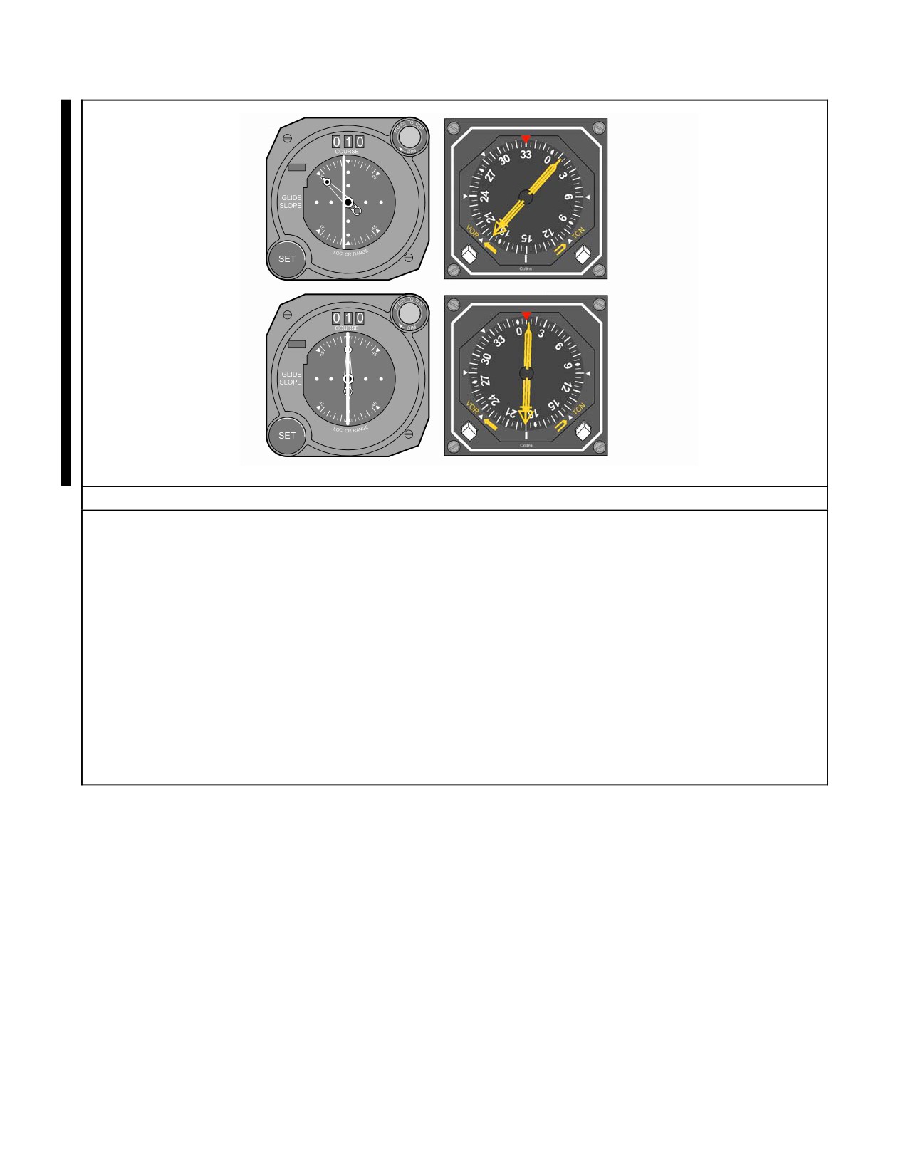
NAVAIR 00-80T-112
FROM
5
FROM
INTERCEPT
COMPLETED
Outbound Procedural Steps Immediately After Station Passage — Course Indicator and RMI
1. Tune and identify the VOR station.
This should already be accomplished.
2. Turn in the shortest direction to a heading that will parallel or intercept the outbound course.
Turning to parallel the desired outbound course is acceptable. Continuing the turn to an intercept heading
may be preferable to expedite the intercept. If turning immediately to intercept, utilize an angle of
intercept equal to the number of degrees or radial desired, not to exceed 45 degrees.
3. Set the desired course in the course selector window and check for FROM indication.
4. Turn to an intercept heading, if not previously accomplished.
5. Maintain the intercept heading until a lead point is reached, then complete the intercept.
Lead point depends on bearing pointer/CDI rate of movement and the time required to turn on course.
Figure 21-8. Course Interception Immediately After Station Passage (Course Indicator and RMI) (Sheet 2 of 2)
ORIGINAL
21-14
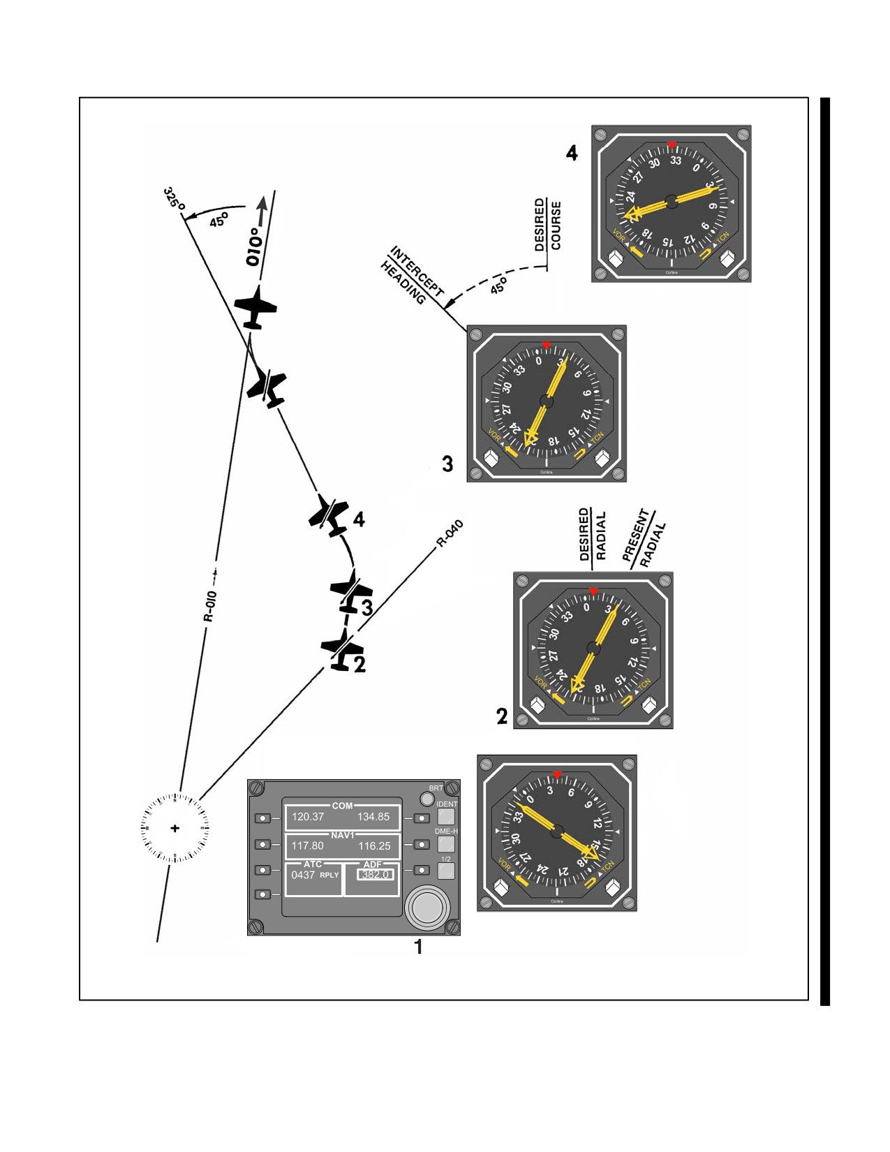
NAVAIR 00-80T-112
Figure 21-9. Outbound Course Interception — Away from the Station (RMI Only) (Sheet 1 of 2)
21-15
ORIGINAL
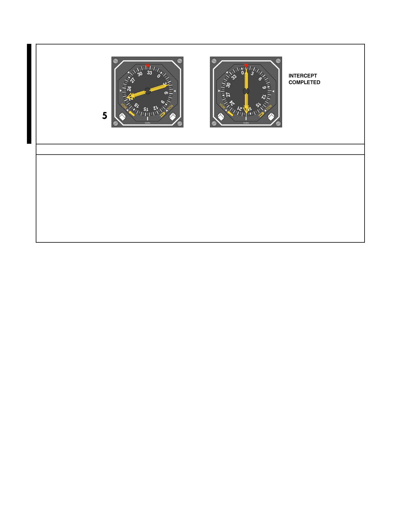
NAVAIR 00-80T-112
Outbound Procedural Steps — RMI Only
1. Tune and identify the VOR station.
2. Determine which radial the aircraft is on by noting the tail of the bearing pointer.
Determine the direction of turn to the new radial.
3. Determine and set in the new course.
4. Turn to the intercept heading in the direction determined in step 2.
Set up a 45-degree, 30-degree, or double-the-angle-off-the-bow intercept.
5. Maintain the intercept heading until a lead point is reached, then complete the intercept.
Lead point depends on bearing pointer rate of movement and the time required to turn on course.
Figure 21-9. Outbound Course Interception — Away from the Station (RMI Only) (Sheet 2 of 2)
21.3.5 Outbound Procedures
To intercept a radial while flying from a station, several methods may be employed. Whereas a 45_ angle of intercept
is recommended, a 30_ angle of intercept or the double the angle off the bow (as described in Figure 21-16) may be
used.
21.3.5.1 RMI Only
Outbound radial interceptions utilizing only the RMI are described in detail in Figure 21-9. The essential element is
to visualize the problem utilizing the RMI center as the station and the tail of the bearing pointer as the present aircraft
position. Then a pilot can visualize the new radial that the pilot wants to intercept as is done in TACAN point to point.
As distances are not known, the pilot can picture the aircraft at the middle of the bearing pointer with the desired point
of interception at the outer edge of the compass card.
21.3.5.2 RMI and CDI
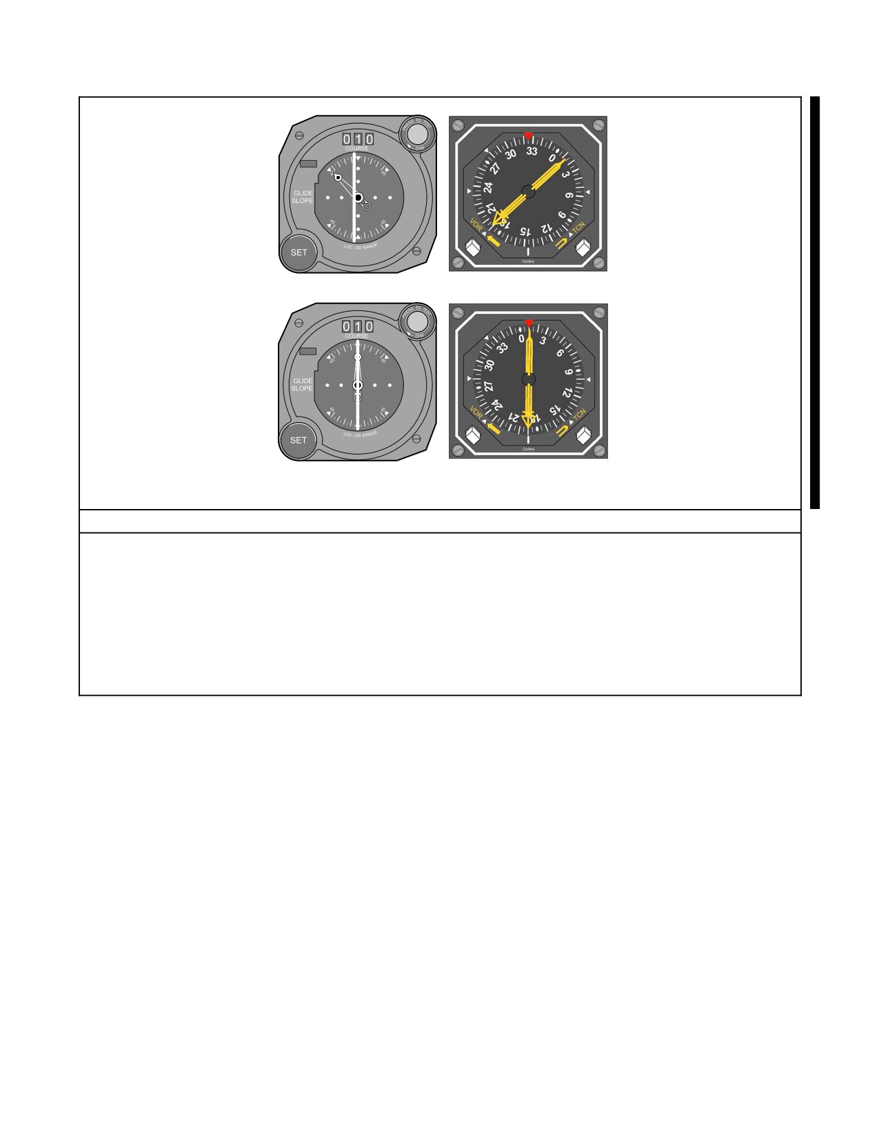
Outbound radial interception utilizing RMI and CDI are described in detail in Figure 21-10. Essentially, these can
be accomplished exactly as described in paragraph 21.3.5.1 with the additional aid of using the CDI in the final phase.
21.3.5.3 CDI Only
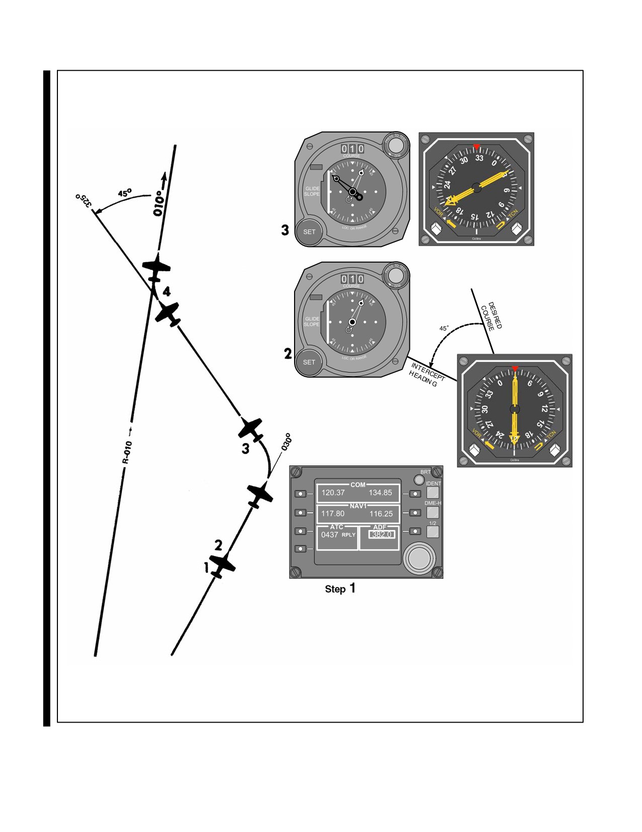
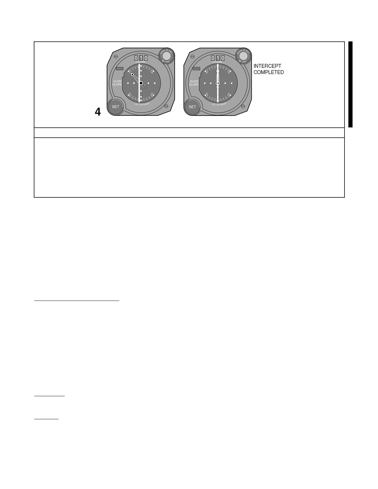
Outbound radial interceptions utilizing the CDI only are described in detail in Figure 21-11. The essential element
is to visualize the problem on an RMI or on any compass card and then proceed as under RMI and CDI. Some CDIs
do not have a heading pointer, and some VOR sets do not employ a bearing pointer. In these cases, it is essential to
disregard aircraft heading until the intercept heading is determined. Then turn in the shortest direction to that heading
(utilizing a timed turn if all compass cards are inoperative).
ORIGINAL
21-16
NAVAIR 00-80T-112
21.3.6 Completing the Intercept
After the intercept heading has been established, adjustments may be required to achieve a more desirable angle
or rate of intercept. As the aircraft approaches course, determine a lead point for turning because of turn radius.
A properly selected lead point will result in the turn being completed as the course is intercepted. Lead point is
determined by comparing bearing pointer/CDI movement (rate of intercept) to the time required to turn to
course. Whenever the CDI is fully deflected, monitor the bearing pointer to detect unusually slow or fast rates
of intercept. Remember that the CDI remains fully deflected until the aircraft is within 10_ of course. As CDI
movement can be accurately compared with angle of intercept displayed by the heading pointer, use the course
indicator for completing intercepts whenever possible. If it is obvious that the lead point selected will result in
undershooting the desired course, reduce the angle of bank or roll out of the turn and resume the intercept. If the
lead point selected results in an overshoot, continue the turn and roll out with an intercept heading. Aircraft is
on course when CDI is centered and/or the bearing pointer points to the desired course. Complete turn to course
with a correction applied for known wind.
21.3.7 Estimating Drift Correction
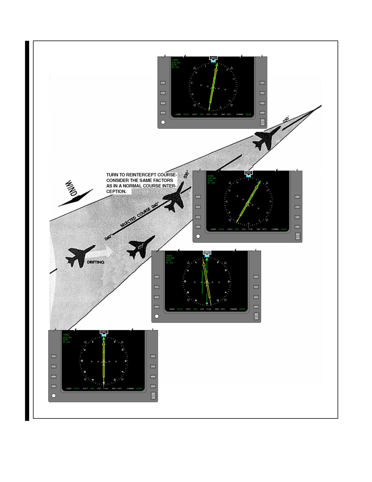
After completing the turn to course with the CDI centered, maintain heading until the CDI indicates deviation from
the selected course. At the first indication of course deviation, turn toward the CDI to reintercept course. Follow the
same procedure used for a normal course interception and consider the same factors (i.e., degrees from course,
distance from the station, True Airspeed [TAS], and wind). After returning to course from a deviation caused by wind,
reestimate the drift correction and increase or decrease the one previously held. To keep the CDI centered, make
further corrections from this new heading. When close to the station, the CDI may show a rapid movement from the
on-course indication because of radial convergence; however, actual course deviation is probably small, especially
if wind drift has been solved. Avoid overcorrecting in this situation.
To maintain a course to the station using only the RMI, maintain heading until the bearing pointer shows a deviation
from the desired course. To return to course, use normal course interception procedures. The aircraft is back on course
when the desired course is again shown under the head of the bearing pointer. If you have applied the correct wind
drift, the pointer should continue to point to the desired course. If the pointer moves toward the top index, the drift
correction is too small; if it moves away from the top index, it is too large.
To maintain an outbound course, use outbound course interception procedures. Apply corrections to keep the desired
course under the tail of the bearing pointer. After applying a wind drift correction outbound and the tail of the pointer
moves toward the top index, the drift correction is too large; if it moves away from the top index, the drift correction
is too small (Figure 21-12).
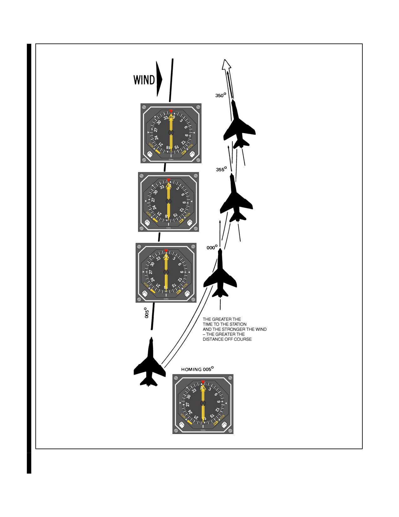
21.3.8 Homing
After the VOR station is tuned, the VOR bearing pointer will point to the magnetic bearing of the selected station.
To home to the station, turn the aircraft to place the head of the bearing pointer under the top index. By keeping the
bearing pointer under the index, the station will always be directly ahead of the aircraft. As homing does not
incorporate wind drift correction, in a crosswind, the aircraft follows a curved path to the station. Homing is not an
approved IFR procedure and, therefore, should be used only when close to the station (Figure 21-13).
21-17
ORIGINAL
NAVAIR 00-80T-112
FROM
3
FROM
Figure 21-10. Outbound Course Interception — Away from the Station (Course Indicator and RMI) (Sheet 1 of 2)
ORIGINAL
21-18
NAVAIR 00-80T-112
FROM
4
FROM
INTERCEPT
COMPLETED
Outbound Procedural Steps — RMI Only
1. Tune and identify the VOR station.
2. Set the desired outbound course in the course selector window.
Determine the direction of turn as in RMI only.
3. Turn to an intercept heading.
Set up a 45-degree, 30-degree, or double-the-angle-off-the-bow intercept.
4. Maintain the intercept heading until a lead point is reached, then complete the intercept.
Lead point depends on bearing pointer/CDI rate of movement and the time required to turn on course.
Figure 21-10. Outbound Course Interception — Away from the Station (Course Indicator and RMI) (Sheet 2 of 2)
21-19
ORIGINAL
NAVAIR 00-80T-112
FROM
FROM
31
Figure 21-11. Outbound Course Interception (CDI Only) (Sheet 1 of 2)
ORIGINAL
21-20
NAVAIR 00-80T-112
FROM
FROM
Outbound Procedural Steps — Course Indicator Only
1. Tune and identify the VOR station.
2. Set the desired outbound course in the course selector window.
3. Turn to an intercept heading.
Determine direction of turn as in RMI only by visualizing the intercept on any compass card.
4. Maintain the intercept heading until a lead point is reached, then complete the intercept.
Lead point depends on the CDI rate of movement and the time required to turn on course.
Figure 21-11. Outbound Course Interception (CDI Only) (Sheet 2 of 2)
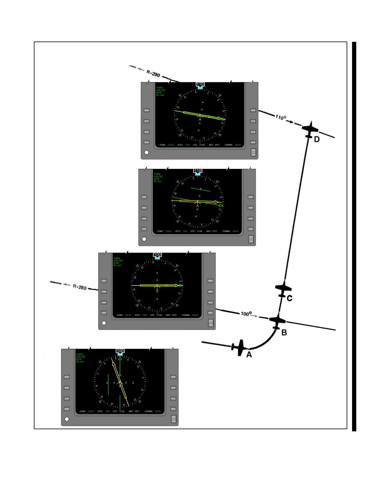
21.3.9 Time-Distance Check
To compute time and distance from an omnirange, first turn the aircraft to place the bearing pointer on the nearest
90_ index. Set the bearing read under the head of the bearing pointer into the course selector window. If this does not
center the CDI exactly, rotate the course set knob until the CDI does center. Note the time and maintain heading. When
the CDI shows a definite displacement from center, set a 10_ bearing change in the course window by rotating the
course set knob in the direction of CDI movement. Check that the CDI has moved over the heading pointer. Maintain
heading until the CDI recenters. Note elapsed time, and apply the following formulas:
Time in seconds between bearings
+ Minutes to station.
Degrees of bearing change
TAS or groundspeed in nm per minute times minutes from the station will give distance. Expressed as a formula, this
is:
* TAS
minutes from the station = nm from the station.
60
*If known, groundspeed should be substituted for TAS.
For example, if it requires 2 minutes to fly a 10_ bearing change at a TAS of 360 knots, you are:
120 seconds
+ 12 minutes from the station.
10 degrees
360 knots
12 = 72 nm from the station.
60
21-21
ORIGINAL
NAVAIR 00-80T-112
ROLL OUT ON COURSE WITH ESTIMATED
WIND DRIFT CORRECTION APPLIED.
MAINTAIN HEADING UNTIL FIRST
INDICATION OF COURSE DEVIATION.
Figure 21-12. Maintaining Course
ORIGINAL
21-22
NAVAIR 00-80T-112
The time from the station is easily calculated provided a 10_ bearing change is flown and the elapsed time for the
bearing change is noted in seconds. The time from the station in minutes is determined by counting off 1 decimal point
from the elapsed time for the bearing change; thus, if it requires 75 seconds to fly a 10_ bearing change, the aircraft
is 7.5 minutes from the station.
Determining the TAS in nm per minute can be easily approximated by referring to indicated Mach, if available. For
example, Mach 0.6 equals approximately 6 nm per minute; Mach 0.7 equals 7 nm per minute, etc. (Figure 21-14).
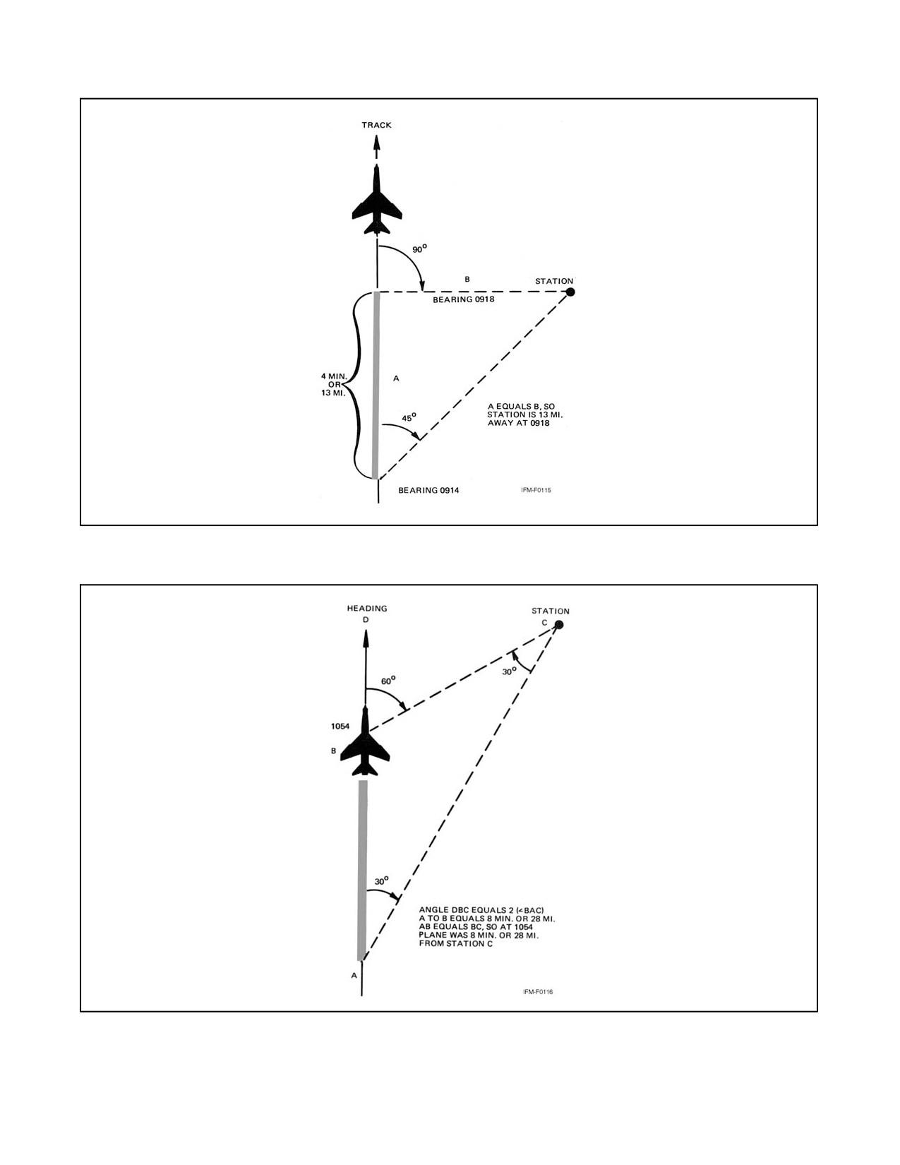
There are several other methods for determining time and distance from a radio station. If it is a station to be passed
abeam, the conventional bow and beam bearing method utilized for visible bearings in navigation may be used
(Figure 21-15). The double the angle on the bow method, similar to the same system discussed for intercepting a
bearing, may also be used (Figure 21-16). More often, however, the pilot will be in a situation where the pilot desires
time/distance from a station that is the destination. If no specific course or bearing is required for the approach, it is
suggested one be selected suitable for the double-the-angle-on-the-bow interception, or one 10_ off your inbound
track for the 30_ turn method (explained in paragraph 21.3.10), and request clearance to approach on that bearing.
The 30_ turn method of time/distance check is preferable because it requires very little alteration of heading; however,
it may or may not be accurate in an unknown wind situation.
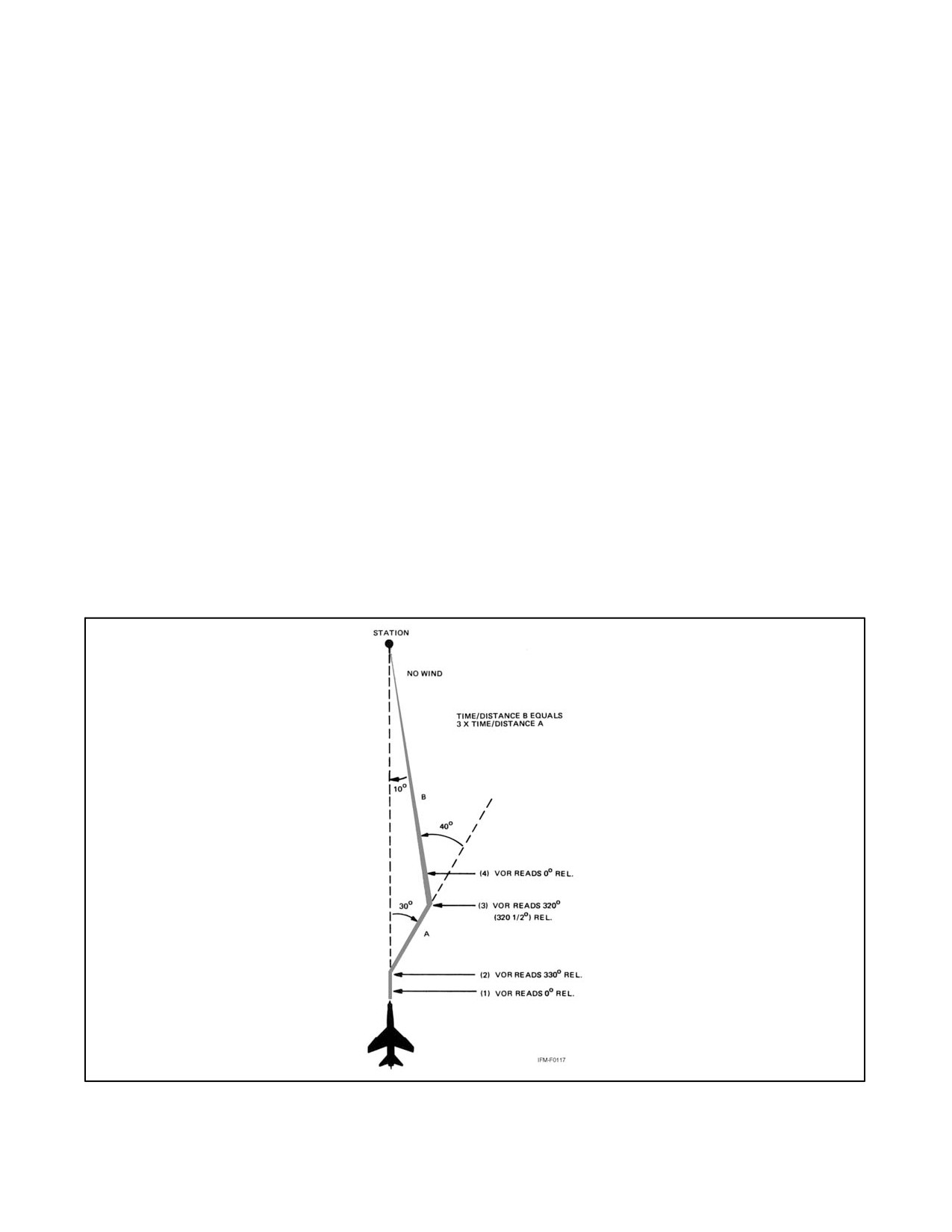
21.3.10 30° Method
This method (Figure 21-17) is begun when tracking toward station. To start the check, turn 30_ right or left and note
the time (to 1 second). Hold this new heading. If the VOR had read zero before the turn, it should now read 330_ or
30° relative. If drift correction was being held, it should now read 330_ or 30_ relative, plus or minus that correction.
This heading should be maintained on the remote compass or RMI until the needle of the VOR has moved 10_ toward
the wingtip position. Note the exact time, turn toward the station, and track to the station. The time from this second
turn to the station will be three times the time between turns.
The distance to the station is also three times the distance between turns. (Compute the time/distance at groundspeed
if groundspeed is known, or at the TAS if groundspeed is not known.)
There are two minor precautions to observe in connection with the 30_ turn method. First, determine drift before starting.
If the pattern is flown under conditions of no wind and there is a wind blowing the aircraft off course, the results obtained
will not be accurate. In fact, if the needle does not progress toward the wingtip at all, the aircraft is drifting to the other
side of the station entirely.
The accuracy of time and distance checks is governed by the existing wind, the degree of bearing change, and the
accuracy of timing. The number of variables involved causes the result to be an approximation; however, by flying
an accurate heading and checking the time and bearing closely, you can get a reasonable estimate of time and distance
from the station.
Time and distance checks using only the course indicator employ the same principles. First, rotate the course set knob
until the CDI centers, then turn to a heading 90_ from the bearing in the course window. After completing this turn,
rotate the course set knob to recenter the CDI and accomplish the time and distance check as previously described.
For VOR time-distance checks using the RMI only, refer to ADF time-distance check in Chapter 23.
21.3.11 Station Passage
The cone of confusion is encountered just before passing over the VOR station. As the width of the cone varies with
altitude, the actual time spent in the cone varies according to altitude and groundspeed. As the aircraft enters the cone
of confusion, the bearing pointer may swing from side to side, the CDI will reflect the bearing pointer movement,
the TO-FROM indicator may fluctuate between TO and FROM, and the course warning flag may appear. For timing
purposes, station passage occurs when the TO-FROM indicator makes the first positive change to FROM. After the
bearing pointer stabilizes, the CDI resumes its normal indications.
When making course changes over a VORTAC and range is available, the pilot may begin the turn just before station
passage so as to roll out on the desired outbound course.
21-23
ORIGINAL
NAVAIR 00-80T-112
Figure 21-13. Curved Flightpath as a Result of Homing with a Crosswind Condition
ORIGINAL
21-24
NAVAIR 00-80T-112
DISTANCE CHECK CAN BE
MADE WITH HSI USING
THE SAME TECHNIQUE.
D AND COMPUTE TIME-STOP TIME
DISTANCE
FROM THE STATION.
C WHEN CDI DISPLACES
FROM CENTER POSITION,
SET 10_ BEARING
CHANGE INTO COURSE
SELECTOR WINDOW.
(CHECK THAT CDI HAS
MOVED OVER THE
HEADING POINTER.)
B AFTER COMPLETING TURN, CENTER THE CDI BY
SETTING THE BEARING TO THE STATION INTO
THE COURSE SELECTOR WINDOW, NOTE TIME.
A TURN TO PLACE THE BEARING POINTER
ON THE NEAREST 90_ INDEX.
Figure 21-14. Time — Distance Check
21-25
ORIGINAL
NAVAIR 00-80T-112
Figure 21-15. Bow-to-Beam Bearing Time/Distance Check
Figure 21-16. Double-the-Angle-on-Bow Time/Distance Check
ORIGINAL
21-26
NAVAIR 00-80T-112
21.3.12 Holding
(Figures 21-18, 21-19, 21-20, 21-21, 21-22, 21-23, and 21-24.)
1. When holding at a VOR station, pilots should begin the turn to the outbound leg at the time of the first complete
reversal of the TO-FROM indicator.
2. Patterns at the most generally used holding fixes are depicted on appropriate charts. Pilots are expected to hold
in the pattern depicted unless specifically advised otherwise by Air Traffic Control (ATC).
3. ATC clearance requiring that an aircraft be held at a holding point where the pattern is not depicted will include
the following information:
a. General holding instructions.
(1) The direction to hold from holding point. (The direction to hold with relation to the holding fix will be
specified as one of eight general points of the compass [i.e., north, northeast, east, etc.].)
(2) Holding fix.
(3) On (specified) radial course, magnetic bearing airway number of jet route.
(4) Outbound leg length in nm, if DME is to be used.
(5) Left turns, if nonstandard pattern is to be used.
Figure 21-17. 30° Turn Method of Time/Distance Check
21-27
ORIGINAL
NAVAIR 00-80T-112
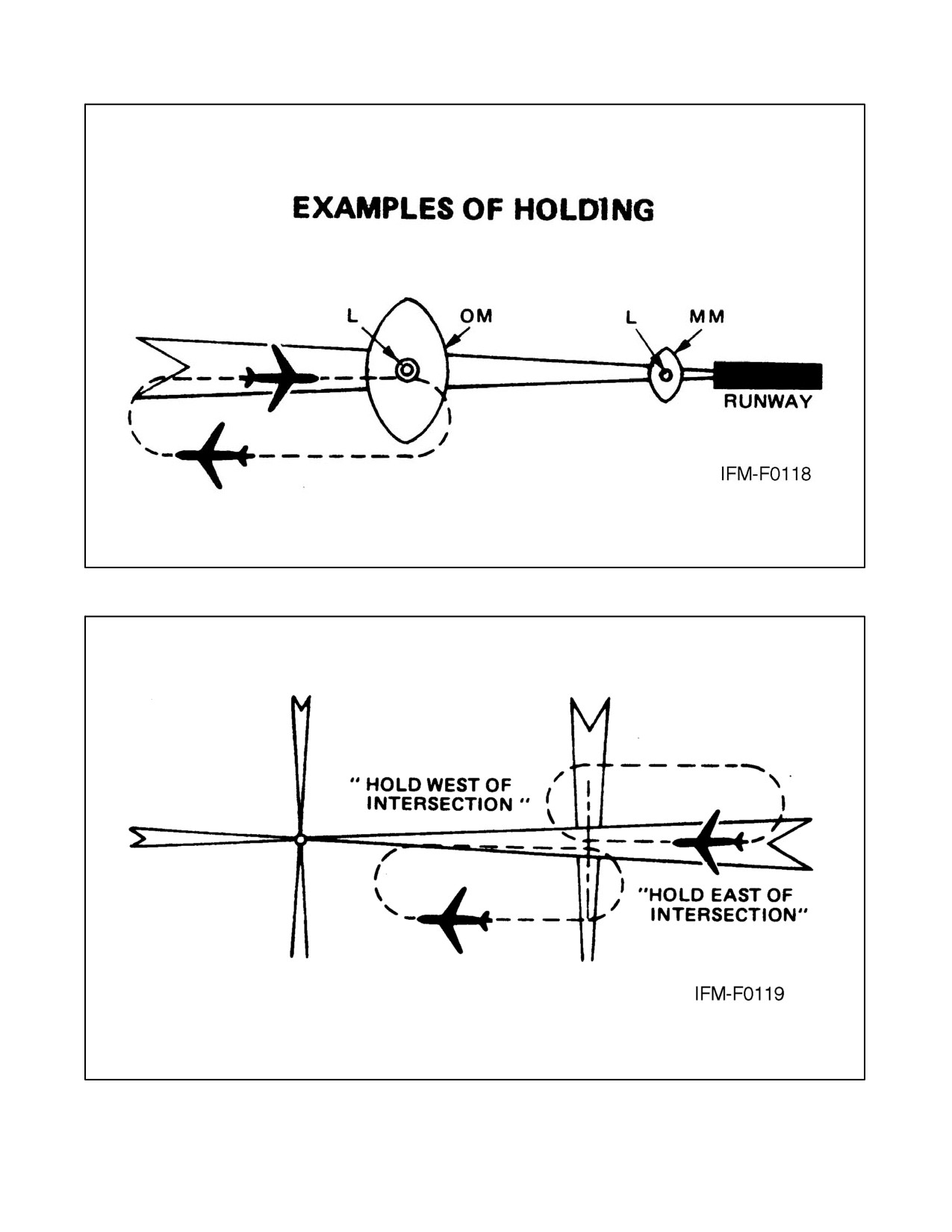
Figure 21-18. Typical Procedure on an ILS Outer Marker
Figure 21-19. Typical Procedure at Intersection of Radio Range Courses
ORIGINAL
21-28
NAVAIR 00-80T-112
Figure 21-20. Typical Procedure at Intersection of VOR Radials
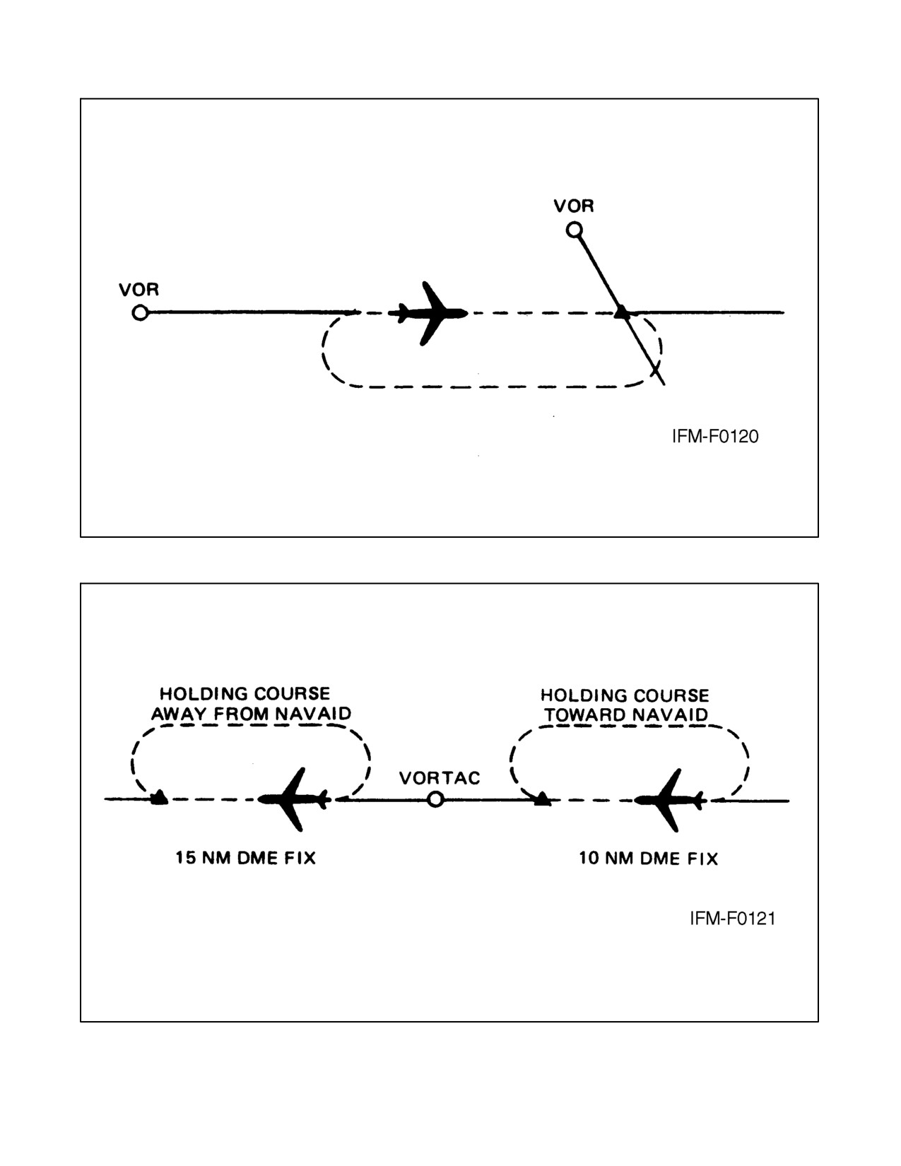
Figure 21-21. Typical Procedure at DME Fix
21-29
ORIGINAL
NAVAIR 00-80T-112
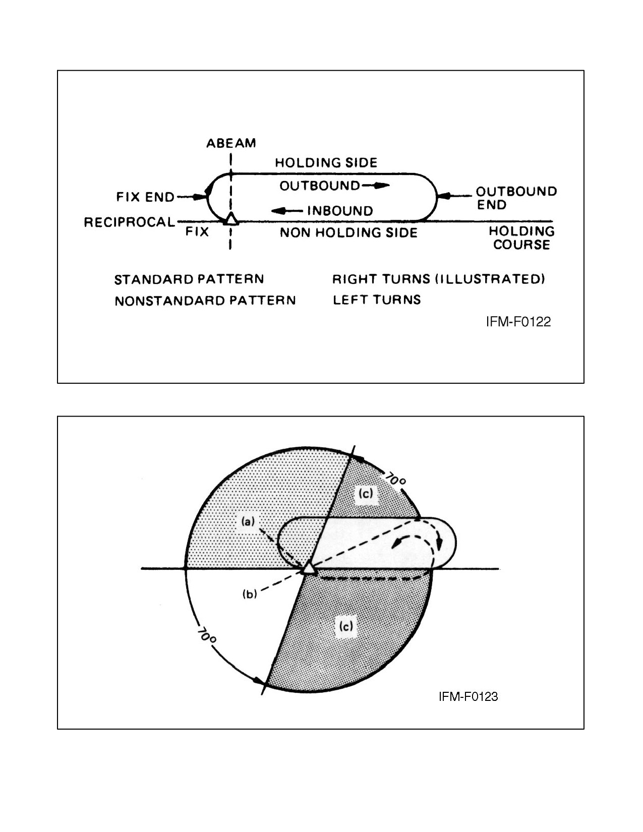
Figure 21-22. Descriptive Terms
Figure 21-23. Standard Pattern
ORIGINAL
21-30
NAVAIR 00-80T-112
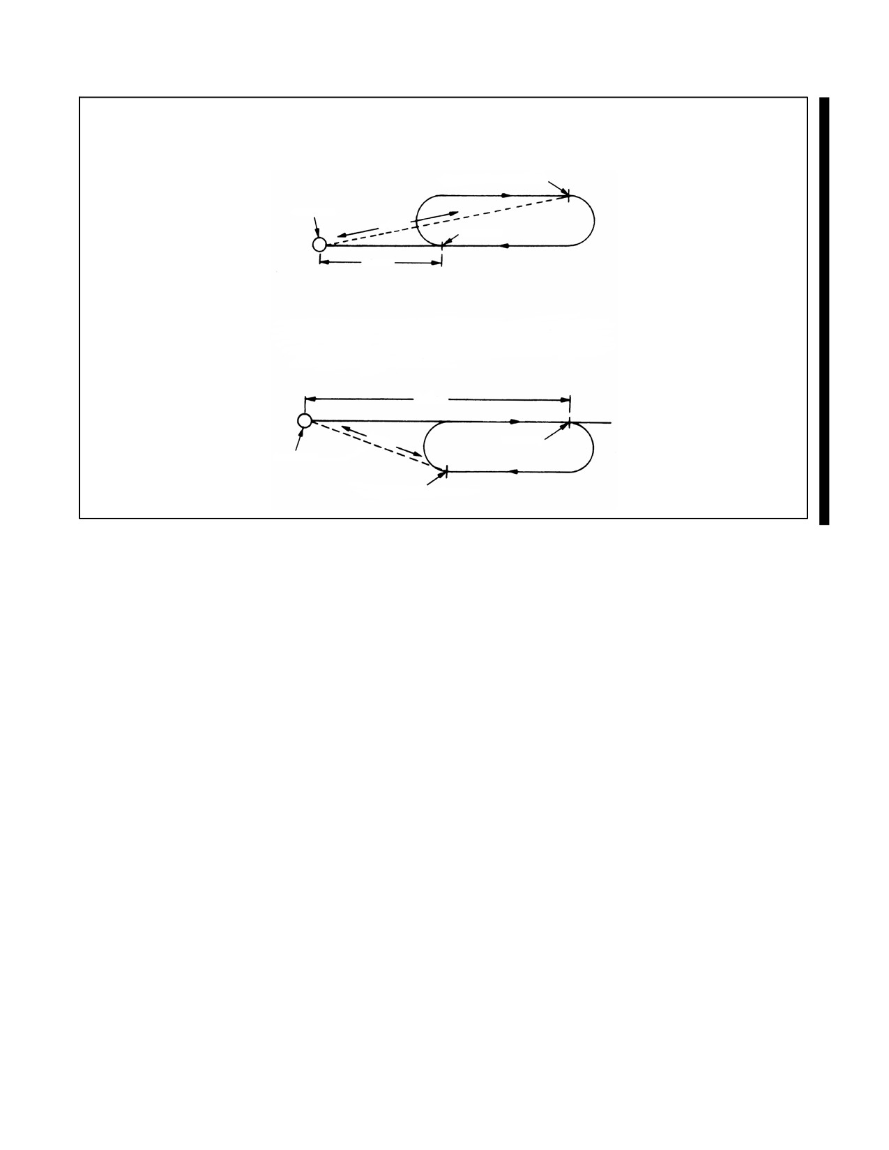
When the inbound course is toward the NAVAID and
the fix distance is 10 nm and the leg length is 5 nm,
then the end of the outbound leg will be reached
when the DME reads 15 nm.
END OUTBOUND LEG
NAVAID
15 nm
DME FIX
10 nm
When the inbound course is away from the NAVAID
and the fix distance is 28 nm and the leg length is
8 nm, then the end of the outbound leg will be reached
when the DME reads 20 nm.
28 nm
20 nm
DME FIX
NAVAID
END OUTBOUND LEG
Figure 21-24. DME Holding
(6) Time to expect further clearance.
b. Detailed holding instructions: Same as a (1), (2), and (3) above with following additions to (4) and (5):
(1) or minute(s) if DME is not to be used.
(2) or right turns if standard pattern is to be used.
4.
Holding pattern airspace protection is based on the following procedures. They are the only procedures for
entry and holding recommended by the Federal Aviation Administration (FAA).
a. Entry procedures.
(1) Descriptive terms.
(2) Airspeed (maximum) — Refer to Flight Information Publications (FLIP) general planning.
(3) Entry.
(a) Parallel Procedure — Parallel holding course, turn left, and return to holding fix or intercept holding
course. (Also called left turn.)
(b) Teardrop procedure — Proceed on outbound track of 30_ (or less) to holding course, turn right to
intercept holding course.
(c) Direct entry procedure — Turn right and fly the pattern. (Also called right turn.)
Note
Text and illustration are standard pattern, turns are opposite for nonstandard
pattern.
21-31
ORIGINAL
NAVAIR 00-80T-112
(4) Timing.
Note
The initial outbound leg should be flown for 1 minute or 1-1/2 minutes
(appropriate to altitude). Timing for subsequent outbound legs should be
adjusted as necessary to achieve proper inbound leg time.
(a) Outbound timing begins over or abeam the fix, whichever occurs later. If the abeam position cannot
be determined, start timing when turn to outbound is completed.
(5) Distance Measuring Equipment (DME).
(a) DME holding is subject to the same entry and holding procedures except that distances (nm) are used
in lieu of time values. The outbound course of a DME holding pattern is called the outbound leg of
the pattern. The length of the outbound leg will be specified by the controller. The end of the
outbound leg is determined by the DME reading.
(6) Pilot action.
(a) Cross holding fix initially at or below maximum holding airspeed. Effect speed reduction within 3
minutes prior to estimated initial time over the holding fix.
(b) Make all turns during entry and while holding at: (1) 3_ per second, (2) 30_ bank angle, or (3) 25_
bank angle (provided a flight director system is used), whichever requires the least bank angle.
(c) Compensate for known effect of wind, except when turning.
(d) Determine entry turn from aircraft heading upon arrival at the holding fix. Plus or minus 5_ in
heading is considered to be within allowable good operating limits for determining entry.
(e) Advise ATC immediately if any increased airspeed is necessary due to turbulence, icing, etc., or if
unable to accomplish any part of the holding procedures. After such higher speeds are no longer
necessary, operate according to the appropriate published holding speed and notify ATC.
Note
Airspace protection for turbulent air holding is based on a maximum of 280
Knots Indicated Airspeed (KIAS) or Mach 0.8, whichever is lower.
Considerable impact on traffic flow will result when turbulent air holding
patterns are used; thus, pilot discretion will ensure their use is limited to
bona fide conditions/requirements.
(7) Nonstandard holding pattern — Fix end and outbound end turns are made to the left. Entry procedures
to a nonstandard pattern are oriented in relation to the 70_ line on the holding side just as in the standard
pattern.
5.
When holding at a fix, and instructions are received specifying the time of departure from the fix, the pilot
should adjust the flightpath within the limits of the established holding pattern in order to leave the fix at the
exact time specified. After departing the holding fix, normal speed is to be resumed with respect to other
governing speed requirements, such as terminal area speed limits, specific ATC requests, etc. Where the fix
is associated with an instrument approach, and timed approaches are in effect, a procedure turn shall not be
executed unless the pilot advises ATC, as aircraft holding is expected to proceed inbound on final approach
directly from the holding pattern when approach clearance is received.
ORIGINAL
21-32
NAVAIR 00-80T-112
6. Radar surveillance of outer fix holding pattern airspace areas.
a. Whenever aircraft are holding at an outer fix, ATC will usually provide radar surveillance of the outer fix
holding pattern airspace area, or any portion of it, if it is shown on the controller’s radarscope.
b. The controller will attempt to detect any holding aircraft that stray outside the holding pattern airspace area
and will assist any detected aircraft to return to the assigned airspace area.
c. Many factors could prevent ATC from providing this additional service, such as workload, number of
targets, precipitation, ground clutter, and radar system capability. These circumstances may make it
unfeasible to maintain radar identification of aircraft or to detect aircraft straying from the holding pattern.
The provision of this service depends entirely upon whether the controller believes to be in a position to
provide it and does not relieve a pilot of the pilot’s responsibility to adhere to an accepted ATC clearance.
21.3.12.1 Wind Correction Techniques
21.3.12.1.1 Crosswind Correction
After entering the holding pattern, the pilot should compensate for wind in order to arrive at an outbound position
from which a turn inbound will place the aircraft on the holding course.
This is normally accomplished by utilizing a larger drift correction on the outbound leg.
21.3.12.1.2 Headwind or Tailwind Corrections
After completing the first circuit of the holding pattern, adjust the time outbound as necessary to provide the desired
inbound time. For example, if the inbound leg was 30 seconds too long, subtract 30 seconds from the outbound leg.
In extreme wind conditions, even though the turn inbound is initiated when abeam the station, the inbound leg may
exceed the 1 or 1-1/2 minute limit. In this case only is the pilot authorized to exceed the time limit inbound.
21.3.12.1.3 Meeting an Expected Further Clearance Time (EFC)
The holding pattern may be shortened (never lengthened) as required to meet the Expected Further Clearance Time
(EFC). Planning to meet the EFC should be based on the point of departure from the holding pattern. Two factors to
consider in planning are the length of time required to make the two turns and the inbound leg time compared to the
outbound leg.
21.3.12.2 Approaches
A limited number of VOR instrument approaches utilizing a VORTAC facility have been approved for use for
TACAN equipped aircraft. These procedures are identified by the phrase “or TACAN” printed adjacent to the name
of the procedure (e.g., VOR or TACAN Rwy 17). Approaches designated as VORTAC may be executed by aircraft
using either TACAN or VOR with DME; DME is required. Approaches designated VOR/DME shall be executed by
aircraft utilizing VOR with DME, and both the VOR and DME are required.
The approach procedures discussed in this section are for basic instruction
only. Consult the latest Aeronautical Information Manual/Federal Aviation
Regulation (AIM/FAR) for detailed procedures.
21.3.12.3 Transition to the Initial Approach Fix (IAF)
Published routes on the terminal chart provide a course and distance from the en route structure to the Initial Approach
Fix (IAF). If other than a published routing is used, ensure it does not exceed the operational limitation of the
Navigation Aid (NAVAID). Limitations according to type NAVAID, aircraft altitude, and range from the facility are
published in FLIP.
21-33
ORIGINAL
NAVAIR 00-80T-112
Before reaching the IAF, review the approach chart, recheck the weather at destination and alternate, and obtain
clearance for the approach.
An IAF may be approached from directions not favorable to intercepting the initial approach course upon arrival at
the fix. When this occurs, and prior approach clearance has been received, the pilot must maneuver to intercept the
initial approach course. Preapproach intercept maneuvers should be accomplished as follows:
1. Turn at the IAF in the shortest direction to intercept the initial approach course.
2. Begin descent from the Initial Penetration Altitude (IPA) when established on a segment of the published
approach.
3. If holding is not required, reduce to penetration airspeed or below before crossing the IAF.
21.3.12.4 High-Altitude Approach Procedures
21.3.12.4.1 Non-DME Teardrop Approach
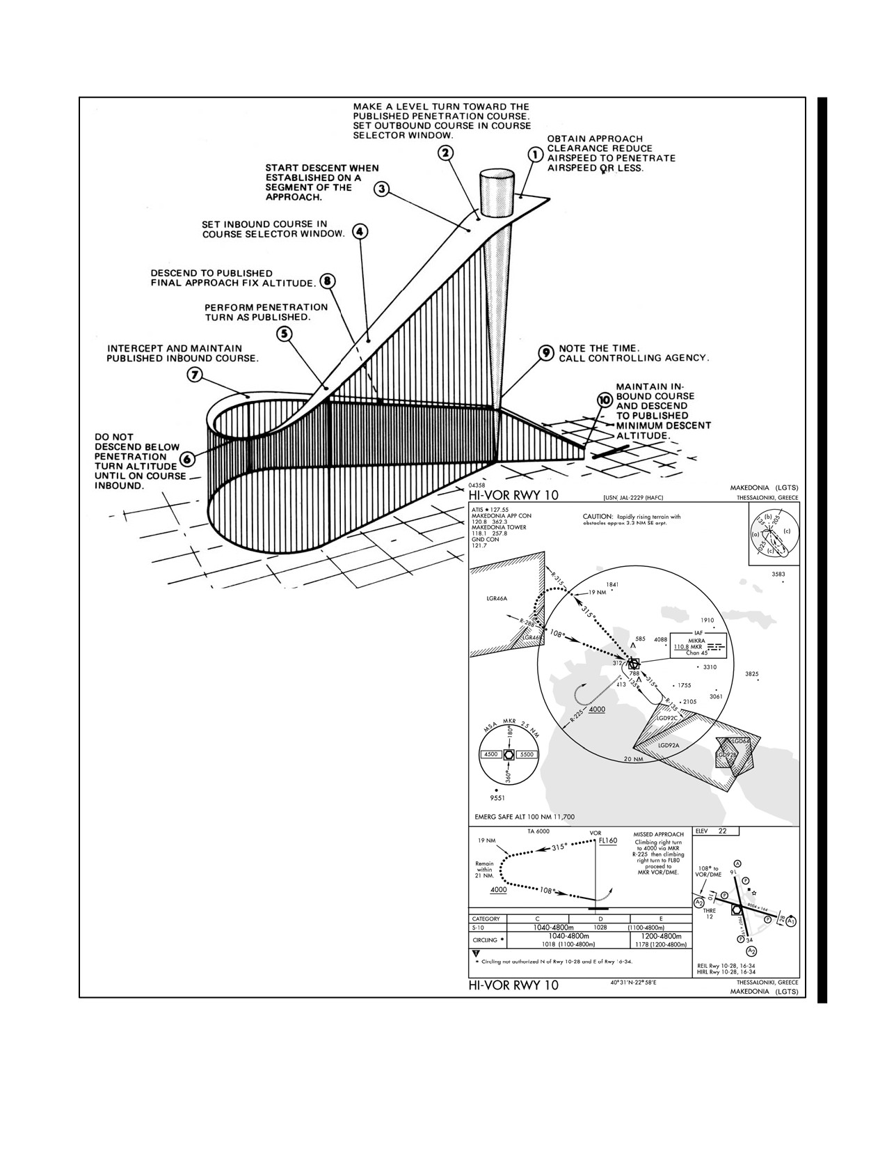
After crossing the IAF, turn in the shorter direction toward the penetration course. Set the altimeter in accordance with
FLIP procedures. Start descent when the aircraft is over or abeam the fix, headed in the direction of the penetration
course. Correct to course using
“immediately after station passage interception” procedures described in
paragraph 21.3.4. Some penetrations include altitude restrictions for a specified number of miles. In these cases,
intercept the outbound course and descend as depicted on the approach chart. Before reaching the penetration turn
altitude, set the inbound course in the course selector window. Recheck the altimeter and the minimum altitude for
completion of the penetration turn.
Perform the penetration turn as published. If it appears the course will not be intercepted upon completion of the
penetration turn, roll out with an intercept to the inbound course. Normally, a 30_ to 45_ intercept angle is sufficient;
however, vary the angle as necessary depending upon groundspeed, displacement from course, and range from the
station.
Descend from the altitude specified for completion of penetration turn when on the inbound course. Before reaching
the Final Approach Fix (FAF), configure the aircraft for landing in accordance with the flight manual. Cross the FAF
at the published altitude, start timing, intercept the final approach course, and report to the controlling agency.
Note
The time-distance tables published in the approach charts are based on
groundspeed; therefore, TAS and the existing wind must be considered in
order to accurately determine the time from the final approach fix to the
missed approach point.
Descend to the Minimum Descent Altitude (MDA) so that visual references for landing may be acquired as soon as
practical. Comply with any published altitude restrictions between the final approach fix and Missed Approach Point
(MAP). The descent to the MDA should be completed before reaching the missed approach point. Descent below
MDA is authorized when visual reference with the runway environment is sufficient to complete the landing. Part
VII discusses landing from a straight-in or circling approach.
The MDA should not be confused with the weather minimums for the approach being flown. The weather minimums
indicate the ceiling and visibility required before the approach may be started (reference OPNAV 3710.7 series,
Chapter 5, Approach Criteria for Multipiloted Aircraft). The MDA indicates the minimum altitude Mean Sea Level
(MSL) to which the aircraft may be flown. Use Runway Visual Range (RVR) for the visibility minimum when
available. The RVR is found in the landing minimums block next to the MDA (Figure 21-25).
ORIGINAL
21-34
NAVAIR 00-80T-112
Figure 21-25. VOR Non-DME Teardrop High-Altitude Approach
21-35
ORIGINAL
NAVAIR 00-80T-112
Perform the missed approach when:
1. Visual reference with the runway environment at the missed approach point is insufficient to complete the
landing.
2. Instructed by the controlling agency.
3. A safe landing is not possible.
21.3.12.4.2 Dual-Facility Approaches
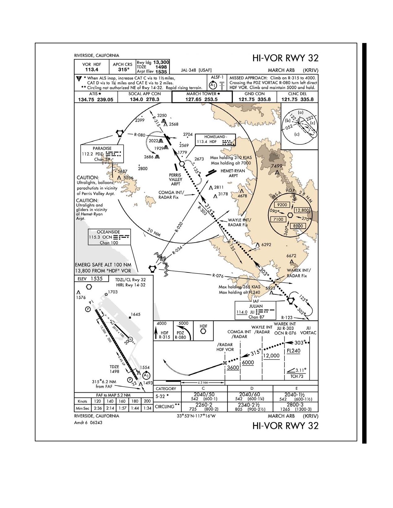
This type of approach may use dual VOR, ADF, or a combination of the two facilities. Figure 21-26 illustrates one
type of dual-facility approach. With dual navigational receivers, this type of approach offers a few advantages over
the non-DME teardrop approach. The pilot can maintain course on one facility and monitor his progress by reference
to the second facility. Normally, the distance between the IAF and FAF is published in the profile view of the approach
chart. If the pilot is position oriented, the pilot can better approximate the time available to configure the aircraft for
the final approach.
With only a single VOR (or ADF) receiver, this type of approach may require a high degree of pilot proficiency. In
the illustration, a pilot flying this approach would have to retune the VOR several times in order to intercept and
maintain course and, at the same time, determine the aircraft position in relation to the intersection(s). Consider
weather, aircraft equipment, and pilot proficiency when planning a dual-facility approach.
Note
Dual receivers are required when an intersection (formed by a radial from
another facility) is used as a step-down fix between the final approach fix
and missed approach point.
21.3.12.5 Low-Altitude Approach Procedures
The reduction of airspace and the predominant use of the procedure turn are two factors that distinguish the Low- (AL)
from the High-Altitude Approach (JAL). Pilots of high-performance aircraft that have an operational requirement
to use the low-altitude charts (AL) should maneuver at airspeeds compatible with the depicted procedure. Category
E will be depicted on low-altitude (AL) procedures only where an operational requirement exists. Procedure turns
are discussed under paragraph 21.3.12.6. Some low-altitude VOR (or ADF) approaches do not use the procedure turn
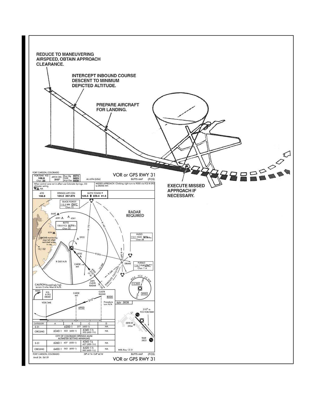
(Figure 21-27). The guidance concerning transition found preceding high-altitude approach procedures also applies
to low-altitude approach procedures.
21.3.12.5.1 Straight-In Approaches
A straight-in approach is an instrument approach conducted by proceeding over the FAF at the prescribed altitude and
continuing inbound on the final approach course to the airport without making a Procedure Turn (PT). When issued
a clearance for a straight-in approach while conducting a timed approach from a holding fix, when the initial approach
published on the Instrument Approach Procedure (IAP) is designated NoPT (procedure turn not required), or when
ATC radar vectors to a final approach position are provided, the pilot shall not make a procedure turn unless the pilot
so advises ATC and an appropriate clearance is received. Some instrument approach procedures specifically prohibit
use of a procedure turn (Figure 21-27).
An aircraft cleared to a holding fix, other than the IAF, then subsequently cleared for a straight-in approach (even if
the aircraft has not yet entered holding) is expected by ATC to proceed to the IAF via the holding fix to commence
the approach. If route of flight directly to the IAF is desired, it should be so stated by the controller. If doubt exists,
contact ATC to determine the correct route of flight.
ORIGINAL
21-36
NAVAIR 00-80T-112
Figure 21-26. Dual VOR High-Altitude Approach
21-37
ORIGINAL
NAVAIR 00-80T-112
Figure 21-27. VOR Low-Altitude Straight-in Approach
ORIGINAL
21-38
NAVAIR 00-80T-112
When operating on an unpublished route or while being radar vectored when an approach clearance is received, the
pilot shall maintain the last assigned altitude: unless a different altitude is assigned by ATC or until the aircraft is
established on a segment of a published route or instrument approach procedure. Descend from the initial approach
altitude to the next altitude depicted after established on the initial approach course. If there is insufficient time to
intercept course and comply with the first altitude restriction, before starting the approach, request ATC clearance
to maneuver for a favorable alignment with the initial approach course. Before reaching the FAF, configure the aircraft
for landing in accordance with the applicable NATOPS flight manual. At the FAF, start the time, intercept the final
approach course, and call the controlling agency, if required.
If no FAF is depicted, treat the point of interception of the final approach course as the FAF.
Note
The time-distance tables published in the approach charts are based on
groundspeed; therefore, TAS and the existing wind must be considered to
determine accurately the time from the final approach fix to the missed
approach point.
Descend to the MDA so that visual references for landing may be acquired as soon as practical. Comply with any
published altitude restriction between the FAF and missed approach point. Descent below MDA is authorized when
visual reference with the runway environment is sufficient to complete the landing. Perform the missed approach
when:
1. Visual reference with the runway environment at the missed approach point is insufficient to complete the
landing.
2. Instructed by the controlling agency.
3. A safe landing is not possible.
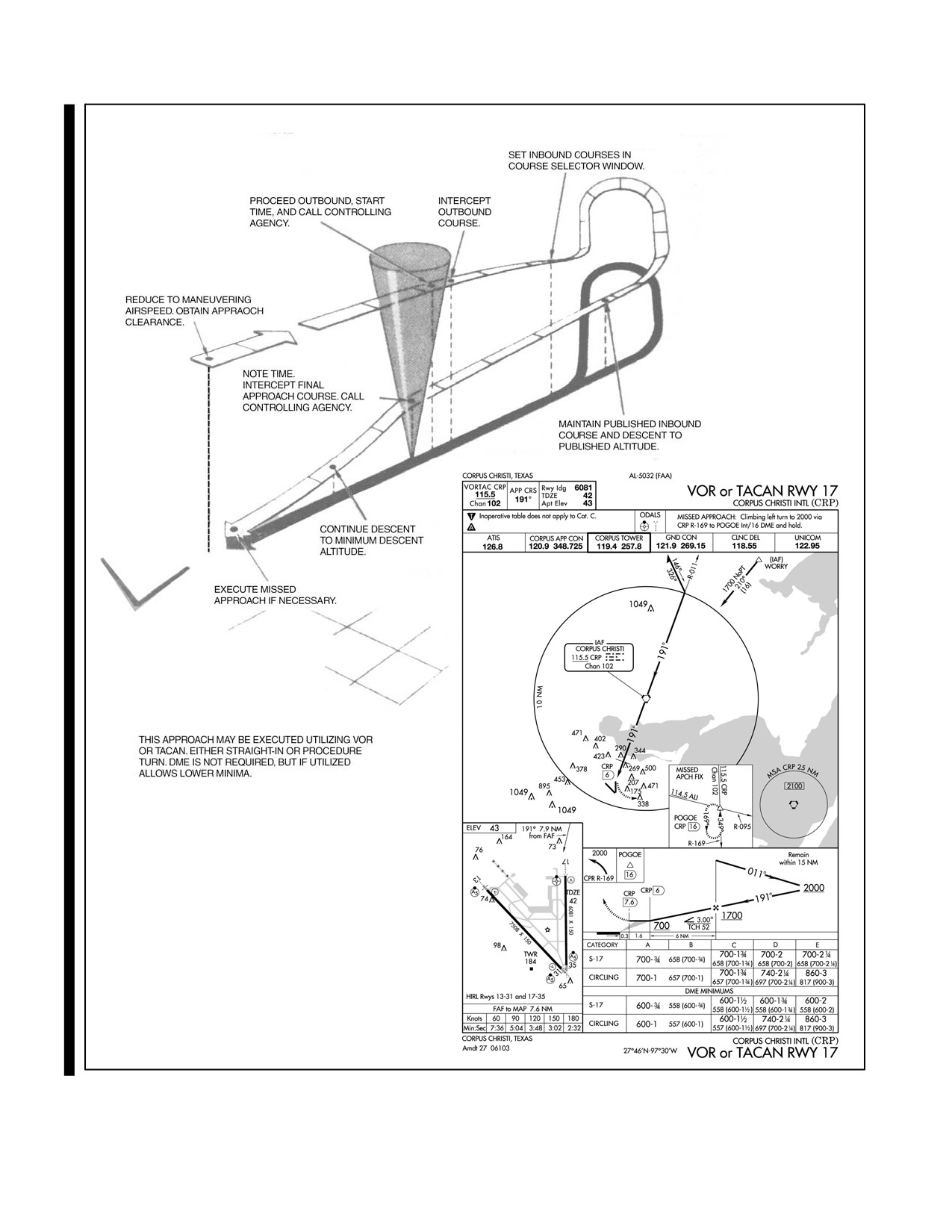
21.3.12.6 Procedure Turns (PT)
A Procedure Turn (PT) is a maneuver that is designed to place the aircraft on an inbound course to the FAF. Further,
it provides for descent to the FAF altitude and affords the pilot time to establish the final approach configuration. A
procedure turn is normally associated with the low-altitude approach (AL); however, it may be included as a part of
the High-Altitude Approach (JAL) procedure (Figures 21-28 and 21-29).
21.3.12.6.1 Entry
Initial entry for a procedure turn may be accomplished as described under paragraph 21.3.12, or may be made by the
aircraft turning in the shortest direction to proceed outbound. On U.S. Government charts, a barbed arrow indicates
the direction or side of the outbound course on which procedure turn is made. Headings are provided for course
reversal using the 45 degree type procedure turn; however, the point at which the turn may be commenced and the
type and rate of turn is left to the discretion of the aircrew. Some of the options are the 45 degree procedure turn, the
racetrack pattern, the teardrop procedure turn, or the 80/260 degree course reversal. Some procedure turns are
specified by procedural track. These turns must be flown exactly as depicted.
When the approach procedure involves a procedure turn, a maximum speed of not greater than 200 knots Indicated
Airspeed (IAS) should be observed from first overheading the course reversal IAF through the procedure turn
maneuver to ensure containment within the obstruction clearance area.
21-39
ORIGINAL
NAVAIR 00-80T-112
COMMENCE PROCEDURE TURN.
Note
Figure 21-28. VOR Low-Altitude Approach, Procedure Turn Type
ORIGINAL
21-40
NAVAIR 00-80T-112
Note
Figure 21-29. VOR Low-Altitude Approach, Teardrop Required
21-41
ORIGINAL
NAVAIR 00-80T-112
On the outbound leg, the aircraft shall not exceed the protected airspace depicted. At the completion of the outbound
leg, course reversal may be accomplished by utilizing the 90-270 method, the depicted procedure turn headings, or
any other method that safely reverses course and keeps the aircraft on the Procedure Turn (PT) side of the approach
course within the protected airspace. If on a teardrop approach, at the completion of outbound timing, turn in the
shortest direction toward the inbound course.
When nonstandard distances are specified, adjust timing in order to comply with the depicted procedure. The standard
procedure turn length is 10 nm (15 nm on terminal charts where Category E minimums are published). For those
procedure turns prescribed from a DME fix, adhere to published distance restrictions in lieu of timing.
21.3.12.6.2 Descent
Initiate descent from the initial approach altitude to the published procedure turn altitude when the aircraft is abeam
the fix or wings level outbound, whichever occurs last. Start descent from procedure turn altitude to final approach
fix altitude when the aircraft is headed inbound on the inbound course. If a teardrop is performed from a fix without
outbound course guidance, descend from procedure turn altitude when the aircraft is on course inbound.
Before reaching the final approach fix, configure the aircraft for landing in accordance with the NATOPS flight
manual. At the final approach fix, note the time, make the mandatory position report, and intercept the final approach
course to the airfield. If no FAF is depicted, treat the point at which the aircraft has intercepted the inbound course
as the FAF.
Note
The time-distance tables published on the approach charts are based on
groundspeed; therefore, TAS and the existing wind must be considered in
order to determine accurately the time from the final approach fix to the
missed approach point.
Descend to the MDA so that visual references for landing may be acquired as soon as practical. Comply with any
published altitude restriction between the FAF and missed approach point. Descent below MDA is authorized when
visual reference with the runway environment is sufficient to complete the landing and the Visual Descent Point
(VDP) has been reached.
Perform the missed approach when:
1. Visual reference with the runway environment at the missed approach point is insufficient to complete the
landing.
2. Instructed by the controlling agency.
3. A safe landing is not possible.
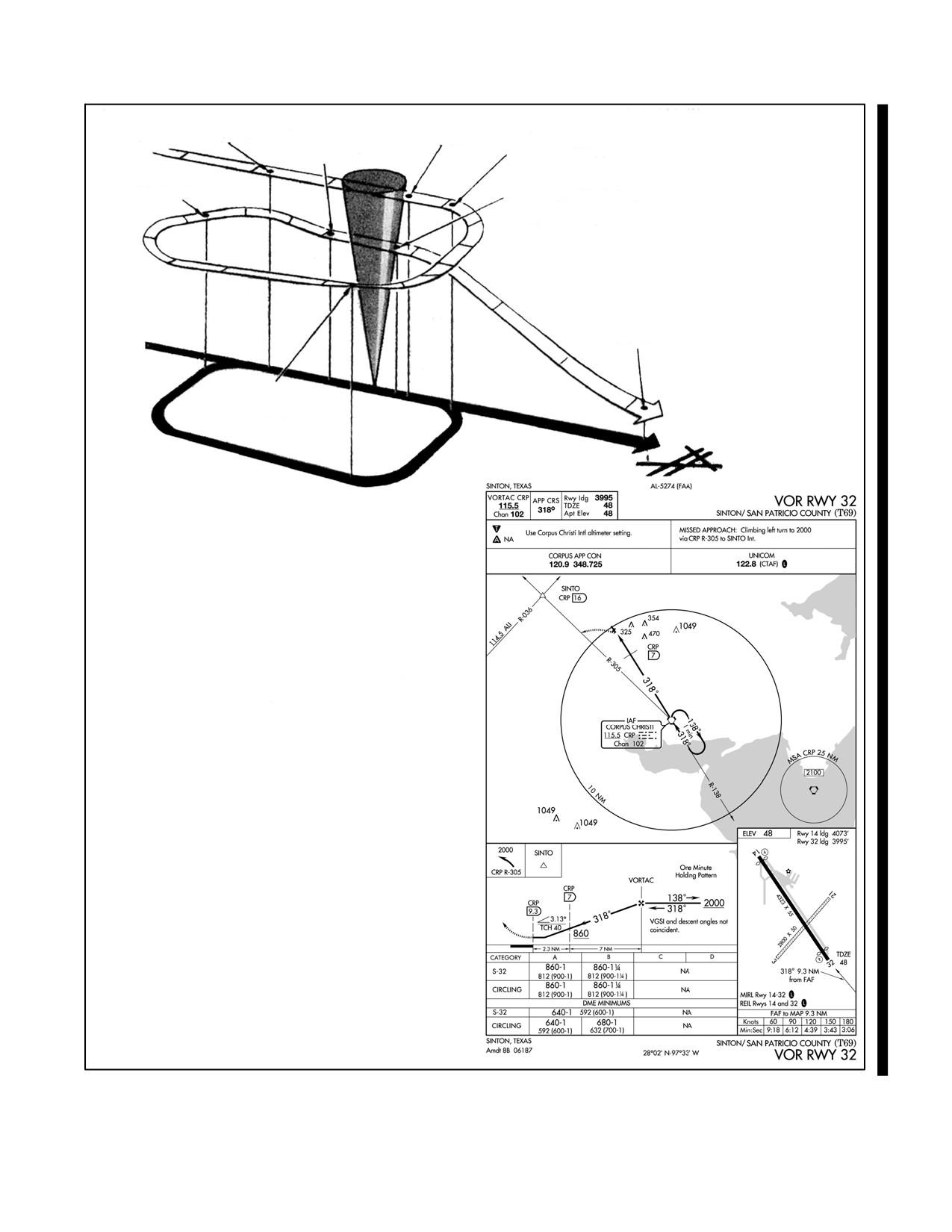
21.3.12.7 Approaches from Holding
21.3.12.7.1 Holding Type Approach
When executing an approach that specifies a holding pattern in lieu of a procedure turn, the pilot must fly the holding
pattern and does not retain the option of executing a procedure turn or teardrop (Figure 21-30). When established in
holding and cleared for the approach, the pilot may start the descent from any position in the pattern. The aircraft will
be configured for landing prior to reaching the FAF.
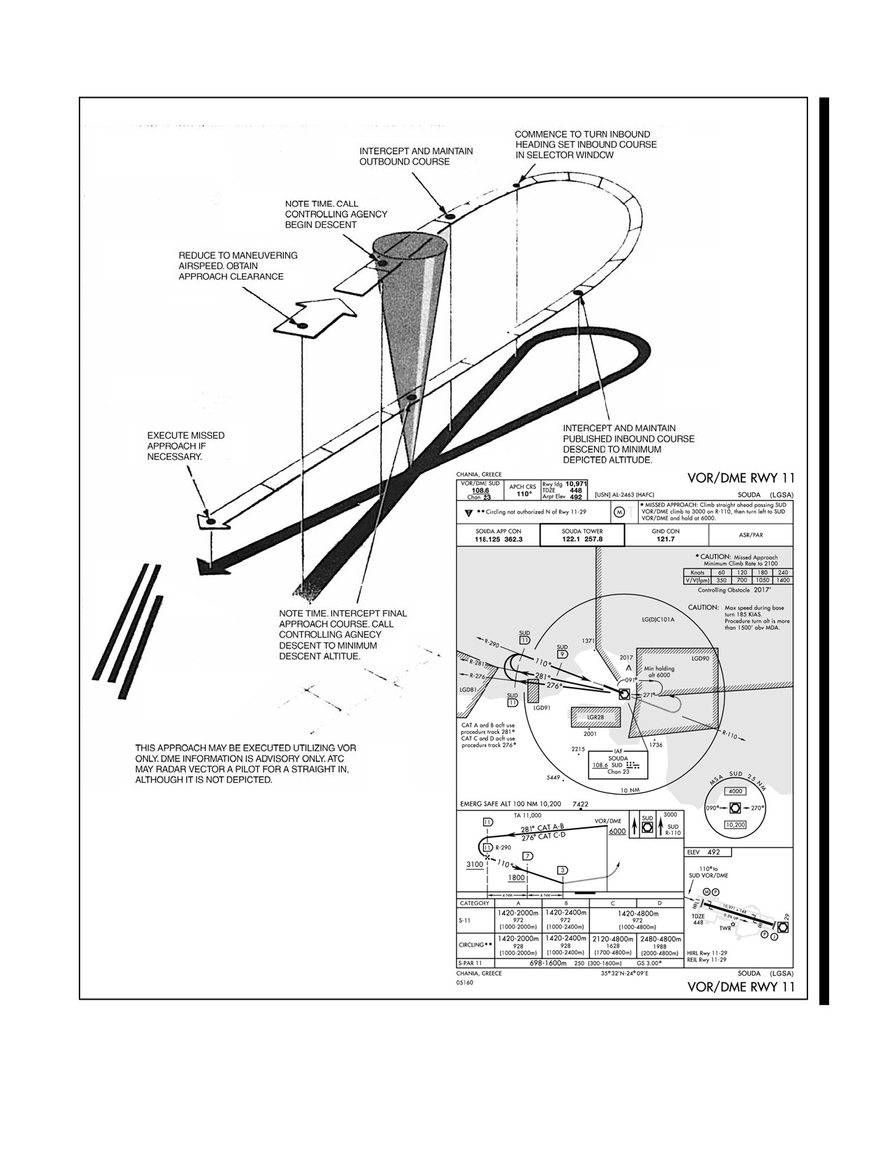
21.3.12.7.2 Holding Pattern Located on the Initial Approach Course
When cleared to hold in a pattern depicted on the approach plate on the initial approach course, and subsequently
cleared for the approach, the pilot may depart holding from any position and need not return to the holding fix. Pilots
may intercept the teardrop or procedure turn course directly and commence descent from IAF altitude immediately.
They may also remain in the holding pattern to dissipate excessive altitude power to proceeding outbound on the
procedure turn or teardrop course (Figure 21-29).
ORIGINAL
21-42
NAVAIR 00-80T-112
CALL CONTROLLING
REDUCE TO MANEUVERING
AGENCY. BEGIN
AIRSPEED. OBTAIN APPROACH
MAINTAIN MINIMUM
DESCENT.
CLEARANCE.
DEPICTED HOLDING
COMMENCE TURN TO
PATTERN ALTITUDE.
OUTBOUND HEADING.
TURN TO INTERCEPT
INBOUND COURSE.
NOTE TIME. INTERCEPT FINAL
APPROACH COURSE. CALL
CONTROLLING AGENCY.
DESCEND TO MINIMUM DESCENT
ALTITUDE.
EXECUTE MISSED
APPROACH IF NECESSARY.
START TIME FOR
HOLDING PATTERN. SET
INBOUND COURSE IN
SELECTOR WINDOW.
Note
ATC MAY RADAR VECTOR AN AIRCRAFT FOR
A STRAIGHT-IN VERSION OF THIS APPROACH.
NORMALLY, THIS WOULD BE VIA THE CRP 138
RADIAL INBOUND TO THE FAF.
Figure 21-30. VOR Low-Altitude Approach, Holding Type
21-43/(21-44 blank)
ORIGINAL
NAVAIR 00-80T-112
CHAPTER 22
Tactical Air Navigation (TACAN)
22.1
INTRODUCTION
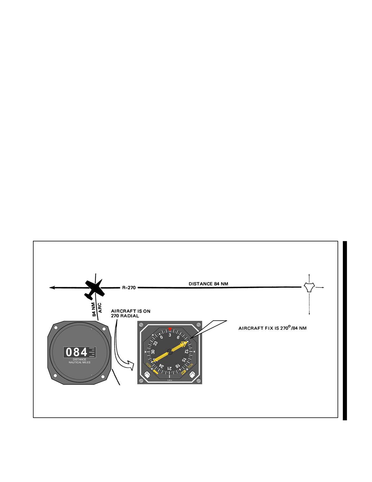
Although VHF Omnidirectional Range (VOR) was a great improvement over earlier navigation systems, a gap still
existed in information presented to the pilot. The Tactical Air Navigation (TACAN) system was developed to fill this
gap by providing the pilot with information needed for precise, geographical orientation within TACAN range.
TACAN added a continuous display of range information to the course information already available. Distance
Measuring Equipment (DME), an integral part of TACAN, provides continuous slant range distance information.
Like VOR, TACAN provides 360 courses radiating from the station. In addition, because TACAN ground equipment
is compact and relatively easy to transport, it provides for greater versatility in beacon installation and mobility than
the VOR system (Figure 22-1).
22.2
EQUIPMENT AND TRANSMISSION PRINCIPLES
TACAN operates in the Ultrahigh Frequency (UHF) (1000 MHz) band. The TACAN system has a total of 126
two-way channels. Suffixes X or Y are used for discrimination between the sets, totaling 252 possible channels.
Air-to-ground frequencies (DME) for these channels are in the 1025 to 1150 MHz range; associated ground-to-air
frequencies are in the 962 to 1024 MHz and 1151 to 1213 MHz ranges. Channels are spaced at 1-MHz intervals in
these bands.
MAGNETIC
BEARING TO
STATION 090°
Figure 22-1. Determining Aircraft Position by TACAN
22-1
ORIGINAL
NAVAIR 00-80T-112
22.2.1 Ground Equipment
The ground equipment consists of a rotating type antenna for transmitting bearing information and a
receiver-transmitter (transponder) for transmitting distance information. The TACAN identifies itself aurally through
international Morse code every 35 seconds. Permanent TACAN ground stations are usually dual-transmitter equipped
(one operating and one on standby), fully monitored installations that automatically switch to the standby transmitter
when a malfunction occurs. The ground monitor (set to alarm at any radial shift of ±1_) is usually located in the base
control tower or approach control and sets off a light and buzzer to warn the groundcrew when an out-of-tolerance
condition exists. Anytime TACAN reception is suspected or bearing/distance unlock conditions are encountered in
flight, a pilot can check on the status of the ground equipment by calling Air Traffic Control (ATC). When ground
equipment is undergoing repairs that might cause it to transmit erroneous signals, its identification must be silenced;
therefore, always listen for identification signals during flight (Figure 22-2).
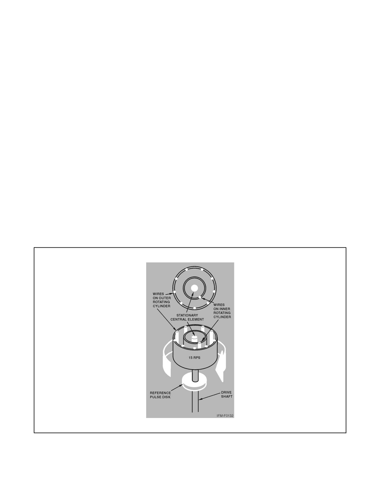
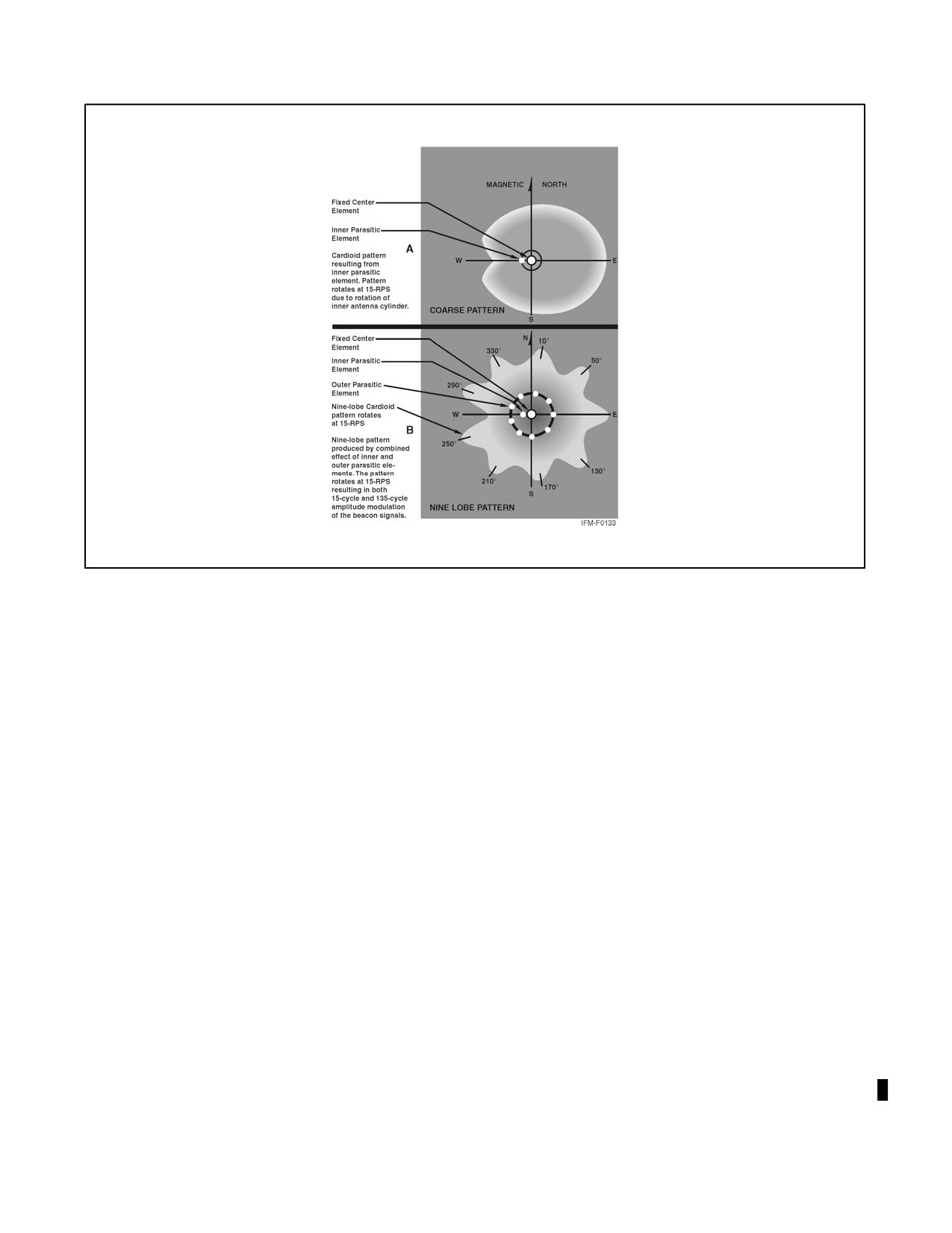
22.2.1.1 TACAN Signal Pattern
The signal pattern for bearing information is formed by varying the nondirectional pattern sent from the stationary
central element of the antenna. This is done by rotating a cylinder around the central element of the antenna at
15 revolutions per second (rps) (Figure 22-3, part A). A metal wire embedded vertically in the plastic cylinder distorts
the radiated signal into a cardioid (heart-shaped) pattern, and its rotation causes the cardioid pattern to also revolve
at 15 rps. This resulting rotating pattern is referred to as the course pattern. From this, the aircraft receives a 15
cycles-per-second (cps) amplitude modulation. This means that the strength of the signal goes from maximum to
minimum and back to a maximum at the rate of 15 cps.
Another larger cylinder, with nine wires in it, is mounted around the central element and the smaller cylinder and also
rotates at 15 rps. This is the fine antenna that superimposes nine lobes on the already-formed course pattern. This
forms a 135 cps signal (Figure 22-3, part B).
Figure 22-2. TACAN Ground Beacon Antenna
ORIGINAL
22-2
NAVAIR 00-80T-112
Figure 22-3. TACAN Antenna Pattern
To determine the aircraft position in bearing from the station, a phase angle must be measured electronically. To
measure the phase angle, a fixed reference is established. This fixed reference is a 15-cps nondirectional pulse signal
normally referred to as the main reference bearing pulse. One main reference pulse occurs with each revolution of
the antenna. In addition to the main reference pulse, eight auxiliary reference pulses also occur during one revolution
of the ground beacon antenna; therefore, a reference pulse occurs each 40_ of antenna rotation (360_ = 9 pulses).
The airborne equipment electronically measures the time lapse between the main reference pulse and the maximum
amplitude (signal strength) of the 15-cps rotating signal pattern. This determines the aircraft bearing from the station
within a 40_ sector. Then, the time lapse between the auxiliary reference pulses and the maximum amplitude of the
135-cps signal is measured to determine the aircraft position within the 40_ sector. The accuracy of this measurement
determines the position of the aircraft relative to the station within ±1_ (Figure 22-4).
22.2.1.2 Distance Measuring Equipment (DME)
Distance is determined with TACAN equipment by measuring the elapsed time between transmission of interrogating
pulses of the airborne set and reception of corresponding reply pulses of the ground station. The aircraft transmitter
starts the process by sending out the distance interrogation pulse signals. Receipt of these signals by the ground station
receiver triggers its transmitter, which sends out the distance reply pulse signals. These pulses require approximately
12 microseconds round trip travel time per nm of distance from the ground beacon. The range indicator displays
distance to the TACAN beacon in nm (Figure 22-5).
22-3
ORIGINAL
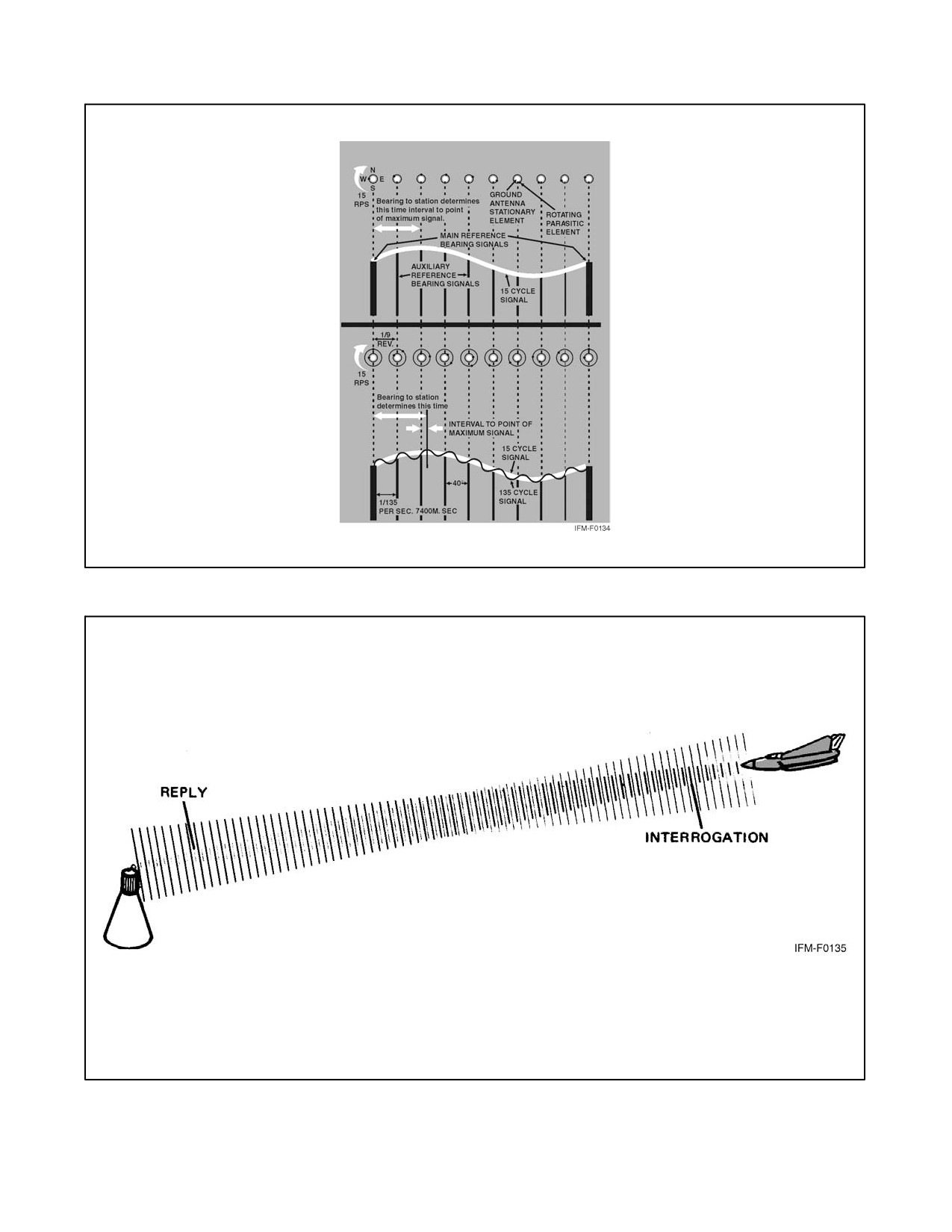
NAVAIR 00-80T-112
Figure 22-4. Combined Course and Fine Bearing Signals
Figure 22-5. Interrogation and Reply Pulses for DME
ORIGINAL
22-4
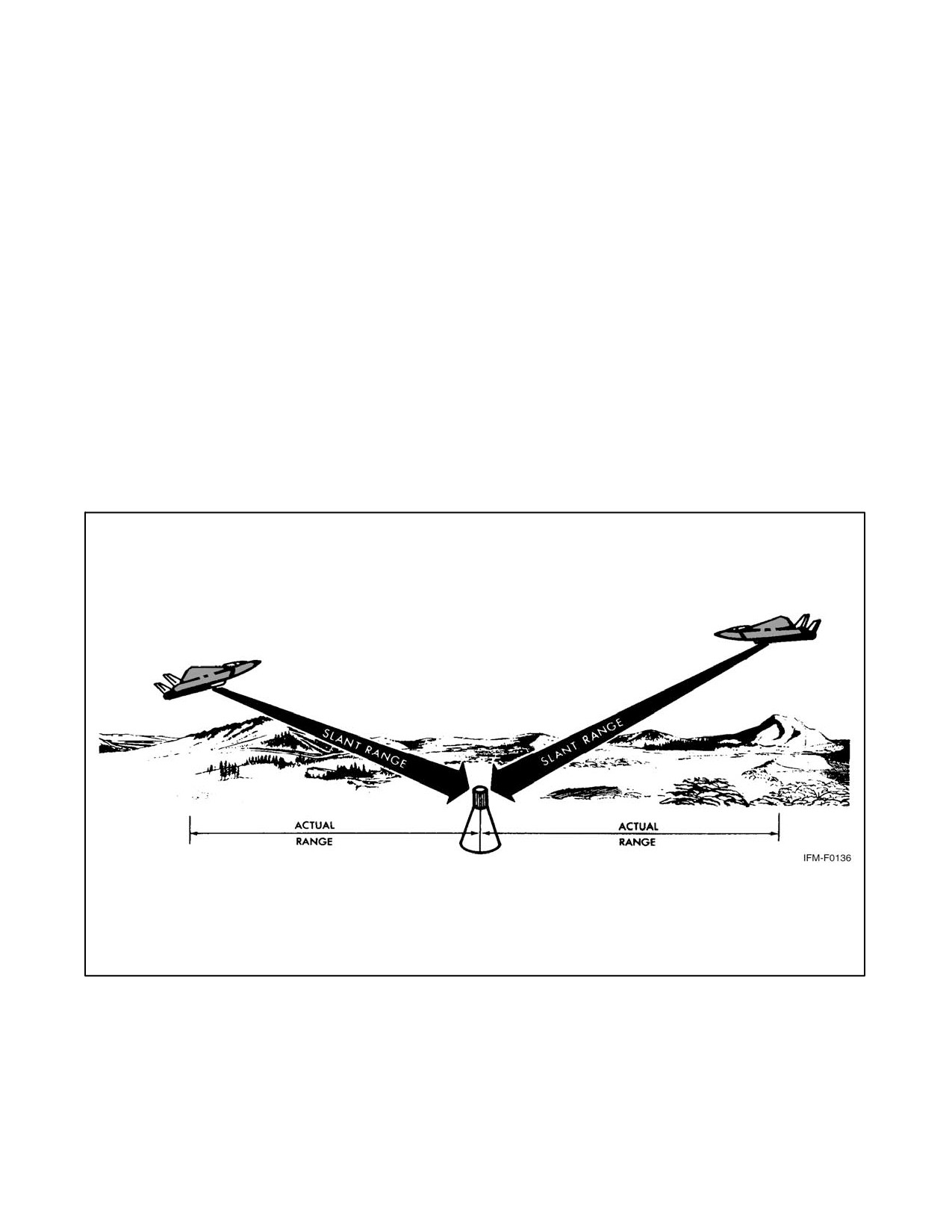
NAVAIR 00-80T-112
As a large number of aircraft could be interrogating the same beacon, the airborne set must sort out only the pulses
that are replies to its own interrogations. Interrogation pulses are transmitted on an irregular, random basis by the
airborne set, which then searches for replies synchronized to its own interrogations. If the signals are interrupted, a
memory circuit maintains the last distance indication on the range indicator for approximately 10 seconds to prevent
the search operation from recurring. The searching process starts automatically whenever the airborne set is tuned
to a new beacon or when there is a major interruption in beacon signals. Depending upon the aircraft actual distance
from the beacon at the time, the searching process may require up to 22 seconds (Figure 22-6).
22.2.2 TACAN Characteristics
22.2.2.1 Bearing/Distance Unlock
TACAN bearing and distance signals are subject to line-of-sight restrictions. Because of the transmission/reception
principles, unlock (rotating of bearing pointer and/or range indicator) will occur if these signals are obstructed.
Temporary obstruction of TACAN signals can occur in flight when aircraft fuselage, wing, gear, external stores, or
wingmen get between the ground and aircraft antenna. Aircraft receiver memory circuits prevent unlock when signals
are obstructed for short periods (approximately 10 seconds for DME and 2 seconds for azimuth), but beyond this,
unlock occurs and will persist until the obstruction is removed and search cycles are completed. Unlock may occur
during procedure or penetration turns, or during maneuvers that cause the aircraft antenna to be obstructed for longer
than 2 to 10 seconds.
Figure 22-6. Slant Range Distance
22-5
ORIGINAL
NAVAIR 00-80T-112
22.2.2.2 Azimuth Cone of Confusion
The structure of the cone of confusion over a TACAN station is considerably different from other navigational aids.
The azimuth cone can be up to 100_ or more in width (approximately 15 nm wide at 40,000 feet). Indications on the
aircraft instruments make it appear even wider to the pilot. Approaching the TACAN station, usable azimuth
information is lost before the actual cone is reached, although actual azimuth unlock is prevented by the memory
circuit until after the aircraft is into the cone. After the cone is crossed and usable signals are regained, the search cycle
function (22 seconds for a full cycle) prior to regaining lock-on extends the unusable area beyond the actual cone.
22.2.2.3 DME Cone of Confusion
The DME cone is much narrower and is actually insignificant to TACAN operation as DME unlock should never
occur when crossing the station except for hovering or very slow aircraft. Faster aircraft should get through the DME
cone area regardless of altitude before unlock occurs. On crossing a TACAN station, the DME should decrease until
the center of the cone is reached, stop, then begin to show an increase as the signal is regained.
22.2.2.4 Range Indicator Fluctuations
Slight oscillations up to approximately 1/4 nm are normal for range indicator operation due to the pulses generated
by the transmit/receive function. When a usable signal is lost, the memory circuit maintains the indicated range for
approximately 10 seconds, after which unlock will occur unless usable signals are regained.
22.2.2.5 Erroneous TACAN Indications
Several forms of malfunction of airborne equipment or interference between ground stations can give false or
erroneous TACAN information to a pilot. These discrepancies are easier to recognize and guard against if the pilot
is aware they can occur.
22.2.2.5.1 40_ Azimuth Error Lock-On
As previously explained, the construction of the TACAN ground antenna is such that it transmits a series of nine signal
lobes (eight auxiliary and one main reference pulse) 40_ apart. With the airborne receiver working correctly, these
pulses lock on the airborne equipment with the main reference at 90_. With a weak airborne receiver, the main
reference pulse may slide over or miss the 90_ slot and lock on at one of the auxiliary positions. When this occurs,
azimuth indications will be 40_ or some multiple of 40_ in error. Rechanneling the airborne receiver to deliberately
cause unlock gives the set another chance to lock on properly. When VOR or ADF bearing information is available,
use it to verify the existence of suspected TACAN errors.
22.2.2.5.2 Adjacent Channel Interference
Adjacent channel interference occurs when an aircraft is in a position to receive TACAN signals from more than one
ground station on the same frequency. Normally, this occurs only at high altitudes when distance separation between
like frequencies is inadequate. DME, azimuth, or identification from either ground station may be received. This is
not a malfunction of either air or ground equipment, but a result of ground equipment location and aircraft position.
22.2.2.5.3 False or Incorrect Lock-On
False or incorrect lock-on indications in the aircraft can be caused by misalignment or excessive wear of the airborne
crystal selector assembly. Selection of a numbered TACAN channel activates a drum and wiper arrangement in the
aircraft black box, which rotates until the wiper contacts the proper crystal on the drum. These crystal contact points
are very small (pinhead size) and close together. Wear of this assembly or misalignment can cause the wiper to miss
the proper crystal and contact the wrong one, resulting in the wrong TACAN being tuned in, or the wiper can miss
contact entirely, resulting in constant unlock. When this occurs, rechanneling from the selected channel number and
back (preferably from the opposite direction than the original setting) sometimes results in proper channelization.
This is an airborne equipment malfunction.
ORIGINAL
22-6
NAVAIR 00-80T-112
22.2.2.5.4 Precautionary Actions
Several precautionary actions should be taken by pilots to guard against in-flight use of erroneous navigation signals:
1. Always check the identification of any navigational aid station and monitor it during flight. Always utilize all
suitable navigation equipment aboard the aircraft and cross-check heading and bearing information.
2. Never overfly preplanned Estimated Times of Arrival (ETAs) without careful cross-check of navigational aids
and ground checkpoints.
3. Check Notices to Airmen (NOTAMs) and Flight Information Publications (FLIP) before flight for possible
malfunctions or limitations on navigational aids to be used.
4. Discontinue use of any suspected navigational aid and, if necessary, confirm aircraft position with radar or
other equipment.
Note
If there is a malfunction of the compass system or card, consider the
TACAN bearing information unreliable and merely advisory until verified
by radar or other navigational equipment.
22.2.3 TACAN Procedures
As TACAN presents bearing information in the same manner as VOR, use the same homing, proceeding direct, course
interception, and maintaining course procedures explained in Part 1 (VOR Navigation); however, with the addition
of range information, additional procedures have been devised to use TACAN to its full advantage. The remainder
of this chapter is devoted to those procedures that differ from VOR.
22.2.3.1 Tuning
The TACAN control panel (Figure 22-7) consists of a power switch, volume control, and channel selector. The power
switch has four positions: OFF, REC, T/R, and A/A. Selecting either the REC or T/R position turns on the set. (As
some TACAN sets require a warmup period in the REC position, before selecting the T/R position, refer to the
appropriate aircraft flight manual for instructions.) In the REC position, only bearing information and station
identification are available. In the T/R position, bearing/distance information and station identification are available.
After turning on the equipment, select the desired channel, adjust the volume, and identify the station. After
identifying the TACAN station, an unreliable signal can be identified on the instrument (refer to specific aircraft
NATOPS).
Tune and check the set before takeoff. After tuning, check the bearing pointer, Course Deviation Indicator/Horizontal
Situation Indicator (CDI/HSI) TO-FROM indicator, and range indicator for proper operation. The bearing pointer
should point to magnetic bearing to the station. The CDI/HSI should center when this bearing is set in the course
selector window, and the TO-FROM indicator should indicate TO. The range indicator should indicate the distance
to the station.
22.2.3.2 Groundspeed Check
A groundspeed check can be made while maintaining a course to or from a TACAN station; however, as a guide,
groundspeed checks should be performed only when the aircraft slant range distance is more than the aircraft altitude
divided by 1,000. For example, if the aircraft is at Flight Level (FL) 200, groundspeed checks should be performed
when beyond 20 nm. Checks made below 5,000 feet are accurate at any distance.
22-7
ORIGINAL
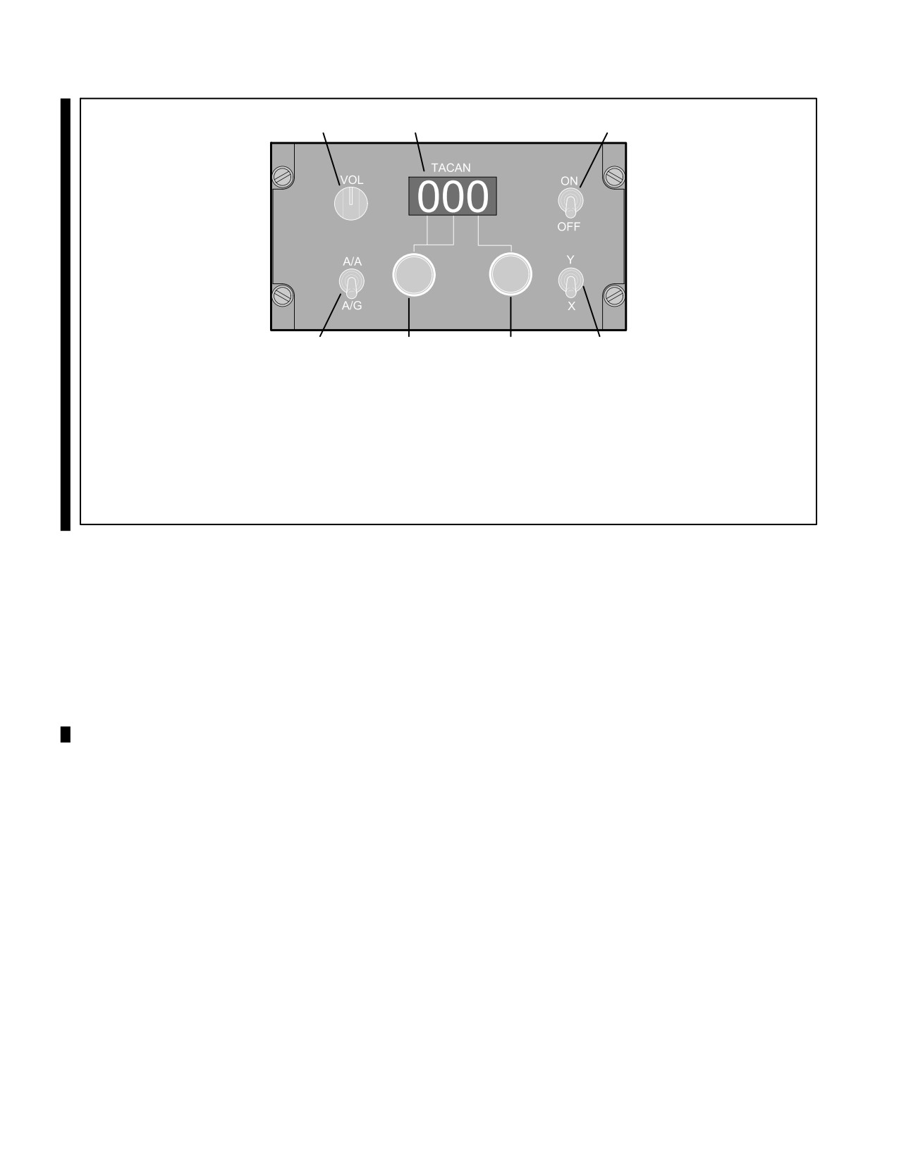
NAVAIR 00-80T-112
1
2
3
7
6
5
4
1. VOLUME CONTROL
2. CHANNEL DISPLAY
3. POWER SWITCH
4. X/Y CHANNEL SELECTOR SWITCH
5. RIGHT KNOB SELECTS UNITS DIGITS
6. LEFT KNOB SELECTS 100 AND 10 DIGITS
7. AIR-TO-AIR (A/A)/AIR-TO-GROUND (A/G) SELECTOR SWITCH
Figure 22-7. TACAN Control Panel
To perform the groundspeed check, begin timing when the range indicator shows a whole number. After the
predetermined time has elapsed, check the range indicator and note the distance flown. Apply this information to the
following formula to determine groundspeed:
Distance flown
60 = Groundspeed elapsed time in minutes.
For precise computation, time for longer periods and solve the problem on a computer. To simplify computations,
use a 2-minute time check and multiply the distance traveled by 30; for a 3-minute time check, multiply distance by
20; for a 6-minute time check, multiply distance by 10 (Figure 22-8).
22.2.3.3 Station Passage
Because of the azimuth cone of confusion over the TACAN station, station passage is determined when the range
indicator stops decreasing. Flying directly over the station, the range indicator will stop decreasing when it indicates
the approximate aircraft altitude above the station in nm. One nm is equal to approximately 6,000 feet. For example,
an aircraft cruising at FL 300 is at an altitude of approximately 5 nm; therefore, the range indicator should stop
decreasing at approximately 5 nm when directly over a station at sea level. If the station elevation is 6,000 feet, the
indicated range over the station would be approximately 4 nm (Figure 22-9).
22.2.3.4 TACAN Arcs
Sometimes used during approaches and departures, a TACAN arc is flown around the station at a specific distance.
Some approaches require the entire final approach to be flown along an arc, using radials to determine the Final
Approach Fix (FAF) and the Missed Approach Point (MAP). On the other hand, an arc may be used to transition to
the FAF and the MAP. During departures, it may be necessary to fly an arc soon after takeoff to transition to a departure
radial. Arc instructions are given as “VIA (NUMBER OF MILES) MILE ARC (DIRECTION) OF (NAME OF
NAVAID).” Direction will be given as “ARC SOUTH” or “ARC EAST,” etc.
ORIGINAL
22-8
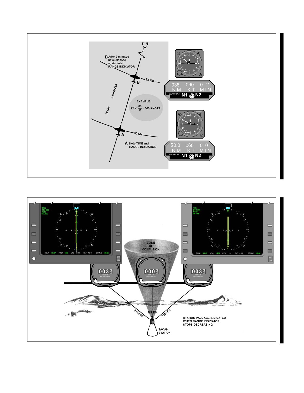
NAVAIR 00-80T-112
Figure 22-8. Groundspeed Check
Figure 22-9. Indication of Station Passage
22-9
ORIGINAL
NAVAIR 00-80T-112
22.2.3.5 Arc Interceptions
To intercept an arc from a radial, a turn of approximately 90_ is required to place the bearing pointer on the wingtip
with a range indication equal to the desired arc. Determine the direction to turn and the desired lead point. Lead point
will equal 0.5 percent of groundspeed (200 knots
.005 = 1 nm). Rollout heading is based on determining if the
aircraft is inside or outside of desired arc track. Detailed techniques for correcting to the arc are discussed under
paragraph 22.2.3.6.
22.2.3.5.1 Techniques for Determining Lead
When using 30_ of bank, an approximate lead point for the arc may be determined from the aircraft Groundspeed
(GS) or Mach. Groundspeed in nm per minute minus 2 represents the approximate lead (e.g., 6 nm per minute, use
4 nm lead). A Mach indicator may be used in the same manner to determine a no-wind lead point because 0.5 Mach
is approximately 5 nm per minute, 0.6 Mach is 6 nm per minute, etc. Lead points based on aircraft turn radius may
be approximated as follows: 1 percent GS = nm lead for 1-1/2_ per second rate of turn, 1/2 percent GS = nm
lead for 3_ per second rate of turn. For groundspeeds below 150 knots, 1/2 nm lead point is satisfactory (Figure 22-10).
22.2.3.6 Maintaining Arcs
In theory, it is a simple matter to maintain an arc. Under no-wind conditions, the aircraft will fly in an exact circle
around the station by maintaining a relative bearing of 90_ or 270_. In practice, a method for maintaining an arc is
to fly a series of short legs, keeping the bearing pointer on or near the wingtip position while maintaining the desired
range. With the bearing pointer on the wingtip and the aircraft at the desired range, maintain heading and allow the
bearing pointer to move 5_ to 10_ behind the wingtip position. This will cause the range to increase slightly. Next,
turn toward the station to place the bearing pointer 5_ to 10_ ahead of the wingtip, and maintain this heading until
the bearing pointer is again behind the wingtip.
During crosswind conditions, the reference point (wingtip) will change. If the wind is blowing the aircraft away from
the station, the reference point is ahead of the wingtip. If the wind is blowing the aircraft toward the station, the
reference point is behind the wingtip. While proceeding around the arc, the drift correction will constantly be
changing for a constant wind direction and velocity. As a guide, correct approximately 10_ to 20_ for each 1/2 mile
deviation from the desired arc. For example, under no-wind conditions, if the aircraft is 1/2 mile outside the arc and
the bearing pointer is on the wingtip, the aircraft should be turned approximately 20_ toward the station to return to
the arc. The actual amount of correction required for a given error varies. Factors to consider are the size of the arc,
groundspeed of the aircraft, whether the aircraft is inside or outside of the arc, etc. These variables are seen by the
pilot as rates of deviation. Establish a correction according to the rate of deviation and adjust as necessary according
to the rate of correction. Remember that the curve of small arcs is relatively sharp, and corrections from the inside
are assisted by the arc curving toward the aircraft. Conversely, the aircraft outside small arc requires larger corrections
because of the curvature away from the aircraft. Large arcs are easier to fly because of their flatter curve. High
groundspeeds require more pilot attention to maintain an arc because of higher rates of deviation and correction
(Figure 22-11).
22.2.3.7 Intercepting a Radial from an Arc
To intercept a radial from an arc, set the desired course in the course selector window as soon as practical. Monitor
the rate of bearing pointer movement while flying the arc, and remember that the interception angle will be
approximately 90_. Changing the lead point used for the arc interception from nautical miles to degrees is a technique
that can be used to determine an approximate lead point. Use the relationship that 1_ is 1 nm wide at 60 nm from the
station and its width increases or decreases in proportion to the distance. For example, with a 200-knot groundspeed
(using a 3_ per second rate of turn), a 1-nm lead point was used to intercept the 10-nm arc. Because 1_ of travel along
the 10 nm arc represents 1/6 nm, the lead point when intercepting a radial from the arc (no wind) would be 6_
(Figure 22-12).
ORIGINAL
22-10
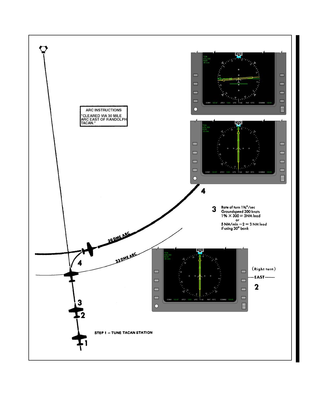
NAVAIR 00-80T-112
Figure 22-10. Intercepting an Arc from a Radial
22-11
ORIGINAL
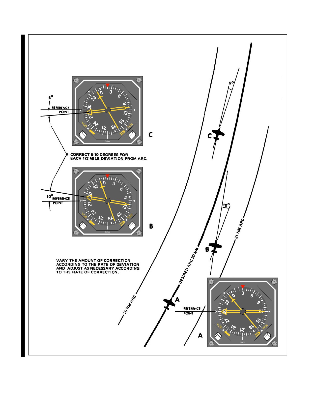
NAVAIR 00-80T-112
Figure 22-11. Correcting to Maintain the Arc
ORIGINAL
22-12
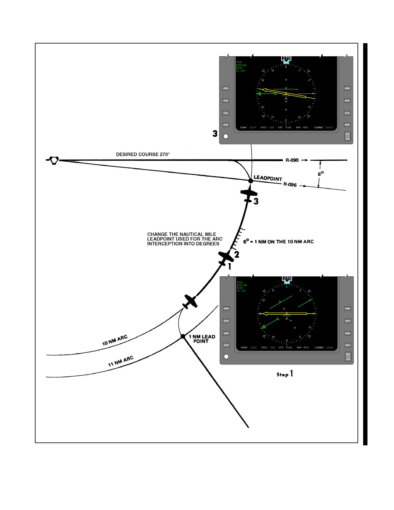
NAVAIR 00-80T-112
Figure 22-12. Intercepting a Radial from an Arc (No Wind)
22-13
ORIGINAL
NAVAIR 00-80T-112
22.2.3.8 Technique of Navigating Point to Point
When an aircraft approaches a terminal area, air traffic control normally clears it to the holding fix or the initial
approach fix. This clearance may be to the station and out the radial, along an arc to a radial, or direct to the fix. If
cleared direct to the fix, the pilot may use a radar vector or point-to-point navigation.
A single TACAN providing bearing and distance information is sufficient for navigating directly to any fix (radial
and distance) within reception range of the station.
Basic navigation principles are used and include:
1. Establishing two fixes (aircraft and desired).
2. Connecting the fixes with a line.
3. Reading the heading to the desired fix.
The technique of applying these principles in the aircraft without cumbersome charts is simple. The key to this
technique is in learning to visually establish the aircraft and the desired fix on the compass card of a Radio Magnetic
Indicator (RMI) or similar type instrument (Figure 22-13). The following factors will aid in developing this ability:
1. The TACAN station is always at the center of the compass card. The compass card is merely a compass rose
around the station.
2. The fix having the greater distance is always established on its radial at the outer edge of the compass card.
3. The remaining fix is established along its radial at a point whose distance from the center of the card is
proportional to the distance represented by the outer edge of the compass card.
For example, assume an aircraft to be on the 180_ radial (indicated by the tail of the bearing pointer) at 60 nm. The
pilot desires to proceed direct to a fix located on the 90_ radial at 30 nm.
If not proceeding in the general direction of the fix, turn to a heading approximately halfway between the head of the
bearing pointer and the desired fix radial, then:
1. Establish the fix with the greater distance (60 nm) on the edge of the card at its radial (180_). The distance
represented from the center to the edge of the compass card is now 60 nm.
2. Establish the remaining fix (90_/30_) along the 90_ radial at a proportionate distance from the center (i.e.,
halfway).
3. Connect the two fixes with an imaginary line or with the aid of a pencil or other straight edge. Move the line
to the center of the compass card so that it is parallel to the original line.
4. Read the no-wind heading at the point where the second line crosses the compass card (30_). Always read
direction from the aircraft position to the desired fix. Turn to this heading and apply wind correction.
As the distance from the center to the edge of the compass card represents 60 nm, the diameter of the card provides
a 120-nm scale. The distance between the aircraft fix and the desired fix may be determined using this scale
(approximately 65 miles in the example). The Estimated Time En Route (ETE) to the desired fix may then be
determined by applying aircraft groundspeed. For better accuracy, repeat the entire technique occasionally while en
route (Figure 22-14).
ORIGINAL
22-14
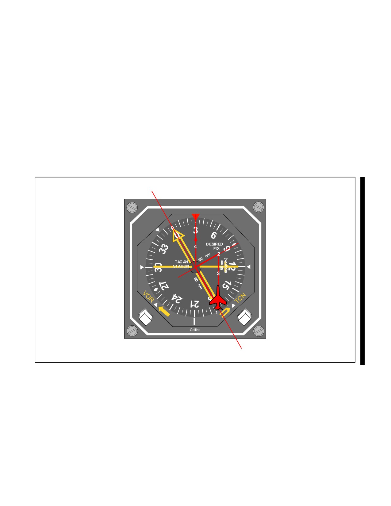
NAVAIR 00-80T-112
22.2.3.9 TACAN Holding
Holding is maneuvering an aircraft in relation to a navigational fix while awaiting further clearance. Initial entry for
TACAN holding is identical to that described earlier for VOR, except a TACAN DME fix is substituted for a VOR
as the holding fix. The standard no-wind holding pattern is flown by following a specified holding course inbound
to the holding fix, making a 180_ turn to the right, flying a heading outbound to parallel the holding course, and
making another 180_ turn to the right to intercept and follow the holding course to the fix. The length of the legs while
using TACAN is usually specified in nautical miles. Pilots should not confuse TACAN holding fix (radial/distance)
with the TACAN station when considering the direction of holding. As illustrated in Figure 22-15, the direction of
holding is relative to the 30-nm fix rather than the TACAN station. The direction of turn is not included for standard
holding patterns. While in the holding pattern, turns are initiated at the indicated range as published or issued by the
controller. To meet the expected approach time, the pattern may be shortened, but never lengthened. The inbound
course to the holding fix should be set in the course selector window. As the holding pattern may be a considerable
distance from the TACAN station, course corrections to intercept course prior to reaching the holding fix will be larger
than those normally used in VOR or ADF holding. For example, 6_ off course at 30 miles is a 3-mile course error,
whereas 6_ off course at 10 miles is only a 1-mile course error.
Figure 22-13. Visualize Problem after Turning to Computed Heading
22-15
ORIGINAL
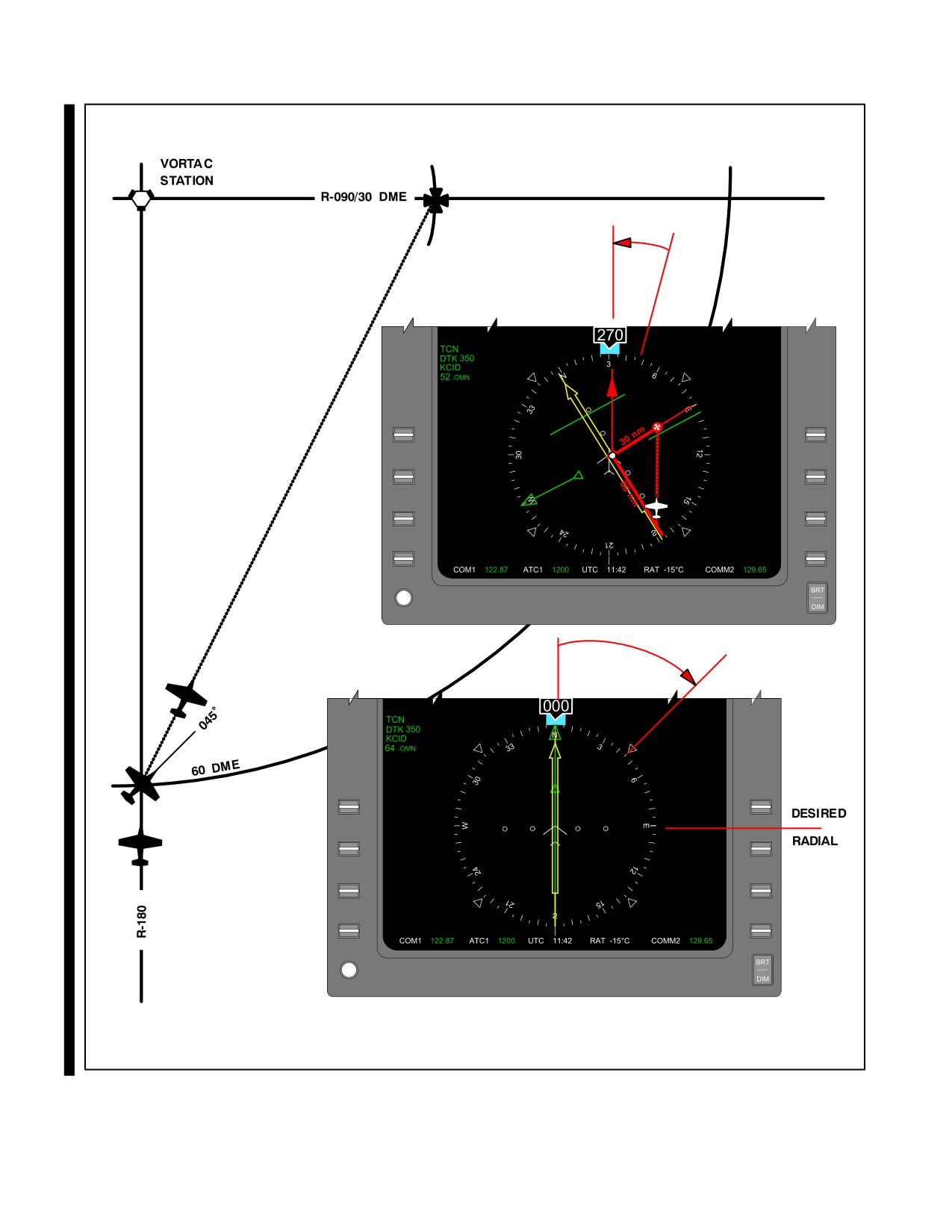
NAVAIR 00-80T-112
C
B
A
B
C
B
A
Figure 22-14. The Technique of Proceeding Direct Between TACAN Fixes
ORIGINAL
22-16
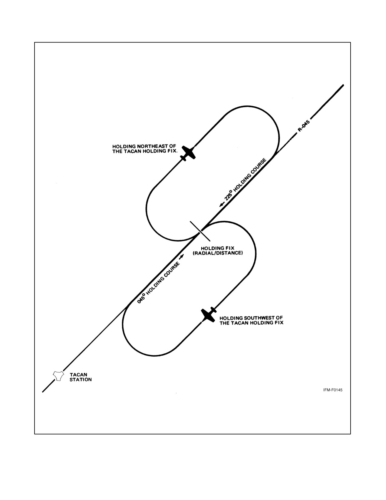
NAVAIR 00-80T-112
Figure 22-15. The Direction of TACAN Holding is Relative to the Holding Fix, Not the Station
22-17
ORIGINAL
NAVAIR 00-80T-112
22.2.4 TACAN Approach Procedures
With range information available, many different types of penetrations are depicted on the approach charts. Some
TACAN approaches are relatively simple and involve only a straight-in flightpath along a radial. Others require
extensive planning and may involve intercepting an arc from a radial, a radial from an arc, or any combination of the
above to arrive at the final approach fix (Figure 22-16).
A limited number of VOR instrument approaches based on a VORTAC facility have been approved for use by
TACAN-equipped aircraft. These procedures are identified by the phrase “or TACAN” printed adjacent to the name
of the procedure (e.g., VOR TACAN Rwy 17). Approaches designated VORTAC may be executed by aircraft using
either TACAN or VOR with DME, but DME is required. Approaches designated VOR/DME may be executed by
aircraft utilizing VOR with DME, and the DME is required.
22.2.4.1 Transition to the Initial Approach Fix
Published routes on the terminal chart may provide a course and range from the en route structure to the Initial
Approach Fix (IAF). If a routing other than one published is used, ensure it does not exceed the operational limitation
of the Navigation Aid (NAVAID) being used. Limitations according to type NAVAID, aircraft altitude, and range from
the facility are published in FLIP. Before reaching the IAF, recheck the weather, review the approach chart, and obtain
clearance for the approach.
An IAF may be approached from directions not favorable to intercepting the initial approach course upon arrival at
the fix. When this occurs, and prior approach clearance has been received, the pilot must maneuver to intercept the
initial approach course. Preapproach intercept maneuvers should be accomplished as follows:
1. Turn at the IAF in the shortest direction to intercept the initial approach course.
2. Begin descent from the Initial Penetration Altitude (IPA) when established on a segment of the published
approach.
3. If holding is not required, reduce to penetration airspeed or below before crossing the IAF.
22.2.4.2 High-Altitude Penetration and Approach
When over the IAF, turn in the shorter direction toward the penetration course. Descent may be started when
established on a segment of the published approach. Crossing the arc forming the IAF is considered abeam. Intercept
the initial penetration course and fly the approach as depicted.
At or before reaching the FAF, configure the aircraft for landing in accordance with the NATOPS flight manual. At
the FAF, report to the controlling agency. Descend to the Minimum Descent Altitude (MDA) to acquire visual
references for landing as soon as practical. Comply with any published altitude restriction between the FAF and
missed approach point. The descent to the MDA should be completed before reaching the missed approach point.
Descent below MDA is authorized when visual reference with the runway environment is sufficient to complete the
landing and the Visual Descent Point (VDP) has been reached.
There are a few approaches that have the final approach course along an arc. On these approaches, the FAF and missed
approach point are designated by radials rather than range.
Perform the missed approach when:
1. Visual reference with the runway environment at the missed approach point is insufficient to complete the
landing.
2. Instructed by the controlling agency.
3. A safe landing is not possible.
ORIGINAL
22-18
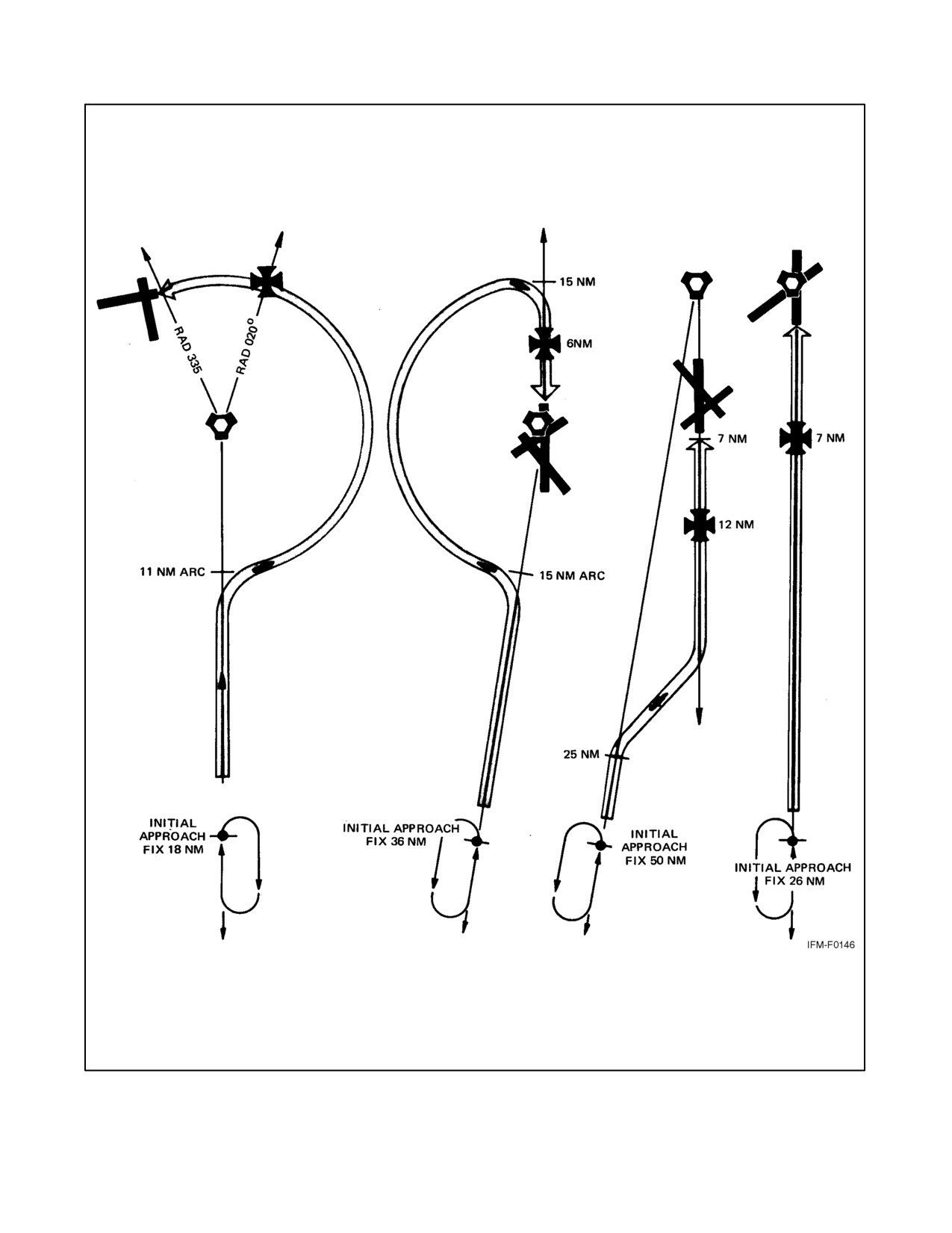
NAVAIR 00-80T-112
Figure 22-16. Typical TACAN Approaches
22-19
ORIGINAL
NAVAIR 00-80T-112
Example: Figure 22-17 illustrates a straight-in TACAN approach to RWY 34R (S-TAC-34R) that combines arc and
radial segments to arrive at the missed approach point. The published weather approach minimums are 300 feet and
3/4 of a mile.
Approach control will assign an initial approach fix altitude. After passing the initial approach fix, call “DEPARTING
THE INITIAL APPROACH FIX.” Also call “LEAVING THE ASSIGNED ALTITUDE,” unless you will be
maintaining altitude until the 130_ radial. Use a lead point based on aircraft turn radius to intercept the 23-nm arc
and the 157_ radial. Before the 5-nm final approach fix, reduce airspeed and establish the landing configuration.
Note the altitude restrictions. After intercepting the 157_ radial inbound, you have approximately 17.5 nm to descend
from 8,000 feet to the 680-foot MDA at the 1.5-nm missed approach point. Although the altitudes published on the
157_ radial at 9 nm, 5 nm, and 3.3 nm are minimum rather than mandatory altitudes, it is advantageous to be near
this altitude. The altitude loss in relation to the distance to travel is significant and may require a continual descent;
therefore, control airspeed so that the final approach configuration may be established not later than the FAF.
Call the controlling agency at the final approach fix (e.g., “EL TORO APPROACH CONTROL, BEEFEATER 301,
FINAL APPROACH FIX WITH GEAR”). You may add intentions as to landing or low approach to this call. Descend
to the 680-foot MDA. If a safe landing is not possible after reaching the missed approach point (1.5 nm), perform
the missed approach.
22.2.4.3 Low-Altitude Approach
The primary differences between the TACAN low-altitude approach (Figure 22-18) and the high-altitude penetration
and approach are the altitude loss and the length of the approach. Before crossing the IAF, establish the airspeed and
the configuration specified in the NATOPS flight manual for low-altitude maneuvering. Category E will be depicted
on low-altitude (AL) charts only when an operational requirement exists. The relatively short length of many
low-altitude approaches may require you to establish the final approach configuration during the transition to the IAF.
When operating on an unpublished route or while being radar vectored when an approach clearance is received, the
pilot shall maintain the last assigned altitude unless a different altitude is assigned by ATC or until the aircraft is
established on a segment of a published route or instrument approach procedure. If in holding, commence descent
as described previously under VOR. Descend from the IAF altitude when established on the initial approach course.
If there is insufficient time to intercept course and comply with the first altitude restriction before starting the
approach, request ATC clearance to maneuver for a favorable alignment with the initial approach course. At or before
reaching the final approach fix, configure the aircraft for landing in accordance with the NATOPS flight manual.
Descend to the MDA on the approach chart to acquire visual reference for landing as soon as practical. Comply with
any published altitude restriction between the FAF and missed approach point. Descent below MDA is authorized
when visual reference with the runway environment is sufficient to complete the landing and the Visual Descent Point
(VDP) has been reached. Perform the missed approach when:
1. Visual reference with runway environment at missed approach is insufficient to complete the landing.
2. Instructed by the controlling agency.
3. A safe landing is not possible.
ORIGINAL
22-20
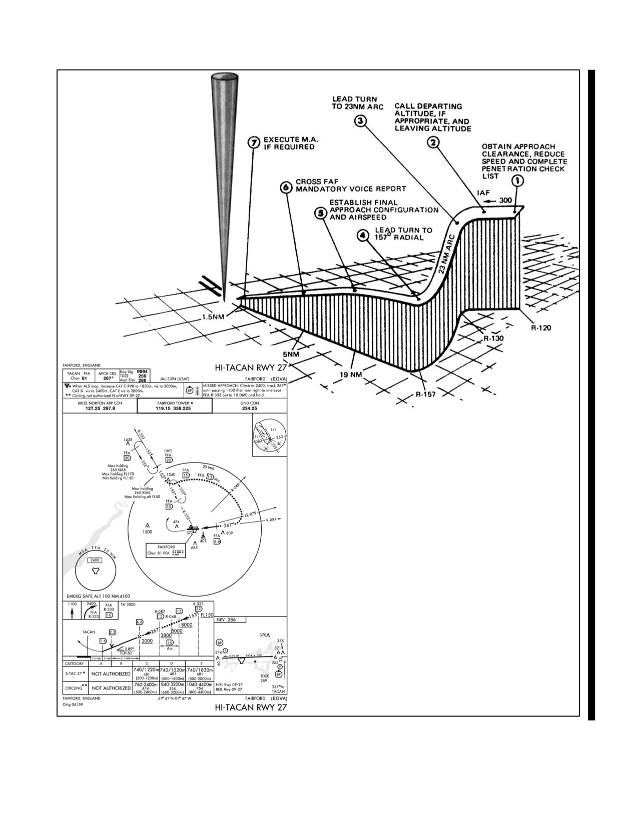
NAVAIR 00-80T-112
Figure 22-17. TACAN Approach
22-21
ORIGINAL
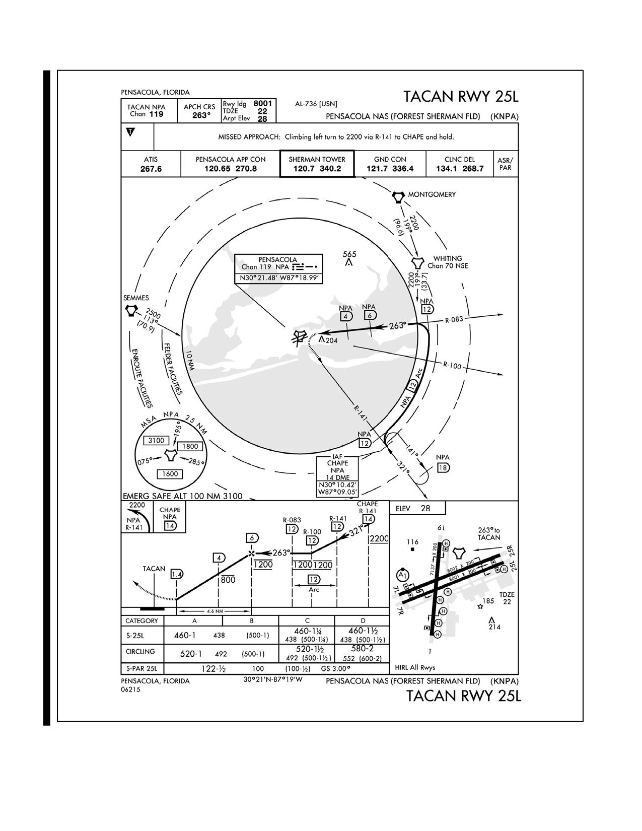
NAVAIR 00-80T-112
Figure 22-18. TACAN Low-Altitude Approaches
ORIGINAL
22-22
NAVAIR 00-80T-112
CHAPTER 23
ADF, UHF/ADF, Marker Beacons
23.1
AUTOMATIC DIRECTION FINDING (ADF)
The radio compass low-frequency receiver is capable of Automatic Direction Finding (ADF). Most direction finding
equipment will receive any frequency between 100 and 1750 kHz. Most other low-frequency receivers have a
frequency range of 190 to 1750 kHz. The en route supplement lists the location and frequency of the Low-Frequency
(LF) radio ranges and radio beacons. Those beacons coded SAB provide continuous weather information.
Both high- and low-altitude instrument approaches are found in the applicable terminal approach procedures books.
23.1.1 Automatic Direction Finding (ADF) Procedures
Whenever possible, use a nondirectional radio beacon. Commercial broadcasting stations should be used with caution
because some have highly directional radiation patterns. Also, they are not flight-checked for navigational use.
Positive identification of the commercial station being used is imperative.
The radio compass automatically determines the bearing to any radio station within its frequency and sensitivity
range. The radio compass also may be used as an auxiliary receiver for the reception of weather broadcasts and other
broadcast information.
The operation of a radio compass depends chiefly upon the characteristics of a loop antenna. A loop-receiving antenna
gives maximum reception when the plane of the loop is parallel to, or in line with, the direction of wave travel. As
the loop is rotated from this position, volume gradually decreases and reaches a minimum when the plane of the loop
is perpendicular to the direction of wave travel.
These characteristics of a loop antenna result from the fact that the receiver input from a loop antenna is the resultant
of the opposing voltages in the two halves of the loop. When current flows in a looped conductor, it must flow in
opposite directions in each half of the loop. This occurs when the plane of the loop is in line with the station. The fact
that one side of the loop is closer to the transmitter causes a slight delay between the time the radio wave reaches one
side and the time it reaches the other; therefore, there is a phase difference between the voltages induced in each half
of the loop. This causes a resultant current to flow through the transformer and creates a signal input to the receiver.
When the plane of the loop is parallel to the direction of wave travel, a maximum voltage is induced in the loop, and
the strength of the signals heard in the headset is also at a maximum. Conversely, when the plane of the loop is
perpendicular to the direction of wave travel, both sides of the loop are equidistant from the station, and the radio wave
reaches both sides of the loop at the same point in its cycle. The induced voltage is theoretically zero, and the strength
of the received signal is at a minimum. This position of the loop is called the null position.
The null position of the loop, rather than the maximum position, is used for direction finding; that is, a bearing is
obtained when the plane of the loop is perpendicular to the line on which the radio waves are traveling when they strike
the loop. The null position is preferred because it can be determined more exactly than the maximum. A 25_ rotation
from the maximum position changes total signal strength less than 10 percent, whereas a 25_ rotation from the
minimum or null position changes the signal strength 50 percent.
With the loop rotated to a null position, the radio station being received is on a line perpendicular to the plane of the
loop; however, the direction of the radio station from the aircraft may be either one of two directions 180_ apart. The
inability of the loop antenna to determine which of the two possible directions is correct is called the 180_ ambiguity
of the loop.
23-1
ORIGINAL
NAVAIR 00-80T-112
The 180_ ambiguity is eliminated with a nondirectional or sensing antenna.
The loop antenna of the radio compass is automatically rotated to the null position when signals are being received
over both the sensing and loop antennas. The combination of signals energizes a phasing system that operates a motor
on the loop drive. As the motor turns, it rotates the loop. The bearing pointer is electrically synchronized and turns
with the loop, indicating the bearing to the station when the loop has stopped in the null position.
The loop antenna continuously positions itself to remain perpendicular to the station. As the loop antenna can move
about only one axis (i.e., it can turn but cannot tilt), an error is induced whenever the aircraft is in a banked attitude.
This is called dip error. The magnitude of this error depends on the position of the aircraft from the station, its altitude
and range, and the angle of bank used. Dip error is most noticeable when the aircraft is banked and the station is on
the nose or tail of the aircraft. The ADF bearing pointer should be considered as giving accurate bearings only in
wings-level flight.
23.1.1.1 Tuning
The radio compass is normally tuned for ADF operation. The ADF feature is used for ease of operation; however,
if reception of radio signals is poor due to static, thunderstorms, or distance from the stations, use Manual Direction
Finder (MDF) procedures described later in this section. Since most ADF receivers do not have a “flag” to warn the
pilot when erroneous bearing information is being displayed, the pilot should continuously monitor the
Non-Directional Beacon (NDB) identification (refer to specific aircraft NATOPS).
Note
See the appropriate Flight Information Publications (FLIP) en route for the
procedures peculiar to tuning foreign low-frequency stations.
ADF tuning:
1. Interphone control panel and radio compass filter switch as required.
2. Obtain control of the set.
3. Function switch — ANT position.
4. VOICE-CW switch — VOICE.
5. Select the frequency band.
6. Tune to the desired frequency for best audible signal. Under conditions of static and/or interferences, a weak
station can sometimes be tuned by using the LOOP position. When tuning in LOOP, an increase in volume will
generally be required.
7. Identify the station.
8. Function switch — COMP/ADF position.
9. Retune for maximum needle deflection on the tuning meter.
Tuning with the nonmetered radio control compass panel:
As this control panel does not incorporate a tuning meter, do fine tuning for ADF with the function switch in the ANT
position and the VOICE-CW switch in the CW position. Tune for minimum or zero modulated tone, return the
VOICE-CW switch to VOICE and the function switch to ADF, and reidentify the station.
ORIGINAL
23-2
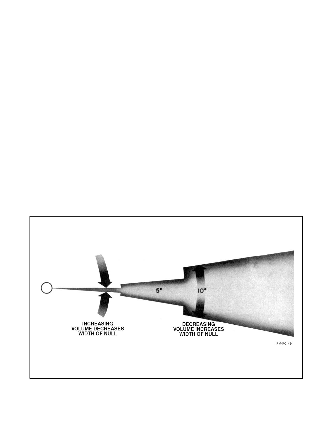
NAVAIR 00-80T-112
Note
Tuning for zero modulation is an accurate method of obtaining maximum
signal strength and can be used if difficulty is experienced determining
maximum needle deflection on the tuning meter. See Figure 23-1 for
volume effects on null width.
23.1.1.2 Course Interceptions
Inbound course interceptions may be done identically to those described in paragraph 21.3.3.1. An alternate method:
To determine the intercept heading, locate the bearing from the station that you are presently on, the bearing that you
want to intercept, and measure the angular difference. If the angular difference is less than 45_, turn toward the desired
bearing in the shortest direction with an angle of intercept equal to the computed angular difference. The time to the
station will be approximately equal to the time necessary to complete the intercept (Figure 23-2). If the angular
difference is greater than 45_, a series of time-distance check maneuvers (discussed under paragraph 23.1.1.5) may
be performed if distance/time to the station is unknown. The pilot may select any angular interception if timing is not
essential, 30_ to 45_ being generally sufficient (Figure 23-3).
23.1.1.3 Station Passage
23.1.1.3.1 ADF Procedure
When close to the station, the bearing pointer becomes unsteady and erratic due to the area of signal confusion. This
characteristic increases with altitude. Also, a small, lateral displacement from the desired course causes a large
off-course bearing indication. A bearing pointer deflection of 5_, when the aircraft is 10 miles from the station, means
that the aircraft has departed from the desired course approximately 1 nm, whereas the same 5_ displacement at 1
mile would represent a distance of approximately 600 feet. Do not chase the bearing pointer when it starts moving
rapidly to the side; instead, maintain a constant heading, as the station is very near.
Figure 23-1. Effects of Volume Control on Null Width
23-3
ORIGINAL
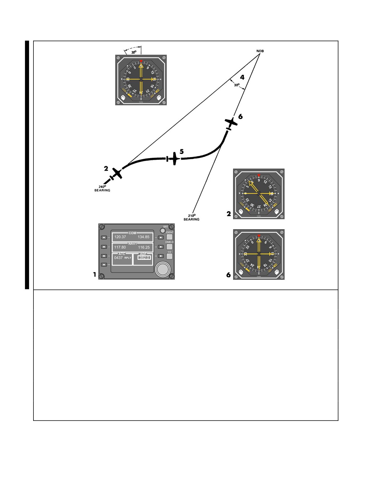
NAVAIR 00-80T-112
3
Procedural Steps
1. Tune and identify station.
2. Determine the bearing from the radio beacon you are on (240_) by looking at the tail of the No. 2 needle.
3. Determine the bearing from the radio beacon you desire to intercept (210_).
Visualize this on your heading indicator.
4. Measure the angular difference (30_).
Since it is less than 45_, compute your intercept heading based on the number of degrees in the
computed angular difference (30_) and your present inbound course to the station (060_). The computed
intercept heading would be (090_). Since the bearing visualized on the heading indicator is to the right of
your present bearing, the 30_ is added to your inbound course.
5. Look at your aircraft heading and turn in the shortest direction to the computed intercept heading.
Start the clock.
6. Maintain the intercept heading until a lead point is reached, then complete the intercept.
Lead points depend on the No. 2 needle rate of movement.
Figure 23-2. Inbound Course Interception Less Than 45°
ORIGINAL
23-4
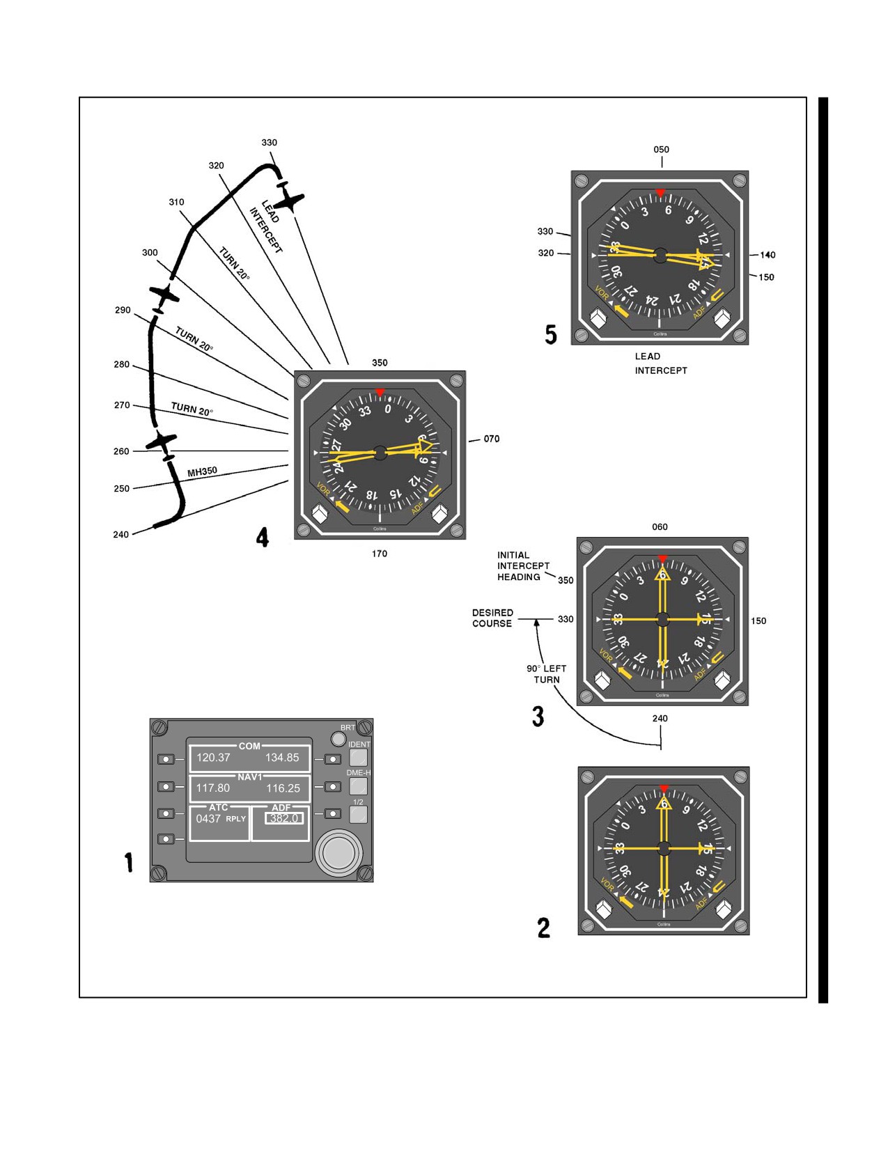
NAVAIR 00-80T-112
Figure 23-3. Inbound Course Interception Greater Than 45° (Timed Distance Method) (Sheet 1 of 2)
23-5
ORIGINAL
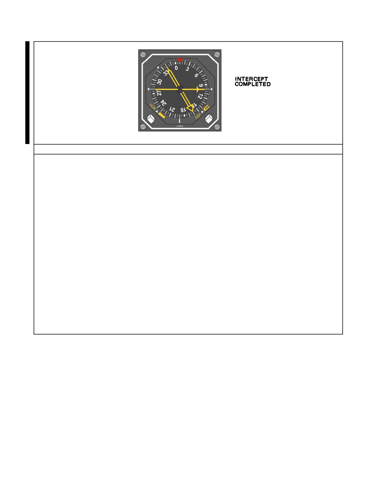
NAVAIR 00-80T-112
Procedural Steps
1. Tune and identify the station.
2. Determine the bearing from the radio beacon you are on (240_) by looking at the tail of the No. 2 needle.
3. Determine an intercept heading.
a. Determine the bearing from the radio beacon you desire to intercept (330_). Visualize this on the
heading indicator.
b. Measure the angular difference (90_).
c. Since it is greater than 45_, compute your initial heading based on the present course to the station
(060_) and the figure 70_.
d. Since the shortest direction to the bearing is to the left, subtract 70_ from the present course to the
station. The computed initial Magnetic Heading (MH) is 350_.
e. Turn in the shortest direction to the computed initial MH.
4. Intercept sequence.
a. When intercepting the 270_ bearing, start the clock and maintain heading.
b. After completing 20_ of bearing shift, note the time, start the clock again, and turn the aircraft 20_
toward the radio beacon.
c. Continue with the 20_ time distance checks until a lead point is reached, then complete the intercept.
d. Lead points depend on the rate of movement of the No. 2 needle.
Note
If heading indicators are inoperative, the No. 2 needle will still point to the station. Utilize the magnetic
compass to determine bearings and make timed turns.
Figure 23-3. Inbound Course Interception Greater Than 45° (Timed Distance Method) (Sheet 2 of 2)
ORIGINAL
23-6
NAVAIR 00-80T-112
Initial station passage is positively determined when the pointer moves through the wingtip position. This usually
occurs shortly after the aircraft has actually passed the station. Timing should begin that instant regardless of further
oscillations.
23.1.1.4 Outbound — Immediately After Station Passage
Turn to parallel the desired outbound course (compensate for wind). Maintain heading and allow the bearing pointer
to stabilize. Note the number of degrees between the tail of the bearing pointer and the desired course. To correct back
on course, use outbound course interception technique (Figure 23-4).
23.1.1.4.1 Outbound — Away from the Station
First, note the position of the bearing pointer tail. Then, on the compass card, look from the tail in the short direction
to the desired course. Any heading beyond the desired course is a no-wind intercept heading. Normally, 45_ beyond
the desired course is a good intercept heading as it also forms a 45_ or “average” angle of intercept; however, as in
inbound intercepts, consider the known factors of groundspeed and distance from the station when selecting an
intercept heading. Outbound procedures are essentially identical with those for VHF Omnidirectional Range (VOR)
— Radio Magnetic Indicator (RMI) only (Figure 21-9).
23.1.1.4.2 Completing the Intercept
After the intercept heading has been established, adjustments may be required to achieve a more desirable angle or
rate of intercept. As the aircraft approaches course, it is necessary to determine a lead point for turning because of
the radius of turn. The lead point will depend upon the rate of movement of the bearing pointer and the time required
to complete the turn to course. Factors affecting the lead point are groundspeed, distance from the station, intercept
angle, and rate of turn. Complete the turn to course, simultaneously applying a correction for known wind.
23.1.1.5 Time-Distance Check
It is possible to calculate the time and distance from the station using ADF.
23.1.1.5.1 ADF Procedures
After tuning the radio compass for ADF, note the position of the bearing pointer. The number of degrees the bearing
pointer is deflected from the wingtip position indicates the magnitude and direction of turn required to place the
pointer on the wingtip position. Turn to this predetermined heading. If the bearing pointer is not within 5_ of the
wingtip position after you have made the turn, make a corrective turn to place it on the wingtip. Note the exact time
at the completion of this turn, and maintain a constant heading until the pointer shows a bearing change of 5_ to 20_
(Figure 23-5).
23.1.1.6 Tracking
It is possible to maintain a course to or from a station using the radio compass bearing pointer, regardless of whether
the compass card is working properly or not, because the bearing pointer will point to the station and show the relative
bearing of the aircraft to the station.
23.1.1.6.1 Inbound
After completing a turn to course, maintain heading until the bearing pointer shows a deflection from the desired
course. Turn toward the pointer and beyond a sufficient number of degrees to return to course.
After reintercepting course with the correct wind drift correction applied, the pointer will continue to point to the
desired course and be displaced from the top index the number of degrees equal to the applied drift correction. If the
pointer moves toward the top index, the correction is too small; if it moves away from the top index, the correction
is too large (Figure 23-6).
23-7
ORIGINAL
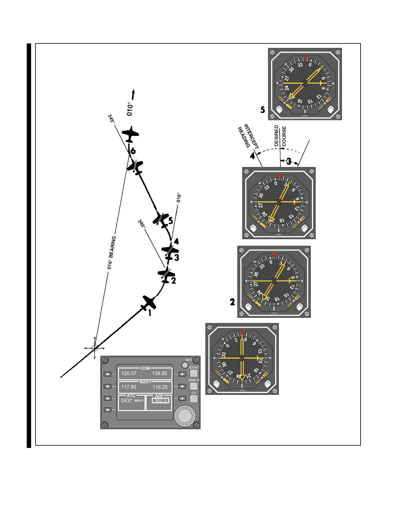
NAVAIR 00-80T-112
Figure 23-4. Course Interception Immediately After Station Passage (Sheet 1 of 2)
ORIGINAL
23-8
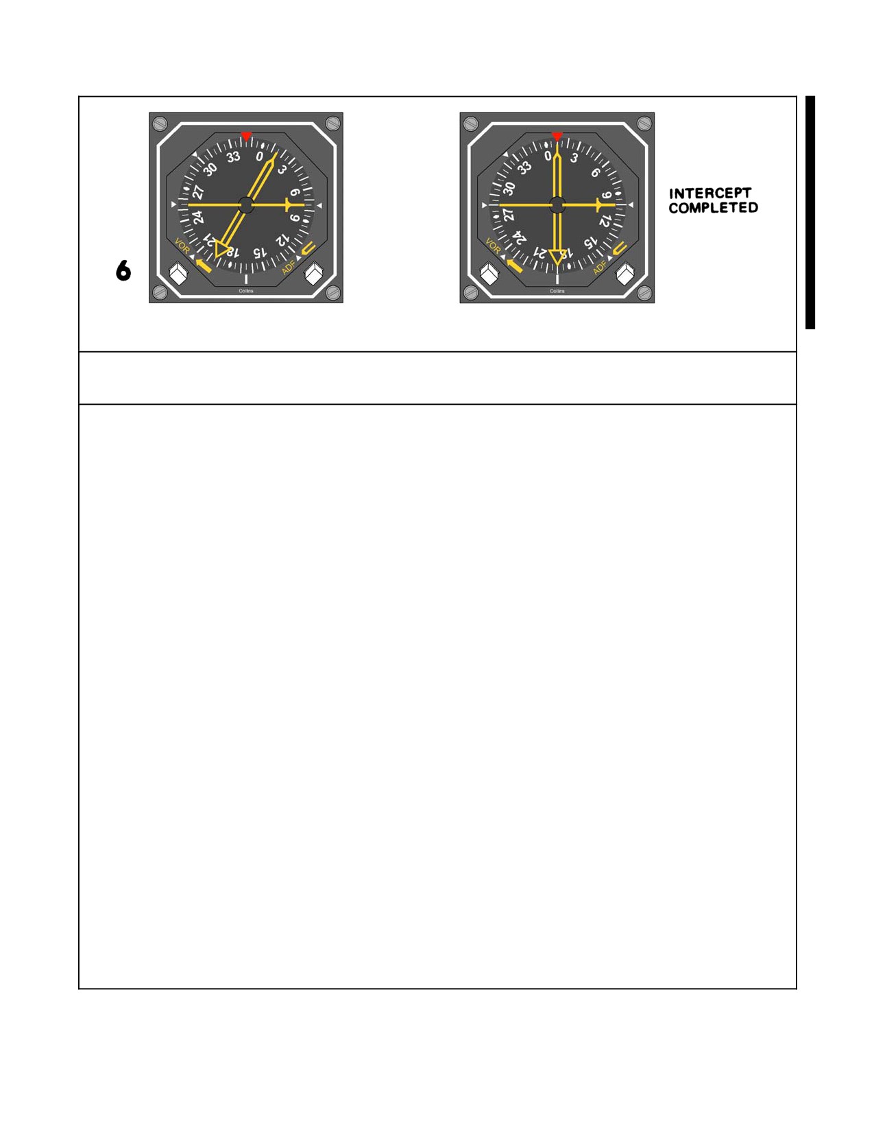
NAVAIR 00-80T-112
Outbound Procedural Steps — ONLY
1. Tune and identify the station.
This should already be accomplished.
2. Turn in the shortest direction to a heading that will parallel or intercept the outbound course.
Turning to parallel the desired outbound course is always acceptable. Continuing the turn to an intercept
heading may be preferable when the bearing pointer is stabilized or when the pilot knows the aircraft
position in relation to the desired course. The effect that airspeed, wind, and magnitude of turn will have
on aircraft position during the turn to an intercept heading should be carefully considered.
3. Determine number of degrees off course.
Note the angular difference between the tail of the bearing pointer and the desired course.
4. Determine an intercept heading.
If a suitable intercept angle was not established during the initial turn, look from the tail of the bearing
pointer to the desired course. Any heading beyond the desired course is a no-wind intercept heading.
Turn in this direction an amount approximately equal to the number of degrees off course. Normally, to
avoid overshooting the course, do not use an intercept angle greater than 45_.
Note
On some aircraft, the RMI/Bearing-Distance-Heading Indicator (BDHI) bearing pointer does not have a tail.
In this case, turn to the magnetic heading of the desired course. Continue on the outbound magnetic heading
of the desired course until the bearing pointer stabilizes. Note the number of degrees the bearing pointer is
off the tail of the aircraft. This is the number of degrees off course. Any heading change in the direction toward
the head of the bearing pointer is a no-wind intercept heading. Turn in the direction of the head of the bearing
pointer an amount approximately equal to the number of degrees off course. Normally, to avoid overshooting
the course, do not use an intercept angle greater than 45_.
5. Turn to an intercept heading, if not previously accomplished.
6. Maintain the intercept heading until a lead point is reached, then complete the intercept.
Lead point depends on bearing pointer rate of movement and the time required to turn on course.
Figure 23-4. Course Interception Immediately After Station Passage (Sheet 2 of 2)
23-9
ORIGINAL
NAVAIR 00-80T-112
23.1.1.6.2 Outbound
To maintain an outbound course, use outbound course interception procedures. Apply corrections to keep the desired
course under the tail of the bearing pointer. After applying a wind drift correction outbound, and the tail of the pointer
moves toward the top index, the drift correction is too large; if it moves away from the top index, the drift correction
is too small (Figure 23-7).
For ease of computation, it is desirable to use 10_ of bearing change. When the bearing pointer shows the desired
bearing change, again note the exact time. Turn immediately to place the bearing pointer under the top index and
maintain that course to the station. Determine the time to the station by applying the following formula:
Time in seconds between bearings
+ Minutes to station.
Degrees of bearing change
For example, if it requires 2 minutes (120 seconds) to fly a bearing change of 10_, the aircraft is:
120
10 = 12 minutes to the station.
The time from the station may also be calculated by using a short method based on the above formula, provided a
10_ bearing change is flown. If the elapsed time for the bearing change is noted in seconds and a 10_ bearing change
is made, the time from the station in minutes is determined by counting off 1 decimal point; thus, if it requires 75
seconds to fly a 10_ bearing change, the aircraft is 7.5 minutes from the station.
When the bearing pointer is moving rapidly or when several corrections are required to place the pointer on the
wingtip position, the aircraft is very close to the station. For all practical purposes, this can be considered station
passage.
The distance from the station may be computed by multiplying True Airspeed (TAS) or groundspeed (in miles per
minute) by the previously determined time in minutes. For example, if the aircraft is 4 minutes from the station, flying
at a TAS of 300 knots (or 5 nm per minute), the distance from the station is:
5
4 = 20 nm.
The preceding are methods of computing approximate time and distance. For increased accuracy, use only a small
amount of bearing change (about 10_) and correct for existing winds.
By flying a constant heading and checking the time and bearing progression closely, you can determine the estimated
time of arrival over the station, or the position and distance from a station not directly on the flightpath.
23.1.1.7 Homing
Homing is essentially keeping the nose of the aircraft pointed at the station while proceeding inbound. As homing
in a crosswind will result in a curved flightpath to the station, use it only for short distances (i.e., transition from one
radio facility to another in the immediate area) (Figure 23-8).
Note
Homing is not an accepted instrument procedure.
23.1.1.7.1 ADF Homing Procedures
Observe the position of the radio compass bearing pointer and turn in the shorter direction to place the head of the
bearing pointer under the top index of the compass card. Maintain this indication while proceeding to the station.
ORIGINAL
23-10
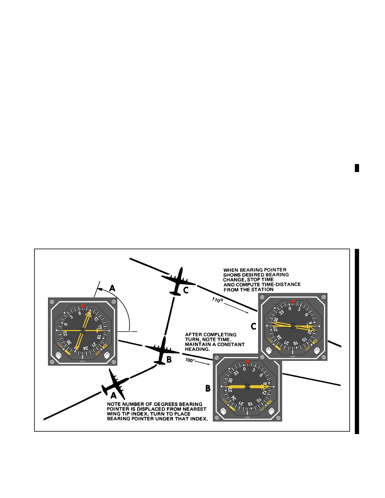
NAVAIR 00-80T-112
23.1.2 UHF Nondirectional Radio Beacon (Homer)
The Ultrahigh Frequency (UHF) homer ground station transmits a continuous carrier in the frequency range of 275
to 287 MHz, modulated with a 1020-cycle tone for identification purposes. Some UHF homers also have a voice
capability. The power output is approximately 15 watts. The pilot of an aircraft equipped with UHF/ADF equipment
can determine the relative bearing of, and home on, the ground equipment. The airborne equipment extracts the
information from signals received by the aircraft UHF communications receiver. The relative bearing of the signal
source is indicated on a heading indicator. Best results are obtained under straight-and-level flight conditions
(Figure 23-9).
23.1.2.1 UHF/ADF Navigation Auxiliary Receivers
UHF/ADF navigation auxiliary equipment receives UHF signals from any UHF radio beacon operating in the range
of 265.0 to 284.9 MHz. The equipment operates on any 1 of 20 preset crystal-controlled channels. To determine the
preset channel from a known frequency, subtract the number 264 from the known frequency, disregarding the
decimal;. thus, 265.2 MHz will be channel 1, 280.4 MHz will be channel 16, etc. A separate crystal-controlled Guard
channel, operating on an alternate basis with the main receiver, is also available. This Guard channel is preset on an
assigned frequency of 243.0 MHz.
The equipment is primarily designed for use in normal automatic direction finding; however, it may also be used to
provide auxiliary or emergency voice reception if the normal radio receiver should fail. When functioning in the
normal automatic direction finding mode, this equipment operates with the UHF homing adapter equipment and the
appropriate needle on the course indicator or RMI. As the relationship between the navigation equipment and the
communications equipment will vary between types of aircraft, the pilot should refer to the applicable NATOPS flight
manual for more specific procedures.
Figure 23-5. Time-Distance Check
23-11
ORIGINAL
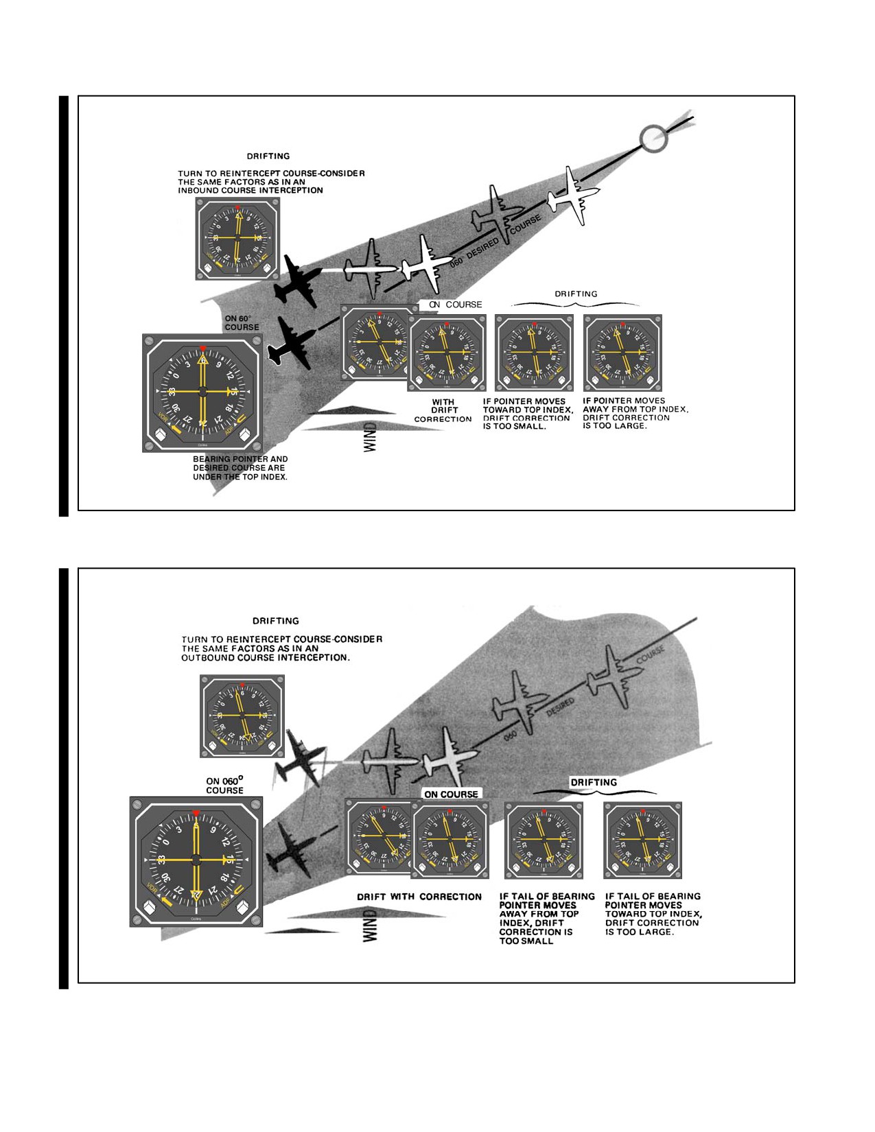
NAVAIR 00-80T-112
Figure 23-6. Maintaining Course Inbound
Figure 23-7. Maintaining Course Outbound
ORIGINAL
23-12
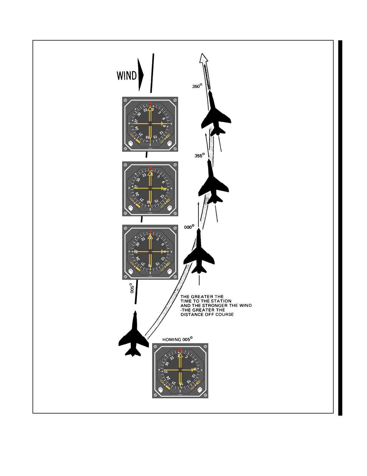
NAVAIR 00-80T-112
Figure 23-8. Curved Flightpath as a Result of Homing with a Crosswind Condition
23-13
ORIGINAL
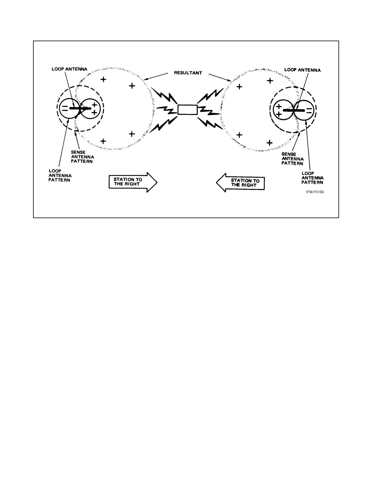
NAVAIR 00-80T-112
Figure 23-9. Automatic Direction Finding Signal Pattern
23.1.2.2 UHF Homing Adapters
These systems are used with UHF transceivers as a navigational aid. They provide a continuous indication of the
approximate relative bearing of an RF signal source transmitted by another aircraft, surface craft, or ground station
on a frequency range of 225.0 to 399.9 MHz. The approximate relative bearing will be indicated by the appropriate
needle on the course indicator or RMI.
Whenever the function selector switch on the UHF control panel is set to the T/R or T/R+G position, the homing
equipment will automatically be placed in the standby condition. When this selector is set to ADF, the command
equipment is placed in circuit with the homing equipment, enabling the latter to receive the frequency selected by
the channel selector switch on the command set control panel. In the ADF position, the auxiliary guard receiving
capability will be lost.
23.1.2.3 Approach Procedures
ADF procedures for holding, high-altitude penetration and approach, procedure turn and approach, and missed
approach are the same as those for VOR (refer to Chapter 21) except that normal ADF interception procedures are
used. Remember, dip error in turns causes erroneous bearing indications; therefore, make all turns to predetermined
headings (Figures 23-10 and 23-11).
23.2
MARKER BEACONS
Marker beacons serve to identify a particular location in space along an airway or on the approach to an instrument
runway. This is done by means of a 75-MHz transmitter that transmits a directional signal to be received by aircraft
flying overhead. These markers are generally used in conjunction with low-frequency radio ranges and the Instrument
Landing System (ILS) as point designators. Four classes of markers are now in general use: Frequency Modulation
(FM), Low-Power Fan Marker (LFM), station location or Z-markers, and the ILS marker beacons.
ORIGINAL
23-14
NAVAIR 00-80T-112
FM and LFM fan markers are keyed to indicate on which radio range course they are located. The radio range courses
are numbered clockwise beginning at true north with the north (or near north) course being designated No. 1. Fan
markers located on course number one are keyed to emit single dashes, those on course two, two dashes, etc. When
two fan markers are located on the same radio range course, the identification of the outermost marker is preceded
by two dots; thus, the identification of the outermost marker on a number one course is two dots and one dash.
The class FM fan markers are used to provide a positive identification of positions at definite points along the airways.
The transmitters have a power output of approximately 100 watts. Two types of antenna array are used with class FM
fan markers. The first type, generally referred to as the standard type, produces an elliptical-shaped pattern, which
at an elevation of 1,000 feet above the station is approximately 4 miles wide and 12 miles long. At 10,000 feet, the
pattern widens to approximately 12 miles wide and 35 miles long. (The long axis lies across the airway or radio range.)
The second array produces a dumbbell or boneshaped pattern, which at the “handle” is approximately 3 miles wide
at 1,000 feet. The boneshaped marker is preferred at approach control locations where timed approaches are used.
The class LFM or low-power fan markers have a rated power output of 5 watts and are usually located within 5 miles
of the radio range stations with which they are associated. The antenna array produces a circular pattern, which
appears elongated at right angles to the airway due to the directional characteristics of the aircraft receiving antenna.
The station location, or Z-marker, was developed to meet the need for a positive position indicator for aircraft
operating under instrument flying conditions to show the pilot when the aircraft was passing directly over a
low-frequency radio range station. The marker consists of a 5-watt transmitter and a directional antenna array that
is located on the range plot between the towers or the loop antennas.
ILS marker beacon information is included in paragraph 24.2.1.3.
23-15
ORIGINAL
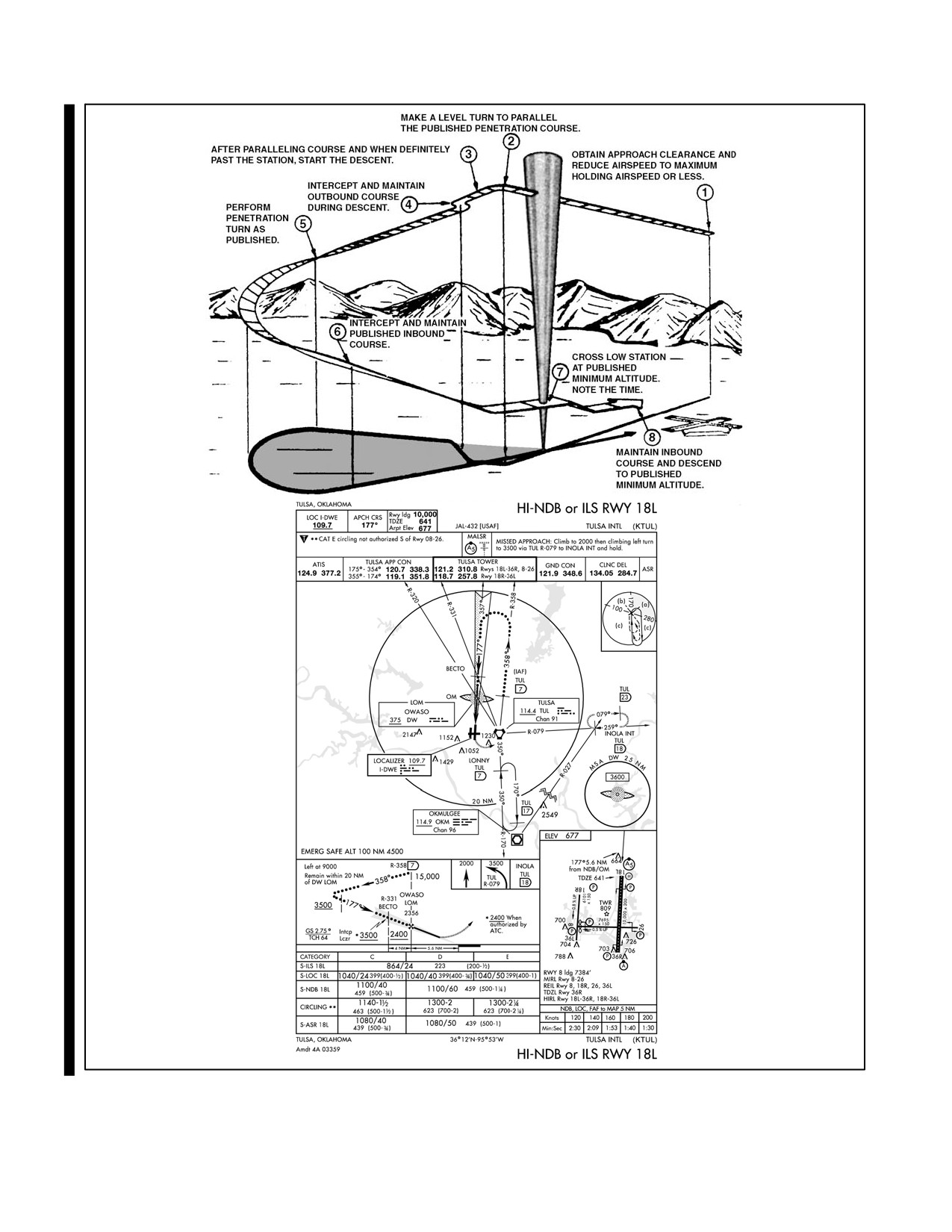
NAVAIR 00-80T-112
Figure 23-10. Typical ADF High-Altitude Penetration and Approach
ORIGINAL
23-16
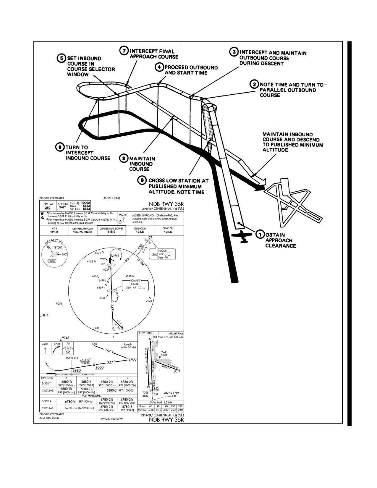
NAVAIR 00-80T-112
Figure 23-11. Typical ADF Low-Altitude Approach
23-17/(23-18 blank)
ORIGINAL
NAVAIR 00-80T-112
CHAPTER 24
Instrument Landing System (ILS)
24.1
INTRODUCTION
The Instrument Landing System (ILS) (Figure 24-1) is a precision approach system that provides azimuth and
glideslope information to the pilot. It consists of a highly directional localizer (course) and glideslope transmitter with
associated marker beacons, compass locators, and, at some sites, Distance Measuring Equipment (DME). The system
is automatically monitored and provides changeover to a standby localizer or glideslope transmitter when the main
system malfunctions.
The system may be divided functionally into three parts:
1. Guidance information: localizer, glideslope.
2. Range information: marker beacon, DME.
3. Visual information: approach lights, touchdown and centerline lights, runway lights.
24.2
EQUIPMENT AND OPERATION
24.2.1 Ground Equipment
24.2.1.1 Localizer Transmitter
Localizer transmitters are located approximately 1,000 feet beyond and to the side of the nonapproach end of the ILS
runway. The antenna is in line with the runway centerline. The 90- and 150-cycle signal patterns are radiated on
opposite sides of the extended runway centerline. The 150-cycle signal is on the right when looking at the runway
from the outer marker; the 90-cycle signal is on the left. The course is formed along the runway centerline extended
(toward outer marker) where the signals overlap and are of equal strength. This course is referred to as the front course.
The front course envelope is approximately 5_ wide, extending 2-1/2_ either side of the course centerline. Most
localizer transmitters also provide a signal pattern around the runway so that course signals also overlap in the
opposite direction, forming a back course. There are few published ILS back course approaches and a glideslope is
not provided for them.
CAUTION
Unless the aircraft ILS equipment includes reverse sensing capability,
when flying inbound on the back course it is necessary to steer the aircraft
in the direction opposite the needle deflection when making corrections
from off-course to on-course. This “flying away from the needle” is also
required when flying outbound on the front course of the localizer. Do not
use back course signals for approach unless a back course approach
procedure is published for that particular runway and the approach is
authorized by Air Traffic Control (ATC).
On aircraft without reverse sensing capability, selecting the front course on your Course Deviation Indicator (CDI)
will prevent the need to fly away from needle deflection. The CDI will deflect in the proper direction, whether you
are on a back course or outbound on a front course.
24-1
ORIGINAL
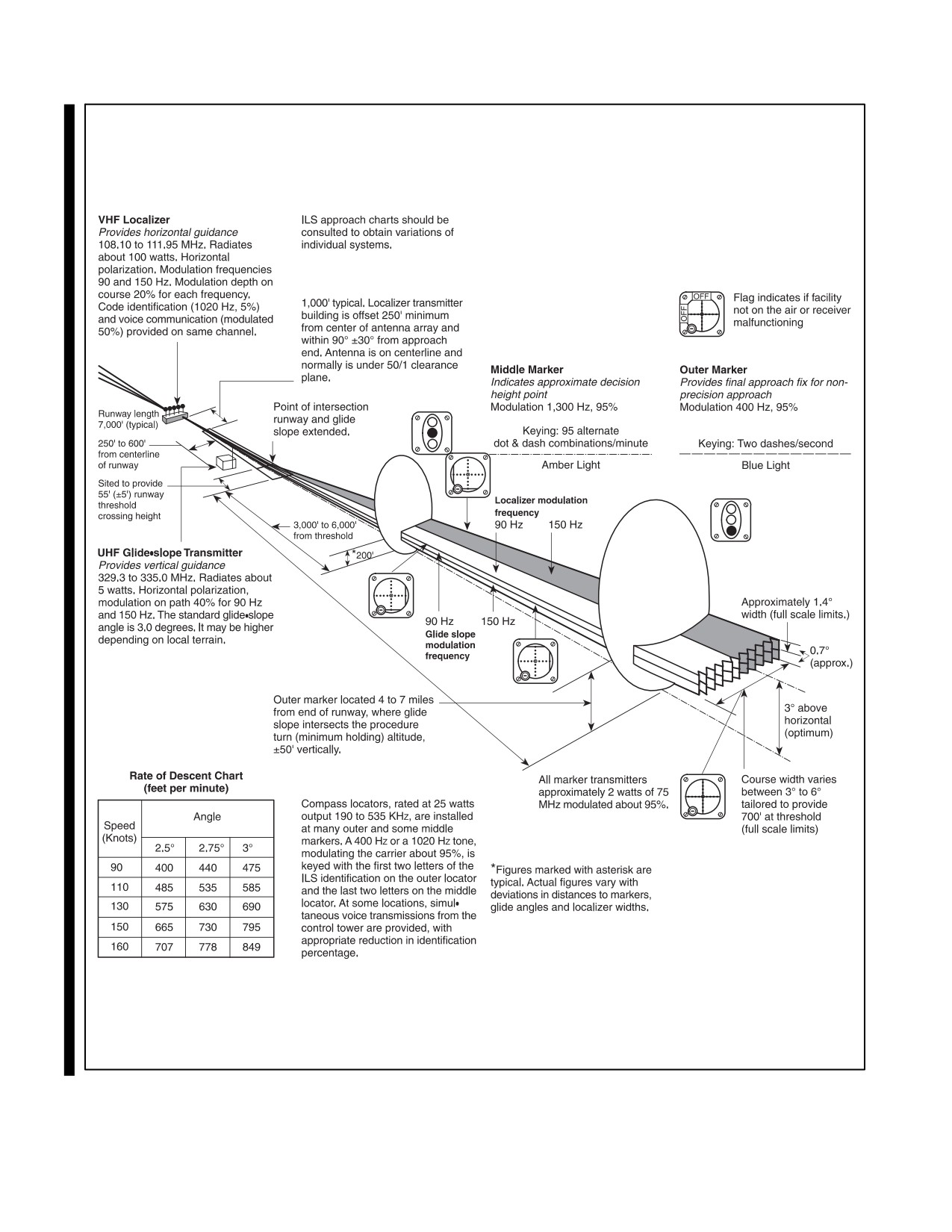
NAVAIR 00-80T-112
Figure 24-1. Instrument Landing System
ORIGINAL
24-2
NAVAIR 00-80T-112
ILS localizer transmitters use the odd decimal VHF frequencies from 108.1 to 111.9 MHz (e.g., 110.3 MHz). The
localizer transmitter emits continuous identification in the form of a coded three-letter station identifier preceded by
the letter I (e.g., I-EMH). Some have voice transmission capabilities.
Note
Momentary localizer flag activity and course aberrations may be observed
when other aircraft cross over the localizer antenna or are in a position to
affect the radiated signal.
24.2.1.2 Glideslope
1.
The Ultrahigh Frequency (UHF) glideslope transmitter, operating on 1 of the 20 ILS channels within the
frequency range 329.3 to 335.0 MHz, radiates its signals principally in the direction of final approach. Any
instrument indications of a glideslope at azimuths other than those within the angular width of the localizer
front course should be disregarded.
2.
The glideslope transmitter is located between 750 and 1,250 feet from the approach end of the runway (down
the runway) and offset 400 to 600 feet from the runway centerline. It transmits a glideslope beam 1.4_ wide.
3.
The glideslope projection angle is normally adjusted to 2.5_ to 3_ above horizontal so that it intersects the
middle marker at approximately 200 feet and the outer marker at approximately 1,400 feet above the runway
elevation.
4.
In addition to the desired glideslope, false course and reversal in sensing will occur at vertical angles
considerably greater than the usable slope. The proper use of the glideslope requires that the pilot maintain
alertness as the glideslope interception is approached and interpret correctly the “fly-up” and “fly-down”
instrument indications to avoid the possibility of attempting to follow one of the higher angle courses.
5.
Extreme caution should be used to avoid exceeding a deviation of one dot (or approximately one-half scale)
below the glideslope up to the middle marker and to avoid any deviation below the glideslope from the middle
marker to completion of landing.
6.
The glideslope facilities provide a signal that flares from 18 to 27 feet above the runway; therefore, the
glideslope should not be expected to provide guidance completely to a touchdown point on the runway.
7.
DME may be installed at the glideslope transmitter site. Range and the three-letter station identifier are
available through the Tactical Air Navigation (TACAN) receiver. Bearing information is not provided.
24.2.1.3 Marker Beacons
Marker beacons are very low-powered, 75-MHz transmitters located along the ILS final approach course to mark a
specific position. Normally, two marker beacons are used for this purpose, and they are depicted on the terminal chart
by the letters OM and MM (Outer Marker and Middle Marker).
An additional beacon called an Inner Marker (IM) may also be installed. The beacons are identified in the aircraft
visually (marker beacon light) and/or aurally depending on aircraft equipment. The reception area of the aural signal
is larger than that of the visual signal. Marker beacons are not installed for navigation purposes but merely to indicate
a fix on the localizer course.
The Outer Marker (OM) is normally located 4 to 7 miles from the end of the runway. Outer marker identification
consists of continuous dashes. Aurally, the dashes are comparatively low pitched (400 Hz). The published altitude
at the outer marker is what the altimeter should indicate when the aircraft is over the marker and on the glideslope;
however, there are no specific limits. The outer marker altitude may also be the procedure turn or glideslope
interception altitude.
24-3
ORIGINAL
NAVAIR 00-80T-112
The Middle Marker (MM) is located approximately 3,500 feet from the runway and is identified by alternating dots
and dashes. The aural signal is comparatively high pitched (1,300 Hertz) and easily distinguished from the outer
marker signal. This is also the position where an aircraft on glidepath will be at an altitude of approximately 200 feet
above the elevation of the touchdown zone.
The IM, where installed, will indicate a point at which an aircraft is at a designated Decision Height (DH) for Category
II equipped aircraft on the glideslope between the middle marker and landing threshold. The IM is modulated at 3000
Hz and identified with continuous dots keyed at the rate of six dots per second.
24.2.1.4 Compass Locators
If installed, compass locators are placed at the marker beacon sites (usually only at the OM) as aids to navigation
around the ILS. They are low-powered nondirectional radio beacons operating between 200 and 415 kHz with a
reliable reception range of at least 15 nm; however, higher-powered, low-frequency nondirectional radio beacons
may be collocated with the marker beacons and used as compass locators. These generally carry transcribed weather
broadcast information.
On the approach chart, the radio data information box for the locator is broken at the top by the letter L. Within the
box are the frequency and the identification of the facility.
The locator identification consists of two letters. When installed at an outer marker, it will normally transmit the first
two letters of the three-letter ILS localizer identification. If installed at a middle marker, it will transmit the last two
letters. For example, with an ILS localizer identified by the letters I-FAT, the compass locator identification at the
outer marker is FA, and at the middle marker is AT. On the profile view of the approach chart, the locators are depicted
by the letters LOM or LMM (Locator Outer Marker or Locator Middle Marker).
During periods of routine or emergency maintenance, the coded identification (or code and voice, where applicable)
will be removed from ILS localizers but not from Non-Directional Beacon (NDB) compass locators or 75-MHz
marker beacons (Figure 24-1).
Note
ILS minimums, with all components operative, normally establish a DH
(decision height MSL) with a Height Above Touchdown (HAT) of 200 feet
and a visibility of one-half statute mile.
24.2.2 Airborne Equipment
The control panel for tuning the ILS localizer is the same as that used for VHF Omnidirectional Range (VOR) in most
aircraft. The glideslope receiver is automatically tuned when the localizer frequency is selected.
A course indicator is used in this chapter to illustrate procedures for flying ILS. The flight director display is illustrated
in Figure 24-3.
The radio magnetic indicator has no function with ILS frequencies; however, bearing information to other radio
facilities (compass locators, TACAN, etc.) can be of considerable value. All available navigation equipment should
be used when appropriate during any approach.
24.2.2.1 ILS Channel/Frequency
ILS are being commissioned utilizing all 20 channels allotted to ILS by International Civil Aviation Organization
(ICAO) in Aeronautical Telecommunications Annex 10. Aircraft equipment should be checked to ensure the
receiving capability of all channels.
ORIGINAL
24-4
NAVAIR 00-80T-112
24.3
ILS PROCEDURES
24.3.1 Performing the ILS Approach
Information for planning an ILS and transitioning to it from other Navigation Aids (NAVAIDs) is found in the
terminal flight information publications (Figure 24-2). The approach should be considered in its entirety from en route
transition through landing or missed approach. Refer to other Flight Information Publications (FLIP) documents such
as Planning and the En Route IFR Supplement.
Pilots should tune the ILS receiver and identify and monitor the localizer identification signal as soon as practical
during the transition procedure. The course and glideslope indicators are reliable only when (1) their warning flags
are not displayed, (2) the localizer identifier is received, and (3) the aircraft is within the usable range of the
equipment. The localizer is considered reliable within 18 miles of the transmitter within 10_ or 10 miles within 35_
of the course centerline unless the published approach depicts a transition point at a farther distance. The glideslope
interception point and altitude are designated on the terminal chart; the glideslope is considered reliable within 10
miles of the transmitter, provided the aircraft is on the localizer course.
Before localizer interception, set the published front course in the course selector window so that the aircraft
heading/localizer relationship is displayed on the course indicator. The transition may require a large turn onto the
localizer course (e.g., a teardrop penetration or procedure turn). If the CDI indicates full-scale deflection (course
deviation 2-1/2_ or greater) during the latter portion of the turn, roll out with an intercept angle that will ensure
localizer interception prior to the glideslope intercept point. Normally a 30_ to 45_ intercept is sufficient; however,
groundspeed, distance from the localizer course, and final approach fix may require another intercept angle.
When the localizer is intercepted, maintain the published heading until the first movement of the CDI. The rate of
CDI movement will aid in estimating the force and direction of the wind. Heading corrections should be sufficient
to stop the CDI movement and return the aircraft to course. After returning to course, apply the drift correction
necessary to keep the CDI centered. Heading corrections should be reduced as the aircraft continues inbound
(increments of 5_ or less are usually sufficient).
The pilot should maintain the glideslope interception altitude, configure the aircraft for landing, and establish the final
approach airspeed before reaching the glideslope intercept point. Do not descend below glideslope interception
altitude if the CDI indicates full-scale deflection. Call the controlling agency at the final approach fix or as directed.
As the Glideslope Indicator (GSI) moves downward from its upper limits, prepare to intercept the glideslope. Slightly
before the GSI reaches the center position, establish a pitch attitude on the attitude indicator and a power setting that
will result in the vertical velocity and airspeed required to maintain the glidepath. The amount of pitch change
required will depend on the glideslope angle. One technique that may be used when intercepting the glideslope
(provided the final approach airspeed and configuration have been established) is to change the pitch attitude on the
attitude indicator the same number of degrees as the glideslope angle (i.e., normally 2-1/2_ to 3_).
The glideslope facility provides a path that flares from 18 to 27 feet above
the runway; therefore, the glidepath should not be expected to provide
guidance completely to a touchdown point on the runway.
Corrections are made using coordinated pitch and power changes. Normally pitch changes should result in vertical
velocity changes of less than 300 fpm. A 1_ pitch change on the attitude indicator is usually a sufficient amount of
correction to achieve a vertical velocity change of 200 to 300 fpm for groundspeeds between 120 and 180 knots.
As indicated in Figure 24-3, the size of the course and glideslope envelope reduces progressively throughout the
approach; therefore, the size of the pitch and bank corrections should be gradually reduced as the distance to
touchdown decreases.
24-5
ORIGINAL
NAVAIR 00-80T-112
Figure 24-2. Typical ILS Approach
ORIGINAL
24-6