NAVAIR 00-80T-112 NATOPS INSTRUMENT FLIGHT MANUAL (15 NOVEMBER 2006) - page 5
NAVAIR 00-80T-112
Note
When cleared for the approach, the published off airway (feeder) routes that
lead from the en route structure to the IAF are part of the approach
clearance.
If a feeder route to an IAF begins at a fix located along the route of flight prior to reaching the holding fix, and
clearance for an approach is issued, a pilot should commence the approach via the published feeder route (i.e., the
aircraft would not be expected to overfly the feeder route and return to it). The pilot is expected to commence the
approach in a similar manner at the IAF if the IAF for the procedure is located along the route of flight to the holding
fix.
If a route of flight directly to the initial approach fix is desired, it should be so stated by the controller with phraseology
to include the words “direct,” “proceed direct,” or a similar phrase that the pilot can interpret without question. When
uncertain of the clearance, immediately query ATC as to what route of flight is desired.
The name of an instrument approach, as published, is used to identify the approach, even though a component of the
approach aid, such as the glideslope on an instrument landing system, is inoperative or unreliable. The controller will
use the name of the approach as published, but must advise the aircraft at the time an approach clearance is issued
that the inoperative or unreliable approach aid component is unusable.
30.7
INSTRUMENT APPROACH PROCEDURES
Minimums are specified for various aircraft approach categories based upon a value 1.3 times the stalling speed of
the aircraft in the landing configuration at maximum certified gross landing weight. In 14 CFR Section 97.3(b)
categories are listed as follows:
1. Category A: Speed less than 91 knots.
2. Category B: Speed 91 knots or more but less than 121 knots.
3. Category C: Speed 121 knots or more but less than 141 knots.
4. Category D: Speed 141 knots or more but less than 166 knots.
5. Category E: Speed 166 knots or more.
Aircraft approach categories are also discussed in the U.S. Terminal Procedures (commonly called approach plates),
which states, among other things, that “An aircraft shall fit in only one category. If it is necessary to maneuver at
speeds in excess of the upper limit of a speed range for a category, the minimums for the next higher category should
be used.” If it is necessary, while circling to land, to maneuver at speeds in excess of the upper limit of the speed range
for each category, due to the possibility of extending the circling maneuver beyond the area for which obstruction
clearance is provided, the circling minimum for the next higher approach category should be used. For example, an
aircraft that falls in Category C, but is circling to land at a speed of 141 knots or higher, should use the approach
Category D minimum when circling to land.
When operating on an unpublished route or while being radar vectored, the pilot, when an approach clearance is
received, shall, in addition to complying with the minimum altitudes for IFR operations (14 CFR Section 91.177),
maintain the last assigned altitude unless a different altitude is assigned by ATC, or until the aircraft is established
on a segment of a published route or IAP. After the aircraft is so established, published altitudes apply to descent
within each succeeding route or approach segment unless a different altitude is assigned by ATC. Notwithstanding
this pilot responsibility for aircraft operating on unpublished routes or while being radar vectored, ATC will, except
when conducting a radar approach, issue an IFR approach clearance only after the aircraft is established on a segment
of a published route or IAP, or assign an altitude to maintain until the aircraft is established on a segment of a published
route or instrument approach procedure. For this purpose, the procedure turn of a published IAP shall not be
considered a segment of that IAP until the aircraft reaches the initial fix or navigation facility upon which the
procedure turn is predicated.
30-27
ORIGINAL
NAVAIR 00-80T-112
Note
The altitude assigned will ensure IFR obstruction clearance from the point
at which the approach clearance is issued until established on a segment of
a published route or IAP. If uncertain of the meaning of the clearance,
immediately request clarification from ATC.
Several IAPs, using various navigation and approach aids, may be authorized for an airport. ATC may advise that a
particular approach procedure is being used, primarily to expedite traffic. If issued a clearance that specifies a
particular approach procedure, notify ATC immediately if a different one is desired. In this event it may be necessary
for ATC to withhold clearance for the different approach until such time as traffic conditions permit; however, a pilot
involved in an emergency situation will be given priority. If the pilot is not familiar with the specific approach
procedure, ATC should be advised and they will provide detailed information on the execution of the procedure.
At times, ATC may not specify a particular approach procedure in the clearance, but will state “CLEARED
APPROACH.” Such clearance indicates that the pilot may execute any one of the authorized IAPs for that airport.
This clearance does not constitute approval for the pilot to execute a contact approach or a visual approach.
Except when being radar vectored to the final approach course, when cleared for a specifically prescribed IAP (i.e.,
“cleared ILS runway one niner approach”) or when “cleared approach” (i.e., execution of any procedure prescribed
for the airport), pilots shall execute the entire procedure commencing at an IAF or an associated feeder route as
described on the IAP chart unless an appropriate new or revised ATC clearance is received or the IFR flight plan is
canceled.
Pilots planning flights to locations served by special IAPs should obtain advance approval from the owner of the
procedure. Approval by the owner is necessary because special procedures are for the exclusive use of the single
interest unless otherwise authorized by the owner. Additionally, some special approach procedures require certain
crew qualifications training or other special considerations in order to execute the approach. Also, some of these
approach procedures are based on privately owned navigational aids. Owners of aids that are not for public use may
elect to turn off the aid for whatever reason they may have (e.g., maintenance, conservation, etc.). Air traffic
controllers are not required to question pilots to determine if they have permission to use the procedure. Controllers
presume a pilot has obtained approval and is aware of any details of the procedure if an IFR flight plan was filed to
that airport.
When executing an instrument approach and in radio contact with an FAA facility, unless in radar contact, report
passing the final approach fix inbound (nonprecision approach) or the outer marker or fix used in lieu of the outer
marker inbound (precision approach).
Pilots should not rely on radar to identify a fix unless the fix is indicated as RADAR on the IAP. Pilots may request
radar identification of an OM, but the controller may not be able to provide the service due either to workload or not
having the fix on the video map.
If a missed approach is required, advise ATC and include the reason (unless initiated by ATC). Comply with the
missed approach instructions for the instrument approach procedure being executed unless otherwise directed by
ATC.
30.8
PROCEDURE TURN
A procedure turn is the maneuver prescribed when it is necessary to perform a course reversal to establish the aircraft
inbound on an intermediate or final approach course. The procedure turn or hold in lieu of procedure turn is a required
maneuver. The procedure turn is not required when the symbol NoPT is shown, when radar vectoring to the final
approach course is provided, when conducting a timed approach, or when the procedure turn is not authorized. The
hold in lieu of procedure turn is not required when radar vectoring to the final approach course is provided or when
NoPT is shown. The altitude prescribed for the procedure turn is a minimum altitude until the aircraft is established
on the inbound course. The maneuver must be completed within the distance specified in the profile view.
ORIGINAL
30-28
NAVAIR 00-80T-112
1.
On U.S. Government charts, a barbed arrow indicates the direction or side of the outbound course on which
the procedure turn is made. Headings are provided for course reversal using the 45-degree type procedure turn;
however, the point at which the turn may be commenced and the type and rate of turn is left to the discretion
of the pilot. Some of the options are the 45-degree procedure turn, the racetrack pattern, the teardrop procedure
turn, or the 80 degree ↔ 260 degree course reversal. Some procedure turns are specified by procedural track.
These turns must be flown exactly as depicted.
2.
When the approach procedure involves a procedure turn, a maximum speed of not greater than 200 knots
Indicated Airspeed (IAS) should be observed from first overhead the course reversal IAF through the
procedure turn maneuver to ensure containment within the obstruction clearance area. Pilots should begin the
outbound turn immediately after passing the procedure turn fix. The procedure turn maneuver must be
executed within the distance specified in the profile view. The normal procedure turn distance is 10 miles. This
may be reduced to a minimum of 5 miles where only Category A or helicopter aircraft are to be operated or
increased to as much as 15 miles to accommodate high-performance aircraft.
3.
A teardrop procedure or penetration turn may be specified in some procedures for a required course reversal.
The teardrop procedure consists of departure from an initial approach fix on an outbound course followed by
a turn toward and intercepting the inbound course at or prior to the intermediate fix or point. Its purpose is to
permit an aircraft to reverse direction and lose considerable altitude within reasonably limited airspace. Where
no fix is available to mark the beginning of the intermediate segment, it shall be assumed to commence at a
point 10 miles prior to the final approach fix. When the facility is located on the airport, an aircraft is considered
to be on final approach upon completion of the penetration turn; however, the final approach segment begins
on the final approach course 10 miles from the facility.
4.
A holding pattern in lieu of procedure turn may be specified for course reversal in some procedures. In such
cases, the holding pattern is established over an intermediate fix or a final approach fix. The holding pattern
distance or time specified in the profile view must be observed. Maximum holding airspeed limitations, as set
forth for all holding patterns, apply. The holding pattern maneuver is completed when the aircraft is established
on the inbound course after executing the appropriate entry. If cleared for the approach prior to returning to
the holding fix, and the aircraft is at the prescribed altitude, additional circuits of the holding pattern are not
necessary nor expected by ATC. If pilots elect to make additional circuits to lose excessive altitude or to become
better established on course, it is their responsibility to so advise ATC upon receipt of their approach clearance.
5.
A procedure turn is not required when an approach can be made directly from a specified intermediate fix to
the final approach fix. In such cases, the term NoPT is used with the appropriate course and altitude to denote
that the procedure turn is not required. If a procedure turn is desired, and when cleared to do so by ATC, descent
below the procedure turn altitude should not be made until the aircraft is established on the inbound course,
since some NoPT altitudes may be lower than the procedure turn altitudes.
30.8.1 Limitations on Procedure Turns
1. In the case of a radar initial approach to a final approach fix or position, or a timed approach from a holding
fix, or where the procedure specifies NoPT, no pilot may make a procedure turn unless, when final approach
clearance is received, the pilot so advises ATC and a clearance is received to execute a procedure turn.
2. When a teardrop procedure turn is depicted and a course reversal is required, this type turn must be executed.
3. When a holding pattern replaces a procedure turn, the holding pattern must be followed, except when radar
vectoring is provided or when NoPT is shown on the approach course. The recommended entry procedures
will ensure the aircraft remains within the holding pattern protected airspace. As in the procedure turn, the
descent from the minimum holding pattern altitude to the final approach fix altitude (when lower) may not
commence until the aircraft is established on the inbound course. Where a holding pattern is established in lieu
of a procedure turn, the maximum holding pattern airspeeds apply.
4. The absence of the procedure turn barb in the plan view indicates a procedure turn is not authorized for that
procedure.
30-29
ORIGINAL
NAVAIR 00-80T-112
30.9
TIMED APPROACHES FROM A HOLDING FIX
Timed approaches may be conducted when the following conditions are met:
1. A control tower is in operation at the airport where the approaches are conducted.
2. Direct communications are maintained between the pilot and the center or approach controller until the pilot
is instructed to contact the tower.
3. If more than one missed approach procedure is available, none require a course reversal.
4. If only one missed approach procedure is available, the following conditions are met:
a. Course reversal is not required.
b. Reported ceiling and visibility are equal to or greater than the highest prescribed circling minimums for the
IAP.
5. When cleared for the approach, pilots shall not execute a procedure turn. (14 CFR Section 91.175.)
Although the controller will not specifically state that timed approaches are in progress, the assigning of a time to
depart the final approach fix inbound (nonprecision approach) or the outer marker or fix used in lieu of the outer
marker inbound (precision approach) is indicative that timed approach procedures are being utilized, or in lieu of
holding, the controller may use radar vectors to the final approach course to establish a mileage interval between
aircraft that will ensure the appropriate time sequence between the final approach fix/outer marker or fix used in lieu
of the outer marker and the airport.
Each pilot in an approach sequence will be given advance notice as to the time they should leave the holding point
on approach to the airport. When a time to leave the holding point has been received, the pilot should adjust the flight
path to leave the fix as closely as possible to the designated time (Figure 30-14).
Example:
At 12:03 local time, in the example shown, a pilot holding receives instructions to leave the fix inbound at 12:07.
These instructions are received just as the pilot has completed turn at the outbound end of the holding pattern and is
proceeding inbound toward the fix. Arriving back over the fix, the pilot notes the time is 12:04 and there are 3 minutes
to lose in order to leave the fix at the assigned time. Since the time remaining is more than 2 minutes, the pilot plans
to fly a racetrack pattern rather than a 360-degree turn, which would use up 2 minutes. The turns at the ends of the
racetrack pattern will consume approximately 2 minutes. Three minutes to go, minus 2 minutes required for the turns,
leaves 1 minute for level flight. Since two portions of level flight will be required to get back to the fix inbound, the
pilot halves the 1 minute remaining and plans to fly level for 30 seconds outbound before starting the turn back to
the fix on final approach. If the winds were negligible at flight altitude, this procedure would bring the pilot inbound
across the fix precisely at the specified time of 12:07; however, if expecting headwind on final approach, the pilot
should shorten the 30-second outbound course somewhat, knowing the wind will carry the aircraft away from the fix
faster while outbound and decrease the groundspeed while returning to the fix. On the other hand, compensating for
a tailwind on final approach, the pilot should lengthen the calculated 30-second outbound heading somewhat,
knowing the wind would tend to hold the aircraft closer to the fix while outbound and increase the groundspeed while
returning to the fix.
30.10 RADAR APPROACHES
The only airborne radio equipment required for radar approaches is a functioning radio transmitter and receiver. The
radar controller vectors the aircraft to align it with the runway centerline. The controller continues the vectors to keep
the aircraft on course until the pilot can complete the approach and landing by visual reference to the surface. There
are two types of radar approaches: Precision (PAR) and Surveillance (ASR).
ORIGINAL
30-30
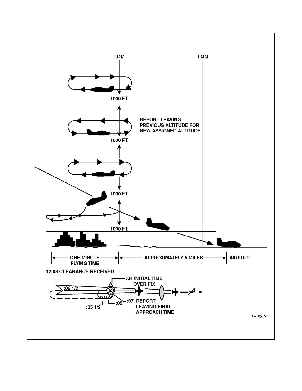
NAVAIR 00-80T-112
Figure 30-14. Timed Approaches from a Holding Fix
30-31
ORIGINAL
NAVAIR 00-80T-112
A radar approach may be given to any aircraft upon request and may be offered to pilots of aircraft in distress or to
expedite traffic; however, an ASR might not be approved unless there is an ATC operational requirement, or in an
unusual or emergency situation. Acceptance of a PAR or ASR by a pilot does not waive the prescribed weather
minimums for the airport or for the particular aircraft operator concerned. The decision to make a radar approach
when the reported weather is below the established minimums rests with the pilot.
PAR and ASR minimums are published on separate pages in the FAA Terminal Procedures Publication (TPP).
1.
A Precision Approach (PAR) is one in which a controller provides highly accurate navigational guidance in
azimuth and elevation to a pilot. Pilots are given headings to fly, to direct them to, and keep their aircraft aligned
with the extended centerline of the landing runway. They are told to anticipate glidepath interception
approximately 10 to 30 seconds before it occurs and when to start descent. The published DH will be given
only if the pilot requests it. If the aircraft is observed to deviate above or below the glidepath, the pilot is given
the relative amount of deviation by use of terms “slightly” or “well” and is expected to adjust the aircraft rate
of descent/ascent to return to the glidepath. Trend information is also issued with respect to the elevation of
the aircraft and may be modified by the terms “rapidly” and “slowly” (e.g., “well above glidepath, coming
down rapidly”). Range from touchdown is given at least once each mile. If an aircraft is observed by the
controller to proceed outside of specified safety zone limits in azimuth and/or elevation and continue to operate
outside these prescribed limits, the pilot will be directed to execute a missed approach or to fly a specified
course unless the pilot has the runway environment (runway, approach lights, etc.) in sight. Navigational
guidance in azimuth and elevation is provided the pilot until the aircraft reaches the published DH. Advisory
course and glidepath information is furnished by the controller until the aircraft passes over the landing
threshold, at which point the pilot is advised of any deviation from the runway centerline. Radar service is
automatically terminated upon completion of the approach.
2.
A Surveillance Approach (ASR) is one in which a controller provides navigational guidance in azimuth only.
The pilot is furnished headings to fly to align the aircraft with the extended centerline of the landing runway.
Since the radar information used for a surveillance approach is considerably less precise than that used for a
precision approach, the accuracy of the approach will not be as great and higher minimums will apply.
Guidance in elevation is not possible but the pilot will be advised when to commence descent to the MDA or,
if appropriate, to an intermediate stepdown fix Minimum Crossing Altitude (MCA) and subsequently to the
prescribed MDA. In addition, the pilot will be advised of the location of the MAP prescribed for the procedure
and the aircraft position each mile on final from the runway, airport, heliport, or MAP, as appropriate. If
requested by the pilot, recommended altitudes will be issued at each mile, based on the descent gradient
established for the procedure, down to the last mile that is at or above the MDA. Normally, navigational
guidance will be provided until the aircraft reaches the MAP. Controllers will terminate guidance and instruct
the pilot to execute a missed approach unless at the MAP the pilot has the runway, airport, or heliport in sight
or, for a helicopter point-in-space approach, the prescribed visual reference with the surface is established.
Also, if, at any time during the approach the controller considers that safe guidance for the remainder of the
approach cannot be provided, the controller will terminate guidance and instruct the pilot to execute a missed
approach. Similarly, guidance termination and missed approach will be effected upon pilot request and, for
civil aircraft only, controllers may terminate guidance when the pilot reports the runway, airport, heliport or
visual surface route (point-in-space approach) in sight or otherwise indicates continued guidance is not
required. Radar service is automatically terminated at the completion of a radar approach.
ORIGINAL
30-32
NAVAIR 00-80T-112
Note
D The published MDA for straight-in approaches will be issued to the pilot
before beginning descent. When a surveillance approach will terminate in
a circle-to-land maneuver, the pilot must furnish the aircraft approach
category to the controller. The controller will then provide the pilot with the
appropriate MDA.
D ASR approaches are not available when an ATC facility is using Center
Radar Approach Control (CERAP).
3. A no-gyro approach is available to a pilot under radar control who experiences circumstances wherein the
directional gyro or other stabilized compass is inoperative or inaccurate. When this occurs, the pilot should
so advise ATC and request a no-gyro vector or approach. Pilots of aircraft not equipped with a directional gyro
or other stabilized compass who desire radar handling may also request a no-gyro vector or approach. The pilot
should make all turns at standard rate and should execute the turn immediately upon receipt of instructions
(e.g., “TURN RIGHT,” “STOP TURN”). When a surveillance or precision approach is made, the pilot will be
advised after the aircraft has been turned onto final approach to make turns at half standard rate.
30.11 RADAR MONITORING OF INSTRUMENT APPROACHES
PAR facilities operated by the FAA and the military services at some joint-use (civil and military) and military
installations monitor aircraft on instrument approaches and issue radar advisories to the pilot when weather is below
VFR minimums (1,000 and 3), at night, or when requested by a pilot. This service is provided only when the PAR
final approach course coincides with the final approach of the navigational aid and only during the operational hours
of the PAR. The radar advisories serve only as a secondary aid, since the pilot has selected the navigational aid as the
primary aid for the approach.
Prior to starting final approach, the pilot will be advised of the frequency on which the advisories will be transmitted.
If, for any reason, radar advisories cannot be furnished, the pilot will be so advised.
Advisory information, derived from radar observations, includes information on:
1. Passing the final approach fix inbound (nonprecision approach) or passing the outer marker or fix used in lieu
of the outer marker inbound (precision approach).
Note
Parallel approach operations demand heightened pilot situational
awareness. A thorough approach procedure chart review should be
conducted with, as a minimum, emphasis on the following approach chart
information: name and number of the approach, localizer frequency,
inbound localizer/azimuth course, glideslope intercept altitude, decision
height, missed approach instructions, special notes/procedures, and the
assigned runway location/proximity to adjacent runways. Pilots will be
advised that simultaneous ILS/MLS or simultaneous close parallel ILS
Precision Runway Monitor (PRM) approaches are in use. This information
may be provided through the ATIS.
2. The close proximity of adjacent aircraft conducting simultaneous parallel ILS/MLS and simultaneous close
parallel ILS PRM approaches mandates strict pilot compliance with all ATC clearances. ATC assigned
airspeeds, altitudes, and headings must be complied with in a timely manner. Autopilot coupled ILS/MLS
approaches require pilot knowledge of procedures necessary to comply with ATC instructions. Simultaneous
parallel ILS/MLS and simultaneous close parallel ILS PRM approaches necessitate precise localizer tracking
to minimize final monitor controller intervention and unwanted No Transgression Zone (NTZ) penetration.
In the unlikely event of a breakout, ATC will not assign altitudes lower than the minimum vectoring altitude.
Pilots should notify ATC immediately if there is a degradation of aircraft or navigation systems.
30-33
ORIGINAL
NAVAIR 00-80T-112
3. Strict radio discipline is mandatory during parallel ILS/MLS approach operations. This includes an alert
listening watch and the avoidance of lengthy, unnecessary radio transmissions. Attention must be given to
proper call sign usage to prevent the inadvertent execution of clearances intended for another aircraft. Use of
abbreviated call signs must be avoided to preclude confusion of aircraft with similar sounding call signs. Pilots
must be alert to unusually long periods of silence or any unusual background sounds in their radio receiver.
A stuck microphone may block the issuance of ATC instructions by the final monitor controller during
simultaneous parallel ILS/MLS and simultaneous close parallel ILS PRM approaches.
4. Use of Traffic Alert and Collision Avoidance Systems (TCAS) provides an additional element of safety to
parallel approach operations. Pilots should follow recommended TCAS operating procedures presented in
approved flight manuals, original equipment manufacturer recommendations, professional newsletters, and
FAA publications.
30.12 PARALLEL ILS/MLS APPROACHES (DEPENDENT)
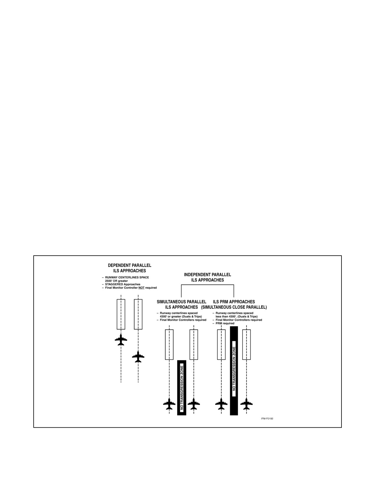
Parallel approaches are an ATC procedure permitting parallel ILS/MLS approaches (Figure 30-15) to airports having
parallel runways separated by at least 2,500 feet between centerlines. Integral parts of a total system are ILS/MLS,
radar, communications, ATC procedures, and required airborne equipment.
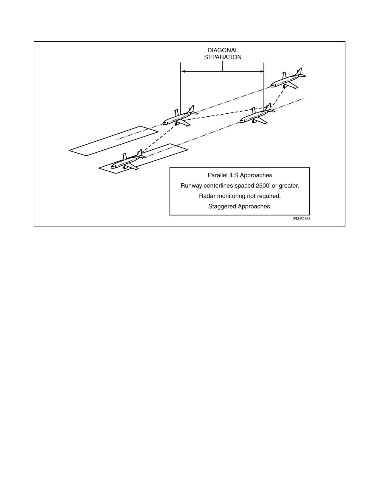
A parallel (dependent) approach differs from a simultaneous (independent) approach in that the minimum distance
between parallel runway centerlines is reduced there is no requirement for radar monitoring or advisories, and a
staggered separation of aircraft on the adjacent localizer/azimuth course is required (Figure 30-16).
Aircraft are afforded a minimum of 1.5 miles radar separation diagonally between successive aircraft on the adjacent
localizer/azimuth course when runway centerlines are at least 2,500 feet but no more than 4,300 feet apart. When
runway centerlines are more than 4,300 feet but no more than 9,000 feet apart, a minimum of 2 miles diagonal radar
separation is provided. Aircraft on the same localizer/azimuth course within 10 miles of the runway end are provided
a minimum of 2.5 miles radar separation. In addition, a minimum of 1,000 feet vertical or a minimum of 3 miles radar
separation is provided between aircraft during turn onto the parallel final approach course.
Figure 30-15. Parallel ILS Approaches
ORIGINAL
30-34
NAVAIR 00-80T-112
Figure 30-16. Staggered ILS Approaches
Whenever parallel ILS/MLS approaches are in progress, pilots are informed that approaches to both runways are in
use. In addition, the radar controller will have the interphone capability of communicating with the tower controller
where separation responsibility has not been delegated to the tower.
30.13 SIMULTANEOUS PARALLEL ILS/MLS APPROACHES (INDEPENDENT)
30.13.1 System
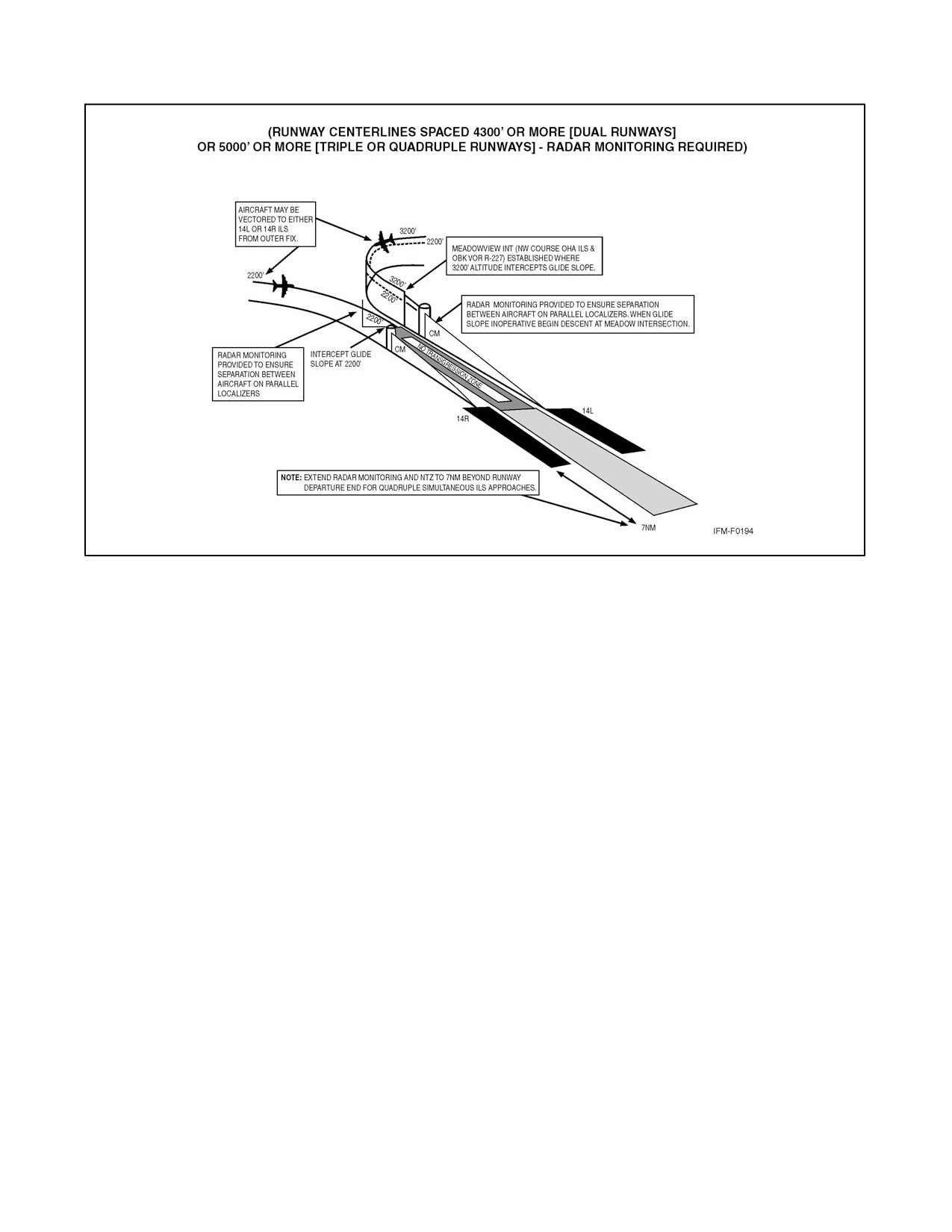
This approach system permits simultaneous ILS/MLS approaches (Figure 30-17) to parallel runways with centerlines
separated by 4,300 to 9,000 feet and equipped with final monitor controllers. Simultaneous parallel ILS/MLS
approaches require radar monitoring to ensure separation between aircraft on the adjacent parallel approach course.
Aircraft position is tracked by final monitor controllers who will issue instructions to aircraft observed deviating from
the assigned localizer course. Staggered radar separation procedures are not utilized. Integral parts of a total system
are ILS/MLS, radar, communications, ATC procedures, and required airborne equipment. The approach procedure
chart permitting simultaneous parallel ILS/MLS approaches will contain the note “simultaneous approaches
authorized RWYS 14L and 14R,” identifying the appropriate runways as the case may be. When advised that
simultaneous parallel ILS/MLS approaches are in progress, pilots shall advise approach control immediately of
malfunctioning or inoperative receivers, or if a simultaneous parallel ILS/MLS approach is not desired.
30-35
ORIGINAL
NAVAIR 00-80T-112
Figure 30-17. Simultaneous Parallel ILS Approaches
30.13.2 Radar Monitoring
This service is provided for each simultaneous parallel ILS/MLS approach to ensure aircraft do not deviate from the
final approach course. Radar monitoring includes instructions if an aircraft nears or penetrates the prescribed NTZ
(an area 2,000 feet wide located equidistant between parallel final approach courses). This service will be provided
as follows:
1. During turn onto parallel final approach, aircraft will be provided 3 miles radar separation or a minimum of
1,000 feet vertical separation. Aircraft will not be vectored to intercept the final approach course at an angle
greater than 30 degrees.
2. The final monitor controller will have the capability of overriding the tower controller on the tower frequency.
3. Pilots will be instructed to monitor the tower frequency to receive advisories and instructions.
4. Aircraft observed to overshoot the turn-on or to continue on a track that will penetrate the NTZ will be
instructed to return to the correct final approach course immediately. The final monitor controller may also
issue missed approach or breakout instructions to the deviating aircraft.
5. If a deviating aircraft fails to respond to such instructions or is observed penetrating the NTZ, the aircraft on
the adjacent final approach course may be instructed to alter course.
6. Radar monitoring will automatically be terminated when visual separation is applied, the aircraft reports the
approach lights or runway in sight, or the aircraft is 1 mile or less from the runway threshold (for runway
centerlines spaced 4,300 feet or greater). Final monitor controllers will not advise pilots when radar monitoring
is terminated.
ORIGINAL
30-36
NAVAIR 00-80T-112
30.14 SIMULTANEOUS CLOSE PARALLEL ILS PRM APPROACHES (INDEPENDENT)
30.14.1 System
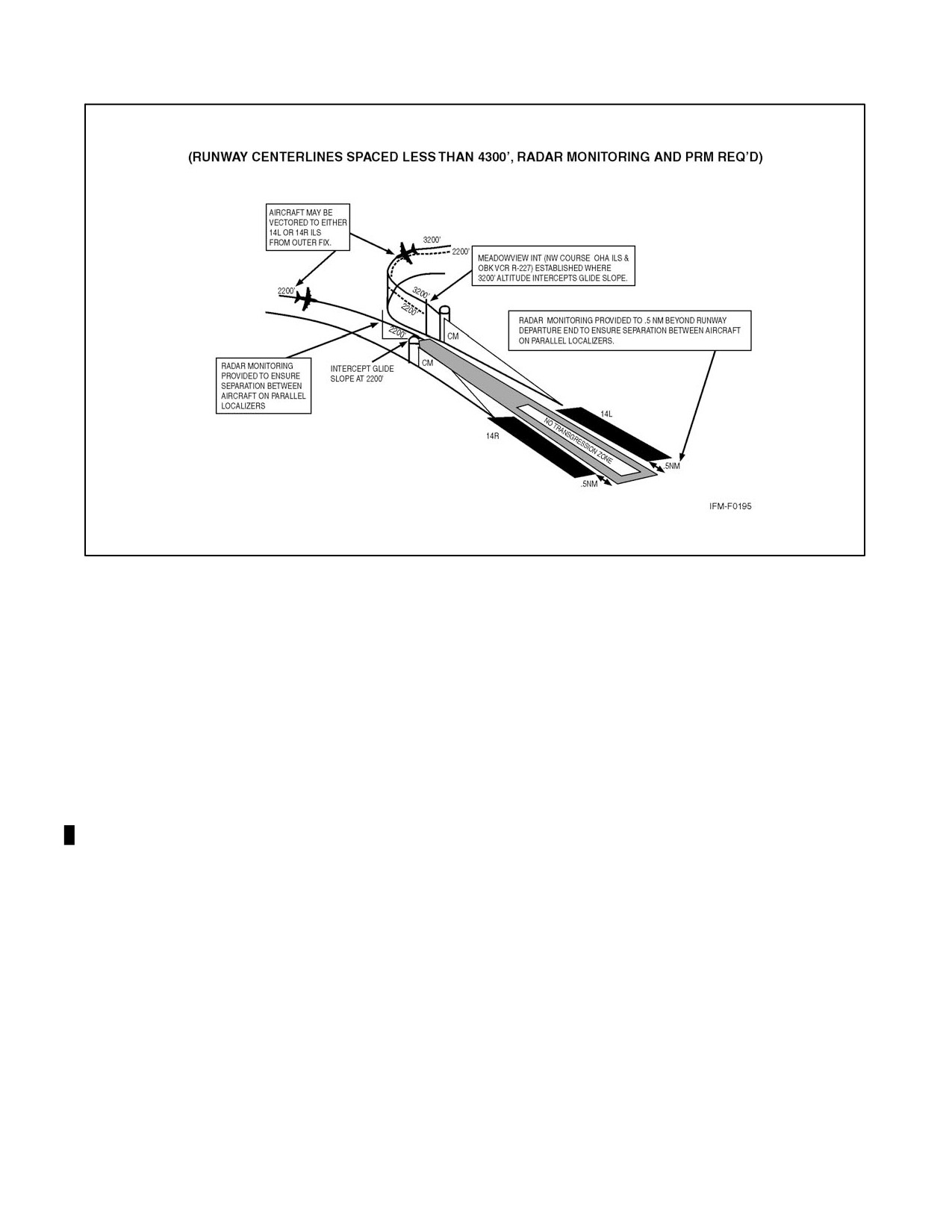
This approach system permits simultaneous ILS PRM approaches (Figure 30-18) to dual runways with centerlines
separated by less than 4,300 feet and equipped with final monitor controllers. To qualify for reduced lateral runway
separation, final monitor controllers must be equipped with high-update radar and high-resolution ATC radar
displays, collectively called a PRM system. The PRM system displays almost instantaneous radar information.
Automated tracking software provides monitor controllers with aircraft identification, position, a 10-second
projected position, as well as visual and aural controller alerts. The PRM system is a supplemental requirement for
simultaneous close parallel approaches in addition to the system requirements for simultaneous parallel ILS/MLS
approaches described in paragraph 30.13. Simultaneous close parallel ILS PRM approaches are identified by a
separate approach procedure chart named ILS PRM (Simultaneous Close Parallel). The name ILS PRM is derived
from the Precision Runway Monitor System (PRMS), which provides a means for simplifying the name of the
simultaneous close parallel ILS approach.
30.14.2 Requirements
The following requirements must be met in order to fly an ILS PRM approach:
1. Air carrier pilots (including Part 121 and Part 135) must complete ILS PRM training, which includes viewing
one of the FAA videos, RDU Precision Runway Monitor: A Pilot’s Approach or ILS PRM Approaches,
Information for Pilots. Watching one of these videos is strongly recommended for all pilots who wish to fly
these approaches.
2. All ATC-directed breakouts, a vector off the ILS prior to the DA, must be hand flown.
3. If the airport has two tower frequencies operating for each runway, the aircraft flying the ILS PRM approach
must have the capability of enabling the pilot(s) to listen to two frequencies simultaneously. Pilots shall advise
air traffic control within 200 miles of the airport of intended landing if the pilot(s) are not qualified and/or the
aircraft is not equipped to fly the approach.
30.14.3 Radar Monitoring
Simultaneous close parallel ILS/MLS approaches require final monitor controllers utilize the Precision Runway
Monitor System (PRMS) to ensure prescribed separation standards are met. Procedures and communications
phraseology are described in paragraph 30.13. To ensure separation is maintained, and in order to avoid an imminent
situation during simultaneous close parallel ILS/MLS approaches, pilots must immediately comply with final
monitor controller instructions to avoid an imminent situation. A minimum of 3 miles radar separation or 1,000 feet
vertical separation will be provided during the turn onto close parallel final approach courses. In the event of a missed
approach, radar monitoring is provided to one-half mile beyond the departure end of the runway. Final monitor
controllers will not notify pilots when radar monitoring is terminated.
30-37
ORIGINAL
NAVAIR 00-80T-112
Figure 30-18. ILS PRM Approaches
30.14.4 Differences Between ILS and ILS PRM Approaches of Importance to the Pilot
30.14.4.1 Runway Spacing
Prior to ILS PRM approaches, most ATC-directed breakouts were the result of two aircraft in trail getting too close
together. Two aircraft going in the same direction did not mandate quick reaction times, but two aircraft along side
each other separated by less than 4,300 feet and closing at 135 feet per second does constitute the need for quick action.
A blunder has to be recognized by one controller, the information passed on to another controller, and breakout
instructions issued to the endangered aircraft. The pilot will not have any warning that a breakout is imminent because
the blundering aircraft will probably be on another frequency. It is important that when a pilot receives breakout
instructions, he/she assumes that a blundering aircraft is heading into his/her approach course and begins the breakout
as soon as safety allows.
30.14.4.2 Communications
To help in avoiding communication problems caused by stuck mikes and two parties talking at the same time, two
tower frequencies for each runway will be in use during ILS PRM approach operations. The tower controller and the
monitor controller will be broadcasting on both of the assigned frequencies. The monitor controller has the capability
of overriding the tower controller. The pilots flying the approach will listen to both frequencies and only broadcast
on the primary tower frequency. If a breakout is initiated by the monitor controller and the primary frequency is
blocked by another transmission, the breakout instruction will be able to be heard on the second frequency.
Antiblocking technology installed in VHF radios might remove the requirement for the second VHF communications
frequency in the near future.
ORIGINAL
30-38
NAVAIR 00-80T-112
30.14.4.3 Hand-Flown Breakouts
The use of the autopilot is encouraged while flying an ILS PRM approach, but the autopilot must be disengaged in
the rare event that a breakout is issued. Simulation studies of breakouts have shown that a hand-flown breakout is
initiated consistently faster than a breakout performed using the autopilot.
30.14.4.4 TCAS
TCAS II-equipped aircraft will fly the ILS PRM approach with the TCAS set to the Traffic Advisory (TA) only mode.
If the TCAS is set to the TA/Resolution Advisory (RA) mode, there is a chance that the TCAS resolution advisory
will be in conflict with the breakout instruction and result in a confusing situation during a critical time. Pilots must
remember to switch back to the TA/RA mode after completing the breakout maneuver.
30.14.4.5 Descending Breakouts
In the past, breakout descents were rarely given to pilots when flying on the lLS localizer and glideslope. A greater
chance exists for the controller to issue a descending breakout when there is a blundering aircraft from an adjacent
approach course crossing an aircraft path. Pilots must be aware that a descending breakout is a possibility. In no case
will the controller descend an aircraft below the Minimum Vectoring Altitude (MVA), which will provide at least
1,000 feet clearance above obstacles. The pilot is not expected to exceed 1,000 feet per minute rate of descent in the
event a descending breakout is issued.
30.15 SIMULTANEOUS CONVERGING INSTRUMENT APPROACHES
ATC may conduct instrument approaches simultaneously to converging runways (i.e., runways having an included
angle from 15 to 100 degrees) at airports where a program has been specifically approved to do so.
The basic concept requires that dedicated, separate standard instrument approach procedures be developed for each
converging runway included. Missed approach points must be at least 3 miles apart and missed approach procedures
ensure missed approach protected airspace does not overlap.
Other requirements are radar availability, nonintersecting final approach courses, precision (ILS/MLS) approach
systems on each runway and, if runways intersect, controllers must be able to apply visual separation as well as
intersecting runway separation criteria. Intersecting runways also require minimums of at least 700-foot ceilings and
2 miles visibility. Straight-in approaches and landings must be made.
Whenever simultaneous converging approaches are in progress, aircraft will be informed by the controller as soon
as feasible after initial contact or via ATIS. Additionally, the radar controller will have direct communications
capability with the tower controller where separation responsibility has not been delegated to the tower.
30.16 SIDESTEP MANEUVER
ATC may authorize a nonprecision approach procedure that serves either one of parallel runways that are separated
by 1,200 feet or less followed by a straight-in landing on the adjacent runway.
Aircraft that will execute a sidestep maneuver will be cleared for a specified nonprecision approach and landing on
the adjacent parallel runway (e.g., “cleared ILS runway 7 left approach, sidestep to runway 7 right”). Pilots are
expected to commence the sidestep maneuver as soon as possible after the runway or runway environment is in sight.
Landing minimums to the adjacent runway will be based on nonprecision criteria and therefore higher than the
precision minimums to the primary runway, but will normally be lower than the published circling minimums.
30.17 APPROACH AND LANDING MINIMUMS
30.17.1 Landing Minimums
The rules applicable to landing minimums are contained in 14 CFR Section 91.175.
30-39
ORIGINAL
NAVAIR 00-80T-112
30.17.2 Published Approach Minimums
Approach minimums are published for different aircraft categories and consist of a minimum altitude (DA, DH,
MDA) and required visibility. These minimums are determined by applying the appropriate TERPS criteria. When
a fix is incorporated in a nonprecision final segment, two sets of minimums may be published: one for the pilot who
is able to identify the fix and a second for the pilot who cannot. Two sets of minimums may also be published when
a second altimeter source is used in the procedure. When a nonprecision procedure incorporates both a stepdown fix
in the final segment and a second altimeter source, two sets of minimums are published to account for the stepdown
fix and a note addresses minimums for the second altimeter source.
30.17.3 Obstacle Clearance
Final approach obstacle clearance is provided from the start of the final segment to the runway or missed approach
point, whichever occurs last. Sidestep obstacle protection is provided by increasing the width of the final approach
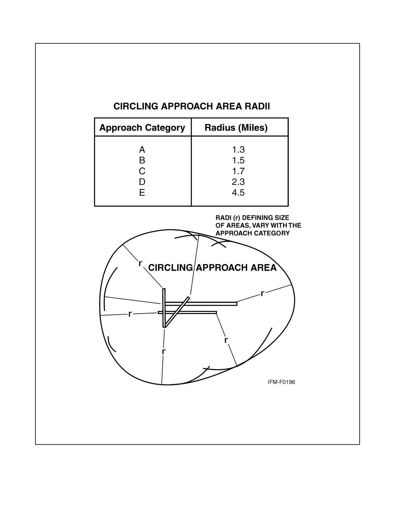
obstacle clearance area. Circling approach protected areas are defined by the tangential connection of arcs drawn from
each runway end. The arc radii distance differs by aircraft approach category. Because of obstacles near the airport,
a portion of the circling area may be restricted by a procedural note (e.g., “Circling NA E of RWY 17-35”). Obstacle
clearance is provided at the published minimums for the pilot who makes a straight-in approach, sidesteps, circles,
or executes the missed approach. Missed approach obstacle clearance requirements may dictate the published
minimums for the approach (Figure 30-19).
30.17.4 Straight-In Minimums
Straight-in minimums are shown on the IAP when the final approach course is within 30 degrees of the runway
alignment (15 degrees for GPS IAPs) and a normal descent can be made from the IFR altitude shown on the IAP to
the runway surface. When either the normal rate of descent or the runway alignment factor of 30 degrees (15 degrees
for GPS IAPs) is exceeded, a straight-in minimum is not published and a circling minimum applies. The fact that a
straight-in minimum is not published does not preclude pilots from landing straight-in if they have the active runway
in sight and have sufficient time to make a normal approach for landing. Under such conditions and when ATC has
cleared them for landing on that runway, pilots are not expected to circle even though only circling minimums are
published. If they desire to circle, they should advise ATC.
30.17.5 Sidestep Maneuver Minimums
Landing minimums for a sidestep maneuver to the adjacent runway will normally be higher than the minimums to
the primary runway.
30.17.6 Circling Minimums
In some busy terminal areas, ATC may not allow circling and circling minimums will not be published. Published
circling minimums provide obstacle clearance when pilots remain within the appropriate area of protection. Pilots
should remain at or above the circling altitude until the aircraft is continuously in a position from which a descent
to a landing on the intended runway can be made at a normal rate of descent using normal maneuvers. Circling may
require maneuvers at low altitude, at low airspeed, and in marginal weather conditions. Pilots must use sound
judgment, have an in-depth knowledge of their capabilities, and fully understand the aircraft performance to
determine the exact circling maneuver because weather, unique airport design, and the aircraft position, altitude, and
airspeed must all be considered. The following basic rules apply:
1. Maneuver the shortest path to the base or downwind leg, as appropriate, considering existing weather
conditions. There is no restriction from passing over the airport or other runways.
2. It should be recognized that circling maneuvers may be made while VFR or other flying is in progress at the
airport. Standard left turns or specific instruction from the controller for maneuvering must be considered when
circling to land.
ORIGINAL
30-40
NAVAIR 00-80T-112
Figure 30-19. Final Approach Obstacle Clearance
30-41
ORIGINAL
NAVAIR 00-80T-112
3. At airports without a control tower, it may be desirable to fly over the airport to observe wind and turn indicators
and other traffic that may be on the runway or flying in the vicinity of the airport.
30.17.7 Instrument Approach at a Military Field
When instrument approaches are conducted by civil aircraft at military airports, they shall be conducted in accordance
with the procedures and minimums approved by the military agency having jurisdiction over the airport.
30.18 MISSED APPROACH
When a landing cannot be accomplished, advise ATC and, upon reaching the missed approach point defined on the
approach procedure chart, the pilot must comply with the missed approach instructions for the procedure being used
or with an alternate missed approach procedure specified by ATC.
Protected obstacle clearance areas for missed approach are predicated on the assumption that the missed approach
is initiated at the DH or at the missed approach point and not lower than MDA. A climb of at least 200 feet per nautical
mile is required, unless a higher climb gradient is published on the approach chart. Reasonable buffers are provided
for normal maneuvers, but no consideration is given to an abnormally early turn; therefore, when an early missed
approach is executed, pilots should, unless otherwise cleared by ATC, fly the IAP as specified on the approach plate
to the missed approach point at or above the MDA or DH before executing a turning maneuver.
If visual reference is lost while circling to land from an instrument approach, the missed approach specified for that
particular procedure must be followed (unless an alternate missed approach procedure is specified by ATC). To
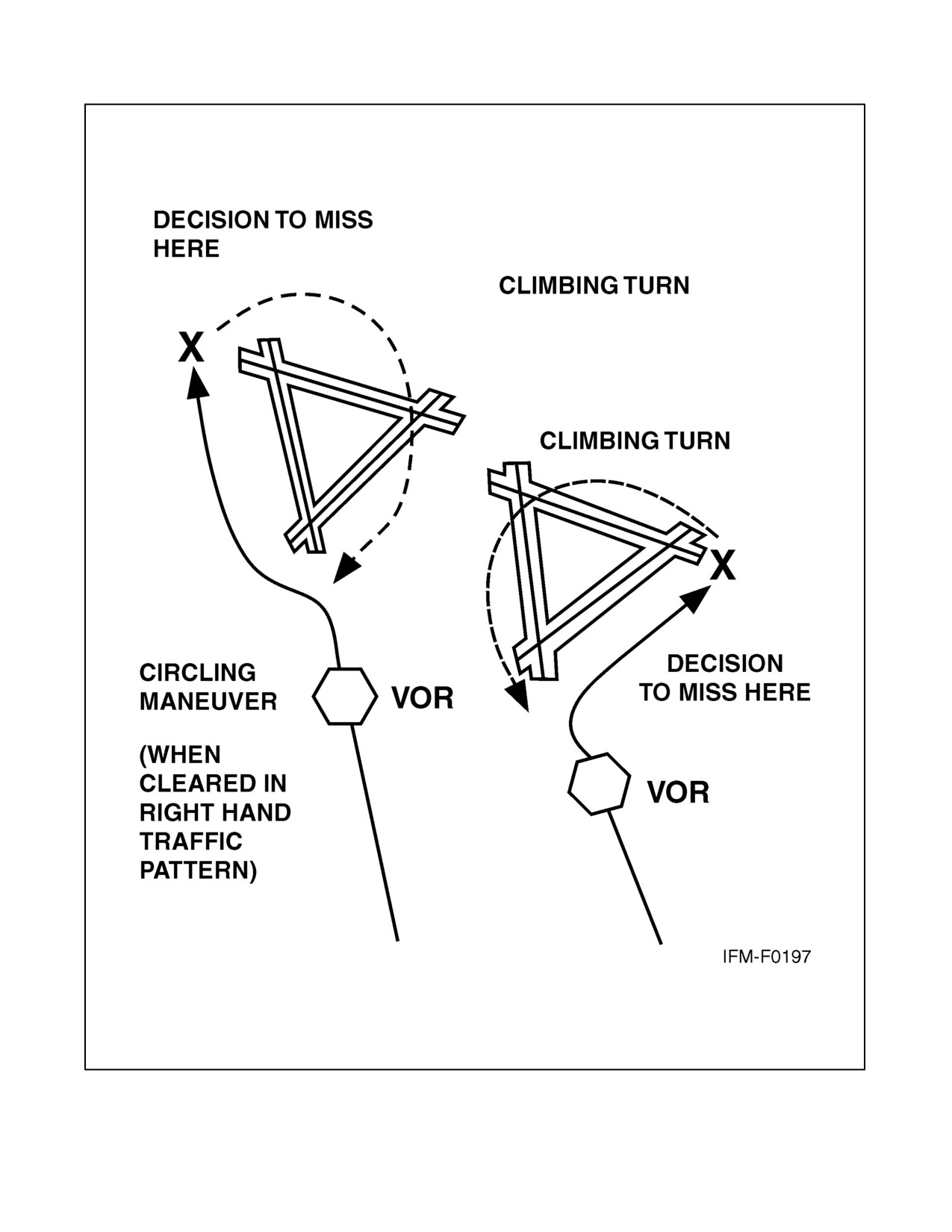
become established on the prescribed missed approach course, the pilot should make an initial climbing turn toward
the landing runway and continue the turn until established on the missed approach course. Inasmuch as the circling
maneuver may be accomplished in more than one direction, different patterns will be required to become established
on the prescribed missed approach course, depending on the aircraft position at the time visual reference is lost.
Adherence to the procedure will ensure an aircraft will remain within the circling and missed approach obstruction
clearance areas (Figure 30-20).
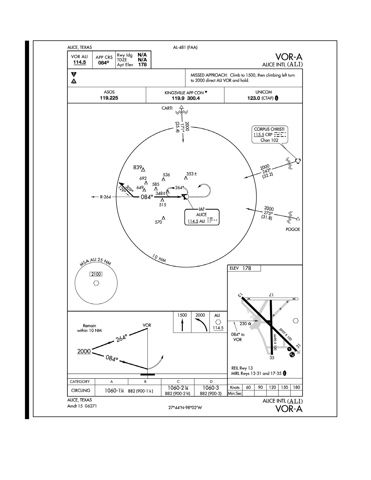
At locations where ATC radar service is provided, the pilot should conform to radar vectors when provided by ATC
in lieu of the published missed approach procedure (Figure 30-21).
When approach has been missed, request clearance for specific action (e.g., to alternative airport, another approach,
etc.).
30.19 VISUAL APPROACH
A visual approach is conducted on an IFR flight plan and authorizes a pilot to proceed visually and clear of clouds
to the airport. The pilot must have either the airport or the preceding identified aircraft in sight. This approach must
be authorized and controlled by the appropriate air traffic control facility. Reported weather at the airport must have
a ceiling at or above 1,000 feet and visibility 3 miles or greater. ATC may authorize this type approach when it will
be operationally beneficial. Visual approaches are an IFR procedure conducted under IFR in Visual Meteorological
Conditions (VMC). Cloud clearance requirements of 14 CFR Section 91.155 are not applicable, unless required by
operation specifications.
30.19.1 Operating to an Airport Without Weather Reporting Service
ATC will advise the pilot when weather information is not available at the destination airport. ATC may initiate a
visual approach, provided there is a reasonable assurance that weather at the airport is a ceiling at or above 1,000 feet
and visibility 3 miles or greater (e.g., area weather reports, Pilot Reports [PIREPs], etc.).
ORIGINAL
30-42
NAVAIR 00-80T-112
Figure 30-20. Circling and Missed Approach Obstruction Clearance Areas
30-43
ORIGINAL
NAVAIR 00-80T-112
Figure 30-21. Missed Approach
ORIGINAL
30-44
NAVAIR 00-80T-112
30.19.2 Operating to an Airport With an Operating Control Tower
Aircraft may be authorized to conduct a visual approach to one runway while other aircraft are conducting IFR or
VFR approaches to another parallel, intersecting, or converging runway. When operating to airports with parallel
runways separated by less than 2,500 feet, the succeeding aircraft must report sighting the preceding aircraft unless
standard separation is being provided by ATC. When operating to parallel runways separated by at least 2,500 feet
but less than 4,300 feet, controllers will clear/vector aircraft to the final at an angle not greater than 30 degrees unless
radar, vertical, or visual separation is provided during the turn-on. The purpose of the 30-degree intercept angle is
to reduce the potential for overshoots of the final and to preclude side-by-side operations with one or both aircraft
in a belly-up configuration during the turn-on. Once the aircraft are established within 30 degrees of final, or on the
final, these operations may be conducted simultaneously. When the parallel runways are separated by 4,300 feet or
more, or intersecting/converging runways are in use, ATC may authorize a visual approach after advising all aircraft
involved that other aircraft are conducting operations to the other runway. This may be accomplished through use
of the ATIS.
30.19.3 Separation Responsibilities
If the pilot has the airport in sight but cannot see the aircraft to be followed, ATC may clear the aircraft for a visual
approach; however, ATC retains both separation and wake vortex separation responsibility. When visually following
a preceding aircraft, acceptance of the visual approach clearance constitutes acceptance of pilot responsibility for
maintaining a safe approach interval and adequate wake turbulence separation.
A visual approach is not an IAP and therefore has no missed approach segment. If a go-around is necessary for any
reason, aircraft operating at controlled airports will be issued an appropriate advisory/clearance/instruction by the
tower. At uncontrolled airports, aircraft are expected to remain clear of clouds and complete a landing as soon as
possible. If a landing cannot be accomplished, the aircraft is expected to remain clear of clouds and contact ATC as
soon as possible for further clearance. Separation from other IFR aircraft will be maintained under these
circumstances.
Visual approaches reduce pilot/controller workload and expedite traffic by shortening flightpaths to the airport. It is
the pilot’s responsibility to advise ATC as soon as possible if a visual approach is not desired.
Authorization to conduct a visual approach is an IFR authorization and does not alter IFR flight plan cancellation
responsibility.
Radar service is automatically terminated, without advising the pilot, when the aircraft is instructed to change to
advisory frequency.
30.20 CHARTED VISUAL FLIGHT PROCEDURE (CVFP)
CVFPs are charted visual approaches established for environmental/noise considerations and/or when necessary for
the safety and efficiency of air traffic operations. The approach charts depict prominent landmarks, courses, and
recommended altitudes to specific runways. CVFPs are designed to be used primarily for turbojet aircraft.
These procedures will be used only at airports with an operating control tower.
Most approach charts will depict some NAVAID information, which is for supplemental navigational guidance only.
Unless indicating a Class B airspace floor, all depicted altitudes are for noise abatement purposes and are
recommended only. Pilots are not prohibited from flying other-than-recommended altitudes if operational
requirements dictate.
When landmarks used for navigation are not visible at night, the approach will be annotated “PROCEDURE NOT
AUTHORIZED AT NIGHT.”
30-45
ORIGINAL
NAVAIR 00-80T-112
CVFPs usually begin within 20 flying miles from the airport.
Published weather minimums for CVFPs are based on minimum vectoring altitudes rather than the recommended
altitudes depicted on charts.
CVFPs are not instrument approaches and do not have missed approach segments.
ATC will not issue clearances for CVFPs when the weather is less than the published minimum.
ATC will clear aircraft for a CVFP after the pilot reports siting a charted landmark or a preceding aircraft. If instructed
to follow a preceding aircraft, pilots are responsible for maintaining a safe approach interval and wake turbulence
separation.
Pilots should advise ATC if at any point they are unable to continue an approach or lose sight of a preceding aircraft.
Missed approaches will be handled as a go-around.
30.21 CONTACT APPROACH
Pilots operating in accordance with an IFR flight plan, provided they are clear of clouds and have at least 1 mile flight
visibility and can reasonably expect to continue to the destination airport in those conditions, may request ATC
authorization for a contact approach.
Controllers may authorize a contact approach provided:
1. The contact approach is specifically requested by the pilot. ATC cannot initiate this approach.
2. The reported ground visibility at the destination airport is at least 1 statute mile.
3. The contact approach will be made to an airport having a standard or special instrument approach procedure.
4. Approved separation is applied between aircraft so cleared and between these aircraft and other IFR or special
VFR aircraft.
A contact approach is an approach procedure that may be used by a pilot (with prior authorization from ATC) in lieu
of conducting a standard or special IAP to an airport. It is not intended for use by a pilot on an IFR flight clearance
to operate to an airport not having a published and functioning IAP, nor is it intended for an aircraft to conduct an
instrument approach to one airport and then, when “in the clear,” discontinue that approach and proceed to another
airport. In the execution of a contact approach, the pilot assumes the responsibility for obstruction clearance. If radar
service is being received, it will automatically terminate when the pilot is instructed to change to advisory frequency.
30.22 LANDING PRIORITY
A clearance for a specific type of approach (ILS, MLS, ADF, VOR, or straight in) to an aircraft operating on an IFR
flight plan does not mean that landing priority will be given over other traffic. Airport Traffic Control Towers (ATCTs)
handle all aircraft, regardless of the type of flight plan, on a first-come, first-served basis; therefore, because of local
traffic or runway in use, it may be necessary for the controller, in the interest of safety, to provide a different landing
sequence. In any case, a landing sequence will be issued to each aircraft as soon as possible to enable the pilot to
properly adjust the aircraft flightpath.
30.23 OVERHEAD APPROACH MANEUVER
Pilots operating in accordance with an IFR flight plan in VMC may request ATC authorization for an overhead
maneuver. An overhead maneuver is not an instrument approach procedure. Overhead maneuver patterns are
ORIGINAL
30-46
NAVAIR 00-80T-112
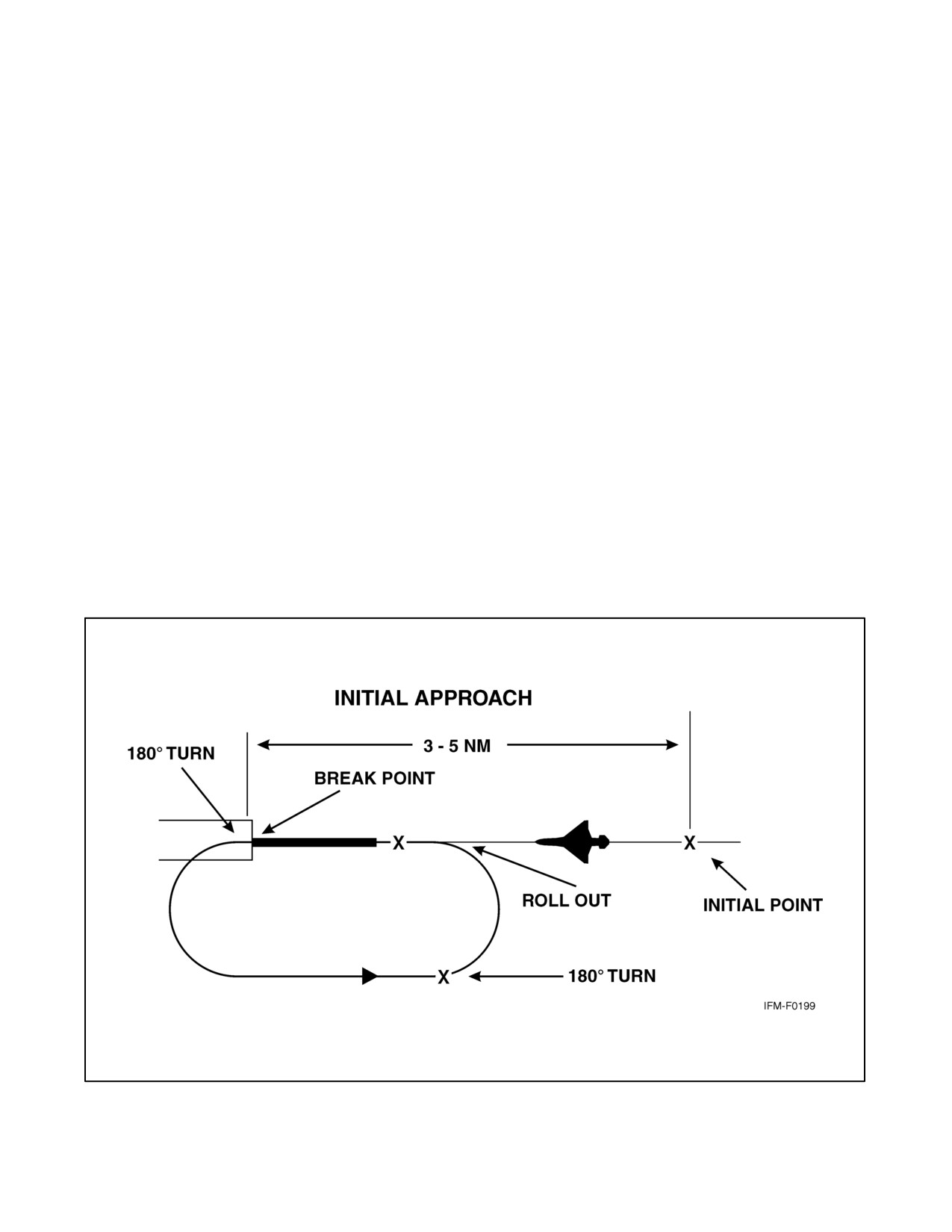
developed at airports where aircraft have an operational need to conduct the maneuver. An aircraft conducting an
overhead maneuver is considered to be VFR and the IFR flight plan is canceled when the aircraft reaches the initial
point on the initial approach portion of the maneuver (Figure 30-22). The existence of a standard overhead maneuver
pattern does not eliminate the possible requirement for an aircraft to conform to conventional rectangular patterns
if an overhead maneuver cannot be approved. Aircraft operating to an airport without a functioning control tower must
initiate cancellation of an IFR flight plan prior to executing the overhead maneuver. Cancellation of the IFR flight
plan must be accomplished after crossing the landing threshold on the initial portion of the maneuver or after landing.
Controllers may authorize an overhead maneuver and issue the following to arriving aircraft:
1. Pattern altitude and direction of traffic. This information may be omitted if either is standard.
2. Request for a report on initial approach.
3. Break information and a request for the pilot to report. The break point will be specified if nonstandard. Pilots
may be requested to report break if required for traffic or other reasons.
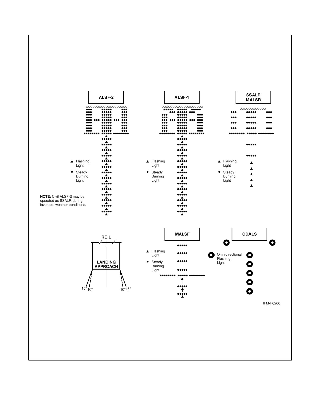
30.24 APPROACH LIGHT SYSTEM (ALS)
The ALS provides the basic means to transition from instrument flight to visual flight for landing. Operational
requirements dictate the sophistication and configuration of the approach light system for a particular runway.
The ALS is a configuration of signal lights starting at the landing threshold and extending into the approach area a
distance of 2,400 to 3,000 feet for precision instrument runways and 1,400 to 1,500 feet for nonprecision instrument
runways. Some systems include sequenced flashing lights, which appear to the pilot as a ball of light traveling toward
the runway at high speed (twice a second) (Figure 30-23).
Figure 30-22. Overhead Maneuver
30-47
ORIGINAL
NAVAIR 00-80T-112
Figure 30-23. Precision and Nonprecision Configuration (Lighting)
ORIGINAL
30-48
NAVAIR 00-80T-112
30.25 VISUAL GLIDESLOPE INDICATORS
30.25.1 Visual Approach Slope Indicator (VASI)
The Visual Approach Slope Indicator (VASI) is a system of lights so arranged to provide visual descent guidance
information during the approach to a runway. These lights are visible from 3 to 5 miles during the day and up to 20
miles or more at night. The visual glidepath of the VASI provides safe obstruction clearance within ±10 degrees of
the extended runway centerline and to 4 nm from the runway threshold. Descent, using the VASI, should not be
initiated until the aircraft is visually aligned with the runway. Lateral course guidance is provided by the runway or
runway lights.
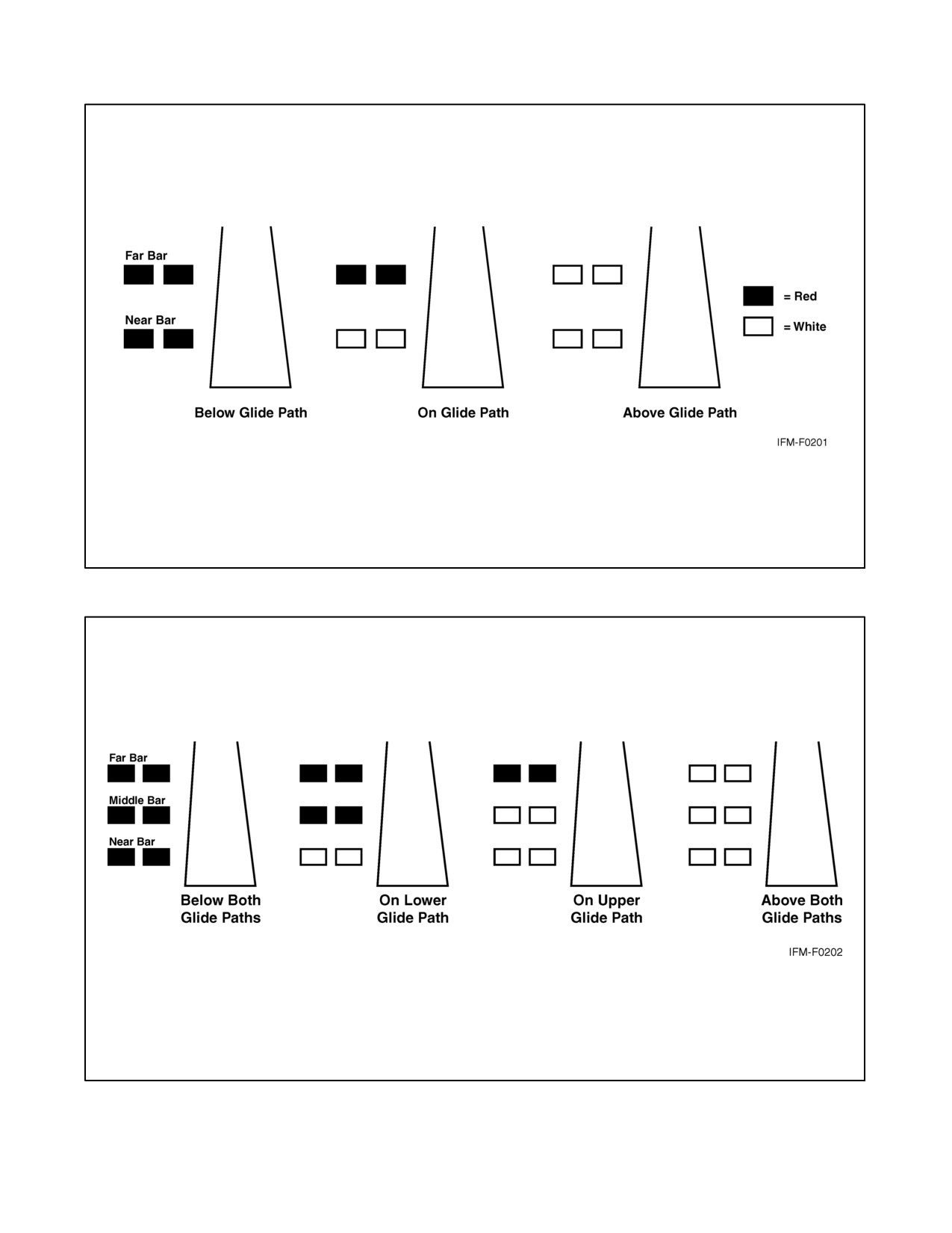
VASI installations may consist of 2, 4, 6, 12, or 16 light units arranged in bars referred to as near, middle, and far bars.
Most VASI installations consist of 2 bars, near and far, and may consist of 2, 4, or 12 light units. Some VASIs consist
of three bars (near, middle, and far), which provide an additional visual glidepath to accommodate high-cockpit
aircraft. This installation may consist of either 6 or 16 light units. VASI installations consisting of 2, 4, or 6 light units
are located on one side of the runway, usually the left. Where the installation consists of 12 or 16 light units, the units
are located on both sides of the runway.
Two-bar VASI installations provide one visual glidepath, which is normally set at 3 degrees. Three-bar VASI
installations provide two visual glidepaths. The lower glidepath is provided by the near and middle bars and is
normally set at 3 degrees whereas the upper glidepath, provided by the middle and far bars, is normally 1/4 degree
higher. This higher glidepath is intended for use only by high-cockpit aircraft to provide a sufficient threshold crossing
height. Although normal glidepath angles are 3 degrees, angles at some locations may be as high as 4.5 degrees to
give proper obstacle clearance. Pilots of high-performance aircraft are cautioned that use of VASI angles in excess
of 3.5 degrees may cause an increase in runway length required for landing and rollout.
The basic principle of the VASI is that of color differentiation between red and white. Each light unit projects a beam
of light having a white segment in the upper part of the beam and red segment in the lower part of the beam. The light
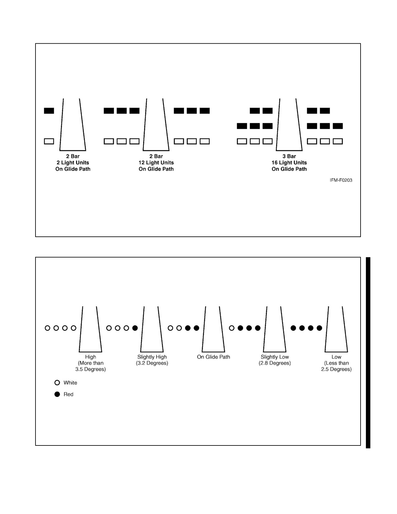
units are arranged so that the pilot using the VASIs during an approach will see the combination of lights shown below.
For 28-bar VASI (4 light units), Figure 30-24.
For 3-bar VASI (6 light units), Figure 30-25.
For other VASI configurations, Figure 30-26.
30.25.2 Precision Approach Path Indicator (PAPI)
The PAPI uses light units similar to the VASI but are installed in a single row of either two or four light units. These
systems have an effective visual range of approximately 5 miles during the day and up to 20 miles at night. The row
of light units is normally installed on the left side of the runway and the glidepath indications are as depicted
(Figure 30-27).
30.25.3 Tricolor Systems
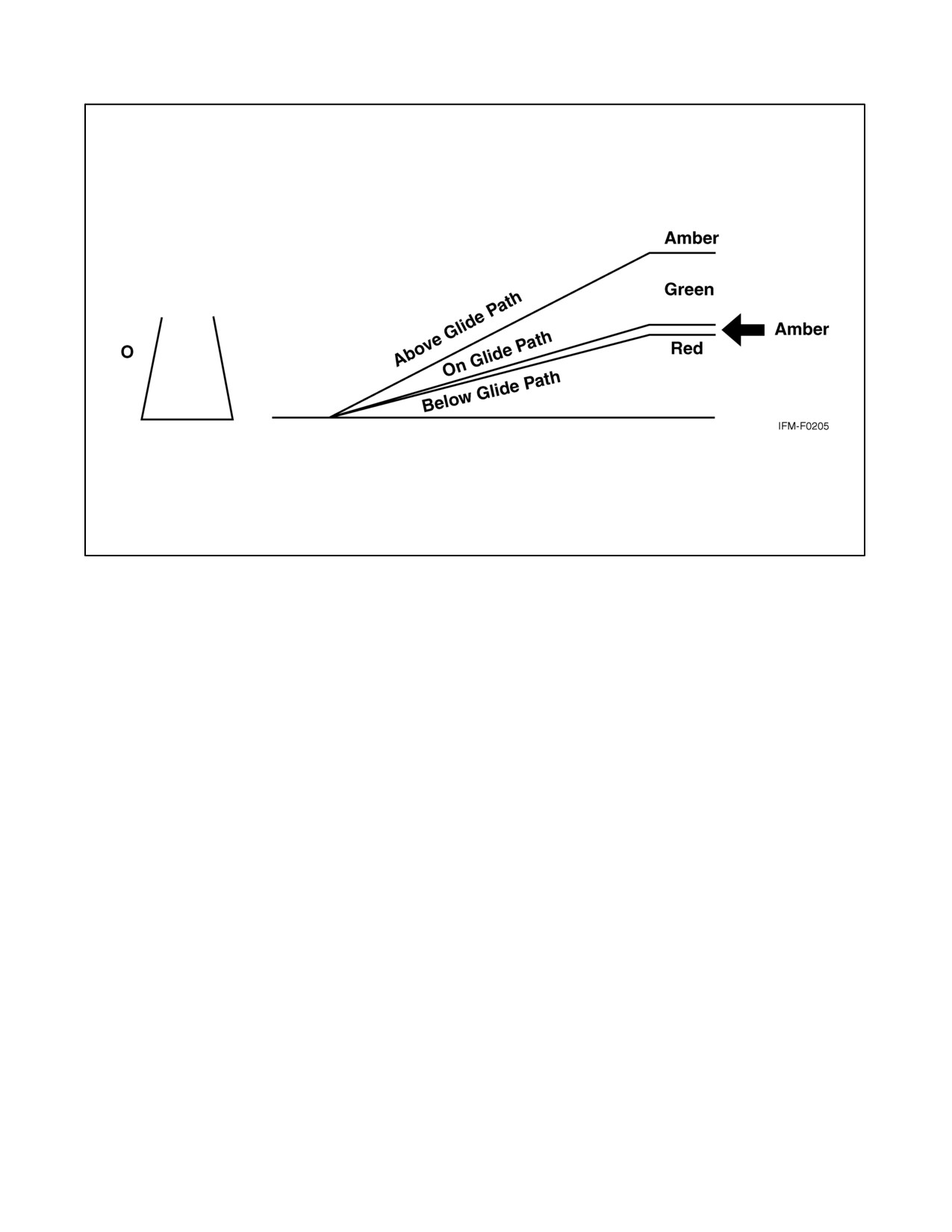
Tricolor visual approach slope indicators normally consist of a single light unit projecting a three-color visual
approach path into the final approach area of the runway upon which the indicator is installed. The below-glidepath
indication is red, the above-glidepath indication is amber, and the on-glidepath indication is green. These types of
indicators have a useful range of approximately one-half to 1 mile during the day and up to 5 miles at night depending
upon the visibility conditions (Figure 30-28).
30-49
ORIGINAL
NAVAIR 00-80T-112
Figure 30-24. 28-Bar VASI
Figure 30-25. 3-Bar VASI
ORIGINAL
30-50
NAVAIR 00-80T-112
Figure 30-26. VASI Variations
(3.0 Degrees)
Figure 30-27. Precision Approach Path Indicator (PAPI)
30-51
ORIGINAL
NAVAIR 00-80T-112
Figure 30-28. Tricolor Visual Approach Slope Indicator
Note
D Since the tricolor VASI consists of a single light source that could possibly
be confused with other light sources, pilots should exercise care to properly
locate and identify the light signal.
D When the aircraft descends from green to red, the pilot may see a dark
amber color during the transition from green to red.
30.25.4 Pulsating Systems
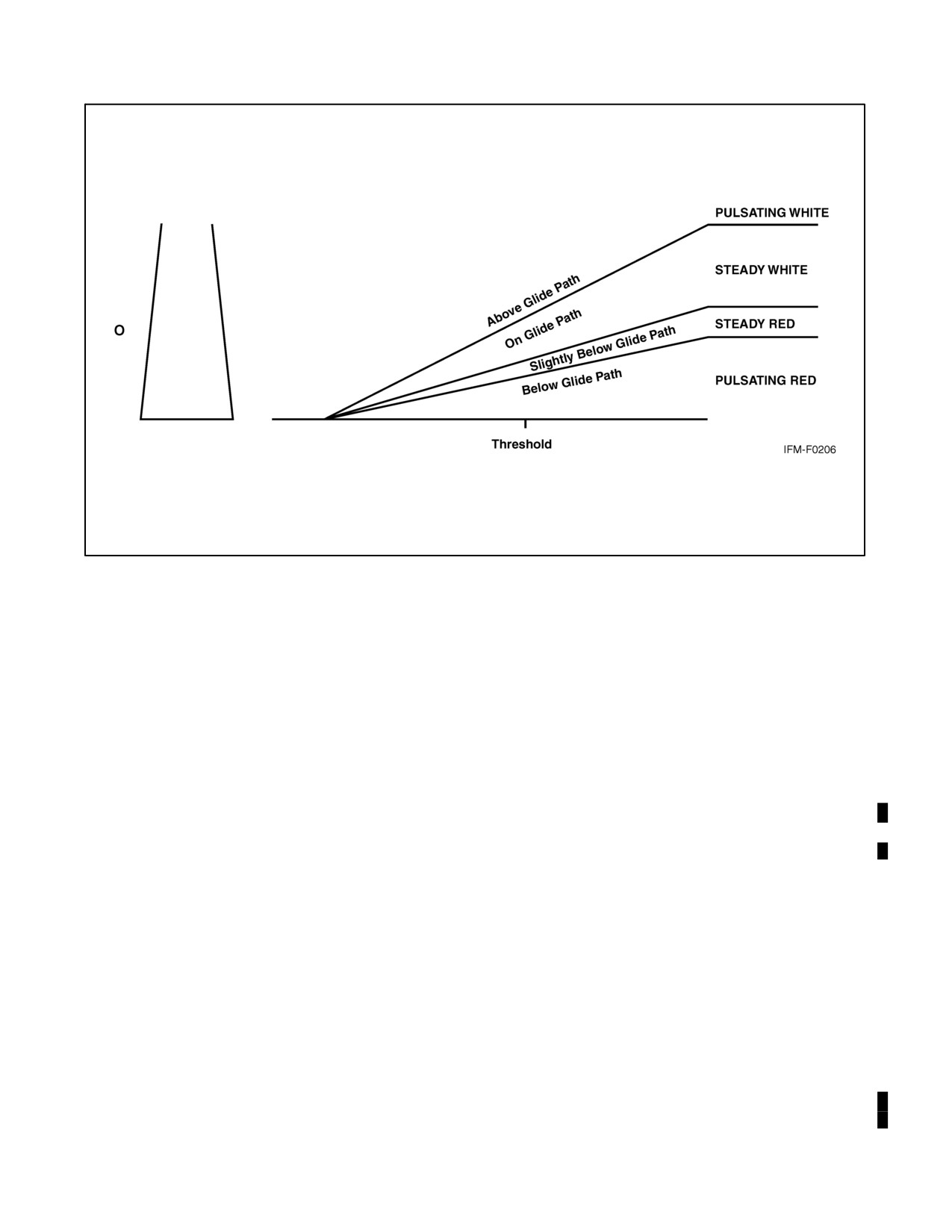
Pulsating visual approach slope indicators normally consist of a single light unit projecting a two-color visual
approach path into the final approach area of the runway upon which the indicator is installed. The on-glidepath
indication is a steady white light. The slightly-below-glidepath indication is a steady red light. If the aircraft descends
further below the glidepath, the red light starts to pulsate. The above-glidepath indication is a pulsating white light.
The pulsating rate increases as the aircraft gets farther above or below the desired glideslope. The useful range of the
system is approximately 4 miles during the day and up to 10 miles at night (Figure 30-29).
Note
Since the PVASI consists of a single light source that could possibly be
confused with other light sources, pilots should exercise care to properly
locate and identify the light signal.
ORIGINAL
30-52
NAVAIR 00-80T-112
Figure 30-29. Pulsating Visual Approach Slope Indicator
30.25.5 Alignment of Elements Systems
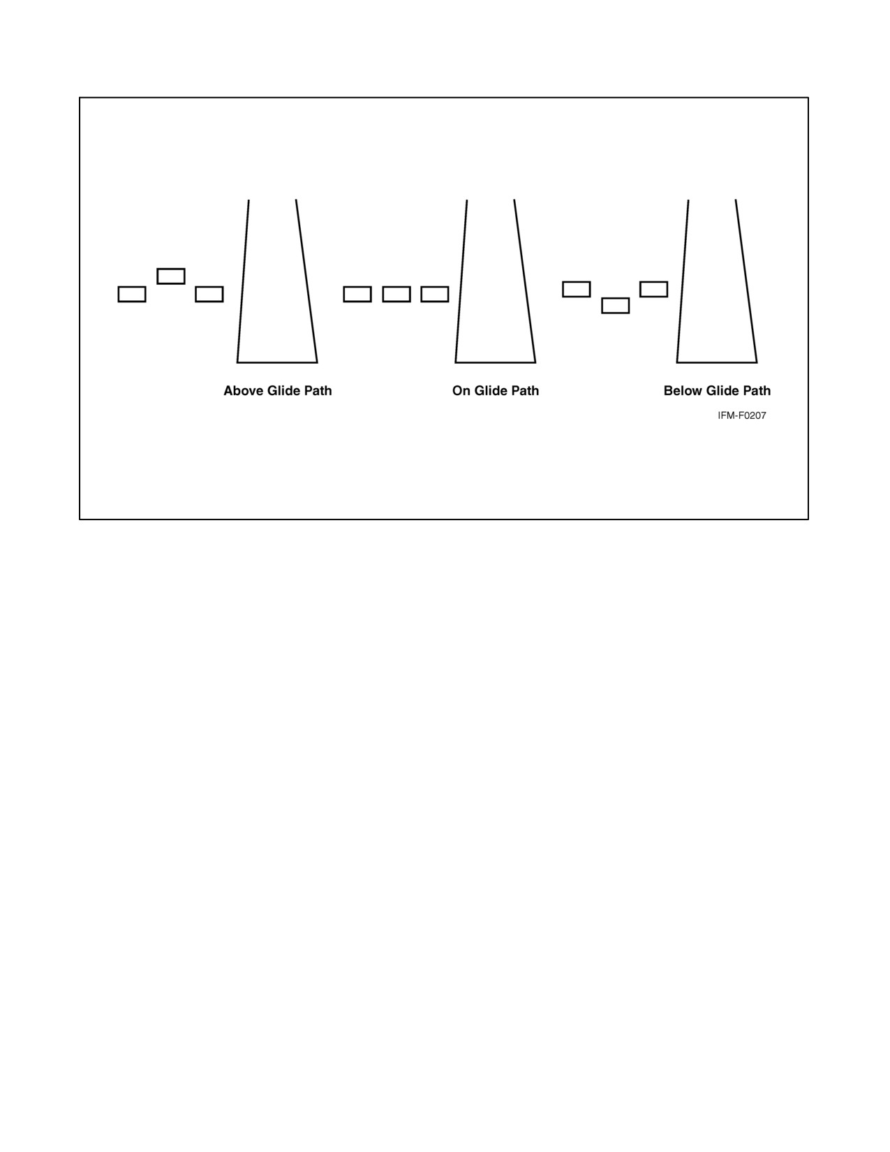
Alignment of elements systems are installed on some small general aviation airports and are a low-cost system
consisting of painted plywood panels, normally black and white or fluorescent orange. Some of these systems are
lighted for night use. The useful range of these systems is approximately three-quarters of a mile. To use the system,
the pilot positions the aircraft so the elements are in alignment. The glidepath indications are shown in Figure 30-30.
30.26 RUNWAY END IDENTIFIER LIGHTS (REIL)
REILs are installed at many airfields to provide rapid and positive identification of the approach end of a particular
runway. The system consists of a pair of synchronized flashing lights located laterally on each side of the runway
threshold. REILs may be either omnidirectional or unidirectional facing the approach area. They are effective for:
1. Identification of a runway surrounded by a preponderance of other lighting.
2. Identification of a runway that lacks contrast with surrounding terrain.
3. Identification of a runway during reduced visibility.
30.27 RUNWAY EDGE LIGHT SYSTEMS
Runway edge lights are used to outline the edges of runways during periods of darkness or restricted visibility
conditions. These light systems are classified according to the intensity or brightness they are capable of producing:
they are the High Intensity Runway Lighting (HIRL), Medium Intensity Runway Lighting (MIRL), and the Low
Intensity Runway Lighting (LIRL). The HIRL and MIRL systems have variable intensity controls, whereas the LIRLs
normally have one intensity setting.
30-53
ORIGINAL
NAVAIR 00-80T-112
Figure 30-30. Alignment of Elements
The runway edge lights are white, except on instrument runways, where yellow replaces white on the last 2,000 feet
or half the runway length, whichever is less, to form a caution zone for landings.
The lights marking the ends of the runway emit red light toward the runway to indicate the end of runway to a departing
aircraft and emit green outward from the runway end to indicate the threshold to landing aircraft.
30.28 IN-RUNWAY LIGHTING
30.28.1 Runway Centerline Lighting System (RCLS)
Runway centerline lights are installed on some precision approach runways to facilitate landing under adverse
visibility conditions. They are located along the runway centerline and are spaced at 50-foot intervals. When viewed
from the landing threshold, the runway centerline lights are white until the last 3,000 feet of the runway. The white
lights begin to alternate with red for the next 2,000 feet, and for the last 1,000 feet of the runway, all centerline lights
are red.
30.28.2 Touchdown Zone Lights (TDZL)
Touchdown zone lights are installed on some precision approach runways to indicate the touchdown zone when
landing under adverse visibility conditions. They consist of two rows of transverse light bars disposed symmetrically
about the runway centerline. The system consists of steady-burning white lights that start 100 feet beyond the landing
threshold and extend to 3,000 feet beyond the landing threshold or to the midpoint of the runway, whichever is less.
30.28.3 Taxiway Lead-Off Lights
Taxiway lead-off lights extend from the runway centerline to a point on an exit taxiway to expedite movement of
aircraft from the runway. These lights alternate green and yellow from the runway centerline to the runway holding
position or the ILS/MLS critical area, as appropriate.
ORIGINAL
30-54
NAVAIR 00-80T-112
30.28.4 Land and Hold Short Lights
Land and hold short lights are used to indicate the hold short point on certain runways that are approved for Land and
Hold Short Operations (LAHSO). Land and hold short lights consist of a row of pulsing white lights installed across
the runway at the hold short point. Where installed, the lights will be on anytime LAHSO is in effect. These lights
will be off when LAHSO is not in effect. Reference Aeronautical Information Manual (AIM), Pilot Responsibilities
When Conducting Land and Hold Short Operations (LAHSO).
30.29 CONTROL OF LIGHTING SYSTEMS
Operation of approach light systems and runway lighting is controlled by the control tower (ATCT). At some
locations, the FSS may control the lights where there is no control tower in operation.
Pilots may request that lights be turned on or off. Runway edge lights, in-pavement lights, and approach lights also
have intensity controls that may be varied to meet the pilot’s request. Sequenced Flashing Lights (SFL) may be turned
on and off. Some sequenced flashing light systems also have intensity control.
30.30 PILOT CONTROL OF AIRPORT LIGHTING
Radio control of lighting is available at selected airports to provide airborne control of lights by keying the aircraft
microphone. Control of lighting systems is often available at locations without specified hours for lighting and where
there is no control tower or FSS or when the tower or FSS is closed (locations with a part-time tower or FSS) or
specified hours. All lighting systems that are radio controlled at an airport, whether on a single runway or multiple
runways, operate on the same radio frequency (Figures 30-31 and 30-32).
Intensity Step Selected Per No. of Mike Clicks
No. of Int.
Status During
Lighting System
Steps
Nonuse Period
3 Clicks
5 Clicks
7 Clicks
Approach Lights
2
Off
Low
Low
High
(Med. Int.)
Approach Lights
3
Off
Low
Med
High
(Med. Int.)
MIRL
3
Off or Low
•
•
•
HIRL
5
Off or Low
•
•
•
VASI
2
Off
*
NOTES:
• Predetermined intensity step.
* Low intensity for night use. High intensity for day use as determined by photocell control.
Figure 30-31. Runways with Approach Lights
30-55
ORIGINAL
NAVAIR 00-80T-112
Intensity Step Selected Per No. of Mike Clicks
No. of Int.
Status During
Lighting System
Steps
Nonuse Period
3 Clicks
5 Clicks
7 Clicks
MIRL
3
Off or Low
Low
Med.
High
HIRL
5
Off or Low
Step1 or 2
Step 3
Step 5
LIRL
1
Off
On
On
On
VASIL*
2
Off
•
•
•
REIL*
1
Off
Off
On/Off
On
REIL*
3
Off
Low
Med.
High
NOTES:
• Low intensity for night use. High intensity for day use as determined by photocell control.
* The control of VASIL and/or REIL may be independent of other lighting systems.
Figure 30-32. Runways without Approach Lights
With FAA-approved systems, various combinations of medium-intensity approach lights, runway lights, taxiway
lights, VASI, and/or REIL may be activated by radio control. On runways with both approach lighting and runway
lighting (runway edge lights, taxiway lights, etc.) systems, the approach lighting system takes precedence for
air-to-ground radio control over the runway lighting system, which is set at a predetermined intensity step, based on
expected visibility conditions. Runways without approach lighting may provide radio-controlled intensity
adjustments of runway edge lights. Other lighting systems, including VASI, REIL, and taxiway lights, may either be
controlled with the runway edge lights or controlled independently of the runway edge lights.
The control system consists of a 3-step control responsive to 7, 5, and/or 3 microphone clicks. This 3-step control
will turn on lighting facilities capable of either 3-step, 28-step, or 1-step operation. The 3-step and 28-step lighting
facilities can be altered in intensity, whereas the 1-step cannot. All lighting is illuminated for a period of 15 minutes
from the most recent time of activation and may not be extinguished prior to end of the 15-minute period (except for
1-step and 28-step REILs, which may be turned off when desired by keying the mike 5 or 3 times, respectively).
Suggested use is always to key the mike 7 times initially; this ensures all controlled lights are turned on to the
maximum available intensity. If desired, adjustment can then be made, where the capability is provided, to a lower
intensity (or the REIL turned off) by keying 5 and/or 3 times. Due to the close proximity of airports using the same
frequency, radio-controlled lighting receivers may be set at a low sensitivity requiring the aircraft to be relatively close
to activate the system. Consequently, even when lights are on, always key mike as directed when overflying an airport
of intended landing or just prior to entering the final segment of an approach. This will ensure the aircraft is close
enough to activate the system and a full 15 minutes lighting duration is available. Approved lighting systems may
be activated by keying the mike (within 5 seconds) as indicated below:
Radio Control System
Key Mike
Function
7 times within 5 seconds
Highest intensity available
5 times within 5 seconds
Medium or lower intensity (Lower REIL or REIL off)
3 times within 5 seconds
Lowest intensity available (Lower REIL or REIL off)
For all public use airports with FAA standard systems, the Airport/Facility Directory contains the types of lighting,
runway, and the frequency that is used to activate the system. Airports with IAPs include data on the approach chart
identifying the light system, the runway on which they are installed, and the frequency that is used to activate the
system.
ORIGINAL
30-56
NAVAIR 00-80T-112
Note
Although the CTAF is used to activate the lights at many airports, other
frequencies may also be used. The appropriate frequency for activating the
lights on the airport is provided in the Airport/Facility Directory and the
standard instrument approach procedures publications. It is not identified
on the sectional charts.
Where the airport is not served by an IAP, it may have either the standard FAA-approved control system or an
independent type system of different specification installed by the airport sponsor. The Airport/Facility Directory
contains descriptions of pilot-controlled lighting systems for each airport having other-than-FAA-approved systems
and explains the type lights, method of control, and operating frequency in clear text.
30.31 AIRPORT/HELIPORT BEACONS
Airport and heliport beacons have a vertical light distribution to make them most effective from 1 to 10 degrees above
the horizon; however, they can be seen well above and below this peak spread. The beacon may be an omnidirectional
capacitor-discharge device, or it may rotate at a constant speed, which produces the visual effect of flashes at regular
intervals. Flashes may be one or two colors alternately. The total number of flashes are:
1.
24 to 30 per minute for beacons marking airports, landmarks, and points on Federal airways.
2.
30 to 45 per minute for beacons marking heliports.
The colors and color combinations of beacons are:
1. White and green — lighted land airport.
2.
*Green alone — lighted land airport.
3. White and yellow — lighted water airport.
4.
*Yellow alone — lighted water airport.
5. Green, yellow, and white — lighted heliport.
Note
*Green alone or yellow alone is used only in connection with a
white-and-green or white-and-yellow beacon display, respectively.
Military airport beacons flash alternately white and green, but are differentiated from civil beacons by dual-peaked
(two quick) white flashes between the green flashes.
In Class B, Class C, Class D, and Class E surface areas, operation of the airport beacon during the hours of daylight
often indicates the ground visibility is less than 3 miles and/or the ceiling is less than 1,000 feet. ATC clearance in
accordance with 14 CFR Part 91 is required for landing, takeoff, and flight in the traffic pattern. Pilots should not rely
solely on the operation of the airport beacon to indicate if weather conditions are IFR or VFR. At some locations with
operating control towers, ATC personnel turn the beacon on or off when controllers are in the tower. At many airports,
the airport beacon is turned on by a photoelectric cell or time clocks and ATC personnel cannot control them. There
is no regulatory requirement for daylight operation and it is the pilot’s responsibility to comply with proper preflight
planning as required by 14 CFR Section 91.103.
30.32 TAXIWAY LIGHTS
30.32.1 Taxiway Edge Lights
Taxiway edge lights are used to outline the edges of taxiways during periods of darkness or restricted visibility
conditions. These fixtures emit blue light.
30-57
ORIGINAL
NAVAIR 00-80T-112
Note
At most major airports, these lights have variable intensity settings and may
be adjusted at pilot request or when deemed necessary by the controller.
30.32.2 Taxiway Centerline Lights
Taxiway centerline lights are used to facilitate ground traffic under low visibility conditions. They are located along
the taxiway centerline in a straight line on straight portions, on the centerline of curved portions, and along designated
taxiing paths in portions of runways, ramps, and apron areas. Taxiway centerline lights are steady burning and emit
green light.
30.32.3 Clearance Bar Lights
Clearance bar lights are installed at holding positions on taxiways in order to increase the conspicuity of the holding
position in low visibility conditions. They may also be installed to indicate the location of an intersecting taxiway
during periods of darkness. Clearance bars consist of three in-pavement steady-burning yellow lights.
30.32.4 Runway Guard Lights
Runway guard lights are installed at taxiway/runway intersections. They are primarily used to enhance the
conspicuity of taxiway/runway intersections during low visibility conditions, but may be used in all weather
conditions. Runway guard lights consist of either a pair of elevated flashing yellow lights installed on either side of
the taxiway or a row of in-pavement yellow lights installed across the entire taxiway at the runway holding position
marking.
Note
Some airports may have a row of three or five in-pavement yellow lights
installed at taxiway/runway intersections. They should not be confused
with clearance bar lights described in paragraph 30.32.3.
30.32.5 Stop Bar Lights
Stop bar lights, when installed, are used to confirm the ATC clearance to enter or cross the active runway in low
visibility conditions (below 1,200 feet runway visual range). A stop bar consists of a row of red, unidirectional,
steady-burning in-pavement lights installed across the entire taxiway at the runway holding position and elevated
steady-burning red lights on each side. A controlled stop bar is operated in conjunction with the taxiway centerline
lead-on lights, which extend from the stop bar toward the runway. Following the ATC clearance to proceed, the stop
bar is turned off and the lead-on lights are turned on. The stop bar and lead-on lights are automatically reset by a sensor
or backup timer.
CAUTION
Pilots should never cross a red illuminated stop bar, even if an ATC
clearance has been given to proceed onto or across the runway.
Note
If, after crossing a stop bar, the taxiway centerline lead-on lights
inadvertently extinguish, pilots should hold their position and contact ATC
for further instructions.
ORIGINAL
30-58
NAVAIR 00-80T-112
PART VIII
Indoctrination and Flight Evaluation
Chapter 31 — The Instrument Flight Evaluation
81/(82 blank)
ORIGINAL
NAVAIR 00-80T-112
CHAPTER 31
The Instrument Flight Evaluation
31.1
PURPOSE OF THE INSTRUMENT FLIGHT EVALUATION
Maintaining a high degree of instrument flight proficiency is basic to safe and effective flight operations and essential
for meeting unit all-weather operational commitments. The NATOPS instrument flight evaluation program was
established to assist the commanding officer in maintaining a high level of all-weather flying proficiency in his unit.
Instrument flight procedures contained in this manual represent the optimum methods for training for and performing
the various maneuvers that will be required for Instrument Flight Rules (IFR) flight. The NATOPS instrument
evaluation is intended to evaluate the pilot’s knowledge and application of these procedures and techniques during
flight operations in instrument weather conditions.
31.2
REQUIREMENTS FOR INSTRUMENT FLIGHT EVALUATIONS
Together, OPNAVINST 3710.7 and this manual contain the elements that compose the NATOPS evaluation program.
The requirements and administrative procedures for NATOPS instrument flight evaluations are contained in
OPNAVINST 3710.7 series. The conduct, content, and grading criteria for these instrument evaluations, which
compliment the information contained OPNAVINST 3710.7, are contained in this chapter. If conflicts develop
between the contents in this manual and OPNAVINST 3710.7 series, the requirements in OPNAVINST 3710.7 series
shall take precedence.
31.3
THE INSTRUMENT FLIGHT EVALUATION PROCESS
The instrument flight evaluation process requires completion of a formal TYCOM-approved ground training syllabus
(if available), a ground evaluation, and a flight evaluation.
31.3.1 Instrument Ground Training
OPNAVINST 3710.7 series requires that all pilots and Naval Flight Officers (NFOs) in DIFOPS status shall complete
a formal TYCOM-approved ground training syllabus (if one is available). In addition to the subjects normally
addressed during the instrument ground and flight evaluations and listed below, the ground training syllabus shall
include any additional ground training subjects listed in OPNAVINST 3710.7 series.
31.3.2 Instrument Ground Evaluation
Incident to the completion of instrument ground training (if utilized) and prior to the evaluation flight, pilots and
NFOs shall satisfactorily complete an approved written examination. The written examination may be open book
or closed book or both. In addition to any subjects listed for coverage during the ground training and written
examination evaluation phases in OPNAVINST 3710.7 series, the written examination shall include questions on
the following subjects:
1. Pertinent Navy regulations, orders, and instructions.
2. Pertinent parts of the Federal aviation regulations, other regulations, and/or aeronautical publications that are
applicable.
3. Interpretation of weather information normally used in flight planning.
31-1
ORIGINAL
NAVAIR 00-80T-112
The written examination should emphasize air traffic control procedures that have been issued or revised during the
preceding year. The written examination shall be completed with a grade of “Qualified,” in accordance with
OPNAVINST 3710.7 series, prior to the commencement of the instrument evaluation flight.
31.3.3 Instrument Flight Evaluation
Following completion of the ground evaluation, an instrument flight evaluation shall be flown and completed with
a grade of “Qualified.” The number of flights required to complete the instrument flight evaluation should be kept
to a minimum — normally one flight. Areas to be observed and graded on an evaluation flight are outlined in the
grading criteria. The instrument flight evaluation shall consist of two parts. Part One covers basic instrument flying,
and Part Two covers the planning and conduct of a flight under actual or simulated instrument conditions in controlled
airspace. Flight evaluations may be in an aircraft or an approved flight simulator. Instrument flight checks under
actual instrument conditions are encouraged.
31.3.3.1
Basic Instrument Flying (Part One)
Part One of the instrument flight evaluation shall consist of:
1. Instrument takeoff (optional).
*2. Climbing, descending, and timed turns.
*3. Steep turns.
*4. Recovery from unusual attitudes.
5. Positioning aircraft on predetermined VHF Omnidirectional Range (VOR)/Tactical Air Navigation (TACAN)
radial.
*6. Partial panel airwork.
7. ADF orientation.
a. ADF/Manual Direction Finder (MDF) for pilots operating in areas where radio beacons are the primary or
secondary means of instrument navigation.
b. Ultrahigh Frequency (UHF)/ADF for jet aircraft.
Note
Asterisked items above are not required when the evaluation is conducted
under actual instrument conditions.
31.3.3.2
Instrument Flight in Controlled Airspace (Part Two)
Part Two of the instrument evaluation shall consist of:
1. Airways flight — The pilot shall be required to take off and proceed to a destination in accordance with an
Air Traffic Control (ATC) clearance and execute an appropriate published instrument approach, utilizing the
available and pertinent navigation facilities. If weather and other conditions permit, the pilot shall be required
to execute approaches (including ILS/radar or GPS) and missed approaches as applicable, utilizing as many
of the existing navigation aids as practicable. The use of VOR/TACAN shall be emphasized when feasible.
2. The pilot shall demonstrate a thorough working knowledge of the operation and use of all installed
communications and navigation equipment.
ORIGINAL
31-2
NAVAIR 00-80T-112
3. The pilot shall demonstrate ability to cope with any emergency situation that might logically be expected to
occur on an instrument flight, for example:
a. Engine failure.
b. Instrument failure.
c. Communications failure.
d. Navigation equipment failure.
31.4
FLIGHT EVALUATION GRADING CRITERIA
The criteria for determining area adjective grades are outlined in the following paragraphs.
31.4.1 Basic Instrument Flying (Part One) Grading Criteria
31.4.1.1
Instrument Takeoff
31.4.1.1.1
Qualified
Receives and acknowledges ATC clearances. Executes engine runup and instrument checks. Brake release is smooth
and good directional control is maintained. Liftoff is accomplished as required to a positive climbing attitude and
acceleration to climb schedule is expeditiously and safely accomplished.
31.4.1.1.2
Unqualified
Does not receive and acknowledge takeoff clearance, causing unnecessary delay or traffic disruption. Exhibits poor
or unsafe technique in directional control, liftoff, transition, climb attitude, or in establishing climb schedule.
31.4.1.2
Climbing, Descending, and Timed Turns
31.4.1.2.1
Qualified
Smoothly transitions to an angle of bank that approximates that required for the desired rate of turn. Adjusts angle
of bank as required to maintain desired rate of turn. Maintains relatively constant turn throughout maneuver.
31.4.1.2.2
Unqualified
Transition to angle of bank indicates a lack of knowledge of procedure and technique or results in an unsafe maneuver.
Exhibits poor or unsafe technique in attaining desired rate of turn. Does not maintain a relatively constant turn
throughout maneuver.
31.4.1.3
Steep Turns
31.4.1.3.1
Qualified
Maintains positive control and applies proper correction to keep within safe limits of altitude and airspeed.
31.4.1.3.2
Unqualified
Exhibits poor or unsafe control. Allows altitude and airspeed to exceed safe limits.
31-3
ORIGINAL
NAVAIR 00-80T-112
31.4.1.4
Recovery from Unusual Attitudes
31.4.1.4.1
Qualified
Demonstrates proper procedure for recovery from unusual attitudes.
31.4.1.4.2
Unqualified
Not familiar with proper procedures for recovery from unusual attitudes.
31.4.1.5
VOR/TACAN Positioning
31.4.1.5.1
Qualified
Demonstrates proper procedures for positioning aircraft on predetermined VOR/TACAN radial.
31.4.1.5.2
Unqualified
Not familiar with proper procedures for positioning aircraft on predetermined VOR/TACAN radial.
31.4.1.6
Partial Panel Airwork
31.4.1.6.1
Qualified
Maintains control and applies proper corrections to keep within safe limits of altitude, airspeed, attitude, and heading.
31.4.1.6.2
Unqualified
Exhibits poor or unsafe control. Exceeds safe limits of altitude, airspeed, attitude, or heading.
31.4.1.7
ADF/MDF Orientation
31.4.1.7.1
Qualified
Demonstrates proper procedures for aural null/ADF orientation.
31.4.1.7.2
Unqualified
Not familiar with proper procedures for aural null/ADF orientation.
31.4.2 Instrument Flight in Controlled Airspace (Part Two) Grading Criteria
31.4.2.1
Flight Planning
31.4.2.1.1
Qualified
Flight plan and clearance executed in accordance with LOCAL, Flight Information Publications (FLIP), OPNAV,
and other governing instructions. Special factors, as required by the mission or aircraft configuration, are computed
and recorded where applicable. Completes flight planning log for route without major errors. Fuel consumption is
properly computed based upon available planning factors and recorded on the flight log. Ensures that maps and charts
for route, destination, and alternate are available and are current. Weather factors, temperatures and winds aloft
information, and Notices to Airmen (NOTAMs) are used in planning the mission. Standard Instrument Departure
(SID)/IFR departure procedures and routes are obtained, if required, and takeoff/climb planned accordingly.
ORIGINAL
31-4
NAVAIR 00-80T-112
31.4.2.1.2
Unqualified
Flight planning was incomplete or resulted in discrepancies that could possibly prevent successful completion of the
mission.
31.4.2.2
Clearance Compliance
31.4.2.2.1
Qualified
Maintains heading/track, airspeed, and altitude as briefed or cleared by controlling agency. Observes good radio
discipline. Gives required reports clearly and in proper sequence.
31.4.2.2.2
Unqualified
Does not maintain heading/track, airspeed, or altitude as cleared. Little or no radio discipline. Unable to communicate
without excessive words and time. Reports incomplete, requiring repeated transmissions.
31.4.2.3
Instrument Approaches
31.4.2.3.1
Qualified
Executes approaches as published or instructed. Completes prelanding checks and executes smooth, safe aircraft
configuration transitions. Adheres to all altitude restrictions. A successful straight-in or circling approach to landing
can be made.
31.4.2.3.2
Unqualified
Deviations from procedures, restrictions, instructions, or errors in technique jeopardize flight safety.
31.4.2.4
Communication and Navigation Equipment
31.4.2.4.1
Qualified
Executes prompt, proper procedures for activating, tuning, and utilizing installed communication and navigation
equipment.
31.4.2.4.2
Unqualified
Not familiar with operation and use of installed communication and navigation equipment.
31.4.2.5
Emergency Procedures
31.4.2.5.1
Qualified
Properly analyzes the emergency situation and takes appropriate action without deviation, error, or omission.
31.4.2.5.2
Unqualified
Improperly analyzes or takes inappropriate action for emergency situations that jeopardizes the mission or flight
safety.
31.4.2.6
Voice Procedures
31.4.2.6.1
Qualified
Complies with procedures prescribed by military and Federal Aviation Administration
(FAA) regulations.
Transmissions are made and received correctly on the proper frequency in minimum time and without interruption
of other transmission. Monitored frequencies and/or facilities at appropriate time. Utilizes backup facilities without
hesitation.
31-5
ORIGINAL
NAVAIR 00-80T-112
31.4.2.6.2
Unqualified
Fails to transmit or receive mandatory reports through omission or lack of familiarity with procedures. Any violation
of military/FAA regulations. Any violation of safety.
31.4.3 Flight Evaluation Grade Determination
All areas on the instrument flight evaluation are critical. An unsatisfactory grade in any area shall result in an
unsatisfactory grade for the flight.
31.5
INSTRUMENT EVALUATION FINAL GRADE DETERMINATION
The final NATOPS instrument evaluation grade shall be the same as the grade assigned for the flight evaluation. An
evaluee who receives an “Unqualified” grade on the ground or flight evaluation shall be placed in an “Unqualified”
instrument flight status until the evaluee achieves a grade of “Qualified” on a reevaluation.
31.6
RECORDS AND REPORTS
A NATOPS Instrument Rating Request OPNAV Form 3710/2 shall be completed for each evaluation and forwarded
to the evaluee’s commanding officer. When completed, this form shall be retained in the individual’s flight training
record. In addition, an entry shall be made in the pilot’s/NFO’s flight log book under “Qualifications and
Achievements” as follows:
QUALIFICATION
Standard (or) special instrument rating.
Exp. (expiration date) DATE (Date issued).
SIGNATURE (Authenticating signature) (Unit issuing rating).
31.7
MAINTAINING ALL-WEATHER READINESS
NATOPS instrument evaluations, combined with a unit training syllabus that includes periodic flights to maintain
these skills, will help each unit prepare for and remain ready to safely and successfully meet its all-weather
commitments.
ORIGINAL
31-6
NAVAIR 00-80T-112
APPENDIX A
References
A.1
PURPOSE
As discussed in Chapter 1, this appendix lists publication series that contain additional information related to
instrument flight. These publications are listed in Figure A-1 below.
Pub Number or Author
Pub Title and Other Significant Information
AFM 11-217V1
USAF Instrument Flight Manual
BUMEDINST 6410.9
Medical Monitoring Flight Personnel in Locations
Where Flight Surgeons are not Available
FAA Order 7110.65
Air Traffic Control
MIL-DTL-85025 (AS)
Draft NATOPS Program Technical Publications and Products;
Style, Format, and Common Technical Content
NAVAIR 00-80T-105
CV NATOPS Manual
NAVAIR 00-80T-106
LHA/LHD NATOPS Manual
NAVAIR 00-80T-111
V/STOL Shipboard and Landing Signal Officer NATOPS Manual
NAVAIR 00-80T-113
NATOPS Aircraft Signals Manual
NAVAIR 00-80T-122
NATOPS Helicopter Operating Procedures For Air-Capable Ships
Manual
NAVMED FM 6410/1
Aeromedical Grounding Notice
NAVMED FM 6410/2
Aeromedical Flight Clearance Notice
OPNAVINST 3710.7
NATOPS General Flight and Operating Instructions
OPNAVINST 6110.1
Physical Readiness Standards
FAA
Aeronautical Information Manual
14 CFR Part 71
Airspace
14 CFR Part 91
General Operating and Flight Rules
Figure A-1.
Other Publications Related to Instrument Flight
A-1/(A-2 blank)
ORIGINAL
NAVAIR 00-80T-112
INDEX
Page
Page
No.
No.
A
Terminal area operations and
departure
26-10
Acceleration error
15-4
Airfoil
6-10
ACM or air-to-ground ordnance deliveries
9-2
Airmass:
Additional reports
29-4
Classification
3-1
At all times
29-4
Development
3-1
When not in radar contact
29-5
Modification
3-1
Thunderstorms
6-3
ADF:
Weather
3-2
Homing procedures
23-10
AIRMETs
27-4
Procedure(s)
23-3 , 23-7
Airport/heliport beacons
30-57
Adherence to clearance
28-5
Airspeed(s)
29-11
Adjacent channel interference
22-6
Control
18-11 , 18-16
Advance information on instrument
Indicator
15-4
approach
30-3
Airway(s):
Advection fog
6-8
And jet routes depiction on flight plan
27-6
Aileron roll
19-9
Or route course changes
29-7
Airborne equipment
24-4
Airways and route systems
29-5
Aircraft control
17-1
Area navigation (RNAV) routes
29-6
Attitude control
17-2
Radar vectors
29-6
Aircraft icing
6-9
Alignment of elements systems
30-53
Clear ice
6-9
Alternate:
Frost
6-9
Airport restrictions
26-9
Rime ice
6-9
Navigation equipment
26-9
Structural icing
6-9
RNAV procedural speed restrictions
26-9
Aircraft trim
17-9
Altimeters
16-1
Altitude:
Aircraft:
Control
18-16
Control
17-1
Data
28-2
Dual-seat
12-2
Stabilization
18-16
Engine icing
6-11
Amended clearances
28-3
Multicrewed
12-2
Angle of attack indicator
15-8
Single-seat
12-1
Application
Trim
17-9
Planning
18-1
Aircrew actions
26-10
Approach and landing minimums
30-39
Approach procedures
26-12
Circling minimums
30-40
Be prepared to use traditional
Instrument approach at a military field
30-42
NAVAIDs
26-11
Landing minimums
30-39
En route operations
26-11
Obstacle clearance
30-40
Preflight
26-10
Published approach minimums
30-40
Prior to descent
26-11
Sidestep maneuver minimums
30-40
Terminal area operations and arrival
26-11
Straight-in minimums
30-40
Index-1
ORIGINAL
NAVAIR 00-80T-112
Page
Page
No.
No.
Approach control
30-2
Direct communications, controllers
Radar approach control
30-2
and pilots
29-1
ATC:
Approach(es):
Advance information on instrument
30-3
Clearance/instruction readback
28-4
Frequency change procedures
29-1
Clearance
30-26
Attitude:
Contact
30-46
Control
17-2 , 18-16
Dual-facility
21-36
Indicator failure
18-18
Final
26-13
Interpretation
20-2
From holding
21-42
Stabilization
18-15
GPS overlay
26-9
Automatic direction finding (ADF):
GPS stand-alone
26-9
Course interceptions
23-3
High-altitude penetration and
22-18
Procedures
23-1
Holding type
21-42
Station passage
23-3
Light systems (ALS)
30-47
Tuning
23-2
Localizer
24-10
Aviation severe weather warning
Localizer (LOC) back course
24-11
bulletins (WWs)
27-2
Low-altitude
22-20
Azimuth cone of confusion
22-6
Missed
30-42
Non-DME teardrop
21-34
B
Performing the ILS
24-5
Bank control
17-2
Performing the missed
26-13
Barrel roll
19-7
Pilot operational considerations when
Basic instrument flying (part one)
flying nonprecision
30-21
grading criteria
31-3
Precision final
25-4
ADF/MDF orientation
31-4
Procedures
23-14 , 26-12
Climbing, descending, and timed turns
31-3
Radar
25-3 , 30-30
Instrument takeoff
31-3
Radar monitoring of instrument
30-33
Partial panel airwork
31-4
Simultaneous converging instrument
30-39
Recovery from unusual attitudes
31-4
Straight-in
21-36
Steep turns
31-3
Surveillance final
25-6
VOR/TACAN positioning
31-4
Vertical descent angle (VDA) on
Be prepared to use traditional NAVAIDs
26-11
nonprecision
30-21
Be wary of “heads-down”
26-11
Visual
30-42
Bearing indicators:
Arc interceptions
22-10
Bearing-distance-heading
Arctic fog
6-8
indicator (BDHI)
16-6
Area navigation (RNAV)
27-8 , 29-6 , 30-22
Horizontal situation indicator (HSI)
16-6
Instrument approach charts
30-22
Radio magnetic indicator (RMI)
16-6
Routes
29-6
Bearing-distance-heading
Area
indicator (BDHI)
16-6
RNAV in the terminal
26-8
Bearing/distance “unlock”
22-5
ARTCC communications
29-1
Before takeoff
28-9
ARTCC radio frequency outage
29-2
Blood donation
10-2
ATC frequency change procedures
29-1
BRAVO pattern
19-6
Index-2
ORIGINAL
NAVAIR 00-80T-112
Page
Page
No.
No.
C
Standby magnetic compass
15-1
Variation
15-1
Canceling IFR flight plan
27-11
Completing the intercept
21-17 , 23-7
CDI only
21-6
Concept:
Change:
Airmass classification
3-1
In flight plan
27-11
Airmass development
3-1
In proposed departure time
27-11
Airmass modification
3-1
Changeover point (COP)
29-8
Airmass weather
3-2
Characteristics:
Confidence maneuvers:
TACAN
22-5
Aileron roll
19-9
CHARLIE pattern
19-5
Barrel roll
19-7
Charts:
Half Cuban eight
19-11
Area navigation (RNAV) instrument
Immelmann
19-11
approach
30-22
Loops
19-9
Instrument approach procedure
30-4
Wingover
19-7
Check NOTAMs
26-10
Confusion of ground lights with stars
8-9
Clear ice
6-9
Constant:
Clear-air turbulence
6-7
Airspeed climbs and descents
18-12
Rate climbs and descents
18-14
Clearance
28-1
Contact approach
30-46
Bar lights
30-58
Control:
Limit
28-1
Aircraft
17-1
Prefix
28-1
Airspeed
18-16
Clearance items
28-1
Altitude
18-16
Altitude data
28-2
Approach
30-2
Clearance limit
28-1
Attitude
17-2
Departure procedure
28-1
Bank
17-2
Holding instructions
28-2
Instruments
17-4
Route of flight
28-2
Of lighting systems
30-55
Climbing:
Panel
21-2
And descending turns
18-15
Pitch
17-2
Constant rate climbs and descents
18-14
Power
18-16
Radar approach
30-2
Climbs and descent(s)
28-9
Segment
26-1
Constant airspeed climbs and descents
18-12
Yaw
17-2
Constant-rate climbs and descents
18-14
Convective:
Clock
15-8
SIGMETs
27-3
Closing VFR/DVFR flight plans
27-11
Thunderstorms
6-3
Cold fronts
4-1
Wind shear
6-12
Thunderstorms
6-4
Conventional cross-check
14-3
Communications
30-38
Convergence zones
5-2
Compasses:
Coriolis illusion
8-2
Acceleration error
15-4
Correlation:
Deviation
15-3
Under actual instrument
Magnetic dip
15-3
conditions
11-1 , 11-2 , 11-3
Oscillation error
15-4
Under instrument conditions
11-3
Index-3
ORIGINAL
NAVAIR 00-80T-112
Page
Page
No.
No.
Course indicator
16-10
Entry
21-39
ILS display
16-11
Procedures
29-12
VOR/TACAN display
16-11
Environmental factors
9-1
Course:
Equipment
21-1
Interceptions
21-4 , 23-3
Ground
22-2
Sensitivity
26-4
Radar
25-2
Crosswind correction
21-33
Equipment and operation:
Cumulus stage
6-1
Airborne equipment
24-4
Equipment
21-1
Ground equipment
24-1
D
Operation
21-2
Database:
Equipment and transmission principles:
Requirements
26-8
Ground equipment
22-2
Restrictions
26-8
TACAN approach procedures
22-18
Dental care
10-2
TACAN characteristics
22-5
Departure procedure
28-1
TACAN procedures
22-7
Descending breakouts
30-39
Erroneous TACAN indications
22-6
Descent
21-42
Establishing and maintaining airspeed
18-6
Develop a backup plan
26-11
Estimating drift correction
21-17
Deviation
15-3
Exercise
10-1
Dial calibration
15-4
Experience
11-3
Differences between ILS and ILS PRM
ACM or air-to-ground ordnance
deliveries
9-2
approaches of importance to the pilot
30-38
Takeoff and landing phases
9-1
Direct:
Communications, controllers and pilots
29-1
F
Entry procedure
29-12
Flights
27-7
Factors related to type or phase of flight:
Display:
ACM or air-to-ground ordnance
ILS
16-11
deliveries
9-2
VOR/TACAN
16-11
Formation flight
9-2
Dissipating stage
6-2
Takeoff and landing phases
9-1
Distance measuring equipment (DME)
22-3
Failure, indicator:
DME cone of confusion
22-6
Attitude
18-18
Drugs
10-1
Heading
18-17
Dual-facility approaches
21-36
False perception (general)
8-1
Dual-seat aircraft
12-2
During helicopter flights
8-10
Illusions: primarily inner ear
8-1
Visual illusions and problems
8-9
E
False:
Elevator illusion
8-6
Or incorrect lock-on
22-6
Emergency procedures
31-5
Perception of attitude
8-6
En route:
Perceptions during helicopter flights
8-10
Mode
26-5
Sensation of reversal of motion
11-2
Operations
26-11
Sensation of rotation
8-2
Index-4
ORIGINAL
NAVAIR 00-80T-112
Page
Page
No.
No.
Sensations of tilting to right or left
11-2
Flight(s):
Vertical and horizontal cues
8-9
Along a direct route
29-3
Along airways or routes
29-3
Fast-moving cold fronts
4-3
Director system (FDS)
16-12
File the appropriate equipment suffix
26-10
In a radar environment
29-4
Final:
Outside the U.S
27-10
Approach
26-13
Weather packets
27-2
Approach mode
26-7
Fog
6-7
Flicker vertigo
8-12
Advection
6-8
Flight evaluation grade determination
31-6
Arctic
6-8
Flight evaluation grading criteria
31-3
Frontal
6-8
ADF/MDF orientation
31-4
Radiation
6-7
Basic instrument flying (part one)
Follow IFR procedures even when
grading criteria
31-3
operating VFR
27-4
Clearance compliance
31-5
Formation flight(s)
9-2
Climbing, descending, and timed turns
31-3
In night or weather
12-2
Communication and navigation
40° azimuth error lock-on
22-6
equipment
31-5
Frontal movement
4-7
Emergency procedures
31-5
Effect of mountains
4-7
Modifications
4-7
Flight evaluation grade determination
31-6
Speed
4-7
Flight planning
31-4
Frontal:
Instrument approach(es)
31-5
Fog
6-8
Instrument flight in controlled airspace
Thunderstorms
6-4
(part two) grading criteria
31-4
Frost
6-9
Instrument takeoff
31-3
Functions of instruments − full panel scan
17-4
Partial panel airwork
31-4
Future improvements to GPS
26-16
Recovery from unusual attitudes
31-4
Local area augmentation system
Steep turns
31-3
(LAAS)
26-17
Voice procedures
31-5
Wide area augmentation system
VOR/TACAN positioning
31-4
(WAAS)
26-16
Flight management system (FMS)
26-2
Flight plan:
G
Composite (VFR/IFR flights)
27-5
Glideslope
24-3
Defense VFR (DVFR) flights
27-5
Global orientation
14-1
IFR flights
27-5
Global positioning system (GPS):
VFR flights
27-5
Flight management system (FMS)
26-2
Flight planning:
Introduction
26-1
Preflight preparation
27-1
Required navigation performance
Weather briefing
27-1
(RNP)
26-2
Weather briefing, support products,
RNAV leg types
26-3
and severe weather restrictions and
System overview
26-1
products
27-1
Waypoints
26-3
Index-5
ORIGINAL
NAVAIR 00-80T-112
Page
Page
No.
No.
GPS approach nomenclature:
Holding
29-8
Overlay approaches
26-9
Instructions
28-2
RNAV (GPS) approaches
26-10
Pattern located on the initial
approach course
21-42
RNAV (RNP) approaches
26-10
Type approach
21-42
Stand-alone approaches
26-9
Homing
21-17 , 23-10
GPS approach restrictions:
Horizontal situation indicator (HSI)
16-6
Multiple GPS receivers
26-9
Hover indicator
15-8
RNAV procedural speed restrictions
26-9
HUD:
Scaling and alerting
26-9
Field of view
14-3
GPS navigation training:
Limitations
14-1
Flight training
26-15
General
26-14
I
Ground instruction
26-14
Icing
6-3
GPS:
IFR:
Approach briefing
26-11
Clearance VFR-on-top
28-4
Approach restrictions
26-8
Operations to high altitude destinations
27-9
Equipment checks
26-10
Separation standards
28-7
Integrity warning after the FAF
26-13
Illness
10-2
Integrity warning prior to FAF
26-13
Illusion(s):
Is a new form of flying
26-12
Coriolis
8-2
Not in the title
26-9
Elevator
8-6
Overlay approaches
26-9
Inversion
8-6
Segments
26-1
Of attitude change (somatogravic
Stand-alone approaches
26-9
illusion)
8-4
Graveyard:
Of banking
8-10
Spin
8-2
Of deviation
8-11
Of nosedown
8-6
Spiral
8-2
Of noseup
8-4
Ground equipment
22-2 , 24-1
Of pivoting on longitudinal axis
8-11
Of vertical flight
8-12
H
Primarily inner ear
8-1
Somatogravic
8-4
Half Cuban eight
19-11
Visual illusions and problems
8-9
Hand-flown breakouts
30-39
ILS channel/frequency:
Heading indicator failure
18-17
Radar vectors
24-10
Heads-up display (HUD)
14-1
Simplified directional facility (SDF)
24-10
Conventional cross-check
14-3
ILS display
16-11
Global orientation
14-1
ILS procedures:
HUD field of view
14-3
Localizer (LOC) back course
HUD limitations
14-1
approach
24-11
Headwind or tailwind corrections
21-33
Localizer approaches
24-10
High-altitude:
Performing the ILS approach
24-5
Approach procedures
21-34
Radar vectors
24-10
Penetration and approach
22-18
Simplified directional facility (SDF)
24-10
Index-6
ORIGINAL
NAVAIR 00-80T-112
Page
Page
No.
No.
Immelmann
19-11
Visual portion of the final segment
30-21
Immunization/injections
10-2
Instrument approach procedures
30-27
In-runway lighting
30-54
Instrument evaluation final grade
determination
31-6
Land and hold short lights
30-55
Instrument flight in controlled airspace
Runway centerline lighting
(part two) grading criteria
31-4
system (RCLS)
30-54
Clearance compliance
31-5
Taxiway lead-off lights
30-54
Communication and navigation
Touchdown zone lights (TDZL)
30-54
equipment
31-5
Inbound
23-7 , 29-12
Emergency procedures
31-5
Leg
29-12
Flight planning
31-4
Procedures
21-6
Instrument approach(es)
31-5
Indications, erroneous TACAN
22-6
Voice procedures
31-5
Indicator(s):
Instrument flight physiology:
Airspeed
15-4
General
7-1
Angle of attack
15-8
Your senses
7-1
Bearing
16-6
Instrument groupings:
Bearing-distance-heading (BDHI)
16-6
Control instruments
17-4
Course
16-10
Functions of instruments − full
Failure
panel scan
17-4
Attitude
18-18
Instrument scan
17-4
Heading
18-17
Performance instruments
17-4
Horizontal situation (HSI)
16-6
Position instruments
17-4
Hover
15-8
Scan analysis
17-7
Radio magnetic (RMI)
16-6
Scan technique
17-6
Range
16-4
Use of angle of attack
17-7
Turn and slip
15-4
Instrument patterns
19-1
Vertical speed (VSI/VVI)
15-4
BRAVO
19-6
Visual glideslope
30-49
CHARLIE
19-5
Inside of 30 nm
26-12
OSCAR
19-4
Instrument approach at a military field
30-42
Steep turns
19-4
Minimum safe altitude (MSA)
30-5
Vertical S-1, S-2, S-3, S-4
19-1
Minimum vectoring altitude (MVA)
30-16
YANKEE
19-6
Terminal arrival area (TAA)
30-6
Instrument patterns and confidence
Visual descent point (VDP)
30-21
maneuvers
19-1
Visual portion of the final segment
30-21
Purpose
19-1
Instrument approach procedure charts
30-4
Instrument takeoff (ITO)
Area navigation (RNAV) instrument
Pretakeoff procedures
18-2
approach charts
30-22
Instrument:
Minimum safe altitude (MSA)
30-5
Hovering
17-10
Minimum vectoring altitude (MVA)
30-16
Scan
17-4
Terminal arrival area (TAA)
30-6
Integrated systems
26-1
Vertical descent angle (VDA) on
Integrity monitoring
26-8
nonprecision approaches
30-21
Intercepting a radial from an arc
22-10
Visual descent point (VDP)
30-21
Intertropical convergence zone
5-2
Index-7
ORIGINAL
NAVAIR 00-80T-112
Page
Page
No.
No.
Introduction to aircraft flight instruments
Localizer:
General
13-1
(LOC) back course approach
24-11
Introduction:
Approaches
24-10
General
1-1
Transmitter
24-1
Loops
19-9
Purpose
1-1
Low-altitude approach
22-20
Responsibilities
1-1
Procedures
21-36
Scope
1-1
Low-level wind shear
6-11
Training
1-2
Convective wind shear
6-12
Waivers
1-2
Nonconvective wind shear
6-12
Inversion illusion
8-6
ITO procedures (fixed wing)
18-2
M
Magnetic dip
15-3
L
Maintain(ing):
A desired altitude
18-4
Land and hold short lights
30-55
A desired heading
18-6
Landing:
All-weather readiness
31-6
Minimums
30-39
Arcs
22-10
Priority
30-46
Situational awareness
26-11
Leans, the
8-1
Manual database manipulation
26-8
Level turns
18-8
Marker beacons
23-14 , 24-3
Lightning
6-3
Mature stage
6-1
Lights:
Meeting an expected further clearance
Clearance bar
30-58
time (EFC)
21-33
Land and hold short
30-55
Meteorology for naval aviators
2-1
Runway guard
30-58
Microbursts
6-12
Stop bar
30-58
Military weather warning advisories
(MWWAs)
27-3
Taxiway
30-57
Minimum safe altitude (MSA)
30-5
Taxiway centerline
30-58
Minimum vectoring altitude (MVA)
30-16
Taxiway edge
30-57
Missed approach
30-42
Taxiway lead-off
30-54
Climb gradient
26-14
Touchdown zone
30-54
Mode
26-7
Limitations:
Point (MAP)
26-13
HUD
14-1
Mode:
Of radar
25-2
En route
26-5
On procedure turns
30-29
Final approach
26-7
Load:
Missed approach
26-7
SID
26-10
Select missed approach
26-13
STAR
26-11
Terminal approach
26-5
Local:
Motion (inner ear)
7-1
Area augmentation system (LAAS)
26-17
Mountainous terrain
6-6
Flow traffic management program
30-2
Multicrewed aircraft
12-2
Index-8
ORIGINAL
NAVAIR 00-80T-112
Page
Page
No.
No.
N
Overcoming spatial disorientation:
Dual-seat aircraft
12-2
Navigation database
26-7
Formation flights in night or weather
12-2
Night (instrument) catapult launch
18-3
General
12-1
No gyro approach (heading indicator
Multicrewed aircraft
12-2
inoperative)
25-6
Single-seat aircraft
12-1
Non-DME teardrop approach
21-34
Overhead approach maneuver
30-46
Nonconvective:
SIGMETs
27-3
P
Wind shear
6-12
Panel
Nonstandard:
Control
21-2
Holding pattern
29-14
Recovery procedures − partial
20-4
Pattern
29-11
Parallel ILS/MLS approaches
Nose-low recovery
20-4
(dependent)
30-34
Nutrition
10-1
Parallel procedure
29-12
Nystagmus
8-2
Partial panel
Unusual attitudes
20-4
O
Partial panel flight:
Attitude indicator failure
18-18
Obstacle clearance
30-40
Heading indicator failure
18-17
Occluded:
Performance instruments
17-4
And stationary fronts
6-4
Performing:
Fronts
4-5
The ILS approach
24-5
Operating to an airport:
The missed approach
26-13
With an operating control tower
30-45
The published missed approach
Without weather reporting service
30-42
procedure
26-13
Operation(s):
Missed approach point (MAP)
26-13
En route
26-11
Personal factors
9-1
Equipment and
21-1 , 24-1
Pilot responsibility upon clearance
Principle of
21-2
issuance
28-4
Training
28-10
ATC clearance/instruction readback
28-4
Optimum path aircraft routing system
Record ATC clearance
28-4
(OPARS)
27-2
Pilot:
Orographic thunderstorms
6-4
Action
29-14
OSCAR pattern
19-4
Control of airport lighting
30-55
Oscillation error
15-4
Operational considerations when flying
Otolith organs
7-4
nonprecision approaches
30-21
Outbound
29-13
Pitch control
17-2
Away from the station
23-7
Pitot-static/angle of attack (AOA) systems
6-11
Immediately after station passage
23-7
Planning
18-1
Leg
29-13
Position report(ing)
29-3
Procedures
21-16
Items
29-4
Procedures − immediately after station
Points
29-3
passage
21-6
Position identification
29-3
Outside air temperature gauge
15-8
Requirements
29-3
Index-9
ORIGINAL
NAVAIR 00-80T-112
Page
Page
No.
No.
Position:
Outbound
21-16
Identification
29-3
Parallel
29-12
Instruments
17-4
Performing the published missed
Report items
29-4
approach
26-13
Pretakeoff
18-2
Reporting points
29-3
Reporting requirements
29-3
Radar approach
25-3
Recovery
20-2
Postural (“seat of the pants”)
7-4
TACAN approach
22-18
Power control
18-16
Teardrop
29-12
Precipitation
6-3
Use of visual clearing
28-9
Precision:
Voice
25-6
Approach path indicator (PAPI)
30-49
Proceeding direct to station
21-4
Final approach
25-4
Propeller
6-10
Preflight
26-10
Published approach minimums
30-40
Pressure:
Pulsating systems
30-52
Altimeter
16-1
Purpose of the instrument flight evaluation
31-1
At fronts
4-7
Vertigo
8-4
R
Pretakeoff procedures
18-2
Prevention of spatial disorientation:
Radar:
Experience
11-3
Approach control
30-2
General
11-1
Approach procedures
25-3
Training
11-1
Approaches
25-3 , 30-30
Preventive measures
8-12
Equipment and operation
25-2
Principle(s):
Limitations
25-2
Of operation
21-2
Monitoring
30-36 , 30-37
Of radar
25-1
Monitoring of instrument approaches
30-33
Prior to descent
26-11
Traffic information service
25-1
Prior to the IAF
26-12
Vectors
24-10 , 29-6
Procedure turn(s) (PT)
21-39 , 30-28
Radiation fog
6-7
Entry
21-39
Radio magnetic indicator (RMI)
16-6
Limitations on
30-29
Radio/radar altimeters
16-4
Procedure(s):
Ramp down
26-12
ADF
23-3 , 23-7
Range indicator
16-4
ADF homing
23-10
Fluctuations
22-6
Approach
23-14 , 26-12
Receiver autonomous integrity monitoring
ATC frequency change
29-1
(RAIM)
26-7
Departure
28-1
Record(s):
Direct entry
29-12
And reports
31-6
High-altitude approach
21-34
ATC clearance
28-4
ILS
24-5
Recovery from unusual attitudes:
Inbound
21-6
Nose-high recovery
20-2
Instrument approach
30-27
Nose-low recovery
20-4
Low-altitude approach
21-36
Partial panel unusual attitudes
20-4
Index-10
ORIGINAL
NAVAIR 00-80T-112
Page
Page
No.
No.
Recovery procedures:
Heading
26-4
Nose-high recovery
20-2
Initial fix
26-3
Nose-low recovery
20-4
Radius to fix
26-4
Partial panel
20-4
Track to fix
26-3
Partial panel unusual attitudes
20-4
Rotary wing instrument flying:
Reduced vertical separation minimums
Airspeed control
18-16
(RVSM)
29-8
Altitude control
18-16
Relation of fronts to airmasses
4-1
Altitude stabilization
18-16
Cold fronts
4-1
Attitude control
18-16
Fast-moving cold fronts
4-3
Attitude stabilization
18-15
Occluded fronts
4-5
Power control
18-16
Slow-moving cold fronts
4-1
Yaw stabilization
18-16
Stationary fronts
4-5
Rotary:
Warm fronts
4-3
Wing ITO
18-3
Relation of fronts to cyclones
4-1
Wing night (instrument) shipboard
Required navigation performance (RNP)
26-2
takeoffs
18-4
RNP levels
26-2
Route of flight
28-2
Runway:
Requirements
29-3 , 30-37
Database
26-8
Centerline lighting system (RCLS)
30-54
for instrument flight evaluations
31-1
Edge light systems
30-53
Position reporting
29-3
End identifier lights (REIL)
30-53
Guard lights
30-58
Responsibilities:
Separation
28-8
Commanding officers
1-2
Spacing
30-38
NATOPS advisory group
1-1
NATOPS cognizant command
1-1
S
NATOPS model manager
1-2
Separation
30-45
Scan:
Restrictions on the use of GPS:
Analysis
17-7
Alternate airport restrictions
26-9
Technique
17-6
Database requirements
26-8
Select missed approach mode
26-13
GPS approach restrictions
26-8
Semicircular canals
7-1
Receiver autonomous integrity
Sensation of:
monitoring (RAIM)
26-7
Climbing during a turn
11-1
RNAV in the terminal area
26-8
Climbing during straight-and-level
Specific capabilities and restrictions
26-7
flight
11-2
Use of GPS outside of the U.S
26-7
Diving during recovery from a turn
11-2
Rime ice
6-9
Diving or rolling beyond the vertical
RMI:
plane
11-2
And CDI
21-6
Separation responsibilities
30-45
RMI only
21-6
Setting the pressure altimeter
16-4
RNAV in the terminal area
26-8
Severe:
RNAV leg types
26-3
Thunderstorms
6-2
Course to fix
26-4
Weather restrictions and products
27-1
Direct to fix
26-4
Shear lines
5-3
Index-11
ORIGINAL
NAVAIR 00-80T-112
Page
Page
No.
No.
Sidestep maneuver
30-39
Proceeding direct to
21-4
Minimums
30-40
Stationary fronts
4-5
Sight
7-5
Steep turns
19-4
SIGMETs
27-3
Level turns
18-8
AIRMETs
27-3
Maintaining a desired altitude
18-4
Signal accuracy
26-1
Stepdown waypoints
26-13
Simplified directional facility (SDF)
24-10
Stop bar lights
30-58
Simultaneous close parallel ILS PRM
Straight and level
28-10
approaches (independent)
30-37
Straight-and-level flight:
Differences between ILS and ILS PRM
Level turns
18-8
approaches of importance to the pilot
30-38
Maintaining a desired altitude
18-4
Radar monitoring
30-37
Straight-in:
Requirements
30-37
Approaches
21-36
System
30-37
Minimums
30-40
Simultaneous converging instrument
Structural deicing
6-10
approaches
30-39
Aircraft engine icing
6-11
Simultaneous parallel ILS/MLS approaches
Airfoil
6-10
(independent)
30-35
Pitot-static/angle of attack (AOA)
Radar monitoring
30-36
systems
6-11
System
30-35
Propeller
6-10
Single-seat aircraft
12-1
Structural icing precautions
6-11
Slip indicator (ball)
15-6
Support products
27-1
Slow-moving cold fronts
4-1
Surveillance final approach
25-6
Space segment
26-1
System overview:
Spatial misorientation
8-12
Course sensitivity
26-4
Special VFR clearances
28-3
Flight management system (FMS)
26-2
Specific capabilities and restrictions
26-7
GPS segments
26-1
Speed
18-6
Integrated systems
26-1
Adjustments
28-7
Navigation database
26-7
Establishing and maintaining air
18-6
Required navigation performance
Spin
(RNP)
26-2
Graveyard
8-2
RNAV leg types
26-3
Squall lines
6-4
Signal accuracy
26-1
Standard:
Waypoints
26-3
Pattern
29-11
System(s)
30-35 , 30-37
Terminal arrival (STAR), flight
Airways and route
29-5
management system procedures
Alignment of elements
30-53
(FMSP) for arrivals
30-1
Control of lighting
30-55
Standby magnetic compass
15-1
Integrated
26-1
Station
Pulsating
30-52
Outbound − away from the
23-7
Runway edge light
30-53
Passage
21-23 , 23-3
Tricolor
30-49
Index-12
ORIGINAL
NAVAIR 00-80T-112
Page
Page
No.
No.
T
The instrument flight evaluation process
31-1
Basic instrument flying (part one)
31-2
Tactical air navigation (TACAN):
Instrument flight evaluation
31-2
Approach procedures
22-18
Instrument flight in controlled airspace
Arcs
22-8
(part two)
31-2
Characteristics
22-5
Instrument ground evaluation
31-1
Equipment and transmission principles
22-1
Instrument ground training
31-1
The leans
8-1
Holding
22-15
30° method
21-23
Introduction
22-1
3 nm prior to the FAF
26-12
Procedures
22-7
Thunderstorm(s)
6-1
Signal pattern
22-2
Classification
6-3
Takeoff:
Development
6-1
And landing phases
9-1
Weather
6-3
Before
28-9
Time-distance check
23-7
Taxiway lights
30-57
Timed approaches from a holding fix
30-30
Centerline
30-58
Timing
29-12
Edge
30-57
Tornadoes and waterspouts
6-4
Lead-off
30-54
Touchdown zone lights (TDZL)
30-54
TCAS
30-39
Tracking
23-7
Teardrop procedure
29-12
Traffic:
Technique(s):
Alert and collision avoidance system
For determining lead
22-10
(TCAS I & II)
28-10
Of navigating point to point
22-14
At VOR sites
28-10
Scan
17-6
Pattern
28-10
Training operations
28-10
Terminal area operations and arrival
Training:
Maintain situational awareness
26-11
False sensations of reversal of motion
11-2
Terminal:
False sensations of tilting to right or left
11-2
Approach mode
26-5
Sensation of climbing during a turn
11-1
Area operations and arrival
26-11
Sensation of climbing during
Area operations and departure
26-10
straight-and-level flight
11-2
Arrival area (TAA)
30-6
Sensation of diving during recovery
Sensitivity
26-11
from a turn
11-2
The altimeter setting
16-1
Sensation of diving or rolling beyond
The instrument flight evaluation
31-1 , 31-6
the vertical plane
11-2
Flight evaluation grading criteria
31-3
Transition to:
Maintaining all-weather readiness
31-6
Final
25-4
Purpose of the instrument flight
The initial approach fix (IAF)
21-33
evaluation
31-1
Tricolor systems
30-49
Records and reports
31-6
Tropical waves:
Requirements for instrument flight
Neutral wave
5-1
evaluations
31-1
Stable wave
5-1
The instrument flight evaluation
Unstable wave
5-1
process
31-1
Tuning
21-3 , 23-2
Index-13
ORIGINAL
NAVAIR 00-80T-112
Page
Page
No.
No.
Turbine icing
6-11
S-2
19-1
Turbulence
6-3 , 6-6
S-3
19-1
Clear-air turbulence
6-7
S-4
19-1
Mountainous terrain
6-6
Speed indicator (VSI/VVI)
15-4
Turn and slip indicator:
VFR/IFR flights
28-5
Slip indicator (ball)
15-6
Visual approach
30-42
Turn indicator (needle)
15-6
Operating to an airport with an operating
Turn indicator (needle)
15-6
control tower
30-45
Operating to an airport without weather
Turning performance
18-12
reporting service
30-42
2 nm lockout
26-13
Separation responsibilities
30-45
Types of altitude
16-4
Visual approach slope indicator (VASI)
30-49
Visual autokinesis
8-10
U
Visual descent point(s) (VDP)
30-21
UHF:
Precision approach path indicator
(PAPI)
30-49
Homing adapters
23-14
Visual approach slope indicator
Nondirectional radio beacon (homer)
23-11
(VASI)
30-49
UHF/ADF navigation auxiliary receivers
23-11
Visual glideslope indicators
30-49
Updating of weather data
29-16
Alignment of elements systems
30-53
Use of predictive integrity
26-11
Pulsating systems
30-52
Climbs and descents
28-9
Tricolor systems
30-49
Straight and level
28-10
Visual approach slope indicator (VASI) . . . 30-49
Traffic at VOR sites
28-10
Visual:
Traffic pattern
28-10
Illusions and problems
8-9
Use of visual clearing procedures
28-9
Portion of the final segment
30-21
Before takeoff
28-9
Separation
28-9
Climbs and descents
28-9
Voice procedures
25-6
Straight and level
28-10
VOR/DME paired frequencies
21-4
Traffic at VOR sites
28-10
VOR/TACAN:
Traffic pattern
28-10
Display
16-11
Training operations
28-10
Positioning
31-4
Use of:
VSI error
15-4
Angle of attack
17-7
GPS outside of the U.S
26-7
W
User segment
26-1
Waivers
1-2
Warm front(s)
4-3
V
Thunderstorms
6-4
Variation
15-1
Waypoints
26-3
Vertical:
Stepdown
26-13
Descent angle (VDA) on nonprecision
Weather briefing, support products, and
approaches
30-21
severe weather restrictions and products
27-1
S-1
19-1
Severe weather restrictions
S-1, S-2, S-3, S-4
19-1
and products
27-2
Index-14
ORIGINAL
NAVAIR 00-80T-112
Page
Page
No.
No.
Support products
27-1
Yaw:
Weather briefing
27-1
Control
17-2
When not in radar contact
29-5
Stabilization
18-16
Wide area augmentation system (WAAS)
26-16
Your senses:
Wind correction techniques
21-33
Motion (inner ear)
7-1
Wingover
19-7
Otolith organs
7-4
Postural (“seat of the pants”)
7-4
Y
Semicircular canals
7-1
YANKEE pattern
19-6
Sight
7-5
Index-15/(16 blank)
ORIGINAL
NAVAIR 00-80T-112
LIST OF EFFECTIVE PAGES
Effective Pages
Page Numbers
Effective Pages
Page Numbers
Original
1 (Reverse Blank)
Original
15-1 thru 15-9 (Reverse Blank)
Original
3 (Reverse Blank)
Original
16-1 thru 16-12
Original
5 (Reverse Blank)
Original
75 (Reverse Blank)
Original
7 (Reverse Blank)
Original
17-1 thru 17-10
Original
9 thru 23 (Reverse Blank)
Original
18-1 thru 18-18
Original
25 thru 31 (Reverse Blank)
Original
19-1 thru 19-12
Original
33 (Reverse Blank)
Original
20-1 thru 20-4
Original
35 thru 65 (Reverse Blank)
Original
77 (Reverse Blank)
Original
67 (Reverse Blank)
Original
21-1 thru 21-43 (Reverse Blank)
Original
1-1 thru 1-2
Original
22-1 thru 22-22
Original
69 (Reverse Blank)
Original
23-1 thru 23-17 (Reverse Blank)
Original
2-1 (Reverse Blank)
Original
24-1 thru 24-13 (Reverse Blank)
Original
3-1 thru 3-2
Original
25-1 thru 25-7 (Reverse Blank)
Original
4-1 thru 4-11 (Reverse Blank)
Original
26-1 thru 26-17 (Reverse Blank)
Original
5-1 thru 5-3 (Reverse Blank)
Original
79 (Reverse Blank)
Original
6-1 thru 6-13 (Reverse Blank)
Original
27-1 thru 27-12
Original
71 (Reverse Blank)
Original
7-1 thru 7-6
Original
28-1 thru 28-10
Original
8-1 thru 8-12
Original
29-1 thru 29-16
Original
9-1 thru 9-2
Original
30-1 thru 30-58
Original
10-1 thru 10-2
Original
81 (Reverse Blank)
Original
11-1 thru 11-3 (Reverse Blank)
Original
31-1 thru 31-6
Original
12-1 thru 12-3 (Reverse Blank)
Original
A-1 (Reverse Blank)
Original
73 (Reverse Blank)
Original
Index-1 thru Index-15 (Reverse
Original
13-1 (Reverse Blank)
Blank)
Original
14-1 thru 14-3 (Reverse Blank)
Original
LEP-1 (Reverse Blank)
LEP-1/(2 blank)
ORIGINAL