ATP 3-18.11 Special Forces Military Free-Fall Operations (October 2014) - page 3
Chapter 7
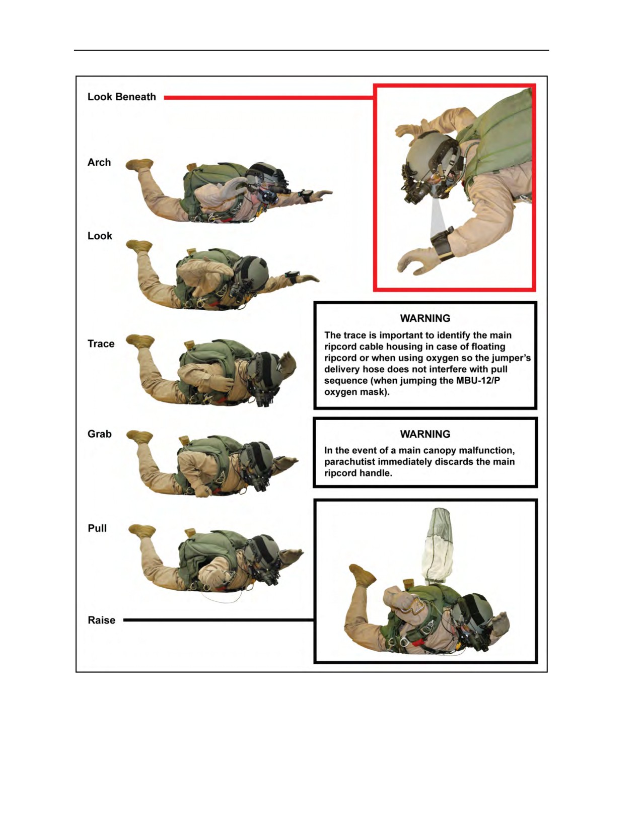
Figure 7-8. Main ripcord pull
7-6
ATP 3-18.11/AFMAN 11-411(I)/NTTP 3-05.26M
24 October 2014

Body Stabilization
TRACKING
7-4. Tracking is the technique of assuming a body position that allows the jumper to move horizontally
while free falling. Although there are many variations of the basic body position, it essentially involves the
jumper moving out of the traditional face-to-earth arched position, straightening the legs, bringing the arms
to the sides at a 45-degree angle, rolling the shoulders forward, and cupping the air to provide maximum
lift. There is, however, debate over what exactly constitutes the most efficient tracking position (providing
the best glide ratio)—especially concerning how far (if at all) the jumper’s legs should be spread. An
example of the tracking position (Figure 7-9) works well for some individuals and not so well for others. It
is claimed that good trackers can cover nearly as much ground as the distance they fall (approaching a glide
ratio of 1:1). It is known that the fall rate of a jumper in an efficient track is significantly lower than that of
a jumper falling in a traditional face-to-earth position; the former reaching speeds as low as 90 mph, the
latter averaging around the 120-mph mark. Inexperienced jumpers would expect such a position to increase
the fall rate. If two jumpers begin with the same fall rate, one will appear to float at the same place relative
to the other—neither appearing to drop below nor float above the other. If one jumper assumed a very good
track position, the other jumper would see the tracking jumper not only accelerate quickly away but quickly
upwards (relative to one another) as well.
Figure 7-9. Tracking position
7-5. Tracking is regarded as an essential lifesaving skill for all MFF jumpers engaging in grouping
exercises. It allows the jumpers to gain horizontal separation before opening their parachutes or when the
jumpers must cover great distance because of an incorrect spot determined by the jumpmaster.
Accordingly, the greater the number of MFF jumpers on a jump, the better their tracking skills must be. In
addition to having to track a longer distance after break off (tracking away for separation before opening),
they also have to be more aware of other jumpers around them and have to be able to track in a straight line
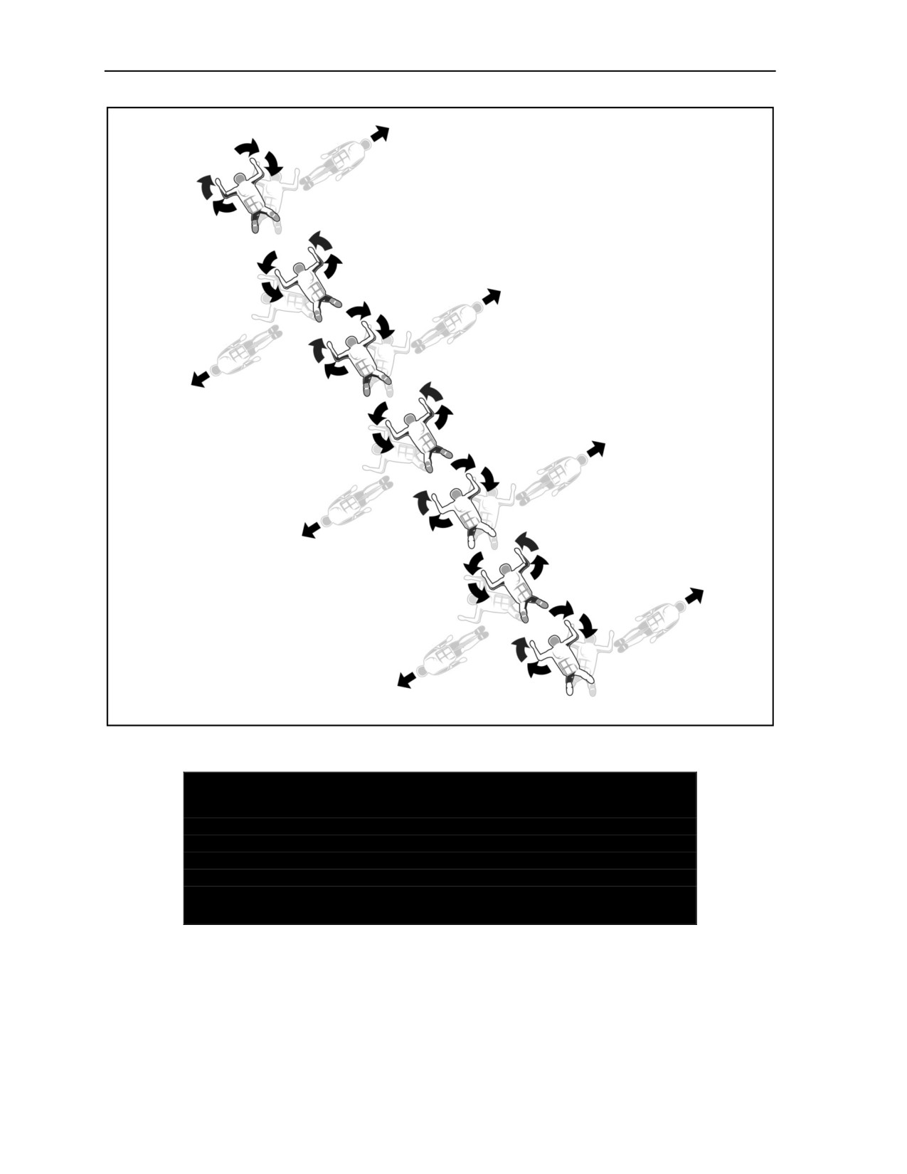
away from the center of the formation (Figure 7-10, page 7-8).
7-6. Because a good track body position can lead to significant horizontal speed and because the body’s
curved and slightly head-down position can cause less-experienced jumpers to be aware of a reduced area
around them, novice jumpers should train themselves to be aware of what is going on around them in all
directions for a greater distance while tracking.
24 October 2014
ATP 3-18.11/AFMAN 11-411(I)/NTTP 3-05.26M
7-7
Chapter 7
Figure 7-10. Example of tracking away for separation
DANGER
The dangers associated with tracking should not be
underestimated. An efficient track can reach horizontal speeds of
nearly 100 mph; collisions with other MFF jumpers could result in
serious injury or DEATH. For this reason, the number of
inexperienced jumpers should be limited per jump.
RECOVERY FROM INSTABILITY
7-7. Instability creates a hazard to the parachutist and to other parachutists in the air. Instability is the
primary cause of MFF malfunctions. There are a variety of reasons for instability. In most cases, it is
caused by a parachutist who does not present a symmetrical body position to the relative wind, either on
exit or in free fall. A contributing factor to instability in free fall is the inadvertent shift or release of combat
equipment. A flat spinning or tumbling body motion characterizes instability. Instability is dangerous not
7-8
ATP 3-18.11/AFMAN 11-411(I)/NTTP 3-05.26M
24 October 2014

Body Stabilization
only to the parachutist experiencing it, but often to other parachutists in free fall with him. Instability
prevents tactical grouping.
Note: If a parachutist encounters any or all of these situations, he should maintain altitude
awareness and pull at the prescribed pull altitude.
RECOVERY FROM A FLAT (HORIZONTAL) SPIN
7-8. If the parachutist is spinning or falling on his back, he must first return to a face-to-earth free-fall
attitude by arching his body. Depending upon the speed of his spin, sometimes this movement alone is
enough to slow or stop a flat spin. If he is still spinning after facing the earth, he must counter the direction
of the spin. He does this movement by looking in the opposite direction of the spin (for example, if
spinning clockwise, he looks counterclockwise) and making a hard body turn in that direction. He holds
this body position until the spin slows and stops. Depending on the amount of momentum he developed
before he started countering the spin, he may have to hold this body position for several revolutions. Once
the spin has stopped, he checks his body position, makes an altimeter check, gets back on heading, and
continues with the mission.
7-9. If a shift of the combat pack causes a flat spin, the parachutist may have to adjust his body position to
obtain stability or maintain a heading. The severity of the shift (versus an inadvertent release) determines
how much adjustment of the knees, the angle of the lower leg, hand and arm placement, or cocking of the
hips he must make to counter the effect of a combat pack that is now not symmetrical or square to the
relative wind.
RECOVERY FROM TUMBLING
7-10. A bump during a group exit or breaking the arched body position normally causes tumbling. If
tumbling, the parachutist assumes the hard arch body position until facing the earth. Then, he relaxes the
hard arch and assumes a stable free-fall body position. The time it takes to return to a face-to-earth position
will vary with the severity of the tumble, the body area surface, and the parachutist’s combat equipment
configuration. Presenting a symmetrical body position to the relative wind on exit from the aircraft is the
most significant factor in preventing tumbling.
ALTITUDE AWARENESS
7-11. A parachutist who is unstable must remain altitude-aware. The stress created by instability can cause
a normal human phenomenon of temporal (time) distortion. The resultant effect varies from individual to
individual. It can appear to be either time compression or a slowing down of perceived time passage. He
must not get so caught up in his attempts to recover stability that he loses altitude awareness and forgets to
manually activate his parachute. He must never sacrifice the pull altitude for stability or the continued
attempts to obtain stability before the pull. An unstable parachutist must remember that as he is falling, an
area of low pressure is created above him. Any altimeter reading while in this low-pressure area will not
reflect the correct altitude AGL. An example is a parachutist falling back to earth who looks at his altimeter
while holding it in front of his face. Due to the low-pressure zone in which the altimeter is located, the
parachutist will read a higher altitude than where he actually is in feet AGL.
Note: Parachutists must remember that this pressure differential can cause the altimeter to be off
as much as 1,000 feet.
24 October 2014
ATP 3-18.11/AFMAN 11-411(I)/NTTP 3-05.26M
7-9

Chapter 7
CORRECTIVE ACTIONS DURING FREE FALL
7-12. These actions are movements used to get off of a fellow parachutist’s back. Primary movements
include—
z
Left or right turns into a safe direction.
z
Forward glides (elbows into lazy “W,” legs extended) to clear airspace.
z
Track (arms back to side, legs straight).
Note: A modification to a forward glide is the high-lift track. Only experienced HALO-qualified
parachutists should use this technique, and only qualified MFF instructors will train parachutists
on this technique to gain separation before canopy deployment.
7-10
ATP 3-18.11/AFMAN 11-411(I)/NTTP 3-05.26M
24 October 2014
Chapter 8
Ram-Air Parachute Flight Characteristics
and Canopy Control
This chapter describes the RAPPS canopy, its components, deployment sequence,
theory of flight, flight characteristics, and canopy control procedures.
RAM-AIR PARACHUTE CHARACTERISTICS
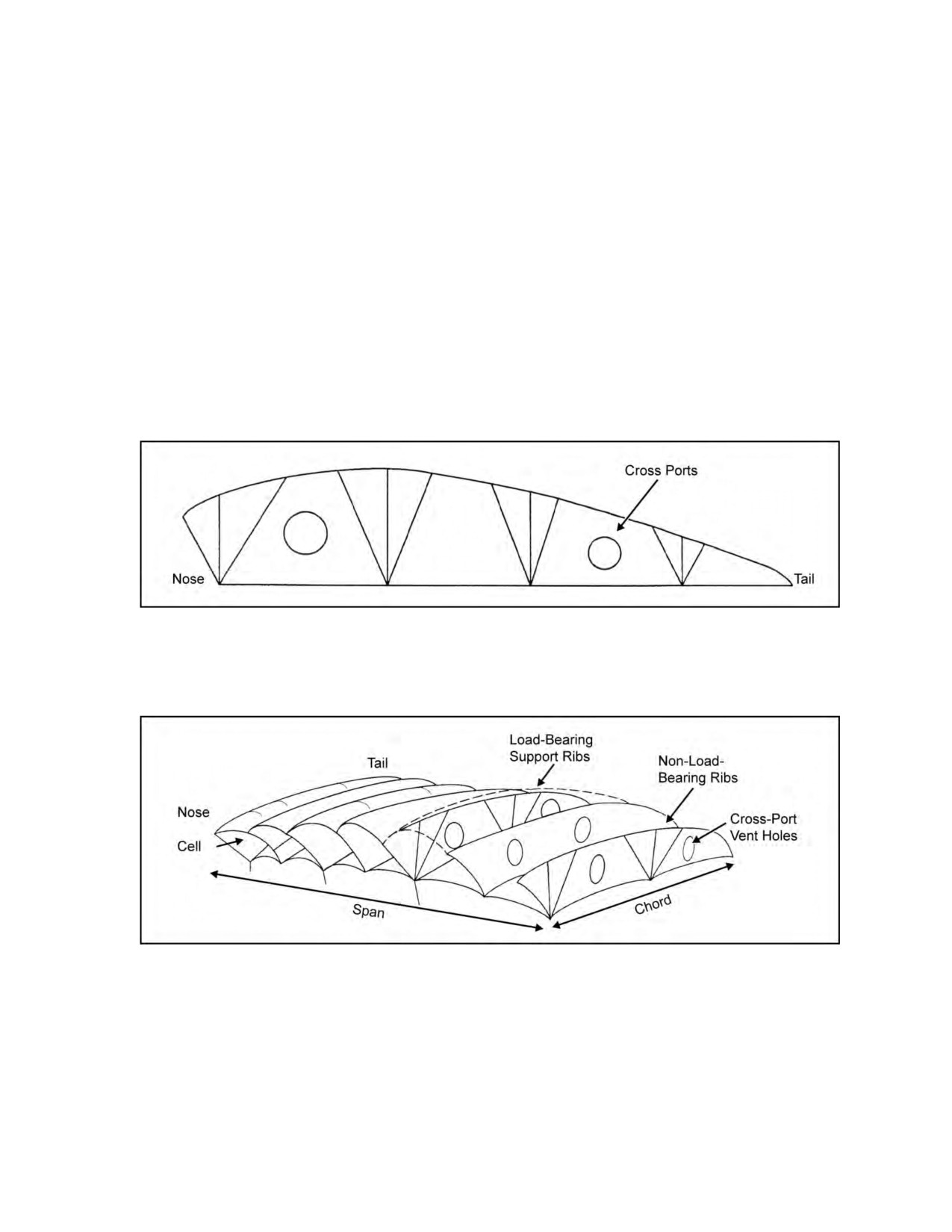
8-1. The ram-air parachute canopy’s design is similar to an aircraft’s wings, with curved upper surfaces
(top skin) and flat lower surfaces (bottom skin). Support ribs maintain the airfoil shape of the canopy
(Figure 8-1).
Figure 8-1. Shape of the ram-air parachute canopy
8-2. Reinforced, load-bearing support ribs serve as attaching points for the suspension lines, and
non-load-bearing ribs separate a cell into two compartments. Cross-port vent holes in the support ribs equalize
the internal air pressure in a canopy. Figure 8-2 shows the structure of the ram-air parachute canopy.
Figure 8-2. Structure of the ram-air parachute canopy
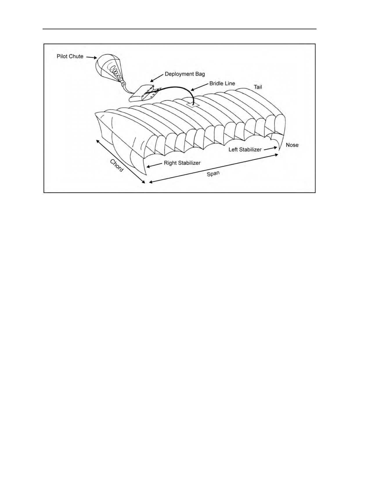
8-3. Nose, tail, chord, and span are terms of reference applied to ram-air parachutes. The open portion at
the front is called the nose, with the rear being the tail. The distance from left to right is the span, and from
nose to tail is the chord. Figure 8-3, page 8-2, shows the components of the ram-air parachute.
24 October 2014
ATP 3-18.11/AFMAN 11-411(I)/NTTP 3-05.26M
8-1
Chapter 8
Figure 8-3. Components and nomenclature of the ram-air parachute
8-4. The stabilizers are single-layered extensions of the canopy on the left and right sides of the
parachute. The stabilizers channel the airflow across the chord and help to maintain straight and stable
flight.
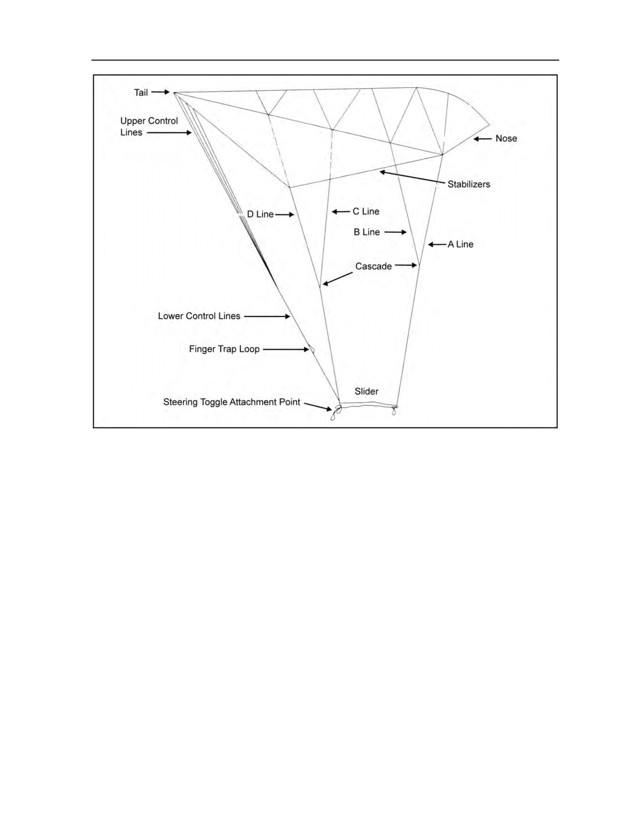
8-5. The military ram-air canopy has four suspension line groups. They are identified from nose to tail as
A, B, C, and D. A continuous line group is a line attached to the parachute’s bottom skin that runs directly
to the connector link without having another line attached to it. The suspension lines distribute a suspended
load under the canopy without distorting the canopy’s airfoil shape. Figure 8-4, page 8-3, shows the
location of the ram-air parachute components.
8-6. Upper control lines converge from points of attachment on the left and right trailing edges of the tail,
respectively, to common connection points with the lower control lines. The lower control lines are
attached to the upper control lines and have a soft steering toggle secured to the lower end. Deployment
brake loops sewn into the lower control lines set the canopy brakes for deployment. Figure 8-5, page 8-4,
shows the components of the lower portion of the ram-air parachute.
8-7. The sail slider is a rectangular piece of reinforced fabric with a large grommet in each corner. The
sail slider is a deployment device that retards the opening of a ram-air parachute.
8-8. Plastic disks called slider stops are sewn to the stabilizers at suspension line attachment points. These
slider stops limit the upward travel of the sail slider.
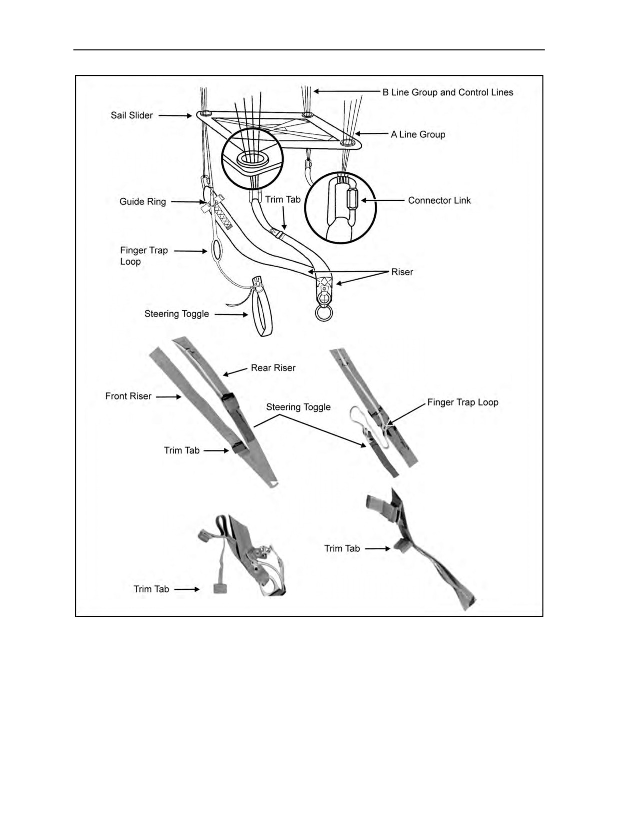
8-9. The suspension lines are attached to a connector link on each riser (Figure 8-5, page 8-4). Trim tabs
on the main parachute’s front risers shorten the risers to create an artificial decrease in the canopy’s angle
of attack into the wind. Guide rings sewn to the rear risers function as anchor points for the deployment
brakes and guides for the lower control lines (Figure 8-5, page 8-4).
8-2
ATP 3-18.11/AFMAN 11-411(I)/NTTP 3-05.26M
24 October 2014
Ram-Air Parachute Flight Characteristics
and Canopy Control
Figure 8-4. Location of ram-air parachute components
RAM-AIR PARACHUTE DEPLOYMENT SEQUENCE
8-10. At the prescribed parachute deployment altitude, the parachutist manually activates his parachute. He
grabs and unseats the main ripcord handle in his right hand and fully extends his arm.
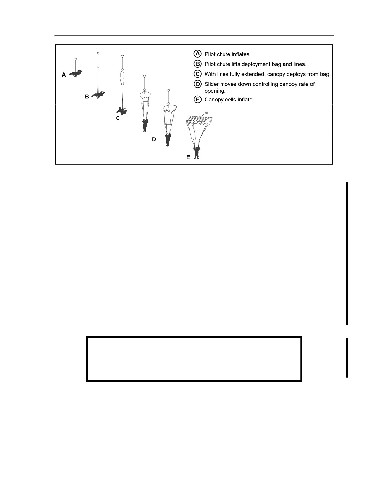
8-11. When the main ripcord pin clears the closing loop, the main pilot chute opens the closing flaps,
launches from the main parachute container, and extends the pilot chute bridle. The bridle extracts the
deployment bag from the main container, and the suspension lines unstow from their retainer bands. When
the lines are fully extended, they pull the main parachute from the deployment bag, and the canopy begins
to inflate (Figure 8-6, page 8-5). The sail slider retards the canopy’s deployment. As the canopy inflates, it
forces the sail slider down toward the risers as the suspension lines spread apart. After complete canopy
deployment, the parachutist pulls the steering toggles from the deployment brake loops to release the
control lines from the deployment brakes setting to the full flight setting.
24 October 2014
ATP 3-18.11/AFMAN 11-411(I)/NTTP 3-05.26M
8-3
Chapter 8
Figure 8-5. Detailed lower portion of the ram-air parachute
8-4
ATP 3-18.11/AFMAN 11-411(I)/NTTP 3-05.26M
24 October 2014
Ram-Air Parachute Flight Characteristics
and Canopy Control
Figure 8-6. Deployment sequence
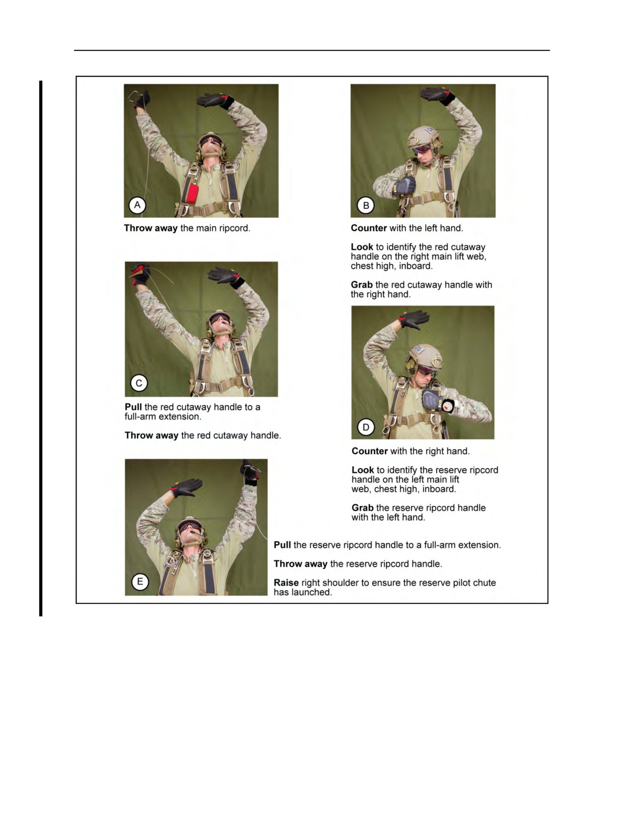
8-12. Should the parachutist encounter an uncontrollable situation requiring the initiation of emergency
procedures, he will—
z
Throw away the main ripcord.
z
Counter with his left hand.
z
Look to identify the red cutaway handle on the right main lift web, chest high, inboard.
z
Grab the red cutaway handle with his right hand.
z
Pull the red cutaway handle to a full-arm extension.
z
Throw away the red cutaway handle.
z
Counter with his right hand.
z
Look to identify the reserve ripcord handle on the left main lift web, chest high, inboard.
z
Grab the reserve ripcord handle with his left hand.
z
Pull the reserve ripcord handle to a full-arm extension.
z
Throw away the reserve ripcord handle.
z
Raise his right shoulder to ensure the reserve pilot chute has launched.
8-13. This action allows the cutaway cables to clear the release loops threaded through the small rings of
the canopy release assembly. The three-ring system activates the right side a moment before the left side to
prevent an entanglement. As the left riser set is jettisoned, it pulls the reserve static line (RSL), usually
deploying the reserve before manual activation of the reserve ripcord. Figure 8-7, page 8-6, identifies the
cutaway sequence.
WARNING
The parachutist must first pull the red cutaway handle AND THEN
the reserve ripcord handle to full-arm extension.
8-14. As the reserve ripcord pins clear the closing loops, the pilot chute opens the closing flaps. The pilot
chute deploys from the reserve parachute container and, as it catches air, extends the 2-inch-wide high-drag
bridle. Upon extraction of the reserve free bag from the container, the free-stowed suspension lines deploy
from a pocket on the free bag and extract the reserve parachute from the free bag. The free bag then
completely separates from the reserve parachute. As the canopy deploys, it forces the sail slider down the
suspension lines. When the parachutist releases the toggles from the deployment brake loops, he releases
the control lines from the deployment brake setting to the full flight setting.
20 October 2015
ATP 3-18.11/AFMAN 11-411(I)/NTTP 3-05.26M, C1
8-5
Chapter 8
Figure 8-7. Cutaway sequence
RAM-AIR PARACHUTE THEORY OF FLIGHT
8-15. The ram-air parachute is an inflated and pressurized fabric airfoil that generates lift by moving
forward through the air. The relative lengths of the suspension lines maintain the airfoil’s trim angle. In
flight, the parachutist keeps the wing’s leading edge at a slightly lower angle than the trailing edge. Thus,
this angle forces the canopy’s airfoil-shaped surface to glide or plane through the air, very much like a
glider in descending flight. The wing-shaped ram-air parachute generates lift caused by the reduced
pressure of the airflow over the curved upper surface.
8-6
ATP 3-18.11/AFMAN 11-411(I)/NTTP 3-05.26M, C1
20 October 2015
Ram-Air Parachute Flight Characteristics
and Canopy Control
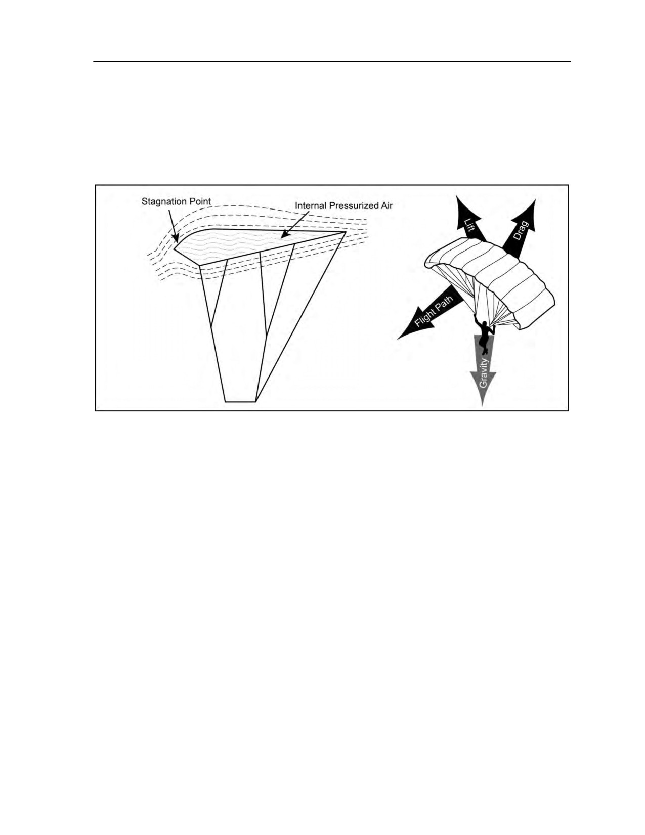
8-16. The ram-air parachute’s leading edge is open or physically missing, forming intakes that allow the
cells to be ram-air inflated. Internal air pressure pushes a small amount of stagnant air ahead of the airfoil,
forming an artificial leading edge. The focal point of this stagnant air acts as a true leading edge, deflecting
the relative air above and below. Drag is the only force that retards the wing’s forward motion through the
air. Drag is created by the friction of air passing over the canopy fabric, the suspension lines, and the
parachutist and his equipment. Gravity, plus the resultant sum of these aerodynamic forces on the upper
surface, acts to pull the ram-air parachute through the air and contributes to the flat glide angle of the
canopy (Figure 8-8).
Figure 8-8. Ram-air parachute theory of flight
8-17. Applying brakes on the ram-air parachute causes the trailing edge to deflect downward, creating
additional drag (Figure 8-9, page 8-8). This drag produces a proportionate loss of airspeed but generates a
slower vertical descent. The glide angle increases with the application of toggles. As full brakes are
reached, the wing ceases to generate dynamic lift, resulting in an increased rate of descent at an almost
vertical descent angle. Depressing the toggles beyond full brakes causes the parachute to cease flying and
enter a stall.
8-18. Differential application of brakes (one side only, or one side more than the other) produces an
unbalanced drag force at the trailing edge. This drag results in a yaw-type turn toward the side with the
highest drag.
8-19. Because the slow side generates less lift, it tends to drop slightly in a shallow banking motion, much
like an airplane. This bank angle increases as differential toggle displacement increases.
CANOPY PERFORMANCE FACTORS
8-20. The performance of a ram-air canopy is primarily affected by the weight of the jumper, density
altitude, and movement of the toggles.
WEIGHT OF JUMPER AND GEAR
8-21. The forward speed and descent rate of the ram-air is affected by the weight of the jumper and his
equipment. A heavier jumper will have greater forward speed and a higher descent rate than a light jumper.
A jumper has some control over how much gear is carried and thus his jump weight.
24 October 2014
ATP 3-18.11/AFMAN 11-411(I)/NTTP 3-05.26M
8-7
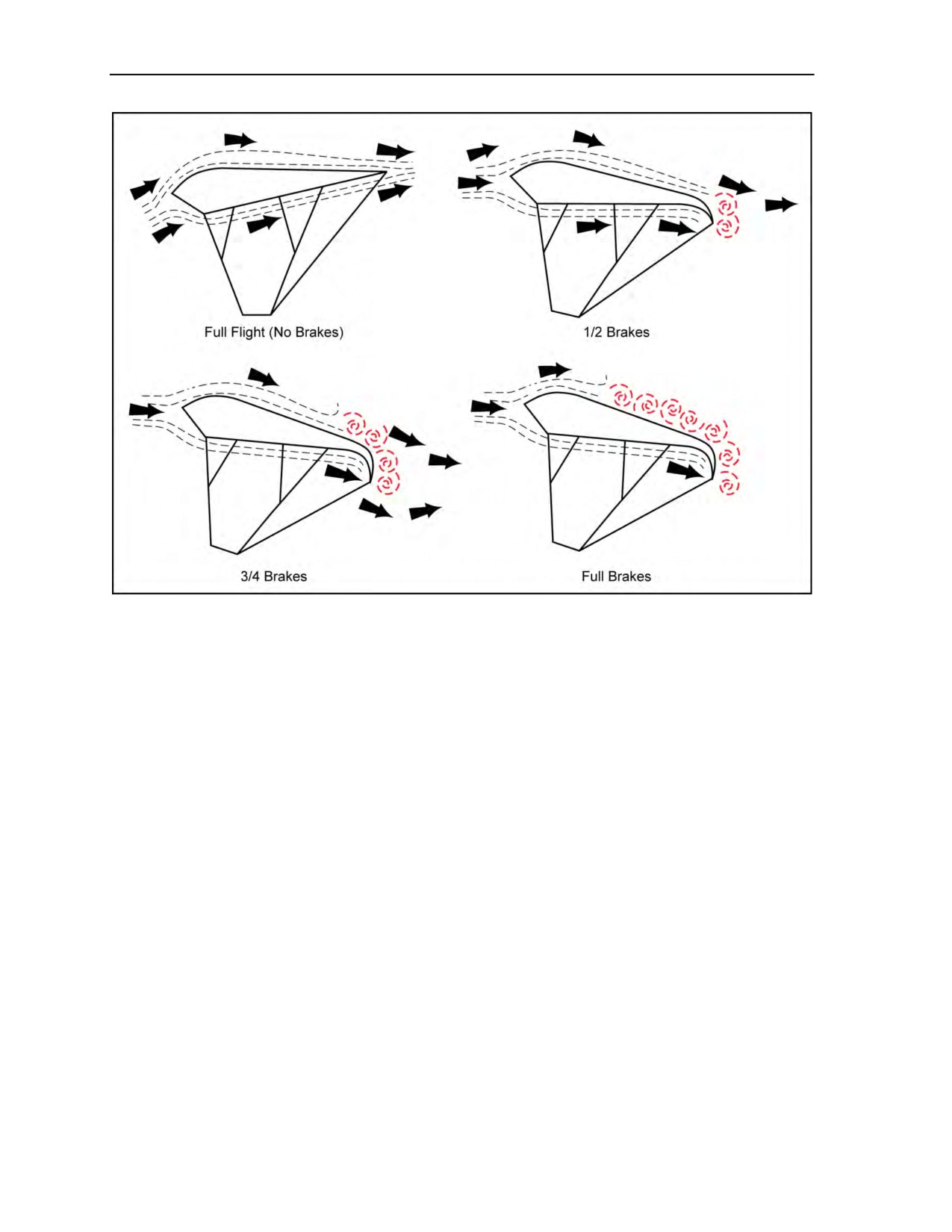
Chapter 8
Figure 8-9. Applying brakes on the ram-air parachute
DENSITY ALTITUDE
8-22. Hot temperatures and/or high altitude will result in the lifting capacity being reduced, the glide slope
decreases requiring an adjusted K-factor, and the overall rate of descent increases.
TOGGLE MOVEMENT
8-23. The ram-air parachute is very responsive to commands. It will do what the parachutist makes it do.
When he decides to perform a flight maneuver, he makes the decision based on what he sees and feels. If
he is in a steeply banked turn or is swinging under the canopy, it is difficult to make a good flight decision
because canopy response lags behind his commands. Thus, if the parachutist flies from an unstable
platform or if he over-controls, he will not get maximum performance. Slow, gentle toggle movements help
a jumper avoid disorientation, and in the case of deep brake flight and stall recovery, gentle toggle
movements are required to avoid hard landings. It is better to fly with the toggles kept fairly close to the
body than with outstretched arms. This technique helps reduce arm fatigue, provides more accurate
identification of the stall point, and helps prevent outstretched arms when performing PLFs.
PARACHUTE FLIGHT CHARACTERISTICS
8-24. The parachutist must remember that the ram-air parachute is a high-performance gliding system.
Because of its high performance, the ram-air parachute is potentially dangerous in the hands of an
inexperienced parachutist. The parachutist must possess a working knowledge of the flight capabilities and
limitations of the ram-air parachute and must fully understand the canopy control techniques.
8-25. The ram-air parachute is not overly complicated. It is basically a fabric wing section. The parachutist
must have a very basic knowledge of aerodynamics to better understand its flight and handling
characteristics.
8-8
ATP 3-18.11/AFMAN 11-411(I)/NTTP 3-05.26M
24 October 2014

Ram-Air Parachute Flight Characteristics
and Canopy Control
8-26. The ram-air parachute planes or glides through the air at about 20 to 30 mph. It always flies at this
speed regardless of wind conditions, except when the parachutist applies brakes.
8-27. The flying speed is called airspeed and remains constant regardless of whether the parachute is
headed upwind, downwind, or crosswind. The only variation in flying upwind or downwind is a change in
ground speed that is often mistaken for a change in airspeed.
8-28. Wind affects ground speed only and has no effect on airspeed. Brakes applied with conventional
control lines and toggles control the ram-air parachute’s airspeed. Fifty percent of toggle travel on a ram-air
parachute will cause a speed reduction of close to 12 mph.
8-29. There is almost no surge on deployment, and there is no wind noise at all until after releasing the
brakes. A parachutist who has not been previously exposed to the ram-air parachute’s flight characteristics
can use the wind noise created by forward speed as a rough airspeed indicator. A reduction in the wind
noise level can provide a stall warning.
8-30. After the parachutist becomes accustomed to the canopy, he may fail to notice the wind noise. By
this time, he should have learned to fly the canopy by feel, and he should notice the stall warning point and
determine this point at altitude under his canopy controllability check. The parachutist will feel the canopy
shudder as it loses lift and begins to stall. The parachutist should remember that angle of attack, cross wind,
and wind turbulence can increase the stall point without warning.
8-31. The parachutist must remember that, in controlling the canopy’s flight, how fast he moves the
toggles from one position to another is as critical as the relative position of the toggles. As a rule, rapid and
generous (more than 30 percent) application of both toggles will cause a rapid decrease in airspeed,
decelerating into the stall range at about 0 to 3 mph. (Depending on the wind speed, the ground speed could
still be very high.)
8-32. Due to the penetrating ability of the ram-air parachute, parachutists often find it difficult to determine
wind direction without the aid of a wind sock, streamer, or smoke on the ground. All landings should be
made facing into the wind.
8-33. The ram-air parachute has a constant airspeed of 20 to 30 mph. If the parachutist points the ram-air
parachute downwind with a 10-mph wind, the ground speed will be 30 to 40 mph. If he turns the ram-air
parachute into the wind and the winds are 10 mph, the airspeed remains the same but the ground speed
reduces by 10 mph. If the ram-air parachute faces into 20-mph winds, the ground speed will be 0 mph
(Figure 8-10, page 8-10).
CANOPY CONTROL
8-34. The overall objective of MFF parachuting is to land personnel and equipment intact to accomplish
the assigned mission. The free-fall parachutist must know and employ the principles of canopy control as
they relate to the use of the ram-air parachute.
8-35. Wind action, direction of canopy flight, and manipulation of the control toggles primarily control the
movement of the ram-air parachute. Upon canopy deployment, the parachutist grabs the control toggles and
performs a controllability check of the parachute. The purpose of this check is to determine if the
parachutist’s canopy is capable of landing him safely. Figure 8-11, page 8-10, contains a condensed guide
to good canopy control.
8-36. The parachutist must first know wind direction and approximate speed since the direction of his
canopy’s flight, as determined by his toggle manipulation, is in relation to wind action. The canopy’s
shape, design, span, and chord generate the ram-air parachute’s 20- to 30-mph glide. The flow of air over
and under the canopy’s wing shape provides the lift and forward flight of the parachute. By specific
manipulation of the toggles, the parachutist may distort the trailing edge and cause the canopy to turn, to
vary forward speed, and to increase the rate of descent.
24 October 2014
ATP 3-18.11/AFMAN 11-411(I)/NTTP 3-05.26M
8-9
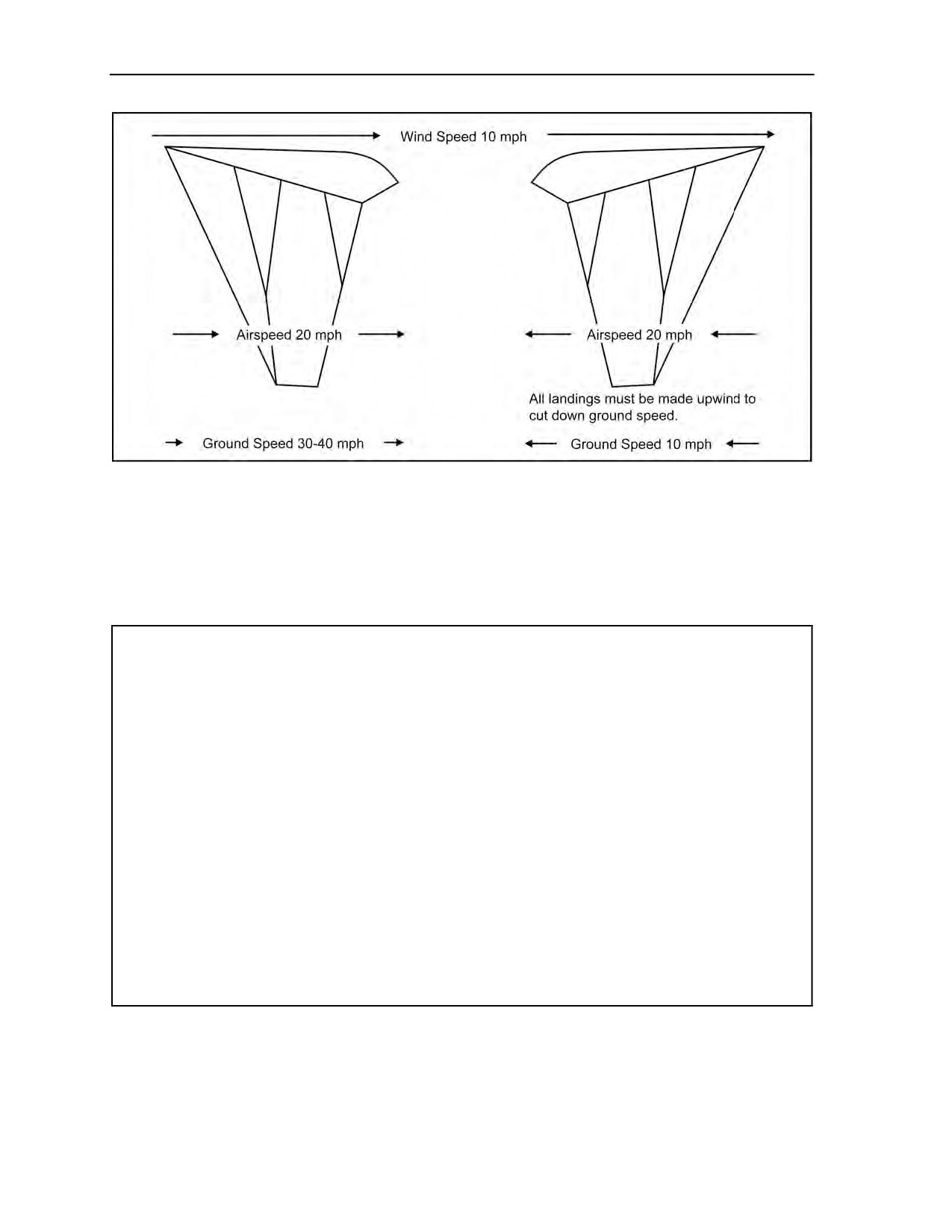
Chapter 8
Figure 8-10. Controlling ground speed
8-37. Canopy control involves the coordination of wind direction and speed, canopy flight and penetration,
and the parachutist’s own selective manipulation and distortion of the canopy. Maneuvering the parachute
requires more than simply turning the canopy. A properly executed parachute maneuver requires correct
canopy manipulation to combine the wind’s force and the canopy’s flight to move the parachute in a given
direction. The parachutist may have to hold into the wind, run with the wind, or crab to the left or right
while holding or running.
Checks canopy and ground position after opening.
Keeps a sharp lookout for other parachutists.
Checks his altitude and his first ground reference point.
Picks out intermediate ground references between him and the target.
Determines wind direction (on the ground and at altitude).
Checks the holding pattern and penetration of his canopy.
Uses the upwind toggle to turn his canopy.
Locates the wind line and determines the direction in which he wants to move.
Always maneuvers toward the wind line.
Checks his progress at halfway and three-quarter-way points and makes necessary adjustments.
Turns into the wind at a minimum altitude of 500 feet.
Controls his canopy all the way to the ground.
Always lands facing into the wind.
Figure 8-11. Parachutist guide to good canopy control
HOLDING MANEUVER
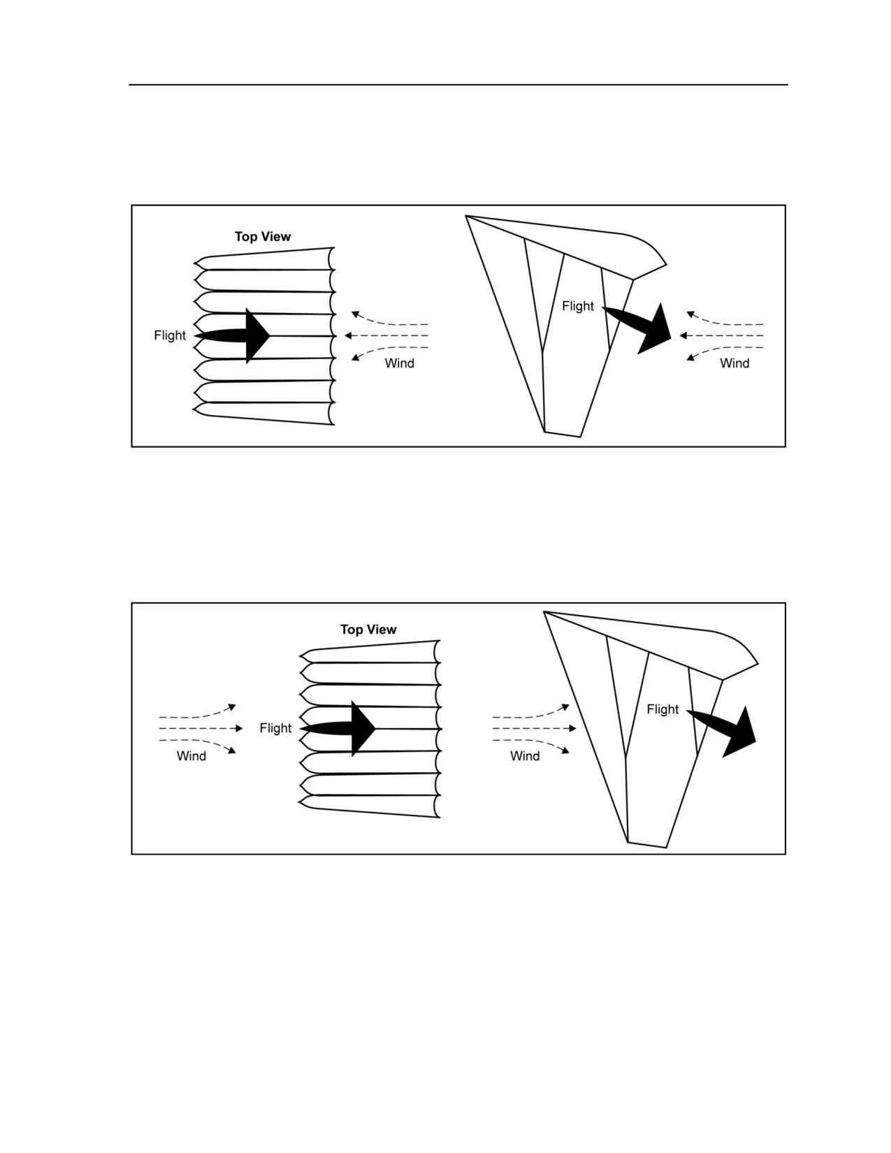
8-38. Pointing the canopy into the wind, or “holding,” aims the canopy flight directly into the wind
(Figure 8-12, page 8-11). This maneuver has the same effect as reduced wind speed and slows the canopy’s
8-10
ATP 3-18.11/AFMAN 11-411(I)/NTTP 3-05.26M
24 October 2014
Ram-Air Parachute Flight Characteristics
and Canopy Control
forward movement. The parachutist manipulates the toggles to maintain the position. To crab to either
direction while holding, he turns the canopy slightly in the direction in which he wants to move. Turning
the canopy too far may cause it to become wind-cocked and move with the wind. As the parachutist’s
canopy begins to move in the desired direction, he manipulates the toggles to keep it in position until he
completes the maneuver.
Figure 8-12. Holding maneuver
RUNNING MANEUVER
8-39. “Running” is when the parachutist points the canopy with the wind; the combined glide speed of the
canopy and the wind speed produce an increased overall ground speed (Figure 8-13). He manipulates the
toggles to maintain the canopy in position. To crab while running, the parachutist turns the canopy slightly
in the desired direction and maintains the position until he completes the maneuver.
Figure 8-13. Running maneuver
CRABBING MANEUVER
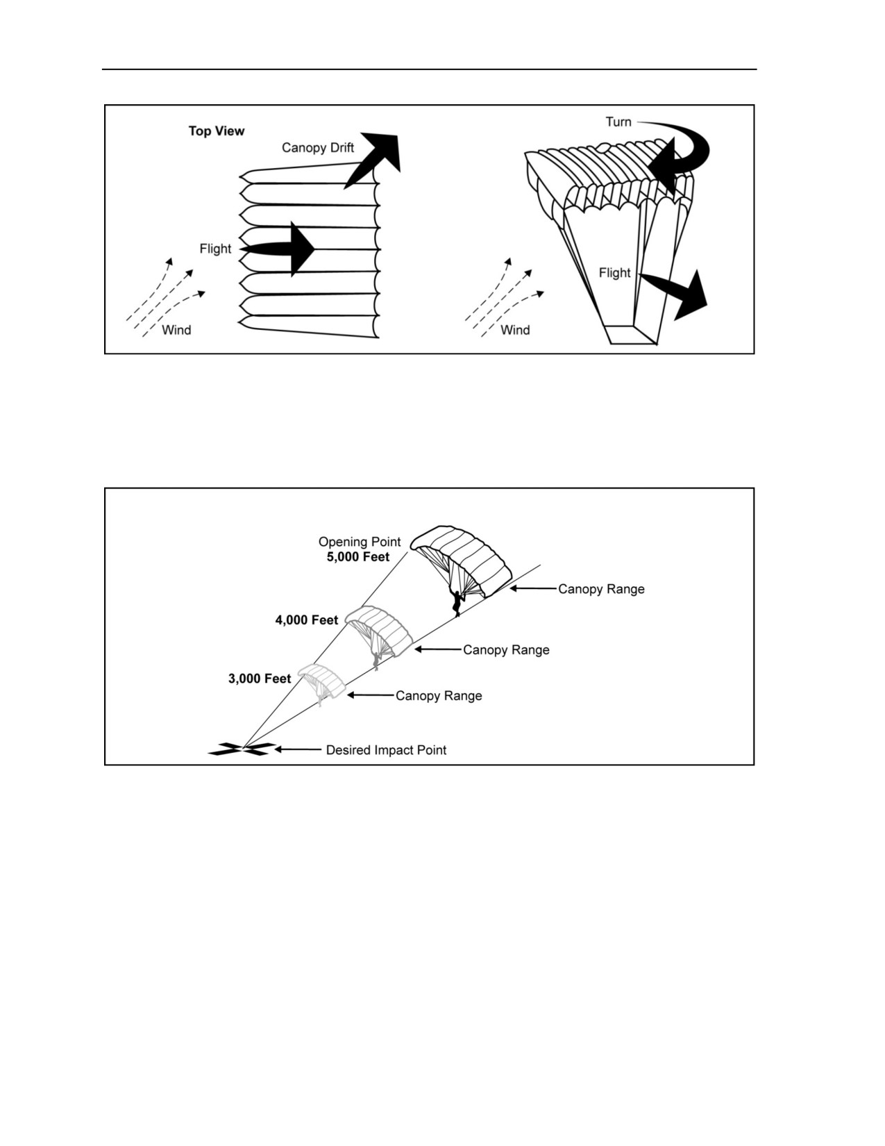
8-40. The parachutist performs a “crabbing” movement by pointing the canopy at any given angle to the
wind direction (Figure 8-14, page 8-12). The force of the wind from one direction and the flight of the
canopy at an angle to it move the canopy at an angle to the direction of flight. The direction of flight varies
with the wind speed and the angle at which the parachutist points the canopy. A canopy pointed at a
downwind angle makes a sharper angle than one pointed upwind.
24 October 2014
ATP 3-18.11/AFMAN 11-411(I)/NTTP 3-05.26M
8-11
Chapter 8
Figure 8-14. Crabbing maneuver
8-41. The effective canopy range and the wind line determine the course (direction of movement) the
parachutist follows in maneuvering toward the target area. The effective canopy range is the maximum
distance from which the parachutist can maneuver the canopy into the target area from a given altitude. It is
greater at high altitudes and decreases proportionately at lower altitudes, forming a cone- or funnel-shaped
area (Figure 8-15). Changes in wind direction and conditions may cause this range to shift in any direction.
Figure 8-15. Effective canopy range
8-42. A wind line is an imaginary line extending upwind from the target area into the prevailing wind. A
wind line can be marked by ground references. Accurate reference points are essential to effective
parachute maneuver.
8-43. The parachutist checks his movement in relation to the ground. Winds at altitude may be from
different directions than those at the desired impact point.
8-44. For the “half method,” the parachutist picks a ground reference point on the wind line, halfway
between the opening point and the target area. This point is the first checkpoint that he can reach in half the
opening altitude with correct canopy manipulation. The second checkpoint is a reference point halfway
between the first checkpoint and the target area that he should reach in half the remaining altitude.
8-45. The “horizon method” allows a parachutist to determine his flight progress by looking at his target
and watching if it rises or descends in his line of sight. If it is rising, he will not make it to that point; if it is
descending, he will probably have enough altitude to get back. It is also important to note that the
parachutist always tries to maintain the “upwind advantage.” This advantage is a margin in his canopy
8-12
ATP 3-18.11/AFMAN 11-411(I)/NTTP 3-05.26M
24 October 2014
Ram-Air Parachute Flight Characteristics
and Canopy Control
range where he will not be blown behind his target area and become unable to recover and land with his
group.
8-46. The ram-air parachute is a highly maneuverable canopy capable of 360-degree turns in 3 to 5 seconds
under normal conditions. Its maneuverability comes from the parachutist’s use of its capabilities to vary
forward speed, rate of descent, turn, and crosswind movement.
8-47. Under normal conditions, the parachutist varies his forward speed and rate of descent by using the
canopy’s toggles. Immediately upon canopy deployment, he clears the toggles from the deployment brakes
setting and performs a controllability check. His toggle position at the stall point will be at a different
position as wind speed increases and when carrying heavy equipment loads.
WARNING
Before attempting any maneuvers or turns, the parachutist must
be alert to prevent collisions with other parachutists. This
maneuver is especially critical below 500 feet AGL.
CANOPY MANEUVERS
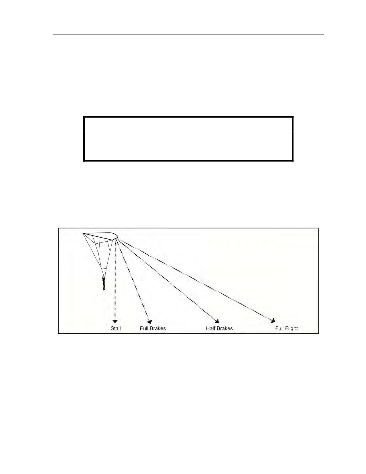
8-48. The various straight-ahead maneuvers are used to affect the glide angle of the canopy. Canopy glide
angles can be changed by manipulating either the steering toggles or the risers. Figure 8-16 shows the glide
angles for a ram-air canopy at the various toggle settings. As toggles are applied, the angle of attack
increases and the glide angle flattens. Airspeed decreases but descent decreases at a greater rate than the
airspeed slows, thus increasing the distance covered through the air when the wind is at the jumper’s back.
Rear risers will offer the best penetration into the wind and with crosswind scenarios.
Figure 8-16. Brake-setting glide angles
FULL FLIGHT (NO BRAKES)
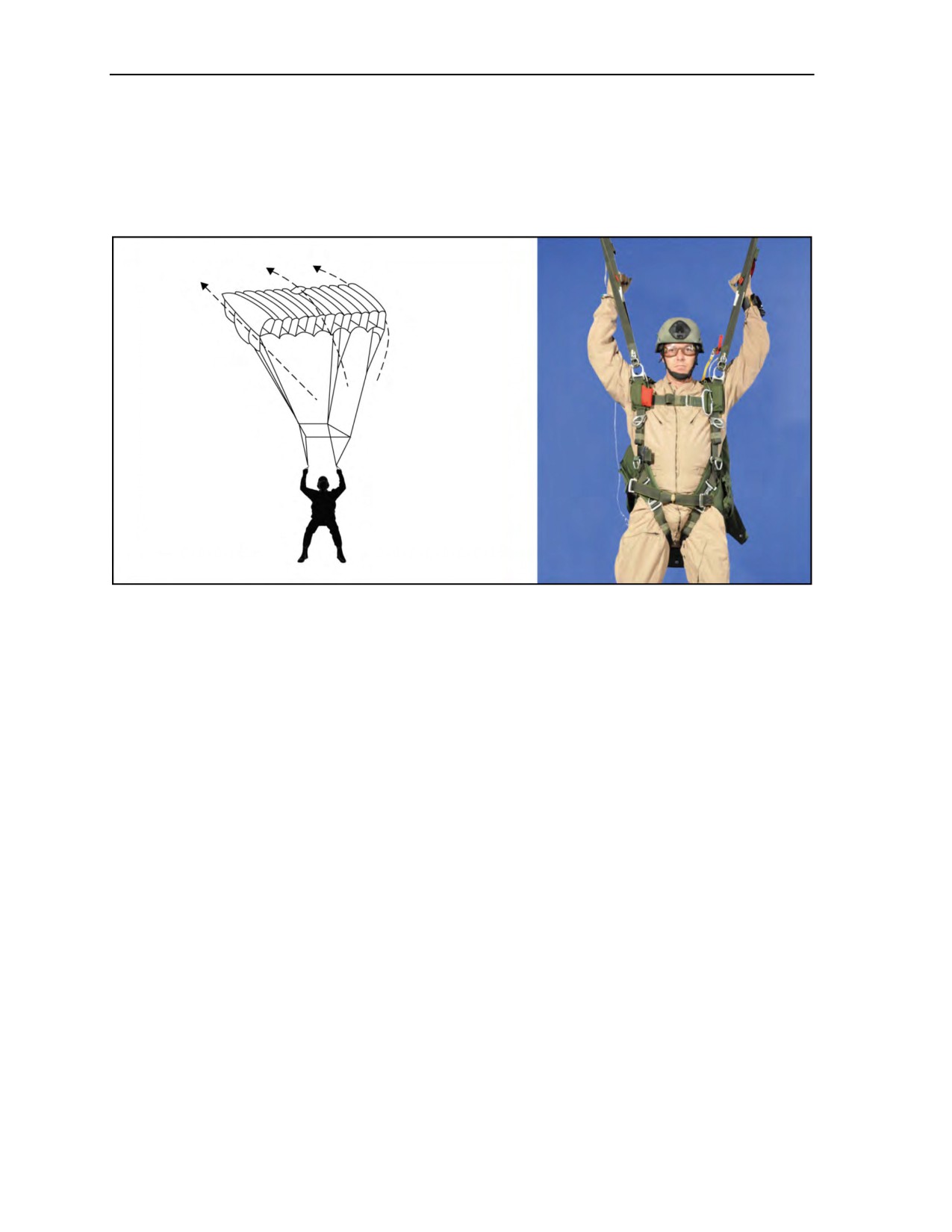
8-49. The maximum canopy flight and penetration for maneuvering are obtained using full flight. The
toggles are in the all-up position behind the rear risers (Figure 8-17, page 8-14). Full-flight maneuvering
includes the following:
z
Toggles are all the way up.
z
Greatest forward speed of any toggle setting is 20 to 30 mph.
z
Greatest descent rate of any toggle setting aside from sink and/or stall is 12 to 16 fps.
z
It is not an acceptable toggle position for landing.
24 October 2014
ATP 3-18.11/AFMAN 11-411(I)/NTTP 3-05.26M
8-13
Chapter 8
8-50. Full flight (run) is the quickest way to get from point A to point B when retention of altitude is not a
concern. If getting blown backwards on final approach, it will allow a jumper to land closer to the spot than
any other toggle setting. The canopy is least susceptible to turbulence at full flight because the canopy has
the higher airspeed, which gives more pressurization to the canopy making it a more rigid wing. Applying
brakes depressurizes the canopy by forcing air out of the wing and slowing the canopy (less airspeed equals
less pressure). In addition, the higher airspeed gets the canopy out of turbulence faster.
Figure 8-17. Full flight
HALF BRAKES
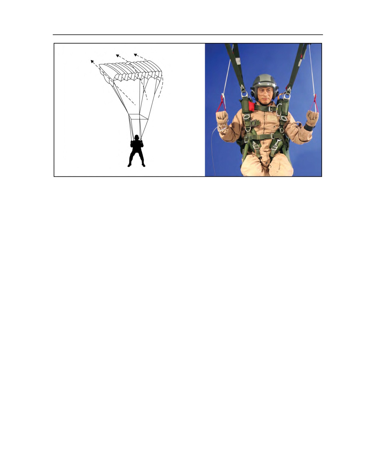
8-51. The parachutist grasps the toggles and pulls them down to about shoulder or chest level for the
half-brakes position (Figure 8-18, page 8-15). The canopy speed will decrease to about a 9- to 12-mph
flight, and the rate of descent will increase. This brake setting and both forward speed and descent rates are
acceptable for landing. Half brakes also give a jumper the maximum flexibility to adapt to changing wind
conditions, which is especially useful on final approach. Higher in the pattern, this brake setting is useful as
it allows a jumper more time to make decisions and it allows for higher margins of error than do
one-quarter brakes or full run. The half-brakes position includes the following:
z
Toggle position is halfway between full run and stall point.
z
Forward speed is 9 to 12 mph.
z
Descent rate is 9 to 12 fps.
z
It is an acceptable toggle position for landing.
z
It is the SAFETY POSITION.
8-14
ATP 3-18.11/AFMAN 11-411(I)/NTTP 3-05.26M
24 October 2014
Ram-Air Parachute Flight Characteristics
and Canopy Control
Figure 8-18. Half brakes
FULL BRAKES
8-52. The parachutist pulls the toggles to about waist level for full brakes (Figure 8-19, page 8-16). The
canopy stops moving forward and the rate of descent increases. In the full-brakes position, the canopy is
actually on the verge of a stall. The full-brakes setting is an extremely useful tool for making an accurate
jump but is dangerous if used inappropriately. Many jumpers have been injured by using this brake setting
at too low of an altitude. All canopies are prone to surging when coming out of this flight mode. The
canopy can transition unexpectedly into a stall in the presence of turbulence and sustained use can result in
canopy transitioning into a stall. Only experienced jumpers should use full brakes below 200 feet AGL and
the canopy should be flying by 100 feet AGL. The full-brakes position includes the following:
z
Forward speed is 0 to 5 mph.
z
Descent rate is 16 to 24 fps.
z
Variance between canopies can be significant.
z
It is an extremely unacceptable toggle position for stand-up landings, but safe PLFs can be
conducted at deeper brake settings.
STALL
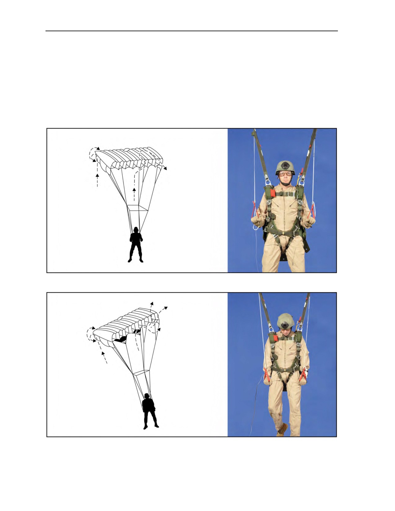
8-53. A stall occurs when the parachutist pulls the toggles below the full-brakes position (Figure 8-20,
page 8-16). The angle of attack of the parachute’s nose and wing change produce a very great amount of
lift for a short time. As the parachute loses forward airspeed (because the parachutist has pulled the tail
down lower than the nose), the canopy will attempt to fly backward and the rate of descent will increase to
a hazardous degree. It is best used prior to entering the pattern or during the downwind leg. The stall
maneuver should not be used lower than 300 feet AGL. It is extremely likely that a landing in this mode
will result in a serious injury. Transitioning out of the stall maneuver should be done by smoothly raising
both toggles and holding until the canopy begins flying again. The canopy should regain flight at the one-half
or three-quarters brakes position. Snapping the toggles up or raising them to a very high setting can result
in an extreme surge causing a rapid dive and high forward speed. The location of stall points can vary
significantly from canopy to canopy. Minor variances in stall point location can exist on the same canopy
depending on density altitude and wing loading. Positive identification of the stall point on every jump
is critical for jump safety and performance. The stall point is located by slowly and smoothly lowering the
toggles until the canopy ceases flying. To regain forward airspeed and flight, the parachutist slowly raises
24 October 2014
ATP 3-18.11/AFMAN 11-411(I)/NTTP 3-05.26M
8-15
Chapter 8
the toggles to the half-brakes or three-quarters position to raise the tail. The stall maneuver includes the
following:
z
Toggles are lower than full-brakes position.
z
Forward speed is 0 mph.
z
Descent rate is 20 to 26 fps.
z
Canopy may have directional instability.
z
MC-4 recovers by smoothly raising both toggles to the three-quarters brake position and holding
until the canopy begins to fly.
z
Toggles may need to be wrapped on the jumper’s hands.
Figure 8-19. Full brakes
Figure 8-20. Stall
8-16
ATP 3-18.11/AFMAN 11-411(I)/NTTP 3-05.26M
24 October 2014
Ram-Air Parachute Flight Characteristics
and Canopy Control
WARNING
The parachutist must not move the toggles quickly from the stall
to the full-flight position, as the canopy will surge forward with an
increased rate of descent. The parachutist must avoid stalling the
ram-air parachute below 500 feet AGL.
TOGGLE TURNS
8-54. The parachutist can make turns from the full-flight, half-brakes, and full-brakes positions. Turns
from full flight are very responsive, but because of the high forward speed, the turns will cover a wide arc.
The parachutist makes these turns by depressing either toggle, leaving the other one at the guide ring. In
this type of turn, the parachute will bank and actually dive, causing the parachute to lose altitude quickly.
The further the parachutist depresses the toggle, the steeper the bank angle becomes.
SPIRAL TURNS
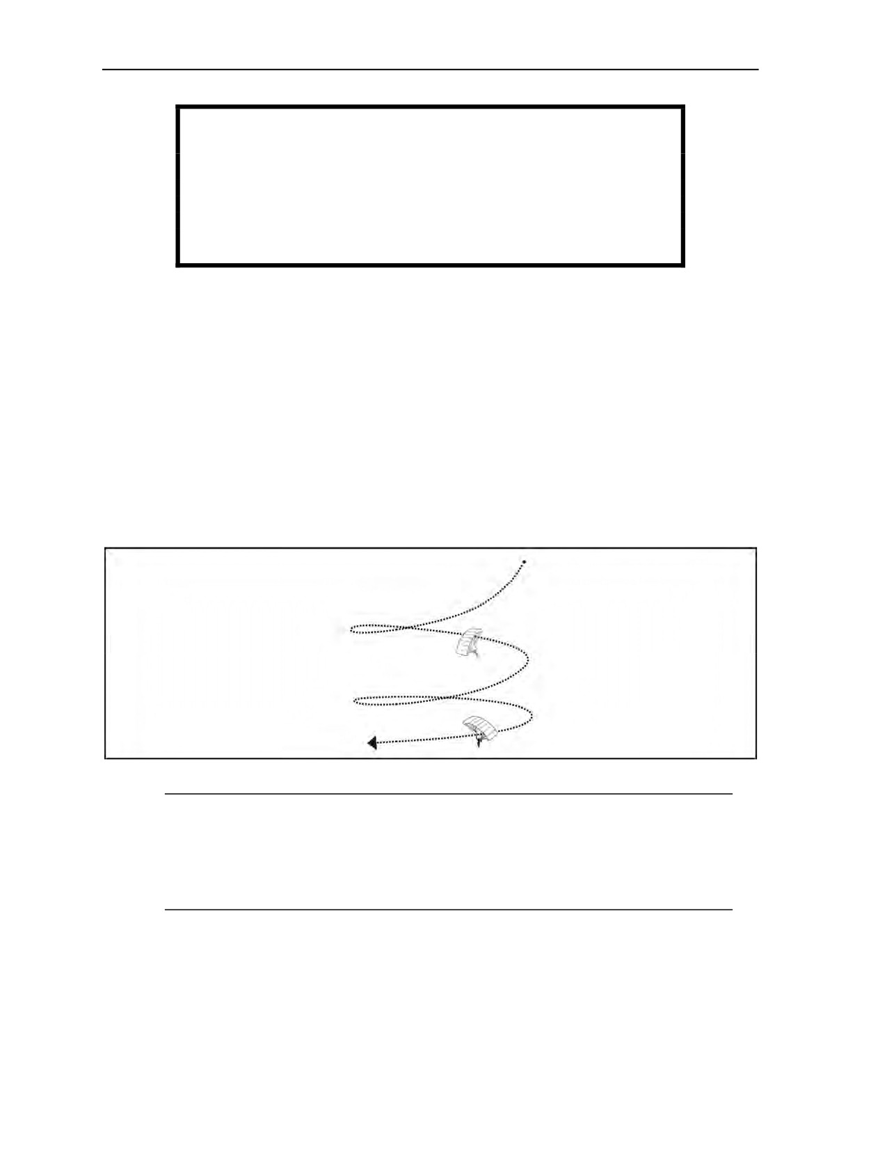
8-55. Spiral turns (full-glide turns) are basically turns from full flight but maintained (Figure 8-21) for
more than 360 degrees of rotation. The parachute will begin diving in a spiral. The first turn will be fairly
slow, with shallow bank angles, but the turn speed and bank angle will increase rapidly while the
parachutist maintains the spiral. Spiral turns are effective tools for turning but subject the jumper to more
banking than flat turns. Sustained spiral turns are an effective maneuver to lose altitude. Common mistakes
made while employing the spiral turn include losing track of altitude and coming out of the turn in the
wrong direction. This maneuver can often result in a jumper becoming dizzy, disoriented, and off target. It
is extremely important that the jumper ensures the airspace is clear below and downwind prior to executing
the turn. The spiral turn includes the following:
z
Toggle is pulled all the way down on the side the jumper wants to turn while the other toggle is
left at full run.
z
Canopy banks similar to an aircraft.
z
Canopy takes 4 to 6 seconds for the first turn.
z
Turn rate, degree of bank, and descent rate will increase with time.
z
Turns are held beyond a full revolution.
z
The jumper will feel increased pressure in the harness and increasing airspeed.
Figure 8-21. Spiral turn
24 October 2014
ATP 3-18.11/AFMAN 11-411(I)/NTTP 3-05.26M
8-17
Chapter 8
WARNING
Spiral turns will cause excessively fast diving speed with a rapid
loss of canopy control. If the parachutist makes a spiral turn, it
should not be conducted in proximity of other canopies or at any
point in the traffic pattern. He must NEVER make a spiral turn
below 1,000 feet AGL.
FLAT TURNS
8-56. The reduced banking associated with flat turns (off-hand) makes it the preferred type of turn for
many parts of the jump. Using flat turns while turning between legs of the pattern helps to minimize
altitude loss. Using flat turns for making corrections on final approach will result in a better sight picture.
Also, gentle flat turns can be safely used to avoid obstacles near or on the ground. Turns from the
half-brakes position result in almost flat turns. Flat turns (Figure 8-22) are generally preferred over spiral
turns. Flat turns include the following:
z
They are initiated while flying in a partially braked mode.
z
Toggle is raised on opposite side from desired turn direction.
z
Canopy banks much less compared to a full-glide turn.
z
Canopy turns tighter.
z
They will consume little altitude.
z
Parachutist will remain close to vertical underneath the parachute.
Figure 8-22. Flat turn
Note: The parachutist should use trim tabs located on the front risers to lose altitude, if required.
During HAHO operation jumps, the trim tabs can be used to make changes in the angle of attack
in order for a lighter jumper to stay in the stack with heavier jumpers. Using the trim tabs
eliminates the need for a jumper to pull on the front risers during the entire canopy flight.
Steering correction can be made with body weight shifts or minor rear or front riser turns until
the toggles are released.
FRONT RISER TURNS
8-57. Sustained front riser turns are an effective tool for gaining vertical separation early in a jump. The
same maneuvers listed under spiral turns apply to sustained front riser turns. Front riser turns are an
effective maneuver to lose altitude. Common mistakes made while employing the front riser turn include
losing track of altitude and coming out of the turn in the wrong direction. This maneuver can often result in
a jumper becoming dizzy and disoriented. It is extremely important to ensure that the airspace is clear
8-18
ATP 3-18.11/AFMAN 11-411(I)/NTTP 3-05.26M
24 October 2014

Ram-Air Parachute Flight Characteristics
and Canopy Control
below and downwind of the jumper prior to executing the turn. Sustained front riser turns put the canopy in
a dive with a significant amount of pitch and roll. The canopy will turn to the jumper’s blind spot and the
jumper will not be able to control the wing until the canopy is midway through the recovery arc. Front riser
turns include the following:
z
Toggles are to remain in the jumper’s hands.
z
Toggles should be put in full-flight position.
z
Turns are initiated by pulling down either riser on side of desired turn.
z
Jumper can grab any upper part of front riser.
z
Canopy will bank significantly.
z
Turn rate, descent rate, and speed will be very high and increase over time.
REAR RISER TURNS
8-58. Rear riser turns should be used in every jump to orient the canopy to the DZ after opening. If a
jumper is faced with an imminent canopy collision after opening, an opposite riser turn will result in a
quicker turn than unstowing the brakes and making a toggle turn. The second situation demanding rear riser
turns would occur in the case of a broken brake line or detached toggle. The jumper can choose to either steer
with rear risers or with the sole functioning steering line and one rear riser. Rear riser turns are similar to
toggle turns in that they deflect the rear sections of the canopy. They require more force to execute because
the jumper is pulling down a larger area of the canopy. Pulling down a rear riser will pull all of the C and D
lines on that side compared with just the trailing edge for a toggle turn. Rear riser turns include the following:
z
Jumper leaves toggles stowed if used in case of imminent collision after opening.
z
Jumper releases toggles from stows if used in the case of a broken control line.
z
Turns are initiated by pulling either rear riser down on side of desired turn.
z
Jumper grabs the upper part of rear riser.
z
Turns are effective but require more force than pulling down a toggle.
Note: Canopy will stall much quicker using rear risers than when using the toggles. In the event
of a broken control line, jumpers should practice this landing technique above 1,000 feet before
actually trying to land with it.
LANDING MANEUVERS
8-59. One of the most common sources of injury is during landing maneuvers. The jumper’s judgment
during this maneuver while flaring his canopy, if incorrect, could result in a high-speed impact with the
ground or other hazards on the ground. Additional hazards that could contribute to bad landing maneuvers
are changing wind conditions, turbulence during hot days, downdrafts close to the ground, crosswinds, and
limited visibility. The following maneuvers will assist the parachutist during his landings.
HALF-BRAKE LANDING
8-60. Half-brake landings are often the best choice for jumps at night, as well as days consisting of low
visibility, rough terrain spots that require a high degree of accuracy and/or have turbulence present.
Virtually no timing is required so it is an easy maneuver to execute. Accuracy is increased due to the ease
of maintaining a consistent sight picture. The canopy is more susceptible to turbulence at half brakes than
full flight. If the jumper encounters turbulence close to the ground, he should conduct a full flare and
prepare for a PLF. A somewhat lighter landing can be obtained by “punching out” from the half-brakes
setting. About 5 to 10 feet off the ground, the jumper slowly depresses both toggles to the stall point
coinciding with touchdown. The jumper should be prepared to perform a PLF. The half-brakes setting—
z
Provides for an acceptable landing due to the low descent rate and moderate forward speed.
z
Allows for the greatest accuracy.
z
Provides less chance of misjudging ground due to poor visibility.
24 October 2014
ATP 3-18.11/AFMAN 11-411(I)/NTTP 3-05.26M
8-19

Chapter 8
Note: The parachutist can safely land the ram-air parachute in the half-brakes position. This
procedure is especially useful during night or limited-visibility operations when he cannot see
the ground or if recovering from a stall. He must be prepared to perform a PLF upon ground
contact.
FLARE
8-61. The parachutist makes flared landings into the wind. He starts them at an altitude of approximately
10 to 15 feet, with room ahead for the actual touchdown. At 200 feet, he eases both toggles to the full-flight
position, allowing airspeed to build. At about 10 feet above the ground (depending on wind conditions), he
slowly pulls both toggles downward, timing the movement to coincide with the full-brakes position at
touchdown. The flared landing, when properly executed, practically eliminates forward and vertical speed
for a short period. If the parachutist slows down the ram-air parachute before the flare point, depressing the
toggles will result in a “sink.” On high-wind days, the parachutist must be aware that the canopy will react
quicker during the flare; therefore, the flare should be conducted slightly lower to the ground. If the flare is
conducted too high on a high-wind day, the parachutist may prematurely stall the canopy, falling backward
on the ground. On low- or no-wind days, the parachutist must be aware that the canopy will react slower
during the flare; therefore, the flare should be conducted slightly higher from the ground. If the flare is
conducted too low on a low- or no-wind day, the parachutist may not have slowed the canopy down enough
to perform a safe landing.
STAGED FLARE
8-62. Staged flares are a good compromise between half-brake landings and dynamic flares. Landings can
be lighter than with a half-brake landing and a staged flare has two significant advantages over a dynamic
flare. First, the staged flare does not require as much precision to execute. Second, the staged flare can be
terminated and a safe brake setting can be held if timing is off and/or turbulence is encountered. In
addition, staged flares help a jumper develop his timing for executing a dynamic flare. Proper altitudes to
initiate are very dependent on density altitude with high-density altitudes requiring the jumper to initiate at
a higher altitude than at low-density altitudes. Staged flares—
z
Convert forward speed of the canopy into lift.
z
Require toggles be moved from full run or one-quarter brake setting to half-brake to full-brake
point in incremental steps with pauses at half-brake and three-quarter brake settings.
z
Allow jumper to hold safe brake setting if timing is off or turbulence is encountered.
LANDING APPROACHES
8-63. The ram-air parachute landing approach is similar to standard aircraft practice consisting of a
downwind leg, a base leg, and a final approach upwind into the target. The pattern can be left or right hand,
defined by the direction of turns used in the pattern. For example, a jumper flying a left-hand pattern would
be making left-hand turns when turning between the legs of the pattern. The standard pattern offers many
advantages to the jumper in the areas of accuracy and safety. The standard pattern allows for a good
inspection of the jump spot and makes it easy to monitor changes in wind direction or speed during the
jump. It also lends itself well to making adjustments for changing conditions. Most importantly, it provides
an orderly landing sequence for multiple jumpers in the air. Components of the pattern include holding
area, downwind leg, base leg, and final approach. The parachutist uses his altimeter to assist his visual
altitude determination during the pattern for the landing approach.
HOLDING AREA
8-64. The holding area is when the jumper is upwind of the landing area. The holding area—
z
Is the point at which the jumper enters the pattern.
z
Begins approximately 1,500 to 2,000 feet AGL upwind from the landing area.
8-20
ATP 3-18.11/AFMAN 11-411(I)/NTTP 3-05.26M
24 October 2014

Ram-Air Parachute Flight Characteristics
and Canopy Control
DOWNWIND LEG
8-65. The parachutist flies the downwind leg along the wind line, passing the target area at an altitude of
1,000 feet (depending on winds), about 300 feet to the side of the target passing the holding area. He
continues the downwind leg about 300 to 400 feet downwind of the target (again, depending on winds).
The downwind leg—
z
Begins at holding area, approximately 1,000 feet AGL.
z
Ends with turn onto base leg, approximately 750 feet AGL.
BASE LEG
8-66. When 300 to 400 feet past the target, the parachutist begins a gentle 90-degree turn to fly the base
(crosswind) leg across the wind line. He usually flies this leg at 30- to 60-percent brakes, depending on the
wind conditions. He may either shorten or extend the base leg to reach the turning altitude. Under low-wind
conditions, he flies the base leg to a turning point about 500 feet directly downwind of the target and at an
altitude of 500 feet. The base leg—
z
Begins at end of downwind leg, approximately 750 feet AGL.
z
Ends with turn onto final approach, approximately 500 feet AGL.
FINAL APPROACH (LEG)
8-67. Under light-wind conditions (0 to 5 knots) and 500 feet directly downwind of the target, the
parachutist makes a braked turn to turn toward the target. He completes the final turn at approximately
500 feet and no lower than 200 feet. On the final approach, braking techniques control descent and flight.
The parachutist performs any major control corrections immediately to avoid obstacles only or to follow
established landing direction while there is enough altitude and distance to the target. He lowers his
equipment at 200 feet. The final approach (leg)—
z
Begins at end of base leg (setup point), approximately 300 to 500 feet AGL.
z
Lowers equipment.
z
Ends with landing.
WARNING
The parachutist avoids the turbulent air directly behind and above
a ram-air parachute by flying offset to a parachute to his front or a
minimum of 25 meters to the rear and above. He does not make
sharp or hook turns on the final approach or attempt a 360-degree
turn.
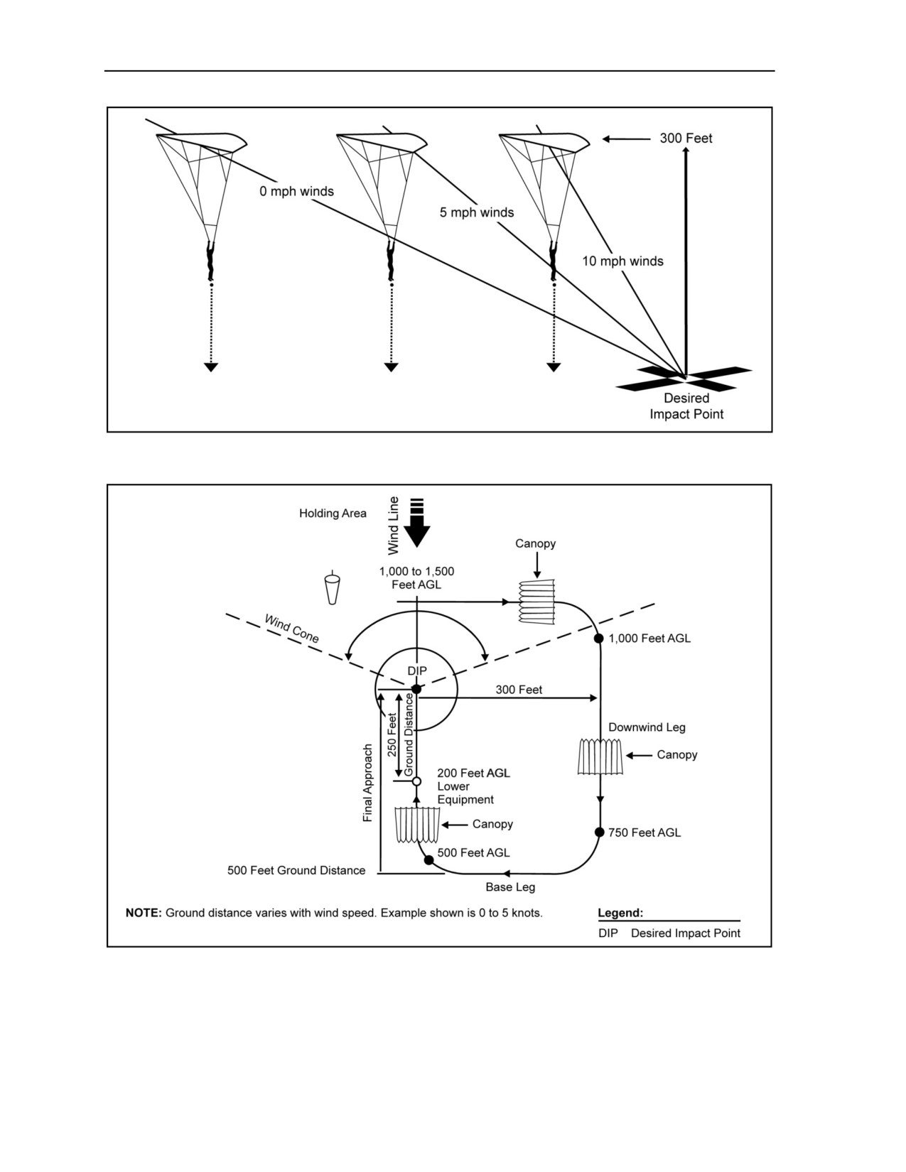
8-68. Figure 8-23, page 8-22, shows approximate glide angles for a final approach flown at the half-brakes
setting for the MC-4. Figure 8-24, page 8-22, shows an example of landing approaches.
24 October 2014
ATP 3-18.11/AFMAN 11-411(I)/NTTP 3-05.26M
8-21
Chapter 8
Figure 8-23. Glide angles for a final approach
Figure 8-24. Landing approaches
8-22
ATP 3-18.11/AFMAN 11-411(I)/NTTP 3-05.26M
24 October 2014
Ram-Air Parachute Flight Characteristics
and Canopy Control
WARNING
The preferred direction for landing is into the wind, but it is far
more important to have all the canopies land in the same landing
direction and follow the established pattern than it is to land into
the wind. Any wind that is a quartering headwind is safe for
jumpers of any level to land in.
WARNING
The parachutist maintains a sharp lookout for fellow parachutists
at
500 feet AGL and below to avoid canopy collisions and
entanglements. The lower parachutist has the right-of-way.
HIGH AND LOW WIND PATTERNS
8-69. The parachutist will tighten pattern as wind speed increases; downwind leg should be closer to wind
line (Figure 8-25), and the base leg will move closer to the desired impact point.
Figure 8-25. High and low wind patterns
ADJUSTING FOR CHANGES IN WIND DIRECTION
8-70. It is not uncommon for the wind to change during the course of jump operations. Most changes are
minor and can be corrected for by slight adjustments on final approach. If the change in wind direction is
significant (Figure 8-26, page 8-24) and it is recognized prior to entering the pattern, it may be preferable to
shift the entire pattern. Shifting the pattern will increase the potential for landing directly into the wind, but
jumpers should be cautious to avoid chasing the wind sock with light and variable wind conditions.
24 October 2014
ATP 3-18.11/AFMAN 11-411(I)/NTTP 3-05.26M
8-23

Chapter 8
Figure 8-26. Significant change in wind direction
TURBULENCE
8-71. Turbulence is the result of an air mass (wind) flowing over obstructions on the earth’s surface.
Common obstructions are irregular terrain
(bluffs, hills, mountains), man-made features
(buildings,
elevated roadways, overpasses), or natural features, such as tree lines. A disturbance of the normal
horizontal wind flow causes turbulence. As the air mass moves around and over the obstruction, it
transforms into a complicated pattern of eddies and other irregular air movements. Turbulence generally
affects the flight of the parachute at the most critical time for the parachutist—the last 200 feet of canopy
flight.
8-72. In general, with ground wind speeds less than 10 knots, both the windward and leeward sides of an
obstruction cause small eddies 10 to 50 feet in depth. When wind speeds are between 10 and 20 knots,
obstructions can cause currents that are several hundred feet in depth. In addition, there will still be eddies
on the windward and leeward side near the obstruction. At wind speeds greater than 20 knots, currents
formed on the leeward side are carried considerable distances beyond the object that created them. Only
minor eddies and currents form over smooth water surfaces. Turbulence is worse over choppy swells closer
to the surface of the water because of the wind flow over a constantly changing surface configuration. Over
mountains, even light winds (moving air masses) pushed up mountainsides or redirected down valleys can
form major eddies and air currents that have violent, abrupt characteristics. In addition, in
HAHO operations in mountains or around hilly terrain, unstable air masses form currents that continue to
grow in size and complexity. The resultant turbulence can extend up to thousands of feet AGL. Turbulence
is also caused by heat rising off roads, concrete, and urban built-up areas and clearings.
8-73. An example of turbulence is the vortex created by aircraft taking off or landing. The turbulence
created by these aircraft can invert smaller aircraft landing too closely behind them. Another example is the
turbulence behind another parachutist’s canopy. The parachutist who finds himself behind this canopy will
feel the turbulence it creates. Turbulence can exist around any cloud mass. Individual clouds probably will
not create turbulence. Clouds that mark the leading edge of an air mass probably will contain strong
downdrafts. Cloud decks capping mountain ridges will contain very strong downdrafts and abrupt
turbulence. Those type cloud formations will contain rapid pressure differentials. Altimeter readings should
be suspect because the parachutist could be 1,000 feet lower than the indicated altitude on the altimeter.
The parachutist should avoid at all costs clouds that contain thunderhead activity because of the violent
turbulence associated with those formations.
8-24
ATP 3-18.11/AFMAN 11-411(I)/NTTP 3-05.26M
24 October 2014
Ram-Air Parachute Flight Characteristics
and Canopy Control
ADJUSTING FOR CHANGES IN WIND VELOCITY
8-74. When winds increase during the jump, it is important to recognize the change and make the
necessary adjustments (Figures 8-27 through 8-29, pages 8-25 and 8-26). Most adjustments are fairly
straightforward and entail reducing the distance traveled on the downwind leg or “cutting corners” of the
base leg. Adjusting for a decrease in winds does not always require changing the pattern. Sinking from the
original setup point will usually result in an acceptable sight picture. Extending the base leg is acceptable if
the parachutist is the last jumper in the stick, but the potential for airspace conflicts increases.
Figure 8-27. Adjusting for increase in winds on downwind leg
Figure 8-28. Adjusting for increase in winds on base leg
24 October 2014
ATP 3-18.11/AFMAN 11-411(I)/NTTP 3-05.26M
8-25
Chapter 8
Figure 8-29. Adjusting for decrease in winds on base leg
LAND AND SEA BREEZES
8-75. The thermal differences of air masses associated with the interface along shorelines (oceans, lakes,
and rivers) causes land and sea breezes. In the daytime, landmasses warm up faster than water. The air
above the land rises, causing a lower air density than over the water. The air flows from the water over the
land to replace the lower air density there. This phenomenon creates onshore breezes known as sea breezes
(or lake breezes). It is most evident on clear, summer days in lower latitudes. The same phenomenon occurs
in reverse in the evening because of the more rapid cooling of the landmass. The reversed process creates
land breezes. The airflow over obstacles near shoreline DZs creates turbulence; when farther away from the
coast, turbulence might not exist.
Note: If turbulence is encountered at altitude, parachutist should maintain full flight.
VALLEY AND MOUNTAIN BREEZES
8-76. Winds generally flow upslope on warm days in mountainous terrain. They flow downslope in the
evening as the air masses cool. During the day, the winds create valley breezes; at night, the reverse process
creates mountain breezes. These breezes, coupled with the airflow over obstacles, can cause strong and
unpredictable turbulence.
8-26
ATP 3-18.11/AFMAN 11-411(I)/NTTP 3-05.26M
24 October 2014

Chapter 9
Emergency Procedures for Military
Free-Fall Operations
Military free-fall airborne operations are inherently dangerous. Emergencies may
occur before or during takeoff, during flight, while in free fall, or during canopy
descent. Safety considerations require that each parachutist be able to recognize an
emergency situation and react accordingly. Any departure from these emergency
procedures may interfere with the parachutist’s conditioned response. This action can
lead to a delay at a critical time with the potential of causing injury or death. This
publication strongly recommends that all parachutists follow these procedures.
REFRESHER TRAINING
9-1. The conditioned response executed as the correct procedure for a particular emergency is a highly
perishable skill. Refresher training must include performance-oriented training with special emphasis on
emergency procedures and the actions required to respond successfully to any situation. This training must
take place before each MFF airborne operation. The duration of the training should be commensurate with
the time between airborne operations and, at the very least, until each parachutist is confident in his
emergency procedure skills.
EMERGENCY MEASURES
9-2. The procedures established by this publication in response to emergency situations have proven to be
the most successful in both MFF training and tactical environments. Figures 9-1 through 9-5, pages 9-1
through 9-10, and Tables 9-1 through 9-6, pages 9-2 through 9-9, depict the emergency procedures that will
be used with the RAPPS during emergency situations.
Parachutist—
Learns the location of emergency exits and how to open them.
Secures all loose items.
Wears helmet.
Fastens seat belt securely.
Figure 9-1. Emergency preparations before takeoff
24 October 2014
ATP 3-18.11/AFMAN 11-411(I)/NTTP 3-05.26M
9-1

Chapter 9
Table 9-1. In-flight emergency procedures and signals
Parachutist’s
Parachutist’s
Actions in Fixed-
Actions in Rotary-
Situation
Signal
Wing Aircraft
Wing Aircraft
Crash Landing:
Continuous ringing of
Remains seated until
Follows aircrew
During takeoff.
alarm bell or verbal
aircraft stops, then
instructions.
warning by aircrew.
exits.
Pulls legs inside
aircraft.
During flight.
Six short rings of alarm
If time and altitude
bell or verbal warning
permit, jumps.
Remains in position.
by aircrew.
If not, secures seat
Covers head with
One long ring of alarm
belt.
arms.
bell.
Braces for impact.
Clears the aircraft as
soon as it stops and
moves well away from
it.
NOTE: Jumpmaster
ensures all personnel are
away from the wreckage.
NOTE: Parachutists coordinate opening the aircraft
exits with the aircrew.
Below 1,000 feet
Six short rings of alarm
Takes aircraft seats
Takes aircraft seats
AGL.
bell or verbal warning
and fastens seat
and fastens seat belts.
by aircrew.
belts.
Prepares for crash
One long ring of alarm
Prepares for crash
landing.
bell.
landing.
Braces for impact.
Emergency Bailout:
Three short rings of
Prepares for exit.
Exits at the
1,000 to 3,000 feet
alarm bell or verbal
Exits at the
jumpmaster’s
AGL.
warning by aircrew.
jumpmaster’s
command.
Green light.
command.
Deploys the reserve
One long sustained
Deploys the reserve
parachute
ring of alarm bell.
parachute
immediately.
immediately.
Attempts to land with
Attempts to land with
the other jumpers.
the other jumpers.
Above 3,000 feet
Three short rings of
Prepares for exit.
Exits at the
AGL.
alarm bell or verbal
jumpmaster’s
Exits at the
warning by aircrew.
jumpmaster’s
command.
Green light.
command.
Deploys the main
One long sustained
parachute after a
Deploys the main
ring of alarm bell.
maximum 5-second
parachute after a
delay.
maximum 5-second
delay.
Attempts to land with
the other jumpers.
Attempts to land with
the other jumpers.
Ditching Over Water
Six short rings of alarm
Remains seated.
Pulls legs inside
With Insufficient Drop
bell.
Secures seat belt.
aircraft.
Altitude.
Verbal warning by
Remains in position.
aircrew.
Covers head with
One long ring of alarm
arms.
bell.
9-2
ATP 3-18.11/AFMAN 11-411(I)/NTTP 3-05.26M
24 October 2014

Emergency Procedures for Military Free-Fall Operations
Table 9-2. In-flight emergency procedures
Situation
Jumpmaster/Jumper Responsibility
Ramp and Doors Closed:
Shouts “PILOT CHUTE” and contains the pilot
Main pilot chute deploys.
chute and canopy in the aircraft.
Moves the jumper to the front of the plane.
Disconnects the RSL and cuts away from the main
parachute.
Keeps the rig on, sits in the seat, and secures his
seat belt.
NOTE: In an aircraft emergency, the jumper can still exit
the aircraft on his reserve.
Reserve pilot chute deploys.
Shouts “PILOT CHUTE” and contains pilot chute.
Moves the jumper to the front of the plane.
Removes the parachute system from the jumper.
Sits in the seat and fastens his seat belt.
Lands with the aircraft.
Ramp or Door Open:
Main pilot chute deploys.
Same as above; the pilot chute is contained.
Reserve pilot chute deploys.
Same as above; the pilot chute is contained.
WARNING
If parachutist is standing in the vicinity of an open door or ramp and he experiences a
premature deployment, he tries to contain it; if any portion of the parachute goes out of the
aircraft, he exits immediately to minimize or avoid serious injury.
Altimeter Failure.
Gets the attention of the jumpmaster.
Replaces the altimeter with the spare in the
jumpmaster bag.
If an altimeter is not available, the jumper is moved
to the front of the aircraft, seated, with seat belt
fastened.
NOTE: The jumper can exit the aircraft in an emergency
situation.
Equipment Malfunctions.
Gets the attention of the jumpmaster.
Corrects the malfunction or make the determination
for the jumper to land with the aircraft.
24 October 2014
ATP 3-18.11/AFMAN 11-411(I)/NTTP 3-05.26M
9-3

Chapter 9
Table 9-3. Emergencies in free fall
Emergency
Parachutist’s Procedures
Collision on Exit.
Maintains his arch, gently pushes off (with an open hand) the
parachutist, regains his stability, checks his altimeter, checks the
ripcords, and continues the MFF as planned.
NOTE: The parachutist does not grab anything.
Instability in Free Fall:
Counters, relaxes, arches, checks his hands and feet, and maintains
Spinning.
altitude awareness.
If unable to gain control of spin, waves off and pulls.
Tumbling.
Arches, keeps his head up, checks his hands and feet, and maintains
altitude awareness.
If unable to maintain altitude awareness and control tumbling, waves
off and pulls.
Entering a cloud or loss of
Stops all movement and returns to a stable, relaxed arch.
visibility.
Maintains altitude awareness.
Pulls at the prescribed altitude even if he is still in the cloud.
Rucksack Shifts.
Counters any turns by turning in the opposite direction.
NOTE: If the rucksack strap moves below his knee, parachutist makes
one attempt to replace it while maintaining stability. If unsuccessful, he
relaxes and attempts to fly. If the parachutist loses altitude awareness
and is unable to gain control, he will wave off and pull.
Premature Opening:
Determines which canopy is deployed.
Main parachute.
Determines by the 3-ring assembly, D-bag, and pilot chute.
Conducts a controllability check.
Reserve parachute.
Determines by NO 3-ring assembly, NO D-bag, and pilot chute.
Conducts postopening procedures.
Collision Avoidance During Free
Lower jumper has the right-of-way.
Fall.
Never gets over the top of another jumper.
Uses forward glide, back slide, or side slide to get off a jumper’s
back.
Lost or Broken Altimeter.
Immediately clears airspace, waves off, and pulls.
Maintains altitude awareness.
Lost or Broken Goggles.
Maintains his arch.
Reaches up with both hands symmetrically (keeping elbows high),
finds and replaces the goggles.
If unable to find the goggles, squints his eyes and maintains altitude
awareness.
If unable to maintain altitude awareness, waves off and pulls.
9-4
ATP 3-18.11/AFMAN 11-411(I)/NTTP 3-05.26M
24 October 2014

Emergency Procedures for Military Free-Fall Operations
Table 9-4. Cutaway procedures
Malfunction
Parachutist’s Procedures
Total Malfunction: Occurs when the canopy
Throw away the main ripcord.
remains in the container assembly after the
Counter with the left hand.
ripcord has been pulled.
Look to identify the red cutaway handle on the right
Partial Malfunction: Occurs when the container
assembly opens but the canopy does not fully or
main lift web, chest high, inboard.
properly deploy.
Grab the red cutaway handle with the right hand.
Pull the red cutaway handle to a full-arm extension.
Throw away the red cutaway handle.
Counter with the right hand.
Look to identify the reserve ripcord handle on the
left main lift web, chest high, inboard.
Grab the reserve ripcord handle with the left hand.
Pull the reserve ripcord handle to a full-arm
extension.
Throw away the reserve ripcord handle.
Raise right shoulder to ensure the reserve pilot
chute has launched.
Upon opening, hands go to rear risers.
Clears airspace. Turns right to avoid collision, unless left is closer.
Activates the strobe light, as required.
Releases the brakes and gains control of the canopy; if controllability is questionable, performs a
controllability check.
If a malfunction cannot be resolved and if the canopy is uncontrollable, the decision to cut away must
be made by 2,500 feet AGL and cutaway performed by 2,000 feet AGL.
Orients himself to the drop zone.
Locates other jumpers and achieves separation.
Maintains altitude awareness.
Checks rate of descent with other parachutists.
Figure 9-2. Parachutist postopening procedures
Parachutist—
Releases the brakes.
Looks left, clears airspace, and turns left 90 degrees.
Looks right, clears airspace, and turns right 90 degrees.
Determines the stall point.
NOTE: If the canopy requires more than 50-percent opposite toggle input to counter a turn, the canopy is
uncontrollable. If the canopy stalls before 50-percent brake setting, the canopy is uncontrollable.
NOTE: If the canopy is uncontrollable, parachutist performs cutaway procedures.
Figure 9-3. Controllability check
20 October 2015
ATP 3-18.11/AFMAN 11-411(I)/NTTP 3-05.26M, C1
9-5
Chapter 9
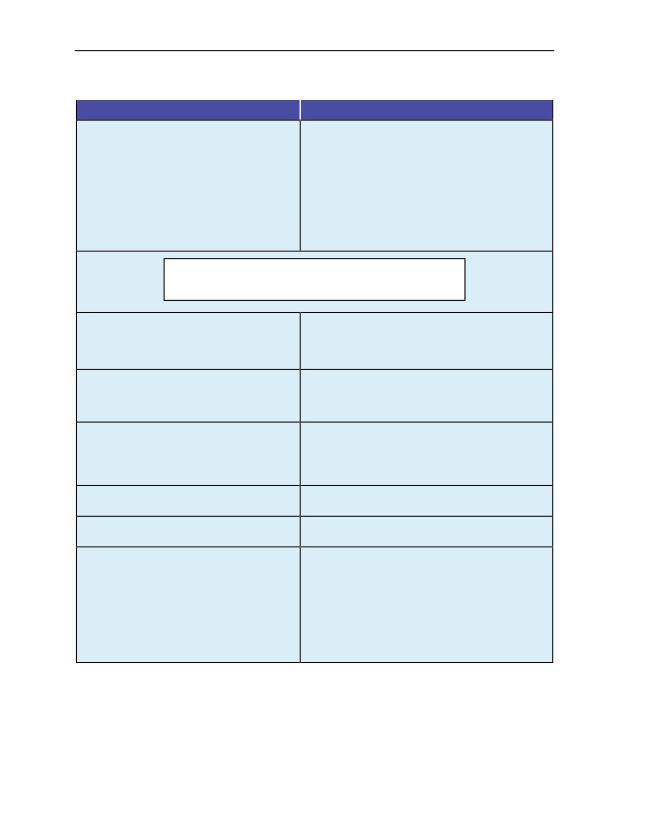
Table 9-5. Malfunction procedures
Malfunction
Parachutist’s Procedures
Floating Ripcord or Unable to See Ripcord.
Arches, looks.
If unable to see the ripcord or if it is floating, locates
the cable housing on his right shoulder with his
right hand.
Traces the cable housing down to where the
ripcord cable protrudes out.
Makes a circle with his index finger and thumb and
pulls to full-arm extension.
Makes one attempt; if unsuccessful, performs
cutaway procedures.
WARNING
Parachutist makes no more than two attempts to locate the
ripcord (the initial attempt is the first attempt).
Hard Pull.
If the pull is unsuccessful, comes across with the
left hand in a punching motion and pushes the right
hand and ripcord out.
If still unsuccessful, performs cutaway procedures.
Pack Closure.
Raises right shoulder to disrupt the partial vacuum
while continuing to look straight down.
If main parachute does not deploy, performs
cutaway procedures.
Pilot Chute Hesitation.
Raises right shoulder to disrupt the partial vacuum
while continuing to look straight down to clear the
burble.
If main parachute does not deploy, performs
cutaway procedures.
Horseshoe.
Performs cutaway procedures immediately.
Makes no attempt to clear this malfunction.
Bag Lock.
Performs cutaway procedures immediately.
Makes no attempt to clear this malfunction.
Streamer/Snivel.
Reaches up and releases the brakes.
Pulls the toggles down to full-brakes position for
3 to 4 seconds.
Lets up slowly to 50-percent brake setting.
If the malfunction is not clear, makes one more
attempt to pull the toggles down to full-brakes
position for 3 to 4 seconds.
If the malfunction still has not cleared, performs
cutaway procedures.
9-6
ATP 3-18.11/AFMAN 11-411(I)/NTTP 3-05.26M, C1
20 October 2015

Emergency Procedures for Military Free-Fall Operations
Table 9-5. Malfunction procedures (continued)
Malfunction
Parachutist’s Procedures
Hung Slider.
Reaches up and releases the brakes.
Pulls the toggles down to the full-brakes position for
3 to 4 seconds.
Lets up slowly to the 50-percent brake setting.
If the slider did not come down, pulls the toggles
down to full-brakes position for 3 to 4 seconds.
Lets the toggles all the way up slowly.
If the slider did not come down below the cascade
point on the lines, after two attempts performs
cutaway procedures.
If the slider came down below the cascade point on
the lines, performs controllability check and
continues to attempt to get the slider down,
maintaining air awareness.
Closed End Cells.
Reaches up and releases the brakes.
Pulls the toggles down to full-brakes position for
3 to 4 seconds.
Lets up slowly to 50-percent brake setting.
If the end cell did not inflate, pulls the toggles down
to full-brakes position for 3 to 4 seconds.
Lets the toggles all the way up slowly.
If the end cells have not inflated, performs a
controllability check.
If uncontrollable, executes cutaway procedures.
Pilot Chute Over the Nose.
Performs postopening procedures.
Performs a stall and recovery in an attempt to sling
the pilot chute to the rear.
If the pilot chute did not go to the rear of the
canopy, performs a controllability check.
If uncontrollable, executes cutaway procedures.
Premature Brake Release.
Immediately releases the opposite toggle/brake.
Performs postopening procedures.
Broken Control Lines.
Releases the brakes and steers with the remaining
control line and rear riser.
Continues the postopening procedures.
At a safe altitude, determines the stall point with the
rear risers.
NOTE: Jumper lands using the rear risers; he DOES
NOT land with one toggle and one riser.
Broken Lines (A, B, C, D).
Determines which and how many lines are broken.
Performs canopy controllability check.
If uncontrollable, executes cutaway procedures.
24 October 2014
ATP 3-18.11/AFMAN 11-411(I)/NTTP 3-05.26M
9-7

Chapter 9
Table 9-5. Malfunction procedures (continued)
Malfunction
Parachutist’s Procedures
Line Twists.
Reaches up with both hands and grabs the risers,
thumbs down.
Pulls hands apart and kicks in a bicycle motion.
Maintains altitude awareness.
If still twisted by 2,500 feet AGL, executes cutaway
procedures.
NOTE: Jumper DOES NOT release the brakes until all
the twists are out.
Holes and Tears (During Postopening
If the hole or tear is in the lower skin of the canopy,
Procedures).
performs a controllability check.
If uncontrollable, executes cutaway procedures.
If the hole or tear is in the top skin of the canopy,
immediately performs cutaway procedures.
Tension Knots (During Postopening Procedures).
If a tension knot is noticed in the lines, reaches up
and grabs the affected line group and pulls it down
to his chest; releases the lines in a snapping
motion in an attempt to clear the knot.
Repeats only twice.
If it fails to clear, performs controllability check.
If uncontrollable, executes cutaway procedures.
Dual Canopies:
If brakes have not been released, leaves them
Main inflated with reserve deployed but
stowed.
not inflated or is still in the D-bag.
If brakes have been released, lets the toggles all
the way up.
Slowly pulls the reserve in and places it between
his legs.
Is prepared to perform cutaway procedures should
the reserve inflate.
NOTE: If the reserve starts to inflate, jumper waits until it
is above shoulder level to perform cutaway procedures.
Both the main and reserve canopies are
First, determines if the canopies are entangled.
deployed and inflated.
If the canopies are not entangled, separates the
canopies and performs cutaway procedures.
If the canopies are entangled or unsure whether
they are or not, assumes they are.
The canopies will be in one of three configurations:
Biplane, one behind the other.
Side by side.
Down plane.
The goal is to keep the canopies together; to do
this, steers one canopy with the rear risers and
turns that canopy into the other one.
Applies minimal input to the canopy to land into the
wind safely.
NOTE: Jumper DOES NOT release his brakes in a dual
canopy situation.
NOTE: There is no special emergency procedure associated with the use of NVGs during MFF operations. If a
horseshoe malfunction occurs, the jumper should make no attempt to clear the malfunction and should
immediately execute cutaway procedures.
9-8
ATP 3-18.11/AFMAN 11-411(I)/NTTP 3-05.26M
24 October 2014

Emergency Procedures for Military Free-Fall Operations
Table 9-6. Canopy entanglement procedures
Situation
Higher Parachutist
Lower Parachutist
Lower parachutist is entangled
Attempts to clear off the lower
If canopy cannot be cleared,
with higher parachutist, and
canopy.
checks the altitude.
higher parachutist has a good
Above 2,000 feet AGL,
canopy.
disconnects RSL and performs
cutaway procedures.
Above 2,000 feet AGL.
NOTE: If lower canopy is cleared, it should reinflate in 150 to 200 feet.
1,000 to 2,000 feet AGL.
Makes every effort to control
Performs cutaway procedures.
lower canopy.
OR
Prepares to do a PLF.
Jettisons equipment.
Lands with higher parachutist.
Prepares to do a PLF.
Below 1,000 feet AGL.
Makes every effort to maintain
Jettisons equipment.
control of lower canopy.
Lands with higher parachutist.
Prepares to do a PLF.
Prepares to do a PLF.
NOTE: The higher parachutist should fly the final approach and land with
half brakes.
Both parachutists are entangled,
Gets clear of entangled lines
Cuts away after the higher
and neither has a good canopy.
and cuts away (altitude
parachutist (altitude permitting).
permitting).
At any altitude.
DANGER
The higher parachutist may be fatally engulfed in the
canopies if the lower parachutist performs a cutaway first.
If still unsuccessful at 1,000 feet, both jumpers must deploy reserve
parachutes in an attempt to slow the descent.
If only one reserve parachute deploys, the parachutist with the good
reserve must bring the other parachutist to the ground.
If both reserves deploy, parachutists cut away from the entanglement.
NOTE: Communication between the parachutists and altitude awareness
are critical in successful disengagement.
24 October 2014
ATP 3-18.11/AFMAN 11-411(I)/NTTP 3-05.26M
9-9

Chapter 9
Trees
Wires
Water
Does not lower equipment;
Avoids wires at all costs, even
Jettisons oxygen mask and
jettisons if it was lowered.
if a downwind landing is
equipment.
required.
Turns canopy into wind.
Unhooks RSL.
Throws away ripcord.
Brakes as needed
Unfastens chest strap and waist
(50-percent or more braking
Turns off oxygen.
strap.
position) to achieve vertical
Slows canopy down.
Inflates flotation device, if
descent through the trees.
available.
Streamlines body while
Prepares for a PLF.
passing through the wires.
Turns canopy into the wind.
Uses forearms to protect
If entangled, remains
Uses brakes to slow airspeed.
face while passing through
motionless until power is
After entering water, releases
trees.
disconnected.
leg straps (as feet contact the
If suspended, signals for
Prepares to do a PLF after
water) and swims free of the
assistance.
passing through the wires.
harness and upstream from the
Attempts to land between
If the parachute is entangled in
canopy.
smaller trees.
the wires and contact with the
If being dragged in the water,
NOTE: Goggles and oxygen
ground is made, cuts away
cuts away the main canopy.
mask provide additional face
from the main chute
If trapped under the canopy,
and eye protection.
immediately and moves away.
follows a seam to the edge.
NOTE: If time and altitude permit,
Signals for assistance using
parachutist unhooks the RSL and
emergency devices.
jettisons equipment.
NOTE: On entering water,
parachutist must be prepared for a
normal landing or a PLF.
Figure 9-4. Parachutist emergency landing procedures
Parachutist—
After landing, releases one toggle and pivots in direction of retained toggle.
Pulls the toggle hand over hand until either the canopy collapses or he has canopy fabric in hand.
Attempts to run behind the canopy or downwind of the canopy.
If unable to recover from a drag, ensures the RSL has been disconnected and pulls the cutaway
pillow to release the main canopy.
Figure 9-5. High-wind landing procedures
ACTIONS FOR DUST DEVILS AND TURBULENT AIR
9-3. Parachutists should stay alert under canopy for signs of swirling or erratic wind conditions. The
DZSO may use red smoke or flares to warn of visible turbulence, such as dust devils. Parachutists avoid
turbulence at all costs by maneuvering away under canopy. If the parachutist is unable to avoid the
turbulence, he should maintain full flight and remove all slack from the brake lines to prepare for a possible
canopy collapse. If the canopy does begin to collapse, the parachutist should quickly conduct a
12- to 24-inch strike on the toggles to prevent collapse. Depending on the altitude, the parachutist should
reattempt this procedure until the canopy reinflates or landing is imminent. As the parachutist approaches
the ground, he should flare the canopy fully and be prepared to conduct a PLF.
9-4. If the parachutist lands and is overtaken by a dust devil, he should—
z
Try to gather up the canopy.
z
Lay down on top of the canopy.
z
If unable to control the canopy, disconnect the RSL and cut away.
9-10
ATP 3-18.11/AFMAN 11-411(I)/NTTP 3-05.26M
24 October 2014

Chapter 10
High-Altitude High-Opening
and Limited-Visibility Operations
Standoff delivery techniques offer the commander a unique method for infiltrating
trained operational elements. The RAPPS gives the commander a tactical capability
to infiltrate these elements by parachute without requiring the aircraft to overfly the
intended DZ. These elements can be released at an offset release point and navigate
long distances under canopy. The flight characteristics of the reserve parachutes of
the RAPPSs are identical to the main parachutes. This fact increases the chance of a
successful infiltration should a cutaway from the main parachute take place because
of a malfunction.
Note: For parachute systems that have a smaller reserve canopy than the main canopy, the
mission commander planning the operation must plan for contingencies that address the reduced
glide capability should a cutaway from the main parachute take place. Canopy openings at
6,000 feet AGL or above are considered HAHO jumps.
TECHNIQUES AND REQUIREMENTS
10-1. The parachutist uses a combination of delayed free-fall and HAHO techniques if making exits at an
altitude above 25,000 feet MSL. He can also deploy his parachute at intermediate altitudes to minimize the
chance of parachute damage or injury to himself upon canopy deployment, while using the glide advantage
of the RAPPS.
WARNING
The maximum deployment altitude of the MC-4 RAPPS is
25,000 feet MSL.
10-2. The commander should consider altitude requirements when conducting training at altitudes. It is
recommended that routine HAHO training be conducted at or below 19,999 feet MSL. Conducting training
at lower altitudes eliminates the need for oxygen prebreathing and additional support personnel, and
minimizes the chance of parachute damage and injury to the parachutist due to opening forces. The
parachutist is also less likely to encounter physiological problems and cold-weather injuries.
10-3. HAHO standoff parachuting requires extensive airspace clearance. In addition, this training must take
place in areas having alternate DZs should the parachutist (or element) not be able to reach the primary DZ.
10-4. Accurate weather data is essential. Wind directions and speeds are critical for route planning. Air
temperatures are important for preparing against exposure injuries. An excellent source of real-time
accurate weather comes from artillery unit support. If the meteorological exploitation team weather section
is deployed near the DZ, this organization has the ability to supply wind direction and speed every
1,000 feet up to 25,000 feet MSL or higher, depending on the conditions.
24 October 2014
ATP 3-18.11/AFMAN 11-411(I)/NTTP 3-05.26M
10-1
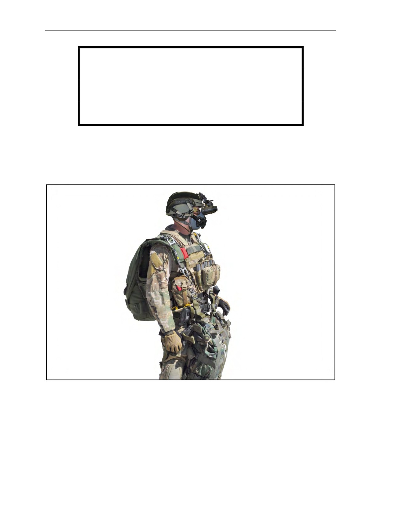
Chapter 10
WARNING
Icing conditions may occur at high altitude or during adverse
weather conditions. Ice formation on the parachute canopy
adversely affects its flight characteristics by increasing the rate of
descent and decreasing its responsiveness. This condition
results in less distance traveled under canopy with a decrease in
canopy control.
SPECIAL EQUIPMENT
10-5. Individual body armor should be rigged and worn with all pouches in a manner that allows for a
proper fit of the MC-4 RAPPS (Figure 10-1). The added bulk of the body armor will not affect the
performance of the MC-4; however, jumpers and jumpmasters must ensure that all handles are free and
clear of any equipment and easily manipulated during any emergency procedures.
Figure 10-1. Jumper with individual body armor
10-6. Special precautions must be taken to prevent exposure injuries to the parachutist at high altitude.
Gloves are necessary to protect the hands. The gloves, however, must not interfere with the manual
activation of the main parachute or the performance of emergency procedures. The following paragraphs
discuss special equipment that the parachutist should use. Future MFF individual clothing and/or protective
equipment, like the USMC parachutist individual equipment kit in Chapter 2, should be looked at to
determine the needs of the force when jumping in these extreme conditions to keep the parachutist
comfortable and safe at any altitude or in extreme conditions.
10-2
ATP 3-18.11/AFMAN 11-411(I)/NTTP 3-05.26M
24 October 2014
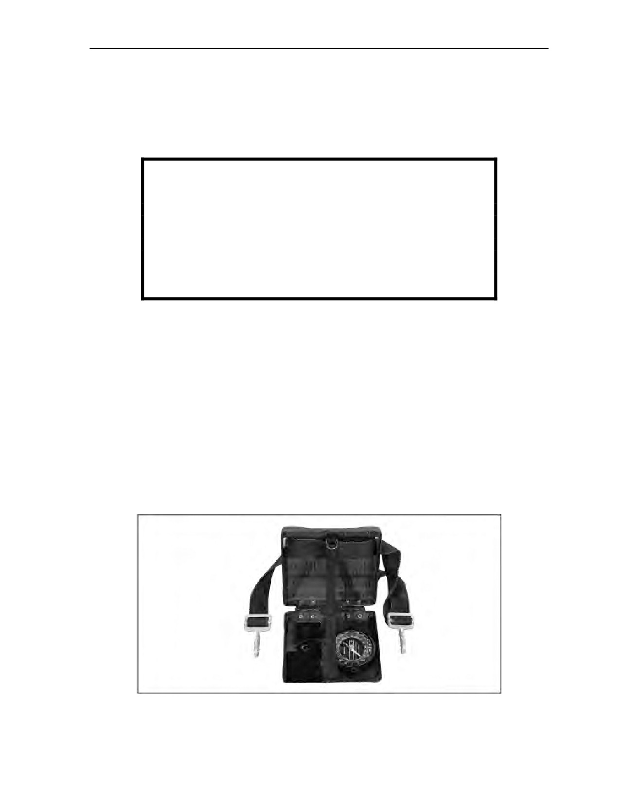
High-Altitude High-Opening and Limited-Visibility Operations
TOGGLE EXTENSIONS
10-7. Toggle extensions permit the parachutist to keep his hands at waist level during extended flights.
They also allow for improved blood circulation to the hands and arms and lessen fatigue. Another
technique is to leave the brakes stowed and simply steer the parachute using the risers to make needed
corrections. If necessary, extreme cold weather gloves can be put on after canopy deployment to keep the
parachutist’s hands from numbing and to increase circulation.
WARNING
Jumper must not use the toggle extensions during landing for
flaring. Toggle extensions affect the control range of toggle input
to the canopy, and will not allow the toggles to be extended far
enough for flaring the canopy during landing. Jumper should put
wrist all the way through toggle extension loops. Extensions
cannot be restowed once used; letting them hang beneath
toggles can cause interference with jumper’s equipment, which
could inhibit the jumper’s ability to flare.
NAVIGATIONAL TOOLS
10-8. HAHO parachute operations require the use of navigational tools to assist the parachutist with
navigating from the predetermined “opening point” to the “point of impact.” Oftentimes, tactical parachute
operations are conducted at extreme high altitudes in order to maximize the parachutist standoff distance.
Extreme high-altitude operations place a higher reliance on the GPS for navigating from the opening point to
the intended point of impact. Temperatures at these extreme high altitudes have an adverse effect on the
electronic and light-emitting diode screen of the attached GPS unit and require additional thermal protection.
Compass
10-9. Each parachutist needs a compass to determine direction should he separate from the group or during
limited visibility, such as when passing through cloud layers. A marine-type, oil-dampened compass that is
unaffected by pressure changes or cold weather is recommended. The compass (Figure 10-2) must show
direction regardless of its mounted attitude on the parachutist. The parachutist takes care when mounting
the compass to avoid erroneous readings caused by interference from radios or other electronic navigation
aids. He adjusts the declination of his compass while wearing all his accompanying equipment. This action
will account for all magnetic variances caused by accompanying metal objects.
Figure 10-2. Compass mounted to high-altitude high-opening navigation board
24 October 2014
ATP 3-18.11/AFMAN 11-411(I)/NTTP 3-05.26M
10-3
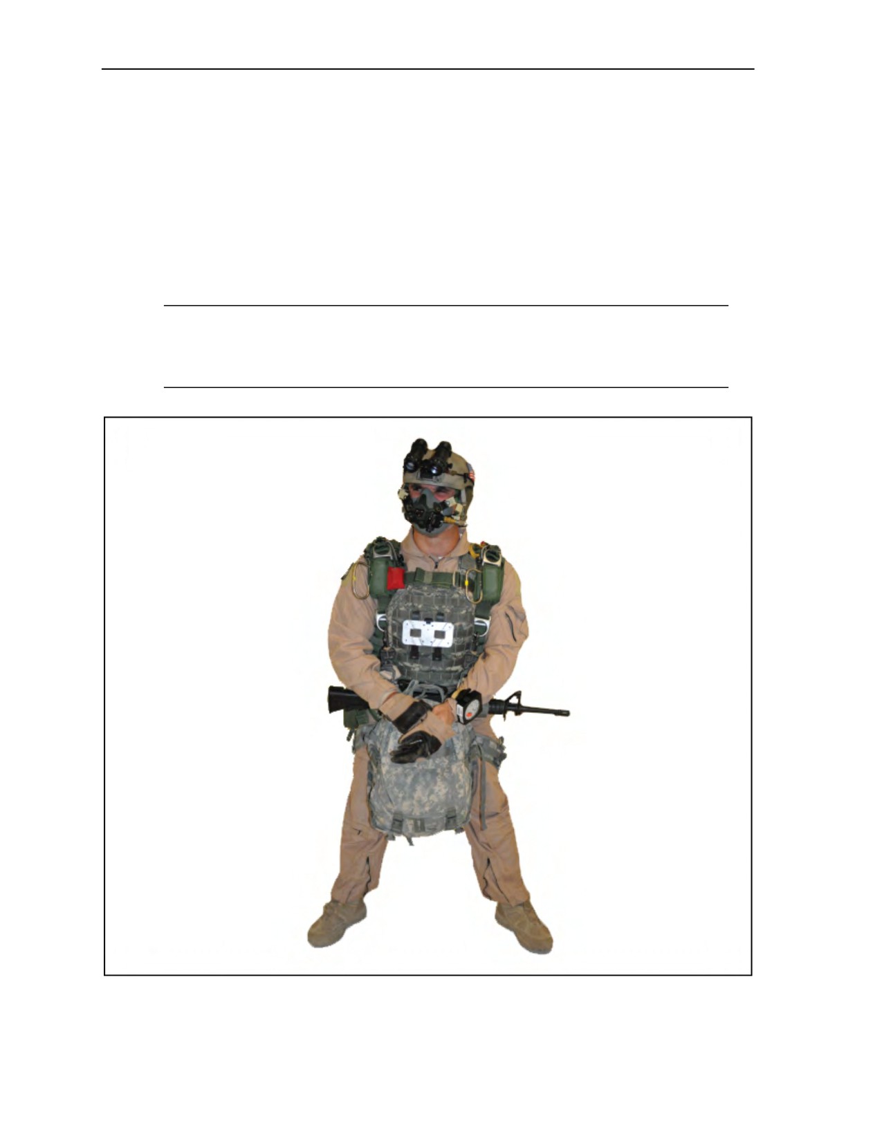
Chapter 10
Electronic Navigation Devices
10-10. The parachutist mounts the electronic navigation or guidance devices by a multi-adjustable,
articulating front plate for mounting the board to the parachutist by means of a variety of harnesses and
Velcro to secure the front plate (Figure 10-3). The electronic navigation board is enclosed in a container
and folded up on the chest during free fall, so as not to interfere with the manual activation of the main
parachute or the performance of emergency procedures. The container with the electronic navigation device
can be opened once the main canopy has deployed to assist the parachutist with the heading and other
information when flying the canopy to the desired impact point. Parachutists should take caution that they
not become fixated on the navigation device and stay alert of their surroundings during flight.
Considerations should also be taken into account that the use of electronic navigation devices may increase
the likelihood of detection during infiltration.
Note: Due to the extremely cold temperatures at these altitudes, regular commercial hand
warmers may be placed inside the electronic navigation devices for additional thermal protection
for navigation devices that do not have their own heated storage box to keep the device from
freezing.
Figure 10-3. Navigation aid attaching point
10-4
ATP 3-18.11/AFMAN 11-411(I)/NTTP 3-05.26M
24 October 2014

High-Altitude High-Opening and Limited-Visibility Operations
WARNING
The use of GPS-assisted parachute and aerial delivery operations
is on the rise. Soldiers involved in these operations routinely
bring GPS receiver and/or repeaters onto the aircraft to provide
remote wireless in-flight updates to their jumper and/or cargo
bundle guidance systems. AR
70-62 requires that carry-on
equipment with an in-flight mission requirement be assessed by
the appropriate Army-level Airworthiness Release Authority to
ensure the equipment will not negatively impact the aircraft or its
subsystems. That assessment will determine the extent of
airworthiness qualification and/or testing and documentation
required for in-flight use. The failure to do so can lead to aircraft
system problems ranging from inaccurate drop points to aircraft
system shut-downs—particularly on aircraft equipped with more
modern digitalized aircraft systems. Civilian contract air
operators may experience similar aircraft system problems. Units
are prohibited from using unapproved systems in Army aircraft
until they have been assessed and approved for use. The devices
listed below have been issued an Airworthiness Release and are
currently approved for use on the CASA 212-200; however, their
use requires disabling the aircraft’s onboard GPS navigation
system:
JPADS, Inc. Block III Kit and Receiver.
GPSRKL1M-AXX-PM/5-TF Military Mobile L1 Repeater.
Requests to use equipment other than that listed above should be
directed to: Commander, USASOC, ATTN: Special Operations
Aviation, Special Programs Office, AOAO-SP, Fort Bragg, NC
28310-9610.
10-11.
One type of navigation board that is being used is the Wilcox Parachutist Navigation Board
described below and in Figure 10-4, page 10-6. Figure 10-5, page 10-7, shows the Wilcox Parachutist
Navigation Board going from the closed (jump) position to the open (under canopy) position. Figure 10-6,
page 10-7, shows the navigation aid attached to the parachutist. The red light-emitting diode backlight
serves as a visual indicator of heater function. When the light-emitting diode backlight turns off, the heater
will also turn off shortly thereafter. All components can be easily manipulated with gloved hands.
24 October 2014
ATP 3-18.11/AFMAN 11-411(I)/NTTP 3-05.26M
10-5

Chapter 10
10-12. The components (Figure 10-4) consist of the following:
z
(1) A multi-adjustable, articulating front plate for mounting the board to the operator by means
of a variety of harnesses. A Velcro adhesive assists in securing the front plate to the harness.
z
(2) A release lever allows for easy access to the GPS unit by means of a hinged cover.
z
(3) A heated GPS storage box protects the GPS unit from freezing at extremely cold temperatures
and is capable of accommodating handheld GPS units up to 3.25 inches wide x 6.25 inches high.
z
(4) An MA-230 standard military altimeter, included with the navigation board (heated version),
features a red backlight for night operations.
z
(5) A three-position power switch provides three modes of operation: Off, Low, and High.
z
(6) The battery compartment houses a 123 3-volt lithium battery.
z
(7) A standard ball compass features a white face and bold black lettering for ease of viewing
during night operations. The ball compass features a red light-emitting diode backlight that can
be operated at high or low power and can accommodate a backup chemlight.
z
(8) An MA-230 housing adapter provides a means for storing and using a backup mini chemlight
for the ball compass in an emergency situation.
z
(9) Up to four mini chemlights can be housed at 3 o’clock, 6 o’clock, 9 o’clock, and 12 o’clock,
to provide a means of illuminating the altimeter in an emergency situation.
Figure 10-4. Wilcox Parachutist Navigation Board
10-6
ATP 3-18.11/AFMAN 11-411(I)/NTTP 3-05.26M
24 October 2014
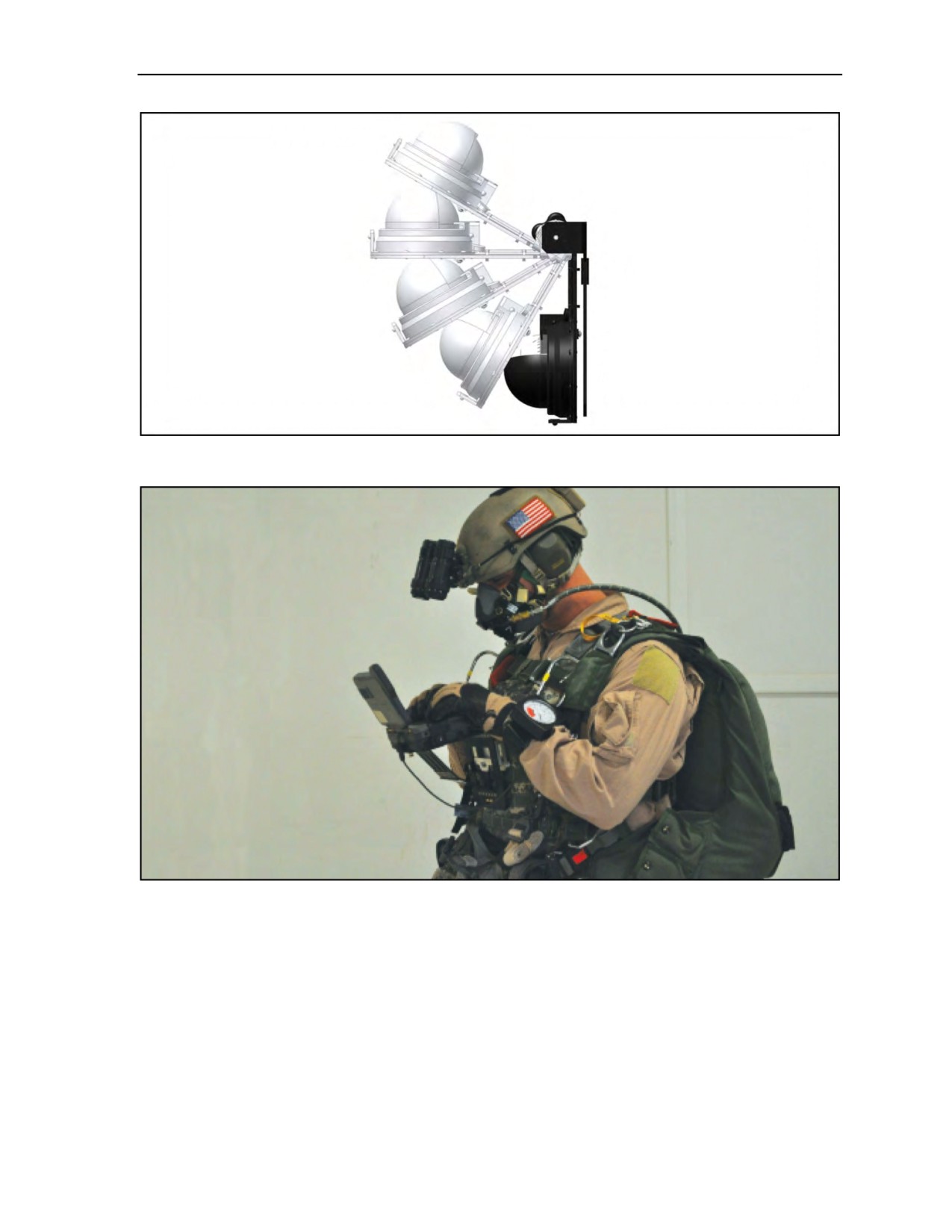
High-Altitude High-Opening and Limited-Visibility Operations
Figure 10-5. Parachutist navigation board closed and open position
Figure 10-6. Navigation aid attached to parachutist
COMMUNICATION EQUIPMENT
10-13. The parachutist can use radios for air-to-air or air-to-ground communications. He mounts the radio
so that it does not interfere with the manual activation of the main parachute or the performance of
emergency procedures. The radio can be mounted into a modified container that the waistband runs through
to attach it to the parachutist. This procedure is approved for operations inside the aircraft or during canopy
flight. The use of radios may increase the likelihood of detection during infiltration. The MICH interface
with the oxygen mask (POM), the AN/PRC-148 multiband inter/intrateam radio, and the radio interface is
all the parachutist should need while on the aircraft and under canopy. The MICH and/or Peltor can also be
plugged directly into the aircraft to communicate with the aircrew.
24 October 2014
ATP 3-18.11/AFMAN 11-411(I)/NTTP 3-05.26M
10-7

Chapter 10
FREE-FALL DELAYS
10-14. As an aircraft increases altitude, the aircraft’s true airspeed must increase to maintain a constant
indicated airspeed due to decreased air density. True airspeed is the actual speed of the aircraft through the
air mass. When true airspeed exceeds terminal velocity, the parachutist must allow for longer delays to
decelerate to a safe speed for parachute deployment (Table 10-1).
WARNING
Failure to take the minimum required delay can result in serious
injury to the parachutist and parachute damage.
Note: Jumpmasters must take into consideration the DZ (in feet AGL) for any delays in
parachute opening during MFF operations.
Table 10-1. Required free-fall delays
Exit Altitude
(in Feet MSL)
Delay
Below 20,000
4 seconds
Pull altitude will be predetermined; pull altitude will
Above 20,000
be no less than 1,500 feet below drop altitude rather
than a set time delay.
PARACHUTE JUMP PHASES
10-15. The HAHO standoff parachute jump has four phases. Each of these phases is discussed in the
following paragraphs.
EXIT, DELAY, AND DEPLOYMENT
10-16. On the command GO, the group leader exits the aircraft. The remainder of the element exits the
aircraft at designated intervals using the same exit technique as the group leader:
z
Each parachutist free-falls for the required delay or until reaching the predetermined pull
altitude.
z
The exit interval will be established to ensure canopy separation between parachutists at
opening. The exit interval will be based on the type of aircraft, its speed, and the mission
requirements.
z
A parachutist experiencing a malfunction must immediately start emergency procedures to
minimize loss of altitude.
z
Upon deployment, the group leader checks with the element for malfunctions, then assumes the
initial flight heading. Should a member of the element be beneath the group, the element must
execute the rehearsed tactical plan
(lose altitude to reform the group or follow the low
parachutist).
ASSEMBLY UNDER CANOPY
10-17. The opening altitude should be a minimum of 1,000 feet above any cloud layer to allow enough
altitude for the element to assemble under canopy. Each parachutist flies his canopy to his rehearsed
position within the formation. Each parachutist assumes the group leader’s heading.
10-8
ATP 3-18.11/AFMAN 11-411(I)/NTTP 3-05.26M
24 October 2014
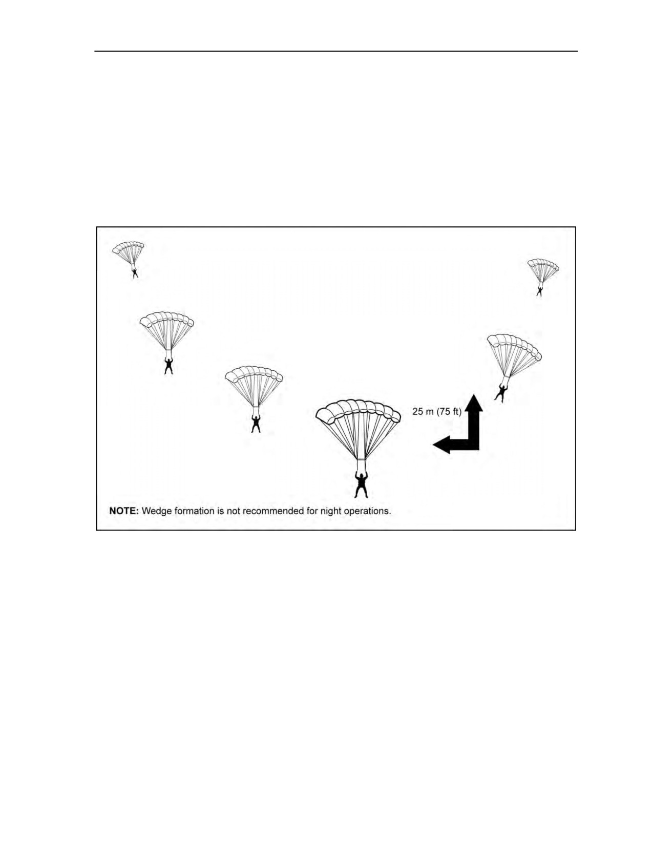
High-Altitude High-Opening and Limited-Visibility Operations
FLIGHT IN FORMATION
10-18. The “wedge” and the “trail” formations are the easiest to control and to maintain in flight
(Figure 10-7 and Figure 10-8, pages 10-9 and 10-10). The group leader (low parachutist) has the primary
responsibility for navigation. All parachutists should have navigation aids when they jump.
10-19. During HAHO operation jumps, element members in the formation maintain relative airspeed and
position with the group leader. They do this maneuver by trimming their canopies using the trim tabs
(Figure 10-9, page 10-10) on the front risers and by braking. Doing so changes the angle of attack in order
for a lighter jumper to stay in the stack with heavier jumpers, thus eliminating the need for a jumper to pull
on the front risers during the entire canopy flight. Steering correction can be made with body-weight shifts
or minor rear or front riser turns until the toggles are released.
Figure 10-7. Wedge formation
24 October 2014
ATP 3-18.11/AFMAN 11-411(I)/NTTP 3-05.26M
10-9
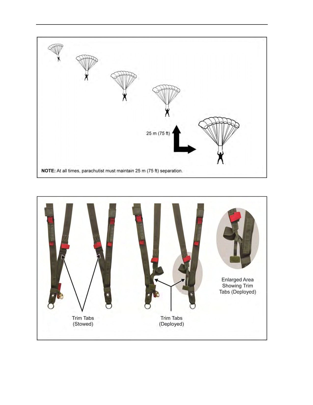
Chapter 10
Figure 10-8. Trail formation
Figure 10-9. Trim tab locations
10-20. Under limited visibility conditions, such as when passing through a cloud layer, each parachutist
goes to half brakes and maintains the compass heading until he regains visual contact with the formation or
10-10
ATP 3-18.11/AFMAN 11-411(I)/NTTP 3-05.26M
24 October 2014

High-Altitude High-Opening and Limited-Visibility Operations
as stated in unit SOP. Each parachutist must maintain altitude awareness and keep a sharp lookout for other
parachutists.
FINAL APPROACH AND LANDING
10-21. The group leader initiates the landing pattern at about 1,000 feet AGL in the landing area. Each
parachutist removes any trim tab settings prior to 1,000 feet AGL to prevent injury on landing from the
increased forward speed.
10-22. The landings are staggered to avoid the turbulence directly above and to the rear of the other ram-air
canopies. Each parachutist prepares to do a PLF should visibility prevent him from seeing the ground.
LIMITED-VISIBILITY OPERATIONS
10-23. MFF infiltrations during periods of limited visibility (adverse weather or darkness) have a higher
chance of success than strictly daylight operations. Adverse weather requires an Adverse Weather Aerial
Delivery System equipped aircraft when unable to identify the HARP (Reference USASOC Regulation
350-2). Limited-visibility infiltrations offer surprise and increased security due to reduced enemy
observation capability. Limited-visibility operations require a high degree of skill and individual discipline.
A well-rehearsed tactical plan executed by personnel proficient in MFF skills is critical to success.
ADVERSE WEATHER
10-24. Foggy, overcast, or mostly cloudy conditions effectively prevent observation from the ground.
However, adverse weather conditions present special problems for the MFF parachutist. (Chapter 14
discusses weather factors.) High winds and precipitation can degrade canopy performance and make
control difficult. Entering clouds may cause disorientation and lead to detachment separation under canopy,
free-fall collisions, or canopy entanglements. The loss of depth perception due to ground fog, smoke, or
haze may prevent the parachutist from executing a proper landing.
10-25. In free fall, the parachutist stops all maneuvering upon entering a cloud. He activates the main
parachute at the designated altitude, even if he has not passed through the cloud layer. In clouds under canopy,
he flies the canopy at the half-brakes position to help prevent a mid-air collision during limited visibility.
NIGHT OPERATIONS
10-26. Night MFF parachuting offers the same advantages as parachuting during adverse weather,
especially during the first quarter, new moon, and last quarter moon phases. Night free-fall parachuting is
the most psychologically demanding of parachute operations. Extensive training must take place at night.
During this training, the parachutist develops confidence in the equipment and his abilities.
10-27. Commanders must weigh the tactical situation when placing lighting devices on the parachutist
and on the parachute canopy for safety and control during free fall and canopy flight. At a minimum,
illumination devices are used for altimeters and other instruments.
10-28. The use of oxygen dramatically improves night vision. Wearing the oxygen mask until the landing
is a recommended procedure. The commander may consider using oxygen for all night free-fall operations,
even if the jumping altitude does not require it.
10-29. The lack of depth perception at night may prevent the parachutist from executing a proper landing.
The parachutist flies the parachute at the half-brakes position and performs a PLF on contact with the
ground. Various night illumination techniques exist to identify parachutists, group leaders, or subunit
elements while under canopy. Some techniques involve attaching the devices in the aircraft and some must
be activated and placed on the canopy before packing the parachute. Some of these techniques include
rheostatic electroluminescent riser lights, chemlights on the parachutist’s body and on the risers, strobe
light on the back of the helmet, and other electrical systems placed in pockets on the canopy’s top skin.
18 August 2016
ATP 3-18.11/AFMAN 11-411(I)/NTTP 3-05.26M, C2
10-11

Chapter 10
MILITARY FREE-FALL WITH NIGHT VISION GOGGLES
10-30. Operational areas frequently have little or no cultural lighting to illuminate DZs and objective
areas during night parachute operations. Helmet-mounted NVGs improve the margin of safety for special
operations forces MFF parachutists performing night MFF missions by providing visual cues to the DZ
terrain features, and the ability to clearly see other jumpers and obstacles while under the canopy. Better
vision translates into increased situational awareness during low-illumination deployments. NVGs are worn
during MFF operations to reduce the risk of injury and improve the capability of MFF-coded elements by
enhancing visual situational awareness during limited visibility. The jumpmaster can use NVGs to help him
while spotting from the aircraft. The parachutist should also use them during canopy flight as an aid to
navigation and formation flying. NVGs may be worn for all MFF operations; however, if they are not worn
in the down-and-locked position during HALO operations, they should be in the up-and-locked position
until after postopening procedures (USASOC Policy Number 20-10).
Note: Airborne commanders and/or jumpmasters will verify that only jumpers who have
completed NVG training participate in NVG-supported MFF operations. The jumpmaster will
ensure that only helmets and NVGs listed in the USASOC Personnel Airdrop Systems/Approved
and Authorized for Use List are utilized during all MFF operations, as well as verifying that
NVG rigging is done in accordance with the approved training support package.
10-31. The following is the minimum recommended qualifications prior to conducting MFF with NVGs:
z
Experienced jumpmaster that has performed MFF jumps with NVGs within the past 120 days to
train and determine if all jumpers are to the standards needed for this type of training.
z
Four hours of ground training with hanging harness for riser manipulation and emergency
procedures with NVGs (to include rigging and attachment procedures for NVGs).
z
15 to 30 minutes of wind tunnel flying with NVGs (recommended).
z
Three day-familiarization jumps with NVGs (turned off).
z
Two night jumps (no equipment, weapon, or oxygen) (NVGs powered on).
z
Minimum 5,500 feet AGL training altitude with maximum 5-second delay before main canopy
deployment.
Note: It is recommended that MFF NVG task-certified personnel perform this task a minimum
of once every 120 days for currency.
WARNING
Jumpers must ensure the NVG mount remains in the LOCKED
position. Jumpmasters will verify the lock is engaged and bungee
cords are attached to helmet and NVGs during jumper inspection
and at the 4-minute window before the jump.
NIGHT VISION GOGGLES AUTHORIZED
10-32. NVGs authorized for MFF NVG operations are the AN/AVS-6(V)3 (Figure 10-10, page 10-13),
AN/PVS-14 (Figure 10-11, page 10-13), AN/PVS-15 (Figure 10-12, page 10-13), AN/PVS-23, AN/VIS-9,
and AN/PVS-31. (Contact the USAJFKSWCS MFF School, Yuma Proving Ground, Arizona, for the latest
information.)
10-12
ATP 3-18.11/AFMAN 11-411(I)/NTTP 3-05.26M, C2
18 August 2016
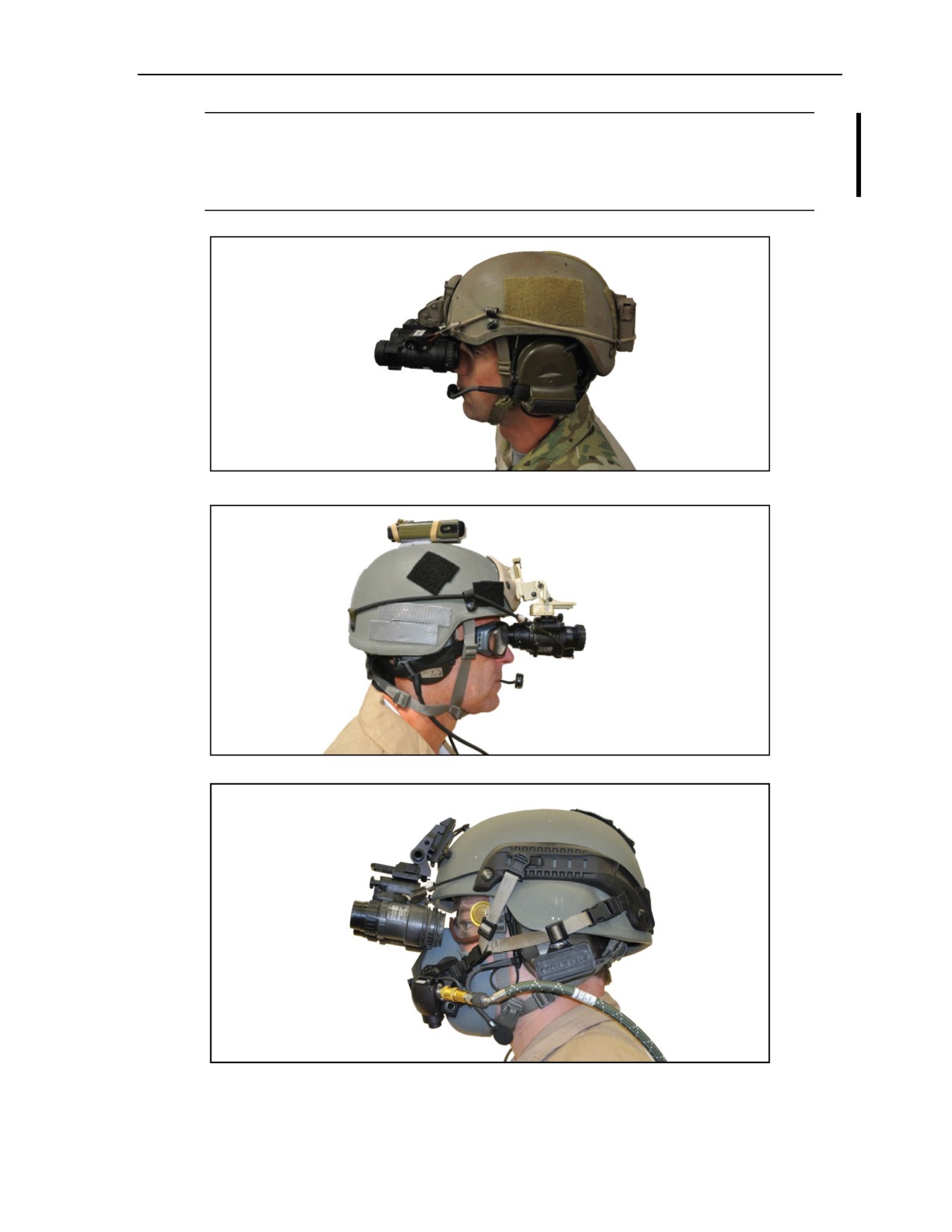
High-Altitude High-Opening and Limited-Visibility Operations
Note: Jumpmasters and jumpers should also refer to TB 43-0001-80 for USASOC’s personnel
airdrop systems and personnel parachutes authorized for use list, to include approved NVGs and
mounts.
Note: All mounts and helmets are not covered within this publication.
Figure 10-10. AN/AVS-6(V)3
Figure 10-11. AN/PVS-14
Figure 10-12. AN/PVS-15
18 August 2016
ATP 3-18.11/AFMAN 11-411(I)/NTTP 3-05.26M, C2
10-13
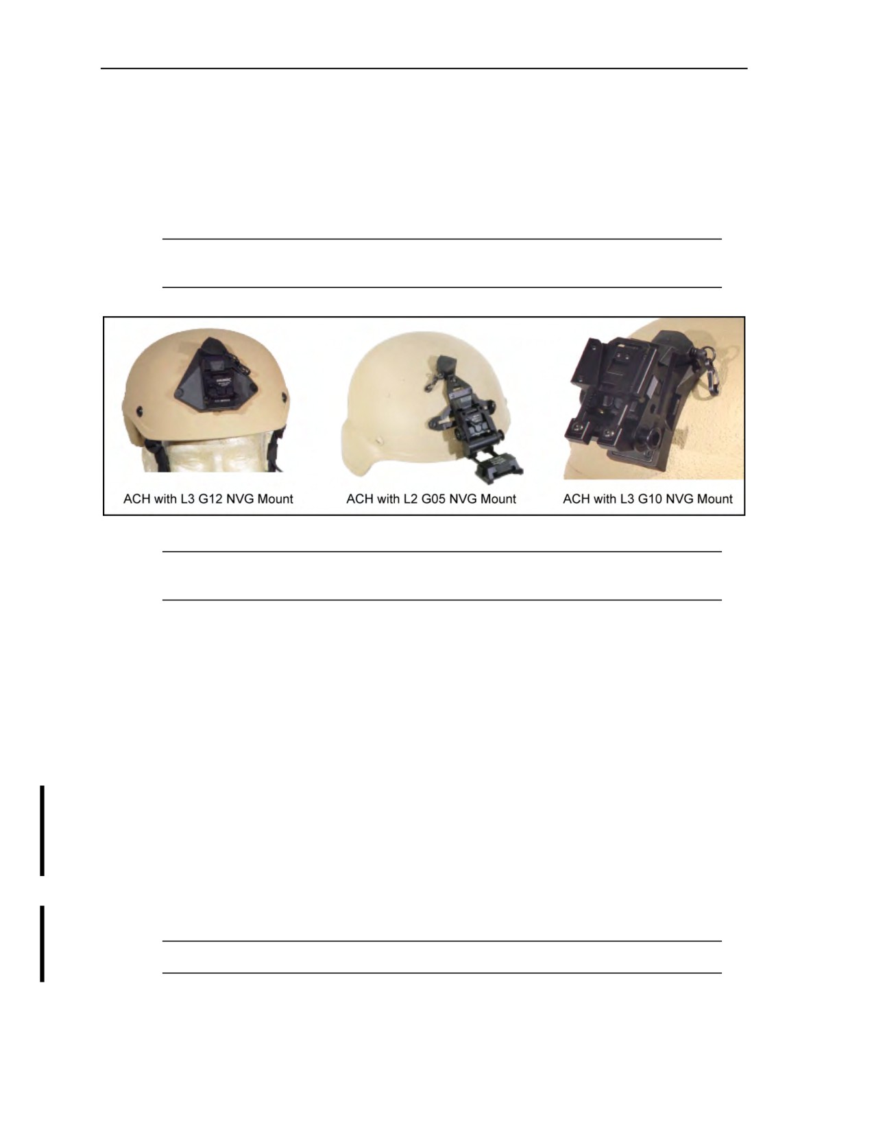
Chapter 10
MOUNTS
10-33. Mounts (Figure 10-13) should provide a strong attaching point with a low profile from the helmet
that is least obtrusive, snag free, and allows for the best ergonomics/adjustment with all goggles and is
“permanent.” The mount should have a break-away feature when exposed to harsh environmental and
combat conditions to reduce injuries to the parachutist’s head or neck if risers or parachute lines come into
contact with the NVG or mount. Mounts should also have the capability and compatibility to switch from
one type of NVG to another by only changing the mount arm.
Note: All manufacturer mounting installation requirements should be followed to reduce injury
to the parachutist.
Figure 10-13. Night vision goggle mounts
Note: Additional testing should continue to keep up with new NVGs and mounts to maintain
safety for the special operations forces parachutist when conducting night MFF operations.
NIGHT VISION GOGGLE PREPARATION
10-34. Before each jump, the parachutist should inspect the entire NVG system to ensure that all
components are serviceable and free from any defects caused from prior training, combat, or airborne
operations. This inspection includes the following:
z
Check components for serviceability.
z
Install new batteries.
z
Clean lenses.
z
Check visual acuity and focus to infinity, preferably using the NVG lane tester.
z
Secure NVG to helmet by wrapping a heavyweight retainer band around the NVG mount (Figure
10-14, page 10-15) release button. The heavyweight retainer band will be routed in a way that it
restricts the NVG release button(s) on the NVG mount from moving. If the NVG mount has two
release buttons (as on the Wilcox mount), the retaining band will be wrapped once around the
first release button and around and over the mount to the second release button, where it will
have another complete wrap and back to the first release button.
z
Close the open end of the bungee cord hook fasteners by using paper tape and rigger’s tape.
z
Use gutted 550 cord to provide a loop connection point to the NVGs for the bungee hooks.
z
Route gutted 550 cord looped through NVG eyelets and secure with a locking knot.
Note: The bungee hooks will be attached to the gutted 550 cord and secured closed with tape.
10-14
ATP 3-18.11/AFMAN 11-411(I)/NTTP 3-05.26M, C2
18 August 2016
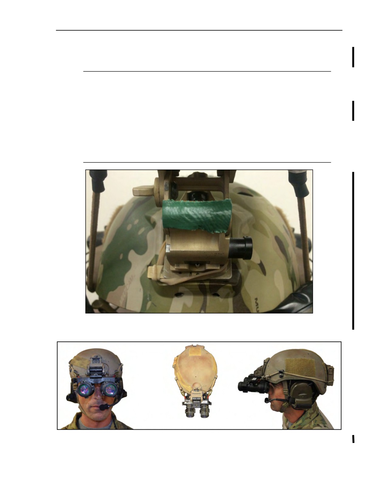
High-Altitude High-Opening and Limited-Visibility Operations
z
Inspect and ensure the bungee strap connector is serviceable and attached to the helmet and NVGs
(Figure 10-15) and that the NVGs are pulled down and fit securely in place at the jumper’s eye or
eyes.
Note: The securing lanyard and/or bungee cord should be short enough so that if NVGs become
dislodged from the mount, there is minimal slack, thereby reducing risk of horseshoe
malfunction.
Note: If using an attached external battery pack on the rear of the helmet, route the power cable
from the battery pack to the NVG, either on the inside of the helmet or secured on the outside of
the helmet, in a manner to prevent possible snags during parachute opening.
Note: Bungee retainers will be a minimum of 5/32 inches (4 millimeters) and not larger than
1/4 inch (6 millimeters) with a hook not to exceed 2 inches in length. The bungee will be secured
to the helmet with appropriate-sized cable clamps or a rail-mounted retention system. Cable
clamps or ties will not have a loop larger than 3/8 inches.
Figure 10-14. Securing night vision goggle mount to helmet
with heavyweight retainer band
Figure 10-15. Bungee position on night vision goggle mount
18 August 2016
ATP 3-18.11/AFMAN 11-411(I)/NTTP 3-05.26M, C2
10-15

Chapter 10
HELMETS
10-35. Helmets authorized for MFF NVG operations are the OPSCORE, MICH, 3/4 MICH, Maritime
MICH, and the Protec. Regardless of which helmet is used, it should fit snuggly to help prevent shifting on
exit and while in free fall. Jumpers should expect the added weight of the NVGs to cause shifting and must
be prepared to correct their helmet position as needed.
Note: Only helmets and NVGs listed in the USASOC Personnel Airdrop Systems/Approved and
Authorized for Use List will be used during all MFF operations.
Note: Some parachutists have found that the ACH or MICH helmet insert (padding) at high
altitudes expands, freezes, and causes the helmet to get too tight causing pressure on the
parachutist’s head. Parachutists should not overtighten the helmet when conducting HAHO
operations. When wearing the ACH or MICH with or without oxygen, the chin strap is routed
underneath the chin.
Note: The ACH becomes the MICH when worn with communications equipment.
10-36. For helmet preparation, the parachutist should—
z
Check components for serviceability.
z
Install NVG mount as required and ensure proper helmet fit.
z
Attach NVG to mount system and LOCK in position.
z
Connect the bungee strap to the NVG (use paper tape to close the open ends of the bungee cord
hook fasteners).
z
Ensure the infrared strobe is operational and attach the chemlight.
WARNING
Jumpers wearing NVGs have an increased chance of horseshoe
malfunctions due to the additional helmet fixtures. The modified
pull technique drastically reduces the chance for a horseshoe
malfunction. All horseshoe malfunctions should be treated as such
and jumpers should immediately execute cutaway procedures.
10-37. Per AFI 11-410, only oxygen masks certified and approved for use may be used. Oxygen masks
will be fitted and inspected by a qualified jumpmaster with experience in jumping with NVGs. When
jumping oxygen with NVGs, it is recommended that the oxygen mask be kept on until landing unless
otherwise required by emergency procedures. The oxygen mask helps support the NVGs and releasing or
lowering it may cause the NVGs to shift and restrict visibility of other jumpers and terrain.
COMMUNICATIONS
10-38. All MFF NVG jumpers should use radio communication to increase situational awareness of the
team. The finger push-to-talk device is recommended because it allows jumpers to maintain canopy control
and communicate while flying.
GENERAL CONSIDERATIONS
10-39. MFF with NVGs can increase situational awareness and safety during reduced lighting operations,
but there are several issues jumpers should consider. Proper training and rehearsal will help minimize these
issues:
z
Jumpers should know the pros and cons of NVG use, restrictions, and alternatives; for example,
exiting with NVGs down and powered on, exiting with NVGs locked in the up position and
turned off, or exiting with the NVGs in a pouch and putting them on after the jumper is under a
good canopy.
10-16
ATP 3-18.11/AFMAN 11-411(I)/NTTP 3-05.26M, C2
18 August 2016

High-Altitude High-Opening and Limited-Visibility Operations
z
Jumpers must have an understanding of all equipment and materials needed to complete rigging
procedures of the NVGs for MFF operations that include the approved types of NVGs, authorized
mounting brackets, and a review of the USASOC Personnel Airdrop Systems/Approved and
Authorized for Use List authorized helmets available for use during NVG operations.
z
NVGs should be focused to infinity to provide the best clarity while under canopy.
z
If the helmet is not properly adjusted, it may shift after exit. The jumper may need to readjust the
helmet after postopening procedures are complete.
z
The normal sight picture for checking the altimeter will change when wearing NVGs. The
jumper should practice checking the altitude on the ground and in the aircraft prior to exit. The
jumper can look beneath the NVG to identify and read the altimeter.
z
When beginning the pull sequence (Chapter 7), the jumper must be sure to look forward after
identifying his main ripcord and before pulling it because the risers may hit the NVGs—potentially
knocking them off.
z
Turning his head to see jumpers behind him while under canopy is difficult. Lack of training and
rehearsal of this can increase the potential for canopy collisions. A useful technique to look
behind him without turning his head excessively is to grasp and push one side of the risers and
“kick and twist” in the harness to rotate his body in that direction. The jumper should avoid
unpredictable turns during canopy manipulation.
z
NVGs limit the jumper’s peripheral vision; therefore, he should fly accurate, predictable, and
briefed patterns. Other jumpers are flying with the same limitations and extra attention must be
given to situational awareness throughout the jump.
CAUTION
NVGs provide greater situational awareness during night MFF
operations; however, jumpers should always be prepared to land with
half brakes and to conduct a PLF.
JUMPMASTER CONSIDERATIONS WITH NIGHT VISION GOGGLES
10-40. JMPIs remain essentially the same for jumping with NVGs. The following additional procedures
should be completed on each parachutist:
z
Check all NVG components for serviceability.
z
Ensure helmet is snug (nape and chin straps tight).
z
Check NVG dovetail mount for proper attachment.
z
Check that NVG mount is in LOCKED position.
z
Turn ON and lower NVGs; verify ON and in proper position on the parachutist (if not, stop the
JMPI and correct).
z
Turn OFF and raise NVGs.
z
Ensure straps are secured and taped.
z
Ensure battery pack and power cables are secured to the helmet and properly stowed.
z
Ensure bungee connector is serviceable and connected to the NVGs.
z
Check the infrared strobe light for serviceability.
z
Verify briefed lighting attachments and placement.
Note: Jumpmaster will instruct jumpers to lower NVGs and turn them ON at the STAND-UP call
(2 minutes). The decision to jump with NVGs in the up or down position and turned ON or OFF
will be made during rehearsals for the operation being conducted.
Note: While performing outside-the-aircraft spotting duties, the jumpmaster should hold the
NVGs securely in place with one hand.
18 August 2016
ATP 3-18.11/AFMAN 11-411(I)/NTTP 3-05.26M, C2
10-17

This page intentionally left blank.

Chapter 11
Military Free-Fall Drop Zone Operations
A DZ is any designated area where personnel and equipment may be delivered by
means of parachute or free drop. DZs for MFF operations are selected during
premission planning using all available intelligence sources. DZs are selected by the
ground unit commander and are located where they can best support the ground
tactical plan. The air mission commander recommends approach headings and selects
initial and subsequent timing points based upon the routes to the DZ, terrain
obstructions, ease of DZ identification, and enemy defenses. Final approval of
selected DZs is a joint decision made by the ground unit commander and the
supporting air unit. This chapter outlines the basic selection criteria, markings, and
procedures used in support of MFF operations, as well as the qualifications and
responsibilities of key DZ support personnel.
RESPONSIBILITIES
11-1. DZ size and selection are the joint responsibility of the air component commander or Commander,
Air Force Special Operations Command, and the supported force commander. The supporting air unit is
responsible for airdrop accuracy and safety of flight. The supported ground unit is responsible for
establishment, operation, safety on the DZ, and the elimination or acceptance of ground hazards associated
with the DZ. The jumpmaster is responsible for accuracy when jumpmaster-directed release procedures are
used. AFI 13-217 has additional information.
Note: For an MFF DZ using MC-4 or approved equivalent parachutes deployed in free fall or by
static line, the jumpmaster will determine the minimum size DZ based on the number of
personnel to be dropped, jumper proficiency, and the prevailing winds.
11-2. If a DZ is selected that does not appear in the Assault Zone Availability Report, the unit must
complete the survey request in full and it must state whether the unit has obtained permission to conduct
the exercise. Any other information relating to the area being used as a DZ should also be stated, such as—
z
Nearest facility capable of landing type of aircraft being used for mission (must include name,
title, and phone number of the individual contacted for authority to land).
z
Medical facility for medical evacuation and hospital support.
z
Communications capabilities (for FLASH/priority of report).
z
If the drop is to be made on civilian-owned land or on a non-Department of Defense government
reservation, written permission from the owner or agency must be attached to the request.
z
Airspace clearance from the Federal Aviation Administration or the local range control agency.
z
Facilities available for storing and/or repacking of air items.
z
Wind historical data for time and date of drop.
z
Any other pertinent information.
11-3. The supporting air unit is responsible for airdrop accuracy and safety of flight. The supported ground
unit is responsible for the establishment of a DZ, DZ operations, safety measures on the DZ, and the
elimination or acceptance of ground hazards associated with the DZ. The jumpmaster is responsible for
accuracy when jumpmaster-directed release procedures are used. AFI 13-217 has additional information.
24 October 2014
ATP 3-18.11/AFMAN 11-411(I)/NTTP 3-05.26M
11-1

Chapter 11
DROP ZONE SELECTION CRITERIA
11-4. The joint force commander gives guidance on DZ size in operation plans and operation orders. The
ground unit commander selects the general area of the DZ where it will best support the ground tactical
plan. DZ selection should be based on the following criteria:
z
Mission Supporting. Some of the main considerations when selecting a DZ that supports the
mission are—
Method of insertion (HALO or HAHO).
Elevation and drop altitude.
Location and capability of enemy forces.
Recognizability during limited visibility.
Distance from the objective area.
Terrain between the DZ and the objective area.
Built-up areas.
Time available for movement to the objective area.
Amount of equipment being carried.
Physical characteristics of available DZs and surrounding areas.
Relative number of obstacles in the area.
Proximity to alternate and contingency DZs.
z
Supporting Aircraft. When considering the capabilities of the supporting aircraft, parachutists
take the following into account:
Type of aircraft.
Capabilities of the aircraft.
Skill level of the aircrew.
Availability of backup aircraft if the primary aircraft has mechanical problems.
z
Infiltration Route. The primary, alternate, and contingency DZs should be selected so that the
aircraft can overfly them in order without making major course corrections. Air routes to and
from the DZ should not conflict with other air operations, restrictive terrain, restrictive airspace,
or fall within the enemy’s air defense umbrella.
z
Security. The DZ must provide security from the enemy threat. The DZ should be located away
from enemy positions and built-up areas.
z
Safety.
z
Weather and Astronomical Conditions. Seasonal weather and astronomical conditions in the
area must be considered. If conducting a water jump, the tides, waves, currents, and sea state
must be considered.
z
Size. There is no minimum size for MFF DZs according to Standardization Agreement 3570 and
AFI 13-217. The jumpmaster will determine the minimum size of an MFF DZ based upon the
experience and capabilities of the parachutists. An area
50 meters by 100 meters is the
recommended minimum DZ size for training.
z
Undesired Landing Areas (Drop Zone Hazards). Some considerations include the following:
Rising terrain: Landing into the hill could cause injury and thermal updrafts could keep
jumpers in the air longer.
Tall timber: Falling out of a tree might cause serious injuries; there is a high probability of a
lengthy letdown of the reserve from the top of a tree. Snags have been known to fall over if
landed in, which could also snap tops, increasing likelihood of injury. Hardwoods are brittle
and can cause possible injury when landing in them. Turbulence near treetops could make it
difficult to land safely at the desired impact point. Parachutes could get hung in trees
disclosing the infiltration location.
Side hill landings: The hill’s steepness could be a safety problem if a jumper does not
contour the hill.
11-2
ATP 3-18.11/AFMAN 11-411(I)/NTTP 3-05.26M
24 October 2014

Military Free-Fall Drop Zone Operations
Power lines: These could be hard to see, especially in fading light, and there is a greater risk
for serious injury.
Fences: These blend in with the landscape and present a hazard.
Deadfall: High risk of extremities catching as the parachute carries jumper forward on
landing.
Ice: There is a higher probability of injury occurring if a jumper busts through ice. The
situation will likely be more serious if bodies of water went undetected due to snowy
landscape. There is a possibility of more jumpers being needed to help assist with recovery
and medical attention, taking away from conducting mission.
Water: Landing in water could require additional equipment and personnel to recover lost
and damaged equipment. Recovery time could take away from mission.
Rocky ground: Large outcroppings can be notorious for blocking wind. Landings could be
rough. There is a possibility of more jumpers needed to assist with medical attention.
z
Aerial Power Line Restrictions. For the purpose of this publication, all restrictions apply to
aerial power lines operating at 50 volts or greater. Power lines present a significant hazard to
jumpers. Jumpers can sustain life-threatening injuries from electric shock and/or falls from a
collapsed canopy. To reduce this hazard, power lines should not be located within 1,000 meters
of any DZ boundary. If power lines are located within
1,000 meters of any boundary,
coordination with the power company must be made to shut off power not later than 15 minutes
prior to time on target. If power cannot be interrupted, the flying mission commander, aircrew,
and jumpmaster must conduct a risk assessment of the mission. Included, as a minimum, are the
type of jump, jumper experience, aircrew experience, ceiling, and surface/altitude wind limits
required to approve, suspend, or cancel the operation. To further minimize risks, consideration
should be given to altering the mission profile to raise or lower drop altitudes, change
DZ run-in/escape headings, or remove inexperienced jumpers from the stick. If possible, power
lines should be marked with visual markings (lights, smoke, or VS-17 panels).
WARNING
At no time will military personnel attempt to climb power line
poles to position or affix markings to wires or poles.
Note: During USAF MFF operations, aircrews should ensure the jumpmaster or team leader is
aware when aerial power lines are within 1,000 meters of the intended point of impact.
Non-USAF personnel will comply with their Service guidance for power line procedures and
restrictions.
DROP ZONE SURVEYS
11-5. A DZ survey is required for all airdrop training missions involving U.S. personnel and equipment.
Completing the DZ survey process involves a physical inspection of the DZ and documenting the DZ
information on AF IMT Form 3823. The using unit completes the DZ survey and forwards it through
appropriate channels for review and approval. The using unit is defined as the unit whose personnel or
equipment are being airdropped. The DZ survey review process involves the following steps:
z
Step 1. The surveyor and/or MFF jumpmaster (AF IMT Form 3823, item 4a) physically surveys
the DZ and completes the ground portion of AF IMT Form 3823. Once completed, AF IMT
Form 3823 is forwarded to the ground operations review authority for approval (AF IMT Form
3823, item 4c). The ground operations review authority is normally the surveyor’s commander
or designated representative. This review ensures the AF IMT Form 3823 is complete, accurate,
and meets the criteria for planned airborne operations.
z
Step 2. Using unit forwards the survey to the USAF regional/wings tactic office for a safety-of-
flight review (AF IMT Form 3823, item 4d). A safety-of-flight review is completed by an
18 August 2016
ATP 3-18.11/AFMAN 11-411(I)/NTTP 3-05.26M, C2
11-3

Chapter 11
airdrop-qualified pilot or navigator on all DZ surveys. The purpose of a safety-of-flight review is
to ensure an aircraft can safely ingress and egress the DZ.
z
Step 3. Regional/wings tactic office forwards the survey to the appropriate operations group
commander for review and final approval (AF IMT Form 3823, item 4e). This approval assures
that the safety-of-flight review has been conducted and the DZ is considered safe for specified
airdrop operations.
z
Step 4. Once AF IMT Form 3823, item 4e, has been completed the survey is approved for use.
Copies of the survey are forwarded to Headquarters, Air Mobility Command/DOKT,
402 Scott Drive, Scott Air Force Base, Illinois
62225-5320, for inclusion into the Zone
Availability Report database.
11-6. The Zone Availability Report is a comprehensive listing of approved assault zones available for use
by the Department of Defense. Use of this report will expedite mission planning, enhance safety, and avoid
duplication of surveys. Information contained in the report does not replace the need for a completed
DZ survey before conducting airdrop operations. Completed surveys are available via facsimile on-demand
system (also located at Scott Air Force Base, Illinois, at Defense Switched Network 576-2899 or commercial
[618] 256-2899).
DROP ZONE PERSONNEL QUALIFICATIONS
AND RESPONSIBILITIES
11-7. The airborne commander designates key personnel for each airborne operation. These key personnel
are the primary jumpmaster, assistant jumpmaster, oxygen safety personnel, departure airfield control
officer (DACO), DZSO, and/or drop zone support team leader (DZSTL), and the malfunction officer (MO).
A primary and assistant jumpmaster are required on every aircraft. Oxygen safety will be used when
required. The qualifications and responsibilities of DZ support personnel are listed in the paragraphs below.
TC 3-21.220 includes further discussion of responsibilities during airborne operations.
DROP ZONE SAFETY OFFICER AND/OR DROP ZONE SUPPORT TEAM LEADER
11-8. The DZSO and/or DZSTL must be a commissioned officer, warrant officer, or noncommissioned
officer (E-5 or above for proficiency jumps; E-6 for tactical jumps). The airborne commander ensures the
DZSO and/or DZSTL is a current, qualified static-line or MFF jumpmaster, has performed the duties of
assistant DZSO and/or DZSTL in support of an airborne operation involving personnel or heavy equipment
at least once, and is familiar with MFF operations in accordance with this manual. The MFF jumpmaster
briefs the DZSO and/or DZSTL on the DZ markings, communications, and operating procedures that will
be used.
11-9. The DZSO and/or DZSTL has overall operational responsibility for the DZ. He conducts a ground or
aerial reconnaissance of the DZ before the drop to make sure there are no safety hazards. Other
responsibilities include—
z
Establishing personal liaison with the USAF DZ control officer and special tactics team, and
discussing drop procedures (USAF troop carrier aircraft).
z
Clearing the DZ of unauthorized personnel and vehicles.
z
Briefing and posting road guards, if required.
z
Ensuring medical personnel are in position.
z
Ensuring that the DZ is operational 1 hour before time on target.
z
Establishing communications with the DACO not later than 1 hour before time on target.
z
Maintaining continuous surface wind readings not later than 12 minutes before time on target.
(Peacetime ground wind training limits will not exceed 18 knots.) There are no winds aloft
restrictions.
z
Giving the pilot the ground winds and the CLEAR TO DROP or NO DROP signal 2 minutes
prior to the scheduled time on target.
11-4
ATP 3-18.11/AFMAN 11-411(I)/NTTP 3-05.26M, C2
18 August 2016

Military Free-Fall Drop Zone Operations
Note: The CLEAR TO DROP or NO DROP signal that is relayed to the pilot 2 minutes prior to
time on target does not indicate the final wind reading. A NO DROP signal can be relayed to the
pilot, any time afterwards, if surface winds increase beyond the authorized limit.
z
Receiving from the pilot the number of parachutists that have exited the aircraft after each pass.
z
Relaying strike reports to the aircraft pilot.
z
During night drops, ensuring that all lights on or next to the DZ (except for DZ markings) are
turned off 15 minutes before drop time and remain off during the jump.
z
Directing the recovery crew to assist parachutists and to retrieve equipment in trees.
z
Assisting in medical evacuation of injured personnel from the DZ.
z
Immediately after the completion of the jump, asking the pilot if any personnel or equipment did
not drop, and then relaying this information to the airborne commander on the DZ.
z
In the event a malfunction occurs, securing the equipment and allowing no one to disturb it until
the MO has completed his on-site investigation. If an MO or a noncommissioned officer is not
physically located on the DZ, the DZSO and/or DZSTL turns it over to an appropriate parachute
maintenance facility.
z
Recording the necessary information for the parachute operation report.
z
Closing the DZ.
UNITED STATES AIR FORCE DROP ZONE CONTROL OFFICER
11-10. The USAF DZ control officer represents the airlift commander. He supervises all USAF personnel
on the DZ. He also observes drop operations. Other responsibilities include—
z
Evaluating all factors that might adversely affect safety.
z
If conditions make drop operations unsafe, directing the special tactics team to relay that
information to the appropriate USAF commander as soon as possible and to display the
established NO DROP signal on the DZ.
z
Directing the use of special tactics team equipment.
z
Canceling drops when requested to do so by the Army DZSO.
z
Keeping the Army DZSO advised on ground wind speed on the DZ.
z
Preparing the necessary log and reports for submission to the airlift control element or the
appropriate USAF commander.
SPECIAL TACTICS TEAM
11-11. The special tactics team marks the DZs with proper navigational and identification aids. The team
establishes ground-to-air communications at DZs, as well as communications with designated control
agencies. Other responsibilities include—
z
Providing the U.S. Army DZSO with surface weather and low-level (up to 1,500 feet) winds
aloft observations.
z
Exercising air traffic control over aircraft in the vicinity of a specific DZ, as directed.
MALFUNCTION OFFICER
11-12. The investigation of personnel, parachutes, and equipment malfunctions receives the highest
priority and is secondary in priority only to medical aid for the injured. This investigation supersedes all
other aspects of the operation, to include ground tactical play. Prompt and accurate investigations and
reporting could save lives and equipment. The report provides data to determine if a system or procedural
training change is necessary to prevent future occurrences. The MO is subordinate to the DZSO and/or
DZSTL and is a member of the DZ support team. Any assistance required by the MO must pass through the
DZSO and/or DZSTL, who controls the DZ.
18 August 2016
ATP 3-18.11/AFMAN 11-411(I)/NTTP 3-05.26M, C2
11-5

Chapter 11
11-13. The MO must be a commissioned officer, warrant officer, or noncommissioned officer (minimum
grade of E-5). The MO must be a trained parachute rigger who is familiar with airdrop, parachute recovery,
and aircraft personnel parachute escape systems in accordance with AR 59-4.
11-14. The organization that provides the air items will provide the MO. He will be present on the DZ
during all personnel and equipment drops and will be familiar with requirements. The MO must have the
following minimum equipment in his possession during duty performance:
z
A communication capability with the DZ control party.
z
A good-quality camera to take photos of malfunctions or incidents (video camera preferred).
Photographic equipment is essential for the proper performance of MO duties. Pictures of
malfunctions greatly assist in investigations.
z
The clerical supplies necessary to tag equipment and initiate reports.
z
Binoculars or NVGs.
z
Transportation to move around the DZ.
11-15. If a malfunction occurs, the MO immediately conducts an on-site investigation of the causes of the
malfunction. The MO photographs the malfunctioned equipment, or the malfunction as it happens, and the
malfunction site that shows possible causes of the malfunction. The MO secures, identifies, tags, and
numbers airdrop equipment involved in the malfunction incident. The MO then prepares and submits
DD Form 1748-2 (Airdrop Malfunction Report [Personnel-Cargo] to report all airdrop malfunctions in
accordance with AR 59-4), as well as any other required reports.
Note: MOs must prepare complete and accurate MFF accident reports. The fielding of new MFF
equipment and the introduction of new MFF procedures depends on the feedback of the
reporting process to detect accident patterns.
MILITARY FREE-FALL DROP ZONE MARKINGS
11-16. MFF infiltrations usually take place on blind DZs because of the general ineffectiveness of visual
markings when viewed from high altitudes (HALO) and extended distances (HAHO). DZ identification is
normally by location in relation to major terrain features.
11-17. DZ markings are sometimes used when the tactical situation permits, and it is desirable to indicate
wind direction to the descending parachutists (Figure 11-1, page 11-7). ATP 3-18.10, FM 3-21.38, and
AFI 13-217 outline approved marking techniques. Markers that can be used with the approved markers are
the wind sock, wind streamer, wind blade, wind arrow, smoke, two-light method (one red and one green),
wind “T,” and infrared light source.
11-18. There are several types of wind socks (Figure 11-2, page 11-7) that are used on airfields and DZs
for MFF and civilian skydiving. Normally, a wind sock is what is seen on airfields for aircraft but can assist
jumpers as well in determining the direction and velocity (somewhat) of the wind. Wind socks come in
5-, 10-, and 15-knot categories determined by the “erectness” of the wind sock to let the user know an
estimate of the velocity. Naturally, the jumper will have to know the type of wind sock in use in order for it
to be of benefit for velocity approximation. For MFF, the 15-knot version is used since this upward end of
the scale is closest to the maximum landing conditions. On most civilian DZs, the wind blade or
tetrahedron is used. These do not give an approximation on the wind speed; however, they are much easier
to be seen by jumpers in the air. On MFF DZs, the wind “V” or other wind direction device is required,
and, depending on the DZ, there may be permanent wind socks, such as on Philips DZ at the MFF School
in Yuma, Arizona.
11-6
ATP 3-18.11/AFMAN 11-411(I)/NTTP 3-05.26M, C2
18 August 2016
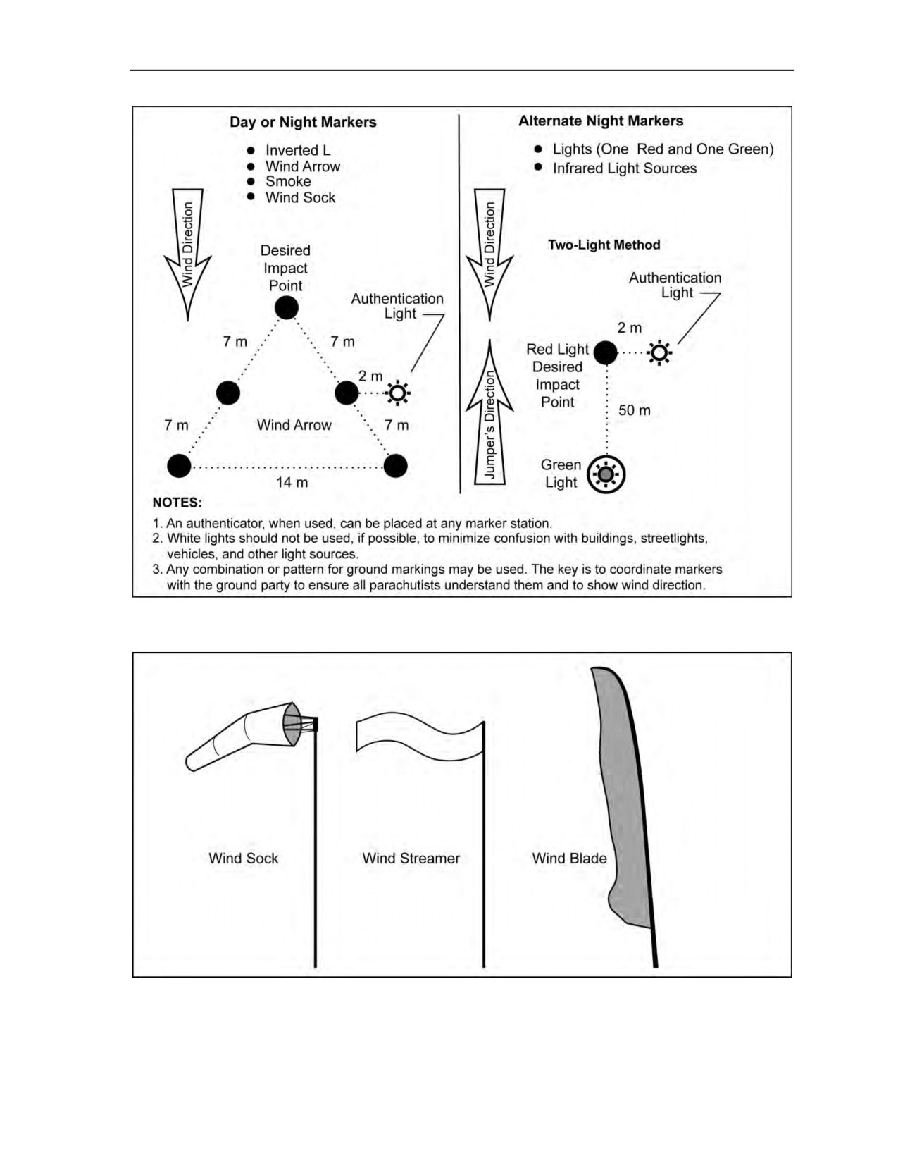
Military Free-Fall Drop Zone Operations
Figure 11-1. Military free-fall drop zone markings
Figure 11-2. Examples of wind socks
24 October 2014
ATP 3-18.11/AFMAN 11-411(I)/NTTP 3-05.26M
11-7

Chapter 11
NONSTANDARD DROP ZONE MARKINGS
11-19. The tactical situation may dictate the use of nonstandard DZ markings. When nonstandard
markings or identification procedures are used, it is imperative that all appropriate participants be
thoroughly briefed.
11-20. The unmarked DZ is not authenticated with any type of visual or electronic marking. Unmarked
DZs are normally used for contingency operations and may not have a DZ party present. USAF Special
Tactics personnel; combat rescue officers; pararescue; rescue squadron assigned or supporting survival,
evasion, resistance, and escape specialists; and USSOCOM-assigned forces are authorized to drop on
unmarked DZs. During training missions, a DZ control party must be on site for safety.
11-21. The two DZ marking systems commonly used during MFF operations are the wind arrow and the
two-light system (Figure 11-1, page 11-7):
z
The wind arrow is formed by placing visual markers on the ground in the shape of an arrowhead.
The arrow is aligned pointing into the wind. The arrow tip marker is placed on the desired
impact point. Jumpers fly their approach to land facing the direction of the arrow.
z
The two-light system consists of one red light and one green light. The red light is placed on the
desired impact point and the green light is placed between 15 and 50 meters downwind. Jumpers
will be briefed on the actual separation of lights. Jumpers fly their approach to landing from
green light to red light.
WATER DROP ZONE MARKINGS
11-22. Water drops can be conducted on marked or unmarked DZs. Marked DZs will have mutually
agreed-upon markings (visual or electronic). Markings that do not mimic local maritime navigational aids
(buoys, channel markers, and so on) should be selected.
Note: Ground parties and aircrews must coordinate and brief NO-DROP markings for all types
of DZs, to include water DZs.
EN ROUTE AND TERMINAL NAVIGATIONAL AIDS
11-23. A variety of electronic navigational aids are available to support DZ operations, including the
tactical air navigation system, zone marker, or radar beacons. These navigational aids are used at the
discretion of the joint force air component commander, joint force special operations component
commander, or mission commander. For MFF airdrops, the beacons will be placed on the point of impact
(AFI 13-217).
HIGH-ALTITUDE RELEASE POINT AND MILITARY FREE-FALL
DROP ZONE DETECTION
11-24. Location in relation to major terrain features identifies the HARP. Appendix F contains methods of
computing the HARP. The HARP may be marked, if known, when the tactical situation permits. In heavily
vegetated, mountainous, or urban terrain and during conditions of restricted visibility, DZs and HARPs
may be difficult to detect. Electronic beacons or radar transponders and appropriate tracking devices help
aircraft personnel and parachutists locate DZs or HARPs. Expedient methods, such as balloons and
pyrotechnics, may also help aircraft personnel and parachutists locate DZs or HARPs. In situations where
secrecy is important, aircraft and parachutists equipped with automatic direction-finding equipment may
conduct drops using only the radio homing beacon. Parachutists may also use the GPS with portable
terminals.
11-8
ATP 3-18.11/AFMAN 11-411(I)/NTTP 3-05.26M
24 October 2014

Military Free-Fall Drop Zone Operations
AIRCRAFT OR HIGH-ALTITUDE HIGH-OPENING TEAM
IDENTIFICATION
11-25. In air-to-ground identification, the aircraft or HAHO team identifies itself to the reception
committee by arriving in the objective area within the specified time limit. The aircraft or HAHO team also
identifies itself by approaching at the designated drop altitude and track (aircraft).
11-26. In ground-to-air identification, the reception committee identifies itself to the aircraft or team by
displaying the correct marking pattern within the specified time limit and using the proper authentication
code signal.
AUTHENTICATION SYSTEM
11-27. There is no standard authentication system for unconventional warfare reception operations.
During mission planning, the commanders concerned agree on the authentication system they will use.
Signal operation instructions prescribe the authentication procedures.
11-28. Authentication may take the form of a coded light source, panel signal, radio contact, homing
beacon, or combinations thereof. Authentication may be used individually or with the marking pattern.
When using a homing beacon or radar transponder for authentication, the commanders concerned will
jointly agree upon positioning and turn-on and turn-off times during mission planning.
11-29. Detachments conducting MFF operations during special reconnaissance missions are not going to
have the opportunity in most cases of being assisted by a reception committee or lighted DZ during the
infiltration. This type of operation will take additional planning and rehearsals on the detachment’s part.
Training with NVGs, electronic navigation devices, compasses, communications while under canopy,
rough terrain landings, caching of equipment, thrall map and terrain analysis of desired impact point, and
all contingency plans for lost jumpers or medical situations must be taken into consideration. This type of
mission is not limited to just special reconnaissance; it can also be used to get into position for direct action
by giving the detachment the element of surprise by not having large numbers of vehicles, hovering aircraft
flying into the area, or foot traffic moving toward the objective causing the target to be empty upon arrival.
Additional forces in vehicles or by helicopters (from staging areas) should assist the detachment as soon as
the detachment begins to move on the objective. This timing is critical to the MFF detachment and the
success of the mission.
24 October 2014
ATP 3-18.11/AFMAN 11-411(I)/NTTP 3-05.26M
11-9

This page intentionally left blank.

Chapter 12
Deliberate Water Military Free-Fall Operations
This chapter outlines the policies, procedures, and restrictions for conducting
deliberate MFF operations into water DZs. Individual Services will use their
applicable regulations and SOPs when conducting Service-pure MFF operations into
water DZs. The procedures outlined in this chapter are different from the emergency
water-landing procedures discussed in Chapter 9.
Note: When conducting joint deliberate water MFF operations, Services must determine if a
waiver requirement for minimum exit altitudes with or without the use of an EAAD is required
for joint operations and which regulation is to be followed due to the differences within the
Services.
Note: The minimum exit altitude for Navy MFF parachutists conducting water jumps, to include
following cargo over the ramp, is 2,500 feet AGL without EAADs. The minimum exit altitude
for the Maritime Craft Aerial Delivery System with MFF parachutists following the boat over
the ramp is 3,000 feet AGL without EAADs.
ADDITIONAL SUPPORT REQUIREMENTS
12-1. All basic parachute support operations outlined in Chapter 11 must be used when conducting
deliberate water parachute operations. Listed below is the additional support needed for parachute
operations using water DZs. Parachutists should refer to individual Service regulations for additional
restrictions.
PARACHUTIST RECOVERY BOATS
12-2. A minimum of one power-driven parachutist recovery boat is required for every parachutist being
dropped on the same pass if parachutists are not combat swimmer, combat diver, waterborne infiltration
course, scout swimmer, or second-class swimmer certified. If the parachutists are combat swimmer, combat
diver, waterborne infiltration course, scout swimmer, or second-class swimmer certified, then the
requirement is one parachutist recovery boat for every four parachutists on the same pass. At 2 minutes
from time on target, all engines must be running and the recovery boats must be circling the command and
control boat before the CLEAR TO DROP signal is relayed to the aircraft. If conducting low-altitude drops
and no ground-to-air communication is established, this formation will indicate a CLEAR TO DROP signal
to the aircraft commander. To indicate a visual no-drop situation, all recovery boats will scramble from
formation.
12-3. The number of parachutists exiting the aircraft per pass will be limited to the number of parachutist
recovery boats available. Parachutist recovery boats must have an inflatable boat or ladder rigged alongside
if they have a freeboard of more than 3 feet or if the boats do not provide an easy platform for recovery of
personnel. Boats assigned as parachutist recovery platforms may only be used to assist in the recovery of
equipment after all parachutists have been recovered. The boat coxswain cannot act as the DZSO and/or
DZSTL, MO, safety swimmer, or medic.
EQUIPMENT RECOVERY BOATS
12-4. A minimum of one power-driven boat is required for every two equipment platforms dropped on the
same pass. Equipment recovery boats are to be used in the recovery of equipment parachutes and platforms.
24 October 2014
ATP 3-18.11/AFMAN 11-411(I)/NTTP 3-05.26M
12-1

Chapter 12
12-5. Recovery boats assigned to recover personnel do not meet this requirement when parachutists and
equipment are on the same pass. Equipment recovery boats must be large enough to recover cargo
parachutes and platforms. The boat coxswain cannot act as the DZSO and/or DZSTL, MO, safety
swimmer, or medic.
SAFETY SWIMMERS
12-6. Safety swimmers must be qualified swimmer and/or divers in accordance with Service publications.
A minimum of one safety swimmer is required to be onboard each recovery boat. The safety swimmer must
have fins, a facemask, a knife, a flare, and an inflatable life preserver. For night drops, safety swimmers
should have a light that is visible for 1 mile (for example, a chemlight) and an emergency light visible for
3 miles (for example, a strobe light).
12-7. The safety swimmer will be used to recover personnel and equipment and assist parachutists, as
needed. The safety swimmer cannot be assigned additional duties, such as the DZSTL, MO, boat coxswain,
or medic.
PARACHUTIST REQUIREMENTS
12-8. Currency requirements for conducting deliberate MFF water jumps include the following:
z
Training Before Jump. Commanders must ensure individuals meet the qualifications as
specified in USASOC Regulation 350-2, Service regulation, and the unit air special operation
procedures.
z
Parachutist Swimmer Qualification. Parachutists must be qualified swimmers in accordance
with Service regulations before making a water parachute drop.
z
First Water Jump. Personnel must be current parachutists to conduct their first water jump.
Their first water jump must be made during the day and without combat equipment.
z
First Night Water Jump. Parachutist training requirements for conducting night water jumps
will be in accordance with Service publications.
z
Jumper Currency. Personnel who are not current can use a water jump for refresher provided it
is done during the day and without combat equipment.
Note: The final decision for water jump training while deployed will be forwarded to the first
O-6 in the chain of command for approval.
EQUIPMENT REQUIREMENTS
12-9. Equipment requirements for conducting deliberate MFF water jumps include the following:
z
Minimum Equipment. Each parachutist must have the following minimum equipment for a
water jump:
Life preserver (Chapter 5).
Long-sleeved top or wet suit.
Booties, coral shoes, jungle boots, or equivalent.
Fins.
Helmet (equipment waiver).
Knife and approved day or night flare.
Chemlight (night operations only).
z
Equipment Waivers. Helmets can be waived by the commanding officer based on operational
requirements and a risk assessment (for example, wet suit hoods or cold weather hoods).
z
Flotation. Parachutists must ensure they wear enough flotation to enable them to be positively
buoyant in the water. If an injury occurs to the parachutist, he must be able to float without
swimming.
12-2
ATP 3-18.11/AFMAN 11-411(I)/NTTP 3-05.26M
24 October 2014

Deliberate Water Military Free-Fall Operations
z
Inflatable Life Jacket. When using an underwater demolition team life vest, parachutists must
route the parachute harness chest strap (Chapter 5, Figure 5-71, page 5-59) underneath the life
jacket to allow proper inflation in an emergency and not interfere with any emergency
procedures.
CAUTION
Routing the chest strap over the underwater demolition team vest will
prevent the life vest from inflating properly and may cause injury to the
parachutist.
z
Altimeters. Altimeters are required for every jump except water jumps with delays less than
10 seconds. Units should coordinate for waivers when conducting deliberate water MFF
parachute operations without an altimeter in accordance with their Service regulations.
z
Automatic Ripcord Releases (ARRs). ARRs are required for all MFF parachute operations.
The Military CYPRES 2 can be used during water operations. The Military CYPRES 2 is
waterproof to a depth of 15 feet (5 meters) for a duration of 15 minutes. Procedures as outlined
in the user’s guide for water operations must be followed in order to retain serviceability of the
Military CYPRES 2. The supporting parachute rigger activity will identify by serial number and
track by annotating in shop records the following information: date, DZ, salt or fresh water, and
estimated depth and duration of submersion for all Military CYPRES 2s that have been used for
water operations. In addition, they will perform post-water-operation procedures as outlined in
the user’s guide. Commanders shall be advised of the probable cost involved to replace the
Military CYPRES 2 in the event that guidelines for water operations are infringed.
z
Safety Lanyards. Only 80-pound cotton tape is authorized as the safety lanyard for swim fins.
The safety lanyards must be short enough not to catch or snag on anything during exit.
z
Reserve Static Line. When making a deliberate water jump with the military RAPPS,
parachutists must disconnect the RSL once they have a good canopy over their heads. This
action will prevent the reserve from being deployed if the main is cut away while in the water.
z
Placement of Fins. During an exit for a water parachute drop, the jumper may wear his fins as
described in one of the three methods listed below. From each configuration, the parachutist
must be able to put the fins on either under canopy or in the water. The fins may be—
Worn on feet as normal with 80-pound safety lanyards. This method may be used if the
parachutist does not have to walk far to exit. Short fins are recommended if the parachutist
must walk in the aircraft to exit.
Taped vertically to shins with foot through strap and 80-pound safety line. Holding the fin
vertically with the strap down, the parachutist places his foot through the fin strap. He tapes
the top of the fin to the front of his leg, folding the end of the tape over to make a
quick-release tab. He then secures the fin to his ankle with a short piece of 80-pound cotton
tape.
Attached or fastened to a separate belt. The fins must be worn in front on the parachutist’s
thigh or in the back under the pack tray. Fins must be placed so as not to interfere with
parachute deployment or the parachutist’s ability to remain stable during free fall.
12-10. Whenever possible, the parachutist should wear his fins on exit. If the parachutist does not have his
fins on during exit, then he should wait to put them on until after entering the water. Doing so allows the
parachutist to concentrate on canopy grouping at low altitudes. Aircraft configuration and SOP will
determine the proper location.
24 October 2014
ATP 3-18.11/AFMAN 11-411(I)/NTTP 3-05.26M
12-3

Chapter 12
DROP ZONE REQUIREMENTS AND MARKINGS
12-11.
DZ requirements and markings for conducting deliberate MFF water jumps include the following:
z
Establishment of the Drop Zone. The DZ must be established not less than 60 minutes before
the time on target to allow time for the DZSO to monitor DZ conditions.
z
Surface Winds. Surface winds (Table 12-1) shall not exceed 18 knots.
z
Sea State. Sea state (Table 12-1) shall not exceed limits in accordance with Service publications.
z
Water Depth. The depth of the water must be at least 10 feet.
z
Water Temperature. Minimum safe water temperature for personnel drops is
50 degrees Fahrenheit (10 degrees Celsius) unless an appropriate exposure suit is worn. Partial
or full exposure suits should be considered whenever water temperatures are below
72 degrees Fahrenheit.
z
Air-to-Ground Communications. Personnel must establish a positive visual or electronic
signal for DZ identification before the drop for water parachute operations. Only a positive
visual or electronic signal for DZ identification is required; however, radio communications are
highly recommended to assist in verifying the DZ.
(USASOC units require radio
communications.) Parachutists must use positive night visual signals (for example, beacons or
strobes) for night drops to avoid confusion and to aid in positive identification.
z
Drop Zone Communications. All DZ safety craft must be equipped with boat-to-boat radio
communications.
z
Drop Zone Configuration. The DZ is configured in accordance with Service regulations.
Table 12-1. Wind/sea state observation chart
Average
Wind
International
Wind Force
Wave
Sea
Sea Indications
Velocity
Description
(Beaufort)
Height
State
(Feet)
<1
Calm
0
0
Like mirror.
0
1-3
Light Air
1
0.05
Ripples with appearance of scales.
0
Small wavelets; crests have glassy
4-6
Light Breeze
2
0.18
1
appearance but do not break.
Large wavelets; crests begin to
7-10
Gentle Breeze
3
0.6
2
break; scattered whitecaps.
Small waves, becoming longer.
11-16
Moderate
4
2.0
3
Fairly frequent whitecaps.
Moderate waves, taking a
17-21
Fresh
5
4.3
pronounced long form; many
4
whitecaps.
Large waves begin to form; white
22-27
Strong
6
8.2
foam crests more extensive; some
5
spray.
Sea heaps up, white foam from
28-33
Near Gale
7
14
breaking waves blown in streaks
6
along direction of waves.
Moderately high waves of greater
length; crests break into spindrift;
34-40
Gale
8
30
7
foam blown in well-marked streaks
in direction of wind.
High waves. Dense streaks of foam;
41-47
Strong Gale
9
36
sea begins to roll; spray affects
8
visibility.
12-4
ATP 3-18.11/AFMAN 11-411(I)/NTTP 3-05.26M
24 October 2014

Deliberate Water Military Free-Fall Operations
PARACHUTIST PROCEDURES FOR WATER JUMPS
12-12.
Parachutist procedures for conducting MFF water jumps include the following:
z
Water Parachute Jump. Procedures for a premeditated water parachute jump after exiting the
aircraft are described below. Parachutists—
Check parachute and locate other parachutists. Parachutists turn canopy toward the DZ.
Disconnect RSL and release waistband.
Continue to steer and group with other parachutists to the target.
At no lower than 200 feet above the water, turn into the wind and release the chest strap
(500 feet is recommended with combat equipment).
Confirm leg strap snap hook locations.
Flare canopy to land (land with half brakes for night jumps).
After entering the water, release leg straps and crawl out of the harness.
Put fins on, if required.
Swim to the center of trailing edge (tail).
Hand the center of the trailing edge (tail) and harness to recovery boat.
z
Reserve Static Line. When making an MFF water jump with the MC-4, parachutists must
ensure they disconnect the RSL once under a good canopy. This action will prevent the reserve
from being activated if the main is cut away while in the water.
z
Life Preserver Use. If the parachutist is unable to stay above the water, he must either add air
using the oral inflation tube or inflate his life preserver with the CO2.
z
High Winds. If a parachutist is being dragged in high winds, he must roll over on his back and
attempt to collapse the canopy by pulling in on one steering toggle. If this is not possible, he
then performs a cutaway on the RAPPS. He must ensure the RSL system is disconnected before
cutaway of the main.
z
No-Wind Landings. In a no-wind landing condition, the canopy may possibly land on top of the
parachutist. If this occurs, parachutist must remain calm and avoid getting tangled in the
suspension lines. He should create an air pocket by splashing the water and lifting the canopy
above the water. Then he finds a seam and follows it to the edge of the canopy. In an emergency,
the parachutist uses his knife to cut through the canopy.
z
Equipment Flotation. The reserve parachute will float for a short time; however, if the
parachute starts to sink, the parachutist should not attempt to hang on or recover it.
DROP ZONE PROCEDURES FOR PICKUP OF PARACHUTISTS
AND EQUIPMENT
12-13. DZ procedures for pickup of parachutists and equipment include the following:
z
Recovery Boat Assignments. Recovery boats must have assigned duties by the DZSTL to
minimize confusion during the recovery procedure. These assignments must be briefed by the
DZSTL and/or DZSO before setting up the DZ.
z
Recovery Priority. Recovery boats will first pick up any parachutist who signals he is in trouble
or has deployed his reserve parachute. Parachutists always have priority for pickup over cargo
chutes or equipment.
z
Approaching Parachutists in the Water. Boat coxswains must approach the parachutist
perpendicular to the wind to avoid drifting or being blown over the parachutist or the parachute.
Caution must always be taken not to operate the propeller (screws) while the parachutist is
alongside in the water. The engine should be placed in neutral. If the parachute gets entangled in
the propeller (screws), the boat coxswain turns the motor off while the safety swimmer frees it.
z
Recovery of RAPPSs. The parachutist must hand the center of the trailing edge (tail) and then
the harness to the boat crewman. The suspension lines should be daisy-chained starting from the
harness end. After the lines are daisy-chained, the canopy will be pulled in from the trailing edge
(tail) first to allow the water to drain out the leading edge (nose).
24 October 2014
ATP 3-18.11/AFMAN 11-411(I)/NTTP 3-05.26M
12-5

Chapter 12
z
Recovery of Parachutes and Platforms. Recovery of equipment after a water parachute jump
is only administrative. Combat conditions will call for the sinking of parachutes and platforms.
All swimmers except one should be in the combat rubber raiding craft or move away from it
before sinking the platform. Parachutes and platforms may be intentionally sunk on training
jumps as long as procedures are used to prevent the equipment from resurfacing and becoming a
navigation hazard.
NIGHT WATER PARACHUTE OPERATIONS
12-14. For night water MFF parachute training, parachutists are required to be equipped with a light
visible for 1 mile (chemlight), an emergency light visible for 3 miles (strobe), and a flare for emergencies
in the water. During free fall and under canopy, parachutists display a light (for example, a chemlight)
visible for 1 mile as a safety measure to prevent mid-air collisions or entanglements. Parachutists are not
required to be marked for combat situations.
WATER JUMPS WITH COMBAT EQUIPMENT
12-15. Requirements for water jumps with combat equipment include the following:
z
Combat Equipment Limitations. Jumping with combat equipment is authorized for water
parachute jumps. Parachutists should minimize the amount of equipment they jump with in the
water for safety reasons. Parachutists are not authorized to jump with rifles rigged on
themselves. They must place rifles and other weapons in buoyant weapons bags and will be
lowered with combat equipment. Rifles rigged on the parachutists may easily entangle with
suspension lines in the water. Whenever possible, parachutists place as much equipment as
possible in the combat rubber raiding craft load except for individual survival gear.
z
Jumper Currency. Parachutists conducting water parachute operations with combat equipment
must be current and have previously made at least one noncombat equipment water parachute
jump.
z
Equipment Rigging. Equipment packs jumped on the individual must be rigged to be positively
buoyant in water. Equipment should be dip-tested for buoyancy before the jump. The equipment
is rigged and attached as described in Chapter 5.
z
Parachutist Procedures. When jumping equipment, it is recommended to make the turn on
final approach at 500 feet, but no lower than 200 feet, to allow additional time to unfasten the
chest strap and lower the equipment. After the parachutist enters the water, he must disconnect
the equipment after getting out of the harness.
12-6
ATP 3-18.11/AFMAN 11-411(I)/NTTP 3-05.26M
24 October 2014

Chapter 13
Jumpmaster Responsibilities
and Currency Qualifications
This chapter establishes the procedures and techniques that jumpmasters use in MFF
parachute operations. It delineates duties and responsibilities, regardless of unit,
location, and mission. Units may have to supplement this guidance with SOPs to
perform certain missions. TC 3-21.220 and ATP 3-18.10 include further discussion
on responsibilities during airborne operations.
RESPONSIBILITIES
13-1. The airborne commander designates the key personnel for each airborne operation. These key
personnel are the primary jumpmaster, assistant jumpmaster, oxygen safety personnel, DACO, DZSO
and/or DZSTL, and MO. A primary and assistant jumpmaster are required on every aircraft. Oxygen safety
will be used when required. The airborne commander gives the designated primary jumpmaster command
authority over, and responsibility for, all airborne personnel and their associated equipment onboard a jump
aircraft. The primary jumpmaster assigns tasks to the assistant jumpmasters and oxygen safety personnel
appointed to help him. The primary jumpmaster can delegate authority but cannot delegate responsibility.
Table 13-1, pages 13-1 and 13-2, lists jumpmaster responsibilities.
Table 13-1. Jumpmaster responsibilities
Location
Responsibilities/Actions
Receive operation officer’s briefing.
Receive weather-decision or mission-abort criteria from airborne troop
commander.
Check manifest (DA Form 1306 [Statement of Jump and Loading
Manifest]).
At the Unit Area
Organize planeload.
Appoint assistant(s) and/or safety personnel.
Brief personnel.
Inspect personnel and equipment.
Conduct prejump training.
Coordinate with departure airfield commander.
Make weather decision.
Authorize issue of the parachutes.
Inspect personnel (Appendix G).
At the Departure Airfield
Inspect equipment.
Inspect aircraft (Appendix H).
Attend jumpmaster crew briefing (Appendix I).
Give planeside briefing, as appropriate.
Announce station time to personnel.
18 August 2016
ATP 3-18.11/AFMAN 11-411(I)/NTTP 3-05.26M, C2
13-1

Chapter 13
Table 13-1. Jumpmaster responsibilities (continued)
Location
Responsibilities/Actions
Remain ground-oriented.
Constantly check personnel.
Enforce flight rules and regulations.
Issue time warnings.
Oversee preparation, placement, and drop of free-fall bundles.
Give heading corrections to flight crew (when using jumpmaster
release).
In Flight
Perform outside safety checks of the aircraft and DZ before
personnel jump.
Issue jump commands.
Visually identify that he is in the vicinity of the HARP unless
conducting an Adverse Weather Aerial Delivery System jump.
(Note: The jumpmaster may use navigation aids to assist in
identifying the HARP.)
Account for personnel and equipment.
Oversee care and evacuation of injured personnel.
On the Drop Zone
Ensure jumpers turn in air items/equipment.
Report to DZSO (peacetime).
QUALIFICATIONS
13-2. For appointment by the airborne commander as either a jumpmaster or assistant jumpmaster for an
airborne operation, the individual must be a graduate of the MFF Jumpmaster Course (note below includes
further information). He must have performed jumpmaster duties within the previous 6 months or attended
MFF jumpmaster refresher training. An assistant jumpmaster must have performed assistant jumpmaster
duties at least twice before being designated as a jumpmaster.
Note: The Commandant, USAJFKSWCS, is the proponent for the conduct of MFF courses of
instruction. Only graduates of a USAJFKSWCS-recognized MFF jumpmaster course may
perform duties as an MFF jumpmaster. The only recognized Navy MFF jumpmasters are those
who hold a Navy MFF jumpmaster graduation certificate dated before 16 June 1989 or those
who have graduated from the USAJFKSWCS MFF Jumpmaster Course. The only recognized
USAF MFF jumpmasters are those who have graduated from the USAJFKSWCS MFF
Jumpmaster Course and those previously qualified Air Force (AF) free-fall jumpmasters who
have undergone an MFF jumpmaster upgrade certification using USAJFKSWCS criteria. The
only recognized Marine Corps MFF jumpmasters are those who have graduated from the
USAJFKSWCS MFF Jumpmasters Course.
CARDINAL RULES FOR THE JUMPMASTER
13-3. General rules stress that the jumpmaster must—
z
Never sacrifice safety for any reason.
z
Rehearse jumpmaster procedures on the ground.
z
Face the open jump door when in flight.
z
Maintain a firm handhold on the aircraft when working in or close to an open jump door or
ramp.
z
Never allow anyone in or near an open jump door or ramp who is not wearing a helmet and
safety harness connected to the aircraft or who is not wearing a parachute. The helmet
requirement may be waived for deliberate water jumps.
13-2
ATP 3-18.11/AFMAN 11-411(I)/NTTP 3-05.26M, C2
18 August 2016

Jumpmaster Responsibilities and Currency Qualifications
CURRENCY AND REQUALIFICATION REQUIREMENTS
13-4. An MFF jumpmaster must be USAJFKSWCS-trained or have formally undergone transitional
training in a proponent-recognized school environment from the MC-3 system to the RAPPS. He must have
performed primary or assistant jumpmaster duties within the last 6 months where parachutists actually
exited the aircraft while using a jumpmaster-directed release.
13-5. Previously qualified MFF jumpmasters who do not meet proficiency and currency requirements will
meet the following requalification requirements:
z
Undergo MFF parachutist refresher training outlined in Appendix B.
z
Receive JMPI training for the primary MFF parachute system used in his parent unit.
z
Receive refresher training in wind drift (HARP) calculation for MFF mission profiles.
z
Receive oxygen equipment refresher training.
z
Perform assistant jumpmaster duties for one MFF jump.
z
Execute under-canopy navigation techniques specific to the navigation aids unique to the parent
unit.
An MFF jumpmaster who meets the currency criteria will conduct the requalification and refresher training.
Note: Whenever possible, a jumpmaster-directed release should be used to enhance MFF
jumpmaster skills.
18 August 2016
ATP 3-18.11/AFMAN 11-411(I)/NTTP 3-05.26M, C2
13-3

This page intentionally left blank.

Chapter 14
Weather Factors for the Military Free-Fall Jumpmaster
The MFF jumpmaster depends on knowledge of and ability to interpret weather
phenomena to make critical decisions concerning the infiltration portion of the
mission. As the commander’s advisor in MFF-unique requirements, the jumpmaster
must maximize knowledge of weather subtleties and know the effects of terrain on
parachuting conditions in order to make informed recommendations and decisions
concerning the application of MFF parachute operations.
Note: The JPADS (Appendix J) uses mission-planning and weather forecasting software and can
receive en route mission changes and weather updates via satellite links before and during
deployment from the aircraft.
CRITICALITY OF WEATHER KNOWLEDGE
14-1. Weather information derives from a variety of sources. These include fixed forecasting and
observation facilities, manned and unmanned aerial reconnaissance platforms, civilian and military satellite
imagery, en route air transport readings (pilot report), the global communications network, and intelligence
reports from the operational area. This data is exploited by the MFF jumpmaster and his supporting
headquarters to enhance the accuracy of his MFF infiltration planning. Rarely are all of these resources
available. The MFF jumpmaster then relies upon an in-depth area analysis during the premission planning
isolation. Effective interpretation of weather information products is supported by the understanding of the
physical principles that drive weather events. The MFF jumpmaster applies this knowledge to the terrain
and probable conditions in the area of operations for that mission. The end product from this analysis is a
preplanned release point determination of where to exit the aircraft to land in the vicinity of the target area.
14-2. Operational weather services are provided to the U.S. Army by the USAF Weather Agency and Joint
AF-Army Weather Information Network
(forecasters) assimilate data from a variety of sources—balloons, satellites, radar, and computer forecast
models available from the weather agency—to provide readings or products that are useful to the MFF
jumpmaster. These forecasts are specific to a certain time frame or locale. It is important that a datum
parameter or particular weather product is applied to the specific operational need for which that product is
intended. This is to preclude decisions being made on outdated or unsuitable data. Once assessed for utility,
the information is then used by the MFF jumpmaster in the computation of a release point for a
HAHO or HALO MFF parachute operation.
14-3. Weather trend knowledge is important in situations where conditions deteriorate en route to the
mission area or when the infiltration is a blind drop. Understanding weather trends assists in the
formulation of mission abort criteria and quantifiable contingency parameters. Knowledge of terrain along
the planned canopy line of flight gives indications of potential air mass turbulence and other daily or
seasonal canopy flight hazards. The winds aloft data help identify what can be significant environmental or
atmospheric planning factors that affect MFF parachute operations. These include the location of the jet
stream or low-level jets, the existence and extent of cloud formations, or extreme temperature conditions.
MISSION PLANNING TOOLS
14-4. Planning is conducted in two stages. Detailed area and terrain analysis is accomplished before the
mission is directed to be executed. It is conducted as part of contingency planning or as part of an operation
plan formulation while reaction time is plentiful. It addresses specified, as well as implied, planning tasks
pertinent to the infiltration as found in the mission tasking directive. An operational area update is
24 October 2014
ATP 3-18.11/AFMAN 11-411(I)/NTTP 3-05.26M
14-1

Chapter 14
conducted during the planning isolation immediately before the mission’s launch. It is used to validate
previous planning parameters, update the intelligence, and incorporate current weather data. The following
are only some of the meteorological and terrain planning products that can be employed in planning for an
MFF infiltration (formats vary and include printouts, two-dimensional computer graphics, matrix charts,
and imagery):
z
Forecast charts of winds aloft can be tailored to the jumpmaster’s needs.
z
Satellite or other platform imagery of the operational area, including primary DZ, alternate DZs,
abort rally points, and exfiltration points.
z
Weather trend (24, 48, and 72 hour) in the mission area.
z
Computer-enhanced digitized terrain analysis for a HAHO flight route (line-of-sight analysis from
various points under canopy). The same products are especially useful for night infiltrations.
z
Seasonal analysis of prevailing winds, air density altitude, and clouds.
z
Area topography within 10 nautical miles of DZ center of mass. Derived from digital National
Geospatial-Intelligence Agency databases for ground movement planning. Terrain elevations in
the vicinity of the planned opening point.
z
Temperature influence of large water masses affecting canopy performance K factors and
subsequent wind drift calculations.
z
Moon phase, percent illumination, moonrise, moonset, sunrise, sunset, end of evening nautical
twilight, end of evening civil twilight, beginning morning nautical twilight, beginning morning
civil twilight, and the location (azimuth and elevation) of the sun or moon in the sky at a given
time.
z
HAHO and/or HALO exit and landing windows (for example, exit in light at altitude, land in
darkness on the DZ).
z
Incorporation of above pertinent factors into the survival, evasion resistance, escape, and
recovery plan.
14-5. Weather aids and products must be employed in mission planning for regularly scheduled
proficiency training. The MFF jumpmaster becomes familiar not only with what information the products
provide but also with what they do not contain. Information gaps drive information requirements and
specific requests for intelligence information. Weather-specific information requirement taskings are filled
by the supporting staff weather officer, who is usually in the USAF. Regardless, weather products are
useful only if the MFF jumpmaster knows their meteorological content. It is the job of the weather staff to
establish the information conduit, provide the products, and assist in their interpretation. It is the
responsibility of the MFF jumpmaster to concisely articulate his weather planning requirements. It is also
the MFF jumpmaster’s responsibility to be the primary interpreter of the data provided by the staff weather
officer. These skills should be exercised during all peacetime MFF proficiency training. It is critical that
they are employed during any tactical exercise. The following are some of the tools and products accessible
to the MFF jumpmaster:
z
Low-Level Prognostic Chart. A chart that gives the significant weather forecast of conditions
at 12- and 24-hour intervals from the surface to 24,000 feet MSL. By comparing prognostic
charts, the MFF jumpmaster determines expected surface weather, its direction and speed of
movement, degree of cloud cover, degree of turbulence induced by frontal air masses, expected
wind patterns, and subsequent directional changes.
z
Flight Hazards Forecast. A forecast that shows areas of icing conditions, clear air turbulence,
and thunderstorms above 10,000 feet MSL. These are expected worst-case conditions not
associated with thunderstorm activity during the time indicated on the product.
z
Radar Summary Chart. A collection of radar weather reports showing precipitation echo
locations, altitudes of cloud or cell tops, direction of storm cell movement, and type of
precipitation. Because this type of convective activity changes extremely rapidly, charts more
than 2 hours old must be carefully considered.
z
Hazard Chart. Graphics depicting aerial extent and timing of hazardous weather, including
tornadoes, thunderstorms, heavy rain or snow, icing, strong winds, and/or other required
parameters.
14-2
ATP 3-18.11/AFMAN 11-411(I)/NTTP 3-05.26M
24 October 2014

Weather Factors for the Military Free-Fall Jumpmaster
z
Winds Aloft Prognostic Chart. Reflects winds and temperatures from the surface to
18,000 feet MSL. Temperatures are read in degrees Celsius. The MFF jumpmaster should use
the Standard Lapse Rate (2 degrees Celsius or 3 degrees Fahrenheit per 1,000 feet) to adjust for
temperatures at altitude and calculate windchill. Weather forecast models and applications now
provide winds and temperature forecasts for all altitudes at 1,000-foot intervals. Jumpmasters
should ensure they have a precision airdrop system forecast of winds, temperatures, and pressure
over their target, which is available via the AF Weather Agency’s Joint AF-Army Weather
Information Network.
z
Weather Advisories/Significant Meteorological Information. Contains weather phenomena
potentially hazardous to light aircraft (or parachutists under canopy during MFF operations). It
includes sand and dust storms.
z
Sky Cover/Ceiling. Includes the cloud bases and multiple layers or decks. It is reported as the
amount of sky actually covered by clouds. For example, it can technically be overcast with areas
still open between cloud cells. The cumulative amount of sky cover determines if it is scattered,
broken, overcast, partially obscured, or totally obscured. Total obscurity is defined as no vertical
visibility upward or downward from the MFF jumpmaster’s perspective. Partial obscurity is
usually manifested in MFF parachute operations when the pilot cannot see the slant view from
the cockpit, but the MFF jumpmaster can see straight down with no difficulty. Current satellite
imagery from either geostationary or polar orbiting satellites provides near-real-time ground-
truth assessments of cloud cover.
14-6. Weather support technology and military information transfer systems have improved exponentially
over the last few years. Development of forecasting capabilities has improved for mesoscale and microscale
forecasting. The ultimate standard using artificial intelligence techniques is to provide mesoscale
descriptions of weather phenomena from 2,000 kilometers to 2 kilometers of the target area and microscale
information within 2 kilometers of the target site. Mesoscale weather data affects release point calculations.
Microscale information is pertinent for DZ landing patterns and tandem bundle release point calculations.
This degree of detail is enhanced by a digitized database to accommodate the nonstandardized products
required. Computer analysis software and the integration of products from a variety of surface, air
breathing, and satellite platforms provide a multitude of tools capable of enhancing an MFF jumpmaster’s
release point calculation. Tasking the supporting weather staff’s systems in regularly scheduled training
establishes the mechanism by which the desired wartime products are developed and transmitted. The
establishment of the need for a particular or unique product and its regular use during recurring training
decreases future operations request response time. It establishes the user’s requirements database. The first
time the staff hears of a desired MFF-unique weather product should not be in an outside the continental
United States forward launch site a few hours from mission launch.
14-7. U.S. civilian, military, and foreign satellites can produce a variety of weather products useful to the
MFF jumpmaster. However, the staff weather officer must be made aware of the need to establish the
information requirements before the fact, thus formalizing the pipeline to create, deliver, customize, or
enhance a desired product. The products may be printouts, graphics, or digitized cross-sectional
representations and consist of a wide spectral range of imagery. Some examples are preprocessed vertical
profile products of cloud formations, wind speed, direction, temperature, humidity, or barometric pressure
differentials. The product display is packaged in user-established increments, parameters, or layers of the
atmosphere. It could be nothing more than an infrared-enhanced satellite observation of the snowfall depth
on the intended DZ or ice thickness on the river the team must cross after infiltrating. Once identified, the
datum will be color enhanced to show bands or intensity (average fog thickness on the intended DZ at
0430 hours) with a specified magnitude range of the measured element. For example, the infrared color
enhancement can also differentiate obstacles, such as height of vegetation or obscured ditches on the
intended DZ. These parameters are user defined to meet the MFF jumpmaster’s tactical planning
information requirements.
14-8. Software programs can overlay National Geospatial-Intelligence Agency geographical boundaries on
intended imagery products. Many of the terrain products are digitized, providing a wide range of computer
manipulation possibilities for planning purposes. They can plot proposed ground movement routes from
DZ to the objective or HAHO canopy flight routes in mountainous terrain from the opening point to the
DZ. The superimposed data can be to any scale the user requires. Tailored packages of data, such as
24 October 2014
ATP 3-18.11/AFMAN 11-411(I)/NTTP 3-05.26M
14-3

Chapter 14
vertical profiles of cloud formations, altitude AGL of the cloud bases, and associated wind speeds, are
easily developed specific to a unique terrain feature or target locale. Cloud animation techniques and color
enhancement can depict future cloud movement during seasonal weather activity or for a specific,
anticipated set of mission conditions. Once in the database, the user-specified algorithm parameters can be
integrated into a variety of other associated weather products.
14-9. In concert with the staff weather officer and the supporting staff, MFF-capable units should develop
MFF-unique weather effects’ critical threshold values to supplement information requirements. These
values are derived from the experience base of the unit’s most skilled parachutists and the assumptions
paragraph of the mission-tasking directive. Some are specified and others are implied. Several sets of
quantifiable values should be developed. These value sets accommodate varying factors, such as overall
skill level of the infiltrating team (for example, accounting for the most inexperienced man). The sets might
include infiltration under ideal conditions; less than tactically ideal conditions (for example, 17-knot winds
and no illumination); marginal conditions (for example, 22-knot winds and 1,500-foot ceiling); conditions
that dictate a shift from HAHO to HALO infiltration (for example, presence of the jet stream); and
conditions that might dictate cancellation of the MFF infiltration entirely.
14-10. The assigned decision matrix parameters assist in deciding whether the operation is HAHO or
HALO, will employ an intermediate deployment altitude (high-altitude medium-openings), are conducted
at oxygen altitudes, incorporate a low-level exit, or are cancelled. Essentially, the MFF jumpmaster and
team’s senior leadership currently undergo the same mental decision process, although with fewer weather
tools to aid the factual basis for their decision. It should always be remembered that weather forecasting is
not an exact science. Nothing, including weather products, replaces the experience that can only come by
actually executing training jumps in unique and tactically realistic conditions.
14-11. Once validated, decision matrix threshold values are used as a trigger mechanism for any specified
weather category or product of interest. When these critical values are compared to observed or forecasted
conditions, computer-enhanced products are more easily produced. When the product is predefined, vice a
nebulous, general request for intelligence information which begs clarification, the collection echelons can
respond immediately without having to create a product from scratch. Essentially, the MFF jumpmaster, in
concert with the directing commander and supporting staff, identifies parameters which can affect the
execution of that operation’s MFF infiltration. These are cataloged as an intelligence preparation of the
battlefield matrix. This matrix indicates that when winds aloft from a cardinal direction reach a certain
speed, a HAHO infiltration onto a waterside DZ should be cancelled due to the now-increased probability
of the team landing offshore in the lake. This same matrix, however, might also indicate that a HALO
infiltration has a better chance to succeed, as the wind conditions negatively affecting a HAHO operation
will mask a HALO operation’s canopy opening noise.
14-12. These parameters become a set of definable, quantified criteria around which a weather product is
designed. Details, such as wind speeds at critical altitudes or any other parameter envisioned in the concept
of the operation or assumptions paragraph, are listed so that they can be graphically depicted and
incorporated into the product requested. A unit or developer of the request for intelligence information
(usually the MFF jumpmaster) who cannot adequately articulate the requirement encumbers the system.
This causes time delays by creating an obligatory request for clarification because the original request is
unreasonable (too broad or not specific enough). Without specificity, the information the requestor receives
is extraneous and largely useless to operational planning.
14-13. Establishment of a solid intelligence preparation of the battlefield matrix of measurable criteria
additionally permits validation during normally scheduled training. The exercise sensitizes supporting staff
echelons to their existence and familiarizes them with their purpose. More importantly, it establishes a
taskable database at the collection echelon which increases responsiveness at the most critical time (usually
during preinfiltration mission planning). A digital terrain database for an envisioned contingency target
takes time to program, but once established it can be used as a database tool from which further products
can be modeled.
14-14. For example, a computer-generated view of a valley depicts the visual field of the baseman of a
HAHO stack wearing NVGs looking down at a 60-degree angle from 4,000 feet above the valley floor.
This view is also used to model potential turbulence as the stack flies over the valley’s western ridgeline
when the wind is from the west. When modeling of weather phenomena is matched with canopy flight
14-4
ATP 3-18.11/AFMAN 11-411(I)/NTTP 3-05.26M
24 October 2014

Weather Factors for the Military Free-Fall Jumpmaster
algorithms (K factors), clouds with bases matching the forecast at infiltration (low-level nephanalysis) can
be plugged into the database. Each parachutist has a chance to see the view of the infiltration DZ as it will
look from under canopy where it is calculated that the stack will descend through the cloud base along the
planned canopy flight route. This view is modified to reflect the illumination conditions which match the
forecast for the infiltration.
14-15. If forecasted winds are strong for the infiltration, the same program’s database is used to identify
aborted or alternate DZs short of (upwind) and beyond (downwind) the ridgeline directly to the east of the
primary DZ. If winds are even stronger, the intelligence preparation of the battlefield weather product
matrix might indicate to abort the MFF infiltration for those conditions and to execute alternative
infiltration plans. Other MFF-unique taskings can be driven by the database and intelligence preparation of
the battlefield matrix. An example is cloud-free line of sight which is the altitude and degree of clarity with
which the DZ can be seen from under canopy while wearing a specified version of night vision equipment
or with the naked eye. A second parameter potentially derived from cloud-free line of sight is a horizon
profile. This is the ambient light terrain feature horizon line generated from user-specified altitudes AGL
when facing a given azimuth orientation. It is very similar to the maritime planning reference, List of
Lights, Radio Aids, and Fog Signals, which is the view of a coastal horizon looking inland as depicted by
its light marker buoys, urban skyline, and terrain horizon line. For example, when sitting under canopy at
6,500 feet, facing 121 degrees magnetic at 0240 hours and the moon is at 36-percent illumination and
47 degrees off the horizon, the team’s leader wants to know what a parachutist will see of the hill to the
northwest of the DZ. Knowing that the target area is off the northeast shoulder of the hill, this product gives
the parachutist another tool by which to visually reference the canopy line of flight during the hours of
darkness. This product is valuable in target areas where there is little commercial electrical power, no
nighttime urban landmarks, and few visual references.
14-16. When the planned DZ location is extremely dark and difficult to differentiate from the surrounding
area, the database can be manipulated to provide perspective detail. This detail might be the angle of the
electric lights of the town 2.5 kilometers away in the parachutist’s field of view when under canopy directly
over the DZ at 2,000 feet when facing into the wind. This detail can provide visual clues of the direction to
set up the desired landing pattern to help ensure upwind landings for tandem bundle delivery. This database
is also useful in contingency planning where a parachutist might get separated from a HAHO stack or have
to divert to an alternate DZ with no landing wind direction indicators after executing emergency cutaway
procedures. Mission preparation studies using observation line-of-sight products (for example, from known
guard posts on the target, given the light conditions forecasted at infiltration, the distance the team under
canopy can be visually identified) will suggest how close to the target the team can land and remain
undiscovered. It might also indicate if a distraction is warranted, perhaps necessitating that the team split up
under canopy and land at separate locations to approach the target from different directions.
ATMOSPHERE
14-17. It is important that the MFF jumpmaster be familiar with the characteristics of the atmosphere.
This aids in interpreting weather data so the MFF jumpmaster can apply existing conditions against
contingency and immediate operational requirements. Fifty percent of the earth’s air by weight is found
below 18,000 feet MSL. Therefore, air density decreases as one travels farther from the earth’s surface. It is
this attribute which affects parachute performance, barometric device function, and human physiology
(supplemental oxygen requirements). Atmospheric oxygen content drives “time of useful consciousness” at
high altitudes. Air density thins to the point that at 43,000 feet above MSL, partial pressure suits are
required. For comparison, outer space starts at approximately 64,000 feet MSL, requiring fully pressurized
suits (Figure 14-1, page 14-6).
24 October 2014
ATP 3-18.11/AFMAN 11-411(I)/NTTP 3-05.26M
14-5
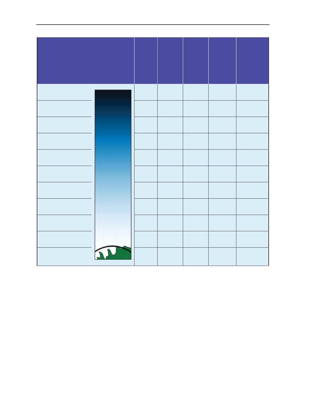
Chapter 14
Standard
Lapse
Standard
Pressure
Rate
Lapse Rate
Altitude
Altitude
(Inches
Ambient
Ambient Air
Event
(Feet)
(Meters)
of
Air
Tempera-
Mercury)
Tempera-
ture
ture
(Fahrenheit)
Celsius)
Top of some thunder
70,000
21,350
1.3
-125.0
-151.0
clouds
“Outer Space” starts
64,000
19,520
50,000
15,250
3.4
-85.0
-91.0
Use of partial pressure
43,000
13,115
-56.7
-69.7
suits required
Commercial airline
35,000
10,675
7.0
-49.4
-57.5
cruising altitude
MC-4 maximum
25,000
7,625
11.8
-35.0
-16.0
opening altitude
One half the earth’s
atmosphere by weight
18,000
5,490
14.9
-21.0
-5.1
below this altitude
Supplemental
breathing oxygen
13,000
3,965
18.5
-10.0
20.0
required
USAF aircrews on
10,000
3,050
20.6
-5.0
23.4
oxygen
Average MFF opening
4,000
1,220
24.9
5.1
41.0
altitude
Mean
Mean sea level
sea
0
29.92
15.0
59.0
(standard atmosphere)
level
Figure 14-1. Atmosphere
14-18. Water vapor is found mostly below 30,000 feet MSL. The water vapor content of an air mass is
temperature dependent: as the temperature of the air mass increases, its ability to hold water vapor
increases. Therefore, hot air can hold more water vapor than cold air. Air also has weight: one square inch
of air at sea level exerts a pressure of 14.7 psi. This is equivalent to a 29.92-inch tall column of Hg at sea
level or 1013.25 millibars of pressure. The bar and millibar are the metric standards used to calculate the
activation settings for most U.S. and foreign military ARRs currently in use (Figure 14-2, page 14-7).
14-6
ATP 3-18.11/AFMAN 11-411(I)/NTTP 3-05.26M
24 October 2014
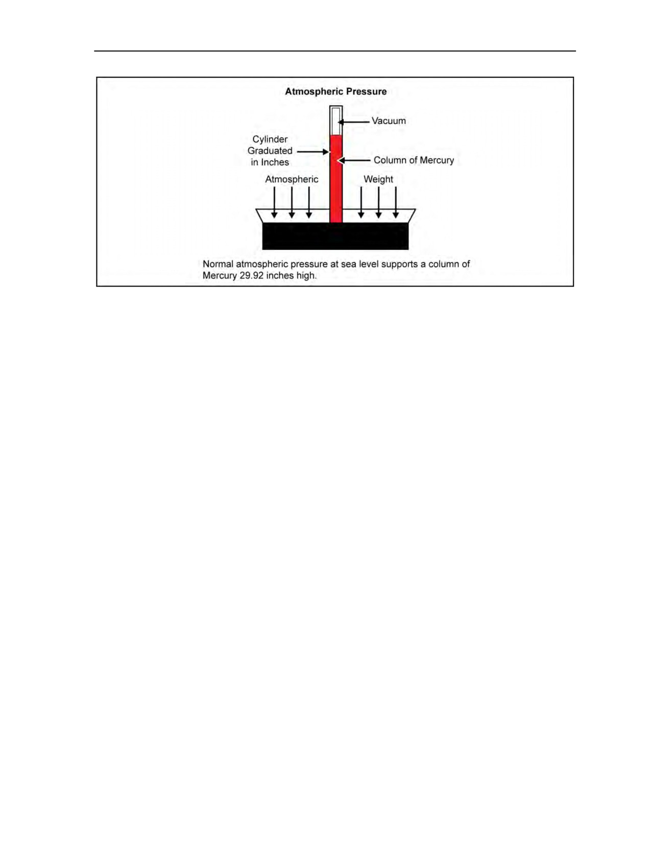
Weather Factors for the Military Free-Fall Jumpmaster
Figure 14-2. Mercury barometer
WEATHER
14-19. Weather is defined as the local state of the atmosphere with respect to its temperature, turbulence,
moisture content, and resultant degree of cloudiness. These factors interact in combinations which have a
variety of militarily significant effects on MFF parachute operations. Weather is characterized by five
meteorological elements: air temperature, humidity, clouds and/or precipitation, atmospheric pressure, and
wind.
14-20. Above the upper limits of the troposphere (35,000 feet MSL), only air temperature, atmospheric
pressure, and wind velocity are key factors. The remaining phenomena are factors below the troposphere
because they can only occur when water vapor (atmospheric moisture) is present. Moisture also affects
icing, turbulence, and environmental stress on the parachutist.
14-21. Weather is caused by the heating and cooling cycles of the earth’s surface. This cycle is the
evaporation of moisture into the atmosphere, its condensation, and the subsequent precipitation of those
water droplets. The presence of moisture causes the militarily significant environmental, temperature, and
atmospheric pressure changes. It is the atmospheric pressure variances that cause wind and generate clouds.
These pressure-variance phenomena are driven by daily and seasonal temperature differentials over the face
of the earth’s surface. Understanding these relationships permits the MFF jumpmaster to identify when
these factors will adversely affect MFF parachute operations.
14-22. World terrain for potential MFF operations varies from extreme mountain ranges to valleys and
flat deserts, some even below sea level. Each type of terrain is affected differently by localized wind flow
patterns (prevailing winds and their seasonal variations) and specific, seasonal weather phenomena. The
MFF jumpmaster is responsible for identifying these factors during the area analysis and incorporating
them into the infiltration planning process. This lessens their adverse impact and maximizes their potential
tactical value. When properly considered, weather factors contribute as much as any other factor to mission
accomplishment. For example, the dust storms encountered on the infiltration helicopter flight into Desert
One had a serious operational effect on mission accomplishment.
14-23. An example of a common, localized weather phenomenon that most MFF parachutists have
encountered is called virga. Virga occurs because all precipitation does not necessarily reach the earth’s
surface. It is characterized by precipitation that evaporates before hitting the ground. This normally
happens when dry air is at or just below a moisture-bearing cloud base. The phenomena is characterized by
the presence of snow, hail, or rain at or below exit altitude, but no evidence of precipitation is observed or
experienced on the ground. An MFF parachutist might fall through several thousand feet of rain after exit,
but experience no precipitation under canopy. In fact, virga conditions contribute to masking the aural and
visual signature of an element infiltrating an operational area.
24 October 2014
ATP 3-18.11/AFMAN 11-411(I)/NTTP 3-05.26M
14-7

Chapter 14
TEMPERATURE
14-24. One key environmental factor affecting atmospheric phenomena is temperature. The earth’s
surface is heated by incoming solar radiation (insolation). At night, the reverse effect is in thermal cooling
(terrestrial radiation). These two basic mechanisms, coupled with the presence of water vapor, are what fuel
nearly all the local weather conditions that affect MFF parachute operations.
14-25. Daily variations in terrestrial temperatures affect the airspace from the earth’s surface to
approximately 4,000 feet AGL. Daily ground-induced temperatures in the free air above 4,000 feet do not
vary significantly. When conditions are still, MFF parachutists on night jumps will often feel a drastic
temperature change while in free fall or under canopy when passing through this approximate altitude.
Land surfaces have a greater daily temperature variance than water. The range of temperature varies with
locale, season, latitude, and type of ground surface (for example, sand, rock, urban, plowed earth, runway
complex, or type of vegetation).
14-26. Larger daily temperature variations occur over DZs at higher elevations MSL. The same effect
occurs over DZs that absorb more thermal radiation. This phenomenon also induces and fuels thermal
updrafts. For MFF jumpmaster planning purposes, daily temperature variations and resultant
convective/thermal uplifting are much smaller over thick (dark, therefore cooler) vegetation and deep
water. For these two sets of conditions, canopy glide slope is significantly reduced, requiring a shortened
opening point calculation in wind drift formulas.
14-27. The mechanism by which temperature affects air masses varies with factors, such as humidity
content and rate of temperature change. In general, air cools (lapses) as it rises. Close to the earth (below
4,000 feet), the rate at which this occurs depends on the local conditions; however, usually a Standard
Lapse Rate is used. The Standard Lapse Rate is 2 degrees Celsius or 3 degrees Fahrenheit for each
1,000-foot-increment increase in altitude. This rule of thumb is used to determine ambient air temperatures
at altitude. For example, if the temperature on the ground is 50 degrees Fahrenheit, at 10,000 feet AGL, the
ambient air temperature is 20 degrees Fahrenheit [50 - (10 x 3)]. For terminal free fall or for MFF
jumpmasters exposed outside the aircraft, the velocity of the slipstream (knots indicated airspeed) is
factored against a standard windchill chart using the ambient Standard Lapse Rate temperature to determine
total windchill effect (Table 14-1, page 14-9). This indicates the degree of environmental protection that the
jumpmaster or parachutists will require on the operation. Figure 14-3, page 14-10, depicts a temperature
scale comparing Celsius (centigrade) and Fahrenheit.
14-28. The Standard Lapse Rate for atmospheric temperature effects assumes a standard temperature of
15 degrees Celsius or 59 degrees Fahrenheit at sea level. Atmospheric temperature decreases at the
Standard Lapse Rate as one climbs in altitude. This progression continues linearly until 35,332 feet MSL,
which is the altitude where air theoretically becomes isothermal (constant temperature). Because of low
atmospheric moisture, a balance is created between sun heat absorbed from space and that reradiated to
space. This results in an ambient air temperature of approximately
-65 degrees Fahrenheit. Air
temperatures (before factoring windchill) above this altitude can drop as low as -121 degrees Fahrenheit.
Seasonal, latitudinal, and jet stream factors serve to moderate this extreme temperature differential between
the ground surface and MFF altitudes.
14-29. A temperature inversion is a condition where the air mass temperature increases instead of decreases
with a gain in altitude. This situation is most frequently found close to the ground (below 500 feet AGL) on a
still, clear, relatively cool night. When the ground loses its heat from the day (radiationally cools), the air
layer directly above it is heated. With the ground now cooler than the air mass directly above it and when
no significant air mass movement or mixing action occurs, the warm air mass acts like a blanket. The
temperature differential can be drastic, sometimes exceeding 20 degrees Fahrenheit.
14-30. When enough moisture is trapped under an inversion blanket of warm air (perhaps from rain the
previous day or heavy morning dew), ground fog occurs. The greater the temperature difference and the
more moisture present, the thicker and denser the fog layer. This is quite common on open areas that
characterize potential tactical DZs, where post-sundown and pre-dawn conditions are ideal for inversions
that will blanket the DZ. This is significant for parachutists on final approach under canopy and during the
landing flare. In addition, sound carries much farther under these conditions.
14-8
ATP 3-18.11/AFMAN 11-411(I)/NTTP 3-05.26M
24 October 2014
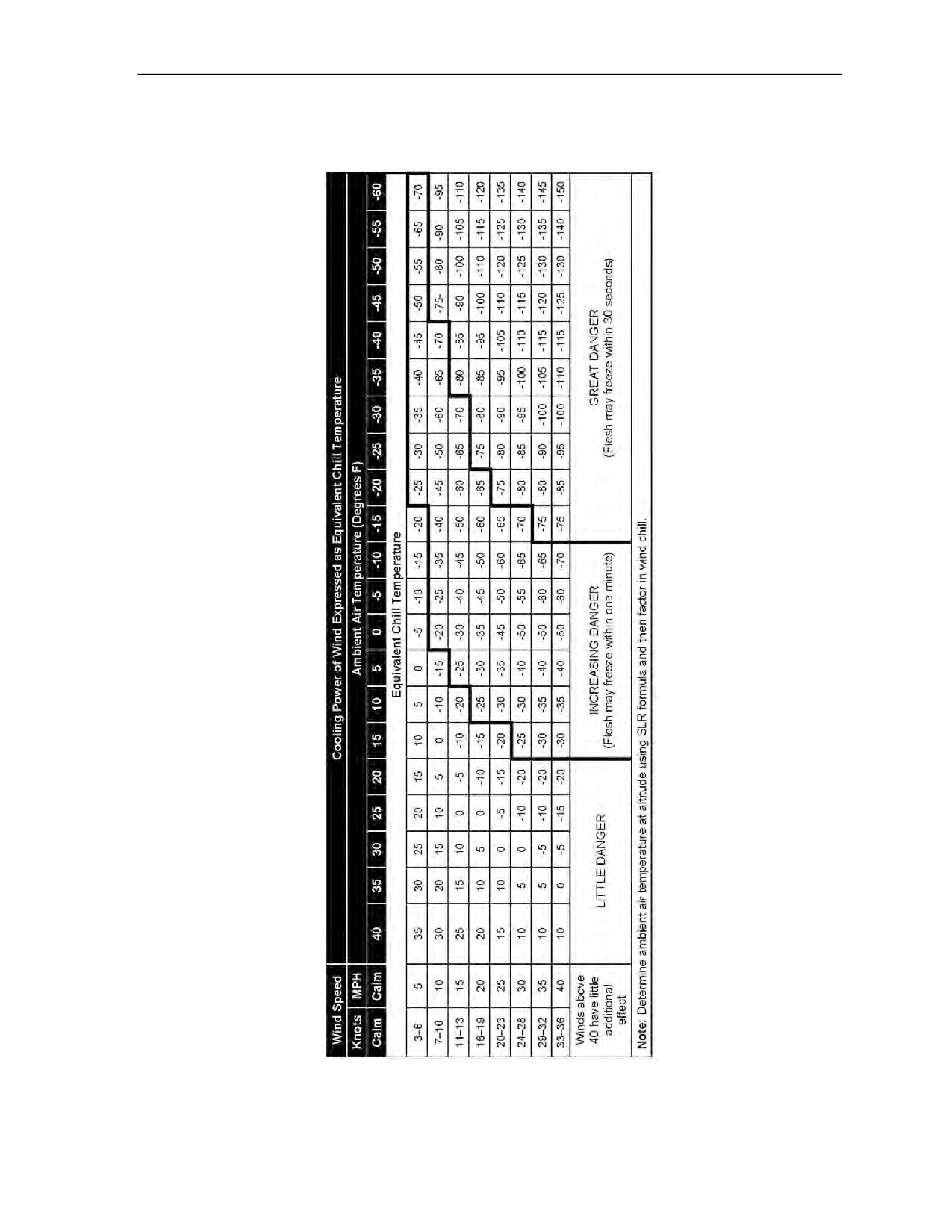
Weather Factors for the Military Free-Fall Jumpmaster
Table 14-1. Military free-fall operations windchill determination
24 October 2014
ATP 3-18.11/AFMAN 11-411(I)/NTTP 3-05.26M
14-9
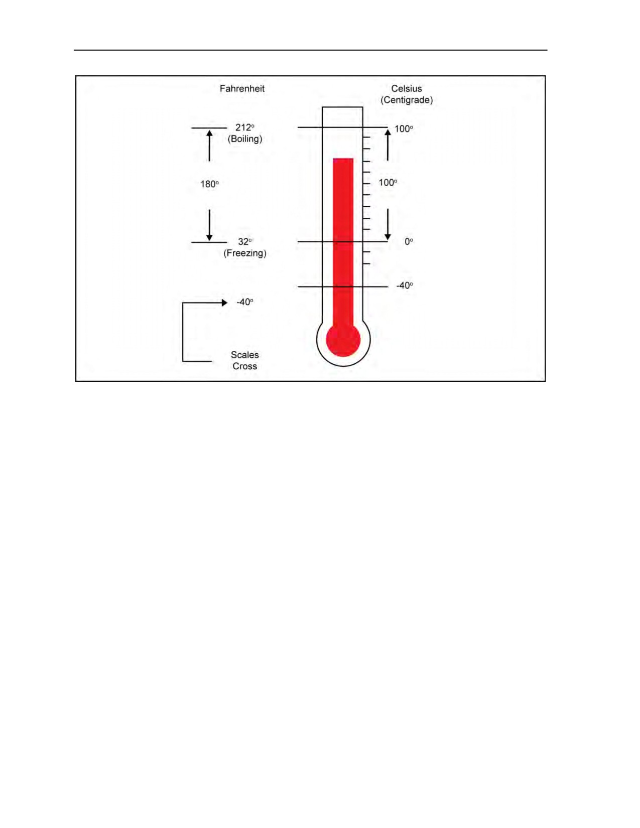
Chapter 14
Figure 14-3. Temperature scales
14-31. Over water, where temperatures are generally cooler closer to the surface than at higher altitudes,
inversion conditions are usually consistent over the last 4,000 feet of altitude of canopy flight. Because of
the lack of thermal convection experienced over land, the canopy lift over water is reduced over the lower
portion of the canopy flight. This is the same effect experienced on cool nights with no wind conditions
where the dynamic stall ability of the parachute is further reduced due to the lack of convective lift. The
canopy glide slope significantly decreases. Most often found over water, a shortened opening point is
required to offset the reduced lift and must be planned for by the MFF jumpmaster. The rule of thumb for
inversion conditions over large cold water bodies is that canopy glide performance can degrade by up to
30 percent once under 4,000 feet AGL.
TEMPERATURE EFFECTS ON ATMOSPHERIC PRESSURE
14-32. In general, air pressure decreases with altitude or in colder air. Environmentally, both of these
conditions are met as one climbs in altitude. Therefore, a temperature stabilized altimeter displays a higher
altitude barometrically (MSL) than its actual altitude AGL. In other words, a parachutist is closer to the
ground than the altitude reflected on his altimeter. This is especially true after an altimeter has been
exposed to colder temperatures, such as those found during MFF HAHO operations. For DZs at higher
elevations, altimeters can read as much as 500 feet higher than actual jumper altitude AGL. With potential
altimeter mechanical lag of up to 250 feet, a parachutist can be seriously mistaken in determining his
altitude above the ground, especially on a night descent. The temperature-affected altitude indicated on a
HAHO parachutist’s altimeter will always be several hundred feet different than a three-dimensional
satellite navigation or Global Orbiting Navigation Satellite System GPS satellite triangulated altitude
(Figure 14-4, page 14-11).
14-33. In warmer air masses, air pressure decreases slightly less rapidly as one climbs in altitude. A
parachutist’s true altitude AGL is higher than the indicated altitude in hotter weather conditions or after the
altimeter has been exposed to direct heat (for example, after lying on the concrete flight line in direct
sunlight on a 95 degrees Fahrenheit day just prior to the jump).
14-10
ATP 3-18.11/AFMAN 11-411(I)/NTTP 3-05.26M
24 October 2014
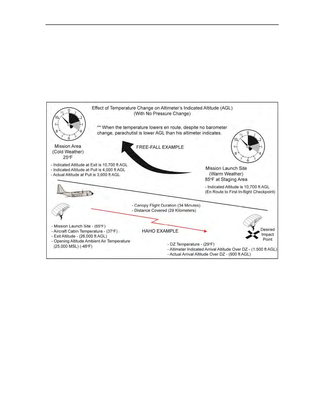
Weather Factors for the Military Free-Fall Jumpmaster
14-34. Warm air has less density than colder air; therefore, less lift is generated by lifting surfaces, such
as ram-air parachutes. Design performance and work capacity is decreased. The same effect occurs in the
lower density air found at DZs at higher altitudes MSL. Hot air conditions at high altitudes must be
considered by the MFF jumpmaster since parachute performance can be seriously degraded, especially
when under combat-equipment-induced higher-suspended weights. Other examples are the increased
runway length and reduced allowable cargo load for aircraft operating at higher altitudes during hot
conditions. The same principle applies to any parachute, whether for a tandem bundle’s cargo round or a
square personnel canopy. The lifting capacity is reduced, the glide slope decreases requiring an adjusted
K factor, and the overall rate of descent increases. Landings are generally harder due to a ram-air
parachute’s decreased ability to generate transitional lift during the landing flare.
Figure 14-4. Effect of temperature change on altimeter’s indicated altitude (AGL)
MEASUREMENT OF ATMOSPHERIC PRESSURE
14-35. Atmospheric temperature tends to even out (increased entropy) over the earth’s surface. Daily,
regional, and seasonal differences in heating and cooling patterns cause air density variations. Horizontal
variations are very small compared to the magnitude of vertical pressure change that occurs with an
increase or decrease in altitude. The scale of horizontal pressure change compared with vertical change is
on the scale of one-thousandth of an inch of Hg. Regardless, it is these small horizontal pressure
differentials that cause all atmospheric circulation (winds) and fuel most other weather phenomena.
14-36. Atmospheric pressure is the result of gravity acting on the mass of air that comprises the earth’s
atmosphere. This pressure is measured by instruments which are all variations of two types of barometric
devices. The first type is a mercury barometer which is impractical in MFF applications. The second type
of atmospheric pressure measuring instrument, most commonly used in MFF operations, is a variation of
the aneroid barometer. In general, an aneroid barometer is a sealed metal bellows containing a partial
vacuum, such as the military MA2-30 wrist altimeter and other analog display altimeters. The bellows
expands and contracts in response to the changes in air mass density surrounding it. When the device goes
higher into lesser atmospheric pressure, the bellows expands. When it goes lower into higher air pressure,
24 October 2014
ATP 3-18.11/AFMAN 11-411(I)/NTTP 3-05.26M
14-11
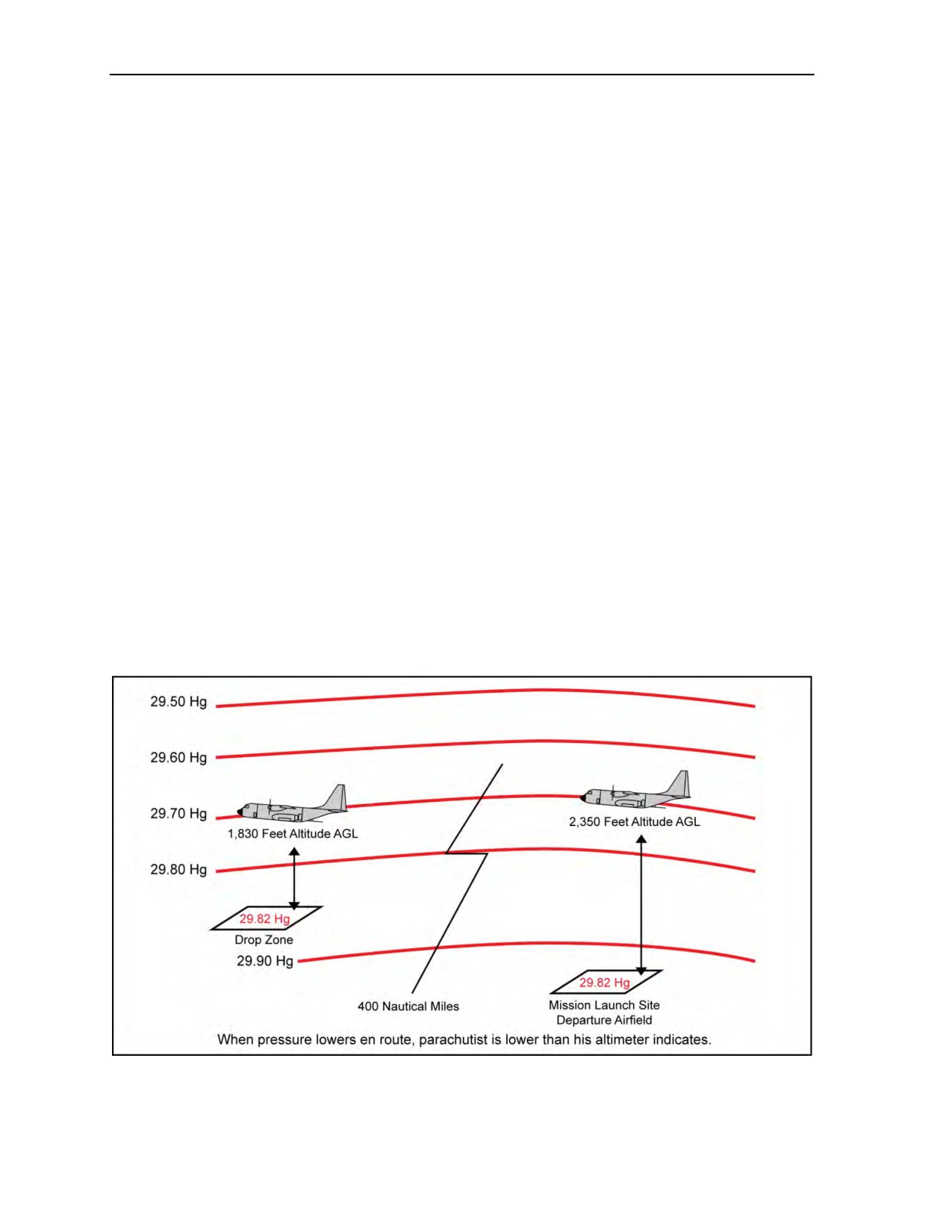
Chapter 14
the bellows is compressed. A pointer linked to the bellows moves around a calibrated dial, which for MFF
applications reads in 100-, 250-, and 1,000-foot increments.
14-37. Other altimeter variations, regardless of the type of readout (such as a digital display), are still
aneroid sensing devices. Because they are mechanical devices, altimeters are never 100-percent accurate.
They are all environmentally sensitive to some degree. In addition, some electronic types of barometric
sensors, such as EAADs or ARRs, are affected by electrical fields. This includes the potential fields
induced by intrateam radios or ambient environmental static electricity found in the immediate vicinity of
storm cloud formations. These conditions potentially affect all electrical instruments (GPS receivers,
compass board-mounted electronics, radio-controlled bundle systems), as well as electrically fired EAADs
or ARRs (for example, Sentinel, FXC, and Military CYPRES 2). For example, analog altimeter needles
have an acceptable manufacturer’s tolerance of up to ±250 feet, simply due to mechanical lag. They are,
however, useful because of their compactness and general consistency. The effects of most minor and some
potentially major environmentally induced inaccuracies can be negated through prior planning by the MFF
jumpmaster.
14-38. A common MFF example that demonstrates aneroid altimeter false readings is a parachutist who is
falling at terminal velocity in a back-to-earth or inverted body position. As any object falls, it creates a zone
of low pressure above it. If a parachutist falls with his back down and attempts to read the altimeter, the
altimeter’s aneroid senses a lower atmospheric pressure than the parachutist’s actual altitude AGL.
Consequently, the altitude reflected on the altimeter face is reading a false altitude AGL. The altimeter
reads a higher altitude than the parachutist’s actual altitude.
14-39. In addition, the altimeter needle fluctuates rapidly due to the inconsistent airflow through this
burble. If the parachutist is wearing combat equipment, the size of the low pressure zone is larger, the effect
of the burble is greater, and the altimeter reading has more extreme fluctuations. This situation is dangerous
for a parachutist approaching a designated pull or key decision altitude, as the parachutist could be up to
700 feet lower (500 feet lower without rucksack) than what is reflected on the altimeter. This could result in
loss of adequate time to react to a parachute malfunction. It could place the parachutist low under canopy
relative to accompanying parachutists. In general, it contributes to a loss of altitude awareness. At night and
with oxygen equipment, this situation has the potential to be catastrophic. Figure 14-5 depicts atmospheric
pressure change resulting in false readings.
Figure 14-5. Atmospheric pressure change over large distance resulting
in false altitude (AGL) readings
14-12
ATP 3-18.11/AFMAN 11-411(I)/NTTP 3-05.26M
24 October 2014

Weather Factors for the Military Free-Fall Jumpmaster
ENVIRONMENTAL EFFECTS ON ALTIMETERS
14-40. An altimeter is simply an air pressure measuring device. It only senses air pressure above MSL. It
does not know the intention of a parachutist or its own altitude relative to an intended DZ’s ground
elevation. For example, an altimeter indicates 10,000 feet MSL when all environmental factors affecting its
aneroid chamber equate to 698 millibars, whether or not it is 10,000 feet above a ground surface. It is the
MFF jumpmaster’s responsibility to understand, identify, and, through prior planning, apply corrections for
the environmental factors which change a linear, standard pressure reading MSL in relation to altitude AGL.
14-41. MFF parachutists only have one altimeter to reference. Because altitude pressure deviations occur
on the infiltration flight, EAAD and/or ARR and parachutist altimeter advances or back offs for intended
DZs should be set on altimeters before takeoff, not en route. Sometimes it is necessary to adjust altimeters
en route (diversion to an alternate DZ), but it should be recognized that some atmospheric deviation occurs
over long distances; barometric devices will not reflect or fire quite as accurately. Setting before launch
provides a known starting point and later in-flight reference point for adjustments that could be
significantly incorrect otherwise. This point of reference is most often used in adjusting instruments when
aborting from the primary to an alternate DZ. When referencing aircraft altimeters in flight to effect EAAD
and/or ARR and altimeter adjustments, it is critical that the correct cockpit altimeter is used. The
barometric pressure in inches of Hg, when reflected on an altimeter that has been adjusted to the DAF
elevation MSL, is called the aircraft altimeter setting. When in doubt, the parachutist asks the pilot which
altimeter is reflecting altitude AGL or MSL. Some adjustment rules of thumb are—
z
1 millibar = 32.25 feet of altitude (always rounded up to 33 feet).
z
1,000 feet of elevation = 30.3 millibars.
Note: The above two equivalencies are true only up to approximately 15,000 feet MSL, after
which reduced air density changes the relationship.
14-42. Altimeter error induced by temperature variation can be significant, even when the altimeter is
properly set for surface conditions (Figure 14-6, page 14-14). Essentially, the relationship is this: if warmer
air is at altitude, the altimeter will read lower than its actual altitude AGL. This means that the parachutist
is actually higher AGL than the altitude reflected on the altimeter. If the temperature aloft is cooler than the
surface, the altimeter will read higher than its actual altitude AGL. This means that the parachutist is
actually lower than the altimeter’s indicated altitude.
14-43. A rule of thumb that can be used to identify the maximum potential discrepancy of altimeters in
cold weather environments is that for a given altitude, allow 2 percent for every 5 degrees Celsius
(or 9 degrees Fahrenheit) temperature increment making up the differential between the surface and that
specified altitude.
EXAMPLE:
Surface temperature is 12 degrees Celsius.
Temperature at 16,000 feet AGL is -18 degrees Celsius.
Temperature differential is 30 degrees Celsius.
30 degrees Celsius = 6 each 5 degrees Celsius increments.
2 percent times 6 increments = 12 percent of 16,000 feet = 1,920 feet.
24 October 2014
ATP 3-18.11/AFMAN 11-411(I)/NTTP 3-05.26M
14-13
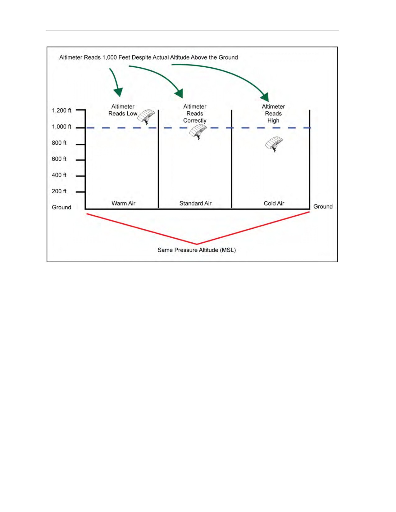
Chapter 14
Figure 14-6. Air density variation with temperature change
AIR DENSITY ALTITUDE
14-44. Air density is the factor that has the biggest effect on parachute flight characteristics. Standard or
textbook atmospheric conditions rarely exist. Therefore, the MFF jumpmaster must understand and plan to
accommodate the changes in canopy flight performance caused by atmospheric pressure, temperature,
humidity, or their combined effects. For example, a DZ can have an effective air density altitude that varies
several thousand feet from the DZ’s actual altitude MSL. It is possible for a DZ physically located at
9,000 feet MSL to have an air density altitude that causes parachute flight characteristics comparable to
those at 14,000 feet MSL.
14-45. Parachute performance characteristics that are degraded by air density altitude are opening shock
(such as in HAHOs), glide slope, and landing flare effectiveness (amount of required run out). Canopies
simply become less efficient as lifting surfaces, especially with the higher suspended weights which
accompany tandem bundles, combat equipment configured parachutists, or tandem pairs. Overall,
parachute lift is degraded. Essentially, air density decreases with an increase in altitude, temperature, or
humidity. When any or all of these factors are combined (high-altitude DZ on a hot, humid day), parachute
performance is degraded to the point that despite using a ram-air canopy, a statistically significant number
of parachutists can expect to have seriously hard (potentially injury-producing) landings.
14-46. This effect is tangible and is a key planning factor as low as 4,000 feet MSL. For round canopies
(tandem bundles), operations above 4,000 feet MSL must carefully consider the effects of air density
altitude. When these effects are combined with no-wind conditions (no wind velocity to create transitional
lift at landing flare), regardless of the type of canopy being employed, the effects are again magnified. An
increase in wind velocity helps offset canopy performance degradation caused by higher density altitudes.
14-14
ATP 3-18.11/AFMAN 11-411(I)/NTTP 3-05.26M
24 October 2014

Weather Factors for the Military Free-Fall Jumpmaster
The MFF jumpmaster plans infiltration times to capitalize on the local weather conditions that best counter
the effects of air density altitude.
14-47. Air density altitude effect is also valid, but to a lesser degree, for oxygen altitudes which can
contribute to the effects of hypoxia. For example, it is possible below 10,000 feet MSL to have an air
density altitude of 13,000 feet (+) MSL in terms of symptoms of hypoxia. This is based on the air
temperature locally reducing air density. This marginally less dense air contains a lower volume of oxygen
molecules, which means there is less oxygen available to the lungs. Its effect is magnified when the
parachutist or aircraft crewmember is physically exerting himself. This condition is usually manifested only
after prolonged exposure (30 minutes or more) at this effective altitude. It is another reason to use oxygen
all the way to landing for MFF operations at higher DZ elevations MSL and night operations. Doing so will
minimize the effect and enhance night vision.
MAPPING OF PRESSURE SYSTEMS
14-48. On weather maps, atmospheric pressure MSL is plotted in millibars based on observations by
reporting stations. Lines, called isobars, are drawn connecting equal values of reported pressure in the same
way that contour lines depict elevation on topographic maps (Figure 14-7, page 14-16). The pressure
differential mapping standard for weather map graphics (atmospheric pressure contour interval) in North
America is an isobar for every four millibars pressure. When isobars are graphically displayed depicting
varying pressures, they create pressure patterns. Patterns that depict low-pressure systems have a
counterclockwise ground wind flow. In the Northern Hemisphere, hurricanes, typhoons, tropical storms,
tornadoes, and waterspouts are all examples of low-pressure phenomena. If MFF parachute operations must
be conducted in the vicinity of low-pressure systems, the following rules of thumb are useful in blind drop
planning. Relative to its direction of movement, the strongest winds and most intense part of the storm are
found on the right front quarter of the cell. The weakest portion of the storm cell is the left rear quarter in
relation to its movement path.
14-49. High-pressure systems have a clockwise ground wind flow. Compared to a low-pressure system,
high-pressure air masses have fewer clouds and lighter, calmer winds. Turbulent areas that exist in a
high-pressure system are less concentrated. High-pressure areas are predominantly found over cold or
cooler ground surfaces. These air masses are generally denser and barometrically will have higher millibar
readings than low-pressure systems. High-pressure systems generally have conditions more conducive to
MFF parachute operations.
24 October 2014
ATP 3-18.11/AFMAN 11-411(I)/NTTP 3-05.26M
14-15
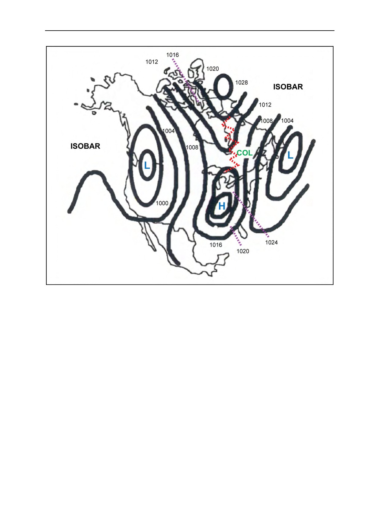
Chapter 14
Figure 14-7. Pressure systems
ATMOSPHERIC CIRCULATION
14-50. Knowledge of atmospheric circulation patterns is needed to fully apply mission-planning
parameters for long-range MFF infiltrations. As tactical missions will not be conducted on known DZs and
long-range infiltrations are the norm, the potential negative impact of weather considerations is significant
for the MFF jumpmaster and preparatory planning. The efforts and ability of the MFF jumpmaster affects
the entire mission’s contingency-planning requirements.
14-51. In general, the unequal heating of the earth’s surface is the basis for atmospheric circulation on the
macro scale. Regional variations in surface temperatures and topography complicate the movement of these
air masses on the micro scale. The resultant airflow sets up irregular circulation patterns. Air mass patterns
are additionally affected by the earth’s rotation (Coriolis effect).
14-52. Secondary circulation is a description of the movement of the air masses found closest to the
surface of the earth. For example, prevailing westerlies are regionally caused by the earth’s rotation. This
type of phenomenon can move air masses as much as 500 miles in 24 hours. Some sections of an air mass
may move more rapidly or flow differently due to the localized effects of topographic irregularities.
14-53. There are two types of air masses. They are differentiated by their atmospheric pressure. They are
also characterized as moving or stationary. In general, low-pressure systems and their associated frontal
activity can adversely affect parachuting conditions. High-pressure systems are, in general, relatively free
of bad weather and are more conducive to MFF parachute operations (Figure 14-8, page 14-17).
14-16
ATP 3-18.11/AFMAN 11-411(I)/NTTP 3-05.26M
24 October 2014
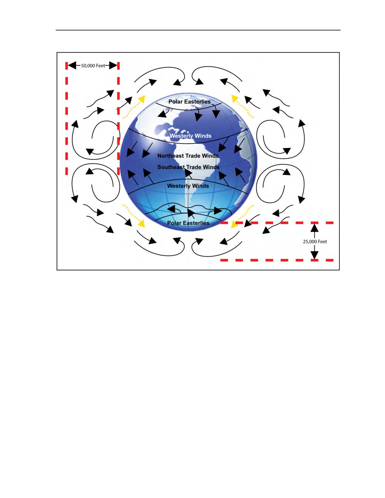
Weather Factors for the Military Free-Fall Jumpmaster
Figure 14-8. General pattern of atmospheric circulation
WIND FLOW MECHANICS
14-54. These systems are categorized into two types of winds—surface and aloft. There are two types of
winds aloft. One is the jet stream, which is a band of maximum winds found along the earth’s middle
latitudes. This feature is concentrated in the troposphere and generally flows from the west. Dipping as low
as 15,000 feet MSL, it can dominate planning factors affecting HAHO and, to a lesser degree, HALO MFF
operations. The normal average altitude for the jet stream is 30,000 feet MSL. When the air acquires
velocity, the Coriolis effect deflects it to the right (with respect to the flow) in the Northern Hemisphere
and the reverse in the south. The term gradient wind refers to the theoretical wind that blows parallel to the
isobars; in fact, in the lower parts of the atmosphere near the ground, friction with the surface deflects the
gradient flow. The angle of deflection varies from approximately
10 degrees over the ocean to
approximately 45 degrees over irregular land surfaces. Thus, analysis of the general wind patterns from
upper air weather maps can be done; winds closer to the surface or where terrain is rugged or high will
have more terrain-induced effects on the flow.
14-55. Surface winds are affected by factors caused by air mass contact with the surface of the earth.
Friction between an air mass and the earth reduces surface wind speed to about 40 percent of the velocity of
gradient winds aloft (Figure 14-9, page 14-18). It is this same friction which, in conjunction with the
Coriolis effect, causes surface wind to flow across (perpendicular to) the isobars instead of parallel to them.
The velocity of the wind is indicated by the spacing of the isobars. The closer the isobars, the higher the
pressure gradient and, consequently, the higher the wind velocity. In the Northern Hemisphere, surface
winds flow clockwise around and away from a high-pressure center. They flow counterclockwise and in
toward a low-pressure center. In the Southern Hemisphere, the winds still blow around and away from
24 October 2014
ATP 3-18.11/AFMAN 11-411(I)/NTTP 3-05.26M
14-17
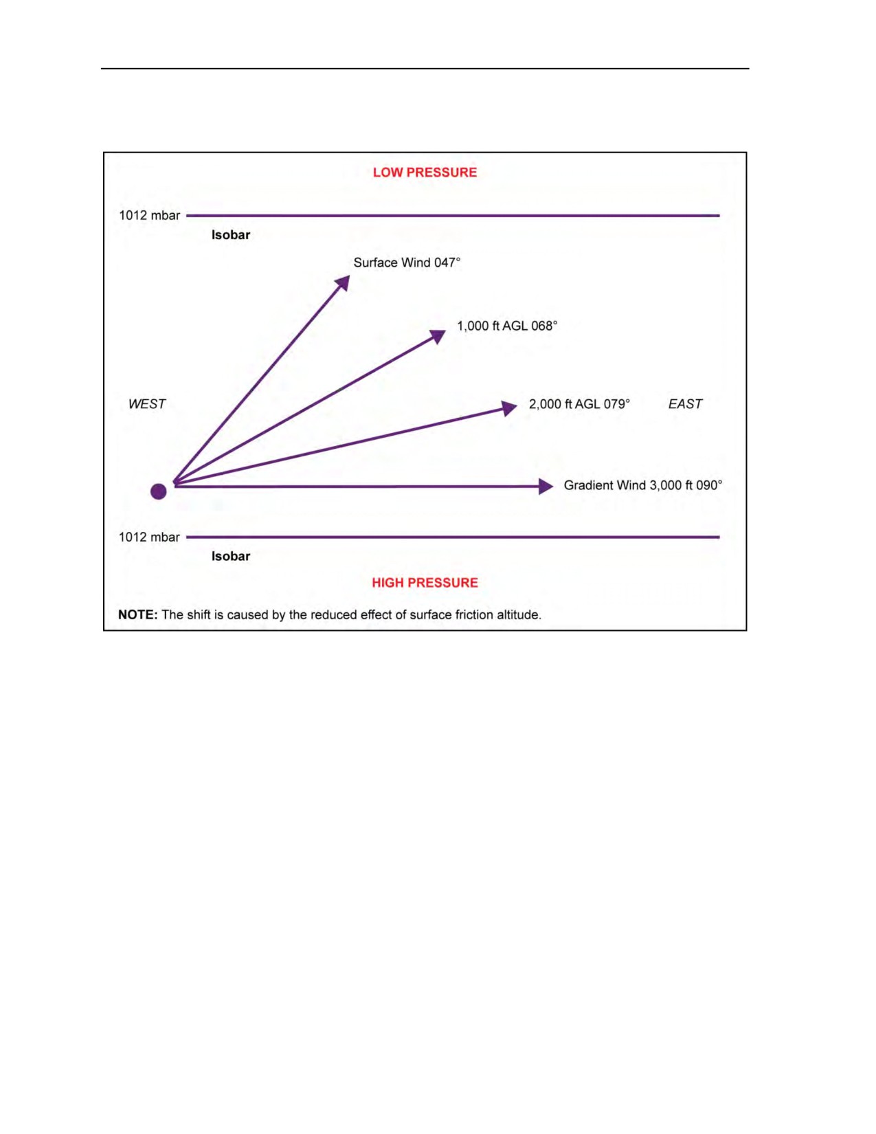
Chapter 14
highs and in toward lows, but the direction of the flow is reversed; for example, counterclockwise around a
high and clockwise around a Southern Hemisphere low.
Figure 14-9. Wind shift with altitude increase
14-56. Surface wind flows across isobars from high pressure toward low pressure. Friction with the
surface generally only affects air masses up to an approximate maximum altitude of 3,000 feet AGL. The
degree of effect will depend on the local contour of the surface. It is least over water bodies or flat deserts
and greatest over irregular mountains. The effect of friction also gradually decreases with altitude. The
ground surface effect is turbulence, which is a localized result of air mass friction and obstacles on the
earth’s surface. Since surface friction decreases with altitude, air mass wind velocity generally increases
with altitude AGL. Above the friction layer (3,000 feet AGL), wind speed is determined by the dimension
of the pressure gradient (closeness of the isobars) and is fairly constant or slightly increases until reaching
altitudes affected by the jet stream (Figure 14-10, page 14-19).
14-57. In HAHO operations, topography influences parachute flight-path planning because of its ability to
channelize and deflect prevailing winds. In addition, the jet stream
(with seasonal variations) is a
significant factor in release point determination. For example, the jet stream can dip as low as 15,000 feet
MSL and achieve wind velocities of more than 270 knots. The jet stream is most often found where a cold
front boundary intersects the 500-millibar level aloft. It is found in segments 1,000 to 3,000 miles long, is
100 to 400 miles wide, and 3,000 to 7,000 feet thick. A thorough premission area study will identify many
of these factors that are unique to the intended area of operations. Later, during mission planning isolation,
just prior to infiltration, an operational area intelligence update with current weather provides the data used
to determine detailed prevailing wind effects on the MFF infiltration. It is the responsibility of the
MFF jumpmaster to assess these factors and advise the commander of their potential combined impact on
that portion of the mission (Figure 14-11, page 14-19).
14-18
ATP 3-18.11/AFMAN 11-411(I)/NTTP 3-05.26M
24 October 2014
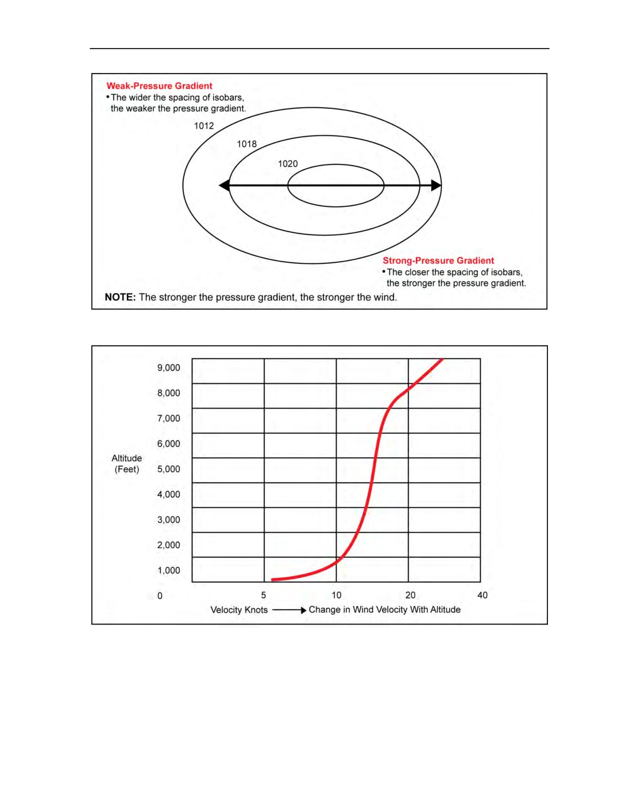
Weather Factors for the Military Free-Fall Jumpmaster
Figure 14-10. Pressure gradient principles
Figure 14-11. Change in velocity with altitude
24 October 2014
ATP 3-18.11/AFMAN 11-411(I)/NTTP 3-05.26M
14-19
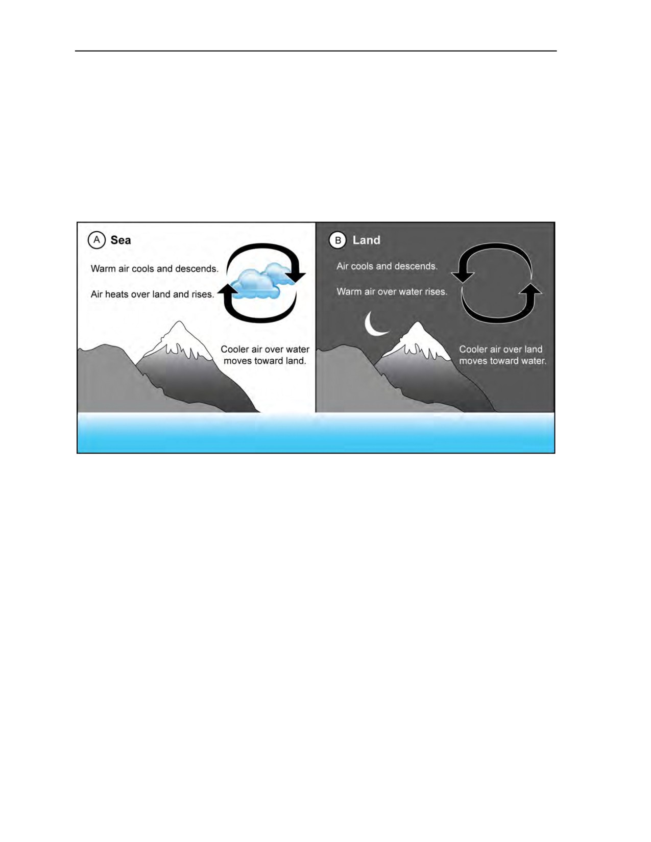
Chapter 14
LAND AND SEA BREEZES
14-58. These related weather phenomena are caused by the difference in heating and cooling rates of
water and land. Generally associated with coastal regions, these effects also occur along larger lakes. The
sea breeze occurs in morning or daytime and the land breeze occurs at dusk or early evening
(Figure 14-12). Since land warms up faster than water, the air rising over the land creates a lower pressure
area than that over the water. The air over the water moves toward the land to fill the low-pressure zone.
The effect creates the onshore or so called sea breeze. The same sequence of events occurs to create the
land breeze. At the end of the day water gives off its heat more slowly than land. After the land has cooled,
heated air is still rising from the water. A low-pressure area is created offshore by the rising warm air. Air
moving from the land to fill in the low-pressure area offshore causes the land breeze.
Figure 14-12. Land and sea breezes
14-59. An example of potential problems for MFF parachutists during these conditions would be a dusk
infiltration onto a coastal DZ after a warm day. Without calculating the canopy opening point to
accommodate the land breeze’s increased offshore wind velocity, an MFF jumpmaster might not factor
enough canopy performance (K factor) to reach the beach. With degraded canopy performance over cold
water, the parachutists could be seriously short of their intended beach DZ. In this case, the parachutists
would be conducting an unintentional water landing just offshore from their beach desired impact point.
14-60. In mountains, there is a parallel phenomenon that is more radical and therefore more potentially
dangerous to the MFF parachutist under canopy. These are the valley and mountain breezes. For land and
sea breezes, heat differential drove the mechanism. These two new events are based on the principle of
warm air masses rising and cool air masses sinking. Valley breezes occur during the day after the sun has
heated an exposed air mass against the side of a terrain feature. It rises causing an upslope breeze. At dusk
into early evening, the air cools and flows downslope. A parachutist entering one of these moving air
masses can be floated or otherwise involuntarily pushed under canopy as the air mass moves with this
thermal event. The closer the parachutist is to the terrain feature, the more graphic the effect and the higher
the potential for turbulence. When eddy winds and localized convective turbulence are factored into the
combined effect, the probability of radical canopy performance is quite high.
14-61. Parachutists must be suspicious of altimeter readings due to the rapidly changing pressure
differentials as air masses are pushed into the sides of larger terrain features. For HAHO parachutists in the
clouds while topping mountains or ridgelines, it is possible to have altimeter readings up to 1,000 feet
higher than the actual altitude AGL. The air mass is compressed against the terrain feature reflecting the air
density of a lower altitude. This means that the parachutist can be up to 1,000 feet lower than the altitude
14-20
ATP 3-18.11/AFMAN 11-411(I)/NTTP 3-05.26M
24 October 2014

Weather Factors for the Military Free-Fall Jumpmaster
reflected on the altimeter. As this also equates to roughly 30 millibars of pressure differential, there is also
potential for barometrically activated EAADs and/or ARRs to fire at an unplanned, inopportune time.
14-62. The MFF jumpmaster must conduct a map survey for the highest terrain feature near the opening
point affecting opening altitude determination and assess canopy glide slope to accommodate terrain along
the anticipated canopy flight route. Essentially, the MFF jumpmaster must consider and evaluate flight
plans when conducting MFF operations in mountainous areas. The MFF jumpmaster accounts for terrain
between the opening point and the DZ, thermal air mass or flow, air pressure variations, air density
altitudes, and environmental factors. The MFF jumpmaster identifies critical altitudes AGL and MSL and
determines canopy performance parameters affecting the ability of the infiltrating team to arrive at their
intended DZ. By assessing canopy K factors, the MFF jumpmaster must determine if the canopy
performance under its loaded weight will, by a given point in the canopy flight path, provide enough
altitude to clear terrain features.
14-63. All mountain phenomena are associated with radically unpredictable wind shears and buffeting.
They are very serious hazards to the parachutist and a planning factor that must be addressed by the
MFF jumpmaster. In general, HAHO or any canopy flight in and around mountains or hills can be
hazardous. Cloud decks, which top mountains or ridgeline terrain features, also contain especially strong
downdrafts and turbulence, especially on the leeward (downwind) side of the feature. Parachutists must
also be aware that clouds do not have to be present for these turbulence conditions to occur. Turbulence is
normally present around any cloud formation and can be found at any altitude—even in clear air a
significant distance downwind of terrain.
EDDY WINDS
14-64. Commonly known as surface or ground turbulence, eddy winds are created when an air mass flows
over physical obstructions on the earth’s surface. Irregular terrain, large individual trees, tree lines along
DZ edges, built-up areas, and individual buildings are common features which create turbulence that
parachutists must negotiate when setting up for a landing.
14-65. Turbulence effects are a function of the angle of contact with and intensity (speed) of the airflow
over and around the parachute’s airfoil shape. In constant aerodynamic
(laboratory) conditions, the
parachutist is the only factor which changes the airfoil shape, and that only occurs when the parachutist
pulls down on the steering lines. Since constant conditions do not exist in free air, the continuously
changing aggregate effects of the airflow disrupt the equally pressurized and smooth flying of the canopy.
Anything other than the hypothetical aerodynamically perfect condition is deflation or distortion of the
canopy, no matter how slight or for how short a period of time. It is this turbulence disturbed airflow that
can unpredictably cause the canopy to stop descending (float), involuntarily turn (side slide), dive, go back
up, momentarily start to deflate (breathe), partially collapse (fold end cells under), radically deform the
airfoil (deflate multiple cells of the canopy or fold the nose of the canopy under), or all of the above at what
often appears to the parachutist to be simultaneously.
14-66. Other key factors are size (square footage), number of cells of the canopy construction, and type of
nylon porosity in relation to the total weight suspended under it. Most MFF jumpmasters are concerned
with combat-equipped parachutists overloading the maximum suspended weight recommendations of a
canopy or parachute system. These are valid concerns to assist in avoiding structural damage to the canopy,
especially at higher opening altitudes MSL. Thus, HAHO free-fall delays are used to minimize opening
shock forces, especially for tandem bundle delivery systems; after the delivery of a cargo payload, the
minimum weight for adequate pressurization of the tandem master’s main canopy might not be met.
Canopies under these conditions can be extremely unpredictable, especially the larger square footage
tandem main parachutes.
14-67. For example, presentation of an underpressurized tandem canopy’s stabilizers to the wind line
when executing a landing approach, in conjunction with normal manipulation of the brake lines, can
depressurize the canopy enough to collapse it. The reinflation time hazard is compounded in that for some
tandem bundle delivery systems, payloads are dropped between 300 to 500 feet AGL. The tandem master is
already close to the ground when turning crosswind onto the base leg of the landing approach. When a
canopy without adequate pressurization is additionally subjected to environmental turbulence, its ability to
24 October 2014
ATP 3-18.11/AFMAN 11-411(I)/NTTP 3-05.26M
14-21