ATP 3-18.11 Special Forces Military Free-Fall Operations (October 2014) - page 1

ATP 3-18.11
AFMAN 11-411(I)
NTTP 3-05.26M
Special Forces
Military Free-Fall Operations
October 2014
DISTRIBUTION RESTRICTION: Distribution authorized to U.S. Government agencies and their contractors only
to protect technical or operational information from automatic dissemination under the International Exchange
Program or by other means. This determination was made on 23 June 2014. Other requests for this document
must be referred to Commander, United States Army John F. Kennedy Special Warfare Center and School,
ATTN: AOJK-CDI-SF, 3004 Ardennes Street, Stop A, Fort Bragg, NC 28310-9610, or by e-mail to
AOJK-DT-SF@soc.mil.
DESTRUCTION NOTICE: Destroy by any method that will prevent disclosure of contents or reconstruction of the
document.
FOREIGN DISCLOSURE RESTRICTION (FD 6): This publication has been reviewed by the product developers in
coordination with the United States Army John F. Kennedy Special Warfare Center and School foreign disclosure
authority. This product is releasable to students from foreign countries on a case-by-case basis only.
Headquarters, Department of the Army

ATP 3-18.11, C2
Change 2
Headquarters
Army Techniques Publication
Department of the Army
No. 3-18.11
Washington, DC, 18 August 2016
Special Forces Military Free-Fall Operations
1.
Change Army Techniques Publication (ATP) 3-18.11/Air Force Manual (AFMAN)
11-411(I)/Navy Tactics, Techniques, and Procedures (NTTP) 3-05.26M, dated
24 October 2014, as follows:
Remove old pages:
Insert new pages:
iii through xv
iii through xv
1-3 and 1-4
1-3 and 1-4
3-1 and 3-2
3-1 and 3-2
3-11 through 3-16
3-11 through 3-16
4-11 through 4-32
4-11 through 4-33
5-1 through 5-4
5-1 through 5-4
5-13 and 5-14
5-13 and 5-14
5-29 and 5-30
5-29 and 5-30
5-33 and 5-34
5-33 and 5-34
5-37 through 5-40
5-37 through 5-40
10-11 through 10-17
10-11 through 10-17
11-3 through 11-6
11-3 through 11-6
13-1 through 13-3
13-1 through 13-3
B-1 and B-2
B-1 and B-2
C-3 and C-4
C-3 and C-4
D-19 and D-20
D-19 and D-20
E-1 through E-4
E-1
G-1 and G-2
G-1 and G-2
G-9 through G-12
G-9 through G-12
Glossary-1 and Glossary-2
Glossary-1 and Glossary-2
References-1 through References-3
References-1 through References-3
2.
A bar (
) marks changed material.
3.
File this transmittal sheet in front of the publication.
DISTRIBUTION RESTRICTION: Distribution authorized to U.S. Government agencies and their contractors only to
protect technical or operational information from automatic dissemination under the International Exchange Program
or by other means. This determination was made on 23 June 2014. Other requests for this document must be
referred to Commander, United States Army John F. Kennedy Special Warfare Center and School,
ATTN: AOJK-SFD,
3004 Ardennes Street, Stop A, Fort Bragg, NC
28310-9610, or by e-mail to
AOJK-DT-SF@soc.mil.
DESTRUCTION NOTICE: Destroy by any method that will prevent disclosure of contents or reconstruction of the
document.
FOREIGN DISCLOSURE RESTRICTION (FD 6): This publication has been reviewed by the product developers in
coordination with the United States Army John F. Kennedy Special Warfare Center and School foreign disclosure
authority. This product is releasable to students from foreign countries on a case-by-case basis only.

ATP 3-18.11, C1
Change 1
Headquarters
Army Techniques Publication
Department of the Army
No. 3-18.11
Washington, DC, 20 October 2015
Special Forces Military Free-Fall Operations
1. Change Army Techniques Publication (ATP) 3-18.11/Air Force Manual (AFMAN)
11-411(I)/Navy Tactics, Techniques, and Procedures (NTTP) 3-05.26M, dated
24 October 2014, as follows:
Remove old pages:
Insert new pages:
ix and x
ix and x
8-5 and 8-6
8-5 and 8-6
9-5 and 9-6
9-5 and 9-6
D-11 and D-12
D-11 and D-12
2. A bar (
) marks changed material.
3. File this transmittal sheet in front of the publication.
DISTRIBUTION RESTRICTION: Distribution authorized to U.S. Government agencies and their contractors only to
protect technical or operational information from automatic dissemination under the International Exchange Program
or by other means. This determination was made on 23 June 2014. Other requests for this document must be
referred to Commander, United States Army John F. Kennedy Special Warfare Center and School,
ATTN: AOJK-CDI-SF,
3004 Ardennes Street, Stop A, Fort Bragg, NC
28310-9610, or by e-mail to
AOJK-DT-SF@soc.mil.
DESTRUCTION NOTICE: Destroy by any method that will prevent disclosure of contents or reconstruction of the
document.
FOREIGN DISCLOSURE RESTRICTION (FD 6): This publication has been reviewed by the product developers in
coordination with the United States Army John F. Kennedy Special Warfare Center and School foreign disclosure
authority. This product is releasable to students from foreign countries on a case-by-case basis only.

This page intentionally left blank.

ATP 3-18.11, C1
20 October 2015
By order of the Secretary of the Army:
MARK A.
MILLEY
General, United
States Army
Chief of
Staff
Official:
GERALD B. O’KEEFE
Administrative Assistant to the
Secretary of the Army
1427201
DISTRIBUTION:
Active Army, Army National Guard, and U.S. Army Reserve: Not to be distributed; electronic media only.
PIN: 104684-001

This page intentionally left blank.

*ATP 3-18.11
AFMAN 11-411(I)
NTTP 3-05.26M
Army Techniques Publication
Headquarters
Department of the Army
No. 3-18.11
Washington, DC, 24 October 2014
Special Forces
Military Free-Fall Operations
Contents
Page
PREFACE
xiii
INTRODUCTION
xiv
Chapter 1
MILITARY FREE-FALL PARACHUTE OPERATIONS
1-1
Characteristics
1-1
Planning Considerations
1-2
Phases of Military Free-Fall Operations
1-5
Chapter 2
MC-4 RAM-AIR PERSONNEL PARACHUTE SYSTEM
2-1
MC-4 Ram-Air Personnel Parachute System Components
2-1
Donning and Recovering the MC-4 Ram-Air Personnel Parachute System
2-22
Chapter 3
CYBERNETIC PARACHUTE RELEASE SYSTEM
3-1
General Information on Military CYPRES 2 Models
3-1
Military CYPRES 2 Principles of Operation
3-2
Military CYPRES 2 Models
3-3
Expert CYPRES 2 Model
3-4
CYPRES Model Identification
3-4
Components
3-6
Maintenance
3-8
General Terms
3-9
DISTRIBUTION RESTRICTION: Distribution authorized to U.S. Government agencies and their contractors only
to protect technical or operational information from automatic dissemination under the International Exchange
Program or by other means. This determination was made on 23 June 2014. Other requests for this document
must be referred to Commander, United States Army John F. Kennedy Special Warfare Center and School,
ATTN: AOJK-CDI-SF,
3004 Ardennes Street, Stop A, Fort Bragg, NC
28310-9610, or by e-mail to
AOJK-DT-SF@soc.mil.
DESTRUCTION NOTICE: Destroy by any method that will prevent disclosure of contents or reconstruction of the
document.
FOREIGN DISCLOSURE RESTRICTION (FD 6): This publication has been reviewed by the product developers
in coordination with the United States Army John F. Kennedy Special Warfare Center and School foreign
disclosure authority. This product is releasable to students from foreign countries on a case-by-case basis only.
*This publication, when published, will supersede ATTP 3-18.11, dated 14 October 2011.
i

Contents
Modes of Operation
3-10
Mode Determination
3-11
Operating Procedures
3-16
Using Military CYPRES 2 Calculators
3-25
Chapter 4
USE OF OXYGEN IN SUPPORT OF MILITARY
FREE-FALL OPERATIONS
4-1
Oxygen Handling and Safety
4-1
Physiological Effects of High-Altitude Military Free-Fall Operations
4-2
Oxygen Forms
4-4
Oxygen Requirements
4-5
Oxygen Life-Support Equipment
4-6
The “PRICE” Check
4-28
Oxygen Safety Personnel and Preflight Checks
4-29
Oxygen Handling and Safety
4-33
Chapter 5
EQUIPMENT AND WEAPON RIGGING PROCEDURES
5-1
Equipment and Weapon Packing Considerations
5-1
Parachutist and Parachute Load Limitations
5-2
Hook-Pile Tape (Velcro) Lowering Line Assembly
5-3
Combat Packs and Other Equipment Containers
5-5
Parachutist Drop Bag
5-29
Weapon Rigging Procedures
5-33
Flotation Devices and/or Life Preservers
5-54
Chapter 6
AIRCRAFT PROCEDURE SIGNALS AND JUMP COMMANDS
6-1
Aircraft Procedure Signals
6-1
Jump Commands
6-9
Chapter 7
BODY STABILIZATION
7-1
Tabletop Body Stabilization Training
7-1
Main Ripcord Pull
7-5
Tracking
7-7
Recovery from Instability
7-8
Chapter 8
RAM-AIR PARACHUTE FLIGHT CHARACTERISTICS
AND CANOPY CONTROL
8-1
Ram-Air Parachute Characteristics
8-1
Ram-Air Parachute Deployment Sequence
8-3
Ram-Air Parachute Theory of Flight
8-6
Canopy Performance Factors
8-7
Parachute Flight Characteristics
8-8
Canopy Control
8-9
Canopy Maneuvers
8-13
Landing Maneuvers
8-19
Landing Approaches
8-20
Turbulence
8-24
Chapter 9
EMERGENCY PROCEDURES FOR MILITARY
FREE-FALL OPERATIONS
9-1
Refresher Training
9-1
Emergency Measures
9-1
ii
ATP 3-18.11/AFMAN 11-411(I)/NTTP 3-05.26M
24 October 2014

Contents
Actions for Dust Devils and Turbulent Air
9-10
Chapter 10
HIGH-ALTITUDE HIGH-OPENING AND LIMITED-VISIBILITY
OPERATIONS
10-1
Techniques and Requirements
10-1
Special Equipment
10-2
Free-Fall Delays
10-8
Parachute Jump Phases
10-8
Limited-Visibility Operations
10-11
Military Free-Fall With Night Vision Goggles
10-12
Chapter 11
MILITARY FREE-FALL DROP ZONE OPERATIONS
11-1
Responsibilities
11-1
Drop Zone Selection Criteria
11-2
Drop Zone Surveys
11-3
Drop Zone Personnel Qualifications and Responsibilities
11-4
Military Free-Fall Drop Zone Markings
11-6
High-Altitude Release Point and Military Free-Fall Drop Zone Detection
11-8
Aircraft or High-Altitude High-Opening Team Identification
11-9
Authentication System
11-9
Chapter 12
DELIBERATE WATER MILITARY FREE-FALL OPERATIONS
12-1
Additional Support Requirements
12-1
Parachutist Requirements
12-2
Equipment Requirements
12-2
Drop Zone Requirements and Markings
12-4
Parachutist Procedures for Water Jumps
12-5
Drop Zone Procedures for Pickup of Parachutists and Equipment
12-5
Night Water Parachute Operations
12-6
Water Jumps With Combat Equipment
12-6
Chapter 13
JUMPMASTER RESPONSIBILITIES AND CURRENCY
QUALIFICATIONS
13-1
Responsibilities
13-1
Qualifications
13-2
Cardinal Rules for the Jumpmaster
13-2
Currency and Requalification Requirements
13-3
Chapter 14
WEATHER FACTORS FOR THE MILITARY FREE-FALL JUMPMASTER .. 14-1
Criticality of Weather Knowledge
14-1
Mission Planning Tools
14-1
Atmosphere
14-5
Weather
14-7
Temperature
14-8
Environmental Effects on Altimeters
14-13
Air Density Altitude
14-14
Mapping of Pressure Systems
14-15
Atmospheric Circulation
14-16
Wind Flow Mechanics
14-17
Land and Sea Breezes
14-20
Eddy Winds
14-21
18 August 2016
ATP 3-18.11/AFMAN 11-411(I)/NTTP 3-05.26M, C2
iii

Contents
Clouds
14-25
Thunderstorms
14-26
Application of General Weather Principles
14-29
Moon Phases
14-33
Reference Tables
14-36
Appendix A
MILITARY FREE-FALL CRITICAL TASK LISTS
A-1
Appendix B
MILITARY FREE-FALL PARACHUTIST QUALIFICATION
AND REFRESHER TRAINING REQUIREMENTS
B-1
Appendix C
RECOMMENDED MILITARY FREE-FALL TRAINING PROGRAMS
C-1
Appendix D
SUGGESTED MILITARY FREE-FALL SUSTAINED
AIRBORNE TRAINING
D-1
Appendix E
........................................................................................................................... E-1
Appendix F
HIGH-ALTITUDE RELEASE POINT CALCULATION
F-1
Appendix G
JUMPMASTER PERSONNEL INSPECTION
G-1
Appendix H
SAMPLE AIRCRAFT INSPECTION CHECKLIST
H-1
Appendix I
JUMPMASTER AIRCREW BRIEFING CHECKLIST
I-1
Appendix J
JOINT PRECISION AIRDROP SYSTEM
J-1
GLOSSARY
Glossary-1
REFERENCES
References-1
INDEX
Index-1
Figures
Figure 1-1. Military free-fall operations planning phases
1-6
Figure 2-1. MC-4 RAPPS components
2-1
Figure 2-2. MC-4 RAPPS harness and container assembly components
2-4
Figure 2-3. MC-4 RAPPS assembly components
2-5
Figure 2-4. Location of the three-ring canopy release assembly
2-6
Figure 2-5. Location of the main ripcord handle and cutaway handle
2-7
Figure 2-6. Location of the chest strap, reserve ripcord handle, large equipment
attachment ring, and reserve ripcord cable housing
2-8
Figure 2-7. Location of the oxygen fitting block and equipment lowering line
attachment V-ring
2-9
Figure 2-8. Location of the main and reserve parachutes in the container
2-9
Figure 2-9. Location of straps
2-10
Figure 2-10. Location of the equipment tie-down loop and main risers
2-10
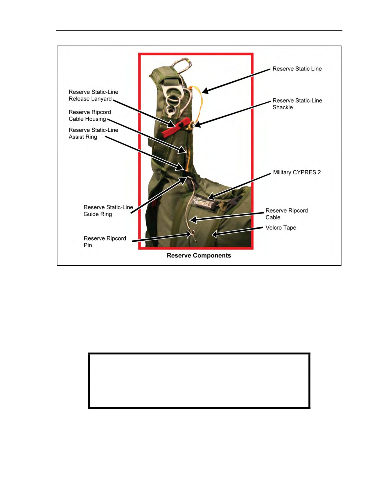
Figure 2-11. Location of reserve components
2-11
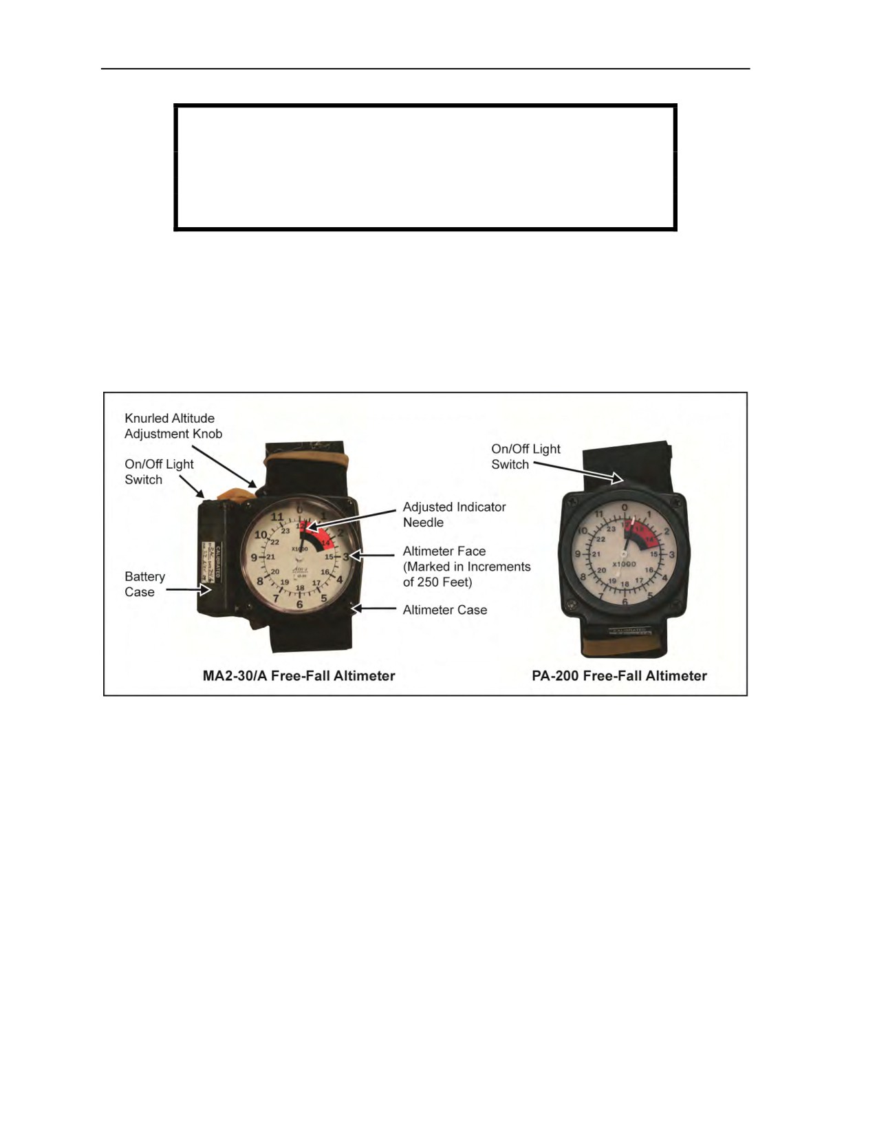
Figure 2-12. MA2-30/A and PA-200 free-fall altimeters
2-12
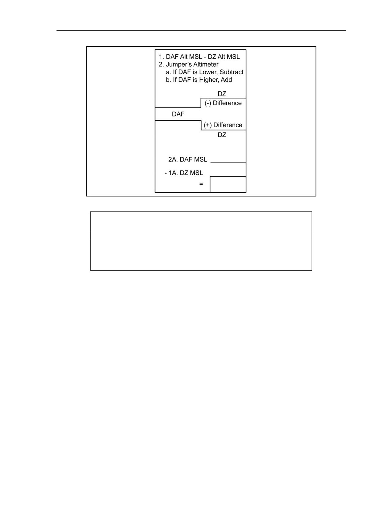
Figure 2-13. Altimeter setting
2-13
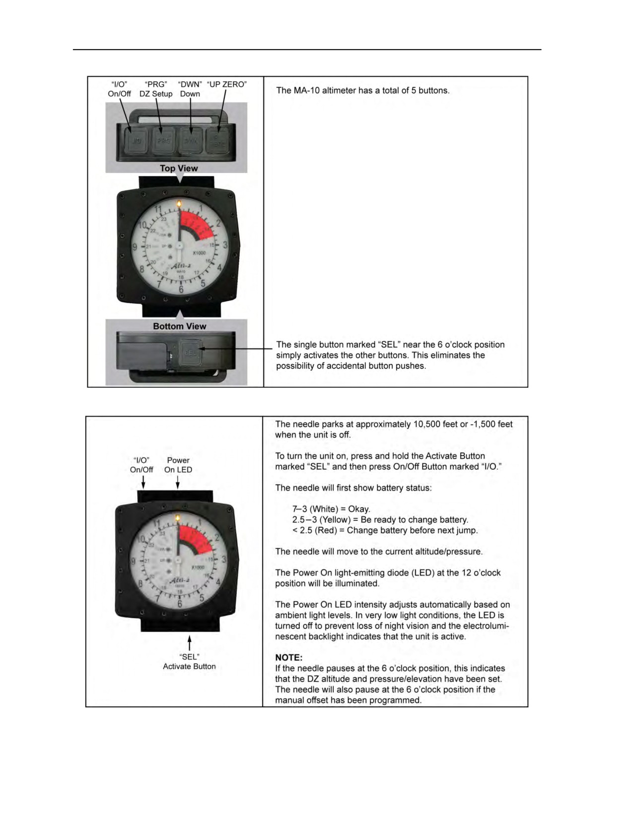
Figure 2-14. MA-10 altimeter buttons
2-14
Figure 2-15. On/Off buttons
2-14
iv
ATP 3-18.11/AFMAN 11-411(I)/NTTP 3-05.26M, C2
18 August 2016

Contents
Figure 2-16. Power-saving mode
2-15
Figure 2-17. Zeroing the MA-10 altimeter
2-15
Figure 2-18. Manual offset
2-16
Figure 2-19. Setting the drop zone
2-17
Figure 2-20. Replacing batteries in the MA-10 altimeter
2-19
Figure 2-21. Jumpsuits
2-21
Figure 2-22. Parachutist individual equipment kit
2-21
Figure 2-23. Aviator’s and MC-4 kit bags
2-22
Figure 2-24. Donning the MC-4 Ram-Air Personnel Parachute System
2-24
Figure 3-1. Military CYPRES 2 1500 35 A
3-3
Figure 3-2. Expert CYPRES 2
3-4
Figure 3-3. Military CYPRES 2 Model 1000 35 A control unit
3-5
Figure 3-4. Military CYPRES 2 Model 1500 35 A control unit
3-5
Figure 3-5. Military CYPRES 2 Model 2500 29 A control unit
3-6
Figure 3-6. Expert CYPRES 2 control unit
3-6
Figure 3-7. Military CYPRES 2 control unit
3-7
Figure 3-8. Back of Military CYPRES 2 control unit
3-7
Figure 3-9. Military CYPRES 2 processing unit
3-7
Figure 3-10. Military CYPRES 2 release unit
3-8
Figure 3-11. Example of Military CYPRES 2 serial number
3-9
Figure 3-12. Example of next required maintenance date for Military CYPRES 2
3-9
Figure 3-13. Power ON sequence for Military CYPRES 2 in default (training) mode ... 3-17
Figure 3-14. Beginning of Military CYPRES 2 self-test countdown
in default (training) mode
3-18
Figure 3-15. Military CYPRES 2 displaying current barometric pressure in millibars ... 3-18
Figure 3-16. Military CYPRES 2 set in default (training) mode
3-18
Figure 3-17. Example of Military CYPRES 2 error code
3-18
Figure 3-18. Power ON sequence for Military CYPRES 2 in
absolute (operational) mode
3-20
Figure 3-19. Beginning of Military CYPRES 2 self-test countdown
in absolute (operational) mode
3-20
Figure 3-20. Military CYPRES 2 displaying current barometric pressure in millibars ... 3-20
Figure 3-21. Military CYPRES 2 set in absolute (operational) mode
3-20
Figure 3-22. Example of Military CYPRES 2 error code
3-21
Figure 3-23. First value of 1 chosen for millibar setting
3-21
Figure 3-24. Second value of 0 chosen for millibar setting
3-21
Figure 3-25. Third value of 1 chosen for millibar setting
3-21
Figure 3-26. Final value chosen and Military CYPRES 2 set
3-22
Figure 3-27. Power ON sequence for Expert CYPRES 2 in offset mode
3-23
Figure 3-28. Expert CYPRES 2 displaying countdown
3-23
Figure 3-29. Example of Expert CYPRES 2 error code
3-24
Figure 3-30. Expert CYPRES 2 control unit displaying countdown
at zero down in offset mode
3-24
18 August 2016
ATP 3-18.11/AFMAN 11-411(I)/NTTP 3-05.26M, C2
v

Contents
Figure 3-31. Expert CYPRES 2 set at 120-foot offset
3-24
Figure 3-32. Power OFF sequence for CYPRES 2
3-25
Figure 3-33. Military CYPRES Absolute Adjust Circular Calculator (Whiz Wheel)
3-26
Figure 3-34. Personal Digital Assistant computer with Military CYPRES Absolute
Model Calculator software download
3-27
Figure 3-35. Military CYPRES Calculator
3-27
Figure 3-36. Military CYPRES Absolute Adjust Circular Calculator
3-28
Figure 3-37. Value for the Military CYPRES setting displayed
in the CYPRES setting box
3-29
Figure 3-38. Usage instructions for the Military CYPRES calculator
3-30
Figure 3-39. Instructions and first page of online “Military CYPRES
Absolute Adjust Model Calculator”
3-30
Figure 3-40. Step 1: Military CYPRES Absolute Adjust Model Calculator
3-31
Figure 3-41. Step 2: Military CYPRES Absolute Adjust Model Calculator
3-31
Figure 3-42. Step 3: Military CYPRES Absolute Adjust Model Calculator
3-31
Figure 3-43. Step 4: Military CYPRES Absolute Adjust Model Calculator
3-32
Figure 3-44. Military CYPRES 2 air travel card
3-33
Figure 4-1. MBU-12/P pressure-demand oxygen mask components
4-8
Figure 4-2. Parachutist Oxygen Mask
4-9
Figure 4-3. The improved oxygen harness
4-9
Figure 4-4. Complete Parachutist Oxygen Mask with MICH
4-10
Figure 4-5. Advanced combat helmet accessory rail connector
with oxygen single-strap and double-strap kits
4-11
Figure 4-5a. Parachutist oxygen mask securing lanyard
4-12
Figure 4-6. Parachutist Oxygen Mask and HS-57 quick disconnect
4-13
Figure 4-7. Fitting the MBU-12/P oxygen mask
4-14
Figure 4-8. Properly fitted mask
4-15
Figure 4-9. Parachutist Oxygen Mask with bayonet connectors and taped straps
4-16
Figure 4-10. The 106-cubic-inch portable bailout oxygen system
with the quick-disconnect oxygen hose
4-18
Figure 4-11. AIROX VIII assembly
4-18
Figure 4-12. Rigging the portable bailout oxygen system with the AIROX VIII
assembly to the RAPPS
4-20
Figure 4-13. Completed rigging of the portable bailout oxygen system
with the AIROX VIII assembly to the RAPPS
4-21
Figure 4-14. Completed rigging of the POM and/or American Safety Flight System
with the Parachutist Oxygen System assembly to the RAPPS
4-22
Figure 4-15. Six-Man Prebreather Portable Oxygen System
4-23
Figure 4-16. Oxygen console rigged in C-130 aircraft
4-25
Figure 4-17. Charging assembly looped and taped out of the way of parachutists
4-26
Figure 4-18. Side and top view of strap on K-bottle
4-26
Figure 4-19. MA-1 Portable Oxygen Assembly
4-27
Figure 4-20. Tie-down assembly and installation
4-28
vi
ATP 3-18.11/AFMAN 11-411(I)/NTTP 3-05.26M, C2
18 August 2016

Contents
Figure 4-21. Portable Bailout Oxygen System preflight inspection
and operational checklist
4-30
Figure 4-22. Sample prebreather preflight inspection and operational
function checklist
4-31
Figure 4-23. Pressure gauge and manual shutoff valve
4-33
Figure 4-24. Removing end plugs and depressing poppets
4-33
Figure 5-1. Stowing the HPT lowering line assembly
5-4
Figure 5-2. H-harness with attaching straps
5-5
Figure 5-3. H-harness attached to the kit bag
5-6
Figure 5-4. Combat pack and frame rigged with the modified H-harness
5-7
Figure 5-5. Improved equipment attachment sling and lowering line (spider harness)... 5-8
Figure 5-6. Combat pack and frame rigged with the improved equipment
attachment sling
5-9
Figure 5-7. Attaching the lowering line to the combat pack
5-10
Figure 5-8. Attaching the rear-mounted combat pack
5-11
Figure 5-9. Lowering line attached to the lowering line attachment V-ring
5-12
Figure 5-10. Attaching the front-mounted combat pack
5-13
Figure 5-11. Opened Single-Action Release Personal Equipment Lowering System
cargo carrier
5-15
Figure 5-12. Single-Action Release Personal Equipment
Lowering System with folded side flaps
5-15
Figure 5-13. Stowage pockets
5-16
Figure 5-14. Side flap
5-16
Figure 5-15. Top flaps
5-17
Figure 5-16. Single-Action Release Personal Equipment Lowering System
with secured horizontal straps
5-17
Figure 5-17. Single-Action Release Personal Equipment Lowering System
with secured vertical straps
5-18
Figure 5-18. Inserting the white webbing through the parachute harness link
5-19
Figure 5-19. Inserting the green 550 cord through the white webbing
5-19
Figure 5-20. Inserting the red 550 cord through the green 550 cord
5-20
Figure 5-21. Inserting the red 550 cord through the grommet
5-20
Figure 5-22. Leg strap cable retainer with buckle and grommet
5-20
Figure 5-23. Single-Action Release Personal Equipment Lowering System
release assembly
5-21
Figure 5-24. Stowage pocket with 8-foot lowering line
5-21
Figure 5-25. Securing the 8-foot lowering line to the cargo carrier
5-22
Figure 5-26. Mounted Single-Action Release Personal Equipment Lowering System . 5-23
Figure 5-27. Single-point release handle
5-23
Figure 5-28. Harness, single-point release (National Stock Number
1670-01-227-7992)
5-24
Figure 5-29. Release handle and D-ring attaching straps
5-25
Figure 5-30. Attaching snap hooks and leg strap release assembly
5-26
Figure 5-31. Rigging the harness, single-point release
5-27
18 August 2016
ATP 3-18.11/AFMAN 11-411(I)/NTTP 3-05.26M, C2
vii

Contents
Figure 5-32. Completing rigging the harness, single-point release
5-27
Figure 5-33. Attaching the hook-pile tape lowering line assembly
5-28
Figure 5-34. Attaching the harness, single-point release-rigged combat equipment
5-29
Figure 5-35. Parachutist with harness, single-point release-rigged combat pack
5-29
Figure 5-36. Compression straps connected and tightened
5-30
Figure 5-37. Loading the drop bag
5-31
Figure 5-38. Drop bag zipped shut with compression straps
connected and tightened
5-31
Figure 5-39. Drop bag is attached to the parachutist by standard
quick-release connectors
5-32
Figure 5-40. Parachutist drop bag rigged for rear-mounted jump
5-32
Figure 5-41. Parachutist drop bag rigged for front-mounted jump
5-33
Figure 5-42. Center-mounted weapons harness
5-34
Figure 5-43. Center-mounted weapons harness components
5-35
Figure 5-44. Main lift web attaching points
5-35
Figure 5-45. Attaching horizontal straps to the pile portion weapons harness
5-36
Figure 5-46. Securing triple-fold hook and pile
5-36
Figure 5-47. Securing weapon harness to weapon
5-37
Figure 5-48. Attaching weapon to main lift web attaching points
5-37
Figure 5-49. Chest strap routed through the sling
5-38
Figure 5-50. Attaching straps routed over weapon
5-38
Figure 5-51. M4 carbine-series rifles rigged for jumping
5-40
Figure 5-52. Positioning the weapon on the parachutist
5-41
Figure 5-53. Special Operations Forces Combat Assault Rifle in folded
and open positions
5-42
Figure 5-54. Right-side weapon rigging
5-43
Figure 5-55. M203 rigged for jumping
5-44
Figure 5-56. M14 rigged for jumping
5-45
Figure 5-57. M110 Semi-Automatic Sniper System
5-45
Figure 5-58. MP5 rigged for jumping
5-47
Figure 5-59. M249 and Para M249 squad automatic weapons rigged for jumping
5-48
Figure 5-60. M240G disassembled and packed for jumping
5-49
Figure 5-61. AT-4 and 84-millimeter Carl Gustaf rigged for jumping
5-50
Figure 5-62. Routing of vertical compression straps
5-50
Figure 5-63. Antiarmor weapon tie-down locations
5-51
Figure 5-64. Parachutist rigged for jumping with an anti-tank weapon
mounted on top of combat pack
5-51
Figure 5-65. Front-mounted weapon with rear-mounted rucksack
5-52
Figure 5-66. Front-mounted weapon with front-mounted rucksack
5-52
Figure 5-67. M224 60-millimeter mortar rigged for front mount
5-53
Figure 5-68. Left-side mount for M224 60-millimeter mortar
5-54
Figure 5-69. Underwater demolition team life preservers
5-55
Figure 5-70. Oralock valve
5-57
viii
ATP 3-18.11/AFMAN 11-411(I)/NTTP 3-05.26M, C2
18 August 2016

Contents
Figure 5-71. Parachutist with underwater demolition team life vest
and MC-4 parachute harness
5-59
Figure
6-1. DON HELMETS signal
6-3
Figure
6-2. UNFASTEN SEAT BELTS signal
6-4
Figure
6-3. EMERGENCY BAILOUT signal
6-4
Figure
6-4. MASK signal
6-5
Figure
6-5. CHECK OXYGEN signal
6-6
Figure
6-6. OXYGEN PROBLEM signal
6-6
Figure
6-7. TIME WARNINGS signal
6-7
Figure
6-8. WIND SPEED signal
6-8
Figure
6-9. GUSTING WINDS signal
6-9
Figure
6-10. STAND UP command
6-10
Figure
6-11. MOVE TO THE REAR command
6-10
Figure
6-12. STAND BY command
6-11
Figure
6-13. GO command
6-11
Figure
6-14. ABORT command
6-12
Figure
7-1. Poised exit position
7-1
Figure
7-2. Box man method
7-2
Figure
7-3. Diving exit position
7-3
Figure
7-4. Stable free-fall position
7-4
Figure
7-5. Body turn
7-4
Figure
7-6. Gliding
7-4
Figure
7-7. Altimeter check
7-5
Figure
7-8. Main ripcord pull
7-6
Figure
7-9. Tracking position
7-7
Figure
7-10. Example of tracking away for separation
7-8
Figure
8-1. Shape of the ram-air parachute canopy
8-1
Figure
8-2. Structure of the ram-air parachute canopy
8-1
Figure
8-3. Components and nomenclature of the ram-air parachute
8-2
Figure
8-4. Location of ram-air parachute components
8-3
Figure
8-5. Detailed lower portion of the ram-air parachute
8-4
Figure
8-6. Deployment sequence
8-5
Figure
8-7. Cutaway sequence
8-6
Figure
8-8. Ram-air parachute theory of flight
8-7
Figure
8-9. Applying brakes on the ram-air parachute
8-8
Figure
8-10. Controlling ground speed
8-10
Figure
8-11. Parachutist guide to good canopy control
8-10
Figure
8-12. Holding maneuver
8-11
Figure
8-13. Running maneuver
8-11
Figure
8-14. Crabbing maneuver
8-12
Figure
8-15. Effective canopy range
8-12
Figure
8-16. Brake-setting glide angles
8-13
18 August 2016
ATP 3-18.11/AFMAN 11-411(I)/NTTP 3-05.26M, C2
ix

Contents
Figure
8-17. Full flight
8-14
Figure
8-18. Half brakes
8-15
Figure
8-19. Full brakes
8-16
Figure
8-20. Stall
8-16
Figure
8-21. Spiral turn
8-17
Figure
8-22. Flat turn
8-18
Figure
8-23. Glide angles for a final approach
8-22
Figure
8-24. Landing approaches
8-22
Figure
8-25. High and low wind patterns
8-23
Figure
8-26. Significant change in wind direction
8-24
Figure
8-27. Adjusting for increase in winds on downwind leg
8-25
Figure
8-28. Adjusting for increase in winds on base leg
8-25
Figure
8-29. Adjusting for decrease in winds on base leg
8-26
Figure
9-1. Emergency preparations before takeoff
9-1
Figure
9-2. Parachutist postopening procedures
9-5
Figure
9-3. Controllability check
9-5
Figure
9-4. Parachutist emergency landing procedures
9-10
Figure
9-5. High-wind landing procedures
9-10
Figure
10-1. Jumper with individual body armor
10-2
Figure
10-2. Compass mounted to high-altitude high-opening navigation board
10-3
Figure
10-3. Navigation aid attaching point
10-4
Figure
10-4. Wilcox Parachutist Navigation Board
10-6
Figure
10-5. Parachutist navigation board closed and open position
10-7
Figure
10-6. Navigation aid attached to parachutist
10-7
Figure
10-7. Wedge formation
10-9
Figure
10-8. Trail formation
10-10
Figure
10-9. Trim tab locations
10-10
Figure
10-10. AN/AVS-6(V)3
10-13
Figure
10-11. AN/PVS-14
10-13
Figure
10-12. AN/PVS-15
10-13
Figure
10-13. Night vision goggle mounts
10-14
Figure
10-14. Securing night vision goggle mount to helmet with heavyweight retainer
band
10-15
Figure 10-15. Bungee position on night vision goggle mount
10-15
Figure 11-1. Military free-fall drop zone markings
11-7
Figure 11-2. Examples of wind socks
11-7
Figure 14-1. Atmosphere
14-6
Figure 14-2. Mercury barometer
14-7
Figure 14-3. Temperature scales
14-10
Figure 14-4. Effect of temperature change on altimeter’s indicated altitude (AGL)
14-11
Figure 14-5. Atmospheric pressure change over large distance resulting
in false altitude (AGL) readings
14-12
x
ATP 3-18.11/AFMAN 11-411(I)/NTTP 3-05.26M, C2
18 August 2016

Contents
Figure 14-6. Air density variation with temperature change
14-14
Figure 14-7. Pressure systems
14-16
Figure 14-8. General pattern of atmospheric circulation
14-17
Figure 14-9. Wind shift with altitude increase
14-18
Figure 14-10. Pressure gradient principles
14-19
Figure 14-11. Change in velocity with altitude
14-19
Figure 14-12. Land and sea breezes
14-20
Figure 14-13. Single-obstacle eddy current
14-23
Figure 14-14. Terrain-induced eddy currents
14-23
Figure 14-15. Tree-line-induced eddy currents
14-24
Figure 14-16. Cloud classification
14-26
Figure 14-17. Air movement beneath a thunderstorm cell
14-27
Figure 14-18. First gust wind flow
14-28
Figure 14-19. Wind shift as a front passes
14-30
Figure D-1. Mock aircraft rehearsal
D-1
Figure D-2. Actions in free fall and canopy flight
D-1
Figure D-3. Sample jumpmaster troop briefing
D-2
Figure D-4. Emergency procedures
D-4
Figure F-1. Plotting the HARP, free-fall, and canopy drift for a 20,000-foot HALO
mission profile
F-2
Figure G-1. Jumpmaster personnel inspection without oxygen,
weapon, or rucksack
G-2
Figure G-2. Jumpmaster personnel inspection with oxygen and life preserver
G-7
Figure G-3. Jumpmaster personnel inspection for weapon, front-mounted rucksack...G-10
Figure G-4. Jumpmaster personnel inspection with the rear-mounted rucksack
and/or parachutist drop bag
G-12
Figure H-1. Sample aircraft inspection checklist
H-1
Figure I-1. Sample jumpmaster aircrew briefing checklist
I-1
Figure J-1. Personnel and joint precision airdrop system combination
airdrop operations
J-3
Tables
Table 1-1. Minimum and maximum exit and opening altitudes
1-3
Table 1-2. Surface interval chart for conducting military free-fall
operations after diving
1-3
Table 1-3. Mission, enemy, terrain and weather, troops and support available, time
available, and civil considerations analysis
1-4
Table 3-1. CYPRES 2 model identification
3-5
Table 3-2. CYPRES 2 power ON self-test error codes in default (training) mode
3-17
Table 3-3. CYPRES 2 power ON self-test error codes in absolute
(operational) mode
3-19
Table 3-4. Expert CYPRES 2 power ON self-test error codes in offset mode
3-22
18 August 2016
ATP 3-18.11/AFMAN 11-411(I)/NTTP 3-05.26M, C2
xi

Contents
Table
4-1. Supplemental oxygen requirements for military free-fall parachutists
4-6
Table
5-1. Container weight limits
5-2
Table
5-2. Parachute load limits
5-2
Table
5-3. Weight of parachutist with two equipment loads
5-2
Table
5-4. Weight of parachutist with two equipment loads and basic load
5-3
Table
5-5. Lift capabilities
5-56
Table
6-1. Aircraft procedure signals (oxygen and nonoxygen jumps)
6-1
Table
6-2. Aircraft jump commands (oxygen and nonoxygen jumps)
6-2
Table
9-1. In-flight emergency procedures and signals
9-2
Table
9-2. In-flight emergency procedures
9-3
Table
9-3. Emergencies in free fall
9-4
Table
9-4. Cutaway procedures
9-5
Table
9-5. Malfunction procedures
9-6
Table
9-6. Canopy entanglement procedures
9-9
Table
10-1. Required free-fall delays
10-8
Table
12-1. Wind/sea state observation chart
12-4
Table
13-1. Jumpmaster responsibilities
13-1
Table
14-1. Military free-fall operations windchill determination
14-9
Table
14-2. Military free-fall lunar data example
14-35
Table
14-3. Approximate wind velocity by natural indicators
14-36
Table
14-4. Handkerchief angle wind velocity
14-36
Table
14-5. Linear measure
14-37
Table
14-6. Liquid measure
14-37
Table
14-7. Weight
14-37
Table
14-8. Square measure
14-37
Table
14-9. Cubic measure
14-37
Table
14-10. Temperature
14-38
Table
14-11. Approximate conversion factors
14-38
Table
14-12. Area
14-38
Table
14-13. Volume
14-39
Table
14-14. Capacity
14-39
Table
14-15. Statute miles to kilometers and nautical miles
14-39
Table
14-16. Nautical miles to kilometers and statute miles
14-40
Table
14-17. Kilometers to statute and nautical miles
14-40
Table
14-18. Yards to meters
14-41
Table
14-19. Meters to yards
14-41
Table
14-20. Determination of altitude by barometric pressure
(in inches of mercury)
14-41
Table C-1. Minimum quarterly training guide
C-1
Table C-2. Suggested 10-day combat-ready training program
C-3
Table F-1. HAHO K factors for Department of Defense Ram-Air
Personnel Parachute Systems
F-3
xii
ATP 3-18.11/AFMAN 11-411(I)/NTTP 3-05.26M, C2
18 August 2016

ontents
Preface
DODD 5100.01 tasks the Army to “train and equip, as required, forces for airborne operations, in coordination
with the other military Services, and in accordance with joint doctrine.” This guidance directs the Army, which
has primary responsibility for the development of airborne doctrine, procedures, and techniques, to develop, in
coordination with the other military Services, doctrine, procedures, and equipment that are of common interest.
United States Special Operations Command (USSOCOM) establishes the Commander, United States Army
Special Operations Command (USASOC), as the lead component for military free-fall (MFF) training, doctrine,
safety, equipment, and interoperability for USSOCOM Active Army and Reserve forces.
The Commander, United States Army John F. Kennedy Special Warfare Center and School (USAJFKSWCS), Fort
Bragg, North Carolina, serves as the USASOC-specified proponent for MFF parachuting training and doctrine.
ATP 3-18.11 presents a series of concise, proven techniques and guidelines that are essential to safe, successful
MFF operations. The techniques and guidelines prescribed herein are generic in nature and represent the safest
and most effective methodologies available for executing MFF operations.
This ATP provides a consolidated reference for MFF airborne operations and training and will assist
commanders at all levels in preparing special operations forces in the execution of MFF airborne operations.
These operations may involve the employment of forces from air platforms to meet objectives aground. MFF
operations may be in support of or independent from other air or ground operations.
When Service publications and USSOCOM publications conflict, USSOCOM publications will take precedence
during operations in which USSOCOM units are the supported unit. When conducting Service-pure MFF
operations, Services will use their applicable regulations and standard operating procedures (SOPs).
This ATP applies to Army and USSOCOM MFF-capable units. USSOCOM components are authorized to
produce publications to supplement this manual to clarify and amplify the procedures and equipment being
utilized to meet the different varieties of equipment being used by special operations forces. Commanders can
request waivers from their Service or component commanders to meet specific operational requirements when
methodologies contained in this manual impede mission accomplishment.
The proponent and preparing agency of this publication is the USAJFKSWCS. Submit comments
and recommended changes on DA Form 2028 (Recommended Changes to Publications and Blank Forms)
directly to Commander, USAJFKSWCS, ATTN: AOJK-CDI-SF,
3004 Ardennes Street, Stop A,
Fort Bragg, NC 28310-9610; by e-mail to AOJK-DT-SF@soc.mil; or by electronic DA Form 2028. This ATP
implements Standardization Agreement 3570, Drop Zones and Extraction Zones—Criteria and Markings, dated
26 March 1986. Unless this publication states otherwise, masculine nouns and pronouns do not refer exclusively
to men.
ACKNOWLEDGEMENT
All images are courtesy of USASOC.
18 August 2016
ATP 3-18.11/AFMAN 11-411(I)/NTTP 3-05.26M, C2
xiii

This page intentionally left blank.

Introduction
MFF high-altitude low-opening (HALO) and high-altitude high-opening (HAHO) operations are only two of
the many available options to a commander for the infiltration of personnel into a designated area of operation.
MFF operations are ideally suited for, but not limited to, infiltration of small reconnaissance teams,
small-scale direct action raids, and resupply missions across the operational continuum.
MFF parachute operations are conducted by flights over, next to, or by means of standoff from the objective
area from altitudes not normally associated with conventional parachute operations. MFF infiltrations will
normally take place during darkness or twilight under varying weather conditions to reduce the chance of
enemy observation. The Ram-Air Personnel Parachute System (RAPPS) permits detachment members to
deploy their parachutes at a designated altitude, assemble in the air, and land together in the objective area
prepared to execute the mission.
ATP 3-18.11 provides guidance for conducting MFF operations from various aircraft using the MC-4 RAPPS.
Chapter 1 provides the characteristics, planning considerations, and phases of MFF operations.
Chapter 2 provides information on the main components and the donning and recovering the MC-4 (RAPPS).
Chapter 3 provides information on the use of the electronic automatic activation device (EAAD).
Chapter 4 provides information on oxygen safety, physiological effects, and oxygen requirements for HAHO
operations.
Chapter 5 discusses the rigging of equipment and weapons for MFF operations.
Chapter 6 discusses jumpmaster and jumper aircraft procedures, signals, and commands for MFF operations.
Chapter 7 provides guidance on body stabilization from exit to main ripcord pull.
Chapter 8 discusses flight characteristics, deployment sequence, theory of flight, and canopy control.
Chapter 9 discusses emergency procedures associated with MFF operations.
Chapter 10 discusses HAHO and limited visibility operations.
Chapter 11 provides MFF information for drop zone (DZ) safety responsibilities and DZ selection and
markings for MFF operations.
Chapter 12 discusses deliberate water infiltration, support requirements, and marking requirements for water
jumps.
Chapter 13 discusses the MFF jumpmaster responsibility and currency qualification requirements.
Chapter 14 discusses weather factors for MFF.
Appendix A provides the MFF critical task list.
Appendix B provides the requirements for MFF parachutist qualification and refresher training.
Appendix C provides guidance for the MFF training program.
Appendix D provides guidance for sustained MFF training.
18 August 2016
ATP 3-18.11/AFMAN 11-411(I)/NTTP 3-05.26M, C2
xiv

tentsIntroduction
Appendix E has been deleted.
Appendix F provides an example of a high-altitude release point (HARP) calculation.
Appendix G discusses the jumpmaster personnel inspection (JMPI).
Appendix H provides an aircraft inspection sample checklist.
Appendix I provides the jumpmaster aircrew briefing checklist.
Appendix J discusses MFF procedures when jumping with the joint precision airdrop system (JPADS).
ATP 3-18.11 does not add or modify any terminology found in the Army lexicon and is not the source
document for any terms.
xv
ATP 3-18.11/AFMAN 11-411(I)/NTTP 3-05.26M, C2
18 August 2016

Chapter 1
Military Free-Fall Parachute Operations
Special operations forces must conduct a detailed mission analysis to determine an
appropriate method of infiltration. MFF operations are one of the many options
available to a commander to infiltrate personnel into a designated area of operations.
MFF operations are ideally suited for, but not limited to, the infiltration of
operational elements, pilot teams, pathfinder elements, special tactics team assets,
and personnel replacements conducting various missions across the operational
continuum. A thorough understanding of all the factors impacting MFF operations is
essential due to the inherently high levels of risk associated with MFF operations.
The objective of this chapter is to familiarize the reader with MFF operations and to
outline the planning considerations needed to successfully execute MFF operations.
CHARACTERISTICS
1-1. MFF parachute operations are used when enemy air defense systems, terrain restrictions, or
politically sensitive environments prevent low-altitude penetration or when mission needs require a
clandestine insertion. MFF parachute infiltrations are conducted using the RAPPS, which is a
high-performance gliding system. The RAPPS is a highly maneuverable parachute that has forward
airspeeds of 20 to 30 mph. The RAPPS can be manually deployed during free fall or with the assistance of
a static line, depending on mission and jumper capabilities. The glide capability of the RAPPS provides
commanders the means to conduct standoff infiltrations of designated areas without having to physically fly
over the target area. This process allows commanders to keep high-value air assets outside the detection and
threat ranges of enemy air defense systems or politically sensitive areas.
1-2. MFF parachuting allows special operations forces personnel to deploy their parachutes at a
predetermined altitude, assemble in the air, navigate under canopy, and land safely together as a tactical
unit ready to execute their mission. Although free-fall parachuting can produce highly accurate landings, it is
primarily a means of entering a designated impact area within the objective area. The following are two basic
types of MFF operations:
z
HALO. HALO operations are jumps made with an exit altitude of up to 35,000 feet mean sea
level (MSL) and a parachute deployment altitude at or below 6,000 feet above ground level
(AGL). HALO infiltrations are the preferred MFF method of infiltration when the enemy air
defense posture is not a viable threat to the infiltration platform or when a low opening will not
compromise the team’s position on infiltration. HALO infiltrations require the infiltration
platform to fly within several kilometers of the DZ.
z
HAHO. HAHO operations are standoff infiltration jumps made with an exit altitude of up to
35,000 feet MSL and a parachute deployment altitude at or above 6,000 feet AGL to 25,000 feet
AGL. HAHO infiltrations are the preferred method of infiltration when the enemy air defense
threat is viable or when a low-signature infiltration is required. Standoff HAHO infiltrations
provide commanders a means to drop MFF parachutists outside the air defense umbrella, where
they can navigate undetected under canopy to the DZ or objective area. The most important
objective of a HAHO is for team members to land together, even if circumstances force the team
to land in an area that might not have been the original landing zone. Sometimes it is necessary
to choose an alternate suitable area close to the objective area that provides the advantages of a
clandestine insertion.
1-3. Personnel involved in MFF operations require extensive knowledge of meteorology and navigation.
They must be able to conduct realistic premission training, gather information, plan, rehearse, and use the
24 October 2014
ATP 3-18.11/AFMAN 11-411(I)/NTTP 3-05.26M
1-1

Chapter 1
appropriate MFF infiltration technique to accomplish their assigned mission. (Appendix A includes the
critical task lists for the MFF basic, advanced, and jumpmaster courses.) Selected units within special
operations forces have the capability to conduct tandem infiltration with large-capacity bundles, personnel,
and multipurpose canines, or a combination of two; for example, a jumper, multipurpose handler, and
multipurpose canine under one canopy during tandem infiltration.
1-4. When used correctly, MFF infiltrations give commanders another means to move special operations
forces and influence the battlefield. The skills and techniques used in MFF operations are equally
applicable to all Special Forces core tasks, especially direct action, special reconnaissance, unconventional
warfare, and foreign internal defense.
PLANNING CONSIDERATIONS
1-5. Successful MFF operations depend on thorough mission planning, preparation, coordination, and
rehearsals. MFF operations are almost always joint operations that require coordination with an aircrew.
Premission planning must include joint briefings and rehearsals between the infiltrating element and the
supporting aircrew. Both elements must have a thorough understanding of primary, alternate, and
emergency plans. When planning MFF operations, mission planners must consider—
z
Mission, enemy, terrain and weather, troops and support available, time available, and civil
considerations.
z
Ingress and egress routes.
z
Suppression of enemy air defenses support.
z
Availability of deception air operations in support of actual infiltration.
z
Use of commercial airline routes if clandestine infiltration is required in politically sensitive
areas.
z
In-flight abort criteria.
z
En route evasion plan of action for the infiltrating element and the aircrew.
z
Availability of aircrews working under arduous conditions in depressurized aircraft at high
altitudes.
z
Specialized training of personnel and special equipment requirements.
z
Currency and proficiency level of the parachutist.
z
Drop altitudes requiring the use of oxygen and special environmental protective clothing.
z
Limitations on jumping with extremely bulky or heavy equipment. The total combined weight of
the parachutist, parachute, and equipment cannot exceed the maximum suspended weight of the
canopy (Chapter 5 has more information).
z
For joint operations, considerations of different types of parachutes being used.
z
Accurate weather data. This information is essential. The lack of accurate meteorological data,
such as winds aloft, jet stream direction and velocity, seasonal variances, or topographical
effects on turbulence, can severely affect the infiltration’s success or the mission’s combat
effectiveness.
z
HAHO standoff operations. Wind, cold, and high-altitude openings increase the probability of
physiological stress and injury, parachute damage, and opening shock injuries.
z
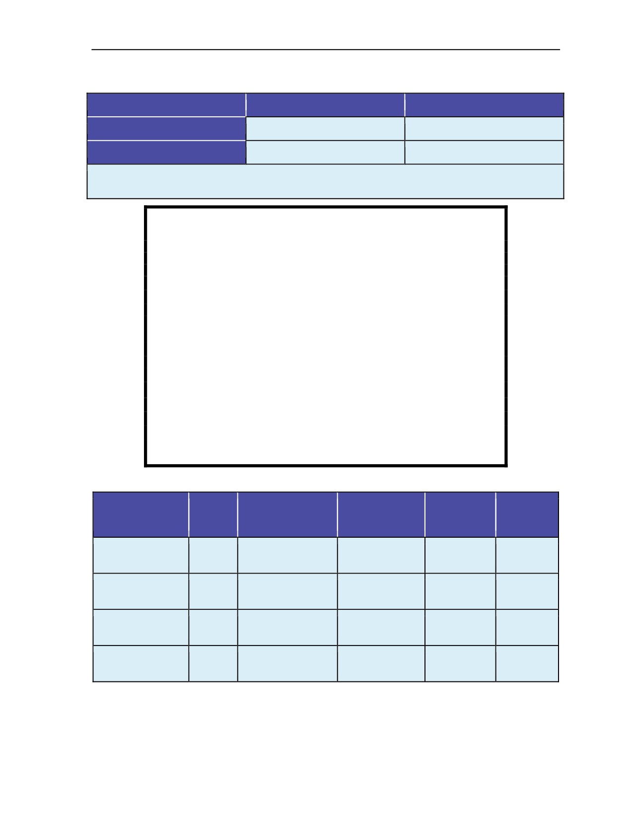
Minimum and maximum exit and opening altitudes for training (Table 1-1, page 1-3).
z
Surface interval after diving operations (Table 1-2, pages 1-3 and 1-4).
1-2
ATP 3-18.11/AFMAN 11-411(I)/NTTP 3-05.26M
24 October 2014
Military Free-Fall Parachute Operations
Table 1-1. Minimum and maximum exit and opening altitudes
Exit Altitude (in Feet)
Opening Altitude (in Feet)
Minimum
5,000 AGL
3,500 AGL
Maximum
35,000 MSL*
25,000 MSL
*NOTE: Openings above 25,000 feet MSL exceed the MC-4, MC-5, and MT-2XX/SL parachute design
specifications. The United States Navy MT-1SS maximum deployment altitude is 12,500 feet MSL.
WARNING
Ascent to altitude after diving increases the risk of
decompression sickness because of the additional reduction in
atmospheric pressure. The higher the altitude, the greater the
risk. (1)
Personnel shall not fly for 72 hours after saturation diving. (2)
Personnel shall wait
48 hours before flying after exceptional
exposure. (3)
A diver may need to wait up to 29 hours after a no-compression
dive or repetitive dive. (3)
Flying is permitted immediately after oxygen diving unless part of
a multiple underwater breathing apparatus dive profile. (4)
References:
(1) USN Diving Manual, Revision 6, paragraph 9-14
(2) USN Diving Manual, Revision 6, paragraph 15-24
(3) USN Diving Manual, Revision 6, Table 9-6
(4) USN Diving Manual, Revision 6, paragraph 18-9
Table 1-2. Surface interval chart for conducting military free-fall operations after diving
Decompression
Exceptional
Exit Altitude
Oxygen
No-Decompression
or Repetitive
Exposure
Saturation
(Maximum)
Dive
Dive
Dive
Dive
Dive
<13,000 feet MSL
No wait
24 hours
24 hours
72 hours
96 hours
<18,000 feet MSL
No wait
24 hours
36 hours
96 hours
96 hours
<25,000 feet MSL
No wait
24 hours
48 hours
96 hours
120 hours
<35,000 feet MSL
No wait
36 hours
48 hours
120 hours
120 hours
18 August 2016
ATP 3-18.11/AFMAN 11-411(I)/NTTP 3-05.26M, C2
1-3

Chapter 1
Table 1-2. Surface interval chart for conducting military free-fall operations after diving
(continued)
NOTES:
1. Diving definitions in the table are based on the USN Diving Manual. Listed times include all breathing
mixtures.
2. For MFF HAHO operations with opening altitudes above 13,000 feet MSL, 12 hours must be added to the
listed times. For MFF HAHO operations with opening altitudes above 18,000 feet MSL, 24 hours must be
added to the listed times.
3. When conducting an operation that combines MFF and military scuba diving, the most recent published
edition of the USN Diving Manual must first be consulted. If questions are not addressed within the
USN Diving Manual, the jumpmaster should consult with the Naval Sea Systems Command 00C
(Naval Sea Director or Deputy Director) for guidance.
1-6. The successful execution of any operation is directly related to thorough and detailed planning.
Mission planning begins with a detailed analysis of mission, enemy, terrain and weather, troops and
support available, time available, and civil considerations questions (Table 1-3, pages 1-4 and 1-5), with
qualifiers pertaining to MFF operations that the executing element must consider when selecting a method
on infiltration.
Table 1-3. Mission, enemy, terrain and weather, troops and support available, time available,
and civil considerations analysis
Factors
Questions
Is the objective located in an area that is conducive to MFF operations?
Is the mission time-critical?
Given the complexity of MFF operations, is time available for the executing
Mission
element to plan, rehearse, and execute an MFF infiltration?
Is the mission flexible enough to allow for an MFF infiltration window that is
dependent on favorable meteorological conditions?
How does the enemy threat, capabilities, disposition, security measures, and
air detection or air defense systems affect the method of infiltration?
Does the enemy have the ability to detect or interdict conventional infiltration
Enemy
methods; for example, static-line, waterborne, or air-mobile insertion?
Does the enemy have an air defense system that can be exploited either
through gaps in coverage or by suppression of enemy air defenses support?
Is the terrain conducive to an MFF infiltration?
Does the terrain hinder ingress and egress routes?
How does the terrain affect the weather and winds at altitude?
Are there suitable primary, alternate, and contingency DZs available within
Terrain
the objective area (located along the ingress route and in close proximity to
and
one another)?
Weather
Are there any storm systems in the area of operations that might cause
unacceptable wind and cloud conditions?
What is the percent of illumination?
Does the executing element have experience navigating under canopy in
limited-visibility conditions?
1-4
ATP 3-18.11/AFMAN 11-411(I)/NTTP 3-05.26M, C2
18 August 2016

Military Free-Fall Parachute Operations
Table 1-3. Mission, enemy, terrain and weather, troops and support available, time available,
and civil considerations analysis (continued)
Factors
Questions
Does the detachment have the training and experience to successfully
execute the selected infiltration method? Is additional training required?
What equipment is required to execute the primary mission?
Does the detachment have the means to infiltrate the required equipment
into the area of operations?
Does the equipment require special rigging? Does it have special handling
Troops
and storage requirements?
and
Do overall equipment requirements exceed the suspended weight limitations
Support
of the parachute?
Available
Are MFF-capable infiltration aircraft available?
Are suppression of enemy air defenses assets available for support if there
is a viable air defense threat?
Does the MFF infiltration require additional aircraft to support a deception
plan?
Will a reception committee be used on the DZ?
Does the detachment have time to conduct the required training and
rehearsals?
How far is it from the HARP to the primary and alternate DZs?
How will unexpected wind conditions at altitude or a low jumper affect the
Time Available
estimated glide distance of the parachute?
Can the detachment make it from the HARP to the primary DZ and complete
actions at the assembly area during the hours of darkness?
Will the detachment have the altitude and time to move to an alternate DZ in
case the primary DZ is unsuitable or compromised?
Can the operation be executed clandestinely so that the civilian populace is
unaware of it?
If the operation is compromised, what will be the repercussions to the local
Civil Considerations
populace?
If the detachment is receiving support from the locals, is there a risk of
reprisals against them?
1-7. A thorough mission, enemy, terrain and weather, troops and support available, time available, and
civil considerations analysis concentrating on those questions pertaining to MFF operations will determine
if MFF infiltration is appropriate. The detachment must then complete the remainder of the mission
planning process.
PHASES OF MILITARY FREE-FALL OPERATIONS
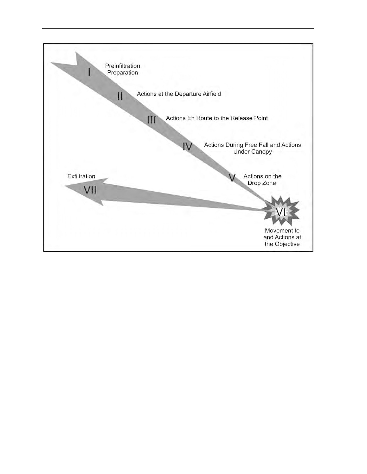
1-8. To aid the Special Forces operational detachment in planning and executing, MFF operations are
divided into seven phases. Figure 1-1, page 1-6, shows each phase, and the following paragraphs provide
the details for each. GTA 31-01-003 has additional information.
24 October 2014
ATP 3-18.11/AFMAN 11-411(I)/NTTP 3-05.26M
1-5
Chapter 1
Figure 1-1. Military free-fall operations planning phases
PHASE I: PREINFILTRATION PREPARATION
1-9. Preinfiltration preparation starts with preparing an estimate of the situation. The detachment uses the
military decisionmaking process to identify critical nodes in the mission and develop courses of action to
address them. During this phase, the detachment will plan the mission, prepare plans and orders, conduct
briefbacks, conduct training, prepare equipment, and conduct inspections and rehearsals.
1-10. The air mission brief is one of the key briefings conducted during premission planning. The air
mission brief takes place during isolation, before the briefback. The ground commander, primary
jumpmaster, and aircrew conduct face-to-face coordination to discuss the following items:
z
Flight routes and in-flight checkpoints, to include the point of no return.
z
En route mission-abort criteria.
z
En route evasion plan of action procedures.
z
Emergency landing procedures.
z
Actions in the aircraft, including bundles should cover—
The earliest possible time the aircraft can be rigged, especially when
6-man oxygen
consoles, bundles, and/or rollers are to be used in the mission.
The use of the Military Cybernetic Parachute Release System (CYPRES) 2 and restrictions,
once armed.
z
Call signs and frequencies or visual recognition signals, if used.
1-11. Aircrew attendance at the briefing is mandatory and should include, at a minimum, the aircraft
commander, navigator, and the primary loadmaster.
1-6
ATP 3-18.11/AFMAN 11-411(I)/NTTP 3-05.26M
24 October 2014

Military Free-Fall Parachute Operations
PHASE II: ACTIONS AT THE DEPARTURE AIRFIELD
1-12. In Phase II of infiltration, the detachment moves from the isolation facility to the departure airfield
(DAF). A pilot-jumpmaster and United States Air Force (USAF) physiological technician briefing normally
takes place planeside before loading the aircraft; any changes or updates to the plan are made at this time to
discuss any last minute updates to the jump plan. Aircraft is rigged at this point with any additional
equipment, such as oxygen consoles and rollers for heavy bundle movement. If in-flight rigging will occur,
the MFF rigs, combat packs, weapons, and additional equipment will need to be secured inside the aircraft
for departure. If prebreathing is required, Table 4-1, page 4-6, provides start times.
PHASE III: ACTIONS EN ROUTE TO THE RELEASE POINT
1-13. Under tactical conditions, the operational element completely rigs itself, and the jumpmasters make
JMPIs before the point of no return. This procedure ensures the personnel will exit the aircraft with all their
equipment in case of a bailout over enemy territory. All detachment members calibrate their altimeters so
that the instruments read distance above the ground at the DZ and Military CYPRES 2 units are set to
indicate the barometric pressure at the intended DZ.
1-14. During flight to the HARP, the aircraft commander keeps the jumpmaster informed of the aircraft’s
position. In turn, the jumpmaster keeps the parachutist updated about the aircraft’s location and mission
progress. This information is essential. The parachutist must know his relative position along the route so
that he can apply the required actions in case of an abort or enemy action. A small dry erase board is
located on the aircraft so that all jump team members can read important information, especially when
oxygen is being used. Communication is limited to written notes on the dry erase board or predetermined
signals from the jumpmaster.
1-15. While in flight, the aircraft commander keeps the MFF jumpmaster informed of changes to the
altimeter reading should it be necessary to abort and make an emergency exit. All actions and time
warnings issued will be in accordance with premission briefings and this manual. The pilot will signal the
jumpmaster upon arriving at the HARP. The parachutists exit the aircraft on the jumpmaster’s command.
PHASE IV: ACTIONS DURING FREE FALL AND ACTIONS UNDER CANOPY
1-16. MFF parachute jumps consist of four phases. They are—
z
Exit, delay, and deployment.
z
Assembly under canopy.
z
Flight in formation.
z
Final approach and landing.
PHASE V: ACTIONS ON THE DROP ZONE
1-17. At the DZ, the team leader and team sergeant immediately account for their personnel and all
equipment. Infiltrating detachments are especially vulnerable to enemy action during this phase. To
minimize the chances of detection, the detachment must clear the DZ as rapidly as possible and move to the
preselected assembly area. This area must provide cover and concealment and facilitate subsequent
movement to the objective area. Parachutes and air items should be buried or cached. If a reception
committee is present, its leader coordinates personnel movement and provides current intelligence on the
enemy and battle situation. Finally, the detachment sterilizes the assembly area and begins moving to the
objective area.
PHASE VI: MOVEMENT TO AND ACTIONS AT THE OBJECTIVE
1-18. Movement from the DZ to the objective area may require guides. If a reception committee is present,
it provides guides to the area or mission support sites where additional equipment brought may be cached.
If guides are not available, the detachment follows the preselected route based on detailed intelligence and
the patrolling plan developed during isolation. A well-planned route to the objective area must take
maximum advantage of cover and concealment and avoid enemy outposts, patrols, civilians, and
24 October 2014
ATP 3-18.11/AFMAN 11-411(I)/NTTP 3-05.26M
1-7

Chapter 1
installations. The detachment carries only mission-essential equipment and supplies (individual equipment,
weapons, communications, and ammunition).
PHASE VII: EXFILTRATION
1-19. Exfiltration planning considerations require the same planning, preparations, tactics, and techniques
as infiltrations. However, in exfiltration the planners are primarily concerned with recovery methods.
Distances involved in exfiltration usually require additional means of transport. Fixed- or rotary-wing
aircraft, vehicles, surface craft, submarines, or various combinations of these methods can be used to
recover operational elements.
1-8
ATP 3-18.11/AFMAN 11-411(I)/NTTP 3-05.26M
24 October 2014
Chapter 2
MC-4 Ram-Air Personnel Parachute System
The evolution of the parachute used in MFF operations has been considerable over
the years. This chapter identifies the MC-4 RAPPS components and donning and
recovery procedures. There are several RAPPSs used in the Department of Defense
that have similar employment and flight characteristics to the MC-4—the USN
MT-1SS and MT2-XX/SL, the United States Marine Corps (USMC) Multimission
Parachute System, the Tandem Offset Resupply Delivery System, and
the MC-5. The MT-2XX/SL and MC-5 RAPPSs have a static-line capability. The
MT-1SS has smaller 5-cell main and reserve canopies.
Note: Questions regarding employment of the RAPPS in the static-line configuration
should be addressed to USASOC, G-37, Special Skills, Fort Bragg, North Carolina.
TM 70244A-OI and TM 10-1670-287-23&P contain information on repairing and
maintaining the MC-4.
MC-4 RAM-AIR PERSONNEL PARACHUTE SYSTEM COMPONENTS
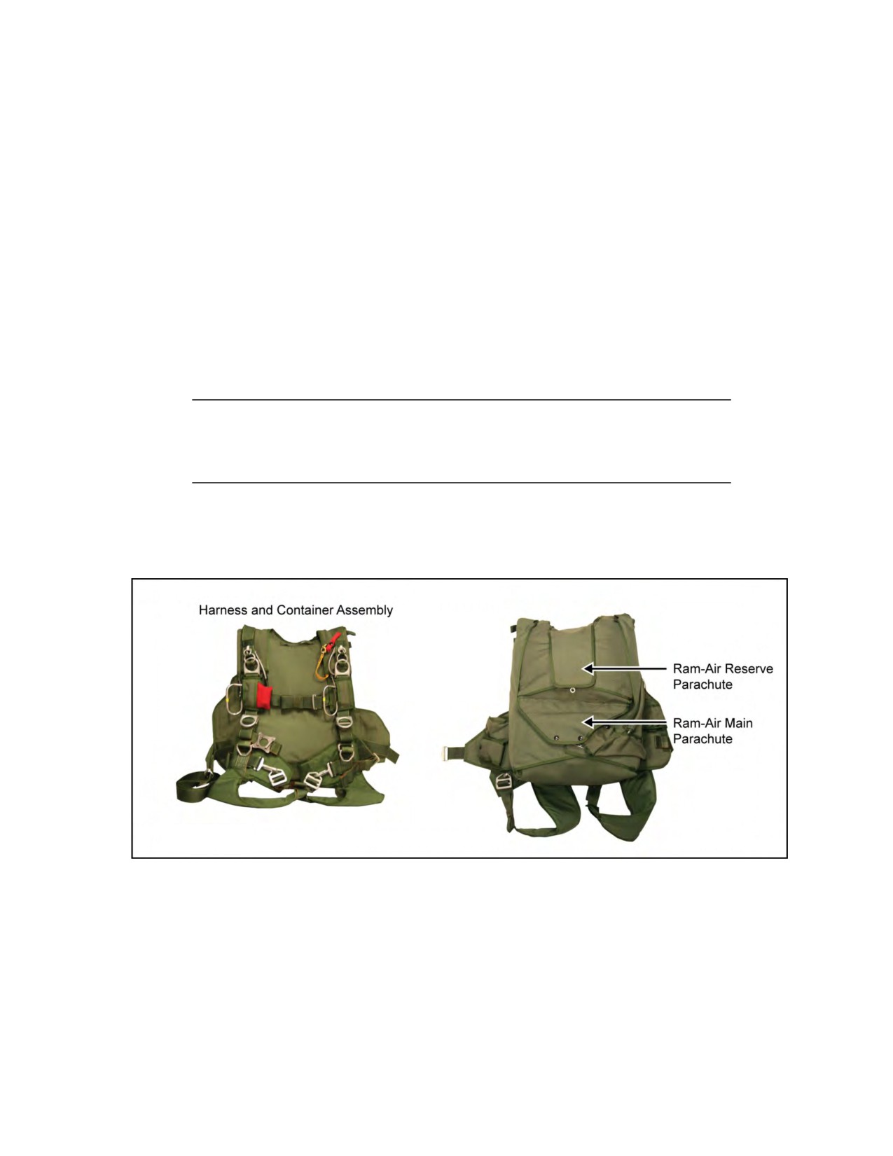
2-1. Figures 2-1 through 2-11, pages 2-1 through 2-11, depict the various components associated with the
MC-4 RAPPS.
Figure 2-1. MC-4 RAPPS components
24 October 2014
ATP 3-18.11/AFMAN 11-411(I)/NTTP 3-05.26M
2-1
Chapter 2
Figure 2-1. MC-4 RAPPS components (continued)
2-2
ATP 3-18.11/AFMAN 11-411(I)/NTTP 3-05.26M
24 October 2014
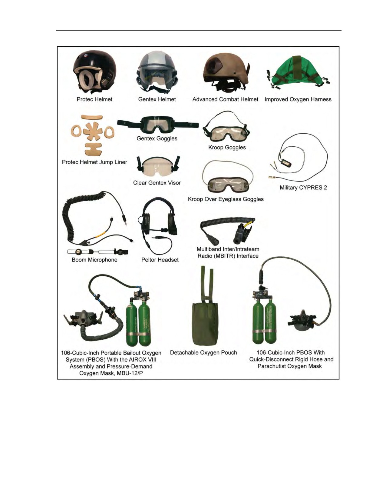
MC-4 Ram-Air Personnel Parachute System
Figure 2-1. MC-4 RAPPS components (continued)
24 October 2014
ATP 3-18.11/AFMAN 11-411(I)/NTTP 3-05.26M
2-3
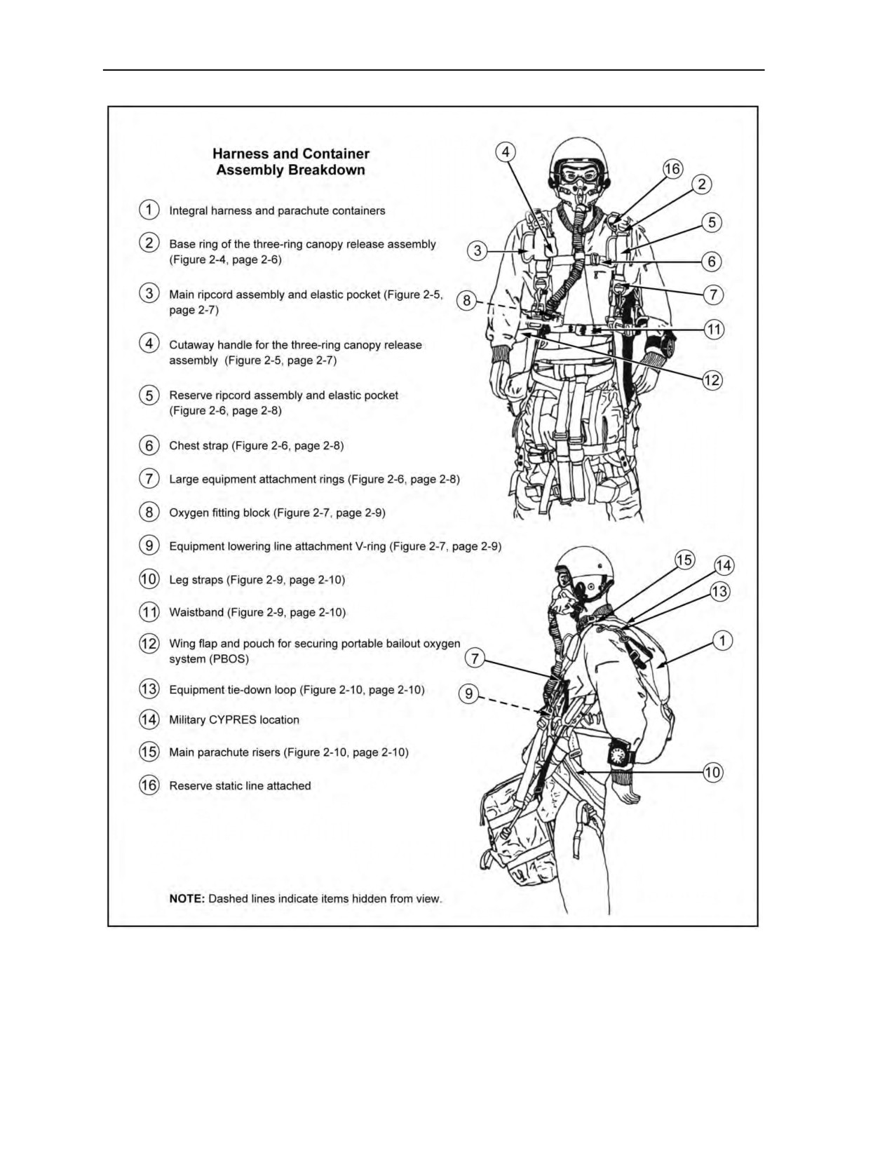
Chapter 2
Figure 2-2. MC-4 RAPPS harness and container assembly components
2-4
ATP 3-18.11/AFMAN 11-411(I)/NTTP 3-05.26M
24 October 2014
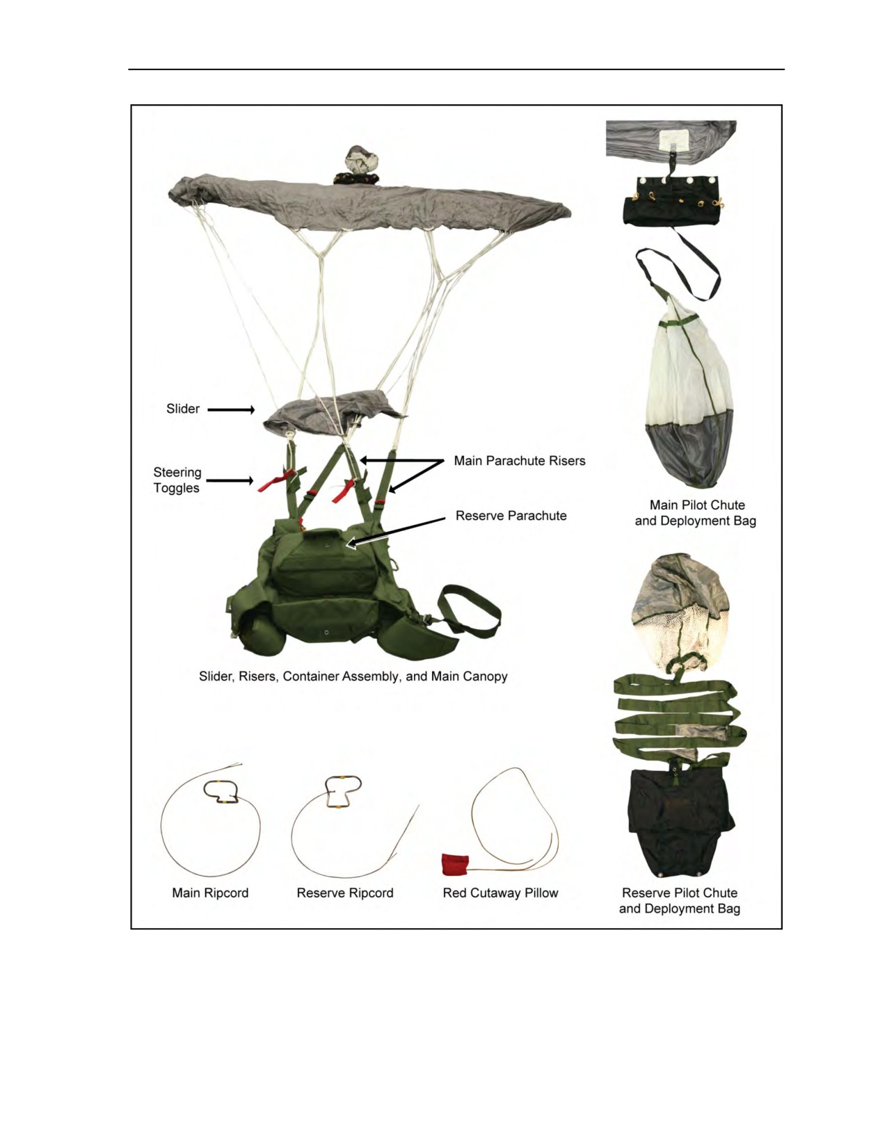
MC-4 Ram-Air Personnel Parachute System
Figure 2-3. MC-4 RAPPS assembly components
24 October 2014
ATP 3-18.11/AFMAN 11-411(I)/NTTP 3-05.26M
2-5
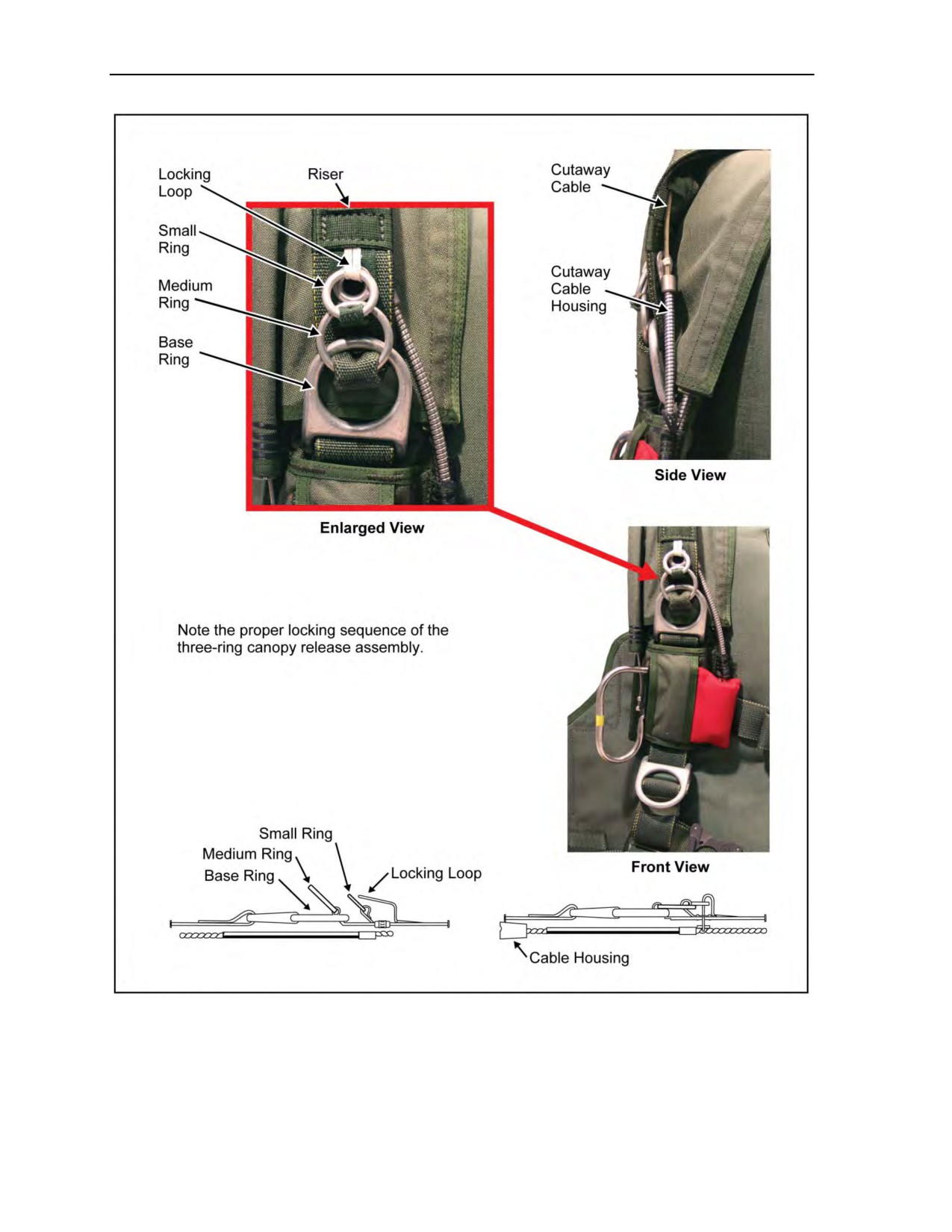
Chapter 2
Figure 2-4. Location of the three-ring canopy release assembly
2-6
ATP 3-18.11/AFMAN 11-411(I)/NTTP 3-05.26M
24 October 2014
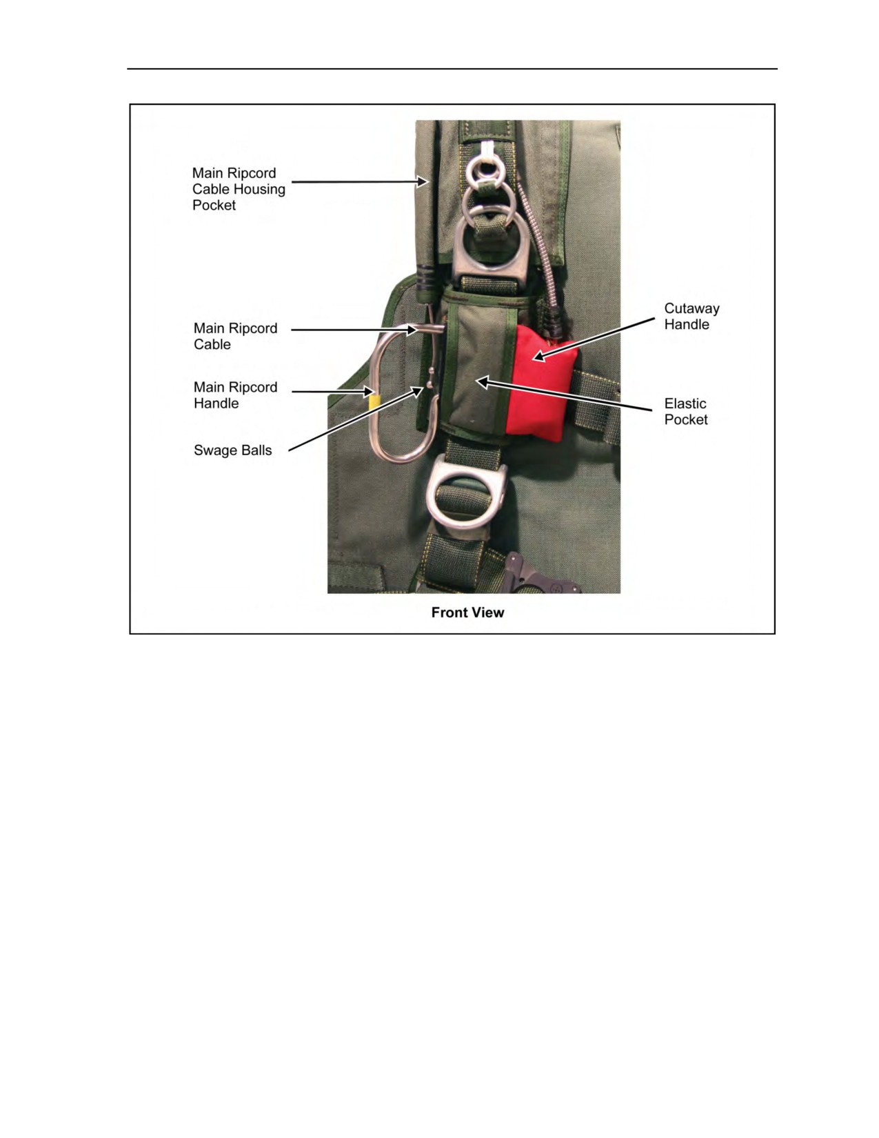
MC-4 Ram-Air Personnel Parachute System
Figure 2-5. Location of the main ripcord handle and cutaway handle
24 October 2014
ATP 3-18.11/AFMAN 11-411(I)/NTTP 3-05.26M
2-7
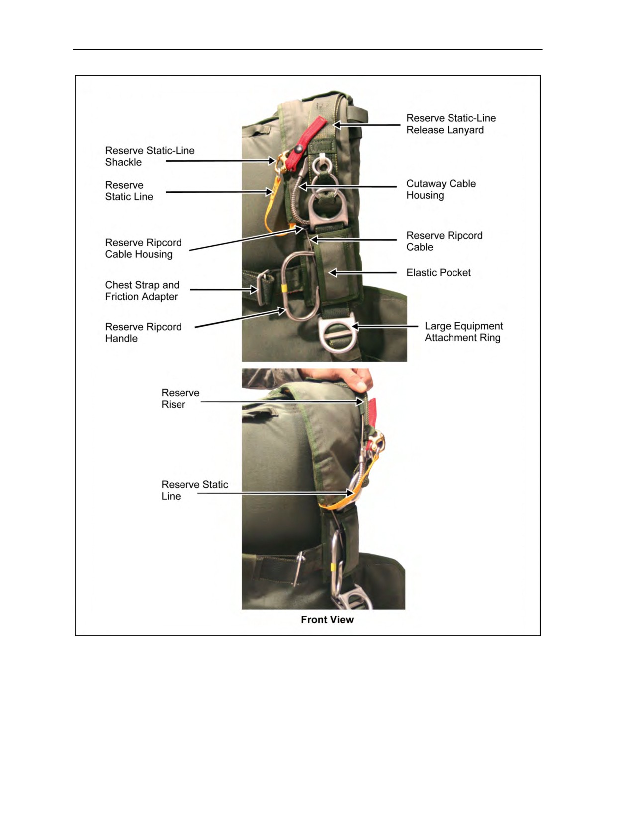
Chapter 2
Figure 2-6. Location of the chest strap, reserve ripcord handle, large equipment
attachment ring, and reserve ripcord cable housing
2-8
ATP 3-18.11/AFMAN 11-411(I)/NTTP 3-05.26M
24 October 2014
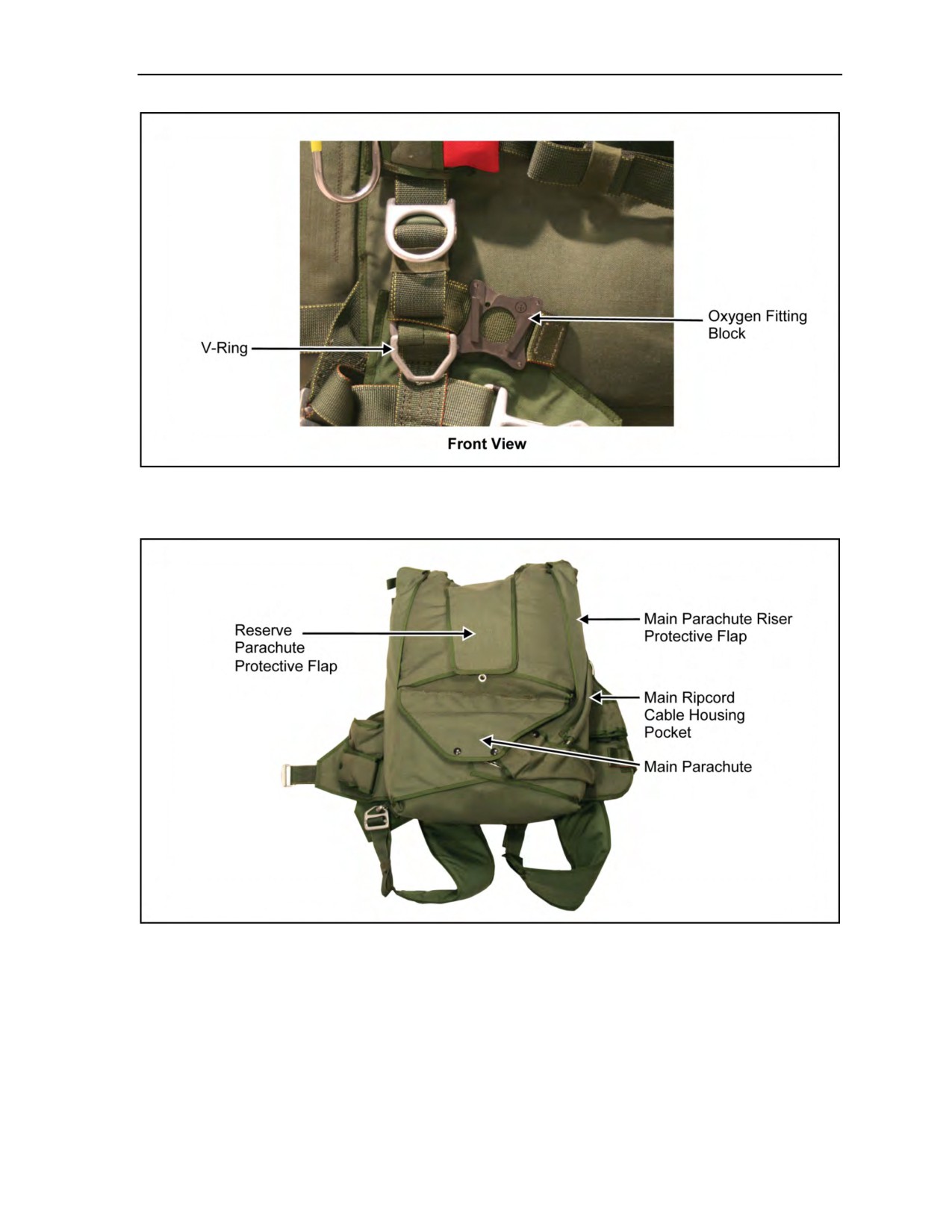
MC-4 Ram-Air Personnel Parachute System
Figure 2-7. Location of the oxygen fitting block and equipment
lowering line attachment V-ring
Figure 2-8. Location of the main and reserve parachutes in the container
24 October 2014
ATP 3-18.11/AFMAN 11-411(I)/NTTP 3-05.26M
2-9
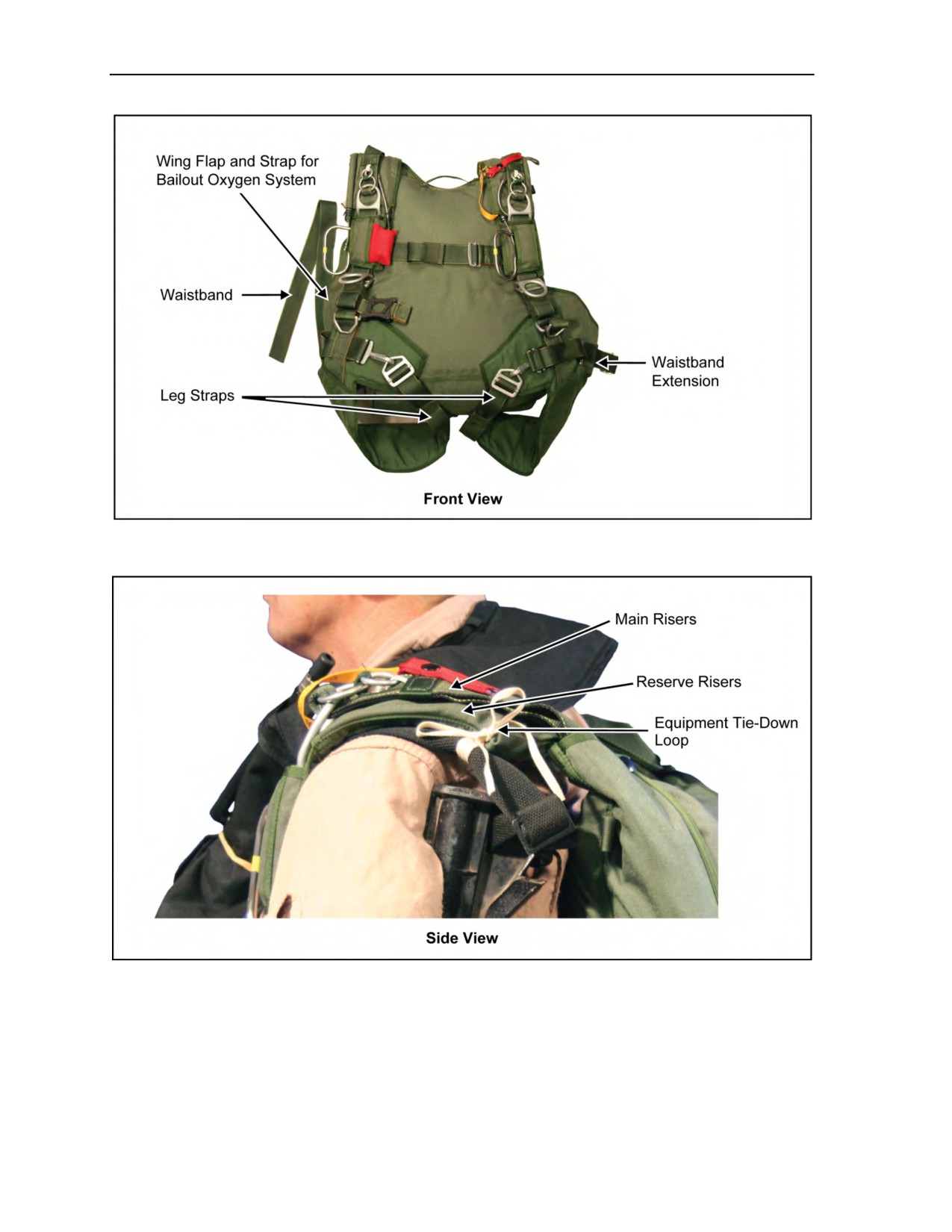
Chapter 2
Figure 2-9. Location of straps
Figure 2-10. Location of the equipment tie-down loop and main risers
2-10
ATP 3-18.11/AFMAN 11-411(I)/NTTP 3-05.26M
24 October 2014
MC-4 Ram-Air Personnel Parachute System
Figure 2-11. Location of reserve components
MILITARY FREE-FALL PARACHUTIST HELMET ASSEMBLY
2-2. MFF parachutists use the following helmets: advanced combat helmet (ACH), the Gentex HGU-55/P
helmet, the Gentex lightweight parachutist helmet, the MC-3 helmet (a semirigid, padded leather helmet)
used for passengers on tandem jumps, the Protec helmet with free-fall liner, and the Bell motorcyclist
helmet (full-face helmet not authorized for MFF). To conduct MFF with oxygen, personnel must wear
helmets with bayonet receptacles attached or use the improved oxygen harness (skull cap) to attach the
oxygen mask. The jumpmaster should have internal earphones and a microphone for communication within
the aircraft and while under canopy.
WARNING
The parachutist must ensure that bayonet receivers on his helmet
are compatible with the oxygen mask and that the mask fits
properly.
24 October 2014
ATP 3-18.11/AFMAN 11-411(I)/NTTP 3-05.26M
2-11
Chapter 2
WARNING
The clear full-face shield (issued with the Gentex helmet and
jumped with the oxygen mask) may become dislodged in free fall
if not properly fitted and tightened.
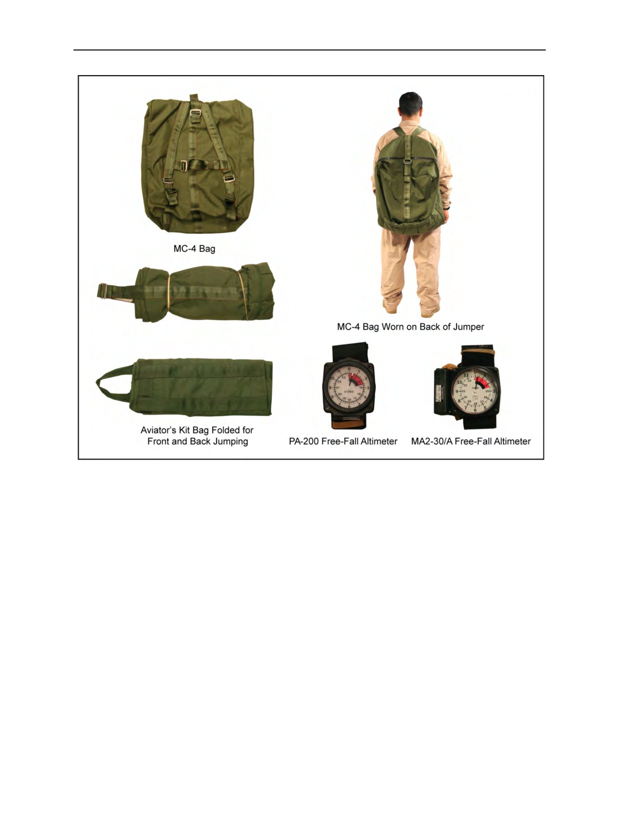
MA2-30/A AND THE PA-200 FREE-FALL ALTIMETERS
2-3. The parachutist wears the MA2-30/A or the PA-200 altimeter on his left wrist (Figure 2-12). The
altimeter shows his altitude above the ground during free fall. The altimeter permits him to determine when
he has reached the proper altitude for deploying the main parachute. The altimeter must be transported and
stored with care. It must be chamber-tested for accuracy. The altimeter must be rechecked after an
unusually hard landing and after accidentally dropping it. If the altimeter is not waterproof, it should be
replaced if it has been submerged in water.
Figure 2-12. MA2-30/A and PA-200 free-fall altimeters
2-4. The computation for the altimeter setting follows. The jumpmaster—
z
Applying the formula below, inputs data (Figure 2-13, page 2-13).
z
Converts meters to feet if map data is in meters.
z
Places DAF elevation in first block.
z
If DZ elevation is lower than DAF, places it in lower block.
z
If DZ elevation is higher than DAF, places it in upper block.
z
If numbers are the same (+/+ or -/-), then subtracts.
z
If numbers are different (+/-), then adds.
z
Places total in appropriate block.
The positive or negative sign next to the block identifies the altimeter setting.
2-12
ATP 3-18.11/AFMAN 11-411(I)/NTTP 3-05.26M
24 October 2014
MC-4 Ram-Air Personnel Parachute System
Figure 2-13. Altimeter setting
CAUTION
Special consideration will be given to any obstacles (for example,
ridgelines, mountains, towers, and other such items and their
elevations) that may be located within 3 nautical miles or 5.5 kilometers
of the parachutist’s release point or desired impact point.
MA-10 MILITARY ALTIMETER
2-5. The MA-10 altimeter is a solid state electronic device with manufacturer-updatable embedded software
and a stepper motor that moves the pointer on an analog display. The 12,000-foot linear scale is capable of
reading up to 40,000 feet MSL with the pointer rotating 12,000 feet per revolution (3 1/3 revolutions to
40,000 feet). The face is highlighted with a red warning arc that begins at 2,500 feet. The MA-10 is
powered by two 1.5-volt AA lithium batteries; standard 1.5-volt AA batteries may be used with reduced
battery life. The MA-10 can be comfortably worn with a Velcro wrist-mount band and is waterproof to a
depth of 6 feet for 1 hour. The battery compartment is not waterproof. The aluminum housing measures
3.27 x 3.20 x 1.37 inches and the face has a 2.50-inch dial. The electroluminescence face automatically
turns on and provides backlighting during low light conditions. The manufacturer-replaceable lens is
protected by a self-adhesive lens protector that can be replaced by a designated parachute rigger. The MA-10
conducts a power-on self-test, checking the pressure sensor, blockage of the filter, stepper motor, battery
voltage, and other critical functions. Using the external buttons, the MA-10 can be set in three ways: zeroed
to the current location, manually entering the DZ offset, or by calculating the DZ offset entering the DZ
altitude and a form of barometric pressure called “altimeter setting” for the DZ. Figures 2-14 through 2-20,
pages 2-14 through 2-19, depict the MA-10 altimeter.
24 October 2014
ATP 3-18.11/AFMAN 11-411(I)/NTTP 3-05.26M
2-13
Chapter 2
Figure 2-14. MA-10 altimeter buttons
Figure 2-15. On/Off buttons
2-14
ATP 3-18.11/AFMAN 11-411(I)/NTTP 3-05.26M
24 October 2014
MC-4 Ram-Air Personnel Parachute System
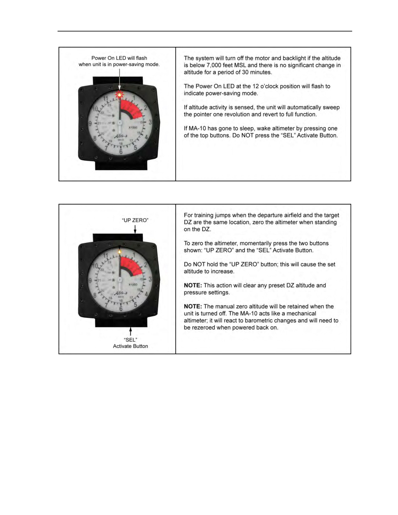
Figure 2-16. Power-saving mode
Figure 2-17. Zeroing the MA-10 altimeter
24 October 2014
ATP 3-18.11/AFMAN 11-411(I)/NTTP 3-05.26M
2-15
Chapter 2
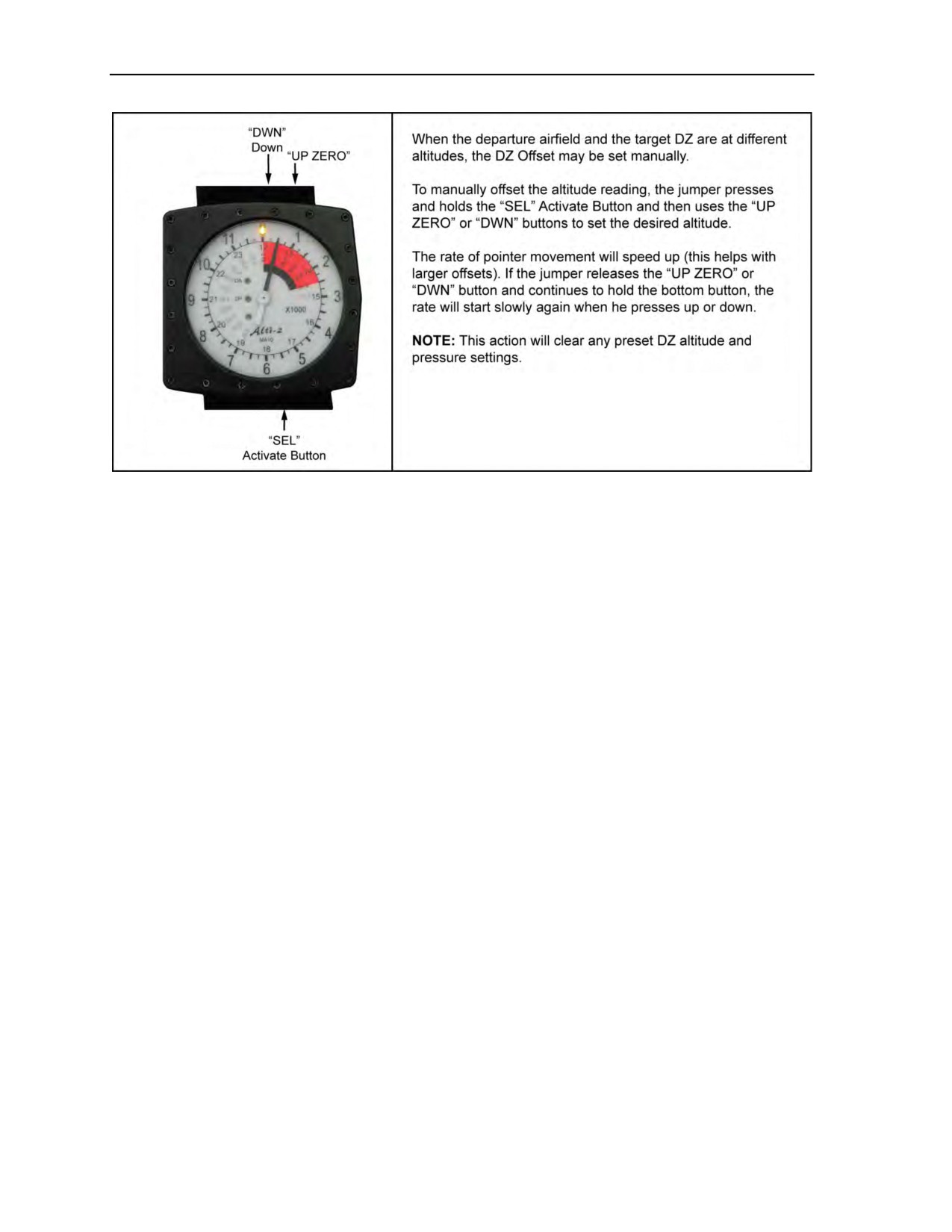
Figure 2-18. Manual offset
2-16
ATP 3-18.11/AFMAN 11-411(I)/NTTP 3-05.26M
24 October 2014
MC-4 Ram-Air Personnel Parachute System
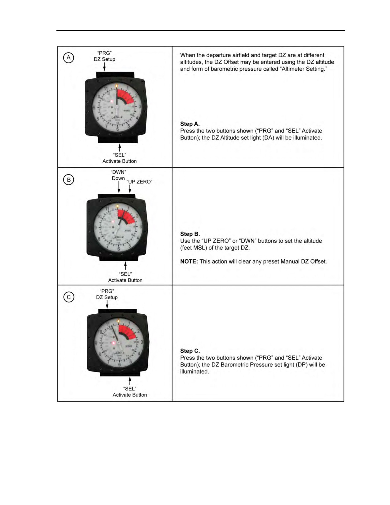
Figure 2-19. Setting the drop zone
24 October 2014
ATP 3-18.11/AFMAN 11-411(I)/NTTP 3-05.26M
2-17
Chapter 2
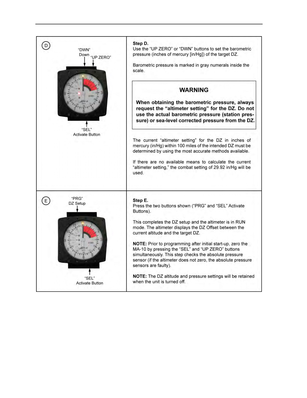
Figure 2-19. Setting the drop zone (continued)
2-18
ATP 3-18.11/AFMAN 11-411(I)/NTTP 3-05.26M
24 October 2014
MC-4 Ram-Air Personnel Parachute System
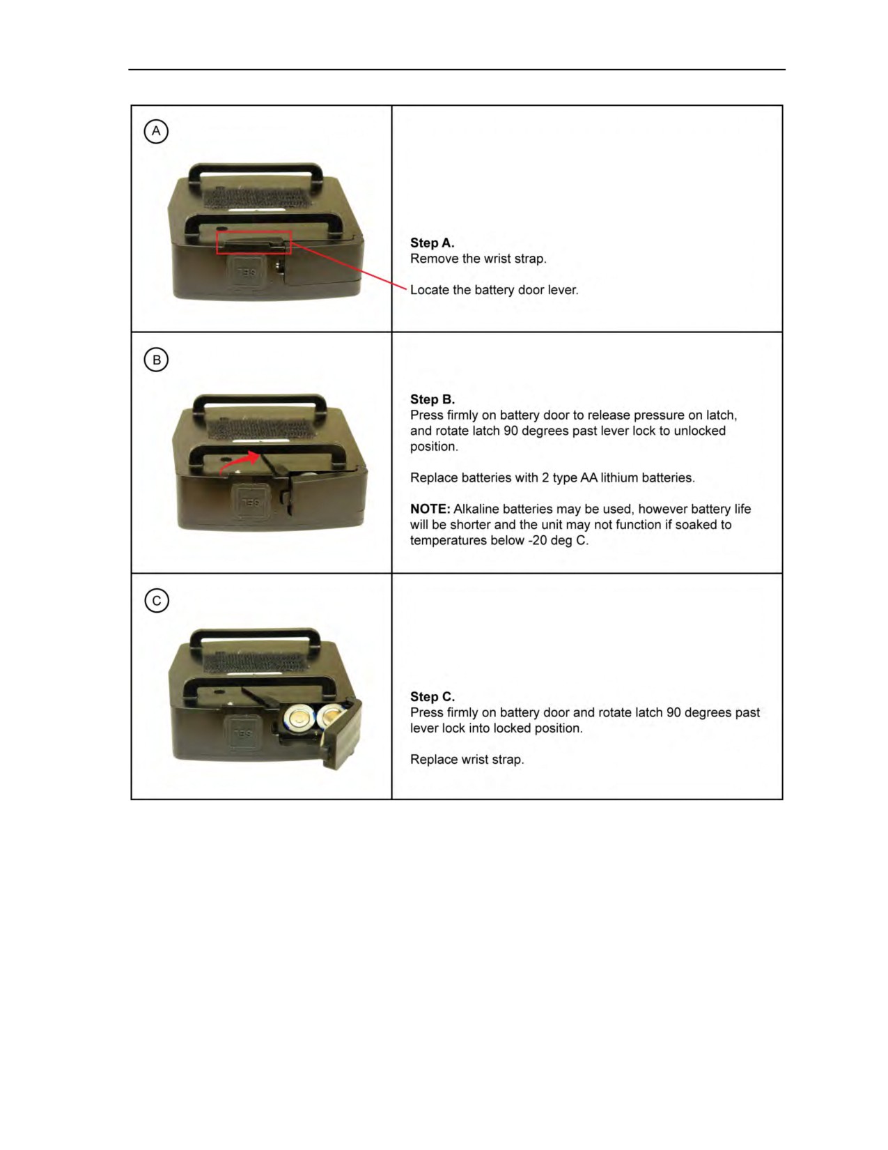
Figure 2-20. Replacing batteries in the MA-10 altimeter
OTHER COMPONENTS AND PROTECTIVE CLOTHING
2-6. The following paragraphs provide basic information about other items required by the MFF
parachutist.
Gloves
2-7. Gloves are worn to protect the parachutist’s hands from the elements and to prevent injury from the
action of the handles, lines, and webbing during canopy deployment and steering. The gloves must be
chosen to provide good protection and must allow the parachutist to retain dexterity. Gloves should not
interfere with the operation of the handles on the parachute.
24 October 2014
ATP 3-18.11/AFMAN 11-411(I)/NTTP 3-05.26M
2-19

Chapter 2
Note: Leather-palmed gloves are required when the temperature at exit altitude is 40 degrees
Fahrenheit and below.
Boots
2-8. While boots without speed-lacing hooks are not RAPPS components, they are considered to be
mandatory safety equipment.
Eye Protection
2-9. MFF parachutists must use eye protection. Commercial (Kroop) goggles provide a wide field of
vision and come in two sizes: regular and a larger box design that fits over standard military eyeglasses.
Military-issue sun, wind, and dust goggles are authorized, but not recommended, as they restrict the
parachutist’s field of vision. Commercial (Kroop) and military-issue goggles are authorized for parachuting
with or without an oxygen mask. All lenses used should be clear and relatively free of scratches that might
obstruct vision. When oxygen is used, all goggles, no matter what type, will be clear. All goggles shall be
made of shatterproof materials.
Note: The clear full-face shield issued with the Gentex helmet is authorized for use only with an
oxygen mask.
Military Free-Fall Parachutist Helmet
2-10. The following helmets are authorized for MFF:
z
Gentex HGU-55/P.
z
Gentex lightweight parachutist helmet.
z
MC-3 helmet.
z
Protec helmet (only with free-fall liner).
z
Bell open-face motorcycle helmet.
z
ACH or modular integrated communication headset (MICH).
z
Soft-shell helmet (authorized for tandem passenger use only).
Note: The Bell full-face motorcycle helmet is not authorized for MFF operations.
Note: Bayonet receiver assemblies may be installed on most helmets for use with an oxygen
mask requiring the use of bayonet lugs. Helmets that cannot be fitted with bayonet receiver
assemblies will be fitted with the rail connector and oxygen strap kit or jumper will use the
improved oxygen harness.
Communications Capabilities
2-11. The jumpmaster should have internal earphones and an external microphone or internal oxygen mask
microphone for communication. The Gentex lightweight parachutist helmet has bayonet receivers for an
oxygen mask and provides each parachutist with communications capability with or without an oxygen
mask. The MICH can be used with the ACH. The Peltor headset will sit between the ACH and improved
oxygen harness, if used.
Other Protective Clothing
2-12. Appropriate garments are chosen per individual MFF mission requirements. Jumpsuits (Figure 2-21,
page
2-21) with lightweight polypropylene undergarments, insulated undergarments, or insulated
overlayers may be necessary depending upon the degree of environmental protection required. The
parachutist individual equipment kit (Figure 2-22, page 2-21) worn during USMC MFF operations, is
another example of outstanding environmental protection clothing for MFF operations.
2-20
ATP 3-18.11/AFMAN 11-411(I)/NTTP 3-05.26M
24 October 2014
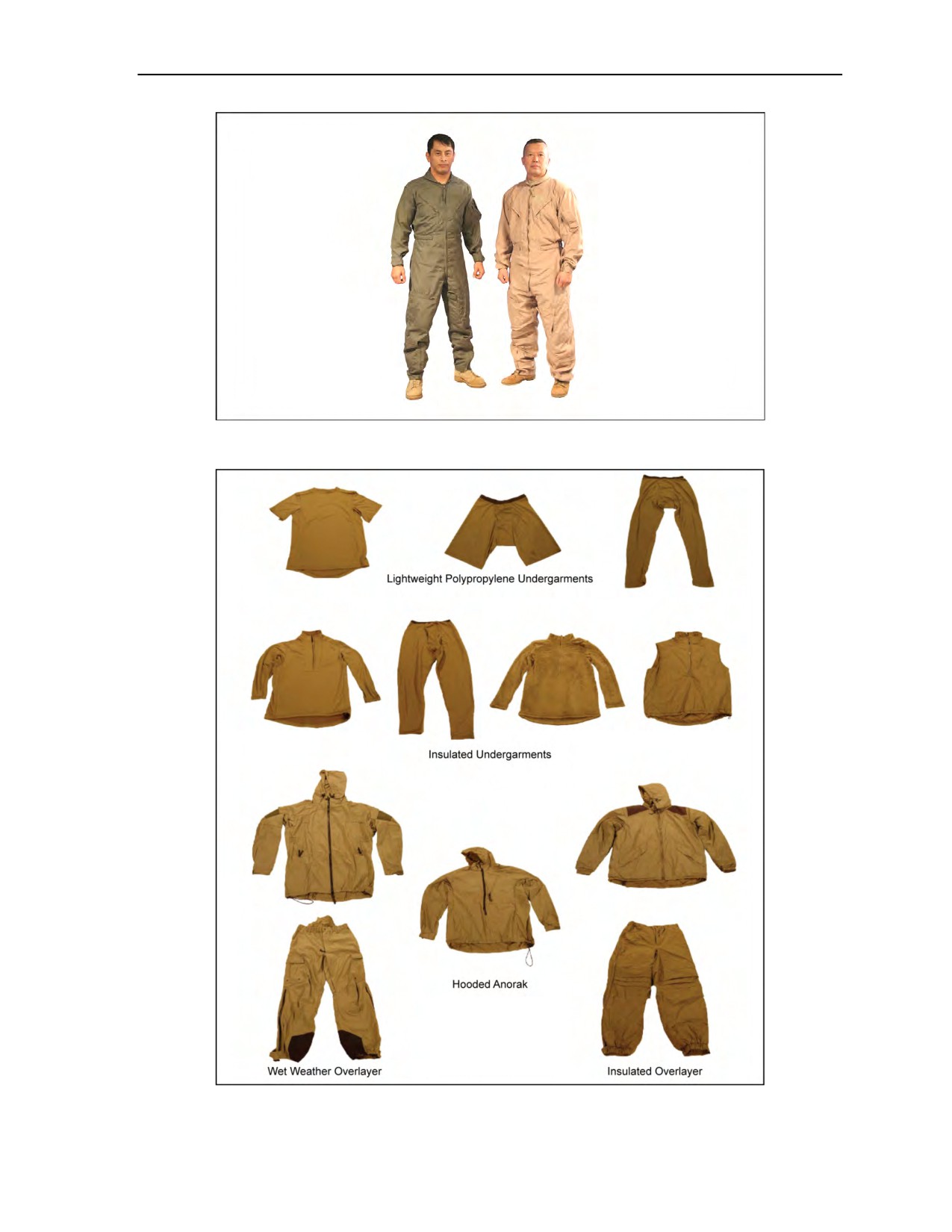
MC-4 Ram-Air Personnel Parachute System
Figure 2-21. Jumpsuits
Figure 2-22. Parachutist individual equipment kit
24 October 2014
ATP 3-18.11/AFMAN 11-411(I)/NTTP 3-05.26M
2-21
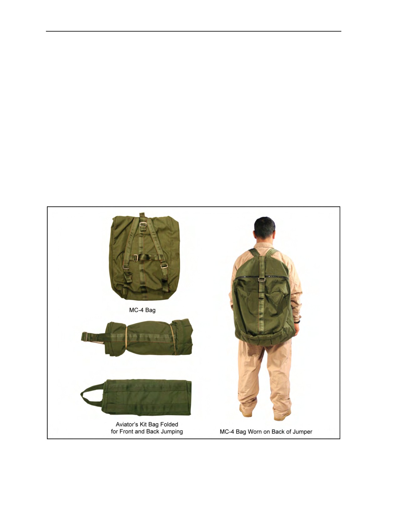
Chapter 2
DONNING AND RECOVERING THE MC-4 RAM-AIR
PERSONNEL PARACHUTE SYSTEM
2-13. The buddy system, or the pairing of parachutists, within each operational element provides the most
efficient and accurate way for parachutists to don, adjust, and check each other’s parachutes. Using the
buddy system to properly don and adjust the MC-4 RAPPS provides an additional safety check and
prevents unnecessary delays during the JMPI.
PREPARING THE KIT BAGS
2-14. The parachutist will determine if the kit bag will be worn on the front across the groin area, on the
rear between the jumper’s back and container, or put on like a rucksack on the back. He selects the method
and prepares the kit bag as follows:
z
Aviator’s Kit Bag. The parachutist closes the slide fastener and secures all snap fasteners. If the
kit bag is worn rear- or front-mounted, he folds each end of it with one fold toward the center
leaving the handles exposed at one end (Figure 2-23).
z
MC-4 Kit Bag. The parachutist closes the slide fastener. The kit bag can be worn like a
rucksack on the jumper’s back (Figure 2-23) under the MC-4 RAPPS. If it is front-mounted, the
parachutist rolls it from bottom to top with shoulder straps exposed and places retainer bands on
each end (Figure 2-23).
Figure 2-23. Aviator’s and MC-4 kit bags
2-22
ATP 3-18.11/AFMAN 11-411(I)/NTTP 3-05.26M
24 October 2014

MC-4 Ram-Air Personnel Parachute System
DONNING THE MC-4 RAM-AIR PERSONNEL PARACHUTE SYSTEM
2-15. The following are procedures for donning the MC-4 RAPPS (Figure 2-24, page 2-24):
z
The parachutist checks the parachute assembly for visible defects, lets out all harness
adjustments for ease of donning (Figure 2-24A), and lays the assembly out with the pack tray
face down.
z
To don the parachute, the parachutist (No. 1) assumes a modified high jumper position. The
second parachutist (No. 2) holds the harness container by the main lift webs at the canopy
release assemblies and places it on No. 1’s back (Figure 2-24B).
z
No. 1 remains bent forward at the waist and No. 2 pushes the container high on No. 1’s back as
No. 1 threads and fastens the chest strap (Figure 2-24C).
z
No. 2 prepares the leg straps. No. 2 calls out, LEFT LEG STRAP, and passes it to No. 1.
No. 1 repeats, LEFT LEG STRAP, and grasps the left leg strap with one hand. With his other
hand, he starts from the saddle and feels the length of the leg strap, removing any twists and
turns. He inserts the leg strap through one aviator’s kit bag handle (if the kit bag is front-
mounted) and fastens the leg strap (Figure 2-24D). He repeats the procedure for the remaining
leg strap. He performs the same steps for the MC-4 kit bag by inserting the leg straps through the
shoulder straps.
z
No. 1 stands erect and checks to make sure the canopy release assemblies are in the hollows of
his shoulders by adjusting the main lift webs (Figure 2-24E).
z
No. 1 locates the free-running ends of the horizontal adjustment straps and tightens the harness
so it fits snugly and comfortably (Figure 2-24F).
z
No. 2 then threads the long-running end of the waistband through both kit bag handles (if the kit
bag is rear-mounted), and No.
1 fastens the waistband to the waistband extension
(Figures 2-24G and H).
z
After final adjustment, No. 1 folds all excess straps inward, except for the main lift webs that are
folded outward, and secures them using the elastic keepers (Figure 2-24I). No. 1 should be able
to stand erect without straining.
z
When properly donned, the system should feel snug but not so tight as to restrict movement. The
jumper should be able to properly arch, look, reach, and pull the ripcord on the ground before the
actual jump.
z
No. 1 and No. 2 then change positions and repeat the procedure.
z
When both parachutists have donned their parachute assemblies and adjusted their harnesses,
they face each other, make a visual inspection of each other, and correct any deficiencies before
the JMPI.
RECOVERING THE RAM-AIR PERSONNEL PARACHUTE SYSTEM
2-16. The following procedures are used to recover a RAPPS; the parachutist—
z
If jumping oxygen, locks the ON/OFF switch in the OFF position and removes the bailout
bottles and pouch from the waistband.
Note: Parachutists do not place the oxygen mask on the ground unprotected during parachute
recovery. Moisture from breathing and condensation due to temperature changes will cause dirt
and debris to adhere to the mask, interfering with sealing and increasing risk of injury.
z
Removes the harness and container and daisy-chains the suspension lines.
z
Removes and opens the aviator’s kit bag.
z
If using the Military CYPRES 2, turns it off.
z
Replaces the ripcord in the ripcord cable housing and the ripcord handle in the stow pocket.
z
Places the pilot chute next to the kit bag.
z
Places the canopy, deployment bag, suspension lines, and risers in the kit bag.
z
Removes the quick-release snap hooks and lowering line quick-ejector snap from the equipment
rings on the parachute harness.
24 October 2014
ATP 3-18.11/AFMAN 11-411(I)/NTTP 3-05.26M
2-23
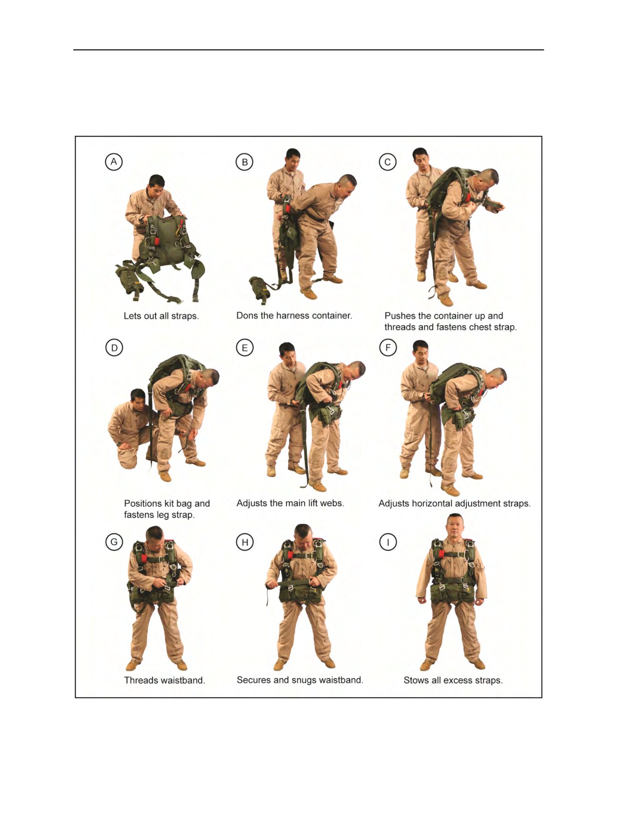
Chapter 2
z
Places the harness and container in the kit bag with the back pad facing up to protect the Military
CYPRES 2.
z
Finally, places the pilot chute in the kit bag or on top of the MC-4 kit bag and snaps or zips the
fasteners.
Figure 2-24. Donning the MC-4 Ram-Air Personnel Parachute System
2-24
ATP 3-18.11/AFMAN 11-411(I)/NTTP 3-05.26M
24 October 2014

Chapter 3
Cybernetic Parachute Release System
The CYPRES is an EAAD designed to cut the loop material that is holding the reserve
pilot chute in place, which deploys the reserve in the event that the MFF parachutist
meets the criteria that the CYPRES uses to make the decision to fire the release unit.
WARNING
As stated in USASOC Regulation 350-2, all Army MFF units will only
utilize the military CYPRES 2 in the absolute (operational) mode. All other
Services will follow their Service regulation on using the CYPRES 2 in
absolute (operational) mode or default (training) mode.
GENERAL INFORMATION ON MILITARY CYPRES 2 MODELS
3-1. Three Military CYPRES 2 models and one Expert CYPRES 2 model are being used by the United
States (U.S.) Army as safety devices designed to activate and enable the reserve parachute to deploy in the
absence of the parachutist failing to deploy his main parachute or having a malfunction of his main parachute:
z
The Military CYPRES 2 is designed specifically for tactical application use. There are three
Military CYPRES 2 models: 1000 35 A, 1500 35 A, and the 2500 29 A. All models have two
modes of operation—training mode and operational mode:
Default (training) mode can be used for nontactical jumps that meet specific parameters;
inclusively, the DAF and DZ must be the same location.
Absolute (operational) mode can be used for both tactical and nontactical jumps in any scenario.
z
The Expert CYPRES 2 is designed for use in authorized nonstandard parachutes and has two
modes of operation—training mode and offset mode:
Default (training) mode can be used for nontactical jumps that meet specific parameters;
inclusively, the DAF and DZ must be the same location.
Offset mode can be used when the DAF and DZ are at different altitudes or locations and
specific parameters are met.
WARNING
All CYPRES information covered in this manual is specific to Military
CYPRES 2 models only. Military CYPRES 1 models are only in use by
USMC Special Operations Command. Military CYPRES 1 and Expert
CYPRES 1 rules and procedures have some discrepancies and should
not be used in conjunction with Military CYPRES 2 information contained
in this manual.
Note: Use of the Military CYPRES 2 in operational mode is recommended for all situations.
Note: It is essential that all personnel read this entire chapter before using and setting the
Military CYPRES 2. The jumpmaster and parachutist must be familiar with all CYPRES model
functions, procedures, and limitations.
18 August 2016
ATP 3-18.11/AFMAN 11-411(I)/NTTP 3-05.26M, C2
3-1

Chapter 3
MILITARY CYPRES 2 PRINCIPLES OF OPERATION
3-2. When the parachutist arms the Military CYPRES 2, the reserve parachute deploys automatically if
the parachutist reaches the preset altitude at the preset vertical velocity and meets other critical conditions.
The Military CYPRES 2 deploys the reserve parachute by firing the release element and severing the
reserve closing loop material. The reserve pilot chute is then free to launch and deploy the reserve
parachute. If the parachutist reaches the preset altitude and does not meet the conditions to fire the release
element (such as when the main parachute is fully deployed), the Military CYPRES 2 will not send the
signal to fire the release element. In case the jump conditions change, the Military CYPRES 2 silently
continues to monitor the parachutist’s condition during canopy flight until the parachutist reaches 130 feet
above the virtual drop zone (VDZ).
GENERAL OPERATION
3-3. The three Military CYPRES 2 models and the Expert CYPRES 2 model will only activate and fire
the release element within the activation window. The Military CYPRES 2 will only fire the release
element for parachute malfunctions that fall through the activation window and meet the vertical activation
speed. All parachute malfunctions that fall faster than the vertical activation speed (such as pack closure,
hard pull, bag lock, and horseshoe malfunctions with the canopy in the bag) and are within the activation
window, will meet the conditions to fire the release element. For all other parachute malfunctions that
cause the parachutist to fall slower than the vertical activation speed (such as single-riser separation, line
over, pilot chute over the nose, line twists, closed end cells, broken control lines, and tension knots), the
parachutist must activate the reserve manually. It must be understood that the Military CYPRES 2 will
leave the activation window at 130 feet above the VDZ and will no longer operate.
ACTIVATION WINDOW
3-4.
The activation window for default (training) and absolute (operational) modes is as follows:
z
Default (Training) Mode. Once properly powered ON, the Military CYPRES 2 in default
(training) mode arms itself 1,500 feet above the default activation altitude (750 feet above
activation altitude for the Expert CYPRES 2). Once armed, the activation window will extend
from the default activation elevation down to approximately 130 feet above the DAF elevation.
For example, once powered ON prior to leaving the ground, the Military CYPRES 2 1500 35 A
arms itself at 3,000 feet AGL (1,500 feet above the default setting of 1,500 feet AGL). The
parachutist exiting the aircraft will need to fall approximately 1,000 feet to reach the vertical
activation speed of 35 meters per second (78 mph or 115 fps). If the parachutist enters the
activation window (1,500 feet AGL to 130 feet AGL) and is falling faster than the vertical
activation speed of 35 meters per second, the Military CYPRES 2 will fire the release element.
The Military CYPRES 2 will go into a standby mode at 130 feet above the VDZ.
Note: The Military CYPRES 2 will go into an energy saving (standby) mode at 130 feet because
this gives it an altitude buffer to make sure it goes into this mode. Without this buffer, the
Military CYPRES 2 could possibly stay in the activation phase of the jump, which consumes the
most battery power. This would greatly depreciate the battery life over time. Also, the Military
CYPRES 2 would not save the jumper if it fired at 130 feet.
z
Absolute (Operational) Mode. Once properly powered ON, the Military CYPRES 2 in absolute
(operational) mode arms itself immediately. The activation window will extend from the default
activation setting above the VDZ, set by the jumpmaster, down to approximately 130 feet above
the VDZ. For example, once powered ON with a 5,000-foot VDZ setting, the Military CYPRES 2
1500 35 A is armed immediately, regardless of the location where it was powered ON. The
parachutist exiting the aircraft will need to fall approximately 1,000 feet to reach the vertical
activation speed of 35 meters per second (78 mph or 115 fps). If the parachutist enters the
activation window (1,500 feet above the VDZ to 130 feet above the VDZ) and is falling faster
than the vertical activation speed of 35 meters per second, the Military CYPRES 2 will fire the
release element.
3-2
ATP 3-18.11/AFMAN 11-411(I)/NTTP 3-05.26M, C2
18 August 2016
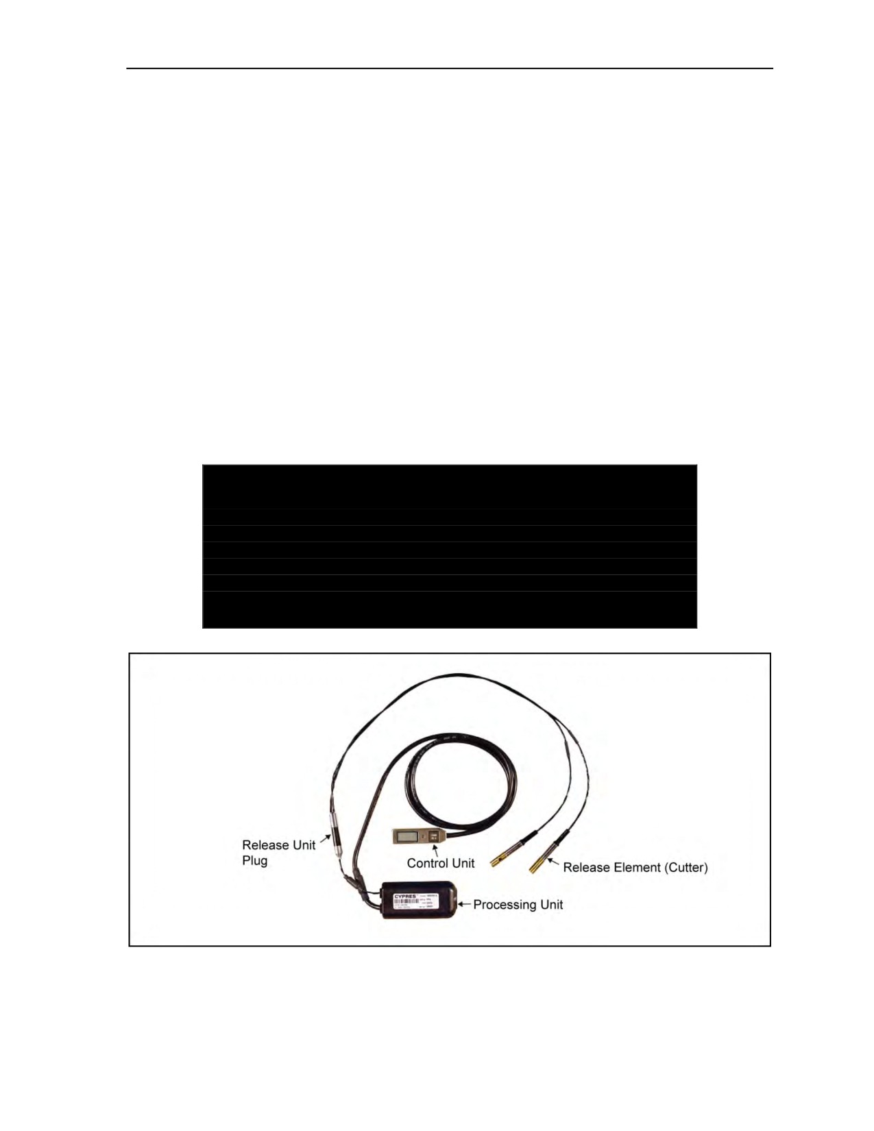
Cybernetic Parachute Release System
MILITARY CYPRES 2 MODELS
3-5. The three Military CYPRES 2 models—1000 35 A, 1500 35 A, and 2500 29 A—are the models in
present use for all tactical parachute systems (except for USMC Special Operations Command). All models
have the same appearance, function, and theory of operation. The Military CYPRES 2 uses millibars
absolute as the unit of measurement. The differences among the three models are their preset information,
including the default activation altitude above the VDZ, the vertical activation speed, and the release unit
configuration.
3-6. Different settings are required to tailor the Military CYPRES 2 to specific parachute equipment and
mission applications. For quick identification and to help ensure proper settings, the three Military
CYPRES 2 models have their presets displayed on the green (ON/OFF) button located on the control unit.
The presets identify the model of a Military CYPRES that goes with a specific parachute system:
z
The Military CYPRES 2 model 1000 35 A is used on the Military Tandem Tethered Bundle
parachute and authorized nonstandard parachute systems.
z
The Military CYPRES 2 model 1500 35 A is used with the MC-4, MJN-1, MJA-2, MT-2XX/SL,
and SOV2-HH.
z
The Military CYPRES 2 model 2500 29 A is used on the Sigma Vector-Military-Tandem
Vector-3 System and the Tandem Offset Resupply Delivery System.
The preset information for each model can be found printed on the back of the control unit and on the front
cover of the processing unit. Figure 3-1 shows the Military CYPRES 2.
DANGER
The jumpmaster must accurately identify the CYPRES model
being used and understand the correct pressure setting method.
Failure to identify the correct model for the parachute system and
to properly set the CYPRES may result in the CYPRES not firing
at the intended altitude, resulting in injury or DEATH to the
parachutist.
Figure 3-1. Military CYPRES 2 1500 35 A
24 October 2014
ATP 3-18.11/AFMAN 11-411(I)/NTTP 3-05.26M
3-3
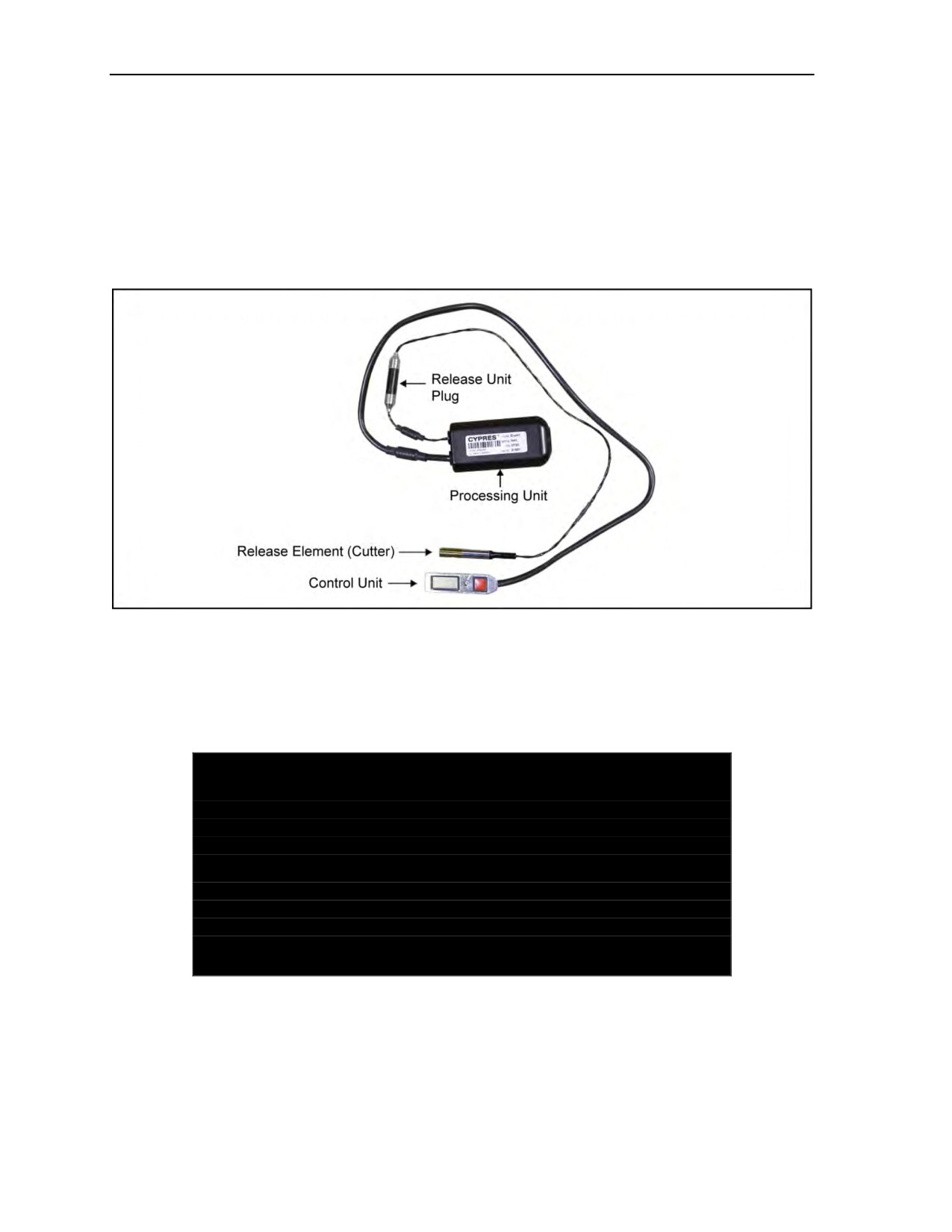
Chapter 3
EXPERT CYPRES 2 MODEL
3-7. The Expert CYPRES 2 has the same look, function, maintenance, and theory of operation as the
Military CYPRES 2 in training mode but is limited in use because it does not have an operational mode
setting. While the Military CYPRES 2 uses millibars absolute as the unit for the setting, the Expert
CYPRES 2 uses feet relative to the DAF. The Expert CYPRES 2 has its own preset activation altitude
above the VDZ, activation speed, and release unit configuration. The Expert CYPRES 2 model is identified
by the red (ON/OFF) button located on the control unit. The preset information is not printed anywhere on
the outside of the Expert CYPRES 2. Figure 3-2 shows the Expert CYPRES 2.
Figure 3-2. Expert CYPRES 2
3-8. The Expert CYPRES 2 model is used with authorized nonstandard parachute systems. The Expert
CYPRES 2 model is set in feet and the display is graduated in feet. This setting is different from the three
Military CYPRES 2 models that are set and displayed in millibars.
CYPRES MODEL IDENTIFICATION
DANGER
Failure to identify the correct Military CYPRES
2 model and
setting method may result in configuring an improper setting,
thus preventing the Military CYPRES 2 from firing when needed,
resulting in injury or DEATH to the parachutist.
Failure to only use the Expert CYPRES 2 in authorized nonstandard
parachute systems may result in the Expert CYPRES 2 not firing
at the intended altitude, resulting in injury or DEATH to the
parachutist.
3-9. The specific models of the CYPRES 2 are only authorized for use on the specified parachute systems
listed in Table 3-1, page 3-5.
3-4
ATP 3-18.11/AFMAN 11-411(I)/NTTP 3-05.26M
24 October 2014
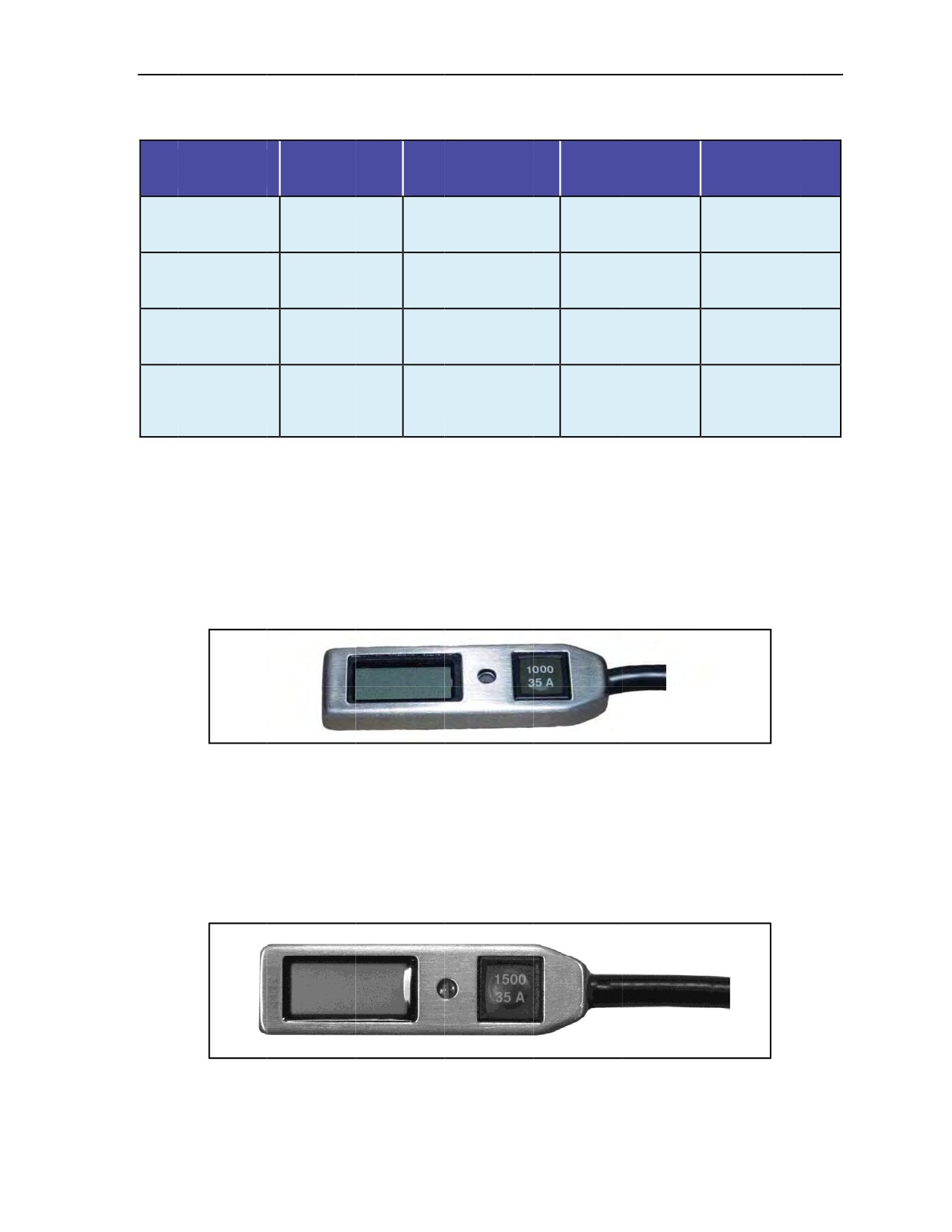
Cybernetic Parachute Release System
Table 3-1. CYPRES 2 model identification
Default
Vertical
Pressure
Authorized
Button
Activation
Activation
Setting
Parachute
Identification
Altitude
Speed
Display Value
System
Military CYPRES 2
1,000 Feet
35 Meters per Second
Millibars
MTTB/Authorized
Green Button
78 mph
Absolute
Nonstandard
1000 35 A
115 fps
Parachute Systems
Military CYPRES 2
1,500 Feet
35 Meters per Second
Millibars
MC-4, MJN-1,
Green Button
78 mph
Absolute
MJA-2, SOV2-HH,
1500 35 A
115 fps
MT-2XX/SL, MMPS
Military CYPRES 2
2,500 Feet
29 Meters per Second
Millibars
MTV-3, TORDS
Green Button
65 mph
Absolute
2500 29 A
95 fps
Expert CYPRES 2
750 Feet
35 Meters per Second
+/- Feet Relative
Authorized
Red Button
78 mph
Nonstandard
(No Letters)
115 fps
Parachute Systems
(Javelin)
3-10. The three
Military CYPRES 2 models and the Expert CYPRES
2 model can
be identified by the
(ON/OFF) button on the control unit as described below:
z
Military CYPRES
2 Model 1000 35 A. The
control unit button is green, and the markings
indicate that the Military CYPRES 2 is set to activate approximately 1,000 feet above the
VDZ
if the vertical speed is faster than approximately 35
meters per
second (78 mph or
115 fps). The A indicates that the pressure setting is in millibars absolute; the information in
the control unit window display also reads
in millibars
(Figure 3-3).
When the Military
CYPRES 2 Model
1000 35 A is
removed from
the parachute system, the
setting information
can be read on the back of the control unit and
on the front cover of the processing unit.
Figure 3-3.
Military CYPRES 2 Model 1000 35 A control unit
z
Military CYPRES
2 Model 1500 35 A. The
control unit button is green, and the markings
indicate that the Military CYPRES 2 is set to activate approximately 1,500
feet above the
VDZ
if the
vertical speed
is faster than
approximately
35 meters per second (78 mph or 115 fps). The
A indicates that the
pressure setting is in millibars absolute; the control unit
window display also
reads
in millibars (Figure 3-4). When the Military CYPRES
2 Model 1500 35 A is removed
from
the parachute
system, the setting information can be read on the back
of the control unit
and on the front cover of the processing unit.
Figure 3-4.
Military CYPRES 2 Model 1500 35 A control unit
24 October 2014
ATP 3-18.11/AFMAN 11-411(I)/NTTP 3-05.26M
3-5
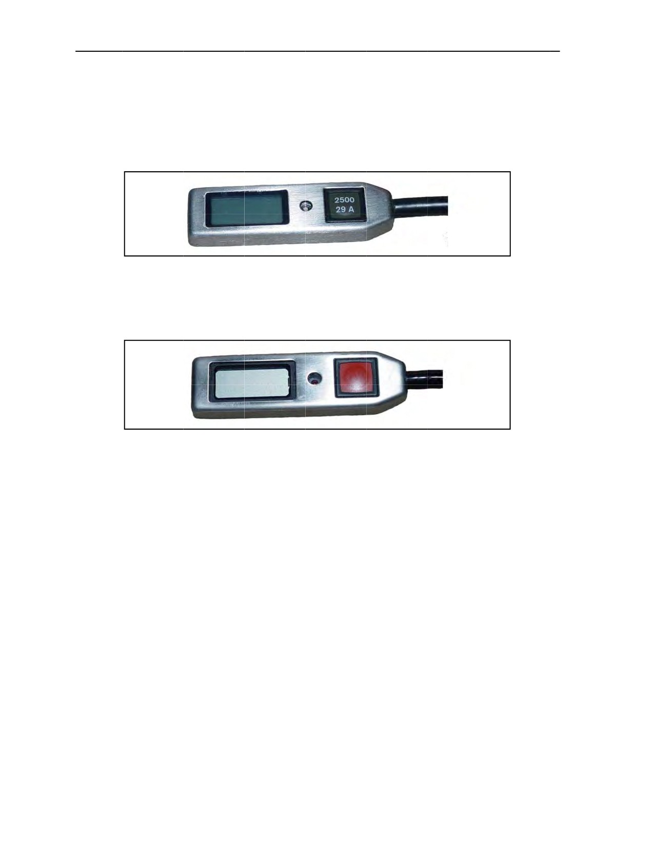
Chapter 3
z
Military
CYPRES 2 Model 2500 29 A. The control unit button is green, and the markings
indicate that the Military CYPRES 2
is set to activate approximately 2,500 feet
above the VDZ
if the vertical speed is faster than approximately 29 meters per second (65 mph or 95 fps). The
A
indicates
the pressure setting is in millibars absolute; the control unit window display also reads
in millibars (Figure 3-5). When the Military CYPRES 2 Model 2500 29 A is removed from the
parachute
system, the setting information can be read on the back
of the control
unit and on the
front cover of the processing unit.
Figure 3-5. Military CYPRES
2 Model 2500 29 A control unit
z
Expert CYPRES 2 Model. The control unit button
is red with no
markings (Figure 3-6). If the
vertical speed is faster than 35 meters
per second (78 mph or 115 fps), the Expert CYPRES
2
model is set to activate
at approximately 750 feet above the DZ. The setting is graduated in feet
and the control unit display is graduated in 30-foot increments.
Figure
3-6. Expert
CYPRES 2 control unit
COMPONENTS
3-11.
The Military
CYPRES 2 has only three
components:
the control unit, the processing unit with
internal battery, and
the release unit with one or two release elements.
CONTROL UNIT
3-12.
The control unit houses a liquid crystal display and a green ON/OFF
button. It is
attached to the
processing unit by an electrical cable. The control unit provides the interface between the user and the
processing unit. This allows the user to control
functions, such
as powering
ON and OFF
and setting the
Military CYPRES 2,
with the proper millibar setting for the absolute (operational) mode. During the power
ON sequence, the liquid crystal display displays
the power ON
self-test information, the error codes, and
the pressure setting.
The user can
see the Military CYPRES 2
is ON or OFF
by observing
the zero down
arrow
(0▼) setting
for use in the
default (training) mode, or by the proper
millibar setting for use in the
absolute (operational) mode. Once
the power ON sequence and pressure setting is complete, the control
unit is
disengaged from the processing unit, and
its only function is to power
OFF the Military CYPRES
2.
The pressure setting
will remain displayed on the liquid crystal display. The
control unit does not conduct
any of the pressure
readings or
calculations
performed by
the Military
CYPRES 2.
The numerical
information written
on the control unit’s single operating
button lets the jumpmaster know which
CYPRES 2 model
is installed in
the parachute system. Table 3-1, page
3-5, explains
the numerical
information. Figure
3-7, page 3-7, shows the control unit for
the Military CYPRES 2 that has a default
setting
of 1,500 feet, fall rate setting of 35 meters per second (115 fps or 78 mph), and a pressure setting of
absolute. When the Military CYPRES 2 is removed from the parachute system, the setting
information can
be read on the back
of the control
unit (Figure 3-8, page 3-7) and on the front cover of the
processing unit
(Figure 3-9, page 3-7).
3-6
ATP 3-18.11/AFMAN 11-411(I)/NTTP 3-05.26M
24 October 2014
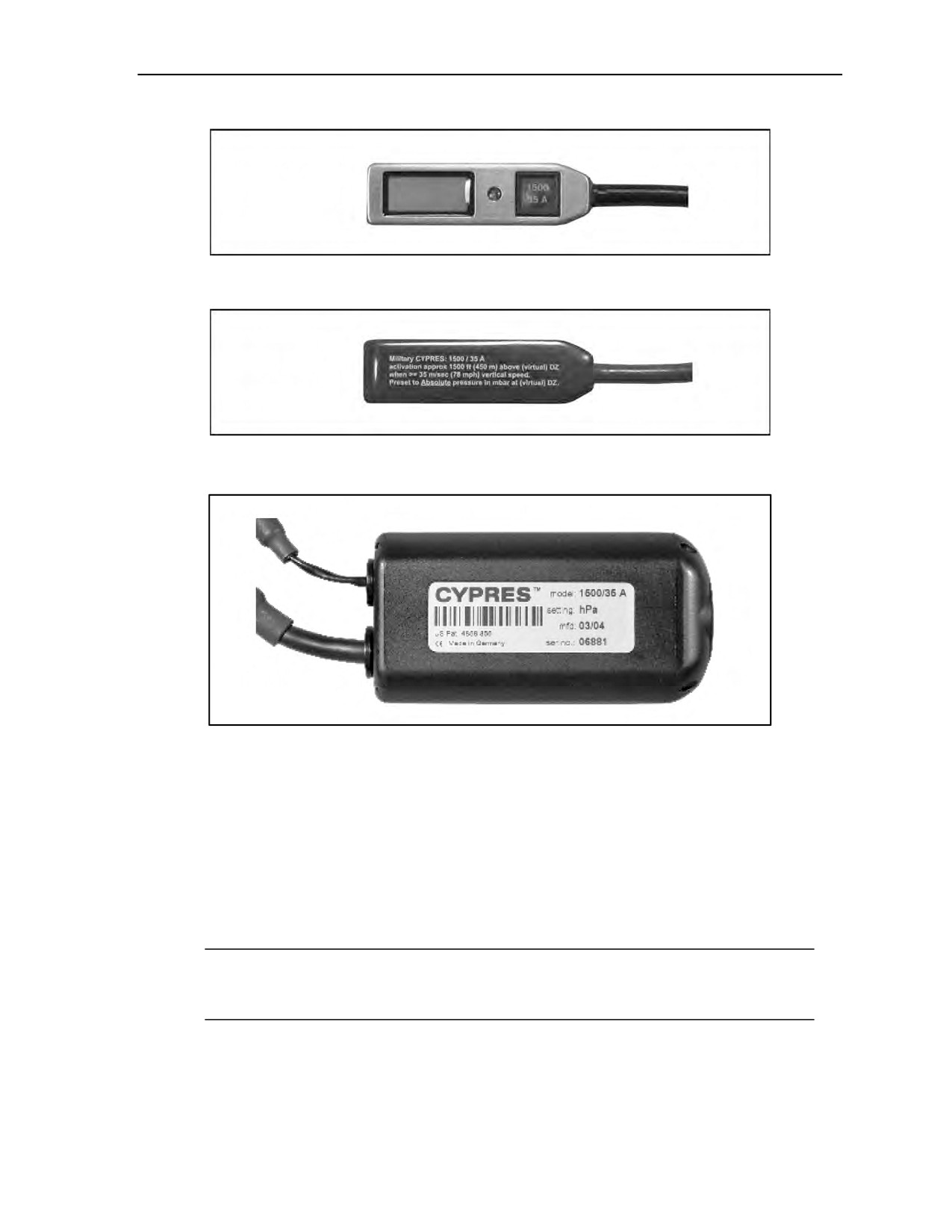
Cybernetic Parachute Release System
Figure 3-7. Military CYPRES 2 control unit
Figure 3-8. Back of Military CYPRES 2 control unit
Figure 3-9. Military CYPRES 2 processing unit
PROCESSING UNIT
3-13. The processing unit houses the microprocessor and the battery (Figure 3-9). The microprocessor
conducts a self-test every time it is powered ON. The processing unit will stay ON and remain active for
14 hours from power ON, and then it will automatically power itself OFF. The microprocessor’s software
and sensors monitor the parachutist’s altitude, vertical velocity, and other critical data points during free
fall. It handles all critical calculations and functions to determine when a parachutist is in trouble so that the
release elements can be fired. If the parachutist reaches the preset altitude at the preset vertical velocity and
meets other critical conditions, the processing unit makes the decision to fire, sends an electrical charge to
the release unit, fires the release elements, and severs the reserve closing loop material.
Note: The processing unit is protected from electromagnetic interference and static electricity,
which means it is highly unlikely that radios and static electric shock will cause accidental
discharge of the release elements.
RELEASE UNIT
3-14. Release units are available for one-pin or two-pin reserve parachutes. The release unit contains a
propellant actuated cutter called the release element (Figure 3-10, page 3-8). The number of release
24 October 2014
ATP 3-18.11/AFMAN 11-411(I)/NTTP 3-05.26M
3-7

Chapter 3
elements used depends on the parachute configuration. The MC-4 parachute system uses two release
elements. The release unit is attached to the processing unit by the release unit plug. A used release element
can be replaced during the reserve repack by unplugging the old release unit from the processing unit and
plugging in the new release unit. In the event the parachutist meets all conditions to fire the release
element, the processing unit sends an electrical input to the release element. A propellant inside the release
element is electrically activated and, in turn, moves the release element knife approximately 5 millimeters
to sever the reserve parachute closing loop(s) in order to open the reserve container. A CYPRES closing
loop must be used to ensure proper operation. Once the release elements have fired, they must be replaced
by the parachute rigger prior to repacking the reserve parachute. Release elements that have been fired are
self-contained and remain pressurized—no attempt should be made to cut them open.
Note: The release element (cutter) is transportable on all military aircraft and does not require
any special load planning or transportation considerations.
Figure 3-10. Military CYPRES 2 release unit
MAINTENANCE
3-15. Inspection, installation, maintenance, and storage of the Military CYPRES 2 shall be maintained by a
ram-air pack-qualified parachute rigger.
BATTERY
3-16. The Military CYPRES 2 battery is replaced at 4 and 8 years from date of manufacture (plus or minus
6 months) during the periodic technical service performed by the manufacturer, SSK. The Military
CYPRES 2 has a lifetime of 12.5 years from date of manufacture.
WATER LANDINGS
3-17. The Military CYPRES 2 is water resistant for 15 minutes at 5 meters. If a Military CYPRES 2 gets
wet from a water landing, the rigger at the unit level is responsible for changing the filter.
SCHEDULED MAINTENANCE
3-18. The Military CYPRES 2 will be sent to the manufacturer for a periodic technical service at 4-year
and 8-year intervals, plus or minus 6 months each, from the date of manufacture. The Military CYPRES 2
alerts the user when the scheduled maintenance is approaching. The maintenance due date and the unit’s
serial number are both easily retrievable (Figures 3-11 and 3-12, page 3-9). To access the serial number or
the next maintenance due date without removing the unit from the parachute, the following steps are
performed:
z
Set the Military CYPRES 2 for use in the absolute (operational) mode.
z
Enter a value outside of its operational range by selecting
0 for the first value and the
numeral 1 (or 0) for the next three values.
The screen will momentarily go blank and then the serial number will appear in the display screen for
approximately 5 seconds. The screen will go blank again and the next required maintenance date will
appear on the screen.
3-8
ATP 3-18.11/AFMAN 11-411(I)/NTTP 3-05.26M
24 October 2014
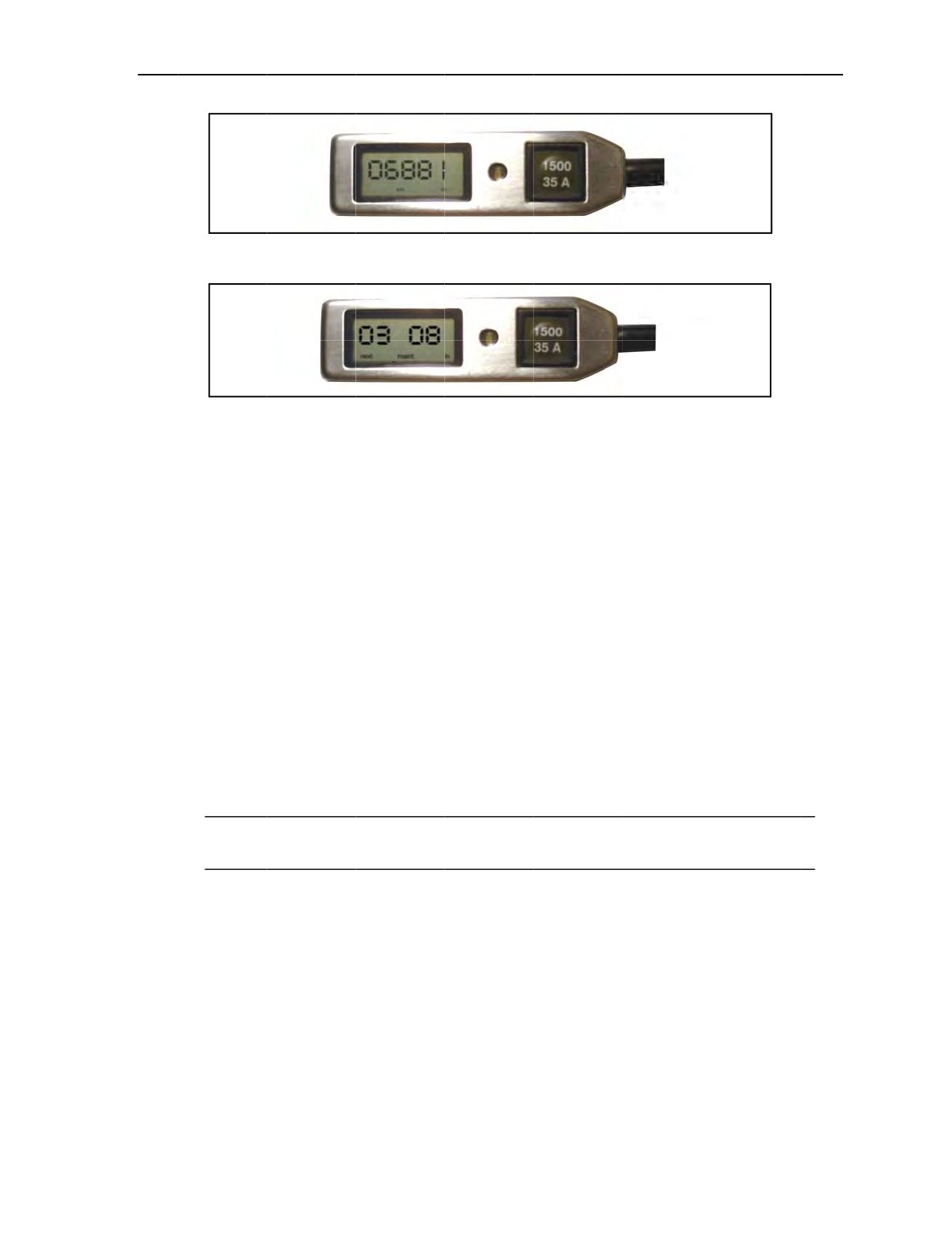
Cybernetic Parachute Release System
Figure 3-11. Example of Military CYPRES 2 serial number
Figure 3-12. Example
of next required maintenance date for Military CYPRES 2
GENERAL TERMS
3-19. The jumpmaster and parachutist should be familiar
with the following terms as
to how the Military
CYPRES 2 performs its setting
calculations:
z
Virtual Drop Zone. The VDZ is
defined as the virtual zero
reference point established
by the
jumpmaster from which the Military CYPRES
2 makes its
calculations. This reference
point
becomes the zero starting point, or the VDZ, for all Military CYPRES 2 calculations. There are
two reasons for use
of a VDZ in lieu of the actual DZ:
I
f a highest release point obstacle exists.
This VDZ (highest elevation) must be used to
provide the jumper with a safe distance above the obstacle for reserve
deployment via the
Military CYPRES 2.
T
o adjust the reserve parachute to a higher actuation altitude for a tactical HAHO option.
This is SOP based only.
z
Highest Release Point Obstacle. For the Military CYPRES 2 setting calculations, a terrain
feature near the release point is considered an obstacle if it is
over 200 feet
higher than the DZ.
This
is for HALO and HAHO jump operations.
The obstacle is taken into consideration if
it falls
within
the parameters below; the highest release
point obstacle
will become the VDZ on which all
setting calculations
are based:
A
500-meter radius of the release point for operations up to 13,000 feet AGL.
A
1,000-meter
radius of the release point for operations above 13,000 feet AGL.
Note: Both highest release point obstacle radiuses are
minimum distances and can
be increased by
the jumpmaster as needed.
z
Altimeter Setting.
This setting is
in inches of Hg (QNH). The barometric pressure is corrected
to MSL by taking the current station pressure and temperature, and adjusting
it to MSL from the
difference in elevation of where
the reading was taken from.
. The pressure
value of an aircraft
altimeter scale is set so that it will
indicate the altitude above MSL of an aircraft on the ground at
the location for which the value was determined
z
Unknown (Combat) Setting (29.
.92). If the aircraft altimeter
setting (inches
of Hg) is unknown,
a value of 29.92 (inches of Hg) is
used to calculate the millibar setting of the Military CYPRES
2. The value of 29.92 (inches
of Hg) is the
average pressure at
0 feet MSL, 59 degrees
Fahrenheit, which is the around-the-world average.
24 October 2014
ATP 3-18.11/AFMAN 11-411(I)/NTTP 3-05.26M
3-9

Chapter 3
MODES OF OPERATION
3-20. The three Military CYPRES 2 models can be set in two modes: default (training) mode and absolute
(operational) mode. The Expert CYPRES 2 can be set in two modes: default (training) mode and offset mode.
3-21. The primary jumpmaster for each jump is responsible for determining the proper mode and setting.
The jumpmaster must properly identify the Military CYPRES 2 model to be used and fully understand its
mode of operation to make the proper mode selection. The following paragraphs describe the Military
CYPRES 2 modes of operation.
DEFAULT (TRAINING) MODE (MILITARY CYPRES 2 AND EXPERT CYPRES 2)
3-22. The default (training) mode is only used if the DZ and the DAF are the same location. Once powered
ON in default (training) mode, the DAF and/or DZ elevation automatically becomes the zero reference
point. The Military CYPRES 2 continuously samples atmospheric pressure changes and makes required
adjustments to ensure that the zero reference point stays on the ground. For example, if all conditions are
met, the Military CYPRES 2 Model 1500 35 A that is powered ON at the DAF and/or DZ will fire the
release element at 1,500 feet above the DAF elevation. If all conditions are not met to fire the release
element, the Military CYPRES 2 will remain active until it reaches 130 feet above the DAF elevation, at
which time it will deactivate automatically. Once set in the default (training) mode, the Military CYPRES 2
must be powered OFF and powered back ON just prior to every lift at the DAF; this is a required safety
measure for military use.
ABSOLUTE (OPERATIONAL) MODE (MILITARY CYPRES 2)
3-23. In absolute (operational) mode, the DZ or VDZ is calculated by the jumpmaster depending on
operational requirements. By entering the desired millibar setting into the Military CYPRES
2, the
jumpmaster tells the Military CYPRES 2 the absolute pressure of the location of the DZ or VDZ. The
elevation corresponding to the pressure entered into the CYPRES calculator is now the zero reference point
for the Military CYPRES 2. All calculations for the activation window and the activation altitude made by
the Military CYPRES 2 are based off of this point. A VDZ may be programmed to any altitude within the
device’s operational range of -1600 feet to +36,000 feet MSL, which equates to 1075-0200 millibars.
3-24. Once set, the DZ and/or VDZ is locked into the millibar setting that corresponds to that altitude to
start the Military CYPRES 2 calculations. The Military CYPRES 2 in absolute (operational) mode does not
make adjustments for barometric pressure changes in weather. For example, if all conditions are met, the
Military CYPRES 2 Model 1500 35 A in absolute (operational) mode with a VDZ set at 5,000 feet MSL
(a mountain is at the release point) will fire at 6,500 feet MSL (VDZ MSL plus default activation equals
Military CYPRES activation MSL). If all conditions are not met to fire the release element, the Military
CYPRES 2 remains active until the parachutist reaches 130 feet above the VDZ (5,130 feet MSL) at which
time it will deactivate automatically for the remainder of the canopy flight.
OFFSET MODE (EXPERT CYPRES 2)
3-25. The Expert CYPRES 2 does not have an absolute (operational) mode. However, the Expert CYPRES 2
can be set with an offset that will allow for a ±3,000-foot difference between the DAF and the DZ. This
setting is derived by the jumpmaster using the same method employed to set the jumper’s altimeter
(altitude difference between the DAF MSL and DZ MSL equals offset). Rounded to the nearest
30-foot increment, the offset is entered into the Expert CYPRES 2. Once powered ON in offset mode, the
VDZ (zero reference point) automatically becomes the DAF plus the amount of offset. For example, if all
conditions are met, the Expert CYPRES 2 that is powered ON at the DAF with a default activation altitude
of 750 feet and a +300-foot offset will fire the release element at 1,050 feet above the DAF elevation. If all
conditions are not met to fire the release element, the Expert CYPRES 2 will remain active until it reaches
130 feet above the VDZ elevation, at which time it will deactivate automatically. Once set in the offset
mode, the Expert CYPRES 2 must be powered OFF and powered back ON just prior to every lift at the
DAF; this is a required safety measure for military use.
3-10
ATP 3-18.11/AFMAN 11-411(I)/NTTP 3-05.26M
24 October 2014

Cybernetic Parachute Release System
MODE DETERMINATION
3-26. The proper mode for the three Military CYPRES 2 models and the Expert CYPRES 2 must be
determined by the primary jumpmaster before and during the jump operation. If the mission or conditions
change, it may be necessary to adjust the setting or mode.
3-27. Absolute (operational) mode can be used in all situations and is the recommended mode to use for all
military free-fall operations. To determine the use of the default
(training) mode on the Military
CYPRES 2, the following questions must be answered for every jump:
z
Are the DAF and DZ at different locations?
z
Is there a highest release point obstacle of 200 feet or greater?
z
Is this a HAHO jump?
z
Is the desired Military CYPRES 2 activation different than the Military CYPRES 2 default values?
z
Will the aircraft fly below the DAF and/or DZ elevation?
z
Will the Military CYPRES 2 be powered ON in flight?
z
Will the aircraft be pressurized?
3-28. If any of the questions were answered “YES,” the Military CYPRES 2 must be used in absolute
(operational) mode. If answered “NO” to every question, default (training) mode can be used. The
jumpmaster will evaluate the operational parameters during the jump. If the parameters change, the
Military CYPRES 2 may have to be reset. The ideal situation to use the three Military CYPRES 2 models
and the Expert CYPRES 2 model in default (training) mode is when a DZ is selected with no terrain feature
obstacles near the release point and the DAF and DZ are the same location and elevation MSL.
DEFAULT (TRAINING) MODE
3-29. The three Military CYPRES 2 models and the Expert CYPRES 2 model are set to operate in the default
(training) mode with the same operational parameters. Both the Military and Expert CYPRES 2 models
function in the same manner and use the same power ON sequence. While in default (training) mode, the
parachutist’s emergency procedures and pull altitudes do not change. The jumpmaster must ensure that all
warnings, cautions, and rules are understood before selecting the default (training) mode of operation.
DANGER
Do not use the CYPRES 2 in default (training) mode unless the
following conditions are met. Failure to adhere to these warnings
may result in the CYPRES 2 not firing at the intended altitude and
may result in injury or DEATH to the parachutist.
Prior to every lift while in default (training) mode, the CYPRES 2
will be powered OFF and powered back ON at the DAF. This
ensures that all parachutists on the aircraft have the correct DZ
setting. The CYPRES 2 will automatically reset the DZ under
certain situations. Failure to power OFF and power back ON the
CYPRES 2 just prior to every lift may result in the CYPRES 2 not
firing at the intended altitude, which may result in injury or
DEATH to the parachutist.
The jump aircraft must never fly below the DAF altitude. If the
jump aircraft flies below the DAF altitude, the CYPRES 2 will reset
the DZ, or zero reference point, to that lower altitude. Then the
CYPRES 2 may fire at a lower-than-intended altitude, which may
result in insufficient time for the reserve parachute to inflate,
resulting in injury or DEATH to the parachutist.
18 August 2016
ATP 3-18.11/AFMAN 11-411(I)/NTTP 3-05.26M, C2
3-11

Chapter 3
DANGER (continued)
The cabin area of the jump aircraft must be depressurized during
engine startup and takeoff to ensure that the cabin pressure will
not build up above the air pressure on the ground. If the cabin
pressure in the jump aircraft is allowed to build up (representing a
lower altitude), the CYPRES 2 will automatically reset the VDZ, or
ground reference, to the lower altitude and the CYPRES 2 may fire
at a lower-than-intended altitude. This may result in insufficient
time for the reserve parachute to inflate, resulting in injury or
DEATH to the parachutist.
The CYPRES 2 must not be powered ON in flight while in default
(training) mode. Powering ON the CYPRES 2 while in flight will set
the VDZ to the aircraft altitude or cabin pressure. This will result
in the CYPRES 2 firing too high upon exit or not firing at all,
depending on the exit altitude, resulting in injury or DEATH to the
parachutist.
Conditions for Using All CYPRES 2 Models in Default (Training) Mode
3-30. While in default (training) mode, the three Military CYPRES 2 models and the Expert CYPRES 2
model may be used only under the conditions listed below. These conditions must be maintained
throughout the operation with no exceptions. If any of these conditions are not met, the CYPRES 2 will not
be used in the default
(training) mode. The absolute
(operational) mode will be used instead. The
conditions include the following:
z
Every CYPRES 2 on the lift must be powered OFF and powered back ON at the DAF while on
the ground prior to every lift; this is a required safety measure for military use.
z
Low-level flights en route to the DZ must not fly below the DAF MSL elevation.
z
The aircraft cannot be pressurized.
z
The DAF and DZ must be the same location.
z
HAHO jumps cannot be done.
z
The CYPRES default activation values must be used.
z
Minimum vertical separation between reserve activation altitude and main deployment altitude is
2,000 feet for the 1000 35 A and the 1500 35 A models and 2,500 feet for the 2500 29 A model.
When the 1000 model is used on the tandem bundle, the vertical separation is not applicable.
z
There cannot be a highest release point obstacle. A terrain feature at the release point is an
obstacle when that feature is 200 feet or higher than the DZ and is within—
A 500-meter radius of the release point for operations 13,000 feet AGL and below.
A 1,000-meter radius of the release point for operations above 13,000 feet AGL.
Jumpmaster and Pilot Considerations in Default (Training) Mode
3-31. When using the default (training) mode, the jumpmaster and pilot should consider the following:
z
The three Military CYPRES 2 models arm at an altitude of 1,500 feet above the default setting
and the Expert CYPRES 2 model at an altitude of 750 feet above the default setting. For
example, once powered ON prior to leaving the ground, the Military CYPRES 2 1500 35 A arms
itself at 3,000 feet above the DAF.
z
The aircraft should never descend to an altitude below the elevation of the DAF. The Military
CYPRES 2 will automatically reset the VDZ, or ground reference, to the lower altitude and the
Military CYPRES 2 may fire at a lower-than-intended altitude.
3-12
ATP 3-18.11/AFMAN 11-411(I)/NTTP 3-05.26M, C2
18 August 2016

Cybernetic Parachute Release System
z
If the aircraft can be pressurized, the pilot ensures the cabin remains depressurized during engine
startup and takeoff. He ensures that the cabin pressure does not build up above the air pressure
on the ground. Jumpmasters onboard the aircraft may monitor this by observing their altimeters.
If the cabin pressure in the aircraft is allowed to build up (representing a lower altitude), the
Military CYPRES 2 will automatically reset the VDZ, or ground reference, to the lower altitude
and the Military CYPRES 2 may fire at a lower-than-intended altitude.
z
While descending, the aircraft should never exceed the vertical activation speed for the Military
CYPRES 2 while in the activation window. Exceeding the vertical activation speed may cause
the Military CYPRES
2 to fire the release element and deploy the reserve parachute.
Aircraft may exceed the vertical activation speed of
6,900 feet per minute for the
1000 and 1500 35 A models or 5,700 feet per minute for the 2500 29 A model during descent
while executing a tactical landing. The jumpmaster must brief the pilots not to exceed 5,000 feet
per minute as this descent rate is easy to remember and covers all three Military CYPRES 2
models.
ABSOLUTE (OPERATIONAL) MODE
3-32. The absolute (operational) mode may be used under all conditions for HALO or HAHO jumps as
long as the required absolute
(operational) mode-setting parameters are followed. The absolute
(operational) mode may be used for short or long flights. The Military CYPRES 2 will power itself OFF
after 14 hours under any condition.
Operating Conditions for Absolute (Operational) Mode
3-33. The three Military CYPRES 2 models must be used in absolute (operational) mode for the following
operating conditions:
z
The Military CYPRES 2 is powered ON in flight.
z
Low-level flights en route to the DZ are flying below the DAF MSL elevation.
z
There is a highest release point obstacle of 200 feet or greater above the DZ.
z
The Military CYPRES 2 activation altitude is different than the default activation altitude.
z
DAF and DZ are at separate locations.
z
The aircraft must be pressurized.
Rules for Using the Absolute (Operational) Mode
3-34. When the Military CYPRES 2 is used in absolute (operational) mode, all of the following apply to all
operations and will be strictly followed:
z
During in-flight power ON, the aircraft climb rate or descent rate will not exceed 1,000 feet per
minute until all Military CYPRES 2 models on board are powered ON. The preferred method is
to have the aircraft level off during Military CYPRES 2 setting.
z
All parachutists on the same stick will have the same DZ and/or VDZ setting.
z
The minimum VDZ setting for jump operations at 13,000 feet AGL and below is the height of
the highest obstacle, if 200 feet or higher than the DZ, within 500 meters of the release point.
z
The minimum VDZ setting for a jump operation at greater than 13,000 feet AGL is the height of
the highest obstacle, if 200 feet or higher than the DZ, within 1,000 meters of the release point.
z
Minimum vertical separation between reserve activation altitude and main deployment altitude is
2,000 feet for the 1000 35 A and the 1500 35 A models and 2,500 feet for the 2500 29 A model.
When the 1000 model is used on the tandem bundle, the vertical separation is not applicable.
z
While in absolute (operational) mode, the altimeter setting for the DZ should be checked every
hour during the operation using the most accurate means available, and the Military CYPRES 2
will be recalculated. If the Military CYPRES 2 setting changes more than ±3 millibars or if the
operational parameters change, the jumpmaster must recalculate and reset the Military CYPRES 2.
18 August 2016
ATP 3-18.11/AFMAN 11-411(I)/NTTP 3-05.26M, C2
3-13

Chapter 3
WARNING
The actual absolute pressure (QFE) at the VDZ must be entered
into the Military CYPRES 2 in operational mode. This pressure
can be determined by direct measurement with an instrument,
such as the Military CYPRES Portable Calibration Station. An
actual Military CYPRES 2 can be calculated from the aircraft
altimeter setting (QNH) and the MSL elevation of the VDZ using
the approved CYPRES calculators; for example, Excel, circular
calculator, or digital calculator.
It is important to realize that flight service and weather stations
normally report pressure as if it were sea level (aircraft altimeter
setting [QNH]), and not the actual absolute pressure (QFE); thus,
it is necessary to convert the aircraft altimeter setting (QNH) to
the actual absolute pressure
(QFE) for use with the Military
CYPRES 2.
Calculations for the Drop Zone in Absolute (Operational) Mode
3-35. When using the Military CYPRES 2 in operational mode, the jumpmaster will calculate the millibar
setting by obtaining the following information:
z
Actual absolute air pressure at the DZ.
z
Both the current aircraft altimeter setting (QNH) in inches of Hg and DZ elevation MSL.
WARNING
Pressure readings should be as current as possible, preferably
updated every hour by the drop zone safety officer (DZSO) and
recorded from the nearest source to the DZ.
Jumpmasters must use their best judgment when obtaining the
aircraft altimeter setting off-site from the DZ. Within ± 20 miles is
a good reference. Depending on the geographic location of the DZ
or, in many cases
(HAHOs), the HARP, in reference to
atmospheric conditions, pressure values could be significantly
different from one valley to another that are only separated by a
single ridgeline. Jumpmasters should make note of pressure
differences and weather conditions in relation to the location they
obtained the aircraft altimeter setting from and to the location of
the DZ. The distances away from the DZ and/or VDZ for obtaining
the pressure can greatly increase if meteorological conditions are
favorable.
The DZ elevation used for calculating the millibar setting is the
highest point of elevation (MSL) given on the AF IMT Form 3823
(Drop Zone Survey).
3-14
ATP 3-18.11/AFMAN 11-411(I)/NTTP 3-05.26M, C2
18 August 2016

Cybernetic Parachute Release System
Calculations for the Virtual Drop Zone in Absolute (Operational) Mode
3-36. In some scenarios, the jumpmaster must use a VDZ, described as a virtual line in the sky, which is a
higher elevation MSL than that of the actual DZ. These scenarios include the following:
z
HALO jumps or HAHO jumps with a low reserve activation altitude that have a highest release
point obstacle of 200 feet or greater than the DZ elevation within a—
500-meter radius of the release point for operations up to 13,000 feet AGL.
1,000-meter radius of the release point for operations above 13,000 feet AGL.
z
HAHO with a high reserve activation altitude setting for a tactical operation based on SOP.
3-37. The jumpmaster will calculate the millibar setting for a VDZ by obtaining the following information:
z
Current aircraft altimeter setting (QNH) in inches of Hg.
z
The higher VDZ elevation MSL.
Note: The jumpmaster will take into account the cutaway decision altitude (in AGL) when
adjusting for VDZ.
WARNING
When using a VDZ or higher elevation than the DZ, the
jumpmaster must also change the pull altitude of his jumpers.
Jumpers must maintain 2,000 feet (1500 35 A model) of vertical
separation between pull altitude and reserve activation altitude
(2,500 feet of vertical separation for the
2500 29 A model
CYPRES). When used with nonstandard parachutes, 1,500 feet of
vertical separation is required for the 1000 35 A model CYPRES.
Calculations for Unknown Setting (29.92) in Absolute (Operational) Mode
3-38. When using the Military CYPRES 2 in operational mode, if the jumpmaster cannot obtain a current
aircraft altimeter setting for a precise measurement of station pressure, he must use 29.92 in inches of Hg
for his millibar calculation. Because the pressure may not actually be 29.92 inches of Hg, the jumpmaster
must plan for the reserve activation altitude being possibly higher or lower than planned for, as follows:
z
If the actual pressure is higher, the Military CYPRES 2 will activate on the high side.
z
If the actual pressure is lower, the Military CYPRES 2 will activate on the low side.
3-39. The jumpmaster must add a safety factor into his calculations in order for the reserve to have enough
altitude to fully inflate and save his jumpers’ lives. To prevent activation on the low side, the jumpmaster
will add 500 feet to the DZ or highest release point obstacle VDZ for a safety factor. This new elevation is
the elevation the jumpmaster will use to calculate the millibar.
3-40. The jumpmaster will calculate the millibar setting by using and obtaining the following information:
z
Unknown aircraft altimeter setting (QNH) = 29.92 inches of Hg.
z
DZ or VDZ elevation MSL + 500 feet for safety factor = VDZ elevation MSL.
DANGER
When using unknown setting of
29.92 inches of Hg, the
jumpmaster must also add 1,000 feet to the jumpers’ pull altitude
as a safety factor in case the Military CYPRES 2 fires on the high
side. Failure to do so could cause a dual canopy deployment,
resulting in injury or DEATH to the parachutist.
18 August 2016
ATP 3-18.11/AFMAN 11-411(I)/NTTP 3-05.26M, C2
3-15

Chapter 3
Note: Unknown setting of 29.92 inches of Hg may be used for tactical training jumps as long as
all calculations are done using the appropriate safety factors.
Jumpmaster and Pilot Considerations for Using the Absolute (Operational) Mode
3-41. When using the absolute (operational) mode, the jumpmaster and pilot must consider the following:
z
While operating in absolute (operational) mode, the three Military CYPRES 2 models arm as
soon as they are powered ON.
z
When in the absolute (operational) mode, the Military CYPRES 2 can be set in both a
pressurized and a depressurized aircraft while in flight. During an in-flight power ON for an
unpressurized cabin, the aircraft climb rate or descent rate will not exceed 1,000 feet per minute
or a steady pressurized rate within 1,000 feet per minute for a pressurized cabin until all Military
CYPRES 2 models are powered ON. Leveling off is preferred.
z
While descending, the aircraft should never exceed the vertical activation speed for the Military
CYPRES 2 while in the activation window. Exceeding the vertical activation speed may cause
the Military CYPRES 2 to fire the release element and deploy the reserve parachute. Aircraft
may exceed the vertical activation speed of 6,900 feet per minute for the 1000 and 1500 35 A
models or 5,700 feet per minute for the 2500 29 A model during descent while executing a
tactical landing that will cause the Military CYPRES
2 to activate in the aircraft. The
jumpmaster must brief the pilots not to exceed 5,000 feet per minute as this descent rate is easy
to remember and covers all three Military CYPRES 2 models.
z
Descent to an altitude below the elevation of the DAF will not affect the Military CYPRES 2 in
the absolute (operational) mode.
z
Once the aircraft descends through the VDZ altitude, the Military CYPRES 2 will deactivate
itself and will not fire the release element. Therefore, if the jump altitude is lowered below the
VDZ, all Military CYPRES 2 models on the aircraft must be reset.
OPERATING PROCEDURES
3-42. There are two modes for the three Military CYPRES 2 models and two modes for the Expert
CYPRES 2 model:
z
Default (training) mode used for both the Military CYPRES 2 and the Expert CYPRES 2 models.
z
Absolute (operational) mode used for the three Military CYPRES 2 models.
z
Offset mode used for the Expert CYPRES 2 model.
3-43. The three Military CYPRES 2 models and the Expert CYPRES 2 model operate and power ON in
the same way. The only difference among the models is the activation speed and altitude. The button on the
control unit is the only means the user has to control the CYPRES 2. The parachutist performs two actions:
powering ON and powering OFF the CYPRES 2.
POWER ON PROCEDURES FOR MILITARY CYPRES 2 AND EXPERT CYPRES 2
IN DEFAULT (TRAINING) MODE
CAUTION
For the default (training) mode only, the Military CYPRES 2 must be
powered ON at the DAF while on the ground; it must not be powered
ON inside a flying aircraft. The user must initialize on the ground at
ground level to be accurate.
3-44. During the power ON sequence, the CYPRES 2 conducts a self-test. The jumper must watch the
display during the entire power ON self-test. Table 3-2, page 3-17, explains the error codes.
3-16
ATP 3-18.11/AFMAN 11-411(I)/NTTP 3-05.26M, C2
18 August 2016
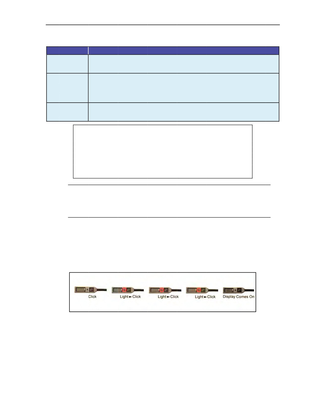
Cybernetic Parachute Release System
Table 3-2. CYPRES 2
power ON self-test error
codes in default (training) mode
Code
Meaning
One or both
of the attached release units are not correctly electrically connected to the
1111
unit. The reason may be a
cable break,
the cutter plug could be disconnected, or the
2222
release unit(s) may have activated.
Excessive variations in ambient air pressure have been measured
during the self-test
period. The
unit is unable
to obtain consistent values
for the ambient air pressure at
3333
ground level.
Possible reasons could be
an attempt to
switch on the
CYPRES 2 in the
training mode in an airborne aircraft while
exceeding a
climb rate or descent rate of
more
than 1,500 feet per minute.
Low battery.
The battery capacity is large
enough to cover most of the usage profile, but
7777
in extreme situations a low-battery indication may show up. In this case, Airtec or
SSK
should be contacted before
the next use.
CAUTION
The
jumper should press the
control unit button with the tip of a finger.
He
should not use a fingernail or a sharp
object. Prolonged use of a
fingernail or a sharp object will wear the
letters off of
the button and
possibly wear
a hole in the button material, thus
rendering
the
CYPRES 2 unserviceable.
Note: If a
button click is missed or a
button is pressed too soon before the light comes on, the
CYPRES
2 will not power ON. If the CYPRES 2
fails to power
ON, the sequence should be
started over again in default (training)
mode.
Note: The
four-click initiation cycle is
designed to avoid accidental activation.
3-45. The jumper starts the power ON process for the Military CYPRES
2 in the default (training) mode by
pressing the button on the control unit four times as follows:
z
Press
the button on
the control unit with the tip of a finger.
z
When
the light-emitting diode illuminates, press
the button again while the light is on.
z
Repeat above step two more times
for a total of
four times.
When the power ON steps are successful,
the display will come on and the self-test will start to
count
down, which should last for 10
seconds (Figure 3-13).
Figure 3-13. Power ON
sequence for Military CYPRES 2
in default (training)
mode
3-46. The jumper must watch the display during
the self-test
period. The
display will
start
with 10 (Figure
3-14, page 3-18) and then show a rapid countdown to zero with the arrow pointing
down
(0▼), referred to
as zero down. If the self-test
is successful,
the Military CYPRES 2 will remain powered ON.
24 October 2014
ATP 3-18.11/AFMAN 11-411(I)/NTTP 3-05.26M
3-17
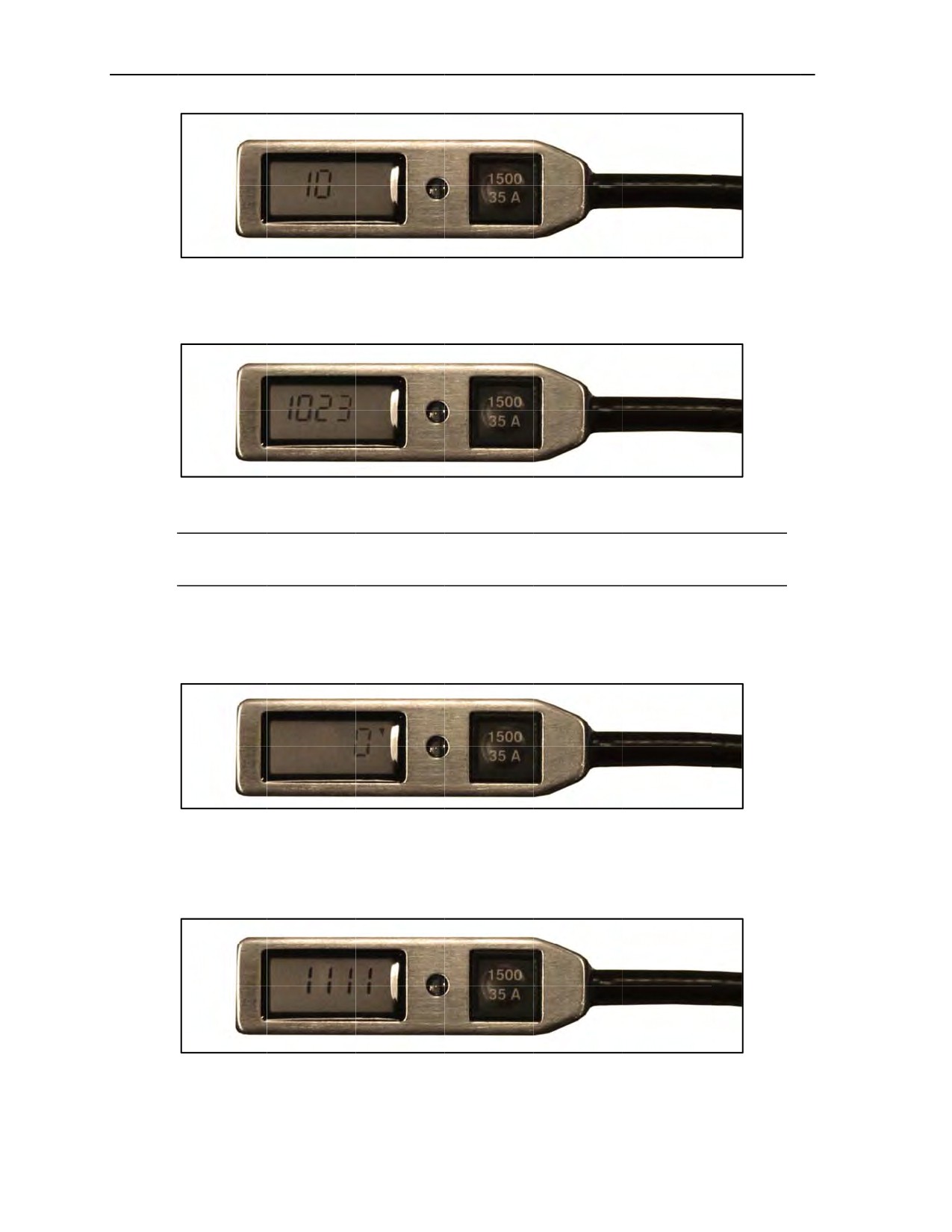
Chapter 3
Figure
3-14. Beginning of Military CYPRES
2 self-test countdown in
default (training) mode
3-47.
During the countdown, the
display pauses
between one
and zero to display the current barometric
pressure in millibars
(Figure 3-15).
. The jumpmaster should always take note of this number
Figure 3-15. Military CYPRES 2 displaying current barometric pressure
in millibars
Note: The Military CYPRES
2 will not display battery voltage because the user cannot replace
the battery. If
battery voltage
is low, the Military CYPRES 2 will not power ON.
3-48.
The Military CYPRES 2 will continue the
countdown to a reading of
0▼ (Figure
3-16). Once the
0▼reading is displayed, the Military CYPRES
2 has passed
the self-test and is powered ON, ready
to
monitor a jump. While in the default mode, the
Military CYPRES 2 will arm itself 1,500
feet above the
default activation altitude.
Figure 3-16. Military CYPRES
2 set in default (training) mode
3-49.
If a functional
deficiency in
the Military CYPRES 2 is
detected during the power ON self-test, the
Military CYPRES 2
will display an error code and power OFF. Prior to the Military CYPRES 2 powering
off, the jumper should note the error code in the display (Figure
3-17).
Figure 3-17.
Example of Military CYPRES 2 error
code
3-18
ATP 3-18.11/AFMAN 11-411(I)/NTTP 3-05.26M
24 October 2014

Cybernetic Parachute Release System
3-50. The Military CYPRES 2 automatically powers OFF after 14 hours. During the 14 hours, the Military
CYPRES 2 settings will adjust for barometric pressure changes.
POWER ON PROCEDURES FOR MILITARY CYPRES 2 IN ABSOLUTE (OPERATIONAL) MODE
3-51. During the power ON sequence, the Military CYPRES 2 conducts a self-test. The jumper must watch
the display during the entire power ON self-test. Table 3-3 explains the error codes.
Table 3-3. CYPRES 2 power ON self-test error codes in absolute (operational) mode
Code
Meaning
One or both of the attached release units are not correctly electrically connected to the
1111
unit. The reason may be a cable break, the cutter plug could be disconnected, or the
2222
release unit(s) may have activated.
Excessive variations in ambient air pressure have been measured during the self-test
period. The unit is unable to obtain consistent values for the ambient air pressure at
3333
ground level. Possible reasons could be an attempt to switch on the CYPRES 2 in the
training mode in an airborne aircraft while exceeding a climb rate or descent rate of more
than 1,500 feet per minute.
Low battery. The battery capacity is large enough to cover most of the usage profile, but in
7777
extreme situations a low-battery indication may show up. In this case, Airtec or SSK
should be contacted before the next use.
CAUTION
The jumper should press the control unit button with the tip of a finger.
He should not use a fingernail or a sharp object. Prolonged use of a
fingernail or a sharp object will wear the letters off of the button and
possibly wear a hole in the button material, thus rendering the
CYPRES 2 unserviceable.
Note: If a button click is missed or a button is pressed too soon before the light comes on, the
Military CYPRES 2 will not power ON. If the Military CYPRES 2 fails to power ON, the
sequence should be started over again in absolute (operational) mode.
Note: The four-click initiation cycle is designed to avoid accidental activation.
3-52. The jumper starts the power ON process for the Military CYPRES 2 in the absolute (operational)
mode by pressing the button on the control unit four times as follows:
z
Press the button on the control unit with the tip of a finger.
z
When the light-emitting diode illuminates, press the button again while the light is on.
z
Repeat above step two more times for a total of four times.
z
Hold the button down on the fourth press.
When the power ON steps are successful, the display will come on and the self-test will start to count
down, which should last for 10 seconds (Figure 3-18, page 3-20).
24 October 2014
ATP 3-18.11/AFMAN 11-411(I)/NTTP 3-05.26M
3-19
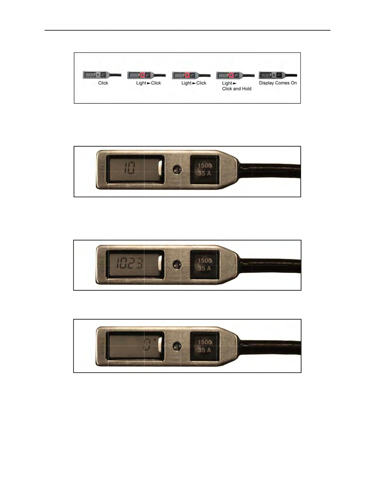
Chapter 3
Figure
3-18. Power
ON sequence for Military
CYPRES 2
in absolute
(operational) mode
3-53.
The jumper
must watch
the display
during the
self-test period. The display will start
with 10 (Figure 3-19)
and then show
a rapid countdown to 0▼.
Figure
3-19. Beginning of Military CYPRES
2 self-test countdown
in
absolute (operational)
mode
3-54.
The self-test cycle takes 10
seconds to complete. There
is a brief pause between 1 and 0 where the
current barometric pressure is displayed in millibars (Figure 3-20).
Figure 3-20. Military CYPRES 2 displaying current barometric pressure in millibars
3-55.
Once the 0▼ reading is displayed (Figure 3-21), the Military CYPRES
2 has passed the self-test.
Figure
3-21. Military CYPRES 2
set in absolute (operational) mode
3-56.
If a functional
deficiency in
the Military CYPRES 2 is
detected during the power ON self-test, the
Military CYPRES 2
will display an error code and power OFF. Prior to the Military CYPRES 2 powering
off, the jumper should note the error code in the display (Figure
3-22, page 3-21).
3-20
ATP 3-18.11/AFMAN 11-411(I)/NTTP 3-05.26M
24 October 2014
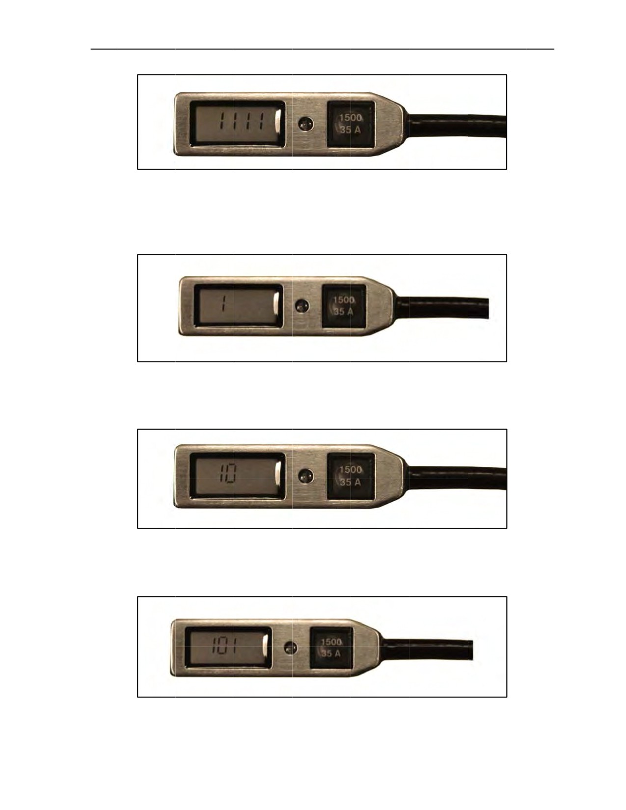
Cybernetic Parachute Release System
Figure 3-22. Example
of Military CYPRES 2 error code
3-57. Upon completion of the
self-test, the Military CYPRES 2 will display the millibar setting of 1000. To
set the appropriate millibar setting, the jumper performs the
following steps:
z
The 1
will alternate
with 0. Release the button to
choose 0 or 1. The chosen value remains
on the
display (Figure 3-23).
Figure 3-23. First value of 1 chosen for millibar setting
z
Press
and hold the button again. The second digit counts from
0 through 9.
To select the second
value, release the button when the desired value appears. This value remains on the display
(Figure 3-24).
Figure 3-24. Second value of 0 chosen for millibar setting
z
Press
and hold the
button again.
The third digit counts from
0 through 9. To select the
third
value, release the button when the desired value appears. This value remains on the display
(Figure 3-25).
Figure 3-25. Third value of 1 chosen for millibar setting
24 October 2014
ATP 3-18.11/AFMAN 11-411(I)/NTTP 3-05.26M
3-21
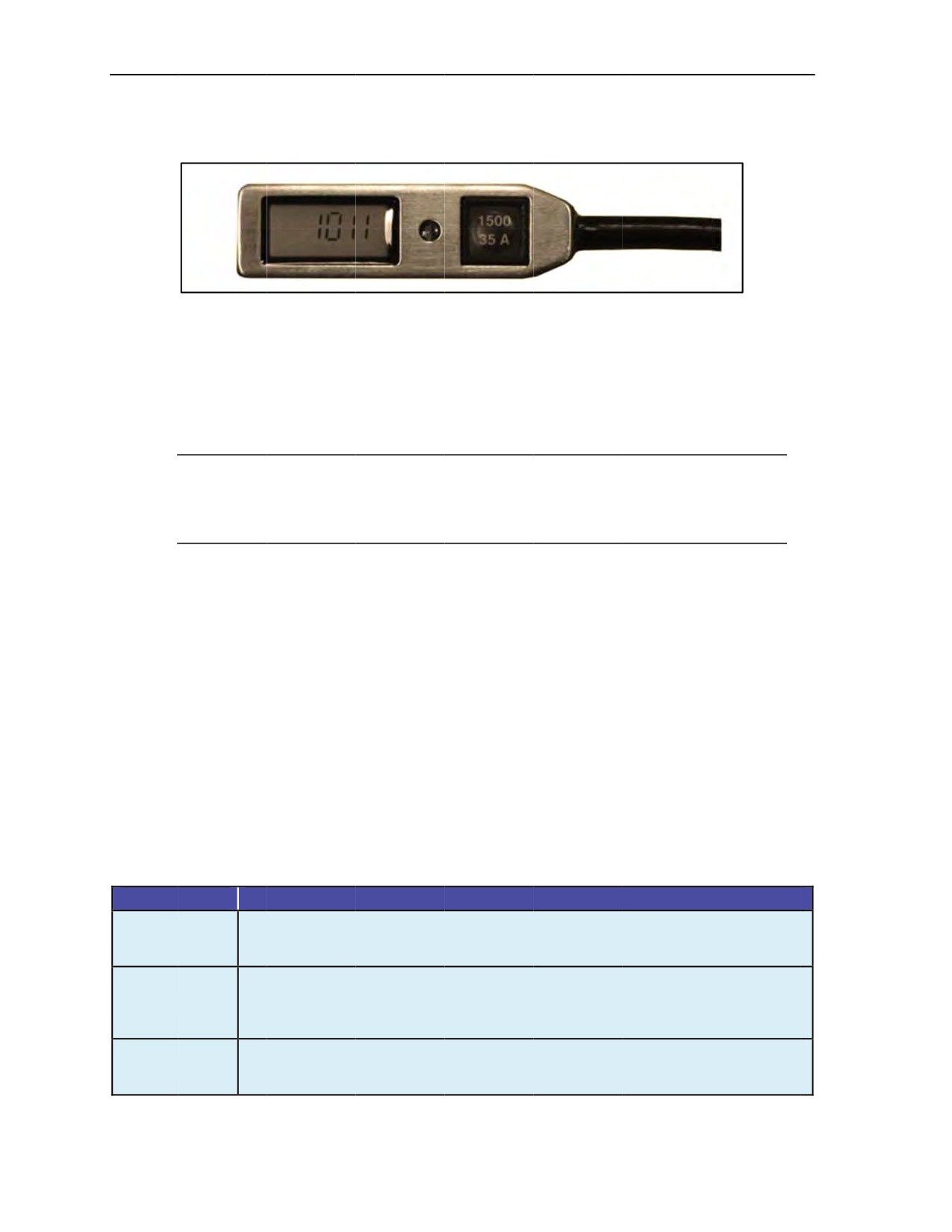
Chapter 3
z
Press and
hold the button
again. The fourth digit counts from 0 through 9. To select the final value,
release the
button when the desired value appears. This value remains on the display (Figure 3-26).
Figure 3-26. Final value chosen and Military CYPRES 2 set
3-58.
To change an
incorrect entered number, the
jumper presses the button until the value
shows up again.
(After
9, the display
restarts automatically with 0.) In order to start over completely because
of an incorrect
input in a previous value, without powering off, the jumper—
z
Inputs a number into all
four values.
z
Before the light goes out after the fourth value input, presses and
holds the button again. The
display will start over at
the first value
again.
Note: If the user tries to enter a pressure
of less than 200 millibars (approximately
39,000 feet
above sea level) or more than 1,075 millibars (approximately 1,600 feet below sea
level), the
Military CYPRES 2 switches itself off. The blank display
indicates that
the desired adjustment is
outside the specified parameters.
3-59.
The pressure adjustment and
the display indication remain until the unit is switched
off. To change
the setting, the jumper switches the
Military CYPRES 2 off and
on again.
3-60.
The Military CYPRES 2 automatically turns off after 14 hours. During the 14 hours, the Military
CYPRES 2 settings will not adjust
for barometric
pressure changes.
POWER ON PROCEDURES FOR EXPERT CYPRES 2 IN OFFSET MODE
3-61.
The Expert CYPRES 2 can be set in an offset mode that
allows the default altitude to
be changed by
±1,500
feet (±3,000
feet with units produced after 2006) from
the DAF. This allows the default setting
to
be adjusted if the DZ
elevation is higher or lower
than the DAF
or if the default activation level needs to be
raised. In the offset
mode, the Expert CYPRES
2 powers ON
the same way
as the Military CYPRES 2
in
the absolute (operational) mode except that the button cannot be released while making the
setting. As soon
as the
button is released, the setting
is locked into
the Expert CYPRES 2. If the desired offset is missed, the
Expert
CYPRES 2
must be powered OFF and
powered back
ON in offset mode to adjust the setting.
During
the power ON sequence, the Expert CYPRES 2 conducts a self-test. The jumper
must watch the
display
during the entire power ON
self-test. Table 3-4 explains
the error codes.
Table 3-4. Expert CYPRES 2 power
ON self-test
error codes
in offset mode
Code
Meaning
One or both of the attached release units are
not correctly
electrically connected to the
1111
unit. The reason
may be a cable break, the
cutter plug could be disconnected, or the
2222
release unit(s) may have activated.
Excessive variations in ambient air pressure
have been measured during the self-test
period. The unit
is unable to obtain consistent values for
the ambient
air pressure at
3333
ground level. Possible reasons
could be an attempt to switch on the CYPRES 2 in the
training mode in a
car, driving uphill or downhill, or in an airborne aircraft.
Low battery. The
battery capacity is large enough to cover
most of the usage profile, but
7777
in
extreme situations a low-battery indication
may show up. In this case,
Airtec or SSK
should be contacted before the
next use.
3-22
ATP 3-18.11/AFMAN 11-411(I)/NTTP 3-05.26M
24 October 2014
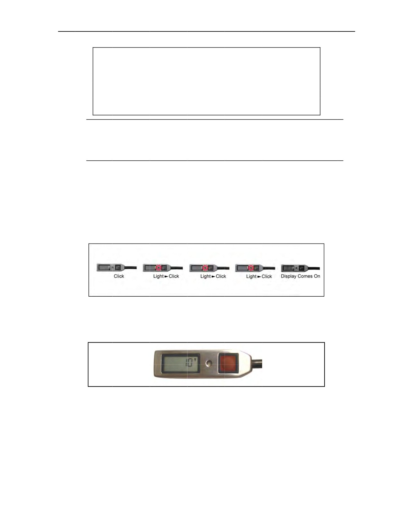
Cybernetic Parachute Release System
CAUTION
The
jumper should press the
control unit button with the tip of a finger.
He
should not use a fingernail or a sharp
object. Prolonged use of a
fingernail or a sharp object will wear the
letters off of
the button and
possibly wear a
hole in the button material, thus rendering the Expert
CYPRES 2 unserviceable.
Note: If a
button click is missed or a
button is pressed too soon before the light comes on, the
Expert CYPRES 2 will not power ON. If the Expert
CYPRES 2 fails to power ON, the sequence
should be
started over again in offset mode.
Note: The
four-click initiation cycle is
designed to avoid accidental activation.
3-62. The jumper starts the power ON process for the Expert CYPRES 2
in the offset mode by pressing the
button on the control unit four
times as follows:
z
Press
the button on
the control unit with the tip of a finger.
z
When
the light-emitting diode illuminates, press
the button again while the light is on.
z
Repeat above step two more times
z
Hold
the button down on the fourth press. Do not let up finger
pressure on the button.
When the power ON steps are successful,
the display will come on and the self-test will start to
count
down, which should last for 10
seconds (Figure 3-27).
Figure 3-27. Power ON sequence for Expert CYPRES
2 in offset mode
3-63. The jumper must watch
the display during the self-test period. The
display will start with 10 and then
show a rapid countdown to zero with the arrow pointing down (0▼), referred to as zero
down. The self-test
cycle takes 10 seconds to complete (Figure 3-28).
Figure 3-28. Expert CYPRES 2 displaying countdown
3-64. If a functional deficiency in the Expert CYPRES 2
is detected during the power ON self-test, the
Expert CYPRES
2 will display
an error code
and power OFF. Prior to the Expert CYPRES 2 powering off,
the jumper should note the error code in the display (Figure
3-29, page 3-24).
24 October 2014
ATP 3-18.11/AFMAN 11-411(I)/NTTP 3-05.26M
3-23
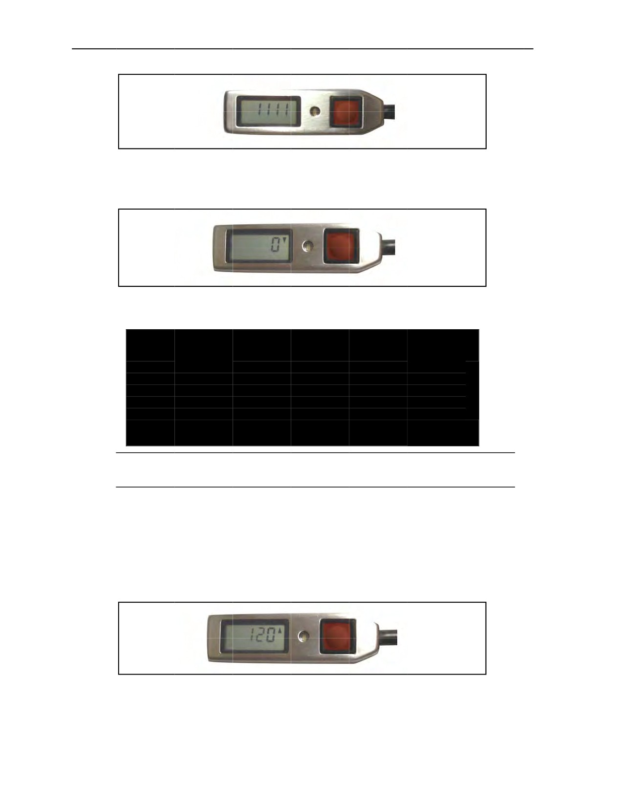
Chapter 3
Figure 3-29.
Example of
Expert CYPRES 2 error code
3-65.
Once the 0▼
reading is displayed (Figure
3-30), the Expert CYPRES
2 has passed
the self-test
in
offset
mode.
Figure
3-30. Expert CYPRES 2
control unit
displaying countdown
at zero down in offset mode
DANGER
In the
offset mode, an arrow
up means the offset is
higher than
the default altitude
of 750 feet;
an arrow down means the offset is
lower than the default altitude
of 750 feet. Failure to
ensure that
the arrow is pointing in the correct direction could result in the
Expert
CYPRES 2
not firing at
the intended altitude,
resulting in
injury
or DEATH to
the parachutist.
Note: The offset mode is good for one jump only. The jumper must reset the offset mode every
time the same
jump profile is
repeated.
3-66.
After reaching
0, the numbers on the display
screen will advance in 30-foot increments
up to 1,500 feet
with the arrow changing from up to down at each increment. The direction of the arrow indicates whether
the designated landing area is higher or lower
than the DAF
(the jumper’s current position). Once the
desired
offset is reached, the jumper releases the
button when the arrow is pointing in the desired direction.
The desired setting will stay on the
display screen. If the desired setting is missed, the jumper powers OFF
the Expert CYPRES
2 and repeats the whole process. Figure 3-31 shows the Expert CYPRES
2 set at 120 feet
above
the default altitude of 750 feet. The Expert CYPRES 2
is now set to
activate at 870
feet above the
DAF (the jumper’s current position).
Figure 3-31. Expert CYPRES 2 set at 120-foot offset
3-67.
The Expert CYPRES 2 automatically powers off after
14 hours. During the 14 hours, the Expert
CYPRES 2 settings will adjust for
barometric pressure changes
3-24
ATP 3-18.11/AFMAN 11-411(I)/NTTP 3-05.26M
24 October 2014

Cybernetic Parachute Release System
POWER OFF PROCEDURES FOR CYPRES 2
3-68. The power OFF procedures are the same for all Military and Expert CYPRES 2 models and in every
mode. It is the reverse of the power ON process (Figure 3-32).
CAUTION
The jumper should press the control unit button with the tip of a finger.
He should not use a fingernail or a sharp object. Prolonged use of a
fingernail or a sharp object will wear the letters off of the button and
possibly wear a hole in the button material, thus rendering the
CYPRES 2 unserviceable.
3-69. The jumper starts the power OFF process by pressing the button on the control unit four times as
follows:
z
Press the button on the control unit with the tip of a finger.
z
When the light-emitting diode illuminates, press the button again while the light is on.
z
Repeat above step two more times.
When the power OFF steps are successful, the display will shut off. If the CYPRES 2 does not power OFF,
the jumper should repeat above three steps.
Figure 3-32. Power OFF sequence for CYPRES 2
USING MILITARY CYPRES 2 CALCULATORS
3-70. In situations where the Military CYPRES 2 absolute (operational) mode must be used, two sets of
information are required to calculate the millibar setting: the altimeter setting for the intended DZ and the
MSL elevation of the DZ or VDZ. The jumpmaster obtains the DZ altimeter setting from the pilot or from a
weather station within as close a range as possible to the DZ. The jumpmaster does not use the actual
barometric pressure of the DZ, but instead uses the altimeter setting for the DZ. If the current DZ altimeter
setting information is unavailable from the pilot or weather station, the unknown altimeter setting of
29.92 inches of Hg, which is 1013 millibars at 0 foot MSL, should be used. Once the jumpmaster obtains
the current aircraft altimeter setting and DZ and/or VDZ MSL elevation, he will calculate the millibar
setting using an approved Military CYPRES 2 calculator.
3-71. Tools authorized to use for the millibar setting calculation include the following:
z
Military CYPRES Absolute Adjust Circular Calculator (Whiz Wheel) (Figure 3-33, page 3-26).
z
Personal Digital Assistant computer and/or Military CYPRES Absolute Model Calculator
(Figure 3-34, page 3-27).
z
Personal computer-based Excel spreadsheet calculator.
24 October 2014
ATP 3-18.11/AFMAN 11-411(I)/NTTP 3-05.26M
3-25
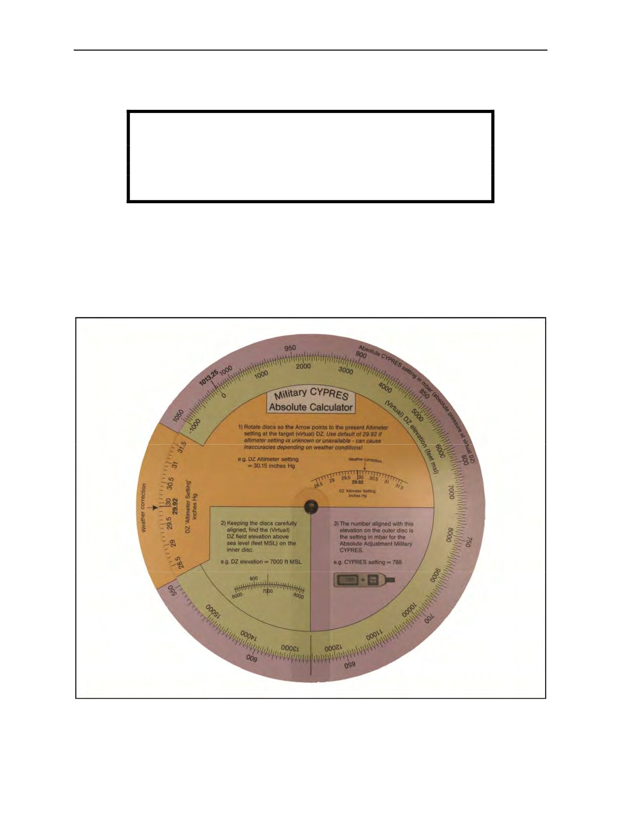
Chapter 3
z
Military CYPRES Web site: http://www.ssk.us/military_calc.asp.
z
Green digital Military CYPRES Calculator from SSK (Figure 3-35, page 3-27).
WARNING
Use of any other device to get the altimeter setting is
unauthorized; for example, Suunto, Kestrel, or other personal
device.
3-72. When on a mission with limited weather information, the aircrew can provide the altimeter setting
for the DZ en route to the drop area. The altimeter (pressure) setting is given in inches of Hg to the nearest
one-hundredth of an inch. The altimeter setting will always be for the intended DZ. Once the altimeter
setting of the intended DZ has been determined, the primary jumpmaster will use an approved CYPRES
calculator to determine the setting of each Military CYPRES 2 model on the mission. Once the primary
jumpmaster has determined the settings, the assistant jumpmaster will independently determine the settings.
If any discrepancy is found in the results, the primary and assistant jumpmasters will work together to
determine the correct settings.
Figure 3-33. Military CYPRES Absolute Adjust Circular Calculator (Whiz Wheel)
3-26
ATP 3-18.11/AFMAN 11-411(I)/NTTP 3-05.26M
24 October 2014
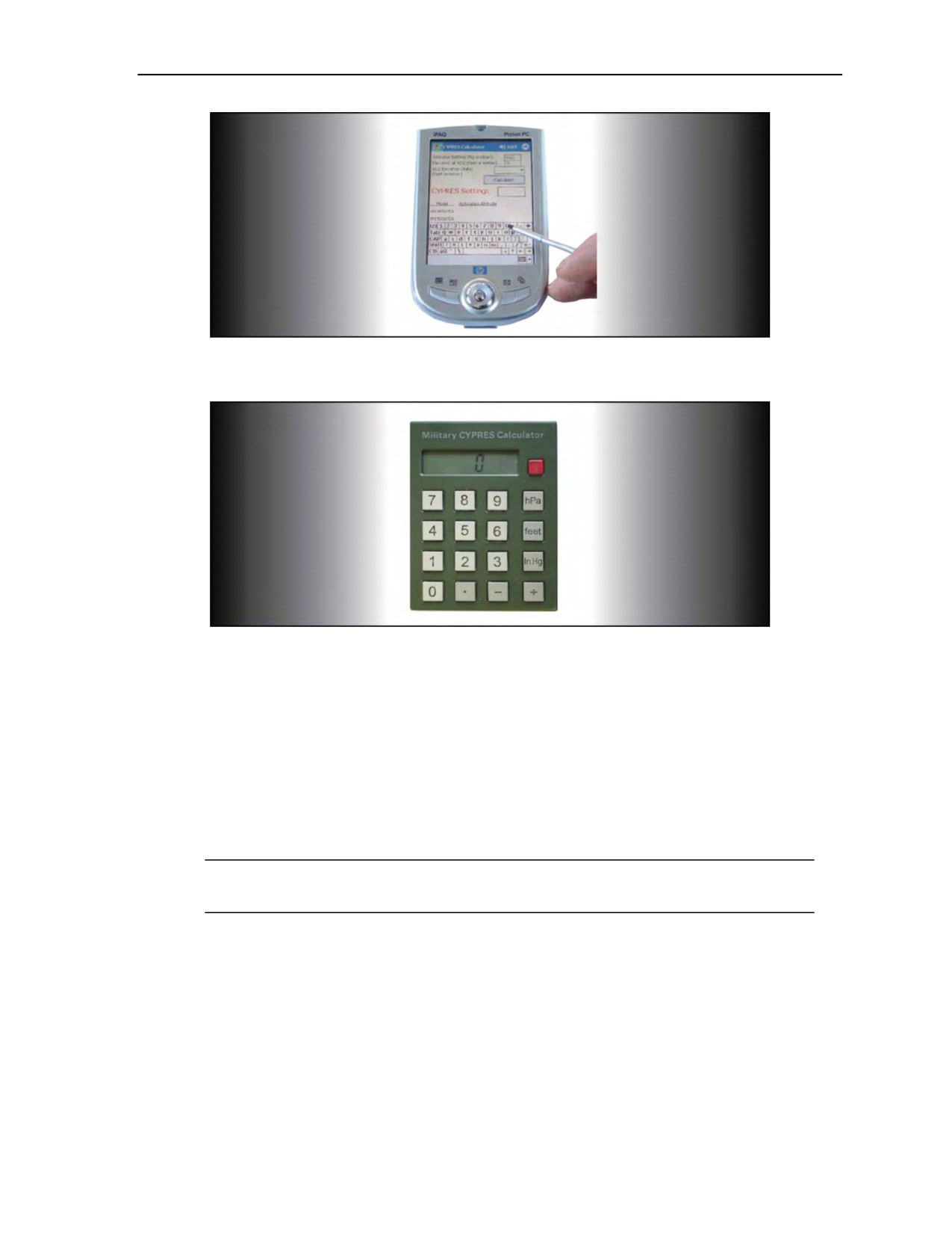
Cybernetic Parachute Release System
Figure 3-34. Personal Digital Assistant computer with Military CYPRES Absolute Model
Calculator software download
Figure 3-35. Military CYPRES Calculator
MILITARY CYPRES ABSOLUTE ADJUST CIRCULAR CALCULATOR
3-73. The jumpmaster obtains the forecasted aircraft altimeter setting for the DZ. If flying a mission with
limited weather information, the aircrew can provide the altimeter setting en route to the drop area. The
altimeter (pressure) setting will be given in inches of Hg. The jumpmaster obtains the setting to the nearest
one-hundredth of an inch. Using the Military Absolute Adjust Circular Calculator (Figure 3-36A, page
3-28), the jumpmaster determines the absolute adjust millibar setting by—
z
Rotating the discs so the weather correction (QNH) arrow points to the present aircraft altimeter
setting at the target (virtual) DZ. A default of 29.92 is used if the altimeter setting is unknown or
unavailable.
Note: This setting can cause inaccuracies depending on weather conditions; for example,
DZ altimeter setting = 30.15 inches of Hg (Figure 3-36B, page 3-28).
z
Keeping the discs carefully aligned, finding the VDZ field elevation above sea level (feet MSL)
on the inner disc, and placing the “clock hand” black indicator line on the ground elevation of
the desired (virtual) DZ (for example, DZ elevation = 7,100 feet) (Figure 3-36C, page 3-28). The
number aligned with this elevation on the outer disc is the setting in millibars for the absolute
adjustment for the Military CYPRES (example 787 millibars) (Figure 3-36C).
24 October 2014
ATP 3-18.11/AFMAN 11-411(I)/NTTP 3-05.26M
3-27
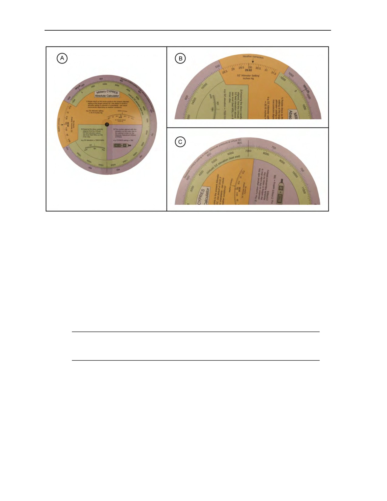
Chapter 3
Figure 3-36. Military CYPRES Absolute Adjust Circular Calculator
MILITARY CYPRES ABSOLUTE ADJUST MODEL CALCULATOR
3-74. All downloads (software programs) for the Military CYPRES Absolute Adjust Model Calculator can
be located at www.ssk.us. To use the online Military CYPRES Absolute Adjust Model Calculator,
jumpmasters may go to www.ssk.us/military_calc.asp. There is no one brand of calculator that must be
used for this application. The military does carry one iPAQ Pocket Personal Computer, National Stock
Number 5180-09-000-3952. The only requirement is that the Personal Digital Assistant or Pocket Personal
Computer have the proper software (example: Microsoft-based program, Excel) to accept downloading of
one of the following:
z
A zipped version of the Military Calculator for Microsoft Excel.
z
A nonzipped version of the Military Calculator for Microsoft Excel.
z
The Personal Digital Assistant versions of Military Calculator (Microsoft OS-VB, Win CE, and
Pocket Personal Computer).
Web page, right-clicks, then chooses “Save Target As” option for Internet Explorer or “Save
Link Target As” option for Netscape Navigator.
USING THE PERSONAL DIGITAL ASSISTANT AND/OR POCKET PERSONAL COMPUTER
3-75. If the atmospheric (absolute) air pressure values to perform the altitude adjustment are not known, it
is possible to do the altitude adjustment using the iPAQ Military CYPRES Absolute Calculator. This
calculator can be ordered separately. To use the Personal Digital Assistant and/or Pocket Personal
Computer, parachutists do the following:
z
Power ON the Personal Digital Assistant.
z
Enter the altimeter setting (Figure 3-37, page 3-29) of the location (in either Hg or millibars).
z
Enter the elevation at the VDZ (Figure 3-37) (in either feet or meters).
z
Select from the drop-down box the elevation scale (either feet or meters).
3-28
ATP 3-18.11/AFMAN 11-411(I)/NTTP 3-05.26M
24 October 2014
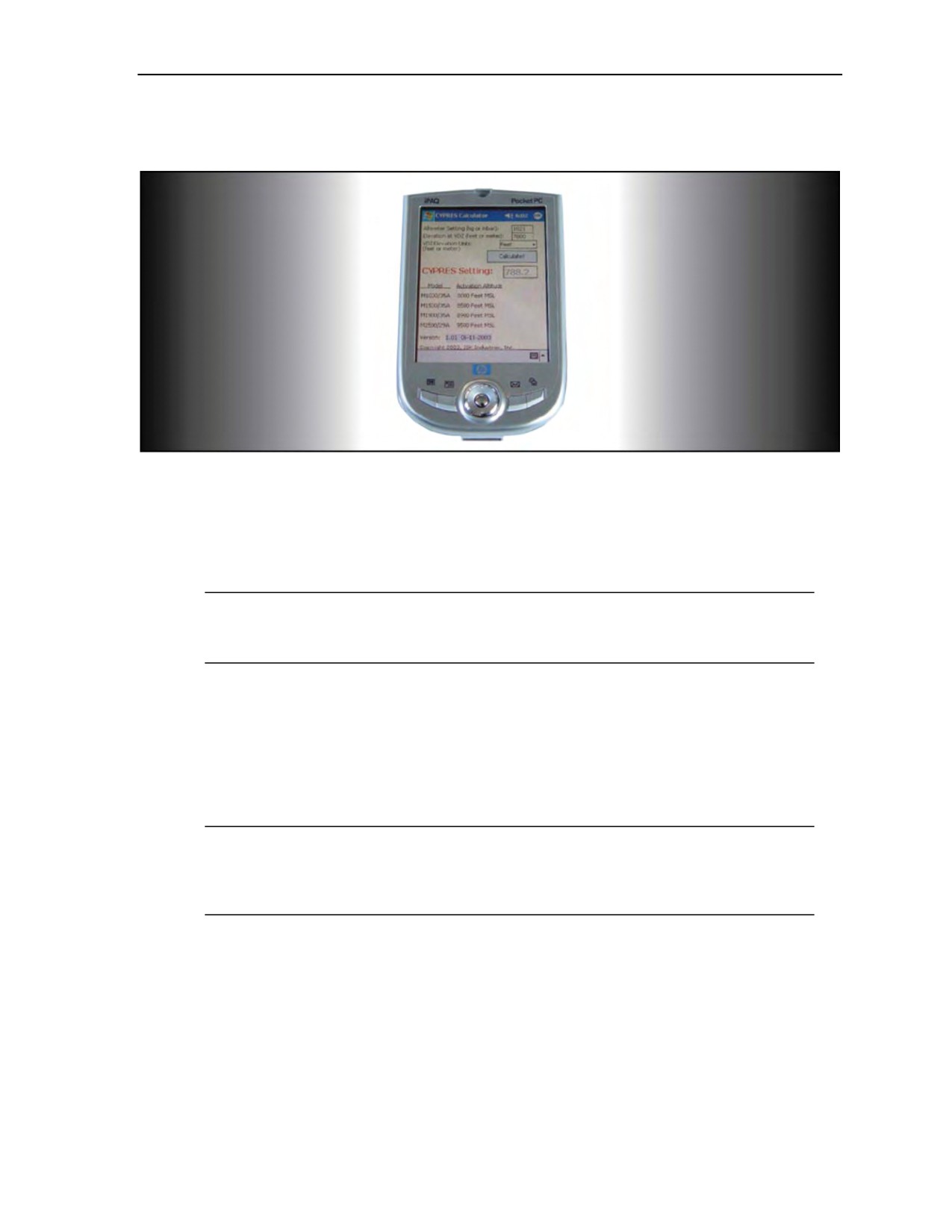
Cybernetic Parachute Release System
z
Click the ‘Calculate!’ button.
z
The value for the Military CYPRES setting (Figure 3-37) is displayed in the box.
Figure 3-37. Value for the Military CYPRES setting displayed in the CYPRES setting box
USING THE MILITARY CYPRES CALCULATOR
3-76. If the atmospheric (absolute) air pressure values to perform the altitude adjustment are not known, it
is possible to do the altitude adjustment using the Military CYPRES Calculator feet/hectopascal/inches of
Hg developed by Airtec. This calculator can be ordered separately (meter scale also available).
Note: If jumpmasters want to set a Military CYPRES 2 in operational mode and nobody is able
to tell them the air pressure of their target, then they should use the Military CYPRES calculator,
or go to the Military CYPRES User’s Guide at www.ssk.us.
Figure 3-38, page 3-30, shows the usage instructions located on the back of the Military CYPRES
calculator.
USING THE ON-LINE MILITARY CYPRES ABSOLUTE ADJUST MODEL CALCULATOR
3-77. Parachutists may go to www.ssk.us/military_calc.asp and click to use the online “Military CYPRES
Absolute Adjust Model Calculator” on the SSK Military Industries, Inc. home page. Figures 3-39 to 3-43,
pages 3-30 through 3-32, show examples of the online calculator.
Note: Parachutists must use this calculator with “Absolute Adjustment” Military CYPRES units
only (“Abs. Adj.” nomenclature on control unit). Detailed procedures are in the Absolute
Adjustment Military CYPRES User’s Guide, as well as additional information on how to utilize
all of the CYPRES capabilities.
24 October 2014
ATP 3-18.11/AFMAN 11-411(I)/NTTP 3-05.26M
3-29
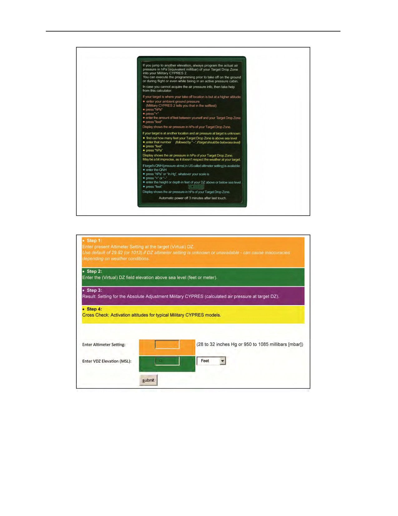
Chapter 3
Figure 3-38. Usage instructions for the Military CYPRES calculator
Figure 3-39. Instructions and first page of online “Military CYPRES
Absolute Adjust Model Calculator”
3-30
ATP 3-18.11/AFMAN 11-411(I)/NTTP 3-05.26M
24 October 2014
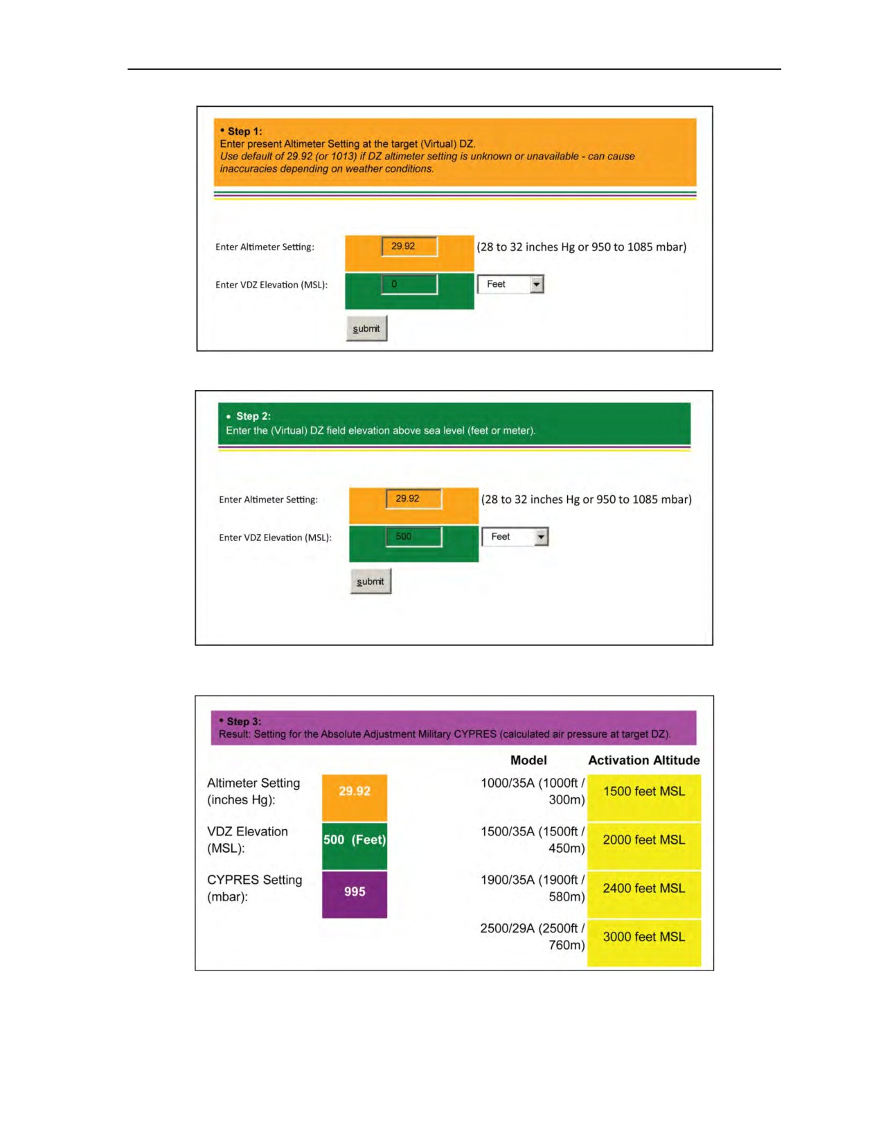
Cybernetic Parachute Release System
Figure 3-40. Step 1: Military CYPRES Absolute Adjust Model Calculator
Figure 3-41. Step 2: Military CYPRES Absolute Adjust Model Calculator
Figure 3-42. Step 3: Military CYPRES Absolute Adjust Model Calculator
24 October 2014
ATP 3-18.11/AFMAN 11-411(I)/NTTP 3-05.26M
3-31
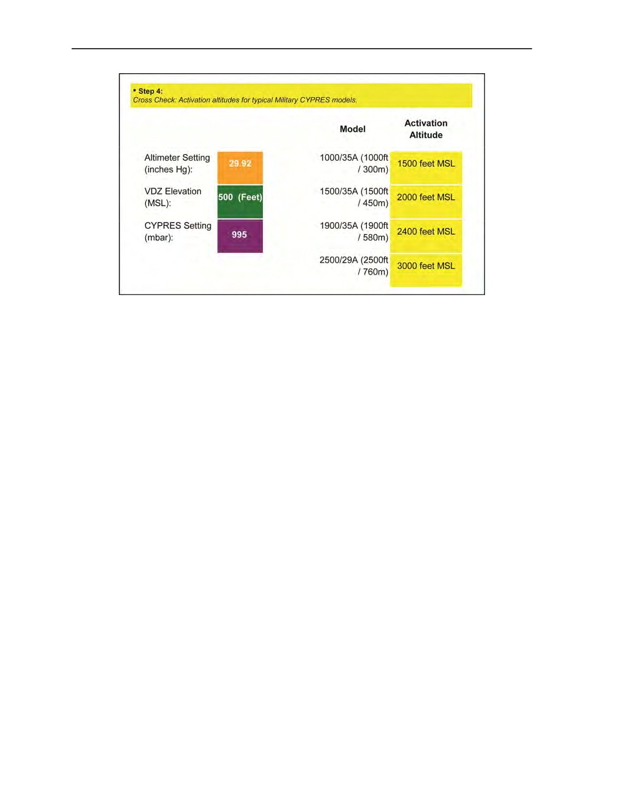
Chapter 3
Figure 3-43. Step 4: Military CYPRES Absolute Adjust Model Calculator
MILITARY CYPRES COMMERCIAL AIR TRAVEL
3-78. A CYPRES-equipped rig may be transported in freight and passenger airplanes without restrictions.
All of its components (for example, electronics, power supply, loop cutter, control unit, plugs, cables, and
casing), as well as the complete system, contain parts and materials that are approved by the
U.S. Department of Transportation and other competent agencies worldwide, and are not subject to any
transport regulations. Because of the size of a rig, it is recommended to check it in as normal luggage and
not take it on board as hand luggage. In case of questions or objections from the security personnel,
parachutists should use the card in Figure 3-44, page 3-33. The card shows an X-ray of a complete rig with
the Military CYPRES 2. Depending on type and design of the rig, the X-ray on the security’s screen may
vary. Presently, the Parachute Industry Association and the United States Parachute Association are
working with the Transportation Security Agency concerning traveling with parachutes.
3-32
ATP 3-18.11/AFMAN 11-411(I)/NTTP 3-05.26M
24 October 2014
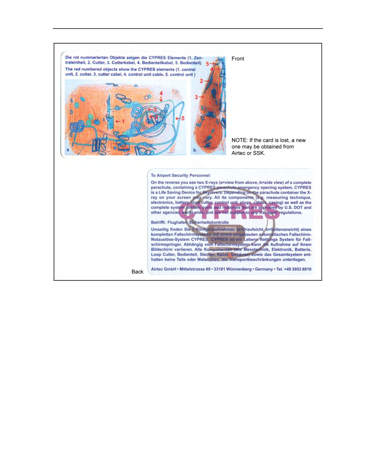
Cybernetic Parachute Release System
Figure 3-44. Military CYPRES 2 air travel card
24 October 2014
ATP 3-18.11/AFMAN 11-411(I)/NTTP 3-05.26M
3-33

This page intentionally left blank.

Chapter 4
Use of Oxygen in Support of Military
Free-Fall Operations
MFF parachuting is physically demanding. It exposes the parachutist to temperature
extremes, rapid pressure changes, and long exposures at altitudes requiring
supplemental oxygen. To prepare for this environment, the MFF parachutist must be
thoroughly familiar with the physiological effects of oxygen, oxygen use, and the
operation of oxygen equipment. All personnel participating in MFF operations must
meet the physiological training requirements outlined in Appendix B, regardless of
altitude and type of aircraft used.
OXYGEN HANDLING AND SAFETY
4-1. Because of the limited contact with oxygen and its handling, personnel may not fully appreciate the
danger involved. Improper use and handling can result in property damage, serious injury, and death.
Personnel handling oxygen should always adhere to the warnings provided below.
DANGER
Keep oil and grease away from oxygen. Do not handle oxygen equipment
with greasy hands or clothing.
No substance will be in the mouth of any jumper while on life-support
equipment (oxygen) at any time, to include smokeless tobacco (dip),
chewing gum, or food.
Keep equipment clean and free from petroleum-based products,
lubricants, hydraulic fluid, and dirt. A drop of oil or lubricant coming in
contact with pure oxygen under certain circumstances can cause an
explosion.
Keep oxygen away from any source of ignition or fire and/or flame. Small
fires rapidly become large fires in the presence of oxygen supplies.
Never permit smoking near oxygen equipment, while handling oxygen
supplies, or when using oxygen life-support equipment.
Handle cylinders and valves with extreme caution. Before opening
cylinder valves, ensure cylinder is firmly supported. Never drop or tip
over an oxygen cylinder. Dropping a cylinder can damage or break the
valve, allowing gas to escape under pressure, with the potential for
propelling the cylinder a great distance and with great force. Only open
and close oxygen valves by hand and never strike the valve with any tool
or object to loosen it. If the parachutist or technician cannot open and
close the oxygen valve by hand, the cylinder must be returned to the
depot for repair.
24 October 2014
ATP 3-18.11/AFMAN 11-411(I)/NTTP 3-05.26M
4-1

Chapter 4
PHYSIOLOGICAL EFFECTS OF HIGH-ALTITUDE
MILITARY FREE-FALL OPERATIONS
4-2. Most physiological effects of high-altitude MFF operations fall into the category of pressure-change
hazards. These hazards usually include various physiological symptoms. Based on Class C physiological
mishaps since
1984, the most common types have been sinus blocks and ear blocks, hypoxia,
decompression sickness, and hyperventilation. Each of these symptoms is discussed in the following
paragraphs. Procedures for physiological and oxygen equipment-related emergencies are also discussed.
SINUS BLOCKS AND EAR BLOCKS
4-3. Sinus blocks and ear blocks normally occur when an MFF parachutist jumps with a head cold or
some other type of upper respiratory illness. Sinus blocks and ear blocks usually occur during free-fall
descent or during aircraft pressurization. Performing a Valsalva maneuver as the parachutist feels his ears
getting “full” can clear most ear blocks. A Valsalva maneuver may clear a sinus block but may require
additional medical attention. Use of nasal sprays may alleviate the symptoms associated with sinus and ear
blocks.
Note: Chewing gum will not be used to clear blocked ears when wearing the oxygen mask.
HYPOXIA
4-4. Hypoxia is a condition caused by lack of oxygen. A reduction in the partial pressure of oxygen in the
atmosphere occurs as the parachutist ascends. When the parachutist inhales, he receives fewer oxygen
molecules. The reduction of the partial pressure inhibits the body’s ability to transfer oxygen to the tissues.
The most common symptoms of hypoxia are blurred or tunnel vision, color blindness, dizziness, headache,
nausea, numbness, tingling, euphoria, belligerence, loss of coordination, and lack of good judgment.
Corrective action for a parachutist who becomes hypoxic is to place him on 100-percent oxygen and inform
the jumpmaster and/or physiological technician. In extreme cases, it may be necessary to descend the
aircraft and evacuate the parachutist to the nearest medical facility. If hypoxia goes unrecognized and
uncorrected, it can result in seizures, unconsciousness, or even death.
DECOMPRESSION SICKNESS
4-5. Decompression sickness is a condition caused by the release of nitrogen from body tissues. It usually
occurs during unpressurized flights above 18,000 feet MSL, but can occur at lower altitudes. Many factors
contribute to decompression sickness. Facial hair can cause an insufficient seal of the oxygen mask to the
parachutist’s face, rendering prebreathing ineffective. Poor physical conditioning and fatigue will make the
individual more susceptible to decompression sickness. Alcohol use dehydrates the body, constricting the
capillaries and decreasing the efficiency of the cardiovascular system. Nicotine from tobacco use hardens
arteries and restricts blood flow to the capillaries, reducing the efficiency of the cardiovascular system.
Smoking also reduces the efficiency of the lungs. Parachutists should know the symptoms of
decompression sickness and constantly monitor themselves on board the aircraft and after return to the
ground. Some parachutists may have symptoms of decompression sickness during flight that are not readily
noticeable. Minor symptoms may be confused with discomfort from the parachute and equipment. Other
individuals may choose not to report what may be considered to be minor problems. Although these
symptoms usually resolve upon the jumper’s return to ground, some personnel may continue to have
symptoms. These individuals require prompt medical evaluation since their illness is more severe.
4-2
ATP 3-18.11/AFMAN 11-411(I)/NTTP 3-05.26M
24 October 2014

Use of Oxygen in Support of Military Free-Fall Operations
WARNING
If untreated, decompression sickness may result in debilitating
and/or permanent medical disorders.
4-6. There are four types of decompression sickness: the bends, chokes, neurological (central nervous
system) hits, and skin manifestations. Each of these is discussed in the following paragraphs.
The Bends
4-7. The bends are the most common type of decompression sickness. The most frequent symptom is a
deep, dull, and penetrating pain in major movable joints that can increase to agonizing intensity. This pain
may be significant enough to make the parachutist feel as if he cannot move the joint. The affected
parachutist might also go into shock. Corrective action for a parachutist who experiences the bends is to—
z
Place him on 100-percent oxygen.
z
Inform the jumpmaster and/or physiological technician.
z
Descend the aircraft and pressurize the cabin to as close to sea level as possible.
z
Evacuate to the nearest medical facility with a recompression chamber. A flight surgeon or
aeromedical examiner will determine if compression therapy is required.
The Chokes
4-8. The chokes are a rare but potentially life-threatening form of decompression sickness. They are
similar to the bends, but occur in the smaller blood vessels of the lungs, resulting in poor gas exchange and
oxygenation of the blood. The most common symptoms are a deep, sharp pain near the breastbone; a dry,
nonproductive cough; the inability to take a normal breath; a feeling of suffocation and apprehension; and
possible shock symptoms, such as sweating, fainting, and cyanosis. Corrective action for a parachutist who
experiences the chokes is the same as that stated for the bends in paragraph 4-7.
Neurological Hits
4-9. Neurological hits occur in extreme cases of decompression sickness when the central nervous system
becomes affected. The affected parachutist may experience vision disturbances, headaches, partial
paralysis, loss of orientation, delirium, and vertigo. Corrective action for a parachutist who experiences
neurological hits is the same as that stated for the bends in paragraph 4-7.
Skin Manifestations or Paresthesia
4-10. Skin manifestations or paresthesia is caused by nitrogen bubbles forming at the subcutaneous layer of
the skin. The most common symptoms are itching, hot and cold flashes, a creepy feeling or gritty sensation,
mottled reddish or purplish rash, and a tingling feeling of the affected area. Corrective action for a
parachutist who experiences any of these symptoms is to—
z
Place him on 100-percent oxygen.
z
Keep him from scratching or exercising the affected area.
z
Inform the jumpmaster and/or physiological technician.
4-11. Normally, the condition will dissipate upon descent. However, if the parachutist is incapacitated due
to the condition, further corrective action is to—
z
Descend the aircraft and pressurize the cabin to as close to sea level as possible.
z
Evacuate to a medical facility with a recompression chamber. A flight surgeon or aeromedical
examiner will determine if compression therapy is required.
24 October 2014
ATP 3-18.11/AFMAN 11-411(I)/NTTP 3-05.26M
4-3

Chapter 4
HYPERVENTILATION
4-12. Hyperventilation is a condition characterized by abnormal shallow and rapid breathing. Fear, anxiety,
stress, intense concentration, or pain normally causes hyperventilation. Symptoms are similar to hypoxia
and include lightheadedness, visual impairment, dizziness, numbness and tingling of the extremities, and
loss of coordination and judgment. Personnel should conduct the following corrective actions:
z
Calm the parachutist and have him talk, which will make him reduce his rate and depth of
breathing. The goal is to achieve a breathing rate of 12 to 16 breaths per minute.
z
Because of the similarity to hypoxia, continue or place him on 100-percent oxygen.
z
Inform the jumpmaster and/or physiological technician.
z
Reevaluate the parachutist’s conscious state. If he is not responsive, treat the situation as an
in-flight emergency and evacuate the parachutist to the nearest medical facility.
PHYSIOLOGICAL AND OXYGEN EQUIPMENT-RELATED EMERGENCIES
4-13. Procedures for physiological and oxygen equipment-related emergencies are discussed below.
Personnel should—
z
For in-flight emergencies, make sure the jumpmaster, oxygen safety technician, and aircraft
commander (also USAF physiological technician if flight is above 20,000 feet MSL) are made
aware of the problem.
z
Ensure that the parachutist is receiving 100-percent oxygen from the console, the walk-around
bottle, or an onboard aircraft regulator.
z
Attempt to establish communications with the parachutist. Identify the problem and take
corrective actions, to include immobilizing the affected areas, if possible.
z
If the problem becomes progressive or severe, inform the aircraft commander of the nature of the
problem and declare an in-flight emergency.
z
Descend the aircraft and pressurize the cabin to as close to sea level as possible.
z
Evacuate to a medical facility with a recompression chamber. A flight surgeon or aeromedical
examiner will determine if compression therapy is required.
4-14. Parachutists should know the symptoms of decompression sickness and monitor themselves on return
to the ground. Some parachutists may have symptoms of decompression sickness during flight that they do
not notice due to discomfort from the parachute and equipment worn or that they do not report. Although
these symptoms usually resolve upon returning to ground, some personnel may continue to have symptoms.
These personnel require prompt medical evaluation since their illness is more severe.
OXYGEN FORMS
4-15. Oxygen is an odorless, colorless, tasteless gas that makes up 21 percent of the atmosphere. The
remaining atmosphere consists of 78-percent nitrogen and 1 percent of other trace gases. There are four
types of oxygen in use today—aviation, medical, welding, and research. Aviation oxygen is the only one
suitable for MFF operations. The following paragraphs discuss the various forms of aviator’s oxygen and
their associated containers.
GASEOUS OXYGEN
4-16. Gaseous aviator’s breathing oxygen is designated Grade A, Type I, Military Specification
MIL-0-27210E. No other manufactured oxygen is acceptable. The difference between aviator’s and
medical or technical (welder’s) oxygen is the absence of water vapor. The purity requirement for aviator’s
oxygen is 99.5 percent by volume. It may not contain more than 0.005 milligram of water vapor per liter at
760 millimeters of Hg at 68 degrees Fahrenheit. It must be odorless and free from contaminants, including
drying agents. The other types of oxygen may be adequate for breathing, but they usually contain excessive
4-4
ATP 3-18.11/AFMAN 11-411(I)/NTTP 3-05.26M
24 October 2014

Use of Oxygen in Support of Military Free-Fall Operations
water vapor that, with the temperature drop encountered at altitude, could freeze and restrict the flow of
oxygen through the oxygen system the parachutist uses. The two types of gaseous aviator’s breathing
oxygen are as follows:
z
Gaseous—Low-Pressure. Low-pressure aviator’s breathing oxygen is stored in yellow,
lightweight, shatterproof cylinders. These cylinders are filled to a maximum pressure of
450 pounds per square inch
(psi); however, they are normally filled in the range of
400 to 450 psi. They are considered empty when they reach 100 psi. If a cylinder is stored at a
pressure less than 50 psi for more than 2 hours, it must be purged because of the water
condensation that forms.
z
Gaseous—High-Pressure. High-pressure aviator’s breathing oxygen is stored in lime green,
heavyweight, shatterproof bottles stenciled with AVIATOR’S BREATHING OXYGEN. These
bottles can be filled to a maximum pressure of 2,200 psi; however, they are normally filled in the
range of 1,800 to 2,200 psi.
LIQUID OXYGEN
4-17. Liquid aviator’s breathing oxygen is designated Grade B, Type II, Military Specification
MIL-0-27210E. The most common use of liquid oxygen is in storage facilities and for aircraft oxygen
supplies because a large quantity can be carried in a small space.
OXYGEN REQUIREMENTS
4-18. The lower density of oxygen at high altitude causes many physiological problems. For this reason,
MFF parachutists and aircrews need additional oxygen. Table 4-1, page 4-6, contains USAF-established
requirements for supplemental oxygen for the MFF parachutist during unpressurized flight.
AFI 11-409 outlines these requirements. The following briefly describe the requirements:
z
All personnel will prebreathe 100-percent oxygen at or below 16,000 feet MSL pressure or cabin
altitude below 16,000 feet MSL pressure on any mission scheduled for a drop at or above
20,000 feet MSL.
z
The required prebreathing time will be completed before the 20-minute warning and before the
cabin altitude ascends through 16,000 feet MSL.
z
Any break in prebreathing requires restarting the prebreathing period or removing the
individuals whose prebreathing was interrupted from the mission.
z
Prebreathing requires the presence of sufficient USAF physiological technician support onboard
the aircraft.
z
All personnel onboard during unpressurized operations above 10,000 feet MSL and higher will
use oxygen.
(Exception: Parachutists may operate without supplemental oxygen during
unpressurized flights up to 13,000 feet MSL provided the time above 10,000 feet MSL does not
exceed 30 minutes each sortie.)
Note: Portable oxygen bottles or locally procured oxygen systems may not be used for
prebreathing; the quick-don and/or smoke mask is emergency equipment and is not approved for
prebreathing or other parachute operations conducted at or above 13,000 feet MSL.
4-19. MFF parachuting is physically demanding. The higher jump altitudes associated with MFF
operations expose the body to rapid pressure changes that require the use of supplemental oxygen. As a
result, the MFF parachutist must—
z
Conduct no more than three prebreather sorties in a 24-hour period.
z
Not conduct MFF operations within 24 hours of making a nonoxygen dive.
z
Wear a clear face shield or goggles on MFF operations that require prebreathing.
Note: The jumpmaster and the oxygen safety technician must be able to see the eyes of the
jumpers to determine if they are having any physiological problems.
24 October 2014
ATP 3-18.11/AFMAN 11-411(I)/NTTP 3-05.26M
4-5

Chapter 4
Table 4-1. Supplemental oxygen requirements for military free-fall parachutists
Maximum
Oxygen
Prebreathe
Altitude
Exposure Time
Requirement
Time*
per Sortie**
Below 10,000 ft MSL
N/A
N/A
N/A
Supplemental Oxygen
Required Only When
10,000 ft to 12,999 ft MSL
Supplemental
N/A
Time Exceeds
30 Minutes
13,000 ft to 19,999 ft MSL
Supplemental
N/A
Unlimited
20,000 ft to 24,999 ft MSL
100-Percent Oxygen
30 Minutes
110 Minutes
25,000 ft to 29,999 ft MSL
100-Percent Oxygen
30 Minutes
60 Minutes
30,000 ft to 34,999 ft MSL
100-Percent Oxygen
45 Minutes
30 Minutes
***
35,000 ft MSL or Above
100-Percent Oxygen
75 Minutes
30 Minutes
NOTES:
* No more than 3 prebreather sorties in a 24-hour period unless otherwise restricted.
** Maximum exposure time per sortie is when cabin altitude reaches maximum planned altitude; extended or
delayed ascent times expose everyone onboard to greater risk of decompression sickness. Missions that
require staggered altitude drops will use accumulative times per sortie information for mission planning.
Example: Mission-planned drops at 35,000 ft MSL, 29,999 ft MSL, and 24,999 ft MSL: 30 minutes upon
reaching 35,000 ft MSL, descend to 29,999 ft MSL—spend only 30 minutes (60 accumulative); descend to
24,999 ft MSL—spend only 50 minutes (110 minutes accumulative).
*** No personnel will be exposed to unpressurized flight above 30,000 ft MSL more than 3 times each 7 days
and must have a minimum of 24 hours between exposures.
OXYGEN LIFE-SUPPORT EQUIPMENT
4-20. Life-support equipment consists of the oxygen mask (MBU-12/P), the portable bailout oxygen
system with the AIROX VIII assembly, the Parachutist Oxygen Mask (POM) with the portable bailout
Parachute Oxygen System, the six-man prebreather portable oxygen system, the MA-1 portable oxygen
assembly, and the prebreather attachment. This equipment is discussed in the paragraphs below.
OXYGEN MASK
4-21. The oxygen mask is designed to be worn with parachutist helmets that have bayonet lug receivers for
the mask’s harness assembly or by utilizing the improved oxygen harness (referred to as “skull cap”) to
attach the mask when wearing the ACH. Oxygen enters the face piece through the valve located at the front
of the mask. Exhaled air passes out through the same valve. The construction of the valve’s exhalation port
allows a pressure of only 1 millimeter of Hg greater than the pressure of the oxygen being supplied by the
regulator to force open the valve and allow exhaled air to pass to the atmosphere. A 17.5-inch-long
convoluted silicone hose with a 3/4-inch internal diameter attaches to the mask. Inside the hose is an
antistretch cord that prevents extreme stretching and hose separation during free fall. The mask has an
integral microphone that adapts to the aircraft’s communication system.
4-6
ATP 3-18.11/AFMAN 11-411(I)/NTTP 3-05.26M
24 October 2014

Use of Oxygen in Support of Military Free-Fall Operations
WARNING
No type of petroleum, oils, and lubricant products (commercial
sunblock, camouflage paint, and lip balm) will be used by MFF
parachutists while on oxygen life-support equipment.
Note: No substance will be in the mouth of any jumper while on oxygen life-support equipment,
to include smokeless tobacco (dip), chewing gum, or food.
4-22. There are several types of oxygen masks currently in use by different Services. The most common of
these masks are described below.
MBU-12/P
4-23. The MBU-12/P pressure-demand oxygen mask is a replacement for the MBU-5/P mask
(Figure 4-1, page 4-8). It has a soft, supple silicone rubber face piece integrally bonded to a plastic hard
shell. It seals firmly during pressure breathing. It comes in four sizes to provide proper fit and superior
comfort during extended wear. The lower profile design and four-point suspension are more stable than the
MBU-5/P mask during free fall. Antiroll webs at the nose seal prevent downward roll-off. The integral face
piece and hard shell design permit good downward vision and increased head mobility. The MBU-12/P
oxygen mask was a system originally designed and produced as an aviator’s oxygen mask. Its oxygen hose
can be mistaken for a ripcord, which is hazardous. The POM system will replace the MBU-12/P system.
Parachutist Oxygen Mask
4-24. The POM breathing-demand oxygen mask is an in-flight oxygen breathing device used either with a
flight helmet and microphone or with a quick-don suspension assembly called the improved oxygen
harness. These masks are manufactured by Gentex Corporation and Carleton Technologies. The POM mask
is available in four sizes, indicated by the marking on the outer edge of the soft shell. The four sizes are
small narrow, medium narrow, medium wide, and large wide. The POM connects to the portable
prebreather assembly and the 106-cubic-inch portable oxygen system through use of the Hydraflow
HS-57 oxygen breathing hose to ensure unrestricted oxygen. The PHANTOM mask and regulator assembly
combines the latest Gentex parachutist oxygen mask
(ParaMaster HALO and/or HAHO) with a
high-performance Carleton miniature oxygen regulator. The PHANTOM system is much more comfortable
and provides significantly improved performance over existing systems. The Gentex mask includes a high-
flow, noncompensated exhalation valve along with an integral antisuffocation valve to protect the user in
the event of oxygen supply depletion. The Carleton miniature regulator installs directly into the standard
inlet port of the Gentex mask. The universal compatibility of Carleton's equipment eliminates the cost and
logistics problems that would typically come with the development of a custom mask. The regulator can be
installed or removed in under 30 seconds, which lends itself to improved maintainability and reliability.
24 October 2014
ATP 3-18.11/AFMAN 11-411(I)/NTTP 3-05.26M
4-7
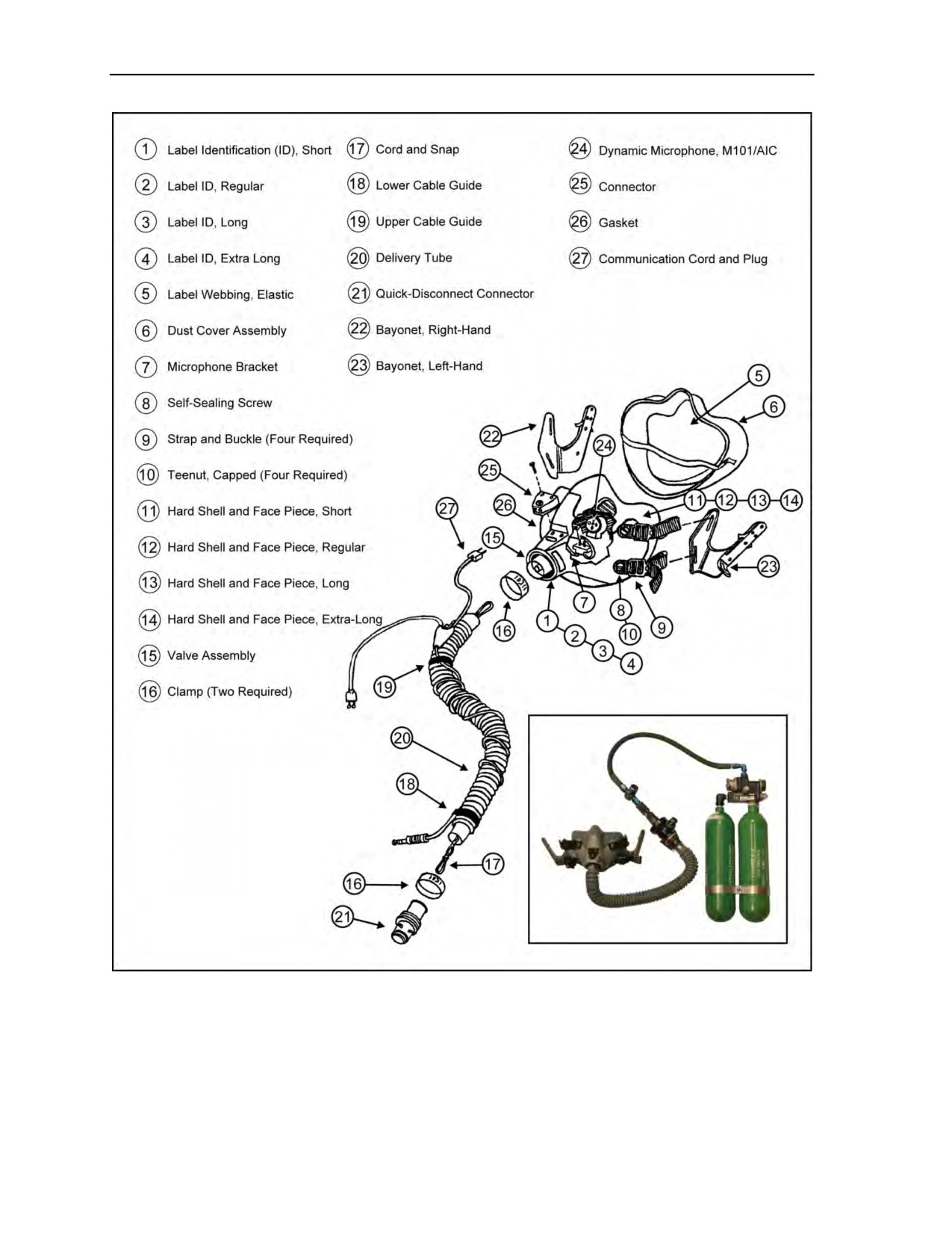
Chapter 4
Figure 4-1. MBU-12/P pressure-demand oxygen mask components
4-25. The POM provides the parachutist with a high oxygen-flow capacity to improve breathing comfort
during long missions with an automatic dilution shut-off feature when connected to a prebreathing console.
Figure 4-2, page 4-9, shows the POM.
4-8
ATP 3-18.11/AFMAN 11-411(I)/NTTP 3-05.26M
24 October 2014
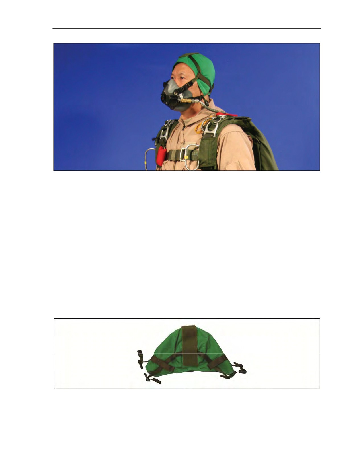
Use of Oxygen in Support of Military Free-Fall Operations
Figure 4-2. Parachutist Oxygen Mask
4-26. The POM has a high-flow, noncompensated exhalation valve and an integral antisuffocation valve to
protect the parachutist in the event of oxygen supply depletion. There is a diffuser over the inhalation valve
of the regulator to provide improved mixing of the oxygen in the mask. The mask allows the jumpers to
pinch their nostrils and perform a Valsalva maneuver in order to release sinus pressure. The configuration
of the screws and nuts used to fix the mask attachment straps are designed in a way to reduce rotational
friction and ease maintenance.
Improved Oxygen Harness (Skull Cap)
4-27. The improved oxygen harness was designed specifically for use with the POM and ACH during MFF
operations. The improved oxygen harness (Figure 4-3) is fabricated from absorbent cotton polyester fabric,
tubular nylon straps, hook-pile tape (HPT) (Velcro), and Fastex buckles. The improved oxygen harness is
worn directly on the parachutist’s head underneath the ACH. After donning the ACH over the improved
oxygen harness, the parachutist mounts the POM by attaching the four half-inch Fastex buckles attached at
each end of the 1/2-inch tubular nylon straps. The straps with Fastex buckles are fully adjustable to
accommodate a wide range of face and head shapes. The improved oxygen harness also contains sizing
channels made of 2-inch-wide pile tape sewn down the center of the cap. When worn with communication
equipment (Figure 4-4, page 4-10) (for example, the MICH), the headset will sit between the ACH and
improved oxygen harness (skull cap).
Figure 4-3. The improved oxygen harness
24 October 2014
ATP 3-18.11/AFMAN 11-411(I)/NTTP 3-05.26M
4-9

Chapter 4
Figure 4-4. Complete Parachutist Oxygen Mask with MICH
Advanced Combat Helmet Accessory Rail Connector
4-28. The advanced combat helmet-accessory rail connector
(ACH-ARC) provides accessory direct
mounting for ACH-style ballistic helmets. Rails and accessories are secured during MFF, combat
movement, or tactical use. The ACH-ARC’s low-profile, lightweight, snag-free design mount addition does
not impede mobility and incorporates a dynamic breakaway feature to help prevent head and neck injury
when exposed to extreme torque with no permanent damage to the unit. Tough, fiber-reinforced rails bolt
directly to the helmet, holding a slide-and-lock Picatinny adapter for mounting of the POM with the
additional plug-in oxygen mask receptacles (Figure 4-5, page 4-11). The straps with Fastex buckles are
fully adjustable to accommodate a wide range of face and head shapes for proper fit of the POM. The rail
connector also contains Picatinny adapter locks and sizing channels that are slot-triggered for ease of
tightening, loosening, and fitting the oxygen mask. The ACH-ARC—
z
Does not require drilling; it uses existing chinstrap mounting holes.
z
Fits ACH, MICH, TC 2000, and MICH 2002 gunfighter helmets in sizes medium to extra large.
z
Does not fit the MICH 2001 (high ear-cut) helmet or the enhanced combat helmet.
z
Includes the oxygen single-strap kit or the oxygen double-strap kit (Figure 4-5) for mounting the
POM and the MBU-12/P oxygen mask.
4-29. In accordance with Headquarters, U.S. Army Developmental Test Command memorandum, subject:
Safety Confirmation for the Advanced Combat Helmet (ACH) in Support of Materiel Release and Fielding,
dated 21 June 2011, the following precautions should be followed for use of the ARC, the oxygen single-
strap kit, and the oxygen double-strap kit with the ACH during MFF operations:
z
MFF parachutists should ensure they are fitted with the correct size helmet and follow fit and wear
instructions in accordance with TM 10-8470-204-10.
z
Preventive maintenance checks and services procedures found in the ACH TM should be used
for the ACH and the ARC. Users must check for loose or missing screws. Missing screws should
be replaced and loose screws should be tightened. If screws remain loose, they should be secured
with thread-locking compound, National Stock Number 8030-01-104-5392.
z
Prior to rigging for MFF, each parachutist and the MFF jumpmaster should—
Inspect the strap kit for frayed or cut webbing, cracked or damaged plastic components, and
inoperable head-lock tabs. All damaged items should be replaced and the strap kit
reinspected before use.
Inspect the strap kit and ensure the swivel clips are securely fastened to the webbing, the
swivel clip securely locks into the accessory rail connector tab, accessory rail connector tab
securely locks into the accessory rail, and the rear-strap buckle and/or front-pull release
buckle are operable. Parachutist should remount and reinspect all incorrectly or loosely
mounted items and/or replace broken or defective components.
4-10
ATP 3-18.11/AFMAN 11-411(I)/NTTP 3-05.26M
24 October 2014
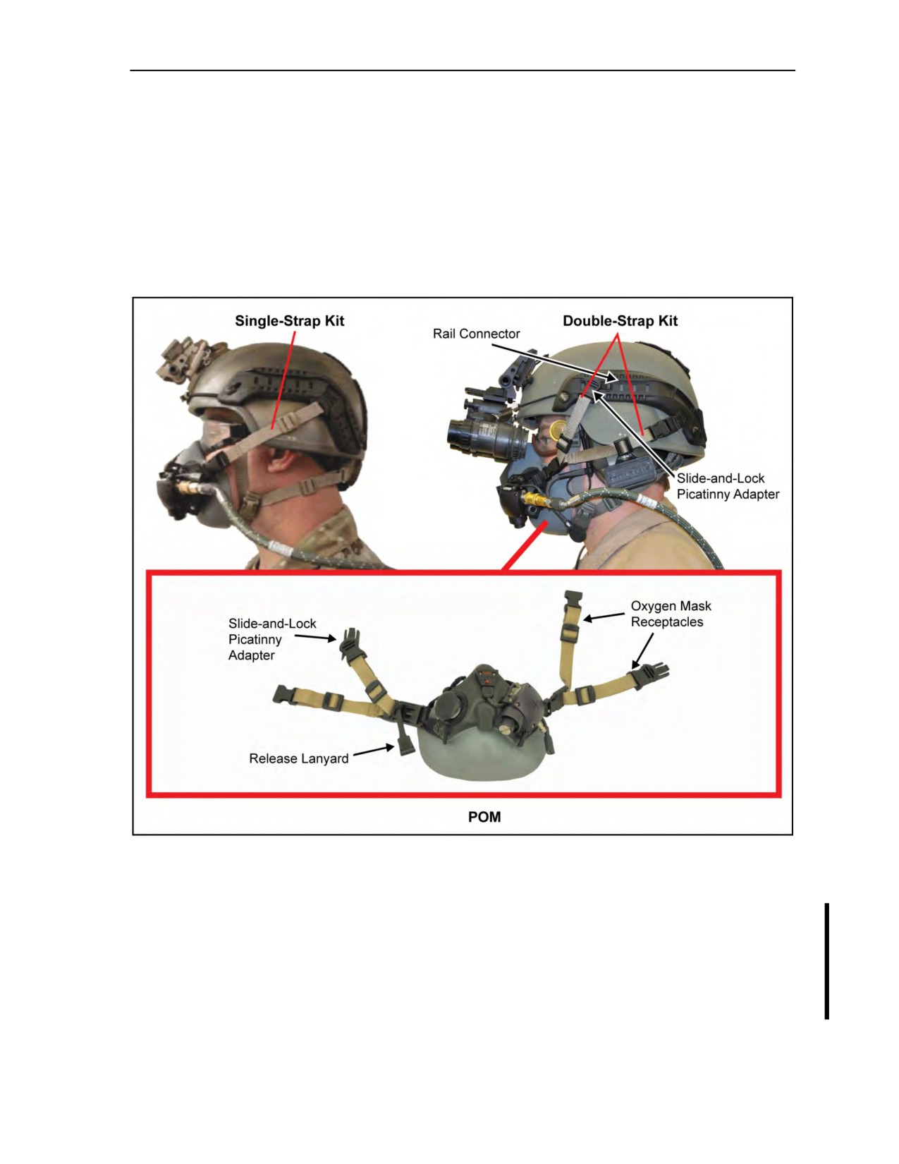
Use of Oxygen in Support of Military Free-Fall Operations
Ensure the rear-strap buckle and/or front-pull release buckle are correctly inserted and the
corresponding strap is not twisted. If the strap is incorrectly inserted and/or twisted, the
parachutist should remove the buckle, rotate 180 degrees, reinsert, and then reinspect the
buckle and strap assembly.
Inspect the ARC for cracked or damaged plastic components, inoperable swivel clips, and
inoperable ARC tab adapters. Parachutist should replace all damaged items that fail to lock
in place.
z
Solvents and steel or metal bristle brushes may damage the ARC and strap kit. Parachutist
should only use a medium bristle brush and/or mild detergent to clean soil and debris from the
rail system and its components.
Figure 4-5. Advanced combat helmet accessory rail connector with oxygen
single-strap and double-strap kits
Parachutist Oxygen Mask Securing Lanyard
4-30. The POM securing lanyard (Figure 4-5a, page 4-12) was added to keep the oxygen mask from
becoming detached during free fall and floating behind the parachutist’s head. The POM securing lanyard
should be attached to the mask on the left bottom attaching strap. The chinstrap is routed through the
securing lanyard. The securing lanyard should be made from a section of gutted 550 cord and secured by
tying a nonslipping knot. Reference Appendix G (paragraph G-4) for JMPI procedures for the POM
securing lanyard inspection.
18 August 2016
ATP 3-18.11/AFMAN 11-411(I)/NTTP 3-05.26M, C2
4-11
//////////////////////////////////////////