ATP 3-18.11 Special Forces Military Free-Fall Operations (October 2014) - page 2
Chapter 4
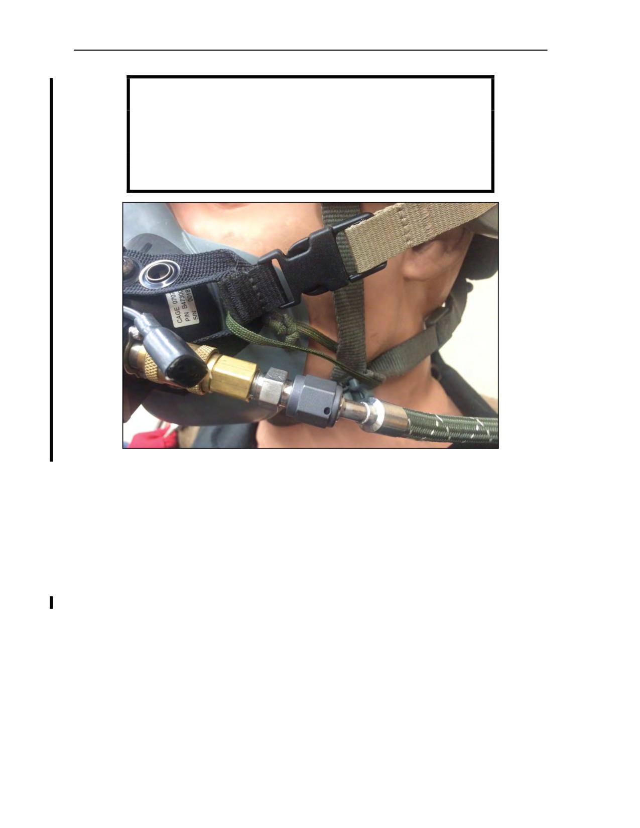
WARNING
Not all figures, pictures, or diagrams within this publication
contain the POM securing lanyard. Parachutists should use the
POM securing lanyard to keep the oxygen mask from becoming
detached during free fall and floating behind the parachutist’s
head.
Figure 4-5a. Parachutist oxygen mask securing lanyard
Oxygen Supply Hose Assembly
4-31. The oxygen supply hose assembly consists of a four-pin male coupling assembly with an attached
end cap, a 98- or 240-inch hose assembly, a flow indicator, and a low-pressure hose assembly. The oxygen
supply hose assembly is used primarily by military parachutists for HALO and HAHO missions. The hose
interfaces with the six-person portable oxygen console to provide a supplemental 100-percent oxygen
source prior to jumping from the aircraft. The oxygen supply hose assembly also incorporates a breathing
regulator, which reduces the flow from the oxygen console to regulate the mask’s breathing pressure.
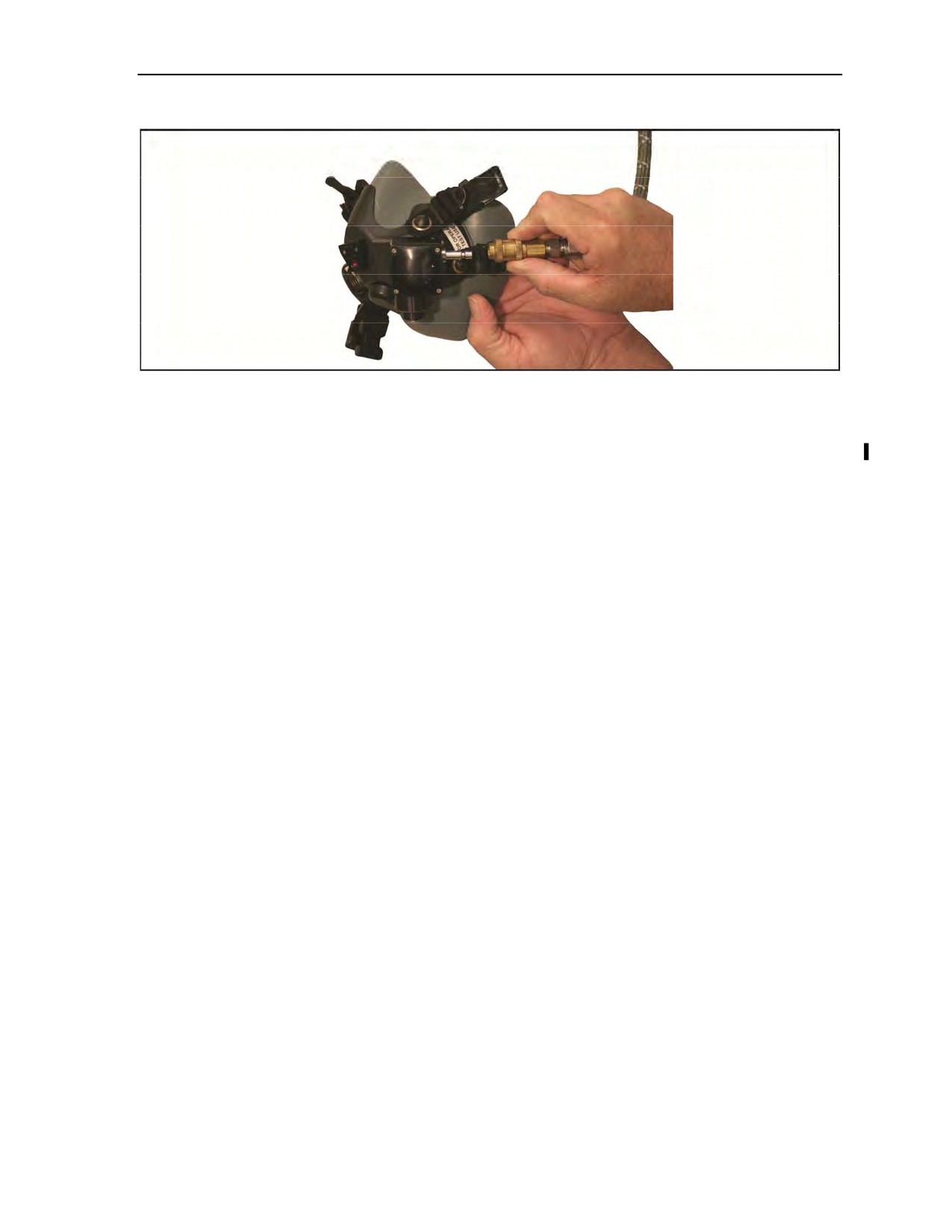
4-32. The POM uses a Hydraflow HS-57 crush-proof oxygen breathing hose to ensure unrestricted oxygen
flow to the parachutist and is easily attached and detached with the quick-disconnect fitting (Figure 4-6,
page 4-13). The POM can fully integrate with the existing Parachutist High-Altitude Oxygen System
equipment with no modification required. When the POM is used with the American Safety Flight System
bail-out storage and delivery system, only minor modifications to the auxiliary equipment is required: the
outlet pressure of the prebreathing console must be adjusted, and an adapter must be incorporated into the
outlet of the existing bail-out system to permit the connection of the oxygen hose to the console.
4-12
ATP 3-18.11/AFMAN 11-411(I)/NTTP 3-05.26M, C2
18 August 2016
Use of Oxygen in Support of Military Free-Fall Operations
Figure 4-6. Parachutist Oxygen Mask and HS-57 quick disconnect
Fitting the MBU-12/P Pressure-Demand Oxygen Mask
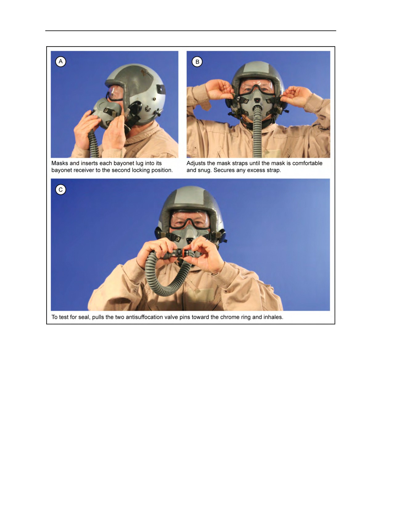
4-33. Trained personnel must supervise mask fitting (Figure 4-7, page 4-14). When the mask fits properly,
it should create a leak-tight seal around the sealing flange throughout the range of pressure-breathing forces
administered by regulators. The mask has a four-point suspension harness with offset bayonet connectors
that the parachutist attaches to the receivers mounted on his helmet to fit the mask. For safety, and to make
sure of proper fit, the MFF parachutist should be issued the same mask and helmet for each operation. To
fit the oxygen mask, the parachutist—
z
Loosens the adjustment screws on the receivers on the helmet (depending on the type of helmet
and bayonet receivers).
z
Places the mask over his face and inserts each bayonet lug into its bayonet receiver to the second
locking position (Figure 4-7A).
z
Adjusts the mask straps until the mask is comfortable and snug, but not so snug that the mask
hinders his vision (Figure 4-7B). He also secures any excess straps.
z
To test for a proper seal, pulls the two pins of the antisuffocation valve toward the chrome ring,
closing the antisuffocation valve, and inhales (Figure 4-7C). If the mask leaks around the face
portion, he readjusts the four straps and once again checks for a proper seal. If any other portion
of the mask leaks, the mask must be replaced. If a seal cannot be made at the face portion, he
exchanges the mask for the next size and repeats the fitting process.
z
Tightens the receiver adjustment screws and secures the excess straps if a proper seal is achieved
(depending on the type of helmet and bayonet receivers).
18 August 2016
ATP 3-18.11/AFMAN 11-411(I)/NTTP 3-05.26M, C2
4-13
Chapter 4
Figure 4-7. Fitting the MBU-12/P oxygen mask
Fitting the New Parachutist Oxygen Mask With Improved Oxygen Harness
4-34. Trained personnel must supervise mask fitting. When the mask fits properly, it should create a
leak-tight seal around the sealing flange throughout the range of pressure-breathing forces administered by
regulators. The mask has a four-point suspension harness strap and buckle assembly that attaches to the
improved oxygen harness (skull cap) connectors that the parachutist wears on his head to fit the mask. For
safety and to ensure proper fit, the MFF parachutist should be issued the same mask and skull cap for each
operation. To fit the oxygen mask, the parachutist should perform the following procedures:
z
Step 1. Center the improved oxygen harness in a comfortable position on the head.
z
Step 2. Place mask over face with left hand and have jumpmaster secure all four Fastex buckles
to the improved oxygen harness.
z
Step 3. While jumper is holding mask with left hand, lightly tighten right top strap; switch hands
and lightly tighten left top strap to hold mask into place. Grasp both top straps and tighten two
top straps equally so mask stays centered on face and is tight enough to create a good seal. The
POM is equipped with an integral antisuffocation valve to protect the parachutist in the event of
4-14
ATP 3-18.11/AFMAN 11-411(I)/NTTP 3-05.26M, C2
18 August 2016

Use of Oxygen in Support of Military Free-Fall Operations
oxygen supply depletion or for when fitting mask without oxygen being attached. If parachutist
cannot exhale, mask must be considered unserviceable.
z
Step 4. Tighten two bottom straps equally, keeping mask centered.
z
Step 5. Move head back and forth two or three times. Alternately, tighten straps until a good seal
is achieved.
z
Step 6. Once this procedure is completed, have the mask inspected by an oxygen technician.
Figure 4-8 shows a completely and properly fitted mask.
z
Step 7. After oxygen technician checks mask, secure any excess straps by rolling them inboard
and securing rolls with masking tape.
z
Step 8. Breathe through mask to determine if proper fit has been achieved. Parachutist should be
able to breathe through ambient air port on mask; however, no air should enter around nose,
cheeks, or chin. If mask is leaking air, readjust it for a proper fit. If a proper fit cannot be
established, try a different size mask.
Figure 4-8. Properly fitted mask
Fitting the New Parachutist Oxygen Mask with Bayonet Connectors
4-35. To fit the new POM with bayonet connectors, the parachutist should perform the following procedures:
z
Step 1. Place mask over face and insert bayonet connectors into the second locking position in
bayonet receiver. Two clicks will be heard on each side indicating the second locking position.
Setting mask in this position will allow adjustments to be made.
z
Step 2. Ensure helmet is in a comfortable position on head. Tighten two top straps equally so
mask stays centered on face and is tight enough to create a good seal. The POM is equipped with
an integral antisuffocation valve to protect the parachutist in the event of oxygen supply
depletion or for when fitting mask without oxygen being attached. If parachutist cannot exhale,
mask must be considered unserviceable.
z
Step 3. Tighten two bottom straps equally, keeping mask centered.
z
Step 4. Move head back and forth two or three times. Alternately, tighten straps until a good seal
is achieved.
z
Step 5. Once this procedure is completed, have the mask inspected by an oxygen technician.
z
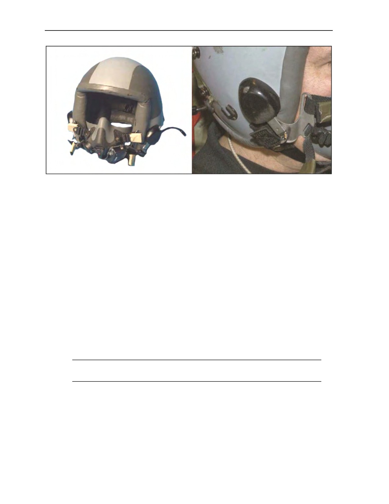
Step 6. After oxygen technician checks mask, secure any excess straps by rolling them inboard
and securing rolls with masking tape (Figure 4-9, page 4-16).
z
Step 7. Breathe through mask to determine if proper fit has been achieved. Parachutist should be
able to breathe through ambient air port on mask; however, no air should enter around nose,
cheeks, or chin. If mask is leaking air, readjust it for a proper fit. If a proper fit cannot be
established, try a different size mask.
18 August 2016
ATP 3-18.11/AFMAN 11-411(I)/NTTP 3-05.26M, C2
4-15
Chapter 4
Figure 4-9. Parachutist Oxygen Mask with bayonet connectors and taped straps
Fitting the New Parachutist Oxygen Mask With Advanced Combat Helmet Accessory Rail
Connector With Oxygen Single-Strap and Double-Strap Kits
4-36. To fit the new POM with double-strap kits to the ACH-ARC, the parachutist should perform the
following procedures:
z
Step 1. Place mask over face and insert slide-and-lock Picatinny adapter swivel clips into
accessory rail connector. Take slack out of all straps by pulling down on them with equal
pressure. Setting mask in this position will allow adjustments to be made.
z
Step 2. Ensure helmet is in a comfortable position on head. Tighten two top straps equally so
mask stays centered on face and is tight enough to create a good seal. The POM is equipped with
an integral antisuffocation valve to protect the parachutist in the event of oxygen supply
depletion or for when fitting mask without oxygen being attached. If parachutist cannot exhale,
mask must be considered unserviceable.
z
Step 3. Tighten two bottom straps equally, keeping mask centered.
z
Step 4. Move head back and forth two or three times. Alternately, tighten straps by sliding strap
retainers until a good seal is achieved.
z
Step 5. Once this procedure is completed, have the mask inspected by a jumpmaster and/or
oxygen technician.
z
Step 6. Breathe through mask to determine if proper fit has been achieved. Parachutist should be
able to breathe through ambient air port on mask; however, no air should enter around nose,
cheeks, or chin. If mask is leaking air, readjust it for a proper fit. If a proper fit cannot be
established, try a different size mask.
Note: To fit the new POM with single-strap kit to the ACH-ARC, the parachutist should perform
Steps 1, 2, 4, 5, and 6 above.
Cleaning the Oxygen Mask
4-37. The parachutist cleans his oxygen mask after each use in accordance with TM 55-1660-247-12. He
carefully wipes all surfaces with gauze pads or a similar lint-free material dampened with 70-percent
isopropyl alcohol (rubbing alcohol). If isopropyl alcohol is not available, a solution of warm water and a mild
liquid dishwashing detergent, such as Ivory, Joy, or Lux, is used. To rinse, the parachutist wipes the mask
with swabs soaked in clean water, taking care not to wet the electronic parts. He allows the mask to air dry
and stores it in a dust-free environment, away from heat and sunlight. If the mask needs more extensive
cleaning, the parachutist turns it in to the supporting life-support facility.
4-16
ATP 3-18.11/AFMAN 11-411(I)/NTTP 3-05.26M, C2
18 August 2016

Use of Oxygen in Support of Military Free-Fall Operations
100-CUBIC-INCH AND 106-CUBIC-INCH PORTABLE BAILOUT OXYGEN SYSTEM
WITH PARACHUTIST OXYGEN SYSTEM ASSEMBLY
4-38. When used with the MBU-12/P oxygen mask, the portable bailout oxygen system is connected to the
AIROX VIII, which is a constant-flow oxygen metering system consisting of a pressure reducer and an
oxygen and air controller with an integrated prebreather adapter. These components increase oxygen duration
and permit comfortable exhalation with standard military pressure-demand masks and associated connectors
(Figure 4-4, page 4-10). This system requires minimum maintenance and—
z
Has been approved for use from 0 to 35,000 feet MSL.
z
Has an 8.2 to 9.3 liters-per-minute nominal oxygen flow to the parachutist.
z
Has an oxygen reducer.
z
Interfaces with the MBU-12/P oxygen mask.
z
Has an oxygen and air controller that mates with the CRU-60/P or MC-3A.
z
Has a charging valve.
z
Has a 20-micron oxygen and/or 60 mesh air inlet filter.
z
Contains two 2.6-inch siphon tubes that protect the oxygen reducer from foreign matter in the
cylinders.
z
Has a toggle-type ON/OFF control.
z
Has an oxygen relief valve.
z
Reduces exhalation difficulty associated with constant-flow oxygen systems.
z
Uses two 50-cubic-inch or 53-cubic-inch high-pressure cylinders.
z
Weighs approximately 10.5 pounds.
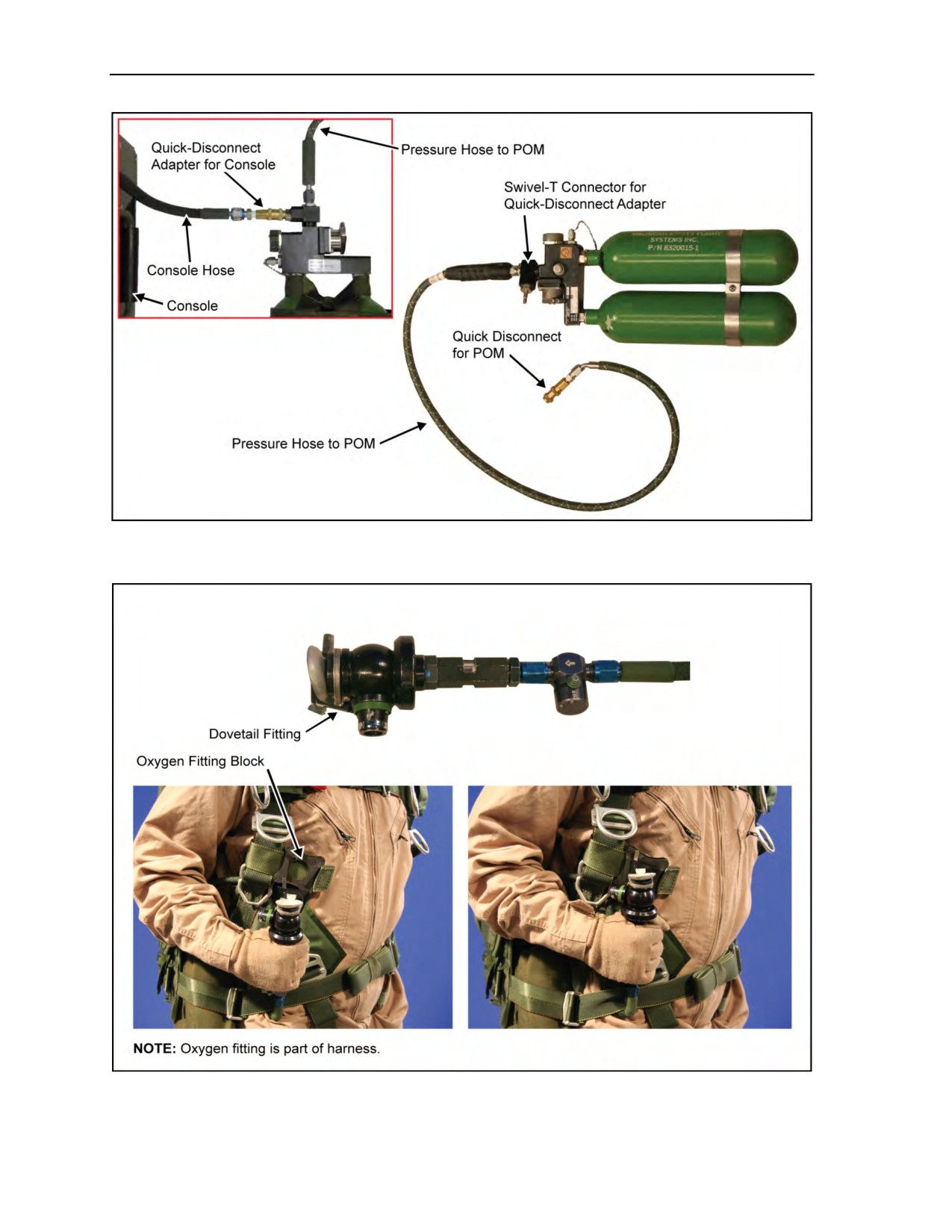
4-39. When used with the POM (Figure 4-10, page 4-18), the Twin-53 (106-cubic-inch) portable oxygen
system consists of two 53-cubic-inch oxygen cylinders rated at 1,800 psi and is connected to a pressure
reducer for oxygen delivery at a nominal pressure of 50 psi. With a nominal inlet pressure of 50 psi, the
oxygen regulating system is capable of delivering 8.2 to 9.3 liters per minute of oxygen to the parachutist.
The Twin-53 system is interconnected via an oxygen hose (Figure 4-10) with its oxygen output controlled
by a mask-mounted regulator. A complete breathing system is formed when the Twin-53 system is
connected to an oxygen mask. When used with a 100-percent oxygen regulator, this system has a maximum
operating altitude equal to that of the aircraft service ceiling. The Twin-50 bottle system has
two 50-cubic-inch oxygen cylinders rated at 2,100 psi, with the same outlet pressure as the Twin-53
system. As the connection point at the manifold of the Twin-50 oxygen system is identical to that of the
Twin-53, the POM is compatible with the Twin-50 bottle system.
4-40. The AIROX VIII assembly (Figure 4-11, page 4-18) provides the MFF parachutist with a standoff
parachuting capability up to 35,000 feet MSL. It extends the duration of two 53-cubic-inch oxygen
cylinders and permits the use of any pressure-demand mask and associated oxygen connectors. The
AIROX VIII assembly also eliminates the back pressure associated with constant-flow oxygen systems and
requires almost no maintenance. TM 1-1680-377-13&P-5 provides further information.
4-41. The parachutist cannot overbreathe the system. When inhaling more volume than the unit delivers, an
ambient air valve opens up negating the breathing starvation sensation felt with other constant-flow
systems as cylinder pressure decreases.
4-42. The AIROX VIII assembly has a special prebreather adapter that allows simultaneous hookup of the
prebreather unit and the bailout system to the AIROX unit. The parachutist makes only one disconnection
upon standing up. The connection from the prebreather connects to the ambient air port on the AIROX unit,
thus preventing any ambient air from entering the parachutist’s system while prebreathing. When preparing
to exit the aircraft, the parachutist stands up, turns on the bailout system, disconnects from the prebreather,
and jumps.
18 August 2016
ATP 3-18.11/AFMAN 11-411(I)/NTTP 3-05.26M, C2
4-17
Chapter 4
Figure 4-10. The 106-cubic-inch portable bailout oxygen system with the quick-disconnect
oxygen hose
Figure 4-11. AIROX VIII assembly
4-18
ATP 3-18.11/AFMAN 11-411(I)/NTTP 3-05.26M, C2
18 August 2016

Use of Oxygen in Support of Military Free-Fall Operations
Rigging the Portable Bailout Oxygen System with the AIROX VIII Assembly to the Ram-Air
Personnel Parachute System
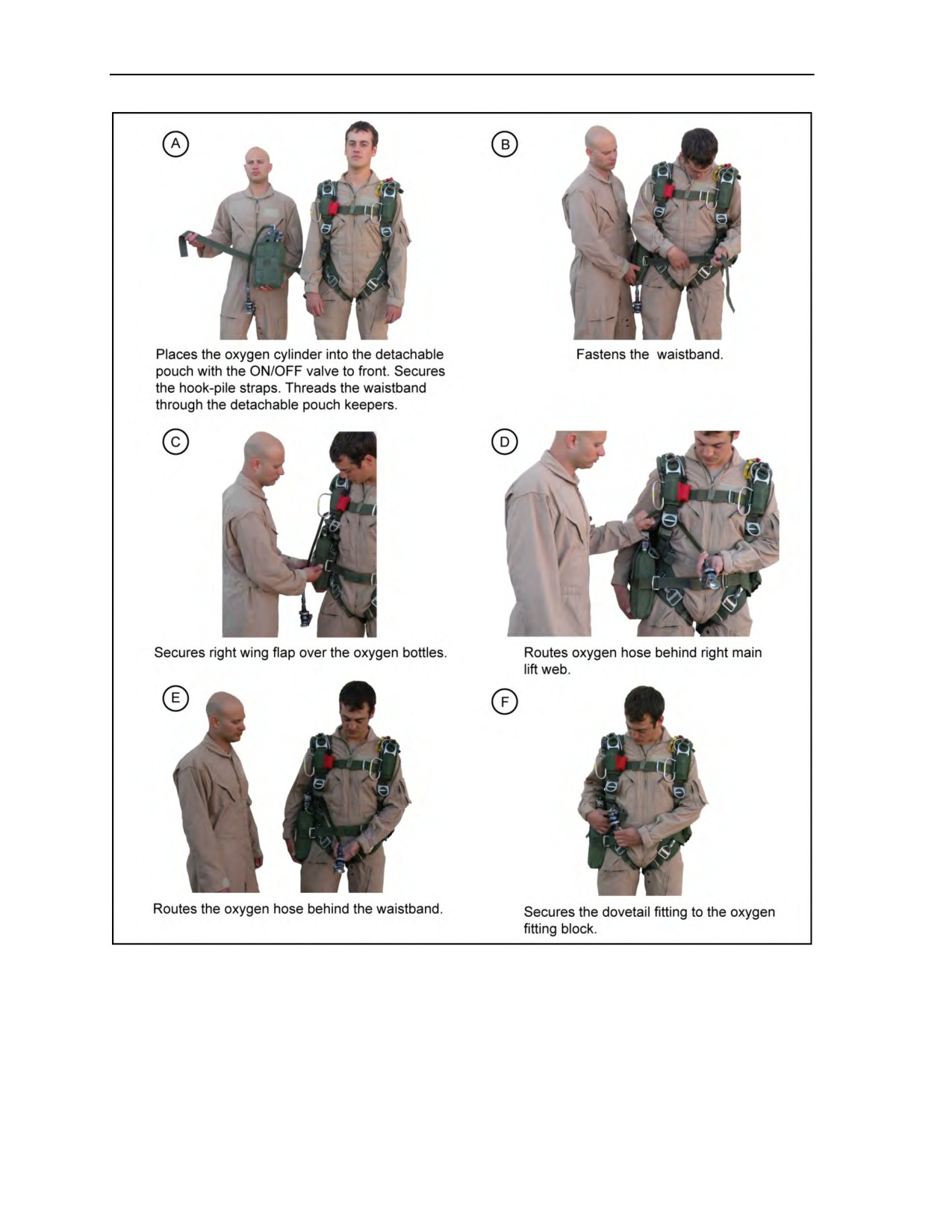
4-43. To rig the portable bailout oxygen system with the AIROX VIII assembly to the RAPPS
(Figure 4-12, page 4-20), the parachutist—
z
Places the oxygen cylinders into the detachable pouch with the ON/OFF valve to his front. He
secures it with the hook-pile straps. He threads the waistband through the center keepers on the
detachable pouch (Figure 4-12A).
z
Fastens the waistband (Figure 4-12B).
z
Tightens the right wing flap over the oxygen bottles (Figure 4-12C).
z
Routes the oxygen hose between his body and the right main lift web and under the waistband
on his right side (Figure 4-12D and E).
z
Routes the oxygen hose over the waistband and secures the dovetail fitting in the oxygen fitting
block (Figure 4-12F).
z
Tightens the waistband.
z
Ensures the center keepers point toward the body.
18 August 2016
ATP 3-18.11/AFMAN 11-411(I)/NTTP 3-05.26M, C2
4-19
Chapter 4
Figure 4-12. Rigging the portable bailout oxygen system with the AIROX VIII assembly
to the RAPPS
4-20
ATP 3-18.11/AFMAN 11-411(I)/NTTP 3-05.26M, C2
18 August 2016
Use of Oxygen in Support of Military Free-Fall Operations
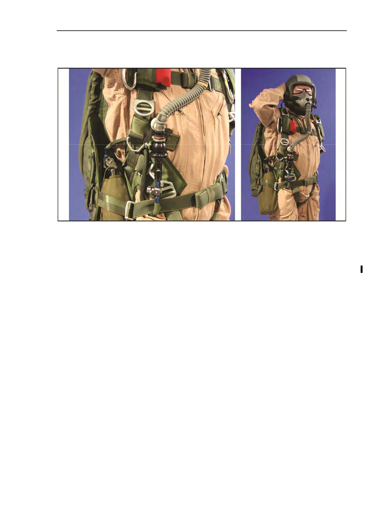
4-44. Figure 4-13 shows the completed rigging of the portable bailout oxygen system with the AIROX
VIII assembly to the RAPPS.
Figure 4-13. Completed rigging of the portable bailout oxygen system with the AIROX VIII
assembly to the RAPPS
Rigging the Parachutist Oxygen Mask and/or American Safety Flight System to the Parachutist
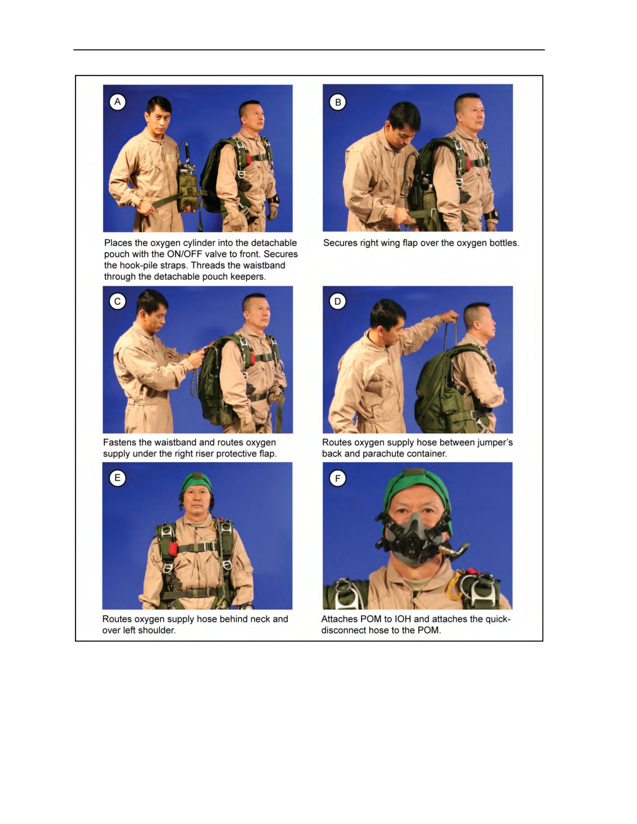
4-45. To rig the complete POM assembly with the portable bailout oxygen system to the RAPPS
(Figure 4-14, page 4-22), the parachutist—
z
Places the oxygen cylinders into the detachable pouch with the ON/OFF valve to his front. He
secures it with the hook-pile straps (Figure 4-14A) rerouted away from the ON/OFF switch. He
threads the waistband through the center keepers on the detachable pouch (Figure 4-14A).
z
Secures right wing flap over the oxygen bottles (Figure 4-14B).
z
Fastens the waistband and routes the oxygen supply under the right riser protective flap
(Figure 4-14C).
z
Routes the rigid oxygen supply hose assembly and quick disconnect between his back
(Figure 4-14D) and the parachute container.
z
Pulls the oxygen supply rigid hose assembly and quick disconnect up behind the neck and over
the left shoulder (Figure 4-14E).
z
Attaches the quick disconnect of the HS-57 hose to the POM (Figure 4-14F).
18 August 2016
ATP 3-18.11/AFMAN 11-411(I)/NTTP 3-05.26M, C2
4-21
Chapter 4
Figure 4-14. Completed rigging of the POM and/or American Safety Flight System with the
Parachutist Oxygen System assembly to the RAPPS
SIX-MAN PREBREATHER PORTABLE OXYGEN SYSTEM
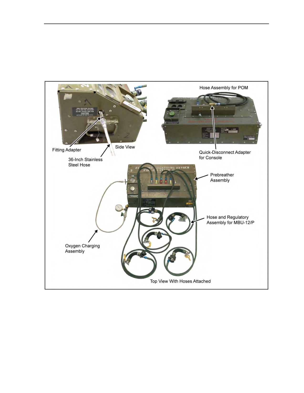
4-46. The six-man prebreather portable oxygen system allows six parachutists to prebreathe 100-percent
oxygen from a 1,292-cubic-inch supply that can be used during flight on fixed-wing aircraft and helicopters as
a supplemental or emergency oxygen source that was designed as a self-contained, easy-to-operate, small,
4-22
ATP 3-18.11/AFMAN 11-411(I)/NTTP 3-05.26M, C2
18 August 2016
Use of Oxygen in Support of Military Free-Fall Operations
lightweight, and nearly maintenance-free oxygen system (Figure 4-15). TM 1-1680-377-13&P-5 provides
further information. The six oxygen-supply hose assemblies interconnect the oxygen console with the
breathers’ oxygen masks. Each of the hoses incorporates a low-pressure regulator that reduces the flow
from the oxygen console to breathing pressure. Oxygen is stored under 1,800 psi or 2,100 psi in two
646-cubic-inch tandem-connected storage cylinders which are charged through the filler valve assembly
connected to the oxygen charging assembly (Part Number T80-30007-9), which is in turn attached to a high-
pressure oxygen source. Oxygen duration is based on altitude and individual consumption requirements.
Figure 4-15. Six-Man Prebreather Portable Oxygen System
4-47. The six-man prebreather portable oxygen system is secured to the existing floor fittings on the
C-17 aircraft. On the C-130 aircraft, the 5,000-pound tie-downs are used to secure the console. On the
V-22 Osprey, the consoles are restrained on the floor on the starboard side using ratchet straps in
accordance with Navy requirements for a 20G load. The outer housing consists of 4130 aircraft sheet steel,
and recesses or steel guards protect the system’s critical components. The oxygen console dimensions are:
length—27 5/16 inches, width—13 6/16 inches, and height—11 inches. The weight is 91 pounds (empty)
and 103 pounds (charged). The hoses are two each of three lengths: 72 inches, 90 inches, and 98 inches.
Color-coding identifies certain parts, such as hoses and their mating parts, to prevent their misconnection.
18 August 2016
ATP 3-18.11/AFMAN 11-411(I)/NTTP 3-05.26M, C2
4-23

Chapter 4
4-48. The six-man console system has 100-percent oxygen capability for six individuals for approximately
one hour at 10,000 to 35,000 feet MSL. The console is primarily intended for use by MFF parachutists
during HAHO and HALO operations.
Note: With the CRU-79/P, the system has an operational ceiling of 50,000 feet MSL.
4-49. Other system features include the following:
z
Weighs 106 pounds when filled.
z
Measures 27.3 inches wide, 13.37 inches deep, and 10.99 inches high.
z
Can provide oxygen for one to six parachutists.
z
Has modular components.
z
Is constructed to survive an 8G (gravitational force) forward crash load.
z
Has a recessed refilling point.
z
Has an easily gripped and guarded ON/OFF knob.
z
Has color-coded and -indexed oxygen connectors to help ensure proper hose connections, and
includes optional hose lengths to fit parachutist seating requirements.
z
Has a steel guard around oxygen hose connectors.
z
Interfaces with any pressure-demand mask and associated connectors.
z
Can be refilled while being used.
OXYGEN CONSOLE
4-50. The oxygen console is a portable, self-contained, deck-mounted oxygen supply system designed to
deliver 100-percent aviator’s breathing oxygen to as many as six parachutists from ground level up to
35,000 feet MSL for approximately 1.5 hours. The console supplies 100-percent oxygen to the parachutist’s
mask by means of a quick-disconnect low-pressure delivery hose (65 to 75 psi) connected to the bailout
bottle worn on the right side of the parachute.
4-51. Up to six delivery hoses can be attached to the console—three on the front of the unit and three on
the back. Some hoses are equipped with a flow indicator for a visual confirmation that oxygen is flowing to
the parachutist. To ensure the parachutist’s oxygen supply is not interrupted when it is time to disconnect
from the oxygen console, the connection of the hose cannot be made without the bailout bottle’s ON/OFF
lever in the ON position. The 70 psi coming from the console’s delivery hose overrides the bailout bottle’s
operation, ensuring that the parachutist gets 100-percent oxygen to the mask and does not consume any of
the oxygen from the bailout bottle. The console is supplied with six delivery hoses and a jumpmaster hose
extension. Because of its configuration, three hoses on the left side and three on the right, the console must
be centerline mounted in the aircraft.
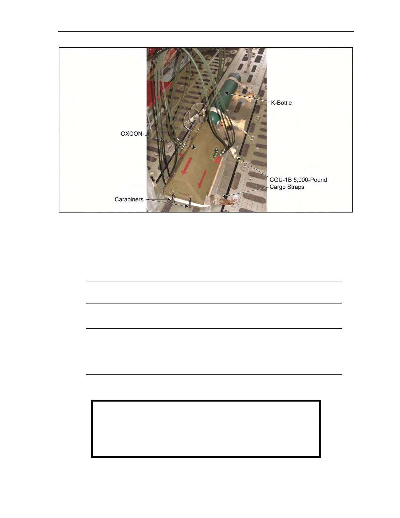
Note: Figure 4-16, page 4-25, displays one example of rigging the oxygen console and K-bottle
inside the aircraft. The load master has final approval authority for securing equipment inside the
aircraft.
Note: Some aircrews may require no metal-to-metal contact between the oxygen console and the
deck of the aircraft.
Note: Oxygen equipment will be rigged and placed in position (jumper configuration) where it
will be used during the airborne operation.
4-52. To extend the duration of the oxygen console, a K-bottle of aviator’s breathing oxygen may be
attached and cascaded into the console when it is rigged on the aircraft. CGU-1B 5,000-pound cargo straps
are used to secure the console and the K-bottles to the deck of the aircraft. To ensure that no metal-to-metal
contact occurs, a piece of plywood can be placed under the console, but cradles must be used to hold the
K-bottles in place.
4-24
ATP 3-18.11/AFMAN 11-411(I)/NTTP 3-05.26M, C2
18 August 2016
Use of Oxygen in Support of Military Free-Fall Operations
Figure 4-16. Oxygen console rigged in C-130 aircraft
4-53. To rig the oxygen console on the deck of approved aircraft, the following procedures must be
performed during pre-stage:
z
Determine how many consoles are going to be used during the mission.
z
Position the consoles with the arrow pointing in the direction of flight. Ensure all gear is
positioned properly before securing.
z
Look for the location of tie-down rings and the accessibility of hoses to the jumpers.
Note: Some squadrons may require no metal-to-metal contact between the oxygen console and
the deck of the aircraft.
z
If supplemental K-bottles are used, ensure wooden 4- by 4-inch cradles are available for each
bottle. Place cradles in the proper direction and within reach of the charging assemblies.
Note: Use Stubai 85 carabiners or equivalent with at least 5,000-pound breaking strength to tie
down because the ends of the tie-down straps do not fit through the tie-downs on the oxygen
console.
Note: The locking barrels on the carabiners need to face out and close downward. They should
be taped so that vibration of the aircraft does not unlock the carabiner barrels.
z
Fasten both sides of the cradle to the deck using CGU1-B 5,000-pound cargo tie-downs with the
direction of pull toward each other and tape the excess straps.
WARNING
Oxygen console hoses are under high pressure. Accidentally
unhooking the hose from the oxygen console unit may result in
injury to a parachutist.
18 August 2016
ATP 3-18.11/AFMAN 11-411(I)/NTTP 3-05.26M, C2
4-25
Chapter 4
z
Tightly stretch a length of 1/2-inch tubular nylon between the centerline stanchions in the
aircraft to hold the hoses up and out of the way.
z
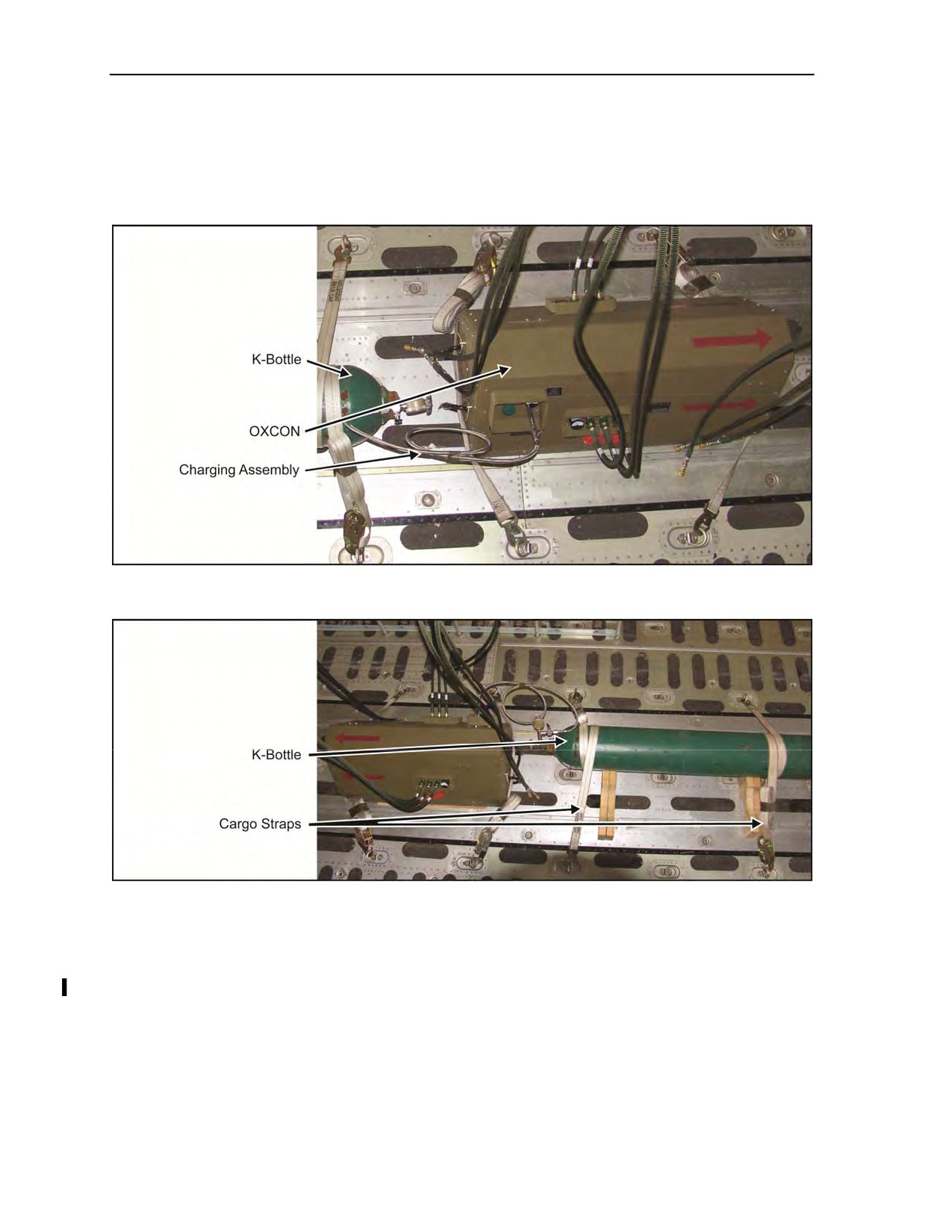
If supplemental K-bottles are used, keep the charging assembly between the K-bottle and oxygen
console securely looped and taped so it cannot get snagged (Figure 4-17).
z
Wrap the cargo strap around the K-bottle once before tightening (Figure 4-18).
Figure 4-17. Charging assembly looped and taped out of the way of parachutists
Figure 4-18. Side and top view of strap on K-bottle
MA-1 PORTABLE OXYGEN ASSEMBLY
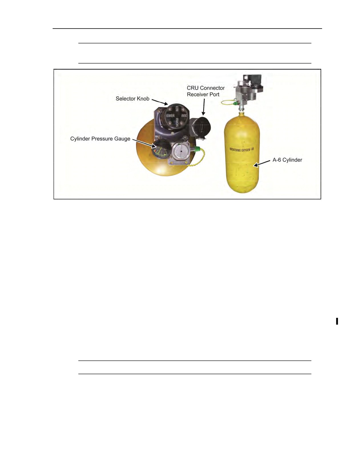
4-54. The MA-1 portable oxygen assembly is a low-pressure system capable of supplying the parachutist
with breathing oxygen for normal or emergency use (Figure 4-19, page 4-27). It is commonly called the
walk-around bottle. The MA-1 is filled from the aircraft’s oxygen supply. Pressure is indicated on the
cylinder pressure gauge. The cylinder is considered full at 300 psi and empty at 100 psi. The MA-1 is
operated by placing the selector knob at one of the four settings (NORM [normal], 30M, 42M, and
EMER [emergency]) and breathing directly through the connector regulator unit’s receiver port or an
attached oxygen mask.
4-26
ATP 3-18.11/AFMAN 11-411(I)/NTTP 3-05.26M, C2
18 August 2016
Use of Oxygen in Support of Military Free-Fall Operations
Note: The hose connectors for the POM are not compatible with the portable MA-1 portable
oxygen bottles on USAF aircraft.
Figure 4-19. MA-1 Portable Oxygen Assembly
PREBREATHER ATTACHMENT
4-55. The prebreather oxygen assembly is normally located under the troop seats, and the oxygen supply
hoses are routed up and behind the seats. The prebreather may also be positioned centerline in the aircraft
using 10,000-pound tie-down fittings (C-17), 5,000-pound tie-down fittings (C-130), or securing straps.
4-56. When using 10,000-pound tie-down fittings, the parachutist places the two large holes in the base
plate of the prebreather over existing 10,000-pound tie-down fitting holes in the floor of the aircraft.
Through the openings in the side of the prebreather, he places two 10,000-pound fittings (one through each
end) into the mating receptacle now visible through the prebreather’s base plate. He then locks the fittings
in place. These fittings will provide all the security necessary to hold the prebreather in place.
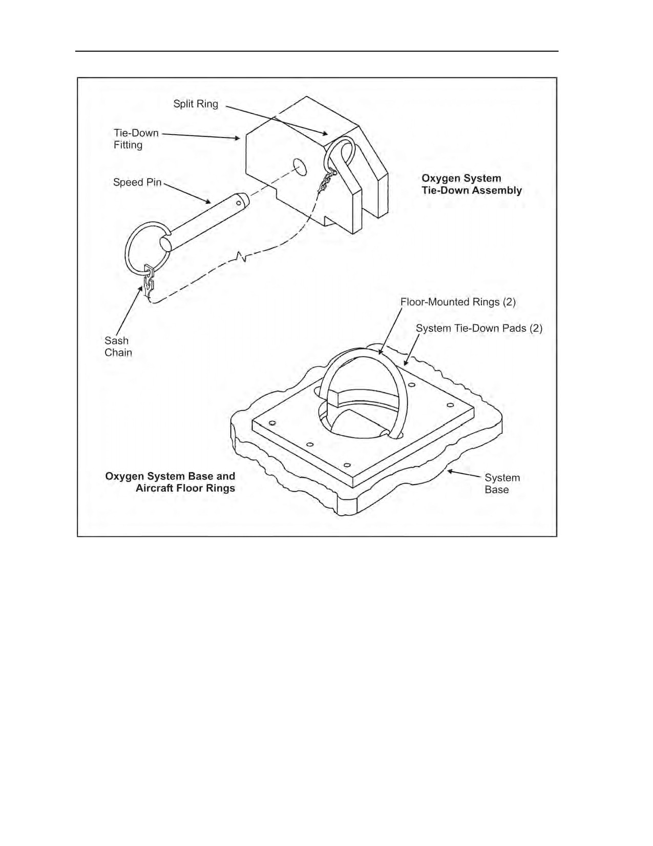
4-57. When using the oxygen console tie-down assembly, the parachutist places the two large holes in the
prebreather’s base plate over the attached 5,000-pound ringed tie-down fittings. Next, he places the
securing adapters over the exposed rings and pushes the pins through the holes in the adapters until they
lock. These fittings will provide all the security necessary to hold the prebreather in place
(Figure 4-20, page 4-28).
4-58. Cargo straps are not necessary for added security when using the 10,000-pound tie-down fittings or
oxygen console tie-down assembly. If cargo straps are used in place of the tie-down fittings, the parachutist
places the straps through the securing access holes at each end of the prebreather and cinches tightly to
existing fittings.
Note: The prebreather carrying handles are not stressed for use as securing points.
18 August 2016
ATP 3-18.11/AFMAN 11-411(I)/NTTP 3-05.26M, C2
4-27
Chapter 4
Figure 4-20. Tie-down assembly and installation
THE “PRICE” CHECK
4-59. Each letter of the acronym PRICE represents an area of or a specific item of oxygen equipment that
the parachutist must check. The PRICE check makes no provision for inspecting the mask or protective
helmet. The parachutist must check each of the following:
z
P—Pressure. Checks for full pressure on the particular system in use.
z
R—Regulator. Checks everything on the particular regulator in use. He checks for dents,
cracks, broken gauges, grease or oil, and movement of dials and levers. He checks the entire
oxygen delivery system for leaks.
z
I—Indicator. Checks to ensure the flow indicator shows that gas is flowing through the
regulator from the storage system.
z
C—Connections. Checks all hose connections.
z
E—Emergency Equipment. Performs a complete check on any emergency oxygen equipment
and the complete bailout system.
4-28
ATP 3-18.11/AFMAN 11-411(I)/NTTP 3-05.26M, C2
18 August 2016

Use of Oxygen in Support of Military Free-Fall Operations
OXYGEN SAFETY PERSONNEL AND PREFLIGHT CHECKS
4-60. Oxygen safety personnel (rigger or another free-fall jumpmaster with experience on the equipment)
must be onboard each aircraft during MFF operations using supplemental oxygen. They must have received
physiological training and unit-level technical training on the oxygen systems being used. For jumps from
20,000 feet or above, one USAF physiological technician per 16 jumpers will be requested with the aircraft
and will be onboard for the jump. The oxygen safety personnel or the USAF physiological technician
will—
z
Plan for all oxygen equipment required for the mission. He will provide one additional mask of
each size and one additional complete bailout system per six parachutists, and plan for one
additional open oxygen station per every six parachutists in the event of a hose or regulator
failure.
z
Conduct preflight inspection and preflight operational checks of all oxygen equipment
(Figures 4-21 and 4-22, pages 4-30 through 4-32).
z
Supervise the transportation of and installation onboard the aircraft of prebreathers and oxygen
cylinders.
z
Issue oxygen supply hoses to each parachutist and supervise hose connection.
WARNING
Never partially close the shutoff valve during oxygen use. Closing
the valve (even partially) will result in a restriction of oxygen flow
to the parachutist, possibly incapacitating and/or causing serious
injury to personnel.
z
Prior to the aircraft procedure signal MASK being given, fully open shutoff valves on
prebreathers.
z
After the aircraft procedure signal MASK is given, ensure the parachutists don their masks
properly and receive oxygen.
z
Periodically check oxygen pressure and equipment function during use (every 10 minutes).
z
Monitor each parachutist for signs of hypoxia, the bends, the chokes, neurological hits, and skin
manifestations or paresthesia.
z
Assist the parachutist with the activation of the bailout systems and inspect all bailout systems to
make sure they were activated.
z
Check the parachutist’s hose connections on the AIROX VIII or oxygen console. If the
parachutist still indicates a problem, the technician activates the bailout system, moves the
parachutist to an open station, and the technician deactivates the bailout system.
WARNING
It is essential that problems associated with faulty bailout bottles
are identified early in the prebreathing cycle. If the affected
parachutist has not been breathing
100-percent oxygen, the
prebreathing clock starts over once a new bailout bottle is
properly installed. This could delay the jump or disqualify the
affected parachutist from jumping.
18 August 2016
ATP 3-18.11/AFMAN 11-411(I)/NTTP 3-05.26M, C2
4-29

Chapter 4
4-61. When connected to an external oxygen system on an aircraft that has an open door or ramp, all
attached equipment will be connected and inspected before takeoff. Jumpmasters need to remain vigilant
and ensure jumpers do not manipulate or adjust their equipment in such a way that would cause an
inadvertent deployment of the main or reserve pilot chute.
4-62. When connected to an external oxygen source, it is recommended that the primary jumpmaster
disconnect his oxygen hose before he allows the ramp or door to be open. The assistant jumpmaster or
oxygen safety will ensure all jumpers are disconnected from their hoses before the ramp or door is opened.
4-63. The oxygen safety will not perform primary jumpmaster or assistant jumpmaster duties. While it is
recommended that the oxygen safety does not jump, he may jump providing no jumpers remain on the
aircraft and only if it is absolutely operationally required.
Preflight Inspection of Portable Bailout Oxygen System
Cylinders are lime green and stenciled in white with the words AVIATOR’S BREATHING OXYGEN.
No cracks, dents, or gouges are in the cylinders.
Cylinder clamp and roller are secured and on the bottom one-third of the cylinders.
Cylinders are tight into the pressure reducer body.
Reducer body is not cracked or damaged.
Filler valve, pressure gauge, and relief valve are tight into the pressure reducer body.
Cap on the filler valve is secure, and the filler cap lanyard is secured to both the cylinder and filler
valve.
Pressure gauge face is not damaged, and the dial indicator is not sticking.
ON/OFF control valve is secured to the pressure reducer body with four Allen screws.
Guide rails of the ON/OFF control valve are undamaged. Operating lever operates properly, and the
detent will hold the valve in the ON and the OFF positions.
Union elbow is secured tightly to the top of the pressure reducer, and the elbow directs the hose over
the pressure gauge.
Hose assembly is not frayed or crushed, and the cloth covering is not worn and is free of oil and
other contaminants.
Hose assembly is securely attached to the union elbow and flow indicator.
There is no obvious damage to the flow indicator body, the arrow points toward the AIROX, and the
flow indicator is securely attached to the AIROX.
View glass is clear, indicating a no-flow condition, and the white sleeve, yellow sleeve, and spring are
present.
Blue tamper-proof dot is present directly below the ambient air port.
Equalization port is free of foreign objects or debris.
Brass set screw and brown tamper-proof dot are present.
Body of the AIROX is not damaged or cracked.
Ambient air port is securely attached to the AIROX and not damaged, and the safety lock wire and
screw are intact.
Chrome ring is present and rotates freely.
Gasket is present, clean, and free of nicks or tears.
Inlet orifice is free of foreign objects or debris, and the screen is present and not damaged.
Cover of the outlet orifice is spring-loaded and seats properly.
Outlet orifice is free of foreign objects or debris, and the screen is present and not damaged.
Dovetail mounting plate is securely attached to the bracket.
There is no damage to the dovetail mounting plate.
Locking lever is spring-loaded and functions properly.
Figure 4-21. Portable Bailout Oxygen System preflight inspection and operational checklist
4-30
ATP 3-18.11/AFMAN 11-411(I)/NTTP 3-05.26M, C2
18 August 2016

Use of Oxygen in Support of Military Free-Fall Operations
Preflight Operational Function Check Procedures
Ensure the system is fully charged at 70 degrees Fahrenheit.
Connect a mask to the outlet orifice and ensure that it is secure and that excessive force is not
required to connect and disconnect.
Turn the system on and seal the mask to the face.
Inhale—yellow sleeve (on flow indicator) rises.
Exhale—yellow sleeve falls. Inhalation should be normal with no undue exertion.
Ensure there is no oxygen flow from the relief valve.
Turn the system off, reseal the mask to the face, and ensure parachutist can breathe through the
ambient air port.
Connect a hose and regulator assembly to the ambient air port; ensure that it is secure and that
excessive force is not required to connect and disconnect.
Preflight Inspection of 6-Man Prebreather
Unit has no obvious damage.
Gauge faces are not broken.
Dial indicators are not sticking.
All screws are present and not coming loose.
Handles are not separating from unit.
Filler cap is present and tied down to unit.
All female disconnect plugs are present and tied down to disconnect.
Female disconnects are not distorted, and the pins of the male connectors of hose assemblies will
engage with the collar of the female disconnect.
Female disconnects are safety-wired to the adjacent female disconnect.
Connector manifold guard does not interfere with the operation of the female disconnects or male
connectors of the hose and regulator assembly.
Both sets of screws in the ON/OFF knob are present and not backing out.
ON/OFF valve stem is not bent.
Container is not cut, damaged severely, or corroded.
Unit is fully charged to 1,800 psi at 70 degrees Fahrenheit.
Preflight Inspection of the Hose and Regulator Assembly
Each male connector has the proper amount of pins (red: 2 pins, yellow: 3 pins, gray: 4 pins), and the
mating probe is not distorted.
Male connector is tight into hose assembly.
Wire wrapping is not frayed, and hose is not crushed.
Cloth covering is free of oil and other contaminants.
Red male connector is connected to 72-inch hose, yellow connector to 90-inch hose, and gray
connector to 98-inch hose.
Hose is tightly connected to regulator.
Regulator is not cut or cracked.
No foreign object or debris is in equalization port.
Hose and check-valve assembly is clamped to regulator, and clamp is safety wired.
Cover is spring-loaded and seats evenly over check valve.
Check valve is spring-loaded.
Figure 4-22. Sample prebreather preflight inspection and operational function checklist
18 August 2016
ATP 3-18.11/AFMAN 11-411(I)/NTTP 3-05.26M, C2
4-31

Chapter 4
Preflight Operational Function Check Procedures
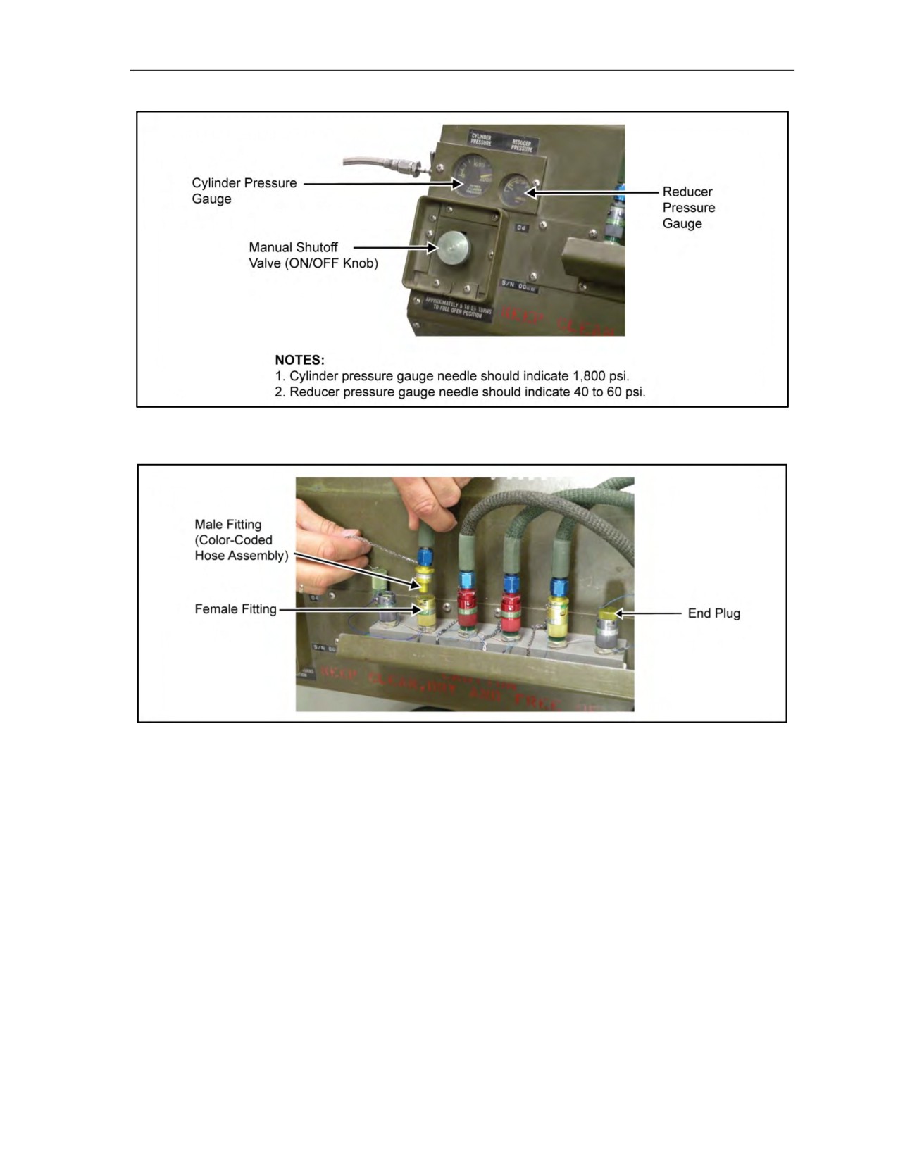
Turn the shutoff valve counterclockwise to the fully opened position (about 5 1/2 turns) (Figure 4-23,
page 4-33).
Ensure the reducer pressure gauge indicates 40 to 60 psi (Figure 4-23).
Remove each disconnect plug, depress the poppet of each disconnect (Figure 4-24, page 4-33), and
ensure oxygen flows from each disconnect.
Close shutoff valve and ensure reducer pressure remains steady (40 to 60 psi).
Bleed off the pressure through the disconnect manifold.
Install all hose and regulator assemblies to their appropriate disconnect (Figure 4-24). (Be sure to
bleed manifold pressure before attaching hose and regulator assemblies.)
Connect an MBU-12/P or POM mask to each hose and regulator assembly.
Open shutoff valve (about 5 1/2 turns).
Listen for and feel the oxygen flow from each mask. Disconnect all but one mask and note the
reducer pressure for 3 to 5 seconds. The reducer pressure should not drop below 40 psi.
Hold the mask to the face and inhale. Inhalation shall be normal with no undue exertion to breathe
oxygen. Remove mask from hose and regulator assembly; ensure check valve closes and that there
is no flow from the hose and regulator assembly. Repeat the above step for each hose and regulator
assembly.
Close shutoff valve and bleed manifold pressure through one or more check valves until reducer
pressure indicates zero.
Monitor reducer pressure for 15 minutes. Ensure gauge indicator remains at zero.
Figure 4-22. Sample prebreather preflight inspection and operational function
checklist (continued)
CAUTION
Failure to properly connect the hose and regulator assemblies to the
prebreather using the above procedures could possibly damage the
diaphragm of the CRU-79/P and render the equipment inoperative.
WARNING
Personnel must NEVER partially close the shutoff valve during
oxygen use; it will result in a restriction of oxygen flow to the
parachutist.
4-32
ATP 3-18.11/AFMAN 11-411(I)/NTTP 3-05.26M, C2
18 August 2016
Use of Oxygen in Support of Military Free-Fall Operations
Figure 4-23. Pressure gauge and manual shutoff valve
Figure 4-24. Removing end plugs and depressing poppets
OXYGEN HANDLING AND SAFETY
4-64. Because of limited contact with oxygen and its handling, personnel may not fully appreciate the
danger involved. Improper use and handling can result in property damage, serious injury, and death.
Personnel handling oxygen must—
z
Keep Oil and Grease Away From Oxygen. They must not handle oxygen equipment with
greasy hands or clothing. They do not let fittings, hoses, or any other oxygen equipment get
smeared with petroleum-based products, lubricants, hydraulic fluid, or dirt. A drop of oil or
lubricant in the wrong place can cause an explosion.
z
Keep Oxygen Away From Fires. Small fires rapidly become large fires in the presence of
oxygen supplies. Personnel handling oxygen must never permit smoking near oxygen
equipment, while handling oxygen supplies, or when using oxygen life-support equipment.
z
Handle Cylinders and Valves Carefully. Before opening cylinder valves, they make sure the
cylinder is firmly supported. They never let a cylinder drop or tip over. Dropping a cylinder can
damage or break the valve, allowing the gas to escape and to propel the cylinder a great distance,
which is an obvious hazard. Personnel open and close the valves only by hand. If they cannot
open and close them by hand, they must return the cylinder to the depot for repair.
18 August 2016
ATP 3-18.11/AFMAN 11-411(I)/NTTP 3-05.26M, C2
4-33

This page intentionally left blank.

Chapter 5
Equipment and Weapon Rigging Procedures
Free-fall parachutists will normally operate with individual equipment that includes
clothing and equipment in keeping with the climatic conditions, food, and survival
items. In addition, each parachutist will have a weapon, free-fall parachutist’s jump
helmet, goggles, and altimeter. Free-fall parachutists jump and carry all detachment
equipment and supplies as individual loads. All parachute systems and combat
equipment will be stored and secured on the aircraft in a manner in which will ensure
no malfunctions or damage will be caused to the rigging and lifesaving equipment on
the parachute system. Oxygen equipment will be rigged and placed in position where
it will be utilized during the airborne operation (jumper configuration). If selected
items must be dropped as accompanying supplies, they pack these supplies in
appropriate aerial delivery containers.
Note: AIRCRAFT WITH LIMITED SPACE: Equipment will be donned by all jumpers and
inspected for any rigging deficiencies by the primary jumpmaster and assistant jumpmaster
before takeoff. All jumpers will ensure that their equipment is properly connected when the hand
and arm signal to standup is given and before standing up.
Note: AIRCRAFT WITH AMPLE SPACE: Equipment will be donned after the 10-minute
warning. All jumpers will be inspected by the primary jumpmaster and assistant jumpmaster.
The primary jumpmaster and assistant jumpmaster will inspect each other. All jumpers will
ensure that their equipment is properly connected when the hand and arm signal to standup is
given and before standing up.
Note: AIRCRAFT WITH AN OPEN DOOR OR RAMP: All attached equipment will be
connected and inspected before takeoff. Jumpmasters need to remain vigilant and ensure that
their jumpers do not manipulate or adjust their equipment in such a way that they could have an
inadvertent deployment of the main or reserve pilot chute.
EQUIPMENT AND WEAPON PACKING CONSIDERATIONS
5-1. The parachutist can attach or wear his individual equipment and weapon in several configurations
(weapons, for example, exposed, placed in containers, or a mix of the two). Unit SOPs specify ways to
pack equipment that are consistent with safety requirements. As a rule, units pack hard, bulky, or
irregularly shaped (nonaerodynamic) items in containers. Parachutists can use rucksack rigging systems
approved by their Service test board.
5-2. The parachutist packs his individual equipment in a container, kit bag, parachutist drop bag (PDB),
or the medium or large combat pack. He then attaches it to the equipment rings on the parachute’s main lift
web. He may front- or rear-mount the combat pack using the harness, single-point release (HSPR);
improved equipment attaching sling (Spider Harness); or the H-harness (modified). He may attach both a
front- and rear-mounted rucksack and equipment as long as he is under the 360-pound “all-up” total weight
(to include personnel, gear, and weight of canopy suspended below the parachute). He should lower combat
packs or any equipment that weighs more than 35 pounds.
5-3. The parachutist pads fragile items, such as weapon sights. He does not place crushable items, such as
the protective mask, directly under the attaching harnesses. Exposed weapons or equipment, snap hooks,
18 August 2016
ATP 3-18.11/AFMAN 11-411(I)/NTTP 3-05.26M, C2
5-1

Chapter 5
and projections are potential safety hazards that the parachutist tapes. All equipment worn (excluding
oxygen and weapon) will be rigged with the capability to jettison the equipment.
PARACHUTIST AND PARACHUTE LOAD LIMITATIONS
5-4. Commanders must not overload the parachutist with equipment. The variety and weight of equipment
and weapons that can be attached to a parachutist (Tables 5-1 through 5-4, pages 5-2 through 5-3) may exceed
the safe design limits of the MC-4 RAPPS. Overloading can result in parachute damage, unsafe descent rates,
and injury to the parachutist. Also, the parachutist’s actions and the time available to release the tie-down
straps and to lower the equipment may interfere with his control of the parachute close to the ground.
Table 5-1. Container weight limits
Maximum Container
Maximum Rigged
Description
Load (Pounds)
Weight (Pounds)*
Medium Combat Pack
50
55.56
Large Combat Pack
70
75.96
145.96
PDB, Medium
140
(Not to Exceed All-up Weight
of Canopy)
Not to Exceed All-up Weight
Not to Exceed All-up Weight
PDB, Large
of Canopy
of Canopy
*Weight of H-harness attaching sling.
Table 5-2. Parachute load limits
Description
Weight (Pounds)
Reference
Remarks
Increased weight will
Maximum Load-Bearing
reduce canopy
Natick Research and
Capacity of MC-4 RAPPS
360
service life or destroy
Development Command
on Deployment
canopy (for example,
blown cells).
Air Movement Planning
Parachutist with one
Weight of Combat-Equipped
305
None
equipment container
Free-Fall Parachutist
and weapon.
Table 5-3. Weight of parachutist with two equipment loads
Suspended
Weight of
Fatigue
Container
MC-4
Uniform,
M4
Maximum
RAPPS
Helmet,
Rifle
Total
Container
Internal
Weight of
With
Mask, and
Soldier
With
Suspended
Type
Weight
Container
Oxygen
Boots
Weight
Magazine
Weight*
Kit Bag
50
3
43.15
15
205
6.9
323.75
Medium
Combat
50
5.56
43.15
15
205
6.9
326.31
Pack
Large
Combat
70
5.96
43.15
15
205
6.9
346.71
Pack
*Weight of parachutist in pounds.
5-2
ATP 3-18.11/AFMAN 11-411(I)/NTTP 3-05.26M, C2
18 August 2016

Equipment and Weapon Rigging Procedures
Table 5-4. Weight of parachutist with two equipment loads and basic load
Remaining
Fatigue
Body Armor
Suspended
Weight
Weapon
Uniform,
With
Weight of
of
Load
Weight
Helmet,
70 Ounces
MC-4
MC-4
Weapon
With
of Large
Mask,
of Water
RAPPS
RAPPS
Total
Load
Ammu-
Combat
Soldier
and
(Camel-Back
With
With
Suspended
Type
nition (1)
Pack
Weight
Boots (2)
Bladder)
Oxygen
Oxygen
Weight*
M4
31
5.96
205
15
24.5
43.15
35.39
360
Rifleman
M203
40
5.96
205
15
24.5
43.15
26.39
360
Gunner
M60
Machine
54.4
5.96
205
15
24.5
43.15
11.99
360
Gunner
*Weight of parachutist
(1) Includes basic load of ammunition, grenades, claymore, bayonet,
in pounds.
and cleaning kit.
(2) Weight of uniform does not include winter gear (for example, parka,
liners, underwear).
HOOK-PILE TAPE (VELCRO) LOWERING LINE ASSEMBLY
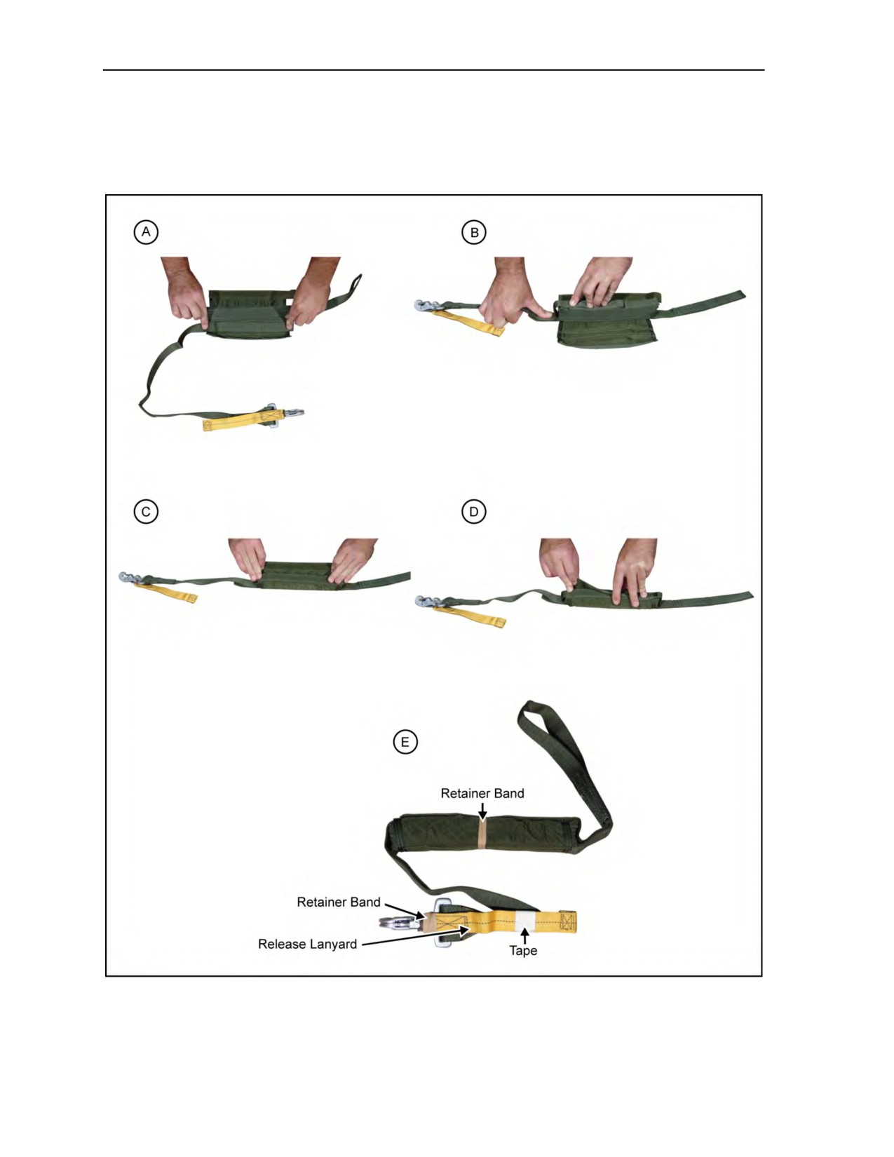
5-5. Figure 5-1, page 5-4, shows the steps (A through D) for stowing an HPT lowering line assembly. The
current HPT lowering line assembly (National Stock Number 1670-01-067-6838) consists of—
z
An 8- or 15-foot lowering line (the 8-foot lowering line is recommended for most equipment)
made of 1-inch-wide tubular nylon.
z
A 9- by 7-inch nylon duck retainer (stow pocket) sewn to the upper end. The flaps have HPT
sewn to the edges.
z
A metal (parachute harness) ejector snap with a yellow safety release.
Note: TM 10-1670-300-20&P describes the modification of the 15-foot HPT lowering line to an
8-foot HPT lowering line. In addition, it provides procedures for altering the HPT lowering line.
Military Occupational Specialty 92R are the only personnel authorized to alter the HPT lowering
line.
Note: The yellow release lanyard may be removed or, if it remains attached to the HPT lowering
line, it should be taped with two wraps of 1-inch masking tape around the end approximately
1 inch from the bottom of the lanyard, securing it to the lowering line and leaving 1 to 2 inches
exposed at the top of the lanyard.
Note: To help prevent inadvertent, premature release of the lowering line, the parachutist places
a medium-weight double-looped retainer band around the middle of the stowed lowering line
retainer pocket before attaching it to the combat pack. Also, the parachutist places a
heavy-weight double-looped retainer band around the quick-ejector snap.
5-6.
The steps for stowing an HPT lowering line assembly, as shown in Figure 5-1, are as follows:
z
Starting with the looped end to the left, neatly S-fold the tubular nylon until the quick-ejector
snap is coming out the right side (Figure 5-1A).
z
Mate the Velcro on the excess tubular nylon to the Velcro on the bottom closing flap
(Figure 5-1B).
z
Close the top flap, encasing the folded tubular nylon (Figure 5-1C).
18 August 2016
ATP 3-18.11/AFMAN 11-411(I)/NTTP 3-05.26M, C2
5-3
Chapter 5
z
Close off both running ends by realigning the Velcro (Figure 5-1D).
z
Remove the yellow release lanyard or tape it with one complete wrap of masking tape. Place a
doubled heavyweight retainer band (Figure 5-1E) around the center of the folded lowering line
and a tripled heavyweight retainer band around the quick-ejector snap.
Figure 5-1. Stowing the HPT lowering line assembly
5-4
ATP 3-18.11/AFMAN 11-411(I)/NTTP 3-05.26M, C2
18 August 2016
Equipment and Weapon Rigging Procedures
COMBAT PACKS AND OTHER EQUIPMENT CONTAINERS
5-7. The following paragraphs discuss the use of harnesses, equipment attachment slings, and lowering
lines in preparing and rigging kit bags and different packs.
H-HARNESS (MODIFIED)
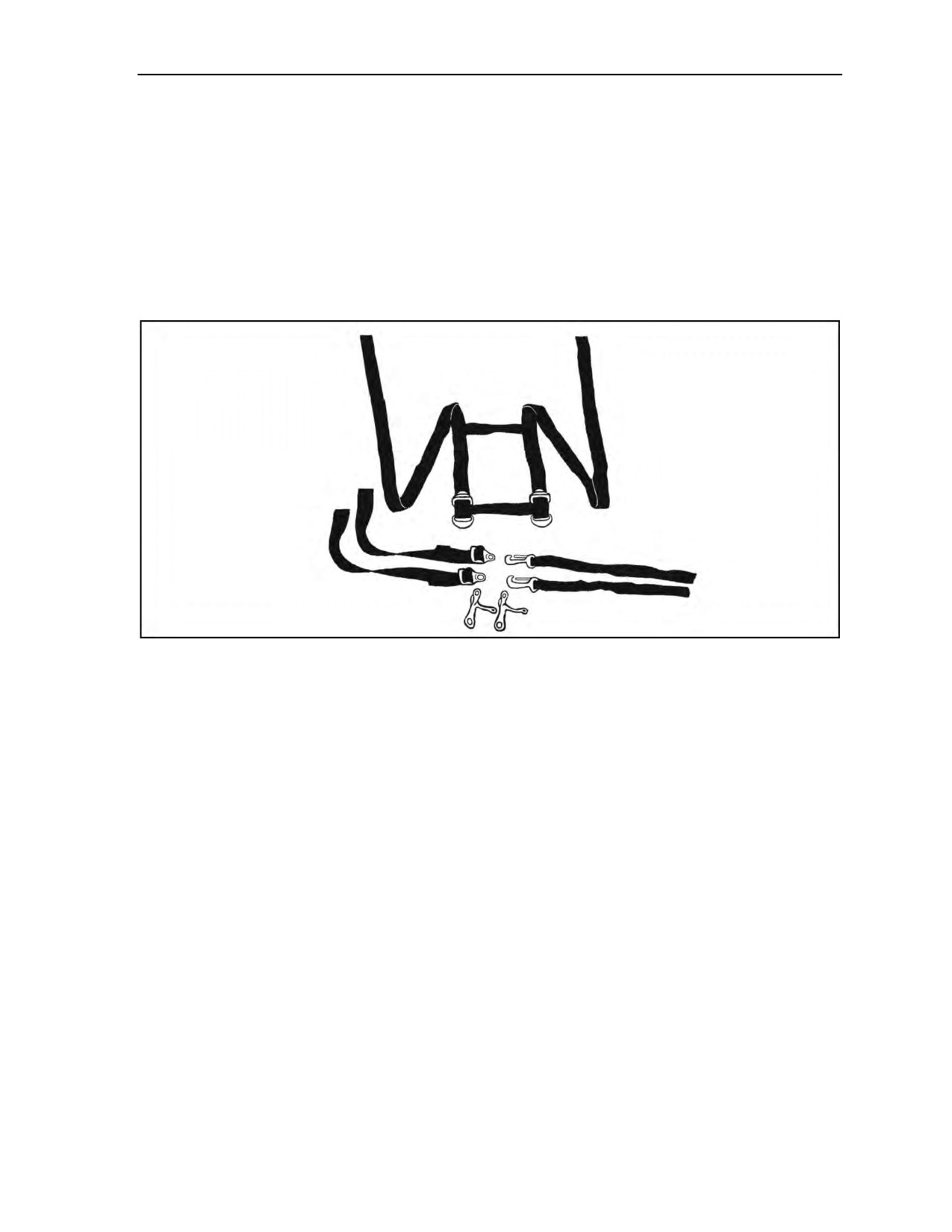
5-8. The modified H-harness consists of two 84-inch nylon straps held together by two 11-inch straps
(Figure 5-2). One end of each strap has two friction adapters attached 3 inches apart. Two 24-inch or
36-inch equipment attachment straps with adjustable lugs and two quick-release ejector snap hooks are part
of the assembly. The H-harness is used to rig the kit bag and combat packs to the parachute harness.
Figure 5-2. H-harness with attaching straps
AVIATOR’S KIT BAG AND/OR MC-4 KIT BAG
5-9. The parachutist uses the canvas aviator’s kit bag or the MC-4 kit bag to jump individual equipment,
such as the load-carrying equipment or properly padded machine gun groups.
Preparing the Bag
5-10. The parachutist packs the equipment in accordance with the unit SOP. He carefully places
sharp-edged objects in the bag so that they are not against his body when he attaches the bag to the
parachute harness. He unfastens the snaps, undoes the slide fastener, and folds down the top of the kit bag
(about one half its filled bulk) to pack the equipment. When packed, the parachutist zips the bag and fastens
the snaps. He gathers up the excess bag material and folds it on top so as to expose the handles.
Attaching the H-Harness to the Kit Bag
5-11. The parachutist takes the two end web adapters and lays out the harness (with the adapters nearest
the body and the second two adapters on top). He connects the equipment attachment straps as outlined
below. The parachutist—
z
With the adjustable lug nearest the body, threads the attachment strap’s end under the attaching
bar of the second friction adapter and back over the top of the bar.
z
Tightens the strap, leaving about 3 inches between the nap and the bar, and repeats this step for
the remaining strap.
z
Places one quick-release snap hook on each adjustable lug.
z
Lays out the H-harness with the attachment straps down and the snap hook openings up.
24 October 2014
ATP 3-18.11/AFMAN 11-411(I)/NTTP 3-05.26M
5-5
Chapter 5
z
Attaches the H-harness to the kit bag by centering the bag on the harness 6 inches from the snap
hooks.
z
Places the H-harness straps around the kit bag and threads them through the friction adapters to
form a quick release.
z
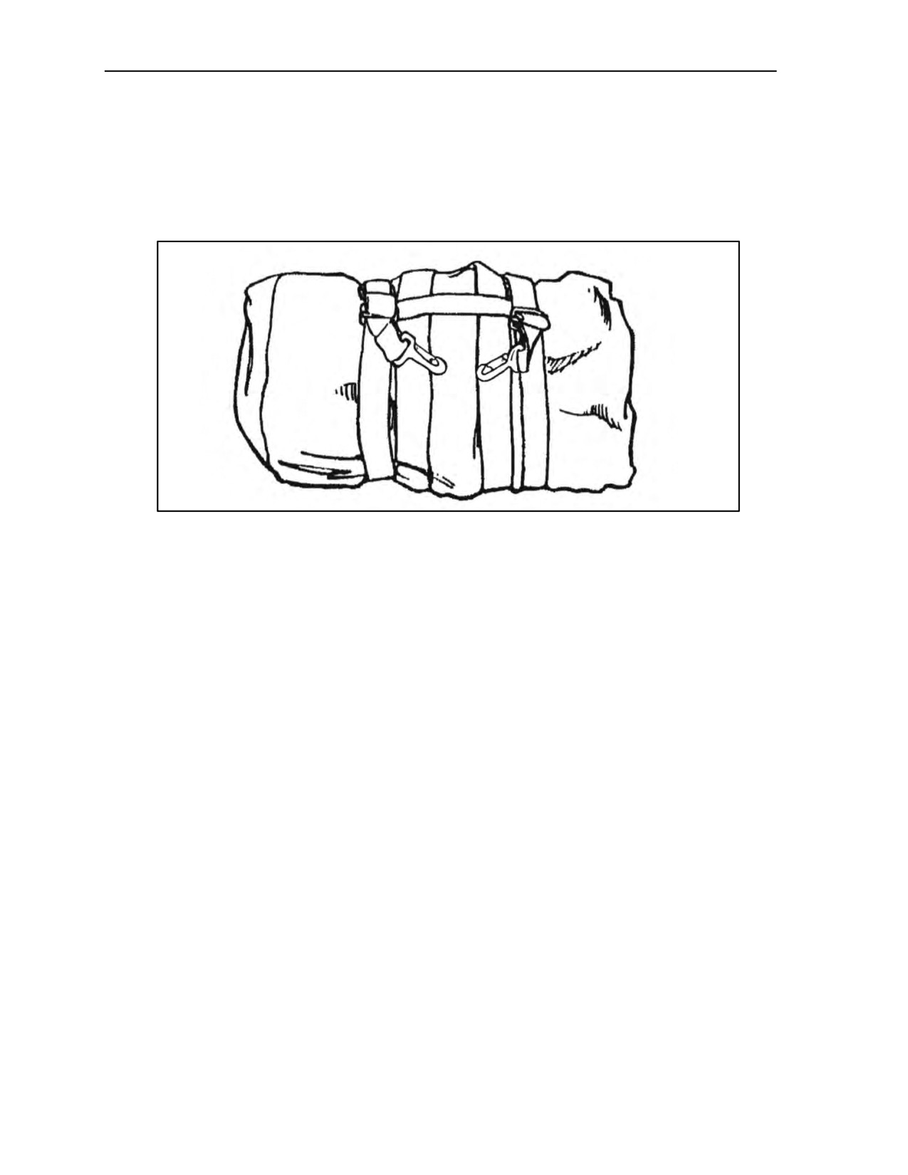
Threads the snap hooks on the attaching straps through the handles of the kit bag. He rolls and
tapes any excess straps (Figure 5-3).
Figure 5-3. H-harness attached to the kit bag
Attaching the Kit Bag to the Parachutist
5-12. When completely rigged, the parachutist attaches the H-harness to himself. He runs the attachment
straps through the handles of the kit bag and then attaches them to the equipment attachment rings on the
parachute harness. If wearing a front-mounted aviator’s kit bag and a rear-mounted combat pack, the
parachutist hooks up the kit bag quick-release snap hooks to the equipment attachment rings first. He then
hooks up the combat pack quick-release snap hooks to the outside of the kit bag’s snap hooks.
COMBAT PACKS
5-13. The parachutist attaches medium and large combat packs by using the modified H-harness or the
improved equipment attachment sling. Combat packs can be either front- or rear-mounted.
Packing the Combat Pack
5-14. The parachutist—
z
Places equipment in the combat pack and places padding between the load and the front portion
of the pack.
z
Fills the outside pockets with nonfragile items (full pockets help to position the H-harness and
attachment sling).
z
Closes the combat pack by engaging the drawstrings and tie-down straps.
z
Routes the running ends of the waist straps behind the frame and secures them by tying or
taping.
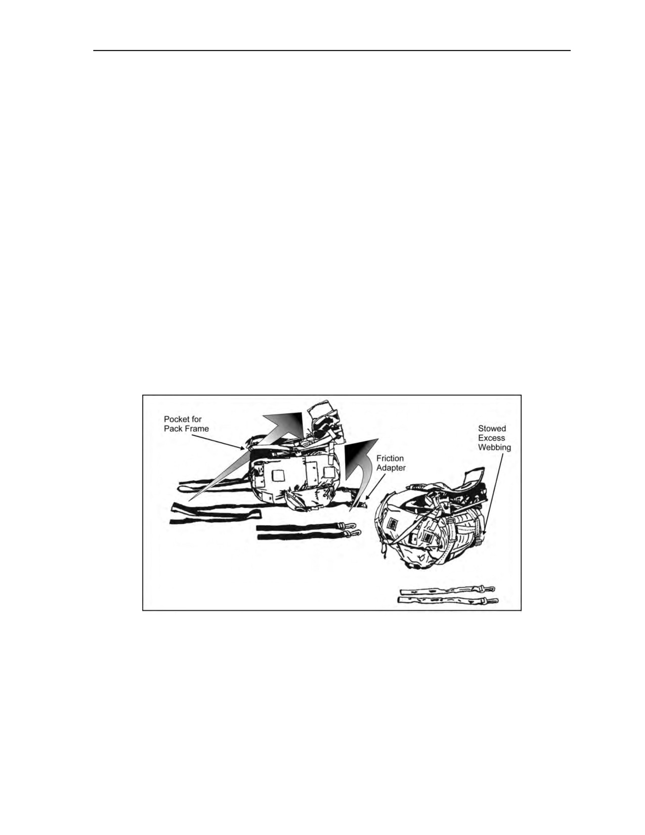
Rigging the Medium Combat Pack Without the Pack Frame
5-15. The parachutist—
z
Turns the pack upside down.
z
Places the H-harness on his pack so that the cross straps are in front of the pack and the friction
adapters are touching the bottom of the pack.
5-6
ATP 3-18.11/AFMAN 11-411(I)/NTTP 3-05.26M
24 October 2014
Equipment and Weapon Rigging Procedures
z
Runs the harness straps over the top of the pack and crosses the straps at the center of the back of
the pack.
z
Runs the straps through the friction adapters.
z
Threads the equipment attaching straps through the intermediate friction adapters.
z
Attaches the quick-release snap hooks to the adjustable lugs.
Rigging the Medium and Large Combat Packs With the Pack Frame, Modified H-Harness,
and Lowering Line
5-16. The parachutist—
z
Positions the modified H-harness on the floor or ground with the friction adapters down. He
places the pack, frame up, over the harness making sure that the cross straps are to the top of the
pack and the friction adapters are touching (or near) the bottom of the frame (Figure 5-4).
z
Runs the harness straps over the top of the pack and then under the top portion of the frame.
z
Runs the harness straps under the horizontal bar of the frame and crosses them at the center of
the back of the pack. He continues to run the straps under the frame and secures them to the
friction adapters.
z
Routes the loop end of the lowering line under the crossed diagonal straps. He passes the
running end of the lowering line through its own loop and tightens it, making sure he centers the
lowering line at the intersection of the straps.
z
Secures the lowering line stow pocket to the pack frame with retainer bands. He leaves the
portion with the quick-ejector snap free for attachment to the parachute harness.
z
Threads the equipment attaching straps through the intermediate friction adapters, attaches a
quick-release snap hook to each adjustable lug, and rolls and tapes any excess straps.
Figure 5-4. Combat pack and frame rigged with the modified H-harness
IMPROVED EQUIPMENT ATTACHMENT SLING
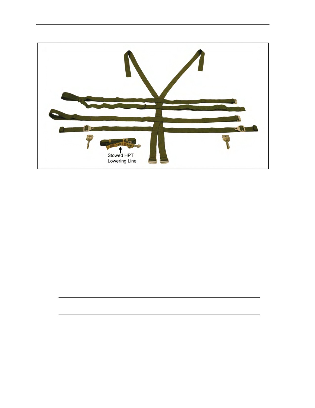
5-17. The improved equipment attachment sling (Figure 5-5, page 5-8) was a component of the MC-3 MFF
system. The parachutist modifies this sling by removing the leg straps with HPT closures or folds and tapes
the leg straps so that he cannot use them. This sling is used to rig combat packs to the parachute harness.
This system is also known as the spider harness.
24 October 2014
ATP 3-18.11/AFMAN 11-411(I)/NTTP 3-05.26M
5-7
Chapter 5
Figure 5-5. Improved equipment attachment sling and lowering line (spider harness)
Rigging the Large Combat Pack With the Improved Equipment Attachment Sling (Spider
Harness) and Lowering Line
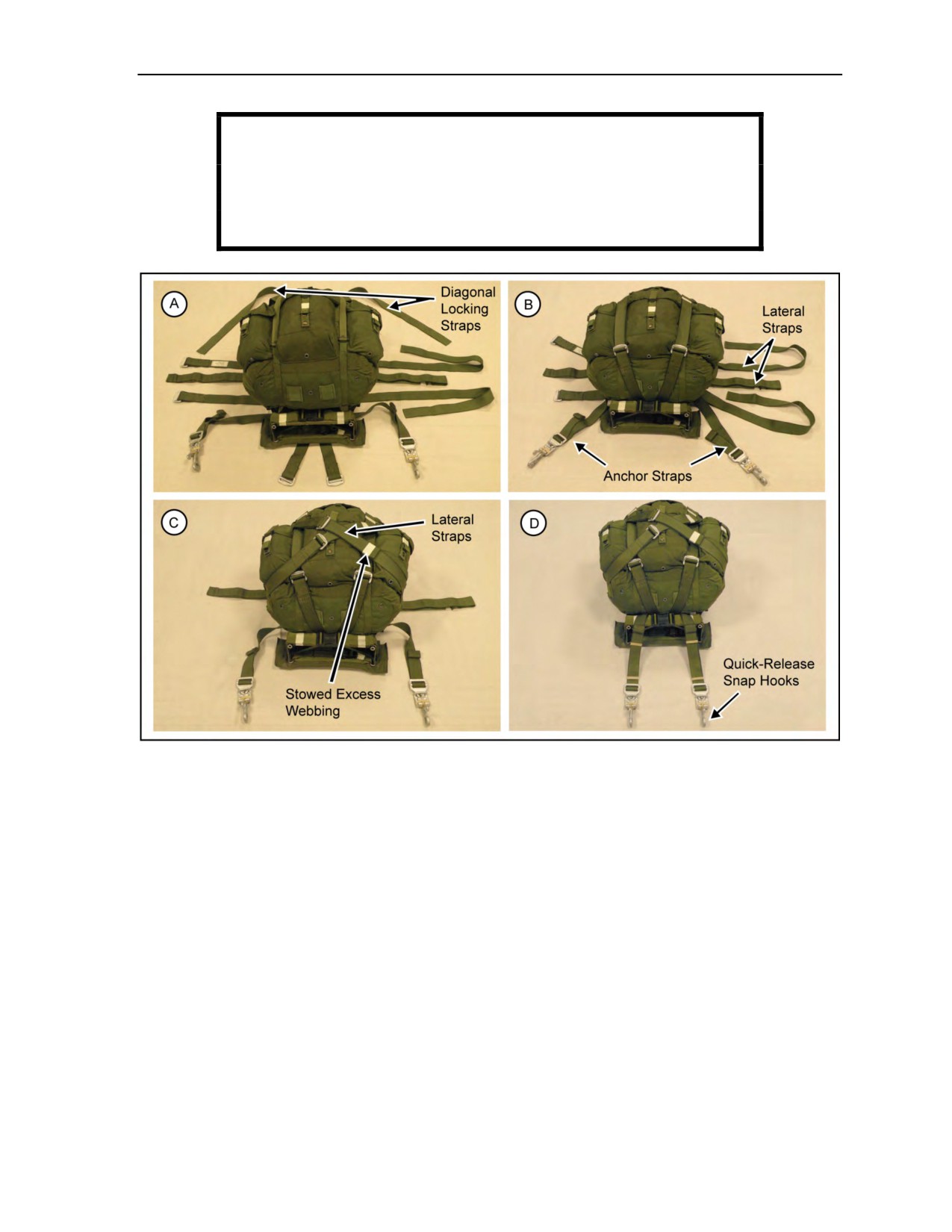
5-18. The parachutist—
z
Tightens and secures all straps on the pack and positions the pack with the frame up
(Figure 5-6A, page 5-9).
z
Positions the harness on the frame with the friction adapters on the diagonal locking straps at the
bottom of the frame and the running ends at the top of the frame.
z
Routes the diagonal locking strap friction adapters under the pack frame’s base.
z
Routes the anchor straps (parachute harness attaching straps with adjustable quick-release lugs)
and lateral locking straps under the shoulder straps and over the pack frame.
z
Turns the pack over and routes the running ends of the diagonal locking straps around the long
axis of the pack, across the straps at the center of the back.
z
Secures the diagonal locking straps to the respective friction adapters that protrude beneath the
bottom of the pack frame (Figure 5-6B, page 5-9).
z
Tightens the lateral locking straps and secures them around the pack and to their respective
friction adapters (Figure 5-6C, page 5-9).
Note: If the pack is small, the parachutist crosses and tightens the lateral locking straps and
secures them around the pack and to their opposite friction adapters.
z
Folds and secures the running ends of all straps with tape or ties them with 1/4-inch cotton
webbing.
z
Places the combat pack in an upright position.
z
Attaches a quick-release snap hook to each adjustable lug so that the latch handles face away
from his body when he attaches the combat pack to the equipment rings (Figure 5-6D).
5-8
ATP 3-18.11/AFMAN 11-411(I)/NTTP 3-05.26M
24 October 2014
Equipment and Weapon Rigging Procedures
WARNING
The parachutist tapes all combat pack shoulder strap quick-ejector
releases to preclude inadvertent release in free fall, causing
instability.
Figure 5-6. Combat pack and frame rigged with the improved equipment attachment sling
Attaching the Lowering Line
5-19. The parachutist—
z
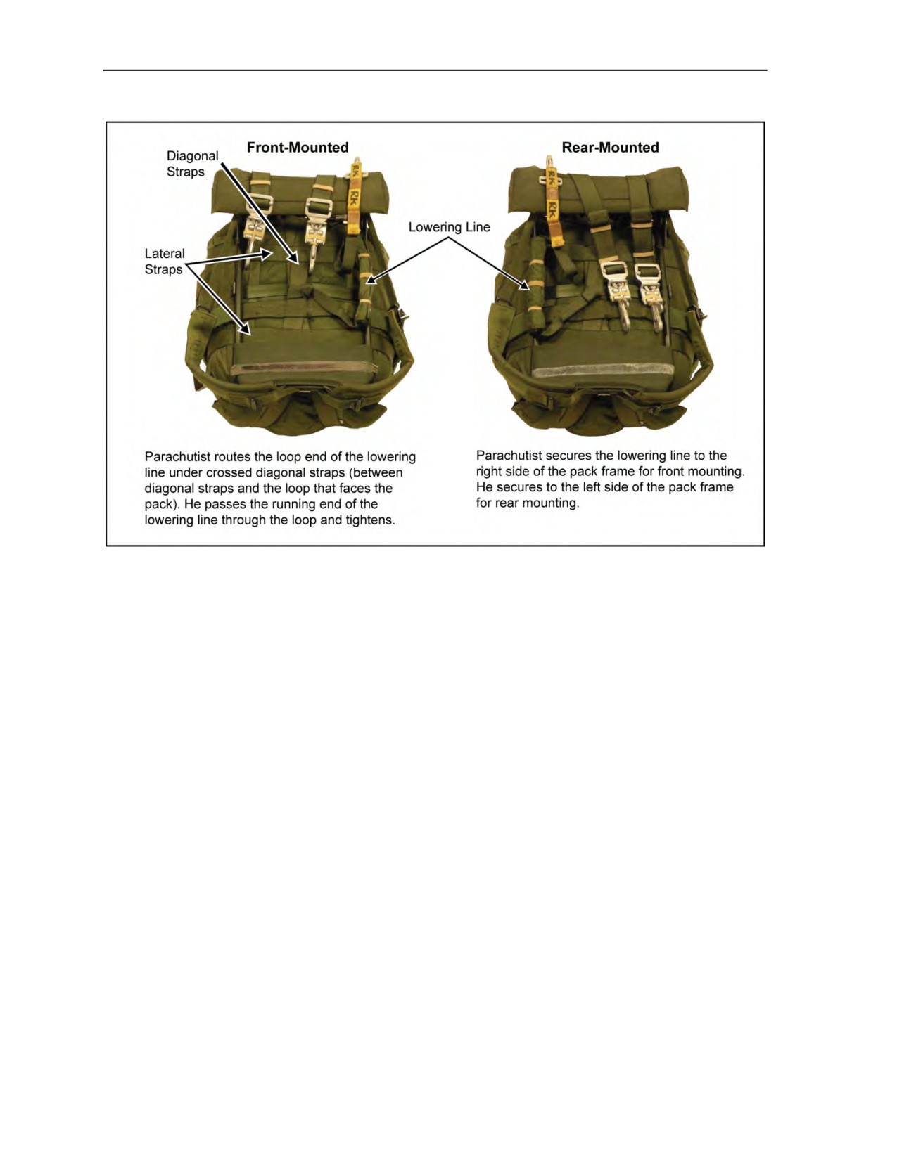
Routes the loop end of the lowering line under the crossed diagonal straps between the diagonal
straps and the loop on the backside of the diagonal straps.
z
Passes the running end of the lowering line through its own loop and tightens it (Figure 5-7,
page 5-10).
z
Makes S-folds with the remainder of the lowering line and places the S-folds into the retainer
pocket.
z
Secures the retainer pocket to the appropriate side of the pack frame (right side for front mount,
left side for rear mount) with retainer bands. He uses three retainer bands: two on the frame and
one double-wrapped around the center of the lowering line.
z
Removes the yellow release lanyard or, if it remains attached to the HPT lowering line, tapes it
to the lowering line with one single wrap of masking tape the length of the lanyard, leaving
1 to 2 inches exposed at the top of the lanyard.
z
Attaches the lowering line quick-ejector snap to the right-side lowering line attachment V-ring
(Figure 5-7).
24 October 2014
ATP 3-18.11/AFMAN 11-411(I)/NTTP 3-05.26M
5-9
Chapter 5
Figure 5-7. Attaching the lowering line to the combat pack
Attaching the Combat Pack
5-20. The parachutist attaches the combat pack with frame to himself in the same manner as the combat
pack without frame.
Attaching the Rear-Mounted Combat Pack
5-21. The parachutist—
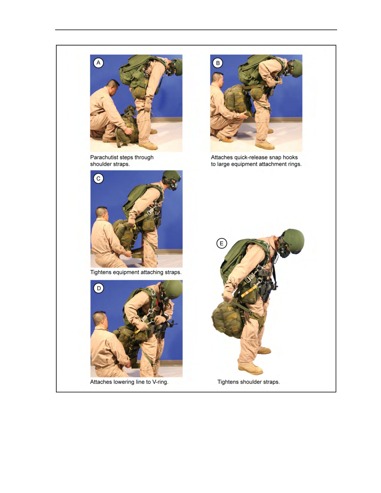
z
Loosens the shoulder straps and steps through the shoulder straps, one leg through each strap
(Figure 5-8A, page 5-11).
z
Attaches the quick-release snap hooks to the large equipment attachment rings on the main lift
webs (Figure 5-8B, page 5-11).
z
No. 2 lifts up on the pack and jumper pulls the slack out (Figure 5-8C, page 5-11). In this last
step, the parachutist could pull out the slack by himself by squatting and sitting on the pack.
z
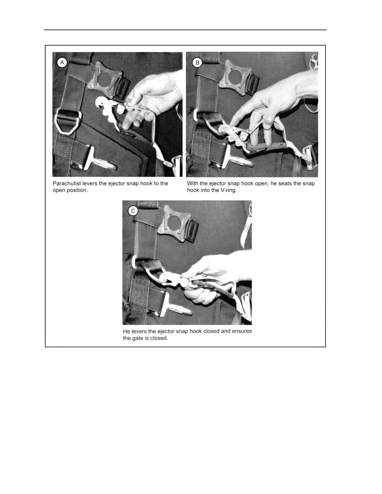
Attaches the lowering line to the right-side lowering line attachment V-ring on the parachute
harness (Figure 5-8D, page 5-11 and Figure 5-9, page 5-12).
z
Tightens shoulder straps around legs (Figure 5-8E, page 5-11).
5-10
ATP 3-18.11/AFMAN 11-411(I)/NTTP 3-05.26M
24 October 2014
Equipment and Weapon Rigging Procedures
Figure 5-8. Attaching the rear-mounted combat pack
24 October 2014
ATP 3-18.11/AFMAN 11-411(I)/NTTP 3-05.26M
5-11
Chapter 5
Figure 5-9. Lowering line attached to the lowering line attachment V-ring
Attaching the Front-Mounted Combat Pack
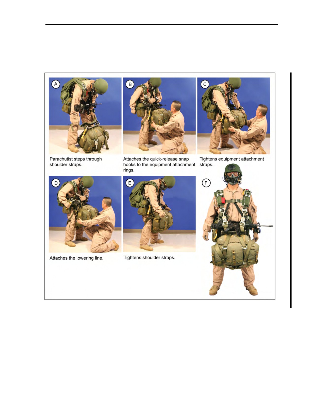
5-22. The parachutist—
z
Loosens the shoulder straps.
z
Faces the combat pack and steps through the shoulder straps, one leg through each strap
(Figure 5-10A, page 5-13).
z
Attaches the quick-release snap hooks to the equipment attachment rings on the main lift webs
(Figure 5-10B, page 5-13).
z
Tightens equipment attachment straps (Figure 5-10C, page 5-13).
5-12
ATP 3-18.11/AFMAN 11-411(I)/NTTP 3-05.26M
24 October 2014
Equipment and Weapon Rigging Procedures
z
Attaches the lowering line to the right-side lowering line attachment V-ring on the parachute
harness (Figure 5-10D).
z
Tightens shoulder straps (Figure 5-10E).
Figure 5-10F shows the parachutist rigged with the front-mounted combat pack.
Figure 5-10. Attaching the front-mounted combat pack
Releasing the Combat Pack
5-23. After his canopy deploys and when he is clear of other parachutists and has canopy control, the
parachutist will verify at 1,000 feet AGL that the HPT lowering line is still attached, cross fit (grip switch)
and pull both brakes to the half position, loosen the combat pack’s shoulder straps, and pull them clear of
the kit bag. He then detaches the combat pack’s left-side quick-release snap hook so that the pack falls
cleanly when released. When on his final approach and 500 feet above the ground, he ensures that the
ejector snap and HPT is still connected, then releases the second quick-release snap hook, catches his
combat pack with his feet, and flies to the desired landing point. Between 500 to 200 feet after turning on
18 August 2016
ATP 3-18.11/AFMAN 11-411(I)/NTTP 3-05.26M, C2
5-13

Chapter 5
final approach, the parachutist looks down and around to verify that airspace is clear and then ensures the
combat pack is fully lowered and off the feet before he lands. To jettison the combat pack, he releases the
lowering line’s quick-ejector snap, allowing the pack to fall free.
WARNING
The parachutist lowers all rear-mounted combat packs with
frames to avoid injury upon landing.
Note: If the combat pack is lowered before 200 feet AGL or the final approach and the
parachutist has to make turns, the combat pack will start to swing and the parachutist may
impact the ground the same time as the pack. No radical maneuvers should be made at the time
or point before landing.
USMC SINGLE-ACTION RELEASE PERSONAL EQUIPMENT LOWERING SYSTEM
5-24. The Single-Action Release Personal Equipment Lowering System
(SARPELS) is a complete
lowering system authorized for use by the USMC for both static-line and MFF parachute operations. The
SARPELS was designed to provide a single-point release capability for personal equipment carried by
military parachutists. USMC TM 10121A-12&P provides further information.
5-25. The system consists of the SARPELS cargo carrier, two D-ring attaching straps, two leg strap cable
retainers with buckle and grommet, the single-point release handle, a 15-foot static-line lowering line, and
an 8-foot MFF lowering line. The complete system weighs 9.5 pounds empty. The SARPELS cargo carrier
weighs 6 pounds empty and measures 22 inches long by 18 inches wide by 24 inches high. The 8-foot MFF
lowering line is made of 1-inch tubular nylon with a maximum capacity of 1,000 pounds.
Loading the SARPELS Cargo Carrier
5-26. The parachutist—
z
Loads personal supplies and equipment in the SARPELS cargo container in such a manner as to
maintain the general shape of the cargo container (Figure 5-11, page 5-15). He does not load
more than 110 pounds into the cargo container.
z
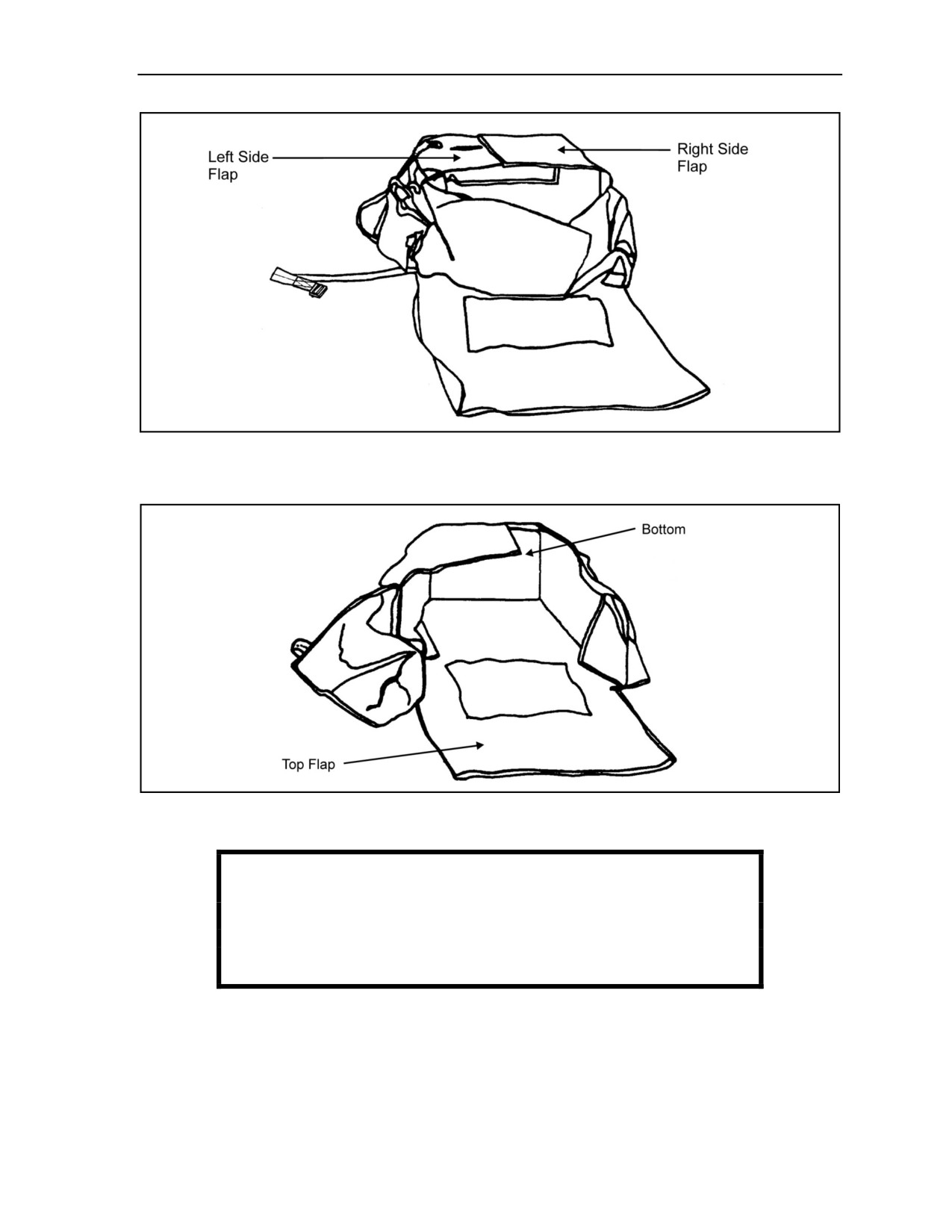
Standing from the top of the SARPELS, folds over the left side flap and then the right side flap
(Figure 5-12, page 5-15).
z
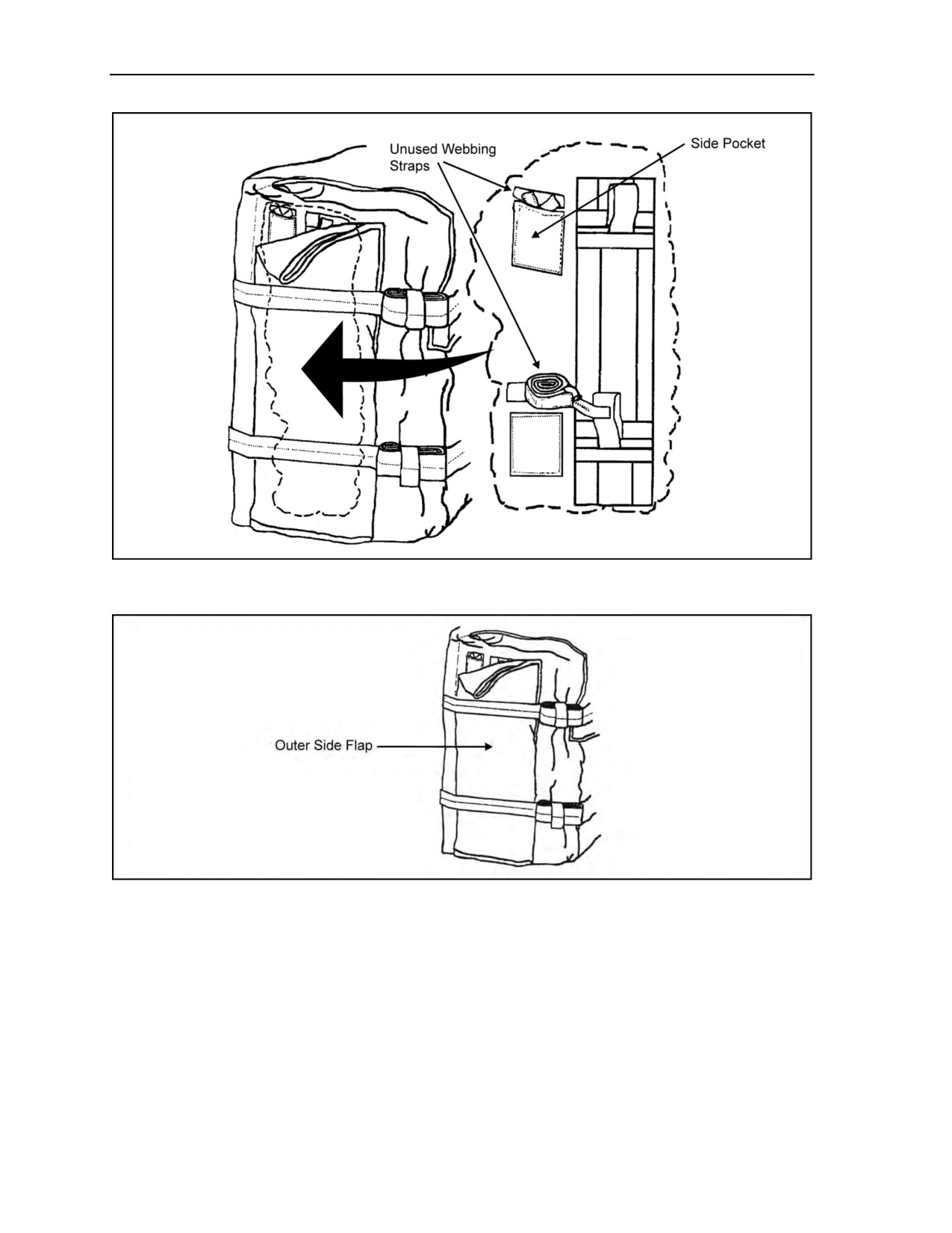
Stows the unused webbing straps into the small side pockets on either side of the SARPELS
cargo carrier (Figure 5-13, page 5-16).
z
Folds the outer side flaps in half and over the side pockets and straps (Figure 5-14, page 5-16).
z
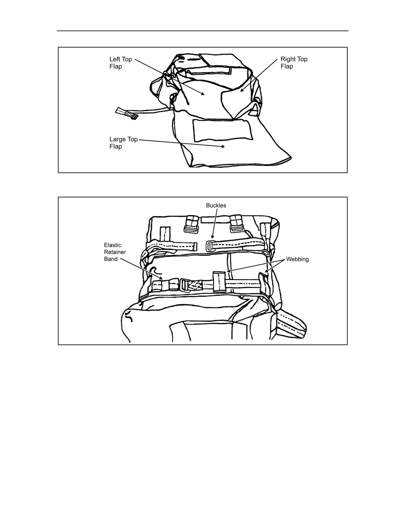
Still standing at the top, folds the left top flap and then the right flap (Figure 5-15, page 5-17).
z
Folds over the large top flap (Figure 5-15).
z
Inserts the horizontal straps through the webbing and buckles (Figure 5-16, page 5-17). On the
SARPELS model with three horizontal straps, the top strap is optional, depending on the size of
the cargo.
z
Roll-folds the excess webbing of the horizontal straps and secures them with the elastic retainer
band.
z
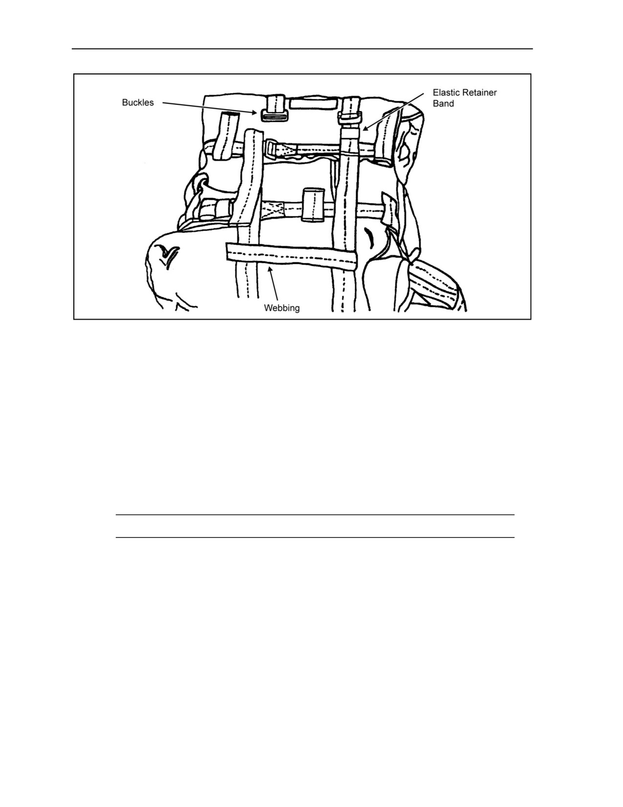
Inserts the vertical straps through the webbing and buckles (Figure 5-17, page 5-18).
z
Roll-folds the excess webbing of the vertical straps and secures them with the elastic retainer band.
5-14
ATP 3-18.11/AFMAN 11-411(I)/NTTP 3-05.26M, C2
18 August 2016
Equipment and Weapon Rigging Procedures
Figure 5-11. Opened Single-Action Release Personal Equipment Lowering System
cargo carrier
Figure 5-12. Single-Action Release Personal Equipment Lowering System
with folded side flaps
WARNING
Parachutists should not overload the SARPELS cargo carrier.
Personal injury may occur. The maximum safe load is
110 pounds.
24 October 2014
ATP 3-18.11/AFMAN 11-411(I)/NTTP 3-05.26M
5-15
Chapter 5
Figure 5-13. Stowage pockets
Figure 5-14. Side flap
5-16
ATP 3-18.11/AFMAN 11-411(I)/NTTP 3-05.26M
24 October 2014
Equipment and Weapon Rigging Procedures
Figure 5-15. Top flaps
Figure 5-16. Single-Action Release Personal Equipment Lowering System with secured
horizontal straps
24 October 2014
ATP 3-18.11/AFMAN 11-411(I)/NTTP 3-05.26M
5-17
Chapter 5
Figure 5-17. Single-Action Release Personal Equipment Lowering System with secured
vertical straps
Rigging the Single-Action Release Personal Equipment Lowering System Cargo Carrier
5-27. The parachutist—
z
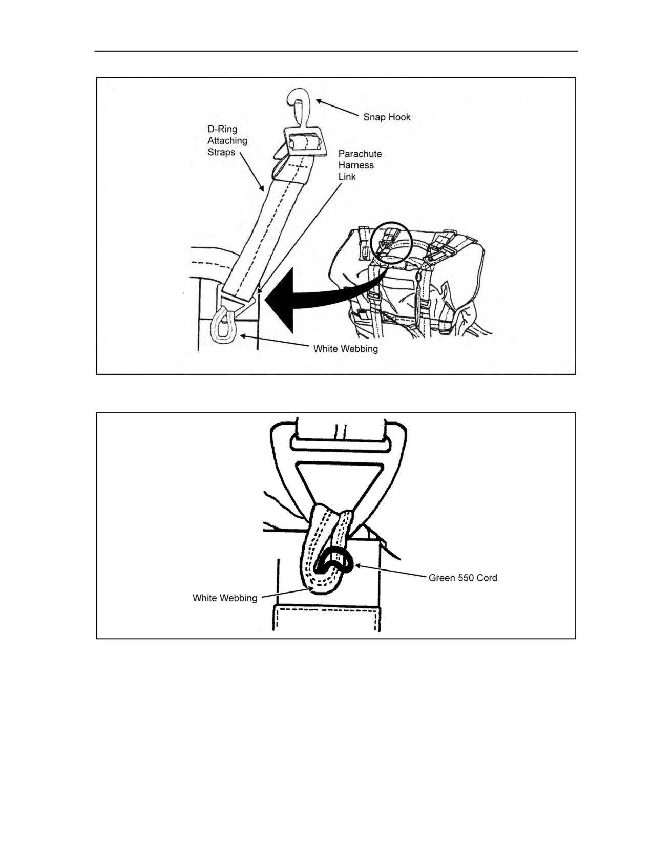
Feeds the white webbing of the SARPELS cargo carrier through the parachute harness link of
the D-ring attaching straps (Figure 5-18, page 5-19). He ensures that the opening to the snap
hooks of the D-ring attaching straps is facing down toward him.
z
Pulls the green 550 cord through the white webbing (Figure 5-19, page 5-19).
z
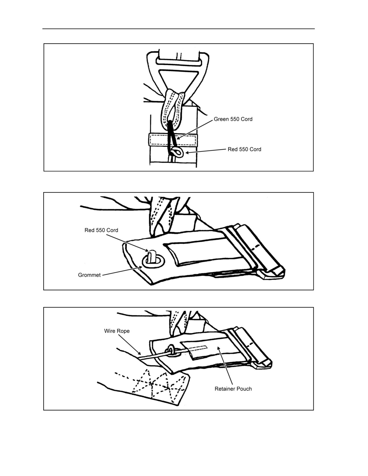
Pulls the red 550 cord through the green 550 cord (Figure 5-20, page 5-20).
z
Pulls the red 550 cord through the grommet of the leg strap (Figure 5-21, page 5-20).
z
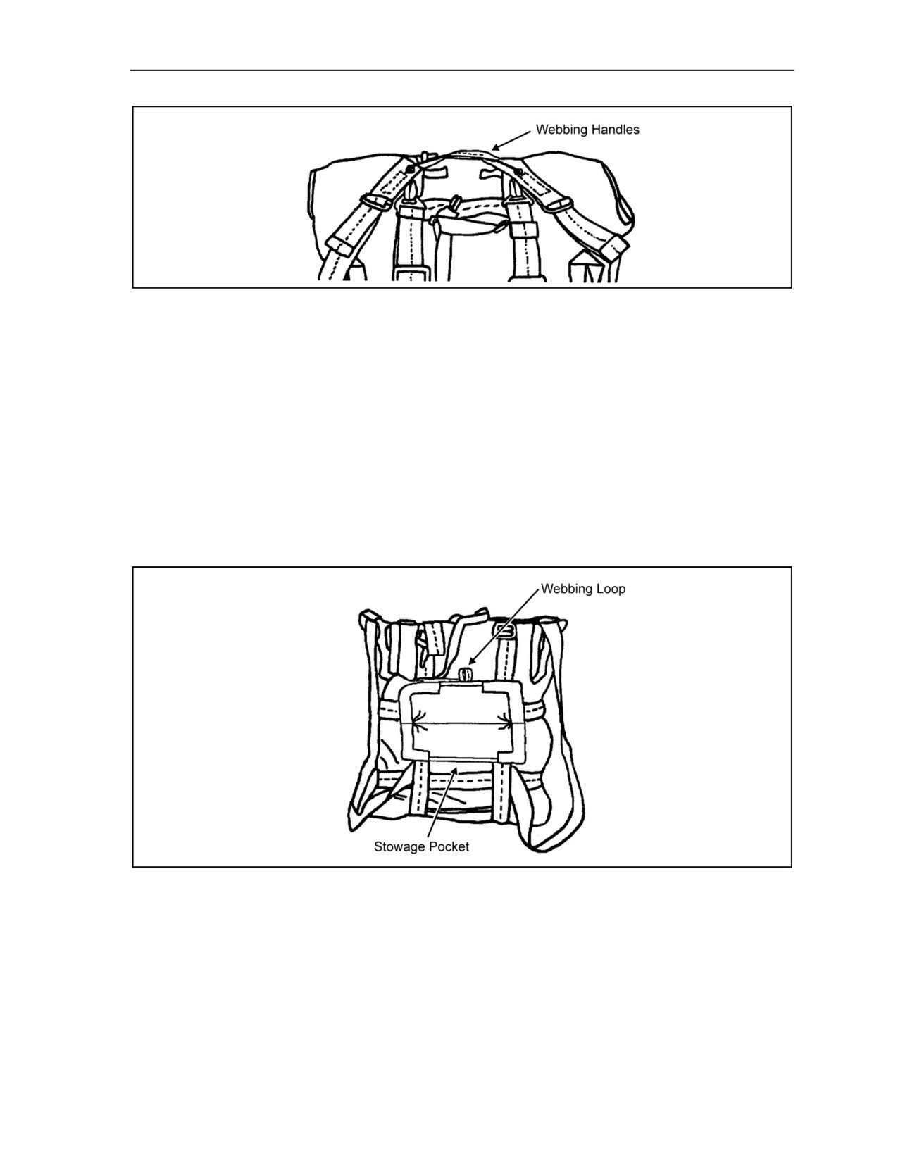
Runs the wire rope of the single-action release handle between the webbing handles (Figure 5-22,
page 5-20). Then he runs the wire rope through the red 550 cord and into the retaining pouch of
the leg strap cable retainers with buckle and grommet.
Note: The dotted line represents the wire rope hidden within the retainer pouch.
z
Secures the single-point release strap with the Velcro within webbing handles (Figure 5-23,
page 5-21).
5-18
ATP 3-18.11/AFMAN 11-411(I)/NTTP 3-05.26M
24 October 2014
Equipment and Weapon Rigging Procedures
Figure 5-18. Inserting the white webbing through the parachute harness link
Figure 5-19. Inserting the green 550 cord through the white webbing
24 October 2014
ATP 3-18.11/AFMAN 11-411(I)/NTTP 3-05.26M
5-19
Chapter 5
Figure 5-20. Inserting the red 550 cord through the green 550 cord
Figure 5-21. Inserting the red 550 cord through the grommet
Figure 5-22. Leg strap cable retainer with buckle and grommet
5-20
ATP 3-18.11/AFMAN 11-411(I)/NTTP 3-05.26M
24 October 2014
Equipment and Weapon Rigging Procedures
Figure 5-23. Single-Action Release Personal Equipment Lowering System release assembly
Installing the 8-Foot Military Free-Fall Lowering Line
5-28. The parachutist—
z
Uses the 8-foot-long lowering line for MFF operations using a RAPPS MC-4.
z
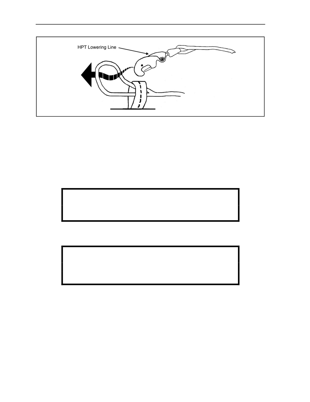
Attaches the lowering line through the sewn webbing loop on the backside of the SARPELS
carrier at the top of the stowage pocket (Figure 5-24).
z
Feeds the sewn loop of the lowering line through the sewn loop on the cargo carrier.
z
Inserts the quick-ejector snap through the sewn loop of the lowering line (Figure 5-25, page 5-22).
z
Pulls the entire lowering line through the loop and cinches it down.
z
S-folds the excess lowering line, secures it with an elastic retainer band, and places it in the
stowage pocket.
z
Closes the stowage pocket with the Velcro.
Figure 5-24. Stowage pocket with 8-foot lowering line
24 October 2014
ATP 3-18.11/AFMAN 11-411(I)/NTTP 3-05.26M
5-21
Chapter 5
Figure 5-25. Securing the 8-foot lowering line to the cargo carrier
Mounting the Single-Action Release Personal Equipment Lowering System Cargo Container
5-29. The parachutist—
z
Mounts the SARPELS cargo container to the large equipment attachment rings on the parachute
harness using the snap hook of the D-ring attaching straps (Figure 5-26, page 5-23).
z
Attaches the quick-ejector snap of the lowering line to the large equipment attachment rings on
the parachute harness.
z
Ensures the SARPELS cargo carrier is securely in place and is attached by the appropriate
lowering line.
WARNING
Personal injury may occur if the wrong lowering line is used.
z
Once under canopy, and in accordance with unit SOP, pulls the white webbing of the
single-point release handle to lower the equipment load (Figure 5-27, page 5-23).
WARNING
Parachutists must release the SARPELS cargo carrier before
landing to avoid personal injury.
5-22
ATP 3-18.11/AFMAN 11-411(I)/NTTP 3-05.26M
24 October 2014
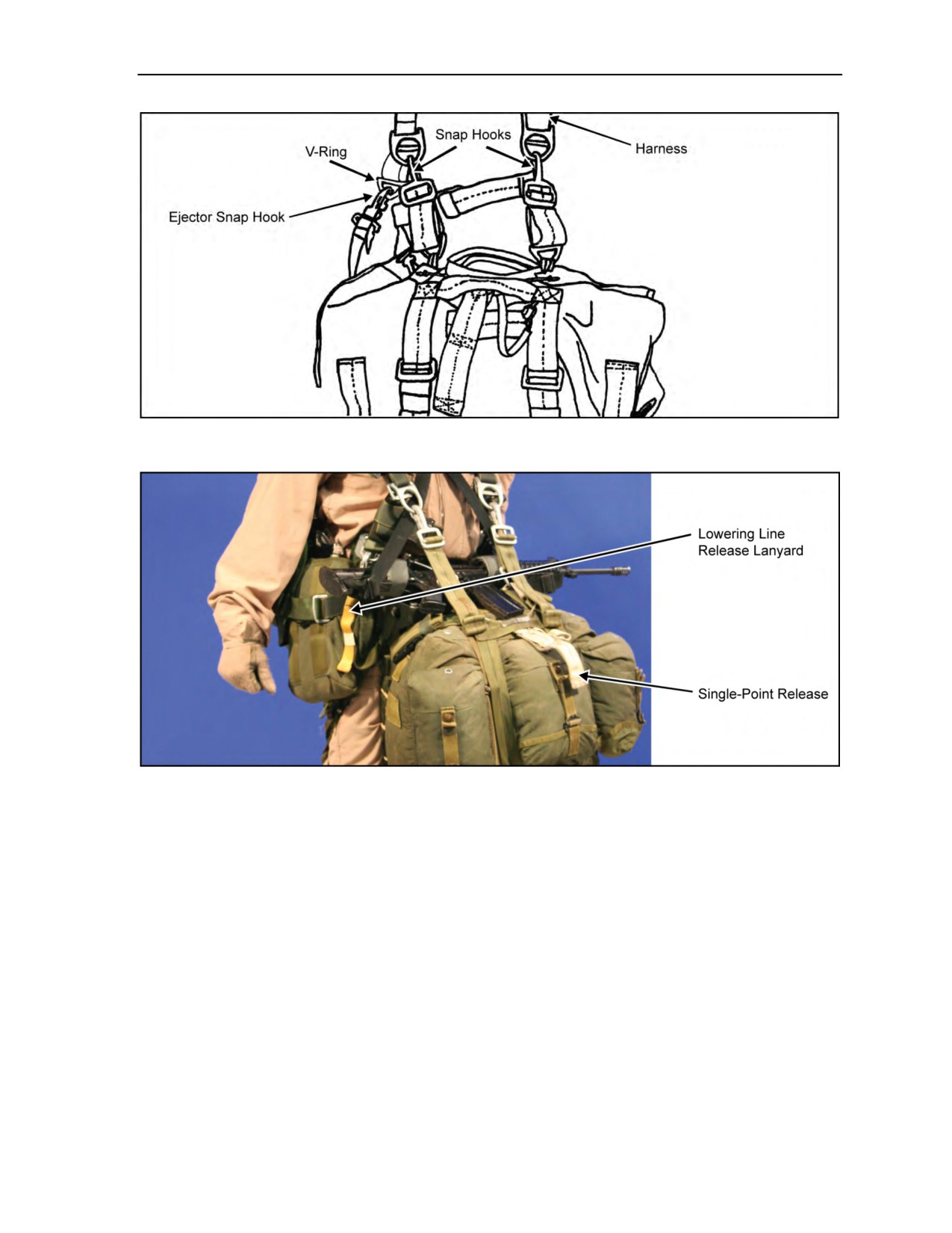
Equipment and Weapon Rigging Procedures
Figure 5-26. Mounted Single-Action Release Personal Equipment Lowering System
Figure 5-27. Single-point release handle
HARNESS, SINGLE-POINT RELEASE
5-30. The HSPR (Figure 5-28, page 5-24) is an H-type design for the parachutists. It is made of nylon
webbing, has friction adapters to secure it around the load, and has two adjustable D-ring attaching straps.
To stabilize the pack to the parachutist during movement in the aircraft, exit, free fall, and parachute
deployment, two adjustable leg straps secure the pack to the parachutist’s right and left legs. The leg straps
are equipped with the male portion of the leg strap release assembly. The harness has a single-point release
assembly that simultaneously releases the load and leg straps from the parachutist and parachute harness.
24 October 2014
ATP 3-18.11/AFMAN 11-411(I)/NTTP 3-05.26M
5-23
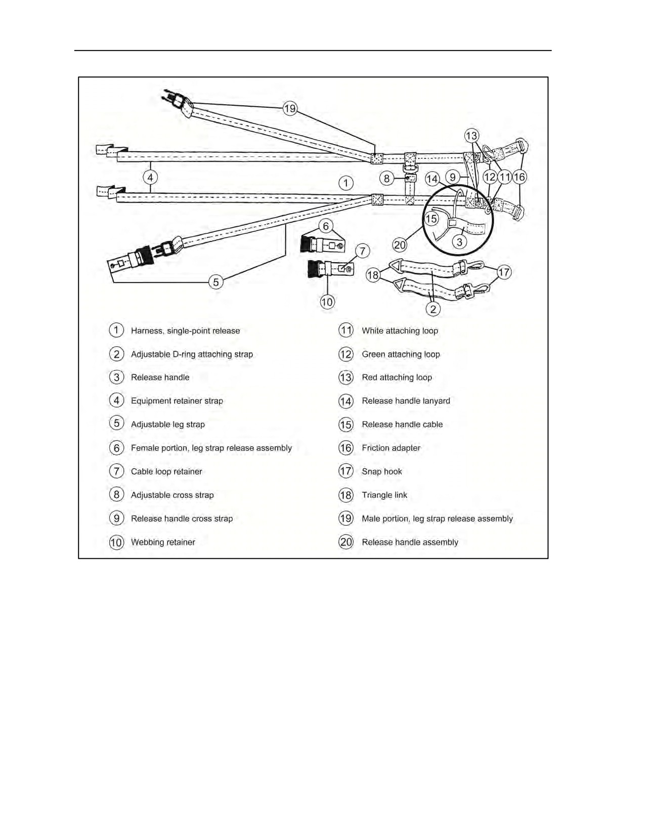
Chapter 5
Figure 5-28. Harness, single-point release (National Stock Number 1670-01-227-7992)
RIGGING THE ALL-PURPOSE, LIGHTWEIGHT, INDIVIDUAL, CARRYING
EQUIPMENT PACK WITH THE HARNESS, SINGLE-POINT RELEASE
5-31. Before attaching the HSPR to the all-purpose, lightweight, individual, carrying equipment (ALICE)
pack and Service-authorized combat pack, the release handle and adjustable D-ring attaching straps are
attached to the HSPR (Figure 5-29, page 5-25).
Packing Procedures
5-32. When packing the combat container, the parachutist conforms to the following procedures:
z
Pad and, if required, waterproof any fragile or sensitive gear, such as communications
equipment. Place these items toward the rear of the container, locating the gear closest to the
lowering line attachment point.
5-24
ATP 3-18.11/AFMAN 11-411(I)/NTTP 3-05.26M
24 October 2014
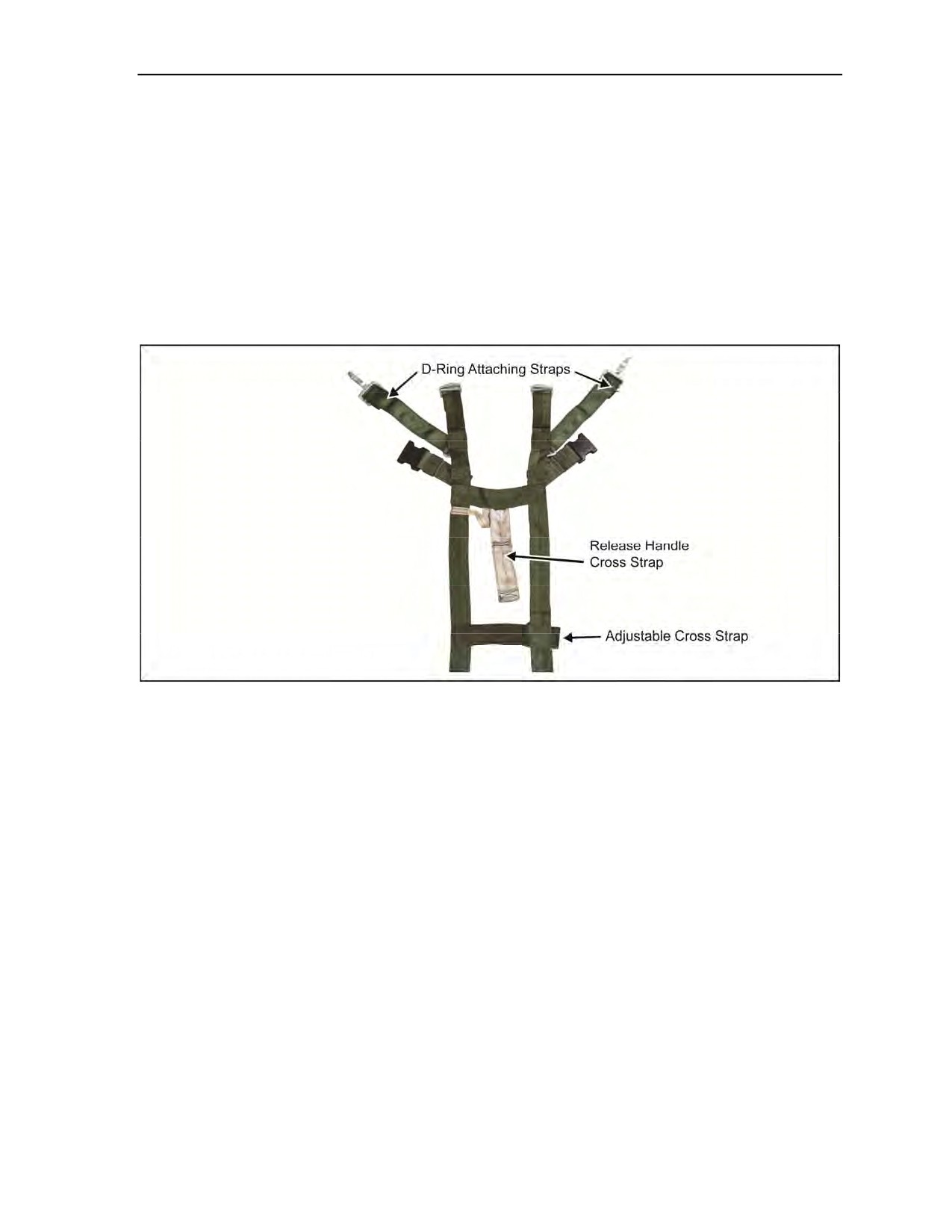
Equipment and Weapon Rigging Procedures
z
Continue waterproofing and packing the personnel load in accordance with team or platoon
SOPs.
z
Place equipment in combat container and padding between the load and the portion of the
container that will make contact with the ground first.
z
Fill outside pockets with nonfragile items and tape snaps to prevent opening during free fall. If
using the HSPR, full pockets help to keep harness in position.
z
Close combat container by engaging drawstrings and tie-down straps.
z
Roll and secure any excess webbing or drawstrings.
z
Route the running ends of the waist straps behind the frame and secure them by tying or taping.
z
If conducting a water jump, dip test equipment to assure positive buoyancy. If using the PDB,
dip test bag again after it is completely rigged.
Figure 5-29. Release handle and D-ring attaching straps
Harness, Single-Point Release
5-33. The HSPR is an equipment attachment sling designed to be used as an alternative to the PDB. It is
attached directly to the equipment being jumped. The parachutist pulls the single-release handle to lower
equipment to the end of an 8- or 15-foot lowering line.
5-34. The HSPR (Figure 5-28, page 5-24) is an H-type design for MFF parachutists. The harness is made
of nylon webbing, has friction adapters to secure it around the load, and has two adjustable D-ring attaching
straps.
5-35. Two adjustable leg straps secure the equipment to the parachutist’s right and left legs. This stabilizes
the equipment to the parachutist during movement in the aircraft, exit, free fall, and parachute deployment.
The leg straps are equipped with the male portion of the leg strap release assembly.
5-36. The harness has a single-point release assembly that simultaneously releases the load and leg straps
from the parachutist and parachute harness.
24 October 2014
ATP 3-18.11/AFMAN 11-411(I)/NTTP 3-05.26M
5-25
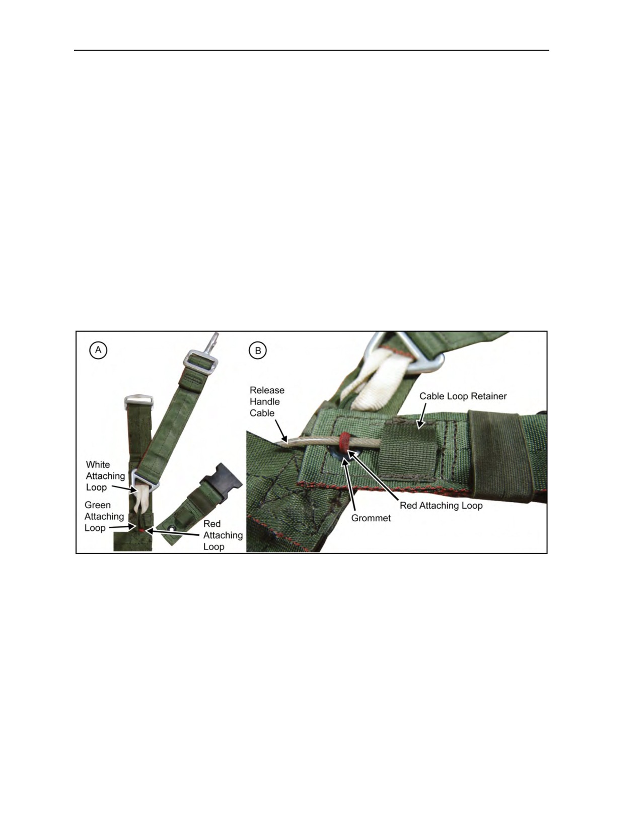
Chapter 5
Rigging Procedures
5-37. The parachutist performs the steps discussed below to rig the HSPR to the ALICE pack. The
parachutist—
z
Routes the two release handle cables between the two plies of the release handle cross strap.
z
Attaches the pile tape of the release handle to the hook tape attaching tab located between the
plies of the release handle cross strap. He ensures that the release handle lanyard is not
misrouted.
z
Places the triangle links of the adjustable D-ring attaching straps on top of the white attaching
loops.
z
Routes the white attaching loop up through the triangle link (Figure 5-30A).
z
Routes the green attaching loop up through the white attaching loop (Figure 5-30A).
z
Routes the red attaching loop up through the green attaching loop (Figure 5-30A).
z
Routes the red attaching loop through the grommet on the female portion of the leg strap release
assembly. He ensures that the cable loop retainer on the female portion of the leg strap release
assembly is facing up (Figure 5-30A).
z
Routes the release handle cable through the red attaching loop and then through the cable loop
retainer. He repeats the process for the other strap (Figure 5-30B).
z
Turns the harness over so that the adjustable D-ring attaching straps are on the bottom.
Figure 5-30. Attaching snap hooks and leg strap release assembly
z
Places the ALICE pack on top of the harness so that the middle outer cargo pocket is placed
between the release handle cross strap and the adjustable cross strap (Figure 5-31A, page 5-27).
z
Ensures the top of the pack is facing the equipment retainer straps (Figure 5-31A).
z
Routes the equipment retainer straps underneath the top of the frame, crosses them on the back
of the pack to form an X, and then routes them underneath the frame and the backrest of the pack
(Figure 5-31B, page 5-27).
5-26
ATP 3-18.11/AFMAN 11-411(I)/NTTP 3-05.26M
24 October 2014
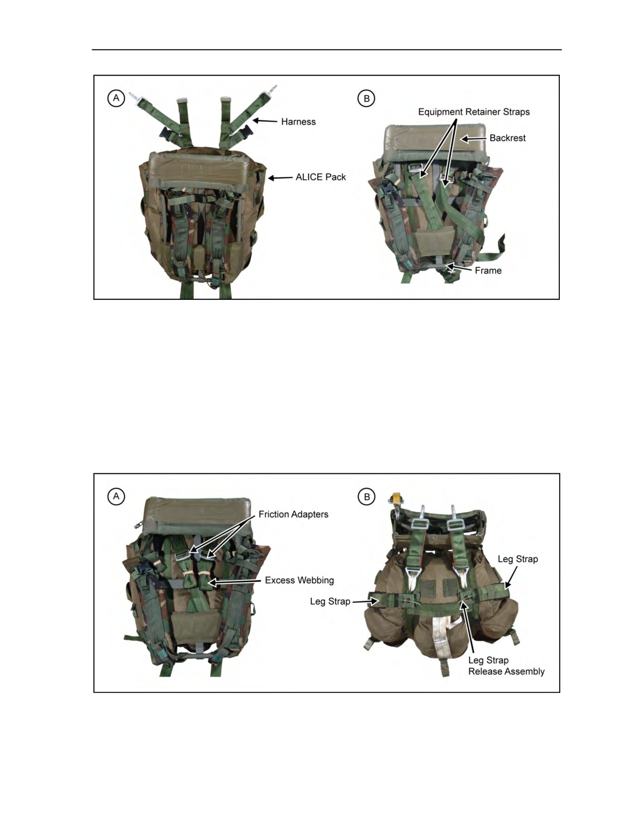
Equipment and Weapon Rigging Procedures
Figure 5-31. Rigging the harness, single-point release
z
Routes the equipment retainer straps through their appropriate friction adapters
(a two- or three-finger quick release is optional; if used, the quick-release loop is secured to the
harness with tape or a retainer band) (Figure 5-32A).
z
S-rolls the excess webbing and secures it with retainer bands or tape (separates from the quick-
release loop, if used) (Figure 5-32A).
z
Tightens the shoulder straps.
z
Routes the adjustable leg straps around the pack and attaches the male portion of the leg strap
release assembly to the female portion of the leg strap release assembly, leaving it connected
until it is time to attach the combat pack to the parachutist (Figure 5-32B). The HSPR leg strap
release (male portion) may be routed through the pack, between the frame and pack, on shorter
parachutists to allow tighter attachment of the rucksack.
Figure 5-32. Completing rigging the harness, single-point release
24 October 2014
ATP 3-18.11/AFMAN 11-411(I)/NTTP 3-05.26M
5-27
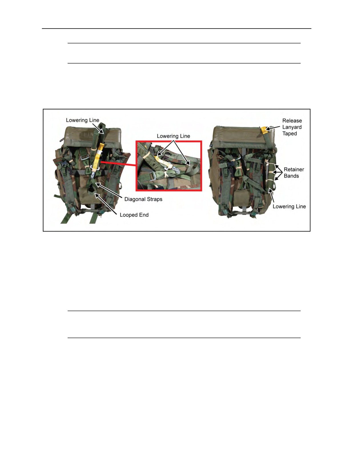
Chapter 5
Note: Oscillation under canopy is dramatically increased when using the 15-foot HPT lowering
line.
Hook-Pile Tape Lowering Line Assembly
5-38. The parachutist attaches the HPT lowering line in the same way as with the modified H-harness for a
front-mounted combat pack (Figure 5-33). The 8-foot HPT lowering line is normally used for MFF
operations. Terrain considerations may require use of a 15-foot HPT and is authorized.
Figure 5-33. Attaching the hook-pile tape lowering line assembly
5-39. The current HPT lowering line assembly consists of an 8- or 15-foot lowering line made of
1-inch wide tubular nylon. The 8-foot lowering line is recommended for most equipment. A 9- by 7-inch
nylon duck retainer is sewn to the upper end. The closing flaps have HPT sewn to the edges with a metal
ejector snap on a yellow safety release.
ATTACHING THE HARNESS, SINGLE-POINT RELEASE-RIGGED COMBAT EQUIPMENT
TO THE PARACHUTIST
5-40. The buddy system, or the seat of the aircraft, should be used to attach the HSPR to the parachutist.
Note: Parachutists can use either the shoulder straps or the leg straps to secure the combat
equipment to the legs when using the HSPR. The same sequence is followed for attaching the
front-mounted combat pack using the HPT.
5-41. The parachutist performs the steps discussed below to attach the HSPR-rigged combat equipment
(Figure 5-34, page 5-29):
z
The parachutist loosens shoulder straps and steps through them, if used in this configuration and
not the HSPR leg straps. If not, continue to next step.
z
Parachutist #1 grasps the harness by the two adjustable D-ring attaching straps and secures the
snap hooks to the large equipment attachment rings directly below the three-ring release
assemblies.
z
Parachutist
#1 attaches the quick-ejector snap on the HPT lowering line to the right-side
lowering line attachment V-ring on the parachute harness.
5-28
ATP 3-18.11/AFMAN 11-411(I)/NTTP 3-05.26M
24 October 2014
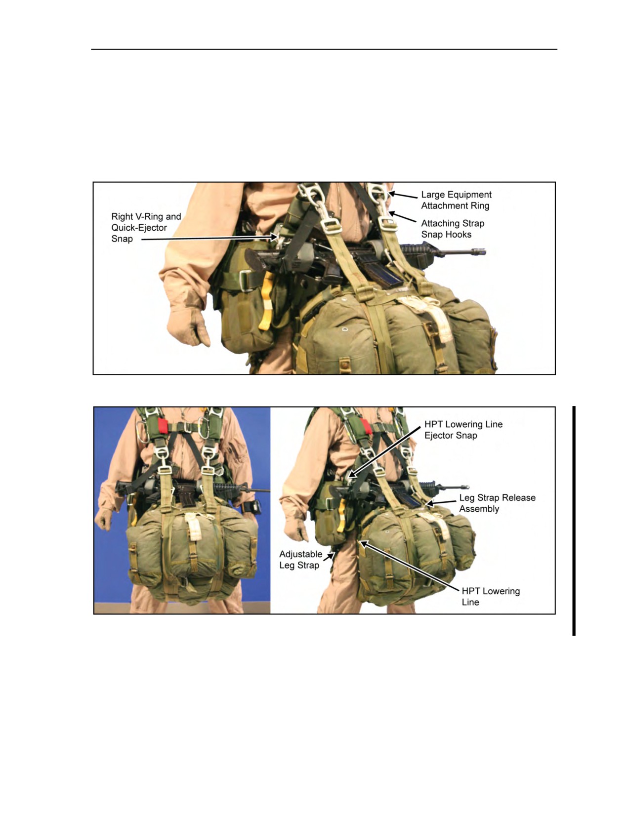
Equipment and Weapon Rigging Procedures
z
Parachutist #2 (if using the adjustable leg straps) routes the adjustable leg straps around the
parachutist #1’s legs and attaches the male portion to the female portion of the leg strap release
assembly. If using the shoulder straps, this step is skipped.
z
Parachutist #1 pulls on the free-running ends of the adjustable D-ring attaching straps and
tightens the pack up to the large equipment attachment rings.
z
Parachutist #1 folds the excess webbing and secures it in the webbing retainer.
Figure 5-35 shows the completed HSPR-rigging of the combat pack.
Figure 5-34. Attaching the harness, single-point release-rigged combat equipment
Figure 5-35. Parachutist with harness, single-point release-rigged combat pack
PARACHUTIST DROP BAG
5-42. The PDB is a fast, easy, and secure way of carrying the parachutist’s rucksack and load-bearing
equipment in free-fall or static-line operations. The bag opens and closes quickly so that the equipment can
be secured efficiently on the DZ. There are exterior pockets for water and maps so that the parachutist does
not have to get into his rucksack on the aircraft. There is an integral 8-foot lowering line attached to the
bag. The bag is reversible with shoulder straps on both sides. The side with the hardware for dropping is
18 August 2016
ATP 3-18.11/AFMAN 11-411(I)/NTTP 3-05.26M, C2
5-29
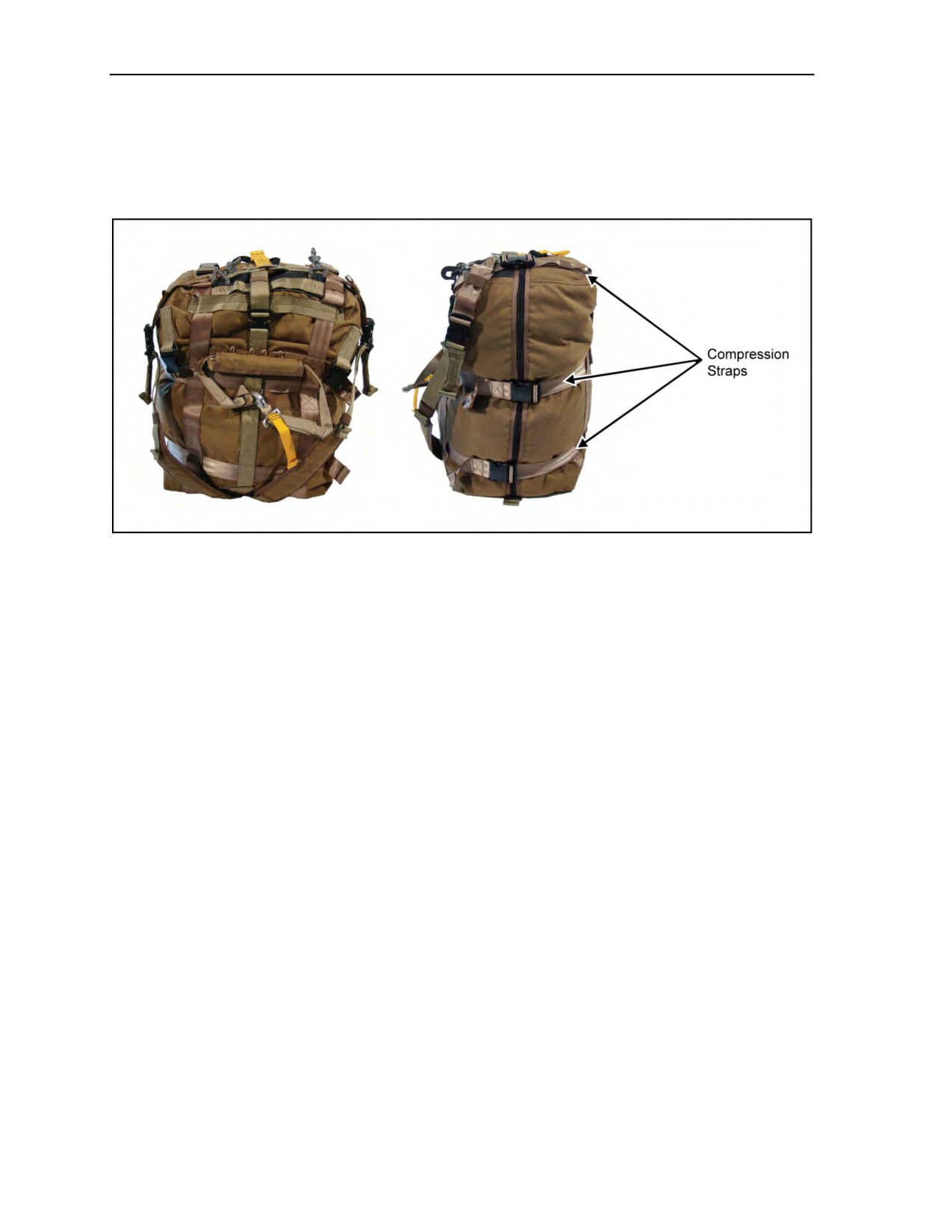
Chapter 5
camouflage in color, allowing the parachutist to put his parachute into it on the DZ for a hasty cache. The
other side is dark gray, which presents a visually lower profile so that equipment can be carried through an
airport. The standard size of the PDB is medium (Figure 5-36); this size will allow most parachutists to put
a mission combat pack and load-bearing equipment in the bag. The smallest bag possible should be used so
the straps can compress the load to prevent the contents of the PDB from shifting.
Figure 5-36. Compression straps connected and tightened
LOADING THE DROP BAG
5-43. The parachutist opens the bag completely, forming an “open clamshell.” He places the rucksack and
load-bearing equipment on the open bag (Figure 5-37, page 5-31). The hip pad of the rucksack should be
against the top of the side facing the parachutist (as the bag hangs on the harness). The parachutist then zips
the bag shut and connects and tightens the compression straps (Figure 5-38, page 5-31).
5-44. After loading bag and securing any excess webbing, the parachutist girth hitches the lowering line to
the attaching point and stows it in the pouch on the outside of the bag. After stowing is completed, he sets
up the quick-release assembly using the same procedures as on the HSPR. The parachutist then does the
following:
z
Stows and mates the Velcro on the release handle with the cables facing toward the white loops.
z
Ensures the release handle lanyard is not misrouted.
z
Threads white attaching loop through the triangle link.
z
Threads green loop through white loop and red loop through green loop.
z
Threads red loop through the grommet on the female portion of the leg strap release assembly
with the cable loop retainer facing up.
z
Threads release cable through red loop and into the cable loop retainer.
z
Repeats the same process on the other side.
5-30
ATP 3-18.11/AFMAN 11-411(I)/NTTP 3-05.26M, C2
18 August 2016
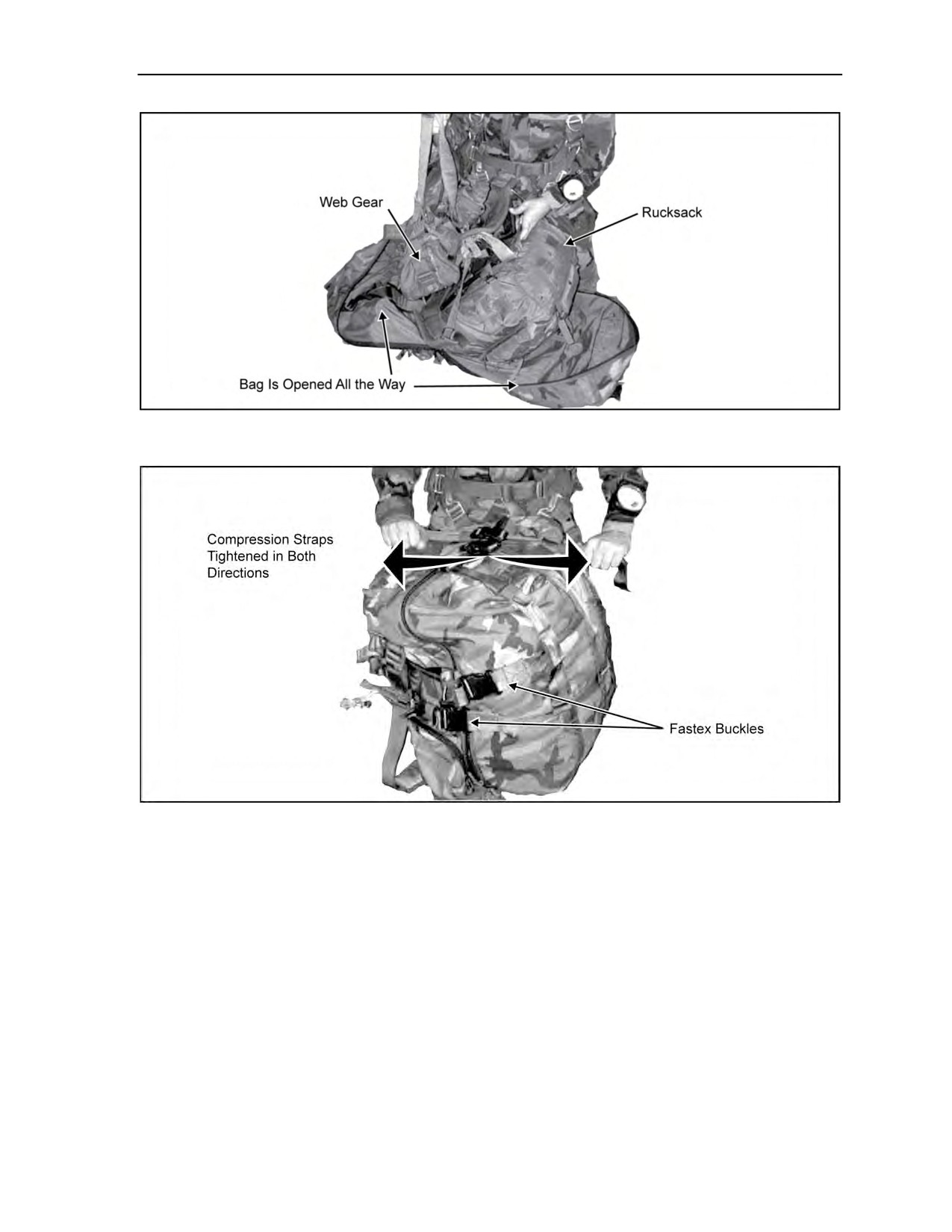
Equipment and Weapon Rigging Procedures
Figure 5-37. Loading the drop bag
Figure 5-38. Drop bag zipped shut with compression straps
connected and tightened
ATTACHING THE DROP BAG
5-45. The PDB can be attached to the front or rear of the parachutist. The PDB attaches to the parachutist
by standard quick-release connectors (Figure 5-39, page 5-32) found in any rigger facility. The equipment
attachment straps are long enough for the parachutist to connect the bag to his parachute harness’s upper
large equipment rings while the bag rests on the floor. The bag should be up against the bottom of the
container, allowing approximately four inches between the bottom of the container and the top of the PDB
when jumping the bag in the rear (Figure 5-40, page 5-32), and as close as possible to the equipment
attachment rings when jumping the bag in front (Figure 5-41, page 5-33). The excess webbing on the
attachment straps should be stowed in the elastic bands on the strap itself prior to jumping. The integral
lowering line is identical to that already used by parachutists. It attaches in the same manner to the lower
attachment point V-ring. The integral lowering line may also be girth hitched to a Stubi-85 (locking
carabiner) and the equipment lowering line V-ring to allow for quick derigging on the ground.
24 October 2014
ATP 3-18.11/AFMAN 11-411(I)/NTTP 3-05.26M
5-31
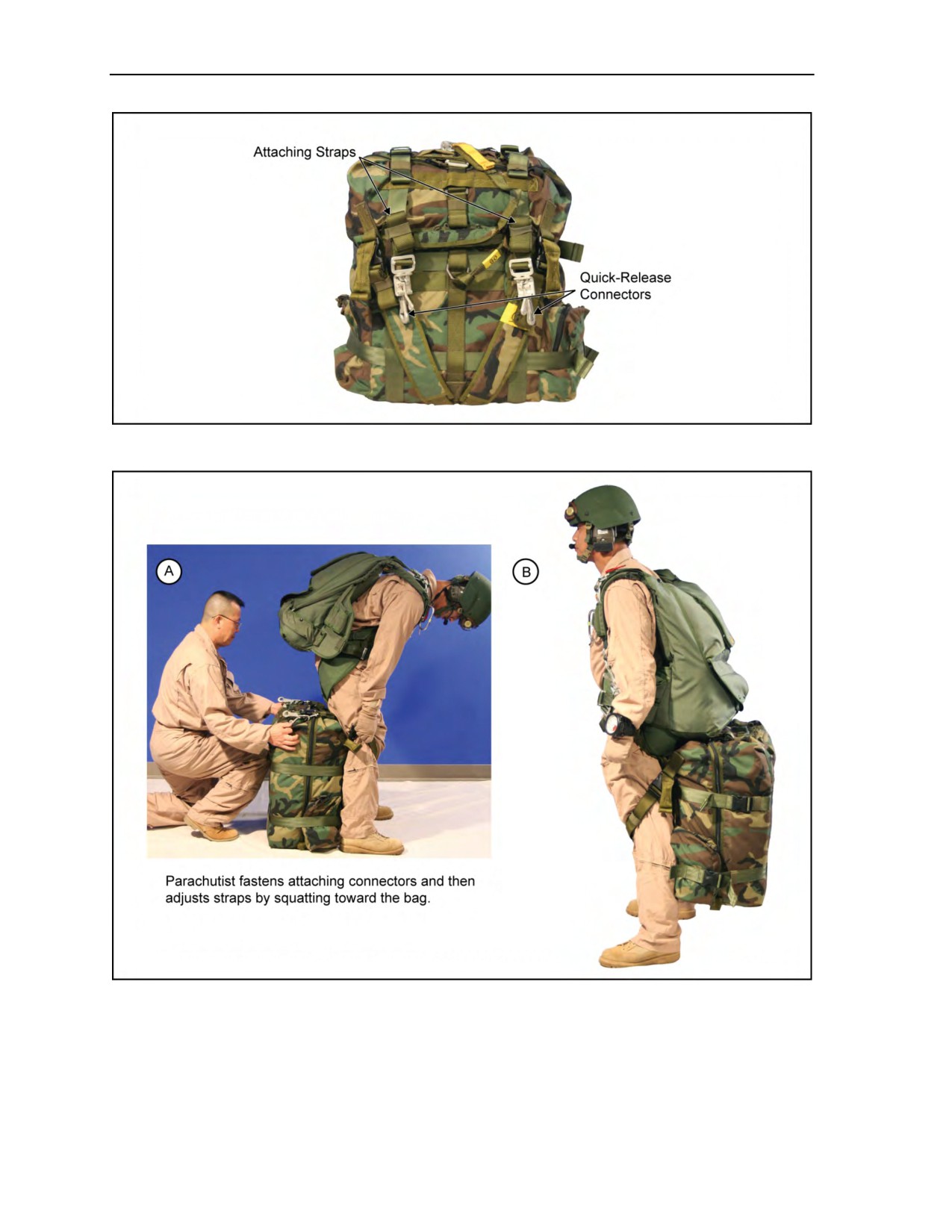
Chapter 5
Figure 5-39. Drop bag is attached to the parachutist by standard quick-release connectors
Figure 5-40. Parachutist drop bag rigged for rear-mounted jump
5-32
ATP 3-18.11/AFMAN 11-411(I)/NTTP 3-05.26M
24 October 2014
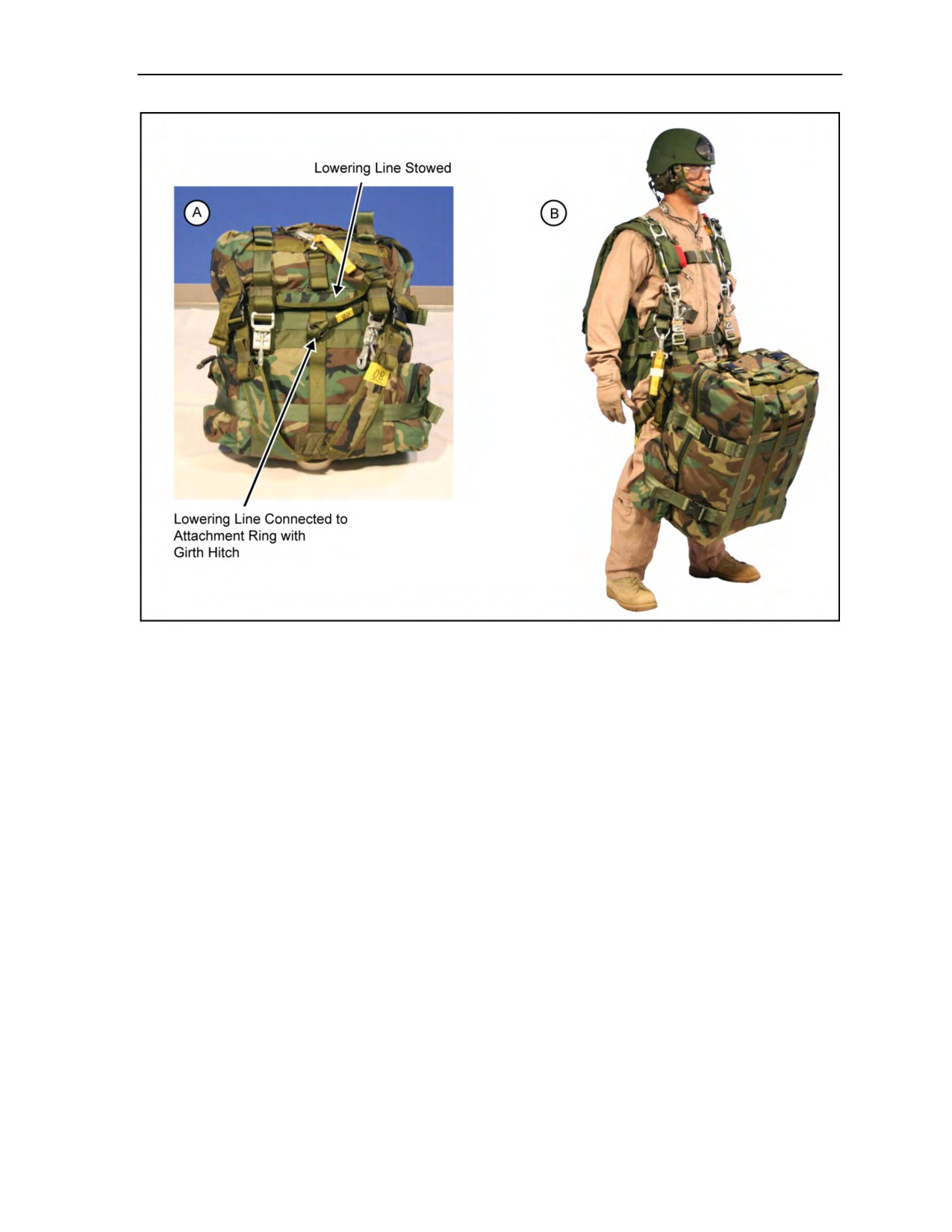
Equipment and Weapon Rigging Procedures
Figure 5-41. Parachutist drop bag rigged for front-mounted jump
JUMPING THE DROP BAG
5-46. The bag is jumped in an identical manner as the standard rucksack. The shoulder straps (used as leg
straps while jumping) should be tightened around the thighs, but not so tight as to restrict movement. Once
under canopy, the pull-tabs on the shoulder straps (leg straps) can be pulled to loosen the straps from
around the legs.
DERIGGING THE DROP BAG
5-47. Once on the ground, the parachutist detaches the lowering line from the parachute. He then
unbuckles all of the Fastex buckles securing the compression straps around the bag. The zipper closing the
bag can be ripped open by pulling apart both sides of the bag, exposing the load. The parachutist removes
the load and puts the parachute into the bag for storage or a hasty cache.
WEAPON RIGGING PROCEDURES
5-48. An MFF parachutist can jump with his individual weapon exposed or inside a weapons container or
another approved container. Weapons may be attached to the left or right side of the parachutist. When
jumping with oxygen, the weapon should be rigged on the left side. If jumping with multiple weapons, the
larger weapon should be attached to the left side or rigged horizontally on top of the combat pack with
smaller weapon attached to the right side of the parachutist (Figure 5-42, page 5-34). The parachutist can
jump with a pistol in a shoulder holster or in an equipment container. The parachutist should wear a
shoulder holster under the jumpsuit or other protective clothing. The parachutist should secure the pistol in
the holster by taping the holster closed using an airborne strap or by using a lanyard that will not interfere
with the jumper or parachute system.
18 August 2016
ATP 3-18.11/AFMAN 11-411(I)/NTTP 3-05.26M, C2
5-33
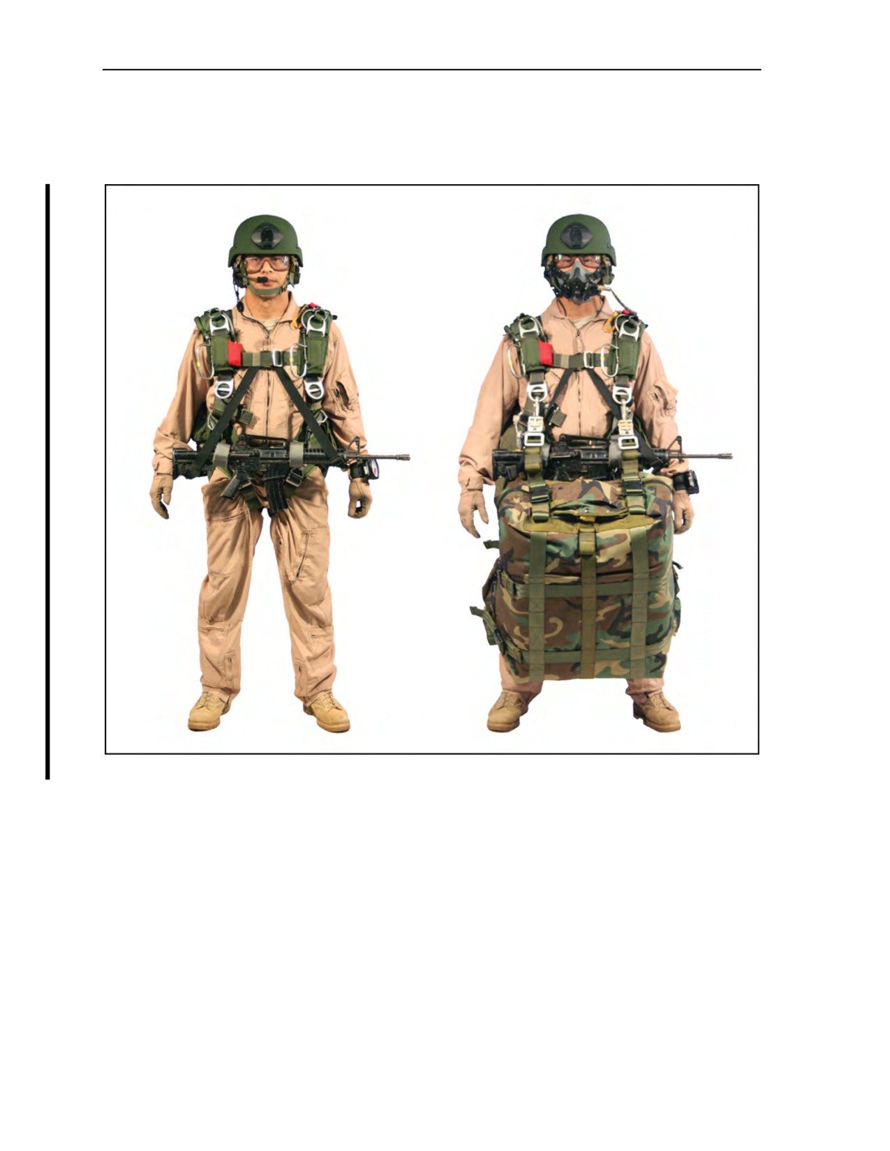
Chapter 5
CENTER-MOUNTED WEAPONS HARNESS
5-49. The center-mounted weapons harness (Figure 5-42) is in response to USASOC’s need for a weapons
harness that allows the parachutist ease of donning and doffing during MFF operations.
Figure 5-42. Center-mounted weapons harness
5-50. Over 150 MFF operations have been conducted using the center-mounted weapons harness at the
MFF School and during user assessments as part of the Arc Angel MFF Training. The harness is
manufactured using the following components (Figure 5-43, page 5-35):
z
Weapons harness uses 1-3/4-inch nylon tape backing with pile sewed the length and two,
non-nylon-based male end adapters. The additional straps on the weapons harness use 1-3/4-inch
nylon tape with either pile or hook sewn to the center of the weapons harness. This forms a triple
fold of hook and pile to secure weapons when worn in the vertical configuration. Length of the
weapons harness is 24 inches.
z
Main lift web attaching points use three sections of hook and pile sewn in a triple-fold
configuration with
1-3/4-inch nylon tape as a backing with two female non-nylon-based
adapters. Length of main lift web adapters, including female adapters, is 10 inches.
z
Horizontal attaching straps use three sections of hook and pile sewn in a triple-fold configuration
with 1-3/4-inch nylon tape as a backing. Length of horizontal attaching straps is approximately
20 inches.
5-34
ATP 3-18.11/AFMAN 11-411(I)/NTTP 3-05.26M, C2
18 August 2016
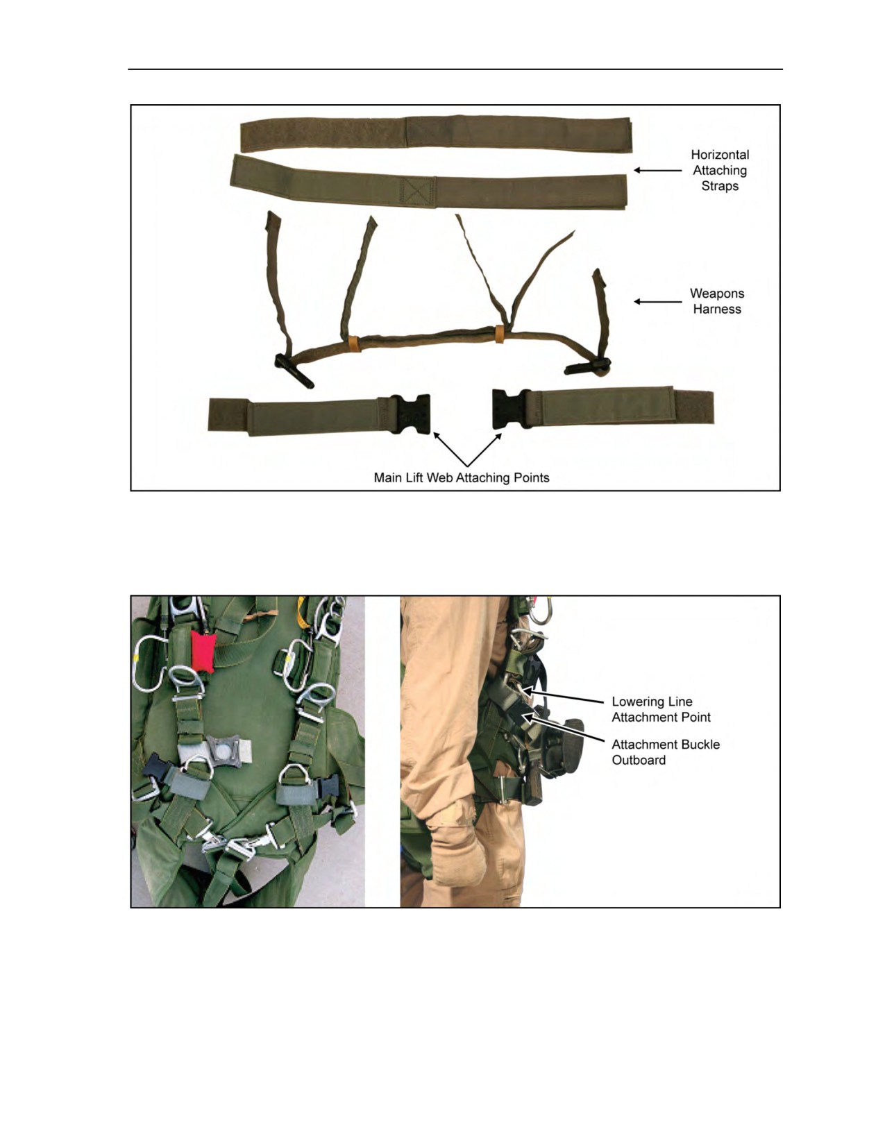
Equipment and Weapon Rigging Procedures
Figure 5-43. Center-mounted weapons harness components
5-51. To use this harness, the parachutist—
z
Attaches main lift web attaching points to the main lift web of the MC-4 harness below the
lowering line attachment point with the attachment buckle outboard (Figure 5-44).
Figure 5-44. Main lift web attaching points
24 October 2014
ATP 3-18.11/AFMAN 11-411(I)/NTTP 3-05.26M
5-35
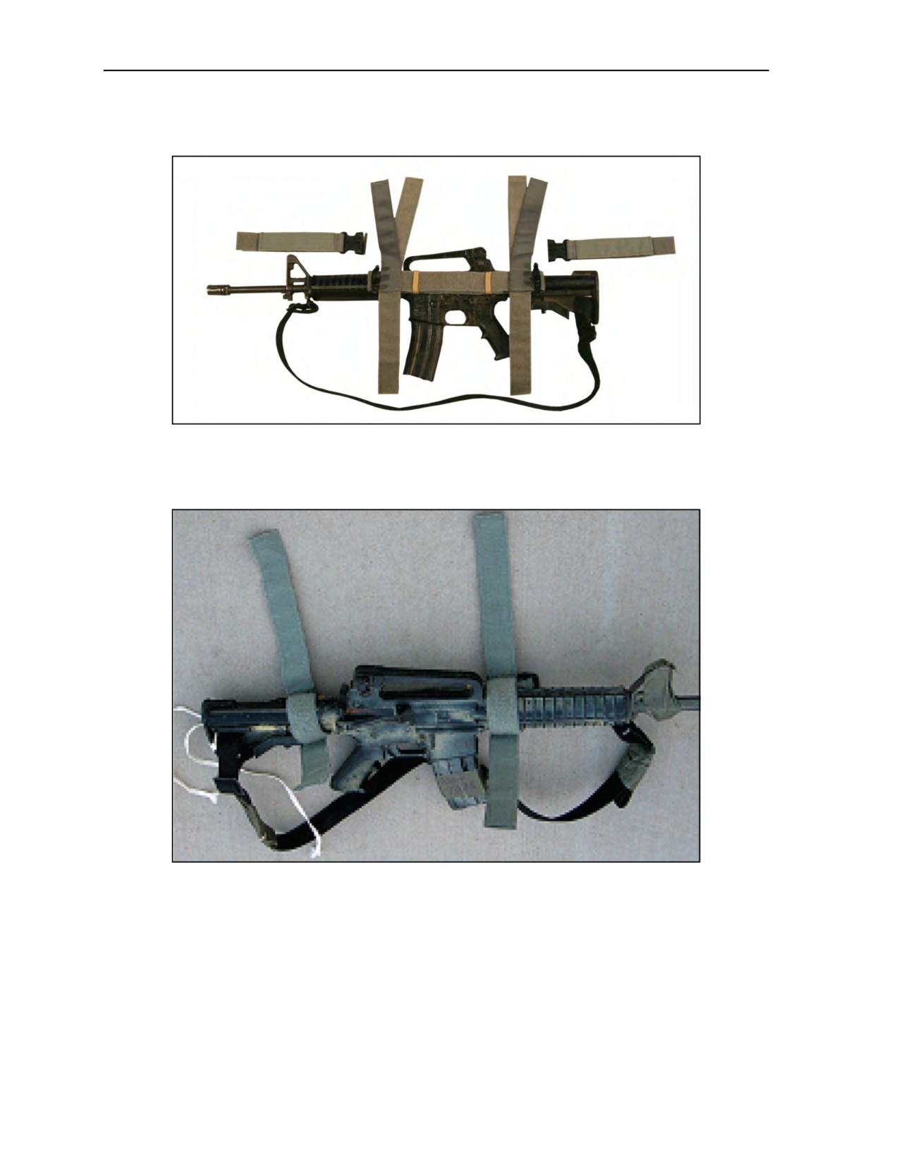
Chapter 5
z
For horizontal configuration, attaches horizontal straps to the pile portion of the weapons harness
as close as possible to the male portion of the Fastex buckles (Figure 5-45).
Figure 5-45. Attaching horizontal straps to the pile portion weapons harness
z
Uses triple-fold hook and pile to secure weapon harness to weapon (Figure 5-46, below, and
Figure 5-47, page 5-37).
Figure 5-46. Securing triple-fold hook and pile
5-36
ATP 3-18.11/AFMAN 11-411(I)/NTTP 3-05.26M
24 October 2014
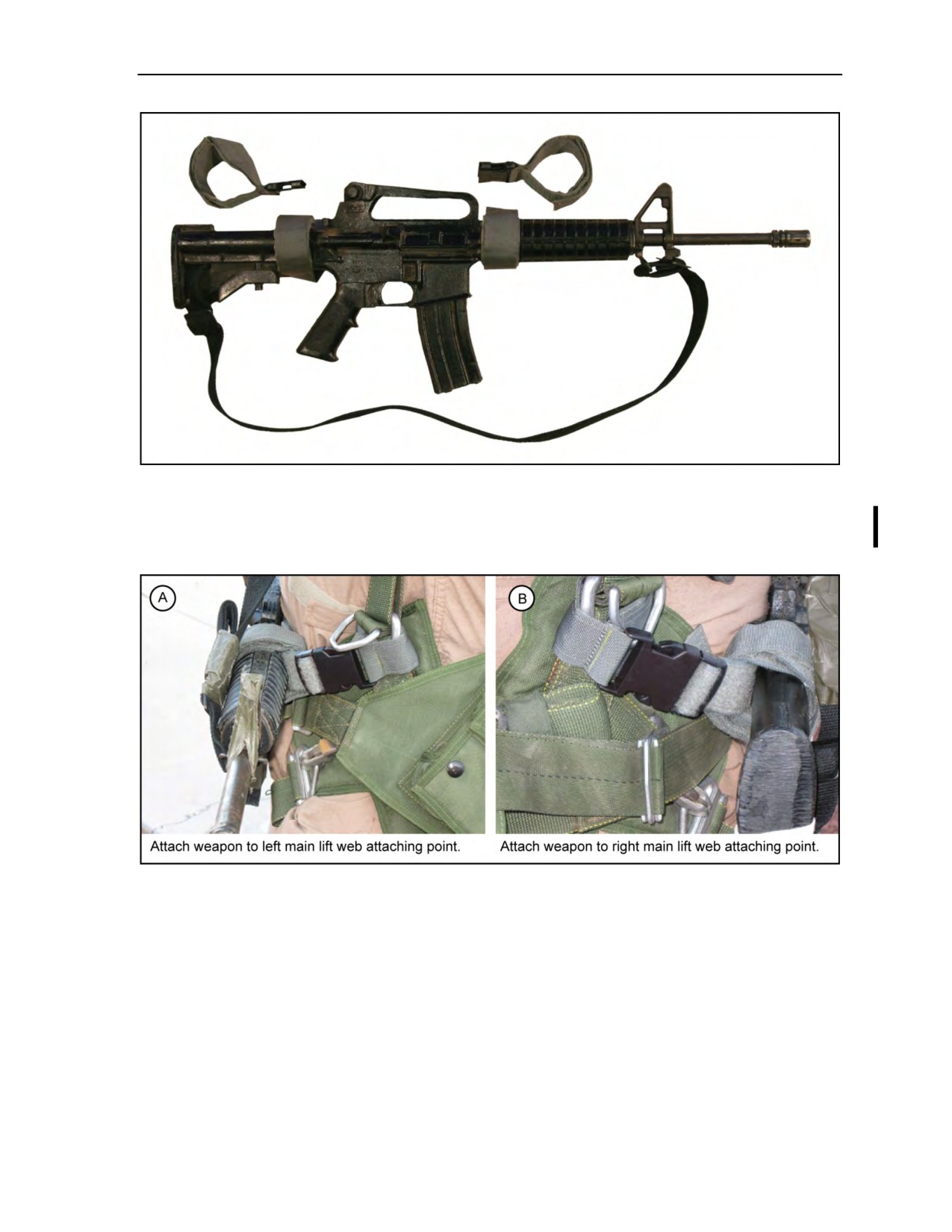
Equipment and Weapon Rigging Procedures
Figure 5-47. Securing weapon harness to weapon
z
Attaches weapon to main lift web attaching points via the Fastex buckle (Figure 5-48). Routes
the chest strap (Figure 5-49, page 5-38) through the sling and secures the sling with the chest
strap excess.
Figure 5-48. Attaching weapon to main lift web attaching points
18 August 2016
ATP 3-18.11/AFMAN 11-411(I)/NTTP 3-05.26M, C2
5-37
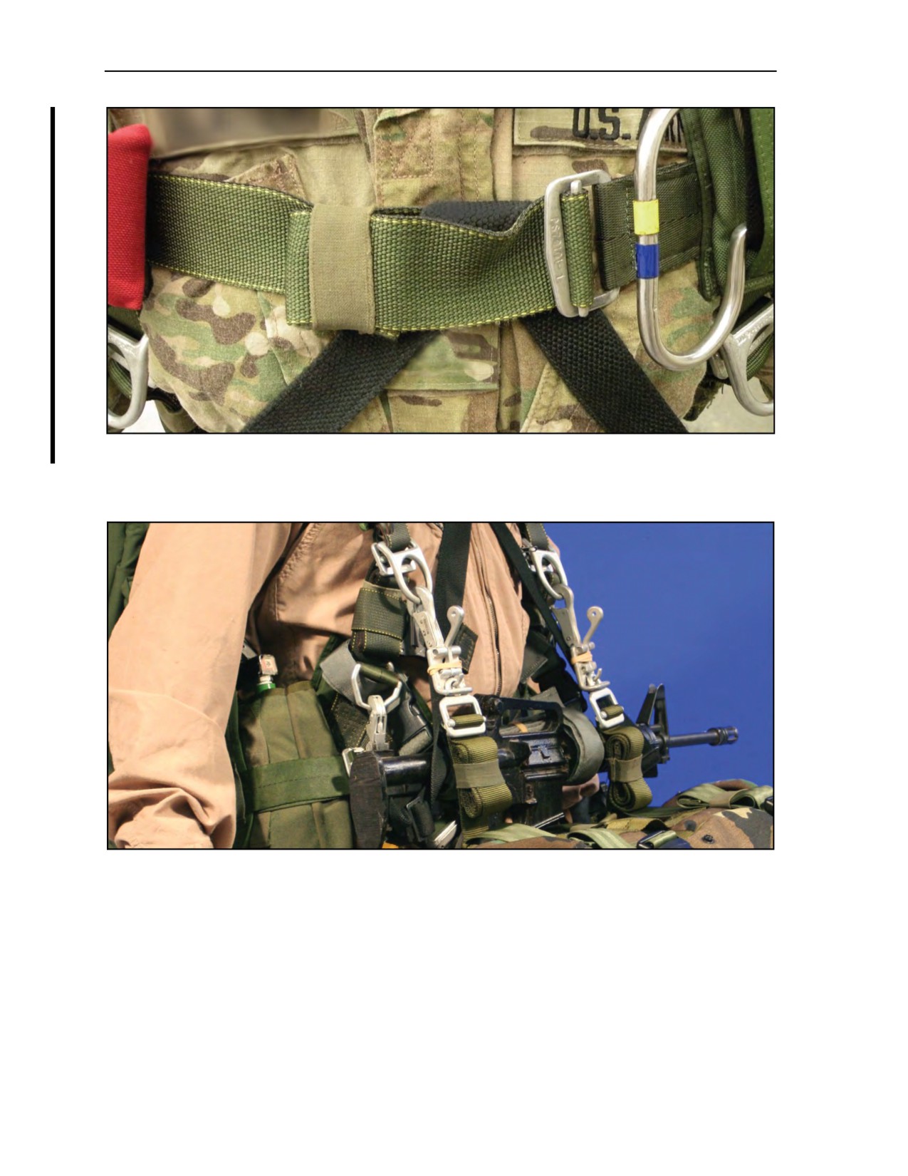
Chapter 5
Figure 5-49. Chest strap routed through the sling
5-52. When the parachutist jumps the PDB or ALICE pack, the attaching straps (Figure 5-50) are routed
over the weapon for additional security.
Figure 5-50. Attaching straps routed over weapon
5-38
ATP 3-18.11/AFMAN 11-411(I)/NTTP 3-05.26M, C2
18 August 2016

Equipment and Weapon Rigging Procedures
EXPOSED WEAPONS CONSIDERATIONS
5-53. If the commander decides that parachutists are to jump with weapons exposed, he must consider the
increased risk of injury to the parachutists. To minimize the risks of jumping with exposed weapons, the
commander should—
z
Consider the proficiency and experience level of the parachutists.
z
Conduct a thorough risk assessment that addresses the following risks associated with jumping
exposed weapons:
Interference with the oxygen system or automatic opening device.
Interference with the parachutist’s exit from the aircraft.
Stability of the parachutist while in free fall.
Ability of the parachutist to perform pull procedures.
Ability of the parachutist to perform emergency procedures.
Deployment of the parachute.
Entanglement of the weapon with another parachutist’s parachute should a midair
entanglement occur.
Ability of the parachutist to perform a parachute landing fall (PLF).
Injury to the parachutist during landing.
Damage to the weapon upon landing or when dragged on the ground.
M4 CARBINE-SERIES RIFLE
5-54. To prepare the M4 carbine-series rifle for jumping (Figure 5-51, page 5-40), the parachutist should—
z
Adjust the sling to fit just over the shoulder and tape the sling keeper in place.
z
Pad and tape the side-mounted bolt assist and the operating handle.
z
Pad and tape the muzzle and the sights to avoid possible entanglement with the parachute
suspension lines or dirt clogging the weapon upon landing.
z
Insert the magazine and tape it to the receiver, including the ejector port cover, to prevent loss of
the magazine and to keep debris from entering the bolt area.
z
Tape the hand guards to prevent their loss during free fall or upon landing.
z
Tape any accessories on the weapon, such as aim points, to ensure they do not come off during
movement.
Note: Neither leather or padded slings are authorized for MFF operations and should not be used
as these items may interfere with emergency procedures when rigged on the parachutist.
Note: The M16-series rifle is rigged in the same manner as the M4 carbine-series rifle.
CAUTION
Any tape should have quick-release tabs and should not interfere with
the weapon’s operation in case weapon is needed immediately once
on the DZ.
18 August 2016
ATP 3-18.11/AFMAN 11-411(I)/NTTP 3-05.26M, C2
5-39
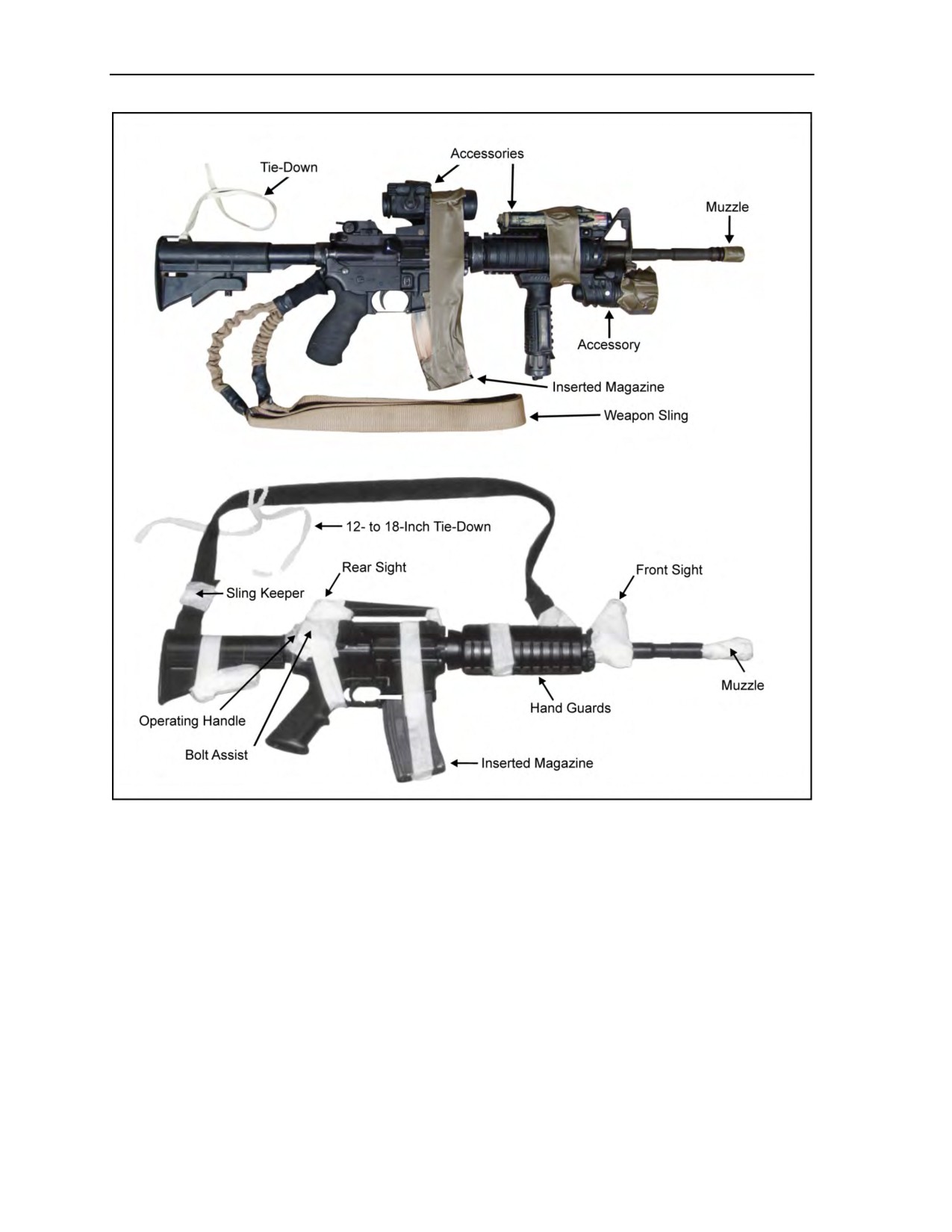
Chapter 5
Figure 5-51. M4 carbine-series rifles rigged for jumping
Tie-Downs
5-55. The parachutist should use a 12- to 18-inch tie-down of 1/4-inch cotton webbing to secure the
weapon. He should attach the tie-down to the weapon sling or to a hard point on the weapon with a girth
hitch knot.
Positioning
5-56. With the help of a buddy, the parachutist should sling his weapon over his shoulder with the muzzle
down, and rotate the pistol grip to his rear (Figure 5-52, page 5-41). The parachutist and his buddy should
then—
z
Place the sling from the lower keeper (buttstock) on the outside of the stock and over the
parachutist’s shoulder.
5-40
ATP 3-18.11/AFMAN 11-411(I)/NTTP 3-05.26M, C2
18 August 2016
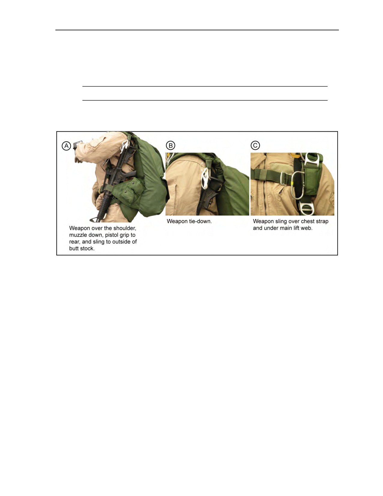
Equipment and Weapon Rigging Procedures
z
Run the sling under the main lift web and route the chest strap through the sling. The buddy ties
off the running ends of the 1/4-inch cotton webbing to a weapon tie-down loop on the harness
with a soft knot (bowknot).
z
Place the weapon between the wing flap and the parachutist with the waistband routed over or
through the weapon-carrying handle.
Note: If optics are mounted on the weapon, they must be free and clear of the waistband.
z
Tighten the waistband securely so that the weapon lies snugly against the parachutist’s side.
The parachutist then assumes the basic free-fall position to test the fit of the weapon.
Figure 5-52. Positioning the weapon on the parachutist
SPECIAL OPERATIONS FORCES COMBAT ASSAULT RIFLE
5-57. The Special Operations Forces Combat Assault Rifle (SCAR), SCAR-L, or SCAR-H, can be rigged
in the side-mounted configuration, as well as in the horizontal position in the center-mounted weapons
harness. To prepare the SCAR-L/H rifles for jumping, the parachutist should—
z
Fully extend the weapon sling all the way and tape the sling keeper in place.
z
Pad and tape the rear sight post and windage adjustment knob prior to conducting MFF
operations to reduce the probability of inadvertent movement of the rear sight aperture.
Continuous lengths of tape should cover the entire rear sight and wrap around folding-stock,
forward of its hinge. The material used to pad and tape the SCAR for MFF operations will vary
depending on what is locally available.
z
Insert the magazine and tape it to the lower receiver, including the ejector port cover, to prevent
loss of the magazine and to keep debris from entering the bolt area.
z
Place the SCAR buttstock in the folded position (Figure 5-53A, page 5-42) when rigged in the
side-mounted configuration to reduce contact with the risers during main parachute deployment.
However, the SCAR can be jumped in the open position (Figure 5-53B).
z
Tape any accessories on the weapon, such as aim points, to ensure they do not come off during
movement.
24 October 2014
ATP 3-18.11/AFMAN 11-411(I)/NTTP 3-05.26M
5-41
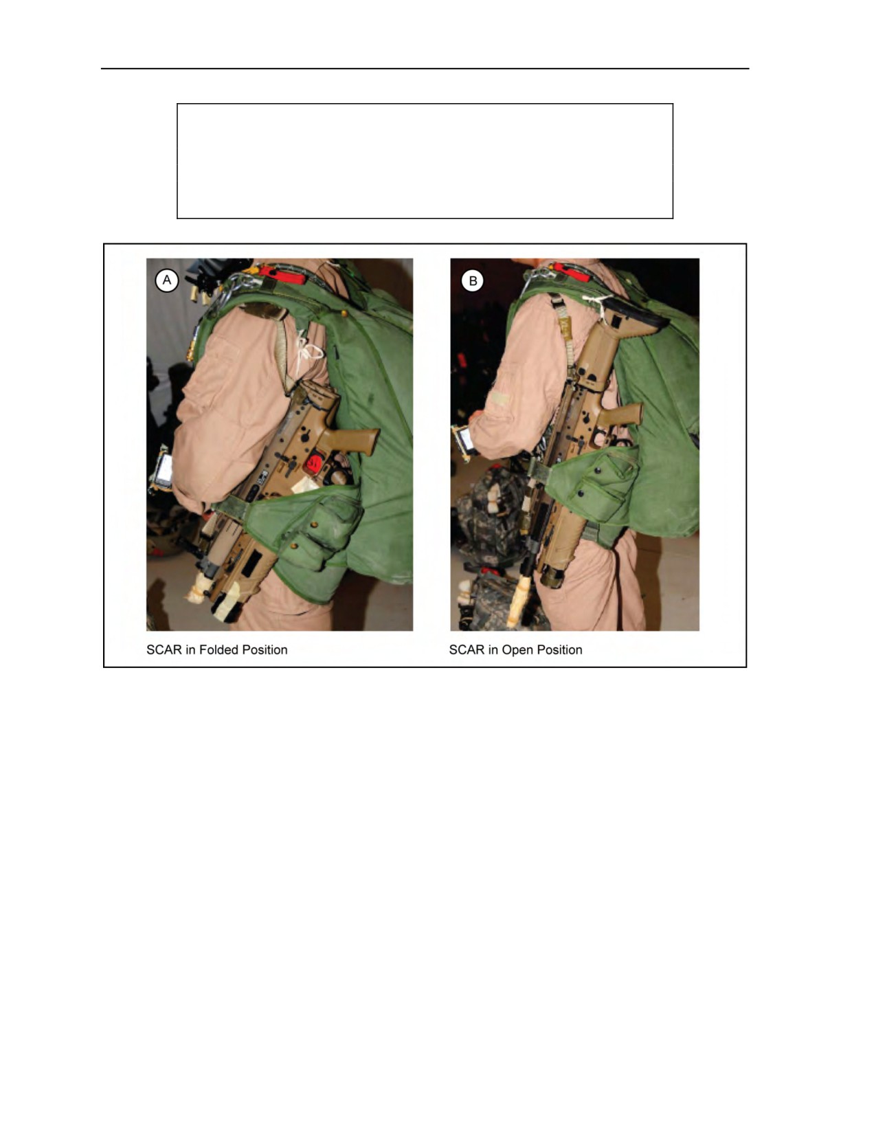
Chapter 5
CAUTION
Any tape should have quick-release tabs and should not interfere with
the weapon’s operation in case weapon is needed immediately once
on the DZ.
Figure 5-53. Special Operations Forces Combat Assault Rifle in folded and open positions
Tie-Downs
5-58. The parachutist should use a 12- to 18-inch tie-down of 1/4-inch cotton webbing to secure the SCAR.
He should attach the tie-down to the weapon sling or to a hard point on the weapon with a girth hitch knot.
Positioning
5-59. With the help of a buddy, the parachutist should sling his weapon over his shoulder with the muzzle
down, and rotate the pistol grip to his rear. The parachutist and his buddy should then—
z
Place the sling from the lower keeper (buttstock) on the outside of the stock and over the
parachutist’s shoulder.
z
Run the sling under the main lift web and route the chest strap through the sling. The buddy ties
off the running ends of the 1/4-inch cotton webbing to a weapon tie-down loop on the harness
with a soft knot (bowknot).
z
Place the weapon between the wing flap and the parachutist with the waistband routed over the
top of the weapon.
z
Tighten the waistband securely so that the weapon lies snugly against the parachutist’s side.
5-42
ATP 3-18.11/AFMAN 11-411(I)/NTTP 3-05.26M
24 October 2014

Equipment and Weapon Rigging Procedures
Note: If optics are mounted on the weapon, they must be free and clear of the waistband.
The parachutist then assumes the basic free-fall position to test the fit of the weapon.
Dual Rigging
5-60. When rigging weapons on both sides of the harness, the buddy should—
z
Place the larger weapon on the parachutist’s left side and the smaller one on his right side.
Note: This setup minimizes interference with the oxygen system, if used.
z
Use standard weapon rigging techniques to secure the weapon to the parachutist.
Note: When an oxygen system is used (Figure 5-54), the buddy should place the weapon behind
the oxygen bottles and against the parachutist’s body. The buddy should carefully route the
medium-pressure delivery hose over or behind the weapon in a manner that does not restrict the
flow of oxygen to the parachutist.
Figure 5-54. Right-side weapon rigging
M203 GRENADE LAUNCHER OR ENHANCED GRENADE LAUNCHER MODULE
5-61. The parachutist should prepare the M203 grenade launcher (Figure 5-55, page 5-44) in the same
manner as he prepares the M16-series, M4, or SCAR carbine-series rifles. In addition, he should—
z
Tape the hand guards and the grenade launcher barrel together with the barrel latch covered.
z
Remove the quadrant sight.
z
Tape down the leaf sight.
Tie-Downs
5-62. The parachutist should follow the same procedures used for the M16 series, M4, or
SCAR carbine-series rifles.
24 October 2014
ATP 3-18.11/AFMAN 11-411(I)/NTTP 3-05.26M
5-43
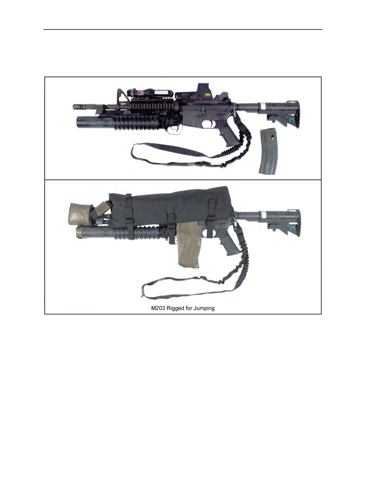
Chapter 5
Positioning
5-63. The parachutist and his buddy should follow the same procedures used for the M16 series, M4, or
SCAR carbine-series rifles.
Figure 5-55. M203 rigged for jumping
M14, G3, AND FN FAL RIFLES
5-64. The parachutist should prepare the M14 (Figure 5-56, page 5-45), the G3, and the FN FAL rifles as
follows:
z
Remove the sling from the weapon and the sling keeper from the sling.
z
Form a loop by running the sling through the sling hook.
z
Replace the sling by placing the loop around the small of the stock.
z
Replace the sling keeper and secure the sling to the barrel, just below the front sight, with a half
hitch.
5-44
ATP 3-18.11/AFMAN 11-411(I)/NTTP 3-05.26M
24 October 2014
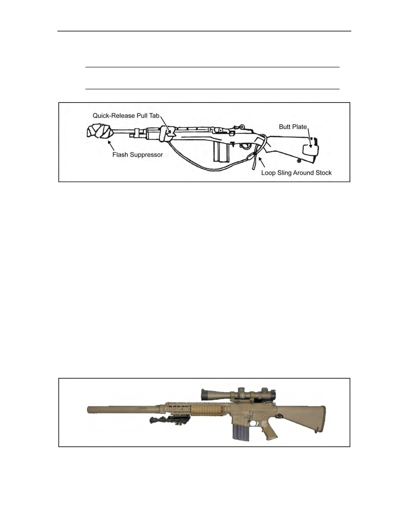
Equipment and Weapon Rigging Procedures
z
Tape the butt plate closed.
z
Pad and tape the flash suppressor, front sight, and bayonet lug.
Note: When jumping with larger weapons on the left side, the parachutist should position the
HPT lowering line to the left side to facilitate a right-side PLF.
Figure 5-56. M14 rigged for jumping
Tie-Downs
5-65. The parachutist should use a 12- to 18-inch tie-down of 1/4-inch cotton webbing to secure the weapon.
He should attach the tie-down to the weapon sling or to a hard point on the weapon with a girth hitch.
Positioning
5-66. With the help of a buddy, the parachutist should sling the weapon over his left shoulder, with the
muzzle down, and rotate the operating handle away from his body. The buddy should then secure the
weapon to the parachutist in the same manner as for the M16-series and the M4 carbine-series rifles.
M110 SEMI-AUTOMATIC SNIPER SYSTEM AND M24 SNIPER RIFLE
5-67. The parachutist should prepare the sniper system as follows:
z
Make an improvised sling. (Note: Parachutist must not use a standard marksmanship sling.)
z
Make sure the rifle has a secure portion where the sling can be attached.
z
Tape the muzzle to protect it from debris upon landing.
z
Tape and secure the bolt (as needed).
z
Insert the magazine and tape it to the receiver, including the ejector port cover, to prevent loss of
the magazine and to keep debris from entering the bolt area.
z
Tape and pad the scope to protect it as necessary.
Figure 5-57 shows the M110 Semi-Automatic Sniper System.
Figure 5-57. M110 Semi-Automatic Sniper System
24 October 2014
ATP 3-18.11/AFMAN 11-411(I)/NTTP 3-05.26M
5-45

Chapter 5
Note: If using a semiautomatic sniper system, the parachutist should follow the same procedures
he used to prepare the M16-series, the M4-carbine series, and the M14 rifles.
Tie-Downs
5-68. The parachutist should use a 12- to 18-inch tie-down of 1/4-inch cotton webbing to secure the
weapon. He should attach the tie-down to the weapon sling or to a hard point on the weapon with a girth hitch.
Positioning
5-69. With the help of a buddy, the parachutist should sling the weapon over his left shoulder, with the
muzzle down, and the scope to the front or rear. They then should secure the weapon to the parachutist in
the same manner as for the M16-series and the M4 carbine-series rifles.
Note: When jumping with larger weapons on the left side, the parachutist should position the
HPT lowering line to the left side to facilitate a right-side PLF.
Note: If optics are mounted on the weapon, they must be positioned free and clear of the
waistband.
CAUTION
All optics should be pressure tested to see if they will hold up under
high altitude and pressure at these levels during flight and under
canopy.
MP5, MP5A3, AND MP5K SUBMACHINE GUNS
5-70. The parachutist should prepare the MP5 (Figure 5-58, page 5-47), MP5A3, and MP5K submachine
guns as follows:
z
Remove the sling from the upper swivel.
z
Fold the end of the sling and run the fold through the upper sling swivel.
z
Pass the tip of the sling through the fold and fasten the snap.
z
Close the ejector port cover and remove the magazine.
z
Collapse the stock.
z
Tape one magazine to the left of the receiver or carry it elsewhere.
z
Cover and tape the muzzle.
5-46
ATP 3-18.11/AFMAN 11-411(I)/NTTP 3-05.26M
24 October 2014
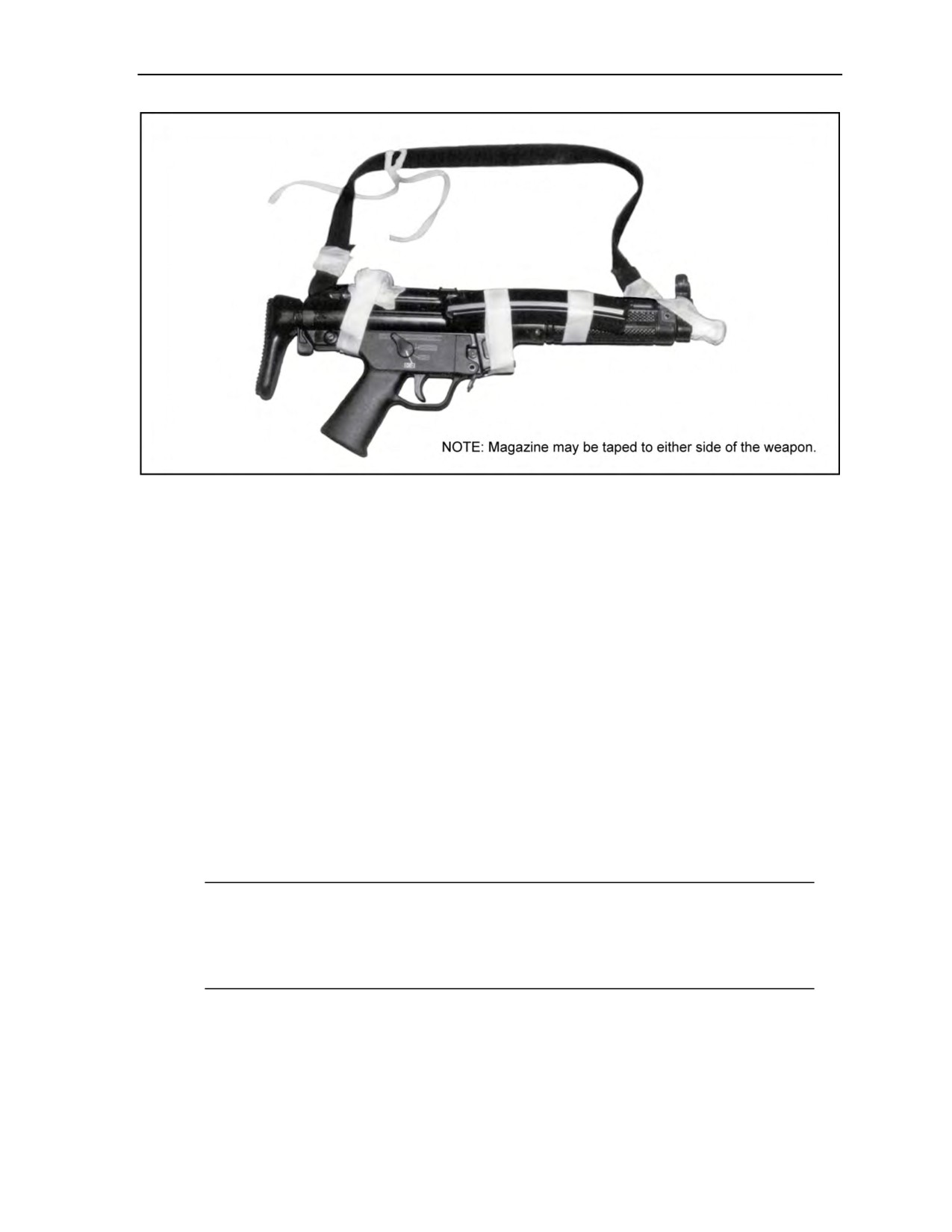
Equipment and Weapon Rigging Procedures
Figure 5-58. MP5 rigged for jumping
Tie-Downs
5-71. The parachutist should use a 12- to 18-inch tie-down of 1/4-inch cotton webbing to secure the weapon.
He should attach the tie-down to the weapon sling or a hard point on the weapon with a girth hitch.
Positioning
5-72. With the help of a buddy, the parachutist should sling the weapon over his shoulder, with the muzzle
down, and rotate the pistol grip to his rear. They then should secure the weapon to the parachutist in the
same manner as for the M16-series and the M4 carbine-series rifles.
M249 AND PARA M249 SQUAD AUTOMATIC WEAPONS
5-73. The parachutist can jump with the M249 squad automatic weapon exposed or in an equipment
container (Figure 5-59, page 5-48). To prepare the weapon, he should—
z
Pad the optics as necessary. (Note: Parachutists must not insert the magazine and must not
chamber rounds.)
z
Tape the muzzle to avoid debris entering the weapon upon landing.
z
Wrap one piece of the tape around the fore grip of the weapon, securing the carrying handle,
hand guard, and bipod.
Note: The Para M249 squad automatic weapon requires an additional piece of tape forward of
the vertical grip on the hand guard. The parachutist should consider padding the charging handle
if the possibility of discomfort or injury exists. When jumping with larger weapons on the left
side, the parachutist should position the HPT lowering line to the left side to facilitate a
right-side PLF.
24 October 2014
ATP 3-18.11/AFMAN 11-411(I)/NTTP 3-05.26M
5-47
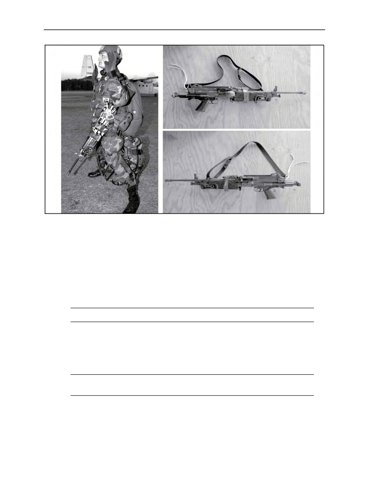
Chapter 5
Figure 5-59. M249 and Para M249 squad automatic weapons rigged for jumping
Tie-Downs
5-74. The parachutist should use a 12- to 18-inch tie-down of 1/4-inch cotton webbing to secure the
M249 squad automatic weapon. The parachutist should attach the tie-down to the weapon sling or to a hard
point on the weapon with a girth hitch. On the Para M249 squad automatic weapon, he should attach the
tie-down to a hard point on the rear of the weapon.
Positioning
5-75. With the help of a buddy, the parachutist should sling the weapon over his left shoulder, with the
muzzle down, and rotate the pistol grip to his rear.
Note: The Para M249 may be rigged with the weapon pistol grip to the parachutist’s front or rear.
5-76. They then run the weapon sling under the main lift web and route the chest strap through the weapon
sling. Parachutist #2 ties off the running ends of the 1/4-inch cotton webbing to a weapon tie-down loop on
the harness with a soft knot (bowknot). He places the weapon between the waistband and the parachutist
with the waistband routed over or through the weapon-carrying handle. He tightens the waistband securely
so that the weapon lies snugly against the parachutist’s side. The parachutist then assumes the basic free-
fall position to test the fit of the weapon.
Note: If optics are mounted on the weapon, they must be positioned free and clear of the
waistband.
5-48
ATP 3-18.11/AFMAN 11-411(I)/NTTP 3-05.26M
24 October 2014
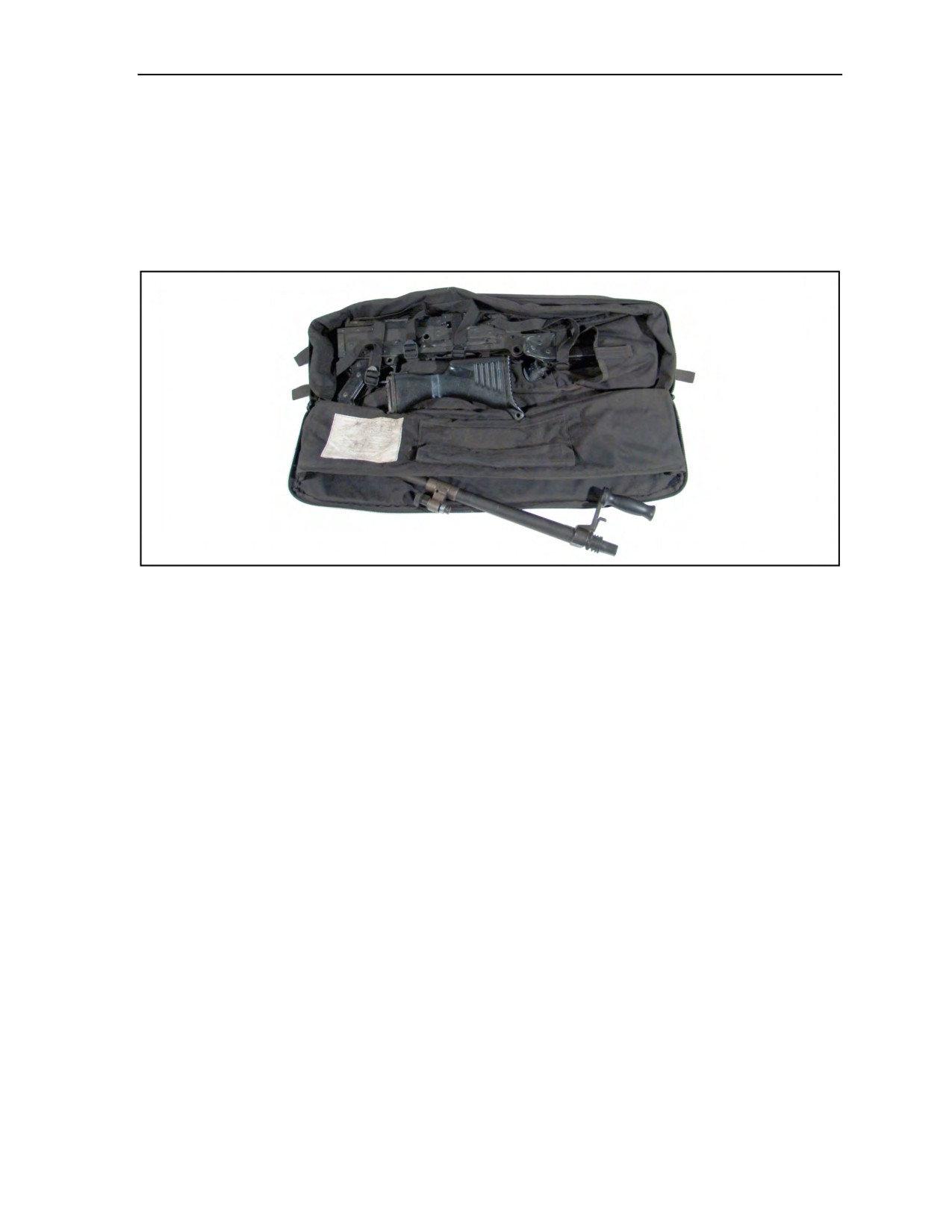
Equipment and Weapon Rigging Procedures
M60 AND M240 MACHINE GUNS, OTHER LIGHT MACHINE GUNS, AND .50-CALIBER
SNIPER SYSTEMS
5-77. The parachutist must not jump these fully assembled and exposed weapons while they are attached to
the parachute harness during MFF operations. The parachutist may break the weapons down and pack them
inside the combat pack, PDB, or a horizontally mounted kit bag with an H-harness. The parachutist pads
optics and secures weapon in the PDB or jump pack. Figure 5-60 is an example of padding and preparing
the M240G.
Figure 5-60. M240G disassembled and packed for jumping
PISTOLS
5-78. The parachutist can jump with a pistol in a shoulder holster or in an equipment container. The
parachutist should wear a shoulder holster under his jumpsuit or other protective clothing. He should secure
the pistol in the holster by taping the holster closed or by using a lanyard.
AT-4, 84-MILLIMETER CARL GUSTAF RECOILLESS RIFLE, AND OTHER LIGHT
ANTIARMOR WEAPONS
5-79. The recommended procedure for rigging the AT-4 and 84-millimeter Carl Gustaf recoilless rifle is to
front-mount the weapon horizontally on top of a combat pack or a PDB, or in an H-harness. This
arrangement limits the parachutist to a ramp-only exit because of the rigged width of the parachutist. To rig
these weapons for a front-mounted jump on top of a combat pack or a PDB, the parachutist—
z
Tapes and pads the end of the launch tube to prevent debris from entering the tube upon landing.
If the launch tube has removable end caps, he tapes and secures them to the launch tube
(Figure 5-61, page 5-50).
z
Tapes the sling securely to the launch tube (Figure 5-61).
z
Pads and tapes the weapon sights and the trigger mechanism (Figure 5-61).
z
Mounts the weapon system on top of the combat pack or PDB. He routes the H-harness, spider
harness, or PDB vertical compression straps over the weapon and through the carrying handle of
the Carl Gustaf or through the sling of the AT-4, and tightens securely (Figure 5-62, page 5-50).
z
Uses 1/4-inch cotton webbing to secure the weapon to the combat pack or PDB. This method
prevents lateral shifting of the weapon system while in free fall (Figure 5-63, page 5-51).
z
Has a buddy attach the combat pack or PDB to the parachutist (Figure 5-64, page 5-51).
24 October 2014
ATP 3-18.11/AFMAN 11-411(I)/NTTP 3-05.26M
5-49
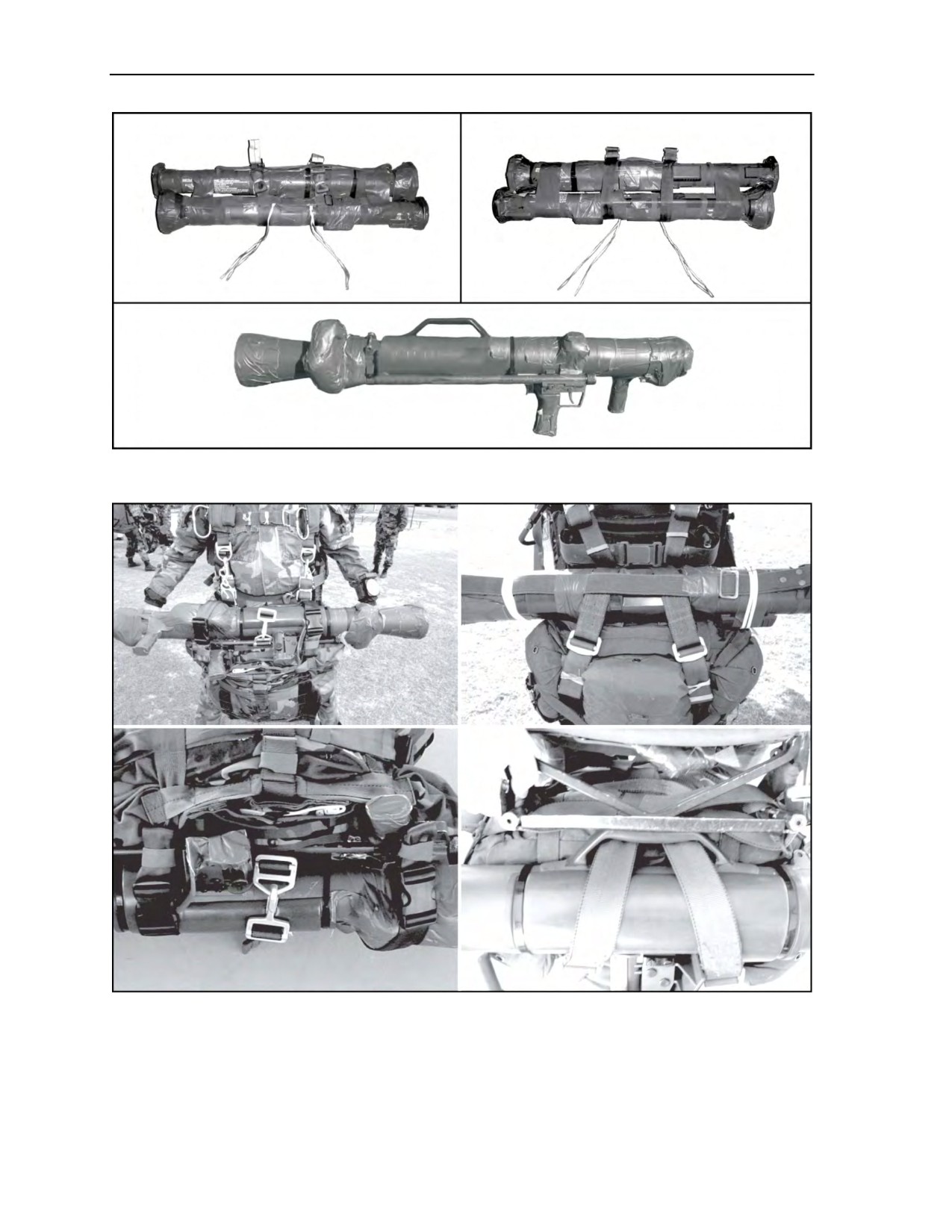
Chapter 5
Figure 5-61. AT-4 and 84-millimeter Carl Gustaf rigged for jumping
Figure 5-62. Routing of vertical compression straps
5-50
ATP 3-18.11/AFMAN 11-411(I)/NTTP 3-05.26M
24 October 2014
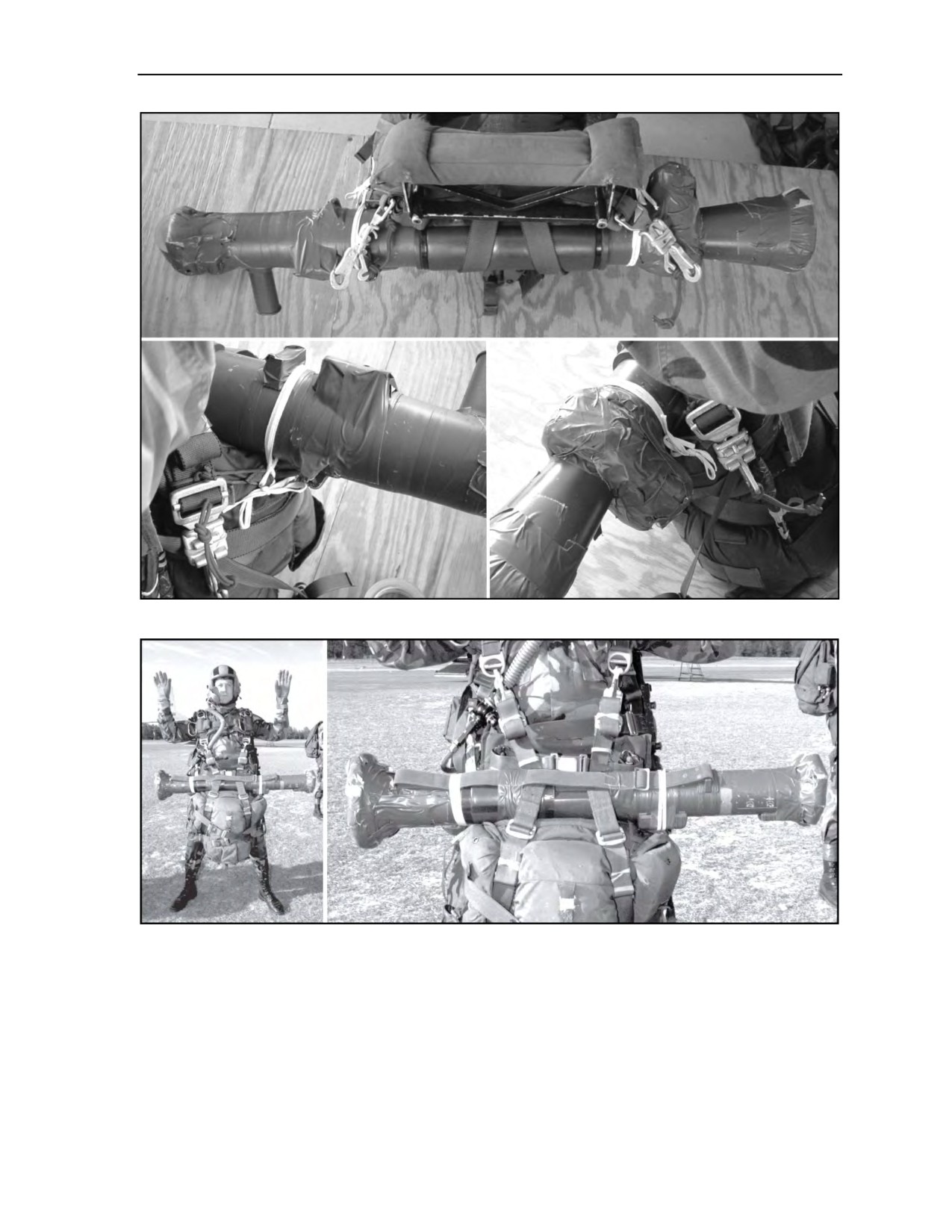
Equipment and Weapon Rigging Procedures
Figure 5-63. Antiarmor weapon tie-down locations
Figure 5-64. Parachutist rigged for jumping with an anti-tank weapon
mounted on top of combat pack
5-80. To rig the AT-4 or the 84-millimeter Carl Gustaf recoilless rifle inside an H-harness for a front-
mounted jump (Figure 5-65, page 5-52), the parachutist—
z
Tapes and pads the end of the launch tube to prevent debris from entering the tube upon landing.
If the launch tube has removable end caps, he tapes and secures them to the launch tube.
z
Tapes the sling securely to the launch tube.
z
Pads and tapes the weapon sights and the trigger mechanism.
24 October 2014
ATP 3-18.11/AFMAN 11-411(I)/NTTP 3-05.26M
5-51
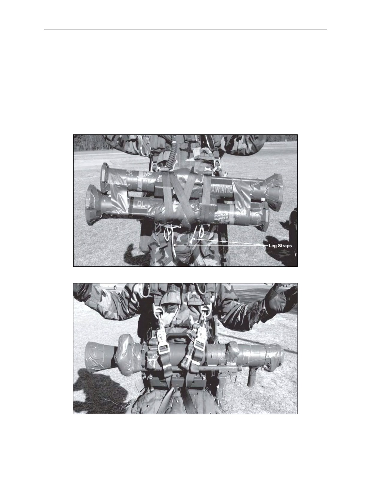
Chapter 5
z
Places the weapon system on top of the H-harness, then routes the vertical compression straps
around the launch tube and through the sling or carrying handle, and tightens securely.
z
Has a buddy attach the H-harness or weapon system to the parachutist as follows:
If jumping a rear-mounted combat pack or PDB, uses a
12- to
18-inch piece of
1/4-inch cotton webbing to secure the H-harness or weapon to the leg straps. This
method prevents the weapon from flying up into the parachutist’s face during free fall
(Figure 5-65).
If jumping a front-mounted combat pack or PDB, attaches the H-harness or weapon to the
equipment attachment rings first, and then attaches the combat pack or PDB. The
attachment straps of the combat pack or container hold the H-harness or weapon system
securely in place (Figure 5-66).
Figure 5-65. Front-mounted weapon with rear-mounted rucksack
Figure 5-66. Front-mounted weapon with front-mounted rucksack
5-52
ATP 3-18.11/AFMAN 11-411(I)/NTTP 3-05.26M
24 October 2014
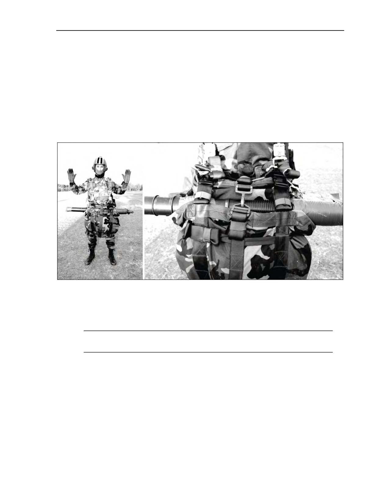
Equipment and Weapon Rigging Procedures
M224 60-MILLIMETER MORTAR
5-81. The recommended procedure for rigging the M224 60-millimeter mortar is to mount it horizontally
on a combat pack or PDB in an H-harness. This arrangement limits the parachutist to a ramp-only exit from
the aircraft. The parachutist should rig the M224
60-millimeter mortar for a front-mounted jump
(Figure 5-67) as follows:
z
Tape and pad the end of the barrel to prevent debris from entering the barrel upon landing.
z
Tape the entire trigger guard and carrying handle, making a smooth surface to prevent any
entanglement of the parachute during deployment.
z
Mount the weapon on top of the combat pack or container and route the H-harness, spider
harness, or container vertical compression straps over the weapon and through the improvised
sling.
Figure 5-67. M224 60-millimeter mortar rigged for front mount
5-82. The parachutist should rig the M224 60-millimeter mortar (Figure 5-68, page 5-54) for a side-
mounted jump as follows:
z
Make an improvised sling with 1-inch tubular webbing.
z
Run the webbing around the end of the mortar and through the trigger guard.
Note: A secured clove hitch on the mortar barrel between the lower sections for the bipod mount
holds the webbing in place.
z
Tape the webbing in place to make sure it does not slide on the barrel.
z
Tape the entire trigger guard and carrying handle, making a smooth surface to prevent any
entanglement of the parachute during deployment.
z
Tape and pad the end of the barrel to prevent debris from entering the barrel upon landing. When
jumping with larger weapons on the left side, the parachutist should position the HPT lowering
line to the left side to facilitate a right-side PLF.
Tie-Downs
5-83. The parachutist should use a 12- to 18-inch tie-down of 1/4-inch cotton webbing to secure the
weapon. He should attach the tie-down to the weapon sling or a hard point on the weapon with a girth
hitch.
24 October 2014
ATP 3-18.11/AFMAN 11-411(I)/NTTP 3-05.26M
5-53
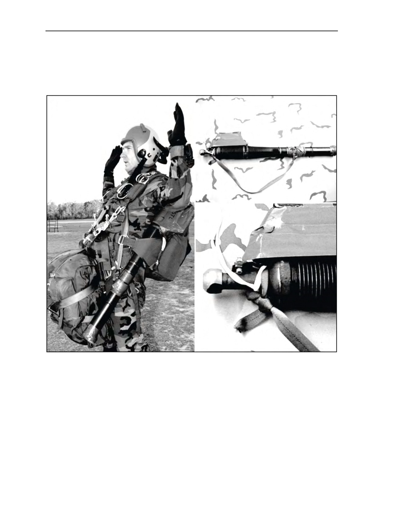
Chapter 5
Positioning
5-84. With the help of a buddy, the parachutist should sling the mortar over his left shoulder, with the
muzzle down, and rotate the trigger to his rear. He should run the sling around the mortar to make sure
tension pulls the trigger assembly toward the container. The parachutist and his buddy should secure the
mortar in the same manner as for the M16-series and the M4 carbine-series rifles.
Figure 5-68. Left-side mount for M224 60-millimeter mortar
OTHER WEAPONS
5-85. The parachutist can rig other weapons using the methods previously described. User unit SOPs
should specify ways to pack or rig similar types of weapons consistent with safety requirements. Units
requiring technical help should contact B Company, 2d Battalion, 1st Special Warfare Training Group,
USAJFKSWCS, Yuma, Arizona; Defense Switched Network 899-3626/3639.
FLOTATION DEVICES AND/OR LIFE PRESERVERS
5-86. Parachutists must wear military-approved flotation devices
(Tactical Flotation Support
System
[TFSS]-5326, B-7 Life Preserver, Life Preserver Unit-10/P, or underwater demolition
team life vest [Figure 5-69, page 5-55]) whenever the planned flight path is over open bodies of water
5-54
ATP 3-18.11/AFMAN 11-411(I)/NTTP 3-05.26M
24 October 2014
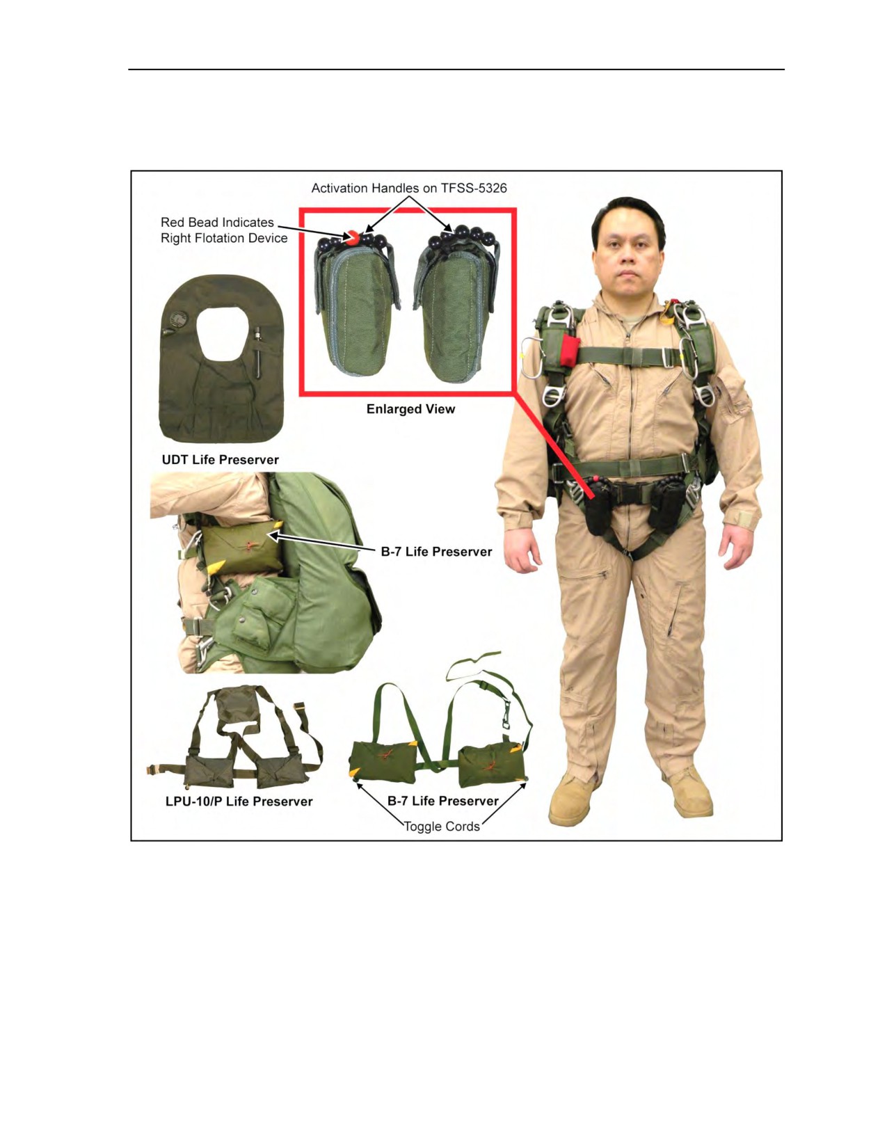
Equipment and Weapon Rigging Procedures
large enough to be unavoidable with a maneuverable chute for one third or more of the distance under
canopy. They also wear them when an open body of water is within 1,000 meters of the planned impact
point.
Figure 5-69. Underwater demolition team life preservers
TACTICAL FLOTATION SUPPORT SYSTEM
5-87. The TFSS-5326 is an inflatable aid to flotation device specifically designed for special operations
forces warfighters, combat swimmers, and/or maritime airborne operations personnel. Each system consists
of one each independent left- and right-hand units, which can be mounted on a belt. Each unit includes a
welded flotation bladder, an inflation system, a pouch closure system, a pouch, and a firing handle. The
bladder is a reusable welded fabric enclosure that deploys from a belt on the waist and can be placed under
the arms of the parachutist while floating in the water. It is readily collapsed and stowed for future use. The
inflation system uses a manually actuated CO2 cartridge (two Leland 38-gram CO2 cartridges) for primary
24 October 2014
ATP 3-18.11/AFMAN 11-411(I)/NTTP 3-05.26M
5-55

Chapter 5
inflation and an oral inflation tube for secondary inflation. The pouch contains and protects the bladder,
inflation system, and closure system. It includes a waist belt loop and clip loops to secure the pouch to the
webbing belt. The firing handle attaches to the outside of the pouch and uses color-coded beads to help
distinguish left- and right-hand units. The handle serves to release the closure system and actuate the CO2
inflation system.
Buoyancy
5-88. The TFSS-5326 is designed to provide a minimum of 45 pounds of positive buoyancy in seawater at
33 feet and 80 pounds at the surface (Table 5-5). The overt system comes with reflective tape on the
yellow-colored bladder to aid in recovery in sea operations.
Table 5-5. Lift capabilities
Depth (Feet)
Lift (Pounds)
50
35
33
45
15
57
3
80
NOTE: All test data is in seawater.
Wearing
5-89. The TFSS-5326 is a one-size-fits-all system that has been designed to accommodate the personal
preference of the user for ease of wearing and comfort. When wearing the TFSS-5326 for MFF operations,
the units should be worn to the front of the parachutist’s body
(Figure
5-69, page 5-55) to avoid
interference with the parachute or any emergency procedures that could arise that the parachutist might
have to correct. The TFSS-5326 is designed for simplicity and ease of wear. However, an improperly
mounted flotation device could interfere with airborne operations, causing injury to the parachutist or
damage to equipment. The parachutist must ensure he does not wear the TFSS-5326 flotation packets
between the parachute harness and his body. Serious injury may result if inflated when worn incorrectly.
To mitigate this risk, MFF parachutists should properly mount the TFSS-5326 ensuring the system is not
placed under the parachute harness at any location.
5-90. The CO2 cartridge cover does not extend the entire length of the CO2 cartridge cylinder, which
poses a potential for a cold burn to unprotected skin (frostbite burn) when the cartridge is activated. To
mitigate this risk, parachutists must ensure the TFSS-5326 mounting belt is worn tightly around their waist
to limit CO2 cartridge movement, and ensure there is a layer of clothing between the CO2 cartridge and the
parachutist’s skin. All parachutists should participate in the mounting procedures for the TFSS-5326.
5-91. To manually actuate a TFSS-5326 unit, the user pulls upward on the firing handle. This motion
initiates two sequential actions. First, the pouch closure pins are released, allowing the pouches to open
freely. Second, the manual inflator lever is actuated, causing the firing pin to puncture the seal on the
CO2 cartridges to release the gas and completely fill the bladder. Should the CO2 inflation system fail to
operate, the bladder is filled through an oral inflation tube. This is accomplished by depressing the Oralock
valve (Figure 5-70A, page 5-57), and then breathing into the tube (Figure 5-70B, page 5-57). Gas is
released from the TFSS-5326 bladder by pressing downward on the Oralock valve and forcing the air out of
the oral inflation tube. Once all of the gas is evacuated from the bladder, the CO2 cartridges are replaced,
maintenance is performed, and the units are repacked for future use.
5-56
ATP 3-18.11/AFMAN 11-411(I)/NTTP 3-05.26M
24 October 2014
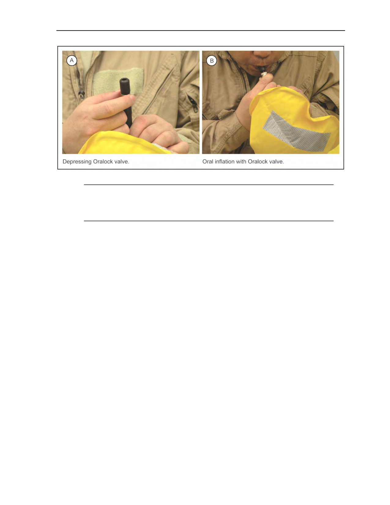
Equipment and Weapon Rigging Procedures
Figure 5-70. Oralock valve
Note: Test results indicate wear of the TFSS-5326 poses no greater risk to Soldiers when
compared to currently issued flotation devices worn during airborne operations (for example, the
B-7 Life Preserver and Life Preserver Unit-10 types of life preservers), provided guidance
contained in the referenced documentation and the safety releases are adhered to.
Periodic Maintenance
5-92. After each use, the parachutist—
z
Rinses entire unit in fresh water.
z
Allows unit to completely air dry.
z
Applies a small amount of a silicon lubricant to all valves.
z
Visually inspects all bladders for any damage.
z
Replaces unit if damaged.
z
Weighs and ensures the minimum gram weight for replacement of 38-gram CO2 cartridges is
147 grams.
z
Repacks unit in accordance with procedures.
Inspections
5-93. The parachutist conducts an annual inspection consisting of the following:
z
Orally inflate unit and allow to sit for 24 hours.
z
Thoroughly inspect unit for leaks. Replace if damaged.
z
Inspect all valves to ensure they are in good working order.
z
Reweigh and ensure the minimum gram weight for each 38-gram CO2 cartridge is 147 grams.
Upon initial issue, the user is required to conduct an annual inspection and report any damage to the
cognizant authority.
B-7 LIFE PRESERVER
5-94. The parachutist wears the B-7 over his uniform or jumpsuit and under his parachute harness
(Figure 5-69, page 5-55). He fits the B-7 by placing one flotation packet under each arm, making sure the
packet flaps are to the outside and the toggle cords are down and to the front. He routes the shoulder strap
from front to rear over his left shoulder, under the back strap, then from rear to front over his right shoulder
and attaches it to the ring on the right flotation packet.
24 October 2014
ATP 3-18.11/AFMAN 11-411(I)/NTTP 3-05.26M
5-57

Chapter 5
5-95. The parachutist adjusts the shoulder strap so that the flotation packets fit snugly against his armpits.
Before donning the parachute, he attaches the chest strap to the attachment ring on the left flotation packet,
forming a quick release. If there is a water emergency, the parachutist inflates the life preserver by pulling
the toggle cords located on each flotation packet. He can also manually inflate it by blowing into the rubber
hose located on each flotation packet.
Note: The parachutist uses manual inflation only if the CO2 inflation system fails to operate.
WARNING
The parachutist ensures he does not wear the B-7 life preserver
with the flotation packets between the parachute harness and his
body. Serious injury may result if inflated when worn incorrectly.
LIFE PRESERVER UNIT-10/P
5-96. The Life Preserver Unit-10/P is a standard USAF CO2 cartridge-activated life preserver assembly
worn during flights over water or during airdrops when water obstacles are near or on the intended DZ. It
has an adjustable harness and underarm inflation bladders. The life preserver is designed to keep the
wearer’s head above water at weights up to 250 pounds for up to 10 minutes. It is compatible with the
USAF C-9, T-10, and MC-4 parachute harness assemblies. It must be maintained in accordance with
TM 1-4220-252.
5-97. The life preserver is worn under the parachute harness. The harness is worn so that the inflatable
packets are under the parachutist’s arms. The manual inflating valves should be completely closed when
donning the life vest. The shoulder and waist straps are then adjusted to ensure the inflation packet is one
hand width beneath the armpit and not constrained by the parachute harness.
WARNING
If the inflation packets are too snug under the armpit, or if they
are between the harness and the parachutist’s body, the
parachutist may experience severe pain or crushed ribs during
inflation.
5-98. The parachutist inflates the flotation bladders by pulling two toggle cords (at the bottom of the vest),
which activate CO2 cartridges that fill the flotation bladders with gas. An alternate way to inflate the vest is
by blowing into the manual inflation valve rubber hoses located on the bottom side of the wings. Manual
inflation should only be used if the CO2 inflation valves fail to operate.
UNDERWATER DEMOLITION TEAM LIFE VEST
5-99. The underwater demolition team life vest is put on over the uniform before donning the parachute
(Figure 5-71, page 5-59). The vest is worn around the neck, with the straps passing under the arms and
fastened to the vest. The parachutist fits the life vest by performing the following steps:
z
Adjust the straps until snug to prevent movement of the vest during free fall and interference
with the red cutaway handle or the reserve ripcord handle.
z
Pass the parachute chest strap between the life vest and the body.
z
Secure the life vest with a lightweight retaining band around the middle to prevent interference
with the green cutaway handle and red reserve ripcord handle.
5-58
ATP 3-18.11/AFMAN 11-411(I)/NTTP 3-05.26M
24 October 2014
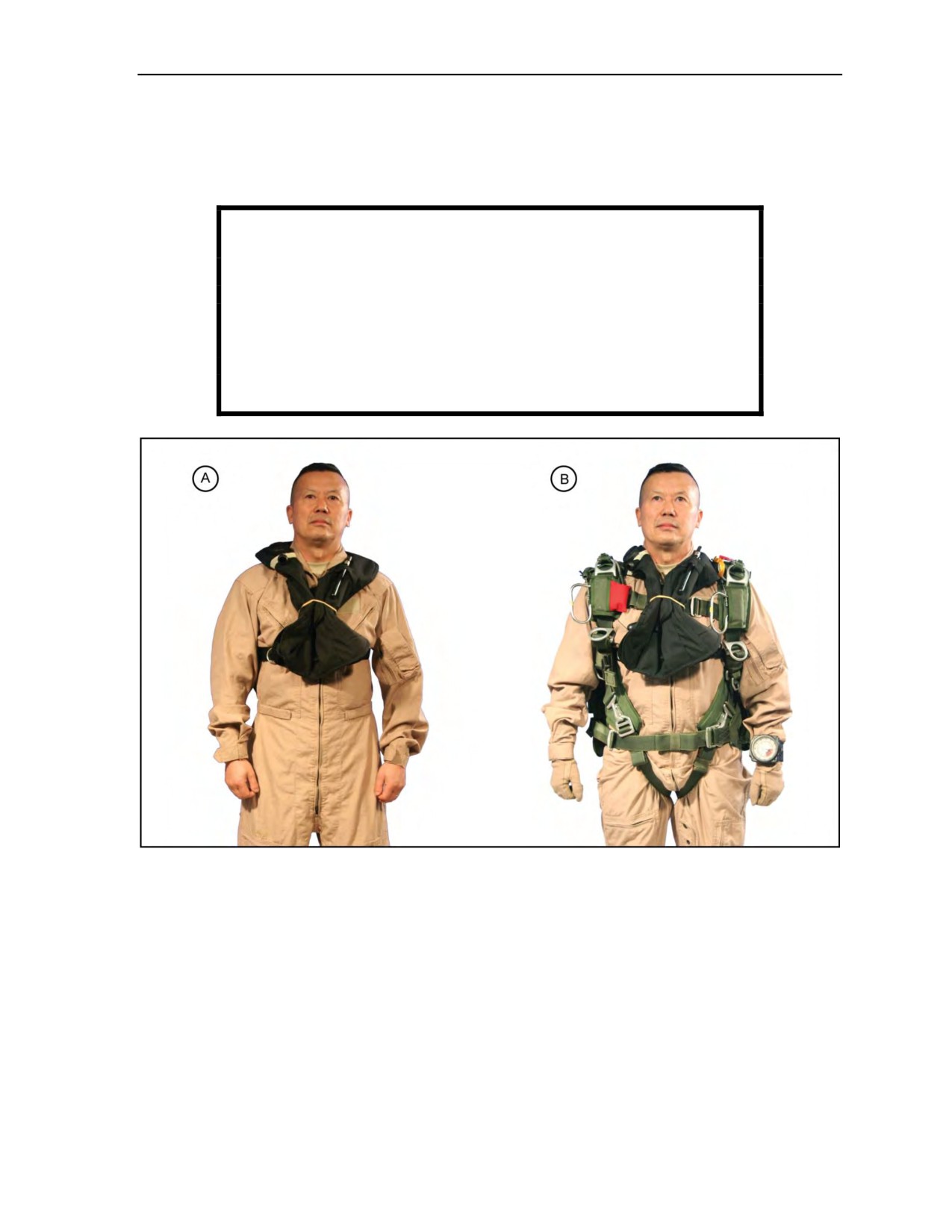
Equipment and Weapon Rigging Procedures
z
Route the oral inflation tube through its retainer loop.
z
Screw the oral inflation tube knurled nut down in the open position to allow inflation.
The life vest has a manually activated CO2 actuator for immediate inflation or an oral inflation tube that
can be used to inflate the vest or to manage a slow leak.
WARNING
The parachutist must not wear the underwater demolition team
life vest with the flotation chamber worn between the parachute
chest strap and his body. Serious injury may result if inflated
when worn incorrectly. Parachutists must protect the activation
lanyard of the vest. Accidental inflation by the CO2 cartridges
may result in obstruction of the reserve ripcord and cutaway
handles.
Figure 5-71. Parachutist with underwater demolition team life vest
and MC-4 parachute harness
24 October 2014
ATP 3-18.11/AFMAN 11-411(I)/NTTP 3-05.26M
5-59

This page intentionally left blank.

Chapter 6
Aircraft Procedure Signals and Jump Commands
Aircraft noise, the MFF parachutist helmet, and the oxygen mask make verbal
communication extremely difficult. Therefore, the parachutist receives aircraft
procedure signals (Table 6-1, pages 6-1 and 6-2) and jump commands (Table 6-2,
pages 6-2 and 6-3) by hand-and-arm signals. The MFF parachutist must be thoroughly
familiar with all signals, and the commands and required actions for each one.
Standardization of procedural signals and jump commands permits interoperability of
all MFF-capable units. Safety significantly increases when the parachutist understands
the jumpmaster’s intent and the jumpmaster understands the parachutist’s desired
response.
AIRCRAFT PROCEDURE SIGNALS
6-1. Signals used between aircraft boarding and the jump command STAND UP are procedure signals. The
aircraft procedure signals discussed in the following paragraphs begin before takeoff. The jumpmaster
gives these signals.
Table 6-1. Aircraft procedure signals (oxygen and nonoxygen jumps)
Aircraft Procedure Signals
Jumpmaster Actions
Parachutist Actions
DON HELMETS
Gives command before takeoff or
Dons helmet, fastens chin strap, and
landing.
fastens seat belt.
*CAUTION
If the helmet is removed after the
JMPI, the jumpmaster ensures there
is no twist in the oxygen delivery
hose.
UNFASTEN SEAT BELTS
Normally gives command on reaching
Disconnects seat belts and stows it to
an altitude of 1,000 feet AGL or when
the left and right for easy retrieval.
notified by the flight crew that it is safe
to do so.
*MASK
*Turns on own console and masks.
*Turns on console.
*Secures mask to face and assures
proper attachment and seal. Checks
delivery of oxygen.
*CHECK OXYGEN
*Gives signal immediately following
*Checks own oxygen and returns
the command MASK and then
the thumbs-up signal to the
periodically.
jumpmaster. In the event of an
oxygen problem, extends arm
*Gives signal after the 20- and
straight forward, palm down.
10-minute warnings.
*These signals, commands, and actions are used only during oxygen jumps with prebreather.
*NOTE: Mask and oxygen checks will be determined by flight plan and mission profile when given.
*NOTE: Oxygen safety technician checks gauges.
24 October 2014
ATP 3-18.11/AFMAN 11-411(I)/NTTP 3-05.26M
6-1

Chapter 6
Table 6-1. Aircraft procedure signals (oxygen and nonoxygen jumps) (continued)
Aircraft Procedure Signals
Jumpmaster Actions
Parachutist Actions
TIME WARNING
*All parachutists must be awake.
20-Minute Warning
First pass attaches combat
equipment.
*CHECK OXYGEN
*Checks own oxygen and returns
the thumbs-up signal to the
jumpmaster. In the event of an
oxygen problem, extends arm
straight forward, palm down.
TIME WARNING
Ensures red jump/caution light is on.
Second pass attaches combat
10-Minute Warning
equipment.
WIND SPEED
Normally gives signal immediately
Receives a Military CYPRES 2 and pin
after the 10-minute warning, if known,
check, and passes the thumbs-up
and updates to remain current with the
signal from the last parachutist in the
DZ party’s information.
front of the aircraft to the rear, and
then to the jumpmaster.
*These signals, commands, and actions are used only during oxygen jumps with prebreather.
Table 6-2. Aircraft jump commands (oxygen and nonoxygen jumps)
Jump Commands
Jumpmaster Actions
Parachutist Actions
STAND UP
Gives command about 2 minutes before
Stands, faces the rear, and checks own
time on target (TOT).
equipment.
Checks the pins *and oxygen
(Oxygen or equipment jumps may require
pressure gauge of the man in front
additional time for this command only; all
and taps him to indicate he is OK. The
other commands remain the same.)
last two parachutists check each other.
*NOTE: During an oxygen jump, the
right hand should be on the ON/OFF
switch of the oxygen bailout bottle
and the left hand on the disconnect
for the console hose.
MOVE TO THE REAR
Gives command about 1 minute
Tightens shoulder straps of rucksack
before TOT.
and puts goggles down.
*Turns on oxygen bailout bottle and
disconnects from the console.
Moves to within 1 meter of the jump
door or to the hinge of the ramp.
STAND BY
Gives command about 15 seconds
Returns thumbs-up signal and moves to
before TOT.
1 foot of edge of ramp or door. Focuses
attention on jumpmaster.
GO
Ensures green jump/caution light is on.
Exits the aircraft.
Ensures aircraft is over release point. Gives
command and proper hand-and-arm
signals.
ABORT
Gives command any time an unsafe
Returns to seat.
condition exists inside the aircraft or
*Reconnects to console and turns
on the DZ.
off oxygen bailout bottle.
Gives command when the red jump/caution
light is on.
*Reconnects own console and turns off
own oxygen bailout bottle.
*These signals, commands, and actions are used only during oxygen jumps with prebreather.
6-2
ATP 3-18.11/AFMAN 11-411(I)/NTTP 3-05.26M
24 October 2014
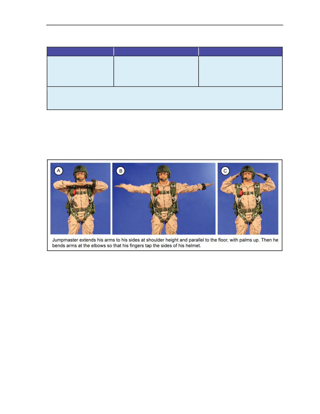
Aircraft Procedure Signals and Jump Commands
Table 6-2. Aircraft jump commands (oxygen and nonoxygen jumps) (continued)
Jump Commands
Jumpmaster Actions
Parachutist Actions
*CHECK OXYGEN
*Checks own oxygen and returns the
thumbs-up signal to the jumpmaster.
In the event of an oxygen problem,
extends arm straight forward, palm
down.
*These signals, commands, and actions are used only during oxygen jumps with prebreather.
NOTE: There are no disarming procedures for the Military CYPRES 2. The jumpmaster must brief the pilots not to exceed
5,000 feet per minute as this descent rate is easy to remember and covers all three Military CYPRES 2 models.
DON HELMETS
6-2. The jumpmaster gives the signal DON HELMETS before takeoff (Figure 6-1). He may also give it
during the flight or if the aircraft is landing with the jumpers (for example, winds out of limits on the DZ or
mission aborted). Upon receiving this signal, the parachutist dons his helmet, fastens his chin strap, and
fastens his seat belt.
Figure 6-1. DON HELMETS signal
UNFASTEN SEAT BELTS
6-3. The jumpmaster normally gives the signal UNFASTEN SEAT BELTS upon reaching an altitude of
1,000 feet AGL or when the flight crew chief indicates that it is safe to do so (Figure 6-2, page 6-4). If the
aircraft descends back through 1,000 feet AGL later in the flight, the parachutist refastens his seat belt upon
receiving the command DON HELMETS.
24 October 2014
ATP 3-18.11/AFMAN 11-411(I)/NTTP 3-05.26M
6-3
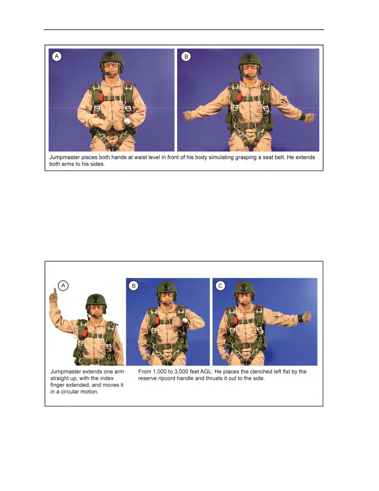
Chapter 6
Figure 6-2. UNFASTEN SEAT BELTS signal
EMERGENCY BAILOUT
6-4. The jumpmaster gives the EMERGENCY BAILOUT signal for an emergency exit during flight (Figure 6-3,
pages 6-4 and 6-5). Jump commands may be given if time permits. If there is no time for the full jump
command sequence, he gives abbreviated signals immediately after the bailout signal:
z
For exits from 1,000 to 3,000 feet AGL, the jumpmaster signals to IMMEDIATELY EXIT, CLEAR,
AND PULL THE RESERVE RIPCORD HANDLE.
z
For exits at 3,000 feet AGL and above, the jumpmaster signals to IMMEDIATELY EXIT, CLEAR,
AND PULL THE MAIN RIPCORD HANDLE.
Figure 6-3. EMERGENCY BAILOUT signal
6-4
ATP 3-18.11/AFMAN 11-411(I)/NTTP 3-05.26M
24 October 2014
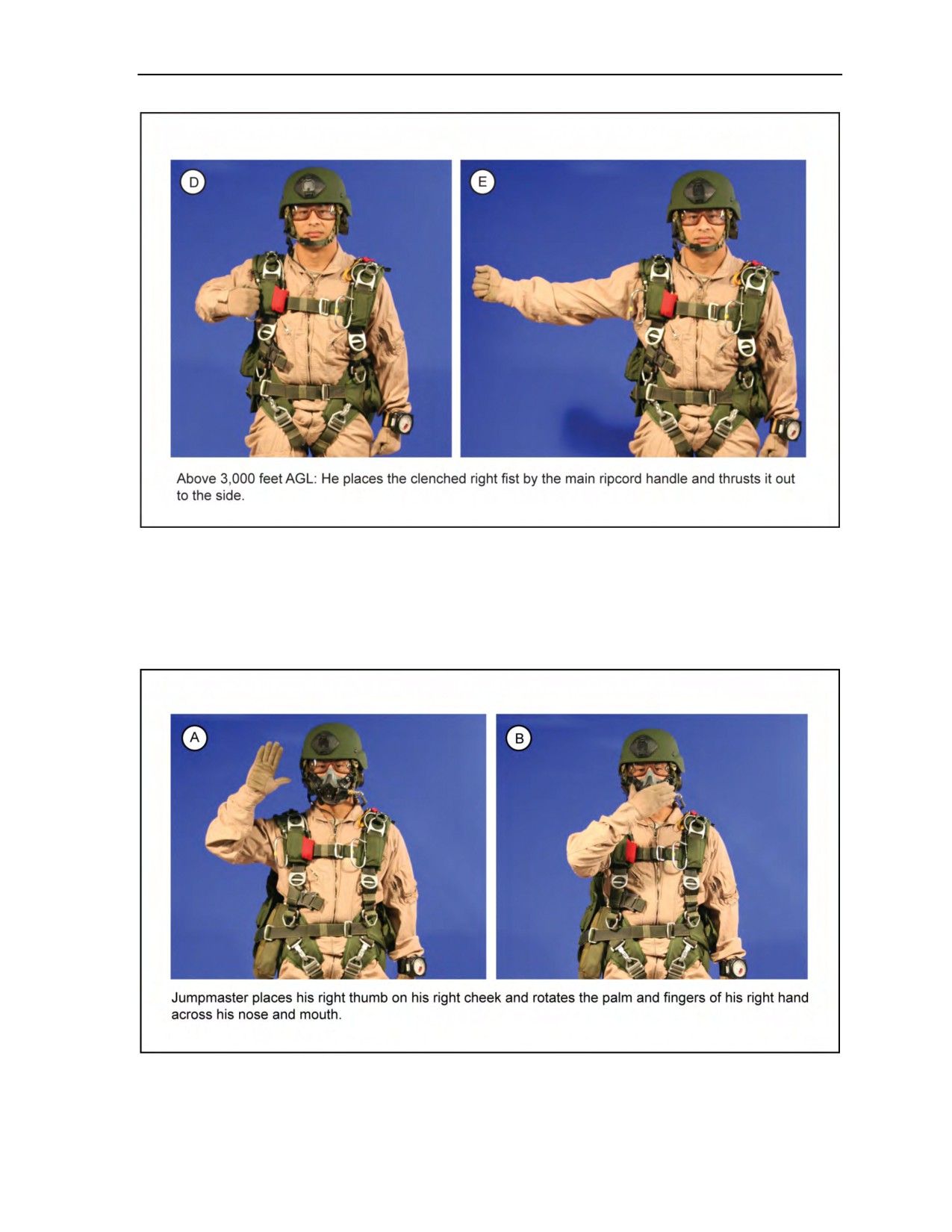
Aircraft Procedure Signals and Jump Commands
Figure 6-3. EMERGENCY BAILOUT signal (continued)
MASK
6-5. The jumpmaster signals MASK when the parachutist must begin using supplemental oxygen
(Figure 6-4). Upon receiving this signal, the parachutist masks and checks to make sure the oxygen system
is functioning properly.
Figure 6-4. MASK signal
24 October 2014
ATP 3-18.11/AFMAN 11-411(I)/NTTP 3-05.26M
6-5
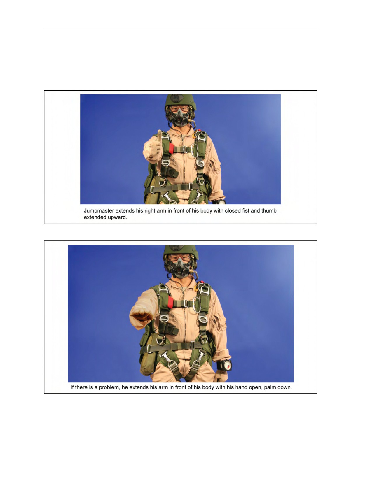
Chapter 6
CHECK OXYGEN
6-6. The jumpmaster signals CHECK OXYGEN immediately after the signal to mask and periodically after
that
(Figure 6-5). At a minimum, he gives it following the 20- and 10-minute time warnings. Upon
receiving this signal, the parachutist returns the signal if everything is functioning correctly. If there is a
problem, the parachutist (Figure 6-6) extends an arm in front of his body with his hand open, palm down.
Figure 6-5. CHECK OXYGEN signal
Figure 6-6. OXYGEN PROBLEM signal
6-6
ATP 3-18.11/AFMAN 11-411(I)/NTTP 3-05.26M
24 October 2014
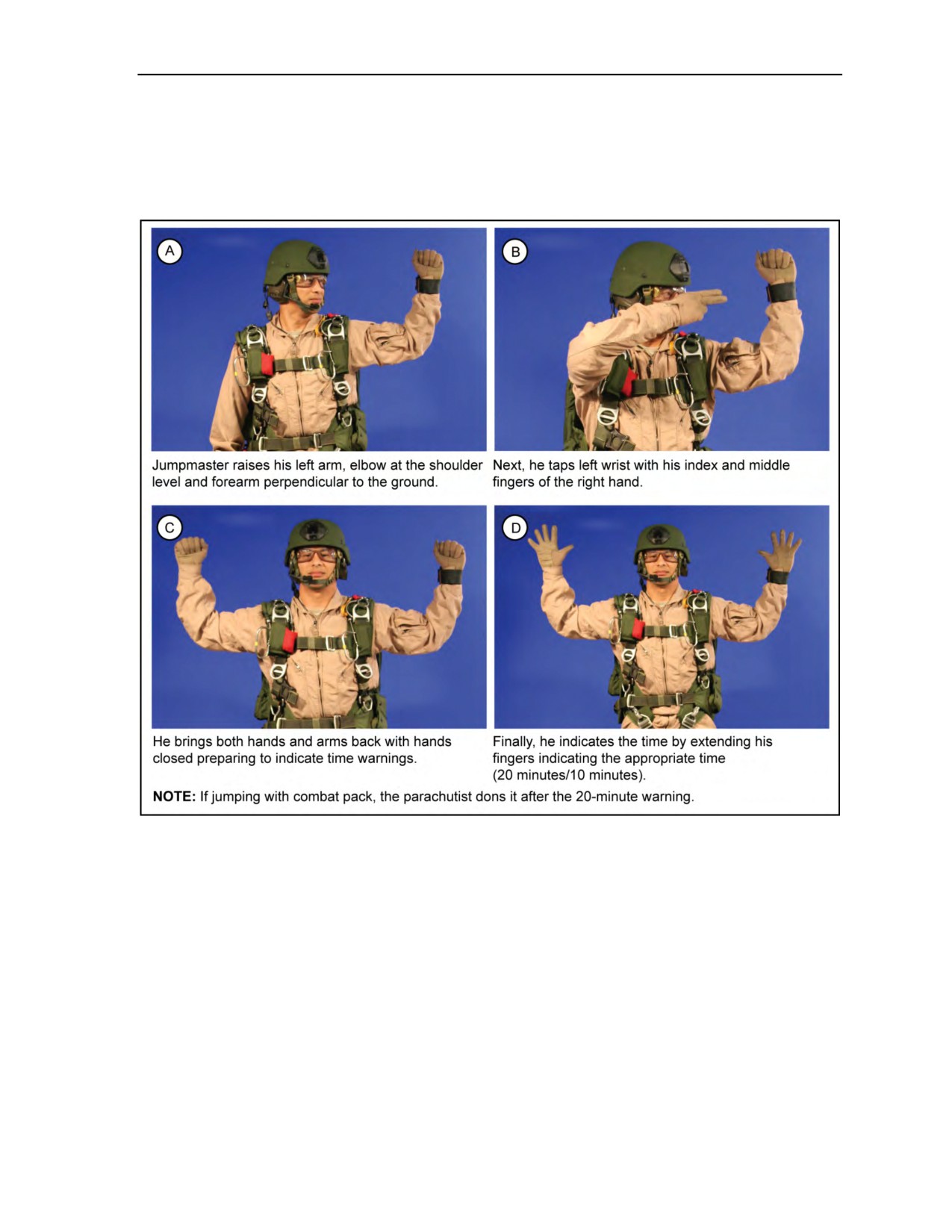
Aircraft Procedure Signals and Jump Commands
TIME WARNINGS
6-7. The jumpmaster receives time warnings from the flight crew. The jumpmaster signals the
TIME WARNINGS to the parachutist to allow him adequate time to prepare for the jump (Figure 6-7). The
parachutist normally receives the time warnings 20 minutes and 10 minutes before time on target.
Figure 6-7. TIME WARNINGS signal
WIND SPEED
6-8. The jumpmaster signals WIND SPEED after the 10-minute time warning (Figure 6-8, page 6-8). In
gusting wind conditions, the jumpmaster gives the wind speed signal first to indicate the lower wind speed.
He follows with the GUSTING WINDS signal to indicate the higher wind speed (Figure 6-9, page 6-9).
24 October 2014
ATP 3-18.11/AFMAN 11-411(I)/NTTP 3-05.26M
6-7
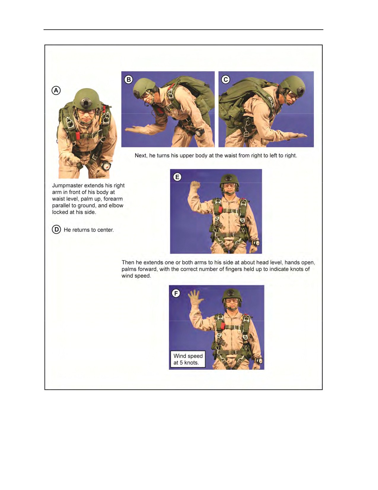
Chapter 6
Figure 6-8. WIND SPEED signal
6-8
ATP 3-18.11/AFMAN 11-411(I)/NTTP 3-05.26M
24 October 2014
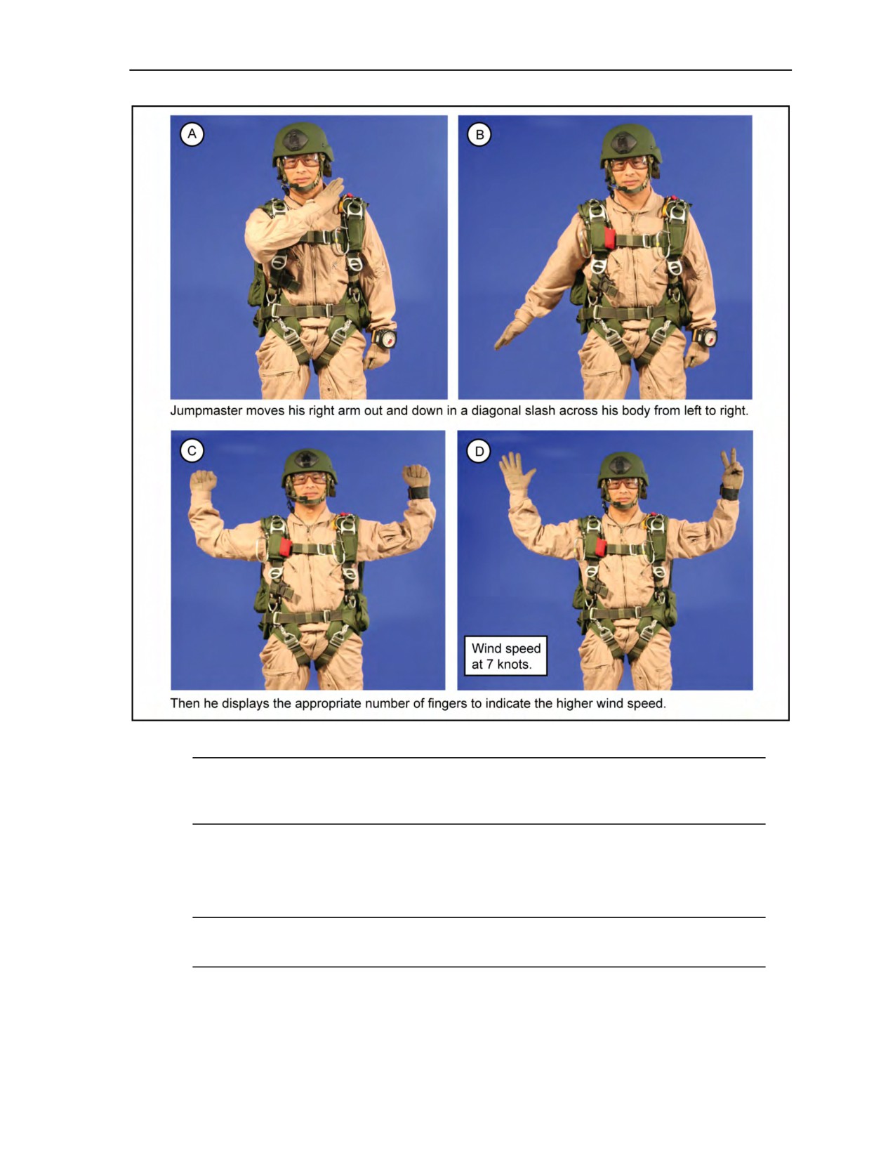
Aircraft Procedure Signals and Jump Commands
Figure 6-9. GUSTING WINDS signal
Note: The ARM ARR signal has been eliminated from the jump commands when jumping the
Military CYPRES 2, but all jumpers must receive a Military CYPRES 2 and pin check after the
WIND SPEED or GUSTING WINDS signal is given and then pass the THUMBS-UP signal.
JUMP COMMANDS
6-9. The jump commands discussed in the following paragraphs begin as early as 2 minutes before the
actual jump is made. The jumpmaster gives these commands.
Note: The 2 MINUTE, 1 MINUTE, 15 SECOND, and GO commands can be given with either hand,
depending upon which side of the aircraft the MFF jumpmaster is on.
24 October 2014
ATP 3-18.11/AFMAN 11-411(I)/NTTP 3-05.26M
6-9
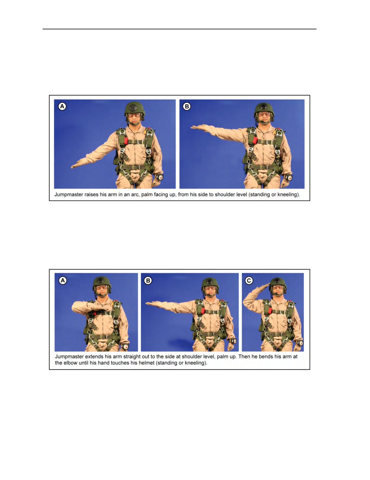
Chapter 6
STAND UP
6-10. The jumpmaster commands STAND UP about 2 minutes before time on target (Figure 6-10). (Oxygen
or equipment jumps may require additional time for this command only; all other commands remain the
same.) Upon receiving this command, the parachutist stands up, receives pin check, faces the jumpmaster,
and checks his equipment. If jumping oxygen, the parachutist also places his right hand on the ON/OFF
valve of the bailout bottles and grasps with his left hand the console hose at the AIROX VIII.
Figure 6-10. STAND UP command
MOVE TO THE REAR
6-11. The jumpmaster commands MOVE TO THE REAR about 1 minute before time on target (Figure 6-11).
Upon receiving this command, the parachutist tightens the combat pack’s shoulder straps around his legs,
adjusts his goggles, and moves to within 1 meter of the jump door or to the hinge of the cargo ramp. If
jumping oxygen, the parachutist must activate the bailout oxygen system, check the flow indicator of the
AIROX VIII, and disconnect from the oxygen console before moving to the rear of the aircraft.
Figure 6-11. MOVE TO THE REAR command
STAND BY
6-12. The jumpmaster commands STAND BY about 15 seconds before the exit (Figure 6-12, page 6-11).
Upon receiving this signal, the parachutist signifies readiness by returning the jumpmaster’s signal and then
moves to the jump door or the cargo ramp.
6-10
ATP 3-18.11/AFMAN 11-411(I)/NTTP 3-05.26M
24 October 2014
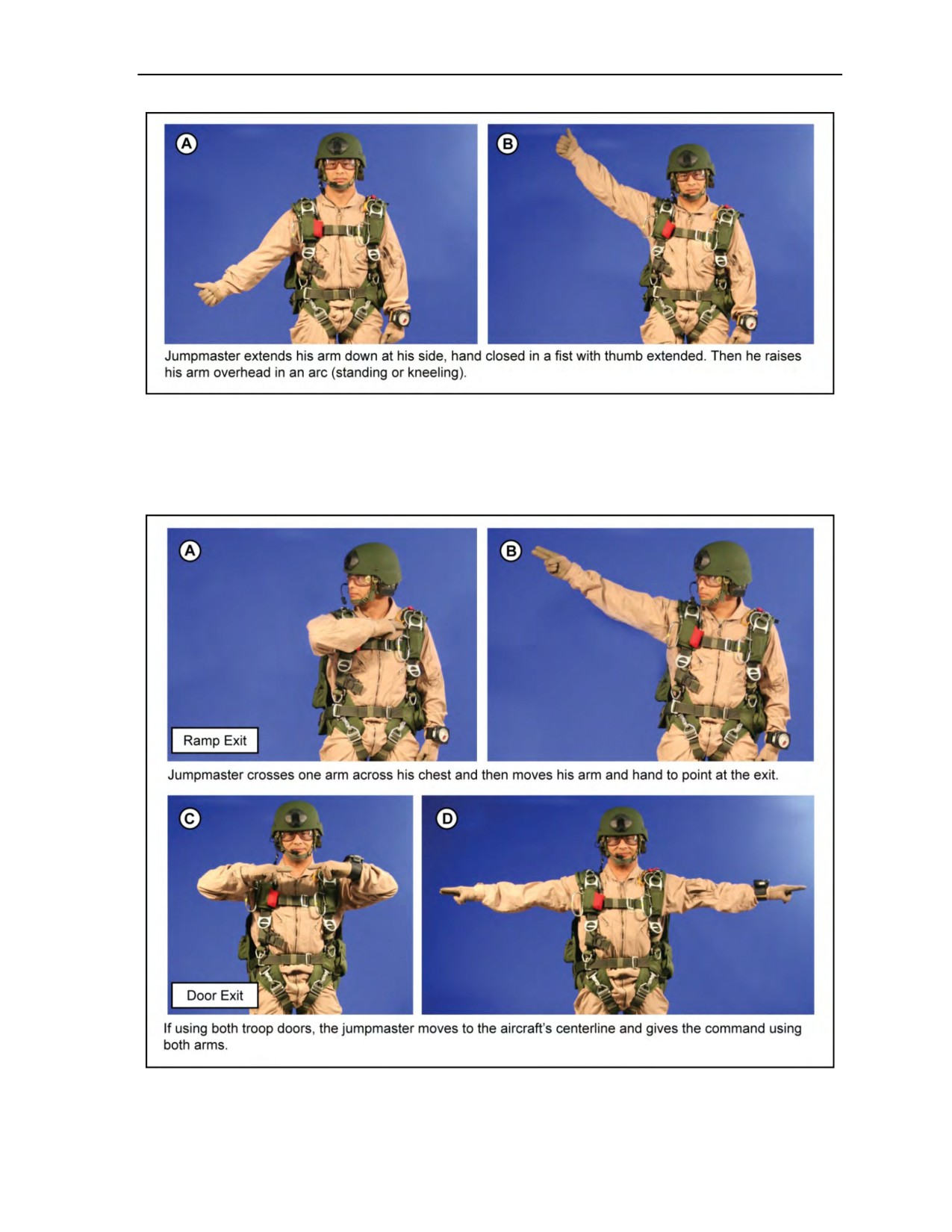
Aircraft Procedure Signals and Jump Commands
Figure 6-12. STAND BY command
GO
6-13. The jumpmaster commands GO when the aircraft is over the release point and the green jump light is
on (Figure 6-13).
Figure 6-13. GO command
24 October 2014
ATP 3-18.11/AFMAN 11-411(I)/NTTP 3-05.26M
6-11
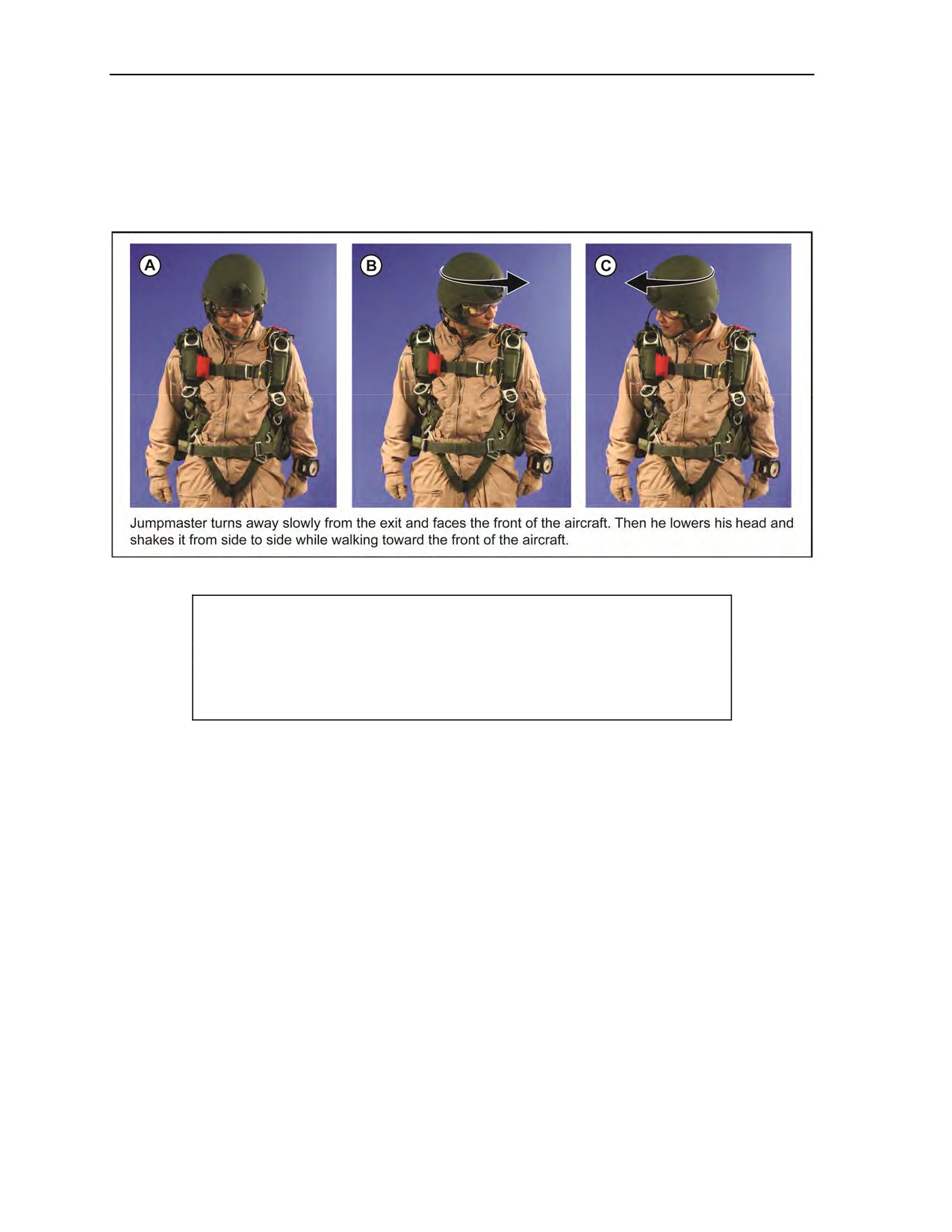
Chapter 6
ABORT
6-14. The jumpmaster commands ABORT anytime an unsafe condition exists inside or outside the aircraft
(red jump light comes on) or on the DZ (Figure 6-14). Upon receiving this command, the parachutist
returns to his seat and sits down. If jumping oxygen, the parachutist reconnects to the oxygen console, turns
off the bailout system, and then sits down.
Figure 6-14. ABORT command
CAUTION
If the jumpmaster has cocked his arm to give the command GO, he
must NOT move it when he gives the ABORT command. The
parachutists may exit if the jumpmaster moves his cocked arm.
6-12
ATP 3-18.11/AFMAN 11-411(I)/NTTP 3-05.26M
24 October 2014
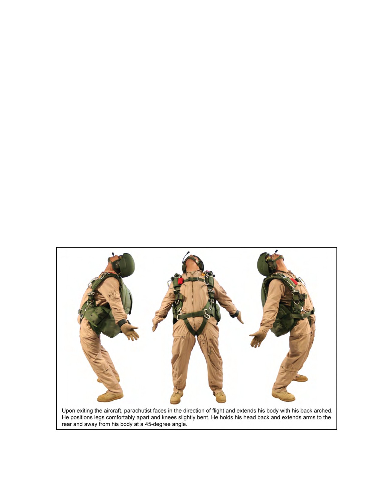
Chapter 7
Body Stabilization
The MFF parachutist must be able to exit an aircraft with his combat equipment, fall
on a designated heading, and manually deploy his main parachute without losing
stability. Body stabilization skills allow the parachutist to group in free fall, cover
small lateral distances with a rucksack, move off a lower parachutist’s back in free
fall, and turn to keep the DZ or group leader in sight. The MFF parachutist maintains
these skills through regular MFF jumps and periodic refresher training. This chapter
addresses the body stabilization skills needed to make a night tactical MFF jump with
combat equipment from oxygen altitudes. Appendixes B and C provide
recommendations for MFF proficiency training programs, and Appendix D covers
suggested sustained airborne training.
TABLETOP BODY STABILIZATION TRAINING
7-1. Any stable tabletop or flat surface can be used for body stabilization training. The parachutist lies on
his stomach on the tabletop. At the command GO, he lifts his arms and legs from the tabletop, assumes the
poised, box man, or diving exit position, then moves to the stable free-fall position (Figures 7-1 through 7-4,
pages 7-1 through 7-4). Controlled movement positions during free fall include turns, gliding, and altimeter
check (Figures 7-5 through 7-7, pages 7-4 and 7-5).
Figure 7-1. Poised exit position
24 October 2014
ATP 3-18.11/AFMAN 11-411(I)/NTTP 3-05.26M
7-1
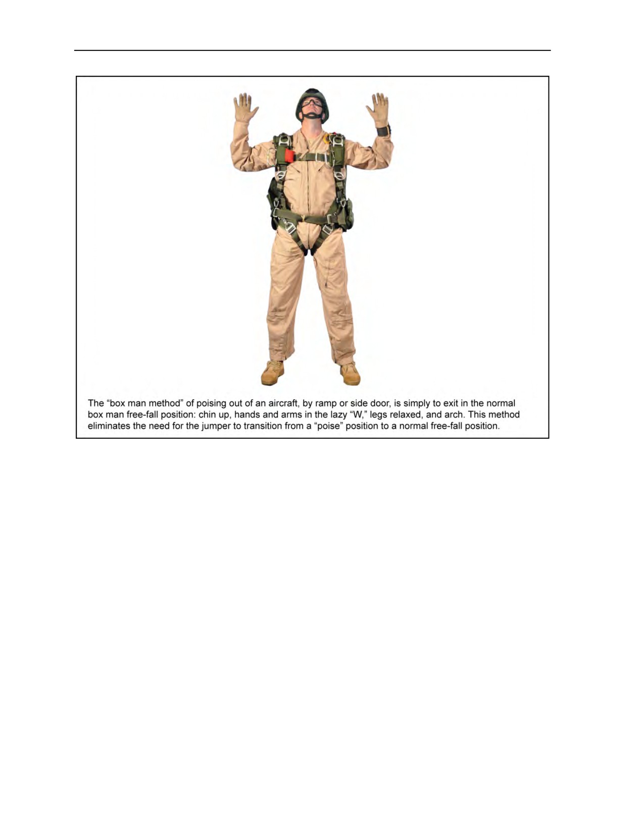
Chapter 7
Figure 7-2. Box man method
7-2
ATP 3-18.11/AFMAN 11-411(I)/NTTP 3-05.26M
24 October 2014
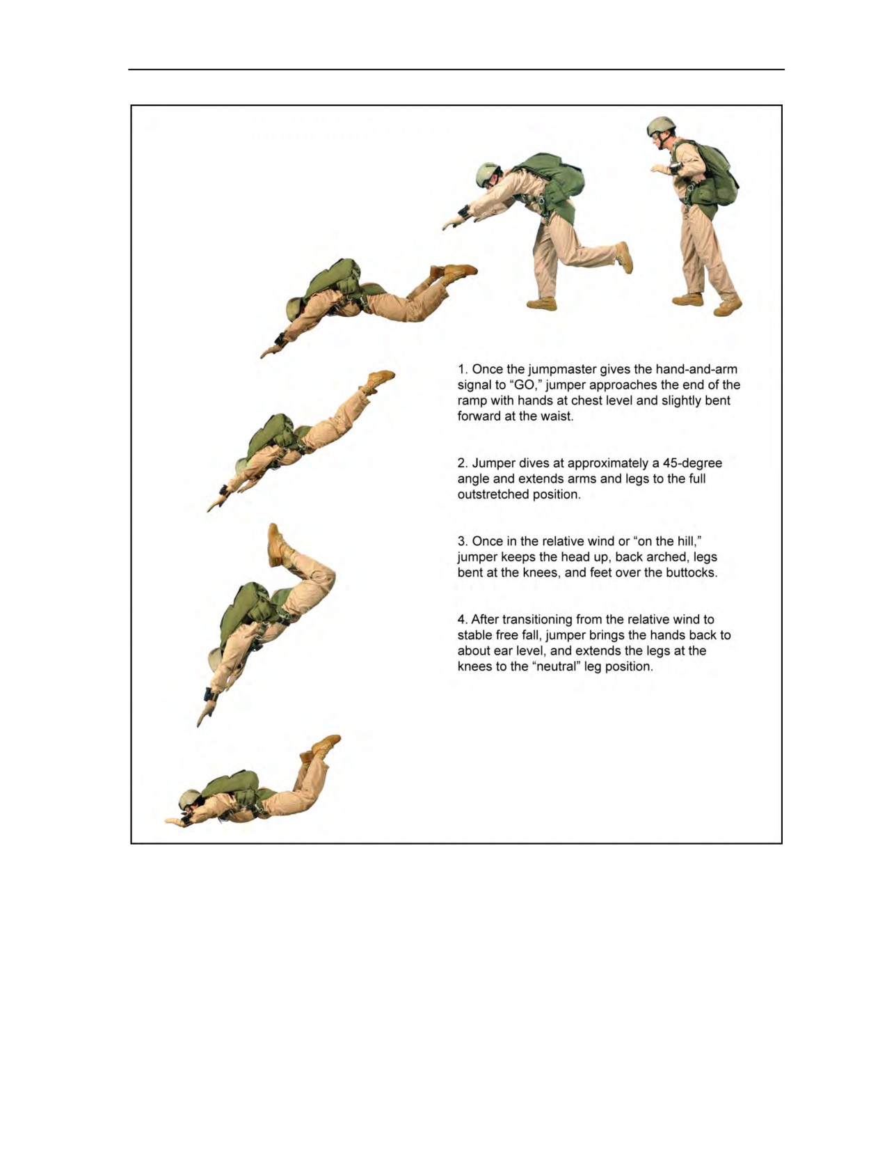
Body Stabilization
Figure 7-3. Diving exit position
24 October 2014
ATP 3-18.11/AFMAN 11-411(I)/NTTP 3-05.26M
7-3
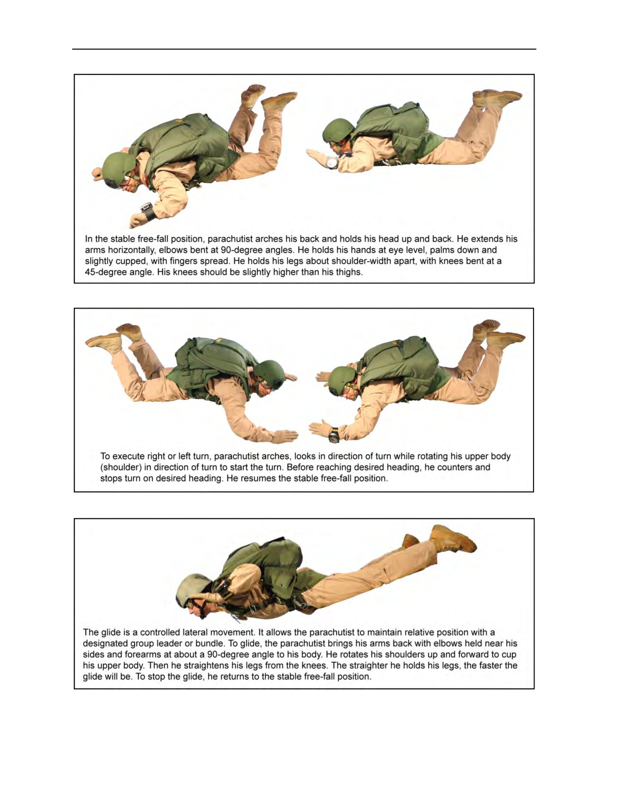
Chapter 7
Figure 7-4. Stable free-fall position
Figure 7-5. Body turn
Figure 7-6. Gliding
7-4
ATP 3-18.11/AFMAN 11-411(I)/NTTP 3-05.26M
24 October 2014
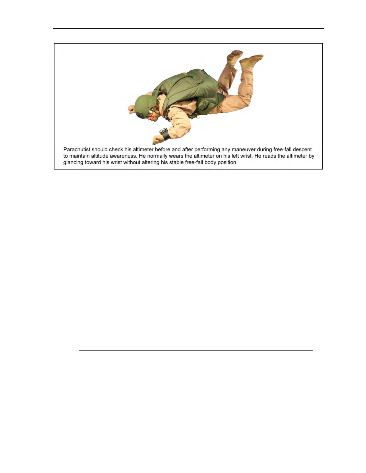
Body Stabilization
Figure 7-7. Altimeter check
MAIN RIPCORD PULL
7-2. The parachutist executes the main ripcord pull at the predesignated altitude. He looks at the main
ripcord handle on the right main lift web. He extends his left arm beyond his head with his hand held palm
down. He traces the main ripcord cable housing. He grasps the main ripcord handle with his right hand,
pulls the handle from the ripcord pocket, pulling the main ripcord cable to full-arm extension. Then he
raises his right shoulder to disrupt the partial vacuum while looking straight down. After canopy
deployment, he slips the main ripcord handle over his wrist.
7-3. When the parachutist uses night vision goggles (NVGs) to assist him during a night jump, the
pull sequence during opening will remain the same as without NVGs (Figure 7-8, page 7-6). The
parachutist will—
z
Look below the NVGs to identify and read the altimeter, ripcord, cutaway pillow, and reserve
ripcord handle when required during free-fall and canopy descent.
z
“Arch-Look-Trace-Grab” as normal. The counter hand will extend slightly more forward to
allow the head to be cradled under the parachutist’s arm in a manner that protects the NVGs
from inadvertent contact with the deploying pilot chute.
z
Pull the ripcord handle to full-arm extension while continuing to look straight down with the
counter arm in place to continue protecting the NVGs from a deploying pilot chute.
z
Not conduct a visual check of the pilot chute; the parachutist will raise his right shoulder in an
attempt to disrupt the partial vacuum while continuing to look straight down. He will attempt
this twice and only twice; if this is unsuccessful, he will perform cutaway procedures for a total
malfunction.
Note: Before pulling the main ripcord, the parachutist should ensure that he is not backsliding.
Backsliding could cause the pilot chute to move forward of the parachutist’s head and body.
Note: There are no special emergency procedures associated with the use of NVGs during MFF
operations. If a horseshoe malfunction occurs, the parachutist should make no attempt to clear
the malfunction and should immediately execute cutaway procedures.
24 October 2014
ATP 3-18.11/AFMAN 11-411(I)/NTTP 3-05.26M
7-5