ATP 3-18.11 Special Forces Military Free-Fall Operations (October 2014) - page 4

Chapter 14
maintain an aerodynamic airfoil shape is further degraded. It can abruptly collapse even when the
turbulence effects appear to be insignificant. When eddy turbulence (gusting) is coupled with thermal
uplifting, the danger of canopy collapse becomes serious, regardless of the adequacy of the canopy loading
or the canopy’s dimensions.
14-68. Turbulence eddies are also known as rotors and dust devils. They are naturally created, ranging in
size from several inches to several kilometers in diameter. The most common that affect MFF parachute
operations are those 1 meter to several hundred meters in diameter. The eddy’s intensity is affected by wind
velocity and the shape of the obstruction over which the air mass flowed to create it. Dust devils are
dangerous in that the diameter of the locally rotating wind column is usually much larger than the visible
portion. Where the eddy might be only marginally wider than the visible diameter at ground level, dust
devils can also extend thousands of feet higher than the visible top and increase in diameter severalfold
with elevation. The visible portion of the eddy is the uplifted soil and debris from the earth’s surface.
14-69. For an MFF parachutist under canopy, flying into or in the vicinity of a dust devil almost certainly
means a collapsed canopy. This is disastrously close to the earth when the canopy might not have time to
reinflate or the rotating air column has twisted the parachute’s line groups. Even a parachutist on the
ground still in the harness must be prepared to release the RSL and cut away the main canopy if it were to
start to be reinflated by eddy turbulence. Parachutists who have been picked up by a dust devil have been
lifted between 10 and 40 feet AGL before being slammed back to the ground, resulting in death or serious
injury.
14-70. Air density can also affect eddies. Higher air density correlates with a higher intensity in the
manifested eddy. Cold air is more dense than warm air. Therefore, in winter conditions, one can expect
slightly more pronounced turbulence effects
(larger-diameter rotors, higher-intensity rotation, higher
altitude effects) than those phenomena that are warm air or thermal conditions. Humid air is less dense than
dry air, so eddy turbulence would be more pronounced in low humidity than in high humidity. DZs at
higher field elevations have lower air density than at sea level and in general produce turbulence of lesser
intensity. All of these parameters are theoretical. Each potential DZ’s set of landing conditions must be
evaluated by the MFF jumpmaster to determine the probable aggregate effect on the parachutists under
supervision for the conditions anticipated for that operation.
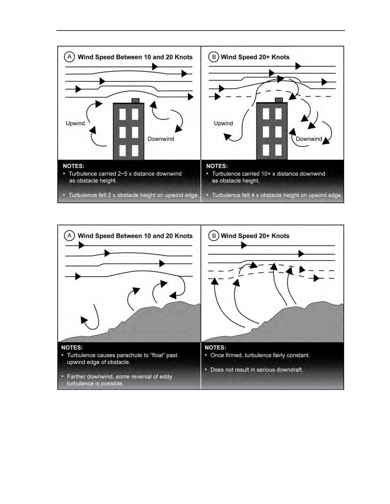
14-71. Obstruction eddy characteristics vary depending on many factors. With wind speed less than
10 knots, small eddies (10 to 50 feet in depth) are created on both the downwind and upwind side of an
obstacle. With wind speeds between 10 and 20 knots, significant turbulence eddies are created on both
sides of an obstacle. Because of the wind’s velocity, they are also carried several hundred feet downwind of
the obstacle before they dissipate. Severity depends on the height and shape of the obstruction, as well as
the wind speed. Obstructions with sharp definition/edges create more pronounced eddy currents. When
winds exceed 20 knots, eddy currents are mostly formed on the leeward side of the obstruction and the
turbulence zone is carried a considerable distance downwind of the obstacle. A rule of thumb for
intermediate strength winds (10 to 20 knots) is that turbulence eddies are carried at least five times the
distance downwind as the height of the obstacle that created them (Figures 14-13 and 14-14, page 14-23).
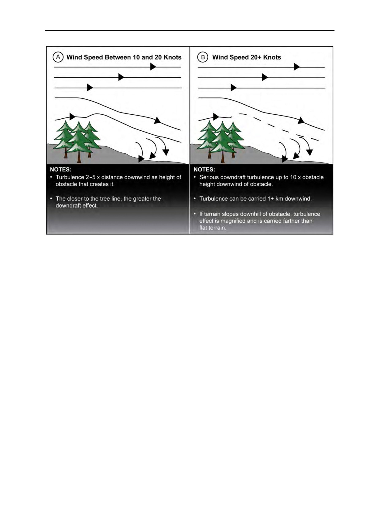
14-72. The rule of thumb for winds stronger than 20 knots is that the eddy turbulence is carried 10 times
the distance downwind as the obstacle height. On large, open DZs with no obstructions (usually the case
with DZs downwind of tree lines), eddies may be carried as much as one-half mile downwind of the
obstruction. This phenomenon is also strengthened if the terrain slopes downhill away from the tree line
causing the turbulence (Figure 14-15, page 14-24).
14-22
ATP 3-18.11/AFMAN 11-411(I)/NTTP 3-05.26M
24 October 2014
Weather Factors for the Military Free-Fall Jumpmaster
Figure 14-13. Single-obstacle eddy current
Figure 14-14. Terrain-induced eddy currents
24 October 2014
ATP 3-18.11/AFMAN 11-411(I)/NTTP 3-05.26M
14-23
Chapter 14
Figure 14-15. Tree-line-induced eddy currents
14-73. For winds stronger than 20 knots, the MFF parachutist may be backing in to the target area. As the
parachutist descends into the turbulence area, eddy effects are unexpected because the object creating the
eddy is a significant distance upwind and probably not in the visual field. Turbulence is also indicated by
the behavior of the wind. Strong winds usually contain gusts, which are wind speed changes of 5 to 10 mph
within a few seconds. Gusts can add to the random deflation and poor performance of an MFF ram-air
canopy. All parachutists must visualize the upwind quadrant (wind cone) during their landing approach to
assess the potential effects of wind speed and obstructions on the parachute’s performance. Horizontal and
vertical separation between parachutists should be increased during a strong wind condition landing
approach to accommodate unexpected canopy movement at low altitudes.
14-74. Only minor eddy currents form over water surfaces. These are created by air movement friction
with the wave tops. Regardless, parachutists must still be cautious in setting up their approach to land on or
in the vicinity of a vessel at sea. Because a vessel is an obstruction, it or its superstructure can create
unexpected downwind eddy currents. The larger the vessel, the greater the potential for eddy currents.
14-75. In HAHO operations, when air is unstable (conditions not consistent as altitude increases) and
once eddy currents or turbulence forms, they tend to continue to grow. This is especially true when thermal
conditions exist. For example, when fueled by thermal convection, ground-induced eddy currents can
extend up to 6,000 feet AGL. Essentially, this is how dust devils can form and evolve to be several hundred
meters in diameter at their base.
14-76. The lighter the parachutist (or total suspended weight), the more susceptible the canopy will be to
turbulence-related problems. The forces acting on a canopy are proportional to the rate of change of wind
velocity on the canopy. Therefore, it is dangerous to fly fast (canopy toggles in the full flight/up position)
through turbulence. Flying through eddy turbulence should be done at 25- to 50-percent brakes. Too slow
(more than 50-percent brakes) may also be dangerous because the canopy may stall without warning due to
a gust. Increasing the canopy rate of descent through braking keeps the canopy’s internal pressurization
higher. This decreases its susceptibility to turbulence-induced instability, decreases the overall potential for
collapse, and increases overall canopy control. It is an effective technique at any altitude.
14-24
ATP 3-18.11/AFMAN 11-411(I)/NTTP 3-05.26M
24 October 2014

Weather Factors for the Military Free-Fall Jumpmaster
14-77. The effects of eddy turbulence normally subside close to the ground, unless the parachutist is
directly in contact with an eddy. Under roughly 50 feet AGL, turbulence should lessen, permitting a
near-normal approach. Regardless, the approach should still be made in the 25- to 50-percent brake range as
a precaution. Turbulence at the landing flare may side slide the canopy or enter it into a turn. The rate of
turn may increase when lowered combat equipment is attached to one side of the parachute harness in lieu
of being suspended from the center of mass (saddle). With significant weight pulling one side of the
harness down, the canopy risers will be uneven. Because the canopy is already canted to one side, a gust is
likely to send the canopy into a turn, usually to the side on which the equipment is suspended. When
braking, the canopy can be controlled by manipulating the steering lines to offset the difference in riser
lengths. Under these conditions, the MFF parachutist should be prepared to perform a PLF.
14-78. Other turbulence is also generated and experienced by MFF parachutists using ram-air canopies.
Airfoil-generated vortices trail off the lateral corners of the canopy, much like those created by airplane
wingtips. Canopy vortices come off the trailing edge at an upward 45-degree angle when the parachute is in
full glide. In full brakes, the vortex angle is almost straight up due to the canopy’s increased rate of descent.
When in a partially braked configuration (such as in a stack setting up to land), the vortex angle produced is
about 60 degrees from the canopy angle of attack at the ground. The vortices descend and dissipate at a rate
slower than the parachutist’s canopy. Closer distances between parachutists in the air result in a stronger
vortex. The vortex intensity is greater with parachutists who have a higher total suspended weight because
their canopies have a greater rate and steeper angle of descent. Upon passing into another canopy’s vortex
(wake), the turbulent air will hit the parachutist’s body before it hits the canopy. The canopy will rock and
then drop up to 20 feet, causing danger during landing. Near the ground or aloft, vortices drift with the
wind, so it is possible to hit vortex turbulence from a canopy that has landed or turned upwind. If this
occurs, the MFF parachutist must be consistent with the steering toggle manipulation and still flare at the
normal time. If in doubt, the parachutist must be prepared to land using a PLF.
CLOUDS
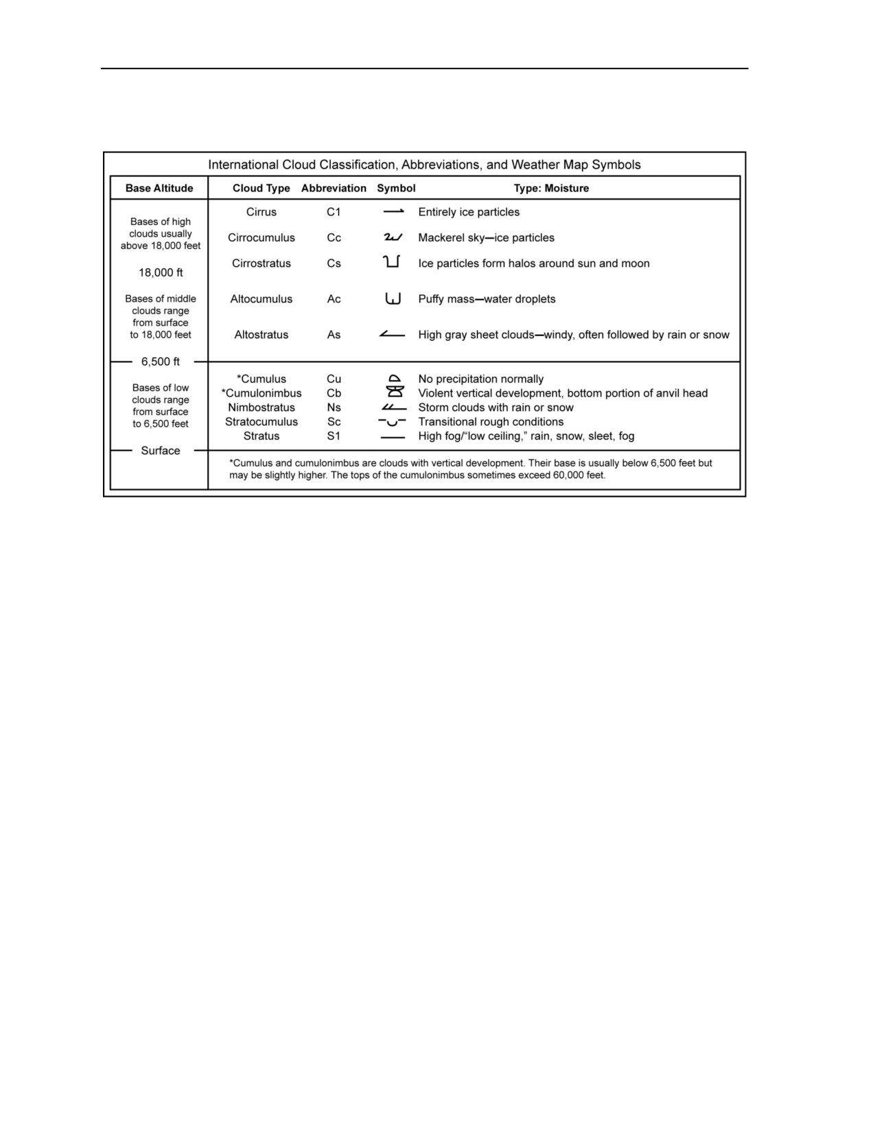
14-79. There are four categories of clouds: high-altitude clouds, middle-altitude clouds, low-altitude
clouds, and clouds with extensive vertical development (Figure 14-16, page 14-26). Each category has
some typical weather characteristics that affect MFF parachute operations.
14-80. High clouds have a base that starts at
18,000 feet AGL and are valuable as indicators of
approaching fronts and associated changes in weather. Middle clouds, found between 6,500 feet and
18,000 feet AGL, are mostly composed of ice crystals or supercooled water vapor, which produces high
clouds and icing conditions. Middle and low clouds are most likely to impede parachuting. Low clouds
extend from near surface to 6,500 feet AGL. Their cloud base changes rapidly. Clouds that have a base
below 50 feet AGL or are in contact with the earth’s surface are defined as fog.
14-81. Clouds with vertical development usually have cloud bases below 6,500 feet AGL, the tops of
which can extend to over 60,000 feet AGL. This lifting action is caused by convective updrafts or frontal
lift when two air masses meet. These conditions are extremely hazardous for parachutists. The turbulence
inside cloud formations is strong enough to cause structural damage to aircraft airframes (and therefore
applies to parachutists under canopy). One example of these formations is the common thunderstorm cloud
with its typical anvil head shape on top as it develops. A cumulonimbus cloud is essentially a thunderstorm
without the thunder, but it has the same turbulence characteristics. Whether a cloud is exhibiting electrical
or thunderstorm activity or not tells nothing about the turbulence in or around it. All clouds have some
degree of turbulence associated with them. The faster a cloud is developing or changing, the more
turbulence it possesses.
14-82. Cloud-induced or associated factors which affect MFF parachute operations are the cloud type and
thickness
(depth) or number of layers, amount of sky covered/obscuration, resultant vertical
(MFF jumpmaster) and lateral/slant (pilot and/or HAHO parachutist) visibility, moisture type/precipitation
contained in them, freezing and/or icing factors, and turbulence. On a macro scale, the three types of
turbulence are thermal, mechanical, and frontal. Thermal turbulence is local vertical convective currents
caused by surface heating or cold air masses moving over warmer ground or water. Mechanical turbulence
results from wind passing over irregular terrain or obstructions. Frontal turbulence occurs when air masses
are locally lifted by another air mass of a different temperature and density. This creates abrupt and usually
24 October 2014
ATP 3-18.11/AFMAN 11-411(I)/NTTP 3-05.26M
14-25
Chapter 14
radical wind shear, normally associated with approaching cold fronts. In general, frontal turbulence
adversely affects HAHO parachute operations.
Figure 14-16. Cloud classification
THUNDERSTORMS
14-83. Flight through thunderstorms and mission accomplishment are not compatible. This premise
applies to rotary-wing aircraft. If it applies to powered flight from inside a protected cockpit, its impact is
as pertinent, if not more so, for MFF parachutists under canopy.
14-84. Thunderstorms are mostly caused by thermal or convective uplifting. Their rate of updraft can
range from a few fps to 6,000 feet per minute. It is not only turbulence, which is associated with a
thunderstorm, but other weather variables that can cause adverse MFF conditions. For example, hail mostly
melts before it reaches the ground. It can be marble through grapefruit size in diameter at
HAHO altitudes. An example is a five-inch-diameter hailstone that came through an aircraft cockpit canopy
at 29,000 feet AGL. Hailstones have been thrown 5 miles from their parent cloud formation. In general, the
atmospheric conditions that can float a two-pound ice ball are not conducive to stable ram-air canopy flight.
14-85. Icing conditions that can accumulate on a canopy and HAHO parachutist can occur as low as
14,000 feet MSL. Buildup degrades the canopy’s glide slope (changes the K/drift factor) and overall
performance. Ice forms when air bearing supercooled moisture comes into contact with a solid object.
When a canopy and its parachutist move through this atmospheric condition, ice forms on all cell leading
edges, suspension lines, slider, as well as surface obstructions, such as canopy seams, pilot chute, and
deployment bag. Snow conditions are mostly found below 20,000 feet MSL and accumulation is not a
concern. Environmental effects on the parachutist for any MFF operation are all that must be
accommodated. Icing increases drag, which significantly decreases lift by deforming the canopy’s airfoil
shape. The most severe icing occurs between 0 and -10 degrees Celsius. Icing is rare below -20 degrees
Celsius, but is possible in any cloud below 0 degrees Celsius. Freezing rain is more probable and occurs
when supercooled water droplets (liquid water whose temperature is below freezing) hit any object and
immediately freeze on contact. This condition is more common and dangerous than normal icing as
dangerous amounts can build up in minutes. There are two documented instances of ice buildup resulting in
a rate of descent and controllability problem severe enough to cause the concerned jumpers to jettison the
main canopy.
14-26
ATP 3-18.11/AFMAN 11-411(I)/NTTP 3-05.26M
24 October 2014
Weather Factors for the Military Free-Fall Jumpmaster
14-86. Lightning is an obvious hazard. The energy to create a lightning stroke
10,000 feet long is
2 to 3 million electron volts and 500,000 to 600,000 amperes. The movement of a canopy through charged
air can accumulate the static charge necessary to prompt a lightning stroke. In addition, that amount of
static electricity is enough to affect HAHO and/or magnetic compasses. This same accumulation or close
lightning strokes can have enough effect to activate EAADs and/or ARRs, which employ electrically fired
explosive cutters or pin pullers (for example, Sentinel, MARS, or Military CYPRES 2). EAADs and/or
ARRs which employ mechanical and barometric mechanisms (for example, FF-2 or KAP-3) would not be
electrically affected. In addition, parachutists who find themselves in high electrical conditions should
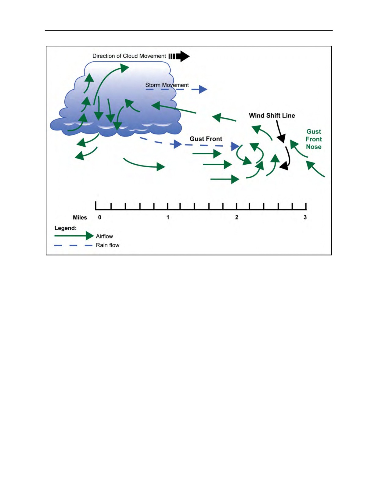
ensure that metal main ripcords are not left exposed, as these metallic objects could very easily act as a
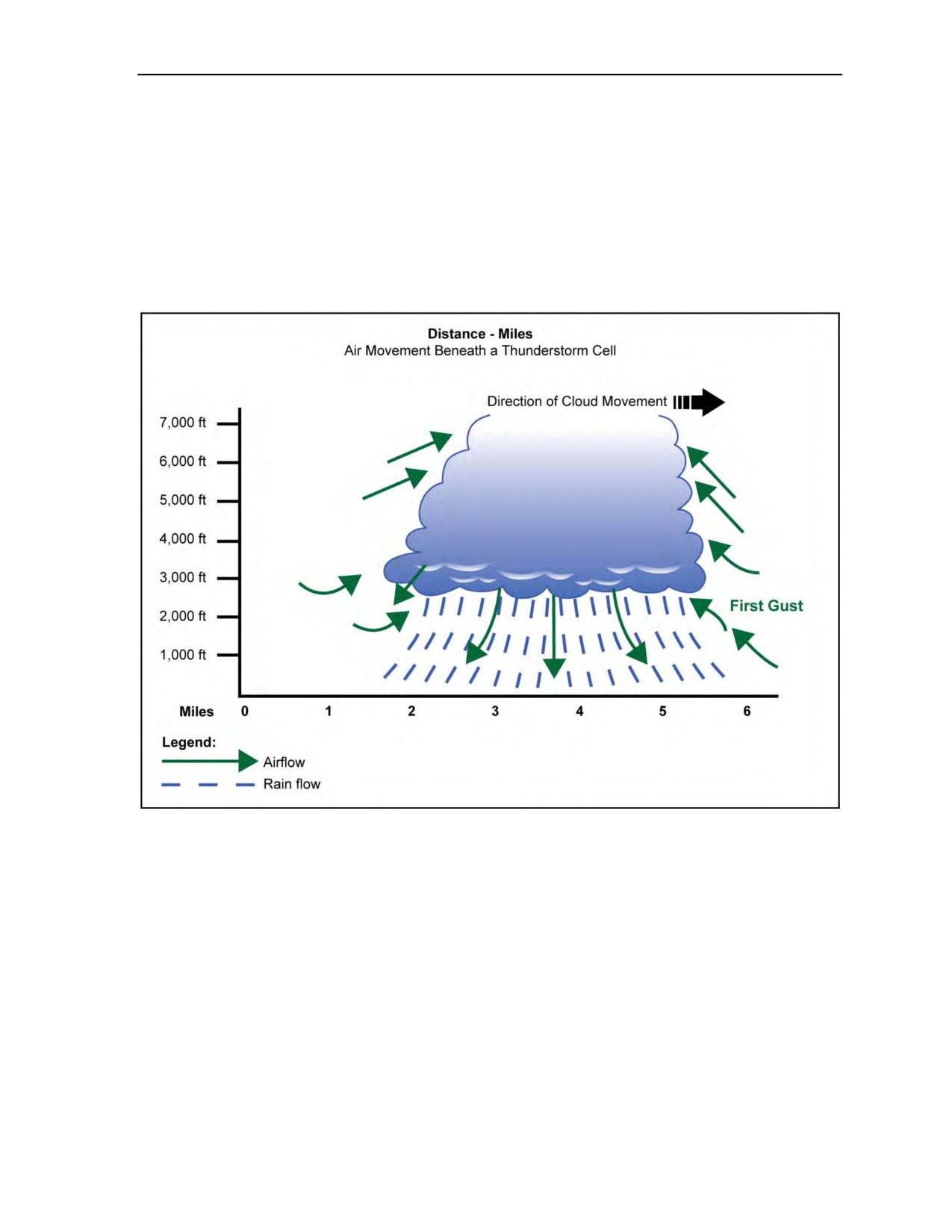
lightning rod and prompt a lightning strike. Figure 14-17 depicts air movement beneath a thunderstorm cell.
Figure 14-17. Air movement beneath a thunderstorm cell
14-87. Another adverse parachuting phenomena associated with thunderstorms is the first gust. This term
applies to the rapid change in wind speed and direction close to the earth’s surface immediately prior to the
passage of a storm cell. The first gust results from the spreading of a thunderstorm’s downdraft air current
as it hits the surface of the earth. This downdraft is the reason canopy flight underneath a seemingly
innocuous storm cell or squall cloud can be disastrous. The initial wind surge, as observed at the earth’s
surface, is the first gust. It can generate turbulence as far as 8 to 10 miles ahead of the storm core,
depending on the extent of the cloud’s development. First gust wind speeds may exceed 50 knots and can
vary up to 180 degrees from previously prevailing wind direction. However, first gusts generally average
15 knots over previous velocities and average a 40-degree change in wind direction. The speed with which
the first gust arrives is extremely hazardous for parachutists under canopy. First gusts are not limited to the
area ahead of the storm cell’s direction of movement. In addition, they have associated with them an abrupt
fall in barometric pressure as the storm cell approaches and a just as rapid rise in pressure as it passes. This
atmospheric pressure change can easily be read on the parachutist’s altimeter. Figure 14-18, page 14-28,
depicts the first gust wind flow.
24 October 2014
ATP 3-18.11/AFMAN 11-411(I)/NTTP 3-05.26M
14-27
Chapter 14
Figure 14-18. First gust wind flow
14-88. Fog occurs when the cloud base is within 50 feet of the earth’s surface. Light wind is generally
favorable to the formation of fog. It gives the moisture-bearing air mass a gentle mixing circulation which
spreads the surface cooling action through a deeper layer of air, thickening the blanket of fog. Fog
dissipates with heating (usually when the sun rises) or is blown away with stronger wind. When the relative
humidity of the air layer that is directly in contact with the earth’s surface drops, the amount of fog will
decrease. The most significant impact of fog on MFF operations is the masking of the DZ surface on final
landing approach. This is especially hazardous on DZs with lower air density altitudes where rates of
descent are increased, on cool calm nights with no wind to land into, or when obstacles on the DZ are
obscured. The MFF jumpmaster should be able to visualize and anticipate potential condition scenarios.
Based on isolation planning, the MFF jumpmaster can minimize their effect by choosing the time and place
where weather factors best offset masking of the DZ surface and maximize the tactical realities of the
infiltration DZ.
14-89. Parachutist depth perception is reduced over unbroken surfaces. With no relief features to provide
visual clues, altitude estimation by the human eye is difficult. This occurs during the day and is worse
during the night or other reduced-visibility conditions. Canopy flight over water, unbroken level ground
(desert sand, grass fields, crops, and so on), and snow fields are examples. For instance, looking down on
newly fallen snow, shadows are usually not visible or are not distinct enough to provide visual clues of
surface elevation. Visual clues aid the human eye in determining angular perspective. Canopy flight
planning for landing approach and flare altitude determination is made more difficult, especially at night
over the same type of surfaces. With reduced depth perception, the tendency is to flare the canopy too late
(plow in). This condition is exacerbated during night’s reduced visibility in that there are also generally
lighter wind conditions, hence a greater rate of descent and less wind against which to create a dynamic
stall. During daylight conditions, amber goggles assist in giving the depth perception necessary to
determine landing surface conditions. At night, staying on 100-percent oxygen all the way to the ground
14-28
ATP 3-18.11/AFMAN 11-411(I)/NTTP 3-05.26M
24 October 2014

Weather Factors for the Military Free-Fall Jumpmaster
maximizes night vision’s visual acuity and depth perception, and increases the probability of avoiding
injury on landing.
APPLICATION OF GENERAL WEATHER PRINCIPLES
14-90. Knowledge of general weather rules and principles is helpful to the MFF jumpmaster.
Opportunities to apply rules of thumb occur during the conduct of peacetime duties as the DZSO, during
mission planning when the operation involves infiltrating blind, or when formulating mission abort criteria
and contingency plans. For example, weather unfavorable to MFF parachuting operations is generally
indicated by falling barometric pressure with winds prevailing from the west. Clearing weather and good
parachuting conditions are usually characterized by winds which shift to western quadrants with a rising
barometer. As the MFF jumpmaster studies weather data in preparation for an infiltration airborne
operation, knowledge of these principles can assist in visualizing the weather conditions that will be in
place over the anticipated area of operations or planned DZ. This gives the MFF jumpmaster a basis of fact
with which to determine exit and opening points, probable upwind quadrants, and to establish realistic GPS
navigation waypoints. Knowledge of general weather principles reduces the reliance on chance as the
primary factor affecting the lives of the parachutists who are entrusted to the MFF jumpmaster for this
critical infiltration portion of the mission.
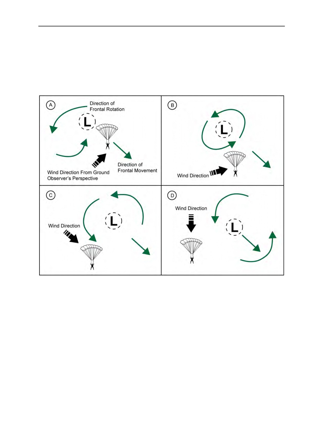
14-91. Most of the following principles can be visualized by remembering that low-pressure systems (bad
or less than ideal parachuting conditions) have counterclockwise airflow. High-pressure systems (relatively
good MFF conditions) rotate clockwise frontally. The last principle is that these fronts rotate around their
axes as the air mass moves from west to east. From the perspective of a ground observer, as the track of the
frontal system crosses near that position, the direction of the wind changes depending on whether it is the
leading edge, center, or trailing edge of the system that is passing. Knowing this and the speed of the front,
one can fairly accurately determine from which direction the winds will be blowing at a specified time in
the near future. At a minimum, the upwind quadrant can be determined and a wind cone established. In this
manner, given no ground-sourced information, the MFF jumpmaster can determine on a blind drop where
to exit the aircraft to be at least initially upwind of an anticipated DZ while under canopy.
14-92. When there is no ground source of wind or weather information, the drop is termed blind. The
preceding techniques are the only tools the MFF jumpmaster has to preidentify exit (release points) and
opening points which will maximize the infiltrating team’s odds of hitting a desired impact point on an
unfamiliar DZ. By sound interpretation and application of basic weather principles, the MFF jumpmaster
can enhance the team’s odds of opening, at a minimum, upwind of the intended DZ and inside the wind
cone. Despite the availability of meteorological information and the studied application of data, weather is
still an inexact science. For this reason, operational plans that do not integrate alternate DZs, abort criteria,
and contingency decision matrices are incomplete. The MFF jumpmaster is responsible for generating these
plans.
14-93. MFF jumpmasters and especially their commanders must understand that landing off of an
intended DZ on a blind drop or not landing at the desired impact point does not mean that the infiltration
was unsuccessful. For directing commanders of MFF infiltrations and peacetime airborne operations, the
definition of a successful MFF parachute infiltration is the team landing with the group intact,
undiscovered, and knowing where they are, regardless of where they land. Peacetime training is too often
conducted with detailed, current weather data and on the same familiar DZs. Those are not the conditions
that teams will realistically experience on a tactical infiltration onto a blind DZ. Teams and their supporting
staffs must exercise the same weather interpretation skills for training that they will be expected to employ
on a contingency blind drop mission preparation. Directing commanders must support and understand this
concept and the realities of the techniques being employed. All too often, landing out is construed as an
error on the part of the MFF jumpmaster instead of as an integral part of essential training. It is a tactical
reality for which the directing commander must prepare during realistic peacetime training, as well as the
cold facts of a blind tactical infiltration. Rarely does an infiltrating MFF element, dropping blind, land at a
preselected desired impact point. A commander who expects otherwise does not understand the realities of
MFF operations. A team can minimize the effects of weather-induced factors only through in-depth
planning. It can never fully control or negate them. Regardless, the MFF jumpmaster’s planning attempts to
exploit them to tactical advantage.
24 October 2014
ATP 3-18.11/AFMAN 11-411(I)/NTTP 3-05.26M
14-29
Chapter 14
14-94. As examples, two National Weather Service interpretation guidelines concerning prevailing
conditions are listed which can be useful rules of thumb in blind drop planning. One states, “when the wind
blows from a south to southeast direction and the barometer falls steadily, a storm is approaching from the
west or northwest. Its center will pass near or north of the observer within 12 to 24 hours. After it passes,
the wind will shift to the northwest by way of south and southwest.” Visualizing the movement of a
high-pressure air mass moving west to east will help explain this phenomenon. Storm centers (low-pressure
air masses) rotate counterclockwise. Their eastward movement toward, while passing over, and to the east
of the ground position explains the predictable shift of the wind direction (Figure 14-19).
Figure 14-19. Wind shift as a front passes
14-95. A second adage is that “when the wind blows from the east or northeast and the barometer falls
steadily, a storm is approaching from the south or southwest. Its center will pass near or to the south of the
observer, after which the wind will shift to the northwest by way of north.” Some other useful general rules
concerning the barometer follow. The speed of a storm’s approach will be indicated by the rate of fall of
the barometric pressure. The storm’s intensity is indicated by the amount of fall. A falling barometer and a
rising thermometer often forecast rain. A barometer and thermometer rising together usually indicates good
weather. A slowly rising barometer forecasts settled, stable weather. A steady, slow fall in barometric
pressure indicates forthcoming unsettled or wet weather.
14-96. There are several linkages between barometric changes and wind velocity. It is generally true that
a rapidly falling barometer forecasts the advent of strong winds. It is reflecting the development or
approach of a low-pressure area or front. In a low-pressure center, the pressure gradient is usually steep,
hence the higher wind velocities. Conversely, a rising barometer is associated with the prospect of lighter
winds. This is true because it is indicating the arrival of a high-pressure center, where the pressure gradient
is characteristically smaller, conditions more stable, and winds therefore lighter. Regardless, the barometer
does not necessarily fall before or during a strong breeze. In fact, the wind can often blow hard without any
appreciable accompanying change in pressure. This is the case where a steep pressure gradient exists
14-30
ATP 3-18.11/AFMAN 11-411(I)/NTTP 3-05.26M
24 October 2014

Weather Factors for the Military Free-Fall Jumpmaster
(isobars close together), but the well-developed high- or low-pressure area is practically stationary. In this
case, the strong winds will continue for some time. Any slackening or change in wind velocity will take
place slowly.
14-97. Temperature can give some indications of approaching weather, but only as it applies to local
conditions. For example, cold air carried down from a thunderstorm cloud as part of the first gust may be
felt more than 3 miles in advance of the storm itself. This is a tangible warning confirming the approach of
hazardous parachuting conditions. Stronger storm systems’ downdrafts may be felt significantly further
from the storm cell and are usually quite graphic in the amount and speed of temperature change.
14-98. Despite all of forecasting’s scientific instruments, satellite imagery, and trained professionals,
there is also a certain amount of guidance inherent in traditional weather proverbs. Where the origins have
been lost over time and their originators did not know why they were true, their survival over the centuries
attests to their general validity. They can be used, with caution, when adapted to local weather conditions.
They illustrate some key weather principles. As such, the following is a distillation of the salient weather
points derived from some weather proverbs and are known to have some value in making weather decisions
and determining prevailing wind directions (the following apply generally to the midlatitudes):
z
Fair weather and good MFF parachuting conditions are indicated when there are high-flying
cirrus clouds that resemble wisps in a mare’s tail. Only when the sky becomes heavy with cirrus
clouds can one expect stormy weather. Thick cirrus clouds (mackerel skies) are the cirrocumulus
clouds that resemble rippled sand on a beach. Less-than-ideal parachuting conditions (advancing
low-pressure systems) can be expected within 8 to 12 hours of the advent of heavy cirrus clouds.
z
The proverb “Red sky in morning, jumper take warning; red sky at night, jumper’s delight”
draws on the following atmospheric facts. A red sunrise (obviously in the east) is caused by a
dry and perhaps hazy or pollutant-laden air mass which scatters the shorter wavelengths of the
sun’s rays, allowing only the red wavelengths to pass through, causing a red tint to the sky and
any clouds. With the dry air mass to the east, it is reasonable that the air mass to the west will be
moist and perhaps stormy. With a generally west-to-east flow, it can be expected that the rainy
or stormy weather would approach next. The opposite scenario occurs when the air mass to the
west is dry with a red sunset; the approaching weather can be expected to be benign.
z
A morning rainbow, when viewed in the west, is illuminated by the sun shining on it from the
east. The moisture in the air creating the rainbow (and the storm behind it) will be moving to the
east; therefore, one can expect rain. An evening rainbow, viewed in the east, would signify that
the storm has passed. Another set of rainbow indicators are the wind conditions. If the rainbow is
upwind, then one can expect its moisture to reach the observer. If the rainbow appears
downwind, then the moisture has already passed and is moving away from the observer.
z
Wind direction that shifts from east to west, or in the same arc as the sun moves, almost always
results in clear skies. Wind that changes against the sun’s movement, west to east, usually brings
bad weather or less-than-ideal parachuting conditions.
z
The shape and color of the moon can be indicators of coming weather changes. Whereas the
moon has no appreciable control over the weather beyond a small tidal effect, it is another
visible and reliable sign of weather change. It is not the moon’s influence, but the atmospheric
conditions that influence the moon’s appearance. A moon halo is an excellent atmospheric sign
of rain. A moon’s halo, especially after that day’s pale sun, confirms the advent of rain. The
moon’s halo is created by the illuminated ice crystals of the high approaching cirriform clouds
on the leading edge of a weather front. When the whole sky is covered with these cloud forms, a
warm front is approaching, normally bringing rain within 8 to 12 hours.
z
A halo visible around the sun indicates the approach of a storm within the next 36 hours. The
storm will approach from the side of the sun that has the brightest (or the open) part of the halo.
As cirrus and cirrostratus fronts push across the sky, they are backlit by the moon or sun. The
halo first appears and subsequently becomes brightest in that part of the halo’s arc from which
the low-pressure system is approaching. Later, the halo becomes complete and the light is
uniform throughout. As the storm advances, altostratus clouds arrive and obliterate the brightest
part of the halo, which is the part closest to the direction from which the storm approaches.
Hence, there are the two halo condition indicators.
24 October 2014
ATP 3-18.11/AFMAN 11-411(I)/NTTP 3-05.26M
14-31

Chapter 14
14-99. Application of the principles described in this chapter has more value when referred against a
weather map, however general or simplified. Understanding the atmospheric conditions which accompany
depicted weather phenomena provides a fairly detailed and useful tool by which the MFF jumpmaster can
plan parachute operations. Therefore, the following weather signs and rules of thumb (not in any specific
order) are provided that can amplify some of the principles discussed and condense longer explanations of
the physical events behind the weather. However, MFF jumpmasters must use great caution when
considering these rules of thumb as most apply to midlatitude, interior-of-continents, Northern Hemisphere
locations:
z
Fair weather will generally continue when—
Summer fog clears off before noon.
Cloud bases along mountains increase in height.
Clouds tend to decrease in number.
The wind blows gently from west to northwest.
The barometer is steady or rising slowly.
There is a red sky at sunset when the sky overhead is clear.
The moon shines brightly and the wind is light.
There is a heavy dew or frost at night.
z
Weather will generally change for the worse when—
Cirrus clouds change to cirrostratus, lower, and thicken.
Rapidly moving clouds increase in number and lower in altitude.
Clouds move in different directions at different altitudes.
Altocumulus or altostratus clouds darken the western horizon and the barometer begins to
fall rapidly.
The wind shifts to the south or the east. The greatest change occurs when the wind shifts
from the north to south via the east.
The wind blows strongly in the early morning.
The temperature rises abnormally in the winter.
The barometer falls steadily.
There is a downpour at night.
A cold, warm, or occluded front approaches.
z
Weather will generally clear when—
Cloud bases increase in altitude.
The wind shifts to a westerly direction. The greatest change occurs when the wind shifts to
the west from east via the south.
The barometer rises rapidly, except when it rises rapidly ahead of an approaching
thunderstorm. Pressure rising rapidly ahead of an approaching thunderstorm is a sign of
potentially severe weather.
A cold front has passed 3 to 6 hours previously.
14-32
ATP 3-18.11/AFMAN 11-411(I)/NTTP 3-05.26M
24 October 2014

Weather Factors for the Military Free-Fall Jumpmaster
z
Rain or snow will generally occur—
When a cold, warm, or occluded front approaches.
18 to 36 hours after the first cirrostratus clouds are noted to thicken.
12 to 24 hours after cirrostratus clouds are noted and there is a halo around the sun or moon.
Within 6 to 8 hours when the morning temperature is unusually high, the air is humid, and
cumulus clouds are building.
Within an hour in the afternoon when there is static on a car radio and cumulus clouds are
observed.
When the sky is dark and threatening in the west.
When a southerly wind increases in speed and clouds are moving from the west.
When the wind, especially a north wind, shifts in a counterclockwise direction from north to
west to south.
The barometer falls steadily.
z
The temperature will generally fall when—
The wind shifts into the north or northwest.
The wind continues to blow from the north or northwest.
The night is clear and the wind is light.
The barometer rises steadily in the winter.
A cold front has passed.
z
The temperature will generally rise when—
The sky is overcast and there is a moderately southerly wind at night.
The sky is clear during the day and there is a light, southerly wind.
The wind shifts from the west or northwest to the south.
A warm front has passed.
z
Fog will generally form when—
The sky is clear at sunset, the wind is light, and the air is humid.
Warm rain is falling through cold air ahead of a warm front.
There is a large temperature difference between relatively warm water and colder air above
it.
MOON PHASES
14-100. In planning night MFF parachute operations, an MFF jumpmaster must know the various moon
phases and the light levels pertinent to each. The moon revolves eastward around the earth. It appears to
move east to west because its rotational speed is slower than the earth’s. A complete revolution around the
earth takes 29 days, 12 hours, 44 minutes, and 28 seconds. Because the time required for a revolution does
not vary, the same side of the moon is always exposed to the earth. Since the orbital plane of the moon is
tilted 5 degrees, 9 minutes toward the earth’s orbital plane, its orbit is closer to the Northern Hemisphere
during winter months. As a result, moonlight is brighter in the winter than in the summer.
14-101. As the moon revolves on a vertical arc, the distance from a stationary point on the earth’s surface
to the moon varies as the moon moves on its easterly orbit. This distance is referred to as the altitude. The
altitude and the moon phase are the two most important factors influencing night illumination. The rotation
of the moon never changes and follows an exact time frame. Therefore, time tables for each moon phase
(new moon, first quarter, full moon, and last quarter) can be accurately computed for any year. These are
normally provided by the USAF Air Weather Service. Geographical location is not a consideration in
computing moon phases. It is, however, pertinent to moonrise, moonset, percent illumination, and the use
of NVGs. Various computer programs exist which will incorporate user-defined illumination parameters
for NVG applications and elevations AGL.
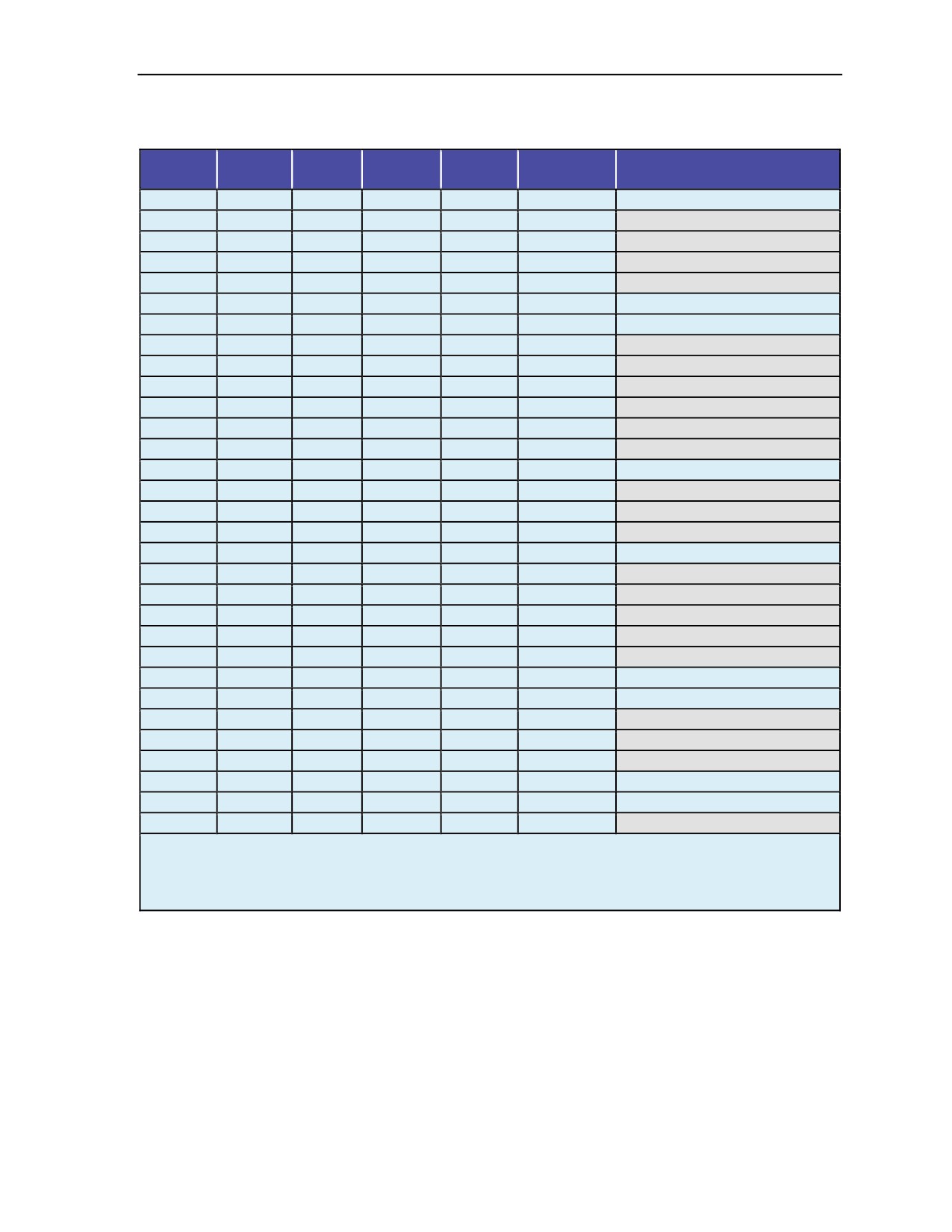
Note: An example of MFF lunar data follows in Table 14-2, page 14-35.
24 October 2014
ATP 3-18.11/AFMAN 11-411(I)/NTTP 3-05.26M
14-33

Chapter 14
14-102. The constant change in the moon’s phase angle causes varying levels of light received from the
moon. At low altitude (moon elevation above the horizon), the vertical component of moonlight incident to
the earth’s horizontal surface is small compared to the incident when the moon is at a higher altitude. Also,
at low angles of incidence, light is further reduced in intensity by the longer distance it must travel through
the earth’s atmosphere. As the moon ascends in the sky, the distance light travels through the atmosphere
decreases as the vertical component increases, thus providing greater illumination. The greatest light level
is achieved when the moon is directly overhead. A description of the moon phases follows.
NEW MOON
14-103. A new moon phase occurs when the moon rotates to a position between the sun and the earth. This
phase always begins during the day and is not visible at night. Visual observation of the new moon at night
is not possible until the moon is approximately two days into this phase. The time required to complete the
phase is approximately 8 days. During the first portion (5 days) of the phase, a low-light level will exist. As
the phase progresses, illumination increases and light conditions will reach mid-light levels. Moonrise
occurs during the daylight hours and moonset before midnight. Approximately 40- to 50-percent of the
moon will be illuminated at the end of the new moon phase. Night parachute operations conducted during
this phase will be under low-light levels, which will prevail most of the time. Best light conditions will
exist shortly after darkness when the moon is at its highest observable altitude of the night.
FIRST QUARTER
14-104. The phase angle of the moon at the first quarter begins at the 90-degree position in relation to the
earth. During this quarter, more than one half of the moon face, but not all the apparent disk, is illuminated.
Approximately 4 days are required to complete the first quarter phase. During the first days of the first
quarter and the last days of the new moon (approximately 5 days), the light will be in the mid-light range
with increasing intensity. Moonrise occurs during daylight near the end of the day. Moonset changes from
midnight to the early morning hours of darkness. The best time to conduct parachute operations will
normally be about midnight when the moon is at its highest altitude. Light intensity is becoming brighter
during this moon phase. When the moon is low on the horizon, avoiding backlighting a landing canopy
stack should be included as a planning factor.
FULL MOON
14-105. A full moon occurs when the sun, moon, and earth are aligned. At this time, the moon is radiating
its greatest percent of illumination. The full moon phase spans approximately 3 days before and 3 days
after the full moon. High-light conditions begin during the last days of the first quarter and extend to the
first days of the last quarter (approximately 12 days). During the early part of this phase, moonrise occurs
just before nautical twilight and progressively moves into the hours of darkness. Moonset will occur during
the early morning daylight hours. The optimum time to conduct parachute operations will be the first few
hours after midnight.
LAST QUARTER
14-106. This phase of the moon is similar to the first quarter, only in reverse sequence. It begins when less
than the entire disk is visible and ends when only half of the moon is visible. The last quarter will normally
last approximately 5 days. Light will decrease from a high-light level (approximately 3 days) down to a
mid-light level that extends into the transition phase (approximately 5 days). Moonrise will occur shortly
before to just after midnight. The optimum time to conduct parachute operations is just prior to beginning
morning nautical twilight. Moonset occurs during daylight hours. Table 14-2, page 14-35, provides an
example of MFF lunar data for Washington National Airport (latitude: 38 degrees 51 minutes north;
longitude: 77 degrees 2 minutes west; DZ altitude: 0). All times are Greenwich Mean Time plus 4 hours.
14-34
ATP 3-18.11/AFMAN 11-411(I)/NTTP 3-05.26M
24 October 2014
Weather Factors for the Military Free-Fall Jumpmaster
Table 14-2. Military free-fall lunar data example
Day of
Moon
Start
Stop
Moon
Percent
Moon Phase
Month
Rise
NVG*
NVG
Set
Illumination
1
0906
1149
1339
2345
38
Transition phase continues
2
0949
1234
1339
****
29
3
1037
****
****
0037
21
4
1130
****
****
0126
13
5
1228
****
****
0212
7
6
1330
****
****
0254
3
End transition
7
1434
****
****
0332
1
New moon starts
8
1540
****
****
0408
0
9
1647
****
****
0442
3
10
1755
****
****
0516
7
11
1904
****
****
0550
14
12
2013
****
****
0626
23
13
2121
****
****
0705
34
14
2228
****
****
0749
45
First quarter starts
15
2331
****
****
0838
57
16
****
0432
0508
0933
68
17
0029
0448
0614
1033
78
18
0121
0513
0742
1136
86
Full moon starts
19
0205
0536
0912
1241
93
20
0245
0555
1033
1345
98
21
0320
0618
1150
1449
100
22
0352
0641
1302
1550
100
23
0422
0704
1401
1650
97
24
0452
0731
1402
1749
93
Full moon ends
25
0522
0800
1403
1847
87
Last quarter starts
26
0553
0832
1404
1944
80
27
0626
0907
1405
2040
72
28
0703
0945
1406
2134
63
29
0744
1028
1407
2227
54
Last quarter ends
30
0829
1115
1408
2317
45
Transition phase starts
31
0920
1205
1408
****
35
NOTES: NVG - Night vision goggle user-defined parameters.
* For NVG use, lunar altitude > 30 degrees above horizon, solar altitude < -6 degrees below horizon,
and lunar illumination > 23%.
**** NVG illumination levels: outside of user-defined parameters.
TRANSITION PHASE
14-107. Although there is no term that describes the period following the last quarter, there is a period of
approximately 7 days after the end of the last quarter before the new moon phase begins. It is similar to the
new moon phase, but in reverse order. Illumination of the moon decreases from half of the disk to no
visible form. Moonrise occurs a few hours before beginning morning nautical twilight and moonset will
always be during the daylight hours. Light will vary from a mid-light level during the first few days
(approximately 3 days) to a low-light condition (approximately 4 days). To achieve any benefit from the
moon illumination, parachute operations must be conducted 2 to 3 hours before beginning morning nautical
twilight. The longest period of time of low-light conditions exists from the transition phase to the first
24 October 2014
ATP 3-18.11/AFMAN 11-411(I)/NTTP 3-05.26M
14-35

Chapter 14
quarter. During this period, there are approximately 16 days when the moon is less than half illuminated,
but is visible less than 50 percent of the hours of darkness.
REFERENCE TABLES
14-108. Wind Estimation—Natural Indicators. DZ reception personnel or MFF jumpmasters can use the
following natural method (Table 14-3) to determine approximate wind velocity. For safety, however,
personnel should add an additional 2.5 mph (3.7 kilometers per hour or 2 knots) to the estimate to avoid
underestimation. Values, when overestimated and used in the computation of canopy drift distances, add
safety margins to wind drift calculations.
Table 14-3. Approximate wind velocity by natural indicators
Miles Per
Kilometers
Knots
Natural Indicators
Hour
Per Hour
0
0
0
No motion; smoke rises vertically.
2
3.2
1.7
Leaves rustle; wind felt on face.
5
8
4
Smoke drifts.
10
16
9
Leaves and twigs in constant motion.
15
24
13
Small branches move; dust raised.
Small trees sway; crests raised on waves of inland water
20
32
17
bodies.
28
45
24
Large branches in motion.
35
56
30
Whole trees in motion; ability to walk is affected.
14-109. Estimating Wind Velocity—Handkerchief Method. A second method of estimating wind
velocity involves holding a handkerchief or similar mass cloth/streamer at the center and letting it hang
free. By estimating the angle of the handkerchief to an imaginary vertical line by extending a line from the
hand to the ground, it is possible, using the following chart (Table 14-4), to estimate wind velocity with
reasonable accuracy. For safety, an additional 2.5 mph (3.7 kilometers per hour or 2 knots) should be added
to avoid underestimation.
Table 14-4. Handkerchief angle wind velocity
Angle
Speed
Speed
Speed
(Degrees)
(Miles Per Hour)
(Kilometers Per Hour)
(Knots)
15
5
8
4
30
10
16
9
50
15
24
13
60
20
32
17
70
25
40
22
80
30
48
26
14-110. Conversion Tables. Use the following tables (Tables 14-5 through 14-20, pages 14-37 through
14-41) to convert between measurements.
14-36
ATP 3-18.11/AFMAN 11-411(I)/NTTP 3-05.26M
24 October 2014

Weather Factors for the Military Free-Fall Jumpmaster
Table 14-5. Linear measure
Unit
Other Metric Equivalent
U.S. Equivalent
1 centimeter
10 millimeters
0.39 inch
1 decimeter
10 centimeters
3.94 inches
1 meter
10 decimeters
39.37 inches
1 decameter
10 meters
32.8 feet
1 hectometer
10 decameters
328.08 feet
1 kilometer
10 hectometers
3,280.8 feet
Table 14-6. Liquid measure
Unit
Other Metric Equivalent
U.S. Equivalent
1 centiliter
10 milliliters
0.34 fluid ounce
1 deciliter
10 centiliters
3.38 fluid ounces
1 liter
10 deciliters
33.81 fluid ounces
1 decaliter
10 liters
2.64 gallons
1 hectoliter
10 deciliters
26.42 gallons
1 kiloliter
10 hectoliters
264.18 gallons
Table 14-7. Weight
Unit
Other Metric Equivalent
U.S. Equivalent
1 centigram
10 milligrams
0.15 grain
1 decigram
10 centigrams
1.54 grains
1 gram
10 decigrams
0.035 ounce
1 decagram
10 grams
0.35 ounce
1 hectogram
10 decigrams
3.52 ounces
1 kilogram
10 hectograms
2.2 pounds
1 quintal
100 kilograms
220.46 pounds
1 metric ton
10 quintals
1.1 short tons
Table 14-8. Square measure
Unit
Other Metric Equivalent
U.S. Equivalent
1 square centimeter
100 square millimeters
0.155 square inch
1 square decimeter
100 square centimeters
15.5 square inches
1 square meter (centaur)
100 square decimeters
10.76 square feet
1 square decameter (are)
100 square meters
1,076.4 square feet
1 square hectometer (hectare)
100 square decameters
2.47 acres
1 square kilometer
100 square hectometers
0.386 square mile
Table 14-9. Cubic measure
Unit
Other Metric Equivalent
U.S. Equivalent
1 cubic centimeter
1,000 cubic millimeters
0.06 cubic inch
1 cubic decimeter
1,000 cubic centimeters
61.02 cubic inches
1 cubic meter
1,000 cubic decimeters
35.31 cubic feet
24 October 2014
ATP 3-18.11/AFMAN 11-411(I)/NTTP 3-05.26M
14-37

Chapter 14
Table 14-10. Temperature
Convert From
Convert To
Celsius
Fahrenheit
Subtract 32, multiply by 5, and divide by 9
Fahrenheit
Celsius
Multiply by 9, divide by 5, and add 32
Table 14-11. Approximate conversion factors
To Change
To
Multiply By
To Change
To
Multiply By
Inches
Centimeters
2.540
Ounce-inches
Newton-meters
0.007062
Feet
Meters
0.305
Centimeters
Inches
3.94
Yards
Meters
0.914
Meters
Feet
3.280
Miles
Kilometers
1.609
Meters
Yards
1.094
Square
Square inches
6.451
Kilometers
Miles
0.621
centimeters
Square
Square feet
Square meters
0.093
Square inches
0.155
centimeters
Square yards
Square meters
0.836
Square meters
Square feet
10.76
Square
Square miles
2.590
Square meters
Square yards
1.196
kilometers
Square
Square
Acres
0.405
Square miles
0.386
hectometers
kilometers
Square
Cubic feet
Cubic meters
0.028
Acres
2.471
hectometers
Cubic yards
Cubic meters
0.765
Cubic meters
Cubic feet
35.315
Fluid ounces
Millimeters
29.573
Cubic meters
Cubic yards
1.308
Pints
Liters
0.473
Millimeters
Fluid ounces
0.034
Quarts
Liters
0.946
Liters
Pints
2.113
Gallons
Liters
3.785
Liters
Quarts
1.057
Ounces
Grams
28.349
Liters
Gallons
0.264
Pounds
Kilograms
0.454
Grams
Ounces
0.035
Short tons
Metric tons
0.907
Kilograms
Pounds
2.205
Pounds-feet
Newton-meters
1.356
Metric tons
Short tons
1.102
Pounds-inches
Newton-meters
0.11296
Nautical miles
Kilometers
1.852
Table 14-12. Area
To Change
To
Multiply By
To Change
To
Multiply By
Square
Square
Square inches
0.00155
Square inches
645.16
millimeters
millimeters
Square
Square
Square inches
9.155
Square inches
6.452
centimeters
centimeters
Square meters
Square inches
1,550
Square inches
Square meters
0.00065
Square meters
Square feet
10.764
Square feet
Square meters
0.093
Square meters
Square yards
1.196
Square yards
Square meters
0.836
Square
Square
Square miles
0.386
Square miles
2.59
kilometers
kilometers
14-38
ATP 3-18.11/AFMAN 11-411(I)/NTTP 3-05.26M
24 October 2014

Weather Factors for the Military Free-Fall Jumpmaster
Table 14-13. Volume
To Change
To
Multiply By
To Change
To
Multiply By
Cubic
Cubic
Cubic inches
0.061
Cubic inches
16.39
centimeters
centimeters
Cubic meters
Cubic feet
35.31
Cubic feet
Cubic meters
0.028
Cubic meters
Cubic yards
1.308
Cubic yards
Cubic meters
0.765
Liters
Cubic inches
61.02
Cubic inches
Liters
0.016
Liters
Cubic feet
0.035
Cubic feet
Liters
28.32
Table 14-14. Capacity
To Change
To
Multiply By
To Change
To
Multiply By
Milliliters
Fluid drams
0.271
Fluid drams
Milliliters
3.697
Milliliters
Fluid ounces
0.034
Fluid ounces
Milliliters
29.57
Liters
Fluid ounces
33.81
Fluid ounces
Liters
0.030
Liters
Pints
2.113
Pints
Liters
0.473
Liters
Quarts
1.057
Quarts
Liters
0.946
Liters
Gallons
0.264
Liters
Gallons
3.785
Table 14-15. Statute miles to kilometers and nautical miles
Statute Miles
Kilometers
Nautical Miles
Statute Miles
Kilometers
Nautical Miles
1
1.61
0.86
60
96.60
52.14
2
3.22
1.74
70
112.70
60.83
3
4.83
2.61
80
128.80
69.52
4
6.44
3.48
90
144.90
78.21
5
8.05
4.35
100
161.00
86.92
6
9.66
5.21
200
322.00
173.80
7
11.27
6.08
300
483.00
260.70
8
12.88
6.95
400
644.00
347.60
9
14.49
7.82
500
805.00
434.50
10
16.10
8.69
600
966.00
521.40
20
32.20
17.38
700
1,127.00
608.30
30
48.30
26.07
800
1,288.00
695.20
40
64.40
34.76
900
1,449.00
782.10
50
80.50
43.45
1,000
1,610.00
869.00
24 October 2014
ATP 3-18.11/AFMAN 11-411(I)/NTTP 3-05.26M
14-39

Chapter 14
Table 14-16. Nautical miles to kilometers and statute miles
Nautical Miles
Kilometers
Statute Miles
Nautical Miles
Kilometers
Statute Miles
1
1.85
1.15
60
111.00
69.00
2
3.70
2.30
70
129.50
80.50
3
5.55
3.45
80
148.00
92.00
4
7.40
4.60
90
166.50
103.50
5
9.25
5.75
100
185.00
115.00
6
11.10
6.90
200
370.00
230.00
7
12.95
8.05
300
555.00
345.00
8
14.80
9.20
400
740.00
460.00
9
16.65
10.35
500
925.00
575.00
10
18.50
11.50
600
1,110.00
690.00
20
37.00
23.00
700
1,295.00
805.00
30
55.50
34.50
800
1,480.00
920.00
40
74.00
46.00
900
1,665.00
1,033.00
50
92.50
57.50
1,000
1,850.00
1,150.00
Table 14-17. Kilometers to statute and nautical miles
Kilometers
Statute Miles
Nautical Miles
Kilometers
Statute Miles
Nautical Miles
1
0.62
0.54
60
37.28
32.38
2
1.24
1.08
70
43.50
37.77
3
1.86
1.62
80
49.71
43.17
4
2.49
2.16
90
55.93
48.56
5
3.11
2.70
100
62.14
53.96
6
3.73
3.24
200
124.28
107.92
7
4.35
3.78
300
186.42
161.88
8
4.97
4.32
400
248.56
215.84
9
5.59
4.86
500
310.70
269.80
10
6.21
5.40
600
372.84
323.76
20
12.43
10.79
700
434.98
377.72
30
18.64
16.19
800
497.12
431.68
40
24.86
21.58
900
559.26
485.64
50
31.07
26.98
1,000
621.40
539.60
14-40
ATP 3-18.11/AFMAN 11-411(I)/NTTP 3-05.26M
24 October 2014
Weather Factors for the Military Free-Fall Jumpmaster
Table 14-18. Yards to meters
Yards
Meters
Yards
Meters
Yards
Meters
100
91
1,000
914
1,900
1,737
200
183
1,100
1,006
2,000
1,828
300
274
1,200
1,097
3,000
2,742
400
366
1,300
1,189
4,000
3,656
500
457
1,400
1,280
5,000
4,570
600
549
1,500
1,372
6,000
5,484
700
640
1,600
1,463
7,000
6,398
800
732
1,700
1,554
8,000
7,212
900
823
1,800
1,646
9,000
8,226
Table 14-19. Meters to yards
Meters
Yards
Meters
Yards
Meters
Yards
100
109
1,000
1,094
1,900
2,078
200
219
1,100
1,203
2,000
2,188
300
328
1,200
1,312
3,000
3,282
400
437
1,300
1,422
4,000
4,376
500
547
1,400
1,531
5,000
5,470
600
656
1,500
1,640
6,000
6,564
700
766
1,600
1,750
7,000
7,658
800
875
1,700
1,860
8,000
8,752
900
984
1,800
1,969
9,000
9,846
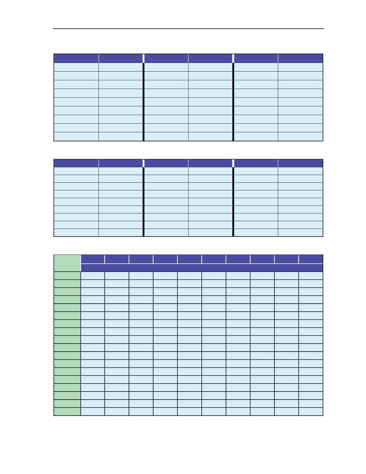
Table 14-20. Determination of altitude by barometric pressure (in inches of mercury)
.0
.1
.2
.3
.4
.5
.6
.7
.8
.9
Inches
Feet
13
22,638
22,430
22,223
22,018
21,815
21,612
21,412
21,213
21,015
20,819
14
20,624
20,431
20,238
20,048
19,858
19,670
19,483
19,298
19,114
18,931
15
18,749
18,568
18,389
18,211
18,033
17,858
17,683
17,509
17,337
17,156
16
16,995
16,825
16,657
16,490
16,324
16,158
15,994
15,831
15,669
15,507
17
15,347
15,187
15,029
14,871
14,715
14,559
14,404
14,250
14,097
13,945
18
13,793
13,643
13,493
13,344
13,196
13,049
12,902
12,756
12,611
12,467
19
12,324
12,181
12,039
11,898
11,758
11,618
11,479
11,340
11,203
11,066
20
10,930
10,794
10,659
10,525
10,391
10,259
10,126
9,995
9,864
9,733
21
9,604
9,474
9,346
9,218
9,091
8,964
8,838
8,712
8,587
8,463
22
8,339
8,216
8,093
7,971
7,849
7,728
7,608
7,488
7,368
7,249
23
7,131
7,013
6,896
6,779
6,662
6,546
6,431
6,316
6,212
6,088
24
5,947
5,861
5,749
5,637
5,525
5,414
5,303
5,193
5,083
4,947
25
4,865
4,756
4,648
4,540
4,433
4,326
4,220
4,114
4,009
3,903
26
3,799
3,694
3,590
3,487
3,384
3,281
3,179
3,077
2,975
2,874
27
2,773
2,672
2,572
2,473
2,373
2,274
2,176
2,077
1,979
1,882
28
1,794
1,688
1,591
1,495
1,399
1,303
1,208
1,113
1,019
925
29
831
737
644
551
458
366
247
182
91
0
30
-91
-181
-271
-361
-451
-540
-629
-718
-806
-894
24 October 2014
ATP 3-18.11/AFMAN 11-411(I)/NTTP 3-05.26M
14-41

This page intentionally left blank.

Appendix A
Military Free-Fall Critical Task Lists
This appendix includes the critical task lists for the MFF Basic Course, the
MFF Jumpmaster Course, the MFF Advanced Tactical Infiltration Course, and the
MFF Instructor Course.
MFF Basic Course
Module A: Ground Training (9 Tasks)
Task Number
Task Title
331-MFF-1000
Perform Body Stabilization Techniques
331-MFF-1005
Pack the MC-4 Ram-Air Canopy
331-MFF-1010
React to Emergencies in the Aircraft During a MFF Operation
331-MFF-1015
React to Emergencies While in Free Fall
331-MFF-1020
React to Emergencies During Canopy Descent Using a RAPPS
331-MFF-1025
Don the MC-4 RAPPS
331-MFF-1030
Activate the Military CYPRES
331-MFF-1035
Rig Weapons and Combat Equipment for a MFF Operation
Respond to Aircraft Procedure Signals and Jump Commands During MFF Airborne
331-MFF-1040
Operation
Module B: Airborne Operations (7 Tasks)
Task Number
Task Title
331-MFF-1045
Perform an MFF Operation Wearing Combat Equipment
Perform an MFF Operation Wearing Combat Equipment and Portable Bailout Oxygen
331-MFF-1050
System
Perform an MFF Operation Wearing Combat Equipment and Portable Bailout Oxygen
331-MFF-1055
System as a Member of a Group
331-MFF-1060
Perform an MFF HAHO Parachute Jump With Navigation Aids
Perform an MFF Operation Wearing Combat Equipment and Portable Bailout Oxygen
331-MFF-1065
System as a Member of a Group at Night
331-MFF-1070
Maneuver the MC-4 Ram-Air Canopy to a Designated Point as a Member of a Group
331-MFF-1075
Perform MFF Operations With NVGs
24 October 2014
ATP 3-18.11/AFMAN 11-411(I)/NTTP 3-05.26M
A-1
Appendix A
MFF Jumpmaster Course
Module A: Ground Training (12 Tasks)
Task Number
Task Title
331-MFF-2000
Perform JMPI on an MFF Parachutist
331-MFF-2005
Compute the HARP for a HALO Operation
331-MFF-2006
Compute the HARP for a HAHO Operation
331-MFF-2010
Determine the Altimeter Setting for a MFF Operation
331-MFF-2015
Compute the Military CYPRES EAAD Setting
331-MFF-2020
Rig Specialized Weapons and Combat Equipment for MFF Operations
331-MFF-2025
Perform the Duties of an MFF Jumpmaster
331-MFF-2030
Operate the Six-Man Prebreather Portable Oxygen System
331-MFF-2045
Conduct MFF Parachute Refresher Training
331-MFF-2050
Conduct MFF Jumpmaster Refresher Training
331-MFF-2055
Perform Sustained Airborne Training for MFF Operations
331-MFF-2065
Supervise the Donning of the MC-4 RAPPS
Module B: Airborne Operations (4 Tasks)
Task Number
Task Title
Determine the Exit Order (Solo Jumpers With Military Tandem Tethered Bundle or
331-MFF-2027
Autonomous Bundle Systems)
331-MFF-2035
Issue Jump Commands Used in MFF Parachute Operation
331-MFF-2040
Direct an Aircraft to the Release Point
331-MFF-2060
React to Emergencies in the Aircraft During an MFF Operation as a Jumpmaster
MFF Advanced Tactical Infiltration Course
Module A: Ground Training (6 Tasks)
Task Number
Task Title
331-MFF-4005
Perform Body Stabilization Techniques With NVGs, Special Weapons, and Equipment
331-MFF-4007
Rig the Parachutist Helmet With NVGs for MFF Operations
331-MFF-4008
Program an Electronic Navigation Board System for MFF Operations
331-MFF-4009
Rig an Electronic Navigation Board System for MFF Operations
331-MFF-4012
Construct an Autonomous Precision Airdrop Bundle System
331-MFF-4013
Program the Autonomous Precision Airdrop Bundle System
A-2
ATP 3-18.11/AFMAN 11-411(I)/NTTP 3-05.26M
24 October 2014

Military Free-Fall Critical Task Lists
MFF Advanced Tactical Infiltration Course
Module B: Airborne Operations (14 Tasks)
Task Number
Task Title
331-MFF-1005
Pack the MC-4 Ram-Air Canopy
331-MFF-2000
Perform JMPI on an MFF Parachutist
331-MFF-2027
Determine the Exit Order (Solo Jumpers With the Autonomous Bundle Systems)
331-MFF-4001
Perform a MFF Operation With Special Weapons and Equipment
Perform MFF Operation With NVGs, Special Weapons and Equipment, and Portable
331-MFF-4003
Oxygen System
Perform an MFF High-Altitude High-Opening (HAHO) Parachute Jump Utilizing
331-MFF-4004
Electronic Navigation and Combat Equipment
331-MFF-4010
Operate the MFF Electronic Navigation System While Under Canopy
Maneuver the MC-4 Ram-Air Canopy to a Designated Point on the Drop Zone Utilizing
331-MFF-4011
Electronic Navigation Equipment
331-MFF-4014
Employ the Autonomous Precision Airdrop Bundle System
Perform MFF Operations With NVGs, Special Weapons, Combat Equipment, and a
331-MFF-4015
Portable Bailout Oxygen System as a Member of a Group
331-MFF-4016
Compute the HARP for a HAHO Operation Utilizing Electronic Navigation Equipment
331-MFF-4017
Perform a Blind Drop for an MFF Operation
331-MFF-4018
Conduct MFF Parachute Special Weapon and Equipment Refresher Training
331-MFF-4019
Conduct MFF Jumpmaster Special Weapon and Equipment Refresher Training
MFF Instructor Course (19 Tasks)
Task Number
Task Title
331-MFF-1005
Pack the MC-4 Ram-Air Canopy
331-MFF-1010
React to Emergencies in the Aircraft During a MFF Operation
331-MFF-1020
React to Emergencies During Canopy Descent Using a RAPPS
331-MFF-1035
Rig Weapons and Combat Equipment for a MFF Operation
Perform an MFF Parachute Jump with Combat Equipment and Portable Bailout
331-MFF-1065
Oxygen System as a Member of a Group at Night
331-MFF-1070
Maneuver the MC-4 Ram-Air Canopy to a Designated Point as a Member of a Group
331-MFF-2035
Issue Jump Commands Used in MFF Parachute Operations
331-MFF-3005
Conduct Vertical Wind Tunnel Training for MFF Parachutist Course Student
331-MFF-3010
Pack the Instructor-Certified Ram-Air Parachute System
331-MFF-3015
Don the Instructor-Certified Ram-Air Parachute System
24 October 2014
ATP 3-18.11/AFMAN 11-411(I)/NTTP 3-05.26M
A-3

Appendix A
MFF Instructor Course (19 Tasks) (continued)
Task Number
Task Title
331-MFF-3020
Inspect the Instructor-Certified Ram-Air Parachute System
331-MFF-3025
Perform an MFF Jump With the Instructor-Certified Ram-Air Parachute System
331-MFF-3030
Conduct the Jump Briefing to MFF Parachutists
331-MFF-3035
Conduct Jump With MFF Parachutist Course Student
331-MFF-3040
Perform Corrective Action to an MFF Parachutist Course Student During Free Fall
331-MFF-3045
Evaluate a MFF Student During an MFF Parachute Jump
331-MFF-3050
Lead MFF Parachutist Course Student Under Canopy to the Drop Zone
331-MFF-3055
Conduct Post Jump After Action Report With MFF Parachutist Course Student
331-MFF-3060
Conduct Drop Zone Safety Officer Duties During Advanced MFF Parachutist Course
A-4
ATP 3-18.11/AFMAN 11-411(I)/NTTP 3-05.26M
24 October 2014

Appendix B
Military Free-Fall Parachutist Qualification
and Refresher Training Requirements
MFF parachuting skills are highly perishable. MFF personnel maintain these skills
through regularly scheduled training periods to develop the necessary degree of
proficiency. Otherwise, mission capability and parachutist safety will be reduced.
MEDICAL AND PHYSIOLOGICAL TRAINING REQUIREMENTS
B-1. Each MFF parachutist must have met the following minimum requirements to participate in MFF
operations:
z
Must have a current HALO physical examination in accordance with Service regulations.
Students attending the MFF course must have a HALO physical in accordance with the
USAJFKSWCS standard.
z
Must have a current physiological training card (AF IMT Form 1274 [Physiological Training] or
USASOC Form 4080 [Reduced Oxygen Breathing Device Physiological Training]) dated within
the last 5 years. A physiological training card is maintained by undergoing physiological training
every 5 years.
z
Must be a graduate of a USAJFKSWCS-recognized MFF parachutist course.
z
Must be a current MFF parachutist.
CURRENCY REQUIREMENTS
B-2. Currency does not equate to proficiency. Parachutists cannot consider MFF airborne operations to
meet pay requirements as proficiency jumps unless the mission profile follows a tactical insertion profile.
MFF jumpmaster currency standards are outlined in Chapter 13.
B-3. To meet the minimum MFF currency standards, the parachutist must have—
z
A current HALO physical (per Service requirements).
z
A current physiological training card (AF IMT Form 1274 or USASOC Form 4080).
z
Conducted an MFF jump within the last 180 days.
MILITARY FREE-FALL PARACHUTE REQUALIFICATION
AND REFRESHER TRAINING
B-4. Previously qualified MFF parachutists who, after meeting medical and USAF chamber currency
requirements, do not meet the proficiency and currency requirements listed above, will undergo the
following training to become requalified:
z
Review arm-and-hand signals, aircraft procedures, and jump commands.
z
Review DZ markings.
z
Attend wind tunnel training (if available).
z
Attend a packing class.
z
Attend Military CYPRES 2 class.
z
Attend an oxygen class.
z
Review exit procedures and body stabilization.
z
Attend emergency procedures class and suspended harness drills.
z
Attend combat equipment rigging (combat pack and weapon) class.
18 August 2016
ATP 3-18.11/AFMAN 11-411(I)/NTTP 3-05.26M, C2
B-1

Appendix B
z
Attend canopy control and grouping under canopy class.
z
Perform one daylight jump without combat equipment, stressing a stable exit, maintaining
heading, and pulling the ripcord at the prescribed pull altitude while maintaining heading
(±500 feet).
z
Perform one daylight jump with rifle and combat equipment, executing a stable exit, making a
left and right turn, stopping on heading, and pulling the ripcord at the prescribed pull altitude
(±500 feet) while maintaining heading, and landing within 50 meters of the group leader.
Note: At any time, the jumpmaster may stop a parachutist from going to the next level if he
determines that the parachutist has not satisfactorily performed the task. Jumpmaster will
conduct after action review with all MFF refresher jumpers.
MILITARY FREE-FALL HIGH-ALTITUDE HIGH-OPENING
PARACHUTIST REQUALIFICATION AND REFRESHER TRAINING
B-5. Previously qualified MFF parachutists who do not meet proficiency and currency requirements will,
after becoming current as an MFF parachutist, undergo the training outlined below. The intent of the
following recommendations is to build upon the training progression listed in the previous paragraphs. In
addition, the intent is to provide safe training and to increase parachutist skills, ability, and confidence,
culminating in a HAHO night combat equipment oxygen jump. Recommendations include that the
parachutists make—
z
One daylight HAHO with NVGs landing within 100 meters of the low man.
z
One daylight HAHO with NVGs and combat equipment landing within 100 meters of the low
man.
z
One daylight HAHO with NVGs, combat equipment, and oxygen landing within 100 meters of
the low man.
Note: Parachutists should perform same day jump sequence as above for night MFF refreshers.
Note: Altitude recommendation will be established by the jumpmaster for each jump. Not all
aircraft and training installations have the capability to reach maximum altitudes for training
jumps during requalification and refresher training. The intent is to provide safe training and to
increase the parachutists’ skills, ability, and confidence, culminating in a HAHO night jump
wearing NVGs, combat equipment, and oxygen—with jumpers landing within the desired
landing point.
B-2
ATP 3-18.11/AFMAN 11-411(I)/NTTP 3-05.26M, C2
18 August 2016

Appendix C
Recommended Military Free-Fall Training Programs
Commanders conduct oxygen-training jumps below 20,000 feet MSL to eliminate the
need for prebreathing. They conduct proficiency jumps as a part of other training
operations, such as field training exercises or Army training and evaluation programs,
to take advantage of available training assets.
MINIMUM QUARTERLY TRAINING
C-1. Commanders follow a minimum program consisting of nine parachute jumps per quarter (Table C-1).
They do not plan more than four proficiency jumps for any one day.
Table C-1. Minimum quarterly training guide
Jump Number
Type of Jump
Type of Jump Definition
1
HA
HALO/administrative-nontactical
2
HEO
HALO/combat equipment/oxygen
3
HEN
HALO/combat equipment/night
4
HEON (Minimum one per month)
HALO/combat equipment/oxygen/night
5
HEON/NVG
HALO/combat equipment/oxygen/night/NVG
6
SA
HAHO/stand-off/administrative-nontactical
7
SEON (Minimum one per quarter)
HAHO/stand-off/combat equipment/oxygen/night
8
SEN/NVG
HAHO/stand-off/combat equipment/night/NVG
9
SEON/NVG
HAHO/stand-off/combat equipment/oxygen/night/NVG
Note: Commanders must remember that for safety and parachutist confidence, parachutists
require a jump refresher before executing night combat equipment jumps after prolonged periods
of nonjumping. Commanders may not be able to include the nine jumps depicted in Table C-1 in
the quarterly training plan; however, they follow the intent of the progression where possible.
For example, after a 3-month layoff, an element should make a daylight jump before a night
combat equipment jump.
Note: Units can fulfill oxygen-training requirements at altitudes below 20,000 feet MSL. A
mission profile that is consistent with prebreathing requirements can be flown without requiring
the coordination with or the presence of USAF physiological technicians. Training missions
using full oxygen equipment can be flown at altitudes below 13,000 feet MSL. Flights at these
altitudes would be consistent with any altitude’s oxygen use requirements. These training
mission profiles might occur in areas where airspace restrictions are in force or when there are
not enough aircrew personnel.
RECOMMENDED TACTICAL MILITARY FREE-FALL
HAHO-SPECIFIC TRAINING PROGRAM
C-2. HALO proficiency does not equate to HAHO proficiency. Parachutists should only consider MFF
jumps with tactical application as proficiency jumps. Nontactical jumps are for currency and not
necessarily for proficiency. While HALO is an integral part of MFF operations, HAHO/stand-off
operations provide the tactical commander a unique method for infiltration. The tactical commander may
24 October 2014
ATP 3-18.11/AFMAN 11-411(I)/NTTP 3-05.26M
C-1

Appendix C
infiltrate these elements by parachute without requiring the aircraft to fly over the intended target area.
These elements can be released at an offset release point and navigate long distances under canopy.
C-3. The desired end state for a combat-ready MFF team is to have the ability to land at the designated
landing point as a detachment, with all required organic weapons systems, individual load-carrying
equipment and issued personal protective equipment (body armor), mission-appropriate rucksack or assault
pack, and tactical communications, by both HALO and HAHO means. The detachments will use available
navigational aids, supplemental oxygen systems, and organic parachute assemblies. The units should use
the maximum altitudes available for training with a culminating jump conducted at
(or close to)
24,999 MSL using on-board oxygen consoles, during hours of darkness, onto an austere and poorly lit
landing area while using NVGs.
C-4. The MFF-coded detachments may fulfill these requirements at lower altitudes, but units will use the
mission profile with the on-board consoles to ensure jumpers are maintaining proficiency of the full
spectrum of oxygen equipment. Examples of justification to utilize lower altitudes for proficiency jumps
include the following:
z
Lack of USAF physiological technicians.
z
Training in areas where airspace restrictions are in force.
z
Aircrew limitations or restrictions.
z
Limiting factors of winds and weather.
Note: Simply using bailout bottles and masking prior to exit would not be considered meeting
the oxygen system requirement for a “culminating proficiency jump.” Even if jumpers exit at
7,500 feet AGL, jumpers will conduct a culminating proficiency jump using on-board consoles
and procedures.
C-5. All MFF detachments will conduct, at a minimum, one (1) HAEON per month and one (1) SAEON
per quarter based on operations tempo. This is done to maintain a combat-ready status (also known as
Level I).
C-6. The goal of the first three days of training should give MFF detachments the opportunity to identify
differences in canopy descent rates, weaknesses in canopy control skills, and to give jumpers the chance to
make familiarization jumps with new equipment during daylight before progressing to night jumps.
C-7. For example, a current jumper who has not jumped with a navigational aid will use these 3 days to
become familiar with navigational aids. A jumper who has never used NVGs will use these first 3 days to
become familiar with flying the canopy while wearing NVGs in daylight hours before attempting to use
them at night.
C-8. Identifying different descent rates between jumpers will allow the detachment leadership to better
plan for cross-loading of equipment and chalk order during exit so the detachment can minimize the
amount of time it takes to group under canopy, build the stack, and navigate to the desired landing area.
Table C-2, page C-3 provides a template for a two-week MFF training plan that focuses on stand-off
parachute infiltration.
Note: The suggested 10-day combat-ready training program (Table C-2) is not meant to be a
basic train-up plan done as a requalification event. It is meant as an advanced proficiency train
up for fully trained elements. Anyone executing this recommended schedule should already be a
current special operations forces common standard free-fall jumper.
C-2
ATP 3-18.11/AFMAN 11-411(I)/NTTP 3-05.26M
24 October 2014
Recommended Military Free-Fall Training Programs
Table C-2. Suggested 10-day combat-ready training program
Maximum
Minimum
Jump
Type
Recommended
Recommended
Notes
Number
Jump
Exit Altitude (AGL)
Pull Altitude (AGL)
Jumps focus on fundamental canopy
1
SA
8,000
6,000
skills.
Proper equipment lowering procedures
2
SAE
8,000
6,000
and new equipment.
3
SAEO
8,000
6,000
Operational detachment—alpha (ODA)
can adjust cross load of equipment to
4
SAEO
8,000
6,000
even the canopy descent rates.
5
SAN
12,500
6,000
A seasoned ODA may exit at 12,500 feet
6
SAEN
12,500
6,000
and pull soon after exit where a lower-
7
SAON
12,500
6,000
experienced level may dictate pulling as
low as 6,000 feet.
8
SAEON
12,500
6,000
9
SAN
12,500
10,000
ODA focuses on use of navigational aids,
10
SAEN
12,500
10,000
night vision aids, and maintaining a tight
canopy stack.
11
SAON
12,500
10,000
12
SAO
17,500
15,000
ODA focuses on use of navigational aids
13
SAEO
17,500
15,000
and maintaining a tight canopy stack.
14
SAEO
17,500
15,000
15
SAEO
24,999 (MSL)
23,000 (MSL)
Pre-dawn exit.
16
Commander’s Time
17
18
SAEON
24,999 (MSL)
23,000 (MSL)
Culmination exercise/full mission profile.
19
Commander’s Time
20
NOTE: The following codes will be used to indicate the type jump performed. One or more code symbols may
be used. (For example: T-S-O-N-J indicates a Tactical, Stand-off jump using Oxygen performed at Night as
Jumpmaster.)
A
Administrative/Nontactical
NVG Night Vision Goggle
C
Combat
O
Oxygen
E
Combat Equipment
S
HAHO/Stand-off
H
HALO
T
Tactical
J
Jumpmaster
TB
Tandem Bundle
N
Night
TP
Tandem Personnel
RECOMMENDED MILITARY FREE-FALL JUMP PROGRESSION
FOR NIGHT VISION GOGGLE AND/OR MILITARY FREE-FALL
TRANSITION PROCESS
C-9. Vertical wind tunnel training is not directed but highly recommended. Advanced Tactical Infiltration
Course graduates and jumpmasters should progress their jumpers through the vertical wind tunnel in the
same manner as for live jumps (dummy parachute with NVGs, dummy parachute and equipment with
NVGs, and emergency procedures with NVGs). Jumpers should concentrate on the modified pull sequence
and emergency procedures during all phases of vertical wind tunnel training with NVGs in both the UP and
DOWN positions. If wind tunnel training is not feasible, then, at a minimum, table drills will be conducted
in an unlit room with NVGs, with a parachute and lit altimeter simulating the modified pull sequence and
emergency procedures.
18 August 2016
ATP 3-18.11/AFMAN 11-411(I)/NTTP 3-05.26M, C2
C-3

Appendix C
LIVE JUMP NIGHT VISION GOGGLE TRAINING
C-10. Army special operations forces will conduct the following minimum jump progression to complete
the NVG and/or MFF transition process:
z
Perform one daylight administrative jump as a member of a group with NVGs mounted on the
jumper’s helmet. Jumper will execute a stable exit, maintain heading, and execute a minimum of
three practice ripcord touches while utilizing the new standard pull sequence. Performance will
focus on the new standard pull sequence, pulling the ripcord at the prescribed pull altitude
(±500 feet) while maintaining heading. Jumper will execute proper canopy control procedures
and land within 50 meters of the designated group leader.
z
Perform one daylight jump as a member of a group with rifle, combat equipment, and NVGs
mounted on the jumper’s helmet. Jumper will execute a stable exit, maintain heading, and
execute a minimum of three practice ripcord touches while utilizing the modified pull sequence.
Performance will focus on the modified pull sequence, pulling the ripcord at the prescribed pull
altitude
(±500 feet) while maintaining heading. Jumper will execute proper canopy control
procedures and land within 50 meters of the designated group leader.
z
Perform one daylight jump as a member of a group with complete oxygen system and NVGs
mounted on the jumper’s helmet. Jumper will execute a stable exit, maintain heading, and
execute a minimum of three practice ripcord touches while utilizing the modified pull sequence.
Performance will focus on the modified pull sequence, pulling the ripcord at the prescribed pull
altitude
(±500 feet) while maintaining heading. Jumper will execute proper canopy control
procedures and land within 50 meters of the designated group leader.
z
Perform one daylight jump as a member of a group with rifle, combat pack, complete oxygen
system, and NVGs mounted on the jumper’s helmet. Jumper will execute a stable exit, maintain
heading, and execute a minimum of three practice ripcord touches while utilizing the modified
pull sequence. Performance will focus on the modified pull sequence, pulling the ripcord at the
prescribed pull altitude (±500 feet) while maintaining heading. Jumper will execute proper
canopy control procedures and land within 50 meters of the designated group leader.
z
Perform one night administrative jump as a member of a group with NVGs mounted on the
jumper’s helmet. Jumper will execute a stable exit, maintain heading, and execute a minimum of
three practice ripcord touches while utilizing the modified pull sequence. Performance will focus
on the modified pull sequence, pulling the ripcord at the prescribed pull altitude (±500 feet) while
maintaining heading. Jumper will execute proper canopy control procedures and land within
50 meters of the designated group leader.
z
Perform one night jump as a member of a group with rifle, combat equipment, and NVGs
mounted on the jumper’s helmet. Jumper will execute a stable exit, maintain heading, and
execute a minimum of three practice ripcord touches while utilizing the modified pull sequence.
Performance will focus on the modified pull sequence, pulling the ripcord at the prescribed pull
altitude
(±500 feet) while maintaining heading. Jumper will execute proper canopy control
procedures and land within 50 meters of the designated group leader.
z
Perform one night jump as a member of a group with complete oxygen system and NVGs
mounted on the jumper’s helmet. Jumper will execute a stable exit, maintain heading, and
execute a minimum of three practice ripcord touches while utilizing the modified pull sequence.
Performance will focus on the modified pull sequence, pulling the ripcord at the prescribed pull
altitude
(±500 feet) while maintaining heading. Jumper will execute proper canopy control
procedures and land within 50 meters of the designated group leader.
z
Perform one night jump as a member of a group with rifle, combat pack, complete oxygen
system, and NVGs mounted on the jumper’s helmet. Jumper will execute a stable exit, maintain
heading, and execute a minimum of three practice ripcord touches while utilizing the modified
pull sequence. Performance will focus on the modified pull sequence, pulling the ripcord at the
prescribed pull altitude (±500 feet) while maintaining heading. Jumper will execute proper
canopy control procedures and land within 50 meters of the designated group leader.
C-4
ATP 3-18.11/AFMAN 11-411(I)/NTTP 3-05.26M, C2
18 August 2016

Recommended Military Free-Fall Training Programs
SUSTAINMENT TRAINING
C-11. MFF-qualified parachutists using NVGs during MFF operations will follow the standard currency
guidelines set forth in USASOC Regulation 350-2.
AUTHORIZED TRAINERS
C-12. The initial train-the-trainer qualifications will be done by Soldiers who have completed the Tactical
Infiltration Course at Yuma Proving Ground (completion dates inclusive from January 2010) or through
members of the MFF School Tactical Application Detachment. Once initial training throughout the force
has commenced, any current MFF jumpmaster who has completed the approved NVG training support
package may administer MFF and/or NVG training.
24 October 2014
ATP 3-18.11/AFMAN 11-411(I)/NTTP 3-05.26M
C-5

This page intentionally left blank.
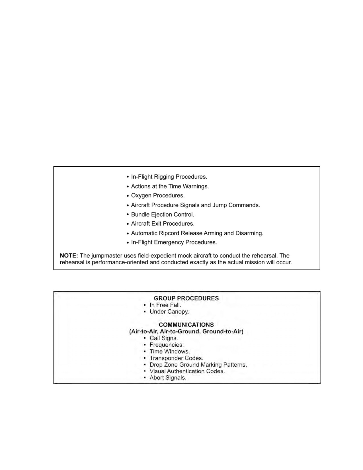
Appendix D
Suggested Military Free-Fall Sustained
Airborne Training
Sustained airborne training must be conducted within the 24-hour period before
station time of any MFF parachute operation. At a minimum, MFF sustained airborne
training must consist of the jumpmaster troop briefing, a mock aircraft rehearsal,
action procedures in free fall and canopy flight, emergency procedures, canopy
entanglement procedures, and landing procedures. Figures D-1 through D-4, pages
D-1 through D-4, provide outlines of the material to be covered during sustained
training.
Figure D-1. Mock aircraft rehearsal
Figure D-2. Actions in free fall and canopy flight
24 October 2014
ATP 3-18.11/AFMAN 11-411(I)/NTTP 3-05.26M
D-1
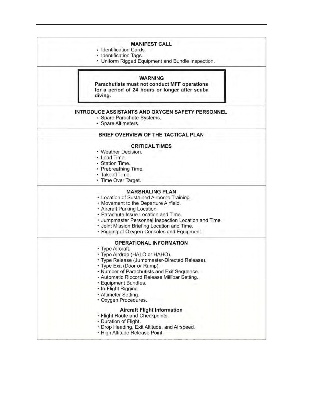
Appendix D
Figure D-3. Sample jumpmaster troop briefing
D-2
ATP 3-18.11/AFMAN 11-411(I)/NTTP 3-05.26M
24 October 2014
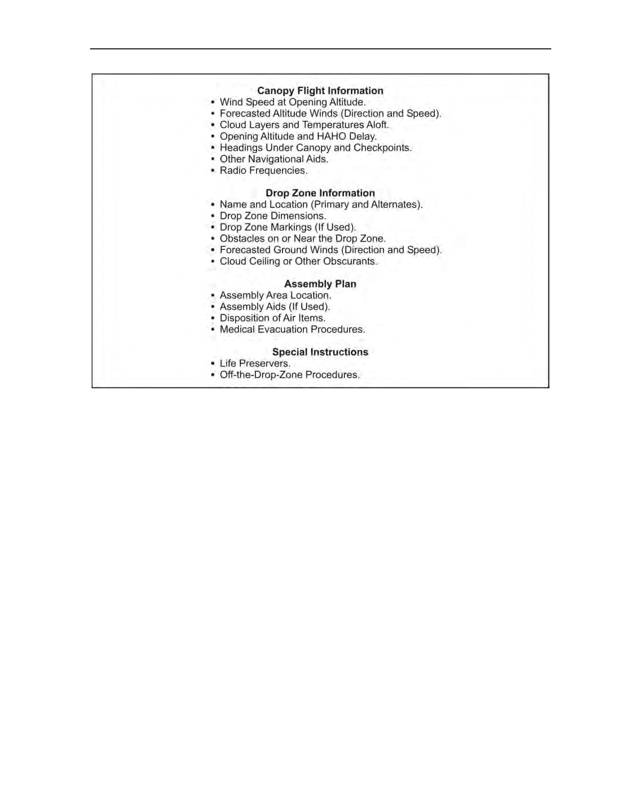
Suggested Military Free-Fall Sustained Airborne Training
Figure D-3. Sample jumpmaster troop briefing (continued)
24 October 2014
ATP 3-18.11/AFMAN 11-411(I)/NTTP 3-05.26M
D-3
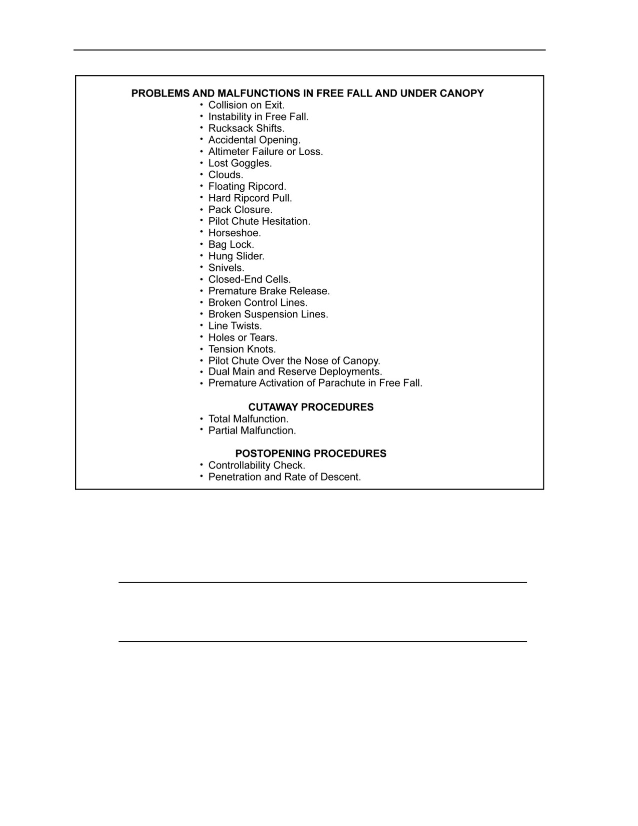
Appendix D
Figure D-4. Emergency procedures
D-1. Sustained airborne training must be conducted within the 24-hour period before station time of any
MFF parachute operation. The jumpmaster must read and ensure all MFF parachutists understand all
aspects of the sustained airborne training and MFF operation. The jumpmaster should also observe all
parachutists to ensure they understand and are fully involved in practicing all emergency procedures they
could encounter.
Note: Parachutists must ensure that they have their identification cards and tags with them
during airborne operations. They must not wear the identification tags around their necks. At no
time will parachutists have tobacco, chewing gum, or anything else in the mouth during airborne
operations.
AIRCRAFT PROCEDURES AND JUMP COMMANDS
D-2. The jumpmaster will explain the aircraft procedure signals and jump commands that follow.
D-4
ATP 3-18.11/AFMAN 11-411(I)/NTTP 3-05.26M
24 October 2014

Suggested Military Free-Fall Sustained Airborne Training
NONOXYGEN MILITARY FREE-FALL OPERATIONS
D-3. Actions for aircraft procedure signals and jump commands are as follows:
z
DON HELMETS: Put on helmets, fasten chinstraps, and ensure seatbelts are securely fastened.
z
UNFASTEN SEATBELTS: At approximately 1,000 feet AGL.
z
20 MINUTES: Stay alert and don equipment as directed.
Note: The 20 MINUTES command may be given prior to takeoff.
z
10 MINUTES: Keep eyes trained on the jumpmaster.
z
WINDS: Surface wind speed on the DZ is expressed in knots. All jumpers conduct a pin check of
their fellow jumpers and ensure the CYPRES has the correct millibar setting.
z
STAND UP: 2 minutes from the release point. Jumpers stand up, face jumpmaster, check the
CYPRES setting and pins on jumper to their front, and give that individual a “thumbs up.”
Jumpers then conduct a check of their own handles and equipment.
z
MOVE TO THE REAR: 1 minute from the release point. Jumpers move to the ramp hinge (or within
1 meter of the door). All jumpers ensure goggles are covering their eyes at this time.
z
STAND BY: 15 seconds from the release point. The jumpmaster gives a “thumbs-up” signal.
Jumpers return the signal and move to within approximately 1 foot of the exit point.
z
GO: At the release point. The jumpmaster points out the door or ramp. Jumpers exit as prescribed
by the jumpmaster.
z
ABORT: If the ABORT command is given, observe the jumpmaster for additional commands. Keep
eyes on the jumpmaster for instructions. If the ABORT command is given before the command to
STAND UP, jumpers will don their helmets, fasten their seatbelts, and prepare for landing.
OXYGEN MILITARY FREE-FALL OPERATIONS
D-4. After the JMPI, jumpers may not remove their helmets. Actions for aircraft procedure signals and
jump commands are as follows:
z
DON HELMETS: Put on helmets, fasten chinstraps, and ensure seatbelts are securely fastened.
z
UNFASTEN SEATBELTS: At approximately 1,000 feet AGL.
z
20 MINUTES: Stay alert and don equipment as directed.
Note: The 20 MINUTES command may be given prior to takeoff.
z
10 MINUTES: Keep eyes trained on the jumpmaster.
Note: For oxygen jumps requiring oxygen console or aircraft-supplied oxygen, the oxygen
safety and/or the USAF Physiological Technician must make periodic checks of all oxygen
equipment used during the flight.
z
WINDS: Surface wind speed on the DZ is expressed in knots. All jumpers conduct a pin check of
their fellow jumpers and ensure the CYPRES has the correct millibar setting.
z
MASK: If not using a console, jumpers turn on their bailout system first. Jumpers secure their
masks to their helmets, fit their masks to their faces, observe the jumpmaster, and give a
“thumbs-up” signal if they are receiving good oxygen flow. Hold the “thumbs-up” signal until
the signal is returned by the jumpmaster.
24 October 2014
ATP 3-18.11/AFMAN 11-411(I)/NTTP 3-05.26M
D-5

Appendix D
WARNING
Jumpers must not sleep while breathing on console or after the
mask signal is given. Jumpers must stay alert. If at any time the
jumper experiences difficulty with the oxygen system, the
individual must extend an arm straight out to the front, palm
facing down, and wait for assistance. Jumpers should not break
the mask seal if receiving oxygen.
z
OXYGEN CHECK: Keep eyes on the jumpmaster, return the “thumbs-up” signal, and hold it until
the jumpmaster returns the signal.
z
STAND UP: 2 minutes from the release point. Jumpers stand, face the jumpmaster, and check the
CYPRES setting, pins, and oxygen bottles of the jumper to their front, and gives the individual a
“thumbs up.” Once this check is complete, jumpers check their own handles and equipment. If
using console oxygen, jumpers place their right hand on the bailout system ON/OFF lever, and
place their left hand on the console hose at the AIROX VIII connection.
z
MOVE TO THE REAR: 1 minute from the release point. If using console oxygen, jumpers turn on
the oxygen bailout bottle system, disconnect from the console, place the hose next to the
console, and move to the ramp hinge or within 1 meter of the door. All jumpers ensure goggles
are covering their eyes at this time.
z
STAND BY: 15 seconds from the release point. The jumpmaster will give a “thumbs-up” signal.
Jumpers return the signal and move to within approximately 1 foot of the exit point.
z
GO: At the release point. The jumpmaster points out the door or ramp. Jumpers exit as prescribed
by the jumpmaster. Jumper—
Upon exiting the aircraft, conducts a practice pull. During the pull sequence, if the oxygen
hose interferes with the ability to locate and pull the main ripcord, the jumper makes a
second attempt by utilizing the head-tilt method, looking at the ripcord stow pocket.
Locates the ripcord housing with the right hand.
Traces the ripcord cable housing down and locates the ripcord cable, which may be
protruding from the housing.
Pulls the cable. If this attempt is unsuccessful, the jumper performs cutaway procedures.
Note: The jumper must keep the mask on while under canopy. Jumpers must not disconnect one
side, allowing the mask to dangle.
Upon landing, turns off his oxygen.
Places elastic cover on mask and puts the mask in the plastic bag.
Covers the AIROX VIII with the plastic bag.
Conducts normal recovery procedures.
z
ABORT: If the ABORT command is given, observe the jumpmaster for additional commands. Keep
eyes on the jumpmaster for instructions. If the ABORT command is given before the command to
STAND UP, jumpers will don their helmets, fasten their seatbelts, and prepare for landing.
AIRCRAFT EMERGENCIES
D-5. The jumpmaster will explain the aircraft emergencies that follow.
D-6
ATP 3-18.11/AFMAN 11-411(I)/NTTP 3-05.26M
24 October 2014

Suggested Military Free-Fall Sustained Airborne Training
AIRCRAFT EMERGENCIES ON THE GROUND AND PRIOR TO TAKEOFF
D-6. Jumpers take all commands from the primary jumpmaster.
D-7. Jumpers exit the aircraft and assemble 100 meters in a safe direction, as directed by the primary
jumpmaster. Once assembled, jumpers report to the primary jumpmaster.
AIRCRAFT EMERGENCIES IN FLIGHT: EMERGENCY LANDINGS
D-8. For incidents occurring below 1,000 feet AGL, all jumpers will land with the aircraft.
D-9. Six short rings or a verbal warning from the aircrew will alert the jumpers to prepare for a crash
landing. One long continuous bell or a verbal warning from the aircrew or the jumpmaster will indicate that
a crash is imminent.
D-10. Jumpers assume the emergency crash landing position by interlocking fingers behind their head and
placing their head between their legs. Jumpers must not unfasten seatbelts until the aircraft comes to a stop.
Once the aircraft comes to a complete stop, jumpers offload the aircraft and assemble 100 meters in a safe
direction, as directed by the primary jumpmaster. Once assembled, jumpers report to the primary
jumpmaster.
AIRCRAFT EMERGENCIES IN FLIGHT: EMERGENCY BAILOUT
D-11. Three short bell rings or a verbal warning from the aircrew will alert the jumpers to prepare to bail
out. The signal to bail out is one long, continuous bell or verbal warning from the aircrew. The following
actions are to be taken for an emergency exit during flight.
D-12. The jumpmaster gives the emergency bailout signal by extending his arm straight up with the index
finger extended and moving his arm in a circular motion. Jump commands may be given at this time, if
time permits. If there is no time for the full jump commands, abbreviated signals will be given immediately
after the bailout signal. Commands and signals to be given and action to be taken are as follows:
D-13. Aircraft emergencies in-flight include the following:
z
Between 1,000 feet AGL and 3,000 feet AGL, a clenched fist placed by the reserve ripcord and
thrust out to the side means “CLEAR AND PULL THE RESERVE RIPCORD.” The jumper
performs the following actions:
Perform a dive exit at the jumpmaster’s command.
Deploy the reserve parachute immediately.
Attempt to land with other jumpers.
Report to the jumpmaster.
z
Above 3,000 feet AGL, a clenched fist placed by the main ripcord and thrust out to the side
means “CLEAR AND PULL THE MAIN RIPCORD.” Jumpers perform the following actions:
Perform dive exit at the jumpmaster’s command.
Immediately clear airspace and deploy the main parachute.
Attempt to land with other jumpers.
Report to the primary jumpmaster.
ACTIONS IN FREE FALL
D-14. The jumpmaster will explain the procedures for actions in free fall that follow.
COLLISION ON EXIT
D-15. Jumper maintains his arch, gently pushes off of the other jumper, regains his stability, checks
altitude, checks the ripcords, and continues the jump as planned.
24 October 2014
ATP 3-18.11/AFMAN 11-411(I)/NTTP 3-05.26M
D-7

Appendix D
SPINNING
D-16. Jumpers counter, relax, arch, check hands and feet, and maintain altitude awareness. If unable to
maintain altitude awareness and hopelessly spinning, jumpers wave off and pull.
TUMBLING
D-17. Jumpers relax, arch, keep head up, check hands and feet, and maintain altitude awareness. If unable
to maintain altitude awareness and still tumbling, jumpers wave off and pull.
ENTERING A CLOUD OR LOSS OF VISIBILITY
D-18. Jumpers stop all movement and return to a stable relaxed arch. Jumpers maintain altitude awareness
and pull at the prescribed altitude, even if still in the cloud.
RUCKSACK SHIFTS
D-19. Jumpers counter any turns by turning in the opposite direction. If the rucksack strap moves below the
knee, jumper makes one attempt to replace it while maintaining stability. If unsuccessful, jumper relaxes
and attempts to fly. If unable to maintain altitude awareness and gain control, jumper should wave off and
pull.
COLLISION AVOIDANCE
D-20. The lower jumper has the right-of-way. Jumpers must never get over the top of another jumper. The
jumper should use forward movement or side slide to get off another jumper’s back.
LOST OR LOOSE GOGGLES
D-21. Jumper makes one attempt to replace them. If unsuccessful, jumper continues the free fall as planned
and squints eyes in order to maintain vision. Jumper maintains altitude awareness and pulls at the
prescribed altitude. If unable to maintain altitude awareness, jumper waves off and pulls.
ALTIMETER FAILURE OR LOST ALTIMETER
D-22. If the altimeter fails or is lost prior to exit, jumper informs the primary jumpmaster and/or assistant
jumpmaster and the defective altimeter will be exchanged with an onboard spare. If the onboard spare is in
use or both altimeters fail prior to exit, the jumper will move forward, be seated, and air land.
D-23. If the altimeter fails or is lost during free fall, regardless of whether conducting day or night
operations, jumper immediately clears airspace, waves off, and pulls.
PULL
D-24. At the prescribed pull altitude, the jumper maintains his arch, looks at the main ripcord, and, with the
right hand, traces the main ripcord cable housing to the main ripcord handle while moving the left hand into
the counter position. The jumper pulls the ripcord to full-arm extension and raises his right shoulder to
ensure the pilot chute has launched and waits 2 seconds. Pull priorities are as follows:
z
Priority one—pull.
z
Priority two—never sacrifice altitude for stability.
ACTIONS UNDER CANOPY
D-25. The jumpmaster will explain the postopening procedures for actions under canopy that follow.
D-8
ATP 3-18.11/AFMAN 11-411(I)/NTTP 3-05.26M
24 October 2014

Suggested Military Free-Fall Sustained Airborne Training
CHECK CANOPY
D-26. Jumper checks canopy and grasps the rear risers. Jumper checks canopy for the three Ss:
z
Square.
z
Stable.
z
Steerable.
LOCATE DROP ZONE
D-27. Jumper locates the DZ using the rear risers.
CLEAR AIRSPACE
D-28. Jumper clears his airspace using the rear risers to steer to avoid other canopies and turning right to
avoid collisions unless left is closer. Jumper activates strobe light at night.
GAIN CONTROL OF TOGGLES
D-29. Jumper unstows the brake lines and gains control of the canopy by pulling down on the steering
toggles to release the brakes.
CONDUCT CONTROLLABILITY CHECK
D-30. If canopy controllability is ever in question, jumper performs a canopy controllability check as
follows:
z
Release the brakes.
z
Look left, clear airspace, and turn left 90 degrees.
z
Look right, clear airspace, and turn right 90 degrees.
z
If the canopy requires more than 50-percent opposite toggle to counter a turn, the canopy is
uncontrollable.
z
Determine the stall point. If the canopy stalls prior to the
50-percent brake setting, it is
uncontrollable. The jumper should execute cutaway procedures and deploy the reserve
parachute.
WARNING
The jumper must avoid turbulent air directly behind and above
another ram-air parachute by flying offset to the parachute to his
front. The jumper must maintain 25 meters of separation to the
rear and above of other canopies. The jumper must not make
sharp turns (greater than
45 degrees) on the final approach
unless it is to avoid other jumpers or obstacles.
FLY THROUGH CLOUDS
D-31. Jumper stops all turns, stays alert, and flies straight through the cloud at half brakes.
CONDUCT LANDING PATTERN
D-32. Jumpers fly the downwind leg along the wind line, passing the target area approximately
1,000 feet AGL and offset about 45 degrees to the left or right of the target. The jumper continues the
downwind leg until approximately 750 feet AGL, where he gently turns into the base leg.
24 October 2014
ATP 3-18.11/AFMAN 11-411(I)/NTTP 3-05.26M
D-9

Appendix D
D-33. Jumpers fly the base or crosswind leg across the wind line. This leg may be flown using the brakes,
depending on wind conditions. Jumpers may shorten or extend the base leg as necessary. When the jumper
reaches his turning altitude of approximately 500 feet AGL, he makes a braked turn toward the target.
D-34. Jumpers fly the final approach into the wind. At 200 feet, the jumper eases the toggles to full-flight
position to allow airspeed to build. At 10 to 15 feet AGL, the jumper conducts a flared landing by pulling
both toggles down to the full-brakes position. The jumper keeps his arms and elbows to his side and keeps
his feet and knees together in the event he needs to conduct a PLF.
WARNING
On a misjudged flare attempt or if the parachute enters a stall, the
jumper should hold the toggles in the flare position and be
prepared to perform a PLF. The canopy may travel backward
because of high winds.
PARACHUTE EMERGENCIES AND EMERGENCY PROCEDURES
D-35. The jumpmaster will explain the parachute emergencies and emergency procedures that follow.
PREMATURE ACTIVATION OF PARACHUTE INSIDE THE AIRCRAFT WITH THE RAMP
OR DOOR CLOSED
D-36. If a premature activation of the parachute occurs within the aircraft with the ramp or doors closed,
the procedures are as follows:
z
Shout “PILOT CHUTE” and contain the pilot chute.
z
Move the jumper to the front of the aircraft.
z
Notify the jumpmaster to ensure the ramp or doors are not opened.
D-37. If the pilot chute activates or container comes open, the container will be reclosed and the jumper
will be seated. The jumper WILL NOT jump unless ordered to bail out by the jumpmaster. If the D-bag and
the suspension lines fall out, the jumper will disconnect the RSL, and then cut away the main and place it in
the kit bag. The jumper will land with the aircraft.
D-38. If the reserve pilot chute is deployed, the procedures are as follows:
z
Shout “PILOT CHUTE” and contain the pilot chute.
z
Move the jumper to the front of the aircraft.
The jumper will remove his equipment and place the parachute system inside the kit bag. The jumper will
then be seated and fasten his seatbelt. The jumper will air land.
PREMATURE ACTIVATION OF PARACHUTE INSIDE THE AIRCRAFT WITH THE RAMP
OR DOOR OPEN
D-39. If a premature activation of the parachute occurs within the aircraft with the ramp or doors open, the
jumper will perform the same actions as with the ramp or door closed.
D-40. If the pilot chute or parachute is pulled outside the aircraft, the jumper and jumpers in front of that
jumper must exit immediately.
PREMATURE ACTIVATION OF PARACHUTE IN FREE FALL
D-41. In the event of a premature activation of a parachute in free fall, the jumper must first determine
which parachute has activated.
D-10
ATP 3-18.11/AFMAN 11-411(I)/NTTP 3-05.26M
24 October 2014

Suggested Military Free-Fall Sustained Airborne Training
Main Parachute Only Deploys
D-42. If the main has activated, there will be a three-ring assembly on the risers, D-bag and pilot chute
trailing.
Reserve Parachute Only Deploys
D-43. If the reserve has activated, there WILL NOT be a three-ring assembly on the risers nor a pilot chute
trailing.
Both Main and Reserve Completely Deploy
D-44. In the event both the main and reserve canopies completely deploy, the jumper must identify the
scenario and separate the risers. The jumper ensures that his main and reserve risers are not entangled. If
they are entangled (or if the jumper is unsure), he should fly both canopies to the ground for landing using
the rear risers. Canopies should be kept touching one another (to avoid a down plane) by using rear risers.
If the risers are not entangled, the jumper may achieve canopy separation by reaching up and pulling down
on the front-left riser of the front canopy. The jumper maintains this front-left riser hold and, at the same
time, with his right hand, grabs the red cutaway pillow and executes cutaway procedures while
simultaneously releasing the left riser with his left hand. The jumper performs a controllability check and
continues to fly the reserve canopy for a landing on the intended DZ.
Main Parachute Fully Deploys and Reserve Parachute Partially Deploys
D-45. If the jumper has not released the brakes, he leaves them stowed. If brakes are released, the jumper
should release the toggles all the way up. The jumper should attempt to pull in the reserve deployment bag
and hold it between his legs. Should the reserve fully inflate, the jumper should wait for the reserve
parachute to rise above shoulder height and execute cutaway procedures.
CUTAWAY PROCEDURES
WARNING
Jumpers must cut away the main parachute before pulling the
reserve ripcord handle.
D-46. Once the jumper initiates the cutaway sequence, it must be continued through to completion.
Cutaway procedures are as follows:
z
Throw away the main ripcord.
z
Counter with the left hand.
z
Look to identify the red cutaway handle on the right main lift web, chest high, inboard.
z
Grab the red cutaway handle with the right hand.
z
Pull the red cutaway handle to a full-arm extension.
z
Throw away the red cutaway handle.
z
Counter with the right hand.
z
Look to identify the reserve ripcord handle on the left main lift web, chest high, inboard.
z
Grab the reserve ripcord handle with the left hand.
z
Pull the reserve ripcord handle to a full-arm extension.
z
Throw away the reserve ripcord handle.
z
Raise right shoulder to ensure the reserve pilot chute has launched.
20 October 2015
ATP 3-18.11/AFMAN 11-411(I)/NTTP 3-05.26M, C1
D-11

Appendix D
TOTAL MALFUNCTIONS
D-47. A total malfunction occurs when the ripcord has been pulled and the D-bag and canopy remain in the
container. Common total malfunctions are described below.
Hard Ripcord Pull
D-48. If the initial pull is unsuccessful, jumper reaches across with the left hand in a punching motion and
pushes the right hand and ripcord out. If this does not pull the ripcord, jumper executes cutaway
procedures.
Note: The first attempt is made during normal pull procedures.
Floating Ripcord or Unable to See Ripcord
D-49. Jumper arches, looks at the ripcord stow pocket, and locates the ripcord housing with the right hand.
If jumper cannot see the ripcord or it is floating, he locates the cable housing on the right shoulder with his
right hand. Jumper traces the cable housing down to where the ripcord cable protrudes out. He makes a
circle with his index finger and thumb, and pulls to full-arm extension. Jumper makes one attempt; if
unsuccessful, he performs cutaway procedures.
Pack Closure
D-50. If the jumper pulls the ripcord and raises his right shoulder, noting that no pilot chute deploys, the
jumper immediately raises the right shoulder again. If the problem is not corrected, the jumper must
execute cutaway procedures.
PARTIAL MALFUNCTIONS
D-51. A partial malfunction occurs when the container assembly opens and the canopy does not fully or
properly deploy. Common partial malfunctions are described below.
Note: Jumper makes only two attempts to clear partial malfunctions.
Horseshoe Malfunction
D-52. In the event of a horseshoe malfunction, jumper makes no attempt to clear the malfunction. He
immediately executes cutaway procedures.
Bag Lock
D-53. In the event of bag lock, jumper makes no attempt to clear the malfunction. He immediately executes
cutaway procedures.
Pilot Chute Hesitation
D-54. If, after pulling the ripcord, raising his right shoulder, and conducting a two-second count, the jumper
notes that the pilot chute is caught in the partial vacuum behind his body, the jumper will raise right
shoulder again in an attempt to disrupt the vacuum followed by another two-second count. If the main
parachute does not deploy, jumper executes cutaway procedures.
Snivels
D-55. Jumper reaches up and releases the brakes. He pulls both toggles down to the full-brakes position for
3 to 4 seconds, letting up slowly to the 50-percent brake setting, clearing the streamer. If unsuccessful,
jumper makes one more attempt with the same procedure. If the malfunction still has not cleared, jumper
performs cutaway procedures.
D-12
ATP 3-18.11/AFMAN 11-411(I)/NTTP 3-05.26M, C1
20 October 2015

Suggested Military Free-Fall Sustained Airborne Training
Hung Slider
D-56. If, after pulling the main ripcord, the jumper notes that the main parachute elongates from the bag but
the slider does not lower below the cascade point, he grasps the toggles and pulls down to a full-brakes
position for 3 to 4 seconds, and then releases the toggles to 50-percent brakes. If the slider does not descend
below the cascade point on the lines allowing the main parachute to fully inflate after two attempts, the
jumper executes cutaway procedures. If the slider does lower below the cascades but not all the way down,
jumper performs a canopy controllability check.
Broken Suspension Lines (A, B, C, D)
D-57. If jumper has one broken suspension line, he will perform a controllability check. If the jumper
encounters two or more broken suspension lines, he will perform cutaway procedures.
WARNING
If ever canopy controllability is in question, jumpers must perform
a canopy controllability check. If the canopy is uncontrollable, the
decision to cut away must be made by 2,500 feet AGL. Jumpers
must not initiate cutaway procedures below 1,000 feet AGL. If the
malfunction cannot be resolved and cutaway procedures have not
been initiated by 1,000 feet AGL, the jumper must immediately
deploy his reserve parachute.
Broken Control Lines
D-58. If encountering broken control lines, jumper releases the brake and steers with the good toggle and
the rear riser of the side with the broken control line and continues with postopening procedures. Overuse
may fatigue the arms. The jumper determines the stall point at a safe altitude using the rear risers, and flares
the parachute for landing with both rear risers.
Note: The canopy responds much quicker when using the rear risers.
Pilot Chute Over the Nose of the Canopy or Through the Suspension Lines
D-59. Jumper performs postopening procedures and performs a canopy controllability check. If
uncontrollable, jumper executes cutaway procedures.
Closed End Cells
D-60. Jumper brings both toggles to the full-brakes position for 3 to 4 seconds and then lets the toggles up
slowly. This process may be repeated a maximum of two times. If this maneuver is unsuccessful, jumper
performs a canopy controllability check. If uncontrollable, he executes cutaway procedures.
Premature Brake Release
D-61. If one control line releases on opening, jumper immediately releases the other control line and
performs postopening procedures.
Line Twists
D-62. Jumper reaches up, grabs the risers (thumbs facing down), pulls the hands apart separating the risers,
and uses a kicking motion to untwist the suspension lines. Jumper does not unstow the brakes until line
twists are cleared, and he maintains altitude awareness while clearing line twists. If still hopelessly twisted
at 2,500 feet AGL, jumper must execute cutaway procedures.
24 October 2014
ATP 3-18.11/AFMAN 11-411(I)/NTTP 3-05.26M
D-13

Appendix D
Holes or Tears
D-63. When performing postopening procedures, if the jumper notices that there is a hole or tear in the
lower skin of the canopy, he should perform a canopy controllability check. If uncontrollable, he executes
cutaway procedures. If there is a hole in the top skin of the canopy, the jumper must immediately execute
cutaway procedures.
Tension Knots
D-64. During postopening procedures, if the jumper notices a tension knot in his lines, he will reach up and
grab the affected line group and pull it down to his chest, releasing the lines in a snapping motion in an
attempt to clear the knot. Jumper will repeat only twice. If procedure fails to clear, he performs a
controllability check. If uncontrollable, jumper executes cutaway procedures.
CANOPY COLLISION AND ENTANGLEMENT EMERGENCIES
D-65. The jumpmaster will explain the canopy collision and entanglement emergencies that follow.
ACTIONS TO BE TAKEN TO AVOID AN ENTANGLEMENT WITH ANOTHER JUMPER
D-66. Jumper maintains a minimum of 25 meters horizontal and vertical separation from other jumpers.
The jumper attempts to steer clear by looking right, clearing right, and turning to the right unless the left is
closer. The lower jumper has the right-of-way.
ACTIONS TO BE TAKEN IF COLLISION IS IMMINENT
D-67. Jumper assumes the modified spread-eagle position with his left arm across his torso, protecting the
reserve ripcord handle and cutaway pillow. If the entanglement occurs, the jumper attempts to free himself.
CANOPY ENTANGLEMENT EMERGENCIES
D-68. If entanglement occurs, “positive” communication of altitude and intent is critical for a successful
disengagement. The jumper should never tell the other jumper to NOT do something by using such a word
as “don’t.” Jumpers should only use the words “cut away” if the intent is to have the other jumper execute
cutaway procedures.
D-69. Actions to be taken if the lower jumper becomes entangled with the higher jumper and the higher
jumper has a good canopy are described below.
Entanglements Above 2,000 Feet AGL
D-70. In such entanglements, the higher jumper attempts to clear the entanglement. If the lower canopy is
cleared, it should reinflate within 150 to 200 feet. If the lower canopy cannot be cleared, jumpers should
check their altitude. At 2,000 feet AGL or above, the lower jumper disconnects his RSL and executes
cutaway procedures.
D-71. If the lower jumper does not want to cut away, the higher jumper must make every effort to maintain
control of the lower jumper’s canopy. The lower jumper should jettison his combat equipment. The higher
jumper must fly the final approach at half brakes and land with half brakes. Both jumpers should be
prepared to perform a PLF.
WARNING
The lower jumper must disconnect the RSL prior to performing
cutaway procedures to prevent his reserve from deploying into
the entanglement.
D-14
ATP 3-18.11/AFMAN 11-411(I)/NTTP 3-05.26M
24 October 2014

Suggested Military Free-Fall Sustained Airborne Training
Entanglements Between 1,000 and 2,000 Feet AGL
D-72. In such entanglements, the lower jumper has two options:
z
The lower jumper can execute cutaway procedures.
z
If the lower jumper does not want to cut away, the higher jumper must make every effort to
maintain control of the lower jumper’s canopy. The lower jumper should jettison his combat
equipment. The higher jumper must fly the final approach at half brakes and land with half
brakes. Both jumpers should be prepared to perform a PLF.
Entanglements Below 1,000 Feet AGL
D-73. In such entanglements, the higher jumper must make every effort to maintain control of the lower
jumper’s canopy. The lower jumper should jettison his combat equipment. The higher jumper should fly
the final approach and land with half brakes. Both jumpers conduct a PLF.
Two Bad Canopies
D-74. Jumpers take the following actions at any altitude if both jumpers become entangled and neither has
a good canopy:
z
The higher jumper has cutaway priority. He should clear himself of entangled lines and cut
away, altitude permitting.
z
The lower jumper should cut away after the higher jumper, altitude permitting. The higher
jumper may be fatally engulfed in the canopy if the lower jumper performs a cutaway first.
z
If all else fails and impact with the ground is imminent, both jumpers should deploy their reserve
parachutes by 1,000 feet AGL in an attempt to slow descent. If only one reserve parachute
deploys, the jumper with the good reserve must bring the other jumper to the ground.
z
If both reserves deploy, both jumpers must attempt to cut away the main parachutes.
Note: Communication between the jumpers and altitude awareness are critical for a successful
disengagement.
WARNING
Jumpers should not cut away the main parachute below 1,000 feet
AGL unless both reserves are fully deployed. There is insufficient
altitude or airspeed for the reserve parachute to properly deploy.
EMERGENCY LANDINGS
D-75. The jumpmaster will explain the various types of emergency landings that follow.
24 October 2014
ATP 3-18.11/AFMAN 11-411(I)/NTTP 3-05.26M
D-15

Appendix D
ACTIONS FOR TREE LANDINGS
D-76. If a tree landing is expected, jumpers—
z
Jettison the rucksack if it has already been lowered. If the rucksack has not been lowered, it
should remain attached.
z
Continue wearing goggles over the eyes.
z
Keep the oxygen mask on, if worn.
z
Turn the canopy into the wind and attempt to land between the trees.
z
Control the parachute until landing. Vertical descent into the trees is desired and should be
accomplished with rear risers.
z
Assume a PLF position as the feet enter the branches, ensuring that the forearms are rotated in
front of the face for protection, and the feet and knees are kept together.
z
Prepare for a PLF in case there is a clear pass through the branches and contact with the ground
is made.
z
Signal for assistance if suspended in trees and wait for help.
ACTIONS FOR WIRE LANDINGS
D-77. Jumpers should avoid wires at all costs by using proper canopy-control techniques. Any other
landing, to include a downwind landing, is preferred to a wire landing. Jumpers should execute the
following actions:
z
After postopening procedures and prior to descending below 1,000 feet AGL, locate alternate
landing sites along their canopy route that will permit a safe into-the-wind landing.
z
Avoid crossing power lines while under canopy at an altitude below 1,000 feet AGL.
D-78. If contact with wires is expected, the jumper should—
z
Attempt to fly parallel with and pass through the wires.
z
Be prepared to flare and/or perform a PLF should he miss or pass through the wires.
z
If the canopy is entangled with the wires and contact with the ground is made, immediately cut
away from the main parachute and quickly move away from the wires.
z
If suspended in the wires, remain motionless and wait for help. The jumper should not let anyone
touch him and he should not cut away.
ACTIONS FOR WATER LANDINGS
D-79. If a water landing is expected, the jumper should—
z
Attempt to land as close to the shore as possible.
z
Jettison his helmet, rucksack, weapon, and oxygen equipment.
z
Unfasten waist straps, chest straps, and disconnect the RSL.
z
Attempt to land facing into the wind using normal canopy-control procedures, flaring the
parachute to land.
z
Be prepared to perform a PLF if the water is shallow.
z
Upon entering the water, release leg straps, remove harness, and swim upwind or upstream away
from the canopy.
z
If trapped under the canopy, follow a seam to the edge of the canopy.
Note: If the jumper lands with the harness attached and is being pulled through the water, he cuts
away the main canopy, releases the leg straps, and swims free of the harness.
D-16
ATP 3-18.11/AFMAN 11-411(I)/NTTP 3-05.26M
24 October 2014

Suggested Military Free-Fall Sustained Airborne Training
ACTIONS FOR HIGH-WIND LANDINGS
D-80. The jumpers should always attempt to land into the wind with the canopy level with the ground.
When landing in high winds, the jumper should perform the following actions:
z
Once contact with the ground is made, release one toggle and pull down on the other.
z
Pivot in the direction of the toggle (for example, pull the right toggle down all the way and pivot
to the right).
z
Continue pulling the control line hand-over-hand until the canopy collapses.
D-81. To recover from a drag, the jumper releases one toggle completely and pulls the other control line
hand-over-hand until the canopy collapses. If unable to recover from a drag, the jumper disconnects the
RSL and cuts away the main.
ACTIONS FOR DUST DEVILS AND TURBULENT AIR
D-82. Jumpers should stay alert under canopy for signs of swirling or erratic wind conditions. The DZSO may
use red smoke or flares to warn of visible turbulence, such as dust devils. Jumpers avoid turbulence at all costs
by maneuvering away under canopy. If the jumper is unable to avoid the turbulence, he should maintain full
flight and remove all slack from the brake lines to prepare for a possible canopy collapse. If the canopy does
begin to collapse, the jumper should quickly conduct a 12 to 24-inch strike on the toggles to prevent collapse.
Depending on the altitude, the jumper should reattempt this procedure until the canopy reinflates or landing is
imminent. As the jumper approaches the ground, he should be prepared to conduct a PLF.
D-83. If the jumper lands and is overtaken by a dust devil, he should—
z
Try to gather up the canopy.
z
Lay down on top of the canopy.
z
If unable to control the canopy, disconnect the RSL and cut away.
ACTIONS FOR OFF-DROP-ZONE LANDINGS
D-84. If jumpers cannot make it to the DZ, they identify a landing area with enough altitude to permit a
safe into-the-wind landing. They land on high ground and avoid gullies, ravines, and landing uphill or
downhill. Jumpers land along the side of the slope. Then they gather their equipment and move in the
direction of the DZ or nearest road. If the road must be crossed, they cross on the high ground where traffic
can be observed.
ACTIONS FOR OTHER OBSTACLES
D-85. Jumpers should attempt to steer clear of all other obstacles, including trees, cacti, buildings, and
vehicles (on or off the DZ). If unable to avoid the obstacle, jumpers attempt to make contact with both feet
and perform a PLF. If a jumper lands on the road or field landing strip, he should gather the canopy and
evacuate the road or field landing strip immediately.
ACTIONS WHEN COMBAT EQUIPMENT IS USED
D-86. The jumpmaster will explain the actions when combat equipment is used that follow.
ACTIONS IN FREE FALL
D-87. When using combat equipment in free fall, the jumper should—
z
Fly body as usual, ensuring he maintains positive legs.
z
If the rucksack shifts and causes a turn, counter the turn by turning the opposite direction.
z
If the rucksack strap moves below the knee, make one attempt to replace it while maintaining
stability. If unsuccessful, relax and continue. Counter any turns by turning into the opposite
direction.
24 October 2014
ATP 3-18.11/AFMAN 11-411(I)/NTTP 3-05.26M
D-17

Appendix D
ACTIONS UNDER CANOPY
D-88. When using combat equipment under canopy, the jumper should—
z
Check canopy.
z
Gain canopy control using rear riser.
z
Clear airspace.
z
Orient himself to the wind cone.
z
Maintain air awareness and heading.
D-89. If jumping a PDB with HSPRs, the jumper——
z
Maintains left rear riser control.
z
Physically checks right equipment attachment snap by tracing the right main lift web, and
physically checks the lowering line.
z
Gains control of right-side rear riser.
z
Physically checks the left equipment attachment snap.
z
Gains control of toggles.
z
If needed, performs a controllability check.
z
Continues to fly normal pattern.
z
At 1,500 feet AGL, brings toggles to 25-percent brakes, performs grip switch into left hand, and
again physically checks lowering line with right hand.
z
Continues flying the canopy to the DZ.
z
Turns final approach at 500 feet AGL.
z
Looks below for fellow jumpers.
z
Pulls the yellow release handle so the PDB will fall. If the PDB does not fall, the jumper kicks
his legs in an attempt to free the PDB.
Note: All manipulation of the PDB must stop by 200 feet AGL.
z
Ensures he is at full flight and prepares to land.
z
Flares as normal for landing.
z
Performs PLF, if necessary.
Note: If the lowering line is observed to be disconnected, jumper reconnects it if it is accessible
and above 500 feet AGL. If not, jumper follows normal landing procedures and lands with his
PDB still connected. He flares as normal and conducts a PLF.
D-90. If jumping equipment using quick-release snaps, the jumper—
z
Maintains left riser control.
z
Physically checks the right quick-release snap (by tracing their right main lift web).
z
Physically checks the lowering line.
z
Loosens the right-side shoulder strap.
z
Gains control of the right-side rear riser.
z
Loosens the left-side shoulder strap.
z
Disconnects the left quick-release snap.
z
Gains control of toggles.
z
Continues to fly normal pattern.
z
At 1,500 feet AGL (prior to entering downwind leg), crosses his legs and brings toggles to
25-percent brakes (eye level).
z
Performs grip switch into his left hand.
z
Using his right hand, physically checks the lowering line.
D-18
ATP 3-18.11/AFMAN 11-411(I)/NTTP 3-05.26M
24 October 2014

Suggested Military Free-Fall Sustained Airborne Training
z
Disconnects the right-side quick-release snap.
z
Catches the PDB between his legs.
z
Flies normal approach pattern.
z
At 500 feet, looks below for fellow jumpers, uncross his legs, and lowers the PDB off his feet.
z
Flares as normal for landing.
ACTIONS IF COMBAT EQUIPMENT WILL NOT LOWER
D-91. If combat equipment will not lower, jumpers maintain altitude awareness under canopy. If the jumper
cannot lower his equipment to his feet by 500 feet AGL, he ensures he is facing into the wind and makes
one attempt to free the equipment by kicking his legs. If still unable to free the equipment, the jumper will
land with his equipment. The jumper flies his canopy and flares as normal (during daylight) or at
50-percent brakes (during night hours) into the wind. The jumper should be prepared to perform a PLF.
Note: All manipulation of the PDB must stop at 200 feet AGL. The jumper must ensure he is at
full flight and be prepared to land and conduct a PLF, if necessary. Any controllability issues or
malfunctions take precedence over lowering procedures.
GROUPING PROCEDURES
D-92. In order to perform grouping procedures, jumpers—
z
Exit as per primary jumpmaster instructions.
z
Maintain 25-meter separation. Jumpers must never get over another jumper’s back.
z
Apply positive legs; jumpers must not backslide.
z
At the designated altitude, turn 180 degrees away from the group and forward glide to increase
separation.
z
Conduct pull procedures at prescribed altitude.
z
While the canopy is opening, grab the rear risers and check canopy.
z
Clear the airspace in all directions. If a jumper is heading toward another jumper, he should use
his rear risers to turn away.
z
Perform postopening procedures and get into the canopy formation.
z
Maintain 25-meter separation.
z
If unable to see the group leader, follow the lower jumper to the front. If a jumper becomes the
low man, he should assume group-lead position and follow landing procedures as prescribed in
sustained airborne training.
z
Follow the group to the designated landing area.
Note: Jumpers must not perform 360-degree turns.
HIGH-ALTITUDE HIGH-OPENING PROCEDURES
D-93. Jumpers perform HAHO procedures as follows:
z
Exit single file at one-arm interval in accordance with the group leader’s instructions.
z
Pull at the designated pull altitude or time delay, as briefed.
z
While the canopy is opening, grab the rear risers and check canopy, and then clear the airspace
in all directions. If jumper is heading toward another jumper, he uses his rear risers to turn away.
z
Perform postopening procedures and assume position in the canopy formation.
z
Maintain 25-meter vertical and horizontal separation.
D-94. The group leader or low man leads the formation to the intended landing area.
18 August 2016
ATP 3-18.11/AFMAN 11-411(I)/NTTP 3-05.26M, C2
D-19

Appendix D
NIGHT MILITARY FREE-FALL OPERATIONS
D-95. Jumpers conducting night MFF operations illuminate chemlights just prior to receiving a JMPI unless
directed otherwise. At the 10-minute warning, all jumpers ensure their chemlights are visible. A minimum of
three chemlights must be worn—one on the altimeter and two additional lights (placed in accordance with
unit SOP).
D-96. If jumpers cannot determine the proper flare altitude, they should go to 50-percent brakes, keep their
feet and knees together, and be prepared to conduct PLFs. This technique is recommended for night
landings.
D-97. During nontactical night jumps, if a jumper lands in the lights, he should quickly move away from
the lights so other jumpers may land near them. If a jumper disturbs the lights, he should quickly return the
lights to their original position.
D-98. If a jumper lands off of the DZ, he should—
z
Attempt to land facing into the wind according to the direction of the wind arrow or briefed wind
direction.
z
Attempt to locate a landing area that is free of obstacles (that is, open areas away from roads).
Jumpers must remember that many roads have power lines running parallel which are difficult to
see at night.
D-99. In a nontactical environment, the jumper—
z
Attempts to move toward the DZ.
z
If unsure of the DZ location or if there is no means of radio contact, moves to the nearest trail,
road, or high ground, and reestablishes contact according to unit SOP.
z
If he does not have his equipment, marks the place on the trail where he entered it using his
second chemlight.
D-100. In a tactical environment, the jumper conducts linkup procedures according to the premission brief.
RECOVERY PROCEDURES FOR ADMINISTRATIVE MILITARY
FREE-FALL OPERATIONS
D-101. Jumpers must daisy-chain the lines while walking toward the parachute without pulling the
parachute toward themselves. Jumpers—
z
Gather up the canopy with the D-bag and pilot chute.
z
Move to the DZSO while keeping a sharp lookout for landing parachutists.
z
Report to the DZSO.
z
If making multiple jumps from the same location, repack the parachute and reset the CYPRES.
z
After the last jump of the day, turn off the CYPRES. Place the canopy in the kit bag first,
daisy-chain the suspension lines, then place the container inside the kit bag and snap it closed.
Failure to turn off the CYPRES could result in a reserve deployment.
z
Account for all their equipment. Report any missing equipment to the jumpmaster immediately.
z
Leave the altimeters on their wrists until returning to the packing and/or recovery area.
INJURIES
D-102. All injuries must be reported immediately to the DZSO, primary jumpmaster, and/or medic.
Jumpers must take all necessary precautions to prevent all injuries. Information on injuries must be
reported on DA Form 285-AB (U.S. Army Abbreviated Ground Accident Report). For more information,
see DA Pamphlet 385-40.
D-103. Jumpers must remember the basic rules of the air:
z
Stay off other jumpers’ backs.
z
The lower jumper has the right-of-way.
z
Pull at the prescribed altitude.
z
Land into the wind.
z
When in doubt, apply half brakes and perform a PLF.
D-20
ATP 3-18.11/AFMAN 11-411(I)/NTTP 3-05.26M, C2
18 August 2016

Appendix E
Appendix E has been deleted.
18 August 2016
ATP 3-18.11/AFMAN 11-411(I)/NTTP 3-05.26M, C2
E-1

This page intentionally left blank.

Appendix F
High-Altitude Release Point Calculation
The effects of variable wind directions and speed must be accounted for when
determining the HARP for each MFF mission. Accurate wind data is essential to
calculate the HARP precisely. Commanders are cautioned against planning pinpoint
landings on targets when wind data is questionable due to the source, timeliness of
reporting, or other dynamic meteorological conditions (for example, thunderstorms or
changing fronts). Wind will affect the parachutist during free fall and canopy
performance after deployment.
OBTAINING WIND DATA
F-1. Military airfields, civilian airports or weather services, artillery meteorological sections, or pilot
teams in the operational areas can provide wind data. Aircrew personnel can also determine wind data
during flight as the aircraft passes through different flight levels. (It is not advisable to use this technique
for actual infiltrations, as the data obtained en route to the objective area may not reflect conditions at the
objective area.)
RECORDING WIND DATA
F-2. The jumpmaster records the reported wind data according to altitude in feet, direction in degrees
(true), and speed (velocity) in knots as follows:
z
HALO. He records the wind data for canopy flight every 1,000 feet of altitude from surface to
pull altitude and every 2,000 feet of altitude from pull altitude to exit altitude for free fall.
Note: If the pull altitude is greater than 6,000 feet AGL, the jumpmaster will record the winds
for, and calculate for, a HAHO operation.
z
HAHO. He records the wind data for canopy flight every 1,000 feet of altitude from surface to
10,000 feet and every 2,000 feet of altitude from 10,000 feet to exit altitude.
CALCULATING AND PLOTTING THE HIGH-ALTITUDE
RELEASE POINT
F-3. The jumpmaster calculates and plots the HARP’s location in reverse sequence (Figure F-1, page F-2).
First, he calculates the distance and direction from the desired impact point to the parachute opening point.
Second, he calculates the distance and direction from the parachute opening point to the preliminary release
point. Third, he calculates the distance and direction from the release point (to compensate for forward
throw) to the HARP.
F-4. Calculation of the HARP during HAHO operations may or may not require calculation of free-fall
drift, depending upon the length of free fall required. For HAHO missions requiring less than 2,000 feet of
free fall, the jumpmaster disregards free-fall drift.
F-5. When plotting the HARP on a map, the jumpmaster converts the wind direction from True North to a
grid azimuth using the declination diagram.
24 October 2014
ATP 3-18.11/AFMAN 11-411(I)/NTTP 3-05.26M
F-1
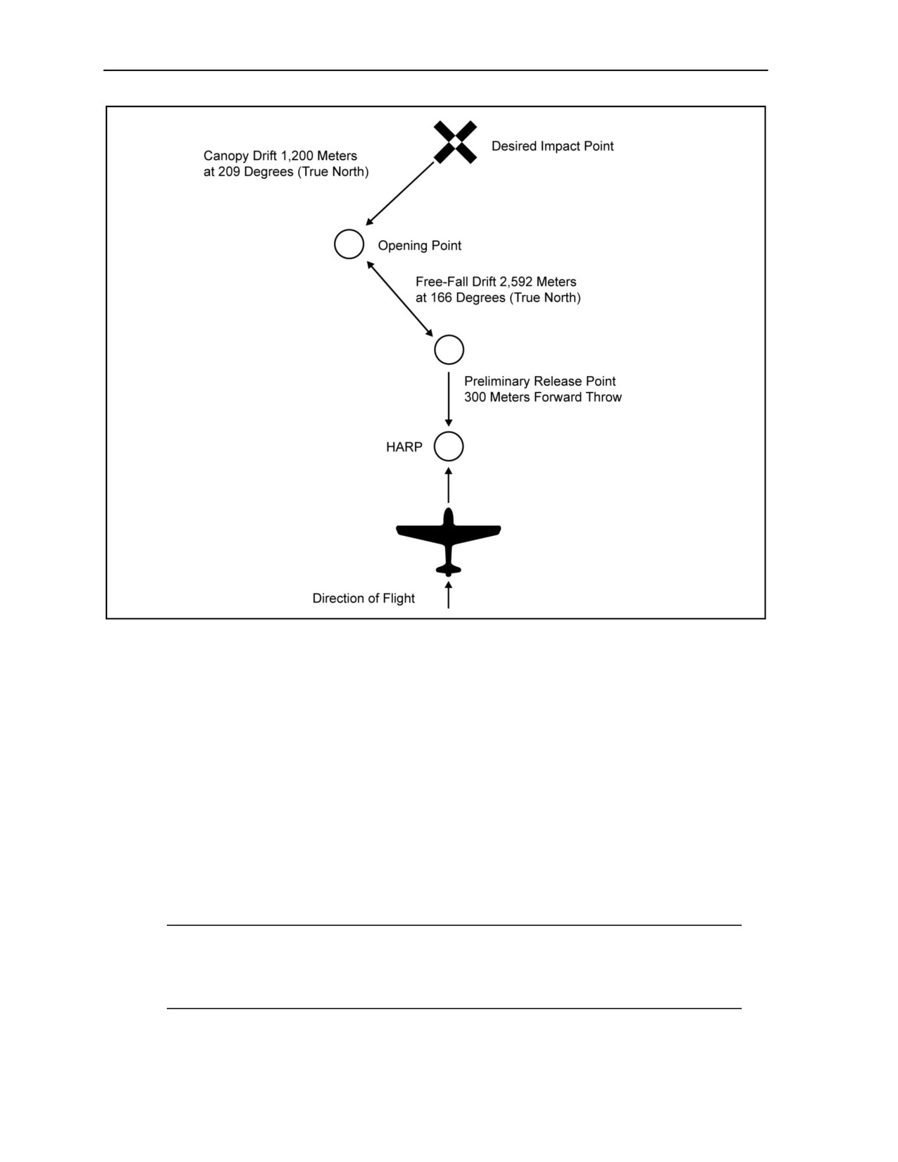
Appendix F
Figure F-1. Plotting the HARP, free-fall, and canopy drift for a 20,000-foot HALO
mission profile
USING THE WIND DRIFT FORMULA AND CONSTANTS
F-6. The jumpmaster uses the wind drift formula D = KAV:
z
D = distance in meters.
z
K = constant (drift in meters per 1,000-foot loss of altitude in a 1-knot wind).
z
A = altitude in thousands of feet.
z
V = average wind speed (velocity).
The jumpmaster also uses the following wind drift constants (K factors):
z
K = 3 (parachutist in free fall).
z
K = 25 (MC-3 parachute system and RAPPS [HALO]).
z
K = 48 (RAPPS [HAHO]).
F-7. Table F-1, page F-3, defines the HAHO K factors for Department of Defense RAPPSs.
Note: The jumpmaster calculating the HAHO wind drift uses the constant of the least
performing canopy; for example, the U.S. Navy MT-1SS uses the S-type reserve that has a
K factor of 66. Therefore, if a parachutist has to activate his reserve parachute, he will still be
able to glide to the DZ.
F-2
ATP 3-18.11/AFMAN 11-411(I)/NTTP 3-05.26M
24 October 2014

High-Altitude Release Point Calculation
Table F-1. HAHO K factors for Department of Defense Ram-Air Personnel Parachute Systems
K-Factor
Parachute Systems
Remarks
48
MC-4, MC-5, MJ-1, MT-2XX/SL
Large High-Glide RAPPS
66
MT-1SS, PD230
Small Low-Glide RAPPS
46
TP-400
Tandem Offset Resupply Delivery System
46
MP-360
Large High-Glide Zero-Porosity RAPPS
31
HG-380
Operations in High-Glide Mode
39
HG-380
Operations in Parachute Mode
NOTE: The jumpmaster always calculates for the lowest performance parachute (largest K factor) to be used
on that MFF operation.
CALCULATING HALO FREE-FALL DRIFT AND DIRECTION
F-8. To determine the parachutist’s drift in free fall, the jumpmaster calculates the average wind speed
(velocity) and average wind direction from the exit to the opening altitude. Opening altitude (4,000 feet in
this example) is not included since that is where the free fall stops. The wind data from 4,000 feet to 1,000 feet
is calculated using the canopy drift constant.
EXAMPLE: Altitude
Velocity
Direction
20,000
85
160
18,000
75
160
16,000
75
165
14,000
65
165
12,000
50
155
10,000
45
150
8,000
20
185
6,000
20
190
435 knots
1330 degrees
The jumpmaster determines the averages by—
z
Determining the total free-fall distance from the exit (20,000) to the opening (4,000).
A = 20,000 - 4,000 = 16,000, or A = 16.
z
Dividing the sum of the wind velocities (435) by the number of velocities (8).
V = 435 ÷ 8 = 54.375, or V = 54 (rounded to nearest whole number) knots average wind speed
(velocity).
z
Dividing the sum of the wind directions (1330) by the number of directions (8).
Direction = 1330 ÷ 8 = 166.25, or Direction = 166 degrees (rounded to nearest whole number)
average wind direction.
Note: Jumpmasters use the following rounding guidelines:
z
0.0 to 0.4: Round down to the nearest whole number.
z
0.5 to 0.9: Round up to the nearest whole number.
F-9. The jumpmaster substitutes the numerical values for the letters of the D = KAV formula.
z
D = (3) (16) (54).
z
D = 2,592 meters at 166 degrees (True North).
24 October 2014
ATP 3-18.11/AFMAN 11-411(I)/NTTP 3-05.26M
F-3

Appendix F
Note: If the jumpmaster uses wind directions from 271 degrees to 089 degrees to calculate the
average wind direction, incompatible averages may result. (All rules for erroneous winds and
doglegs apply.) To compensate, the jumpmaster adds
360 degrees to directions of
001 to 089 degrees and averages the wind direction. If the resulting average is greater than
360 degrees, the jumpmaster subtracts 360 to obtain the correct average wind direction.
EXAMPLE: Direction (incorrect) Direction (correct) Direction (average greater than 360 degrees)
345
345
345
350
350
355
345
345
005 (+ 360) = 365
010
010 (+ 360) = 370
020 (+ 360) = 380
015
015 (+ 360) = 375
025 (+ 360) = 385
350
350
035 (+ 360) = 395
1415 degrees
2135 degrees
2225 degrees
Direction = 1415 ÷ 6 = 235.83 degrees or D = 236 degrees (incorrect).
Direction = 2135 ÷ 6 = 355.83 degrees or D = 356 degrees (correct).
Direction = 2225 ÷ 6 = 370.83 degrees or D = 371 (- 360) = 011 degrees.
CALCULATING CANOPY DRIFT
F-10. To determine the parachutist’s drift under canopy, the jumpmaster calculates the average wind speed
(velocity) and direction from 1,000 feet to the opening altitude.
EXAMPLE: Altitude
Velocity
Direction
4,000
15
190
3,000
14
220
2,000
11
205
1,000
9
220
49
835
Note: Disregard surface winds for calculation. Winds from 1,000 feet to surface are not used to
allow the parachutist to maneuver in the landing pattern.
The jumpmaster determines the averages by—
z
Dividing the sum of the velocities (49) by the number of velocities (4).
V = 49 ÷ 4 = 12.25, or V = 12 (rounded to nearest whole number) average wind speed (velocity).
z
Dividing the sum of the wind directions (835) by the number of directions (4).
Direction = 835 ÷ 4 = 208.75 degrees, or 209 degrees (rounded to the nearest whole number)
average wind direction.
The jumpmaster substitutes the numerical values for the letters of the D = KAV formula.
z
D = (25) (4) (12).
z
D = 1,200 meters at 209 degrees (True North).
CALCULATING FORWARD THROW
F-11. Compensation must be made for the distance a parachutist’s body initially travels into the direction
of flight due to forward speed (velocity). The forward throw distances used in HALO and HAHO are—
z
300 meters for a high-performance aircraft with exit speeds above 120 knots.
z
150 meters for a low-performance aircraft with exit speeds below 120 knots.
F-4
ATP 3-18.11/AFMAN 11-411(I)/NTTP 3-05.26M
24 October 2014

High-Altitude Release Point Calculation
CALCULATING DOGLEGS
F-12. A dogleg is a situation in which the wind direction changes 90 degrees or more for two (or more)
consecutive recorded altitudes. Doglegs require separate calculations from the altitude where the wind
direction changes.
Note: A single 90-degree or greater change in wind direction is treated as an erroneous wind and
will not be included in wind direction or velocity calculations; the altitude will still be included
in the D = KAV formula.
CALCULATING THE HAHO HIGH-ALTITUDE RELEASE POINT
F-13. To calculate the HAHO HARP, the jumpmaster uses the modified D = KAV formula, as the intention
is to maximize the linear distance traveled using the gliding capability of the RAPPS.
Note: For doglegs with less than 6,000 feet of vertical descent, the jumpmaster may use the
standard D = KAV formula; however, it will be less accurate.
The jumpmaster uses the following HAHO gliding distance formula:
z
D = (A - SF) (V + 20.8)
K
z
D = gliding distance in nautical miles.
z
A = altitude in thousands of feet.
z
SF = safety factor in thousands of feet.
z
V = average wind speed (velocity) in knots.
z
20.8 = canopy speed constant.
z
K = 48 (canopy drift constant).
Note: Jumpmasters use the following rounding guidelines:
z
0.0 to 0.4: Round down to the nearest whole number.
z
0.5 to 0.9: Round up to the nearest whole number.
F-14. The jumpmaster calculates the safety factor, which provides a buffer area after exit to permit the
parachutists to assemble under canopy and to establish the landing pattern over the DZ. For example, the
element commander desires 1,000 feet for canopy assembly after exit and 2,000 feet to establish the
landing pattern. The safety factor is 3,000 feet. Therefore, SF = 3.
F-15. The jumpmaster calculates the total canopy gliding distance in nautical miles. He does not round up
or down. Instead, he truncates the result to the tenth of a nautical mile; for example, 12.666 = 12.6 and
18.37486 = 18.3. To convert nautical miles to kilometers, the jumpmaster multiplies by 1.85 and again
truncates the result.
F-16. When an element exits the aircraft in stick formation, the jumpmaster compensates for dispersion
between the parachutists. He obtains this figure by dividing the total number of parachutists by 2 and then
multiplying the result obtained by 50 meters. He plots the calculated distance back into the aircraft’s line of
flight. This procedure places the middle of the stick on the desired opening point.
F-17. The jumpmaster plots back into the aircraft’s line of flight to compensate for forward throw
(300 meters for high-performance aircraft and 150 meters for low-performance aircraft). The following are
examples of HAHO HARP calculations.
24 October 2014
ATP 3-18.11/AFMAN 11-411(I)/NTTP 3-05.26M
F-5

Appendix F
EXAMPLE 1: HAHO HARP Calculation
Situation. The exit altitude is 14,000 feet. Twelve parachutists will exit the aircraft in stick formation. The
element commander desires 1,000 feet for canopy assembly and a 1,000-foot arrival altitude over the DZ.
Wind speed and direction at altitude are—
Altitude
Velocity
Direction
14,000
25
090
12,000
22
080
10,000
21
090
9,000
21
090
8,000
20
085
7,000
18
080
6,000
18
080
5,000
17
085
4,000
16
080
3,000
12
075
2,000
12
080
1,000
08
080
210 knots
995 degrees
F-18. The jumpmaster—
z
Determines the average wind speed: V = 210 ÷ 12 = 17.50, or V = 18 (rounded to nearest whole
number) average wind speed.
z
Determines the average wind direction: D = 995 ÷ 12 = 82.91, or D = 83 (rounded to nearest
whole number) degrees (True North) average wind direction.
z
Determines the safety factor is 2 (minimum).
z
Substitutes the numerical values for the letters of the formula:
D = (12 - 2) (20.8 + 18) ÷ 48.
D = (10) (38.8) ÷ 48.
D = 388.0 ÷ 48.
D = 8.0 nautical miles at 83 degrees (True North).
z
Determines the gliding distance: 8.0 nautical miles x 1.85 = 14.8 kilometers.
z
Determines dispersion: (12 ÷ 2) x 50 = 300 meters.
z
Determines forward throw: 300 meters.
z
Converts the average wind direction from degrees (True North) to a grid azimuth and plots it on
the map to determine the canopy opening point.
z
Plots the dispersion and forward throw from the preliminary release point to determine the
HARP.
z
Determines the grid azimuth from the opening point to the desired impact point. Converts the
grid azimuth to a magnetic azimuth. The magnetic azimuth is the compass heading followed by
the parachutists to the DZ.
Note: If there is no free fall prior to canopy deployment, the opening point is the preliminary
release point.
F-6
ATP 3-18.11/AFMAN 11-411(I)/NTTP 3-05.26M
24 October 2014

High-Altitude Release Point Calculation
EXAMPLE 2: HAHO HARP Calculation With a Dogleg.
Situation. The exit altitude is 15,000 feet. Twelve parachutists exit the aircraft in stick formation. The
element commander desires 1,000 feet for canopy assembly and a 2,000-foot arrival altitude over the DZ. A
change of wind direction creates a dogleg at 9,000 feet AGL. Wind speed and direction at altitude are—
Altitude
Velocity
Direction
14,000
33
210
12,000
30
210
10,000
29
180
92 knots
600 degrees
9,000
26
075
8,000
24
080
7,000
22
085
6,000
20
090
5,000
18
090
4,000
14
085
3,000
12
090
2,000
10
085
1,000
8
080
154 knots
760 degrees
JUMPMASTER CALCULATIONS (BELOW THE DOGLEG
FROM 9,000 TO 1,000 FEET)
F-19. The jumpmaster calculates the gliding distance and direction from the desired impact point to the
dogleg at 9,000 feet. He—
z
Determines that the average wind speed
(velocity) from
1,000 feet to
9,000 feet is
17.11 or V = 17 (rounded to the nearest whole number) knots average wind speed.
z
Determines that the average wind direction from 1,000 feet to 9,000 feet is 84.44 or 84 (rounded
to the nearest whole number) degrees (True North).
z
Determines that the safety factor is 3. He must remember that in a formula for a HAHO dogleg,
the safety factor is 2 on the base leg and 1 on the dogleg to equal a total safety factor of 3.
z
Establishes that altitude = 9,000 feet, or A = 9.
z
Substitutes the numerical value for the letters of the formula:
D = (9 - 2) (20.8 + 17) ÷ 48.
D = (7) (37.8) ÷ 48.
D = 264.6 ÷ 48 = 5.5 nautical miles x 1.85 = 10.1 kilometers gliding distance at
84 degrees (True North).
JUMPMASTER CALCULATIONS (ABOVE THE DOGLEG
FROM 10,000 TO 14,000 FEET)
F-20. The jumpmaster calculates the gliding distance and direction from 10,000 feet to the exit altitude.
He—
z
Determines that the average wind speed (velocity) from 10,000 feet to 15,000 feet is 30.66 or 31
(rounded to the nearest whole number) knots.
z
Determines that the average wind direction from 10,000 feet to 15,000 feet is 200 degrees
(True North).
z
Determines that the safety factor is 1.
24 October 2014
ATP 3-18.11/AFMAN 11-411(I)/NTTP 3-05.26M
F-7

Appendix F
z
Establishes that altitude = 5,000 feet, or A = 5.
z
Substitutes the numerical value for the letters of the formula:
D = (5 - 1) (20.8 + 31) ÷ 48.
D = (4) (51.8) ÷ 48.
D = 207.2 ÷ 48 = 4.3 nautical miles x 1.85 = 7.9 or 8 kilometers (rounded to the
nearest whole number) gliding distance at 200 degrees (True North).
F-21. The jumpmaster converts the True North azimuths to grid azimuths. He plots the glide path from the
desired impact point to the dogleg, and plots the glide path from the dogleg to the opening point. He
calculates the dispersion for 12 parachutists (300 meters) and plots the preliminary release point from the
opening point. The jumpmaster compensates for forward throw and plots the HARP.
F-22. The jumpmaster determines the grid azimuth from the opening point to the desired impact point. He
converts the grid azimuth to a magnetic azimuth. The magnetic azimuth is the compass heading followed to
the DZ. By holding a single compass heading, the parachutist will maintain direction and follow a curving
path from the opening point to the DZ, rather than a path with distinct turns.
Note: The safety factor above the dogleg and below the dogleg, when combined, mathematically
incorporates the desired effect over the complete group.
F-8
ATP 3-18.11/AFMAN 11-411(I)/NTTP 3-05.26M
24 October 2014

Appendix G
Jumpmaster Personnel Inspection
Before each MFF parachute operation, the jumpmaster conducts a systematic
inspection of each parachutist’s parachute and combat equipment for proper wear, fit,
and attachment. All equipment being airdropped will receive a JMPI. The jumpmaster
must never sacrifice safety for speed.
DANGER
Improper or incomplete JMPIs may result in DEATH, serious
injury, or equipment loss and damage.
WARNING
Changes to the JMPI procedures may change as new equipment
and procedures are developed. Jumpmasters should ensure that
they are using the latest JMPI procedures taught at the
USAJFKSWCS MFF school when conducting JMPIs.
JUMPMASTER PERSONNEL INSPECTION OF THE MC-4 HARNESS
AND CONTAINER SYSTEM
G-1. The jumpmaster uses the following sequence to detect and identify deficiencies. With hands and eyes
working together, he starts at the front of the parachutist and moves to the rear, from top to bottom, right
side to left side (Figure G-1, page G-2).
Note: If making an oxygen jump, the jumpmaster first performs the oxygen inspection sequence
on page G-6. Then he continues with the following:
Note: If jumping in the vicinity of a water hazard, the jumpmaster follows the inspection
sequence for flotation devices on page G-9. Then he continues with the following:
z
Harness: Checks for proper fit before continuing the JMPI.
z
Helmet and goggles:
Uses correct helmet: MC-3, Gentex HGU-55/P, Gentex lightweight parachutist helmet,
Bell helmet, Protec with free-fall liner, ACH helmet, MICH, or OPSCORE.
Makes sure helmet fits properly and is serviceable.
Uses approved goggles (Kroop; military-issue sun, wind, and dust goggles; or Gentex only).
Makes sure the lenses are clear and not cracked or scratched.
Makes sure the goggle strap is secured if worn outside of helmet.
Checks that bayonet receivers are present and securely attached.
Makes sure the two adjustment screws are present on the receiver covers.
Checks chin strap for proper attachment and serviceability, with excess stowed.
Right riser: Makes sure no twists are present in front or rear riser from riser cover to
3-ring release assembly.
18 August 2016
ATP 3-18.11/AFMAN 11-411(I)/NTTP 3-05.26M, C2
G-1

Appendix G
Figure G-1. Jumpmaster personnel inspection without oxygen, weapon, or rucksack
z
Right 3-ring release assembly:
Checks for correct assembly—small ring, medium ring, and base ring (elongated snowman
effect).
Gives small and medium ring a one-quarter turn to check for free movement.
G-2
ATP 3-18.11/AFMAN 11-411(I)/NTTP 3-05.26M, C2
18 August 2016

Jumpmaster Personnel Inspection
z
Right main canopy release cable and cable housing:
Inspects for tacking and proper routing.
Makes sure the 3-ring locking loop is through the small ring and the grommet on the riser
and the eye on the cable housing (without any twists or frays).
Rotates riser toward the parachutist’s neck, ensuring the release cable is routed through the
locking loop and the running end is stowed in the stowage flute.
z
Main ripcord assembly:
Makes sure the housing is tacked properly.
Makes sure there are no broken strands on main ripcord cable.
Makes sure the two swage balls are present on the end of the ripcord cable.
Checks that the main ripcord handle is properly seated in the elastic pocket.
Note: The jumpmaster resumes JMPI sequence of the center-mounted weapons harness after
inspection of the main canopy release handle (page G-10, JMPI for the MC-4 RAPPS using the
center-mounted weapons harness).
z
Cutaway handle (main canopy release ripcord):
Makes sure that the cutaway cables are not twisted more than 180 degrees.
Checks that the handle is seated in its pocket and the Velcro is properly mated.
z
Chest strap:
Makes sure there are no twists and it is properly routed
(to include the chest strap
extension).
Makes sure the excess is rolled under and stowed in the slack retainer.
Makes sure it is properly routed through the friction adapter.
Note: If jumping with a weapon, jumpmaster follows the inspection sequence on page G-10.
Then he continues with the following:
z
Reserve ripcord:
Makes sure it is properly seated in the elastic pocket.
Checks that the two swage balls are present on end of the reserve ripcord cable.
Makes sure there are no broken strands.
Makes sure the cable is properly routed to the cable housing.
Makes sure the cable housing is tacked.
Makes sure RSL is free and clear of reserve ripcord cable (first free and clear).
z
Left riser: Makes sure there are no twists in the front or rear riser from the riser cover to the
3-ring release assembly.
z
Left 3-ring release assembly:
Checks for correct assembly—small ring, medium ring, and base ring (elongated snowman
effect).
Gives the small and medium rings a one-quarter turn to check for free movement.
z
Left main canopy release cable and cable housing:
Inspects for tacking and proper routing.
Makes sure the 3-ring locking loop is through the small ring and the grommet on the riser
and the eye on the cable housing (without any twists or frays).
Rotates riser toward parachutist’s neck, making sure the release cable is routed through the
locking loop and the running end is stowed in the stowage flute.
24 October 2014
ATP 3-18.11/AFMAN 11-411(I)/NTTP 3-05.26M
G-3

Appendix G
z
Reserve static line:
Makes sure the RSL quick-release lanyard is attached and snapped.
Makes sure the RSL loop is attached to the release shackle and routed correctly.
Makes sure RSL is free and clear of canopy release cable housing (second free and clear).
z
Left main lift web:
Checks that the large equipment attachment ring and V-ring are present.
Makes sure the running end of the adjustment strap is rolled and stowed in the slack
retainer.
Makes sure there are no twists.
Note: If jumping with a rucksack, jumpmaster follows the inspection sequence on page G-11.
Then he continues with the following:
z
Right main lift web:
Checks that the large equipment attachment ring and V-ring are present.
Makes sure the running end of the adjustment strap is rolled and stowed in the slack
retainer.
Makes sure there are no twists.
Checks free-floating strap and oxygen fitting block for proper attachment, and makes sure
the four screws are present on the back of the fitting block.
z
Waistband, waistband extension, and kit bag handles (rear-mounted):
Makes sure the right wing flap is secured to the waistband.
Checks that there are no twists from its attachment point on the right side of container to the
left wing flap.
Makes sure the excess is rolled under and stowed in the slack retainer.
Checks for proper routing through the waistband extension friction adapter.
Checks the waistband extension is routed through the kit bag handles (rear-mounted).
Checks the kit bag is positioned between the jumper’s back and the main pack tray.
Makes sure waistband is routed over all equipment.
z
Right leg strap, kit bag handle (front-mounted):
Makes sure the snap hook gate closes and has proper spring tension.
Makes sure the excess is rolled under and stowed in the slack retainer.
Checks for correct routing, with no twist in leg strap or saddle.
Ensures the leg strap is routed through one kit bag carrying handle (front-mounted).
z
Left leg strap, kit bag handle (front-mounted):
Makes sure the snap hook gate closes and has proper spring tension.
Makes sure the excess is rolled under and stowed in the slack retainer.
Checks for correct routing, with no twist in leg strap or saddle.
Ensures the leg strap is routed through one kit bag carrying handle (front-mounted).
z
Altimeter, MA2-30:
Makes sure it is located on parachutist’s left wrist, that it fits snugly, and it is properly
attached (with 0 to the top).
Checks for proper free-fall altimeter setting.
Tells the parachutist to turn and continues the JMPI.
z
Altimeter, MA-10:
Makes sure it is located on parachutist’s left wrist, that it fits snugly, and it is properly
attached (with 0 to the top).
Looks at the altimeter and ensures the altimeter is on (steady yellow light).
Checks for proper free-fall altimeter setting.
G-4
ATP 3-18.11/AFMAN 11-411(I)/NTTP 3-05.26M
24 October 2014

Jumpmaster Personnel Inspection
Tells the parachutist to turn and continues the JMPI.
z
Reserve container:
Peels open the reserve ripcord protective flap.
Makes sure the reserve ripcord cable housing is tacked down.
Checks that the RSL is routed correctly, and that the reserve ripcord cable runs through the
RSL guide and assist ring.
z
Reserve ripcord cable:
Checks that the reserve ripcord cable has no broken strands.
Makes sure it is routed on the left side of the grommets.
Makes sure the top pin is inserted at a 45-degree angle.
Makes sure the closing loops are not frayed.
Makes sure both pins are not seated past their shoulders.
Tells the parachutist to bend.
z
Main container:
Opens both protective flaps.
Makes sure the closing flaps are closed in the proper sequence (bottom, left, right, top).
Makes sure the main ripcord cable housing is tacked.
Checks that main ripcord cable and EAAD and/or ARR power cable are not twisted around
each other.
Makes sure the 2-inch cable extension with swage ball is at the 12 o’clock position (top).
Makes sure the closing loop is not frayed.
Makes sure the main pin is not seated past its shoulder.
z
The Military CYPRES 2: Jumpmaster does the normal JMPI sequence through the inspection of
the parachutist’s altimeter. After the altimeter inspection, the jumpmaster continues with the
following:
Opens the reserve protector flap and pins it up and out of the way.
Traces the control cable and inspects for any damage and proper routing.
Makes sure the control cable is properly routed through the binding tape guide.
Makes sure the binding tape is properly tacked to the reserve top-closing flap.
Makes sure the control unit is set at the proper default for the current free-fall operation.
Makes sure the control unit light-emitting diode indicator light is not lit.
Checks that the control unit digital readout screen shows the proper millibar setting or 0▼.
Inspects the reserve ripcord cable for proper routing and no broken strands.
Makes sure the reserve ripcord cable runs through the assist ring (little ring) of the RSL and
then through the guide ring (big ring).
At the top reserve locking pin, ensures the reserve ripcord cable is to the right of the
grommet.
Inspects the pin to make sure it is not shouldered inside the grommet and the pin is not bent.
Makes sure the continuous Military CYPRES 2 closing loop of the reserve is not frayed.
Continues to inspect the reserve ripcord cable to the bottom locking pin, making sure it is
properly routed and there are no broken strands.
At the bottom reserve locking pin, inspects the pin to make sure it is not shouldered inside
the grommet and the pin is not bent.
Makes sure the continuous Military CYPRES 2 closing loop of the reserve is not frayed.
Makes sure the closing flaps are closed in the proper sequence (bottom, left, right, top).
Makes sure the main ripcord cable housing is tacked.
Inspects the cable for proper routing and no broken strands.
Continues past the locking pin and inspects the 2-inch extension for proper routing and no
broken strands.
24 October 2014
ATP 3-18.11/AFMAN 11-411(I)/NTTP 3-05.26M
G-5

Appendix G
Ensures the 2-inch extension terminates with a single steel swage ball.
Pinches the swage ball to ensure the main locking pin does not come loose.
Inspects the pin to make sure it is not shouldered inside the grommet and the pin is not bent.
Makes sure the main closing loop is not frayed.
Slaps the bottom of the container to indicate completion of the JMPI.
JMPI FOR THE MC-4 RAPPS WITH THE 106-CUBIC-INCH
PORTABLE BAILOUT OXYGEN SYSTEM
G-2. The jumpmaster inspects the entire oxygen system before inspecting the harness and/or container
system. The recommended inspection sequence for the MC-4 RAPPS with the oxygen system follows
(Figure G-2, page G-7):
z
Inspects the inside of the mask, making sure there is no debris, the four self-sealing screws are
present, the combination valve retainer is present, and the portion that matches with the
parachutist’s face is not torn or damaged in any way that would cause the parachutist to have an
improper seal or fit.
z
Attaches the mask to the left-side bayonet receiver.
z
Checks for proper fit and seal. Makes sure there is no damage to the hard-shell or soft-shell
portion of the mask. Makes sure the four capped tee nuts secure the four attaching straps to the
hard-shell portion of the mask, and the excess is either taped or tacked. Checks that the
combination valve is of the correct type (green exhalation port flaps only), the delivery tube
clamp is present and attached properly, and there is no damage to the delivery tube at its
attachment point to the combination valve.
z
Detaches the oxygen mask from the left-side bayonet receiver. Inspects the oxygen mask
delivery tube to make sure there is no damage (checks for holes, discoloration, or deterioration).
Makes sure the delivery tube retainer is present and attached correctly. Checks that the elastic
slack retainer is around the chest strap and that the Velcro is mated around the delivery tube.
z
Moves to the quick-disconnect assembly. Inspects the delivery tube clamp to make sure that it is
present and attached properly. Makes sure there is no damage to the delivery tube at its
attachment point to the quick disconnect. Disconnects the delivery tube from the AIROX VIII.
Inspects the quick disconnect to make sure that there is no debris inside the quick disconnect and
that the antisuffocation valve moves freely, has correct spring tension, and returns to the closed
position. Inspects the gasket (O-ring) to make sure it is present and the beveled lip portion is up
(not reversed).
z
Inspects the AIROX VIII. Disconnects the oxygen mask delivery tube. Makes sure the dust
cover is present and serviceable. Checks that the debris screen is present and is not damaged or
corroded. Checks that there is no debris inside the AIROX VIII. Reconnects the oxygen mask
delivery tube, making sure the quick-disconnect assembly is fully seated.
z
Grasps the AIROX VIII and moves the entire assembly gently up and down to check that the
dovetail mounting plate is correctly mated with the oxygen fitting block. Inspects the oxygen
fitting block to make sure it is assembled correctly and the four attachment screws are present
and secure on the back of the oxygen fitting block.
z
Checks the ambient air port of the AIROX VIII. Visually inspects the inside of the ambient air
port to make sure the debris screen is present and is not damaged or corroded. Checks that there
is no debris inside the ambient air port. Inspects the antisuffocation valve to make sure it has
correct spring tension and returns to the closed position. Inspects the gasket (O-ring) to make
sure it is present and that the beveled lip portion is up (not reversed).
z
Inspects the blue antitamper seal (blue dot of paint). Makes sure it is present and aligned.
z
Checks to ensure both flow indicator windows are not damaged.
z
Grasps the “B” nut, giving it a slight turn to make sure it is tight. (The “B” nut attaches the
delivery hose [medium pressure] to the AIROX VIII.)
G-6
ATP 3-18.11/AFMAN 11-411(I)/NTTP 3-05.26M
24 October 2014
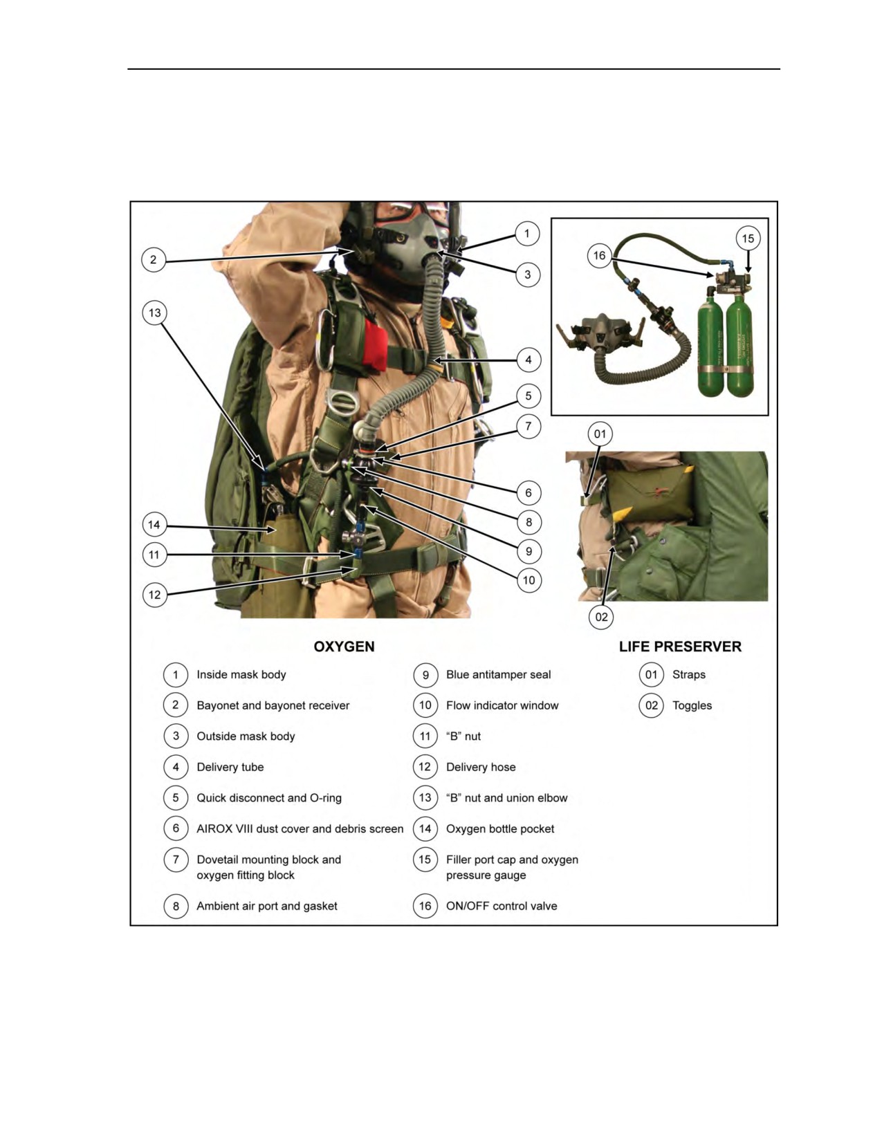
Jumpmaster Personnel Inspection
z
Follows the delivery hose (medium pressure) from its point of connection on the AIROX VIII
and checks for proper routing. Makes sure the delivery hose is routed from the AIROX VIII over
the outside of the waistband. Checks that the delivery hose then makes a 180-degree bend and
runs under the waistband and between the parachutist’s body and his right main lift web. Checks
that it then runs to the union elbow.
Figure G-2. Jumpmaster personnel inspection with oxygen and life preserver
z
Checks the “B” nut at its point of attachment to the union elbow for tightness by giving it a
slight twist. Then gives the union elbow a slight twist, checking for proper tightness to the
reducer manifold.
24 October 2014
ATP 3-18.11/AFMAN 11-411(I)/NTTP 3-05.26M
G-7

Appendix G
z
Pushes up on the bottom of the oxygen bottle pocket with the left hand while the right hand is on
the manifold and pulls the bottles away from the parachutist’s body. Moves to the overpressure
relief valve making sure it is seated by pushing in on the cap. While in this position with the
oxygen bottles away from the parachutist’s body, inspects the waistband from its point of
attachment on the container to the right wing flap friction adapter. Makes sure the waistband is
not twisted and the waistband is routed through both of the center loops on the oxygen bottle
pocket. Checks that the oxygen system is between the waistband and right wing flap.
z
Tells the parachutist to bend. Inspects the filler port cap making sure it is present and finger-
tight. Checks that the oxygen pressure gauge indicates adequate pressure. The needle on the
oxygen pressure gauge must be on the number 1 of 1800 psi or higher to be correct.
z
Tells the parachutist to stand erect. Turns the ON/OFF control valve on and listens for a flow of
oxygen out of the oxygen mask. Makes sure the ON/OFF control valve can be locked in the ON
position. Turns the ON/OFF control valve off, making sure it can be locked in the OFF position.
G-3. This sequence completes the JMPI of the 106-cubic-inch portable bailout oxygen system. The
jumpmaster returns to the normal JMPI sequence for the MC-4 RAPPS.
JMPI FOR THE POM MFF MASK AND JUMP BOTTLE SYSTEM
G-4. The jumpmaster begins the inspection by reaching, with his right hand, the pressure reducer on the
bottle and turning the ON/OFF toggle switch to the ON position. Then he continues with the following:
z
Moves to the front of the jumper and visually checks that the mask is attached to the left side of
the jumper’s helmet.
z
With his right hand, grasps the mask on the outside portion on the hard shell and rotates the
mask making the inside visible. Visually inspects the inside to ensure cleanliness. Looks for the
presence of the pressure-demand relief valve (brass ring), microphone element, exhalation valve,
and antisuffocation valve.
z
Using his left index finger as a guide, places it inside the mask at the top and rotates it in a
clockwise direction while peeling back the lip and exposing the inside of the mask. He should be
inspecting for tears, dirt, or damage to the inner soft-shell portion. He continues this process
until he comes back up to the 12 o’clock position. Then he does another sweep on outer portion
of the inner soft shell making sure there are no damages to the mask that would hinder a good
seal to the jumper’s face.
z
With his right hand, gently pulls out and rotates the mask on the jumper’s face. With the left
hand, attaches the bayonet fitting into the receiver on the right side of the jumper’s helmet and
seats it with two clicks.
z
From the nose of the jumper, looks in a clockwise direction around the mask and inspects for
any problems with fit and the mask edges are not pinched or rolled over the jumper’s face. Gives
the mask a shake ensuring a good seal and sounds off with key word “PROPER FIT.”
z
Brings his right index finger to the friction buckle at the 2 o’clock position on the mask. Makes
sure it is present and excess webbing of the attaching strap is stowed properly by either tape or
tacking. In a clockwise motion, inspects the remaining three buckles and attaching straps and
sounds off with key words “BUCKLE TAPE” (four times).
z
Inspects the hard shell for cracks and ensures exhalation valve cover is secure. Visually looks
under the cover for the spring and the overall cleanliness. Ensures intercom block on the top of
the mask has two screws present and the intercom cord is attached if necessary. Checks regulator
for damage and cleanliness, and gently shakes to ensure it is secure.
z
Places his right hand to the right of the quick-disconnect fitting on the regulator. Grasps and
pushes the hose toward the mask to ensure it is properly seated. Pulls on the hose to make sure
that it is securely attached and sounds off with key words “PUSH IN - PULL OUT.” Instructs
the jumper to breathe in and out, listens for oxygen flow (it should stop when the jumper
exhales). Next, he moves to the union elbow and with his left hand, grasps it; with his right
hand, he grasps the blue “B” nut and attempts to turn it to the right ensuring tightness, sounding
off with key word “TIGHT.”
G-8
ATP 3-18.11/AFMAN 11-411(I)/NTTP 3-05.26M
24 October 2014

Jumpmaster Personnel Inspection
z
Leaving his right hand in place on the union elbow, seeks out the securing lanyard and gives it a
tug with his left index finger. Inspects the securing lanyard, ensuring it is attached to the mask
on the jumper’s left bottom attaching strap and ensuring the chinstrap is routed through the
securing lanyard.
z
From the mask end, traces the medium-pressure delivery hose as it routes behind the jumper’s
neck. The hose should be routed through the heavyweight retainer band that is half-hitched to the
carrying handle on the top center of the jumper’s container. Moves to the right side of the
jumper. The hose should be seen running from the carrying handle to and through a half-hitched
retainer band attached to the equipment tie-down loop. Traces the hose from the retainer to the
top of the swivel “T.”
z
Grasps the nut that connects the medium-pressure delivery hose to the swivel “T” and ensures it
is connected and that the unit rotates freely.
z
Places his left hand on the bottom of the bottles. At the same time, places his right hand on the
manifold at the top of the bottles and lifts up and out.
z
While pulling out on the bottles, looks behind them to visually inspect the origin. Places his right
hand behind the bottles and sweeps the waistband to ensure there are no twists and it routes
through the middle loops on the oxygen pouch. Sounds off with key word “ORIGIN.”
z
Rotates the bottles forward and with his left hand checks for the presence of the filler cap and
ensures it is tight.
z
Looks at the bottle gauge and states in reference to the 1800 on the gauge face, key words
“ONE,” or “ABOVE” or “BELOW ONE.”
z
Rotates the switch to the OFF position and sounds off with key word “LOCK OFF.”
z
Removes the mask from the jumper’s face and starts his inspection of the jumper’s parachute as
normal.
JMPI FOR THE MC-4 RAPPS WITH FLOTATION DEVICES
G-5. The recommended JMPI sequence for the MC-4 with flotation devices follows (Figure G-2, page G-7):
z
B-7 Life Preserver and Life Preserver Unit-10/P:
Checks that the life preserver straps are over the uniform and under the parachute harness
(B-7 chest strap fastened with a quick release).
Ensures flotation packets fit under the armpits, with the flaps to the outside, and the toggles
down and to the front. Makes sure no part of the flotation packet is under the parachute
harness.
z
Underwater demolition team life vest:
Makes sure the life vest is worn around the neck with all straps under the parachute harness,
including the parachute harness chest strap. The vest is secured with a rubber band to
prevent interference with the cutaway handle and the reserve ripcord.
Makes sure the inflatable portion of the vest does not go under the chest strap.
Unscrews the CO2 cartridge to make sure it has not been fired. Reinserts the cartridge into
its fitting and ensures it is finger-tight. Makes sure the protective flap does not cover the
toggle.
G-6. Jumpmaster returns to the normal JMPI sequence for the MC-4 RAPPS.
JMPI FOR THE MC-4 RAPPS WITH WEAPON (M16A1/A2 AND M4A1)
G-7. The jumpmaster follows the normal JMPI sequence until he encounters the weapon sling over the
chest strap extension. The recommended inspection sequence for the MC-4 RAPPS with weapon follows
(Figure G-3, page G-10):
z
Makes sure the sling is routed over the chest strap extension and under the left main lift web.
z
Makes sure the sling is routed over the parachutist’s shoulder.
z
Checks that the weapon tie-down is secured around the weapon sling about 6 inches from the
swivel on the stock of the weapon.
18 August 2016
ATP 3-18.11/AFMAN 11-411(I)/NTTP 3-05.26M, C2
G-9
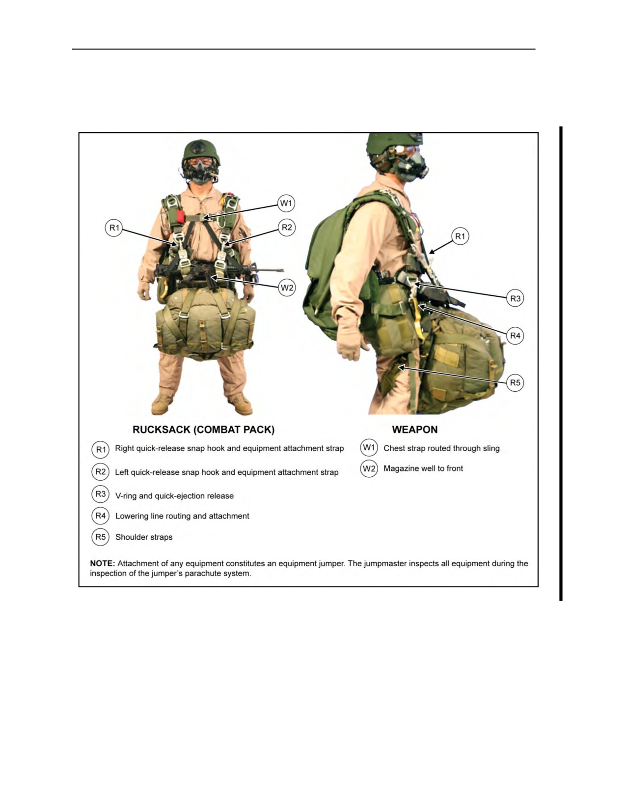
Appendix G
z
Makes sure the sling is routed to the outside of the weapon buttstock and that the weapon
magazine is to the parachutist’s rear.
z
Checks that the weapon is placed between the left wing flap and the parachutist with the
waistband extension routed through the weapon-carrying handle.
Figure G-3. Jumpmaster personnel inspection for weapon, front-mounted rucksack
JMPI FOR THE MC-4 RAPPS USING THE CENTER-MOUNTED
WEAPONS HARNESS
G-8. The sequence of the JMPI procedures for the center-mounted weapons harness remains the same for
the helmet, oxygen, and right three-ring assembly, main ripcord grip, and cutaway handles. The sequence
remains the same regardless of the weapons system checked; for example, M-4, M24, M249, M240B, and
AT-4. The jumpmaster continues with the following:
z
Ensures proper routing of the chest strap through the friction adapter and picks up the inspection
at the weapon’s sling. Jumpmaster states the key word, “Weapon.”
G-10
ATP 3-18.11/AFMAN 11-411(I)/NTTP 3-05.26M, C2
18 August 2016

Jumpmaster Personnel Inspection
Note: In all Category B weapons—M24, M249, M240B, and AT-4—the chest strap must be
routed through the sling and secured with the chest strap excess to prevent the sling from
interfering with the cutaway pillow or reserve ripcord handle.
z
Ensures the weapon’s sling is routed under the chest strap on the main ripcord side and over the
chest strap on the reserve ripcord side. Jumpmaster states the key words, “Under, Over.”
z
Traces the weapon’s sling from the chest strap down to the sling tie-down point and ensures that
it is secured to the weapon and all excess webbing has been taped or secured using a
heavyweight retainer band.
z
At the point of attachment, ensures the weapon’s muzzle is oriented to the jumper’s left, the
sling is routed in front of the weapon, and the main lift web attachment buckle is outboard of the
left main lift web. Jumpmaster states the key words, “Muzzle Left Outboard.”
z
Traces the weapons system ensuring that the forward assist and charging handle are located
away from the jumper, the waistband is behind the weapon, and the harness is securely attached
to the weapon.
Note: When jumping weapons that have bipods and/or feed tray covers, the weapon’s
attachment straps must cover and secure these components to mitigate an inadvertent release.
z
Upon reaching the right main lift web, ensures the main lift web attaching point is rotated
outboard of the right main lift web. Jumpmaster states the key word, “Outboard.”
z
Upon reaching the right sling attachment point, traces the sling ensuring proper routing and all
excess material is secured using tape or a heavyweight retainer band, and the sling is routed
behind the chest strap.
G-9.
The jumpmaster goes to the reserve ripcord handle and continues the normal JMPI.
JMPI FOR THE MC-4 RAPPS WITH REAR- OR FRONT-MOUNTED
COMBAT PACK (RUCKSACK)
G-10. The recommended inspection sequence for the MC-4 parachute assembly with the combat pack
(rucksack) follows (Figures G-3 [front-mounted], page G-10, and G-4 [rear-mounted], page G-12). The
jumpmaster follows the normal JMPI sequence until he arrives at the equipment attachment ring on the left
main lift web. Then the jumpmaster—
z
Makes sure the left quick-release snap hook has proper spring tension and that the gate is closed.
Makes sure the quick-release is seated. Follows the left attachment strap around to the improved
equipment attachment sling, making sure it is not routed under any portion of the MC-4 harness
or rucksack frame.
z
Makes sure the right quick-release snap hook has proper spring tension and that the gate is
closed. Makes sure the quick-release is seated. Follows the right attachment strap around to the
improved equipment attachment sling, making sure it is not routed under any portion of the
MC-4 harness or rucksack frame.
z
Inspects the HPT lowering line assembly at its point of attachment on the right V-ring. Makes
sure the gate on the quick-ejector release is closed and that the locking arm is locked. Checks the
routing of the tubular nylon to the nylon duck container (stow pocket), making sure it is routed
free of any portion of the MC-4 parachute system or the rucksack frame and is located between
the parachutist’s leg and the shoulder strap of the rucksack.
z
Checks the running end of the HPT lowering line for proper attachment. Makes sure it is
attached between the lateral locking straps where the diagonal straps cross. Checks that the
running end of the lowering line passes through its own loop and is tightened down.
z
Grasps both shoulder straps and pulls to the outside of the parachutist’s legs to make sure they
are attached correctly and that the parachutist has a leg through each shoulder strap.
G-11. Jumpmaster returns to the JMPI inspection sequence at the left main lift web large equipment ring.
18 August 2016
ATP 3-18.11/AFMAN 11-411(I)/NTTP 3-05.26M, C2
G-11
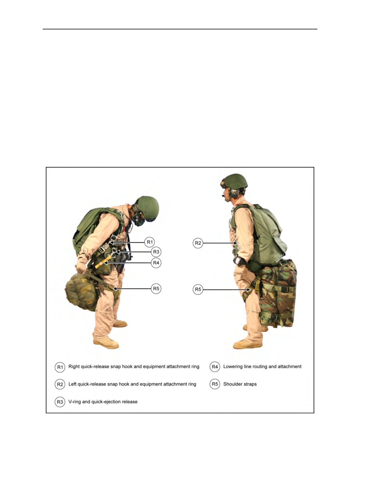
Appendix G
JMPI WITH NIGHT VISION GOGGLES (WITH AND WITHOUT
OXYGEN)
G-12. The jumpmaster will conduct a general visual inspection of the helmet and NVGs to ensure overall
serviceability, suitability, and proper fit.
G-13. The jumpmaster will ensure the NVGs are properly mounted and secured, as well as verify that the
NVGs function as designed; for example, power on and off, and flip up and down freely. If the NVGs have
an external battery pack and power cables, the jumpmaster will inspect to ensure the battery pack and
power cables are secured to the helmet and properly stowed.
G-14. The jumpmaster will trace the bungee cord to ensure it is routed through the retention loops with a
not less than
4-mm-diameter bungee cord, but not larger than a 6-mm-diameter bungee cord. The
jumpmaster will also ensure the hook is no more than 2 inches long. The jumpmaster will continue to trace
the bungee cord to the termination point where it will be attached to the 550 cord loop on the NVG. The
jumpmaster will then complete the bungee inspection by verifying that the bungee hook is closed with one
turn of paper masking tape with a quick release. The chin strap and oxygen system will be inspected in
accordance with current JMPI standards.
Figure G-4. Jumpmaster personnel inspection with the rear-mounted rucksack
and/or parachutist drop bag
G-12
ATP 3-18.11/AFMAN 11-411(I)/NTTP 3-05.26M, C2
18 August 2016

Appendix H
Sample Aircraft Inspection Checklist
Special Forces operational detachments primarily use USAF troop carrier aircraft
when conducting MFF operations and proficiency training. The preparation of the
aircraft for parachute operations is an aircrew responsibility. The jumpmaster,
accompanied by the aircraft loadmaster, inspects the aircraft and coordinates any
activities particular to the airborne operation (for example, loading and placement of
oxygen consoles). At a minimum, the jumpmaster checks the exterior and interior
areas of the aircraft directly related to the airborne operation. TC 3-21.220 contains
the specific items that must be inspected and the peculiarities of certain aircraft.
Figure H-1 contains a sample aircraft inspection checklist.
Figure H-1. Sample aircraft inspection checklist
24 October 2014
ATP 3-18.11/AFMAN 11-411(I)/NTTP 3-05.26M
H-1

This page intentionally left blank.

Appendix I
Jumpmaster Aircrew Briefing Checklist
The jumpmaster briefs the aircrew as a part of his duties at the DAF. He uses the
following checklist (Figure I-1, pages I-1 and I-2) to brief the aircrew.
Figure I-1. Sample jumpmaster aircrew briefing checklist
24 October 2014
ATP 3-18.11/AFMAN 11-411(I)/NTTP 3-05.26M
I-1

Appendix I
Figure I-1. Sample jumpmaster aircrew briefing checklist (continued)
I-2
ATP 3-18.11/AFMAN 11-411(I)/NTTP 3-05.26M
24 October 2014

Appendix J
Joint Precision Airdrop System
This appendix discusses the new JPADS, which uses the GPS, steerable parachutes,
and an onboard computer to steer loads to a designated point of impact on a DZ.
AUTONOMOUS BUNDLE OPERATIONS
J-1. New and emerging technologies are now allowing for the deployment of GPS-guided bundles that
can carry an ever-increasing load to pinpoint grid coordinates. This new technology will greatly increase
mission capabilities and allow for more than just personnel to be delivered to the objective area via the
RAPPS.
J-2. In recent years, GPS-guided RAPPSs render more flexibility to load drops. Since
2004, the
U.S. Marine Corps has been using Sherpa TM and/or MC GPS-guided parachutes in Iraq, dropping one-ton
loads within 70 meters from their designated target point. In August 2006, the first “Screamers” were tested
in Afghanistan, dropping container-delivery-system bundles containing food, water, ammunition, and other
supplies, weighing 500 to 2,200 pounds (0.2 to 1 ton) to troops on the ground.
J-3. Precision airdrop for special operations has been chosen among the ten highest priority areas defined
for the North Atlantic Treaty Organization’s defense against terrorism effort. The purpose of the defense
against terrorism program is to develop new, cutting-edge technology to protect troops and civilians against
terrorist attacks. Precision airdrop capabilities will enhance the capability of North Atlantic Treaty
Organization forces to deliver personnel or equipment stealthily and precisely under all weather conditions,
wherever they may be needed. This capability will also support the increasing deployment of troops to
long-distance out-of-area contingency operations, which have lately become in vogue.
J-4. High-altitude precision airdrop is expected to be a key enabling technology for future forces’
deployment. Such capabilities will facilitate rapid strategic and tactical deployment of forces, supported
“just in time,” with supplies delivered precisely to any location throughout the world. The increased
accuracy and ability to drop to more than one location simultaneously means that Soldiers on the ground
can recover the cargo quickly and know exactly where it will land. Such capability is providing military
planners with the capability of strategically and covertly positioning equipment and supplies for rapidly
moving ground and special operations forces.
J-5. Aimed at supporting ground troops with essential supplies, the U.S. Army Natick Soldier Center has
teamed with the USAF Air Mobility Command to develop new airdrop capabilities, first pushing
immediately essential supplies, such as ammunition, water, fuel, and medical supplies to forward-deployed
troops. The medium and heavy systems will be fielded at a later phase and will enable precision airdrop of
loads ranging from 20,000 to 60,000 pounds (9 to 27 tons) of cargo, more than enough to deliver the
Army’s eight-wheel 19-ton Stryker combat vehicle. As the Army transforms to the Future Combat System,
JPADS will provide the just-in-time logistics needed. The ultimate goal is to resupply troops anywhere in
the world within 24 hours with supplies directly flown from the U.S. bases. JPADS will satisfy four “gaps”
identified in the current airdrop capability:
z
Increased ground accuracy.
z
Standoff delivery.
z
Increased air carrier survivability.
z
Improved effectiveness of airdrop mission operations.
J-6. The JPADS family of systems consists of “self-guided” cargo parachute systems with navigation aids
for MFF parachute systems all linked to a common mission planning and weather system. The JPADS is
intended to be deployed as a containerized-delivery-system bundle via static-line deployment. The JPADS
24 October 2014
ATP 3-18.11/AFMAN 11-411(I)/NTTP 3-05.26M
J-1

Appendix J
uses a ram-air parachute canopy for the entirety of the descent, and is controlled by an Autonomous
Guidance Unit. The canopy is deployed directly off the ramp of the aircraft and the opening is
slider-controlled. The system is designed for operation up to
24,500 feet MSL and offset up to
25 kilometers from the target, providing a high standoff delivery and aircraft survivability. Minimum
release altitude during combination drops is 5,000 feet AGL. The JPADS uses Military Global Positioning
System (GPS) sensor data for navigation to waypoints and accurate soft landings within 150 meters from
the designated impact point. The weight classes are as follows:
z
Micro lightweight: 10 to 150 pounds.
z
Ultra lightweight: 250 to 700 pounds.
z
Extra light (also known as 2K): 700 to 2,200 pounds.
z
Light: 5,000 to 10,000 pounds.
z
Medium: 15,000 to 30,000 pounds.
J-7. All systems will be required to hit a preplanned GPS ground target within 50 meters, cleared for
high-altitude drop from 24,500 feet MSL, and capable of being deployed from at least 8 kilometers
horizontal offset from the ground target. Using a portable mission-planning tool and wireless
communications, loadmasters will be able to update the mission plans uploaded to the rigged JPADS before
the flight with last minute changes of DZ location, threats, and so on.
RIGGING
J-8. Because of the complexities of JPADS rigging, joint airdrop inspection is required for all JPADSs
and is only conducted by qualified personnel.
J-9. As early as possible, personnel should try to identify the type of aircraft and style of rollers that they
are using for delivery. It is crucial that the rollers are wide enough to accept the skid plate. If the rollers are
too thin, then the load may roll off of the rollers during deployment. C-130 rollers are too thin to accept the
Tandem Offset Resupply Delivery System (round) bundle, but work well with square loads.
J-10. Square loads are tied down with a minimum of two cargo straps ensuring the handles are forward of
the load so the bundle safety can manipulate them without getting between the ramp and the bundle. A
chain bridle with four cargo straps works best for the Tandem Offset Resupply Delivery System bundle.
PERSONNEL AND JPADS COMBINATION AIRDROP OPERATIONS
J-11. MFF parachutists exiting directly following JPADS bundles are restricted to HAHO operations only.
Combination drops will only be conducted with extra light, ultra lightweight, and micro lightweight
systems.
J-12. Minimum pull altitude for jumpers conducting combination airdrops (MFF and/or JPADS) is
1,000 feet from drop altitude.
J-13. The limiting factor for combination airdrops is the jumper. The JPADS generally has a greater glide
distance and should easily make the DZ during combination airdrops using the more restrictive personnel
release point.
J-14. Jumpers must realize the JPADS is robotic in nature and will normally have an increased forward
airspeed and a slightly increased rate of descent compared to a typical MFF parachutist. Figure J-1, page
J-3, depicts personnel and JPADS combination airdrop operations. The following paragraphs discuss
considerations that must be taken into account when conducting combination airdrops using JPADS.
J-2
ATP 3-18.11/AFMAN 11-411(I)/NTTP 3-05.26M
24 October 2014

Joint Precision Airdrop System
Figure J-1. Personnel and joint precision airdrop system combination airdrop operations
PREJUMP CONSIDERATIONS
J-15. Jumpers should note the size and weight of the JPADS they will be following. As the JPADS weight
increases, the airspeed and descent rate of the JPADS bundle also increase. This information should give
the parachutist an idea how difficult the JPADS will be to fly with.
J-16. Personnel jumping with the JPADS should adjust their planned exit weight to ensure they do not
exceed the descent and glide rate of the JPADS bundle. Under no circumstances should parachutists
intentionally perform maneuvers that place them lower than the JPADS bundle.
J-17. The jumpmaster will brief the JPADS procedures for grouping on the bundle during canopy flight.
Units may consider having the low man concentrate primarily on maintaining visual contact with the
bundle while other jumpers in the stick monitor the low man’s pattern and planned flight routes.
24 October 2014
ATP 3-18.11/AFMAN 11-411(I)/NTTP 3-05.26M
J-3

Appendix J
CANOPY FLIGHT CONSIDERATIONS
J-18. The JPADS will normally be the lowest canopy in the stack. All parachutists should use prebriefed
grouping procedures to get into a stacked formation and exercise added caution to ensure they maintain
separation with the JPADS and other jumpers while joining the stack.
J-19. The jumpers will accomplish standard postopening procedures, build the initial canopy formation
behind the bundle, and begin flying the intended flight route.
J-20. Jumpers should become familiar with and consider using trim tabs to stay with the bundle and to
alleviate arm fatigue from excessive front riser use. Jumpers must avoid radical canopy maneuvers while
following a JPADS.
J-21. In the event that jumpers lose visual contact with the bundle, or cannot acquire the Autonomous
Guidance Unit after exit, they should keep scanning and attempt to locate the bundle system. After
completing postopening procedures, all jumpers should turn to the briefed heading and continue scanning,
keeping a sharp lookout during the entire descent in an attempt to visually reacquire the bundle system.
COLLISION OR ENTANGLEMENT WITH THE BUNDLE
J-22. These procedures are intended to correspond with personnel entanglement emergency procedures so
individual jumpers will not have to memorize a different set of emergency procedures if entanglement
occurs with a JPADS or bundle:
z
If jumper’s canopy is entangled with the JPADS and the JPADS has a good canopy, jumper
should cut away no lower than 1,000 feet AGL.
z
If jumper has a good canopy but the JPADS canopy is entangled with the jumper, the jumper
should clear the canopy entanglement from himself and his equipment.
z
If jumper and JPADS are entangled and neither has a good canopy, jumper should clear himself
from the entanglement and cut away regardless of position in the entanglement.
z
If impact with the ground is imminent, jumper should deploy the reserve in an attempt to slow
his descent.
DUTY POSITIONS
J-23. The bundle safety is responsible for ensuring the bundle is programmed, rigged, loaded, and
deployed correctly.
J-24. The bundle pusher is responsible for verifying the bundle is programmed, rigged, loaded, and
deployed correctly. It is also his primary responsibility to deploy and follow the load out of the aircraft and
lead the stack to land in close vicinity of the bundle by using proper canopy control techniques.
BUNDLE OPERATIONS
J-25. During night operations, the bundle will be marked in accordance with a published unit SOP. It is
recommended that all MFF jumpers conducting combination drops with JPADS utilize available NVG
technology to maintain continuous visual contact with the system. For night operations, it is recommended
that the bundle be marked as follows:
z
One strobe light on each side and one on the top.
z
All strobe lights should be secured with HPT.
z
Overt or covert markings should reflect mission profile.
J-26. The bundle should be placed as close as possible to the ramp hinge, with ratchet portion of cargo
strap facing the ramp, so the safety releasing the cargo strap does not interfere with the jumper controlling
the bundle. The bundle should be rigged with the static line on the port side of the aircraft, but the overall
rigging will depend on the aircraft.
J-4
ATP 3-18.11/AFMAN 11-411(I)/NTTP 3-05.26M
24 October 2014

Joint Precision Airdrop System
J-27. Time warnings for bundle operations are as follows:
z
10 Minutes. All jumpers will put rucksacks on and perform buddy checks of equipment. The
safety turns on the JPADS GPS.
z
6 Minutes. Aircraft will be flat and level on heading for jump run.
z
4 Minutes. All jumpers stand up and perform pin checks.
z
3 Minutes. Lead jumper controls bundle and Safety disconnects cargo strap. All jumpers are
ready with eyes on the jumpmaster. The jumpmaster will call for the ramp after the safety’s
thumbs-up signal. The ramp will not be opened until both jumper and safety have positive
control of the bundle.
z
2 Minutes. The bundle will be moved to the ramp hinge. Lead jumper and safety will maintain
control.
z
1 Minute. With the ramp open, the bundle will be moved by the lead jumper with the assistance
of the Safety halfway to the ramp edge.
z
Stand By. Lead jumpers will move the bundle to the ramp edge. The safety at this time will
control the static line of the bundle and assist the lead jumper in any way necessary.
z
Go. Lead jumper will push the bundle. After the bundle is pushed, the lead jumper will delay
5 to 10 seconds to ensure the bundle has a good canopy and the GPS guidance system has found
its heading.
J-28. In the event of a mishap with the bundle guidance unit, it is recommended that the stack follow the
bundle until the low man decides the bundle is not flying to its intended landing point.
JUMPER ACTIONS ON EXIT, UNDER CANOPY, AND UPON LANDING
J-29. Exit procedures for jumpers are as follows:
z
After the bundle is pushed, the lead jumper will delay 5 to 10 seconds ensuring the bundle has a
good canopy and the GPS guidance system has found its heading.
z
On exit, all jumpers will exit the aircraft immediately, turn toward the DZ, and deploy the main
canopy.
z
Pull procedures are as normal with NVGs; these pull procedures are as follows:
The jumper will “ARCH,” look under the NVGs at the ripcord housing and ripcord,
“TRACE” ripcord housing, “GRAB” ripcord, “PULL” ripcord, and “RAISE” right arm and
shoulder.
The jumper’s counter hand is moved past the jumper’s head, exaggerating the counter.
To clear the partial vacuum, the jumper will raise his right arm and shoulder to disrupt the
vacuum.
z
After deploying the main canopy, jumpers will orient in the direction of the DZ and check in on
the radio in exit number order.
J-30. The lead jumper’s responsibility is to maintain visual contact with the bundle and set up a safe
landing pattern for the remainder of the formation. The second jumper and the last jumper (jumpmaster)
should be primary for navigation. In addition, these jumpers should use the GPS (Parachutist Navigation
System) mounted to the jumpers’ equipment.
J-31. The last jumper (jumpmaster) should be the stack commander; his responsibility is to maintain stack
integrity and to relay any directions to all jumpers in the stack.
J-32. All jumpers not using the computer GPS should use compass boards with a marine compass and a
commercial-brand GPS.
J-33. At 2,000 feet AGL, the lead jumper should call by radio the landing pattern to the remainder of the stack.
J-34. All jumpers will land as normal; once on the ground, jumpers will turn off strobe lights and rally on
the low man.
24 October 2014
ATP 3-18.11/AFMAN 11-411(I)/NTTP 3-05.26M
J-5

This page intentionally left blank.

Glossary
SECTION I - ACRONYMS AND ABBREVIATIONS
ACH
advanced combat helmet
ACH-ARC
advanced combat helmet-accessory rail connector
ADRP
Army doctrine reference publication
AF IMT
Air Force information management tool
AFI
Air Force instruction
AFMAN
Air Force manual
AGL
above ground level
ALICE
all-purpose, lightweight, individual carrying equipment
AR
Army regulation
ARC
accessory rail connector
ARR
automatic ripcord release
ATP
Army techniques publication
CYPRES
Cybernetic Parachute Release System
DA
Department of the Army
DACO
departure airfield control officer
DAF
departure airfield
DD
Department of Defense
DODD
Department of Defense directive
DZ
drop zone
DZSO
drop zone safety officer
DZSTL
drop zone support team leader
EAAD
electronic automatic activation device
FM
field manual
GPS
Global Positioning System
GTA
graphic training aid
HAHO
high-altitude high-opening
HALO
high-altitude low-opening
HARP
high-altitude release point
HPT
hook-pile tape
HSPR
harness, single-point release
JMPI
jumpmaster personnel inspection
JP
joint publication
JPADS
joint precision airdrop system
MFF
military free fall
MICH
modular integrated communication headset
MO
malfunction officer
MSL
mean sea level
NVG
night vision goggle(s)
18 August 2016
ATP 3-18.11/AFMAN 11-411(I)/NTTP 3-05.26M, C2
Glossary-1

Glossary
PDB
parachutist drop bag
PLF
parachute landing fall
POM
Parachutist Oxygen Mask
psi
pounds per square inch
RAPPS
Ram-Air Personnel Parachute System
RSL
reserve static line
SARPELS
Single-Action Release Personal Equipment Lowering System
SCAR
Special Operations Forces Combat Assault Rifle
SOP
standard operating procedure
TC
training circular
TFSS
Tactical Flotation Support System
TM
technical manual
U.S.
United States
USAF
United States Air Force
USAJFKSWCS
United States Army John F. Kennedy Special Warfare Center and School
USASOC
United States Army Special Operations Command
USMC
United States Marine Corps
USN
United States Navy
USSOCOM
United States Special Operations Command
VDZ
virtual drop zone
SECTION II - TERMS
departure airfield
An airfield on which troops and/or materiel are enplaned for flight. (JP 3-17)
drop zone
A specific area upon which airborne troops, equipment, or supplies are airdropped. Also called DZ.
(JP 3-17)
jumpmaster
The assigned airborne qualified individual who controls paratroops from the time they enter the aircraft
until they exit. (JP 3-17)
special tactics team
An Air Force task-organized element of special tactis that may include combat control, pararescue,
tactical air control party, and special operations weather personnel. (JP 3-05)
Glossary-2
ATP 3-18.11/AFMAN 11-411(I)/NTTP 3-05.26M, C2
18 August 2016

References
REQUIRED PUBLICATIONS
These documents must be available to intended users of this publication.
ADRP 1-02, Terms and Military Symbols, 7 December 2015.
JP 1-02, Department of Defense Dictionary of Military and Associated Terms,
8 November 2010.
RELATED PUBLICATIONS
These documents contain relevant supplemental information.
AIR FORCE PUBLICATIONS
Most Air Force publications are available online on the Air Force e-Publishing Web site
AFI 11-409, High Altitude Airdrop Mission Support Program, 1 December 1999.
AFI 11-410, Personnel Parachute Operations, 4 August 2008.
AFI 13-217, Drop Zone and Landing Zone Operations, 10 May 2007.
ARMY PUBLICATIONS
Most Army doctrinal publications are available online on the Army Publishing Directorate
Web
site
AR 59-4, Joint Airdrop Inspection Records, Malfunction/Incident Investigations, and Activity
Reporting, 8 April 2008.
AR 70-62, Airworthiness Qualification of Aircraft Systems, 21 May 2007.
ATP 3-18.10, Special Forces Air Operations, 24 February 2016.
DA Pamphlet 385-40, Army Accident Investigations and Reporting, 18 March 2015.
FM 3-21.38, Pathfinder Operations, 25 April 2006.
GTA 31-01-003, Detachment Mission Planning Guide, 30 July 2012.
TB 43-0001-80, Technical Bulletin Army Equipment Data Sheets Personnel Parachute Authorized for
Use List, 1 July 2011.
TC 3-21.220, Static Line Parachuting Techniques and Training, 28 April 2014.
TM 1-1680-377-13&P-5, Technical Manual Operator’s, Unit, and Direct Support Maintenance
Manual, Including Repair Parts and Special Tools List for Helicopter Oxygen Systems
(UH-60), 23 March 2012.
TM 1-4220-252, Maintenance Instructions With Illustrated Parts Breakdown USAF Flotation
Equipment LRU-1/P, F-2B, 20-Man VPLR, and 25-Man Life Rafts LPU-3/P, LPU-6/P,
LPU-10/P, A-A-50652, and MB-1 Life Preservers, 31 January 2005.
TM 10-1670-287-23&P, Unit and Direct Support Maintenance Manual Including Repair Parts and
Special Tools List for MC-4 Ram Air Free-Fall Personnel Parachute System,
30 July 2003.
TM 10-1670-300-20&P, Unit and Direct Support Maintenance Manual Including Repair Parts And
Special Tools List For Ancillary Equipment For: Military Free-Fall System, Helmet, Free-
Fall, Parachutists, Type I, NSN 8415-01-018-4911) (8415-01-018-4912) (8415-01-018-4913)
Helmet, Free-Fall, Parachutists, Type II (8415-01-018-4914) (8415-01-018-4915) Goggles
(8465-01-328-8268) Altimeter, Parachutists (6660-01-213-9035) Sling Assembly, Equipment
Attaching (1670-01-008-7755) Line, Equipment Lowering (P/N 11-1-2530-2) Release
Assembly, Ripcord, Automatic, Type FF2 (1670-01-213-8145) Release, Automatic Ripcord
18 August 2016
ATP 3-18.11/AFMAN 11-411(I)/NTTP 3-05.26M, C2
References-1

References
AR2, Model 451 (1670-01-508-9015) Drop Bag, Parachute w/15-Foot Lowering Line
(1670-01-508-9053) Harness, Single Point Release Assembly, 31 July 2004.
TM 10-8470-204-10, Operator’s Manual for Advanced Combat Helmet (ACH), 17 May 2010.
TM 55-1660-247-12, Operation, Fitting, Inspection and Maintenance Instructions With Illustrated
Parts Breakdown for MBU-12/P Pressure-Demand Oxygen Mask, 1 April 1981.
USASOC Policy 20-10, Wear of Night Vision Devices During Military Free-Fall Operations,
1 September 2010.
USASOC Regulation 350-2, Airborne Operations, 12 July 2010.
MARINE CORPS PUBLICATIONS
Most Marine Corps publications are available online at https://www.doctrine.usmc.mil.
USMC TM 10121A-12&P, Single-Action Release Personal Equipment Lowering System (SARPELS),
30 September 1997.
USMC TM 70244A-OI, Tactics, Techniques, and Procedures Manual for U. S. Marine Corps Military
Free-Fall Operations, July 2006.
NAVY PUBLICATIONS
U.S. Navy Diving Manual, 15 April 2008.
DEPARTMENT OF DEFENSE PUBLICATIONS
Most Department of Defense issuances are available online at http://www.dtic.mil/whs/directives/index.html.
DODD 5100.01, Functions of the Department of Defense and Its Major Components,
21 December 2010.
JOINT PUBLICATIONS
Most JPs are available online at www.dtic.mil/doctrine/new_pubs/jointpub.htm.
JP 3-05, Special Operations, 16 July 2014.
JP 3-17, Air Mobility Operations, 30 September 2013.
OTHER PUBLICATIONS
National-Geospatial Intelligence Agency, List of Lights, Radio Aids, and Fog Signals, 2012.
2&pubCode=0007
Standardization Agreement 3570, Drop Zones and Extraction Zones—Criteria and Markings,
27 March 1998.
PRESCRIBED FORMS
None.
REFERENCED FORMS
DEPARTMENT OF THE AIR FORCE FORMS
Unless otherwise indicated, AF IMT forms are available on the Air Force e-Publishing
AF IMT Form 1274, Physiological Training.
AF IMT Form 3823, Drop Zone Survey.
References-2
ATP 3-18.11/AFMAN 11-411(I)/NTTP 3-05.26M, C2
18 August 2016

References
DEPARTMENT OF THE ARMY FORMS
Unless otherwise indicated, DA forms are available on the Army Publishing Directorate Web site
DA Form 285-AB, U.S. Army Abbreviated Ground Accident Report (AGAR).
DA Form 1306, Statement of Jump and Loading Manifest.
DA Form 2028, Recommended Changes to Publications and Blank Forms.
DEPARTMENT OF DEFENSE FORMS
DD forms are available on the DOD Forms Management Program Web site
DD Form 1748-2, Airdrop Malfunction Report (Personnel-Cargo).
USASOC FORMS
USASOC Form 4080, Reduced Oxygen Breathing Device Physiological Training.
(For organizations outside of USASOC that require this form, please send a request to
Commander, USAJFKSWCS, SF Directorate, ATTN: AOJK-SF, 3004 Ardennes Street, Stop A, Fort
Bragg, NC 28310-9610.)
18 August 2016
ATP 3-18.11/AFMAN 11-411(I)/NTTP 3-05.26M, C2
References-3

This page intentionally left blank.

Index
A
E
O
aircraft procedure signals, 6-1,
emergency procedures, xv,
oxygen console, 4-11, 4-22,
D-4, D-5
3-11, 5-41, 5-58, 7-5, 8-5,
4-23, 4-24, 4-26, 4-28, 6-11,
all-purpose lightweight,
9-1, 9-2, 9-3, 10-2, 10-4,
6-13, D-5
individual, carrying
10-8, 10-9, 10-13, 10-17,
oxygen mask, 2-11, 2-12, 2-20,
equipment (ALICE) pack,
12-3, B-1, B-2, C-3, D-1,
2-23, 4-2, 4-6, 4-7, 4-8, 4-10,
5-26, 5-28, 5-40
D-4, D-10, J-4
4-12, 4-13, 4-15, 4-16, 4-25,
altimeter, 1-7, 2-12 through
6-1, 9-10, 10-8, 10-12,
H
2-15, 2-19, 3-9, 3-10, 3-14,
10-17, D-16, G-6, G-8
harness, single-point release
3-15, 3-25 through 3-28, 5-1,
(HSPR), 5-1, 5-25 through
P
7-1, 7-5, 7-9, 8-20, 8-24, 9-3,
5-32
9-4, 10-7, 10-17, 12-3,
Parachutist Oxygen Mask
14-10 through 14-13, 14-20,
(POM), 4-6 through 4-10,
J
14-28, C-4, D-8, D-20, G-4,
4-12 through 4-16, 4-20,
jump commands, 6-1, 6-3, 6-4,
G-5
4-21, 4-26, 4-30, 10-8, G-8
6-10, 13-2, B-1, D-4, D-5,
aviator’s kit bag, 2-23, 5-7, 5-8
portable bailout oxygen
D-7
system, 4-6, 4-16 through
C
jumpmaster personnel
4-20, G-8
inspection (JMPI), 2-22,
calculations, 3-6, 3-7, 3-9,
2-23, 6-1, 13-3, A-2, A-3,
R
3-10, 3-15, 3-16, 14-2, 14-3,
D-5, D-20, G-1, G-3, G-4,
14-36, F-5
ram-air personnel parachute
G-5, G-6, G-8 through G-13
system (RAPPS), xv, 1-1,
canopy control, xv, 5-15, 8-1,
2-1 through 2-5, 2-20, 2-22,
8-8, 8-9, 8-10, 8-18, 10-2,
L
2-23, 4-18, 4-19, 4-20, 4-21,
10-17, 14-25, B-2, C-2, C-4,
life preserver, 5-56, 5-59, 5-60,
5-1, 5-3, 5-5, 5-23, 8-1, 9-1,
C-5, D-18, J-4
12-5, G-9
10-1, 10-2, 12-3, 12-5, 13-2,
controllability check, 8-9, 8-13,
A-1, A-2, A-3, F-2, F-3, F-5,
M
9-4, 9-5, 9-7, 9-8, D-9, D-11,
G-3, G-6, G-8 through G-11,
D-13, D-14, D-18
main parachute, 2-12, 3-1, 3-2,
G-12, J-1
5-43, 7-1, 8-2, 8-3, 9-2, 9-3,
CYPRES calculator, 3-26,
reserve parachute, 3-1, 3-2,
9-6, 10-1, 10-2, 10-4, 10-8,
3-27, 3-29
3-8, 3-9, 3-11, 3-12, 3-13,
10-12, D-7, D-11, D-12,
3-16, 8-5, 8-6, 9-2, 9-9, 12-5,
D-13, D-15, D-16
D-7, D-9, D-11, D-13, D-15,
F-2
24 October 2014
ATP 3-18.11/AFMAN 11-411(I)/NTTP 3-05.26M
Index-1