JEPPESEN GENERAL AIRWAY MANUAL (Issue Date 1 JUL 21) - page 38
 

  Index      Manuals     JEPPESEN GENERAL AIRWAY MANUAL (Issue Date 1 JUL 21)


Search            copyright infringement  


Content      ..     36      37      38      39     ..


JEPPESEN GENERAL AIRWAY MANUAL (Issue Date 1 JUL 21) - page 38


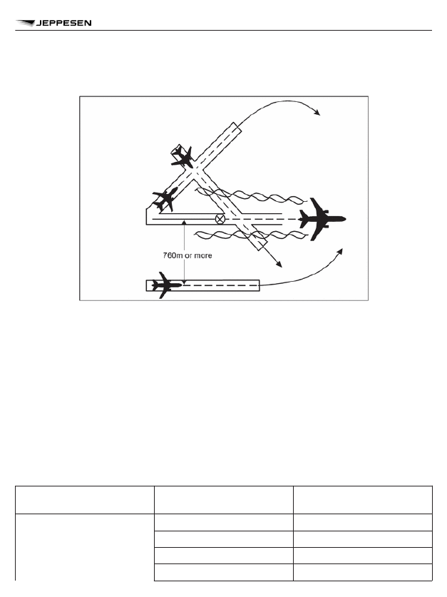
Figure 5-43 — Wake Turbulence Separation for Crossing Aircraft (see 5.8.3.1 c. and d. and

5.8.3.2 c. and d.)

5.8.3.3  When using wake turbulence categories contained in Chapter 4, 4.9.1.1 for aircraft
taking off from an intermediate part of the same runway or an intermediate part of a parallel
runway separated by less than 760m (2500 ft) (see Figure 5-44), the following minimum separa-
tions shall be applied:

a. HEAVY aircraft taking off behind a SUPER aircraft — 3 minutes;
b. LIGHT or MEDIUM aircraft taking off behind a SUPER aircraft — 4 minutes;

c. LIGHT or MEDIUM aircraft taking off behind a HEAVY aircraft — 3 minutes;

d. LIGHT aircraft taking off behind a MEDIUM aircraft — 3 minutes.

5.8.3.4  When applying the wake turbulence groups in Chapter 4, 4.9.1.2 for aircraft taking off
from an intermediate part of the same runway or an intermediate part of a parallel runway separa-
ted by less than 760m (2500 ft) (see Figure 5-44), the following minimum separations shall be
applied:

Preceding aircraft wake tur-

bulence group

Succeeding aircraft wake

turbulence group

Time-based wake turbulence

separation minima

A

B

160 seconds

C

180 seconds

D

200 seconds

E

220 seconds

INTERNATIONAL CIVIL AVIATION ORGANIZATION -

AIR TRAFFIC MANAGEMENT

1185

AIR TRAFFIC MANAGEMENT (DOC 4444)

Preceding aircraft wake tur-

bulence group

Succeeding aircraft wake

turbulence group

Time-based wake turbulence

separation minima

F

220 seconds

G

240 seconds

B

D

160 seconds

E

180 seconds

F

180 seconds

G

200 seconds

C

D

140 seconds

E

160 seconds

F

160 seconds

G

180 seconds

D

G

180 seconds

E

G

160 seconds

Figure 5-44 — Wake Turbulence Separation for Following Aircraft (see 5.8.3.3 and 5.8.3.4)

Displaced Landing Threshold

5.8.4.1  When using wake turbulence categories contained in Chapter 4, 4.9.1.1 and when oper-
ating a displaced landing threshold, the following minimum separations shall be applied if the pro-
jected flight paths are expected to cross:

a. a departing HEAVY aircraft following a SUPER aircraft arrival — 2 minutes;

5.8.4

INTERNATIONAL CIVIL AVIATION ORGANIZATION -

AIR TRAFFIC MANAGEMENT

1186

AIR TRAFFIC MANAGEMENT (DOC 4444)

b. a departing LIGHT or MEDIUM aircraft following a SUPER aircraft arrival — 3 minutes;

c. a departing LIGHT or MEDIUM aircraft following a HEAVY aircraft arrival — 2 minutes;

d. a departing LIGHT aircraft following a MEDIUM aircraft arrival — 2 minutes;
e. a HEAVY aircraft arrival following a SUPER aircraft departure — 2 minutes;

f. a LIGHT or MEDIUM aircraft arrival following a SUPER aircraft departure — 3 minutes;

g. a LIGHT or MEDIUM aircraft arrival following a HEAVY aircraft departure — 2 minutes;
h. a LIGHT aircraft arrival following a MEDIUM aircraft departure — 2 minutes.

5.8.4.2  When using wake turbulence groups contained in Chapter 4, 4.9.1.2 and when operating
a displaced landing threshold, the following minimum separations shall be applied when a depart-
ing aircraft follows an arriving aircraft. if the projected flight paths are expected to cross:

Preceding arriving aircraft

group

Succeeding departing air-

craft group

Time-based wake turbulence

separation minima

A

B

100 seconds

C

120 seconds

D

140 seconds

E

160 seconds

F

160 seconds

G

180 seconds

B

D

100 seconds

E

120 seconds

F

120 seconds

G

140 seconds

C

D

80 seconds

E

100 seconds

F

100 seconds

G

120 seconds

D

G

120 seconds

E

G

100 seconds

5.8.4.3  When using wake turbulence groups contained in Chapter 4, 4.9.1.2 and when operating
a displaced landing threshold. the following minimum separations shall be applied when an arriv-
ing aircraft follows a departing aircraft, if their projected flight paths are expected to cross:

INTERNATIONAL CIVIL AVIATION ORGANIZATION -

AIR TRAFFIC MANAGEMENT

1187

AIR TRAFFIC MANAGEMENT (DOC 4444)

Preceding departing aircraft

group

Succeeding arriving aircraft

group

Time-based wake turbulence

separation minima

A

B

100 seconds

C

120 seconds

D

140 seconds

E

160 seconds

F

160 seconds

G

180 seconds

B

D

100 seconds

E

120 seconds

F

120 seconds

G

140 seconds

C

D

80 seconds

E

100 seconds

F

100 seconds

G

120 seconds

D

G

120 seconds

E

G

100 seconds

Opposite Direction

5.8.5.1  When using wake turbulence categories contained in Chapter 4, 4.9.1.1 for a heavier air-
craft making a low or missed approach and when the lighter aircraft is:

a. using an opposite-direction runway for take-off (see Figure 5-45); or
b. landing on the same runway in the opposite direction, or on a parallel opposite-direction

runway separated by less than 760m (2500 ft) (see Figure 5-46);
the following minimum separations shall be used:

1. between a HEAVY aircraft and a SUPER aircraft — 3 minutes;
2. between a LIGHT or MEDIUM aircraft and a SUPER aircraft — 4 minutes;
3. between a LIGHT or MEDIUM aircraft and a HEAVY aircraft — 3 minutes;
4. between a LIGHT aircraft and a MEDIUM aircraft — 3 minutes.

5.8.5.2  When applying the wake turbulence groups in Chapter 4, 4.9.1.2 and a heavier aircraft is
making a low or missed approach and the lighter aircraft is:

a. utilizing an opposite-direction runway for take-off (see Figure 5-45); or

5.8.5

INTERNATIONAL CIVIL AVIATION ORGANIZATION -

AIR TRAFFIC MANAGEMENT

1188

AIR TRAFFIC MANAGEMENT (DOC 4444)

b. landing on the same runway in the opposite direction, or on a parallel opposite-direction

runway separated by less than 760m (2500 ft) (see Figure 5-46),
the following minimum separations shall be used:

Preceding aircraft group

Succeeding aircraft group

Time-based wake turbulence

separation minima

A

B

160 seconds

C

180 seconds

D

200 seconds

E

220 seconds

F

220 seconds

G

240 seconds

B

D

160 seconds

E

180 seconds

F

180 seconds

G

200 seconds

C

D

140 seconds

E

160 seconds

F

160 seconds

G

180 seconds

D

G

180 seconds

E

G

160 seconds

INTERNATIONAL CIVIL AVIATION ORGANIZATION -

AIR TRAFFIC MANAGEMENT

1189

AIR TRAFFIC MANAGEMENT (DOC 4444)

Figure 5-45 — Wake Turbulence Separation for Opposite-Direction Take-off (see 5.8.5.1 a.

and 5.8.5.2 a.)

INTERNATIONAL CIVIL AVIATION ORGANIZATION -

AIR TRAFFIC MANAGEMENT

1190

AIR TRAFFIC MANAGEMENT (DOC 4444)

Figure 5-46 — Wake Turbulence Separation for Opposite-Direction Landing (see 5.8.5.1 b.

and 5.8.5.2 b.)

CLEARANCES TO FLY MAINTAINING OWN SEPARATION WHILE IN

VISUAL METEOROLOGICAL CONDITIONS

NOTE 1: As indicated in this Section, the provision of vertical or horizontal separation by an air
traffic control unit is not applicable in respect of any specified portion of a flight cleared subject to
maintaining own separation and remaining in visual meteorological conditions. It is for the flight so
cleared to ensure, for the duration of the clearance, that it is not operated in such proximity to
other flights as to create a collision hazard.
NOTE 2: It is axiomatic that a VFR flight must remain in visual meteorological conditions at all
times. Accordingly, the issuance of a clearance to a VFR flight to fly subject to maintaining own
separation and remaining in visual meteorological conditions has no other object than to signify
that, for the duration of the clearance, the provision of separation by air traffic control is not
entailed.
When so requested by an aircraft and provided it is agreed by the pilot of the other aircraft and so
authorized by the appropriate ATS authority, an ATC unit may clear a controlled flight, including
departing and arriving flights, operating in airspace Classes D and E in visual meteorological con-
ditions during the hours of daylight to fly subject to maintaining own separation to one other air-

5.9

INTERNATIONAL CIVIL AVIATION ORGANIZATION -

AIR TRAFFIC MANAGEMENT

1191

AIR TRAFFIC MANAGEMENT (DOC 4444)

craft and remaining in visual meteorological conditions. When a controlled flight is so cleared, the
following shall apply:

a. the clearance shall be for a specified portion of the flight at or below 3050m (10,000 ft),

during climb or descent and subject to further restrictions as and when prescribed on the
basis of regional air navigation agreements;

b. if there is a possibility that flight under visual meteorological conditions may become imprac-

ticable, an IFR flight shall be provided with alternative instructions to be complied with in the
event that flight in visual meteorological conditions (VMC) cannot be maintained for the term
of the clearance;

c. the pilot of an IFR flight, on observing that conditions are deteriorating and considering that

operation in VMC will become impossible, shall inform ATC before entering instrument mete-
orological conditions (IMC) and shall proceed in accordance with the alternative instructions
given.
NOTE: See also 5.10.1.2.

ESSENTIAL TRAFFIC INFORMATION

General

5.10.1.1  Essential traffic is that controlled traffic to which the provision of separation by ATC is
applicable, but which, in relation to a particular controlled flight is not, or will not be, separated
from other controlled traffic by the appropriate separation minimum.
5.10.1.2  Essential traffic information shall be given to controlled flights concerned whenever
they constitute essential traffic to each other.
NOTE: This information will inevitably relate to controlled flights cleared subject to maintaining
own separation and remaining in visual meteorological conditions and also whenever the intended
separation minimum has been infringed.

Information to Be Provided

Essential traffic information shall include:

a. direction of flight of aircraft concerned;
b. type and wake turbulence category (if relevant) of aircraft concerned;

c. cruising level of aircraft concerned; and

1. estimated time over the reporting point nearest to where the level will be crossed; or
2. relative bearing of the aircraft concerned in terms of the 12-hour clock as well as dis-

tance from the conflicting traffic; or

3. actual or estimated position of the aircraft concerned.

5.10

5.10.1

5.10.2

INTERNATIONAL CIVIL AVIATION ORGANIZATION -

AIR TRAFFIC MANAGEMENT

1192

AIR TRAFFIC MANAGEMENT (DOC 4444)

SEPARATION IN THE VICINITY OF AERODROMES

PROCEDURES FOR DEPARTING AIRCRAFT

Standard Clearances for Departing Aircraft

General

The appropriate ATS authority should, wherever possible, establish standardized procedures for
transfer of control between the ATC units concerned, and standard clearances for departing air-
craft.

Contents

Standard clearances for departing aircraft shall contain the following items:

a. aircraft identification;
b. clearance limit, normally destination aerodrome;

c. designator of the assigned SID, if applicable;

d. cleared level;
e. allocated SSR code;

f. any other necessary instructions or information not contained in the SID description, e.g.

instructions relating to change of frequency.

NOTE 1: See 6.3.2.4.1 for clearances to aircraft on SID.
NOTE 2: The use of a SID designator without a cleared level does not authorize the aircraft to
climb on the SID vertical profile.

Clearance on a SID

6.3.2.4.1  Clearances to aircraft on a SID with remaining published level and/or speed restric-
tions shall indicate if such restrictions are to be followed or are cancelled. The following phraseol-
ogies shall be used with the following meanings:

a. CLIMB VIA SID TO (level):

1. climb to the cleared level and comply with published level restrictions;
2. follow the lateral profile of the SID; and
3. comply with published speed restrictions or ATC-issued speed control instructions as

applicable.

b. CLIMB VIA SID TO (level), CANCEL LEVEL RESTRICTION(S):

1. climb to the cleared level; published level restrictions are cancelled;
2. follow the lateral profile of the SID; and
3. comply with published speed restrictions or ATC-issued speed control instructions as

applicable.

6

6.3

6.3.2

6.3.2.1

6.3.2.3

6.3.2.4

INTERNATIONAL CIVIL AVIATION ORGANIZATION -

AIR TRAFFIC MANAGEMENT

1193

AIR TRAFFIC MANAGEMENT (DOC 4444)

c. CLIMB VIA SID TO (level), CANCEL LEVEL RESTRICTION(S) AT (point(s)):

1. climb to the cleared level; published level restriction(s) at the specified point(s) are can-

celled;

2. follow the lateral profile of the SID; and
3. comply with published speed restrictions or ATC-issued speed control instructions as

applicable.

d. CLIMB VIA SID TO (level), CANCEL SPEED RESTRICTION(S):

1. climb to the cleared level and comply with published level restrictions;
2. follow the lateral profile of the SID; and
3. published speed restrictions and ATC-issued speed control instructions are cancelled.

e. CLIMB VIA SID TO (level), CANCEL SPEED RESTRICTION(S) AT (point(s)):

1. climb to the cleared level and comply with published level restrictions;
2. follow the lateral profile of the SID; and
3. published speed restrictions are cancelled at the specified point(s).

f. CLIMB UNRESTRICTED TO (level) or CLIMB TO (level), CANCEL LEVEL AND SPEED

RESTRICTION(S):

1. climb to the cleared level; published level restrictions are cancelled;
2. follow the lateral profile of the SID; and
3. published speed restrictions and ATC-issued speed control instructions are cancelled.

6.3.2.4.2  If there are no remaining published level or speed restrictions on the SID, the phrase
CLIMB TO (level) should be used.
6.3.2.4.3  When subsequent speed restriction instructions are issued, and if the cleared level is
unchanged, the phrase CLIMB VIA SID TO (level) should be omitted.
6.3.2.4.4  When a departing aircraft is cleared to proceed direct to a published waypoint on the
SID, the speed and level restrictions associated with the bypassed waypoints are cancelled. All
remaining published speed and level restrictions shall remain applicable.
6.3.2.4.5  When a departing aircraft is vectored or cleared to proceed to a point that is not on the
SID, all the published speed and level restrictions of the SID are cancelled and the controller
shall:

a. reiterate the cleared level;
b. provide speed and level restrictions as necessary; and

c. notify the pilot if it is expected that the aircraft will be instructed to subsequently rejoin the

SID.

NOTE: See also 8.6.5.2 regarding prescribed obstacle clearance.

INTERNATIONAL CIVIL AVIATION ORGANIZATION -

AIR TRAFFIC MANAGEMENT

1194

AIR TRAFFIC MANAGEMENT (DOC 4444)

6.3.2.4.6  ATC instructions to an aircraft to rejoin a SID shall include:

a. the designator of the SID to be rejoin, unless advance notification of rejoin has been provi-

ded in accordance with 6.3.2.4.5;

b. the cleared level in accordance with 6.3.2.4.1; and

c. the position at which it is expected to rejoin the SID.

NOTE: See 12.3.3.1 for phraseology on rejoin instructions.

Communication Failure

6.3.2.5.1  Clearances for departing aircraft may specify a cleared level other than that indicated
in the filed flight plan for the en-route phase of flight, without a time or geographical limit for the
cleared level. Such clearances will normally be used to facilitate the application of tactical control
methods by ATC, normally through the use of an ATS surveillance system.
6.3.2.5.2  Where clearances for departing aircraft contain no time or geographical limit for a
cleared level, action to be taken by an aircraft experiencing air-ground communication failure in
the event the aircraft has been radar vectored away from the route specified in its current flight
plan should be prescribed on the basis of a regional air navigation agreement and included in the
SID description or published in AIPs.

Departure Sequence

6.3.3.1  Departing aircraft may be expedited by suggesting a take-off direction which is not into
the wind. It is the responsibility of the pilot-in-command of an aircraft to decide between making
such a take-off or waiting for normal take-off in a preferred direction.

PROCEDURES FOR ARRIVING AIRCRAFT

Standard Clearances for Arriving Aircraft

Contents

Standard clearances for arriving aircraft shall contain the following items:

a. aircraft identification;
b. designator of the assigned STAR if applicable;

c. runway-in-use, except when part of the STAR description;

d. cleared level; and
e. any other necessary instructions or information not contained in the STAR description, e.g.

change of communications.

NOTE 1: See 6.5.2.4.1 for clearances on a STAR.
NOTE 2: The use of a STAR designator without a cleared level does not authorize the aircraft to
descend on the STAR vertical profile.

6.3.2.5

6.3.3

6.5

6.5.2

6.5.2.3

INTERNATIONAL CIVIL AVIATION ORGANIZATION -

AIR TRAFFIC MANAGEMENT

1195

AIR TRAFFIC MANAGEMENT (DOC 4444)

Clearance on a STAR

6.5.2.4.1  Clearances to aircraft on a STAR with remaining published level and/or speed restric-
tions shall indicate if such restrictions are to be followed or are cancelled. The following phraseol-
ogies shall be used with the following meaning:

a. DESCEND VIA STAR TO (level):

1. descend to the cleared level and comply with published level restrictions;
2. follow the lateral profile of the STAR; and
3. comply with published speed restrictions or ATC-issued speed control instructions as

applicable.

b. DESCEND VIA STAR TO (level), CANCEL LEVEL RESTRICTION(S):

1. descend to the cleared level; published level restrictions are cancelled;
2. follow the lateral profile of the STAR; and
3. comply with published speed restrictions or ATC-issued speed control instructions as

applicable.

c. DESCEND VIA STAR TO (level), CANCEL LEVEL RESTRICTION(S) AT (point(s)):

1. descend to the cleared level; published level restriction(s) at the specified point(s) are

cancelled;

2. follow the lateral profile of the STAR; and
3. comply with published speed restrictions or ATC-issued speed control instructions as

applicable.

d. DESCEND VIA STAR TO (level), CANCEL SPEED RESTRICTION(S):

1. descend to the cleared level and comply with published level restrictions;
2. follow the lateral profile of the STAR; and
3. published speed restrictions and ATC-issued speed control instructions are cancelled.

e. DESCEND VIA STAR TO (level), CANCEL SPEED RESTRICTION(S) AT (point(s)):

1. descend to the cleared level and comply with published level restrictions;
2. follow the lateral profile of the STAR; and
3. published speed restrictions are cancelled at the specified point(s).

f. DESCEND UNRESTRICTED TO (level) or DESCEND TO (level), CANCEL LEVEL AND

SPEED RESTRICTION(S):

1. descend to the cleared level; published level restrictions are cancelled;
2. follow the lateral profile of the STAR; and
3. published speed restrictions and ATC-issued speed control instructions are cancelled.

6.5.2.4

INTERNATIONAL CIVIL AVIATION ORGANIZATION -

AIR TRAFFIC MANAGEMENT

1196

AIR TRAFFIC MANAGEMENT (DOC 4444)

6.5.2.4.2  If there are no remaining published level or speed restrictions on the STAR, the phrase
DESCEND TO (level) should be used.
6.5.2.4.3  When subsequent speed restriction instructions are issued and if the cleared level is
unchanged, the phrase DESCEND VIA STAR TO (level) should be omitted.
6.5.2.4.4  When an arriving aircraft is cleared to proceed direct to a published waypoint on the
STAR, the speed and level restrictions associated with the bypassed waypoints are cancelled. All
remaining published speed and level restrictions shall remain applicable.
6.5.2.4.5  When an arriving aircraft is vectored or cleared to proceed to a point that is not on the
STAR, all the published speed and level restrictions of the STAR are cancelled and the controller
shall:

a. reiterate the cleared level;
b. provide speed and level restrictions as necessary; and

c. notify the pilot if it is expected that the aircraft will be instructed to subsequently rejoin the

STAR.

NOTE: See 8.6.5.2 regarding prescribed obstacle clearance.
6.5.2.4.6  ATC instructions to an aircraft to rejoin a STAR shall include:

a. the designator of the STAR to be rejoined, unless advance notification of rejoin has been

provided in accordance with 6.5.2.4.5;

b. the cleared level on rejoining the STAR in accordance with 6.5.2.4.1; and

c. the position at which it is expected to rejoin the STAR.

NOTE: See 12. 3. 3. 2 for phraseology on rejoin instructions.

Visual Approach

6.5.3.1  Subject to the conditions in 6.5.3.3, clearance for an IFR flight to execute a visual
approach may be requested by a flight crew or initiated by the controller. In the latter case, the
concurrence of the flight crew shall be required.
6.5.3.3  An IFR flight may be cleared to execute a visual approach provided that the pilot can
maintain visual reference to the terrain and;

a. the reported ceiling is at or above the level of the beginning of the initial approach segment

for the aircraft so cleared; or

b. the pilot reports at the level of the beginning of the initial approach segment or at any time

during the instrument approach procedure that the meteorological conditions are such that
with reasonable assurance a visual approach and landing can be completed.

6.5.3.4  Separation shall be provided between an aircraft cleared to execute a visual approach
and other arriving and departing aircraft.
6.5.3.5  For successive visual approaches, separation shall be maintained by the controller until
the pilot of a succeeding aircraft reports having the preceding aircraft in sight. The aircraft shall

6.5.3

INTERNATIONAL CIVIL AVIATION ORGANIZATION -

AIR TRAFFIC MANAGEMENT

1197

AIR TRAFFIC MANAGEMENT (DOC 4444)

then be instructed to follow and maintain own separation from the preceding aircraft. When both
aircraft are of a heavy wake turbulence category, or the preceding aircraft is of a heavier wake
turbulence category than the following, and the distance between the aircraft is less than the
appropriate wake turbulence minimum, the controller shall issue a caution of possible wake turbu-
lence. The pilot-in-command of the aircraft concerned shall be responsible for ensuring that the
spacing from a preceding aircraft of a heavier wake turbulence category is acceptable. If it is
determined that additional spacing is required, the flight crew shall inform the ATC unit accord-
ingly, stating their requirements.

Instrument Approach

6.5.4.1  The approach control unit shall specify the instrument approach procedure to be used by
arriving aircraft. A flight crew may request an alternative procedure and, if circumstances permit,
should be cleared accordingly.
6.5.4.3  If visual reference to terrain is established before completion of the approach procedure,
the entire procedure must nevertheless be executed unless the aircraft requests and is cleared for
a visual approach.

Holding

6.5.5.5  Holding and holding pattern entry shall be accomplished in accordance with procedures
established by the appropriate ATS authority and published in AIPs. If entry and holding proce-
dures have not been published, or if the procedures are not known to a flight crew, the appropri-
ate air traffic control unit shall specify the designator of the location or aid to be used, the inbound
track, radial or bearing, direction of turn in the holding pattern as well as the time of the outbound
leg or the distances between which to hold.
6.5.5.9  If an aircraft is unable to comply with the published or cleared holding procedure, alter-
native instructions shall be issued.

Approach Sequence

General

The following procedures shall be applied whenever approaches are in progress:
6.5.6.1.1  The approach sequence shall be established in a manner which will facilitate arrival of
the maximum number of aircraft with the least average delay. Priority shall be given to:

a. an aircraft which anticipates being compelled to land because of factors affecting the safe

operation of the aircraft (engine failure, shortage of fuel, etc.);

b. hospital aircraft or aircraft carrying any sick or seriously injured person requiring urgent medi-

cal attention.

c. aircraft engaged in search and rescue operations; and

d. other aircraft as may be determined by the appropriate authority.

6.5.6.1.2  Succeeding aircraft shall be cleared for approach:

6.5.4

6.5.5

6.5.6

6.5.6.1

INTERNATIONAL CIVIL AVIATION ORGANIZATION -

AIR TRAFFIC MANAGEMENT

1198

AIR TRAFFIC MANAGEMENT (DOC 4444)

a. when the preceding aircraft has reported that it is able to complete its approach without

encountering instrument meteorological conditions; or

b. when the preceding aircraft is in communication with and sighted by the aerodrome control

tower and reasonable assurance exists that a normal landing can be accomplished; or

c. when timed approaches are used, the preceding aircraft has passed the defined point

inbound and reasonable assurance exists that a normal landing can be accomplished;
NOTE: See 6.5.6.2.1 concerning timed approach procedures.

d. when the use of an ATS surveillance system confirms that the required longitudinal spacing

between succeeding aircraft has been established.

6.5.6.1.4  If the pilot of an aircraft in an approach sequence has indicated an intention to hold for
weather improvement, or for other reasons, such action shall be approved. However, when other
holding aircraft indicate intention to continue their approach-to-land, the pilot desiring to hold will
be cleared to an adjacent fix for holding awaiting weather change or re-routing. Alternatively, the
aircraft should be given a clearance to place it at the top of the approach sequence so that other
holding aircraft may be permitted to land. Coordination shall be effected with any adjacent ATC
unit or control sector, when required, to avoid conflict with the traffic under the jurisdiction of that
unit or sector.

Sequencing and Spacing of Instrument Approaches

TIMED APPROACH PROCEDURES

6.5.6.2.1.1  Subject to approval by the appropriate ATS authority, the following procedure should
be utilized as necessary to expedite the approaches of a number of arriving aircraft:

a. a suitable point on the approach path, which shall be capable of being accurately determined

by the pilot, shall be specified, to serve as a check point in timing successive approaches;

b. aircraft shall be given a time at which to pass the specified point inbound, which time shall be

determined with the aim of achieving the desired interval between successive landings on
the runway while respecting the applicable separation minima at all times, including the
period of runway occupancy.

6.5.6.2.1.2  The time at which aircraft should pass the specified point shall be determined by the
unit providing approach control service and notified to the aircraft sufficiently in advance to permit
the pilot to arrange the flight path accordingly.
6.5.6.2.1.3  Each aircraft in the approach sequence shall be cleared to pass the specified point
inbound at the previously notified time, or any revision thereof, after the preceding aircraft has
reported passing the point inbound.

INFORMATION FOR ARRIVING AIRCRAFT

6.6.1  As early as practicable after an aircraft has established communication with the unit pro-
viding approach control service, the following elements of information, in the order listed, shall be
transmitted to the aircraft, with the exception of such elements which it is known the aircraft has
already received:

6.5.6.2

6.5.6.2.1

6.6

INTERNATIONAL CIVIL AVIATION ORGANIZATION -

AIR TRAFFIC MANAGEMENT

1199

AIR TRAFFIC MANAGEMENT (DOC 4444)

a. type of approach and runway-in-use
b. meteorological information, as follows:

1. surface wind direction and speed, including significant variations;
2. visibility and, when applicable, runway visual range (RVR);
3. present weather;
4. cloud below 1500m (5000 ft) or below the highest minimum sector altitude, whichever is

greater; cumulonimbus; if the sky is obscured, vertical visibility when available;

5. air temperature;
6. dew point temperature, inclusion determined on the basis of a regional air navigation

agreement;

7. altimeter setting(s);
8. any available information on significant meteorological phenomena in the approach

area; and

9. trend-type landing forecast, when available.

c. current runway surface conditions, in case of precipitants or other temporary hazards;

d. changes in the operational status of visual and non visual aids essential for approach and

landing.

6.6.4  At the commencement of final approach, the following information shall be transmitted to
aircraft:

a. significant changes in the mean surface wind direction and speed;

NOTE: Significant changes are specified in Annex 3, Chapter 4. However, if the controller
possesses wind information in the form of components, the significant changes are:

– Mean head-wind component: 19km/h (10 kt)
– Mean tail-wind component: 4km/h (2 kt)
– Mean cross-wind component: 9km/h (5 kt)

b. the latest information, if any, on wind shear and/or turbulence in the final approach area;

c. the current visibility representative of the direction of approach and landing or, when provi-

ded, the current runway visual range value(s) and the trend.

6.6.5  During final approach, the following information shall be transmitted without delay:

a. the sudden occurrence of hazards (e.g. unauthorized traffic on the runway);
b. significant variations in the current surface wind, expressed in terms of minimum and maxi-

mum values;

c. significant changes in runway surface conditions;

d. changes in the operational status of required visual or non-visual aids;

INTERNATIONAL CIVIL AVIATION ORGANIZATION -

AIR TRAFFIC MANAGEMENT

1200

AIR TRAFFIC MANAGEMENT (DOC 4444)

e. changes in observed RVR value(s), in accordance with the reported scale in use, or changes

in the visibility representative of the direction of approach and landing.

OPERATIONS ON PARALLEL OR NEAR-PARALLEL RUNWAYS

Departing Aircraft

Types of Operation

Parallel runways may be used for independent instrument departures as follows:

a. both runways are used exclusively for departures (independent departures);
b. one runway is used exclusively for departures while the other runway is used for a mixture of

arrivals and departures (semi-mixed operation); and

c. both runways are used for mixed arrivals and departures (mixed operation).

Requirements and Procedures for Independent Parallel Departures

Independent IFR departures may be conducted from parallel runways provided:

a. the runway centre lines are spaced by a minimum distance of 760m (2500 ft) (see Annex 14,

Volume I);

b. the nominal departure tracks diverge by at least:

1. 15 degrees immediately after take-off; or
2. 10 degrees, where:

i) both aircraft are flying an RNAV or RNP instrument departure; and

ii) the turn commences no more than 3.7km (2.0 NM) from the departure end of the

runway;

c. a suitable ATS surveillance system capable of identification of the aircraft within 1.9km (1.0

NM) from the end of the runway is available; and

d. ATS operational procedures ensure that the required track divergence is achieved.

NOTE: For further details refer to Circular 350, Guidelines for the Implementation of Reduced
Divergence Departures (not published herein).

Arriving Aircraft

Types of Operations

6.7.3.1.1  Parallel runways may be used for simultaneous instrument operations for:

a. independent parallel approaches; or
b. dependent parallel approaches; or

c. segregated parallel operations.

6.7

6.7.2

6.7.2.1

6.7.2.2

6.7.3

6.7.3.1

INTERNATIONAL CIVIL AVIATION ORGANIZATION -

AIR TRAFFIC MANAGEMENT

1201

AIR TRAFFIC MANAGEMENT (DOC 4444)

Requirements and Procedures for Independent Parallel Approaches

6.7.3.2.1  Independent parallel approaches may be conducted to parallel runways provided that:

a. the runway centre lines are spaced by the distance specified in Table 6-1 (see Annex 14,

Volume I) and the surveillance criteria contained in Table 6-1 are met;

Table 6-1. ATS Surveillance System Criteria for Different Runway Spacings

Runway Centre Line Spacing

ATS Surveillance System Criteria

Less than 1310m (4300 ft) but not
less than 1035m (3400 ft)

a) a minimum accuracy for an ATS surveillance system

as follows:

1) for SSR, an azimuth accuracy of 0.06 degrees

(one sigma); or

2) for MLAT or ADS-B, an accuracy of 30m (100

ft);

b) an update period of 2.5 seconds or less; and

c) a high resolution display providing position predic-

tion and deviation alert is available.

Less than 1525m (5000 ft) but not
less than 1310m (4300 ft)

a) an ATS surveillance system with performance speci-

fications other than those above, but equal to or bet-
ter than:

1) for SSR, a minimum azimuth accuracy of 0.3

degrees (one sigma); or

2) for MLAT or ADS-B, a performance capability

equivalent to or better than the SSR require-
ment can be demonstrated;

b) an update period of 5 seconds or less; and

c) when it is determined that the safety of aircraft oper-

ations would not be adversely affected.

1525m (5000 ft) or more

a) a minimum SSR azimuth accuracy of 0.3 degrees

(one sigma), or for MLAT or ADS-B, a performance
capability equivalent to or better than the SSR re-
quirement can be demonstrated; and

b) an update period of 5 seconds or less.

NOTE 1: Information pertaining to use of ADS-B and MLAT and their system performance is
contained in the Assessment of ADS-B and Multilateration Surveillance to Support Air Traf-
fic Services and Guidelines for Implementation (Circ 326).

6.7.3.2

INTERNATIONAL CIVIL AVIATION ORGANIZATION -

AIR TRAFFIC MANAGEMENT

1202

AIR TRAFFIC MANAGEMENT (DOC 4444)

NOTE 2: Refer to Chapter 2, Section 2.6.2 f) on ADS-B implementation that envisages reli-
ance upon a common source for surveillance and/or navigation.

b. the instrument approach procedures that align the aircraft with the extended runway centre

line are any combination of the following:

1. a precision approach procedure; or
2. except as provided in 6.7.3.2.1 b. 3., an approach with vertical guidance (APV)

designed using the RNP AR APCH specification where:

i) the RNP value for B, and the RNP value for C if that segment of the approach is

within the horizontal separation minimum of a parallel approach, do not exceed
one-quarter of the distance between runway centre lines (A), (Figure 6-1 refers);
and

ii) the RNP value for B, and the RNP value for C if that part of the approach is within

the horizontal separation minimum of a parallel approach, do not exceed (A-D)/2,
(Figure 6-1 refers); or

3. an APV procedure designed using either the RNP APCH or RNP AR APCH navigation

specification, provided that:

i) an appropriate, documented safety risk assessment has shown that an accepta-

ble level of safety can be met;

ii) operations are approved by the appropriate ATS authority (Note 1 refers); and

iii) the instrument approach is demonstrated to protect the NTZ from infringement

during normal operations.

INTERNATIONAL CIVIL AVIATION ORGANIZATION -

AIR TRAFFIC MANAGEMENT

1203

AIR TRAFFIC MANAGEMENT (DOC 4444)

Figure 6-1. Distance between Centre Lines, NTZ and NOZ

NOTE 1: The demonstration of the safety of an APV procedure designed using either
RNP APCH or RNP AR APCH navigation specification during simultaneous
approaches may consider: the collision risk from normal and residual (not mitigated)
atypical errors; likelihood of ACAS nuisance alerting during normal operations; wake
hazard; monitoring and available levels of system automation; database management;
flight management system input and related crew workload; impacts of meteorological
conditions and other environmental factors; training and published ATC break-out pro-
cedures.
NOTE 2: For examples of the approach types and scenarios applicable to 6.7.3.2.1 b.
see Manual on Simultaneous Operations on Parallel or Near-Parallel Instrument Run-
ways (SOIR) (Doc 9643), Table 2-2 and Appendix C.

INTERNATIONAL CIVIL AVIATION ORGANIZATION -

AIR TRAFFIC MANAGEMENT

1204

AIR TRAFFIC MANAGEMENT (DOC 4444)

c. the nominal tracks of the missed approach procedures diverge by at least 30 degrees;

d. an obstacle survey and evaluation is completed, as appropriate, for the areas adjacent to

the final approach segments;

e. aircraft are advised as early as possible, of the assigned runway, instrument approach pro-

cedure and any additional information considered necessary to confirm correct selection;

f. the final approach course or track, is intercepted by use of:

1. vectoring; or
2. a published arrival and approach procedure that intercepts with the IAF or IF;

g. a no-transgression zone (NTZ) at least 610m (2000 ft) wide is established equidistant

between extended runway centre lines and is depicted on the ATS surveillance system sit-
uation display;

h. the approaches are monitored by:

1. a separate monitoring controller for each runway; or
2. a single monitoring controller for no more than two runways, if determined by a safety

risk assessment and approved by the appropriate ATS authority (6.7.3.2.2 refers);

i. monitoring ensures that when the 300m (1000 ft) vertical separation is reduced:

1. aircraft do not penetrate the depicted NTZ; and
2. the applicable minimum longitudinal separation between aircraft on the same final

approach course or track is maintained; and

j. if no dedicated radio channels are available for the controllers to control the aircraft until

landing:

1. transfer of communication of aircraft to the respective aerodrome controller’s channel is

effected before either of the two aircraft on adjacent final approach tracks intercepts
the glide path or vertical path for the selected instrument approach procedure; and

2. the controller(s) monitoring the approaches to each runway are provided with the capa-

bility to override transmissions of aerodrome control on the respective radio channels
for each arrival flow.

6.7.3.2.2  States conducting safety risk assessments to enable the monitoring of not more than
two runways by a single controller (6.7.3.2.1 h. refers) should review factors such as, but not limi-
ted to: complexity, times of operation, traffic mix and density, arrival rate, available levels of
system automation, availability of backup systems, impacts of meteorological conditions and other
environmental factors.
6.7.3.2.9  When an aircraft is observed to overshoot the turn-on or to continue on a track which
will penetrate the NTZ, the aircraft shall be instructed to return immediately to the correct track.
6.7.3.2.10  When an aircraft is observed penetrating the NTZ, the aircraft on the adjacent ILS
localizer course or MLS final approach course or track shall be instructed to immediately climb
and turn to the assigned altitude/height and heading (break-out procedures) in order to avoid the

INTERNATIONAL CIVIL AVIATION ORGANIZATION -

AIR TRAFFIC MANAGEMENT

1205

AIR TRAFFIC MANAGEMENT (DOC 4444)

deviating aircraft. Where parallel approach obstacle assessment surfaces (PAOAS) criteria are
applied for the obstacle assessment, the monitoring controller shall not issue the heading instruc-
tion to the aircraft below 120m (400 ft) above the runway threshold elevation, and the heading
instruction shall not exceed 45 degrees track difference with the final approach course or track.
6.7.3.2.11  Flight path monitoring using ATS surveillance system shall not be terminated until:

a. visual separation is applied, provided procedures ensure that both controllers are advised

whenever visual separation is applied;

b. the aircraft has landed, or in the case of a missed approach, is at least 1.9km (1.0 NM)

beyond the departure end of the runway and adequate separation with any other traffic is
established.
NOTE: There is no requirement to advise the aircraft that flight path monitoring using radar is
terminated.

Requirements and Procedures for Dependent Parallel Approaches

6.7.3.4.1  Dependent parallel approaches may be conducted to parallel runways provided;

a. the runway centre lines are spaced by 915m (3000 ft) or more (see Annex 14, Volume I);
b. the final approach course or track is intercepted by use of:

1. vectoring; or
2. a published arrival and approach procedure that intercepts with the IAF or IF;

c. an ATS surveillance system with a minimum SSR azimuth accuracy of 0.3 degrees (one

sigma), or for MLAT or ADS-B, a performance capability equivalent to or better than the SSR
requirement can be demonstrated and an update period of 5 seconds or less is available;

d. the instrument flight procedures that align the aircraft with the extended runway centre line

are any combination of the following:

1. a precision approach procedure;
2. an APV procedure designed using the RNP AR APCH navigation specification, provi-

ded that the RNP value for B, and the RNP value for C if that segment of the approach
is within the horizontal separation minimum of a parallel approach, does not exceed one
quarter of the distance between runway centre lines (A) (Figure 6-2 refers); and

6.7.3.4

INTERNATIONAL CIVIL AVIATION ORGANIZATION -

AIR TRAFFIC MANAGEMENT

1206

AIR TRAFFIC MANAGEMENT (DOC 4444)

Figure 6-2. RNP value and distance between centre lines

3. an APV procedure designed using the RNP AR APCH navigation specification that

does not meet the provisions in d) 2) or an RNP APCH, provided that:

i) an appropriate, documented safety risk assessment has shown that an acceptable

level of safety can be met; and

ii) operations are approved by the appropriate ATS authority (Note 1 refers).

NOTE 1: The demonstration of the safety of an APV procedure designed using either RNP
APCH or RNP AR APCH navigation specification during simultaneous approaches may con-
sider: the collision risk from normal and residual (not mitigated) atypical errors; likelihood of
ACAS nuisance alerting during normal operations; wake hazard; monitoring and available
levels of system automation; database management; flight management system input and
related crew workload; impacts of meteorological conditions and other environmental factors;
training; and published ATC break-out procedures.

INTERNATIONAL CIVIL AVIATION ORGANIZATION -

AIR TRAFFIC MANAGEMENT

1207

AIR TRAFFIC MANAGEMENT (DOC 4444)

NOTE 2: For examples of approach types and scenarios that meet the requirements of
6.7.3.4.1 d., see Manual on Simultaneous Operations on Parallel or Near-Parallel Instrument
Runways (SOIR) (Doc 9643) Table 2-3 and Appendix C.

e. aircraft are advised that approaches are in use to both runways (this information may be pro-

vided through the ATIS);

f. the nominal tracks of the missed approach procedures diverge by at least 30 degrees; and

g. approach control has a frequency override capability to aerodrome control.

Determination that an Aircraft is Established on RNP AR APCH

6.7.3.5.1  In addition to the requirements specified under 6.7.3.2, for the purposes of applying
6.7.3.2.5 b., an aircraft conducting an RNP AR APCH procedure is considered to be established
for the entire approach procedure after the IAF/IF provided that:

a. the aircraft confirms that it is established on the RNP AR APCH procedure prior to a desig-

nated point, the location of such point to be determined by the appropriate ATS authority;

b. the designated point shall be positioned on the RNP AR APCH to ensure the applicable hori-

zontal separation minimum (e.g. 5.6km (3 NM)) from the adjacent approach procedure
(Figure 6-6 refers). The designated point may normally be coincident with the IAF; and

c. to facilitate the application of the procedure, the designated point shall be readily apparent to

the approach and monitoring controllers. The designated point may be depicted on the situa-
tion display.

6.7.3.5.2  Appropriate wake turbulence separation shall be applied between aircraft on the same
approach.
6.7.3.5.3  If, after reporting that it is established on the RNP AR APCH procedure, the aircraft is
unable to execute the procedure, the pilot shall notify the controller immediately with a proposed
course of action, and thereafter follow ATC instructions (e.g. break-out procedure).
NOTE: Break-out procedures are described in the Manual on Simultaneous Operations on Paral-
lel or Near-Parallel Instrument Runways (SOIR) (Doc 9643).

6.7.3.5

INTERNATIONAL CIVIL AVIATION ORGANIZATION -

AIR TRAFFIC MANAGEMENT

1208

AIR TRAFFIC MANAGEMENT (DOC 4444)

Figure 6-6. Established on RNP AR APCH Concept (RNP AR APCH/Precision Approach

with 3 NM Separation Minimum Example)

6.7.3.5.4  In circumstances where a break-out procedure becomes necessary during the applica-
tion of the independent parallel approach procedure (for example, an aircraft penetrating the
NTZ), the controller may issue climb and/or heading instructions to an aircraft established on an
RNP AR APCH.
6.7.3.5.5  To support a break-out instruction, an obstacle assessment shall be completed.
NOTE: Guidance on obstacle assessment is provided in the Manual on Simultaneous Operations
on Parallel or Near-Parallel Instrument Runways (SOIR) (Doc 9643).
6.7.3.5.6  Break-out procedures shall be prescribed in the AIP and local instructions.
6.7.3.5.7  The monitoring controller shall protect the NTZ in accordance with 6.7.3.2.1 i.

Requirements and Procedures for Segregated Parallel Operations

6.7.3.6.1  Segregated parallel operations may be conducted on parallel runways provided:

a. the runway centre lines are spaced by a minimum of 760m (2500 ft) (see Annex 14, Vol-

ume I); and

b. the nominal departure track diverges immediately after take-off by at least 30 degrees from

the missed approach track of the adjacent approach.

6.7.3.6

INTERNATIONAL CIVIL AVIATION ORGANIZATION -

AIR TRAFFIC MANAGEMENT

1209

AIR TRAFFIC MANAGEMENT (DOC 4444)

PROCEDURES FOR AERODROME CONTROL SERVICE

INITIAL CALL TO AERODROME CONTROL TOWER

For aircraft being provided with aerodrome control service, the initial call shall contain:

a. designation of the station being called;
b. call sign and, for aircraft in the SUPER or HEAVY wake turbulence category, the word

“super” or “heavy”;

c. position; and

d. additional elements, as required by the appropriate ATS authority.

INFORMATION TO AIRCRAFT BY AERODROME CONTROL TOWERS

Information Related to the Operation of Aircraft

Runway Incursion or Obstructed Runway

7.4.1.4.2  Pilots and air traffic controllers shall report any occurrence involving an obstruction on
the runway or a runway incursion.
NOTE 1: Information regarding runway incursions’ reporting forms together with instructions for
their completion are contained in the Manual on the Prevention of Runway Incursions (Doc 9870).
Attention is drawn to the guidance for analysis, data collection and sharing of data related to
runway incursions (see Chapter 5 of Doc 9870).
NOTE 2: The provisions in 7.4.1.4.2 have the objective of supporting the State’s safety pro-
gramme and safety management system (SMS).

Uncertainty of Position on the Manoeuvring Area

7.4.1.5.1  Except as provided for in 7.4.1.5.2, a pilot in doubt as to the position of the aircraft with
respect to the manoeuvring area shall immediately:

a. stop the aircraft; and
b. simultaneously notify the appropriate ATS unit of the circumstances (including the last known

position).

7.4.1.5.2  In those situations where a pilot is in doubt as to the position of the aircraft with respect
to the manoeuvring area, but recognizes that the aircraft is on a runway, the pilot shall immedi-
ately:

a. notify the appropriate ATS unit of the circumstances (including the last known position);
b. if able to locate a nearby suitable taxiway, vacate the runway as expeditiously as possible,

unless otherwise instructed by the ATS unit; and then,

c. stop the aircraft.

7

7.3

7.4

7.4.1

7.4.1.4

7.4.1.5

INTERNATIONAL CIVIL AVIATION ORGANIZATION -

AIR TRAFFIC MANAGEMENT

1210

AIR TRAFFIC MANAGEMENT (DOC 4444)

CONTROL OF AERODROME TRAFFIC

General

As the view from the flight deck of an aircraft is normally restricted, the controller shall ensure that
instructions and information which require the flight crew to employ visual detection, recognition
and observation are phrased in a clear, concise and complete manner.

Designated Positions of Aircraft in the Aerodrome Traffic and Taxi Circuits

The following positions of aircraft in the traffic and taxi circuits are the positions where the aircraft
normally receive aerodrome control tower clearances. Aircraft should be watched closely as they
approach these positions so that proper clearances may be issued without delay. Where practica-
ble, all clearances should be issued without waiting for the aircraft to initiate the call.

– Position 1. Aircraft initiates call to taxi for departing flight. Runway-in-use information and taxi

clearances given.

– Position 2. If there is conflicting traffic, the departing aircraft will be held at this position. Engine

run-up will, when required, normally be performed here.

– Position 3. Take-off clearance is issued here, if not practicable at position 2.
– Position 4. Clearance to land is issued here as practicable.
– Position 5. Clearance to taxi to apron is issued here.
– Position 6. Parking information issued here, if necessary.

NOTE 1: Arriving aircraft executing an instrument approach procedure will normally enter the traf-
fic circuit on final except when visual manoeuvring to the landing runway is required.
NOTE 2: See Figure 7-1.

Traffic on the Manoeuvring Area

Control of Taxiing Aircraft

USE OF RUNWAY-HOLDING POSITIONS

7.6.3.1.3.1  Except as provided in 7.6.3.1.3.2 or as prescribed by the appropriate ATS authority,
aircraft shall not be held closer to a runway-in-use than at a runway-holding position.
7.6.3.1.3.2  Aircraft shall not be permitted to line up and hold on the approach end of a runway-
in-use whenever another aircraft is effecting a landing, until the landing aircraft has passed the
point of intended holding.

7.6

7.6.1

7.6.2

7.6.3

7.6.3.1

7.6.3.1.3

INTERNATIONAL CIVIL AVIATION ORGANIZATION -

AIR TRAFFIC MANAGEMENT

1211

AIR TRAFFIC MANAGEMENT (DOC 4444)

Figure 7-1 — Designated Positions of Aircraft From an Aerodrome Control Tower View-

point (see 7.6.2)

CONTROL OF TRAFFIC IN THE TRAFFIC CIRCUIT

Priority for Landing

7.7.3.2  In cases of emergency it may be necessary, in the interests of safety, for an aircraft to
enter a traffic circuit and effect a landing without proper authorization. Controllers should recog-
nize the possibilities of emergency action and render all assistance possible.
7.7.3.3  Priority shall be given to:

a. an aircraft which anticipates being compelled to land because of factors affecting the safe

operation of the aircraft (engine failure, shortage of fuel, etc.);

b. hospital aircraft or aircraft carrying any sick or seriously injured persons requiring urgent

medical attention;

c. aircraft engaged in search and rescue operations; and

d. other aircraft as may be determined by the appropriate authority.

NOTE: An aircraft which has encountered an emergency is handled as outlined in Chapter 15,
Section 15.1.

CONTROL OF DEPARTING AIRCRAFT

Take-off Clearance

7.9.3.1  Take-off clearance may be issued to an aircraft when there is reasonable assurance that
the separation in 7.9.2 (not published herein), or prescribed in accordance with 7.11, will exist
when the aircraft commences take-off.
7.9.3.2  When an ATC clearance is required prior to take-off, the take-off clearance shall not be
issued until the ATC clearance has been transmitted to and acknowledged by the aircraft con-

7.7

7.7.3

7.9

7.9.3

INTERNATIONAL CIVIL AVIATION ORGANIZATION -

AIR TRAFFIC MANAGEMENT

1212

AIR TRAFFIC MANAGEMENT (DOC 4444)

cerned. The ATC clearance shall be forwarded to the aerodrome control tower with the least pos-
sible delay after receipt of a request made by the tower or prior to such request if practicable.
7.9.3.3  The expression TAKE-OFF shall only be used in radiotelephony when an aircraft is
cleared for take-off or when cancelling a take-off clearance.
NOTE: The expression TORA, pronounced TOR-AH, may be used to indicate take-off run availa-
ble.
7.9.3.4  Subject to 7.9.3.2, the take-off clearance shall be issued when the aircraft is ready for
take-off and at or approaching the departure runway, and the traffic situation permits. To reduce
the potential for misunderstanding, the take-off clearance shall include the designator of the
departure runway.
7.9.3.5  In the interest of expediting traffic, a clearance for immediate take-off may be issued to
an aircraft before it enters the runway. On acceptance of such clearance the aircraft shall taxi out
to the runway and take off in one continuous movement.

REDUCED RUNWAY SEPARATION MINIMA BETWEEN AIRCRAFT

USING THE SAME RUNWAY

7.11.1  Provided that an appropriate, documented safety risk assessment has shown that an
acceptable level of safety can be met, lower minima than those in 7.9.2 and 7.10.1 (not published
herein) may be prescribed by the appropriate ATS authority, after consultation with the operators.
The safety risk assessment shall be carried out for each runway for which the reduced minima are
intended, taking into account factors such as:

a. runway length;
b. aerodrome layout; and

c. types/categories of aircraft involved.

7.11.2  All applicable procedures related to the application of reduced runway separation minima
shall be published in the Aeronautical Information Publication as well as in local air traffic control
instructions. Controllers shall be provided with appropriate and adequate training in the use of the
procedures.
7.11.3  Reduced runway separation minima shall only be applied during the hours of daylight
from 30 minutes after local sunrise to 30 minutes before local sunset.
7.11.4  For the purpose of reduced runway separation, aircraft shall be classified as follows:

a. Category 1 aircraft: single-engine propeller aircraft with a maximum certificated take-off mass

of 2000kg or less;

b. Category 2 aircraft: single-engine propeller aircraft with a maximum certificated take-off mass

of more than 2000kg but less than 7000kg; and twin-engine propeller aircraft with a maxi-
mum certificated take-off mass of less than 7000kg;

c. Category 3 aircraft: all other aircraft.

7.11

INTERNATIONAL CIVIL AVIATION ORGANIZATION -

AIR TRAFFIC MANAGEMENT

1213

AIR TRAFFIC MANAGEMENT (DOC 4444)

7.11.5  Reduced runway separation minima shall not apply between a departing aircraft and a
preceding landing aircraft.
7.11.6  Reduced runway separation minima shall be subject to the following conditions:

a. wake turbulence separation minima shall be applied;
b. visibility shall be at least 5km and ceiling shall not be lower than 300m (1000 ft);

c. tailwind component shall not exceed 5 kt;

d. there shall be available means, such as suitable landmarks, to assist the controller in

assessing the distances between aircraft. A surface surveillance system that provides the air
traffic controller with position information on aircraft may be utilized, provided that approval
for operational use of such equipment includes a safety assessment to ensure that all requi-
site operational and performance requirements are met;

e. minimum separation continues to exist between two departing aircraft immediately after take-

off of the second aircraft;

f. traffic information shall be provided to the flight crew of the succeeding aircraft concerned;

and

g. the braking action shall not be adversely affected by runway contaminants such as ice,

slush, snow and water.

7.11.7  Reduced runway separation minima which may be applied at an aerodrome shall be
determined for each separate runway. The separation to be applied shall in no case be less than
the following minima:

a. landing aircraft:

1) a succeeding landing Category 1 aircraft may cross the runway threshold when the pre-

ceding aircraft is a Category 1 or 2 aircraft which either:

i) has landed and has passed a point at least 600m from the threshold of the runway,

is in motion and will vacate the runway without backtracking; or

ii) is airborne and has passed a point at least 600m from the threshold of the runway.

2) a succeeding landing Category 2 aircraft may cross the runway threshold when the pre-

ceding aircraft is a Category 1 or 2 aircraft which either:

i) has landed and has passed a point at least 1500m from the threshold of the

runway, is in motion and will vacate the runway without backtracking; or

ii) is airborne and has passed a point at least 1500m from the threshold of the

runway;

3) a succeeding landing aircraft may cross the runway threshold when a preceding Cate-

gory 3 aircraft:

i) has landed and has passed a point at least 2400m from the threshold of the

runway, is in motion and will vacate the runway without backtracking; or

INTERNATIONAL CIVIL AVIATION ORGANIZATION -

AIR TRAFFIC MANAGEMENT

1214

AIR TRAFFIC MANAGEMENT (DOC 4444)

ii) is airborne and has passed a point at least 2400m from the threshold of the

runway.

b. departing aircraft:

1) a Category 1 aircraft may be cleared for take-off when the preceding departing aircraft

is a Category 1 or 2 aircraft which is airborne and has passed a point at least 600m
from the position of the succeeding aircraft;

2) a Category 2 aircraft may be cleared for take-off when the preceding departing aircraft

is a Category 1 or 2 aircraft which is airborne and has passed a point at least 1500m
from the position of the succeeding aircraft; and

3) an aircraft may be cleared for take-off when a preceding departing Category 3 aircraft is

airborne and has passed a point at least 2400m from the position of the succeeding air-
craft.

7.11.7.1  Consideration should be given to increased separation between high performance
single-engine aircraft and preceding Category 1 or 2 aircraft.

ATS SURVEILLANCE SERVICES

COMMUNICATIONS

8.3.2  Direct pilot-controller communications shall be established prior to the provision of ATS
surveillance services, unless special circumstances, such as emergencies, dictate otherwise.

USE OF SSR TRANSPONDERS AND ADS-B TRANSMITTERS

8.5.1  To ensure the safe and efficient use of ATS surveillance services, pilots and controllers
shall strictly adhere to published operating procedures and standard radiotelephony phraseology
shall be used. The correct setting of transponder codes and/or aircraft identification shall be
ensured at all times.

SSR Code Management

8.5.2.1  Codes 7700, 7600 and 7500 shall be reserved internationally for use by pilots encoun-
tering a state of emergency, radio communication failure or unlawful interference, respectively.

Operation of SSR Transponders

8.5.3.3  Aircraft equipped with Mode S having an aircraft identification feature shall transmit the
aircraft identification as specified in Item 7 of the ICAO flight plan or, when no flight plan has been
filed, the aircraft registration.
NOTE: All Mode S-equipped aircraft engaged in international civil aviation are required to have an
aircraft identification feature.

8

8.3

8.5

8.5.2

8.5.3

INTERNATIONAL CIVIL AVIATION ORGANIZATION -

AIR TRAFFIC MANAGEMENT

1215

AIR TRAFFIC MANAGEMENT (DOC 4444)

FLIGHT INFORMATION SERVICE AND ALERTING SERVICE

FLIGHT INFORMATION SERVICE

Air Traffic Advisory Service

Aircraft

AIRCRAFT USING THE AIR TRAFFIC ADVISORY SERVICE

IFR flights electing to use or required by the appropriate ATS authority on the basis of regional air
navigation agreements to use the air traffic advisory service when operating within Class F air-
space are expected to comply with the same procedures as those applying to controlled flights
except that:

a. the flight plan and changes thereto are not subjected to a clearance, since the unit furnishing

air traffic advisory service will only provide advice on the presence of essential traffic or sug-
gestions as to a possible course of action;

b. it is for the aircraft to decide whether or not it will comply with the advice or suggestion

received and to inform the unit providing air traffic advisory service, without delay, of its deci-
sion;

c. air-ground contacts shall be made with the air traffic services unit designated to provide air

traffic advisory service within the advisory airspace or portion thereof.
NOTE: See Chapter 4, 4.4.2, for procedures governing submission of a flight plan.

AIRCRAFT NOT USING THE AIR TRAFFIC ADVISORY SERVICE

9.1.4.2.2.1  Aircraft wishing to conduct IFR flights within advisory airspace, but not electing to
use the air traffic advisory service, shall nevertheless submit a flight plan, and notify changes
made thereto to the unit providing that service.
NOTE: See Chapter 4, 4.4.2, for procedures governing submission of a flight plan.
9.1.4.2.2.2  IFR flights intending to cross an advisory route should do so as nearly as possible at
an angle of 90 degrees to the direction of the route and at a level, appropriate to its track, selec-
ted from the table of cruising levels prescribed for use by IFR flights operating outside controlled
airspace.

ALERTING SERVICE

Aircraft

NOTE: Whenever applied, the procedures for the provision of air traffic control service or air traffic
advisory service take the place of the following procedures, except when relevant procedures do
not call for more than hourly position reports, in which case the Operations normal procedure
applies.
9.2.1.1  When so required by the appropriate ATS authority to facilitate the provision of alerting
and search and rescue services, an aircraft, prior to and when operating within or into designated

9

9.1

9.1.4

9.1.4.2

9.1.4.2.1

9.1.4.2.2

9.2

9.2.1

INTERNATIONAL CIVIL AVIATION ORGANIZATION -

AIR TRAFFIC MANAGEMENT

1216

AIR TRAFFIC MANAGEMENT (DOC 4444)


Content      ..     36      37      38      39     ..