CSP-H-2 BASIC HANDBOOK OF MAINTENANCE INSTRUCTIONS FOR MDHI 369H HELICOPTERS - page 11
MD Helicopters, Inc.
CSP−H−2
500 Series − Basic HMI
+28 VDC
P/O
J3
R31
# 1 AUDIO TONE
R32
C
(TO HEADSETS)
(SHEET 1) X
C6
(NOTE 5)
# 1 TONE
R27
R28
R30
LEVEL
R24
R25
R26
Q14
C5
Q15
TONE
# 1 AUDIO
INTERRUPTER
AMPLIFIER
R28
R34
C4
22
# 2 AUDIO TONE
CR7
R35
D
P/O
Q13
(NOT USED)
Q12
# 2 TONE
C7
GEN
P/O
TONE
(NOTE 5)
SWITCH
J3
TONE
LEVEL
OSCILLATOR
OSCILLATOR
OFF
CR6
AMPLIFIER
H
Q16
ON
# 2 AUDIO
(NOTE 4)
AMPLIFIER
AUDIO TONE CIRCUITS
NOTES: (CONT)
4.
REMOVAL OF GROUNDS IN FROM GENERATOR SWITCH DISABLES
7.
ABBREVIATIONS:
AUDIO TONE CIRCUITS.
AMP − AMPLIFIER
5.
AUDIO TONE OF 680−1700 HZ INTERRUPTED AT A RATE OF 150 HZ.
ENG − ENGINE
MAXIMUM OF 3.0−3.5 VOLTS WITH OUTPUT TERMINATED INTO
GEN − GENERATOR
100 OHM LOAD. (VOLTAGE MEASURED WITH RMS AC VOLTMETER.)
OSC − OSCILLATOR
6.
REFER TO ELECTRICAL SYSTEM WIRING DIAGRAM (APPLICABLE PART
P/O − PART OFF
OF HMI) FOR INTERCONNECTION WIRING INFORMATION.
PRESS − PRESSURE
RMS − ROOT MEAN SQUARE
TEMP − TEMPERATURE
XMSN − TRANSMISSION
30−195−2
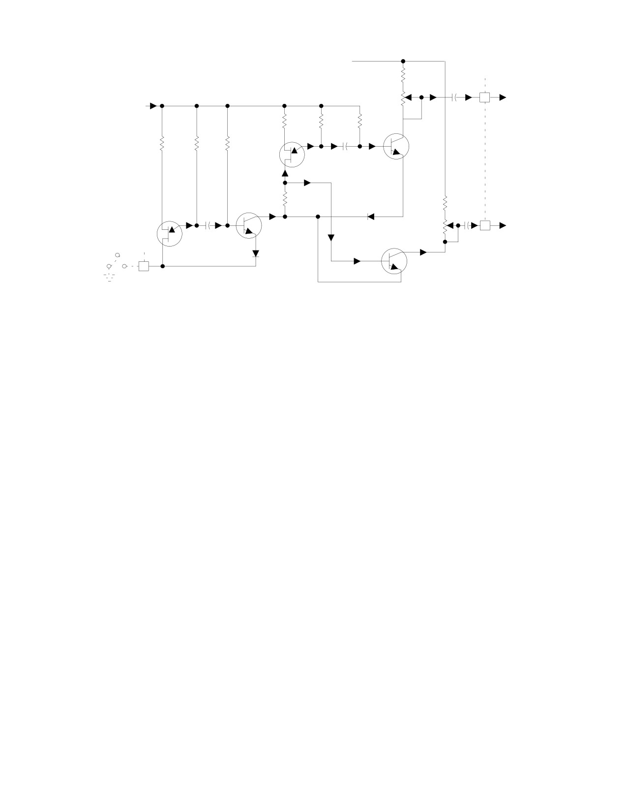
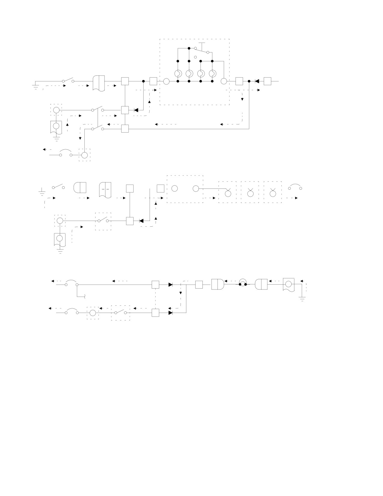
Figure 17-19, Autronics 2146-5 Warning Audio and Lights Flashing Control
Circuit (Sheet 2 of 2)
When activated, either N1 or NR sensing
EPO warning control unit; except as follows:
circuits activate and control the engine out
The unit contains additional circuits for
flashing light, audible warning tones and the
sensing low main rotor (NR) speed to control
audible warning horn.
engine out flashing light and audible warning
horn indications, and generation of an
Audible warning tones No. 1 & 3 are activated
additional separate audible warning tone No.3
and controlled by either N1 or NR sensing.
when low NR speed is sensed. (For a simplified
internal block diagram of the unit, see
The Autronics 2200−3 is a sealed unit without
Figure 17−5.)
adjustments; an internal defect requires
The unit senses low NR speed at approximate−
replacement of the unit.
ly 98% NR rpm (equivalent to tachometer
NOTE: Input, control and output circuits, sig−
generator output ac voltage with a frequency
nals and voltages differ from those of the
of 68.6 ±0.7 Hz), or less. Low NR speed sensing
2146− 5 unit as described above. Internal
functions incorporate disable and time delay
schematic diagrams of the unit are not pro−
circuits.
vided; internal maintenance is not practical.
A. Autronics 2200-3 EPO Warning Control
Unit Maintenance
23. Autronics 2200-3 EPO Warning Control
Unit
An internal malfunction requires removal and
replacement of the unit. Remove and replace
The autronics 2200−3 EPO warning control
the unit as described for the Autronics 2146−5,
unit is a sealed, solid state device that
except disregard information on adjustment of
functions similarly to the Autronics 2146−5
internal controls. (autronics 2200−3 unit does
Page 17-61
Revision 19
MD Helicopters, Inc.
CSP−H−2
500 Series − Basic HMI
not have accessible internal adjustments.) For
B. Negative (Ground) Input Fault Dimming
information on checking operation of the unit,
Circuits
refer to the following data.
(Ref. Figure 17−21) Negative input fault
dimming circuits function when a ground is
(1). For information on troubleshooting the
applied from external sensing switches to the
unit installed in the helicopter, refer to
dimmer unit.
Table 17−2 and Table 17−3.
When the ground fault is applied, a current
(2). For additional maintenance informa−
path is completed from the external ground
tion on the unit, refer to Table 17−4.
through the associated external caution lamps,
diode CR9, and normally closed contacts of
dimming relay K1 to +28 Vdc for bright lamp
24. Grimes 70-0054-1 Indicator Lights
indication.
Dimmer Assembly (Panel Type A)
For a dim lamp indication, the dim−bright
switch completes a current path from ground
The Grimes 70−0054−1 indicator lights
through the winding of dimming relay K1 and
dimmer assembly is a solid state device that is
diode CR1 to +28 Vdc. This selects a current
used with the EPO warning unit for caution
path or the fault indicator lamps through
and warning lights dimming and dims
zener diode VR1 to +28 Vdc.
instrument panel lights when the option night
lighting system is installed.
When selected, zener diode VR1 introduces a
constant voltage drop to reduce lamp voltage
The indicator lights dimmer assembly is
for simultaneous dim lighting of all caution
installed at the lower left interior of the
light indicators that are illuminated.
instrument panel console.
The dim−bright circuit is common to and
functions identically for all negative input
A removable cover permits access to two
fault dimming circuits. is common to and
circuit boards and components of the indicator
functions identically for all negative input
lights dimmer assembly for maintenance and
fault dimming circuits.
repair.
C. Positive (+28 Vdc) Input Fault and
The indicator lights dimmer assembly contains
Function Dimming Circuits
the following internal circuits.
(Ref. Figure 17−21) Each of the two positive
(+28 Vdc) input fault dimming circuits, and
A. Indicator Lights Dimming Assembly
the one +28 Vdc input function dimming
Circuits
circuit, control illumination of separate
external warning light indicators on the
The indicator lights dimming assembly
instrument panel.
contains components for use in for use in four
When a +28 Vdc input is applied to diode
negative input signal fault dimming indicator
CR15, a current path is completed from
circuits for the four caution light indicators,
ground, through transistor Q3, the external
three positive input fault and function
START PUMP lamp and diode CR15 to the
indicator circuits for three warning light
+28 Vdc applied for a bright lamp indication.
indicators and a panel light dimming circuit (d
below) for panel lamps. In addition, test
The + 28 Vdc applied through dimming relay
circuits are included for all the circuits.
K1 contacts to resistor R4 at the base of
transistor Q3 forward biases Q3, so that the
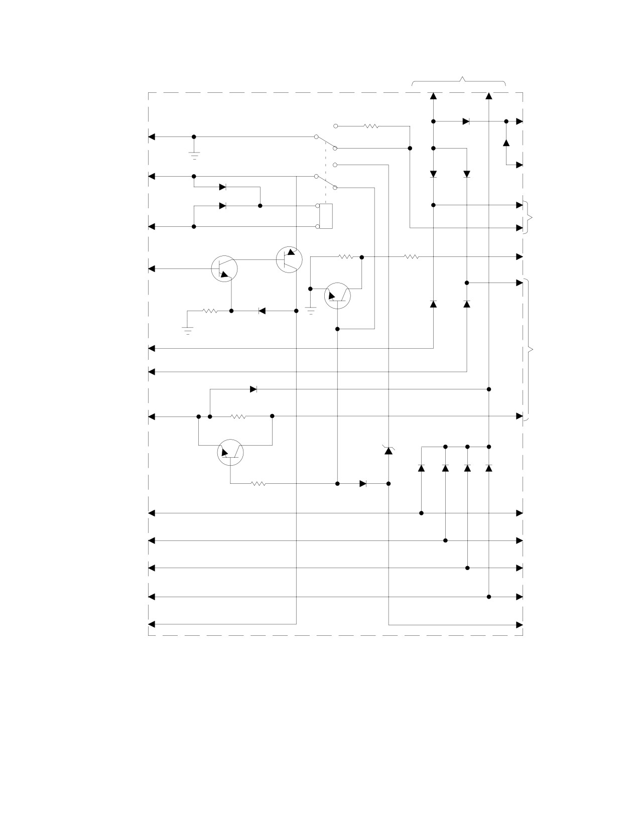
Figure 17−20 is a schematic diagram of the
lamp current path is through Q3, bypassing
dimming assembly.
parallel resistor R3. For a dim lamp indication,
the dim−bright switch energizes K1 removing
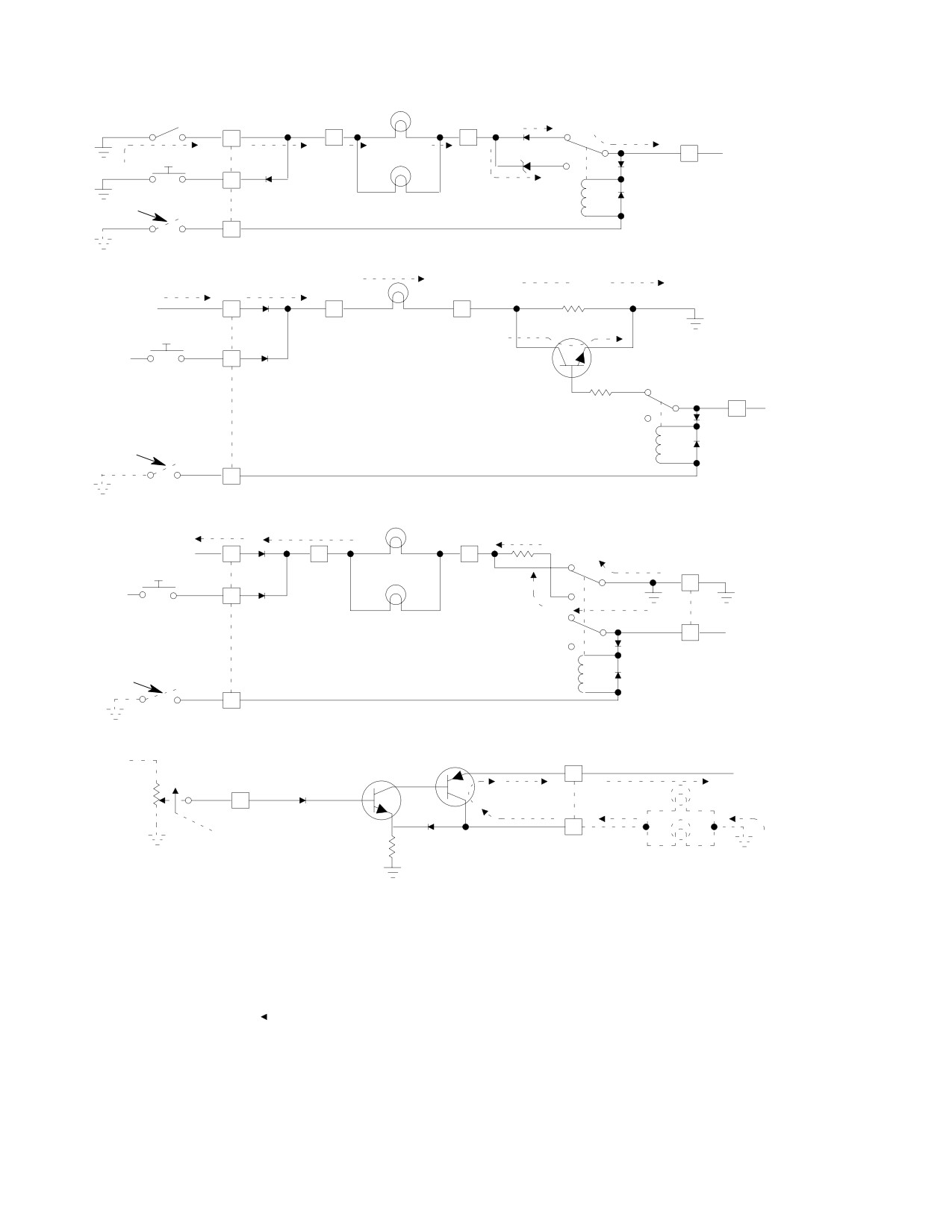
Figure 17−21 is a partial breakdown of the
the positive voltage applied to the base of Q3;
indicator lights dimming assembly overall
Q3 ceases conduction and lamp current must
schematic diagram with associated circuits
flow through resistor R3. The resulting voltage
and shows typical circuits separately by
drop across R3 reduces lamp voltage and dims
functions.
the lamp.
Page 17-62
Revision 19
MD Helicopters, Inc.
CSP−H−2
500 Series − Basic HMI
The circuit for the XMSN OIL TEMP &
(4). Connect electrical plug to dimmer
PRESS lamps functions identically, except a
assembly. Turn on power, push−to−test
pulsating positive dc voltage input is provided
switch for the indicator lights and check
by the transmission oil and temperature light
for proper functioning of the lights.
flasher circuit of the EPO warning unit, to
flash the associated lamps.
(5). Reinstall instrument panel fairing.
The circuit for the ENG OUT warning light
25. Autronics 2245-1 Indicator Lights Dimmer
functions in the same manner as the XMSN
Assembly (Panel Type B)
OIL TEMP & PRESS dimming circuits, except
resistor R1 is directly switched in the lamp
The Autronics 2245−1 dimmer assembly is a
current path for lamp dimming by dimming
solid state device associated with the caution
relay K1.
and warning indicator lights of the type used
in instrument panel type B. The unit contains
D. Panel Lights Dimming Circuit
28 Vdc and ground test circuits, with isolation
(Ref. Figure 17−21) When the night lighting
diodes, which are part of the PRESS−TO−
system is installed, a variable positive voltage
TEST circuit for the lights. The unit also
from the panel and instruments light dimming
contains a switching regulator to regulate
potentiometer R113 is applied to the base of
voltage for instrument panel and instrument
transistor Q1. The variable voltage varies
light dimming. Caution and warning indicator
external panel lamps current flowing through
lights may be dimmed by pressing the face of
transistor Q2 to control panel and instrument
each indicator. See Figure 17−22 for a sche−
lamp illumination.
matic diagram of the dimmer assembly. The
unit contains components used in the following
E. Grimes 70-0054-1 Indicator Lights
circuits.
Dimmer Assembly Repair
A. Dimmer Assembly Associated Circuits
Replace circuit component as necessary in the
indicator lights dimmer assembly. Refer to the
The unit contains 16 diodes and other circuit
functional information and troubleshooting
components used in: six negative fault input
data for the indicator lights dimmer assembly
indicator circuits for six caution light indica−
to locate and isolate defective internal compo−
tors; two negative fault input signal indicator
nents.
circuits for main transmission (XMSN) oil
F. Grimes 70-0054-1 Indicator Lights
temperature (TEMP) and pressure (PRESS)
Dimmer Assembly Replacement
warning light indicator; a positive input signal
indicator for the START PUMP light indicator;
(Ref. Figure 17−3)
a circuit for an engine (ENG) OUT warning
light indicator; and a panel and instrument
(1). Check that all electrical power is OFF
lights dimming circuit.
and remove left instrument panel
fairing.
In addition, internal components permit
simultaneous press−to−test checking of all the
(2). Disconnect the electrical plug from the
circuits and light indicators.
dimmer assembly, remove the mounting
screws and washers, and lift out the
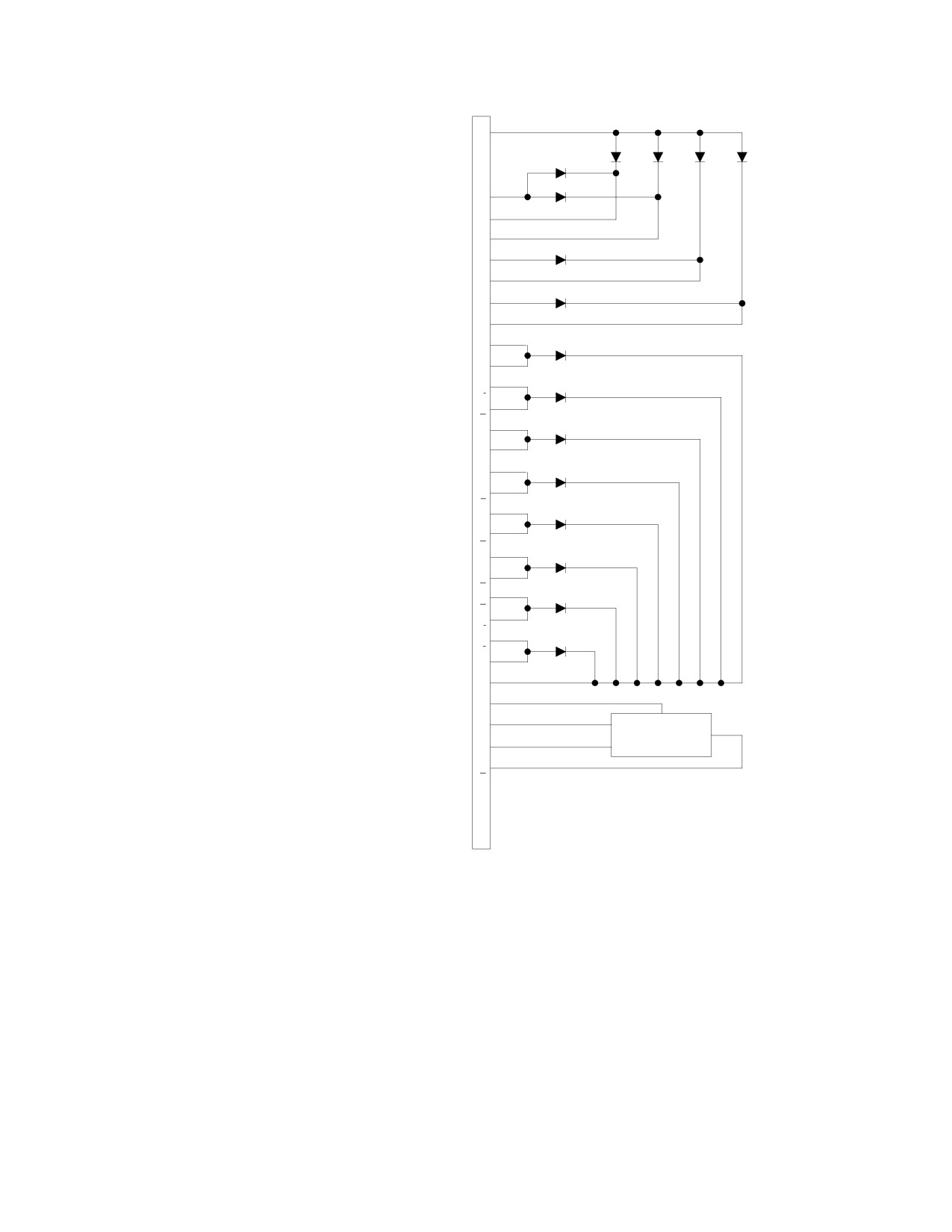
Figure 17−22 is a partial breakdown of the
dimmer assembly.
dimmer assembly overall schematic diagram
(3). Position replacement dimmer assembly
with associated light circuits and shows typical
and install attaching hardware.
circuits separately by functions.
Page 17-63
Revision 19

MD Helicopters, Inc.
CSP−H−2
500 Series − Basic HMI
Table 17-4. Input/Output Signals - Autronics 2200-3 EPO Unit
Input
Output
Connector
Connector
Name
Signal or Control
Name
Signal
J21 Pin
J22 Pin
A
N1 tach gen
Ac voltage, 36.75
F
Eng out light flasher
Pulsating 28 Vdc with
±1.75 Hz, or less
and audible warning
3-5 Hz flash rate, 0.2A
horn
max., 28 Vdc present
for min. 25% - max.
75% of flash rate
period.
K
Xmsn oil & temp
Same as for J21, Pin F
flasher
C
Audio warning tone
Interrupted 680 to 1700
No. 1
Hz, 0.9 ±1 Vac into 16K
ohm load; interrupted
120 ±40 times/minute,
ac voltage present for
min. 25% -max. 75% of
interrupt rate period.
D
Audio warning (not
Same as J21, pin C.
used)
M
Audio warning tone
Same as J21, pin C;
No. 3
except 18.5 ±2 Vac into
100 ohm load.
J
Audio tone
Airframe ground
Presence of this input is required for outputs
enable ground
at J21, pins C and D.
B
Supply input
+28 Vdc
voltage
Presence of these inputs required for all EPO unit outputs.
E
Ground
Airframe ground
L
NR tach gen
Ac voltage, 68.6
F
Same as above
Same as above
±0.7 Hz, or less
K
Same as above
Same as above
M
Audio warning tone
Same as J21, pin C;
No. 3
except 18.5 ±2 Vac into
100 ohm load.
C
Same as above
Same as above
D
Same as above
Same as above
G
NR sensing
Airframe ground
Presence of this input is required to prevent
and audio
outputs at J21, pins F, K and M with input at
tone No. 3
pin L. (3)
disable
NOTE:
(1) All ac voltage levels are peak-to-peak on calibrated oscilloscope.
(2) N1 and NR sensing inputs produce all associated outputs listed, when other required indicated inputs are
present.
(3) At removal and reapplication of input at pin G, output at G, outputs occur 3.5 seconds after reapplication
due to internal time-delay circuits.
Page 17-64
Revision 19
MD Helicopters, Inc.
CSP−H−2
500 Series − Basic HMI
PRESS−TO−TEST SWITCH
+28 VDC IN
GND IN
A
B
CR14
L
START PUMP
W
ON LAMP
R1
CR15
GROUND
N
START PUMP IN
CR3
CR4
V
(+28 VDC)
+28 VDC IN
CR1
C
BRIGHT−
CR2
ENG OUT
DIM RELAY
U
D
LAMPS DIM GND
LAMPS
K−1
CONTROL IN
Q2
Q1
R3
R4
J
START PUMP
X
LAMPS VARIABLE
ON LAMP
DIM CONTROL IN
E
Q3
R2
CR6
CR7
CR5
ENGINE OUT
PULSATING
S
XMSN OIL TEMP
+DC V IN
AND PRESS
LAMPS
T
XMSN OIL TEMP
AND PRESS
CR8
PULSATING
+DC V IN
Y
R5
F
*XMSN OIL TEMP
AND PRESS IN
Q4
VR1
R6
CR10
CR11
CR12
CR13
CR9
Z
H
*ENG CHIP
CHIP DET LAMP
DETECTOR IN
AA
K
*FUEL LOW HI
FUEL LOW LAMP
BB
M
*FUEL FILTER IN
FUEL FILTER LAMP
CC
P
*GEN OUT IN
GEN OUT LAMP
DD
R
LAMPS
PANEL LAMPS
(CHIP DET,
V OUT
FUEL LOW,
FUEL FILTER
NOTES:
AND GEN OUT)
1.
REFERENCE DESIGNATORS ASSIGNED FOR REFERENCE
COMMON
ONLY AND ARE NOT ON COMPONENTS.
2.
ASTERISK ( * ) INDICATES NEGATIVE (GROUND) FAULT INPUT.
3.
ALL CONNECTOR PINS ARE PART OF SINGLE CONNECTOR
ON UNIT.
30−196
Figure 17-20. Grimes 70-0054-1 Indicator Dimming Assembly Schematic Diagram
Page 17-65
Revision 19
MD Helicopters, Inc.
CSP−H−2
500 Series − Basic HMI
P/O
P/O
P/O
FAULT
P8
P8
P8
CR9
P/O
INPUT
BRT
Z
H
R
P8
CHIP DET
VR1
V
+28 VDC
PRESS−TO−TEST
DS3 (NOTE 7)
DIM
CR1
CR10
B
NEG TEST
P/O
CR2
K1
NOTE 1
BRT
U
DIM
NEGATIVE (GRD) FAULT INPUT CAUTION INDICATOR LIGHTS
(TYPICAL FOR CHIP DETECTOR, FUEL LOW, FUEL FILTER AND GENERATOR OUT)
P/O
P/O
P/O
(DIM)
P8
P8
P8
+28 VDC FROM
R3
FUEL PUMP CB
N
L
J
START PUMP
CR15
ON DS7
(BRT)
PRESS−TO−TEST
(NOTE 7)
+28 VDC
A
Q3
POS
CR14
TEST
BRT
R4
V
+28 VDC
DIM
CR1
P/O
CR2
NOTE 1
BRT
K1
U
DIM
POSITIVE (+28 VDC) INPUT WARNING LIGHTS
(TYPICAL FOR START PUMP ON AND XMSN OIL TEMP AND PRESS)
P/O
P/O
P8
PULSATING +VDC
P8
R1
INPUT FROM EPO UNIT
S
C
D
BRT
P/O
CR6
ENG OUT DS1
P8
PRESS−TO−TEST
P/O
(NOTE 7)
P8
DIM
W
+28 VDC
A
POS
CR3
TEST
V
+28 VDC
CR1
BRT
K1
CR2
NOTE 1
U
DIM
POSITIVE (+28 VDC) INPUT WARNING ENG OUT LIGHT
P/O
+28 VDC
Q2
P8
P/O
Q1
V
+28 VDC
BRT
P8
R113
CR16
(NOTE 7)
X
CR5
OFF
DD
NOTE 1
R2
EXTERNAL
PANEL LAMPS
(NOTE 1)
PANEL LIGHTS DIMMING
NOTES:
1.
DIM−BRT SWITCH AND R113 ARE MECHANICALLY LINKED. PANEL LAMPS,
4.
EACH CIRCUIT SHOWS ONLY COMPONENTS USED FOR
DIM−BRT SWITCH AND R113 ARE PART OF OPTIONAL NIGHT LIGHTING
FUNCTION INDICATED.
SYSTEM.
5.
ALL COMPONENTS WITH REFERENCE DESIGNATORS ARE PART
2.
REFER TO ELEC SYSTEM SCHEMATIC AND WIRING DIAGRAMS (REF. SEC 20)
OF DIMMER ASSY UNLESS OTHERWISE INDICATED.
FOR FAULT AND FUNCTION INPUT SOURCES, INTERCONNECTING WIRING
6.
REFERENCE DESIGNATORS ARE FOR REFERENCE ONLY AND
INFORMATION AND DIMMER ASSY SCHEMATIC DIAGRAM.
ARE NOT ON COMPONENTS.
3.
DASHED LINE WITH ARROWHEAD ( − − − ) INDICATES CURRENT PATH
7.
NOT PART OF DIMMER ASSY.
(OPPOSITE OF VOLTAGE) THROUGH INDICATOR LAMPS.
30−167A
Figure 17-21. Caution and Warning Indicating Light System Dimming Circuits
(Instrument Panel Type A)
Page 17-66
Revision 19
MD Helicopters, Inc.
CSP−H−2
500 Series − Basic HMI
B. Negative (Ground) Input Fault Caution
E. Engine Out warning Light and Horn
Light Indicator Circuits
Circuit
(Ref. Figure 17−23) The ENG OUT warning
(Ref. Figure 17−23) Negative input fault
light and audible horn functions when the
caution light indicator circuits function when a
engine out frequency sensor circuit in the
ground is applied from external sensing switch
engine power out waning control unit is
to the dimmer assembly.
actuated by a decrease of engine speed to a
specific value of N1 rpm.
When the ground is applied, a current path is
completed from the external ground through
When this occurs, a pulsating dc voltage input
the associated external caution lamps and
from the sensor circuit is applied through
PANEL LT circuit breaker CB104 to the +28
diode CR 7 to and flashes the ENG OUT
Vdc source.
lamps. Simultaneously, the pulsating dc
voltage is applied to and activates the audible
A diode (CR11 or other diode, as applicable) is
warning horn DS105 by means of the circuit
provided for each individual negative input
through part of the closed generator (GEN)
fault circuit for use in the press−to−test
switch S4.
circuits.
When open, GEN switch, GEN switch S4
C. Negative (Ground) Input Fault Warning
disables the audio warning horn. Diode CR3 is
Light Indicator Circuits
provided for use in the press−to−test circuits.
(Ref. Figure 17−23) Negative input fault
F. Panel and Instrument Lights Dimming
warning light indicator circuits for the XMSN
Circuit
high OIL TEMP and/or low OIL PRESS lamps
(Ref. Figure 17−23) When the night lighting
function when a ground is applied from the
system is installed, a variable positive dc
associated sensor switch to the dimmer
voltage (0 to +28 Vdc) from the external
assembly.
FLIGHT instrument light potentiometer R110
is applied to the input of the switching
When the ground is applied, a current path is
regulator in the dimming assembly.
completed through the external warning
indicator lamps and a diode CR5 (or CR6) to
The variable input voltage causes the switch−
the transmission oil and temperature light
ing regulator to vary the positive dc output
flasher circuit of the engine power out warning
voltage applied to and current panel and
control unit. A pulsating dc voltage is applied
instrument cluster lamps.
to and flashes the warning indicator lamps. A
diode CR9 (or CR10) is provided for each of the
The control panel and instrument internal
two negative input fault circuits for use in the
illumination.
press−to−test circuits.
Minimum regulator output voltage is +2.5 Vdc
D. Positive (+28 Vdc) Input Start Pump
with an input o 0 Vdc and +26 Vdc with an
Warning Light Circuit
input of +28 Vdc.
G. Caution and Warning Lights
(Ref. Figure 17−23) The START PUMP
Press-T o-T est Circuits
warning light circuit functions when an
external +28 Vdc input is applied through
(Ref. Figure 17−23) Diodes are incorporated in
diode CR8 to the external START PUMP
the dimmer assembly for all of the caution and
warning lamp.
warning light circuits to provide either a
required ground or +28 Vdc input for the
The input is applied when the start pump is
associated circuit when the external PRESS−
energized by the START PUMP circuit breaker
TO−T est switch is depressed.
CB 118 on the instrument panel.
Lamp illumination is constant during press−
Diode CR4 is provided for use in the press−to−
to−test operation; none of the lamps flash
test circuits.
during the check.
Page 17-67
Revision 19
MD Helicopters, Inc.
CSP−H−2
500 Series − Basic HMI
H. Autronics 2245-1 Dimmer Assembly Test
26. Engine Power Out (EPO) Audio Amplifier
and Repair
(Used with Vapair EPO Warning Control
Unit)
(Ref. Figure 17−22)
The EPO audio amplifier is a solid state
amplifier that amplifies the audio signal from
(1). Test diodes, using an ohmmeter at
the EPO warning unit for application to radio
electrical connector pins. Check for low
headset(s).
forward resistance with positive lead
applied to the anode and negative lead
The amplifier is a sealed in a cylindrical
applied to the cathode. Read very back
container, with a wiring harness and attached
resistance when leads are reversed.
connector secured to each end.
(2). Test switching regulator by applying
The early type amplifier is an Autronics
+28 Vdc at electrical connector pin V
2037−1 two−transistor, dual channel amplifier;
and ground at pin W. Check output at
however, only one channel is used. The power
pin d for 2.5 Vdc minimum. Apply +28
gain ratio of the dual channel amplifier is 3 to
Vdc at pin d for 26 Vdc minimum.
1 greater, when used with the EPO warning
unit.
(3). Replace faulty internal components.
For the current type, two−transistor, single
I. Autronics 2245-1 Dimmer Assembly
channel amplifier, a 2 milliwatt input input
Replacement
produces a 100 milliwatt minimum output.
Refer to the electrical system wiring diagram
(Ref. Figure 17−22)
(Ref. Sec. 20) for inter−connecting wiring
information.
(1). Check that electrical power is OFF.
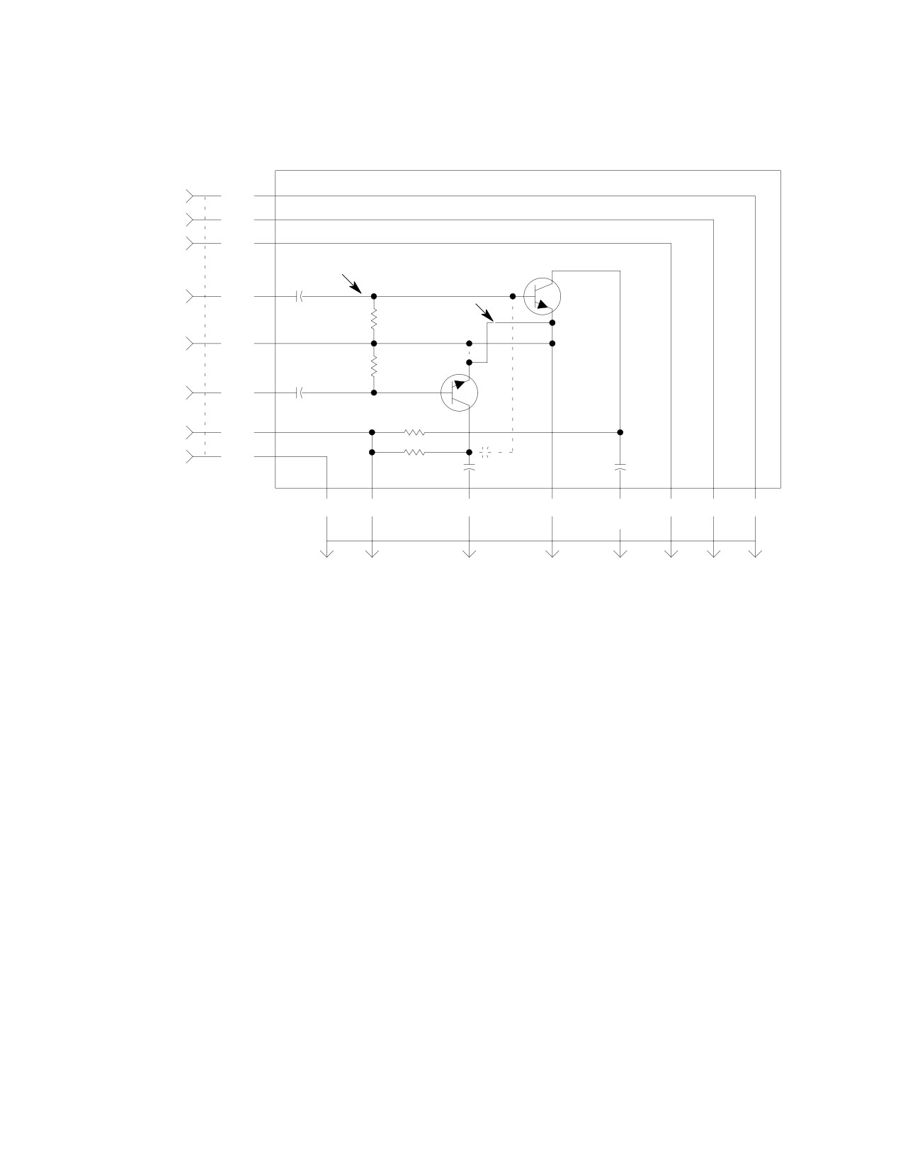
A schematic diagram for both early and
(2). Locate dimmer assembly mounted
current type units is provided in Figure 17−24.
forward of the ash tray in the lower
Both the single and dual channel amplifier
switch/circuit breaker panel box.
interconnect with the electrical system
identically.
(3). Disconnect plug at the front of the
dimmer assembly.
The amplifier also contains straight through
circuits, not interconnected to the internal
(4). Remove four screws attaching dimmer
amplifier circuit, that transfer all inputs and
to lower surface of panel box and
outputs to and from the EPO warning unit.
remove dimmer.
The EPO audio amplifier is installed with the
EPO warning unit at the lower right interior of
(5). Install replacement dimmer by essen−
the instrument panel console.
tially reversing the above procedure.
A. EPO Audio Amplifier Replacement
(6). Connect electrical power and check
caution and warning light PRESS−TO−
(Ref. Figure 17−3) Accomplish replacement of
TEST operation.
the audio amplifier according to the instruc−
tions in Replacement of Vapair 26530332M
NOTE: If any single caution or warning light
EPO Warning Control Unit except disconnect
does not illuminate and N1 sensing equip−
both electrical plugs of the amplifier and
ment is used, try pressing the legend face of
remove only the upper aft screw from the
the indicator to be sure that the internal
engine power out control unit case to release
switch and lamps are not defective.
the amplifier.
(7). Check instrument panel lights for
NOTE: The single channel amplifier is used for
proper dim and bright operation. Turn
replacement and is one− way interchange−
off electrical power.
able with the dual channel amplifier.
Page 17-68
Revision 19
MD Helicopters, Inc.
CSP−H−2
500 Series − Basic HMI
J12
+28 VDC
A
CR1
CR2
CR3
CR4
CR5
CR6
PRESS. AND TEMP WARN. SIGNAL
T
XMSN OIL TEMP LT/SW HI
E
XMSN OIL PRESS. LT/SW HI
G
CR7
ENGINE OUT WARN. SIGNAL
S
ENGINE OUT LT/SW HI
C
CR8
START PUMP HI
N
START PUMP LIGHT HI
L
XMSN OIL TEMP SWITCH
Y
CR9
XMSN OIL TEMP LT/SW LO
F
XMSN OIL PRESS. SWITCH
j
CR10
XMSN OIL PRESS. LT/SW LO
h
ENGINE CHIPS LT/SW LO
H
CR11
ENGINE CHIP DETECTORS
Z
GEN OUT LT/SW
P
CR12
GEN OUT ALARM
c
FUEL LOW LT/SW LO
K
CR13
FUEL LOW SWITCH
a
FUEL FILTER LT/SW LO
M
CR14
FUEL FILTER SWITCH
b
M/R XMSN CHIPS LT/SW LO
g
CR15
M/R XMSN CHIP DETECTOR
l
T/R XMSN CHIP LT/SW LO
f
CR16
T/R XMSN CHIP DETECTOR
R
DC GROUND TEST
B
DC GROUND
W
28 VDC
V
SWITCHING
REGULATOR
DIMMER POT ARM
X
PANEL LIGHTING, VARIABLE DC
d
D
J
U
NOTES:
1.
TERMINALS NOT DESIGNATED WITH LIGHT SWITCH (LT/SW) ARE INPUTS
FROM SENSOR/SENDER UNITS, UNLESS OTHERWISE INDICATED.
2.
TERMINALS DESIGNATED WITH LIGHT SWITCH (LT/SW) ARE OUTPUTS
TO CAUTION AND WARNING LIGHTS.
3.
TERMINALS DESIGNATED DC GROUND TEST AND +28 VDC ARE INPUTS
FROM PRESS−TO−TEST SWITCH.
4.
TERMINAL DESIGNATED DIMMER POT ARM IS INPUT FROM PANEL
LIGHTS DIMMING CONTROL.
5.
TERMINAL DESIGNATED PANEL LIGHTING, VARIABLE DC IS OUTPUT
TO PANEL AND INSTRUMENT LIGHTS.
6.
DIODES CR5 THRU CR8 USED IN WARNING LIGHTS FLASHING CIRCUITS.
ALL OTHER DIODES USED ONLY IN PRESS−TO−TEST CIRCUITS FOR LIGHT INDICATORS.
30−187A
Figure 17-22. Autronics 2245-1 Dimmer Schematic Diagram (Instrument Panel Type B)
Page 17-69
Revision 19
MD Helicopters, Inc.
CSP−H−2
500 Series − Basic HMI
NC
ROTOR OIL
NO
2
4
1
5
TEMP SWITCH P/O
P/O
P/O
FAULT
S202
P9J
P12
P12
INPUT
PULSATING +VDC IN
Y
Y
Y
F
3 URLLULLR
C
E
T
FROM EPO UNIT
XMSN OIL TEMP
P/O ENG OUT
LT/SW DS12
PRESS−TO−TEST
LT/SW DS14
(NOTE 2)
SWITCH
CR9
3
B
S2
P/O
5
TB6
A
S1
NEGATIVE (GND) FAULT INPUT WARNING INDICATOR LIGHTS
1
2
P/O GEN OUT
+28 VDC
C
(TYPICAL FOR MAIN XMSN OIL TEMP AND OIL PRESS)
LT/SW DC18
PANEL LT
CB104
T/R XMSN
P/O
P/O
PANEL LT
CHIP DET P402J
P9J
CB104
J12
T/R XMSN
2
1
q
q
R
F
3
CHIPS
C
+28 VDC
LT/SW DS20
C
C
C
P/O M/R
P/O ENG
P/O GEN
XMSN
CHIPS
OUT
P/O ENG
CR11
CHIPS
LT/SW
LT/SW
OUT LT/SW
3
B
LT/SW
DS15
DS18
DS14
S2
DS19
P/O
P/O
5
NEGATIVE (GND) FAULT INPUT CAUTION INDICATOR LIGHTS
TB6
PRESS−TO−TEST
(TYPICAL FOR ENG CHIPS, GEN OUT, FUEL LOW, FUEL FILTER,
SWITCH
M/R XMSN CHIPS AND T/R XMSN CHIPS)
START
START
PUMP
P/O
PUMP
P/O
P/O
CB118
J24P
LT DS7
P23J
TB6
P12
P12
+28 VDC
N
L
6
2
1
CR8
TO START
PUMP
1
2
+28 VDC
C
A
PANEL LT
S1
CR4
CB104
P/O GEN
P/O
OUT LT/SW
PRESS−TO−TEST
DS18
SWITCH
POSITIVE (+28 VDC) INPUT WARNING LIGHT (START PUMP)
NOTES:
1.
CIRCUITS SHOWN ARE TYPICAL. VARIATIONS MAY EXIST
4.
COMPONENTS CONNECTED BETWEEN CONNECTOR P12 PINS
FROM THAT SHOWN ACCORDING TO HELICOPTER MODEL
ARE PART OF DIMMER ASSEMBLY.
AND SERIAL NO. (REF. NOTE 5).
5.
FOR FAULT AND FUNCTION INPUT SOURCES NOT SHOWN AND
2.
FOR INTERNAL CIRCUITS OF ALL LIGHT/SWITCHES, SEE
INTERCONNECTING WIRING INFORMATION, SEE APPLICABLE
CIRCUIT FOR XMSN OIL TEMP LT/SW DS12. IT IS TYPICAL
ELECTRICAL SYSTEM SIRING DIAGRAM (REF. SEC. 20).
FOR ALL LIGHT/SWITCHES. LIGHTS WITHOUT SWITCHES
6.
FOR COMPLETE CIRCUIT INFORMATION ON DIMMER ASSEMBLY,
DIFFER (REF NOTE 5).
SEE SCHEMATIC DIAGRAM FOR DIMMER ASSEMBLY IN THIS
3.
EACH CIRCUIT SHOWS ONLY COMPONENTS USED FOR
SECTION.
FUNCTION INDICATED.
30−197−1A
Figure 17-23. Caution and Warning Indicating Lights System Circuits
(Instrument Panel Type B) (Sheet 1 of 2)
Page 17-70
Revision 19
MD Helicopters, Inc.
CSP−H−2
500 Series − Basic HMI
P/O GEN
P/O
SW S4
+
P12
PULSATING DC V IN
2
1
F
FROM EPO UNIT
−
AUDIBLE WARNING
HORN DS105
P/O
P/O
P12
TB6
CR7
S
C
C
3
5
P/O GEN OUT
PANEL LT
ENG OUT
LT/SW DS18
CB104
CR3
LT/SW DS14
1
2
+28 VDC
C
A
P/O
PRESS−TO−TEST
SW S1
ENGINE OUT WARNING LIGHT AND HORN
P/O
P/O
PANEL LTS
P12
P12
TB502−6
TB502−7
+28 VDC
V
d
PANEL LT
CB104
SWITCHING
1
2
REGULATOR
+28 VDC
1
(NOTE 9)
X
W
2
INSTRUMENT
5K
P/O
CLUSTER LTS
3
5
2W
TB6
P/O
4
TB6
PANEL AND INSTRUMENTS LIGHT DIMMING
NOTES: (CONT)
7.
ABBREVIATIONS:
BRT − BRIGHTNESS
LL − LOWER LEFT
LR − LOWER RIGHT
LT − LIGHT
M/R − MAIN ROTOR
P/O − PART OF
SW − SWITCH
T/R − TAIL ROTOR
UL − UPPER LEFT
UR − UPPER RIGHT
XMSN − TRANSMISSION
8.
DASHED LINES WITH ARROWHEAD ( − − ) INDICATES CURRENT
PATH (OPPOSITE OF VOLTAGE) THROUGH CIRCUITS.
9.
INPUT (P12−X):
0 − +28 VDC.
OUTPUT (P12−d): +2.5 VDC MINIMUM WITH 0 VDC INPUT.
+26 VDC MINIMUM WITH +28 VDC INPUT.
30−197−2A
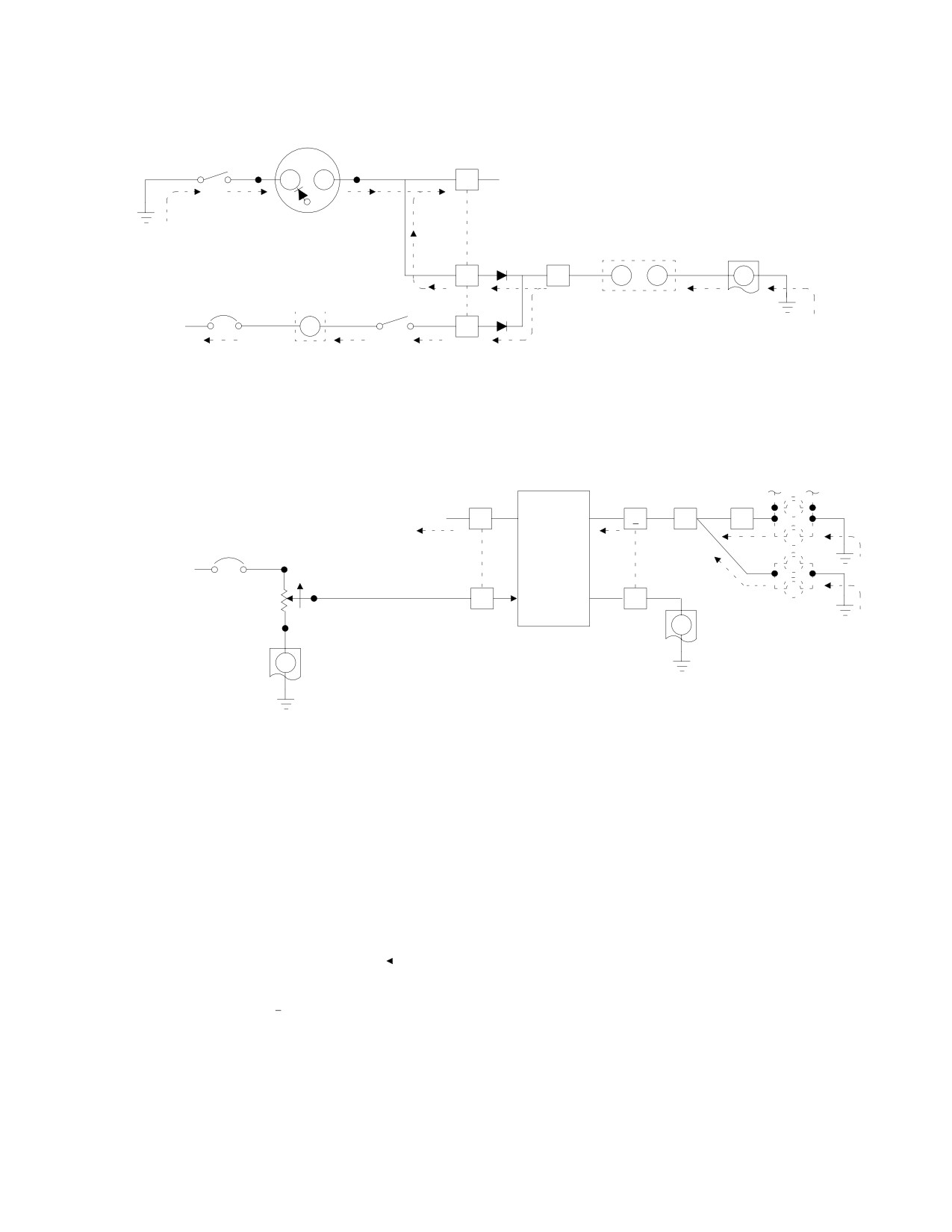
Figure 17-23. Caution and Warning Indicating Lights System Circuits
(Instrument Panel Type B) (Sheet 2 of 2)
Page 17-71
Revision 19
MD Helicopters, Inc.
CSP−H−2
500 Series − Basic HMI
P13
AR500 AUDIO AMP
(P7)
XMSN HI OIL TEMP K
WHT
GEN SW GND H
BLK
ENG OUT LAMP F
YEL
*C1
0.1
*
Q2
*HEADSET AUDIO D
*BLU
2N697
#2 IN
(2N3053)
R1 (R3)
1.5 K
GROUND E
ORN
R3 (R1)
C3 (C1)
1.5 K
0.1
Q1
HEADSET AUDIO C
GRN
2N697
#1 IN
R4 1K (530)
+28 VDC OUT B
RED
R2 1K
N1 TACH GEN V A
VIO
*C2
C4 (C3)
(C2) (0.1)
0.47
0.47
(6.8)
VIO
RED
*GRN
ORN
BLU
YEL
BLK
WHT
(GRN)
A
B
C
E
D (C)
F
H
K
N1
+28 VDC
*HEADSET
GROUND
HEADSET
ENG
GEN
XMSN
TACH
IN
AUDIO #1
AUDIO #2
OUT
SW
HI OIL
GEN V
OUT
OUT
LAMP
GND
TEMP
(HEADSET
AUDIO #1
OUT)
NOTES:
1.
ASTERISK ( * ) INDICATES ITEM APPLIES ONLY TO DUAL CHANNEL AMPLIFIER.
2.
UNLESS OTHERWISE NOTED, SOLID LINES APPLY TO BOTH DUAL AND
SINGLE CHANNEL AMPLIFIERS.
3.
DASHED CIRCUIT LINES ( − − − ) AND ITEMS IN PARENTHESIS ( ) APPLY ONLY
TO SINGLE CHANNEL AMPLIFIER.
4.
RESISTANCE VALUES IN OHMS AND CAPACITANCE VALUES IN MICROFARADS.
30−169A
Figure 17-24. Audio Amplifier (Dual and Single Channel) Schematic Diagram
Page 17-72
Revision 19
MD Helicopters, Inc.
CSP−H−2
500 Series − Basic HMI
27. Engine Power Out (EPO) Audible Warning
(7). Install replacement horn, housing and
Horn
fairing in reverse order of removal. For
electrical wiring interconnect informa−
The EPO audible warning horn is an electro−
tion, refer to Section 19.
mechanical warning unit that produces an
audible ‘‘beeping" sound in the pilot’s compart−
(8). Perform an operational check of the
ment when engine Nl speed decreases below
audible warning horn.
approximately 55% Nl rpm, or NR speed
decreases to 98% rpm or less for N1/NR sensing
28. NR Disable Switch
equipment.
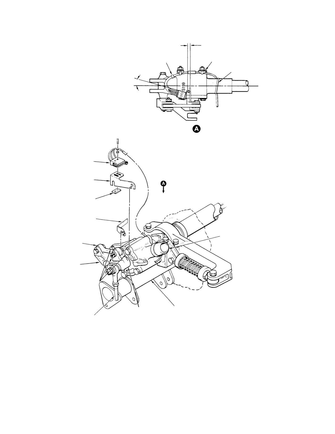
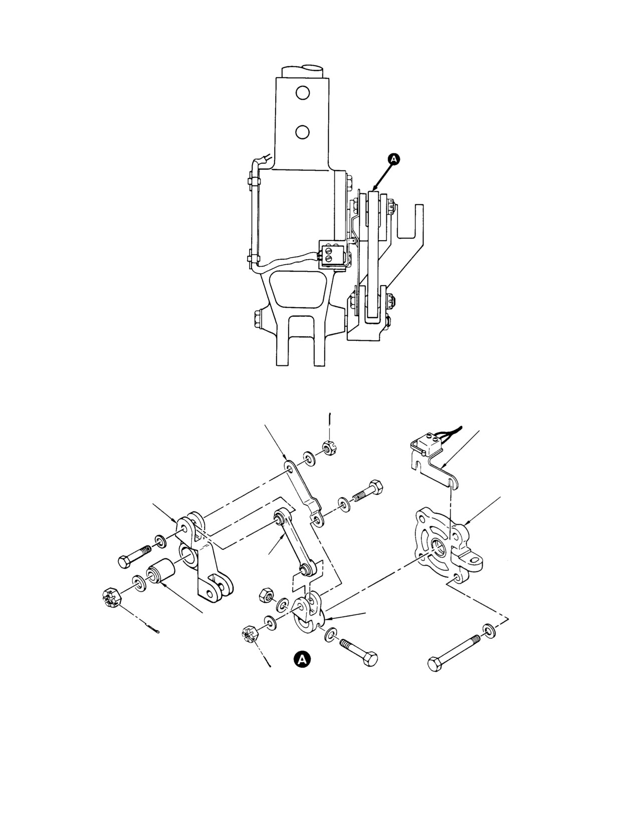
(Ref. Figure 17−25) NR disable switch S199 is
The audible warning horn is installed at either
mounted on the inboard collective stick socket
the upper left or right side of the instrument
on those helicopters with the N1/NR engine
panel (model difference only).
power out warning system.
On instrument panel type A and early type B,
The switch disables NR (main rotor) speed
mounting of the original audible warning horn
sensing and prevents engine out warning
(Figure 17−1) is changed to that of the current
indications when the pilot’s collective pitch
instrument panel type B shown in
stick is in the full down position and the
Figure 17−2, due to required installation of
throttle is at idle.
battery temperature sensing equipment.
The audible warning horn is mounted in a
These control positions are normal during
lights/switch and horn housing on the side of
engine starting, idling, autorotation flight and
the raised top of the center instrument panel
engine shutdown when an engine out warning
fairing, with two battery temperature caution
is not desired.
and warning light/switch indicators.
NOTE: On helicopters originally equipped with
An early type audible warning horn installa−
N1 sensing equipment that has been modi−
tion uses a modified Edwards 319 horn;
fied to N1/NR sensing equipment, NR disable
current type incorporates a modified Mallory
switch installation may differ slightly from
SC628 ‘‘Sonalert’’ unit.
that shown. (Refer to CSP−3 for differences
and for instructions for modification of such
A. Edwards Audible Warning Horn
an installation to the current type NR dis−
Replacement
able switch installation.)
(1). Check that all electrical power is off.
A. NR Disable Switch Replacement
(2). Remove instrument panel side fairings
(1). Remove center seat cover and controls
as necessary for access to internal
access door.
wiring.
(2). Check that electrical power is off.
(3). Loosen and remove attachment hard−
Disconnect wire E105B20N at ground
ware securing instrument panel center
terminal and wire E105A20 at splice.
fairing to free it sufficiently for partial
Cut all tie straps attaching wires to
access.
inboard collective stick socket
(Figure 17−25).
(4). As necessary, remove attaching hard−
ware and disconnect electrical wiring to
(3). Remove the switch by removing the two
permit removal of the lights/switch and
screws and the threaded attach plate.
horn housing (Figure 17−24).
(5). Remove lights/switch and horn housing
(4). Remove the switch attaching bracket by
from center fairing.
loosening the two upper bolts in the
inboard collective stick socket housing
(6). Disassemble horn housing; remove horn
cap and slipping out the slotted attach−
from housing as shown in Figure 17−1.
ing bracket.
Page 17-73
Revision 19
MD Helicopters, Inc.
CSP−H−2
500 Series − Basic HMI
0.030 IN. (0.762 MM)
OVERTRAVEL
(NOTE)
TIE STRAP
(3 PLCS)
CLIP
(3 PLCS)
TIE STRAP
10°−20°
VIEW LOOKING DOWN
NR DISABLE
SWITCH S199
SWITCH ATTACH
BRACKET
ATTACH PLATE
ACTUATING ARM
INBOARD COLLECTIVE
SOCKET ASSEMBLY
GAS PRODUCER
LINK
GAS PRODUCER
IDLER
(LOOSEN THESE BOLTS)
CONTROLS SUPPORT
GAS PRODUCER
GAS PRODUCER
BRACKET
BELLCRANK
CONTROL ROD
EARLY CONFIGURATION
NOTE: FOR ADJUSTMENT OF NR DISABLE SWITCH, REFER
TO TEXT. AFTER SWITCH ADJUSTMENT, PERFORM CHECK
OF SWITCH OPERATION.
30−209−1A
Figure 17-25. NR Disable Switch Installation (Sheet 1 of 2)
Page 17-74
Revision 19
MD Helicopters, Inc.
CSP−H−2
500 Series − Basic HMI
ACTUATING ARM
NR DISABLE SWITCH
AND BRACKET
(NOTE 1)
HOUSING CAP
IDLER
LINK
BELLCRANK
IDLER
BEARING
CURRENT CONFIGURATION
30−209−2
Figure 17-25. NR Disable Switch Installation (Sheet 2 of 2)
Page 17-75
Revision 19
MD Helicopters, Inc.
CSP−H−2
500 Series − Basic HMI
(5). Remove the switch actuating arm by
(4). If CHIPS indicator light does go on,
loosening the bolt in the gas producer
check that jumper is properly grounded.
bellcrank and slipping out the slotted
If so, check circuit components for
actuating arm. Remove the actuating
continuity and replace defective parts.
cam used in current installation by
removing the bolts in each end of the
30. Fuel Pressure Switch
gas producer bellcrank.
A. Fuel Pressure Switch Operational Check
(6). Install replacement components in
essentially reverse order of removal;
(1). Check that all electrical power is OFF;
adjust NR disable switch.
disconnect battery.
B. NR Disable Switch Adjustment
(2). Gain access to engine accessory section;
locate fuel filter (bypass) pressure
(1).
Check that pilot’s collective pitch stick
switch on front of engine driven fuel
is in full down position and throttle grip
pump.
rotated to idle position.
(3). Remove protective sleeving and
(2).
Position switch so that it activates
disconnect knife splice on bypass switch
(clicks) when the switch roller contacts
wiring.
the actuator cam.
(4). Disconnect and cap bypass hose
(3).
Note switch position at point of actua−
assembly at bushing.
tion and move switch toward actuator
cam an additional 0.030 inch (0.762
(5). Remove switch (with bushing fitting
mm). Tighten switch mounting screws
intact) from the after filter port (AF)
to secure switch in position and
engine driven fuel pump.
safetywire.
(6). Perform function test of bypass switch
(4).
Check that pilot’s throttle grip will
as follows:
rotate to cutoff position. Check pilot’s
collective pitch stick operation through
(a). Remove bushing and O−ring from
full range to determine that switch
bypass switch.
wiring does not interfere with move−
ment.
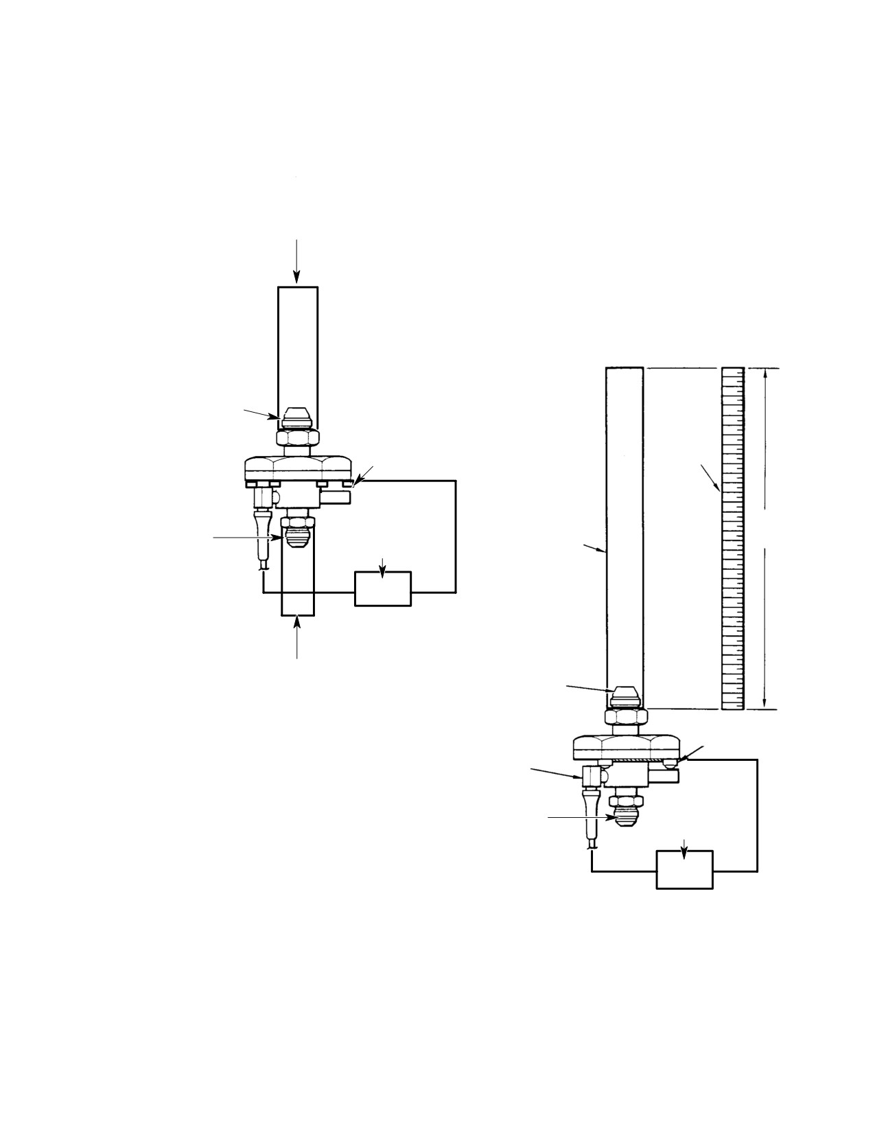
(b). Fabricate test set up (Figure 17−26).
(5).
Perform operational check of NR disable
NOTE: Switch actuation (closing) pressure
switch and audible warning horn with
should be 24.5−35.0 inches (62.23−88.9 cm)
collective pitch stick full down and
of fuel.
throttle at idle position.
(c). Pressurize inlet port of switch by
NOTE: Audible warning horn should not be ac−
adding fuel to the tub; watch ohmme−
tivated when throttle is at idle.
ter or continuity tester for indication
of switch actuation.
29. Chip Detector Circuits Operational Check
(1). Turn on electrical power; use an
(d). Check switch diaphragm for leakage.
external power supply when possible.
Replace switch if leakage is noted.
(2). Disconnect electrical wiring and
(e). Reinstall bushing with new O−ring
temporarily connect a jumper wire from
on bypass switch.
detector connector plug pin or wire
terminal to an unpainted (grounding)
(7). Perform operation check of switch as
surface of the airframe or engine.
follows:
(3). Observe CHIPS indicator light. If light
(a). Remove cap from bypass hose and
is on, circuit tests properly; remove
reconnect bushing (with switch) in
jumper wire and reinstall wiring.
hose fitting.
Page 17-76
Revision 19
MD Helicopters, Inc.
CSP−H−2
500 Series − Basic HMI
PRESSURE METHOD:
APPLY 8−9 PSIG (16.3−18.3 IN. HG.) TO CLOSE SWITCH. BLEED
OFF TO 4 PSIG (8.1 IN. HG.) TO OPEN SWITCH.
PORT A
36 IN. (91.5 CM)
SCALE
NOTE 2
OHMMETER
36 IN.
PORT B
OR
3/8" TYGON TUBING
(91.5 CM)
CONTINUITY TESTER
(OR EQUIV.)
VACUUM METHOD:
APPLY 8−9 PSIG (16.3−18.3 IN. HG.) TO CLOSE SWITCH. BLEED
OFF TO 4 PSIG (8.1 IN. HG.) TO OPEN SWITCH.
PORT A
369D28144 FUEL FILTER
PRESSURE SWITCH
NOTE 1
FUEL FILTER
PRESSURE SWITCH
OHMMETER
PORT B
OR
CONTINUITY TESTER
NOTES:
369H8144 FUEL FILTER
1.
CONNECT GROUND TEST LEAD TO ONE OF
PRESSURE SWITCH
THREE SCREW HEADS ON THE HOUSING BODY.
2.
CONNECT GROUND TEST LEAD TO ONE OF
SIX SCREW HEADS ON THE HOUSING BODY.
G28−0010A
Figure 17-26. Fuel Pressure Switch Test Set-Up
Page 17-77
Revision 19
MD Helicopters, Inc.
CSP−H−2
500 Series − Basic HMI
(b). Plug adapter fitting with AN 814−2
filter bypass caution light when start
in after filter (AF) port. Connect
pump is activated.
jumper wire to ground bypass switch
B. Fuel Pressure Switch Replacement
to aircraft ground (E12).
(Ref. Figure 17−7)
(c). Have assistant hold switch clear;
connect battery or electrical power
(1). Disconnect Knife splice in electrical
supply and activate start pump.
wire at switch.
(d). Check caution indicator light (fuel
(2). Remove interconnect tube, fuel pres−
bypass) for illumination.
sure switch and O−ring from engine
fuel pump filter.
NOTE: If fuel filter bypass caution indicator
does not light, perform electrical trouble
(3). Install replacement switch and service−
shooting of caution and warning lights.
able O−ring in the after filter port of
the pump filter. Torque the switch to 40
(e). Check switch diaphragm through
−
50 inch−pounds (4.52 − 5.65 Nm),
open port for leakage. Replace switch
reinstall interconnect tube and connect
if leakage is noted.
knife splice.
(f). Shut off electrical power, start pump,
(4). Operate engine starting pump and
battery switch; disconnect battery or
check for fuel leakage.
power supply and jumper wire.
NOTE: If fuel filter bypass caution indicator
31. Running Time Meter
did not light and electrical system is not
The running time meter is basically an electric
faulty, install new fuel filter pressure switch
clock that provides an accurate record of
(with new O−ring) at bushing, and repeat
engine and/or transmission operating time in
operational check of switch.
hours and tenths of hours.
(8). Remove plug from adapter fitting fuel
The meter operates whenever an oil pressure
filter port (AF); install bypass switch
switch in the main transmission is closed by
with new O−ring on adapter fitting.
transmission operating oil pressure.
Torque switch to 40 − 50 inch−pounds
(4.52 − 5.65 Nm).
The meter receives 28 Vdc power from the
instrument 5 ampere circuit breaker. The
(9). Remove plug from bypass hose; recon−
circuit is completed to ground through the
nect bushing at bypass hose. Torque
normally open contacts of the transmission
bushing to 40 − 50 inch−pounds (4.52
pressure switch (S203).
− 5.65 Nm).
A second set of normally closed contacts in the
(10). Reconnect knife splice on switch and
switch operates the XMSN oil pressure
reinstall protective sleeving.
warning light when below normal operating
(11). Bleed fuel filter housing (Ref. Sec. 12
pressure exists.
for fuel system bleeding instructions).
The running time is installed in a cover panel
(12). Run up engine and perform operational
on the left side of the instrument panel
check of engine and fuel system; check
structure just below floor level and is visible
for leaks and non−activation of fuel
from outside the helicopter.
Page 17-78
Revision 19
MD Helicopters, Inc.
CSP−H−2
500 Series − Basic HMI
Section
18
Heating and
Ventilation System
MD Helicopters, Inc.
CSP−H−2
500 Series − Basic HMI
This Page Intentionally Left Blank
MD Helicopters, Inc.
CSP−H−2
500 Series − Basic HMI
TABLE OF CONTENTS
Para/Figure/Table
Title
Page
Section 18 Heating and Ventilating System .
18−1
1.
Heating System
18−1
2.
Ventilating System
18−1
3.
Ventilating Valve Control
18−1
A. Ventilating Valve Control Replacement
18−1
4.
Cabin Ventilating Valve
18−2
A. Ventilating Valve Removal
18−2
B. Ventilating Valve Installation
18−2
C. Ventilating Valve Inspection
18−2
D. Ventilating Valve Disassembly
18−2
E. Ventilating Valve Reassembly
18−2
F. Ventilating Valve Repair
18−3
5.
Door Window Ventilators (Snapvents)
18−3
A. Window Snapvent Replacement
18−3
Figure 18−1. Ventilating System
18−4
Page 18−i
Revision 19
MD Helicopters, Inc.
CSP−H−2
500 Series − Basic HMI
TABLE OF CONTENTS (Cont.)
Para/Figure/Table
Title
Page
This Page Intentionally Left Blank
Page 18−ii
Revision 19
MD Helicopters, Inc.
CSP−H−2
500 Series − Basic HMI
SECTION 18
HEATING AND VENTILATING SYSTEM
1. Heating System
Before high speed flight is per−
CAUTION
formed, ensure that all door
ventilator cutouts are positioned up, aft, or
The heating system is not installed as stan−
down (in the aft 120 degree arc). Door dam−
dard equipment. Refer to CSP−H−3 for
age and vibrations could occur if vent cut
information on the Cabin Heating Installation.
outs face airstream.
3. Ventilating Valve Control
2. Ventilating System
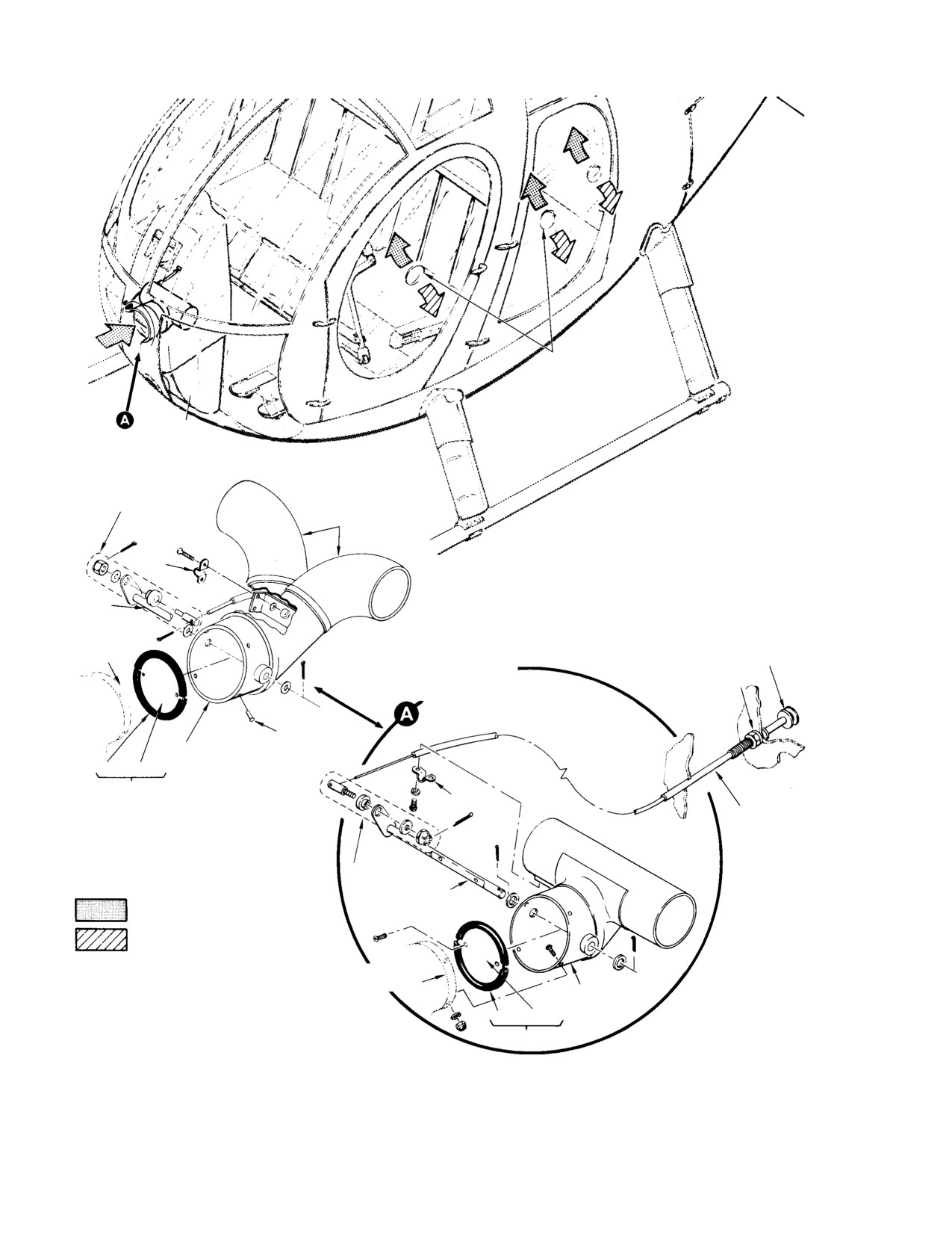
(Ref. Figure 18−1) The ventilating valve cable
is a flexible, coaxial−wire type that incorpo−
(Ref. Figure 18−1) The main fresh air source
rates a push−button locking device in the
for the cabin interior is a cable−actuated vent
control housing. This feature allows locking of
control valve located on the fuselage center−
the ventilating valve in the open, closed, or
line, recessed in the canopy panel forward of
any intermediate position.
the instrument panel.
The control assembly is not repairable. Failure
of the internal locking device is cause for
The vent control valve has a circular 4 inch
replacement.
(10.16 cm) inlet that supports the valve shaft
and control matching valve vane assembly.
A. Ventilating Valve Control Replacement
(1).
Ensure that electrical power is OFF.
The valve vane assembly is actuated by a
(2).
Disconnect cable wire from valve arm
push−pull control cable mounted in the right
swivel.
center of the instrument panel. The control
cable knob marked PULL FOR AIR is a
(3).
Remove screws, nuts washers and clip
friction catch type that locks the cable in any
securing cable to support bracket.
selected position throughout the full stroke
(4).
Remove instrument panel right side
when the knob plunger is released.
fairing.
(5).
Loosen and remove hex nut and
The vent control valve housing is formed of
lockwire securing cable knob to instru−
polycarbonate plastic.
ment panel and with drawn cable from
panel.
A single cylindrical duct on the rear of the vent
(6).
Route new cable through instrument
control valve directs air outward from both
panel and secure knob in place with
sides of the valve.
lock washer and nut.
(7).
Fasten cable sleeve to support bracket
On the early configuration, two polycarbonate
on valve and secure with clip, screws,
plastic ducts, attached to the rear of the valve,
washers and nuts.
direct inlet air through holes in sides of
console fairings for circulation through−out the
(8).
Actuate control knob to align cable wire
cabin interior.
with hole in valve arm swivel; push
knob to cable panel fitting stop.
Each pilot’s and cargo/passenger compartment
(9).
Position valve to full closed and tighten
door window contains adjustable ventilators
swivel on cable wire. Install cotter pin.
that can be opened, closed, and positioned by
rotation of the vent cutout, to supplement
(10).
Check swivel for free rotation by
fresh air intake or provide an air circulation
actuating control knob through full
exhaust outlet as desired.
stroke.
Page 18-1
Revision 19
MD Helicopters, Inc.
CSP−H−2
500 Series − Basic HMI
(11). Inspect valve assembly for complete
with 90 degree spacing to attach valve
closure of inlet opening when control
to duct. On the early configuration, if
knob is pushed forward against cable
rivet holes are elongated or over−size,
panel fitting stop.
install next larger size rivets (5/32 inch
diameter).
(12). Check valve door for looseness on shaft
(3).
Fasten cable sleeve to valve bracket
and deformation; valve door must be
with clip.
flat, and a firm, snug fit in the inlet.
(4).
Install swivel assembly loosely in arm
(13). Reinstall right side fairing on instru−
of shaft.
ment panel.
(5).
Insert control wire into swivel assem−
4. Cabin Ventilating Valve
bly.
(6).
Position shaft arm so that valve door is
(Ref. Figure 18−1) The cabin ventilating valve
fully closed.
is made of polycarbonate plastic and incorpo−
rates a valve vane assembly to control ventilat−
(7).
Push control knob all the way in then
ing air flow.
tighten swivel assembly on wire. Install
cotter pin.
The vane assembly consists of a seal bonded
around a circular aluminum vane.
(8).
Operate valve through several open−
close cycles to assure ease of operation
The valve assembly is attached by four screws,
and to determine that valve locks in
washers, and nuts to a duct molded into the
any position when control knob is
fiberglass canopy panel.
released.
(9).
On early configuration, install ducts on
On the early configuration, the valve is
rear of vent control valve.
attached with four rivets.
(10).
Install instrument panel left and right
A. Ventilating Valve Removal
side fairings
(1). Remove instrument panel left and right
C. Ventilating Valve Inspection
side fairings.
(1). Inspect plastic walls for cracks, secure
(2). On the early configuration, remove
attachment to the canopy panel and
ducts from rear of vent control valve.
separation of bonded joints. (Very small,
widely separated spots or voids in the
(3). Remove cable clip.
plastic joints are not separation but air
pockets produced during the solvent
(4). Pull cable control to open valve door.
bonding process.)
(5). Loosen swivel assembly and disconnect
(2). Inspect for bent shaft or valve vane
control cable.
assembly and excessive shaft wear in
the pivot areas.
(6). Remove four screws, washers and nuts
(3). Inspect seal on vane assembly for wear.
that attach valve to canopy panel duct.
On the early configuration, drill out the
D. Ventilating Valve Disassembly
four rivets.
(1). Remove two screws from shaft and vane
(7). Remove valve assembly.
assembly. Slide vane assembly from
shaft.
B. Ventilating Valve Installation
(2). Remove cotter pin and washer and slide
(1). Position valve on canopy panel duct and
shaft from valve body.
align screws or rivet holes, as applica−
E. Ventilating Valve Reassembly
ble
(1). Install cotter pin in hole at control arm
(2). Install four screws, washers and nuts
end of shaft. Install washer on shaft to
(or MS20470A rivets, as applicable)
bear on cotter pin.
Page 18-2
Revision 19
MD Helicopters, Inc.
CSP−H−2
500 Series − Basic HMI
(2). Insert shaft in body of valve.
5. Door Window Ventilators (Snapvents)
(3). Insert valve vane assembly into slot in
(Ref. Figure 18−1) Plastic snapvents are
shaft.
installed in each of the four door windows.
These units may be rotated in their reinforced
(4). Install two screws through vane and
window holes for intake or exhaust of ventilat−
shaft using loctite (29, Table 2−4).
ing air or may be pulled in ward for completed
(5). Install washer on end of shaft and
closure. Damaged snapvents should be
insert cotter pin.
replaced; repair is not practical.
(6). Operate valve several times to assure
A. Window Snapvent Replacement
freedom and positive closing.
(1). Push snap vent outward in window
F. Ventilating Valve Repair
(open position).
(1). Repair polycarbonate valve body cracks
(2). Grasp the open side of the snapvent
by binding a patch according to the
and gently squeeze it into an elliptical
criteria and methods specified for
shape.
acrylic plastic in FAA AC 43.13−1,
Aircraft Inspection and Repair. Use
(3). Slip snapvent out of window hole at
dichloromethane (38, Table 2−4) or
about a 30 degree angle to surface of
ethylene dichloride as the bonding
window.
agent.
(4). Hold the open end of the replacement
(2). Repair small areas of rib or seam
snapvent and gently squeeze it into an
separation by injecting ethylene
elliptical shape.
dichloride (39) into the void area and
clamping together under light pressure.
(5). Slip snapvent flange into window hole
(3). Replace unserviceable seal, using
at an angle of about 30 degrees to the
adhesive (69) according to container
surface of the window. Be sure the ends
instructions.
of wire stiffener are inside window hole.
Page 18-3
Revision 19
MD Helicopters, Inc.
CSP−H−2
500 Series − Basic HMI
DOOR WINDOW
VENTILATORS
(SNAPVENTS)
(TYP)
SWIVEL ASSY
DUCT
CLIP
SHAFT
CANOPY
CONTROL
PANEL
KNOB
JAMNUT AND SPRING
CURRENT CONFIGU−
LOCKWASHER
RATION
RIVET
(MS20470A4)
CABIN VENT VALVE
SEAL
VANE
VANE AS−
EARLY CONFIGU−
CLIP
SEMBLY
RATION
CONTROL
CABLE
SWIVEL ASSY
SHAFT
OUTSIDE (RAM) AIR
INSIDE (EXHAUST AIR
CANOPY PANEL
CABIN VENT
VALVE
SEAL
VANE
VANE ASSY
30−093D
Figure 18-1. Ventilating System
Page 18-4
Revision 19
MD Helicopters, Inc.
CSP−H−2
500 Series − Basic HMI
Section
19
Electrical System
MD Helicopters, Inc.
CSP−H−2
500 Series − Basic HMI
TABLE OF CONTENTS
Para/Figure/Table
Title
Page
Section 19 Electrical System .
19−1
1.
Power Supply and Distribution
19−1
2.
Power Supply and Distribution System Troubleshooting . .
19−1
3.
Electrical System Load Chart
19−1
Figure 19−1. Arrangement of Electrical System Switches and
Circuit Breakers
19−2
Table 19−1. Basic Equipment Electrical Load Analysis Chart .
19−3
Table 19−2. Optional Equipment Electrical Load Analysis Chart .
19−6
Figure 19−2. Electrical System Load Analysis
19−9
Table 19−3. Troubleshooting Dc Power Distribution
19−11
4.
Wiring Harnesses
19−13
A. Wire Harness Replacement
19−13
5.
Electrical Connectors
19−13
A. Plug/Socket Connector Repair or Replacement
19−13
Figure 19−3. Repair or Replacement of Rectangular Electrical Connectors .
19−14
B. Disconnection/Connection of Wire Mate Connectors
19−15
C. Minilok and Modulok Terminal Block Contact Tip Replacement .
19−15
Figure 19−4. Identification and Replacement of Burndy Terminal Block
Modules
19−16
D. Minilok and Modulok Terminal Block Replacement
19−17
E. Electrical Bonding Connector Maintenance
19−17
Figure 19−5. Typical Requirement for Electrical Bonding Connections .
19−18
F. External Power Receptacle Replacement
19−19
6.
Electrical Equipment
19−19
7.
Voltage Regulator
19−19
A. Voltage Regulator Replacement
19−19
Figure 19−6. Electrical Equipment (Cabin Locations)
19−20
B. Installed Voltage Regulator Adjustment
19−21
Figure 19−7. Voltage Regulator Test Points
19−21
Table 19−4. Recommended Voltage Setting
19−21
C. Voltage Regulator Bench Testing
19−22
8.
Overvoltage Relay
19−22
A. Overvoltage Relay Replacement
19−22
Figure 19−8. Test Hookup for Voltage Regulator
19−23
Figure 19−9. Electrical Equipment Locations (Instrument Panel Type A) .
19−24
Figure 19−10. Electrical Equipment Locations (Instrument Panel Type B) .
19−25
9.
Circuit Breaker Panel
19−26
A. Circuit Breaker Replacement
19−26
Page 19−i
Revision 15
MD Helicopters, Inc.
CSP−H−2
500 Series − Basic HMI
TABLE OF CONTENTS (Cont.)
Para/Figure/Table
Title
Page
10. Control Switches
19−26
A. Control Switch Replacement
19−26
Table 19−5. Resistor Reference Designator
19−27
11. Voltage Reduction and Calibration Resistors
19−27
A. Voltage Reduction and Calibration Resistor Replacement .
19−27
12. Start Relay
19−27
A. Start Relay Replacement
19−27
Figure 19−11. Replacement of Engine Compartment Relays .
19−28
13. Reverse Current Relay
19−29
A. Reverse Current Relay Replacement
19−29
14. Battery Relay
19−29
A. Battery Relay Replacement
19−29
B. Battery Relay Troubleshooting
19−29
15. APU Relay
19−29
A. APU Relay Replacement
19−29
B. APU Relay Troubleshooting
19−30
16. Collective Pitch Stick Switches
19−30
A. Collective Pitch Stick Switch Replacement
19−30
Figure 19−12. Replace of Collective Pitch Stick Switches .
19−31
17. Battery Temperature Sensing Equipment
19−32
A. Battery Temperature Sensing Equipment Maintenance . .
19−32
B. Battery Temperature Sensing Equipment Operational Check .
19−32
Figure 19−13. Battery Temperature Sensing Equipment .
19−33
18. Battery
19−34
A. Battery Maintenance
19−34
B. Battery Replacement
19−34
Figure 19−14. Replacement of Battery Components
19−35
C. Battery Inspection
19−36
D. Testing of Battery Temperature Sensing Switches
19−36
E. Repair of Battery
19−36
19. Starter/Generator
19−38
A. Starter/Generator Removal
19−39
B. Starter/Generator Inspection
19−39
Figure 19−15. starter/generator Replacement and Repair . .
19−40
Figure 19−16. Starter/Generator Bushing Wear Limits
19−41
C. Starter/Generator Repair
19−41
Figure 19−17. Test Hookup for Starter/Generator and Brush Run−in
19−43
Page 19−ii
Revision 15
MD Helicopters, Inc.
CSP−H−2
500 Series − Basic HMI
TABLE OF CONTENTS (Cont.)
Para/Figure/Table
Title
Page
D. Starter/Generator Installation
19−44
20. Night Lighting System − Instrument Panel Type B
19−44
Page 19−iii/(19−iv blank)
Revision 15
MD Helicopters, Inc.
CSP−H−2
500 Series - Basic HMI
SECTION 19
ELECTRICAL SYSTEM
1. Power Supply and Distribution
equipment enclosure to the structure. Current
path return and static charge bonding jumpers
The electrical system consists of all electrical
are also installed at appropriate locations.
power supply, distribution and control equip−
ment, wiring and miscellaneous associated
NOTE: On all current models of the 500 Series
equipment supplied as standard on the
helicopters, electrical systems are standard
helicopter.
and essentially identical, except in instru−
ment/electrical controls console area for dif−
The electrical system is supplied by a 28−volt
ferent models. (Electrical components, com−
direct current, 150−ampere, engine−driven
ponent locations, installation, wiring, etc.
generator in conjunction with a 24−volt
throughout the helicopters are basically
nickel−cadmium battery and incorporates an
identical, except for those areas specified.)
external power receptacle. The system is a
Any differences that exist in these areas
nominal 28 Vdc, single−wire type installation
from the electrical system outlined in this
with helicopter structure used as the ground
section are described in the applicable HMI
return.
Supplement for that specific model helicop−
ter.
Control of the electrical system, exclusive of
optional intercom controls, is provided by the
2. Power Supply and Distribution System
switches and circuit breakers on the instru−
Troubleshooting
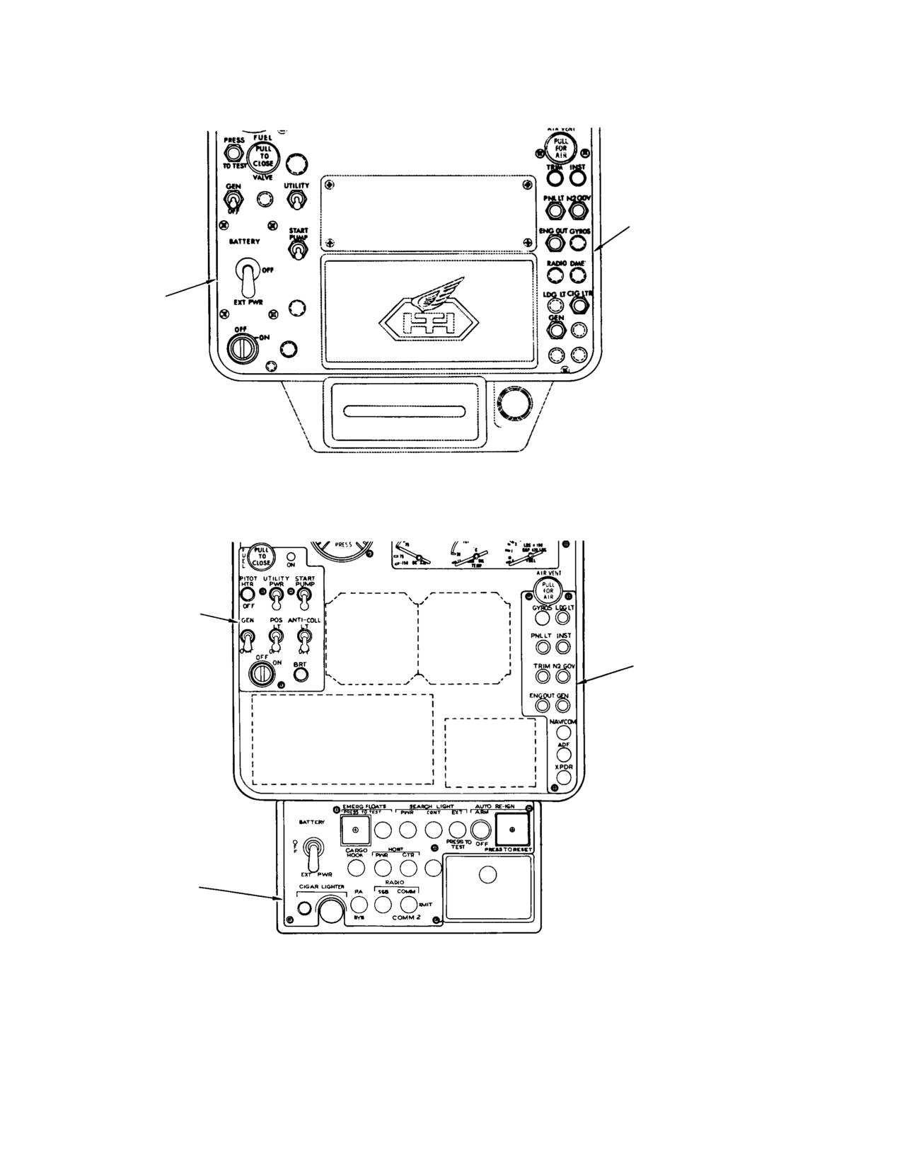
ment panel (Ref. Figure 19−1). All circuits of
the electrical system are protected by push−to−
(Ref. Table 19−3)
reset or switch−type circuit breakers. All
electrical or electronic units or components
3. Electrical System Load Chart
that produce electromagnetic energy (rf
potential) are bonded to the adjacent structure
Refer to Table 19−1, Table 19−2 and
to ensure a continuous, negligible radio
Figure 19−2 for electrical system load analysis
frequency (rf) impedance path from the
data.
Page 19-1
Revision 15
MD Helicopters, Inc.
CSP−H−2
500 Series - Basic HMI
CIRCUIT BREAKER
PANEL
SWITCH PANEL
PANEL TYPE A
(LOWER HALF)
SWITCH PANEL
CIRCUIT BREAKER
PANEL
LOWER SWITCH AND CIRCUIT
BREAKER PANEL
PANEL TYPE B
(LOWER HALF)
30−099A
Figure 19-1. Arrangement of Electrical System Switches and Circuit Breakers
Page 19-2
Revision 15
MD Helicopters, Inc.
CSP−H−2
500 Series - Basic HMI
Table 19-1. Basic Equipment Electrical Load Analysis Chart
PRE−START
START TURBINE
TAKEOFF & CLIMB
NO
AMPS
DAY
NIGHT
EQUIPMENT
PART
OF
PER
OPER
AVG. AMPS.
AVG. AMPS.
AVG. AMPS.
AVG. AMPS.
BASIC SHIP
DESIGNATION
UNITS
UNIT
TIME
OR
OR
IN
5
2
5
2
5
2
5
2
SYS
SYS
MIN.
SEC.
MIN.
SEC.
MIN.
SEC.
MIN.
SEC.
MIN.
FLIGHT CONTROLS
ACT−CYCLIC TRIM
(LONG. / LAT.)
369A7001
2
1.0
(6)
INSTRUMENTS
(OTHER THAN ENG. / FLT.)
HOUR METER
369H90027
1
0.1
15
0.1
0.1
0.1
0.1
0.1
0.1
INSTRUMENTS ENGINE
(3 PACK)
FUEL QUANT.
OIL TEMP.
( 2 )
369H6417
SYS
0.5
15
0.5
0.5
0.5
0.5
0.5
0.5
AMMETER
ENGINE−OUT WARNING SYSTEM
369H4540−BSC/−3
1
0.5
15
0.5
0.5
0.5
0.5
0.5
0.5
ENGINE−OUT WARNING LTS.
ENG. OUT
1041HS7−3
4
0.04
( 6/10 )
XMSN OIL PRESS.
( 14 )
1041HS7−4
0.04
( 6/10 )
XMSN OIL TEMP.
( 14 )
1041HS7−5
0.04
( 6/10 )
CHIP DET. ENG.
( 15 )
1041HS7−6
0.04
( 6/10 )
CHIP DET. T/R
( 15 )
1041HS7−7
0.04
( 6/10 )
CHIP DET. M/R
( 15 )
1041HS7−8
0.04
( 6/10 )
FUEL FILTER
1041HS7−11
0.04
( 6/10 )
GEN. OUT
1041HS7−10
0.04
( 6/10 )
FUEL LOW
1041HS7−9
4
0.04
( 6/10 )
INSTRUMENTS − FLIGHT
SEE OPTIONS
HEATING & VENTILATION
SEE OPTIONS
EXCITER (ALLISON)
6870058
1
1.0
2 ( 6 )
1.0
ENGINE CONTROLS
ACTUATOR − N2 GOV.
369A7002
1
1.2
2
1.2
1.2
STARTER (GENERATOR)
369H4550
SYS
−
( 12 )
(12)
(12)
LIGHTING
ANTI−COL (STROBE) LTS.
369H90062−519
SYS
2.8
15
2.8
2.8
2.8
2.8
2.8
2.8
POS. LTS. (L, R & TAIL)
369H90062
SYS
3.0
15
3.0
3.0
INSTR. & PNL LTS. (327)
369H90062
SYS
( 17 )
LANDING LT. (MS25241−4581)
369H90062
SYS
16.0
2
16.0
16.0
MAP LT (HE/HS),
UTILITY LT (HM)
( 1309 )
369H90062
1
0.3
2
0.3
0.3
0.3
0.3
CONVENIENCE LT. (REAR)
( 1309 )
369H90062
1
0.3
2
0.3
0.3
DIMMER (AUTRONICS)
369H6425
SYS
2.5
15
2.5
2.5
2.5
2.5
2.5
2.5
CIGAR LIGHTER (C75Z1505A2 FORD)
369H6508
2
7.7
( 6 )
POWER
369H4115
BATTERY CHARGING
( 18 )
369A4540
1
( 4 )
( 4 )
40.0
30.0
40.0
30.0
OVER VOLTAGE RELAY
369A4557
1
0.2
( 5 )
REVERSE CURRENT RELAY
A700xA HARTMAN
1
0.5
15
0.5
0.5
0.5
0.5
0.5
0.5
VOLTAGE REGULATOR
369A4552
1
−
( 5 )
GENERATOR (STARTER)
369A4550
1
−
( 1 )
START PUMP
369A8143
SYS
3.5
2
3.5
3.5
BASIC SHIP AMPERES
2.8
2.8
9.3
8.3
44.4
34.4
66.5
56.5
Page
19-3
Revision 15
MD Helicopters, Inc.
CSP−H−2
500 Series - Basic HMI
Table 19-1. Basic Equipment Electrical Load Analysis Chart (Cont)
HOVER
CRUISE
DAY
NIGHT
DAY
NIGHT
EQUIPMENT
PART
AVG. AMPS.
AVG. AMPS.
AVG. AMPS.
AVG. AMPS.
BASIC SHIP
DESIGNATION
5
2
15
5
2
15
5
2
15
5
2
15
SEC.
MIN.
MIN.
SEC.
MIN.
MIN.
SEC.
MIN.
MIN.
SEC.
MIN.
MIN.
FLIGHT CONTROLS
ACT−CYCLIC TRIM
(LONG. / LAT.)
369A7001
INSTRUMENTS
(OTHER THAN ENG. / FLT.)
HOUR METER
369H90027
0.1
0.1
0.1
0.1
0.1
0.1
0.1
0.1
0.1
0.1
0.1
0.1
INSTRUMENTS ENGINE
(3 PACK)
FUEL QUANT.
OIL TEMP.
( 2 )
369H6417
0.5
0.5
0.5
0.5
0.5
0.5
0.5
0.5
0.5
0.5
0.5
0.5
AMMETER
ENGINE−OUT WARNING SYSTEM
369H4540−BSC/−3
0.5
0.5
0.5
0.5
0.5
0.5
0.5
0.5
0.5
0.5
0.5
0.5
ENGINE−OUT WARNING LTS.
ENG. OUT
1041HS7−3
XMSN OIL PRESS.
( 14 )
1041HS7−4
XMSN OIL TEMP.
( 14 )
1041HS7−5
CHIP DET. ENG.
( 15 )
1041HS7−6
CHIP DET. T/R
( 15 )
1041HS7−7
CHIP DET. M/R
( 15 )
1041HS7−8
FUEL FILTER
1041HS7−11
GEN. OUT
1041HS7−10
FUEL LOW
1041HS7−9
INSTRUMENTS − FLIGHT
SEE OPTIONS
HEATING & VENTILATION
SEE OPTIONS
EXCITER (ALLISON)
6870058
ENGINE CONTROLS
ACTUATOR − N2 GOV.
369A7002
STARTER (GENERATOR)
369H4550
LIGHTING
ANTI−COL (STROBE) LTS.
369H90062−519
2.8
2.8
2.8
2.8
2.8
2.8
2.8
2.8
2.8
2.8
2.8
2.8
POS. LTS. (L, R & TAIL)
369H90062
3.0
3.0
3.0
3.0
3.0
3.0
3.0
INSTR. & PNL LTS. (327)
369H90062
LANDING LT. (MS25241−4581)
369H90062
16.0
16.0
MAP LT (HE/HS),
UTILITY LT (HM)
( 1309 )
369H90062
0.3
0.3
0.3
0.3
0.3
0.3
CONVENIENCE LT. (REAR)
( 1309 )
369H90062
0.3
0.3
0.3
0.3
0.3
0.3
DIMMER (AUTRONICS)
369H6425
2.5
2.5
2.5
2.5
2.5
2.5
CIGAR LIGHTER (C75Z1505A2 FORD)
369H6508
POWER
369H4115
BATTERY CHARGING
( 18 )
369A4540
30.0
23.4
17.0
30.0
23.4
17.0
30.0
23.4
17.0
30.0
23.4
17.0
OVER VOLTAGE RELAY
369A4557
REVERSE CURRENT RELAY
A700xA HARTMAN
0.5
0.5
0.5
0.5
0.5
0.5
0.5
0.5
0.5
0.5
0.5
0.5
VOLTAGE REGULATOR
369A4552
GENERATOR (STARTER)
369A4550
START PUMP
369A8143
BASIC SHIP AMPERES
34.4
27.8
21.4
56.5
49.9
27.5
34.4
27.8
21.4
40.5
33.9
27.5
Page 19-4
Revision 15

MD Helicopters, Inc.
CSP−H−2
500 Series - Basic HMI
Table 19-1. Basic Equipment Electrical Load Analysis Chart (Cont)
LANDING
EMERGENCY − GENERATOR OUT
DAY
NIGHT
DAY
NIGHT
EQUIPMENT
PART
AVG. AMPS.
AVG. AMPS.
AVG. AMPS.
AVG. AMPS.
BASIC SHIP
DESIGNATION
5
2
5
2
5
2
15
5
2
15
SEC.
MIN.
SEC.
MIN.
SEC.
MIN.
MIN.
SEC.
MIN.
MIN.
FLIGHT CONTROLS
ACT−CYCLIC TRIM
(LONG. / LAT.)
369A7001
INSTRUMENTS
(OTHER THAN ENG. / FLT.)
HOUR METER
369H90027
0.1
0.1
0.1
0.1
0.1
0.1
0.1
0.1
0.1
0.1
INSTRUMENTS ENGINE
(3 PACK)
FUEL QUANT.
OIL TEMP.
( 2 )
369H6417
0.5
0.5
0.5
0.5
0.5
0.5
0.5
0.5
0.5
0.5
AMMETER
ENGINE−OUT WARNING SYSTEM
369H4540−BSC/−3
0.5
0.5
0.5
0.5
0.5
0.5
0.5
0.5
0.5
0.5
ENGINE−OUT WARNING LTS.
ENG. OUT
1041HS7−3
XMSN OIL PRESS.
( 14 )
1041HS7−4
XMSN OIL TEMP.
( 14 )
1041HS7−5
CHIP DET. ENG.
( 15 )
1041HS7−6
CHIP DET. T/R
( 15 )
1041HS7−7
CHIP DET. M/R
( 15 )
1041HS7−8
FUEL FILTER
1041HS7−11
GEN. OUT
1041HS7−10
0.2
0.2
0.2
0.2
0.2
0.2
FUEL LOW
1041HS7−9
INSTRUMENTS − FLIGHT
SEE OPTIONS
HEATING & VENTILATION
SEE OPTIONS
EXCITER (ALLISON)
6870058
ENGINE CONTROLS
ACTUATOR − N2 GOV.
369A7002
STARTER (GENERATOR)
369H4550
LIGHTING
ANTI−COL (STROBE) LTS.
369H90062−519
2.8
2.8
2.8
2.8
2.8
2.8
2.8
2.8
2.8
2.8
POS. LTS. (L, R & TAIL)
369H90062
3.0
3.0
3.0
3.0
3.0
INSTR. & PNL LTS. (327)
369H90062
LANDING LT. (MS25241−4581)
369H90062
16.0
16.0
16.0
16.0
MAP LT (HE/HS),
UTILITY LT (HM)
( 1309 )
369H90062
0.3
0.3
0.3
0.3
0.3
CONVENIENCE LT. (REAR)
( 1309 )
369H90062
0.3
0.3
0.3
0.3
0.3
DIMMER (AUTRONICS)
369H6425
2.5
2.5
2.5
2.5
2.5
CIGAR LIGHTER (C75Z1505A2 FORD)
369H6508
POWER
369H4115
BATTERY CHARGING
( 18 )
369A4540
OVER VOLTAGE RELAY
369A4557
REVERSE CURRENT RELAY
A700xA HARTMAN
0.5
0.5
0.5
0.5
VOLTAGE REGULATOR
369A4552
GENERATOR (STARTER)
369A4550
START PUMP
369A8143
BASIC SHIP AMPERES
4.4
4.4
26.5
26.5
4.1
4.1
4.1
26.2
26.2
10.2
Page
19-5
Revision 15
MD Helicopters, Inc.
CSP−H−2
500 Series - Basic HMI
Table 19-2. Optional Equipment Electrical Load Analysis Chart
PRE−START
START TURBINE
TAKEOFF & CLIMB
NO.
AMPS
DAY
NIGHT
EQUIPMENT
PART
OF
PER
OPER
AVG. AMPS.
AVG. AMPS.
AVG. AMPS.
AVG. AMPS.
OPTIONS
DESIGNATION
UNITS
UNIT
TIME
OR
OR
IN
5
2
5
2
5
2
5
2
SYS
SYS
MIN
SEC.
MIN.
SEC.
MIN.
SEC.
MIN.
SEC.
MIN.
ARMAMENT
SYS.
GYRO
ATTITUDE
369H90041−501
0.7
15
0.7
0.7
0.7
0.7
DIRECTIONAL
369H90042−BSC
0.7
15
0.7
0.7
0.7
0.7
DIRECTIONAL
369H90042−501
1.8
15
1.8
1.8
1.8
1.8
ANTI−COL−LTS
(QTZ IODINE 2 LTS)
369H90062
1.5
15
1.5
1.5
BOOM (QTZ 1 LT)
369H90062−515
1.5
15
1.5
1.5
POS−LTS BOOM
369H90062−513
1.8
15
1.8
1.8
CARGO HOOK
369H90065
14.0
( 6 )
HOIST
( 13 )
369H90070
35.0
( 6 )
RE−IGNITION−ENGINE
369H90118−501/−505
( 6 )
EMERGENCY FLOATS
369H92557
2.2
15 ( 7 )
HEATED PITOT TUBE
369H90034
1.3
15
1.3
1.3
1.3
1.3
HEATING − CABIN
369H90020
1.1
( 6 )
HEATING − ANTI−ICE
369H90020
0.3
( 6 )
VHF COMM (TRANS) RT−221AE−28
369H90064−3
3.9
( 8 )
VHF COMM (REC) RT−221BE−28
369H90064−5
1.1
15
1.1
1.1
1.1
1.1
VOR−VHF (NAV) RN−222AE−28
369H90064−7
0.3
15
0.3
0.3
0.3
0.3
DME
NARCO 001−4
369H90064−11
3.5
15
3.5
3.5
3.5
3.5
TRANSPONDER TR611B−28ATC
369H90064−81/−151
0.5
15
0.5
0.5
0.5
0.5
0.5
0.5
NAV RCVR RCA−AVN−211
REC
369H90066−503
0.2
15
0.2
0.2
0.2
0.2
0.2
0.2
TRANSCEIVER RCA−AVC−110 TRAN
369H90066−BSC
4.5
( 8 )
S
NAV/COM KING KX170A
REC
369H90071
1.0
15
1.0
1.0
1.0
1.0
1.0
1.0
TRANS
5.0
( 8 )
ADF KING
KR80
369H90064−9
0.4
15
0.4
0.4
0.4
0.4
KR85
369H90067
1.0
15
1.0
1.0
1.0
1.0
SSB SUNAIR ASB/125/60
REC
369H90144
2.5
15
2.5
2.5
2.5
2.5
TRANS
7.5
( 8 )
P.A. UNIVERSITY SOUND
IDLE
369H90146
0.1
15
0.1
0.1
0.1
0.1
PEAK
8.0
( 8 )
ICS INTERCOM
369H6426 ADP
369H90068
0.2
15
0.2
0.2
0.2
0.2
369H94008 ADP
369H90064
SYS.
0.2
15
0.2
0.2
0.2
0.2
INSTALLED OPTIONS AMPS
BASIC SHIP AMPS
2.8
2.8
9.3
8.3
44.4
34.4
66.5
56.5
TOTAL SHIP AMPERES
Page 19-6
Revision 15

MD Helicopters, Inc.
CSP−H−2
500 Series - Basic HMI
Table 19-2. Optional Equipment Electrical Load Analysis Chart (Cont)
HOVER
CRUISE
DAY
NIGHT
DAY
NIGHT
EQUIPMENT
PART
AVG. AMPS.
AVG. AMPS.
AVG. AMPS.
AVG. AMPS.
OPTIONS
DESIGNATION
5
2
15
5
2
15
5
2
15
5
2
15
SEC.
MIN.
MIN.
SEC.
MIN.
MIN.
SEC.
MIN.
MIN.
SEC.
MIN.
MIN.
ARMAMENT
GYRO
ATTITUDE
369H90041−501
0.7
0.7
0.7
0.7
0.7
0.7
0.7
0.7
0.7
0.7
0.7
0.7
DIRECTIONAL
369H90042−BSC
0.7
0.7
0.7
0.7
0.7
0.7
0.7
0.7
0.7
0.7
0.7
0.7
DIRECTIONAL
369H90042−501
1.8
1.8
1.8
1.8
1.8
1.8
1.8
1.8
1.8
1.8
1.8
1.8
ANTI−COL−LTS
(QTZ IODINE 2 LTS)
369H90062
1.5
1.5
1.5
1.5
1.5
1.5
BOOM (QTZ 1 LT)
369H90062−515
1.5
1.5
1.5
1.5
1.5
1.5
POS−LTS BOOM
369H90062−513
1.8
1.8
1.8
1.8
1.8
1.8
CARGO HOOK
369H90065
HOIST
( 13 )
369H90070
RE−IGNITION−ENGINE
369H90118−501/−505
EMERGENCY FLOATS
369H92557
2.2
2.2
2.2
2.2
2.2
2.2
2.2
2.2
2.2
2.2
2.2
2.2
HEATED PITOT TUBE
369H90034
1.3
1.3
1.3
1.3
1.3
1.3
1.3
1.3
1.3
1.3
1.3
1.3
HEATING − CABIN
369H90020
HEATING − ANTI−ICE
369H90020
VHF COMM (TRANS) RT−221AE−28
369H90064−3
VHF COMM (REC) RT−221BE−28
369H90064−5
1.1
1.1
1.1
1.1
1.1
1.1
1.1
1.1
1.1
1.1
1.1
1.1
VOR−VHF (NAV) RN−222AE−28
369H90064−7
0.3
0.3
0.3
0.3
0.3
0.3
0.3
0.3
0.3
0.3
0.3
0.3
DME
NARCO 001−4
369H90064−11
3.5
3.5
3.5
3.5
3.5
3.5
3.5
3.5
3.5
3.5
3.5
3.5
TRANSPONDER TR611B−28ATC
369H90064−81/−151
0.5
0.5
0.5
0.5
0.5
0.5
0.5
0.5
0.5
0.5
0.5
0.5
NAV RCVR RCA−AVN−211
REC
369H90066−503
0.2
0.2
0.2
0.2
0.2
0.2
0.2
0.2
0.2
0.2
0.2
0.2
TRANSCEIVER RCA−AVC−110 TRAN
369H90066−BSC
S
NAV/COM KING KX170A
REC
369H90071
1.0
1.0
1.0
1.0
1.0
1.0
1.0
1.0
1.0
1.0
1.0
1.0
TRANS
ADF KING
KR80
369H90064−9
0.4
0.4
0.4
0.4
0.4
0.4
0.4
0.4
0.4
0.4
0.4
0.4
KR85
369H90067
1.0
1.0
1.0
1.0
1.0
1.0
1.0
1.0
1.0
1.0
1.0
1.0
SSB SUNAIR ASB/125/60
REC
369H90144
2.5
2.5
2.5
2.5
2.5
2.5
2.5
2.5
2.5
2.5
2.5
2.5
TRANS
P.A. UNIVERSITY SOUND
IDLE
369H90146
0.1
0.1
0.1
0.1
0.1
0.1
0.1
0.1
0.1
0.1
0.1
0.1
PEAK
ICS INTERCOM
369H6426 ADP
369H90068
0.2
0.2
0.2
0.2
0.2
0.2
0.2
0.2
0.2
0.2
0.2
0.2
369H94008 ADP
369H90064
0.2
0.2
0.2
0.2
0.2
0.2
0.2
0.2
0.2
0.2
0.2
0.2
INSTALLED OPTIONS AMPS
BASIC SHIP AMPS
34.4
27.8
21.4
56.5
49.9
27.5
34.4
27.8
21.4
40.5
33.9
27.5
TOTAL SHIP AMPERES
Page 19-7
Revision 15
MD Helicopters, Inc.
CSP−H−2
500 Series - Basic HMI
Table 19-2. Optional Equipment Electrical Load Analysis Chart (Cont)
LANDING
EMERGENCY − GENERATOR OUT
DAY
NIGHT
DAY
NIGHT
EQUIPMENT
PART
AVG. AMPS.
AVG. AMPS.
AVG. AMPS.
AVG. AMPS.
OPTIONS
DESIGNATION
5
2
5
2
15
5
2
15
5
2
15
SEC.
MIN.
SEC.
MIN.
MIN.
SEC.
MIN.
MIN.
SEC.
MIN.
MIN.
ARMAMENT
GYRO
ATTITUDE
369H90041−501
0.7
0.7
0.7
0.7
0.7
0.7
0.7
0.7
0.7
0.7
0.7
DIRECTIONAL
369H90042−BSC
0.7
0.7
0.7
0.7
0.7
0.7
0.7
0.7
0.7
0.7
0.7
DIRECTIONAL
369H90042−501
1.8
1.8
1.8
1.8
1.8
1.8
1.8
1.8
1.8
1.8
1.8
ANTI−COL−LTS
(QTZ IODINE 2 LTS)
369H90062
1.5
1.5
1.5
1.5
1.5
1.5
BOOM (QTZ 1 LT)
369H90062−515
1.5
1.5
1.5
1.5
1.5
1.5
POS−LTS BOOM
369H90062−513
1.8
1.8
1.8
1.8
1.8
1.8
CARGO HOOK
369H90065
HOIST
( 13 )
369H90070
RE−IGNITION−ENGINE
369H90118−501/−505
EMERGENCY FLOATS
369H92557
2.2
2.2
2.2
2.2
2.2
2.2
2.2
2.2
2.2
2.2
2.2
HEATED PITOT TUBE
369H90034
1.3
1.3
1.3
1.3
1.3
1.3
1.3
1.3
1.3
1.3
1.3
HEATING − CABIN
369H90020
HEATING − ANTI−ICE
369H90020
VHF COMM (TRANS) RT−221AE−28
369H90064−3
VHF COMM (REC) RT−221BE−28
369H90064−5
1.1
1.1
1.1
1.1
1.1
1.1
1.1
1.1
1.1
1.1
1.1
VOR−VHF (NAV) RN−222AE−28
369H90064−7
0.3
0.3
0.3
0.3
0.3
0.3
0.3
0.3
0.3
0.3
0.3
DME
NARCO 001−4
369H90064−11
3.5
3.5
3.5
3.5
3.5
3.5
3.5
3.5
3.5
3.5
3.5
TRANSPONDER TR611B−28ATC
369H90064−81/−151
0.5
0.5
0.5
0.5
0.5
0.5
0.5
0.5
0.5
0.5
0.5
NAV RCVR RCA−AVN−211
REC
369H90066−503
0.2
0.2
0.2
0.2
0.2
0.2
0.2
0.2
0.2
0.2
0.2
TRANSCEIVER RCA−AVC−110 TRAN
369H90066−BSC
S
NAV/COM KING KX170A
REC
369H90071
1.0
1.0
1.0
1.0
1.0
1.0
1.0
1.0
1.0
1.0
1.0
TRANS
ADF KING
KR80
369H90064−9
0.4
0.4
0.4
0.4
0.4
0.4
0.4
0.4
0.4
0.4
0.4
KR85
369H90067
1.0
1.0
1.0
1.0
1.0
1.0
1.0
1.0
1.0
1.0
1.0
SSB SUNAIR ASB/125/60
REC
369H90144
2.5
2.5
2.5
2.5
2.5
2.5
2.5
2.5
2.5
2.5
2.5
TRANS
P.A. UNIVERSITY SOUND
IDLE
369H90146
0.1
0.1
0.1
0.1
0.1
0.1
0.1
0.1
0.1
0.1
0.1
PEAK
ICS INTERCOM
369H6426 ADP
369H90068
0.2
0.2
0.2
0.2
0.2
0.2
0.2
0.2
0.2
0.2
0.2
369H94008 ADP
369H90064
0.2
0.2
0.2
0.2
0.2
0.2
0.2
0.2
0.2
0.2
0.2
INSTALLED OPTIONS AMPS
BASIC SHIP AMPS
4.4
4.4
26.5
26.5
− − −
4.1
4.1
4.1
26.2
26.2
10.2
TOTAL SHIP AMPERES
Page 19-8
Revision 15
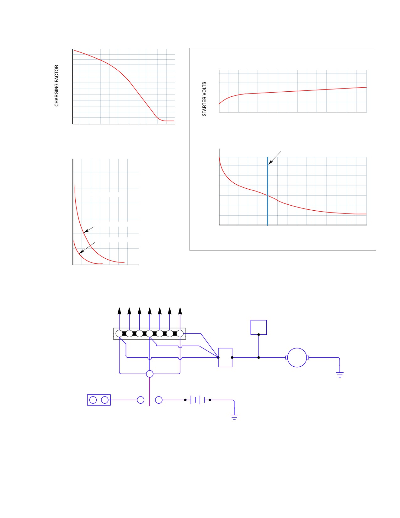
MD Helicopters, Inc.
CSP−H−2
500 Series - Basic HMI
BATTERY CHARGING GRAPH
FACTOR VS. TIME
3.0
ENGINE STARTING REQUIREMENTS DATA
2.5
2.0
30
1.5
20
1.0
10
0.5
0
0
2
4
6
8
10
12
14
16
18
20
22
24
26
28
30
0
TIME (SECONDS)
0
0.1
0.2
0.5
1.0
2.0
5.0
15
20
50
100
POSSIBLE SYSTEM PEAK, 369 AMPS
ELAPSED TIME IN MINUTES
PROBABLE SYSTEM PEAK, 360 AMPS
LIGHT OFF
TYPICAL CHARGING CURVE
FOR BATTERY
350
300
150
250
200
AT 75°F (24°C)
150
100
100
50
75
SEVERELY DISCHARGED BATTERY
0
0
2
4
6
8
10
12
14
16
18
20
22
24
26
28
30
50
TIME (SECONDS)
MODERATELY DISCHARGED BATTERY
STARTING TRANSIENT CURVE
25
0
0
10
20
30
40
50
60
TIME IN MINUTES
TO CIRCUIT BREAKERS AND LOADS
VOLTAGE
REGULATOR
1
2
3
4
5
6
7
STARTER
GENERATOR
REVERSE
2
CURRENT
RELAY
EXT. PWR.
BATTERY
S4
−
+
3
1
28 V
BATTERY EXT. PWR.
SWITCH
30−188−1
Figure 19-2. Electrical System Load Analysis
Page 19-9
Revision 15

MD Helicopters, Inc.
CSP−H−2
500 Series - Basic HMI
NOTE:
(1) The power source consists of:
A. Generator (369A4550) regulated at 26-28.5 Vdc (Ref. Generator Output table).
B. Battery (369A4530) (NI-CAD) 13 AH (19 CELL) Hi-Rate.
Generator Output
Operating
Speed
Amp Output
Volts
Altitude
Ambient Temp. Max.
Period
7500
85
26.0
Sea Level
Cont.
250°F (121°C)
8100
150
28.5
Sea Level
10 Min.
250°F (121°C)
8100
100
28.5
Sea Level
Cont.
160°F (71°C)
8300 - 12000
150
30.0
Sea Level
Cont.
104°F (40°C)
14000
0
Over−Speed
5 Min.
----
(2)
Ships with 369H4560 type console use a 4-Pack which includes an electrical engine oil pressure meter (6).
(3)
Manual controls replace electrical controls effective with production ships 0391HS, 0216HE and 0222HM.
(4)
Battery charging formula:
Avg. AMPS - (I) = AH X C;
I = Battery charging current;
AH = Ampere-hour capacity of battery, based on the 2-hour discharge rate;
C = Charging factor from the graph above.
(5)
This load is considered negligible.
(6)
This load is intermittent and is considered negligible.
(7)
Valves remain electrically energized after inflation of floats.
(8)
Duty cycle is 10% of maximum time interval.
(9)
Idle current 1 ampere maximum. average current 5-8 amperes, peak current 18 amperes.
(10)
Warning lights are operative during alarm conditions only.
(11)
Solenoid valves remain energized during time floats are inflated.
(12)
See starting load chart.
(13)
The maximum duty cycle for the hoist is 3 complete cycles (approximately 15 minutes total) and then rest
40 minutes before repeating cycle.
(14)
Ships with 369H4260 type console have one light only for engine oil pressure and temperature.
(15)
Ships with 369H4260 type console have one light only for engine oil, main rotor and tail rotor chip
detectors.
(16)
Time interval of 15 minutes or over is considered as continuous.
(17)
Instrument and panel lights are included with dimmer system.
(18)
For longer duration, see typical charging curve. Accumulate time for different operating conditions.
Page 19-10
Revision 15
MD Helicopters, Inc.
CSP−H−2
500 Series - Basic HMI
Table 19-3. Troubleshooting Dc Power Distribution
Symptom
Probable Trouble
Corrective Action
WARNING: Before removing or installing components of the electrical systems, check that all electrical
power is OFF. If units are not immediately replaced, ensure that all electrical connectors are suitably
capped and stowed and all loose cable ends are properly insulated and stowed to prevent the
possibility of shorting. Serious injury or death could result from voltages present in the electrical
system.
Battery fails to energize electrical
Defective power selector switch
Replace switch.
circuits
Defective battery relay
Replace battery relay.
Battery discharged
Install serviceable battery.
Discharged battery
Charging rate incorrectly set
Adjust voltage regulator.
Battery idle too long
Install serviceable battery.
Excessive corrosion on battery
Exposure to water or corrosive fluids
Clean terminals, coat with
terminal
non-corrosive grease.
Battery overheats and/or
Charging rate too high
Adjust voltage regulator.
discharges smoke
Loose battery terminal links, straps
Repair battery as necessary.
or screws
Damaged or defective battery
Repair or replace battery.
Starter/generator fails to function
Circuit breaker out
Reset circuit breaker.
when START switch pressed
Start relay defective
Replace start relay.
Battery relay defective
Replace battery relay.
APU relay defective
Replace APU relay.
Discharged battery
Install serviceable battery.
APU, reverse polarity diode open
Replace diode.
Start/generator defective
Replace starter/generator.
START switch or wiring defective
Replace switch or repair defective
wiring.
Page 19-11
Revision 15
MD Helicopters, Inc.
CSP−H−2
500 Series - Basic HMI
Table 19-3. Troubleshooting Dc Power Distribution (Cont.)
Symptom
Probable Trouble
Corrective Action
Starter/generator fails to supply
Circuit breaker out
Reset circuit breaker.
charging current with engine
Reverse current relay defective
Replace reverse current relay.
operating
Starter/generator defective (Check
Replace sheared drive shaft.
for sheared armature drive shaft
through air inlet screen)
Voltage regulator defective
Replace voltage regulator.
Voltage regulator incorrectly adjusted
Adjust voltage regulator.
Overvoltage relay defective
Replace overvoltage relay.
GEN-OFF switch defective
Replace switch.
Defective wiring
Repair or replace defective wiring.
Ammeter indication off-scale below
Defective reverse current relay
Replace reverse current relay.
zero; engine not operating and
GEN-OFF switch is on
GEN OUT indicator light on;
Weak generator field
Replace starter/generator.
voltage lower than normal when
Defective voltage regulator
Replace voltage regulator.
engine operating
Defective starter/generator
Replace or repair starter/generator.
Incorrectly adjusted voltage regulator
Adjust voltage regulator.
Fluctuating current indication on
Unstable voltage regulator
Replace voltage regulator.
ammeter
Brushes excessively worn
Replace starter/generator brushes.
Defective starter/generator
Replace or repair starter/generator.
Loose ammeter circuit wiring or
Check ammeter circuit connections
defective resistor R3
and resister R3. Repair as
necessary.
Excessively high or low current
Incorrectly adjusted voltage regulator
Adjust voltage regulator.
indication on ammeter, engine
Defective voltage regulator
Replace voltage regulator.
operating; GEN OUT indicator light
not on
Defective starter/generator
Replace or repair starter/generator.
Defective ammeter
Replace instrument cluster (three
pack).
Incorrect connection of ammeter
Check shunt wire connection and
shunt wire, or defective resistor R3
resistor R3. Repair as necessary.
Adjustment of voltage regulator has
Defective voltage regulator
Replace voltage regulator.
no effect on voltage indication
Page 19-12
Revision 15
MD Helicopters, Inc.
CSP−H−2
500 Series - Basic HMI
4. Wiring Harnesses
NOTE: Observe method of wiring harness rout−
ing, clamping and tying prior to removal to
Components of the electrical system are
facilitate reinstallation.
connected by wiring harnesses, with wire
identification as shown in the applicable
(7).
Cut tying twine and cut or loosen nylon
wiring diagrams.
straps as necessary to permit removal
of harness.
Wires in a harness are terminated with
(8).
Route replacement harness into
terminal lugs, electrical connectors (plugs and
position.
receptacles), Wire Mate locking type pin
connectors, knife splices or snap−in contacts.
(9).
Install harness connectors (receptacle,
plug or inserts).
Wiring harnesses are held in place by nylon
self−clinching loop straps and nylon tying
(10).
Connect any harness single−terminal
twine. Nylon caterpillar−type grommets
leads.
provide insulation where harnesses pass
(11).
Replace tying twine (30, Table 2−4) and
through structural openings.
reinstall nylon straps, if available.
(Substitute tying twine if nylon straps
Each electrical wire of a harness is identified
unavailable.)
by a letter−number code (with the exception of
a few color−coded lengths that are integral to a
(12).
Install component(s) removed to gain
specific component or assembly). The letter−
access.
number code identifies the function of the
circuit of which the wire is a part, the wire
(13).
Close panels and reinstall fasteners.
number, segment and wire size (gage),
(14).
Install access door, where removed.
respectively. A description of the wire code is
included in Section 20.
(15).
Connect battery and external power
source.
NOTE: Electrical wiring that interconnects the
optional integrated interphone control unit
(16).
Check operation of all circuits affected
and terminal blocks for the optional inter−
by harness replacement. (Refer to
phone control system is installed in all heli−
applicable wiring diagrams.)
copters on which the electrical system is
5. Electrical Connectors
standard.
Plugs, receptacles, terminal block snap−in type
A. Wire Harness Replacement
contacts, locking type pin connectors, knife
splices and terminal lugs provide the means by
(1). Check that all electrical power is OFF.
which wiring and electrical harness assemblies
Accomplish the following steps as
are connected to individual panels and
applicable.
electrical components.
(2). Remove access doors.
Each plug−receptacle combination is secured
with lockwire or otherwise mechanically
(3). Open panel by removing the fasteners
locked, to prevent opening of the connection
that secure panel to structural support.
due to vibration.
(4). Remove component(s) blocking access.
Terminal block snap−in type contacts physical−
(Refer to component coverage in
ly and electrically connect individual harness
appropriate section of HMI.)
leads (wires) to terminal block modules.
(5). Disconnect and tag−identify wire
A. Plug/Socket Connector Repair or
terminal(s) at applicable panel.
Replacement
(6). Disconnect wiring harness connectors
(Ref. Figure 19−3)
(plugs or receptacles), Wire Mate
(1). Check that all electrical power is OFF.
connections and/or knife splices and
tag−identify any single terminal
(2). Remove any connector bonding or
connections
lockwire.
Page 19-13
Revision 15
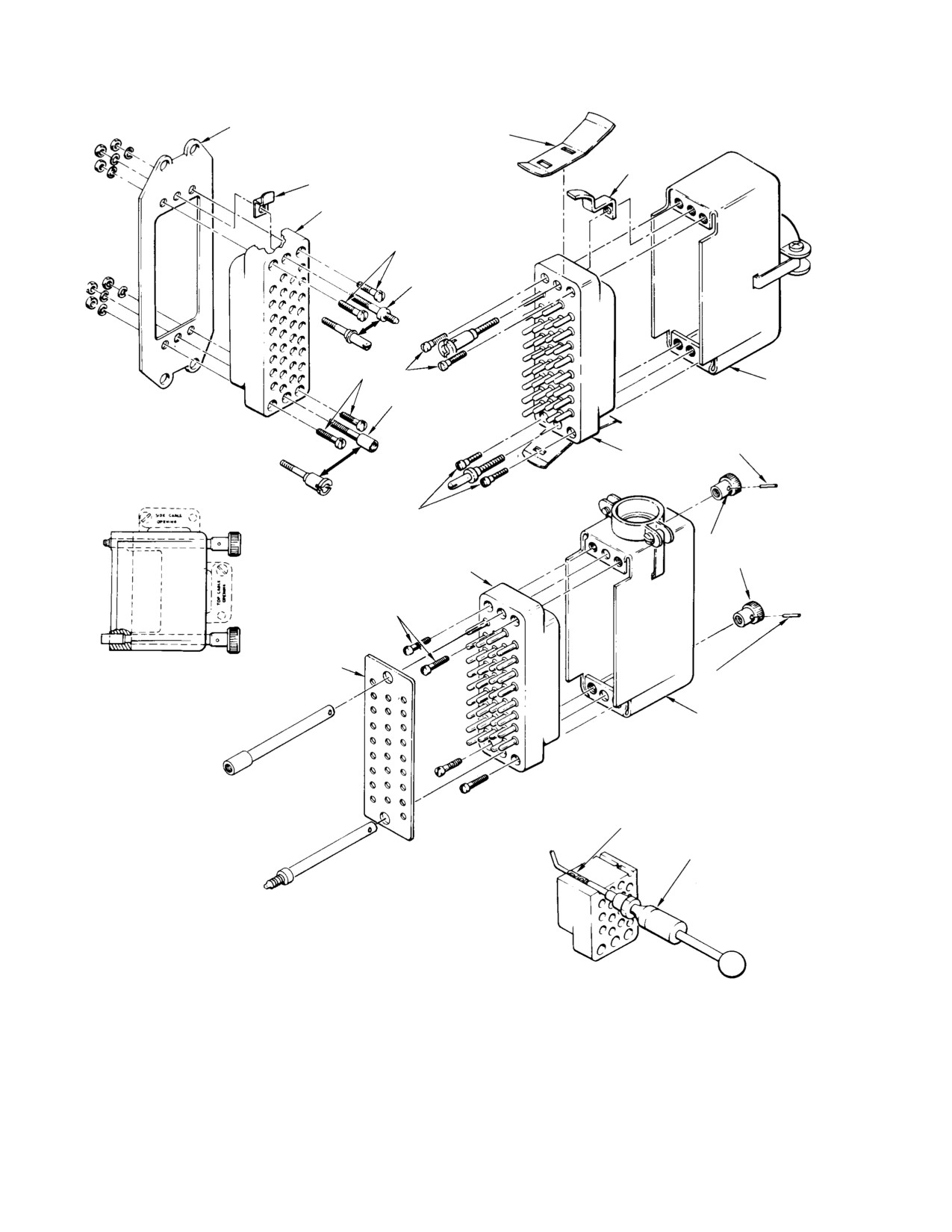
MD Helicopters, Inc.
CSP−H−2
500 Series - Basic HMI
MOUNTING PLATE
LEVER
(BULKHEAD INSTL)
PIVOT
LOCK TAB
FEMALE INSERT
NOTE 2
FIXED JACKSCREW
(NOTE 1)
NOTE 2
HOOD
FIXED JACKSCREW
EXPLODED VIEW
(NOTE 1)
OF RECEPTACLE
SELF−LOCKING
PIN
MALE INSERT
NOTE 2
JACKSCREW AND
JACKSCREW KNOBS
MALE INSERT
NOTE 2
FACE GASKET
ASSEMBLED VIEW OF MATING
(TYP) (NOTE 4)
SELF−LOCKING
CONNECTOR HALF WITH
PIN
HOOD AND TURNABLE LONG
JACKSCREWS WITH KNOBS
HOOD
EXPLODED VIEW OF PLUG
NOTE 3
REMOVABLE CONTACT
REMOVAL TOOL
(107R1001)
ASSEMBLIES
NOTES:
1.
PLUG OR RECEPTACLE INSERTS WITH 26 OR FEWER CONTACTS
ARE ASSEMBLED WITH, AND HELD IN HOOD, OR IN MOUNTING PLATE
CROSS−SECTION VIEW
BY ONLY THE TURNABLE OR FIXED JACKSCREW AND JACKSOCKET.
OF CONNECTOR
2.
MACHINE SCREWS (4−40 OR 6−32 UNC THREAD SERIES) ARE USED TO
ASSEMBLE PLUG OR RECEPTACLE INSERTS HAVING 34 OR MORE
CONTACTS.
3.
REMOVABLE CONTACTS INSTALLED ON WIRES WITH HAND−OPERATED
CRIMPING TOOL.
4.
NOT INSTALLED ON ALL CONNECTORS.
30−101B
Figure 19-3. Repair or Replacement of Rectangular Electrical Connectors
Page 19-14
Revision 15
MD Helicopters, Inc.
CSP−H−2
500 Series - Basic HMI
(3). Disconnect electrical connector from
B. Disconnection/Connection of Wire Mate
mating plug or receptacle by using the
Connectors
applicable following steps:
Wire Mate locking type pin con−
CAUTION
nectors will be damaged if
(a). Loosen strain−relief clamp on
pulled apart and disconnected without use
connector hood or adapter.
of appropriateconnector insertion/extrac−
tion tool.
(b). On circular type connectors, loosen
hood and disengage plug lock spring
(1). Disconnect Wire Mate pin connectors as
from receptacle lock ring by rotating
follows:
lock spring in either direction.
(a). Slide white end of insertion/extrac−
tion tool (42 or 43, Table 2−2) on wire
(c). Disassemble shell or hood from
with tip end toward male contact
electrical connector to expose termi−
terminal.
nals.
(b). While holding connector female half,
(d). Disconnect crimp−type removable
slide tool along wire and fully insert
contacts by using the appropriate
tool around male contact terminal
contact removal tool (33 or 36,
into female half. This disengages
Table 2−2).
retaining clip tines from male contact
terminal shoulder.
(4).
Slide insulation sleeves back over wires
and unsolder wires from contact
(c). Pull wire and male contact from
inserts, or cut off crimp−type contacts
female half while holding tool in
place.
as necessary.
(2). Connect Wire Mate pin connectors as
(5).
Solder or crimp electrical wires to insert
follows:
contacts and remove identifying tags, if
used. Use a tin−alloy solder (48,
(a). Slide colored end of insertion/extrac−
Table 2−4) for all soldering operations,
tion tool (42 or 43) on wire with tip
and the appropriate crimping tool (34 or
end behind male contact terminal
35, Table 2−2) for replacement of
shoulder.
removable crimp−type contacts.
(b). Insert and push male contact termi−
nal straight into connector female
(6).
Install crimp−type contacts by using
half, using tool end. A click will occur
the appropriate contact insertion tool
when contact terminal seats and
(33 or 36).
retaining clip tines snap in place
behind terminal shoulder.
(7).
Check for short circuits. Ensure that
resistance between pins is infinite
(c). Remove insertion−extraction tool and
except where pins are interconnected.
gently pull on connected wires to
(Refer to applicable wiring diagrams.)
ensure firm seating.
C. Minilok and Modulok Terminal Block
(8).
Join connector halves and secure.
Contact Tip Replacement
(a). On circular type connectors, rotate
(Ref. Figure 19−4)
plug lock spring to engage receptacle
lock ring.
(1). Check that all electrical power is OFF.
(2). Use a Burndy insertion/extraction tool
(b). Tighten hood or adapter strain−relief
(33, Table 2−2) to pull a HYTIP contact
clamp on connector and tighten
from a MINILOK module.
clamp screws.
(3). Strip either 0.17 or 0.20 inch (4.37 or
(c). Use lockwire and attach connector
5.16 mm) of insulation from end of wire,
bonding, as applicable.
as applicable.
Page 19-15
Revision 15
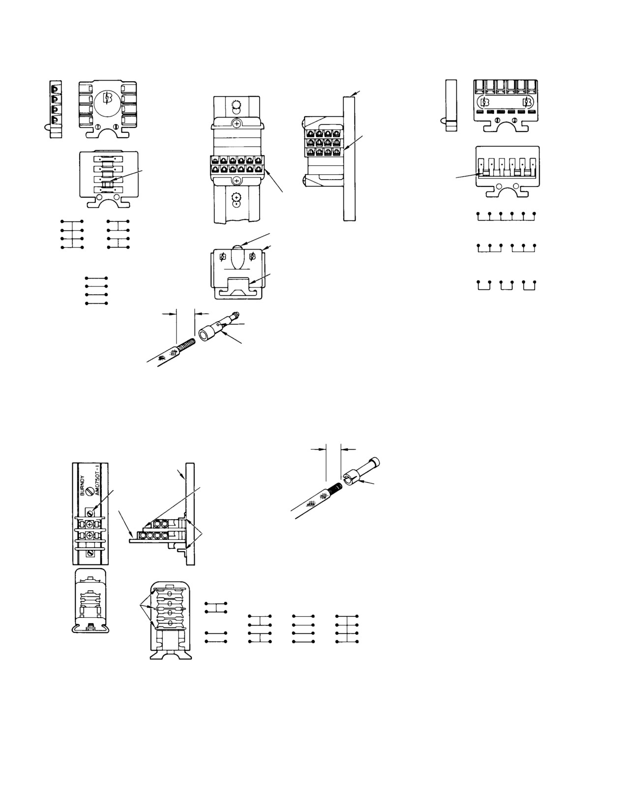
MD Helicopters, Inc.
CSP−H−2
500 Series - Basic HMI
SIDE FEED MODULE TYPE AMM 20−1
TRACK TYPE AMM 3600T−1 (POLYVINYL CHLORIDE)
TOP FEED MODULE TYPE AMM 20T−1
NOTE
BURNDY
MINILOK
MINILOK
SIDE FEED
MODULE
BUSSING
(TYP)
BUSSING
(TYP)
TOP FEED
MODULE
SCREW
A6SMM20T−1
(ALL RECEPTACLES BUSSED)
UPPER HALF
A4SMM20−1
A22DMM20−1
A23DMM20T−1
(ALL TIERS
(TWO TOP TIERS BUSSED)
(TWO SETS OF THREE
BUSSED)
(TWO BOTTOM TIERS BUSSED)
MINILOK
BASE
RECEPTACLES BUSSED)
A32DMM20T−1
(THREE SETS OF TWO
A4DMM20−1
11/64 IN.
RECEPTACLES BUSSED)
(ALL TIERS
(4.3656 MM)
INSPECTION
INDIVIDUAL)
HOLE
PCM 22M−HIF3 (AWG 24−22) USE HYTOOL M8ND WITH DIE SET N22PCT−1
MINILOK
PCM 22M−HIF3 (AWG 20) USE HYTOOL M8ND WITH DIE SET N22PCT−2
HYTIP
TYPICAL INSTALLATION OF MINILOK TERMINAL BLOCK MODULES
(REF. TB1, TB5, TB7 AND TB502)
13/64 IN.
TRACK, AM0750T−1 (NOTE) (CADMIUM−PLATE STEEL)
(5.1594 MM)
TRACK
HEADLESS
2 TIER MODULE
MODULOK CONTACT TIP
SETSCREW
AYH 14−H (AWG 20−14)
4 TIER MODULE
USE HYTOOL M8ND
WITH DIE SET N14HCT
AMC−1 CLAMP
NOTE: THE FOUR MIDDLE NUMERICAL
DIGITS IDENTIFY LENGTH IN INCHES.
AMM TRACK COMES IN 36 IN. (914.4 MM)
BUSSING
LENGTHS AND IS CUT TO SIZE: AM
(TYP)
TRACK CAN BE ORDERED IN ANY
A2SM14−1
PRECUT LENGTH UP TO 32 IN. (812.8
MM) (EG. 0750 = 7.50 IN. (190.5 MM).
A2DM14−1
A22DM14−1
A4DM14−1
A4SM14−1
TYPICAL INSTALLATION OF MODULOK TERMINAL BLOCK MODULES
(REF. TB3)
30−102A
Figure 19-4. Identification and Replacement of Burndy Terminal Block Modules
Page 19-16
Revision 15
MD Helicopters, Inc.
CSP−H−2
500 Series - Basic HMI
(4).
MODULOK modules have either
NOTE: To facilitate reassembly, tag and identi−
two−tier or four−tier spring−loaded
fy all wires that are to be disconnectedfrom
connectors. Using a standard screw−
terminal block module to be replaced.
driver for recessed head screws, twist
the locking screw counterclockwise to
(2).
Remove contact tips (Ref. Minilok and
the quick−disconnect position of the
Modulok Terminal Block Contact Tip
Screw and spring mechanism to release
Replacement).
the contact tips. Pull tips from spring−
loaded socket connectors.
(3).
Loosen the screw that secures the end
clamp holding the modules on the
(5).
Insert stripped end of wire into snap−in
track. Slide the end clamp away from
contact. On HYTIP (MINILOK)
the modules and separate the module to
contacts, check that stripped end of
be replaced by unsnapping it from
wire extends past the inspection hole.
adjoining modules.
Make sure the stripped end of the wire
is inserted as far as possible into the
(4).
With modules separated for clearance
contact tip and that the wire insulation
from one another, remove the module
extends approximately one−sixteenth of
by turning it 90 degrees and unsnap−
an inch into the contact shoulder
ping it from the track.
(MINILOK) or to end of the contact
shoulder notch (MODULOK).
(5).
Insert the replacement module into
mounting position between or next to
(6).
Using the Burndy manual crimping tool
the correct adjoining modules, rotate it
and correct die−set (34, Table 2−2),
90 degrees and snap into place. Press
crimp contact on the wire.
modules together.
(7).
Visually inspect contact tip on the wire;
(6).
Slide the end clamp into place against
check that it is firmly attached to the
the outside module. While pressing and
wire and that the stripped end of the
holding the clamp against the outside
wire blocks inspection hole in HYTIP
module, tighten the end clamp screw.
contacts.
(7).
Install contact tips.
(8).
Use a Burndy insertion/extraction tool
(33) to push HYTIP snap−in contact
(8).
Remove identifying tags from wires.
into the proper terminal block module
of the terminal block assembly. (Refer
E. Electrical Bonding Connector
to applicable wiring diagrams.)
Maintenance
(9).
Plug MODULOK contact tips into
(Ref. Figure 19−5)
spring−loaded socket connectors and
twist locking screw clockwise to the
(1). When replacing a bonding jumper, use
locked position (spring fully com−
solvent (1, Table 2−4) to remove all
pressed).
traces of grease, oil or other nonconduc−
NOTE: MODULOK modules may be set in ei−
tive film from the mating surfaces.
ther the quick− disconnect position or the
Nonsoluble films should be removed by
locked position; the spring− loaded socket
sanding and polishing with grade 400
connectors exert uniform pressure in either
abrasive paper (20), using care to
position. The quick− disconnect position
remove only a minimum of the base
should only be used to facilitate circuit ring−
metal. The polished area should be
out.
brushed clean.
D. Minilok and Modulok Terminal Block
(2). After polishing aluminum alloys, apply
Replacement
a brush coating of Iridite No. 14−2,
Class 3, chemical film protection (8) to
(1). Check that all electrical power is OFF.
the mating surfaces.
Page 19-17
Revision 15
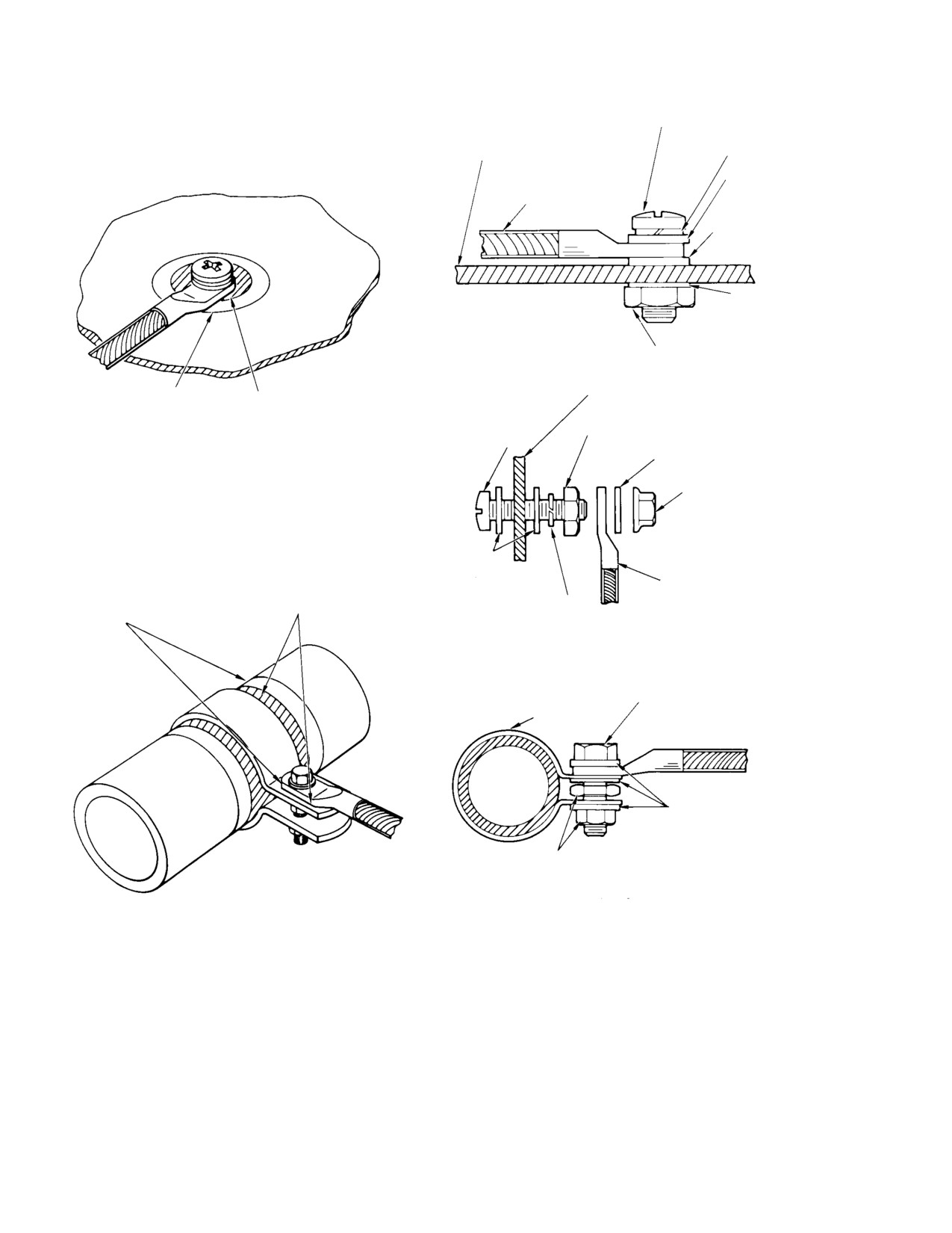
MD Helicopters, Inc.
CSP−H−2
500 Series - Basic HMI
CADMIUM−PLATED OR
CRES SCREW OR BOLT
STEEL SPRING
ALUMINUM OR MAGNESIUM
LOCKWASHER
STRUCTURE
CADMIUM−PLATED
OR CRES WASHER
JUMPER
(LIGHT SERIES)
AL ALY WASHER ( # )
AL ALY WASHER
(LIGHT SERIES)
SCREW/BOLT CONNECTION (TYP)
STANDARD OR LOW HEIGHT
STEEL LOCKNUT
AL ALY OR MAGNESIUM STRUCTURE
STEP 3
STEPS 1 AND 2
CADMIUM−PLATED OR
CADMIUM−PLATED OR CRES PLAIN HEX NUT
CRES SCREW OR BOLT
CLEANING, CORROSION
AL ALY WASHER (LIGHT SERIES)
PROTECTION AND FINISHING
STANDARD OR LOW HEIGHT
STEEL LOCKNUT
STUD CONNECTION (TYP)
AL ALY WASHER
(LIGHT SERIES)
JUMPER
STEPS 1 AND 2
STEEL SPRING
STEP 3
LOCKWASHER
BONDING JUMPER TO STRUCTURE ( * )
CADMIUM−PLATED OR CRES SHORT
THREAD SCREW OR BOLT
CLAMP ( * * )
CADMIUM−PLATED OR
CRES WASHERS
STANDARD OR THIN LOCKNUT
BONDING JUMPER TO TUBE ( * )
STEP 1. CLEAN TO BASE METAL: AREA 1−1/2 DIA. OF
( # )
NOT USED ON PLATED OR CRES STRUCTURE.
WASHER; AREA 1−1/2 CLAMP WIDTH AND INSIDE
( * )
USE CADMIUM−PLATED PARTS BELOW 300°F (149°C)
SURFACE OF CLAMP. (CLEAN CLAMP
USE CRES PARTS ABOVE 300°F (149°C); USE
EAR−TO−TERMINAL MATING SURFACE.)
WASHERS AGAINST STRUCTURE AS APPLICABLE TO
STEP 2. BRUSH COAT THE CLEANED AREA OF ALUMINUM
THE STRUCTURE MATERIAL.
WITH CHEMICAL FILM (8, TABLE 2−4).
( * * )
ALCLAD CLAMP FOR PLATED STEEL, AL ALY FOR MAG
STEP 3. APPLY CLEAR LACQUER (47) TO 1−1/2 DIA. OF
ALY STRUCTURE. CADMIUM−PLATED STEEL CLAMP
CLEANED AREA.
FOR NON−PLATED STEEL STRUCTURE (CRES CLAMPS
FOR CRES TUBE).
30−103A
Figure 19-5. Typical Requirement for Electrical Bonding Connections
Page 19-18
Revision 15
MD Helicopters, Inc.
CSP−H−2
500 Series - Basic HMI
(3). When removed bonding jumpers are
A voltage regulator, overvoltage relay and
reconnected, check that the clear
reverse current relay function with the
lacquer finish, originally applied to the
starter/generator to monitor, regulate and
cleaned mating surfaces, will not act as
control generator dc output voltage, the
an insulator between the mating
nominal 28 Vdc voltage for the electrical
surfaces. Restore mating surfaces to the
system, charging of the battery and protect
cleaned condition, as necessary,
from overvoltage. The starter/generator both
according to steps (1). and (2). above.
starts the engine and generates dc electrical
power.
(4). After connecting a bonding jumper,
apply clear lacquer (47) to the exposed
Battery temperature sensing equipment
area of the cleaned surface.
monitors and provides a visual indication of
excessive battery temperature.
(5). Ensure that bonding jumpers do not
Voltage reduction and calibration resistors are
impede the operation of movable
used for certain instruments and associated
components.
equipment.
F. External Power Receptacle Replacement
Miscellaneous switches provide for application
(Ref. Figure 19−6)
of dc power and control of related equipment.
The night lighting system is part of the
(1). Check that all electrical power is OFF.
electrical system on a helicopter with instru−
(2). Remove the two attaching screws and
ment panel type B. Information is provided in
pull receptacle outward.
Section 17 on electrically actuated instru−
ments, caution and warning indicator lights,
NOTE: It may be necessary to disconnect the
engine power out warning equipment, the
ground cable to gain sufficient slack for re−
associated sending units, and the other
ceptacle removal. If so, open right access
components installed directly in the instru−
door of pilot’s compartment floor for access
ment panel, excluding the control switches and
to cabling.
circuit breakers.
(3). Disconnect cables and remove recep−
Refer to system coverage for information on
tacle.
the engine starting pump (Section 12), the N2
trim actuator (Section 11), and cyclic trim
(4). Attach cables to terminals of replace−
actuators (Section 7). Maintenance data for
ment receptacle and secure with
optional electrical equipment items such as
terminal nuts.
night lighting kit on a helicopter with instru−
NOTE: The aft terminal is the negative (−) or
ment panel type A, heated pitot tube, inter−
ground terminal, the center terminal is the
communication systems, etc., can be found in
positive (+) terminal, and the forward(small
CSP−H−3, HMI Appendix A.
polarity pin) terminal is not used.
7. Voltage Regulator
(5). Install receptacle with two screws.
(Ref. Figure 19−6) The static voltage regulator
maintains a constant generator output voltage
(6). Reconnect any cabling disconnected to
under varying speed and load conditions. The
obtain slack for receptacle removal.
regulator has a voltage adjustment range of
26−30 volts and contains an overvoltage
6. Electrical Equipment
circuit.
Electrical equipment consists of the basic
A. Voltage Regulator Replacement
power supply, distribution and control compo−
nents, and other electrical items installed as
(1). Check that all electrical power is OFF.
standard equipment, in all configurations of
(2). Open pilot’s compartment floor left
the 500 Series helicopter.
access door, disconnect electrical
Such equipment includes the battery, starter/
connector, remove four mounting
generator, control switches, circuit breakers
screws and washers, and lift out voltage
and power supply and control relays.
regulator.
Page 19-19
Revision 15
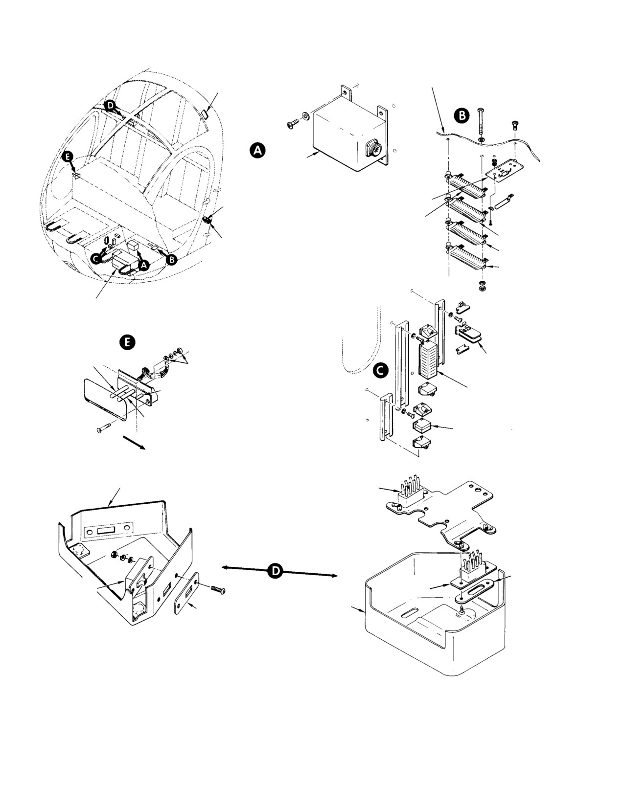
MD Helicopters, Inc.
CSP−H−2
500 Series - Basic HMI
MINILOK MODULE
TERMINAL BLOCK
PILOT’S COMPARTMENT FLOOR
(TB7)
VOLTAGE
REGULATOR
RESISTOR BOARD
UTILITY RECEPTACLE (J103)
(TB8) (R1, R2)
RESISTOR BOARD (R9)
(NOTE 2)
R10
ARMAMENT RECEPTACLE (J200)
R11
R12
BATTERY
EXTERNAL RECEPTACLE (J100)
( − ) NEGATIVE
MODULOK
TERMINAL PIN
(TYP) (2 PLCS)
TERMINAL
BLOCK (TB3)
POLARITY PIN
MINILOK MODULE
(NOT USED)
TERMINAL BLOCK
(TB1)
( + ) POSITIVE
TERMINAL PIN
MINILOK MODULE
FWD
TERMINAL BLOCK
(TB5)
HEAT DUCT AND
VNE CARD COVER
CABIN HEAT SWITCH
(OPTIONAL)
SIDE−MOUNTED
SWITCH
FACE−MOUNTED
SWITCH
SPACER
ENG. DE−ICE
ENG. DE−ICE
SWITCH
SWITCH
(NOTE 1)
(NOTE 1)
HEAT DUCT AND
BEZEL
VNE CARD COVER
NOTES:
1.
SWITCH INSTALLED AT RIGHT SIDE OF COVER WHEN PILOT
SEAT AT RIGHT POSITION.
2.
FWD AND AFT CIGAR LIGHTER RESISTOR INSTALLATION
SHOWN, USED WITH INSTRUMENT PANEL TYPE A.
30−104E
Figure 19-6. Electrical Equipment (Cabin Locations)
Page 19-20
Revision 15
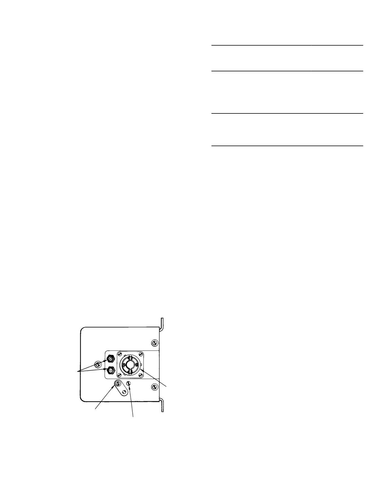
MD Helicopters, Inc.
CSP−H−2
500 Series - Basic HMI
(3). Install replacement voltage regulator
Table 19-4. Recommended Voltage Setting
with four screws and washers, and
Battery Ambient Temperature
attach electrical connector.
in Degrees
F (C)
Voltage Setting
(4). Perform an operational check of the
Up to 80 (26.9)
28. 5
new regulator and make adjustment, as
necessary.
81 - 100
(27.4
- 38.1)
28.O
101 - 130
(38.6
- 54.9)
27. 5
B. Installed Voltage Regulator Adjustment
131 - 140
(55.5
- 60.5)
27.0
NOTE: Figures in Voltage Setting column
(Ref. Table 19−4) The voltage regulator is to be
represent recommended constant potential
adjusted for a specific generator output voltage
charging voltages to which voltage regulator
according to prevailing ambient temperature.
is to be adjusted for listed temperatures.
(1). Connect a precision voltmeter to the
voltage regulator test jacks (Ref.
(4).
Increase Nl rpm to 68−70% and check
Figure 19−7).
voltmeter reading. If reading is not as
shown in Table 19−4, open the adjust−
NOTE: The voltmeter must be capable of mea−
ment screw cover, and on the connector
suring voltage within 0.25% full scale accu−
end of the voltage regulator, insert a
racy in the 0−50 Vdc range. A Weston Model
small screwdriver, and turn adjustment
931, or equivalent, is recommended. Com−
screw slowly for incremental voltage
monly available multimeters have a much
increase or decrease as necessary.
broader accuracy tolerance and are there−
Increments of 0.5 volt are possible.
fore unsatisfactory for use in setting the
(5).
While maintaining full down collective
voltage regulator.
pitch, increase Nl rpm to approximately
77−80 percent.
(2). Start engine, keep collective pitch full
(6).
Check voltmeter to see if voltage
down and allow Nl idle speed to
stabilize.
remains within the applicable tolerance
range. If necessary, readjust voltage to
remain within limits at engine speeds
(3). Turn off all unnecessary electrical
specified in steps (4). and (5). above.
loads.
(7).
Rapidly increase electrical loads by
turning on all radio and electrical
equipment possible. Except for momen−
tary fluctuations, the regulator must
maintain generator output at voltage
listed in Table 19−4 as indicated on
meter. If the electrical loads cause
voltage to vary outside this range,
replace voltage regulator and repeat
VOLTAGE
TEST JACKS
steps (1).thru (6).
(8).
Turn off electrical loads, reduce Nl rpm
CONNECTOR
to 68−70 percent, and repeat step (7).
Replace regulator if voltage setting
varies from that specified for an
ADJUSTMENT
SCREW COVER
increase in electrical load.
VOLTAGE ADJUSTMENT
SCREW
(9).
Shut down engine.
30−105
(10).
Disconnect and remove voltmeter, close
Figure 19-7. Voltage Regulator Test Points
voltage regulator adjustment screw
Page 19-21
Revision 15
MD Helicopters, Inc.
CSP−H−2
500 Series - Basic HMI
cover, and tighten cover retaining
This should occur at 32.0 ±1.0 volts
screw.
indicated on meter M1. Return poten−
tiometer to full CCW position.
C. Voltage Regulator Bench Testing
(11). Reset the overvoltage relay by switch−
(Ref. Figure 19−8 for test equipment and
ing Sl OFF and then ON.
wiring hookup)
(12). Turn switches OFF in the following
(1).
Mount generator on vari−drive.
order: S1, S3, S5, and S4, Disconnect
the voltage regulator.
(2).
Connect voltage regulator into test
circuit.
8. Overvoltage Relay
(3).
Adjust potentiometer R2 fully CCW
(Ref. Figure 19−9) The overvoltage relay
while the load bank is off (switch S5
protects the 28 Vdc system from an overvol−
OFF). Set switch Sl OFF and S3 and S4
tage condition. With the GEN OFF switch on,
ON.
the normally closed contacts of the overvoltage
relay apply generator output to the SW
(4).
Hold momentary contact switch S2 ON,
(switch) circuit of the reverse current relay.
start vari−drive and adjust to bring
When an overvoltage occurs in the range of
generator speed to 7200 rpm or above.
32.0 ±1.0 volts, the overvoltage relay ener−
Voltage shown on meter M1 must not
gizes, removing power from the switch circuit
exceed 10.75 volts; this indicates that
of the reverse current relay to remove genera−
the voltage regulator is in the simu−
tor output from the electrical system.
lated start mode.
No attempt should be made to
CAUTION
(5).
Release switch S2. Regulator must
adjust the overvoltage circuit in
regulate voltage to between 26.0−30.0
the helicopter. Adjustment is performed
Vdc as indicated on meter M1.
only during bench test of the voltage regula−
tor.
(6).
Check that full range of voltage
A. Overvoltage Relay Replacement
adjustment potentiometer on voltage
regulator is 26.0−30.0 Vdc as indicated
(1).
Check that all electrical power is OFF.
on meter M1.
(2).
Gain access to overvoltage relay on
(7).
Adjust generator speed to 10,750 rpm.
instrument panel structure by remov−
Switch Sl ON and adjust the potentiom−
ing fairing from left side of instrument
eter on the voltage regulator to 28.5
panel.
±0.3 Vdc as indicated on meter M1.
(3).
Remove two screws, washers, and nuts
(8).
Switch S5 ON and adjust the load bank
that attach relay.
to a 100−ampere load as indicated on
meter M2; then switch S1 ON and then
(4).
Unsolder electrical wiring from relay
OFF. The voltage regulator shall
terminal lugs.
regulate voltage under load surge
conditions.
(5).
Be sure insulation sleeving is used over
wires and solder wires to terminal lugs
(9).
Decrease generator speed to 7200 rpm
of replacement relay. Slide insulation
and apply a 100−ampere load; then
sleeving over relay solder terminals.
switch Sl ON and OFF. The voltage
Remove identifying tags if used.
regulator shall regulate voltage under
load surge conditions.
(6).
Locate overvoltage relay on mounting
panel and secure with screws, washers
(10).
Adjust load bank to 10−20 ampere load.
and nuts.
Switch S4 OFF. Adjust potentiometer
R2 CW until overvoltage relay operates.
(7).
Reinstall instrument panel fairing.
Page 19-22
Revision 15
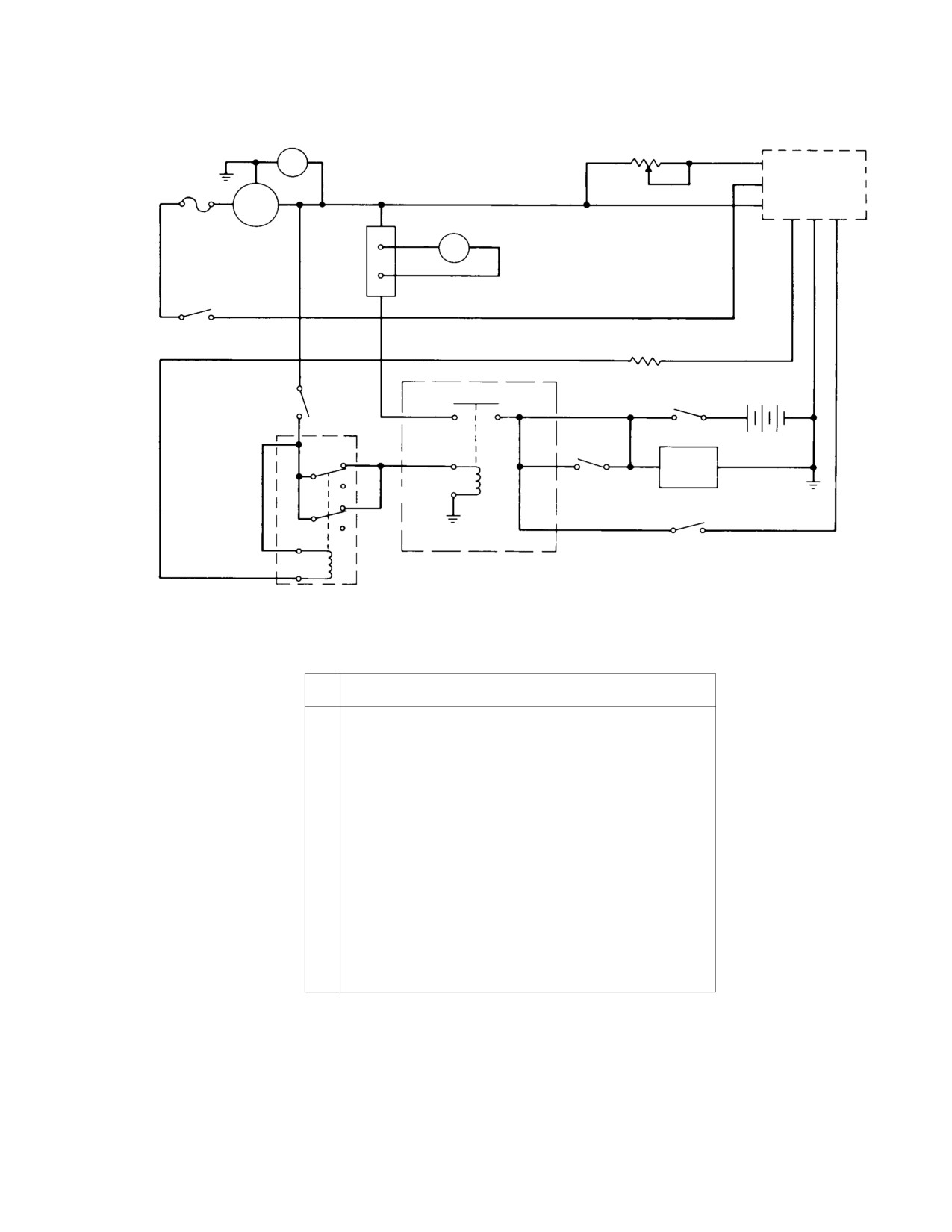
MD Helicopters, Inc.
CSP−H−2
500 Series - Basic HMI
0−50 VDC
VOLTMETER
RHEOSTAT R2
CONNECTOR
M1
25 OHMS, 1000 W
MS3106E14S−6S
V
A
E−
VOLTAGE
REGULATOR
C
(UNDER TEST)
A+
B+
GEN
B
E D F
FUSE
M2
0−200 A
6A
50 MV.
A AMMETER
200A
SHUNT
SWITCH
S3 SPST
R1, 1W, 5%
120 OHMS
RESISTOR
BATTERY
SWITCH
GENERATOR
BATTERY
24 VDC
S4 SPST
S1 SPST
TERMINAL
TERMINAL
SWITCH
+
−
SWITCH
SWITCH
1
NC
TERMINAL
LOAD
3
BANK
5
F
K1
S5
NO
TERMINAL
8
NC
6
4
NO
7
S2 SPST
MOMENTARY SWITCH
2
REVERSE CURRENT RELAY
OVERVOLTAGE RELAY
ITEM
EQUIPMENT DESCRIPTION
NO.
1
VARI−DRIVE, 3,000−12,000 RPM (U.S. TYPE VEU−GSTD OR
EQUIVALENT).
2.
DC GENERATOR, 28 VOLT (369A4550 OR EQUIVALENT).
3
NI−CAD BATTERY, 24 VOLT (369A4530 OR EQUIVALENT).
4
0−200A DC AMMETER (M2), 50 MV FULL SCALE (WESTON MODEL
931 WITH 50 MV, 200 AMPERE SHUNT, OR EQUIVALENT).
5
0−50 VDC VOLTMETER (M1), CALIBRATED WITHIN 0.25%, AT
0−50 VOLTS (WESTON MODEL 931 OR EQUIVALENT).
6
LOAD BANK, 0−150 AMPERES (SUN ELECTRIC COMPANY MODEL
GBL OR EQUIVALENT).
7
OVERVOLTAGE RELAY (369A4557 OR EQUIVALENT).
8
REVERSE CURRENT RELAY (HARTMANN A700XA OR EQUIVALENT).
9
SWITCHES AND WIRING AS REQUIRED.
30−106C
Figure 19-8. Test Hookup for Voltage Regulator
Page 19-23
Revision 15
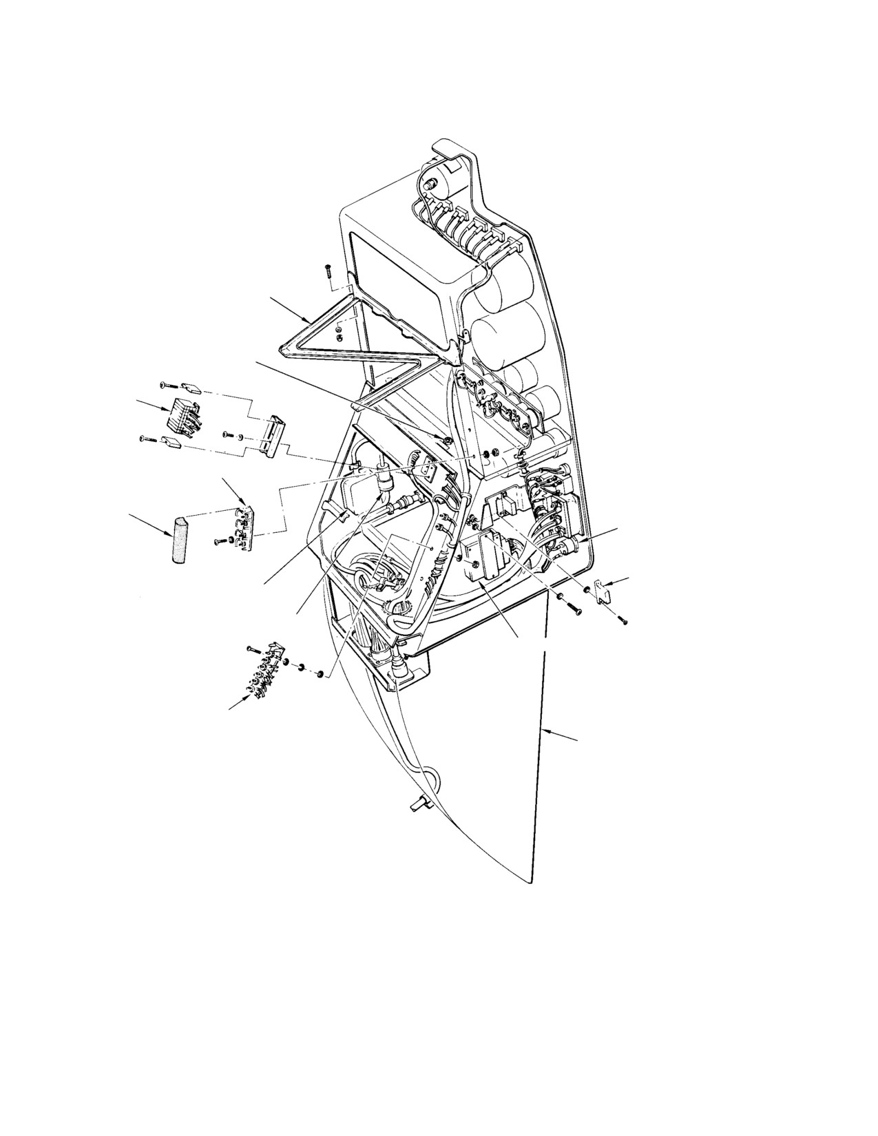
MD Helicopters, Inc.
CSP−H−2
500 Series - Basic HMI
UPPER INSTRUMENT PANEL
SUPPORT ASSEMBLY
R303 OIL PRESSURE
GAUGE ADJUSTMENT
(NOTE 3)
MINILOK MODULE
ASSY (TB502)
TERMINAL BLOCK (TB501)
RUBBER INSULATOR
COVER
KEY SWITCH
(NOTE 1)
OVERVOLTAGE RELAY (K103)
(NOTE 2)
ENGINE POWER OUT WARNING UNIT
AUDIO AMPLIFIER
INDICATOR LIGHTS DIMMER ASSY
TERMINAL BLOCK (TB6)
LOWER INSTRUMENT PANEL
SUPPORT ASSY
NOTES:
1.
WHEN REPLACING KEY SWITCH, USE AN3066−6 NUT
AND SHAKEPROOF WASHER IN PLACE OF NUT SUPPLIED
WITH KEY SWITCH.
2.
COVER RELAY SOLDER TERMINALS WITH ELECTRICAL
INSULATION SLEEVING (31, TABLE 2−4).
3.
PART OF CURRENT CONFIGURATION OIL PRESSURE
GAUGE CIRCUIT.
30−107C
Figure 19-9. Electrical Equipment Locations (Instrument Panel Type A)
Page 19-24
Revision 15
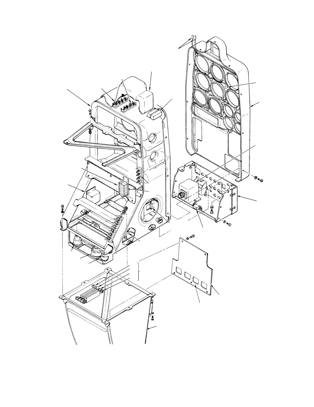
MD Helicopters, Inc.
CSP−H−2
500 Series - Basic HMI
POST LIGHT
WIRE SPLICES
LIGHT AND
HORN HOUSING
(NOTE 1)
TB104
POST LIGHT
INSTRUMENT PANEL
TB105
CAUTION AND
(TYP) (NOTE 2)
STRUCTURE
WARNING LIGHT
(TYP) (NOTE 1)
HOOD
INDICATING LIGHTS
DIMMER DS11
(NOTE 1)
TB106
(NOTE 4)
EPO WARNING
UNIT DS10
TB501
(NOTE 1)
TB502
LOWER SWITCH AND
CIRCUIT BREAKER
PANEL
OVERVOLTAGE
RELAY K103
OVERVOLTAGE
RELAY K103
(NOTE 3)
TB101
J11
TB6
J9
J10
R9
CIGAR
R10
LIGHTER
R11
RESISTORS
R12
ACCESS PANEL
RELAY MOUNTING
PROVISIONS (TYP)
PEDISTAL
STRUCTURE
NOTES:
1.
REFER TO SECTION 17.
2.
REFER TO CSP−H−3.
3.
EARLY CONFIGURATION ONLY.
4.
NOT ON CURRENT CONFIGURATION.
30−186B
Figure 19-10. Electrical Equipment Locations (Instrument Panel Type B)
Page 19-25
Revision 15
MD Helicopters, Inc.
CSP−H−2
500 Series - Basic HMI
9. Circuit Breaker Panel
corner of the instrument panel in the basic
configuration. Mounting holes for four optional
(Ref. Figure 19−1) The circuit breaker panel,
equipment control switches are also provided
located on the lower right side of the instru−
at this panel location. The basic control
ment panel, is a removable assembly with
switches are one key type, two circuit breaker
provisions for mounting 14 pushbutton−type
type, one pushbutton type, and two toggle
circuit breakers; 7 breakers are used in the
type.
basic configuration.
Control functions are apparent from adjacent
The circuit breakers are normally depressed
legends; the UTILITY and START PUMP
(button in) when the associated circuits are
switches are the circuit breaker type that will
energized.
snap to the off position if the circuit is over−
loaded. The switch marked UTILITY controls
When a circuit is overloaded, the circuit
power to the two−wire receptacle at the lower
breaker button pops out and de−energizes the
left corner of the forward canted bulkhead
circuit.
(Ref. Figure 19−6).
A. Circuit Breaker Replacement
A. Control Switch Replacement
(1). Check that all electrical power is OFF.
If the main power selector
CAUTION
(2). Remove the three screws that attach
switch is to be replaced, be sure
circuit breaker panel to instrument
to disconnect the battery and external pow−
panel. Pull panel out to expose wiring
er.
to circuit breakers.
NOTE:
When key switch (Ref. Figure 19−9) is
NOTE: Check the orientation of installed cir−
replaced, an AN3066− 6 nut and a shake−
cuit breakers. Observe that each column of
proof washer are to be used in place of nut
breakers has a staggered installation; one
supplied with replacement switch.
horizontal, then one vertical. This orienta−
(1). Check that all electrical power is OFF.
tion is required for installation clearance be−
tween breakers and should be maintained.
(2). Remove the two rectangular blank
panels and left side fairing from the
(3). Disconnect wiring from circuit breaker
instrument panel to gain access to the
to be replaced; then remove hex nut and
switch to be replaced (Section 17).
breaker.
(3). Remove hex nut or screws and washers
(4). Remove and discard the key washer
as applicable; then remove switch far
supplied with a new circuit breaker.
enough to permit the wiring to be
(5). Position the replacement breaker for
disconnected from the switch.
correct orientation and secure with hex
nut. Reconnect wiring and reinstall the
(4). Position replacement switch and
circuit breaker panel.
reconnect wiring; install attaching
hardware.
(6). Check operation of the new circuit
breaker.
(5). Check operation of the new control
switch.
10. Control Switches
(6). Reinstall the left side fairing and blank
(Ref. Figure 19−1) Six individually removable
panels on the instrument panel (Section
control switches are installed in the lower left
17).
Page 19-26
Revision 15
MD Helicopters, Inc.
CSP−H−2
500 Series - Basic HMI
Table 19-5. Resistor Reference Designator
Circuit
Purpose
Location
Instrument cluster power
R1 (reduce voltage)
Part of TB8 terminal board mounted
supply
on structure beneath pilot’s
compartment floor, left side
(Figure 19-6).
Voltage regulator/overvoltage
R2 (calibrate sensing circuit sensitivity Same as R1 (mounted on TB 8,
relay sensing circuit
for correct tripping of overvoltage relay
(Figure 19-6).
when overvoltage condition occurs)
Ammeter
R3 (calibrate low voltage output for
Engine compartment right side oleo
indicator deflection proportional to
support fitting (Figure 19-11).
main output)
TOT indicator
R4 (calibration)
Part of the resistor board TB9 on aft
end of TOT indicator in instrument
console.
Cigarette lighter
R9, R10, R11, R12 (reduce voltage)
Approximately the same as R1 and R2
(near TB8, Figure 19-6), or in the left
side of panel type B mounting
structure (Figure 19-10)
Instrument cluster lighting
R112 (reduce voltage)
Mounted on back of instrument cluster
(current 3-pack only)
in instrument panel.
Oil pressure gage circuit
R303, R304, R305 (calibration)
Forward of instrument cluster on panel
(current 4-pack only)
structure.
11. Voltage Reduction and Calibration
(4). Restore wiring security where nylon
Resistors
straps have been cut; use nylon twine
(30) if straps are not available.
(Ref. Table 19−5) Resistors are installed in
various circuits of the electrical system to
(5). Check repaired circuit for correct
reduce the nominal supply voltage from 24
operation.
volts to 12 volts (dropping resistor), and to
12. Start Relay
adjust circuit voltage for proper circuit
performance (calibration resistor). These
(Ref. Figure 19−11) The start relay, mounted
resistors may be identified and located by the
aft of the reverse current relay on the oleo
following:
support fitting at the right side of the engine
compartment, is a single−pole, single−throw,
A. Voltage Reduction and Calibration
normally open relay with enclosed contacts.
Resistor Replacement
The relay connects battery or external power
to the starter when the START switch on the
(1). Check that all electrical power is OFF.
pilot’s collective pitch stick is pressed. Refer to
CSP−H−3, HMI Appendix A for information
(2). Gain access to resistor location. Cut
optional engine automatic reignition compo−
nylon straps if necessary to get wire
nent used with the start relay.
slack, disconnect wiring and remove
defective resistor.
A. Start Relay Replacement
NOTE: Terminal board TB8 should be removed
(1). Check that all electrical power is OFF.
from the structure when replacementof ei−
ther resistor R1 or R2 is necessary.
(2). Slide back insulating boots and discon−
nect cable terminal attaching hardware
(3). Use a pencil type soldering iron and tin
and wiring from relay. Separately
alloy solder (48, Table 2−4) when
insulate and tie back cable terminals to
installing replacement resistor.
prevent an inadvertent short circuit.
Page 19-27
Revision 15
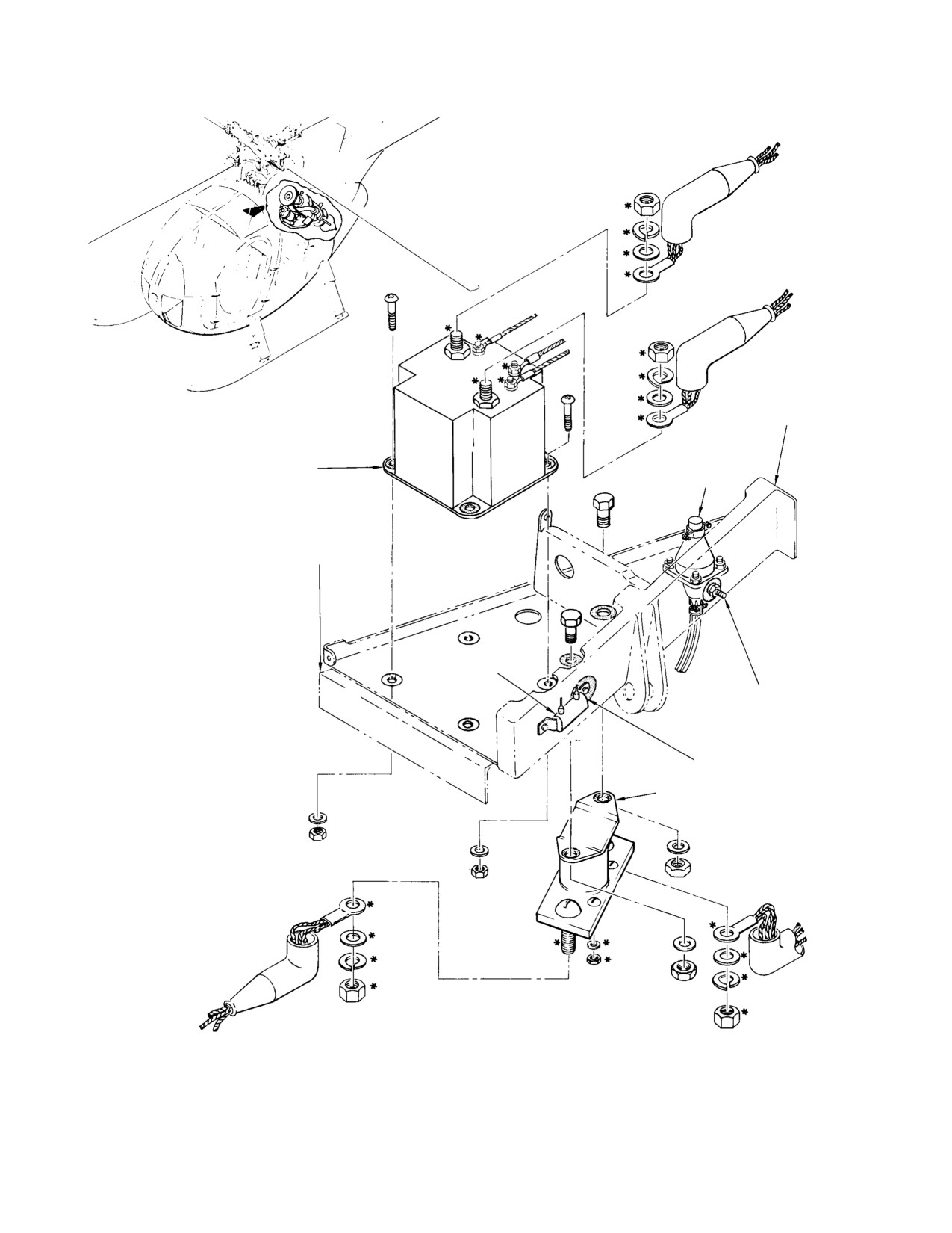
MD Helicopters, Inc.
CSP−H−2
500 Series - Basic HMI
OLEO SUPPORT
FITTING
ENGINE HARNESS
REVERSE CURRENT RELAY
RECEPTACLE
STA.
124
RESISTOR (R3)
NOTES:
GROUNDING
1.
SHADED SPOTS ARE CURRENT RETURN
STUD
PATHS (BONDING−TO−GROUND).
2.
COAT ALL EXPOSED ELECTRICAL STUDS,
TERMINALS AND ASSOCIATED CONNECTING
HARDWARE WITH LACQUER (47, TABLE 2−4)
AFTER ASSEMBLY (*REF. EXAMPLES).
NOTE 1
START RELAY
30−108A
Figure 19-11. Replacement of Engine Compartment Relays
Page 19-28
Revision 15
MD Helicopters, Inc.
CSP−H−2
500 Series - Basic HMI
(3). Remove relay mounting hardware and
14. Battery Relay
remove start relay.
The battery relay, mounted aft of the battery
(4). Check bonding surfaces for good
at Sta. 64.37, is a single−pole, single−throw,
condition. Position replacement relay
normally open relay with enclosed contacts.
on mounting surface and secure with
The relay connects the battery to the main
attaching hardware.
power bus when power selector switch is in
battery position.
(5). Connect wiring to terminals with
A. Battery Relay Replacement
washers and nuts. Slide insulating
boots over studs.
(1). Ensure all electrical power is OFF.
(6). Apply a coating of lacquer (47,
(2). If installed, disconnect and remove
Table 2−4) to all exposed electrical
battery.
studs, terminals, and associated
connecting hardware.
(3). Disconnect wires and mark wires for
reinstallation.
13. Reverse Current Relay
(4). Remove hardware (two screws, two
nuts and two washers) from relay
(Ref. Figure 19−11) The reverse current relay,
mount.
mounted on the oleo support fitting at the
right side of the engine compartment, serves to
(5). Replace relay.
isolate the battery and the 28 Vdc bus from the
generator. The relay will isolate the generator
(6). Reinstall hardware and reconnect
from the 28 Vdc bus (and battery) when the
wires.
generator switch is off, an overvoltage condi−
(7). Reinstall battery, if required.
tion exists, or when the battery voltage is
greater than the generator voltage and current
B. Battery Relay Troubleshooting
flows in the reverse direction.
(1). Connect battery. Insure instrument
A. Reverse Current Relay Replacement
panel circuit breaker is in.
(1).
Check that all electrical power is OFF.
(2). Turn power selector switch to BATT
position.
(2).
Remove terminal nuts and washers,
and disconnect electrical wiring from
(3). Check instrument panel for lights.
reverse current relay. Reinstall termi−
15. APU Relay
nal nuts and washers.
The APU relay, mounted under the right fwd
(3).
Insulate cable terminals to prevent
seat on the right hand bulkhead, is a single−
inadvertent short circuit.
pole, single−throw, normally open relay with
(4).
Remove mounting hardware and
enclosed contacts.
reverse current relay.
A. APU Relay Replacement
(5).
Check that case bond surfaces are clean
(1). Ensure all electrical power is OFF.
on replacement reverse current relay
and on mounting surface. Secure relay
(2). Remove right hand passenger footwell.
with screws, washers and nuts.
(3). Disconnect wires and mark for reinstal−
(6).
Connect electrical wiring to terminal
lation.
studs of reverse current relay. Secure
(4). Remove hardware (2 bolts, 2 nuts and 4
with washers and nuts.
washers) from relay mount.
(7).
Apply a coating of lacquer (47,
(5). Replace relay.
Table 2−4) to all exposed electrical
studs, terminals and associated
(6). Reinstall hardware and reconnect
connecting hardware.
wires.
Page 19-29
Revision 15
MD Helicopters, Inc.
CSP−H−2
500 Series - Basic HMI
(7). Reinstall passenger footwell.
(c).
Solder wires to replacement switch
and remove tags.
B. APU Relay Troubleshooting
(d).
Clean solder terminals and wiring
(1). Connect auxiliary power source. Ensure
adjacent to terminals with MEK (22,
instrument panel circuit breaker is in.
Table 2−4).
(2). Turn power selector switch to APU
(e).
Brush or spray switch terminals and
position.
adjacent wiring with adhesive (122)
to provide bond for potting com−
(3). Check instrument panel for lights.
pound.
(f).
Form potting mold with electrical
16. Collective Pitch Stick Switches
tape (123); Position mold around
switch terminals and attach wires as
(Ref. Figure 19−12) The collective stick
shown; then fill mold with potting
contains the START, N2 GOV and LDG LT
compound (124). Allow potting
switches. Wires from the switches are routed
compound to cure for eight hours
through the center of the collective pitch stick
minimum.
and out through two exit holes just aft of the
stick friction gear train. The wires from the
(g).
Place check washer on replacement
collective pitch stick switches are connected to
switch and attach switch to switch
an electrical connector to facilitate removal of
plate with lockwasher and panel nut.
the complete stick assembly.
Install knob on switch and secure in
place by tightening setscrew.
A. Collective Pitch Stick Switch
Replacement
(h).
Attach switch plate to stick housing
with four washers and screws.
(1). Check that all electrical power is OFF.
(6). To replace START switch:
(2). Cut twine or nylon strap securing
wiring to collective pitch stick, and
disconnect grounding terminals.
(a). Loosen self−tapping screw in front
half of switch, unthread front half of
(3). Loosen two setscrews that secure grip
switch from switch body, and remove
switch housing to stick. Feed wire slack
switch from stick housing.
into stick while sliding switch housing
from end of stick.
(b). Unsolder electrical wires attached to
switch terminals and tag−identify to
(4). Remove four screws and washers to
facilitate reconnection.
detach switchplate.
(c). Solder wires to replacement switch
(5). To replace either N2 governor switch or
and remove tags.
landing light switch:
(d). Position switch body in stick housing
(a). Use a small knife to cut and remove
and secure to housing by threading
potting compound from wires and
front half of switch onto switch body.
terminals at the base of the switch.
Tighten self−tapping screw to pre−
Avoid cutting wires and terminals.
vent loosening of front half of switch.
Unsolder wires and tag−identify to
facilitate reconnection.
(7). Assemble grip switch housing, stop
release spring and ring on collective
(b). Loosen knob setscrew and remove
pitch stick. Carefully draw slack wire
knob, panel nut, lockwasher, check
from stick, then tighten two housing
nut and switch.
setscrews.
Page 19-30
Revision 15
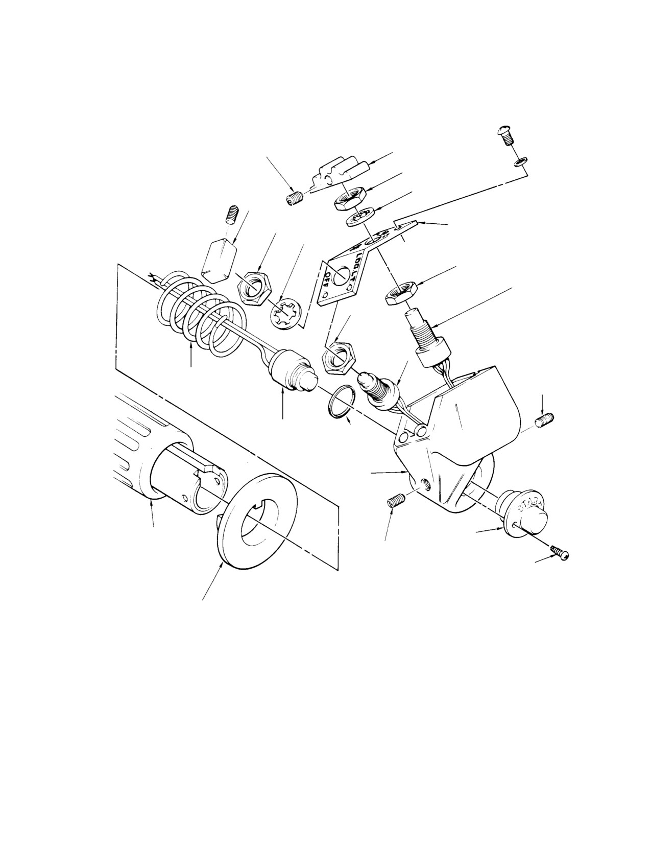
MD Helicopters, Inc.
CSP−H−2
500 Series - Basic HMI
SETSCREW
KNOB
PANEL NUT
LOCKWASHER
KNOB
SWITCH IDENTIFICATION
PANEL NUT
PLATE
LOCKWASHER
CHECK NUT
N2 GOV SWITCH
(TYP)
CHECK NUT
LANDING LIGHT
SWITCH
IDLE STOP
RELEASE SPRING
SETSCREW
START SWITCH
(HALF)
RETAINING RING
(NOTE)
PILOT’S STICK GRIP
SWITCH HOUSING
THROTTLE
START SWITCH
(HALF)
SETSCREW
SELF−TAPPING SCREW
(SUPPLIED WITH SWITCH)
IDLE STOP
RELEASE RING
NOTE: NOT USED ON ALL
COLLECTIVE PITCH STICKS.
30−109A
Figure 19-12. Replace of Collective Pitch Stick Switches
Page 19-31
Revision 15
MD Helicopters, Inc.
CSP−H−2
500 Series - Basic HMI
(8). If nylon strap is not available, secure
The light/switches are mounted in a light/
wiring to collective pitch stick at a point
switch and horn housing installed on the hood
approximately one inch from holes with
of the instrument panel.
twine (30).
NOTE:
At intervals specified in CSP−H−4, an
(9). Connect electrical connector and attach
operational check of the battery tempera−
grounding terminal.
ture sensing equipment is to be performed.
(10). Check replacement switch for proper
A. Battery Temperature Sensing Equipment
operation by performing the engine
Maintenance
starting procedure in the Owner’s
Manual.
NOTE: For view of light/switches and wiring
inside light/switch and horn housing, refer
17. Battery Temperature Sensing Equipment
to Section 17.
(Ref. Figure 19−13) Battery temperature
(1). As required, perform an operational
sensing equipment provides a monitoring
check of battery temperature sensing
system with visual caution and warning light
equipment.
indicators that illuminate at battery over−tem−
peratures.
(2). For information on low and high
temperature switch limits, Ref. Testing
The battery temperature sensing equipment
of Battery Temperature Sensing
consists of two temperature indicator light/
Switches
switches and horn housing, interconnecting
wiring and associated attaching and mounting
(3). Troubleshoot battery temperature
hardware. The equipment provides an amber
sensing equipment according to
caution light indication when battery tempera−
information on troubleshooting caution
ture reaches 140°F, and a red warning light
and warning light indicators.
indication at 160°F. Both indicator light/
B. Battery Temperature Sensing Equipment
switches contain a built−in press−to−test
Operational Check
switch for testing internal lamps.
NOTE: This operational check is required at in−
The indicator light/switches are electrically
tervals specified in CSP−H−4.
interconnected to low and high temperature
sensing switches installed on a buss bar of the
(1). Remove battery from helicopter.
ni−cad battery (Ref. Figure 19−14). The
switches are part of and are furnished with the
(2). Check low and high temperatures
battery.
sensing switches on battery bus bar for
correct operation at specified tempera−
A rise in battery temperature to 140°F causes
tures.
the low temperature switch to close and apply
+dc voltage from the battery to illuminate the
(3). Install battery in helicopter.
amber caution light. An increase of battery
temperature to 160°F causes the red warning
(4). Inspect electrical wiring for security,
light to illuminate in the same manner.
physical damage and continuity.
When depressed, the press−to−test switch on
(5). With electrical power ON and PNL LT
each indicator applies +28 Vdc from the panel
circuit breaker CB104 ON, alternately
lights circuit breaker CB104 to the associated
depress and check that both 140°F and
light indicator for testing internal lamp
160°F light indicators illuminate.
illumination.
Replace any defective lamps.
Page 19-32
Revision 15
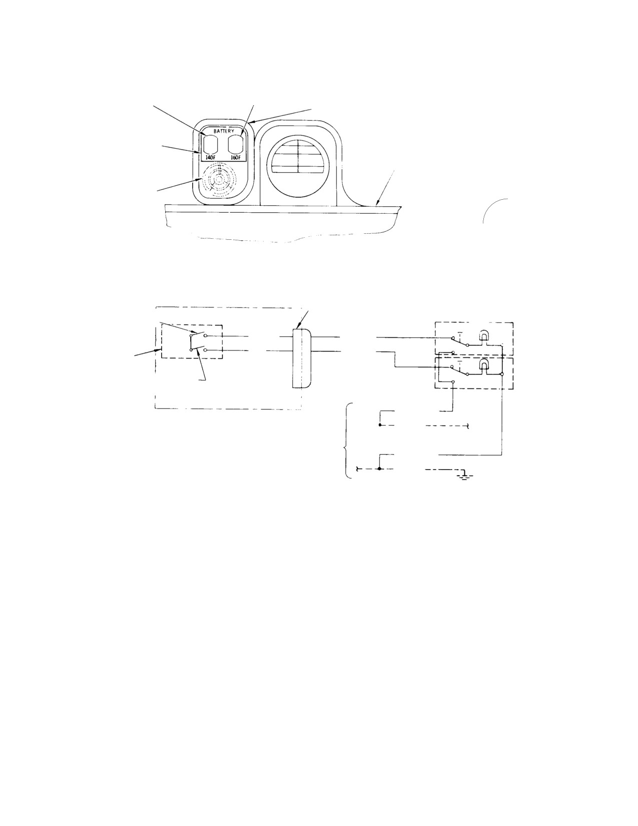
MD Helicopters, Inc.
CSP−H−2
500 Series - Basic HMI
RED 160° WARNING
AMBER 140° CAUTION
LIGHT SWITCH
LIGHT SWITCH
LIGHTS/SWITCH AND
HORN HOUSING
HOUSING
PLATE
INSTRUMENT PANEL
CENTER FAIRING
ENGINE OUT
WARNING HORN
LIGHT INDICATORS IN HOUSING
BATTERY CONNECTOR
(NOTES 5, 7)
LOW TEMPERATURE (140°F)
XDS24
SWITCH
(NOTE 3)
J529
P529
2
140°F
YELLOW
A
A
E559AA22
140° CAUTION
(NOTE 1)
1
LIGHT−SWITCH
160°F
3
BUS BAR
RED
C
C
E559AC22
AMBER
(NOTES 5, 6)
(NOTE 1)
2
D
D
160° WARNING
3
1
LIGHT−SWITCH
HIGH TEMPERATURE
B
B
RED
(160°F) SWITCH (NOTE 4)
XDS25
BATTERY
E559AB22
E559A22
E508A22 (NOTE 2)
+28 VDC FROM
PANEL LIGHTS
CIRCUIT BREAKER
E559AD22N
E510A22
WIRING DIAGRAM (NOTE 4)
NOTES:
1.
PART OF WIRING HARNESS: ROUTE WITH EXISTING WIRING.
2.
APPLIES ONLY TO 500S WITH TYPE A INSTRUMENT PANEL
(REF. SEC. 17) AND INCREASED GROSS WEIGHT CAPABILITY.
3.
HIGH TEMPERATURE SWITCH IDENTIFIED BY RED MARK ON BUS BAR;
LOW TEMPERATURE SWITCH BY YELLOW MARK.
4.
THIS WIRING DIAGRAM SHOULD BE USED WITH APPLICABLE ELECTRICAL
SYSTEM WIRING DIAGRAM IN SECTION 20 FOR COMPLETE CIRCUIT
IDENTIFICATION.
5.
PART OF BATTERY.
6.
WHEN SWITCH CLOSES, +VDC IS APPLIED FROM BUS BAR FOR LIGHT.
7.
ON LATER BATTERIES, YELLOW CONNECTS TO J108−D AND RED
CONNECTS TO J108−B.
30-204A
Figure 19-13. Battery Temperature Sensing Equipment
Page 19-33
Revision 15
MD Helicopters, Inc.
CSP−H−2
500 Series - Basic HMI
18. Battery
A. Battery Maintenance
(Ref. Figure 19−14) The battery is a recharge−
Handling, servicing precautions, servicing,
able, nominal 24−volt, 13−ampere−hour,
charging and cleaning instructions for the
l9−cell, nickel cadmium battery capable of
battery are provided in Section 2.
starting the engine in temperatures from
−25 ° F (−32°C) to +130° F (+54°C).
B. Battery Replacement
Early batteries are connected to the electrical
(1). Check that all electrical power is OFF.
system by a two−pin keyed female connector
receptacle located at the inboard end of the
(2). Raise pilot’s floor left access door. For
battery case; the connector is provided with a
better access, hand−press access door
smaller key pin to prevent polarity reversal
pivot pins from hinge points and
between the mating halves of the connector.
remove door.
Later batteries have a five−socket receptacle
connecting the battery to the electrical system
If corrosion is present be−
and temperature sensors to the battery
WARNING
tween the plug and recep−
temperature warning lights. The arrangement
tacle, the plug will be difficult to re−
of pins in this receptacle prevents improper
move. If excessive force is used to turn
connection of the connector halves.
the plug on the hex nut−secured recep−
tacle (Figure 19−14), it may rotate and
The 19 identical and individually replaceable
cause the internal leads to short. When
battery cells are contained in separate molded
normally required hand−pressure will
nylon cases and interconnected by bus bars.
not release the plug, apply hydraulic
oil or equivalent, to the threaded con−
nection. Allow enough time for the cor−
The cells are equipped with removable filler
rosion deposits to soften so that plug
cap vent plugs that allow gasses from the cell
can be removed.
to escape through the vent when the battery is
in, or near, the up−right position. The filler cap
(3). Disconnect battery plug and tempera−
vent plugs also prevent electrolyte spillage
ture sensing connector, or single plug if
when the battery is tipped or inverted.
single connector is used.
A mixture of potassium hydroxide and water is
(4). Remove four screws and washers that
used as the electrolyte; however, only pure
secure battery to mounting flanges.
distilled water is used for replenishment
purposes.
Avoid tilting the connector end
CAUTION
of the battery downward during
The battery case, cover and end plates are
the removal and handling after removal.
constructed from epoxy−impregnated fiber−
Any water or electrolyte in the battery case
glass.
will collect at the connector leads and short−
ing may occur.
The battery is secured to brackets on the
pilot’s compartment floor structure by four
(5). Lift battery and cover from the under−
screws and washers installed through the
floor compartment. Using suitable
cover and battery case.
hardware, secure the cover to the
battery case, Place battery in a pro−
Gases generated within the battery are vented
tected area away from any lead−acid
from the cells to the inside of the cover and out
type battery.
through the ventilation gap between each
upper side edge of the case and cover. Refer to
(6). Install serviced battery and secure
CSP−H−3, HMI Appx A for installation
battery and cover to mounting brackets
instructions of a battery compartment ventila−
with four mounting screws and wash−
tion scoop.
ers.
Page 19-34
Revision 15
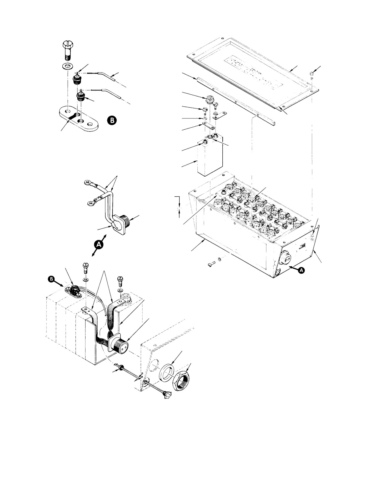
MD Helicopters, Inc.
CSP−H−2
500 Series - Basic HMI
HI−LIMIT SWITCH
COVER
NOTE 1
FIBERGLASS
CELL HOLD−
SLEEVING
DOWN BAR
FILLER CAP
VENT PLUG
LOW−LIMIT
TERMINAL SCREW
SWITCH
(NOTE 2)
BAFFLE
TERMINAL WASHER
BUS BAR
HIGH TEMPERATURE SWITCH
(RED PAINT MARK)
FILLER
TERMINAL
VENT
RECEPTACLE
CELL
BUSS WIRE
(NOTE 3)
NOTE 4
VENTILATION CAP
(BOTH SIDES)
BENDIX 10−87324−9S
RECEPTACLE (NOTE 6)
NOTE 1
NYLON
SEALANT
SEPARATOR
(NOTE 6)
COVER WITH
CASE
SEALANT
(NOTE 7)
RECEPTACLE BUS STRIP
(NOTE 5)
GUSSET
(OPT)
CONNECTOR SEPARATOR
(VINYL PLASTIC−COVERED
CORROSION RESISTANT
STEEL SHEET)
NOTES:
1.
SCREW, WASHER AND NUT SHOULD NOT BE USED FOR
BENDIX 10−87324−9S
SHIPMENT, HANDLING AND STORAGE.
RECEPTACLE (NOTE 5)
2.
SCREW TORQUE:
MARATHON (SONOTONE); 15−18 IN.−LBS. (1.69−2.03 NM).
GULTON; 26−30 IN.−LBS. (2.94−3.39 NM).
3.
CAUTION: COMPLETE SET OF EITHER GULTON CELLS
OR MARATHON (SONOTONE) CELLS MUST BE USED. mIXING
PLASTIC
OF GULTON AND MARATHON (SONOTONE) CELLS IS NOT
WASHER
ALLOWED. REFER TO THE APPLICABLE MANUFACTURER’S
PUBLICATION.
RECEPTACLE
4.
CELLS ARE SHOWN NUMBERED FOR REFERENCE ONLY.
NUT
5.
CONNECTOR BUS STRIPS AND BACK OF CONNECTOR
COVERED TO WITHIN 0.62 IN. (15.748 MM) OF CELL
NOTE 7
TERMINALS WITH 0.060 IN. (1.524 MM) THICK COATING OF
SEALANT (3, TABLE 2−4).
LOCKWIRE HOLES
6.
CONNECTOR BACK FILLED AND CONNECTOR BUS WIRES
COVERED 0.25 IN. (6.35 MM) BEYOND ENDS OF RECEPTACLE
TERMINALS WITH SEALANT (3). INSULATION SLEEVING
REMOVED FROM CONNECTOR BUS LEADS UNDER SEALANT.
7.
COVER WITH SEALANT (3).
30−110E
Figure
19-14. Replacement of Battery Components
Page 19-35
Revision 15
MD Helicopters, Inc.
CSP−H−2
500 Series - Basic HMI
(7). Apply a generous coating of dielectric
(2). Remove the bus bar equipped with
compound (185, Table 2−4) to the male
sensors (sensors and connecting wires
and female connector pins and sockets
attached).
and also the connector plug and
(3). Using a container, oil or water, ther−
receptacle threads. All surfaces should
mometer and heat source, submerge
be coated, Connect battery plug and
sensor bus bar and check at battery
temperature sensing connector or single
sensor connector plug, or single connec−
plug if used; then wipe away excess
tor receptacle pins A and C, for proper
compound.
heat range.
(8). Reinstall floor access door.
(a). Low temperature switch −
Closes on temperature rise at
C. Battery Inspection
140° ±8°F.
Opens on temperature decrease at
(1). Check that all electrical power is OFF.
100° ±8°F.
(2). Remove screws and washers that
(b). High temperature switch −
secure battery to mounting brackets
Closes on temperature rise at
and remove cover.
160° ±8°F.
Review the general battery
Opens on temperature decrease at −
WARNING
130° ±8°F.
handling and servicing pre−
cautions outlined in Section 2 before
(4). Clean the bus bar with MEK (22,
performing the following operations.
Table 2−4) and reinstall.
(3). Inspect tops of cells for dust, dirt, white
NOTE: The sensors may be removed from the
powder (potassium carbonate) or
bus bar for testing or replacement by remov−
spewed electrolyte. Refer to Section 2
ing the sealant and un−soldering wire con−
for cleaning instructions.
nections.
(4). Inspect receptacle bus strips, bus bars
(5). Reinstall battery in helicopter.
and screws for security and evidence of
(6). Inspect electrical wiring for security,
damage.
physical damage and continuity.
(5). Inspect cells for cracks, evidence of
(7). Perform a power ON operational check
overheating or other physical damage.
of battery temperature sensing equip−
Inspect cell bus bars for greenish color
ment.
indicating acid contamination. Replace
E. Repair of Battery
battery if any such damage is detected.
NOTE: Complete disassembly and reassembly
Electrolyte level inspection
of battery is covered in the following proce−
CAUTION
should be accomplished only
dures. Follow the procedures, in sequence,
when the battery has been fully charged and
until the part or parts requiring repair or re−
then allowed to rest for a period of 1 to 2
placement have been removed and rein−
hours after charging. If the helicopter has
stalled. Refer to battery manufacturer’s
operated for a minimum of one hour or more
maintenance instructions (Ref. Table 2−15)
of continuous flight, the battery may be con−
for repairs not covered in the procedures
sidered charged.
Discharge the battery before
(6). Reinstall cover and secure with four
WARNING
attempting disassembly. If
screws and washers.
the battery bas not been discharged,
serious personal burns may result and
D. Testing of Battery Temperature Sensing
damage to the battery may occur. Refer
Switches
to Deep Cycling of Battery, Section 2.
NOTE: This test is required at intervals speci−
(1). Removing Bus Bars.
fied in CSP−H−4, HMI Appendix B.
(a). Remove the terminal screw and
(1). Remove the battery from helicopter.
washer from each end of the bus bar.
Page 19-36
Revision 15
MD Helicopters, Inc.
CSP−H−2
500 Series - Basic HMI
NOTE: Refer to Figure 19−14 and note the loca−
(e). For batteries with a dual connector,
tion of the bus bar with temperature sensing
cut and remove the lockwire from the
switches. If required, remove sealant, un−
receptacle nut. Remove the receptacle
solder wire connections and remove
with attached receptacle bus wires or
switches, according to step (7).
strips from the case.
(b). Lift the bus bar from the cell.
(f). For batteries with a single connector,
remove the four nuts, washers, and
(c). Clean bus bar with methyl−ethyl−ke−
screws that secure the receptacle to
tone (22, Table 2−4).
the battery case and pull the recep−
tacle forward to gain access to
(2). Removing Cells.
attached wires.
NOTE: Each cell is removed from the battery
(g). Remove sealant, if used, and unsold−
case with a cell puller. Two battery bus bars
er wires attached to the receptacle
and a piece of cord may be used to fabricate
terminals.
a puller. Attach the cord to the hole at one
end of each bus bar. Initial removal of either
(4). Replacing Battery Case
cell No. 5 or No. 6 will aid in the removal of
(a). Disassemble the battery, steps (1).
other cells.
thru (3).
(a). Remove screws and washers that
(b). Using a stiff nylon brush and a
secure hold−down bars to battery
3−percent boric acid solution, wash
case.
the replacement battery case; then
flush with clean water (cold if
(b). Remove the battery bus bars and/or
possible) to ensure that the case is
bus wires or strips from the cells.
clean. Dry the case with a clean
cloth, and then air−dry in a warm
(c). Remove nylon separator when
area for at least 1 hour.
required to permit removal of cells.
(c). Reassemble battery components into
(d). Attach the cell puller to the cell
the new case, steps (5). and (6).
terminals; use the terminal screws
and washers to secure the puller to
(d). Deep cycle the battery (Section 2).
the cell.
(5). Installing Receptacle
(e). Lift the cell from the battery case. If
Observe correct polarity when
necessary, slightly rock the cell from
CAUTION
connecting the receptacle bus
side to side to work it loose.
wires or strips to the receptacle. Reversed
NOTE: Observe the polarity of the removed cell
connections can damage the battery when it
to prevent reinserting the cell in reverse po−
is connected to the helicopter electrical sys−
larity.
tem.
(a). Using a tin−alloy solder (48), solder
(3). Removing Receptacle
the two receptacle bus wires or strips
(a). Loosen and remove the two terminal
and the two temperature sensor
screws and washers that secure the
wires (single connector) to the
two receptacle bus wires or strips to
terminals at the back of the recep−
adjacent cells.
tacle.
(b). Remove the bus bar that connects
(b). For dual connector batteries, insert
cells No. 1 and No. 2.
the receptacle into the battery case
and securely tighten the receptacle
(c). Remove the cell hold−down bar from
nut. Using lockwire (2), safety the
the same side of the battery as the
nut to the holes in the case.
connector separator.
(c). For single connector batteries, secure
(d). Remove the nylon separator and cell
the receptacle to the battery case
No. 1.
with four screws, washers and nuts.
Page 19-37
Revision 15
MD Helicopters, Inc.
CSP−H−2
500 Series - Basic HMI
(d).
For dual connector batteries, fill
(e). Spray a thin film of WD−40 (101)
receptacle back and cover bus wires
over entire top surface of battery and
or strips with sealant (3). For recep−
inside connector receptacle or coat all
tacle with bus wires, the receptacle
exposed metal parts with petrolatum
back and wires are covered 0.250
(34).
inch (6.35 mm) beyond rear of
(f). Deep cycle the battery (Section 2),
receptacle terminals. Insulation
before returning the battery to
sleeving must be removed from wires
service.
under sealant. For receptacle with
bus strips, receptacle back and strips
(7). Replacement of Temperature Sensing
are covered to within 0.62 inch
Switches
(15.748 mm) of cell terminals with
0.060 inch (15.24 mm) thick sealant
(a). Remove sealant covering switches
coating.
and unsolder wire connections,
remove switch.
(e).
Position the connector separator
(b). Install correct replacement switch in
inside the battery case so that open
location shown in Figure 19−14 and
end butts against end of case, enclos−
torque to 5 − 15 inch−pounds (0.56
ing the two receptacle bus wires or
− 1.69 Nm).
strips and the receptacle.
(c). Install fiberglass sleeving and solder
(f).
Install the nylon separator and
wire connections; red wire to high
removed cells, step (6).
temperature switch and yellow to low
temperature switch.
(6). Installing Cells
(d). Cover the switch connections with
sealant (3).
Do not intermix Gulton and
CAUTION
Marathon (Sonotone) cells. Re−
(e). Check that high temperature switch
fer to the applicable manufacturer ’s publi−
is identified by a red paint mark on
cation.
the bus bar and renew, if required.
19. Starter/Generator
(a). Obtain a new or serviceable cell to
replace a defective cell.
(Ref. Figure 19−15) A combined starter and
generator is used to start the engine and to
(b). Check that the cell is clean and
provide primary 28−volt, direct−current power
position it in the battery case for
for operation of the electrical system.
correct polarity orientation.
The starter/generator, a self−cooled unit, is
clamp−attached to a quick−disconnect mount−
NOTE: When replacing a complete set of cells,
ing flange on the engine power and accessory
install cells in order, No. 1 thru No. 9, the
gearbox.
nylon separator, No. 19. and then No. 10
thru No. 18.
A shear point is incorporated in the generator
drive shaft to protect the engine drive from
(c). Connect the bus bars and/or bus
excessive torque loads.
wires or strips with terminal screws
The starter system consists of the starter/gen−
and washers; the cup side of the
erator, start relay, voltage regulator and a
washer must be down. Torque screws
START switch located in the pilot’s collective
to 15 − 18 inch−pounds (1.69 − 2.03
pitch stick.
Nm) for Marathon/ Sonotone or 26 −
30 inch−pounds (2.94 − 3.39 Nm)
When pressed, the START switch energizes
for Gulton.
the solenoid of the start relay and supplies
power from the power selector switch bus
(d). Install the hold−down bars on the
through the BAT terminal of the reverse
case.
current relay and start relay to the start
Page 19-38
Revision 15