CSP-H-2 BASIC HANDBOOK OF MAINTENANCE INSTRUCTIONS FOR MDHI 369H HELICOPTERS - page 9
MD Helicopters, Inc.
CSP−H−2
500 Series − Basic HMI
NOTE: Hughes Notice HN− 151 provides
and checking for binding during full
instructions for replacing existing cabinet
movement of control lever knob or lever
heat duct assemblies with new fiberglass−
from ON to OFF positions. Manually
type duct assemblies. The new configuration
actuate the anti−icing valve lever to
for the optional cabin heating system is de−
check freedom of movement. Early
signed to provide greater resistance against
system: Reinstall cable wire and torque
heat, deformation, and wear. A procedure
adapter nut to 10 inch−pounds (1.13
for rework of the control cable assemblies to
Nm) maximum. Secure nut with new
make them compatible with the new fiber−
cotter pin. Current system: Reinstall
glass duct installation also is provided by
clevis to valve lever with clevis pin,
HN−151.
washer and cotter pin.
A. Anti-Icing Valve Control Operational
B. Anti-Icing Valve Control Cable Inspection
Check (Manually Operated)
(Manually Operated)
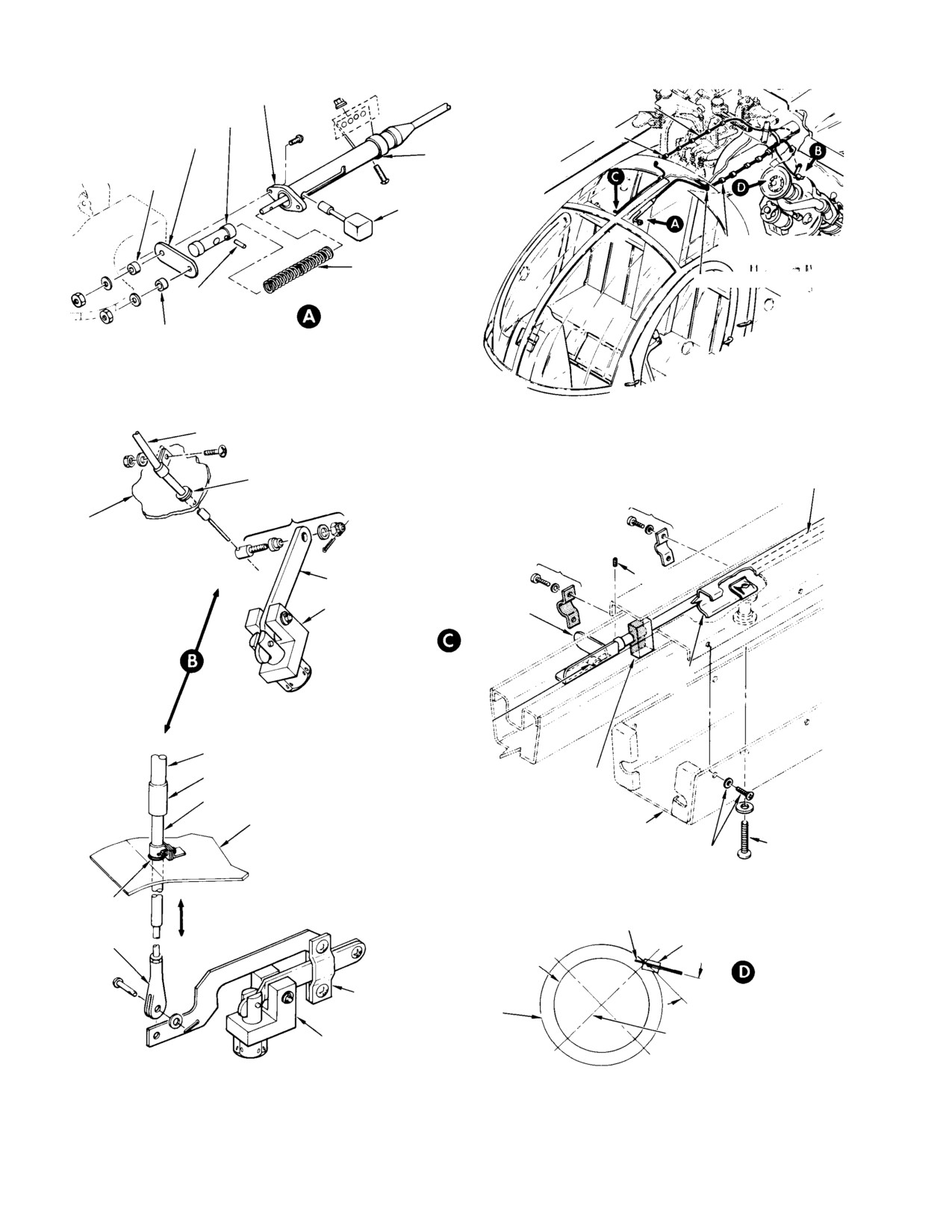
(1). Inspect cable for kinks, crushed sleeve
(1).
Move control lever knob to full aft
and corrosion.
position (early system) or control
handle to full forward position (current
(2). Early system: Inspect piston for wear or
system) to open anti−icing air valve.
elongation of knob shaft or lock pin
Control knob or handle should not creep
holes; inspect control spring for kinks
away from anti−icing valve full open
or breaks.
position.
(3). Inspect valve lever or valve lever
(2).
In engine compartment, check that
adapter for excessive wear.
anti−icing air valve lever is positioned
at aft travel limit and that cable wire
C. Anti-Icing Valve Control Cable
does not appear to be distorted by
Replacement (Manually Operated)
overtravel.
(Ref. Figure 11−14)
(3).
Early system: Release control lever
(1).
Unlatch or remove plenum chamber
knob from housing notch; lever piston
access door, and left or right half of
return spring should return lever knob
engine air inlet forward fairing, as
to housing forward stop without
appropriate, for access to cable.
manual assistance. If valve does not
return, the valve lever adapter nut may
(2).
Remove two screws, washers, and nuts
be over−tightened; refer to step (6).
and spacers that attach cable housing
Current system: Manually return
to structure (early system); or remove
control handle to full aft (of position.
seven screws attaching heat duct outer
box to heat duct and canopy frame
(4).
Recheck position of anti−icing valve
(current system)
lever; lever should be positioned at
forward travel limit.
(3).
Remove clamps and straps that attach
cable to structure along its full length.
(5).
If anti−icing valve lever does not have
sufficient travel or the cable appears to
(4).
Loosen the nut of adapter at the
distort when actuated, adjust cable wire
anti−icing valve on the engine (early
(early system) or cable clevis (current
system); or remove clevis pin, washer
system) for correct lever stroke,
and cotter pin attaching clevis to valve
lever (current system).
NOTE: On current system, check that pop−
petguide and arm are positioned as shown
(5).
Remove control cable.
in engine build−up illustration.
(6).
Route the replacement cable assembly
(6). When control cable operation is stiff,
into position. Check that grommets
isolate the trouble by removing the
(two on early type, one on current type
cable wire or clevis from the valve lever
cable) are in place on the cable.
Page 11-29
Revision 18
MD Helicopters, Inc.
CSP−H−2
500 Series − Basic HMI
PISTON HOUSING
FLEXIBLE CASING
TEFLON PISTON
HOUSING SPACER
CABLE SPLICE
MOUNTING SPACER
CLAMP
0.34375 IN. (8.73125 MM)
LONG
CONTROL KNOB
NYLON STRAPS
(TYP EITHER SIDE)
RETURN SPRING
GROMMET (TYP)
LOCK PIN
EARLY SYSTEM
(LEFT SIDE)
MOUNTING SPACER
0.453125 IN. (11.509375 MM)
LONG
NOTES:
1.
SEAL HOLE, ON ENGINE SIDE OF PAN,
CABLE ASSY
WITH ADHESIVE (102, TABLE 2−4).
2.
FORWARD BLOCK AND CLAMP MATING
SURFACES FACED WITH TAPE (112).
GROMMET
HANDLE SHAFT SLIDES AGAINST THESE
RIGID TUBING
SURFACES.
2 PLCS
ADAPTER
PLENUM CHAMBER
AIR INLET PAN
1 PLC
SETSCREW
LEVER
ANTI−ICING VALVE
(EARLY SYSTEM)
POPPET GUIDE
CONTROL HANDLE
ANTI−ICING SYSTEM
(CURRENT SYSTEM)
CANOPY
FRAME
HANDLE DETENT
SPRING
FLEXIBLE CASING
CABLE SPLICE
CABLE SUPPORT BLOCK
(3 PLCS) (NOTE 2)
RIGID TUBING
PLENUM CHAMBER
CURRENT SYSTEM
OUTER BOX
AIR INLET PAN
HEAT DUCT
6 PLCS
MOUNTING
SCREW
OPEN
NOTE 1
CLEVIS ATTACH POINT
CABLE
ANTI−ICING VALVE
CLOSED
CLEVIS
INLET AIR
SCREEN
30°
LEVER ASSY
FIREWALL
SEAL
VERTICAL CENTERLINE
POPPET GUIDE
OF ENGINE
(LOOKING AFT)
30-092B
Figure 11-14. Engine Anti-Icing Valve Manual Control Installation
Page 11-30
Revision 18
MD Helicopters, Inc.
CSP−H−2
500 Series − Basic HMI
(7). Early system only: Attach control
D. Anti-Icing Control Cable Repair
housing to canopy structure bracket
(Manually Operated)
with two screws, the housing spacer,
(Ref. Figure 11−14) Early system only: The
mounting spacers (0.34375 inch
control assembly is normally replaced as a
(8.73125 mm) length inboard), washers
unit. However, disassembly to the extent
and nuts.
shown in Figure 11−14 can be accomplished for
inspection purposes No repairs are recom−
(8). Install clamps and straps that attach
mended except for replacement of lever
cable to structure. Seal hole at engine
mechanism parts.
side of plenum pan where current type
cable passes through, using adhesive
(1).
Move control knob to full extent of
(102, Table 2−4).
forward travel.
NOTE: The clamp nearest to the valveshould
(2).
Pull control knob shaft out of piston.
not be aligned until after travel is checked.
(3).
Pull piston out of housing.
(9). Current system only: Attach heat duct
(4).
Remove lock pin from piston to free
outer box to heat duct and canopy
cable and piston.
frame with seven screws.
(5).
Inspect and replace worn lever mecha−
nism parts as required.
(10). Adjust cable wire in valve lever adapter
(early system) or cable clevis at valve
(6).
Extend cable rod through housing so
lever (current system).
parts can be assembled.
(11). When assured that control will operate
(7).
Apply a thin film of grease (26,
the valve through full range of travel,
Table 2−4) on a serviceable spring.
tighten the clamp nearest the valve.
(8).
Fit serviceable piston on cable rod and
secure with lockpin.
(12). Latch or reinstall plenum chamber
access door and removed half of engine
(9).
Push piston into housing until large
air inlet forward fairing.
hole in piston is aligned with large hole
in end of housing slot.
(13). Current system only: After installation,
adjust handle to be parallel with
(10).
Insert control knob through housing
windshield glass.
slot and into piston.
Page 11-31
Revision 18
MD Helicopters, Inc.
CSP−H−2
500 Series − Basic HMI
This Page Intentionally Left Blank
Page 11-32
Revision 18
MD Helicopters, Inc.
CSP−H−2
500 Series − Basic HMI
Section
12
Engine Fuel System
MD Helicopters, Inc.
CSP−H−2
500 Series − Basic HMI
This Page Intentionally Left Blank
MD Helicopters, Inc.
CSP−H−2
500 Series − Basic HMI
TABLE OF CONTENTS
Para/Figure/Table
Title
Page
Section 12 Engine Fuel System .
12−1
1.
Engine Fuel System
12−1
2.
Troubleshooting the Fuel System
12−1
3.
Fuel System Inspection
12−1
Table 12−1. Troubleshooting the Fuel Supply System
12−1
4.
Fuel Cells
12−2
5.
Fuel Cell Replacement
12−2
A. Left Fuel Cell Removal
12−2
B. Right Fuel Cell Removal
12−2
C. Fuel Cell Installation
12−2
6.
Fuel Cell Cover Replacement
12−3
A. Left Fuel Cell Cover Removal
12−3
B. Right Fuel Cell Cover Removal
12−3
C. Left Fuel Cell Cover Installation
12−3
Figure 12−1. Fuel Cell Installation (Sheet
1 of 2)
12−4
D. Right Fuel Cell Cover Installation
12−5
7.
Fuel Cell Repair
12−6
A. Preparing Fuel Cell for Repairs
12−6
B. Fuel Cell Cleaning
12−6
C. Repair of Fuel Cell
12−6
8.
Fuel Cell Pressure Test
12−8
9.
Fuel Filler Shield
12−8
A. Fuel Filler Shield Replacement
12−8
B. Fuel Filler Shield Inspection
12−8
C. Fuel Filler Shield Repair
12−8
10. Fuel Filler Cap
12−9
11. Fuel Filler Cap Replacement
12−9
12. Fuel Filler Cap Inspection
12−9
13. Fuel Filler Cap Repair
12−9
14. Fuel Cell Vents
12−9
15. Fuel Cell Vent System Replacement
12−9
A. Forward Fuel Cell Vent System Removal
12−9
B. Aft Fuel Cell Vent System Removal
12−10
C. Forward Fuel Cell Vent System Installation
12−10
D. Aft Fuel Cell Vent System Installation
12−10
16. Fuel Cell Vent System Inspection
12−10
Page 12−i
Revision 18
MD Helicopters, Inc.
CSP−H−2
500 Series − Basic HMI
TABLE OF CONTENTS (Cont.)
Para/Figure/Table
Title
Page
Figure 12−2. Forward Vent − Fuel Cell
12−11
17. Fuel Shutoff Valve Control Assembly
12−12
18. Fuel Shutoff Valve Control Assembly Replacement
12−12
A. Fuel Shutoff Valve Control Assembly Removal
12−12
B. Fuel Shutoff Valve Control Assembly Installation
12−12
19. Fuel Shutoff Valve Control Assembly Inspection
12−13
20. Fuel Shutoff Valve Control Assembly Adjustment
12−13
21. Fuel Shutoff Valve Control Assembly Repair
12−13
Figure 12−3. Fuel Shutoff Valve (Sheet 1 of 2)
12−14
22. Fuel Shutoff Valve
12−16
23. Fuel Shutoff Valve Replacement
12−16
A. Fuel Shutoff Valve Removal
12−16
B. Fuel Shutoff Valve Installation
12−16
24. Fuel Shutoff Valve Inspection
12−16
25. Fuel Supply Drain Valves
12−16
26. Fuel Supply Drain Valve Replacement
12−16
A. Fuel Supply Drain Valve Removal
12−16
B. Fuel Supply Drain Valve Installation
12−17
27. Fuel Supply Drain Valve Inspection
12−17
28. Engine Fuel Supply System
12−17
29. Engine Fuel Supply System Replacement
12−17
A. Engine Fuel Supply System Removal
12−17
B. Engine Fuel Supply System Installation
12−18
30. Engine Fuel Supply System Inspection
12−18
31. Start Pump
12−18
32. Start Pump Replacement
12−18
A. Start Pump Removal
12−18
B. Start Pump Installation
12−19
33. Fuel System Bleeding
12−19
Figure 12−4. Fuel Start Pump Installation (Sheet
1 0f
4)
12−20
Page 12−ii
Revision 18
MD Helicopters, Inc.
CSP−H−2
500 Series − Basic HMI
SECTION 12
ENGINE FUEL SYSTEM
1. Engine Fuel System
2. Troubleshooting the Fuel System
(Ref. Table 12−1 and Sec. 17)
The fuel system is a suction type (non−gravity
feed) system that consists of two flexible
3. Fuel System Inspection
interconnected fuel cells,located in separate
compartments beneath the cargo/passenger
(1).
Inspect the fuselage skin beneath the
compartment.
fuel cells for indications of fuel leakage.
Both fuel cells are vented to the atmosphere
(2).
Inspect the fuel cell drain valve for
through a venting system to the lower side of
leaks and lockwire for security.
the fuselage.
(3).
Inspect fuel lines, fittings, fuel cell
Additional components of the fuel system
covers and tank unit for leakage,
include forward and aft vents, two drainvalves,
damage and security.
starting fuel pump, shutoff valve, tank unit,
(4).
Inspect electrical wiring for damage
filler neck (with an extended range tank
and security.
fuelline connection) various interconnecting
fuel lines and associated electrical wiring.
(5).
Inspect fuel shutoff valve for operation,
leaks, damage and security.
The fuel cells are serviced through a filler neck
on the rightside of the fuselage.
(6).
Inspect fuel inlet line, engine pump
drain valve and fuel line connections at
Once the engine is started, fuel is drawn from
pump and bulkhead fittings for leaks,
the cells through the shut−off valve by the
damage and security. Inspect fire sleeve
engine−driven fuel pump.
for cuts, tears and punctures.
The engine operation and maintenance
(7).
Check that vent fairing opening (and
manual provides detailed information and
alternate opening, if installed) is free of
theory of operation for the engine fuel system.
obstructions such as ice, mud or other
foreign matter that may have come in
Refer to Section 17 for fuel filter switch and
contact with underside of helicopter.
fuel quantity tank unit information.
Inspect for damage and security.
Table 12-1. Troubleshooting the Fuel Supply System
Symptom
Probable Trouble
Corrective Action
Engine fails to start (starting pump
Starting fuel pump defective.
Replace starting fuel pump.
in operation).
No fuel flow or insufficient fuel flow
Disconnected, ruptured or broken
Check all fuel lines for security;
to engine-driven fuel pump
fuel line.
replace damaged fuel line.
(starting pump operating properly).
Defective fuel shutoff valve or fuel
Replace fuel shutoff valve; repair
shutoff control disconnected or
control installation as necessary.
loose at valve.
Clogged fuel line.
Clean or replace defective fuel line.
Twisted fuel inlet hose.
Remove and correctly install inletline.
FUEL FILTER warning light ON.
Clogged fuel filters.
Remove and clean engine-driven
fuel pump and gas producer fuel
control filters. (Refer to engine
operation and maintenance manual.
Page 12-1
Revision 18
MD Helicopters, Inc.
CSP−H−2
500 Series − Basic HMI
4. Fuel Cells
(detail A). Remove baffle support rod
from nipple and tabs in baffle.
The two fuel cells are interconnected, bladder
type cells enclosed within the lower fuselage
(9). Remove the two aluminum washers
section, directly under the cargo compartment
that are installed between crossover
floor.
fitting flange and the cell.
(10). Fold the fuel cell lengthwise and
Fuel is delivered to the engine from the left
remove through floor access opening.
fuel cell, which contains the fuel quantity tank
unit, engine starting fuel pump, an access
B. Right Fuel Cell Removal
cover and a forward and aft vent crossover
connection.
(1). Remove fuel filler shield (Ref. Sec. 2).
Remove clamp and disconnect filler
The mechanically actuated fuel shutoff valve is
from fuel cell neck.
located adjacent to the fuel quantity tank unit
(2). Remove nylon lacing.
on the access cover of the left fuel cell.
(3). Remove two bolts and washers from
The right fuel cell contains an access cover, a
forward fuel vent crossover fitting:
filler neck, and a forward and aft vent cross−
remove the two aluminum washers
over connection.
between the fitting and cell.
The fuel cells are supported by a fiberglass
(4). Remove nut and seal washer from aft
liner on the fuselage frames and secured by
vent fitting.
nylon lacing strung through non−metallic
hangers on the cells and supporting eyelets on
(5). Release two baffle support hooks by
the structure.
lifting tank upward at each end of
baffle support rod (detail A).
5. Fuel Cell Replacement
(6). Remove baffle support rod from nipple
and tabs of baffle.
(Ref. Figure 12−1)
(7). Fold the fuel cell lengthwise and
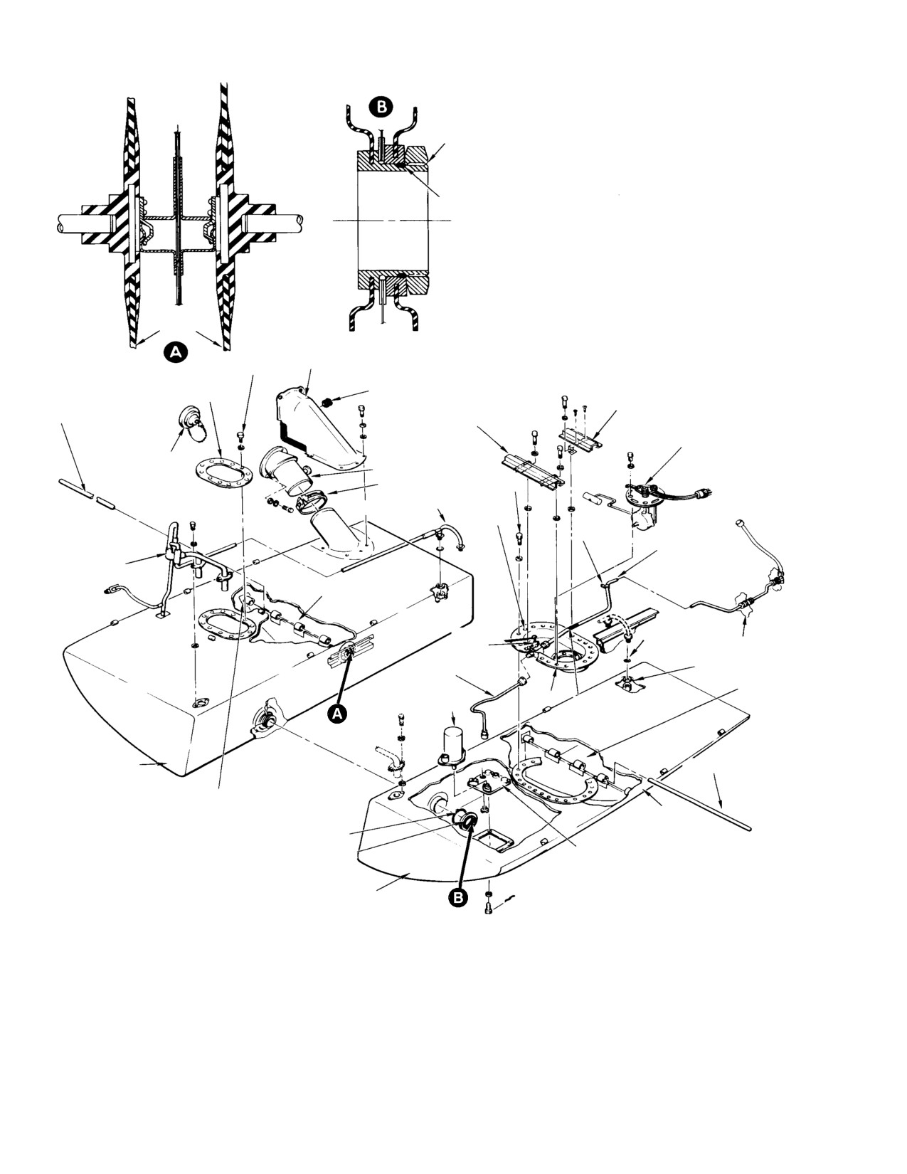
A. Left Fuel Cell Removal
remove through floor access opening.
(1).
Remove fuel cell covers.
C. Fuel Cell Installation
(2).
Using a spanner wrench to hold the
(1). Check that all electrical power is OFF
crossover fitting in the right cell,
and disconnect battery and external
remove nut and O−ring from fitting in
power. Check that helicopter is electri−
left cell.
cally grounded and left and right fuel
cell compartments are clean and free of
(3).
Remove lacing from left cell.
obstructions.
(4).
Remove starting pump.
(2). Fold fuel cells lengthwise and insert the
fuel cells into their respective compart−
(5).
Remove four bolts and washers that
ment. Align openings in the fuel cells
secure mounting pad to structure.
with associated openings in the struc−
ture.
(6).
Remove the fuel vent cover (Ref. Sec. 2).
Remove two bolts and washers from
(3). Install starting pump.
forward vent crossover fitting.
(4). Install the baffle support rods through
(7).
Remove nut and seal washer from rear
the tank baffle tabs and insert ends of
vent tube fitting. Disconnect clamp and
rod into the mating nipples inside the
remove powerplant supply tube from
fuel cells. Connect the four baffle
the union in Sta. 124.00 bulkhead.
support hooks to the structure (detail
A).
(8).
Release two baffle support hooks from
structure by lifting tank upward at
(5). Coat O−ring with petrolatum (34,
each end of the baffle support rod
Table 2−4) and install O−ring and cell
Page 12-2
Revision 18
MD Helicopters, Inc.
CSP−H−2
500 Series − Basic HMI
interconnect fitting nut. Hold the fitting
leaks. Repair cause of any leakage as
in the right cell with a spanner wrench
necessary. Check fuel quantity indicator
and tighten nut. After nut has been
for correct indication.
tightened, end face of cell fitting must
(17). Install left and right access plates in
not be located more than 0.005 inch
cargo compartment floor.
(0.127 mm) inside exposed face of nut;
protrusion through nut is acceptable
6. Fuel Cell Cover Replacement
(detail B).
(Ref. Figure 12−1)
(6).
Install right fuel cell cover with twelve
A. Left Fuel Cell Cover Removal
washers and bolts; torque bolts to 50 −
(1).
Check that all electrical power is OFF
70 inch−pounds (5.65 − 7.91 Nm).
and disconnect battery and external
power.
(7).
Connect forward fuel vent crossover
fitting with four steel washers, four
(2).
Check that helicopter is electrically
aluminum washers between crossover
grounded.
fitting and fuel cell, and bolts. Torque
(3).
Drain all fuel from the fuel cells.
bolts to 20 − 25 inch−pounds (2.26 −
2.82 Nm).
(4).
Purge the fuel cells with dry filtered
compressed air.
(8).
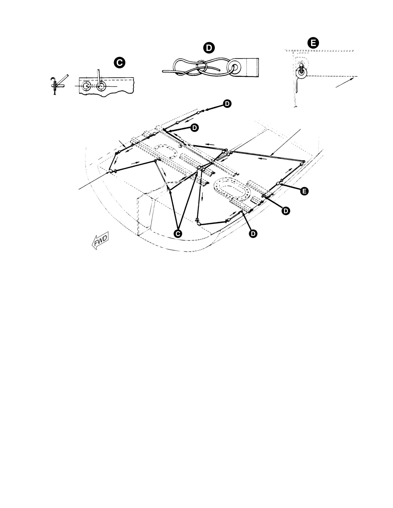
Install nylon lacing (details C, D, and
(5).
Remove lockwire and disconnect
E). Draw lacing taut and tie each end
electrical connections from tank unit
with a bowline (detail D).
and from fuel pump receptacle.
(9).
Place clamp on filler and connect filler
(6).
Loosen nut and disconnect control cable
to fuel cell neck; tighten clamp. Install
wire from swivel in lever of fuel shutoff
fuel filler shield.
valve. Disconnect powerplant supply
(10).
Install new seal washers and aft vent
tube at fuel shutoff valve.
tube nuts. Torque nuts to 40 − 60
(7).
Remove tank unit (fuel quantity
inch−pounds .
transmitter) (Ref. Sec. 17).
(11).
Install four washers and bolts to secure
(8).
Remove bolts and washers from left fuel
fuel inlet mounting pad; torque bolts to
cell cover. (A headless setscrew is
20 − 25 inch−pounds. Install fuel cell
installed in place of the most inboard
drain valve in fuel inlet mounting pad
bolt and washer.)
and safety with 0.032 inch (0.8128 mm)
(9).
Remove the six attaching screws that
lockwire (2).
secure the three left fuel cell cover
support brackets. Remove the brackets
(12).
Install lacing (details C and E). Draw
and the three washers that are
lacing taut and tie each end with a
installed between the brackets and the
bowline (detail D).
cover.
(13).
Install left fuel cell cover.
(10).
Move left fuel cell cover sufficiently to
gain access to the starting pump supply
(14).
Install tank unit (Ref. Sec. 17)
hose and electrical connector. Discon−
(15).
Connect powerplant supply tube at fuel
nect hose and connector from cover:
shutoff valve and torque tube nut to
then remove cover.
150 − 250 inch−pounds (16.95 − 28.25
B. Right Fuel Cell Cover Removal
Nm). Connect control cable wire to
shutoff valve lever and rig the control.
Perform steps (1). thru (4). for removal of Left
Connect electrical plug to tank unit and
Fuel Cell Cover Removal. Remove right fuel
starting fuel pump plug to receptacle.
cell cover attaching hardware; remove cover.
C. Left Fuel Cell Cover Installation
(16).
Fill the fuel cells. Connect the battery
and external power. Operate fuel pump
(1). Check that all electrical power is OFF
and make fuel leak check. Inspect fuel
and disconnect battery and external
cells and associated plumbing for fuel
power.
Page 12-3
Revision 18
MD Helicopters, Inc.
CSP−H−2
500 Series − Basic HMI
C
L
ACFT
NOTE 3
O−RING
CELLS
50−70 IN. LB
(5.65−7.91 NM) FUEL FILLER SHIELD
RIGHT FUEL CELL COVER
GROMMET
SUPPORT BRACKET
BAFFLE SUPPORT ROD
SUPPORT
BRACKET
TANK UNIT
CAP
FILLER
50−70 IN. LB
CLAMP
(5.65−7.91 NM)
AFT VENT
NOTE 1
CLAMP
POWER PLANT
SUPPLY TUBE
FWD VENT
TORQUE TUBE
NUTS 150−250 IN.
SYSTEM
LB (16.95−28.25 NM)
TANK BAFFLE
SHUT−OFF
SEAL WASHER
VALVE
STA. 124.00
40−60 IN. LB
FUEL INLET
(4.52−6.78 NM)
HOSE
TANK
COVER
BAFFLE
START PUMP
ANTI−CHAFING TAPE
(NOTE 4)
RIGHT FUEL
BAFFLE SUPPORT ROD
CELL
BAFFLE SUPPORT HOOK
(NOTE 2)
BAFFLE
SUPPORT HOOK
O−RING
(NOTE 2)
CELL INTERCONNECT NUT
MOUNTING
(NOTE 3)
PAD
LEFT FUEL CELL
NOTES:
1.
LOCATION FOR HEADLESS SET SCREW.
2.
OUTBOARD CLIP TYPICAL OF INBOARD CLIP.
3.
AFTER NUT HAS BEEN TIGHTENED, END FACE OF CELL FITTING MUST NOT
BE LOCATED MORE THAN 0.005 IN. (0.127 MM) INSIDE OF EXPOSED FACE OF
NUT; FITTING PROTRUSION THROUGH NUT IS ACCEPTABLE.
4.
USE TAPE (42 OR 56, TABLE 2−4).
30−119−1F
Figure 12-1. Fuel Cell Installation (Sheet 1 of 2)
Page 12-4
Revision 18
MD Helicopters, Inc.
CSP−H−2
500 Series − Basic HMI
BOWLINE KNOT
TOP OF TANK
START LACING WITH
BOWLINE KNOT
(FOLLOW ARROWS)
END LACING WITH
NYLON LACE
BOWLINE KNOT
NYLON LACE
LOOP
START LACING WITH
BOWLINE KNOT
(FOLLOW ARROWS)
END LACING WITH
BOWLINE KNOT
30−119−2C
Figure 12-1. Fuel Cell Installation (Sheet 2 of 2)
(2).
Check that helicopter is electrically
(8). Install washers and bolts to attach
grounded.
support brackets to left cell cover, and
cover to cell. (Substitute a headless
(3).
Install fuel pump electrical receptacle
setscrew for the most inboard bolt and
in fuel cell cover with nut; secure with
washer if the hex−head bolt contacts
lockwire.
the cargo floor structure.) Torque bolts
to 50 − 70 inch−pounds (5.65 − 7.91
(4).
Check condition of anti−chafing tape on
Nm).
powerplant supply tube. If worn,
replace with new tape (42 or 56,
(9). Install tank unit (fuel quantity trans−
Table 2−4).
mitter) (Ref. Sec. 17).
(5).
Position cover over cell opening.
(10). Connect powerplant supply tube at fuel
shutoff valve and torque tube nut to
(6).
Place clamp on powerplant supply tube
150 − 250 inch−pounds (16.95 − 28.25
and connect tube to union at Sta.
Nm). Connect control cable wire to
124.00 bulkhead; torque to 150 − 250
shutoff valve control. Connect electrical
inch−pounds (16.95 − 28.25 Nm).
plug to tank unit and starting fuel
Secure clamp to cargo floor with screw,
pump plug to receptacle.
washer and nut.
D. Right Fuel Cell Cover Installation
(7).
Install the three left fuel cell cover
support brackets and secure with six
Perform steps (1). and (2). for installation of
screws. Install one washer between
Left Fuel Cell Cover Installation. Install right
each of the bracket legs and the cover.
fuel cell cover with twelve washers and bolts;
Page 12-5
Revision 18
MD Helicopters, Inc.
CSP−H−2
500 Series − Basic HMI
torque bolts to 50 − 70 inch−pounds (5.65 −
Do not use soaps or strong de−
CAUTION
7.91 Nm).
tergents when cleaning fuel
cells. Certain powerful detergents can react
with fuel to form a compound that may block
7. Fuel Cell Repair
fuel filters.
NOTE: The fuel cells are susceptible to fungus
The time and effort required for making
growth after contact with contaminated
temporary repairs to fuel cells is as great as
fuel. Fungus in a fuel cell is usually caused
that necessary for permanent repairs and the
by improper servicing and storage of jet
results are not satisfactory: therefore, the
fuels. Suitable filters and water traps
repair procedures provided are for permanent
should always be used in fuel storage tanks
cold type repairs.
and servicing equipment. If evidence of fun−
gus is present in the fuel cells, contamina−
tion is usually present in the helicopter fuel
The repairs are made with a cold type repair
filters which should be cleaned or replaced.
kit (84, Table 2−4) which contains consumable
materials listed in Table 2−4.
(1). Use hot water not exceeding 160°F
(71°C) and clean fuel cells by hand or
with a soft brush.
Either side of the fuel cell can be patched:
however, repair of a hole or tear larger than 2
(2). Use a solution of acetic acid (10% max.)
inches should not be attempted using the cold
for fuel cell cleaning. Vinegar may also
repair procedure. In such a case. contact the
be used as vinegar contains a 4−5
fuel cell manufacturer for information on
percent acetic acid concentration that
factory type repairs.
will clean and inhibit airborne fungus
growth.
A. Preparing Fuel Cell for Repairs
(3). Use jet fuels for fuel cell cleaning. The
oil content in the jet fuel will assist in
protecting the fuel cell during storage.
(1). Accomplish repair work on fuel cells in
a warm, dry place, 60° to 80°F (16° to
(4). Do NOT use MEK or similar solvents,
27°C) with a 50 percent humidity. High
alcohol, or soap for fuel cell cleaning.
humidity, especially in combination
with low temperature, will cause
NOTE: To prevent formation of bacteria, an
condensation to form on cemented
FAA approved fuel additive is recommended
surfaces and make adhesion of repair
for routine addition to the helicopter fuel
patches difficult.
cells while refueling. This is the same as the
anti−icing additive recommended in the fuel
servicing section of the Owner’s Manual.
(2). Drain cell and dry thoroughly as soon
Usually one treatment will kill the bacteria
as possible after damage. Drying may
and prevent re−growth in the fuel cells for
be speeded up by keeping cell in a
some time. Use Owner’s Manual instruc−
warm place, 80° F (27°C) and by using
tions for blending additive with fuel during
an air hose on the inside. Do not keep
servicing.
cells warm for long periods at a time.
C. Repair of Fuel Cell
(3). Thoroughly clean the cell.
(1). Remove the fuel cell.
(2). Collapse the cell and expose the
B. Fuel Cell Cleaning
damaged area on a flat working
surface.
Any one of three methods outlined in steps (1).
(3). Wipe the damaged area and surround−
thru (3). is recommended for cleaning the fuel
ing surface with a piece of cheesecloth
cells.
(53, Table 2−4) dampened with solvent
Page 12-6
Revision 18
MD Helicopters, Inc.
CSP−H−2
500 Series − Basic HMI
(55) to remove any foreign material.
across at a time, so that air is not
The surface must be absolutely clean
trapped between the patch and the fuel
and dry to apply the patch.
cell material.
(4). Select and prepare a patch of synthetic
NOTE: Buffing and cementing of patch and cell
rubber−coated repair fabric:
is normally down at the same time. A clamp−
inside material (50) or
ing device consisting of two pieces of board
outside material (51) as follows:
or metal, one on each side of the seal, should
be placed over the patch and held in place by
(a). Select a patch 2 inches (5.08 cm)
two C−clamps under pressure for 8 hours. If
larger in all directions than the
such equipment is not available, a 25 pound
damaged area.
(12 kg) shot bag may be used. Oiled paper or
polyethylene should be placed between the
(b). Hand buff the material lightly and
equipment and the patch to prevent stick−
thoroughly with fine emery cloth
ing.
(49).
(c). Remove buffing dust by wiping patch
(8). Allow repair to remain undisturbed for
with slightly dampened cheesecloth
at least 8 hours; fuel cell is not to be
dipped in cement solvent.
returned to service for a minimum of 24
hours.
(d). Apply two thin, even coats of fuel cell
cement (54) to buffed side of patch,
NOTE: Twenty−four hours at temperatures of
allowing first coat to dry 15 minutes
60° to 80° F (16° to 27°C) is the minimum
before application of second coat;
time required forthe cement to fully cure for
allow second coat to dry 15 minutes.
the cold patch.
NOTE: Cement is to be used sparingly. Two
(9). Make additional minor repairs as
thin, even coats provide better adhesion
follows:
than thick uneven coats.
(a). Loose reinforcement edges, hangers
(5). Prepare damaged area of cell as follows:
or lap splices are to be lifted, buffed,
cemented thoroughly and looseness
(a). Hand−buff damaged area of cell
remedied, using procedures in steps
lightly and thoroughly with fine
(6). thru (8).
emery cloth: buffed area is to be
slightly larger in size than the patch.
(b). Scuffed areas where fabric is exposed
are to be buffed and cemented, and
(b). Remove buffing dust and apply two
allowed to air−dry for 8 hours as
thin coats of fuel cell cement to the
instructed in preceding steps. No
buffed area as described in steps
patch is required unless the fabric is
(4).(c). and (d).
torn
(6). Wipe the cemented area of the patch
and the fuel cell with cheesecloth
(10). Repairing Blisters:
moistened with solvent to make the
An inner blister is caused by trapped
surface of the cement tacky.
air between the liner and sealant.
NOTE: Application of the solvent to the cement
Blisters under 1 inch (2.54 cm) in
freshens the surface of the cement after it
diameter are not injurious and need not
has become dry to the touch.
be repaired.
(7). While still tacky, center and apply
To repair a blister:
patch to cemented area on the fuel cell
over the damaged area. Using a steel
(a). Buff surface of blister and an area
roller, or the smooth, round handle of a
extending 2 inches (5.08 cm) in all
screwdriver, roll the patch down on the
directions from its edge. Slit blister
cemented area. Roll the patch down
with a knife and buff underside of
from one edge, a half−inch to an inch
loose edges.
Page 12-7
Revision 18
MD Helicopters, Inc.
CSP−H−2
500 Series − Basic HMI
(b). Thoroughly clean buffed area and
(g). Loose patches may also be repaired
apply two coats of cement to inside
by buffing, washing and cementing
surfaces, allowing proper time
separation unless it is obviously
between coats.
better to replace patch with a new
one.
(c). Roll down blister to remove all
trapped air.
8. Fuel Cell Pressure Test
(1). Plug the forward vent system.
(d). After blister has dried completely,
apply a patch of repair material (50)
(2). Install a manometer and air pressure
extending 1.50 inches (3.81 cm) in all
equipment.
directions from edge of blister, and
(3). Apply and hold 2 psi (14 kPa) of air
complete the repair in same manner
pressure for 10 minutes as a precondi−
as for inside repair.
tioning measure. This will force trapped
(11). Repairing Loose Seams and Patches:
air out from between the fuel cells and
helicopter structure. Repeat if neces−
Loose lap seams must be repaired as
sary until the cells are adjusted to the
soon as possible.
contour of the cell bay.
(4). Apply 2 psi (14 kPa) air pressure and
To repair loose seams and patches:
hold for 15 minutes with no visible, less
(a).
Buff both surfaces inside separation.
than 0.250 inch (6.35 mm), drop on
Buff an area on top of loose seam
manometer. If a pressure drop occurs,
extending 2 inches (5.08 cm) in all
check all fittings and retest the cells.
directions from edges of separation,
After careful testing, repair or replace
continuing measurement on next cell
parts as necessary to eliminate the
wall if necessary
pressure drop.
(5). Remove plug(s) from forward vent
(b).
Clean area inside separation with a
system, the manometer, and air
rag moistened with solvent (1). Allow
pressure equipment after completion of
area to dry. Apply two coats of
pressure test and or repairs.
cement (54). Allow proper drying
time between coats.
9. Fuel Filler Shield
(c).
Roll separation down firmly to
A. Fuel Filler Shield Replacement
remove trapped air and allow to dry
(Ref. Sec. 2, Fuel Filler Shield)
before proceeding.
B. Fuel Filler Shield Inspection
(d).
Cut a patch of repair material (50)
extending 1.50 inches (3.81 cm) in all
Inspect shield for cracks, crazing, and radius of
directions from edge of separation.
flanges for chipping and cracking. Inspect the
Round corners slightly and slice one
fuel inlet shield seals and grommet on side (if
edge of patch at an angle by tilting
installed) for security and deterioration.
shears instead of cutting square. Buff
C. Fuel Filler Shield Repair
patch on flat side.
(1). Repair polycarbonate fuel inlet shield
(e).
Clean buffed surface of patch and
body cracks by bonding a patch accord−
apply patch and complete the repair
ing to the criteria and methods speci−
in the same manner as for inside
fied for acrylic plastic in FAA AC 43.
repair.
13−1, Aircraft Inspection and Repair.
Use dichloromethane (38, Table 2−4) or
(f).
Loose lap seams on outside of cell
ethylene dichloride (39) as the bonding
are repaired in the same manner as
agent.
inside repair except that material
comparable to outside material of cell
(2). Repair small areas of seam separation
is used.
by injecting ethylene dichloride into the
Page 12-8
Revision 18
MD Helicopters, Inc.
CSP−H−2
500 Series − Basic HMI
void area and clamping together under
The vent tube is routed downward through the
light pressure.
control rod tunnel to a vent fairing mounted on
the bottom of the fuselage.
(3). Replace damaged or deteriorate
grommet (if installed).
An alternate venting source is provided on
current helicopters. Hughes Notice HN−8l
provides instructions for modifying early
10. Fuel Filler Cap
helicopters for the second vent provision.
(Ref. Figure 12−1) The fuel filler cap is located
A fuel cell vent line emergency shutoff valve, if
flush with the fuselage skin aft of the right
installed, connects the forward and aft vent
cargo door. The filler cap is attached to the
line hoses. The valve remains open as long as
filler neck by a safety chain.
the helicopter is within 45 degrees of normal
attitude in any direction. If this limit is
11. Fuel Filler Cap Replacement
exceeded, the vent valve closes to prevent fuel
spillage.
(1). Removal. Remove the filler cap from
filler neck by raising the spring−loaded
15. Fuel Cell Vent System Replacement
lever and rotating it counterclockwise
to OPEN. Remove the filler cap and
(Ref. Figure 12−1 and Figure 12−2)
disconnect the wire clip.
A. Forward Fuel Cell Vent System Removal
(2). Installation. Verify that the safety
(1). Check that all electrical power is OFF.
chain is securely attached to filler neck
Disconnect external power and battery.
in fuselage and connect the safety chain
to the replacement filler cap with a wire
(2). Drain all fuel from the fuel cells into
clip. Insert cap in filler neck and rotate
suitable containers.
clockwise to CLOSE. Check that filler
cap is tight and firmly seated in filler
(3). Remove right foot support fairing,
neck.
controls access door, and fuel vent cover
(Ref. Sec. 2), Remove lockwire from
12. Fuel Filler Cap Inspection
connector hoses; remove hoses as
required.
Inspect the filler cap gasket for deterioration.
(4). Remove forward fuel vent line attach−
Inspect the cap body for damage and the
ing hardware; remove fuel vent line. On
condition of the spring that keeps the lever
helicopters equipped with a vent line
flush.
emergency shutoff valve, remove the
right pilot’s seat for access to the third
13. Fuel Filler Cap Repair
attachment bolt.
Replace an unserviceable filler cap gasket or
(5). On helicopters with an alternate
cap. Smooth scratches and nicks by filing.
venting air source, remove lockwire and
disconnect necessary tubing and
14. Fuel Cell Vents
connector at lower tee to release lower
vent tube.
(Ref. Figure 12−1) Fuel cell vents are located
in the forward and aft end of each fuel cell.
NOTE: After disconnecting the vent system
tubing and attaching hardware, removal is
The aft vent is a short, U−shaped tube that
best accomplished with the collective pitch
interconnects the top aft end of each fuel cell;
stick in the full down position. Then rotate
the vent line is routed forward and connected
the vent valve assembly inboard and slide
to the forward vent tube.
down over landing gear structure. This posi−
tions the assembly for removal through the
The forward end of each fuel cell is intercon−
controls access door opening.
nected by a vent crossover fitting (Ref.
Figure 12−2) that is routed into the control rod
(6). Carefully pull vent tube inboard, to
tunnel in the canted bulkhead.
release from clip, and upward to
Page 12-9
Revision 18
MD Helicopters, Inc.
CSP−H−2
500 Series − Basic HMI
withdraw from flared tubing riser of
(7). Secure controls access cover, right foot
plastic vent fairing; remove vent tube.
support fairing, fuel vent cover and
right pilot’s seat, if removed.
(7). Remove crossover fitting attaching
D. Aft Fuel Cell Vent System Installation
hardware; remove crossover fitting with
two clamps and two seals attached.
(1). Position aft vent over center beam at
aft end of the fuel cell compartments
(8). Provide suitable covers or plugs for fuel
and install new seal washers.
vent holes in fuel cells and aft vent line
tube to prevent contamination.
(2). Secure aft vent to each fuel cell with
nuts: torque nuts to 40 − 60 inch−
B. Aft Fuel Cell Vent System Removal
pounds (4.52 − 6.78 Nm).
(1). Remove fuel cell covers.
(3). Connect hose from forward vent line
and install clamp.
(2). Remove two nuts to disconnect aft vent
(4). Install fuel cell covers.
from left and right fuel cells.
16. Fuel Cell Vent System Inspection
(3). Remove the hose that connects the aft
vent to the forward vent; remove aft
(Ref. Figure 12−1 and Figure 12−2)
vent and discard two seal washers.
(1). Check fuel cell vent fairing(s) for
C. Forward Fuel Cell Vent System
freedom of obstruction and undamaged
Installation
condition.
(2). Inspect vent tube for dents, cracks,
(1).
Remove protective covers or plugs from
deformation or corrosion. Minor (or
fuel vent holes in fuel cells and aft vent
smooth) dents are permissible except at
line tube.
the lower end which must fit flush with
inner diameter of lower plastic vent
(2).
Install two clamps and seals on cross−
fairing flared riser.
over fitting and position fitting in fuel
cell vent openings. Install attaching
(3). Inspect hoses, tubes, and connectors for
hardware (steel washers on top of
cracks, deterioration or obstructions.
fitting flange).
(4). Inspect crossover fitting for cracks,
(3).
Assemble lower vent tube as shown in
dents, or corrosion. Minor (or smooth)
Figure 12−2 and place lower end into
dents are permissible. Check that the
vent fairing tube and press outboard to
two anti−syphon vent holes are open
snap upper end of vent tube into clip.
and that the hole diameter, 0.025−0.030
inch (0.635−0.762 mm) is not decreased
(4).
Install upper vent tube with two
by residue.
washers, bolt, nut and clamp.
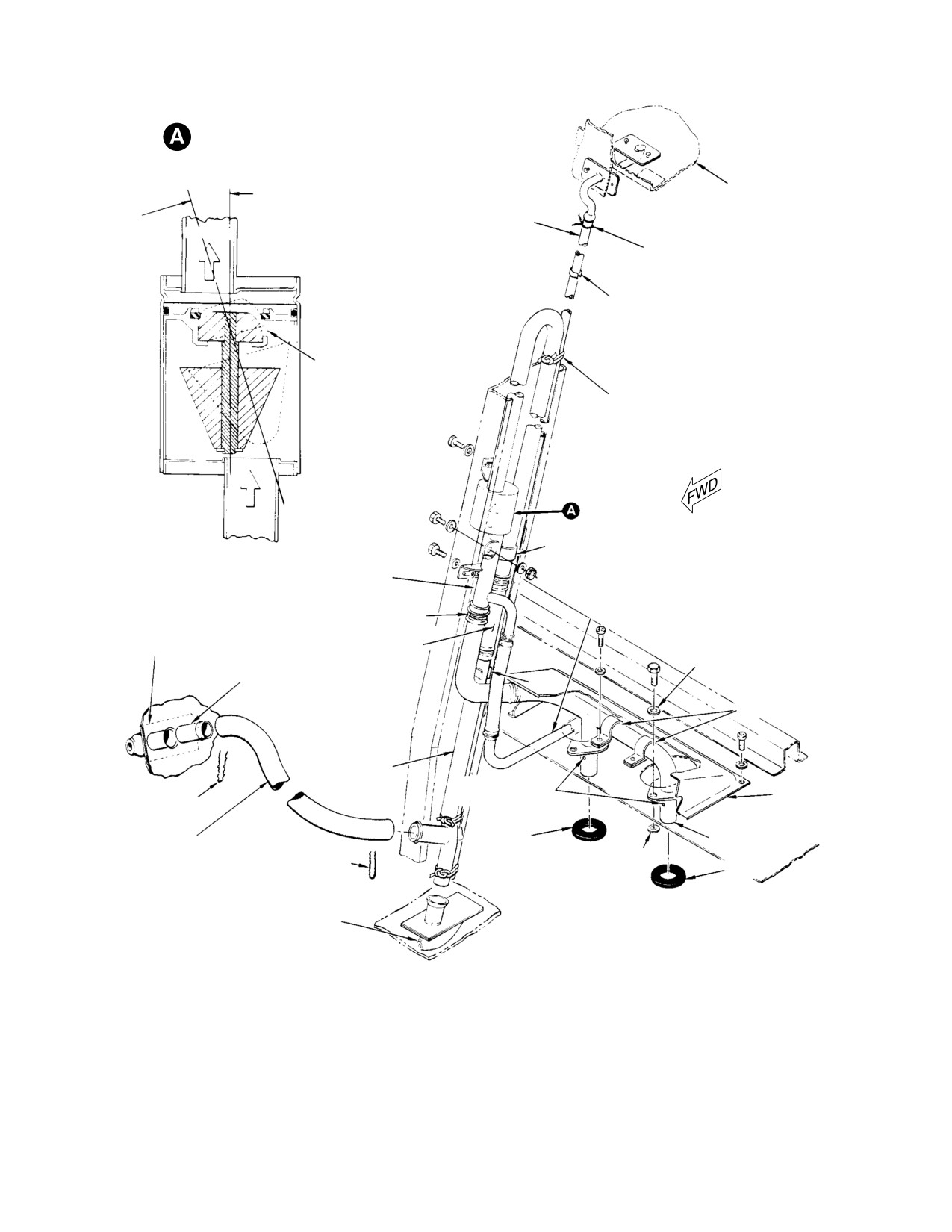
(5). Inspect the vent line emergency shutoff
valve (detail A, Figure 12−2) as follows.
(5).
Install fuel vent hoses (if removed) and
alternate vent tube (if installed);
(a). Inspect for condition outlined in steps
protect vent tube against chaffing by
(1). and (2).
wrapping with tape (42, Table 2−4) as it
passes through landing gear brace.
(b). Valve should remain open when
Secure all hoses with a double wrap of
tilted in any direction up to 45
0. 032 inch (0.8128 mm) lockwire (2)
degrees off vertical.
that ends in at least five full twists.
(c). Gently blow in valve and check that
(6).
Check that complete installation does
valve is closed at any angle in excess
not interfere with free movement of
of 45 degrees from vertical in any
flight controls.
direction.
Page 12-10
Revision 18
MD Helicopters, Inc.
CSP−H−2
500 Series − Basic HMI
EMERGENCY SHUTOFF VALVE
(CROSS−SECTION VIEW)
VALVE CLOSED WHEN
PAN
TILT EXCEEDS 45°
FROM VERTICAL
FORWARD DRAIN TUBE
OVERBOARD
(NOTE 4)
LOCKWIRE
CLIP (2 PLCS)
FUEL VENT OUT
LACING CORD (TYP)
FUEL VENT
IN
CLAMP
UPPER VENT TUBE
FORWARD−TO−AFT
LOCKWIRE (TYP)
VENT HOSE
SIDE VENT
FAIRING
CONNECTOR HOSE
(NOTE 5)
(NOTE 3)
STEEL WASHER
TUBE
CLIP
(NOTE 1)
CLAMPS
LOWER VENT
TUBE
ANTI−SYPHON
FUEL VENT COVER
LOCKWIRE
VENT HOLES
TUBING
SEAL
CROSSOVER FITTING
(NOTE 2)
ALUMINUM WASHER
LOCKWIRE
SEAL
LOWER VENT FAIRING
(NOTE 3)
NOTES:
1.
BONDED TO FAIRING WITH ADHESIVE (121, TABLE 2−4).
2.
ROUTED THRU LANDING GEAR BRACE.
3.
NOT TO BE PAINTED.
4.
FOR ADDITIONAL INFORMATION, REFER TO SECTION 9.
5.
DO NOT PAINT FAIRINGS MADE FROM LEXON (TRANSPARENT).
O.K. TO PAINT FAIRINGS MADE FROM FIBERGALSS (NON−TRANSPARENT).
44−028C
Figure 12-2. Forward Vent - Fuel Cell
Page 12-11
Revision 18
MD Helicopters, Inc.
CSP−H−2
500 Series − Basic HMI
17. Fuel Shutoff Valve Control Assembly
helicopter, and that hole in lever arm
aligns with holes in cam and stem.
(Ref. Figure 12−3) The fuel shutoff valve
control assembly consists of a flexible sheathed
(6). Secure valve lever arm and cam to
control wire actuated by a red PULL TO
valve stem with cotter pin.
CLOSE knob mounted on the instrument
(7). Check operation of fuel shutoff valve
panel.
assembly; full throw of valve lever arm
Pulling the control knob will close the fuel
is 90 degrees, stop−to−stop.
shutoff valve attached through a swivel to the
18. Fuel Shutoff Valve Control Assembly
control wire.
Replacement
On early configuration helicopters, the control
(Ref. Figure 12−3)
wire is routed aft near the helicopter center−
line to the shutoff valve located under the
A. Fuel Shutoff Valve Control Assembly
cargo compartment floor. On current configu−
Removal
ration helicopters, the control wire is routed
aft through the outboard left side of the
(1). Remove left fuel cell access door.
helicopter floor structure.
(2). Remove cotter pin, nut, washer and
swivel at valve.
Due to control wire routing, the respective
valves close in opposite directions when
(3). Remove control wire end clamp or
actuated.
strap.
Optional modification of early helicopters to
(4). Remove clamps or straps from flexible
the current fuel shutoff control configuration,
sheath.
i.e., PN 369A8104−3 to 369A8104−5, may be
accomplished as follows:
(5). Remove instrument panel left fairing
and lower cover panels.
(1). Check that existing 369A8104−3 fuel
shutoff control valve is in CLOSED
(6). Loosen control assembly nut at instru−
position, with valve lever arm pointing
ment panel and run nut off threaded
towards C/L of helicopter.
portion of plunger housing.
(7). Pull fuel shutoff control through
NOTE:
instrument panel mounting hole. Catch
D Use care in removing valve lever arm and
the lockwasher and nut when control
cam, to prevent loss of two detentballs
wire end passes through mounting hole.
seated in detent cavities in valve boss.
(8). Remove any unserviceable hardware.
D Note existing position of cam valve stem
to facilitate repositioning (Ref. view F).
B. Fuel Shutoff Valve Control Assembly
Installation
(2). Remove cotter pin securing valve lever
arm and cam to valve stem; remove
(1). Determine fuel shutoff control configu−
valve lever arm.
ration.
(3). Remove cam and detent balls; reposi−
(2). Install bracket (if used) and new
tion cam on valve stem 90 degrees
grommets if required.
clockwise from original position, with
holes in cam and valve stem aligned.
(3). Place control wire end of fuel shutoff
control assembly through mounting
(4). Insert detent balls in holes in top of
hole in instrument panel and place
cam; check that ball bearings are
lockwasher and nut over end of control
seated properly in detent cavities in
wire.
valve boss.
(4). Thread fuel shutoff control assembly
(5). Install valve lever on cam and valve
through mounting hole in panel,
stem; check that lever arm bends
through grommets back to fuel shutoff
downward and points away from C/L of
valve.
Page 12-12
Revision 18
MD Helicopters, Inc.
CSP−H−2
500 Series − Basic HMI
(5). Tighten nut to secure forward end of
NOTE: Shutoff valves on early configuration
control.
helicopters move clockwise to OPEN as
viewed from above. Current configuration
shutoff valves and shutoff systems so modi−
(6). Install clamps and/or straps as shown
fied move counterclockwise to OPEN. If in
in Figure 12−3.
doubt, blow gently through valve to deter−
mine open and closed positions or verify cor−
(7). Install valve arm swivel and washer.
rect part number.
Insert control wire through hole in
swivel and draw taut. Install and
(2). Watch fuel shutoff valve lever to check
tighten nut. Install cotter pin.
that lever has moved to closed position.
(3). Remove cotter pin and loosen nut on
(8). Adjust control assembly.
valve lever. Press lever arm against
open stop. Position control knob to
provide a 0.090−0.150 inch (2.286−3.81
19. Fuel Shutoff Valve Control Assembly
Inspection
mm) gap between the bottom of the
operating knob and the surface of the
fixed housing. Tighten nut on swivel to
(Ref. Figure 12−3)
secure.
(1). Remove left fuel cell access door.
(4). Operate control to close fuel shutoff
valve.
(2). Inspect the fuel shutoff control assem−
(5). Check that fuel shutoff valve lever arm
bly, nylon grommets and attachments
is in the closed position against stop.
for security.
NOTE: Full throw of valve lever is 90 degrees,
stop to stop. If both stops are not contacted,
(3). Inspect control bracket, if installed, for
check valve for angular installation of 90 de−
deformation and security.
grees to fuel tank cover.
(4). Inspect valve lever for corrosion,
(6). Operate control to open the fuel shutoff
damage, and freedom of movement.
valve. Recheck for proper gap under
Operate control and check for binding.
control knob when control lever is
Minimum bend radius of cable at any
against the open stop.
point must not be less than 2.75 inches
(6.985 cm). Push knob in and check for
21. Fuel Shutoff Valve Control Assembly
0.090−0.150 inch (2.286−3.81 mm) gap
Repair
between the bottom of the operating
(Ref. Figure 12−3) If the fuel shutoff valve
hand knob and the surface of the fixed
control assembly is pulled out more than 2
housing.
inches (5.08 cm) and the ball bearing moves
out of place, accomplish the following.
20. Fuel Shutoff Valve Control Assembly
(1). Loosen the swivel that secures control
Adjustment
wire to the valve arm and establish free
movement of the wire.
(Ref. Figure 12−3)
(2). Pull plunger of control assembly
outward until small hole in side of
NOTE: If the wire end of the control cable is
plunger is slightly beyond the plunger
disconnected or loose in the swivel, avoid
housing. Insert release rod into mating
pulling the control plunger more than 2 in−
opening of the plunger. Use care to
ches (5.08 cm) from the open position to pre−
align the notch in the release rod with
vent the ball bearing from moving out of
the hole in the plunger.
place.
(3). Apply grease (18, Table 2−4) between
(1). Pull control to close fuel shutoff valve.
the plunger and plunger housing.
Page 12-13
Revision 18
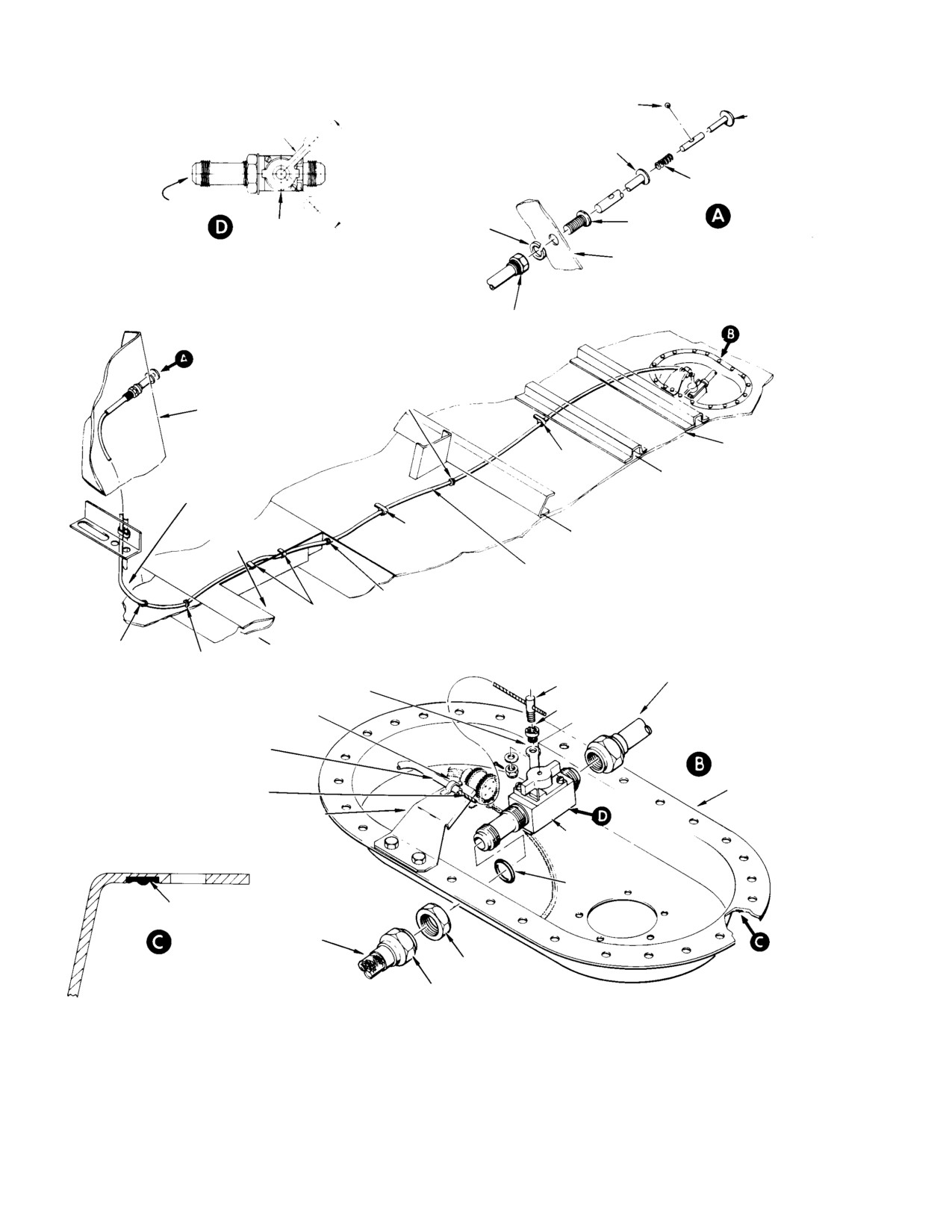
MD Helicopters, Inc.
CSP−H−2
500 Series − Basic HMI
STEEL BALL
RELEASE ROD
CLOSED
VALVE LEVER ARM
PLUNGER
90°
SPRING
ACFT C/L
PLUNGER
OPEN
LOCKWASHER
CAM
HOUSING
INSTRUMENT PANEL
FUEL SHUTOFF VALVE (369A8104−3)
HEXNUT
NYLON
GROMMET
INSTRUMENT PANEL
CARGO FLOOR
CLAMP
(NOTE)
PITOT PRESSURE
STA. 84.79
TUBE
PILOT’S
CLAMP
FLOOR
STA. 78.50
(NOTE)
FUEL SHUTOFF
CONTROL CABLE
NYLON
CLAMP
GROMMET
(NOTE)
NYLON
NYLON
POWER PLANT SUPPLY TUBE
GROMMET
GROMMET
VALVE LEVER AND
150−250 IN. LB (16.95−28.25NM)
STUD
SWIVEL
STRAPS, SCREWS,
CUP
WASHERS, NUTS
FLEXIBLE SHEATH
STAINLESS STEEL
LEFT FUEL
CONTROL WIRE
CELL COVER
BRACKET
FUEL
SHUTOFF
VALVE
SEAL
SEAL
FUEL INLET
HOSE
150−250 IN. LB
(16.95−28.25NM)
270−325 IN. LB
(30.51−36.72 NM)
EARLY CONFIGURATION
NOTE: SCREW, WASHER AND NUT
INSTALLATION
TYPICAL HARDWARE
30−118−1A
Figure
12-3. Fuel Shutoff Valve (Sheet 1 of 2)
Page 12-14
Revision 18
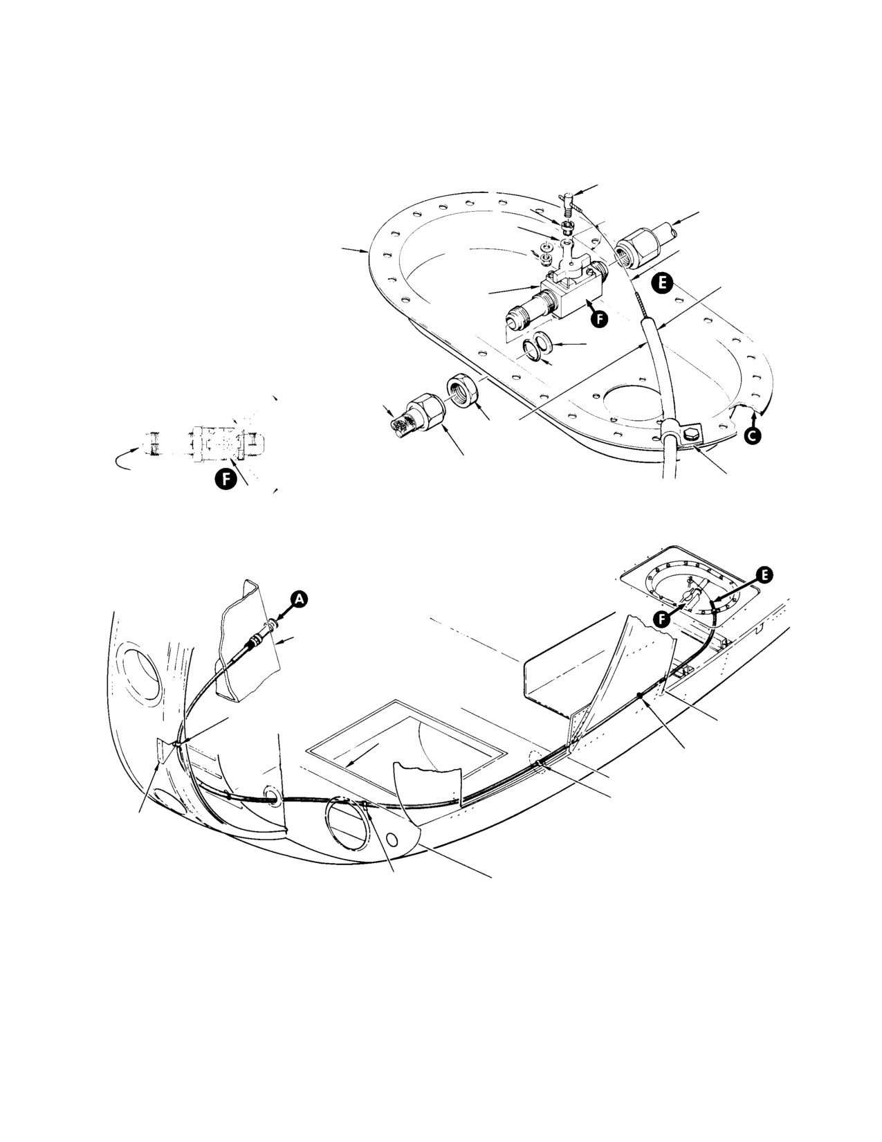
MD Helicopters, Inc.
CSP−H−2
500 Series − Basic HMI
STUD
POWER PLANT
SUPPLY TUBE
150−250 IN. LB
(16.95−28.25 NM)
VALVE LEVER
AND SWIVEL
LEFT FUEL
STAINLESS STEEL
CELL COVER
CONTROL WIRE
FUEL SHUTOFF
FLEXIBLE SHEATH
VALVE
WASHER
SEAL
FUEL INLET
VALVE LEVER ARM
OPEN
HOSE
150−250 IN. LB
90°
(16.95−28.25 NM)
270−325 IN. LB
ACFT C/L
(30.51−36.72 NM)
CLAMP
CAM
CLOSED
FUEL SHUTOFF VALVE (369A8104−5)
INSTRUMENT PANEL
STRAP
(NOTE)
STA. 78.50
PILOT’S
FLOOR
NYLON GROMMET
STA. 64.36
STRAP SCREW
BRACKET
STRAP
STA. 50.50
(NOTE)
CURRENT CONFIGURATION
INSTALLATION
30−118−2A
Figure 12-3. Fuel Shutoff Valve (Sheet 2 of 2)
Page 12-15
Revision 18
MD Helicopters, Inc.
CSP−H−2
500 Series − Basic HMI
(4). Install ball bearing into hole of plunger
(6). Fill the fuel tanks. Connect the battery
and push both release rod and plunger
and external power. Operate fuel pump
inward to full open position.
and make fuel leak check. Inspect fuel
cells and associated plumbing for fuel
Use care to hold ball bearing in
leaks. Repair cause of any leakage as
CAUTION
thehole until it goes into the
necessary. Check fuel quantity indicator
plunger housing.
for correct indication.
(5). Adjust control assembly.
(7). Install left access door in cargo
compartment floor.
22. Fuel Shutoff Valve
24. Fuel Shutoff Valve Inspection
The fuel shutoff valve is located on the left fuel
(Ref. Figure 12−3)
cell cover. A lever arm, mounted on top of the
(1). Inspect the fuel shutoff valve for
fuel shutoff valve, is actuated through an arc
obvious damage
of 90 degrees by push−pull control action from
the FUEL VALVE control on the instrument
(2). Check that the control lever arm
panel. The lever arm is detented in the open
operates through a 90 degree arc of
and closed positions. One of two part number
rotation with a pull of 2.5 ±1.0 lb. (1.13
valves are used. The respective valves close in
±0.454 kg) and seats firmly in detent at
opposite directions when actuated. Refer to
the full open and closed positions.
Figure 12−3 for valve identification.
Replace a defective shutoff valve.
23. Fuel Shutoff Valve Replacement
25. Fuel Supply Drain Valves
(Ref. Figure 12−4) Two drain valves are
(Ref. Figure 12−3)
provided in the fuel supply system.
A. Fuel Shutoff Valve Removal
The main drain valve is installed in the start
pump mounting pad and is accessible from the
(1). Disconnect the powerplant supply tube
underside of the helicopter. The engine fuel
assembly and swivel assembly; remove
drain valve is installed in the engine compart−
the left fuel cell cover.
ment as part of the engine fuel supply system.
(2). Remove nut and seal to disconnect fuel
The main drain valve and early configuration
shutoff valve from fuel cell cover.
engine compartment valves are identical.
These valves consist of a spring loaded plunger
B. Fuel Shutoff Valve Installation
which is depressed and rotated clockwise or
counterclockwise to the open−stop position
(1). Install fuel shutoff valve with washer
with a screwdriver.
(if installed) and seal on left fuel cell
cover.
Depress the plunger to release it from the
open−stop position, turn and allow valve
(2). Install nut; torque nut to 150 − 250
spring tension to return it to the closed
inch−pounds (16.95 − 28.25 Nm).
position. Current configuration engine
compartment drain valves are attached to the
(3). Install fuel cell cover).
engine compartment firewall fuel fitting and
drain overboard through a flexible tube. The
(4). Install tank unit (Ref. Sec. 17).
valve is actuated by depressing the plunger at
(5). Connect powerplant supply tube at fuel
the tube attachment.
shutoff valve and torque tube nut to
26. Fuel Supply Drain Valve Replacement
150 − 250 inch−pounds (16.95 − 28.25
Nm). Connect control cable wire to
(Ref. Figure 12−4)
shutoff valve lever. Refer to Fuel
A. Fuel Supply Drain Valve Removal
Shutoff Valve Control Assembly
Adjustment for rigging instructions.
(1). Check that all electrical power is OFF
Connect electrical plug to tank unit and
and disconnect battery and external
starting fuel pump lug to receptacle.
power.
Page 12-16
Revision 18
MD Helicopters, Inc.
CSP−H−2
500 Series − Basic HMI
(2). Drain all fuel from the fuel cells if
compartment. The fuel hose−to−engine pump
removing the fuel cell sump drain
connection is a self closing coupling. The Sta.
valve. Drain only the supply line and
124.00−to−Sta. 137.50 supply tube is only used
engine−driven pump if removing the
on early fuel systems. Hughes Notice HN−49
supply tube drain valve.
provides instructions for optional modification
and relocation of engine fuel hose and supply
NOTE: Current supply tube drain valve is
tube to the current routing, to preclude chafing
theneedle and seat type and is recom−
and damage to the fuel line in event of a hard
mended re−placement for early type valve.
landing or a collapsed landing gear damper.
(3). Remove lockwire, disconnect drain tube
29. Engine Fuel Supply System Replacement
on firewall mounted valve; then
unscrew drain valve and remove
(Ref. Figure 12−4)
O−ring. Discard O−ring if it is unser−
viceable.
A. Engine Fuel Supply System Removal
B. Fuel Supply Drain Valve Installation
(1). Check that all electrical power is OFF
and disconnect battery and external
(1). Install O−ring (new, if necessary) on
power.
drain valve. Install and tighten drain
valve in mounting pad or firewall
(2). Close the fuel shutoff valve by pulling
fitting as applicable.
outward on the fuel control knob.
(2). Safety fuel cell drain valve to adjacent
(3). Drain fuel from engine supply system.
bolthead and/or fuel line drain valve to
(4). Remove current configuration engine
body of firewall fitting (supply tube)
fuel supply system as follows:
with lockwire (2, Table 2−4).
(a). Loosen hose nuts and remove engine
(3). On firewall mounted drain valve,
fuel hose.
connect drain line and secure with
lockwire. Check that drain tube is
(b). Remove lockwire and overboard
routed through grommet in underside
drain line from firewall drain valve.
of fuselage.
(c). Release nuts and remove firewall
(4). Check that drain valves are closed.
fitting drain valve and elbow with
Refill fuel tanks and check drain valves
O−ring as required.
for leakage. Open fuel shutoff valve and
operate pump to pressurize the system
(5). Remove early configuration engine
during the leak check.
pump fuel hose and supply tube as
follows:
27. Fuel Supply Drain Valve Inspection
(a). Loosen or remove clamps; then slide
(Ref. Figure 12−4)
fire sleeve down away from the
engine pump and unscrew the
(1). Inspect drain valve for obvious damage.
coupling halves.
Check for positive shutoff in the closed
position.
(b). Slide fire sleeve upward and discon−
nect the hose coupling assembly at
(2). On firewall mounted drain valves,
the structural ring tee fitting; cap
check that drain tube is secure and is
open fittings.
routed through the grommet in under−
side of the fuselage. Check that slack is
(c). Loosen tube nut on supply tube at
provided in the drain tube to allow for
Sta. 137.50 structural ring and at
depression of the drain valve.
Sta. 124.00 bulkhead.
(d). Spring structural ring slight aft until
28. Engine Fuel Supply System
flare on supply tube clears lip on tee
(Ref. Figure 12−4) The engine pump fuel hose
fitting. Remove supply tube; cap ends
is located at the lower left side of the engine
of tube.
Page 12-17
Revision 18
MD Helicopters, Inc.
CSP−H−2
500 Series − Basic HMI
B. Engine Fuel Supply System Installation
A twisted line will result in a
CAUTION
partial blockage in the line,
(1). Install current configuration engine
causing flame−out at high power settings.
fuel supply system as follows:
(d). Slide fire sleeve over coupling
assembly at pump and tee fitting and
(a). Assemble Sta. 124.00 firewall fitting,
secure with clamps.
elbow and drain valve with O−ring as
shown in Figure 12−4. Position the
(e). Secure split end of fire sleeve with a
fitting so that the drain valve tilts
double wrap of lockwire (2,
down from the horizontal plane
Table 2−4) at a point just above the
12−16 degrees.
fitting drain valve.
30. Engine Fuel Supply System Inspection
(b). Install the engine fuel hose between
the fitting elbow and the engine fuel
(Ref. Figure 12−4)
pump.
(1). Inspect self−closing coupling halves and
bulkhead fitting for obvious damage.
(c). On the 250−C18 series engine, torque
both hose ends to 120 − 140 inch−
(2). Inspect fire sleeve for serviceable
pounds (13.56 − 15.82 Nm).
condition (no cuts, tears, ect.).
(d). On the 250−C20 engine, torque the
(3). Inspect hose for damage and signs of
fuel hose−to−pump connection to 120
leakage.
− 140 inch−pounds (13.56 − 15.82
(4). If installed, inspect Sta. 124.00−to−Sta.
Nm) and the firewall connection to
137.50 supply tube for obvious damage.
150 − 250 inch−pounds (16.95 −
28.25 Nm).
31. Start Pump
(Ref. Figure 12−4) The start pump is a
(2). Install early configuration engine pump
submerged type installed in the left fuel cell.
fuel hose and supply tube as follows:
The pump operates on 24 Vdc power and is
controlled by a 7.5 ampere circuit breaker type
NOTE: A washer should be installed under Sta.
switch on the instrument panel.
124.00 bulkhead union jamnut. When not
present, install AN960PD1216 washers if
Do not operate start pump if
CAUTION
union loosens or when left fuel cell is re−
fuel is not present. Without fuel,
moved. Jamnut torque is 400 − 420 inch−
pump rpm is to high resulting in failure of
pounds (45.19 − 47.45 Nm).
the pump motor.
32. Start Pump Replacement
(a). Spring structural ring slightly aft so
that supply tubes flares will fit over
After each opening, removal
lip of fittings at Sta. 124.00 and Sta.
WARNING
or replacement of any part
137.50.
of the engine and/or aircraft fuel sys−
tem between the aircraft fuel tank and
(b). torque supply tube nuts to 250 − 300
the engine fuel nozzle, the fuel system
inch−pounds (28.25 − 33.90 Nm).
must be bled to remove trapped air.
Failure to comply with this procedure
(c). Position engine fuel hose and cou−
can result in engine flameout or power
pling assembly between fuel supply
loss.
line fitting in structural ring and the
A. Start Pump Removal
engine fuel pump. Torque fuel pump
coupling nut to 120 − 140 inch−
(1). Remove left fuel cell cover.
pounds (13.56 − 15.82 Nm). Torque
the nuts at the fuel drain valve ends
(2). Remove the three bolts and washers
to 150 − 250 inch−pounds (16.95 −
that attach the electrical pump to the
28.25 Nm).
mounting pad; remove pump.
Page 12-18
Revision 18
MD Helicopters, Inc.
CSP−H−2
500 Series − Basic HMI
(3). Remove fuel inlet hose and fitting from
(6). Connect inlet hose to shut off valve
pump and retain for re−use on replace−
fitting. With fuel cell cover correctly
ment pump.
oriented, torque hose nut to 270 − 325
inch−pounds (30.51 − 36.72 Nm).
B. Start Pump Installation
(7). Install fuel cell cover.
(1). Check that all electrical power is OFF
33. Fuel System Bleeding
and disconnect battery and external
power. Check that helicopter is electri−
Fuel/air vapor discharged
cally grounded.
WARNING
during bleeding procedure
is highly flammable. Ensure helicopter
(2). Check that fuel cell is clean and free of
is electrically grounded and is not en−
foreign material.
closed in a space (i.e.. hanger) where
fuel fumes can accumulate. Do not al−
(3). Install O−ring and fitting in pump
low fuel/air mixture to get into eyes as
outlet port.
irritation or injury may result.
Proper tightening of engine
(1). Ground helicopter per general mainte−
WARNING
tubing connections is criti−
nance instructions.
cal to flight safety. Correct torque val−
(2). Set helicopter master switch to battery
ues must be used at all times. Excessive
and start pump switch to on (up)
torque on fuel or pneumatic sensing
system connections can result in crack−
position.
ing of the flare causing an air leak
(3). Place an empty container under
which can cause flameout, power loss,
overboard drain line on underside of
or overspeed.
fuselage at Sta. 124.00.
Ensure start pump wire lead is
NOTE: On helicopter with optional drain kit in−
CAUTION
wrapped around or tie−wrapped
stalled, drain valve will be located on fire−
(using only MS3367 Ty−Raps) to fuel supply
wall fitting.
hose so that there is no possibility of its in−
terfering with fuel quantity transmitter
(4). Open drain valve and allow fuel to flow
float mechanism. Ensure electrical connec−
until a steady stream flow uninter−
tions will not be strained by G−induced hose
rupted without air bubbles. Close drain
movements.
valve.
(5). Purge air from engine fuel system
(4). Install fuel inlet hose of fuel pump
(Refer to applicable Allison engine
fitting and torque to 270 − 325 inch−
operation and maintenance manuals.
pounds (30.51 − 36.72 Nm).
(6). Set start pump and master switches to
(5). Install pump assembly on mounting
OFF position.
pad with three bolts and washers.
Torque bolts to 20 − 25 inch−pounds
(7). Replace any safety wire removed during
(2.26 − 2.82 Nm).
this procedure.
Page 12-19
Revision 18
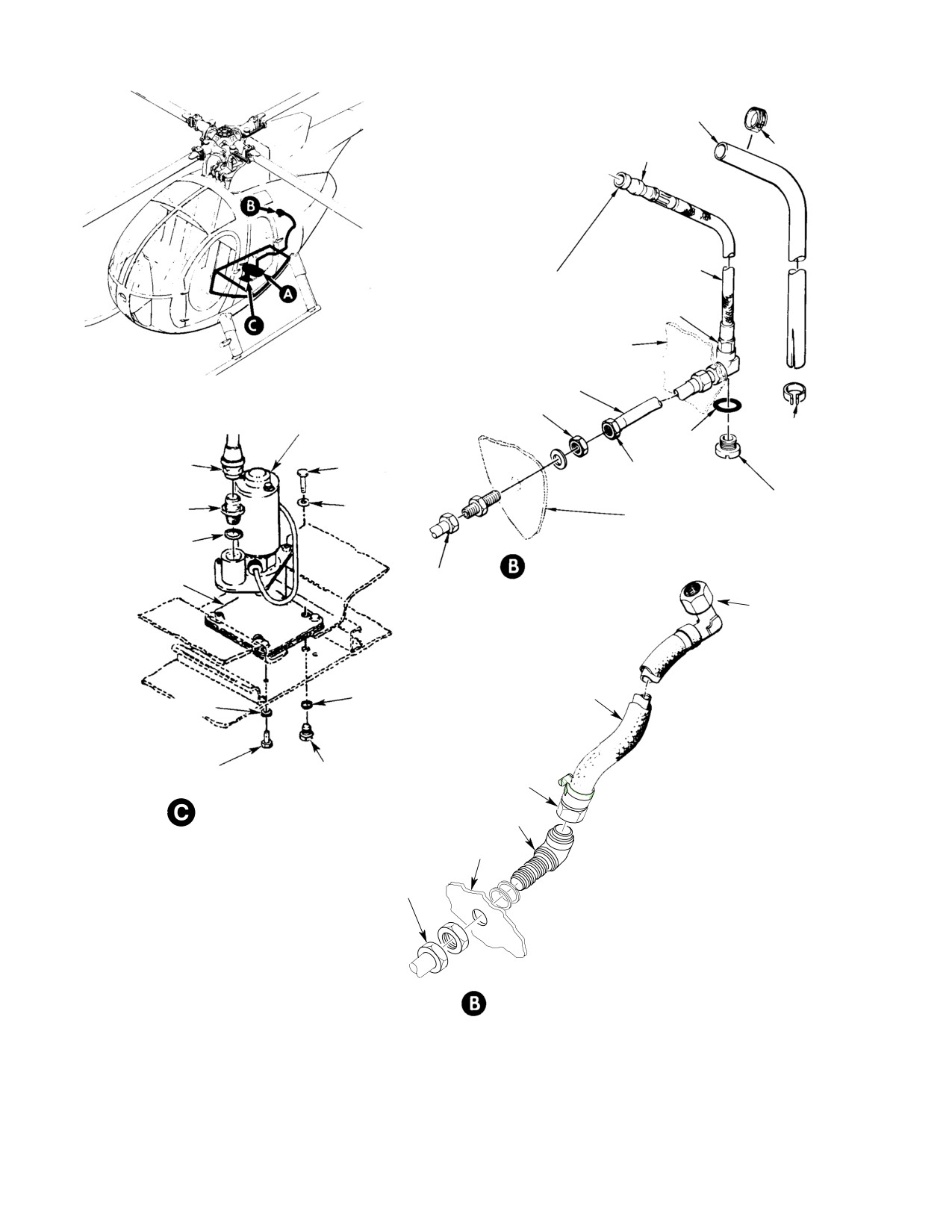
MD Helicopters, Inc.
CSP−H−2
500 Series − Basic HMI
FIRE SLEEVE
(NOTE 1)
COUPLING HALVES
120−140 IN. LB (13.56−15.82 NM)
CLAMP
ENGINE FUEL
TO ENGINE−DRIVE
HOSE
FUEL PUMP
150−250 IN. LB
(16.95−28.25 NM)
STA. 137.50
STRUCTURAL RING
SUPPLY TUBE
400−420 IN. LB
(45.19−47.45 NM)
START PUMP
CLAMP
O−RING
HOSE NUT, TORQUE TO
230−260 IN LB
BOLT TORQUE TO
(25.99−29.38 NM)
250−300 IN. LB
36−46 IN LB (4.07−5.20 NM)
(28.25−33.90 NM)
UNION, TORQUE TO
FUEL LINE
280−305 IN LB
WASHER
DRAIN VALVE
STA. 124.00
(31.64−34.46 NM)
O−RING
EARLY CONFIGURATION
150−250 IN. LB
SUMP PLATE
(16.95−28.25 NM)
TO ENGINE
DRIVEN
FUEL PUMP
ENGINE FUEL HOSE
O−RING
WITH FIRE SLEEVE
WASHER
BOLT, TORQUE TO
36−46 IN LB (4.07−5.20 NM)
TANK SUMP DRAIN VALVE
150−250 IN. LB
(TORQUE 95−105 IN LB)
(16.95−28.25 NM)
START PUMP INSTALLATION
ELBOW
STA. 124.00
150−250 IN. LB
(16.95−28.25 NM)
NOTES:
1.
NOT IN ALL HELICOPTERS. INSTALL AT FIRST OPPORTUNITY.
2.
LOCKWIRE TO DRAIN VALVE. ALLOW SLACK IN LINE FOR
CURRENT CONFIGURATION
ACTUATION OF DRAIN VALVE.
3.
ENSURE ELECTRICAL HARNESS IS WRAPPED AROUND FUEL
INLET HOSE TO PREVENT ANY INTERFERENCE WITH THE
FUEL TANK FLOAT.
30−120J
Figure 12-4. Fuel Start Pump Installation (Sheet 1 0f 4)
Page 12-20
Revision 18
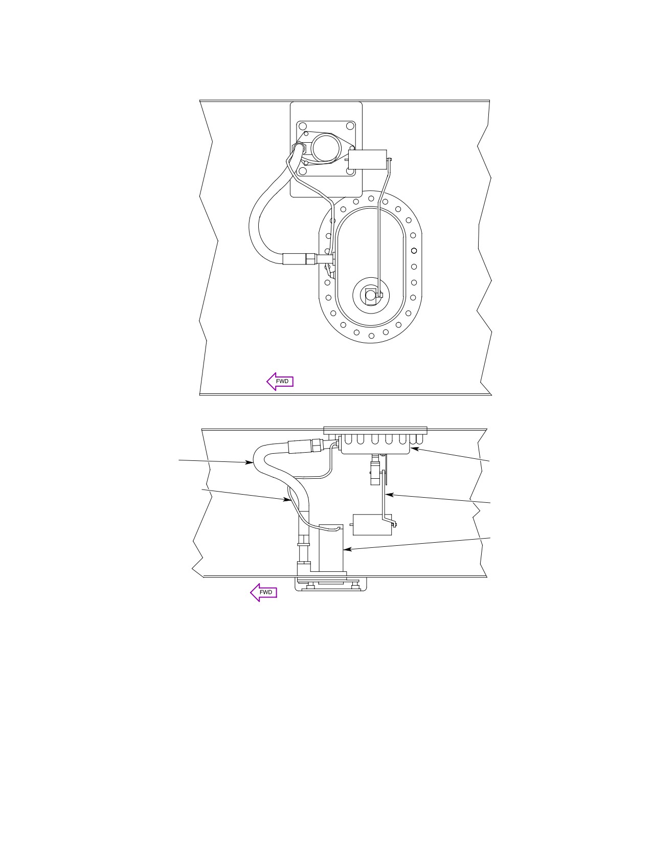
MD Helicopters, Inc.
CSP−H−2
500 Series − Basic HMI
TOP VIEW
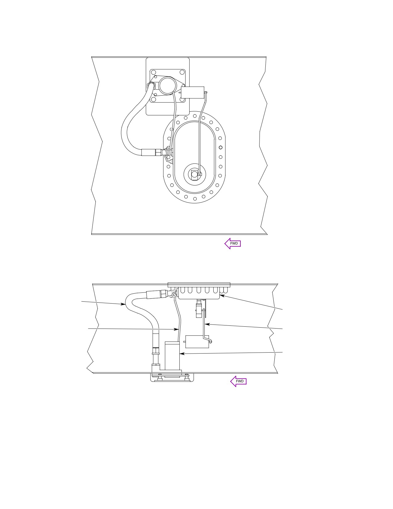
FUEL HOSE
BATHTUB FITTING
START PUMP WIRE
FLOAT ASSEMBLY
START PUMP
SIDE VIEW
NOTE: WRAP WIRE AROUND FUEL INLET HOSE TO
PREVENT INTERFERENCE WITH FLOAT.
G28−0004−2
Figure 12-4. Fuel Start Pump Installation (Sheet 2 0f 4)
Page 12-21
Revision 18
MD Helicopters, Inc.
CSP−H−2
500 Series − Basic HMI
TOP VIEW
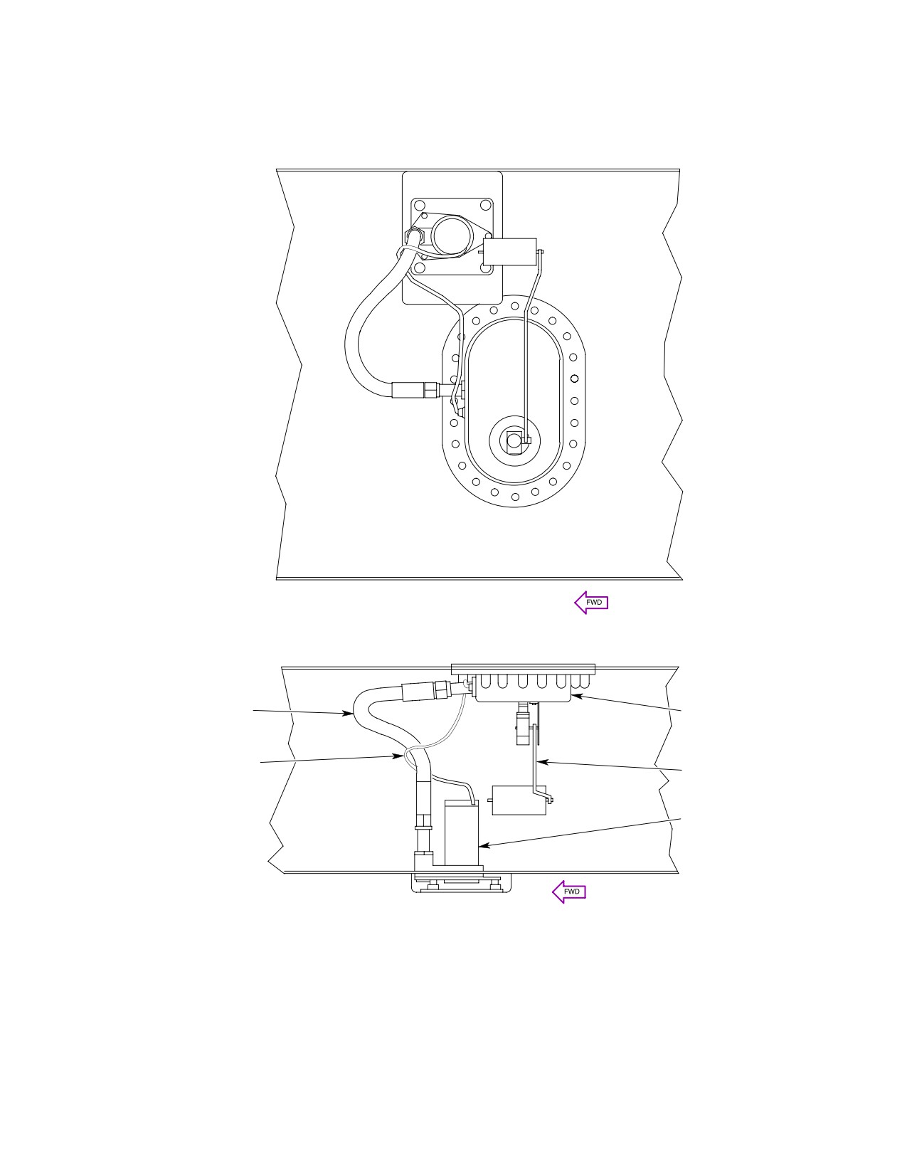
FUEL HOSE
BATHTUB FITTING
START PUMP WIRE
FLOAT ASSEMBLY
START PUMP
SIDE VIEW
NOTE: WRAP WIRE AROUND FUEL INLET HOSE TO
PREVENT INTERFERENCE WITH FLOAT.
G28−0004−3
Figure 12-4. Fuel Start Pump Installation (Sheet 3 0f 4)
Page 12-22
Revision 18
MD Helicopters, Inc.
CSP−H−2
500 Series − Basic HMI
TOP VIEW
FUEL HOSE
BATHTUB FITTING
START PUMP WIRE
FLOAT ASSEMBLY
START PUMP
SIDE VIEW
NOTE: WRAP WIRE AROUND FUEL INLET HOSE TO
PREVENT INTERFERENCE WITH FLOAT.
G28−0004−4
Figure 12-4. Fuel Start Pump Installation (Sheet 4 0f 4)
Page 12-23
Revision 18
MD Helicopters, Inc.
CSP−H−2
500 Series − Basic HMI
This Page Intentionally Left Blank
Page 12-24
Revision 18
MD Helicopters, Inc.
CSP−H−2
500 Series − Basic HMI
Section
13
Engine Oil System
MD Helicopters, Inc.
CSP−H−2
500 Series − Basic HMI
This Page Intentionally Left Blank
MD Helicopters, Inc.
CSP−H−2
500 Series − Basic HMI
TABLE OF CONTENTS
Para/Figure/Table
Title
Page
Section 13 Engine Oil System .
13−1
1.
Engine Oil Supply System
13−1
2.
Troubleshooting the Oil Supply System
13−1
Table 13−1. Troubleshooting the Oil Supply System
13−1
Figure 13−1. Engine Oil System Schematic
13−3
3.
Engine Oil Tank
13−4
4.
Engine Oil Tank Replacement
13−4
A. Engine Oil Tank Removal
13−4
B. Engine Oil Tank Installation
13−4
5.
Engine Oil Tank Inspection
13−4
6.
Engine Oil Tank Repair
13−4
Figure 13−2. Engine Oil Tank
13−5
7.
Liquid Level (Sight) Plug Replacement
13−6
8.
Engine Oil Cooler
13−6
9.
Engine Oil Cooler Replacement
13−6
A. Engine Oil Cooler Removal
13−6
B. Engine Oil Cooler Installation
13−6
Figure 13−3. Engine Oil Cooler and Duct
13−7
10. Oil Cooler Inspection
13−8
11. Oil Cooler Flushing
13−8
Figure 13−4. Oil Cooler Cleaning Setup
13−8
12. Engine Oil Cooler Repair
13−9
13. Upper Flanges, Oil Cooler Duct and Engine Oil Cooler Assembly Attachment .
13−9
Figure 13−5. Nutplate Installation − Oil Cooler Duct Attachment .
13−9
14. Oil Cooler Duct Assembly
13−9
15. Oil Cooler Duct Assembly Replacement
13−9
A. Oil Cooler Duct Assembly Removal
13−9
B. Oil Cooler Duct Assembly Installation
13−9
16. Oil Cooler Duct Assembly Inspection
13−9
17. Oil Cooler Duct Assembly Repair
13−10
18. Engine Oil Supply System Drain Valve and Check Valve . .
13−10
19. Oil Supply System Drain Valve and Check Valve Replacement .
13−10
A. Oil Supply System Drain Valve and Check Valve Removal .
13−10
B. Oil Supply System Drain Valve and Check Valve Installation .
13−10
20. Oil Supply System Drain Valve and Check Valve Inspection .
13−10
21. Oil Supply System Hoses, Fittings and Tubing
13−11
22. Oil Supply System Hoses, Fittings and Tubing Replacement .
13−11
Page 13−i
Revision 18
MD Helicopters, Inc.
CSP−H−2
500 Series − Basic HMI
TABLE OF CONTENTS (Cont.)
Para/Figure/Table
Title
Page
A. Oil Supply System Hoses, Fittings and Tubing Removal .
13−11
B. Oil Supply System Hoses, Fittings and Tubing Installation .
13−11
23. Oil Supply System Hoses, Fittings and Tubing Inspection .
13−11
Page 13−ii
Revision 18
MD Helicopters, Inc.
CSP−H−2
500 Series − Basic HMI
SECTION 13
ENGINE OIL SYSTEM
1. Engine Oil Supply System
a pressure relief by−pass valve. Oil then flows
from the cooler into the spherical oil tank from
(Ref. Figure 13−1) The engine oil system is a
which the oil is pumped backed to the engine
circulating dry sump−type system that
internal lubrication system.
includes the engine internal lubrication
Section 17 provides information on the engine
system, oil tank and cooler, oil cooler duct, oil
oil temperature and oil pressure indicating
temperature and pressure senders, drain and
systems.
check valves and associated interconnecting
pressure and drain hoses and tubes.
The Engine Operation and Maintenance
Manual provides detailed information and
Oil flows from the engine through a check
theory of operation for the engine.
valve at the inlet port of the oil cooler. The
circulating oil is cooled to approximately 185°F
Refer to CSP−H−3 for information on optional
(85°C) by air blown through the cooler by the
armor installation engine oil system and an
cooler blower that is driven by the main
optional engine oil tank and oil cooler drain
transmission drive shaft.
kit.
The oil cooler contains a thermostat for
2. Troubleshooting the Oil Supply System
bypassing oil around the cooler until the
engine oil reaches operating temperature and
(Ref. Table 13−1)
Table 13-1. Troubleshooting the Oil Supply System
Symptom
Probable Trouble
Corrective Action
No oil pressure or low oil
Restriction in oil lines
Inspect, clean, or replace as
pressure
necessary.
Oil filter element restricted
Inspect and clean as necessary.
(Refer to engine operation and
maintenance manual.)
Defective sender or indicator
Inspect and replace as necessary
(Ref. Sec. 17).
Oil pressure regulator valve
Adjust as necessary (Ref. Engine
improperly adjusted
Operational and Maintenance
Manual).
Oil supply low
Check oil supply and refill as
necessary.
Contaminated oil
Drain oil system and refill.
Oil pressure drops off severely
Oil supply low
Check oil supply and refill as
necessary.
Defective sender or indicator
Inspect and replace as necessary
(Ref. Sec. 17).
Oil pressure regulator valve
Adjust as necessary. Replace valve if
sticking or broken spring
spring is broken (Ref. Engine
Operation and Maintenance Manual).
Defective oil pump
Test oil pump (Ref. Engine Operation
and Maintenance Manual).
Page 13-1
Revision 18
MD Helicopters, Inc.
CSP−H−2
500 Series − Basic HMI
Table 13-1. Troubleshooting the Oil Supply System (Cont.)
Symptom
Probable Trouble
Corrective Action
Excessive oil pressure fluctuation
Defective indicator
Inspect and replace as necessary
(Ref. Sec. 17).
Oil leaks
Inspect oil system hoses and tubes.
Replace as necessary.
Restriction in oil filter or pressure
Clean oil filter; adjust pressure
regulator valve
regulator valve. Replace valve if
pressure cannot be regulated (Ref.
Engine Operation and Maintenance
Manual).
Defective oil pump
Replace oil pump (Ref. Engine
Overhaul Manual).
High oil pressure
Defective indicator
Inspect and replace as necessary
(Ref. Sec. 17).
Pressure regulator valve
Adjust as necessary (Ref. Engine
improperly adjusted
Operation and Maintenance Manual).
Abnormal oil temperature
Defective temperature sender or
Inspect and replace as necessary
indication.
indicator
(Ref. Sec. 17).
Oil consumption exceeds 6.50 oz
Leakage at loose fittings or
Inspect and tighten fittings and
(28.35 g) per hour
connections
connections as necessary.
Restricted vent lines
Inspect and clean as necessary.
Defective internal engine oil seals
Replace seals or engine.
Chip detector waring light comes
System lubricant contaminated
Inspect engine chip detector (Ref.
on
Engine Operation and Maintenance
Manual).
Page 13-2
Revision 18
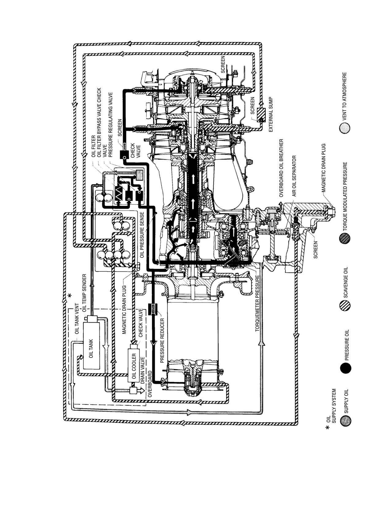
MD Helicopters, Inc.
CSP−H−2
500 Series − Basic HMI
30−096
Figure 13-1. Engine Oil System Schematic
Page 13-3
Revision 18
MD Helicopters, Inc.
CSP−H−2
500 Series − Basic HMI
3. Engine Oil Tank
B. Engine Oil Tank Installation
(Ref. Figure 13−2) The engine oil tank is
(1). Install new packings and drain tube
constructed of two hemispherical aluminum
union.
alloy halves welded together to form a sphere.
(2). Install replacement sight plug.
Welded fittings for the vent tube, inlet line,
outlet line, sight plug and mounting support
(3). Position oil tank and align nutplate
complete the assembly. The replaceable sight
holes with holes in mounting bracket
plug allows visual reading of the oil level
secure with four bolts and washers.
within the tank without use of a dip stick.
(4). Install oil tank filler seal and retaining
4. Engine Oil Tank Replacement
plate. Check that oil tank filler seal
neck is properly mated over oil tank
A. Engine Oil Tank Removal
filler neck and secure with four screws,
washers, and nuts. Install oil tank filler
(1).
Drain oil system.
seal clamp.
(2).
Remove oil cooler duct for access to oil
(5). Connect drain tube (tank) to oil tank
tank.
fitting and tighten.
(3).
Disconnect oil tank vent hose at oil
(6). Connect oil cooler tank return hose to
tank support by loosening clamp
oil tank fitting and tighten.
securing the fire sleeve and sliding the
clamp and fire sleeve back to clear the
NOTE: After installing engine oil−in hose cou−
fitting; cap open end of hose.
pling and engine oil tank vent hose, steps
(7). and (8)., pull fire sleeves into position
(4).
Disconnect oil−in hose coupling at oil
and tighten clamps.
tank outlet fitting by loosening clamp
(7). Install new O−ring, connect oil−in hose
securing the fire sleeve and sliding the
coupling to oil tank fitting and tighten.
clamp and fire sleeve back to clear
fitting; allow hose to drain; then cap
(8). Install new O−ring, connect engine oil
open end of hose.
tank vent hose to fitting on oil tank
support and tighten.
(5).
Disconnect oil cooler tank return hose
at oil tank fitting; allow tube to drain;
(9). Install oil cooler duct.
then cap open end of fitting.
5. Engine Oil Tank Inspection
(6).
Disconnect tank drain tube at oil tank
fitting; allow tube to drain; then cap
Inspect engine oil tank assembly for cracks,
open end of fitting.
corrosion distortion, obvious damage, leaks
and security. Inspect all associated hoses, lines
(7).
Remove oil tank filler seal clamp.
and fittings for oil leaks and security.
Remove four nuts, washers and screws;
then cap retaining plate and the filler
6. Engine Oil Tank Repair
seal.
(1). Weld all cracks, loose fittings, open
(8).
Remove four bolts and washers that
seams, and tubes with acetylene (76,
mount tank and remove the tank.
Table 2−4), oxygen (77), and welding
rod (85). Replace a damaged tank when
(9).
Remove sight plug and O−ring when
repair is impractical or excessive.
tank repair is necessary or the plug
becomes defective.
(2). Remove or smooth scratches and nicks
by sanding and touch up the surface
(10).
Remove engine oil temperature sender
with chemical film (8).
when tank repair is necessary or if the
sender becomes defective (Ref. Sec. 17).
(3). Replace a damaged sight plug.
Page 13-4
Revision 18
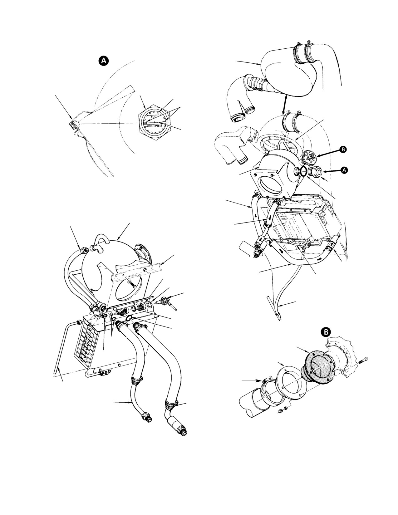
MD Helicopters, Inc.
CSP−H−2
500 Series − Basic HMI
BELT−DRIVEN BLOWER
UPPER OIL TANK
OIL TANK
MOUNT NUTPLATE
SIGHT PLUG
DECAL
WL LOCATOR
MARKS
SHAFT−DRIVEN
BLOWER
WL 48.63
ENGINE OIL TANK
SIGHT PLUG
80−90 IN. LB
(9.04−10.17 NM)
ENGINE OIL TANK
VENT HOSE
O−RING
OIL COOLER TANK
ENGINE OIL TANK
RETURN HOSE
ENGINE OIL IN HOSE
AND COUPLING ASSY
(NOTE)
STA. 124.00
FIREWALL
CHECK VALVE
ENGINE OIL OUT HOSE
BUSHING
AND COUPLING ASSY
TANK DRAIN TUBE
(NOTE)
WASHER OR GASKET
ENGINE OIL TEMP SENDER
OVERBOARD DRAIN TUBE
WASHER OR GASKET
O−RING
O−RING
OIL TANK FILLER SEAL
UNION
OIL TANK CAP
RETAINING PLATE
FILLER SEAL
DRAIN TUBE (TANK)
CLAMP
ENGINE OIL IN HOSE
ENGINE OIL TANK
AND COUPLING
VENT HOSE
(NOTE)
NOTE: SELF−CLOSING COUPLING NOT
INSTALLED ON ALL HELICOPTERS.
30−097D
Figure 13-2. Engine Oil Tank
Page 13-5
Revision 18
MD Helicopters, Inc.
CSP−H−2
500 Series − Basic HMI
7. Liquid Level (Sight) Plug Replacement
(3). Remove oil cooler duct assembly.
(1). Remove lockwire from sight plug.
(4). Remove cooler drain tube. union, and
O−ring. Cap the cooler port.
(2). Remove sight plug by unscrewing
counterclockwise.
Have an assistant hold pressure
CAUTION
with a wrench across flats of the
(3). Remove and inspect O−ring. Install new
oil cooler inlet fitting during removal of the
O−ring if required, on sight plug.
engine oil− out hose and/or check valve,
steps (5). and (6)., to prevent deformation of
NOTE: When a new sight plug is being
the fitting or cooler frame.
installed the liquid level decal is applied af−
ter the plug is installed and torqued.
(5). Disconnect engine oil−out hose from
check valve.
(4). Coat threads of replacement sight plug
with lubricating oil (3, Table 2−3) and
(6). Remove check valve and O−ring. Install
place new O−ring on sight plug. Torque
protective caps on oil line and in oil
sight plug to 80 − 90 inch−pounds
cooler boss.
(9.04 − 10.17 Nm). Secure with 0.032
(7). Remove screws and washers attaching
inch (0.8128 mm) lockwire (2).
deflector to mounting flange: remove
(5). Project a line from the oil tank upper
deflector.
mounting nutplate center across the
(8). Remove six bolts, washers, and nuts
center of the sight plug and pencil mark
attaching oil cooler to structure; remove
as shown in Figure 13−2, detail A.
cooler.
Position decal WL locator marks to
match pencil marks and install decal.
(9). Cut lockwire and remove shields from
oil cooler, if installed.
8. Engine Oil Cooler
B. Engine Oil Cooler Installation
(Ref. Figure 13−3) The engine oil cooler is a
radiator−type heat exchanger that is
(1). Position shields on sides of oil cooler so
constructed of aluminum alloy tubes welded to
that missing tab on outboard shield is
an aluminum frame.
adjacent to oil in fitting. Tie shields in
place with lockwire completely around
Engine outlet oil enters the cooler through an
front and rear sides of cooler.
inlet fitting at the lower right corner, circu−
lates through the tubes, and exits through an
(2). Position oil cooler on the firewall.
outlet fitting at the upper left corner of the
Install union with a new O−ring and
cooler.
install cooler drain tube.
The pressure relief bypass valve opens at
(3). Install six bolts, washers and nuts to
25−30 psi (172−207 kPa); the thermostat valve
attach cooler to firewall.
closes at +140°−180 °F (60°−82 °C).
(4). Coat threads of check valve with
9. Engine Oil Cooler Replacement
lubricating oil (3, Table 2−3).
A. Engine Oil Cooler Removal
Have an assistant hold pressure
CAUTION
on a wrench across flats of the
NOTE: Oil cooler removal requires two people.
oil cooler inlet fitting during tightening of
the check valve and/or engine oil−out hose,
(1). Drain oil system.
steps (5). and (6)., to prevent deformation of
the fitting or cooler frame.
(2). Disconnect oil cooler tank return hose
from cooler fitting and allow to drain
(5). Install check valve with a new O−ring.
into a suitable container. Cap open end
of the oil cooler tank return hose and
(6). Install engine oil−out line with a new
the cooler port.
O−ring.
Page 13-6
Revision 18
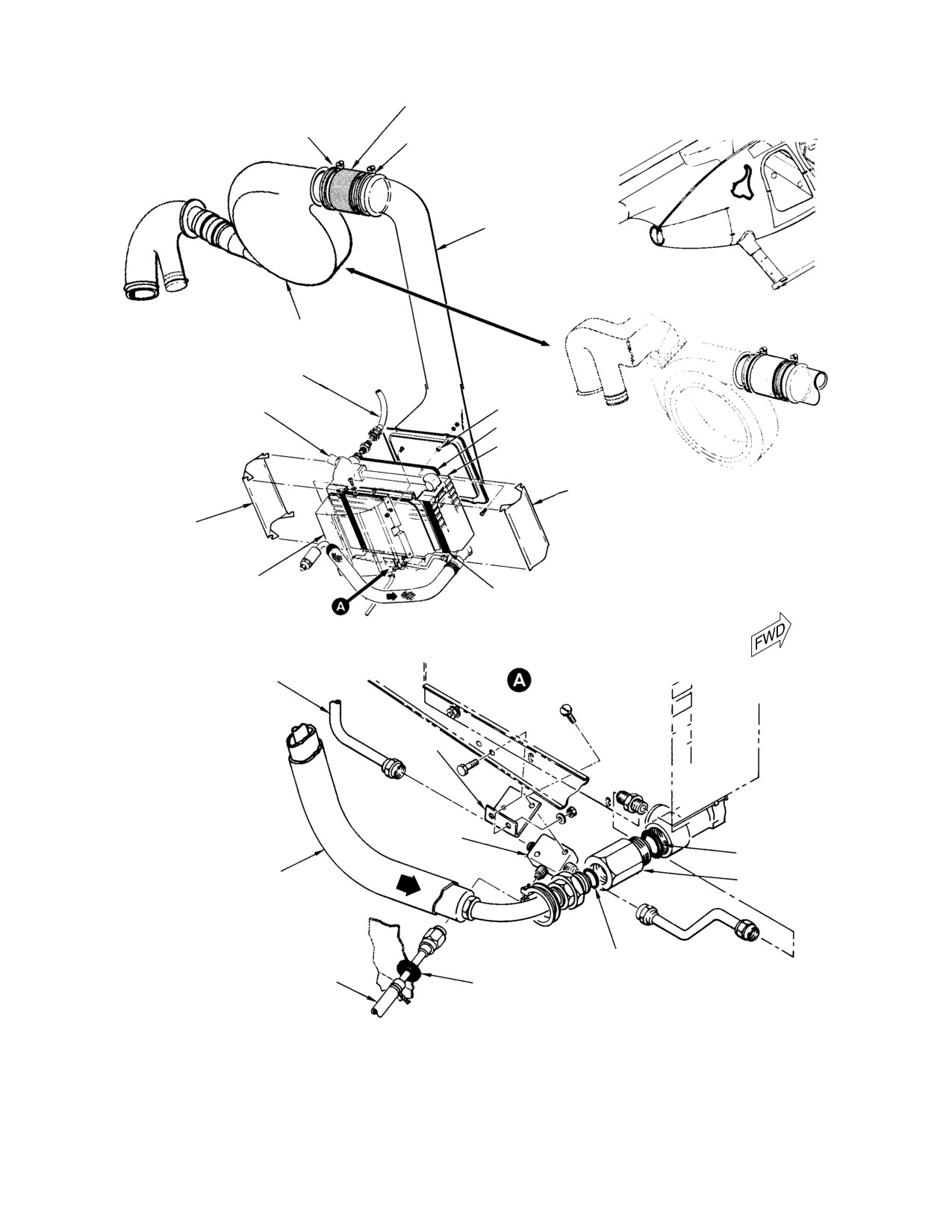
MD Helicopters, Inc.
CSP−H−2
500 Series − Basic HMI
AIR DUCT CONNECTION
CLAMP
CLAMP
ENGINE OIL
COOLER DUCT
BELT−DRIVEN OIL
COOLER BLOWER
OIL COOLER
BLOWER SCROLL
OIL COOLER−TO−TANK
OIL RETURN HOSE
THERMOSTATIC VALVE
SPACER
GASKET
ENGINE OIL COOLER
SHIELD
SHAFT−DRIVEN OIL
COOLER BLOWER
SHIELD
DEFLECTOR
GASKET
POWER PLANT
TUBE (TANK)
BRACKET
DRAIN VALVE
O−RING
ENGINE OIL OUT LINE
CHECK VALVE
O−RING
DRAIN HOSE
GROMMET
30−095C
Figure 13-3. Engine Oil Cooler and Duct
Page 13-7
Revision 18
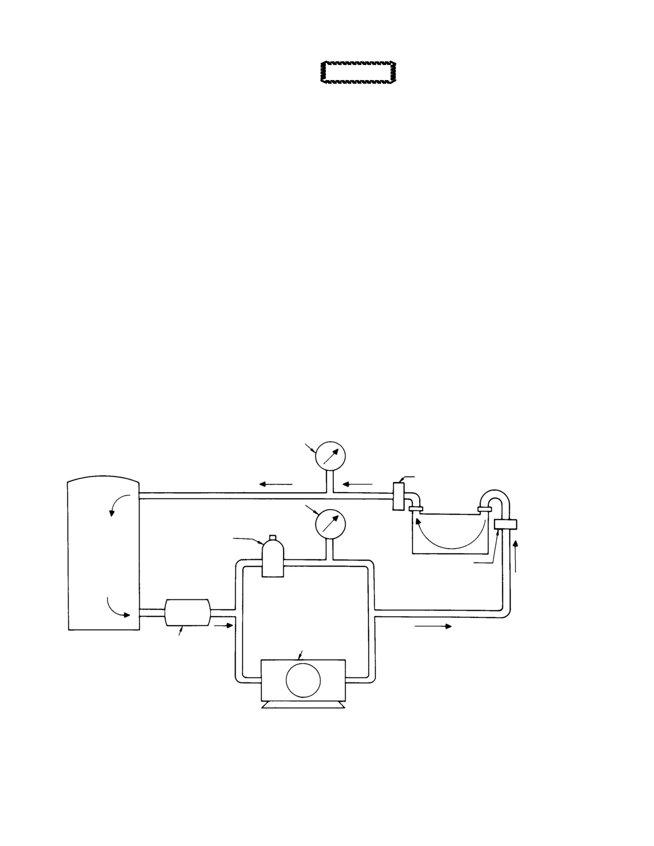
MD Helicopters, Inc.
CSP−H−2
500 Series − Basic HMI
(7). Install plastic deflector using screws
Use only recommended cleaning
CAUTION
and washers.
solutions or one that is satisfac−
tory for use on aluminum. Many solutions
(8). Install tank return hose.
satisfactory for cleaning copper or copper
nickel are highly corrosive to aluminum
(9). Install oil cooler duct (para 13−23).
and. if used, will result in the destruction of
the oil cooler assembly. If equipment has
(10). Fill oil tank with lubricating oil.
been previously used with any other clean−
(11). Start and operate engine according to
ing solutions, it should be thoroughly
the Owner’s Manual. Inspect oil cooler
washed out and flushed with the recom−
and related parts for oil leaks.
mended solution.
10. Oil Cooler Inspection
(3).
Establish flushing setup as shown in
Figure 13−4. Use solvent (1, Table 2−4)
Inspect engine oil cooler for cracks, corrosion,
to clean oil cooler interior.
damaged or bulged plates, broken welds,
foreign matter clogging, oil leaks, and security.
(4).
Connect hose from discharge side of
Inspect all associated hoses and fittings for oil
pump to oil cooler outlet to provide a
leaks and security.
cleaning solution flow opposite to
direction of normal flow.
11. Oil Cooler Flushing
(5).
Connect hose from storage tank to inlet
(Ref. Figure 13−4)
port of oil cooler.
(1). Remove thermostatic valve and plug all
openings in engine oil cooler.
(6).
Start centrifugal pump and allow to
flush for 30 minutes or until the
(2). Clean exterior of engine oil cooler with
cleaning solution appears clean after
steam.
flowing through oil cooler.
HYDRAULIC PRESSURE
GUAGE
100 MESH SCREEN
INLET
HYDRAULIC PRESSURE
GUAGE
COOLER
PRESSURE RELIEF VALVE
SET FOR 75 PSI (517 KPA)
TANK
100 MESH SCREEN
CENTRIFUGAL PUMP
OUTLET
28−56 GPM (26.5 LPM);
75 PSI (517 KPA)
FULL−FLOW FILTER
DISCHARGE PRESSURE
IN
OUT
30−094A
Figure 13-4. Oil Cooler Cleaning Setup
Page 13-8
Revision 18
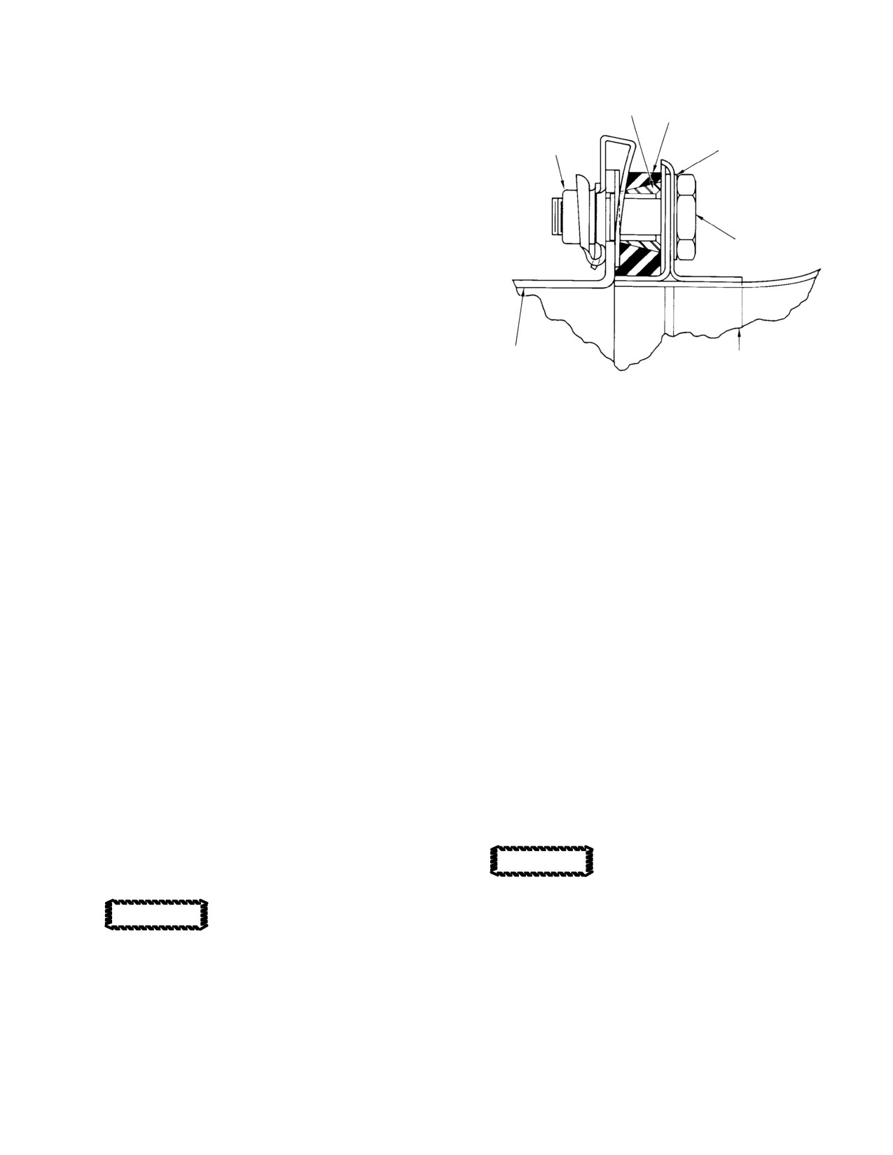
MD Helicopters, Inc.
CSP−H−2
500 Series − Basic HMI
NOTE: After each flushing operation, (7). thru
S−403−I FRONT FERRULE
(11)., examine the 100 mesh screens for met−
(SWAGELOK)
OIL COOLER GASKET
al or other foreign particles. If metal par−
A4972−6−02
ticles are found, clean screens with solvent
NUTPLATE
AN960PD10L WASHER
and dry with clean, filtered compressed air.
(7). Drain oil cooler.
(8). Flush oil cooler with compound (75) in
reverse direction for 30 minutes.
NAS1303−6 BOLT
(9). Reverse hoses and flush engine oil
cooler for 10 to 15 minutes in normal oil
flow direction.
(10). To rinse, flush engine oil cooler with
solvent for 10 minutes.
369A8302 ENGINE OIL
COOLER ASSY
369H8301 OR 369A8304
(11). Check filter screens for metal particles.
ENGINE OIL COOLER
Discard oil cooler if metal particles still
DUCT ASSY
appear in filter screens.
30−222
Figure 13-5. Nutplate Installation - Oil
12. Engine Oil Cooler Repair
Cooler Duct Attachment
(1). Replace a defective thermostatic valve.
14. Oil Cooler Duct Assembly
(2). Straighten bent cooling fins with a pair
of duckbill pliers ground to fit between
(Ref. Figure 13−3) The engine oil cooler duct is
a plastic assembly that directs cooling air from
cooling tubes.
the oil cooler blower to the engine oil cooler.
(3). Weld all small holes, cracked seams, or
loose fittings with welding rod (85,
15. Oil Cooler Duct Assembly Replacement
Table 2−4).
A. Oil Cooler Duct Assembly Removal
(4). Smooth scratches and nicks by sanding,
(1). Remove two clamps and air duct
and touch up the surface with chemical
connector.
film (8).
(2). Remove four bolts, spacers, washers,
13. Upper Flanges, Oil Cooler Duct and
and nuts; remove engine oil cooler duct
Engine Oil Cooler Assembly Attachment
assembly. Use care to retain spacers for
reinstallation of duct.
A nutplate installation to facilitate field
maintenance is accomplished as follows:
B. Oil Cooler Duct Assembly Installation
(1). Disconnect oil cooler duct from engine
(1). Position oil cooler duct. Install spacer at
oil cooler assembly. Discard existing
each attaching bolt location.
two nuts and 369A8304−13 spacers
Overtightening bolts can crack
used at upper flanges of duct and oil
CAUTION
the duct flange. Tighten nuts
cooler.
only to the point of firm contact.
Overtorquing bolts can crack
CAUTION
(2). Install four bolts, washers, and nuts.
duct flange; tighten bolts only to
point of firm contact and security.
(3). Install air duct connector and clamps.
(2). Reconnect duct to engine oil cooler with
16. Oil Cooler Duct Assembly Inspection
existing hardware, except install front
ferrules and clip−type nutplates to
Inspect oil cooler duct assembly for cracks,
secure top two bolts as shown in
foreign matter clogging, security and other
Figure 13−5.
signs of damage.
Page 13-9
Revision 18
MD Helicopters, Inc.
CSP−H−2
500 Series − Basic HMI
17. Oil Cooler Duct Assembly Repair
(4). Plug opening at inlet fitting of oil cooler
and cap open end of engine oil−out hose
(1). Repair polycarbonate duct assembly
coupling.
body cracks by bonding a patch accord−
(5). Disconnect tube assemblies at drain
ing to the criteria and methods speci−
valve, and cap open ends of tubes.
fied for acrylic plastic in FAA AC
43.13−1, Aircraft Inspection and Repair.
(6). Remove two bolts, and the valve
Use dichloromethane (38, Table 2−4) or
mounting bracket.
ethylene dichloride (39) as the bonding
agent.
(7). Cut lockwire and remove the two
screws that attach drain valve to
(2). Repair small areas of seam separation
bracket.
by injecting ethylene dichloride into the
void area and clamping together under
B. Oil Supply System Drain Valve and Check
light pressure.
Valve Installation
(1). Install new O−ring in oil cooler inlet
18. Engine Oil Supply System Drain Valve and
fitting.
Check Valve
Have an assistant hold pressure
CAUTION
(Ref. Figure 13−3) The oil supply system drain
on a wrench across the flats of
valve is a three port plug−type valve mounted
the oil cooler inlet fitting during installation
on a bracket beneath the oil cooler.
of the engine oil−out hose and/or check valve
to prevent deformation of the fitting or cool−
Three oil tubes are connected to the drain
er frame.
valve; one from the oil tank, one from the oil
(2). Coat threads of check valve with
cooler, and the third providers an overboard
lubricating oil (3, Table 2−3), install
drain. The drain valve is spring−loaded in the
check valve and tighten to secure.
close position. When the valve is opened, all
ports are closed.
(3). Install new O−ring in inlet port of check
valve.
The oil system check valve is a one−way, ball
type valve mounted at the inlet fitting of the
(4). Connect engine oil−out hose coupling to
oil cooler. The check valve functions to prevent
inlet port of check valve and tighten to
hot oil from flowing back into the engine when
secure.
the engine is not operating.
(5). Install the drain valve on mounting
bracket and safety with lockwire (2,
19. Oil Supply System Drain Valve and Check
Table 2−4).
Valve Replacement
(6). Install bracket on oil cooler flange.
A. Oil Supply System Drain Valve and Check
Valve Removal
(7). Install bracket on oil cooler flange.
Connect tube assemblies to drain valve,
and tighten to secure.
(1). Drain oil system.
(8). Start and operate engine according to
Have an assistant hold pressure
CAUTION
the Owner’s Manual. Check oil supply
on a wrench across the flats of
system check valve, drain valve, and
the oil cooler inlet fitting during removal of
associated plumbing for oil leaks.
the engine oil−out hose and/or check valve to
prevent deformation of the fitting or cooler
20. Oil Supply System Drain Valve and Check
frame.
Valve Inspection
(2). Disconnect engine oil−out hose coupling
Inspect the oil system drain valve and check
and allow to drain.
valve for cracks, corrosion, security, and leaks.
Check connected hoses and tubing for leakage
(3). Remove check valve and O−ring.
at connections.
Page 13-10
Revision 18
MD Helicopters, Inc.
CSP−H−2
500 Series − Basic HMI
21. Oil Supply System Hoses, Fittings and
(3). Install upper end of oil line.
Tubing
NOTE:
During tightening, rotate coupling nut
(Ref. Figure 13−2 and Figure 13−3) The hoses
of hose or tubing with one wrench while
and tubing used in the oil supply system are
holding the fitting to which it is being at−
lightweight assemblies incorporating perma−
tached securely with another wrench. This
nent fittings. The hoses located near the
procedure will prevent twisting and possible
engine are provided with fire shields.
deformation of the hose or tubing.
22. Oil Supply System Hoses, Fittings and
(4). Torque nuts of 1/4 inch tubes to 80 −
Tubing Replacement
100 inch−pounds (9.04 − 11.30 Nm)
and nuts on 5/16 inch tubes to 150 −
A. Oil Supply System Hoses, Fittings and
200 inch−pounds (16.95 − 22.60 Nm).
Tubing Removal
23. Oil Supply System Hoses, Fittings and
When removing an oil supply system hose or
Tubing Inspection
tube that is connected to lower end of oil cooler
or oil tank, drain the oil from the cooler or
(1). Inspect oil lines for kinks, uniformity of
tank before disconnecting the hose or tube.
diameter, breaks, and freedom from
Tagging or otherwise identifying fittings,
interference with adjoining structure or
tubing and hardware will facilitate reassemb−
other components.
ly.
(2). Replace defective oil lines. Inspect and
(1). Disconnect lower end of oil line. Drain
reject oil tubes for the following:
residual oil from line into suitable
(a). Kinks or dents which could obstruct
container.
oil flow. Dents are allowable up to
(2). Disconnect upper end of oil line and
0.015 inch (0.381 mm) deep.
remove line.
(b). Cracked or broken tubes or coupling
(3). Cap oil lines and all open lines to
nuts.
prevent entry of foreign matter.
(c). Cross−threaded, crushed, or other−
B. Oil Supply System Hoses, Fittings and
wise damaged coupling nuts.
Tubing Installation
(d). Chafing within clamp areas in excess
(1). Remove caps or plugs from fittings, oil
of 0.010 inch (0.254 mm). No chafing
hoses and tubes. Apply lubricating oil
is allowed at or near the flared
(3, Table 2−3) to all fittings.
tubing end.
(2). Install lower end of oil line but do not
(e). Nicks are allowable up to 0.010 inch
tighten.
(0.254 mm) deep.
Page 13-11
Revision 18
MD Helicopters, Inc.
CSP−H−2
500 Series − Basic HMI
This Page Intentionally Left Blank
Page 13-12
Revision 18
MD Helicopters, Inc.
CSP−H−2
500 Series − Basic HMI
Section
14
Engine Ignition
System
MD Helicopters, Inc.
CSP−H−2
500 Series − Basic HMI
This Page Intentionally Left Blank
MD Helicopters, Inc.
CSP−H−2
500 Series − Basic HMI
TABLE OF CONTENTS
Para/Figure/Table
Title
Page
Section 14 Engine ignition System .
14−1
1.
Engine Ignition Control System
14−1
2.
Troubleshooting the Ignition System
14−1
Table 14−1. Troubleshooting Ignition System
14−1
Page 14−i
Revision 18
MD Helicopters, Inc.
CSP−H−2
500 Series − Basic HMI
TABLE OF CONTENTS (Cont.)
Para/Figure/Table
Title
Page
This Page Intentionally Left Blank
Page 14−ii
Revision 18
MD Helicopters, Inc.
CSP−H−2
500 Series − Basic HMI
SECTION 14
ENGINE IGNITION SYSTEM
1. Engine Ignition Control System
Current configuration helicopters are equipped
with start circuitry protection. A dedicated
The engine starter−ignition switch is a
START circuit breaker (optional equipment)
push−button switch located on the pilot’s
can be installed on earlier model helicopters.
collective stick. The switch is marked START
Refer to Section 20 for information on engine
and is spring−load to the OFF position.
ignition control system wiring.
Once the keyswitch is turned on, depressing
Electrical power to the key switch is controlled
the start switch energizes both the start relay
by the main power switch (master switch).
and ignition exciter, and causes the generator
The engine operation and maintenance
field circuit in the voltage regulator to open so
manual provides detailed information for
that the starter will operate as a series motor.
maintenance of the ignition system.
Electrical power to the keyswitch, starter and
Refer to CSP−H−3 for information on optional
ignition system is controlled by the main
engine automatic reignition equipment.
power selector switch on the instrument panel.
2. Troubleshooting the Ignition System
Refer to Section 19 when keyswitch or start
switch replacement is necessary.
(Ref. Table 14−1)
Table 14-1. Troubleshooting Ignition System
Symptom
Probable Trouble
Corrective Action
WARNING: Before removing or installing components of the electrical system, check that all electrical
power is OFF. If units are not immediately replaced, ensure that all electrical connector are suitably
capped and stowed and all loose cable ends are properly insulated and stowed to prevent the
possibility of shorting. Serious injury or death could result from voltages present in the electrical
system.
Engine fails to ignite (Starter
Preservative oil fouling spark
Try a second start.
operation normal)
igniter
Faulty circuit to ignition unit
Listen for ignition operation. Check for
fuel from vapor exhaust.
Check input power to ignition unit.
Isolate and replace defective part.
Faulty igniter exciter
Listen for ignition operation. Check for
fuel vapor from exhaust. Replace with
serviceable unit (Ref. Engine
Operation and Maintenance Manual).
Page 14-1
Revision 18
MD Helicopters, Inc.
CSP−H−2
500 Series − Basic HMI
Table 14-1. Troubleshooting Ignition System (Cont.)
Symptom
Probable Trouble
Corrective Action
Faulty spark igniter
Listen for igniter operation. Check for
fuel vapor from exhaust. Replace with
serviceable unit (Ref. Engine
Operation and Maintenance Manual).
Spark igniter firing intermittently
Check input voltage to exciter. Check
ignition exciter by temporarily
replacing with serviceable unit (Ref.
Engine Operation and Maintenance
Manual).
Starter-generator fails to function
Key switch, start switch or
Replace defective switch or repair
with START switch pressed
interconnecting wiring defective
defective wiring (Ref. Sec. 19).
Battery voltage low
Start with APU or charge battery (Ref.
Sec. 2).
Start relay defective
Replace relay.
Voltage regulator defective
Replace regulator.
Circuit breaker out
Replace circuit breaker (If installed).
Page 14-2
Revision 18
MD Helicopters, Inc.
CSP−H−2
500 Series − Basic HMI
Section
15
Engine Exhaust
System
MD Helicopters, Inc.
CSP−H−2
500 Series − Basic HMI
This Page Intentionally Left Blank
MD Helicopters, Inc.
CSP−H−2
500 Series − Basic HMI
TABLE OF CONTENTS
Para/Figure/Table
Title
Page
Section 15 Engine Exhaust System .
15−1
1.
Exhaust System
15−1
2.
Tailpipe Assembly Replacement
15−1
A. Tailpipe Assembly Removal
15−1
B. Tailpipe Assembly Installation
15−1
3.
Tailpipe Assembly Inspection
15−2
4.
Tailpipe Assembly Repair
15−2
Figure 15−1. Exhaust System
15−3
Page 15−i
Revision 18
MD Helicopters, Inc.
CSP−H−2
500 Series − Basic HMI
TABLE OF CONTENTS (Cont.)
Para/Figure/Table
Title
Page
This Page Intentionally Left Blank
Page 15−ii
Revision 18
MD Helicopters, Inc.
CSP−H−2
500 Series − Basic HMI
SECTION 15
ENGINE EXHAUST SYSTEM
1. Exhaust System
During steps (2). thru (5)., an
CAUTION
assistant must support the aft
ends of the exhaust tailpipes while the tail−
(Ref. Figure 15−1) The exhaust system consists
pipes are being secured in place. Do not al−
of two engine tailpipes attached to the engine
low the aft ends of the tailpipes to become
exhaust collector outlets by two engine−to
displaced from their proper mounting loca−
tailpipe clamps and supported at the airframe
tions; to do so may damage the forward
exhaust outlet by a cushioned hanger assem−
mounting flanges or result in a poorly mated
bly. The hanger assembly is suspended from an
clamp joint. When assembling the tailpipe
attach fitting located above the tailpipes. The
and hanger assemblies, take care not to tear
upper and lower hangers are spring−loaded
or otherwise damage the inconel pads that
together. The inconel wire mesh cushions and
serve as cushions between the hangers and
the adjoining spring provide a flexible coupling
tailpipes.
between the aft ends of the tailpipes and the
supporting structure.
(2).
Position the forward end of each
tailpipe over its respective engine
exhaust outlet opening and install the
2. Tailpipe Assembly Replacement
two clamps. Position the clamp joints at
the upper surfaces of the tailpipes and
partially tighten the clamp; final
(Ref. Figure 15−1)
tightening will be accomplished later.
(3).
Taking care not to displace the ends of
A. Tailpipe Assembly Removal
the tail pipes, install the two hanger
assemblies as shown in Figure 15−1.
(1). Remove right side thermocouple
Make certain that the hanger assembly
hardware if installed; then remove
saddles are properly positioned between
tailpipe clamp nuts and clamps.
the locating flanges at the aft ends of
the tailpipes.
(2). Remove cotter pin, nut, washers and
(4).
Secure the tailpipes and hanger
bolt attaching tailpipe hanger to
assemblies together by installing the
structure fitting,
spring over the rivets connecting each
pair of hanger clips. Attach the upper
Whenever tailpipes are re−
spring hook so that the four captive
CAUTION
moved, cover the engine ex−
washers on the rivet are divided equally
haust ports with barrier material (44,
on either side of the spring hook (two
Table 2−4) or other suitable material into
washers separating the hook from each
the engine power turbine section.
hanger clip), Attach the lower spring
hook between the left side of the lower
hanger support link and the adjacent
(3). Remove the two tailpipes as an assem−
clip,
bly.
(5).
Attach the vertical link of the lower
hanger assembly to the support fitting
(4). Remove spring and hangers; then
on the structure with a bolt, two
separate the tailpipes.
washers and nut (all CRES hardware).
Tighten the nut only finger−tight at
B. Tailpipe Assembly Installation
this time.
(6).
Torque the two engine−to−tailpipe
(1). Remove the protective covers from the
clamp nuts to 15 − 18 inch−pounds
engine exhaust ports.
(1.69 − 2.03 Nm). On helicopters with a
Page 15-1
Revision 18
MD Helicopters, Inc.
CSP−H−2
500 Series − Basic HMI
250−C20 engine installed, install
(b). If a welded pad has been installed,
thermocouple wire support on right
use a hand file and carefully grind
tailpipe clamp and secure with nut and
spot welds and residue of pad from
washer as shown in Figure 15−1.
hanger.
(7). Using a plastic or rawhide mallet, tap
(c). Install replacement cushion assembly
lightly around the outer circumference
by positioning on the hanger and
of both clamps to ensure that they are
then bending the five tabs as shown
properly seated; then re−torque the
in Figure 15−1.
clamp nuts.
(8). Torque the support fitting bolt and nut
(d). Install the replacement wire pad by
to 12 − 15 inch−pounds (1.36 − 1.69
resistance welding (poke weld) the
Nm) and safety with a cotter pin.
edges of the pad (inconel wire,
Tadpole−type, Johns−Manville PN
3.
Tailpipe Assembly Inspection
2069 Rev. 2) to the hanger. The weld
spots should be approximately 0.250
(1). Inspect for cracks and broken weld
inch (6.35 mm) apart.
seams.
(2). Inspect for dents and bends.
(3). Repair cracks and breaks in the
tailpipes (CRES material No. 21−6−9)
(3). Inspect inconel wire pads or cushion
as follows:
assemblies on hanger assemblies for
wear, tears and for spotweld security.
(a). Using a stainless steel brush, thor−
oughly clean at least 1 inch (2.54 cm)
4.
Tailpipe Assembly Repair
on all sides of the cracked area. The
cleaning should remove all carbon
(1). Repair dents and bends using a form
from both inner and outer surfaces
block and suitable mallet.
and from the crack itself.
NOTE: Either inconel wire pads welded to the
hanger assembly or replaceable wire cush−
(b). Weld, using the inert arc method,
ion assemblies may be installed on the ex−
with rod (78, Table 2−4). Shield the
haust system. If so desired, the welded wire
back side of the weld with inert gas
pads may be replaced with PN 369H8202
or a suitable stainless steel flux.
cushion assemblies after the welded pad is
removed and the hanger is cleaned up.
(c). Repair single cracks less than 2
inches (5.08 cm) in length by stop−
(2). Replace hanger assembly inconel wire
drilling a 0.040 inch (1.016 mm)
pads or cushions as follows:
diameter hole at the termination of
(a). Remove damaged pad by tearing off
the crack. This method of repair does
inconel wire pad or by bending five
not apply to intersecting racks that
tabs to release each cushion assem−
form an acute angle leaving an
bly.
unsupported section.
Page 15-2
Revision 18
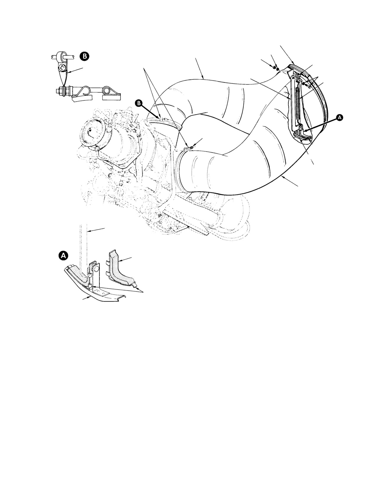
MD Helicopters, Inc.
CSP−H−2
500 Series − Basic HMI
UPPER HANGER
CRES
RIGHT TAIL PIPE
CRES; 12−15 IN. LB
TAIL PIPE
INCONEL WIRE
(1.36−1.69 NM)
THERMOCOUPLE
CLAMP
MESH PAD
WIRE SUPPORT
(NOTE 2)
CRES
SPRING
HANGER
15−18 IN. LB
(1.69−2.03 NM)
INCONEL WIRE
MESH PAD
LOWER HANGER
LEFT TAIL PIPE
SUPPORT LINK
REPLACEMENT CUSHION
ASSY (TYP)
NOTES:
1.
UPPER HANGER REPLACEABLE CUSHION ASSEMBLY
INSTALLATION IS THE SAME SHOWN.
2.
THERMOCOUPLE WIRE SUPPORT USED ON 250−C20
ENGINE INSTALLATION.
LOWER HANGER
(NOTE 1)
30−098C
Figure 15-1. Exhaust System
Page 15-3
Revision 18
MD Helicopters, Inc.
CSP−H−2
500 Series − Basic HMI
This Page Intentionally Left Blank
Page 15-4
Revision 18
MD Helicopters, Inc.
CSP−H−2
500 Series − Basic HMI
Section
16
Engine Air Induction
System
MD Helicopters, Inc.
CSP−H−2
500 Series − Basic HMI
This Page Intentionally Left Blank
MD Helicopters, Inc.
CSP−H−2
500 Series − Basic HMI
TABLE OF CONTENTS
Para/Figure/Table
Title
Page
Section 16 Engine Air Induction System .
16−1
1.
Engine Air Induction System
16−1
2.
Engine Air Induction System Inspection
16−1
3.
Engine Air Inlet Screen
16−1
4.
Engine Air Inlet Screen Replacement
16−1
A. Engine Air Inlet Screen Removal
16−1
Figure 16−1. Air Induction System (Without Air Inlet Screen) .
16−2
Figure 16−2. Air Inlet Screen Installation
16−3
B. Engine Air Inlet Screen Installation
16−4
5.
Engine Air Inlet Screen Inspection
16−4
6.
Engine Air Shield Screen Assembly
16−4
7.
Engine Air Shield Screen Assembly Replacement
16−4
8.
Engine Air Shield Screen Assembly Inspection
16−4
9.
Engine Air Inlet Bell, Engine−to−Firewall Seal Ring and Engine Air
Inlet−to−Firewall Seal
16−4
10. Engine Air Inlet Bell and Engine−to− Firewall Seal Ring Replacement .
16−5
A. Engine Air Inlet Bell and Engine−to− Firewall Seal Ring Repair .
16−5
B. Engine Air Inlet−to−Firewall Seal Replacement
16−5
11. Air Induction System Drains
16−5
12. Air Induction System Drain Tubing Replacement
16−5
Figure 16−3. Air Induction System Drain Installations
16−6
Page 16−i
Revision 19
MD Helicopters, Inc.
CSP−H−2
500 Series − Basic HMI
TABLE OF CONTENTS (Cont.)
Para/Figure/Table
Title
Page
This Page Intentionally Left Blank
Page 16−ii
Revision 19
MD Helicopters, Inc.
CSP−H−2
500 Series − Basic HMI
SECTION 16
ENGINE AIR INDUCTION SYSTEM
1. Engine Air Induction System
(3). Inspect engine inlet bell for cracks
breaks or other damage.
(Ref. Figure 16−1) The basic air induction
system consists of an engine air inlet installa−
(4). Inspect engine−to−firewall seal ring for
tion (plenum chamber), engine air shield
weak springs, cracks, corrosion or
screen, engine air inlet bell, engine−to−firewall
damage that prevents complete sealing
seal ring, and engine air inlet−to−firewall seal.
of the firewall. Repair or replace a
damaged ring.
(Ref. Figure 16−2) The current type engine air
induction system includes an air inlet screen
(5). Inspect engine air inlet−to=firewall seal
vertically mounted in the forward position of
for conditions that prevent complete
the aft fairing.
contact of the seal ring, Replace a
damaged seal.
The screen provides filtration of air flowing
into the engine air intake and protects against
(6). On current type system with plenum
foreign object entry. The upper portion of the
chamber drain tubing, check that
air inlet screen ends approximately 1−1/2
tubing is not deformed, corroded or
inches from the top of the aft fairing to provide
clogged.
a bypass air area.
3. Engine Air Inlet Screen
Air enters the engine air inlet fairings which
are part of the airframe. Air flows from the
The engine air inlet screen assembly is shaped
to fit the inlet area of the aft fairing. The
inlet fairings to the plenum chamber above the
screen assembly is constructed of a polycarbo−
engine air inlet bell, through the engine air
nate material bonded to an aluminum alloy
shield screen (when used) above the inlet bell
frame. The filter screen is arranged in a
and to the compressor inlet.
saw−tooth pattern to provide maximum
Air loss from the inlet chamber is prevented by
filtering capacity.
the engine−to−firewall seal ring that is
spring−loaded against the engine side of the
4. Engine Air Inlet Screen Replacement
firewall.
(Ref. Figure 16−2)
Refer to Section 10 for engine drive shaft
A. Engine Air Inlet Screen Removal
firewall seal information.
(1). Remove engine air inlet forward
Refer to CSP−H−3 for maintenance instruc−
fairings.
tions.
(2). Open hinge−mounted plenum chamber
2. Engine Air Induction System Inspection
access door on aft fairing (Section 2).
(Ref. Figure 16−1 or Figure 16−2)
(3). Install a temporary cover of cardboard
or suitable material over the engine air
(1). On helicopters equipped with the air
intake.
inlet vertical screen, inspect for security
of attachment, deformation, and screen
Use care to avoid dropping
damage. Check that screen area is not
CAUTION
screws, washers or any foreign
clogged. Inspect boot(s) on station 100
material into the engine air intake. The en−
tail rotor control rod for condition and
gine can be badly damaged by the entry of
security of attachment.
such objects.
(2). On helicopter equipped with plenum
(4). Remove clamps securing tail rotor
chamber engine air shield screen,
control rod boot to inlet screen.
inspect unit for security of attachment,
cracks, breaks and screen damage.
(5). Remove Sta. 100 tail rotor control rod.
Page 16-1
Revision 19
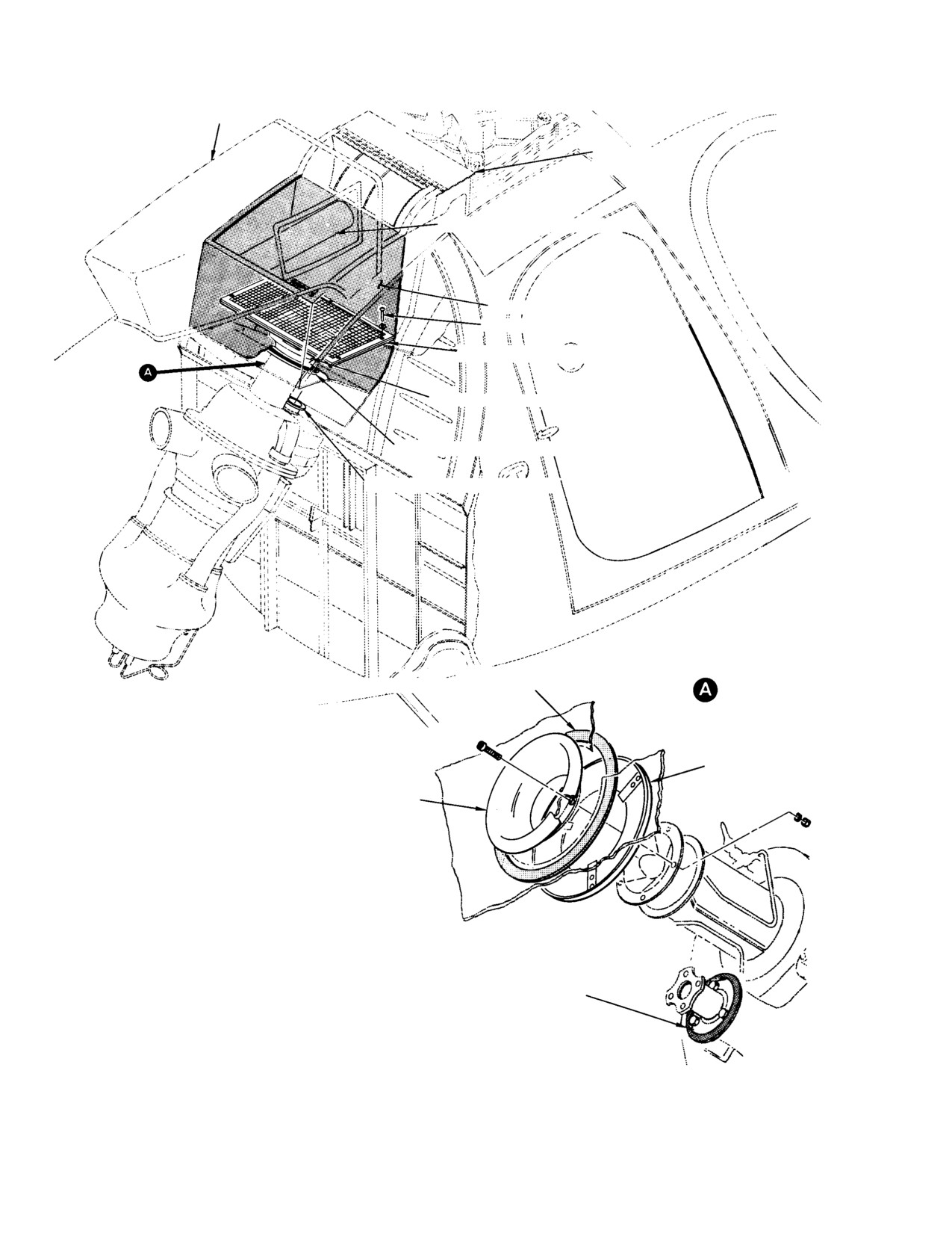
MD Helicopters, Inc.
CSP−H−2
500 Series − Basic HMI
ENGINE AIR INLET FAIRING
AFT FUSELAGE
STRUCTURE
TAIL ROTOR SHAFT FAIRING
NOTE 1
SCREW (NOTE 2)
ENGINE AIR SHIELD SCREEN (NOTE 3)
ENGINE AIR INLET BELL
ENGINE AIR INLET−TO−FIREWALL SEAL
ENGINE SHAFT FIREWALL SEAL
ENGINE AIR INLET−TO−FIREWALL SEAL
ROTATED
ENGINE−TO−FIREWALL
SEAL RING
ENGINE AIR
INLET BELL
ENGINE SHAFT
NOTES:
FIREWALL SEAL
1.
SHADED AREA REPRESENTS PLENUM CHAMBER.
2.
RIVE ATTACHING SCREWS USED ON EARLY CONFIGURATION SCREEN;
TWO SCREWS USED WITH TWO SCREEN−MOUNTED CLIPS ON CURRENT
CONFIGURATION.
3.
USED ON HELICOPTERS NOT EQUIPPED WITH AIR INLET SCREEN.
30-149
Figure 16-1. Air Induction System (Without Air Inlet Screen)
Page 16-2
Revision 19
MD Helicopters, Inc.
CSP−H−2
500 Series − Basic HMI
PLENUM CHAMBER ACCESS DOOR
ENGINE AIR INLET SCREEN
SCREW (6 PLCS)
SCREW (9 PLCS)
LATCH
COTTER PIN (TYP)
(NOTE)
EARLY SYSTEM
TAIL ROTOR CONTROL ROD
BOOT SUPPORT
PLENUM CHAMBER
TURNLOCK
ACCESS DOOR
FASTENER
(TYP)
EXTERIOR HANDLE
ACCESS COVER
BOLT (2 PLCS)
ENGINE AIR INLET FAIRING
ACCESS COVER
NOTE: ROLL ENDS OF ALL COTTER PINS.
DO NOT BEND FLAT.
MAST SUPPORT STRUCTURE
30-150
Figure 16-2. Air Inlet Screen Installation
Page 16-3
Revision 19
MD Helicopters, Inc.
CSP−H−2
500 Series − Basic HMI
(6). Remove two bolts securing screen to aft
Use care to avoid dropping
CAUTION
fairing. Remove six screws securing aft
screws, washers, or any foreign
base of screen to air inlet panel.
material into the engine air intake. The en−
Remove nine screws securing forward
gine can be badly damaged by the entry of
base of screen to mast support struc−
such objects.
ture.
7. Engine Air Shield Screen Assembly
Replacement
B. Engine Air Inlet Screen Installation
(Ref. Figure 16−1)
(1). Position inlet screen in place and install
(1). Open plenum chamber access door.
attaching hardware.
(2). Remove two screws and washers and
(2). Install Sta. 100 tail rotor control rod.
un−clip engine air screen from engine
air inlet pan, or remove five screws and
(3). Install tail rotor control rod boot on
washers and lift screen from support
inlet screen and secure with clamps.
clips (early configuration).
(3). Tape a temporary cover of card board or
Before removing the temporary
CAUTION
suitable material over the engine air
cover for reinstallation of the
intake.
screen , check the entire plenum area for
any foreign material that could fall into the
Before removing the temporary
CAUTION
engine as the is removed. The engine can be
cover for reinstallation of the
badly damaged by the entry of such objects.
screen, check the entire plenum area for any
foreign material that could fall into the en−
(4). Remove temporary cover from engine
gine as the cover is removed. The engine can
air intake.
be badly damaged by the entry of such ob−
jects.
(5). Close hinge−mounted plenum chamber
(4). Remove temporary cover from engine
access door on aft fairing and be sure
air intake.
door is locked closed.
(5). Install replacement engine air shield
(6). Install engine air inlet forward fairings.
with two screws and washers, or five
screws and washers (early configura−
tion).
5.
Engine Air Inlet Screen Inspection
(6). Inspect air inlet, base of mast, and
(1). Inspect filter for cleanliness, clogged
entire plenum chamber; remove any
areas, and foreign particle accumula−
foreign material (dirt, cotter pins, chips,
tion. Refer to Section 2 for cleaning of
etc.).
air inlet screen.
8. Engine Air Shield Screen Assembly
Inspection
(2). Inspect unit for cracks, breaks and
distortion. Check fiberglass filtering
Inspect the engine air shield screen for holes,
screen for cuts, breaks and other
breaks, tears, corrosion, or other damage.
damage.
Replace a damaged screen.
9. Engine Air Inlet Bell, Engine-to-Firewall
6.
Engine Air Shield Screen Assembly
Seal Ring and Engine Air Inlet-to-Firewall
Seal
(Ref. Figure 16−1) The engine air shield screen
assembly is used on early helicopter configura−
(Ref. Figure 16−1) The engine air inlet bell is a
tion not equipped with an air inlet screen. The
molded nylon assembly with the bell and
engine air shield screen consists of four
mounting flange formed as a unit. The engine
aluminum alloy frames and a six−mesh,
air inlet bell provides a method of collecting
aluminum screen which are assembled and dip
and directing air from the plenum chamber to
brazed.
the engine compressor.
Page 16-4
Revision 19