CSP-H-2 BASIC HANDBOOK OF MAINTENANCE INSTRUCTIONS FOR MDHI 369H HELICOPTERS - page 10
MD Helicopters, Inc.
CSP−H−2
500 Series − Basic HMI
The engine−to−firewall seal ring is a stamped
(1). Remove engine.
steel assembly incorporating three flat springs
for mounting on the inlet bell mounting flange.
(2). Pull engine air inlet to firewall seal
The engine inlet−to−firewall seal is a high
from firewall.
temperature, all synthetic seal. The seal
provides a pliable surface for the rim of steel to
(3). Carefully scrape firewall as necessary
press against when the engine is installed.
to remove seal particles. Remove
residue from firewall with methyl−
10. Engine Air Inlet Bell and Engine-to-
ethyl−ketone (MEK) (22, Table 2−4).
Firewall Seal Ring Replacement
(4). Using adhesive (19), bond replacement
(Ref. Figure 16−1)
engine air inlet−to−firewall seal so that
it is centered on firewall opening.
(1). Remove engine.
(2). Remove five screws, washers and nuts;
(5). Reinstall engine.
remove engine air inlet bell.
11. Air Induction System Drains
(3). Pull engine to firewall seal ring from
bell.
Air induction system drains are provided for
the plenum chamber, the transmission cooling
(4). Attach replacement engine−to−firewall
shroud, and the oil cooler blower shroud. The
seal ring to engine air inlet bell by
drains are located at the low points
lifting the leaf springs on the ring and
repositioning them over bell flange.
of these components to prevent accumulations
(5). Position engine air inlet bell and
of moisture that may have been entrained with
firewall seal ring on compressor inlet
the inducted air. The drain tubes are generally
mounting flange; secure with five
of clear plastic material which is attached to
screws, washers and nuts.
metal drain fittings with lockwire.
(6). Reinstall engine.
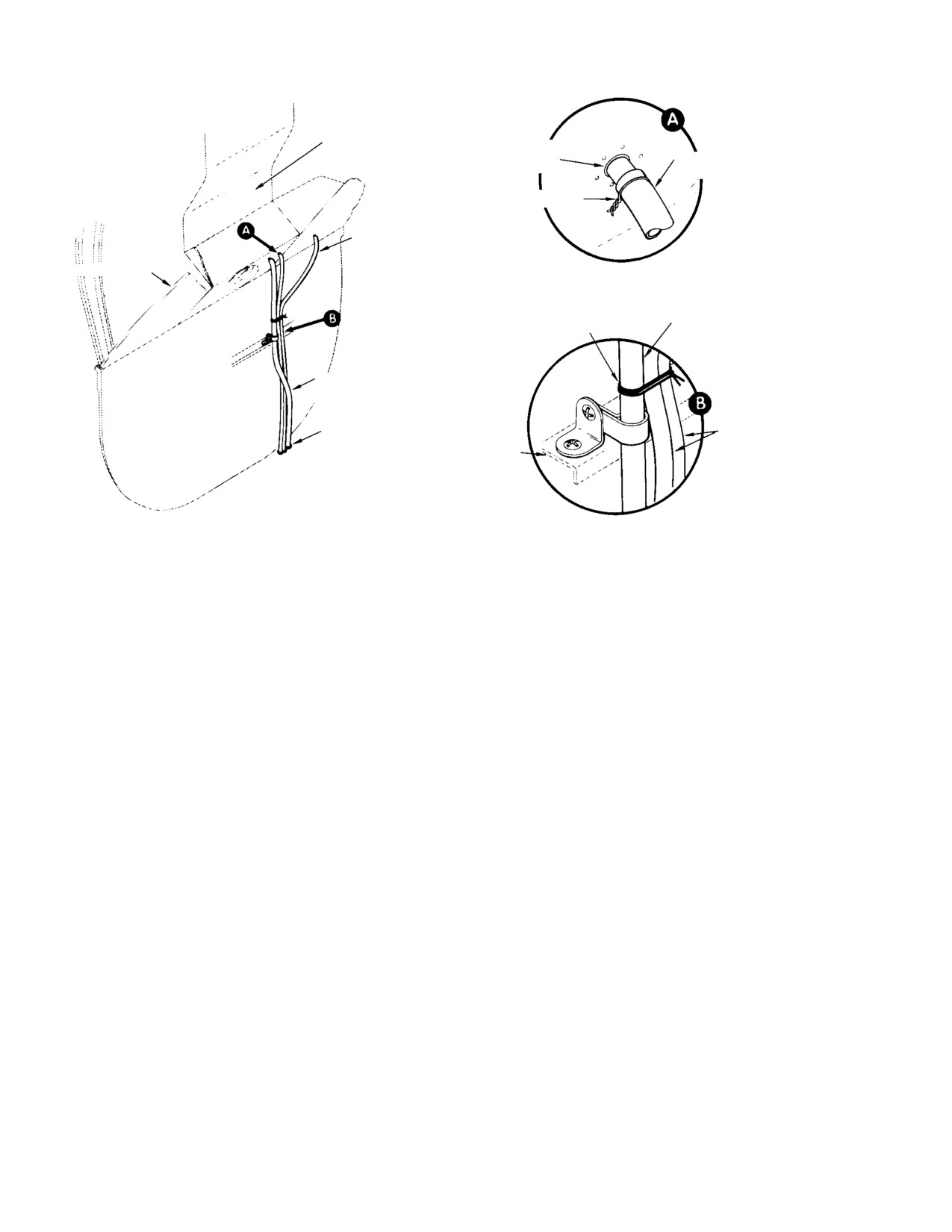
12. Air Induction System Drain Tubing
Replacement
A. Engine Air Inlet Bell and Engine-to-
Firewall Seal Ring Repair
Replace the drain tubing using standard shop
(1). To repair engine−to−firewall seal ring,
procedures. See Figure 16−3 for routing and
replace any damaged or broken springs.
installation details for tubing located on the
aft side of the firewall. See a similar figure in
(2). There is no authorized repair for the
Section 9 for tubing located on the forward
inlet bell.
side of the firewall.
B. Engine Air Inlet-to-Firewall Seal
NOTE: When replacing drain tubing, the rout−
Replacement
ing should be as direct as possible. Avoid
(Ref. Figure 16−1)
creating loops that can become liquid traps.
Page 16-5
Revision 19
MD Helicopters, Inc.
CSP−H−2
500 Series − Basic HMI
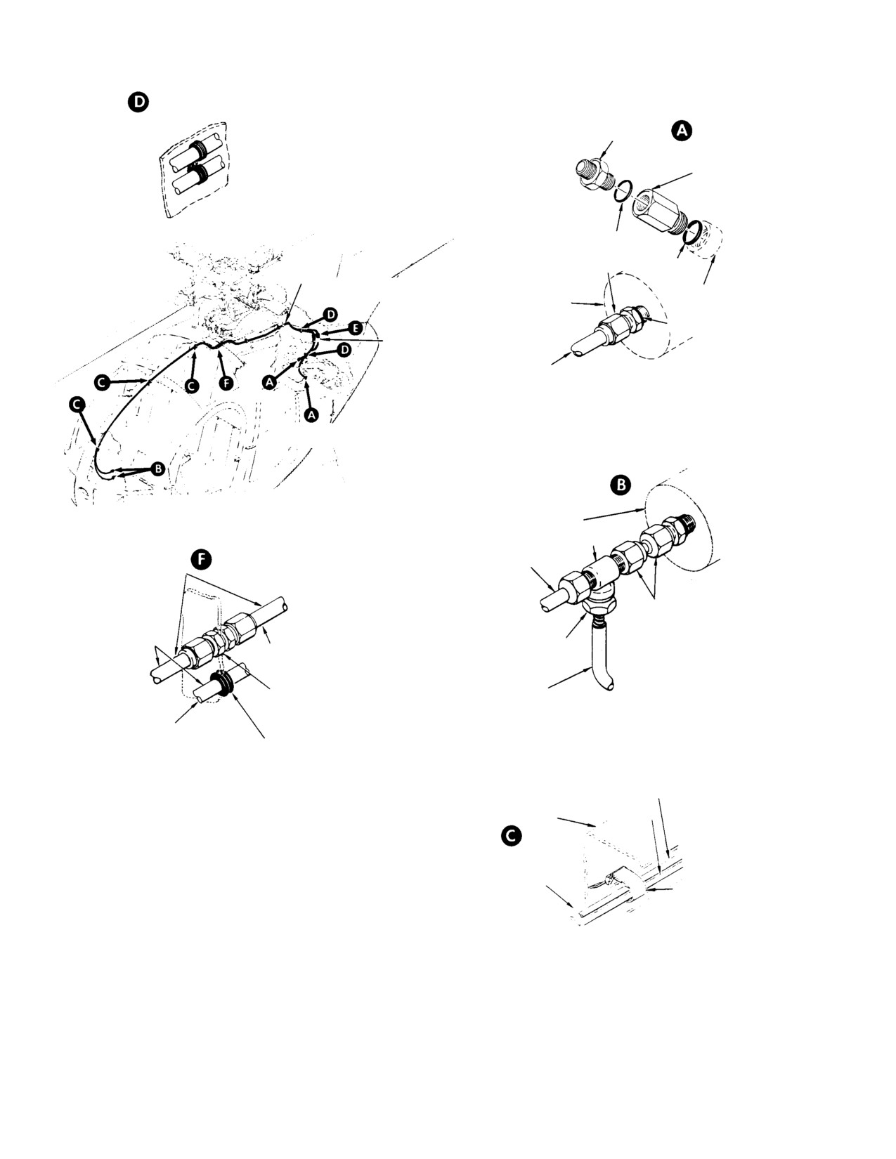
PLENUM CHAMBER
FIREWALL
FITTING
PLENUM CHAMBER
DRAIN TUBE
LOCKWIRE
OIL COOLER DRAIN
FWD FIREWALL
NYLON TWINE
RIGID PLASTIC TUBE
(30, TABLE 2−4)
TRANSMISSION AND BLOWER
SHROUD DRAIN
GROMMETS
FLEXIBLE PLASTIC
TUBES
STIFFENER
30-159A
Figure 16-3. Air Induction System Drain Installations
Page 16-6
Revision 19
MD Helicopters, Inc.
CSP−H−2
500 Series − Basic HMI
Section
17
Instrument Panel and
Indicating System
MD Helicopters, Inc.
CSP−H−2
500 Series − Basic HMI
This Page Intentionally Left Blank
MD Helicopters, Inc.
CSP−H−2
500 Series − Basic HMI
TABLE OF CONTENTS
Para/Figure/Table
Title
Page
Section 17 Instrument Panel and Indicating System .
17−1
1.
Instrument Panel
17−1
A. Instrument Panel Maintenance
17−1
B. Instrument Panel Removal
17−1
Figure 17−1. Arrangement of Instruments and Indicators (Instrument
Panel Type A)
17−2
Figure 17−2. Arrangement of Instruments and Indicators (Instrument
Panel Type B)
17−3
C. Instrument Panel Installation
17−4
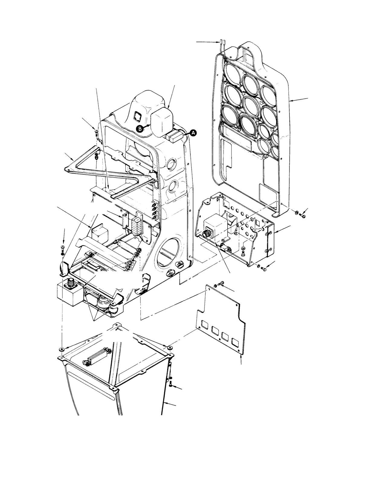
Figure 17−3. Component Locations (Instrument Panel Type A) .
17−5
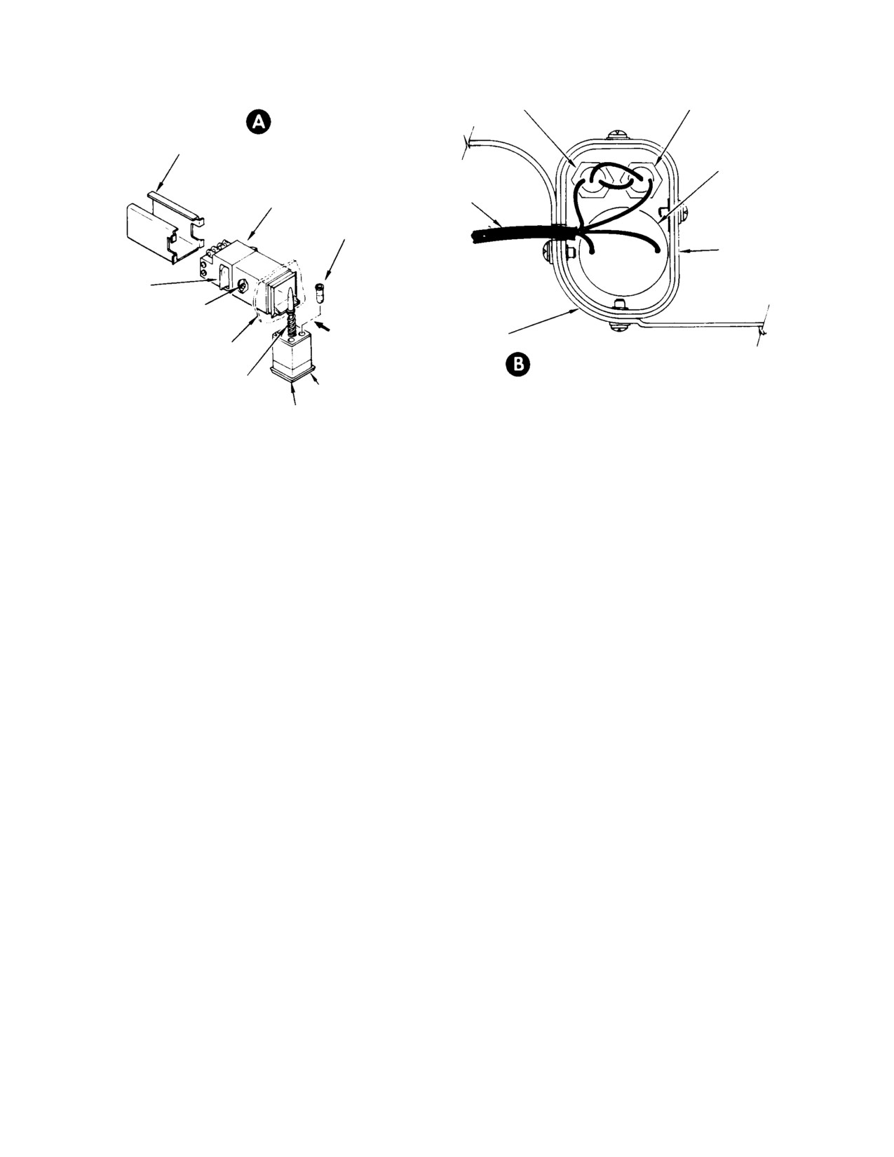
Figure 17−4. Component Location (Instrument Panel Type B) (Sheet 1 of 2) .
17−6
2.
Instrument Panel Type B Hood
17−7
3.
Instrument Indicating System
17−7
A. Instrument Indicating System Troubleshooting
17−8
Table 17−1. Troubleshooting the Instrument Indicating System
17−8
B. Indicating System Instrument Replacement
17−11
C. Indicating System Instrument Inspection
17−11
D. Indicating System Instrument Repair
17−11
4.
Pitot−Static System
17−11
A. Pitot−Static System Inspection
17−12
B. Pitot Tube Assembly Replacement
17−12
C. Static Pressure Tubing Replacement
17−12
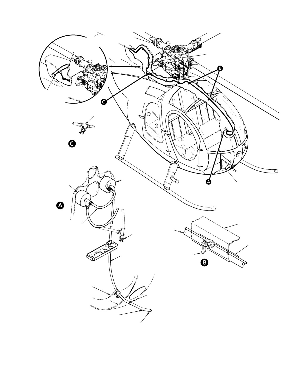
Figure 17−5. Pitot Static System
17−13
D. Static Pressure Tube Aft End Protective Screen Installation .
17−14
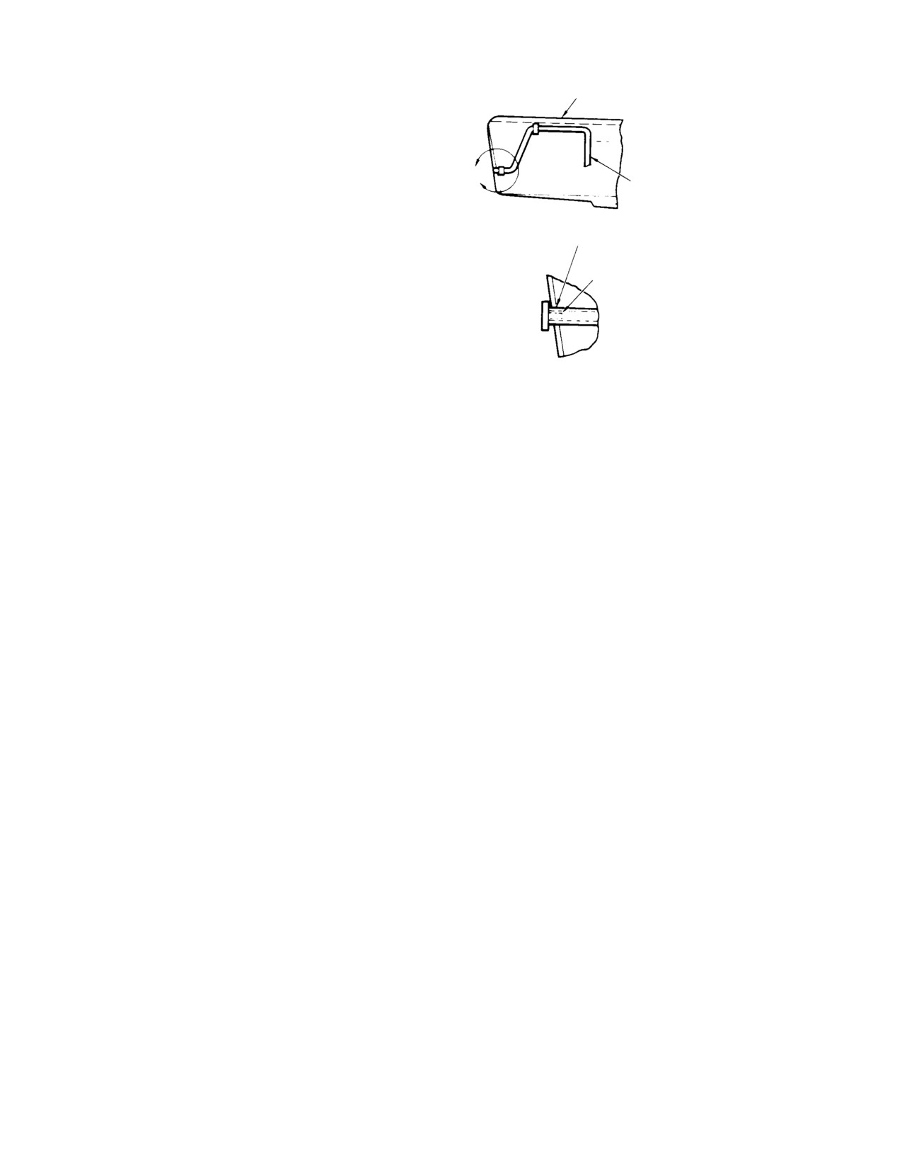
Figure 17−6. Installation of Static Pressure Tube Bug Screen .
17−14
5.
Altimeter
17−14
A. Altimeter Maintenance
17−14
6.
Airspeed Indicator
17−14
A. Airspeed Indicator Maintenance
17−15
7.
N1, N2 and Rotor Tachometer Indicating System
17−15
A. N1, N2 and NR Tachometer Indicator Maintenance
17−15
B. Tachometer Generator Replacement
17−15
C. Tachometer Generator Testing
17−15
8.
Turbine Outlet Temperature (TOT) Indicating System
17−16
A. TOT Indicator Maintenance
17−16
B. Thermocouple Harness Maintenance
17−16
C. TOT Indicating System Calibration
17−16
Page 17−i
Revision 19
MD Helicopters, Inc.
CSP−H−2
500 Series − Basic HMI
TABLE OF CONTENTS (Cont.)
Para/Figure/Table
Title
Page
Figure 17−7. Indicating System Electrical Senders (Sheet 1 of 3) .
17−17
Figure 17−8. Test Hookup For Tachometer Generator
17−20
9.
Engine Torque Indicating System
17−20
A. Torque Gage Maintenance
17−20
B. Torque Gage Pressure Line Removal
17−21
C. Torque Gage Pressure Lines Installation
17−21
Figure 17−9. Torque Gage and Direct Reading Engine Oil Pressure Gage
(Sheet 1 of 2)
17−22
10. Direct Reading Oil Pressure Indicating System
17−24
A. Engine Oil Pressure Gage Tubing Replacement
17−24
B. Torque or Direct Reading Engine Oil Pressure Line Bleeding and Servicing .
17−24
11. Instrument Cluster Three−Pack or Four−Pack Indicating System .
17−24
A. Instrument Cluster Three−Pack or Four−Pack Maintenance .
17−25
B. Instrument Cluster Three−Pack or Four−Pack Calibration Check .
17−25
Figure 17−10. Instrument Cluster Three−Pack with Wiring Harness
(Instrument Panel Type B) (Sheet 1 of 2)
17−26
Figure 17−11. Instrument Cluster Four−Pack with Wiring Harness .
17−28
12. Engine Oil Temperature Sender
17−29
A. Engine Oil Temperature Sender Replacement
17−29
13. Engine Electrical Oil Pressure System
17−30
A. Engine Electrical Oil Pressure Sender Replacement
17−30
B. Electrical Oil Pressure Gage Calibration
17−30
14. Fuel Quantity System
17−31
A. Fuel Quantity Transmitter (Tank Unit) Replacement
17−31
B. Fuel Quantity Transmitter and Indicator Operational Check .
17−32
C. Fuel Tank Sending Unit and Fuel Low Warning Light Indicating System
Inspection
17−33
Figure 17−12. Bench Test and Potting of Fuel Tank Sending Unit .
17−34
D. Tank Unit Testing
17−35
15. Outside Air Temperature Indicator
17−35
A. Outside Air Temperature Indicator Replacement
17−35
16. Magnetic Compass
17−36
A. Magnetic Compass Maintenance
17−36
17. Caution and Warning Lights Indicating System
17−36
A. Caution and Warning Lights Indicating System Troubleshooting .
17−37
Figure 17−13. Testing of Tank Unit
17−38
Figure 17−14. Outside Air Temperature Indicator and Magnetic Compass .
17−39
Table 17−2. Caution and Warning Lights Troubleshooting Data .
17−40
Page 17−ii
Revision 19
MD Helicopters, Inc.
CSP−H−2
500 Series − Basic HMI
TABLE OF CONTENTS (Cont.)
Para/Figure/Table
Title
Page
Table 17−3. Troubleshooting the Caution and Warning Lights Indicating
System
17−41
18. Instrument Panel Type A Caution and Warning Indicator Lights .
17−45
A. Instrument Panel Type A Indicator Lights Replacement .
17−46
19. Instrument Panel Type B Caution and Warning Indicator Lights .
17−46
A. Panel Type B Indicator Lights Replacement
17−47
20. Engine Out Warning System
17−47
A. N1 Sensing Equipment
17−47
B. N1/NR Sensing Equipment
17−48
C. Engine Out Warning System Functioning
17−48
21. Vapair 26530332M Engine Power Out (EPO) Warning Control Unit .
17−49
A. Engine Power Out Warning Unit Circuit
17−49
B. Engine Out Frequency Sensor and Light Flasher Circuits .
17−49
C. Dc Voltage Regulator Circuit
17−49
D. Audio Tone Signal Generators
17−49
Figure 17−15. N1/NR Engine Power Out Warning System Combined Simplified
Block and Schematic Diagram (Panel Type B) (Sheet 1 of 2) .
17−50
E. Transmission Oil and Temperature Light Flasher
17−52
F. Vapair 26530332M EPO Warning Unit Frequency Sensing Adjustment .
17−52
Figure 17−16. Vapair 26530332M Engine Power Out Warning Control Unit
Schematic Diagram
17−53
Figure 17−17. Vapair 26530332M Warning Audio and Light Flashing Control
Circuit (Sheet 1 of 2)
17−54
G. Vapair 26530332M EPO Warning Unit Repair
17−56
H. Vapair 26530332M EPO Warning Control Unit Replacement .
17−56
22. Autronics 2146−5 Engine Power Out (EPO) Warning Control Unit .
17−56
A. Engine Power Out Warning Circuits
17−56
B. Engine Out Frequency Sensing Circuits
17−56
C. Engine Out and Transmission Lights Flasher Circuits .
17−57
D. Audio Tone Circuits
17−57
E. Audio Tone Output Level Adjustment − Autronics 2146−5 EPO Warning
Control Unit
17−57
Figure 17−18. Autronics 2146−5 Engine Power Out Warning Control Unit
Schematic Diagram
17−58
F. Autronics 2146−5 EPO Warning Control Unit Repair
17−59
G. Autronics 2146−5 EPO Warning Control Unit Replacement .
17−59
Figure 17−19. Autronics 2146−5 Warning Audio and Lights Flashing Control
Circuit (Sheet 1 of 2)
17−60
23. Autronics 2200−3 EPO Warning Control Unit
17−61
Page 17−iii
Revision 19
MD Helicopters, Inc.
CSP−H−2
500 Series − Basic HMI
TABLE OF CONTENTS (Cont.)
Para/Figure/Table
Title
Page
A. Autronics 2200−3 EPO Warning Control Unit Maintenance .
17−61
24. Grimes 70−0054−1 Indicator Lights Dimmer Assembly (Panel Type A) .
17−62
A. Indicator Lights Dimming Assembly Circuits
17−62
B. Negative (Ground) Input Fault Dimming Circuits
17−62
C. Positive (+28 Vdc) Input Fault and Function Dimming Circuits .
17−62
D. Panel Lights Dimming Circuit
17−63
E. Grimes 70−0054−1 Indicator Lights Dimmer Assembly Repair .
17−63
F. Grimes 70−0054−1 Indicator Lights Dimmer Assembly Replacement .
17−63
25. Autronics 2245−1 Indicator Lights Dimmer Assembly (Panel Type B) .
17−63
A. Dimmer Assembly Associated Circuits
17−63
Table 17−4. Input/Output Signals − Autronics 2200−3 EPO Unit .
17−64
Figure 17−20. Grimes 70−0054−1 Indicator Dimming Assembly Schematic
Diagram
17−65
Figure 17−21. Caution and Warning Indicating Light System Dimming Circuits
(Instrument Panel Type A)
17−66
B. Negative (Ground) Input Fault Caution Light Indicator Circuits .
17−67
C. Negative (Ground) Input Fault Warning Light Indicator Circuits .
17−67
D. Positive (+28 Vdc) Input Start Pump Warning Light Circuit .
17−67
E. Engine Out warning Light and Horn Circuit
17−67
F. Panel and Instrument Lights Dimming Circuit
17−67
G. Caution and Warning Lights Press−To−Test Circuits
17−67
H. Autronics 2245−1 Dimmer Assembly Test and Repair . .
17−68
I.
Autronics 2245−1 Dimmer Assembly Replacement
17−68
26. Engine Power Out (EPO) Audio Amplifier (Used with Vapair EPO Warning
Control Unit)
17−68
A. EPO Audio Amplifier Replacement
17−68
Figure 17−22. Autronics 2245−1 Dimmer Schematic Diagram (Instrument
Panel Type B)
17−69
Figure 17−23. Caution and Warning Indicating Lights System Circuits
(Instrument Panel Type B) (Sheet 1 of 2)
17−70
Figure 17−24. Audio Amplifier (Dual and Single Channel) Schematic
Diagram
17−72
27. Engine Power Out (EPO) Audible Warning Horn
17−73
A. Edwards Audible Warning Horn Replacement
17−73
28. NR Disable Switch
17−73
A. NR Disable Switch Replacement
17−73
Figure 17−25. NR Disable Switch Installation (Sheet 1 of 2) .
17−74
B. NR Disable Switch Adjustment
17−76
29. Chip Detector Circuits Operational Check
17−76
Page 17−iv
Revision 19
MD Helicopters, Inc.
CSP−H−2
500 Series − Basic HMI
TABLE OF CONTENTS (Cont.)
Para/Figure/Table
Title
Page
30. Fuel Pressure Switch
17−76
A. Fuel Pressure Switch Operational Check
17−76
Figure 17−26. Fuel Pressure Switch Test Set−Up
17−77
B. Fuel Pressure Switch Replacement
17−78
31. Running Time Meter
17−78
Page 17−v
Revision 19
MD Helicopters, Inc.
CSP−H−2
500 Series − Basic HMI
TABLE OF CONTENTS (Cont.)
Para/Figure/Table
Title
Page
This Page Intentionally Left Blank
Page 17−vi
Revision 19
MD Helicopters, Inc.
CSP−H−2
500 Series − Basic HMI
SECTION 17
INSTRUMENT PANEL AND INDICATING SYSTEM
1. Instrument Panel
warning lights indicating system to provide
visual and audible signals for the pilot during
The instrument panel is an assembly of
certain conditions. The caution and warning
aluminum alloy angles and a 0.040 inch (1.016
lights indicating system and engine out
mm) thick aluminum alloy panel. The panel
warning equipment are described in this
assembly is riveted to an aluminum alloy
section.
structural framework called the upper
instrument panel support assembly.
Provisions are incorporated in the panel face
for installation of night−lighting, vhf/uhf
This instrument panel and upper support
communication equipment, navigational aid
assembly is fabricated so that it is removable
equipment and miscellaneous instrumenta−
from the lower structural framework, called
tion.
the lower instrument panel support assembly,
that is attached to the pilot’s compartment
Information on instruments, controls and
floor.
equipment other than those shown in
Figure 17−1 and Figure 17−2 is provided in
Contour−molded thermoplastic fairings and a
CSP−H−3.
hood enclose the instrument panel structure,
shield the instruments and equipment from
A. Instrument Panel Maintenance
direct sunlight and prevent instrument glare.
Perform maintenance on the instrument panel
All standard flight, navigation and engine
and supporting structure according to the
instrument, except the canopy−located outside
Cleaning, Corrosion Control and Paint Finish
air temperature gage, are mounted in the
in Section 2, the Fuselage Sheet Metal Repair
instrument panel.
in CSP−H−6 and Maintenance of Electric
Bonding Connections in Section 19.
Two different types of instrument face panels
are provided; panel type A (Figure 17−1) and
B. Instrument Panel Removal
type B (Figure 17−2). The major differences
are that panel type B provides integral
The instrument panel and upper support
provisions for the addition of optional equip−
assembly, along with installed instruments
ment and panel type B instruments are
and most of the electrical wiring, is remove−
recessed in a thermoplastic hood covering the
able as an assembled unit. Follow the basic
face of the panel. See Figure 17−3 and
requirements outlined below to accomplish
Figure 17−4 for structure details and location
removal.
of indicating system components.
The main electrical power
The switches, circuit breakers and other
WARNING
supply wiring is discon−
manually operated controls on the panel face
nected for removal of the panel assem−
that are parts of the fuel supply system
bly. External power and the battery
(Section 12), heating and ventilating system
must remain disconnected at all times
(Section 18) and electrical system (Section 19)
during this procedure.
are discussed as part of the system in which
they function.
(1). Remove the instrument panel side
fairings.
Caution and warning lights indicators are
mounted in a row horizontally across the top of
(2). Disconnect the torque gage, engine oil
the panel face.
pressure gage (panel type B), and the
pitot and static pressure lines to the
Engine out warning equipment functions with
altimeter and airspeed indicator. Cap
an audible warning horn and the caution and
the lines and fittings.
Page 17-1
Revision 19
MD Helicopters, Inc.
CSP−H−2
500 Series − Basic HMI
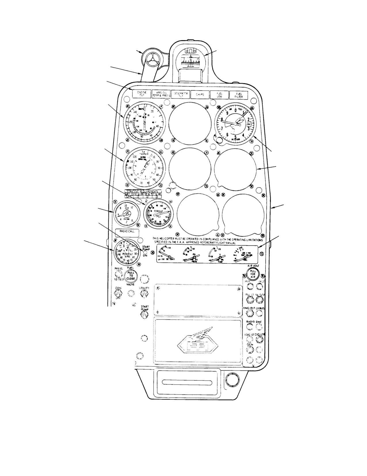
ENGINE OUT AUDIBLE WARNING HORN
MAGNETIC COMPASS
(NOTE 1)
ANTIVIBRATION BRACKET
CAUTION AND WARNING LIGHTS
AIRSPEED INDICATOR
N2 AND NR (ROTOR)
TACHOMETER INDICATOR
ALTIMETER
BLANK PLATES
(5 PLCS)
TORQUE GAUGE
TURBINE OUTLET TEMPERATURE
FAIRING AND
(TOT) INDICATOR
HOOD
(NOTE 2)
START PUMP LIGHT
INSTRUMENT
N1 TACHOMETER
CLUSTER (4−PACK)
INDICATOR
NOTES:
1.
ORIGINAL CONFIGURATION SHOWN; EITHER
RIGHT OR LEFT SIDE (MODEL DIFFERENCE).
MODIFICATION OF ORIGINAL CONFIGURATION
IS REQUIRED FOR INCORPORATION OF BATTERY
TEMPERATURE SENSING EQUIPMENT (REF.
SEC 19). MODIFIED CONFIGURATION IS
IDENTICAL TO THAT SHOWN IN FIGURE FOR
ARRANGEMENT OF INSTRUMENTS AND
INDICATORS (FRONT PANEL OF INSTRUMENT
PANEL TYPE B).
2.
RESISTOR BOARD ASSY TB9 AND THERMOCOUPLE
LEAD RESISTOR R4 MOUNTED ON INDICATOR
TERMINALS.
30-1 15A
Figure 17-1. Arrangement of Instruments and Indicators (Instrument Panel Type A)
Page 17-2
Revision 19
MD Helicopters, Inc.
CSP−H−2
500 Series − Basic HMI
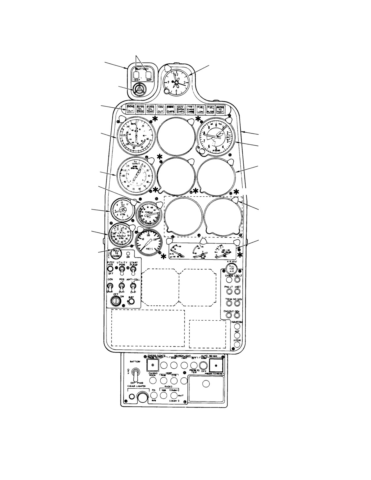
BATTERY TEMPERATURE SENSING
CAUTION AND WARNING LIGHTS
(NOTE 6)
HOUSING
(NOTES 1, 6)
CLOCK
(NOTE 5)
ENGINE OUT AUDIBLE
WARNING HORN
CAUTION AND
WARNING LIGHTS
AIRSPEED INDICATOR
FAIRING AND HOOD
ALTIMETER
BLANK PLATES (4 OR 5 PLCS)
N2 AND NR (ROTOR)
(NOTE 3)
TACHOMETER INDICATORS
TORQUE GAUGE
(8 PLCS)
TURBINE OUTLET
TEMPERATURE
(TOT) INDICATOR
BOLT LIGHT (14 PLCS)
(NOTE 2)
N1 TACHOMETER
INDICATOR
INSTRUMENT CLUSTER (3−PACK)
ENGINE OIL PRESSURE
INDICATOR
NOTES:
1.
EITHER RIGHT OR LEFT SIDE (MODEL
DIFFERENCE).
2.
RESISTOR BOARD ASSY TB9 AND
THERMOCOUPLE LEAD RESISTOR R4
MOUNTED ON INDICATOR TERMINALS.
3.
VARIES WITH EQUIPMENT INSTALLED.
4.
ASTERISK ( * ) INDICATES SCREW
SECURING FRONT OF HOOD TO
INSTRUMENT PANEL FACE. (SEE FIGURE
SHOWING INSTRUMENT PANEL TYPE B
COMPONENT LOCATIONS FOR
LOCATIONS OF SCREWS SECURING
SIDE OF HOOD TO INSTRUMENT
CONSOLE.)
5.
MAGNETIC COMPASS ON EARLY PANEL.
6.
ADDITION REQUIRED ON EARLY PANEL.
30-1 183C
Figure 17-2. Arrangement of Instruments and Indicators (Instrument Panel Type B)
Page 17-3
Revision 19
MD Helicopters, Inc.
CSP−H−2
500 Series − Basic HMI
(3).
Disconnect thermocouple leads from
(1). Mount the instrument panel and
terminal board TB9 on the TOT
support assembly on the supporting
indicator.
structure and secure the base in place
with screws and washers (Figure 17−3).
(4).
Remove the fuel shutoff valve control
cable. Disconnect the wire end of the
NOTE: If upper support does not align with
ventilating valve control cable. (Remov−
canopy structure, use special shim washers,
ing the fuel shutoff cable will also
0.120 inch (3.048 mm) thickness, under both
release a clamp holding the pitot
forward or both aft console−to−support at−
pressure line; leave the line detached.)
tachment points. Use one− half the shim
thickness at both middle attachment screws
(5).
Disconnect the electrical plugs from the
and vary screw length accordingly.
connector support bracket under the
upper support assembly.
(2).
Attach the Z−brace to the upper
structure.
(6).
Disconnect coaxial antenna cables if
radio equipment is installed.
(3).
Route all lines and wiring into position
for connection. Check that there is
(7).
Disconnect the wiring (three wire
sufficient slack for proper connection
bundles) from the power selector switch
without straining the lines or wiring.
and insulate the wiring terminals.
Remove clamps that secure the three
(4).
Connect power supply wiring (three−
wire bundles to the panel structure.
wire bundles) to the power selector
switch and reinstall wiring support
(8).
Check the entire instrument panel and
clamps and straps where previously
upper support assembly for clamps or
removed.
nylon straps that would restrict
separation from the lower support
(5).
Connect coaxial antenna cables if radio
assembly. Disconnect any such items.
equipment is installed.
(9).
Remove the two screws, washers and
(6).
Connect the electrical plugs under the
nuts that attach the upper support (Z
upper support assembly.
brace) to the panel structure.
(7).
Connect the ventilating valve control
(10).
Remove the screws and washers that
cable and perform an operational check.
attach the base of the panel assembly to
the lower support (Figure 17−3 or
(8).
Install the fuel shutoff valve control
Figure 17−4).
cable and perform an operational check.
Reattach the pitot pressure line clamp
NOTE: Make notes of the routing of all lines,
with the hardware used to attach the
cables and wiring before removing the panel
cable under the upper support assem−
assembly to aid reinstallation.
bly.
(11). Obtain assistance and carefully lift out
(9).
Connect the thermocouple leads to
the panel and support assembly.
terminal board TB9 on the TOT
indicator. Check for correct thermocou−
C. Instrument Panel Installation
ple circuit resistance.
Before and during placement of the instru−
(10).
Connect the torque gage, engine oil
ment panel and upper support assembly into
pressure gage (panel type B), and the
position on the supporting structure, check all
pitot and static pressure lines to the
cables, wiring and lines are routed properly.
altimeter and airspeed indicator
Incorrect routing can result in lines or wiring
(Figure 17−5).
not being long enough to reach the connection
point, or in lines or wiring being subjected to
(11).
Check that all lines and wiring are
unnecessary strain and possible damage from
connected and secure; then reconnect
chafing.
the battery.
Page 17-4
Revision 19
MD Helicopters, Inc.
CSP−H−2
500 Series − Basic HMI
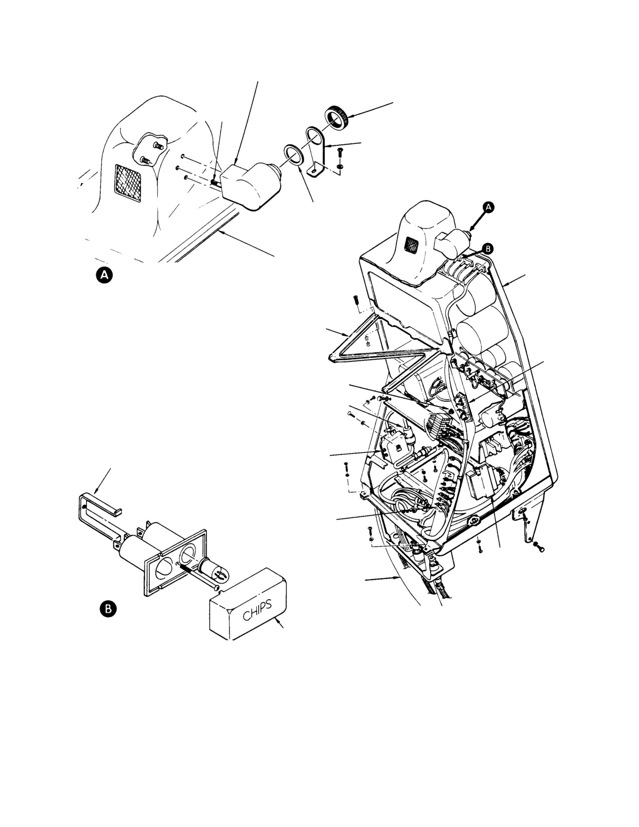
ENGINE OUT AUDIBLE WARNING HORN
(NOTE 1)
HORN RING
ELECTRICAL WIRING
SUPPORT BRACKET
GASKET
INSTRUMENT PANEL
AUDIBLE WARNING
CENTER FAIRING
INSTRUMENT PANEL
HORN INSTALLATION
(NOTE 4)
UPPER SUPPORT
TERMINAL
BLOCK TB501
R303, OIL PRESSURE GAUGE
ADJUSTMENT RESISTOR ASSY
(NOTE 2)
AUDIO AMPLIFIER
(NOTE 3)
ENGINE POWER OUT
SADDLE CLAMP
(EPO) WARNING UNIT
TERMINAL
BLOCK TB6
INDICATOR LIGHTS
DIMMING ASSEMBLY
LOWER SUPPORT
ASSEMBLY
LIGHTS INDICATOR
(TYP)
LEGEND CAP
NOTES:
1.
EITHER RIGHT OR LEFT SIDE INSTALLATION (MODEL DIFFERENCE).
SUPPORT BRACKET IS PART OF KIT M50436.
2.
PART OF OIL PRESSURE GAGE CIRCUIT (KIT M50438).
3.
USED WITH VAPAIR EPO UNIT ONLY.
30−117E
4.
MODIFICATIONS OF ORIGINAL CONFIGURATION SHOWN IS REQUIRED.
Figure 17-3. Component Locations (Instrument Panel Type A)
Page 17-5
Revision 19
MD Helicopters, Inc.
CSP−H−2
500 Series − Basic HMI
PANEL LIGHTS
WIRE SPLICE
ALTERNATE LOCATION FOR
LIGHT / SWITCH AND
ENGINE POWER OUT
HORN HOUSING
WARNING HORN
HOOD
(NOTE 1)
2 PLCS
UPPER SUPPORT
ENGINE POWER OUT
WARNING UNIT
RESISTOR−DIODE
9 PLCS
BOARD TB106
2 PLCS
SWITCH AND CIRCUIT
BREAKER PANEL
8 PLCS
ALTERNATE LOCATION
PANEL LIGHTS
FOR PANEL LIGHTS
DIMMER
DIMMER
5 PLCS
ELECTRICAL
CONNECTORS
SPECIAL SHIM
WASHER
ACCESS PANEL
NOTES:
5 PLCS
1.
FOR REMOVAL OF HOOD, REMOVAL OF
9 SCREWS AND WASHERS AT SIDES AND
LOWER SUPPORT
8 SCREWS AT FRONT OF HOOD IS REQUIRED.
STRUCTURE
(SEE SEPARATE VIEW SHOWING ARRANGEMENT
OF INSTRUMENTS AND INDICATORS.)
2.
ROUTE WITH EXISTING WIRINGS.
30−185−1
Figure 17-4. Component Location (Instrument Panel Type B) (Sheet 1 of 2)
Page 17-6
Revision 19
MD Helicopters, Inc.
CSP−H−2
500 Series − Basic HMI
RED 160°F WARING
AMBER 140°F CAUTION
LIGHT / SWITCH
LIGHT / SWITCH
CAUTION AND WARNING
LIGHT ASSEMBLY
(TYP)
MOUNTING SLEEVE
ENGINE OUT AUDIBLE
WANING HORN
WIRING HARNESS
(NOTE 2)
SWITCH HOUSING
LAMP
(4 PLCS)
LIGHT / SWITCH AND
HORN HOUSING
LOCKING
CAM
LOCKING CAM
SCREW (2)
INSTRUMENT PANEL
FWD
CENTER FAIRING
PANEL
LIGHT / SWITCH AND HORN HOUSING
MOUNTED ON HOOD
SWITCH ACTUATOR
LEGEND FACE
INDICATOR MODULE
30-185-2
Figure 17-4. Component Location (Instrument Panel Type B) (Sheet 2 of 2)
(12). Connect an external power supply, if
To remove the hood, remove nine attaching
available, and perform a power−on
screws and washers at sides of hood
check of all systems. If there is a
(Figure 17−4), eight screws at front of hood
malfunction, correct the trouble as
(Figure 17−2) and pull hood away from panel
necessary.
far enough to disconnect two panel light wiring
splices.
(13). Perform a ground run−up of the
Use tetrahydrofuran (46, Table 2−4), or
helicopter according to the Owner’s
equivalent, to bond and repair cracks and
Manual to check operation of all
tears in the hood.
systems. Bleed the torque gage and
engine oil pressure gage (panel type B)
3. Instrument Indicating System
pressure lines as necessary.
Three basic types of instrument indicating
(14). Shut down helicopter and reinstall the
system are installed in the helicopter.
instrument panel side fairings.
The first group includes indicators that are
actuated by other than electrical power input
2. Instrument Panel Type B Hood
these are the airspeed indicator, altimeter,
outside air temperature indicator, torque gage,
The panel type B hood, formed of 0.063 inch
engine oil pressure gage (panel type B) and the
(1.6002 mm) thick thermoplastic, covers the
magnetic compass.
upper portion of the instrument panel face and
The second group of indicators are intercon−
is secured to the instrument console with nine
nected with electrical sending units that
screw and washers at side and top edges of the
self−generate the power source necessary for
hood.
indicator operation once they are mechanically
or thermally actuated; indicators in this are N1
Built−in panel bolt lights on the hood provide
and N2 rotor tachometer indicators and the
illumination for all standard instruments and
TOT indicator.
indicators, except the magnetic compass and
optional clock. The panel lights are part of the
The third group includes those indicators and
night lighting system that is standard equip−
sending units that rely on power from the
ment on the helicopter with panel type B.
helicopter electrical system for functional
Page 17-7
Revision 19
MD Helicopters, Inc.
CSP−H−2
500 Series − Basic HMI
capability; such indicators include the caution
ic helicopter instrument limit markings.
and warning lights and the instrument cluster
Instrument markings used with the Model
3−pack or 4−pack.
250− C20 Engine Conversion Kit M50031
are also described in CSP−H−3.
NOTE: Instrument limit markings shown in
A. Instrument Indicating System
this section may differ depending on heli−
Troubleshooting
copter configuration and engine installa−
tion. Refer to the Owner’s Manual for specif−
(Ref. Table 17−1)
Table 17-1. Troubleshooting the Instrument Indicating System
Symptom
Probable Trouble
Corrective Action
NOTE: Ref. Table 17-3 for Troubleshooting the Caution and Warning Lights Indicating System.
Pitot-Static System
No reading on airspeed indicator
Ice or water in pitot lines or static
Thaw out; clean and dry lines and
pressure tube
tube.
Erratic readings on airspeed
Leak in pressure lines
Tighten line connections.
indicator or altimeter
Ice or water in pitot lines and static
Thaw out; clean and dry lines.
pressure tube
Defective interconnecting lines
Check pitot static system using test
set. Repair leaks by tightening
connections and replacing lines as
required.
Pointer of altimeter or airspeed
Obstruction in pressure source
Clear static and pitot lines.
indicator does not move
Defective altimeter or airspeed
Replace defective indicator.
indicator
Disconnected line
Check for disconnected line and
make necessary connections.
Altimeter or airspeed indicator
Loose static connections
Tighten static source line
pointer oscillates
connections.
Moisture in lines
Clear line.
Defective indicator
Replace defective indicator.
Altimeter pointer will not adjust to
Moisture in static pressure lines
Clear static source and
airport altitude within 70 feet (21 M)
interconnecting lines.
on ground with proper barometric
Altimeter instrument case leaking
Replace altimeter.
scale setting
Barometric scale out of adjustment
Replace altimeter or remove for
adjustment by an authorized
instrument repair agency.
High reading
Improper venting
Clear lines.
Altimeter adjustment knob binds
Defective altimeter
Replace altimeter.
Airspeed indicator pointer does not
Defective indicator
Replace indicator.
align with 0 ±1/16 inch (0 ±1.6 mm)
Moisture in lines
Clear lines.
on ground
N1, N2 and Rotor Tachometer Indicators
Excessive scale error (low reading) Weak magnet in tachometer
Replace indicator.
indicator
Page 17-8
Revision 19
MD Helicopters, Inc.
CSP−H−2
500 Series − Basic HMI
Table 17-1. Troubleshooting the Instrument Indicating System (Cont.)
Symptom
Probable Trouble
Corrective Action
Excessive scale error (high reading Weak restraining spring in
Replace indicator.
tachometer indicator
Pointer off zero position with
Pointer shifted
Replace indicator.
engine inoperative
No reading or intermittent reading
Loose wiring, disconnected
Check continuity through wiring and
connector or bad ground terminal
connectors. Repair as necessary.
connection
Defective tachometer indicator or
Replace defective indicator or
generator
generator.
Poor ground connection on
Check for good bond between
tachometer generator
tachometer generator mounting
flange and engine pad stud.
Turbine Outlet Temperature Indicator
No reading on indicator
Loose connection
Check and tighten all connections.
Defective airframe thermocouple
Replace or repair thermocouple
harness
harness.
Defective engine thermocouple
Replace engine thermocouple
harness
harness. (Refer to engine operational
and maintenance manual.)
Defective indicator
Replace indicator.
Open adjustable resistor R4
Replace resistor.
Erratic reading on indicator
Defective indicator
Replace indicator.
Defective connections or resistor
Repair connections or replace
R4 on TB9 at back of instrument
resistor.
Torque Gage and Direct Reading Engine Oil Pressure Gage
Pointer fails to respond
Pressure line kinked or bent
Check entire length of line; replace if
necessary.
Pointer indications sluggish
Torquemeter oil pressure snubber
Remove torquemeter oil pressure
inoperative due to cold weather
snubber. (Reinstall snubber when
weather conditions improve.)
Obstruction in line
Clear the line.
Defective gage
Replace gage.
Pointer indicates incorrectly
Line or line connectors leaking
Check for damaged ring gasket
under fitting hex and tighten
connections; if leak persists, replace
line.
Air trapped in line
Check for air bubbles and bleed if
necessary.
Page 17-9
Revision 19
MD Helicopters, Inc.
CSP−H−2
500 Series − Basic HMI
Table 17-1. Troubleshooting the Instrument Indicating System (Cont.)
Symptom
Probable Trouble
Corrective Action
Instrument Cluster 3-Pack and 4-Pack
Engine oil temperature pointer or
Open or short circuit in indicator
Replace instrument cluster.
oil pressure pointer (4-pack) off
Open or short circuit in wiring
Replace sender.
either end of scale or does not
harness
respond
Defective sender
Replace sender.
No reading or erratic ammeter
Malfunctioning voltage regulator
Replace voltage regulator.
rereading
Shunt leads open or intermittent or
Check security of shunt leads;
defective resistor R3
tighten if loose. Replace defective
resistor R3.
Open or short circuit in ammeter
Replace instrument cluster.
Dirty or worn mechanism in
Replace instrument cluster.
ammeter
Fuel quantity indicator inaccurate,
Wire loose, shorted or open
Check tank unit electrical
erratic or inoperative
connections; repair as necessary.
NOTE: The top of a later type tank
Check electrical wires between tank
unit is potted with sealant (3,
unit and instrument cluster. Repair as
Table 2-4) to prevent shorting
necessary.
due to moisture accumulation
Fuel indicator or tank unit defective
Perform operational check. Replace
instrument cluster or tank unit.
Calibrate fuel system.
Magnetic Compass
Excessive error
External magnetic interference
Locate and eliminate magnetic
interference.
Defective bearings
Replace magnetic compass.
Improper compensation
Compensate compass as required.
(Refer to FAA AC 43.13-1A.)
Excessive oscillation
Insufficient liquid in bowl
Replace compass.
Rotating element not level
Leaking float chamber
Replace compass.
Magnets detached from rotating
Replace compass.
element
Sluggish operation
Dirty jewels or pivots
Replace compass.
Weak cards magnets
Replace compass.
Liquid leakage or bubbles visible
Defective gasket or float chamber
Replace compass.
under normal flight conditions
Page 17-10
Revision 19
MD Helicopters, Inc.
CSP−H−2
500 Series − Basic HMI
B. Indicating System Instrument
(7). Reinstall panel fairings. Install hood on
Replacement
instrument panel type B.
(8). Perform engine run−up and flight test
The following instructions are typical and
to check instrument operation.
apply to all instruments installed in the
instrument panel.
C. Indicating System Instrument Inspection
(1). Check that all electrical power is OFF
(1). Inspect instrument case for dents and
to avoid the possibility of electrical
cover glass for slippage and cracks.
shorts while working in the area of the
(2). Inspect fitting or electrical receptacle at
instrument panel.
back of instrument for damaged
threads that might prevent proper
(2). Remove instrument panel fairings. For
connection of the tube nut or electrical
instrument panel type B, remove hood
plug.
attaching screws and move hood aft far
enough for access to instrument
(3). Inspect index markings and numerals
mounting screws.
on dial face for discoloration and
legibility. Inspect pointers for cracked
(3). Disconnect electrical plug, wiring or
or peeling fluorescent paint.
tubing, as applicable, from back of the
instrument. Install suitable covers over
(4). Inspect for presence of all required
tube fittings, instrument fittings and
range markings and white slippage
loose wire terminals.
mark at bottom of glass.
D. Indicating System Instrument Repair
(4). At the face of the panel, remove the
screws (usually two or four) that attach
Refer to FAA AC 43.13−lA, Aircraft Inspection
instrument to panel and remove
and Repair, when repair or overhaul of
instrument from back side of panel.
instruments becomes necessary.
NOTE: The N1 tachometer and TOT indicators
4. Pitot-Static System
are mounted to the panel with clamps that
only have to be loosened to remove the
CAUTION
instrument. Always loosen the cinching
screws in the upper left corner of the clamp
D Do not blow air through the pitot−static
first to release the clamp adjusting mecha−
system lines without disconnecting the al−
nism; then loosen the lower right, or holding
timeter and airspeed indicator. Instanta−
screw and slide the instrument outward,
neous air pressure may result in distor−
away from the panel face and out of the
tion or rupture of the instrument
clamp.
diaphragm.
D Before performing maintenance near the
(5). Position replacement instrument into
engine air inlet, covers of cardboard or
panel cutout from back side of panel
other suitable material should be taped in
and secure with mounting screws.
place over the engine inlet screen and oil
cooler air inlets to prevent entry of foreign
NOTE: When installing either the N1 tachome−
objects into the engine compressor. Cov−
ter or TOT indicator, slide the instrument
ers should not be removed until work is
into the face side of the panel and through
completed and debris is thoroughly
the supporting clamp. Align the instrument,
cleaned out of the area. After removing
tighten the lower right (holding) screw and
covers, verify that area around base of
then tighten the upper left (cinching) screw
mast, inlet to plenum and entire plenum
to tighten the clamp and secure the case.
chamber is free of foreign material.
(6). Connect tubing, electrical plug or
(Ref. Figure 17−5) The pitot−static system
wiring to the back of the instrument.
consists of a pitot tube assembly, a static
Use care to avoid reversing connections
pressure port installation and interconnecting
for the pitot and static lines.
tubing and fittings.
Page 17-11
Revision 19
MD Helicopters, Inc.
CSP−H−2
500 Series − Basic HMI
The pitot tube, in the lower center of the
panel grommet and connect pitot line to
canopy panel, is connected to the airspeed
elbow at back of airspeed indicator.
indicator by a nylon pitot line.
(5). Secure tube to structure with the
The static pressure port may be either a single
removed hardware.
or dual type.
(6). Check that pitot tube head is aligned
parallel to the longitudinal centerline of
The dual type has interconnected ports in each
the helicopter.
side of the engine air intake fairing while the
single type has one port in the aft end of the
(7). Check pitot pressure system for leaks;
fairing. The port(s) are connected to a pressure
repair leaks as necessary.
line routed between the port(s) and the
altimeter.
(8). Reinstall instrument panel fairings and
cover panel.
On current configuration helicopters, spring
C. Static Pressure Tubing Replacement
loaded drain valves are provided at the static
line low points aft of Sta. 127.00 and forward
(Ref. Figure 17−4)
of the instrument panel.
(1).
Remove the instrument panel fairings,
A static source crossover line interconnects the
forward right side fairing of engine air
altimeter and airspeed indicator.
intake and plenum chamber access
door.
A. Pitot-Static System Inspection
(2).
Remove tube(s) from single or dual
(1). Inspect system lines for damage that
pressure ports in engine air intake
could prevent an airtight connection.
fairing by breaking the bondline or
disconnecting coupling nuts at the tee
(2). Inspect pitot tube opening, drain hole
fitting.
and line for foreign matter. Clear and
clean the pressure line, as necessary.
(3).
Remove nylon straps attaching the
main tube (detail B) and drain valve, if
(3). Inspect static pressure tube port(s) for
installed, to the canopy structure.
foreign matter. Clear and clean the
port(s) and pressure lines, as necessary.
(4).
Remove nylon straps attaching the
main tube to air intake fairing longer−
(4). Inspect pitot tube for lateral misalign−
on, aft section strut and structure
ment. The pitot tube should be parallel
(detail A and C).
to the longitudinal centerline of the
helicopter.
(5).
Disconnect aft end of tube from tee
fitting.
B. Pitot Tube Assembly Replacement
(6).
Disconnect the main tube from altime−
(Ref. Figure 17−5)
ter and cover instrument opening.
(1). Remove the instrument panel fairings
(7).
Withdraw the main tube through
and the cover panel from the left side of
canted bulkhead grommet.
the lower instrument panel support
(8).
Remove crossover tube from altimeter
assembly.
and airspeed indicator.
(2). Remove the clamps, screws, washers
(9).
Route replacement static pressure tube
and nuts that attach pitot tube assem−
through the grommet in canted bulk−
bly to structure.
head and locate aft end of the tube at
pressure port tee fitting.
(3). Disconnect pitot tube from back of
airspeed indicator, slide aluminum
(10).
Secure the main tube to the canopy
head end of tube from canopy panel
structure with nylon straps (detail B).
grommet and remove the assembly.
(11).
Attach the main tube to the air intake
(4). Insert the replacement pitot tube
fairing longeron, aft section strut and
assembly head into place in canopy
structure (details A and C).
Page 17-12
Revision 19
MD Helicopters, Inc.
CSP−H−2
500 Series − Basic HMI
SINGLE STATIC
PRESSURE PORT
LEFT STATIC
(NOTE 2)
PRESSURE PORT
(NOTE 2)
STATIC PRESSURE TUBE
RIGHT STATIC
PRESSURE PORT
GROMMET
(NOTE 2)
DRAIN VALVE
(NOTE 3)
STA. 127.00 DRAIN VALVE
(NOTE 3)
AIRSPEED
INDICATOR
ALTIMETER
COVER PANEL
CANOPY FRAME
NYLON CROSSOVER TUBE
STATIC PRESSURE
(NOTE 1)
TUBE
DRAIN VALVE
(NOTE 3)
TORQUE GAUGE
PRESSURE LINE
PITOT PRESSURE
NYLON STRAP
NYLON TUBE
TYPICAL
INSTRUMENT PANEL LOWER
SUPPORT STRUCTURE
NOTES:
GROMMET
1.
MAINTAIN MINIMUM BEND RADIUS OF
1.00 IN. (2.54 CM) FOR ALL TUBES.
2.
BOND TUBES TO FAIRING WITH ADHESIVE
(19, TABLE 2−4). TUBE ENDS MUST BE
DRAIN HOLE
FLUSH WITH OUTSIDE SURFACE.
3.
NOT INSTALLED ON ALL HELICOPTERS.
AFT DRAIN VALVE ATTACHED WITH NYLON
PITOT TUBE ASSEMBLY
STRAPS AND FORWARD VALVE WITH
LACING CORD (37).
30−123E
Figure 17-5. Pitot Static System
Page 17-13
Revision 19
MD Helicopters, Inc.
CSP−H−2
500 Series − Basic HMI
(12). Secure static pressure tube and drain
AFT ENGINE AIR INLET FAIRING
valve, if installed, to canopy structure;
then connect tube to tee on altimeter.
B
(13). Using adhesive (19, Table 2−4), bond
STATIC PRESSURE TUBE
tube to static pressure port(s) in engine
VIEW A
air intake fairing. The outer end of the
STATIC PRESSURE PORT
tube must be flush with the fairing
surface. Connect lines of dual type to
BUG SCREEN
tee fitting.
(14). Connect crossover tube to altimeter and
airspeed indicator.
DETAIL B
30−224
Figure 17-6. Installation of Static Pressure
(15). Check that system tubing and fittings
Tube Bug Screen
are secure and air tight.
5. Altimeter
(Ref. Figure 17−1 and Figure 17−2) The
(16). Reinstall instrument panel fairings, air
altimeter presents helicopter altitude in feet
intake fairing and plenum chamber
above sea level under standard conditions of
access door.
atmospheric pressure and temperature.
The range of the internal mechanism is
0−50,000 feet. Three pointers, concentrically
D. Static Pressure Tube Aft End Protective
arranged, indicate altitude in increments of
Screen Installation
100, 1000 and 10,000 feet.
A small scale, located between the 2 and 3
index marking on the instrument face is
(Ref. Figure 17−6) Protective screen D3738 or
calibrated in inches of mercury. The scale is
D4272 may be installed at the aft end of the
rotated by a knob at the lower left of the
static pressure tube to preclude entry of
instrument for adjustment to the ambient
foreign material or objects and improve the
barometric pressure. After this adjustment is
maintainability of the pitot−static system.
accomplished, the reading of the altimeter will
indicate the actual height of the helicopter in
feet above sea level.
(1). Check static pressure tube aft port for
A. Altimeter Maintenance
foreign matter; clear and clean port, as
necessary.
Use the information in Instrument Indicating
System Troubleshooting thru Indicating
System Instrument Repair for troubleshooting,
(2). Clean faying surface of protective
inspection, replacement and repair of the
altimeter.
screen and coat with adhesive.
6. Airspeed Indicator
(3). Insert and seat protective screen in
(Ref. Figure 17−1 and Figure 17−2) The
airspeed indicator is a pressure−sensitive unit
static pressure tube.
actuated by the differential between impact
and static air pressures.
(4). Check installation of protective screen
The impact (pitot) pressure is connected from
for discrepancies.
the pitot tube to the inside of a pressure−sensi−
Page 17-14
Revision 19
MD Helicopters, Inc.
CSP−H−2
500 Series − Basic HMI
tive diaphragm in the indicator case. Static air
B. Tachometer Generator Replacement
pressure, derived from the static port(s) in the
(Ref. Figure 17−7) The following instructions
engine air intake fairing, is connected to the
are typical and apply to all three tachometer
interior of the indicator case.
generators.
The pitot tube and airspeed indicator function
(1).
Gain access to the generators by
in forward flight only; the speed of rearward or
opening the engine access doors or the
sideward movement is not indicated.
air inlet and tail rotor drive shaft
access door, as applicable.
A. Airspeed Indicator Maintenance
(2).
Remove electrical connector from
Use the information in Instrument Indicating
tachometer generator and install
System Troubleshooting thru Indicating
protective cover on the generator
System Instrument Repair for troubleshooting,
receptacle.
inspection, replacement and repair of the
(3).
Remove four nuts and washers, remove
airspeed indicator.
bonding jumper and lift tachometer
generator straight off mounting pad.
7. N1, N2 and Rotor Tachometer Indicating
Discard gasket if unserviceable.
System
(4).
Check the grounding surface on nut
side of replacement generator case
(Ref. Figure 17−1 and Figure 17−2) The N1
flange to be sure it will provide a good
tachometer indicator indicates the speed of the
electrical bond.
gas producer turbine in percent of rpm.
(5).
Position gasket and generator on
(Ref. Figure 17−1 and Figure 17−2) The N2
mounting studs with shaft aligned so
and rotor tachometer indicator provides two
that it will mate with driving gear. If
indications: the actual rpm of the main rotor is
generator with side mounted electrical
indicated on the inner scale with the small (R)
connector is used at the transmission,
pointer; the engine power turbine speed is
install with connector outboard. Rotate
indicated in percent of rpm on the outer scale
driven shaft as necessary to obtain
with the long pointer.
flush mounting.
Three 3−phase, 2−pole, synchronous tachome−
(6).
Secure generator with four washers and
ter generators produce the voltages that
nuts, with bonding jumper attached at
energize the power turbine rpm (N2), gas
appropriate stud.
producer turbine rpm (N1) and main rotor rpm
(7).
Remove protective cover and connect
(NR) indicators.
electrical plug to generator receptacle.
The N2 and N1 tachometer generators are
C. Tachometer Generator Testing
located on the front of the engine accessories
gear case and the NR tachometer generator is
(1). Connect the tachometer generator to
located by the tail rotor drive output shaft on
test harness and equipment shown in
the main transmission accessory section. The
Figure 17−8.
tachometer generators are connected through
individual wiring circuits to the indicators.
(2). Mount tachometer generator on test
stand. Check that the case grounding
surface has good contact.
A. N1, N2 and NR Tachometer Indicator
Maintenance
(3). Start tachometer test stand. Set speed
control to zero rpm. Turn strobe light
Use the information in Instrument Indicating
switch to ON.
System Troubleshooting thru Indicating
System Instrument Repair for troubleshooting,
(4). Connect the tachometer generator to
inspection, replacement and repair of the N1,
test setup for 20 ohm load test (test No.
N2 and NR tachometer indicators.
1).
Page 17-15
Revision 19
MD Helicopters, Inc.
CSP−H−2
500 Series − Basic HMI
(5).
Increase tachometer generator speed to
nals, is adjusted to establish and maintain an
1000 rpm. Check phase to phase
accurate circuit resistance of 8 ohms.
voltage; TP1 to TP2, TP1 to TP3 and
TP2 to TP3. Voltage should be 3.0−4.0
A. TOT Indicator Maintenance
Vac for each measurement.
Use the information in Instrument Indicating
(6).
Reduce tachometer generator speed to
System Troubleshooting thru Indicating
zero, disconnect 20 ohm test setup and
System Instrument Repair for troubleshooting,
connect 40 ohm load test setup.
inspection, replacement and repair of the TOT
indicator.
(7).
Increase tachometer generator speed to
3600 rpm. Check phase to phase
B. Thermocouple Harness Maintenance
voltage; TP1 to TP2, TP1 to TP3 and
TP2 to TP3. Voltage should be
The thermocouple harness that interconnects
17.5−18.5 Vac for each measurement.
the engine thermocouple harness from the
engine terminal block to the TOT indicator is a
(8).
Increase tachometer generator speed to
one−piece harness.
4200 rpm. Check phase to phase
voltage; TP1 to TP2, TP1 to TP3 and
(1). Replace the helicopter thermocouple
TP2 to TP3. Voltage should be
leads according to harness replacement
20.0−22.0 Vac for each measurement.
instructions in Section 19.
(9).
Reduce tachometer generator speed to
(2). Replace damaged harness lead termi−
zero, disconnect 40 ohm test setup and
nal; install new terminal with silver
prepare for open circuit test.
solder.
(10).
Increase tachometer generator speed to
(3). Adjust TOT circuit resistance after
3600 rpm. Check phase voltage; pin A
completion of any repair.
to ground, pin B to ground and pin A to
pin B. Voltage should be 25.0−31.0 Vac
(4). Maintain the engine thermocouple
for each measurement.
harness according to instructions in the
engine operation and maintenance
(11).
Replace generator if its output does not
manual.
meet test requirements.
C. TOT Indicating System Calibration
8. Turbine Outlet Temperature (TOT)
Indicating System
The following procedure is to be performed
periodically as specified in CSP−H−4 and when
(Ref. Figure 17−1 and Figure 17−2) The TOT
required due to system malfunction or
indicator indicates the temperature of the
suspected error in indications.
gases moving from the gas producer turbine to
the power turbine.
(1). Remove the left instrument panel
fairing.
The indicator is calibrated in major units from
0−12; reading is in degrees centigrade times
(2). Check that the engine thermocouple
one hundred (0−1200 degrees centigrade).
lead connections are tight and that
there are no signs of corrosion on the
The indicator is energized by electrical signals
terminals.
received from the 8 ohm thermocouple harness
mounted on the engine.
Do not connect test equipment
CAUTION
The thermocouple harness is chromel and
to the TOT indicating system
alumel and is self−generating; there is no
until the indicator is disconnected.
connection to the helicopter electrical system.
(3). Disconnect resistor board TB 9 from the
A variable resistor, mounted on a resistor
indicator terminal lugs and remove
board that is attached to the indicator termi−
indicator from instrument panel
Page 17-16
Revision 19
MD Helicopters, Inc.
CSP−H−2
500 Series − Basic HMI
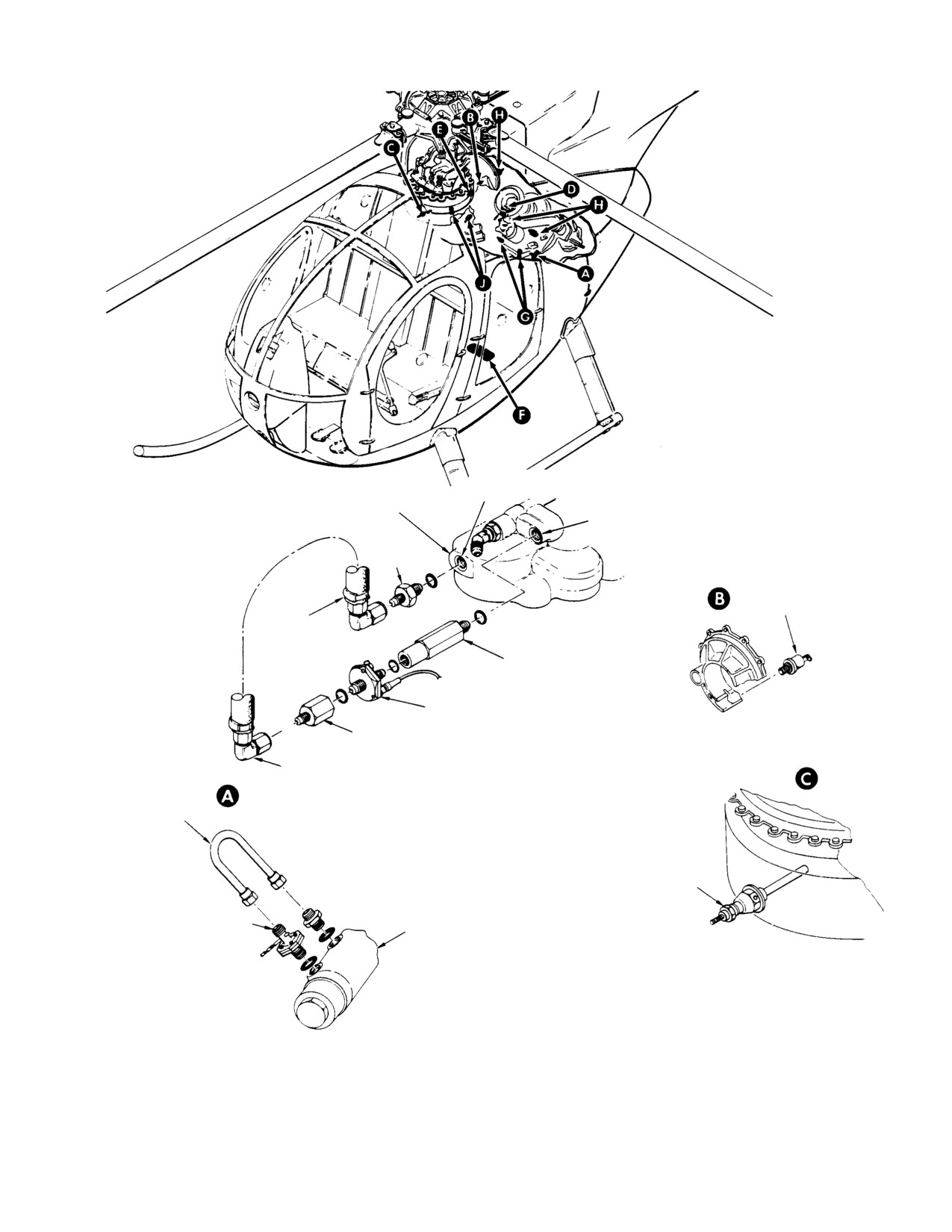
BEFORE FILTER
ENGINE FUEL
PORT (BF)
PUMP FILTER
AFTER FILTER
REDUCER
PORT (AF)
40−50 IN. LB
(4.52−5.65 NM)
MAIN TRANSMISSION OIL
PRESSURE SENDER
30−40 IN. LB (3.39−4.52 NM)
HOSE ASSEMBLY
20−25 IN. LB
(2.26−2.82 NM)
FITTING
40−50 IN. LB (4.52−5.65 NM)
FUEL FILTER PRESSURE SWITCH
40−50 IN. LB (4.52−5.65 NM)
(NOTE 2)
BUSHING
40−50 IN. LB (4.52−5.65 NM)
(NOTE 1)
ELBOW
20−25 IN. LB
(2.26−2.82 NM)
HOSE OR
TUBE
SINGLE ELEMENT PUMP
OIL TEMPERATURE SWITCH
12−25 IN. LB (1.36−2.82 NM)
FUEL FILTER
ENGINE FUEL
PRESSURE SWITCH
PUMP FILTER
40−50 IN. LB
(4.52−5.65 NM)
NOTES:
1.
INSTALL PRESSURE SWITCH BEFORE INSTALLATION
OF BUSHING.
2.
ENSURE THAT TWO HALVES OF THE SWITCH BODY ARE
NOT TWISTED RELATIVE TO EACH OTHER DURING
TORQUING, AS DIAPHRAGM DAMAGE CAN OCCUR.
DUAL ELEMENT PUMP
30−124−1G
Figure 17-7. Indicating System Electrical Senders (Sheet 1 of 3)
Page 17-17
Revision 19
MD Helicopters, Inc.
CSP−H−2
500 Series − Basic HMI
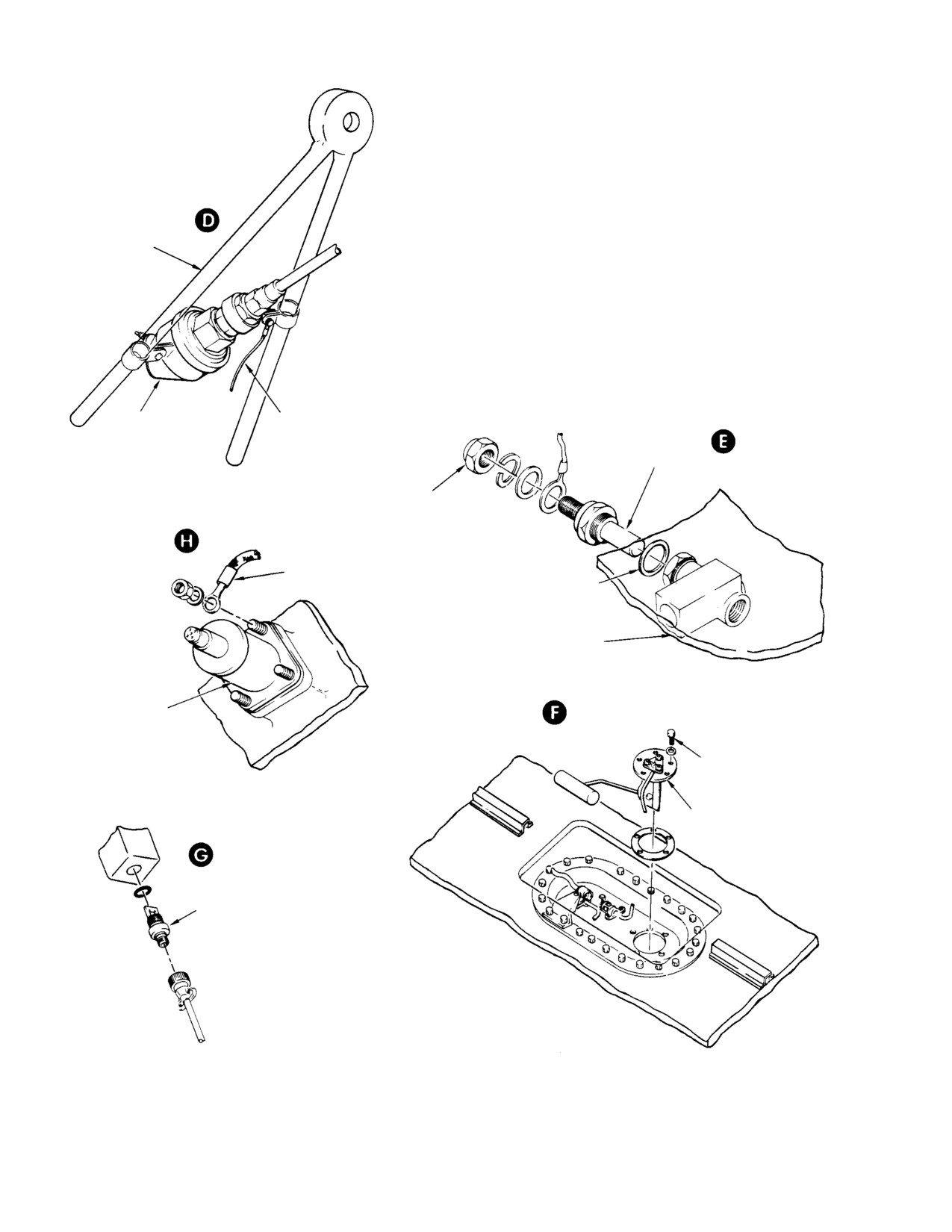
NOTES:
3.
USED WITH 250−C18 ENGINES. FOR ELECTRICAL TYPE
OIL PRESSURE INDICATING SYSTEMS. SENDER, AC6460013,
IS USED IN PLACE OF 369A4534 AFTER CIRCUIT MODIFICATION
RIGHT SIDE
BY KIT M50438.
ENGINE MOUNT
4.
NOTE USED ON ALL HELICOPTERS.
(250−C18 ENGINE)
ENGINE OIL
ENGINE OIL
BONDING JUMPER
TEMP SENDER
PRESSURE SENDER
(NOTE 4)
100−150 IN. LB
(NOTE 3)
(11.30−16.96 NM)
12−15 IN. LB
(1.36−1.69 NM)
TYPICAL
BONDING JUMPER
(NOTE 4)
WASHER OR GASKET
OIL TANK
N1, N2 AND NR
TACHOMETER
GENERATOR
50−70 IN. LB
(5.65−7.91 NM)
FUEL QUANTITY
TRANSMITTER
(TANK UNIT)
TYPICAL
ENGINE CHIP DETECTOR
60−80 IN. LB (6.78−9.04 NM)
30−124−2G
Figure 17-7. Indicating System Electrical Senders (Sheet 2 of 3)
Page 17-18
Revision 19
MD Helicopters, Inc.
CSP−H−2
500 Series − Basic HMI
TYPICAL CHIP
DETECTOR INSTL. EARLY
CONFIGURATION
MAIN TRANSMISSION
MAIN OR TAIL ROTOR TRANSMISSION
12−15 IN. LB
CHIP DETECTOR
1.36−1.69 NM)
VALVE: 50−60 IN. LB (5.65−6.78 NM)
DETECTOR: 40−50 IN. LB (4.52−5.65 NM)
TRANSMISSION CHIP
DETECTOR INSTL.
CURRENT CONFIGURATION
KNURLED CHIP DETECTOR
PROBE KNOB
TRANSMISSION CHIP
TRANSMISSION CHIP
DETECTOR VALVE
DETECTOR VALVE
50−60 IN. LB (5.65−6.78 NM)
50−60 IN. LB (5.65−6.78 NM)
SEAL FLANGE
12−15 IN. LB
1.36−1.69 NM)
30−124−3B
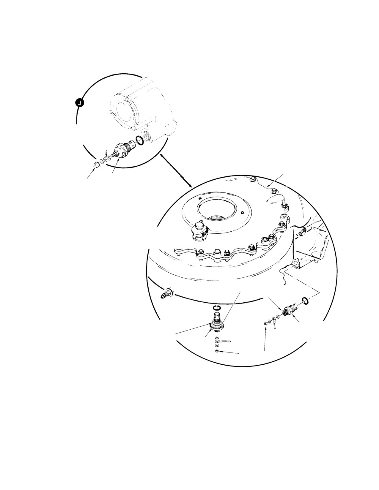
Figure 17-7. Indicating System Electrical Senders (Sheet 3 of 3)
Page 17-19
Revision 19
MD Helicopters, Inc.
CSP−H−2
500 Series − Basic HMI
GENERATOR
CONNECTOR 369A4599
GENERATOR
A
TP1
A
TP2
ALL RESISTORS
B
20 OHM 5W
B
TP3
G
G
CASE GND
CASE GND
TEST NO. 1 − 20 OHM LOAD TEST
TEST NO. 3 − OPEN CIRCUIT TEST
GENERATOR
ITEM
EQUIPMENT DESCRIPTION
NO.
A
TP1
1.
TACHOMETER TEST STAND (IDEAL AEROSMITH , MODEL
17−23−3 O, OR EQUIVALENT).
TP2
ALL RESISTORS
2.
VTVM (RCA MODEL WV−77C, OR EQUIVALENT) CALIBRATED
B
40 OHM 5W
TO 25 VAC ±2%.
3.
20 OHM, 5 WATT RESISTORS (THREE REQUIRED).
4.
40 OHM, 5 WATT RESISTORS (THREE REQUIRED).
TP3
G
5.
369A4599 OR MS316E8−3P CONNECTORS AND WIRING
CASE GND
AS REQUIRED.
TEST NO. 2 − 40 OHM LOAD TEST
30−125A
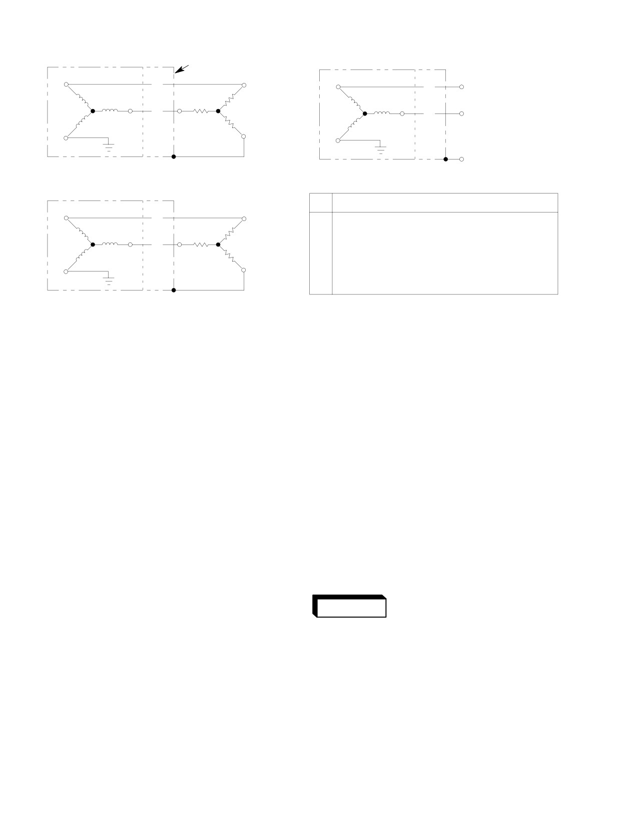
Figure 17-8. Test Hookup For Tachometer Generator
(4).
Using tester (52, Table 2−2) or an
(8). Reconnect TB 9 to indicator terminal
equivalent precision ohmmeter, check
lugs and reinstall instrument panel
total circuit resistance through resistor
fairings.
R 4 and complete thermocouple system.
9. Engine Torque Indicating System
Resistance must be 8 +0.05, −0.0 ohms.
If adjustment is required, loosen screw
(Ref. Figure 17−1 and Figure 17−2) The torque
and retighten finger−tight in sliding
gage indicates engine torque supplied to the
contact on older type resistor R4 or by
engine output shaft.
turning rotating contact on resistor
currently being used, adjust contact
The torque gage is a reading instrument that
position to obtain specified resistance.
indicates a pound−per−square inch reading
Fully tighten screw on older type
equivalent to the amount of pressure (torque)
resistor. Recheck resistance and repeat
exerted on the accessory gear train by the
turbine output shaft.
adjustment, if necessary.
Oil pressure is routed from the torquemeter
(5).
Connect tester or an equivalent tester
pressure port of the engine through metal
to the indicator terminal lugs. Select
tubing and nylon tubing to the gage.
750°C (250−C18) or 790° (250−C20) on
the tester dial. The indicator must
A. Torque Gage Maintenance
indicate the selected temperature
Federal Aviation Adminis−
±5°C,. Adjust slotted adjustment screw
WARNING
tration rules CAR 6.606(b) &
on back of indicator if required.
6.613 require the installation of a re−
striction device at the pressure source
(6).
Select 1000°C on tester dial; the
of engine oil and torque sensing system
indicator must indicate 1000° ±20°C. If
to restrict oil flow in the event of sys−
this requirement is not met, recheck
tem failure. (Refer to HN−221).
adjustment of repeating step (5).
Use the information in Instrument Indicating
(7).
Seal the adjustment screw on the back
System Troubleshooting thru Indicating
of the indicator with a small amount of
System Instrument Repair for troubleshooting,
sealant (24, Table 2−4) and reinstall
inspection, replacement and repair of the
indicator in the instrument panel.
torque gauge.
Page 17-20
Revision 19
MD Helicopters, Inc.
CSP−H−2
500 Series − Basic HMI
B. Torque Gage Pressure Line Removal
C. Torque Gage Pressure Lines Installation
NOTE: At replacement, use only a 3/16 inch di−
(Ref. Figure 17−9)
ameter nylon forward tube section line. The
3/16 inch diameter replacement line is long−
(1). Forward Tube Section (Nylon):
er and replaces both the 1/8 inch diameter
forward tube section and 1/8 inch aluminum
(a).
Check that all electrical power is
(or corrosion− resistant steel) center tube
OFF and remove left instrument
section on an early installation. After re−
panel fairing.
placement of any section of the pressure line
installation, pressure and leak test the as−
(b).
Disconnect pressure line from fitting
sembled lines between the engine and the
on torque gage (detail B).
gage at 200 psi (1379 kPa).
(c).
Cap the openings in torque gage and
(1). Forward Tube Section (Nylon):
pressure line.
(a). Remove covers from pressure line
(d).
Remove nylon pressure line by
and torque gage fitting.
releasing or cutting the three nylon
(b). Connect pressure line to torque gage.
straps along center canopy frame
Connect bleed valve at torquemeter
(detail C). If center tube section
on helicopters so equipped.
(aluminum alloy or corrosion−resis−
tant steel) is installed, disconnect the
(c). Route line along center canopy
pressure line nut at upper frame of
frame, and connect line to bulkhead
canted Sta. 78.50 (detail F). Cap end
at upper frame of canted Sta. 78.50.
of line
(d). If a fitting is installed at bulkhead
(e).
Remove left forward air inlet fairing
and a 1/8 inch diameter nylon line is
and left aft bulkhead access cover in
being reinstalled, connect the line to
cargo compartment.
the fitting. Or if a 3/16 inch diameter
line is being installed, remove any
(f).
Remove screws, clamps, nuts and
fitting at the bulkhead and route line
washers that secure line along left
aft through hole in bulkhead to
side of mast support structure and at
plenum chamber pan fitting. Use
left side of air inlet (plenum) cham−
grommet to secure line in bulkhead
ber (detail D).
hole.
1). Wrap duct tape around tube,
(g).
If center tube section (aluminum
approximately one inch in front of
alloy or corrosion−resistant steel) is
bulkhead fittings.
installed, disconnect pressure line
nuts at bulkhead fittings. Cap ends of
2). Tie a small loop in one end of a 2−3
line.
foot (0.6−0.9 m) length of cord. Tie
opposite end of cord to tube using a
(2). Aft Tube Section (Corrosion−Resistant
rolling hitch; slide rolling hitch
Steel):
down tube until it rests on duct
tape; tighten hitch.
(a). Open left engine compartment access
door.
3). Using a short body length spring
scale, capacity, 0 − 25 pounds(0 −
(b). Remove screw, clamp, nut and
12 kg), attach hook on scale to loop
washer (detail D).
in free end of cord. Apply 15 − 20
Lbs. (6.80 − 11.34 kg) straight
(c). Disconnect pressure line nuts at
pull, using cord. on oil pressure
plenum chamber pan fitting and at
tube for approximately 15 seconds.
engine torquemeter fitting (details E
If tube pulls partially or completely
and A).
out of fitting, replace fitting.
Page 17-21
Revision 19
MD Helicopters, Inc.
CSP−H−2
500 Series − Basic HMI
CLAMPING
(TYP)
AT ENGINE
REDUCER
(TYP)
TORQUEMETER
OIL PRESSURE
SNUBBER
O−RING SNUBBER
O−RING
FITTING
(NOTE 1)
CHAFING TAPE OR PLASTIC
ENGINE BOSS
EDGING GROMMET
TYPICAL TORQUE OR
OIL PRESSURE GAUGE
O−RING
PLENUM CHAMBER
PAN
NYLON TUBE
OIL
(NOTE 4)
PRESSURE
TORQUE
PRESSURE
TORQUE PRESSURE GAUGE
WITH BLEED PROVISION
TEE
TORQUE GAUGE LINE
NYLON TUBE
(NOTE 3)
(NOTE 4)
ADAPTER
NYLON TUBE
(NOTE 4)
BLEED VALVE
ALUMINUM ALLOY OR CORROSION
(NOTE 5)
RESISTANT STEEL TUBE
(NOTE 4)
UNION AND NUT
ATTACH 1/4 IN.
BLEED HOSE
OIL PRESSURE LINE
(NOTE 2)
GROMMET
ENGINE OIL
PRESSURE LINE
(NOTE 2)
TORQUE GAUGE
PRESSURE LINE
CANOPY FRAME
TYING
NOTES:
(TYP)
1.
USE ONLY AT 250 SERIES TORQUEMETER CONNECTION.
2.
ENGINE OIL PRESSURE LINE USED WHEN DIRECT READING
STATIC PRESSURE
TYPE GAUGE IS INSTALLED.
NYLON TUBE
NYLON STRAP
3.
LINE WITH FITTINGS APPLIES ONLY TO HELICOPTER WITH
INSTRUMENT PANEL A. SINGLE CONTINUOUS NYLON LINE
FOR PANEL TYPE B WITH GROMMET AS SHOWN FOR OIL
PRESSURE LINE (REF. NOTE 4).
4.
AT REPLACEMENT, USE SINGLE CONTINUOUS 3/16 IN. O.D.
LINE. ORIGINAL LINES ARE 3/16 IN. O.D. FOR PANEL TYPE B
AND 1/8 IN. O.D. FOR PANEL TYPE B.
30−126−1B
5.
AT INSTALLATION, WRAP VALVE THREADS WITH TEFLON
TAPE (79, TABLE 2−4).
Figure 17-9. Torque Gage and Direct Reading Engine Oil Pressure Gage (Sheet 1 of 2)
Page 17-22
Revision 19
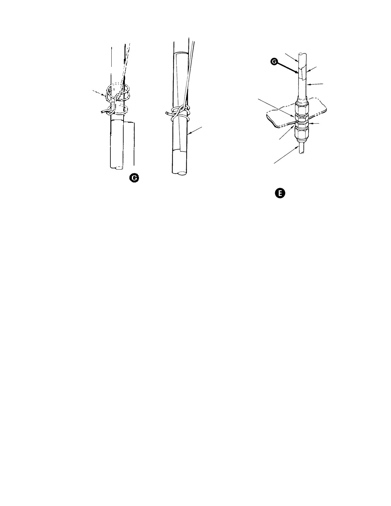
MD Helicopters, Inc.
CSP−H−2
500 Series − Basic HMI
ALUMINUM ALLOY, CORROSION
RESISTANT STEEL OR NYLON TUBE
(NOTE 4)
DUCT TAPE
(NOTE 6)
NYLON TUBING
ROLLING HITCH
(NOTES 6, 7)
FIREWALL FITTING,
FORWARD SIDE
NOTE 7
UNION AND NUT
FIREWALL FITTING,
AFT SIDE
CORROSION RESISTANT
STEEL TUBE
NOTES: (CONT.)
FIREWALL
(TYP)
6.
WRAP TUBE AT LEAST ONCE WITH 2 IN. (5.08 CM)
WIDE DUCT TAPE APPROX. 1 IN. (2.54 CM) FROM FITTING.
7.
SLIDE HITCH DOWN TUBE UNTIL IT RESTS ON DUCT TAPE.
30−126−2
Figure 17-9. Torque Gage and Direct Reading Engine Oil Pressure Gage (Sheet 2 of 2)
4). Remove cord, scale and duct tape
NOTE: Following procedure is for reinstalla−
from tube assembly.
tion of 1/8 inch OD center tube section. For
replacement, a single longer 3/16 inch OD
(e). Secure line in place along side static
nylon forward tube section replaces both the
pressure line, using the canopy frame
1/8 inch OD nylon forward tube section and
slots and nylon straps, or tying twine
1/8 inch OD center tube section.
(30, Table 2−4) if straps arc is not
available.
(a).
Locate pressure line in position,
connect to bulkhead fittings, and
(f). After pressure and leak test, reinstall
tighten.
instrument panel fairing.
(2). Aft Tube Section (Corrosion−Resistant
(b).
Wrap length of aluminum tubing
Steel):
where it is routed past aft corner of
mast support structure and into
(a). Locate pressure line in position,
plenum chamber, using tape and
connect to plenum chamber pan
activator (56, Table 2−4), to prevent
fitting and engine torquemeter
chafing between the tube and struc−
fitting, and tighten.
ture. Steel tubing has a plastic
edging grommet instead of tape.
(b). Secure pressure line to left side of
mast support structure and plenum
(c).
Secure line along left side of mast
chamber with screws, clamps,
support structure and at left side of
washers and nuts or stand−off (detail
plenum chamber with screws,
D).
clamps, nuts and washers (detail D).
(c). After pressure and leak test, secure
(d).
After pressure and leak test, install
engine compartment access door.
left forward air intake fairing and
(3). Center Tube Section (Aluminum Alloy
left aft bulkhead access cover in
or Corrosion−Resistant Steel):
cargo compartment.
Page 17-23
Revision 19
MD Helicopters, Inc.
CSP−H−2
500 Series − Basic HMI
10. Direct Reading Oil Pressure Indicating
(5). Disconnect pressure line from fitting at
System
gage.
NOTE: During filling of line, do not introduce
The direct reading engine oil pressure indicat−
any air bubbles into the system. Use a suit−
ing system utilizes a pressure gage of 0−150
able pump with sufficient volume to fill the
psi (0−1035 kPa) capacity which is mounted
entire length of the pressure line.
near other engine instruments in instrument
panel type B (Figure 17−2). The gage is
(6). At gage end, pump the pressure line
connected to an oil pressure port on the front
full with new engine oil. Force oil
face of the engine accessory section by 1/8 inch
through the line until clean oil flows at
diameter corrosion resistant steel and nylon
the engine end.
tubing. The tubing is in two sections, with
(7). Tighten tube fitting at the engine and
corrosion resistant steel being used aft of the
continue to pump a small amount of oil
engine firewall and nylon tubing forward of
back into the engine.
the firewall. The tubing is routed adjacent to
the torque gage tubing from the firewall to the
(8). Install and tighten gage line fitting at
instrument panel and some tie straps and
back of instrument. Keep the line as
clamping arrangements are common to both
full as possible during connection.
(Figure 17−9).
(9). Start and operate engine at idle
according to the Owner’s Manual and
A. Engine Oil Pressure Gage Tubing
check for visible air bubbles in the
Replacement
forward nylon line.
Replace engine oil pressure gage tubing using,
(10). If air bubbles are present (introduced
in general, the instructions provided for
during connection at instrument),
replacement of torque gage tubing. After
momentarily loosen fitting at back of
replacement, service and bleed the system.
instrument and bleed system with
engine running.
B. Torque or Direct Reading Engine Oil
Pressure Line Bleeding and Servicing
NOTE: A higher power setting may be required
to obtain adequate pressure.
NOTE: On helicopters equipped with a plunger
11. Instrument Cluster Three-Pack or
actuated bleed valve at the torquemeter fit−
Four-Pack Indicating System
ting, gain access to the rear of the torqueme−
ter and attach a 1/4 inch diameter drain
(Ref. Figure 17−10 and Figure 17−11) The
hose at the bleed valve. For best access, re−
instrument cluster is an instrument assembly
move an adjacent instrument or avionics
built as a single unit with three or four
unit not necessary to ground operation of
indicators. The instrument clusters are
the helicopter. Proceed with bleeding and
identical except that the 3−pack does not
servicing described below; or service and
include an engine oil pressure indicator and is
bleed system with engine operating by de−
not internally illuminated.
pressing valve plunger until clear engine oil
Indicators register generator output in
flows through the drain hose into a contain−
amperes, engine oil pressure in pounds−per−
er.
square inch (4−pack), engine oil temperature
in degrees centigrade and operating fuel
(1). Remove left instrument panel fairing.
weight in pounds.
(2). Open engine compartment left access
The helicopter electrical system voltage of 28
door.
Vdc is reduced to a nominal 14.5 Vdc by
voltage dropping resistor R1, located on
(3). Wrap cloth around gage line under
terminal board TB8 mounted on the structure
fitting at engine and at the back of the
beneath the left side pilot’s compartment floor,
instrument.
for instrument circuit power.
(4). Loosen, but do not remove, pressure
The senders for the engine oil pressure
tube fitting at engine.
(4−pack), engine temperature and fuel
Page 17-24
Revision 19
MD Helicopters, Inc.
CSP−H−2
500 Series − Basic HMI
quantity indicators each function as the
NOTE: The individual indicators of the instru−
variable resistance leg of the associated
ment cluster are not replaceable. If there is
instrument bridge circuit.
an indicator malfunction, the complete unit
should be replaced. Remove the wiring har−
As pressure, temperature or float arm position
ness for reinstallation of a replacement
change, the sender resistance changes and
instrument cluster (Figure 17−11 for 4−pack
causes an imbalance in current flow through
or Figure 17−10 for a 3−pack); resistor R112
the indicator windings to produce pointer
is supplied as part of a new 4−pack cluster
movement.
assembly.
B. Instrument Cluster Three-Pack or
Except for the ammeter, external, fixed value
Four-Pack Calibration Check
shunt resistors are mounted across the input
terminals of each of these instruments and
This calibration check is to be performed at a
furnished as part of the cluster (Figure 17−11).
qualified instrument calibration facility. The
following calibration information is supplied
for reference only, for convenience of the
An exception is the (4−pack) oil pressure
calibration facility. All calibration checks are
circuit which has a separate adjustable
to be made with precision equipment, carefully
potentiometer for indicator calibration. This
observing polarities and with face on instru−
potentiometer is used in conjunction with PN
ment cluster positioned approximately
6460013 pressure sender and is located on
vertically.
panel structure forward of and below the
4−pack cluster.
NOTE: Supply voltage is to be 14.5 ±0.3 Vdc for
all following checks. To measure and adjust
Ammeter pointer deflection is a result of
resistance of variable resistor in the checks,
current flow through resistor R3 which is
supply voltage source and variable resistor
located next to the reverse current relay in the
must be disconnected from circuits. For in−
engine compartment. The resistor, installed in
formation on the specific terminal studs
the low voltage output (ammeter) circuit of the
used for individual gages in the cluster, see
starter−generator , acts as a calibrating
Figure 17−10 for a 3−pack or Figure 17−11
resistance to cause ammeter pointer move−
for a 4−pack. Gages of the instrument clus−
ment that is proportional to the main power
ter should provide indications within the
output of the generator.
tolerances specified in following checks re−
gardless of cluster position. Vertical position
A plus scale reading on the ammeter indicates
is specified only to approximate the installa−
the current demand of the helicopter electrical
tion position in the helicopter. For a 3−pack,
system during normal generator operation.
scale error determined at any major gradua−
Minus amperage is indicated only during
tion that is checked should not exceed 5 per−
engine starting and shows the current demand
cent of the full scale value.
of the starter.
(1). Fuel Quantity Gage:
Resistor R112, mounted at terminal point 8 on
(a). Obtain a variable resistor that is
the back of a 4−pack cluster, is an input
continuously variable over a mini−
voltage dropping resistor for the instrument
mum range of 0−90 ohms, and adjust
lights circuit and functions only when night
it to provide 59 ohms resistance.
lighting is installed.
(b). Connect the 59 ohm resistance across
the terminal studs for the fuel
A. Instrument Cluster Three-Pack or
quantity gage and power input
Four-Pack Maintenance
ground.
Use the information in Instrument Indicating
(c). Apply supply voltage to instrument
System Troubleshooting thru Indicating
cluster. Note that the gage indicates
System Instrument Repair for troubleshooting,
approximately 200 pounds (2 mark)
inspection, replacement and repair of the
and keep supply voltage applied
instrument cluster.
approximately 5 minutes.
Page 17-25
Revision 19
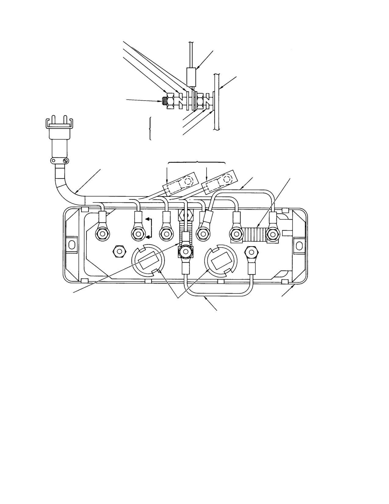
MD Helicopters, Inc.
CSP−H−2
500 Series − Basic HMI
WASHER
WIRE LEAD AND
LOCKWASHER
TERMINAL LUG
NUT
PRINTED CIRCUIT BOARD
(NOTE 1)
THREADED TERMINAL STUD
(NOTE 1)
NUT
NOTE 1
LOCKWASHER
WASHER
VIEW A−A
(TYP)
STOWED WIRES
(NOTE 7)
INSTRUMENT CLUSTER
WIRING HARNESS
E507A22
L534C22
FIXED SHUNT
J4
(NOTE 4)
WIRE E540D22
RESISTOR (TYP)
(NOTES 1, 3)
A
5
4
3
6
1
10
A
DC
AMP.
FUEL
OIL
8
T
11
12
FIXED SHUNT
RESISTOR (TYP)
(NOTES 1, 3)
INTERIOR LAMPS
INSTRUMENT CLUSTER
(NOTE 2)
3−PACK
WIRE L542E20N
REAR VIEW
NOTES:
1.
PART OF AND FURNISHED WITH INSTRUMENT CLUSTER.
5.
THREADED STUDS:
2.
NOT USED.
NO.
ITEM
3.
FOR ASSOCIATED INDICATOR INSIDE CLUSTER.
1
FUEL QUANTITY GAUGE
4.
FOR INFORMATION ON HARNESS CONNECTION WIRING
3
OIL TEMPERATURE GAUGE
BETWEEN CONNECTOR J4 AND THREADED TERMINAL
4
AMMETER − (GND)
STUDS, SEE APPLICABLE ELECTRICAL SYSTEM WIRING
5
AMMETER +
DIAGRAM (REF. SEC. 20).
6
+14.5 VDC POWER INPUT
8
−POWER INPUT, COMMON GND (NOTE 6)
6.
ALSO GND FOR FUEL QUANTITY AND TEMPERATURE GAUGES.
7.
WIRE END INSULATED AND SECURED AT STOWED POSITION.
30−193−1
Figure 17-10. Instrument Cluster Three-Pack with Wiring Harness
(Instrument Panel Type B) (Sheet 1 of 2)
Page 17-26
Revision 19
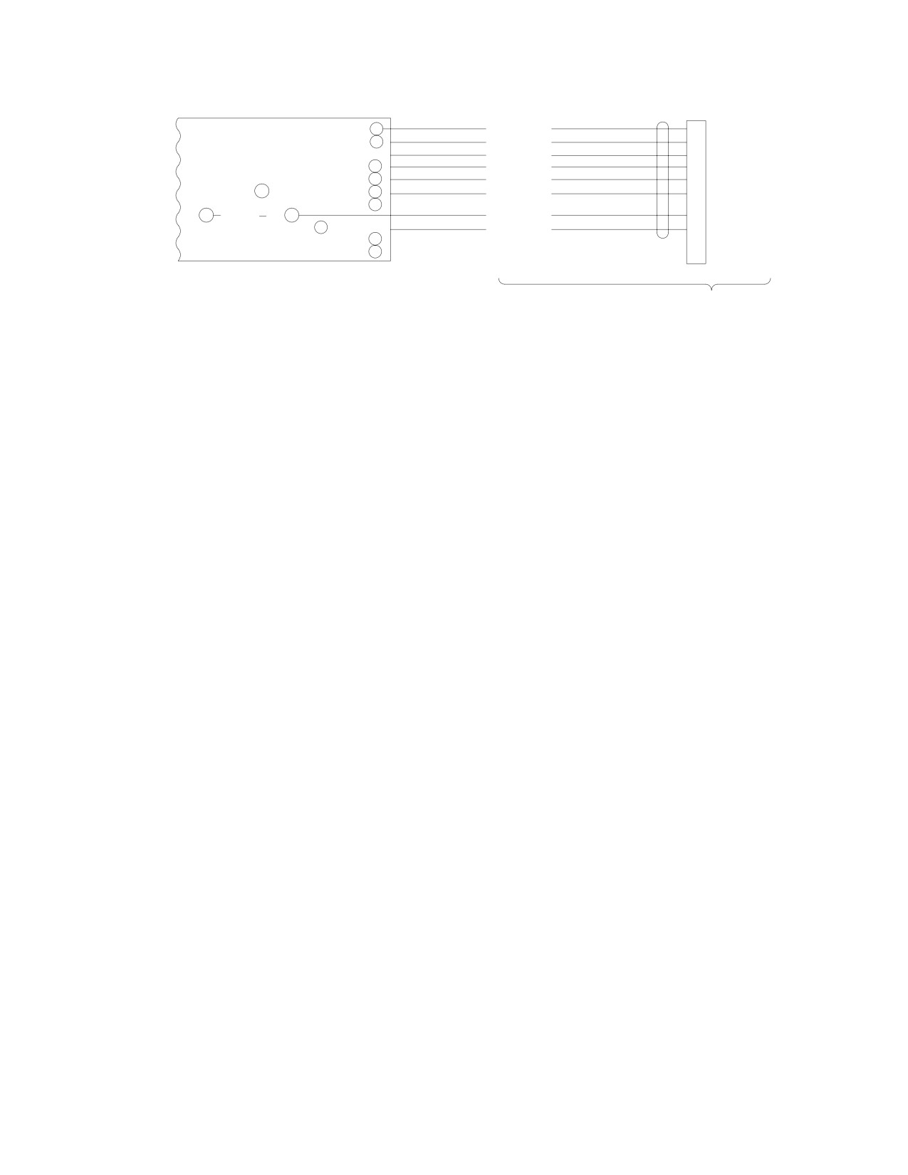
MD Helicopters, Inc.
CSP−H−2
500 Series − Basic HMI
M4
J4
1
E505A22
A
3
E506A22
B
(NOTE 7)
E507A22
C
(AMM BATT)
5
D501A20
D
(AMM GEN)
4
D505A20
E
10 E540D22 − (GEN)
6
E540C22
F
8
12 L542E20N
11
L535A20
H
ILLUMINATION 9
(NOTE 7)
L534C22
J
BLANK
2
K
KEY
7
L
INSTRUMENT CLUSTER
CLUSTER WIRING CONNECTIONS
WIRING HARNESS
(NOTE 4)
30−193−2
Figure 17-10. Instrument Cluster Three-pack with Wiring Harness
(Instrument Panel Type B) (Sheet 2 of 2)
(d). Remove supply voltage and adjust
(b). Connect the 139 ohm resistance
resistance to 88 ohms. Reapply
across the terminal studs for the
supply voltage and check that pointer
engine oil temperature gage and
ascends and indicates full (F).
power input ground.
Centerline of pointer should align
(c). Apply supply voltage to instrument
with ±4° of centerline of F mark.
cluster. Note that the gage indicates
approximately midrange (mid−range
NOTE: Checks, steps (e). and (f)., are to be per−
mark) and keep supply voltage
formed with descending pointer.
applied approximately 5 minutes.
(e). Remove supply voltage and adjust
NOTE: Checks, steps (d). thru (f)., are to be per−
resistance to 59 ohms. Reapply
formed with ascending pointer.
supply voltage and check that gage
(d).
Remove supply voltage and adjust
indicates 200 pounds (2 mark).
resistance to 734 ohms. Reapply
Centerline of pointer should align
supply voltage and check that pointer
with ±3° of centerline of 2 mark.
ascends and indicates 15°C. Center−
line of pointer should align with ±2°
(f). Remove supply voltage and adjust
of centerline of 15 mark.
resistance to 1 ohm. Reapply supply
voltage and check that gage indicates
(e).
Remove supply voltage and adjust
empty (E). Centerline of pointer
resistance to 139 ohms. Reapply
should align with −2° of centerline of
supply voltage and check that pointer
E mark.
indicates mid−range. Centerline of
pointer should align with ±3° of
(g). Disconnect supply voltage source and
centerline of mid−range mark.
variable resistor from terminals of
(f).
Remove supply voltage and adjust
the cluster.
resistance to 46.3 ohms. Reapply
supply voltage and check that gage
(2). Engine Oil Temperature Gage:
indicates 125°C. Centerline of pointer
should align within ±2° of centerline
(a). Obtain a variable resistor that is
of 125 mark.
continuously variable over a mini−
mum range of 0−750 ohms, and
(g).
Disconnect supply voltage source and
adjust it to provide 139 ohms resis−
variable resistor from terminal studs
tance.
of the cluster.
Page 17-27
Revision 19
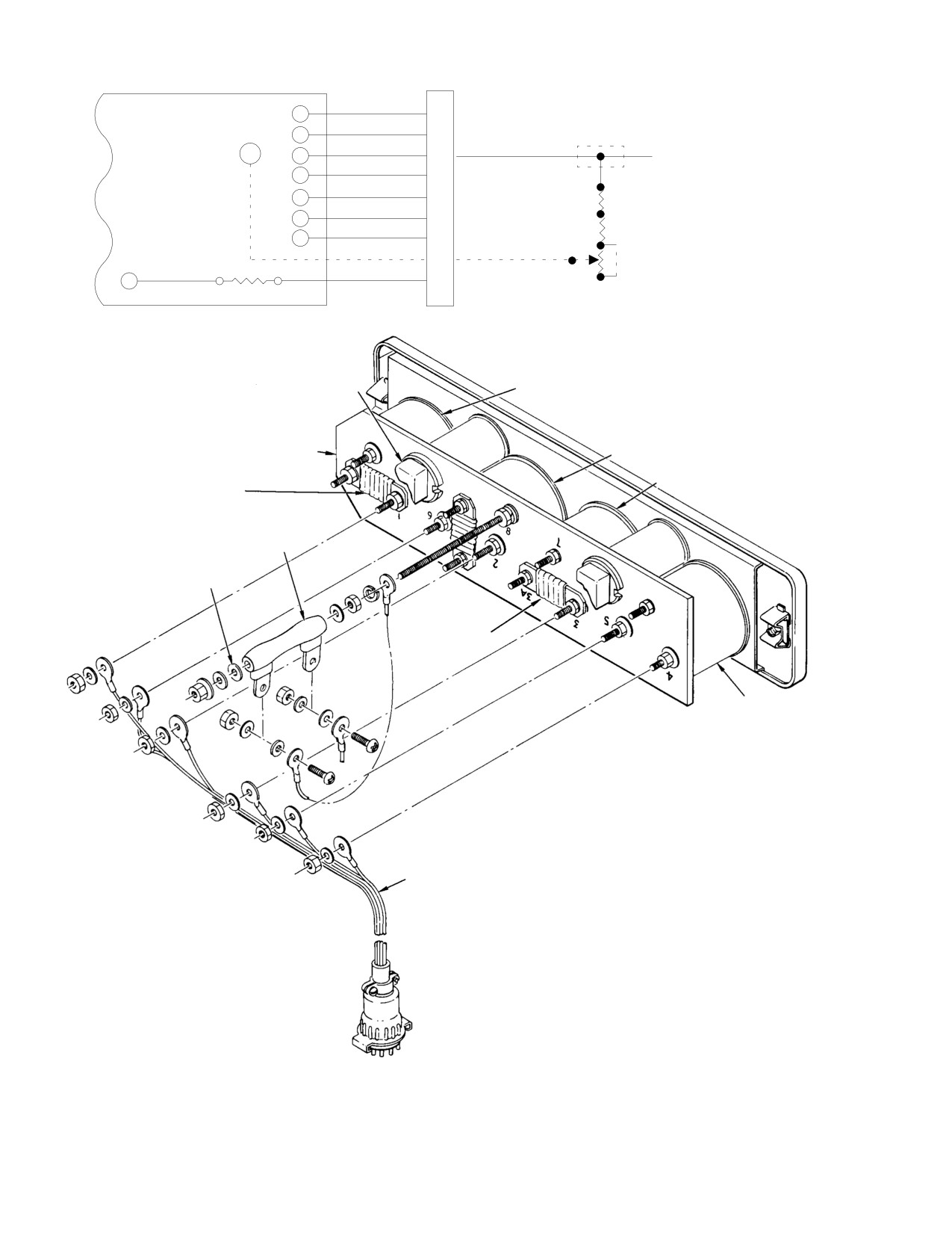
MD Helicopters, Inc.
CSP−H−2
500 Series − Basic HMI
E505A22
1
A
FUEL SENDER
E506A22
2
B
ENG TEMP SENDER
SP50
E507A22
E507B22
3A
3
C
OIL PRESS SENDER
D501A20
4
D
AMMETER (BATTERY)
E507D22
D506A20
5
E
AMMETER (GEN)
R305
E540C22
6
F
POWER INPUT (R1)
L535A20
R304
7
H
GROUND
2
OIL PRESS. GAUGE
E532A22
E532B22
K
R303
CALIBRATION
2
R112
1
L542A22
L534C22
POTENTIOMETER
8
J
PANEL LIGHTS
1
(NOTE 1)
8W20Ω
CLUSTER WIRING CONNECTIONS
INSTRUMENT LIGHT
FUEL QUANTITY
INSTRUMENT CLUSTER 4−PACK
ENGINE OIL TEMPERATURE
ENGINE OIL PRESSURE
INSTRUMENT SHUNT
RESISTOR (TYP)
INPUT VOLTAGE DROPPING
RESISTOR R112 (LIGHTS)
FIBER WASHER (2 PLCS)
NOTE 2
AMMETER
CLUSTER WIRING HARNESS
NOTES:
1.
OIL PRESSURE GAUGE CALIBRATION POTENTIOMETER AND
DASHED LINE CIRCUIT USED ON CURRENT CONFIGURATION.
2.
FIXED RESISTOR (OIL PRESS. GAUGE SHUNT) USED IN THIS
LOCATION ONLY ON EARLY CONFIGURATION WITH 369A4534
OIL PRESSURE SENDER.
30−127A
Figure 17-11. Instrument Cluster Four-Pack with Wiring Harness
Page 17-28
Revision 19
MD Helicopters, Inc.
CSP−H−2
500 Series − Basic HMI
(3). Ammeter Gage:
(4). Engine Oil Pressure Gage (4−Pack):
Comply with applicable
(a). Obtain a variable resistor that is
WARNING
continuously variable over a mini−
electrical safety precautions
when checking the ammeter gage.
mum range of 0−90 ohms, and adjust
it to provide a resistance of 1 ohm.
(a). Connect a variable resistance load, a
(b). Connect the 1 ohm resistance across
test ammeter and the ammeter gage
the terminal studs for the engine oil
to be tested in a series circuit to a
pressure gage and power input
14.5 ±0.3 Vdc supply source that is
ground.
capable of supplying 1.38 amperes
through the circuit.
NOTE: Checks steps (c). thru (f). are to be per−
formed with ascending pointer.
NOTE: Variable resistance load must be adjust−
able to provide either a total current of 0.75
(c). Apply supply voltage to instrument
or 1.38 amperes through the combined resis−
cluster. Note that gage indicates
tance of the variable load, test ammeter and
approximately 0 pounds per square
ammeter gage being tested. Make resis−
inch (psi). Centerline of pointer
tance measurements and/or calculate re−
should align within ±2° of 0 psi mark.
quired values of load resistance for use with
the test ammeter in the series circuit as nec−
(d). Remove supply voltage and adjust
essary. A current flow of 0.75 ampere
resistance to 59 ohms. Reapply
through the ammeter gage being tested
supply voltage and check that pointer
should result in a 75 ampere indication on
ascends and indicates 90 psi. Center−
the gage.
line of pointer should align within
±3° of 90 psi mark.
(b).
Set variable load to correct resistance
and apply supply voltage with the
(e). Remove supply voltage and adjust
required polarity to provide a +0.75
resistance to 88 ohms. Reapply
ampere current reading on the test
supply voltage and check that pointer
ammeter and a +75 ampere indica−
ascends and indicates 125 psi.
tion on the ammeter gage being
Centerline of pointer should align
tested. Centerline of pointer should
within ±2° of 125 psi mark.
align within ±4° of centerline of +75
(f). Disconnect supply voltage source and
mark.
variable resistor from terminals of
the cluster.
(c).
Remove supply voltage from cluster.
(5). All Gages:
(d).
Set variable load to correct resistance
and apply supply voltage with the
Without supply voltage applied to cluster,
correct polarity to provide a −1.38
check that each pointer in the cluster returns
amperes current reading on the test
to a position at or below the lowest calibration
ammeter and a negative current
mark of its gage.
indication on the ammeter gage being
tested. Pointer on ammeter gage
12. Engine Oil Temperature Sender
being tested should indicate between
−75 and −150.
(Ref. Figure 17−7)
A. Engine Oil Temperature Sender
(e).
Remove supply voltage from cluster
Replacement
and check that ammeter gage being
tested indicates 0 (zero). Centerline
(1). Check that all electrical power is OFF.
of pointer should return to and align
with ±3° of centerline of 0 mark.
(2). Drain the engine oil tank.
(f).
Disconnect variable load resistor and
(3). Disconnect electrical wire from oil
test ammeter from ammeter gage
temperature sender, cut safetywire and
being tested.
remove sender from bushing in oil tank
Page 17-29
Revision 19
MD Helicopters, Inc.
CSP−H−2
500 Series − Basic HMI
fitting; keep sender washer for rein−
(5). Tightly wrap two to three turns of
stallation if it is serviceable. (Plug tank
white teflon tape (79, Table 2−4) on
fitting and insulate wire terminals
sender pipe threads. Connect pressure
when replacement sender is not
line and check both ends of tube for
immediately available.
security.
(6). Tighten clamp bolts and connect
NOTE: 369A4533− BSC sensor is compatible
electrical wire.
with the 369D296305−21,
−23 and
−31
instrument clusters only. 369A4533−3 sen−
(7). Start the engine according to Owner’s
sor is compatible with the 369D296305−33,
Manual and check for oil leakage and
−35 and −37 instrument clusters only.
proper operation of the pressure system
indicator.
(4). Install replacement sender with
serviceable or new washer or gasket
B. Electrical Oil Pressure Gage Calibration
and tighten to 100 − 150 inch−pounds
Calibrate oil pressure gage systems having
(11.30 − 16.95 Nm). Lockwire the
adjustment potentiometer R303 and PN
sender to oil tank bushing. Connect
640013 pressure sender, using one of the
electrical wire.
following methods.
(5). Fill the engine oil tank.
(1). Method I:
(6). Start the engine according to Owner’s
The following equipment is required: A
Manual and check for oil leakage and
0−150 psi (0−1035 kPa) pressure gage
proper operation of the temperature
with 1 percent accuracy, high pressure
system indicator.
hose and tee fitting to connect into the
engine oil pressure sender inlet line.
(7). Reinstall aft bulkhead access cover.
(a).
Disconnect engine oil pressure inlet
13. Engine Electrical Oil Pressure System
line from sender (Figure 17−7) and
reconnect with the tee fitting in the
A. Engine Electrical Oil Pressure Sender
line.
Replacement
(b).
Connect master gage to high pres−
sure hose, fill the hose and gage with
(1). Check that all electrical power is OFF.
engine lubricating oil (Table 2−3);
then connect to the tee fitting.
(2). Disconnect electrical wire and pressure
line from oil pressure sender mounted
(c).
Locate potentiometer R303 on
on right engine mount; use suitable
instrument panel structure. Loosen
means to catch residual oil from line.
adjustment locknut and set poten−
(Cap pressure line and sender, and
tiometer at approximate mid−range.
insulate wire terminal when replace−
ment sender is not immediately
(d).
Start and operate the engine at idle
available).
in accordance with the Owner’s
Manual. Observe oil pressure indica−
(3). Observe locations of mounting clamps;
tion on the master gage. If indication
then remove clamps, bonding jumper
is erratic, bleed out air by loosening
and sender from mount.
hose fitting at the gage.
(4). Using the two removed support clamps,
(e).
Increase engine N1 to 80 percent. The
install replacement sender on engine
stabilized oil pressure at this point
mount but do not tighten clamps.
should be in the 90−130 psi (621−896
kPa) range on the master gage. If oil
NOTE: The small clamp and bonding jumper
pressure is not in this range, the
provides the bonding path between the
engine oil pressure regulator will
sender and firewall. Be sure that sender
require adjustment according to
bonding is as specified in Maintenance of
engine operation and maintenance
Electrical Bonding Connections, Section 19.
manual.
Page 17-30
Revision 19
MD Helicopters, Inc.
CSP−H−2
500 Series − Basic HMI
(f). While maintaining 80 percent N1,
(f). Connect engine oil pressure line to
adjust potentiometer R303 until
sender inlet. Start and operate
four−pack gage indicates the same
engine at idle in accordance with the
pressure as the master gage. Tighten
Owner’s Manual. Bleed engine oil
potentiometer locknut.
pressure line at the sender for a
stable indication on the four−pack
gage.
(g). Shut down engine and remove test
equipment. Reconnect oil pressure
(g). Perform a flight check to ensure that
line to sender. Check engine oil level
oil pressure regulation at high power
in tank and service if required.
settings is in the 120 ±10 psi (827 ±69
kPa) range.
(h). Perform a flight check to ensure that
14. Fuel Quantity System
oil pressure regulation at high power
settings is in the 120 ±10 psi (827 ±69
(Ref. Figure 17−7)
kPa) range.
A. Fuel Quantity Transmitter (Tank Unit)
Replacement
(2). Method II:
(1). Check that all electrical power is OFF
and that the helicopter is grounded.
The following equipment is required: A
0−150 psi (0−1035 kPa) gage of 1
Use all necessary precautions
CAUTION
percent accuracy, a source of regulated
consistent with safe practice
pressure (air, inert gas or hydraulic oil),
when working in or around the fuel cells. If
fittings, and necessary lines and hoses
a replacement tank unit is not available for
to connect gage and pressure source to
immediate installation,do not remove the
the oil pressure sender inlet.
installed unit.
(2). Remove left fuel cell access door.
(a).
Remove oil pressure line at pressure
sender (Figure 17−6) and connect
(3). Disconnect tank unit harness electrical
pressure source with master gage in
plug from mating connector at fuel
the line.
shutoff cable support bracket.
(4). Cut the lockwire, remove the five bolts
(b).
Locate potentiometer R303 on
and washers from tank unit and lift
instrument panel structure. Loosen
unit from fuel cell cover plate. Discard
adjustment locknut and set poten−
the gasket.
tiometer at approximate mid−range.
Connect 28 Vdc electrical power.
(5). Check the replacement tank unit for
the following:
(c).
Slowly pressurize the sender until
(a). Housing and pivot mechanism for
master gage indicates 130 psi (896
deformation or corrosion.
kPa). Adjust potentiometer until
(b). Float and arm for freedom of move−
four−pack gage also indicates 130 psi
ment between stops.
(896 kPa).
(c). Float arm for sufficient offset so that
(d).
Release pressure and then recheck.
the float will clear the edge of the cell
With pressure increased to 130 psi
sump and allow full travel of the
(896 kPa), the four−pack gage
arm.
tolerance is one needle width at the
(d). If shaft end play seems excessive,
tip.
install a washer and clip to limit play
to 0.015−0.025 inch (0.381−0.635
(e).
Tighten locknut on potentiometer,
mm) clearance between float arm and
release all pressure and remove test
bushing according to instructions in
equipment.
Hughes Notice HN−89.
Page 17-31
Revision 19
MD Helicopters, Inc.
CSP−H−2
500 Series − Basic HMI
(6). Install gasket, tank unit with float
(a). For the single unit type gage, cut the
inboard, washers and bolts. Torque
template circular to fit flat on the
bolts to 50 − 70 inch−pounds (5.65 −
instrument glass, inside the bezel.
7.91 Nm), and using lockwire (2,
Scribe two lines, pointer pivot shaft
Table 2−4), safety boltheads (three and
as the center.
two) together.
(b). For the 3−pack or 4−pack type gage,
(7). Reconnect electrical plug to mating
cut the template rectangular to fit
connector.
flat on the instrument glass, inside
the bezel and covering the fuel
quantity gage area. Tape the tem−
(8). Check fuel quantity indicator reading
plate in position and scribe lines on
against a known quantity of fuel in the
the template from center of pointer
cells.
pivot shaft through the center of
graduation marks at E, 2 and F.
(9). Fill cells to capacity and check for fuel
Scribe maximum tolerance, step
leakage; none is permissible.
(1).(b)., lines on each side of the
center lines.
(10). Reinstall fuel cell access cover.
NOTE: During defueling, the helicopter should
B. Fuel Quantity Transmitter and Indicator
be as near level as possible and battery or
Operational Check
external power voltage should be 24− 28.5
Vdc. Inaccurate readings may result if these
Perform the following checks to determine that
conditions are not met.
fuel quantity indicator readings are within
tolerance. Checks are made at empty, 200
(3). Defuel the helicopter. Refer to Section 2
pounds and full fuel loads.
for procedure and observe the following.
(1). Use the following tolerances when
(a). Stop defueling when the FUEL LOW
checking fuel quantity indications.
caution light goes on (Indicator
should be passing through the 35
(a). For the single unit type gage:
pound position).
E = +0 degrees from centerline of
marker (not above zero)
(b). Following caution light illumination,
2 = +6 degrees from centerline of
drain remaining fuel into a container.
marker
There should be approximately 5.4
F = +6 degrees from centerline of
gallons (20.5 L) of drained fuel.
marker
(c). If conditions in steps (a). and (b).
above are not met, check caution
(b). For the 3−pack or 4−pack type gage:
light circuitry and/or readjust tank
E = +0, −2 degrees from centerline
unit as required.
marker
2 = ±3 degrees from centerline of
(4). Turn electrical power ON. Check
marker
indicator reading. Pointer must be at E
F = +4, −0 degrees from centerline of
or below. Refer to tolerances, step
marker
(1).(a). and (b).
(c). Tank unit circuit resistance (gage
NOTE: If indications are not within tolerances,
disconnected) is as follows:
determine whether gage or tank unit is at
E = 1 ohm
fault by removing electrical power, discon−
2 = 59 ohms
necting gage wiring, and checking tank unit
F = 88 ohms
circuit resistance, step (1).(c).
(2). In order to check degrees of error,
(5). Start refueling slowly. Note that the
construct a template of thin clear
FUEL LOW caution light goes out
plastic as follows.
shortly after the indicator passes the
Page 17-32
Revision 19
MD Helicopters, Inc.
CSP−H−2
500 Series − Basic HMI
35−pound position, approximately 5.4
NOTE: Sending units installed on early Model
gallons(20.5 L) of fuel in cells.
369H and 369HS helicopters may not have
potting compound applied on sending unit
mounting plate around terminals. If potting
(6). Continue to fill the cells to 200 pounds,
compound has not been applied, pot the
approximately 30.75 gal (116.5 L) of
tank sending unit as shown in
fuel.
Figure 17−12, detail A or detail C.
NOTE: Density of JP−4 fuel is 6.5 lb/gal (0.78
(3). Using flashlight and pointed probe
kg/L) on standard day 59°F (15°C), 29.92 in.
(wood or plastic), inspect interface of
Hg, dry air. Fuel density will vary under
potting compound and sending unit
other ambient conditions and should always
mounting plate for voids. Pay particular
be taken into account when indicator accu−
attention to area around terminal
racy is questionable.
screws (detail A, Figure 17−12). If any
voids are noted, perform steps (7). thru
(14).
(7). Check that indicator reading at 200
pounds is within scribed tolerance
NOTE: Troubleshooting is accomplished with
marks on template. For the single unit
electrical power ON, circuit breaker in (re−
type gage, rotate the template as
set) and caution and warning lights set at
required to check that pointer is within
BRT.
6 degrees of the center of the marker.
(4). If FUEL LOW warning light is on or
(8). Continue to refuel until the tanks are
glows when fuel level is above the low
full. Check that indication is within
level mark, perform steps (7). thru (14).;
tolerance in the same manner as in step
otherwise end inspection after step (6).
(7).
(5). Apply fault (ground) input to terminal
No. 2 on sending unit (Figure 17−12).
(9). Remove electrical power and secure the
Check that lamp illuminates properly
refueling operations. If fuel quantity
when fault input is applied. If lamp
indications were not within tolerances,
does not come on or does not illuminate
test the tank unit.
properly, check wiring between termi−
nal No. 2 and CB104−2 circuit breaker
C. Fuel Tank Sending Unit and Fuel Low
and make corrections.
Warning Light Indicating System
Inspection
(6). Reinstall fuel cell access door if steps
(7). thru (14). are not to be performed.
This inspection, checks for security and
When performing mainte−
condition of the fuel tank sending unit, and for
WARNING
nance of fuel system compo−
proper operation of the fuel low warning light
nents, comply with all applicable safe−
indicating system. Bench testing as well as
ty precautions to avoid possibility of
rework of the fuel tank sending unit may be
fuel vapor ignition and fire. Prior to
necessary if inspection reveals voids between
maintenance always turn off all electri−
potting compound and unit mounting plate or
cal power; make sure helicopter is
dimness/erroneous actuation of the fuel low
grounded; disconnect external pow−
level warning light.
ersource and disconnect battery.
(7). Remove fuel tank sending unit; refer to
(1). Remove left side fuel cell access door.
safety precautions noted above.
(2). Check fuel tank sending unit, electrical
(8). Dry top of sending unit with heat gun
terminals and wiring for security and
or oven for one hour at 100°F (38°C).
condition; check wiring harness
between tank unit and instrument
(9). Bench test sending unit (Ref. Tank Unit
cluster.
Testing); replace unit as required.
Page 17-33
Revision 19
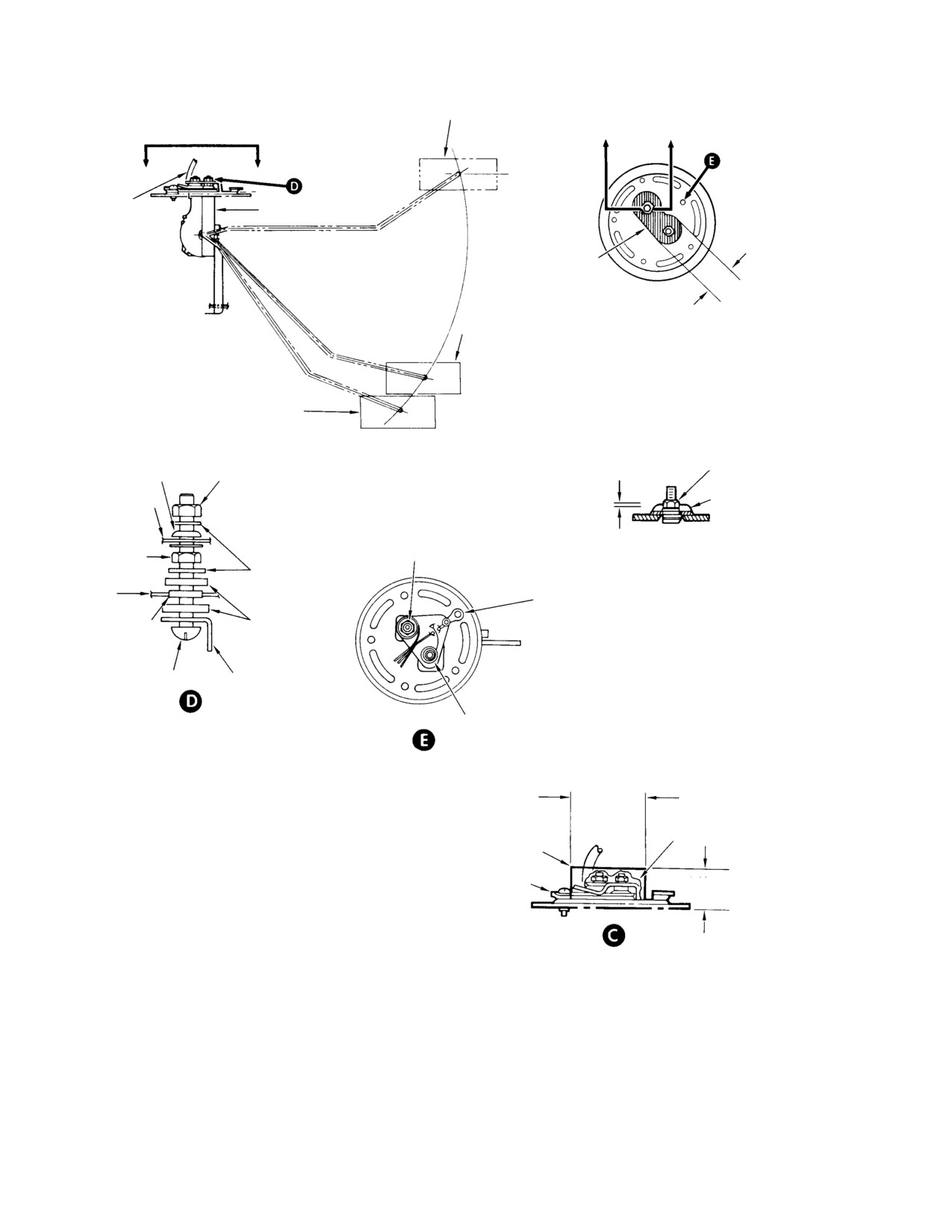
MD Helicopters, Inc.
CSP−H−2
500 Series − Basic HMI
FULL POSITION
B
B
A
A
NOTE 1
369A4245−3 BRACKET
NOTE 2
0.75 IN. (19.05 MM)
APPROX.
SPRING CONTACT POSITION
A − A
MODEL 369H AND 369HS ONLY
(SEE DETAIL C FOR MODEL 369HM)
EMPTY POSITION
0.04 IN. (1.016 MM)
TOPSIDE OF NUT
GS 6−5 EYELET
MS20364−632 NUT
MIN.
POTTING COMPOUND
TRANSISTOR
(RTV−732 SEALANT)
BOARD
B − B
(TYP) (2 PLCS)
TERMINAL NO. 1
NAS671−6 NUT
AN960−6L WASHER
COVER
MS35206−244 SCREW
AN960−8L WASHER
#46 TERMINAL LUG
NAS549−6 WASHER
NEOPRENE WASHER
NAS1598−C8Y STAT−O−SEAL
AN515−GR10 SCREW
−3 BRACKET
TERMINAL NO. 2
(NOTE 4)
MODEL 369H/369HS ONLY
1.75 IN. (4.445 CM)
MAX. DIA. SEALING ENVELOPE
NOTE 3
POTTING COMPOUND (PR1221)
369A4520 TANK UNIT
0.75 IN. (19.05 MM) MAX.
SEALING ENVELOPE
NOTES:
1.
ORIENT ELECTRICAL HARNESS AS SHOWN.
2.
APPLY POTTING COMPOUND AROUND TERMINALS
AS SHOWN; DO NOT EXTEND ABOVE NUT OR
MODEL 369HM ONLY
APPLY POTTING COMPOUNDS ON TOP SIDE OF NUT.
3.
MINIMUM ENVELOPE OF POTTING COMPOUND
(0.60 IN. (15.24 MM) MIN. COVER OVER ELECTRICAL
COMPONENTS AND WIRING.
4.
APPLY FAULT (GROUND) INPUT TO TERMINAL NO. 2.
30−225A
Figure 17-12. Bench Test and Potting of Fuel Tank Sending Unit
Page 17-34
Revision 19
MD Helicopters, Inc.
CSP−H−2
500 Series − Basic HMI
(10). For 369H and 369HS commercial
(22.835−23.140 cm). Bend the float full
helicopters only, perform the following
stop as required to obtain 88−95 ohms
(Figure 17−12, detail D and detail E):
(88 ohms desired) within these float
travel limits.
(a). Tighten NAS671−6 nut to hold
369A4245−3 bracket firmly in
(6). Disconnect the ohmmeter. Obtain a 24
position.
Vdc power supply or battery, a No. 328
lamp and the necessary wiring to make
(b). Disconnect and lift No. 46 ground
connections shown in Figure 17−13.
terminal lug away from mounting
(7). Apply 24 Vdc power and check that
plate flange; hold float arm at full
lamp illuminates when centerline of
position.
arm−to−float attachment is 1.25 inches
(c). Resistance measured from −3 bracket
(3.175 cm) above its empty position.
to flange shall be greater than 2
(8). Bend the spring attached to tank unit
megohms.
bracket if required and recheck that
(11). Apply potting compound to seal voids,
lamp is illuminated from the empty
as applicable.
(rest) position to the 1.25 inch (3.175
cm) raised position.
(12). Reinstall fuel tank sending unit; torque
(9). Disconnect 24 Vdc power and all test
screws to 12 − 15 inch−pounds (1.36 −
equipment.
1.69 Nm). Do not overtighten screws as
this may warp mounting plate flange.
(10). Seal all connections at top of tank unit
with sealant (3, Table 2−4).
(13). Recheck electrical circuitry per steps
(4). and (5).
15. Outside Air Temperature Indicator
(14). Reinstall fuel cell access door.
(Ref. Figure 17−14) The outside air tempera−
ture indicator consists of a bimetal element
D. Tank Unit Testing
(enclosed in a stainless steel thermometer
stem) attached through the stem to a dial−type
(Ref. Figure 17−13)
temperature indicator.
(1).
Set up tank unit on a level platform
The thermometer is installed through the right
approximately 9 inches (22.86 cm)
or left side canopy (as applicable) just forward
above a second level surface, such as a
of the instrument panel, and is secured by a
table top.
sunshield.
(2).
Obtain a sensitive ohmmeter and set on
0The temperature dial indicates outside air
low range resistance scale.
temperature in both Fahrenheit and centi−
grade.
(3).
Allow float arm to rest on the float
empty stop. If wiring harness is
NOTE: Left or right side installation de−
attached, measure resistance across
pendson model and configuration.
pins B to H of tank unit connector.
A. Outside Air Temperature Indicator
Resistance must be 0−3 ohms (1 ohm
Replacement
desired). Adjust (bend) the float empty
stop until this resistance is obtained.
(1). Hold indicator dial firmly and remove
sun shield from thermometer stem.
(4).
Raise the float until arm is in contact
Remove applicable hardware shown in
with the full stop and observe that
Figure 17−14 from stem; then remove
resistance increases to approximately
indicator from canopy.
88 ohms.
(2). Remove hardware from replacement
(5).
Measure from the centerline of arm
indicator and install indicator in canopy
attachment to float when in full
as shown.
position, to the same point when in
empty position! This measurement
(3). Rotate indicator dial for correct reading
should be 8.99−9.11 inches
position, install seal and spacer (if
Page 17-35
Revision 19
MD Helicopters, Inc.
CSP−H−2
500 Series − Basic HMI
used), outer rubber washer, dished
power out warning unit or the indicator lights
washer and sun shield, and securely
dimming assembly or disable switch Sl99, if
hand−tighten the sun shield.
installed.
16. Magnetic Compass
17. Caution and Warning Lights Indicating
System
The magnetic compass is either installed in
the instrument console of type A panels or
The caution and warning light indicating
attached to the center canopy frame on
system includes the following components.
helicopters with a type B panel.
(1).
For instrument panel type A
Hughes Notice HN−77 provides optional
(Figure 17−1), six indicator lights
relocation instructions for canopy frame
mounted across the top of the panel.
mounting of a compass mounted in an A type
For instrument panel type B
panel.
(Figure 17−2), nine indicator lights
mounted in the same location. Early
The magnetic compass continuously indicates
type indicator lights on panel type B
the heading of the helicopter relative to the
are switched from bright to dim when
earth’s magnetic field.
the legend face of the indicator is
depressed and remain dim until
The compass consists of a liquid−filled case in
indicator is depressed a second time for
which a float assembly, incorporating a
bright illumination.
compass card and magnets, pivots on a jewel
post.
(2).
Senders, detectors and switches
associated with the indicators
The compass card is graduated in 5 degree
(Figure 17−7).
increments. The card is read against a fixed
vertical white line (lubber’s line) on the face of
(3).
An indicator light dimming assembly
the instrument.
for panel type A that automatically
dims the indicator lights when the
A compass correction card is located in the
instrument panel lights are on and
logbook holder.
furnishes light test circuits. The panel
type B dimmer assembly provides light
The compass face is tilted at a downward angle
test circuits and a switching regulator
so that the compass is level during normal
for panel and instrument light dim−
flight.
ming.
A wedge is used for this purpose in the type A
(4).
An engine power out (EPO) warning
panel installation.
control unit. EPO units manufactured
The compass is internally illuminated, using
by Autronics include an integral audio
dc electrical power, from the night lighting
amplifier (Figure 17−4) while an
system.
external audio amplifier is used with
Vapair EPO units (Figure 17−3).
A. Magnetic Compass Maintenance
(5).
Legend−type signal indicator lights
Use the information in Instrument Indicating
that are interconnected with the
System Troubleshooting thru Indicating
PRESS−TO−TEST light test pushbut−
System Instrument Repair for troubleshooting,
ton switch and EPO solidstate dimmer
inspection, replacement of the magnetic
assembly that isolates the light test
compass.
circuit from the operational circuits.
Operational Check. An operational check of
(6).
With power on, and the engine not
the caution and warning lights indicating
running, the red engine power out light
system must be performed after maintenance
and the red transmission oil pressure
on the caution and warning lights, engine
warning light flash alternately. None of
Page 17-36
Revision 19
MD Helicopters, Inc.
CSP−H−2
500 Series − Basic HMI
the amber caution lights flash when
the indicator lights dimming assembly, are
they are on.
listed in Table 17−2.
NOTE:
(1). Operational Check. An operational
check of the caution and warning lights
D The early type indicator lights used in
indicating system must be performed
instrument panel type B may be individu−
after maintenance on the caution and
ally switched to dim illumination by
warning lights, engine power out
pressing the face of the indicator. The
warning unit or the indicator lights
light remains dim until the legend face of
dimming assembly or disable switch
the indicator is depressed a second time.
Sl99, if installed.
D The caution and warning lights indicat−
ing system on a current helicopter with
NOTE: Although the procedure outlined below
instrument panel type B functions with
reveals the functional state of only three of
Nl/NR engine power out warning equip−
the fault input circuits, it will also show
ment.
whether or not the components common to
all circuits function correctly. A check of the
D Helicopters with an early instrument
other fault input circuits can be made in the
panel type B or panel type A use Nl engine
same way, when necessary, by bridging the
power out sensing equipment only. Nl/NR
applicable switching device or sender.
sensing equipment senses both low en−
gine Nl and main rotor (NR) speeds. Nl
sensing equipment functions only with
(a). Turn on electrical power. Check that
low engine Nl speed.
WARNING AND PANEL lights and
ENG out circuit breakers are in
D A helicopter with early panel type B or
(reset) and that the panel lights
type A may be modified to incorporate
dimming control is set at OFF (fully
N1/NR sensing equipment. For difference
counterclockwise) if installed.
information on a caution and warning
light system in which the Nl/NR sensing
(b). Check that red warning lights
equipment was installed in this manner.
indicating engine out and low main
transmission oil pressure flash.
A.
Caution and Warning Lights Indicating
System Troubleshooting
NOTE: These faults are supplied whenever the
engine is not operating.
When troubleshooting, perform an operational
check, step (1)., as necessary. Troubleshoot the
(c). Using a jumper lead, ground the
caution and warning lights indicating system,
terminal stud of the tail rotor trans−
using the data in Table 17−2 and Table 17−3.
mission chip detector to produce a
fault input.
Refer to Table 17−2 to determine the function−
al unit associated with each light indicator, the
input fault signal that activates each indicator,
(d). Check that the applicable CHIPS
and the connector pins used in each circuit.
lamps light.
Use Table 17−3 to assist in isolating trouble to
(e). If a panel lights dimming control is
a defective unit and component.
installed, check that the control can
control the panel instrument and
Apply the correct input signal to the connector
lamp illumination and select bright
pin(s) to provide a specific light indication, or
or dim indicator lamp illumination
check for presence of the correct fault input
(for panel type A).
signal for a light indication obtained.
(f). Check that early panel type B light
Light indications that are provided by the
indicators can be switched from
caution and warning lights, controlled by the
bright to dim illumination by de−
engine power out warning control unit and/or
pressing the indicator legend face.
Page 17-37
Revision 19
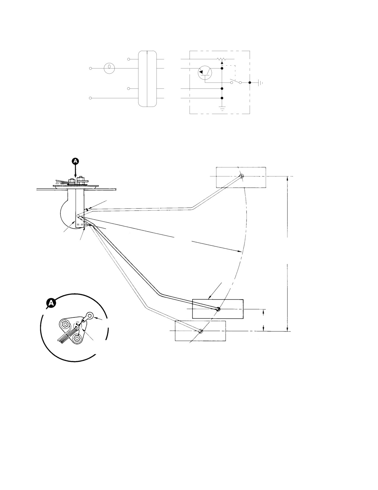
MD Helicopters, Inc.
CSP−H−2
500 Series − Basic HMI
CONNECTOR
FUEL QUANTITY
369A4599
TRANSMITTER
NO. 328
R
A
LAMP
B
BLU
+
D
RED
Q
24 VDC
POWER
G B
SUPPLY
E
BLK
−
H
BLK
TEST CONNECTIONS
FULL POSITION
FUEL QUANTITY
TRANSMITTER
FLOAT STOP (FULL)
SPRING
BRACKET
10.08 IN. (25.6032 CM)
FLOAT STOP
RADIUS
(EMPTY)
8.99−9.11 IN.
(22.8346−23.1394 CM)
FLOAT
SPRING CONTACT
POSITION
NOTE 3
1.25 IN.
GROUND TERMINAL
(3.175 CM)
EMPTY POSITION
TRANSISTOR SWITCH
(ON UNDERSIDE)
FLOAT POSITIONS
NOTES:
1.
TRANSMITTER RESISTANCE (POINT A TO GROUND):
FLOAT POSITION
RESISTANCE
EMPTY
0−3 (1 NOMINAL OHMS
FULL
88−95 (88 NOMINAL) OHMS
2.
REFER TO TEXT FOR INFORMATION ON CHECKING UNIT IN SYSTEM.
3.
CONNECTIONS AT TOP TRANSMITTER ARE POTTED WITH
SEALANT (3, TABLE 2−4) ON LATER CONFIGURATION.
30−128C
Figure 17-13. Testing of Tank Unit
Page 17-38
Revision 19

MD Helicopters, Inc.
CSP−H−2
500 Series − Basic HMI
INDICATOR
SPACER
SEAL
SPACER
DISHED WASHER
INNER MOUNTING
RUBBER WASHER
SUNSHIELD
OUTER MOUNTING
RUBBER WASHER
CURRENT OAT INDICATOR
HEATING DUCT
TRIM
MAGNETIC COMPASS
INSTALLATION
MAGNETIC COMPASS
ROTATED
INDICATOR
(NOTE)
OUTER MOUNTING
EARLY OAT INDICATOR
RUBBER WASHER
INNER MOUNTING
RUBBER WASHER
DISHED WASHER
SUNSHIELD
NOTE: LOCATION FOR RIGHT SIDE CANOPY
INSTALLATION. TYPICAL FOR LEFT SIDE.
30−129C
Figure 17-14. Outside Air Temperature Indicator and Magnetic Compass
Page 17-39
Revision 19
MD Helicopters, Inc.
CSP−H−2
500 Series − Basic HMI
Table 17-2. Caution and Warning Lights Troubleshooting Data
Indicator Lights
Engine Power Out
Light Indicator
Fault Input Signal
Dimmer Assembly
Warning Unit
Connector Number and Pin Letter
Instrument Panel Type A
P8
P7
Caution Lights
Chips
Ground
Z
-
Start Pump On (located near switch)
28 Vdc
N
-
Fuel Low
Ground
AA
-
Fuel Filter
Ground
BB
-
Generator Out
Ground
CC
-
Warning Lights
{ Engine Out (Nl)
38.2 ±0.7 Hz
-
A
(at 13.0 ±2 Vac)
or less
{ Xmsn Oil Temp & Press
Ground
Y
-
Miscellaneous
* Dim
** Ground
U
{{ Press-to-test
** 28 Vdc
A
{{ Press-to-test
** Ground
B
Instrument Panel Type B
P12
Pl9 P3 (4)
Caution Lights
Engine Chips
Ground
Z
-
-
M/R Xmsn Chips
Ground
l
-
-
T/R Xmsn Chips
Ground
R
-
-
Fuel Low
Ground
a
-
-
Gen Out
Ground
c
-
-
Fuel Filter
Ground
b
-
-
Start Pump On (located near switch)
28 Vdc
N
-
-
Bat Temp Amber (140°F)
28 Vdc
P529
-
-
Warning Lights
{ Engine Out (Nl)
Frequency less than
-
A A
36.75 ±1.75 Hz
{ Engine Out (NR)
Frequency less than
-
L
-
68.6 ±0.7Hz
BAT TEMP Red (160°F)
28 Vdc
P529C
-
-
{ Xmsn Oil Temp
Ground
Y
-
-
{ Xmsn Oil Press
Ground
j
-
-
Miscellaneous
* N1 disable (disables audible tone and
** Ground
-
J H
horn for Nl only)
Page 17-40
Revision 19

MD Helicopters, Inc.
CSP−H−2
500 Series − Basic HMI
Table 17-2. Caution and Warning Lights Troubleshooting Data (Cont.)
Indicator Lights
Engine Power Out
Light Indicator
Fault Input Signal
Dimmer Assembly
Warning Unit
Connector Number and Pin Letter
Instrument Panel Type B
P12
Pl9 P3 (4)
* NR disable (disables NR sensing and
** Ground
-
G
-
audible tone for NR only)
* Dim to bright
** 0 to +28 Vdc
X
-
-
respectively
{{ Press-to-test
** 28 Vdc
A
-
-
{{ Press-to-test
** Ground
B
-
-
NOTE:
(1) Listed fault input signal causes the associated light indicator to illuminate when input is applied to listed
connector number and pin letter.
(2) For a helicopter with early instrument panel type B or A equipped with optional N1/NR sensing equipment,
for any necessary difference troubleshooting data refer to CSP-H-3.
(3) Wiring harness connectors listed are those that mate with connectors of units listed.
(4) Note that connector number and pin letters on mating connector for EPO warning unit differ according to
unit used (Pl9 for N1/NR EPO warning unit and P3 for N1 EPO warning unit).
* Function (not an indicator) for instrument and panel lights.
* * Function input signal (not a fault input signal) for all lights.
{ Light indicator flashes with listed input applied; all other light indicators continuously illuminated with listed
inputs.
{{ Function (not an indicator) for caution and warning light indicators.
Table 17-3. Troubleshooting the Caution and Warning Lights Indicating System
CAUTION: Continuous flashing operation of the EPO warning unit is limited to 10 minutes. Excessive,
uninterrupted operation can result in damage to internal flasher circuits.
NOTE: Unless specified otherwise, troubleshooting is accomplished with the engine power out (EPO) warning
unit and indicator lights dimmer assembly installed, electrical power on, the WARNING AND PANEL LAMPS
and ENG OUT circuit breakers in (reset) and the panel lights dimming control set at BRT.
Symptom
Probable Trouble
Corrective Action
Caution and Warning Light Indicators
Indicator light erratic or inoperative
Circuit wiring loose, shorted, open, Inspect electrical connections; repair
when checked by PRESS-TO-
or improperly connected
as necessary.
TEST switch
Indicator defective
Replace defective lamp or indicator
socket.
One or more light indicators, but
Indicator lamp filaments open
Replace lamps.
not all, do not light when
Open diode in dimmer unit
Replace diode associated with
PRESS-T O-TEST switch is
unlighted indicator or replace dimmer
depressed
unit.
Light indicator on panel type B
Indicator lamp filaments open
Replace lamps.
extinguishes or does not dim or
brighten when legend face is
Defective switch in indicator
Replace indicator.
depressed, with PRESS-TO-TEST
switch held depressed
Page 17-41
Revision 19
MD Helicopters, Inc.
CSP−H−2
500 Series − Basic HMI
Table 17-3. Troubleshooting the Caution and Warning Lights Indicating System (Cont.)
Symptom
Probable Trouble
Corrective Action
NOTE: Indicator should alternately dim or brighten each time legend face is depressed for panel type B equipped
with N1 sensing equipment. Light indicators do not dim on panel type B equipped with N1/NR sensing
equipment.
Indicator light on; associated
Short-circuit in light circuit
Check light circuit wiring; repair as
system functioning normally
necessary.
Sensor/sender unit defective
Replace sensor/sender.
Abnormal light indication(s)
Refer to corrective action column
Refer to caution light indicators
peculiar only to caution light
information below.
indicator(s)
Abnormal light indication(s)
Refer to corrective action column
Refer to warning light indicators
common to both caution and
information below.
warning light indicator(s)
Abnormal light indication(s)
Refer to corrective action column
Refer to warning light indicators
peculiar only to warning light
information below.
indicator(s) and/or audible warning
horn
Caution Light Indicators
NOTE: Panel lights dimming control affects dimming of light indicators only on panel type A. Dimming affects
dimming of light indicators on panel type B with N1 sensing equipment is controlled by depressing legend face
of indicator.
One or more light indicators, but
One indicator lamp has open
Replace lamp.
not all, light dimly when panel type
filament
A light dimming control is set at
Defective diode in Grimes dimmer
Replace associated diode or dimmer
BRT and PRESS-TO-TEST switch
unit
unit.
is held depressed
All light indicators light brightly with
Open relay diode, relay winding or
Repair or replace dimmers unit.
panel type A panel lights dimming
shorted Zener diode in Grimes
control at DIM when PRESS-TO-
dimmer unit dimming circuit
TEST switch is held depressed
All light indicators do not light with
Open Zener diode in Grimes
Replace Zener diode or dimmer unit.
panel type A panel lights dimming
dimmer unit
control at DIM while PRESS-TO-
TEST switch is held depressed
Light indicator does not light with
Indicator lamp filaments open
Replace lamps.
fault input signal applied or when
Defective component in dimmer
Replace associated component in
PRESS-T O-TEST switch is
unit
dimmer unit or dimmer unit.
depressed
Defective switch in indicator on
Replace indicator.
panel type B
Lighted indicator without a fault
Defective component in dimmer
Replace associated component in
signal applied.
unit
dimmer unit or dimmer unit.
Page 17-42
Revision 19
MD Helicopters, Inc.
CSP−H−2
500 Series − Basic HMI
Table 17-3. Troubleshooting the Caution and Warning Lights Indicating System (Cont.)
Symptom
Probable Trouble
Corrective Action
Warning Light Indicators
No ENG OUT indication from either
Disconnected or defective wiring to
Reconnect or repair electrical wiring.
warning light indicator or audible
engine power out warning unit
warning horn with engine out fault
Misadjusted frequency sensing
For Vapair unit, adjust sensing
input signal applied (or low main
control in Vapair EPO warning
control. Replace defective EPO
rotor speed fault input signal
control unit, or defective sensing
warning unit.
applied with N1/NR sensing
circuit in any EPO unit
equipment)
Defective ENG OUT frequency
Repair or replace EPO warning unit.
sensor or flasher circuit in EPO
warning unit
No ENG OUT warning light
Indicator lamp filaments open
Replace lamps.
indication with engine out fault
input signal applied; sound from
Defective diode in dimmer unit
Repair or replace dimmer unit.
audible warning horn present (or
low main rotor speed fault input
Defective ENG OUT flasher in EPO
Repair or replace EPO warning unit.
signal applied with N1/NR sensing
unit
equipment)
Flashing ENG OUT light indicator
Defective audio amplifier or
Repair or replace EPO warning unit.
with fault input signal applied with
misadjusted tone level control in
sound from audible warning horn;
Autronics EPO warning unit
no audible warning tone in
Defective pilot’s audio tone
Repair or replace EPO warning unit,
headset(s)
generator in EPO warning unit
Defective audio amplifier (used
Replace audio amplifier.
with Vapair EPO warning unit)
No flashing XMSN OIL TEMP &
Defective xmsn oil and temp light
Repair or replace EPO warning unit.
OIL PRESS light indication with
flasher in EPO warning unit if
fault input applied; ENG OUT light
indicator lights when PRESS-TO-
indicator functions normally
TEST switch is depressed
Defective diode in dimmer unit if
Repair or replace dimmer unit.
indicator does not light when
PRESS-T O-TEST switch is
depressed
No flashing warning light indication
Defective voltage regulator in
Repair or replace EPO warning unit.
when any warning fault input signal
Vapair EPO warning unit
is applied; all indicators light when
PRESS-T O-TEST switch is
depressed
No flashing light indication or
Improperly adjusted or defective
Adjust position of or replace
audible warning with low main rotor
disable switch
defective switch.
speed fault input si
gnal, for N1/N
R
Defective EPO warning unit
Replace EPO warning unit.
sensing equipment
XMSN warning lights flash with
Defective voltage regulator in
Repair or replace EPO warning unit.
fault inputs; no audio tone in
Autronics EPO warning unit
headset, ENG OUT light does not
flash and audible warning horn
does not ‘‘beep” with engine off.
Page 17-43
Revision 19
MD Helicopters, Inc.
CSP−H−2
500 Series − Basic HMI
Table 17-3. Troubleshooting the Caution and Warning Lights Indicating System (Cont.)
Symptom
Probable Trouble
Corrective Action
Lighted or flashing light indicator
Defective component in EPO
Replace component in indicator
without fault input signal applied
warning unit
associated circuit in EPO warning
unit or replace EPO warning unit.
Defective component in dimmer
Replace component in indicator
unit
associated circuit in dimmer unit or
replace dimmer unit.
Light indicator on panel type A
Defective component in Grimes
Replace component associated with
does not dim when panel lights
dimmer unit
indicator dimming circuit in dimmer
dimming control is set from BRT to
unit or replace dimmer unit. (Refer to
DIM while PRESS-TO-TEST
information on caution light indicators
switch is held depressed
above.)
Audio Equipment
No warning tone in pilot’s headset;
Defective tone generator in EPO
Repair or replace EPO warning unit.
‘‘beeping” audible from audible
warning unit
warning horn and engine out light
Misadjusted or defective audio tone
For Nl sensing type EPO unit, adjust
indicator flashes
circuit in Autronics EPO warning
audio tone level control. Replace
unit
Nl/NR sensing type EPO unit.
Defective audio amplifier in
Repair or replace Autronics EPO
Autronics EPO warning unit
warning unit.
Defective EPO audio amplifier
Replace EPO audio amplifier.
(used with Vapair EPO warning
unit)
No ‘‘beeping” from EPO audible
Defective EPO audible warning
Replace audible warning horn.
warning horn with engine off;
horn
engine out light indicator flashes
and warning tone is present in
pilot’s headset
No warning tone in pilot’s headset,
Defective engine out frequency
Repair or replace EPO warning unit.
flashing of engine out light indicator
sensor circuit in EPO warning unit
of ‘‘beeping” from audible warning
horn
Panel and Instrument Lights Dimming
One or more, but not all, panel or
Lamp filament(s) open
Replace lamp(s).
instrument lamps will not illuminate
All panel and instrument lamps will
Defective component in dimmer
Repair or replace dimmer unit.
not illuminate
unit
All panel and instrument lights
Defective component in dimmer
Repair or replace dimmer unit.
illuminate; panel lights dimming
unit
control does not vary brightness of
Defective or disconnected dimming
Replace or reconnect dimming
lights
control
control.
Page 17-44
Revision 19
MD Helicopters, Inc.
CSP−H−2
500 Series − Basic HMI
18. Instrument Panel Type A Caution and
In case of a reduction or loss of trans−
Warning Indicator Lights
mission oil pressure, below approxi−
mately 15 psi, a pressure−sensing
(Ref. Figure 17−1) The caution and warning
sender (Figure 17−5) energizes the oil
indicator lights consist of two warning and
temperatures and pressure warning
four caution indicator lights across the top of
light flashing circuit of the EPO
the instrument panel and a start pump on
warning unit. If the transmission oil
light at the left of the instrument cluster.
supply reaches an abnormally high
temperature, a temperature−sensing
Each of the upper six indicators are separate
switch energizes the oil temperature
removable dual lamp light assemblies. The
and pressure warning light flashing
start pump on light assembly contains a single
circuit of the EPO warning unit. Early
lamp. The two upper left light indicators are
type senders actuate at 115°C while the
red warning lights. The four indicators at the
current type actuates at 121°C.
right of the warning lights are amber caution
(3).
Chip Detector Caution Light
lights.
The chip detector light will go on
Ground inputs, from caution fault sensors,
whenever loose ferrous metallic matter
applied directly to negative fault dimming
has been magnetically accumulated by
indicator circuits in the indicator lights
any one of five chip detectors; two are
dimmer assembly, control caution light
located in the engine oil system, two in
indicators illumination and dimming.
the main transmission, and one in the
tail rotor transmission.
Warning sensors supply inputs to and cause
the EPO warning unit to provide pulsating
(4).
Fuel Low Caution Light
positive output voltages. The pulsating
positive voltages are applied to positive fault
When the fuel supply has diminished to
input dimming circuits in the dimmer assem−
35 pounds, a spring wire contact is
bly to control flashing of warning light
made by the tank unit float arm at the
indicators.
warning level to complete a ground
circuit and energize the caution light.
The caution and warning lights function as
(5).
Fuel Filter Caution Light
follows:
When the engine fuel pump filter
NOTE: Hughes Notice HN−158 gives a proce−
becomes clogged, the caution light is
dure for rewiring the utility light circuit and
illuminated by a case−grounded
the transmission oil pressure and tempera−
differential pressure switch. The switch
ture warning light circuit. This wiring modi−
is installed across the fuel pump
fication is to eliminate deactuation of the
pressure drop ports to measure pres−
utility light and transmission warning light
sure differential increase across the
circuits should the engine power out (EPO)
filter.
circuit breaker be tripped, thus deactuating
the EPO unit.
(6).
Generator Out Caution Light
If generator output voltage should fall
(1). Engine Out Warning Light
below the battery voltage because of
engine shutdown, generator failure, or
The engine out warning light flashes
other cause, the reverse current relay
when engine speed decreases to
disconnects the generator from the 28
approximately 55% N1 rpm or less.
Vdc bus and causes the generator out
With N1/NR sensing equipment (option−
caution light to illuminate.
al on panel type A) the light also
flashes when NR speed decreases to
(7).
Start Pump On Caution Light
approximately 98% N1 rpm or less.
When the start pump circuit breaker is
(2). Main Transmission Oil Temperature
set to ON, the start pump is turned on
and Oil Pressure Warning Light
and +28 Vdc is applied to the start
Page 17-45
Revision 19
MD Helicopters, Inc.
CSP−H−2
500 Series − Basic HMI
pump light circuit and the light illumi−
dimming unit and through an Autronics
nates.
engine power out (EPO) warning unit which
provides a pulsating source of 28 Vdc for light
A. Instrument Panel Type A Indicator Lights
flashing. The dimming unit used with this
Replacement
system provides the indicator lamps test
circuits and a dimming regulator for instru−
(Ref. Figure 17−3)
ment panel and instrument lighting.
(1).
Check that all electrical power is OFF.
Separate battery temperature caution and
warning light indicators are mounted in a
(2).
Remove instrument panel fairings, and
light−switch and horn housing on the side of
instruments as necessary, to gain access
the raised top center of the instrument panel
to defective indicator light.
center fairing. The amber caution BAT TEMP
(3).
Remove legend cap by using direct pull,
140°F light illuminates at a battery tempera−
and then remove the screw and saddle
ture of 140°F and the red BAT TEMP light at
clamp from light socket. Loosen light
160°F. Each light indicator incorporates a
wiring harness ties to release socket;
press−to−test switch for testing of internal
then unsolder wiring and tag for
lamps. (For circuit and other information on
identification.
the light indicators and battery temperature
sensing equipment, refer to Section 19.)
(4).
Using solder (48, Table 2−4), connect
wiring to replacement indicator light
The start pump is provided with an indicator
and remove tags.
light near the startpump switch on the lower
left side of the instrument panel. This light
(5).
Install indicator light in panel with
does not have a dimming feature and remains
saddle clamp and restore harness ties
on bright whenever the start pump is operat−
where removed.
ing.
(6).
Transfer old lamps to new indicator
For other than battery temperature light
light or install new lamps. Turn on
indicators, caution and warning light functions
power and check light circuit by the
are as described in Instrument Panel Type A
press−to−test switch.
Caution and Warning Indicator Lights, steps
18.(1). thru 18.(7)., except that separate chip
(7).
Reinstall removed instruments and
detector indicators are provided as well as
reinstall panel fairings.
separate main transmission oil pressure and
oil temperature warning indicators.
(8).
Reinstall legend cap.
Indicators provided are:
NOTE: Each light socket and legend cap is a
matched assembly. Legend caps cannot be
Engine Out Warning Light.
interchanged.
Main Transmission Oil Temperature
Warning Light.
19. Instrument Panel Type B Caution and
Warning Indicator Lights
Main Transmission Oil Pressure
Warning Light.
(Ref. Figure 17−2) The caution and warning
lights consist of nine modular units mounted
Battery Temperature Caution Light.
across the top of the instrument panel. The left
three indicators are red warning lights and the
Engine Chip Detector Caution Light.
remainder are yellow caution lights. The
Main Transmission Chip Detector
indicator assemblies contain places for four
Caution Light.
midget, flange base lamps (Figure 17−4).
Tail Rotor Transmission Chip Detector
The caution light circuits are completed to
Caution Light.
ground through their respective fault sensors.
Fuel Low Caution Light.
The warning light circuits are completed
through their fault sensors, an Autronics
Fuel Filter Caution Light.
Page 17-46
Revision 19
MD Helicopters, Inc.
CSP−H−2
500 Series − Basic HMI
Generator Out Caution Light.
(c).
Inside housing, locate two mounting
cam locking screws. Loosen the
Start Pump On Caution Light.
screws until cams are disengaged
from mounting sleeve.
Battery Temperature Warning Light.
(d).
Gain access to forward side of
NOTE:
instrument panel and slide mounting
sleeve from switch housing.
D For a helicopter equipped with N1 sensing
equipment, each of the nine light indica−
(e).
Move switch housing assembly aft
tors across the top of the instrument pan−
from face of panel until wiring at
el contains a latching type switch. When
lamp terminals is accessible.
the legend face of the indicator is de−
pressed, the switch is actuated to dim the
(f).
Note wire and terminal numbers for
light. The indicator remains dim until the
reinstallation and then unsolder
legend face is depressed a second time
wires at the terminals. Remove
and then brightens. This feature is not in−
switch housing assembly.
corporated for light indicators used with
(g).
Install replacement indicator assem−
N1/NR sensing equipment.
bly by essentially reversing the
D Any helicopter not originally equipped
removal procedure above.
with battery temperature sensing equip−
(h).
Connect electrical power and check
ment requires addition of the equipment,
indicator operation with PRESS−TO−
including the battery temperature light
TEST switch. When N1 sensing
indicators.
equipment is used, check that
indicator dims when legend face is
A. Panel Type B Indicator Lights
depressed and returns to bright when
Replacement
depressed again.
(Ref. Figure 17−4)
20. Engine Out Warning System
(1). Lamp Replacement
The engine out warning system consists of an
engine power out (EPO) warning control unit,
(a). Grasp edges of legend face and pull
an audible warning horn, interconnecting
lamp module out of housing.
electrical wiring and functions with the engine
out and transmission warning lights of the
(b). Allow lamp module to hinge down−
caution and warning lights system.
ward for access to base of midget
lamps.
One of two types of sensing equipment is used,
an early type that senses only engine N1
low
(c). Replace faulty lamp and reinstall
speed and the current type that senses both N1
lamp module in housing.
and main rotor (NR) low speeds.
(d). Check lamp operation by depressing
Both provide a visual and audible indication of
PRESS−TO−TEST switch.
low speed(s) as follows:
A. N1 Sensing Equipment
NOTE: If any light does not illuminate and N1
sensing equipment is used, try pressing the
The EPO warning control unit monitors engine
indicator legend face to actuate the internal
N1 speed, main transmission (low) oil pressure
switch.
and (high) oil temperature.
(2). Indicator Light Assembly Replacement
Engine low N1 speed is sensed by the EPO
warning control unit monitoring the frequency
(a). Check that electrical power is OFF.
of the output ac voltage from the N1 tachome−
ter generator.
(b). Grasp edges of legend face, pull lamp
module from switch housing and
When engine speed decreases to approximately
allow it to hinge downward.
55% N1 rpm or less, the EPO warning control
Page 17-47
Revision 19
MD Helicopters, Inc.
CSP−H−2
500 Series − Basic HMI
unit produces an output to flash the engine out
Low NR rpm is sensed by the EPO warning
warning light and activates the EPO audible
control unit monitoring the frequency of the
warning horn which produces an audible
output ac voltage from the main rotor (NR)
‘‘beeping" in the pilot’s compartment. Simulta−
tachometer generator; NR sensing occurs at
neously, the EPO warning control unit
main rotor speed of approximately 98% NR
provides separate audio tone warning signals
rpm, or less.
for headsets.
When the inboard collective pitch stick is full
down and the throttle is at idle or cutoff
The tone warning signals occur and the
position, the NR disable switch activates to
audible warning horn ‘‘beeps" only when the
disable NR sensing to prevent flashing the
generator (GEN) switch is ON and Nl speed is
engine out light and activation of both the
55% rpm or less; however, the engine−out
warning horn and audible tone during engine
warning light flashes regardless of GEN
idle and cutoff.
switch position.
A built−in time delay function keeps NR
NOTE:
sensing disabled after NR disable switch is
D On early N1 sensing equipment using the
deactivated for sufficient time to permit NR to
Vapair 26530332M EPO warning unit, a
be attained.
separate audio amplifier is also used.
N1 sensing circuits remain operational (are not
When installed, the separate audio ampli−
disabled) while NR sensing is disabled.
fier amplifies the audio tone warning sig−
nal before application to earphones of
The EPO warning control unit produces the
headsets.
output for flashing the engine out warning
light, "beeping" the warning horn and gener−
D The Autronics 2146−5 EPO warning con−
ates the audible warning tone if low N1 rpm
trol unit on the later N1 sensing equip−
occurs while NR sensing is disabled.
ment contains an integral audio amplifier
used for the same purpose and the exter−
C. Engine Out Warning System Functioning
nal audio amplifier is not used. A helicop−
ter originally equipped with the N1 sens−
Figure 17−15 is a combined simplified block
ing equipment may be modified with the
diagram and schematic diagram of the N1/NR
optional N1/NR engine sensing equipment
engine out warning system and shows signal
described below by installation of the N1/
paths and flow for the system.
NR Engine Out Warning System Kit
The EPO warning control unit senses low
M50033.
frequency ac output voltages from the N1 and
NR tachometer generators to actuate and
B. N1/NR Sensing Equipment
control warning light and audible indications.
The N1/NR sensing equipment uses an
When the GEN−OFF switch is ON, a ground is
Autronics 2200−3 EPO warning control unit,
supplied to a tone interrupt circuit in the EPO
NR disable switch S199 located on the base of
warning control unit to enable audio warning
the inboard collective pitch stick and resistor
tone circuits and to the audible warning horn
and diode board TB106.
for ‘beeping,’ when low N1 rpm is sensed.
N1/NR sensing equipment has identical
When low Nl rpm is sensed, Nl speed sensing
capabilities and functions the same as the N1
circuits and flasher and tone control circuits
sensing equipment described above, except as
actuate engine out flashing light and audio
follows: The N1/NR sensing equipment has the
tone No. 1, 2 and 3 generation circuits. NR
additional capabilities of sensing main rotor
sensing circuits, with the flasher and tone
(NR) low speed, producing the output for
control circuits, actuate and control the
flashing of the engine out warning lights and
flashing light and audio tone generation
actuation of the audible warning horn,
circuits for operation at low NR rpm. Audio
generating a separate additional audible
warning tone No. 1 is routed through the ICS
warning tone for headsets and providing
system to headsets. The higher amplitude
engine restart voltage when low NR rpm is
audio warning tone No. 3 is applied directly to
sensed.
headsets so that audible warning is present in
Page 17-48
Revision 19
MD Helicopters, Inc.
CSP−H−2
500 Series − Basic HMI
headsets in event of failure of ICS system
transmission oil and temperature light flasher,
equipment.
and dc voltage regulator circuits.
When either N1 or NR sensing occurs, the auto
Figure 17−17 is a breakdown of the EPO
reignition +28 Vdc control circuit supplies
warning unit overall schematic diagram and
steady state +28 Vdc for optional automatic
shows the circuits separately by functions. See
reignition equipment. NR disable switch S199
the electrical system wiring diagram in Section
furnishes a ground to the EPO warning control
20 for interconnecting wiring information on
unit to disable NR sensing and prevent engine
the lights indicating system.
out light flashing and audible warnings at
B. Engine Out Frequency Sensor and Light
engine idle and cutoff positions.
Flasher Circuits
Diodes in the indicator lights dimmer assem−
(Ref. Figure 17−17) The engine out frequency
bly provide directional paths for flashing light
sensor circuit functions when an N1 tachome−
currents, and for test voltages and grounds
ter output ac voltage with a frequency of 28.2
during press−to−test check of lights.
±0.7 Hz (at approximately 13.0 ±2 Vac) or less
is applied to the EPO warning unit. Poten−
Resistor and diode board TB106 furnishes
tiometer R26 adjusts the frequency at which
isolation and correct termination impedance
the sensing circuit operates.
for audio warning tone No. 3.
The circuit controls conduction of transistors
NOTE: This information applies to the N1/NR
Q7 and Q6 which alternately open and close
engine out warning system. For an N1 en−
the engine out lamp circuit current path
gine out warning system disregard informa−
through transistor Q5 and the indicator lights
tion on NR sensing functions, since these
dimmer assembly and apply a pulsating dc
functions are not applicable.
voltage 150 ±30 times a minute to the engine
out lamps and the audible warning horn. The
21. Vapair 26530332M Engine Power Out
sensing circuit also provides a tone generator
(EPO) Warning Control Unit
control signal to the audio tone signal genera−
tors.
The Vapair 26530332M engine power out
(EPO) warning unit is a solid state device that
C. Dc Voltage Regulator Circuit
controls warning light indicators flashing and
provides drive for the audible warning horn
(Ref. Figure 17−17) A zener diode CR1
and tone signals for headsets in event of
develops a stable reference voltage for transis−
engine failure.
tor Q1. Transistor Q1 conducts with load
changes and voltage fluctuations as necessary
The EPO unit is installed at the lower right
to maintain a constant regulated positive dc
interior of the instrument panel console.
supply voltage across capacitor C8 for applica−
tion to and use of all other EPO warning unit
A removable cover permits access to interior
circuits.
components of the EPO unit for adjustment,
maintenance and repair.
D. Audio Tone Signal Generators
The unit provides pulsating dc voltage through
(Ref. Figure 17−17) Dual identical pilot’s and
indicator lights dimmer assembly warning
copilot’s tone signal generators are incorpo−
lights circuits to flash the warning lights.
rated into the EPO warning unit. Each tone
Figure 17−16 is a schematic diagram of the
generator utilizes a unijunction transistor.
EPO warning unit. The following information
Only the pilot’s tone generator is used.
describes EPO unit operation.
When the generator switch is set to on, the
A. Engine Power Out Warning Unit Circuit
tone generator control signal is present from
the engine out frequency sensor circuit at
(Ref. Figure 17−17) The EPO warning unit
engine rpm of less than approximately 55%
contains an engine out frequency sensor and
N1, and the base of Q9 is biased to initiate
flasher circuit, two audio tone generators, a
conduction of Q9.
Page 17-49
Revision 19
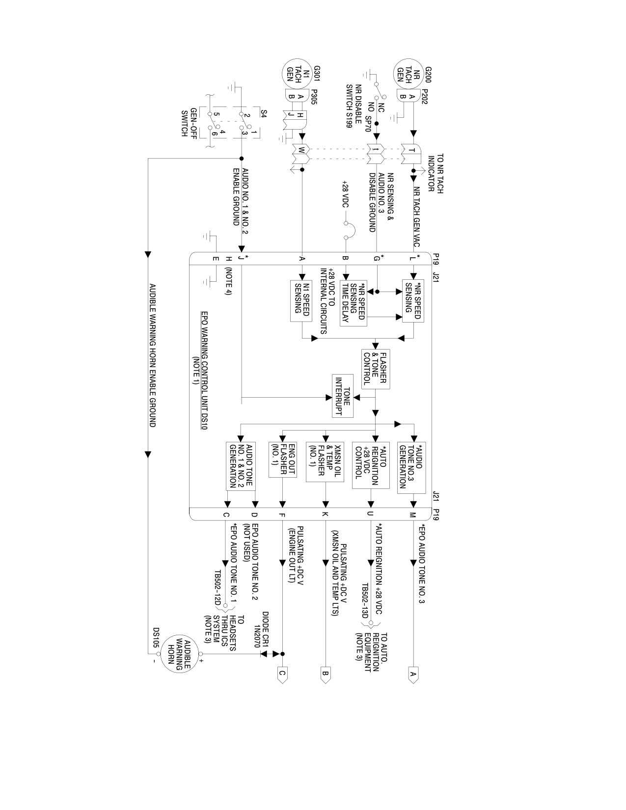
MD Helicopters, Inc.
CSP−H−2
500 Series − Basic HMI
30−208−1
Figure 17-15. N1/NR Engine Power Out Warning System Combined Simplified Block
and Schematic Diagram (Panel Type B) (Sheet 1 of 2)
Page 17-50
Revision 19
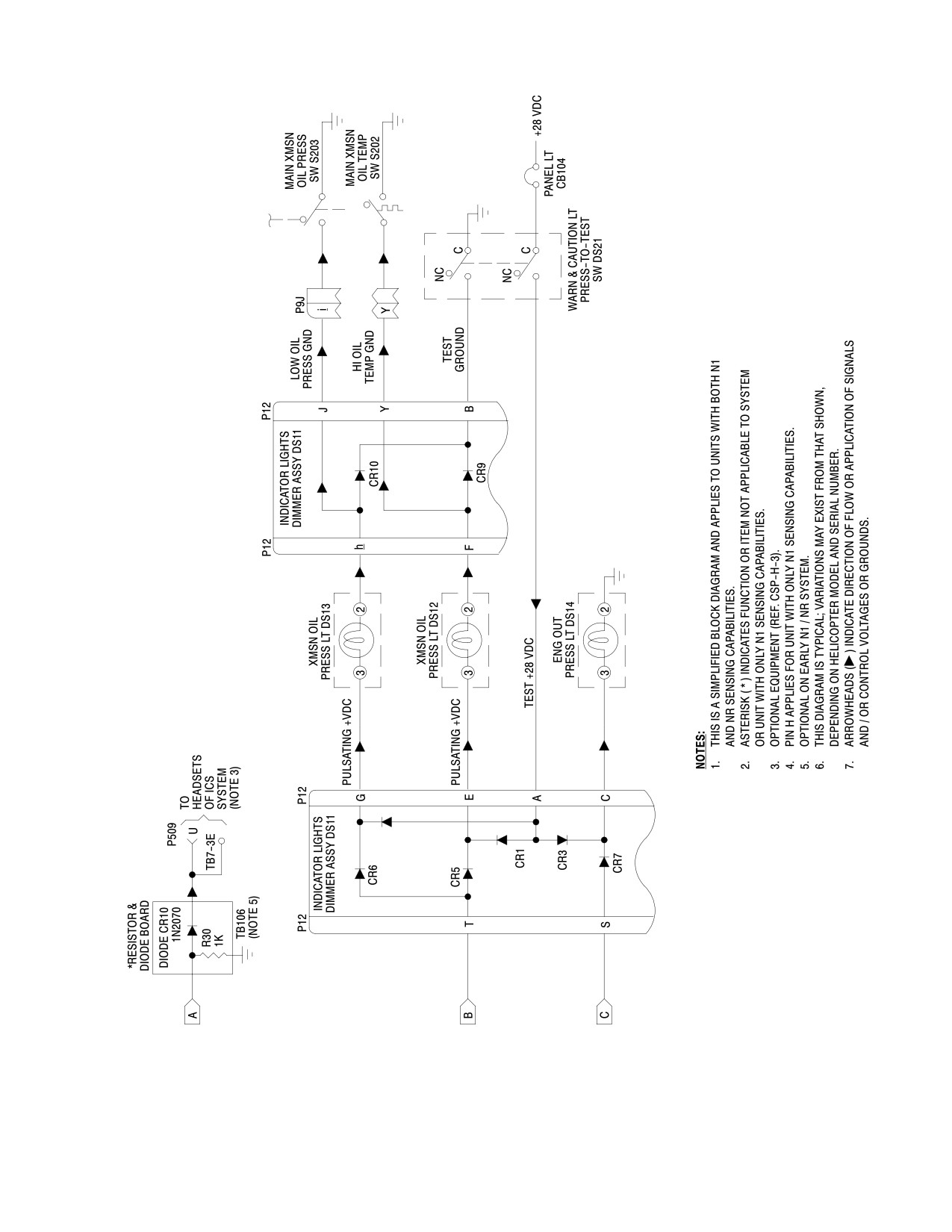
MD Helicopters, Inc.
CSP−H−2
500 Series − Basic HMI
30−208−2
Figure 17-15. N1/NR Engine Power Out Warning System Combined Simplified Block
and Schematic Diagram (Panel Type B) (Sheet 2 of 2)
Page 17-51
Revision 19
MD Helicopters, Inc.
CSP−H−2
500 Series − Basic HMI
Resistance capacitance (RC) charging and
connect the output to pins A and B of
discharging circuit components then alternate−
connector P2.
ly shut off and turn on Q9 to produce negative
NOTE: A driven tachometer generator, the
output pulses at an audio frequency of 680 to
equivalent of the Nl tachometer generator
1700 Hz for application to the external audio
and whose speed is variable and can be cor−
amplifier.
rectly regulated, may be used for the input
The generation of the output pulses is initiated
voltage source. Measuring equipment must
and interrupted at a rate of 150 ±30 times a
be sufficiently accurate.
minute by the tone generator control signal.
(6). Turn ON the helicopter electrical
Setting the generator switch to off, or an
system.
increase of engine rpm above 55% Nl, deactu−
(7). Set the ENG OUT circuit breaker to
ates the tone control signal and tone generator.
ON.
E. Transmission Oil and Temperature Light
Flasher circuits in the EPO
Flasher
CAUTION
warning unit should not be al−
(Ref. Figure 17−17) Transistors Q4, Q3, Q2
lowed to remain energized for more than 10
and associated components form the transmis−
minutes of uninterrupted operation to pre−
sion oil and temperature light flasher circuit.
vent possible internal EPO warning unit
damage.
Resistance−capacitance (RC) charging and
discharging circuit components cause Q2 and
NOTE: The engine out warning light should
Q3 to alternately turn on and turn off Q4. This
flash and the engine out audible warning
applies a pulsating dc voltage through the
horn should ‘‘beep".
dimmer unit to the lamps to make them flash
(8). Turn on the ac test voltage source and
150 ±30 times a minute, when the external
make sure that the test frequency of the
lamp circuit is closed to ground through the
ac voltage is set to the correct value (e
indicator lights dimmer assembly, lamps and
above).
fault sensor switch.
NOTE: The engine out indications, noted in
The flasher circuit continues to flash the lamps
step (7)., should cease when the correct test
until the input fault ground is removed.
frequency is applied. Any decrease of the in−
F. Vapair 26530332M EPO Warning Unit
put frequency should activate the indica−
Frequency Sensing Adjustment
tions. The indications should not be actu−
ated at any frequency above the input test
Use the following procedures to adjust sensing
frequency.
for the engine out warning light and EPO
audible warning horn ‘‘beeping".
(9). If necessary, adjust the variable
potentiometer in the EPO warning unit
(1). Turn OFF all electrical power.
to the position that the engine out
indicator light just goes out with the
(2). Remove the instrument panel right side
correct input test frequency, step (5).,
fairing for access to the EPO warning
applied.
unit.
(10). Turn OFF the ac test voltage source.
(3). Remove the cover from the installed
EPO warning unit (Figure 17−3).
(11). Set the ENG OUT circuit breaker to
OFF.
(4). Disconnect electrical wiring connector
P2 from the Nl tachometer generator.
(12). Turn off the helicopter electrical
system.
(5). With an ac voltage source, capable of
being set to provide an ac output
(13). Disconnect the ac test voltage source
voltage at a test frequency of 38.2 ±0.7
electrical leads from connector P2 and
Hz (at approximately 13.0 ±2 Vac),
reconnect P2 to the EPO warning unit.
Page 17-52
Revision 19
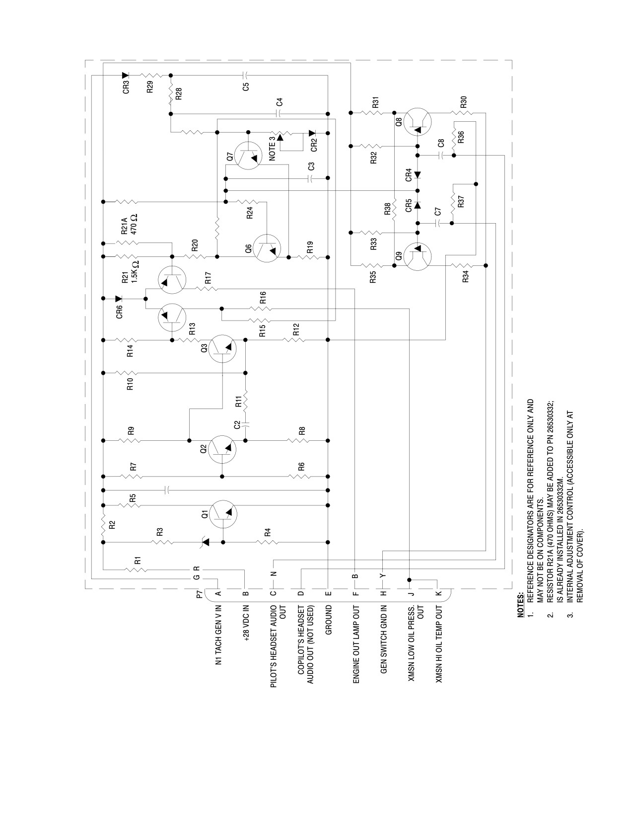
MD Helicopters, Inc.
CSP−H−2
500 Series − Basic HMI
30−165B
Figure 17-16. Vapair 26530332M Engine Power Out Warning Control Unit
Schematic Diagram
Page 17-53
Revision 19
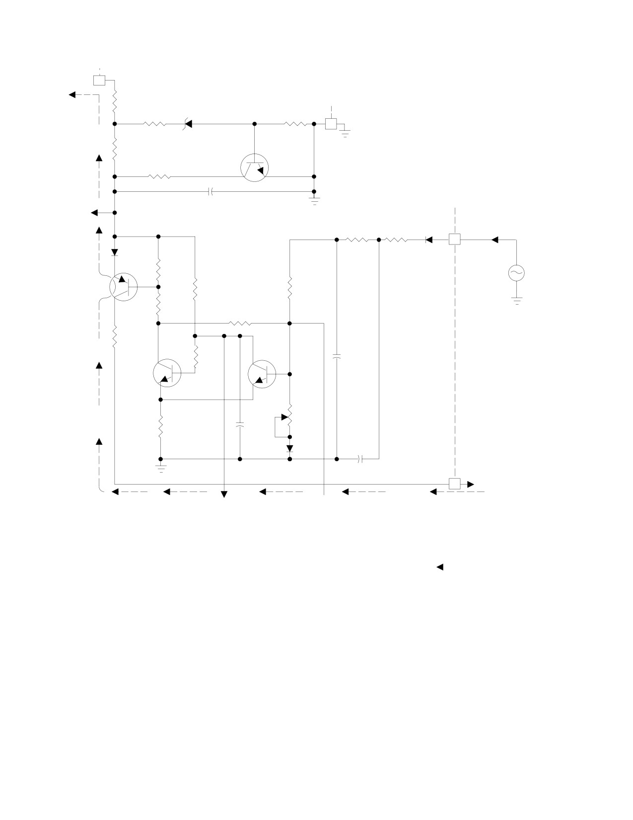
MD Helicopters, Inc.
CSP−H−2
500 Series − Basic HMI
P/O P7
+28 VDC
(FROM EPO
B
DC VOLTAGE REGULATOR
AUDIO AMP)
R1
P/O P7
CR1
R3
R4
E
NOTE 10
R2
Q1
R5
REGULATED
C1
P/O P7
+DC VOLTAGE
(SHEET 2)
N1 TACH GEN V IN
CR3
(NOTES 2, 10)
R28
R29
A
CR6
ENGINE OUT
(NOTE 1)
FREQUENCY SENSOR
R21
N1 TACH
1.5K Ω
GEN
R27
Q5
R20
R22
R17
R24
C4
Q6
Q7
FREQ
SENSE
ENGINE OUT
R26
FLASHER
C3
R19
(NOTE 9)
CR2
C5
PULSATING +DC
OUTPUT V TO
F
DIMMER UNIT (FOR
ENGINE OUT LIGHT
TONE GEN
X
AND AUDIBLE
CONTROL SIGNAL
(SHEET 2)
WARNING HORN)
(SHEET 2)
(NOTES 3, 10)
DC VOLTAGE REGULATOR AND ENGINE OUT FREQUENCY SENSOR
NOTES:
1.
CR6 IS COMMON TO EMITTER CIRCUITS OF BOTH Q4 AND Q5.
6.
DASHED LINES WITH ARROWHEAD ( − − − ) INDICATES INDICATOR
2.
INPUT FREQUENCY OF 38.2 ±0.8 HZ (AT APPRO 13.0 ±2 VAC)
LAMPS CURRENT PATH.
OR LESS ACTIVATES CIRCUIT. THIS FREQUENCY REPRESENTS
7.
ALL COMPONENTS WITH REFERENCE DESIGNATORS ARE PART
ENGINE SPEED OF 54.5 ±0.5% N1.
OF EPO UNIT UNLESS OTHERWISE INDICATED.
3.
PULSATION RATE: 150 ±30/MINUTE.
8.
REFERENCE DESIGNATORS ARE FOR REFERENCE ONLY AND MAY
4.
NEGATIVE PULSES, 0.6V PEAK−TO−PEAK ACROSS 15−OHM
NOT BE ON COMPONENTS.
RESISTIVE LOAD OR 0.7 PEAK−TO−PEAK ACROSS 300−OHM
9.
INTERNAL ADJUSTMENT. ADJUST SO THAT ENGINE OUT INDICATOR
LOAD (FREQUENCY OF 680 − 1700 HZ, INTERRUPTED 150 ±30
LIGHT JUST GOES OUT WITH INPUT SPECIFIED IN NOTE 2.
TIMES/MINUTE).
10. PATH COMPLETED BY STRAIGHT−THRU CIRCUITS IN EPO AUDIO
5.
REFER TO ELECTRICAL SYSTEM WIRING DIAGRAMS (SECTION 20)
AMPLIFIER.
FOR FAULT INPUT SOURCES AND INTERCONNECTING WIRING
INFORMATION.
30−166−1
Figure 17-17. Vapair 26530332M Warning Audio and Light Flashing Control
Circuit (Sheet 1 of 2)
Page 17-54
Revision 19
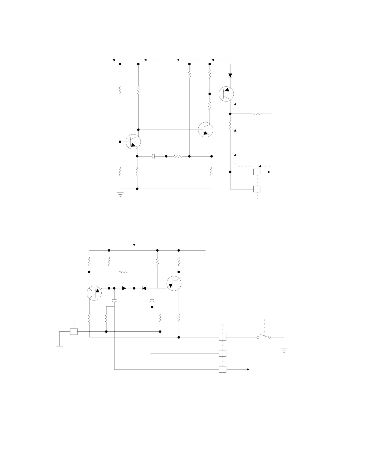
MD Helicopters, Inc.
CSP−H−2
500 Series − Basic HMI
NOTES: (CONT)
11. ABBREVIATIONS:
REGULATED
AMP − AMPLIFIER
+DC VOLTAGE
FREQ − FREQUENCY
(SHEET 1)
R10
R14
CR6
GEN − GENERATOR
(NOTE 1)
P/O − PART OF
XMSN − TRANSMISSION
R7
R9
Q4
R13
R15
X (SHEET 1)
R16
Q3
Q2
C2
R11
PULSATING +DC VOLTAGE TO
DIMMER UNIT
R6
R8
R12
K
(FOR XMSN OIL AND TEMP LIGHT)
(NOTES 3, 10)
J
NOT USED
XMSN OIL AND TEMP LIGHT FLASHER
P/O
P7
TONE GEN
CONTROL SIGNAL
(SHEET 1)
REGULATED
+DC VOLTAGE
(SHEET 1)
R35
R33
R34
R31
R38
CR5
CR4
COPILOT’S AUDIO
TONE GEN
PILOT’S AUDIO
Q8
TONE GEN
Q9
C7
C6
P/O
P/O GEN
P/O
SWITCH
P7
R34
R37
R36
R30
P7
OFF
E
GND IN
H
NOTE 10
(NOTE 10)
ON
COPILOT’S AUDIO TONE
D
SIGNAL OUT (NOT USED)
PILOT’S AUDIO TONE SIGNAL OUT TO
C
EPO AUDIO AMP AND HEADSET(S)
(NOTE 4)
AUDIO TONE SIGNAL GENERATORS
30−166−2B
Figure 17-17. Vapair 26530332M Warning Audio and Light Flashing Control
Circuit (Sheet 2 of 2)
Page 17-55
Revision 19
MD Helicopters, Inc.
CSP−H−2
500 Series − Basic HMI
(14). Reinstall the cover on the EPO warning
Internal circuits are located on two circuit
unit.
boards inside a case under a removable cover.
The unit provides pulsating output dc voltage
(15). Install the instrument panel right side
for the engine out (ENG OUT) warning light
fairing.
indicator and audible warning horn, at engine
G. Vapair 26530332M EPO Warning Unit
speed of approximately 55% Nl rpm (with an
Repair
ac input frequency less than 36.75 ±1.75 Hz
from the Nl tachometer generator).
Replace defective circuit components as
The unit does not contain a frequency sensing
necessary in the EPO warning unit. Refer to
adjustment control.
the functional information and troubleshooting
data for the EPO warning unit to locate and
The pulsating output dc voltage for flashing
isolate defective internal components.
the ENG OUT warning lamps and sounding
the warning horn is rated at 0.20 ampere, 28
H. Vapair 26530332M EPO Warning Control
volts, 120−180 pulses per minute with an on
Unit Replacement
time of 50 ±15% of the period.
(1).
Check that all electrical power is OFF
The unit also furnishes separate pulsating
and remove right instrument panel
output dc voltages, identical to that for the
fairing.
ENG OUT warning lamps, to flash the main
transmission oil pressure and temperature
(2).
Disconnect electrical plug to control
(XMSN OIL PRESS and TEMP) warning
unit from audio amplifier and remove
lights when associated sensing switches are
amplifier from control unit case; then
actuated.
remove the four mounting screws and
washers, and lift out the control unit.
Audio tone generation and amplification
circuits provide an audio tone output level
(3).
Position replacement control unit and
sufficient for earphones of headsets without
install attaching hardware. Mount the
use of an external audio amplifier.
audio amplifier support clip with the
Internal adjustment controls permit setting
upper aft screw of the control unit case.
the level of the audio tone outputs.
(4).
Connect electrical plug to control unit,
Figure 17−18 is a schematic diagram of the
turn on power and check that the red
Autronics EPO warning unit.
warning lights flash. Turn on generator
switch and listen in headset for warn−
The following information describes differ−
ing signal beeping. When flashing and
ences in EPO operation from the Vapair unit.
audio signals are present, turn off
A. Engine Power Out Warning Circuits
switches and power. When control unit
does not function properly, check
The EPO warning unit contains engine out
warning circuits for continuity and
frequency sensing, warning lights flasher,
proper connection according to
audio tone generation and dc voltage regulator
Figure 17−16 and to the wiring dia−
circuits.
grams, Section 20.
Figure 17−19 is a breakdown of the Autronics
(5).
Reinstall instrument panel fairing.
EPO warning unit overall schematic diagram
and shows circuits separately by functions.
22. Autronics 2146-5 Engine Power Out
See the electrical system wiring diagram in
(EPO) Warning Control Unit
Section 20 for interconnection wiring informa−
tion on the warning lights indicating system.
The Autronics 2146−5 engine power out (EPO)
warning control unit is a solid state device
B. Engine Out Frequency Sensing Circuits
similar in function to the
(Ref. Figure 17−19) Engine out frequency
Vapair EPO warning control unit’s internal
sensing circuits consist of input gate and
circuit differences are as follows:
engine speed sensing circuits.
Page 17-56
Revision 19
MD Helicopters, Inc.
CSP−H−2
500 Series − Basic HMI
In the input gate circuits, diode CR3 rectifies
When present, drive current from the under−
the positive portion of the input ac voltage
speed switch Q10 causes unijunction tone
from the N1 tachometer generator for amplifi−
oscillator Q12 to provide a tone signal for
cation by series connected sense amplifiers Q7
amplification by tone oscillator amplifier Q13,
and Q8.
if a ground is applied to diode CR6 from the
external generator switch.
When the time interval of the rectified and
amplified input is longer than one−half the
Q10 drive current also causes tone interrupter
period of one cycle of the unijunction speed
Q14 to alternately enable and interrupt
sensing oscillator Q9, a pulsating output is
application of the amplified tone signal from
produced by Q9, is amplified by sensing
Q13 to audio #1 and #2 amplifiers Q15 and
oscillator amplifier Q11 and is applied to
Q16. Q15 and Q16 amplify the interrupted
underspeed switch Q10 of the engine speed
audio tone to a sufficient level for headsets
sensing circuits.
without additional external amplification.
Q10 drives the engine out and transmission
An internal audio tone level control in both the
lights flasher circuits and supplies dc power to
#1 and #2 audio amplifier circuits permits
the audio tone circuits.
adjustment of output tone audio level.
Sense oscillator and amplifier circuits are
supplied dc power from the dc voltage regula−
The amplified interrupted audio tone from Q15
tor circuit.
is applied to earphones of headsets.
C. Engine Out and Transmission Lights
Turning the generator switch off disables the
Flasher Circuits
audio tone circuits.
(Ref. Figure 17−19) Unijunction flasher
Output from Q16 is not used in the standard
oscillator Q1 operates continuously supplying
electrical system configuration.
a pulsating signal for amplification by flasher
oscillator amplifier Q3 to drive both engine out
and transmission lights flasher circuits.
E. Audio Tone Output Level Adjustment -
Autronics 2146-5 EPO Warning Control
Unit
Transmission light flasher driver Q2 applies
the pulsating signal to flasher amplifier Q4
that amplifies the pulsating signal to flash
When necessary, or after replacement of the
parallel connected main transmission oil
EPO warning control unit, adjust audio tone
pressure and temperature warning lights
output level for earphones of headsets as
indicators through associated sensing
follows.
switches.
(1). Be sure that a headset is connected to a
Engine out flasher driver Q5 and amplifier Q6
radio/intercom station and that any
function in the same manner to flash the
installed interphone equipment is
engine out warning lamps and drive the
functioning normally.
audible engine out warning horn, except Q5
drives Q6 to amplify the pulsating signal only
when drive is present from underspeed switch
(2). Check that all electrical power is OFF.
Q10.
(3). With right instrument panel fairing
D. Audio Tone Circuits
removed from instrument console,
remove cover from EPO warning
(Ref. Figure 17−19) Audio tone circuits consist
control unit and be sure that electrical
of audio generation, interrupter and amplifica−
wiring harness is connected to the
tion circuits.
warning control unit.
Page 17-57
Revision 19
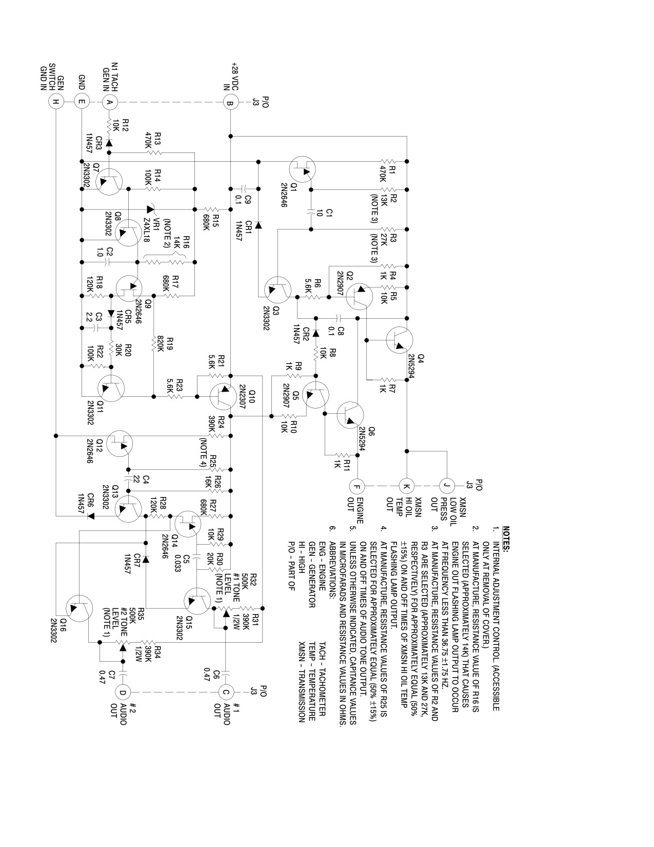
MD Helicopters, Inc.
CSP−H−2
500 Series − Basic HMI
30−194
Figure 17-18. Autronics 2146-5 Engine Power Out Warning Control Unit Schematic Diagram
Page 17-58
Revision 19
MD Helicopters, Inc.
CSP−H−2
500 Series − Basic HMI
(4).
Turn electrical power ON. Check that
G. Autronics 2146-5 EPO Warning Control
WARNING AND PANEL lights and
Unit Replacement
ENG OUT circuit breakers are reset
(1). Check that all electrical power is OFF.
(in) and that generator switch is set to
GEN.
(2). Remove right instrument panel fairing
from instrument console.
(5).
Check that red warning light indicators
for ENG OUT and low XMSN OIL
(3). Disconnect electrical wiring harness
PRESS are flashing, that audible
connector from EPO warning unit that
warning horn is ‘‘beeping" and that
is mounted on inboard side of instru−
audible warning tone is present in
ment console.
headset. This should occur when engine
(4). Remove attaching hardware and EPO
is not operating.
warning unit from instrument console.
(6).
Set generator switch OFF to disable the
(5). Install replacement EPO warning unit
audible warning horn while completing
on right panel of instrument console in
the adjustment.
reverse order of removal.
(6). Turn on electrical power and check that
(7).
While listening with a headset, adjust
the red ENG OUT and OIL PRESS
#1 audio tone level control R32 inside
warning lights flash. Set generator
the EPO warning unit for adequate and
switch to GEN and listen to audible
desired warning tone audio level in
warning horn for audible ‘‘beeping" and
earphone. Be sure that the tone audio
headset for audible tone signal. When
level is present and adequate with
flashing and audio warning signals are
controls on any installed interphone
present, turn OFF switches and power.
audio equipment at normal operating
settings.
NOTE: If control unit does not function proper−
ly, check interconnection wiring for continu−
(8).
Set generator switch to GEN to enable
ity and proper connection according to wir−
the audible warning horn.
ing diagram in Section 20 and check
internal circuits according to Figure 17−18.
(9).
Set the generator switch OFF and
(7). If necessary, adjust #1 audio tone
verify that audible warning horn stops
output level from EPO warning unit for
‘‘beeping", audible warning tone is no
headsets.
longer present in the headset and that
ENG OUT and XMSN OIL PRESS
(8). Reinstall the right instrument panel
warning indicator lights continue to
fairing.
flash.
Application of a disable ground to the unit
(10).
Turn all electrical power OFF.
cause the disable circuits to deactivate NR
sensing which prevents the warning indica−
(11).
Reinstall cover on EPO warning control
tions while the disable ground is applied.
unit, connect electrical connector to
The time delay keeps NR sensing disabled for
warning control unit and install right
3.5 ±0.5 seconds after removal of the disable
instrument panel fairing on instrument
ground.
console.
Engine low N1 speed sensing, and engine out
F. Autronics 2146-5 EPO Warning Control
flashing light and audible warning horn
Unit Repair
activation, control and generation circuits
function similarly for low N1 rpm sensing
Replace defective circuit components as
similarly to those of the Autronics 2146−5;
necessary in the EPO warning unit. Refer to
except low N1 speed sensing occurs at 55% N1
the functional information and troubleshooting
rpm (equivalent to tachometer generator ac
data for the EPO warning unit to isolate
output voltage with a frequency of 36.75 ±1.75
defective internal components.
Hz) or less.
Page 17-59
Revision 19
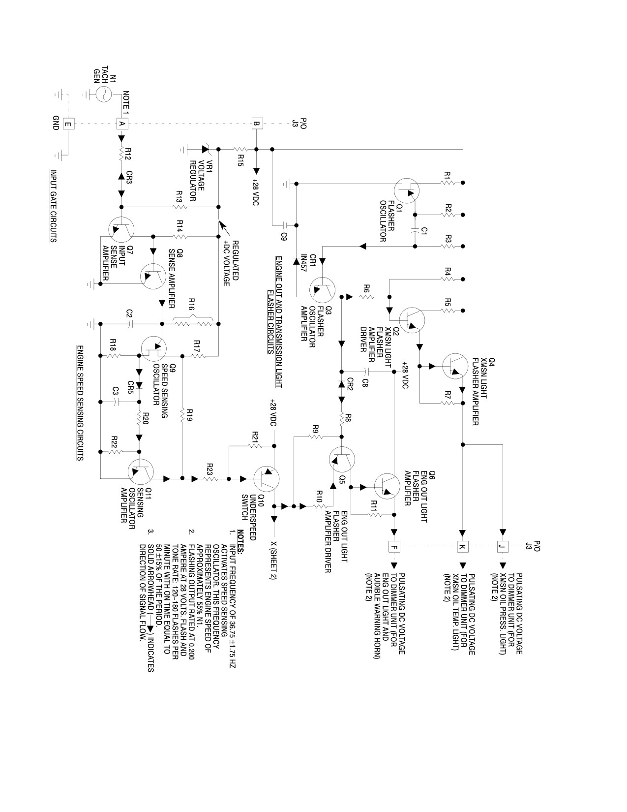
MD Helicopters, Inc.
CSP−H−2
500 Series − Basic HMI
30−195−1
Figure 17-19. Autronics 2146-5 Warning Audio and Lights Flashing Control
Circuit (Sheet 1 of 2)
Page 17-60
Revision 19