CSP-H-2 BASIC HANDBOOK OF MAINTENANCE INSTRUCTIONS FOR MDHI 369H HELICOPTERS - page 8
MD Helicopters, Inc.
CSP−H−2
500 Series − Basic HMI
(b). Install contact pattern shim(s)
on the transmission. A damper located near
removed at disassembly, and gear−
the center of the shaft maintains a minimum
shaft in housing. Heat output hous−
vibrations level in the tail rotor drive system.
ing bore using heat gun or blow dryer
until gearshaft bearing retainer
A. Tail Rotor Drive Shaft Removal
assembly fits easily into housing.
(Ref. Figure 9−13 and Figure 9−14)
(c). Install clamp−up shim removed at
(1). Remove (or open) tail rotor drive shaft
disassembly and output gearshaft
access doors.
cover assembly ( Ref. CSP−H−5).
(2). Remove three bolts and washers that
(7). Install tail rotor and pitch control
secure shaft to output gearshaft
assembly (Ref. Sec. 8).
coupling on main transmission.
(8). Fill tail rotor transmission with
approved lubricant (Ref. Sec. 2).
(3). Disconnect chip detector wiring from
tail rotor transmission.
G. Protective Sleeve (Speedi-Sleeve)
Replacement, Output Gearshaft
(4). Detach Sta. 282 bellcrank from tail
rotor transmission.
(Ref. Figure 9−16) Replace a worn protective
sleeve (Speedi−Sleeve PN 084957) on the
(5). Remove lockwire, bolts and washers
output gearshaft as follows:
that attach tail rotor transmission to
tailboom.
Use care not to cut into or dam−
CAUTION
age gearshaft when removing
To prevent damage to the gear−
CAUTION
damaged sleeve. Do not allow filings or oth−
box coupling during and after
er contaminants to enter shaft bearings.
removal, provide good level support for both
the transmission and tail rotor, as the
(1). Remove output gearshaft from tail rotor
weight of these items might buckle the cou−
transmission.
pling.
(2). Use file or other suitable instrument to
(6). With help from an assistant in guiding
cut through edge of sleeve; carefully pry
the shaft through the damper, remove
cut edge away from shaft.
tail rotor driveshaft as an assembly.
(3). Grasp raised edge with pliers and peel
Slowly and carefully slide the assembly
damaged sleeve off shaft.
aft until drive shaft clears the tailboom.
(4). Remove any plastic steel residue from
(7). Support assembly along its entire
shaft using dry cleaning solvent (1,
length, remove the three gearbox
Table 2−4); dry shaft with clean, lint
coupling bolts and washers, and remove
free cloth.
drive shaft from gearbox.
(5). Install replacement sleeve on shaft
Do not carry or otherwise sup−
CAUTION
(Ref. Protective Sleeve (Speedi−Sleeve)
port the gearbox by use of the
Installation, Output Gearshaft.
coupling. Use care with removal tools to pre−
vent scratching coupling.
10. Tail Rotor Drive Shaft
B. Tail Rotor Drive Shaft Installation with
(Ref. Figure 9−13 and Figure 9−14) The tail
Kamatics Couplings
rotor drive shaft interconnects the main
transmission and the tail rotor transmission.
(Ref. Figure 9−13) Whenever main transmis−
The shaft is a dynamically balanced and
sion, tail rotor transmission, transmission
positively dampened aluminum alloy tube,
couplings, coupling shims, tail rotor drive shaft
approximately 13 feet (4 M) long, that rotates
or tailboom assembly have been replaced, start
at 2,045 rpm. Identical mounting flanges,
installation with step (1). If none of these
riveted to each tapered end of the tube,
components has been replaced, and only
connect the shaft to the flexible joint couplings
installation is involved, start with step (5).
Page 9-47
Revision 17
MD Helicopters, Inc.
CSP−H−2
500 Series − Basic HMI
NOTE:
inch−pounds (8.47 − 10.73 Nm) plus
drag torque.
D Kamatic coupling to not require failsafe
bolts and sockets.
(7). Align forward end of drive shaft with
D When installing 369D25501− 9 Kamatic
coupling on main transmission output
coupling, install SKCP2554−15 or
gearshaft. Partially install two bolts as
369D25503−1 coupling bolt supplied with
an alignment aid but do not tighten.
the Kamatic coupling.
Align drive shaft inspection markings.
If any of four white stripes is indistinct
D If tail rotor drive shaft is replaced for tor−
or does not exist, paint replacement
sional buckling, replace and discard main
stripes.
transmission output gearshaft coupling,
tail rotor gearbox coupling and both cou−
(8). Obtain 0.010−0.020 inch (0.254−0.508
pling bolts.
mm) gap between forward flange of tail
rotor drive shaft and flange of forward
(1).
Coat coupling splines with grease (21,
coupling using using the following
Table 2−4) and coupling bolt threads
procedure:
with anti−seize compound (36) before
assembly. Install coupling onto tail
(a).
Ensure alignment bolts in previous
rotor gearbox and torque coupling bolt
step are backed off between
to 250 − 300 inch−pounds (28.25 −
0.050−0.100 inch (1.27−2.54 mm).
33.90 Nm) plus drag torque. Check
coupling bolt for drag torque service−
(b).
Remove end play in tail rotor trans−
ability of 25 inch−pounds (2.82 Nm)
mission by applying force to tail rotor
minimum, 200 inch−pounds (22.60
blades in opposite direction of
Nm) maximum.
operation rotation while holding
forward coupling of tail rotor drive
(2).
Coat forward coupling splines with
shaft on main transmission to
grease (21) and coupling bolt threads
prevent rotation. Do not push tail
with anti−seize compound (36) before
rotor drive shaft fore or aft.
assembly. Install coupling onto tail
rotor gearbox and torque coupling bolt
(c).
Using feeler gage, measure gap
to 250 − 300 inch−pounds (28.25 −
between forward coupling flange and
33.90 Nm) plus drag torque. Check
flange of tail rotor drive shaft. Record
coupling bolt for drag torque service−
the gap.
ability of 25 inch−pounds (2.82 Nm)
(d).
With assistance, remove tail rotor
minimum, 200 inch−pounds (22.60
transmission and driveshaft in line
Nm) maximum.
for minimum deflection of coupling.
(3).
Support entire length of tail rotor drive
(e).
Using measured gap from step (c).
shaft and position end stamped AFT to
above, add or remove required
align with tail rotor transmission
number of shims at main transmis−
coupling.
sion between output pinion shaft and
forward coupling to obtain specified
(4).
Install three bolts and washers to
gap of 0.010−0.020 inch (0.254−0.508
connect tail rotor gearbox coupling to
mm).
shaft; torque bolts to 80 − 100 inch−
pounds (9.04 − 11.30 Nm) plus drag
(9). Coat forward coupling splines with
torque.
grease (21) and coupling bolt threads
with antiseize compound (36) before
(5).
With assistance, support transmission
assembly. Install coupling and torque
and shaft in line, for minimum deflec−
coupling bolt to 250 − 300 inch−
tion of coupling, and guide drive shaft
pounds (28.25 − 33.90 Nm) plus drag
carefully through tailboom and damper
torque. Check coupling bolt for drag
into position.
torque serviceability of 25 inch−
(6).
Install four tail rotor mounting bolts
pounds (2.82 Nm) minimum, 200
with washers and torque to 75 − 95
inch−pounds (22.60 Nm) maximum.
Page 9-48
Revision 17
MD Helicopters, Inc.
CSP−H−2
500 Series − Basic HMI
(10). With assistance, support transmission
(16). Check transmission oil level and service
and shaft in line for minimum deflec−
as required (Ref. Sec. 2).
tion of coupling and guide drive shaft
carefully through tailboom and damper
(17). Slowly rotate drive shaft and check for
into position.
not less than 0.250 inch (6.35 mm)
clearance between shaft and fairing
NOTE: If in use, four AN174H−17A bolts are to
tube at Sta. 137.50. In addition, check
be replaced with either NAS1304− 24H or
for minimum clearance of 0.190 inch
− 26H bolts to provide increased tail rotor
(4.826 mm) between shaft and cooling
transmission to tailboom mounting frame
blower scroll.
attachment strength (check bolt hole depth
for proper bolt installation). The gearbox
(18). Install all access doors and covers.
mounting bolt washers are 5052 aluminum
alloy (NAS1197−416) and are used specifi−
C. Tail Rotor Drive Shaft Installation with
cally for corrosion protection. When new, the
Bendix Couplings
outside edge is painted orange for identifica−
tion.
(Ref. Figure 9−14) Whenever main transmis−
sion, tail rotor transmission, transmission
(11). Measure bolt holes for proper bolt
couplings, coupling shims, tail rotor drive shaft
installation as follows:
or tailboom assembly have been replaced, start
installation with step (1). If none of these
(a). Fabricate a tool for measuring bolt
components has been replaced, and only
hole depth.
installation is involved, start with step (7).
(b). Install three gearbox mounting bolts
NOTE: If tail rotor drive shaft is replaced for
and lightly tighten bolts.
torsional buckling, replace and discard
main transmission output gear shaft cou−
(c). Measure depth of remaining bolt hole
pling and tail rotor gearbox coupling.
to determine proper bolt length.
(1). Remove existing shims and install one
(d). Remove bolts and proceed with
0.010 inch (0.254 mm) shim on tail
following steps.
rotor transmission input shaft. Coat
coupling splines with grease (21,
(12).
Apply primer (4) to the four gearbox
Table 2−4) and coupling failsafe bolt
mounting bolts. Install bolts and
threads with anti−seize compound (36)
aluminum washers while primer is still
before assembly. Install coupling and
wet: torque evenly to 75 − 95 inch−
torque failsafe coupling bolt to 250 −
pounds (8.47 − 10.73 Nm) plus drag
300 inch−pounds (28.25 − 33.90 Nm)
torque.
plus drag torque. Check coupling bolt
for drag torque serviceability of 25
(13).
Install three bolts and washers at
inch−pounds (2.82 Nm) minimum,
forward coupling; torque bolts to 80 −
200 inch−pounds (22.60 Nm) maxi−
100 inch−pounds (9.04 − 11.30 Nm)
mum.
plus drag torque.
(14).
Connect electrical wire to tail rotor
(2). Determine shim thickness required at
transmission chip detector. Torque nut
forward flexible coupling:
to 12 − 15 inch−pounds (1.36 − 1.69
Nm).
Bottom the flexible coupling by
CAUTION
holding at the
1.370 inch
(15).
Coat pin of Sta. 284.00 bellcrank with
(3.4798 cm) OD of coupling. Do not bottom
grease (18) and insert it into bearing in
coupling by pushing on drive shaft attach
tail rotor pitch control. Pivot bellcrank
flange; doing so may damage coupling.
to align with mating hole in tail rotor
transmission and install bolt, washers
(a). Bottom forward coupling on main
and nut and cotter pin (Ref. Sec. 8).
transmission output shaft.
Page 9-49
Revision 18
MD Helicopters, Inc.
CSP−H−2
500 Series − Basic HMI
(b). Measure gap between end of flexible
tion of coupling, and guide drive shaft
coupling and shoulder of output
carefully through tailboom and damper
shaft. Add 0.005 inch (0.127 mm) to
into position.
gap measured. This is the minimum
shim thickness required at the
(8). Install four tail rotor gearbox mounting
forward coupling, to prevent coupling
bolts with washers and; torque to 75 −
from bottoming on output shaft.
95 inch−pounds (8.47 − 10.73 Nm)
plus drag torque.
(c). Install minimum shim thickness on
main transmission output shaft.
(9). Align forward end of drive shaft with
coupling on main transmission output
(d). Measure step between aft end of
gearshaft. Partially install two bolts as
output shaft and shoulder of cou−
an alignment aid but do not tighten.
pling, by bottoming coupling against
Align drive shaft inspection markings.
shims. (Ref. CAUTION above)
If any of four white stripes is indistinct
or does not exist, paint replacement
NOTE: Maintain minimum 0.010 inch (0.254
stripes.
mm) step between aft end of output shaft
and coupling shoulder to prevent coupling
(10). Obtain 0.010−0.020 inch (0.254−0.508
bolt from bottoming on output shaft.
mm) gap between forward flange of tail
rotor drive shaft and aft end of failsafe
(e). Install additional shims to maintain
socket using the following procedure:
0.010 inch (0.254 mm) minimum step
as required.
(a).
Ensure alignment bolts in previous
step are backed off between
(3).
Position failsafe socket on aft face of
0.050−0.100 inch (1.27−2.54 mm).
forward coupling so that three of the
nine holes are indexed to the three
(b).
Remove end play in tail rotor trans−
nutplates of the coupling in such a way
mission by applying force to tail rotor
that maximum clearance is obtained
blades in opposite direction of
between the bolt key and socket.
operational rotation (while holding
Visually verify proper clearance before
forward coupling of tail rotor drive−
in stalling tail rotor drive shaft.
shaft on main transmission output
shaft to prevent rotation). Do not
(4).
Repeat previous step to install failsafe
push tail rotor drive shaft fore or aft.
socket on input coupling of tail rotor
transmission.
(c).
Using feeler gage, measure gap
between socket flange and flange of
(5).
Support entire length of tail rotor drive
tail rotor drive shaft. Socket flange
shaft and position end stamped AFT to
must be in full contact with flange of
align with tail rotor transmission
forward flexible coupling. Record the
coupling.
gap.
(6).
Install three bolts and washers to
(d).
With assistance, remove tail rotor
connect tail rotor transmission coupling
transmission and driveshaft, sup−
to shaft; torque bolts to 80 − 100
porting transmission and driveshaft
inch−pounds (9.04 − 11.30 Nm) plus
in line for minimum deflection of
drag torque.
coupling.
When reinstalling tail rotor
(e).
Using measured gap from step (c).
CAUTION
transmission and drive shaft, do
above, add or remove required
not compress the forward or aft couplings as
number of shims at main transmis−
damage to the couplings could result.
sion between output shaft and
forward coupling to obtain specified
(7). With assistance, support transmission
gap of 0.010−0.020 inch (0.254−0.508
and shaft in line, for minimum deflec−
mm).
Page 9-50
Revision 18
MD Helicopters, Inc.
CSP−H−2
500 Series − Basic HMI
NOTE:
(b). Install three gearbox mounting bolts
and lightly tighten bolts.
D Maintain minimum 0.010 inch (0.254
mm) step between coupling shoulder and
(c). Measure depth of remaining bolt hole
output shaft (step (2).).
to determine proper bolt length.
D Shim, 0.010 inch (0.254 mm), installed in
(d). Remove bolts and proceed with
step (1). may be removed from aft cou−
following steps.
pling if necessary. If less than specified
gap, 0.010−0.020 inch (0.254−0.508 mm),
(14).
Apply primer (4) to the four gearbox
exists under minimum shim require−
mounting bolts. Install bolts and
ments, install a maximum of one
aluminum washers while primer is still
NAS1197− 416 washer between gearbox
wet; torque evenly to 75 − 95 inch−
housing and boom fitting. Apply zinc
pounds (8.47 − 10.73 Nm) plus drag
chromate primer (4) to both sides of wash−
torque.
er at installation. After washer installa−
(15).
Install three bolts and washers at
tion, repeat steps (10). (a). thru (e).
forward end of tail rotor drive shaft to
D If adding a washer between gearbox and
connect to forward coupling; torque
boom fitting, it may be necessary to
bolts to 80 − 100 inch−pounds (9.04 −
install a longer bolt. Ensure proper bolt
11.30 Nm) plus drag torque.
thread engagement while ensuring that
(16).
Connect electrical wire to tail rotor
bolt does not shank out.
transmission chip detector. Torque nut
to 12 − 15 inch−pounds (1.36 − 1.69
(11). Coat forward coupling splines with
grease (21) and coupling bolt threads
Nm).
with anti−seize compound (36) before
(17).
Coat pin of Sta. 284.00 bellcrank with
assembly. Install coupling and torque
grease (18) and insert it into bearing in
failsafe coupling bolt to 250 − 300
tail rotor pitch control. Pivot bellcrank
inch−pounds (28.25 − 33.90 Nm) plus
to align with mating hole in tail rotor
drag torque. Check coupling bolt for
transmission and install bolt, washers,
drag torque serviceability of 25 inch−
nut and cotter pin (Ref. Sec. 8).
pounds (2.82 Nm) minimum, 200
inch−pounds (22.60 Nm) maximum.
(18).
Check transmission oil level and service
as required (Ref. Sec. 2).
(12). With assistance, support tail rotor
(19).
Slowly rotate drive shaft and visually
transmission and shaft in line for
check to ensure shaft is not bent and for
minimum deflection of coupling and
not less than 0.250 inch (6.35 mm)
guide drive shaft carefully through
clearance between shaft and fairing
tailboom and damper into position.
tube at Sta. 137.50. In addition, check
NOTE: If in use, four AN174H−17A bolts are to
for minimum clearance of 0.190 inch
be replaced with either NAS1304− 24H or
(4.826 MM) between shaft and cooling
− 26H bolts to provide increased tail rotor
blower scroll.
transmission to tailboom mounting frame
(20).
Install all access doors and covers.
attachment strength (check bolt hole depth
for proper bolt installation). The gearbox
D. Tail Rotor Drive Shaft Twist Inspection
mounting bolt washers are 5052 aluminum
(Ref. Figure 9−17) The following inspection
alloy (NAS1197−416) and are used specifi−
determines if the drive shaft has been torsion−
cally for corrosion protection. When new, the
ally strained to the extent that permanent
outside edge is painted orange for identifica−
twist exists.
tion.
(1). Remove left side aft fairing access door;
(13). Measure bolt holes for proper bolt
then hand turn main rotor until two
installation as follows:
white stripes (View A) are aligned.
(a). Fabricate a tool for measuring bolt
(2). At tail rotor transmission, look inboard
hole depth.
from tail rotor side of helicopter and
Page 9-51
Revision 18
MD Helicopters, Inc.
CSP−H−2
500 Series − Basic HMI
locate two white stripes (View B). Stripe
(9). Apply white index stripe 0.120 inch
on input shaft bearing retainer flange
(3.048 mm) wide and 0.50 inch (12.7
of tail rotor transmission is located at
mm) long on boom fairing bulkhead
approximately 2 O’clock, looking aft.
doubler (Sta. 137.50) at approximately
Stripe on coupling should be approxi−
6−8 O’clock position looking forward.
mately 10 O’clock, looking forward.
(10). Apply a corresponding joining index
Both stripes should be aligned.
stripe on the tail rotor drive shaft at
NOTE: Any time the associated tail rotor drive
Sta. 137.50. approximately 0.120 inch
shaft units are removed or replaced, an in−
(3.048 mm) wide and 0.50 inch (12.7
dexing check and reapplication of index
mm) long.
marks is required.
NOTE: Any time the associated tail rotor drive
E. Tail Rotor Drive Shaft Index Stripe
shaft units are removed or replaced, an in−
Application
dexing check and re− application of index
marks is required.
(Ref. Figure 9−17) If any of four white stripes
used for inspection of tail rotor drive shaft
(11). Install all access doors and covers.
twist are indistinct or do not exist, paint
replacement aligning index stripes (128,
F. Tail Rotor Drive Shaft Inspection
Table 2−4) as follows:
(1). Inspect a removed shaft by the follow−
(1). Remove tail rotor drive shaft, tail rotor
ing indications:
transmission as an assembly.
(a). Scratches in the shaft section that
To prevent damage to the gear−
CAUTION
passes through the plenum chamber
box coupling during and after
fairing tube. Such scratches indicate
shaft removal, provide good level support for
possible contact with the tube edges
both the tail rotor transmission and shaft,
at the bulkhead openings.
as the weight of these items might buckle
the coupling.
(b). Evidence of torsional buckling or
(2).
Inspect tail rotor drive shaft for
shaft bending as a result of blade
evidence of torsional twist or buckling.
strike or hard ground contact by the
lower stabilizer (tail low, hard
(3).
Remove any old index stripes.
landing).
(4).
Apply white index stripe 0.120 inch
(c). Corrosion.
(3.048 mm) wide and approximately
0.250 inch (6.35 mm) long on the tail
(d). Evidence of shaft damper sleeve bond
rotor transmission input shaft bearing
failure (sleeve shifting) from exces−
retainer flange at approximately 10
sive heat or loads.
O’clock position looking forward, so it
will be seen when standing on the left
(2). Take the following action with shafts
of tail rotor.
having the above indications:
(5).
Apply white index stripe 0.120 inch
(a). Replace shafts for bending, or for
(3.048 mm) wide and any length on the
scratches that exceed limits.
coupling inline with the index stripe on
tail rotor gearbox retainer.
(b). Repair corrosion.
(6).
Install tail rotor drive shaft.
(3). If there is abnormal shaft vibration,
check damper friction and shaft
(7).
Align index stripes on tail rotor gearbox
straightness or runout. When rotated
bearing retainer and aft coupling.
between centers, or with ends plugged
(8).
Remove tail rotor bellcrank access door
and rolled over rollers, the runout of
fairing and observe the area where tail
the large diameter must not exceed
rotor drive shaft passes through the
0.060 inch (1.524 mm) tir (permissible
fairing forward bulkhead.
dents exclude).
Page 9-52
Revision 18
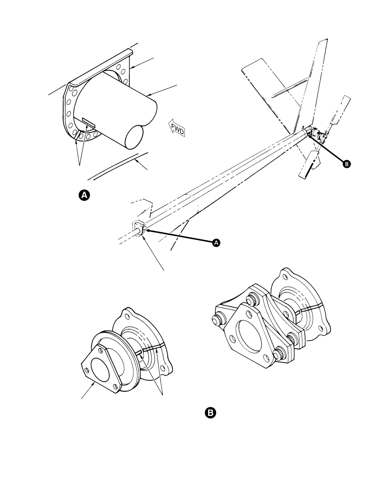
MD Helicopters, Inc.
CSP−H−2
500 Series − Basic HMI
DOUBLER
TAIL ROTOR
DRIVE SHAFT
WHITE STRIPES
STA. 137.50 RING
STA. 137.50 (LOOKING FORWARD)
STA. 137.50
NEW CONFIGURATION
WHITE STRIPES
COUPLING
EARLY CONFIGURATION
30-080B
Figure 9-17. Drive Shaft Twist Check
Page 9-53
Revision 18
MD Helicopters, Inc.
CSP−H−2
500 Series − Basic HMI
G. Tail Rotor Drive Shaft Repair
spring−loaded against a structural support
bracket mounted on the aft section tailboom
(1). Nicks and scratches no deeper than
fairing. Maximum possible shaft deflection in
0.0015 inch (0.0381 mm) are allowable
one direction is limited to less than 1.50 inch
without rework but require finish
(3.81 cm) at the extreme throw positions of the
protection with chemical film (8,
damper.
Table 2−4).
A. Tail Rotor Drive Shaft Damper Inspection
(2). Other surface damage shall be eva−
luated and repaired according to the
(Ref. Figure 9−18) If there is excessive drive
limits specified below. Use grade 400
shaft vibration as shaft passes through the
abrasive paper (9) to smooth out and
first critical rpm range, the probable cause is a
blend the repair area into the surround−
defective or loose damper.
ing material until the damage is
(1). Inspect the damper for correct drag
completely removed; then polish with
friction adjustment (Ref. Tail Rotor
crocus cloth (23) to equal the original
Drive Shaft Damper Friction Adjust−
finish. Apply finish protection with
ment).
chemical film (8) and two coats of
primer (4).
(2). Inspect the damper for shaft clearance
as follows:
Any section of the shaft that ap−
CAUTION
pears to be scratched, nicked or
(a). Remove boom−bolts access doors.
corroded in a previously reworked area
must not be repaired a second time. Remove
(b). Inspect the tail rotor drive shaft
such a shaft from further service. Replace
damper and support structure for
any shaft that has damage in excess of the
broken, cracked or bent parts.
specified limits.
(c). Displace the damper so that it
(a). Scratches 0.007 inch (0.1778 mm)
touches the tail rotor drive shaft.
deep to a maximum length of 1.00
inch (2.54 cm), at any random angle.
(d). Use a wire gage to measure the
damper to shaft clearance 180° from
(b). Scratches 0.007 inch (0.1778 mm)
the contact point. Minimum accept−
deep to a maximum length of 0.250
able clearance is 0.020 inch (0.508
inch (6.35 mm), at any random angle.
mm).
(c). Circumferential scratches 0.004 inch
(e). Repeat steps (c). and (d). above at 90°
(0.1016 mm) deep.
intervals from the initial check point
until clearance on each side (360°) of
(3). Smoothly contoured dents are allowable
damper has been checked.
when the ratio of dent diameter to dent
depth is at least 15:1; for example,
(f). Dampers not meeting the minimum
when the depth is 0.040 inch (1.016
clearance of 0.020 inch (0.508 mm) on
mm), the minimum acceptable diameter
each side are to be replaced.
would be 0.60 inch (1.524 mm). The
(3). Inspect the inside diameter of the
maximum acceptable depth of a dent is
damper for excessive wear. If the
0.040 inch (1.016 mm). Dents that raise
diameter is more than 3.035 inches
material require that the shaft be
(7.7089 cm), damper must be replaced.
replaced.
B. Tail Rotor Drive Shaft Damper
11. Tail Rotor Drive Shaft Damper
Replacement
(Ref. Figure 9−18) Tail rotor drive shaft
(Ref. Figure 9−18)
damper is a graphite−filled teflon plate that
controls and limits deflection of the tail rotor
(1). Remove boom−bolts access doors.
drive shaft about its approximate mid−point at
all drive system speeds. The damper is
(2). Remove tail rotor drive shaft.
Page 9-54
Revision 18
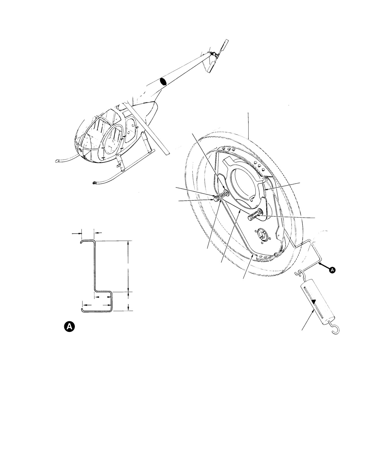
MD Helicopters, Inc.
CSP−H−2
500 Series − Basic HMI
STA. 197.78
THIN WASHERS
(AS REQUIRED)
TEFLON GRAPHITE
WASHER
DAMPER
BOLT
SPACER
1.13 IN.
(2.8702 CM)
SPRING
5.00 IN. (12.7 CM)
METAL PLATE
BRACKET
1.75 IN.
(4.445 CM)
2.88 IN.
2.00 IN. (5.08 CM)
(7.3152 CM)
FRICTION CHECKING TOOL
(NOTE)
SPRING SCALE
0−10 LB (0−5 KG)
NOTES: MANUFACTURED LOCALLY FROM 0.125 IN. (3.175 MM)
CORROSION−RESIST ANT SPRING WIRE.
44-120A
Figure 9-18. Tail Rotor Drive Shaft Damper Friction - Checking
Page 9-55
Revision 17
MD Helicopters, Inc.
CSP−H−2
500 Series − Basic HMI
(3). Remove the two bolts, washers, springs,
B. Tail Rotor Drive Shaft Coupling
shim washers, plate and spacers, and
Inspection (Bendix)
damper.
(Ref. Figure 9−14)
(4). Position new damper over mounting
(1). Inspect coupling diaphragms for dents,
holes in support bracket. Install plate
cracks, nicks, rust spots and joint
and spacers with bolts, washers,
separation at the weld junction. If any
springs and spacer washers.
such defect is evident, the coupling
must be replaced.
Make certain that the two bolts
CAUTION
and washers under the bol−
(2). Inspect coupling ends for scratches,
theads are seated against the spacers when
nicks, dents, cracks and corrosion pits.
tightened. The bolts will wear rapidly if the
No cracks are allowed. Maximum depth
clamp−up is not solid.
of other defects allowed before rework is
0.005 inch (0.127 mm).
C. Tail Rotor Drive Shaft Damper Friction
Adjustment
(3). Measure the overall length of the
couplings at three different points. If
(Ref. Figure 9−18)
average of the readings exceeds 2.541
inches (6.45414 cm), the coupling must
(1). Remove tail rotor drive shaft.
be replaced.
(2). Using a 0−10 lb. (0−5 kg) spring scale,
C. Tail Rotor Drive Shaft Coupling
measure the force required to move the
Inspection (Kamatic)
damper radially on bulkhead. Pressure
friction must be adjusted so that a pull
(Ref. Figure 9−13)
of 2 ±0.25 lb. (0.91 ±0.11 kg) is required
to slide the damper between the plate
(1). Inspect coupling springs for dents,
and support bracket.
cracks, nicks and rust spots.
(2). Inspect coupling splined section and
(3). To increase friction, add spacer washers
flange for scratches, nicks, dents,
between the springs and the plate. To
cracks and corrosion pits. No cracks are
decrease friction, remove washers. (Add
allowed. Maximum depth of other
or remove the same number of washers
defects allowed before rework is 0.005
at each pressure point.)
inch (0.127 mm).
NOTE: A minimum of one washer must always
(3). Measure overall length of coupling at
remain between each spring and the plate.
three different points. If average of
readings exceed 2.630 inches (6.6802
(4). Install tail rotor drive shaft.
cm), coupling must be replaced.
12. Tail Rotor Drive Shaft Couplings
(4). Inspect drive shaft flange for signs of
contact. If signs of contact are noted,
A. Tail Rotor Drive Shaft Coupling Removal
remove and reinstall coupling bolt.
(Ref. Figure 9−13 and Figure 9−14)
D. Tail Rotor Drive Shaft Coupling Repair
(Bendix)
(1). Remove tail rotor drive shaft.
(Ref. Figure 9−14)
(2). Remove rear coupling from tail rotor
transmission by removing attaching
(1). Repairs to flexible web areas of dia−
coupling. Retain shims with coupling
phragms are not allowed.
for reinstallation.
(2). Repair damage to splined section and
(3). Remove front coupling from main rotor
flange of coupling that is no deeper
transmission by removing attaching
than 0.005 inch (0.127 mm). Use
bolt. Retain shims with coupling for
abrasive paper grade 400 − 600 (9,
reinstallation.
Table 2−4) and crocus cloth (23) to
Page 9-56
Revision 18
MD Helicopters, Inc.
CSP−H−2
500 Series − Basic HMI
completely remove and polish out
abrasive paper grade 320 grit or finer
defect. Maximum depth after rework is
(9, Table 2−4) and crocus cloth (23) to
0.010 inch (0.254 mm). Apply primer (4)
completely remove and polish out
to repaired area.
defect. Maximum depth after rework is
0.007 inch (0.1778 mm). Apply primer
(3). Repair damage to outer welded portion
(4) to repaired area.
of diaphragm halves as in step (2).
above, except that maximum thickness
NOTE: Flange may be hand lapped using a
of material removed shall be not more
sheet of #440 emery cloth (49), placed on a
than 10 percent of original material
surface table. A figure ‘‘8’’ motion should be
thickness.
used while lapping the coupling, using care
not to let part ‘‘rock’’.
E. Tail Rotor Drive Shaft Coupling Repair
(Kamatic)
(3). Minimum flange thickness after
cleanup is 0.10 inch (0.254 mm).
(Ref. Figure 9−13)
F. Tail Rotor Drive Shaft Coupling
(1). Repairs to coupling spring areas are not
Installation
allowed.
(Ref. Figure 9−13 and Figure 9−14, Tail Rotor
(2). Repair damage to splined section and
Drive Shaft Installation with Kamatics
flange of coupling that is no deeper
Couplings or Tail Rotor Drive Shaft Installa−
than 0.005 inch (0.127 mm). Use
tion with Bendix Couplings).
Page 9-57
Revision 18
MD Helicopters, Inc.
CSP−H−2
500 Series − Basic HMI
This Page Intentionally Left Blank
Page 9-58
Revision 18
MD Helicopters, Inc.
CSP−H−2
500 Series − Basic HMI
Section
10
Engine Installation
and Cooling System
MD Helicopters, Inc.
CSP−H−2
500 Series − Basic HMI
This Page Intentionally Left Blank
MD Helicopters, Inc.
CSP−H−2
500 Series − Basic HMI
TABLE OF CONTENTS
Para/Figure/Table
Title
Page
Section 10 Engine Installation and Cooling System .
10−1
1.
Engine
10−1
2.
Engine Installation Troubleshooting
10−1
Table 10−1. Engine Installation Troubleshooting
10−1
3.
Engine Removal
10−2
A. Engine Disconnecting for Removal
10−2
B. Removal of Disconnected Engine
10−2
4.
Engine Installation
10−3
A. Engine Installation in Mounts
10−3
B. Connecting an Installed Engine
10−3
Figure 10−1. 250−C18 Engine Removal and Installation (Sheet 1 of 2) .
10−4
Figure 10−2. 250−C20 Engine Removal and Installation (Sheet 1 of 2) .
10−6
5.
Engine Stripping
10−8
6.
Engine Build−Up
10−9
Figure 10−3. 250−C18 Engine Stripping and Buildup (Sheet 1 of 2) .
10−10
Figure 10−4. 250−C20 Engine Stripping and Buildup (Sheet 1 of 2) .
10−12
7.
Installation of 369H8144−3 Engine Fuel Pump Pressure Switch Assembly .
10−15
8.
Engine Mounts and Fittings
10−15
9.
Lower Engine Mount Replacement
10−16
A. Lower Engine Mount Removal
10−16
B. Lower Engine Mount Installation
10−16
10. Upper Engine Mount Replacement
10−16
A. Upper Engine Mount Removal
10−16
Figure 10−5. Engine Mounts and Fittings
10−17
B. Upper Engine Mount Installation
10−18
C. Engine Mounts and Fittings Inspection
10−18
D. Engine Mounts and Fittings Repair
10−18
E. Engine−to−Transmission Alignment Check
10−18
Figure 10−6. Adjustable Engine Mounts
10−19
11. Engine Cooling System
10−19
A. Engine Cooling System Inspection
10−20
B. Cooling System Repair or Replacement
10−20
12. Engine Shaft Firewall Seal
10−20
A. Engine Shaft Firewall Seal Replacement
10−20
B. Engine Shaft Firewall Seal Inspection
10−20
C. Engine Shaft Firewall Seal Repair
10−20
Figure 10−7. Engine Cooling (Sheet 1 of 2)
10−21
Page 10−i
Revision 18
MD Helicopters, Inc.
CSP−H−2
500 Series − Basic HMI
TABLE OF CONTENTS (Cont.)
Para/Figure/Table
Title
Page
This Page Intentionally Left Blank
Page 10−ii
Revision 18
MD Helicopters, Inc.
CSP−H−2
500 Series − Basic HMI
SECTION 10
ENGINE INSTALLATION AND COOLING SYSTEM
1. Engine
temperatures (TOT) and consequently higher
output power, particularly at higher altitudes.
The helicopter may be equipped with either
Refer to the applicable engine operation and
the Allison 250−C18A, 250−C18C or 250−C20
maintenance manual for detailed maintenance
engine.
information and theory of engine operation.
The free turbine, turboshaft engine is mounted
Starter limitations for engine compressor
in the helicopter on centerline at a 43−degree
cleaning are given in Section 2. A daily water
angle from horizontal. It consists of a multi−
rinse that is accomplished without disconnect−
stage axial−centrifugal compressor, a single
ing the compressor discharge pressure (Pc)
combustion chamber, a two−stage gas producer
sensing tube is recommended for helicopters
turbine and a two−stage power turbine which
operating in a corrosive environment to
provides the output power of the engine.
remove any contaminants and corrosive air
particles. A periodic (200 to 300 hours)
The engines are basically identical in external
compressor waterwash using cleaning solvents
appearance except for variations in fuel control
to remove dirt buildup is recommended for
system components on the 250−C20 engine. In
helicopters that operate in smoggy areas. The
addition, a start (cycle) counter is included as
Pc tube must be disconnected and the opening
part of the 250−C20 engine electrical system.
capped to prevent introduction of chemical
agents into the controls system Pc connection
When engine automatic reignition is installed,
during the wash operation.
the counter is modified to prevent counter
NOTE: Engine conversion information that mo−
operation when automatic reignition occurs.
difies the helicopter for 250− C20 engine
Section 14 of this manual provides basic
installation is provided in CSP−H−3.
ignition troubleshooting information.
2. Engine Installation Troubleshooting
Internal differences in the 250−C20 engine
allow for operation at higher turbine outlet
(Ref. Table 10−1)
Table 10-1. Engine Installation Troubleshooting
Symptom
Probable trouble
Corrective action
NOTE: Refer to the engine operation and maintenance manual for troubleshooting information on the engine
assembly. Verify that the associated helicopter system is functioning correctly (i.e. chip detectors, instruments, fuel
supply system, etc.) before troubleshooting the engine.
High frequency vibration
Loose engine mount bolts
Retorque engine mount bolts to 100
-140 in.-lb. (11.30 - 15.82 Nm)
NOTE: High frequency vibrations may also be caused by components in other systems. (Ref. Sec. 5, 8 and 9.)
Page 10-1
Revision 18
MD Helicopters, Inc.
CSP−H−2
500 Series − Basic HMI
3. Engine Removal
(12). Disconnect N2 control rod from idler
bellcrank. Tie or tape control rod out of
(Ref. Figure 10−1 and Figure 10−2)
the way against the firewall.
NOTE: Removal of the engine does not require
(13). If cable−actuated anti−icing control
removal of the engine mounts.
valve lever is installed, disconnect by
removing cotter pin, loosening nut on
A. Engine Disconnecting for Removal
adapter and detaching control cable. If
anti−icing valve electrical actuator is
(1). Turn all switches OFF and disconnect
installed, remove two clamps at forward
external power.
firewall.
(2). Remove main transmission drive shaft
(14). Disconnect N1 control rod from gas
(Ref. Sec. 9).
producer lever. Tape or tie control rod
out of the way against the firewall.
(3). Remove engine tailpipes (Ref. Sec. 15).
(15). Disconnect accessory drive overboard
Cap all disconnected lines and
vent.
CAUTION
fittings. Do not use tape to cover
fuel and oil openings. Tape adhesive is solu−
(16). Disconnect oil line from engine oil
ble in fuel or oil and can cause contamina−
pressure reducer fitting.
tion.
(17). On 250−C20 engine, disconnect drain
NOTE: As an aid to reassembly, attach identify−
line from fuel control.
ing tags to all electrical wires and fuel and
oil hoses prior to disconnection.
Remove the oil inlet and outlet
CAUTION
lines only at the engine. Remov−
(4).
Remove lockwire and engine electrical
al at the oil cooler end will damage the cool−
harness plug from the receptacle
er frame if the frame oil port boss is not sup−
mounted on the right side oleo structur−
ported with a wrench. For the same reason,
al fitting.
do not apply extreme bending loads on the
oil cooler lines after they are disconnected
(5).
Disconnect thermocouple leads from
from the engine.
terminal studs and leads from termi−
nals E, C and B of starter−generator.
(18). Disconnect engine oil inlet line.
Disconnect bond jumper at center
firewall stud.
(19). Disconnect engine oil outlet line.
(6).
Remove clamp on right engine mount to
(20). Disconnect engine oil vent line.
release engine harness.
B. Removal of Disconnected Engine
(7).
Remove combustion chamber drain line
from burner drain valve.
(1). Install engine hoist (39, Table 2−2)
between hoisting eye fitting (located on
(8).
Disconnect fuel inlet line at pump and
intercostal above engine) and the hoist
seal drain line.
fitting provided on engine.
(9).
Disconnect cabin air outlet tube at
(2). Station an assistant on engine hoist
firewall fitting.
and apply tension on hoist line.
(10).
Loosen compressor cooling air duct
(3). Remove bolt and washer from bottom
clamp at firewall coupling, disconnect
engine mount. Maintain slight down−
support bracket at hoisting eye and
ward pressure at rear of engine during
remove duct from engine compartment.
removal of engine mount bolts.
(11).
Disconnect oil line from torquemeter
(4). Remove two bolts and washers from the
fitting.
left and right engine mounts.
Page 10-2
Revision 18
MD Helicopters, Inc.
CSP−H−2
500 Series − Basic HMI
Do not use fuel or oil lines to
handle. Shift engine toward side of
CAUTION
handle engine during removal.
stand with disconnected shaft to
Take care not to contact adjoining structure
disengage the fixed shaft. Roll stand
or compartments while lowering engine.
away from engine.
Use particular care to prevent damage to
Do not grasp fuel or oil lines
the N1 bearing oil return line on the under−
CAUTION
during engine installation. Use
side of the compressor, and to avoid cracking
particular care not to contact adjoining
or breaking the engine air inlet bell on the
structure or components and to avoid crack−
compressor.
ing or breaking engine air inlet bell on com−
pressor.
(5).
Remove detent pin and unscrew the
adjustable support shaft in engine
(3). Have assistant slowly raise the engine
stand (38) for clearance.
while necessary pressure is applied
downward at rear of engine.
(6).
Align the engine stand under the
engine so that the adjustable support
(4). Align left and right engine mounts with
shaft will engage the left engine mount
mount fittings and install bolts and
fitting.
washers. Torque bolts to 100 − 140
inch−pounds (11.30 − 15.82 Nm).
(7).
Slowly lower engine from the helicopter.
Align hole in lower engine mount with
Align engine side mount fittings
mount fitting and install bolt and
between the fixed and the adjustable
washer. Torque bolt to 100 − 140
support shaft.
inch−pounds (11.30 − 15.82 Nm).
Safety bolts with lockwire (2,
(8).
Screw the adjustable support shaft
Table 2−4).
inward until engine mount bosses are
securely engaged with the support shaft
(5). Check to ensure that the engine air
sockets.
inlet firewall seal ring contacts the
firewall seal all the way around.
(9).
Insert detent pin through the adjust−
(6). Remove engine hoist from helicopter.
able support shaft.
B. Connecting an Installed Engine
(10).
If engine is to be stored or transported,
(1). Connect engine oil vent line; torque the
engage the engine stand transport and
line nut to 120 − 140 inch−pounds
storage bar in the engine lifting eye
(13.56 − 15.82 Nm).
fitting.
Do not overtorque engine oil in−
4. Engine Installation
CAUTION
let or outlet couplings; damage
to the coupling orself− closing valve, if
(Ref. Figure 10−1 and Figure 10−2)
installed, may result. Do not apply extreme
bending loads on the oil outlet line. Such
A. Engine Installation in Mounts
loads will be transferred to the oil cooler in−
(1). Position engine stand as close as
let port boss and can cause the cooler frame
possible to helicopter with engine
to fracture.
access doors open. Remove detent pin
(2). Connect engine oil outlet and inlet
from the adjustable support shaft on
lines. Hand−tighten until snug; then
engine stand. Detach transport and
wrench−tighten approximately 1/4 turn
storage bar from engine lifting eye
or until definite resistance is felt.
fitting.
(3). Connect engine oil pressure line.
(2). Install engine hoist (39, Table 2−2)
(4). Position accessories drive overboard
between engine hoist fitting on struc−
vent elbow and torque to 150 − 250
ture above engine and on engine hoist
inch−pounds (16.95 − 28.25 Nm).
fitting on engine. Have assistant apply
and hold tension on the hoist. With
(5). Connect accessories drive overboard
engine supported manually, unscrew
vent. Torque tube nut to 20 − 30
the adjustable support shaft with
inch−pounds (2.26 − 3.39 Nm).
Page 10-3
Revision 18
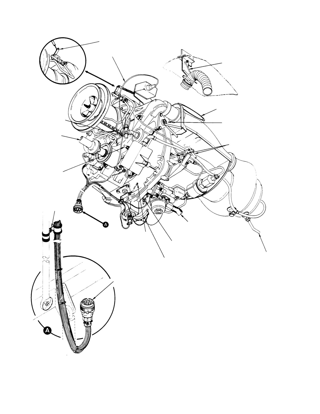
MD Helicopters, Inc.
CSP−H−2
500 Series − Basic HMI
ANTI−ICING VALVE CONTROL CABLE
(NOTE 1)
OR ELECTRICAL ACTUATOR HARNESS
(NOTE 2)
COMPRESSOR COOLING AIR
DUCT AND SUPPORT BKT
TAIL PIPES
CABIN AIR OUTLET TUBE
LH ENGINE MOUNT BOLT
350 IN. LB (39.54 NM)
100−140 IN. LB (11.30−15.82 NM)
MAIN TRANSMISSION
DRIVE SHAFT
N2 CONTROL ROD
TORQUEMETER
OIL LINE
HARNESS CLAMP
FUEL INLET LINE
120−140 IN. LB
(13.56−15.82 NM)
BOND JUMPER
FUEL PUMP SEAL DRAIN LINE
20−30 IN. LB (2.26−3.39 NM)
COMBUSTION CHAMBER
DRAIN LINE
GENERATOR LEADS
(E, C, B ONLY) AND
BOND JUMPER
ENGINE HARNESS PLUG
NOTES:
1.
USED ON HELICOPTERS WITH MANUALLY
OPERATED ANTI−ICING VALVE INSTALLATION.
2.
ON ELECTRICALLY OPERATED ANTI−ICING
VALVE INSTALLATION, REMOVE TWO WIRE
HARNESS CLAMPS ON FIREWALL.
30-081-1D
Figure 10-1.
250-C18 Engine Removal and Installation (Sheet 1 of 2)
Page 10-4
Revision 18
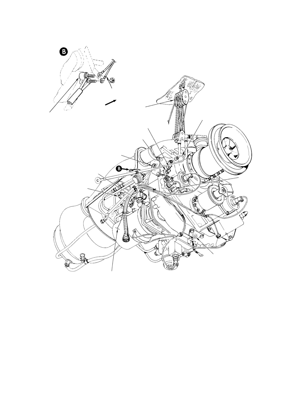
MD Helicopters, Inc.
CSP−H−2
500 Series − Basic HMI
THERMOCOUPLE LEADS
FWD
ENGINE HOIST
TERMINAL BLOCK
OIL PRESSURE SENDER LINE
ENGINE OIL INLET LINE
ENGINE OIL OUTLET LINE
ENGINE RH MOUNT BOLT
100−140 IN. LB
(11.30−15.82 NM)
N1 CONTROL ROD
ENGINE OIL VENT LINE
120−140 IN. LB
(13.56−15.82 NM)
LOWER ENGINE MOUNT BOLT
100−140 IN. LB (11.30−15.82 NM)
THERMOCOUPLE
WIRE
30-081-2D
Figure 10-1.
250-C18 Engine Removal and Installation (Sheet 2 of 2)
Page 10-5
Revision 18

MD Helicopters, Inc.
CSP−H−2
500 Series − Basic HMI
CABLE AND CLEVIS
ANTI−ICING VALVE LEVER
ENGINE HOIST
TAIL PIPES
CABIN AIR OUTLET TUBE
THERMOCOUPLE WIRE
350 IN. LB (39.54 NM)
LH ENGINE MOUNT BOLT
100−140 IN. LB (11.30−15.82 NM)
MAIN TRANSMISSION
DRIVE SHAFT
TORQUEMETER OIL LINE
N2 CONTROL ROD
40−50 IN. LB
COMBUSTION CHAMBER
(4.52−5.08 NM)
DRAIN LINE
BOND JUMPER
FUEL PUMP SEAL
DRAIN LINE
20−30 IN. LB
FUEL CONTROL DRAIN LINE
(2.26−3.39 NM)
FUEL INLET LINE
120−140 IN. LB
(13.56−15.82 NM)
COMPRESSOR COOLING AIR DUCT
AND SUPPORT BRACKET
30-206-1B
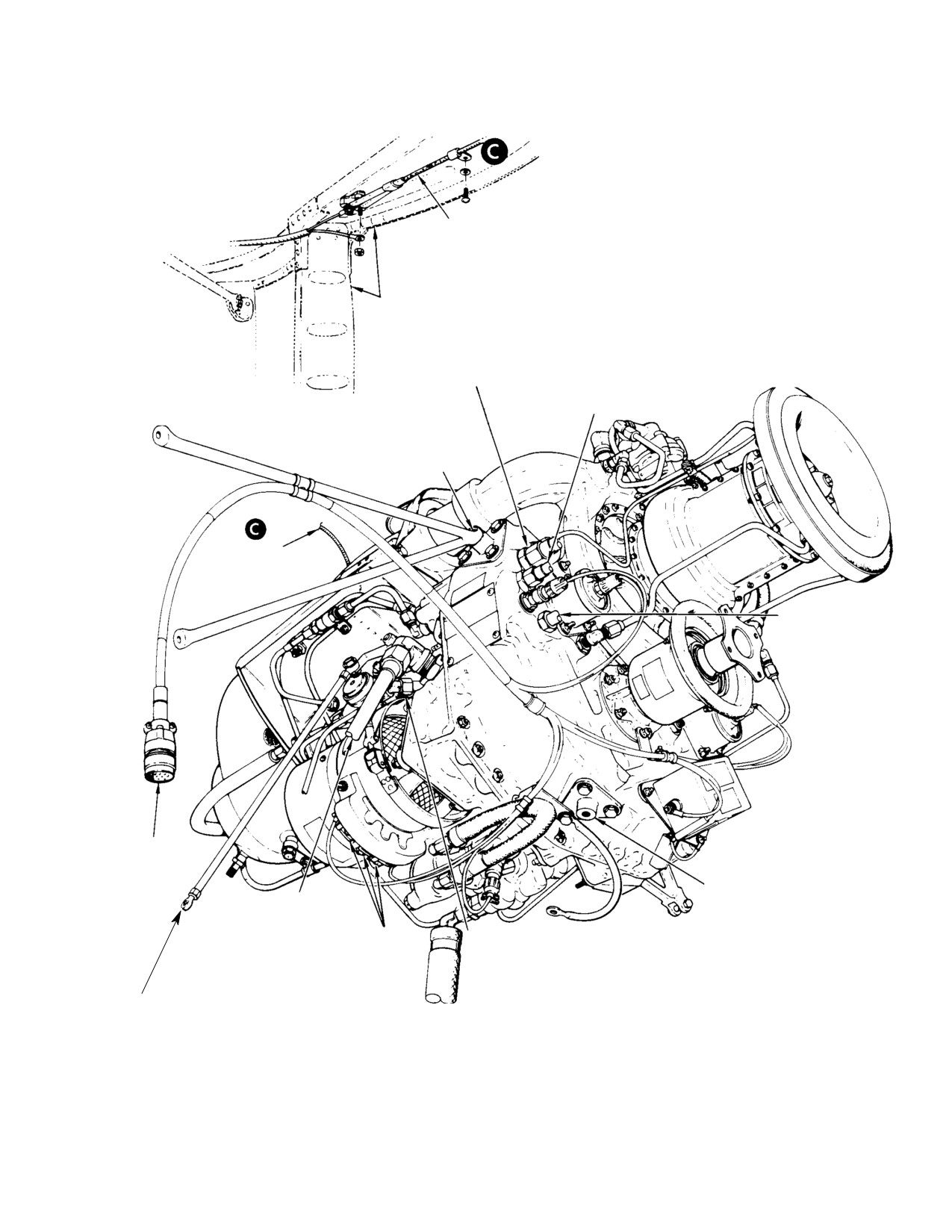
Figure 10-2.
250-C20 Engine Removal and Installation (Sheet 1 of 2)
Page 10-6
Revision 18
MD Helicopters, Inc.
CSP−H−2
500 Series − Basic HMI
THERMOCOUPLE LEADS
ENGINE DOOR FRAME
ENGINE OIL VENT LINE
ENGINE OIL OUTLET LINE
RH ENGINE MOUNT BOLT
100−140 IN. LB (11.30−15.82 NM)
THERMOCOUPLE
WIRE
ENGINE OIL
VENT LINE
120−140 IN. LB
(13.56−15.82 NM)
ENGINE
HARNESS
PLUG
LOWER ENGINE MOUNT BOLT
ACCESSORIES DRIVE
100−140 IN. LB (11.30−15.82 NM)
OVERBOARD VENT ELBOW
150−250 IN. LB (16.95−28.25 NM)
GENERATOR
VENT TUBE
FUEL CONTROL DRAIN
LEADS (E, C,
20−30 IN. LB (2.26−3.39 NM)
20−30 IN. LB (2.26−3.39 NM)
B ONLY)
N1 CONTROL ROD
40−50 IN. LB
(4.52−5.65 NM)
30-206-2B
Figure 10-2.
250-C20 Engine Removal and Installation (Sheet 2 of 2)
Page 10-7
Revision 18
MD Helicopters, Inc.
CSP−H−2
500 Series − Basic HMI
(6).
On 250−C20 engine, connect drain line
NOTE: Check that the burner drain valve and
to fuel control. Torque nut to 20 − 30
plug are correctly installed in the combus−
inch−pounds (2.26 − 3.39 Nm).
tion chamber. Each part must be installed
with a packing. The drain valve is installed
(7).
Connect N1 control rod to lever with
in the aft (lowest) position.
bolt, two washers, nut and new cotter
(16).
Secure engine harness to engine mount
pin. Install the bolt with head outboard,
with cushioned loop clamp. Connect oil
one washer (standard OD) under the
pressure sender lead if the electrical
nut and one large OD, 0.80 inch (20.32
indicating system is used.
mm) washer under the head. Torque
nut to 40 − 45 inch−pounds (4.52 −
(17).
Install E, C, B generator leads on
5.08 Nm) and install new cotter pin.
starter/generator and secure with
washers and nuts.
(8).
If anti−icing valve is manually con−
trolled, install control cable in lever
(18).
Connect thermocouple leads to terminal
adapter. If valve is electrically con−
block studs and secure with chromel
trolled, install wire harness clamps at
and alumel nuts provided. Install clamp
firewall. Make an operational check of
on door frame.
either installation (Ref. Sec. 11).
(19).
Connect engine harness plug to recep−
tacle and safety with 0.032 inch (0.8128
(9).
Connect short N2 control rod to gover−
mm) lockwire (2, Table 2−4). Install
nor lever with bolt (head up), one
bond jumper terminal to lower engine
washer (standard OD) under head, one
attach fitting. Torque bolt to 140 − 160
large OD, 0.80 inch (20.32 mm) washer
inch−pounds (15.82 − 18.08 Nm).
under the nut and a new cotter pin.
Safety bolt with 0.032 inch (0.8128 mm)
Connect long N2 control rod with
lockwire.
bolt−head forward), two washers, nuts
and new cotter pin.
(20).
Install engine exhaust tailpipes (Ref.
Sec. 15).
(10).
Connect oil line to torquemeter fitting
(21).
Install main transmission drive shaft
below N2 tach generator.
(Ref. Sec. 9).
(11).
Install compressor cooling air duct
(22).
Remove all identifying tags from
support bracket on hoisting eye above
electrical wires and fuel and oil lines.
engine. Connect and tighten flexible
duct on firewall coupling.
(23).
Check rigging of gas producer (Nl) and
power turbine (N2) engine power
controls (Ref. Sec. 17).
(12).
Connect cabin air outlet tube (or hose)
to firewall fitting. Make sure no
(24).
Check overall condition of engine
interference exists between compressor
installation and connections.
bleed air tube and 3/8 inch diameter
engine bleed air tube. Tighten both tube
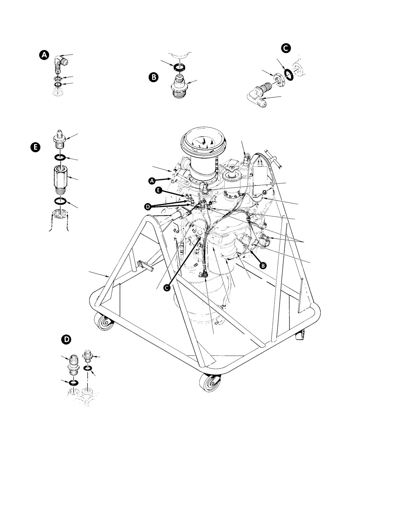
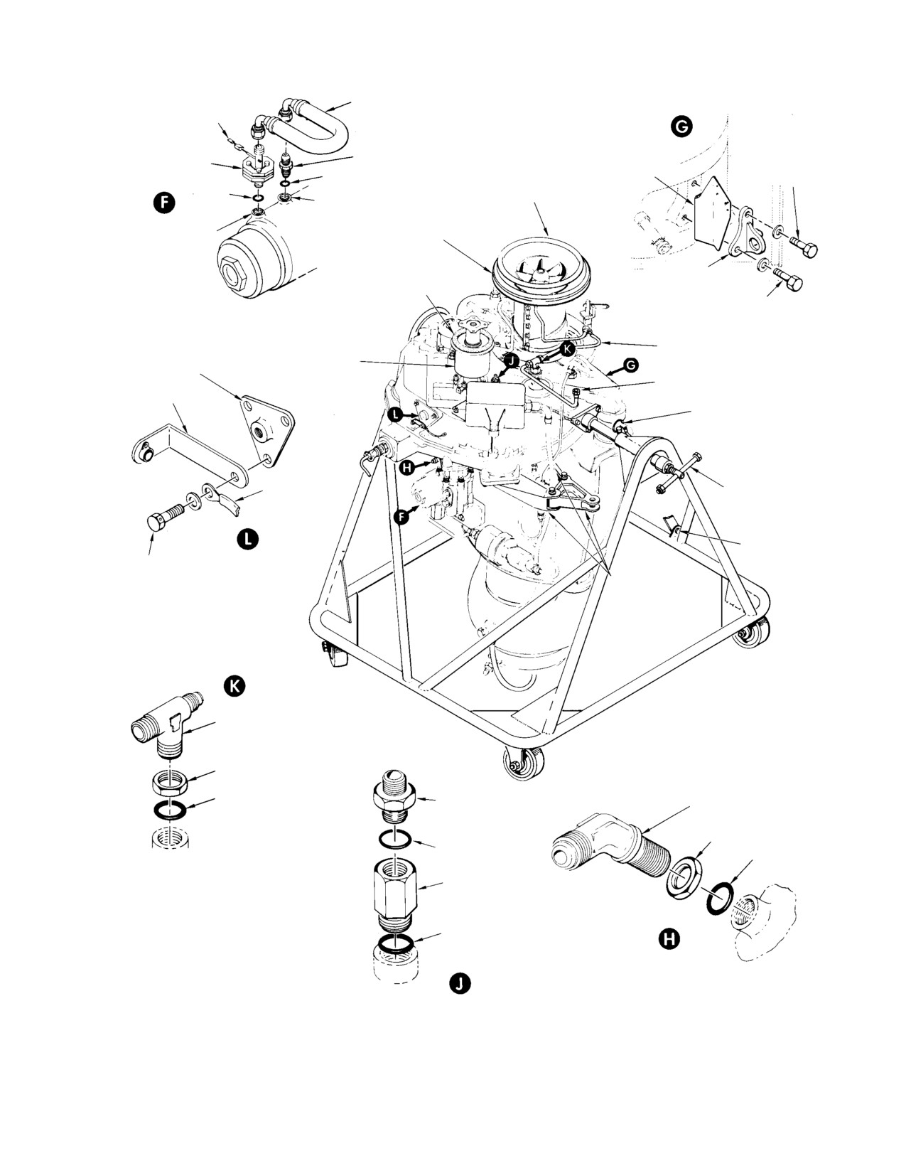
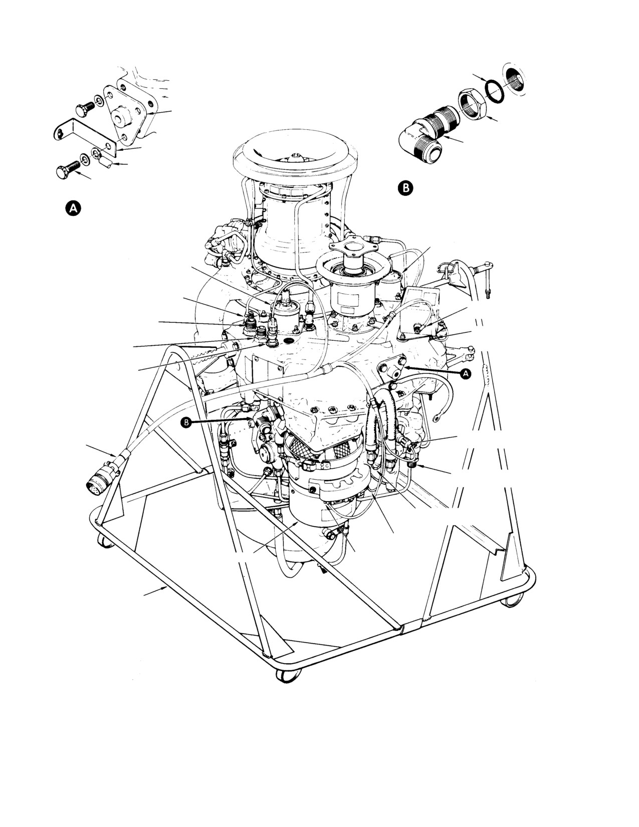
5. Engine Stripping
nuts to 350 inch−pounds (39.54 Nm).
(Ref. Figure 10−3 and Figure 10−4)
(13).
Connect engine fuel pump seal drain
(1). Disconnect A and D leads from starter−
line. Torque tube nut to 20 − 30 inch−
generator. Loosen mounting clamp that
pounds (2.26 − 3.39 Nm).
secures starter−generator to mounting
flange and remove starter−generator.
(14).
Connect fuel inlet line to fuel pump.
Remove four nuts and washers; then
Torque line nut to 120 − 140 inch−
remove mounting flange and gasket.
pounds (13.56 − 15.82 Nm).
Install pad cover on engine.
(15).
Install combustion chamber drain line
(2). Disconnect electrical connectors from
on drain valve.
both chip detectors.
Page 10-8
Revision 18
MD Helicopters, Inc.
CSP−H−2
500 Series − Basic HMI
(3).
Disconnect both tachometer generator
(19).
Remove governor control idler support,
connectors, anti−icing valve actuator
bellcrank and short N2 control rod as
connector (if installed), ignition exciter
an assembly. Install vacuum/hydraulic
lead, fuel filter pressure switch and
pump pad cover.
start counter leads (if installed).
(20).
Remove torque pressure snubber,
(4).
Remove bracket or clamp at overrun−
reducer and two O−rings.
ning clutch and lower engine mount
(21).
Remove three bolts, washers and nuts
fitting; then remove entire wire har−
attaching firewall seal to overrunning
ness.
clutch and remove seal.
(5).
Remove fuel inlet reducer and O−ring.
(22).
Remove the overrunning clutch (Ref.
Sec. 9), install pad cover.
(6).
Remove oil inlet and outlet couplings
with O−rings.
(23).
On 250−C20 engine, remove fuel control
vent elbow fitting, nut and O−ring.
(7).
Remove accessory drive overboard vent
elbow, nut and O−ring.
(24).
On engines with a Bendix fuel system
installed, remove the three cubic inch
(8).
Loosen both ends of the compressor
accumulator from fuel line in accor−
bleed air tube and detach from engine.
dance with the engine manufacturer’s
applicable installation bulletin.
(9).
Remove elbow, nut and gasket from the
compressor scroll.
(25).
With engine supported manually,
unscrew the adjustable support shaft
(10).
Remove tee, nut and gasket from
with handle.
compressor scroll.
(26).
Switch engine toward side of stand with
(11).
Remove oil pressure reducer, snubber
disconnected shaft to disengage the
and two O−rings.
fixed shaft.
(12).
Remove both tachometer generators by
(27).
Keep engine in vertical position and
removing four nuts and washers and
remove carefully from stand.
lifting directly off mounting pad; then
remove gasket.
(28).
Position engine on a stable surface.
Remove bolts, washers, bond jumper
(13).
Remove tube or hose assembly, reducer,
and three mount fittings from engine.
fuel filter pressure switch and two
O−rings from fuel pump assembly.
6. Engine Build-Up
(14).
Remove engine air inlet bell and
(Ref. Figure 10−3 and Figure 10−4)
engine−to−firewall seal (Ref. Sec. 16).
(1). Support replacement engine in position
(15).
On helicopter equipped with electrically
for access to engine mount fitting
actuated anti−icing valve, remove
locations.
actuator and controls (Ref. Sec. 11).
(2). Install the three engine mount fittings,
(16).
On helicopter equipped with manually
using washers and bolts. Torque to 140
actuated anti−icing valve, remove
− 160 inch−pounds (15.82 − 18.08
anti−icing valve lever assembly from
Nm) and safety with lockwire. Do not
poppet guide.
safety lower engine mount fitting at
this time.
(17).
Remove three bolts, washers and
engine hoist fitting, and actuator
(3). Install engine in engine stand (38,
bracket, if installed.
Table 2−2).
(18).
Remove elbow, nut and O−ring from the
(4). Install O−ring, nut and special tee in
fuel pump seal drain port.
compressor scroll. Do not tighten.
Page 10-9
Revision 18
MD Helicopters, Inc.
CSP−H−2
500 Series − Basic HMI
ELBOW
O−RING
(NOTE 1)
O−RING
NUT
NUT
FUEL INLET
GASKET
COUPLING
OVERBOARD VENT ELBOW
(NOTE 1)
OIL PRESSURE
N2 TACH / GEN
REDUCER
CONNECTION
COMPRESSOR BLEED
AIR TUBE (OR HOSE)
O−RING
150−200 IN. LB
(16.95−28.25 NM)
OIL PRESSURE
N1 TACH / GEN
SNUBBER
CONNECTION
IGNITION
EXCITER LEAD
O−RING
OIL TANK VENT
UNION AND O−RING
CHIP DETECTOR
CONNECTORS
FUEL FILTER
SWITCH KNIFE
ENGINE STAND
SPLICE
369A9948
(NOTE 2)
D" LEAD
A" LEAD
OIL PRESSURE
SENDER LEAD
(ELECTRICAL
START / GEN CLAMP
GAUGE ONLY)
ENGINE HARNESS
OIL INLET
OIL OUTLET
COUPLING
COUPLING
O−RING
O−RING
NOTES:
1.
OBSERVE POSITION OF FITTING BEFORE
REMOVING TO AID REASSEMBLY AT
CORRECT ANGLE.
2.
INSULATE WITH FIBERGLASS SLEEVING
(87, TABLE 2−4.).
30-082-1G
Figure 10-3.
250-C18 Engine Stripping and Buildup (Sheet 1 of 2)
Page 10-10
Revision 18
MD Helicopters, Inc.
CSP−H−2
500 Series − Basic HMI
HOSE ASSY
ELECTRICAL CONNECTION
(NOTE 3)
(NOTE 2)
3/8 IN. DIA. BOLT
FUEL PRESSURE
REDUCER
ANTI−ICING ACTUATOR BRACKET
160−190 IN. LB
SWITCH 40−50 IN. LB
(NOTE 4)
(18.08−21.47 NM)
(4.52−5.65 NM)
O−RING
ENGINE AIR
O−RING
INLET BELL
AFTER FILTER
PORT
ENGINE−TO−FIREWALL
BEFORE FILTER
SEAL
PORT
LIFT
ENGINE SHAFT
FITTING
FIREWALL SEAL
5/16 IN. DIA. BOLT (TYP)
140−160 IN. LB (15.82−18.08 NM)
BLEED AIR TUBE OR HOSE
OVERRUNNING
150−250 IN. LB (16.95−28.25 NM)
ENGINE MOUNT
CLUTCH
FITTING
CABIN AIR OUTLET TUBE
350 IN. LB (39.54 NM)
ANGLE
DETENT PIN AND LANYARD
BOND JUMPER
SUPPORT SHAFT
ADJUSTMENT HANDLE
STORAGE AND
TRANSPORT BAR
140−160 IN. LB
(15.82−18.08 NM)
RPM GOVERNOR
CONTROL IDLER
SUPPORT BELLCRANK,
N2 CONTROL ROD
TEE
(NOTE 1)
NUT
GASKET
REDUCER
PUMP SEAL DRAIN ELBOW
(NOTE 1)
NUT
O−RING
O−RING
TORQUEMETER
OIL PRESSURE
SNUBBER
O−RING
NOTES: (CONT)
3.
HOSE ASSEMBLY IS ONE−WAY
INTERCHANGEABLE WITH TUBE ASSEMBLY.
4.
INSTALLED ON ENGINES EQUIPPED
WITH ELECTRICALLY OPERATED
ANTI−ICING VALVE.
30-082-2G
Figure 10-3.
250-C18 Engine Stripping and Buildup (Sheet 2 of 2)
Page 10-11
Revision 18
MD Helicopters, Inc.
CSP−H−2
500 Series − Basic HMI
O−RING
ENGINE MOUNT
FITTING
NUT
ANGLE
OVERBOARD VENT
(NOTE 1)
ELBOW
BOND JUMPER
(NOTE 1)
140−160 IN. LB
ACCESSORIES DRIVE VENT
(15.82−18.08 NM)
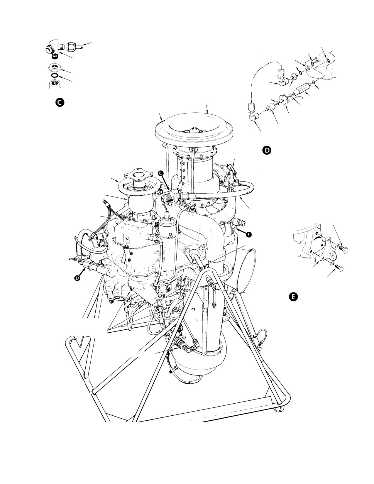
ELBOW INSTALLATION
ENGINE MOUNT FITTING
INSTALLATION (TYP)
N2 TACHOMETER GENERATOR
N1 TACHOMETER
GENERATOR
OIL PRESSURE
REDUCER FITTING
IGNITION EXCITER LEAD
(NOTE 2)
OIL INLET COUPLING
WITH O−RING
START COUNTER
KNIFE SPLICE
OIL OUTLET COUPLING
(NOTE 2)
WITH O−RING
CHIP DETECTOR
CONNECTOR
ENGINE ELECTRICAL
CHIP DETECTOR
HARNESS
CONNECTOR
FUEL INLET REDUCER
WITH O−RING
FUEL INLET SWITCH
KNIFE SPLICE
(NOTE 2)
D" WIRE LEAD
STARTER/GENERATOR
A" WIRE LEAD
ENGINE STAND
NOTES:
1.
APPLIES ONLY TO LOWER MOUNT.
2.
INSULATE WITH FIBERGLASS SLEEVING
(87, TABLE 2−4).
3.
CHECK THAT LEVER ARM IS INSTALLED
PARALLEL WITH TOP OF ENGINE.
30-207-1C
Figure 10-4.
250-C20 Engine Stripping and Buildup (Sheet 1 of 2)
Page 10-12
Revision 18
MD Helicopters, Inc.
CSP−H−2
500 Series − Basic HMI
AFTER FILTER
COMPRESSOR BLEED AIR HOSE
PORT (AF)
FUEL PUMP SEAL ELBOW,
NUT AND O−RING
BEFORE FILTER PORT (BF)
SPECIAL TEE FITTING
O−RING
NUT
O−RING
ELBOW 20−25 IN. LB (2.26−2.82 NM)
REDUCER 40−50 IN. LB (4.52−5.65 NM)
O−RING
ENGINE AIR
O−RING
FITTING 40−50 IN. LB
CABIN AIR FITTING
INLET BELL
(4.52−5.65 NM)
INSTALLATION
ENGINE−TO−FIREWALL
O−RING
SEAL RING
FUEL PRESSURE SWITCH
40−50 IN. LB (4.52−5.65 NM)
BUSHING 40−50 IN. LB (4.52−5.65 NM)
HOSE ASSEMBLY 20−25 IN. LB 2.26−2.82 NM)
ANTI−ICE VALVE
FUEL PRESSURE SWITCH
LEVER
INSTALLATION
(NOTE 3)
OVERRUNNING CLUTCH−
TO−FIREWALL SEAL
OVERRUNNING
CLUTCH
3/8 IN. DIA. BOLT
TORQUEMETER REDUCER
COMPRESSOR
160−190 IN. LB
FITTING WITH O−RING
BLEED AIR HOSE
(18.08−21.47 NM)
DETENT PIN
LIFT FITTING
5/16 IN. DIA. BOLT (2 PLCS)
140−160 IN. LB (15.82−18.08 NM)
ADJUSTABLE
ENGINE LIFT FITTING
SUPPORT
INSTALLATION
SHAFT
GOVERNOR CONTROL IDLER
SUPPORT, BELLCRANK AND
N2 CONTROL ROD ASSEMBLY
ACCUMULATOR
30-207-2D
Figure 10-4.
250-C20 Engine Stripping and Buildup (Sheet 2 of 2)
Page 10-13
Revision 18
MD Helicopters, Inc.
CSP−H−2
500 Series − Basic HMI
(5). Connect compressor bleed air hose
(14).
Install anti−icing valve lever with
between special tee and compressor
attaching hardware on poppet guide
elbow. Tighten special tee nut; then
(Ref. Sec. 11). If required, reposition
torque hose nut to 150 − 250 inch−
poppet guide so that lever is parallel
pounds (16.95 − 28.25 Nm).
with top of engine.
(15).
On helicopters equipped with electrical−
(6). Install overrunning clutch (Ref. Sec. 9).
ly actuated anti−icing valve, install
actuator and controls (Ref. Sec. 11).
(7). Install engine firewall seal on overrun−
ning clutch and secure with three bolts,
(16).
Install engine−to−firewall seal and
six washers and three nuts.
engine inlet bell (Ref. Sec. 16).
(8). Install torquemeter oil pressure reducer
(17).
On 250−C18, install O−ring and fuel
and snubber with O−rings.
filter pressure switch in the before−filt−
er port of the pump. Torque switch to 40
The engine spark igniter lead on
− 50 inch−pounds (4.52 − 5.65 Nm).
CAUTION
a new or overhauled engine is
Install O−ring and reducer in the
routed above the N2 governor causing inter−
after−filter port. Install tube assembly.
ference with and possible obstruction of the
(18).
On 250−C20, install fuel pressure
governor arm. During installation of the
switch fitting with O−ring in after (AF)
governor idler support, check that the en−
port of the fuel pump; then install fuel
gine spark igniter lead is routed as shown in
filter pressure switch an O−ring and
Figure 10−3 and Figure 10−4. Also, check
torque to 40 − 50 inch−pounds (4.52 −
that only cushioned clamps are used to at−
5.65 Nm). Install bushing in switch.
tach the igniter lead and replace if required.
Install reducer fitting with O−ring in
If not as shown, re−route the lead below the
before filter (BF) port; then install hose
governor as shown using existing hardware
between (AF) and (BF) fittings.
and additional cushioned clamps as neces−
sary.
(19).
Install tachometer generators (Ref. Sec.
17).
(9). Install governor control idler support,
bellcrank and short N2 control rod as
(20).
Install O−ring, nut and elbow for
an assembly.
accessories drive overboard vent. DO
NOT tighten until final installation in
NOTE: Only high temperature all metal nuts
helicopter.
(not the fiber insert type) are to be used for
anchoring governor control idler support
(21).
Install oil inlet and outlet couplings
bracket to engine accessory pad.
with O−rings.
(22).
Install starter−generator (Ref. Sec. 19).
(10). Install oil pressure reducer fitting,
snubber and O−rings.
(23).
Install engine harness. Connect ignition
exciter lead, starter−generator A and D
(11). Install fuel inlet reducer coupling and
leads, fuel pressure switch splice and
O−ring.
start counter splice. Install fiber glass
sleeving (87, Table 2−4) over knife
(12). Install O−ring, nut and elbow fitting in
splice and secure with high tempera−
fuel pump seal drain port.
ture lacing cord (37). Install electrical
connectors to tach generators and chip
(13). Position anti−icing valve actuator
detectors. Safety the connectors with
bracket, if so equipped, and install
lockwire.
engine hoist fitting using three washers
and bolts. Torque the 3/8 inch−diameter
(24).
On engines with Bendix fuel system
bolt to 160 − 190 inch−pounds (18.08
installed, install the three cubic inch
− 21.47 Nm). Torque the two 5/16
accumulator in fuel line according to
inch−diameter bolts to 140 − 160
the engine manufacturer’s applicable
inch−pounds (15.82 − 18.08 Nm).
installation instructions.
Page 10-14
Revision 18
MD Helicopters, Inc.
CSP−H−2
500 Series − Basic HMI
7. Installation of 369H8144-3 Engine Fuel
(c). Have assistant hold switch clear;
Pump Pressure Switch Assembly
connect battery and electrical power
and actuate start pump. Filter
This procedure is for replacement of the
by−pass warning light should actu−
existing 369H8144 engine fuel pump fuel
ate, indicating proper operation of
pressure switch assembly with new
filter by−pass switch.
369H8144−3 switch assembly to be accom−
(d). Shut off electrical power, start pump,
plished in conjunction with installation of 5
battery switch; disconnect battery
micron filter replacement kit (Allison PN
and jumper wire.
6895028). The −3 switch assembly accommo−
dates the 5 micron filter element to preclude
(e). Disconnect bushing at by−pass hose;
premature actuation of the fuel filter warning
cap hose assembly.
light on the instrument console.
(9). Remove plug from after filter port;
install 369H8020 adapter fitting with
(1).
Check that all electrical power is OFF;
new MS29512−03 packing at the after
disconnect battery.
filter port.
(10). Remove cap from by−pass hose; recon−
(2).
Gain access to engine accessory section;
nect bushing at by−pass hose.
locate fuel filter pressure (by−pass)
switch on front of engine driven fuel
(11). Check fuel filter pressure switch
pump (Ref. Figure 10−4).
installation for discrepancies.
(12). Run up engine and perform operational
(3).
Remove protective sleeving and
check of engine and fuel system; check
disconnect knife splice on by−pass
for leaks and non−actuation of fuel
switch wiring.
filter by−pass light when start pump is
actuated.
(4).
Disconnect and cap by−pass hose
assembly at AN894−3−2 bushing.
8. Engine Mounts and Fittings
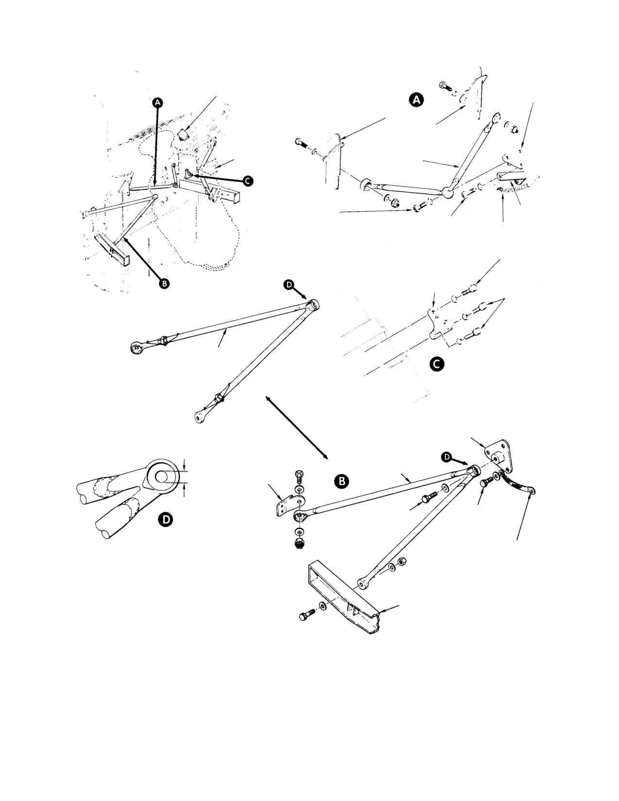
(Ref. Figure 10−5) The engine mount installa−
(5).
Remove 369H8020 adapter fitting (with
tion consists of one lower and two upper
switch and bushing intact) from after
engine mounts, six structural attach fittings,
filter port. Plug after filter port.
three engine mount fittings and associated
attaching hardware.
(6).
Remove bushing and adapter from
switch, discard switch and packing.
Each of the three engine mounts is a tubular
steel, V−shaped, welded assembly.
(7).
Install bushing with new MS29512−03
The lower engine mount is bolted to the two
packing on new 369H8144−3 switch;
bulkhead splice fittings and an engine mount
install switch with new MS29512−02
fitting located on the underside mounting pad
packing on adapter; torque switch and
of the power and accessories gearbox.
bushing 40 − 50 inch pounds (4.52 −
5.65 Nm).
The two upper engine mounts are symmetri−
cally opposite assemblies; the longer end is
bolted to an upper engine attach fitting on the
(8).
Perform function test of new
firewall; the shorter end to the oleo support
369H8144−3 switch as follows:
fitting and the aft end to an engine attach
fitting on the side mounting pad of the power
(a). Remove cap from by−pass hose and
and accessory gearbox.
reconnect bushing (with switch and
adapter fitting intact) in hose fitting.
On current configuration helicopters, the left
and right upper engine mounts may be
(b). Connect knife splice on switch
adjustable for engine−to−transmission
wiring; connect jumper wire to
alignment. Adjustment is accomplished by
ground by−pass switch to airframe
turning a left and right threaded fitting that is
ground (E−12).
part of each upper engine mount leg.
Page 10-15
Revision 18
MD Helicopters, Inc.
CSP−H−2
500 Series − Basic HMI
The three engine mount fittings, bolted to the
(4). Disconnect the left and right forward
power and accessory gearbox are machined
ends of the lower engine mount; discard
aluminum alloy forgings, each having a
the two nuts.
self−locking, steel−thread insert.
(5). Disconnect lower engine attach fitting.
The engine lift fitting (hoisting eye) is an
B. Lower Engine Mount Installation
anodized machined aluminum alloy forging,
mounted on top of the power and accessory
gearbox just aft of the air inlet scroll.
CAUTION
D Do not tighten bolts until the engine at−
CAUTION
tach bolt is tightened.
D If engine mount adjustment fittings are
D Retorque the engine attach bolt after 3 to
disturbed or if new or replacement upper
5 hours of flight if the engine mount will
be attached to a previously unused mount
engine mounts (either fixed or adjustable)
fitting.
are installed, realignment of the engine is
required.
NOTE: All engine mount fitting bolts, washers
D To avoid disturbing security of the engine
and nuts are corrosion resistant steel.
installation or alignment of the engine, do
(1). Place ends of lower engine mount
not loosen and/or remove more than one
against bulkhead fittings. Install two
engine mount at any one time.
bolts, four washers and two new nuts at
D Do not readjust adjustable engine mount
bulkhead attach points. Torque nuts to
fittings unless an engine− to− transmis−
30 − 40 inch−pounds (3.39 − 4.52 Nm)
sion alignment check is performed.
plus drag torque.
D Do not use open end wrenches when re−
(2). Install engine attach bolt and washer
moving engine attach fittings and attach−
securing mount to fitting on engine.
ing hardware. Use box end and socket
Torque bolt to 100 − 140 inch−pounds
wrenches to avoid tool damage to hard−
(11.30 − 15.82 Nm); safety with 0.032
ware and engine mount fittings.
inch (0.8128 mm) lockwire.
9. Lower Engine Mount Replacement
(3). Tighten bulkhead fitting bolts and nuts.
A. Lower Engine Mount Removal
10. Upper Engine Mount Replacement
(1). Remove the bolt and nut attaching the
A. Upper Engine Mount Removal
compressor air duct support bracket to
the overhead engine hoist fitting.
(1). Remove engine oil pressure sender
clamps, if installed, and engine harness
(2). Install engine hoist (39, Table 2−2).
clamp from right side engine mount.
Apply enough tension with hoist to
remove weight from lower mount.
(2). Disconnect forward attach points of
Engine load will be neutral when the
upper engine mount at upper mount
attaching bolts turn freely with nuts
fitting and oleo support; discard the
backed off one−half turn.
nuts.
(3). Release cargo compartment upholstery
(3). Remove aft end of mount from mount
enough to gain access to the bulkhead
fitting on pad of power and accessory
fitting boltheads.
gearbox.
Page 10-16
Revision 18
MD Helicopters, Inc.
CSP−H−2
500 Series − Basic HMI
OVERHEAD ENGINE
LOWER ENGINE
HOIST FITTING
*
ATTACH FITTING
BULKHEAD
*
SPLICE FITTING
LOWER ENGINE
STA. 124 FIREWALL
MOUNT
BULKHEAD
100−140 IN. LB
ANGLE
(11.30−15.82 NM)
140−160 IN. LB
BONDING
(15.82−18.08 NM)
JUMPER
160−190 IN. LB
(18.08−21.47 NM)
ENGINE LEFT
FITTING
140−160 IN. LB
(15.82−18.08 NM)
ADJUSTABLE UPPER
SIDE ENGINE MOUNT
(NOTE 4)
ENGINE SIDE
0.3122−0.3132 IN.
ATTACH FITTING
(7.92988−7.95528 MM)
NON−ADJUSTABLE
(NOTE 2)
UPPER SIDE ENGINE
MOUNT
UPPER ENGINE
MOUNT FITTING
*
100−140 IN. LB
140−160 IN. LB
(11.30−15.82 NM)
(15.82−18.08 NM)
BONDING JUMPER
(NOTE 3)
NOTES:
*
1.
ALL BOLTS, NUTS AND WASHERS MUST BE
CRES. USE THIN WASHERS IN ALL
OLEO SUPPORT
APPLICATIONS EXCEPT THOSE MARKED
FITTING
WITH AN ASTERISK ( * ).
2.
ON UPPER ENGINE MOUNT−TO−FITTING BOLT
HOLES ONLY. HOLES WITH THREAD DAMAGE
MAY BE ENLARGED TO 0.3170 IN. DIAMETER
PROVIDED ENGINE ALIGNMENT IS NOT AFFECTED.
3.
NOT USED ON ALL HELICOPTER MOUNTS.
4.
REFER TO TEXT FOR ADJUSTMENT AND
30−084E
ENGINE ALIGNMENT CHECK.
Figure 10-5. Engine Mounts and Fittings
Page 10-17
Revision 18
MD Helicopters, Inc.
CSP−H−2
500 Series − Basic HMI
B. Upper Engine Mount Installation
corrosion. Magnetic−particle inspect
suspected engine mount assemblies. If
cracks are evident, the mount is
CAUTION
unserviceable.
D Do not tighten bolts until the engine at−
(5). Inspect flanges and bosses of engine
tach bolt is tightened.
mount fittings and lifting eye for
D Retorque the engine attach bolt after 3 to
flatness, cracks and corrosion. Replace
5 hours of flight if the engine mount will
defective fittings.
be attached to a previously unused mount
fitting.
(6). Inspect threaded steel insert for
damaged threads, corrosion and for full
NOTE: All engine mount fitting bolts, washers
bottoming to seat of insert hole.
and nuts are corrosion resistant steel.
D. Engine Mounts and Fittings Repair
(1). Place short end of upper engine mount
against oleo support fitting and long
No straightening or weld repair of the engine
end against firewall attach fitting.
mounts is authorized. Thread damage to either
Install bolt, two washers and new nut
upper engine mount, at the engine attach
to fasten mount to structure.
point, can be repaired by re−drilling the hole
(2). Install bolt and washer that attach
up to a maximum diameter of 0.3170 inch
mount to fitting on engine. Torque bolt
(8.0518 mm), provided that re−drilling does
to 100 − 140 inch−pounds (11.30 −
not permit engine−to−main transmission drive
15.82 Nm).
shaft misalignment and resulting clutch or
main transmission to drive shaft coupling gaps
(3). Torque upper mount fitting and oleo
in excess of that specified in Section 9.
support nuts to 30 − 40 inch−pounds
Otherwise, replace defective mounts and
(3.39 − 4.52 Nm) plus drag torque.
fittings.
(4). Remove engine hoist and reinstall the
NOTE: Re− drilling (opening) the hole on one
compressor air duct support bracket in
mount usually will not cause misalignment
the overhead hoist fitting.
beyond permitted tolerance. However, if
both mounts are reworked, engine to drive
(5). Reinstall engine oil pressure sender
shaft alignment must be checked.
clamps (if used) and engine harness
clamp on right engine mount.
E. Engine-to-T ransmission Alignment
Check
C. Engine Mounts and Fittings Inspection
(Ref. Figure 10−6) Adjustable upper left and
(1). Inspect all engine mount assemblies for
right engine mounts should normally not be
good condition of painted surface.
disassembled except for spares replacement or
magniflux inspection. In this event, a realign−
(2). Inspect all engine mount tubes for
ment check of the engine is required. Realign−
straightness. Hold a steel straight−edge
ment of the engine is also required if adjust−
against the surface of tubes to reveal
able mounts are interchanged between
any warps or bends in the tubes.
helicopters.
(3). Check that jam nuts and lockwire on
mounts with adjustable fittings are
(1). If only one adjustable upper mount is
secure and have not been disturbed. If
replaced or readjusted, check and
not secure or adjustment has been
readjust engine−to−transmission
disturbed, a check of engine−to−trans−
alignment using engine−to−transmis−
mission alignment is required.
sion aligning tool 369A50000−40101
according to instructions in CSP−H−6.
(4). Visually inspect all the tubes and
Following adjustment, proceed with
welded joints for cracks and evidence of
steps (3). and (4).
Page 10-18
Revision 18
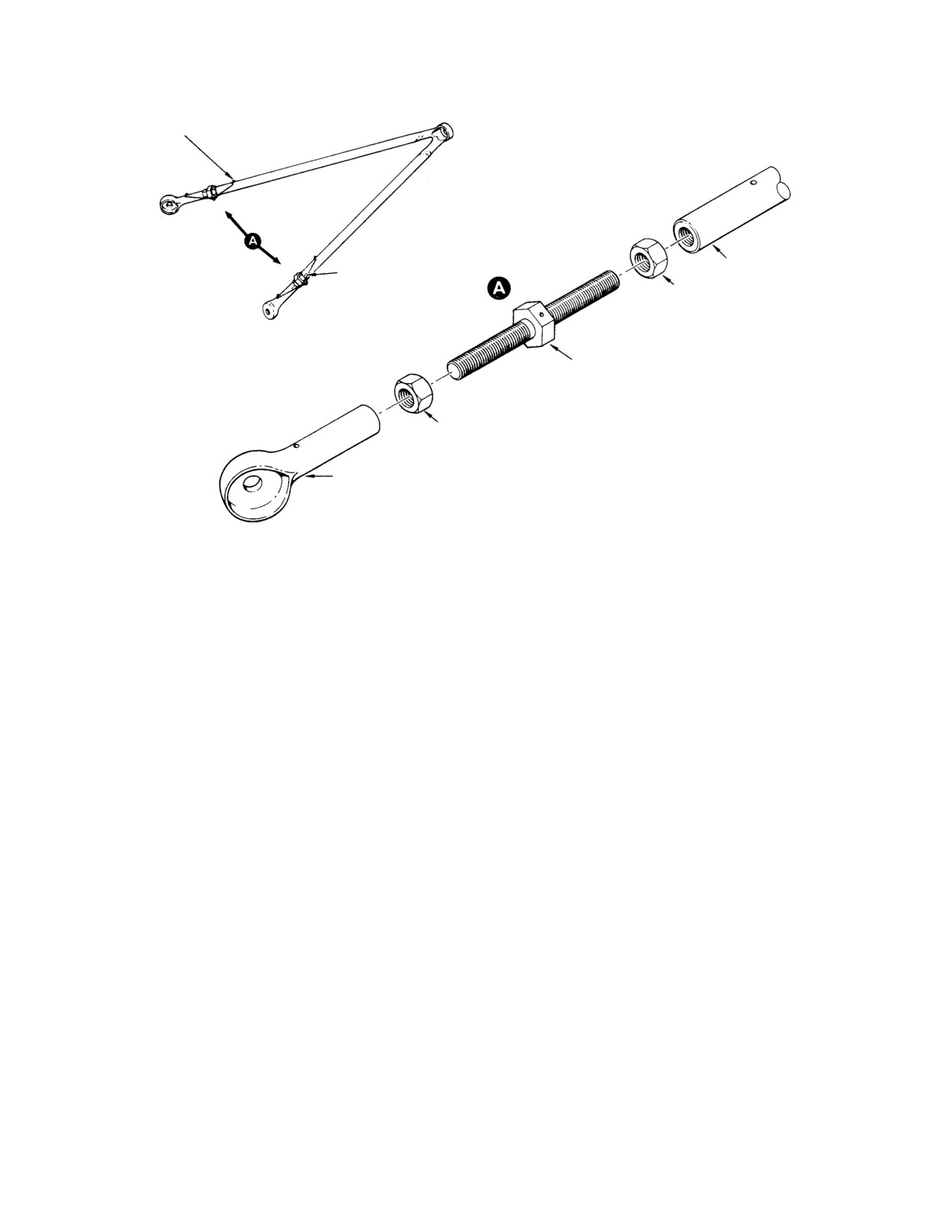
MD Helicopters, Inc.
CSP−H−2
500 Series − Basic HMI
0.032 IN. (8.128 MM) CRES
LOCKWIRE (BOTH LEGS)
UPPER ENGINE MOUNT
SLIPPAGE MARK
(RIGHT−HAND THREAD)
(BOTH LEGS)
JAM NUT
SCREW FITTING
JAM NUT
CAUTION:
DO NOT RE−ADJUST OR DISASSEMBLE UPPER ENGINE
UPPER END FITTING
(LEFT−HAND THREAD)
MOUNTS UNLESS AN ENGINE−TO−TRANSMISSION
ALIGNMENT CHECK IS PERFORMED FOLLOWING ANY
ADJUSTMENT.
30−213A
Figure 10-6. Adjustable Engine Mounts
(2). If both adjustable upper engine mounts
The oil cooler blower is belt−driven on the
are replaced or readjusted, install
current configuration helicopter and shaft−
engine and tailboom check fixture
driven on the early configuration.
369A9900−80906 (Ref. CSP−H−6) and
adjust mounts as required. Following
Air enters the ram air scoops, flows into the
adjustment proceed with steps (3). and
transmission cover around the transmission
(4).
and through ducts to the oil cooler blower. The
transmission cover is equipped with special
(3). Adjust mount(s) to bring engine into
baffles on helicopters with a 250−C20 engine.
alignment with transmission; then
tighten jam nuts and recheck align−
ment.
Air from the oil cooler blower is directed to and
through the engine oil cooler by the oil cooler
(4). Secure jam nuts with 0.032 inch
duct and into the engine compartment. The oil
(0.8128 mm) lockwire; then paint a
cooler blower also supplies a constant air flow
slippage mark across both jam nuts at
through the engine gearcase and compressor
each mount leg.
cooling ducts into the lower and upper areas of
the engine compartment.
11. Engine Cooling System
Two duct outlets direct the air upon the engine
(Ref. Figure 10−7) The engine cooling system
gearcase and the compressor section. Engine
consists of two ram air scoops integral with the
differences require variations in air flow
air inlet fairing, an oil cooler blower driven by
direction. All cooling air then exhausts from
the main transmission input gear shaft, an oil
the engine compartment through a gap
cooler duct and engine gearcase and compres−
provided around and between the exhaust
sor cooling ducts.
pipes and the engine access doors.
Page 10-19
Revision 18
MD Helicopters, Inc.
CSP−H−2
500 Series − Basic HMI
A. Engine Cooling System Inspection
A. Engine Shaft Firewall Seal Replacement
(1). Remove engine.
Visually inspect for general condition, security
of clamps and for fraying or tears in the
(2). Remove three bolts, six washers and
flexible tubing.
three nuts that attach engine shaft
firewall seal to overrunning clutch.
B. Cooling System Repair or Replacement
(3). Position replacement engine shaft
firewall seal assembly on flange of
Repair damaged hose with tape (32,
clutch and secure with attaching
Table 2−4). Remove attaching clamps to
remove hose. Install clamps on each end of
hardware.
replacement hose; position hose and tighten
B. Engine Shaft Firewall Seal Inspection
clamps.
Inspect the firewall seal and backing for
cracks, breaks, corrosion or other damage that
12. Engine Shaft Firewall Seal
would prevent complete sealing of the firewall
opening.
(Ref. Figure 10−1 or Figure 10−2) The engine
shaft firewall seal assembly consists of a
C. Engine Shaft Firewall Seal Repair
stamped steel backing and a seal that is
bonded to the cupped diameter of the backing.
Replace engine shaft firewall seal by bonding
A slightly larger seal is used on helicopters
new seal to backing with adhesive (19,
equipped with the 250−C20 engine.
Table 2−4).
Page 10-20
Revision 18
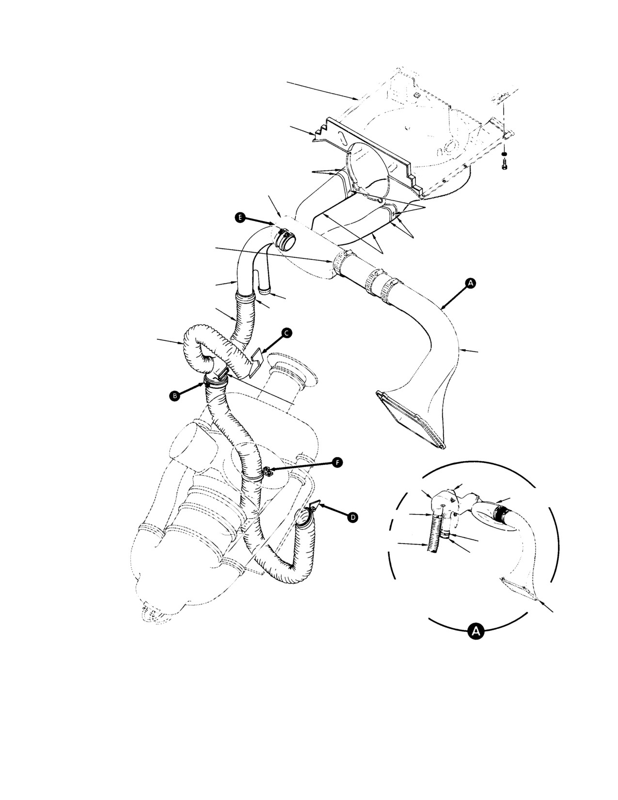
MD Helicopters, Inc.
CSP−H−2
500 Series − Basic HMI
TRANSMISSION COVER
COOLING INSTALLATION
BAFFLE
WITH BELT−DRIVEN
BLOWER
O−RING
(NOTE 2)
ENGINE OIL COOLER BLOWER
DUCT CONNECTOR
(NOTE 1)
O−RING
BLOWER PRIMARY OUTLET
(NOTE 2)
DUCT
COOL AIR MANIFOLD DUCT
CAP
ENGINE COOLING AIR DUCT
CLAMP
ENGINE COMPRESSOR
COOLING AIR DUCT
OIL COOLER DUCT
DUCT COUPLING
COOL AIR
STA. 121.50
MANIFOLD DUCT
OIL COOLER
BLOWER SCROLL
CLAMP
ENGINE COOLING
CLAMP
AIR DUCT
CAP
COOLING INSTALLATION
WITH SHAFT−DRIVEN
BLOWER
OIL COOLER
DUCT
NOTES:
1.
NOT INSTALLED ON ALL DUCTS.
2.
MAY BE REPLACED WITH NYLON TWINE
(30, TABLE 2−4).
30−083−1B
Figure 10-7. Engine Cooling (Sheet 1 of 2)
Page 10-21
Revision 18
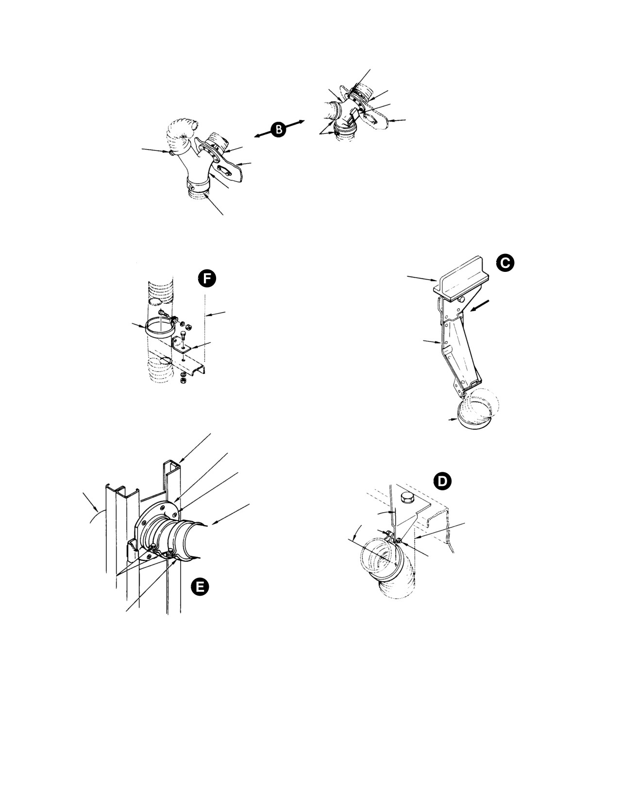
MD Helicopters, Inc.
CSP−H−2
500 Series − Basic HMI
SCREW, WASHERS AND NUT
(5 OR 6 PLCS)
DUCT COUPLING
CLAMP
RESTRICTOR
(NOTE 1)
STA. 124.00 CANTED
FIREWALL
CLAMP
CLAMP
CLAMP
STA. 124.00 CANTED
FIREWALL
DUCT COUPLING
CLAMP
ENGINE HOISTING
EYEBOLT
FWD
STA. 124.00
CLAMP
CLIP
SUPPORT BRACKET
DUCT SUPPORT RING
(INSIDE DUCT) CLAMP
CHANNEL ASSY
GASKET
(NOTE 3)
SCREW, WASHER AND NUT
COOL AIR
(5 PLCS)
MANIFOLD DUCT
BLOWER SECONDARY
OUTLET
NOTE 4
FIREWALL BULKHEAD
STA. 124.00
DUCT SUPPORT RING (INSIDE
DUCT), BOLT, CLAMP,
CLAMP OR O−RING
0.250 IN. (6.35 MM) SPACER ( * ),
0.28125 IN. (7.14375 MM) SPACER,
WASHER AND NUT
DUCT CONNECTOR
NOTES: (CONT)
3.
BOND TO STRUCTURE WITH ADHESIVE
(19, TABLE 2−4) ACCORDING TO
CONTAINER INSTRUCTIONS.
4.
ADJUST AT 45 DEGREES FOR 250−C18 ENGINE
AND 30 DEGREES FOR 250−C20 ENGINE.
30−083−2E
Figure
10-7. Engine Cooling (Sheet 1 of 2)
Page 10-22
Revision 18
MD Helicopters, Inc.
CSP−H−2
500 Series − Basic HMI
Section
11
Engine Control
Systems
MD Helicopters, Inc.
CSP−H−2
500 Series − Basic HMI
This Page Intentionally Left Blank
MD Helicopters, Inc.
CSP−H−2
500 Series − Basic HMI
TABLE OF CONTENTS
Para/Figure/Table
Title
Page
Section 11 Engine Control System .
11−1
1.
Power Control System
11−1
2.
Power Controls Troubleshooting
11−1
Table 11−1. Power Controls Troubleshooting
11−1
Figure 11−1. Engine Power Controls System
11−2
3.
Power Control System Rigging
11−3
A. Bendix Gas Producer Controls Rigging
11−3
Figure 11−2. Bendix Gas Producer Controls Rigging
11−4
Figure 11−3. Bendix Gas Procedure Fuel Control Adjustments .
11−5
B. CECO Gas Producer Fuel Control Rigging
11−6
Figure 11−4. CECO Gas Producer Control Rigging
11−7
Figure 11−5. Gas Producer Fuel Control Adjustment CECO .
11−8
C. Power Turbine Governor Controls Rigging (Bendix or CECO) .
11−9
Figure 11−6. Bendix Power Turbine Governor Controls Rigging (Sheet 1 of 2) .
11−10
Figure 11−7. CECO Power Turbine Governor Controls Rigging .
11−12
4.
Gas Producer Controls
11−15
A. Gas Producer Linkage Replacement
11−15
B. Gas Producer Control Linkage Inspection
11−16
Figure 11−8. Gas Producer Control Linkage Disassembly .
11−17
C. Gas Producer Control Linkage Repair
11−18
D. Gas Producer Throttle Linkage
11−18
5.
Power Turbine Governor Controls
11−18
A. Power Turbine Governor Linkage Replacement
11−18
Figure 11−9. Governor Control Linkage Disassembly (Forward of Engine
Compartment)
11−19
Figure 11−10. Governor Control Linkage Disassembly (Engine Compartment) .
11−20
B. Governor Control Linkage Inspection
11−21
C. Governor Control Rods and Bellcranks Repair
11−21
D. Relocation of Locknut and Installation of Spacer
11−22
E. Droop Control Override Link Assembly Repair
11−22
Figure 11−11. Relocation of Locknut − Sta. 68.00 Bellcrank Assembly .
11−23
6.
RPM Governor (N2) Trim Actuator
11−24
A. N2 Trim Actuator Replacement
11−24
B. N2 Trim Actuator Repair
11−24
C. N2 Trim Actuator Testing
11−24
Figure 11−12. N2 Trim Actuator Test hookup
11−24
7.
Anti−Icing System
11−25
Page 11−i
Revision 18
MD Helicopters, Inc.
CSP−H−2
500 Series − Basic HMI
TABLE OF CONTENTS (Cont.)
Para/Figure/Table
Title
Page
8.
Anti−Icing System Troubleshooting
11−25
Table 11−2. Anti−Icing System Troubleshooting
11−25
9.
Anti−Icing Controls (Electrically Operated System)
11−26
A. Anti−Icing Controls Operational Check (Electrically Operated0
11−26
B. Electrically Operated Anti−Icing Valve Rigging
11−26
C. Anti−Icing Valve Actuator and Linkage Replacement
11−26
Figure 11−13. Engine Anti−Icing Valve Electrically Actuated Equipment .
11−27
10. Anti−Icing Valve Control Cable (Manually Operated)
11−28
A. Anti−Icing Valve Control Operational Check (Manually Operated) .
11−29
B. Anti−Icing Valve Control Cable Inspection (Manually Operated) .
11−29
C. Anti−Icing Valve Control Cable Replacement (Manually Operated) .
11−29
Figure 11−14. Engine Anti−Icing Valve Manual Control Installation .
11−30
D. Anti−Icing Control Cable Repair (Manually Operated) .
11−31
Page 11−ii
Revision 18
MD Helicopters, Inc.
CSP−H−2
500 Series − Basic HMI
SECTION 11
ENGINE CONTROL SYSTEM
1. Power Control System
engine operation and maintenance manual for
fuel system theory of operation and other
detailed information.
(Ref. Figure 11−1) The power controls system
consists of the gas producer (N1) controls and
NOTE: The Bendix system may be used on
the power turbine (N2) governor controls. The
250−C18 Series engines converted to
mechanically operated gas producer controls
250− C20 configuration provided that Alli−
actuate the gas producer control lever that
son Commercial Engine Bulletin 250
schedules the quantity of fuel metered to the
CEB−126 and 250−C20 Installation Bulle−
engine. The electrically operated trim actuator
tin 1005 are complied with, and provided
and the mechanically operated droop compen−
that only the special ignition exciter Allison
PN 6870885 (GLA PN 43754) is used if auto−
sator change the position of the power turbine
matic reignition equipment is installed. Re−
governor control lever that regulates the
fer to CSP−H−3 for information on auto−re−
operating rpm of the engine. Bendix fuel
ignition equipment and the Model 250−C18
control system components are standard on
to 250−C20 engine conversion.
Allison 250−C18 engines and may also be
installed on the 250−C20 engine. Current
configuration helicopters equipped with the
2. Power Controls Troubleshooting
250−C20 engine use Chandler Evans (CECO)
fuel control system components. Refer to the
(Ref. Table 11−1)
Table 11-1. Power Controls Troubleshooting
Symptom
Probable Trouble
Corrective Action
Movement of control results in
Lost motion in linkage; gas
Tighten pipe plugs in torque tube for
springy feeling; response lags
producer interconnect torque tube
zero backlash (Ref. Sec. 7).
behind control movement
loose in collective stick gearshafts
Worn rod ends; worn bellcrank
Replace worn parts.
bearings
Control action stiff
Rod ends binding in fitting
Realign rod end bearings to
eliminate jamming.
Low power; improper idling speed;
Incorrectly adjusted gas producer
Adjust gas producer or power turbine
improper acceleration; variable
or power turbine governor controls
governor controls for correct
power output at constant setting
operation.
Defective gas producer control
Replace faulty unit (Ref. Engine
assembly or power turbine
Operation and Maintenance Manual).
governor
Stagnated or hot engine starts
Fuel control derichment
Adjust derichment valve (BENDIX).
misadjusted (BENDIX)
Fuel control light off and start
Adjust variable start and derichment
derichment controls misadjusted
control (CECO).
(CECO)
Excessive TOT readings during
Incorrectly adjusted engine power
Adjust engine power controls for
engine shutdown
controls
correct operation.
Page 11-1
Revision 18
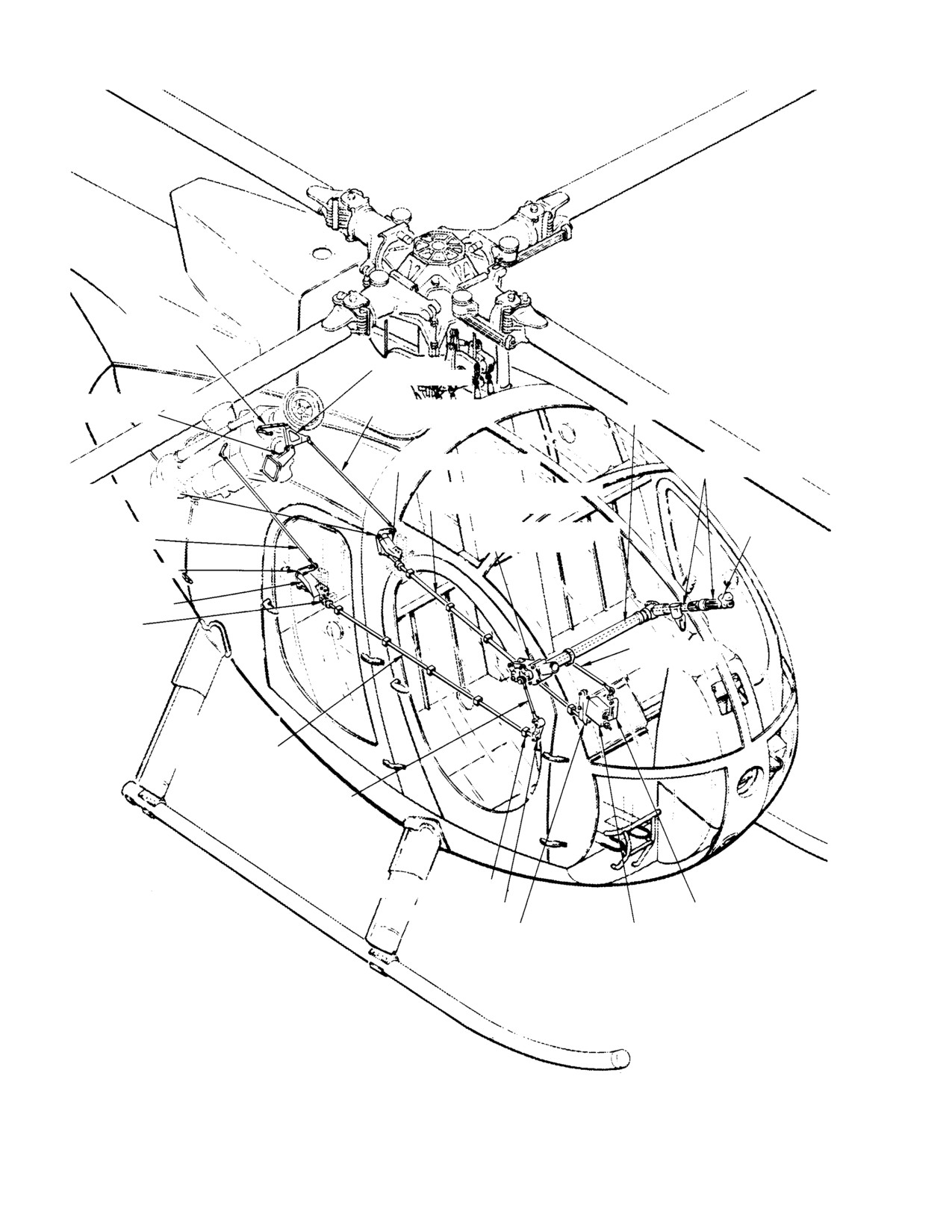
MD Helicopters, Inc.
CSP−H−2
500 Series − Basic HMI
GOVERNOR LEVER
CONTROL ROD
N2 CONTROL
IDLER BELLCRANK
RPM GOVERNOR CONTROL
GAS PRODUCER INTERCONNECT
N2 IDLER BELLCRANK
IDLER SUPPORT
TORQUE TUBE
CONTROL ROD
THROTTLE AND GAS
STA 124 CONTROL SUPPORT
PRODUCER TUBE
FUSELAGE−ROUTED CONTROL ROD
STA 124 BELLCRANK
(POWER TURBINE GOVERNOR)
N2 TRIM
GAS PRODUCER LEVER
INBD COLLECTIVE STICK
SWITCH
CONTROL ROD
SOCKET ASSY
STA 129 BELLCRANK
GAS PRODUCER CON−
TROL SUPPORT
FIRE SCREEN
(2 PLCS)
DROOP CONTROL
OVERRIDE LINK
FUSELAGE−ROUTED CON−
TROL ROD
(GAS PRODUCER)
STA 73 GAS PRODUCER
CONTROL ROD
SPACER (TYP 10 PLCS)
STA 70 BELLCRANK
STA 68 BELLCRANK
STA 72 BELLCRANK
N2 TRIM ACTUATOR
30−085
Figure 11-1. Engine Power Controls System
Page 11-2
Revision 18

MD Helicopters, Inc.
CSP−H−2
500 Series − Basic HMI
3. Power Control System Rigging
When repositioning the gas pro−
CAUTION
ducer lever in d below, do not ex−
ceed the lever nut torque limit of 40 − 50
Rigging of the engine power controls system
inch−pounds (4.52 − 5.65 Nm). Overtorqu−
must be accomplished:
ing will cause binding of the lever.
(1). Immediately after replacement of
(4). With the engine compartment gas
linkage that cannot be accurately
producer control rod length set to 16.56
measured (by trammeling, etc.) before it
inches (420.624 mm), re−establish the
is installed in either the gas producer
gas producer lever mid−position so that
control system or the power governor
lever centerline is half way between the
control system; or
‘‘closed" and ‘‘maximum" travel stops;
lever serrations have 15 degree spacing.
(The ‘‘closed" stop position is parallel to
(2). If engine operation reveals a rigging
the engine compartment door frame
deficiency.
within ±5 degrees.)
When tightening a jam nut to
If any interference exists at the
CAUTION
CAUTION
secure a control end, always
gas producer lever, check that
hold the rod end with a wrench to prevent
the correct lever is installed.
jamming of the bearing against the fitting.
Check that all misalignment is divided
(5). Lower collective stick to full down.
equally between bearings of each control rod
(6). Rotate pilot’s throttle counterclockwise
assembly.
to maximum rpm, then clockwise to
idle.
A. Bendix Gas Producer Controls Rigging
(7). With pilot’s throttle held at idle, adjust
upper rod end of gas producer lever rod
(Ref. Figure 11−2) The following rigging
until gas producer pointer is positioned
instructions apply to all 250−C18 engines and
at 30−31 degrees on quadrant (detail
250−C20 engines with a Bendix fuel control
A). Mark pointer position on quadrant
system.
with grease pencil.
NOTE: Adjustment steps (1). thru (4). of this
Do not alter gas producer lever
CAUTION
procedure are necessary only when the pi−
position or control linkage to ad−
lot’s compartment linkage or the fuselage−
just idle speed. Idle speed will be checked
routed control rod have been removed and
during flight test and, if necessary, adjusted
reinstalled or replaced, or if there is insuffi−
by the fuel control idle screw, not by the
cient clearance between the lower firewall
linkage. Check extreme travel position of
bellcrank and its support. Otherwise, per−
the linkage to ensure that gas producer le−
form adjustment of gas producer controls
ver hits the fuel control stops before the
starting with step (5).
throttle grip stops make contact. There
must be no interference or binding in the
linkage. Ensure linkage clears engine tub−
(1). Position the collective stick and throttle
ing.
at mid−travel.
(8). Rotate pilot’s throttle counterclockwise
(2). Adjust the length of the Sta. 73 control
to maximum rpm.
rod so that the long arm of Sta. 70
bellcrank is vertical.
(9). Observe gas producer lever to ensure it
strikes the maximum travel stop.
(3). Adjust the length of the fuselage−
(10). Raise collective stick to full up.
routed gas producer control rod so that
the bolt center in the lower arm of Sta.
(11). If gas producer lever does not strike
129 bellcrank is 5.00 ±0.03 inch (127
maximum travel stop, check gas
±0.762 mm) from the firewall.
producer controls for binding.
Page 11-3
Revision 18
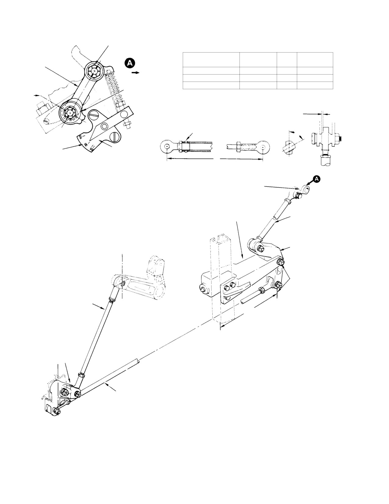
MD Helicopters, Inc.
CSP−H−2
500 Series − Basic HMI
40−50 IN. LB
(4.52−5.65 NM) MAX.
INITIAL ROD ASSY LENGTH AND BEARING ANGULARITY (BEFORE RIG)
CONTROL
DIMENSION L
ANGLE
ASSY PART
GAS PRODUCER
ROD ASSY
IN. (CM)
A
NUMBER
LEVER
FWD
FUSELAGE−ROUTED
58.67
(149.0218)
IN LINE
369A7008−5
STA. 73
7.11
(18.0594)
IN LINE
369A7334
GAS PRODUCER LEVER
16.56
(42.0624)
IN LINE
369A7705−5
L OF CON−
LEVER CONTROL
TROL ROD
ROD
0.040 IN. (1.016 MM) MAX. AL−
LOWABLE AXIAL PLAY
MS20470AD RIVET
A
LEVER POSITION
NOTE 2
QUADRANT
L
GAS PRODUCER LEVER CENTERLINE
SHOULD BE HALF−WAY BETWEEN
CLOSED AND MAXIMUM TRAVEL STOPS
(NOTE 1)
GAS PRODUCER CON−
GAS PRODUCER LE−
TROL SUPPORT
VER CONTROL ROD
STA 74.87
(L OF COLLECTIVE
STA 129 BELL−
PITCH TORQUE TUBE)
CRANK
VERTICAL CENTERLINES
SHOULD COINCIDE
(NOTE 1)
STA 73 CONTROL ROD
5 IN. (12.7 CM)
STA 124
STA 70 BELL−
CRANK
FUSELAGE−ROUTED
CONTROL ROD
NOTES:
1.
WITH COLLECTIVE STICK AND THROTTLE AT MID−TRAVEL.
2.
NORMAL SETTING IS 30−31 DEGREES.
IF THROTTLE TUBE IN COLLECTIVE STICK NOT MODIFIED,
CENTERLINE SHOULD
SETTING IS 30−35 DEGREES.
BE VERTICAL
(NOTE 1)
30−086F
Figure 11-2. Bendix Gas Producer Controls Rigging
Page 11-4
Revision 18
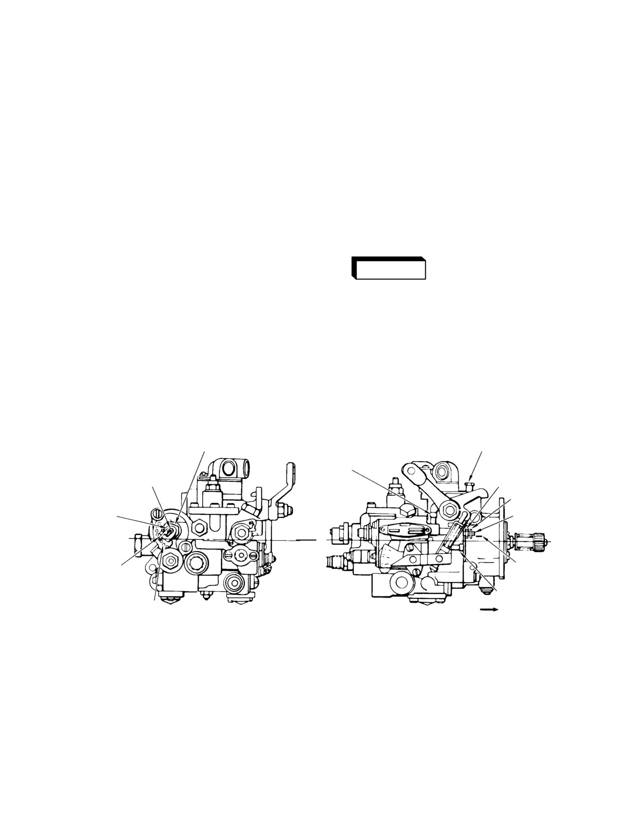
MD Helicopters, Inc.
CSP−H−2
500 Series − Basic HMI
(12). Rotate pilot’s throttle fully clockwise to
speed stabilizes at 62−67 percent.
fuel off. Observe gas producer lever to
Adjust N1 speed with the fuel control
ensure it strikes minimum travel stop
idle speed adjustment screw (Ref.
(closed position).
Figure 11−3).
(13). Lower collective stick to full down.
(17). If idle rpm does not stabilize within
Observe gas producer lever to ensure it
limits in step (16)., proceed with engine
does not move from the minimum travel
troubleshooting in engine operation and
stop.
maintenance manual.
(14). At the full closed and full open posi−
NOTE: Bendix gas producer fuel controls
tions of the throttle, check all the
equipped with a variable derichment valve
movable linkage for clearance with
may be adjusted to eliminate stagnated or
supporting or adjacent parts. Check
hot starts (Ref. Allison Operation and Main−
that control rod bearings are not
tenance Manual).
jammed when the linkage is in the
extreme control positions.
The following check must be
WARNING
made to ensure that engine
NOTE: Before operating an engine in 250−C20
shutdown will not occur due to throttle
configuration with a Bendix gas producer
chop. Refer to NOTE: after step (17).
fuel control, check that the maximum fuel
flow adjusting screw is fixed in position
(18). Rotate pilot’s throttle control counter−
shown in Figure 11−3.
clockwise to normal engine operating
rpm; then clockwise to idle in a manner
(15). Start and operate engine at idle with
simulating a pilot training throttle
main rotor blades in flat pitch according
chop. Repeat this check using the
to the Owner’s Manual.
copilot’s throttle if optional dual
(16). With pilot’s throttle at idle, observe N1
controls are installed. If shutdown
tachometer indicator to ensure N1
occurs, perform steps (19). and (20).
IDLE SPEED ADJUSTING SCREW
LOCKNUT
(NOTE 1)
MINIMUM SPEED
START DERICHMENT
STOP
ADJUSTING SCREW
LOCKNUT
DIAL
(NOTE 2)
CLAMP
MAXIMUM FLOW
ADJUSTING SCREW
SCRIBE LINE (TYP)
POINTER
(NOTE 2)
MAXIMUM SPEED
REFERENCE DOTS AT
STOP SCREW
FWD
10 DEGREE INTERVALS
REAR VIEW
SIDE VIEW
(AS INSTALLED)
(AS INSTALLED)
NOTES:
1.
TURN CLOCKWISE TO INCREASE, COUNTERCLOCKWISE TO DECREASE
N1 SPEED. ENGINE SPEED CHANGES APPROXIMATELY 5% PER 1/8 TURN
(USE ALLISON TOOL P/N 6798292.)
2.
USED ONLY WITH 250−C20 ENGINE WITH BENDIX FUEL CONTROL. INDEX
LINE ON FACE OF DIAL TO ALIGN WITH SCRIBE MARK ON SIDE OF DRIVE BODY.
30−155B
Figure 11-3. Bendix Gas Procedure Fuel Control Adjustments
Page 11-5
Revision 18
MD Helicopters, Inc.
CSP−H−2
500 Series − Basic HMI
(19). Adjust upper rod end of gas producer
129 bellcrank is 5.00 ±0.03 inch (127
lever rod to increase rod length by one
±0.762 mm) from the firewall.
or two rod turns to obtain slightly
higher setting (31 degrees maximum)
(4). Set gas producer lever control rod
on lever position quadrant. Be sure
length to 16.56 inches (420.624 mm).
maximum control rod length is not
When reinstalling control lever
exceeded by checking at the control rod
CAUTION
on fuel control shaft in next
witness hole.
step, do not exceed nut torque of 40 − 50
inch−pounds (4.52 − 5.65 Nm). Overtorqu−
(20). Repeat procedures in (5). thru (19).
ing will cause binding of the lever.
until engine shutdown does not occur
from a throttle chop.
(5). Remove control lever from gas producer
fuel control, rotate quadrant pointer to
NOTE: After rigging and testing of Bendix or
0° and then reinstall control lever so
CECO gas producer controls, perform a de−
that it is approximately parallel to
celeration check in accordance with proce−
engine compartment door frame.
dures found in the pilot’s flight manual, If
confirmed deceleration time is less than the
NOTE: Control lever serrations have a 15°
allowable minimum, refer to the applicable
spacing.
Allison Operation and Maintenance Manu−
al.
(6). Rotate pilot’s throttle to cutoff position
and connect gas producer rod to control
B. CECO Gas Producer Fuel Control Rigging
lever.
(Ref. Figure 11−4) The following rigging
If any interference exists at the
CAUTION
instructions apply to 250−C20 engines with a
gas producer lever, check that
CECO fuel control system.
the correctlever is installed.
(7). Rotate pilot’s throttle to fully open
NOTE: For all new fuel control unit installa−
position and check that fuel control
tions, check that the maximum fuel flow
quadrant pointer is on 90° and that
stop adjustment screw (Figure 11−5) is set
maximum stop on fuel control is
at the minus (−) mark, 235 PPH (107 kgPH).
contacted before throttle grip stop is
Use a 3/32 inch Allen wrench to reset the
contacted.
screw if required.
(8). Rotate pilot’s throttle to idle position
NOTE: Adjustment steps (1). thru (4). of this
and check that fuel control pointer is at
procedure are necessary only when the pi−
the 30° mark and that rigging pin holes
lot’s compartment linkage or the fuselage−
are aligned. Make small adjustments in
routed control rod have been removed and
length of gas producer control rod, at
reinstalled or replaced, or if there is insuffi−
the control lever end, if required.
cient clearance between the lower firewall
bellcrank and its support. Otherwise, per−
NOTE: The maximum allowable rigging error
form adjustment of gas producer controls
at idle position (pointer position not at 30°)
starting with step (5).
is 0.078 inch (1.984 mm) below the 30°
mark. However, the higher setting (30°) is
(1). Position the collective stick and throttle
required to prevent inadvertent over− con−
at midtravel.
trol and shutdown when dual controls are
installed.
(2). Adjust the length of the Sta. 73 control
rod (Figure 11−4) so that the long arm
(9). Rotate pilot’s throttle to cutoff position
of Sta. 70 bellcrank is vertical.
and check that quadrant pointer is at 0°
to minus 2° and that stop is in contact.
(3). Adjust the length of the fuselage−
The minimum stop on the fuel control
routed gas producer control rod so that
should be in contact before the throttle
the bolt center in the lower arm of Sta.
grip stop is contacted.
Page 11-6
Revision 18
MD Helicopters, Inc.
CSP−H−2
500 Series − Basic HMI
INITIAL ROD ASSY LENGTH AND BEARING ANGULARITY (BEFORE RIG)
CONTROL
DIMENSION L
ANGLE
ASSY PART
ROD ASSY
IN. (CM)
A
NUMBER
FUSELAGE−ROUTED
58.67
(149.0218)
IN LINE
369A7008−5
STA. 73
7.11
(18.0594)
IN LINE
369A7334
GAS PRODUCER LEVER
16.56
(42.0624)
IN LINE
369A7705−5
0.040 IN. (1.016 MM) MAX.
ALLOWABLE AXIAL PLAY
MS20470AD RIVET
A
L
CONTROL LEVER
(NOTES 2, 3)
CECO FUEL CONTROL
NOTES:
1.
WITH COLLECTIVE STICK AND THROTTLE AT MID−TRAVEL.
GAS PRODUCER
2.
LVER SRRATIONS HAVE 15 DEGREE SPACING.
GAS PRODUCER
CONTROL SUPPORT
3.
INSTALL LEVER ON FUEL CONTROL SHAFT WITH POINTER
LEVER CONTROL ROD
AT 0° MARK ON QUADRANT AND WITH LEVER PARRALLEL
TO ENGINE COMPARTMENT DOOR FRAME.
STA 129
BELLCRANK
STA 74.87
(L OF COLLECTIVE
PITCH TORQUE TUBE)
VERTICAL CENTERLINES
SHOULD COINCIDE
(NOTE 1)
5 IN. (12.7 CM)
STA 73 CONTROL ROD
STA 124
IDLE
POSITION
CECO FUEL CONTROL
0.078125 IN. (1.984375 MM)
STA 70
MAX. ALLOWABLE POSITION
QUADRANT
BELLCRANK
ERROR FROM ALL CAUSES
FUSELAGE−ROUTED
TORQUE NUT TO
CONTROL ROD
40−50 IN. LB
POINTER
(NOTE 3)
(4.52−5.65 NM)
RIGGING PIN
PROVISIONS
CENTERLINE SHOULD
BE VERTICAL
(NOTE 1)
30−21 1A
Figure 11-4. CECO Gas Producer Control Rigging
Page 11-7
Revision 18
MD Helicopters, Inc.
CSP−H−2
500 Series − Basic HMI
MAX FLOW STOP
ADJUSTMENT SCREW
270 PPH SETTING
(NOT USED)
235 PPH SETTING
BOTTOM VIEW
IDLE SCREW ADJUSTMENT
MIN THROTTLE STOP (C.O.)
QUADRANT (CONTROL
MAX THROTTLE STOP
LEVER REMOVED)
START DERICHMENT
ADJUSTMENT
LIGHTOFF ADJUSTMENT
PAD END
RIGHT SIDE VIEW
(CONTROL LEVER REMOVED)
(AS INSTALLED)
30−210
Figure 11-5. Gas Producer Fuel Control Adjustment CECO
Page 11-8
Revision 18
MD Helicopters, Inc.
CSP−H−2
500 Series − Basic HMI
The minus 2° pointer position is
The following check must be
CAUTION
WARNING
desired for positive fuel cut−off.
made to ensure that engine
One−half turn on the minimum stop screw
shutdown will not occur due to throttle
equals 2° of pointer travel.
chop.
(10).
Rotate pilot’s throttle to fully open
(19). Rotate pilot’s throttle control counter−
position and check that fuel control
clockwise to normal engine operating
pointer is at 90° and in contact with the
rpm; then clockwise to idle in a manner
maximum stop.
simulating a pilot’s training throttle
(11).
Raise collective stick to full up position
chop. If optional dual controls are
and check that fuel control pointer
installed, repeat this check using the
remains in contact with the maximum
copilot’s throttle. If shutdown occurs
stop.
perform steps (20). and (21).
(12).
Rotate pilot’s throttle to cutoff position
(20). Recheck rigging and adjust rod length
and check that fuel control pointer
at upper rod end of gas producer lever
contacts the minimum stop.
rod, as required, until neither the pilot’s
(13).
Lower the collective stick to full down
or copilot’s throttle will move quadrant
position and check that fuel control
pointer below 30° at idle. Be sure
pointer remains on the minimum stop.
maximum control rod length is not
(14).
Recheck idle position rigging by
exceeded by checking at the control rod
rotating pilot’s throttle from cutoff
witness hole.
position to idle and from full open
position to idle. The fuel control pointer
(21). Recheck engine operation to determine
should indicate 30° with rigging pin
that shutdown does not occur at
holes aligned in both cases.
throttle chop, using both the pilot’s and
copilot’s throttles.
(15).
While operating the throttle through its
complete range, check all movable
C. Power Turbine Governor Controls
linkage for clearance from supporting
Rigging (Bendix or CECO)
and adjacent parts and check that
control rod bearings are not jammed at
Before rigging the power turbine governor
extremes of travel.
controls, determine the type governor installed
(16).
Start and operate engine at idle with
(either BENDIX or CECO).
main rotor blades in flat pitch according
to the Owner’s Manual.
(Ref. Figure 11−6 for the BENDIX installation.
(17).
With pilot’s throttle at idle, observe N1
(Ref. Figure 11−7 for the CECO installation.
tachometer indicator to ensure Nl speed
stabilizes at 61−65 percent. Adjust N1
speed with the fuel control idle speed
(1). Bendix Rigging Adjustments:
adjustment screw (Figure 11−5) using
5/16 inch Allen wrench. A 1/8 turn
NOTE: Adjustment steps (a). thru (d). of this
equals approximately 1% N1. Turn the
procedure are necessary only when: the un−
screw clockwise to increase N1 idle
derseat linkage or the fuselage−routed con−
speed.
trol rod has been removed and reinstalled or
replaced; or with Bendix governors prior to
(18).
If idle rpm does not stabilize within
Allison PN 6873450 installed, if there is less
limits in step (17)., proceed with engine
than 0.030 inch (0.762 mm) clearance be−
troubleshooting in engine operation and
tween the lower firewall bellcrank and its
maintenance manual.
support when the governor lever is at the
NOTE: The CECO fuel control is equipped with
maximum stop. (If governor nameplate does
lightoff and start derichment controls which
not have an Allison part number, the gover−
may be adjusted to eliminate stagnated or
nor is prior to PN 6873450.) Otherwise, per−
hot starts. (Ref. Allison Operation and
form adjustment of power turbine governor
Maintenance Manual)
controls starting with step (e).
Page 11-9
Revision 18
MD Helicopters, Inc.
CSP−H−2
500 Series − Basic HMI
INITIAL ROD ASSY LENGTH AND BEARING ANGULARITY (BEFORE RIG)
CONTROL
DIMENSION L
ANGLE
ASSY PART
NOTES:
ROD ASSY
IN. (CM)
A
NUMBER
1.
INITIAL DIMENSION: SHORTEN TO INCR
FUSELAGE−ROUTED
56.13
(142.5702)
IN LINE
369A7008−3
COMPENSATION. LENGTHEN TO DECREASE.
N2 IDLER BELLCRANK
14.38
(36.5252)
90°
369A7705
2.
DROOP CONTROL OVERRIDE LINK SPRING
GOVERNOR LEVER
3.94
(10.0076)
90°
369A7706
STARTS TO COMPRESS, GOV LEVER AT
APPROX. 78° AND STA 124.00 BELLCRANK
BOTTOMED.
0.040 IN. (1.016 MM) MAX. AL−
MS20470AD3
LOWABLE AXIAL PLAY
RIVET
A
L
GOVERNOR LEVER
CONTROL ROD
CONTROL IDLER
SUPPORT
COLLECTIVE TORQUE TUBE
IDLER BELLCRANK
IDLER BELLCRANK
CONTROL ROD
DROOP COMPENSATION
ADJUSTMENT FORK
DROOP CONTROL
OVERRIDE LINK
STRUCTURE RIB
STA 124.00
(REF)
(REF)
N2 TRIM
ACTUATOR
1.60 IN. (4.064 CM)
STA 68.00 BELLCRANK
(NOTE 1)
3.63 IN.
STA 124.00 BELLCRANK
(NOTE 2)
(NOTE 2)
STA 124.00 CONTROL
SUPPORT
FUSELAGE−ROUTED
STA 72.00
CONTROL ROD
BELLCRANK
30−087−1B
Figure 11-6. Bendix Power Turbine Governor Controls Rigging (Sheet 1 of 2)
Page 11-10
Revision 18
MD Helicopters, Inc.
CSP−H−2
500 Series − Basic HMI
RIGGING BENDIX GOVERNOR (PRIOR TO ALLISON PN 6873450)
FWD
TRIM ACTUATOR RETRACTED
TO MINIMUM N2, COLLECTIVE
PARALLEL TO
NOTE 8
STICK DOWN
ENGINE
L
MINIMUM N2 STOP
(UNUSED)
GOVERNOR LEVER CONTROL ROD
ADJUSTED TO POSITION LEVER 80°
(UNUSED TRAVEL)
FROM MINIMUM STOP (NOTE 3)
MAXIMUM N2 STOP
40−50 IN. LB
(NOTE 7)
(4.52−5.65 NM) MAX.
GOVERNOR LEVER
GOVERNOR POINTER
(NOTE 5)
(NOTE 4)
RIGGING BENDIX GOVERNOR (ALLISON PN 6873450 OR LATER)
NOTE 8
TRIM ACTUATOR RETRACTED
GOVERNOR LEVER CONTROL ROD ADJUSTED
TO MINIMUM N2, COLLECTIVE
TO POSITION LEVER 68° FROM MINIMUM STOP
STICK DOWN
(NOTE 3)
MINIMUM N2 STOP
(UNUSED)
(UNUSED TRAVEL)
MAXIMUM N2 STOP RANGE
(NOTE 7)
GOVERNOR LEVER
GOVERNOR POINTER
(NOTE 5)
(NOTE 6)
40−50 IN. LB
(4.52−5.65 NM) MAX.
MAXIMUM SPEED
POSITION
ONE SERRATION 15°
NOTES: (CONT)
3.
WITH TRIM ACTUATOR EXTENDED TO MAXIMUM N2, COLLECTIVE STICK DOWN.
4.
POINTER SHOULD ALIGN WITH GOVERNOR LEVER CENTERLINE.
5.
LEVER SERRATIONS HAVE 15° SPACING.
6.
WITH POINTER ONE SERRATION CLOCKWISE (AWAY FROM ENGINE) FROM LEVER
CENTERLINE, TIP SHOULD ALIGN BETWEEN LETTERS P & E OF WORD SPEED.
7.
DROOP CONTROL OVERRIDE LINK SPRING STARTS TO COMPRESS, ARM IS NOT
REQUIRED TO HIT MAXIMUM STOP WITH FULL COLLECTIVE AND ACTUATOR EXTENDED.
8.
TRAVEL LIMIT OF TRIM ACTUATOR IS 32°.
30−087−2D
Figure 11-6. Bendix Power Turbine Governor Controls Rigging (Sheet 2 of 2)
Page 11-1 1
Revision 18
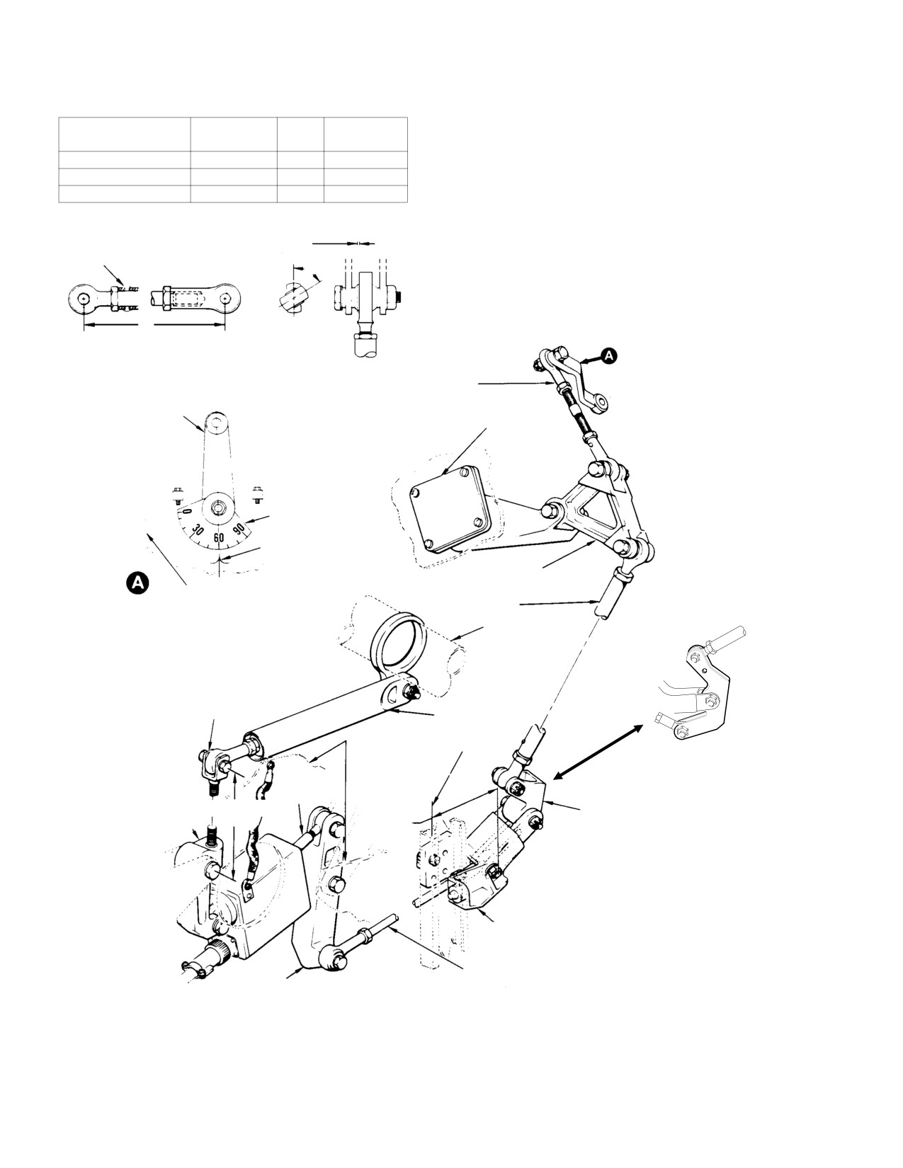
MD Helicopters, Inc.
CSP−H−2
500 Series − Basic HMI
INITIAL ROD ASSY LENGTH AND BEARING ANGULARITY (BEFORE RIG)
NOTES:
CONTROL
DIMENSION L
ANGLE
ASSY PART
1.
INITIAL DIMENSION: SHORTEN TO INCREASE
ROD ASSY
IN. (CM)
A
NUMBER
COMPENSATION, LENGTHEN TO DECREASE.
FUSELAGE−ROUTED
56.13
(142.5702)
IN LINE
369A7008−3
2.
WITH PILOT’S COLLECTIVE STICK AT FULL DOWN
N2 IDLER BELLCRANK
14.28
(36.2712)
90°
369A7705
AND N2 TRIM ACTUATOR AT FULL INCREASE.
GOVERNOR LEVER
4.15
(10.541)
90°
369A7706
0.040 IN. (1.016 MM) MAX. AL−
MS20470AD3
LOWABLE AXIAL PLAY
RIVET
A
L
GOVERNOR LEVER
CONTROL ROD
CONTROL LEVER
CONTROL IDLER
SUPPORT
MAX
MIN
STOP
STOP
CECO GOVERNOR
QUADRANT
POINTER
IDLER BELLCRANK
PARTING LINE OF
IDLER BELLCRANK
GOVERNOR OUTER
CONTROL ROD
COVER PARALLEL
COLLECTIVE
TO LEVER
L
TORQUE TUBE
DROOP COMPENSATION
ADJUSTMENT FORK
369A7717−3
DROOP CONTROL
OVERRIDE LINK
STRUCTURE
RIB
STA 124.00
N2 TRIM
ACTUATOR
2.30 IN. (5.842 CM)
3.60 IN.
STA 124.00 BELLCRANK
(NOTE 1)
STA 68.00 BELLCRANK
(NOTE 2)
STA 124.00 CONTROL
SUPPORT
FUSELAGE−ROUTED
STA 72.00
CONTROL ROD
BELLCRANK
30−212B
Figure 11-7. CECO Power Turbine Governor Controls Rigging
Page 11-12
Revision 18
MD Helicopters, Inc.
CSP−H−2
500 Series − Basic HMI
(a).
Check that droop control override
NOTE: Do not exceed the lever nut torque limit
link total end play does not exceed
of 40 − 50 inch−pounds (4.52 − 5.65 Nm) or
0.015 inch (0.381 mm).
the lever will bind.
NOTE: The pointer−to−lever positions specified
(b).
Check that the correct droop com−
above are standard production settings. Oc−
pensation adjustment fork is
casionally, slight variation in pointer−to−le−
installed. Fork must measure
ver position may be required to obtain prop−
2.50−2.75 inches (63.50−69.85 mm)
er travel and satisfactory engine operation.
from center of link hole to end of
Such variation is acceptable provided all
threaded shaft. Adjusted so that the
other rigging and engine performance re−
installed dimension between the
quirements are met. Governor lever travel
centerlines of the Sta. 68 bellcrank
produced by trim actuator operation, from
pivot bolt and the fork bolt is 1.60
forward travel point (trim actuator re−
±0.03 inches (40.64 ±0.762 mm).
tracted, collective stick down) to the aft
travel point (trim actuator extended − col−
(c).
Connect and turn on external power.
lective stick down), is 32°. Approximately
Check that the N2 trim actuator is
48° degrees of governor lever travel from the
adjusted so that the dimension
minimum N2 stop is unused on governors
between attach bolt centers is 5.47
prior to Allison PN 6873450; 36 degrees is
±0.03 inches (138.938 ±0.762 mm)
unused on governors with Allison PN
with actuator at maximum extension.
6873450 or later.
(d).
With the pilot’s collective stick full
(g). Adjust governor lever control rod
down and the N2 trim actuator at
length until the governor pointer is
maximum extension, adjust the
at the center of the letter D in the
length of the fuselage−routed gover−
word SPEED embossed on the power
nor control rod so that the bolt center
turbine governor (detail A) or be−
in the lower arm of Sta. 124 bell−
tween the letters P and E in the word
crank is 3.63 ±0.03 inches (92.202
SPEED (detail B), as applicable.
±0.762 mm) from the firewall.
(h). Raise the pilot’s collective stick
(e).
Check that the engine compartment
approximately one−third to one−half
N2 idler bellcrank control rod length
of full up travel and note the follow−
is set to 14.38 ±0.03 inches (365.252
ing with the N2 trim actuator fully
±0.762 mm).
extended:
(f).
Check position of governor lever and
1). With governor shown in detail A
pointer.
installed, the governor lever may
shift to the maximum travel stop.
1). On Bendix governors prior to
NOTE: As the stick is raised above this position
Allison PN 6873450, the lever
and until it reaches full up travel the droop
pointer should align with the lever
control override spring compression contin−
centerline (detail A).
ues to increase.
2). On Bendix governors with Allison
2). With governor shown in detail B
PN 6873450 or later, the lever
installed, check that the governor
pointer should be positioned one
lever shifts to between the E and D
serration clockwise (away from
in the word SPEED before the
engine) from lever centerline
linkage (lower arm of Sta. 124
(detail B).
bellcrank) bottoms out.
3). Reposition lever and pointer, if
(i). Lower collective stick to full down
necessary, starting with both the
and decrease N2 trim to minimum.
lever and governor shaft at the
Check that the governor lever shifts
minimum stop; lever serrations
back to approximately over the N of
have 15 degree spacing.
N2 embossed on the governor.
Page 11-13
Revision 18
MD Helicopters, Inc.
CSP−H−2
500 Series − Basic HMI
If any interference exists at the
(h). Install governor lever control rod and
CAUTION
governor lever, check that the
check rigging as indicated by gover−
correct lever is installed.
nor quadrant and pointer.
(2). CECO Rigging Adjustments:
1). With pilot’s collective stick full
down and with full increase trim,
(a).
Check that droop control override
read 75° ±2°. Operate N2 trim to
Link total end play does not exceed
full decrease and read 45° ±2°.
0.015 inch (0.381 mm).
2). With pilot’s collective stick full up
(b).
Check that correct droop compensa−
and with full decrease trim read
tion adjustment fork is installed.
64° ±2°. Operate N2 trim to full
Fork must measure 3.00 inches (76.2
increase and read 90° (quadrant
mm) from center of the link hole to
contacting maximum stop screw).
end of threaded shaft. Adjusted so
that the installed dimension between
NOTE: Use a mirror to view quadrant and
the centerlines of the Sta. 68 bell−
pointer squarely when taking readings.
crank pivot bolt and the fork bolts is
2.30 ±0.02 inches (58.42 ±0.508 mm).
(i). Adjust length of governor lever
control rod as required to achieve
(c).
Connect and turn on external power.
travel within the limits of steps (h).
Check that the N2 trim actuator is
1). and 2).
adjusted so that the dimension
between attach bolt centers is 5.47
If any interference exists at the
CAUTION
±0.02 inches (138.938 ±0.508 mm)
governor lever, check that the
with actuator at maximum extension.
correct lever is installed.
(d).
With the pilot’s collective stick full
(3). Final Check and Adjustment (Bendix or
down and the N2 trim actuator at
CECO):
maximum extension, adjust the
length of the fuselage−routed gover−
(a).
At the full up and full down positions
nor control rod so that the bolt center
of the collective stick, check all
in the lower arm of Sta. 124 bell−
movable linkage for clearance with
crank is 3.60 ±0.02 inches (91.44
supporting or adjacent parts. Check
±0.508 mm) from the firewall.
that the control rod, N2 actuator and
override link bearings are not
(e).
Check that the engine compartment
jammed when the linkage is in the
N2 idler bellcrank control rod length
extreme control positions.
is set to 14.28 ±0.03 inches (362.712
±0.762 mm).
(b).
Start and operate engine at idle with
main rotor blades in flat pitch
(f).
Adjust governor lever control rod
according to Pilot’s Flight Manual.
length to 4.15 inches (105.41 mm)
between attaching bolt centers.
(c).
Rotate pilot’s throttle counterclock−
wise to maximum rpm.
(g).
Remove control lever from turbine
governor. Rotate control quadrant
(d).
Decrease N2 trim to minimum.
until 60° mark aligns with pointer on
housing and then reinstall control
(e).
Observe N2 tachometer pointer for 98
lever so that it is approximately
percent or less (250−C18); 100
parallel to the governor outer cover
percent or less (250−C20) when rotor
parting line.
rpm pointer is superimposed on N2
pointer and Nl
tachometer pointer is
NOTE: Lever and quadrant serrations have 15°
stabilized.
spacing. Do not exceed 40 − 50 inch−
pounds (4.52 − 5.65 Nm) torque when
(f).
With collective stick down, increase
tightening the lever nut.
N2 trim to maximum.
Page 11-14
Revision 18
MD Helicopters, Inc.
CSP−H−2
500 Series − Basic HMI
(g). Observe N2 tachometer pointer for
a). Shorten droop compensation
103 percent minimum (250−C18),
adjustment fork to increase
104 percent minimum (250−C20);
compensation.
104 percent maximum (250−C18),
b). Lengthen fork extension to
105 percent maximum (250−C20)
decrease compensation.
when rotor rpm pointer is superim−
posed on N2 pointer and N1 tachome−
c). Align fork with override link rod
ter pointer is stabilized.
end before tightening fork jam
nut.
Make all engine compartment
CAUTION
control rod adjustments with
d). Three to five turns of droop
engine shut down.
compensation fork may be
necessary to change droop
(h). Stop the engine. Adjust the length of
compensation approximately 0.5
the governor lever control rod until
percent.
N2 trim is within limits given in
(m).
If high operating range for N1 and
steps (e). and (g). Adjust one rod end
TOT cannot be reached when full
not more than one turn at a time.
power is demanded in flight, the gas
producer fuel control maximum
(i). Restart the engine, actuate N2 trim
throttle stop may require adjustment.
for 102 percent with main rotor
(Refer to Allison Operation and
blades in flat pitch, lift off and hover.
Maintenance Manual.)
(j). Observe N2 tachometer pointer when
NOTE: After rigging and test of Bendix or
pointer of Nl tachometer is stabilized.
CECO power turbine governor controls, per−
N2 pointer indication (droop compen−
form deceleration check in accordance with
sation) should be 1 to 2 percent
procedure found in the pilot’s flight manual.
(250−C18) 0.50 to 1 percent
If confirmed deceleration time is less than
(250−C20) above N2 setting in step
the allowable minimum, refer to the appli−
(i).
cable Allison Operation and Maintenance
Manual.
(k). Land and shut down engine.
4. Gas Producer Controls
(l). If droop compensation does not occur
as required in step (k)., perform the
(Ref. Figure 11−1) The gas producer controls
following:
include the throttle and its associated linkage
in the collective controls system (Ref. Sec. 7), a
1). Recheck entire power turbine
fuselage−routed control rod and engine
governor (N2 rpm) control linkage
compartment linkage. The control rod assem−
rigging.
blies consist of aluminum alloy tubes or solid
rods with spherical bearing rod ends. Bell−
2). Check gas producer (Nl fuel con−
cranks and supports are either cast aluminum
trol) linkage adjustment.
or magnesium, each bellcrank containing a
roller bearing. Refer to Section 2 for corrosion
Any change to initial droop com−
control and identification of magnesium and
CAUTION
pensation fork length may re−
aluminum alloy parts.
sult in interference between N2 trim actua−
A. Gas Producer Linkage Replacement
tor case and fork threaded end. Move
collective through full travel after adjust−
(Ref. Figure 11−8) Disassemble linkage only to
ment and check for clearance between mov−
extent necessary to replace worn or damaged
able linkage and adjacent parts.
parts, or to perform repairs.
3). If Nl and N2 linkage are correctly
(1). Remove cotter pins, nuts, washers and
adjusted, an additional adjustment
bolts as necessary to disconnect the
may be made at droop compensa−
appropriate control rod, bellcrank or
tion adjustment fork.
support.
Page 11-15
Revision 18
MD Helicopters, Inc.
CSP−H−2
500 Series − Basic HMI
(2). Remove the control support from the
the collar swaging is questionable, use
firewall by removing the three standard
a Cherry or Huck inspection (strip)
bolts, washers and nuts from the
gage (#HG85−10) or an equivalent
vertical stiffener; then remove the
inspection gage per NAS1563 to check
pull−type lockbolt from the firewall as
for proper installation. Replace an
follows:
incorrectly installed lockbolt.
(6). Tighten the three nuts that attach the
(a). Locate the lockbolt installation at the
control support to the firewall.
floorline of the cargo compartment.
Split the collar axially with a sharp
NOTE: Before installing any control rod, mea−
cold chisel. Use a backup bar on the
sure the rod assembly for correct length
collar opposite to the side being split,
(Ref. Figure 11−2 or Figure 11−4).
to prevent deformation or breakout of
the hole.
When tightening a jam nut to
CAUTION
secure a control rod end, always
(b). Drive the lockbolt pin out with a
hold the rod end with a wrench to prevent
drift.
jamming of the bearing against the fitting.
Check that all misalignment is divided
NOTE: If lockbolt is carefully removed, another
equally between the bearings of each control
lockbolt of same diameter may be used as re−
rod assembly.
placement. If hole is enlarged to more than
0.1870 inch (4.7498 mm), an oversized lock−
(7). Install replacement control rod or
bolt must be installed.
bellcrank with bolt, washers, nut, and
new cotter pin (Ref. Figure 11−8).
(3). Fit replacement control support on the
(8). Rig the gas producer control system.
firewall. Align the three standard bolt
holes and the lockbolt hole with the
B. Gas Producer Control Linkage Inspection
matching holes. Install, but do not
tighten the three standard bolts,
washers, and nuts.
(1). Inspect rod end bearings for binding
and excessive wear, 0.040 inch (1.016
mm) maximum axial play.
NOTE: If locknut hole diameter in the firewall
does not exceed 0.1870 inch (4.7498 mm), a
(2). Inspect control rod for surface damage
standard diameter pin can be used. If the
and evidence of bending.
hole is oversize and can be cleaned up with a
#7 drill, 0.2015 inch (5.1181 mm) maximum,
(3). Inspect for loose rivet at fixed rod end
use an oversize 3/16 inch nominal diameter
(lower end).
pin (Cherry or Huck part #R3007− T, or
equivalent).
(4). Inspect bearings in bellcranks for
binding.
(4). Install the replacement lockbolt pin and
collar; best fit results when the com−
(5). Perform a fluorescent dye penetrant
pressed air line pressure to the pulling
inspection on any suspected part.
gun is 90−125 psi (621−862 kPa). Use
up to three AN960PD10 washers under
NOTE: After replacement and inspection of gas
the pin head, if necessary, to obtain
producer controls linkage, perform decelera−
correct lockbolt grip.
tion check in accordance with the proce−
dures found in the pilot’s flight manual. If
(5). Visually inspect the lockbolt installa−
confirmed deceleration time is less than the
tion. No measurable gap is permissible
allowable minimum, refer to the applicable
under either the pin head or collar. If
Allison Operation and Maintenance Manu−
the pin grip length or completeness of
al.
Page 11-16
Revision 18
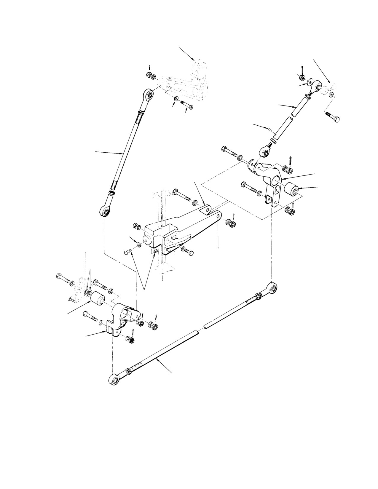
MD Helicopters, Inc.
CSP−H−2
500 Series − Basic HMI
GAS PRODUCER IDLER
(NOTE 2)
GAS PRODUCER
LEVER
NOTE 3
GAS PRODUCER LEVER
CONTROL ROD, JAM NUTS
AND ROD ENDS
COUNTERSUNK
COUNTERSUNK
MS20470AD3 RIVET
STA. 73 CONTROL
ROD, JAM NUTS
AND ROD ENDS
* STA. 129
* GAS PRODUCER
BELLCRANK
CONTROL SUPPORT
BEARING
(NOTE 4)
NOTE 1
STA. 70
STA. 129
THIN SPACER
WASHERS
STA. 124
PULL−TYPE LOCKBOLT
PIN AND COLLAR
BEARING
(NOTE 4)
* STA. 70
NOTES:
BELLCRANK
1.
AN960PD10 WASHER(S) USED UNDER HEAD ONLY
IF REQUIRED TO OBTAIN CORRECT GRIP.
2.
PART OF INBD COLLECTIVE STICK SOCKET ASSY.
3.
SPECIAL AL ALY WASHER, 0.25 IN. (6.35 MM) ID X
0.80 IN. (20.32 MM) OD.
4.
INSTALL BEARING WITH GRADE A LOCKING
COMPOUND (29, TABLE 2−4).
FUSELAGE−ROUTED
5.
ASTERISK ( * ) INDICATES PARTS MAY BE EITHER
CONTROL ROD, JAM
MAGNESIUM OR ALUMINUM ALLOY. REFER TO
NUTS AND ROD ENDS
SECTION 2 FOR ALLOY IDENTIFICATION AND
CORROSION CONTROL.
30−088D
Figure 11-8. Gas Producer Control Linkage Disassembly
Page 11-17
Revision 18
MD Helicopters, Inc.
CSP−H−2
500 Series − Basic HMI
C. Gas Producer Control Linkage Repair
control tube, interconnect torque tube and
associated linkage.
(1). Perform a straightness check on a
control rod that appears bent or bowed.
5. Power Turbine Governor Controls
The total length of gas producer
controls rods (excluding rod ends) must
(Ref. Figure 11−1) The power turbine governor
be straight within the following
controls include the N2 trim actuator and/con−
tolerances, with straightness variation
trol (beeper) switch on the collective stick, the
limited to a maximum of 0.010 inch
governor trim, droop control and override
(0.254 mm) in each 12 inches (304.8
linkage within the pilot’s seat structure, a
mm) of length.
fuselage routed control rod, and the engine
(a). Fuselage−routed control rod: 0.050
compartment linkage. The control rod assem−
inch (1.27 mm).
blies consist of aluminum alloy tubes or solid
rods with spherical bearing rod ends. The
(b). Sta. 73 control rod: 0.010 inch (0.254
bellcranks and supports may be either
mm).
aluminum or magnesium castings, each
(c). Gas producer lever control rod: 0.020
bellcrank containing a roller bearing. The N2
inch (0.508 mm).
trim actuator consists of a reversible continu−
ous duty 26 Vdc motor that drives a gear train
A dye−check for cracking
having non−jamming mechanical stops. Refer
WARNING
shall always be performed
to Section 2 for corrosion control and identifi−
after cold−straightening. Replace a
cation of magnesium and aluminum alloy
cracked rod, or a cracked or bent rod
parts.
end.
A. Power Turbine Governor Linkage
(2). Cold−straighten a bent rod that is not
Replacement
within tolerance (Ref. step (1).) pro−
vided there are no nicks or sharp dents
Replace control rods, bellcranks or supports
in the bend length. DO NOT use the rod
according to Gas Producer Linkage Replace−
ends to support the rod during the
ment, and Figure 11−9 and Figure 11−10, with
straightening process.
the following exceptions: the trim actuator and
Use care when drilling to re−
Sta. 72 bellcrank which must be removed as a
CAUTION
move or install a riveted rod
unit, and the droop control override link
end; the rod end is steel and the rod is alu−
assembly.
minum. Tighten the jam nut before drilling
and riveting.
NOTE: Only high temperature all metal nuts
(not fiber insert type) are to be used for an−
(3). Replace a control rod end if bearing
choring control idler support (Figure 11−10)
axial play is more than 0.040 inch
to engine gear case accessory pad.
(1.016 mm). Set initial control rod
length and bearing agularity as shown
(1). Remove the droop control override link
in Figure 11−2 or Figure 11−4.
by disconnecting the link housing end
fitting from the collective torque tube,
(4). Replace unserviceable bellcrank
and the rod end from the droop com−
bearings. Install a new bearing of the
pensation fork.
correct type with surface primer and
grade A locking compound (28 and 29,
Table 2−4), according to container
(2). Remove the N2 trim actuator and Sta.
72 bellcrank as a unit:
instructions.
(5). Replace bellcranks or control supports
(a). Disconnect the bonding jumper and
for distortion, cracks or elongated holes.
electrical connector from the actua−
tor.
D. Gas Producer Throttle Linkage
Refer to Collective Controls in Section 7 for
(b). Disconnect the actuator from Sta. 68
information on the throttle gas producer
bellcrank.
Page 11-18
Revision 18
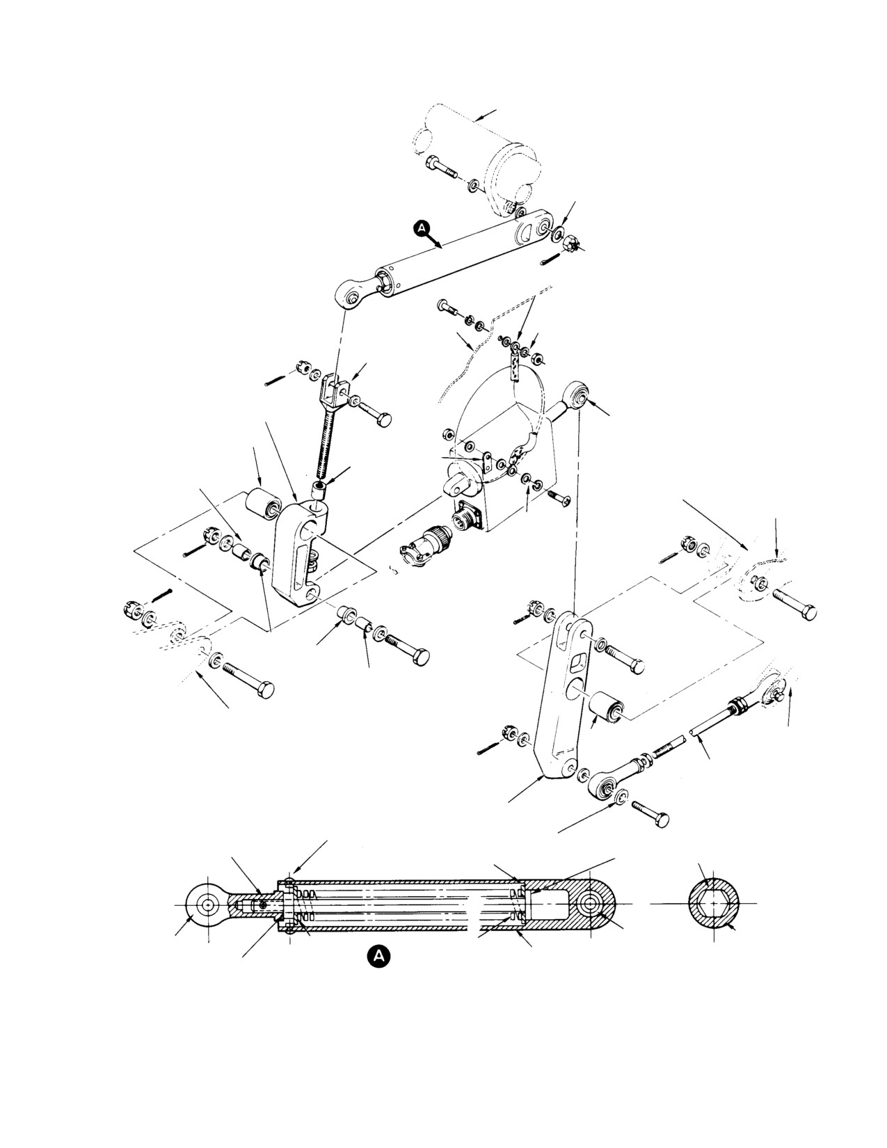
MD Helicopters, Inc.
CSP−H−2
500 Series − Basic HMI
NOTES:
NOTES: (CONT)
1.
BUSHINGS MUST ROTATE FREELY AFTER
6.
TAB ON CURRENT TYPE; STRAP ON
COLLECTIVE
ASSEMBLY.
EARLY TYPE.
TORQUE TUBE
2.
INSTALL BEARINGS WITH GRADE A LOCKING
7.
ASTERISK ( * ) INDICATES CORROSION
COMPOUND (29, TABLE 2−4).
RESISTANT STEEL.
3.
LUBRICATE SPRING, RETAINERS, PLUNGER
8.
DOUBLE ASTERISK ( * * ) INDICATES THAT
AND INSIDE OF HOUSING WITH GREASE (26)
PARTS MAY BE EITHER MAGNESIUM OR
BEFORE INSTALLATION OF RIVETS.
SPECIAL
ALUMINUM ALLOY. REFER TO SECTION 2
4.
PLUNGER HEX FLATS ALIGN AT 90 DEGREES
WASHER
FOR ALLOY IDENTIFICATION AND
WITH ROD END VERTICAL. PLUNGER HEAD
CORROSION CONTROL.
MUST HAVE FREE TRAVEL TO END OF OBLONG
SLOT IN HOUSING END FITTING.
5.
JAM NUT TIGHTENED FOR MINIMUM FREE
PLAY IN SPRING.
BONDING JUMPER
STRUCTURE RIB
DROOP
COMPENSATION
FORK
* * STA. 68 BELLCRANK
N2 TRIM ACTUATOR
BEARING
(NOTE 2)
NOTE 6
LOCKED
SLEEVE BUSHING
THREAD
CONTROLS SUPPORT
(NOTE 1)
INSERT
BRACKET
STRUCTURE
*
RIB
FLANGE
BUSHING
SLEEVE BUSHING
(NOTE 1)
STA. 64 SEAT
STRUCTURE
STA. 124
BRACKET
BEARING
BELLCRANK
(NOTE 2)
FUSELAGE−ROUTED
CONTROL ROD, JAM
NUTS AND ROD ENDS
* * STA. 72 BELLCRANK
SPECIAL
MS20604AD4K1
WASHER
(OR AD4W1) RIVET
MS20470A2 RIVET
PLUNGER (NOTE 4)
(NOTE 3)
RETAINER
ROD END
BEARING
(NOTE 4)
RETAINER
SPRING
(NOTE 2)
LINK HOUSING
DROOP CONTROL
JAM NUT
(NOTE 3)
OVERRIDE LINK
(NOTE 5)
30−089D
Figure 11-9. Governor Control Linkage Disassembly (Forward of Engine Compartment)
Page 11-19
Revision 18
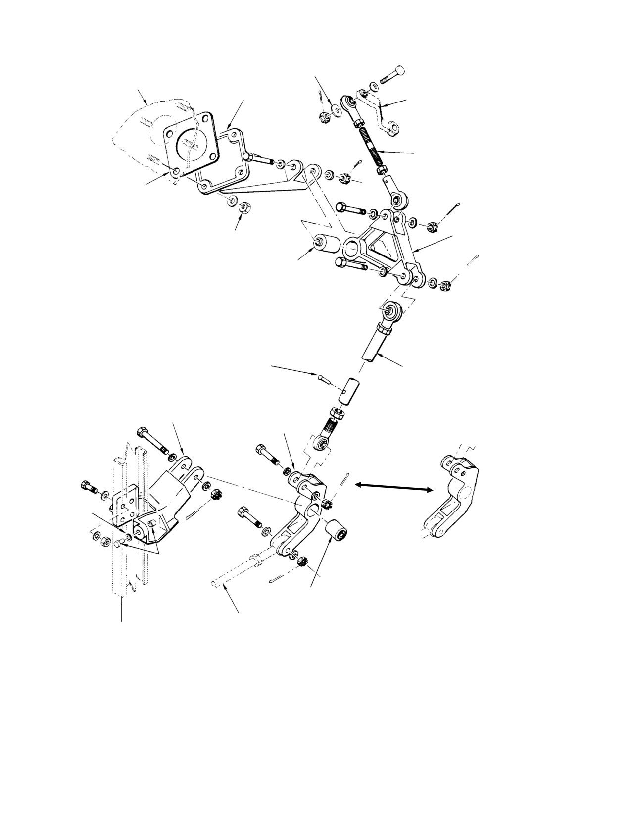
MD Helicopters, Inc.
CSP−H−2
500 Series − Basic HMI
NOTE 3
ENGINE ACCESSORY
GEARCASE PAD
* CONTROL IDLER
GOVERNOR LEVER
SUPPORT
GOVERNOR LEVER CONTROL ROD,
JAM NUTS AND ROD ENDS
AN4045−1 GASKET
* IDLER BELLCRANK
NOTE 4
BEARING
(NOTE 2)
MS20470AD3 RIVET
IDLER BELLCRANK CONTROL ROD,
JAM NUTS AND ROD ENDS
* STA. 124 CONTROL SUPPORT
* STA. 124 BELLCRANK
NOTE 1
PULL−TYPE
LOCK BOLT PIN
AND COLLAR
BEARING
(NOTE 2)
FUSELAGE−ROUTED CONTROL ROD
NOTES:
1.
AN960PD10 WASHERS USED UNDER HEAD ONLY IF REQD TO OBTAIN CORRECT GRIP.
2.
INSTALL BEARING WITH GRADE A LOCKING COMPOUND (29, TABLE 2−4).
3.
SPECIAL ALUMINUM ALLOY WASHER; 0.25 IN. (6.35 MM) ID X 0.80 IN. (20.32 MM) OD.
4.
USE HIGH TEMPERATURE ALL−METAL NUTS ONLY.
5.
ASTERISK ( * ) INDICATES THAT PARTS MAY BE EITHER MAGNESIUM OR ALUMINUM ALLOY.
REFER TO SECTION 2 FOR ALLOY IDENTIFICATION AND CORROSION CONTROL.
30−090F
Figure 11-10. Governor Control Linkage Disassembly (Engine Compartment)
Page 11-20
Revision 18
MD Helicopters, Inc.
CSP−H−2
500 Series − Basic HMI
(c). Disconnect Sta. 72 bellcrank from the
B. Governor Control Linkage Inspection
fuselage−routed control rod end.
(1). Inspect rod end bearings for binding
and excessive wear, 0.040 inch (1.016
(d). Remove the pivot bolt that attaches
mm) maximum axial play.
Sta. 72 bellcrank to structure rib and
controls support bracket; remove
(2). Inspect control rod for surface damage
actuator and bellcrank.
and evidence of bending.
(3). Inspect for loose rivet at fixed rod end
(3).
Disconnect the trim actuator from Sta.
(lower end).
72 bellcrank. Use care to keep sleeve
bushings with bellcrank.
(4). Inspect bearings in bellcranks for
binding.
(4).
Check a replacement trim actuator for
(5). Perform a fluorescent dye penetrant
correct maximum extended length of
inspection on any suspected part.
5.47 ±0.03 inches (138.938 ±0.762 mm)
between attach bolt centers. If dimen−
NOTE: After replacement and inspection of the
sion is not correct, test actuator for
power turbine governor controls linkage,
proper operation.
perform deceleration check in accordance
with procedures found in the pilot’s flight
manual. If confirmed deceleration time is
(5).
Assemble original or replacement trim
less than the allowable minimum, refer to
actuator to original or replacement Sta.
the applicable Allison Operation and Main−
72 bellcrank with a bolt, two washers,
tenance Manual.
nut and new cotter pin. Check that both
sleeve bushings are in place in Sta. 68
C. Governor Control Rods and Bellcranks
bellcrank arm before connecting the
Repair
actuator; then install assembled unit in
controls support bracket and connect
(1). Perform a straightness check on a
linkage as shown in Figure 11−9. The
control rod that appears bent or bowed.
sleeve bushings in Sta. 68 bellcrank
The total length of governor control
arm must rotate freely, without any
rods (excluding rod ends) must be
binding, after the actuator is attached
straight within the following tolerances,
and the connecting hardware is tight−
with straightness variation limited to a
ened.
maximum of 0.010 inch (0.254 mm) in
each 12 inches (304.8 mm) of length.
(6).
Connect replacement droop control
(a). Fuselage−routed control rod: 0.050
override link to collective torque tube.
inch (1.27 mm).
Push on rod end and check that the link
assembly plunger head is free to slide
(b). Governor lever control rod: 0.010
back and forth in the link housing end
inch (0.254 mm).
fitting. Connect rod end to droop
compensation fork; the rod end should
(c). N2 idler bellcrank control rod: 0.020
align with the fork.
inch (0.508 mm).
A dye−check for cracking
(7).
Connect the bonding jumper and
WARNING
shall always be performed
electrical connector to the actuator.
after cold−straightening. Replace a
cracked rod, or a cracked or bent rod
end.
NOTE: Replacement trim actuator may have a
tab or use a bonding strap/clamp for connec−
(2). Cold−straighten a bent rod that is not
tion of the bonding jumper.
within tolerance (step (1).) provided
there are no nicks or sharp dents in the
(8). Rig the control system.
bend length. DO NOT use the rod ends
Page 11-21
Revision 18
MD Helicopters, Inc.
CSP−H−2
500 Series − Basic HMI
to support the rod during the straight−
Apply primer (4, Table 2−4) to reworked
ening process.
area.
Use care when drilling to re−
(5). Install existing locknut and new
CAUTION
move or install a riveted rod
NAS42DD1010 spacer on −3 extension;
end; the rod end is steel and the rod is alu−
reinstall extension (Ref. Figure 11−1 1).
minum. Tighten the jam nut before drilling
(6). Perform rigging of power turbine
and riveting.
governor controls.
(3). Replace a control rod end if bearing
(7). Reinstall control covers and floor access
axial play is more than 0.040 inch
panels.
(1.016 mm). Set initial control rod
length and bearing angularity as shown
E. Droop Control Override Link Assembly
in Figure 11−6 or Figure 11−7.
Repair
(4). Replace unserviceable bellcrank
(Ref. Figure 11−9)
bearings. Install a new bearing of the
(1). Replace an unserviceable link housing
correct type with surface primer and
end fitting bearing (detail A). Install a
grade A locking compound (28 and 29,
new bearing of the correct type with
Table 2−4), according to container
surface primer and grade A locking
instructions.
compound (28 and 29, Table 2−4),
(5). Replace bellcranks or control supports
according to container instructions.
for distortion, cracks or elongated holes.
(2). Replace an unserviceable rod end or
broken spring:
D. Relocation of Locknut and Installation of
Spacer
(a). Remove the four rivets from rod end
of housing.
The following procedure to relocate the
existing droop compensation adjustment
(b). Drill out rod end rivet and disas−
locknut on the PN 369A7717−3 extension to a
semble spring assembly. Discard rod
new location above the arm assembly is to
end and plunger.
preclude loosening and/or loss of the locknut
during helicopter operation. This procedure
(c). Assemble new plunger, retainers,
affects PN 369H7825 droop control bellcrank
spring and jam nut. Screw down the
assembly (Sta. 68.00); it does NOT affect PN
jam nut on plunger threads until
369H7825−1 1 droop control bellcrank assem−
there is minimum free play of the
blies.
spring.
(1). Remove pilot’s floor access panels and
(d). Install replacement rod end to point
control covers to gain access to under−
of contact with jam nut. Check
seat linkage for power turbine governor
alignment of the flats on the plunger
controls.
head and the rod end; with rod end
vertical, two of the flats must be
(2). Remove PN 369A7717−3 extension from
perpendicular at 90 degrees (detail
droop control override link and Sta.
A). Tighten jam nut against rod end.
68.00 bellcrank.
NOTE: When the override link assembly is
NOTE: Spotface through radius of arm only.
installed between the droop compensation
DO NOT spotface below flat surface of arm
fork and the collective torque tube, the
around circumference of insert in arm.
plunger must be free to travel to the end of
the oblong slot in the link housing end fit−
(3). Spotface PN 369A7716 or 369N2606
ting without binding.
arm assembly, as shown in
(e). Using a #50 drill, drill through rod
Figure 11−1 1.
end and plunger at the witness hole
(4). Touch up reworked surface of arm with
of the rod end. Install an MS20470A2
Dow 7 or Dow 17 chemical treatment.
rivet of correct length.
Page 11-22
Revision 18
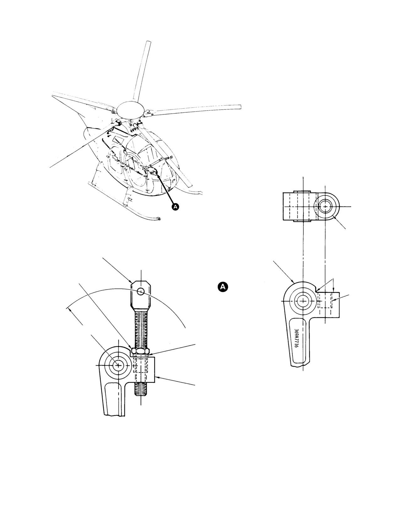
MD Helicopters, Inc.
CSP−H−2
500 Series − Basic HMI
0.687 IN.
(17.4498 MM) DIA.
SPOTFACE
(NOTE)
369A7717−3 EXTENSION
369A7716−BSC ARM ASSEMBLY
NOTE
AN316−5R NUT
INSERT
2.30 IN. (5.842 CM) R
NAS42DD10−10 SPACER
REWORK − ARM ASSEMBLY
369A7716−BSC ARM ASSEMBLY
NEW NUT LOCATION
NOTE: DO NOT SPOTFACE BELOW FLAT SURFACE
OF ARM AROUND CIRCUMFERENCE OF INSERT.
30−221A
Figure 11-1 1. Relocation of Locknut - Sta. 68.00 Bellcrank Assembly
Page 11-23
Revision 18
MD Helicopters, Inc.
CSP−H−2
500 Series − Basic HMI
(f). Lubricate the interior of the housing,
MS3106−10SL−3S
the spring retainers and plunger
SPDT
CONNECTOR
M1
EXTEND
SWITCH
A
with grease (26). Install the spring
+
MA
RETRACT
B
assembly in the housing so that
26 VDC
C
plunger hex enters end fitting slot
V M2
POWER
and rod end aligns vertically with
−
30−091
housing bearing (detail A).
(g). Complete the link assembly by
ITEM
EQUIPMENT DESCRIPTION
installing the four retention rivets
NO.
(MS20604AD4K1 or W1) in the
1
6 in. (152.4 mm) scale.
housing (detail A).
2
Dc voltmeter, calibrated 0-50 volts (Weston
6. RPM Governor (N2) Trim Actuator
Model 931 or equivalent).
3
Dc miliiammeter, calibrated 0-5 amperes
The N2 trim actuator (a linear electro−me−
(Weston Model 931 or equivalent).
chanical actuator that is operated by a
‘‘beeper" switch on the collective pitch stick)
4
Variable dc power supply, 10-36 volts
allows N2 speed to be varied over a range of
(N.J.E. Model SY36-10 or equivalent).
approximately 94−105 percent. Any change in
5
Dial indicator gauge (Brown and Sharp
actuator length or in collective pitch actuates
Model 740 or equivalent).
the governor linkage and establishes a new
power output demand on the engine. For all
6
Switch, SPDT, center off.
practical purposes, the main rotor speed is
held constant. Operating stroke of the actuator
Figure 11-12. N2 Trim Actuator Test hookup
ram is approximately 1.00 inch (25.4 mm), and
linear speed is 0.15 inch (3.81 mm) per second;
(3).
With actuator ram approximately
full travel from full retraction to full extension
halfway between stops, set up dial test
is approximately 7 seconds. The actuator is
indicator and measure the ram end
lubricated by the manufacturer and no further
play. The end play must not exceed
0.005 inch (0.127 mm) tir when mea−
lubrication is required for the life of the
sured under a 10 lb. (4.5 kg) reversing
actuator.
load.
A. N2 Trim Actuator Replacement
(4).
Position test switch to RETRACT and
allow the actuator ram to fully retract.
Refer to Power Turbine Governor Linkage
Using the end of the ram sleeve as a
Replacement.
reference point, measure the portion of
ram that remains out of the sleeve to
B. N2 Trim Actuator Repair
the nearest 0.015625 inch (0.396785
Repair of the N2 trim actuator, other than that
mm). Record this measurement for use
performed by an authorized overhaul agency
in step (5).
or the manufacturer, is limited to replacement
(5).
Position test switch to EXTEND and
of an unserviceable rod end in the actuator
run ram to the extend stop. Measure
ram. With the ram at full extension, set the
the length of the extended ram, Sub−
distance between attach bolt centers to 5.47
tract the measured result of step (4).
inches (138.938 mm) before reinstalling the
from this value. The result should be
actuator.
0.97−1.03 inches (24.638−26.162 mm).
C. N2 Trim Actuator Testing
(6).
The operating current under no−load
conditions, at 26.0 Vdc input should be
(1). Connect the N2 trim actuator to test
between 0.60−1.25 amperes when
harness and equipment shown in
running and 2.0 amperes maximum
Figure 11−12.
when stalled.
(2). Turn on dc power and adjust output to
(7).
Operate the actuator motor in both
25.75−26.25 volts.
extend and retract direction. Overtravel
Page 11-24
Revision 18

MD Helicopters, Inc.
CSP−H−2
500 Series − Basic HMI
must not exceed 0.020 inch (0.508 mm)
(10). Run the actuator to the fully extended
maximum when power is turned off.
position. The overall length of the
extended actuator should be 5.47 inches
(8). Reduce the voltage input to 21 volts.
(138.938 mm) between attach bolt
The actuator ram must retract and
centers. Turn power off and disconnect
extend to the stops without binding on
the actuator.
the stops or between the stops.
7. Anti-Icing System
(9). Increase the input voltage to 28 volts.
The actuator ram must retract and
8. Anti-Icing System Troubleshooting
extend to the stops without binding on
the stops or between stops.
(Ref. Table 11−2)
Table 11-2. Anti-Icing System Troubleshooting
Symptom
Probable Trouble
Corrective Action
NOTE: Refer to Section 19 for interconnection wiring and circuit information for the electrically operated anti-icing
system.
Actuation of anti-ice system does
Inoperative or defective actuator.
Replace actuator.
not restore normal engine
Defective N2 GOV circuit breaker
Ref. Sec. 19.
operation when compressor icing
or electrical circuits.
occurs.
Actuator not rigged properly.
Check rigging.
Lack of anti-icing air.
Check engine air lines for leaks.
Defective or stuck anti air valve.
Replace anti-icing valve.
*Cable wire loose in anti-icing air
*Tighten or replace adapter with
valve lever adapter or adapter stud
cable and valve in correct position.
sheared or stripped.
De-actuation of anti-ice system
Same as troubles above.
Same as actions above.
does not return anti-icing valve
lever to forward position. (Inflight
*Cable to control lever piston
Replace damaged parts.
symptom is continuation of
retaining pin sheared (inside lever
approximately 10% reduction in
housing).
available power or torque.)
*Adapter nut over-tightened.
*Loosen adapter nut and retorque to
not more than 10 inch-pounds
(1.13 Nm).
Movement of anti-icing valve
**Control cable sleeve kinked or
**Check cable operation with cable
control lever very difficult.
one or more routing bend radii less
wire detached from shutoff valve
than a 3 inch (76.2 mm) minimum.
lever adapter (early system) or cable
clevis detached from shutoff valve
lever (current system). Replace
kinked cable or remove sharp bends
in cable routing.
NOTE:
* Indicates early manually operated anti-icing system only.
* * Indicates early and current manually operated anti-icing systems.
Page 11-25
Revision 18
MD Helicopters, Inc.
CSP−H−2
500 Series − Basic HMI
9. Anti-Icing Controls (Electrically Operated
(4). If anti−icing valve lever has insufficient
System)
travel or linkage binds, re−rig (Ref.
Electrically Operated Anti−Icing Valve
(Ref. Figure 11−13) Anti−icing valve electrical
Rigging).
control equipment consists of an anti−icing
B. Electrically Operated Anti-Icing Valve
valve control switch, an electrical actuator and
Rigging
associated electrical wiring and miscellaneous
hardware.
(1). Disconnect the aft end of the engine
ant−ice rod (if connected).
The actuator is attached to a bracket mounted
under the engine hoist fitting behind the
(2). Manually position the engine anti−ice
anti−icing valve.
lever to the full OFF (forward) position.
Rigging adjustment is made by
An adjustable rod connects the anti−icing lever
CAUTION
changing anti− ice rod length.
to the actuator crank arm.
Do not reposition the actuator arm on the
A three−position anti−icing control valve
shaft. Also, do not force the actuator arm in
switch located overhead in the pilot’s compart−
either direction. Use the DE−ICE switch to
ment controls actuator operation in either a
position the actuator arm.
clockwise or counterclockwise direction.
(3). Turn power ON. Set DE−ICE switch to
OFF (aft) position.
Actuator circuits are protected by the N2 GOV
circuit breaker on the instrument panel (Ref.
(4). For the spring−loaded anti−ice rod,
Section 19). When the switch is moved to the
loosen jam nut on engine anti−ice rod.
full aft (OFF) position the actuator shaft
Adjust the rod end until the forward
rotates counterclockwise (viewed from the
terminal slide pin is centered in the slot
shaft end) closing the anti−icing valve.
with aft terminal attached to the
Stop−to−stop actuator shaft rotation normally
actuator arm.
requires a minimum of 20 seconds.
(5). For the non−spring−loaded double end
adjustable engine anti−ice rod, loosen
A. Anti-Icing Controls Operational Check
jamnut and adjust disconnected aft rod
(Electrically Operated0
end until rod length is proper for
NOTE: The N2 GOV circuit breaker on the
connection of rod to actuator crank arm;
instrument panel must be set (pushed in)
then tighten jamnut.
for the anti−icing actuator to operate.
(6). Secure the aft rod end to the actuator
arm with a clevis pin, washer and
(1). Set the DE−ICE switch to the OFF (aft)
cotter pin.
position.
(7). Perform an operational check of the
(2). Observe that the anti−icing valve lever
installed electrical actuator.
moves to the forward (OFF) position.
C. Anti-Icing Valve Actuator and Linkage
NOTE: If the installation is equipped with a
Replacement
spring−loaded anti−icing rod, carefully ob−
(Ref. Figure 11−13)
serve the pin position in the forward termi−
nal slot. The pin must be in the center of the
(1). Check that all electrical power is OFF.
slot (Figure 11−13). If the pin is not centered
NOTE: Although not mandatory, removal of the
in the slot, re−rig the anti−icing rod.
tailpipe assembly provides best access to
(3). Alternately set the DE−ICE switch to
components.
the ON and OFF positions. Make sure
(2). Disconnect the electrical connector from
the actuator operates the anti−icing
the actuator.
valve from the OFF (forward) to ON
(aft) position. Allow a minimum of 20
(3). Remove cotter pins, washer and pins to
seconds for the crank arm to travel
disconnect anti−icing rod from actuat−
between full throw positions.
ing levers.
Page 11-26
Revision 18
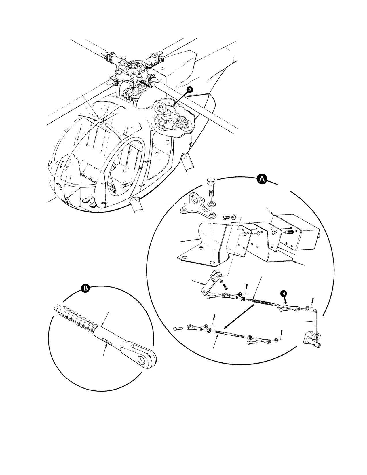
MD Helicopters, Inc.
CSP−H−2
500 Series − Basic HMI
HEAT DUCT AND
VNE CARD COVER
ENGINE DE−ICE
SWITCH
(NOTE 2)
ENGINE LIFT
FITTING
ELECTRICAL
ACTUATOR
ACTUATOR
BRACKET
GASKET
SPRING−LOADED
SHIELD
ANTI−ICING ROD
ACTUATOR
CRANK ARM
SLIDE TERMINAL
ANTI−ICING VALVE LEVER
FIXED ANTI−ICING ROD
SLIDE PIN
(NOTE 1)
NOTES:
1.
SLIDE PIN MUST BE CENTERED IN SLOT WHEN ANTI−ICING VALVE
LEVER IS IN FORWARD (OFF) POSITION.
2.
SIDE−MOUNTED SWITCH (EARLY CONFIGURATION) OR FACE−MOUNTED
SWITCH (CURRENT CONFIGURATION) MAY BE LOCATED EITHER LEFT
OR RIGHT SIDE FOR PILOT SEAT CONVENIENCE.
30−158A
Figure 11-13. Engine Anti-Icing Valve Electrically Actuated Equipment
Page 11-27
Revision 18
MD Helicopters, Inc.
CSP−H−2
500 Series − Basic HMI
(4). Disassemble rod only to the extent
10. Anti-Icing Valve Control Cable (Manually
necessary to replace worn or damaged
Operated)
parts.
(Ref. Figure 11−14) There are two types of
manually operated anti−icing valve control
(5). Release setscrew tension on actuator
cable installations.
crank arm and remove crank from
actuator.
The early type anti−icing valve control consists
of a flexible, enclosed wire−type cable assem−
(6). Remove the actuator, gasket and shield
bly bonded to a control housing.
by removing the lockwire, four attach−
ing screws and washers from the
The control housing with cable actuating knob,
support bracket.
is attached to the left side of the overhead
canopy frame in the pilot’s compartment.
NOTE: Refer to Section 10 for actuator bracket
Movement of the control lever rearward to the
assembly replacement.
latch notch opens the anti−icing valve com−
pletely. Releasing the control lever from the
(7). Install replacement actuator with
latch notch results in spring−loaded return of
gasket and shield on bracket assembly
the lever to the forward (OFF) position.
with four screws and washers. Safety
screwheads with lockwire.
Control lever piston travel in the housing is
approximately 1.50 inches (38.1 mm), from the
open to closed positions.
(8). Connect the electrical connector to
actuator.
The current type anti−icing valve control has a
control handle and the push−pull wire and
(9). Turn power ON and set DE−ICE switch
conduit assembly incorporated at the right side
to OFF (aft) position.
of a heat duct attached to the overhead canopy
structure.
(10). Install actuator crank arm on serrated
Movement of the cable actuating control
actuator shaft at 23 degree angle aft of
handle forward opens the anti−icing valve
shaft vertical centerline. (Vertical
completely. A spring−type detent holds the
centerline is parallel to forward edge of
handle in the forward (on) position. The
anti−ice actuator.) Alignment of missing
control handle must be manually returned to
tooth in arm and shaft (with arm
the rearward (off) position.
positioned down and aft) indicates
correct arm−to−shaft alignment. Be
Minimum travel for the control handle is 1.44
sure that shaft clears actuator scre−
inches (36.576 mm), from the open to the
wheads. Tighten the setscrew.
closed positions.
NOTE: If the engine anti−ice rod has a spring−
Cable routing for the early type installation is
loaded slide terminal and an adjustable ter−
on the left side of the main rotor mast support
minal jamnut, the slide terminal end must
structure alongside the torquemeter oil
be installed on the engine anti−ice lever.
pressure line as far as the plenum chamber; at
this point the anti−ice cable is routed down−
ward through the firewall into the engine
(11). Connect the slide (forward) terminal
compartment.
end of engine anti−ice rod to the engine
anti−ice lever with clevis pin, washer
Cable routing for the current type installation
and cotter pin.
is similar but along the right side of the mast
support structure and back to the plenum
(12). Refer to Electrically Operated Anti−Ic−
chamber.
ing Valve Rigging for instructions on
connection of the adjustable end of the
No electrical switching is used in the manually
anti−ice rod and proper rigging.
controlled anti−icing valve control systems.
Page 11-28
Revision 18