CSP-H-2 BASIC HANDBOOK OF MAINTENANCE INSTRUCTIONS FOR MDHI 369H HELICOPTERS - page 7
MD Helicopters, Inc.
CSP−H−2
500 Series − Basic HMI
NOTE: It is recommended that the MS 21250
Perform first run−up in a cau−
CAUTION
bolt be replaced with any of the alternate
tious manner so that vibrations
bolts called out with the higher torque at the
from an unbalanced tail rotor will not cause
operators earliest convenience.
damage.
(23). Balance the tail rotor using vibration
(17). If an MS 21250 bolt is installed, install
analyzer and strobe light.
nut and torque to 600 − 650 inch−
pounds (67.79 − 73.44 Nm) while
18. Pitch Control Assembly
primer is wet. If an HS 5482−6, HS
805−6, HS 3532−6 or a HS 84208−6 bolt
(Ref. Figure 8−4) The pitch control assembly
is installed, torque nut to 750 − 775
consists of a swashplate assembly that rotates
inch−pounds (84.74 − 87.56 Nm)
in a double−row bearing inside a housing.
while primer is wet.
A self−aligning bearing at the underside of the
housing provides the pivot for transferring
After blade is secured to strap
motion of Sta. 282.00 bellcrank to the housing.
CAUTION
assembly, do not allow blade
Two clevis ears on each end of the swashplate
pitch travel from neutral to exceed 30 de−
provide for connection of pitch control links.
grees in either direction (Ref. Figure 8−5).
Rotating the blade to excessive pitch angles
Movement of the Sta. 282.00 bellcrank shifts
may result in undetected damage to the
the housing axially on the output shaft of the
strap assembly.
tail rotor transmission and moves pitch control
links inward and outward to change pitch of
the tail rotor blades.
(18). Attach outboard end of pitch control
link to pitch control arm of blade with
Two types of pitch control assemblies are in
spring washer, special (reduced OD)
service. The swashplate on the current pitch
washer, pitch arm (extended balance or
control assembly has oilite bronze liners. The
NAS) bolt, washer at outer side of pitch
early type swashplate has a nylon composition
control arm and nut.
liner.
The replaceable swashplate on the current
(19). Torque nut to 50 − 80 inch−pounds
pitch control assembly is retained in the
(5.65 − 9.04 Nm) and safety with cotter
housing by a washer and locknut. Parts of an
pin coated with primer.
early type pitch control assembly without a
locknut are not individually replaceable.
NOTE: Standard NAS bolts may be used as al−
The self−aligning bearing is swaged in place in
ternates at the pitch arms if extended bal−
the pitch control housing.
ance bolts are not available.
19. Pitch Control Assembly Replacement
(20). If the same blade that was removed is
being reinstalled with the original
(1). Remove complete tail rotor assembly
remaining blade, reinstall the same
including the pitch control assembly.
hardware and number of balance
(2). Disconnect ends of pitch control links
washers on the pitch arm bolt that were
from clevis ears of swashplate and
present at initial removal of the blade.
remove pitch control assembly.
(21). For a replacement blade, install balance
NOTE: Ensure matchmarks are aligned when
washers required for static cordwise
performing step (3). below.
balance of the assembled tail rotor
(3). Connect ends of pitch control links to
which have been determined by using
clevis ears on swashplate pitch control
an appropriate balance fixture.
assembly.
(22). If fiberglass blades were replaced with
(4). Install tail rotor and pitch control
metal blades, rig tail rotor controls.
assembly.
Page 8-33
Revision 17
MD Helicopters, Inc.
CSP−H−2
500 Series − Basic HMI
20. Pitch Control Assembly Inspection
(b). If greater amount of wobble is
present replace the swashplate or
(1). If tail rotor control system drag or
pitch control housing double−row
friction is suspected, use a spring scale
bearing or the complete assembly, as
(Ref. Figure 8−5) to measure drag
applicable.
(sliding friction) of the pitch control
assembly on the output shaft of the tail
NOTE: Wobble may be accurately measured by
rotor transmission.
attaching a dial indicator support to the tail
rotor drive fork, with the indicator probe in
NOTE: Pitch control links, Sta. 282.00 bell−
contact with the swashplate clevis ear loca−
crank and rubber boots must be detached
tion shown in Figure 8−5. Use care not to al−
from the assembly during the drag check.
low the pitch control assembly to slide on
the output shaft while measuring wobble.
(2). If drag exceeds 3 pounds (13.34 N),
remove the pitch control assembly and
(8). Perform following inspections for pitch
clean the swashplate and output shaft
control bearings at the time specified in
splines. Use solvent (1, Table 2−4) and
CSP−H−4 and when bearing condition
grade 400 emery paper or crocus cloth
is questionable.
(23).
NOTE: An early type pitch control assembly
without swashplate nut should not be disas−
NOTE: If tail rotor swashplate with a bronze
sembled. If it has defective bearings, the
liner is installed, coat the output shaft
complete pitch control assembly should be
splines with a light film of grease (18).
replaced.
(3).
If surface defects such as nicks,
(a). Remove cotter pin, nut, washers and
scratches, dents or corrosion are found,
bolt securing Sta. 282.00 bellcrank to
make detailed inspections and perform
transmission.
allowable repairs according to limits
and procedures in CSP−H−5.
(b). Separate pivot pin on bellcrank from
pitch control assembly (Ref.
(4).
If brinnelling wear of the inner surfaces
Figure 8−4).
of the swashplate clevis ears is de−
tected, 0.003 inch (0.0762 mm) depth is
(c). Rotate pitch control housing by hand:
allowable without rework or repair. For
wear of greater depth refer to CSP−H−5
1). Check for rough binding or hard
for limits and allowable repairs.
turning.
2). Inspect for grease leakage.
(5).
If there is evidence of swashplate
contact with housing, check that
3). If any of these conditions are
minimum clearance of 0.010 inch (0.254
noted, remove pitch control assem−
mm) exists through 360 degrees of
bly and inspect bearing for further
rotation with axial loading applied. If
evidence of damage.
contact is apparent, replace swashplate;
or double−row bearings if axial play can
(d). To inspect double−row bearing,
be measured.
remove grease seal at gearbox end of
bearing housing by first removing
(6).
(Early type only) If there is evidence of
seal lockring with thin sharp blade.
slippage between double−row bearing
inner race and swashplate, replace the
NOTE: Pitch control double−row bearing may
pitch control assembly.
be repacked or replaced, as appropriate.
(7).
Check pitch control wobble on output
(e). Check that self−aligning bearing on
shaft (Ref. Figure 8−5).
underside of pitch control housing is
adequately lubricated (packed
(a). Up to 0.020 inch (0.508 mm) pitch
approximately 40% full) with grease
control wobbles on the transmission
(18, Table 2−4), is movable and is
output shaft is allowable.
serviceable.
Page 8-34
Revision 17

MD Helicopters, Inc.
CSP−H−2
500 Series − Basic HMI
FORK BOLT
FORK
SPRING WASHER SPECIAL WASHER
(REDUCED OD)
SPHERICAL
BALANCE WASHER(S)
BEARING
PITCH ARM
PITCH ARM BOLT
(NOTE 3)
HUB
WASHER
WASHER, NUT & COTTER PIN
50−80 IN−LB (5.65−9.04 NM)
EARLY CONFIGURATION
EARLY CONFIGURATION
SPHERICAL BEARINGS
BALANCE BOLT
NUT
SHOULD BUSHING
(NOTE 7)
SPECIAL WASHER
BLADE LEADING EDGE
CRUSH WASHER
(REDUCED OD)
(NOTE 7)
PITCH CONTROL LINK
TENSION−TORSION
SPRING WASHER
STRAP ASSEMBLY
PITCH ARM
(NOTE 1)
BALANCE WASHER(S)
GREEN DOT
OUTBOARD
NUT
(NOTE 2)
STRAP SHOE
O−RING
(NOTE 1)
FORK
PITCH ARM BOLT
BLADE BOLT
BLADE PITCH
CONICAL BEARING
(FEATHERING)
BEARINGS
HUB
INBOARD STRAP SHOE
BLADE SPAR (FIBERGLASS BLADE)
(NOTE 1)
OR ROOT FITTING (METAL BLADE)
DUST COVER
NUT 50−54 FT−LB (68−73 NM)
HUB TRUNNION
SLEEVE
NOTES:
BUSHING
1.
CAUTION: DO NOT REMOVE SHOES FROM STRAP
(NOTE 6)
ASSEMBLY. AVOID DAMAGING STRAP ASSEMBLY.
SCRATCHES OR NICKS ON STRAP LAMINATES MAY
MAKE STRAP ASSEMBLY UNSERVICEABLE.
FORK BOLT
2.
USE COLORED LACQUER (6, TABLE 2−4).
(NOTE 4)
3.
MAY BE MODIFIED TO CURRENT CONFIGURATION
OUTBOARD
USING EXTENDED BALANCE BOLT. SEE TAIL ROTOR
STRAP SHOE
BLUE DOT
BALANCING FIGURE.
(NOTE 1)
(NOTE 2)
4.
COAT FORK BOLT HEAD AND NUT AREA WITH
SPECIAL WASHER
PRIMER (4, TABLE 2−4) TO PREVENT CORROSION.
WASHER, NUT & COTTER PIN
5.
USED ONLY WITH EARLY CONFIGURATION METAL
(COUNTERSUNK)
50−80 IN−LB. (5.65−9.04 NM)
(NOTE 5)
BLADES.
SPECIAL
BOLT
6.
USED WITH FIBERGLASS AND EARLY CONFIGURATION
WASHER
METAL BLADES.
(FLAT)
7.
USED ON CURRENT CONFIGURATION METAL BLADES.
30−201−1B
Figure 8-10. Assembled Tail Rotor Hub and Blades - Cross Section View
Page 8-35
Revision 17
MD Helicopters, Inc.
CSP−H−2
500 Series − Basic HMI
BUSHING
CRUSH WASHER
WASHER UNDER
BOLT HEAD
NUT
O−RING
THREADED BUSHING
ELASTOMERIC BEARING
DIRECTION
OF ROTATION
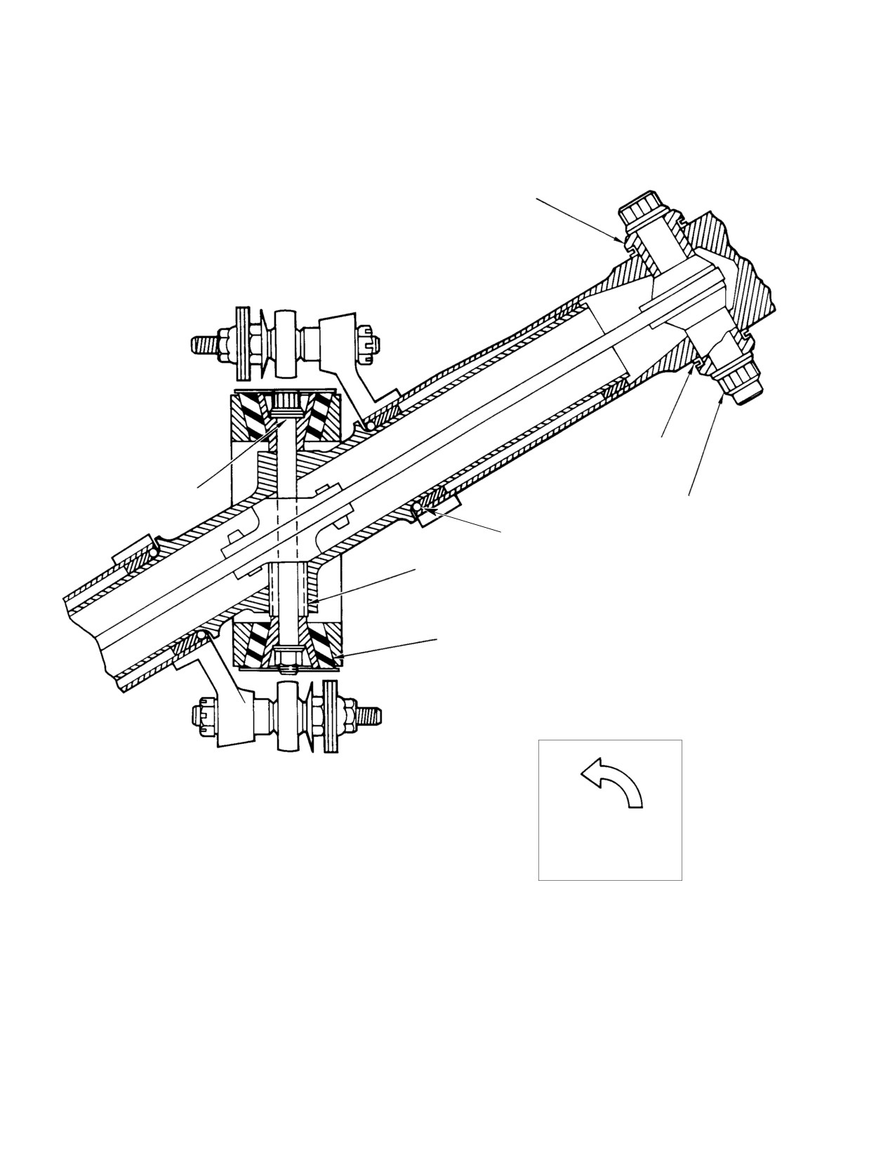
30−201−2A
Figure 8-11. Assembled Tail Rotor and Blades - Cross Section View (Elastomeric Bearings)
Page 8-36
Revision 17
MD Helicopters, Inc.
CSP−H−2
500 Series − Basic HMI
(f). Make sure that pivot pin on Sta.
(b). Rotate bearings while greasing.
282.00 bellcrank is lubricated with
(8). Remove plastic wedge (or equivalent
grease. Position bellcrank to engage
plug) and regreasing tool.
pivot pin with pitch control assembly.
Secure bellcrank to gearbox with
(9). Hand rotate bearing to remove excess
bolt, washers, nut and cotter pin.
grease.
NOTE: For any questionable and all other
NOTE: Ensure seal is serviceable. If new seal is
items, refer to the complete and detailed in−
required, seals and bearings must come
spection, damage, wear and repair limits
from the same vendor.
and requirements for the pitch control as−
sembly provided in CSP−H−5.
(10). Install serviceable seal, new tang
washer and nut.
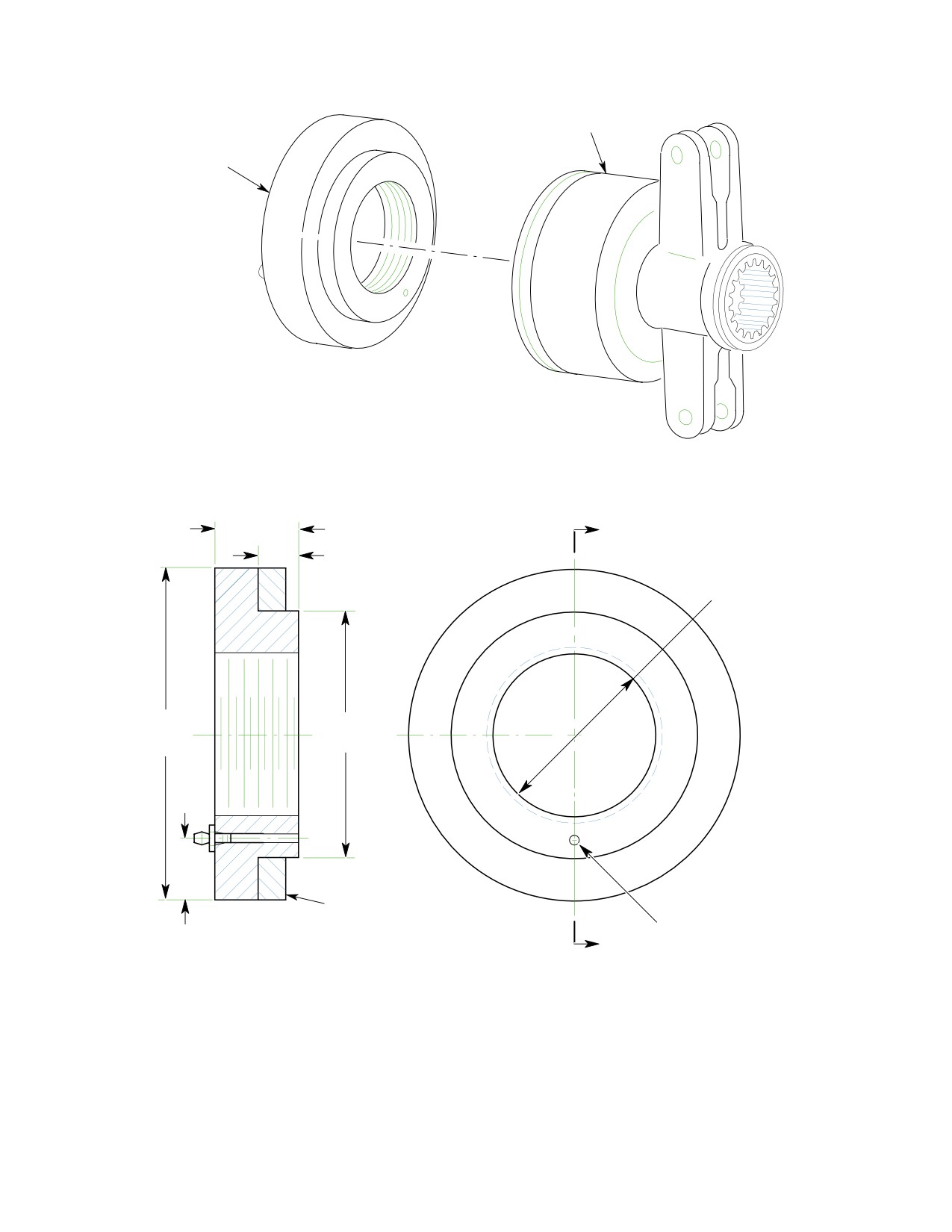
21. Tail Rotor Swashplate Regreasing
(11). Install nut with a new tang washer.
Using wrench and holding block, torque
(Ref. Figure 8−12)
nut to 400 − 450 inch−pounds (45.19 −
(1). Remove tail rotor and swashplate from
50.84 Nm).
helicopter (Ref. Tail Rotor and Pitch
(12). Bend one tang of washer into any
Control Assembly Removal).
aligned slot on nut.
(2). Remove pitch control links from
NOTE: Avoid getting alcohol in bearings.
swashplate assembly.
(13). Clean surface of locknut and swash−
Tail rotor swashplate bearings
plate with a lint−free cloth dampened
CAUTION
cannot be removed from hous−
with alcohol (71).
ing without damage to the bearings. If bear−
ings are removed from housing, install new
NOTE: Avoid getting torque seal in swashplate
bearings.
splines.
(3). Using wrench (44, Table 2−2) and
(14). Apply a 0.125 inch (3.175 mm) wide
holding block (45), Remove nut and
torque strip, using torque seal or
tang washer from threaded end of
equivalent, to surface of swashplate
swashplate. Discard tang washer.
assembly and locknut in two places.
(4). Carefully remove bearing grease seal at
22. Tail Rotor Hub and Fork Assembly
gearbox end of housing (seal will be
(Ref. Figure 8−10) The hub, with internal
reused at reassembly).
tension−torsion strap assembly, is held inside a
(5). Inspect seal for damage; no damage is
drive fork assembly by a fork bolt, shims,
allowed.
washer, nut and cotter pin to form a hub and
fork assembly.
(6). Install regreasing tool (Ref.
Types of bearings in service include the early
Figure 8−13) and plug tang washer
type spherical and conical bearings and
groove with locally fabricated plastic
current type elastomeric bearings. Conical
wedge (or equivalent plug).
spherical and elastomeric teeter bearing differ
NOTE: The following procedure provides 100%
in size and configuration. The existing tail
grease fill. Normal grease fill is 20 to 40%.
rotor drive fork may be replaced with a new
Excess grease will extrude past seals for
drive fork assembly equipped with elastomeric
several hours of operation until the proper
bearings. Refer to CSP−H−5 for modification
level is met.
instructions.
(7). Purge bearings with grease (21,
The tension−torsion strap assembly consists of
Table 2−4).
a strap pack to which inboard shoes are
riveted with shims, collars and rivets and
(a). Purge bearings slowly to prevent
outboard shoes containing bushings. The strap
damage to outer seal.
pack consists of 20 (or 19, as required for
Page 8-37
Revision 17
MD Helicopters, Inc.
CSP−H−2
500 Series − Basic HMI
correct thickness) corrosion−resistant (cold
C. Parts Replacement Information
rolled and tempered) steel straps, each
(1). Replace bearing in and reinstall an
approximately 0.009 inch (0.2286 mm) thick,
original serviceable fork assembly on an
that form a pack. A bushing threaded into the
original hub as specified in CSP−H−5.
hub against the inboard shoe holds the center
of the strap pack assembly in place inside the
(2). Removal of the strap pack assembly
hub.
from the hub is accomplished according
to CSP−H−5.
23. Hub and Fork Assembly Maintenance
(3). Disassembly of the strap pack assembly
is not recommended; parts should not
A. Inspection of Hub and Fork Assembly -
be removed from the strap pack
Blades Removed
assembly.
After removal of blades and before installation
24. Tail Rotor Pedal Installation (Left Position)
of replacement blades, inspect components of
fork and hub assembly as follows:
(Ref. Figure 8−14) The tail rotor pedal installa−
tion consist of a pair of adjustable pedals,
(1). Two types of hubs are in service: one is
pedal arms with interconnecting linkage, a
a 4340 steel hub with chrome plated
pedal mounting bracket for the left control
trunnions and the current type is
position, a torque tube with control rod fitting
marriaging steel.
and torque tube mounting bracket.
Forward pressure on the right pedal rotates
(2). For hub with chrome plated trunnions,
the torque tube rearward, moving control
check surface area on trunnion that
system linkage to increase tail rotor blade
mate with blade pitch (feathering)
pitch. Pressure on the left pedal decreases tail
bearing for wear. Wear through chrome
rotor blade pitch.
platting is not allowed and requires hub
replacement
(CSP−H−5).
A bungee spring is installed on the aft end of
the floor−routed control rod in the underseat
(3). Check visible areas of tension−torsion
tail rotor control linkage of helicopters with
strap assembly for nicks or scratches on
the cambered metal−blade tail rotor. This
strap laminates, cracked laminates and
spring relieves left pedal forces during flight
kinks, sharp bends or permanent twist
and causes the left pedal to remain in the
in laminates.
forward position when the helicopter is on the
ground and not operating.
(a). Any one of these defects, except
NOTE: Parts identified in Figure 8−14 with an
minor outer surface defects that can
(*) may be either magnesium or aluminum
be removed by abrasive polishing
alloy. Refer to Section 2 for corrosion control
requires replacement of the strap
and identification of magnesium and alumi−
pack assembly.
num alloys.
NOTE: For information on allowable repairs,
25. Tail rotor Pedal Installation Replacement
serviceability requirements and replace−
ment, refer to CSP−H−5.
(Ref. Figure 8−14)
A. Tail rotor Pedal Installation Removal (Left
B. Strap Pack Assembly Precautions
Position)
(1). When blades are removed from the hub
(1). Pull the two hinge pins from pilot’s
and fork assembly, the exposed ends of
compartment floor access door hinges
the strap pack assembly should be
and remove door. Remove the access
protected with a covering and the hub
panel from each side of the instrument
and fork assembly should be handled
panel lower support structure.
carefully to avoid damage to the strap
pack assembly.
(2). Remove battery.
Page 8-38
Revision 17
MD Helicopters, Inc.
CSP−H−2
500 Series − Basic HMI
TAIL ROTOR SWASHPLATE
BEARNG ASSEMBLY
REGREASE TOOL
GH08−002
Figure 8-12. Tail Rotor Swashplate Bearing Regreasing
0.75 IN.
A
(19.05 MM)
0.35 IN.
(8.89 MM)
1.173−18 UNJS−3B THREADS
PER MIL−S−8879
3.0 IN.
2.25 IN.
(7.62 MM)
(5.715 MM)
SEAL MATERIAL
0.50 IN.
MS15002−1 GREASE FITTING 1/4−28 TAPER
(12.7 MM)
SECTION A−A
A
THREADS 0.093 IN. (2.3622 MM) THRU HOLE
MATERIAL:
1.
MATERIAL 6061−T651 ALUM PER QQ−A−250/11, OR EQUIVALENT.
2.
SURFACE FINISH 125 RMS.
3.
BREAK SHARP EDGES 0.002−0.015 IN. (0.0508−0.381 mm).
4.
CHEMICAL FILM TREAT PER MIL−C−5541.
5.
DIMENSIONAL TOLERANCE ±0.030 IN. (±0.762 MM); DIAMETERS TO BE
CONCENTRIC TO CENTERLINE WITHIN 0.002 IN. (0.0503 MM).
GH08−001A
Figure 8-13. Tail Rotor Swashplate Bearing Regreasing Tool
Page 8-39
Revision 17
MD Helicopters, Inc.
CSP−H−2
500 Series − Basic HMI
(3). Remove pins securing pedals to pedal
(4). Add skim washers as required at
arms and remove pedals.
bracket attachment points to maintain
the bearing alignment established in
(4). On a helicopter with a metal−blade tail
step (1). above.
rotor, perform steps (a). thru (d). below.
(5). Install two bolts, four washers and two
(a). Gain access to the bungee by remov−
nuts.
ing the access cover between the
pilot’s seat and/or by removing the
(6). On a helicopter with a metal−blade tail
left passenger’s footwell on the aft
rotor, perform steps (a). and (b). below.
side of the canted bulkhead.
(a). Install forward eyebolt on replace−
ment bungee and then hook aft end
(b). Block the left tail rotor control pedal
of bungee into eyebolt on floor−routed
in the full forward position to relieve
control rod fitting.
tension on bungee.
(b). Stretch bungee into position at Sta.
(c). Remove eyebolt at Sta. 63.00 with
63.00 bracket, install washer and nut
bungee attached.
on eyebolt and tighten.
(d). Disconnect bungee from eyebolt on
(7). Check that slotted bushing is in place;
fitting at the aft end of the floor−
then install floor−routed control rod in
routed control rod and remove
torque tube fitting and install bolt, two
bungee.
washers, nut and cotter pin.
(5). Remove cotter pin, two washers and
(8). Check rigging of tail rotor control and
bolt that connect floor−routed control
pedal−to−canopy clearance following
rod to torque tube fitting.
installation of any removed or replaced
parts.
(6). Remove two nuts, four washers, any
shim washers and two bolts that secure
26. Disassembly of Tail Rotor Pedal
torque tube bracket to bulkhead. (Keep
Installation (Left Position)
shim washer selection with bracket to
facilitate torque tube alignment during
(Ref. Figure 8−14)
reinstallation.)
(1).
Disconnect links from pedal arms and
(7). Remove four nuts, eight washers, any
bellcrank; remove links.
shim washers and four bolts that secure
(2).
Remove bellcrank from pedal bracket.
pedal bracket to bulkhead. Remove the
control pedal installation. (Keep shim
(3).
Remove nut washer of the two bushing
washer selection with bracket.)
assemblies that secure the left pedal
arm and control rod fitting to torque
B. Installation of Tail Rotor Pedal Installation
tube. Carefully remove ABC bushing
(Left Position)
bolt and reinstall washer and nut on
bolt.
(1). Install pedal bracket with four bolts,
eight washers and four nuts.
(4).
Side pedal bracket and pedal arms off
end of torque tube.
(2). Add shim washers as required at pedal
bracket attachment points to keep
(5).
Do not remove the two teflon−lined
centerline alignment of pedal bracket
bushings from the right pedal arm
bearings within 0.010 inch (0.254 mm).
unless replacement is required.
NOTE: Correct alignment is indicated by free
(6).
Do not remove the two stop bolts, stop
rotational movement of torque tube after
nuts (if installed) on stop bolts or
the nuts are tightened.
bearings from the pedal bracket unless
replacement is required.
(3). Position torque tube bracket over
mating holes in bulkhead and check
(7).
Slide torque tube bracket and control
alignment with bulkhead.
rod fitting off torque tube.
Page 8-40
Revision 17
MD Helicopters, Inc.
CSP−H−2
500 Series − Basic HMI
A. Reassembly of Tail Rotor Pedal
inforced bushing liners for deteriora−
Installation (Left Position)
tion.
(Ref. Figure 8−14)
(2). Inspect pedal−to−arm quick−release
locking pin for condition and positive
(1).
If previously removed, thread a stop
spring action.
nut on each of the two stopbolts and
install the two stopbolts into thread
(3). Inspect links and bellcrank for cracks
inserts of pedal bracket.
and bends, and bearings for excessive
looseness.
(2).
Slide torque bracket and control rod
fitting onto torque tube.
(4). Inspect control rod fitting, torque tube
mounting bracket, and pedal mounting
(3).
Locate pedal bracket and pedal arms
bracket for cracks and corrosion.
for correct position on torque tube; slide
bracket and arms onto torque tube.
(a). Using an 8X−power magnifying
glass, a mirror and a flashlight,
inspect the pedal link bellcrank
(4).
Fasten left pedal arm and control rod
fitting of the pedal bracket in the
fitting to torque tube with adjustable
center forward area where the fitting
bushing assemblies; install the bushing
(fork piece) joins the tubular section.
bolt so that the shank at the bolt head
end protrudes at least 0.002 inch
(b). If any cracks are detected, replace
(0.0508 mm). Torque nut to 50 − 80
the bracket assembly.
inch−pounds (5.65 − 9.04 Nm) plus
drag torque. Do Not allow the bolt to
(c). Inspect bracket bearing for excessive
turn.
looseness.
(5).
Check that each end of the bushing
(5). Inspect torque tube for cracks,
assembly shank protrudes at least
scratches, nicks, dents and similar
0.002 inch (0.0508 mm). If not, loosen
surface defects.
and repeat step (4). above.
A. Tail Rotor Pedal Installation Repair (Left
(6).
Check that slotted bushing is in place;
Position)
then attach bellcrank to pedal bracket
with bolt, two washers, nut and cotter
(1). Replace parts that are cracked, or have
pin.
elongated attachment holes.
(7).
Check that slotted bushings are in
Do not attempt to straighten a
place; then fasten each link to bellcrank
CAUTION
bent torque tube or pedal link.
with bolt, two washers nut and cotter
pin.
(2). Replace unserviceable pedal covers.
Apply cement (3, Table 2−4) to approxi−
(8).
Check that slotted bushings are in
mately 30 percent of the upper and
place; then fasten each link in pedal
lower edge surfaces that contact the
arm lugs with bolt, two washers, nut
metal; cure according to container
and cotter pin.
instructions.
27. Tail Rotor Pedal Installation Inspection
(3). Replace complete pedal link if it is
(Left Position)
cracked or contains unserviceable
bearings; bearings are not replaceable.
(Ref. Figure 8−14)
(4). Replace unserviceable bearings in the
(1). Inspect pedals and pedal arms for
mounting brackets or pedal link
cracks, elongated pedal attach holes,
bellcrank. Install replacement with
and open drain holes. Inspect teflon−re−
grade A locking compound (29).
Page 8-41
Revision 17
MD Helicopters, Inc.
CSP−H−2
500 Series − Basic HMI
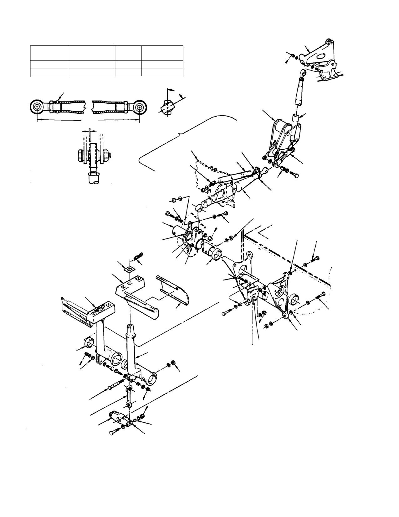
INITIAL ROD ASSY LENGTH AND BEARING ANGULARITY (BEFORE RIG)
STA 95 BELLCRANK
CONTROL
DIM L
ANGLE
ASSY PART
ROD ASSY
IN.
(CM)
A
NUMBER
STA. 78.50
57.95
(147.193)
IN LINE
369A7007
FLOOR
30.06
(76.3524)
IN LINE
369A7006−3
MS 20470 RIVET
A
CONTROLS SUPPORT
STA 78.50
BRACKET
(TUNNEL−ROUTED)
CONTROL ROD
L
MAX. ALLOWABLE
NOTE 6
LOOSENESS
0.040 IN. (1.016 MM)
STA 63.00
AFT EYEBOLT
BUNGEE
FORWARD EYEBOLT
TAIL ROTOR
SPRING
IDLER BELLCRANK
NOTE 2
SPRING FITTING
FLOOR−ROUTED CONTROL ROD
NOTE 2
BUSHING ASSY
TORQUE TUBE
(NOTE 4)
NOTE 3
* TORQUE TUBE BRACKET
NOTE 1
NOTE 3
(NOTE 5)
FITTING
WASHER
(NOTE 7)
NOTE 1
PIN
NOTE 4
BEARING
* LEFT PEDAL
STOP BOLT
STOP NUT (NOTE 7)
* RIGHT PEDAL
NOTE 2
PEDAL
NOTE 3
COVER
NOTE 1
* PEDAL BRACKET
NOTE 1
BUSHING
NOTES:
* PEDAL ARM
(TEFLON−LINED)
1.
SHIM BETWEEN BRACKET AND BULKHEAD WITH
AN960PD416 AND/OR −416L WASHERS AS REQUIRED
FOR ALIGNMENT WITHIN 0.010 IN. (0.254 MM)
NOTE 2
2.
EDGE OF BUSHING MUST PROTRUDE A MIN. OF 0.010 IN.
NOTE 4
(0.254 MM) TO A MAX. OF 0.060 IN. (1.524 MM) ABOVE
OUTSIDE SURFACE OF PART AFTER NUT IS TIGHTENED.
3.
DIRECTION OF BOLT IS OPTIONAL.
BUSHING ASSY
4.
ADJUSTABLE BUSHING MUST HAVE A MIN. PROTRUSION
(NOTE 4)
OF 0.002 IN. (0.0508 MM) AT EACH END.
5.
INSTALL WITH BEARING RECESS FACING FITTING.
LINK
6.
ON HELICOPTERS WITH METAL−BLADED TAIL ROTOR ASSY.
7.
NOT ON ALL HELICOPTERS; AS REQUIRED.
NOTE 2
BEARING
8.
ASTERISK ( * ) INDICATES PARTS THAT MAY EITHER
MAGNESIUM OR ALUMINUM ALLOY. REFER TO SECTION 2
BELLCRANK
FOR ALLOY IDENTIFICATION AND CORROSION CONTROL.
30−066F
Figure 8-14. Pilot’s Compartment and Intermediate Tail Rotor Controls
Page 8-42
Revision 17
MD Helicopters, Inc.
CSP−H−2
500 Series − Basic HMI
The right pedal arm bushings
(4). Disconnect control rod from pedal
CAUTION
are glass− filled phenolic. En−
torque tube fitting or from tail rotor
sure bushing does not cock during replace−
idler bellcrank (Ref. Figure 8−14).
ment, and that it is fully seated in arm bore.
Remove metal tail rotor control bungee
Keep tools from contact with bushing liners
spring if installed.
to avoid fraying.
NOTE: Check rigging of tail rotor controls fol−
lowing installation of any removed or re−
(5). Replace bearings in right pedal arm
placed parts.
when teflon−reinforced liner is galled or
frayed. Pull bushing to remove; press to
(5). Accurately measure and record distance
install.
between un−chamfered edge of rod end
jamnut and center of rod end bearing
28. Floor-and-tunnel-Routed Control Rods
hole. Record measurement.
(Ref. Figure 8−14) The floor−and−tunnel−
Use care when drilling to re−
CAUTION
routed control rods interconnect the tail rotor
move or install riveted rod end;
pedal installation with the upper fuselage and
the rod end is steel and the rod is aluminum.
tailboom control linkage (Ref. Figure 8−15).
(6). Drill out rivet(s) (as applicable), loosen
jam nut and unscrew rod end.
The control rods, each an anodized, aluminum
alloy tube with two rod end bearings, are
(7). Screw replacement rod end into rod,
linked by a cast magnesium tail rotor bell−
and adjust jam nut to obtain same
crank mounted on the under−seat control
measurement made in step (5). above.
support bracket. An aluminum alloy tail rotor
(8). Align control rod ends so that the
bellcrank may be installed to replace the
bearings have equal space for angular
magnesium bellcrank. (Refer to Control
throw; hold rod end and tighten jam
Support Bracket and Bellcranks, Section 7.)
nut.
29. Floor-Routed Tail Rotor Control Rod
(9). As applicable, install rivet(s) to secure
Repair
rod end.
(1). Replace rod end if bearing axial play is
(10). Check that slotted bushing is in place;
then secure control rod in torque tube
more than 0.040 inch (1.016 mm).
fitting or idler bellcrank with bolt, two
NOTE:
washers, nut and cotter pin.
D The riveted rod end bearing is replaceable
(11). Reinstall metal tail rotor control
without removal if located at forward end
bungee spring as required.
of rod. If riveted rod end is aft, rod remov−
(12). Reinstall access doors.
al is required to replace the rod end bear−
ing.
30. Sta. 78.50 Tail Rotor (Tunnel-Routed)
D The floor−routed control rod will normally
Control Rod
not require replacement unless the heli−
(Ref. Section 7, Tunnel−Routed Control Rods)
copter has received extensive impact or
All the tunnel−routed control rods are re−
crash damage.
moved, inspected, repaired and installed in
same manner. Ref. Figure 8−14 for initial
(2). On current configuration helicopters,
length and rod end angularity.
remove the control rod forward through
the landing light wiring grommet hole
31. Tail Rotor Idler Bellcrank
after the landing light is removed.
(Ref. Section 7, Control Support Bracket and
(3). Early configuration helicopters may be
Bellcranks)
modified for this purpose by relocating
32. Upper Fuselage and Boom Tail Rotor
the landing light wire hole and opening
Control Linkage
up the hole to 1.25 inch (3.175 cm); then
install a 369H4011 grommet after the
(Ref. Figure 8−15) Upper fuselage tail rotor
control rod is reinstalled.
controls consist of the Sta. 95 bellcrank and
Page 8-43
Revision 17
MD Helicopters, Inc.
CSP−H−2
500 Series − Basic HMI
support at the front of the main rotor mast
of engine air inlet screen (Sta. 119.50) if
base, the Sta. 100 control rod and the Sta. 142
installed.
bellcrank inside the boom fairing.
(8). Disconnect control rod from upper end
The boom linkage consist of the tailboom
of bellcrank.
control rod, supported by six nylon bushings or
B. Sta. 100 Control Rod or Sta. 142
teflon grommets, and the Sta. 282 bellcrank
Bellcrank Installation
that is mounted on the tail rotor transmission.
The Sta. 142 bellcrank and Sta. 100 control
The Sta. 95 bellcrank support and the Sta. 100
rod must be installed as an assembled unit by
and 142 bellcranks are either cast magnesium,
routing assembled end of bellcrank and control
or forged or cast aluminum; the control rods
rod through boot support tube at air inlet
are aluminum alloy. Aluminum alloy parts
screen (when installed) and through boot
may be installed to replace magnesium parts.
support tube at plenum chamber Sta. 137.50.
33. Sta. 100 Control Rod Sta. 142 Bellcrank
(1). Gain access to bellcrank support
Replacement
bracket through access door in boom
fairing.
(Ref. Figure 8−15)
(2). Check that slotted bushings are in
A. Sta. 100 Control Rod Sta. 142 Bellcrank
place at each end of bellcrank.
Removal
(3). Position riveted rod end in bellcrank
The Sta. 142 bellcrank and Sta. 100 control
and install bolt, two washers, nut and
rod must be removed as an assembled unit.
cotter pin.
NOTE: Check to be sure that the hump of the
(1). Remove tail rotor control bellcrank
bellcrank will face forward.
access door from left side of boom
fairing.
(4). Carefully feed assembled control rod
and bellcrank through forward air
(2). Disconnect tailboom control rod from
intake at left side of control mixer
lower end of Sta. 142 bellcrank.
installation while an assistant guides
(3). Remove hardware that secures Sta. 142
the assembly through boot support
tubes to the bellcrank support bracket.
bellcrank to boom fairing brackets.
(5). Position rubber boot or fabric boot and
(4). Remove plenum chamber access door
grommet in place at Sta. 137.50, and
(early type) or open hinge−mounted
also at front air inlet screen if installed.
access door (current type) on engine
inlet aft fairing.
(6). Position Sta. 142 bellcrank in support
bracket and install bolt, two washers,
(5). Remove clamp on boot support tube at
nut and cotter pin.
front of engine air inlet screen (Sta.
119.50) if screen is installed.
Check Sta. 142.00 bellcrank for
CAUTION
clearance with support struc−
(6). Disconnect forward end of Sta. 100
ture. Pay particular attention to area above
control rod from Sta. 95 bellcrank.
369A7951−23 bearing when top of bellcrank
is in forward position. If contact is noted,
NOTE: The Sta. 95 bellcrank must also be de−
machine surface of bellcrank (machine sur−
tached from its support to get clearance
face with interference only)
(Ref.
from the air inlet fairing for rod end bolt re−
Figure 8−16).
moval.
(7). Check that slotted bushing is in place
(7). Carefully pull at forward end of control
in Sta. 95 bellcrank.
rod and withdraw assembled and
bellcrank out through boot support tube
(8). Install forward rod end in bellcrank
at plenum chamber Sta. 137.50 and
with bolt (head to left), two washers,
also through boot support tube at front
nut and cotter pin.
Page 8-44
Revision 17
MD Helicopters, Inc.
CSP−H−2
500 Series − Basic HMI
BELLOWS−TYPE BOOT
NOTE 2
(ONE OR TWO PLACES)
(RUBBER−TYPE
STA. 137.50
PREFERRED)
DRAIN SLOT
(NOTE 6)
STA. 119.50
* STA. 142
STA. 282
BELLCRANK
BELLCRANK
NYLON STRAP
BEARING
(TWO PER BOOT)
NOTE 2
NOTE 2
STA. 100
* STA. 95
CONTROL ROD
NOTE 4
BELLCRANK
(NOTE 1)
TAIL BOOM
CONTROL ROD
DRAINAGE HOLES
HS308−616L
(NOTE 3)
(HIDDEN; NOTE 6)
WASHER
* SUPPORT
(NOTE 5)
MAX. ALLOWABLE
LOOSENESS
0.040 IN. (1.016 MM)
BEARING
MS20470AD
MS20470AD
ADAPTER
RIVET
RIVET
A
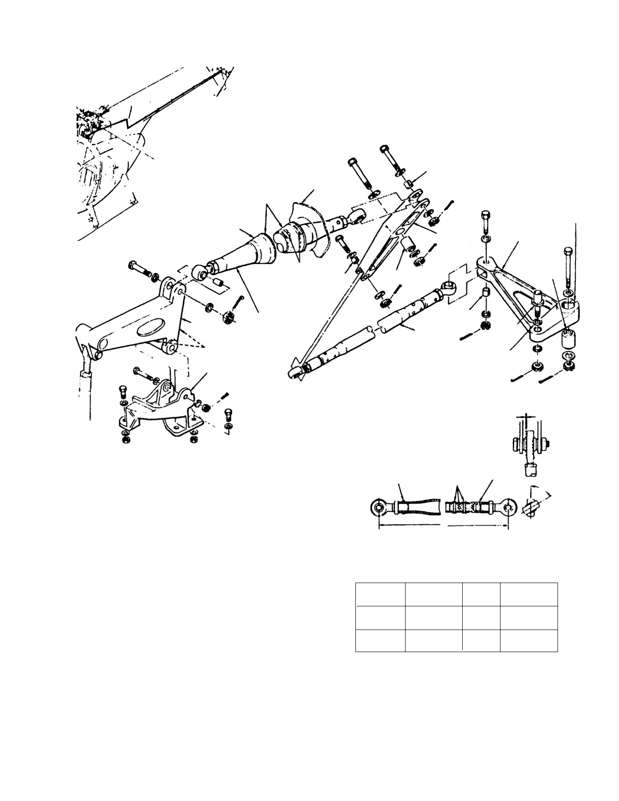
NOTES:
L
1.
MIN. OF 0.060 IN. (1.524 MM) CLEARANCE FOR FULL RANGE OF
TRAVEL THRU STA. 137.50 BULKHEAD.
2.
EDGE OF BUSHING MUST PROTRUDE A MIN. OF 0.010 IN. (0.254 MM)
TO A MAX. OF 0.060 IN. (1.524 MM) ABOVE OUTSIDE SURFACE OF
INITIAL ROD ASSY LENGTH AND
PART AFTER NUT IS TIGHTENED.
BEARING ANGULARITY (BEFORE RIG)
3.
MIN. OF 0.010 IN. (0.254 MM) CLEARANCE FOR FULL RANGE OF
CONTROL
DIM
ANGLE
ASSY PART
TRAVEL BETWEEN BOOM AND TAIL ROTOR TRANSMISSION.
ROD ASSY
L
A
NUMBER
4.
MUST BE CHROME PLATED OR NITRIDED.
5.
USE TO PREVENT DISSIMILAR METAL CONTACT; INSTALL AT
45.88 IN.
STA. 100
IN LINE
369A7006−5
EARLIEST OPPORTUNITY.
(116.5352 CM)
6.
DRAINAGE PROVISIONS FOR WATER ENTRAPMENT AREAS
141.70 IN.
(REFER TO MDHI HN−39).
TAILBOOM
63°
369A7518
(359.918 CM)
7.
ASTERISK ( * ) INDICATES PARTS THAT MAY BE EITHER ALUMINUM
OR MAGNESIUM ALLOY. REFER TO SECTION 2 FOR ALLOY
IDENTIFICATION CONTROL.
30−067G
Figure 8-15. Upper Fuselage and Boom Tail Rotor Control Linkage
Page 8-45
Revision 17
MD Helicopters, Inc.
CSP−H−2
500 Series − Basic HMI
(9). Reinstall Sta. 95 bellcrank in its
35. Tailboom Control Rod Replacement
support with bolt, two washers, nut and
(Ref. Figure 8−15)
cotter pin.
A. Tailboom Control Rod Removal
(10). Secure grommet to fabric boot with
nylon strap and boot to support tube
(1). Disconnect control rod from Sta. 282.00
with nylon strap.
bellcrank.
(2). Accurately measure and record distance
(11). If rubber boot is used:
between un−chamfered edge of forward
rod end bearing jam nut and center of
(a). Secure end at support tube with
bearing attach bolt hole.
nylon strap.
(3). Hold forward rod end, loosen jam nut
(b). Clamp tail rotor pedals in neutral.
and un−thread control rod from rod end
by turning aft end of rod.
(c). Set free length of bellows portion of
boot at approximately 5.50 inches
(4). Slowly pull at aft end of control rod and
(13.97 cm) and secure end to control
withdraw rod out through opening in
rod with nylon strap.
tail rotor transmission mounting frame.
(12). Check rigging of tail rotor controls after
B. Tailboom Control Rod Installation
installation of any removed or replaced
NOTE: Tailboom control rod is routed through
parts.
the boom with the forward rod end removed.
Use of special grommet installation tool (57,
34. Sta. 282.00 Bellcrank Replacement
Table 2−2) simplifies installation of tail ro−
tor control rod grommets. For replacement
(Ref. Figure 8−15)
of grommets, refer to CSP−H−6.
A. Sta. 282.00 Bellcrank Removal
(1).
Guide control rod through boom aft
frame opening and carefully route
(1). Disconnect bellcrank from tailboom
through the six control rod grommets.
control rod.
Rotate the rod slightly to start it
through each grommet.
(2). Disconnect bellcrank from tail rotor
transmission arm. Disengage bellcrank
(2).
Check that slotted bushing is in place
pitch control pin from tail rotor assem−
in lower lug of Sta. 282 bellcrank; then
bly and remove bellcrank.
attach aft rod end to bellcrank with
bolt, two washers, nut and cotter pin.
B. Sta. 282.00 Bellcrank Installation
(3).
Using measurement recorded at time of
(1). Position tail rotor pitch control assem−
rod removal, install forward rod end
bly to align with pitch control pin in
bearing. Align rod ends so that the
bellcrank and engage pin.
bearings have equal space for angular
throw; hold rod end and tighten jam
(2). Position bellcrank to align with mating
nut.
hole in tail rotor transmission arm and
(4).
Check that slotted bushing is in place
install bolt, two washers, nut and cotter
in lower end of Sta. 142 bellcrank; then
pin.
attach forward rod end to bellcrank
with bolt, two washers, nut and cotter
(3). Check that slotted bushing is in place
pin.
in lower lug of bellcrank; then attach
tailboom control rod to bellcrank with
(5).
Check rigging of tail rotor controls
bolt, two washers, nut and cotter pin.
following installation of any removed or
replaced parts.
(4). Check rigging of tail rotor controls after
installation of any removed or replaced
(6).
Reinstall or close plenum chamber
parts.
access door as applicable (Ref. Sec. 2).
Page 8-46
Revision 17
MD Helicopters, Inc.
CSP−H−2
500 Series − Basic HMI
36. Sta. 95 Bellcrank and Support
(4). Inspect the rubber boot, or fabric boot
Replacement
with grommet, at Sta. 137.50 bulkhead
and, when applicable, at front of engine
(Ref. Figure 8−15)
air inlet screen for good condition.
A. Sta. 95 Bellcrank and Support Removal
(5). Clean any accumulation of dirt from the
grommet in the fabric boot to minimize
(1). Disconnect tunnel−routed control rod
abrasive wear on the control rod.
from bellcrank.
(6). Inspect Sta. 100 control rod for chafing
of the surface that feeds through the
(2). Disconnect bellcrank from support.
fabric boot grommet; serviceable wear
is limited to 0.004 inch (0.1016 mm)
(3). Disconnect bellcrank from Sta. 100
measured from adjacent undamaged
control rod and remove bellcrank.
area.
(4). Remove hardware that secures support
NOTE: A fabric boot with grommet may be re−
to mast structure; remove support.
placed with a rubber bellows type boot
369A8415 to eliminate grommet chafing of
B. Sta. 95 Bellcrank and Support Installation
rod.
(1). Install bellcrank support to mast
(7). Inspect for wear of the tailboom control
structure with three bolts, seven
rod surfaces that pass through the
washers and three nuts. (The forward
control rod grommets.
bolt requires an extra washer
(AN960PD416) under the bolthead).
(a). Serviceable wear is limited to the
thickness of the hard anodic coating.
NOTE: Two thin washers are used at all three
locations.
(b). Check that all grommets are secure.
(2). Torque nuts to 80 − 100 inch−pounds
(8). Inspect bellcranks for scratches,
(9.04 − 11.30 Nm).
corrosion and similar surface defects.
(9). Inspect bellcrank bearing for looseness
(3). Check that slotted bushings are in
and binding.
place in bellcrank; then attach Sta. 100
control rod to bellcrank with bolt (head
(10). Check that Sta. 282 (tail rotor gearbox)
to left), two washers, nut and cotter pin.
bellcrank drain slot, if provided, is free
of obstruction.
(4). Install bellcrank in support with bolt,
two washers, nut and cotter pin.
(11). Replace Sta. 282.00 bellcrank pivot pin
if worn or corroded. Install washer
(5). Attach tunnel−routed control rod to
HS308−616L between pin and bell−
bellcrank with bolt, two washers, nut
crank.
and cotter pin.
38. Upper Fuselage and Boom Tail Rotor
37. Upper Fuselage and Boom Tail Rotor
Control Linkage Repair
Control Linkage Inspection
(1). Perform a straightness check on a
(1). Inspect rod end bearing for binding and
control rod that appears bent or bowed.
excessive wear, 0.040 inch (1.016 mm)
maximum axial looseness.
(a). The total length of Sta. 100 control
rod, excluding rod ends, must be
(2). Inspect for loose rivet at fixed rod end.
straight within 0.040 inch (1.016
mm), with straightness variation
(3). Inspect control rod for surface damage
limited to a maximum of 0.010 inch
and evidence of bending.
(0.254 mm) in each foot of length.
Page 8-47
Revision 17
MD Helicopters, Inc.
CSP−H−2
500 Series − Basic HMI
(b). The total length of the tailboom
(a). Install replacement bearing with
control rod, excluding rod ends, must
grade A locking compound (29,
be straight within 0.120 inch (3.048
Table 2−4). Check that bearing seats
mm), with straightness variation
against bore shoulder.
limited to a maximum of 0.010 inch
NOTE: The installation direction of Sta. 142
(0.254 mm) in each foot (30.48 cm) of
bellcrank bearing may be from either side,
length.
depending on location of bearing shoulder.
A dye− check for cracking
There must not be less than 0.010 inch
WARNING
must always be performed
(0.254 mm) protrusion of bearing inner race
after cold− straightening. Replace a
beyond the sides of the bellcrank after the
cracked rod, or a cracked or bent rod
bearing is installed.
end.
(6). Repair minor surface defects such as
(2). Cold−straighten a bent rod that is not
scratches, nicks and corrosion on
within tolerance provided there are no
bellcranks and support bracket.
nicks or sharp dents in the bend length.
(a). Use abrasive cloth grade 400−600
DO NOT use the rod ends to support
(20) to smooth out and blend in such
the rod during straightening process.
defects.
Use care when drilling to re−
(7). The following rework limits represent
CAUTION
move or install riveted rod end;
total limits, including the effects of all
the rod is steel and the rod and bearing
previous repairs to any given area.
adapter are aluminum.
NOTE: Parts identified in Figure 8−15 with an
(3). Replace a control rod end if bearing
asterisk (*) may be either magnesium or
axial play is more than 0.040 inch
aluminum alloy. Refer to Section 2 for corro−
(1.016 mm). Set initial control rod
sion control and identification of magne−
length and bearing angularity as shown
sium and aluminum alloys.
in Figure 8−15.
(a). Cast surfaces may be reworked to
(4). Replace unserviceable control rod
depth of 0.020 inch (0.508 mm).
bearing adapter.
(b). Flat machined surfaces, except clevis
NOTE: Use the trammel method, or equivalent,
inner ears, may be reworked to depth
to establish rod length when replacing an
of 0.015 inch (0.381 mm).
adapter.
(c). Clevis inner ear surfaces may be
(a). Measure length and record position
reworked to depth of 0.020 inch
of rod end in adapter; then remove
(0.508 mm).
affected rod end.
(d). Machined holes may have 0.003 inch
(b). Observe the CAUTION above and
(0.0762 mm) removed from the bore
drill out rivets securing adapter to
wall in an area no greater than 15
rod and aft rod end.
percent of the circumference and 50
percent of the depth.
(c). Install rod end in replacement
adapter and position at recorded
(e). All edges may have 0.030 inch (0.762
measurement.
mm) removed except around ma−
chined holes, which are limited to
(d). Fit adapter into rod and position to
0.010 inch (0.254 mm) chamfer.
fit recorded trammel position.
(f). All rework must be smoothly blended
(e). Drill through existing rivet holes in
into the adjacent surfaces and the
rod and install rivets to secure
finish must be restored. Refer to
adapter to rod.
preceding NOTE.
(5). Replace unserviceable bellcrank and
(8). Repair surface abrasion on Sta. 100
support pivot bearings.
control rod by smoothing the area with
Page 8-48
Revision 17
MD Helicopters, Inc.
CSP−H−2
500 Series − Basic HMI
grade 400 abrasive cloth (20) and
(10). Replace split or torn boot or a cracked
restoring protective finish with primer
grommet:
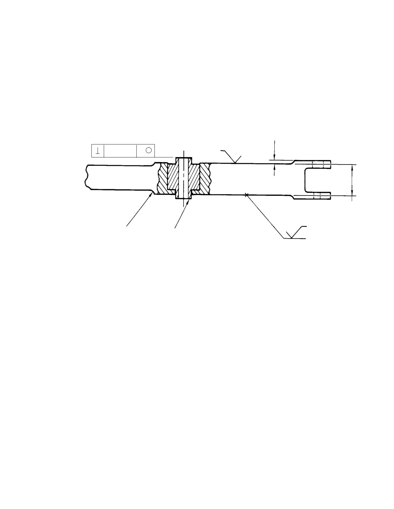
(4). Replace rod if wear or depth of
(a). Remove Sta. 100 control rod.
repair exceeds 0.004 inch (0.1016 mm).
NOTE: A fabric boot with grommet may be re−
placed with a rubber bellows type boot
369A8415.
(9). Replace tailboom control rod if hard
anodic coating is worn through and
(b). Replace boot, as required, and
aluminum base metal is visible.
reinstall Sta. 100 control rod.
BELLCRANK AND SUPPORT
(2 PLS) (NOTE 1)
(NOTES
0.002 IN.
A S
2 & 3)
(0.0508 MM)
0.750 IN.
(19.05 MM)
(NOTES
MIN.
2 & 3)
0.090 IN. (2.286 MM) R
369A7951−23
(TYP)
BEARING
NOTES:
1.
0.010 IN. (0.254 MM) MIN. CLEARANCE REQUIRED IN THIS AREA.
2.
TREAT MACHINED AREA (5, TABLE 2−4).
3.
TOUCH−UP (COLOR 34151 GREEN).
44−475A
Figure 8-16. Rework of Sta. 142 Bellcrank Assembly
Page 8-49/(8-50 blank)
Revision 17
MD Helicopters, Inc.
CSP−H−2
500 Series − Basic HMI
Section
9
Transmissions and
Drives System
MD Helicopters, Inc.
CSP−H−2
500 Series − Basic HMI
TABLE OF CONTENTS
Para/Figure/Table
Title
Page
Section 9 Transmissions and Drives System .
9−1
1.
Power Train System
9−1
2.
Power Train System Troubleshooting
9−1
Table 9−1. Troubleshooting the Power Train System
9−1
Figure 9−1. Power Train System
9−4
3.
Main Transmission
9−5
A. Main Transmission Removal
9−5
Figure 9−2. Main Transmission Installation
9−6
B. Main Transmission Installation
9−7
C. Main Transmission Inspection
9−7
D. Main Transmission Stripping
9−8
E. Main Transmission Buildup
9−8
F. Main Transmission Repair
9−8
Figure 9−3. Main Transmission Cross−Section
9−9
4.
Lubrication Pump and Oil System Accessories
9−10
A. Lubrication Pump Removal
9−10
B. Lubrication Pump Installation
9−10
C. Lubrication Pump and Oil System Accessories Inspection .
9−10
D. Transmission Filter Replacement
9−10
E. Chip Detector Replacement
9−10
F. Tachometer Generator Replacement
9−11
G. Oil Pressure Sender and Temperature Switch Replacement .
9−11
H. Liquid Level (Sight) Plug Replacement
9−11
I.
Application of Markings on Liquid Level Plug
9−11
J. Repair and Replacement of Transmission Drains and Tubing .
9−11
Figure 9−4. Main Transmission Drain Tubing
9−12
5.
Main Rotor Drive Shaft
9−13
A. Main Rotor Drive Shaft Removal
9−13
B. Main Rotor Drive Shaft Installation
9−14
C. Main Rotor Drive Shaft Inspection
9−14
Figure 9−5. Main Rotor Drive Shaft
9−15
D. Main Rotor Drive Shaft Exterior Repair
9−16
6.
Main Transmission Drive Shaft
9−16
A. Main Transmission Drive Shaft Removal
9−16
B. Main Transmission Drive Shaft Installation
9−16
C. Main Transmission Drive Shaft Inspection (Bendix)
9−17
D. Main Transmission Drive Shaft Inspection (Kamatic)
9−18
Page 9−i
Revision 17
MD Helicopters, Inc.
CSP−H−2
500 Series − Basic HMI
TABLE OF CONTENTS (Cont.)
Para/Figure/Table
Title
Page
E. Main Transmission Drive Shaft Couplings Corrosion Removal .
9−18
F. Main Transmission Drive Shaft Repair (Bendix)
9−19
G. Main Transmission Drive Shaft Repair (Kamatic)
9−19
7.
Oil Cooler Blower
9−19
A. Oil Cooler Blower Removal (Early−Type, Belt−Driven) . .
9−19
Figure 9−6. Main Transmission Driveshaft and Early Type Belt−Driven
Oil Cooler Blower (Sheet 1 of 2)
9−20
B. Oil cooler Blower Installation (Early−Type, Belt−Driven) .
9−22
C. Oil Cooler Blower Removal (Current−Type, Belt−Driven) .
9−24
D. Oil Cooler Blower Installation (Current−Type, Belt−Driven) .
9−24
Figure 9−7. Main Transmission Driveshaft and Current Type Belt−Driven
Oil Cooler
9−25
E. Oil Cooler Blower Inspection (Belt−Driven)
9−27
Figure 9−8. Belt−Driven Oil Cooler Blower (Screw−Assembled), Exploded
View
9−28
Figure 9−9. Early Type Belt−Driven Oil Cooler Belt Tension and Pulley
Alignment
9−29
F. Oil Cooler Blower Removal (Shaft−Driven)
9−30
G. Oil Cooler Blower Installation (Shaft−Driven)
9−30
H. Oil Cooler Blower Inspection (Shaft−Driven)
9−31
I.
Oil Cooler Blower Disassembly (Belt−Driven)
9−31
J.
Oil Cooler Blower Reassembly (Belt−Driven)
9−32
Figure 9−10. Main Transmission Driveshaft and Shaft−Driven Oil Cooler
Blower
9−33
K. Oil Cooler Blower Repair
9−34
Figure 9−11. Cutaway View of Belt−Driven Oil Cooler Blower .
9−35
8.
Overrunning Clutch
9−36
A. Overrunning Clutch Removal
9−36
B. Overrunning Clutch Installation
9−36
Figure 9−12. Overrunning Clutch Repair or Replacement .
9−37
C. Overrunning Clutch Inspection
9−38
D. Overrunning Clutch Sub−Assembly and Ball Bearing Inspection .
9−38
E. Overrunning Clutch Sub−assembly Replacement
9−38
F. Overrunning Clutch Repair/Overhaul
9−38
9.
Tail Rotor Transmission
9−38
A. Tail Rotor Transmission Removal
9−38
Figure 9−13. Tail Rotor Transmission and Drive Shaft Installation with
Kamatic Couplings Installed (Sheet 1 of 2)
9−39
Figure 9−14. Tail Rotor Transmission and Drive Shaft Installation with
Bendix Couplings Installed (Sheet 1 of 2)
9−41
Page 9−ii
Revision 17
MD Helicopters, Inc.
CSP−H−2
500 Series − Basic HMI
TABLE OF CONTENTS (Cont.)
Para/Figure/Table
Title
Page
B. Tail Rotor Transmission Installation
9−43
C. Tail Rotor Transmission Inspection
9−43
D. Tail Rotor Transmission Stripping
9−43
E. Tail Rotor Transmission Buildup
9−43
Figure 9−15. Replacement of Tail Rotor Transmission Liquid Level Plug and
Breather−Filler
9−44
F. Protective Sleeve (Speedi−Sleeve) Installation, Output Gearshaft .
9−45
Figure 9−16. Protective Sleeve Installation/Replacement, Output Gearshaft .
9−46
G. Protective Sleeve (Speedi−Sleeve) Replacement, Output Gearshaft
9−47
10. Tail Rotor Drive Shaft
9−47
A. Tail Rotor Drive Shaft Removal
9−47
B. Tail Rotor Drive Shaft Installation with Kamatics Couplings .
9−47
C. Tail Rotor Drive Shaft Installation with Bendix Couplings .
9−49
D. Tail Rotor Drive Shaft Twist Inspection
9−51
E. Tail Rotor Drive Shaft Index Stripe Application
9−52
F. Tail Rotor Drive Shaft Inspection
9−52
Figure 9−17. Drive Shaft Twist Check
9−53
G. Tail Rotor Drive Shaft Repair
9−54
11. Tail Rotor Drive Shaft Damper
9−54
A. Tail Rotor Drive Shaft Damper Inspection
9−54
B. Tail Rotor Drive Shaft Damper Replacement
9−54
Figure 9−18. Tail Rotor Drive Shaft Damper Friction − Checking .
9−55
C. Tail Rotor Drive Shaft Damper Friction Adjustment
9−56
12. Tail Rotor Drive Shaft Couplings
9−56
A. Tail Rotor Drive Shaft Coupling Removal
9−56
B. Tail Rotor Drive Shaft Coupling Inspection (Bendix)
9−56
C. Tail Rotor Drive Shaft Coupling Inspection (Kamatic) . .
9−56
D. Tail Rotor Drive Shaft Coupling Repair (Bendix)
9−56
E. Tail Rotor Drive Shaft Coupling Repair (Kamatic)
9−57
F. Tail Rotor Drive Shaft Coupling Installation
9−57
Page 9−iii
Revision 18
MD Helicopters, Inc.
CSP−H−2
500 Series − Basic HMI
TABLE OF CONTENTS (Cont.)
Para/Figure/Table
Title
Page
This Page Intentionally Left Blank
Page 9−iv
Revision 18
MD Helicopters, Inc.
CSP−H−2
500 Series − Basic HMI
SECTION 9
TRANSMISSIONS AND DRIVES SYSTEM
1. Power Train System
Main transmission output through the tail
rotor drive shaft to the tail rotor transmission
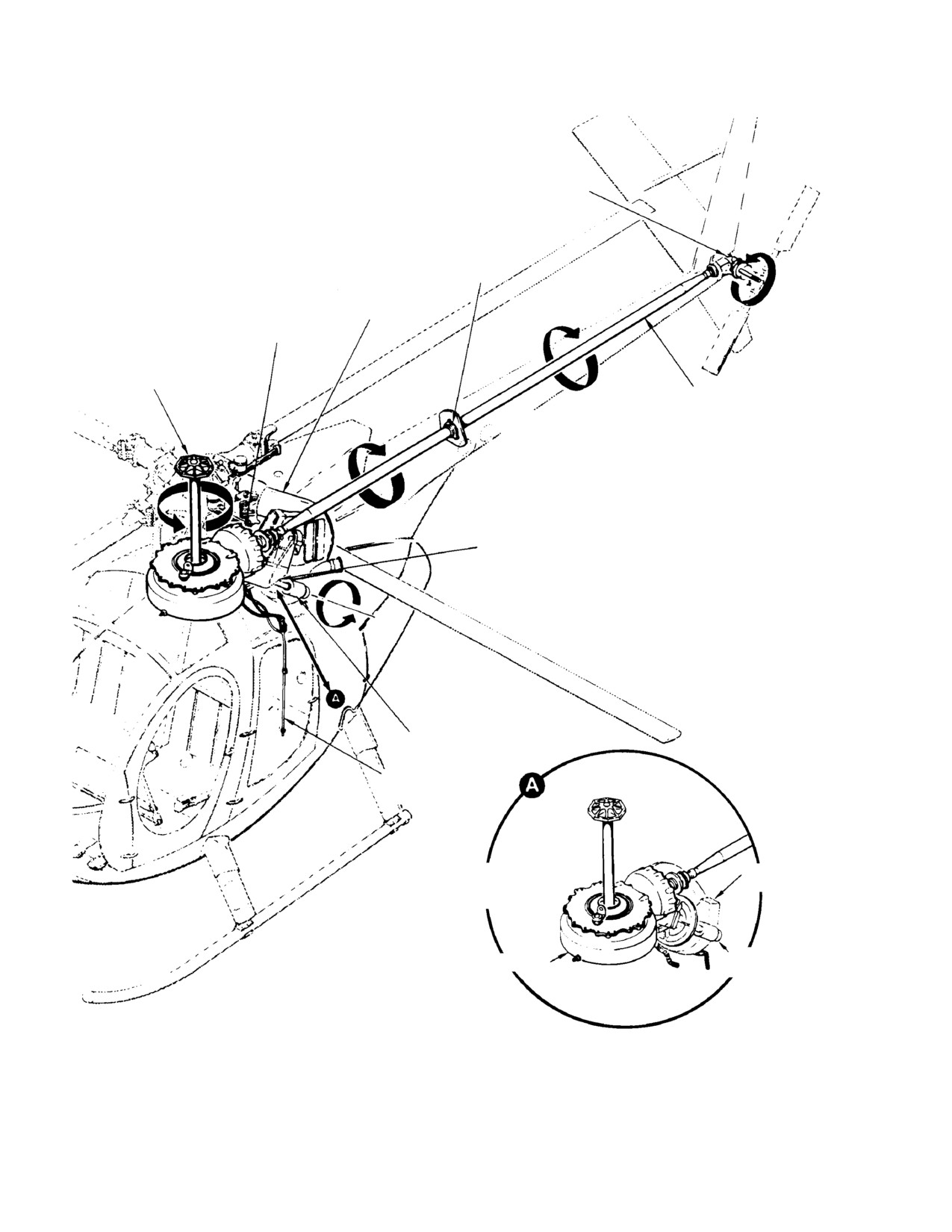
(Ref. Figure 9−1) The power train system
is 2045 rpm in a clockwise direction: tail rotor
starting at the engine power take−off pad,
transmission output to the tail rotor is 3018
consists of the overrunning clutch, drive shafts
rpm, also clockwise.
and transmissions.
Engine input through the clutch to the main
2. Power Train System Troubleshooting
transmission is 6000 rpm in a clockwise
direction: main transmission output to the
main rotor is 470 rpm, also clockwise.
(Ref. Table 9−1)
Table 9-1. Troubleshooting the Power Train System
Symptom
Probable Cause
Corrective Action
Main drive shaft vibrates
Loose attaching bolts on main drive
Retorque bolts to 50 - 70
shaft
inch-pounds (5.65 - 7.91 Nm).
Shaft dented or bent
Check drive shaft limits for
serviceability.
Excessive noise or vibration in oil
Defective impeller or damaged scroll
Replace impeller or scroll.
cooler blower assembly
Overrunning clutch will not
Defective overrunning clutch
Replace overrunning clutch.
operate
Main transmission requires
Leakage at main transmission input
If leakage is found at input pinion,
frequent addition of oil
or output seals
replace the face seal according to
applicable instructions in CSP-H-5,
HMI Appx C. If leakage is past either
output seal, replace the defective
seal.
Oil leak around accessory drive
Tighten cover or replace
cover
transmission.
Oil temperature warning light
Defective oil temperature switch
Replace oil temperature switch.
comes on when oil temperature is
normal
Oil temperature warning light
Blockage of cooling air
Check airflow paths for blockage.
comes on when oil temperature is
Low oil level or oil above full level in
Establish correct oil level (Ref. Sec.
excessive
main transmission
2).
Defective lube pump
Replace lube pump.
Defective bearings or gears
Replace transmission.
NOTE: Noise that signals a defective transmission should not be confused with normal gear backlash noise at
rundown or low rpm and power conditions.
Excessive noise in main
Inadequate oil supply
Service main transmission (Ref. Sec.
transmission
2).
Defective bearings or gears in main
Replace transmission.
transmission
Page 9-1
Revision 17
MD Helicopters, Inc.
CSP−H−2
500 Series − Basic HMI
Table 9-1. Troubleshooting the Power Train System (Cont.)
Symptom
Probable Cause
Corrective Action
Oil pressure warning light on (oil
Low oil level in main transmission
Service main transmission (Ref. Sec.
pressure low). Light should go out
2).
at approximately 55% N2
Defective oil pressure sender
Replace oil pressure sender.
Defective main lube pump
Replace lube pump.
Filter clogged
Clean filter (Ref. Sec. 2).
NOTE: Rapid or abrupt maneuvers that involve extreme changes in aircraft attitude and/or produce negative
G-forces, can result in transmission oil pressure caution warning light illuminating briefly.
Tail rotor drive shaft damper
Damper out of adjustment
Adjust damper friction.
vibrates
Damper defective
Replace damper.
Tail rotor drive shaft bent or dented
Check tail rotor drive shaft condition.
Replace shaft if straightness or tir is
beyond limits.
Tail rotor out of balance
Adjust tail rotor balance (Ref. Sec.
8).
Tail rotor transmission output
Worn or damaged bearings or gears
Replace tail rotor transmission.
shaft vibrates
in tail rotor transmission
Bent shaft or excessive shaft run-out
Replace tail rotor transmission.
Excessive noise in tail rotor
Inadequate oil supply
Service tail rotor transmission (Ref.
transmission
Sec. 2).
Defective bearings or gears in tail
Replace tail rotor transmission.
rotor transmission
Chip detector caution light on
Metallic chips in either main or tail
Inspect and clean chip detector
rotor transmissions
magnetic plugs. If there are heavy
chip deposits (chips larger than
0.125 inch (3.175 mm) in any
direction), replace the transmission.
If chips are smaller, drain and refill
transmission with new oil. Reinstall
chip detector and check after 4 hours
of flight. If more chips are found,
replace the transmission.
Defective chip detector
Replace chip detector.
Page 9-2
Revision 17
MD Helicopters, Inc.
CSP−H−2
500 Series − Basic HMI
Table 9-1. Troubleshooting the Power Train System (Cont.)
Symptom
Probable Cause
Corrective Action
NOTE: High frequency vibrations in the helicopter can also be caused by components in other systems (Ref. Sec.
5, 8, and 10).
High frequency vibration
Loose tail rotor drive shaft couplings Retorque couplings bolt to 250 - 300
inch-pounds (28.25 - 33.90 Nm),
plus allowable drag torque.
Tail rotor drive shaft couplings
Check shimming: correct as
shimmed improperly
required.
Loose, mismatched or bottomed
Tighten or install proper hardware
hardware retaining tail rotor drive
and be sure hard ware is installed
shaft couplings to main transmission correctly.
Oil cooler blower impeller has
Replace impeller.
cracks, loose rivets, defective blades
or other damage
Tail rotor drive shaft damper out of
Adjust damper friction.
adjustment
Defective overrunning clutch
Replace overrunning clutch.
Tail rotor drive shaft bent, dented or
Check tail rotor drive shaft condition.
otherwise damaged.
Replace shaft if straightness or tir is
beyond limits
NOTE: Drag is excessive when force required to rotate the transmission input shaft exceeds 25 inch-pounds
(2.82 Nm) with all shafting disconnected and transmission temperature between 50°F (10°C) and 100°F
(38°C).
Abnormal drag in the drive
Excessive rotational drag in main
Replace transmission if drag torque
system
transmission
exceeds 25 inch-pounds (2.82 Nm).
Page 9-3
Revision 17
MD Helicopters, Inc.
CSP−H−2
500 Series − Basic HMI
TAIL ROTOR TRANSMISSION
TAIL ROTOR DRIVE
SHAFT DAMPER
OIL COOLER
BLOWER
MAIN
TRANSMISSION
MAIN ROTOR
DRIVE SHAFT
TAIL ROTOR DRIVE SHAFT
MAIN TRANSMISSION
DRIVE SHAFT
OVERRUNNING CLUTCH
TRANSMISSION DRAIN
INSTALLATION
OIL COOLER
SHAFT−DRIVEN
BLOWER
BLOWER
OVERRUNNING
MAIN TRANSMISSION
CLUTCH
30−071A
Figure 9-1. Power Train System
Page 9-4
Revision 17
MD Helicopters, Inc.
CSP−H−2
500 Series − Basic HMI
3. Main Transmission
(4). Remove tail rotor driveshaft (Ref. Tail
Rotor Drive Shaft Removal).
(Ref. Figure 9−2) The main transmission is
mounted on the main rotor mast support
NOTE: Removal of the main rotor driveshaft,
structure. The transmission is a two−stage,
step (5)., is optional. If help is not available
speed reduction unit, utilizing the first
to rotate the rotor hub for spline alignment,
reduction stage for the tail rotor drive system
shaft removal could facilitate reinstallation
and accessory drive trains, and the second
of the transmission.
stage to further reduce rpm for the main rotor.
(5). Remove main rotor driveshaft (Ref.
All of the gears are spiral−bevel type, except
Main Rotor Drive Shaft Removal).
for the accessory drive gears which are spur
type.
(6). Disconnect wiring from tachometer
generator, two chip detector, and oil
The transmission housing is magnesium alloy.
pressure and temperature senders.
The input pinion drives the input bevel gear
(7). Drain oil from transmission.
which is concentrically mounted on the tail
rotor output pinion.
(8). Obtain assistance to support the
transmission, then remove four nuts
The output pinion simultaneously drives the
and washers.
output bevel gear, main rotor drive shaft, tail
rotor drive shaft and accessory drive train.
Lower the transmission with ex−
CAUTION
The accessory gear train drives, at 4200 rpm,
treme care to prevent contact
both the rotor tachometer generator and the
between the tail rotor drive coupling and the
transmission oil pump which are mounted on
surrounding structure. Any dents, nicks or
drive pads at the back of the transmission.
scratches on the coupling diaphragm re−
quires that the coupling be scrapped. Use
Transmission cooling is accomplished by the
care to protect temperature sender and chip
lubrication oil and by air drawn over the
detector terminal studs from damage during
housing by the oil cooler blower and ram air
handling or when placing transmission on
routed to the gearbox by the two side ducts in
any surface.
the forward end of the air inlet fairing.
(9). With help from assistant, carefully
A. Main Transmission Removal
lower transmission from mounting
studs; Blower impeller is left attached
(1). Remove the sound insulation and
on helicopter with shaft −driven oil
transmission access covers.
cooler blower.
(2). Remove main transmission driveshaft
(Ref. Main Transmission Drive Shaft
(10). Keep output seal with transmission by
Removal).
tapping or tying in place to prevent loss
during handling, shipping or storage.
(3). Remove belt−driven oil cooler blower
(Ref. Oil Cooler Blower Removal,
NOTE: Apply covering over the top opening of
Current Type, Belt−Driven) or scroll
the transmission to prevent entry of dirt or
from shaft−driven oil cooler blower (Ref.
water. The residual operating lubricant is
Oil Cooler Blower Removal, Shaft−Driv−
an approved preservative for transmission
en).
shipment or storage.
Page 9-5
Revision 17
MD Helicopters, Inc.
CSP−H−2
500 Series − Basic HMI
3°
90°
C OUTPUT SHAFT
L
0.650 IN.
0.050 IN.
0.060 IN. (15.24 MM)
DECAL
(16.51 MM)
(12.7 MM)
MAIN ROTOR
NEW FULL
DRIVE SHAFT
MARKINGS
ORIGINAL
DECAL MARKINGS
PAINTED MARKINGS
MARKINGS
MAST BASE
SHAFT−DRIVEN BLOWER
BLOWER SCROLL
COUPLING BOLT 250−300 IN. LB
(28.25−33.90 NM) PLUS DRAG TORQUE
TAIL ROTOR
(NOTES 2, 4)
DRIVE SHAFT
50−70 IN. LB
(5.65−7.91 NM)
WASHER (REDUCED OD)
SHIMS
OUTPUT
(NOTE 1)
SEAL
LUBE PUMP & FILTER
O−RINGS
TAIL ROTOR DRIVE
DEBRIS SEAL
SHAFT COUPLING
(NOTE 3)
ROTOR TACHOMETER
FILLER
GENERATOR
SCREEN
O-RING
OIL
LIQUID LEVEL PLUG
80−90 IN. LB
(9.04−10.17 NM)
O−RING
BOND
JUMPER
60−80 IN. LB
(6.80−9.04 NM)
NOTES:
BELT-DRIVEN BLOWER
1.
ALUMINUM ALLOY; 0.002−IN. LAMINATIONS.
2.
DRAG TORQUE FOR BOLT (SELF LOCKING) IS 25 IN LBS. (2.82 NM) MIN.,
200 IN LBS. (22.60 NM) MAX.
3.
COAT COUPLING SPLINES WITH CORROSION PREVENTIVE COMPOUND
(70, TABLE 2−4) BEFORE ASSEMBLY.
4.
COAT COUPLING BOLT THREADS WITH ANTISEIZE COMPOUND (36) BEFORE
ASSEMBLY.
30−072G
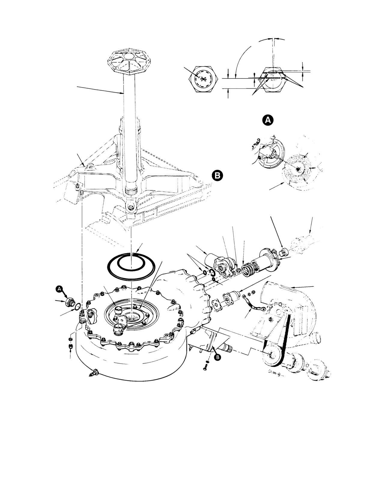
Figure 9-2. Main Transmission Installation
Page 9-6
Revision 17
MD Helicopters, Inc.
CSP−H−2
500 Series − Basic HMI
B. Main Transmission Installation
When reinstalling main rotor
CAUTION
drive shaft, check that there is
no gap between shaft mounting flange and
Install only a 369A5100− 705,
CAUTION
rotor hub before tightening installation
− 705M,
−707,
−707M, or
−709
bolts. Gap indicates that shaft splines are
main transmission on helicopters equipped
not correctly meshed in transmission.
with a 250−C20 engine. In addition, a
369A5186−1 1 temperature switch is also re−
(8). If main rotor drive shaft has been
quired with either of these transmissions if
removed, apply coating of oil (35,
the transmission is not already identified
Table 2−4) on shaft before reinstalla−
with a 0.50 inch (12.7 mm) white dot located
tion. Install drive shaft.
next to the identification plate. Refer to
CSP− H− 5 for addition main transmission
(9). Install blower on helicopter equipped
qualifying information.
with belt−driven oil cooler blower, or
blower scroll for shaft−driven oil cooler
blower. Install drain assembly, drain
(1). If transmission is a replacement,
lines, and aft cover on transmission.
perform buildup.
(10). Install main transmission drive shaft.
CAUTION
(11). Ground run helicopter according to the
Pilot’s Flight Manual and check drive
system for excessive vibration and
D If transmission is new, remove output
unusual noise. Check transmission for
seal from shipping container and install
correct warning light operation and oil
on transmission.
leakage (Ref. Sec. 2, Fluid Leak
D Damage to main rotor drive shaft or main
Analysis). Replace unserviceable output
transmission splines can occur during in−
seals.
stallation. Care should be taken while
(12). Install access covers and sound insula−
meshing driveshaft splines into transmis−
tion.
sion output splines to prevent damage.
NOTE: If a 250− C20 engine is installed, a
(2).
Apply petrolatum (34, Table 2−4) to
transmission cover with airflow baffles
outer edge of output seal. Press firmly
must be used to assure adequate cooling.
into recess in top of transmission
C. Main Transmission Inspection
housing.
(1). Remove the sound insulation and
(3).
With help from an assistance, carefully
transmission access covers.
lift and position transmission in place
(2). Inspect transmission for oil leaks,
on mounting studs.
cracks, corrosion, secure electrical
connections, and proper oil level.
(4).
Install four washers and nuts; torque to
Evaluate oil leakage according to Fluid
60 − 80 inch−pounds (6.78 − 9.04
Leak Analysis.
Nm).
(3). Inspect the four mounting flanges on
main transmission housing for corro−
(5).
If transmission is new, drain any
sion and cracks. Check that transmis−
residual preservative oil. Service
sion mounting studs and nuts are
transmission with lubricating oil (2,
secure. This should be accomplished
Table 2−3).
from the fuselage interior as well as the
exterior at the main rotor mast base.
(6).
Connect wiring to tachometer genera−
(4). Check that all safety wiring is intact
tor, two chip detectors and oil pressure
and secure.
and temperature sender switch.
(5). Reinstall transmission access covers
(7).
Install tail rotor drive shaft.
and sound insulation.
Page 9-7
Revision 17
MD Helicopters, Inc.
CSP−H−2
500 Series − Basic HMI
(6). Inspect internal ring gear bolts in the
shaft coupling and tighten against shim
main transmission as follows.
with internal wrenching bolt.
(a). Drain the main transmission.
(3). On helicopter equipped with shaft−driv−
en oil cooler blower, install oil cooler
(b). Remove liquid level (sight) plug.
blower impeller; install input gearshaft
coupling.
(c). Using an adequate light source,
rotate main rotor 360 degrees while
(4). Install tachometer generator.
visually checking that all sixteen (16)
ring gear bolts and lockwire are
(5). Install transmission input gearshaft
intact. Also check visible areas of the
seal drain tube if not already in place.
ring gear and carrier for cracks and
other discrepancies.
F. Main Transmission Repair
NOTE: If damage (bolt heads sheared, lockwire
(Ref. Figure 9−2 and Figure 9−3) Replace
broken, crack or other discrepancies) is vis−
electrical components, the breather−filler
ible, replace transmission or overhaul (Ref.
and/or screen, the output seal, externally
CSP−HMI−5).
accessible O−rings, the lubrication pump
(d). Reinstall liquid level plug.
and/or filler, and the output pinion gearshaft
oil seal when they become defective. Repair
(e). Fill main transmission.
housing outer surface damage within the
limits outlined below. Replace or repair other
D. Main Transmission Stripping
components of the main transmission accord−
ing to applicable instructions in CSP−H−5.
(Ref. Figure 9−2 and Figure 9−3)
(1). If the depth of a depression does not
(1). Remove tachometer generator.
exceed 0.030 inch (0.762 mm) and the
area is no greater than 0.60 square inch
(2). Remove shaft−driven oil cooler impeller
(3.87096 square cm), repair according to
from transmission.
steps (3)., (4). and (6)..
(3). Remove internal wrenching bolt, tail
(2). If the depth of a depression exceeds
rotor drive coupling and shims. Keep
0.030 inch (0.762 mm) but does not
shims with coupling for reuse.
exceed 0.10 inch (2.54 mm) and the
area is no greater than 0.60 square inch
(4). Install suitable covers and plugs to
(3.87096 square cm), repair according to
protect seal ports, stud threads and the
steps (3). thru (6).
tachometer generator pad.
NOTE: Any evidence of lubricating oil leakage
NOTE: Further disassembly is not required.
in a repaired area requires replacement of
the transmission.
E. Main Transmission Buildup
(3). Clean area with solvent (1, Table 2−4)
(Ref. Figure 9−2 and Figure 9−3)
and remove sharp edges with grade 320
abrasive paper (9).
(1). Install one preliminary 0.010 inch
(0.254 mm) shim on transmission
(4). Apply a coat of primer (4) on the
output (tail rotor drive) gearshaft to
repaired surface.
prevent internal wrenching bolt from
bottoming against end of gearshaft.
(5). Fill depression with epoxy adhesive (19)
(2). Coat coupling splines with corrosion
and blend to surrounding surfaces.
preventive compound (70, Table 2−4)
before assembly. Install tail rotor drive
(6). Touch up the reworked area with paint
Page 9-8
Revision 17
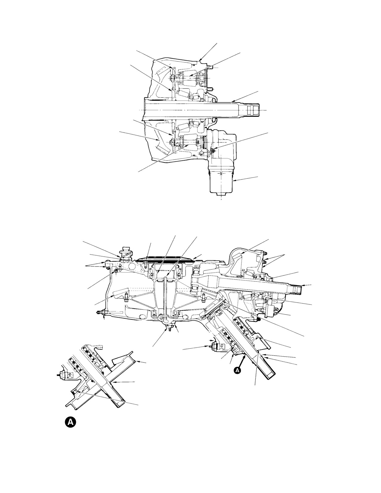
MD Helicopters, Inc.
CSP−H−2
500 Series − Basic HMI
TAIL ROTOR DRIVE HOUSING COVER
ACCESSORY DRIVE PINION
TACHOMETER GENERATOR
DRIVE SHAFT
ACCESSORY DRIVE GEAR
TAIL ROTOR DRIVE OUTPUT PIN−
ION GEARSHAFT
ACCESSORY DRIVE PINION
INPUT BEVEL GEAR
50−70 IN. LB
(5.65−7.91 NM)
LUBE PUMP DRIVE SHAFT
LUBE PUMP & FILTER
OUTPUT SHAFT
FILLER CAP & BREATHER
SPLINES
65−75 IN. LB
OIL JET FOR COUPLING
50−60 IN. LB
INPUT BEVEL GEAR
(7.34−8.47 NM)
(5.65−6.78 NM)
OUTPUT SEAL
TAIL ROTOR DRIVE HOUS−
(NOTE 1)
SHIM & O−RING
ING COVER NUTS: 50−70 IN.
LB (5.65−7.91 NM)
OUTPUT COVER
NUTS: 50−70 IN. LB
OIL SEAL
(5.65−7.91 NM)
OUTPUT PINION
SCAVENGE OIL
GEARSHAFT
RETURN TUBE
(DISCHARGE)
SEAL RETAINER
OUTPUT BEVEL GEAR
DRAIN TUBE
OIL PRESSURE SENDER
30−40 IN. LB (3.39−4.52 NM)
OIL TEMPERATURE SWITCH
12−25 IN. LB (1.36−2.82 NM)
SELF−CLOSING DRAIN
SCAVENGE PUMP
VALVES (NOTE 2)
65-75 IN. LB (7.34-8.47 NM)
CHIP DETECTORS
BLOWER SPACER
FACE SEAL
SHROUD MOUNT
INPUT SEAL DRAIN
INPUT PINION GEARSHAFT
BLOWER SPACER (MATCHED TO TRANSMISSION
FOR IMPELLER−TO−SHOUD MOUNT CLEARANCE)
BLOWER BRACKET MOUNT
INPUT SEAL DRAIN
NOTE:
SHROUD MOUNT FOR SHAFT−DRIVEN BLOWER
1.
INSTALLED AT INSTALLATION.
2.
TORQUE TO 50−60 IN. LB (5.65−6.78 NM).
30−073E
Figure 9-3. Main Transmission Cross-Section
Page 9-9
Revision 17
MD Helicopters, Inc.
CSP−H−2
500 Series − Basic HMI
4. Lubrication Pump and Oil System
B. Lubrication Pump Installation
Accessories
(Ref. Figure 9−2)
(Ref. Figure 9−3) The main transmission has a
(1).
Remove plugs from pressure ports in
self−contained oil system.
pump and transmission.
A lubrication pump draws oil from the main
(2).
Install new O−rings in ports and
sump of the transmission housing and
O−ring groove of pump sleeve. Apply a
provides oil flow to the oil pressure sender,
light coating of petrolatum (34,
bearings, gears and the output spline for the
Table 2−4) to both the O−ring and
main rotor drive shaft.
mating bore in transmission to prevent
damage to O−ring.
The pump is a positive−displacement, vane−
type with a non−adjustable discharge pressure
(3).
Align square drive of pump with drive
of 25−50 psi (172−345 kPa). It is driven at
shaft in transmission and carefully
4200 rpm by the accessory drive gear splined
press pump into place on mating
to the tail rotor output gearshaft.
surface.
(4).
Install three washers and nuts; torque
A relief valve that cracks open above 60 psi
50 − 70 inch−pounds (5.65 − 7.91
(414 kPa), with full flow bypass at 100 psi (690
Nm).
kPa) maximum, and a filter are integral parts
of the lubrication pump housing.
(5).
Ground run the helicopter according to
the Owner’s Manual and check pump
A vane−type scavenge pump, with a discharge
parting surfaces for leaks, and pressure
pressure of 10−20 psi (69−138 kPa) is mounted
warning light for proper operation.
on the upper end of the input pinion.
Refer to Fluid Leaks Analysis (Ref. Sec.
2). Replace defective O−rings. Contin−
The scavenge pump draws oil from the input
ued excessive leakage requires pump
gearshaft sump and pumps the oil to a
replacement.
discharge tube mounted inside the top of the
transmission housing.
(6).
Reinstall access covers and sound
insulation.
The tube is perforated to direct oil against the
interior sides of the transmission housing to
C. Lubrication Pump and Oil System
produce cooling as the oil drains down to the
Accessories Inspection
main sump.
(1). Inspect for external leaks around
mounting pad and ports, and for cracks
Externally mounted oil system accessories
or corrosion.
include a combined filler/breather, a liquid
level plug, two chip detectors, an oil pressure
(2). Check that all safetywire is intact.
sender and temperature warning switch.
(3). Check sender, switch, tachometer, and
A. Lubrication Pump Removal
electrical connections for security.
D. Transmission Filter Replacement
(Ref. Figure 9−2)
Refer to Transmission Lubrication Pump Oil
(1). Remove sound insulation and transmis−
Filter Cleaning (Ref. Sec. 2) for removal,
sion access covers.
cleaning, inspection and installation of the
filter.
(2). Remove three nuts and washers that
secure pump housing to mounting pad.
E. Chip Detector Replacement
(3). Remove pump and discard the three
Refer to Main Transmission Draining (Ref. Sec
O−rings. To exclude foreign matter,
2) for removal and installation instructions.
plug inlet and discharge ports in pump
Refer to Section 17 for functional test of
housing, and the drive bore.
detector circuit.
Page 9-10
Revision 17
MD Helicopters, Inc.
CSP−H−2
500 Series − Basic HMI
F. Tachometer Generator Replacement
(3). Remove sight plug by unscrewing
counterclockwise.
(Ref. Section 17)
(4). Remove and inspect O−ring. Install new
G. Oil Pressure Sender and Temperature
O−ring, if required on sight plug.
Switch Replacement
NOTE: When a new sight plug is to be
installed, use the S−51HL bullseye type that
(Ref. Figure 9−3)
may be torqued to any position.
NOTE: When oil temperature switch is to be re−
(5). Install sight plug by screwing clock−
placed, drain oil from transmission.
wise. Torque sight plug to 80 − 90
inch−pounds (9.04 − 10.17 Nm);
(1).
Cut safetywire from temperature
install safetywire.
switch.
I. Application of Markings on Liquid Level
(2).
Remove electrical wire from terminal
Plug
post.
(Ref. Figure 9−2) If decal type oil level mark−
(3).
Unscrew switch or sender in a counter−
ings are not available, paint markings can be
clockwise direction. Catch any residual
applied to the sight gage after it is torqued into
oil from the transmission port in an
the transmission. Use the dimensions shown
absorbent cloth.
in detail A, and proceed as follows.
(4).
Apply a light coat of antiseize com−
(1). Using a machinists level and scale,
pound or tightly wrap two to three
scribe an ADD line horizontally on both
turns of teflon tape (36 or 79,
outer faces of the sight plug, Do NOT
Table 2−4) on the replacement sender
mark the window.
or switch.
(2). Scribe the FULL line horizontally on
both outer edges of the sight plug. DO
(5).
Install oil pressure sender; torque to 30
NOT mark the window.
−
40 inch−pounds (3.39 − 4.52 Nm).
Application of any paint not ex−
(6).
Install oil temperature switch; torque to
CAUTION
pressly made for polycarbonate
12 − 25 inch−pounds (1.36 − 1.69
plastic or any cleaning material other than
Nm).
soap and water to the sight plug window
may cause it to craze.
(7).
Safetywire the temperature switch hex
to adjacent lug on transmission hous−
(3). Using white paint (6, Table 2−4), paint
ing.
four 0.050 inch (1.27 mm) wide lines
with the edges touching the scribe
(8).
Connect electrical wire to terminal post.
marks as shown in detail A. DO NOT
paint the surface of the window.
NOTE: If the oil pressure sender is the dual
contact type used in conjunction with a run−
J. Repair and Replacement of Transmission
ning time meter, refer to wiring diagram in
Drains and Tubing
CSP− H− 3 to be sure wire connections are
(Ref. Figure 9−4)
properly made.
(1). Removal
(9). Service transmission (Ref. Sec. 2).
(a). Disconnect transmission drains tubes
H. Liquid Level (Sight) Plug Replacement
from transmission components and at
the firewall drain fitting.
(Ref. Figure 9−2)
(b). Release supporting nylon straps and
(1). Drain oil from transmission until oil
remove drain tubes.
level is well below edge of sight plug
and port.
(c). Remove attaching clamp on engine
compartment lower firewall drain
(2). Remove safetywire from sight plug.
tube and remove drain tube.
Page 9-11
Revision 17
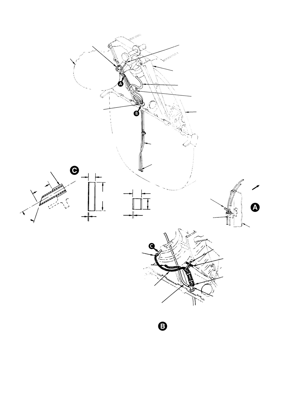
MD Helicopters, Inc.
CSP−H−2
500 Series − Basic HMI
FAN AND BEARING MOUNT
MAIN TRANSMISSION DRAIN TUBE
ASSY DRAIN TUBE
(TAIL ROTOR DRIVE OUTPUT SEAL)
MAIN TRANSMISSION
BULKHEAD CHANNEL
FAN DRAIN TUBE
PLENUM CHAMBER DRAIN
FIREWALL DRAIN FITTING
STA. 124.00 CANTED FRAME
MAIN TRANSMISSION DRAIN TUBES
(WITH BELT−DRIVEN BLOWER)
DRAIN TUBE
MAIN DRIVE SHAFT
INPUT PINION SEAL
NYLON GROMMET
DRAIN TUBE
NOTE 1
0.250 IN.
(6.35 MM)
NOTE 2
1.00 IN (25.4 MM)
0.375 IN.
FWD
1.62 IN.
(9.525 MM)
(41.148 MM)
STRAP
0.62 IN.
(1.5748 MM)
0.062 IN.
0.065 IN.
45°
CHANNEL CLIP
(1.5748 MM)
(16.51 MM)
BULKHEAD
CHANNEL
NYLON STRAP
SAFETY WIRE
(TYPI)
RUBBER CHAFE STRIP
BLOWER SCROLL DRAIN TUBE
SAFETY WIRE
(TYPICAL)
DRAIN ASSY SHROUD
DRAIN TUBE
FIREWALL DRAIN
FITTING
MAIN TRANSMISSION DRAIN TUBE
(TAIL ROTOR DRIVE OUTPUT PINION
SEAL DRAIN)
MAIN TRANSMISSION DRAIN TUBES
NOTES:
(WITH SHAFT−DRIVEN BLOWER)
1.
TYGON TUBING (TYPE R3603).
2.
2024−T3 ALUMINUM ALLOY TUBE
(FEDERAL SPEC WW−T−700/4).
30−074E
Figure 9-4. Main Transmission Drain Tubing
Page 9-12
Revision 17
MD Helicopters, Inc.
CSP−H−2
500 Series − Basic HMI
NOTE: Remove main transmission input pin−
(d).
Position transmission drain assembly
ion drain and bushing (detail C) whenever
and install bolts. Check that trans−
the transmission is replaced. The flex−tube
mission flex−tube will drain directly
and bushing are not normally part of a spare
into mating assembly port.
transmission assembly.
(e).
Attach upper ends of drain tubing to
(d). Grasp the flex−tube and pull out to
transmission drain assembly; secure
release the bond. Insert a 5/16 or 3/8
with double wraps of 0.032 inch
inch tap or easy−out into tube ID and
lockwire.
rotate to pull out bushing.
(f).
Route drain tubing and secure with
(2). Inspection
nylon straps as shown in detail B.
Position tubing so that drainage
Inspect drains and tubing for service−
traps are formed.
ability and repair as necessary.
(g).
Secure lower ends of drain tubing to
(3). Repair
firewall drain fitting with double
wraps of 0.032 inch lockwire.
(a). Repair a damaged polycarbonate
plastic drain assembly according to
(h).
Position engine compartment firewall
the criteria and methods specified for
drain tube; wrap tube with one layer
for acrylic plastic in FAA AC
of 1 inch (2.54 cm) width pressure−
43.13−1A, Aircraft Inspection and
sensitive polyurethane tape (42) at
Repair. Use dichloromethane (38,
clamp−attach point, and install
Table 2−4) or ethylene dichloride (39)
clamp.
as the bonding agent.
5.
Main Rotor Drive Shaft
(b). Repair deteriorated or otherwise
damaged mounting gasket segments
(Ref. Figure 9−5) The main rotor drive shaft is
on the plastic drain assembly by
a shot−peened, nitrated steel alloy forging
replacing with new gasket material
having a spline coupling at one end that mates
(40).
with the main transmission output shaft, and
an octagon shaped head that attaches to the
(c). Repair damaged flexible drain tubing
main rotor hub with four bolts and four
with tape (41).
hoisting eyebolts.
(4). Installation
The main rotor drive shaft is a
CAUTION
highly stressed part. Do not al−
(a). On newly installed main transmis−
low tools to strike the shaft, or the shaft to
sion clean mating surfaces of flex−
strike any object. Any impact damage may
tube, bushing and transmission drain
require replacement of the drive shaft.
outlet with solvent (1).
A. Main Rotor Drive Shaft Removal
NOTE: A replacement flex− tube and bushing
may be fabricated using materials and di−
mensions shown in detail C.
(1). Remove the nuts, washers, bolts, and
hoisting eyebolts.
(b). Bond flex−tube to bushing and
bushing to transmission with sealing
Whenever the drive shaft is re−
CAUTION
compound (3), according to container
moved, cover the opening in the
instructions.
top of the main rotor hub to prevent possible
entry of foreign matter into the hub, mast,
(c). Remove excess sealing compound and
and the transmission.
scarf the flex−tube 45 degrees (detail
C).
(2). Lift drive shaft clear of main rotor hub.
Page 9-13
Revision 17
MD Helicopters, Inc.
CSP−H−2
500 Series − Basic HMI
B. Main Rotor Drive Shaft Installation
according to Specification ASTM E1444.
No surface or sub−surface defects are
Damage to main rotor drive
permissible.
CAUTION
shaft or main transmission
splines can occur during installation. Care
(3). Inspect all external surfaces of drive
should be taken while meshing driveshaft
shaft for corrosion. Remove corrosion as
splines into transmission output splines to
follows.
prevent damage.
(a). Degrease corroded area of drive shaft
(1).
Position drive shaft over main rotor hub
with clean cloth saturated in trichlo−
with gear coupling down.
roethane.
Surface cleaner irritates hands
(2).
Slowly and carefully lower drive shaft
CAUTION
on repeated exposure. Rubber
through main rotor hub and mast until
gloves should be worn.
rotor shaft splines and transmission
shaft splines engage.
(b). Swab shaft exterior with diluted
solution of surface cleaner (10,
(3).
Rotate drive shaft head to align holes in
Table 2−4) (Mix one part surface
flange with holes in hub.
cleaner with four parts water). Keep
wet with solution for 10 minutes or
(4).
Install in every other hole, four hoisting
until corrosion appears to be re−
eyebolts, each with a countersunk
moved. Wipe clean and inspect.
washer (beveled next to head).Then
Repeat as necessary until there is no
install the nuts, each with two standard
further evidence of corrosion.
thin flat washers; do not tighten nuts.
(c). Rinse with water and dry thoroughly
(5).
Install the four remaining bolts, with
with compressed air.
washers and nuts in the same manner.
Exercise care when removing
(6).
Align hoisting eyebolt so that a center−
CAUTION
pits to ensure that shot peening
line through the eyebolt flats intersects
is not completely penetrated. Also, remove
the drive shaft axis. Using torque
only minimum material necessary to re−
wrench adapter (32, Table 2−2), torque
move pits.
all nuts to 120 − 140 inch−pounds
(13.56 − 15.82 Nm).
(d). Light abrade corroded surface with
crocus cloth to remove pits. If pit
C. Main Rotor Drive Shaft Inspection
removal exceeds depth of 0.0012 inch
(0.03048 mm) in area 2, shaft is
(1). Inspect all surfaces of drive shaft for
unserviceable and must be replaced.
dents, nicks scratches, and evidence of
deformation. Inspect splines on end of
(e). Repeat steps (a). thru (c). above.
drive shaft for excessive wear. No
damage of any kind is permissible in
(f). Spray two coats of primer (4,
the area within 2 inches (5.08 cm) of
Table 2−4) on shaft exterior. DO NOT
the spur gear. Dents less than 0.050
primer spline teeth of mounting
inch (1.27 mm) deep and 0.050 inch
surface.
(1.27 mm) diameter are permissible in
other areas. A dent is defined as a
(4). Apply preservative oil to spline teeth
smooth depression on the surface with
and mounting surface.
no sharp edges or abrupt changes in
contour. No nicks or scratches are
(5). Immediately reinstall main drive shaft.
permitted.
(6). Apply 0.060 inch (1.524 mm) bead of
(2). If shaft condition is questionable,
sealing compound around interface of
perform a magnetic particle inspection
hub and drive shaft.
Page 9-14
Revision 17
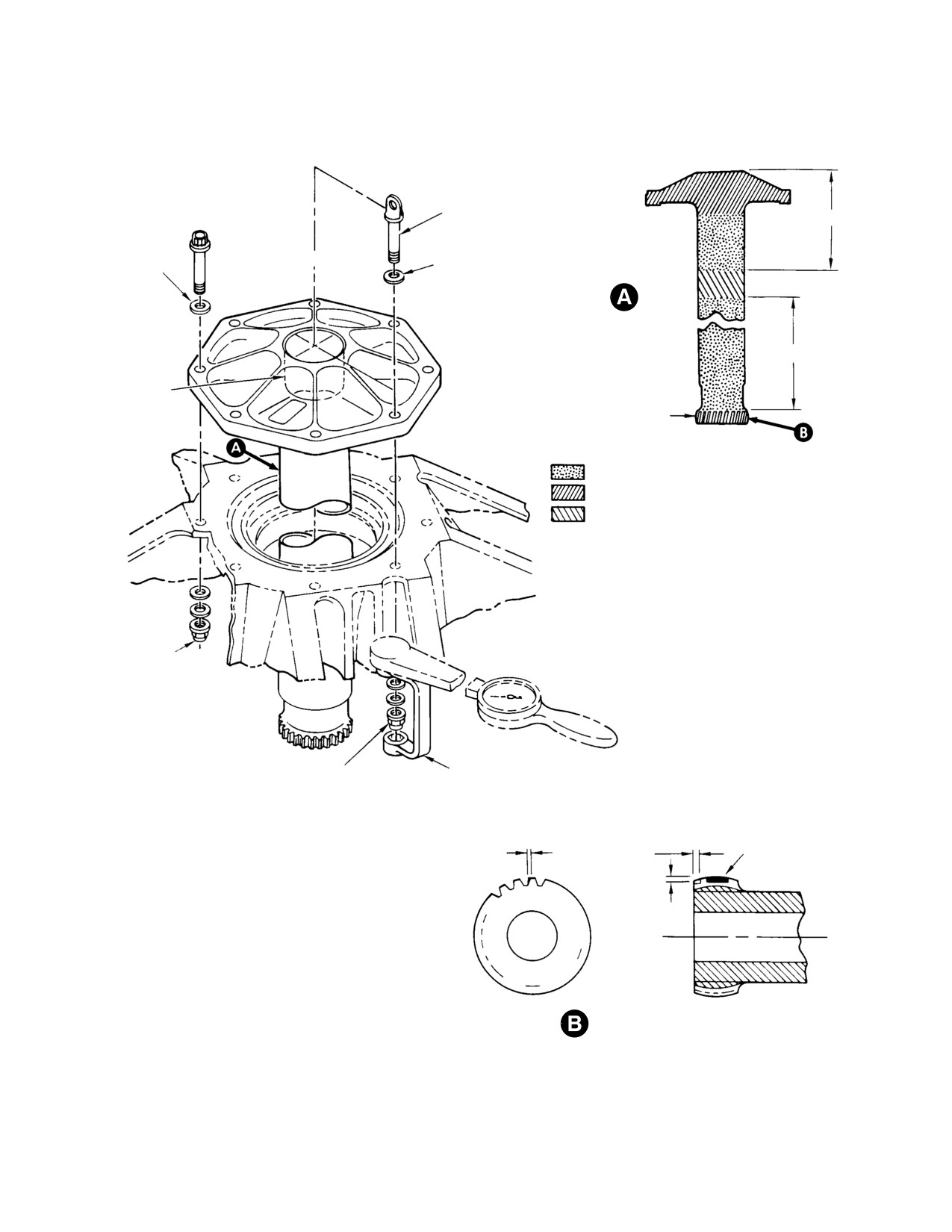
MD Helicopters, Inc.
CSP−H−2
500 Series − Basic HMI
HOISTING EYEBOLT
8 IN. (20.32 CM)
NOTE 1
NOTE 2
NOTE 2
5.4 IN. (13.716 CM)
CORK
(NOTE 3)
AREA 4
AREA 1: MAXIMUM PIT DEPTH 0.0012 IN. (0.03048 MM).
AREA 2: MAXIMUM PIT DEPTH 0.0008 IN. (0.02032 MM)
AREA 3: MAXIMUM PIT DEPTH 0.0020 IN. (0.0508 MM)
AREA 4: CHECK SPLINES BY MEASURING ACROSS
TWO 0.108 IN. (2.7432 MM) DIA. PINS PLACED
IN OPPOSITE SPLINE GROOVES. MEASURED
DIMENSION SHOULD BE 2.2643 IN.
(5.751322 CM) MIN.
120−140 IN. LB
(13.56−15.82 NM)
120−140 IN. LB
TORQUE WRENCH ADAPTER
(13.56−15.82 NM)
(369A9957)
TOOTH CONTACT
0.010 IN. (0.254 MM)
0.050 IN. (1.27 MM)
AREA
MAX DEPTH
MAX
0.050 IN. (1.27 MM)
MAX
NOTES:
1.
FLAT OF EYEBOLT HEADS TO INTERSECT DRIVE SHAFT AXIS.
INSPECTION DATA
2.
INSTALL WITH COUNTERSINK NEXT TO EACH BOLTHEAD.
OTHER WASHERS ARE STANDARD FLAT.
3.
INSTALL WITH SEALING COMPOUND (3, TABLE 2−4).
30−075E
Figure 9-5. Main Rotor Drive Shaft
Page 9-15
Revision 17
MD Helicopters, Inc.
CSP−H−2
500 Series − Basic HMI
D. Main Rotor Drive Shaft Exterior Repair
(a). Using 320 to 400 grit abrasive stone,
carefully grind, blend and polish out
nicks and chips which are outside the
No repair of drive shaft is permitted except for
critical (active) spline tooth contact
removal of light surface corrosion and polish−
areas (see Area 4 profile and end
ing of minor nicks and chips in noncritical
views for permissible repair areas).
spline areas indicated below.
(b). If the repair (grind and polish)
(1). Remove corrosion as follows:
operation extends beyond limits
shown, or if any tooth damage exists
(a). Degrease corroded area of drive shaft
within the critical tooth contact area,
with clean cloth saturated with
shaft is unserviceable and must be
trichloreothane (61, Table 2−4).
replaced.
(c). Perform magnetic particle inspection
Surface cleaner used in 2 be−
according to Specification
WARNING
low irritates hands on re−
MIL−I−6868. No surface or sub−sur−
peated exposure. Rubber gloves should
face defects are permissible.
be worn.
6. Main Transmission Drive Shaft
(b). Swab shaft exterior with diluted
(Ref. Figure 9−6, Figure 9−10 and Figure 9−7)
solution of surface cleaner (10) (Mix
The main transmission drive shaft is a
one part surface cleaner with four
dynamically pre−balance steel shaft equipped
parts water). Keep wet with solution
with a flexible diaphragm−type joint and
for 10 minutes or until corrosion
mounting flange (coupling) at each end. The
appears to be removed. Wipe clean
shaft interconnects the overrunning clutch and
and inspect. Repeat as necessary
the transmission input shaft.
until there is no further evidence of
corrosion.
A. Main Transmission Drive Shaft Removal
(c). Rinse with water and dry with
(1). Remove sound insulation and main
transmission access cover over main
compressed air.
transmission drive shaft in cargo
compartment.
Exercise care when removing
CAUTION
pits to ensure that shot peening
(2). Remove eight bolts and washers that
is not completely penetrated.
secure shaft to couplings.
(3). Remove drive shaft; use care to keep it
(d). Lightly abrade corroded surface with
from striking any object.
crocus cloth (23) to remove pits. If pit
removal exceeds depth of 0.0012 inch
NOTE: The clutch oil level should be checked
(0.03048 mm) in Area 1 or 0.0008
any time engine or main drive shaft is re−
inch (0.02032 mm) in Area 2, shaft is
moved (Ref. Sec. 2).
unserviceable and must be replaced.
B. Main Transmission Drive Shaft
(e). Repeat steps (a). thru (c).
Installation
(1). Check overrunning clutch for proper oil
(f). Spray two coats of epoxy primer and
level, indications of oil seepage, drive
catalyst reducer (128 and 129), mixed
shaft couplings for corrosion and that
per manufacturer’s instructions, on
the bolt securing the clutch coupling
shaft exterior. Do not prime spline
seated properly. With anti−seize
teeth or mounting surface.
compound (36, Table 2−4) on threads,
torque bolt to 250 − 300 inch−pounds
(2). Polish out minor nicks and chips on
(28.25 − 33.90 Nm) plus drag torque.
shaft spline teeth as follows:
Check coupling bolt for drag torque
Page 9-16
Revision 17
MD Helicopters, Inc.
CSP−H−2
500 Series − Basic HMI
serviceability of 25 inch−pounds (2.82
DO NOT USE clutch coupling
CAUTION
Nm) minimum, 200 inch−pounds
shims under transmission input
(22.60 Nm) maximum.
coupling. The ID of clutch coupling shims
are 1.260−1.270 inches (32.004−32.258
Compression of the drive shaft
mm), that’s approximately 0.070 inch (1.778
CAUTION
diaphragms (static state) is lim−
mm) larger than the ID of shims used at the
ited to 0.020 inch (0.508 mm). Do not stress
transmission coupling, while the OD is the
the diaphragms by forcing the drive shaft
same. The difference in ID can cause an im−
into position for installation in step (2). be−
properly seated shim, misalignment and
low.
cocking of the coupling.
NOTE: If original shaft and couplings are being
(4). Attach driveshaft to clutch coupling
reinstalled, a check of shimming as de−
with four bolts and washers. Torque
scribed below is not necessary. Install drive
bolts to 50 − 70 inch−pounds (5.65 −
shaft to clutch and transmission couplings
7.91 Nm).
as described in steps (1). and (4).
(5). Manually align the driveshaft and
(2). Position drive shaft alongside the
transmission input coupling flange.
transmission input and clutch cou−
Using a feeler gage, measure the gap
plings. If compression will be required
between the flanges (detail A). If gap is
to fit driveshaft between the couplings,
0.010 inch (0.254 mm) or less, attach
continue with step (3). If there is a gap
upper end of driveshaft to transmission
between the drive shaft flanges and the
input coupling according to step (4). If
coupling flanges continue with step (4).
gap exceeds 0.010 inch (0.254 mm),
repeat step (3)., except install a thick−
NOTE: Removal or addition of shims should be
ness of shims equal to the measured
accomplished at transmission input cou−
gap, plus 0.010 inch (0.254 mm)
pling only. Shims at overrunning clutch cou−
additional thickness. A nominal 0.010
pling are predetermined thickness to pro−
inch (0.254 mm) compression of the
vide 0.035−0.055 inch (0.889−1.397 mm) gap
shaft diaphragm is the preferred static
to prevent O−ring packing damage and oil
state condition.
leakage.
(6). Install access door and sound insulation
(3). Remove coupling bolt that secures
over main transmission driveshaft.
transmission input coupling and
remove coupling. Remove sufficient
C. Main Transmission Drive Shaft Inspection
shims so there is no compression of
(Bendix)
shaft flexible coupling. A minimum of
0.010 inch (0.254 mm) shim is required
(1). Inspect drive shaft diaphragms for
between end of drive input shaft and
dents, cracks, scratches, nicks, rust
coupling; to prevent coupling bolt from
spots and evidence of joint separation
bottoming out on bolt seating surface
from shaft or outside edges. Evidence of
and end of shaft input. Lubricate input
any such defects on either diaphragm
shaft splines with grease (21) Coat bolt
requires removal of shaft from service.
threads with anti−seize compound (36).
Reinstall coupling and bolt. Check
(2). Inspect drive shaft tube between
coupling bolt for drag torque service−
diaphragms for dents, scratches, cracks
ability of 25 inch−pounds (2.82 Nm)
or corrosion pits.
minimum, 200 inch−pounds (22.60
(a). Measure depth and diameter of
Nm) maximum. Torque bolt to 250 −
dents. Dents that blend smoothly into
300 inch−pounds (28.25 − 33.90 Nm)
surrounding surface area with no
plus drag torque.
sharp change in contour and do not
NOTE: Transmission input coupling shims are
exceed 0.015 inch (0.381 mm) depth
laminated stock. Each lamination is 0.002
are acceptable. Dents not within
inch (0.0508 mm) thick. Peel away as re−
these limits require removal of shaft
quired.
from service.
Page 9-17
Revision 17
MD Helicopters, Inc.
CSP−H−2
500 Series − Basic HMI
(b). Measure depth of cracks, nicks,
(a).
Measure depth and diameter of
corrosion pits, or scratches; length
dents. Dents that blend smoothly into
and direction are not limited. Maxi−
surrounding surface area with no
mum depth allowed before rework is
sharp change in contour and do not
0.003 inch.
exceed 0.010 inch (0.254 mm) in
depth are acceptable. Dents not
(c). Check suspected cracks using dye
within these limits require removal
penetrant. If crack indication ap−
of shaft from service.
pears, remove black (phenolic com−
(b).
Measure depth of cracks, nicks,
pound) coating from area (Ref. Main
corrosion pits or scratches; length
Transmission Drive Shaft Repair
and direction are not limited. Maxi−
(Bendix).
mum depth allowed before rework is
0.005 inch (0.127 mm).
NOTE: Drive shaft is coated with special phe−
nolic thermosetting compound. It is a brittle
(c).
Check suspected cracks using dye
coating that may indicate a crack that does
penetrant. If crack indication ap−
not penetrate tube.
pears, remove coating from surface.
(d).
Re−inspect suspected area using
(d). Reinspect suspected area using
magnetic particle or dye penetrant
magnetic−particle or dye−penetrant
methods. If crack does not reappear,
methods. If crack does not reappear,
touch up cleaned area with primer
touch up cleaned area with primer
coating (4, Table 2−4) and return part
coating (4, Table 2−4) and return part
to service.
to service. If shaft is found to be
cracked, remove shaft from service.
NOTE: Perform inspections in steps (3). and
Kamatic parts cannot be inter−
(4). only if shaft damage is suspected.
CAUTION
changed between drive shafts.
(3). Inspect shaft tube for out−of−round
(3). Inspect all attaching hardware for
condition. Ovality shall not exceed
serviceable condition. Discard and
0.060 inch (1.524 mm) tir.
replace defective hardware.
NOTE: Perform the following inspections if
(4). Inspect shaft for straightness. Shaft
shaft damage is suspected.
shall be within 0.030 inch (0.762 mm)
tir at all locations relative to the
(4). Inspect shaft tube for out−of−round
centerline of the two flange mounting
condition not to exceed 0.060 inch
bolt pattern.
(1.524 mm).
(5). Inspect all attaching hardware for
(5). Inspect shaft for straightness. Shaft
serviceable condition. Check nut plates
shall be straight within 0.030 inch
for drag torque. Discard defective
(0.762 mm) at all locations relative to
hardware.
centerlines of two flange mounting bolt
patterns.
D. Main Transmission Drive Shaft Inspection
E. Main Transmission Drive Shaft Couplings
(Kamatic)
Corrosion Removal
(1). Inspect drive shaft for dents, cracks,
(1). Prior to installing original drive shaft
scratches, nicks, rust spots and evi−
coupling (369A5512 or 369H5560 only),
dence of joint separation from shaft or
inspect flange face of coupling for
outside edges.
fretting corrosion. Evidence of fretting
may be removed by hand lapping the
(2). Inspect drive shaft tube between
effected parts using a sheet of # 440 (or
couplings for dents, scratches, cracks or
finer) emery cloth (49, Table 2−4) or wet
corrosion pits.
or dry abrasive paper (9) placed on a
Page 9-18
Revision 17
MD Helicopters, Inc.
CSP−H−2
500 Series − Basic HMI
surface table with a figure eight motion,
(c). After rework, check shaft tube wall
using care not to let the part rock.
thickness in repair area.
NOTE: Coupling may be reused if flange thick−
(d). Apply primer coating (4) for corrosion
ness is not less than 0.10 inch (0.254 mm)
protection.
after cleanup; Recheck shimming.
7. Oil Cooler Blower
F. Main Transmission Drive Shaft Repair
The belt−driven blower is mounted to a
(Bendix)
bracket on the back underside of the main
transmission and coupled to the transmission
(1). Repair of drive shaft diaphragms is not
input shaft through a pulley drive.
permissible.
The blower consists of a riveted and brazed
(2). Repair all damage that is no deeper
impeller assembly of a casting and aluminum
than 0.003 inch (0.0762 mm).
blades within a polycarbonate plastic scroll
(a). Completely remove defect. Maintain
enclosure.
smooth transition into surrounding
The fiberglass scroll enclosure is used on the
surface.
current configuration helicopter and those
with the optional 250−C20 Series engine.
(b). Use grade 400 wet or dry abrasive
paper (9, Table 2−4) for preliminary
The belt driven impeller is dynamically
finishing, and then polish with crocus
balanced for operation at approximately
cloth (23). Restore surface until it
12,000 rpm.
equals original finish of shaft.
On the shaft−driven blower, the impeller is
(c). After rework, check shaft tube wall
mounted directly on the transmission input
thickness in repair area. Wall thick−
pinion gearshaft and is enclosed in a scroll
ness shall not be less than 0.025 inch
that is attached to the transmission housing.
(0.635 mm).
The shaft−driven impeller is dynamically
(d). Apply primer coating (4) for corrosion
balanced and rotates at approximately 6000
protection.
rpm.
G. Main Transmission Drive Shaft Repair
The blower draws cooling air over the main
(Kamatic)
transmission in addition to supplying forced
ambient air to the engine oil cooler, compart−
(1). Repairs of Kamatic drive shaft flexible
ment heating system and the engine area.
couplings are limited. Repairs to spring
Sections 10 and 13 provide information on the
area are not allowed. No cracks are
engine cooling and oil cooler ducting
allowed.
A. Oil Cooler Blower Removal (Early-Type,
(2). Repair drive shaft tube area damage
Belt-Driven)
that is no deeper than 0.005 inch (0.127
mm). Maximum depth after repair is
(Ref. Figure 9−6)
0.010 inch (0.254 mm). The maximum
(1). Remove main transmission driveshaft.
thickness of material removed shall not
be more than 10 percent of the original
(2). Remove belt−driven blower and
material thickness.
attached idler drive unit as follows.
(a). Completely remove defect. Maintain
(a). Remove four screws and nylon
smooth transition into surrounding
washers that attach blower belt drive
surface.
shroud to sides of transmission fan
mount assembly and mounting
(b). Use grade 400 wet or dry abrasive
bracket on idler drive unit. Remove
paper (9, Table 2−4) for preliminary
blower belt drive shroud.
finishing, then polish with crocus
cloth (23). Restore surface until it
(b). Disconnect drain tube and loosen
equals original finish of shaft.
scroll clamps.
Page 9-19
Revision 17
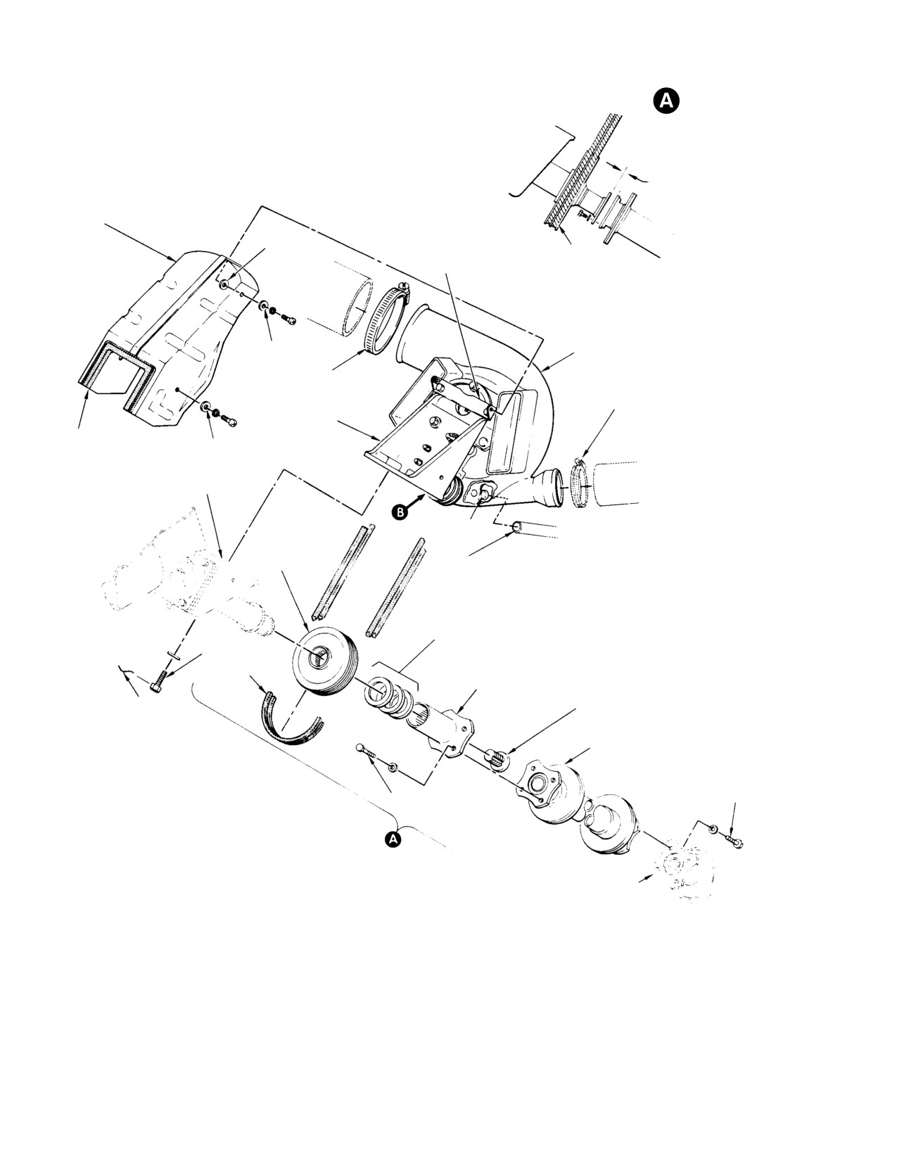
MD Helicopters, Inc.
CSP−H−2
500 Series − Basic HMI
0.010 IN. (0.254 MM) MAX.
GAP; 0.020 IN. (0.508 MM)
MAX. COMPRESSION
BLOWER DRIVE
(NOTE 3)
SHROUD
NYLON
DRIVE SHROUD
WASHER
MOUNTING
(NOTE 6)
BRACKET
NYLON WASHER
BLOWER
SCROLL CLAMP
SCROLL CLAMP
IDLER DRIVE UNIT
GASKET
NYLON WASHER
(NOTE 5)
FAN MOUNT
ASSEMBLY
DRAIN
INPUT SHAFT
DRAIN
DRIVE PULLEY
TUBE
COUPLING SHIMS
(NOTE 1)
65−75 IN. LB
(7.34−8.47 NM)
TRANSMISSION IN−
BELT (2)
PUT COUPLING
(NOTE 4)
COUPLING BOLT, 250−300 IN. LB
LOCKWIRE
(28.25−33.90 NM) PLUS DRAG TORQUE
(NOTES 2, 7)
MAIN TRANSMISSION DRIVE SHAFT
50−70 IN. LB
(5.65−7.91 NM)
50−70 IN. LB
(5.65−7.91 NM)
NOTES:
1.
CORROSION RESISTANT STEEL SHIM, 0.002 IN.
(0.0508 MM) LAMINATIONS.
CAUTION: ID MUST NOT BE MORE THAN 1.20 IN. (30.48 MM).
2.
DRAG TORQUE FOR BOLT (SELF−LOCKING) SERVICEABILITY
IS 25 IN. LB (2.82 NM) MIN., 200 IN. LB (22.60 NM) MAX.
CLUTCH COUPLING
3.
CHECK WITH LOWER END OF SHAFT ATTACHED.
4.
REPLACE ONLY AS A MATCHED SET.
5.
BOND TO SHROUD WITH ADHESIVE (91, TABLE 2−4).
6.
USE AS REQUIRED TO CLOSE SHROUD TO BRACKET GAP.
7.
COAT COUPLING BOLT THREADS WITH ANTI−SEIZE COMPOUND
(36) BEFORE REASSEMBLY.
30−076−1F
Figure 9-6. Main Transmission Driveshaft and Early Type Belt-Driven
Oil Cooler Blower (Sheet 1 of 2)
Page 9-20
Revision 17
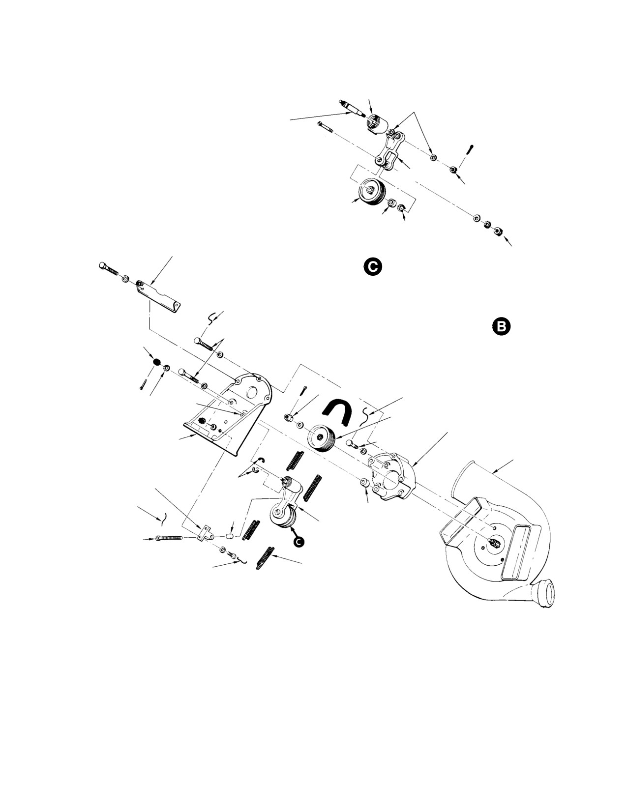
MD Helicopters, Inc.
CSP−H−2
500 Series − Basic HMI
IDLER FAN SPRING
SHIMMING WASHER
(NOTE 9)
IDLER SHAFT
IDLER FORK
65−75 IN. LB
(7.34−8.47 NM)
IDLER PULLEY
BEARING
RETAINING
RING
DRIVE SHROUD MOUNT−
ING BRACKET
65−75 IN. LB
(7.34−8.47 NM)
IDLER FORK ASSEMBLY
LOCKWIRE
65−75 IN. LB
65−75 IN. LB
(7.34−8.47 NM)
IDLER DRIVE UNIT AS−
(7.34−8.47 NM)
SEMBLY
(160-190 IN. LB)
LOCKWIRE
CRES WASHER
(NOTE 8)
(NOTE 8)
DRIVEN PULLEY
FAN MOUNTING BRACKET
IDLER MOUNTING
65−75 IN. LB
BRACKET
(7.34−8.47 NM)
BLOWER
IDLER FORK HOLD−
ING BRACKET
SPLIT
WASHER
(NOTE 7)
LOCKWIRE
SPACER
BUMPER
(NOTE 7)
IDLER FORK
IDLER FORK AD−
ASSY
JUSTMENT
SCREW
(NOTE 10)
BELTS
LOCKWIRE
NOTES: (CONT)
8.
APPLY PRIMER (4, TABLE 2−4).
9.
USE AS REQUIRED TO ALIGN IDLER PULLEY GROOVES WITH
DRIVE PULLEY GROOVES. (SEE BELT TENSION
AND PULLEY ALIGNMENT FIGURE.)
10. USE TO ADJUST IDLER FORK HOLD POSITION. (SEE BELT
TENSION AND PULLEY ALIGNMENT FIGURE.)
30−076−2F
Figure 9-6. Main Transmission Driveshaft and Early Type Belt-Driven
Oil Cooler Blower (Sheet 2 of 2)
Page 9-21
Revision 17
MD Helicopters, Inc.
CSP−H−2
500 Series − Basic HMI
(c). Cut lockwire from idler fork adjust−
(f). Remove cotter pin, nut, washer and
ment adjustment screw sufficiently
any shimming washers that attach
so that idler fork can be positioned to
idler fork to idler shaft.
release belt tension.
(g). Remove idler yoke with attached
(d). Move idler fork to release belt
idler pulley, washer and any shim−
tension and disengage both belts
ming washers from idler shaft.
from main transmission input shaft
NOTE: The shaft bushing is factory installed
drive pulley.
by temperature−difference or press fit meth−
(e). Remove the lockwire, bolts and
od and is to remain in idler yoke.
washers that attach idler drive unit
(h). Remove idler fan spring from shaft
to the transmission fan mount
remaining on idler mounting bracket.
assembly.
(i). Remove nut, washer and bolt attach−
(f). Remove the assembled fan and idler
ing idler pulley to idler yoke.
drive unit.
NOTE: Retain shim washers with idler yoke.
(g). As required, remove coupling bolt,
transmission input coupling shim(s)
(j). Remove retaining ring to remove
and drive pulley from transmission
bearing from idler pulley.
input shaft. Keep shim(s) with
(k). Remove cotter pin, nut and CRES
couping for reuse.
washer securing idler shaft in
(3). Remove components from the idler
mounting bracket; remove idler shaft
drive unit only to the extent required
and split washer from idler mounting
for maintenance, as follows.
bracket.
(l). Remove idler fork holding bracket.
(a). Remove nylon bumper from idler fork
adjustment screw and adjustment
B. Oil cooler Blower Installation (Early- Type,
screw from fork holding bracket on
Belt- Driven)
idler mounting bracket.
(1). Install belt−driven blower and idler
(b). Remove lockwire, bolts, and washers
drive unit as follows:
that attach fan mounting bracket to
idler mounting bracket
(a).
Reassemble components on the idler
mounting bracket, to the extent
(c). Remove spacer, belts fan and at−
disassembled for maintenance, by
tached fan mounting bracket from
reversing the order of disassembly
idler mounting bracket. Keep spacer
and complying with the following
with fan mounting bracket for reuse.
instructions. See Figure 9−9 for stack
of parts.
The impeller must be hand−
CAUTION
held for pulley attachment nut
(b).
Assemble idler pulley parts but do
removal. Do not hold impeller blades with
not torque nut at this time.
tools or other devices to remove nut. Such
action can physical damage.
(c).
Reinstall shim washers on sides of
idler fork attachment end as required
(d). Remove cotter pin, pulley attachment
so that dimensions ‘‘B’’ and ‘‘C" (Ref.
nut and driven pulley for access to
Figure 9−9) are equal and provide
fan mounting bolts. Nut is removed
0.001−0.020 inch (0.0254−0.508 mm)
by reaching through blower scroll
coaxial clearance.
primary air outlet and carefully
(d).
Install idler spring on idler shaft so
hand−holding the impeller.
that spring hook will be approximate−
(e). Remove lockwire, bolts and washers
ly 3 O’clock on the shaft centerline
attaching fan to fan mounting
looking aft (at idler fork free posi−
bracket; remove fan.
tion).
Page 9-22
Revision 17
MD Helicopters, Inc.
CSP−H−2
500 Series − Basic HMI
(e). Apply primer (4, Table 2−4) to inside
(k). Install shroud mounting bracket on
of square hole in idler mounting
idler mounting bracket, using
bracket and split washer when
washers and bolts. Torque bolts to 65
installing idler spring shaft and idler
−
70 inch−pounds (7.34 − 7.91 Nm).
fork. Torque nuts attaching idler fork
(l). Install hard−anodized driver pulley
to idler spring shaft to 65 − 75
on splined transmission input shaft.
inch−pounds (7.34 − 8.47 Nm).
Reinstall existing shims and output
Ensure free movement of idler spring
coupling. Coat coupling threads with
is not hampered.
anti−seize compound (36) and install
bolt. Check that bolt self−locking
(f). Torque bolts that attach fan to fan
torque is not less than 25 inch−
mounting bracket to 65 − 75 inch−
pounds (2.82 Nm) or more than 200
pounds (7.34 − 8.47 Nm).
inch−pounds (22.60 Nm). Torque
bolt to 250 − 300 inch−pounds
Impeller must be hand−held
CAUTION
(28.25 − 33.90 Nm) plus drag
when torquing pulley nut. DO
torque.
NOT use tools or other devices to hold im−
peller while torquing pulley attachment
(m). Position drive belt on driver, driven
nut.
and idler pulleys.
(g).
Reach through scroll primary air
(2). Check for proper alignment of all three
outlet and hand−hold impeller.
pulleys as follows
Torque nut attaching driven pulley to
(a). Clamp alignment tool 369H9008 to
impeller shaft to 160 − 190 inch−
left side upper surface of the driver
pounds (18.08 − 21.47 Nm).
pulley.
(h).
Position drive belt on driven pulley
NOTE: Alignment tool is designed so that if
and attach fan mounting bracket
idler pulley and driven pulley are in perfect
(with blower assembly) to idler
alignment with the driver pulley, 0.030 inch
mounting bracket. Install spacer with
(0.762 mm) feeler gage will just fit under off−
primer and torque fan mounting
sets in tool at both idler and driven pulley
bracket bolts to 65 − 75 inch−
surfaces. This tool is required to ensure
pounds (7.34 − 8.47 Nm).
alignment each time belt drive components
are removed and replaced.
(i).
Rotate the idler arm to extreme
(b). If misalignment of driver pulley to
position away from holding bracket.
driven pulley exceeds 0.020 inch
Position strap so that side of slot
(0.508 mm), perform one or both of
closest to spring touches the slot bolt.
the following.
Torque the idler pulley bolt to 65 − 75
inch−pounds (7.34 − 8.47 Nm).
1). Loosen four bolts attaching idler
Check movement of idler strap by
mounting bracket to transmission
pivoting idler arm. If necessary,
mounting pad and slide bracket in
adjust strap position to assure full
direction desired. Re−secure and
travel within limits of slot.
torque bolts to 65 − 75 inch−
pounds (7.34 − 8.47 Nm).
NOTE: Prior to installation, inspect all ducting
inlets and outlets and entire blower fan and
2). If adjustment in step 1). is not
scroll area for blockage or foreign objects.
sufficient and driven pulley still
needs to be raised, remove the
(j). Position and install assembled drive
driver pulley from the transmis−
belt unit (with blower) on transmis−
sion input shaft and transfer
sion mounting pad, using existing
369A5625 coupling shims, as
washers and bolts. Do Not torque
required, to upper side of driver
bolts at this time. Reconnect scroll
pulley. Reinstall driver pulley and
ducting and rubber connectors.
coupling bolt.
Page 9-23
Revision 17
MD Helicopters, Inc.
CSP−H−2
500 Series − Basic HMI
(c). Align idler pulley to driven pulley, as
C. Oil Cooler Blower Removal
required, by transferring shims
(Current-T ype, Belt-Driven)
between dimensions ‘‘B" and ‘‘C" (Ref.
(Ref. Figure 9−7)
Figure 9−9); hold to 0.020 inch (0.508
mm) maximum misalignment.
(1). Remove main transmission driveshaft.
Ensure that idler arm is not ham−
pered.
(2). Remove transmission input coupling
bolt, input coupling, coupling shims and
input shaft drive pulley. Retain shim for
(d). Remove and clamp alignment tool on
reinstallation.
right (opposite) side of driver pulley
and recheck alignment to driven
(3). Cut lockwire and remove four bolts
pulley on that side. Alignment should
attaching mounting bracket to trans−
agree within 0.015 inch (0.381 mm)
mission fan mount assembly. Retain
to measurement obtained in step (b).
laminated shims for reinstallation.
(3).
Adjust idler fork for proper belt tension.
(4). Cut lockwire and remove four bolts
attaching mounting bracket to fan
mounting bracket.
(4).
Reconnect blower scroll drain tube.
Reinstall channel assemblies, as
(5). Disconnect blower scroll drain tube.
applicable, using eight screws, washers
Loosen scroll duct clamp and roll back
and nuts. Do not use rivets.
rubber connectors; disconnect scroll
ducts.
(5).
Install guard, using existing shroud
hardware. Install transmission input
NOTE: The capstrip on the right channel, adja−
shaft seal drain tube on right side of
cent to blower, may be removed if required
guard, using clamp shown in
for access.
Figure 9−6, view C. Pull drain tube
(6). Remove fan mounting bracket (with
downward and secure to helicopter
blower scroll, pulley and belt) from
structure with tie−strap.
helicopter.
(6).
Connect blower scroll drain tube and
The impeller must be hand−
CAUTION
check for excess slack and close proxim−
held for removal of driven pulley
ity to driveshaft. Reposition and secure
attachment nut. Do not hold impeller blades
drain tube with tie−strap to helicopter
with tools or other devices to remove nut.
structure, as required, to eliminate
Such action can affect impeller balance as
slack or possible interference with
well as cause physical damage.
driveshaft. Check drain tube for kinks.
(7). Remove nut and washer securing
driven pulley on impeller shaft.
(7).
Install main transmission driveshaft.
(8). If required, cut lockwire and remove
(8).
Rotate driveshaft by hand and check
bolts attaching fan mounting bracket
pulley operation.
tom blower assembly.
D. Oil Cooler Blower Installation
(9).
Lockwire in pairs: the four bolts
(Current- Type, Belt- Driven)
securing the idler mounting bracket to
the transmission mounting pad; and
(1). Install fan mounting bracket on blower
the four bolts securing idler mounting
assembly.
bracket to fan mounting bracket.
NOTE: Before tightening bolts, remove bolt
hole slack in the belt tension direction by
(10).
Perform operational check of belt−driv−
moving blower toward, and bracket away
en oil cooler blower system.
from, the transmission driveshaft side.
(11).
Install main transmission access covers
(2). Torque bolts to 65 − 75 inch−pounds
and trim cover panel.
(7.34 − 8.47 Nm).
Page 9-24
Revision 17
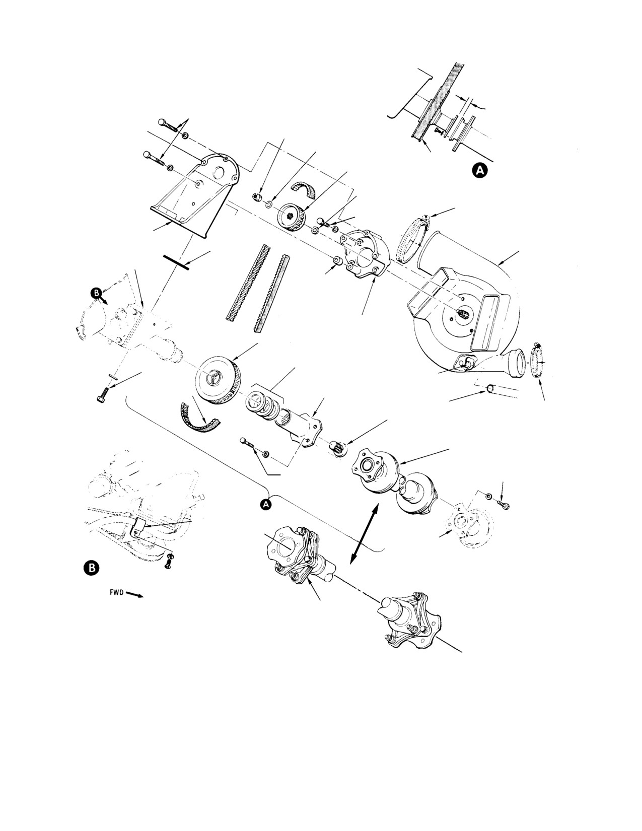
MD Helicopters, Inc.
CSP−H−2
500 Series − Basic HMI
65−75 IN. LB
0.010 IN. (0.254 MM) MAX. GAP
(7.34−8.47 NM)
0.020 IN. (0.508 MM) MAX. COM−
160−190 IN. LB
PRESSION
(18.08−21.47 NM)
(NOTE 3)
THIN WASHER (5710−84−16)
(NOTE 5)
DRIVE PULLEY
COUPLING−T O−DRIVE
DRIVEN PULLEY
SHAFT ATTACHMENT
THICK WASHER (AN960−916)
(NOTE 5)
SCROLL CLAMP
(65 - 75 IN. LB)
MOUNTING BRACKET
LAMINATED
SHIM (2)
BLOWER
FAN MOUNT ASSY
SPACER
FAN MOUNTING
BRACKET
INPUT SHAFT
DRIVE PULLEY
COUPLING SHIMS
(65 − 75 IN. LB)
(NOTE 1)
DRAIN
BELT (TIMING−
TRANSMISSION IN−
TYPE)
BLOWER SCROLL
PUT COUPLING
DRAIN TUBE
SCROLL CLAMP
COUPLING BOLT, 250−300 IN. LB
(28.25−33.90 NM) PLUS DRAG TORQUE
(NOTES 2, 4)
MAIN TRANSMISSION
DRIVE SHAFT (BENDIX)
50−70 IN. LB
50−70 IN. LB
(5.65−7.91 NM)
(5.65−7.91 NM)
(NOTE 4)
CLAMP, INPUT SEAL
DRAIN TUBE
CLUTCH
COUPLING
SECURING DRAIN
TUBE
MAIN TRANSMISSION
DRIVE SHAFT (KAMATIC)
NOTES:
1.
CORROSION RESISTANT STEEL SHIM, 0.002 IN. (0.0508 MM) LAMINATIONS
CAUTION: ID MUST NOT BE MORE THAN 1.20 IN. (30.48 MM).
2.
DRAG TORQUE FOR BOLT (SELF−LOCKING) SERVICEABILITY IS 25 IN. LB
(2.82 NM) MIN., 200 IN. LB (22.60 NM) MAX.
3.
CHECK WITH LOWER END OF SHAFT ATTACHED.
4.
COAT COUPLING BOLT THREADS WITH ANTISEIZE COMPOUND (36, TABLE 2−4)
BEFORE ASSEMBLY.
5.
REPLACE ANY EXISTING ALUMINUM WASHER WITH STEEL WASHER INDICATED.
30−162F
Figure 9-7. Main Transmission Driveshaft and Current Type Belt-Driven Oil Cooler
Page 9-25
Revision 17
MD Helicopters, Inc.
CSP−H−2
500 Series − Basic HMI
Impeller must be hand−held
Do not use levers or tools on belt
CAUTION
CAUTION
when torquing pulley nut. Do
or in any way force belt onto
not use tools or other devices to hold impel−
driver pulley.
ler while torquing pulley attachment nut.
(8). Install four mounting bolts, washers
and two laminated shims. Reconnect
NOTE: When performing step (3). below, re−
scroll ducting and rubber connectors.
place any original aluminum washers with
thick and thin steel washers.
(9). Adjust belt tension as follows:
(a).
Check that laminated shims are in
(3). Install pulley on impeller shaft with a
position between mounting bracket
thick washer under pulley and a thin
and transmission fan mount assem−
washer under shaft nut. Reach through
bly. Tighten the four mounting bolts.
scroll primary air outlet and hand−hold
Rotate pulley by hand a few turns to
impeller. Torque nut attaching driven
even out belt tension.
pulley to impeller shaft to 160 − 190
inch−pounds (18.08 − 21.47 Nm).
(b).
Measure belt deflection at approxi−
mate center of one of the spans. The
force required to deflect the belt
(4). Position timing−type belt on driven
0.170−0.200 inch (4.318−5.08 mm)
pulley and attach fan mounting bracket
must be 1.00−1.75 pounds
(with blower assembly to mounting
(4.448−7.784 N). This load is to be
bracket. Install spacer with primer (4,
applied at a right angle to the outside
Table 2−4).
face of the belt.
NOTE: Before tightening bolts, remove all bolt
(c).
If the tension is too high, greater
hold slack in the belt tension direction by
than 1.75 pounds (7.784 N): Tension
moving mount bracket away from the trans−
can be reduced by peeling off a layer
mission driveshaft side.
of the laminated shim, one at a time
alternately from shim to shim, until
tension falls into proper range.
(5). Torque bolts to 65 − 75 inch−pounds
(7.34 − 8.47 Nm) and then safetywire.
(d).
If the tension is to low: Add layers
from a spare shim in the same
NOTE: Prior to installation of blower assembly,
manner as removed in step (c). above,
inspect all ducting inlets and entire blower
until tension falls into proper range.
fan and scroll area or foreign objects.
(e).
Make a final check of bolt torque, 60
− 75 inch−pounds (6.78 − 8.47 Nm)
(6). Install timing−belt type driver pulley
and then safetywire.
on splined transmission input shaft; do
not hammer or strike on pulley if force
(10). Install transmission input shaft seal
fit. Reinstall existing shims and output
drain tube on right side of transmission
coupling. Coat coupling threads with
fan mount, using clamp shown in
anti−seize compound (36) and install
Figure 9−7. Pull drain tube downward
bolt. Check that bolt self−locking torque
and secure to helicopter structure with
is not less than 25 inch−pounds (2.82
tie−strap.
Nm) or more than 200 inch−pounds
(11). Connect blower scroll drain tube and
(22.60 Nm). Torque bolt to 250 − 300
check for excess slack and proximity to
inch−pounds (28.25 − 33.90 Nm) plus
driveshaft. Reposition and secure drain
drag torque.
tube with tie−strap to helicopter
structure, as required, to eliminate
(7). Position assembled drive belt unit and
slack or possible interference with the
blower assembly on transmission
driveshaft.Check the drain tube for
mounting pad, without shims, washers
kinks.
and bolts. Position belt on driver pulley
and check position on driver pulley.
(12). Install main transmission driveshaft.
Page 9-26
Revision 17
MD Helicopters, Inc.
CSP−H−2
500 Series − Basic HMI
(13). Rotate driveshaft by hand and check
(c).
On installation with a slotted idler
pulley operation.
strap, check that idler fork is free to
move under spring tension. If the
slotted strap binds to prevent move−
(14). Perform operational check of belt−dri−
ment of fork, loosen the idler pulley
ven oil cooler system.
bolt and strap bolt and reposition
strap for free movement. Tighten
E. Oil Cooler Blower Inspection
idler pulley bolt. The strap bolt
(Belt-Driven)
should be loose enough to allow strap
movement.
(Ref. Figure 9−8 and Figure 9−9) For recom−
(d).
Check idler spring tension using a
mended replacement intervals of bearings and
spring scale attached to the idler
belt, refer to CSP−H−4.
pulley bolt. Spring tension should be
4 − 5.5 pounds (17.8 − 24.5 N) just
(1). Early Type Installed Blower−Belt
as idler pulley contacts belt. Spring
Condition:
tension is adjusted by rotating the
square idler shaft bolt in the idler
mounting bracket (Ref. Figure 9−6,
(a). Remove plug buttons (or tape) from
detail C).
inspection ports on main transmis−
sion trim cover panel
(e).
Rotate drive pulley by hand a few
turns so that belt tension is evened
(b). Visually inspect drive belt for proper
out under the spring tension.
seating in pulley grooves and for
(f).
Adjust stop by turning in the stop
condition of belt.
screw until the stop bumper just
contacts the idler fork arm. If screw
NOTE: Belt should be fully seated in pulley
head bottoms on bracket, additional
grooves. Cracking or separation of the belt
extension is available by turning the
between pulley grooves is acceptable. Visu−
stop.
ally monitor propagation. Belt should be re−
placed if any one separation exceeds 3.00 in−
(g).
After contact is made, lock the nut
ches (7.62 cm) in length or if total separation
against the stop. Check for over−ex−
exceeds 50% of the peripheral length of the
tension of stop by inserting wire
belt.
through safety hole to determine that
stop screw is not retracted beyond
the safety hole.
(c). Install plug buttons (or tape) at
inspection ports of trim cover panel.
(h).
Install the main transmission access
cover and trim panel.
(2). Early Type Installed Blower−Belt
(3). Installed Blower General Inspection:
Tension:
(a). Check oil cooler blower and drive
(a). Remove main transmission access
components for smoothness and
cover and trim panel.
correct operation while hand−turning
main rotor through several complete
revolutions, first clockwise and then
NOTE: Whenever belt drive components are re−
counter−clockwise. Listen and feel for
moved and/or replaced at specified inter−
evidence of rubbing or chafing
vals, belt should be adjusted per steps (b).
between impeller and blower scroll.
thru (g). below.
No rubbing or noise is permissible.
Belts should remain seated and be a
(b). Loosen bumper stop jam nut and
snug fit in pulley grooves while
back off stop screw for free movement
rotating. Also check for parallel
of idler fork.
alignment of belts between pulleys.
Page 9-27
Revision 17
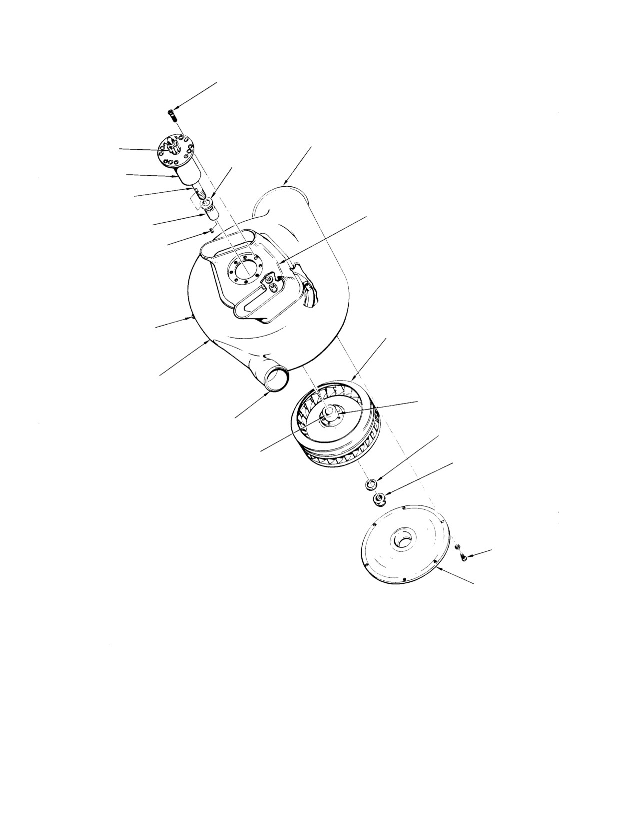
MD Helicopters, Inc.
CSP−H−2
500 Series − Basic HMI
12−14 IN. LB
(1.36−1.58 NM)
PRIMARY AIR OUTLET
SPLINE
(NOTE)
SHIM (REFER
TO TEXT)
SHAFT HUB
SHAFT KEYWAY
AIR INLET ASSEMBLY
SPACER
KEY
DRAIN
IMPELLER
SCROLL
IMPELLER HUB
SECONDARY AIR OUTLET
WASHER
KEYWAY
FIBER LOCKNUT,
250−300 IN. LB
(28.25−33.90 NM)
(NOTE)
12−14 IN. LB
(1.36−1.58 NM)
SCROLL COVER
NOTE:
HOLD ONLY THE SHAFT HUB SPLINE WHEN LOOSENING OR TIGHTENING
THE FIBER NUT.
CAUTION:
DO NOT HOLD IMPELLER WITH TOOLS OR OTHER DEVICES. TOOLS WILL DAMAGE THE PRECISION
BALANCE OF THE IMPELLER. ALL ROTATING COMPONENTS ARE MATCHED AND BALANCED AND
MUST BE REASSEMBLED TOGETHER TO MAINTAIN DYNAMIC BALANCE.
30−157B
Figure 9-8. Belt-Driven Oil Cooler Blower (Screw-Assembled), Exploded View
Page 9-28
Revision 17
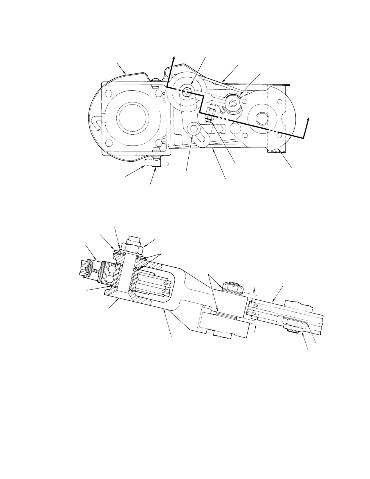
MD Helicopters, Inc.
CSP−H−2
500 Series − Basic HMI
A
IDLER STRAP
GUARD
BELT
IDLER SPRING
A
BUMPER STOP ASSY
FAN MOUNTING BRACKET
INPUT SHAFT SEAL
STRAP BOLT (LARGE
DRAIN TUBE
O.D. WASHERS EACH
IDLER MOUNTING
CLAMP
SIDE OF STRAP)
BRACKET
WASHER
STRAP
NUT
IDLER PULLEY ASSY
WASHER
WASHER
C
DRIVEN PULLEY
WASHER
IDLER PULLEY BOLT
B
IDLER FORK ASSY
WASHER
NUT
SECTION A−A
30−151A
Figure 9-9. Early Type Belt-Driven Oil Cooler Belt Tension and Pulley Alignment
Page 9-29
Revision 17
MD Helicopters, Inc.
CSP−H−2
500 Series − Basic HMI
(b). Check ducting and shrouds for
(b). Visually inspect (minimum 10X
cracks. Also check boots, if installed,
magnification) all blower rotating
for condition. Ducting is to be re−
components for wear, cracks,
paired as required. Replace boots if
scratches and any other damage.
wear, damage or deterioration is
Handle rotating components
noted.
CAUTION
carefully, especially impeller, to
(c). Check blower scroll for condition
prevent damage and imbalance. Any impel−
(Ref. Oil Cooler Blower Inspection
ler damage requires blower replacement.
(Shaft−Driven)) and security of
(c). Visually inspect vanes for deforma−
attaching hardware. Check drain
tion,separation and cracks.
tube for freedom from obstruction.
Check drain tube for kinks, collapsed
(d). Dye−penetrant inspect impeller root
walls and proper position.
area for cracks, scratches and
notches.
(d). Visually inspect impeller for cracks
and separated or deform vanes.
(e). Inspect for foreign material attached
Direct a light through duct openings
to impeller; foreign material attach−
in scroll. An impeller having any
ment is not is not allowable.
damage, including scratches, cracks,
(f). Check for free end play between
notches and deformation, requires
blower shaft and internal bearings in
replacement of the blower.
hub; no play is permitted.
(4). Removed Blower Inspection When
(g). Inspect for surface damage; use an
Assembled:
electroprobe or a gage of equivalent
accuracy to measure depth of
NOTE: The following inspection procedures are
scratches and nicks. Any metal
to be performed whenever the blower is re−
surface damage is not allowable.
moved.
F. Oil Cooler Blower Removal
(a). Inspect normally inaccessible areas
(Shaft-Driven)
for damage (Ref. Oil Cooler Blower
Inspection (Shaft−Drive)).
(Ref. Figure 9−10)
(b). Visually inspect (minimum 10X
(1). Remove main transmission driveshaft.
magnification) or dye−penetrant
(2). Loosen scroll clamp.
inspect impeller root areas for cracks,
scratches and notches. Impeller
(3). Remove the bolts and washers that
scratches and notches in excess of
attach scroll to main transmission.
0.006 inch (0.1524 mm) depth,
(4). Remove scroll, lower end of drain tube,
deformation, and any other impeller
aft cover, and main transmission drain
damage is not allowable.
assembly.
Any impeller damage requires
CAUTION
(5). Remove coupling bolt, transmission
blower replacement.
input coupling, shim(s) and impeller.
Keep shim(s) with coupling for reuse.
(5). Removed Blower Inspection When
Disassembled:
G. Oil Cooler Blower Installation
(Shaft-Driven)
NOTE: The following applies only to the screw−
assembled blower, not a riveted blower as−
(1). Position impeller on transmission input
sembly.
shaft.
(a). Inspect scroll areas inaccessible on
(2). Install coupling shim(s) and transmis−
an assembled blower for damage
sion input coupling. Coat coupling bolt
(Ref. Oil Cooler Blower Inspection
threads with anti−seize compound (36,
(Shaft−Driven)).
Table 2−4) and install bolt. Check that
Page 9-30
Revision 17
MD Helicopters, Inc.
CSP−H−2
500 Series − Basic HMI
bolt self−locking drag torque is not less
NOTE: There may be small irregular− shaped
than 25 inch−pounds (2.82 Nm) or
voids in the cement between the cemented
more than 200 inch−pounds (22.60
pieces. Such voids should not be considered
Nm). Torque bolt to 250 − 300 inch−
as delamination (separation).
pounds (28.25 − 33.90 Nm) plus drag
torque.
(d). Check for scroll wear caused by
impeller rubbing.
(3).
Position scroll to engage oil cooler and
(e). Check rectangular gasket for deterio−
heater system ducting. Position aft
ration.
cover and yoke−type drain assembly.
Install bolts and washers to secure
(f). Inspect teflon seal ring that is
scroll to transmission. Torque the bolts;
bonded to the transmission shroud
torque should not exceed 5 − 10 inch−
and bearing−retainer mount. Seal
pounds (0.56 − 1.13 Nm).
ring must be completely bonded
around the mount perimeter.
(4).
Tighten scroll clamp and connect output
seal drain tube. Secure drain tube.
(2). Impeller:
Secure drain tube with a double wrap of
lockwire.
(a). Inspect for cracks and separated or
deformed vanes. A cracked impeller
(5).
Turn impeller and check for clearance
or one having damaged vanes shall
with scroll.
be considered unserviceable and be
replaced.
(6).
Install main transmission driveshaft.
(b). Inspect for surface damage; use an
(7).
Install capstrip on right channel, if
electroprobe or gage of equivalent
removed, main transmission access
accuracy to measure depth of
cover and trim cover panel.
scratches and nicks. Scratches and
nicks not exceeding 0.006 inch
H. Oil Cooler Blower Inspection
(0.1524 mm) depth are repairable if
(Shaft-Driven)
impeller imbalance does not result.
I. Oil Cooler Blower Disassembly
(Ref. Figure 9−10)
(Belt-Driven)
(1). Scroll:
(Ref. Figure 9−8) The following information
provides disassembly procedures that apply
(a). Inspect for surface damage; use an
only to the screw−assembled belt−driven
electroprobe or a gage of equivalent
blower and is intended for use to the extent
accuracy to measure depth of
required for inspection of specific components.
scratches and nicks. Scratches and
The riveted belt−driven blower should not be
nicks that do not exceed 0.012 inch
disassembled.
(0.3048 mm) depth are repairable.
The blower assembly is a bal−
CAUTION
(b). Inspect for and measure length of
anced unit and must be handled
cracks. Cracks that do not exceed 3
carefully to prevent damage that could re−
inches (7.62 cm) in length, do not
sult in assembly imbalance. The blower con−
extend to the hardware mounting
tains match−balanced rotating components
holes and will not impair the function
and assemblies that must be reused togeth−
of the scroll are repairable.
er. Retain all rotating parts for subsequent
reassembly. Disassembly only to the extent
(c). Inspect ribs and seams for separa−
specified in the procedures.
tion, and thread nutplates or inserts
for stripped threads or looseness in
(1). Remove scroll cover from scroll by
flange.
removing screws and washers.
Page 9-31
Revision 17
MD Helicopters, Inc.
CSP−H−2
500 Series − Basic HMI
In the following steps, do not
assembly with screws, washers and
CAUTION
use tools or other devices to hold
nuts (spacer and nut ring on fiberglass
impeller. Tool damage can affect the preci−
assemblies). Torque screws to 12 − 14
sion balance of the impeller. Do not use any
inch−pounds (1.36 − 1.58 Nm).
type of holding device that will place a
strain on the blower scroll. The holding de−
(2).
Install spacer and impeller on shaft.
vice must be capable of holding the shaft
with 250 − 300 inch−pounds (28.25 − 33.90
Nm) torque applied to the fiber nut.
(3).
Install washer and locknut on end of
shaft. Using a holding device on splined
(2). Secure pulley (splined) end of impeller
end of shaft, tighten locknut sufficiently
shaft with a holding device that will
to remove all end clearance from the
prevent shaft and impeller rotation
stack−up of parts.
while removing fiber nut that secures
impeller hub to shaft.
(4).
Check for minimum clearance between
(3). While holding the pulley (splined) end
impeller and shroud lip, using a feeler
of the impeller, loosen and remove fiber
gage through the larger air outlet port.
nut and washer securing impeller hub
on shaft.
(5).
Remove impeller and spacer and grind
Be careful to prevent impeller
CAUTION
or file spacer to remove the minimum
damage. Slight impeller de−
clearance measured in step (4). Coat
formation or damage can cause imbalance.
reworked end of spacer with primer (4,
Protect shaft threads and use non−metallic
Table 2−4).
mallet when performing step (4). below.
(4). Manually support impeller with the
fingers and separate impeller from
(6).
Reinstall spacer, impeller, washer and
blower shaft by carefully tapping
locknut. Tighten to remove all end
impeller hub end of shaft.
clearance and then rotate impeller and
check for rubbing. If impeller rubs
(5). Remove impeller from inside scroll. As
shroud, disassemble and install shim(s)
impeller slides off shaft end, remove
369H5654, 0.002 inch (0.0508 mm)
and retain shaft key, spacer and shims
thick, between bearing inner race and
(if any) for reuse.
spacer to eliminate rubbing.
(6). Detach shaft hub from blower air inlet
assembly by removing screws, washers
NOTE: This procedure (steps (4). thru (6).
and nuts (spacer and nut ring on
above) ensures that impeller is at minimum
fiberglass assemblies).
clearance without rubbing shroud lip.
NOTE: If spacer is removed from splined end of
shaft retain spacer and shims (if any) for re−
(7). When clearance is properly adjusted,
use.
remove impeller, and install shaft key,
J. Oil Cooler Blower Reassembly
impeller, washer and locknut. Torque
(Belt-Driven)
locknut 250 − 300 inch−pounds (28.25
− 33.90 Nm). Use care to avoid placing
(Ref. Figure 9−11)
stress on the impeller or scroll. Hold the
Review the Cautions in Oil
splined end of the shaft in a suitable
CAUTION
Cooler Blower Disassembly
device.
(Belt− Driven) regarding holding, handling
and reuse of belt− driven blower blower
(8). For fiberglass scrolls, install scroll
matched− balanced rotating component.
cover with a bead of sealant (3) between
These components must be handled careful−
mating surfaces. Secure cover to scroll
ly to avoid damage.
with screws and washers. Torque
(1). Insert impeller shaft into blower scroll
screws to 12 − 14 inch−pounds (1.36 −
and install shaft blower air inlet
1.58 Nm).
Page 9-32
Revision 17
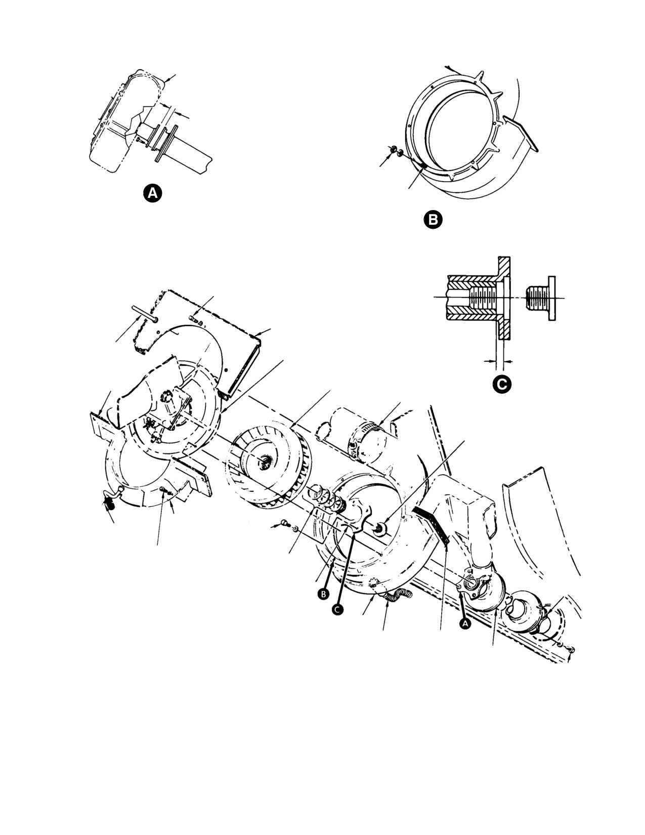
MD Helicopters, Inc.
CSP−H−2
500 Series − Basic HMI
SCROLL
0.010 IN. (0.254 MM) MAX. GAP
0.020 IN. (0.508 MM) MAX. COMPRESSION
(NOTE 3)
5−10 IN. LB
(0.56−1.13 NM)
COUPLING TO DRIVE
SHAFT ATTACHMENT
STUD
SCROLL STUD
5−10 IN. LB
(0.56−1.13 NM)
AFT COVER
0.010 IN. (0.254 MM)
OUTPUT PINION
(BETWEEN END OF
SHROUD MOUNT SEAL RING
SEAL DRAIN
SHAFT AND BOLT SEAT−
(TEFLON)
TUBE
ING SURFACE ON COU−
PLING)
GASKET
IMPELLER
SCROLL CLAMP
COUPLING BOLT, 250−300 IN. LB
(28.25−33.90 NM) PLUS DRAG TORQUE
(NOTES, 2, 4)
MAIN TRANSMIS−
SION DRAIN ASSY
LOCKWIRE
50−70 IN. LB
(5.65−7.91 NM)
50−70 IN. LB
COUPLING SHIMS
(5.65−7.91 NM)
(NOTE 1)
TRANSMISSION IN−
PUT COUPLING
SCROLL
NOTES:
SCROLL DRAIN
GASKET
1.
CORROSION RESISTANT STEEL SHIM, 0.002 IN. (0.0508 MM)
TUBE
LAMINATIONS.
MAIN TRANSMISSION
CAUTION: ID MUST NOT EXCEED 1.20 IN. (30.48 MM)
DRIVE SHAFT
2.
DRAG TORQUE FOR BOLT (SELF−LOCKING) SERVICEABILITY IS
50−70 IN. LB
25 IN. LB (2.82 NM) MIN., 200 IN. LB (22.60 NM) MAX.
(5.65−7.91 NM)
3.
CHECK WITH LOWER END OF SHAFT ATTACHED.
4.
COAT COUPLING BOLT THREADS WITH ANTI−SEIZE COMPOUND
(36, TABLE 2−4) BEFORE ASSEMBLY.
30−152E
Figure 9-10. Main Transmission Driveshaft and Shaft-Driven Oil Cooler Blower
Page 9-33
Revision 17
MD Helicopters, Inc.
CSP−H−2
500 Series − Basic HMI
K. Oil Cooler Blower Repair
(d). Repair small areas of rib or seam
separation by injecting ethylene
dichloride into the void area and
(Ref. Figure 9−8 and Figure 9−10)
clamping together under light
pressure. On shaft−driven blower,
(1). Scroll:
repair deteriorated or otherwise
damaged gasket by replacing with
0.50 inch (12.7 mm) thickness of
The early type scroll is made of acrylic
gasket material (40).
plastic while the later type is of lami−
nated fiberglass. For fiberglass repair
(e). On a shaft−driven blower, repair a
refer to CSP−H−6 and use only the
teflon seal ring that is not completely
applicable portions of the following
secure around outside edge of trans−
procedure.
mission shroud and bearing−retainer
mount. Bond the loose area with a
mixture of 100 parts of resin to 74
NOTE: All permissible patching repairs must
parts of activator (43). Cure at 150°F
be made on exterior surfaces so that inter−
(66°C) for 1 hour or for 8 hours at
nal airflow is not restricted. Any repair
room temperature.
made must not restrict airflow. Patching or
repair that prevents proper duct mating and
(2). Impeller:
sealing, or that results in interference at
(a). Replace impeller that is cracked or
installation, is not allowable. On the belt−
that has damaged vanes or loose
driven blower, patching is not permissible
rivets securing adapter to impeller or
on the upper flat and depressed attachment
balance weights to impeller.
areas of the inlet assembly. Patching is per−
missible on shroud flat and circular surface
(b). Repair scratches and nicks not
areas.
exceeding 0.006 inch (0.1524 mm)
depth by sanding. Use grade 320
abrasive paper to blend defect into
(a).
Repairs cracks that do not exceed 3
surrounding surface area.
inches (7.62 cm) in length, do not
extend to the hardware mounting
(3). Bearing Replacement (Belt−Driven
holes and will not impair the function
Blower):
of the scroll. Such scroll damage is
(a).
Disassemble belt−driven oil cooler
repairable by bonding a patch
blower assembly.
according to the criteria and methods
specified for acrylic in FAA AC
(b).
Remove snap ring, washer and wave
43.13−1A, Aircraft Inspection and
washer from impeller end of shaft.
Repair. Use dichloromethane (38,
(c).
Install existing nut on splined end of
Table 2−4) or ethylene dichloride (39)
shaft.
as the bonding agent.
(d).
Using fiber/rubber mallet or equiva−
lent, tap gently on nut to remove
(b).
Repair scratches and nicks not
shaft and bearings from hub; remove
exceeding 0.012 inch (0.3048 mm)
nut.
depth by sanding the affected area to
blend smoothly with surrounding
(e).
Using a arbor press or equivalent
surface area. Use grade 320 abrasive
tool, press bearing from shaft. When
paper (9).
removing bearing from splined end of
shaft, retain the shim (if installed)
and spacer for reinstallation. Check
(c).
On a shaft−driven blower, replace
spacer for 0.5630−0.5645 inch
inserts that are stripped or loose. Use
(14.3002−14.3383 mm) ID. Ream if
self−locking inserts NAS1394−3L for
necessary and coat reworked surface
replacement. (Drill and tap the scroll
lightly with primer (4).
according to the NAS insert specifica−
tion.)
(f).
Discard old bearings.
Page 9-34
Revision 17
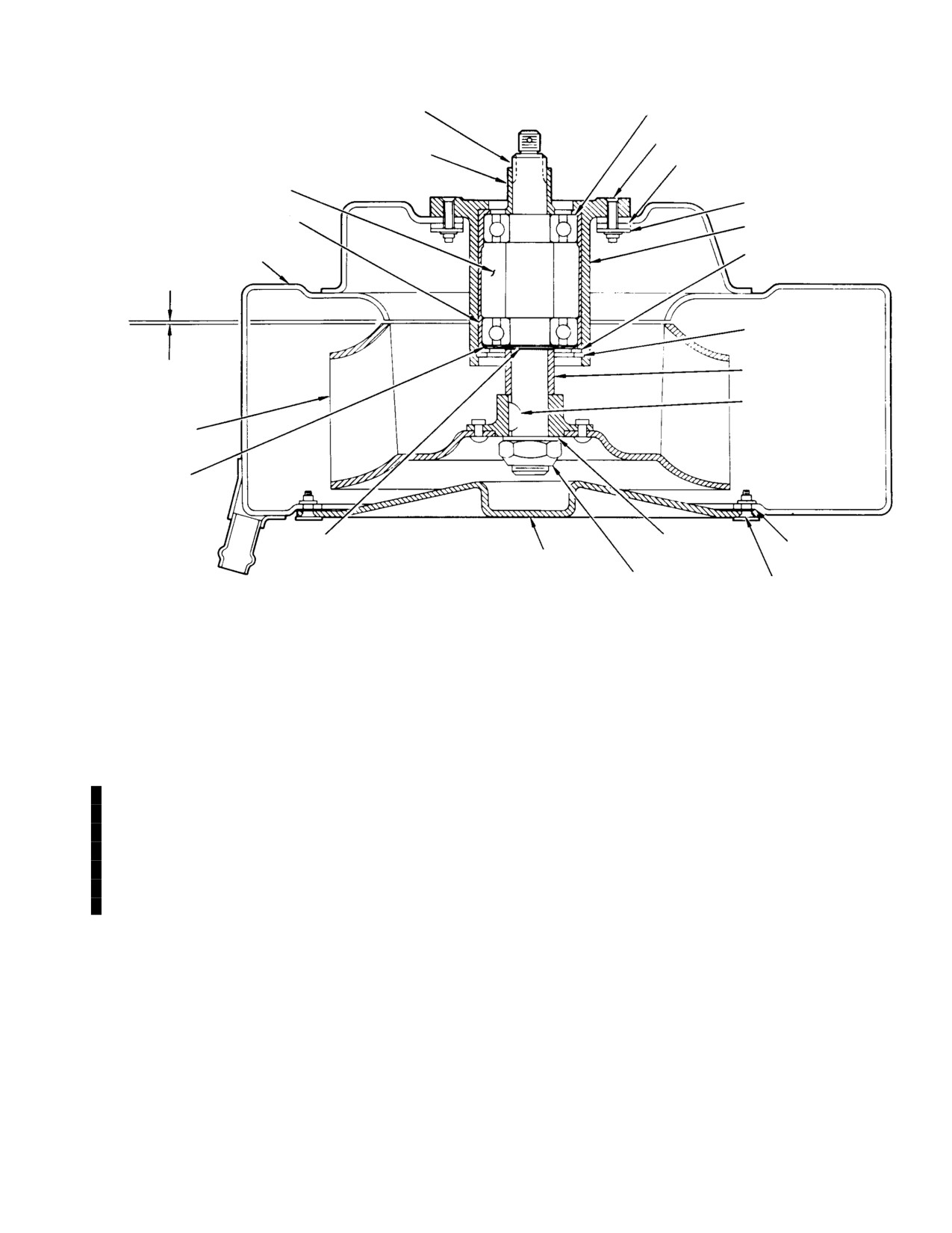
MD Helicopters, Inc.
CSP−H−2
500 Series − Basic HMI
SHAFT
BEARING 369H5655−5
(NOTE 2)
SCREW
SPACER
SPACER
CAVITY FILLED WITH GREASE
(26, TABLE 2−4)
NUT RING
BEARING 369H5655−3
(NOTE 2)
HUB
BLOWER SCROLL
WASHER
(FIBERGLASS TYPE SHOWN)
RETAINING RING
CLEARANCE
IMPELLER SPACER
(NOTE 1)
KEY
IMPELLER
WAVE
WASHER
SHIMS 369H5654; AS REQUIRED
WASHER
SEALANT
(NOTE 1)
COVER
(3, TABLE 2−4)
LOCKNUT 250−300 IN. LB
(28.25−33.90 NM)
NOTES:
1.
ADJUST CLEARANCE TO MINIMUM (WITHOUT RUBBING).
2.
BEARING GREASE SEALS TO FACE OUTWARD.
30−175B
Figure 9-11. Cutaway View of Belt-Driven Oil Cooler Blower
(g).
Clean the shaft and interior of hub
(k). Fill hub cavity with grease up to
with solvent (1).
about half the width of the lower
bearing land in hub.
(h).
Lightly coat bearing journal or
splined end of shaft and ID of bearing
(l). Position bearing 369H5655−3 on
369H5655−5 with grease (26) Posi−
shaft with rubber grease seal out−
tion bearing on shaft with rubber
ward (toward impeller). Press against
grease seal outward. Press against
bearing inner and outer races
bearing inner race until bearing is
simultaneously to seat bearing in
seated on shaft shoulder.
hub and on shaft journal.
(i).
Install shims (if applicable) on
(m). Wipe away excess grease that is
splined end of shaft; then press on
forced from bearing seals at both
the upper spacer with larger OD end
ends of shaft.
toward bearing inner race.
(j).
Lightly coat interior of hub with
(n). Install a nut temporarily on splined
grease; then install the shaft and
end of shaft. Using a fiber/rubber
upper bearing assembly. Press
mallet, tap on nut to extend lower
against bearing outer race if neces−
bearing out of hub enough for excess
sary.
to hub interior.
Page 9-35
Revision 20
MD Helicopters, Inc.
CSP−H−2
500 Series − Basic HMI
(o). Remove approximately 1/4 teaspoon
369A5528 and packing MS29561−017
of grease from hub interior an then
or suitable plug in the output shaft
reinstall shaft and bearings in hub;
(clutch inner race bore) to prevent
secure with wave washer, washer
contamination during clutch handling,
and snap ring.
shipping or storage.
NOTE: Ensure that wave washer is installed
NOTE: The operating lubricant is an approved
next to bearing on impeller end. Also check
preservative for shipping or storage.
that OD of the washer is completely seated
against the outer race of bearing.
(6). Wrap clutch in barrier material (44,
Table 2−4) to protect splined areas of
(p). Rotate shaft by hand to check
race shaft.
smoothness of operational. Reas−
semble blower.
B. Overrunning Clutch Installation
8. Overrunning Clutch
NOTE: Trapped oil can be removed by inverting
the clutch a minimum of three times.
(Ref. Figure 9−12) The overrunning clutch
transmits power from the engine to the main
(1). If clutch is new, remove tag, drain
transmission driveshaft in a clockwise
residual (trapped) preservative oil and
direction. The purpose of the clutch is to
add lubricating oil (9, Table 2−3).
disengage the engine from the remainder of
the drive system (allow free−wheeling) in case
NOTE: The −11, −21 and −31 clutch assembly
of engine failure and during auto−rotations.
capacity is 1.52 U.S. Oz (45cc).
The clutch contains a sprag unit that disen−
The −41 and −51 clutch assembly capac−
gages automatically when N2 rpm is less than
ity is 1.01 U.S. Oz (30cc).
the corresponding main rotor rpm.
(2).
Check fluid level of clutch assembly
A. Overrunning Clutch Removal
before installing clutch coupling.
NOTE: Refer to Overrunning Clutch Assembly
(3).
Temporarily install coupling bolt and
Replacement for removal of only the inter−
packing.
nal clutch subassembly as an alternative to
complete clutch removal.
(4).
Coat clutch splines with grease (21,
Table 2−4). Insert overrunning clutch
(1). Remove engine (Ref. Sec. 10).
outer−race spline into engine and
install six washers and nuts.
(2). Remove the bolts, washers, nuts and
engine shaft firewall seal from the
(5).
Remove coupling bolt and shim cou−
clutch.
pling so that there is 0.035−0.055 inch
(0.889−1.397 mm) gap from end of
NOTE: Removal of the clutch coupling from the
clutch shaft to edge of coupling recess
clutch in step (3). is unnecessary unless the
(surface that bolt head contacts).
clutch is being replaced.
Measure gap with feeler gage. Install
new O−ring. Check that bolt self−lock−
(3). Remove coupling bolt, packing, clutch
ing torque is not less than 25 inch−
coupling and coupling shim(s). Keep
pounds (2.82 Nm) or not more than
shim(s) with coupling for reuse.
200 inch−pounds (22.60 Nm) drag
Reinstall bolt and packing to prevent
torque. Torque bolt to 250 − 300
spillage of lubricating oil from clutch
inch−pounds (28.25 − 33.90 Nm) plus
housing during final steps of removal.
drag torque.
(4). Remove nuts and washers that secure
the overrunning clutch; remove clutch.
(6).
Install engine shaft firewall seal, bolts,
washers and nuts.
(5). If the clutch is being replaced, install a
spare coupling bolt 369A5513 or
(7).
Reinstall engine.
Page 9-36
Revision 17
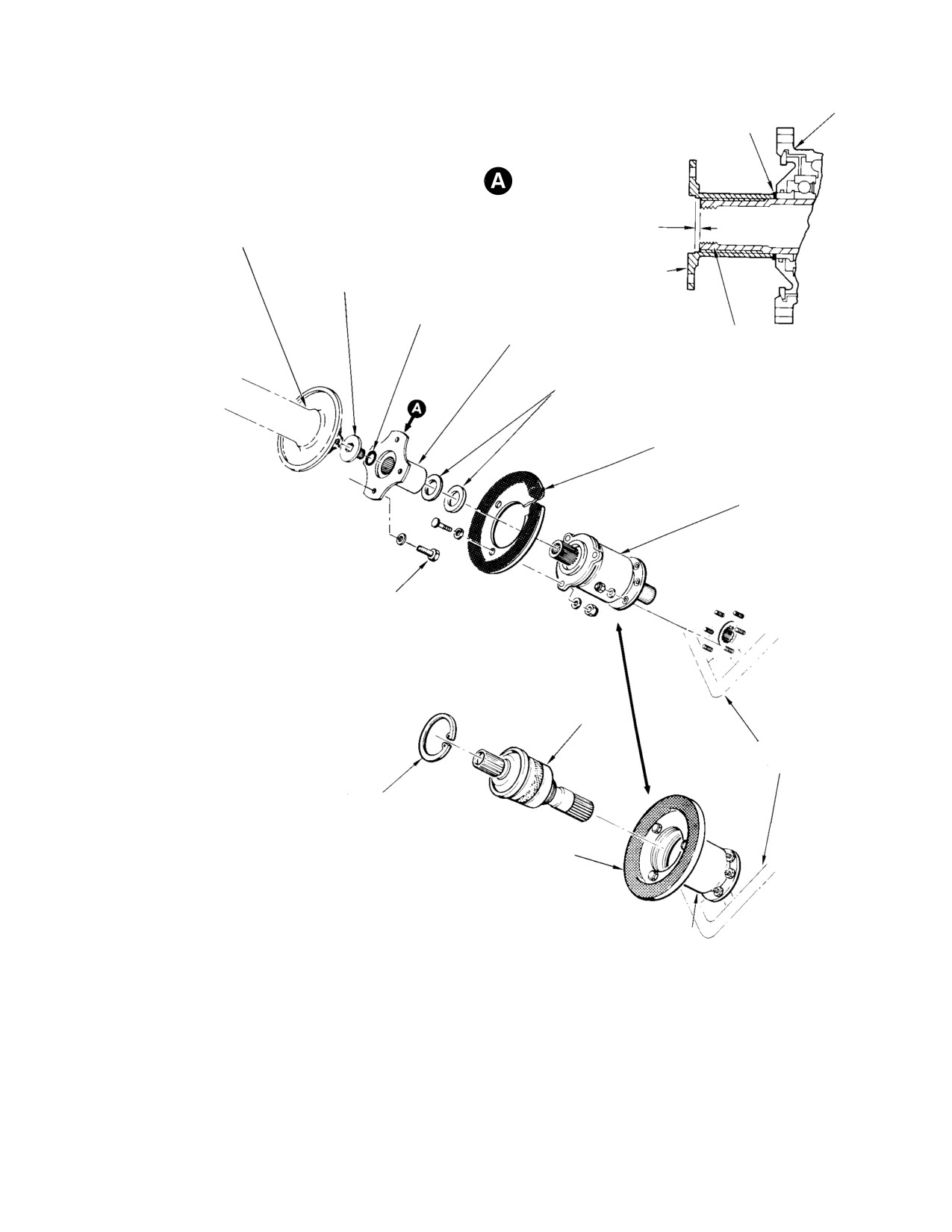
MD Helicopters, Inc.
CSP−H−2
500 Series − Basic HMI
CLUTCH
SHIM AS REQUIRED
COUPLING−T O−CLUTCH
SHIMMING
0.035−0.055 IN.
MAIN TRANSMISSION
(0.889−1.397 MM) GAP
DRIVE SHAFT
(NOTE 3)
COUPLING BOLT, 250−300 IN. LB
(28.25−33.90 NM) PLUS DRAG TORQUE
COUPLING
(NOTES 1, 4)
O−RING
CLUTCH COUPLING
OVERRUNNING
(NOTE 5)
CLUTCH SHAFT
COUPLING SHIMS
(NOTE 2)
ENGINE SHAFT FIREWALL SEAL
OVERRUNNING CLUTCH
50−70 IN. LB
(5.65−7.91 NM)
REPLACEMENT OF COMPLETE CLUTCH
CLUTCH SUBASSEMBLY
369A5350−11
(NOTE 6)
ENGINE POWER AND AC−
CESSORY GEARBOX
RETAINING RING
(BEVEL SIDE OUTWARD)
ENGINE SHAFT FIRE−
WALL SEAL
NOTES:
CLUTCH HOUSING
1.
DRAG TORQUE FOR BOLT (SELF−LOCKING) SERVICEABILITY
(NOTE 6)
IS 25 IN. LB (2.82 NM) MIN., 200 IN. LB (22.60 NM) MAX.
2.
CORROSION RESISTANT STEEL SHIM; 0.002 IN. (0.0508 MM) LAMINATIONS.
3.
USE FEELER GAGE TO CHECK GAP DIMENSION.
REPAIR BY REPLACEMENT OF
4.
COAT COUPLING BOLT THREADS WITH ANTI−SEIZE COMPOUND
CLUTCH SUBASSEMBLY
(36, TABLE 2−4) BEFORE ASSEMBLY.
(NOTE 6)
5.
COAT COUPLING−TO−CLUTCH SPLINES WITH GREASE (57).
6.
THE CLUTCH SUBASSEMBLY SERIAL NUMBER IDENTIFIES THE COMPLETE
REPAIRED CLUTCH.
30−077J
Figure 9-12. Overrunning Clutch Repair or Replacement
Page 9-37
Revision 17
MD Helicopters, Inc.
CSP−H−2
500 Series − Basic HMI
C. Overrunning Clutch Inspection
NOTE: The −11, −21 and −31 clutch assembly
capacity is 1.52 U.S. Oz (45cc).
Perform the following inspections anytime the
The −41 and −51 clutch assembly capac−
helicopter engine or overrunning clutch
ity is 1.01 U.S. Oz (30cc).
assembly is removed from the helicopter.
(6). Using care to avoid oil spillage, insert
NOTE: Overrunning clutch subassembly can
clutch sub−assembly into clutch
be replaced with engine installed.
housing and install retaining ring with
beveled side outward.
(1). Check clutch oil level (Ref. Sec. 2).
NOTE: On the identification plate on the clutch
(2). Remove grease and visually check
housing, obliterate the serial number and
clutch input shaft splines for wear. If
lubrication specification. Change part num−
wear is noted, refer to Part II, COM.
ber to read 369A5350−603. The serial num−
ber on the clutch sub−assembly identifica−
tion plate will now identify the complete
NOTE: Relubricate splines on clutch input
clutch.
shaft and splines inside engine power and
accessory gearbox with grease
(21,
Table 2−4) prior to reinstalling overrunning
(7). Install clutch.
clutch.
(8). Install main transmission drive shaft.
(3). Inspect overrunning clutch sub−assem−
bly and ball bearing.
F. Overrunning Clutch Repair/Overhaul
D. Overrunning Clutch Sub-Assembly and
Accomplish repair/overhaul of the overrunning
Ball Bearing Inspection
clutch according to applicable instructions in
CSP−H−5.
Accomplish inspection of overrunning clutch,
clutch sub−assembly and ball bearing accord−
9. Tail Rotor Transmission
ing to applicable instructions in CSP−H−5.
The tail rotor transmission is a right−angle,
E. Overrunning Clutch Sub-assembly
speed−increasing transmission (2045−3018
Replacement
rpm at 100% N2) having a magnesium alloy
housing. The transmission drive consists of a
The overrunning clutch sub−assembly can be
pair of spiral−bevel gears that are splash
replaced while the engine installed as followed:
lubricated. An oil level sight plug and magnet−
ic chip detector are located on the aft end of
(1). Remove main transmission drive shaft.
the transmission and a breather−filler is
located on top. The breather−filler, on all
(2). Remove coupling bolt, clutch coupling
except early gearboxes, is threaded for
and shims.
attachment of a strobe light pickup of a tail
rotor balancing kit (31, Table 2−2) when tail
rotor balancing is required. Section 2 provides
(3). Remove retaining ring from clutch
servicing information.
housing. Then pull complete clutch
sub−assembly out of housing.
A. Tail Rotor Transmission Removal
(4). Remove shipping plug and O−ring from
end of shaft in replacement clutch
(Ref. Figure 9−13 and Figure 9−14)
sub−assembly .
(1). Remove tail rotor drive shaft and
(5). Drain preservative oil from clutch
transmission as a unit.
sub−assembly by inverting it several
times. Then add lubricating oil (5, Table
(2). Remove tail rotor from tail rotor
2−3).
transmission (Ref. Sec. 8).
Page 9-38
Revision 17
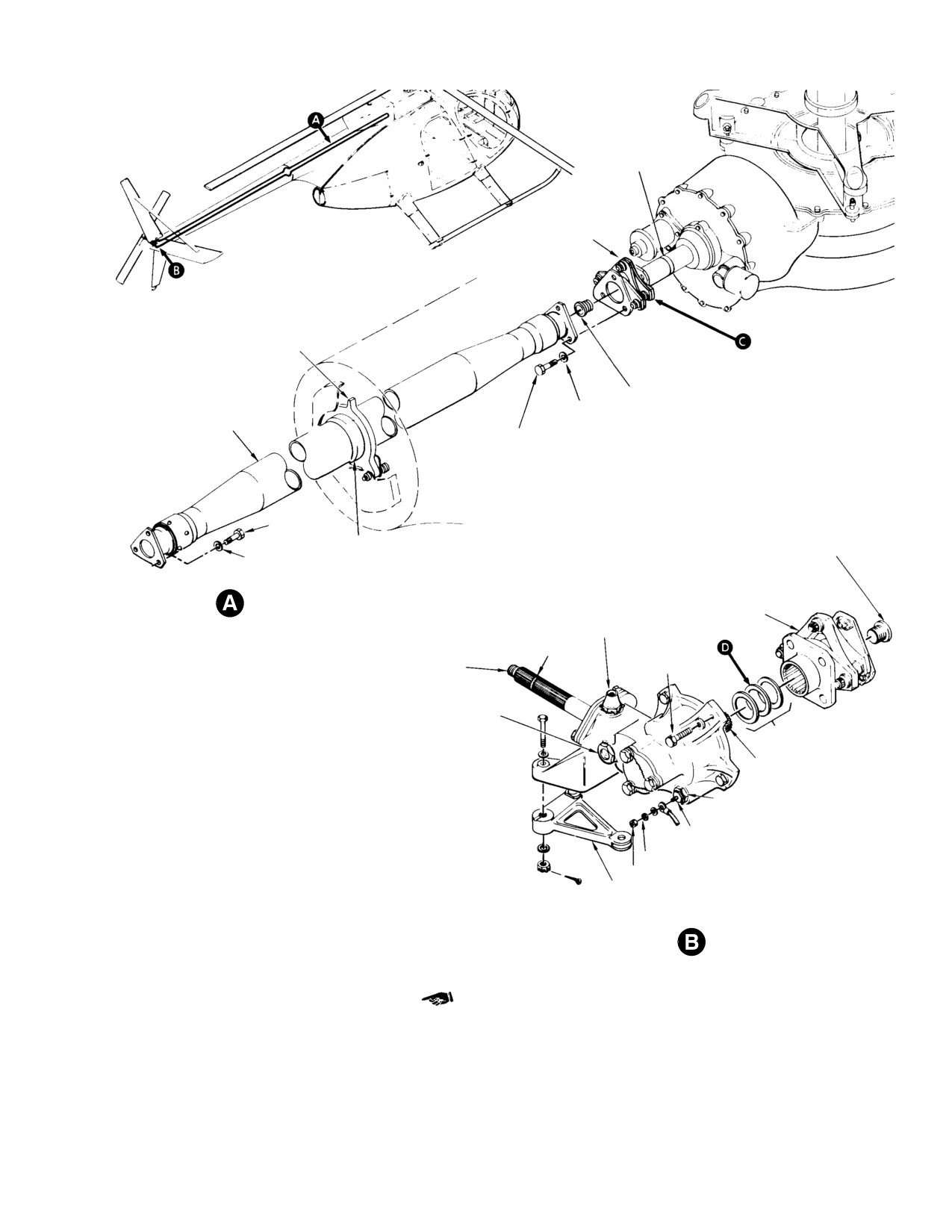
MD Helicopters, Inc.
CSP−H−2
500 Series − Basic HMI
COUPLING SHIMS
(NOTE 4)
TRANSMISSION
OUTPUT GEARSHAFT
COUPLING
(NOTE 7)
TAIL ROTOR DRIVE
SHAFT DAMPER
COUPLING BOLT, 250−300 IN. LB
(28.25−33.90 NM) PLUS DRAG TORQUE
TAIL ROTOR
(NOTES 1, 9)
NOTE 6
DRIVE SHAFT
80−100 IN. LB
(9.04−1 1.30 NM)
80−100 IN. LB
COUPLING BOLT, 250−300 IN. LB
(28.25−33.90 NM) PLUS DRAG TORQUE
(9.04−1 1.30 NM)
(NOTES 1, 9)
SHAFT DAMPER
NOTE 6
SLEEVE
TAIL ROTOR
DRIVE SHAFT INSTALLATION
BREATHER/FILLER,
GEARBOX COUPLING
45−55 IN. LB (5.08−6.21 NM)
(NOTE 7)
(NOTE 5)
75−95 IN. LB
NOTE 2
(8.47−10.73 NM)
(NOTE 8)
OUTPUT BEVEL
PINION GEARSHAFT
LIQUID LEVEL PLUG,
50−60 IN. LB (5.65−6.78 NM)
COUPLING SHIMS
(NOTE 4)
INPUT BEVEL PINION
GEARSHAFT (NOTE 3)
SELF−CLOSING VALVE,
50−60 IN. LB (5.65−6.78 NM)
NOTES:
CHIP DETECTOR,
1.
DRAG TORQUE FOR SELF−LOCKING BOLT SERVICEABILITY IS
40−50 IN. LB (4.52−5.65 NM)
25 IN. LB (2.82 NM) MIN., 200 IN. LB (22.60 NM) MAX.
LOCKWASHER
2.
RUNOUT (TIR) NOT MORE THAN 0.003 IN. (0.0762 MM) AT SPLIT
12−15 IN. LB (1.36−1.58 NM)
RING GROOVE.
3.
AXIAL PLAY NOT MORE THAN 0.005 IN. (0.127 MM) WHEN INPUT
STA. 282.00 BELLCRANK
SHAFT IS MOVED IN AND OUT.
4.
ALUMINUM ALLOY; 0.002 IN. (0.0508 MM) LAMINATIONS.
5.
THREADED INSERT TYPE BREATHER/FILLER FOR TAIL ROTOR
TRANSMISSION INSTALLATION
VIBRATION ANALYSIS.
6.
REASSEMBLY USING CORROSION RESISTANT STEEL WASHER
IN PLACE OF AL ALY.
7.
COAT COUPLING SPLINES WITH CORROSION PREVENTIVE
COMPOUND (70, TABLE 2−4).
8.
USE ONLY NAS1304−24H OR −26H BOLTS. CHECK BOLT
HOLE DEPTH FOR PROPER BOLT INSTALLATION.
9.
COAT COUPLING BOLT THREADS WITH ANTI−SEIZE
COMPOUND (36) BEFORE ASSEMBLY.
44-463C
Figure 9-13. Tail Rotor Transmission and Drive Shaft Installation with
Kamatic Couplings Installed (Sheet 1 of 2)
Page 9-39
Revision 20
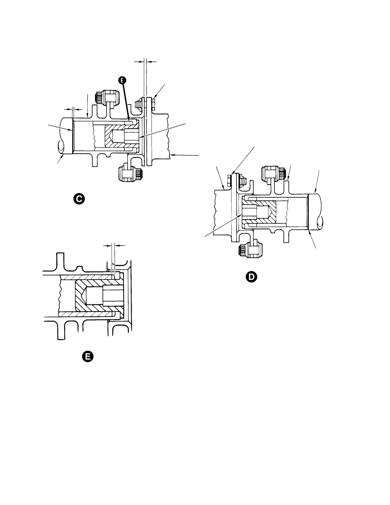
MD Helicopters, Inc.
CSP−H−2
500 Series − Basic HMI
MEASURED GAP
ALIGNMENT
BOLT OR PIN
1.370 IN. (34.798 MM) OD
(NOTE 11)
NOTE 10
COUPLING
SHIMS
BOLT
THIN WASHER
(3 PLCS)
TAIL ROTOR
TAIL ROTOR
AFT
GEARSHAFT
DRIVE SHAFT
COUPLING
INPUT SHAFT
MAIN
TRANSMISSION
OUTPUT PINION
FORWARD COUPLING
COUPLING
0.010 IN. (0.254 MM
BOLT
MINIMUM STEP
(NOTE 12)
SHIMS
AFT COUPLING
NOTES: (CONT)
10. ADD 0.005 IN. (0.127 MM) TO MEASURED GAP FOR MINIMUM SHIM THICKNESS.
11. HOLD COUPLING AT 1.370 IN. (34.798 MM) OD ONLY, TO BOTTOM COUPLING.
12. MINIMUM 0.010 IN. (0.254 MM) STEP BETWEEN AFT END OF OUTPUT SHAFT AND
SHOULDER OF FORWARD COUPLING.
44-460-3A
Figure 9-13. Tail Rotor Transmission and Drive Shaft Installation with
Kamatic Couplings Installed (Sheet 2 of 2)
Page 9-40
Revision 17
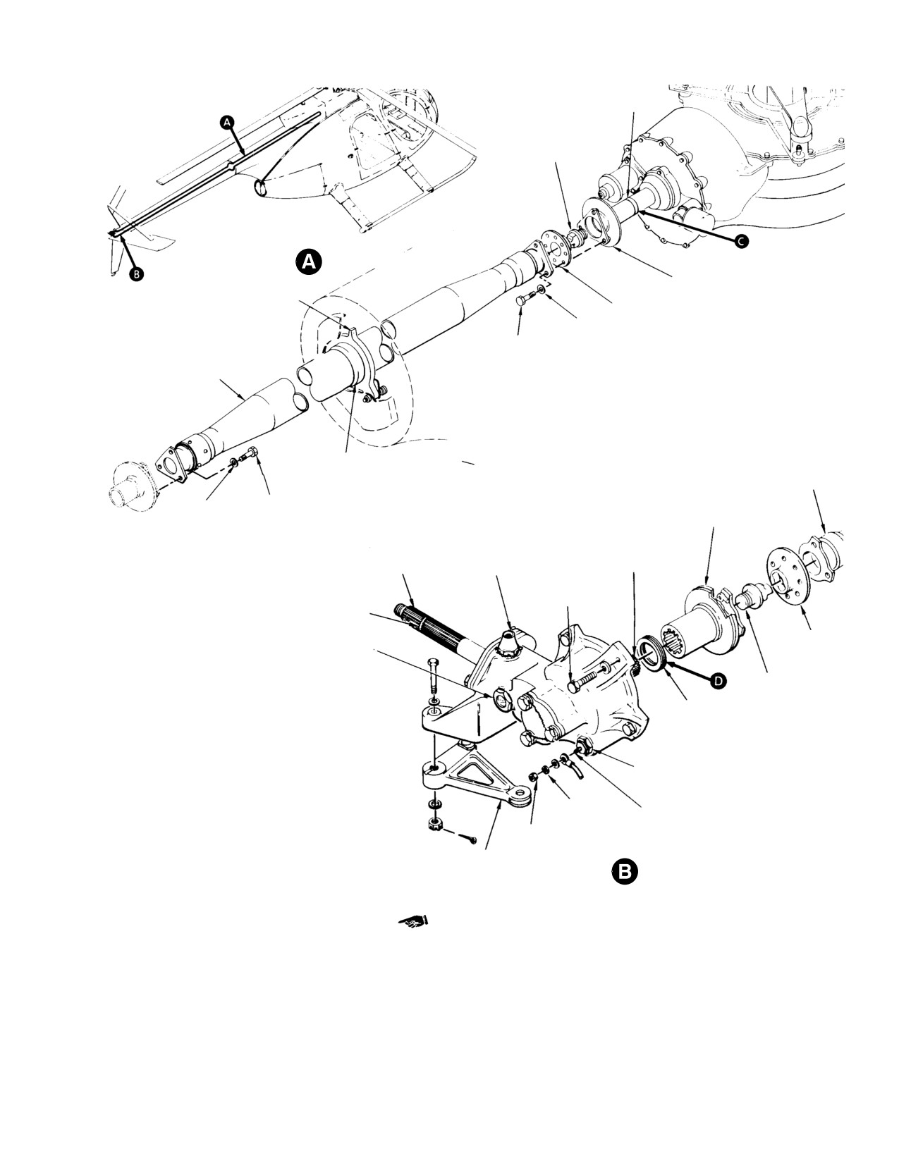
MD Helicopters, Inc.
CSP−H−2
500 Series − Basic HMI
COUPLING SHIMS
(NOTE 4)
FAILSAFE COUPLING BOLT,
250−300 IN. LB (28.25−33.90 NM)
PLUS DRAG TORQUE
(NOTES 1, 9, 10)
DRIVE SHAFT INSTALLATION
TRANSMISSION OUTPUT
GEARSHAFT COUPLING
TAIL ROTOR DRIVE
(NOTE 7)
SHAFT DAMPER
FAILSAFE SOCKET
NOTE 6
(NOTE 10)
80−100 IN. LB
(9.04−1 1.30 NM)
TAIL ROTOR
DRIVE SHAFT
SHAFT DAMPER
TAIL ROTOR
SLEEVE
DRIVE SHAFT
TAIL ROTOR
80−100 IN. LB
GEARBOX COUPLING
NOTE 6
(9.04−1 1.30 NM)
(NOTE 7)
BREATHER/FILLER,
45−55 IN. LB
INPUT BEVEL
(5.08−6.21 NM)
PINION GEARSHAFT
OUTPUT BEVEL
(NOTE 5)
(NOTE 3)
PINION GEARSHAFT
75−95 IN. LB
(8.47−10.73 NM)
(NOTE 8)
NOTE 2
LIQUID LEVEL PLUG,
FAILSAFE
50−60 IN. LB (5.65−6.78 NM)
SOCKET
FAILSAFE
COUPLING BOLT
COUPLING SHIMS
(NOTE 4)
NOTES:
1.
DRAG TORQUE FOR SELF−LOCKING BOLT
SERVICEABILITY IS 25 IN. LB (2.82 NM) MIN.,
SELF−CLOSING VALVE,
200 IN. LB (22.60 NM) MAX.
50−60 IN. LB (5.65−6.78 NM)
2.
RUNOUT (TIR) NOT MORE THAN 0.003 IN.
(0.0762 MM) AT SPLIT RING GROOVE.
3.
AXIAL PLAY NOT MORE THAN 0.005 IN. (0.127 MM)
LOCKWASHER
CHIP DETECTOR,
WHEN INPUT SHAFT IS MOVED IN AND OUT.
40−50 IN. LB (4.52−5.65 NM)
4.
ALUMINUM ALLOY; 0.002 IN. (0.0508 MM)
12−15 IN. LB (1.36−1.58 NM)
LAMINATIONS.
5.
THREADED INSERT TYPE BREATHER/FILLER FOR
STA. 282.00 BELLCRANK
TAIL ROTOR VIBRATION ANALYSIS.
TRANSMISSION INSTALLATION
6.
REASSEMBLY USING CORROSION RESISTANT
STEEL WASHER IN PLACE OF AL ALY.
7.
COAT COUPLING SPLINES WITH CORROSION
PREVENTIVE COMPOUND (70, TABLE 2−4).
8.
USE ONLY NAS1304−24H OR −26H BOLTS. CHECK BOLT
HOLE DEPTH FOR PROPER BOLT INSTALLATION.
9.
COAT COUPLING BOLT THREADS WITH ANTI−SEIZE
COMPOUND (36) BEFORE ASSEMBLY.
30-078L
10. FAILSAFE COUPLING AND FAILSAFE BOLT REQUIRED
ON BENDIX COUPLING INSTALLATION.
369A5000 / 369H5600
Figure 9-14. Tail Rotor Transmission and Drive Shaft Installation with
Bendix Couplings Installed (Sheet 1 of 2)
Page 9-41
Revision 18
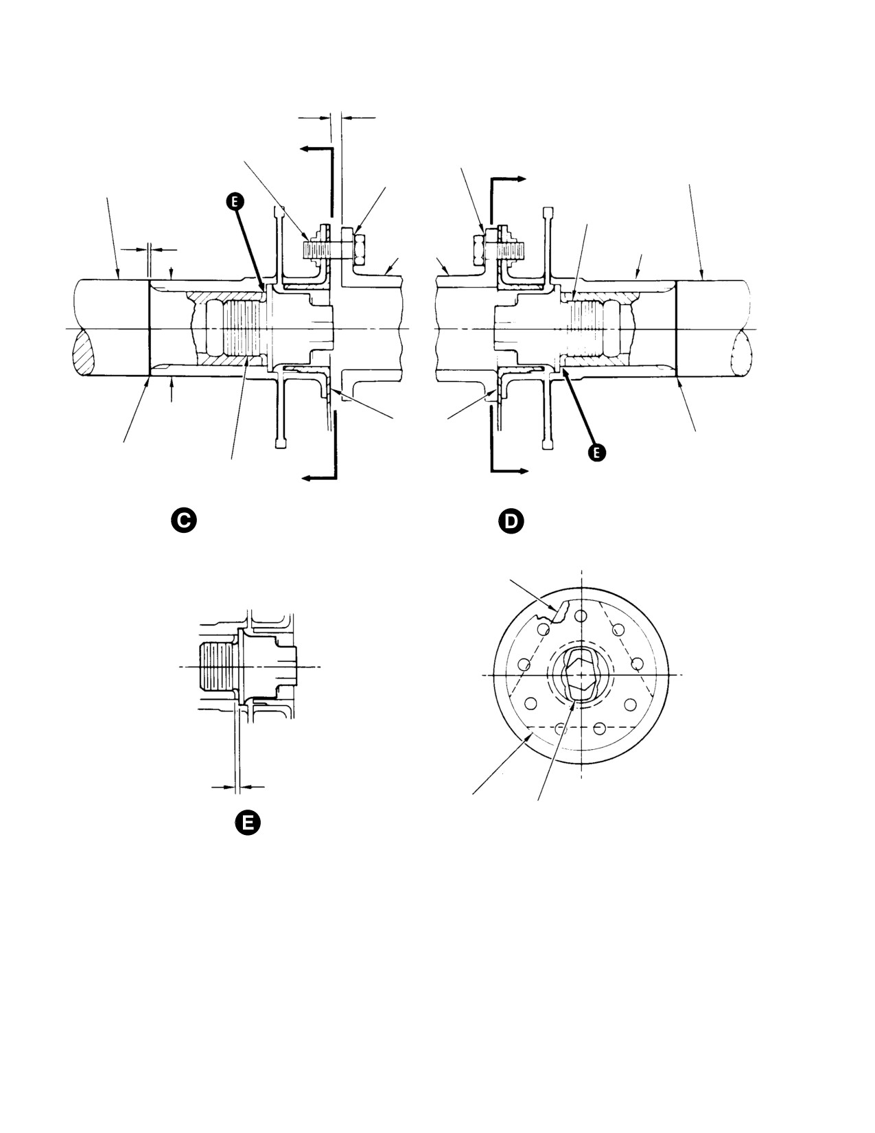
MD Helicopters, Inc.
CSP−H−2
500 Series − Basic HMI
MEASURED GAP
THIN
ALIGNMENT
WASHER
BOLT OR PIN
D
TAIL ROTOR
(3 PLCS)
MAIN
WASHER
GEARBOX INPUT
TRANSMISSION
(3 PLCS)
SHAFT
D
OUTPUT PINION
FAILSAFE
BOLT
AFT
TAIL ROTOR
COUPLING
DRIVE SHAFT
NOTE 11
1.370 IN.
FAILSAFE
(34.798 MM) OD
SOCKET
(NOTE 12)
SHIMS
SHIMS
FAILSAFE
D
BOLT
D
FORWARD COUPLING
AFT COUPLING
COUPLING
0.010 IN. (0.254 MM)
MINIMUM STEP
(NOTE 13)
FAILSAFE SOCKET
FAILSAFE
BOLT
VIEW D−D
NOTES: (CONT)
11. ADD 0.005 IN. (0.127 MM) TO MEASURED GAP FOR MINIMUM SHIM THICKNESS.
12. HOLD COUPLING AT 1.370 IN. (34.798 MM) OD ONLY, TO BOTTOM COUPLING.
13. MINIMUM 0.010 IN. (0.254 MM) STEP BETWEEN AFT END OF OUTPUT SHAFT AND
SHOULDER OF FORWARD COUPLING.
44-462-1A
Figure 9-14. Tail Rotor Transmission and Drive Shaft Installation with
Bendix Couplings Installed (Sheet 2 of 2)
Page 9-42
Revision 17
MD Helicopters, Inc.
CSP−H−2
500 Series − Basic HMI
B. Tail Rotor Transmission Installation
NOTE: Although not required, placing marks
on the end of the output shaft provides
Do not carry or otherwise sup−
guides for subsequent installation of the tail
CAUTION
port the gearbox by the cou−
rotor assembly in a manner that reduces
pling, as the coupling diagram will buckle if
chances of high frequency tail rotor vibra−
excessively deflected. During performance
tions and lessens possibility of requirement
of all maintenance on the gearbox, use extra
for tail rotor balancing.
care to keep contaminants such as paint,
(5). Inspect all scoring or scratching of the
dirt, etc. from the areas around the input
output shaft to determine if the marks
and output shaft seals.
penetrate through the cadmium plating
and into the steel shaft. Penetration of
(1). If gearbox is a replacement, perform
the steel shaft is allowable to a maxi−
buildup.
mum depth of 0.010 inch (0.254 mm).
(2). Install tail rotor on tail rotor transmis−
D. Tail Rotor Transmission Stripping
sion (Ref. Sec. 8).
(Ref. Figure 9−13 and Figure 9−14)
(3). Install tail rotor drive shaft and
transmission as a unit (Ref. Tail Rotor
(1). Remove coupling bolt, coupling, and
Drive Shaft Installation with Kamatic
coupling shims from input gearshaft.
Couplings or Tail Rotor Drive Shaft
Keep shims with coupling for reuse.
Installation with Bendix Coupling).
NOTE: Further stripping is not required, as a
replacement transmission is equipped with
(4). Drain any residual preservative oil and
all other accessories.
service transmission with lubricating
oil (1, Table 2−3).
(2). Drain oil from gearbox. The residual
operating lubricant is approved internal
C. Tail Rotor Transmission Inspection
preservative for shipping or storage.
(Ref. Figure 9−13 and Figure 9−14) If the
(3). Wrap gearbox in barrier material (44,
following inspections reveal damage, perform
Table 2−4) to protect shaft splines and
repair according to applicable instructions in
chip detector stud during handling,
CSP−H−5.
shipping or storage.
E. Tail Rotor Transmission Buildup
(1). Check the transmission for leaks,
cracks or corrosion. (Refer to Fluid
(Ref. Figure 9−13, Figure 9−14 and
Leak Analysis, Section 2, to evaluate oil
Figure 9−15) Replace the liquid level plug, chip
leakage.)
detector and breather−filler according to the
following information. Repair other compo−
(2). Check the input bevel gearshaft for
nents or replace tail rotor transmission oil
axial play by moving the input shaft in
seals according to applicable instructions in
and out. The gearbox must be cold.
CSP−H−5.
Axial play is limited to 0.005 inch
(0.127 mm) maximum.
(1). Replacement of Chip Detector, Liquid
Level Plug and Breather−Filler:
(3). Check tir in the split ring groove of the
Use the following torque values for
output bevel pinion gearshaft. Runout
accessories; lubricate with petrolatum
is limited to 0.003 inch (0.0762 mm) tir.
(34, Table 2−4) to prevent damage to
Check the gearshaft for axial play; no
O−rings.
play is permissible.
(a). Chip detector:
(4). Check for high and low runout at the
split ring groove on the output shaft;
Valve body − 50 − 60 inch−pounds
mark the high and low extremes on the
(5.65 − 6.78 Nm);
outer end of the shaft with grease
Detector − 40 − 50 inch−pounds
pencil.
(4.52 − 5.65 Nm).
Page 9-43
Revision 17
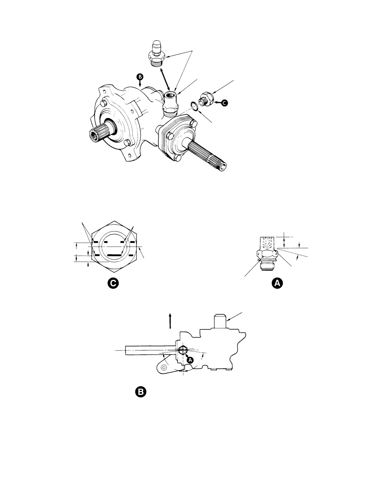
MD Helicopters, Inc.
CSP−H−2
500 Series − Basic HMI
BREATHER−FILLER
NOTE
50−60 IN. LB
(5.65−6.78 NM)
O−RING
0.046 IN. (11.684 MM)
MARKINGS ON REPLACE−
MENT PLUG
ORIGINAL MARKINGS
0.485−0.500 IN.
(12.319−12.70 MM)
FULL
0.406 IN. 10.3124 MM)
ADD
15° ±2°
AXIS OF INPUT BEVEL PIN−
ION GEARSHAFT
0.060 IN.
0.0625 IN. (1.5875 MM)
(1.524 MM)
DRAIN HOLE
BREATHER HOLE
INPUT SHAFT
FWD
85°
85°
BREATHER HOLE ORIENTATION (TOP VIEW)
NOTE:
THREADED INSERT−TYPE BREATHER−FILLER
FOR TAIL ROTOR VIBRATION ANALYSIS;
NOT PART OF EARLY GEARBOX.
30−079E
Figure 9-15. Replacement of Tail Rotor Transmission Liquid Level Plug and Breather-Filler
Page 9-44
Revision 17
MD Helicopters, Inc.
CSP−H−2
500 Series − Basic HMI
(b). Liquid Level Plug:
cover to housing; remove cover and
shim. Retain all hardware except safety
50 − 60 inch−pounds (5.65 − 6.78
wire for use at reassembly.
Nm).
(4). Using heat gun or blow dryer, heat
(c). Breather−Filler:
output housing bore to 275° ±25°F
(135° ±l2°C); remove gearshaft and
45 − 55 inch−pounds (5.08 − 6.21
contact pattern shim(s). Retain shim(s)
Nm). Locate the breather hole on
for use at reassembly.
threaded insert breather−filler. The
breather hole must be directed
(5). Install Speedi−Sleeve as follows:
rearward at final torque relative to
gearbox installation on helicopter
Do not allow any contaminants
CAUTION
(Ref. Figure 9−15). Locating the vent
to enter shaft bearings. Dust
at any angle aft of the output shaft
and other contaminants can damage or
centerline (viewed from above)
shorten the service life of the bearings.
adequately directs vent rearward.
One or two AN960PD1016L washers
(a). Set gearshaft on end, bearings down,
may be added between the O−ring
on hard, clean, level surface. Wipe
and breather flange, one washer
away dust and foreign particles from
changes orientation by approximately
gearshaft using a clean, lint free
100°.
cloth, dampened by solvent (1,
Table 2−4).
(2).
Install shim selection retained for reuse
at disassembly, 0.010 inch (0.254 mm)
NOTE: If shaft has been grooved from rubbing
minimum, on input gearshaft.Coat
against lip of output gearshaft cover seal,
coupling splines with corrosion preven−
and depth of groove exceeds 0.005 inch
tive compound (70) and coupling bolt
(0.127 mm), shaft must be replaced (Ref.
threads with anti−seize compound (36)
CSP−H−5). If groove does not exceed 0.005
before assembly. Install coupling and
inch (0.127 mm) depth, it may be repaired
bolt. Check that bolt self−locking drag
with plastic steel (135).
torque is not less than 25 inch−
(b). Apply light coat of plastic steel (135)
pounds (2.82 Nm) or more than 200
to shaft area to be covered by sleeve.
inch−pounds (22.60 Nm). Torque
coupling bolt to 250 − 300 inch−
(c). While plastic steel is wet, put sleeve
pounds (28.25 − 33.90 Nm) plus drag
on shaft, flange down, and press or
torque.
tap in place using 1.250 inch (3.175
cm) tube or pipe bottomed on flange
(3).
Install tail rotor drive shaft.
of sleeve. Unflanged end of sleeve
F. Protective Sleeve (Speedi-Sleeve)
must be even with outboard end of
Installation, Output Gearshaft
1.088−1.090 inch (2.76352−2.7686
cm) diameter portion of shaft. Tap
(Ref. Figure 9−16) Repair oil leaks at output
end of pipe with hammer or mallet as
gearshaft cover by installing a protective
necessary to correctly position sleeve
sleeve (Speedi−Sleeve PN 084957) on the
on shaft. Wipe any excess plastic
gearshaft area contacted by the oil seal lip.
steel from shaft using a clean, lint
Install the protective sleeve as follows;
free cloth.
(1). Remove tail rotor and pitch control
(d). Clip flange of sleeve to notch line and
assembly (Ref. Sec. 8).
peel from shaft.
(2). Drain lubricant from tail rotor trans−
(6). Reassemble tail rotor transmission.
mission (Ref. Sec. 2).
(a). Apply heavy coating of petroleum
(3). Remove safety wire, three bolts and
jelly (34) to bearings on gearshaft
washers attaching output gearshaft
end.
Page 9-45
Revision 17
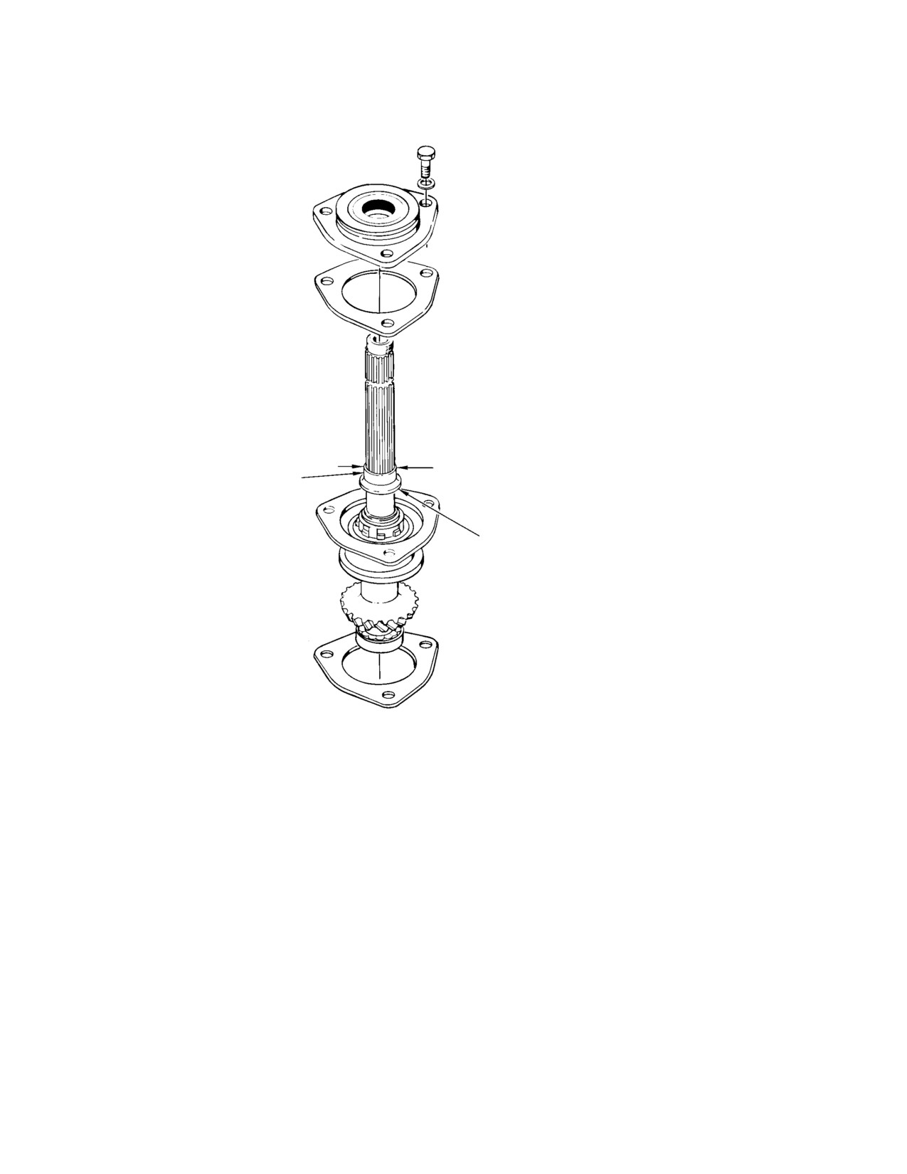
MD Helicopters, Inc.
CSP−H−2
500 Series − Basic HMI
1.088−1.090 IN.
(2.76352−2.7686 CM) DIA
SLEEVE
OUTBOARD END
FLANGE
NOTES:
REPAIRABLE
DAMAGED SHAFT
UNDAMAGED SHAFT
SLEEVE REPLACEMENT
1.
FILL GROOVED AREA AND BOND
1.
BOND SLEEVE TO SHAFT WITH
1.
CUT EDGE OF DAMAGED SLEEVE WITH FILE
SLEEVE TO SHAFT WITH DEVCON A.
DEVCON A.
AND PEEL BACK.
2.
CLIP FLANGE AND PEEL FLANGE OFF
2.
CLIP FLANGE AND PEEL FLANGE
2.
PEEL SLEEVE FROM SHAFT.
SHAFT AT NOTCH LINE.
OFF SHAFT AT NOTCH LINE.
3.
CLEAN WITH KEROSENE; DRY WITH CLEAN,
LINT−FREE CLOTH.
4.
BOND SLEEVE TO SHAFT WITH DEVCON A.
5.
CLIP FLANGE AND PEEL FLANGE OFF SHAFT
AT NOTCH LINE.
44−230A
Figure 9-16. Protective Sleeve Installation/Replacement, Output Gearshaft
Page 9-46
Revision 17