CSP-H-2 BASIC HANDBOOK OF MAINTENANCE INSTRUCTIONS FOR MDHI 369H HELICOPTERS - page 5
MD Helicopters, Inc.
CSP−H−2
500 Series - Basic HMI
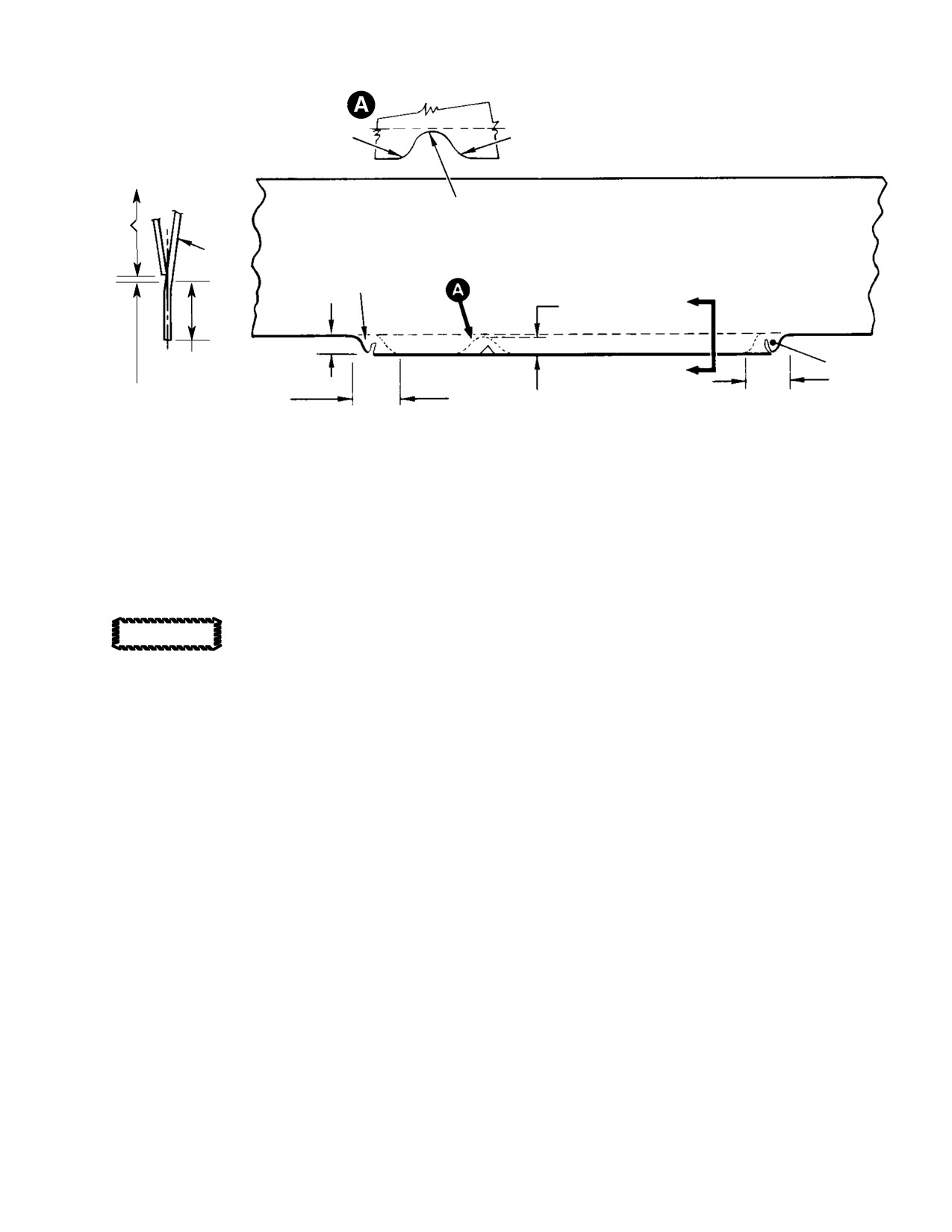
0.25 IN. (6.35 MM) R
0.25 IN. (6.35 MM) R
6.80 IN.
(17.272 CM)
0.25 IN. (6.35 MM) R
(NOTES 2, 3)
TOP
SURFACE
NOTE 1
0.35 IN. (8.89 MM)
A
(NOTE 3)
0.38 IN. (9.652 MM)
0.38 IN.
NOTE 4
(9.652 MM)
A
1.00 IN.
0.00−0.10 IN.
1.00 IN.
(25.4 MM)
(0.00−0.254 MM)
(25.4 MM)
VIEW A−A
NOTES:
1.
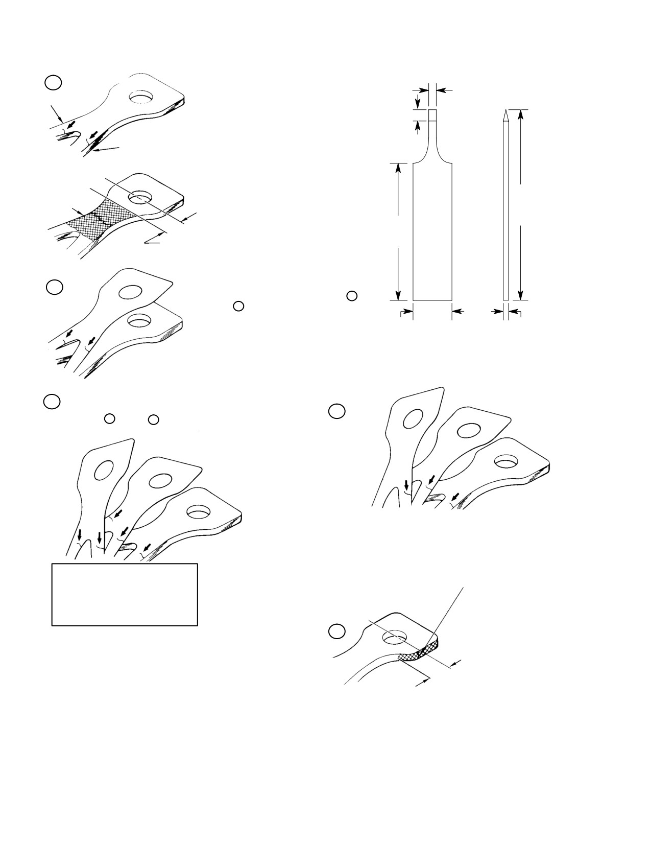
REMOVE DAMAGED END(S) IF THEY OCCUR WITHIN 1.00 IN. (25.4 MM) OF TAB ENDS.
2.
0.25 IN. (6.35 MM) RADIUS CLEANUP. FINISH PER BASIC HMI.
3.
MAXIMUM DEPTH OF REPAIR 0.35 IN. (8.89 MM).
4.
NO MINIMUM LENGTH OF TAB REQUIRED. IF DAMAGE OCCURS AT BOTH ENDS.
IT IS PERMISSIBLE TO REMOVE BOTH ENDS.
5.
ENTIRE TAB MAY BE REMOVED IF REQUIRED.
30−217A
Figure 7-11. Repair and Removal of Trim Tab, Main Rotor Blade
Cutting, grinding or filing to re−
15. Main Rotor Blade and Damper Attach Pin
CAUTION
move trim tab, and deburring of
Inspection and Corrosion Protection
reworked blade trailing edge, are to be per−
(Ref. Figure 7−12)
formed in a spanwise direction only. DO
NOT use shears or clippers to remove trim
(1). Inspect pin cam handle lobe for cracks
tab.
and excessive wear. Remove pin from
service if cracking or excessive wear is
noted.
(b). Use metal cutting saw or equivalent
to remove the 0.380 inch (9.652 mm)
NOTE: If hard anodizing surface of cam lobes is
wide trim tab, view A − A Deburr
worn, cam lobes can be re−anodized or
edges in a spanwise direction only.
treated with corrosion preventive oil (104,
Table 2−4).
(8). Peel and remove tape from blade and
(2). Inspect attach pin for evidence of
inspect area around repair; clean
corrosion or wear and straightness.
repaired area with cloth dampened in
solvent (aliphatic naphtha).
(a). Pay particular attention to area
along edges of barrel nut and bore in
cam handle.
(9). Apply chemical film treatment (Iridite)
to reworked area of blade trailing edge
(b). Remove pin from service if corrosion
or trim tab; apply a thin film of primer
or wear is noted or pin is bent.
and paint lightly.
Standard hardware (Ref. Figure 7−3)
may be used to replace faulty damper
attach pins.
(10). As applicable, reinstall main rotor
blade.
(c). If used, install at all four locations.
Page 7-31
Revision 16
MD Helicopters, Inc.
CSP−H−2
500 Series - Basic HMI
NOTE: Corrosion protection treatment is to be
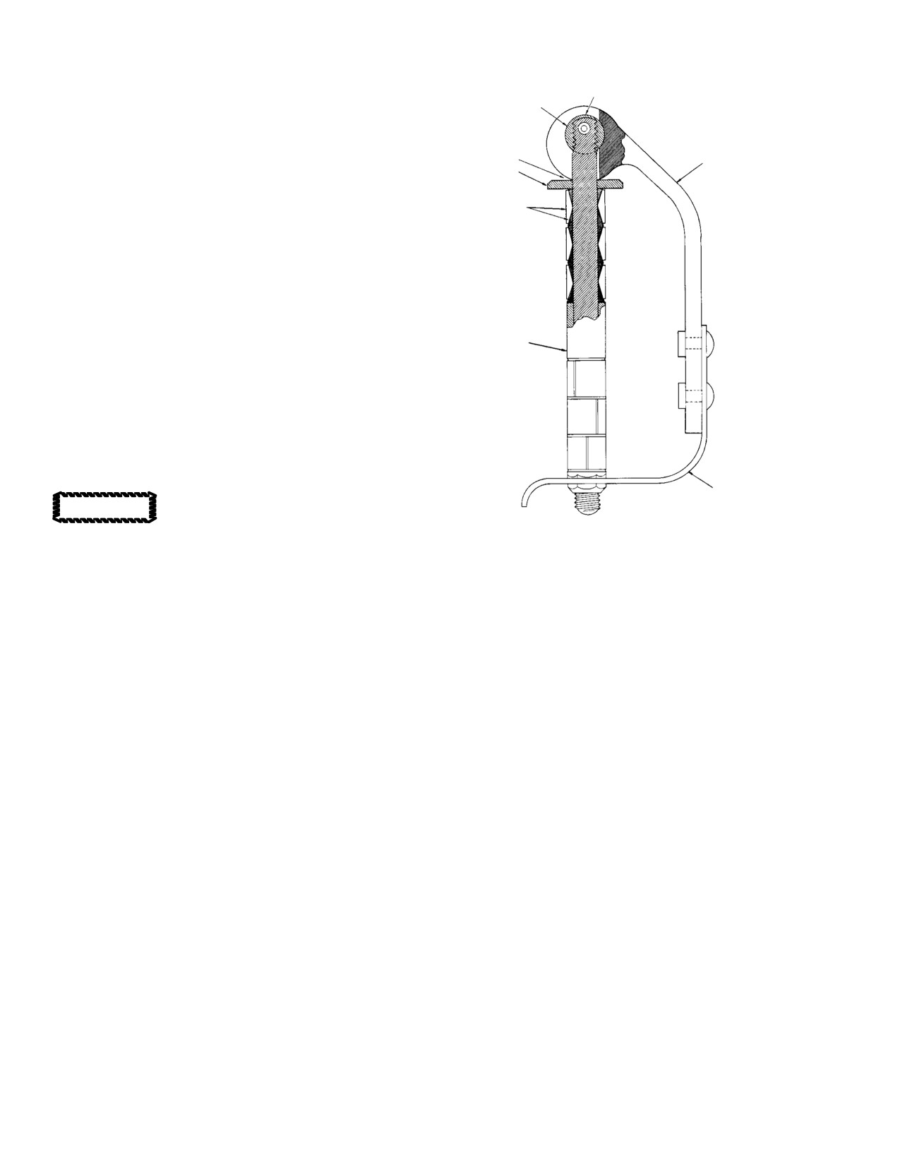
OIL
BARREL NUT
applied at each periodic inspection to ensure
continued serviceability of attach pin; and
at each pin removal, if subject to salt laden
OIL
atmosphere.
CAM HANDLE
THRUST
WASHER
(3). With attach pin removed, lubricate
mating surfaces of barrel nut and cam
BUSHING
SEGMENTS
handle, using corrosion preventive oil.
Rotate cam handle back and forth on
barrel nut several times to ensure that
oil penetrates all sections of pin
operating mechanism. Wipe excess oil
from pin surfaces.
SPACER
(4). Adjust pin at installation.
16. Main Rotor Blade and Damper Attach Pin
Disassembly and Special Inspection
(Ref. Figure 7−12) This inspection is to be
performed in event of a main rotor blade
strike.
Do not intermix bushings,
SAFETY LATCH
CAUTION
spacers and thrust washers be−
tween bolts. Components parts make up a
G62−1008
single bolt assembly.
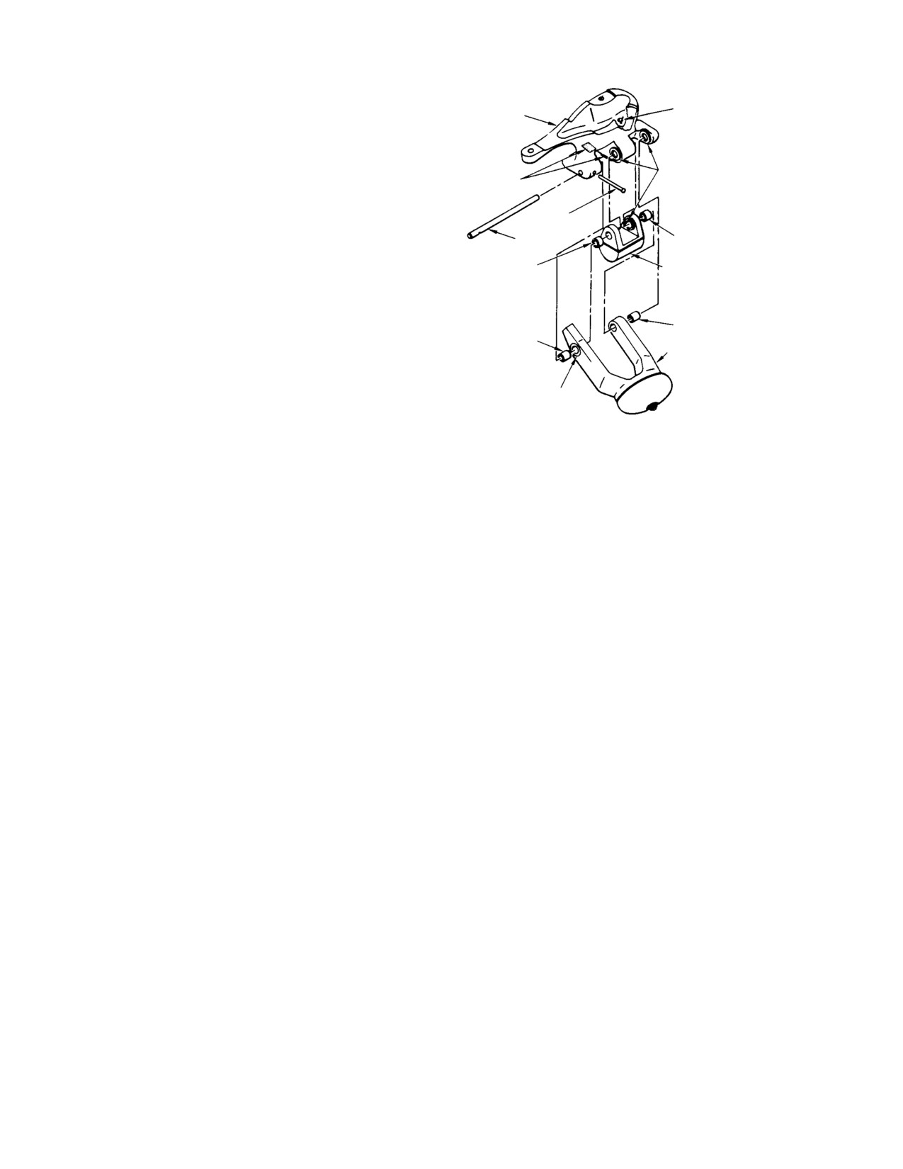
Figure 7-12. Main Rotor Blade and Damper
(1). Remove adjusting nut and remove
Attach Pin
adjustable bushings, spacer and thrust
washers from pin.
17. Main Rotor Blade and Damper Attach Pin
Adjustment
(2). Using brush and clean cloth, clean
(Ref. Figure 7−3)
parts with isopropyl alcohol (71,
Table 2−4). Dry with clean cloth.
NOTE: Whenever a new attach pin is installed,
a main rotor blade is replaced, or the rotor
(3). Inspect pins as follows:
hub assembly is replaced, adjustment is re−
quired to ensure that the pin(s) properly
(a). Fluorescent inspect pin per MIL−
seize in the mating holes.
STD−6866.
(1). Check the main rotor blade and damper
(b). Magnetic particle inspection; thrust
arm attach pins for cracks, wear and
washers, bushings and spacers per
corrosion.
MIL−STD−1949.
(2). Support the blade tip to establish
(4). Reassemble pin in sequence as follows;
alignment of the holes in the blade root
install thrust washer, three (3) adjust−
fittings and lead−lag links; Install pin.
able bushings, spacer, three (3) adjust−
able bushings, spacer, three (3) adjust−
NOTE: After final adjustment of main rotor
able bushings, thrust washer and
blade and damper attach pins, thread pro−
secure with adjusting nut.
trusion from adjuster nut of 1/2 to 1 thread
is acceptable if attach pin safety latch is se−
(5). Lubricate mating surfaces of barrel nut
curely latched over the adjuster nut.
and cam handle with corrosion preven−
tive oil (104).
(3). Adjust the pin for correct seizure by
turning the small hex nut at end of pin
(6). Reinstall and adjust pin.
until 25 − 35 pounds (111 − 156 N)
Page 7-32
Revision 16
MD Helicopters, Inc.
CSP−H−2
500 Series - Basic HMI
hand pressure is required to snap the
(1). Visually inspect exposed portion of all
safety latch into place over the nut.
installed main rotor blade upper and
lower root fitting attach lugs, and main
NOTE: After adjustment, the installed length
rotor hub lead−lag link attach lugs for
of the pins, measured from the face of the
broken or cracked lugs, corrosion or
thrust washer to the outer edge of last bush−
other damage to the lug areas.
ing,
should be
0.99−1.04 inch
NOTE: If movement is suspected but cannot be
(25.146− 26.416 mm) for damper pins and
verified with the blades installed, remove
2.84− 2.89 inches (72.136− 73.406 mm) for
those blades and inspect bushings for move−
main rotor blade pins.
ment.
(4). For final installation, the locking levers
(2). Using a bright light, inspect slippage
of the two blade root fitting pins should
marks on the root fitting bushings to
be located inboard of (behind) the stop
ensure there has been no movement of
springs of the pitch housing lead−lag
the bushings.
links.
(a). If bushings have moved, replace
main rotor blade before next flight.
18. Main Rotor Blade Forward Tip Cap
Inspection and Corrosion Prevention
(b). Return those main rotor blades
where bushing movement has
(1). Inspect tip caps for evidence of corro−
occurred to MDHI for possible
sion, pay particular attention to mating
rework.
area of blade skin to tip weight inter−
face, verify integrity of sealant coating.
CAUTION
(2). If damage is evident, remove tip caps
D If broken or cracked lugs are noted in
and apply penetrating oil to blade tip
main rotor blade upper or lower root fit−
weight area. The oil will arrests any
tings, replace main rotor blade before fur−
corrosion between blade skin and
ther flight.
weight assembly.
D If broken or cracked lugs are noted in
main rotor lead−lag links, replace main
(3). Using brush and clean cloth, clean area
rotor hub.
with isopropyl alcohol (71, Table 2−4).
Dry with clean cloth.
D If cracking is suspected in either the rotor
blade or hub lead− lag link attach lugs,
(4). Spray area with light film of rust
perform dye penetrant (178, Table 2−4)
inhibitor (101); then apply thin film of
inspection of lugs per MIL− I− 25135. If
primer and paint lightly as required.
cracking is noted, replace main rotor
blade, or, replace or repair main rotor hub
19. Main Rotor Blade Upper and Lower Root
assembly, before further flight.
Fitting Attach Lug and Lead-Lag Link
NOTE: Lead−Lag link assemblies may only be
Inspection (25 Hour)
replaced by MDHI authorized personnel or
under MDHI supervision. Contact your local
(Ref. Figure 7−13 and Figure 7−14) The
MDHI Field Service Representative for fur−
following procedure pertains to helicopters
ther information.
equipped with 369A1100−501 thru −505 main
rotor blades and/or 369A1234, 369H1203−BSC
20. Main Rotor Blade Upper and Lower Root
thru −31 lead−lag link assemblies.
Fitting, Attach Lug and Lead-Lag Link
Inspection (100 Hour)
NOTE: Main rotor blades and hub assemblies
installed on helicopters operating in a salt
(Ref. Figure 7−13 and Figure 7−14) The
water or corrosive environment should be
following procedure pertains to helicopters
cleaned and washed on a daily basis as a
equipped with 369A1100−501 thru −511 and
preventative measure to arrest corrosion
369D21123−501 main rotor blades and/or
(Ref. Sec. 2, Main Rotor Hub Corrosion Pre−
369A1234, 369H1203−BSC thru −31 lead−lag
vention (Tri−Flow Wash Procedures)).
link assemblies.
Page 7-33
Revision 17
MD Helicopters, Inc.
CSP−H−2
500 Series - Basic HMI
(1). Remove affected main rotor blades.
(b). Insert a 0.004 inch (0.102 mm) thick
piece of mylar/viewfoil between the
fitting and the doubler.
CAUTION
(c). If the mylar can be inserted, contact
D If broken or cracked lugs are noted in
Field Service Representative for
main rotor blade upper or lower root fit−
disposition of blade.
tings, replace main rotor blade before fur−
ther flight.
(d). If the insertion is 0.10 inch (2.540
D If broken or cracked lugs are noted in
mm) or greater, remove blade from
main rotor lead−lag links, replace main
service.
rotor hub.
NOTE: Measurement of the insertion is from
D If cracking is suspected in either the rotor
the edge of the root fitting.
blade or hub lead− lag link attach lugs,
perform dye penetrant (178, Table 2−4)
(e). Retorque root fitting outboard bolt to
inspection of lugs per MIL− I− 25135. If
60 − 65 inch−pounds (6.78 − 7.34
cracking is noted, replace main rotor
Nm) plus drag torque.
blade, or, replace or repair main rotor hub
assembly, before further flight.
NOTE: Lead−Lag link assemblies may only be
replaced by MDHI authorized personnel or
NOTE: Do not remove bushings or corrosion in−
under MDHI supervision. Contact your local
hibiting sealer.
Field Service Representative for further in−
formation.
(2). Using a bright light and 5X magnifying
glass, visually inspect the attach lugs of
(4). Inspect lead−lag link blade attach pin
all main rotor blade upper and lower
hole bushings for any indication of
root fitting and main rotor lead−lag
movement of the bushings in the links.
links for broken or cracked lugs,
If any of the bushings have movement,
corrosion or other damage to the lug
replace the link.
areas.
If required, apply a light but
CAUTION
(a). Pay particular attention to area
thorough coat of sealer or zinc−
around attach pin hole bushings in
chromate primer around bushings. Note
the lugs.
that excessive amounts of sealant or zinc−
chromate primer around the bushings are
(b). Pay particular attention to the
not desirable and can unbalance the main
cross−hatched areas.
rotor system.
(c). If slippage marks have already been
(5). If sealing compound (171) is not already
applied, inspect the root fitting for
installed or becomes loose, clean and
any indication of movement of the
seal all junctions between all the steel
bushings; no movement is allowed.
bushings and the main rotor blade root
fitting attach lugs with a film of sealing
(d). Return main rotor blades that have
compound or primer (4) without
root fitting bushing movement to
removing the bushings.
MDHI for possible rework.
(6). For the main rotor blade root fitting
(e). If slippage mark is degraded, reapply
attach lugs, carefully remove sufficient
per steps (6). and (8).
amount of sealant and paint from only
(3). Inspect main rotor blade root fitting for
the bushing in the area where the
missing (no squeeze−out) or cracked
slippage mark is to be applied (if not
adhesive/paint around the periphery of
already done).
the root fitting. If this condition exists,
(7). Using isopropyl alcohol (71), clean the
proceed as follows:
area where the slippage mark is going
(a). Loosen, but do not remove the
to be applied to allow adequate adher−
extreme outboard bolt.
ence of epoxy paint.
Page 7-34
Revision 17
MD Helicopters, Inc.
CSP−H−2
500 Series - Basic HMI
NOTE:
22. Main Rotor Blade Torque Event Inspection
D Locate slippage mark in a position that
(Ref. Figure 7−13)
can be viewed at subsequent inspections
NOTE: This inspection requires the use of a
with main rotor blade installed in the
bright light.
hub. Slippage marks should not be ap−
plied to cross−hatched areas to preclude
(1). Lifting from the outboard end of the
masking possible cracks.
blade, lift blade off the droop stop.
D Insure that slippage mark is applied to
(2). Inspect the bottom−side of the blade as
bushing at upper and lower root fitting in−
follows:
side surfaces.
(a). Inspect the area around the root
D Do not use torque seal.
fitting, doubler and skin for cracks.
(b). Inspect the attach lugs at the bush−
(8). Apply epoxy paint slippage marks to
ings for cracks.
four locations as shown.
(c). Inspect the entire length of the blade
(9). Install main rotor blades.
for cracks.
(d). Lower blade back onto droop stop.
21. Main Rotor Blade Leading Edge Abrasion
Strip Check
(3). With blade resting on the droop stop,
inspect the top−side of the blade as
The leading edge abrasion strip should be
follows:
checked prior to each flight or on every daily
check. The following is a comprehensive
(a). Inspect the area around the root
checklist:
fitting, doubler and skin for cracks.
(b). Inspect the attach lugs at the bush−
(1). Check for any blistering, bubbling or
ings for cracks.
lifting of the abrasion strip; this
indicates a void.
(c). Inspect the entire length of the blade
for cracks.
(a). Voids cannot be closer than 0.50 inch
(4). If any of the above defects are found,
(12.7 mm) to any outside edge of
the main rotor blade is to be rejected
abrasion strip.
and scrapped.
(b). Voids exceeding 1.5 square inch
23. Vibration Absorber
(9.6774 square cm) are unacceptable.
(Ref. Figure 7−15) One vibration absorber is
(c). Voids cannot be closer than one inch
installed on the lower inboard end of each
(25.4 mm) to any other void.
main rotor blade. Each vibration absorber
consists of two pendulums that pivot about a
(2). Number of acceptable voids depends
common axis. These pendulums are tuned to
upon length of abrasion strip.
cancel out the first and second harmonic beats
of the natural vibration frequency of each
(a). There cannot be more than three
individual blade. The largest pendulum
voids on either the top or bottom of
counteracts any 3−per−revolution vibrations;
the 36 inch long (91 cm) abrasion
the smallest pendulum counteracts any
strip surface.
5−per−revolution vibrations.
(b). There cannot be more than two voids
A. Vibration Absorber Removal
on either the top or bottom of the 18
(1). Remove bolt and washer at trailing
inch (46 cm) long abrasion strip
edge of blade; remove shim washer(s) if
surface.
installed.
(3). Record all voids in regards to size and
NOTE: Shim washers are installed between vi−
location in the helicopter log book and
bration absorber and main rotor blade as re−
check each void prior to each flight for
quired to compensate for minor variations
growth and acceptable criteria.
in blade contour.
Page 7-35
Revision 17
MD Helicopters, Inc.
CSP−H−2
500 Series - Basic HMI
(2). Remove two nuts, radius blocks,
that the shorter of the bolts is in the
washers and bolts that attach absorber
outboard hole. Torque bolts to 50 − 60
to blade.
inch−pounds (5.65 − 6.78 Nm).
(3). Remove vibration absorber.
(3). If a gap exists between the trailing edge
of vibration absorber and main rotor
B. Vibration Absorber Installation
blade, shim with washers. If no gap
(1). Apply primer (4, Table 2−4) on the two
exists, install trailing edge bolt and
long bolts.
washer without shim washers. Apply
chromate primer to bolt and install bolt
(2). Align vibration absorber with holes in
and washer while primer is still wet.
main rotor blade. Install two long bolts
and washers while primer is still wet;
(4). Torque bolt to 15 − 20 inch−pounds
then install radius block nuts. Check
(1.69 − 2.26 Nm).
Page 7-36
Revision 17
MD Helicopters, Inc.
CSP−H−2
500 Series - Basic HMI
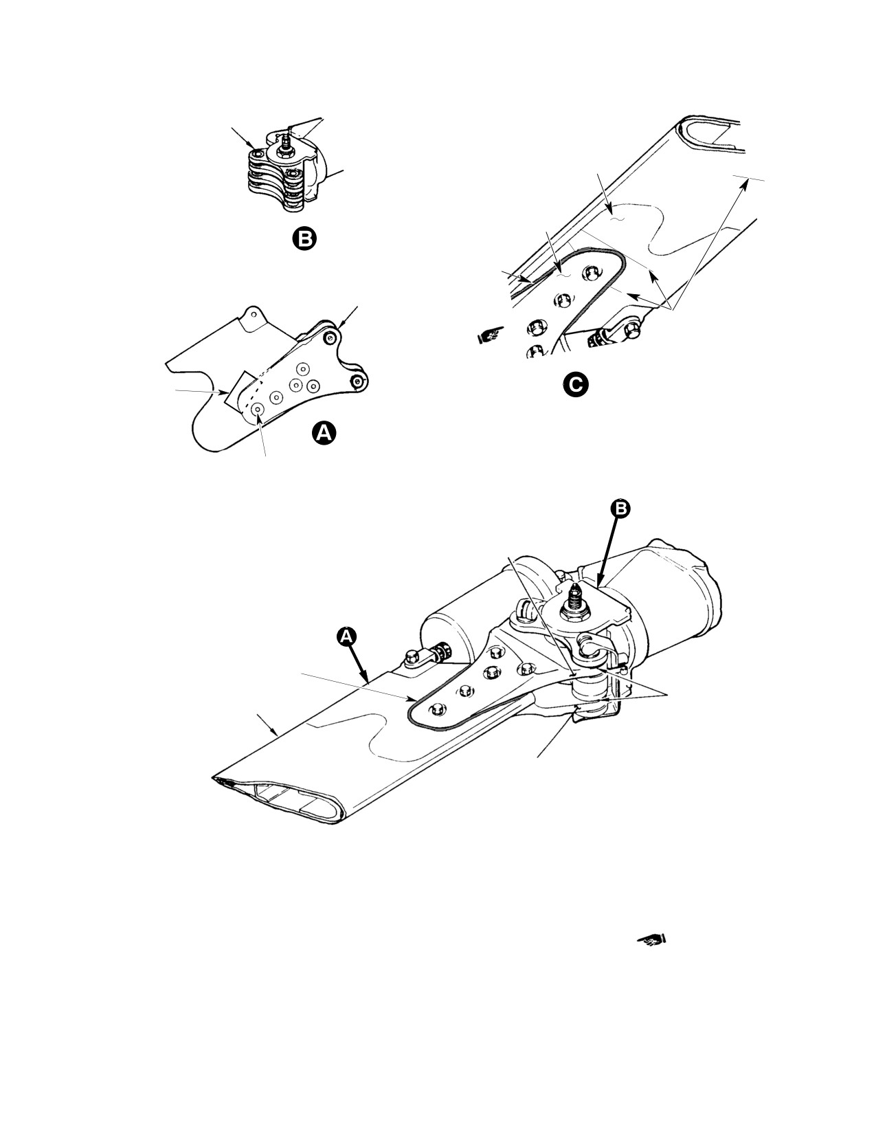
NOTES 2, 3 AND 4
DOUBLER
ROOT FITTING
NOTE 5
NOTES 1, 2 AND 3
USE BRIGHT LIGHT TO INSPECT
FOR CRACKS IN THIS AREA. PAY
PARTICULAR ATTENTION TO
BOTTOM SIDE OF BLADE.
VIEW LOOKING UP
NOTE 5
ROTATED
LOOSEN BUT DO NOT REMOVE BOLT.
RETORQUE BOLT TO 60 − 65 IN−LB
(6.78−7.34 NM) PLUS DRAG TORQUE.
UPPER ROOT FITTING ATTACH LUG
(TYP 2 PLCS) (NOTE 1)
NOTE 5
LEAD−LAG LINK ATTACH LUG
MAIN ROTOR BLADE
(TYP 8 PLCS) (NOTE 1)
LOWER ROOT FITTING
ATTACH LUG
(TYP 2 PLCS) (NOTE 1)
NOTES:
1.
VISUALLY INSPECT AREAS OF ALL ROOT FITTINGS AND LEAD−LAG ATTACH LUGS FOR CRACKS OR
BREAKS. INSPECT BLADE ATTACH BUSHINGS FOR LOOSENESS. IF LOOSE, REPLACE LEAD−LAG LINKS.
2.
PAY PARTICULAR ATTENTION TO AREA AROUND ATTACH PIN HOLES IN LUGS.
3.
SEAL ALL JUNCTIONS BETWEEN BUSHINGS AND ATTACH LUGS WITH SEALER OR PRIMER (4, TABLE 2−4).
4.
LEAD−LAG LINK ASSEMBLIES ARE SUB−ASSEMBLIES OF THE MAIN ROTOR HUB ASSEMBLY.
5.
INSPECT MAIN ROTOR BLADE UPPER AND LOWER ROOT FITTING FOR MISSING OR CRACKED ADHESIVE.
6.
USING BRIGHT LIGHT, INSPECT MAIN ROTOR BLADE DOUBLER FOR CRACKS. PAY PARTICULAR ATTENTION
TO BOTTOM SIDE OF BLADE, JUST BEYOND ROOT FITTING AND IN LINE WITH ROOT FITTING ATTACH BOLTS.
88−347F
Figure 7-13. Main Rotor Blade Root Fitting Attach Lugs and Lead-Lag Link
Assembly Inspection
Page 7-36A/(7-36B blank)
Revision 17
MD Helicopters, Inc.
CSP−H−2
500 Series - Basic HMI
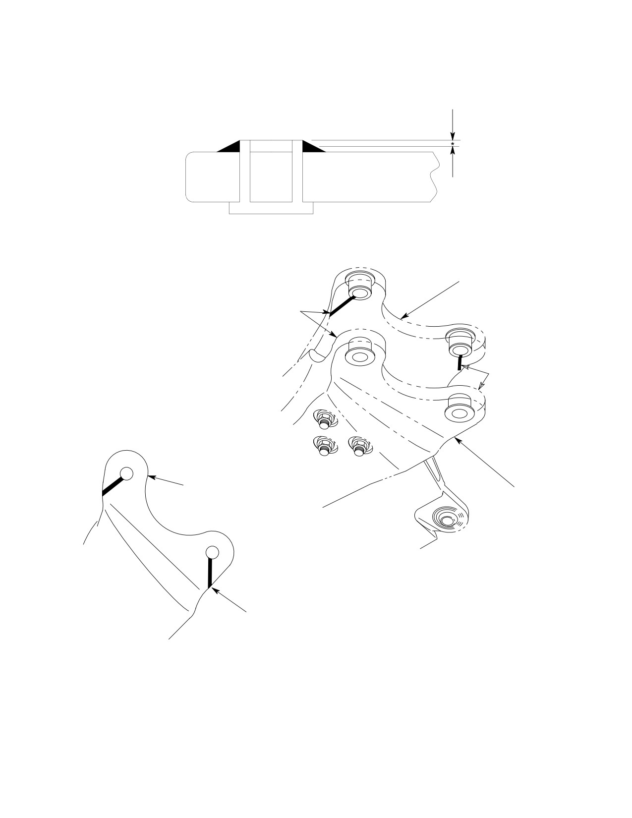
* ONLY REMOVE 1/2 DEPTH OF
CORROSION INHIBITING SEALER
AT LOCATION WHERE SLIPPAGE
MARK IS TO BE APPLIED.
Ç ÇÇ
Ç ÇÇ
Ç ÇÇ
Ç ÇÇ
ÇÇÇÇÇÇ
ÇÇÇÇÇÇ
UPPER ROOT FITTING
SLIPPAGE MARK LOCATIONS
SLIPPAGE MARK LOCATIONS
Î
(INSIDE SURFACES)
Î
ÎÎÎÎ
ÎÎÎÎ
DO NOT APPLY SLIPPAGE MARK
ÎÎÎÎ
TO CROSS−HATCH AREAS
LOWER ROOT FITTING
Î
ÎÎÎ
ÎÎÎ
ÎÎ
VIEW LOOKING UP
ÎÎ
SLIPPAGE MARK LOCATIONS
(LAG SIDE SHOWN)
(LEAD SIDE OPPOSITE)
UPPER AND LOWER
88−675
Figure 7-14. Application of Slippage Mark to Main Rotor Blade Bushings and Root Fittings
Page 7-37
Revision 16
MD Helicopters, Inc.
CSP−H−2
500 Series - Basic HMI
C. Vibration Absorber Inspection
DRAIN HOLE
BRACKET
(1). Inspect bracket for presence of ballast
weights. Evidence of lost ballast will
require weighing of complete vibration
THRUST WASHERS
absorber (Ref. Vibration Absorber
PADS
Weighing).
RIVET
(2). Refer to Main Rotor Blade Inspection
SHAFT
BEARING
for installed absorber inspection
requirements.
5−PER REVOLUTION
BEARING
PENDULUM
D. Vibration Absorber Disassembly
(1). Remove rivet that secures pivot shaft to
BEARING
BEARING
bracket.
3−PER REVOLUTION
PENDULUM
(2). Remove pivot shaft by inserting a pin
through the hole in the forward end of
THRUST WASHER
the bracket and pushing shaft out of
bracket.
Figure 7-15. Vibration Absorber
(3). Remove 5−per−revolution pendulum
(2). Using adhesive (19, Table 2−4), install
and 3−per−revolution pendulum.
new or rebond loosened thrust washers
to bracket or pendulums. Follow
(4). Do not remove shaft bearings or thrust
container instructions for adhesive
washers unless replacement is neces−
application.
sary.
(3). Using sealing compound (3), install new
(5). Use dry, low pressure compressed air to
or rebond loosened 3−per−revolution
blow out bearing bores and drain hole
and 5−per−resolution pads to bracket.
in bracket.
Follow container instructions for
compound application. After bonding,
(6). Inspect bores of bearings for evidence of
seal the edges of the pad with sealing
galling, scoring and wear. Maximum
compound. Ensure that center hole in
allowable bore dimension is 0.268 inch
pad at 5−per−resolution location does
(6.8072 mm).
not block the drain hole through the
bracket.
(7). Inspect shaft for distortion and wear.
F. Vibration Absorber Reassembly
E. Vibration Absorber Repair
NOTE: During reassembly, do not allow chro−
mate primer to get on to the shaft bearings.
Repair of the vibration absorber is limited to
disassembly and replacement of pivot shaft
(1). Using primer (4, Table 2−4), coat cavity
bearings, thrust washers and rubber pads on
in bracket where undrilled end of shaft
the bracket. The pendulum weights may be
will seat.
inter−changed subject to total weight restric−
tions (Ref. Vibration Absorber Weighing). The
(2). Align bores of pendulums with bracket.
weight shims must not be altered because the
(3). Install shaft so that rivet hole in shaft
weights and the assembly have been tuned.
aligns with matching hole in bracket
The absorber bracket may be either an
while primer is still wet.
aluminum or magnesium casting. Refer to
Section 2 for corrosion control and identifica−
(4). Install new rivet and flush the shop
tion of magnesium and aluminum alloys.
formed end.
(1). Use press to remove and install new
(5). Coat open hole in bracket with primer.
pivot bearing into pendulums.
Check that the pendulums rotate freely
Page 7-38
Revision 16
MD Helicopters, Inc.
CSP−H−2
500 Series - Basic HMI
on shaft, without binding, and that the
25. Main Rotor Hub Assembly Replacement
shaft is free of primer.
(Ref. Figure 7−16)
G. Vibration Absorber Weighing
A. Main Rotor Hub Assembly Removal
Vibration absorbers may have either an
(1). Remove four main rotor blades.
aluminum or magnesium bracket as part of
the assembly. The total weight of an assembled
(2). Remove main rotor drive shaft; then
magnesium absorber is 1360 grams ±0.1 gram
reinstall hoisting eyebolts, washers and
when installed in sets of four. The total weight
nuts in rotor hub.
of an assembled aluminum vibration absorber
(3). Remove lockwire and disconnect
is 1405−1425 grams maximum. Absorbers may
flexible boot from lower end of hub
be mixed in a ship set if additional weight is
liner.
added to magnesium absorber(s) to obtain the
equivalent aluminum damper total weight
(4). Disconnect scissors crank from main
(1405−1425 gram). Paint an identifying yellow
rotor hub or scissors link (Ref.
band on a magnesium bracket lug if so
Figure 7−24).
modified.
(5). Disconnect each pitch change rod from
(1). Add lead weights (lead shot or equiva−
pitch housing.
lent) as required to establish total
NOTE: Color code each pitch change rod to
weight of 1360 grams ±0.1 gram
match the pitch housing and blade to which
(magnesium absorber) or 1405−1425
it is attached, so that the main rotor can be
grams (aluminum absorber).
reinstalled in the same position from which
removed.
(2). Bond lead weight into recess cut area of
bracket with adhesive (24, Table 2−4).
(6). Cut lockwire and removed two screws
securing retainer to main rotor hub nut
24. Main Rotor Hub Assembly
(Ref. Figure 7−17).
(Ref. Figure 7−16) The main rotor hub
(7). Remove nut retainer.
assembly consist of a hub and four identical
(8). Using main rotor mast nut wrench (19,
pitch housing assemblies that are 90° apart
Table 2−2), remove nut from mast.
and slightly offset. Lead−lag links, a blade
damper and damper arm, a droop stop striker
NOTE: On mast having nut without safety−
strip and spacer, and a pitch control bearing
wired dual screw installation, main rotor
assembly are combined with each pitch
mast nut wrench (20), may be used.
housing to produce the pivoting axis, blade
flapping stop contact surfaces and lead−lag
(9). Using hub puller (22), break loose main
hinge for the rotor blades. Two laminated
rotor hub. (Ref. Figure 7−18). Remove
retention strap assemblies that are both
hub puller. Then remove main rotor
vertically and torsionally flexible extend
hub, using suitable hoisting adapter
through the pitch housings and connect to the
attached to eyebolts in hub.
lead−lag links. A lower shoe assembly attached
B. Main Rotor Hub Assembly Installation
to the central hub contains, a droop stop ring
and droop restrainers that support the blades
NOTE:
at rest and distribute droop loads at low blade
D Removal of the recessed spacer, upper
rpm.
bearing cone, upper seal and seal retainer
is not mandatory for installation of the
NOTE: MDHI HN− 11 defines mast modifica−
main rotor hub. If these items are in−
tion and replacement requirements for non−
stalled, perform steps (1). thru (4). and
lockwired main rotor hub nut and retainer
steps (11). thru (18). Caution should be
with safetywired dual screw retainer and
used when installing the hub to prevent
nut. Note also that prebalanced hub assem−
damage to these parts.
blies may have balancing hardware in−
stalled in the hollow cores of the lead−lad
D If recessed spacer, upper bearing cone,
bolts.
upper seal and seal retainer have been re−
Page 7-39
Revision 19
MD Helicopters, Inc.
CSP−H−2
500 Series - Basic HMI
moved, these parts should not be as−
(7). Install recessed washer, upper bearing
sembled in hub before installation of hub
cone, upper seal, and seal retainer in
on helicopter. These items are reas−
hub and lubricate components as
sembled in hub after seating hub on mast.
follows:
Prior to installing the main rotor hub, in−
(a).
Hand−pack hub cavity, between
sure that all bearings are adequately
sleeve bushing and hub, with grease
serviced with grease (21, Table 2−4).
(21, Table 2−4).
(1). Inspect for interference between
(b).
Place recessed washer, recess down,
damper housings and pitch housings. If
on top of sleeve bushing.
less than 0.002 inch (0.051 mm) gap
exists between the housings, rework
(c).
Hand−pack upper bearing cup and
area as required in step (2). below prior
cone with grease; then install cone in
to hub installation.
cup and use hub driver tool to fully
seat cone.
(2). Remove main rotor damper. Rework
pitch housing by smooth blending into
(d).
Fill remaining cavity up to level of
the surrounding area with grade 320
upper seal with grease.
abrasive cloth (20). Finish polish to
(e).
Position upper seal, with lip up, and
restore original finish with crocus cloth
press in hub counterbore.
(23). Maximum rework depth is limited
to 0.010 inch (0.254 mm). Clean
(f).
Using light mallet, carefully tap seal
reworked area with MEK (22), prime
to seat in counterbore. Wipe away
with primer (4) and repaint (Ref. Sec.
any excess grease.
2).
(g).
Install seal retainer, recess up, and
NOTE: The main rotor hub is a highly stressed
seat it against the top surface of the
component. Use extreme care to prevent if
upper bearing cone.
from striking any object. Any impact dam−
(h).
Apply grease (21) to exposed threads
age may require replacement of the hub.
on mast.
(3). Attach hoisting adapter to eyebolts in
Refer to CSP− H− 5 for a re−
main rotor hub and connect a suitable
WARNING
quired modification of the
hoist.
mast and replacement of the mast nut
and lockwasher with a lockwired dual
NOTE: If the hub assembly (with sleeve bush−
screw retainer and nut.
ing, spacer, upper bearing and seal retainer
installed) does not seat properly onto the
NOTE:
mast, do not attempt to force it into position.
D Ensure seal is properly positioned against
Remove hub assembly from mast and deter−
seal retainer and that seal retainer does
mine cause of hub not seating, correct the
not pinch seal. Check by inserting a loop
problem and follow the procedures for in−
of approximately 0.040 inch (1.016 mm)
stallation.
lockwire, round feeler gage or other suit−
able tool without sharp edges between
(4). Check; that rotor mast is clean. Hoist
seal lip and retainer.
main rotor hub and position over the
mast then lower hub onto mast.
D To insure that hub is seated onto the mast
properly before torquing, 2− 4 threads
NOTE: To inhibit mast corrosion when operat−
should be showing above the mast nut
ing in salt water environment, lightly coat
with nut installed finger tight.
bearing journals of mast with grease (21).
(8). Install mast nut using wrench (19,
(5). Remove adapter, hoist and eyebolts.
Table 2−2); torque nut to 200 foot−
pounds (271 Nm). Apply a coat of
(6). Use main rotor hub driver tool (24,
corrosion preventive compound (70,
Table 2−2) to ensure that main rotor
Table 2−4) to the screw holes in the
hub is fully seated on mast.
mast nut.
Page 7-40
Revision 16
MD Helicopters, Inc.
CSP−H−2
500 Series - Basic HMI
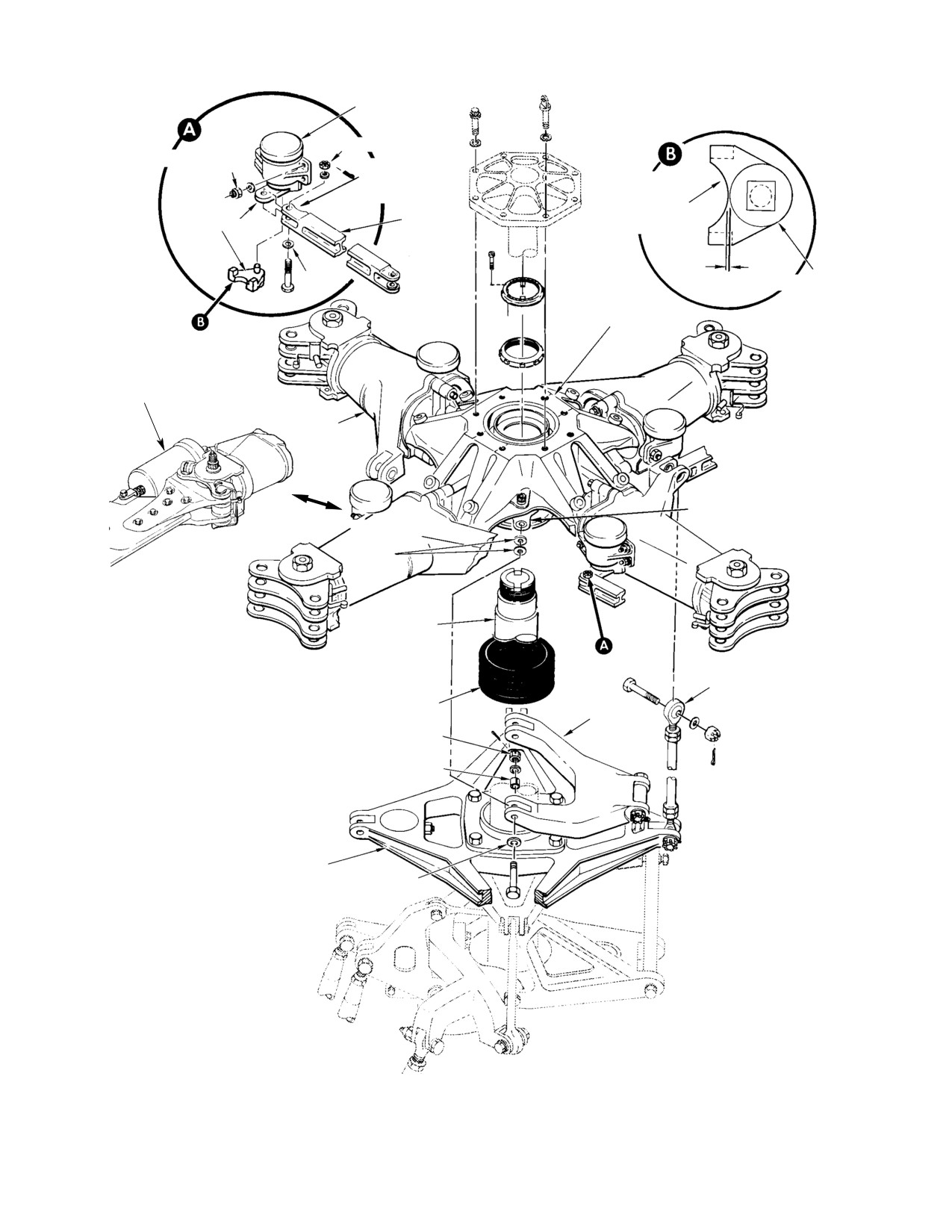
MAIN ROTOR
DAMPER
30−60 IN. LB (3.39−6.78 NM)
50−70 IN. LB
(5.65−7.91 NM)
INSTALL WITH
TORQUE
CUTOUT AREA
ROTATED
INBOARD
WRENCH
0.690 IN. (17.526 MM)
ADAPTER
DAMPER
DAMPER
R (NOTE 2)
(369A9949)
ARM LINK
ARM
0.030 IN.
NOTE 3
(0.762 MM)
369A9949
ADAPTER
MAIN ROTOR
HUB
ELASTOMERIC
DAMPER
PITCH
HOUSING
ASSY
LOWER SHOE
SHIMS/SHIM
MODIFIED CONFIGURATION
WASHERS
(NOTE 5)
MAIN ROTOR
MAST
CURRENT CONFIGURATION
PITCH CONTROL ROD
FLEXIBLE BOOT
SCISSORS
CRANK
30−60 IN. LB
(3.39−6.78 NM)
NOTE 1
NOTES:
1.
EDGE OF BUSHING MUST
PROTRUDE A MIN. OF 0.010 IN.
(0.254 MM) TO A MAX. OF 0.060 IN.
(1.524 MM) ABOVE OUTSIDE
ROTATING
SURFACE OF PART AFTER NUT
SWASHPLATE
NOTE 4
IS TIGHTENED.
2.
RECESS NOT PRESENT ON ALL
ADAPTERS.
3.
ADD WASHERS UNDER HEAD
AS REQUIRED FOR CLEARANCE
BETWEEN BOLT END AND
DAMPER HOUSING.
4.
ADD WASHER(S) AS REQD FOR
BOLT END−TO−SWASHPLATE
BOOT CLEARANCE.
5.
USE SHIMS/SHIM WASHERS TO
FILL GAP.
30−038B
Figure 7-16. Main Rotor Hub Installation
Page 7-41
Revision 16
MD Helicopters, Inc.
CSP−H−2
500 Series - Basic HMI
CURRENT
CONFIGURATION
RETAINER
RETAINER
SCREW
LOCKNUT
(NOTE 3)
LOCKWIRE
MAST
DRIVE SHAFT
MAIN ROTOR MAST
SCREW
0.050 IN. (1.27 MM) MAX SCREW
LOCKWASHER
HEAD HEIGHT ABOVE HUB
RETAINER
EARLY
CONFIGURATION
MAST
(NOTE 1)
SEAL
SEAL RETAINER
MAST NUT
MAIN ROTOR HUB
LOCKWASHER
SEAL RETAINER
MAIN ROTOR
MAST
MAST
NOTE 2
MAST NUT
200−250 FT LB
(271−339 NM)
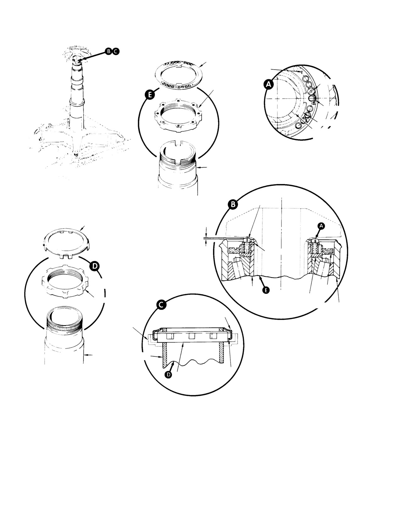
NOTES:
1.
MANDATORY MOD TO THIS CONFIGURATION: REFER TO TEXT.
2.
RELIEVED EDGE OF NUT MUST BE DOWN.
3.
IF LOCKNUT AND RETAINER SCREW HOLES WILL NOT MATCH WITHIN
THE 200−250 FT LB (271−339 NM) RANGE, INVERT LOCKNUT.
30−156B
Figure 7-17. Main Rotor Mast Locknut Installation
Page 7-42
Revision 16
MD Helicopters, Inc.
CSP−H−2
500 Series - Basic HMI
SLEEVE BUSHING
ROTOR HUB OUTER LINER
SEAL
FRAME JAW CONTACT
POINT (EACH SIDE)
THRUST PAD
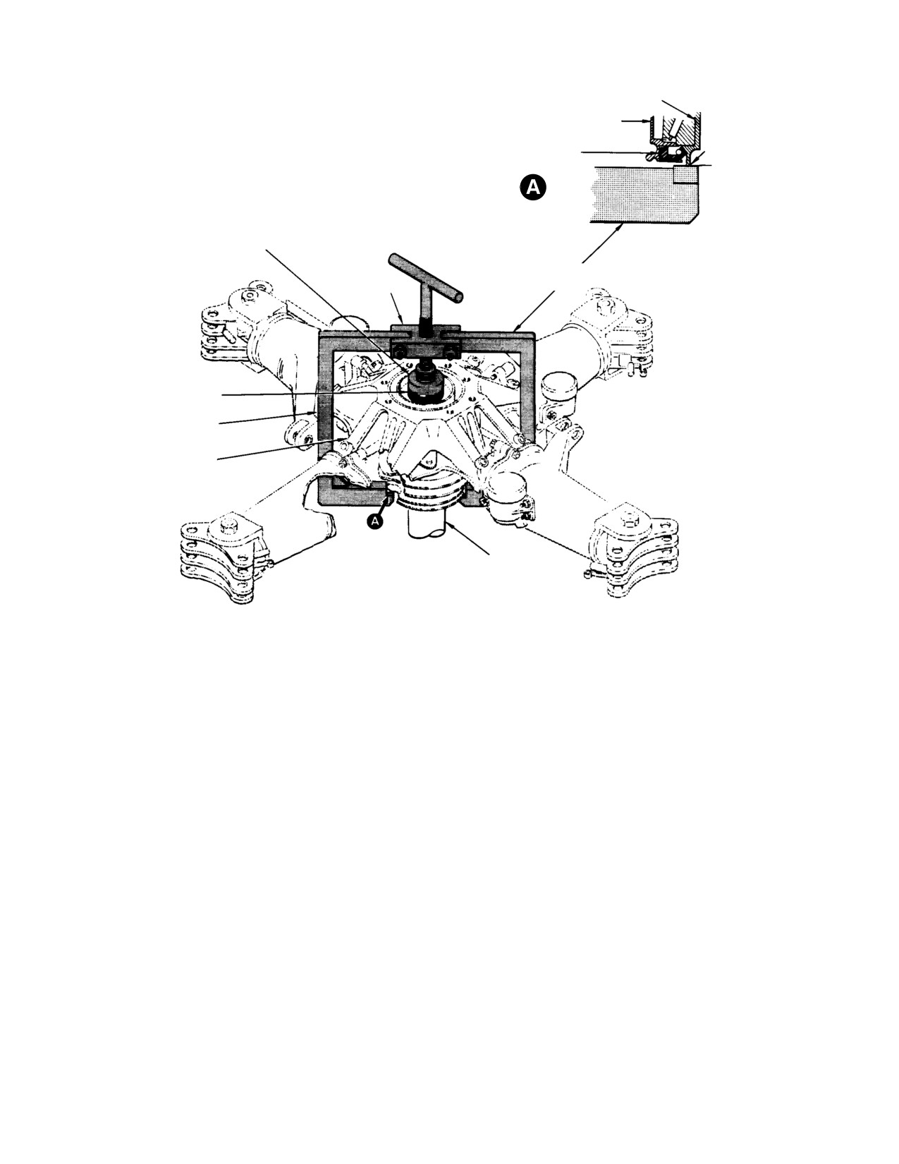
MAIN ROTOR PULLER
PULLER NUT
369A9932
ROTOR MAST
FRAME
ROTOR HUB
ROTOR MAST
30−040A
Figure 7-18. Pulling Hub Assembly
NOTE: If wrench (19, Table 2−2) is not avail−
NOTE: Be sure that no washers are used under
able, wrench (20) may be modified for use on
screwheads and that screwheads are free of
nut by hand−filing and increasing slot
burrs.
widths symmetrically to 0.343 ±0.007 inch
(8.7122 ±0.178) mm).
(12). Verify that screwheads do not project
more than 0.050 inch (1.270 mm) above
hub upper surface for adequate clear−
(9). Place retainer on nut and check
ance between screwheads and drive−
retainer to nut screw hole alignment.
shaft flange underside.
(10). Increase nut torque to not more than
(a). Place straight edge across hub upper
250 foot−pounds (339 Nm) to align
surface and extend straightedge to
holes in retainer and nut.
screw to make the check.
(13). Install four pitch change rods to pitch
NOTE: If holes cannot be aligned in the 200 −
housing.
250 foot− pound (271 − 339 Nm) torque
range, remove and invert the nut and repeat
NOTE: Be sure pitch change rods are rein−
procedures in Steps (8). thru (10). to align
stalled in the same position from which re−
holes.
moved.
(11). Secure retainer to nut with two screws
(14). Connect scissors crank to main rotor
and lockwire the screws.
hub lower shoe and/or to scissors link.
Page 7-43
Revision 19
MD Helicopters, Inc.
CSP−H−2
500 Series - Basic HMI
(15). Connect flexible boot to lower end of
found, repair or replacement droop stop
rotor hub liner and secure with lock−
ring.
wire (2, Table 2−4).
NOTE: To inhibit corrosion, spray droop stop
(16). Install main rotor driveshaft (Ref. Sec.
ring, rollers and pitch bearings with rust in−
19).
hibitor (101, Table 2−4).
(4). Inspect droop stop roller for flat spots,
(17). Install four main rotor blades.
pit marks and looseness on roller shaft.
(18). Perform main rotor blade droop angle
(5). Inspect striker plate for dents (brinel−
check if rotor hub is new or a replace−
ling) and pit marks that exceed 0.030
ment.
inch (0.762 mm) depth. Damage
exceeding this limit requires replace−
26. Main Rotor Hub Assembly Inspection
ment of striker plate.
(Ref. Figure 7−19)
(6). Press each pitch housing downward
several times and check for evidence of
(1). Inspect pitch housing for scratches,
a binding pitch bearing or droop
nicks and cracks.
restrainer follower.
(a). No cracks are permissible.
(7). Inspect visible portion of droop re−
strainer for cracks and the follower
(b). Scratches and nicks must be cleaned
spring for breaks.
up before measuring the depth of the
damage to determine housing ser−
NOTE: Do not remove tetrafluoroethylene
viceability.
(TFE) debris which works out of pitch bear−
ing edge. The debris is normal and helps lu−
(c). Accomplish repairs or replacement
bricate bearing. Removal of debris will in−
according to Pitch Housing Assembly
crease bearing wear rate.
Repair.
(8). Inspect each of the four main rotor hub
(2). Inspect sleeve bushing for snug fit in
lead−lag link assemblies after removing
pitch housing arm clevis lug; the lug
the bolt or pin attaching damper arm to
must not show evidence of wear caused
main rotor blade and blade attach pins.
by bushing movement.
Rotate blade about lead blade attach
pin and visually inspect for signs of
(a). Maximum allowable diameter for the
cracking around the blade pin hole in
bushed lug is 0.5004 inch (12.71016
the lug of the lag portion.
mm); for unbushed lug, not more
than 0.1320 inch (3.3528 mm).
(9). Use a bright light and 5X magnifying
glass to inspect all main rotor hub
(b). Inspect inner surfaces of all pitch
assembly lead−lag links for discolor−
housing arm clevis lugs for chafing
ation, pitting, intergranular cracks or
caused by misaligned pitch control
stress corrosion cracks.
rod end bearings.
(a). Any discoloration or pitting is
(c). Chafing will be in the form of cres−
evidence of more than superficial
cent−shaped grooves.
corrosion and the main rotor hub
must be removed for replacement of
(d). If chafing wear is found, accomplish
lead−lag links.
repair or replacement (Ref. Pitch
Housing Assembly Repair).
(b). Otherwise reinstall lag blade attach
pin and damper attach pin or bolt. As
(e). The chafed area must be cleaned up
applicable, torque nut to 30 − 60
before measuring the depth of the
inch−pounds (3.39 − 6.78 Nm);
damage to determine housing ser−
install cotter pin.
viceability.
NOTE:
Normal or premature overhaul requires
(3). Inspect the droop stop ring for corro−
visual inspection plus dye−penetrant inspec−
sion, dents and scratches. If defects are
tion of the links for the same conditions.
Page 7-44
Revision 19
MD Helicopters, Inc.
CSP−H−2
500 Series - Basic HMI
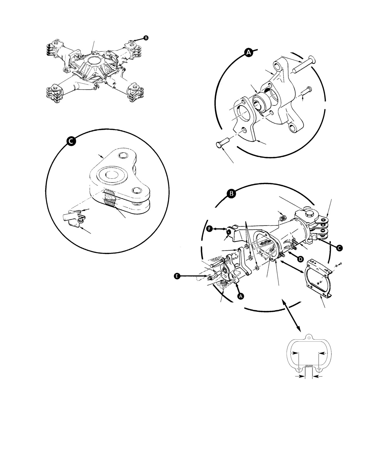
HUB
MS20427M5 RIVET
(NOTE 1)
HOUSING
PITCH BEARING
MS20615−5M RIVET
(NOTE 2)
STRIKER PLATE
LEAD−LAG LINK
MS20427M5 RIVET
(NOTE 3)
LEAD−LAG
LEAD−LAG BOLT
LINKS
NOTE 5
50−70 IN. LB
NOTE 7
(5.65−7.91 NM)
DROOP SHIM WASHERS
NOTE 8
(NOTE 4)
LEAD−LAG STOP
SLEEVE BUSHING
SPACER
PITCH
HOUSING
PIVOT PIN
MAIN ROTOR
PITCH CONTROL
STRAP PACK
BEARING HOUSING
ONE−PIECE
ASSEMBLY
STRIKER STRIP
MAIN ROTOR
STRAP PACK
TWO−PIECE
STRIKER STRIP
NOTES:
1.
COUNTERSUNK RIVET HEAD MUST BE FLUSH WITH HOUSING. IF STRIKER PLATE IS
COUNTERSUNK, COUNTERSUNK HEAD MUST BE FLUSH WITH PLATE.
2.
SHOP−FORMED HEAD MUST BE FLUSH WITH PLATE.
3.
COUNTERSUNK RIVET HEAD MUST BE FLUSH WITH PLATE IN ALTERNATE RIVET INSTALLATION.
2.50 IN.
4.
CAUTION: WASHERS ARE INSTALLED BETWEEN SPACER AND STRIKER STRIP TO ESTABLISH
(6.35 MM)
CORRECT STATIC DROOP ANGLE BETWEEN HOUSING AND HUB. ENSURE THAT THE EXACT
NUMBER REMOVED ARE REINSTALLED. THE THREE PITCH BEARING HOUSING BOLTS MUST
EACH HAVE THE SAME NUMBER (THICKNESS) OF WASHERS WHEN SHIMMING IS NECESSARY.
0.25−0.50 IN.
5.
SHOWN EXPLODED ONLY FOR CLARITY.
(6.35−12.7 MM)
6.
CUT OUT 0.25−0.50 IN. (6.35−12.7 MM) PIECE OF THE STRIKER STRIP BETWEEN LOWER
(NOTE 6)
BOLT HOLES. DEBURR AND RADIUS CUT EDGES.
ONE−PIECE STRIKER STRIP
CAUTION: DO NOT SCRATCH STRAP PACK WHEN INSTALLING THROUGH STRAP ASSEMBLY.
INSTALLATION MODIFICATION
7.
FOR STOP REMOVAL, PLACE WOOD DOWEL HERE, STRIKE SHARPLY WITH HAMMER TO
BREAK STOP BOND.
8.
BOND ALL STOP−TO−LINK SHADED CONTACT SURFACES WITH ADHESIVE (90, TABLE 2−4).
30−041−1D
Figure 7-19. Repair of Main Rotor Hub Components (Sheet 1 of 3)
Page 7-45
Revision 16
MD Helicopters, Inc.
CSP−H−2
500 Series - Basic HMI
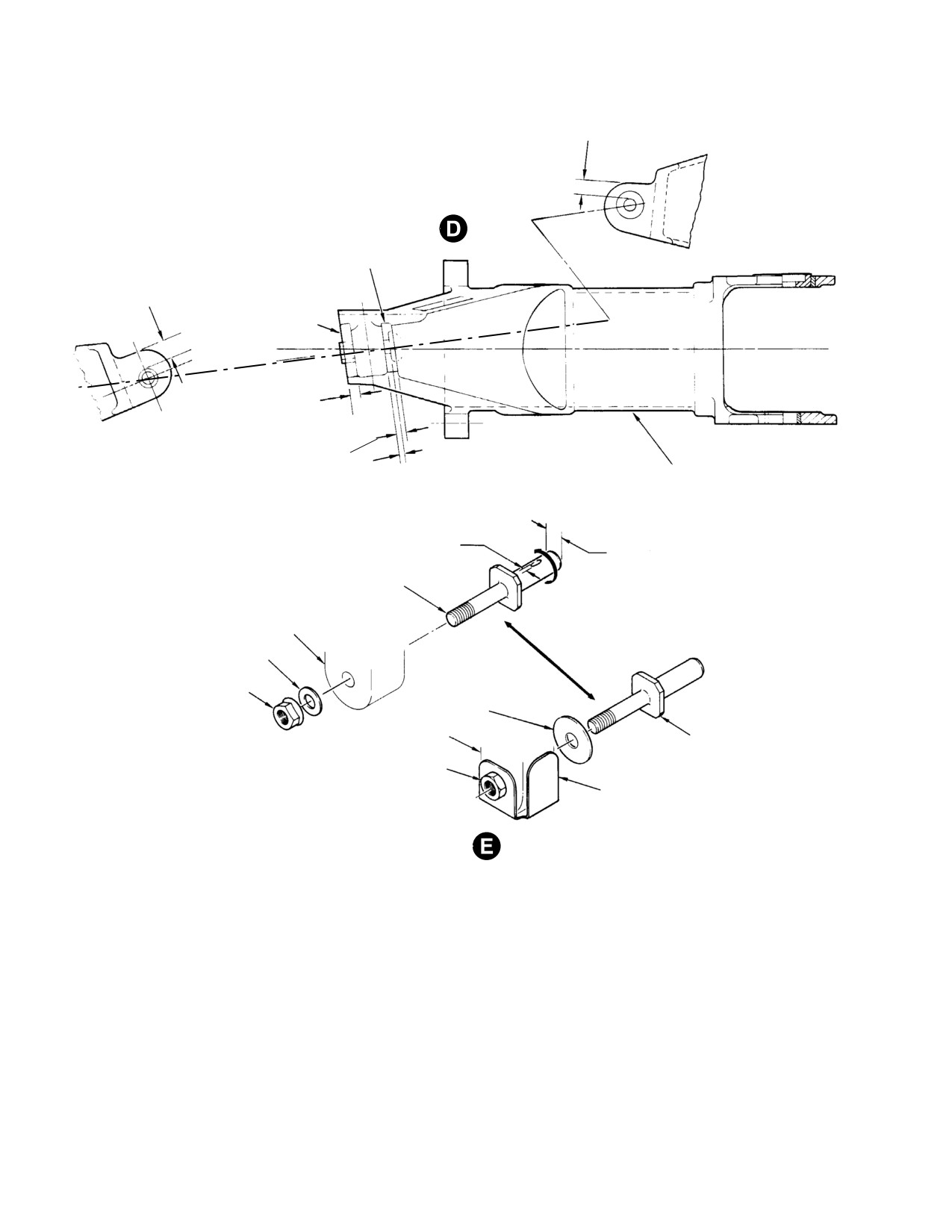
0.360 IN. (9.144 MM) MIN. WALL
THICKNESS AROUND LUG
(NOTE 15)
OUTBOARD LUG
0.250 IN. (6.35 MM) MIN. WALL
OUTBOARD LUG
THICKNESS AROUND LUG
(NOTE 15)
INBOARD LUG
0.220 IN. (5.588 MM) MIN.
WALL THICKNESS
AROUND LUG
(NOTE 15)
INBOARD LUG
0.146 IN. (3.7084 MM) MIN.
0.200 IN. (5.08 MM) MIN.
LUG THICKNESS
LUG THICKNESS
MAIN ROTOR HUB PITCH
(NOTE 15)
(NOTE 15)
HOUSING ASSEMBLY
0.125 IN. (3.175 MM) MAX.
0.4328 IN. (10.99312 MM) MIN.
PITCH PIVOT PIN
200−220 IN. LB
90% CIRCUMFERENCE OF 0.4328 IN.
(22.60−24.86 NM)
(10.99312 MM) MIN. DIAMETER MUST
(NOTES 9, 11)
BE UNDAMAGED
HUB
NOTE 14
NON−CAPTIVE NUT
SPECIAL WASHER
(NOTE 10)
HUB
NOTE 13
CAPTIVE NUT
NUT RETAINING BRACKET
(NOTE 12)
NOTES: (CONT)
9.
LIGHTLY LUBRICATE THE THREADED SHANK WITH GREASE
12. THE NUT RETAINING BRACKET IS BONDED TO CURRENT
(18, TABLE 2−4) BEFORE INSTALLATION.
TYPE HUB AND IS REPLACEABLE AT OVERHAUL FACILITY.
10. APPLY WET PRIMER (4 TABLE 2−4) ON WASHER AND MATING
13. CURRENT TYPE PIVOT PIN HAS LETTER ‘‘M’’ ETCHED ON
SURFACES BEFORE INSTALLATION.
OUTER FACE OF FLANGE.
11. TORQUE WITH PITCH BEARING STUD WRENCH 369A9825.
14. DISCARD AT REPLACEMENT OF EARLY TYPE PIVOT PIN.
HOLD NON−CAPTIVE NUT WITH PITCH BEARING STUD WRENCH
SPECIAL WASHER REQUIRED UNDER CURRENT TYPE PIN
369A9826. BEFORE APPLYING THE LAST 20−30 IN. LB (2.26−3.39 NM)
FLANGE FOR INSTALLATION AND TORQUING.
OF REQUIRED TORQUE, USE A 0.002 IN. (0.051 MM) FEELER GAGE
15. MAINTAIN MINIMUM WALL THICKNESS AROUND LUG AND
AND CHECK FOR GAP BETWEEN THE PIN FLANGE AND MOUNTING
MINIMUM LUG THICKNESS FOR FIELD REPAIR OF CLEVIS
LUG SURFACE. NO GAP IS ALLOWED.
LUG.
30−041−2D
Figure 7-19. Repair of Main Rotor Hub Components (Sheet 2 of 3)
Page 7-46
Revision 16
MD Helicopters, Inc.
CSP−H−2
500 Series - Basic HMI
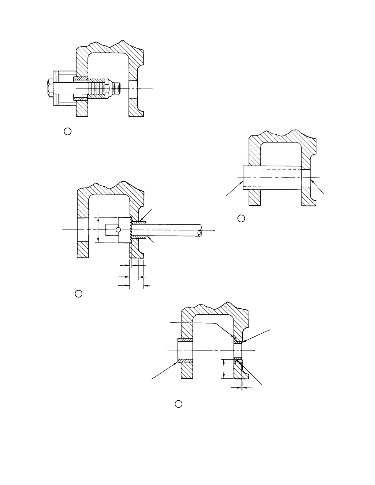
BUSHING: 0.44 IN. (11.176 MM) O.D. X 0.25 IN. (6.35 MM) I.D. X 0.31 IN. (7.874 MM) LONG
BUSHING: 0.75 IN. (19.05 MM) O.D. X 0.56 IN. (14.224 MM) I.D. X 0.31 IN. (7.874 MM) LONG
BOLT: 0.250 IN. (6.35 MM) DIA X 1.38 (35.052 MM) LONG
WASHER: 0.250 IN. (6.35 MM) I.D. X 0.75 IN. (19.05 MM) O.D. X 0.060 IN. (1.524 MM) THICK (2)
1
REMOVAL OF OLD BUSHING
DRILL BUSHING
0.4990−0.4995 IN.
0.3775−0.3780 IN.
1.13 IN.
O.D. X
I.D. X
LONG
(12.6746−12.6873 MM)
(9.5885−9.6012 MM)
(2.8702 CM)
0.3760−0.3770 IN.
DIA
REAMER
(9.5504−9.5758 MM)
DRILL NO. U: 0.3680 IN.
(9.3472 MM) DIA
DRILL BUSHING
DRILL THEN
0.5625 IN.
REAM
DRILL BUSHING
(14.2875 MM)
0.375 X 0.250 X 0.31 IN.
LONG
(9.525 X 6.35 X 7.874 MM)
2
DRILL AND REAM OUTBOARD LUG
BACK SPOT FACE
TREAT SPOTFACE SURFACE & REAMED
0.5625 DIA X 0.250 DIA
HOLE WITH IRIDITE−CHEM. FILM
SHAFT
TREATMENT PER MIL−C−5541 CLASS 2
0.010−0.030 IN.
0.015−0.020 IN. (0.381−0.508 MM)
FILLET RADIUS
(0.254−0.762 MM)
0.146 IN. (3.7084 MM)
0.20 IN. (5.08 MM) MIN
3
BACK SPOTFACE OUTBOARD LUG
AFTER INSTALLATION OF BUSHING,
SEAL EDGE WITH PRIMER
GRIND OFF BUSHING TO
0.00−0.015 IN. (0.00−0.381 MM)
BELOW 0.750 IN. (19.05 MM) DIA.
SPOTFACE SURFACE; INSTALL
WITH LOCTITE
0.360 IN.
MIN
(9.144 MM)
INSTALL BUSHING WITH GREASE
0.015−0.025 IN.
0.00−0.015 IN.
(0.381−0.635 MM)X 45° CHAMFER (TYP)
(0.00−0.381 MM)
4
INSTALLATION OF SPLIT BUSHINGS
30−041−3A
Figure 7-19. Repair of Main Rotor Hub Components (Sheet 3 of 3)
Page 7-47
Revision 16
MD Helicopters, Inc.
CSP−H−2
500 Series - Basic HMI
(10). Inspect lead−lag link stop for broken
lag legs of the straps at these loca−
spring, cracks, breaks, or visible bond
tions.
line cracks.
NOTE: Do not pry at the strap pack with a
(11). Inspect ID of lead−lag bolts for presence
sharp or hard−edged tool. If edges become
of corrosion. Bolts having evidence of
nicked, the strap pack assembly must be re−
corrosion should be treated for corro−
placed.
sion.
(d). If no obvious strap failure is noted,
NOTE: There are prebalanced rotor hub assem−
use a blunt−nosed wooden or pheno−
blies in service. The lead−lag bolts in preba−
lic pin, pencil size with 0.0625 inch
lanced hub assemblies may contain balanc−
(1.5875 mm) radius point, to probe at
ing hardware. If such is the case, remove the
the upper and lower strap lamina−
balancing hardware to perform inspection.
tions at the outboard end of the blade
Each set of removed hardware should be
pitch housings. A failed strap, either
tagged or color−coded to ensure correct rein−
in the lead or lag of the pack, will
stallation.
move away from the other straps. If
the upper and lower strap lamina−
(12). Inspect each striker strip for cracks,
tions remain in tension under this
deformation and badly worn contact
probing operation, no failure has
surfaces.
occurred.
(13). Inspect all parts of main rotor hub for
(e). If a single strap failure is noted
cracks, breaks, scratches, and nicks.
during inspection, rotor operation
(Refer all questionable damage to
can still be continued. The pack must
MDHI for deposition.)
be inspected again in 300 hours.
When three straps to any one blade
(14). Visually inspect the main rotor reten−
are broken (at one side of the rotor
tion straps for gaps between the pack
hub) the strap pack assembly must
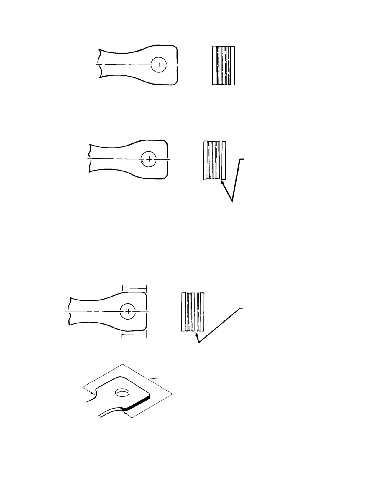
laminations (Ref. Figure 7−20).
be replaced.
(a). A single straight lamination gap not
NOTE: Ends of permissible broken straps must
in excess of 0.030 inch (0.762 mm) is
be taped to prevent scratching adjacent
permissible within the pack or next
straps.
to either the upper or lower outer
shoe.
(15). Whenever a new or replacement main
NOTE: On some strap packs the teflon may ap−
rotor hub has been installed, determine
pear wrinkled or extend past the end of the
that the droop angle of the main rotor
laminates obstructing the view. When this
blades does not exceed the maximum
condition exists, visual inspection should be
allowable angle of 6 degrees.
made from the leading and trailing edges of
the strap packs.
27. Main Rotor Strap Pack Lamination
Inspection
(b). Retention strap packs showing a
fanning or bowing of the laminations
(Ref. Table 7−7 and Figure 7−20)
indicate an improper condition and
the hub must be repaired. (Available
NOTE:
repair/overhaul information is
provided in CSP−H−5.)
D If a hub assembly or strap assembly (oth−
er than new parts in storage) are sub−
(c). Check for cracks or breaks in the
jected to extended periods of non−use,
strap pack laminations at the in−
whether installed on the helicopter or not,
board and outboard ends of the pitch
the strap assembly should be inspected
housing where the straps are accessi−
critically for corrosion and pitting due to
ble to view. Check both the lead and
corrosion before being returned to service.
Page 7-48
Revision 16
MD Helicopters, Inc.
CSP−H−2
500 Series - Basic HMI
If corrosion is found on the strap pack as−
A laminate has failed:
CAUTION
semblies, contact MDHI for disposition.
D If a crack is found in tongue area of the
D Figure 7−20 depicts the main rotor hub
laminate.
and strap pack assembly disassembled for
clarity of location and area to be inspected
D If a crack is found in both legs (lead and
for cracks. Under no circumstances
lag) of the same laminate.
should the strap pack or main rotor hub
A strap pack is to be rejected
assembly ever be disassembled in the
CAUTION
(return hub for overhaul):
field. MDHI and MDHI Approved Licens−
D If three or more laminates in a single
ees are the only approved repair stations
strap pack have failed, as defined above.
for main rotor hub assembly overhaul.
D If three or more laminates in a single
D It is acceptable to operate a helicopter
strap pack are cracked in the same leg
with a hub assembly having a strap pack
(lead or lag).
with up to two failed laminates in any one
D If one laminate is cracked at the outboard
leg of the strap assembly. When a lami−
end (area between outboard shoes).
nate in the strap assembly fails, the re−
maining laminates pick up and carry the
D Two or more gaps in the same strap pack
load. This increased load causes slightly
requires main rotor hub replacement. A
more elongation in the remaining lami−
single gap in any one strap pack assembly
nates of that leg thus shifting the mass of
is allowed.
the rotor system. Any time a vibration de−
NOTE:
velops or there is an increase in vibration
D Do not pry at strap pack assemblies with
level over a short period of time, the main
sharp or hard edged tools. If edges become
rotor strap pack assembly should be in−
nicked or laminates get scratched, addi−
spected for cracked or failed laminates.
tional cracking can occur thus causing
D Conduct inspection indoors, if possible, or
hub replacement.
in a shaded area to eliminate glare of sun
D Where accessible, ends of acceptable
or bright outdoor light. To facilitate in−
cracked or broken laminates should be
spection, field fabricate and use plastic in−
taped to prevent scratching and damag−
spection tool.
ing of adjacent laminates.
(6). Visually inspect strap pack assemblies
(1).
Remove main rotor blades.
for evidence of corrosion. If corrosion is
found on strap pack laminates contact
(2).
Trim teflon from edges of laminates.
MDHI service department for disposi−
tion.
(3).
Field fabricate plastic tool per
(7). Using a blunt−nosed wooden or pheno−
Figure 7−20. Run plastic inspection tool
lic pin, pencil size, with 0.0625 inch
in both directions along each laminate,
(1.5875 mm) radius point, probe at the
feeling for a ‘‘catch’’ from a crack on a
upper and lower strap laminations at
single laminate.
the outboard ends of the blade pitch
housings for evidence of laminate
(4).
Using a light and mirror, visually
failure.
inspect each of the main rotor strap
pack assemblies for evidence of cracks
(a). A failed laminate, either at the lead
or breaks in strap pack laminates in the
or lag end of the strap pack, will
areas of the outboard shoes and pitch
move away from the other laminates.
housing assemblies.
(b). If the adjacent upper and lower
laminates remain in tension under
(5).
Using a 10X magnifying glass, visually
the probing operation, no laminate
inspect the edge of strap pack lami−
failures have occurred.
nates on both sides at outboard end of
blade pitch housing (area between
NOTE: Laminate failures are defined in step
outboard shoes).
(5). (Ref. CAUTION:).
Page 7-49
Revision 16
MD Helicopters, Inc.
CSP−H−2
500 Series - Basic HMI
Table 7-7. Strap Pack Inspection
Replace or Return
Inspect
Procedure (1)
For
Acceptable
Hub for Overhaul if:
Outboard end
Visually. Use blunt nosed
Failed laminates
Two or less per pack
Three or more
wooden or phenolic pin
(3)
laminate failures in
(Ref. Figure 7-20).
one pack.
Probe at upper and lower
end of pack. Failed
laminate in lead or lag
leg will move away from
other laminates
Visually.
Gaps between
Single straight gap
More than one gap
laminates
not exceeding 0.030
found; gap exceeds
inch (0.762 mm)
acceptable limit.
within pack or next to
either upper or lower
outer shoe
Visually using light and
Cracks or breaks
None
Cracks or breaks are
mirror (2)
noted.
In area of and
Visually with light and
Cracks or breaks
Two or less laminate
Three or more
within pitch
mirror (2)
failures per strap
laminate failures (2)
housing assem-
pack (2)
in a pack; three or
blies
more laminates in
pack with crack in
same leg (lead or
lag).
Shims at attach
Visually with light and
Cracks or breaks
Inspect top laminate
Top laminate is
points
mirror
around shim (4)
cracked in area of
cracked or broken
shim.
NOTE:
(1) Conduct visual inspections indoors or in shaded area to eliminate glare of sun or bright outdoor light.
(2) Removal of teflon covering is required for visual inspection of laminate edges. Use aluminum chisel
fabricated from stock 0.025 x 6.00 x 0.10 inch (0.635 x 152.4 x 2.54 mm) to carefully scrape excess
interlaminate teflon sheets from both sides of strap pack between top and bottom shoes at outboard
attachment bolt of all five strap packs. Remove excess teflon from a point 0.50 inch (12.7 mm) outboard
of bolt centerline to 1.50 inches (38.1 mm) inboard of bolt centerline. Field fabricate and use plastic tool
(Ref. Figure 7-20). Run plastic tool in both directions along each laminate feeling for cracked laminate.
Use of plastic tool will ensure that shreds of teflon still hanging free does not obscure small cracks.
(3) Laminate has failed if crack is found in tongue area or if crack is found in both legs (lead and lag).
(4) Pay particular attention to shim installed at upper side of lead leg of each strap pack assembly. Maximum
of two shims may have been installed on top side of lead leg of strap pack to accommodate tolerance
buildup during strap pack assembly. If more than one top shim is installed, pay particular attention to
lower shim when checking for cracks or breaks.
Page 7-50
Revision 16
MD Helicopters, Inc.
CSP−H−2
500 Series - Basic HMI
ALL LAMINATES STRAIGHT.
NO GAPS
DETAIL 1 ACCEPTABLE
ALL LAMINATES STRAIGHT. SINGLE GAP
EXISTING ADJACENT TO EITHER SHOE.
DETAIL 2 ACCEPTABLE
NOTE:
WHITE TEFLON MAY APPEAR WRINKLED AND EXTEND PAST END OF LAMINATES
PREVENTING CLEAR VIEW OF LAMINATE. WHEN THIS OCCURS, LOOK ALONG
EITHER SIDE IN AREA A−A OR B−B (DETAIL 3).
A
A
ALL LAMINATES STRAIGHT. SINGLE GAP
EXISTING ANYPLACE WITHIN LAMINATES
DETAIL 3
ACCEPTABLE
B
B
REMOVE EXCESS TEFLON THIS AREA.
44−060−1
Figure 7-20. Strap Pack Lamination Inspection (Sheet 1 of 2)
Page 7-51
Revision 16
MD Helicopters, Inc.
CSP−H−2
500 Series - Basic HMI
1
0.125 IN.
(3.175 MM)
LAG LEG
LAMINATE HAS FAILED IF CRACKS OCCUR
ON BOTH LEAD AND LAG LEGS OF SAME
LAMINATE.
0.250 IN.
LEAD LEG
(6.35 MM)
PROBE
PLASTIC
LAMINATE HAS FAILED IF CRACK OCCURS
TOOL
6.00 IN.
TONGUE
IN TONGUE OF LAMINATE (SHADED AREA
(15.24 CM)
SHOWN BEYOND JOINT OF STRAP PACK
LEGS).
4.00 IN.
(10.16 CM)
1 1/2 INCH (REF)
3
TWO LAMINATE FAILURES AS DEFINED IN
1
AND/OR
2 ARE ALLOWED IN EACH STRAP
PACK ASSEMBLY. (TOTAL OF EIGHT LAMINATE
1.00 IN.
0.050−0.125 IN.
FAILURES PER HUB ASSEMBLY.)
(25.4 MM)
(1.27−3.175 MM)
FIELD FABRICATED INSPECTION TOOL
STRAP PACK IS REJECTED IF THREE OR MORE
4
LAMINATES IN SAME PACK HAVE FAILED AS
5
DEFINED IN
1 AND/OR
2 ABOVE.
STRAP PACK IS REJECTED IF THREE OR MORE
LAMINATES IN THE SAME PACK ARE CRACKED IN
THE LEG (LEAD OR LAG).
CAUTION:
DO NOT DISASSEMBLE STRAP PACK
FAILED LAMINATE IF CRACK
ASSEMBLY − LAMINATIONS ARE
IS FOUND ON EITHER EDGE
SHOWN SEPARATED ONLY TO DEPICT
OF LAMINATE.
POSSIBLE CRACK LOCATIONS.
IF ONE LAMINATE IS FAILED,
REMOVE HUB.
6
NOTE:
ANY CRACK IN LAMINATE IS CONSIDERED A BREAK.
THE LAMINATE HAS NOT FAILED HOWEVER, UNLESS
1 1/2’’
BOTH LEAD AND LAG LEGS ARE CRACKED, CRACK IS
LOCATED IN TONGUE AREA OF LAMINATE, OR IS
UNDER SHOES (SEE DETAIL 6).
44−060−2E
Figure 7-20. Strap Pack Lamination Inspection (Sheet 2 of 2)
Page 7-52
Revision 16
MD Helicopters, Inc.
CSP−H−2
500 Series - Basic HMI
(8). Inspect upper, lower and center lami−
exceed 0.010 inch (0.254 mm) in any
nates for cracks and breaks.
area of the housing except the inner
surfaces of arm clevis lugs.
NOTE: Cracks, breaks or other noticeable dam−
age to the laminate/shims require main ro−
(3). A maximum (repaired) depth of 0.050
tor hub overhaul/replacement.
inch (1.270 mm) is acceptable in the
clevis lug with the sleeve bushing.
(9). Install main rotor blades.
(a). On the opposite clevis lug, a maxi−
(10). Perform tracking of main rotor blades.
mum (repaired) depth of 0.010 inch
(0.254 mm) is permissible in the area
(11). Record location of all cracked/broken
of the spot faces and maximum of
laminates in helicopter Log Book
0.050 inch (1.270 mm) in the area
including strap serial number, blade
outside the spot faces.
color, leg (lead or lag) and laminate
position, if possible numbering from the
(4). Repair elongated hole in unbushed side
top down.
of clevis lug (View E). Maximum hole
diameter is 0.3135 inch (7.9629 mm).
28. Main Rotor Strap Pack Repair
(a). Disconnect pitch control rod from
(Ref. Figure 7−20) Where accessible, ends of
clevis lugs on pitch control housing.
permissible cracks or broken laminates should
be taped to prevent scratching and damaging
(b). Remove existing bushing from
adjacent laminates.
inboard lug.
NOTE: Do not bend broken ends excessively
(c). Use drill bushing as guide and drill
and scratch adjacent straps.
elongated hole in outboard lug to
0.368 inch (9.3472 mm) diameter;
(1). Carefully wipe ends of broken strap
line ream hole to 0.375−0.376 inch
with a clean soft cloth moistened with
(9.525−9.5504 mm) diameter.
solvent (1, Table 2−4).
NOTE: Prior to back spot− facing, check out−
(2). Use mild blast of filtered air to dislodge
board lug two places for minimum wall
any foreign particles between broken
thickness of 0.146 and 0.20 inch (3.7084 and
strap ends and adjacent strap.
5.08 mm).
(3). Carefully tape broken ends of strap
(d). Use drill bushing as guide for spot−
with plastic electrical tape (74).
face pilot, and back spotface inside
surface of outboard lug to 0.5625 inch
29. Pitch Housing Assembly Repair
(14.2875 mm) diameter and
0.015−0.020 inch (0.381−0.508 mm)
(Ref. Figure 7−19)
depth. Add chamfer to clear bushing
in two places, as shown.
NOTE: During repair, use adequate covering
over engine air inlet fairing opening to pre−
(e). Use attach bolt or assembly pin as
vent entry of foreign objects into air intake.
guide to ensure proper alignment,
When reconnecting a pitch control rod, be
and install 369D21309 flanged
sure that the rod ends are centered in the
bushing and seal edges with Loctite
swashplate and housing arm clevis lugs. Re−
sealing compound.
align, if necessary, and hold rod to prevent
turning while tightening locknuts.
(f). Install slotted bushing with grease
(58) in inboard lug.
(1). Use grade 320 abrasive cloth (20,
Table 2−4) to smooth scratches, nicks
NOTE: Check outboard and inboard lugs of
and chafing wear in pitch housing.
pitch control horn for evidence of interfer−
ence with upper jam nut on pitch control
(2). After smoothing (removal of all sharp or
rod. If evidence of interference is noted, per−
raised edges) repair depth must not
form step (5).
Page 7-53
Revision 16
MD Helicopters, Inc.
CSP−H−2
500 Series - Basic HMI
(g). Reconnect pitch control rod assembly
(3). Slide bearing assembly off pivot pin.
if check of pitch control rod lugs
Inspect pivot pin for grooving or
discloses no evidence of interference
excessive wear.
with rod upper jam nut.
NOTE: Do not remove TFE debris which works
(5). Remove pitch control horn lug interfer−
out of pitch bearing edge. The debris is nor−
ence with pitch control rod upper jam
mal and helps lubricate bearing. Removal of
nut clearance (View E).
debris will increase bearing wear.
(4). Remove and discard pitch bearing if
(a). Using file or portable grinder,
defective. Total radial looseness of
carefully trim off interfering corner of
assembled ball and pivot pin must not
pitch housing lugs so there is suffi−
exceed 0.010 inch (0.254 mm).
cient pitch control rod clearance. It is
not necessary to trim to minimum
(5). Replace striker strip if it is cracked or
wall thickness, and do not exceed
the flapping stop contact areas are
rework limitations shown.
worn through hard anodized surface.
(b). Reconnect pitch control rod assembly.
NOTE: Hub assemblies may have either one−
Check for proper clearance between
or two−piece striker strips.
outboard lug and upper jam nut on
pitch control rod.
(6). Prepare one−piece striker strip for
installation as follows:
(6). Touch up repaired areas with chemical
(a). Remove sealant between pitch
film (8) followed by primer (4); paint
housing and striker strip, use care
with matching color.
not to scratch pitch housing
(7). Remove main rotor hub assembly for
(b). Remove striker strip from pitch
pitch housing or hub replacement.
housing.
30. Pitch Housing Parts Repair or
(c). Cut old striker strip to facilitate
Replacement
removal from retention strap assem−
bly. Do not scratch strap assembly.
(Ref. Figure 7−19)
(d). Clean old sealant from pitch housing
NOTE: Use care during removal of parts from
using 1,1,1 trichloroethane (61,
around the strap pack. Any nicks or
Table 2−4).
scratches on the straps requires scrapping
(e). Cut out area of new striker strip
of the strap pack.
(View B), deburr, smooth and radius
A. Pitch Control Bearing Housing Assembly,
cut edges.
Spacer or Striker Strip Replacement
(f). Apply sealant (3) to faying surfaces of
the striker strip and pitch housing.
(1). Support blade and pitch housing from
beneath. Remove three nuts, six
(7). Position pitch control bearing housing
washers and three bolts that secure
on pivot pin.
bearing housing.
NOTE: If droop shim washers were removed
NOTE: Check if washers are installed between
from between spacer and striker strip, the
the spacer and the striker strip. These
exact thickness removed must be rein−
washers must be reinstalled to establish
stalled. There must be an equal number of
correct static droop angle between the pitch
washers on each of all three bolts. These
housing and hub.
washers establish correct static droop be−
tween pitch housing and the hub.
(2). Carefully remove spacer by sliding it
downward past striker strip. Retain
(8). Slide spacer into position between
exact number of droop shim washers, if
bearing housing assembly and striker
installed.
strip on pitch housing. Install exact
Page 7-54
Revision 16
MD Helicopters, Inc.
CSP−H−2
500 Series - Basic HMI
thickness of droop shim washers
(b). The shop−formed head of the
removed at time of disassembly. Align
MS20615−5M rivet must be flush
holes for the three bolts.
with the plate.
(c). An MS20427M5 rivet may be used as
(9). Install three bolts, six washers and
an alternate for the MS20615−5M
three nuts. Torque nuts to 50 − 70
rivet.
inch−pounds (5.65 − 7.91 Nm).
(d). When the alternate is used, install
(10). Seal all the parting lines (joints) of the
the rivet from the plate side of the
assembly with a bead of sealing
assembly.
compound.
(e). The heads of all countersunk rivets
B. Replacing Pitch Control Bearing
must be completely flush.
C. Lead-Lag Link Blade Stop Replacement
(1).
Drill out rivets to remove striker plate.
Discard striker plate if brinelling or
Replace a blade stop if it is broken or cracked,
pitting exceeds 0.030 inch (0.762 mm)
has a broken spring, or if there are visible
depth.
bond line cracks.
(2).
Press bearing from housing bore. Clean
NOTE: The lead−lag link assembly must not be
any residual primer from housing bore
removed from pitch control housing for this
with MEK solvent (22, Table 2−4).
repair, the retention bolt cannot be retor−
qued without a special adapter.
(3).
Rework minor surface abrasion in
(1). Remove lead−lag link stop as follows;
housing bore by polishing with crocus
cloth (23). Restore chemical film (8),
(a). Provide a backup support for the link
where removed.
assembly.
(4).
Apply one thin coat of primer (4) to the
(b). Use a 0.50 inch (12.7 mm) wood
bearing OD and the housing bore.
dowel and a hammer to drive stop
from link.
(5).
Press bearing into bore while primer is
still wet.
(c). Strike the dowel sharply to break the
adhesive bond.
(6).
Wipe away any excess primer using
(2). Using a sharp−edged metal scraper,
care to keep it out of bearing races.
carefully scrape any adhesive residue
from the link.
(7).
Check Teflon linings of bearing after
installation to determine that no
(a). If scraper penetrates through the
damage has occurred from the pressing
paint and chemical surface film, the
operation.
surface must be refinished.
NOTE: Outside edge of bearing outer race must
(b). The depth of gouges or nicks is
be at least flush with the face of the bearing
limited to 0.010 inch (0.254 mm)
housing. However, the bearing can be re−
maximum after rework.
cessed up to 0.015 inch (0.381 mm).
(c). Rework by smooth blending into the
surrounding area with grade 320
(8). Install striker plate with one
abrasive cloth (20).
MS20427M5 rivet (upper hole) and one
MS20615−5M rivet (lower hole).
(d). Final polish with crocus cloth.
Restore chemical film protection.
(a). If upper hole of striker plate is
countersunk, rivet must installed
(3). Clean the bond area of all contact
with shop−formed head flush with
surfaces by wiping with surface cleaner
the plate.
(10).
Page 7-55
Revision 16
MD Helicopters, Inc.
CSP−H−2
500 Series - Basic HMI
(a). Flush−wipe the cleaned surface four
(3). Swab cleaned surface with methyl ethyl
times with a mixture of equal parts of
ketone (22) and apply unthinned primer
distilled water and isopropyl alcohol
(4).
(71) to remove all traces of the
(4). Reinstall balance hardware that was
phosphoric acid.
removed.
(b). Rinse the cleaned surface with tap
E. Taping Broken Strap Ends of Strap Pack
water, followed by a rinse of distilled
water until the surface is ‘‘water
NOTE: Be careful not to bend broken ends ex−
break" free.
cessively and scratch adjacent straps.
(c). Dry for 30 minutes minimum at
(1). Carefully wipe ends of broken strap
150°F (66°C).
with a clean, soft cloth moistened with
solvent (1, Table 2−4).
(4). Check the fit of the stop in the link.
(2). Use a mild blast of filtered air to
(a). The flange and radius contact
dislodge any foreign particles between
surfaces of the stop must mate with
broken strap ends and adjacent strap
the link within 0.010 inch (0.254
mm).
(3). Carefully tape broken ends of strap
with plastic electrical tape (74).
(b). Maximum clearance between the
stop and inside surfaces of the link
31. Pitch Control Bearing Pivot Pin Repair or
ears is limited to 0.020 inch (0.508
Replacement
mm).
(Ref. Figure 7−19) Minimum allowable pin
diameter is 0.4328 inch (10.99312 mm). Pivot
NOTE: This tolerance applies to either side of
pin grooving or excessive side wear may be
the stop.
polished to original finish as long as minimum
(5). Prepare a mixture of epoxy adhesive
allowable pin diameter remains after rework.
(91).
Replace any pin requiring more rework, as
follows:
(a). Apply a uniform coating of the mixed
NOTE: Due to tolerance build−ups in forging
adhesive to all contact surfaces.
and casting of individual main rotor hubs,
(b). Hand press the stop into place
insertion of the stud nut holding wrench (50,
between link ears until all mating
Table 2−2) may not be possible with some
surfaces are in firm contact.
hubs. If the holding wrench cannot be in−
serted properly to engage the stud attach
(c). Apply a suitable clamping device so
nuts, the hub assembly must be sent to an
that contact is maintained.
overhaul facility for stud replacement.
(d). Cure for a minimum of 8 hours at
(1). Hold nut with stud nut wrench (50) and
room temperature, or 2 hours at
remove pivot pin with pitch bearing
150°F (66°C).
stud wrench (49). The stud nut wrench
is not required when nut retaining
D. Corrosion Control - Lead-Lag Bolt
brackets are installed on the hub.
NOTE: Do not disturb the torque on the lead−
(2). Lightly lubricate the threaded shank of
lag bolts. A special adapter is needed to re−
the replacement pivot pin with grease
torque the lead−lag bolts.
(18, Table 2−4).
(1). Remove and tag or color−code each set
NOTE: Before applying the last 20 − 30 inch−
of balance hardware that is installed.
pounds (2.26 − 3.39 Nm) of the torque spe−
cified in steps (3). and (5). below, use a 0.002
(2). Remove corrosion with grade 180
inch (0.0508 mm) feeler gage and check for
abrasive cloth (20, Table 2−4) and finish
gap between the pin flange and mounting
with grade 400 abrasive cloth.
lug surface. No gap is allowed.
Page 7-56
Revision 16
MD Helicopters, Inc.
CSP−H−2
500 Series - Basic HMI
(3). If nut retaining brackets are not
side of the hub from the roller to be
installed;
installed. Install roller, shaft, and new
cotter pin.
(4). Install pivot pin in mounting lug and
secure with a washer coated with wet
(5). Install pitch control bearing housing
primer (4) and a nut.
assembly.
(a). Hold nut with stud nut wrench.
33. Droop Stop Ring Repair
(b). Using pitch bearing stud wrench,
(Ref. Figure 7−21)
torque pivot pin to 200 − 220 inch−
pounds (22.60 − 24.86 Nm).
(1).
The repair depth limit for corrosion,
nicks or scratches in the droop stop ring
(5). If nut retaining brackets are installed;
is 0.007 inch (0.1778 mm) for all
surfaces except the edges of the ring
(a). Install pivot pin in mounting lug
OD.
with washer.
The depth limit for the ring OD edges is
(b). Using pitch bearing stud wrench,
0.030 inch (0.762 mm) (Detail C).
torque pivot pin to 200 − 220 inch−
pounds (22.60 − 24.86 Nm).
All reworked areas must be blended
smoothly with a 15:1 ratio into the
32. Droop Stop Restrainer and Roller Repair
surrounding area.
or Replacement
(2).
Touch up repaired areas of cadmium−
(Ref. Figure 7−21) Replace a defective droop
plated rings, except the channel, with
stop roller if clearance between roller bearing
chemical film (8, Table 2−4) followed by
liner and shaft is more than 0.015 inch (0.381
primer (4).
mm), replace the worn part.
(3).
Repairs in the channel of cadmium−
Roller shaft OD must not be less than 0.437
plated rings and in all areas of stainless
inch (11.0998 mm).
steel rings should be sprayed with dry
film lubricant (25) only.
A defective follower or spring is replaceable
after removal of the droop stop ring (Ref.
(4).
Replace the droop stop ring if repair
Droop Stop Ring Replacement).
limits have been exceeded.
(1). Remove pitch control bearing housing
34. Droop Stop Ring Replacement
assembly that contacts the lower shoe
roller to be removed.
(Ref. Figure 7−21)
NOTE: Only one roller of each opposing pair of
(1). Turn the hub upside down. Support the
droop stop rollers can be removed at one
hub so that the pitch housings will
time. One droop stop restrainer must be
unload the cam followers and provide
pressed against the droop stop ring to force
maximum clearance between the
the opposite restrainer out and expose the
striker plates and droop stop rollers.
roller shaft for removal. The same condition
pertains during installation.
(2). Release the retaining (snap) ring of
each droop stop restrainer from its
(2). Press down on pitch housing that is
groove.
opposite to the roller to be removed.
Remove cotter pin and shaft.
(3). Move the retaining ring flush against
the T−head to provide additional
(3). Remove droop stop roller.
clearance and reduce the spring
tension.
(4). To install replacement roller, press
down on pitch housing at the opposite
(4). Remove the four droop stop rollers.
Page 7-57
Revision 16
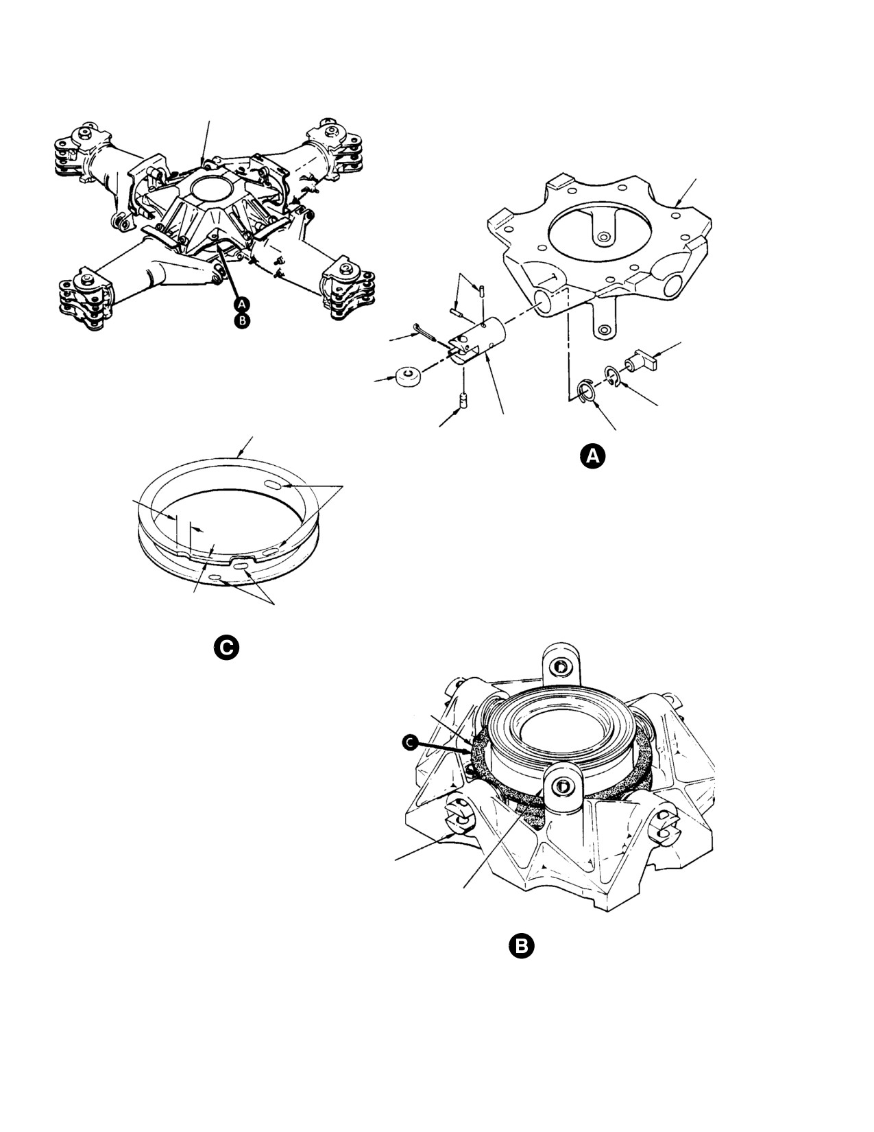
MD Helicopters, Inc.
CSP−H−2
500 Series - Basic HMI
HUB
LOWER SHOE
PINS
COTTER PIN
DROOP STOP
FOLLOWER
(T−HEAD)
DROOP STOP
ROLLER
SNAP RING
DROOP
DROOP STOP RING
SHAFT
STOP
SPRING
PLUNGER
0.007 IN. (0.1778 MM) MAX DEPTH
(15 TO 1 RADIUS) AFTER REWORK
15 TO 1 RADIUS
0.030 IN. (0.762 MM) MAX
0.007 IN. (0.1778 MM) MAX DEPTH
AFTER REWORK
(15 TO 1 RADIUS) AFTER REWORK
DROOP STOP RING
DROOP STOP FOLLOWER ASSEMBLY
(4 PLCS)
SCISSORS CRANK ATTACH LUG
(LOWER SHOE)
INVERTED
30−164B
Figure 7-21. Main Rotor Hub Assembly Repair
Page 7-58
Revision 16
MD Helicopters, Inc.
CSP−H−2
500 Series - Basic HMI
(5). Starting from either scissors crank
(16).
Orient the number 2 follower for correct
attach lug, number the four droop
(lower) position.
restrainers in a clockwise direction for
(17).
Pull the number 1 and 2 followers
identification during the replacement
outboard and engage the number 1 and
procedure.
2 T−heads in the new droop stop ring
(a). This number code should be replaced
channel.
on the outboard (roller) upper end of
(18).
Rotate the number 3 follower in the
the follower.
direction that has the greatest amount
(b). Guard against the accidental removal
of clearance between the T−head and
of the codes during the remaining
ring. Continue the rotation of the
steps.
number 3 follower until the T−head is in
the incorrect (lower) position and
NOTE: Designation of upper and lower droop
engages the ring channel.
restrainer followers is in relation to the hub
(19).
Rotate the number 4 follower 180°
as it sits, not as it is installed on the helicop−
which will position the T−head in the
ter. Notice that the odd numbered (1 and 3)
correct (lower) position and engage the
followers are in the upper position and the
ring channel.
even numbered (2 and 4) followers are in the
lower position.
(20).
Pull the number 3 follower outboard to
disengage the T−head from the ring
(6). Push the droop stop ring toward the
channel.
number 1 and 2 followers.
(21).
Rotate the number 3 follower 90° until
(7). Pull the number 3 and 4 follower
the T−head is perpendicular (vertical) to
T−heads from the droop stop ring
the ring channel.
channel.
(22).
Push down on the ring. Rotate the
(8). When the T−heads are free of the ring
number 3 follower 90° until the T−head
channel they should be turned perpen−
is in the correct (upper) position and
dicular (vertical) to the channel.
engages the ring channel.
NOTE: The followers can be easily rotated by
(23).
Check the number 1 and 3 followers for
the use of a non−metallic drift in the hole for
correct (upper) orientation.
the droop stop roller shaft.
(24).
Check the number 2 and 4 followers for
(9). Tilt the ring up on the number 3 and 4
correct (lower) orientation.
followers as far as possible.
(25).
Check the droop stop ring for correct
(10). While pulling upward on the ring, turn
(level) installation.
the number 4 follower to rotate the
(26).
Compress the droop restrainer spring
T−head under the ring.
and install the retaining (snap) ring in
(11). Continue pulling upward on the ring
its groove on each follower.
and turn the number 3 follower to
(27).
Reinstall the droop stop rollers.
rotate the T−head under the ring.
35. Droop Stop Plunger Inspection and
(12). Withdraw the number 1 and 2 T−heads
Replacement
from the ring channel.
(Ref. Figure 7−21)
(13). Remove the ring from the hub assem−
bly.
(1). Remove droop stop ring.
(14). Prepare for installation of replacement
(2). Remove pitch control bearing housing
droop stop ring by orienting the number
assembly that contacts the lower shoe
4 follower for incorrect (upper) position.
roller.
(15). Orient the number 1 and 3 followers for
(3). Remove cotter pin and shaft from droop
correct (upper) position.
stop follower assembly.
Page 7-59
Revision 16
MD Helicopters, Inc.
CSP−H−2
500 Series - Basic HMI
(4). Remove droop stop roller.
(3). Clean the hub bore, sleeve bushing,
seal retainer and reusable bearings,
(5). Push droop stop plunger out of lower
using filtered solvent (1) spray.
shoe.
(4). Check bearing cup hub bore for scoring.
(6). Check droop stop plunger for wear as
(a). Smooth out any roughness with
follows:
grade 400 to 600 abrasive cloth (20).
(a). The minimum acceptable diameter
(b). Restore chemical film protection (Ref.
after wearing in service, should be
Sec. 2), where removed.
0.996 inch (25.2984 mm).
(c). Maximum diameter of the hub bore
(b). The acceptable amount of wear
for upper bearing cup is 4.4335
through the anodized coating shall
inches (11.26109 cm), measured in
not exceed 40% or 2.1 square inches
any direction.
(13.55 square cm) of the total sliding
surface area of the cylinder.
(d). Maximum diameter of the hub bore
for lower bearing cup is 4.3095 inches
(c). The maximum wear condition may
(10.94613 cm), measured in any
exist in one spot or in several spots
direction.
totaling 2.1 square inches (13.55
square cm).
(5). Check upper seal retainer. No cracks,
sharp nicks or burrs are allowed. Minor
(7). Wet down and clean plunger and
corrosion or other surface defects may
mating shoe bushing with isopropyl
be polished out using crocus cloth (23).
alcohol (71, Table 2−4).
Grooving on seal contact surfaces must
not exceed 0.004 inch (0.1016 mm)
(8). Install droop stop plunger into lower
depth after polishing.
shoe.
The bearing cups are in−
(9). Install roller, shaft and new cotter pin.
WARNING
stalled in the hub by the dif−
ferential temperature (shrink−fit)
(10). Complete droop stop ring installation.
method. Take appropriate precautions
to prevent burns when handling parts
36. Main Rotor Hub Tapered Bearing
that have been cooled down to sub−
Replacement
zero temperatures.
(Ref. Figure 7−7) Replace tapered roller
(6). Place bearing cups in a closed container
bearing cup or cone if it has any flat spots,
of dry ice and cool down for not less
scoring, pitting, grooving, discoloration (blue)
than 20 minutes to −40°F (−40°C).
or if it feels rough when rotated. If a cone is
unserviceable, the mating cup must be
(7). Coat bore of hub with grease (21). Use
replaced, and vice versa.
care to maintain cup to hub bore
alignment and press cup into bore,
NOTE: The roller bearing cones and cups
using tools D and E until cup is seated.
should always be replaced as a set.
(8). Apply a film of grease to sleeve bush−
(1). Use pressing tools equivalent to items
ing. Use d pressing tool equivalent to
A and B (Ref. Figure 7−22) to press
tool C and press bearing cone onto
upper and lower bearing cups from hub
sleeve bushing.
assembly, press ram of 1 to 2 tons is
sufficient for removal.
(9). Install center seal in hub by hand
pressing it into place. Check that seal
(2). Press lower bearing cone from sleeve
lip is upward.
bushing.
(10). Apply a film of grease on mast. Install
NOTE: In next step, do not spin reusable bear−
preassembled sleeve bearing and
ings while cleaning. Coat bearings lightly
bearing cone on mast. Do not apply any
with oil (35, Table 2−4) after cleaning.
additional lubricant to roller bearing
Page 7-60
Revision 16
MD Helicopters, Inc.
CSP−H−2
500 Series - Basic HMI
set. Wipe any excess preservative oil
(19). Discard lead spacer after recessed
from bearing cone and cup.
washer is ground.
(11). Place assembled hub over mast and
NOTE:
seat on lower roller bearing cone.
D If the hub assembly (with sleeve bushing,
(12). Install a lead spacer 369A1224−5
spacer, upper bearing and seal retainer
(thickness gage substitute for upper
installed) does not seat properly onto the
seal retainer) over dummy mast. Rest
mast, do not attempt to force it into posi−
spacer on top of sleeve bushing.
tion. Remove hub assembly from mast
and determine cause of hub not seating,
NOTE: If a lead spacer 369A1224− 5 is not
correct the problem and follow the proce−
available, fabricate its equivalent from lead
dures for installation.
sheet. Spacer dimensions are: 2.96 inches
D To insure that hub is seated onto the mast
(7.5184 cm) OD; 2.68 inches (6.8072 cm) ID;
properly before torquing, 2 to 4 threads
0.075−0.085 inch (1.905−2.159 mm) thick.
should be showing above the mast nut
with nut installed finger tight.
(13). Install upper bearing cone into hub and
on top of lead spacer.
(20).
Install recessed washer, recess down,
NOTE: This step is not required. However, the
on the top of sleeve bushing.
use of a substitute washer for the retainer
will prevent unnecessary scoring of the re−
(21).
Reinstall upper bearing cone, the ring
tainer. Several tightening and loosening ac−
washer (or seal retainer) and mast nut.
tions might be required to get the correct ro−
tational drag on the hub bearings.
(22).
Tighten nut to 200 − 250 foot−pounds
(271 − 339 Nm) and check for rotation−
(14). Install a steel ring washer, equivalent
al drag of 10 − 20 inch−pounds (1.13 −
to tool F, as a substitute for packing
2.26 Nm). This will be 1.50 − 3.0
retainer.
pounds (6.67 − 13.34 N) on the spring
scale used as in step (15). above.
(15). Install mast nut on mast.
(23).
Remove hub and sleeve bushing with
(a). Tighten using mast nut wrench (19
lower bearing cone from mast.
or 20, Table 2−2) until bearings are
preloaded to 10 − 12 inch−pounds
(24).
Position hub upside−down on a suitable
(1.13 − 1.36 Nm) of rotational drag.
work bench. Hand−pack the lower hub
(b). Measure rotational drag using a 0 −
cavity and the bearing cone on sleeve
10 pound (0 − 44 N) spring scale,
bushing with grease (21, Table 2−4).
hooked over one of the hub fairing
bosses, 6.5 inches (16.5 cm) from hub
(25).
Install sleeve bushing with bearing
centerline.
cone in the hub.
(c). Read a 1.50 − 1.75 pound (6.67 −
(26).
Hand−pack the cavity between bearing
7.78 N) pull with hub in motion.
and the hub liner with grease; then
press in the lower seal with seal lip
(16). Remove mast nut, ring washer F or seal
toward top of hub. Wipe off excess
retainer, and upper bearing cone.
grease.
(17). Remove lead spacer and measure
(27).
With the aid of an assistant, turn hub
compressed thickness.
assembly right side up on the bench.
(18). Obtain a serviceable recessed washer of
the same thickness if one is available.
(28).
Complete reassembly of hub by install−
ing recessed washer, upper bearing
(a). If not, grind a new recessed washer
cone, upper seal, and seal retainer in
to the required dimension.
hub at installation of hub on the mast.
Page 7-61
Revision 16
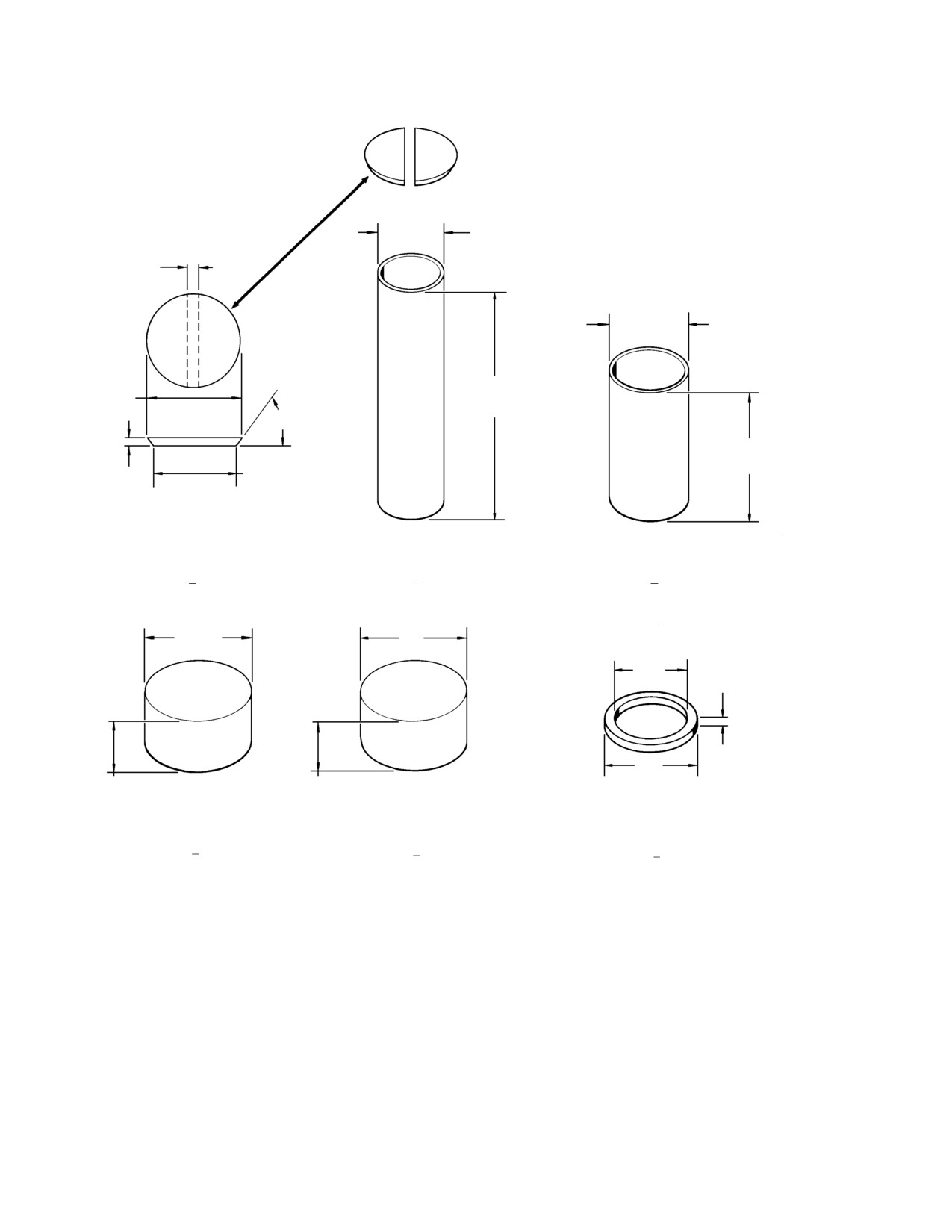
MD Helicopters, Inc.
CSP−H−2
500 Series - Basic HMI
A
A
2.875 INCH (7.3025 CM)
OUTSIDE DIAMETER
CUT OUT
0.50 INCH
AFTER BEVELING
12.7 MM)
3.50 INCH (8.89 CM)
OUTSIDE DIAMETER
3.875 INCH
11.0 INCH
(9.8425 CM)
(27.94 CM)
53°
5.75 INCH
(14.605 CM)
0.375 INCH
3.375 INCH
(9.525 MM)
(8.5725 CM)
0.1875 INCH (4.7625 MM)
0.203125 INCH (5.159375 MM)
4130 STEEL PLATE
WALL STEEL PIPE
WALL STEEL PIPE
A
B
C
4.40 INCH
4.30 INCH
(11.176 CM)
(10.922 CM)
2.58 INCH
0.30 INCH
(6.5532 CM)
(7.62 MM)
3.50 INCH
(8.89 CM)
2.0 INCH
2.0 INCH
(5.08 CM)
(5.08 CM)
ALUMINUM ALLOY
ALUMINUM ALLOY
STEEL RING WASHER
D
E
F
TOOL USE:
A & B − PRESS BEARING CUPS OUT OF HUB
C − PRESS LOWER BEARING CONE ON SLEEVE BUSHING
D − PRESS UPPER BEARING CUP INTO HUB
E − PRESS LOWER BEARING CUP ONTO HUB
F − IN PLACE OF UPPER SEAL RETAINER WHILE ADJUSTING ROTATIONAL DRAG
G − HUB BEARING REMOVAL − FABRICATION
G62−2010−1
Figure 7-22. Main Rotor Hub Tapered Bearing Tools
Page 7-62
Revision 16
MD Helicopters, Inc.
CSP−H−2
500 Series - Basic HMI
37. Main Rotor Hub Assembly Droop Angle
installation procedures for main rotor
Check
drive shaft in Section 9.
When a new or replacement main rotor hub is
38. Main Rotor Hub Assembly Droop Angle
installed or whenever excessive droop angle is
Adjustment
suspected, measure the static droop angle of
(Ref. Figure 7−19) If static droop angle exceeds
all four rotor blades. Droop angle must be
6 degrees, adjust as follows.
between 5 and 6 degrees.
(1). Remove main rotor blades.
(1). Install cyclic lateral rigging fixture (14,
Table 2−2), cyclic longitudinal rigging
(2). Use ‘‘AN960
" (C416, C416L,
KD416 or KD416L) flat washers to
fixture (12) and collective rigging
adjust the spacing between spacer and
fixture (9).
striker strip.
(2). Position main rotor with one blade over
NOTE: Any one type, or combination, of the
the tailboom.
washers specified may be used; however, an
identical washer selection (thickness) must
(3). Raise and support the forward blade
be installed on each of the three bolts that
until the droop stop roller of the
secure the pitch control bearing assembly to
forward blade is no longer in contact
the pitch housing.
with the striker plate.
(3). Remove nuts and washers and separate
(4). Place an accurate prop protractor (63)
spacer from striker strip.
beside head of main rotor driveshaft
and seat protractor on flat machined
NOTE: The use of one thick 0.016 inch (0.4064
surface of main rotor hub. Adjust
mm) washer will raise the static droop angle
protractor to zero setting.
approximately one−half a degree.
(4). Add sufficient washers to adjust droop
NOTE: If sufficient flat surface area is not
angle to within the range of 5 to 6
available on hub to properly support pro−
degrees. Reinstall nuts and washers.
tractor, four bolts, nuts and associated
washers securing driveshaft maybe re−
(5). If more than 0.063 inch (1.6002 mm)
moved and a metal plate with four equal
spacing (above factory spacing) is
length spacers can be temporarily attached
required, inspect striker plate, droop
at the four holes to provide a flat level sur−
stop roller, follower and ring for
face for the protractor.
excessive wear; Replace as required.
(5). Place the protractor on the machined
NOTE: The average factory spacing on new and
surface of the outboard end of the aft
rebuilt hubs is 0.032 inch (0.8128 mm).
blade pitch housing, alongside the
(6). Reinstall blades. Repeat the measure−
lead−lag bolthead (Ref. Figure 7−18).
ment of static droop angle to recheck
Measure and record the static droop
the droop angle.
angle.
(7). Check track of main rotor blades
(6). Repeat steps (2). thru (5). for the
following reinstallation or replacement
remaining blades.
of parts.
(7). The maximum allowable static droop
39. Main Rotor Damper (Friction Type, P/N
angle is 6 degrees. If the measured
369A1400)
droop angle exceeds 6 degrees, inspect
the striker plate and roller for excessive
(Ref. Figure 7−16) A main rotor damper is
wear and adjust the droop angle.
attached to each pitch housing of the rotor hub
assembly. The damper is connected to the
(8). If metal plate and spacers were used to
inboard trailing edge of the associated main
provide surface for protractor, remove
rotor blade by a damper arm link to prevent
plate, spacers and reinstall removed
lateral vibrations from occurring in the main
bolts, washers and nuts as specified in
rotor blades.
Page 7-63
Revision 16
MD Helicopters, Inc.
CSP−H−2
500 Series - Basic HMI
The damper contains spring−loaded friction
NOTE: Slight looseness of damper attaching
plates and associated parts in an oil filled
studs is allowable. The maximum displace−
housing. The damper functions as a rotary
ment of the threaded end (tip) of the stud is
friction damper with either three or four
limited to 0.015 inch (0.381 mm). The large
consecutive separate torque stages through an
portion of the stud must be below the
overall torque range of 300 − 1950 inch−
mounting surface on the pitch housing.
pounds (2.12 − 13.77 Nm). A damper torque
Damper attaching studs not meeting these
adjustment bolt retains the components inside
requirements require replacement. Refer to
the housing and provides the means for torque
CSP−H−5 for available repair and overhaul
adjustment.
information.
(2). Install three washers and nuts. Torque
The main rotor damper is designed to operate
the nuts to 50 − 70 inch−pound (5.65 −
as a sealed unit and does not require the
7.91 Nm).
addition of hydraulic oil at regular intervals.
Refer to CSP−H−5 for maintenance informa−
(3). Inspect for a minimum of 0.002 inch
tion such as torque adjustment, internal
(0.0508 mm) gap between damper and
phasing, weight adjustment (if applicable),
pitch housing. If gap is insufficient,
detail parts inspection, repair and overhaul.
rework pitch housing.
(4). Align damper arm link with damper;
NOTE: The main rotor damper may be a basic
install bolt with head down, washer
four−stage, uniform four−stage or uniform
and nut.
three−stage damper. The basic four− stage
(a). Install washers under bolthead as
damper is not weight controlled. Both the
required to provide additional
uniform four−stage and uniform three−stage
clearance between bolt end and
dampers are weight controlled to maintain a
damper housing.
completely balanced main rotor hub config−
uration.
(b). Torque nut to 30 − 60 inch−pounds
(3.39 − 6.78 Nm). Install new cotter
A. Main Rotor Damper Removal (Friction
pin.
Type, P/N 369A1400)
NOTE: Cutout (scalloped) area on damper arm
link must be installed towards damper. If in−
NOTE: If more than one damper is being re−
correctly installed, interference between
moved, the main rotor blades should be re−
arm and damper can occur.
moved.
(5). Attach damper arm link to fitting on
blade with bolt, two washer and nut.
(1). If in use, unlock damper arm link
attach pin, but do not remove.
(a). Torque nut to 30 − 60 inch−pound
(3.39 − 6.78 Nm) and install new
cotter pin.
(2). Remove cotter pin, nut, washer and bolt
that attach damper arm link to damper.
(b). If damper arm attach pin is in use,
install pin and lock into place.
(3). Swing damper arm link aside.
NOTE: Ensure damper arm (blade) attach pins
are adjusted correctly.
(4). Remove three nuts and washers that
(6). If removed, reinstall main rotor
mount damper and remove damper.
blade(s).
C. Main Rotor Damper Inspection (Friction
B. Main Rotor Damper Installation (Friction
Type, P/N 369A1400)
Type, P/N 369A1400)
(1). Inspect bearing in arm of damper for
(1). Position main rotor damper on studs of
looseness, binding and galling or
pitch housing.
scoring in bore.
Page 7-64
Revision 16
MD Helicopters, Inc.
CSP−H−2
500 Series - Basic HMI
(a). Bearing radial play is limited to
(6). Move arm slowly toward lag stop from
0.010 inch (0.254 mm) maximum;
phased position through first stage
axial play is limited to 0.020 inch
travel (approximately 5 to 10 degrees).
(0.508 mm) maximum.
(a). Minimum allowable torque required
to move arm can vary according to
(b). Bearing roughness is not permissible.
temperature as indicated in
Table 7−8.
(c). If these limits are exceeded, or the
bearing outer race is loose in the arm
(b). Maximum torque required to move
bore, the damper must be replaced.
arm must not exceed 240 inch−
pounds (27.12 Nm) on current
(2). Inspect housing and cap for cracks and
dampers, or 385 inch−pounds
breaks, for evidence of oil leakage and
(43.50 Nm) on early dampers,
lockwire for security. Replace a leaking
regardless of temperature.
damper.
(c). If torque is outside these range
NOTE: Damper repair must only be performed
limits, torque must be adjusted or the
according to CSP−H−5.
damper replaced, or repaired.
NOTE:
D. Main Rotor Damper Torque Check
(Friction Type, P/N 369A1400)
D Reducing damper torque to the minimum
allowable setting for low temperature op−
When trouble has been experienced with rotor
eration may smooth out damper perfor−
vibration, refer to Table 7−8. Check damper
mance and eliminate one−to−one lateral
phasing and first stage torque as follows.
vibrations (Ref. Table 7−1).
D It is important that the correct minimum
(1). If in use, unlock damper arm link
torque value be used. This especially so
attach pin but do not remove.
when adjusting damper torque at ex−
treme low temperatures.
(2). If recessed torque wrench adapter (23,
Table 2−2) is used, disconnect damper
D For optimum results, damper should be
arm link at blade and rotate link to
(set) to the ambient (indoor or outdoor)
align with arm of damper.
temperature. For temperature of +40°F
(+4°C), minimum damper torque setting
(3). If non−recessed adapter is to be used,
would be 289 inch−pounds (32.65 Nm);
disconnect link from arm of damper.
or at
−20°F (−29°C), it is 265 inch−
pounds (29.94 Nm), etc. (Intermediate
NOTE: Do not use vibration dampers for turn−
settings within each temperature range
ing main rotor or handholds. Such use can
listed would be proportional; for instance,
damage damper bracket.
between 0° and +40°F (− 17° and +4°C),
the correction would be 1 inch−pound
(4). Move rotor blade out of the way, as
(0.113 Nm) per each 3.5°F (1.5°C)
necessary and attach torque wrench
change.)
adapter to damper arm; then attach a
(7). Remove torque wrench and adapter and
suitable tool and cycle the damper
reposition damper arm link.
through the first stage approximately
50 times.
(8). If non−recessed adapter was used,
reinstall bolt, head down, washer and
NOTE: Repeated cycling of the damper prior to
nut. Torque nut to 30 − 60 inch−pound
torque check will provide an in−service
(3.39 − 6.78 Nm), and install new
condition for a true check of damper torque
cotter pin. If recessed adapter was used,
setting.
reinstall attach pin or standard hard−
ware in blade.
(5). Remove tool and attach dial indicating
torque wrench so torque wrench can be
(9). If in use, lock the attach pin and check
used to move arm.
tightness.
Page 7-65
Revision 16
MD Helicopters, Inc.
CSP−H−2
500 Series - Basic HMI
Table 7-8. Temperature vs Damper Torque
(4). Carefully push same main rotor blade
in a lag direction and again release
Ambient Temperature
Minimum Damper Torque
pressure when a positive increase in
F (C)
in. -lb
(Nm)
friction is felt.
+70 (+21)
300 (33.90)
(5). Repeat step (3).
+40 (+4)
289 (32.65)
(a). Obtain or fabricate a main rotor
0
(-18)
278 (31.41)
damper check tool for installed
-20
(-29)
265 (29.94)
dampers (a template is provided in
CSP−H−5) and chock for correct
-40
(-40)
243 (27.46)
damper arm tang position by mea−
surement.
E. Installed Main Rotor Damper Phasing
Check (Friction Dampers Only, P/N
(b). One inch (2.54 cm) between lag edge
369A1400)
of tang and lag stop of housing is
approximate dimension required.
Phasing of the main rotor dampers may be
necessary if there is ground rocking or if a
NOTE: If phasing is correct, an aid to any fu−
one−to−one lateral (main rotor) vibration occurs
ture check of phasing would be to apply ver−
during certain flight maneuvers. A check of
tical paint marks on the damper housing to
damper internal phasing can be made as
indicate the lead and lag positions of the
outlined below. The phasing should be
damper arm (link attach bolt) centerline for
accomplished by two persons.
correct first stage travel.
(6). Release drive system, rotate main rotor
NOTE:
blades and repeat the above procedure
D Do not use vibration dampers for turning
for the remaining three dampers.
main rotor or handholds. Such use can
damage vibration damper bracket.
40. Main Rotor Damper (Elastomeric Type,
P/N 369D21400-503)
D To move the damper arm back and forth
through the first (low torque) stage, only
(Ref. Figure 7−16) A main rotor damper is
10 − 15 pounds (44.48 − 66.72 N) of fin−
attached to each pitch housing of the rotor
gertip pressure is required at the tip of
hub. The damper is connected to the inboard
the main rotor blade.
trailing edge of the associated main rotor blade
by an adjustable clevis to prevent lateral
D If pressure in excess of approximately 19
vibrations from occurring in main rotor blades.
pounds (84.52 N) is applied to blade tip
Neither damper travel nor stiffness is adjust−
in a lag direction, the internal friction
able on the helicopter. Phasing of rotor blades
plates can be shifted out of phase with
is affected by turnbuckle adjustment. Any
each other and only rephasing by the
phasing problem caused by a defective damper
bench method outlined in CSP−H−5 will
should be corrected by replacing damper.
restore the damper for proper operation.
If light pressure at the blade tip will not
NOTE:
move the blade, check damper for proper
D Excessive lead− lag load applied to the
torque.
main rotor blades during ground handl−
ing can result in damage to the elastomer−
(1). Rotate and position one main rotor
ic damper buns and failure of the damper
blade over the tailboom.
assembly. Operators and maintenance
personnel should use extra caution to
(2). Engage rotor brake (if installed) or hold
avoid lead−lag loads in excess of 35
tail rotor blades to prevent rotation of
pounds (156 N) at the tip of the main ro−
main rotor blades.
tor blades.
(3). Carefully push the main rotor blade at
D If one or more main rotor blades strike an
right side of helicopter in a lead
object while rotating or the drive system
direction and when a positive increase
has been subjected to sudden stop, inspect
in friction is detected, release pressure.
damper.
Page 7-66
Revision 16
MD Helicopters, Inc.
CSP−H−2
500 Series - Basic HMI
A. Main Rotor Damper Removal
(5). Install main rotor blade.
(Elastomeric Type, P/N 369D21400-503)
(6). Connect damper to blade.
(1). Note and record location from which
(7). Remove blade support.
damper is to be removed from main
rotor hub.
C. Main Rotor Damper and Attachments
Inspection (Elastomeric Type, P/N
NOTE: At reinstallation, if damper is not rein−
369D21400-503)
stalled at same location, main rotor balanc−
ing is required.
NOTE: Excessive lead−lag load applied to the
main rotor blades during ground handling
(2). Remove main rotor blade.
can result in damage to the elastomeric
damper buns and failure of the damper as−
(3). Remove damper.
sembly. Operators and maintenance person−
nel should use extra caution to avoid lead−
NOTE:
lag loads in excess of 35 pounds (156 N) at
D If damper is to be reinstalled at same lo−
the tip of the main rotor blades.
cation, do not disturb damper clevis, jam
nuts or turnbuckle setting.
(1). Inspect bearing in rotor blade and
bearing in the pitch housing for
D If damper is not to be reinstalled, remove
looseness around outer race. No degree
bushing from damper ear and retain with
of radial or axial play is permitted.
hub.
(2). Inspect pitch housing and blade
B. Main Rotor Damper Installation
bearings for binding, galling, or scoring
(Elastomeric Type, P/N 369D21400-503)
in bore and for wear.
(1). Check, and if necessary, preset main
(a). No radial play is permitted.
rotor damper length (center−to−center
dimension between mounting holes in
(b). Maximum allowable axial play is
damper ears and clevis) to approxi−
0.015 inch (0.381 mm).
mately 8.229 inches (209.0166 mm).
Leave jamnuts fingertight.
(3). Inspect clevis bushings for wear and
looseness.
NOTE: Ensure that bushing is installed in
(4). Inspect damper flange bushing for wear
large hole of damper ears.
and play.
(2). With damper rotational direction decal
(5). Inspect lower bolt hole in damper
facing outboard so it can be read, attach
flange for wear.
damper ears to pitch housing lug with
bolt (head up), washers, and nut.
(6). Inspect damper housing (including
Torque nut to 30 − 60 inch−pounds
flanges) for damage.
(3.39 − 6.78 Nm) and install cotter pin.
(7). Inspect damper turnbuckle, jamnuts
(3). Adjust main rotor blade phasing for
and safetywire for security. No end play
associated main rotor blade.
is permitted when manually tested.
(4). After final phasing adjustments, torque
NOTE: When performing lead−lag of main ro−
jamnuts to 95 − 110 inch−pounds
tor blades, apply rotor brake (if installed) or
(10.73 − 12.43 Nm). Safety jamnuts to
have assistant hold main rotor hub from
turnbuckle with new lockwire. Lock−
moving. A second assistant is recommended
wire must be located out−board, away
to measure approximate damper extension
from pitch housing.
and compression.
NOTE: Threaded end of damper turnbuckle
(8). Lead−lag each main rotor blade in turn
shaft must protrude through clevis base a
to provide approximately 0.10 inch
minimum of two full threads and must clear
(2.54 mm) extension and compression of
blade damper attach fitting.
the damper elastomer.
Page 7-67
Revision 16
MD Helicopters, Inc.
CSP−H−2
500 Series - Basic HMI
(9). Visually check each damper in turn for
(5). If extension exceeds 0.063 inch (1.6002
cracks in elastomer or in elastomer−to−
mm), replace the damper assembly.
metal bond at end face of damper:
(6). Reinstall existing damper; or as
(a). If bonding or elastomer cracks are
required; install replacement damper.
noted, measure depths of cracks,
using depth gage fabricated of shim
NOTE: If replacement damper is installed, re−
stock or equivalent having a 0.20
cord part number, serial number, and other
inch (0.508 mm) indication.
pertinent information in Components Re−
cord of helicopters Log Book.
(b). If depth of crack exceeds 0.20 inch
(0.508 mm), remove and check
E. Blade Phasing Procedure (Elastomeric
damper.
Type, P/N 369D21400-503)
D. Main Rotor Damper Weight Loading and
(1). Remove all four main rotor blade
Extension Check (Elastomeric Dampers
dampers from helicopter.
Only, P/N 369D21400-503)
(2). Store all four dampers together in
(Ref. Figure 7−23)
horizontal position for minimum of six
hours. Preferred ambient temperature
(1). Remove damper assembly.
during storage is 55° − 85°F (13° −
(2). Attach dial indicator or equivalent to
29°C).
outer case of damper; position indicator
(3). Set damper length, centerline−to−cent−
arm on center aluminum disc as shown.
erline of bolt attach holes, to 8.229
NOTE: Fabricate holding bar or fixture capable
±0.015 inch (209.0166 ±0.381 mm) for
of sustaining 100 pound (45.36 kg) static
initial installation.
load.
(4). Install dampers on helicopter.
(3). Attach damper end cap to holding bar
or fixture.
NOTE: If ground rock or stick shake is noted,
complete step (5).
NOTE: Perform weight loading and extension
check at ambient temperature of 70° ±l0°F
(5). Length of damper may be adjusted
(21° ±5°C). Apply total 100 pound (45.36 kg)
after initial setting by checking main
weight load to damper at one time, not in
rotor system balance (Ref. Main Rotor
weight increments.
Balancing). Check of main rotor system
balance should be accomplished only
(4). Using hydraulic jack or equivalent,
after main rotor blades have been
raise and attach 100 pound (45.36 kg)
tracked.
weight load at damper clevis end.
Slowly lower jack to avoid shock
NOTE: If more than four flats turn of turn−
loading. After period of two minutes
buckle adjustment is necessary to correct
under load, measure damper extension
balance, return to step (1). and repeat proce−
on dial indicator.
dure.
Page 7-68
Revision 16
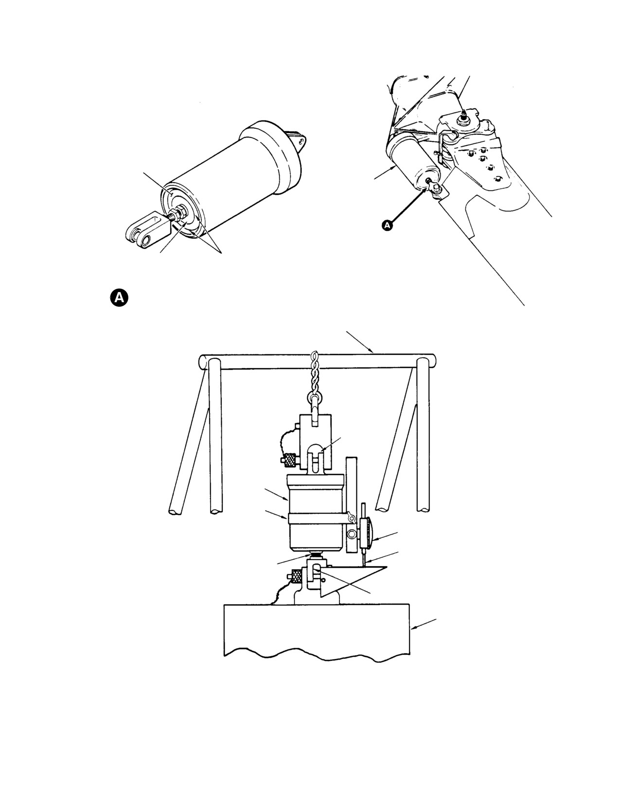
MD Helicopters, Inc.
CSP−H−2
500 Series - Basic HMI
ELASTOMER
(NOTE)
MAIN ROTOR
DAMPER
ALUMINUM DISC
ELASTOMER−TO−METAL BOND
(NOTE)
END FACE − MAIN ROTOR DAMPER
HOLDING BAR OR
FIXTURE
END CAP
DAMPER
CLAMP
INDICATOR
INDICATOR ARM
THREADED SHAFT
CLEVIS
100 LBS (45 KG) WEIGHT
NOTE:
DIAL INDICATOR SETUP
CHECK ELASTOMER AND ELASTOMER−TO−METAL
BOND FOR CRACKS.
G62−2008A
Figure 7-23. Periodic Check of Main Rotor Elastomeric Damper Assembly
Page 7-69
Revision 16
MD Helicopters, Inc.
CSP−H−2
500 Series - Basic HMI
41. Main Rotor Controls
NOTE: Rods are color coded to prevent rein−
stallation in the wrong locations. Observe
coding and location at time of removal. If
(Ref. Figure 7−24) The main rotor controls
coding is no longer visible, reapply appropri−
consist of a scissors assembly, rotating
ate color identity.
swashplate, stationary swashplate, mixer
controls (lateral bellcrank, longitudinal idler,
(3). Measure rod length before replacing.
collective pitch mixer bellcrank, longitudinal
bellcrank, longitudinal control−mixer link,
B. Pitch Control Rod Installation
longitudinal link, and two mixer links) and
four pitch control rods.
(1). If pitch control rods are badly out of
adjustment, or if the rod end bearing
have been replaced, set length of the
Movement of collective pitch stick and cyclic
affected pitch control rod(s).
control sticks is transferred to mixer controls
through control rods routed up through the
(a). For blades with a lower−tracking
controls tunnel at the center of Sta. 78.50
data decal, set pitch control rods,
bulkhead. The mixer controls transfer the
between rod end bearing centerlines,
required combination of collective, longitudinal
to the applicable strap pack pitch
and lateral travel to the main rotor blades
link length specified on the decal of
through the main rotor swashplate assembly.
the mating blade.
(b). For blades without a decal, set pitch
CAUTION
control rods to 6.60 inches (16.764
cm) between rod end bearing center−
D Ensure main rotor controls do not strike
lines for the two blade attached to
or get struck by any object. Many of the
the hub upper strap pack, and 6.35
components are highly stressed and must
inches (16.1544 cm) for the two
not be returned to service if surface dam−
blades attached to the lower strap
age occurs.
pack.
D When maintenance work is being per−
(2). Observe the ground track before
formed near the engine air inlet use care
making addition adjustments.
to prevent entry of foreign objects. Tape
covers of cardboard or other suitable ma−
(3). Install O−ring and pitch control rod.
terial in place over the engine inlet screen
and oil cooler air inlets. Do not remove
NOTE:
covers until work is completed and debris
D Check pitch control rods for location color
is thoroughly cleaned out of the area. Af−
code.
ter removing covers, verify that area
D Blades must be tracked if rod length is
around base of mast, inlet to plenum, and
changed. Be sure that rod end threads are
entire plenum chamber is free of foreign
engaged beyond witness hole in rod body
material.
(hole blocked).
D After proper bearing alignment (center−
42. Pitch Control Rods
ing) in swashplate lugs and pitch housing
lugs, tighten locknuts and install lock−
(Ref. Figure 7−24) Four pitch control rods
wire.
transfer pitch control from the rotating
D Rod ends must be centered; if not cen−
swashplate to main rotor blades.
tered, fitting wear will result.
D Be sure that pitch rod bolts are installed
A. Pitch Control Rod Removal
with the bolthead in the direction of rota−
tion (counter−clockwise as viewed from
(1). Remove cotter pin, nut washer and bolt
above).
from each end of pitch control rod.
(4). Install bolt, washer and nut in upper
(2). Remove pitch control rod and O−ring.
end of rod. Torque nut to 100 − 140
Page 7-70
Revision 16
MD Helicopters, Inc.
CSP−H−2
500 Series - Basic HMI
inch−pound (11.30 − 15.82 Nm) and
inch−pounds (1.69 − 2.26 Nm). Install
install new cotter pin.
new cotter pin.
NOTE: If castellation alignment is not possible
Scissors crank must be posi−
CAUTION
with the torque specified in step (5). below,
tioned with hole in crank web
add another washer. Do not exceed the max−
down and decal, if present, up.
imum torque value.
NOTE: Ensure crank− to− hub lower shoe lugs
are not preloaded.
(5). Install bolt, washer, and nut in lower
end of rod. Torque nut 30 − 60 inch−
(3). Position scissors crank and required
pound (3.39 − 6.78 Nm) and install
shim washers on hub lower shoe lugs.
new cotter pin.
(a). Install bolts with bolt heads facing
43. Scissors Assembly
outward and a washer under the
head of the bolt.
(Ref. Figure 7−24) The scissors assembly is a
pivoting link that provides a movable connec−
(b). Torque nut to 30 − 60 inch−pounds
tion between the rotating swashplate and the
(3.39 − 6.78 Nm). Install new cotter
main rotor hub.
pin.
NOTE: Shim washers may be required on
A. Scissors Assembly Removal
shouldered bushing side of clevis.
Removal of all pitch control rods
CAUTION
(4). Position O−ring and lower end of pitch
is recommended prior to scissors
control rod in swashplate lug and
removal. Failure to observe this precaution
install attaching hardware.
could result in damage to pitch control rods,
swashplate and/or hub.
(a). Nut is to be adjacent to bushing in
swashplate.
(1). Disconnect lower end of pitch control
rod that is in line with scissors link in
(b). Torque nut to 30 − 60 inch−pounds
rotating swashplate.
(3.39 − 6.78 Nm). Install new cotter
pin.
(2). Remove cotter pin, nut, washer, and
bolt from each leg of scissors crank.
C. Scissors Disassembly
Disconnect crank from hub lower shoe,
(1). Remove cotter pin, nut, washer, and
use care to prevent loss of shim wash−
bolt that join link and crank.
ers.
(2). Remove two bushings from link only if
(3). Remove cotter pin, nut, washer, and
replacement is necessary.
bolt connecting scissors link to swash−
plate; remove scissors assembly.
(3). Do not remove bearing from link.
Replace complete link if bearing is
B. Scissors Assembly Installation
defective.
(1). Place scissors assembly link in mount−
(4). Remove two lotted bushings and two
ing position, chamfered edge of link
bearings from crank, only if replace−
must face outboard.
ment is necessary,
(2). Check that slotted bushing is in
NOTE: During cleaning, do not allow solvent to
swashplate web and install attaching
enter the races of scissors assembly bear−
hardware. Torque nut to 15 − 20
ings.
Page 7-71
Revision 16
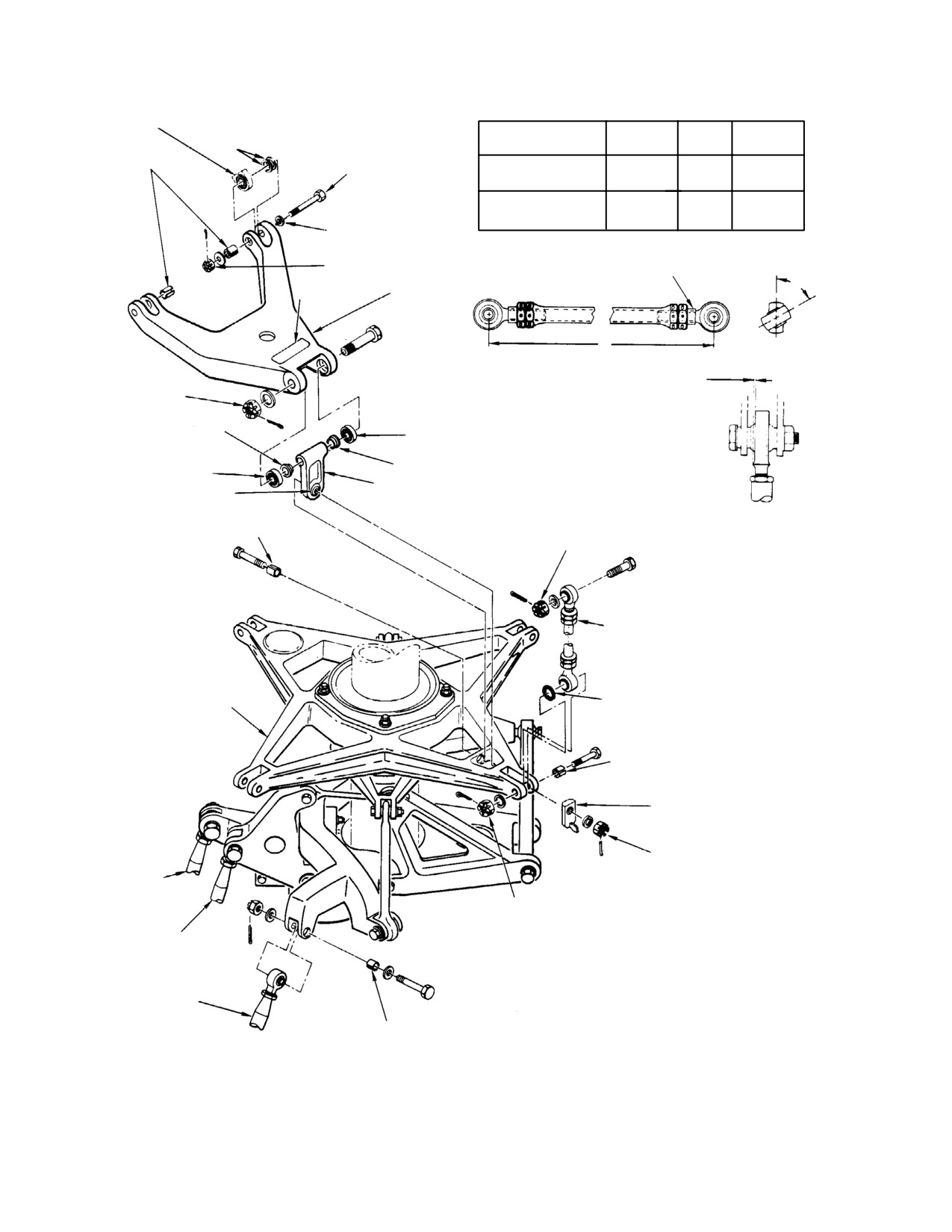
MD Helicopters, Inc.
CSP−H−2
500 Series - Basic HMI
ROTOR HUB
SHIMS/SHIM
INITIAL ROD LENGTH AND BEARING ANGULARITY
LOWER SHOE
WASHERS
CONTROL
DIM
ANGLE
ASSY PART
(NOTE 5)
SLOTTED BUSHING
ROD ASSY
L − IN. (CM)
A
NUMBER
(NOTE 1)
369A1020−3 OR
MAIN ROTOR PITCH
6.35
IN LINE
369A1008−3
NAS464P4−17
(LOWER STRAP PACK)
(16.1544)
MAIN ROTOR PITCH
6.60
IN LINE
369A1008−3
(UPPER STRAP PACK)
(16.764)
SHIM WASHER
(NOTE 3)
30−60 IN. LB (3.39−6.78 NM)
PART NO. 369A1011 ROD
DECAL
END HAS LH THREAD
SCISSORS
A
(NOTE 4)
CRANK
L
MAX ALLOWABLE LOOSENESS
30−40 IN. LB
0.040 IN. (1.016 MM)
(3.39−4.52NM)
BUSHING
BEARING
BUSHING
BEARING
SCISSORS LINK
BEARING
SLOTTED BUSHING
(NOTE 1)
60−140 IN. LB
(6.78−15.82 NM)
PITCH CONTROL ROD
(NOTE 2)
ROTATING SWASHPLATE
O−RING
SLOTTED BUSHING
(NOTE 1)
TRACKING INTERRUPTER
(369A9946−29)
30−60 IN. LB
(3.39−6.78 NM)
COLLECTIVE PITCH
CONTROL ROD
30−60 IN. LB
(3.39−6.78 NM)
LONGITUDINAL PITCH
CONTROL ROD
NOTES:
1.
EDGE OF BUSHING MUST PROTRUDE A MIN. OF 0.010 IN.
(0.254 MM) TO A MAX. OF 0.060 IN. (1.524 MM) ABOVE
LATERAL PITCH
OUTSIDE SURFACE OF PART AFTER NUT IS TIGHTENED.
CONTROL ROD
2.
COLOR−CODED TO MATCH BLADE.
3.
ADD WASHERS UNDER HEAD AS REQUIRED FOR
SLOTTED BUSHING
CLEARANCE BETWEEN BOLT END AND SWASHPLATE BOOT.
(NOTE 1)
4.
ON CURRENT CONFIGURATION ONLY.
5.
USE SHIMS/SHIM WASHERS TO FILL GAP.
30−023F
Figure 7-24. Pitch Control Rods and Swashplate Scissors Assembly Installation
Page 7-72
Revision 16
MD Helicopters, Inc.
CSP−H−2
500 Series - Basic HMI
D. Scissors Inspection
Do not allow sealant to enter
CAUTION
bearing race.
Any evidence of failure,
(e). Apply a small fillet of sealant to the
WARNING
damage, or deformation of
faying edges of the bearing housing.
crank or link is justification for re−
placement of either crank, link, or the
(f). Use cellophane or masking tape to
complete scissors assembly. Failure of
exclude air and allow sealant to cure
any of these component in flight can re−
for 24 hours at ambient temperature
sult in failure of movable flight con−
or force cure by heating to
trols, loss of helicopter, and possible in−
140°−160 °F (60°−71 °C) for 1 hour
jury or loss of life.
prior to use of assembly.
(1). Inspect crank and link for evidence of
(3). If bushings were removed from link
impact damage and deformation. If
during disassembly, install new
condition is questionable, perform a
bushings. Dimension between outside
fluorescent dye penetrant inspection.
faces of bushings is 1.616−1.628 inches
(4.1046−4.1351 mm).
(2). Inspect bearings for binding, looseness
(4). Align bore of link with bore of crank;
in mating bore and wear. Maximum
install bolt, washer and nut. Torque nut
wear limits are 0.010 inch (0.254 mm)
to 30 − 40 inch−pounds (3.39 − 4.52
radial and 0.020 inch (0.508 mm) axial.
Nm). Install new cotter pin.
(3). Inspect bushings for condition.
44. Main Rotor Swashplate
(Ref. Figure 7−25) The main rotor swashplate
E. Scissors Reassembly
consists primarily of a rotating swashplate,
stationary swashplate, a bearing assembly and
(1). If bushings were removed from the
retainer, and a counterweight.
crank during disassembly, install new
bushings. Use lubricant (25, Table 2−4);
A. Swashplate Assembly Removal
do not use primer. Seat bushings until
ends are flush with inside surface of
(1). Tag or color−identify the four pitch
crank inboard ears.
control rods to facilitate their replace−
ment in the same location.
(2). If bearings were removed from crank
Failure to reinstall the four
during disassembly, reinstall using the
CAUTION
pitch control rods in the correct
following procedure:
location will most likely result in the main
rotor blades being badly out of track.
(a). Clean bearing outerace, counterbore,
(2). Disconnect pitch control rods from the
and faying surfaces with trichloroe−
rotating swashplate.
thane (61).
(3). Remove scissors assembly.
(b). Coat the faying surfaces with Locquic
Activator (28) as per manufacturer’s
(4). Remove main rotor hub.
instructions.
(5). Disconnect longitudinal link from
stationary swashplate.
(c). Apply Loctite Sealant A (29) to faying
surfaces and press bearing until
(6). Disconnect right and left side mixer
outer face is seated firmly against
links from stationary swashplate.
shoulder of counterbore.
(7). Remove protective boot from groove in
(d). Remove excess sealant.
lower side of stationary swashplate.
Page 7-73
Revision 16
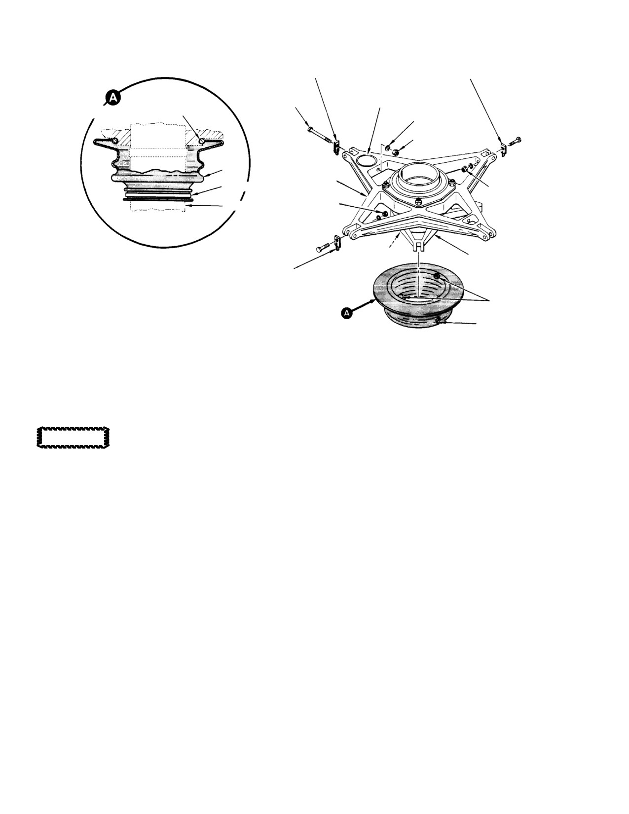
MD Helicopters, Inc.
CSP−H−2
500 Series - Basic HMI
TRACKING INTERRUPTER
TRACKING INTERRUPTER
(369A9946−27; NOTE 1)
(369A9946−25 OR −23; NOTE 1)
STATIONARY
SWASHPLATE
NOTE 2
COUNTERWEIGHT
GROOVE
BOOT INSTALLED
NOTE 3
30−60 IN. LB
(3.39−6.78 NM)
BOOT
ROTATING
NYLON STRAP
SWASHPLATE
15−20 IN. LB
(1.69−2.26 NM)
MAST
15−20 IN. LB
(1.69−2.26 NM)
DRAIN HOLES
STATIONARY
(HIDDEN; NOTE 4)
TRACKING INTERRUPTER
SWASHPLATE
(369A9946−25 OR −23; NOTE 1)
NOTES:
INDEX
1.
COLOR CODE TO MATCH BLADES AND MAINTAIN SEQUENCE
2.
COAT BOLT WITH GREASE (21, TABLE 2−4).
DRAIN HOLES
3.
EXTRA WASHERS FOUND IN THIS LOCATION ARE PART OF
(2 PLCS)
COUNTERWEIGHT.
4.
DRAINAGE PROVISIONS FOR WATER ENTRAPMENT AREA IN
STATIONARY SWASHPLATE LOWER FORWARD FLANGE.
(REF. MDHS SERVICE INFORMATION NOTICE HN−39.)
30−024C
Figure 7-25. Main Rotor Swashplate Assembly
Do not strike rotating swash−
NOTE: To inhibit mast corrosion when operat−
CAUTION
plate or bearing assembly with
ing in salt water environment, fresh water
tools or in any way deface these compo−
rinse and thoroughly dry the sliding swash−
nents. The rotating swashplate is a stressed
plate area of mast and lightly coat area with
part that has had all surfaces shot peened.
grease film (18, Table 2−4).
Use particular care to protect Teflon liner in
bearing bore. A damaged swashplate bear−
(3). Engage upper end of boot in groove at
ing must not be retained in service. (Refer to
lower side of stationary swashplate.
HN−1 12 if stiff main rotor controls traceable
Secure boot with self−clinching nylon
to excessive preload torque on main rotor
strap.
swashplate bearing occurs.)
(4). Align longitudinal link with stationary
swashplate (Ref. Figure 7−26).
(8). Lift swashplate assembly carefully up
and off of mast.
(5). Install flanged bushing (if removed),
bolt, two washers, nuts and new cotter
(9). To remove boot from mast, remove
pin to secure upper end of longitudinal
self−clinching nylon strap.
link.
B. Swashplate Assembly Installation
(6). Align upper ends of mixer links with
stationary swashplate. Install slotted
(1). If swashplate lower boot was removed,
bushing (if removed), bolt, two washers
install boot on mast.
nut and new cotter pin to secure each
link to swashplate.
(2). Position swashplate over main rotor
mast and carefully lower into place.
(7). Install scissors assembly.
Page 7-74
Revision 16
MD Helicopters, Inc.
CSP−H−2
500 Series - Basic HMI
(8). Using color code, reinstall pitch control
NOTE: The swashplate bearing assembly will
rods at same locations from which
normally show some signs of grease leakage
removed.
for the first 10−15 hours of operation after a
new installation.
(9). Check track of main rotor blades
(3). Inspect swashplate spherical ball and
following installation of any removed or
double row ball bearing for condition.
replaced parts.
(a). Maximum radial play between
sliding surface liner and the station−
C. Swashplate Disassembly
ary mast is 0.020 inch (0.508 mm).
Disassembly other than as illustrated is
(b). Maximum axial play between spheri−
considered a part of swashplate overhaul.
cal ball and Teflon liner is 0.010 inch
Refer to CSP−H−5 for this type of information.
(0.254 mm).
If tracking interrupters are removed, mark
(c). If play is suspected in double row ball
them to match the blade color code so that they
bearing, turn rotating swashplate
may be returned to the original positions. Also
until arms line up with those of
note the number and type of washers used
stationary swashplate and check
under the nut at the counterweight location.
motion between the arms at the
These are a part of the counterweight required
control bolt in the stationary swash−
for rotating swashplate balance.
plate. A maximum total vertical
movement of 0.015 inch (0.381 mm)
D. Swashplate Assembly Inspection
is allowable.
(d). Nicks and dents that do not deform
When cleaning swashplate as−
CAUTION
ID chamfered edge of the hard
sembly for inspection, use care
anodized ball and that do not extend
to prevent solvent from entering the race
more than 0.040 inch (1.016 mm)
area of either the spherical ball bearing or
along spherical ball surface from
the double row ball bearing. Use a cloth,
edge are allowed.
moistened in alcohol (71, Table 2−4) to wipe
clean the spherical ball, ball bore liner and
(4). Check the existing preload on the
exterior of double row ball bearing.
spherical bearing.
(a). Hold the ball to prevent rotation;
NOTE:
then hook a spring scale over one of
the bolts securing the stationary
D The swashplate may be constructed of ei−
swashplate to the bearing flange.
ther magnesium or aluminum alloy. Ref.
Sec. 2 for corrosion control and identifica−
(b). With the stationary swashplate in
tion of magnesium and aluminum alloys.
motion, drag should be no more than
30 pounds (13.61 kg). (Use the
D In the following inspection, the rotating
average of two readings taken 90
and stationary swashplates must be dis−
degrees apart.)
connected (Ref. Swashplate Assembly Re−
moval/Installation).
(5). Perform a careful visual inspection of
the stationary and rotating swashplate
(1). Inspect swashplate bearing assembly
for cracks, wear in bolt and bushing
for evidence of binding in either radial
bores and fork inner surfaces, and for
or axial movement.
corrosion, nicks and dents. Perform dye
penetrant check on questionable areas.
(2). Inspect Teflon liners for good condition.
(6). Check that counterweight is securely
Ensure that all flexible rubber seals
bonded in rotating swashplate.
enclosing ball bearing races are in
E. Swashplate Reassembly
place; inspect for deterioration and
indication of grease leakage. Refer to
Reinstall tracking interrupters in original
CSP−H−5 for re−greasing and seal
color coded positions and torque nuts to the
replacement.
values shown.
Page 7-75
Revision 18
MD Helicopters, Inc.
CSP−H−2
500 Series - Basic HMI
NOTE: When installing tracking interrupter at
Do not allow solvent to enter
CAUTION
the counterweight position, apply grease
bearing races when cleaning
(21, Table 2−4) to the bolt and to the 0.250
mixer control components to prevent wash−
inch (6.35 mm) diameter bore areas. Also be
ing of dirt into bearing surfaces or grease
sure to reinstall all washers that were origi−
out of the bearings.
nally installed under the nut. These area
B. Mixer Controls Installation
part of the counterweight required for rotat−
ing swashplate balance.
(1). Position support bracket over forward
lug on mast base.
45. Mixer Controls
(2). Install the two aft bolts and washers in
the support bracket and mast base.
(Ref. Figure 7−26) The mixer controls consist
Install two thin washers and nuts;
of various links, bellcranks, idlers, a support
torque nuts to 80 − 100 inch−pounds
bracket and associated fasteners that secure
(9.04 − 11.30 Nm) plus drag torque.
these components in place and to the control
tubes and main rotor swashplate.
(3). Using a ball hole gage and standard
micrometer, check that misalignment
A. Mixer Controls Removal
between the forward bolt hole bore in
the support bracket and the bore in the
(1). Remove air intake forward fairing for
mast base lug is 0.015 inch (0.381 mm)
access (Ref. Sec. 2).
or less.
(2). Disconnect upper end of the collective
NOTE: If necessary, loosen the aft two bracket−
mixer, lateral mixer and longitudinal
to−fitting nuts, position support bracket to
mixer control tubes.
minimize misalignment and retighten nuts.
(4). Install mixer support attaching bushing
NOTE: The control tubes are attached by
in bracket and mast base lug.
slightly different length bolts. Reinstall
each bolt in its bellcrank following control
(5). Check that the sleeve bushing is in
tube removal to facilitate reinstallation of
place; then install bolt, two washers
the correct size.
and nut. Torque nut to 80 − 100
inch−pounds (9.04 − 11.30 Nm).
(3).
Remove mixer links. (Mixer link
bearings are not replaceable.)
(6). Position longitudinal pitch idler and
collective pitch mixer bellcrank on
(4).
Disconnect longitudinal link.
support bracket.
(a). Position washer between right side of
(5).
Disconnect each end of longitudinal
longitudinal pitch idler bearing and
control−mixer link and remove link.
center bearing of mixer support
(6).
Disconnect lateral bellcrank and lift
bracket.
from collective pitch mixer bellcrank.
(b). Install left−hand bearing, bolt, two
washers, nut and new cotter pin.
(7).
Disconnect longitudinal pitch mixer
bellcrank and carefully remove bell−
(7). Position lateral bellcrank between
crank.
collective pitch mixer bellcrank bear−
ings and install bolt, two washers, nut
(8).
Remove hardware from hingeline of
and new cotter pin.
support bracket, longitudinal pitch idler
(8). Position longitudinal bellcrank with
and collective pitch mixer bellcrank.
collective pitch mixer bellcrank.
Separate the three parts.
(a). Insert the two flanged bushings into
(9).
Disconnect support bracket from mast
place.
base and remove.
(b). Install two bolts, six washers (two
(10).
Remove the mixer support attaching
under each nut), two nuts and new
bushing.
cotter pins.
Page 7-76
Revision 16
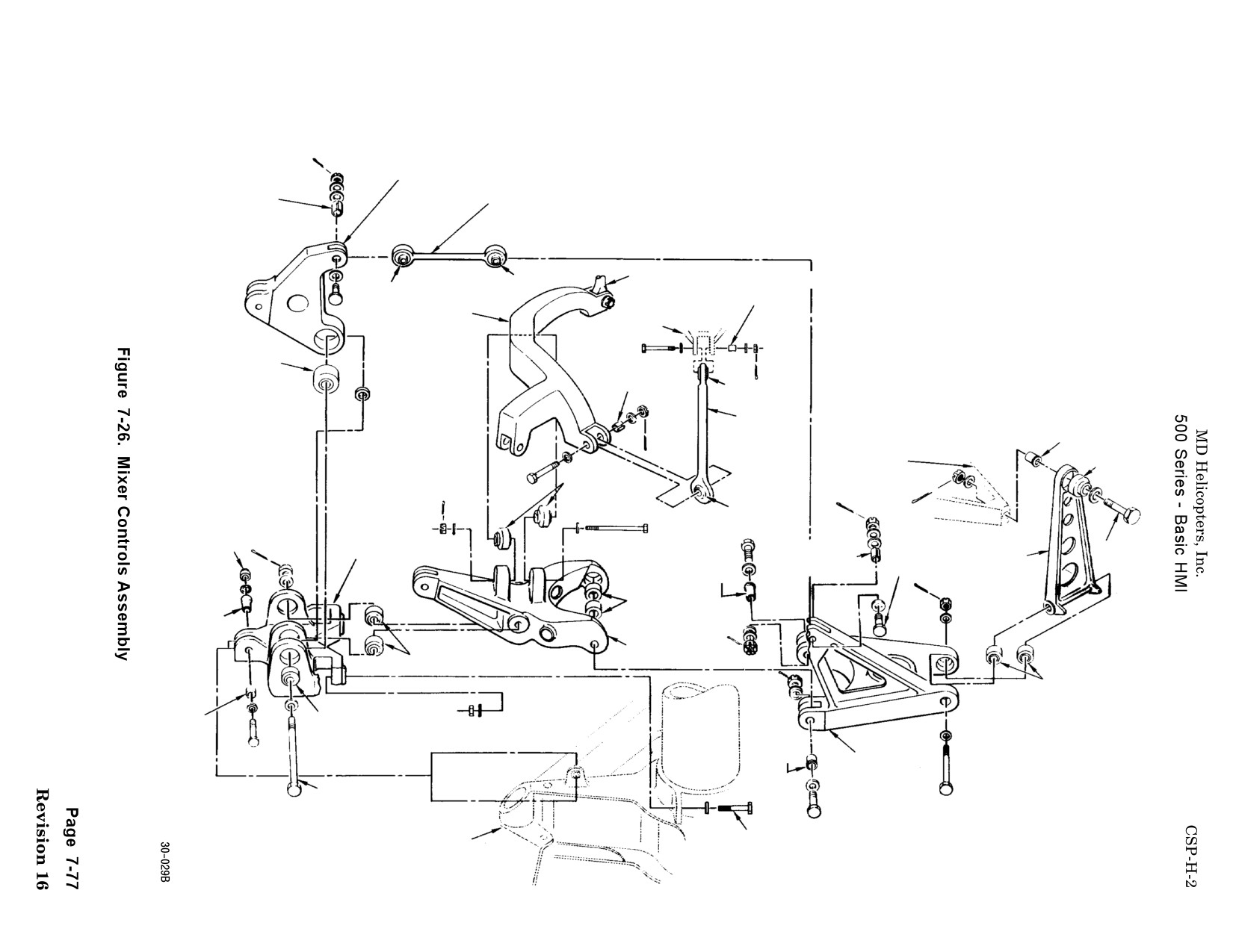
NOTES:
3.
LONGITUDINAL LINK DETAILS ROTATION
1.
DIRECTION OF BOLT OPTIONAL.
FOR CLARITY.
2.
EDGE OF BUSHING MUST PROTRUDE
4.
NOT PART OF SUPPORT BRACKET.
A MIN. OF 0.010 IN. (0.254 MM) TO A MAX.
* LONGITUDINAL
5.
MUST BE PULLED OUT FIRST TO REMOVE
OF 0.060 IN. (1.524 MM) ABOVE OUTSIDE
PITCH MIXER
SLOTTED
LONGITUDINAL CONTROL
BELLCRANK.
SURFACE OF PART AFTER NUT IS
BUSHING
6.
SPHERICAL BEARING WITH TEFLON OR
MIXER LINK
TIGHTENED.
(NOTE 2)
EQUIVALENT LINING. WEAR LIMIT
0.008 IN. (0.203 MM) RADIAL OR 0.040 IN.
(1.016 MM) AXIAL.
7.
ASTERISK ( * ) INDICATES PARTS MAY BE
MIXER LINK
NOTE 6
SLOTTED BUSHING
EITHER MAGNESIUM OR ALUMINUM ALLOY.
NOTE 6
(NOTE 2)
* LATERAL MIXER
REF. SEC. 2 FOR ALLOY IDENTIFICATION
BELLCRANK
AND CORROSION CONTROL.
STATIONARY
SWASHPLATE
BEARING
SLOTTED BUSHING
(NOTE 2)
NOTE 6
FLANGED
MIXER LINK
BUSHING
BEARING
STATIONARY
(NOTE 6)
SWASHPLATE
BEARING
NOTE 6
80−100 IN. LB
(9.04−11.30 NM)
MIXER SUPPORT
BRACKET
SLOTTED BUSHING
LONGITUDINAL LINK
NOTE 1
FLANGED BUSHING
(NOTE 2)
(NOTE 3)
NOTE 1
(NOTE 5)
MIXER
BEARING
SUPPORT
ATTACHING
BUSHING
* COLLECTIVE PITCH
BEARING
MIXER BELLCRANK
BEARING
SLEEVE
BEARING
BUSHING
FLANGED
(NOTE 4)
BUSHING
(NOTE 5)
* LONGITUDINAL
PITCH MIXER
NOTE 1
BELLCRANK
MAST BASE
80−100 IN. LB
(9.04−11.30 NM)
MD Helicopters, Inc.
CSP−H−2
500 Series - Basic HMI
(9). Position longitudinal control−mixer link
(a). Wear limit is 0.008 inch radially and
between longitudinal pitch idler and
0.040 inch (1.016 mm) axially.
longitudinal pitch mixer bellcrank.
(b). Replace complete mixer link if
(a). Check that two slotted bushings are
bearings are faulty.
in place.
(c). Inspect bearings in other linkage for
binding and looseness in mating
(b). Install bolt, three washers (two
bores.
under each nut), nut and new cotter
pin at each end of link.
D. Mixer Control Repair
(10). Position longitudinal link between
Repair minor surface defects such as
longitudinal, pitch mixer bellcrank
scratches, nicks and corrosion using abrasive
bearings. Install bolt, two washers, nut,
cloth (20, Table 2−4), grade 400−600 to smooth
and new cotter pin.
out and blend in such defects. The following
depth limits represent total limits, including
(11). Position mixer links in stationary
the effects of all previous repair to any given
swashplate and lateral bellcrank; check
area.
that slotted bushings are in place.
Install bolt, two washers, nut, and new
(1).
Cast and forged surfaces may be
cotter pin at each end of link.
reworked to a depth of 0.020 inch (0.508
mm).
(12). Place the collective mixer, lateral mixer,
and longitudinal mixer control tubes in
(2).
Flat machined surfaces, except clevis
position.
inner ears, may be reworked to a depth
of 0.015 inch (0.381 mm). Clevis inner
(a). Check that slotted bushings are in
ear surfaces may be reworked to a
place.
depth of 0.020 inch (0.508 mm).
(3).
Machined holes, may have 0.003 inch
(b). Install bolt, two washers, nut, and
(0.0762 mm) removed from the bore
new cotter pin to secure each rod end.
wall in an area no greater than 15
(13). Install air intake forward fairing.
percent of the circumference and 50
percent of the depth.
(14). Check rigging of collective and cyclic
(4).
All edges may have 0.030 inch (0.076
controls following installation of any
mm) removed except round machined
removed or replaced parts.
holes which are limited to 0.010 inch
(0.254 mm) chamfer.
C. Mixer Controls Inspection
(5).
All rework must be smoothly blended
(1). Inspect all bushings for security of fit.
into the adjacent surfaces and the
finish must be restored on magnesium
(2). Inspect longitudinal link, support
parts and aluminum parts (Ref. Sec. 2).
bracket, longitudinal control−mixer
link, mixer links, longitudinal pitch
(6).
Replace defective bearings and bush−
idler, longitudinal pitch mixer bell−
ings, except swaged spherical bearings
crank, lateral bellcrank and collective
in mixer links which require link
pitch mixer bellcrank for scratches,
replacement.
cracks, corrosion and similar surface
defects. Perform a fluorescent dye
(a). Remove bearings or bushings by
penetrant inspection on components
pressing out the old part.
that are questionable.
(b). Install a new bearing of the correct
(3). Inspect spherical, Teflon (or equivalent)
type with surface primer and grade A
lined bearings for binding/looseness in
locking compound (28 and 29)
link bore and wear.
according to container instructions.
Page 7-78
Revision 16

MD Helicopters, Inc.
CSP−H−2
500 Series - Basic HMI
NOTE: The left−hand bearing in the support
Use care during removal of con−
CAUTION
bracket is not supplied as a part of the
trol tubes. Any surface damage
bracket. This bearing is installed at the time
caused by hasty removal may result in un−
the support bracket and longitudinal pitch
serviceable control tubes.
idler are assembled. Install a new bearing
(7). Grasp upper end of control tube and
by seating flush with inner face of support
carefully withdraw tube until lower end
bracket flange.
clears the cover.
B. Tunnel-Routed Control Tube Installation
(7). Mixer links at the lateral mixer
bellcrank are either smooth contoured
(1). Hand turn main rotor blades to obtain
or octagonal shaped with check nuts.
clear space for tube installation.
Do not disassemble or intermix types.
Use care during installation of a
CAUTION
control tube to avoid striking
other installed control tubes.
46. Tunnel-Routed Control Tubes
(2). With the riveted rod end at the lower
(Ref. Figure 7−27) Each tunnel−routed control
position, carefully lower tube through
tube consists of two rod end bearings and an
cover opening into tunnel.
anodized aluminum alloy tube. The control
(3). Install control tunnel cover boot and
tubes mechanically transfer displacement of
secure with self−clinching nylon strap.
the flight controls to the associated bellcranks
and idler at the front of the main rotor mast
Do not tighten loosened jam
CAUTION
base. All the tunnel−routed control tubes are
nuts on rod end bearings with−
removed, inspected, repaired and installed in
out holding the rod end with a wrench.
the same manner.
(4). Align lower rod end with mating
bellcrank. Install bolt, two washers,
A. Tunnel-Routed Control Tube Removal
nut, and new cotter pin.
(5). Align upper rod end of control tube with
Before disconnecting collective
mating idler or bellcrank. Install bolt,
CAUTION
pitch control tube, install collec−
two washers, nut, and new cotter pin.
tive bungee installation tool to prevent
(6). Remove bungee installation tool used
spring reaction due to droop stop load on
for removal of collective control tube.
control tube.
(7). Perform controls rigging check follow−
ing installation of removed or replaced
(1). Install collective bungee installation
parts.
tool (26, Table 2−2).
C. Tunnel-Routed Control Tube Inspection
(2). Gain access to lower tube ends by
(1). Inspect rod end bearings for binding
removing controls access door at base of
and excessive wear, 0.040 inch (1.016
canted bulkhead in cargo compartment.
mm) maximum axial play.
(2). Inspect control tube for surface damage
(3). Disconnect lower tube end from
and evidence of bending.
bellcrank or fitting.
(3). Inspect for loose rivets at fixed rod end
(lower end).
(4). Hand turn main rotor blades to obtain
clear space for tube removal.
(4). Inspect longitudinal mixer control tube.
Control tube is an ‘‘On Condition" item.
(5). Remove cotter pin, two washers, and
When tightening loosened jam
CAUTION
bolt securing upper end of control.
nut on rod ends as in step (5).
Disconnect upper end of control tube.
below, always hold rod end with wrench.
(5). Determine if excessive rod end loose−
(6). Remove boot from control tunnel cover.
ness exists in tunnel−routed control
Page 7-79
Revision 16
MD Helicopters, Inc.
CSP−H−2
500 Series - Basic HMI
tube assemblies by checking the upper
(h). Disconnect rod end from control
end as follows.
system.
(i). Screw rod end completely out of
Do not disconnect rod ends from
CAUTION
control tube.
mixer assembly to perform this
inspection except as instructed.
(j). Use 0.339 inch (8.6106 mm) diameter
drill to check tube threads.
(a). Loosen jam nut a minimum of two
threads.
(k). If drill can be inserted, tube assembly
is unserviceable and must be re−
(b). Apply light finger pressure to the top
placed.
of the rod end to preload it against
one side of attaching clevis. This will
(l). If drill cannot be inserted, tube is
eliminate play other than where
serviceable.
inspection is desired.
(m). Reinstall rod end, reconnect tube to
(c). Use a dial indicator or position a 6
control system and tighten jam nut.
inch (15 cm) rule horizontally at the
upper end of the tube (where the tube
(n). Check rigging of reconnected control
end enters). Lightly deflect tube
system.
laterally from one extreme to other.
D. Tunnel-Routed Control Tube Repair
NOTE: Maintain the preload of the rod end
bearing to eliminate the effect of bearing
(1). Perform straightness check on control
looseness.
tube that appears bent or bowed.
(d). Measure the total movement of the
(a). Total length of any tunnel−routed
top of the tube where the tube end
tube (excluding rod ends) must be
centers.
straight within 0.050 inch (1.270
mm), with straightness variation
limited to maximum of 0.010 inch
(e). If total lateral movement from one
(0.254 mm) in each foot of length.
extreme to the other is in excess of
0.0625 inch (1.5875 mm), the entire
Dye−check for cracking must
tube assembly must be replaced with
WARNING
always be performed after
serviceable parts.
cold− straightening. Replace cracked
tube, or cracked or bent rod end.
NOTE: Because of normal tolerance build some
play or looseness is expected. Play or loose−
(2). Cold−straighten bent tube that is not
ness less than 0.0469 inch (1.1906 mm) is no
within tolerance (step (1). above)
cause for concern.
provided there are no nicks or sharp
dents in bent length. Do not use rod
(f). If the total lateral movement is less
ends to support tube during straighten−
than 0.0469 inch (1.1906 mm), the
ing.
tube assembly is serviceable; tighten
the jam nut. Movement of less than
Use care when drilling to re−
0.0469 inch (1.1906 mm) is consid−
CAUTION
move or install riveted rod end;
ered negligible.
the rod end is steel and the tube is alumi−
num.
(g). If the lateral movement is
0.0469−0.0625 inch (1.1906−1.5875
(3). Replace a control rod end if bearing
mm), the rod end should be further
axial play is more than 0.040 inch
inspected for serviceable steps (h).
(1.016 mm). Set initial control tube
thru (n). below.
length and bearing angularity.
Page 7-80
Revision 16
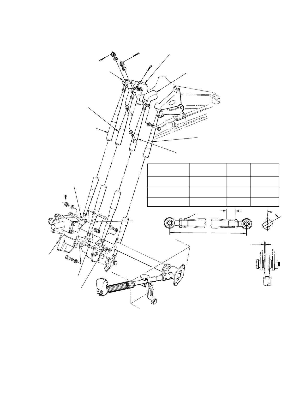
MD Helicopters, Inc.
CSP−H−2
500 Series - Basic HMI
LONGITUDINAL PITCH IDLER
COLLECTIVE PITCH
MIXER BELLCRANK
LATERAL BELLCRANK
LONGITUDINAL MIXER
CONTROL ROD
COLLECTIVE MIXER
CONTROL ROD
TAIL ROTOR CONTROL ROD
LATERAL MIXER CONTROL ROD
INITIAL ROD ASSY LENGTH AND BEARING ANGULARITY (BEFORE RIG)
CONTROL
DIM L
ANGLE
ASSY PART
ROD ASSY
IN.(CM)
A
NUMBER
COLLECTIVE
56.51−56.67
LONGITUDINAL MIXER
IN LINE
369A7011
PITCH FITTING
(143.535−143.942)
55.67
LATERAL MIXER
IN LINE
369A7012
(141.402)
53.14
COLLECTIVE MIXER
IN LINE
369A7009
(134.976)
2.0 IN. (5.08 CM)
RIVET
(NOTE)
A
SERIAL NO.
PLATE
L
MAX ALLOWABLE LOOSENESS
0.040 IN. (1.016 MM)
CONTROLS
SUPPORT
BRACKET
LONGITUDINAL IDLER
BELLCRANK
LATERAL IDLER
BELLCRANK
NOTE:
INSPECT FOR WEAR. REPLACE RODS WITH
WEAR DEPTH EXCEEDING 0.020 IN. (5.06 CM) OR
HAVING O.D. LESS THAN ALLOWABLE MINIMUM.
30−045C
Figure 7-27. Tunnel-Routed Control Tubes
Page 7-81
Revision 16
MD Helicopters, Inc.
CSP−H−2
500 Series - Basic HMI
47. Tunnel-Routed Control Tube Inspection
(c). Measure outside diameter of control
and Sleeve Installation
tube end and select proper sleeve.
(Ref. Figure 7−28) The following procedures
(d). Temporarily install sleeve onto
are for inspection and installation of reinforc−
control tubes.
ing sleeves to the tunnel−routed control tubes.
(e). Align sleeve and control tube witness
A. Control Tube Tapered Area Sleeve
hole.
Installation
(f). If sleeve protrudes past end of control
(1). Remove all four control tubes (Ref.
tube, trim end of sleeve flush, 0.0
Tunnel−Routed Control Tube Replace−
inch (0.0 mm), or back 0.080 inch
ment).
(2.032 mm) from end of tube.
(2). Using paint remover (11, Table 2−4)
NOTE: Bond integrity is dependent on clean
remove paint approximately six inches
surfaces.
(15 cm) back from end of each tube,
(g). Thoroughly clean end of control tube
tape and cover−rap remaining area of
and interior surface of sleeve with
tube.
lint free cloth and MEK (22) or
NOTE: Control tubes that are cracked must be
equivalent.
removed from service.
(h). Mix epoxy adhesive (121) per
(3). Dye penetrant inspect external surface
manufacturer’s instructions.
of stripped area for cracks.
(i). Remove excessive adhesive with lint
(a). Cracks are indicated by heavy bleed
free cloth moistened with MEK or
out.
equivalent. Do not saturate the
cleaning cloth. Remove adhesive from
NOTE: It may be necessary to wipe off and
witness holes.
reapply the developer to distinguish be−
tween surface defects caused during swag−
(j). Plug end of control tube to prevent
ing operation.
adhesive from entering threads. Bond
sleeve to control tube. Apply adhesive
(b). Light penetrant indications are not
to both surfaces and install sleeve.
cause for rejection.
Align witness/rivet hole in sleeve and
tube.
(4). If no cracks are found; inspected control
tube can be reworked for sleeve instal−
Do not use heat gun. Use of heat
lation. All four control tubes are to be
CAUTION
lamp is acceptable.
reworked as follows:
(k). Allow to cure for 24 hours at mini−
(a). Measure and record length of control
mum ambient temperature of 68°F
tubes for reinstalling rod ends and to
(20°C); alternate cure 4 hours at
prevent rerigging after tube rein−
115°−140 °F (46°−60 °C).
stallation.
(l). Repeat procedure for ends of each
Drilled out rivets may damage
control tube.
CAUTION
threads upon removal. Visually
inspect control tube threads for damage
(m). Using primer (4), touch−up repaired
from rivet and rod end removal. Replace
area(s) of control tube.
damaged control tubes. Drilled rod ends are
(n). Install rod ends into ends in which it
matched drilled to each control tube and
was removed. On fixed rod end, align
must be reinstalled into control tube end
witness/rivet hole in sleeve and tube
from which removed.
with rivet hole in rod end. Drill (#40)
(b). Remove rod ends, MS20470AD3
thru opposite end of sleeve. Rivet
rivets must be removed from fixed
fixed end with MS20470AD3−15
end.
rivet.
Page 7-82
Revision 16
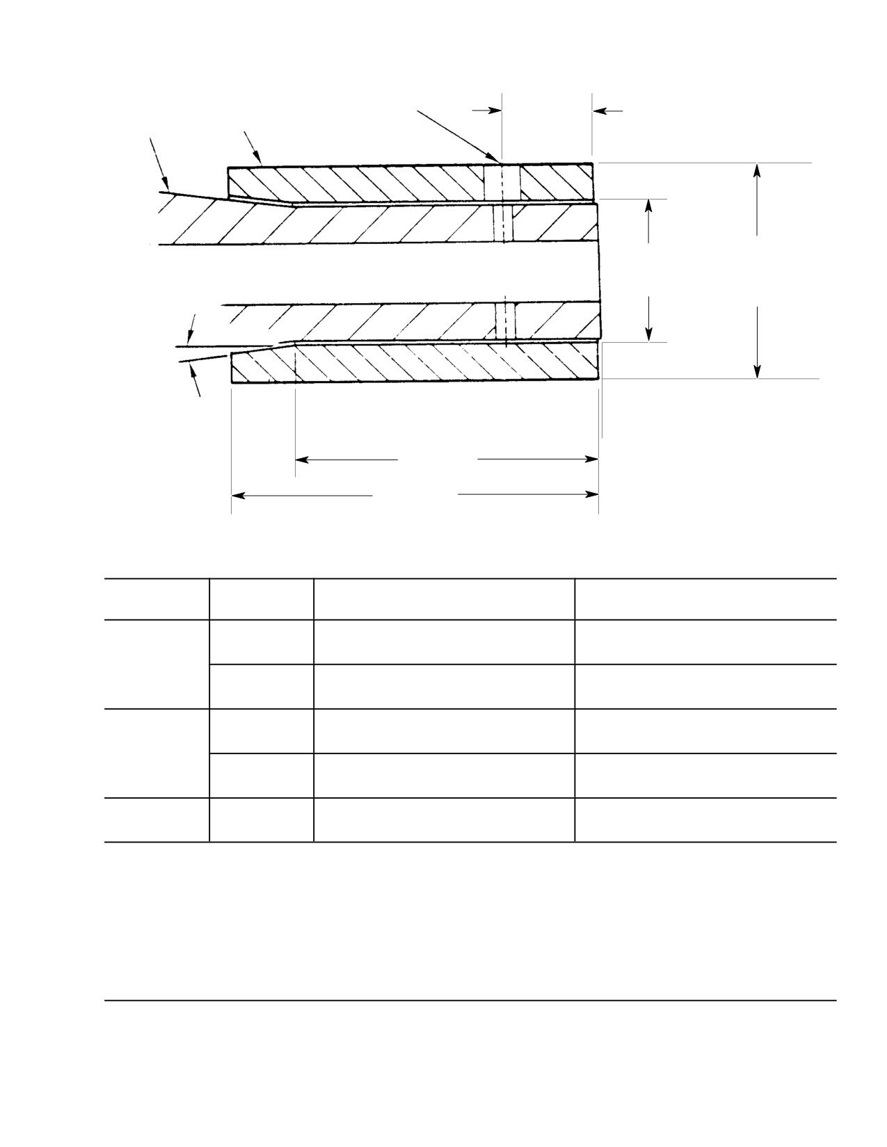
MD Helicopters, Inc.
CSP−H−2
500 Series - Basic HMI
0.097−0.102 IN.
0.340 IN.
CONTROL
(2.4638−2.5908 MM)
(8.636 MM) *
SLEEVE
TUBE
A
0.750 IN.
DIA
(19.05 MM)
7°
0.00−0.080 IN.
±
0.5°
(0.00−2.032 MM)
0.720 IN.
(18.288 MM)
0.910 IN.
(23.114 MM) *
54−412A
Dimensional Table
Sleeve No.
Dim A
Tube O.D.
Tube No.
369D27013
inch (mm)
inch (mm)
-1
0.540-0.545
(13.716-13.843)
0.501-0.530
(12.7254-13.462)
369A7007
369A7009
-2
0.510-0.515
(12.954-13.081)
0.470-0.500
(11.938-12.7)
-3
0.590-0.595
(14.986-15.113)
0.551-0.580
(13.9954-14.732)
369A7011
-4
0.560-0.565
(14.224-14.351)
0.520-0.550
(13.208-13.97)
369A7012
-5
0.570-0.575
(14.478-14.605)
0.530-0.560
(13.462-14.224)
NOTE:
(1) Material; 2024-T351 or T4 (QQA 225/6) bar or round stock.
(2) Break sharp edges 0.005-0.015 inch (0.127-0.381 mm).
(3) Surface finish 125 RMS.
(4) Chemical film per MIL-C-5541.
(5)
* - Tolerance ±0.010 inch (0.254 mm).
Figure 7-28. Sleeve Fabrication and Installation
Page 7-83
Revision 16
MD Helicopters, Inc.
CSP−H−2
500 Series - Basic HMI
(o). Adjust each control tube to its
B. Control Tube Straight Area Sleeve
previously measured length and
Installation
paint the control tube ends with
primer. Paint adjustable ends of
This repair is permissible on the straight area
control tube flat black.
of the tube only and increases the outside
diameter.
(p). Re−identify , with permanent ink, the
control tubes that have been re−
NOTE: Ensure adequate clearance exists prior
worked (Ref. Table 7−9).
to performing the repair. Determine and re−
(q). Rework control tube boot (Ref.
pair condition that caused damage. Maxi−
Figure 7−29).
mum length of repair sleeve is 6 inches. Two
sleeve repairs permitted per control tube.
If control tube is not accurately
CAUTION
measured, flight controls will
(1). Remove damaged control tube(s) (Ref.
require re−rigging.
Tunnel−Routed Control Tube Replace−
ment).
(r). Reinstall control tubes. Reinstall
trimmed boot with vertical seam
facing aft. Check flight controls for
(2). Tape around area to be repaired.
interference or binding.
(3). Using paint remover (11, Table 2−4),
Table 7-9. Control Tube Re-Identification
strip paint 1.0 inch (2.54 cm) beyond
area of repair.
Old Part Number
New Reworked Part Number
369A7007
369A7007-5
(4). Polish out burrs and sharp edges.
369A7009
369A7009-5
Ensure defects do not exceed allowable
limits (Ref. Table 7−10). Dye penetrant
369A7011
369A7011-5
inspect area per MIL−I−25135; no
369A7012
369A7012-5
cracks allowed.
Table 7-10. Control Tube Straight Area Repair Limits
Nicks and Gouges (2)
Dents and Depressions (2)
Repair Sleeve (3)
Control
Max. Depth
Max. Depth
Max. Depth
Max. Depth
Wall
Tube
W/O Repair
With Repair
W/O Repair
With Repair
O.D.
Thickness
(4)
(1)
(4)
(1)
0.006 inch
0.015 inch
0.010 inch
0.025 inch
1.375 inch
0.049 inch
369A7007
(0.152 mm)
(0.381 mm)
(0.254 mm)
(0.635 mm)
(3.4925 cm)
(1.2446 mm)
0.008 inch
0.020 inch
0.010 inch
0.025 inch
1.50 inch
0.049 inch
369A7009
(0.203 mm)
(0.508 mm)
(0.254 mm)
(0.635 mm)
(3.810 cm)
(1.2446 mm)
369A7011
0.010 inch
0.025 inch
0.010 inch
0.025 inch
1.625 inch
0.049 inch
369A7012
(0.254 mm)
(0.635 mm)
(0.254 mm)
(0.635 mm)
(4.1275 cm)
(1.2446 mm)
NOTE:
(1) Sleeve repair not permitted in tapered area. Two sleeve repairs per control tube. Maximum defect area
0.375 in2 (2.41935 cm2 ) per sleeve.
(2) Must be free of burrs and sharp areas.
(3) Aluminum tube 6061-T6 WW-T-700/6 or 2024-T3 WW-T-700/3. Alternate: field fabricate from
2024-T351 or 2024-T4 (QQ-A-225/6 or QQ-A-200/3). Inside diameter to be 0.010-0.025 inch
(0.254-0.635 mm) larger than outside diameter of tube to be repaired. Outside diameter as listed in table,
±0.010 inch (0.254 mm) and concentric to inside diameter 0.005 inch (0.127 mm). Maximum length of
repair sleeve 6 inches (15.24 cm). Break sharp edges 0.005-0.015 inch (0.127-0.381 mm).
(4) Maximum defect area without repair 0.10 in2 (0.64516 cm2) total. For threaded area, last 2 inches (5.08
cm) of both ends, maximum depth of defect 0.020 inch (0.508 mm).
Page 7-84
Revision 16
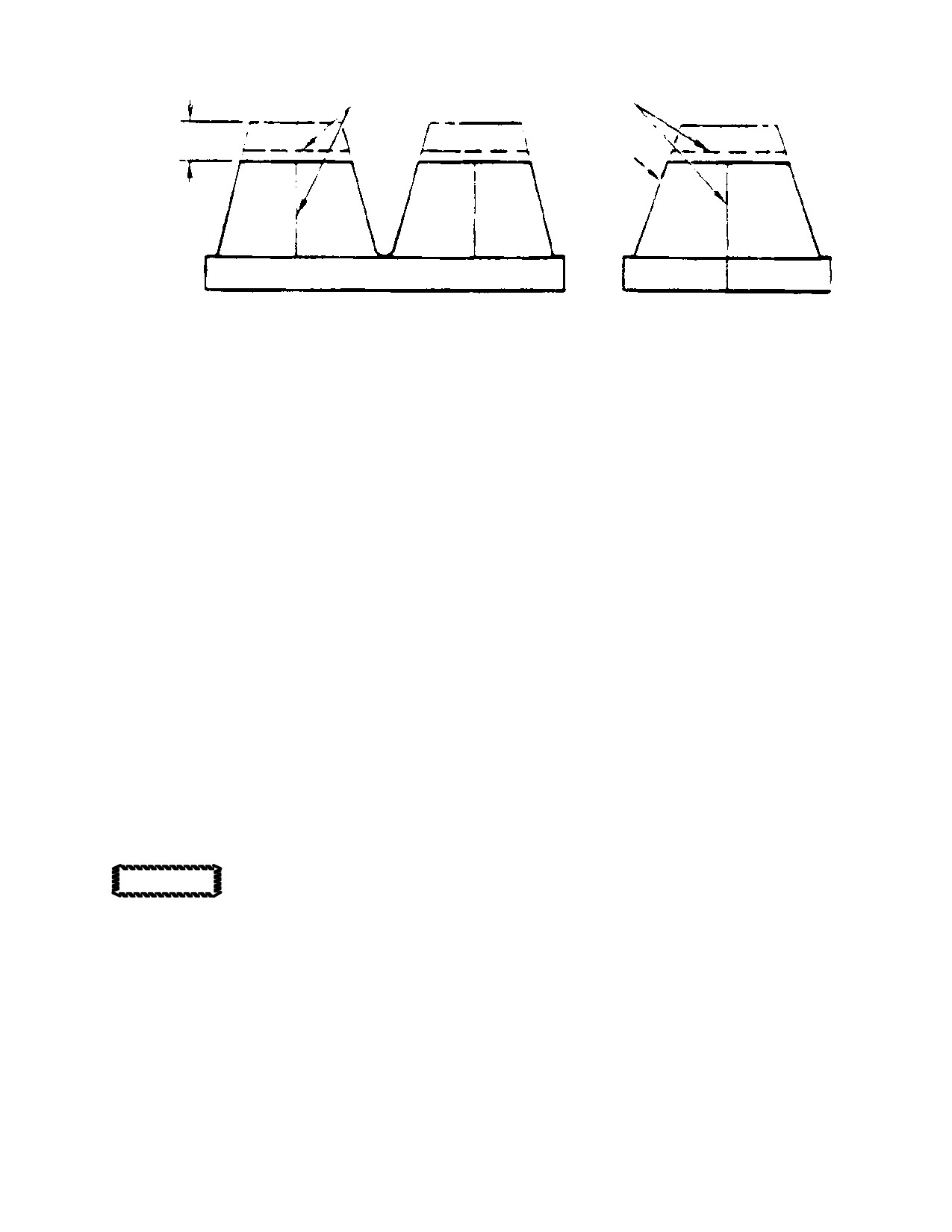
MD Helicopters, Inc.
CSP−H−2
500 Series - Basic HMI
SEWN SEAMS
SEWN SEAMS
2 PLCS
0.40−0.50 IN.
(10.16−12.7 MM)
(NOTE 1)
DOUBLE BOOT
SINGLE BOOT
NOTES:
1.
TRIM BOOTS BELOW HORIZONTAL SEAM.
CAUTION:
DO NOT USE SOLVENTS OR PETROLEUM BASED
CLEANING
FLUIDS ON VINYL BOOTS.
2.
CLEAN INSIDE AND OUTSIDE OF VERTICAL SEAM AND TOP OF
BOOT WITH CLEAN CLOTH DAMPENED WITH ISOPROPYL ALCOHOL.
3.
COAT BOTH SIDES OF VERTICAL SEAM WITH CONTACT CEMENT.
4.
APPLY THIN COAT OF CONTACT CEMENT ALONG TRIMMED EDGE
AND 0.125−0.250 IN. (3.175−6.35 MM) DOWN INSIDE AND OUTSIDE
SURFACES OF BOOTS TO PREVENT FRAYING.
G67−1036A
Figure 7-29. Control Tube Boot Rework
NOTE: Bond integrity is dependent on clean
mounts below the pilot’s seat cover, between
surfaces.
the right and left inboard sides of the seat
structure. The bracket provides the hingeline
(a). Thoroughly clean repair area of
for the longitudinal and lateral idler bell−
control tube and interior surface of
cranks, the tail rotor bellcrank, and the engine
sleeve with lint free cloth and MEK
droop control bellcrank, which are also made of
(22) or equivalent.
magnesium. It also provides the inboard
support for the collective torque tube.
(b). Mix epoxy adhesive per manufactur−
er’s instructions.
A. Controls Support Bracket and Bellcrank
(c). Apply adhesive (121) to both surfaces
Removal
and install sleeve.
(1). Remove foot fairings and controls
(d). Remove excessive adhesive with lint
access door (Sta. 78.50), and remove
free cloth moistened with MEK or
pilot’s seat cover.
equivalent. Do not saturate the
cleaning cloth.
(2). Remove collective bungee.
Do not use heat gun. Use of heat
(3). Disconnect tunnel−routed control tubes.
CAUTION
lamp is acceptable.
(4). Remove cotter pin, nut, two washers
(e). Allow to cure for 24 hours at mini−
and bolt; disconnect upper end of each
mum ambient temperature of 68°F
cyclic trim actuator.
(20°C); alternate cure 4 hours at
115°−140 °F (46°−60 °C).
(5). Disconnect floor−routed tail rotor
control tube from tail rotor bellcrank.
(f). Using primer (4), touch−up repaired
area(s) of control tube.
(6). Disconnect Sta. 70 lateral control tube
from lateral idler bellcrank.
48. Controls Support Bracket and Bellcranks
(Ref. Figure 7−30) The controls support
(7). Disconnect one−way lock from longitudi−
bracket is a cast magnesium bracket that
nal idler bellcrank.
Page 7-85
Revision 16
MD Helicopters, Inc.
CSP−H−2
500 Series - Basic HMI
COLLECTIVE TORQUE
BUNGEE SUPPORT BRACKET
TUBE
WASHER
(SPECIAL)
* * CONTROLS SUPPORT
BRACKET
DROOP CONTROL
OVERRIDE LINK
COUNTERSUNK
* * TAIL ROTOR BELLCRANK
BEARING
BUSHING
BEARING
NOTE 2
(NOTE 3)
LAT IDLER
BELLCRANK
0.1875 IN.
FLOOR−ROUTED
BEARING &
(4.7625 MM)
TAIL ROTOR
SPACER
DIA
CONTROL ROD
BUSHING
(NOTE 3)
0.250 IN.
(6.35 MM)
BEARING
DIA
STA 70 LAT
CONTROL ROD
MAX. TORQUE
COUNTERSUNK
50 IN. LB (5.65 NM)
NOTE 4
BEARING
ELECTRICAL
SPACER
FLAT
WASHER
* * LONGITUDINAL
(NOTE 5)
IDLER BELLCRANK
LATERAL CYCLIC
ONE−WAY
TRIM ACTUATOR
LOCK
STA 72 DROOP
CONTROL
BELLCRANK
LONGITUDINAL CYCLIC
TRIM ACTUATOR
NOTE 4
BOLT INSTL
HOLE
2.
SHIM WASHERS USED AS REQUIRED TO OBTAIN NO SIDELOAD ON
ONE−WAY LOCK.
3.
MUST ROTATE FREELY IN ACTUATOR BEFORE INSTALLATION; MUST
*
NOT ROTATE AFTER INSTALLATION.
4.
BOND JUMPER ATTACHMENT AT ACTUATOR MAY BE EITHER
NOTES:
CONFIGURATION SHOWN.
1.
ASTERISK ( * ) IDENTIFIES SLOTTED BUSHINGS. EDGE OF BUSHING
5.
ON CURRENT CONFIGURATION ONLY. INSTALL AT FIRST OPPORTUNITY.
MUST PROTRUDE A MIN. OF 0.010 IN. (0.254 MM) TO A MAX. OF 0.080 IN.
6.
DOUBLE ASTERISK ( * * ) INDICATES PARTS THAT MAY BE EITHER
(2.032 MM) ABOVE OUTSIDE SURFACE OF PART AFTER NUT IS
MAGNESIUM OR ALUMINUM ALLOY. REF. SEC. 2 FOR ALLOY
TIGHTENED.
IDENTIFICATION AND CORROSION CONTROL.
30−046D
Figure 7-30. Installation of Controls Support Bracket, Idler Bellcranks and
Cyclic Trim Actuators
Page 7-86
Revision 16
MD Helicopters, Inc.
CSP−H−2
500 Series - Basic HMI
(8).
Remove pilot’s collective pitch stick.
NOTE: Parts identified with a double asterisk
(∗∗) may be either magnesium or aluminum
(9).
Provide support for collective torque
alloy. Ref. Sec. 2 for corrosion control and
tube. Remove two bolts, four washers,
identification of magnesium and aluminum
and two nuts securing bungee support
alloys.
bracket and collective torque tube to
controls support bracket.
D. Control Support Bracket and Bellcrank
Repair
(10).
Remove cotter pin, nut, three washers,
(1). Replace unserviceable bearings. Install
and bolt (Detail A); disconnect aft end
a new bearing of the correct type with
of droop control override link from
surface primer and grade A locking
collective torque tube bracket.
compound (28 and 29, Table 2−4),
(11).
Remove cotter pin, nut, two washers,
according to container instructions.
bolt, and Sta. 72 droop control bellcrank
NOTE: Ensure that the idler bellcrank spacers
from support bracket (Detail B).
are reinstalled between bearings whenever
idler bellcrank bearings are replaced.
(12).
Remove six screws, six washers, and six
nuts securing support bracket to seat
(2). Replace bellcranks or the controls
structure.
support bracket for distortion, cracks,
or enlongated holes.
(13).
Remove support bracket; use care to
avoid striking any of the bellcranks and
E. Controls Support Bracket and Bellcrank
push tubes.
Reassembly
B. Controls Support Bracket and Bellcrank
(1). Install longitudinal idler bellcrank with
Disassembly
bolt, two washers, nut, and new cotter
pin. Check that the slotted bushing is
(1). Remove cotter pin, nut, two washers,
in place in the support bracket lug, and
bolt, and lateral idler bellcrank. Do not
reinstall the shim washers used
remove slotted bushing unless replace−
between the bellcrank and bracket for
ment is necessary.
no sideload of the one−way lock.
(2). Remove cotter pin, nut, two washers,
(2). Install lateral idler bellcrank, bolt, two
bolt, and tail rotor bellcrank. Do not
washers, nut, and new cotter pin.
remove slotted bushing unless replace−
Check that the slotted bushing is in
ment is necessary.
place in the support bracket lug.
(3). Remove cotter pin, nut, two washers,
(3). Install tail rotor bellcrank, countersunk
bolt, and longitudinal idler bellcrank.
head bolt two washers (one counter−
Do not remove slotted bushing unless
sunk), nut, and new cotter pin. Check
replacement is necessary.
that the slotted bushing is in place n
the support bracket lug.
NOTE: The shim washers between the longitu−
dinal idler bellcrank and support bracket
F. Controls Support Bracket and Bellcrank
are used to align the one−way lock for no
Installation
sideload. Keep the washer selection with the
bracket for use during reassembly.
(1). Carefully position assembled support
bracket and bellcranks between the
C. Controls Support Bracket and Bellcrank
seat structure bulkheads and secure
Inspection
with six screws, six washers, and six
nuts.
(1). Inspect bearings in bellcranks for
binding.
(2). Position Sta. 72 droop control bellcrank
in support bracket and install with bolt,
(2). Perform a fluorescent dye penetrant
two washers, nut, and new cotter pin
inspection on any suspected part.
(Detail B).
Page 7-87
Revision 16
MD Helicopters, Inc.
CSP−H−2
500 Series - Basic HMI
NOTE: The cap is matched to the cradle of each
collective pitch stick, the collective bungee
control support bracket. Check that the
installation, and the interconnecting shafts
numbers on each part are the same before
and linkage. All components, except the stick
accomplishing step (a). below.
and tunnel−routed collective mixer control
tube, are located within the pilot’s seat
(3). Position collective torque tube and
structure.
bungee bracket on support bracket
cradle and install cradle bolts, four
Dual control provisions are incorporated into
washers, and two nuts.
the pilot’s compartment collective controls
installation. Refer to CSP−HMI−3, HMI
(a). Check that two slotted bushings are
Supplement M, as applicable for information
in place in the bungee support
on dual collective controls.
bracket.
(b). Check that index groove in edge of
50. Pilot’s Collective Pitch Control Stick (Left
Position)
cap that clamps torque tube to
support bracket cradle mates with
(Ref. Figure 7−32) The pilot’s collective pitch
matching index at bracket cradle
stick consists primary of a switch housing,
parting surface.
throttle grip and friction mechanism, collective
(4).
Install pilot’s collective pitch stick.
stick tube and friction mechanism, and gas
producer control shafts having right angle
(5).
Connect aft end of droop control
(pinion and bevel gear) drive. Collective pitch
override link to collective torque tube
stick controls include: the N1 throttle and idle
droop control bracket.
stop release ring, an N2 governor trim switch,
a landing light switch, a stick friction adjust−
(6).
Connect one−way lock to longitudinal
ment grip, a throttle friction nut, and a
idler bellcrank.
starter−ignition switch.
(7).
Connect Sta. 70 lateral control tube to
A. Pilot’s Collective Pitch Stick Removal
lateral idler bellcrank. Check that
(Left Position)
slotted bushing is in place in the
bellcrank ear.
Install bungee installation
WARNING
(8).
Connect floor−routed tail rotor control
tool (26, Table 2−2) before
tube to tail rotor bellcrank. Check that
disconnecting any pilot’s collective
slotted bushing is in place in bellcrank
stick hardware. There is strong bun−
ear.
gee spring pressure present in the
stick linkage; if suddenly released,
(9).
Connect upper end of each cyclic trim
spring reaction in the linkage can
actuator with bolt, two washers,
cause personal injury or parts dam−
bushing, nut, and new cotter pin.
age.
(a). Check that slotted bushing is in place
(1). Remove outboard collective stick cover
in bellcrank ear.
(Ref. Sec. 2).
NOTE: Lateral actuator upper hingeline has
(2). Disconnect pilot’s collective pitch stick
0.1875 inch (4.7625 mm) ID; longitudinal
electrical plug.
has 0.25 inch (6.35 mm) ID.
(3). Install bungee installation tool (26,
(10). Connect lower ends of tunnel−routed
Table 2−2) on collective bungee (Ref.
control tubes.
Collective Bungee Installation).
(11). Install collective bungee.
(4). Remove attaching hardware that
49. Collective Controls
secures the guide to the seat structure
bracket.
(Ref. Figure 7−31) The pilot’s compartment
collective controls consist of the left position
(5). Remove collective bungee.
Page 7-88
Revision 16
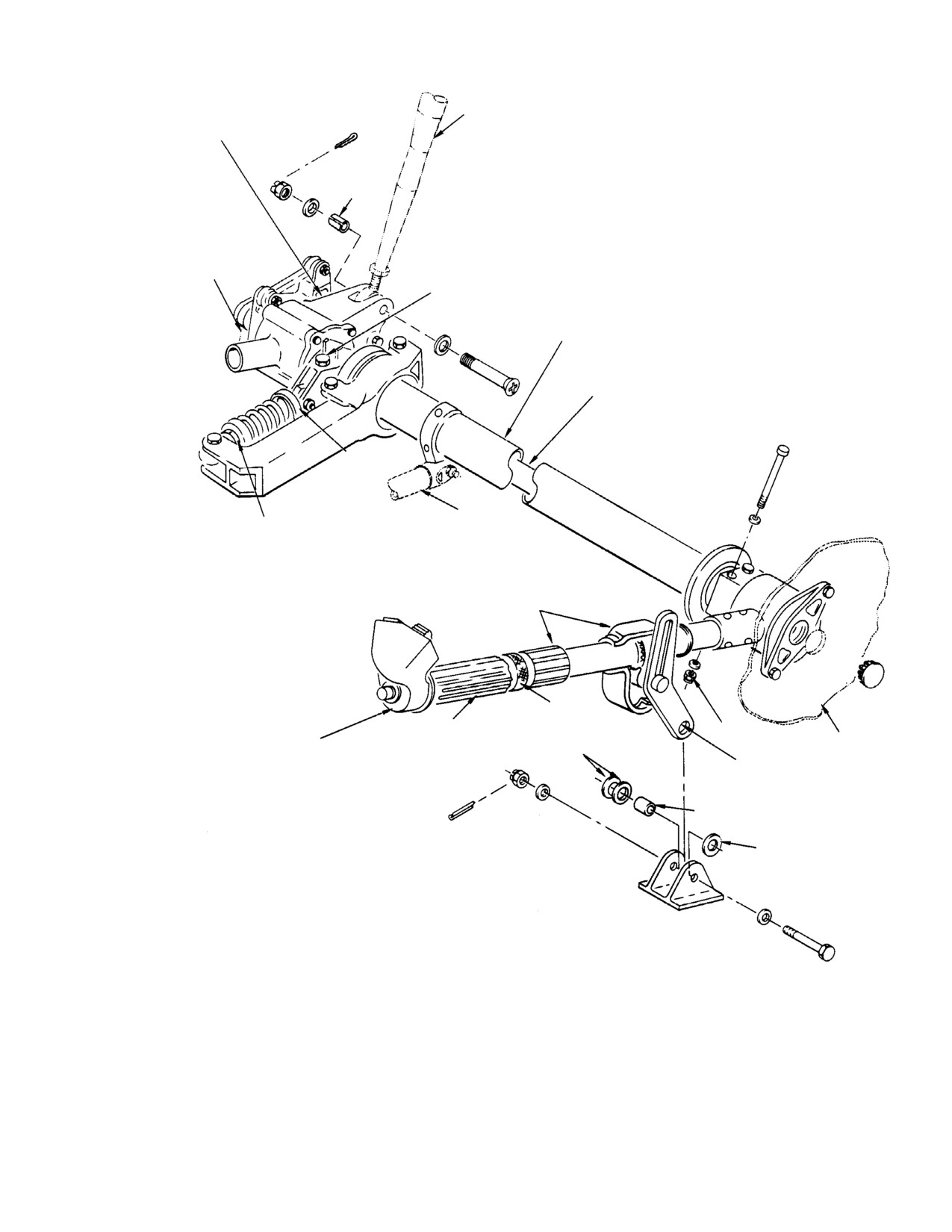
MD Helicopters, Inc.
CSP−H−2
500 Series - Basic HMI
COLLECTIVE MIXER TUNNEL−ROUTED
INBOARD COLLECTIVE
CONTROL ROD
STICK SOCKET ASSY
NOTE 3
GAS PRODUCER
CONTROL ROD
BUNGEE OVER−CENTER ADJUSTMENT BOLT
(NOTE 1)
COLLECTIVE CONTROL INTERCONNECTING
TORQUE TUBE
GAS PRODUCER INTERCONNECTING
TORQUE TUBE
BUNGEE
INSTL
N2 DROOP
BUNGEE SPRING
CONTROL
ADJUSTMENT RETAINER
OVERRIDE LINK
(NOTE 2)
COLLECTIVE STICK FRICTION
MECHANISM AND GUARD
THROTTLE
FRICTION
PILOT’S COLLECTIVE
THROTTLE
NOTE 4
FUSELAGE
PITCH STICK ASSY
NOTE 5
SKIN
GUIDE
SLEEVE BUSHING
NOTE 5
NOTES:
1.
TURN CW TO INCR, CCW TO DECR OVERALL COLLECTIVE DOWNLOADS.
2.
TURN CW TO INCR, CCW TO DECR BUNGEE PRELOAD.
CAUTION: DO NOT ADJUST BUNGEE SPRING TENSION WHILE BUNGEE INSTL
TOOL (369A9936) IS INSTALLED. USE OVERCENTER ACTION OF STICK TO
COMPRESS SPRING TO REMOVE TOOL.
3.
BUSHINGS MUST PROTRUDE A MIN. OF 0.010 IN. (0.254 MM) AFTER BOLT IS TIGHTENED.
4.
TORQUE PER TABLE 2−5; APPLY EQUALLY AND BY SMALL INCREMENTS.
5.
ARRANGE WASHERS TO LINE UP GUIDE WITH STICK; SPACE LOOSELY WITH
THREE WASHERS.
30−048B
Figure 7-31. Pilot’s Compartment Collective Controls
Page 7-89
Revision 16
MD Helicopters, Inc.
CSP−H−2
500 Series - Basic HMI
(6). Remove inboard collective socket
D At mid−travel, two pilot’s throttle grip at−
assembly;
taching bolts should be approximately
straight down.
(a). Disconnect droop control override
D The inboard pinion and outboard grip
link.
should be set to and held at these posi−
tions while socket and stick gearing is in−
(b). Slide bungee bracket to side.
terconnected by gas producer intercon−
nect torque tube.
(c). Remove cradle cap and slide collec−
D If mid−travel positions are not synchro−
tive torque tube inboard (Ref. Collec−
nized, further adjustment of installation
tive Control Interconnecting torque
is required.
Tube Removal).
(3). Complete insertion of collective torque
(7). Remove nuts, washers, and bolts that
tube, install cradle cap, position bungee
connect stick housing to torque tube.
bracket in mounting position, connect
droop control override link, install
(8). Remove stick by sliding it outboard and
collective socket assembly and install
off torque tube.
collective bungee.
(4). Position friction guide in the seat
B. Pilot’s Collective Pitch Stick Installation
structure bracket.
(Left Position)
(a). Arrange three washers and bushings,
(1). Lubricate stick housing socket with
loosely spaced between bracket ears,
grease (26, Table 2−4).
so that guide is in line (parallel) with
the stick.
(2). Install stick by sliding housing on
collective control interconnecting torque
(b). Install bolt, two washers, nut and
tube.
new cotter pin.
(a). Align matching holes and install
(5). Connect the electrical plug.
bolts, washers and nuts.
(6). Install outboard collective stick cover.
(b). Tighten nuts equally and by small
Check that wiring will not foul when
increments until correct torque is
stick is raised and lowered.
applied (Ref. Table 2−5).
(7). Remove snap plug from exterior skin.
NOTE:
(a). Rotate throttle and visually check for
D On completing attachment of pilot’s col−
zero backlash between gas producer
lective pitch stick and inboard collective
interconnect torque tube and the
socket assembly on collective control in−
hexagonal ID of the drive gearshaft
terconnect torque tube, ensure both pi−
in the stick housing.
lot’s throttle grip and inboard socket N1
pinion gear are at mid−travel position.
(b). Eliminate any backlash by tightening
pipe plug in end of torque tube; zero
D At mid−travel, wide tooth−space of inboard
backlash is required at both ends of
socket pinion gear will be at approximate−
tube.
ly one o’clock as viewed looking aft into
open end of socket.
(8). Check that inboard stick socket gears
D Gas producer control rod−to−inboard stick
are at mid−travel when pilot’s stick
assembly idler bolt holes should be in line
throttle grip is set to mid−travel. If not,
with centerline of stick assembly housing
adjust collective pitch stick(s) gas
cap.
producer control linkage.
Page 7-90
Revision 16
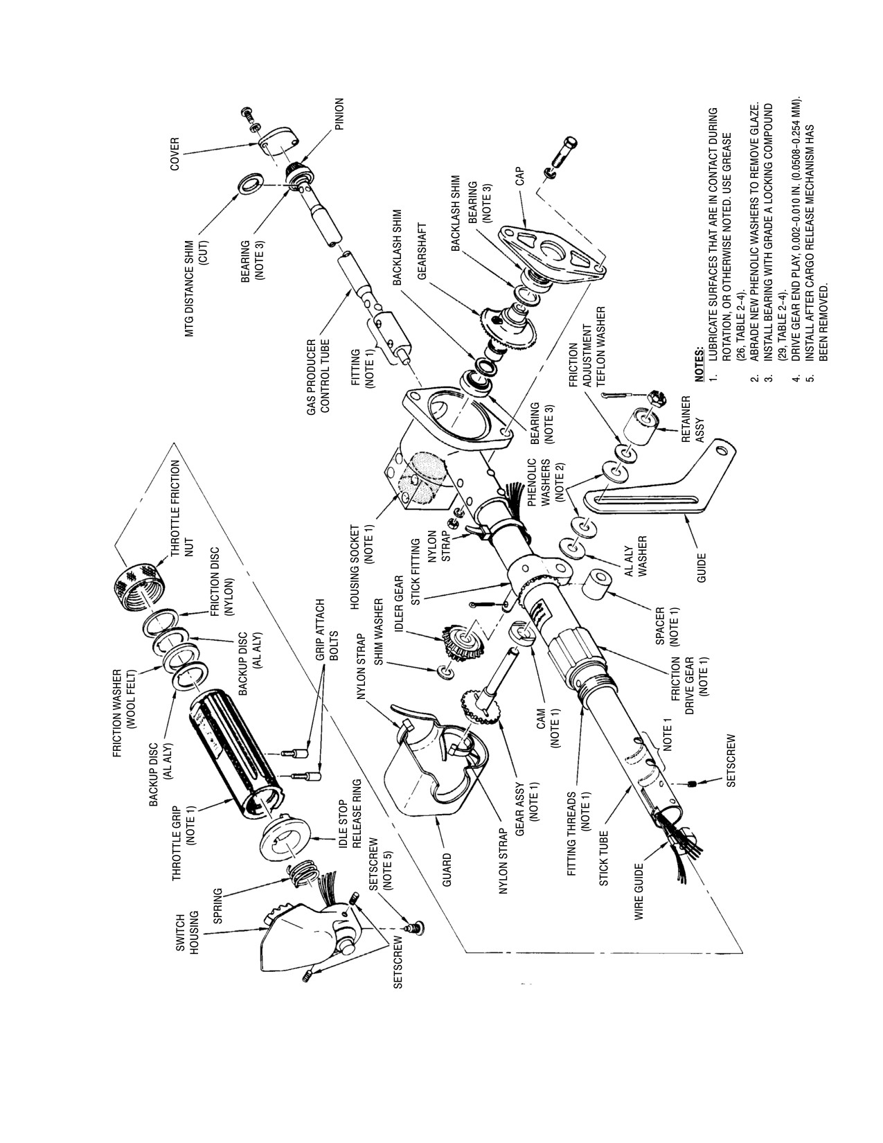
MD Helicopters, Inc.
CSP−H−2
500 Series - Basic HMI
30−049D
Figure 7-32. Assembly of Pilot’s Collective Pitch Stick (L/H Command)
Page 7-91
Revision 16
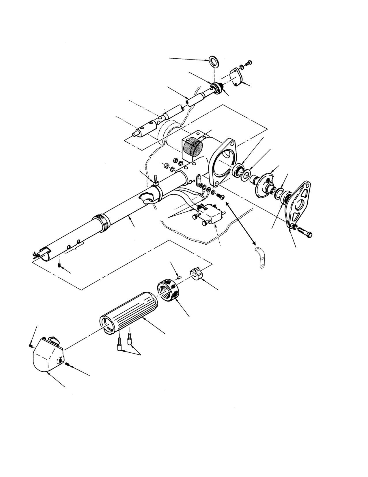
MD Helicopters, Inc.
CSP−H−2
500 Series - Basic HMI
MOUNTING DISTANCE SHIM
(CUT)
BEARING
(NOTE 2)
GAS PRODUCER
COVER
CONTROL TUBE
PINION
HOUSING SOCKET
(NOTE 1)
BEARING
(NOTE 2)
BACKLASH SHIM
GEARSHAFT
NYLON STRAP
BACKLASH SHIM
ELECTRICAL
WIRING
STICK TUBE
BEARING
(NOTE 2)
CONNECTOR
(NOTE 1)
CAP
PIN
SETSCREW
WIRE GUIDE
ADJUSTMENT NUT
SETSCREW
THROTTLE GRIP
GRIP ATTACH BOLT
NOTES:
1.
SURFACES IN CONTACT DURING ROTATION
TO BE LUBRICATED OR OTHERWISE NOTED,
WITH GREASE (26, TABLE 2−5).
SETSCREW
2.
INSTALL BEARINGS WITH GRADE A LOCKING
COMPOUND (29, TABLE 2−5) AFTER SHIMMING
SWITCH HOUSING
FOR MOUNTING DISTANCE AND BACKLASH.
44−162A
Figure 7-33. Copilot’s Collective Pitch Stick (R/H Command)
Page 7-92
Revision 16
MD Helicopters, Inc.
CSP−H−2
500 Series - Basic HMI
C. Pilot’s Collective Pitch Stick Disassembly
(b). Remove pinion and bearing from
(Left Position)
control tube only if replacement is
necessary.
(1). Cut the two nylon straps, and remove
stick friction mechanism guard.
D. Pilot’s Collective Pitch Stick Inspection
(Left Position)
(2). Remove setscrews that secure switch
(1). Inspect bearings for binding or loose−
housing.
ness.
NOTE: Removal of an additional setscrew is
(2). Inspect all gears for cracks and chipped
also required on helicopters equipped with a
or broken teeth.
cargo release mechanism.
(3). Inspect stick tube and gas producer
(3). Cut nylon strap or twine that secures
control tube for corrosion, deformation,
electrical wiring to stick tube.
and loose rivets.
(4). Push wire slack into stick, carefully
NOTE: The pitch stick housing and cap may be
pull housing and wiring from end of
either a magnesium or aluminum alloy cast−
stick tube and disconnect wiring from
ing. (Ref. Sec. 2 for corrosion control and
switches (Ref. Sec. 19).
identification of magnesium or aluminum
alloys.)
(5). Remove setscrew and wire guide from
forward end of stick. Tie a ‘‘fish’’, string
E. Pilot’s Collective Pitch Stick Repair (Left
on each wire bundle to aid reassembly
Position)
and remove wiring.
(1). Replace bearings if corroded, excessive−
(6). Remove spring and idle stop release
ly worn, or if the outer or inner races of
ring.
bearings rotate on mating surfaces and
locking compound is inadequate to
(7). Remove grip attach bolts and slide
prevent rotation.
throttle grip, friction washer and discs,
and friction nut from stick tube.
(2). Replace loose rivets in the gas producer
control tube.
(8). Remove friction mechanism and guide
(3). Replace a friction drive gear or idler
from stick fitting.
gear having cracked, chipped or broken
(9). Remove idler gear from stick fitting.
teeth.
NOTE: Do not remove bearing from cap unless
(4). Replace friction drive gear if it does not
replacement is necessary.
rotate freely on stick tube, or if the
rotating stop is damaged (Ref.
(10). Remove cap from stick housing.
Figure 7−35, Detail B). Drill out rivets
that attach throttle friction nut fitting
NOTE: Keep backlash shims with gear shaft
to the stick to remove gear.
and do not remove bearing from stick hous−
ing unless replacement is necessary.
NOTE: Before replacing a drive gear for bind−
ing, clean and then relubricate the ID with
(11). Remove gear shaft assembly.
grease (26, Table 2−4) . Reinstall gear on
stick tube and recheck for free rotation. If
(12). Remove cover from back of stick
gear still binds it must be replaced.
housing.
(5). Replace the phenolic friction washers
(13). Remove gas producer control tube
that slide against the guide if worn to
through access hole at back of stick
less than 0.03125 inch (0.79375 mm)
housing.
thickness.
(a). Remove mounting distance shim only
(6). Replace the friction gear assembly if
if necessary to adjust pinion gear
the driven gear has cracked, chipped or
mounting distance.
broken teeth, or if the cam pin is bent.
Page 7-93
Revision 16
MD Helicopters, Inc.
CSP−H−2
500 Series - Basic HMI
(7). Replace a damaged idle stop release
(7). Reinstall mounting distance shims
ring. The ring must slide freely on the
forward side of pinion bearing if
tube and in the throttle grip.
removed during disassembly.
NOTE: One edge of shim must be cut for instal−
F. Pilot’s Collective Pitch Stick Reassembly
lation.
(Left Position)
(8). Establish gas producer control tube
(1). Check gear shaft bearings in housing
pinion mounting distance (Ref.
cap and housing for security of outer
Figure 7−34).
races.
(9). After mounting distance shimming is
(a). Use grade A locking compound (29,
correct.
Table 2−4) to install replacement
bearings.
(a). Remove gas producer control tube
and apply grade A locking compound
(b). Use care to prevent compound from
to outside diameter pinion bearing
entering bearings, and make sure
outer race and stick housing bore.
that each bearing is seated against
(b). Reinstall control tube, and check that
its bore shoulder.
compound does not enter bearing and
that bearing outer race and shims
(2). Using grease (26), lubricate the stick
are firmly seated against housing
tube interior where the gas producer
bore.
control tube fitting makes contact.
(10). Install throttle friction nut, friction
(3). Attach ‘‘fish’’ strings routed through the
discs and washers.
stick tube during disassembly, and
thread the electrical wire bundles from
(11). Using grease, lubricate interior of
the plug through the exit hole, throttle
throttle grip and install grip on stick
friction nut, friction washers and discs,
tube.
throttle grip, idle stop release ring, and
the spring.
(a). Align grip and gas producer control
tube fitting and install grip attach
(4). Pull wiring out through front end of
bolts.
stick tube.
(b). When tightened, bolts must be flush
or not more than 0.010 inch (0.254
(5). Install wire guide so that it divides the
mm) below outer surface of grip.
switch wiring, three wires in one cutout
and four in the other.
(12). Establish gas producer control tube
pinion and shaft assembly bevel gear
(a). Align guide with matching hole in
backlash (Ref. Figure 7−34).
stick tube and install set−screw.
(13). After backlash shimming is correct,
(b). When tightened, setscrew must be at
remove housing cap and gear shaft.
least flush and not recessed more
than 0.010 inch (0.254 mm) below
(14). Lubricate teeth of pinion gear and shaft
outer surface of tube.
assembly bevel gear with grease.
(15). Apply grade A locking compound to
NOTE: Ensure gas producer control tube is
gear shaft and to ID of bearings.
installed into stick tube housing with elon−
gated area of fitting facing down.
NOTE: With throttle grip at mid−travel the two
grip attach bolts will be positioned approxi−
(6). Install gas producer control tube
mately straight down.
through access hole in back of stick
housing, and through stick tube until
(16). Install housing cap on shaft assembly
control tube fitting engages wire guide
and seat with hand pressure while
bore.
slowly rotating the grip back and forth.
Page 7-94
Revision 16
MD Helicopters, Inc.
CSP−H−2
500 Series - Basic HMI
Secure cap to side of housing and cover
NOTE: If gears are correctly aligned and
to back of housing.
mated, do not perform steps (4). thru (6).
and continue with step (7). If gears are mis−
(17).
Using solder (48), connect wiring to
aligned, continue with step (4).
stick switches.
(4). Disconnect link from idler and remove
link and bellcrank as an assembly from
(18).
Pull electrical wiring slack out through
gearshaft of inboard collective pitch
exit holes in stick tube, position release
stick socket by removing bolt, two
ring and. spring and install switch
washers and nut (Ref. Figure 7−38).
housing with setscrews.
NOTE: During gear shaft rotation to establish
(19).
Using nylon strap, or twine (30), secure
correct mid−position for gearshaft and pin−
electrical wiring to stick tube approxi−
ion in the next step, the gearshaft cutout
mately one inch (25.4 mm) aft of exit
can be seen through the hole in back of the
holes.
socket assembly housing.
(20).
Install friction cam and driven gear
(5). Rotate end of the gas producer intercon−
assembly on stick fitting. Temporarily
nect torque tube in the pilot’s stick
mesh idler gear and driven gear, and
socket housing until the gearshaft−
rotate friction drive gear counter−clock−
to−N1 pinion gearmesh is at mid−travel
wise to maximum stop (Ref.
and N1 pinion gear wide toothspace is
Figure 7−35, Detail B).
positioned at approximately one o’clock.
View pinion by looking aft into open
(21).
Hold drive gear at stop and re−mesh
end of collective stick socket.
idler gear and driven gear so that gear
NOTE: The inboard collective N1 pinion gear
assembly pin is at high point of cam
must be held in correct position while steps
(Detail C).
(7). thru (9). below are performed. If avail−
able, the optional co−pilot’s collective pitch
(22).
Use shim washers sufficient to limit
stick can be used to hold the gear in position
gear end play to maximum of 0.010 inch
by setting the copilot’s throttle grip attach
(0.254 mm) (Detail A), and secure idler
bolts at approximately seven o’clock (look−
gear with cotter pin.
ing aft) before engaging the stick and socket.
(23).
Assemble remainder of friction mecha−
(6). Reattach inboard collective pitch stick
nism.
socket bellcrank to the gearshaft and
link to the idler. Bellcrank attachment
(24).
Adjust collective friction mechanism.
bolt must be installed with head
slightly down and forward.
51. Gas Producer Linkage Adjustment
(7). With inboard collective pitch stick
(Ref. Figure 7−34) The following procedure is
socket N1 pinion gear held at position
for adjustment of gas producer linkage in
described in step (5)., rotate pilot’s
installed collective pitch stick(s) and/or
collective pitch stick throttle grip to
inboard socket assembly.
mid−travel position (grip attaching
bolts approximately straight down).
(1). Remove cap and outboard bearing from
(8). Install backlash shims and gear shaft
pilot’s collective pitch stick housing.
in pilot’s collective stick socket housing
(Ref. Figure 7−32). Be sure that
(2). Remove backlash shims and gear shaft
gearshaft and pinion are aligned and
assembly from socket housing.
mated when pilot’s throttle grip is at
NOTE: Note locations and mark removed shim
mid−travel.
thicknesses to ensure proper reassembly.
NOTE: Be sure that shims are installed in orig−
inal locations.
(3). Ensure inboard collective pitch stick
socket internal gears are aligned and
(9). Reinstall outboard bearing and cap on
mated.
pilot’s stick housing.
Page 7-95
Revision 16
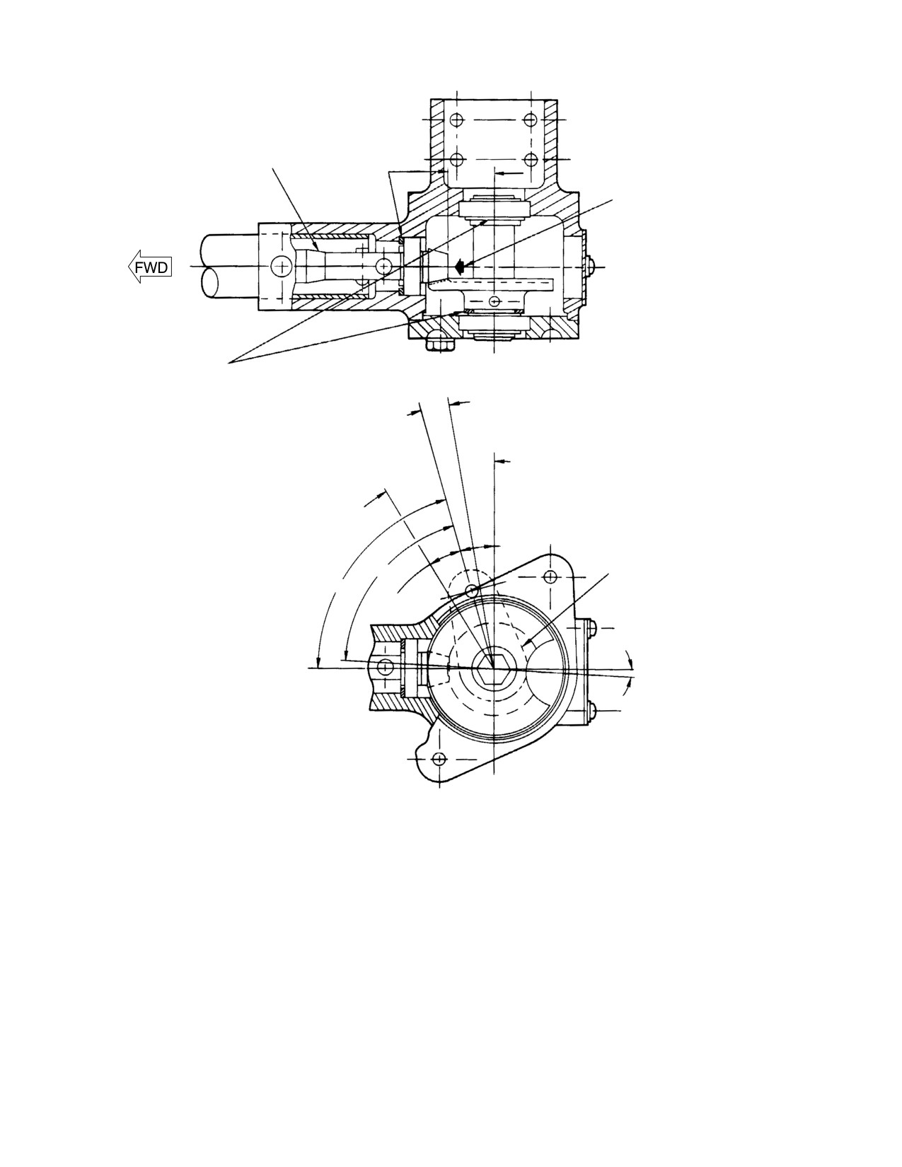
MD Helicopters, Inc.
CSP−H−2
500 Series - Basic HMI
GAS PRODUCER
TORQUE TUBE
STEP 1
STEP 2
STEP 3
STEP 4
TOP VIEW
IDLE STOP
6°
GRIP MID−TRAVEL
GENERAL NOTE:
SELECT SHIMS AS REQUIRED. CRES SHIMS
N1 CLOSED
PROVIDED IN 0.001, 0.002, 0.005, 0.012 AND
0.032 IN. (0.0254, 0.0508, 0.127, 0.3048 AND
0.8128 MM) THICKNESS.
N1 OPEN
15°
BELLCRANK ON INBD COLLECTIVE
70° 40’
STICK SOCKET ASSY
73° 30’
15°
STEP 5
LEFT SIDE VIEW
STEP 1
STEP 4
INSTALL MTG DISTANCE SHIMS TO GET 0.699−0.709 IN.
INSTALL BACKLASH SHIMS TO OBTAIN 0.003 IN. (0.0762 MM)
(17.7546−18.0086 MM) AFTER SHIMMING IS CORRECT, INSTALL
MAX. BACKLASH.
BEARING IN HOUSING WITH GRADE A LOCKING COMPOUND
CAUTION: HSG AND CAP BEARINGS MUST BE SEATED
(29, TABLE 2−4).
AGAINST BORE SHOULDER, GEARS MUST NOT BIND AND
NOTE: SHIMS ARE CUT THRU ONE EDGE FOR INSTALLATION.
PINION MTG DISTANCE MUST BE CORRECT.
STEP 2
STEP 5
APPLY10 LB (45 N) MIN. LOAD TO END OF PINION DURING
AFTER SHIMMING IS CORRECT, INSTALL SHAFT ASSY SO
CHECK OF MTG DISTANCE DIMENSION.
THAT C OF GEAR TOOTH CUTOUT MATCHES LOF STICK.
NOTE: TIGHTENING THE THROTTLE FRICTION NUT WILL
L
USE GRADE A LOCKING COMPOUND (29, TABLE 2−4) TO
APPLY ENOUGH LOAD.
BOND SHAFT TO I.D. OF BEARINGS.
NOTE:
STEP 3
POSITION THROTTLE GRIP AT MID−TRAVEL.
LOF SHAFT ASSY GEAR CENTER TOOTH IS 2° −50’ OFF
THE CUTOUT
NOTE: ONE PINION GEAR TOOTH EQUALS 5° 38’.
L
30−051B
Figure 7-34. Gas Producer Drive Mounting Distance and Backlash Adjustment
(Pilot’s Collective Pitch Stick)
Page 7-96
Revision 16
MD Helicopters, Inc.
CSP−H−2
500 Series - Basic HMI
(10). Check that both the pilot’s throttle grip
hex end of gas producer interconnect
and the inboard collective pitch stick
torque tube.
socket N1 pinion gear wide toothspace
(8). Measure distance between inboard end
are correct at mid−travel.
of pilot’s collective stick assembly
(11). Remove snap plug from skin, rotate
housing and inboard face of gas produc−
pilot’s throttle grip and visually check
er gearshaft in pilot’s collective stick
for evidence of backlash between gas
assembly.
producer interconnect torque tube and
(9). Subtract measurement taken in step
hexagonal ID of the gear shaft.
(8). from measurement taken in step
(a). Zero backlash is preferred and 10
(7). Remainder is engagement of gas
degree is maximum allowed.
producer interconnect torque tube with
gearshaft in pilot’s collective stick
(b). If necessary, remove cover and gear
assembly.
shaft from torque tube and eliminate
(10). Subtract engagement (remainder) from
any excessive backlash by tightening
0.750 inch (19.05 mm).
pipe plug in end of torque tube.
(a). In addition to thickness of external
(c). Zero backlash is preferred at both
snap ring, add AN960−C816 washers
ends of the tube.
to end of gas producer interconnect
(12). Reinstall snap plug.
torque tube to a total thickness equal
to the remainder from 0.750 inch
52. Gas Producer Interconnect Torque Tube
(19.05 mm) less engagement.
Shimming
(b). Equivalent washers varying in
thickness may be made from corro−
(Ref. Figure 7−36)
sion resistant steel sheet and used in
(1).
Remove pilot’s seat cover and controls
combination with AN960C816
access door.
washers.
(2).
Make an index mark on end of collec−
(11). Reinstall pilot’s collective stick assem−
tive torque tube fitting flush with
bly.
inboard end of pilot’s collective stick
NOTE: If the normally installed plug does not
assembly housing.
expand tube, a 1/8− 27 internal−wrenching
pipe plug 0.380 inch (9.652 mm) long may be
(3).
Remove bolts securing pilot’s collective
substituted. Whichever plug is used, it must
stick assembly to end of collective
not protrude more than 0.030 inch (7.62
torque tube fitting
mm) when tightened.
(4).
Loosen pipe plug in end of gas producer
(12). Tighten pipe plug of gas producer
interconnecting torque tube which
interconnect torque tube to obtain zero
secures it to the gas producer gearshaft
backlash between torque tube and
in pilot’s collective stick assembly.
gearshaft in pilot’s collective stick
(5).
Remove pilot’s collective stick assembly.
assembly.
(13). Reinstall pilot’s seat cover and controls
(6).
Using rubber mallet or equivalent soft
tool, tap gas producer interconnecting
access door.
torque tube assembly toward copilot’s
53. Pipe Plug Adjustment for Zero Backlash
collective socket assembly. Avoid
damage to gas producer interconnect
(Ref. Figure 7−37)
torque tube hex end or pipe plug
threads.
(1). Remove pilot seat cover for access to
under seat controls (Ref. Sec. 2).
(7).
Measure distance between index mark
on end collective torque tube fitting and
(2). Remove snap plug from exterior skin.
Page 7-97
Revision 16
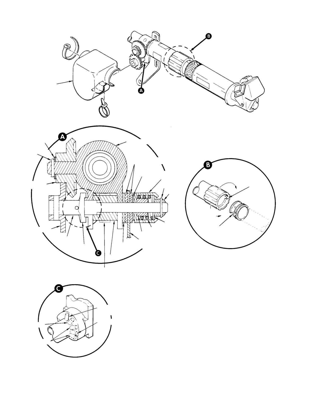
MD Helicopters, Inc.
CSP−H−2
500 Series - Basic HMI
GUARD
WASHER(S)
(NOTE 1)
STICK FITTING
COTTER
PIN
PHENOLIC WASHERS
TEFLON
WASHER RETAINER
HOUSING
CCW MAX FRICTION
IDLER GEAR
COTTER PIN
FRICTION
DRIVE GEAR
NUT
(ROTATING
STOP)
CW MIN
FRICTION
WASHER
DRIVEN GEAR
SPRING
STICK FITTING
STOP
(FIXED STOP)
GEAR ASSY
GUIDE
(NOTE 2)
AL ALY WASHER
CAM
SPACER
GUARD ATTACHMENT
cc
NYLON STRAP
NOTES:
1.
SHIM AS REQD FOR 0.010 IN. (0.254 MM) MIN. END
PLAY. GEAR TRAIN MUST ROTATE FREELY.
2.
GEAR ASSY MUST SLIDE AND ROTATE FREELY IN
GEAR ASSY PIN
FITTING. APPLY GREASE (26, TABLE 2−4) TO SHAFT.
(NOTE 4)
3.
ACCEPTABLE MINIMUM FRICTION POSITION.
4.
DESIRED MINIMUM FRICTION POSITION
NOTE 5
(CAM LOW POINT).
NOTE 3
5.
CORRECT MAXIMUM FRICTION POSITION
(CAM HIGH POINT).
6.
UNACCEPTABLE MAXIMUM FRICTION POSITION.
NOTE 6
30−050C
Figure 7-35. Collective Pitch Stick Friction Adjustment
Page 7-98
Revision 16