CSP-H-2 BASIC HANDBOOK OF MAINTENANCE INSTRUCTIONS FOR MDHI 369H HELICOPTERS - page 3
MD Helicopters, Inc.
CSP−H−2
500 Series − Basic HMI
(9). Align doublers with existing rivet
located directly below the forward air scoop at
pattern.
WL 32.00.
(10). Drill doubler to match existing rivet
A. Insulator Padding and Insulation Tape
pattern; deburr holes and remove chips
Inspection
as required.
(Ref. Figure 3−6 and Figure 3−7)
(11). Secure doublers, former, and skin using
(1). Check that the drain hole is free and
wet primer (4, Table 2−4), rivet gun,
clear of obstruction.
and rivets. Install rivets from inside
engine compartment.
(2). Inspect insulator padding and insula−
tion tape for security.
(12). Remove all debris from work area,
inspect installation for discrepancies,
(3). Inspect oil cooler/tank area for possible
and touch up as required with primer.
air gaps and insufficient sealing.
(13). Reinstall removed components in
B. Insulator Padding Replacement
reverse order of removal; inspect
installations for discrepancies.
(1). Remove individual insulator pads by
pulling away from the structure.
14. Underfloor Compartments
(2). Clean insulator attachment surface
Underfloor compartments are those areas
with naphtha (59, Table 2−4). Surface
below fuselage floor level, on both sides of the
must be completely free of oil, grease
center beam and forward of seat structure.
and grit to assure bond.
The left forward area contains electrical
NOTE: Insulator pads are installed with the
equipment and the battery. The right forward
silver reflective material outside and the
area is for utility storage and is lined by an
cushion (red) side against the structure.
area contour−matching thermoplastic contain−
er. The utility compartment is rated for 50
(3). Apply a thin film of adhesive (102) over
pounds (23 kg) maximum weight.
the entire contact surface of either the
structure or the insulator pad.
A. Underfloor Compartment Inspection
(4). Press the surfaces to be bonded togeth−
Inspect electrical harnesses and wiring for
er and work gently from the center
frayed insulation and grounding terminals for
outward in all directions.
corrosion.
(5). Allow the bond to cure approximately
15. Firewall and Sta. 124.00 Insulation
24 hours.
(Ref. Figure 3−5) The engine compartment
C. Oil Cooler/Tank Insulation Tape
forward firewall is insulated on current
Replacement
configuration helicopters and helicopters so
modified to provide heat reduction in the
(Ref. Figure 3−7)On helicopters with a vented
passenger/cargo compartment. Insulator pads
oil cooler/tank compartment, remove any loose
covered with heat reflective material are
tape and seal all gaps between the mast base
bonded to the helicopter structure inside the
support frame and right side of the plenum
engine compartment on the forward firewall
chamber, and between access covers and
and plenum chamber, on the rear passenger/
supporting structure.
cargo compartment firewall and inside the oil
(1). Tape must overlay metal surfaces by a
cooler/tank access cover. In addition, the oil
minimum of 1 inch (2.54 cm).
cooler/tank area at the Sta. 124.00 bulkhead is
sealed with aluminum foil tape between the
(2). Overlay tape on tape a minimum of 1/4
right mast base support frame and the right
inch (6.35 mm).
side of the plenum chamber. An external air
vent and scoop, located on the right side of the
(3). Tape around junction of frame and
fuselage, provides airflow through the sealed−
firewall must extend a minimum of 1
oil cooler/tank area. A small drain hole is
inch (2.54 cm) on both surfaces.
Page 3-13
Revision 14
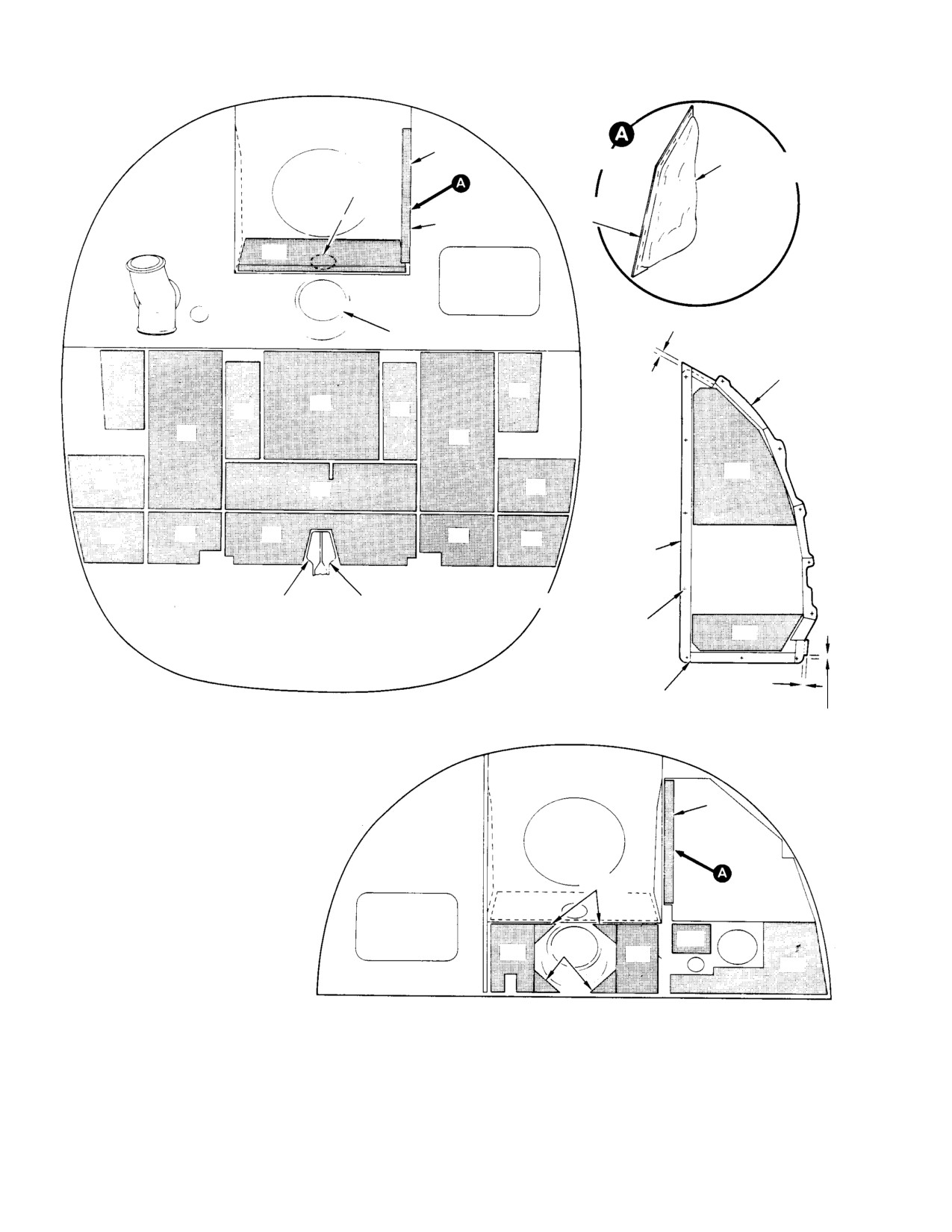
MD Helicopters, Inc.
CSP−H−2
500 Series − Basic HMI
−191
TYPICAL
CUSHION (RED SIDE)
(NOTE 7)
NOTE 6
INSULATOR
PAD
NOTE 4
−171
0.25 IN. (6.35 MM) OVERLAP
DRIVE SHAFT PORT
AS SHOWN
TRIM AS
−71
SHOWN
−72
−11
−21
−21
−51
−51
−211
−81
−31
−82
−91
−61
−41
−62
−92
TAPE
(NOTE 5)
AFT LANDING GEAR CENTER BEAM
NOTE 2
PIERCE FOR
SCREWS (TYP)
−221
FIREWALL (ENGINE SIDE)
(NOTE 1)
0.25 IN. (6.35 MM)
OVERLAP AS SHOWN
OVERLAP
0.38 IN.
ACCESS COVER
INSULATION INSTALLATION
(9.652 MM)
(TYP BACK SIDE)
369H2008
NOTES:
1.
BOND INSULATOR PADS TO STRUCTURE
WITH ADHESIVE (101, TABLE 2−4).
−181
2.
TAPE EDGES OF THE INSULATOR TO THE
LANDING GEAR CENTER BEAM FITTING
WITH TAPE (61, TABLE 2−4).
3.
APPLY TO PASSENGER/CARGO SIDE OF
PLENUM CHAMBER.
NOTE 3
−161
4.
APPLY TO INSIDE (ENGINE COMPT) OF
PLENUM CHAMBER.
5.
APPLY TAPE (67, TABLE 2−4) TO AFT SIDE
OF ALL THREE ACCESS COVERS. APPLY
−131
TWO LAYERS TO RIGHT COVER ONLY.
−141
−161
−151
6.
DISH−IN INSULATOR FOR DRIVE SHAFT
−111
FLANGE RECESS.
7.
INSULATOR PADS ARE INSTALLED WITH
SILVER REFLECTIVE MATERIAL OUTWARDS
FIREWALL AND PLENUM CHAMBER
AND CUSHION (RED) SIDE AGAINST
(PASSENGER/CARGO SIDE)
STRUCTURE.
(NOTE 1)
30−161
Figure 3-6. Insulation Padding
Page 3-14
Revision 14
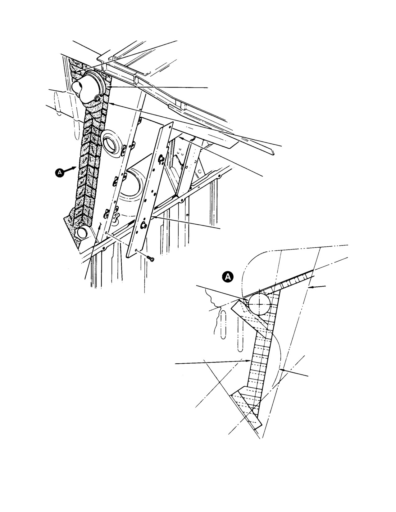
MD Helicopters, Inc.
CSP−H−2
500 Series − Basic HMI
CLOSE OFF OIL COOLER/TANK AREA FOR
MINIMUM AIR FLOW OUT OF AREA
OIL COOLER DUCT
ALUMINUM FOIL TAPE
PLENUM CHAMBER
ACCESS COVER CHANNEL
MAST BASE
MAST BASE
OIL COOLER DUCT
SUPPORT FRAME
SUPPORT FRAME
ALUMINUM FOIL TAPE (61, TABLE 2−4), CLOSE GAPS
BETWEEN OIL TANK/COOLER COMPARTMENT AND
CENTER SECTION ON RIGHT SIDE OF SHIP ONLY.
PLENUM CHAMBER
C OF DRIVE SHAFT
30−163A
L
Figure 3-7. Oil Cooler/Tank Compartment Sealing
Page 3-15
Revision 14
MD Helicopters, Inc.
CSP−H−2
500 Series − Basic HMI
(4). Tape upper corner at oil cooler duct
(59, Table 2−4). Allow to air−dry a
hose to obtain a minimum flow of air
minimum of 30 minutes. Install a 0.50
through corners.
x 40 inch (1.27 x 101.6 cm) strip of
polyurethane tape (42) to the clean dry
(5). Seal all holes with aluminum foil tape
surface. Apply hand pressure to ensure
(62, Table 2−4).
firm contact and trim as required.
(6). Apply strips of nitrite tape (68) to the
(2). Replace adjustable door hinges as
attaching surfaces of the three access
follows:
covers and trim the tape as shown in
Figure 3−6. Apply a double layer of
(a). Remove door from fuselage structure.
tape to the right access cover. Pierce
the tape at all attachment screw holes.
(b). Remove nut, washer and hinge pivot
screw.
16. Engine Access Doors
(c). Carefully press out the hinge pivot
Current type doors have upper and lower door
point spacer and separate the hinge
hinges that allow door fit adjustment. Fore
halves. Retain the two nylon spacers.
and aft adjustment of the doors is made
Rivets must be carefully drilled
possible by slotted holes in the hinges and
CAUTION
out. Removal by the standard
serrated mating surfaces between the hinges
method of drilling and drift punching could
and doors. Lateral adjustment is obtainable by
result in damage to the internal structure
installing laminated shims under the door
and surrounding material.
hinges. Door alignment during closing is
provided by V−type striker blocks (with or
(d). Drill out rivets that secure the
without shims) or spring−type retainers riveted
defective hinge half to the fuselage
to the door frames next to the lower latch, and
structure.
two locating pins that engage holes in the
lower fuselage structure.
(e). Transfer existing hole pattern in
fuselage structure to replacement
A. Engine Access Door Removal
fuselage hinge half and drill out
holes. Install hinge and shim on
(Ref. Section 2)
fuselage structure and secure with
B. Engine Access Door Inspection
replacement rivets.
(1). Check the door hinges, door attaching
(f). Assemble the hinge halves with
hardware, and latches for looseness,
nylon bushings. Press the steel pivot
cracks and damage.
spacer coated with wet primer (4)
through the mating holes. Install
(2). Check the outside edge of door for
pivot screw with washer and nut.
security of bonding between outer and
inner skin. Any separation requires
(g). Install door and check for alignment.
repair.
NOTE:
Install shims under door hinge to ob−
(3). Inspect doors for corrosion, distortion,
tain a firm fit without binding at door−to fu−
breaks or cracks and condition of
selage contact surfaces when the door is
abrasion strip tape along upper inside
closed. Use slotted holes in hinge and ser−
door edge.
rated surfaces to obtain forward and aft ad−
justment. When adjustments are complete,
C. Engine Access Door Repair
tighten screws that secure hinge to access
door.
(Ref. Figure 3−8) Refer to CSP−H−6 for sheet
metal repair procedures.
(h). Refinish repaired area.
(1). Replace worn abrasion strip tape by
(3). Replace defective catches or latch hooks
cleaning the contact area with naphtha
as follows.
Page 3-16
Revision 14
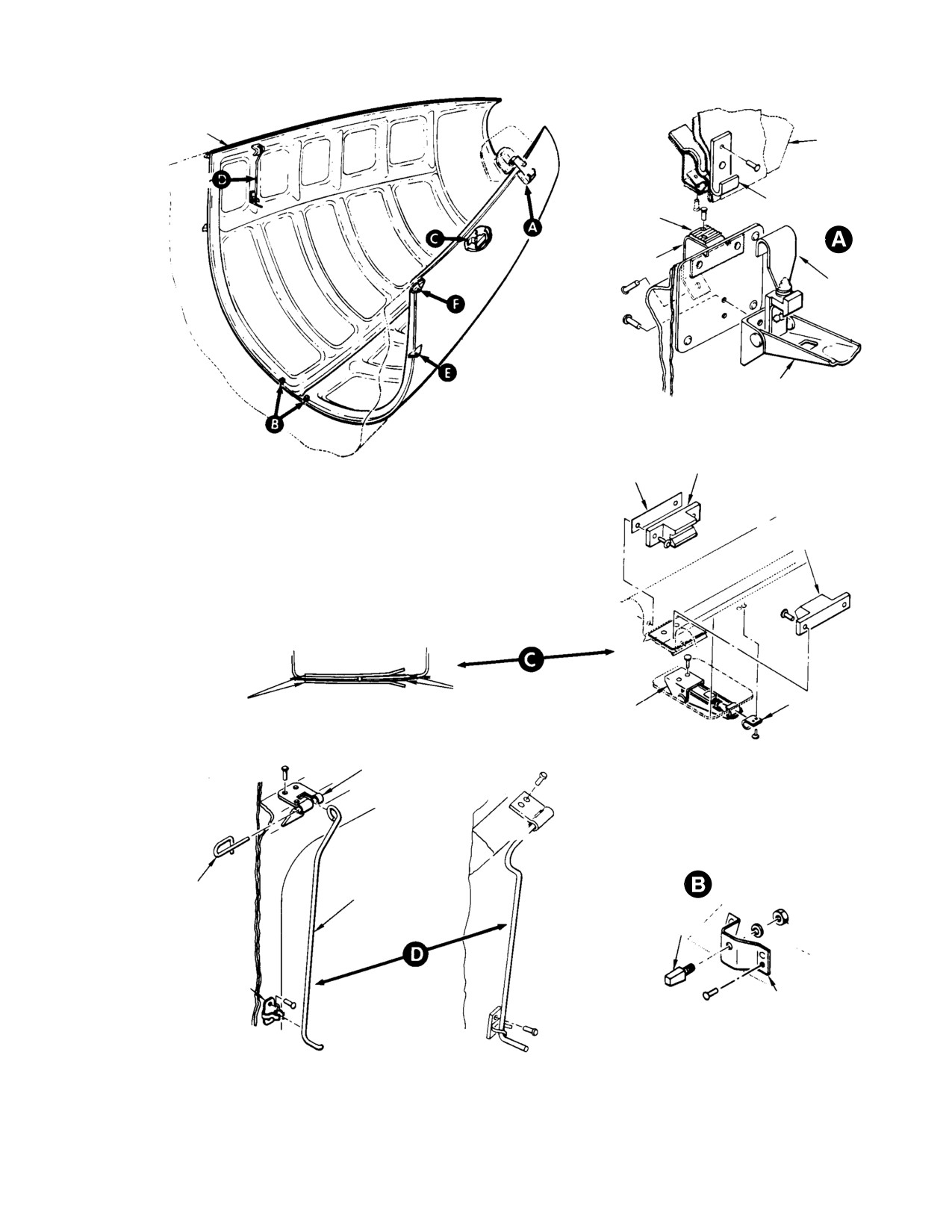
MD Helicopters, Inc.
CSP−H−2
500 Series − Basic HMI
ABRASION STRIP
FUSELAGE
STRUCTURE
CATCH
PLATE
STOP
HOOK
LEVER
V−TYPE
STRIKER
SHIM
V−TYPE
STRIKER
ABRASION STRIP TAPE
(102, TABLE 2−4) 0.013 IN.
(0.3302 MM) THICK
RETAINER
CATCH
ALTERNATE SPRING−TYPE STRIKER
LEVER
BRACKET
PIN
HOOK
PIN
BRACKET
BRACKET
CURRENT TYPE
EARLY TYPE
30−136−1D
Figure 3-8. Engine Access Doors (Sheet 1 of 2)
Page 3-17
Revision 14
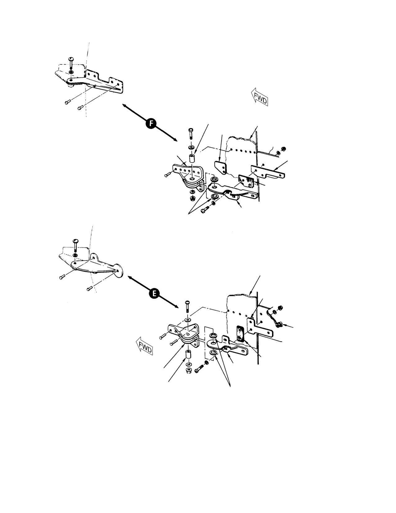
MD Helicopters, Inc.
CSP−H−2
500 Series − Basic HMI
STEEL SPACER
NON−ADJUSTABLE UPPER DOOR
FUSELAGE STRUCTURE
HINGE
SHIM
FORWARD HALF
(NOTE)
SHIM
PLATE
AFT HALF
NYLON WASHERS
ADJUSTABLE UPPER DOOR HINGE
FUSELAGE STRUCTURE
SHIM
NON−ADJUSTABLE LOWER DOOR HINGE
RIVNUT
PLATE
FORWARD HALF
AFT HALF
(NOTE)
STEEL SPACER
NYLON WASHERS
ADJUSTABLE LOWER DOOR HINGE
NOTE:
UPPER AND LOWER FORWARD HINGE HALVES SHOWN AT LEFT
SIDE ARE REVERSED AT RIGHT SIDE LOCATIONS (UPPER LEFT
USED AT LOWER RIGHT AND LOWER LEFT USED AT UPPER RIGHT).
30−136−2B
Figure 3-8. Engine Access Doors (Sheet 2 of 2)
Page 3-18
Revision 14
MD Helicopters, Inc.
CSP−H−2
500 Series − Basic HMI
Rivets must be carefully drilled
The window retainers are riveted to the
CAUTION
out. Removal by the standard
fuselage structure. Doubler strips are used
method of drilling and drift punching could
along all riveted edges of the early type
result in damage to the internal structure
window.
and surrounding material.
A. Aft Section Window Repair
(a). Drill out rivets and remove defective
latch or catch from engine access
Refer to FAA AC 43.13−1 for repair of plastics.
door or fuselage structure. Replace
Replace the aft section window if it is damaged
defective stops or serrated adjust−
beyond practical repair, according to applicable
ment plates, if required, by drilling
instructions in CSP−H−6.
out attaching rivets.
18. Canopy and Windshield
(b). Locate existing rivet holes and install
replacement latch, catch, door stop or
The canopy and windshield installation forms
adjustment plate. Secure with
the forward part of the fuselage airframe
replacement rivets.
enclosing the pilot’s compartment. The canopy
has three sections: a lower windshield, a
(c). Adjust latches as required for proper
center windshield and an upper windshield.
tension of latch lever to catch without
Each section consists of symmetrical left and
deflecting the door.
right side panels extending from the wind−
shield centerline to the edges of the pilot’s
(d). Refinish area, except latch lever
compartment door frames and the lower edge
assembly, as required.
of the floor structure. The center and lower
sections are clear cast acrylic. The upper
D. Engine Access Door Fit Adjustment
section is smoke−grey−tinted cast acrylic. Each
(Ref. Figure 3−8) Door alignment is provided
panel has Y−section plastic retainers bonded to
by means of V−type striker blocks or spring−
the edges. These retainers are riveted to the
type retainers riveted in the door frames
canopy frame, the fiberglass canopy ventilat−
adjacent to the lower latch.
ing panel and fuselage structure. Early upper
canopy windshields are of slightly thinner
(1). Remove lockwire from threaded
material than the current type and require the
(adjustment) end of hooks.
addition of stiffeners if the helicopter is to be
flown with doors off in excess of 85 knots (98
(2). Loosen all hooks until strikers engage
mph) unless canopy upper windshield assem−
in light contact with no door deflection
blies 369A2405−3 and −4 are replaced with
when the hooks are latched.
360H2410−3 and −4, 0.080 inch (2.032 mm)
(3). Unlatch the doors and tighten all hooks
minimum thickness. Refer to CSP−H−3 for
four to five turns. Check door latching
modification information.
and make additional minor adjust−
A. Canopy Panel Inspection
ments as required.
(4). Install lockwire (2, Table 2−4) in hook
Minor defects or imperfections that do not
threaded end in a manner to allow
impair pilot’s critical visibility, or that obvious−
latching and unlatching without
ly are not signs of impending structural failure
interference.
may be considered as negligible. Negligible
damage includes:
17. Aft Section Windows
(1). Nicks not more than 0.010 inch (0.254
The aft section window installation consists of
mm) deep and occupying an area not
a left and right transparent window of tinted
larger than 0.250 x 0.50 inch (6.35 12.7
gray cast acrylic or plexiglass in a formed
mm); one only per square foot (929 cm2)
plastic retainer. The early type acrylic window
allowed.
panels are installed without retainers. Each
window extends from the top of the cargo door
(2). Scratches not more than 0.010 inch
to the outboard edge of the engine air inlet
(0.254 mm) deep and 5 inches (12.7 cm)
fairing, and between the canted bulkheads.
long.
Page 3-19
Revision 14
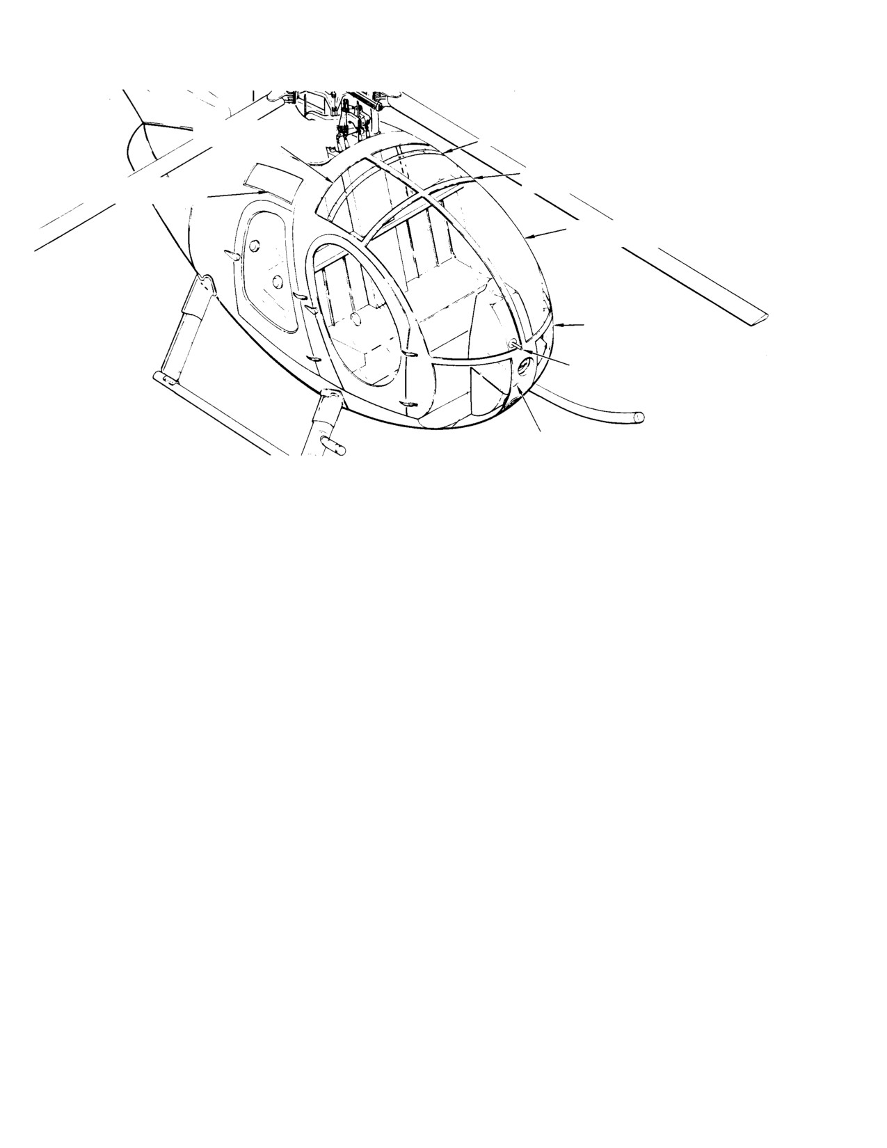
MD Helicopters, Inc.
CSP−H−2
500 Series − Basic HMI
UPPER CANOPY WINDSHIELD
(TWO SECTIONS)
STIFFENERS (NOTE 2)
FAIRING TAPE
FUSELAGE AFT SECTION
(NOTE 1)
WINDOWS (BOTH SIDES)
CENTER CANOPY WINDSHIELD
(TWO SECTIONS)
LOWER CANOPY WINDSHIELD
(TWO SECTIONS)
OUTSIDE AIR TEMPERATURE INDICATOR
(NOTE 3)
CABIN VENTILATING
PANEL (FIBERGLASS)
NOTES:
1.. FAIRING TAPE NO LONGER USED IN PRODUCTION. IF REMOVED, REINSTALLATION IS NOT REQUIRED PROVIDED
RETAINERS ARE SEALED TO FRAMEWORK WITH SEALING COMPOUND (3, TABLE 2−4).
2.
STIFFENER MODIFICATION HUGHES NOTICE HN−23 IS REQUIRED FOR DOORS−OFF HIGH SPEED FLIGHT IF UPPER
WINDSHIELDS ARE THE EARLY TYPE, 0.060 IN. (1.524 MM) THICKNESS INSTEAD OF THE THICKER CURRENT TYPE.
3.
EARLY LOCATION SHOWN, SEE SECTION 17 FOR CURRENT CONFIGURATION.
30−019E
Figure 3-9. Canopy and Window Installation
(3). Any surface defect such as minute spots
C. Canopy Frame Replacement
or stains that can be removed by light
(Ref. CSP−H−6)
polishing.
19. Pilot and Cargo Doors
(4). Delamination of doubler or stiffener in
not more than one area within each
The two pilot doors and two cargo doors are
square foot of panel.
bonded aluminum alloy frames containing
large smoke−grey−tinted cast acrylic windows
(5). Crazing around delaminated areas less
in extruded plastic retainers. Early type
than 0.010 inch (0.254 mm) deep.
windows are clear cast acrylic. Plastic snap−
vents are installed in each of the four door
windows, inside strengthening doublers. An
(6). Minor punctures in panels (other than
acrylic stop, bonded to the doubler, prevents
windshields and windows) not exceed−
ing 0.020 inch (0.508 mm) diameter.
normal airflow from pulling the snapvent from
the window during flight. These units may be
rotated in the reinforced window holes for
(7). Minor polarization faults (distortion) in
intake or exhaust of ventilating air and may
small areas of windshield near edges.
be pulled inward for complete closure. Dam−
aged snapvents should be replaced; repair is
B. Canopy Panel Repair
not practical. Current type doors are equipped
with an automatic latching mechanism; early
Refer to FAA AC 43.13−lA for repair of plastics.
type doors have a manual latching mecha−
Replace canopy panel if it is damaged beyond
nism. Two door hinges on each door are
practical repair, according to applicable
provided with quick−removal type ball−lock
instructions in CSP−H−6.
hinge pins. Current type cargo doors are
Page 3-20
Revision 14
MD Helicopters, Inc.
CSP−H−2
500 Series − Basic HMI
approximately 4 inches (10 cm) higher than
(b).
Install replacement hinges at body
the early type.
attach points with door hinge pins.
(c).
With damaged hinges removed,
A. Pilot and Cargo Door Removal
install doors in closed position. Have
(Ref. Section 2)
an assistant retain door in place by
actuating door handle locking levers.
B. Pilot and Cargo Door Auto-Latching
(d).
If required for door fit, use one−piece
Operational Check
solid aluminum alloy shim, up to
(1). When opening door, apply light
0.040 inch (1.016 mm) maximum
inward force on the door. This will
thickness trimmed flush with hinge
reduce wear of the latching mecha−
outer edges, under upper or lower
nism by overcoming the door seal
hinge (between hinge and door
pressure.
exterior).
(2). Open door and check for smooth
(e).
Mark hinge rivet attach locations
operation of handles and latch mecha−
through existing holes in door. Locate
nism. Check operation of door stop.
and mark blind rivet attach points
(cargo door only).
(3). Close door from inside. Check all inside
latches for correct engagement at latch
(f).
Remove door hinges and check for
and safelock positions of interior and
proper edge distance.
exterior handle.
(g).
Drill holes with a No. 41 drill at
(4). Check that setting interior and exterior
pilot’s door upper and lower hinge aft
handles to safelock position pulls door
attach points. Use a No. 21 drill at
inward for proper closure and sealing.
all other pilot and cargo door attach
points.
(5). Check that key will lock and unlock
door handle.
(h).
On pilot’s door upper hinge, install
rivets with washer’s under bucked
C. Pilot and Cargo Door Manual-Latching
heads.
Operational Check
(i).
Install rivets at remaining pilot’s
(1). When opening door, apply light inward
door attach points.
force on the door. This will reduce wear
(j).
Install two mechanically expanding
of the latching mechanism by overcom−
rivets at aft cargo door hinge attach
ing the door seal pressure
points.
(2). Open door and check for smooth
(k).
Install four rivets at remaining
operation of handles and latch mecha−
attach points.
nism. Check operation of door stop and
springs (if installed).
(l).
Paint as required.
(3). Close door from inside and check
(m).
Install doors and perform an opera−
latching mechanism on inside of door.
tional check.
Inspect the forward latch lever to
ensure that it is within the detent
(2). Replacement of Pilot’s and Cargo Door
position of the main striker plate.
Hinge and Preload Spring
Visually check he remaining latch
(Ref. Figure 3−13)
levers for correct positioning and snug
fit.
NOTE: Preload spring is used only on current
type door hinge installation.
D. Pilot and Cargo Door Hinge Repair
(a). Remove two cotter pins and clevis
(1). Removal of Door Hinges
pins.
(a). Remove door and drill out hinge
(b). Remove door spring first; then
attaching rivets.
preload spring.
Page 3-21
Revision 14
MD Helicopters, Inc.
CSP−H−2
500 Series − Basic HMI
(c). Replace preload spring; with longest
(5). Trim retainer as required to provide
flat area outboard and aft in hinge
clearance for door handle and end butt
body recess.
joint.
(d). Replace door spring; with longest flat
(6). For windows with the flat retainer,
area also outboard and aft in body
clamp replacement in position and drill
hinge recess. Forward curved area of
retainer using holes in door flange as a
door hinge presses against preload
guide. 0.380 inch (9.652 mm) minimum
spring inboard curved area, at
engagement and flush fit with window
installed position.
frame. Trim excess if required.
(e). Install hinge pins and cotter pins.
(7). For windows with the angled retainer,
Pins may be installed upward if
clamp window in position and use a
interference does not permit installa−
hole finder to locator holes in door
tion with cotter pin hole down.
reinforcing frame. Mark the retainer;
then remove window assembly and drill
(f). Cover exposed sharp edges of cotter
retainer.
pins and pins with sealer (60,
Table 2−4).
(8). For sealed Windows with the single leg
type retainer:
(3). Replacement of Pilot’s and Cargo Door
Rubber Stop
(a).
Place window in position and check
for 0.380 inch (9.652 mm) minimum
Replace rubber door stop if damaged or
engagement and flush fit with
partially separated. Remove door stops
window frame. Trim excess if re−
by carefully prying bonded rubber out
quired.
of hinge recess. Bond new stop to
forward end of hinge recess with
adhesive (19).
(b).
Use 3M Company #4508 tape (138),
0.50 inch (12.7 mm) width, to replace
original sponge rubber seal. Bond
E. Pilot and Cargo Door Window Repair
seals to retainer and to door frame
using adhesive (69); bond inside of
(Ref. Figure 3−10) Refer to FAA AC 43.13.1
seals to window using sealant (3). Do
For repair of plastics. Replace window as
not stretch seals when bonding.
follows. refer to FAA AC 43.13−1A. Replace
window as follows:
(c).
With retainer and window in position
on door frame, press down firmly and
(1). Remove snap vent from window.
evenly on retainer so that seals are
compressed tightly against window
(2). Drill out rivets attaching window
around full circumference of door
retainers to door structure and remove
frame.
window. Remove two screws, washers
and nuts from door hinge doubler.
(d).
Using a hole finder, locate existing
holes in door reinforcing frame. Mark
(3). If door frame or window is to be reused,
and drill and drill holes in retainer. It
carefully scrape off sealant around edge
is permissible to install new rivets
of door or window frame using a
wooden, plastic or other suitable
between existing holes in rivet
nonmetallic scraper.
pattern.
(4). Repair retainer−to−window bond, if
(9). Rivets window to door using rivets of
applicable, with dichloromethane (38,
appropriate length Note that blind
Table 2−4) or ethylene chloride (39); or
rivets are used for retainers riveted to
use PS−18 or S147 cement (45).
door reinforcing frame.
Page 3-22
Revision 14
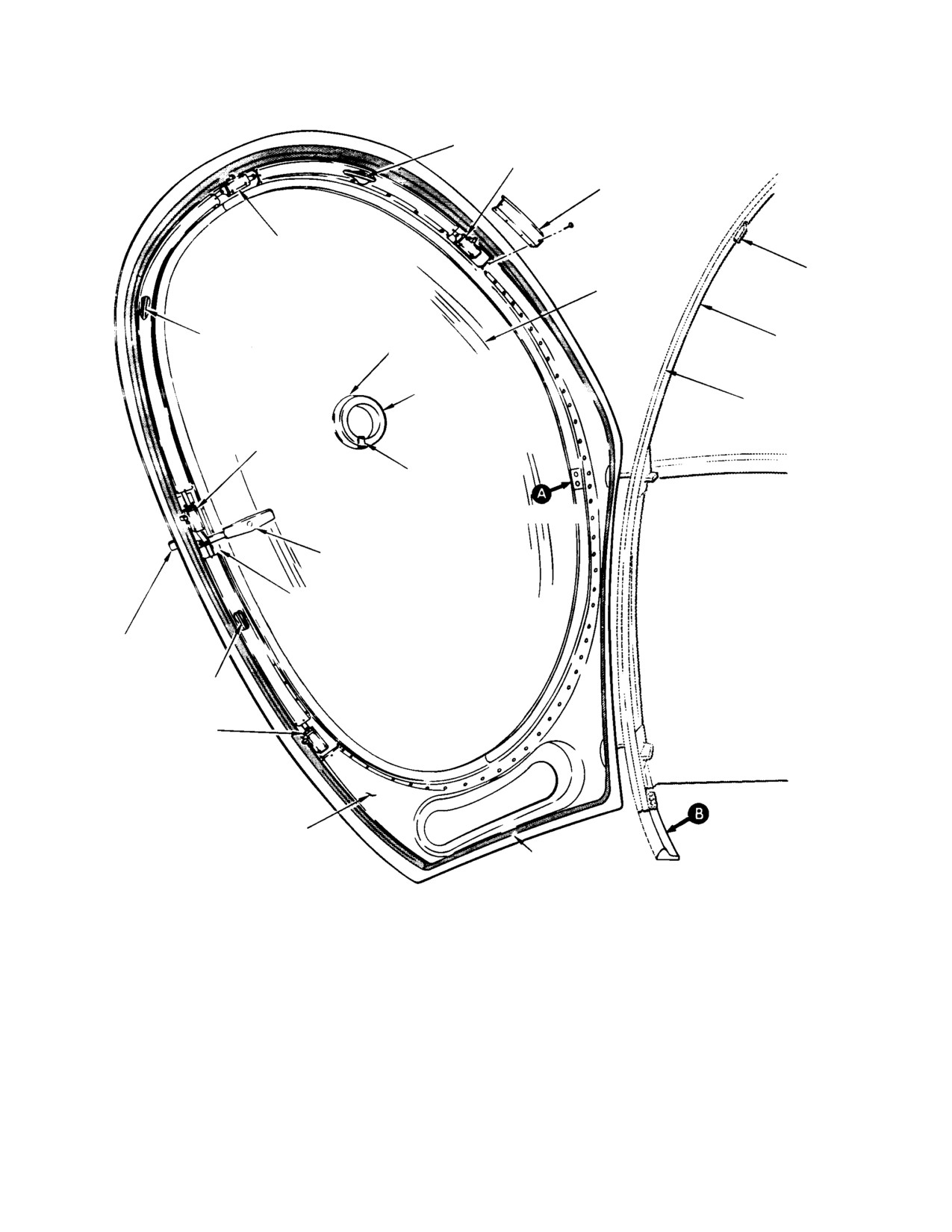
MD Helicopters, Inc.
CSP−H−2
500 Series − Basic HMI
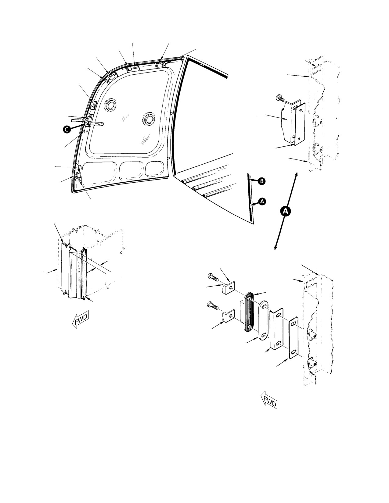
FORWARD CABLE SEGMENT
FORWARD LATCH
LATCH COVER
(TYP)
SECOND LATCH
STRIKER PLATE
WINDOW
REAR CABLE SEGMENT
FUSELAGE DOOR
DOUBLER
FRAME
WINDOW SNAP VENT
SEAL
BUMPER/DEPRESSOR
THIRD LATCH
STOP
(NOTE 1)
(SEE SHEET
2)
INSIDE LATCH HANDLE
NOTE 2
OUTSIDE LATCH
HANDLE
LATCH ROD
FOURTH LATCH
DOOR PANEL
DOOR SEAL
(BULB−TYPE SHOWN)
(NOTE 3)
NOTES:
1.
NOT ON ALL WINDOWS.
2.
TRIM RETAINER IF REQUIRED TO PROVIDE CLEARANCE
FOR DOOR HANDLE.
3.
BOND SEAL TO DOOR WITH ADHESIVE (68, TABLE 2−4).
30−142−1A
Figure 3-10. Pilot’s Door, Auto-Latching (Sheet 1 of 2)
Page 3-23
Revision 14
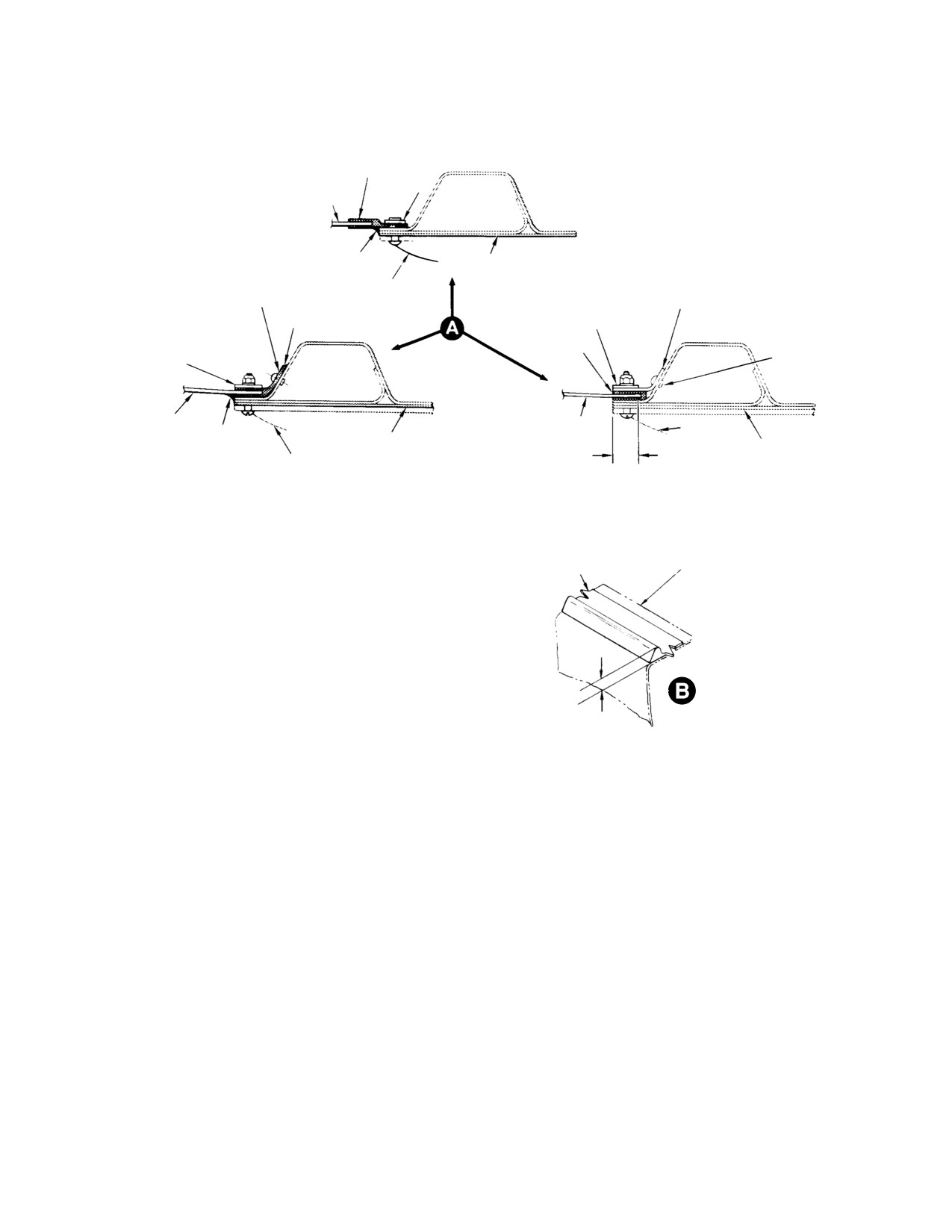
MD Helicopters, Inc.
CSP−H−2
500 Series − Basic HMI
FLAT RETAINER
(NOTE 2)
WASHER
WINDOW
(NOTE 7)
(NOTE 4)
NOTE 5
DOOR PANEL
ANGLED RETAINER
RETAINER (SINGLE LEG TYPE)
HINGE
(NOTE 2)
(NOTE 2)
DOOR HINGE DOUBLER
NOTE 5
(NOTE 6)
SEAL
RIVET
DOOR HINGE DOUBLER
(NOTE 8)
(NOTE 9)
(NOTE 6)
WINDOW
WINDOW
(NOTE 4)
NOTE 5
HINGE
DOOR PANEL
WINDOW ENGAGEMENT
DOOR PANEL
HINGE
0.38 IN. (9.652 MM) MIN.
TYPES OF WINDOW ATTACHMENT
BUMPER/DEPRESSOR
FUSELAGE DOOR FRAME
(NOTE 10)
NOTE 10
NOTES: (CONT)
4.
CLEAN PLASTIC SURFACES TO BE BONDED WITH ALIPHATIC NAPTHA (58, TABLE 2−4).
REPAIR WINDOW−TO−RETAINER BOND WITH DICHLOROMETHANE (38) OR ETHYLENE
CHLORIDE (39) OR USE PS−18 OR S147 CEMENT (45).
5.
APPLY A 0.060 IN. (1.524 MM) BEAD OF SEALING COMPOUND (3, TABLE 2−4).
6.
ON THIS TYPE, INSTALL DOUBLER AT HINGE LOCATION WITH TWO SCREWS,
WASHERS AND NUTS.
7.
ON THIS TYPE, INSTALL WASHER UNDER SHOP−FORMED RIVET HEAD AT HINGE
LOCATION.
8.
USE 3M COMPANY #4508 TAPE, 0.50 IN. (12.7 MM) WIDTH, TO REPLACE ORIGINAL SPONGE
RUBBER SEAL. BOND SEALS TO DOOR FRAME WITH ADHESIVE (68, TABLE 2−4).
BOND INSIDE OF SEAL TO WINDOW WITH SEALANT (3). DO NOT STRETCH SEAL
WHEN BONDING.
9.
COMPRESS SEAL EVENLY AROUND DOOR FRAME WITH RETAINER IN PLACE; LOCATE
HOLES, DRILL AND RIVET. NEW RIVETS MAY BE INSTALLED BETWEEN HOLES OF
EXISTING RIVET PATTERN.
10. TWO TYPES ARE IN USE;
BUMPER EXTRUSION IS 0.22 IN. (5.588 MM) HIGH WITH 0.060 IN. (1.524 MM) RADIUS.
DEPRESSOR EXTRUSION IS 0.31 IN. (7.874 MM) HIGH WITH 0.030 IN. (0.762 MM) RADIUS.
30−142−2C
Figure 3-10. Pilot’s Door, Auto-Latching (Sheet 2 of 2)
Page 3-24
Revision 14
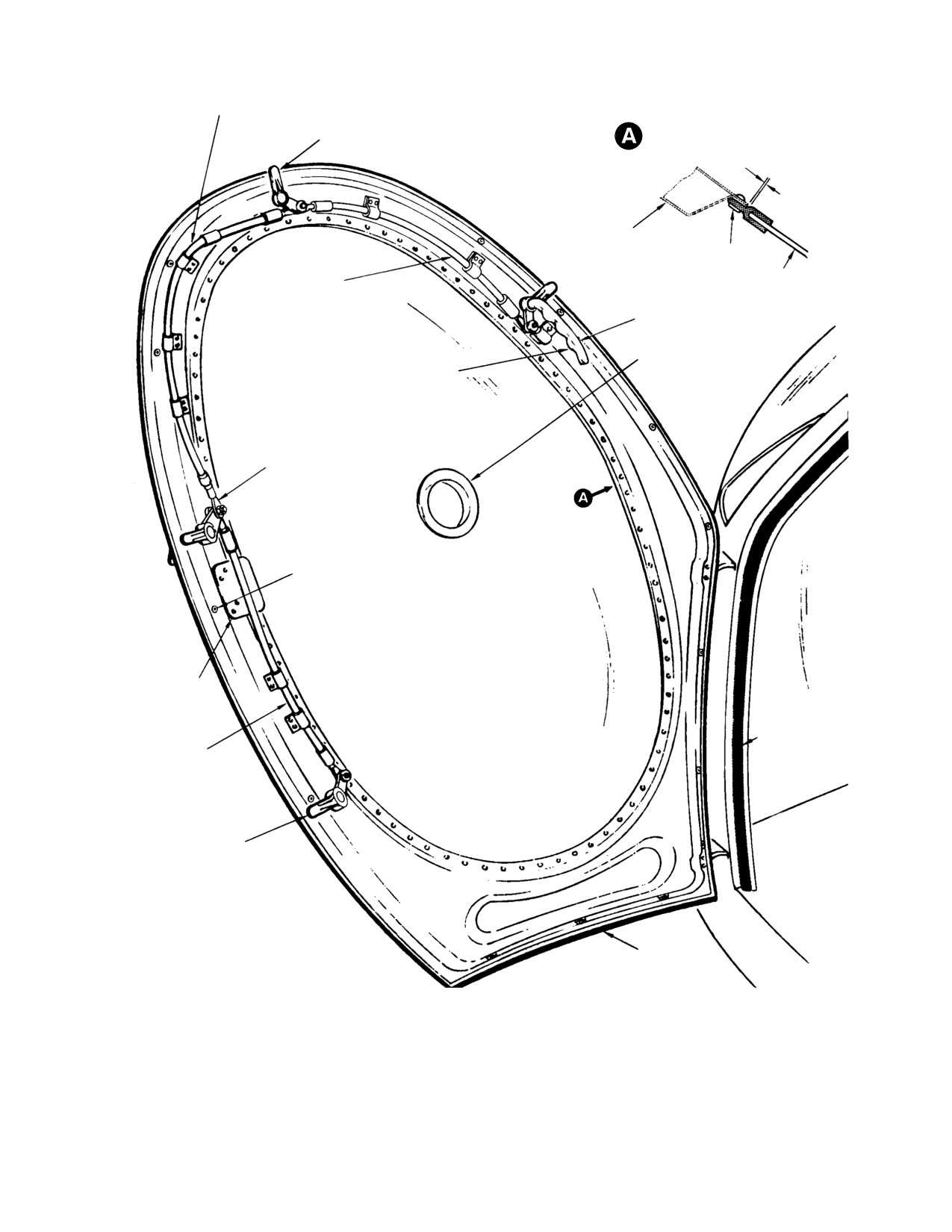
MD Helicopters, Inc.
CSP−H−2
500 Series − Basic HMI
SECOND CABLE SEGMENT
RETAINER ATTACHMENT
SECOND LATCH
(NOTE 2)
0.050 IN.
(12.7 MM)
DOOR STRUCTURE
RIVET
FORWARD CABLE
WINDOW
SEGMENT
GRIP
WINDOW SNAPVENT
FORWARD LATCH
HANDLE
THIRD LATCH
TRIM MOUNTING RIVNUT
(NOTE 1)
DOOR PULL
BRACKET
FUSELAGE DOOR
FRAME SEAL
THIRD CABLE
SEGMENT
FOURTH LATCH
DOOR SEAL
NOTES:
1.
DOOR INTERIOR TRIM NOT SHOWN.
2.
THE SINGLE LEG RETAINER AND SEAL TYPE OF WINDOW
ATTACHMENT SHOWN FOR AUTOLATCHING PILOT’S DOOR
ALSO APPLIES TO THIS.
30−021E
Figure 3-11. Pilot’s Door, Manual Latching
Page 3-25
Revision 14
MD Helicopters, Inc.
CSP−H−2
500 Series − Basic HMI
FORWARD CABLE SEGMENT
FORWARD LATCH
MOUNTING CLIP
LATCH COVER
SECOND LATCH
FUSELAGE DOOR FRAME
LATCH COVER
BUMPER
REAR CABLE SEGMENT
STRIKER PLATE
THIRD LATCH
(NOTES 4, 5)
SHIM, 0.063 IN. (1.6002 MM)
MAX. THICKNESS 2024−T3
LATCH COVER
AL ALY AS REQUIRED
BUMPER
LATCH ROD
CURRENT TYPE
FOURTH LATCH
LATCH COVER
4 PLCS
BUMPER/DEPRESSOR
(NOTE 6)
EARLY TYPE
EXTRUDED SEAL FILLER
NOTE 6
FUSELAGE DOOR FRAME
(NOTE 1)
FUSELAGE
BUMPER
DOOR FRAME
NOTE 2
STRIKER PLATE
ANTI−CHAFE TAPE
EXTRUDED SEAL FILLER
(NOTE 1)
NOTES:
1.
FORMED ANGLE SEAL FILLER USED FOR SEALING AS REQUIRED WHEN
STRIKER BASE PLATE
STRIKER PLATE AND BUMPER EDGES ALIGN WITHIN 0.060 IN. (1.524 MM)
FORMED ANGLE SEAL FILLER
EXTRUDED SEAL FILLER USED WHEN EDGE MISALIGNMENT EXCEEDS
(NOTE 1)
0.060 IN. (1.524 MM) OR AS REQUIRED WHEN SHIMMING OR ADJUSTING
AUTOMATIC LATCHING.
LAMINATED SHIM
2.
BEVEL EXTRUDED SEAL FILLER EXTERIOR CORNERS SO THAT MATING FILLER AND
(NOTE 3)
BUMPER EDGES ARE EVEN, REMOVING MATERIAL INDICATED, AT INSTALLATION.
3.
SHIM AS REQUIRED TO A MAXIMUM 0.187 IN. (4.7498 MM) SHIM THICKNESS.
4.
SEAL ALL GAPS BETWEEN BUMPERS, FILLERS AND STRIKER PLATE CORNER JOINTS,
AND ALL OUTER EDGES, USING SEALANT (3, TABLE 2−4) TO HEIGHT OF BUMPER.
5.
STRIKER MAY BE SHIMMED IF REQUIRED. BOND STRIKER (AND SHIMS) TO DOOR FRAME
USING ADHESIVE (19) ACCORDING TO CONTAINER INSTRUCTIONS.
6.
TWO TYPES ARE IN USE:
BUMPER EXTRUSION IS 0.22 IN. (5.588 MM) HIGH WITH 0.060 IN. (1.524 MM) RADIUS.
DEPRESSOR EXTRUSION IS 0.31 IN. (7.874 MM) HIGH WITH 0.030 IN. (0.762 MM) RADIUS.
30−143−1A
Figure 3-12. Cargo Door, Auto-Latching (Sheet 1 of 2)
Page 3-26
Revision 14
MD Helicopters, Inc.
CSP−H−2
500 Series − Basic HMI
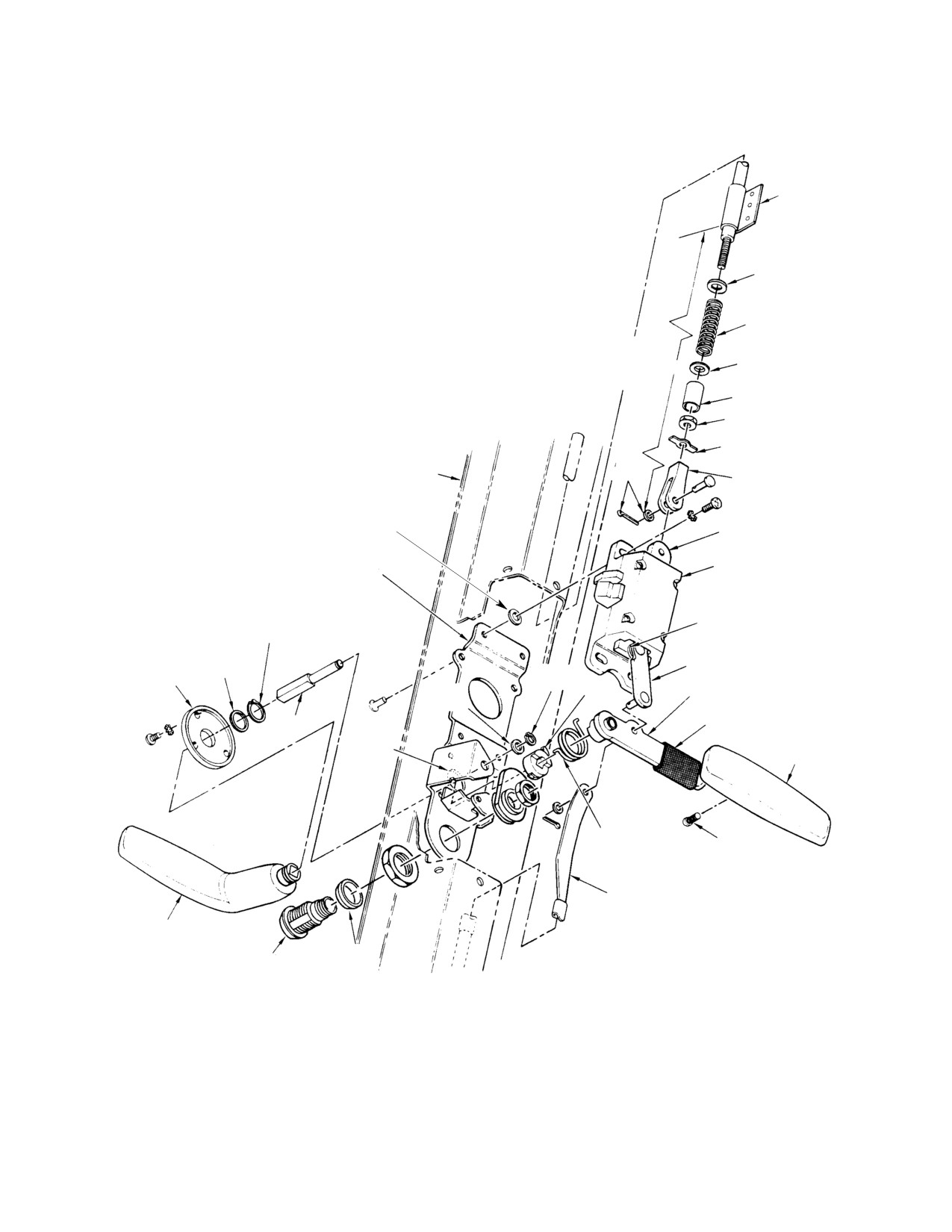
NOTES: (CONT)
7.
REFER TO TEXT FOR CABLE LENGTH AND FOR SPRING PRELOAD ADJUSTMENTS.
8.
INSTALL OUTBOARD TO ELIMINATE POSSIBILITY OF INTERFERENCE.
9.
BEND ONE TANG OVER NUT AND OPPOSITE TANG OVER CLEVIS END AT
REASSEMBLY, AFTER CABLE LENGTH ADJUSTMENT.
10.
INSTALL, IF REQUIRED, FOR LATCH ADJUSTMENT.
CABLE MOUNTING
11.
SPACER REQUIRED ON CURRENT LOCKS WHICH ARE LONGER THAN EARLY
CLIP
MODEL CAM LOCK.
CABLE SPRING WASHER
COMPRESSION SPRING
PRELOAD
MEASUREMENT
CABLE SPRING WASHER
(NOTE 7)
SPACER
NUT
TAB WASHER
(NOTE 9)
PANEL DOOR
NOTE 8
CLEVIS
(NOTE 7)
SHIM WASHER
(NOTE 10)
ACTUATOR SLIDER
LATCH BLOCK ASSY
LOCK PLATE ASSY (CALLED
NUTPLATE AT OTHER LOCATIONS)
PLAIN WASHER
RETAINING RING
HANDLE
LINK ASSY
WASHER
RETAINING
ESCUTCHEON
SPINDLE
RING LOCK
INSIDE HANDLE ARM ASSY
WASHER
BOSS
SPINDLE
TUBING
SPRING
HOOK
INSIDE HANDLE GRIP
NOTCH
HANDLE TORSION
SET SCREW
SPRING
LATCH ROD END
OUTSIDE
HANDLE
SPACER
CAM
(NOTE 11)
(KEY OPERATED LOCK)
30−143−2F
Figure 3-12. Cargo Door, Auto-Latching (Sheet 2 of 2)
Page 3-27
Revision 14
MD Helicopters, Inc.
CSP−H−2
500 Series − Basic HMI
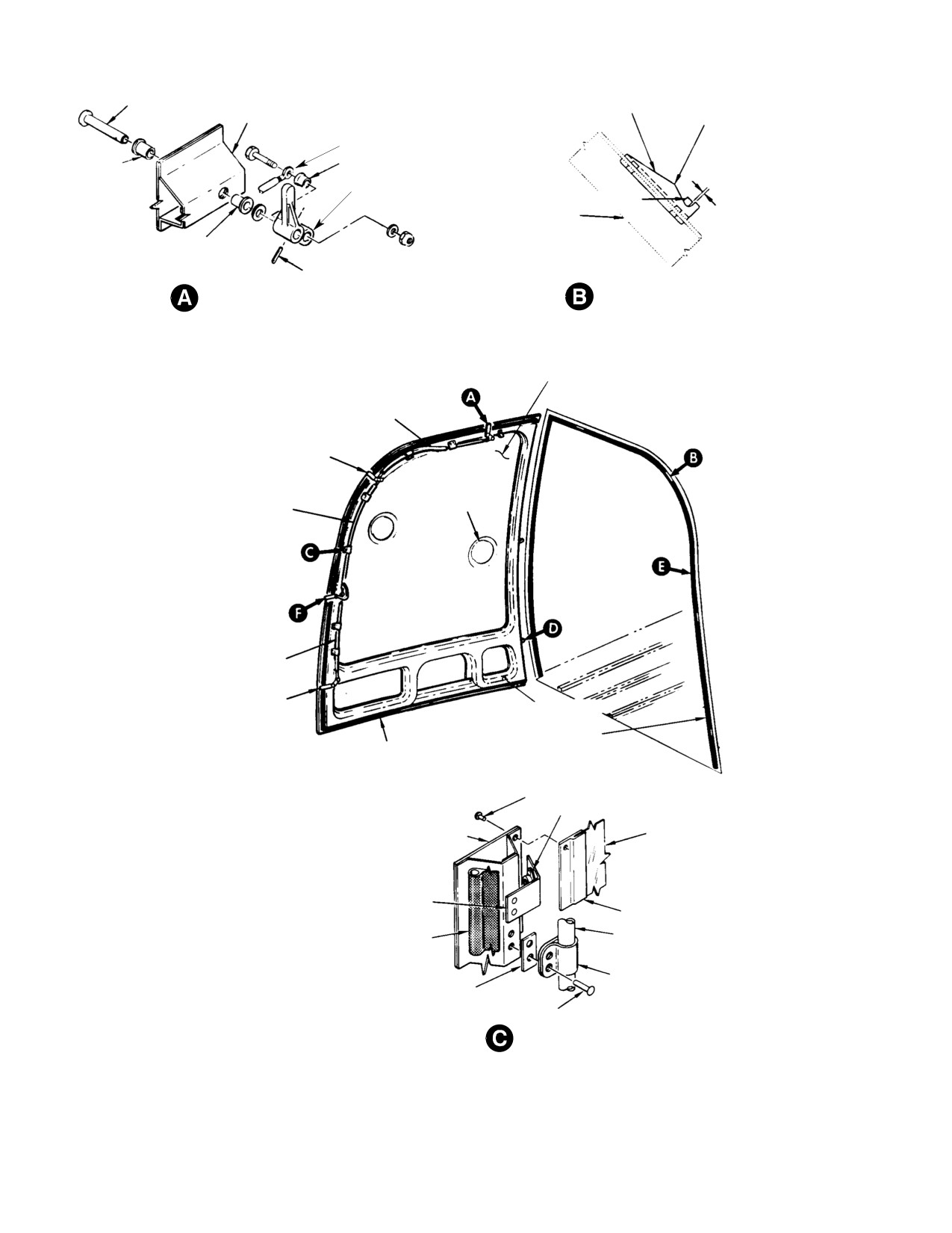
CLEVIS PIN
LATCH STRIKER PLATE
DOOR STRUCTURE
OVERCENTER POINT
LATCH CABLE ASSY
BUSHING
BUSHING
LATCH LEVER
LATCH LEVER
FUSELAGE STRUCTURE
0.00−0.20 IN.
(0.00−5.08 MM)
BUSHING
GAP
SPRING PIN
FORWARD LATCH
LATCH AND STRIKER ENGAGEMENT
PLASTIC WINDOW
FORWARD CABLE SEGMENT
2ND LATCH
SNAPVENT
2ND CABLE SEGMENT
3RD CABLE SEGMENT
4TH LATCH
DRAIN HOLE
FUSELAGE SEAL
DOOR SEAL
SOFT RIVET
NUTPLATE
DOOR STRUCTURE
WINDOW
COVER CLIP
(NOTE 2)
RETAINER
SEAL
LATCH CABLE ASSY
CABLE CLAMP
SHIM
(6 PLCS)
NOTES:
(NOTE 1)
1.
ONE ONLY ON DOOR AT LOCATION C
BLIND RIVET
(EARLY DOOR ONLY).
2.
INTERIOR TRIM COVERS NOT SHOWN.
(TYPICAL)
30−047−1C
Figure 3-13. Cargo Door, Manual Latching (Sheet 1 of 2)
Page 3-28
Revision 14
MD Helicopters, Inc.
CSP−H−2
500 Series − Basic HMI
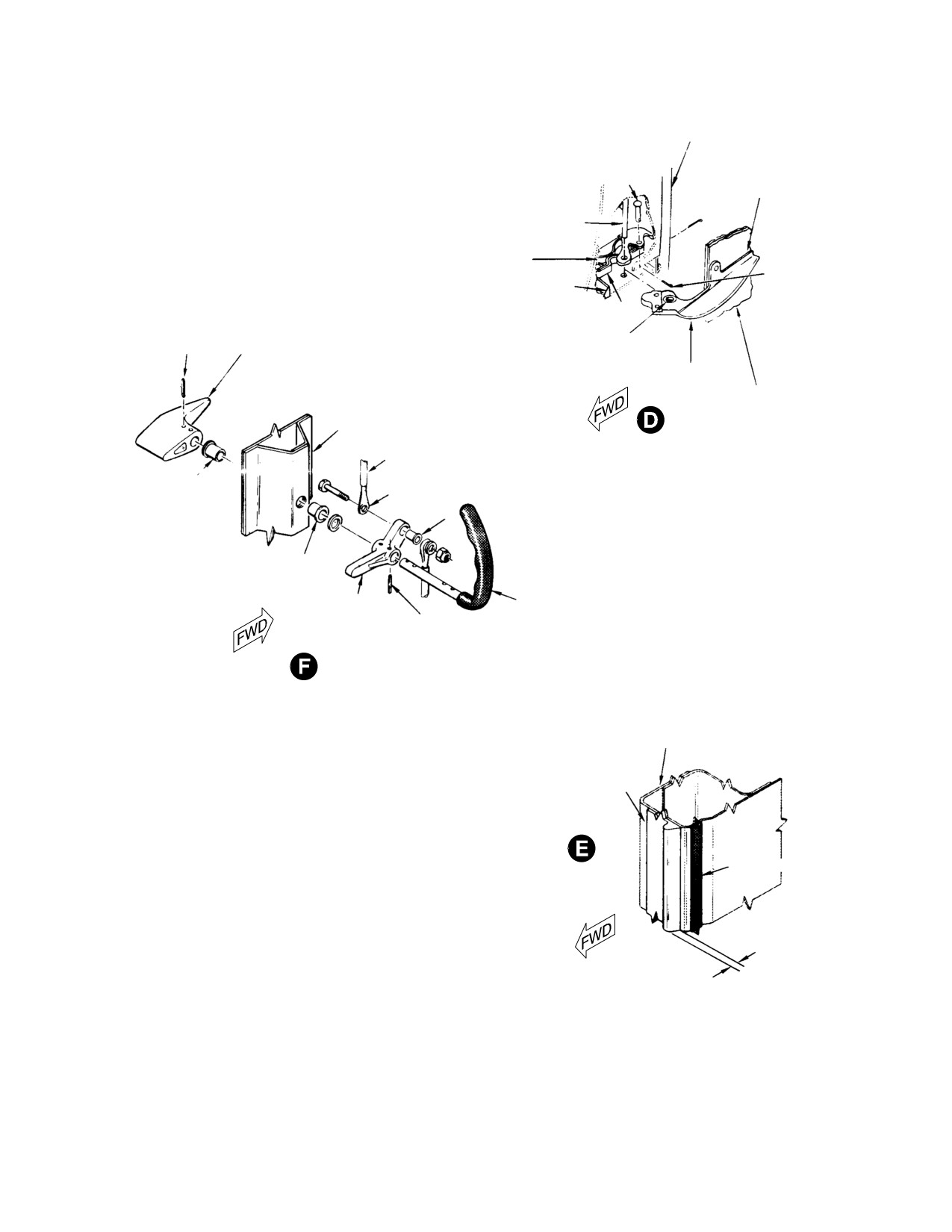
FUSELAGE STRUCTURE
CLEVIS PIN
SHIM (AS REQD)
(NOTE 3)
(NOTE 6)
HINGE PIN
PRELOAD SPRING
(NOTE 4)
COTTER PIN
STOP
DOOR SPRING
SPRING PIN
OUTSIDE LATCH HANDLE
BUSHING
(NOTE 7)
DOOR HINGE
HALF
DOOR STRUCTURE
DOOR HINGE
DOOR STRUCTURE
(TYP 2 PLCS)
LATCH CABLE ASSEMBLY
BUSHING
ROD END
BUSHING
BUSHING
LATCH LEVER
INSIDE LATCH HANDLE
SPRING PIN
3RD LATCH AND HANDLE
CARGO DOOR FRAME
SEAL, BUMPER OR DEPRESSOR
(NOTE 5)
NOTES: (CONT)
3.
SEAL BOTH ENDS WITH SEALANT (59, TABLE 2−4)
AT INSTALLATION.
ANTI−CHAFING TAPE
4.
CURRENT DOOR HINGES ONLY.
(TYPICAL)
5.
THREE TYPES ARE IN USE:
A. RUBBER SEAL.
B. BUMPER EXTRUSION 0.22 IN. (5.588 MM) HIGH WITH
0.060 IN. (1.524 MM) RADIUS.
C. DEPRESSOR EXTRUSION 0.31 IN. (7.874 MM) HIGH
WITH 0.030 IN. (0.762 MM) RADIUS.
6.
MAXIMUM 0.040 IN. (1.016 MM) SHIM IF REQUIRED FOR
(NOTES 5B, 5C)
DOOR FIT. ONE−PIECE ALUMINUM ALLOY SHIM TRIMMED
FLUSH WITH HINGE HALF OUTER EDGES.
7.
BUSHING NOT USED ON STEEL DOOR HINGES.
30−047−2D
Figure 3-13. Cargo Door, Manual Latching (Sheet 2 of 2)
Page 3-29
Revision 14
MD Helicopters, Inc.
CSP−H−2
500 Series − Basic HMI
(10). Spread a 0.060 inch (1.524 mm) bead of
(c). Apply local pressure to insure
sealant compound (3) around exterior
complete contact between adherents
edge of window and door flange (except
and maintain pressure for a mini−
sealed windows with single leg retain−
mum of 30 seconds.
er) frame.
(6). Remove masking tape and remove
residue with aliphatic naphtha.
(11). On doors originally equipped with
doubler, install doubler over retainer at
G. Window Snapvent Replacement
hinge area with two screws, washers,
and nuts. Drill (No. 21 drill) and ream
(1). Removal of Window Snapvent
(0.166 inch (4.2164 mm) diameter)
Push snapvent outward in window
window panel for screws, using slow
(open position). Grasp open side of
speed drill (700 to 800 rpm).
snapvent and gently squeeze it into an
(12). Install snapvent.
elliptical shape. Slip snapvent out of
window hole at about a 30 degree angle
(13). Remove protective covering and clean
to surface of window.
window.
(2). Installation of Window Snapvent
F. Geon Strip Repair
Grasp open end of snapvent and gently
squeeze it into an elliptical shape. Slip
Fill voids between geon strips and transparen−
snapvent flange into window hole at an
cies as follows.
angle of about 30 degrees to window
surface. Be sure that ends of wire
(1). Measure the insertion depth of acrylic
stiffener are inside window hole.
windshield into geon slot, reject parts
having less than 0.125 inch (3.175 mm)
20. Door Latching Mechanism
insertion. Replace parts with debonding
areas over 8 inches (20 cm) in length.
Current type door latching mechanisms
automatically latches the door when the door
(2). Mask the geon weather strip and
are closed. Early type door latching mecha−
windshield on both sides with 3M
nisms are manually actuated. The automatic
polyethylene masking tape (132,
door latching mechanism (Ref. Figure 3−10),
Table 2−4).
installed within the door panel, consist of four
latching blocks that house spring−loaded latch
(3). Wipe all faying surfaces with aliphatic
bolts and safelock bolts together with actuator
naphtha (59) and air dray for a mini−
sliders. The latch sliders are interconnected by
mum of 15 minutes.
cables and connectors and are moved by
turning the inside or an outside door handle.
(4). For small voids.
The system allows the door to be closed and
safelocked from inside or outside. The handle
(a). Apply cyanoacrylic adhesive (133) to
contains a key−operated cam lock, actuated
all fraying surfaces using syringe if
from outside. Moving the inside handle to the
necessary.
open position will overrides the cam lock and
allow the door to be opened. Movement of
(b). Use light pressure to hold the joint
either handle into safelock position is pre−
closed for a minimum of 2 minutes.
vented until the door is closed and the safelock
bolts are actuated by strikes. This actuation
(5). For large voids, Hysol Super Drop
causes the safelock bolts to clear notches on
Accelerator (134) may be used.
actuator sliders, allowing the sliders and
(a). Apply accelerator to the acrylic
linkage to move into safelock position. The
transparency and air dry for a
pilot’s and cargo door auto−latching mecha−
minimum of 2 minutes.
nisms are essentially the same except for
length of interconnecting cables. The manual
(b). Apply 3CI−1000 adhesive to the geon
door latching mechanism (Ref. Figure 3−11)
weatherstrip only.
consists of four lever type latches and three
Page 3-30
Revision 14
MD Helicopters, Inc.
CSP−H−2
500 Series − Basic HMI
lengths of wire−reinforced cable within
(a).
Lubricate all moving parts except
aluminum housing.
lock, with grease (57, Table 2−4) to
prevent binding.
A. Door Latching Mechanism Inspection
and Repair
(b).
Lubricate lock with powdered
graphite (111).
(1). Inspection
(c).
At time of disassembly clean reusable
As applicable to type of installation,
parts except locks, using soft bristle
check the following under magnification
brush dipped in solvent (1). Dry
and strong light:
parts, using clean, lint−free cloth or
dry compressed air at 20 psi (138
(a).
All parts for excessive wear, nicks,
kPa) maximum.
cracks and corrosion.
(d).
Clean key−operated cam locks, using
(b).
Threaded parts for worn, crossed or
dry compressed air at 20 psi (138
otherwise damaged threads.
kPa) maximum.
(c).
Latch block assemblies for broken
(e).
Touch up handles with semigloss
springs and wear on strike contact
black acrylic lacquer (6).
surfaces of latching bolts; and for
undue wear of latch sliders, bolts and
(f).
Eliminate binding by lubricating
bolt rollers.
moving parts, Eliminate persistent
binding in the cables by bending the
(d).
Retaining rings for distortion.
conduits, taking care not to dent or
crease them.
(e).
Cam lock for jamming when key is
operated.
NOTE: Cables are bonded to clamps that are
riveted to the structure. If removal is neces−
(f).
Link assembly for wear or distortion.
sary, rivets must be drilled out.
(g).
Handles for distortion, worn pivot
B. Pilot and Cargo Door Automatic Latch
holes and worn finish.
Replacement
(h).
Escutcheon and handle for dents,
(1).
Perform this procedure with the door in
distortion, or worn finish.
the open position. Handles will be at
(i).
Lock plate assembly for wear,
the latched rest position (Ref.
distortion, thread damage and
Figure 3−1 1).
breakage.
(2).
Remove screws securing cover (Ref.
(j).
Latch block nutplates for thread
Figure 3−12) on door and remove cover.
damage and loose rivets.
(3).
Mark the lock plate so that replacement
(k).
Cables and connector for wear in
latch block can be installed at approxi−
clevis pin holes, thread damage,
mately the same position as the latch
distortion or loose clamps. holes,
that is to be removed.
thread damage, and distortion.
(4).
Remove four screws and washers
(2). Repair
securing latch block to lock plate. Make
note of any washers found between the
Replace worn or damaged parts as
latch block and lock plate. These are
necessary. Disassemble only to extent
adjustment shims and should be
required for replacement of parts. Refer
reinstalled in the same position during
to Figure 3−12 for an exploded view
latch installation.
showing disassembly relationship for
the auto−latching door mechanism, or
(5).
Remove cotter pin, washer and pin
Figure 3−13 for the manually actuated
securing rod or cable end clevis to top of
door latching mechanism. Also perform
latch block. Remove latch block from
following steps as required:
door.
Page 3-31
Revision 14
MD Helicopters, Inc.
CSP−H−2
500 Series − Basic HMI
NOTE: The latch rod end below the inside han−
(a). Adjust the door inboard or outboard
dle arm is detached by removing the cotter
by moving the striker plates in their
pin and washer from the latch block link
slotted mounting holes or by the
that attaches rod end to inside handle.
removal or addition of shim washers
Latch movement may be required to disen−
under the latch assemblies.
gage link pin from handle and clevis from
latch block.
(b). Adjust the depth of engagement of
the latch bolts with the striker plates
(6). Install replacement latch block by
by moving the latch assemblies in
performing applicable latch removal
their slotted mounting holes or by
procedures inverse order. Replacement
the removal or addition of shims
latch should be installed at approxi−
under the striker plates.
mate same position from which old
latch was removed.
NOTE: Current type striker plates are also
bonded to door frame structure. If loosening
NOTE: When reconnecting latch rod end or
or removal of these plates is required, clean
cable clevis, the washer and cotter pin
the mating surfaces with naphtha (59,
should be installed outboard to eliminate
Table
2−4) andrebond with adhesive (19)
possibility of interference.
after correct striker plate position is deter−
mined.
(7). Adjust latch engagement and be sure
door closes and seals correctly.
(4). Adjust latch cables and rod for simulta−
C. Pilot and Cargo Door Automatic Latch
neous latch bolt extension and complete
Adjustment
safe−locking as follows.
(Ref. Figure 3−10, Figure 3−12 and
NOTE: Complete safe−locking is that point at
Figure 3−14)
which latch bolt extension is at maximum
and the roller on the safelock trigger is en−
(1). Make a preliminary check of door
gaged in the safelock slot in the latch slide
latching as follows.
(Ref. Figure 3−14). In this position the safe−
lock trigger can be observed to retract when
(a). Pull the door closed from inside. Each
the latch slide is moved slightly in unlatch
of the latch bolts should make
direction.
contact with their respective striker
plates at the same time and latch
(a). With the door in the open position or
evenly. Unequal striking and latching
removed from the helicopter, actuate
indicates that latch assembly or
the latches to safelocked position.
striker plate positions should be
adjusted.
NOTE: With the door open or removed it is nec−
essary to depress all safelock triggers at the
(b). Safelock the door and observe that
same time in order to rotate the latch han−
the door is forced inward for seal
dle to safelock position.
compression at each latch position.
Check that a minimum of 0.125 inch
(b). Remove the clevis pin from the cable
(3.175 mm) of the flat surface (be−
or latch rod of the latch being ad−
yond the angled leading edge) of each
justed. Move the latch slide manually
latch bolt is engaged with the face of
to the complete safelock position and
the striker plate. Unequal safe−lock−
then adjust the cable or latch rod
ing may indicate that the latch
length so that clevis pin can be
cables are not properly adjusted for
reinstalled easily.
complete extension of the latch bolts.
NOTE: The fourth and the forward latches can
(2). Remove the four latch covers.
be individually adjusted without disturbing
(3). Adjust the positions of the latch
the adjustment of the other latches. Howev−
assemblies and/or striker plates as
er, if the second or third latches are adjusted
required, using the following methods.
then all should be checked.
Page 3-32
Revision 14
MD Helicopters, Inc.
CSP−H−2
500 Series − Basic HMI
CHANNEL STRIP
INSIDE HANDLE UNLATCHED
ACTION POSITION
INSIDE HANDLE
OUTSIDE HANDLE SAFELOCK
ACTION POSITION
TUBING
OUTSIDE HANDLE
OUTSIDE HANDLE
SAFELOCKED POSITION
INSIDE HANDLE LATCHED
STRUCTURAL DOOR FRAME
REST POSITION
(NOTE 3)
LATCH COVER
OUTSIDE HANDLE LATCHED REST POSITION
(NOTE 3)
INSIDE HANDLE
DOOR PANEL
SAFELOCKED POSITION
OUTSIDE HANDLE UNLATCHED
ACTION POSITION
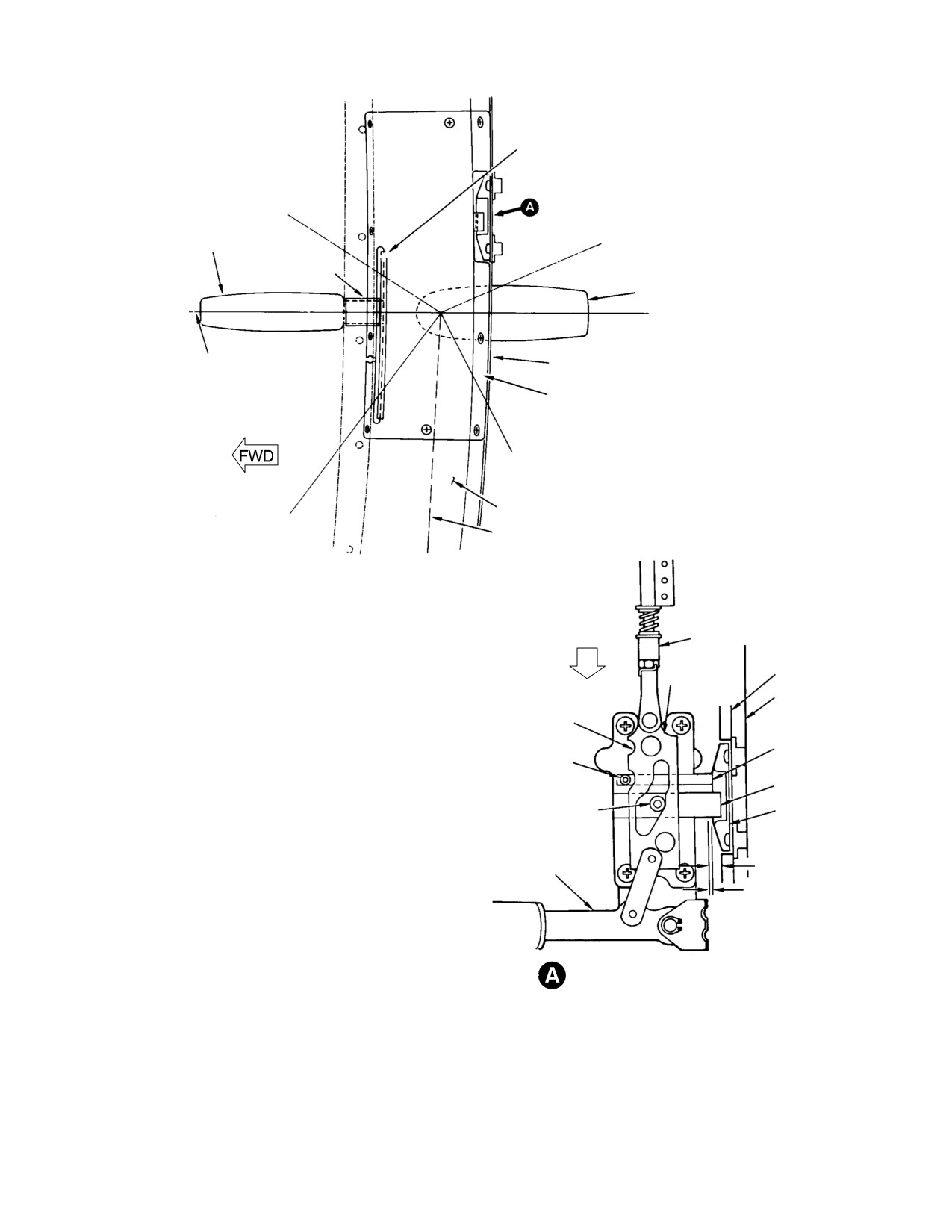
HANDLE POSITIONS
(RIGHT DOOR INSIDE VIEW)
SAFELOCK
ACTION
LATCH CABLE
LATCH SLIDE
BUMPER
DOOR FRAME
SAFELOCK SLOT
SAFELOCK TRIGGER
SAFELOCK ROLLER
LATCH BOLT
STRIKER PLATE
LATCH BOLT ROLLER
(NOTE 1)
0.88 IN. (22.352 MM)
INSIDE HANDLE
UNLATCHED ACTION
NOTE 2
NOTES:
LATCH ENGAGEMENT
1.
CURRENT TYPE STRIKER PLATE SHOWN.
(THIRD LATCH INTERIOR
2.
WHEN LATCH IS COMPLETELY SAFELOCKED, A MINIMUM OF 0.125 IN.
SHOWN FOR CLARITY)
(3.175 MM) OF FLAT SURFACE (BEYOND ANGLED LEADING EDGE) OF
LATCH BOLT MUST BE ENGAGED WITH STRIKER PLATE.
3.
LATCHED REST POSITION APPLIES WITH DOOR OPEN OR CLOSED.
30−144E
Figure 3-14. Latch Engagement for Auto-Latching Door Handle Positions
Page 3-33
Revision 14
MD Helicopters, Inc.
CSP−H−2
500 Series − Basic HMI
(c). For complete rigging of all latches,
(f). Reinstall all parts and be sure that
remove clevis pins from all cable and
clevis is engage to the same of
latch rod connections and move all
number of turns as recorded in Step
latch slides to the complete safelock
(b). above.
position. Adjust cable and latch rod
(6). Tighten all clevis retaining nuts and
length for easy installation of clevis
bend tangs of tab washer, one over the
pins. Start with the third latch and
clevis and one over the nut, for safety.
proceed to the second, to the forward
and then to the fourth.
(7). Install washers and cotter pins in all
clevis pins. Washers and cotter pins are
(5). Latch compression spring preload
to be installed on the outboard side to
adjustment should be checked if a
preclude interference with door struc−
change has occurred to affect spring
ture.
preload. Replacement of parts in the
(8). Make a final check of door latching,
stack−up between the upper clevis pin
safe−locking and key−locking. Install
on the third latch and the first cable
the latch covers.
mounting clip (Ref. Figure 3−12) or a
change in position of the cable mount−
(9). Fill in gaps and fair−in the area be−
ing clip is cause for preload adjustment.
tween latch striker plates and bumper
strips at each position, using sealant
(a).
With the main (third) latch in
(3).
safe−locked position measure the
D. Pilot and Cargo Door Manual Latch
distance from the center of the upper
Adjustment
clevis pin to the shoulder of the cable
mounting clip. Add 0.060−0.080 inch
(Ref. Figure 3−11 and Figure 3−13)
(1.524−2.032 mm) to this measure−
ment and record. This is the required
(1). With the door in the open position,
parts stack−up length.
rotate the latch handle to the locked
position.
(b).
Remove clevis and the complete stack
(2). Check all latch levers. The levers
up of parts from the third latch to the
should be positioned at approximately
cable mounting clip. Note and record
90 degrees to the straight door edge
the number of turns required to
and in line with the radius of the
remove clevis so that it can be
curved door edges.
returned to original position without
further adjustment.
(3). Remove nuts, washers and bolts at the
adjustable rod end on each cable
segment.
(c).
Assemble the stack−up with all parts
in contact and the spring in relaxed
(4). Turn adjustable rod ends and change
condition. Measure from the center of
cable length as required to properly
the clevis pin hole to the outer edge
position latch levers with bolt installed
of the last washer and record.
in Step (2).
NOTE: A change in the length of one cable seg−
(d).
Compare this last measurement,
ment can affect the position of all the latch
Step (c)., with the required stack−up
levers. Therefore, start adjustment at the
length recorded in Step (a). above.
forward cable segment and work progres−
Record the amount to be added or
sively to second: then third segments while
subtracted.
maintaining adjusted latch position.
(e).
Adjust stack−up length by the
(5). Close and latch the door. Check that
amount recorded in Step (c). by using
the latch levers rotate past the over−
a longer or shorter spacer and by
center point on striker plates and are in
grinding and filing the spacer as
the position shown in detail B of
required.
Figure 3−13.
Page 3-34
Revision 14
MD Helicopters, Inc.
CSP−H−2
500 Series − Basic HMI
(6). Open the door and make adjustment of
(d). Loosen latch block mounting screws
cable rod ends as necessary to meet
far enough to allow raising of latch
requirements of Step (5).
block to disengage link pin from latch
rod end and handle arm. If required,
(7). Check that bushings are installed in
remove the four latch block mounting
latch levers. Install bolts, washers and
screws.
nuts.
NOTE: Marking the location of the latch block
E. Pilot and Cargo Door Auto-Latching
on the lock plate inside the door panel aids
Handle Replacement
reattachment at approximate same posi−
tion.
(1). Replacement of Outside Handle.
(e). Note position of the lock boss and
(a). Open the door.
handle torsion spring to aid reinstal−
lation.
(b). Remove three screws and washers
securing handle escutcheon to door
(f). Remove retaining ring and spindle
exterior. Drive spring pin (if in−
washer securing spindle to the lock
stalled) from handle and slide handle
plate.
from spindle (Ref. Figure 3−12).
(c). Remove escutcheon from handle by
(g). Hold handle, lock boss and torsion
removing retaining ring and handle
spring in position and withdraw
washers.
spindle. Then slide handle, lock boss
and torsion spring out of the lock
(d). Attach replacement handle to
plate. Use care to avoid dropping
escutcheon with handle washers and
parts into the door channel cavity.
retaining ring. Use the maximum
number of handle washers possible
(h). Disassemble handle grip from handle
without impeding free movement
arm by loosening setscrew and
between the handle and the escutch−
sliding grip from arm.
eon.
NOTE: Current cam lock is longer than early
(e). Slide handle on spindle and secure
model cam lock and requires a spacer be−
escutcheon to door with washers and
tween lock flange and outside surface of
screws.
door skin.
NOTE: Spring pin NAS561P4−16 may be
(i). As required, replace key−operated
installed for additional security of handle
cam lock by unscrewing hexagonal
attachment: line drill through exterior door
nut.
handle and door latch shaft (spindle), then
install pin through handle and shaft. Be
NOTE: When the lock is in the locked position,
sure that handles are horizontal when
be sure that the cam has actuated the
mechanism is in the safe−lock position.
hinged lock bar. When lock is in correct posi−
tion, lock it in place by center punching sur−
(2). Replacement of Inside Handle or Cam
face of lock plate assembly close to flat on
Lock.
hexagonal locking nut.
(a). Open the door.
(j). Holding lock boss, torsion spring and
(b). Remove outside handle (Step (1).) but
replacement handle together, slide
do not disassemble escutcheon from
the assembly into position and insert
spindle.
handle.
(c). Remove cotter pin and washer from
(k). Install spindle washer and retaining
link assembly pin connecting latch
ring to secure the spindle in the lock
rod end to link and handle arm.
plate.
Page 3-35
Revision 14
MD Helicopters, Inc.
CSP−H−2
500 Series − Basic HMI
(l). Attach one spring hook to ear of lock
check for gaps between window glass,
boss (or in hole of current type boss)
rubber seal and door structure.
and attach the other spring hook at
notch in the lock plate. Use safety−
(6). Replace seal and/or use shorter length
wire to pull the spring hook into
studs to close any gaps. Use longer
plate.
length studs if seal is extruded.
(m). Reconnect link and latch rod end to
22. Pilot and Cargo Door Seal Compression
handle arm with cotter pin and
Check
washer.
Inspect the rubber weather−strip compression
NOTE: Cotter pin and washer should be in−
seal for tight compression between the door
stalled on outboard side of latch rod end to
and frame as follows.
eliminate possibility of interference. Use ex−
tra washers for shimming to eliminate ex−
(1). Open door.
cess play.
(2). Hold a strip of heavy paper against the
door seal so that the strip extends
(n). Secure latch block to lock plate at
approximately 1/4 inch (6.35 mm)
original marked position with four
beyond the seal toward the outside of
screws and washers.
the doorway.
(o). Install outside handle (Step (1).).
(3). While holding the paper strip in place,
close and lock the door.
(p). Check door latching and safe−locking
operation and make any adjustments
(4). Attempt to pull the paper strip from
necessary.
between the door frame and the seal.
The strip should not pull out unless a
21. 369H90085 Litter Door Installation
moderately heavy pull is exerted.
Inspection
NOTE: Correct fit is indicated by an approxi−
mate 0.060 inch (1.524 mm) interference fit
(1).
Visually inspect installation to ensure
between door seal and bumper. Where the
proper condition and security of the
strip can be withdrawn with a light pull, the
quick−release fastener assemblies and
fit of the door against the frame is not suffi−
the rubber seal (gasket) installed
ciently tight to provide an adequate seal.
between the window glass and door
This condition be due to deterioration of the
frame.
weatherstrip compassion seal, deformation
of the door frame, worn hinges or improper
(2).
Remove quick−release fasteners
latching.
securing windows to litter doors and
inspect each fastener for condition and
(5). Repeat steps (1). thru (4). at approxi−
each anchor receptacle in door structure
mately 1 foot (30 cm) increments along
for condition and security of attach−
the length of the door seal.
ment.
A. Pilot and Cargo Door Seal Replacement
(3).
Replace fastener if stud is loose or
worn; replace anchor receptacle and/or
(1). Carefully pull or scrape away damaged
rivets as required.
seal.
(4).
Rebond rubber seal to door structure if
(2). Restore chemical film protection to any
it is not fully intact. Replace seal if it is
base metal exposed during cleaning
worn, cracked or hard.
process.
(5).
Reinstall window assemblies to litter
(3). Clean the seal contact area on metal
doors with quick−release fasteners, then
and rubber seal.
Page
3-36
Revision 14
MD Helicopters, Inc.
CSP−H−2
500 Series − Basic HMI
UPPER LATCHES
3.50 IN. (8.89 CM)
3.50 IN. (8.89 CM)
8.00 IN. (20.32 CM)
8.00 IN.
BLEND FROM 0.12 IN (3.048 MM)
(20.32 CM)
0.12 IN. 3.048 MM)
DIMENSION TO EDGE OF DOOR
(2 PLCS)
SEAL
PILOT’S DOOR
(LEFT SHOWN)
0.12 IN. 3.048 MM)
0.30 IN.
0.762 MM)
8.00 IN.
0.12 IN.
(20.32 CM)
B
(3.048 MM)
SEAL
(FLUSH WITH EDGE OF
A
DOOR AT BOTTOM)
0.35 IN.
A
B
0.12 IN.
(8.89 MM)
(3.048 MM)
CARGO DOOR
(LEFT SHOWN)
NOTE 1
FINGER−TYPE
SEAL
SEAL
SECTION
A−A
A
0.12 IN.
DOOR REINFORCING
(3.048 MM)
A
FRAME
0.30 IN.
SEAL
0.762 MM)
NOTE 1
(FLUSH WITH EDGE
OF DOOR AT BOTTOM)
SECTION B−B
(BOTTOM SEAL FINGERS DOWNWARD;
PILOT’S DOORS ONLY)
NOTES:
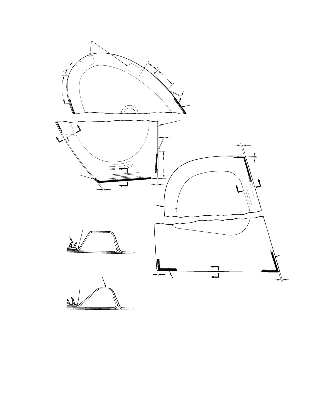
1.
DO NOT LOCATE SEAL ON RADIUS OF REINFORCING FRAME.
2.
INSTALL SEAL USING ADHESIVE (68, TABLE 2−4) ACCORDING TO
CONTAINER INSTRUCTIONS.
30−168A
Figure 3-15. Door Seal Installation, Current Type
Page 3-37
Revision 14
MD Helicopters, Inc.
CSP−H−2
500 Series − Basic HMI
NOTE: The bulb−type seal is installed on the
23. Improved Door Seal Installation
door reinforcing frame with the bulb radius
The following procedure is for installation of
and frame radius coincident
(Ref.
QGR2178 door seals on the cargo/passenger
Figure 3−13) . The finger−type seal is in−
doors.
stalled on the flat door flange at the outer
edge of the reinforcing frame radius. Refer
(1). Remove existing door seals using
to Figure 3−15 for proper location and in−
Desoclean 45 (183, Table 2−4) or
stallation.
naphtha aliphatic (59). Ensure that all
surfaces are clean to allow proper
(4). Carefully align and bond to mounting
adhesion of new seal material. Allow
surface with adhesive (69, Table 2−4)
surface to air−dry a minimum of 15
according to container instructions.
minutes.
NOTE: Seals are to be installed around the
NOTE: Correct seal mounting position results
entire circumference of the aft doors.
in an approximately 0.060 inch (1.524 mm)
interference fit between door seal and bum−
(2).
Prime seal faying surface with red
per.
silicone primer and allow to air−dry a
minimum of 15 minutes.
B. Partially Separated Pilot and Cargo Door
(3).
Apply a thin uniform coat of cyanoa−
Seal Repair
crylic adhesive (133) to faying surface of
door and seal. Allow to air−dry a
(1). Clean the separated area with naphtha
minimum of five minutes.
(59, Table 2−4) and allow to dry for a
(4).
Apply a second thin uniform coat of
minimum of 20 minutes.
cyanoacrylic adhesive to faying surface
of door and seal. Allow to air−dry a
(2). Thoroughly stir adhesive (69).
minimum of five minutes.
(5).
Test glue with clean knuckle. If adhe−
(3). Apply one uniform brush coat of
sive does not transfer to knuckle, press
adhesive to both the rubber seal and
the seal into place.
mating surface contact area. Allow to
dry for 5 minutes and press mating
(6).
Butt joints at forward and aft lower
surfaces together.
locations.
(7).
Maximum gap of 0.030 inch (0.762 mm)
C. Pilot and Cargo Door Frame Anti-Chafing
at butt joints.
Tape Repair
(8).
Miter joints at upper locations.
Inspect the condition of the anti−chafing tape
(9).
Bond mitered joints with adhesive
installed on the pilot’s and cargo compartment
(184).
door frames. For minor repair,remove defective
tape where necessary. Clean frame surface
NOTE: Use glue very sparingly to achieve best
with methyl −ethyl−ketone (22, Table 2−4).
bond.
Replace with polyurethane pressure sensitive
tape (42).
(10). Trim seal flush with edge of door.
Page 3-38
Revision 14
MD Helicopters, Inc.
CSP−H−2
500 Series − Basic HMI
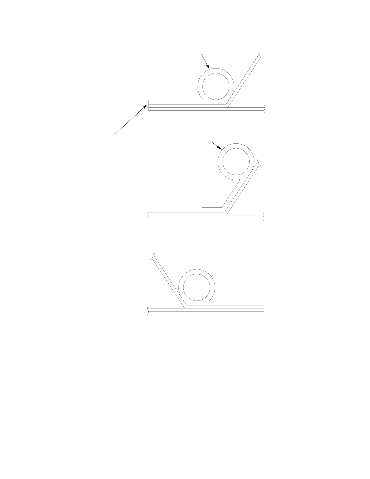
QGR2178 SEAL
SEAL MAY BE LOCATED FROM
EDGE TO INCLINE AS SHOWN
TRIM SEAL FLUSH WITH
AND AS REQUIRED TO ENSURE
EDGE OF DOOR.
PROPER SEAL OPERATION.
POSITION OF SEAL ALONG HINGE SIDE
TYPICAL SEAL POSITION;
SEAL MAY BE RELOCATED AS REQUIRED TO
ACHIEVE PROPER SEAL BETWEEN DOOR AND JAMB.
88−759
Figure 3-16. Improved Door Seal Installation
Page 3-39/(3-40 blank)
Revision 14
MD Helicopters, Inc.
CSP−H−2
500 Series − Basic HMI
Section
4
Furnishings
MD Helicopters, Inc.
CSP−H−2
500 Series − Basic HMI
TABLE OF CONTENTS
Para/Figure/Table
Title
Page
Section 4 Furnishings .
4−1
1.
Furnishings
4−1
A. General Description of S / E Differences
4−1
2.
Crew Compartment Seats
4−1
A. Crew Compartment Seat Replacement
4−1
B. Passenger Compartment Seats
4−1
C. Passenger Compartment Seat Replacement
4−1
D. Seat Inspection
4−1
Figure 4−1. Seat Installation − Typical (Sheet 1 of 2)
4−2
Figure 4−2. Early Configuration Seat Belt and Shoulder Harnesses .
4−4
E. Seat Repair
4−5
3.
Seat Belts and Shoulder Harnesses
4−5
A. Seat Belt and Shoulder Harness Replacement
4−5
B. Seat Belt and Shoulder Harness Inspection
4−5
C. Seat Belt Load Testing
4−5
D. Seat Belt and Shoulder Harness Repair
4−5
4.
Interior Trim
4−5
A. Crew Compartment Interior Trim Removal
4−6
B. Crew Compartment Interior Trim Installation
4−6
C. Passenger Compartment Interior Trim Removal
4−6
D. Passenger Compartment Interior Trim Installation
4−6
Figure 4−3. Crew Compartment Interior Trim and Covers (Sheet 1 of
3) .
4−7
E. Interior Trim Inspection
4−10
F. Interior Trim Repair
4−10
5.
Control Covers
4−10
A. Control Covers Removal
4−10
B. Control Covers Installation
4−10
C. Control Covers Inspection
4−10
D. Control Covers Repair
4−10
Figure 4−4. Passenger Compartment Interior Trim and Covers
(Sheet 1 of 3)
4−11
6.
Boltaron Trim Panel Repair
4−14
A. Fiberglass Patch Method
4−14
B. Solvent Bonding Patch Method
4−14
Figure 4−5. Boltaron Panel Repair
4−15
C. Epoxy Adhesive Patch Method
4−16
D. Bond and Rivet Patch Method
4−16
Page 4−i
Revision 14
MD Helicopters, Inc.
CSP−H−2
500 Series − Basic HMI
TABLE OF CONTENTS (Cont.)
Para/Figure/Table
Title
Page
E. Main Transmission/Engine Drive Shaft Access Door Assembly .
4−17
F. Main Transmission/Engine Drive Shaft Access Door Assembly Seal
Replacement
4−17
7.
Crew Compartment Floor Trim
4−17
8.
Passenger Compartment Floor Trim
4−17
A. Passenger Compartment Floor Trim Removal
4−17
B. Passenger Compartment Floor Trim Installation
4−17
C. Floor Trim Inspection
4−17
D. Floor Trim Repair
4−17
Figure 4−6. Main Transmission/Engine Drive Shaft Access Door Assembly
4−18
9.
Miscellaneous Furnishings
4−18
A. Stowage Compartment Box
4−18
B. Stowage Compartment Box Replacement
4−18
C. Stowage Compartment Box Repair
4−18
Figure 4−7. Crew and Passenger Compartment Floor Trim .
4−19
D. Cargo Tiedown Fittings
4−20
E. Cargo Tiedown Fitting Inspection
4−20
F. Pilot’s Compartment Canopy Frame Trim and VNE Card Cover .
4−20
G. Helicopter Checklist
4−20
H. VNE Card and Holder (Bracket Mounted)
4−20
I.
Magnetic Compass Card
4−20
J. Operation Record Holder
4−20
K. Heat Duct and VNE Card Cover
4−20
L. Heat Duct and VNE Card Cover Replacement
4−20
M. Heat Duct and VNE Card Cover Removal
4−20
N. Heat Duct and VNE Card Cover Installation
4−21
O. Heat Duct and VNE Card Cover Inspection
4−21
P. Heat Duct and VNE Card Cover Repair
4−21
Q. Ashtrays
4−21
R. Passenger Compartment Upper Convenience Panel (Without Trim) .
4−21
S. Passenger Compartment Upper Convenience Panel (Standard Trim) .
4−21
T. Folding Table Assembly (Executive Trim)
4−21
Figure 4−8. Basic Helicopter Furnishings
4−22
U. Passenger Compartment Lower Convenience Panel (Executive Trim) .
4−23
V. Passenger Compartment Upper Convenience Panel (Executive Trim) .
4−23
W. Pilot’s Compartment Footrest
4−23
X. Pilot’s Compartment Footrest Replacement
4−23
Page 4−ii
Revision 14
MD Helicopters, Inc.
CSP−H−2
500 Series − Basic HMI
TABLE OF CONTENTS (Cont.)
Para/Figure/Table
Title
Page
Y. Pilot’s Compartment Footrest Inspection
4−23
Z. Pilot’s Compartment Footrest Repair
4−23
AA. Passenger Step
4−23
Figure 4−9. Miscellaneous Furnishings
4−24
Page 4−iii/(4−iv blank)
Revision 14
MD Helicopters, Inc.
CSP−H−2
500 Series − Basic HMI
SECTION 4
FURNISHINGS
1. Furnishings
B. Passenger Compartment Seats
The MDHI Model 369HS (500S) Helicopter is
The passenger/cargo compartment contains
the standard configuration of the Model 369H
two single or a bench type seat for accommo−
Helicopter Series, manufactured by Hughes
dating two passengers.
Helicopter, now MD Helicopters, Inc. The
Model 369HE (500E) is an executive configura−
The seat consists of a tubular structure that
tion, Model 369HS (500S) is a standard
supports a cushioned and upholstered seat
configuration. The 500S and 500E differ from
bottom and seat backrest or optional nylon
other Series 500 Helicopters primarily as
mesh seat without cushions.
described below.
Seat cushions with standard trim are uphol−
A. General Description of S / E Differences
stered and trimmed with vinyl.
Except for interior trim upholstery and floor
Seats with executive trim are upholstered and
coverings, equipment furnishings, paint finish
trimmed with leather.
and the other details described in this section,
the 369S and 369E are essentially identical to
The seat cushion and backrest can be de−
the basic helicopter configuration. Normally,
tached. The seats can be folded to provide
the 369S has the standard trim package and
additional room in the cargo compartment and
the 369E has the executive trim package.
are easily removable from the floor and
Furnishing variations between models include
bulkhead attach points by quick−disconnect
a passenger/cargo compartment folding table,
fittings on the seat tubular structure. The
passenger steps, and different ashtray
later configuration seat structure incorporates
locations and passenger/cargo convenience
an adjustable feature at the seat structure leg.
panels.
C. Passenger Compartment Seat
2. Crew Compartment Seats
Replacement
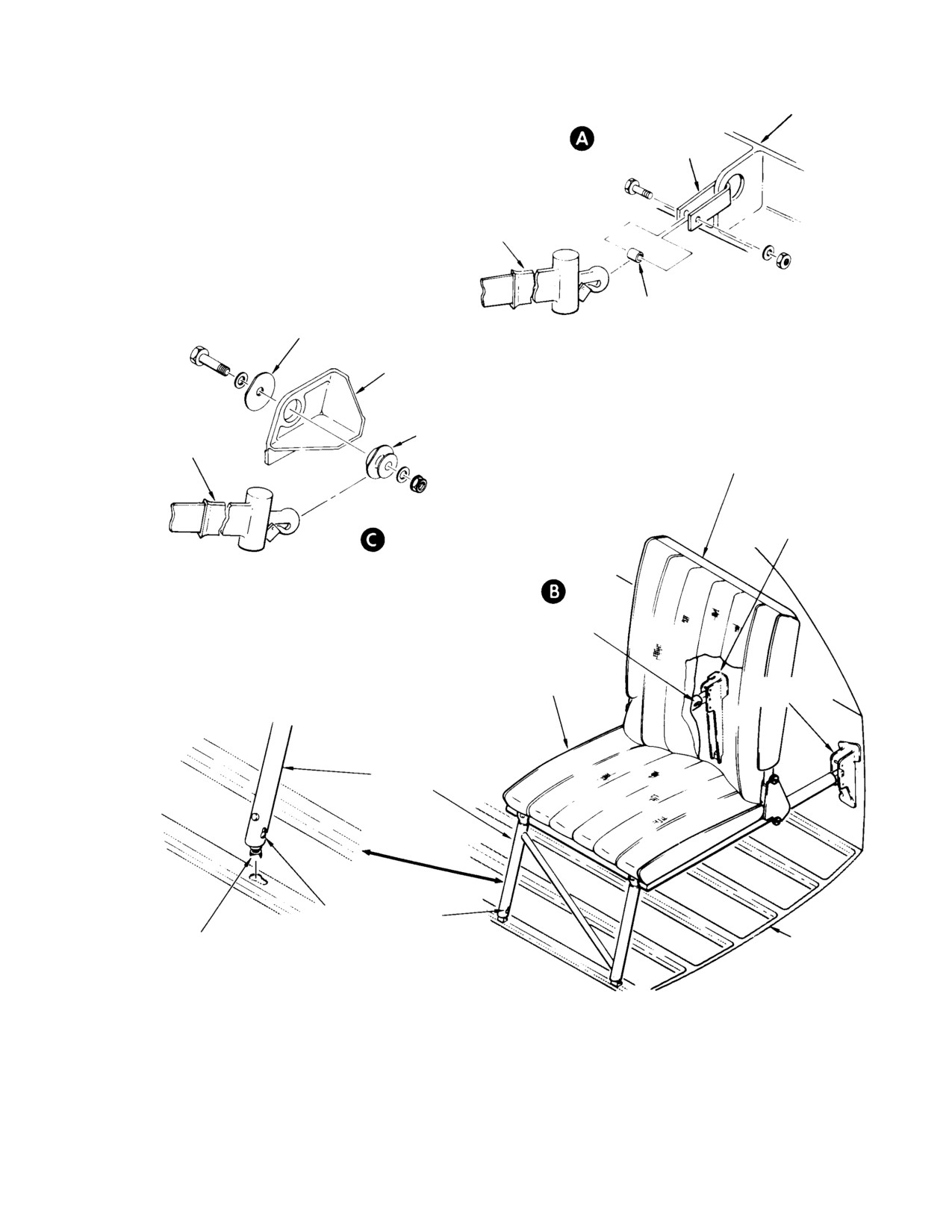
(Ref. Figure 4−1) The crew compartment
equipped with single controls has a three−
(1). Release quick−disconnect fitting at
place arrangement to accommodate the pilot
bulkhead and then at floor points.
and two passengers. The seat consist of a
left−side, right−side and center seat bottom,
(2). To install the seats, position seat(s) in
each with a seat backrest. Seat cushions with
place and allow quick disconnects to
standard trim are upholstered and trimmed
lock in place first at floor points and
with vinyl. Seats with executive trim are
then at bulkhead fittings.
upholstered and trimmed with leather. Velcro
fastener strips on the underside of the seat
D. Seat Inspection
and on the fuselage structure secure the seats
(1). Inspect seating material for cuts, loose
in place.
stitching and for other evidence of
A. Crew Compartment Seat Replacement
unserviceable condition.
(1). Clear the seat of seat belts and shoul−
(2). Inspect quick disconnect on seat
der harness.
structure for correct operation and
damage that might prevent positive
(2). Lift seats away from fuselage structure
locking.
to release Velcro fastener hook from
Velcro pile strips.
(3). Inspect the various Velcro fastener hook
(3). To install the seats, position seating in
and pile strips installed on seat struc−
place and press down so Velcro fasten−
ture and fuselage structure for security
ers mate.
of attachment and condition.
Page 4-1
Revision 14
MD Helicopters, Inc.
CSP−H−2
500 Series − Basic HMI
INERTIA REEL (2)
SEAT BACK CUSHION
SEAT BACK
NOTE 1
AFT SUPPORT FITTING AND
VELCRO STRIP
HEIGHT ADJUSTMENT
FASTENER (TYP)
SEAT BOTTOM
LOCKPIN
CUSHION
PASSENGER
LOWER FRAME
COMPARTMENT
INERTIA REEL (2)
NYLON MESH
FLOOR STRUCTURE
RELEASE PIN
FORE AND AFT
SUPPORT LEG AND
ADJUSTMENT HOLES
HEIGHT ADJUSTMENT
INERTIA REEL
HARNESS MUST UNREEL IN
DIRECTION SHOWN
NOTE 2
SEAT BACK
41° ±3°
CUSHION
90° LIMITS OF
CUTOUT IN ALUM.
HOUSING
NOTE 1
VELCRO STRIP FAS−
TENER (TYP)
NOTES:
1.
SHOWN WITHOUT CUSHION
FOR CLARITY.
2.
CENTER CUSHIONS AND SEAT
SEAT BOTTOM
BELTS ONLY FOR 3−PLACE
CUSHION
SEATING.
CREW
INERTIA REEL
COMPARTMENT
SEAT STRUCTURE
41−007−1A
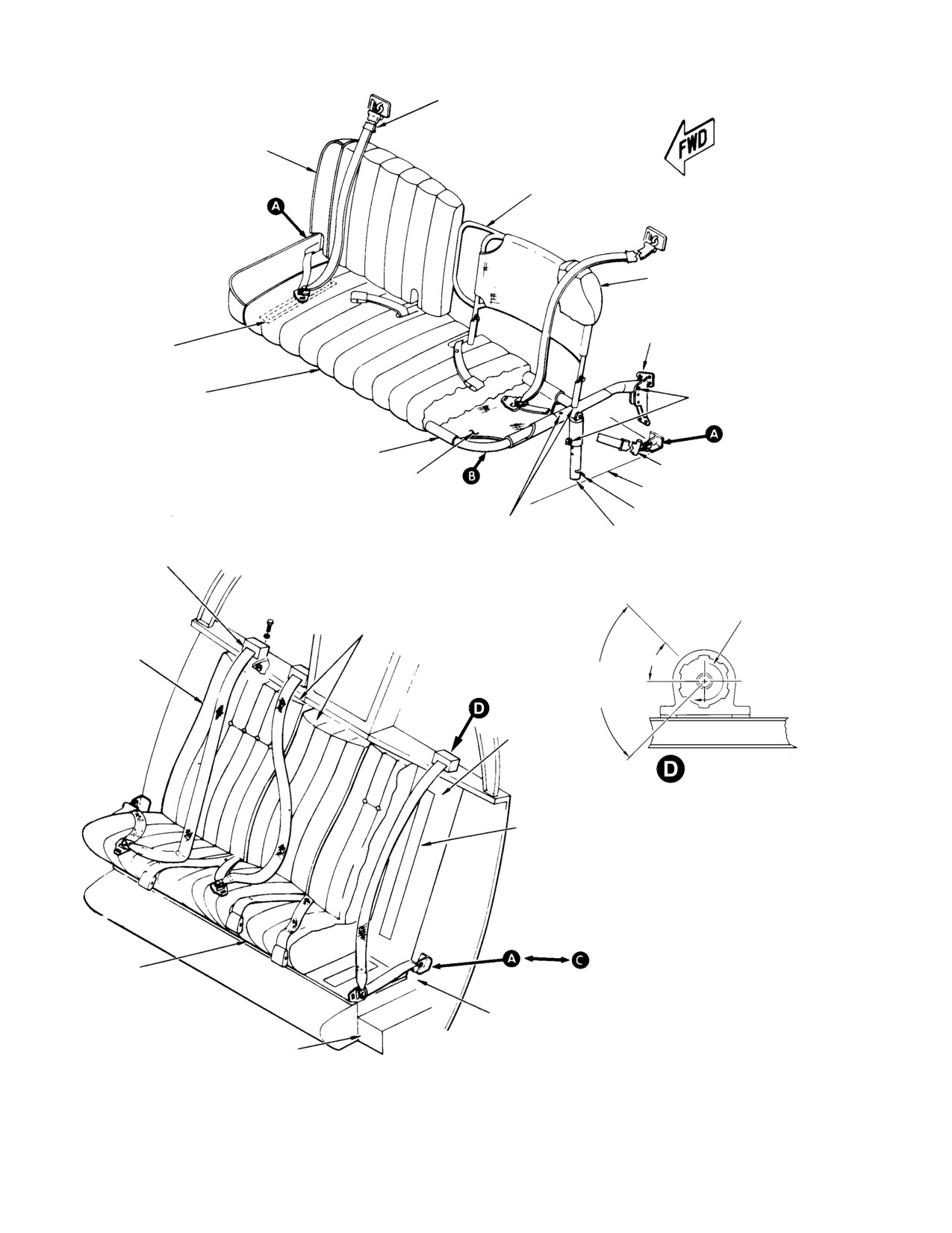
Figure 4-1. Seat Installation - Typical (Sheet 1 of 2)
Page 4-2
Revision 14
MD Helicopters, Inc.
CSP−H−2
500 Series − Basic HMI
STRUCTURE
FITTING
FITTING
SEAT BELT AND INERTIA REEL
SPACER
WASHER
STRUCTURE FITTING
SEAT BELT AND
FITTING
INERTIA REEL
SEAT BACKREST
INBOARD SEAT
FITTING
DISCONNECT BUTTON
SEAT BOTTOM
OUTBOARD SEAT
FITTING
SEAT
STRUCTURE
DISCONNECT BUTTON
INTERIOR
ADJUSTABLE
FLOOR TRIM
SCREW
41−007−2
Figure 4-1. Seat Installation - Typical (Sheet 2 of 2)
Page 4-3
Revision 14
MD Helicopters, Inc.
CSP−H−2
500 Series − Basic HMI
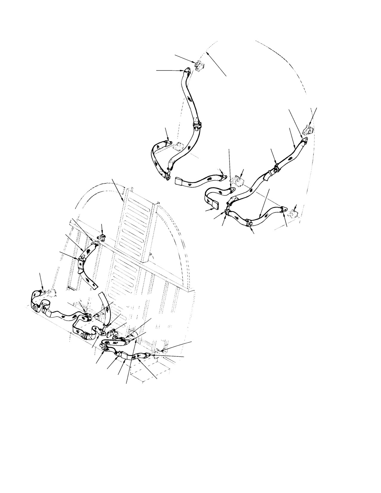
SHOULDER STRAP FITTING
SNAP END FITTING
(HOOK UP)
PASSENGER/CARGO COMPARTMENT
AFT BULKHEAD
SHOULDER
SNAP END FITTING
STRAP
(HOOK DOWN)
FITTING
SNAP END FITTING
NYLON WEBBING
(HOOK UP)
SHOULDER STRAP
SNAP END
FITTING (HOOK
ADAPTER
DOWN)
(NOTE 1)
SNAP END
INBOARD
FITTING
SEAT BELT
(HOOK UP)
FITTING
CANTED BULKHEAD
NYLON WEBBING SEAT BELT
OUTBOARD SEAT
BELT FITTING
SHOULDER
SNAP END FITTING
BUCKLE
STRAP
(HOOK UP)
FITTING
LATCH
NYLON WEBBING
ADAPTER
SNAP END FITTING
SHOULDER STRAP
ADAPTER
(HOOK DOWN)
(NOTE 1)
ADAPTER
(NOTE 1)
PASSENGER/CARGO COMPARTMENT
SNAP END FITTING
(HOOK UP)
SNAP END FITTING
(HOOK UP)
SNAP END FITTING
(HOOK DOWN)
ADAPTER
SNAP END FITTING
BUCKLE
(HOOK DOWN)
SNAP END FITTING
(HOOK DOWN)
OUTBOARD SEAT BELT FITTING
LATCH
SNAP END FITTING
(HOOK DOWN)
ADAPTER
(NOTE 1)
LATCH
BUCKLE
NYLON WEBBING SEAT BELT
INBOARD SEAT
BELT FITTING
PILOT’S COMPARTMENT
NOTES:
1.
SLIDE BAR HARNESS LENGTH AD−
JUSTER.
2.
SEATS AND INTERIOR TRIM NOT
41−012A
Figure 4-2. Early Configuration Seat Belt and Shoulder Harnesses
Page 4-4
Revision 14
MD Helicopters, Inc.
CSP−H−2
500 Series − Basic HMI
E. Seat Repair
B. Seat Belt and Shoulder Harness
Inspection
(1). Lap−stitch frayed or worn upholstery.
(1). Inspect seat belts and shoulder har−
(2). Replace unserviceable Velcro fastener
nesses for worn or frayed condition and
hook and pile strips. Install new Velcro
loose stitching.
pile and hook strips to mate, and bond
(2). Inspect snap−end fitting for cracks,
with cement (91, Table 2−4).
excessive wear, corrosion and deforma−
NOTE: Loosened Velcro fasteners can be reacti−
tion.
vated for adhesion by wiping the original
(3). Check for freedom from binding, ease of
adhesive with methyl ethyl ketone (MEK)
adjustment, and operation as applica−
(22).
ble.
3. Seat Belts and Shoulder Harnesses
C. Seat Belt Load Testing
(Ref. Figure 4−1 and Figure 4−2) Seat belts
Perform seat belt load testing in accordance
and shoulder harnesses are provided at the
with FAA AC 43.13−1A and TSO−C22.
five seat positions.
D. Seat Belt and Shoulder Harness Repair
The early configuration seat belts and shoul−
(1). Replace shoulder harness or seat belt if
der harnesses are fabricated of nylon webbing
webbing is excessively worn or there is
with sewn−in buckles, attachment fittings and
loose stitching.
adjusters.
(2). Polish out minor nicks and scratches,
Later configuration seat belts and shoulder
restore protective finish to aluminum
harnesses have sewn−in snap end fittings and
parts and renew paint finish as neces−
buckles, and are equipped with inertia reels at
sary.
each seat position.
4. Interior Trim
Crew compartment shoulder harness inertia
reels and fittings are attached to the canted
(Ref. Figure 4−3 and Figure 4−4) The trim
bulkhead with a bolt, nut and washer.
panels are fabricated from thermoplastic
material and are contoured to cover the
Executive trim seat belts pass through a
interior fuselage structure, doors and door
semi−rigid cover and seat cushion and frame
frames. The interior trim panels provide the
in the passenger compartment.
interior finish, insulation for the compartment
interior and also provide mounting surfaces for
A. Seat Belt and Shoulder Harness
convenience items.
Replacement
Trim panels furnished with early configuration
(1). Early configuration seat belts and
executive trim are flocked. Trim installed on
shoulder harnesses are removed by
early configuration helicopters are attached
unfastening the snap−type end fittings
with Hedlok semi−rigid interlocking nylon
from structure attachments.
fasteners and attaching screws.
(2). Remove later configuration seat belts
Trim installed in later configuration helicop−
by unfastening the snap−type fitting
ters are attached with upholstery screws that
from special fittings.
fasten to mating rivnuts and isolator nut
mounts on the fuselage structure.
(3). Remove nut, bolt and washer securing
inertia reel and fitting to bulkhead. If
Later configuration trim have access doors at
required, remove access door on right
hinge pin locations and in lower right and left
side outboard trim panel to unsnap seat
panels for access to fuselage structure seat belt
belt fitting.
fittings.
(4). Install seat belts and shoulder har−
The map case trim cover panel located on the
nesses in reverse order of removal.
central control tunnel contains a map case
Page 4-5
Revision 14
MD Helicopters, Inc.
CSP−H−2
500 Series − Basic HMI
pocket and provisions for an optional untility
(3). Connect electrical wires for utility light
light.
when installing map case trim cover on
canted Sta. 78.50.
On later configuration helicopters, crew
C. Passenger Compartment Interior Trim
compartment doors use trim only on the lower
Removal
area.
(1). Identify trim panels, applicable attach−
On helicopters equipped with standard trim,
ing devices and locations.
the upper convenience panel trim cover
contains panel provisions for optional heating
(2). Remove all screws used to secure trim
and lighting items. The forward bulkhead
panel.
standard trim panel contains two literature
(3). On helicopters where trim panels use
pockets and an ashtray and cigarette lighter.
Hedlok fasteners, remove all visible
On helicopters furnished with executive trim,
attachment screws and gently lift off
the upper convenience panel cover contains a
trim panel to disengage fasteners.
blank panel with provisions for an optional
NOTE: The upper convenience panel cover
utility light. The forward bulkhead executive
must be removed before the transmission
trim panel assembly contains two folding
cover panel can be lowered. Release fasten−
tables, literature pockets and convenience
ers and push panel slightly upwards; then
panel.
pivot lower end to clear the bulkhead. Re−
move the transmission cover trim panel by
On later configuration helicopters, passenger
rotating forward end downward.
compartment doors use trim only on the lower
area. A later transmission cover panel contains
(4). Disconnect electrical wires from
two cover plugs for access to the main trans−
ashtray and cigarette lighter when
mission drain and chip detector plugs.
removing forward bulkhead trim panel.
A. Crew Compartment Interior Trim Removal
(5). Disconnect electrical wires from
optional utility light when removing
(1). Identify trim panels, applicable attach−
upper convenience panel trim cover
ing devices, and attaching devices, and
panel.
attaching screws.
(6). Remove passenger compartment seats
(2). Remove all attaching screws securing
when removing lower bulkhead trim
trim panel. On early configuration
panel.
helicopters where Hedlok fasteners are
D. Passenger Compartment Interior Trim
used, remove all visible attaching
Installation
screws; then gently pry and lift off the
selected trim panel.
(1). Identify all trim panels, applicable
attaching devices and locations. Refer
(3). Disconnect electrical wires from untility
to Passenger Compartment Interior
light when removing map case trim
Trim Removal and install in reverse
cover from canted Sta. 78.50.
order.
B. Crew Compartment Interior Trim
(2). Position trim panels with Hedlok
Installation
fasteners in place.
(3). Press on panel to engage all Hedlok
(1). Identify trim panels, applicable attach−
fasteners. Install applicable screws.
ing devices, and the number and
approximate location of attaching
(4). Connect electrical wires to ashtray and
screws.
cigarette lighter assembly when
installing forward bulkhead trim panel.
(2). Position trim panels using Hedlok
fasteners in place and engage all
(5). Connect electrical wires to optional
Hedlok fasteners. Install applicable
utility light when installing upper
screws.
convenience panel trim cover panel.
Page 4-6
Revision 14
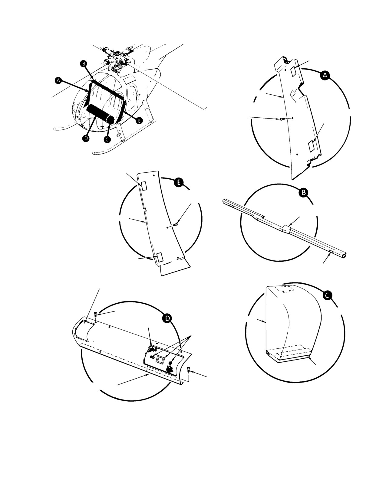
MD Helicopters, Inc.
CSP−H−2
500 Series − Basic HMI
ACCESS DOOR
(NOTE 1)
LOWER AFT PANEL, RH
ACCESS DOOR
SCREW WITH MATING
(NOTE 1)
RIVNUTS (3 PLCS)
ACCESS DOOR
(NOTE 1)
SCREW WITH MATING
NUT MOUNTS (3 PLCS)
SHOULDER BEAM
PANEL
LOWER AFT PANEL, LH
ACCESS DOOR
(NOTE 1)
DNZ HEDLOK ON MOUNT
PAD (2 PLCS)
BLANK COVER FOR OPTION−
AL DUAL CONTROLS
SCREW (4 PLCS)
ROTATED
HEADSET COVER
DUST COVER
GROMMET
HINGE
SCREW (2 PLCS)
CYCLIC STICK CONTROL COVER
NOTES:
1.
CURRENT CONFIGURATION ONLY.
2.
CONTAINS MAGNETIC COMPASS
CARD
41−013−1B
Figure 4-3. Crew Compartment Interior Trim and Covers (Sheet 1 of 3)
Page 4-7
Revision 14
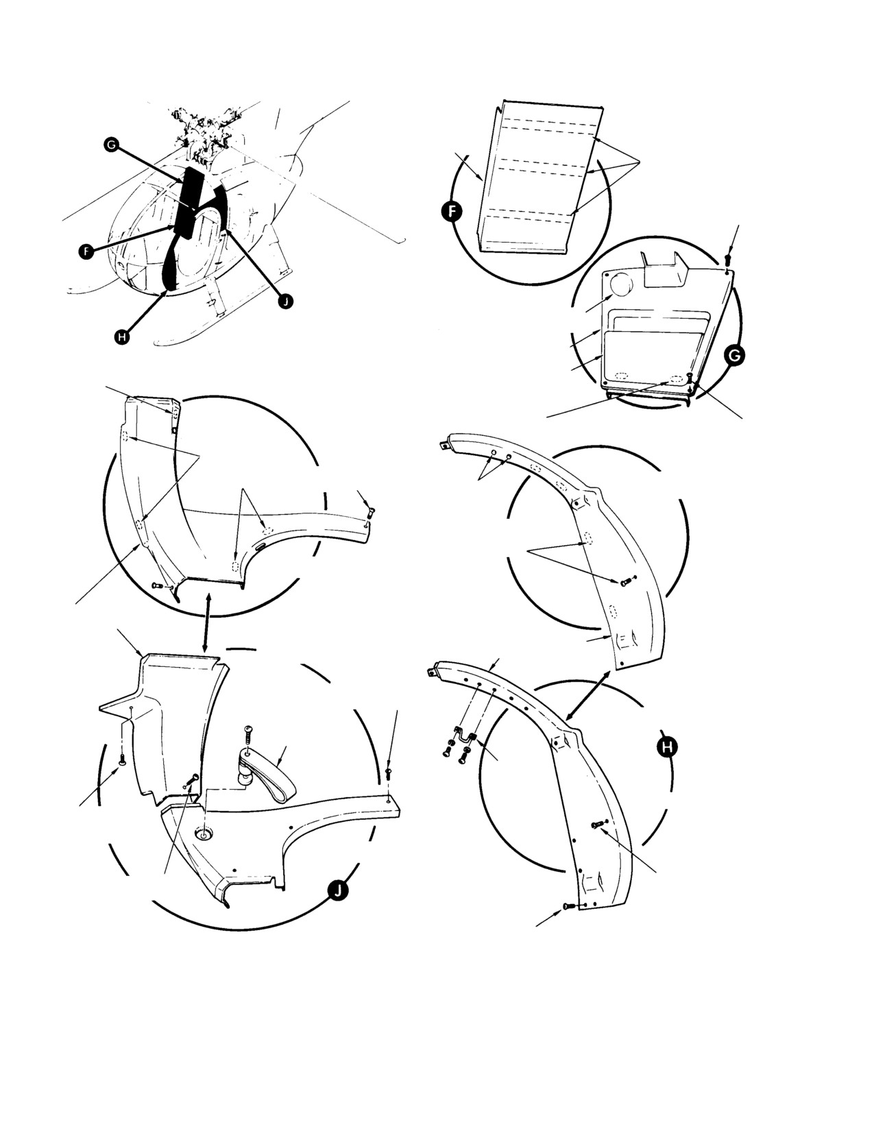
MD Helicopters, Inc.
CSP−H−2
500 Series − Basic HMI
CONTROLS TUNNEL
TRIM COVER
VELCRO FASTENER
SCREW (2 PLCS)
REMOVEABLE PLUG (FOR
OPTIONAL UTILITY LIGHT)
MAP CASE TRIM COVER
DNZ HEDLOK ON
MAP POCKET
MTG PAD
(NOTE 2)
DNZ HEDLOK ON MOUNTING PAD (2 PLCS)
(EARLY CONFIGURATION)
SCREW
(2 PLCS)
DNZ HEDLOK ON
STANDOFF (4 PLCS)
SCREW (2 PLCS)
HEDLOK − FASTENER
GROMMET
MOUNTED
DNZ HEDLOK ON STANDOFF
(4 PLCS) AND ATTACHING
SCREW (4 PLCS)
ONE PIECE
UPPER SIDE PANEL
(LEFT SHOWN)
CREW COMPARTMENT
FORWARD PANEL
ROTATED
SCREW WITH MATING
NUT MOUNT (3 PLCS)
SCREW MOUNTED
ASSIST STRAP
ASSIST
HANDLE
ROTATED
SCREW WITH MAT−
ING NUT MOUNT
TWO PIECE
(NOTE 1)
SCREW WITH
SCREW WITH MATING
MATING RIVNUT
RIVNUT (1 PLC)
SCREW WITH MATING
NUT MOUNT (8 PLCS)
41−013−2B
Figure 4-3. Crew Compartment Interior Trim and Covers (Sheet 2 of 3)
Page 4-8
Revision 14
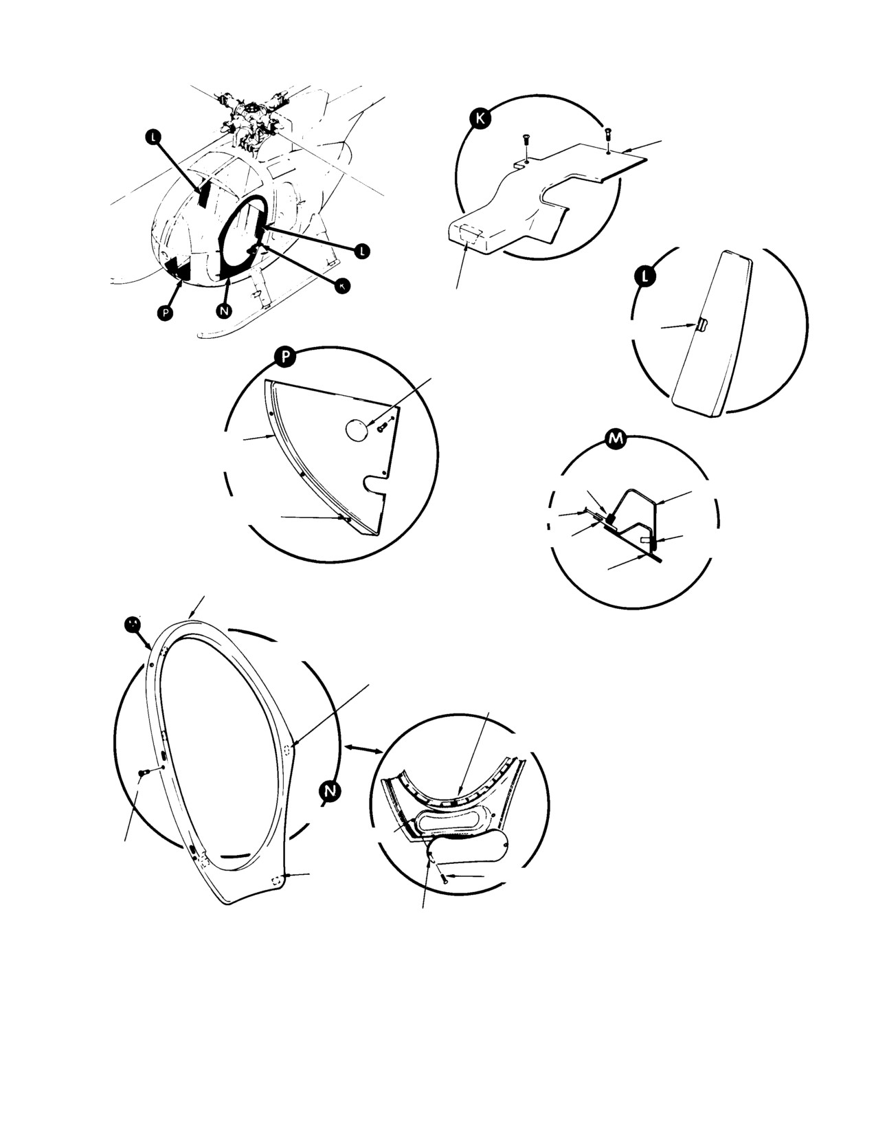
MD Helicopters, Inc.
CSP−H−2
500 Series − Basic HMI
COLLECTIVE STICK COVER
CREW COMPARTMENT BULKHEAD
TRIM COVER (LEFT SHOWN)
DNZ HEDLOK ON
STANDOFF
VELCRO FASTENER
REMOVABLE PLUG
(LEFT COVER ONLY)
LOWER INSTRUMENT
PANEL TRIM COVER (TYP)
CHANNEL TRIM
DOOR TRIM PANEL
ACCORDION RIVET
(3 PLCS)
WINDOW
GEON
PLASTIC TAPE
DOOR
DOOR TRIM PANEL
MANUAL LATCH DOOR
DNZ HEDLOK ON STANDOFF
(3 PLCS)
DOOR STRUCTURE
AUTO−LA TCH DOOR
ROTATED
RIVNUT
SCREW (7
PLCS)
CNS HEDLOK
SCREW (2 PLCS)
(2 PLCS)
DOOR TRIM PANEL
41−013−3B
Figure 4-3. Crew Compartment Interior Trim and Covers (Sheet 3 of 3)
Page 4-9
Revision 14
MD Helicopters, Inc.
CSP−H−2
500 Series − Basic HMI
E. Interior Trim Inspection
of the controls cover group, is located on the
left of the cyclic controls cover. The base of the
(1). Inspect trim panels for teats, cuts,
case is hinge−mounted to the fuselage struc−
breaks or other evidence of an unser−
ture and allows the case to swing open.
viceable condition. Inspect underside of
trim panels for the condition and
A. Control Covers Removal
security of insulation.
(1). Separate the Velcro fastened−attached
(2). Inspect underside of trim panels for
fabric dust cover from cyclic cover and
broken, damaged, or missing Hedlok
locate the four interior attaching screws
fasteners, as applicable.
at the base.
(3). Inspect fuselage structure for loose,
(2). Remove interior attaching screws.
damaged, or missing mating Hedlok
(3). To remove cyclic control cover, remove
fasteners or isolator nut mounts, as
crew compartment seats and four
applicable.
screws atop the seat structure.
(4). Inspect Velcro fasteners used to secure
B. Control Covers Installation
trim panels for serviceable condition.
(1). Identify all control covers, applicable
F. Interior Trim Repair
attaching devices, and the number and
(1). Remove and replace broken or missing
approximate location of attaching
Hedlok fastener of trim panels or on
screws.
fuselage structure.
(2). Install cyclic control cover over cyclic
(2). Remove and replace broken or missing
controls linkage and install the four
isolator nut mounts, as applicable.
inside interior attaching screws.
(3). Remove and replace unserviceable seat
(3). Install attaching screws atop the
fitting cover installed on aft section
fuselage seat structure.
lower bulkhead trim panel.
(4). Attach Velcro−fastened cloth dust cover
(4). Rebond loose insulation material on
to cyclic control cover.
underside of trim panel or on fuselage
(5). Install crew compartment seating.
structure with cement (91, Table 2−4).
C. Control Covers Inspection
(5). Remove and replace unserviceable
Velcro fastener hook and pile strips.
(1). Inspect control covers for tears, cuts,
Install new Velcro pile and hook strip to
breaks or other evidence of an unser−
mate; bond with cement.
viceable condition.
NOTE: Loosened Velcro fasteners can be reacti−
(2). Inspect condition of dust cover, grom−
vated for adhesion by wiping the original
met and Velcro fasteners on cyclic stick
film with MEK (22).
control cover.
5. Control Covers
D. Control Covers Repair
(Ref. Figure 4−3) The crew compartment
(1). Remove and replace unserviceable
control cover consist of a cyclic stick control
Velcro fastener hook and pile strips
cover, headset cover and a collective stick
installed on cyclic stick control cover
cover. The cyclic control cover is mounted to
and dust cover. Install new Velcro hook
the forward portion of the seat structure and
and pile to mate; bond with (91,
covers the control linkage and friction controls.
Table 2−4).
A cutout with a flexible cloth dust cover is
provided in the cover at the cyclic base. The
(2). Remove and replace worn or torn
control cover has cutout provisions for optional
Velcro−fastened cloth dust cover on
dual controls. The headset case, a component
cyclic controls cover.
Page 4-10
Revision 14
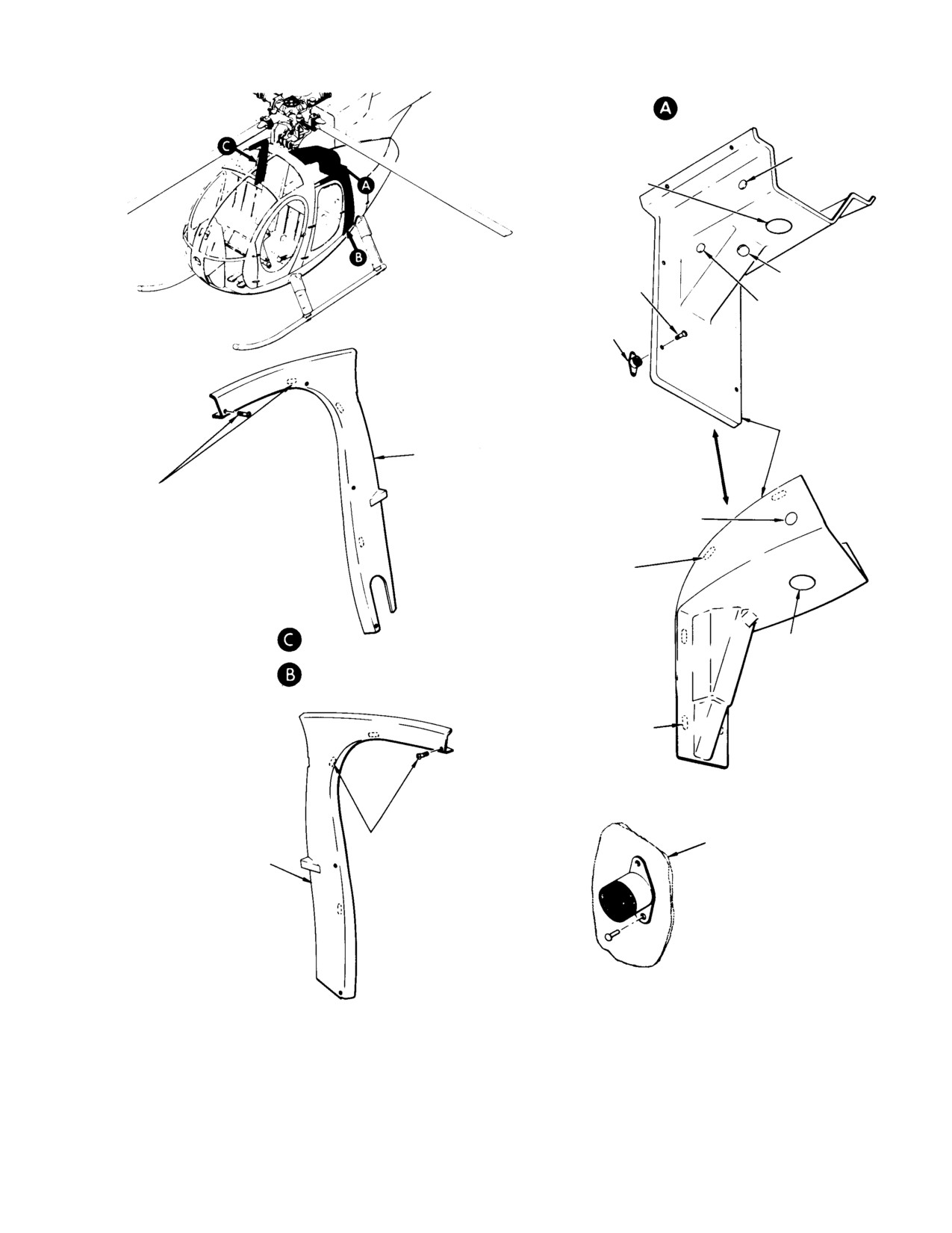
MD Helicopters, Inc.
CSP−H−2
500 Series − Basic HMI
TRANSMISSON COVER PANEL
INSTALLATION
PLUG BUTTON
MAIN TRANSMISSION DRAIN COVER
PLUG (CURRENT STANDARD TYPE)
CHIP DETECTOR
SCREW (8 PLCS)
COVER PLUG
PLUG BUTTON
ISOLATOR NUT MOUNT
(BOTH SIDES)
SCREW MOUNTED
MAIN TRANSMIS−
SION COVER
PASSENGER COMPARTMENT
PANEL
SIDE PANEL (RH)
DNZ HEDLOK FASTENER ON
STAND−OFF (3 PLCS) AND AT−
PLUG BUTTON
TACHING SCREWS (3 PLCS) OR
ATTACHING SCREWS WITH MAT−
ING RIVNUTS (6 PLCS)
DNZ HEDLOK ON
MOUNTING PAD (4 PLCS)
MAIN TRANSMISSION
ISOLATOR NUT MOUNT
DRAIN COVER PLUG
INSTALLATION (TYP)
(CURRENT EXECUTIVE
TYPE)
DNZ HEDLOK ON
HEDLOK FASTENER
STAND−OFF (4 PLCS)
MOUNTED
DNZ HEDLOK FASTENER ON
STRUCTURE
PASSENGER COMPARTMENT
STAND−OFF (3 PLCS) AND AT−
SIDE PANEL (LH)
TACHING SCREWS (3 PLCS) OR
ATTACHING SCREWS WITH MAT−
ING RIVNUTS (6 PLCS)
ISOLATOR NUT MOUNT
INSTALLATION (TYP)
41−015−1C
Figure 4-4. Passenger Compartment Interior Trim and Covers (Sheet 1 of 3)
Page 4-11
Revision 14
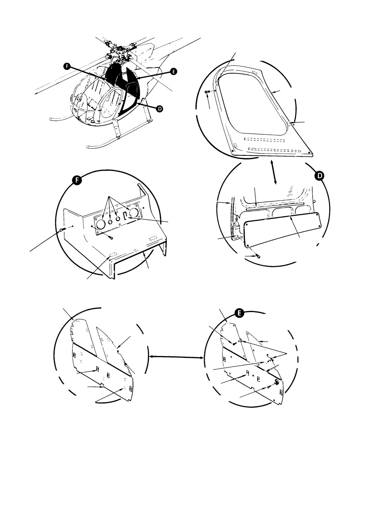
MD Helicopters, Inc.
CSP−H−2
500 Series − Basic HMI
DNZ HEDLOK ON
STAND−OFF (3 PLCS)
PASSENGER COMPARTMENT
DOOR TRIM PANEL
SCREW (5 PLCS)
DNZ HEDLOK ON
MOUNT PAD
VELCRO PILE
DOOR STRUCTURE
BLANK COVER
RIVNUT
VELCRO HOOK
DOOR TRIM PANEL
DNZ HEDLOK ON
SCREW (5 PLACES)
(AUTO−LATCH DOOR)
MOUNT PAD OR
SCREW (2 PLCS)
CONVENIENCE
PANEL COVER
DNZ HEDLOK ON
STAND−OFF
HEDLOK
UPPER BULKHEAD
PANEL (RH)
INSTALLATION
UPPER BULKHEAD PANEL (RH)
SCREW MOUNTED
(EARLY
(CURRENT
CONFIGURATION)
CONFIGURATION)
UPPER BULKHEAD
PANEL (LH)
UPPER BULKHEAD PANEL (LH)
ISOLATOR NUT MOUNT
LOWER BULKHEAD PANEL
SCREW (5 PLCS)
SEAT FITTING COVER
DNZ HEDLOK
ON STAND−OFF
SEAT FITTING COVER
LOWER BULKHEAD PANEL
(5 PLCS)
SCREW (5 PLCS)
DNZ HEDLOK ON
STAND−OFF (5 PLCS)
41−015−2A
Figure 4-4. Passenger Compartment Interior Trim and Covers (Sheet 2 of 3)
Page 4-12
Revision 14
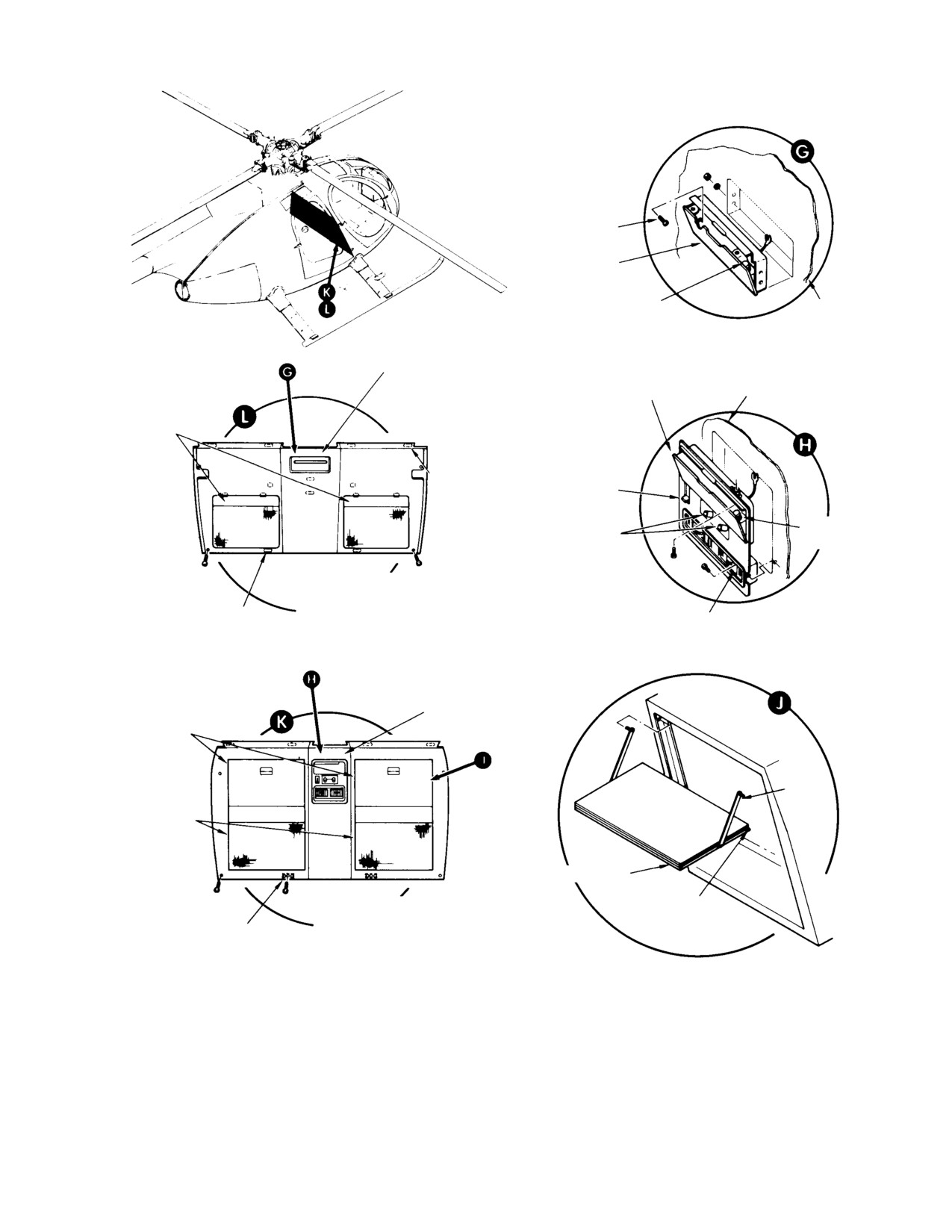
MD Helicopters, Inc.
CSP−H−2
500 Series − Basic HMI
SCREW (4 PLCS)
ASHTRAY
CIGARETTE LIGHTER
TRIM PANEL
ASHTRAY AND CIGARETTE
LIGHTER
EXECUTIVE TRIM PANEL
ASHTRAY
LITERATURE
POCKET
BLANK PLATE OR
OPTIONAL HEAT
DNZ HEDLOK ON
CONTROL
MOUNTING PAD
SELECTOR KNOB
(6 PLCS)
CIGARETTE
HEADSET CONNECTOR
LIGHTER
PASSENGER COMPARTMENT
FORWARD BULKHEAD TRIM
DNZ HEDLOK ON
PANEL (STANDARD TRIM)
HEAT DIFFUSERS
STAND−OFF (2 PLCS)
CONVENIENCE PANEL
FOLDING
TABLE
ARM
LITERATURE
POCKET
FOLDING TABLE
PASSENGER COMPARTMENT
SPRING PLUNGER
FORWARD BULKHEAD TRIM
BRACKET AND SCREW
PANEL (EXECUTIVE TRIM)
OR DNZ HEDLOK ON
STAND−OFF (2 PLCS)
41−015−3B
Figure 4-4. Passenger Compartment Interior Trim and Covers (Sheet 3 of 3)
Page 4-13
Revision 14
MD Helicopters, Inc.
CSP−H−2
500 Series − Basic HMI
6. Boltaron Trim Panel Repair
(3). Deburr stop drill(s) and clean any
jagged area of crack.
(Ref. Figure 4−5)
(4). Select a piece of boltaron material,
A. Fiberglass Patch Method
same contour of area to be patched.
Plating surfaces must provide a snug
(1).
Remove damaged panel.
fit. Patch material to overlap damaged
area a minimum of 1 inch (25.4 mm) in
(2).
Stop drill end(s) of crack.
all directions.
(3).
Deburr stop drill(s) and clean any
(5). Clean mating surfaces with aliphatic
jagged area of crack.
naphtha (59, Table 2−4). Ensure
surfaces are free from oil, grease or
(4).
Cut patch from fiberglass cloth to
other contaminates.
overlap damaged area or crack, mini−
mum 1 inch in all directions.
(6). Assemble patch, when possible, with
mating surface of patch in contact with
(5).
Cut second patch to overlap first,
panel but without application of
minimum 0.50 inch (12.7 mm) in all
pressure.
directions. If required, cut third patch
to overlap second, minimum 0.50 inch
Bonding solvent, tetrahy−
(12.7 mm) in all directions.
WARNING
drofuran, is a flammable liq−
uid; care must be exercised in handl−
(6).
Abrade surface of panel, in area to be
ing.
patched, with emery cloth (49,
Table 2−4).
Solvent shall be applied careful−
CAUTION
ly so no excess material will run
(7).
Clean surface by wiping with cloth,
over other surfaces and mar the finish.
dampened not saturated, with solvent
(10).
(7).
Inject tetrahydrofuran (46) between
mating surfaces by means of syringe or
(8).
Place panel in horizontal position. Tape
eye dropper.
around area to be repaired with
masking tape, to catch residual resin.
(8).
On larger parts, solvent shall be
applied evenly to mating surfaces with
(9).
Apply glass cloth (159) to panel, one ply
brush.
at a time.
(9).
Assemble mating surfaces as quickly as
(10).
Apply resin (160) to material with a
possible by firmly pressing together.
brush or squeegee.
(10).
Apply clamps to assembly, immediately
(11).
Continue adding material and resin
after solvent application, with sufficient
until desired thickness has been
pressure to force out air bubbles.
achieved.
(11).
After forcing out bubbles, adjust clamps
(12).
Allow repair to cure, minimum 45
to minimum pressure required to hold
minutes at 265° ±10°F (129° ±5°C). As
parts together.
alternate, heat lamp may be used,
minimum 2 hours.
(12).
If solvent has evaporated at or near
NOTE: Heat lamp should be placed a minimum
edge of patch, apply more solvent in
of 12 inches from fiberglass repair area.
accordance with step (7).
B. Solvent Bonding Patch Method
(13).
Leave clamps in place for a minimum of
20 minutes.
(1). Remove damaged panel.
(14).
Allow the panel to cure for 24 hours
(2). Stop drill end(s) of crack.
prior to reinstallation.
Page 4-14
Revision 14
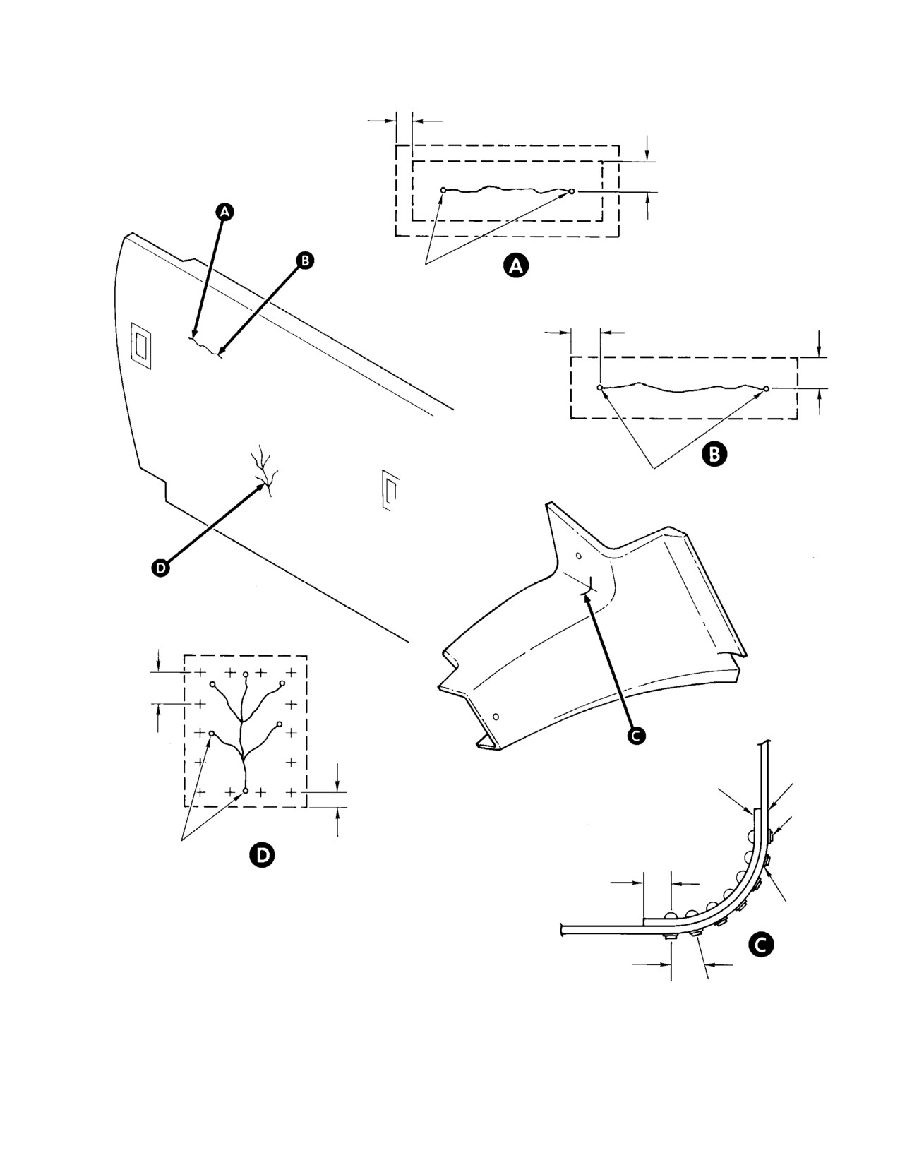
MD Helicopters, Inc.
CSP−H−2
500 Series − Basic HMI
FIBERGLASS PATCH METHOD A
0.50 IN.
1.0 IN.
(12.7 MM)
(25.4 MM)
STOP DRILL
SOLVENT BONDING AND EPOXY
ADHESIVE PATCH METHOD B & C
1.0 IN.
(25.4 MM)
1.0 IN.
(25.4 MM)
STOP DRILL
BOND AND RIVET PATCH METHOD D
4−6 X O.D.
PATCH
PATCH
RIVETS
BOND AND RIVET PATCH METHOD D
STOP DRILL
2 X O.D. +0.030 IN.
(0.762 MM)
2 X O.D. +0.030 IN.
(0.762 MM)
WASHER
(NOTE)
NOTE:
USE AN960 WASHER, OF PROPER SIZE TO FIT RIVET DIAMETER, TO PRE−
4−6 X O.D.
CLUDE RIVET TAIL FROM PULLING THROUGH BOLTARON PANEL.
54−400
Figure 4-5. Boltaron Panel Repair
Page 4-15
Revision 14
MD Helicopters, Inc.
CSP−H−2
500 Series − Basic HMI
C. Epoxy Adhesive Patch Method
MS20426A4 Countersunk Rivets
MS20470A4 Universal Rivets
(1).
Remove damaged panel.
(1). Cut patch to proper size.
(2).
Stop drill end(s) of crack.
(2). Determine rivet spacing.
(3).
Deburr stop drill(s) and clean any
(a). Rivet spacing to be 4−6 times rivet
jagged area of cracks.
diameter.
(4).
Select a piece of boltaron material,
(b). Minimum edge distance to be 2X
same contour of area to be patched.
rivet dia. +0.030 inch (0.762 mm).
Mating surfaces must provide a snug
Example: For #4 rivet, min. edge
fit. Patch to overlap damaged area a
distance is 0.028 inch (0.711 mm).
minimum of one inch (25.4 mm) in all
Rivet diameter 0.125 in. (3.175 mm)
directions.
X 2 +0.030 in. (0.762 mm) = 0.280 in.
(7.112 mm)
(5).
Lightly abrade mating surfaces with
(3). Lay out rivet pattern on patch and drill
emery cloth (49, Table 2−4) and clean
holes. Position patch on panel and drill
with solvent (10).
holes.
(6).
Air dry for 30 minutes at ambient
(4). Deburr all holes on both sides of patch
temperature. Apply adhesive (19)
and panel.
within 2 hours of drying.
(5). Countersink holes on patch if
(7).
Thoroughly mix equal parts, by weight,
MS20426A4 rivets are to be used.
of adhesive. Color should be uniform
(6). Comply with the following procedures if
green. Use unwaxed disposable contain−
using solvent bonding method (tetrahy−
er and wooden tongue depressor or
drofuran).
metal spatula for mixing. Pot life of
mixed adhesive is 45 minutes at
(a). Perform step (5). of Fiberglass Patch
ambient temperature.
Method.
(b). Set patch in place, using a minimum
(8).
Spread thin uniform layer, 0.002−0.010
amount of clecos required to hold
inch (0.051−0.254 mm), of adhesive
patch in contact with panel without
lightly on mating surfaces and clamp
applying too much pressure (Ref: step
lightly together.
(6).).
(9).
Wipe excess adhesive from bond line.
(c). Perform steps (7). thru (9).
(d). Install clamps per steps (10). and
(10).
The clamps are to remain in place for 8
(11). Keep all clamps in place for a
hours minimum at ambient tempera−
minimum of 20 minutes. Perform
ture or 2 hours at 160° ±10°F (71°
step (12). if necessary.
±5°C).
NOTE: If gap exists between patch and panel,
(11).
Allow panel to cure for 24 hours prior to
perform step (7). in immediate area of each
installation.
rivet hole with a gap prior to installing riv−
ets
D. Bond and Rivet Patch Method
(e). Rivet patch to panel.
The following procedure may be used in
(f). Allow panel to cure for a minimum of
conjunction with one of the above bonding
24 hours prior to installation.
procedures. If cracks are excessive and/or a
piece of boltaron isn’t available that fits
(7). Comply with the following procedures if
contour in area to be repaired, rivets may be
using the epoxy adhesive method
used to help secure patch to panel.
(scotchweld EA 1838A4−8).
Page 4-16
Revision 14
MD Helicopters, Inc.
CSP−H−2
500 Series − Basic HMI
(a). Perform steps (5). thru (7). of Fiber−
8. Passenger Compartment Floor Trim
glass Patch Method.
(Ref. Figure 4−7) The passenger compartment
(b). Spread a thin uniform layer,
floor is furnished with standard or executive
0.002−0.010 inch (0.051−0.254 mm),
trim. The floor trim consists basically of a
of adhesive on mating surfaces. Try
form−fitted plastic two−section floor trim panel
to keep adhesive out of the rivet
with floor covering. Floor covering for execu−
holes.
tive trim is carpeting. Floor covering for
standard trim is a plastic vinyl material. The
(c). Install the patch on the panel with
area below the forward bulkhead trim panel
clecos.
and the control access door is also trimmed.
Foot support fairings are only trimmed on
(d). Rivet the patch to the panel.
executive models. A trim flap (lower left)
encloses the electrical receptacle recess and is
(e). Wipe excess adhesive from bond line
secured in placed with Velcro fasteners.
and from around the rivets.
A. Passenger Compartment Floor Trim
(f). Allow the panel to cure for 24 hours
Removal
prior to installation.
(1). Remove passenger compartment seats.
E. Main Transmission/Engine Drive Shaft
Access Door Assembly
(2). Remove cargo tiedown fittings (when
installed).
(Ref. Figure 4−6) The Access Door Assembly is
(3). Pry and lift trim panel from floor
made of 0.093 inch (2.362 mm) thick boltaron
structure.
plastic, on some models pre−impregnated
layers of fiberglass cloth form the access door.
(4). Remove foot support fairings and
The door provides access to the air cooler
controls access door (Ref. Sec. 2).
blower fan assembly and engine to transmis−
sion drive shaft.
B. Passenger Compartment Floor Trim
Installation
F. Main Transmission/Engine Drive Shaft
Access Door Assembly Seal
(1). Clear floor of seat belts and check that
Replacement
floor structure is clean and free of
debris.
MEK is highly flammable
WARNING
and toxic. Use only in well
(2). Place trim panel over floor structure
ventilated area and away from heat
and press in place.
and flame.
(3). Install passenger compartment seats.
(1). Remove seal from access door; remove
(4). Install foot support fairings, if required,
seal residue from access door using a
and controls access door (Ref. Sec. 2).
cloth dampened with MEK (22,
Table 2−4).
C. Floor Trim Inspection
(2). Install new seal.
(1). Inspect floor trim panel for cuts,
breaks, or other evidence of an unser−
7. Crew Compartment Floor Trim
viceable condition.
D. Floor Trim Repair
(Ref. Figure 4−7) The crew compartment floor
is furnished with either standard or executive
(1). Repair loose or torn plastic vinyl floor
trim. The standard trim uses a fire resistant
covering material or carpeting by using
vinyl floor covering material. The executive
new application of double−backed−faced
trim consist of fire resistant carpeting. The
tape (90, Table 2−4).
plastic vinyl material and carpeting are
secured to the floor area with double−backed−
(2). Repair loose or torn floor covering or
faced tape and bonded to the two floor access
carpeting on access doors by rebonding
doors.
with cement (91).
Page 4-17
Revision 14
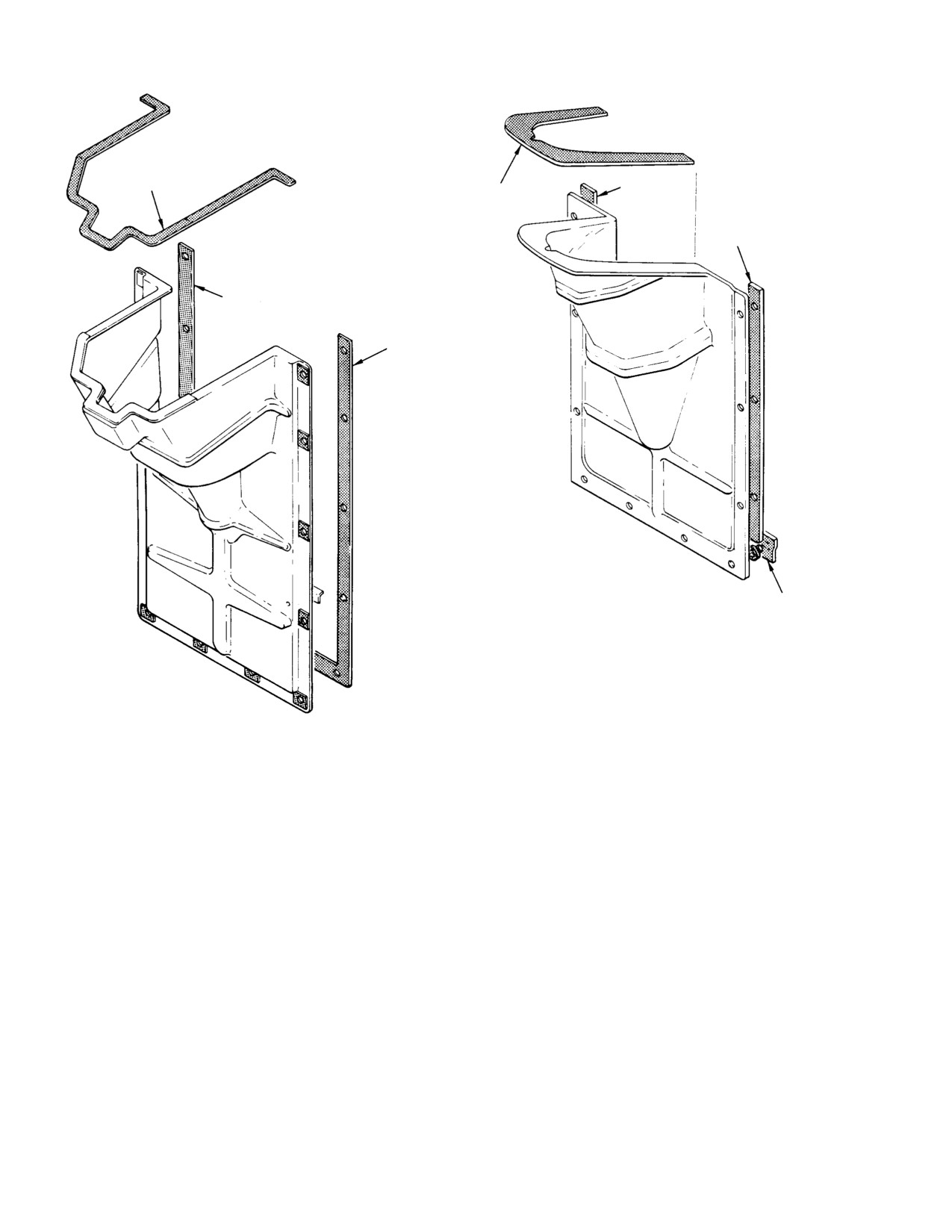
MD Helicopters, Inc.
CSP−H−2
500 Series − Basic HMI
NOTES 2 AND 3
NOTE 1
NOTES 2 AND 3
NOTE 1
NOTE 1
NOTE 1
NOTE 1
NOTES:
1.
NE−71A ADHESIVE−BACKED NITRILE BUTALINE TAPE.
2.
MIL−R−6130 & MIL−R−6130D TYPE II, GRADE A COND.
SOFT (ARMSTRONG TYPE DE−41 OR EQUIVALENT).
3.
NS 210−2400 ELASTIC EXTRUSION (SILICONE RUBBER SPONGE)
31−340
Figure 4-6. Main Transmission/Engine Drive Shaft Access Door Assembly
(3). Replace unserviceable Velcro fasteners
B. Stowage Compartment Box Replacement
on the electrical receptacle recess trim
flap.
(1). Raise pilot’s compartment floor right
access door. Remove tape covering
9. Miscellaneous Furnishings
screwheads and 10 screws and washers
to release stowage box.
A. Stowage Compartment Box
(Ref. Figure 4−8) The stowage compartment
(2). Install replacement stowage box and
box is a bonded, stitched and riveted thermo−
secure with screws and washers. Cover
plastic box with a uniformly distributed load
screwheads with tape (42, Table 2−4).
capacity of 50 pounds (23 kg) maximum. It is
Close and latch access door.
located under the pilot’s compartment floor on
the right side.
C. Stowage Compartment Box Repair
NOTE: Helicopters equipped with certain op−
tional communications and avionics instal−
Perform fiberglass repair of stowage compart−
lations will not have a stowage compart−
ment box according to applicable instructions
ment box installed.
in CSP−H−6, HMI Appendix D.
Page 4-18
Revision 14
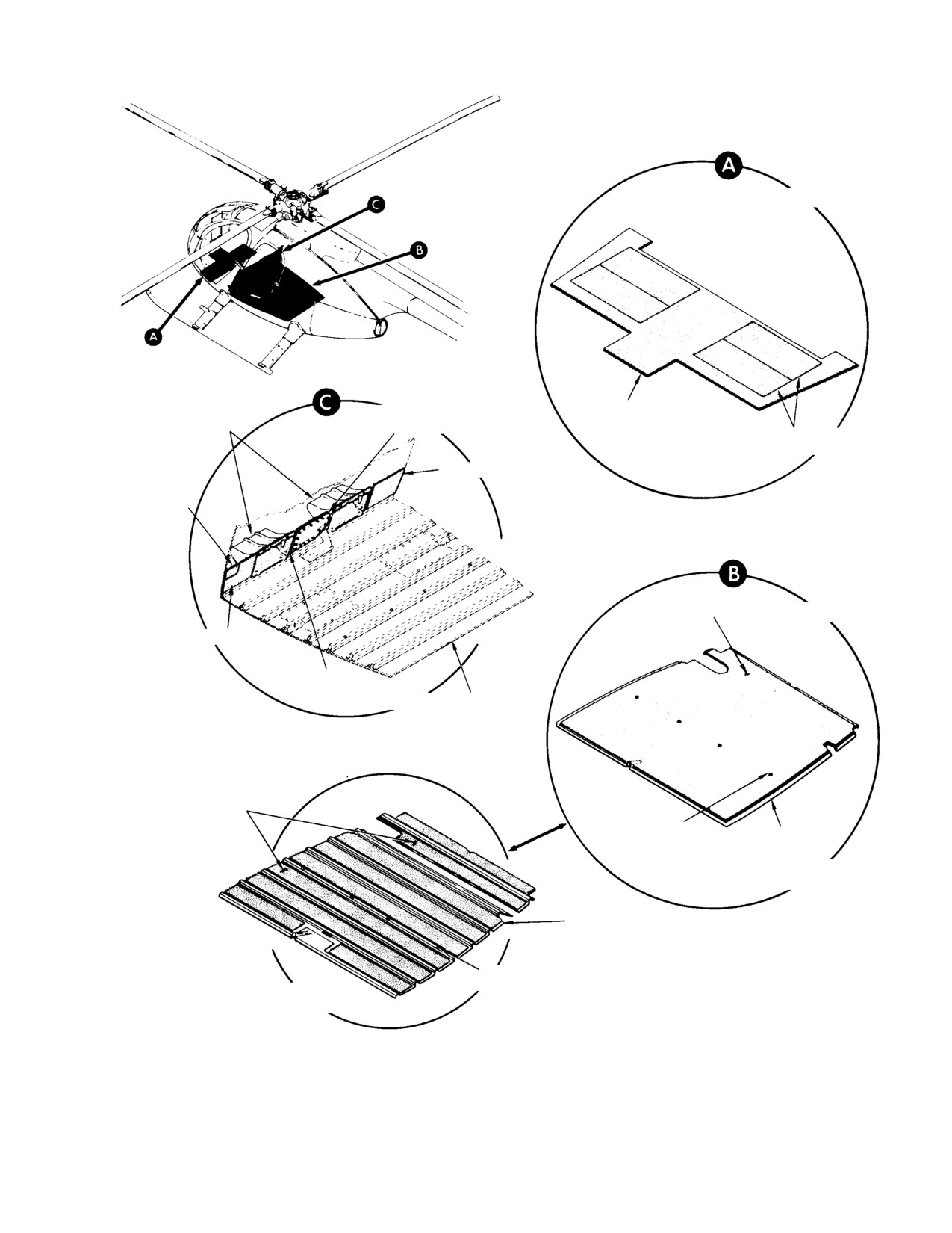
MD Helicopters, Inc.
CSP−H−2
500 Series − Basic HMI
ROTATED
EXECUTIVE FOOT SUPPORT
CONTROLS ACCESS
FLOOR AREA
FAIRING TRIM ASSEMBLY
DOOR TRIM
CREW COMPARTMENT
ACCESS DOOR
FLOOR INTERIOR TRIM
INTERIOR TRIM
RIGHT TRIM
ACCESS
FLAP TRIM
FLOOR
CARPETING
ROTATED
LEFT TRIM
CENTER
TRIM
PASSENGER COMPARTMENT
FLOOR STRUCTURE
COVERING
(2 SECTIONS)
CUTOUT FOR LEG OF
SEAT STRUCTURE
FLOOR PAN
PASSENGER COMPARTMENT FLOOR
INTERIOR TRIM (EXECUTIVE TRIM)
FLOOR PAN
CUTOUT FOR LEG OF
PASSENGER COMPARTMENT FLOOR
SEAT STRUCTURE
INTERIOR TRIM (STANDARD TRIM)
41−014B
Figure 4-7. Crew and Passenger Compartment Floor Trim
Page 4-19
Revision 14
MD Helicopters, Inc.
CSP−H−2
500 Series − Basic HMI
D. Cargo Tiedown Fittings
place or riveted to the center canopy frame on
the early configuration.
(Ref. Figure 4−8) The cargo tiedown fittings
are formed of 0.250 inch (6.35 mm) diameter,
I. Magnetic Compass Card
U−shaped steel rods, with ends flattened. The
The magnetic compass card contains calibra−
flats are drilled to accept a quick−release pin
tion information for the specific compass
for attaching the fitting to the cargo floor. The
installed in the helicopter.
pin is secured to the fitting with a 4 inch
(10.16 cm) lanyard. Cargo tiedown fittings can
J. Operation Record Holder
be fastened to the cargo floor at any of 12
locations for various cargo loads.
(Ref. Figure 4−9) The operation record holder
with a transparent window is attached to the
E. Cargo Tiedown Fitting Inspection
outboard side of the right instrument panel
fairing on later configuration helicopters. On
(1). Check for cracks or deformation.
early configuration helicopters, the holder is
attached to the lower right front of the pilot’s
(2). Check that quick−release pin functions
seat structure.
properly and that lanyard is secure.
K. Heat Duct and VNE
Card Cover
F. Pilot’s Compartment Canopy Frame Trim
and VNE Card Cover
(Ref. Figure 4−9) The heat duct and VNE card
cover assembly provides interior trim for the
(Ref. Figure 4−9) On all later configuration
canopy frame and a mounting surface for the
helicopters, trim is provided for the canopy
VNE card. A wire pin on the VNE card is used
center frame in the pilot’s compartment. The
to mount the card to the cover. The pin
trim is screw−mounted to the canopy frame
installation enables the VNE card to be flipped
and consists of an upper and lower section,
for a view of either side. Velcro fasteners
and a VNE card cover that provides the trim
secure the VNE card in the desired viewing
joint. On certain configuration helicopters, the
position. Several configuration of the heat duct
magnetic compass is mounted to the trim just
and VNE card cover are installed. On a
above the instrument panel. When electroni−
helicopter equipped with an electrically
cally activated engine anti−icing and cabin
controlled engine anti−icing system (Ref. Sec.
heat control systems are installed, the VNE
11) and cabin heating system (Ref. CSP−H−3),
card cover also provides the mounting surface
an engine de−ice switch and a cabin heat
for the ENGINE DE−ICE and CABIN HEAT
switch are mounted to the heat duct and VNE
switches. The trim sections also function as
card cover assembly. The cover may be secured
heat ducts when the optional heating system is
to the canopy frame with Hedlok fasteners or
installed. When the heating system is not
attaching screws.
installed, removable end−caps enclose the
upper and lower ends of the trim.
L. Heat Duct and VNE Card Cover
Replacement
G. Helicopter Checklist
(Ref. Figure 4−9)
The helicopter checklist contains instructions
M. Heat Duct and VNE Card Cover Removal
for an interior check, engine starting, engine
runup and stopping the engine. The checklist
(1). Remove screws securing heat duct and
is stored with the magnetic compass card in
VNE card cover assembly to canopy
the map case trim cover on the upper forward
frame.
side of the central controls tunnel in the crew
compartment.
(2). On early configuration helicopters
where Hedlok fasteners are used on the
H. VNE Card and Holder (Bracket Mounted)
cover, gently pry and lift cover off
canopy frame.
(Ref. Figure 4−8 and Figure 4−9) The VNE
(Velocity to Never Exceed) card is held by a
(3). On covers that have side−mounted
holder directly above the hood of the instru−
switches, disconnect wiring for engine
ment console. The holder may be bonded in
de−ice switch (Ref. Sec. 11). Refer to
Page 4-20
Revision 14
MD Helicopters, Inc.
CSP−H−2
500 Series − Basic HMI
CSP−H−3 for wiring of the optional
Q. Ashtrays
cabin heat switch.
(Ref. Figure 4−4 and Figure 4−8) The crew
N. Heat Duct and VNE Card Cover
compartment is equipped with an ashtray and
Installation
cigarette lighter located in the lower portion of
the instrument panel.
(1). On cover assemblies that have side−
On helicopters with standard trim, an ashtray
mounted switches, connect electric
and cigarette lighter is installed on the
wires for engine de−ice switch (Ref. Sec.
forward bulkhead trim panel. On helicopters
11). Refer to CSP−H−3 for wiring of the
furnished with executive trim, the ashtray and
optional cabin heat switch.
cigarette lighter assembly is mounted on the
forward bulkhead trim panel as part of the
(2). Where Hedlok fasteners are used on the
lower convenience panel.
cover, position in place and engage
fasteners.
On early configuration helicopters without
interior trim, an ashtray and cigarette lighter
(3). On screw−mounted cover assemblies,
assembly is installed on the forward bulkhead.
reinstall mounting screws.
R. Passenger Compartment Upper
O. Heat Duct and VNE Card Cover Inspection
Convenience Panel (Without Trim)
(Ref. Figure 4−9)
(Ref. Figure 4−4) On early configuration
helicopters without interior trim, a plastic
(1). Inspect cover for tears, cracks, breaks
convenience panel is located above the
or other evidence of unserviceable
compartment forward bulkhead. The conve−
condition and legibility.
nience panel provides mounting facilities for
utility light switch, heated air outlet diffuser
(2). Check that the VNE card mounting is
valve and two head set connectors (all optional
secure. Check that Velcro fasteners are
equipment). Six screws attach the panel to the
not defective.
fuselage structure. Plugs and covers are
supplied with the panel when optional
equipment is not installed.
(3). On covers using the Hedlok fasteners
installation, check that fasteners on
S. Passenger Compartment Upper
cover and mating fasteners on canopy
Convenience Panel (Standard Trim)
frame are not defective.
(Ref. Figure 4−4) On helicopters with standard
P. Heat Duct and VNE Card Cover Repair
trim, the upper convenience panel is contained
in the convenience panel panel trim cover. The
(Ref. Figure 4−9)
convenience panel provides mounting facilities
for a utility light switch, heated air outlet
(1). Replace defective or illegible VNE cards.
diffuser valve and two headset connectors. Six
Replace unserviceable Velcro fastener
screws attach the panel to the convenience
strips on card or at card cover location.
panel trim cover. Plugs and covers are supplied
Install new Velcro fastener strips to
with the panel when the optional equipment is
mate. Bond in place with cement (91,
not installed.
Table 2−4).
T. Folding Table Assembly (Executive Trim)
(2). Remove and replace broken or missing
Hedlok fasteners.
(Ref. Figure 4−4) On helicopters with executive
trim, two folding tables are provided in the
(3). Repair or replace loose or illegible
passenger/cargo compartment for passenger
switch bezels. Bond bezel to cover with
use. The folding tables are installed on the
adhesive (19).
compartment forward bulkhead trim panel.
Page 4-21
Revision 14
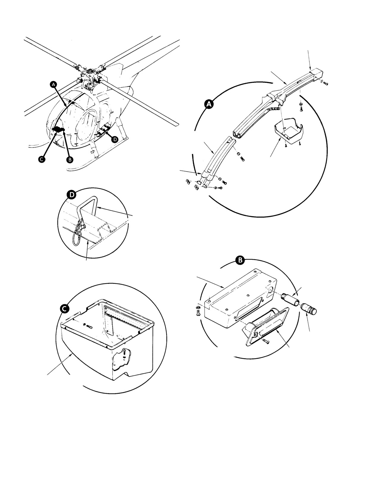
MD Helicopters, Inc.
CSP−H−2
500 Series − Basic HMI
TRIM DUCT END CAP
CANOPY CENTER
FRAME TRIM − UPPER
(NOTE)
CANOPY CENTER
FRAME TRIM − LOWER
(NOTE)
VNE CARD COVER
TRIM DUCT END CAP
CARGO TIE−DOWN
FITTING (TYP)
FLOOR STRUCTURE
ASHTRAY AND LIGHTER
PANEL
HOLDER
LIGHTER
ROTATED
ASHTRAY
STOWAGE COMPARTMENT
BOX
NOTE:
TRIM SECTIONS USED FOR HEAT DISTRIBUTION
WHEN HEATING SYSTEM INSTALLED.
30−122D
Figure 4-8. Basic Helicopter Furnishings
Page 4-22
Revision 14
MD Helicopters, Inc.
CSP−H−2
500 Series − Basic HMI
U. Passenger Compartment Lower
(3). Position replacement foot rest on floor
Convenience Panel (Executive Trim)
support bulkhead and install four bolts,
sixteen washers and four nuts. When
(Ref. Figure 4−4) On helicopters with executive
necessary, use thin aluminum washers
trim, the passenger/cargo compartment is
to shim between footrest and bulkhead
equipped with a lower convenience panel. The
attach points to obtain fourpoint
panel is mounted in the compartment forward
contact before tighten bolts.
bulkhead trim panel. The convenience panel
contains an ashtray and cigarette lighter
(4). Reinstall stowage compartment box.
assembly, heat diffusers and provisions for an
optional heat control selector knob and two
Y. Pilot’s Compartment Footrest Inspection
headset connectors.
Inspect the foot rest for security and service−
V. Passenger Compartment Upper
able condition.
Convenience Panel (Executive Trim)
Z. Pilot’s Compartment Footrest Repair
(Ref. Figure 4−3) On helicopters with executive
trim, the convenience panel trim cover
Perform weld repair of the foot rest tubing
contains provisions for an optional utility light
according to FAA AC 43.13−1A, Aircraft
(Ref. CSP−H−3). When the optional utility
Inspection and Repair.
light is not installed in the trim cover, a
AA. Passenger Step
removeable plug is used.
(Ref. Figure 4−9) The executive trim helicopter
W. Pilot’s Compartment Footrest
is furnished with a removable passenger step,
(Ref. Figure 4−9) The pilot’s compartment foot
that readily attaches to the helicopter side
rest consist of welded aluminum alloy tubes
jacking points, to make entering or leaving the
attached to the floor support bulkhead (Sta.
cargo/passenger compartment more conve−
44.65) at the right side of the compartment.
nient. The step assembly consists of a step
plate attached to a tubing arm with a step
X. Pilot’s Compartment Footrest
support pin and is rated for 340 pounds (154
Replacement
kg). A locking pin on the step support pin
ensures security of the step in the jacking
(1). Remove stowage compartment box.
point when the step is installed. The step may
(2). Remove four bolt and nuts, and sixteen
be stowed in the cargo/passenger compartment
washers to release foot rest.
when not in use.
Page 4-23
Revision 14
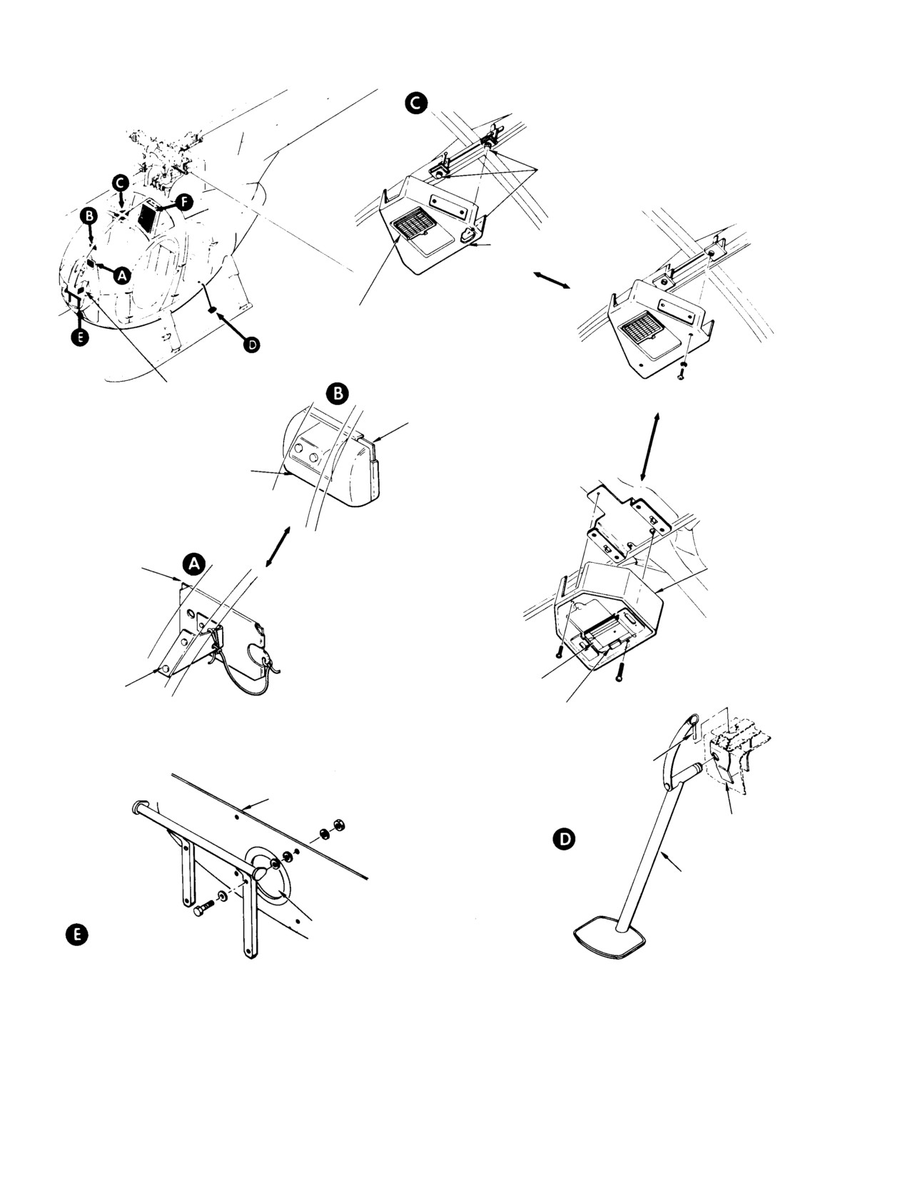
MD Helicopters, Inc.
CSP−H−2
500 Series − Basic HMI
HEDLOK MOUNTED
HEDLOK FASTENER
HEAT DUCT AND
VNE CARD COVER
VNE CARD
OPERATION RE−
SCREW MOUNTED
CORD HOLDER
VNE CARD
VNE CARD HOLDER
CURRENT
CONFIGURATION
EARLY CONFIGURATION
HEAT DUCT
AND VNE CARD
COVER
VNE CARD
VNE CARD
HOLDER
VELCRO FASTENER
LOCKING PIN
BULKHEAD
JACKING
FITTING
EXECUTIVE STEP
SUPPORT SHAFT
BULKHEAD COVER (NOT USED WHEN
PASSENGER
STROBE LIGHTS POWER SUPPLY
FOOTREST
INSTALLED)
41−008C
Figure 4-9. Miscellaneous Furnishings
Page 4-24
Revision 14
MD Helicopters, Inc.
CSP−H−2
500 Series − Basic HMI
Section
5
Tailboom and Tail
Surfaces
MD Helicopters, Inc.
CSP−H−2
500 Series − Basic HMI
TABLE OF CONTENTS
Para/Figure/Table
Title
Page
Section 5 Tailboom And Tail Surfaces .
5−1
1.
Tailboom Assembly
5−1
2.
Troubleshooting Tailboom and Tail Surfaces
5−1
3.
Tailboom Assembly Replacement
5−1
A. Tailboom Assembly Removal
5−1
B. Tailboom Assembly Installation
5−1
Table 5−1. Troubleshooting Tailboom and Tail Surfaces
5−1
4.
Tailboom Assembly Inspection
5−2
5.
Tailboom Assembly Repair
5−2
6.
Tail Surfaces
5−2
Figure 5−1. Empennage and Boom Assembly
5−3
Figure 5−2. Tailboom Removal and Installation
5−4
7.
Stabilizer Sheet Metal Repair
5−5
8.
Upper Vertical Stabilizer Replacement
5−5
A. Upper Vertical Stabilizer Removal
5−5
B. Upper Vertical Stabilizer Installation
5−5
9.
Upper Vertical Stabilizer Inspection
5−5
10. Upper Vertical Stabilizer Repair
5−5
11. Horizontal Stabilizer Replacement
5−5
A. Horizontal Stabilizer Removal
5−5
B. Horizontal Stabilizer Installation
5−5
Figure 5−3. Empennage Removal and Installation (Sheet
1 of
2) .
5−6
12. Horizontal Stabilizer Inspection
5−8
13. Horizontal Stabilizer Repair
5−8
14. Lower Vertical Stabilizer Replacement
5−8
A. Lower Vertical Stabilizer Removal
5−8
B. Lower Vertical Stabilizer Installation
5−9
15. Lower Vertical Stabilizer Inspection
5−9
16. Lower Vertical Stabilizer Repair
5−9
17. Stabilizer Strut Replacement
5−10
A. Stabilizer Strut Removal
5−10
B. Stabilizer Fixed Strut Installation
5−10
C. Stabilizer Damped Strut Installation
5−10
D. Damped Stabilizer Strut Disassembly
5−11
E. Damped Stabilizer Strut Re−Assembly
5−11
18. Stabilizer Strut Inspection
5−11
Page 5−i
Revision 14
MD Helicopters, Inc.
CSP−H−2
500 Series − Basic HMI
TABLE OF CONTENTS (Cont.)
Para/Figure/Table
Title
Page
19. Stabilizer Strut Repair
5−11
Figure 5−4. Strut Damper Disassembly and Inspection
5−12
Page 5−ii
Revision 14

MD Helicopters, Inc.
CSP−H−2
500 Series − Basic HMI
SECTION 5
TAILBOOM AND TAIL SURFACES
1. Tailboom Assembly
(5). Disconnect connector of chip detector
wiring, and optional night lighting
(Ref. Figure 5−1) The boom assembly, a
system wiring if installed. Disconnect
monocoque structure of aluminum skin over
knife splice by hand or use appropriate
forged aluminum frames, houses the tail rotor
connector insertion/extraction tool (42
drive shaft and tail rotor control rod, and
or 43, Table 2−2) for wire mate type
supports the horizontal and vertical stabilizer
connector (Ref. Section 19).
tail surfaces. The horizontal stabilizer is
mounted at an upward angle of 25 degrees.
(6). Remove the nuts, washers and bolts
The tail surfaces stabilize the helicopter and
that attach boom to fuselage and
maintain it in a relatively level attitude during
remove boom.
high speed forward flight. (CSP−H−3 contains
information on optional exterior lights.)
B. Tailboom Assembly Installation
2. Troubleshooting Tailboom and Tail
(1). Support tailboom so that mating
Surfaces
bulkheads are flush.
(Ref. Table 5−1)
NOTE: Prior to tailboom installation, coat
threads of external wrenching bolts and at−
3. Tailboom Assembly Replacement
taching nuts with lubricant (25, Table 2−4).
(Ref. Figure 5−2)
(2). Slide countersunk washers on external
A. Tailboom Assembly Removal
wrenching bolts with countersunk side
facing bolt heads.
(1). Remove the tail rotor transmission and
drive shaft (Ref. Section 9).
If washers are installed back−
CAUTION
wards, structural failure may
(2). Remove the tail rotor control rod (Ref.
result due to insufficient surface in bearing
Section 8).
that can cause spreading or cracking of
washers and result in loss of clamp−up
(3). Position suitable cradles under the
torque.
tailboom at the canted Sta. 209.78
frame fitting and the forward stabilizer
(3). Install bolts through aft section
boom mounting frame.
fuselage frame into boom frame and
place flat washer(s) on each bolt as
To avoid damage, ensure that
CAUTION
required for correct bolt grip. Use no
the boom is properly supported
more than three flat washers under
before removing the boom attach bolts
each nut. Install nuts and torque only
(4). Open the boom bolts access doors and
the nuts to 200 − 240 inch−pounds
remove the bond jumper from the boom.
(22.60 − 27.12 Nm).
Table 5-1. Troubleshooting Tailboom and Tail Surfaces
Symptom
Probable Trouble
Corrective Action
High-frequency vibration Loose lower vertical stabilizer On stabilizer attached with adjustable bolt,
retorque to 25-40 inch-pounds (2.82-4.52 Nm).
On stabilizers attached with two bolts, retorque to
90-1 10 inch-pounds (10.17-12.43 Nm)
NOTE: High frequency vibrations on the helicopter can also be caused by components in other systems. (Ref.
Sections 8, 9, and 10.)
Page 5-1
Revision 14
MD Helicopters, Inc.
CSP−H−2
500 Series − Basic HMI
NOTE: Bolts may be reversed for access to
(2). Replacement − Defective Tail Rotor
torque nuts. Torque wrench adapter (25,
Control Rod Grommets:
Table 2−2) is used for torquing.
Replacement of control rod grommets
(4). Install bond jumper to boom and
may require removal of tailboom
connect chip detector wiring. Connect
frames. Refer to CSP−H−5 for available
night lighting wiring if used.
information on replacement grommets
with increased service life and for
(5). Install the tail rotor transmission and
grommet replacement.
drive shaft.
(6). Install the tail rotor and control rod.
6. Tail Surfaces
(7). Check rigging of tail rotor control.
(Ref. Figure 5−3) Helicopter tail surfaces
consist of a vertical and horizontal stabilizer
(8). Install boom bolts access doors.
attached to the aft end of the tailboom. A fixed
or a damped strut interconnects the horizontal
4. Tailboom Assembly Inspection
stabilizer and the upper vertical at their
approximate midpoints.
(Ref. Figure 5−2)
The stabilizers are constructed of beaded
(1). Inspect the boom interior skin and
aluminum alloy sheet metal skin over formed
frames for corrosion and cracks.
sheet metal ribs. Each stabilizer is supported
by a forged aluminum attached fitting.
(2). Check the attaching nuts and bolts in
the boom canted Sta. 197.78 frame
fitting for security.
The upper stabilizer incorporates a 5−degree
twist which improves the tail rotor (anti−
(3). Inspect the tail rotor control rod
torque) pedal neutral position during cruise
grommets in the boom frames for
flight.
evidence of deterioration.
The upper end of the skid attaches to the lower
(4). Inspect the bond jumper for security
stabilizer and gearbox mounting frame. The
and corrosion.
tail skid is formed from an aluminum tube
which tapers from its attach point in the root
(5). Inspect the boom exterior for loose or
to a curved end just below the bottom rib of the
missing rivets.
lower stabilizer.
(6). Inspect the boom stabilizer and gearbox
Ensure the countersunk wash−
mounting frames for cracks, security of
CAUTION
ers used with the internal
attachment and elongated holes.
wrenching bolts that attach the tail surfaces
are installed with the beveled edge facing
5. Tailboom Assembly Repair
the bolt head. If washers are installed back−
wards, structure failure may result due to
Refer to CSP−H−5 for sheet metal repair.
insufficient surface in bearing that can
cause spreading or cracking of the washers
NOTE: The most highly stressed skins on the
and result in loss of clamp−up torque.
helicopter are the two panels that form the
monocoque boom assembly
(Ref.
Figure 5−1).
NOTE: MDHI Service Information Notice
HN−42 provides instructions for optional re−
(1). Negligible Damage:
work of an existing fixed strut to the
damped strut configuration which is de−
There is no damage that can be consid−
signed to decrease vibration effects on the
ered negligible. All drainage must be
stabilizer resulting from a tail rotor out−of−
repaired upon detection.
balance condition.
Page 5-2
Revision 14
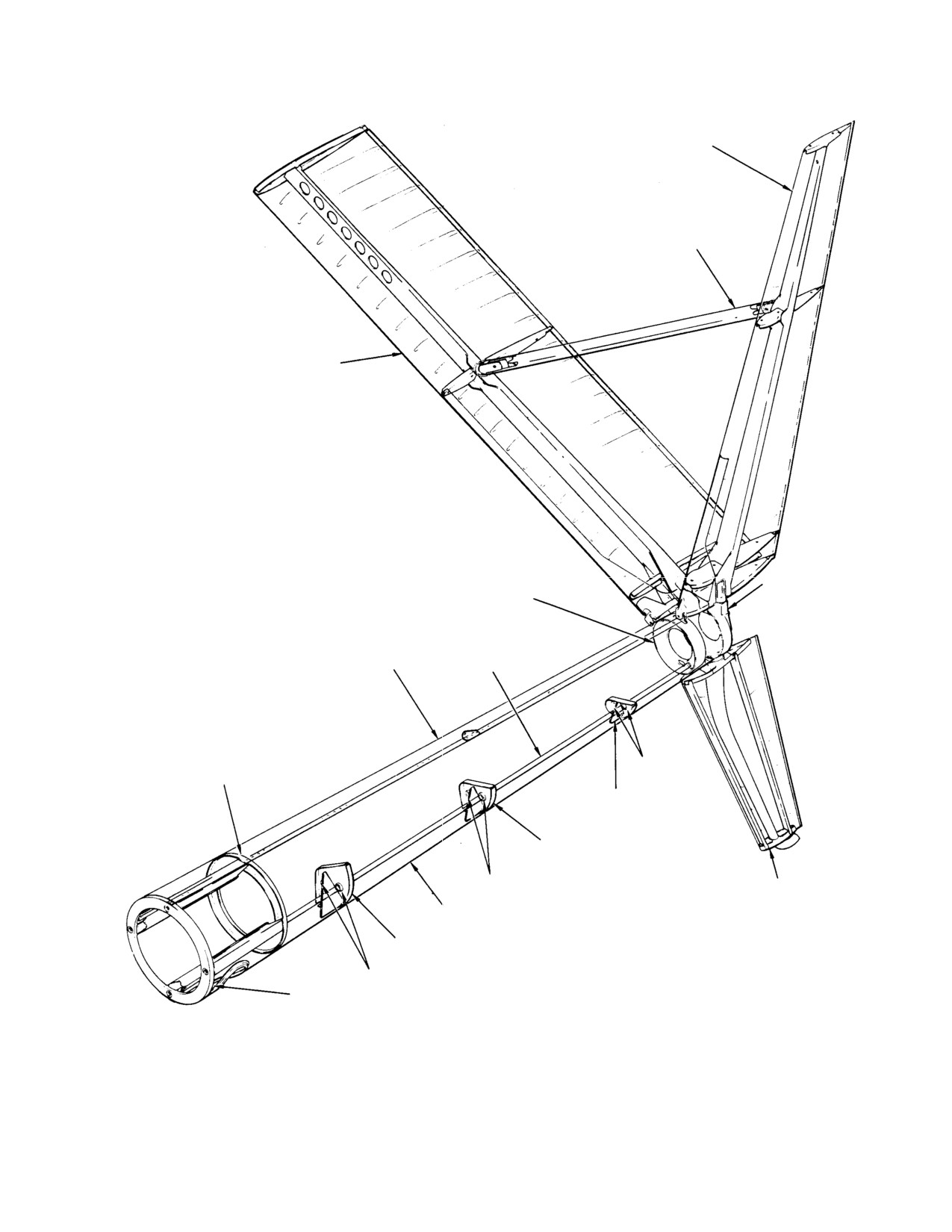
MD Helicopters, Inc.
CSP−H−2
500 Series − Basic HMI
UPPER VERTICAL
STABILIZER
VERTICAL−TO−HORIZONTAL
STABILIZER STRUT
HORIZONTAL STABILIZER
BOOM STABILIZERS AND
FWD STABILIZER BOOM
GEARBOX MOUNTING
MOUNTING FRAME
FRAME AND BRACKET
RIGHT SKIN
WIRING
PANEL
CONDUIT
STA. 209.78
GROMMET
CANTED FRAME
STA. 264.32
CANTED FRAME
STA. 242.14
CANTED FRAME
GROMMET
LOWER VERTICAL
STABILIZER
LEFT SKIN PANEL
STA. 219.96
CANTED FRAME
GROMMET
STA. 197.78 CANTED
FRAME FITTING
30−060C
Figure 5-1. Empennage and Boom Assembly
Page 5-3
Revision 14
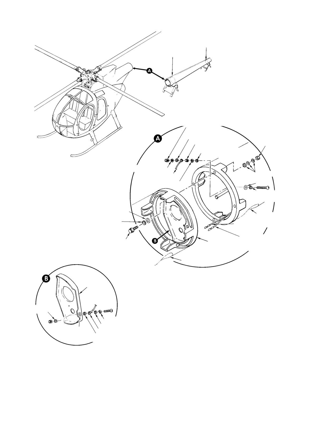
MD Helicopters, Inc.
CSP−H−2
500 Series − Basic HMI
FWD STABILIZER BOOM
MOUNTING FRAME
CANTED
STA. 209.78
SELF−LOCKING NUT
FLAT WASHER (CRES)
NUT 200−240 IN. LB
(NOTE 3)
(22.60−27.12 NM)
PLAIN HEX NUT
(NOTE 4)
FLAT WASHER (AL−ALY
UNTREATED)
SPRING LOCKWASHER
FLAT WASHER(S) (NOTE 2)
BOND JUMPER
SPRING LOCKWASHER
NOTE 1
FLAT WASHERS
(AL−ALY UNTREATED)
FLAT WASHER
(NOTE 2)
ACCESS HOLE
COUNTERSUNK WASHER
CHIP DETECTOR WIRING
TAIL LIGHT WIRING
EXTERNAL WRENCHING BOLT
BOOM FITTING
(REF OPTIONAL)
(NOTE 4)
ACCESS HOLE
BRACKET
NOTES:
FLAT WASHER
1.
ENSURE GROUND CONTACT SURFACE IS CLEAN
BEFORE BOND JUMPER INSTALLATION. AFTER
SPRING LOCKWASHER
INSTALLATION, COAT EXPOSED BARE METAL GROUNDED
FLAT WASHER (CRES) (NOTE 3)
AREA WITH LAQUER (47, TABLE 2−4).
NOTE 1
BOND JUMPER
2.
THREE FLAT WASHERS MAX UNDER NUT. ADD CSK
FLAT WASHER
WASHERS UNDER BOLT HEAD AS REQUIRED.
(AL−ALY UNTREATED)
3.
CRES−STAINLESS STEEL.
4.
COAT THREADS WITH LUBRCANT (25, TABLE 2−4) PRIOR
TO INSTALLATION.
30−062E
Figure 5-2. Tailboom Removal and Installation
Page 5-4
Revision 14
MD Helicopters, Inc.
CSP−H−2
500 Series − Basic HMI
7. Stabilizer Sheet Metal Repair
(7). Position access plates at each end of
fixed strut and attach with screws and
(1). Negligible Damage:
washers.
Shallow scratches, nicks, light corrosion
9. Upper Vertical Stabilizer Inspection
deposits, and smooth contour dents that
blend into surrounding surfaces are
(Ref. Figure 5−3)
considered negligible damage and
(1). Inspect metal skin for holes, cracks,
require only normal corrosion control
loose rivets or corrosion.
and paint finish maintenance.
(2). Inspect attach fitting for cracks, loose
(2). Repairable Damage:
rivets or corrosion.
Repair stabilizer sheet metal according
(3). Inspect attach bolts and mating holes
to applicable instructions in CSP−H−5.
for evidence of wear caused by loose−
ness in service. Inspect questionable
8. Upper Vertical Stabilizer Replacement
bolts or attach fittings by the dye−
(Ref. Figure 5−3)
penetrant or magnetic particle method,
as applicable.
A. Upper Vertical Stabilizer Removal
(4). Inspect bonding jumper for security,
(1). Remove stabilizer strut.
corrosion and fraying.
(2). Remove forward attach bolts and
10. Upper Vertical Stabilizer Repair
countersunk washers and nuts that
Perform repair of the upper vertical stabilizer
secure stabilizer to tailboom structure;
remove bonding jumper and upper
according to applicable instructions in CSP−
vertical stabilizer.
H−5.
B. Upper Vertical Stabilizer Installation
11. Horizontal Stabilizer Replacement
(Ref. Figure 5−3)
(1). Place upper vertical stabilizer in
position on tailboom. Install bonding
A. Horizontal Stabilizer Removal
jumper, forward attach bolt, counter−
sunk washer and bushing. Countersunk
(1). Remove tail rotor transmission and
side of washer must face bolthead; do
drive shaft (Section 9).
not tighten.
(2). Remove stabilizer strut.
(2). Insert external wrenching bolts with
(3). Remove three bolts, washers, nuts and
counter−sunk washers through mount−
bushing; remove bonding jumper and
ing holes; countersunk side of washer
horizontal stabilizer.
must face bolthead. Install two new
nuts and washers; do not tighten.
B. Horizontal Stabilizer Installation
(3). Install strut; do not tighten strut bolts.
(1). Place horizontal stabilizer in position
on tailboom. Install a countersunk
(4). Torque forward attach bolt to 50 − 70
washer and bushing on external
inch−pounds (5.65 − 7.91 Nm).
wrenching bolt; countersunk side of
washer must face bolthead. Insert bolt
NOTE: Torque values for the nuts may be ap−
in forward mounting hole; do not
plied to the corresponding bolthead at the
tighten. Install bonding jumper.
high limit of the tolerance in cases where
the nut is not accessible.
(2). Install a countersunk washer on each of
the other external wrenching bolts;
(5). Torque the two nuts to 170 − 200
countersunk side of washer must face
inch−pounds (19.21 − 22.60 Nm).
the bolthead. Insert bolts through aft
(6). Torque the strut bolts to 50 − 70
mounting holes and install a nut and
inch−pounds (5.65 − 7.91 Nm).
washer on each bolt; do not tighten.
Page 5-5
Revision 14
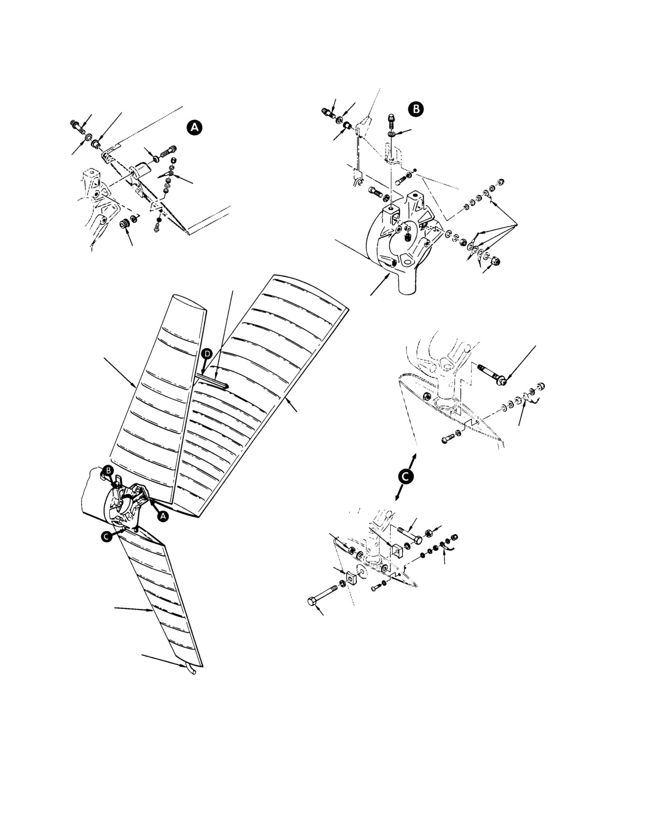
MD Helicopters, Inc.
CSP−H−2
500 Series − Basic HMI
50−70 IN. LB
(5.65−7.91 NM)
50−70 IN. LB
FLANGED
(5.65−7.91 NM)
BUSHING
FLANGED BUSHING
BONDING JUMPER
BONDING
JUMPER
380−410 IN. LB
(42.93−46.32 NM)
170−200 IN. LB
STRUT
(19.21−22.60 NM)
STABILIZER AND
ADJUSTABLE BOLT
GEARBOX MOUNTING
25−40 IN. LB
FRAME
(2.82−4.52 NM)
(NOTES 1, 2)
UPPER VERTICAL
STABILIZER
HORIZONTAL STABILIZER
BONDING
JUMPER
BOLT
(NOTE 1)
SPACER
90−110 IN. LB
90−110 IN. LB
(NOTE 3)
(10.17−12.43 NM)
(10.17−12.43 NM)
SPACER
(NOTE 3)
BONDING JUMPER
LOWEER VERTICAL
STABILIZER
DUAL BOLT INSTALLATION
BOLT
NOTES:
TAIL SKID
1.
DIRECTION OF BOLT HEAD OPTIONAL.
2.
AFTER TORQUING, 0.030 IN. (0.762 MM) MIN. GAP TO
EXIST UNDER BOLT HEAD, UNDER NUT, OR IN TOTAL.
3.
CURVED SIDE OF SPACER MUST FACE STABILIZER.
4.
ASTERISK ( * ) INDICATES COUNTERSUNK WASHER.
30−061−1B
Figure 5-3. Empennage Removal and Installation (Sheet 1 of 2)
Page 5-6
Revision 14
MD Helicopters, Inc.
CSP−H−2
500 Series − Basic HMI
SILICONE RUBBER SEAL
ACCESS PLATE
ACCESS PLATE
*
HORIZONTAL
STABILIZER
FIXED STRUT
50−70 IN. LB
(5.65−7.91 NM)
(TYP BOTH ENDS)
UPPER VERTICAL
STABILIZER
TAB WASHER
DAMPED STRUT
HORIZONTAL
CHECK NUT
STABILIZER
*
FITTING
50−70 IN. LB
(5.65−7.91 NM)
(TYP BOTH ENDS)
30−061−2B
Figure 5-3. Empennage Removal and Installation (Sheet 2 of 2)
Page 5-7
Revision 14
MD Helicopters, Inc.
CSP−H−2
500 Series − Basic HMI
(3). Install strut between horizontal and
(3). Reapply the 75 pound (34 kg) down−
upper vertical stabilizer. Use
ward load to stabilizer tip. Inspect spar
MS21250−04004 bolts and MS20002C4
web and upper flange through access
washers; do not tighten bolts at this
holes for cracks, using flashlight. Pay
time.
particular attention to area around first
rivet at each side of bead.
(4). Torque forward mounting bolt to 50 −
70 inch−pounds (5.65 − 7.91 Nm).
NOTE: If spar cracking is noted, horizontal sta−
bilizer must be replaced.
NOTE: Torque values for the nuts may be ap−
(4). Smooth the inspection hole edges to
plied to the corresponding bolthead at the
eliminate surface irregularities. Cover
high limit of the tolerance in cases where
holes with masking tape, or equivalent,
the nut is not accessible.
in place of patching.
(5). Torque the two remaining nuts to 380 −
NOTE: Smooth the access hole edges to remove
410 inch−pounds (42.93 − 46.32 Nm).
possible stress risers. At each subsequent
300−Hour Inspection, remove tape and in−
(6). Tighten strut rut attachment bolts.
spect skin area around holes for possible
(7). Install access plates at each end of fixed
cracks; repair as required (HMI Appx D).
strut with screws and washers.
Re−tape holes
(5). Replace all loose (working) rivets with
(8). Reinstall tail rotor transmission and
correct length CR2249NS−4 or OCKLP−
drive shaft.
B4 rivets.
12. Horizontal Stabilizer Inspection
(6). Check tail rotor balance.
(Ref. Figure 5−3)
NOTE: A tail rotor badly out of balance imposes
excessive stabilizer fatigue loads.
(1). Apply an approximate 75 pound (34 kg)
downward load to horizontal stabilizer
(7). Inspect metal skin for cracks, holes or
tip and visually check for the following:
corrosion.
(8). Inspect attach fitting for cracks, loose
(a). Abnormal deflections.
rivets or corrosion.
(b). Any motion between skin and rivets
(9). Inspect attach bolts and mating holes
on upper surface across first three
for evidence of wear caused by loose−
skin beads out−board of strut attach
ness in service. Replace questionable
fitting.
bolts and dye−penetrant inspect
questionable attach fittings as applica−
If either one of the above condi−
CAUTION
ble.
tions is noted, perform steps (2).
thru (6). below; otherwise, no further action
(10). Inspect bonding jumper for security,
is required.
corrosion and fraying.
(2). Cut three 1 inch (25.4 mm) diameter
13. Horizontal Stabilizer Repair
holes through bottom of skin surface
Perform repair of the horizontal stabilizer
with the center line of the holes 2.0
according to applicable instructions in CSP−
inches (50.8 mm) aft of the spar rivet
H−5.
line at following locations.
14. Lower Vertical Stabilizer Replacement
(a). First hole midway between chordwise
row of rivets and first bead outboard
(Ref. Figure 5−3)
of strut attach fitting.
A. Lower Vertical Stabilizer Removal
(b). Second hole midway between first
(1). Remove bonding jumper.
and second bead.
(2). On helicopters with adjustable bolt
(c). Third hole between second and third
installation, loosen the adjustable bolt
bead.
until it is free but do not remove.
Page 5-8
Revision 14