CSP-H-2 BASIC HANDBOOK OF MAINTENANCE INSTRUCTIONS FOR MDHI 369H HELICOPTERS - page 4
MD Helicopters, Inc.
CSP−H−2
500 Series − Basic HMI
(3). Firmly push bolt inward to free the
Torque nuts to 90 − 110 inch−pounds
bushing stack; then turn the bolt
(10.17 − 12.43 Nm).
approximately 1/4 turn clockwise to
engage the threaded end bushing.
(6). Install bonding jumper.
(4). Remove the bolt and bushing stack as
15. Lower Vertical Stabilizer Inspection
an assembly.
(Ref. Figure 5−3)
(5). On helicopter with dual mounting bolt
installation, remove nuts, washers,
(1).
Inspect the metal skin for holes, cracks,
spacers and bolts.
loose rivets or corrosion. Any crack
must be stop−drilled or patched (CSP−
(6). Slide stabilizer from gearbox mounting
H−5).
frame.
(2).
Inspect attach fittings for cracks, loose
B. Lower Vertical Stabilizer Installation
rivets or corrosion. Check that the
drain holes in stabilizer bottom rib are
(1). Apply a coat of zinc chromate paste (72,
open. If there appears to be excessive
Table 2−4), or lubricant (21), on the
clearance between the stabilizer tube
gearbox mounting frame post.
and attach fitting, a temporary repair
should be made using aluminum
(2). Position stabilizer on mounting frame
laminated shim stock to reduce this
post and align holes in stabilizer and
clearance installation fit.
mounting post.
(3).
Check adjustable bolt or the two
(3). On helicopters using the adjustable
mounting bolts for condition. Oversized
bolt, install the bolt and engage threads
or elongated bolt holes in both the
in nut. (Direction of bolthead is option−
stabilizer and the stabilizer and
al; nut facing aft makes torquing
gearbox mounting frame must be
easier.)
repaired.
Tighten bolt by turning bol−
(4).
Inspect visible portion of tail skid tube
CAUTION
thead; do not turn the nut. After
for cracks, deformation and condition of
torquing, check for proper installation by
plastic sleeve between tube and bottom
measuring the gap between the bolthead
rib.
and fitting and the nut and fitting. A mini−
mum gap of 0.030 inch (0.762 mm) must ex−
(5).
Inspect bonding jumper for security,
ist at either end or in combined total for the
corrosion and fraying.
bolt to be correctly installed. If at least one
full thread is not visible through the nut,
16. Lower Vertical Stabilizer Repair
the wrong bolt is installed, or bolt is in−
stalled incorrectly. Do not try to eliminate
(1). Repair lower vertical stabilizer sheet
gap by over−torquing.
metal or mounting tube according to
applicable instructions in CSP−H−5.
(4). Torque the adjustable bolt to 25 − 40
inch−pounds (2.82 − 4.52 Nm). If no
(2). Repair oversized holes in stabilizer and
torque wrench is available, tighten bolt
gearbox mounting frame having single
until bolt just binds in hole; then
bolt attachment as follows.
tighten nut one more complete turn.
NOTE: An ABC 4677 bolt is originally used in
(5). On helicopters using dual mounting
unbushed holes. Maximum serviceable di−
bolts, install bolts, spacers (curved side
ameter for worn unbushed holes is 0.257
against stabilizer), washers and nuts.
inch (6.5278 mm). Bolt hole wear in excess
Direction of bolthead is optional; upper
of the maximum should be repaired by the
nut facing aft makes torquing easier.
bushing method given in CSP−H−5.
Page 5-9
Revision 14
MD Helicopters, Inc.
CSP−H−2
500 Series − Basic HMI
(a). If the mounting hole is oversized or
B. Stabilizer Fixed Strut Installation
elongated, but within maximum
NOTE: The use of AN bolts for strut attach−
permissible diameter in either or
ment is not recommended because this bolt
both the gearbox mounting frame
type lacks uniformity in tensile strength.
and stabilizer fitting, rework and
bush the damaged hole(s) according
(1). Position strut between horizontal and
to CSP−H−5 and continue to use an
upper vertical stabilizers. Attach strut
ABC 4677 bolt.
to stabilizers with washers and bolts
(countersunk side of washers to face
(b). If mounting hole(s) are already
bolthead). Do not tighten.
bushed but bushing ID is not within
the permissible wear limit, re−bush
(2). Torque upper vertical stabilizer root
the hole(s) according to CSP−H−5
mounting bolts.
and continue to use an ABC 4677
(3). Torque the attachment bolts to 50 − 70
bolt.
inch−pounds (5.65 − 7.91 Nm).
NOTE: The oversize bolt repair given in step
(4). Position access plates at each end of
(c). below should be used only as an expedi−
strut and attach with screws and
ent repair. Use of the oversize bolt will affect
washers.
interchangeability of other stabilizers on
the gearbox mounting frame. Also, if the
C. Stabilizer Damped Strut Installation
oversize bolt repair is made and any subse−
NOTE: The use of AN bolts is not recommended
quent wear causes hole diameter to exceed
for strut attachment due to the lack of uni−
0.3125 inch (7.9375 mm), the bushing repair
formity in tensile strength of AN type bolts.
is not permissible.
(1). Torque upper vertical stabilizer root
(c). For expedient repair, oversized or
mounting bolts if these were loosened
elongated mounting bolt holes in both
for fixed type strut removal.
stabilizer and mounting frame may
be drilled and reamed to 0.312 inch
(2). Position the damped strut assembly
(7.9248 mm) diameter and an over−
and temporarily install the upper strut
size adjustable ABC 4678 bolt
attachment bolt.
installed. The ABC 4678 bolt is
similar to the ABC 4677 bolt except
(3). Re−adjust the lower end fitting of the
the bolt bushing OD is 0.312 inch
damper assembly so that a bolt will
(7.9248 mm) instead of 0.250 inch
slide into the lower vertical stabilizer
(6.35 mm) and it has a hex head
attachment hole.
instead of a recessed head.
(4). Disengage fitting and turn the fitting
inward one full turn to shorten the
17. Stabilizer Strut Replacement
strut length and establish damper
preload.
(Ref. Figure 5−3)
(5). Install both fitting attachment bolts
A. Stabilizer Strut Removal
and countersunk washers (countersunk
side toward bolthead) and torque to 50
(1). Remove access plates at each end of
−
70 inch−pounds (5.65 − 7.91 Nm).
fixed strut.
(6). Tighten check nut on damper fitting.
(2). Remove attachment bolts and washers
that attach strut to stabilizers.
(a). If installed, bend one tab of tab
washer over a hex flat on the check
(3). At root of upper vertical stabilizer,
nut and another tab over a hex flat
loosen bolts and nuts far enough to
on the damper fitting.
allow the fixed strut to clear the
stabilizer attach fittings.
(b). If check nut and fitting with lockwire
provisions are used, lockwire check
(4). Remove the strut.
nut to fitting.
Page 5-10
Revision 14
MD Helicopters, Inc.
CSP−H−2
500 Series − Basic HMI
D. Damped Stabilizer Strut Disassembly
pound (11 − 36 kg) pushing or pulling
load applied to the plunger should
(Ref. Figure 5−4) Disassemble the damped
produce 0.010 inch (0.254 mm) move−
stabilizer strut by removing retaining ring and
ment.
pulling plunger out of damper housing.
Further disassembly, as illustrated, may be
(4). Adjust the nominal length of the
performed if required. Do not remove inboard
damper assembly to the dimension
snubbers unless outboard snubbers are found
shown. If installed, do not bend tab
unserviceable upon inspection. Discard used
washer at this time.
tab washer.
18. Stabilizer Strut Inspection
E. Damped Stabilizer Strut Re-Assembly
(Ref. Figure 5−4)
(Ref. Figure 5−4)
(1). Inspect the strut for holes, cracks and
corrosion.
Refer to Hughes Notice HN−102.3 for inspec−
tion and/or modification of strut assemblies.
(2). Inspect cushion seals at each end of
fixed strut for deterioration and
(1). Assemble damper as shown. Be sure to
security of bonding.
place the thin snubbers next to the
collar on damper plunger. If a slotted
(3). Inspect outboard snubbers of damped
plunger is used, install a new tab
strut for serviceability as shown. If
washer.
outboard snubbers are not serviceable,
replace all four snubbers.
(2). Push assembled plunger firmly into
damper housing and install retaining
19. Stabilizer Strut Repair
ring. Additional compression of snub−
bers, by pushing on cap assembly, may
No structural repair is currently authorized for
be required in order to completely seat
the stabilizer strut. Replace deteriorated
the retainer in the housing.
cushion seals on fixed strut, using adhesive
(69, Table 2−4) according to container instruc−
(3). Check that plunger will move smoothly
tions. Replace unserviceable snubbers and
with no binding in bearings. A 25 − 80
other parts of the damper on damped struts.
Page 5-11
Revision 14
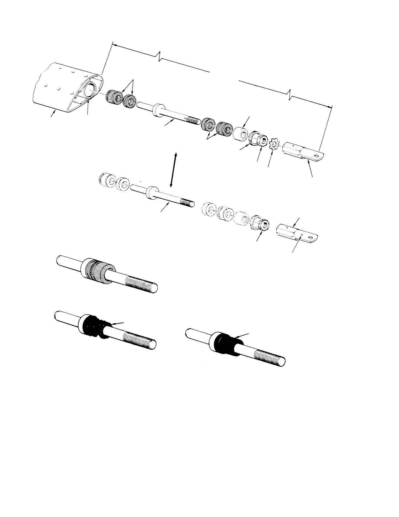
MD Helicopters, Inc.
CSP−H−2
500 Series − Basic HMI
2.83 IN.
INBOARD SNUBBERS
(71.882 MM)
(NOTE 2)
STRUT DAMPER
CAP ASSEMBLY
STRUT
HOUSING
PLUNGER (WITH
TAB SLOT)
OUTBOARD
SNUBBERS
RETAINING
RING
CHECK NUT
TAB WASHER
(NOTE 1)
FITTING
PLUNGER (WITHOUT
FITTING
TAB SLOT)
DAMPER ASSEMBLY
CHECK NUT
LOCKWIRE TO
CHECK NUT
(NOTE 1)
NOTES:
1.
DO NOT BEND TABS OR LOCKWIRE UNTIL
SERVICEABLE SNUBBER
INSTALLED PRELOAD IS ESTABLISHED.
2.
NOMINAL ASSEMBLED DIMENSION.
TACKY OR DETERIORATED
WORN
UNSERVICEABLE SNUBBERS
DAMPER INSPECTION
REMOVE RETAINING RING. PULL PLUNGER AND FITTING
DO NOT REMOVE INBOARD SNUBBER DISCS UNLESS
(WITH TWO OUTBOARD DAMPER SNUBBERS ATTACHED)
OUTBOARD SNUBBERS ARE INSPECTED AND FOUND
OUT OF DAMPER HOUSING. INSPECT FOR CONDITION
UNSERVICIBLE.
AND SERVICEABILITY. IF OUTBOARD SNUBBERS ARE
SERVICIBLE, REINSTALL PLUNGER ASSEMBLY.
30−172C
Figure 5-4. Strut Damper Disassembly and Inspection
Page 5-12
Revision 14
MD Helicopters, Inc.
CSP−H−2
500 Series − Basic HMI
Section
6
Landing Gear
MD Helicopters, Inc.
CSP−H−2
500 Series − Basic HMI
TABLE OF CONTENTS
Para/Figure/Table
Title
Page
Section 6 Landing Gear .
6−1
1.
Landing Gear Description and Operation
6−1
2.
Landing Gear Replacement
6−1
A. Landing Gear Removal
6−1
Figure 6−1. Landing Gear
6−2
B. Landing Gear Installation
6−3
3.
Landing Gear Inspection
6−3
Figure 6−2. Repair and Replacement of Landing Gear (Sheet 1 of 2) .
6−4
4.
Landing Gear Strut Inspection
6−6
Figure 6−3. Landing Gear Strut Inspection
6−7
5.
Landing Gear Repair
6−8
6.
Landing Gear Strut Drag Brace Hole Repair
6−8
A. Landing Gear Strut with Bushing Installed
6−8
B. Landing Gear Strut with No Bushing Installed
6−8
7.
Landing Gear Skid Description
6−9
8.
Landing Gear Skid Replacement
6−9
A. Landing Gear Skid Removal
6−9
B. Landing Gear Skid Installation
6−9
Table 6−1. Maximum Damage Limits for Landing Gear Components .
6−10
9.
Heavy−Duty Abrasion Strip Replacement
6−11
10. Landing Gear Skid Inspection
6−11
11. Landing Gear Skid Repair
6−11
A. Repair of Scratches, Nicks, Dents and Punctures
6−11
B. Skid Plug Replacement
6−11
C. Abrasion Strip Replacement
6−11
D. Skid Cap Replacement
6−12
E. Ground Handling Fitting Replacement
6−12
F. Safety Walk Tape Replacement
6−12
G. Skid Tube Nutplate Fitting Replacement
6−12
12. Landing Gear Damper Description and Operation
6−12
13. Landing Gear Damper Replacement
6−13
A. Landing Gear Damper Removal
6−13
B. Landing Gear Damper Installation
6−13
Table 6−2. Damper Assembly Identification
6−14
14. Landing Gear Damper Inspection
6−14
Figure 6−4. Landing Gear Damper Assembly Extension Check .
6−15
Table 6−3. Minimum Damper Extension (Dimension A)
6−15
Page 6−i
Revision 18
MD Helicopters, Inc.
CSP−H−2
500 Series − Basic HMI
TABLE OF CONTENTS (Cont.)
Para/Figure/Table
Title
Page
15. Landing Gear Damper Repair
6−15
16. Landing Gear Fairing Assembly Description
6−16
17. Landing Gear Fairing Replacement
6−16
A. Landing Gear Fairing Assembly Removal
6−16
B. Landing Gear Fairing Assembly Installation
6−17
Figure 6−5. Repair and Replacement of Fairing (Sheet 1 of 2) .
6−18
18. Landing Gear Fairing Assembly Inspection
6−20
19. Landing Gear Fairing Assembly Repair
6−20
20. Cabin Entry Step Description
6−21
21. Cabin Entry Step Replacement
6−21
22. Cabin Entry Step Inspection and Repair
6−21
Page 6−ii
Revision 18
MD Helicopters, Inc.
CSP−H−2
500 Series − Basic HMI
SECTION 6
LANDING GEAR
1. Landing Gear Description and Operation
(1).
Jack up the helicopter until the landing
gear dampers are fully extended (Ref.
(Ref. Figure 6−1) The landing gear consists of
Section 2). Place support beneath the
two strut−mounted, shock−dampened skids
skid tubes at the strut locations.
aligned longitudinally along the helicopter
fuselage. Both right and left skids pivot as the
damper assemblies extend and retract. Five
(2).
Gain access to the forward brace, strut,
replacement abrasion pads are installed on
and damper at fuselage attachment
each skid to retard skid wear on hard surfaces.
points by opening the compartment
Fairings on each strut reduce aerodynamic
access doors and foot support fairings,
drag during flight. Forged aluminum alloy
respectively.
landing gear braces are attached between the
landing gear strut and fuselage center beam.
The braces prevent shearing of the struts, and
(3).
Gain access to aft landing gear attach−
keep the strut in alignment with the landing
gear. The landing gear struts, made of
ment points by opening the engine
aluminum alloy forgings, attach to the
access doors.
fuselage center beam. At the lower ends of the
struts, feet attach the landing gear skids to the
struts. A cabin entry step is mounted on the
(4).
Disconnect lower end of landing gear
forward struts of all current configuration
dampers. Remove clamp that attaches
helicopters. The step has provisions for
the bonding jumper to strut.
optional side position lights (part of optional
night lighting system). On early configuration
helicopters, the cabin entry step was provided
(5).
Pull fairing fillet downward against
as an optional item and may not be installed
spring tension and secure with tape (14,
on all helicopters. Helicopters not having cabin
Table 2−4).
entry steps are equipped with a forward
fairing cover.
(6).
If optional night lighting system is
NOTE: A skid vibration damper kit may be in−
installed, disconnect wiring by using
stalled on standard or extended landing
appropriate connector insertion/extrac−
gear skids equipped with heavy duty or co−
tion tool (42 or 43, Table 2−2).
balt insert type abrasion strips. The option−
al kit, described in CSP− H− 3, will reduce
any excessive skid vibration by addition of
weight to the aft end of each skid tube.
(7).
Remove cotter pins, nuts, washers and
bolts that attach braces to struts and
2. Landing Gear Replacement
support fittings, and struts to support
fittings, on left side of fuselage. Remove
(Ref. Figure 6−2)
braces.
A. Landing Gear Removal
(8).
Remove supports from beneath left skid
NOTE: The following procedure removes the
entire landing gear, except the landing gear
and carefully remove left struts, skid
damper, as an assembled unit. For removal
and fairings as an assembled unit.
of an individual component, refer to the ap−
plicable paragraph following this procedure.
Two personal are required to accomplish re−
(9).
Repeat the sequence to remove the
moval.
right landing gear.
Page 6-1
Revision 15
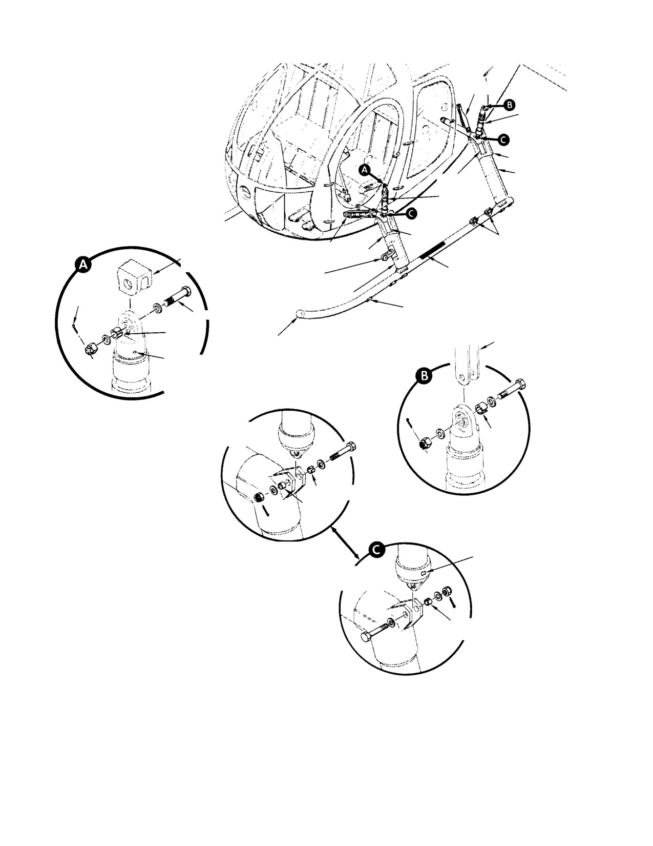
MD Helicopters, Inc.
CSP−H−2
500 Series − Basic HMI
BRACE
DAMPER
ASSY
FILLET
FAIRING
STRUT
DAMPER
ASSY
STRUT
GROUND HANDLING
BRACE
FILLET
FITTINGS
OLEO SUPPORT
FITTING
SAFETY WALK TAPE
CABIN ENTRY STEP
FAIRING
COTTER PIN
ABRASION STRIP
NOTE 3
(5 PLCS)
BUSHING
OLEO SUPPORT
(NOTE 2)
LANDING GEAR
FITTING
SKID
0.030 IN. (0.762 MM)
MAX. DEFECT
DEPTH
CURRENT
CONFIGURATION
BUSHING
BUSHING (NOTE 2)
BUSHING
(NOTE 5)
DAMPER CAP 0.015 IN.
(0.381 MM) MAX. DEFECT
EARLY
DEPTH
CONFIGURATION
BUSHING
(NOTE 2)
NOTES:
1.
ALL COMPONENTS SHOWN ARE TYPICAL FOR RIGHT GEAR.
2.
EDGE OF BUSHING MUST PROTRUDE A MINIMUM OF 0.010 IN. (0.254 MM) TO A
MAXIMUM OF 0.060 IN. (1.524 MM) ABOVE THE OUTSIDE SURFACE OF PART AFTER
NUT IS TIGHTENED.
3.
LEFT FWD DAMPER ATTACHING BOLT HEAD AFT FOR REMOVAL CLEARANCE.
4.
NOT INSTALLED ON EARLY CONFIGURATION HELICOPTERS.
5.
INSTALL FLUSH WITH INSIDE SURFACE.
30−068C
Figure 6-1. Landing Gear
Page 6-2
Revision 15
MD Helicopters, Inc.
CSP−H−2
500 Series − Basic HMI
B. Landing Gear Installation
Do not overtighten brace to
CAUTION
strut hardware. Maximum per−
(1). Gain access to landing gear attachment
missible torque of nut is 5 inch− pounds
points by opening or removing fuselage
(0.56 Nm).
access doors, engine access doors and
(8). Align outboard end of each brace with
foot support fairings.
mating hole in strut and install bolt,
(2). With helicopter supported by jacks,
install two washers and nut.
position left landing gear to align the
(9). Torque nut to 2 − 5 inch−pounds
struts with their openings in the
(0.226 − 0.56 Nm) and install cotter
fuselage structure.
pin.
NOTE: Check that the fairing fillet guide pins
(10). If optional night lighting system is
are engaged with the fairing guide holes be−
installed, connect wiring by using
fore positioning the struts for attachment to
appropriate connector/insertion/extrac−
the structure (Ref. Figure 6−5).
tion tool (42 or 43, Table 2−2).
(3). Lift and carefully position the left
(11). Repeat steps (1). thru (8). to install the
landing gear; then place supports
right landing gear.
beneath the landing gear to hold it in
(12). Remove skid supports, lower helicopter,
place.
and remove jacks.
NOTE: The left forward damper upper bolt
(13). Close engine and underfloor compart−
must be installed with bolt head aft (Ref.
ment access doors; install foot fairings.
Figure 6−2). Bolt direction on right side is
optional.
3. Landing Gear Inspection
(4). Check that slotted bushing is in place.
NOTE: Inspection should be performed with
Align lower bearing of dampers with
helicopter skids clear of the ground.
mating holes in strut and install bolt,
(1). Inspect skids, skid abrasion strips,
two washers, nut and new cotter pin to
struts, feet, braces and fairings for
secure each damper.
dents, cracks, loose components or
rivets, missing cotter pins and loose
(5). Align struts with mating bearings in
nuts.
fuselage support fittings and install
bolt, two washers, nut and new cotter
(2). Inspect the skid−to−foot and foot−to−strut
pin.
attachments for loose bolts and relative
motion between connecting parts. If the
(6). Align inboard end of each brace with
bolts are loose, replace with original
mating bearing in fuselage support
size (if holes are not elongated) or next
fitting and install bolt, two washers,
larger size bolts.
nut and new cotter pin.
NOTE: On other than lock bolt type installa−
(7). Install bonding jumper with clamp and
tions, use of next larger size lock bolt re−
attaching hardware.
quires replacement of nutplate.
Page 6-3
Revision 15
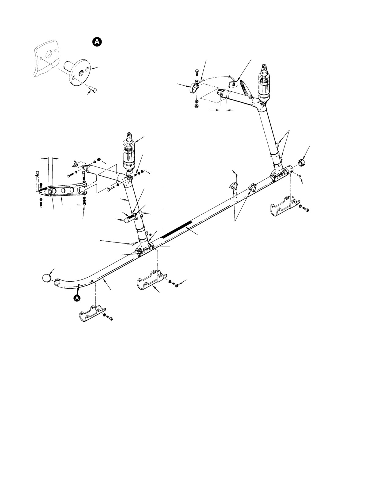
MD Helicopters, Inc.
CSP−H−2
500 Series − Basic HMI
(12 PLCS)
BONDING JUMPER CENTER BEAM
NUTPLATE FITTING
(NOTE 2)
CLAMP
MLS100M4−4 RIVET
2.00 IN.
(5.08 CM)
FAIRING BRACKET
(8 PLCS)
DAMPER
(NOTES 9, 10)
SKID PLUG
(NOTE 5)
SLOTTED BUSHING
1.00 IN.
(NOTE 1)
(2.54 CM)
MLSP−M4−4 RIVET
CABIN ENTRY STEP
(NOTE 6)
MS20470AD4 RIVET
STRUT
BP−T5−4 LOCKBOLT
(4 PLCS)
BRACE
NON−SKID TAPE
ABRASION
NOTE 7
STRIP
CAP
5 IN.−LB.
GROUND HANDLING FITTING
(0.56 NM) MAX.
FOOT
(NOTE 5)
ABC5244 BOLT 95−115 IN.−LB.
SAFETY WALK TAPE
(10.73−12.99 NM) (4 PLCS) (NOTE 3)
NAS624−6 BOLT
1030−428−8M SCREW
MS20002C4 WASHER
(8 PLCS) (NOTES 3, 4)
80−100 IN.−LB. (9.04−11.30 NM)
CURRENT TYPE
SKID CAP
(8 PLCS) (NOTE 3)
25−35 IN.−LB.
(2.82−3.95 NM)
SKID TUBE
HEAVY DUTY ABRASION STRIP
(EXTRUDED)
(3 PLCS) (NOTE 8)
(NOTE 6)
NOTES:
1.
EDGE OF BUSHING MUST PROTRUDE A MINIMUM OF 0.010 IN. (0.254 MM) TO A MAXIMUM OF 0.060 IN. (1.524 MM)
ABOVE OUTSIDE SURFACE OF PARTS AFTER NUT IS TIGHTENED.
2.
SEAL PARTING EDGE WITH A FILLET OF SEALING COMPOUND (3, TABLE 2−4).
3.
INSTALL ALL RIVETS, AND OTHER HARDWARE WHERE NOTED, WITH WET PRIMER (4, TABLE 2−4).
4.
INSTALL SCREWS ON OUTBOARD SIDE OF INTERCHANGEABLE SKID TUBES.
5.
SEAL MATING SURFACES WITH ZINC CHROMATE PUTTY (71, TABLE 2−4).
6.
NOT INSTALLED ON EARLY TYPE.
7.
LONGER BRACKET WITH THREE MOUNTING HOLES USED ON EARLY TYPE.
8.
MAXIMUM 0.050 IN. (1.27 MM) GAP PERMISSIBLE FORE−AND−AFT CENTERLINE OF ABRASION STRIP AND SKID TUBE.
9.
USE OF PLASTIC COVER IS OPTIONAL ON POPPET TYPE DAMPERS.
10. AT INSTALLATION, POSITION SO THAT TORQUE STRIPES ON CAPS ARE VISIBLE.
30−069−1C
Figure 6-2. Repair and Replacement of Landing Gear (Sheet 1 of 2)
Page 6-4
Revision 15
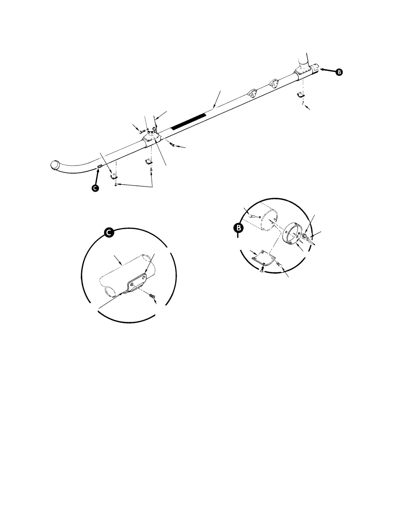
MD Helicopters, Inc.
CSP−H−2
500 Series − Basic HMI
SKID TUBE
STRUT
NAS517−3−4 SCREW
OR
BP−T5−3 LOCKBOLT
MLSP−M4−2 RIVET
(4 PLCS) (NOTE 3)
ABRASION STRIP
NAS1496−5 LOCKBOLT
(NOTES 2, 12)
NAS1080R6 COLLAR
(8 PLCS) (NOTE 3)
BP−T6−3 LOCKBOLT
(8 PLCS) (NOTES 3, 11)
NAS517−3−4 SCREW
OR
MLSP−M4−2 RIVET
NAS1291−3 NUT
MLSP−M4−3 RIVET
(2 PLCS)
AN960PD10L WASHER
(2 PLCS)
ABRASION STRIP
(NOTES 2, 12)
ABRASION STRIP
SKID
SKID PLUG
(NOTE 5)
NAS517−3−5 SCREW
OR
MLSP−M4−4 RIVET
(2 PLCS)
GAP TOLERANCE
NAS517−3−5 SCREW
(NOTES 2, 12)
OR
MLSP−M4−2 RIVET
EARLY CONFIGURATION CHANGES
NOTES: (CONT.)
11. BT−T6−4 LOCKBOLTS MAY BE USED AS ALTERNATE, IF REQUIRED, AS BY TOLERANCE BUILDUP.
12. SMALL GAPS ARE ALLOWED BETWEEN SKID TUBE AND ABRASION STRIPS:
AT FWD STRIP (DETAIL C) − 0.030 IN. (0.762 MM) GAP AT FWD EDGE AND 0.010 IN. (0.254 MM)
GAP AT AFT EDGE; AT ALL OTHER STRIPS − 0.030 IN. (0.762 MM) GAP AT BOTH EDGES.
30−069−2B
Figure 6-2. Repair and Replacement of Landing Gear (Sheet 2 of 2)
Page 6-5
Revision 15

MD Helicopters, Inc.
CSP−H−2
500 Series − Basic HMI
4. Landing Gear Strut Inspection
(d). If no cracks are found around drag
brace attach hole in strut and hole is
(Ref. Table 6−1 and Figure 6−3)
not elongated, install new bushing in
hole with wet primer (4, Table 2−4).
(1).
Check landing gear dampers for correct
servicing by observing stance of
(e). If either hole is oversized or cracking
helicopter. Check rear dampers for
is noted, rework strut (Landing Gear
correct extension and signs of leakage.
Strut Drag Brace Hole Repair).
(2).
Remove foot support fairings in passen−
(8). If no bushing is installed in drag brace
ger/cargo compartment and open engine
attach hole in strut, proceed as follows:
access doors.
(3).
Visually inspect strut attachment
(a). Using 10X glass and bright light,
points and pivot bearing for signs of
inspect strut around drag brace
fretting, wear and damage. Fretting
attach holes (top and bottom sur−
will be evident by gray or black materi−
faces) for cracks. If any cracks longer
al around bearing, rivets or seams.
than 0.030 inch (0.762 mm) in length
are noted, strut must be scrapped
(4).
Jack helicopter until landing gear
and serviceable strut installed.
dampers are fully extended.
(b). Check drag brace attach holes in
(5).
Shake landing gear assemblies and
strut for elongation.
note any play or looseness at pivot
bearings, inboard strut assembly
(c). If any cracks, 0.030 inch (0.762 mm)
fittings and drag brace holes.
in length or less, are noted or hole is
elongated, rework strut (Landing
(6).
If any play or looseness is noted,
Gear Strut Drag Brace Hole Repair).
remove landing gear (Ref. Landing
Gear Removal) and inspect drag brace
(9). Reinstall landing gear (Ref. Landing
and strut.
Gear Installation).
(7).
If bushing is installed in drag brace
(10). Inspect strut for cracks or dents.
attach hole in strut, proceed as follows:
(a). Check bushing for looseness. If
(a). If strut is cracked, scrap strut and
bushing is loose, remove it.
replace with serviceable strut.
(b). Using 10X glass and bright light,
(b). If dents in strut exceed 0.060 inch
inspect strut around drag brace
(1.524 mm) depth; or, if scratches and
attach holes (top and bottom sur−
repair area depth would exceed 0.010
faces) for cracks.
inch (0.254 mm) when measured to
surrounding unrepaired surface strut
(c). Check drag brace attach holes in
must be scrapped and serviceable
strut for elongation.
strut installed.
1). Diameter of top hole (DIM. A)
(11). Remove plug button from underside of
should be 0.5313 inch (13.495 mm)
fairing assembly. Using a bright light
maximum in any direction.
and 10X magnifying glass, inspect rivet
2). Diameter of bottom hole (DIM. B)
hole in underside of strut for cracks. If
should be 0.50 inch (12.70 mm)
crack is found, strut must be scrapped
maximum in any direction.
and serviceable strut installed.
Page 6-6
Revision 15
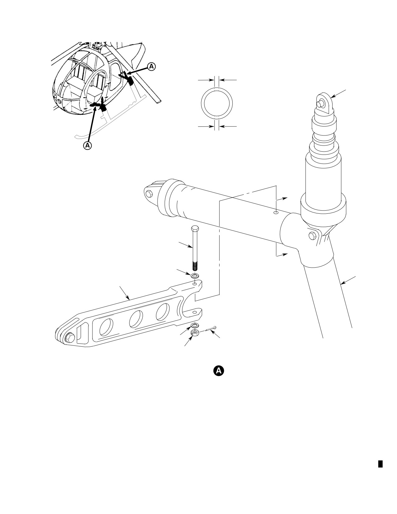
MD Helicopters, Inc.
CSP−H−2
500 Series − Basic HMI
DIM. A
(TOP HOLE)
DAMPER
( REF )
DIM. B
(BOTTOM HOLE)
SECT B−B
B
BOLT
B
WASHER
STRUT
DRAG BRACE
WASHER
COTTER PIN
NUT
STRUT AND BRACE ATTACHMENT
88−779
Figure 6-3. Landing Gear Strut Inspection
Page 6-7
Revision 15
MD Helicopters, Inc.
CSP−H−2
500 Series − Basic HMI
5. Landing Gear Repair
(2). Perform fluorescent penetrant inspec−
tion of reworked areas for cracks. If any
(Ref. Figure 6−2)
cracks are noted, replace strut assem−
bly with serviceable strut assembly.
(1). Repair scratches and nicks by smooth−
ing sharp edges.
(3). Perform fluorescent penetrant inspec−
tion of reworked areas for cracks.
(2). Repair elongated, enlarged or worn bolt
holes in strut fittings, either inboard or
(a). If any cracks are noted, rework strut
outboard (Ref. CSP−H−6).
per step (4).
(3). Repair bolt holes at large end of brace
(b). If no cracks are noted, install new
that attaches to strut (Ref. CSP−H−6).
369H6023−1 bushing in hole with
wet primer (4, Table 2−4).
(4). Replace a strut that is cracked or for
(4). Ream out top hole (DIM. A) to
the following damage.
0.5908−0.5913 inch (15.006−15.019
(a). Dents with depth in excess of 0.060
mm) and ream out bottom hole (DIM.
inch (1.524 mm).
B) to 0.5595−0.560 inch (14.211−14.224
mm).
(b). Scratches if repaired area depth
exceeds 0.010 inch (0.254 mm) when
(5). Perform fluorescent penetrant inspec−
measured to surrounding unrepaired
tion of reworked areas for cracks.
surface.
(a). If crack is found, strut must be
scrapped and serviceable strut
(5). Replace defective or badly damaged
installed.
fairing.
(b). If no cracks are noted, install new
(6). Repair fairing fiberglass damage, such
369H6023−3 bushing in hole with
as small tears or punctures that do not
wet primer.
impair the telescoping action of the
fairing (Ref. CSP−H−6).
B. Landing Gear Strut with No Bushing
Installed
(7). Replace cracked, dented or distorted
braces.
(1). Ream out top hole (DIM. A) to
0.5308−0.5313 inch (13.482−13.495
(8). Repair or replace damaged skid tube.
mm) and ream out bottom hole (DIM.
B) to 0.4995−0.50 inch (12.687−12.70
(9). Replace center beam−to−landing gear
mm).
attachment bearings that exceed 0.040
inch (1.016 mm) axial play. Refer to
(2). Perform fluorescent penetrant inspec−
CSP−H−6 for replacement procedure.
tion of reworked areas for cracks.
6.
Landing Gear Strut Drag Brace Hole
(a). If any cracks are noted, rework strut
Repair
per step (3).
(b). If no cracks are noted, install new
(Ref. Figure 6−3) The following procedure is for
369H6002−1 1 bushing in hole with
repair of the bolt hole in the landing gear strut
wet primer (4, Table 2−4).
where the drag brace attaches. This rework is
for either elongated or cracks in the bolt hole
(3). Ream out top hole (DIM. A) to
area (Ref. Landing Gear Strut Inspection).
0.5608−0.5613 inch (12.244−14.257
mm) and ream out bottom hole (DIM.
A. Landing Gear Strut with Bushing
B) to 0.5295−0.530 inch (13.449−13.462
Installed
mm).
(1). Ream out top hole (DIM. A) to
(4). Perform fluorescent penetrant inspec−
0.5608−0.5613 inch (12.244−14.257
tion of reworked areas for cracks.
mm) and ream out bottom hole (DIM.
B) to 0.5295−0.530 inch (13.449−13.462
(a). If any cracks are noted, proceed with
mm).
step (5).
Page 6-8
Revision 15
MD Helicopters, Inc.
CSP−H−2
500 Series − Basic HMI
(b). If no cracks are found around drag
B. Landing Gear Skid Installation
brace attach hole in strut and hole is
NOTE: Left and right side machine bolt at−
not elongated, install new
tached skids are interchangeable. As re−
369H6023−1 bushing in hole with
quired, eight 1032−428−8M screws are re−
wet primer.
moved from inboard side of skid tube an
(5). Ream out top hole (DIM. A) to
installed on outboard side with primer (4,
0.5908−0.5913 inch (15.006−15.019
Table 2−4) . If machine bolt−attached skids
mm) and ream out bottom hole (DIM.
are to be used with the lockbolt struts, per−
B) to 0.5595−0.560 inch (14.211−14.224
form steps (4). thru (11). below to enlarge
mm).
strut holes. When machine bolt style strut is
to be used with lockbolt style skid, use Huck
(6). Perform fluorescent penetrant inspec−
or Olympic 0.250 inch (6.35 mm) lock−bolts
tion of reworked areas for cracks.
with a washer to protect counterbore sur−
face on strut foot.
(7). If crack is found, strut must be
scrapped and serviceable strut
(1).
Apply a thin coating of primer (4,
installed.
Table 2−4) to strut and skid tube
mating surfaces.
(8). If no cracks are noted, install new
(2).
Align mating parts and install lockbolts
369H6023−3 bushing in hole with wet
with primer, or secure with machine
primer.
bolts and washers.
7.
Landing Gear Skid Description
(3).
Seal edges of landing strut foot with
0.060 inch (1.524 mm) fillet of sealing
(Ref. Figure 6−2) The landing gear skids
compound (3). Seal the two unused
consist of contoured aluminum alloy tubes,
holes on the top of each strut foot (if
bonded skid caps and riveted end plugs,
present) with silicone rubber (17).
ground handling wheel fittings and abrasion
strips having cobalt−barium inserts. Skid tubes
(4).
To enlarge strut foot mounting holes for
(excepting the early configuration) are
machine bolt−attached skids, place the
extruded and have a 0.095 inch (2.413 mm)
left (−1 detail) landing gear foot drill jig
wall thickness along underside and around
(40, Table 2−2) on the left strut forward
entire perimeter of tube at both strut foot
foot. Use the small diameter alignment
attachment locations. Table 6−1 lists maxi−
pin to locate the existing lockbolt hole.
mum damage limits.
(5).
Clamp the tool to strut with C−clamps
8. Landing Gear Skid Replacement
in three places.
(Ref. Figure 6−2)
(6).
Insert the drill bushing in the jig and
drill a 0.250 inch (6.35 mm) hole in the
A. Landing Gear Skid Removal
strut by a flat end (bottom) drill (size
F). Install the large diameter alignment
(1). Jack up the helicopter until the landing
pin in the drilled hole. Use the bushing
gear dampers are fully extended. Place
and drill the remaining holes.
supports beneath the skid tubes at the
strut locations.
(7).
Remove special tool from strut. Deburr
drilled holes.
(2). Remove the lower fairing from the
(8).
Enlarge counterbore of mounting holes
two−piece fairing assembly.
on face of strut to 0.687 inch (17.4498
(3). As applicable, remove the machine
mm) diameter, flush with, or 0.020 inch
bolts or lockbolts that attach the skid
(0.508 mm) above original depth (0.090
tube assembly to feet on forward and
inch (2.286 mm) minimum thickness
aft struts.
remaining). Maintain the 0.030−0.060
inch (0.762−1.524 mm) lower corner
(4). Remove skid from landing gear.
radius.
Page 6-9
Revision 15
MD Helicopters, Inc.
CSP−H−2
500 Series − Basic HMI
(9). Apply chemical film protection (8,
(11). Perform steps (4). thru (10). above,
Table 2−4) on exposed aluminum
using the right (−2 detail) drill jig (41,
surfaces.
Table 2−2) for the right struts as
necessary.
(10). Repeat steps (4). thru (9). above for left
(12). Install lower fairing of two−piece fairing
aft strut foot.
assembly.
Table 6-1. Maximum Damage Limits for Landing Gear Components
Dents
Nicks
Scratches
Cracks
Holes
Component
in. / mm
in. / mm
in. / mm
in. / mm
in. / mm
Skid tube (1)
0.200 / 5.08
0.010 / 0.254 from aft side of aft Same as (2)
No cracks
0.250 / 6.35
(2)
strut to 10 / 254 forward of the
for nicks
allowed
(2)(3)
strut, with cleanup not
exceeding 0.015 / 0.381 if
forward of that point to start of
curved section, with cleanup not
exceeding 0.020 / 0.508 (1)
Foot
0.060 / 1.524
0.060 / 1.524
0.010 / 0.254
No cracks
No holes
allowed
allowed
Strut
0.060 / 1.524
(2)
(2)
No cracks
No Holes
allowed
allowed
Brace
0.040 / 1.016
0.010 / 0.254
0.005 / 0.127
No cracks
No holes
allowed
allowed
Damper
0.060 / 1.524
0.010 / 0.254
0.010 / 0.254
No cracks
No holes
Assembly
allowed
allowed
Fitting
0.010 / 0.254
0.010 / 0.254
0.010 / 0.254
No cracks
No holes
allowed
allowed
Plug
0.200 / 5.08
0.250 / 6.35
0.010 / 0.254
0.250 / 6.35
0.250 / 6.35
NOTES:
(1) Repair of minor skid tube damage aft of the rear strut and on the forward (curved) section is not required
but surface finish must be restored.
(2) Refer to CSP-H-6 for other repair data.
(3) Hole must be plugged with correct size blind rivet.
Page 6-10
Revision 15
MD Helicopters, Inc.
CSP−H−2
500 Series − Basic HMI
9. Heavy-Duty Abrasion Strip Replacement
(6.35 mm) and a depth of 0.020 inch
(0.508 mm) when repaired.
(Ref. Figure 6−2)
(8). Inspect ground handling fittings for
(1). Remove bolts and washers attaching
cracks, loose rivets and corrosion.
heavy−duty abrasion strips to landing
gear skid tube.
(9). Install the lower fairing.
(2). Completely remove any residual zinc
11. Landing Gear Skid Repair
chromate putty or sealing compound
(Ref. Figure 6−2)
from attachment and mating areas of
the skid tube.
A. Repair of Scratches, Nicks, Dents and
Punctures
(3). Attach and secure replacement heavy−
duty abrasion strip to nutplate fittings
(1). Repair scratches and nicks by smooth−
on skid tube with four bolts and
ing sharp edges (Ref. Table 6−1).
washers. Comply with the following.
(2). Drill (0.250 inch (6.35 mm) maximum)
(a). Use washer under each bolt head.
out dents, nicks and scratches to the
nearest blind rivet size when such
(b). Apply a 0.060 inch (1.524 mm) bead
damage exceeds the depth limits
of sealing compound (3, Table 2−4) to
specified in Landing Gear Skid Inspec−
all mating part edges.
tion. Clean out puncture holes in the
same manner.
(c). Install with minimum gap between
abrasion strip and skid tube. Gap
(3). Apply zinc chromate putty (72,
limit is 0.030 inch (0.762 mm)
Table 2−4) to edges of drilled repair
maximum along fore−and−aft center−
holes and install the appropriate size
line of abrasion strip.
rivet to close the hole.
(d). Torque bolts to 25 − 35 inch−pounds
(4). Repair the skid tube assembly when
(2.82 − 3.95 Nm).
puncture hole, or drilled out dents,
nicks or scratches will exceed 0.250
10. Landing Gear Skid Inspection
inch (6.35 mm) diameter, or when
fluorescent penetrant inspection reveals
(1).
Jack the helicopter until the landing
damage adjacent to punctures. Perform
gear dampers are fully extended.
repair of the skid tube according to
(2).
Remove the lower fairing from a
CSP−H−6.
two−piece fairing assembly.
B. Skid Plug Replacement
(3).
Inspect for dents and depressions in
(1). Drill out rivets or remove screws
excess of 0.20 inch (0.508 mm) in depth.
attaching skid plug. Remove unservice−
able plug by drilling a hole in the center
(4).
Inspect for punctures.
of the plug and using a suitable puller.
(5).
Perform fluorescent penetrant inspec−
(2). Apply a thin layer of zinc chromate
tion of areas adjacent to punctures.
putty (72, Table 2−4) to the mating
(6).
Inspect from the aft end of the tube to a
surfaces of the new plug and skid tube
point 10 inches (25.4 cm) forward of the
to ensure a watertight fit.
aft strut for scratches and nicks which
(3). Rivet new skid plug through aft
will exceed a length of 0.250 inch (6.35
abrasion strip to tube.
mm) and a depth of 0.015 inch (0.381
mm) when repaired.
C. Abrasion Strip Replacement
(7).
Inspect from the forward end of the
(1). Remove screws or drill out rivets, as
tube to 10 inches (25.4 cm) forward of
applicable. Drill out rivets attaching
the aft strut for scratches and nicks
abrasion strip and remove unservice−
which will exceed a length of 0.250 inch
able strip.
Page 6-11
Revision 15
MD Helicopters, Inc.
CSP−H−2
500 Series − Basic HMI
(2). Completely remove any residue zinc
G. Skid Tube Nutplate Fitting Replacement
chromate putty. Apply primer (4) to any
(1). Drill out rivets attaching nutplate
bare metal.
fitting to skid tube and remove fitting.
(3). Secure new skid plug to tube with
(2). Completely remove any residual zinc
screws, or rivets, as applicable, through
chromate putty or sealing compound
the aft abrasion strip.
from nutplate mounting area on skid
tube.
(4). Coat new screws or rivets with primer.
As applicable screw or rivet the replace−
(3). When installing replacement nutplate
ment abrasion strip to tube while
fitting on skid tube, use sealing com−
primer is still wet.
pound (3). Rivet nutplate fitting in
place. Apply a 0.060 inch (1.524 mm)
NOTE: To allow use of common abrasion strips
bead of sealing compound around
on the curved portion of the skid, a maxi−
mating part edges.
mum gap of 0.10 inch (2.54 mm) between
center underside of skid and aft end of the
12. Landing Gear Damper Description and
abrasion strip is permissible. Permissible
Operation
gap at forward end is 0.030 inch (0.762 mm).
Each landing gear assembly is equipped with a
(5). After installation, seal all of the parting
front and rear damper assembly.
edge of the abrasion strip next to the
skid tube. Apply an approximate 0.060
The landing gear dampers absorb vertical
inch (1.524 mm) bead (fillet) of sealing
shock to the landing gear struts during
compound (3) to ensure a watertight
helicopter landings. The front damper assem−
assembly.
blies are attached to the oleo attachment
fittings located on the outboard side of the
D. Skid Cap Replacement
pilot’s compartment seat structure. The aft
damper assemblies are attached to oleo
(1). Remove skid cap.
support fittings in the engine compartment.
The damper assemblies are 12.21 inches
(2). Using isopropyl alcohol (71, Table 2−4)
(31.0134 cm) long when extended and 8.96
clean bonding area.
inches (22.7584 cm) long when compressed.
There are two basic types of landing gear
(3). Bond new cap to skid tube with sealing
dampers which can be installed on the
compound (3).
helicopter:
E. Ground Handling Fitting Replacement
(1) A bladder−type damper assembly consisting
of a barrel, upper and lower mounting cap, and
(1). Replace an unserviceable ground
internal rubber bladder, and a piston.
handing fitting using the same proce−
dures as Abrasion Strip Replacement
(2) A poppet−type damper assembly consisting
except gaps are not allowable and seal
of a barrel, upper and lower mounting cap,
mating surfaces with zinc chromate
main poppet, rebound poppet and a piston.
putty (72, Table 2−4) instead of primer.
The poppet−type damper is one−way inter−
changeable (in sets of four only) with the
F. Safety Walk Tape Replacement
bladder−type damper. Use of poppet−type
(1). Carefully pull or scrape away damaged
dampers requires larger bushings and 5/16
tape. Remove all residual adhesive from
inch diameter hardware for both upper and
skid tube by wiping with a clean cloth
lower attachment. A damper must be replaced
wetted by naphtha (59, Table 2−4).
if damaged, or if loss of pneumatic pressure
(nitrogen gas) or hydraulic oil occurs. Replace−
(2). Carefully align new tape (73) with
ment of a single damper must be with the
mounting surface and press firmly into
same type and configuration as the one
place. Expel air bubbles while pressing
removed. Refer to Table 6−2 for damper
down the tape.
application.
Page 6-12
Revision 15
MD Helicopters, Inc.
CSP−H−2
500 Series − Basic HMI
13. Landing Gear Damper Replacement
Protective glasses and
WARNING
heavy gloves must be worn
(Ref. Figure 6−1 and Figure 6−2)
when drilling the pressure relief hole
in the damaged damper. The spray of
A. Landing Gear Damper Removal
hydraulic oil under pressure can result
in injury to personnel.
Be sure the helicopter is jacked
CAUTION
up evenly and in a level area;
(c). Drill a 0.0625 inch(1.5875 mm) hole
otherwise, jacks might slip and damage the
in lower end of the damper body.
helicopter structure.
Keep the drill bit in the hole until the
hydraulic fluid stops flowing.
(1). Jack up the helicopter until the landing
gear skids just clear the ground.
NOTE: Note damper part number and color
(2). For forward damper removal, remove
code to be sure that correct dampers are re−
foot support fairings located in the
installed.
passenger compartment.
(4). Remove hardware, except bushings,
attaching the damper assemblies to the
WARNING
fuselage fitting and to landing gear
D Check that all electrical power is
struts; remove damper assemblies.
OFF. This precaution will prevent
personal injury or helicopter dam−
B. Landing Gear Damper Installation
age which could result from body or
tool contact with electrical termi−
nals.
NOTE: Ensure the replacement damper is cor−
rect for the helicopter (Ref. CSP−H−7 and
D Use extreme care during damper re−
Table 6−2). Also check that the cap torque
moval if a green or white bladder−
stripes will be visible for inspection after in−
type damper is extended beyond
stallation.
11.38 inches (28.9052 cm) as mea−
sured between flat surface of both
(1). Install replacement damper in upper
end caps. This condition indicates an
internal failure of the damper that
and lower mounting position with
will result in a sudden release of in−
attaching hardware. Ensure bushings
ternal pressure and explosion of the
are in place.
bladder if the damper is released
from the fuselage fittings before ac−
NOTE: Left forward damper upper bolt must be
complishing step (3). below.
installed with bolt head aft. Bolt direction
on right side is optional.
(3). Bladder−type dampers that show
evidence of, or are suspected of, inter−
(2). For aircraft 0001 thru 0100, torque
nal failure must have the pressure
nuts to 25 − 30 inch−pounds (2.82 −
relieved, steps (a). thru (c). below,
3.39 Nm) and install cotter pin.
before performing removal.
(a). Removal any avionics equipment in
(3). For aircraft 0101 & subs, torque nuts to
the immediate area of the damaged
48 − 55 inch−pounds (5.42 − 6.21 Nm)
damper. Cover all electrical connec−
and cotter pin.
tors with plastic material.
(4). Check installation for proper alignment
(b). Wrap the damaged damper with 1
of torque stripes.
inch (2.54 cm) thick polyfoam (or
material equivalent absorption
property) to minimize spraying of
(5). Install foot support fairings and close
hydraulic oil.
engine access doors.
Page 6-13
Revision 15
MD Helicopters, Inc.
CSP−H−2
500 Series − Basic HMI
Table 6-2. Damper Assembly Identification
Factory Charge
Landing Gear
Part No.
Configuration
Color
Type
psi / kPa
Application
369A6300
Basic
Light Green
Bladder
560 ±10 / 3861 ±69
Early standard (4)
369A6300
-501
Light Green
Bladder
560 ±10 / 3861 ±69
Early standard (4)
369A6300
-503
Light Green
Bladder
560 ±10 / 3861 ±69
Current standard (4)
369A6300
-601
White
Bladder
560 ±10 / 3861 ±69
Early standard (4)
369H6340
Basic
Blue
Poppet
520 ±2 / 3585 ±14
Current standard (4)
* * *
Extended option (2 fwd)
369H92131
Basic
Orange
Poppet
850 ±3 / 5861 ±21
Extended option (2 aft)
* * *
369H92800 *
Basic
Medium Green Poppet
705 ±2 / 4861 ±14
Winterized standard
option (4)
Winterized extended
option (2 fwd)
369H92801 * *
Basic
Yellow
Poppet
1075 ±3 / 7412 ±21
Winterized extended
option (2 aft)
NOTES:
* Not available for replacement purposes; replaced by winterized version of 369H6340. May be modified to
369H6340 at overhaul; refer to CSP−H−5.
* * Not available for replacement purposes; replaced by winterized version of 369H92131. May be modified
to 369H92131 at overhaul; refer to CSP−H−5.
* * * Requires a higher charge and adjustment of oil level for winterized service; refer to CSP−H−5 for
charging data.
14. Landing Gear Damper Inspection
discarded, or replaced if spare is
available.
NOTE: It is normal for a thin hydraulic oil film
(3). Inspect landing gear dampers for
to remain on damper as a result of wiping
condition by observing stance of
contact with piston seal. Newly installed
helicopter (normal stance is slightly
dampers may also have slight oil seepage
nose up). If stance indicates excessive
from oil trapped in end cap threads during
nose up/nose down attitude, perform
damper assembly. Neither of these should
damper extension check.
be considered damper leakage or cause for
damper replacement.
(a). Inspect landing gear damper assem−
blies for proper extension, with
(1). With helicopter on jacks, inspect
helicopter in empty weight configura−
damper assemblies for evidence of
tion (no passengers or cargo) but with
bearing looseness in upper and lower
full fuel tanks. This configuration
caps, worn bearings (excessive radial
should weight between 1675−1825
play) loose or cracked caps and oil
pounds (760−583 kg) exclusive of skid
leakage. Any misalignment of torque
mounted float gear. Place helicopter
stripes on caps, piston and barrel
on smooth concrete or equivalent
indicates loosening of caps. Replace
surface (not asphalt).
immediately and repair damper
according to CSP−H−5.
(b). Check dampers which have been
modified (winterized) for cold weath−
(2). Inspect damper for security of attaching
er operation are to be checked at not
hardware and condition of plastic cover.
more than 30°F (−1°C) above the
Plastic cover is no longer required or
coldest temperature at which the
installed in production; it may be
helicopter is operated.
Page 6-14
Revision 15
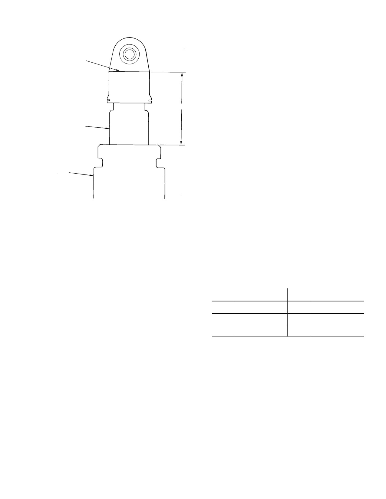
MD Helicopters, Inc.
CSP−H−2
500 Series − Basic HMI
(i). Determine average extension from all
six readings for each damper assem−
bly. Remove and overhaul any damper
END CAP
assembly not meeting dimensions shown
(FLAT)
in Table 6−3.
NOTE: If two damper assemblies fail to meet
the minimum extension shown in Table 6−3,
replace the damper having the greater
amount of deflection with a known service−
DIMENSION A
able damper and repeat steps (c). thru (i). If
the original damper again fails to meet
PISTON
minimum extension requirements, replace
it with serviceable damper, reinstall the
first damper, and repeat steps (c). thru (i).
This will determine whether one or both
dampers require overhaul. Dampers which
have been modified (winterized) for cold
BARREL
weather operation are to be soaked at −3° to
+3°F (−19 to −16°C) for 24 hours minimum
prior to conducting the bench check.
(4). Inspect for damper internal failure by
checking for clearance between the
bottom of the landing gear strut and
30−226
measuring the length of the damper. If
the gear strut is touching the fuselage
Figure 6-4. Landing Gear Damper Assembly
or the length of the damper measured
Extension Check
between the end cap flat surfaces is
11.38 inches (28.9052 cm) or more, it
(c).
Raise and lower tailboom above and
must be replaced.
below the normal at−rest position
three times. On the last cycle, allow
Table 6-3. Minimum Damper Extension
the tailboom to slowly settle to the
(Dimension A)
at−rest position.
Standard Landing Gear
Extended Landing Gear
(d).
Measure and record dimension from
upper end cap to upper end of barrel
in. / cm
in. / cm
on all four damper assemblies (Ref.
Aft
2.55 / 6.477
Aft
2.60 / 6.604
Dimension A, Figure 6−4).
Fwd
3.00 / 7.62
Fwd
2.90 / 7.366
(e).
Repeat steps (c). and (d). two more
times.
15. Landing Gear Damper Repair
(f).
Lower and raise tailboom below and
Exterior damage limits for the landing gear
above the normal at−rest position
damper are provided in Table 6−1. Refer to
three times. On the last cycle, allow
CSP−H−5 for available repair and overhaul
the tailboom to slowly rise to the
information. Remove scratches and nicks in
at−rest position.
damper fittings as follows:
(1). Use grade 400 (or finer) wet or dry
(g).
Measure and record dimension from
abrasive paper (9, Table 2−4) to remove
upper end cap to upper end of barrel
any raised or sharp edges and to blend
on all four damper assemblies (See
the defect smoothly with the surround−
dimension A, Figure 6−4).
ing surfaces.
(h).
Repeat steps (f). and (g). two more
(2). Use crocus cloth (23) to remove any
times.
surface scratches left by the coarser
Page 6-15
Revision 15
MD Helicopters, Inc.
CSP−H−2
500 Series − Basic HMI
abrasive and to polish the repaired area
17. Landing Gear Fairing Replacement
to match the surrounding surfaces.
(Ref. Figure 6−5)
(3). Apply corrosion protection treatment
A. Landing Gear Fairing Assembly Removal
(Ref. Section 2).
The following removal instructions are typical
NOTE: If dust cover is not installed, there is no
for all four fairing assemblies.
requirement for the felt spacer, rubber re−
(1). Remove 6 screws, 12 washers and 6
taining sleeve and the tie strap (or plastic
nuts that secure trailing edge of
tape) for securing cover. When replacing or
lower fairing and 6 screws and
discarding a plastic cover, only the upper
washers that secure lower fairing to
end of the damper must be detached.
the two strut brackets.
(4). To replace a damper assembly plastic
(a). Carefully spread trailing edge of
cover (installed only at aft locations on
lower fairing and remove in a for−
early damper configurations), remove
ward direction.
plastic tape or rubber sleeve and tie
strap used to compress cover tangs and
NOTE: Be sure that doublers between lamina−
carefully but firmly pull cover toward
tions at trailing edge are retained for reuse.
top end to disengage tangs from bearing
(2). Remove the fillet from the upper part of
cap groove. Install replacement by
the fairing assembly as follows.
reversing the procedure. Secure the
cover tangs in place with rubber sleeve
(a).
Remove the four rivets from the
and tie strap or by wrapping several
trailing edge of the fillet.
turns of tape (74) around tanged end of
(b).
Drill out one of the six rivets securing
cover
the fillet to the upper guide. Replace
the rivet with a sheet metal hole
16. Landing Gear Fairing Assembly
fastener (Cleco, or equivalent).
Description
Repeat this step on the other five
rivets.
The landing gear fairing consists of a stream−
lined fiberglass fairing surrounding each
(c).
Open underfloor compartment or
landing gear strut, extending from the
engine compartment doors to gain
fuselage to the landing gear skid. Each fairing
access to the strut cutout in the
assembly is constructed of either two or three
fuselage skin. Have an assistant
main parts; a fillet and an upper and lower
push down on the upper guide with a
(two−piece) fairing are used on all but early
suitable tool (wood dowel or equiva−
configurations which have a one−piece fairing.
lent) to relieve the spring tension.
The fillet is spring−loaded to remain in firm
(d).
With spring tension off the guide,
contact with a fiberglass rubbing plate that is
take out the six fasteners. Slowly
bonded and riveted to the fuselage. The upper
relax the dowel pressure on the guide
part of the two−piece fairing is bonded and
until the springs reach maximum
riveted to a strut bracket that is riveted to the
travel.
strut. The lower part of the two−piece fairing
is attached to the upper fairing and strut
(e).
Carefully spread fillet at trailing
brackets with screws for ease of removal
edge and remove in a forward
and/or replacement of the strut feet and skid
direction.
tubes. The fairing telescopes inside the fillet to
allow movement of the strut as the landing
(3). Remove the upper part of the fairing, or
gear dampers compress or extend. A seal on
the one−piece fairing as follows.
the bottom edge of the fairing forms a fillet
(a). As applicable, remove one or two (or
between the fairing and the skid tube. The
eight or nine) rivets that secure
forward fairing may have a fairing cover
trailing edge of fairing.
installed. When a cabin entry step is installed,
the fairing assembly has an opening with a
(b). Remove two (or eight) rivets that
rubber seal.
secure fairing to strut bracket(s).
Page 6-16
Revision 15
MD Helicopters, Inc.
CSP−H−2
500 Series − Basic HMI
(c). Use a putty knife or similar thin−
(e).
Back up the fairing with a fiber block
bladed tool to carefully pry apart the
at the transfer punch location. Using
bonding and separate the upper 5
a plastic hammer, hit the opposite
inches (12.7 cm) of the trailing edge;
side of the fairing hard enough to
then separate the fairing from the
transfer the hole centers.
flange of the lower guide.
(f).
Remove fairing and check that all the
transfer marks appear within the
(d). Carefully spread trailing edge of
outline of the small laminated
fairing and remove in a forward
doublers. Drill out the located holes.
direction.
(g).
Carefully bond the fairing to the
B. Landing Gear Fairing Assembly
lower guide. Use adhesive (19)
Installation
according to container instructions.
The following installation instructions are
(h).
As applicable, install two (or eight)
typical for all four fairing assemblies. Where
rivets to secure the fairing to the
riveting is required, use rivets of the type
strut bracket(s).
shown.
(i).
As applicable, install one or two (or
(1). Install the upper part of the fairing, or
eight or nine) rivets to secure the
the one−piece fairing as follows.
trailing edge of the fairing.
(a). Assemble upper guide, pin assembly,
(j).
Using a soft lead pencil, draw a
inner guide half, outer guide half,
continuous line along the horizontal
springs and lower guide on the
center of the upper guide flange.
landing gear strut. Install two rivets
(2). Install the fillet as follows.
with wet primer (4, Table 2−4) to
secure lower guide to strut.
(a).
Drill a 0.0980 inch(2.4892 mm) hole
in the center of each 0.375 inch
(b). Push guide pins into the matching
(9.525 mm) square doubler in the
holes of the lower guide. Wedge a
fillet. (There are six doublers.)
temporary holding device between
the upper guide and the strut to keep
(b).
Carefully spread trailing edge of fillet
the pins engaged.
and position about upper guide.
Clamp the lower end of the fillet
NOTE: Use two small wood blocks or any simi−
trailing edge to the upper end of the
lar suitable means to keep the springs in
fairing trailing edge. Clamping will
compression. The device used must be small
prevent fillet movement when the
enough to be removed through the strut cut−
fillet rivets are installed.
out in the skin after the fillet is assembled.
(c).
Have an assistant remove the
(c). Install blind hole transfer punches
temporary holding device and push
(two or four places, as applicable) or
down on the upper guide with a
fabricate suitable tools as shown in
suitable tool (wood dowel, etc). Have
Figure 6−5. Install tool(s) between
the guide pushed down to a point
opposing holes in strut bracket(s).
where the pencil line drawn on the
guide flange is visible through one of
(d). Carefully spread trailing edge of
the 0.0980 inch(2.4892 mm) holes in
fairing and position the fairing on the
the fillet. Match−drill the guide and
strut bracket(s) and the lower guide.
secure the fillet and guide with a hole
Have an assistant hold the fairing in
fastener (Cleco, or equivalent).
this position.
Repeat the procedure for all six rivet
locations. Remove the pushing tool
NOTE: On the one−piece fairing, there should
from the strut opening.
be 0.020−0.080 inch (0.508−2.032 mm) com−
pression of the fairing seal against the skid
(d).
Remove one fastener at a time,
tube when the fairing is correctly posi−
enlarge the hole to rivet diameter
tioned.
and install a blind rivet.
Page 6-17
Revision 15
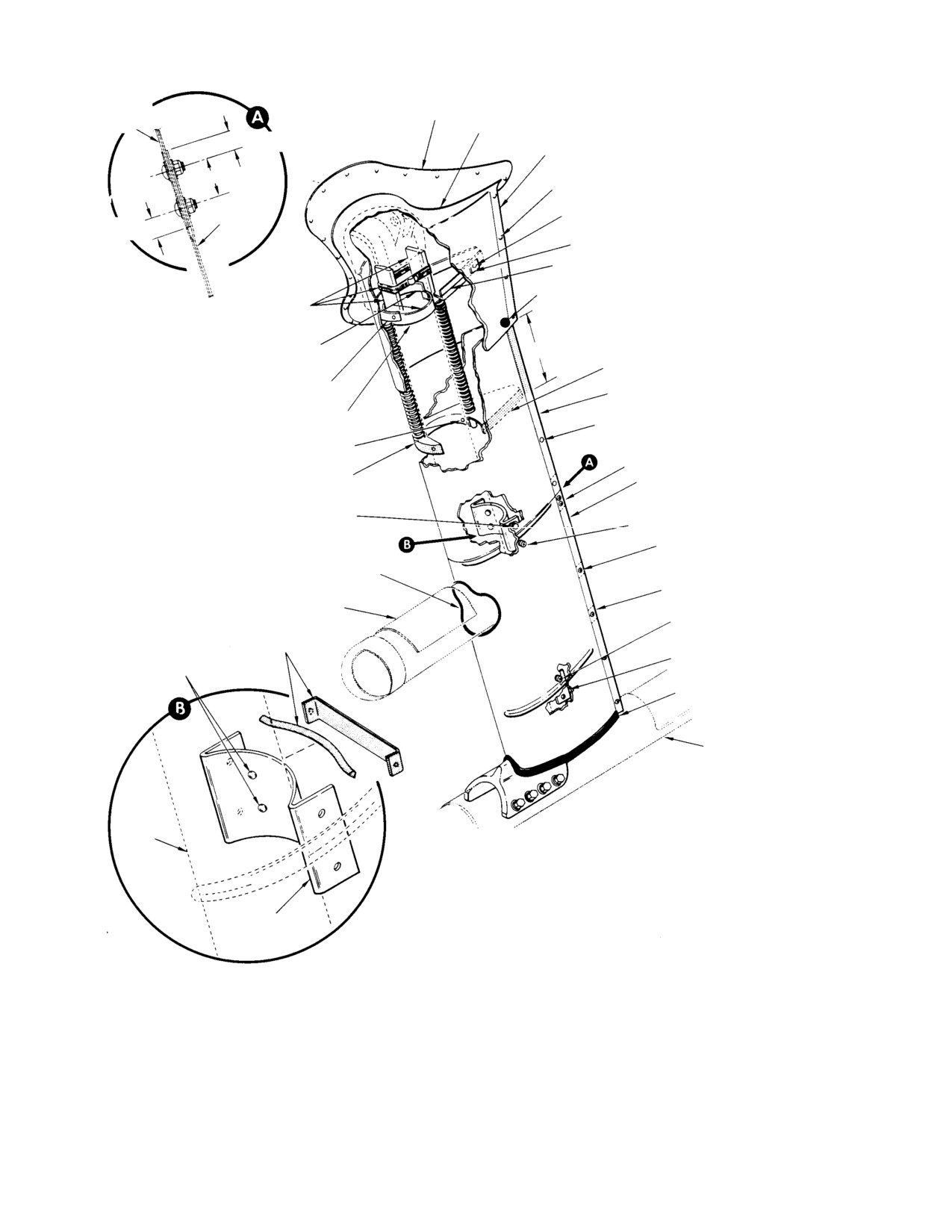
MD Helicopters, Inc.
CSP−H−2
500 Series − Basic HMI
UPPER
CHAFING PAD
FAIRING
TEFLON STRIP
0.35 IN. (8.89 MM)
FILLET (NOTE 3)
0.80 IN. (20.32 MM)
MS20470A RIVETS
LOWER
MS20600AD OR CKL−P RIVETS
0.35 IN. (8.89 MM)
FAIRING
0.375 IN. (9.525 MM) DOUBLER
NOTE 5
NOTE 4
RETAINING BLOCKS AND CLAMPS
TEFLON PAD (INSIDE GUIDES)
5 IN. (12.7 CM) (NOTE 1)
FAIRING−TO−LOWER GUIDE (NOTE 1)
UPPER GUIDE PIN ASSY,
INNER GUIDE HALF AND SPRING
UPPER FAIRING (NOTE 3)
MS20470A RIVET
OUTSIDE GUIDE HALF
(FWD FAIRING − 1 RIVET)
MS20600AD OR CKL−P RIVETS (NOTE 2)
(AFT FAIRING − 2 RIVETS)
1.4375 IN. (3.65125 CM) DOUBLER
LOWER GUIDE (NOTE 1)
LOWER FAIRING (NOTE 3)
MS20470A RIVET (2 PLCS)
SCREW, WASHER (2 PLCS)
SCREW, WASHERS, NUT (6 PLCS)
SEAL
(NOTE 7)
NAS1398D4−4 RIVETS
0.750 IN. (19.05 MM) DOUBLER
CABIN ENTRY STEP
(UPPER BRACKET)
(NOTE 7)
S3L10−DT4−3 HUCKBOLTS
SCREW, WASHER (4 PLCS)
(LOWER BRACKET (NOTES 2, 8)
NOTE 7
CKL−P RIVETS
0.50 X 0.750 IN. (12.7 X 19.05 MM)
(NOTES 2, 9)
DOUBLER
SEAL
SKID
STRUT
NOTES:
1.
BONDED AREA: USE EPOXY ADHESIVE (19, TABLE 2−4).
2.
INSTALL NEW RIVETS WITH WET PRIMER (4, TABLE 2−4)
3.
REFER TO CSP−H−6 FOR FIBERGLASS REPAIR.
4.
CLAMP FILLET AND FAIRING TRAILING EDGES DURING INSTALLATION OF
FAIRING
FILLET RIVETS.
BRACKET
5.
PENCIL CENTERLINE ALONG FLANGE.
6.
3/16 IN. (4.7625 MM) WELDING ROD OR OTHER SUITABLE DEVICE (4 PLCS).
7.
FWD FAIRING ONLY.
8.
HUCKBOLT HEAD COUNTERSUNK INSIDE STRUT; NO PORTION OF HEAD TO
PROTRUDE INSIDE STRUT.
9.
AFT FAIRING BRACKETS AND LWR FWD FAIRING BRACKET ON ONE−PIECE
FAIRING ONLY.
30−070−1C
Figure 6-5. Repair and Replacement of Fairing (Sheet 1 of 2)
Page 6-18
Revision 15
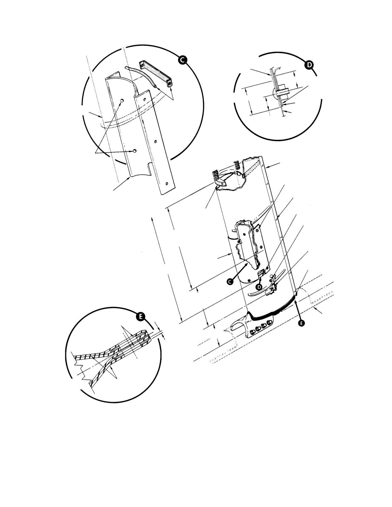
MD Helicopters, Inc.
CSP−H−2
500 Series − Basic HMI
UPPER FWD
FAIRING COVER
0.40 IN. (10.16 MM)
UPPER FWD FAIRING
BRACKET
0.64 IN. (16.256 MM)
DOUBLER
NOTE 6
STRUT
FWD
0.32 IN.
FAIRING
(8.128 MM)
CKL−P RIVETS
(4 PLCS) (NOTE 2)
FAIRING
(NOTE 3)
SCREW (10 PLCS)
UPPER FWD FAIRING
MS20470A RIVETS
BRACKET
(FWD FAIRING − 9 RIVETS)
(AFT FAIRING − 8 RIVETS)
TO FWD FAIRING
DOUBLER
UPPER EDGE
LOWER GUIDE
(NOTE 1)
MS20600AD OR CKL−P
RIVETS (NOTE 2) OR
SCREW AND WASHER
7.87 IN. (19.9898 CM)
(NOTES 11, 12)
0.50 X 0.750 IN.
(12.7 X 19.05 MM)
FWD FAIRING
DOUBLER
COVER
12.13 IN. (30.8102 CM)
(NOTE 7)
SEAL
(NOTE 11)
NOTE 10
12.96 IN. (32.918 CM)
(NOTES 11, 12)
SKID
DOUBLER
4.32 IN. (10.973 CM)
(NOTE 2)
0.020 IN.
(0.508 MM)
SKID C
L
C
OF
NOTES: (CONT.)
LWR FAIRING
FAIRING
10. UPPER AFT FAIRING BRACKET ON ONE−PIECE FAIRING
SHOWN IN DETAIL B.
11. DIMENSIONS FOR BRACKET AND GUIDE LOCATIONS ON
NEW STRUTS.
12. MEASURED TO LWR EDGE OF UPPER FAIRING BRACKET
SHOWN IN DETAIL B ON TWO−PIECE FAIRING.
30−070−2B
Figure 6-5. Repair and Replacement of Fairing (Sheet 2 of 2)
Page 6-19
Revision 15
MD Helicopters, Inc.
CSP−H−2
500 Series − Basic HMI
(e). Install four rivets to secure the fillet
(2). Inspect fairing support brackets for
trailing edge together.
security of attachment to strut, cracks
and deformation.
(f). Check for smooth telescoping action
of fairing into fillet by manually
(3). Inspect fairing−to−skid seal for deterio−
sliding the fillet up and down several
ration.
times.
(4). Inspect the fuselage rubbing plate for
(g). Close access doors.
security of bond and excessive wear.
(3). Install the lower part of the two−piece
(5). Inspect fairing cover for damage.
fairing as follows.
(6). Inspect fairing step seal for deteriora−
(a).
Carefully spread the trailing edge of
tion.
fairing and position the fairing on the
upper fairing and lower strut brack−
et; at the correct position there
19. Landing Gear Fairing Assembly Repair
should be 0.020−0.080 inch
(Ref. Figure 6−5) If the two−piece upper fairing
(0.508−2.032 mm) compression of the
or one−piece fairing fiberglass is damaged
fairing seal against the skid tube.
beyond repair limits (Ref. CSP−H−6), the fillet
Have an assistant hold the fairing in
as well as the fairing must be removed.
this position.
(b).
Back up the fairing with a fiber block
(1).
Replace an excessively damaged lower
at the transfer punch location. Using
fairing or step fairing cover.
a plastic hammer, hit the opposite
(2).
Replace a damaged fairing bracket or
side of the fairing hard enough to
lower guide. Remove the rivets, locate
transfer the hole centers.
the new part, and install blind rivets.
(c).
Remove fairing and check that all
Use next larger size rivets if mating
transfer marks appear within the
holes in strut are enlarged.
outline of the small laminated
(3).
Replace a damaged guide/pin assembly
doublers. Drill out the located holes.
or guide half if guide is cracked, pins
(d).
Reinstall the fairing in mounting
are bent or badly worn, or Teflon pad is
position and secure to upper strut
loose or badly worn.
bracket with two screws and washers
and lower strut bracket with four
(4).
Replace springs that are badly worn,
screws and washers.
rusty, or if free length is less than 8.72
inches (22.1488 cm).
(e).
Secure fairing trailing edge with 6
screws, 12 washers and 6 nuts.
(5).
Replace fillet if the Teflon strip is loose
or badly worn.
NOTE: Ensure doublers are installed between
laminations at trailing edge.
(6).
Replace a damaged strut bracket.
Remove the rivets, locate the new part,
18. Landing Gear Fairing Assembly
and install blind rivets. Use next larger
Inspection
size rivets if mating holes in strut are
(Ref. Figure 6−5)
enlarged.
(1). Refer to Landing Gear Inspection for
(7).
Replace unserviceable rubber seals. Use
inspection of installed fairing assem−
adhesive (69, Table 2−4) according to
blies.
container instructions.
Page 6-20
Revision 15
MD Helicopters, Inc.
CSP−H−2
500 Series − Basic HMI
20. Cabin Entry Step Description
are elongated use next size larger
lockbolts.
(Ref. Figure 6−2) The landing gear step is
formed of aluminum alloy tubing, covered with
(5). If applicable, install and connect the
non−skid tape and attached to the forward
optional side position light in the step.
landing gear strut with lockbolts. The step also
(6). Install the lower fairing on the strut.
has mounting provisions for a position light
when this type of optional night lighting
22. Cabin Entry Step Inspection and Repair
system is installed.
(Ref. Figure 6−2)
21. Cabin Entry Step Replacement
(1). Remove landing gear fairing assembly.
(Ref. Figure 6−2)
(2). Inspect step to strut attachment for
(1). Remove the landing gear fairing.
loose lockbolts by checking for relative
motion between mating parts. Replace
(2). If installed, disconnect and remove the
loose lockbolts with lockbolts same size
optional side position light.
as original if holes are not elongated;
otherwise, use next size larger lock−
(3). Remove four lockbolts and step from
bolts.
front of forward landing gear strut.
(3). Inspect safety walk tape for condition
(4). Install replacement step on forward
and security. Replace unserviceable
landing gear strut, using four lockbolts
tape.
(BP−T5−4) with wet primer (4,
Table 2−4). The four holes in the step
(4). Inspect fairing step cover and seal for
collar must be drilled out to
condition.
0.164−0.167 inch (4.1656−4.2418 mm)
for installation of the lockbolts. If holes
(5). Install landing gear fairing assembly.
Page 6-21/(6-22 blank)
Revision 15
MD Helicopters, Inc.
CSP−H−2
500 Series − Basic HMI
Section
7
Main Rotor and
Control System
MD Helicopters, Inc.
CSP-H-2
500 Series - Basic HMI
TABLE OF CONTENTS
Para/Figure/Table
Title
Page
Section 7 Main Rotor and Control System .
7−1
1.
Main Rotor and Control System
7−1
2.
Main Rotor and Control System Troubleshooting
7−1
Figure 7−1. Main Rotor Control System
7−2
Table 7−1. Troubleshooting Main Rotor Vibrations
7−3
Table 7−2. Troubleshooting Controls
7−4
Table 7−3. Isolating Control System Troubles
7−5
3.
Cyclic, Collective and Main Rotor Control Rigging
7−6
A. Collective Control Rigging
7−6
B. Cyclic Control Rigging
7−6
Figure 7−2. Rigging Main Rotor Control System (Sheet 1 of 2) .
7−8
4.
Main Rotor Blades
7−10
5.
Main Rotor Blade Tracking
7−10
6.
Main Rotor Tracking Equipment Installation
7−1 1
Figure 7−3. Main Rotor Blade Assembly
7−12
Figure 7−4. Installation of Main Rotor Blade Tracking Strobe .
7−13
Table 7−4. Summary Procedure for Blade Tracking
7−14
7.
Main Rotor Blade Track Adjustment
7−14
A. Pitch Control Rod Adjustment
7−15
B. Blade Tab Adjustment
7−15
Figure 7−5. Main Rotor Blade Tab Adjustment
7−16
Figure 7−6. Typical Tracking Conditions and Adjustments .
7−17
C. Main Rotor Blade Ground Tracking
7−17
D. Hover Track Verification
7−18
E. Forward Flight Tracking
7−18
F. Autorotation RPM Check
7−18
G. Autorotation Rpm Adjustment
7−19
Table 7−5. Autorotation RPM Chart
7−20
8.
Main Rotor Balancing
7−20
A. Balancing Equipment and Balance Spare Kit
7−20
B. Procedural Instruction
7−20
C. Balance Equipment Installation
7−20
Figure 7−7. Main Rotor Hub − Cross Section
7−21
D. Balancing Procedure
7−22
Table 7−6. Main Rotor Balancing Hardware
7−22
9.
Main Rotor Blade Replacement
7−22
A. Main Rotor Blade Removal
7−22
Page
7-i
Revision 17
MD Helicopters, Inc.
CSP-H-2
500 Series - Basic HMI
TABLE OF CONTENTS (Cont.)
Para/Figure/Table
Title
Page
B. Main Rotor Blade Installation
7−22
10. Main Rotor Blade Inspection
7−22
Figure 7−8. Main Rotor Blade Damage and Repair Limits for Nicks,
Scratches, Gouges and Cracks
7−25
Figure 7−9. Main Rotor Blade Damage and Repair Limits for Dents
and Depressions
7−26
11. Main Rotor Blade Repair
7−27
A. Nicks, Scratches and Wear Spots
7−27
B. Dents, Depressions and Erosion
7−28
C. Forward Tip Cap Insert
7−28
D. Loose Balance Weights
7−28
E. Loose or Missing Rivets or Aft Tip Cap
7−28
F. Vibration Absorber
7−29
12. Leading Edge Erosion Protection
7−29
13. Bearing Replacement − Damper Attach, Blade Fitting
7−29
Figure 7−10. Bearing Replacement − Main Rotor Blade Attach Fitting
Repair
7−30
14. Repair of Trim Tab and Trailing Edge (369A1100 Series) .
7−30
Figure 7−1 1. Repair and Removal of Trim Tab, Main Rotor Blade .
7−31
15. Main Rotor Blade and Damper Attach Pin Inspection and Corrosion Protection .
7−31
16. Main Rotor Blade and Damper Attach Pin Disassembly and Special Inspection .
7−32
Figure 7−12. Main Rotor Blade and Damper Attach Pin . .
7−32
17. Main Rotor Blade and Damper Attach Pin Adjustment
7−32
18. Main Rotor Blade Forward Tip Cap Inspection and Corrosion Prevention .
7−33
19. Main Rotor Blade Upper and Lower Root Fitting Attach Lug and Lead−Lag Link
Inspection (25 Hour)
7−33
20. Main Rotor Blade Upper and Lower Root Fitting, Attach Lug and Lead−Lag Link
Inspection (100 Hour)
7−33
21. Main Rotor Blade Leading Edge Abrasion Strip Check
7−35
22. Main Rotor Blade Torque Event Inspection
7−35
23. Vibration Absorber
7−35
A. Vibration Absorber Removal
7−35
B. Vibration Absorber Installation
7−36
Figure 7−13. Main Rotor Blade Root Fitting Attach Lugs and Lead−Lag Link
Assembly Inspection
7−36A
Figure 7−14. Application of Slippage Mark to Main Rotor Blade Bushings and
Root Fittings
7−37
C. Vibration Absorber Inspection
7−38
D. Vibration Absorber Disassembly
7−38
Page 7-ii
Revision 17
MD Helicopters, Inc.
CSP-H-2
500 Series - Basic HMI
TABLE OF CONTENTS (Cont.)
Para/Figure/Table
Title
Page
E. Vibration Absorber Repair
7−38
Figure 7−15. Vibration Absorber
7−38
F. Vibration Absorber Reassembly
7−38
G. Vibration Absorber Weighing
7−39
24. Main Rotor Hub Assembly
7−39
25. Main Rotor Hub Assembly Replacement
7−39
A. Main Rotor Hub Assembly Removal
7−39
B. Main Rotor Hub Assembly Installation
7−39
Figure 7−16. Main Rotor Hub Installation
7−41
Figure 7−17. Main Rotor Mast Locknut Installation
7−42
Figure 7−18. Pulling Hub Assembly
7−43
26. Main Rotor Hub Assembly Inspection
7−44
Figure 7−19. Repair of Main Rotor Hub Components (Sheet 1 of 3)
7−45
27. Main Rotor Strap Pack Lamination Inspection
7−48
Table 7−7. Strap Pack Inspection
7−50
Figure 7−20. Strap Pack Lamination Inspection (Sheet 1 of 2) .
7−51
28. Main Rotor Strap Pack Repair
7−53
29. Pitch Housing Assembly Repair
7−53
30. Pitch Housing Parts Repair or Replacement
7−54
A. Pitch Control Bearing Housing Assembly, Spacer or Striker Strip
Replacement
7−54
B. Replacing Pitch Control Bearing
7−55
C. Lead−Lag Link Blade Stop Replacement
7−55
D. Corrosion Control − Lead−Lag Bolt
7−56
E. Taping Broken Strap Ends of Strap Pack
7−56
31. Pitch Control Bearing Pivot Pin Repair or Replacement .
7−56
32. Droop Stop Restrainer and Roller Repair or Replacement . .
7−57
33. Droop Stop Ring Repair
7−57
34. Droop Stop Ring Replacement
7−57
Figure 7−21. Main Rotor Hub Assembly Repair
7−58
35. Droop Stop Plunger Inspection and Replacement
7−59
36. Main Rotor Hub Tapered Bearing Replacement
7−60
Figure 7−22. Main Rotor Hub Tapered Bearing Tools
7−62
37. Main Rotor Hub Assembly Droop Angle Check
7−63
38. Main Rotor Hub Assembly Droop Angle Adjustment
7−63
39. Main Rotor Damper (Friction Type, P/N 369A1400)
7−63
A. Main Rotor Damper Removal (Friction Type, P/N 369A1400) .
7−64
Page 7-iii
Revision 17
MD Helicopters, Inc.
CSP-H-2
500 Series - Basic HMI
TABLE OF CONTENTS (Cont.)
Para/Figure/Table
Title
Page
B. Main Rotor Damper Installation (Friction Type, P/N 369A1400) .
7−64
C. Main Rotor Damper Inspection (Friction Type, P/N 369A1400) .
7−64
D. Main Rotor Damper Torque Check (Friction Type, P/N 369A1400) .
7−65
Table 7−8. Temperature vs Damper Torque
7−66
E. Installed Main Rotor Damper Phasing Check (Friction Dampers Only,
P/N 369A1400)
7−66
40. Main Rotor Damper (Elastomeric Type, P/N 369D21400−503) .
7−66
A. Main Rotor Damper Removal (Elastomeric Type, P/N 369D21400−503) .
7−67
B. Main Rotor Damper Installation (Elastomeric Type, P/N 369D21400−503) .
7−67
C. Main Rotor Damper and Attachments Inspection (Elastomeric Type, P/N
369D21400−503)
7−67
D. Main Rotor Damper Weight Loading and Extension Check (Elastomeric
Dampers Only, P/N 369D21400−503)
7−68
E. Blade Phasing Procedure (Elastomeric Type, P/N 369D21400−503) .
7−68
Figure 7−23. Periodic Check of Main Rotor Elastomeric Damper Assembly .
7−69
41. Main Rotor Controls
7−70
42. Pitch Control Rods
7−70
A. Pitch Control Rod Removal
7−70
B. Pitch Control Rod Installation
7−70
43. Scissors Assembly
7−71
A. Scissors Assembly Removal
7−71
B. Scissors Assembly Installation
7−71
C. Scissors Disassembly
7−71
Figure 7−24. Pitch Control Rods and Swashplate Scissors Assembly
Installation
7−72
D. Scissors Inspection
7−73
E. Scissors Reassembly
7−73
44. Main Rotor Swashplate
7−73
A. Swashplate Assembly Removal
7−73
Figure 7−25. Main Rotor Swashplate Assembly
7−74
B. Swashplate Assembly Installation
7−74
C. Swashplate Disassembly
7−75
D. Swashplate Assembly Inspection
7−75
E. Swashplate Reassembly
7−75
45. Mixer Controls
7−76
A. Mixer Controls Removal
7−76
B. Mixer Controls Installation
7−76
Figure 7−26. Mixer Controls Assembly
7−77
Page 7-iv
Revision 17
MD Helicopters, Inc.
CSP-H-2
500 Series - Basic HMI
TABLE OF CONTENTS (Cont.)
Para/Figure/Table
Title
Page
C. Mixer Controls Inspection
7−78
D. Mixer Control Repair
7−78
46. Tunnel−Routed Control Tubes
7−79
A. Tunnel−Routed Control Tube Removal
7−79
B. Tunnel−Routed Control Tube Installation
7−79
C. Tunnel−Routed Control Tube Inspection
7−79
D. Tunnel−Routed Control Tube Repair
7−80
Figure 7−27. Tunnel−Routed Control Tubes
7−81
47. Tunnel−Routed Control Tube Inspection and Sleeve Installation .
7−82
A. Control Tube Tapered Area Sleeve Installation
7−82
Figure 7−28. Sleeve Fabrication and Installation
7−83
Table 7−9. Control Tube Re−Identification
7−84
B. Control Tube Straight Area Sleeve Installation
7−84
Table 7−10. Control Tube Straight Area Repair Limits
7−84
Figure 7−29. Control Tube Boot Rework
7−85
48. Controls Support Bracket and Bellcranks
7−85
A. Controls Support Bracket and Bellcrank Removal
7−85
Figure 7−30. Installation of Controls Support Bracket, Idler Bellcranks and
Cyclic Trim Actuators
7−86
B. Controls Support Bracket and Bellcrank Disassembly .
7−87
C. Controls Support Bracket and Bellcrank Inspection
7−87
D. Control Support Bracket and Bellcrank Repair
7−87
E. Controls Support Bracket and Bellcrank Reassembly
7−87
F. Controls Support Bracket and Bellcrank Installation
7−87
49. Collective Controls
7−88
50. Pilot’s Collective Pitch Control Stick (Left Position)
7−88
A. Pilot’s Collective Pitch Stick Removal (Left Position)
7−88
Figure 7−31. Pilot’s Compartment Collective Controls
7−89
B. Pilot’s Collective Pitch Stick Installation (Left Position) .
7−90
Figure 7−32. Assembly of Pilot’s Collective Pitch Stick (L/H Command) .
7−91
Figure 7−33. Copilot’s Collective Pitch Stick (R/H Command) .
7−92
C. Pilot’s Collective Pitch Stick Disassembly (Left Position) .
7−93
D. Pilot’s Collective Pitch Stick Inspection (Left Position) .
7−93
E. Pilot’s Collective Pitch Stick Repair (Left Position)
7−93
F. Pilot’s Collective Pitch Stick Reassembly (Left Position) .
7−94
51. Gas Producer Linkage Adjustment
7−95
Figure 7−34. Gas Producer Drive Mounting Distance and Backlash Adjustment
(Pilot’s Collective Pitch Stick)
7−96
Page 7-v
Revision 17
MD Helicopters, Inc.
CSP-H-2
500 Series - Basic HMI
TABLE OF CONTENTS (Cont.)
Para/Figure/Table
Title
Page
52. Gas Producer Interconnect Torque Tube Shimming
7−97
53. Pipe Plug Adjustment for Zero Backlash
7−97
Figure 7−35. Collective Pitch Stick Friction Adjustment .
7−98
Figure 7−36. Shimming of Gas Producer Interconnecting Torque Tube
Assembly
7−99
54. Collective Pitch Stick Friction
7−100
A. Collective Stick Friction Mechanism Operational Check .
7−100
B. Collective Stick Friction Mechanism Adjustment
7−101
Figure 7−37. Collective Torque Tube, Gas Producer Torque Tube, Collective
Bungee (Sheet 1 of 2)
7−102
55. Collective Control Interconnect Torque Tube
7−104
A. Collective Control Interconnect Torque Tube Inspection .
7−104
B. Collective Control Interconnect Torque Tube Removal .
7−104
C. Collective Control Interconnect Torque Tube Repair
7−104
D. Collective Control Interconnect Torque Tube Installation .
7−104
56. Collective Bungee
7−105
A. Collective Bungee Removal
7−105
B. Collective Bungee Installation
7−106
C. Collective Bungee Disassembly
7−106
D. Collective Bungee Inspection
7−106
E. Collective Bungee Reassembly
7−106
F. Collective Bungee Adjustment
7−107
57. Inboard Collective Stick Socket Assembly
7−108
A. Inboard Collective Stick Socket Assembly Removal
7−108
B. Inboard Collective Stick Socket Assembly − Disassembly .
7−108
C. Inboard Collective Stick Socket Assembly Inspection
7−108
Figure 7−38. Inboard Collective Stick Socket Assembly
7−109
D. Inboard Collective Stick Socket Assembly Repair
7−1 10
E. Inboard Collective Stick Socket Assembly − Reassembly .
7−1 10
F. Inboard Collective Stick Socket Assembly Installation .
7−1 10
58. Cyclic Controls
7−1 11
Figure 7−39. Adjustment of Gas Producer Drive Backlash (Inboard Collective
Stick Socket Assembly)
7−1 12
59. Pilot’s Cyclic Control Stick (Left Position)
7−1 13
A. Pilot’s Cyclic Control Stick Removal (Left Position)
7−1 13
B. Pilot’s Cyclic Control Stick Installation (Left Position) .
7−1 13
C. Pilot’s Cyclic Control Stick Grip Removal
7−1 13
D. Pilot’s Cyclic Control Stick Grip Installation
7−1 13
Page 7-vi
Revision 17
MD Helicopters, Inc.
CSP-H-2
500 Series - Basic HMI
TABLE OF CONTENTS (Cont.)
Para/Figure/Table
Title
Page
Figure 7−40. Pilot’s Cyclic Stick, Control Linkage and Friction Controls .
7−1 14
E. Pilot’s Cyclic control Stick Inspection (Left Position)
7−1 15
F. Pilot’s Cyclic Control Stick Repair (Left Position)
7−1 15
G. Pilot’s Friction Mechanism Replacement
7−1 15
60. Cyclic Stick Guard
7−1 15
A. Cyclic Stick Guard Replacement
7−1 15
61. Pilot’s Compartment Lateral and Longitudinal Cyclic Control Linkage .
7−1 15
A. Lateral Control Rods and Station 67 Bellcrank Removal .
7−1 15
Figure 7−41. Pilot’s Compartment Cyclic Control and Guard Installation .
7−1 16
B. Lateral Control Rods and Station 67 Bellcrank Installation .
7−1 16
C. Lateral Control Rods and Station 67 Bellcrank Repair .
7−1 17
D. Cyclic Pitch Interconnect Torque Tube Removal
7−1 17
E. Cyclic Pitch Interconnect Torque Tube Repair
7−1 17
F. Cyclic Pitch Interconnect Torque Tube Installation
7−1 18
62. One−W ay Lock Control System
7−1 18
A. One−W ay Lock Removal
7−1 19
B. One−W ay Lock Inspection
7−1 19
C. One−W ay Lock Repair
7−1 19
Figure 7−42. Cyclic Torque Tube and One−Way Lock Control System .
7−120
D. One−W ay Lock Installation
7−121
63. Installation of Fuselage Access Panels for Cyclic Trim Actuator Assemblies .
7−121
Figure 7−43. Removal of Stiffeners and Doublers
7−122
Figure 7−44. Installation of Trim Actuator Assembly Access Panels .
7−123
64. Cyclic Trim Actuators
7−125
A. Cyclic Trim Actuator Removal
7−125
B. Cyclic Trim Actuator Installation
7−125
C. Cyclic Trim Actuator Inspection
7−126
D. Cyclic Trim Actuator Bench Testing
7−126
Figure 7−45. Cyclic Trim Actuator
7−127
65. Cyclic Trim Actuator Repairs
7−128
A. Cyclic Trim Actuator Drive Gear Retention Nut Field Repair .
7−128
B. Cyclic Trim Actuator Spring Assembly Replacement
7−129
C. Cyclic Trim Actuator Housing or Trim Tube Replacement .
7−129
D. Cyclic Trim Actuator (Motor/ Gear Drive Mechanism) Replacement .
7−129
Page 7-vii/(7-viii blank)
Revision 17
MD Helicopters, Inc.
CSP−H−2
500 Series - Basic HMI
SECTION 7
MAIN ROTOR AND CONTROL SYSTEM
1. Main Rotor and Control System
(1). Troubleshooting information is divided
into:
(Ref. Figure 7−1) The main rotor is located at
the approximate center of the CG range and
provides lateral control, longitudinal control,
(a). Investigation of operational vibration
and the lifting force of the helicopter.
problems originating with the main
rotor assembly (Ref. Table 7−1).
The main rotor is fully articulated with offset
flapping hinges and consists primarily of four
removable rotor blades attached to rotor hub
(b). Investigation of symptoms that can
pitch housings and a central hub with cross−
be recognized (Ref. Table 7−2).
connected retention straps, and associated
pitch change mechanism.
(c). Isolation of an unusual controls
The main rotor is controlled by the collective
malfunction (Ref. Table 7−3).
pitch control system that governs the rate of
ascent or decent and the cyclic pitch control
system that controls horizontal movement.
(2). First determine which of the four major
installations is defective.
The four major installations are the main rotor
installation, the upper (exterior) main rotor
controls, the pilot’s compartment cyclic
(3). Isolate each linkage installation from
controls, and the pilot’s compartment collective
the others until the area in which the
controls.
malfunction is occurring has been
located.
2. Main Rotor and Control System
Troubleshooting
(4). Then investigate and locate the mal−
Sudden onset, excessive
function and repair or replace the
WARNING
and/or unusual main rotor
defective component.
vibrations should be investigated as to
cause, prior to continued flight. Under
no circumstance should main rotor
NOTE: Since the first indication of trouble will
tracking be attempted to correct the
appear at the cyclic control stick or the col−
problem until a thorough inspection of
lective pitch stick, the isolation procedures
the main rotor blades, hub assembly
in Table
7−2 nd Table
7−3 egin with
and strap assembly has been per−
symptoms detected during operation of
formed.
these controls.
Page 7-1
Revision 16
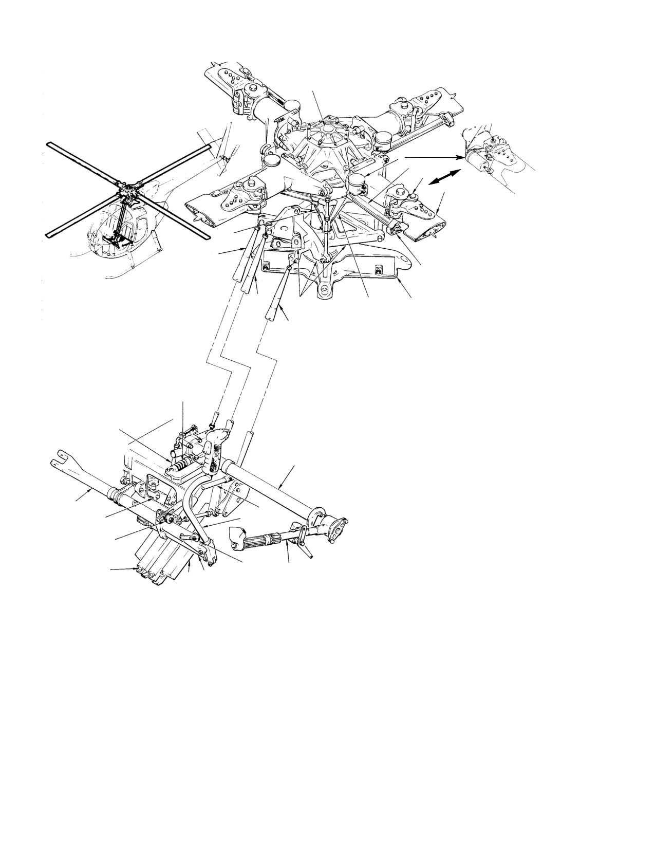
MD Helicopters, Inc.
CSP−H−2
500 Series - Basic HMI
1
2
3
4
5
13
12
6
11
9
8
7
10
26
25
14
24
16
23
17
22
18
21
15
20
19
30−030A
1. MAIN ROTOR DRIVE SHAFT (REF. SEC. 9)
14. COLLECTIVE CONTROL TORQUE TUBE
2. DAMPER
15. PILOT’S COLLECTIVE PITCH STICK
3. DAMPER ARM (LINK)
16. DROOP CONTROL OVERRIDE LINK (REF. SEC. 1)
4. BLADE ATTACH PIN (TYP)
17. PILOT’S CYCLIC STICK
5. MAIN ROTOR BLADE
18. LATERAL CYCLIC FRICTION KNOB
6. DAMPER LINK ATTACH PIN
19. CYCLIC LATERAL CONTROL ROD
7. MAIN ROTOR MAST BASE
20. LATERAL CYCLIC TRIM ACTUATOR
8. ROTATING SWASHPLATE
21. LONGITUDINAL CYCLIC TRIM ACTUATOR
9. MAIN ROTOR CONTROLS (MIXER, IDLER
22. LONGITUDINAL CYCLIC FRICTION KNOB
BELLCRANKS AND LINKS)
10. LATERAL MIXER CONTROL ROD (CYCLIC)
23. ONE-W AY LOCK (LONGITUDINAL CYCLIC CONTROL)
11. LONGITUDINAL MIXER CONTROL ROD (CYCLIC)
24. CYCLIC CONTROL TORQUE TUBE
12. COLLECTIVE MIXER CONTROL ROD
25. GAS PRODUCER CONTROL ROD (REF SEC 1)
13. STATIONARY SWASHPLATE
26. COLLECTIVE BUNGEE
Figure 7-1. Main Rotor Control System
Page 7-2
Revision 16
MD Helicopters, Inc.
CSP−H−2
500 Series - Basic HMI
Table 7-1. Troubleshooting Main Rotor Vibrations
Symptom
Probable Trouble
Corrective Action
Unusual and/or excessive
Damage to main rotor blades.
Inspect blades.
vibration: Vertical or lateral.
Damage to main rotor hub
Inspect main rotor hub and strap
components.
pack assemblies(Ref. Figure 7-20).
One per revolution lateral beat first
Damper torque is not at required
Check damper torque. Replace
encountered at high power
value.
damper if torque not within limits.
settings, in autorotation, and in
turns. This beat may also occur on
the ground during warmup or
shutdown.
Lateral beat occurs at low (idle)
Damper torque is not at require
Check damper torque. Replace
rotor rpm. When operating at
value.
damper if torque not within limits.
normal (flight) rotor rpm, lateral
beat becomes a vertical beat.
Four per revolution or medium
Main rotor dampers sticking, or low
Check damper torque. Replace
frequency beat.
range torque is not at required
damper if torque not within limits.
value.
Vibration absorber defective.
Replace vibration absorber.
Worn feathering bearings.
Replace feathering bearings.
One per revolution vertical beat.
Main rotor blades not tracked
Track main rotor blades.
Beat may appear throughout entire
correctly.
flight regime, becoming more
pronounced at higher airspeeds.
Lateral feedback (beat) in cyclic
Rotor blades out of track.
Track main rotor blades.
control stick (no longitudinal
feedback detected).
One per revolution lateral beat,
Main rotor blade tip weights not
Check tip weights for security, repair
continuous.
secure.
as necessary.
Torque setting on main rotor blade
Set torque of all four dampers to the
damper(s) too high for proper
allowable minimum torque value.
operation at low ambient
temperature.
High frequency vibrations.
Loose or defective component in
Ref. Sec. 5, 8, 9 and 10.
another system.
Page 7-3
Revision 16
MD Helicopters, Inc.
CSP−H−2
500 Series - Basic HMI
Table 7-2. Troubleshooting Controls
Symptom
Probable Trouble
Corrective Action
Cyclic control stick pressures
Improperly set cyclic trim.
Re-trim cyclic control stick.
cannot be reduced by operating
trim switch.
Trim change is too slow.
Trim actuator inoperative.
Troubleshoot cyclic trim electrical
circuit; replace defective component.
Cyclic control sticks have tendency
Low fluid in one-way lock fluid
Add fluid to one-way lock reservoir
to move to aft position.
reservoir.
as required (Ref. Sec. 2).
Inadequate cyclic control during
Helicopter loaded out of center of
Check and correct weight and
flight.
gravity range.
balance.
Excessive pressure required for
Lateral friction device improperly
Loosen lateral friction device.
lateral or longitudinal movement of
adjusted.
cyclic control stick
s on the groun
d
Swashplate spherical bearing
Replace swashplate bearing
and during flight. Some droop stop
surface damaged.
assembly if torque required to rotate
friction will always be felt when
bearing exceeds 120 inch-pounds
there is no rotor rpm.
(13.56 Nm).
Scissors crank bearings or hub
Replace defective bearings.
lower shoe bearings binding or
frozen.
Lateral interconnecting rod end
Realign rod end bearing.
bearing binding due to incorrect
alignment.
Droop stop plunger sticking.
Clean plungers and mating brushes
with isopropyl alcohol (71,
Table 2-4).
Droop stop striker plate(s) or cam
Replace striker plate and/or cam
roller(s) damaged.
roller.
Longitudinal friction devise
Loosen longitudinal friction devise.
improperly adjusted.
Binding rod end bearings in
Realign rod end bearings.
longitudinal push rods.
One-way lock check valve or push
Replace one-way lock assembly.
rod shaft that unseats the valve
galled or seized.
Swashplate spherical bearing
Replace swashplate bearing
surface damaged.
assembly if torque required to rotate
bearing exceeds 120 inch-pounds
(13.56 Nm).
Page 7-4
Revision 16
MD Helicopters, Inc.
CSP−H−2
500 Series - Basic HMI
Table 7-3. Isolating Control System Troubles
Symptom
Isolating Step
Corrective Action
Binding, locking−up and erratic
Disconnect one−way lock.
If symptom gone, replace one−way
action of cyclic control stick.
lock.
Symptom remains
Disconnect upper ends of
If symptom gone and rod ends are
longitudinal and lateral control
good, disassemble and inspect main
rods (10 and 11, Figure 7−1).
rotor mixer controls until defective
part is located.
Symptom remains.
Reconnect upper ends of
If symptom gone and rod ends are
longitudinal and lateral control
good, disassemble and inspect pilot
rods, and disconnect lower ends. compartment controls until
defective part is located.
Trouble corrected
(Reconnect all control linkage)
WARNING: Do not disconnect any hardware from the pilot’s collective stick unless collective bungee
installation tool 369A9936 is installed. Strong bungee spring pressure can cause linkage reaction and
severe personal injury, or parts damage.
Binding, locking−up, and erratic
Disconnect upper ends of
If symptom gone and rod ends are
action of collective control stick.
collective pitch control rod (12,
good, disassemble and inspect main
Figure 7−1) and operate stick.
rotor mixer controls until defective
part is located.
Symptom remains
Leave upper end of collective
Trouble is in pilot’s compartment
pitch control rod disconnected.
collective control linkage.
Symptom remains
Disconnect gas producer control
If symptom gone, trouble is in
rod (25, Figure 7−1) from
engine controls (Ref. Sec. 11).
collective stick. Disconnect droop
control override link (16) from
collective control torque tube.
Symptom remains
Leave gas producer control rod
Disassemble and inspect pilot’s
and droop control override link
compartment collective control
disconnected.
linkage until defective part is
located.
Trouble corrected
(Reconnect all control linkage)
Page 7-5
Revision 16
MD Helicopters, Inc.
CSP−H−2
500 Series - Basic HMI
3. Cyclic, Collective and Main Rotor Control
(Detail C), to the surface of mixer
Rigging
rigging plate; it should be the same as
the dimension recorded in step (6).
(Ref. Figure 7−2) Rigging of the main rotor
above.
control system must be accomplished immedi−
ately after replacement of linkage that can not
(a). If not, loosen checknut, disconnect
be accurately measured (by trammeling) before
upper end of collective control rod,
it is installed in the main rotor control system,
and adjust rod end of collective
or if helicopter operation reveals a rigging
control rod, and adjust rod end until
deficiency.
dimensions are the same.
(8).
Reconnect the control rod, remove the
NOTE: The cyclic and collective controls must
collective stick rigging fixture and
be rigged, in sequence, starting with the col−
check mixer travel.
lective. Control rod end bearing adjust−
ments are to be made to the nearest half
(9).
With stick at the down stop, the
turn that will produce correct rigging. When
centerline of the collective pitch mixer
tightening the jam nut at the adjustable end
bellcrank bolt (Detail C) should move
of control rods, always hold the rod end with
down so that the dimensions recorded
a wrench to prevent jamming of the bearing.
in step (6). above is decreased by not
less than 0.074 inches (1.8796 mm).
A. Collective Control Rigging
(10).
With stick at the up stop, the centerline
(1). Remove main rotor blades, or manually
of the collective pitch mixer bellcrank
raise the blades off their droop stops by
bolt should move up so that the dimen−
simultaneously lifting the blade tips.
sion recorded in step (6). above is
increased by not less than 0.74 inch
NOTE: All four blades must be off the stops
(1.8796 mm).
during rigging. Padded supports should be
used, if available.
(11).
Adjust rod end of collective pitch control
rod if necessary to meet the limits
(2).
Release the friction and raise pilot’s
specified in steps (8). and (10). above.
collective stick.
When adjustment is complete, tighten
checknut and make certain that length
(3).
Position collective rigging fixture (9,
of control rod is not changed.
Table 2−2) in outboard lower end of slot
in collective friction guide link (Ref.
When tightening rod end check−
Detail A).
CAUTION
nuts, ensure that rod end bear−
ings at both ends of rod are aligned between
(4).
Lower collective stick on rigging fixture
the bellcrank ears.
and tighten friction grip (drive gear).
(12). Reconnect collective pitch control rod
(5).
Position mixer rigging plate (11) on
and secure with a new cotter pin.
mast support fitting and secure firmly
by use of the two toggle clamps.
(13). Reinstall collective rigging fixture. All
mixer rigging is done with collective in
(6).
Measure the distance from horizontal
mid−position.
centerline of the mast support bracket
hingeline bolt (attaching the longitudi−
B. Cyclic Control Rigging
nal idler bellcrank and collective pitch
When timing the longitudinal
mixer bellcrank to the mast support
CAUTION
trim motor for full travel in the
bracket) to the surface of mixer rigging
following step, do not continue to hold the
plate and record actual distance (Detail
trim switch after the actuator has reached
B).
the travel limit.
(7).
Measure the distance from the horizon−
(1). Loosen longitudinal friction knob.
tal centerline the bolt that attaches the
collective pitch mixer bellcrank to the
(2). Actuate longitudinal cyclic trim for no
longitudinal pitch mixer bellcrank
load by accurately timing trim motor
Page 7-6
Revision 16
MD Helicopters, Inc.
CSP−H−2
500 Series - Basic HMI
from full aft to full forward trim.
NOTE: Make adjustment carefully as there is
Return trim to full aft; then trim
only 1/2 turn tolerance. When adjustment is
forward for one−third the travel time.
complete, tighten checknut and make cer−
tain that length of control rod does not
(3). Position cyclic stick so that longitudinal
change.
rigging fixture (12, Table 2−2) will fit in
outboard side of slot in longitudinal
(11). Reconnect control rod to longitudinal
friction guide link.
pitch idler and secure with a new cotter
pin.
(a). Bushing end of fixture butts against
forward end of the slot, and friction
(12). Reinstall longitudinal rigging fixture,
knob stud fits in fixture detent
reposition and secure mixer rigging
(Detail D).
plate, and continue with lateral rigging.
(4). Secure fixture hook in aft end of slot,
tighten knurled thumbnut to seat
(13). Loosen friction knob and actuate lateral
bushing at forward end, and tighten
cyclic trim for no load.
friction knob.
(14). Position cyclic stick so that lateral
(5). Measure the distance from the horizon−
rigging fixture (14) will fit in forward
tal centerline of bolt at aft end of
side of slot in lateral friction guide link.
longitudinal pitch mixer bellcrank
(Detail E) to the surface of mixer
(a). Bushing end of fixture butts against
rigging plate;
outboard end of slot, and friction
knob stud fits in fixture detent
(a). It should be the same as the dimen−
(Detail F).
sion recorded in step A.(6).
(15). Secure fixture hook in inboard end of
(b). If not, loosen checknut, disconnect
slot, tighten knurled thumbnut to seat
longitudinal pitch control rod, and
bushing at outboard end, and tighten
adjust rod end until dimensions are
friction knob.
the same.
(6).
Reconnect the control rod, remove the
(16). Measure the distance from the horizon−
longitudinal stick rigging fixture and
tal centerline of bolt connecting lateral
check mixer travel.
bellcrank to stationary swashplate
mixer link (Detail G) to the surface of
(7).
With stick at the forward stop, the
mixer rigging plate;
centerline of the longitudinal pitch
mixer bellcrank bolt (Detail E) should
(a). It should be the same as the dimen−
move up so that the dimension recorded
sion recorded in step A.(6).
in step A.(6). is increased by not less
than 1.12 inches (28.448 mm).
(b). If not, loosen checknut, disconnect
lateral pitch control rod, and adjust
(8).
Reposition the mixer rigging plate to
rod end until dimensions are the
clear the longitudinal pitch mixer
same.
bellcrank.
(17). Reconnect the control rod, remove the
(9).
With the stick at the aft stop, the
lateral stick rigging fixture and check
centerline of the longitudinal pitch
mixer travel.
mixer bellcrank bolt (Detail E) should
move down so that the dimension
(a). With stick at the left stop, the
recorded in step A.(6). is decreased by
centerline of the lateral bellcrank
not less than 0.60 inch (15.24 mm).
bolt (Detail G) should move down so
(10).
Adjust rod end of longitudinal pitch
that the dimension recorded in step
control rod if necessary to meet the
A.(6). is decreased by not less than
limits specified in steps A.(6). and A.(7).
0.50 inch 12.7 mm).
Page 7-7
Revision 16
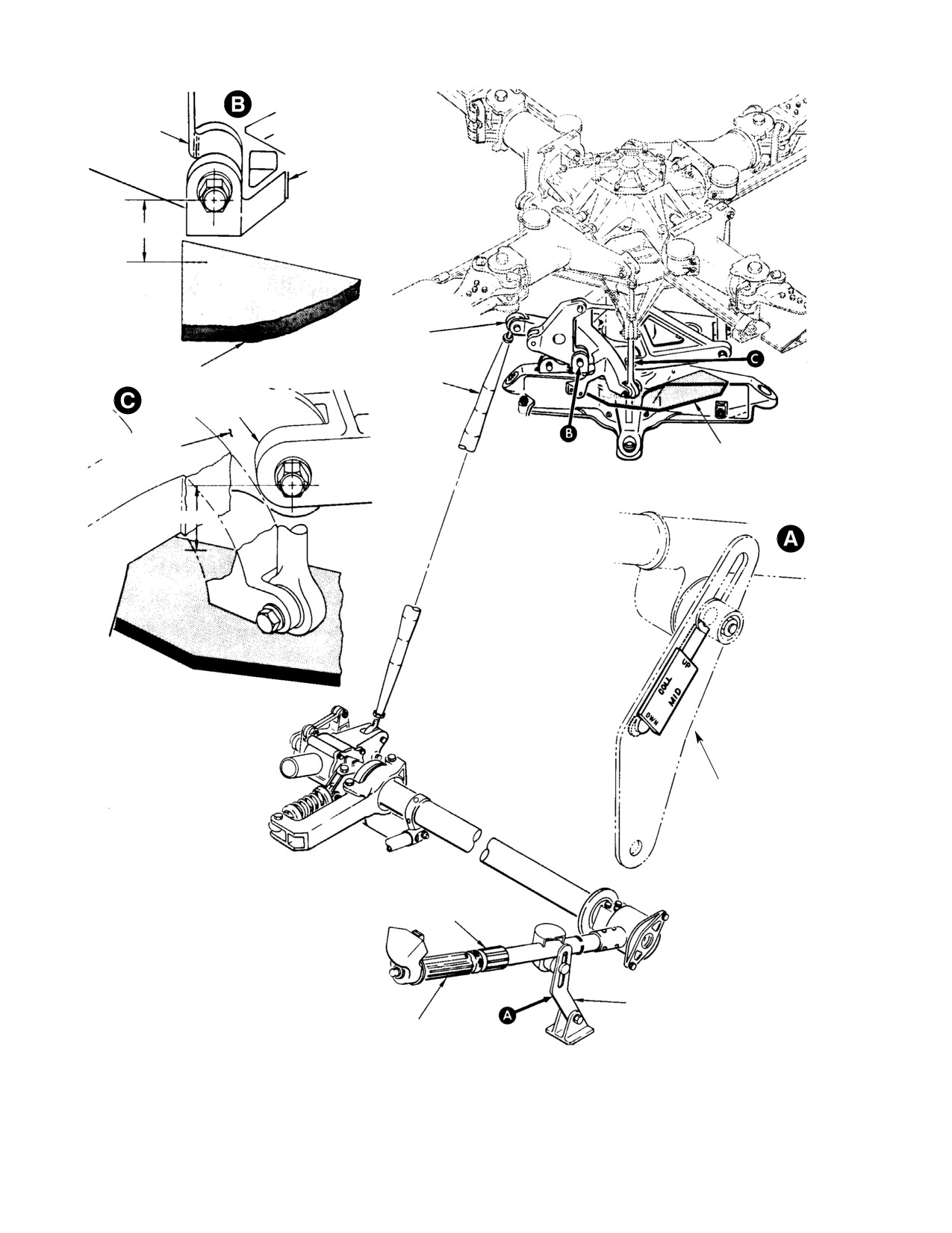
MD Helicopters, Inc.
CSP−H−2
500 Series - Basic HMI
LONGITUDINAL
PITCH IDLER
BELLCRANK
MAST SUPPORT
BRACKET
NOTE 1
BOLT (HEAD LEFT),
WASHERS, NUT,
COTTER PIN
MIXER RIGGING PLATE
COLLECTIVE PITCH
LONGITUDINAL PITCH
CONTROL ROD
MIXER BELLCRANK
COLLECTIVE PITCH
MIXER BELLCRANK
MIXER RIGGING
PLATE (369A9930)
NOTE 2
COLLECTIVE
RIGGING FIXTURE
(369A9925)
CONTROL FRICTION GRIP
(DRIVE GEAR)
COLLECTIVE FRICTION
NOTES:
GUIDE LINK
1.
MEASURE AND RECORD
PILOT’S COLLECTIVE
ACTUAL DISTANCE.
PITCH STICK
2.
SAME AS ACTUAL DISTANCE
30−031−1B
MEASURED (DETAIL B).
Figure 7-2. Rigging Main Rotor Control System (Sheet 1 of 2)
Page 7-8
Revision 16
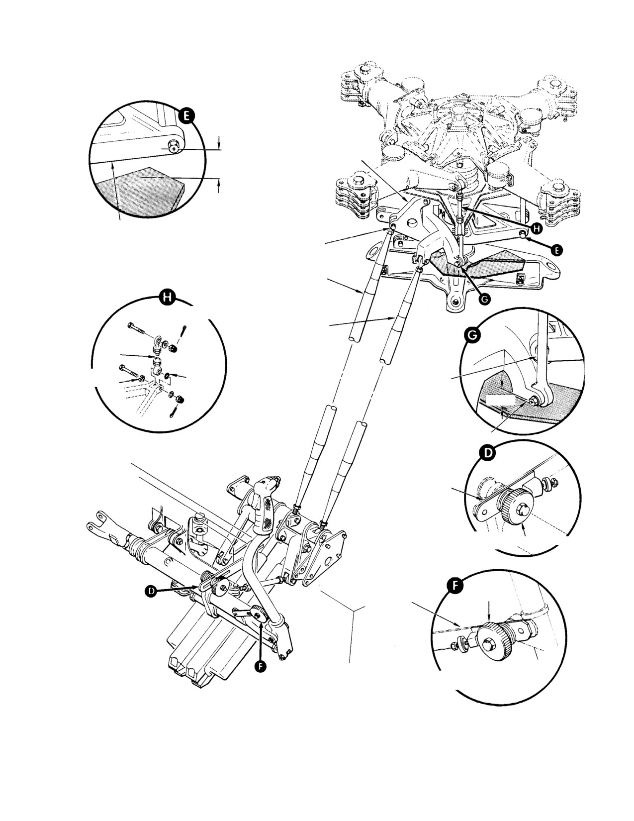
MD Helicopters, Inc.
CSP−H−2
500 Series - Basic HMI
LONGITUDINAL
PITCH IDLER
NOTE 2
LONGITUDINAL PITCH
MIXER BELLCRANK
BOLT (HEAD LEFT),
WASHERS, NUT,
COTTER PIN
LONGITUDINAL PITCH
CONTROL ROD
TYPICAL
LATERAL PITCH
CONTROL ROD
PITCH
CONTROL
ROD
SLOTTED
O−RING
STATIONARY
BUSHING
SWASHPLATE
MIXER LINK
LATERAL BELLCRANK
LONGITUDINAL
FRICTION
GUIDE LINK
CYCLIC STICK LONGITUDINAL
FRICTION KNOB
RIGGING FIXTURE (369A9929−9)
FRICTION
LATERAL FRICTION
KNOB
GUIDE LINK
CYCLIC STICK LATERAL
RIGGING FIXTURE (369A9928−9)
30−031−2A
Figure 7-2. Rigging Main Rotor Control System (Sheet 2 of 2)
Page 7-9
Revision 16
MD Helicopters, Inc.
CSP−H−2
500 Series - Basic HMI
(18). With stick at the right stop, the center−
A vibration absorber is installed on the lower
line of the lateral bellcrank bolt should
inboard end, and two balance weights are
move up so that the dimension recorded
installed in the tip end of each blade.
in step A.(6). is increased by not less
A removable forward tip cap, attached to the
than 0.43 inch (10.922 mm).
outboard end of the blade, is replaced with a
tracking cap when tracking procedures are
(19). Adjust rod end of lateral pitch control
performed.
rod, if necessary, to meet the limits
specified in steps (17). and (18). above.
The blade trailing edge tab may be bent up or
down to compensate for the differences in
(20). When adjustment is complete, tighten
diving or climbing characteristics between
checknut, and make certain that length
individual blades during forward flight.
of control rod is not changed.
5. Main Rotor Blade Tracking
(21). Reconnect control rod to lateral bell−
(Ref. Figure 7−4 thru Figure 7−5)Track of the
crank and secure with a new cotter pin.
main rotor blades is observed by means of
(22). Loosen friction control, friction knobs,
tracking tip caps temporarily attached to the
knurled thumbnuts and hooks of
tip of each blade, and a high−intensity strobe
rigging fixture and remove all three
light that flashes in synchronization with the
fixtures.
rotating blades.
The strobe light operates from electrical power
NOTE: The following step establishes initial
obtained from the helicopter electrical system.
adjustment of the main rotor pitch control
rods.
By observing the image pattern formed by the
four reflectors attached to the blade tips, it is
(23). Set each pitch control rod (Detail H)
possible to view the track of the rotating
(centerline to centerline of rod bearings)
blades.
to the applicable strap pack pitch link
Sudden onset, excessive
length specified on the tower tracking
WARNING
and/or unusual main rotor
data decal of the mating blade.
vibrations should be investigated as to
(a). Set pitch control rods to 6.60 inches
cause, prior to continued flight. Under
(16.764 cm) (between rod end bearing
no circumstances should main rotor
centerlines) for the two blades
tracking be attempted to correct the
attached to the hub upper strap pack
problem until a thorough inspection of
the main rotor blades, hub assembly
(b). Set pitch control rods to 6.35 inches
and the strap pack assembly has been
(16.129 cm) (between rod end bearing
performed.
centerlines) for the two blades
NOTE: Before attempting to track the rotor
attached to the lower strap pack.
blades, it is important to read and thorough−
(c). Install the pitch control rod.
ly understand the tracking sequence and in−
terrelationship of the various adjustments.
(24). Install main rotor blades or remove
A review of the following should prove help−
supports and simultaneously lower all
ful.
four blades to normal position.
(1). Install the tracking strobe light, blade
tip cap reflectors and related equipment
(25). Track main rotor blades and adjust
(Ref. Main Rotor Tracking Equipment
autorotation rpm.
Installation).
4. Main Rotor Blades
(2). Refer to Table 7−4 for a condensed
summary of the proper sequence for
(Ref. Figure 7−3) Each of the four main rotor
blade tracking.
blades is a balanced airfoil that consists of a
wrap−around, aluminum alloy skin bonded to
(3). Ground tracking basically involves
an extruded aluminum alloy spar, and upper
track−observation and adjustment at
and lower root fitting.
idle rpm and at flight rpm.
Page 7-10
Revision 16
MD Helicopters, Inc.
CSP−H−2
500 Series - Basic HMI
(a). Track at idle rpm is adjusted by the
manual apply (instead of any conflicting
pitch control rods connecting the
instructions in the manual).
rotating swashplate and the blades.
Install equipment as follows:
(b). Ground track at flat pitch and flight
NOTE: The helicopter is originally equipped
rpm is corrected by blade tab adjust−
with four tracking interrupters
ment.
(369A9946−23, −25, −27 and −29) installed on
NOTE: No track adjustments are made on the
the rotating swashplate, and a support
basis of track observations during hovering.
bracket (369A9943) for the magnetic pickup
installed on the stationary swashplate.
(4).
Hover track verification is essentially
(Spare swashplate assemblies are also pro−
an observation to check for track
vided with these tracking devices.) The du−
variation that might occur between
plicate set of interrupters and pickup brack−
high rpm (flat pitch) ground track check
et included in the strobe light installation
and hovering. However, track varia−
kit will not have to be used unless existing
tions should be noted and recorded for
parts are unserviceable. See Figure 7−4
reference use during the check of track
when replacement is necessary.
in forward flight.
(1). Install strobe light (369A9925) contain−
(5).
Forward flight tracking requires track
er on cargo floor, using four adjustable
observation during the following
straps for tiedown.
airspeeds and maneuvers.
(a). Straps should extend diagonally
(6).
Flight track is corrected by making
outward from container to tiedown
blade tab adjustments ONLY.
fittings attached to cargo floor.
* Flight at 0−100 knots.
(2). Remove strobe light from container and
* Forty−five degree banked turns at
pass light through opening in forward
80−100 knots.
bulkhead to observer’s seat location.
* Flight at 100−130 knots.
(3). Route all three electrical cables from
(7).
Obtaining correct autorotation rpm
container through cutout opening in
consists of checking the main rotor rpm
container and close cover.
during stabilized autorotation flight
and adjusting rpm to specified limits as
(4). Attach 24 Vdc power cord connector to
necessary.
utility power receptacle at lower left
corner of forward canted bulkhead.
(8).
The autorotation rpm check must be
accomplished to ensure that track
When maintenance work is be−
adjustments have not altered the rotor
CAUTION
ing performed near the engine
performance necessary for safe power−
air inlet, use care to prevent entry of foreign
off landings.
objects. Tape covers of cardboard or other
suitable material in place over the engine
6.
Main Rotor Tracking Equipment
inlet screen and oil cooler air inlets. Do not
Installation
remove covers until work is completed and
debris is thoroughly cleaned out of the area.
(Ref. Figure 7−4) Prepare for main rotor blade
After removing covers, verify that area
tracking by installing strobe light components
around base of mast, inlet−to−plenum, and
furnished either with the strobe light installa−
entire plenum chamber is clean.
tion kit (16, Table 2−2) or tracking analyzer
instrument kit (59).
(5). Route triggering cable through either
vent in right−side cargo door, continuing
If the tracking analyzer instrument kit is used,
up around engine air inlet.
instructions for equipment installation are
part of the Balancer and Strobex Blade
(a). Use strips of pressure−sensitive tape
Tracker Manual supplied with the kit. Any of
(32, Table 2−4) to attach cable to
the following instructions that differ with the
fuselage and air intake.
Page 7-11
Revision 16
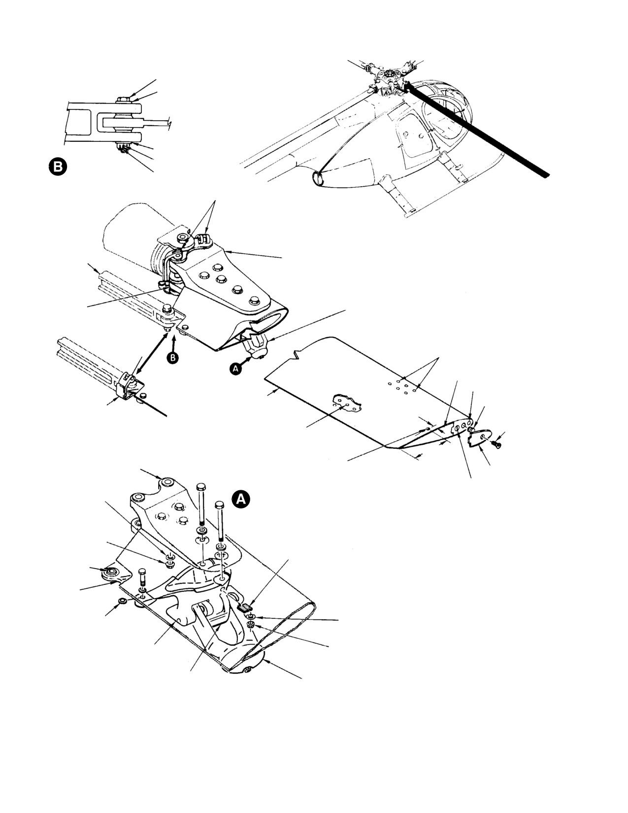
MD Helicopters, Inc.
CSP−H−2
500 Series - Basic HMI
BOLT (NAS1305−14D)
WASHER
WASHER
COTTER PIN
BOLT ATTACHED
LINK
NUT 30−60 IN. LB
(3.39−6.78 NM)
BLADE ATTACHING PINS
DAMPER
UPPER ROOT FITTING
ARM LINK
LOWER ROOT
FITTING
VIBRATION ABSORBER
SPAR AND WEIGHT
ASSY RIVETS
AFT TIP CAP
FWD BALANCE WEIGHT
BLADE TIP
THREAD INSERT
DAMPER ARM
ATTACHING PIN
0.130−0.160 IN.
SCREW
DRAIN HOLES
(3.302−4.060 MM)
15−20 IN. LB
PIN ATTACHED LINK
(NOTE 2)
(1.69−2.26 NM)
2.62 IN.
MS20604AD3C2
(66.548 MM)
BUSHING
TIP CAP RIVET
(TYP)
FWD TIP CAP
(NOTE 1)
AFT BALANCE WEIGHT
VIBRATION ABSORBER
RADIUS BLOCK
INSTALLATION
NUT 50−60 IN. LB
NOTES:
(5.65−6.78 NM)
1.
BLIND RIVET TO BE INSTALLED THRU
RUBBER PAD
EACH SIDE, ALL BLADES, IF ONE TIP
DAMPER ARM
CAP REPLACED OR REPAIRED.
BEARING
ASSEMBLY BALANCE NOT AFFECTED.
FITTING
2.
BLADE MAY HAVE EITHER TWO OR
THREE DRAIN HOLES.
SHIM WASHER(S)
RADIUS BLOCK
(AN960PD10
AND/OR 10L
NUT 50−60 IN. LB
BRACKET
(5.65−6.78 NM)
5−PER−REV
3−PER−REV
PENDULUM
PENDULUM
30−032D
Figure
7-3. Main Rotor Blade Assembly
Page 7-12
Revision 16
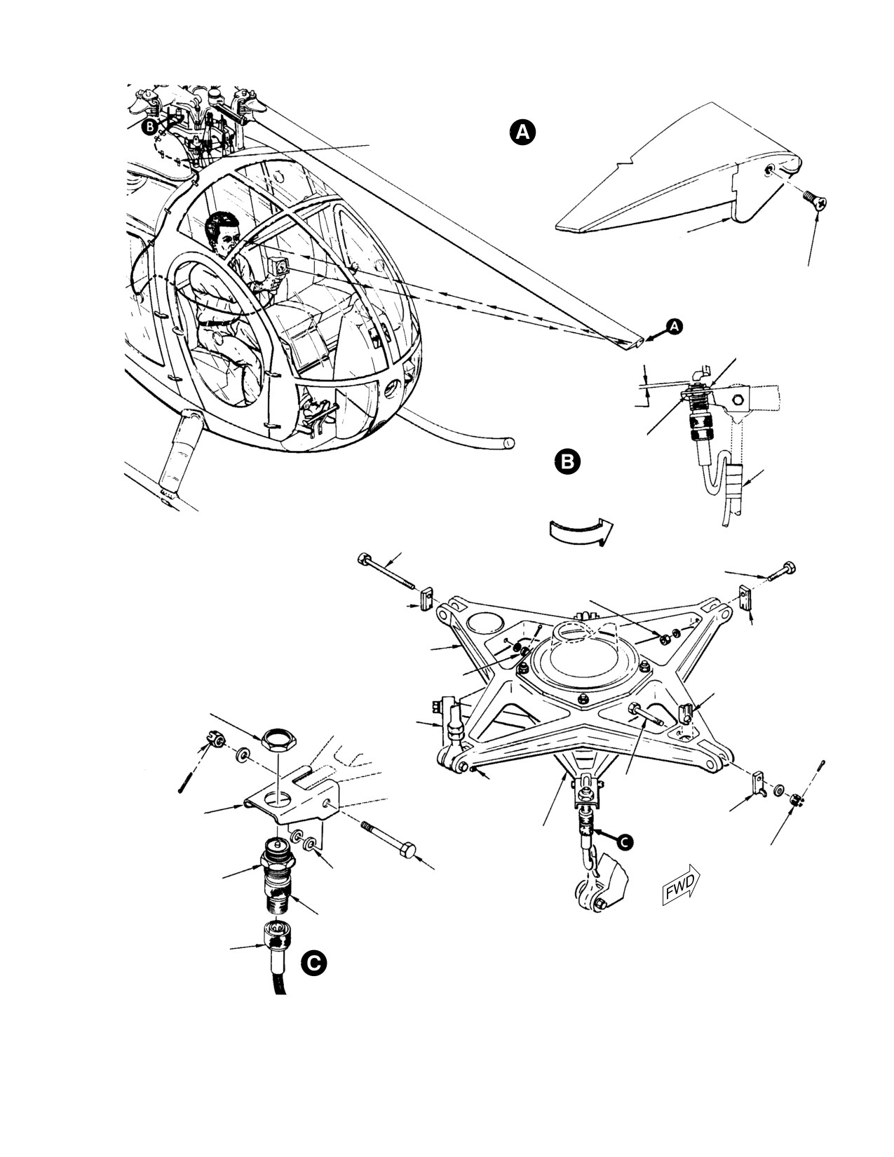
MD Helicopters, Inc.
CSP−H−2
500 Series - Basic HMI
TRACKING TIP CAP
TAPE
INSTALLATION
(16, TABLE 2−4)
TIP CAP
369A9942−( * )
(NOTES 1, 2)
SCREW 15−20 IN. LB
(1.69−2.26 NM)
NOTE 7
0.020−0.030 IN.
(0.508−0.762 MM)
NOTE 7
INTERRUPTER−TO−
TAPE
PICKUP GAP
(16, TABLE 2−4)
ROTATION
OF HUB
NOTES:
1.
MUST ALWAYS BE REMOVED AFT
BOLT NAS464P4−41
TRACKING.
(NOTES 5, 6)
2.
INSTALL IN NUMERICAL SEQUENCE
BOLT NAS464P3A7
IN DIRECTION OF HUB ROTATION.
NUT 15−20 IN. LB
(2 PLCS) (TYP)
( * INDICATES −7, −9, −11 AND −13
(1.69−2.26 NM)
OR −17, −19, −21 AND −23.)
INTERRUPTER
(2 PLCS) (TYP)
3.
AS REQUIRED BETWEEN BRACKET
369A9946−27
AND SWASHPLATE TO FILL GAP.
INTERRUPTER
4.
COLOR CODE TO MATCH BLADES
ROTATING
369A9946−23 OR−25
AND MAINTAIN SEQUENCE.
SWASHPLATE
(NOTE 4)
NUT 30−60 IN. LB
(3.39−6.78 NM)
SCISSORS LINK
ADJUSTMENT NUT
15−20 IN. LB
LONGITUDINAL
(1.69−2.26 NM)
LINK
30−60 IN. LB
(3.39−6.78 NM)
BOLT NAS464P4−26
INTERRUPTER
(NOTE 5)
369A9946−25 OR−23
INTERRUPTER
BRACKET
(NOTE 4)
369A9946−29
369A9943
STATIONARY
SWASHPLATE
NUT 30−60 IN. LB
(3.39−6.78 NM)
SHIM WASHERS
BOLT NAS464P4−20
NUT
(NOTE 3)
(NOTE 5)
MAGNETIC PICKUP
369A9944 (NOTE 1)
NOTES: (CONT)
5.
REPLACES BOLT ON HUB WITHOUT PERMANENTLY
STROBE LIGHT CABLE
PICKUP
INSTALLED INTERRUPTERS.
(NOTE 1)
INSTALLATION
6.
COAT WITH GREASE (26, TABLE 2−4).
7.
ADJUST AS NECESSARY FOR GAP INDICATED; THEN
TORQUE UPPER NUT (DETAIL C).
30−033D
Figure
7-4. Installation of Main Rotor Blade Tracking Strobe
Page 7-13
Revision 16
MD Helicopters, Inc.
CSP−H−2
500 Series - Basic HMI
Table 7-4. Summary Procedure for Blade Tracking
NOTE: The 0.50 inch (12.7 mm) diameter tracking tip cap reflector size should be used as a guide for estimating
track accuracy. For example: a reflector image displaced a half diameter upward or downward indicates that
the corresponding blade tip is approximately 0.250 inch (6.35 mm) out of track; one full reflector diameter
indicates 0.50 inch (12.7 mm) out of track.
Observed ground track
Adjust pitch control rods and/or blade tabs as required
Satisfactory
Unsatisfactory
and repeat track observation.
Perform hover verification
Record track verification and proceed with forward flight
Satisfactory
Unsatisfactory
tracking.
Perform forward flight tracking
Satisfactory
Unsatisfactory
Adjust blade tabs and repeat forward flight tracking.
Perform autorotational rpm check
Satisfactory
Unsatisfactory
Adjust autorotation rpm and repeat rpm check.
Remove tracking equipment and return helicopter to service.
(6). Install magnetic pickup (369A9944) in
369A9926−5). Torque attaching screws
bracket on stationary swashplate.
to 15 − 20 inch−pounds (1.69 − 2.26
Nm). Do not to over−tighten screws.
NOTE: Do not tighten top nut securing pickup
at this time.
(10). To operate strobe, turn ON the UTIL−
ITY switch/circuit breaker. Refer to
strobe manufacturer’s instructions for
(7). Plug triggering cable into pickup and
strobe operation and other additional
secure cable so that it will not interfere
information on the strobe equipment.
with extreme control movements.
Rotor must be turning to trigger the
lamp.
(8). Adjust gap between interrupters and
pickup to 0.020−0.030 inch (0.508−0.762
NOTE: Strobe light operation can be checked
mm) and torque top nut securing
with no signal input (rotor not turning) by
pickup to 15 − 20 inch−pounds (1.69 −
actuating the lamp trigger several times.
2.26 Nm).
This action will flash the light. Do not de−
press lamp trigger for prolonged periods
Gap must not be less than 0.020
when rotor is not turning; to do so may dam−
CAUTION
inch (0.508 mm). Swashplate
age lamp circuitry. The tracking strobe light
must be rotated to check the clearance be−
unit is a Model 135M (or 135M−( )) Point
tween each interrupter and the pickup. Do
Source Strobex Rotor Blade Tracker man−
not use over 20 inch−pounds (2.26 Nm)
ufactured by Chadwick−Helmuth Co., Inc.
torque in tightening nut on pickup.
7. Main Rotor Blade Track Adjustment
(9). Remove existing forward tip caps from
tips of rotor blades and install reflector−
equipped tip caps starting with cap
(Ref. Figure 7−6 and Figure 7−5) Although
369A9942−17, followed by caps −19, −21
adjustment of pitch control rods will affect
and −23 in dash number order and in
blade track at all rotor speeds, they should be
direction of hub rotation. (Early type
adjusted only when necessary to establish
caps 369A9942−7, −9, −11 and −13,
acceptable track at ground idle speed; the
without retainers over reflectors, are
blade tabs are used for all other track correc−
furnished with tracking equipment
tions.
Page 7-14
Revision 16
MD Helicopters, Inc.
CSP−H−2
500 Series - Basic HMI
NOTE:
(2). Different zones of the tabs are used to
D If pitch control rods are badly out of ad−
adjust blade track at different air−
justment, or if the rod end bearings have
speeds.
been replaced, set the length of the af−
(a). Tab Zone A is used for high−rpm, flat
fected pitch control rod(s) (as measured
pitch ground tracking (103% N2).
between the rod end bearing centerline)
to the applicable strap pack pitch link
(b). Zones C, D, and E are used for
length specified on the tower tracking
tracking at the higher airspeeds.
data decal of the mating blade. Observe
the ground track before adjusting control
(c). Zone B is used to supplement Zone A
rods.
track correction when maximum tab
D Blade tab and/or track can make the col−
(5 degrees) has been applied to Zone
lective heavy or light.
A; Zone B may also be used, if
A. Pitch Control Rod Adjustment
necessary, for correction in the 0 to
100 knot airspeed range.
Repeat this adjustment procedure as necessary
to establish ground idle track.
Restrict bending to very small
CAUTION
increments so that the bonded
(1). Remove lockwire from both ends of
trailing edge joint between the upper and
pitch control rod and loosen the rod end
lower skins will not be damaged. All tabs
jam nuts.
must never be displaced more than 5 de−
NOTE: The upper jam nut and rod end have
grees above or below the normal position
left−hand threads.
(parallel to the chordline).
(a). To lower a blade tip, shorten the
NOTE: Tab zones on same blade can require
pitch control rod assembly by turning
bending in opposite directions. For example,
the rod in a counterclockwise direc−
after bending tab zone C downward to get
tion as viewed from below.
good tracking at 60 to 90 knots, it might be−
come necessary to bend tab zone E upward
(b). To raise a blade tip, lengthen the
to correct track at redline airspeed. In any
pitch control rod assembly by turning
case, do not use larger tab corrections than
in a clockwise direction.
are actually necessary.
(c). One−sixth of a turn of the rod (one
(3). To lower the blade tip that tends to
flat) will raise or lower the blade tip
climb during ground tracking at high
approximately 0.250 inch (6.35 mm).
rpm or during forward flight, bend the
appropriate tab section slightly down−
After adjusting pitch control
ward.
CAUTION
rods, check that the rod end
threads are engaged far enough to block the
(4). To raise the tip of a blade that tends to
rod body inspection (witness) hole. Center
descend, bend the tab slightly upward.
each rod end or fitting wear will result.
(5). If only slight track correction is neces−
Make sure there is no binding in the full up
sary, limit tab bending to the width of
travel position.
the bending tool.
(2). After adjusting the pitch control rod
(6). If more correction is necessary, bend a
length, center each rod end in its fitting
slightly wider section of the tab.
and hold while tightening the jam nuts.
Safety with lockwire.
NOTE: Avoid excessive re−bending of tabs by
B. Blade Tab Adjustment
using small adjustments until the necessary
(Ref. Figure 7−5)
result is obtained.
(1). Once ground idle track is obtained, all
(7). Each time blade tabs are adjusted,
remaining tracking correction is
recheck ground idle track and readjust
accomplished by VERY SLIGHT
if necessary.
bending of the various blade tab zones
with tab bending tool (17 or 18,
(8). After completion of forward flight
Table 2−2).
tracking, and check autorotation rpm.
Page 7-15
Revision 19
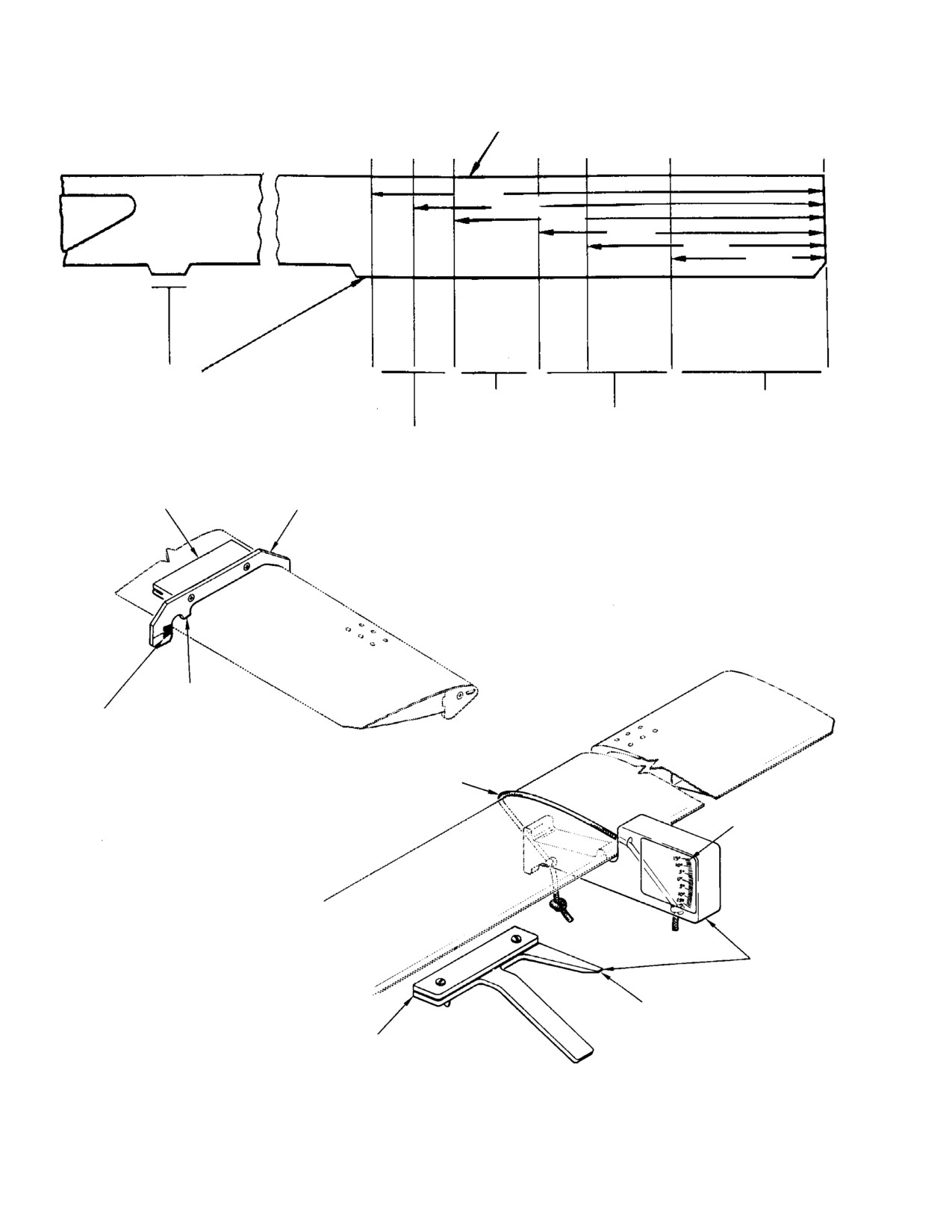
MD Helicopters, Inc.
CSP−H−2
500 Series - Basic HMI
MAIN ROTOR BLADE (TOP VIEW)
BLADE STATIONS:
93
99
105
117
124
136
158
65 IN.
(165 MC)
59 IN.
(150 CM)
53 IN.
(135 CM)
41 IN.
(104 CM)
34 IN.
(86 CM)
22 IN.
(55 CM)
TAB ZONES:
E
D
C
B
A
* NOT USED
MEDIUM SPEED
* NOT USED
UNUSED TAB ZONES MUST BE
FLIGHT TRACKING
HIGH RPM
MAINTAINED STRAIGHT, NEUTRAL
(0−100 KNOTS,
HIGH SPEED
GROUND
AND PARALLEL.
103% N2)
FLIGHT TRACKING
TRACKING
(100−120 KNOTS,
(103% N2 )
103% N2)
BENDING BLOCK
PROTRACTOR
TAB BENDING TOOL
(369A9958)
EACH MARKING
= 2° 30’
SHOCK CORD
(OR EQUIV)
EACH MARK 1°
TAB BENDING
TOOL (369H9928)
POINTER
TAB BENDING ASSY
30−035C
Figure 7-5. Main Rotor Blade Tab Adjustment
Page 7-16
Revision 16
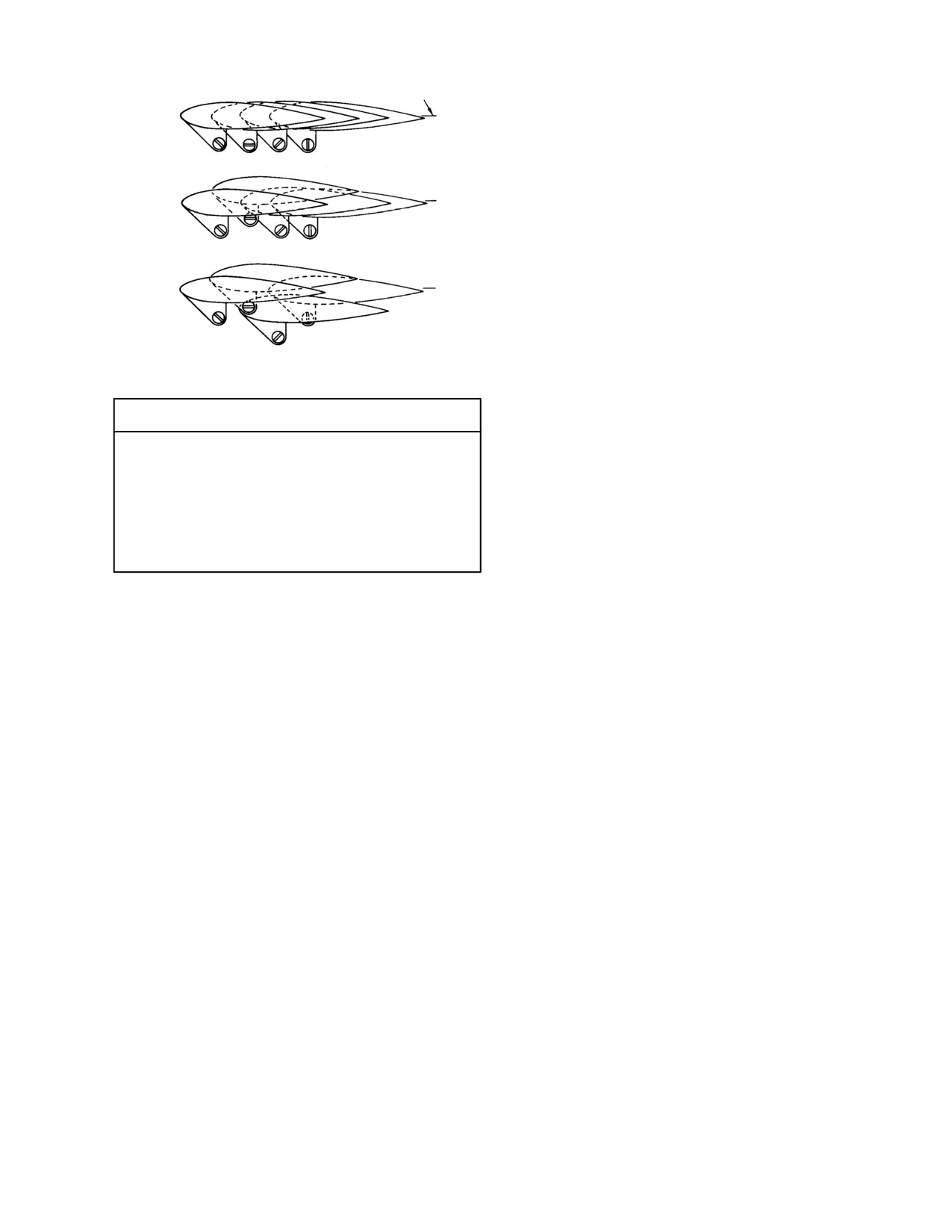
MD Helicopters, Inc.
CSP−H−2
500 Series - Basic HMI
TIP PATH PLANE
(1). Before tracking blades that are NOT
new, check that normally straight (not
to be used) tab areas (Ref. Figure 7−5)
are in neutral position (centered on
IMAGE A: ALL BLADES IN TRACK
chordline) and straight.
NOTE: On NEW (untracked) blades, check that
all tab areas are straight and in neutral po−
sition (centered on chordline 0° ±5°).
IMAGE B: ONE BLADE APPROX. 0.50 IN. (12.7 MM) HIGH
(2). Load helicopter to a gross weight of
approximately 1900−2250 pounds
(862−1021 kg).
(3). With collective pitch stick full down,
operate engine for a brief period at
IMAGE C: ONE BLADE APPROX. 0.50 IN. (12.7 MM) HIGH;
ONE BLADE APPROX. 1 IN. (25.4 MM) LOW
103% N2 and then reduce rpm to the
ground−idle (approximately 62% N1);
CORRECTIVE ACTION
this will ensure that the blade dampers
HIGH RPM AND
CONDITION
GROUND IDLE RPM
FWD FLIGHT
are correctly positioned.
IMAGE A NONE REQUIRED
NONE REQUIRED
(4). Observe tracking tip cap reflector image
IMAGE B SHORTEN PITCH CONTROL MOVE TAB DOWNWARD
by directing strobe light beam toward
ROD (2ND BLADE)
(2ND BLADE)
blade tip path and sweeping beam
slowly back and forth until reflector
IMAGE C SHORTEN PITCH CONTROL MOVE TAB DOWNWARD
images are clearly seen.
ROD (2ND BLADE);
(2ND BLADE); MOVE
LENGTH CONTROL
TAB UPWARD (3RD
(a). The tracking image should appear
ROD (3RD BLADE)
BLADE)
directly in front of helicopter or
30−034A
slightly off helicopter centerline.
Figure 7-6. Typical Tracking Conditions and
(5). If blades are in track, tip cap reflector
Adjustments
image pattern should resemble image
A, (Ref. Figure 7−6) (none of the blade
C. Main Rotor Blade Ground Tracking
tip more than 1/4 of one tracking
(Ref. Figure 7−6 and Figure 7−5) For best
reflector diameter, 0.125 inch(3.175
results, tracking should be performed under
mm) above or below adjacent reflec−
calm air conditions. Wind velocity should not
tors).
exceed 6 knots during preliminary adjust−
(a). If blades are in track, proceed with
ments or 3 knots for final adjustment.
step (6). below.
Accurate adjustment of initial ground track is
(b). If blades are out of track, adjust pitch
very important. In most instances, forward
control rods and repeat step (3).
flight tracking problems can be avoided or
above.
greatly reduced by setting initial track as
(6). With collective pitch stick full down,
nearly perfect as possible.
increase engine speed to 103% N2 and
observe tip cap reflector image to see if
Tolerances specified in following instructions
blade track is changed from ground idle
should be considered maximum permissible
track.
deviation rather than desired goal.
(a). When all four blades are in track
NOTE: If a replacement main rotor hub has
within 1/4 of one reflector diameter,
been installed, or if a replacement pitch con−
0.125 inch(3.175 mm), ground track
trol rod assembly or rod end bearing has
is good; proceed with hover verifica−
been installed, set the length of each pitch
tion.
control rod assembly to the applicable strap
pack pitch link length specified on the tower
(b). When a blade is out of track, adjust
tracking data decal of the mating blade be−
blade tab zone A until high rpm
fore proceeding with ground tracking
ground track is within tolerance.
Page 7-17
Revision 16
MD Helicopters, Inc.
CSP−H−2
500 Series - Basic HMI
D. Hover Track Verification
(3). Check autorotation rpm; rpm must not
be less than 450.
(Ref. Figure 7−6 and Figure 7−5) Hover track
Do not attempt to adjust chord−
verification must be performed after ground
CAUTION
wise balance of a blade found to
tracking and before forward flight tracking.
be faulty when performing banked turns
Verification is only a CHECK of hover track.
((4). below). Chordwise balance corrections
DO NOT adjust pitch control rods or blade
must be accomplished by manufacturer
tabs because of track images observed during
(MDHI).
hovering.
(4). Perform a series of 45 degree banked
Tab adjustments often cause variation between
turns 80−100 knots and observe track
ground track and hovering track.
change from level flight. If any blade
climbs or dives more than one inch out
A large track variation may indicate that one
of track with others, chordwise balance
or more blades is beyond its chordwise balance
(center of gravity) of that blade is
tolerance, but this can only be determined
beyond its tolerance and blade must be
during forward flight tracking.
replaced. (Hover track variations of this
type that do not repeat during banked−
NOTE: Collective pitch stick may be ‘‘heavy" af−
turn maneuver may be disregarded.)
ter tracking reflectors are mounted on blade
tips. This condition is not unusual and may
(5). Perform flight tracking at 100−130
be disregarded.
knots at 103% N2. If necessary, adjust
tab zone D (five degrees maximum) to
(1). Verify helicopter gross weight,
limit track variation to 0.50 inch (12.7
1900−2200 pounds (862−998 kg).
mm) or less and to minimize excessive
vertical (one−per revolution) vibration.
(2). With collective pitch stick full down,
If variation is excessive, bend tab zone
increase N2 to 103 percent.
E (five degrees maximum).
(3). Observe tracking reflector images to
NOTE: When determining whether blade track
verify that ground track is within
is acceptable, overall vibration level of heli−
limits.
copter should be determining factor. Some
combinations of rotor blades might produce
(4). With helicopter in a stable hover,
higher four− per− revolution vibration as
observe reflector images.
blade tips are brought into close track; in
such cases, lowest vibration level is pre−
(a). If one or more blades are out of track,
ferred, even though observed blade track
record condition(s) for reference
may be beyond specified tolerances.
during forward flight tracking.
(6). After flight tracking is completed,
(5). Proceed with forward flight tracking.
perform a autorotation rpm check.
E. Forward Flight Tracking
F. Autorotation RPM Check
(Ref. Figure 7−6 and Figure 7−5) Forward
(Ref. Table 7−5) An autorotation rpm check is
flight tracking should be performed whenever
required after each blade tracking operation
vertical flight vibrations indicate that blades
and whenever rpm is outside limits. Check
may be out of track.
rotor rpm and make adjustments as follows:
Main rotor blade (targets− cap/
(1). Verify helicopter gross weight,
CAUTION
plates) reduce blade to tailboom
1900−2200 pounds (862−998 kg).
clearance. Performing autorotations to−
(2). Perform flight tracking from hover up
the−ground could result in tailboom strikes.
to 100 knots at 103% N2. If flight track
(1). Load helicopter to a gross weight of
varies from hover track more than 0.50
1900−2200 pounds (862−998 kg).
inch (12.7 mm), bend tab zone C (five
degrees maximum) to limit variation to
(2). Perform a practice autorotative descent
tab zone B (five degrees maximum).
according to the Owner’s Manual,
Page 7-18
Revision 16
MD Helicopters, Inc.
CSP−H−2
500 Series - Basic HMI
taking care not to allow rpm to exceed
control interference as described in
the rotor speed limitations.
steps (4). and (5). below.
(3). During autorotative descent, take
careful note of the stabilized autorota−
(4). Check for interference between the
tive rpm at one of the gross weight/
lateral bellcrank and longitudinal pitch
density altitude combinations given.
idler (Ref. Figure 7−2, Details B and G)
of the mixer control by positioning the
(4). After landing, compare observed rpm
collective stick full up and the cyclic
with the values given in Table 7−5.
stick at the aft stop.
(a). If observed rpm is within the limits
(a). If interference exists, lengthen the
given in the table, rpm setting is
collective pitch mixer control rod
correct.
enough to eliminate the interference;
then lengthen the four blade pitch
(b). If limits were exceeded, make correc−
link control rods (Detail H) equally
tions adjustments until rpm falls
the same amount.
within limits.
NOTE: When the rotor track autorotation rpm
(5). Check for interference between the
adjustment have been satisfactorily accom−
rotating swashplate and longitudinal
plished, remove tracking equipment before
pitch idler of the mixer controls by
returning helicopter to service. Take care to
positioning the collective stick on the
properly tighten and safety all bolts after
downstop and the cyclic stick full
they have reinstalled.
forward and full left.
G. Autorotation Rpm Adjustment
(a). If less than 0.150 inch (3.81 mm)
(Ref. Table 7−5)
clearance exists, shorten the collec−
tive pitch mixer control rod enough to
NOTE: RPM adjustments in excess of 25 RPM
establish clearance, 0.250 inch (6.35
should be accomplished by adjusting the
mm) preferred; then shorten the four
four pitch control links.
blade pitch link control rods equally
by the same amount.
(1). Hold the lower end of the collective
mixer control rod with a wrench to
restrain it against rotation and loosen
(6). After accomplishing checks and
the upper rod end jam nut.
adjustments in steps (4). and (5). above,
install nut, washer and new cotter pin.
(2). Remove bolt that attaches upper control
Tighten the rod assembly jam nut while
rod end to bellcrank and shorten rod by
holding rod end centered in the bell−
turning rod end clockwise (as viewed
crank fitting.
from above) to decrease rotor rpm or
counter clockwise to increase rotor rpm.
Each 1/2 turn of rod end will change
(7). If more adjustment is needed, change
rotor speed by approximately 6 rpm.
the length of all four pitch link control
rods as necessary to obtain additional
After adjusting collective pitch
autorotation rpm.
CAUTION
control rod, check to make sure
that all threads of the rod are engaged far
enough to block the rod body inspection (wit−
NOTE: Lengthen or shorten all four rods exact−
ness) hole.
ly the same or blade track will be changed.
One flat (1/6 turn) of the control rod body
(3). After adjusting collective mixer control
will cause approximately 8 rpm change in
rod length, install bolt and check for
autorotation rpm.
Page 7-19
Revision 16
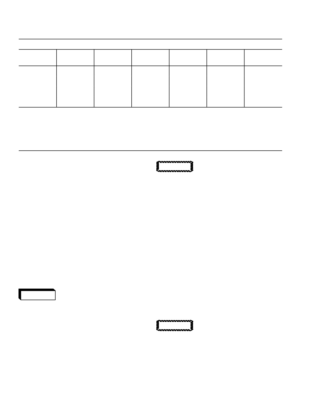
MD Helicopters, Inc.
CSP−H−2
500 Series - Basic HMI
Table 7-5. Autorotation RPM Chart
Stabilized Autorotation RPM at Density Chart
Gross Wt
1000 Ft
2000 Ft
3000 Ft
4000 Ft
5000 Ft
lb / kg
Sea Level
(305 M)
(610 M)
(915 M)
(1220 M)
(1525 M)
1900 / 862
447-457
454-464
461-471
468-478
475-486
482-492
2000 / 907
459-469
466-476
473-483
480-490
487-497
494-504
2100 / 953
471-481
478-488
485-495
492-502
499-509
---
2200 / 998
483-493
490-500
497-507
504-514
---
---
NOTE:
(1) Chart values based upon 15°C (59°F) OAT. At sea level, 8°C (14°F) temperature change is equal to
1000 ft.. (305 M) of change in density altitude.
(2) Perform autorotation rpm checks at gross weight/density altitude combinations for which rpm values are
given. Blank spaces indicate that application of collective pitch may be necessary to avoid rotor
overspeed.
8. Main Rotor Balancing
The maximum allowable bal−
CAUTION
ance weight per pitch case hous−
ing on the main rotor hub assembly is 150
(Ref. Figure 7−7) Analysis of main rotor
grams.
balance is accomplished using instrumentation
that measures and localizes vibrations due to
B. Procedural Instruction
main rotor imbalance.
The Tracking and Balancing Manual for
Data provided by the instrumentation is
Helicopter Main Rotor and Tail Rotor Track
plotted on a chart designed to indicate how
and Balance is a part of the balancing equip−
much weight shall be added to or subtracted
ment (59, Table 2−2) and shall be used for
from thin bolts installed through the hollow
equipment installation and balancing proce−
lead−lag bolts.
dure, except that any following instructions
that differ apply (instead of any conflicting
instruction in the Tracking and Balancing
No other means of balancing is to be used.
Manual).
Do not attempt the balancing procedure
C. Balance Equipment Installation
without first tracking the blades.
Complying with instructions in the Chadwick−
Never add weight to, sub−
Helmuth Balancer and Strobex Blade Tracker
WARNING
tract weight from, nor redis−
Manual to install that portion of the balancing
tribute weight on the main rotor
kit (59, Table 2−2) needed to balance the main
blades.
rotor.
When working near engine air
A. Balancing Equipment and Balance Spare
CAUTION
inlet, comply with precautions
Kit
to prevent entry of foreign material. During
main rotor balancing the helicopter is air−
The balancing equipment (59, Table 2−2)
borne. Carefully observe precautions in the
contains all equipment needed to analyze main
Tracking and Balancing Manual relating to
rotor balance. The balance spare kit (60)
the placement and security of equipment
contains quantities of the balancing hardware
(especially cables) fastened to the exterior of
listed in Table 7−6.
the helicopter.
Page 7-20
Revision 16
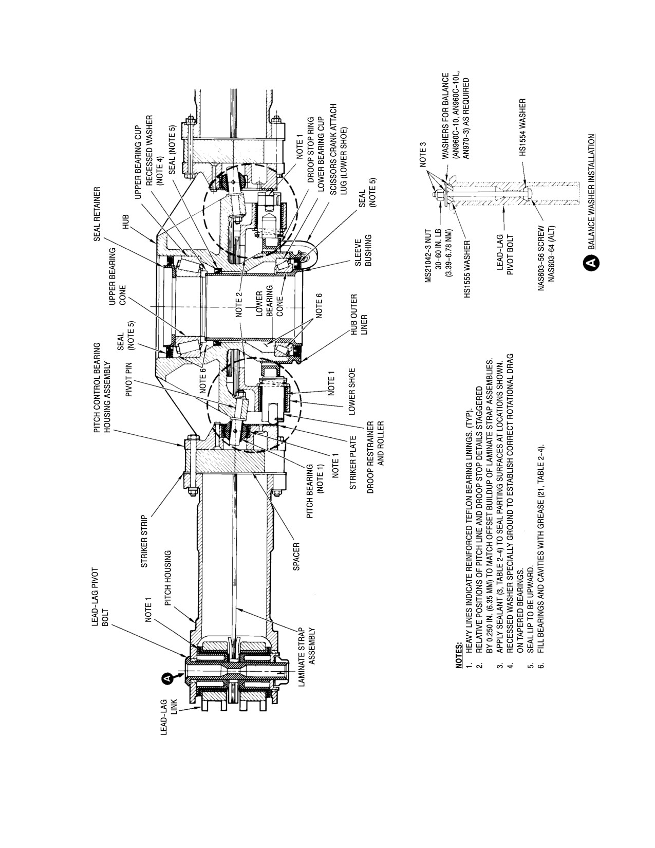
MD Helicopters, Inc.
CSP−H−2
500 Series - Basic HMI
30−039A
Figure 7-7. Main Rotor Hub - Cross Section
Page 7-21
Revision 16
MD Helicopters, Inc.
CSP−H−2
500 Series - Basic HMI
D. Balancing Procedure
etc). Detach damper arm link from
blade by removing cotter pin, nut, two
Balance the main rotor according to instruc−
washers and bolt. Or, if damper link
tions in the Tracking and Balancing Manual.
attaching pin is used, unlock and
remove pin. Remove the two blade
Since vibration reduction by weight adjust−
fitting attaching pins.
ment depends on mechanical condition and
functioning of the main rotor and the main
(3). Using masking tape and/or grease
rotor drive system, the troubleshooting
pencil, mark each blade and its respec−
information (Ref. Main Rotor and Control
tive pitch housing links so that blades
System Troubleshooting and Troubleshooting
can be reinstalled in same relative
the Power Train System) should be used in
positions.
conjunction with balancing kit instructions.
B. Main Rotor Blade Installation
Acceptance criteria for balance and vibration
(1). Position main rotor blade in its
are contained in the balancing kit (59,
(marked) pitch housing links. Install
Table 2−2) and on each balancing chart. The
blade attaching pins.
charts are components of the balancing
equipment.
NOTE:
D If new blade is to be installed, or if blades
Figure 7−7 shows how balancing hardware is
are not reinstalled in same positions from
installed and sealed at the lead−lag bolts.
which removed or are installed on new ro−
tor hub, blade attach pins must be ad−
Table 7−6 lists approved balancing hardware
justed. It is also necessary to track blades.
and gives the weight of each item.
D Check that cutout (scalloped) area on in−
The balancing charts indicate an option of
board end of damper arm link is installed
adding or subtracting weight. Keep overall
towards the damper (Ref. Figure 7−16). If
weight at a minimum always removing when
incorrectly installed interference between
possible.
the arm and damper can occur.
Table 7-6. Main Rotor Balancing Hardware
(2). Align damper arm link with fitting on
main rotor blade; install damper attach
Hardware
Unit Weight (Grams)
pin or bolt to attach link to blade.
NAS603-56 Screw
11.10
NOTE: Standard hardware may be used to re−
NAS603-64 Screw
12.25
place damper attach pins. If used, install at
all four locations, torque nuts to 30 − 60
MS21042-3 Nut
1.90
inch−pounds (3.39 − 6.78 Nm) and safety
AN960C10 Washer
0.63
with cotter pin.
AN960C10L Washer
0.32
(3). Lock all attaching pins.
AN970-3 Washer
4.33
(4). Remove blade−to−pitch housing link
HS1554 Washer
1.00
match−markings.
HS1555 Washer
2.80
10. Main Rotor Blade Inspection
9. Main Rotor Blade Replacement
(Ref. Figure 7−8 and Figure 7−9)
NOTE: MDHI Notice HN−8 requires additional
(Ref. Figure 7−3)
inspections of a limited number of main ro−
A. Main Rotor Blade Removal
tor blades with specific serial numbers.
These blades must be inspected for the pos−
(1). Relieve load on blade attachment points
sibility of unsatisfactory bonding of root fit−
by supporting main rotor blade from
ting doublers which can impose a reduction
below.
in service life.
(2). Identify blade attaching hardware and
(1). Inspect skin for evidence of cracks and
pins for location (grease pencil, tape,
holes.
Page 7-22
Revision 16
MD Helicopters, Inc.
CSP−H−2
500 Series - Basic HMI
(a). Cracks or holes in blade skin surface,
mm) removal of skin surface are
regardless of location, are cause for
permissible.
rejection of the blade. Scratches,
AREA 4: Scratches to 0.003 inch (0.076
dents, nicks and other surface defects
mm) deep if oriented 0 to 30 degrees
in the blade skin are limited accord−
and to 0.003 inch (0.076 mm) deep if
ing to steps (2). and (3). below.
oriented between 30 and 90 degrees
(b). Use a suitable dial indicator to check
from span−line must be removed. No
depth of blade dents and scratches.
sharp nicks or gouges requiring more
than 0.003 inch (0.076 mm) removal of
The repairable limit dimensions
skin surface are permissible.
CAUTION
presented in the following pro−
AREA 5: Scratches exceeding a depth of
cedure apply to surfaces that have not been
0.001 inch (0.025 mm) are cause for
repaired before. Be sure that material has
rejection. Remove scratches to a depth
not been removed from damaged areas be−
of 0.001 inch (0.025 mm). The area
fore determining that the damage depth has
inside of the outboard two root fitting
not been exceeded. Refer all questionable
bolt holes (includes both upper and
surface damage, not covered by the follow−
lower surfaces) and including the skin
ing information, to MDHI as outlined in Sec−
surface adjacent to these bolt holes
tion 2.
within a radius of l.00 inch (25.4 mm)
(2).
Limitations for surface scratches, nicks,
from each hole must be free of
gouges and erosion in seven areas of
scratches, nicks, or gouges as would be
the blade skin are described below.
detected under 5X magnification
Scratches that do not penetrate the clad
(minimum).
surface are acceptable without rework
AREA 6: Scratches to 0.005 inch deep
in all areas except areas 5 and 8.
and oriented 0 to 15 degrees from
AREA l: Minor scratches, nicks and
spanline are acceptable without repair.
gouges without skin penetrations are
Scratches to 0.005 inch (0.127 mm)
acceptable without repair. Skin defor−
deep and oriented from 15 to 30 degrees
mation with holes is cause for replace−
from spanline must be removed.
ment. Blade leading edge erosion may
Scratches 0.003 inch (0.076 mm) deep
be repaired (Ref. Main Rotor Blade
and oriented from 15 to 30 degrees from
Repair) if the skin is not eroded
spanwise are acceptable without repair.
through. If the leading edge skin is
Scratches to 0.003 inch (0.076 mm)
eroded through, no matter how slightly,
deep and oriented from 30 to 90 degrees
the blade must be immediately re−
from spanline must be repaired. Nicks
placed.
and gouges not exceeding 0.005 inch
(0.127 mm) depth must be repaired. All
AREA 2: Scratches to 0.005 inch (0.127
gouges, nicks, scratches and cracks on
mm) deep if oriented 0 to 30 degrees
trailing edge not exceeding 0.030 inch
from spanline and to 0.003 inch (0.076
(7.62 mm) depth must be smoothed and
mm) deep if oriented between 30 and 90
radiused out over 0.120 inch (3.048
degrees from spanline are acceptable
mm) area on each side of damage.
without repair. Nicks and gouges not
Defects beyond 0.030 inch (7.62 mm)
exceeding 0.003 inch (0.076 mm) in
depth are cause for rejection.
depth are acceptable without repair and
AREA 7: Scratches, nicks, or gouges up
to 0.005 inch (0.127 mm) with repair.
to 0.005 inch (0.127 mm) deep and
AREA 3: Scratches to 0.005 inch (0.127
detectable with 5X magnification are
mm) deep if oriented 0 to 30 degrees
not acceptable without repair. Defects
from spanline and to 0.003 inch (0.076
beyond 0.005 inch (0.127 mm) depth are
mm) deep if oriented between 30 and 40
cause for rejection. Gouges, nicks,
degrees from spanline must be re−
scratches and cracks not exceeding
moved. No sharp nicks or gouges
0.250 inch (6.35 mm) depth on trailing
requiring more than 0.005 inch (0.127
edge, except for AREA 8, must be
Page 7-23
Revision 16
MD Helicopters, Inc.
CSP−H−2
500 Series - Basic HMI
smoothed and radiused out to 0.250
AREA G: No repairs permitted.
inch (6.35 mm) area on each side of
damage center. Defects beyond 0.250
AREA H: Dents and depressions
inch (6.35 mm) depth are cause for
exceeding 0.010 inch (0.254 mm)
rejection.
without sharp change in section to
maximum of 0.040 inch (1.016 mm)
AREA 8: Check for gouges, nicks,
must be repaired.
scratches and cracks detected by using
AREA J: Dents and depressions
a bright light and 5X magnification at
exceeding 0.010 inch (0.254 mm)
trailing edge corners where blade and
without sharp changes in section to a
tabs join. View area from different
maximum of 0.040 inch (1.016 mm)
angles during inspection. Damage at
must be repaired. Dents and depres−
this point not exceeding 0.030 inch
sions exceeding these limitations
(7.62 mm) depth must be smoothed and
require blade replacement.
radiused out over a 0.120 inch (3.048
mm) area on each side of damage.
NOTE: MDHI Notice HN− 211 contains infor−
Defects beyond 0.030 inch (7.62 mm)
mation relative to inspection of main rotor
depth are cause for rejection.
fittings and lead−lag link assemblies.
(3).
Depth limitations for surface dents or
(4). Inspect surface areas of upper− and
depressions in eight areas of blade skin
lower−root fittings (other than Area 5)
are described below. A dent or depres−
for evidence of nicks, scratches, and
sion is defined as a smooth depression
wear spots.
or discontinuity with no sharp changes
in section.
(a). Nicks, scratches, and wear spots
deeper than 0.010 inch (0.254 mm) in
AREA A: Dents and depressions
attachment lug area, and bolt hole
exceeding 0.015 inch (0.381 mm)
area are not repairable.
without sharp changes in section to a
maximum of 0.062 inch (1.5748 mm)
(b). Damage 0.010 inch (0.254 mm) deep
must be repaired.
or less must be repaired.
AREA B: Dents and depressions to a
(5). Inspect four attachment lug bushings
maximum of 0.010 inch (0.254 mm) are
in root fittings for security, and evi−
acceptable without repair. No repairs
dence of cracks or severe scoring.
are permitted in this area.
(6). Inspect trailing edge bearing for
binding, evidence of galling or scoring
AREA C: No repairs permitted.
in bore and wear.
AREA D: Dents and depressions
(a). No radial play is permissible.
exceeding 0.005 inch (0.127 mm)
without sharp change in section to a
(b). Maximum axial play is 0.015 inch
maximum of 0.030 inch (0.762 mm)
(0.381 mm).
must be repaired.
(7). Inspect all bonded areas for evidence of
AREA E: Dents and depressions
separation.
exceeding 0.010 inch (0.254 mm)
without sharp change in section to a
(a). If there appears to be separation of
maximum of 0.040 inch (1.016 mm)
trailing edge bond, lightly probe joint
must be repaired.
with a 0.001−0.002 inch (0.025−0.051
mm) plastic inspection tool.
AREA F: Dents and depressions
exceeding 0.010 inch (0.254 mm)
(b). If plastic inspection tool can be
without sharp change in section to
inserted to a depth of 0.50 inch (12.7
maximum of 0.040 inch (1.016 mm)
mm) or more, either above or below V
must be repaired.
insert, separation is evident.
Page 7-24
Revision 16
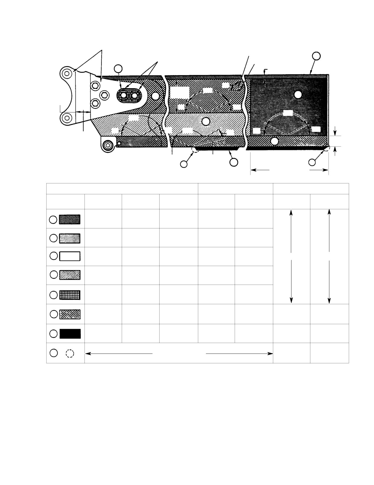
MD Helicopters, Inc.
CSP−H−2
500 Series - Basic HMI
DAMAGE 0.010 IN. (0.254 MM) IN DEPTH OR LESS
IS REPAIRABLE IN THESE AREAS (NOTE 1)
CHORD LINE
1.00 IN. (25.4 MM) RADIUS AROUND LAST
1
2 BOLT HOLES 0.001 IN. (0.025 MM)
SPAN LINE
MAXIMUM DEPTH
5
0.38 IN. (9.652 MM)
90°
3.00 IN.
120°
1.25 IN.
4
(76.2 MM)
2
(31.75 MM)
30°
30°
120°
120°
3
30°
120°
30°
30°
15°
30°
DAMAGE LESS THAN
0.030 IN. (0.762 MM)
6
DEPTH REPAIRABLE IN
THIS AREA (NOTE 1)
30°
15°
1.00 IN.
7
8
8
(25.4 MM)
23.00 IN.
(58.42 CM)
GOUGES, NICKS AND CRACKS
SCRATCHES
GOUGES AND NICKS
TRAILING EDGE ONLY
ORIENTATION
MAX. DEPTH
MAX. DEPTH
MAX. DEPTH
MAX. DEPTH
MAX. DEPTH
MAX. DEPTH
AREA
FROM SPANLINE
WITHOUT REPAIR
WITH REPAIR
WITHOUT REPAIR
WITH REPAIR
WITHOUT REPAIR
WITH REPAIR
MINOR WITHOUT
MINOR WITHOUT
MINOR WITHOUT
MINOR WITHOUT
1
0°−90°
SKIN PENETRATION
SKIN PENETRATION
SKIN PENETRATION
SKIN PENETRATION
0.005 IN. (0.127 MM)
0.005 IN. (0.127 MM)
0.003 IN. (0.076 MM)
0.005 IN. (0.127 MM)
0°−30°
2
0.003 IN. (0.076 MM)
0.003 IN. (0.076 MM)
0.003 IN. (0.076 MM)
0.005 IN. (0.127 MM)
30°−90°
ÉÉÉ
NONE
3
0°−30°
NONE
0.005 IN. (0.127 MM)
0.005 IN. (0.127 MM)
N/A
N/A
30°−90°
NONE
0.003 IN. (0.076 MM)
NONE
0.005 IN. (0.127 MM)
ÉÉÉ
0.003 IN. (0.076 MM)
NONE
4
0°−30°
NONE
0.003 IN. (0.076 MM)
NONE
0.002 IN. (0.051 MM)
NONE
30°−90°
0.003 IN. (0.076 MM)
0.001 IN. (0.025 MM)
0.001 IN. (0.025 MM)
5
0°−90°
NONE
NONE
(NOTE 3)
(NOTE 3)
NOTE 2
0°−15°
0.005 IN. (0.127 MM)
0.005 IN. (0.127 MM)
NONE
0.005 IN. (0.127 MM)
6
15°−30°
0.003 IN. (0.076 MM)
0.003 IN. (0.076 MM)
NONE
0.005 IN. (0.127 MM)
NONE
0.030 IN. (0.762 MM)
30°−90°
NONE
NONE
NONE
0.005 IN. (0.127 MM)
(NOTES 3, 5)
0.005
0.250 IN. (6.35 MM)
7
0°−90°
NONE
NONE
0.005 IN. (0.127 MM)
NONE
(NOTE 3)
(NOTES 3, 6)
(NOTES 3, 4, 6)
0.030 IN. (0.762 MM)
8
NOT APPLICABLE
NONE
(NOTES 3, 5, 6)
TAB END
NOTES:
3.
AREAS NOTED: 0.25 SMOTHERED AND RADIUSED
1.
DAMAGE LIMITS APPLY TO BOTH UPPER AND LOWER ROOT
CLEANOUT ALLOWED.
FITTING SURFACES.
4.
SMOOTHED AND RADIUSED CLEANOUT OVER 0.12 IN. (3.048 MM)
2.
INSPECTION UNDER 5X MAGNIFICATION (MIN.) REQUIRED.
AREA ON EACH SIDE OF DAMAGE.
5.
REFER TO TRIM TAB DAMAGE REPAIR.
G62−1001A
Figure 7-8. Main Rotor Blade Damage and Repair Limits for Nicks,
Scratches, Gouges and Cracks
Page 7-25
Revision 16
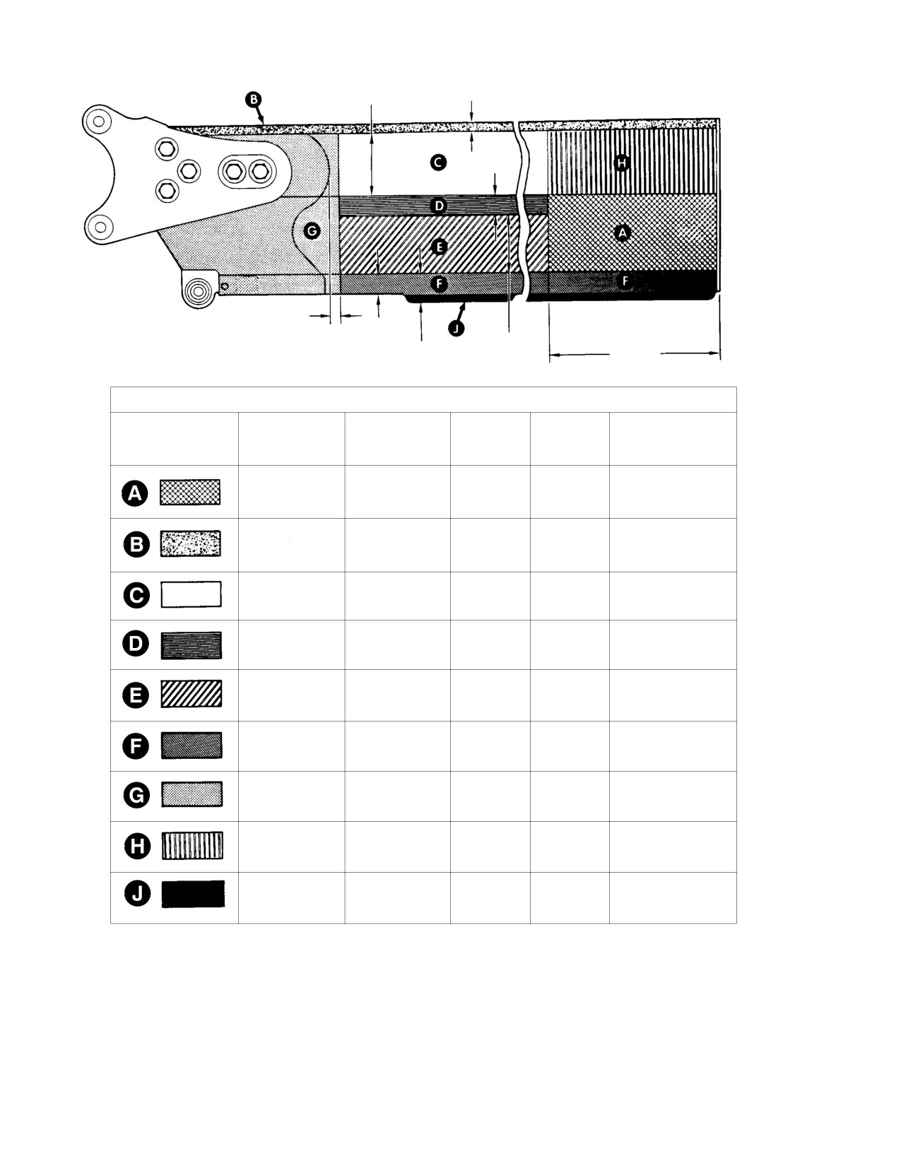
MD Helicopters, Inc.
CSP−H−2
500 Series - Basic HMI
0.38 IN.
2.12 IN.
(9.652 MM)
(5.3848 CM)
1.58 IN.
(4.0132 CM)
2.00 IN.
(5.08 CM)
0.58 IN.
(14.732 MM)
2.17 IN.
(5.5118 CM)
23.00 IN.
0.96 IN.
(58.42 CM)
(24.384 MM)
DENTS AND DEPRESSIONS (NOTE)
MAXIMUM
MAXIMUM
MAXIMUM
MAXIMUM
MINIMUM DISTANCE
AREA
DEPTH
DEPTH
ALLOWED
NUMBER
BETWEEN DEFECT
WITHOUT REPAIR
WITH REPAIR
AREA
OF DEFECTS
CENTERS
0.015 IN.
0.062 IN.
1.5 X 1.5 IN.
1
N/A
(0.381 MM)
(1.5748 MM)
(3.81 X 3.81 CM)
0.010 IN.
0.25 X 0.25 IN.
18 IN.
0.000
2
(0.254 MM)
(6.35 X 6.35 MM)
(45.72 CM)
NONE
0.000
0.000
0.000
N/A
ALLOWED
0.005 IN.
0.030 IN.
1.5 X 1.5 IN.
18 IN.
2
(0.127 MM)
(0.762 MM)
(3.81 X 3.81 CM)
(45.72 CM)
0.010 IN.
0.040 IN.
1.5 X 1.5 IN.
18 IN.
2
(0.254 MM)
(1.016 MM)
(3.81 X 3.81 CM)
(45.72 CM)
0.010 IN.
0.040 IN.
1.5 X 1.5 IN.
18 IN.
3
(0.254 MM)
(1.016 MM)
(3.81 X 3.81 CM)
(45.72 CM)
NONE
0.000
0.000
0.000
N/A
ALLOWED
0.010 IN.
0.040 IN.
1.5 X 1.5 IN.
1
N/A
(0.254 MM)
(1.016 MM)
(3.81 X 3.81 CM)
0.35 IN.
0.010 IN.
1.5 X 1.5 IN.
N/A
N/A
(8.89 MM)
(0.254 MM)
(3.81 X 3.81 CM)
(NOTE 3)
NOTES:
1.
N/A − NOT APPLICABLE.
2.
REFER TO TRIM TAB DAMAGE REPAIR.
H07−0001A
Figure 7-9. Main Rotor Blade Damage and Repair Limits for Dents
and Depressions
Page 7-26
Revision 16
MD Helicopters, Inc.
CSP−H−2
500 Series - Basic HMI
NOTE: Trailing edge structural bond line to V
(c). If a torque wrench is not available,
insert starts 0.250 inch (6.35 mm) in (chord−
check weight security by fitting a
wise) from trailing edge joint: therefore the
small coin in the slots and applying
above tolerance allows 0.250 inch (6.35 mm)
the maximum force that can be
separation. Be sure measurement is taken
exerted by ONLY the index finger
from the trailing edge joint, not the tab trail−
and thumb.
ing edge. Maximum trailing edge joint gap
allowed during fabrication is 0.080 inch
(13). Inspect vibration absorber pad on
(2.032 mm).
underside of blade for security.
(14). Inspect vibration absorber for security
(8). Inspect doubler shown in area G for
of installation on blade.
bonding voids between doubler and
blade skin top and bottom.
(15). Ensure both pendulums swing freely
and no more than 0.015 inch (0.381
(a). Use a heavy coin and lightly tap
mm) radial play exists between the
doubler surface.
pendulums and the hinge pins.
(b). A void will appear as a distinct
(a). Maximum allowable axial play
change in sound.
between pendulums and bracket is
0.085 inch (2.159 mm).
NOTE: Tapping sound will differ slightly due to
blade structure in leading and trailing edge,
(16). Inspect all parts of the vibration
internal channel and doubler areas.
absorber for cracks and breaks.
(17). Inspect pad on bracket below pivot end
(9). Ensure that vent holes are open.
of largest pendulum for security.
NOTE: Two or three vent holes are located in
(18). Inspect thrust washers bonded to the
the lower blade skin 5.50 inches (13.97 cm)
bracket, to the 5−per−revolution
aft of the leading edge with the first hole
pendulum, and to the 3−per−revolution
7.50 inches (19.05 cm) inboard from the tip.
pendulum for evidence of damaged
Teflon surfaces, wear and failure of
(10). Inspect the fasteners that secure upper
bond.
and lower root fittings, and the six
rivets that secure skin to spar near tip,
11. Main Rotor Blade Repair
for security.
A. Nicks, Scratches and Wear Spots
(11). Inspect forward tip cap screw insert for
security and thread damage.
(Ref. Figure 7−8)
(1). Using abrasive paper (9, Table 2−4), no
(12). When continuous one−per−revolution
coarser than grade 320, remove nicks,
lateral vibration occurs, inspect forward
scratches and wear spots from upper
and aft balance weights for security
and lower root fittings, and from blade
(Ref. Figure 7−3).
skin.
(a). Weights are normally recessed 0.050
(2). Use finer grade of paper, as necessary
inch (1.270 mm) below the end
to restore surface roughness to original
surface of the weight assembly tip.
finish.
(b). Security of the weights may be
(3). Remove material in such a manner that
checked by using a torque wrench
no abrupt changes occur in surface
with a screwdriver socket in the slot
contours.
of the weight to detect if the weight
can be rotated by less than 20
(4). Apply chemical film surface treatment
inch−pounds (2.26 Nm).
to repaired surface (Ref. Sec. 2).
Page 7-27
Revision 16
MD Helicopters, Inc.
CSP−H−2
500 Series - Basic HMI
B. Dents, Depressions and Erosion
(1). Unscrew loose weight until it projects
approximately one−half inch and
(Ref. Figure 7−9)
remove old accumulation of powdered
compound.
Repair only those damaged
CAUTION
areas that are within repairable
(2). Apply grade A locking compound (29)
limits.
and screw the weight back into the
blade until slotted end of the weight is
(1). Use paint remover (11, Table 2−4) to
recessed 0.050 inch (1.27 mm) below
remove paint from surface area to be
the surface of the weight assembly tip.
repaired.
Wipe off excess compound.
(2). Wipe away all residue with clean cloth
Allow to cure for a minimum of
CAUTION
dampened by solvent (1). Allow to dry
12 hours. If faster cure is de−
for minimum of 15 minutes.
sired, complete cure can be obtained by al−
lowing part to set for 30 minutes at room
(3). Mask edges of repair areas with one
temperature and then heating for 30 min−
layer of tape (93).
utes at approximately 212°F (100°C).
Do not cut tape after it is
(3). If locking compound is not available,
CAUTION
applied to blade.
screw weight into normal position and
centerpunch the end of the weight into
(4). Mix filler (94), three parts ‘‘A’’ and two
the mating threads at three evenly
parts ‘‘B’’ by weight. Mix thoroughly
spaced points to prevent rotation.
until mixture is dark red in color. An
alternate filler (95) may be used if
E. Loose or Missing Rivets or Aft Tip Cap
equal parts ‘‘A’’ and ‘‘B’’ by weight are
Replace all loose or missing rivets. Reinstall or
mixed.
replace loose or missing aft tip cap as follows:
(5). Allow filler to cure for minimum of 24
NOTE: Spare tip caps are supplied with the
hours at room temperature.
bonding surface pretreated (coated) with a
nylon primer to facilitate installation.
(6). Smooth filler area with grade 400
abrasive paper (9). Limit smoothing to
(1).
Lightly abrade primed surfaces of the
masked area.
tip cap with grade 180 abrasive paper
(9, Table 2−4).
(7). Remove the tape and inspect alclad
coating of area around repair. Penetra−
(2).
Wipe away residue with cloth damp−
tion of coating is cause for blade
ened in solvent (1) and allow tip cap to
replacement.
dry at room temperature for 30 min−
utes.
(8). Clean repaired area with a cloth
dampened by solvent (58).
(3).
Mix two−part bonding adhesive (19) in
equal proportions by weight.
(9). Apply chemical film treatment to
repaired surface.
(4).
Apply bonding adhesive previously
prepared tip cap and mating surfaces at
C. Forward Tip Cap Insert
rotor blade tip. To extent possible, be
sure that there are no adhesive voids.
Replace a loose or stripped insert. Use
self−locking insert NAS1394 of correct size for
(5).
Install tip cap in blade tip, apply
replacement and install with wet primer (4,
uniform clamping pressure to the joint,
Table 2−4) (Comply with replacement require−
and wipe away excess adhesive. Allow
ments of applicable NAS standard).
adhesive to cure for 8 hours at room
temperature or 2 hours at 150°F (66°C).
D. Loose Balance Weights
(6).
Install two MS20604AD3C2 blind
Reinstall loose forward and aft balance
rivets, one through each side of the
weights as follows:
blade tip and tip cap (Ref. Figure 7−3).
Page 7-28
Revision 16
MD Helicopters, Inc.
CSP−H−2
500 Series - Basic HMI
(7). Check other blades of rotor for tip cap
13. Bearing Replacement - Damper Attach,
security. Rebond if necessary and add
Blade Fitting
rivets to the other tip caps in the same
manner.
(Ref. Figure 7−10)
NOTE: Main rotor balance will not be affected.
(1). Use fly or circle cutter with 5/16 inch
(0.3125 mm) pilot to remove staked lip
F. Vibration Absorber
from one side of bearing without
(Ref. Vibration Absorber Repair)
removing any material from fitting.
12. Leading Edge Erosion Protection
If fitting is damaged by cutter,
CAUTION
blade must be replaced.
Blades subjected to operation in a highly
abrasive environment should have the outer
(2).
Use an arbor press to press bearing
12−36 inches (30−91 cm) of each blade leading
from fitting.
edge covered equally by protective tape so that
blade life will not be reduced by excessive
(3).
Clean primer residue from fitting bore
erosion.
with MEK (22, Table 2−4). Remove
locking compound residue (if any) with
NOTE: Cement and tape must be applied to a
locking compound remover (33).
thoroughly clean surface with no rough
paint edges. Work out trapped air bubbles
(4).
Using 10 power magnifying glass,
during application and allow 2 hours for
inspect fitting bore for cracks. No
tape to set.
cracks are permitted.
(1).
Thoroughly wash the blade leading
edge with clean cloths dampened with
(5).
Measure fitting bore diameter. Accept−
MEK (22, Table 2−4). Allow to air dry at
able limits are 0.7488−0.7493 inch
least 15 minutes.
(19.0195−19.0322 mm).
(2).
Mask around the outside of the area to
(6).
Apply thin coat of primer (4) to fitting
be taped leaving a 0.250 inch (6.35 mm)
bore.
gap.
(7).
Press bearing into fitting with arbor
(3).
Apply a uniform brush coat of cement
press and fixture (61, Table 2−2). Wipe
(120). Allow to air dry for 5 to 10
away excess primer.
minutes.
(4).
Remove backing from 3 inch (7.62 cm)
(8).
Stake bearing at both sides of fitting
width by 0.014 inch (0.3556 mm) thick
with staking tool (62) in hydraulic press
tape (42), and apply along the leading
with 6000 − 8000 pounds (26689 −
edge so that tape overlap over bottom
35586 N) of force.
and top of leading edge is equal.
(a). When staked, outer race of bearing
(5).
Roll out any air trapped under the tape
shall be flush to not more than 0.010
with a cylindrical object.
inch (0.254 mm) above fitting surface
(both sides).
(6).
Remove masking tape; then carefully
remove cement residue using MEK.
(b). Gap between staked lip of bearing
(7).
Replace the tape when it becomes
race and chamfered surface of fitting
abraded. Operation in rain reduces tape
bore shall not exceed 0.005 inch
life and more frequent replacement will
(0.127 mm) as checked with feeler
be necessary.
gage.
NOTE: The use of abrasion tape will not affect
(c). Staking operation shall produce no
flight characteristics or vibration levels;
cracks in fitting or bearing.
however, with 36 inches (91 cm) of tape
applied there is a 3 to 4 hp loss in rotor pow−
(9). Fill staking gap (if any) with primer (4,
er.
Table 2−4).
Page 7-29
Revision 16
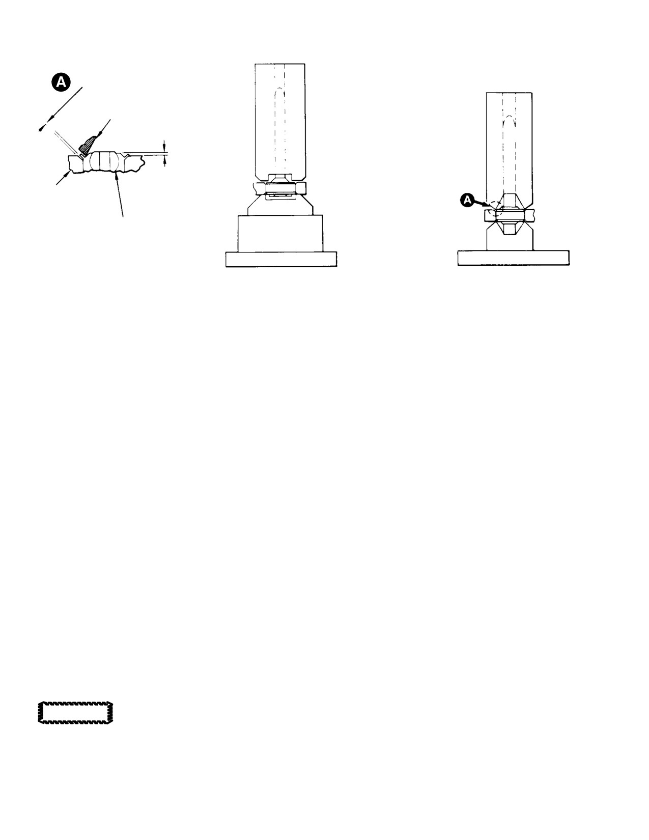
MD Helicopters, Inc.
CSP−H−2
500 Series - Basic HMI
0.005 IN. (0.127 MM)
MAX.
EDGE OF STAKING TOOL
FLUSH TO
+0.010 IN.
ARM
(+0.254 MM)
BEARING WITH STAKING
GROOVE IN OUTER RACE
PRESSING BEARING
STAKING BEARING
IN ARM
IN ARM
30−215A
Figure 7-10. Bearing Replacement - Main Rotor Blade Attach Fitting Repair
14. Repair of Trim Tab and Trailing Edge
(3). Wipe away dirt on and around trim tab
(369A1100 Series)
area with clean cloth dampened with
dry cleaning solvent.
(Ref. Figure 7−11) The following procedures
provide broad cleanup of a damaged trim area,
(4). Mask edges of blade area around trim
which distributes stresses over a larger area to
tab area with tape; DO NOT cut tape
after it has been applied to blade.
preclude cracking and permit continued use of
the rotor blade.
(5). Remove damaged area of trimtab by
making V−type cut with 45° sides
No minimum length of trim tab is required.
joined by a 0.250 inch (6.35 mm) radius
The entire trim tab or portion of the trim tab
at the bottom of the V. Blend into
may be removed.
trailing edge of the blade with a 0.250
inch (6.35 mm) radius as shown.
Main rotor blades with and without trim tabs
are 100% interchangeable, individually and in
NOTE: Maximum V cut depth is 0.350 inch
ship sets.
(8.89 mm); do NOT cut past trim tab area
into portion of blade.
(1). Inspect trim tab area of main rotor
blade and repair tab area, as required.
(6). If damage occurs within 1 inch (25.4
mm) of either or both ends of trim tab,
NOTE: If damage to trim tab area exceeds limi−
remove tab end(s) and restore contour
tations (Ref. Figure
7−9, perform the fol−
as shown.
lowing:
(7). If excessive damage requires full or
(2). As applicable, remove main rotor blade.
partial removal of trim tab from blade,
perform the following (no minimum
Provide protective surface and/
length of trim tab is required):
CAUTION
or covering to prevent scratch−
ing, nicking or other damage to blade during
(a). Position blade on workbench so that
rework. Position blade on work bench or
a firm straight edge is provided for
equivalent.
cutting or filing off trim tab.
Page 7-30
Revision 16