CSP-H-2 BASIC HANDBOOK OF MAINTENANCE INSTRUCTIONS FOR MDHI 369H HELICOPTERS - page 2
MD Helicopters, Inc.
CSP−H−2
500 Series - Basic HMI
HINGE PIN, WASHER
HEAL STRIP
AND COTTER PIN
CLIP
SPRING
HINGE
LATCH
PIN (2)
CURRENT TYPE
BEAM
HINGE
PIN
PILOT’S COMPARTMENT
FWD FAIRING
FLOOR ACCESS DOOR (TYP)
8 SCREWS, WASHERS
HINGE PIN
AFT FAIRING
LATCH
PLENUM CHAMBER
TAIL ROTOR DRIVESHAFT
ACCESS DOOR
ACCESS DOOR
HINGE PIN
EARLY TYPE
TURNLOCK FASTENERS
LATCH
ACCESS DOORS
(HINGE−MOUNTED)
CARGO COMPARTMENT AFT
BULKHEAD ACCESS COVER
LATCH
(TYP)
HANDLE (TYP)
FUEL FILLER SHIELD
5 SCREWS,
2 SCREWS,
WASHERS
WASHERS, NUTS
TURNLOCK
FASTENERS
GROMMET
(NOTE 1)
30−007−2E
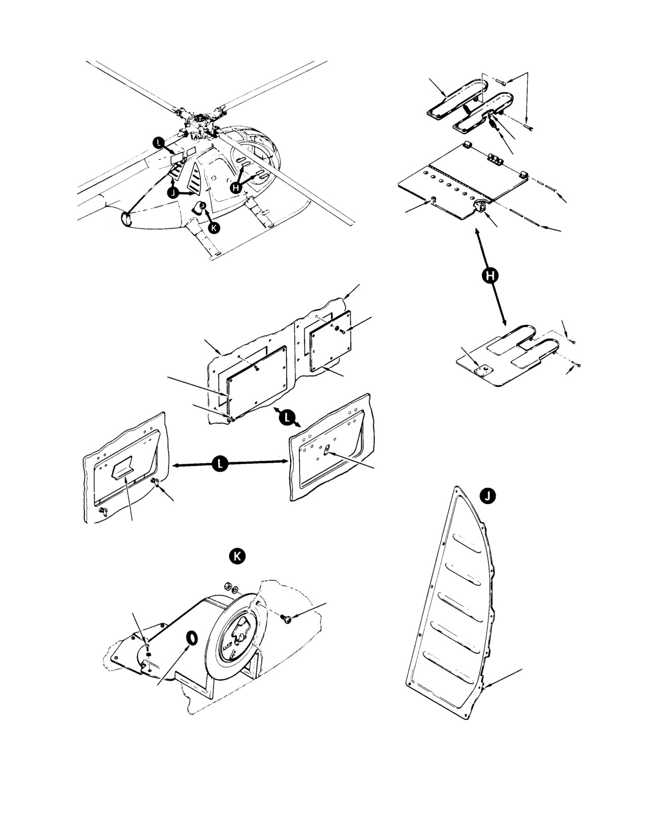
Figure 2-6. Access and Inspection Provisions (Sheet 2 of 6)
Page 2-33
Revision 14
MD Helicopters, Inc.
CSP−H−2
500 Series - Basic HMI
FUSELAGE STRUCTURE
SHIM PLATE
(INDEX BEFORE REMOVAL)
ENGINE ACCESS
DOOR
CURRENT TYPE
ENGINE ACCESS DOOR HINGE
(TYP 4 PLCS)
PILOT,S AND CARGO DOOR HINGE
(TYP 8 PLCS)
EARLY TYPE
HINGE PIN
TURNLOCK
FASTENERS
BOOM BOLTS ACCESS
DOORS
(TAIL ROTOR CONTROL
BELLCRANK) CONTROL
ENGINE COMPARTMENT ACCESS
ACCESS DOOR
DOORS LOWER LATCH
FOOT SUPPORT
FAIRING
8 SCREWS,
WASHERS
(TYP)
TURNLOCK
29 SCREWS,
FASTENERS
WASHERS
LEVER ASSY
(TYP)
STRIKER
CONTROLS ACCESS DOOR
14 SCREWS, WASHERS OR
27 SCREWS, WASHERS
4 SCREWS,
WASHERS
ENGINE COMPARTMENT
ACCESS DOOR LATCH
FUEL VENT
(TYP)
COVER
CHANNEL
FUEL CELL
FOOT SUPPORT FAIRING
ACCESS DOORS
SECONDARY LATCH
CHANNEL
PRIMARY LATCH LEVER
30−007−3E
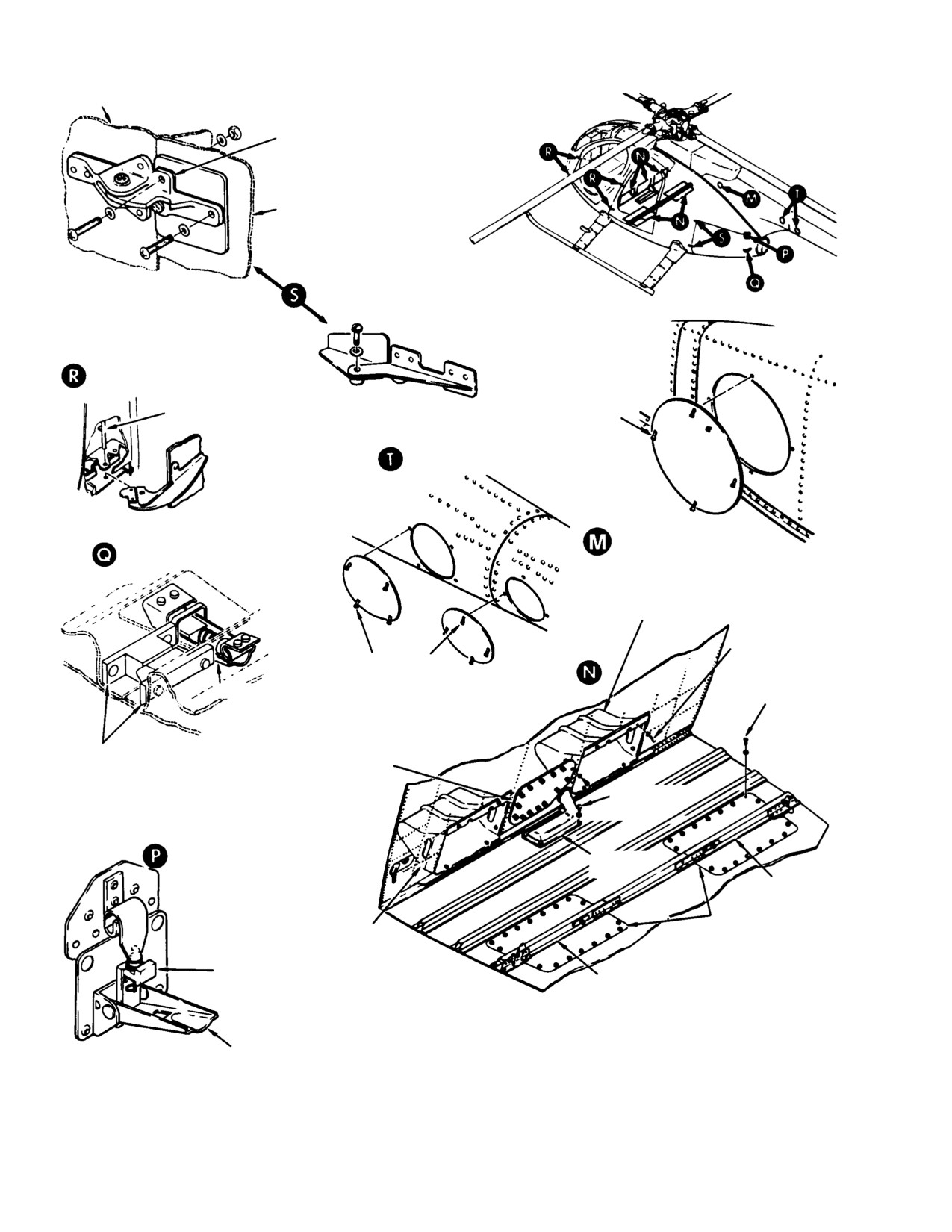
Figure 2-6. Access and Inspection Provisions (Sheet 3 of 6)
Page 2-34
Revision 14
MD Helicopters, Inc.
CSP−H−2
500 Series - Basic HMI
CARGO HOOK COVER
6 SCREWS,
WASHERS
LOWER INSTRUMENT
PANEL SUPPORT
MOUNTING HOLE FOR
RUNNING TIME METER
(LEFT SIDE ONLY)
5 SCREWS,
WASHERS
INSTRUMENT PANEL
LOWER SECTION
FRONT PANEL
INSTRUMENT PANEL LOWER
SECTION SIDE COVER PANEL
(TYP LEFT AND RIGHT SIDE)
5 SCREWS,
WASHERS
12 SCREWS
ACCESS COVER
EARLY TYPE
MAST SUPPORT
STRUCTURE
TAIL ROTOR DRIVE
TURNLOCK
ACCESS DOOR
FASTENERS
CURRENT TYPE
30−007−4E
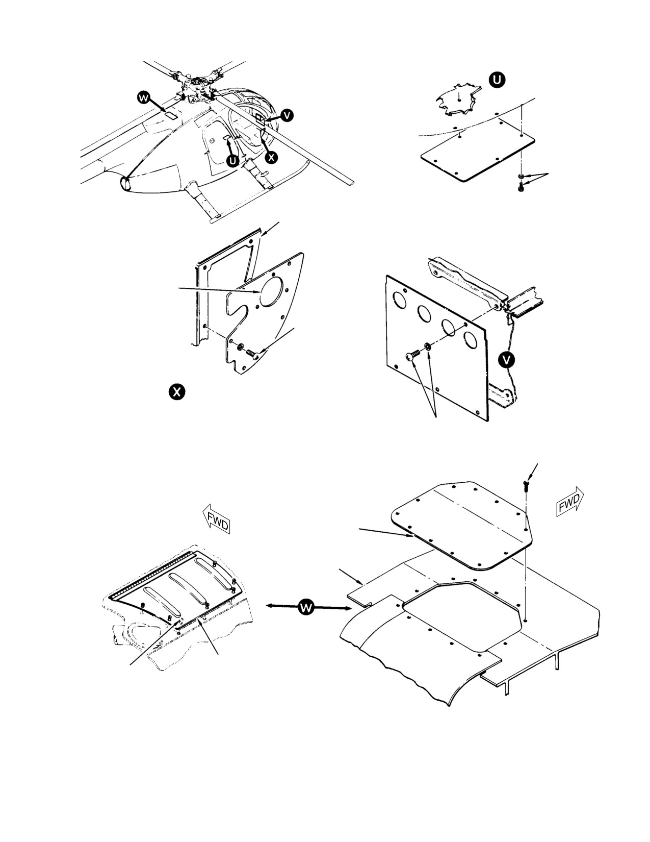
Figure 2-6. Access and Inspection Provisions (Sheet 4 of 6)
Page 2-35
Revision 14
MD Helicopters, Inc.
CSP−H−2
500 Series - Basic HMI
CURRENT TYPE
GASKET
CHIP DETECTOR ACCESS
NOTE 3
AIRFLOW BAFFLES
(NOTE 5)
BELT INSPECTION
FASTENER
GASKET
MAIN GEARBOX
ACCESS COVER
MAIN TRANSMISSION COVER
(NOTE 3)
EARLY TYPE
CHANNEL
MAIN TRANSMISSION
COVER
1 NUT, WASHER
MAIN GEARBOX
ACCESS COVER
2 BOLTS, WASHERS;
NOTES: (CONT)
10 IN. LB. (1.13 NM) MAX.
FASTENER
2 SCREWS
3.
SHADED AREAS REPRESENT FOAM GASKET SEALS.
4.
COAT MATING SURFACES OF TRANSMISSION AND STRUCTURE WITH PARTING AGENT
(112, TABLE 2−4). JUST PRIOR TO INSTALLATION, COAT SURFACES AND EDGES OF COVER
(EXCEPT SEALS) THAT MATE WITH TRANSMISSION AND STRUCTURE WITH SEALING COMPOUND (105).
5.
PART OF 369A8063−505 COVER ASSY ONLY. (REQUIRED WITH 250−C20 ENGINE,)
30−007−5F
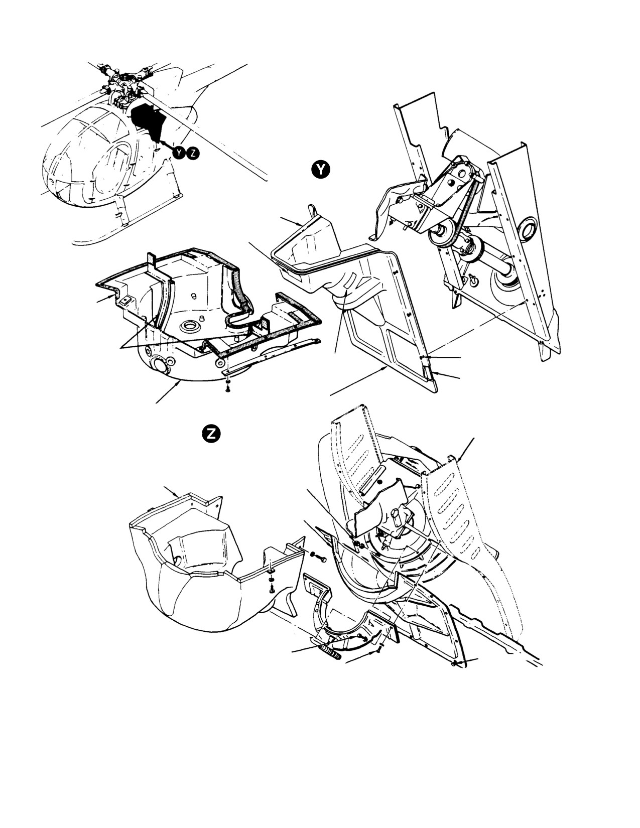
Figure 2-6. Access and Inspection Provisions (Sheet 5 of 6)
Page 2-36
Revision 14
MD Helicopters, Inc.
CSP−H−2
500 Series - Basic HMI
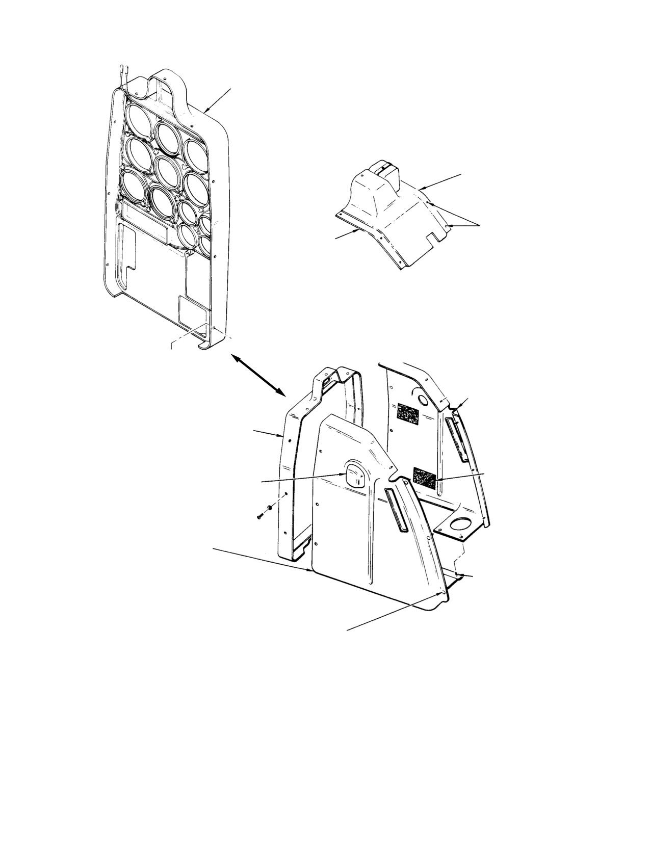
TYPE B HOOD
INSTRUMENT PANEL
CENTER FAIRING
FASTENERS (NOT USED
FOR CURRENT TYPE)
RETAINER
(CURRENT TYPE)
INSTRUMENT PANEL
LEFT SIDE FAIRING
TYPE A HOOD
VELCRO VIBRATION PAD
FRESH AIR DEFLECTOR
(TYP)
INSTRUMENT PANEL
RIGHT SIDE FAIRING
FASTENERS
(SEVERAL TYPES USED)
CANOPY PANEL ATTACHMENT
(6 PLCS) (EITHER ACCORDION RIVETS OR
HOOK AND PILE FASTENERS ARE USED)
30−007−6C
Figure 2-6. Access and Inspection Provisions (Sheet 6 of 6)
Page 2-37
Revision 14
MD Helicopters, Inc.
CSP−H−2
500 Series - Basic HMI
(b). Install the two screws, two bolts and
for deterioration and plastic cover for
nut and washers that secure the
cracks.
drain assembly to the structure,
shroud and scroll.
(3). Installation (Shaft−Driven Blower):
(a). Position cover over transmission.
NOTE: Do not overtighten the two bolts and
nut. Torque to 10 inch−pounds (1.13 Nm)
(b). Install heater duct bolt at lower left
maximum.
aft inside corner of cover if heating
system ducting is installed.
(c). If drain assembly is a replacement,
connect the flexible drain hose and
(c). Install the four screws and washers
secure with two wraps to lockwire (2,
fingertight. Check cover for proper fit
Table 2−4).
and that liquid level plug is visible.
C. Main Transmission Cover
(d). Tighten screws.
Different main transmission covers are used
(e). Set the nylon tape edging to the
with the shaft−driven and belt−driven oil
mating file fasteners by using hand
cooler blower installations. The main trans−
pressure.
mission cover is a polycarbonate plastic form
(f). Attach the main transmission drain
that essentially matches the transmission
assembly.
housing contour. The plastic form has a
permanently bonded insulation blanket cover
(4). Removal (Belt−Driven Blower):
with a fiberglass core and flexible vinyl
exterior. Plastic form gaskets cushion the cover
(a). Disconnect electrical wiring from
surfaces that mate with the adjacent struc−
transmission temperature sensor and
ture. When installed, there is space between
chip detector.
the cover and transmission to allow inlet air
flow for transmission cooling. With the
NOTE: The cover assembly may be installed
shaft−driven blower, a yoke−type drain
with sealant. To remove the cover, split the
assembly fits around the lower end of the
sealant with a sharp knife to protect seals
cover. A flexible hose connects to the drain
and surface finish from damage.
assembly outlet tube and pipes overboard any
water or oil that collects in the cover.
(b). Remove 14 washers and screws to
remove cover from fuselage structure,
(1). Removal (Shaft−Driven Blower):
trim support strips and upper
transmission baffle.
(a). Detach the main transmission drain
assembly.
(c). Remove cover from left and right
cooling ducts.
(b). Release nylon tape edging (Velcro
(5). Installation (Belt−Driven Blower):
hook tapes) from mating nylon pile
fasteners (Velcro piles) at aft edges of
(a). Apply parting agent (113, Table 2−4)
cover.
and sealant (106) to areas indicated
in Figure 2−6.
(c). Remove four screws and washers
from cover.
(b). Position cover over transmission and
install cooling ducts.
(d). Remove bolt from heater duct flange
at lower left aft inside corner of cover
(c). install 14 screws and washers to
if heating system ducting is installed;
secure cover and trim support strips.
then lower cover to remove it..
(d). Connect electrical wiring to transmis−
(2). Inspection (Shaft−Driven Blower):
sion temperature sensor and chip
Inspect foam gaskets and cover blanket
detector.
Page 2-38
Revision 14
MD Helicopters, Inc.
CSP−H−2
500 Series - Basic HMI
D. Main Transmission Cover Assembly
(6). Apply adhesive (3, Table 2−4) to both
Seals Replacement
rubber seal and cover assembly. Align
seals and press into place.
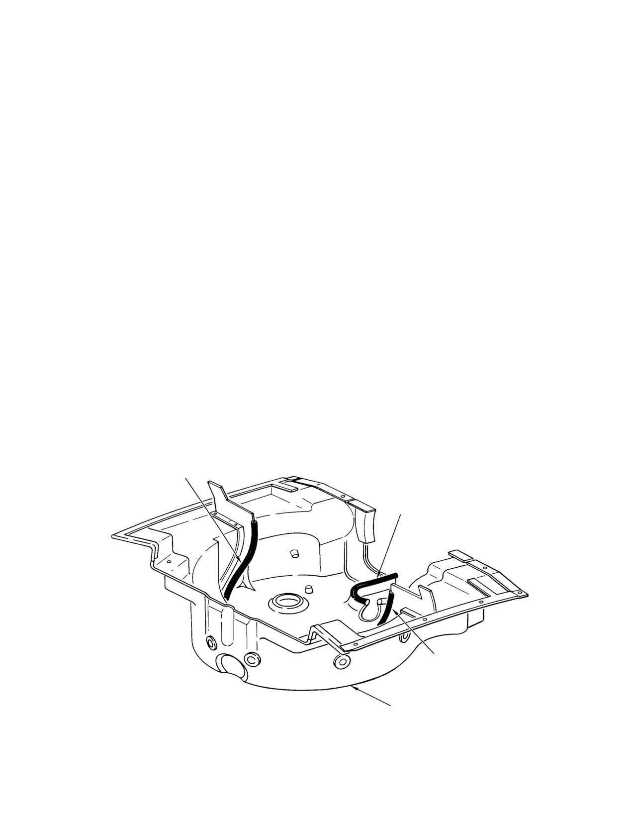
(Ref. Figure 2−7) Cover seals PN
369H8063−85, 89, and −91 in the
(7). Allow bond to cure for 24 hours;
369H8063−505 polycarbonate type main
reinstall cover assembly.
transmission cover assembly may be removed
E. Cargo Compartment Aft Bulkhead Access
on a one time basis for inspection, and
Covers
reinstalled using a rubber adhesive to ensure
adequate bond between the seals and the
The cargo compartment aft bulkhead access
polycarbonate cover. This procedure, which
covers enclose essentially symmetrical
follows, does not apply to 369H8097 fiberglass
openings to the fuselage spaces at either side
type main transmission cover.
of the engine air inlet plenum chamber. The
right side cover provides access to the oil tank,
(1).
Remove main transmission cover
oil cooler and oil system drain valve. The left
assembly.
side cover provides access to elements of the
cabin heating installation on the helicopters so
(2).
Remove 369H8063−85, −89 and −91
equipped. Turnlock fasteners secure the outer
rubber seals from cover assembly.
edge of each cover to the fuselage.
Discard seal if any deterioration is
noted.
(1). Removal: Release turnlock fasteners
and lift cover from structure.
(3).
Use X−acto knife or equivalent to
remove loose adhesive material adher−
(2). Inspection:
ing to polycarbonate cover and rubber
seals. Use abrasive paper to remove
(a). Inspect turnlock fasteners and
remaining adhesive residue from cover
receptacles for condition.
and seals.
(b). Inspect cover for corrosion and
(4).
Abrade inside flange of rubber seals.
cracks.
(5).
Wipe clean the abraded areas of cover
(3). Installation: Position the cover over the
and seals, using naphtha and clean
opening in the structure and engage the
cloth.
turnlock fasteners.
369H8063−85 SEAL
369H8063−91 SEAL
369H8063−89 SEAL
MAIN TRANSMISSION
COVER ASSEMBLY
30−216
Figure 2-7. Main Rotor Transmission Cover Seals Installation
Page 2-39
Revision 14
MD Helicopters, Inc.
CSP−H−2
500 Series - Basic HMI
F. Pilot Compartment Floor Access Doors
(b). If removed, heel strips are reinstalled
by inserting hinge pins through
Each of the two pilot’s compartment access
brackets on forward end of strip and
doors are formed by two hinged aluminum or
antitorque pedal mounting bracket
fiberglass panels, hinged at the forward edge
and connecting springs to clips or
to the pilot’s compartment floor. A latch at the
brackets on underside of heel strips.
rear secures each door in place. Two aluminum
Crimp or stake end of pins slightly
heel strips, on which two stainless steel skids
after installation or use hinge pins
are bonded, are hinged and held in place over
secured by a cotter pin as follows:
each door by a spring. early type doors are a
single piece of fiberglass with heel strips
1). Detach spring from clip or bracket
bonded in place and the forward ends of the
on underside of each heel strip (not
strips hinged to permit opening the doors.
applicable to early type one−piece
pilot compartment floor access
(1). Removal: Remove either floor access
door).
door as follows.
2). Remove existing hinge pins secur−
NOTE: The one−piece door is removed accord−
ing forward end of heel strips.
ing to step (d).
3). Install new hinge pins and secure
end of each pin with washer and
(a). Release the latch at the rear of the
cotter pin. Direction of pinhead is
door.
optional.
(b). Raise and hold up the rear of the heel
4). Attach spring to clip or bracket on
strips for access to the long hinge pin
underside of each heel strip, as
at forward end of door.
applicable.
NOTE: Heel strips may be removed for ease of
5). Check installation of new hinge
access by detaching springs from clips (or
pins for discrepancies.
brackets) on underside of strips and remov−
ing hinge pins attaching forward ends of
(c). Position one−piece door and install
strips to the anti− torque pedal mounting
hinge pins through hinges and
bracket.
antitorque pedal mounting bracket.
(c). Remove the long hinge pin securing
G.
Fuel Cell Access Doors
forward edge of door to pilot’s
The fuel cell access doors are stiffener−rein−
compartment floor; remove door.
forced aluminum plates that form a portion of
(d). Remove one−piece access door by
the cargo floor. the left access door provides
releasing the flush−mounted latch
access to the fuel quantity transmitter (tank
and removing the two hinge pins that
unit) and fuel shutoff valve and the fuel cell
secure the door at the forward end.
cover (for access to the engine start pump), as
well as the left fuel cell. A quick−release lock
(2). Inspection:
pin is secured with a 4 inch (10 cm) lanyard to
the outboard edge of each door. The pins retain
(a). Inspect doors for cracks and other
the removable jacking fittings that are used for
visible damage.
jacking, parking and mooring the helicopter. A
stud on the stiffener of current type doors
(b). Check security of heel strip bonding.
provides an attachment point for floor cushion
material.
(c). As applicable, inspect hinges and
hinge pins for damage.
These are stressed doors. The
CAUTION
helicopter must never be flown
(3). Installation:
with either door removed.
(a). Position door and secure forward
(1). Removal: Remove the 29 retaining
edge to floor using a long hinge pin.
screws and washers and lift out door.
Page 2-40
Revision 14
MD Helicopters, Inc.
CSP−H−2
500 Series - Basic HMI
(2). Installation:
I. Engine Air Inlet Forward Fairings
(a). Position door over opening and
Ambient air is directed to the engine and the
secure in place with retaining screws
engine oil cooler through the two removable
and washers.
forward engine air inlet fairings and the aft
fairing that is riveted to the structure. The
(b). Stow quick−release lock pin in its
engine inlet fairings are fabricated of glass
hole.
cloth layers over polyurethane foam fillers.
The forward fairing halves establish the main
H. Controls Tunnel Cover
air inlet duct. Each half contains a smaller
Four tunnel−routed control rods exit the
duct on its inside leading edge that diverts
tunnel area through a cover mounted at the
cooling air to the main transmission and oil
top of the Sta. 78.50 canted frame. The cover
cooler blower. The forward fairings provide
or cover boots must be removed before any of
access to the main rotor mixer controls and the
the control rods are removed. The cover has
main rotor mast, its base and supporting
four naugahyde boots, two of which are sewed
structure.
together while the other two are individual. All
(1). Removal: A total of 32 screws with
boots are secured to the cover with self−clinch−
washers secure the fairing halves
ing nylon straps.
together and to the structure. Either
(1). Removal: The right− and left−side
half may be independently removed or
engine air inlet forward fairings should
the joined halves may be removed as an
be removed for best access to the
assembly. Two screws and washers join
controls tunnel cover.
the halves at the center splice.
(a). Remove the three screws, nuts, and
(a). Remove screws and washers attach−
six washers, and the four bolts and
ing forward fairing to fuselage.
washers from controls cover.
Remove forward fairing.
(b). Remove the cotter pin, nut, bolt and
(b). Remove two screws and washers at
washers that secure the upper end of
the splice if it is necessary to sepa−
each tunnel−routed control rod.
rate the two halves.
Disengage the rods ends from the
bellcranks.
(2). Inspection: Inspect the engine air inlet
fairings for structural damage. inspect
(c). Lift controls cover over rod ends.
for cracked or frayed glass cloth
(2). Installation:
surfaces and crushed fillers. Inspect
tape seals on closures inside fairings for
(a). Place controls tunnel cover over the
deformation and damage.
four control rods, with double boot
section fitting over the two right−side
(3). Repair: Make general repairs to the
control rods.
engine air inlet fairings according to
CSP−H−6. Replace the tape seals on
(b). Attach each control rod end to its
closures inside fairings with 0.25 x 0.50
bellcrank with bolt (head to left, two
inch (6.35 x 12.7 mm) pressure−sensi−
washers, nut and cotter pin.
tive tape (42, Table 2−4), cut to length
(c). Install controls tunnel cover with the
as required.
three screws, nuts and six washers
(4). Installation:
aft, and the four bolts and washers
forward. Tighten bolts and screws
(a). Position engine air inlet fairings on
evenly.
fuselage and align attachment holes.
(d). If removed, reinstall right− and
(b). Install attaching washers and screws
left−side engine inlet fairings.
in mounting flanges and through
(e). Check that control rods move freely
splice at top of left−side fairing, if
in the cover boots.
fairing halves separated.
Page 2-41
Revision 14
MD Helicopters, Inc.
CSP−H−2
500 Series - Basic HMI
J. Engine Air Inlet Fairing Access Doors
and is secured in place with turnlock fasten−
ers. The current type access door is a flat cover
Access doors are provided on both the forward
on the mast support structure. Twelve screws
and aft engine air inlet fairings. The right side
secure the access cover in place. When an
of the forward fairing contains the tail rotor
engine air inlet vertical screen is installed, five
drive shaft access door. The right side of the
of the cover screws with washers also retain
aft fairing contains a removable or hinge−
the front of the screen base. Primarily in−
mounted plenum chamber access door.
tended for access to the front end of the tail
rotor shaft, the door/cover provides limited
(1). Removal: Remove screws and washers
access to the accessories mounted on the aft
or release turnlock fasteners to take off
end of the main transmission.
desired access door.
(1). Removal:
(2). Inspection:
(a). Remove engine air inlet forward
(a). Inspect turnlock fasteners and
fairing.
receptacles for proper fastening
action.
(b). Remove screws from cover or release
turnlock fasteners to release door.
(b). Inspect fiberglass doors for structural
damage such as cracked or frayed
(2). Inspection: Inspect turnlock fasteners
glass cloth surfaces.
and receptacles for proper fastening
action. Inspect door for structural
(c). Inspect the hinge−mounted door for
defects and door hinge for damage and
structural damage and loose or
operation.
missing latching mechanism hard−
(3). Installation:
ware.
Check that all areas of the air
(d). Check latching mechanism and door
CAUTION
inlet and plenum chamber are
hinges for proper operation and
clean and free of debris. Check that all pro−
locking capability.
tective covers are removed. Engine damage
(e). Inspect seal installed around aft
will result if these precautions are not ob−
fairing door for security and condi−
served.
tion.
(a). Close access door and engage turn−
lock fasteners or position access cover
(3). Installation:
on mast support structure and secure
Check that all areas of the air
with screws (and five washers as
CAUTION
inlet and plenum chambers are
applicable to inlet screen).
clean and free of debris. check that all pro−
(b). Install engine air inlet forward
tective covers are removed. Engine damage
fairing.
will result if these precautions are not ob−
served.
L. Controls Access Door and Foot Support
Fairings
(a). Position door on fairing and install
applicable screws and washers or
The controls access door and the two foot
engage turnlock fasteners.
support fairings provide access to the forward
landing gear struts and dampers, lower
(b). Close the hinge−mounted plenum
elements of the underseal installation for the
chamber access door and ensure that
engine and flight control systems and portions
locking mechanism locks in place.
of the electrical wiring routed beneath the
pilot’s seat structure. The foot fairings are
K. Aft Section Air Inlet (Tail Rotor Drive)
fiberglass assemblies, each having two small
Access Door
polycarbonate plastic windows. the outboard
The early type aft section air inlet (tail rotor
windows allow inspection of the forward
drive) access door is hinge−mounted to the aft
landing gear damper assemblies without prior
fuselage structure above the plenum chamber
removal of the fairings. The inboard windows
Page 2-42
Revision 14
MD Helicopters, Inc.
CSP−H−2
500 Series - Basic HMI
are not for inspection by establish left−or
(2). Installation: Check that there are no
right−hand interchangeability. The controls
foreign objects in the area shielded by
access door is aluminum plate that provides
the covers, position cover and secure
primary access to the lower end of the tunnel−
with screws and washers.
routed flight control push rods in addition to
O. Fuel Vent Cover
other elements of the control system.
The formed aluminum fuel vent cover provides
The controls access door is a
CAUTION
access to the fuel cell vent system crossover
stressed door. The helicopter
fitting that interconnects the forward top
must never be flown with this door removed.
inboard corners of the two cells.
(1). Removal: Remove eight screws and
(1). Removal: Remove four screws and
washers to release each foot fairing.
washers to release the fuel vent cover.
Remove 14 screws and washers, or 27
screws and washers as applicable, to
(2). Installation: Check that area to be
release controls access door.
covered is clean. Position cover and
secure with screws and washers.
(2). Installation: Position controls access
door (bevel at lower right corner) or foot
P. Fuel Filler Shield
support fairings and secure with screws
The polycarbonate plastic fuel filler shield
and washers.
protects the right fuel cell filler extension from
M. Pilot’s Seat Cover
possible damage from cargo impact, and also
covers the cargo floor opening for the filler.
The pilots seat cover is an aluminum alloy
panel assembly with a honeycomb core. The
(1). Removal:
seat cover provides primary access to the
(a). Remove five screws and washers that
upper elements of the underseat installation of
secure the fuel filler shield base to
engine and flight control systems.
the cargo floor.
(1). Removal: Remove 16 screws and
(b). Remove the two nuts, screws and
washers to release the pilot’s seat cover.
washers that secure the shield tabs
to the fuselage skin and fuel filler cap
Use all necessary precautions to
CAUTION
to release the shield.
prevent the possible entry of for−
eign objects into the controls linkage ex−
NOTE: Use care not to dislodge or damage the
posed by removal of the cover. Unnoticed de−
sealing grommet (if installed) that fits
bris in this area could jam or damage the
around the extended range fitting opening
controls when they are moved.
in the shield.
(2). Installation: Check that there are no
(2). Installation: Position the fuel filler
foreign objects present in the controls
shield and install the two screws,
linkage. Position pilot’s seat cover and
washers and nuts that secure the shield
secure with screws and washers.
tabs to the fuselage skin and fuel filler
cap; do not tighten.
N. Outboard (LH) Collective Stick Cover and
Wiring Cover
NOTE: Check that extended range fitting
grommet (if installed) provides a tight seal
The two small covers installed at the left side
between the shield and fitting. Replace
of the seat structure keep the left seat belt
grommet if deteriorated.
from fouling the aft end of the collective stick.
They also shield the electrical wiring where it
Q. Boom Bolts Access Doors and Tail Rotor
exits the seat structure and where it connects
Control Bellcrank Access Door
to the auxiliary circuit receptacles mounted in
The forward and aft boom bolts access doors
the left corner of the bulkhead.
provide access to the bolts that secure the
(1). Removal: Remove screws and washers
tailboom to the fuselage aft section. These
to release either cover.
doors are also removed for access to perform
Page 2-43
Revision 14
MD Helicopters, Inc.
CSP−H−2
500 Series - Basic HMI
removal and installation of the tail rotor drive
(b). Remove or release fasteners joining
shaft and/or tailboom (tail rotor blade angle)
the two side fairings.
control rod and to check drive shaft damper
(c). Detach side fairings from the canopy
friction or replace the damper. The tail rotor
structure by releasing accordion
control bellcrank access door provides primary
rivets or velcro fasteners.
access to the Sta. 142 bellcrank link between
the Sta. 100 tail rotor control rod and the
(d). Disconnect and tag−identify electrical
tailboom control rod.
loads from light/switch and horn
housing; then remove center fairing.
(1). Removal: Release turnblock fasteners
and lift boom bolts or controls access
(e). If required, remove attaching hard−
door from fuselage.
ware and horn and light assembly
from center fairing.
(2). Inspection: Inspect turnlock fasteners
and receptacles for proper fastening
(2). Installation: Install the instrument
action.
panel fairings in reverse order starting
with the last fairing section removed.
(3). Installation: Position boom bolts or
Refer to Section 19 for battery sensing
controls access door and engage
and engine out warning horn equip−
turnlock fasteners.
ment.
R. Exterior Lights Covers
U. Instrument Panel Lower Section Side
Cover Panels
Three fuselage openings for exterior lights are
closed off by round aluminum covers. Informa−
The two side cover panels that enclose the
tion on night lights is provided in CSP−H−3.
lower instrument panel support assembly
structure are aluminum alloy sheet. Removal
S. Cargo Swing/Hook Fairing Cover
of the covers provides access to wiring, tubing
and the fuel shutoff control cable routed
The well of the cargo swing/hook fairing is
upward to the instrument panel, as well as
closed off by a rectangular aluminum alloy
parts of the tail rotor control torque tube
cargo hook cover. Information on the cargo
installation. Refer to applicable configuration
swing and hook is provided in CSP−H−3.
supplement for removal of instrument panel
lower section.
T. Instrument Panel Fairings
(1). Removal: Remove five screws and
The three instrument panel fairings and hood
washers to release either side cover.
around the instrument panel are molded
thermoplastic enclosures that shield the area
NOTE: The running time meter is mounted in
froward of the panel from direct sunlight and
the left side cover and the landing light
foreign material. Removal of the side fairings
relay is mounted on the right side cover of
provides access to the shutoff valve controls,
helicopters equipped with either or both of
electrical and indicating system components
these options. For instructions or replace−
and any optional avionics equipment mounted
ment of either item, refer to CSP−H−3.
to the instrument panel and on the panel
support structure.
(2). Installation: Check that there are no
foreign Objects present in the controls
(1). Removal:
linkage, position the cover(s) and secure
with screws and washers.
NOTE: On helicopters equipped with a type B
instrument panel with full face hood, eight
V. Instrument Panel Lower Section Front
face attachment screws and two panel lights
Cover Panel
knife splices must be disconnected before
hood removal. Ref. Sec. 17 for attachment
The front panel inside the lower section of the
and disconnect points.
instrument panel support is aluminum alloy.
Removal of the cover provides access to
(a). Remove hood attachment screws and
electrical and avionics wiring at the lower
washers; remove hood.
forward area of the instrument panel.
Page 2-44
Revision 14
MD Helicopters, Inc.
CSP−H−2
500 Series - Basic HMI
(1). Removal: Remove five screws and
(1).
Removal (Current Type): Release the
washers to release the cover.
three latches to open access doors.
Index mark the hinge, shim and
(2). Installation: Position panel and secure
serrated plate to the door structure.
with screws and washers.
Remove the three engine access door
hinge attachment screws with washers.
W. Pilot and Cargo Doors
The forward screws are attached with
nuts and the aft screws attach to
The two pilot doors and two cargo doors are
rivnuts.
bonded aluminum alloy frames containing
large plastic windows. Current type doors are
(2).
Installation (Current Type): Position
auto−latching (automatically latch) when
door and temporarily install shim,
closed. Early type doors are latched manually.
serrated plate and attachment hard−
The door latching mechanism consists of four
ware. Align indexing marks on shim,
latches, two lengths of wire−reinforced cable
serrated plate and hinge with those on
within housings and a latch rod. The door
the door and then tighten the screws.
hinges on each door are provided with quick
Close and latch the doors and check for
removal type ball−lock hinge pins. The doors
firm fit with no deflection. If further
do not incorporate jettison provisions.
adjustment is required.
(3).
Removal (Early Type): Release the
(1). Removal:
three latches to open access doors.
Remove the pivot point attaching
(a). Open the door and individually pull
hardware from the door hinge and lift
the hinge pins up and out by the
door from fuselage hinge halves.
tabs.
(4).
Installation (Early Type): Lift access
(b). Hold door in alignment so that
door into position, align hinges and
hinges do not bind and slide door
install attaching hardware. Close and
hinges from hinge sockets to remove
latch the doors and check for firm fit
door.
with no deflection. If further adjust−
ment is required, refer to Section 3.
(2). Installation:
9. Helicopter Cleaning
(a). Lift door into position so that hinges
are aligned and engage door hinges
General cleaning of oil and dirt deposits from
with fuselage hinge sockets.
the helicopter and its components must be
accomplished by using dry−cleaning solvent (1,
(b). Hold door open and insert hinge pins
Table 2−4), standard commercial grade
far enough for the spring−loaded ball
kerosene or a solution of detergent soap and
detent to emerge past the lower side
water. The exceptions that must be observed
of the hinge socket. Close and latch
are specified in the following cleaning para−
the door.
graphs.
Some commercial cleaning
X. Engine Access Doors
CAUTION
agents, such as readily avail−
able household cleaners, contain chemicals
The two engine access doors are stamped and
that can cause corrosive action and/or leave
bonded aluminum alloy structures that form
residue that can result in corrosion. Exam−
the fuselage contour below the aft section
ples of cleaning agents that are not to be
engine compartment. The hinge−mounted
used are ‘‘Fantastik" and ‘‘409" type clean−
doors are secured in the closed position by
ers, or locally made strong soap cleaners.
three lever type, draw hook latches.
A. Fuselage Interior Trim and Upholstery
NOTE: For removal of current type doors, do
Cleaning
not attempt to remove hinge pivot bolts and
spacers. Refer to Section 3 for disassembly
(1). Clean dirt or dust accumulations from
at hinge points and for all door mainte−
floors and other metal surfaces with a
nance.
vacuum cleaner or small hand brush.
Page 2-45
Revision 14
MD Helicopters, Inc.
CSP−H−2
500 Series - Basic HMI
(2). Sponge soiled upholstery and trim
C. Transparent Plastic Cleaning
panels with a mild soap and lukewarm
water solution. Avoid complete soaking
(1). Clean the outside surfaces of plastic
of the upholstery and flocked trim
panels by rinsing with clean water and
panels. Wipe solution residue from
rubbing lightly with palm of hand.
upholstery with a cloth dampened by
(2). Use a mild soap and water solution or
clean water.
aircraft type plastic cleaner to remove
oil spots and similar residue.
(3). Remove imbedded grease or dirt from
upholstery and carpeting by sponging
Never attempt to dry plastic
CAUTION
or wiping with an upholstery cleaning
panels with a dry cloth; To do so
solvent recommended for nylon fabric.
will cause any abrasive particles lying on
the plastic to scratch or dull the surface.
Wiping with a dry cloth will also build up an
(4). Clean leather surfaces with saddle soap
electrostatic charge that will attract dust
and warm water. Wipe residue with a
particles from the air.
clean cloth and warm water.
(3). After dirt is removed from surface of
plastic, rinse with clean water and let
NOTE: If necessary, seat upholstery may be
air dry or dry with a soft, damp cham−
thoroughly dry−cleaned with solvent. When
ois.
complete dry−cleaning is performed, uphol−
stery must be re− flame− proofed in com−
(4). Clean the inside surfaces of plastic
pliance with FAR Part 27.
panels by using aircraft type plastic
cleaner and tissue quality paper wipers.
B. Airframe Exterior and Rotor Blade
Cleaning
D. Battery Cleaning
(1). Check that electrical power selector
Use care to prevent scratching
switch on instrument panel is OFF.
CAUTION
of the aluminum skin when
cleaning main rotor blades. Never use vola−
(2). Unlatch and raise pilot compartment
tile solvents or abrasive materials. Never
floor left side access door. Remove four
apply bending loads to blades or blade tabs
screws and washers securing battery
during the cleaning process.
cover and remove cover.
Use care to avoid damaging bat−
(1). Wash the helicopter exterior, including
CAUTION
tery temperature sensing wires
fiberglass components and rotor blades,
and switch connections during cleaning.
when necessary, by using a solution of
clean water and mild soap.
(3). Use a clean cloth dampened by clean
water to remove any accumulation of
dust, dirt or white powder (potassium
NOTE: Avoid directing soapy or clean water
carbonate).
concentrations toward the engine air intake
area and the instrument static source ports
(4). If battery is unusually dirty or shows
in the aft fairing.
evidence of caked crystals around the
cells it should be removed from the
(2). Clean those surfaces that are stained
helicopter for further cleaning with a
with fuel or oil by initial wiping with a
nylon (or other non−metallic) brush and
soft cloth dampened by solvent (1,
clean running water.
Table 2−4), followed by washing with
(5). Dry the top of the battery thoroughly
clean water and mild soap.
with a clean cloth.
(3). Rinse washed areas with clean water
(6). Reinstall battery cover, mounting
and dry with a soft cloth.
screws and washers.
Page 2-46
Revision 14
MD Helicopters, Inc.
CSP−H−2
500 Series - Basic HMI
(7). Lower and latch the floor access door.
(3).
Position a container of cloth to catch
residual oil. Loosen and remove filter
E. Battery Electrolyte Spillage Cleaning
housing by turning it counterclockwise.
Electrolyte is a strong alka−
(4).
Remove filter element and O−ring from
WARNING
line solution and is harmful
pump housing.
to the skin and clothing. Wear protec−
(5).
Inspect the filter element for metal
tive clothing that is used exclusively
particles. If metal particles are present,
for servicing nickel− cadmium batter−
remove the main transmission chip
ies. Neutralize and flush electrolyte
detectors and inspect for other evidence
from the skin or hands as described be−
of internal failure in the gearbox.
low. Where there is evidence of spewed
or spilled battery electrolyte, flush off
(6).
Clean the filter element and housing
the surface immediately with water
with solvent (1, Table 2−4) and ultra−
(cold if possible) and neutralize with a
sonic equipment, if available, or by
3 percent boric acid solution. Follow
reverse flushing using a solvent
with a thorough flushing of clean wa−
blowgun. Repeat cleaning until solvent
ter (cold if possible).
is clear and then let element dry.
F. Transmission Lubrication Pump Oil Filter
(7).
Inspect element for cracks or dents that
Cleaning
would make it unserviceable. Replace
element if condition is questionable.
(1). Remove, in order, sound insulation,
Check condition of O−rings and replace
gearbox access cover, transmission
if damaged.
drain assembly and main transmission
cover.
(8).
Lubricate O−rings with transmission oil
and install on end of filter and in pump
(2). Remove lockwire from filter housing.
housing.
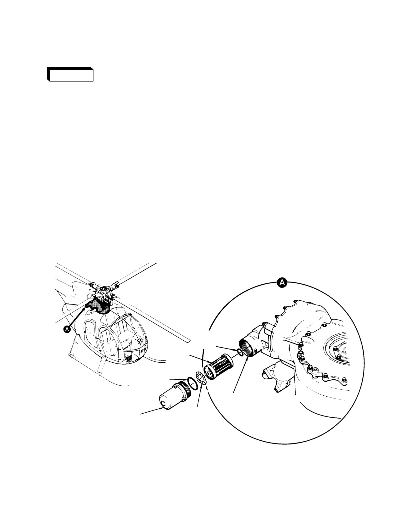
ELEMENT
O−RING
PACKING
FILTER
ELEMENT
HOUSING
O−RING
PACKING
PUMP
HOUSING
SPRING
FILTER HOUSING;
TENSION
70−100 IN. LB. (7.91−11.30 NM)
WASHER
30−009B
Figure 2-8. Transmission Lubrication Pump Oil Filter
Page 2-47
Revision 14
MD Helicopters, Inc.
CSP−H−2
500 Series - Basic HMI
(9). Check that tension washer is in filter
NOTE: The current drawn by the starter−gen−
housing and install element in filter
erator to maintain 10% N1 rpm should be
housing. Check that the O−ring on the
approximately 150 amperes with 12 Vdc in−
element will seat properly in the pump
put.
housing when element is installed.
I. Engine Air Inlet Screen Cleaning
(10). Turn filter housing clockwise and
(1). Remove vertical air inlet screen.
tighten to 70 − 100 inch−pounds (7.91
(2). Clean filter screen with a soft brush to
−
11.30 Nm). Safety the filter housing
remove dirt accumulations.
to the pump housing with lockwire (2).
(3). Immerse screen assembly in a solution
(11). Replenish transmission oil supply if
of detergent soap (63, Table 2−4) and
necessary; then perform ground runup
allow to soak approximately 15 min−
of helicopter and check splitline for oil
utes. Flush out with clear water. Allow
leakage.
screen assembly to drain and air−dry
thoroughly.
(12). Reinstall, in order, the main transmis−
sion cover, the drain assembly, the main
10. Corrosion Control
gearbox access cover and sound insula−
The airframe is fabricated mainly of aluminum
tion.
and some magnesium alloys, with selective use
of stainless steel and titanium, and should be
G. Engine Fuel and Oil Filter Cleaning
checked regularly for any signs of corrosion,
especially at points of dissimilar and overlap−
Refer to the appropriate Allison Operation and
ping metal contact.
Maintenance Manual.
(1). Corrosion of dissimilar metals is the
H. Engine Compression Cleaning
result of several conditions; lack of
sufficient insulation in the areas of
Clean engine compressor according to the
metal contact, tears or punctures in the
Allison Operation and Maintenance Manual
metal itself, and areas where the
and the following limits. The Lear−Siegler
protective finishes have been scuffed,
Model Number 23032−020 starter−generator
scratched, chipped or worn away.
can be used to motor the Allison 250 Series
engine for compressor cleaning cycles each 50
(2). Inspections and maintenance precau−
or more hours. Input voltage should be 24 Vdc,
tions should be performed to inhibit the
but it is permissible to use 12 Vdc. To prevent
start of corrosive action (Ref. Standard
starter−generator damage, the duty cycle
Practices for Corrosion Prevention).
(cranking) time limits that must not be
(3). Common types of corrosion that may be
exceeded are:
encountered are described in the
following paragraphs.
24 Vdc External
24 Vdc Helicopter
Auxiliary Power
Battery Power
(4). Restoration procedures for marred but
uncorroded surfaces, as well as surfaces
25 Seconds ON
40 Seconds ON
in which corrosion is found, are given in
30 Seconds OFF
60 Seconds OFF
the touch−up procedures.
25 Seconds ON
40 Seconds ON
(5). Refer to MDHI Publication No.
30 Seconds OFF
60 Seconds OFF
CSP−A−3 Corrosion Control Manual for
a more complete treatment of this
25 Seconds ON
40 Seconds ON
maintenance area.
30 Minutes
OFF
30 Minutes
OFF
A. Standard Practices for Corrosion
12 Vdc External Auxiliary Power
Prevention
2 Minutes ON
(1). Inspection of Interior Metal Surfaces:
30 Minutes OFF
(a). Inspect primer−painted surfaces for
2 Minutes ON
scratches and other damage.
Page 2-48
Revision 14
MD Helicopters, Inc.
CSP−H−2
500 Series - Basic HMI
(b). Inspect finish−painted (color coated)
(a). Check that seam or joint is clean and
surfaces for condition of finish.
free of foreign matter and moisture.
(c). Inspect areas of metal overlap (faying
(b). Apply sealant with a putty knife or
similar tool.
surfaces) for evidence of corrosion.
(c). Force the sealant well down into the
(d). Inspect the attachment area of bolts,
seam to eliminate any air pockets.
screws and other fasteners for
corrosion.
(d). Fillet the sealant to give the joint or
seam a smooth appearance.
(2). Inspection of Exterior Metal Surfaces:
(5). Removal of Salt Deposits: To inhibit
(a). Inspect finish for scratches, cracks,
corrosion, helicopters operating over
peeling, fading, or other damage,
salt water and those that come in
particularly around bolts, screws,
contact with salt water or spray should
and other fasteners.
be washed with fresh water as fre−
quently as possible.
(b). Inspect normally sealed seams and
B. Magnesium Alloy Corrosion
joints for loose or missing sealing
compound.
Corrosion will not normally be present on
painted, treated or protected surfaces.
(c). Inspect exposed skin edges for
condition of corrosion−protective
Corrosion will attack magnesium when nicks
finish or sealing compound and for
or scratches through the surface protection
evidence of corrosion.
expose the metal to moisture or air. Corrosion
is present if the following conditions are in
(d). Inspect areas of metal overlap for
evidence.
evidence of corrosion.
Bare magnesium alloys, when
CAUTION
(3). Insulation of Magnesium Alloys
exposed to salt− laden air, will
Against Corrosion: To prevent galvanic
corrode very rapidly. Adequate protective fi−
corrosion between magnesium and any
nishes must at all times be maintained on
dissimilar metals:
magnesium.
(1). Whitish powdered deposits.
(a). Coat contacting surfaces with a layer
of sealing compound (3, Table 2−4) in
(2). Zinc chromate primer discoloration over
addition to the primer (4 or 7).
an area.
(b). Use 5056S aluminum alloy washers
(3). Blistering or cracking of the finish
under boltheads and nuts that would
coating.
otherwise contact magnesium. If
5056S aluminum is not available, use
C. Aluminum Alloy Corrosion
5052S alloy washers.
Corrosion will not normally be present on
aluminum surfaces that have a chemical
CAUTION
protective finish; however, because moisture
Do not use steel washers.
can permeate paint that is nicked or scratched,
corrosion might attack the metal even though
(c). Apply primer (4) on the attaching
it is painted. In such cases, the affected areas
hardware before installation.
will generally be characterized by:
(4). Application of Sealing Compound: Use
(1). A scaly or blistered appearance of the
sealing compound (3) to replace loose or
finish surface.
missing sealant on exterior surfaces.
Sealant is used to fill seams and joints
(2). A dulling and pitting of the area.
that might trap water. Apply sealant as
follows:
(3). Whitish powdered deposits.
Page 2-49
Revision 14
MD Helicopters, Inc.
CSP−H−2
500 Series - Basic HMI
NOTE: To differentiate between aluminum and
(4). If protective paint coatings are not
magnesium alloy, apply one drop of ordinary
available, liberally apply a corrosion−
sulfuric acid (dropped from a glass rod) to
preventive compound or any available
the surface of the metal being tested. If the
grease to affected areas.
alloy is magnesium, a foaming or boiling ac−
F. Corrosion Arresting on Main Rotor
tion of the liquid, accompanied by a black
Blades
discoloration of the metal, will immediately
occur. If the alloy is aluminum, no reaction
The following outlines a method of arresting a
to the acid will be evidenced.
corrosive condition on main rotor blades.
Do not apply sulfuric acid to or
Wear rubber gloves when using
CAUTION
CAUTION
near bolts, fasteners, seams, or
phosphoric solution in next step.
faying surfaces. Immediately after complet−
(1). Wipe down main rotor blades with a 10
ing the magnesium and aluminum test,
percent phosphoric acid solution (10,
wash the tested area with water to prevent
Table 2−4).
burns and continued acid action on the ma−
terial.
(2). Rinse main rotor blades immediately
with water and wipe dry.
D. Alloy Steel Corrosion
(3). Wax main rotor blades.
Corrosion (rust) will not normally be present
on steel surfaces that have been painted;
NOTE: As a preventive measure to assist in ar−
however, surfaces may corrode where moisture
resting further corrosion the main rotor
has permeated the paint. Such corrosion will
blades should be washed with water and
be characterized by:
waxed on a weekly basis.
G. Main Rotor Hub Corrosion Prevention
(1). A reddish or brownish blistered
(Tri-Flow Wash Procedure)
appearance in the corroded area.
The following procedure will help prevent
(2). Blistering of the painted surfaces.
corrosion of main rotor hub components,
especially on helicopters operated in marine
E. Temporary Anti-Corrosion Measures
environments. The procedure should be
The temporary anti−corrosion measures
accomplished following the last flight each day
outlined here are to be used only in cases
for helicopters operated in marine or other
where the proper materials or equipment are
corrosive environments, and at each 25 hour
not available.
inspection, or more often if desired, for
helicopters not operated in corrosive environ−
These temporary anti−corro−
ments.
WARNING
sion measures apply to the
Use care when working
helicopter airframe only. If a part of
WARNING
around turning rotor blades.
the structure is corroded too badly to
Stay low. Remain on right side of heli−
withstand normal loads before the heli−
copter to avoid tail rotor blades.
copter can reach a repair station, metal
patches will have to be installed before
NOTE: Perform the first step below prior to en−
the helicopter is flown
gine shutdown, following the last flight of
the day if possible. When the rotor stops
(1). Examine part or area in question for
turning, the laminates of the strap− pack
extent of corrosion.
spread apart slightly. Contaminates col−
lected on the edges of the strap−pack assem−
(2). Remove loose paint and powdery
bly can enter the area between the lami−
products of corrosion by scraping with a
nates as they spread apart. If the rotor
sharp phenolic scraper, or brushing the
continues turning until the contaminants
area with a heavy fiber brush.
are washed away, centrifugal force will keep
(3). Wash off the affected areas with mild
the laminates compressed and not allow the
soap and clean fresh water; rinse
corrosive substances to enter the area be−
thoroughly.
tween the laminates.
Page 2-50
Revision 14
MD Helicopters, Inc.
CSP−H−2
500 Series - Basic HMI
(1). Bring engine to ground idle; set SCAV
I. Aluminum Alloy Exterior Surface
AIR to ON (Ref. applicable PFM).
Touch-Up Treatment
Perform the following:
NOTE:
If there is any question of whether or
(a). Spray fine fresh water mist on main
not the protective coating is removed, it
rotor blades.
should always be assumed that bare metal
is exposed.
(b). Direct a strong stream of fresh water
(1). Wash affected area with a solution of
into main rotor hub and control
mild soap and fresh water. Rinse area
system at main rotor hub.
with clean water and wipe dry with a
clean soft lint−free cloth.
(c). Spray entire rotor hub with lubricant
(149, Table 2−4).
(2). Using a swab, liberally apply chemical
film solution (8, Table 2−4).
NOTE: Lift main rotor blades to separate strap
pack laminates in next step, and spray di−
(3). Allow solution to remain on surface for
rectly between individual laminates.
1 to 3 minutes, or until surface becomes
amber to brown in color.
(2). Shut down engine. When rotor blades
stop turning, spray strap−packs with
NOTE: Avoid letting the chemical mixture dry
lubricant.
on the surface. If it has dried, re−wet the
surface with the solution.
(3). Perform engine water wash.
(4). Rinse treated surface thoroughly with
clean water. After rinsing, wipe off
(4). Wash remainder of helicopter exterior
excess moisture with a clean lint−free
using fresh water spray.
cloth. If dry compressed air is available,
(5). Wash main rotor blades with Zip Wax
blow any moisture from joints or
(150), or equivalent, mixed per man−
crevices and allow to dry completely at
ufacturer’s instructions.
room temperature for approximately
one hour.
H. Magnesium Alloy Exterior Surface
(5). Apply paint finish touch−up.
Touch-Up Treatment
J. Steel Alloy Exterior Surface Touch-Up
(1). Prepare solution of chromic acid, 20
Treatment
ounces per gallon (150 g/L), ammonium
sulfate, 14 ounces per gallon (105 g/L),
(1). Remove loose paint and corrosion
and ammonium hydroxide, 12 fluid
products by scraping area with a sharp
ounces per gallon (94 g/L). Solution pH
phenolic scraper, brushing with a heavy
should be 2.6 − 3.4 and operating
fiber brush and light sanding with 320
temperature should be ambient.
grit or finer sandpaper (9, Table 2−4).
(2). Clean painted parts for three to five
(2). Wash off the area with mild soap and
minutes in alkaline solution (Oakite 61
clean fresh water; rinse thoroughly.
or equivalent); swab unpainted parts
(3). Treat surface with surface cleaner (10)
with MEK or aliphatic naphtha.
or equivalent.
(3). Dampen clean cloth or soft brush in
(4). Allow solution to remain on surface for
prepared solution and apply to touch−
approximately five minutes. Keep
up areas for ten to thirty minutes until
surfaces wet.
desired color is produced. Color range is
from gold through yellow to brown.
(5). Rinse thoroughly roughly with clean
water. Dry with a clean lint−free cloth
(4). Rinse or swab parts thoroughly in
and then allow to air−dry completely.
clean, room temperature water. Dry;
paint as required.
(6). Apply paint finish touchup.
Page 2-51
Revision 14
MD Helicopters, Inc.
CSP−H−2
500 Series - Basic HMI
11. Paint Finish
If paint remover is used in the
CAUTION
vicinity of drive shaft couplings,
ensure the couplings are completely masked
Refer to the applicable configuration supple−
and covered. if paint remover contacts the
ment for details of standard production paint
coupling diaphragms, rust spots will devel−
finish, color and color scheme. (Customized
op and coupling replacement will be re−
paint schemes are not shown.)
quired.
B. Paint Touch-Up
A. Paint Removal
Whenever possible, paint touch up should be
performed in a dust−free shelter that is free of
excessive air currents and that has ventilation
(1).
Use paint remover (11, Table 2−4)when
provisions for adequate (safe) personal
it becomes necessary to remove the
respiration.
finish paint coatings. Ordinarily, the
use of paint remover should be limited
The following items should nev−
CAUTION
to stripping of paint from parts that
er be touched up, primed or fin−
require magnetic particle or fluores−
ish−painted: rod ends containing bearings;
cent−penetrant inspection and to parts
bolts and nuts securing rod ends; decals and
that require the removal of excessive
serialization plates; transparent surfaces
paint buildup.
(canopy, etc); parts made from natural, syn−
thetic or silicone rubber; electrical bonds;
close tolerance holes; and parts continuous−
(2).
Solvent type paint remover is usually
ly coated with grease, oil or fluid.
not capable of removing the primer
NOTE: Following procedures apply to applica−
coating. However, complete removal of
tion of both polyurethane and acrylic paints.
the epoxy primer coating may not be
The primary interior finish of the helicopter
required to perform dye−penetrant
is acrylic paint. Polyurethane paint is used
inspection.
for the exterior finish on a current 369HS/
HE helicopter. The exterior of a 369HM or
(3).
If necessary, it may be possible to
early 369HS/HE helicopter is finished with
remove small amounts of primer by
acrylic paint. Polyurethane paint may be
light scrubbing of the primer surface
applied directly over acrylic paint since the
with solvent type paint remover and a
two are compatible.
stiff bristle brush. No other means,
(1). Touch up − Small Sanded Areas
short of sanding or mechanical scrap−
(Reworked Scratches, Nicks, Gouges,
ing, will prove more suitable or effective
etc):
for removal of epoxy primer except use
(a). If metal protection is not adequate,
of the acid type remover.
apply applicable chemical surface
treatment.
(4).
Whenever the acid type remover is used
(b). If chemical surface treatment is
all special safety precautions noted on
undamaged or has already been
the container must be observed. Use all
applied, wipe the surface clean with
necessary precautions to prevent the
thinner (12, Table 2−4). Wipe dry
entry of any type paint remover into
immediately.
structural seams or joints, and the joint
lines of bearings and bushings that are
(c). Apply coat of epoxy primer (7).
still assembled with the part to be
Feather primer coating onto sur−
stripped.
rounding color coat.
(d). Allow primer to air−dry for 30
minutes.
(5).
When possible, use a high pressure
water spray to rinse off paint remover
(e). Apply lacquer color coats (6), to
and paint particles and to neutralize
match original finish color, as appli−
the paint remover.
cable.
Page 2-52
Revision 14
MD Helicopters, Inc.
CSP−H−2
500 Series - Basic HMI
(2). Touchup − Flaking or Dried Paint or
(b). Mix equal parts (1:1) of primer resin
Primer:
(109) and thinner (110). Apply one
coat to surface and allow to air−dry
(a). Using 320−grit or finer sandpaper
minimum of three hours.
(9), and wet or dry sanding method,
sand the nonadherent surface to a
(c). Apply epoxy primer and color finish
smooth feather edge with the sur−
according to step (1). above.
rounding area. Do not sand beyond
point where chemical film protection
(6). Touchup − ABS Thermoplastic Parts:
begins to show through primer.
(a). Clean surface with mild soap and
(b). Touchup sanded area according to
water. Dry thoroughly.
step (1). above.
(b). Apply one coat of lacquer according to
(3). Touchup − Primer Not Adhering to
step (1).(e).
Metal Finish:
12. Main Rotor Blade Paint
(a). Use 320−grit or finer sandpaper and
wet or dry sanding method to sand
The following procedures is to be used whenev−
through chemical film to bare metal.
er the main rotor blades require either
Feather edge the surrounding surface
repainting or paint touch−up.
with the bare surface.
NOTE:
(b). Touchup re−treated surface according
to step (1). above.
D Repaint main rotor blades only in sets to
maintain rotor balance. Never completely
(4). Touchup − Glass Fiber Laminate Parts:
repaint only one main rotor blade
installed on helicopter.
(a). Use 100−grit or coarser sandpaper to
D New main rotor blades have the inboard
abrade area requiring finish. Remove
24 inches (610 mm) painted gloss white.
all gloss until there is a uniform dull
This aids in inspection of the blade.
condition.
D At owner−operators convenience, in−ser−
(b). Wipe surface clean with 1:1 mixture
vice main rotor blades may have the in−
of MEK (22) and isopropyl alcohol
board 24 inches (610 mm) painted gloss
(71).
white.
(c). Squeeze one coat of Poly−EP (107),
A. Main Rotor Blade Paint Removal
thinned as required with thinner
(108), into fiberglass pores until
(1). Position main rotor blade on a bench of
surface of fibers is smooth.
sufficient length to provide support.
(d). Lightly sand surface with 320−grit
(2). Inspect main rotor blade (Ref. Sec. 7,
sandpaper. Normal grain appearance
Main Rotor Blade Inspection).
does not require further filling or
sanding.
When removing paint from
CAUTION
main rotor blade, do not use any
(e). Apply epoxy primer according to step
paint remover. Bonding agents used in
(1). above.
manufacture of the blade may be damaged
by the chemicals causing the blade to be un−
(5). Touchup − Polycarbonate Plastic Parts:
serviceable.
(a). Wipe surface clean with a 1:1 mix−
(3). Apply tape (14, Table 2−4) to all
ture of naphtha (59) and isopropyl
bushings, bearing, data plates and the
alcohol (71).
abrasion strip.
Page 2-53
Revision 19

MD Helicopters, Inc.
CSP−H−2
500 Series - Basic HMI
(6). Apply primer to sanded areas, feather
CAUTION
into surrounding color coat.
D When sanding paint from the main rotor
(7). Allow to air−dry for one hour minimum.
blade, take care to not damage rivet heads
and sealant.
NOTE: Mix paint (148) according to manufac−
turer’s recommendations.
D Do not sand through the paint and primer
into the base metal.
(8). Allow mixed paint (148) to stand for 20
minutes minimum prior to use.
(4). Using 320 grit, or finer, abrasive paper
(9) and wet or dry sanding method,
NOTE:
sand areas that require painting.
D Working life of mixed paint is four hours
maximum.
(5). Using a soft cloth, dampened in
isopropyl alcohol (71), thoroughly clean
D Addition of freshly mixed primer to re−
main rotor blade.
plenish an older mixture is not permitted.
(6). Inspect sanded areas for damage.
(9). Apply paint to primed areas. Feather−
edge paint while applying.
B. Main Rotor Blade Paint Application
(10). Allow to air−dry for eight hours
NOTE: If inboard 24 inches (610 mm) of main
minimum.
rotor blade is to be painted white, paint is to
(11). Remove protective tape from main rotor
be applied to the entire circumference of the
blade.
blade. There is to be no ridges in the paint
when completed.
NOTE: Main rotor assembly may need to be re−
balanced after painting.
(1). Inspect main rotor blade (Ref. Sec. 7,
Main Rotor Blade Inspection).
13. Metal Tail Rotor Blade Paint
(2). Ensure all bushings, bearing, data
The following procedures is to be used whenev−
plates and the abrasion strip are
er the metal tail rotor blades require either
protected from paint with tape (14).
repainting or paint touch−up.
(3). Using a soft cloth, dampened in
NOTE: Repaint tail rotor blades only in sets to
isopropyl alcohol (71), thoroughly clean
maintain rotor balance. Never completely
main rotor blade.
repaint only one tail rotor blade installed on
helicopter.
(4). Treat any bare metal areas of main
rotor blade with chemical coating (8).
A. Metal Tail Rotor Blade Paint Removal
NOTE: Mix primer (4) according to manufac−
(1). Inspect tail rotor blade (Ref. Sec. 8,
turer’s recommendations.
Metal Blade Inspection).
(5). Allow mixed primer (4) to stand for 15
When removing paint from tail
CAUTION
rotor blade, do not use any paint
to 30 minutes prior to use.
remover. Bonding agents used in manufac−
NOTE:
ture of the blade may be damaged by the
chemicals causing the blade to be unservice−
D Working life of mixed primer is four hours
able.
maximum.
(2). Apply tape (14, Table 2−4) to all
D Primer allowed to stand for more than
bushings, data plates and the abrasion
two hours must be stirred or shaken be−
strip.
fore use.
D Addition of freshly mixed primer to re−
(3). Plug root end of tail rotor blade to
plenish an older mixture is not permitted.
ensure no paint enters.
Page 2-54
Revision 19

MD Helicopters, Inc.
CSP−H−2
500 Series - Basic HMI
NOTE: Mix paint (148) according to manufac−
CAUTION
turer’s recommendations.
D When sanding paint from the tail rotor
(9). Allow mixed paint (148) to stand for 20
blade, take care to not damage rivet heads
minutes minimum prior to use.
and sealant.
D Do not sand through the paint and primer
NOTE:
into the base metal.
D Working life of mixed paint is four hours
maximum.
(4). Using 320 grit, or finer, abrasive paper
(9) and wet or dry sanding method,
D Addition of freshly mixed primer to re−
sand areas that require painting.
plenish an older mixture is not permitted.
(5). Using a soft cloth, dampened in
(10). Apply paint to primed areas. Feather−
isopropyl alcohol (71), thoroughly clean
edge paint while applying.
tail rotor blade.
(11). Allow to air−dry for eight hours
(6). Inspect sanded areas for damage.
minimum.
B. Metal Tail Rotor Blade Paint Application
(12). Remove protective tape from tail rotor
blade.
(1). Inspect tail rotor blade (Ref. Sec. 8,
Metal Blade Inspection).
NOTE: Tail rotor assembly may need to be re−
(2). Ensure all bushings, data plates and
balanced after painting.
the abrasion strip are protected from
paint with tape (14).
14. Fluid Leak Analysis
(3). Ensure root end of tail rotor blade is
A. Main Rotor or Tail Rotor Transmission Oil
plugged to prevent entry of paint.
Leaks
(4). Using a soft cloth, dampened in
Oil leakage, seepage or capillary wetting at oil
isopropyl alcohol (71), thoroughly clean
seals assembly joint lines of main or tail rotor
tail rotor blade.
transmission are permissible if leakage rate
does not exceed 2 cc per hour (one drop per
(5). Treat any bare metal areas of tail rotor
minute). An acceptable alternate rate of
blade with chemical coating (8).
leakage from either transmission is, if oil loss
is not more than from full to the add mark on
NOTE: Mix primer (4) according to manufac−
sight gage within 25 flight hours. Repair leaks
turer’s recommendations.
according to instructions in CSP−H−5.
(6). Allow mixed primer (4) to stand for 15
NOTE: On transmission input and output pin−
to 30 minutes prior to use.
ion gear oil seals with less than 2 hours of
NOTE:
operation, some seepage or wetting of adja−
cent surfaces is normal until seal is wetted
D Working life of mixed primer is four hours
and worn−in (seated). If seepage continues
maximum.
at rate of one drop per minute or less, seal
D Primer allowed to stand for more than
may be continued in service. Check trans−
two hours must be stirred or shaken be−
mission oil level and observe seepage rate
fore use.
after every 2 hours of operation. Shorter in−
spection periods may be required if seal
D Addition of freshly mixed primer to re−
leakage appears to be increasing.
plenish an older mixture is not permitted.
(7). Apply primer to sanded areas, feather
NOTE: If excessive tail rotor gearbox oil seep−
into surrounding color coat.
age occurs, check breather filler for sticky
piston (Ref. CSP− H− 5 for cleaning proce−
(8). Allow to air−dry for one hour minimum.
dures).
Page 2-54A
Revision 19
MD Helicopters, Inc.
CSP−H−2
500 Series - Basic HMI
B. Engine Oil Leaks
damper is not replaced when leakage is
noticed, continuation of damper in service can
Refer to the appropriate Allison Operation and
cause internal damage that might otherwise
Maintenance Manual for definition of permis−
not occur.
sible engine oil leakage.
NOTE: It is normal for a thin hydraulic oil film
C. Landing Gear Damper Hydraulic Fluid
to remain on the damper piston as a result
Leaks
of wiping contact with the piston seal. New−
Hydraulic fluid leakage from any of landing
ly installed dampers may also exhibit slight
gear dampers is not permissible. When
oil seepage caused by oil trapped in the end
leakage is observed, the damper assembly
cap threads during damper assembly. Nei−
should be overhauled as required and service−
ther of these should be construed as damper
able unit installed. If leaking landing gear
leakage or cause for damper replacement.
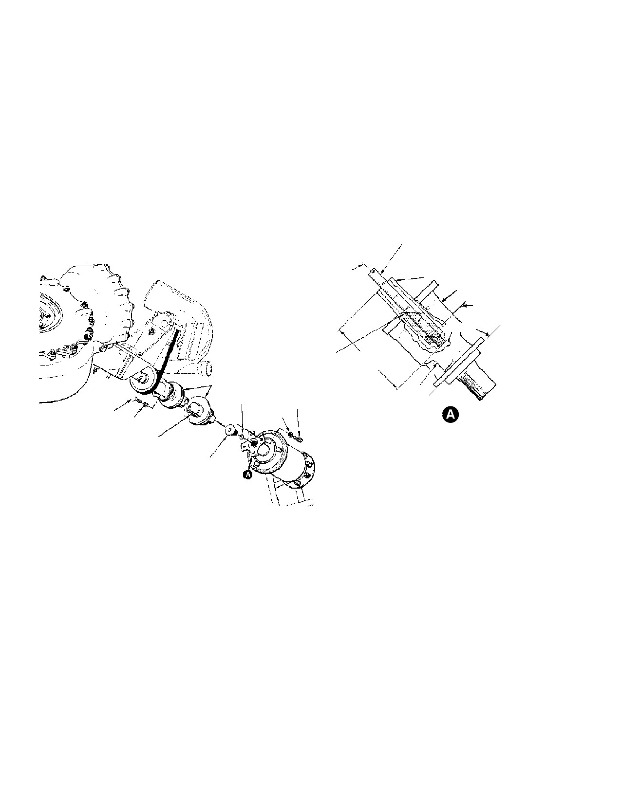
IF REQUIRED, REDUCE WIDTH OF
6.0 IN. (15 CM) MACHINIST SCALE
TO LESS THAN 0.50 IN (12.70 MM).
CLUTCH CL
CLUTCH OUTPUT SHAFT
CLUTCH
0.875 IN (22.23 MM)
(13 CC; NOTE 2)
ENGINE
FULL OIL LEVEL
2.875 IN (7.30 CM)
4−7/8 IN.
(12.38 CM)
COUPLING BOLT
COUPLING
(TYP) 50−70 IN. LB.
O−RING
(5.65−7.91 NM)
DRAIN HOLES
COUPLING BOLT;
WASHER
50−70 IN. LB.
WASHER
(5.65−7.91 NM) (TYP)
NOTES:
MAIN TRANSMISSION
1.
DRAG TORQUE FOR BOLTS (SELF−LOCKING)
DRIVE SHAFT
SERVICEABILITY IS 25 IN. LB. (2.82 NM) MIN,
200 IN. LB. (22.60 NM) MAX.
COUPLING BOLT;
2.
MINIMUM ALLOWABLE OIL QUANTITY
250−300 IN. LB. (28.25−33.90 NM)
PERMITTING REFILL WITHOUT REPAIR.
PLUS DRAG TORQUE (NOTES 1, 3)
IF OIL QUATITY IS LESS, CLUTCH MUST
BE REPAIRED AS REQUIRED BY HMI APPX C.
3.
COAT COUPLING BOLT THREADS WITH
ANTI−SEIZE COMPOUND (36, TABLE 2−4)
BEFORE REASSEMBLY.
30−010K
Figure 2-9. Checking Overrunning Clutch Oil Level
Page 2-54B
Revision 19
MD Helicopters, Inc.
CSP−H−2
500 Series - Basic HMI
D. Overrunning Clutch Oil Leak Analysis
(a). Full oil level will read 2−7/8 inches
and Servicing
(7.30 cm) on LOWER edge of 6 inch
(15.24 cm) scale. Recheck reading a
(Ref. Figure 2−9) When oil leakage or seepage
minimum of three times.
is noticed at the oil seals or assembly joint
(b). Minimum allowable oil quantity (13
lines of the overrunning clutch, the clutch
cc of trapped oil) will read 7/8 inch
requires further inspection and investigation
(2.22 cm) on bottom edge of scale.
as follows.
Recheck reading a minimum of three
times.
CAUTION
NOTE: If oil quantity is less than 13 cc, the
D Mixing of oils within an oil series, not in
clutch must be removed for repair according
the same group, is not recommended. If
to instructions in CSP−H−5.
oils of different groups are mixed, flush
(7). Service clutch with lubricating oil
and re−service overrunning clutch.
(Table 2−3) if oil level readings indicate
D Checking clutch oil level requires removal
less than the full level. Do not overfill.
of the main transmission drive shaft. Do
Recheck oil level.
not stress the drive shaft diaphragms
(8). If coupling was removed, shim coupling
during shaft removal and installation. Di−
so that there is 0.035−0.055 inch
aphragm deflection is limited because of
(0.889−1.397 mm) O−ring gap from end
material hardness.
of clutch shaft to face of coupling recess
(surface that bolt head contacts).
(1).
Remove, in order, the sound insulation,
Measure gap with feeler gage.
gearbox access cover, and transmission
drain assembly.
When installing the clutch cou−
CAUTION
pling bolt in the installation
(2).
Remove four bolts and washers from
torque on the bolt must not be less than
each end of main transmission drive
250 − 300 inch pounds (28.25 − 33.90
shaft. Carefully slide shaft from drive
Nm). Torquing to a lower value will reduce
couplings; do not strike shaft against
clutch bearing clamp−up and possibly lead
any object.
to bearing race spinning.
(3).
Remove bolt and O−ring packing from
(9). Coat bolt threads with anti−seize
end of clutch.
compound (36). Install coupling bolt
and O−ring packing. Check drag
(4).
On helicopters with clutch housing
torque for bolt self locking service−
drain holes, check that the three drain
ability is 25 inch−pounds (2.82 Nm)
holes are clean and free of obstruction.
minimum, 200 inch−pounds (22.60
Oil leakage may indicate engine power
Nm) maximum. Torque bolt to 250 −
output seal leakage if clutch oil level is
300 inch−pounds (28.25 − 33.90 Nm)
checked and found within limits.
plus drag torque.
(5).
Using a CLEAN, 6 inch (15.24 cm)
(10). Position main transmission drive shaft
machinists scale, 1/2 inch (12.7 mm)
between drive couplings and install.
width, slowly insert the scale into
(11). Reinstall, in order, the transmission
center of clutch output shaft until scale
drain assembly, gearbox access cover,
bottoms. Scale must be inserted 4−7/8
and the sound insulation.
inches (12.38 cm).
E. One-W ay Lock (Uniloc) Fluid Leak
NOTE: Reduce 1/2 inch (12.7 mm) scale width
as required to allow scale to bottom in
Hydraulic fluid leakage from any part of the
clutch.
one−way lock is not permissible. When leakage
is observed the assembly should be overhauled
(6). Read scale to determine oil level and
as required and a serviceable unit installed. If
servicing required.
a leaking one−way lock is not replaced when
Page 2-55
Revision 14
MD Helicopters, Inc.
CSP−H−2
500 Series - Basic HMI
leakage is noticed, continuation in service may
(g). Install a static ground.
result in mechanical malfunction that could be
(3). Return to Service:
hazardous to safety of flight.
(a). Remove covers and equipment used
15. Preservation and Storage
to park and moor the helicopter.
Helicopters to be put in storage or non−opera−
(b). Perform a preflight inspection.
tional status must get adequate inspection,
maintenance and preservation to avoid
B. Storage up to 45 Days
unnecessary deterioration of the airframe,
(1). Inspection During Storage:
components or equipment during the storage
or non−operational interval. The extent of
(a).
Where local average humidity
preventive maintenance that should be
exceeds 40 percent carefully inspect
performed will depend on the anticipated time
the helicopter every 15 days for
in storage. The following paragraphs establish
corrosion. Apply corrosion control as
what should be performed on a helicopter: for
necessary. In conducting an inspec−
flyable storage; for up to 45 days in storage;
tion for corrosion, pay particular
and for up to 6 months in storage.
attention to those area where mois−
ture deposits will not evaporate
A. Flyable Storage (No Time Limit)
rapidly.
(1). Inspection Before Storage:
(b).
Where local average humidity is 40
(a). Perform a preflight inspection.
percent or less, inspect for corrosion
every 30 days.
(b). Ensure that fuel cells are full (topped
off), and that the engine oil tank and
(c).
If interior temperature of fuselage
rotor transmissions are at the FULL
exceeds 160°F (71°C), ventilate
level.
helicopter by opening all doors and
vents. If necessary, promote air
(2). Storage: To maintain a flyable storage
circulation by use of fans or other
condition, perform daily inspection. A
forced air equipment.
ground runup must also be performed
at least once every 5 days.
(d).
Ensure that fuel cells are full (topped
off) and that the rotor transmissions
(a). Perform a preflight inspection.
are at the FULL level.
(b). Start the engine (Ref. PFM). After
(e).
Drain fuel cell sump daily. (Replenish
idle has stabilized, accelerate the
fuel as necessary.)
engine to 100 percent N2 collective
full down. Operate until the oil
(f).
Check fuel and oil systems periodical−
temperature is in normal operating
ly for leakage. Repair as necessary.
range and ammeter indicates battery
(2). Storage:
is fully charged.
(a). Perform engine preservation accord−
(c). Drain fuel cell sump (Ref.
ing to the engine operation and
Figure 2−5). (Replenish fuel as
maintenance manual and current
necessary.)
engine service letters.
(d). Ensure that fuel shutoff valve is
(b). Remove battery and store it in a cool,
closed.
dry area.
(e). Open movable air vents in each door
(c). Clean the battery compartment, if
of the cargo compartment. Position
necessary.
opening in each air vent downward.
Close all other vents.
(d). Ensure that the fuel shutoff valve is
closed.
(f). Install covers and equipment used to
park and moor helicopter.
(e). Clean entire helicopter.
Page 2-56
Revision 20
MD Helicopters, Inc.
CSP−H−2
500 Series - Basic HMI
(f). Inspect all drain holes (blades,
(b).
Drain the engine oil system and fill
fuselage, etc) for obstructions and
the engine oil tank with corrosion
clear them where necessary.
preventive (13, Table 2−4).
(g). Open movable air vents in each door
(c).
Remove battery and store it in a cool,
of cargo compartment. Position
dry area.
opening in each air vent downward.
(d).
Clean the battery compartment, if
Close all other air vents.
necessary.
(h). Install main rotor blade covers, if on
(e).
Ensure that the fuel shutoff valve is
hand. Park and moor the helicopter.
closed.
(i). Install a static ground.
(f).
Seal static source openings in the
engine inlet fairing with tape (14)
(j). Remove from the area any objects
and cover pitot tube with pitot cover
that are likely to strike the helicopter
(4, Table 2−2).
during high wind conditions.
(g).
Clean entire helicopter.
(3). Return to Service:
(h).
Inspect all drain holes (blades,
(a). Check that the battery area is clean;
fuselage, etc) for obstructions and
then install and connect battery.
clear them where necessary.
(b). Check that fuel cells are full.
(i).
Spray or brush on the canopy and all
windows a 0.008 inch (0.2032 mm)
(c). Remove covers and equipment used
thickness of protective coating (15,
to park and moor the helicopter.
Table 2−2). Cover and overlap all
edges.
(d). Inspect areas around mooring
attachments for damage. Repair
(j).
Inspect all external access doors for
damage as necessary.
close fit. If doors are likely to admit
moisture, seal edges with tape.
(e). Clean the helicopter, as necessary.
(k).
Install main rotor blade covers, if on
(f). Check that all drain holes in helicop−
hand. Park and moor helicopter.
ter are free of obstructions.
(l).
Install a static ground.
(g). Perform a preflight inspection.
(m).
Remove from the area any objects
that are likely to strike the helicopter
C. Storage up to 6 Months
during high wind conditions.
(1). Inspection During Storage:
(3). Return to Service:
(a). Perform same inspection as for 45
(a). Carefully lift protective coating along
days of storage.
the edges and peel it from the canopy
and windows.
(b). Check rotor blades for damage every
15 days.
(b). Remove masking tape from all
external access doors.
(c). Check areas around mooring attach−
ments for damage every 15 days.
Do not use steam or unautho−
CAUTION
rized cleaning compounds to
(2). Storage:
clean the helicopter as damage to equip−
ment may result.
(a). Perform engine preservation accord−
ing to the engine operation and
(c). Drain corrosion preventive from the
maintenance manual and current
oil tank and replenish with correct oil
engine service letters.
(Table 2−3).
Page 2-57
Revision 14
MD Helicopters, Inc.
CSP−H−2
500 Series - Basic HMI
(d). Perform same procedures as for
(d).
The turning (drag) torque required to
return to service after 45 days of
install self−locking nut or bolt up to
storage.
point of final tightening must always
be added to the final torque value or
NOTE: Depreservation of the engine fuel sys−
the maintenance instruction, as
tem can usually be accomplished by making
applicable.
a normal start. (Refer to the engine opera−
tion and maintenance manual, and current
(e).
Torques specified in handbook
engine service letters for engine depreserva−
maintenance instructions are special
tion procedures.)
torque that take precedence over
those listed in Table 2−5 thru
16. Torque Data
Table 2−8.
A. Torque Wrenches
(f).
If adapters are used such that the
Torque wrenches should be of good quality and
adapter and the torque wrench are
must be calibrated at least every 90 days to
not at right angles (90°) to each
other, wrench or indicator reading
verify accuracy. Torque wrench accuracy at
must be corrected.
room temperature, 70°F (21°C) must be within
the following limits.
(g).
Any reuse of self−locking nuts over
(1). From zero thru 19 percent of the torque
3/8 inch will be governed by the
wrench range, the error may not exceed
values in Table 2−8.
±7 percent of the load applied.
(h).
The bolt must not be rotated during
(2). From 20 thru 79 percent of the torque
installation or torquing of the mating
wrench range, the error may not exceed
nut.
±4 percent of the load applied.
(3). From 80 thru 100 percent of the torque
NOTE: All special (non−standard) torque val−
wrench range, the error may not exceed
ues appearing in Table 2−9
±5 percent of the load applied.
(2).
Installation of Castellated Nuts on
17. Torque Wrench Load Application
Non−rotating (Static) Parts: Finger−
tighten the nut on installation. Turn
Recommended tightening torque values and
the nut a minimum of 60 degrees and a
minimum drag torque values for fine and
maximum of 110 degrees (or the next
coarse thread nuts, and minimum breakaway
slot after 60 degrees of rotation) past
torque for used self−locking bolts or screws are
finger−tight and insert and secure
shown in Table 2−5 thru Table 2−8.
cotter pin for final installation. Maxi−
mum applied torque must not exceed
(1). Requirements Governing Application of
the applicable values in Table 2−5 and
Torque Loads:
Table 2−6.
(a). The values apply to cadmium− plated
(3).
Installation of Castellated Nuts on
bolts, cadmium−plated nuts and nuts
Rotating (Dynamic) Parts: When
coated with molybdenum disulfide
tightening castellated nuts and bolts, it
(MoS2).
is possible that the cotter pin holes will
(b). Manufacturer−applied lubricant
not line up with the slots in the nuts for
must not be removed nor additional
the range of recommended installation
lubricant added.
torques. In such a case, the nut may be
overtighten just enough to line up the
(c). The bolts, nuts and surfaces they
nearest slot with the cotter pin hole,
bear on must be clean, dry and free of
but the maximum applied torque must
lubricant (except as stated in step (b).
not exceed the applicable values in
above).
Table 2−5 and Table 2−6.
Page 2-58
Revision 20
MD Helicopters, Inc.
CSP−H−2
500 Series - Basic HMI
(4). Installation of Self−Locking Tension−
which are all metal and non−metallic
and Shear−Type Nuts:
which have non−metallic locking
inserts. Non−metallic self−locking
NOTE: Non−metallic self−locking nuts should
nuts should not be subject to temper−
not be subjected to temperatures in excess of
atures in excess of 250°F (121°C).
250°F (121°C).
(b). Self−locking bolts come in three
(a). Use torques in Table 2−5 for tension−
general types: a round pellet, a hex
type cadmium−plated steel nuts.
pellet or a strip type insert is placed
in the threaded area to provide the
(b). Use torques in Table 2−6 for shear−
self−locking feature. In addition to
type cadmium−plated steel nuts.
checking for breakaway torque
(5). Installation of Bolts − General:
values listed in Table 2−8, the bolts
should be checked for loose or miss−
(a). If bolt can be inserted through the
ing inserts.
material and started into the nut by
fingers, use the applicable torque in
NOTE: Burrs on cotter pin holes tend to tear
Table 2−5 and Table 2−6.
the non−metallic inserts.
(b). If installing the bolt in a close
(c).
Bolts, nuts or screws of 5/16 inch
tolerance hole, or under other
(7.94 mm) diameter and over with
conditions that increase the tighten−
cotter pin holes may be used with
ing resistance, torque to the high
self−locking nuts provided the cotter
limit of the applicable recommended
pin holes are free from burrs.
torque in Table 2−5 and Table 2−6.
(d).
Bolts and screws of 1/4 inch (6.35
mm) diameter and under with cotter
(6). Installation of Bolts Into Threaded
Parts:
pin holes may be used with self−lock−
ing nuts only in an emergency for one
(a). When installing the bolt into a
time flight. They will be replaced
threaded part, use the applicable
before the next flight with the
torque in Table 2−5 if the mating
specified type.
thread length is equal to or greater
(e).
Self−locking nuts will not be used at
than one diameter of the bolt.
joints in control systems of the
(b). Use Table 2−6 if the mating thread
helicopter when movement of the
length is less than one diameter of
joint may result in motion of the nut
the bolt.
relative to the surface against which
it is bearing.
NOTE: The requirements in steps (5). and (6).
above also apply to thread inserts.
(f).
Self−locking nuts may be used with
anti−friction bearings and control
(7). Installation of Used Self−Locking Bolts
pulleys provided the inner race of the
or Screws: New self−locking nuts or
bearing is clamped to the supporting
bolts provide tight connections which
surfaces by the nut and bolt.
will not loosen under vibration. Self−
locking nuts or bolts approved for use
(g).
The nuts which are attached to the
on helicopters meet critical specifica−
structure must be attached in a
tions as to strength, corrosion−resis−
positive manner to eliminate the
tance and temperatures. Reuse of
possibility of their rotating or misal−
self−locking nuts or bolts are limited to
igning when the tightening is to be
those nuts and bolts that meet the
accomplished by rotating the bolts or
minimum requirements established in
screws.
Table 2−7 and Table 2−8 for drag or
(h).
The manner of attachment must
breakaway torque values.
permit removal without injury to the
(a). Self−locking nuts come in two
structure and the replacement of the
general types: metallic lock type
nuts.
Page 2-59
Revision 14
MD Helicopters, Inc.
CSP−H−2
500 Series - Basic HMI
(i). Round or chamfered−end bolts must
ing units of one system into different but
extend at least the full round or
related units of other systems.
chamfer through the nut.
20. Related Publications
(j). Flat end bolts must extend at least
1/32 inch (0.794 mm) through the
Table 2−15 provides a listing of publications
nut.
and directives that form part of the available
information file for maintenance of helicopter
18. Installation, Staking or Swaging Force
components.
Needed for Bearings
21. Maintenance Information Requests
The following procedure explains how to
convert from a given ‘‘Force’’ which is required
Questions that may arise during maintenance
to perform a given task to a proper hydraulic
of the helicopter or it’s components should,
pressure reading.
when possible, be referred to the company’s
(1). Determine the diameter of the ram on
Field Service Representative assigned to the
the hydraulic press to be used.
geographic area in which the helicopter is
being operated. Should there be no factory
NOTE: The hydraulic press to be used must
representative in the area, contact Customer
have a pressure gauge.
Service, MDHI, Mesa, Arizona or the manufac−
turer of the component as appropriate.
(2). Divide the ram diameter by two to get
Table 2−15 lists manufacturers of major
the radius.
components, and addresses.
(3). Multiply 3.14159 (pi, π) times the
22. Inspection Practices and Technical
Radius squared (R2). This will give the
Definitions
area of the ram.
(4). Divide the force required for the task by
Inspection procedures and serviceability
the area of the ram. This gives the
(wear) tolerances for maintenance of the
actual PSI reading for the hydraulic
helicopter are provided either as part of the
press pressure gauge needed to perform
instructions for reassembly and installation of
the task.
components or in inspection and repair
paragraphs. Any damage or wear of a part that
EXAMPLE:
exceeds the given tolerance or that affects the
function and/or integrity of the part is cause
(a). Ram Diameter = 2.65 inch
for replacement with a new or serviceable unit.
Definitions of technical terms normally
(b). Ram Radius (R) = 1.325 inch
associated with the inspection and repair of
the helicopter and its components are shown in
(c). Radius squared (R2 ) = 1.756
Figure 2−10 and listed in Table 2−16.
(d). R2 x 3.14159 = 5.517 (Area of ram)
23. Service and Operations Report Form 853
(e). Force required = 7500−8500 pounds
(variable)
MDHI Service and Operations Report Form
853 may be used to report to MDHI in detail
(f).
7500−8500 = 1359−1540 PSI
any service difficulties encountered with any
MDHI helicopter. Use of the form is encour−
(g). PSI Required = 1359 PSI Minimum
aged and recommended to enable MDHI to
1540 PSI Maximum
provide Owner’s and Operator’s improved
FORCE NEEDED
= Pressure Gauge Reading
service,support and product improvements.
(R2 ) x 3.14159
The form also serves a convenient detailed
record for Owner’s and Operator’s. Copies of
19. Useful Conversion Data
the form may be procured by contacting the
Table 2−10 thru Table 2−14 provide useful
Customer Service Department − Commercial
information for converting common engineer−
Service Publications.
Page 2-60
Revision 20

MD Helicopters, Inc.
CSP−H−2
500 Series - Basic HMI
Table 2-5. Recommended Standard Torques for Tension-T ype Nut:
Min. and Max. Torque Values; AN310, AN365, MS20365, MS21042, NAS1021, NAS1291, NAS679
Recommended
Maximum
Recommended
Maximum
Thread
Thread
Torque
Allowable
Torque
Allowable
Size
Size
in. lb (Nm)
in. lb (Nm)
in. lb (Nm)
in. lb (Nm)
12 - 15
20
12 - 15
20
8 - 36
8 - 32
(1.13
- 1.36)
(2.26)
(1.36
- 1.69)
(2.26)
20 - 25
40
20 - 25
35
10 - 32
10 - 24
(2.26
- 2.82)
(4.52)
(2.26
- 2.82)
(3.95)
50 - 70
100
40 - 50
75
1/4 - 28
1/4 - 20
(5.65
- 7.91)
(11.30)
(4.52
- 5.65)
(8.47)
100 - 140
225
80 - 90
160
5/16 - 24
5/16 - 18
(11.30
- 15.82)
(25.42)
(9.04
- 10.17)
(18.08)
160 - 190
390
160 - 185
275
3/8 - 24
3/8 - 16
(18.08
- 21.47)
(44.06)
(18.08
- 20.90)
(31.07)
450 - 500
840
235 - 255
475
7/16 - 20
7/16 - 14
(50.84
- 56.49)
(94.91)
(26.55
- 28.81)
(53.67)
480 - 690
1100
400 - 480
880
1/2 - 20
1/2 - 13
(54.23
- 77.96)
(124.3)
(45.19
- 54.23)
(90.39)
800 - 1000
1600
500 - 700
1100
9/16 - 18
9/16 - 12
(90.39
- 112.98)
(180.8)
(56.49
- 79.09)
(124.3)
1100 - 1300
2400
700 - 900
1500
5/8 - 18
5/8 - 11
(124.3
- 146.9)
(271.2)
(79.09
- 101.69)
(169.5)
2300 - 2500
5000
1150 - 1600
2500
3/4 - 16
3/4 - 10
(259.9
- 282.5)
(565.0)
(129.95
- 180.8)
(282.5)
2500 - 3000
7000
2200 - 3000
4600
7/8 - 14
7/8 - 9
(282.5
- 339.0)
(791.0)
(248.6
- 339.0)
(542.4)
3700 - 5500
10000
3700 - 5000
7600
1 - 14
1 - 8
(418.1
- 621.5)
(1130.0)
(418.1
- 565.0)
(858.8)
5000 - 7000
15000
5500 - 6500
12000
1-1/8 - 12
1-1/8 - 8
(565.0
- 791.0)
(1695.0)
(621.5
- 734.5)
(1356.0)
9000 - 11000
25000
6500 - 8000
16000
1-1/4 - 12
1-1/4 - 8
(1017.0
- 1243.0)
(2825.0)
(734.5
- 904.0)
(1469.0)
Page 2-61
Revision 14

MD Helicopters, Inc.
CSP−H−2
500 Series - Basic HMI
Table 2-6. Recommended Standard Torques for Shear-Type Nut:
Min. and Max. Torque Values; AN320, AN364, MS20364, NAS1022, MS21083
Recommended
Maximum
Recommended
Maximum
Thread
Thread
Torque
Allowable
Torque
Allowable
Size
Size
in. lb (Nm)
in. lb (Nm)
in. lb (Nm)
in. lb (Nm)
7 - 9
12
7 - 9
12
8 - 36
8 - 32
(0.79
- 1.02)
(1.36)
(0.79
- 1.02)
(1.36)
12 - 15
25
12 - 15
21
10 - 32
10 - 24
(1.36
- 1.69)
(2.82)
(1.36
- 1.69)
(2.37)
30 - 40
60
25 - 30
45
1/4 - 28
1/4 - 20
(3.39
- 4.52)
(6.78)
(2.82
- 3.39)
(5.08)
60 - 85
140
48 - 55
100
5/16 - 24
5/16 - 18
(6.78
- 9.60)
(15.82)
(5.42
- 6.21)
(11.30)
95 - 110
240
95 - 110
170
3/8 - 24
3/8 - 16
(10.73
- 12.43)
(27.12)
(10.73
- 12.43)
(19.21)
270 - 300
500
140 - 155
280
7/16 - 20
7/16 - 14
(30.51
- 33.90)
(56.49)
(15.82
- 17.51)
(31.64)
290 - 410
660
240 - 290
520
1/2 - 20
1/2 - 13
(32.77
- 46.32)
74.57)
(27.12
- 32.77)
(58.75)
480 - 600
960
300 - 420
650
9/16 - 18
9/16 - 12
(54.23
- 67.79)
(108.47)
(33.90
- 47.45)
(73.44)
660 - 780
1400
420 - 540
900
5/8 - 18
5/8 - 11
(74.57
- 88.13)
(158.2)
(47.45
- 61.01)
(101.69)
1300 - 1500
3000
700 - 950
1500
3/4 - 16
3/4 - 10
(146.9
- 169.5)
(339.0)
(79.09
- 107.34)
(169.5)
1500 - 1800
4200
1300 - 1800
2700
7/8 - 14
7/8 - 9
(169.5
- 203.4)
(474.6)
(146.9
- 203.4)
(305.1)
2200 - 3300
6000
2200 - 3000
4500
1 - 14
1 - 8
(248.6
- 372.9)
(678.0)
(248.6
- 339.0)
(508.5)
3000 - 4200
9000
3300 - 4000
7200
1-1/8 - 12
1-1/8 - 8
(339.0
- 474.6)
(1017.0)
(372.9
- 452.0)
(813.6)
5400 - 6600
15000
4000 - 5000
10000
1-1/4 - 12
1-1/4 - 8
(610.2
- 745.8)
(1695.0)
(452.0
- 565.0)
(1130.0)
Page 2-62
Revision 14

MD Helicopters, Inc.
CSP−H−2
500 Series - Basic HMI
Table 2-7. Self-Locking Nut Minimum Run-On Torque Values
Fine Thread Series
Fine Thread Series
Minimum Drag
Minimum Drag
Thread Size
Thread Size
in. lb (Nm)
in. lb (Nm)
7/16 - 20
8 (0.90)
7/16 - 14
8 (0.90)
1/2 - 20
10 (1.13)
1/2 - 13
10 (1.13)
9/16 - 18
13 (1.47)
9/16 - 12
14 (1.58)
5/8 - 18
18 (2.03)
5/8 - 11
20 (2.26)
3/4 - 16
27 (3.05)
3/4 - 10
27 (3.05)
7/8 - 14
40 (4.52)
7/8 - 9
40 (4.52)
1 - 12
55 (6.21)
1 - 8
51 (5.76)
1-1/8 - 12
73 (8.25)
1-1/8 - 7
68 (7.68)
1-1/4 - 12
94 (10.62)
1-1/4 - 7
88 (9.94)
Table 2-8. Minimum Breakaway Torque For Used Self-locking Bolts or Screws
Fine Thread Series (UNF)
Coarse Thread Series (UNC)
Minimum Drag
Minimum Drag
Thread Size
Thread Size
in. lb (Nm)
in. lb (Nm)
4 - 40
0.5
(0.06)
6 - 32
1.0
(0.11)
8 - 32
1.5
(0.17)
10 - 32
2.0
(0.23)
10 - 24
2.0
(0.23)
1/4 - 28
3.5
(0.40)
1/4 - 20
4.5
(0.51)
5/16 - 24
6.5
(0.73)
5/16 - 18
7.5
(0.85)
3/8 - 24
9.5
(1.07)
3/8 - 16
12.0
(1.36)
7/16 - 20
14.0
(1.58)
7/16 - 14
16.5
(1.86)
1/2 - 20
18.0
(2.03)
1/2 - 13
24.0
(2.71)
9/16 - 18
24.0
(2.71)
9/16 - 12
30.0
(3.39)
5/8 - 18
32.0
(3.62)
5/8 - 11
40.0
(4.52)
3/4 - 16
50.0
5.65)
3/4 - 10
60.0
(6.78)
7/8 - 14
70.0
(7.91)
7/8 - 9
82.0
(9.27)
1 - 12
90.0
(10.17)
1 - 8
110.0
(12.43)
1-1/8 - 12
117.0
(13.22)
1-1/4 - 12
143.0
(16.16)
Page 2-63
Revision 14

MD Helicopters, Inc.
CSP−H−2
500 Series - Basic HMI
If any size self−locking nut un−
NOTE:
CAUTION
der 3/8 inch (9.525 mm) can be
D The final torque value for self− locking
run down with the fingers after the locking
nuts must be determined by adding the
feature engages the bolt or stud, indicating
free running torque (torque wrench read−
the locking friction does not exist, the nut or
ing) to the specified torque value. The free
friction device must be replaced. These val−
running torque (drag torque) is the torque
ues for self−locking nuts over 3/8 inch (9.525
required to overcome the friction of the
mm) are to be used only for determining con−
nut running down the bolt threads prior
tinued serviceability. The values apply only
to tightening.
when the nut is being run down on the mat−
D Minimum breakaway torque will be the
ing threads prior to reaching the clamp−up
minimum torque required to start remov−
point. Standard torque values for final
al (turning) of the bolt or screw from the
tightening are shown in Table
2−5 hru
installed position. The installed position
Table 2−8.
is after the self−locking device of the bolt
or screw has been completely engaged
plus two or three turns of engagement.
Table 2-9. Special Torques
Torque
Location
in. lb.
(Nm)
ft. lb.
(Nm)
Transmission and Drive System
Main transmission mounting nuts
60-80
(6.78-9.04)
Main transmission lubrication pump attach nuts
50-70
(5.65-7.91)
Oil pressure sender
30-40
(3.39-4.52)
Oil temperature sender
12-25
(1.36-2.82)
Main transmission oil level sight plug
80-90
(9.04-10.17)
Main rotor drive shaft head hoisting eyebolts nuts
120-140
(13.56-15.82)
Main rotor drive shaft head attach nuts
120-140
(13.56-15.82)
Main transmission output pinion/tail rotor drive shaft coupling
250-300
(28.25-33.90)
bolts
Main transmission input pinion coupling bolt
250-300
(28.25-33.90)
Overrunning clutch coupling bolt
250-300
(28.25-33.90)
Main transmission drive shaft coupling flange attach bolts
50-70
(5.65-7.91)
Oil cooler blower scroll to transmission attach bolts
5-10
(0.56-1.13)
Oil cooler blower driven pulley
160-190
(18.08-21.47)
Oil cooler blower impeller shaft fiber locknut
250-300
(28.25-33.90)
Tail rotor transmission output cover attach bolts
65-70
(7.34-7.91)
Tail rotor transmission chip detector valve:
body
50-60
(5.65-6.78)
detector
40-50
(4.52-5.65)
Tail rotor transmission breather-filler
45-55
(5.08-6.21)
Tail rotor transmission liquid level plug
50-60
(5.65-6.78)
Tail rotor gearbox coupling bolt
250-300
(28.25-33.90)
Tail rotor drive shaft coupling flange attach bolts
80-100
(9.04-11.30)
Deleted
Main Rotor and Controls System
Rotor tracking magnetic pickup nut
15 - 20
(20-26)
Forward tip cap and tracking tip cap attaching screws
15-20
(1.69-2.26)
Blade vibration absorber attach bolts:
long
50-60
(5.65-6.78)
short
15-20
(1.69-2.26)
Main rotor pitch control bearing attach nuts
50-70
(5.65-7.91)
Page 2-64
Revision 14
MD Helicopters, Inc.
CSP−H−2
500 Series - Basic HMI
Table 2-9. Special Torques (Cont.)
Torque
Location
in. lb.
(Nm)
ft. lb.
(Nm)
Main rotor mast nut
200 - 250
(271-339)
Main rotor damper attach nuts
50-70
(5.65-7.91)
Main rotor damper arm to damper attach nut
30-60
(3.39-6.78)
Pitch control rod upper attach nut
60-140
(6.78-15.82)
Pitch control rod lower attach nut
30-60
(3.39-6.78)
Scissors link to crank attach nut
30-40
(3.39-4.52)
Scissors link to swashplate attach nut
30-60
(3.39-6.78)
Scissors crank to hub nut
30-60
(3.39-6.78)
Swashplate bearing retainer nuts
50-70
(5.65-7.91)
Swashplate bearing flange to stationary swashplate nuts
30-40
(3.39-4.52)
Tracking interrupter (369A9946 -23 & -25) attach nuts
15-20
(1.69-2.26)
Tracking interrupter (369A9946 -27 & -29) attach nuts
30-60
(3.39-6.78)
Mixer support bracket to mast base attach nuts
80-100
(9.04-11.30)
Torque tube bungee adjusting bolt
30-40
(3.39-4.52)
Fuselage
Main rotor mast holddown bolts
700-820
(79.09-92.65)
58 - 68
(79-92)
Main rotor mast studs
160-190
(18.08-21.47)
Tail Rotor and Control System
Spar to strap assembly bolts and nuts, tail rotor blade
600-650
(67.79-73.44)
50 - 54
(68-73)
Pitch control link to swashplate bolt
50-80
(5.65-9.04)
Pitch control link to pitch control arm
50-80
(5.65-9.04)
Tail rotor retaining nut (Ref. Sec. 8 for torquing method)
400-450
(45.19-50.84)
Left pedal bushing bolt
50-80
(5.65-9.04)
Bellcrank support to mast structure attach nuts
80-100
(9.04-11.30)
Hub threaded bushing
60-65
(6.78-7.34)
Hub to fork hinge bolt and nut
170-210
(19.21-23.73)
Servicing and General Maintenance
Engine accessory gearbox chip detector
50-60
(5.65-6.78)
Tail rotor transmission breather/filler
50-60
(5.65-6.78)
Main transmission self-closing valves
50-60
(5.65-6.78)
Main transmission lubrication pump oil filter housing
70-100
(5.65-11.30)
Main transmission chip detectors (without knurled detector
40-50
(4.52-5.65)
knob)
Tail rotor transmission chip detector
40-50
(4.52-5.65)
Main transmission drain assembly nut
10 (1.13) max.
Overrunning clutch coupling bolt
250-300
(28.25-33.90)
Main transmission drive shaft coupling flange attach bolts
50-70
(5.65-7.91)
Tailboom and Tail Surfaces
Tailboom attach nuts
200-240
(22.60-27.12)
Upper vertical stabilizer forward attach bolts
50-70
(5.65-7.91)
Upper vertical stabilizer attach nuts
170-200
(19.21-22.60)
Horizontal to vertical stabilizer strut bolts
50-70
(5.65-7.91)
Horizontal stabilizer forward mounting bolt
50-70
(5.65-7.91)
Horizontal stabilizer attach nuts
380-410
(42.93-46.32)
Page
2-65
Revision 14
MD Helicopters, Inc.
CSP−H−2
500 Series - Basic HMI
Table 2-9. Special Torques (Cont.)
Torque
Location
in. lb.
(Nm)
ft. lb.
(Nm)
Lower vertical stabilizer adjustable bolt
25-40
(2.82-4.52)
Engine Installation and Cooling System
Engine mount fitting-to-engine bolt
140-160
(15.82-18.08)
Compressor bleed air tube nuts
150-250
(16.95-28.25)
Engine hoist fitting:
3/8 inch dia. bolts
160-190
(18.08-21.47)
5/16 inch dia. bolts
140-160
(15.82-18.08)
Fuel pressure switch
40-50
(4.52-5.65)
Engine mount-to-engine fitting bolts
100-140
(9.04-11.30)
Engine oil vent line nut
120-140
(13.56-15.82)
Accessories drive overboard vent tube nut
150-250
(16.95-28.25)
Cabin air outlet tube to firewall fitting tube nuts
150-250
(16.95-28.25)
Engine fuel pump seal drain line nut
20-30
(2.26-3.39)
Fuel inlet line to fuel pump line nut
120-140
(13.56-15.82)
Anti-icing lever cable wire adapter nut
10 (1.13) max.
Engine Fuel System
Power plant fuel supply tube nuts
150-250
(16.95-28.25)
Left fuel cell cover (and cell support brackets) attach bolts
50-70
(5.65-7.91)
Right fuel cell cover attach bolts
50-70
(5.65-7.91)
Forward fuel vent crossover fitting bolts
20-25
(2.26-2.82)
Aft vent tube nuts
80-100
(9.04-11.30)
Fuel inlet mounting pad bolts
20-25
(2.26-2.82)
Fuel shutoff valve inlet hose nut
150-250
(16.95-28.25)
Fuel supply tube nuts
250-300
(28.25-33.90)
Engine fuel pump supply hose nut (drain valve end)
270-420
(30.51-47.45)
Engine fuel hose coupling halves
120-140
(15.82-18.08)
Fuel inlet hose to start pump
270-325
(30.51-36.72)
Pump-to-mounting pad attach bolt
20-25
(2.26-2.82)
Sta. 124 bulkhead fitting nut
270-420
(30.51-47.45)
Engine Oil System
Oil tank liquid level plug
80-90
(9.04-10.17)
Oil supply 1/4 inch tube nuts
80-100
(9.04-11.30)
Oil supply 5/16 inch tube nuts
150-200
(16.95-22.60)
Engine Exhaust System
Engine-to-tailpipe clamp nuts
15-18
(1.69-2.03)
Support fitting bolt
12-15
(1.36-2.82)
Instrument Panel and Indicating System
Engine oil temperature sender
100-150
(11.30-16.95)
Fuel quantity tank unit attach bolts
50-70
(5.65-7.91)
Fuel pressure switch
40-50
(4.52-5.65)
Electrical System
Battery cell bus bar attach screw
(Gulton)
20-25
(2.26-2.82)
(Marathon/Sonotone)
26-30
(2.94-3.39)
Page 2-66
Revision 14

MD Helicopters, Inc.
CSP−H−2
500 Series - Basic HMI
Table 2-10. Temperature Convervision
Numbers in the center column (between those
temperature in left−hand column marked C; in
marked C and F) refer to temperature, either
like manner, find equivalent temperature in
Centigrade or Fahrenheit, which it is desired
right−hand column when converting from
to convert into the other scale. To convert from
Centigrade to Fahrenheit. Example: 50F is
Fahrenheit to Centigrade, find equivalent
10C; 50C is 122F.
C.
F.
C.
F.
C.
F.
C.
F.
C.
F.
C.
F.
-40.0
-40
-40.0
-6.7
20
68.0
15.6
60
140.0
37.8
100
212.0
82.2
180
356.0
137.8
280
536.0
-38.9
-38
-36.4
-6.1
21
69.8
16.1
61
141.8
38.9
102
215.6
83.3
182
359.6
140.6
285
545.0
-37.8
-36
-32.8
-5.6
22
71.6
16.7
62
143.6
40.0
104
219.2
84.4
154
363.2
143.3
290
554.0
-36.7
-34
-29.2
-5.0
23
73.4
17.2
63
145.4
41.1
106
222.8
85.6
186
366.8
146.1
295
563.0
-35.6
-32
-25.6
-4.4
24
75.2
17.8
64
147.2
42.2
108
226.4
86.7
188
370.4
148.9
300
572.0
-34.4
-30
-22.0
-3.9
25
77.0
18.3
65
149.0
43.3
110
230.0
87.8
190
374.0
151.7
305
581.0
-33.3
-28
-18.4
-3.3
26
78.8
18.9
66
150.8
44.4
112
233.6
88.9
192
377.6
154.4
310
590.0
-32.2
-26
-14.8
-2.8
27
80.6
19.4
67
152.6
45.6
114
237.2
90.0
104
381.2
157.2
315
599.0
-31.1
-24
-11.2
-2.2
28
82.4
20.0
68
154.4
46.7
116
240.8
91.1
196
384.8
160.0
320
608.0
-30.0
-22
-7.6
-1.7
29
84.2
20.6
69
156.2
47.8
118
144.4
92.1
198
388.4
162.8
325
617.0
-28.9
-20
-4.0
-1.1
30
86.0
21.1
70
158.0
48.9
120
248.0
93.3
200
392.0
165.5
330
626.0
-27.9
-18
-0.4
-0.6
31
87.8
21.7
71
159.8
50.0
122
251.6
94.4
202
395.6
168.3
335
635.0
-26.7
-16
+3.2
0.0
32
89.6
22.2
72
161.6
51.1
124
255.2
95.6
204
399.2
171.1
340
644.0
-25.6
-14
6.8
+0.6
33
91.4
22.8
73
163.4
52.2
126
258.8
96.7
206
402.8
173.9
345
653.0
-24.4
-12
10.4
1.1
34
93.2
23.3
74
165.2
53.3
128
262.4
97.8
208
406.4
176.7
350
662.0
-23.3
-10
14.0
1.7
35
95.0
23.9
75
167.0
54.4
130
266.0
98.9
210
410.0
179.4
355
671.0
-22.2
-8
17.6
2.2
36
96.8
24.4
76
168.8
55.6
132
269.6
100.0
212
413.6
182.2
360
680.0
-21.1
-6
21.2
2.8
37
98.6
25.0
77
170.6
56.7
134
273.2
101.1
214
417.2
185.0
365
689.9
-20.0
-4
24.8
3.3
38
100.4
25.6
78
172.4
57.8
136
276.8
102.2
216
420.8
188.2
370
698.0
-18.9
-2
28.4
3.9
39
102.2
26.1
79
174.2
58.9
138
280.4
103.3
218
424.4
190.6
375
707.0
-17.8
0
32.0
4.4
40
104.0
26.7
80
176.0
60.0
140
284.0
104.4
220
428.0
193.3
380
716.0
-17.2
+1
33.8
5.0
41
105.8
27.2
81
177.8
61.1
142
287.6
105.6
222
431.6
196.1
385
725.0
-16.7
2
35.6
5.6
42
107.6
27.8
82
179.6
62.2
144
291.2
106.7
224
435.2
198.9
390
734.0
-16.1
3
37.4
6.1
43
109.4
28.3
83
181.4
63.3
146
294.8
107.8
226
438.8
201.7
395
743.0
-15.6
4
39.2
6.7
44
111.2
28.9
84
183.2
64.4
148
298.4
108.9
228
442.4
204.4
400
752.0
-15.0
5
41.0
7.2
45
113.0
29.4
85
185.0
65.6
150
302.0
110.0
230
446.0
210.0
410
770.0
-14.4
6
42.8
7.8
46
114.8
30.0
86
186.8
66.7
152
305.6
111.1
232
449.6
215.6
420
788.0
-13.9
7
44.6
8.3
47
116.6
30.6
87
188.6
67.8
154
309.2
112.2
234
453.2
221.1
430
806.0
-13.3
8
45.4
9.9
48
118.4
31.1
88
190.4
68.9
156
312.8
113.3
236
456.8
226.7
440
824.0
-12.8
9
48.2
9.4
49
120.2
31.7
89
192.2
70.0
158
316.4
114.4
238
460.4
232.2
450
842.0
-12.2
10
50.0
10.0
50
122.0
32.2
90
194.0
71.1
160
320.0
115.6
240
464.0
237.8
460
860.0
-11.7
11
51.8
10.6
51
123.8
32.8
91
195.8
72.2
162
323.6
116.7
242
467.6
243.3
470
878.8
-11.1
12
53.6
11.1
52
125.6
33.3
92
197.6
73.3
164
327.2
117.8
244
471.2
248.9
480
896.0
-10.6
13
55.4
11.7
53
127.4
33.9
93
199.4
74.4
166
330.8
118.3
245
473.0
254.4
490
914.0
-10.0
14
57.2
12.2
54
129.2
34.4
94
201.2
75.6
168
334.4
121.1
250
482.0
260.0
500
932.0
-9.4
15
59.0
12.8
55
131.0
35.0
95
203.0
76.7
170
338.0
123.9
255
491.0
265.6
510
950.0
-8.9
16
60.8
13.3
56
132.8
35.6
96
204.8
77.8
172
341.6
126.7
260
500.0
271.1
520
968.0
-8.3
17
62.6
13.9
57
134.6
36.1
97
206.6
78.9
174
345.2
129.4
265
509.0
276.7
530
986.0
-7.8
18
64.4
14.4
58
136.4
36.7
98
208.4
80.0
176
348.8
132.2
270
518.0
282.3
540
1004.0
-7.2
19
66.2
15.0
59
138.2
37.2
99
210.2
81.1
178
352.4
135.0
275
527.0
287.8
550
1022.0
Page 2-67
Revision 14

MD Helicopters, Inc.
CSP−H−2
500 Series - Basic HMI
Table 2-11. Conversion of Inches to
Table
2-12. Conversion of Millimeter to
Millimeter
Inches
Milli-
Milli-
Milli-
Milli-
Milli-
Milli-
Inches
Inches
Inches
Inches
Inches
Inches
meters
meters
meters
meters
meters
meters
0.001
0.025
0.290
7.37
0.660
16.76
0.01
0.0004
0.35
0.0138
0.68
0.0268
0.002
0.051
0.300
7.62
0.670
17.02
0.02
0.0008
0.36
0.0142
0.69
0.0272
0.003
0.076
0.310
7.87
0.680
17.27
0.03
0.0012
0.37
0.0146
0.70
0.0276
0.004
0.102
0.320
8.13
0.690
17.53
0.04
0.0016
0.38
0.0150
0.71
0.0280
0.005
0.127
0.330
8.38
0.700
17.78
0.05
0.0020
0.39
0.0154
0.72
0.0283
0.006
0.152
0.340
8.64
0.710
18.03
0.06
0.0024
0.40
0.0157
0.73
0.0287
0.007
0.178
0.350
8.89
0.720
18.29
0.07
0.0028
0.41
0.0161
0.74
0.0291
0.008
0.203
0.360
9.14
0.730
18.54
0.08
0.0031
0.42
0.0165
0.75
0.0295
0.009
0.229
0.370
9.40
0.740
18.80
0.09
0.0035
0.43
0.0169
0.76
0.0299
0.010
0.254
0.380
9.65
0.750
19.05
0.10
0.0039
0.44
0.0173
0.77
0.0303
0.020
0.508
0.390
9.91
0.760
19.30
0.11
0.0043
0.45
0.0177
0.78
0.0307
0.030
0.762
0.400
10.16
0.770
19.56
0.12
0.0047
0.46
0.0181
0.79
0.0311
0.040
1.016
0.410
10.41
0.780
19.81
0.13
0.0051
0.47
0.0185
0.80
0.0315
0.050
1.270
0.420
10.67
0.790
20.07
0.14
0.0055
0.48
0.0189
0.81
0.0319
0.060
1.524
0.430
10.29
0.800
20.32
0.15
0.0059
0.49
0.0193
0.82
0.0323
0.070
1.778
0.440
11.18
0.810
20.57
0.16
0.0063
0.50
0.0197
0.83
0.0327
0.080
2.032
0.450
11.43
0.820
20.83
0.17
0.0067
0.51
0.0201
0.84
0.0331
0.090
2.286
0.460
11.68
0.830
21.08
0.18
0.0071
0.52
0.0205
0.85
0.0335
0.100
2.540
0.470
11.94
0.840
21.34
0.19
0.0075
0.53
0.0209
0.86
0.0339
0.110
2.794
0.480
12.19
0.850
21.59
0.20
0.0079
0.54
0.0213
0.87
0.0343
0.120
3.048
0.490
12.45
0.860
21.84
0.21
0.0083
0.55
0.0217
0.88
0.0346
0.130
3.302
0.500
12.70
0.870
22.10
0.22
0.0087
0.56
0.0220
0.89
0.0350
0.140
3.56
0.510
12.95
0.880
22.35
0.23
0.0091
0.57
0.0224
0.90
0.0354
0.150
3.81
0.520
13.21
0.890
22.61
0.24
0.0094
0.58
0.0228
0.91
0.0358
0.160
4.06
0.530
13.46
0.900
22.86
0.25
0.0098
0.59
0.0232
0.92
0.0362
0.170
4.32
0.540
13.72
0.910
23.11
0.26
0.0102
0.60
0.0236
0.93
0.0366
0.180
4.57
0.550
13.97
0.920
23.37
0.27
0.0106
0.61
0.0240
0.94
0.0370
0.190
4.83
0.560
14.22
0.930
23.62
0.28
0.0110
0.62
0.0244
0.95
0.0374
0.200
5.08
0.570
14.48
0.940
23.88
0.29
0.0114
0.63
0.0248
0.96
0.0378
0.210
5.33
0.580
14.73
0.950
24.13
0.30
0.0118
0.64
0.0252
0.97
0.0382
0.220
5.59
0.590
14.99
0.960
24.38
0.31
0.0122
0.65
0.0256
0.98
0.0386
0.230
5.84
0.600
15.24
0.970
24.64
0.32
0.0126
0.66
0.0260
0.99
0.0390
0.240
6.10
0.610
15.49
0.980
24.89
0.33
0.0130
0.67
0.0264
1.00
0.0394
0.250
6.35
0.620
15.75
0.990
25.15
0.34
0.0134
0.260
6.60
0.630
16.00
1.000
25.40
0.270
6.86
0.640
16.26
0.280
7.11
0.650
16.51
Page 2-68
Revision 14

MD Helicopters, Inc.
CSP−H−2
500 Series - Basic HMI
Table 2-13. Conversion of Fractional Inches to Decimals and Millimeter
Inches
Decimal Inch
Millimeter
Inches
Decimal Inch
Millimeter
1/64
0.015625
0.396785
33/64
0.515625
13.096875
1/32
0.03125
0.79375
17/32
0.53125
13.49375
3/64
0.046875
1.190625
35/64
0.546875
13.890625
1/16
0.0625
1.5875
9/16
0.5625
14.2875
5/64
0.078125
1.984375
37/64
0.578125
14.684375
3/32
0.093125
2.38125
19/32
0.59375
15.08125
7/64
0.109375
2.778125
39/64
0.609375
15.478125
1/8
0.125
3.175
5/8
0.625
15.875
9/64
0.140625
3.571875
41/64
0.640625
16.271875
5/32
0.15625
3.96875
21/32
0.65625
16.66875
11/64
0.171875
4.365625
43/64
0.671875
17.065625
3/16
0.1875
4.7625
11/16
0.6875
17.4625
13/64
0.203125
5.159375
45/64
0.703125
17.859375
7/32
0.21875
5.55625
23/32
0.71875
18.25625
15/64
0.234375
5.953125
47/64
0.734375
18.653125
1/4
0.25
6.35001
3/4
0.75
19.05
17/64
0.265625
6.746875
49/64
0.765625
19.446875
9/32
0.28125
7.14375
25/32
0.78125
19.84375
19/64
0.296875
7.540625
51/64
0.796875
20.240625
5/16
0.3125
7.9375
13/16
0.8125
20.6375
21/64
0.328125
8.334375
53/64
0.828125
21.034375
11/32
0.34375
8.73125
27/32
0.84375
21.43125
23/64
0.359375
9.128125
55/64
0.859375
21.828125
3/8
0.375
9.525
7/8
0.875
22.225
25/64
0.390625
9.921875
57/64
0.890625
22.621875
13/32
0.40625
10.31875
29/32
0.90625
23.01875
27/64
0.421875
10.715625
59/64
0.921875
23.415625
7/16
0.4375
11.1125
15/16
0.9375
23.8125
29/64
0.453125
11.509375
61/64
0.953125
24.209375
15/32
0.46875
11.90625
31/32
0.96875
24.60625
31/64
0.484375
12.303125
63/64
0.984375
25.003125
1/2
0.50
12.7
1
1.00000
25.4
Table 2-14. Conversion of U.S. Measure used in Servicing and Maintenance
Multiply
By
To Obtain
Pints
0.437
Liters
Quarts
0.946
Liters
Liters
1000
Cubic Centimeters (CC)
Ounces
29.57
CC
Gallons
3.785
Liters
Gallons
0.833
Imperial Gallon
Pounds / sq in.
703.1
Kgs. / sq Meter
Inch−pounds
1152
Gram − Centimeters
Foot−pounds
0.1383
Kilogram − Meters
Page 2-69
Revision 14
MD Helicopters, Inc.
CSP−H−2
500 Series - Basic HMI
Table 2-15. Related Publications and Directives
NOTE: Publication numbers marked with an asterisk should be maintained and treated as part of the primary
information file for the helicopter.
Component and
Publication or
Publication Title
Manufacture, or Source
Directive
General Information
Superintendent of Documents
Acceptable Methods, Techniques, and
FAA
U.S. Government Printing Office
Practices-Aircraft Inspection and Repair (GPO
AC No. 43.13-1A*
Division of Public Documents
Catalog No. TD 4-28/2:972)
AC No. 43-13-2B*
Washington D.C. 20402
Advisory Circular - Corrosion Control for
FAA AC No. 43-4*
Aircraft
Aerospace Industries Association of
National Aerospace Standard
NAS No. as applicable
America, Inc.
(Title as applicable)
1725 De Sales Street, N.W.
Washington 6, D.C.
MDHI Publications
MD Helicopters, Inc.
Illustrated Parts Catalog, MDHI Helicopter,
369H Series IPC*
Commercial Technical Publications
Model 369HS, 369HM, 369HE
4555 E. McDow ell Rd
Corrosion Control Manual
CSP-A-3*
Mesa, Arizona 85215-9734
Battery
Marathon Battery Company
Marathon Battery Instruction Manual
BA-89 (Rev. 2-71)
Cold Spring, New York 10516
Phone: (817) 776-0650
(formerly Sonotone)
Gulton Industries Inc.
Gulton Instructions for Use and Care of
ABD1100
Metuchen, N.J. 08840
Sintered Plate Nickel Cadmium Storage
Batteries
Engine
Allison Engine Company, Inc.
Operation and Maintenance Manual,
5W2*
Parts Distribution Center
Turboshaft Engine Models 250-C18, -C18A,
7100 Riverport Drive
-C18B, C18C
Louisville, KY 40258
Overhaul Manual, Turboshaft Engine Models
5W3*
USA
250-C18,-C18A, -C18B, C18C
Illustrated Parts Catalog, Turboshaft Engine
5W4*
Models 250-C18,-C18A, -C18B, C18C
Operation and Maintenance Manual,
10W2*
Turboshaft Engine Model 250-C20
Overhaul Manual, Turboshaft Engine Model
10W3*
250-C20
Illustrated Parts Catalog, Turboshaft Engine
10W4*
Model 250-C20
Page 2-70
Revision 14
MD Helicopters, Inc.
CSP−H−2
500 Series - Basic HMI
Table 2-15. Related Publications and Directives (Cont.)
Component and
Publication or
Publication Title
Manufacture, or Source
Directive
Starter-Generator
Aircraft Parts Corporation
Brush Seating - APC Brushes in High Speed
SB150SG105
160 Finn Court
Starter/Generators: MDHI Part No. 369A4550
Farmingdale, NY 11735
Phone: (516) 249-3053
Datafax: (516) 249-2577
Lucas Aerospace
Overhaul Instructions with Parts Breakdown,
File No. 23206
(formerly Lear Siegler, Inc.)
Models 23032-010, 23032-011, 23032-020,
17600 Broadway Ave.
23032-022
Maple Heights, Ohio 44137
Phone: (216) 662-1000
Datafax: (216) 663-5336
Avionics Equipment
Vhf COMM Receiver-Transmitter
Maintenance Manual, CNS-220 VHF
RT-221
Bendix Avionics Division
Comm-Nav System, RT-221
Fort Lauderdale, Florida
Receiver-T ransmitter
VHF Navigation Receiver
Maintenance Manual, CNS-220 VHF
RN-222
Bendix Avionics Division
Comm-Nav System, RN-222 Receiver
VOR/LOC Converter
Maintenance Manual, CNS-220 VHF
IN-225
Bendix Avionics Division
Comm-Nav System, IN-225 VOR/LOC
Converter
Distance Measuring Equipment
Maintenance Manual for CN-142A Narco DME
UDI-4
National Aeronautical Corp.,
Model UDI-4 Interrogator Distance Measuring
Fort Washington, Pennsylvania
Equipment
Automatic Directional Finder
Type ADF-73 Automatic Direction Finder
TM34-53-0
Bendix Radio Division,
System Maintenance Manual
IB1073-1
Avionics Products,
Automatic Direction Finder System Type
TM34-53-1
Baltimore, MD 21204
DFA-73A-1 ADF Receiver Overhaul Manual
IB1073A-1
Automatic Direction Finder System ADF 73
TM34-53-3
System Access Overhaul Manual
IB1073C-1
ATC Transponder System
Maintenance Manual, TPR-640 ATC
Manual Number
Bendix Avionics Division
Transponder System
I,.B. 2640A
Installation Manual, TPR-610 ATC
I.B. 2610A
Transponder System
Vhf COMM Transceiver
AVC-1 10 VHF Communication Transceiver
IB8029004
RCA Aviation Eqpt. Dept.
Instruction Manual
11819 W. Olympic Blvd.
Los Angeles, CA 90064
Vhf NAV Receiver
AVN-210 Series Integrated Navigation
IB96460
RCA Aviation Equipment Dept.
Systems
Page 2-71
Revision 14
MD Helicopters, Inc.
CSP−H−2
500 Series - Basic HMI
Table 2-15. Related Publications and Directives (Cont.)
Component and
Publication or
Publication Title
Manufacture, or Source
Directive
University Sound of LTV
Operators Manual, SA-250 & SA-500 High
Ling Altec, Inc.
Power Sound and Siren
Oklahoma City, Okla.
Operators Manual, Model 500 Super High
Power Solid-State Amplifier and Model
RMC-1 Remote Control
Automatic Direction Finder
KR 85 Automatic Direction Finder Installation
KPN 006-0043-00
King Radio Corp.
Manual
400 North Rogers Road
KR 85 Automatic Direction Finder Maintenance
Olathe, Kansas
Manual
Automatic Direction Finder
Maintenance Manual for King KR80 Automatic
KR80
King Radio Corp
Direction Finder
Nav/Comm Transceiver and
Maintenance/Overhaul Manual KX 170A/KX
006-5053-00
Communications Transceiver
175 Nav/Comm Transceiver, KY 195
King Radio Corp.
Communications Transceiver
Transponder King Radio Corp.
Installation Manual, KT 76/78 Transponder
006-0067-1
Maintenance/Overhaul Manual, KT 76/78
006-5085-02
Transponder
Sunair Electronics, Inc.
Maintenance Manual SSB Communications
99655
3101 S. W. Third Avenue
Equipment ASB-125, ASB-60
Fort Lauderdale, Fla. 33315
Spilsbury & Tindall, Ltd.
Instruction Manual ”Stringer” Model AC-31
65-018
120 E. Cordova Street
Mobile Antenna System
Vancouver 4, B. C. Canada
Hoist Equipment
Hoist Winch Assembly
BL-16600 Series 300 Lb Capacity Hoist
HB-136
Breeze Corporations, Inc.,
Operating Instructions - Use and Maintenance
700 Liberty Avenue
of Aircraft Hoist Cable
Union, New Jersey 07083
Maintenance and Test Equipment
Tail Rotor Balancer
Operation and Maintenance Manual for Model
Chadwick-Helmuth Co., Inc.
170 Tail Rotor Balancer
111 E. Railroad Avenue
Monrovia, Ca. 91016
Rotor Blade Tracker Chadwick-Hel-
Operation and Maintenance Manual for Point
muth Co., Inc.
Source Strobex Rotor Blade Tracker Model
135M- ( )
Model 177MÄ6 Balancer and Model
Chadwick-Helmuth Operation and Service
135MÄlOB Strobex Blade Tracker
Instruction Handbook for Helicopter Main and
Chadwick-Helmuth Co., Inc.
Tail Rotor Track and Balance
Landing Gear Equipment
Helicopter Float Assemblies
Overhaul Manual With Illustrated Parts List
Garrett-Air Cruiser Company
Helicopter Float Assemblies Utility Floats,
P. O. Box 180
21D24368-1/-2 Emergency Floats,
Belmar, New Jersey
D24484-5/-6
Page 2-72
Revision 14
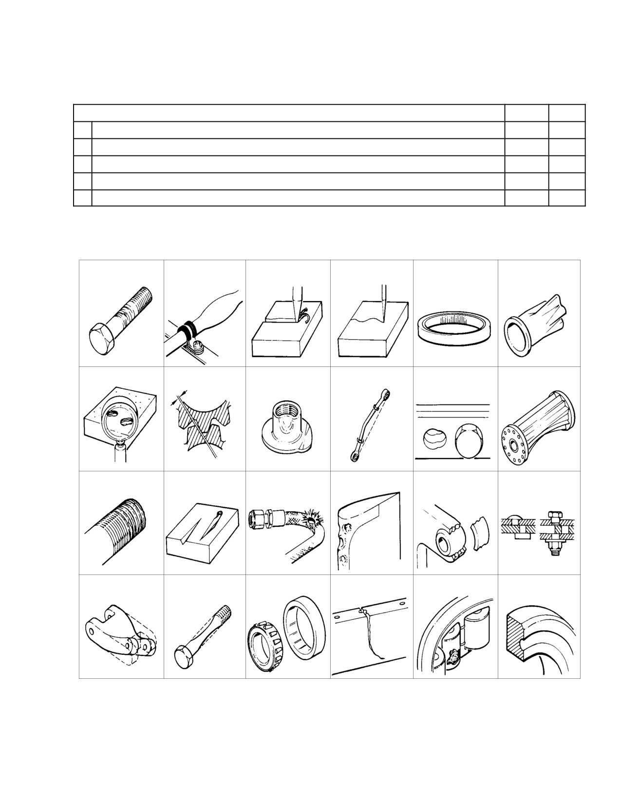
MD Helicopters, Inc.
CSP−H−2
500 Series - Basic HMI
Determination of Excessive Wear or Damage
NOTE: Wear tolerances are provided in this manual whenever practical. In addition, excessive wear or damage
can usually be determined by visual inspection as shown in the following table.
QUESTIONABLE WEAR / DAMAGE CONDITIONS
* YES /
NO /
1
Is the condition dangerous for flight
2
Is the condition on a highly stressed part of the helicopter
3
Could the condition contribute to failure of another part
4
Will the condition continue to worsen at the same rate (or faster)
5
Does the condition affect the quality of performance, function or apperance
*Any check mark ( √ ) in the YES column indicates that the part is worn or damaged excessively and should be
replaced with a new or serviceable unit.
1
WORN
2
SWOLLEN
3
SCORED
4
SCRATCHED
5
GALLED
6
DISTORTED
7
PITTED
8
BACKLASH
9
BENT
10
BOWED
11
ELONGATED
12
COLLAPSED
13
STRIPPED
14
GOUGED
15
RUPTURED
16
DENTED
17
BROKEN
18
SHEARED
19
TWISTED
20
STRETCHED
21
BRINNELLED
22
CRACKED
23
SPALLED
24
GROOVED
30−170
Figure 2-10. Technical Definitions
Page 2-73
Revision 14
MD Helicopters, Inc.
CSP−H−2
500 Series - Basic HMI
Table 2-16. Technical Definitions
Example No.
Technical Terms
Definition
(Figure 2-10)
Abrasion
-
An area of roughened scratches or marks; usually caused by
foreign matter between moving parts or surfaces.
Arced
-
Visible effects (burn spots, fused metal) of an undesired electrical
discharge between two electrical connections.
Axial play
-
The back and forth movement of a part along the line (shaft, tube or
bolt) about which it rotates; usually a bearing.
Backlash
8
The lost motion between two mating gear teeth; the amount the first
has to move owing to distance between tooth contact surfaces.
Bent
9
Sharp deviation from original line or plane; usually caused by lateral
force.
Binding
-
Restricted movement such as tightened or sticking condition
resulting from misalignment or jamming.
Blend
-
To form or smooth metal or fiberglass so there is no sharp change
or line from one area to another.
Blister
-
An enclosed raised spot or bulge, usually with a void underneath.
Bowed
10
Curved or gradual deviation from original line of plane; usually
caused by lateral force.
Brinnelled
21
Circular surface indentions on bearing races; usually caused by
repeated shock loading of the bearing: i. e., ball or roller indention.
Broken
17
Separated by force into two or more pieces.
Burning
-
Surface damage due to excessive heat; usually caused by improper
fit, defective lubrication, overtemperature operation.
Burrs
-
A sharp projection or rough edge remaining after machining or
rework.
Chafed
-
Frictional wear damage; usually caused by two rubbing together
with limited motion.
Checked
-
Surface cracks.
Chipped
-
A breaking away of the edge, corner or surface of material; usually
caused by heavy impact (not flaking).
Chord
-
An imaginary straight line joining the leading and trailing edges of
an airfoil: i. e., main and tail rotor blades, stabilize.
Circuit - grounded
-
Undesired current path to ground (common).
Circuit - open
-
Incomplete electrical circuit due to separation at or between
electrical connection points.
Circuit - shorted
-
Undesired current path between leads or circuits that normally are
at a different potential.
Clogging
-
Blockage of fluid or air passage or line; usually by foreign material.
Collapsed
12
Inward deformation of the original contour of a part; usually due to
high pressure differential.
Concentricity
-
Perfect roundness about a common center. The appearance of a
part and its readiness to function.
Condition
-
The appearance of a part and its readiness to function.
Page 2-74
Revision 14
MD Helicopters, Inc.
CSP−H−2
500 Series - Basic HMI
Table 2-16. Technical Definitions (Cont.)
Example No.
Technical Terms
Definition
(Figure 2-10)
Contamination
-
The introduction of undesirable elements, usually into a fluid.
Corrosion
-
Pitting, or a surface breakdown of a material due to chemical or
electro-chemical attack by atmosphere, moisture or other agents.
(Sometimes called rust on steel surfaces.)
Cracked
22
Visible (not requiring special fluorescent or magnetic penetrants)
partial separation of material which may progress to a complete
break.
Crossed
-
Damage to parts (crossed threads) or parts made inoperative
(crossed wires) from improper assembly.
Crushed
-
Destruction of a part or structure by a squeezing force. Changes
original shape.
Defect
-
Imperfection; anything that will not allow a part to function as
intended or that might cause failure.
Deflection
-
The turning away from original shape or direction by an undesired
force.
Delamination
-
Separation into layers; usually fiberglass.
Dented
16
A surface indention with rounded bottom usually caused by impact
of a foreign object. Material is displaced, seldom separated.
Depression
-
See dent.
Deterioration
-
To grow worse; quality less than new or original.
Dimension
-
Under blueprint dimension or other dimensions published in an
authoritative publication (not caused by wear).
Discoloration
-
A color that is not normal to a part; usually caused by heat.
Distorted
6
Extensive deformation of the original shape of apart; usually due to
structural stresses, excessive localized heating or any combination
of these.
Dye-penetrant
-
A portable method of detecting small cracks in metal too small to be
inspection
seen with the naked eye. The questionable area is thoroughly
cleaned and dye is then applied to the area. After penetration time
the excess dye is removed and developer is applied. After a drying
period, a mark will appear in the developer if a crack is present.
Eccentric
-
Part(s) wherein the intended common center is displaced
significantly.
Elongated
11
A hole (bolt or rivet) that is not round; usually due to loose fastener
or improper drilling.
Erosion
-
Carry away of material by flow of fluids or gases, accelerated by
heat or grit.
Excessive
-
Greater than the usual or specified amount; more than normal.
Faulty
-
See defect.
Ferrous
-
Metal having a high iron content such as steel.
Finite life
-
A definite time limit for part serviceability; established by the
manufacturer and usually in accumulated hours of operation.
Page 2-75
Revision 14
MD Helicopters, Inc.
CSP−H−2
500 Series - Basic HMI
Table 2-16. Technical Definitions (Cont.)
Example No.
Technical Terms
Definition
(Figure 2-10)
Fluctuation
-
Moving or swinging back-and-forth: often seen as an unstable
instrument indication.
Fluorescent-penetrant
-
Method of inspecting components used for detecting cracks, flaws,
inspection
or defects in nonferrous metal which are too small or in such a
position that they cannot be detected with the naked eye. This
method uses the principle of submerging the component in a
penetrating dye and placing it under ultra-violet light.
Foreign particle
-
A piece of material not normally found in or around a part or
location.
Fouling
-
Clogging or choking with a foreign substance; usually found in oil.
Frayed
-
Worn into shreds by rubbing action.
Freedom of motion
-
Operating as intended without binding or excessive friction.
Friction
-
Rubbing together of two parts, resisting motion; usually causes
excessive wear.
Fused
-
Joining together of two materials; usually caused by heat, friction or
current flow.
Galled
5
A transfer of metal from one surface to another in an advanced
case of fretting corrosion or pitting.
Gap
-
An opening, break, space or separation.
Gouged
14
Scooping out of material; usually caused by a foreign object.
Grooved
24
Smooth, rounded furrow or furrows of wear; usually wider than
scoring, with rounded corners and smooth on the groove bottom.
Hot-Spot
-
Subjected to excessive temperature; usually evidenced by change
in color and appearance of part.
Impact
-
The forceful striking or contact of one thing against another.
Imperfection
-
See defect.
Inclusion
-
A particle of foreign matter in the metal; usually associated with
magnetic particle inspection.
Indications
-
Cracks, inclusions, fractures, etc., not visible without fluorescent or
magnetic penetrant.
Inoperative
-
Not functioning.
Intermittent
-
A coming and going at various times, not all the time.
Internal
-
Inside, within the surface or structure.
Kink
-
A short tight twist or curl caused by doubling or winding of
something upon itself.
Leakage
-
Escaping fluid or air; usually caused by a crack, hole or worn seal.
Longitudinal
-
The length or lengthwise dimension; usually the longest area.
Page 2-76
Revision 14
MD Helicopters, Inc.
CSP−H−2
500 Series - Basic HMI
Table 2-16. Technical Definitions (Cont.)
Example No.
Technical Terms
Definition
(Figure 2-10)
Magnetic-particle
-
The method used to detect cracks, flaws or defects in ferrous metal
inspection
which are too small or in such a position that they cannot be seen
with the naked eye. Two distinct magnetic fields are established
around a flaw in ferrous metal. By submerging the specimen into a
solution containing iron filings and exposing it to a magnetic field,
the iron filings, attached to the ferrous specimen, form a pattern
about the flaw.
Malfunction
-
Not operating as intended.
Misalignment
-
Not in correct relative position.
Mismatched
-
Improper association of two or more parts.
Mis-positioned
-
Improper installation of a part resulting in damage to the installed
part or to associated parts.
Moisture
-
Condensed liquid; usually a small quantity of water.
Nicked
-
A sharp surface indentation caused by impact of a foreign object.
Material is displaced, seldom separated.
Obstruction
-
A condition of being clogged or blocked; in the way of something.
Out-of-round
penetra-
-
Diameters of part not constant.
tion
Penetration
-
The amount that an object has entered a material by overcoming
resistance.
Peripheral
-
The outer surface or edge of a body.
Pitted
7
Small irregular shaped hollows in the surface; usually caused by
corrosion, chipping or heavy electrical discharge.
Play
-
Movement of one part in relation to another: free motion. (Limited
play between parts is often required.)
Plugged
-
Pipe, hoses, tubing, channeling, internal passage, etc., which are
totally or partially blocked.
Preload
-
The exact clamping force applied to bearing races or mating parts
to eliminate the possibility of play during operation; usually
established in bearings by shimming and measuring rotational drag
torque.
Propagation
-
To grow, spread out; usually referring to cracks.
Puncture
-
A hole through material; usually caused by complete penetration of
a foreign object.
Radial play
-
The perpendicular movement of a part outward (at right angles)
from the line (shaft, tube or bolt) about which it rotates; usually a
bearing.
Radius
-
The distance from the center of a circle to the outside edge. Often
used to discuss a curve in material.
Resistance - high
-
High electrical resistance in an electrical circuit, causing improper
component or circuit operation.
Resistance - low
-
Low electrical resistance in an electrical circuit, causing improper
component or circuit operation.
Page 2-77
Revision 14
MD Helicopters, Inc.
CSP−H−2
500 Series - Basic HMI
Table 2-16. Technical Definitions (Cont.)
Example No.
Technical Terms
Definition
(Figure 2-10)
Restricted
-
Blocked or limited; usually refers to limited flow in hoses or tubing.
Rough
-
Usually applies to operation as opposed to surface finish; i. e., a
condition of bearings where during the spin test the rotation is
rough.
Rubbed
--
To move with pressure or friction against another part.
Ruptured
-
Extensive breaking apart of material; usually caused by high
stresses, differential pressure, locally applied force or any
combination of these.
Rust
-
See Corrosion.
Scored
3
Deep scratch or scratches made during part operation by sharp
edges of foreign particles.
Scratched
4
Light narrow, shallow mark or marks caused by movement of a
sharp object or particle across a surface.
Security
-
Correctly installed or fastened so as not to loosen.
Seized
-
Parts bound together because of expansion or contraction due to
high or low temperature; foreign object jammed in mechanism.
Separation
-
A space or gap caused by two parts moving away from each other.
Sheared
18
Dividing a body by cutting action; i.e., division of a body so as to
cause its parts to slide relative to each other in a direction parallel to
their plane of contact.
Spalled
23
Sharply roughened area characterized by progressive
chipping-away of surface material (Not to be confused with flaking).
Usual causes are surface cracks, inclusions or any similar surface
injury causing a progressive breaking away of the surface under
load.
Snug
-
A close fit between two parts.
Spanline
-
The maximum distance from tip to root, as of main rotor blade.
Springback
-
The partial return motion of a control handle or lever back from its
end stop after release; usually ensures complete actuation of unit
being controlled. Sometimes called cushion.
Stress
-
Force running through an object or material, caused externally;
usually tension or shearing.
Stretched
20
Elongation of a part as a result of exposure to operating conditions
(tension type stress) or overtorquing.
Stripped
13
A condition usually associated with threads or insulation. Involves
removal of material (threads) by force.
Swollen
2
A bulge; usually found in hoses and plastic tubing. A puffed-up or
expanded area caused by internal pressure.
TIR
-
Total indicator reading. The result of checking (usually with a dial
indicator) for an out-of-round condition; usually of a shaft surface
and/or shaft rotational axis.
Torn
-
Separation by pulling apart.
Page 2-78
Revision 14
MD Helicopters, Inc.
CSP−H−2
500 Series - Basic HMI
Table 2-16. Technical Definitions (Cont.)
Example No.
Technical Terms
Definition
(Figure 2-10)
Torsional (windup)
-
A twisting action; usually caused by holding one end of a part while
turning the other.
Torque
-
Rotational force; usually the amount of measurable force required to
rotate a shaft or bearing.
Transverse
-
Extended or lying crosswise; usually cracks or scratches across
material.
Twisted
19
A change in original shape of a part by a turning motion. Sometimes
called distorted.
Void
-
An empty space, opening, cavity or gap in metal or plastics.
Worn
1
Material or part consumed as a result of exposure to operation or
usage.
Page 2-79/(2-80 blank)
Revision 14
MD Helicopters, Inc.
CSP−H−2
500 Series − Basic HMI
Section
3
Fuselage
MD Helicopters, Inc.
CSP-H-2
500 Series - Basic HMI
TABLE OF CONTENTS
Para/Figure/Table
Title
Page
Section 3 Fuselage .
3−1
1.
Fuselage Assembly
3−1
2.
Fuselage Sheet Metal Repair
3−1
A. Stressed Sheet Metal Panels
3−1
B. Non−Stressed Sheet Metal Panels
3−1
Figure 3−1. Major Sections of Fuselage
3−2
3.
Mast Support Structure
3−3
A. Mast Support Structure Inspection
3−3
4.
Main Rotor Mast
3−3
A. Main Rotor Mast Removal
3−3
Figure 3−2. Main Rotor Mast and Support Structure
3−4
Figure 3−3. Main Rotor Mast Inspection and Repair Criteria .
3−5
B. Main Rotor Mast Installation
3−6
C. Main Rotor Mast Inspection and Repair
3−6
5.
Fuselage Structure
3−7
A. Center Beam
3−7
B. Sta. 78.50 Canted Frame
3−7
C. Sta. 124.00 Canted Frame and Lower Section Frame
3−7
D. Pilot’s Compartment Floor
3−7
E. Instrument Panel Support Structure
3−7
F. Pilot’s Seat Support Structure
3−7
G. Cargo Compartment Floor
3−7
H. Cargo Floor Fittings
3−8
I.
Fuel Tank Support Skins
3−8
J. Fuel Tank Support Skin Inspection
3−8
K. Fuel Tank Support Skin Repair
3−8
6.
Firewalls
3−8
A. Firewall Inspection
3−8
B. Upper Firewall Replacement
3−8
Figure 3−4. Major Bulkheads and Structural Members
3−8A
C. Upper Firewall Patch Silver Brazing
3−9
Figure 3−5. Firewall Installation
3−10
7.
Fuselage Fittings
3−11
A. Fuselage Fitting Repair
3−11
8.
Aft Section Strut
3−11
A. Aft Section Strut Repair
3−11
9.
Landing Gear Fitting Swivel Bearing Replacement
3−11
Page 3-i
Revision 19
MD Helicopters, Inc.
CSP-H-2
500 Series - Basic HMI
TABLE OF CONTENTS (Cont.)
Para/Figure/Table
Title
Page
10. Optional Equipment Structural Hard Points
3−11
11. Engine Air Inlet Fairing
3−11
12. Engine Air Inlet (Plenum Chamber)
3−12
A. Plenum Chamber Inspection
3−12
B. Plenum Chamber Hole Sealing
3−12
13. Aft Fuselage Skin Cracks Inspection/Repair (Sta. 146.62) .
3−12
14. Underfloor Compartments
3−13
A. Underfloor Compartment Inspection
3−13
15. Firewall and Sta. 124.00 Insulation
3−13
A. Insulator Padding and Insulation Tape Inspection
3−13
B. Insulator Padding Replacement
3−13
C. Oil Cooler/Tank Insulation Tape Replacement
3−13
Figure 3−6. Insulation Padding
3−14
Figure 3−7. Oil Cooler/Tank Compartment Sealing
3−15
16. Engine Access Doors
3−16
A. Engine Access Door Removal
3−16
B. Engine Access Door Inspection
3−16
C. Engine Access Door Repair
3−16
Figure 3−8. Engine Access Doors (Sheet 1 of 2)
3−17
D. Engine Access Door Fit Adjustment
3−19
17. Aft Section Windows
3−19
A. Aft Section Window Repair
3−19
18. Canopy and Windshield
3−19
A. Canopy Panel Inspection
3−19
Figure 3−9. Canopy and Window Installation
3−20
B. Canopy Panel Repair
3−20
C. Canopy Frame Replacement
3−20
19. Pilot and Cargo Doors
3−20
A. Pilot and Cargo Door Removal
3−21
B. Pilot and Cargo Door Auto−Latching Operational Check .
3−21
C. Pilot and Cargo Door Manual−Latching Operational Check .
3−21
D. Pilot and Cargo Door Hinge Repair
3−21
E. Pilot and Cargo Door Window Repair
3−22
Figure 3−10. Pilot’s Door, Auto−Latching (Sheet 1 of 2)
3−23
Figure 3−11. Pilot’s Door, Manual Latching
3−25
Figure 3−12. Cargo Door, Auto−Latching (Sheet 1 of 2)
3−26
Figure 3−13. Cargo Door, Manual Latching (Sheet 1 of 2) .
3−28
Page 3-ii
Revision 19
MD Helicopters, Inc.
CSP-H-2
500 Series - Basic HMI
TABLE OF CONTENTS (Cont.)
Para/Figure/Table
Title
Page
F. Geon Strip Repair
3−30
G. Window Snapvent Replacement
3−30
20. Door Latching Mechanism
3−30
A. Door Latching Mechanism Inspection and Repair
3−31
B. Pilot and Cargo Door Automatic Latch Replacement
3−31
C. Pilot and Cargo Door Automatic Latch Adjustment
3−32
Figure 3−14. Latch Engagement for Auto−Latching Door Handle Positions .
3−33
D. Pilot and Cargo Door Manual Latch Adjustment
3−34
E. Pilot and Cargo Door Auto−Latching Handle Replacement .
3−35
21.
369H90085 Litter Door Installation Inspection
3−36
22. Pilot and Cargo Door Seal Compression Check
3−36
A. Pilot and Cargo Door Seal Replacement
3−36
Figure 3−15. Door Seal Installation, Current Type
3−37
B. Partially Separated Pilot and Cargo Door Seal Repair .
3−38
C. Pilot and Cargo Door Frame Anti−Chafing Tape Repair .
3−38
23. Improved Door Seal Installation
3−38
Figure 3−16. Improved Door Seal Installation
3−39
Page 3-iii
Revision 19
MD Helicopters, Inc.
CSP-H-2
500 Series - Basic HMI
TABLE OF CONTENTS (Cont.)
Para/Figure/Table
Title
Page
This Page Intentionally Left Blank
Page 3-iv
Revision 19
MD Helicopters, Inc.
CSP−H−2
500 Series − Basic HMI
SECTION 3
FUSELAGE
1. Fuselage Assembly
are those that form the cylindrically tapered
boom assembly.
(1).
Forward Section
(1). Negligible Damage
The fuselage forward section includes
upper−, center−, and lower−canopy
No damage can be considered negligi−
windshield assemblies, door frames,
ble. All repairable damage shall be
and a canopy panel containing an air
repaired upon detection. Cracks, tears
intake duct and provisions for a
or punctures in stressed sheet metal
landing/hovering light.
panels that do not exceed 0.20 inch
(5.08 mm) diameter and can be re−
(2).
Lower Section
moved by drilling out with a 1/4 inch
(6.35 mm) or smaller diameter drill do
The fuselage lower section includes the
not require structural doublers.
pilot’s compartment floor, cargo
compartment floor, underfloor stowage
(2). Repair or Replacement
compartment and battery area, floor
and seat support bulkheads and seat
Cracks, tears or punctures in stressed
support bulkheads and associated
sheet metal panels exceeding 0.20 inch
structure, the center beam assembly,
(5.08 mm) diameter are to be repaired.
landing gear fittings, and the fuel tank
support structure.
B. Non-Stressed Sheet Metal Panels
Non−stressed sheet metal members consist
(3).
Aft Section
primarily of hinged covers and doors except
The fuselage aft section includes the
the fuel cell access and controls access doors
main rotor mast support structure,
which are stressed (Ref. Stressed Sheet Metal
cargo door frames, engine compart−
Panels).
ment, engine air inlet (plenum cham−
ber) installation, engine inlet aft
(1). Negligible Damage
fairing, firewall installation, and the
Small dents, scratches, nicks, and light
boom fairing.
corrosion deposits are considered
negligible damage. Cracks that do not
2. Fuselage Sheet Metal Repair
exceed 0.250 inch (6.35 mm) in length,
Perform repair of the structure according to
are less than one−fourth the width of
applicable instructions in CSP−H−6. Refer to
the damaged component, and are
the following paragraphs for classification and
removed at least one−inch from the end
definition of the types of negligible damage,
of the damaged component or an
and for guidelines defining the extent of
attachment point, may also be conĊ
damage requiring repair or replacement.
sidered negligible damage.
A. Stressed Sheet Metal Panels
(2). Repair or Replacement
Stressed sheet metal panels consist primarily
Repair or replacement of non−stressed
of the helicopter fuselage skins and bulkhead
panels shall be at the discretion of the
webs. The most highly stressed skin sections
owner. Refer to CSP−H−6.
Page 3-1
Revision 14
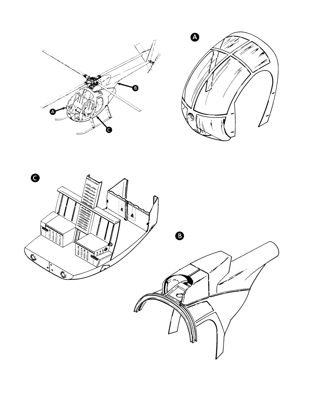
MD Helicopters, Inc.
CSP−H−2
500 Series − Basic HMI
FORWARD FUSELAGE
LOWER FUSELAGE
AFT FUSELAGE
30−027
Figure 3-1. Major Sections of Fuselage
Page 3-2
Revision 14
MD Helicopters, Inc.
CSP−H−2
500 Series − Basic HMI
3. Mast Support Structure
(a). Inspect the side channels and
forward and aft webs of the controls
tunnel, from the mast support fitting
(Ref. Figure 3−2) The mast support structure
down to the top of the pilot’s seat−
consists of two mast support fittings, stiffener
back (canted bulkhead waterline
angles, a panel riveted to the upper−rear
45.36).
surface of the mast support fittings, a pan, a
doubler riveted to the lower forward surfaces
(b). Inspect visible areas of mast support
of the mast support fittings, and two channels.
fitting, mast base and mast tube,
Two bolt holes in each mast support fitting
with particular attention to base
provide the four attach points for mounting
attachment areas and shaded areas.
the main rotor mast support base. Three
(c). Inspect both side of channels on aft
additional holes through the forward end of
canted bulkhead from mast support
the left−hand mast support fitting provide
fitting down to waterline 34.00 with
attach points for mounting the tail rotor
particular attention to points of
control rod bellcrank support bracket. The
attachment.
forward end of the mast support fittings are
riveted to the upper ends of two channels on
(d). Clean and inspect any suspected
the rear surface of Sta. 78.50 canted bulkhead.
area; use dye−penetrant to determine
The aft ends of the mast support fittings are
if a crack does exist. If a crack is
riveted to the upper ends of two channels on
found, part must be replaced.
the forward surface of Sta. 124.00 canted
bulkhead.
(5). Inspect mast support structure for
corrosion, loose bolts and rivets and
general condition of finish.
A. Mast Support Structure Inspection
(6). Check that the two 1/4 inch (6.35 mm)
drain holes located in the pan are not
Any time work is being per−
CAUTION
plugged.
formed near the engine air inlet,
use care to prevent entry of foreign objects.
(7). Reinstall controls tunnel cover.
Tape covers of cardboard or other suitable
material in place over the engine inlet
(8). Reinstall left and right forward sections
screen and oil cooler air inlets. Do not re−
of air inlet fairing.
move covers until work is completed and de−
(9). Reinstall main transmission access
bris is thoroughly cleaned out of the area.
cover and main gearbox access cover.
After removing covers, verify that the area
around base of mast, air inlet, and entire
4. Main Rotor Mast
plenum chamber are free of foreign materi−
al.
(Ref. Figure 3−3) The main rotor mast consists
of a steel tube and a forged base assembly. The
mast encloses the main rotor drive shaft and
(1). Remove left and right forward sections
supports the main rotor hub assembly.
of air inlet forward fairing.
A. Main Rotor Mast Removal
(2). Remove main transmission cover and
Main rotor mast is highly
CAUTION
main gearbox access cover.
stressed. Do not allow tools to
strike mast or mast to strike any object. Any
impact damage may require replacement of
(3). Detach controls tunnel cover from
mast.
structure. Slide cover up on control rods
and secure it out of the way. and slide
(1). Remove main rotor hub.
out of way.
(2). Remove main rotor controls.
(4). Using a bright light and a 5−power
(3). Remove main transmission. Transmis−
magnifying glass, carefully inspect the
sion removal is required for access to
following areas for evidence of cracks.
the mounting studs.
Page 3-3
Revision 14
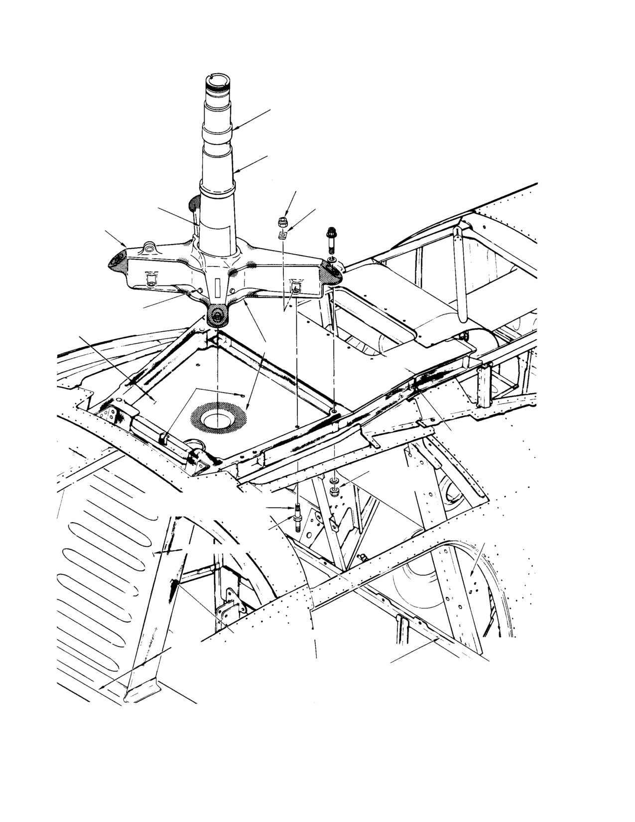
MD Helicopters, Inc.
CSP−H−2
500 Series − Basic HMI
NOTES:
1.
THIS STUD REQUIRES ELECTRICAL BOND
TO
STRUCTURE PAN THIS SURFACE.
HUB SLEEVE BEARING
2.
SEAL MAIN ROTOR MAST TO STRUCTURE
SURFACE
PAN (INSIDE MAST TUBE AT BASE) WITH
SILICONE RUBBER (17, TABLE 2−4).
MAIN ROTOR MAST
NUT (LEFT−HAND THREADS)
TAPE
PLATE SPACER
MAST BASE
RIVETS
MAST SUPPORT
STRUCTURE PAN
NOTE 2
DRAIN
HOLES
MAST SUPPORT FIT−
TING
NUT
700−820 IN. LB
(81.35−92.65 NM)
MAIN TRANSMISSION MOUNTING STUD
160−190 IN. LB (18.08−21.47 NM)
AFT BULKHEAD
NOTE 1
CHANNEL
TUNNEL BEAM WEB
TUNNEL BEAM (SIDE) CHANNEL
WATERLINE 45.36
WATERLINE 34.00
30−017E
Figure 3-2. Main Rotor Mast and Support Structure
Page 3-4
Revision 14
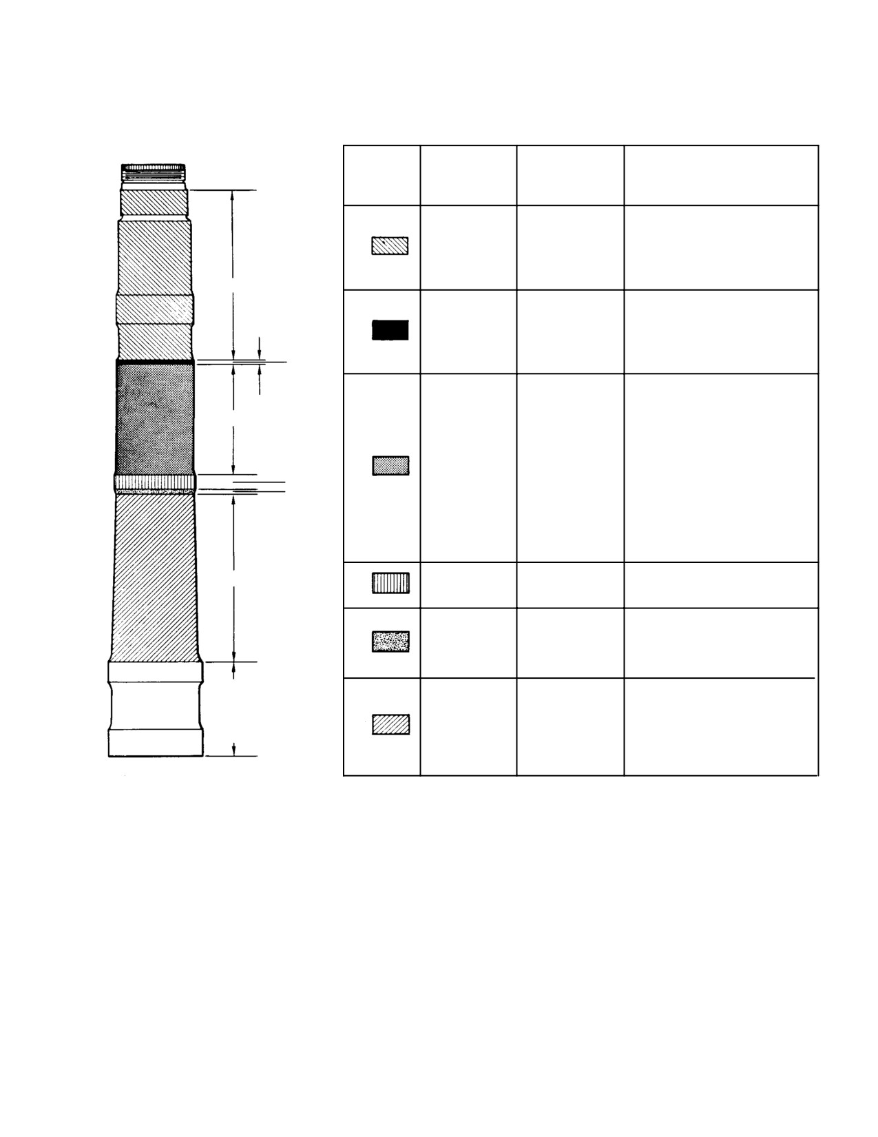
MD Helicopters, Inc.
CSP−H−2
500 Series − Basic HMI
MAXIMUM
REPAIRABLE
AREA
REMOVAL OF
REPAIR
DAMAGE
MATERIAL (DEPTH)
PROCEDURE
POLISH AREA SMOOTH WITH ABRA−
CORROSION
SIVE CLOTH (20 AND 23, TABLE 2−4)
0.010 IN.
A
AND
(0.254 MM)
IF CADMIUM PLATING HAS BEEN
SCRATCHES
PENETRATED. TREAT REWORKED
AREA WITH PRIMER (4).
A
THICKNESS OF
0.063 IN.
POLISH AREA SMOOTH WITH ABRA−
CHIPPING
NICKEL PLAT−
(1.6002 MM)
SIVE CLOTH (20 AND 23, TABLE 2−4).
B
OF NICKEL
ING 0.0035 IN.
THREAT REWORKED AREA WITH
PLATING
(0.0889 MM)
PRIMER (4).
B
MAXIMUM
LONGITUDINAL
SCRATCHES THAT
C
DO NOT PENE−
TRATE THROUGH
MUST NOT PER−
THE NICKEL PLATE.
NETRATE NICKEL
POLISH AREA WITH ABRASIVE CLOTH
C
SCRATCHES MUST
PLATING 0.0035
(20 AND 23, TABLE 2−4) TO REMOVE
D
BE A MINIMUM OF
IN.
BURRS AND SHARP EDGES ONLY.
E
0.25 IN. (6.35 MM)
(0.0889 MM) MAX−
APART. RADIAL
IMUM
SCRATCHES ARE
NOT PERMITTED.
CORROSION
F
0.020IN.
POLISH AREA SMOOTH WITH ABRASIVE
D
AND
(0.508 MM)
CLOTH (20 AND 23, TABLE 2−4)
SCRATCHES
POLISH AREA SMOOTH WITH ABRA−
CORROSION
SIVE CLOTH (20 AND 23, TABLE 2−4).
E
0.010 IN.
AND
TREAT REWORKED AREA WITH PRIM−
(0.254 MM)
SCRATCHES
ER (7) AND A TOP COAT OF LACQUER
(6).
REMOVE DAMAGED OR DETERI−
AREA
ORATED TAPE. POLISH CORROSION
ENCLOSED
CORROSION AND
SPOTS WITH ABRASIVE CLOTH (20
BY
0.010 IN.
F
REPLACEMENT OF
MAST BASE
(0.254 MM)
AND 23, TABLE 2−4). TREAT RE−
TAPE
WORKED AREA WITH PRIMER (7) AND
A TOP COAT OF LACQUER (6). RE−
MAST TUBE TO BE PERPENDICULAR TO
PLACE TAPE (32).
MAST BASE WITHIN 0.010 IN. (0.254 MM)
IN 10 INCHES (25.4 CM)
NOTE: FOR MAGNETIC PARTICLE INSPECTION, REMOVE
PAINT FROM APPLICABLE SURFACES.
30−160B
Figure 3-3. Main Rotor Mast Inspection and Repair Criteria
Page 3-5
Revision 14
MD Helicopters, Inc.
CSP−H−2
500 Series − Basic HMI
(4). Remove four studs, washers and nuts
C. Main Rotor Mast Inspection and Repair
(Ref. Figure 3−3). Nuts securing studs
Inspect all areas of main rotor mast for cracks,
have left−hand threads.
nicks, scratches and evidence of impact
damage. Refer to Figure 3−3 for inspection and
(5). Remove shaft support hold−down nuts,
repair criteria. Inspect bearing surfaces for
washers and bolts.
scoring and galling. Inspect threads and
(6). Lift main rotor mast from helicopter.
serrations for damage. Inspect four rivets that
secure base to mast tube for security. Check
B. Main Rotor Mast Installation
that tape on forward edge of mast tube is
secure and undamaged.
(1).
Apply silicone sealant (17, Table 2−4)
NOTE: To inhibit corrosion of mast when oper−
on bottom surface of mast tube and
ating in salt water environment, check tape
base at drive shaft opening to seal base
at frequent intervals. Also, apply thin
to mast support structure at installa−
grease film (18, Table 2−4) to bearing jour−
tion. Sealing will contain any oil
nals.
leakage coming from top of transmis−
sion.
(1). Inspect all areas of main rotor mast for
cracks, nicks, scratches and evidence of
(2).
Position main rotor mast so that holes
impact damage.
in base align with holes in mast
support structure.
(2). Inspect bearing surfaces for scoring and
galling.
(3).
Install four holddown bolts, eight
(3). Inspect threads for damage.
washers and four nuts; torque nuts to
700 − 820 inch−pounds (79.09 − 92.65
(4). Inspect rivets that secure base to mast
Nm).
tube for security.
(4).
Check underside of mast support
(5). Check that tape (Ref. Figure 3−2) on
structure at left aft stud hole location.
forward edge of mast tube is secure and
Stud−to−pan doubler surface must be
undamaged; replace if defective.
clean to bare metal for electrical
(a). Peel defective tape from mast.
bonding (Ref. Figure 3−2). Install main
transmission mounting four studs,
(b). As required, polish area to remove
plate spacers and nuts. Torque studs to
burrs and sharp areas with abrasive
160 − 190 inch−pounds (18.08 − 21.47
cloth (20, Table 2−4) or crocus cloth
Nm).
(23).
(c). Clean mast thoroughly with cleaner
(5).
Using 0.001−0.0015 inch
(183) and allow to dry.
(0.0254−0.0381 mm) feeler gage, check
for gap between self−locking nuts and
(d). Apply primer (4) and paint (6) to
plate spacers. No gap is allowed.
affected area.
(6).
If gap is observed, remove nut and
(e). Apply pressure sensitive tape (123) to
replace with new self−locking nut.
mast.
Torque studs into replacement nuts to
NOTE: To inhibit corrosion of mast when oper−
160 − 190 inch−pounds (18.08 − 21.47
ating in salt water environment, check tape
Nm) and repeat step (5). above.
at frequent intervals. Also, apply thin
Continue until each nut is flush against
grease film (18, Table 2−4) to bearing jour−
its spacer. Seal bare bond area with
nals.
clear lacquer (47).
(6). Inspect internal bore for paint chipping,
(7).
Install main transmission.
orange peeling or flaking, none allowed.
(8).
Install main rotor controls.
NOTE: Chipping, orange peeling or flaking
paint will normally be at the base of the
(9).
Install main rotor hub.
static mast tube.
Page
3-6
Revision 19
MD Helicopters, Inc.
CSP−H−2
500 Series − Basic HMI
(7). Re−apply finish to mast internal bore
the helicopter. Three cutouts, at cargo floor
as follows:
level, provide access to the landing gear
dampers, other underseat components and the
(a).
Remove main rotor hub (Ref. Sec.
four flight control push rods that are routed
62−20−00 or 62−20−60, Main Rotor
upward through the canted tunnel.
Hub Replacement).
C. Sta. 124.00 Canted Frame and Lower
(b).
Remove main transmission (Ref. Sec.
Section Frame
63−20−00 or 63−20−25, Main Trans−
mission Replacement).
The Sta. 124.00 upper and lower section
frames are primary structural members of the
(c).
Remove static mast (Ref. Main Rotor
helicopter. The upper canted frame is formed
Static Mast Replacement).
of channel and sheet aluminum. Passenger
seat, shoulder harness and engine mount
(d).
Thoroughly clean interior tube with
support fittings are bolted to the chanted
Solvent (1).
frame. The lower section frame is formed of
(e).
Inspect for any corrosion, none
titanium sheet and aluminum channel
allowed.
members.
(f).
Remove paint from bad areas and
D. Pilot’s Compartment Floor
lightly feather paint edge with crocus
cloth (23), remove any residue from
The pilot’s compartment floor is a structure of
feathering.
aluminum alloy formed channels, intercostals,
clips, gussets and skin. The pilot’s seat support
(g).
Apply primer (131) to repair areas.
structure attaches to the aft end of the floor.
Tail rotor control support fittings are at the
(h).
Allow to cure per manufacturer’s
forward end of the floor and there are openings
instructions.
on each side for access to the underfloor
compartments.
(i).
Reinstall static mast.
E. Instrument Panel Support Structure
(j).
Reinstall main transmission.
The instrument panel support assembly is
(k).
Reinstall main rotor hub.
aluminum alloy sheeting, stiffeners, webs and
5.
Fuselage Structure
channels riveted together to form a pedestal
assembly.
A.
Center Beam
F. Pilot’s Seat Support Structure
(Ref. Figure 3−4) The lower section center
beam is a primary structural member of the
The pilot’s seat support structure is formed of
helicopter. The beam is a riveted and bolted
aluminum alloy ribs and sheet. The seat
assembly of aluminum alloy webbing, stiffen−
structure incorporates forged or cast and
ers and doublers. Landing gear fittings of
machined aluminum alloy and/or magnesium
machined aluminum forgings are mounted at
fittings for seat belt attachment, landing gear
the forward and aft ends of the center beam.
damper attachment, and flight and engine
Each fitting contains four swivel bearings for
control components. Refer to Section 2 for
attachment of the landing gear braces and
corrosion control and identification of magne−
struts. The forward fittings have two addition−
sium and aluminum alloy.
al bearing attachment points for the longitudi−
G. Cargo Compartment Floor
nal and lateral cyclic trim actuators.
The cargo compartment provides a multi−use
B. Sta. 78.50 Canted Frame
area for accommodation of cargo and/or
The Sta. 78.50 canted frame establishes the
passengers. If floor is bent or punctured,
forward portion of the cross−sectional form of
remove appropriate fuel cell access cover and
the helicopter. The canted frame, constructed
inspect fuel cell. If water accumulation is
of formed sheet metal webs, stiffeners and
noted, refer to CSP−H−6 for drain hole
doublers, is a primary structural member of
addition instructions.
Page 3-7
Revision 19
MD Helicopters, Inc.
CSP−H−2
500 Series − Basic HMI
H. Cargo Floor Fittings
upper firewall is thin, 0.0015 inch (0.0381 mm)
thick sheet, rigidized CRES sheet, covered
The cargo floor incorporates 8 cargo tiedowns,
with a double thickness of nonflammable
4 seat belt attachment fittings and on the
ceramic fiber blanket. Flanges at the forward
underside of the floor, 12 tiedown eyelets that
and lower edges of the upper firewall are
support the fuel cell and lacing.
covered with heat−resistant tape. Pronged
fasteners attach the upper firewall to three
I. Fuel Tank Support Skins
vertical fuselage rings and to a horizontal rib.
The fuel tank support skins located under the
The semicircular forward firewall is an
cargo compartment floor are made of fiberglass
assembly of CRES sheets that contain circular
sheets riveted to the tank support ribs.
cutouts for passage of the engine drive shaft
and engine oil cooler lines, and a reinforced
J. Fuel Tank Support Skin Inspection
rectangular opening for the engine oil cooler.
The forward firewall is riveted to the fuselage
When the cells are removed, check security of
structure.
fiberglass skin attachment to support angles
and brackets, and inspect the anti−abrasion
A. Firewall Inspection
tape for security of adhesion over rivet heads,
all sharp edges and lap joints.
Inspect the aft upper firewall for security,
punctures, and corrosion. Inspect the forward
K. Fuel Tank Support Skin Repair
firewall for punctures, corrosion, and for a
(1). Cover exposed rivet heads with 10−mil
complete seal around the openings for the
by one inch (2.54 cm) tape (16,
overrunning clutch, engine compressor air
Table 2−4) to prevent chafing fuel cell
inlet, and the oil cooler. No un−repaired
fabric.
damage is permissible. Refer to CSP−H−6 for
forward firewall repair.
(2). Perform repair of the fuel tank support
skins according to applicable instruc−
B. Upper Firewall Replacement
tion in CSP−H−6.
Be careful when working on or
CAUTION
6. Firewalls
around the firewall shell. It is
extremely light gage, 0.0015 inch (0.0381
(Ref. Figure 3−5) The shell like aft section
mm) thick sheet.
upper firewall surrounds the upper portion of
the engine combustion chamber and exhaust
(1). Remove tailpipes.
pipe assembly and is designed to contain
engine heat as well as any fire that might
(2). Remove tape covering fasteners and
develop within the engine compartment. The
firewall edges.
Page 3-8
Revision 19
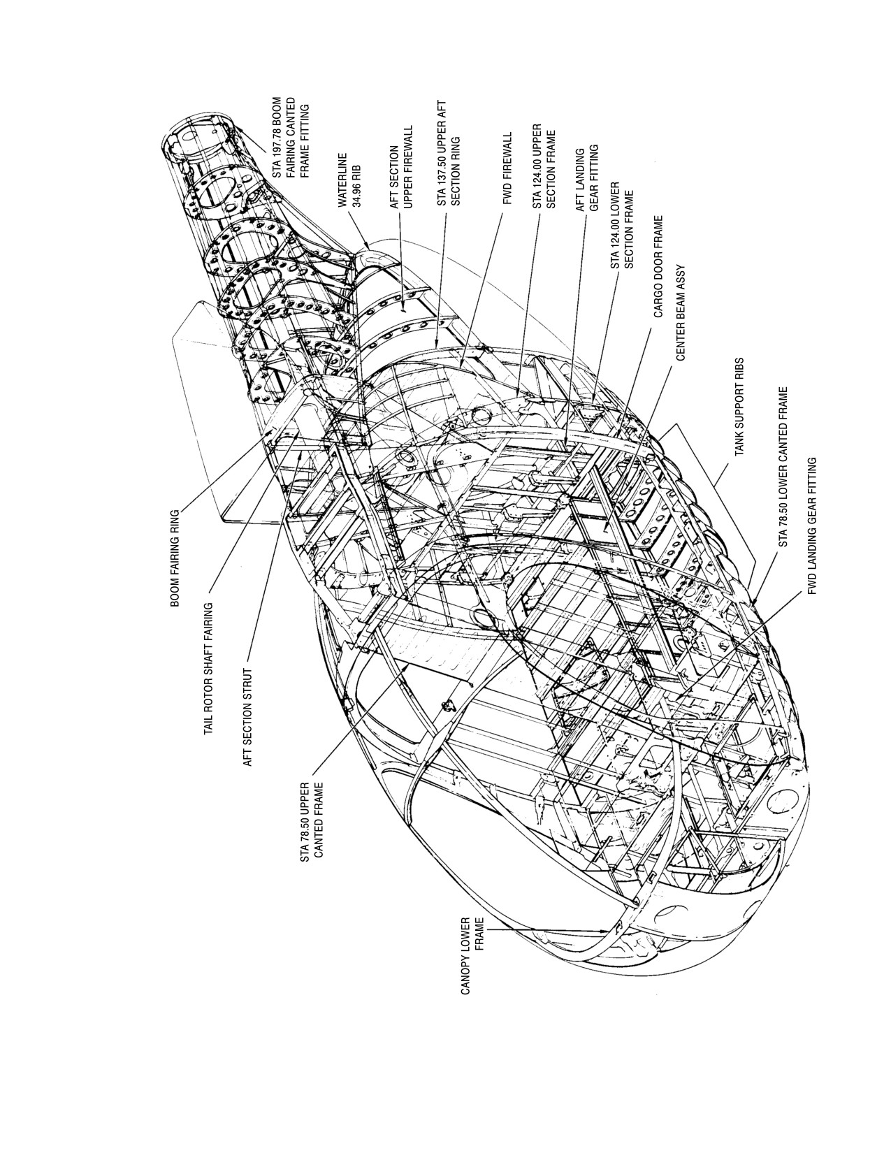
MD Helicopters, Inc.
CSP−H−2
500 Series − Basic HMI
30−018C
Figure 3-4. Major Bulkheads and Structural Members
Page 3-8A
Revision 18
MD Helicopters, Inc.
CSP−H−2
500 Series − Basic HMI
This Page Intentionally Left Blank
Page 3-8B
Revision 18
MD Helicopters, Inc.
CSP−H−2
500 Series − Basic HMI
(3).
Detach the compressor cooling air duct
ness range of 0.0015−0.0018 inch
support bracket. Remove firewall shell
(0.0381−0.04572 mm).
by pulling out the button head fasten−
ers attaching it to surrounding fuse−
(7).
Contour the patch to match the contour
lage.
of the firewall shell repair area.
(4).
Replace damaged or corroded fasteners.
(8).
Use a stiff bristle brush with the
cleaning solution prepared in step (5).
(5).
Replace aft firewall shell if damaged
to clean the inner and outer surfaces of
beyond practical repair. Trim replace−
the stainless steel patch and firewall.
ment shell to fit installation. Allow
sufficient trim excess for folding back
(9).
Rinse the patch and firewall shell
the edge to provide double thickness at
thoroughly with clean water and allow
the attach points.
to air dry.
(6).
Pierce fastener holes in new firewall
(10).
Coat the surfaces to be joined with a
shell to align holes in surrounding
thin even coating of silver alloy brazing
fuselage rings and waterline 34.96 rib.
flux (66).
(7).
Place firewall shell in position and
secure in place by pressing fasteners
(11).
Use a clamp or other suitable device to
into holes. Attach the compressor
hold the patch in place during the
cooling air duct support bracket to hoist
brazing operation.
fitting.
(12).
Braze the patch in place with Class 8
(8).
Using solvent (1, Table 2−4) clean the
silver brazing alloy (67) using a
forward flanges, lower flanges, and
suitable torch to heat the patch area to
surface where tape routing will cover
a temperature moderately above the
the fasteners; then apply tape (62).
flow point, 1295°F, (707°C) of the
brazing alloy.
(9).
Install tailpipes.
Use extreme care not to over−
CAUTION
C. Upper Firewall Patch Silver Brazing
heat and burn through the fire−
wall shell.
(1). Remove the aft section upper firewall.
(13). Allow joint to cool for at least 60
(2). Remove tape and ceramic fiber blan−
seconds before removing clamping
kets from the firewall shell.
device.
(3). Clean the firewall with a stiff bristle
(14). Remove flux by immersing repaired
brush moistened with solvent (1,
area in water at 160−212°F (71−100°C)
Table 2−4) and wipe dry with a clean,
for 40 minutes.
dry cloth.
(15). Follow by a thorough rinse in clear,
(4). Smooth out the rigidized pattern in the
running water and air−dry, or wipe dry
area on which the patch will be brazed.
with a clean, dry cloth.
(5). Prepare a cleaning solution as follows:
(16). Install ceramic blanket on outer surface
1 − 30 percent hydrofluoric acid (64)
of firewall shell.
and 18 − 30 percent nitric acid (65) by
volume at 75 − 140°F (24 − 60°C)
maximum temperature.
(17). Install aft section upper firewall shell.
(6). Cut a suitable repair patch from Type
(18). Install tape (62) on flanges of firewall
321 stainless steel sheet in the thick−
shell.
Page 3-9
Revision 14
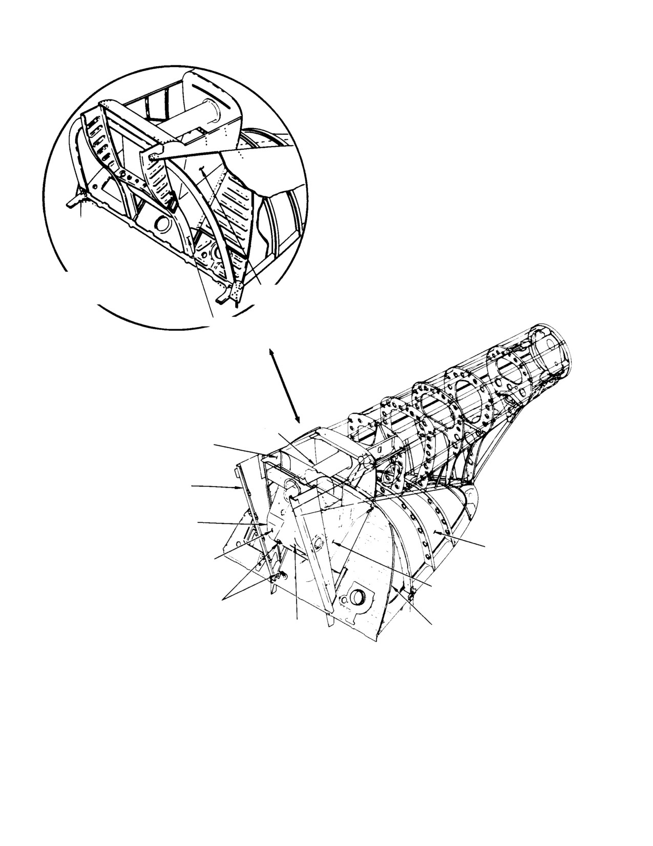
MD Helicopters, Inc.
CSP−H−2
500 Series − Basic HMI
EARLY CONFIGURATION
ENGINE AIR INLET INSTL.
(PLENUM CHAMBER)
CANTED STA. 124.00
CHANNEL
TAIL ROTOR SHAFT FAIRING
REMOVABLE PANEL
CANTED STA. 124.00 CHANNEL
ENGINE AIR INLET INSTL.
(PLENUM CHAMBER)
AFT SECTION UPPER
FIREWALL (NOTE)
FWD ENGINE AIR INLET PANEL
ENGINE AIR INLET SIDE PAN
DRAIN FITTINGS
ENGINE AIR
AFT SECTION FWD FIREWALL
INLET DAM
NOTE:
AFT SECTION UPPER FIREWALL IS A REMOVABLE ASSEMBLY.
WITHDRAW BOTTONHEAD FASTENERS FROM INSIDE SURFACE
OF FIREWALL SHELL TO REMOVE.
30−025B
Figure 3-5. Firewall Installation
Page 3-10
Revision 14
MD Helicopters, Inc.
CSP−H−2
500 Series − Basic HMI
7. Fuselage Fittings
9. Landing Gear Fitting Swivel Bearing
Replacement
The mast support structure fittings and the
Replace landing gear swivel bearings accord−
fuselage boom fairing frame fitting are critical
ing to applicable instructions in CSP−H−6.
fatigue−loaded parts. Any damage in excess of
negligible limits requires replacement of the
10. Optional Equipment Structural Hard
damaged part. Any crack, regardless of length,
Points
requires replacement of the part. Refer to
CSP−H−6 for location and identification of
Structural hard points for attachment of
fuselage fitting
optional equipment are installed on certain
helicopters. The associated structure is
A. Fuselage Fitting Repair
strengthened for installation of options such as
a hoist, cargo hook or litter. On early configu−
Repair of cast and forged fittings should be
ration helicopters, hard points may not be
performed only when replacement components
provided. However, equivalent mounting
are not immediately available. Replacement of
brackets and other provisions are available by
bushings, bearings or inserts that become part
modification of the helicopter or by installation
of the fitting assembly are considered insertion
of alternate equipment. If external provisions
repairs. Insertion repairs are described in
for the optional hoist installation are not in
CSP−H−6.
use, the mounting holes are filled with nylon
screws. The holes are located near and above
(1). Negligible Damage
the cargo door opening in the fuselage and
must be filled with the screws to prevent entry
Longitudinal scratches, nicks or dents
of moisture when the hoist is not installed.
shall not exceed 0.010 inch (0.254 mm)
Current configuration hard points are located
depth or 15 percent of the length of the
as follows.
fitting. Transverse scratches, nicks or
(1). Three hoist attachment points are
dents shall not exceed 0.010 inch (0.254
located on the exterior fuselage above
mm) depth or 10 percent of the thick−
both cargo doors.
ness of the fitting. The preceding
damage limits apply after polishing,or
(2). Eight litter bracket attachment points
repair is accomplished.
are located on the passenger/cargo
compartment side of the Sta. 78.50
(2). Replacement
bulkhead.
(3). A cargo hook attachment fitting is
Replace fittings according to applicable
riveted to the helicopter lower center
instructions CSP−H−6.
beam structure for attachment of an
external cargo hook.
8. Aft Section Strut
11. Engine Air Inlet Fairing
(Ref. Figure 3−4) The aft section strut is
The engine air inlet fairing on top of the
approximately 28 inches (71 cm) long, is
fuselage structure directs ambient outside air
diagonally attached by lock−bolts to the aft
to the engine air inlet, oil cooler blower, and
end of the left mast support structure fitting at
main transmission. The fairing installation
the canted firewall, and to a longeron and
consists of a forward fairing section and an aft
angle in the upper right corner of the boom
fairing section. The removable right and left
fairing ring.
halves of the forward fairing encircle the mast
support structure above the cargo compart−
A. Aft Section Strut Repair
ment. The aft fairing is riveted to the fuselage
structure and directs airflow down into the
Repair of the strut is limited to smoothing out
plenum chamber of the engine air inlet. A
minor dents, scratches or nicks. Replace the
uhf/vhf antenna, consisting of a triangular−
strut if it is badly damaged, according to
shaped aluminum sheet and and antenna
applicable instructions in CSP−H−6.
cable connection bracket, is bonded to the aft
Page 3-11
Revision 14
MD Helicopters, Inc.
CSP−H−2
500 Series − Basic HMI
vertical face and is part of the aft fairing.
B. Plenum Chamber Hole Sealing
Refer to Section 2 for maintenance information
All tape must be applied to out−
on the forward fairing section.
CAUTION
side of inlet surfaces, so that
any subsequently loosened tape cannot en−
12. Engine Air Inlet (Plenum Chamber)
ter plenum chamber. The engine can be
badly damaged by entry of foreign materi−
The engine air inlet plenum chamber is just
als.
below the engine air inlet aft fairing. The basic
air chamber is formed by a forward panel, two
(1). Using 10−mil by l inch (2.54 cm)
pressure−sensitive tape (32, Table 2−4),
side panels, and a pan that extends between
tape all small holes 0.130 inch (3.302
the lower edges of the side panels. The pan
mm) diameter or larger.
contains an opening for entry of the engine
compressor bell mouth into the air chamber.
(2). Using sealant (60), seal all holes less
The boom fairing ring at Sta. 137.50 forms the
than 0.130 inch (3.302 mm) diameter.
rear wall of the plenum chamber. A diagonal
strut passes through a cutout in the upper left
(3). Rebond loose rubber seals with adhe−
side of the forward panel (Ref. Figure 3−4).
sive (69) according to container instruc−
The strut braces the structure opening from in
tions.
back of the left mast support fitting to the
boom fairing ring. The tail rotor drive shaft
13. Aft Fuselage Skin Cracks
fairing passes through the chamber. Five angle
Inspection/Repair (Sta. 146.62)
clips, each with a nutplate, provide attach
(1).
Remove tail rotor control bellcrank
points for the engine air shield screen.
access door from left side of fuselage
boom fairing.
A. Plenum Chamber Inspection
(2).
Use light source and mirror and
visually inspect fuselage skin adjacent
(1).
Open two access doors on right side of
to doublers for evidence of cracks. If no
engine air inlet fairing and open the
cracking is found, replace boom fairing
engine compartment access doors.
access door.
(3).
Commence repair procedure when
(2).
Inspect all panels for evidence of
cracking is found by removing engine
corrosion, for rivet security and for
from helicopter.
punctures.
(4).
Remove tail rotor control bellcrank
(3).
Inspect the engine air shield mounting
access door from left side of fuselage
clips for secure attachment.
boom fairing when not previously
removed.
(4).
Inspect the aft section strut for rivet
(5).
Gain access through boom fairing
corrosion and for edge clearance where
access door and use angled drill motor
it passes through the cutout in the
and appropriate bit to drill out man−
forward panel.
ufactured head of four rivets each
which secure 369A3000−67 and −68
(5).
On belt−driven blower installation,
doublers.
check that removable forward panels
(6).
Drill out four rivets each to left and
are secure. Inspect rubber seals for
right of helicopter centerline securing
security and partial compression.
aircraft skin to Sta. 146.62 ringer
former flange.
(6).
Inspect the tail rotor drive shaft tube
(7).
Stop−drill all cracks.
fairing for dents, buckled or wrinkled
areas and signs of corrosion.
(8).
Slide 88−369H3000−3 doubler between
Sta. 146.62 ring former flange and
(7).
Close the engine compartment access
fuselage skin (equally distant) on either
doors and two air inlet access doors.
side of center line.
Page
3-12
Revision 14