CSP-H-2 BASIC HANDBOOK OF MAINTENANCE INSTRUCTIONS FOR MDHI 369H HELICOPTERS - page 1
MD Helicopters, Inc.
MAINTENANCE MANUAL
MD HELICOPTERS INC.
CSP−H−2
BASIC HANDBOOK OF MAINTENANCE INSTRUCTIONS
FOR
MDHI 369H HELICOPTERS
ISSUED: 15 SEPTEMBER 1981
NOTE
This manual has been reprinted and now contains
Revisions 1 through 21
CSP−H−2
MDHI MODEL HELICOPTERS
MODEL 369H
BASIC HANDBOOK
OF
MAINTENANCE INSTRUCTIONS
MD Helicopter, Inc.
4555 East McDowell Road
Mesa, Arizona 85215−9734
Issued: 15 September 1981
All rights reserved under the copyright laws.
Revision No. 21: 25 April 2007
PROPRIETARY RIGHTS NOTICE
The technical data and information contained in this publication is the property of
and proprietary to MD Helicopters, Inc. and is not to be disclosed or reproduced in
whole or in part without the written consent of MD Helicopters, Inc.
RESTRICTED USE
MDHI provides this manual for use by owners, operators and maintainers of MDHI
products and authorized parts. Use by STC or PMA applicants or holders as
documentation to support their certificates is not an authorized use of this manual
and is prohibited. MDHI takes no responsibility for customer’s use of parts
manufactured under an STC or PMA when this manual is used as documentation with
the Federal Aviation Administration to justify the STC or PMA. Use of unauthorized
parts on MDHI products will void the MDHI warranty offered to the customer on
components and may void the warranty on the helicopter.
MD HELICOPTER, INC.
TECHNICAL MANUAL RECOMMENDED CHANGE REPORT
This manual has been prepared and distributed by the Technical Publications Department and is
intended for use by personnel responsible for the maintenance of MDHI Helicopters. Periodic revision
of this manual will be made to incorporate the latest information. If, in the opinion of the reader, any
information has been omitted or requires clarification, please direct your comments to this office via
this form (or a duplicate). An endeavor will be made to include such information in future revisions.
MD Helicopters, Inc.
Bldg 615 M/S G048
4555 East McDowell Road
Mesa, AZ 85215-9734
Telephone:
(800) 310-8539
Technical Publications Order Desk:
(480) 346-6372; FAX:
(480) 346-6821
Technical Publications Changes:
(480) 346-6212; FAX:
(480) 346-6809
Date:
Originator:
Address:
E- Mail:
Manual Title:
Page Number(s):
Chapter Title:
Paragraph Number(s):
ATA Section Number:
Step Number(s):
Issue Date:
Figure Number(s):
Revision No. and Date:
Table Number(s):
Remarks / Instructions:
Page CRi
This Page Intentionally Left Blank
Page CRii
MD HELICOPTERS, INC.
RECORD OF TEMPORARY REVISIONS
MANUAL TITLE: CSP−H−2, Basic Handbook of Maintenance Instructions
REV.
DATE
REMOVED BY
REV.
DATE
REMOVED BY
BY
BY
NO.
INSERTED
INCORPORATING
NO.
INSERTED
INCORPORATING
95−001
10−18−95
95−002
11−01−95
Revision 13
96−001
01−19−96
Page 1
TR
Revision 21
This Page Intentionally Left Blank
2
Revision 21
MD Helicopters, Inc.
CSP−H−2
500 Series − Basic HMI
LIST OF EFFECTIVE PAGES
INSERT LATEST CHANGE PAGES, DESTROY SUPERSEDED PAGES
The highest revision number indicates pages changed, added or removed by the current change.
Date of original and revision pages are:
Original .
15 September 1981
Revision 11 .
27 April 1994
Revision 1
15 June 1985
Revision 12 .
10 February 1995
Revision 2 .
14 March 1988
Revision 13 .
23 August 1996
Revision 3 .
15 January 1989
Revision 14
19 May 2000
Revision 4 .
1 November 1989
Revision 15 .
18 August 2000
Revision 5
15 June 1990
Revision 16 .
16 February 2001
Revision 6
1 July 1991
Revision 17
15 May 2001
Revision 7 .
15 October 1992
Revision 18 .
29 January 2003
Revision 8 .
13 September 1993
Revision 19 .
22 June 2005
Revision 9
2 March 1994
Revision 20 .
22 November 2005
Revision 10
5 April 1994
Revision 21 .
25 April 2007
Cover/Title
2−16
Revision 16
Cover/Title
Revision 20
2−17
Revision 18
2−18 thru 2−20 .
Revision 14
Change Request
2−21 thru 30B .
Revision 19
CRi and CRii
N/A
2−31 thru 2−52 .
Revision 14
Temporary Revision
2−53 thru 2−54B .
Revision 19
1 and 2
Revision 21
2−55
Revision 14
List of Effective Pages
2−56
Revision 20
A and B
Revision 21
2−57
Revision 14
2−58
Revision 20
Table of Contents
2−59
Revision 14
i and ii
Revision 19
2−60
Revision 20
Bulletins
2−61 thru 2−79/(2−80 blank) .
Revision 14
1
Revision 14
Section 3
2
Revision 19
3−i thru 3−iv
Revision 19
3 thru 5
Revision 14
3−1 thru 3−5
Revision 14
6
Revision 21
3−6 thru 3−8
Revision 19
7/(8 blank)
Revision 14
3−8A and 3−8B .
Revision 18
Section 1
3−9 thru 3−39/(3−40 blank) .
Revision 14
1−i/(1−ii blank) .
Revision 16
Section 4
1−1
Revision 15
4−i thru 4−iii/(iv blank) .
Revision 14
1−2
Revision 14
4−1 thru 4−24 .
Revision 14
1−3 and 1−4
Revision 15
1−5/(1−6 blank) .
Revision 16
Section 5
5−i and 5−ii
Revision 14
Section 2
5−1 thru 5−12 .
Revision 14
2−i thru 2−iv
Revision 19
2−1 thru 2−7
Revision 14
Section 6
2−8 and 2−11 .
Revision 19
6−i and 6−ii
Revision 18
2−12 thru 2−15 .
Revision 14
6−1 thru 6−21/(6−22 blank) .
Revision 15
Page A
LOEP
Revision 21
MD Helicopters, Inc.
CSP−H−2
500 Series − Basic HMI
Section 7
9−56 thru 9−58 .
Revision 18
7−i thru 7−vii/(7−viii blank) .
Revision 17
Section 10
7−1 thru 7−14 . .
Revision 16
10−i and 10−ii .
Revision 18
7−15
Revision 19
10−1 thru 10−22
Revision 18
7−16 thru 7−32 .
Revision 16
Section 11
7−33 thru 7−36A/(7−36B blank) .
Revision 17
11−i and 11−ii . .
Revision 18
7−37 and 7−38 .
Revision 16
7−39
Revision 19
11−1 thru 11−32 .
Revision 18
7−40 thru 7−42 . .
Revision 16
Section 12
7−43 and 7−44 . .
Revision 19
12−i and 12−ii .
Revision 18
7−45 thru 7−74 . .
Revision 16
12−1 thru 12−24
Revision 18
7−75
Revision 18
Section 13
7−76 thru 7−125
Revision 16
13−i and 13−ii .
Revision 18
7−126
. . . . . . . . . . . . . . . . . . . . . . . . . . Revision 20
13−1 thru 13−12
Revision 18
7−127 thru 7−129/(7−130 blank) .
Revision 16
Section 14
Section 8
14−i and 14−ii .
Revision 18
8−i thru 8−iii/(8−iv blank) .
Revision 17
14−1 and 14−2 . .
Revision 18
8−1 thru 8−7
Revision 17
8−8
Revision 19
Section 15
8−9 thru 8−10 .
Revision 17
15−i and 15−ii .
Revision 18
8−11 and 8−12 .
Revision 19
15−1 thru 15−4 .
Revision 18
8−13 thru 8−15 .
Revision 17
Section 16
8−16 and 8−17 .
Revision 19
16−i and 16−ii .
Revision 19
8−18 thru 8−26 .
Revision 17
16−1 thru 16−6 .
Revision 19
8−27
Revision 19
8−28 thru 8−49/(8−50 blank) .
Revision 17
Section 17
17−i thru 17−vi . .
Revision 19
Section 9
17−1 thru 17−78
Revision 19
9−i and 9−ii
Revision 17
9−iii and 9−iv .
Revision 18
Section 18
9−1 thru 9−34 . .
Revision 17
18−i and 18−ii .
Revision 19
9−35
Revision 20
18−1 thru 18−4 .
Revision 19
9−36 thru 9−38 .
Revision 17
Section 19
9−39
Revision 20
19−i thru 19−iii/(19−iv blank) .
Revision 15
9−40
Revision 17
19−1 thru 19−44
Revision 15
9−41
Revision 18
9−42 thru 9−48 . .
Revision 17
Section 20
9−49 thru 9−54 . .
Revision 18
20−i and 20−ii .
Revision 20
9−55
Revision 17
20−1 thru 20−102
Revision 20
Page B
Revision 20
LOEP
MD Helicopters, Inc.
CSP−H−2
500 Series − Basic HMI
TABLE OF CONTENTS
CSP-H-2
Cover/Title Page
Technical Manual Recommended Change Report
Record of Temporary Revisions
List of Effective Pages
Service Bulletins
1
Introduction
2
Servicing and General Maintenance
3
Fuselage
4
Furnishings
5
Tailboom and Tail Surfaces
6
Landing Gear
7
Main Rotor and Control System
8
Tail Rotor and Control System
9
Transmissions and Drives System
10
Engine Installation and Cooling System
11
Engine Control Systems
12
Engine Fuel System
13
Engine Oil System
14
Engine Ignition System
15
Engine Exhaust System
16
Engine Air Induction System
17
Instrument Panel and Indicating Systems
18
Heating and Ventilating Systems
19
Electrical System
20
Wiring and Schematic Diagrams
Page i
Contents
Revision 19
MD Helicopters, Inc.
CSP−H−2
500 Series − Basic HMI
This Page Intentionally Left Blank
Page ii
Contents
Revision 19
MD Helicopters, Inc.
CSP−H−2
500 Series − Basic HMI
SERVICE BULLETINS
INDEX
NOTE: As Service Information Notices are re−
3. Scope
issued, they will be identified as Service
The following is an explanation of how to read
Bulletins using the helicopter model desig−
Table 1.
nation as the prefix.
(1). Model Effectivity − The following is a
1. Service Bulletins (Notices)
list of the aircraft models effected by
the following Service Bulletins.
This Index provides a current list of Service
Bulletins (Notices), active and cancelled or
DESIGNATION
superceded.
MODEL
SERVICE DOCUMENT
FAA
Marketing
New SB
Old SIN
2. Active Service Bulletins (Notices)
369H
500C
SB369H-
HN-
Table 1 is a list of Service Bulletins (SB),
(2). Subject − A brief description of the
previously published as Service Information
Bulletin.
Notices (SIN) that have been issued and are
currently active against the 369H Model
(3). Date − Date of the last issuance of the
Helicopter.
Bulletin.
Table 1. ACTIVE SERVICE BULLETINS
369H
SUBJECT
DATE
1.1
Inspection of 369A5400 Tail Rotor Transmission Assembly
10-06-69
1.1*
Addendum x1
10-27-69
8
Inspection and Possible Retirement of 369A1100-501 Main Rotor Blades
11-19-68
11
M30223 Kit Installation - Main Rotor Locknut and Retaining Ring
12-8-69
17
Installation of Dual Bolt - Lower Vertical Stabilizer
4-21-70
18
M30209 Kit Installation - Engine Fuel Filter Pressure Switch
4-21-70
23
Modification for Door-Off Flight - 369A2405-3 & -4 Canopy Upper Windshield Assemblies
9-1 1-70
28.1
M50027 Modification Kit - Transmission and Coupling Fan Assembly
3-1-71
30
M50023 Modification Kit - Heat Control Valve Assembly
12-21-70
34.1
M50438 Modification Kit - Trim Potentiometer, Engine Oil Pressure Gage
6-16-71
35
M50436 Modification Kit - Engine-Out Warning Horn Support
5-18-71
37
Rework of 369H8062 Engine Oil Cooler Fan Assembly
8-12-71
38
New Pressure-Actuated Switch - 369H90118-501 or 369H90140 Automatic Engine Re-ignition Kit Installations
8-23-71
39
Provision for Drainage of Water Entrapment Areas
8-23-71
40.1
Inspection of Tail Rotor Transmission Output Bevel Gearshaft
12-13-71
42
Shock-Mounted Vertical-to-Horizontal Stabilizer Strut Assembly
12-17-71
45
Installation of New VNE Placards
2-9-72
47
Modification of Mechanical Release System - 369H90065 Cargo Hook Kit Installation
4-10-72
48
Modification and Alignment Check - Rotor Brake Installation
5-1-72
49
Relocation of Engine Fuel Supply Hose
5-1-72
50
Inspection and Shimming of Cabin Heater Control Valve Assembly
5-31-72
51
Rework of 369H2048 Door Latching System (Autolatching)
7-24-72
53.1
369A5400 Tail Rotor Gearbox Revised Overhaul Schedule (TBO) and Component Infinite Life (Input Gearshaft
8-7-72
Assembly)
Page 1
BULLETINS
Revision 14
MD Helicopters, Inc.
CSP−H−2
500 Series − Basic HMI
Table 1. ACTIVE SERVICE BULLETINS (Cont.)
369H
SUBJECT
DATE
54
Inspection of 369H6340 and 369H92131 Landing Gear Damper Assembly (Poppet Type)
10-23-72
55
Valve Housing Modification - Heat Control Valve Assembly, Cabin Heating System Kit Installation
3-1-73
56
369A5100 Series Main Transmission Assembly (Including Basic and All Dash-Numbered Configuration) - Installation
3-6-73
of New Ring Gear Bolts and Serial Number Identification
57
Engine Anti-Icing and Cabin Heating System Installations - Conversion from Electrical to Manual Operation
5-1-73
58
Installation of SCR Assembly - M50036 Auto-Reignition Modification Kit
5-29-73
61
Periodic Inspection of 369A5174 or 369A5145 Main Transmission Ring Gear Bolts
7-31-73
62
Installation of M50037 or M50038 Nickel-Cadmium Battery Temperature Sensing Modification Kit
8-6-73
64
Sealing 369H4534-21 and -22 Skid Mounted Position Lights
3-3-74
65
Replacement of 369A1613-3 Metal Tail Rotor Blade - Compatibility Criteria
3-4-74
66
Inspection of 369A2515-3 Frame and Battery
3-25-74
67
Corrosion Prevention/Inspection - 369A1100-501 Main Rotor Blade
4-15-74
68
Terminal Inspection/Modification - 369A4530 and 369H4540 Nickel-Cadmium Battery
4-15-74
69
Installation of Heater System Muffler Assembly
6-10-74
70
Installation of 369A8136-503 or -701 Fuel Shutoff Valve Control
8-5-74
71
Installation of M50039 Modification Kit Noise Filter
8-5-74
72
M50041 Emergency Release Mechanism Modification - 369H90065 Cargo Hook Kit Installation
8-5-74
73
Inspection of Main Rotor Blade Trailing Edge
8-19-74
74.2
Installation of 369N2697 Aluminum Type Main Rotor Blade Pendulum Weight Vibration Absorber Assembly
9-29-75
75
Rework or Replacement of 369H8101-3, -5 and 369A8102-3, -5 Fuel Cell Assemblies
8-19-74
77
Relocation of 369H4508 Magnetic Compass
9-30-74
79.1
Re-greasing Double Row Bearing - 369A7003-3 Main Rotor Swashplate Bearing Assembly
9-24-82
80
Bendix Service Bulletin No. 109, Dated 10-22-74, Inspection of Flexible Coupling Locknut
11-18-74
81
Modification of M50042 Fuel Cell Vent System Installation Modification Kit
1-2-75
82.1
Inspection/Repair of Aft Fuselage Skin Cracks
9-26-75
83
Inspection of 369A1613-Basic and -3 Root Fitting of Metal Tail Rotor Blades
4-15-75
84
Inspection of 369A8437 Hinges; Engine Air Filter Bypass Door
5-5-75
85.1
Relocation of 369H8144 Fuel Filter Pressure Switch
6-20-75
86
Tail Rotor Drive System Inspection - Installation of
369A5518-601 Tail Rotor Drive Shaft and Bungee Assembly
4-28-75
Associated with Metal Tail Rotor Blades and Indexing of all Helicopter Tail Rotor Drive Shafts
87
Inspection and Relocation of 369H8144 Fuel Filter Pressure Switch
6-23-75
88
Inspection of 369A1710-Basic, -9, -11, 369A6120, 369A1607 and 369CSK22 Fiberglass Tail Rotor Blades
8-28-75
89
M50047 Modification Kit - Tank Unit Fuel Quantity Rheostat 369A4225-501
11-7-75
90
Field Modification of M50440 Door Latch Kit
12-1 1-75
91
Modification for Seating and Belts - (4) Kit Installation, Additional of 369H90035-501 Head and Back Restraint Panels
1-23-76
92
Field Maintenance of 369A1400-603 to -605 Configuration Main Rotor Damper Assembly
3-1-76
93
Operational Check and Adjustment of Autolatching Mechanism - Pilot and Cargo Doors
3-1 1-76
94
Removal of Inboard Tab - 369A1100-501 Main Rotor Blade
4-1-76
95
Inspection and Repair of 369H8016-1 and -2 Adjustable Upper Engine Mount Assemblies
4-26-76
96
369H90148 Basic and -501 Configurations Engine Air Particle Separator Filter Assembly Kit Installation - Installation
5-10-76
of New 369H90157 Aft Screen Assembly
97
Relocation of 369H4515 Outside Air Temperature (OAT) Indicator M30301 Modification Kit
6-18-76
98
Potting of 369A4580 N2 Governor Control - Pilot’s and Co-pilot’s Collective Pitch Stick Assemblies
6-18-76
Page 2
BULLETINS
Revision 19
MD Helicopters, Inc.
CSP−H−2
500 Series − Basic HMI
Table 1. ACTIVE SERVICE BULLETINS (Cont.)
369H
SUBJECT
DATE
99
Inspection of 369A1807-Basic and -5 Tail Rotor Pitch Control Link Assemblies
6-18-76
101
Field Replacement of Lock Fitting - 369A9905 Ground Handling Wheel Assemblies AER-BEA AB 2387
8-10-76
102.3
Inspection of 369A2001-601 Shock-Mounted Stabilizer Strut Assembly and Possible Replacement of 369A2130
12-24-76
Damper Plunger
103.2
Rework of 369A7120 Longitudinal Friction Guide Link - Cyclic Pitch Control Installation
9-12-77
104
M50455 Modification Kit for Fan Assembly - Engine Oil and Compartment Cooling
11-5-76
108
Inspection of Attachment Hardware - Main Rotor Pitch Control Rods to Pitch Housing Assembly
12-24-76
109
100 Hour Inspection of 369A1234-Bsc, -7 Main Rotor Hub, 80-369H1234 Lead-Lag Links and 369H1203 Lead-Lag
12-24-76
Link Assembly
110
Inspection of 369A5506 Tail Rotor Drive Shaft Damper
12-24-76
111.1
Inspection of 369A3511-15 and 369A3511-17 Tailboom Bracket Assemblies - Tail Rotor Transmission Attachment
9-12-77
112
Field Fix for Main Rotor Swashplate Uniball
12-24-76
113
M50049 Modification Kit - Tachometer Generator Assembly
12-24-76
114
Replacement of 23111357 Tavco Solenoid Valve - 369H92036-1/-2 Emergency Float Kits
4-15-77
116
M50450 Wiring Modification Kit - 369H90118-505, -507, -509, -511 Automatic Engine Re-ignition Kit
8-8-77
117
Inspection and Modification of 369H8301 or 710108 Oil Cooler Duct - M50451 Kit Installation
7-22-77
118.2
369A5350-601 Overrunning Clutch Assembly - Inspection of 3695350-11 Clutch Assembly; 369A5361 Ball Bearing
10-27-78
and 369A5368 Seal
119
Door Latch Synchroization Check - Pilot’s and Cargo Doors Autolatching Mechanisms
9-12-77
120
Installation of Auxiliary Drain Valve - Fuel System Installation 369H92255 Drain Kit
10-3-77
121
Inspection of 369H90085 Litter Door Installation
11-30-77
122
Removal of AAE or LSI Model VR204 Capacitor - Voltage Regulator; Installation of 369A4558 or MS24166D1 Varistor
2-6-78
- Landing Light Relay
123
Installation of 369A1907-5 Tail Rotor Pitch Control Links
4-3-78
124
369A92537 Engine Compressor Water Wash Kit Installation - Inspection and Replacement of Rivets
4-14-78
125
Replacement of Plenum Wall Fittings - Torque Pressure Gage Tubing and Engine Oil Pressure Gage Tubing
6-6-78
127
Field Inspection and Corrosion Repair - 369A5500 Main Rotor Drive Shaft
7-5-78
128.1
Inspection and Rework of 369A1725-Basic and 369A1725-5 Tail Rotor Hub
12-8-78
129.1
Installation of 369H90022-501 Anti-Ice Fuel Filter
11-24-80
130
Periodic Inspection of Battery Over-Temperature Warning System
1-10-79
131.1
Replacement of 369A1602 Tail Rotor Drive Fork Hinge Bolt and 369A1603 Nut, New Assembly Procedure for Tail Rotor
9-2-80
Hub and Drive Fork Unit, Periodic Check of Flapping Bolt Preload
132
Field Repair of 369A7170 and 369A7171 Series Cyclic Trim Actuator Assemblies
1-29-79
135
Field Repair of 369A1100 Series Trim Tab - Main Rotor Blade
2-15-79
136
Field Rigging Check of 369A8013 and 369A8051 Series Heater Control Valve Assembly
2-16-79
137
Replacement of Radio Transmit/Intercom Trigger Switch; - Rework of Cycle Stick Grip Assembly
5-10-79
139
Inspection and Repair of 369A3035-11 and 369A3035-15 Tail Control Sta. 142.00 Bellcrank Support
6-1 1-79
140
Inspection of Main Rotor Blade Root Fitting Assemblies; Inspection of Main Rotor Hub Lead-Lag Assemblies
9-5-79
141.1
Installation of Voltage Transient Suppressors
11-26-79
143
Rework of Ground Handling Wheel Assemblies (Float Type)
8-20-79
144
369D290140 Kit Installation - Auxiliary Fairing and Seals Air Filter (Particle Separator)
7-23-79
145.2
100-Hour Periodic Inspection of Fuel Tank Sending Unit and Fuel Low Warning Light Indication System
5-4-81
146
Inspection of 369A7304 Magnesium, 369H2608 Aluminum Collective Torque Tube Support Bracket and 369A7339
8-1-79
Magnesium, 369N2650 Aluminum Collective Bungee Support Bracket
Page 3
BULLETINS
Revision 14
MD Helicopters, Inc.
CSP−H−2
500 Series − Basic HMI
Table 1. ACTIVE SERVICE BULLETINS (Cont.)
369H
SUBJECT
DATE
150
369A1800 and 369H1800 Series Tail Rotor Pitch Control Assembly - Seating of Bearing Inner Race; Torque Increase
11-26-79
for 369A1817 Locknut
151
Installation of 369D22099-101 Fiberglass Cabin Heat Duct Assemblies
1-15-80
152
Removal of Filter Gasket - 369H90148 and 369H90148-501 Engine Air Inlet (Particle Separator) Filter Kit Installation
3-3-80
154
Rework of 369A7010 Series One-Way Lock Assembly
6-2-80
155
Polarity Check of Diode Assemblies
6-30-80
156
Identification and Possible Rework of Seat Belt and Shoulder Harness Assemblies
7-1 1-80
157
Conversion from Pressure Switch Activated to EPO Activated Auto-Reignition System
8-1-80
158
Wiring Modification - Untility Light Circuit and Transmission Oil Pressure and Temperature Warning Light Circuit
9-30-80
159
Installation of 369D28300-501 Drain Kit - Engine Oil Tank and Oil Cooler
8-18-80
160
Relocation of Auto-Reignition Controls and Modification of System for Full Time Operation
2-22-83
161
Rework of Static Pressure Tube Installation to Minimize Altimeter Needle Oscillation
12-8-80
162.1
Inspection of 369A7003-3 Swashplate Bearing
9-14-81
163
Sealing of Interface - Abrasion Strip and Main Rotor Blade Skin
1-30-81
164.1
Inspection of Overrunning Clutch Sprag Assembly
5-10-83
165
Field Inspection and Repair of 369A5401 Tail Rotor Transmission Main Housing Assembly
4-15-81
166
Installation of M30287-501 Engine Air Inlet Deflector Kit
4-21-81
167
Shimming Procedure - Gas Producer Interconnecting Torque Tube Assembly
5-4-81
168
Special Inspection of 369A7003-1 Swashplate Bearing Assembly
5-6-81
169
Replacement of 369A7706-3 RPM Governor Lever Control Rod
5-15-81
170
Corrosion Inspection/Treatment of 369A7314 and 369N2648 One-Way Lock Support Assembly
6-4-81
171
Inspection/Modification of BI-16600-12 Breeze Corporation Inc. Hoist
6-18-81
172
Inspection and Torque Requirements - Scroll Mounted Bleed Air Fittings
7-21-81
173
Deactivation of Main Rotor Brake System (if installed); Periodic Inspection of 369A5501 or 369H92564 Tail Rotor Drive
11-2-81
Shaft Forward Flexible Coupling. Installation of Fail Safe Device at 369A5501 or 369H92564 Tail Rotor Drive Shaft
Forward Flexible Coupling Check of Flexible Couplings.
174
369H90123 Series Main Rotor Brake System - Installation of 369D292585 Master Cylinder Stop
8-28-81
175
Inspection of 369A1200 Series Main Rotor Hub Assembly; Inspection of 369A1220 Main Rotor Blade Lead-Lag Pivot
1-4-82
Bolt (Vertical Hinge Pin)
176
Installation of 3569H4237-21 Resistor Board Assembly for Easier Accurate Adjustment of TOT Indicator
2-1-82
177
Instrument Cluster 3-Pack Conversion - AC-to-Rochester
2-15-82
178
Rework of 369A9905-Basic and -3 Ground Handling Wheel Assemblies to Accommodate Installation of New
6-29-82
369D26107 Landing Gear Skid Fittings
179
Replacement of Intercom (ICS) Switch and Jack Assembly
7-1-82
181
New Shimming Procedure - 369A5501 or 369H92564 Tail Rotor Drive Shaft Forward Flexible Coupling With Fail Safe
10-12-82
Device Installed
182
Replacement of Float Inflation System Solenoid Valves with Squib Valves, 369H90121 Series Emergency Float
1-10-83
Assemblies
183
Relocation of 369A8448 Engine Air Inlet Filter Bypass Door Aft Pulley and 369A8447 Bracket, and 369H90152-3
1-10-83
Particle Separator Filter Gasket Inspection
184
Center Passenger Seat, Lap Belt Check; Preflight Check of Passenger Lap Belt and Shoulder Strap Fit and Adjustment
2-15-83
185
Fuel System Service, Maintenance and Testing
3-15-83
186
Fuel Vent System Hose Inspection
5-2-83
187.1
Installation of Collective Stick Support Bracket Reinforcement Strap
11-23-83
Page 4
BULLETINS
Revision 14
MD Helicopters, Inc.
CSP−H−2
500 Series − Basic HMI
Table 1. ACTIVE SERVICE BULLETINS (Cont.)
369H
SUBJECT
DATE
187.1
Installation of Collective Stick Support Bracket Reinforcement Strap
11−23−83
188
Installation and Replacement of 084956 Protective sleeve (Speedi−Sleeve) on Tail Rotor Transmission Output
5−21−83
Gearshaft
189.1
Inspection and Overhaul of 369A8104−5 Fuel Shutoff Valve
8−20−84
190
Battery Case Inspection
10−28−83
191
Main Rotor Swashplate Bearing Inspection and Possible Replacement
12−23−83
192
Instrument Cluster 4−Pack Conversion − AC−to−Rochester
2−15−84
193
369A8137−503 and −603 Fuel Shut−Off Valve Control Cable Pull Test
4−9−84
195
Riveting Tip Cap to Tail Rotor Blade
8−27−84
196
Inspection of Landing Gear Feet and Strut
10−1−84
197.2
One−Time Inspection of Tail Rotor Blade Leading Edge Abrasion Strip Bonding; Pilot’s Preflight Check of Tail Rotor
3−23−87
Blade Leading Edge Abrasion Strip
198.1
Corrosion Removal − Main Rotor Drive Shaft ID
10−30−87
199.1
Riveting Tail Rotor Tip Cap−to−Blade
5−1−85
200
Non−Airworthy Parts
3−18−85
201
Exit Warning Decal (Including AC 91−32 Safety In and Around Helicopters)
8−7−85
202
EON Seat Belt Removal
5−15−86
203
Installation of 369D28318 Oil Tank Filler Nozzle Strainer Assembly
4−15−86
205
Inspection/Rework of United Instrument Inc. Altimeter
5−20−86
206.1
Installation/Inspection of Tail Rotor Driveshaft Aft Fail Safe Device
11−28−86
208.1
Daily/Pre−Flight Examination of Main Rotor Blade Leading Edge Abrasion Strip Bonding
9−10−92
209
3659A8010 Engine Oil Pressure and Torque Tube Pull Test
9−15−87
210
Start Pump Wire Routing and Fuel Quantity Sender Inspection
9−15−87
211.6
Inspection of Main Rotor Blade Root Fitting Assemblies; Inspection of Main Rotor Hub Lead−Lag Link Assemblies
1−3−00
212.2
Inspection and Replacement of 369A1602 Tail Rotor Fork Bolt
4−21−89
213
Replacement of 369A8442−Basic Latch Assembly on the Particle Separator Door
12−18−87
214
Main Rotor Hub Strap Pack Lamination Inspection and Tri−Flow Wash Procedure
1−15−88
215.2
Inspection of 369A5352 Outer Race − 369A5350 Overrunning Clutch Assembly
4−11−97
216
One−Time Inspection of 369H5660 Transmission Driveshaft Couplings
4−5−89
217.1
One−Time Inspection and Rework of 369A7007, 369A7009, 369A7011 and 369A7012 Main and Tail Rotor Control
7−21−89
Tubes
218
One−Time Inspection of 369A8352, 369H8306, 369H8025, 369H8024−5 and 369D28651 Aeroquip Hoses
6−12−89
219
Finite Service Life Reduction of 369A1706−Bsc Tail Rotor Tension Torsion Strap Pack Assembly
6−20−89
220
One−Time Inspection of 369A5358 Lockwasher in the Overrunning Clutch Assembly and Inspection of Engine Output
10−27−89
Drive Splines
221
Installation of Oil Flow Restricting Devices into the Engine Oil and Torque Pressure Sensing System
10−27−89
222
Conversion to 369A5350−41 Overrunning Clutch Sub−Assemblies
5−4−90
223
One−Time Replacement of 369A9817 Polycarbonate Cover Assemblies
6−15−90
224
One−Time Replacement of Tail Rotor Blade Pitch Arm Bolt Attaching Nuts
6−15−90
225.1
One−Time Torque Check and Inspection of Main Rotor Blades
5−15−91
226.1
One−Time Installation of 369D24054−3 Warning Decals in the Engine Compartment
9−4−90
227
Inspection of Lead−Lag Link Attach Nuts
9−4−90
228
One−Time Inspection of 369H8407 Engine Bleed Air Tube Flexible Area
11−21−91
Page 5
BULLETINS
Revision 14
MD Helicopters, Inc.
CSP−H−2
500 Series − Basic HMI
Table 1. ACTIVE SERVICE BULLETINS (Cont.)
369H
SUBJECT
DATE
229
One−Time Re−Installation of 369A1602 Tail Rotor Fork Bolt
11−21−91
230.1
Pre−flight Check and One−Time Inspection of Tail Rotor Blades
3−3−91
231
One−Time Rework of Main Transmission Oil Cooling Fan Mounting Bracket
2−1−91
232
One−Time Addition of Rivets to Tail Rotor Abrasion Strip
9−27−91
233
Inspection of Overrunning Clutch Outer Race − 369A5352 Overrunning Clutch Assy.
1−17−92
234.1
Inspection/Rework of Fuel Vent System (Helicopters Equipped With 369H8108, 369H8108−501 or 369H8108−503 Fuel
1−17−92
Vent Line Emergency Shutoff Valve)
235
One−Time Inspection/Rework of Engine Air Inlet Area
3−20−92
236
Four−Way Trim Switch Replacement Program
3−10−94
237
Firewall Fuel Fitting Modification
9−26−94
238
Tail Rotor Blade Abrasion Strip Modification
10−26−94
239
Main Rotor Blade Root End Inspection
10−27−95
240
Input Shaft Coupling Assembly Inspection
9−26−97
241.1
T/R Blade, Leading Edge Inspection for Cracks
5−3−99
243R3
M/R Blade Root End Inspection and Termination Action for Suspect M/R Blades
7−13−98
244
Landing Gear Strut Inspection and Fairing Modification
4−7−00
245.2
Main Rotor Blade Assembly Torque Event Inspection
2−2−04
246R1
Tail Rotor Blade Abrasion Strip Tap Test and Modification
1−23−06
Page 6
BULLETINS
Revision 21
MD Helicopters, Inc.
CSP−H−2
500 Series − Basic HMI
4. Cancelled or Superceded Service
5. Scope
Information Notices
The following is an explanation of how to read
(1). Table 2 is a list of Service Information
Table 2.
Notices that have been cancelled or
superceded.
(1). HN− 369H Model Helicopters.
(2). Updated information, pertinent to the
Notice, has been incorporated into the
(2). Subject − A brief description of the
appropriate manuals.
Notice.
(3). If the Notice is superceded by another
Notice, it will be noted in the Subject
(3). Date − Date the Notice was cancelled
column after the description.
or superceded.
Table 2. CANCELLED OR SUPERCEDED SERVICE INFORMATION NOTICES
369H
SUBJECT
DATE
194
Oil Pressure and Torque Pressure Fire-Wall Fitting Check (Superceded by HN-209)
9-15-87
204
Main Rotor Hub Strap Pack Inspection (Superceded by HN-214)
1-15-88
207
Tail Rotor Elastomeric Bearing Shimming Procedure
7-1 1-86
242
M/R Blade Root End Inspection (Superceded by HN-243R3)
7-13-98
Page 7/(8 blank)
BULLETINS
Revision 14
MD Helicopters, Inc.
CSP−H−2
500 Series − Basic HMI
Section
1
Introduction
1−i
MD Helicopters, Inc.
CSP−H−2
500 Series − Basic HMI
TABLE OF CONTENTS
Para/Figure/Table
Title
Page
Section 1 Introduction .
1−1
1.
Proprietary Rights
1−1
2.
This Handbook and Your Helicopter
1−1
3.
Model Configuration
1−1
4.
369H Helicopter Description
1−1
Figure 1−1. Helicopter − Major Components
1−2
5.
Scope
1−3
6.
Organization of Handbook Contents
1−3
7.
Associated MDHI Manuals
1−3
A. Optional Equipment Manual
1−3
B. Inspection Requirements
1−3
C. Component Overhaul Manual
1−3
D. Structural Repair Manual
1−3
E. Illustrated Parts Catalog
1−3
8.
Engine Data
1−3
9.
MDHI Publications Changes and Revisions
1−4
A. Revision
1−4
B. Reissue
1−4
C. Reprint
1−4
D. Service Information Notices and Letters
1−4
10. Application of Warnings, Cautions and Notes
1−5
11. Service and Operations Report Form 1601
1−5
Page 1−i/(1−ii blank)
Revision 16
MD Helicopters, Inc.
CSP−H−2
500 Series − Basic HMI
SECTION 1
INTRODUCTION
1. Proprietary Rights
constructed primarily of aluminum alloy. The
main rotor is the four−bladed, fully articulated
MD Helicopters, Inc. proprietary rights are
type. The tail rotor is two bladed, anti−torque,
included in the information disclosed herein.
and semi−ridged type. Power from the turbo−
Recipient, by accepting this document, agrees
shaft engine is coupled to the main and tail
that neither this document nor any part
rotors by driveshafts and two transmissions.
thereof shall be reproduced or transferred to
The driveshaft from the engine to the main
other documents or used or disclosed to others
transmission incorporates an overrunning
for manufacturing or any other purpose,
(one−way) clutch that permits free wheeling of
except as specifically authorized in writing by
the main rotor for autorotational descent.
MD Helicopters, Inc. All rights are reserved
under the copyright laws by MD Helicopters,
The fuselage (incorporating a central frame
Inc.
work consisting of a mast support structure,
two bulkheads and a center beam) is a
2. This Handbook and Your Helicopter
semimonocoque structure that is divided into
three main sections.
Hughes 500 (Model 369H) Series Helicopter,
Manufactured by Hughes Helicopter Inc..
Culver City, California, now MD Helicopter,
The forward section includes a pilot’s compart−
Inc., Mesa, Arizona, are produced in three
ment and a cargo/passenger compartment. The
model configurations.
pilot’s compartment is normally equipped with
seating for the pilot and one or two passengers.
3. Model Configuration
The seat on the left side of the pilot’s compart−
ment (when looking forward) is the pilot’s seat
Model 369HM (500M International Military)
(command position) except in Model 369HM
Model 369HS (500S Standard) and
helicopters where the pilot’s seat is on the
Model 369HE (500E Executive).
right side. The cargo compartment in back of
the pilot compartment contains provisions for
Except for interior trim upholstery and floor
installation of two additional passenger seats.
coverings, equipment furnishings, paint finish
The cargo compartment seats may be easily
and other details described in Section 4, the
folded out of the way or completely removed
500S and 500E are essentially identical
for the accommodation of cargo.
helicopters.
The main differences are the type and ar−
The aft section includes the structure for the
rangement of interior furnishings and
tailboom attachment and houses the engine.
equipment, the pilot’s flight control position,
and the variety of special or optional (kit)
The lower section is divided by the center
equipment installed in the individual helicop−
beam and provides a housing for the two fuel
ter. Normally, the 500S has the standard trim
cells.
package and the 500E has the executive trim
package.
The tailboom is a monocoque structure of
The basic design features and performance
aluminum alloy frames and an aluminum alloy
characteristics of each model configuration are
skin. The tailboom serves as the supporting
essentially the same.
structure to which the horizontal stabilizer,
the upper and lower vertical stabilizers, and
4.
369H Helicopter Description
the tail rotor transmission and tail rotor are
attached. In addition, the tailboom houses the
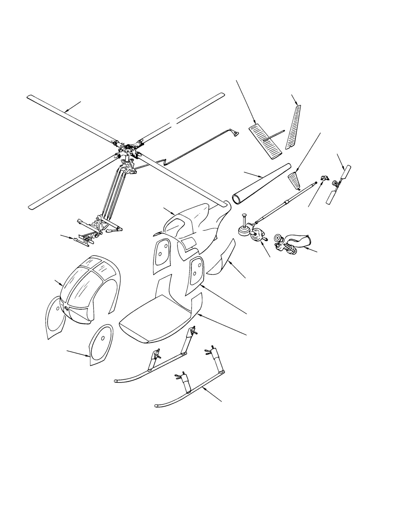
(Ref. Figure 1−1) The MDHI 369H helicopter is
tail rotor transmission, driveshaft and the tail
a turbine−powered, rotor wing aircraft,
rotor blade angle control rod.
Page 1-1
Revision 15
MD Helicopters, Inc.
CSP−H−2
500 Series − Basic HMI
HORIZONTAL STABILIZER
UPPER VERTICAL
STABILIZER
MAIN ROTOR INSTL
LOWER VERTICAL
STABILIZER
TAIL ROTOR
ASSY
TAILBOOM
AFT SECTION
INSTL
TAIL ROTOR
TRANSMISSION
FLIGHT
CONTROLS
INSTL
ENGINE INSTL
MAIN TRANSMISSION
& POWER TRAIN
FORWARD
SECTION
ENGINE ACCESS
INSTL
DOOR ASSY
CARGO DOOR ASSY
LOWER SECTION INSTL
PILOT DOOR
ASSY
LANDING GEAR
30−001
Figure 1-1. Helicopter - Major Components
Page 1-2
Revision 14
MD Helicopters, Inc.
CSP−H−2
500 Series − Basic HMI
The main rotor group consists of four rotor
Removal
blades, a fully articulated main rotor hub
Inspection (Other than Daily or Periodic)
assembly that incorporates offset flapping
Disassembly
hinges, a scissors assembly and a swashplate,
Reassembly
and associated mixer control mechanisms. The
Installation
main rotor blades are secured to the rotor hub
Adjustment (Other than System Rigging or
assembly with standard hardware and/or by
Tracking)
quick−release lever type pins that permit easy
Repair
and fast removal of the blades.
7. Associated MDHI Manuals
The landing gear is the horizontal, skid type,
Information beyond the scope of the Mainte−
attached to the fuselage at 12 points; it is
nance Manual may be found in these basic
non−retractable. The struts, from the fuselage
associated manuals which are prepared as
to the skids, are covered with aerodynamic
separate publications but should always be
fairings. Nitrogen−charged landing gear
kept and used with this manual:
dampers, between the struts and structure, act
A. Optional Equipment Manual
as shock absorbers to cushion landings.
CSP−H−3, Appendix A, contains descriptive
5. Scope
and maintenance information on the various
accessory and system equipment options
MDHI maintenance manuals provide system
available for each of the three helicopter model
descriptions, servicing and maintenance
configurations.
procedures, periodic and special inspections,
B. Inspection Requirements
overhaul schedules, limited life component
replacement schedules, and weight and
CSP−H−4, Appendix B, contains the daily and
balance calculations.
recurrent inspections that must be performed
on a repetitive cycle basis to verify that the
This manual is one of a group of publications
helicopter is airworthy. CSP−H−4 B also
that form the information file for the helicop−
includes special inspections, overhaul and
ter. The maintenance and inspection proce−
retirement schedule for components that have
dures are to be used for the 369H helicopters
a limited hourly life between overhaul periods
only. Study the contents to gain an under−
or for retirement, and weight and balance
standing of the arrangement and use of this
procedures.
and associated manuals before working on the
C. Component Overhaul Manual
aircraft.
CSP−H−5, Appendix C, contains overhaul
6. Organization of Handbook Contents
instructions for major components such as
main transmission, tail rotor transmission,
The contents of this handbook are grouped into
overrunning clutch, etc.
Sections as outlined by the Table of Contents.
D. Structural Repair Manual
Each Section of this manual has its own Table
of Contents and List of Figures. The content of
CSP−H−6, Appendix D, contains helicopter
each Section is organized to provide compre−
structural maintenance and repair informa−
hensive coverage on an entire system, on a
tion.
major assembly or on a group of equipment
E. Illustrated Parts Catalog
items that are similar or associated. Mainte−
nance procedures for each component, assem−
The 369 Series Illustrated Parts Catalog
bly or system are presented in sequence.
(CSP−H−7) provides, by means of text and
Instructions for all or part of the following
companion illustrations, complete definition of
maintenance functions are included as
all repair parts and spare items available for
applicable.
all configurations of the helicopter. Use
Troubleshooting
CSP−H−7 for parts procurement only.
Operational Check
8. Engine Data
Rigging Check
Tracking
The Model 250 Series gas turbine engines are
Balancing
manufactured by the Allison Engine Company
Page 1-3
Revision 15
MD Helicopters, Inc.
CSP−H−2
500 Series − Basic HMI
Inc.. Refer to the applicable Allison Engine
(a).
Red Border Notices: The red border
Repair and Maintenance Manual and the
notices deal with critical items that
Illustrated Parts Catalog supplied with the
must be corrected. These notices are
engine for specific engine maintenance
mandatory and require a record of
information. Fault isolation and maintenance
accomplishment. They may be
procedures for the helicopter/engine interface
re−occurring (flight−time or calendar)
systems are in divisions specified by the index.
or one−time only notices.
9. MDHI Publications Changes and
(b).
Blue Border Notices: The blue border
Revisions
notices are not mandatory and can be
accomplished at the owner/operator’s
Changes in the helicopter, equipment, mainte−
discretion. When instructed, these
nance practices, procedures and additional
notices may require a record of
information developed by experience affect
accomplishment. These notices deal
manual content. To ensure that MDHI
manuals continue to reflect current changes,
with non−critical or optional items
revised information is provided by one or more
only.
of the following communications:
(c).
Service Bulletins: The Service
A. Revision
Bulletin deal with critical items that
must be corrected. These bulletins
Alteration of portions of the handbook by the
are mandatory and require a record
replacement, addition and/or deletion of pages
of accomplishment. They may be
is accomplished by revision. The List of
re−occurring (flight−time or calendar)
Effective Pages (LOEP) that accompanies each
or one−time only notices. The service
revision identifies all affected pages; such
bulletin replaces the red border
pages should be removed from the handbook
notice.
and destroyed. Added or replacing pages
should then be inserted and checked against
the LOEP.
(d).
Technical Bulletin: The Technical
Bulletins are not mandatory and can
B. Reissue
be accomplished at the owner/opera−
tor’s discretion. When instructed,
When large numbers of changes are involved,
these bulletins may require a record
the handbook is reissued. The preceding issue
of accomplishment. These bulletins
of the handbook then becomes obsolete and
deal with non−critical or optional
should be discarded.
items only. the technical bulletin
C. Reprint
replaces the blue border notice.
When large numbers of changes are involved,
(e).
For a complete listing and explana−
the manual is reprinted to include all prior
tion of current and cancelled notices,
revisions.
refer to Service Information Notices
D. Service Information Notices and Letters
Index.
Service information is to be considered as part
(2). Service Information Letters are strictly
of the handbook.
information only. They may inform the
(1). Service Information Notices and
owner/operator of options available,
Bulletins are broken into two categories
up−coming notices, warranty/repair
as follows:
changes, etc.
Page 1-4
Revision 15
MD Helicopters, Inc.
CSP−H−2
500 Series − Basic HMI
10. Application of Warnings, Cautions and
11. Service and Operations Report Form 1601
Notes
MDHI Service and Operations Report Form
Throughout this manual, and associated
1601 may be used to report to MD Helicopters,
manuals, Warnings, Cautions and Notes are
Inc. in detail any service difficulties encoun−
used to emphasize instructions or information
tered with any MDHI helicopter. Use of the
considered to be unusual or critical.
form is encouraged and recommended to
WARNING and CAUTION statements are
enable MDHI to provide owners and operators
always placed before the information or
improved service, support and product
instructions to which they apply.
improvements. The form also serves as a
convenient detailed record for owners and
A NOTE may appear in the text either before
operators. Copies of the form may be procured
or after instructions to which it applies,
by contacting the Product Support Dept.
depending on the relative significance of the
information.
The conditions that warrant use of Warnings,
Cautions and Notes are defined as follows:
Operating procedures and
WARNING
practices which, if not strict−
ly observed, may result in personal in−
jury, or loss of life.
Operating procedures and prac−
CAUTION
tices which, if not strictly ob−
served, may result in damage to or destruc−
tion of equipment.
NOTE: An operating procedure or condition
that is essential to highlight.
Page 1-5/(1-6 blank)
Revision 16
MD Helicopters, Inc.
CSP−H−2
500 Series − Basic HMI
Section
2
Servicing and
General Maintenance
MD Helicopters, Inc.
CSP−H−2
500 Series − Basic HMI
TABLE OF CONTENTS
Para/Figure/Table
Title
Page
Section 2 Servicing and General Maintenance .
2−1
1.
Maintenance and Operational Check Requirements and Precautions
2−1
Figure 2−1. Principal Dimensions
2−2
2.
Helicopter Fundamentals
2−3
A. Principal Dimensions
2−3
B. Airframe Stations Locations
2−3
C. Component Weights for Hoisting
2−3
Table 2−1. Approximate Maximum Hoisting Weights of Components .
2−3
3.
Helicopter Ground Handling
2−3
A. Use of External Power
2−3
B. Hoisting
2−3
Figure 2−2. Hoisting, Jacking and Leveling
2−4
C. Jacking
2−5
D. Leveling
2−5
E. Parking
2−5
F. Mooring
2−5
G. Ground Handling Wheels
2−6
H. Helicopter Moving and Towing
2−6
Figure 2−3. Ground Handling Wheels
2−7
Table 2−2. Ground Support Equipment and Special Tools .
2−8
Figure 2−4. Parking and Mooring
2−12
4.
Servicing
2−13
A. Fuel System Filling
2−13
B. Fuel System Draining
2−13
C. Engine Oil System Filling
2−13
Figure 2−5. Servicing Points
2−14
D. Engine Oil System Draining (with Sta. 137.50 Bulkhead Drain
Ports Installed)
2−14
E. Engine Oil System Draining (with Drain Valve Installed) .
2−14
F. Engine Oil System Flushing
2−15
G. Main Rotor and Tail Rotor Transmission Filling
2−15
H. Main Rotor Transmission Draining
2−15
I.
Main Rotor Transmission Oil System Flushing
2−16
J. Tail Rotor Transmission Draining
2−16
K. Tail Rotor Transmission Oil System Flushing
2−16
L. One−Way Lock Control system Servicing
2−16
Table 2−3. Component Servicing and Materials
2−17
Page 2−i
Revision 19
MD Helicopters, Inc.
CSP−H−2
500 Series − Basic HMI
TABLE OF CONTENTS (Cont.)
Para/Figure/Table
Title
Page
5.
Battery Handling and Servicing Precautions
2−18
6.
Battery Servicing
2−18
7.
Battery Charging
2−19
A. Normal Battery Charging
2−19
B. Battery Deep Cycling
2−20
Table 2−4. Maintenance Materials
2−21
8.
Access and Inspection Provisions
2−31
A. Main Gearbox Access Cover
2−31
B. Main Transmission Drain Assembly (used with Shaft−Driven Blower) .
2−31
Figure 2−6. Access and Inspection Provisions (Sheet 1 of 6) .
2−32
C. Main Transmission Cover
2−38
D. Main Transmission Cover Assembly Seals Replacement .
2−39
E. Cargo Compartment Aft Bulkhead Access Covers
2−39
Figure 2−7. Main Rotor Transmission Cover Seals Installation .
2−39
F. Pilot Compartment Floor Access Doors
2−40
G. Fuel Cell Access Doors
2−40
H. Controls Tunnel Cover
2−41
I.
Engine Air Inlet Forward Fairings
2−41
J. Engine Air Inlet Fairing Access Doors
2−42
K. Aft Section Air Inlet (Tail Rotor Drive) Access Door
2−42
L. Controls Access Door and Foot Support Fairings
2−42
M. Pilot’s Seat Cover
2−43
N. Outboard (LH) Collective Stick Cover and Wiring Cover .
2−43
O. Fuel Vent Cover
2−43
P. Fuel Filler Shield
2−43
Q. Boom Bolts Access Doors and Tail Rotor Control Bellcrank Access Door
2−43
R. Exterior Lights Covers
2−44
S. Cargo Swing/Hook Fairing Cover
2−44
T. Instrument Panel Fairings
2−44
U. Instrument Panel Lower Section Side Cover Panels
2−44
V. Instrument Panel Lower Section Front Cover Panel
2−44
W. Pilot and Cargo Doors
2−45
X. Engine Access Doors
2−45
9.
Helicopter Cleaning
2−45
A. Fuselage Interior Trim and Upholstery Cleaning
2−45
B. Airframe Exterior and Rotor Blade Cleaning
2−46
C. Transparent Plastic Cleaning
2−46
Page 2−ii
Revision 19
MD Helicopters, Inc.
CSP−H−2
500 Series − Basic HMI
TABLE OF CONTENTS (Cont.)
Para/Figure/Table
Title
Page
D. Battery Cleaning
2−46
E. Battery Electrolyte Spillage Cleaning
2−47
F. Transmission Lubrication Pump Oil Filter Cleaning
2−47
Figure 2−8. Transmission Lubrication Pump Oil Filter
2−47
G. Engine Fuel and Oil Filter Cleaning
2−48
H. Engine Compression Cleaning
2−48
I.
Engine Air Inlet Screen Cleaning
2−48
10. Corrosion Control
2−48
A. Standard Practices for Corrosion Prevention
2−48
B. Magnesium Alloy Corrosion
2−49
C. Aluminum Alloy Corrosion
2−49
D. Alloy Steel Corrosion
2−50
E. Temporary Anti−Corrosion Measures
2−50
F. Corrosion Arresting on Main Rotor Blades
2−50
G. Main Rotor Hub Corrosion Prevention (Tri−Flow Wash Procedure) .
2−50
H. Magnesium Alloy Exterior Surface Touch−Up Treatment .
2−51
I.
Aluminum Alloy Exterior Surface Touch−Up Treatment .
2−51
J. Steel Alloy Exterior Surface Touch−Up Treatment
2−51
11. Paint Finish
2−52
A. Paint Removal
2−52
B. Paint Touch−Up
2−52
12. Main Rotor Blade Paint
2−53
A. Main Rotor Blade Paint Removal
2−53
B. Main Rotor Blade Paint Application
2−54
13. Metal Tail Rotor Blade Paint
2−54
A. Metal Tail Rotor Blade Paint Removal
2−54
B. Metal Tail Rotor Blade Paint Application
2−54A
14. Fluid Leak Analysis
2−54A
A. Main Rotor or Tail Rotor Transmission Oil Leaks
2−54A
B. Engine Oil Leaks
2−54B
C. Landing Gear Damper Hydraulic Fluid Leaks
2−54B
Figure 2−9. Checking Overrunning Clutch Oil Level
2−54B
D. Overrunning Clutch Oil Leak Analysis and Servicing
2−55
E. One−Way Lock (Uniloc) Fluid Leak
2−55
15. Preservation and Storage
2−56
A. Flyable Storage (No Time Limit)
2−56
Page 2−iii
Revision 19
MD Helicopters, Inc.
CSP−H−2
500 Series − Basic HMI
TABLE OF CONTENTS (Cont.)
Para/Figure/Table
Title
Page
B. Storage up to 45 Days
2−56
C. Storage up to 6 Months
2−57
16. Torque Data
2−58
A. Torque Wrenches
2−58
17.
Torque Wrench Load Application
2−58
18.
Installation, Staking or Swaging Force Needed for Bearings .
2−60
19.
Useful Conversion Data
2−60
20.
Related Publications
2−60
21.
Maintenance Information Requests
2−60
22.
Inspection Practices and Technical Definitions
2−60
23.
Service and Operations Report Form 853
2−60
Table 2−5. Recommended Standard Torques for Tension−Type Nut:
Min. and Max. Torque Values; AN310, AN365, MS20365, MS21042,
NAS1021, NAS1291, NAS679
2−61
Table 2−6. Recommended Standard Torques for Shear−Type Nut:
Min. and Max. Torque Values; AN320, AN364, MS20364, NAS1022,
MS21083
2−62
Table 2−7. Self−Locking Nut Minimum Run−On Torque Values .
2−63
Table 2−8. Minimum Breakaway Torque For Used Self−locking Bolts or Screws .
2−63
Table 2−9. Special Torques
2−64
Table 2−10. Temperature Convervision
2−67
Table 2−11. Conversion of Inches to Millimeter
2−68
Table 2−12. Conversion of Millimeter to Inches
2−68
Table 2−13. Conversion of Fractional Inches to Decimals and Millimeter .
2−69
Table 2−14. Conversion of U.S. Measure used in Servicing and Maintenance .
2−69
Table 2−15. Related Publications and Directives
2−70
Figure 2−10. Technical Definitions
2−73
Table 2−16. Technical Definitions
2−74
Page 2−iv
Revision 19
MD Helicopters, Inc.
CSP−H−2
500 Series - Basic HMI
SECTION 2
SERVICING AND GENERAL MAINTENANCE
1. Maintenance and Operational Check
and loose cable ends are properly in−
Requirements and Precautions
sulated and stowed to prevent the
possibility of shorting. Serious inju−
All maintenance on the helicopter is to be
ry or death could result from volt−
accomplished in compliance with the following
ages present in electrical wiring of
requirements and precautions.
the electrical system or associated
equipment.
(1).
All maintenance and operational checks
that require operation of the helicopter
D Install bungee installation tool (26,
must be preformed in accordance with
Table 2−2) before disconnecting any
requirements and limitations specified
pilot’s collective stick hardware (Ref.
in the MDHI 369 Owners Manual and
Sec. 7). There is strong bungee spring
pressure present in the stick linkage;
the applicable optional equipment
if suddenly released, spring reaction
supplement to the Owners Manual for
in the linkage can cause personnel
the specified model helicopter.
injury, or parts damage.
(2).
After performance of maintenance or
modification (disassembly, cleaning
CAUTION
parts, parts replacement, repair,
D Whenever work is performed near the en−
reassembly, installation, etc.) the
gine air inlet, use care to prevent entry of
affected parts, assemblies installa−
foreign objects. Tape covers of cardboard
tion(s) or system(s) are to be inspected
for discrepancies and an operational
or other suitable material in place over
check is to be preformed. Should
the engine inlet or screen in the plenum
maintenance questions arise, refer to
chamber and also the oil cooler air inlets.
Table 2−15.
Do not remove covers until work is com−
pleted and any debris is thoroughly
(3).
Cautions and Warning statements
cleaned out of the area. After removing
throughout this HMI are provided to
covers, verify that area around base of
promote safe maintenance of the
mast, inlet plenum, and entire plenum
helicopter as defined in Section 1. To
chamber is free from foreign material.
avoid repetitious appearance in text,
D Use care when drilling and removing riv−
certain precautions that should always
eted rod ends from control rods. Tighten
be observed will not always be stated at
jam nut before drilling or riveting; the rod
each possible point of application.
end is steel and the rod is aluminum.
Cautions and warnings of this nature
are listed below to emphasize that
D When working on the belt−drive blower,
appropriate compliance is required at
the impeller must be hand− held for re−
moval and installation of the pulley at−
all times even though the precautionary
tachment nut. Do not hold impeller
statement are not repeated. Always
blades with tool or other devices. Tool
comply with the following precautions.
damage can affect precision balance of
impeller as well as cause physical dam−
WARNING
age. Do not use any type of holding device
that will place strain on the blower scroll.
D Before disconnecting, removing,
Impeller is balanced to within 0.03 inch
installing or connecting components
ounce (0.0002 Nm). Slight impeller de−
of the electrical system or associated
formation or damage can cause impeller
equipment with electrical wiring,
imbalance.
check that all electrical power is
OFF. If units are not immediately re−
D Do not use vibration dampers for turning
placed, ensure all electrical connec−
main rotor or handholds. Such use can
tors are suitably capped and stowed
damage vibration damper bracket.
Page 2-1
Revision 14
MD Helicopters, Inc.
CSP−H−2
500 Series - Basic HMI
26.33 FT.
(8.025 M)
5.06 FT.
(1.542 M)
4.57 FT.
(1.393 M)
30.30 FT. (9.235 M)
23.00 FT. (7.01 M)
21.25 FT. (6.477 M)
15.00 FT. (4.572 M)
8.50 FT.
(2.591 M)
7.00 FT.
4.25 FT.
(2.134
6.30 FT.
(1.295 M)
M)
(1.92 M)
8.20 FT.
7.20 FT.
(2.499 M)
(2.195 M)
0.79 FT.
(0.241 M)
NOTE:
ADD 0.63 FT. (0.19 M) TO ALL VERTICAL
6.80 FT.
DIMENSIONS IF EXTENDED GEAR IS INSTALLED.
(2.073 M)
30−002D
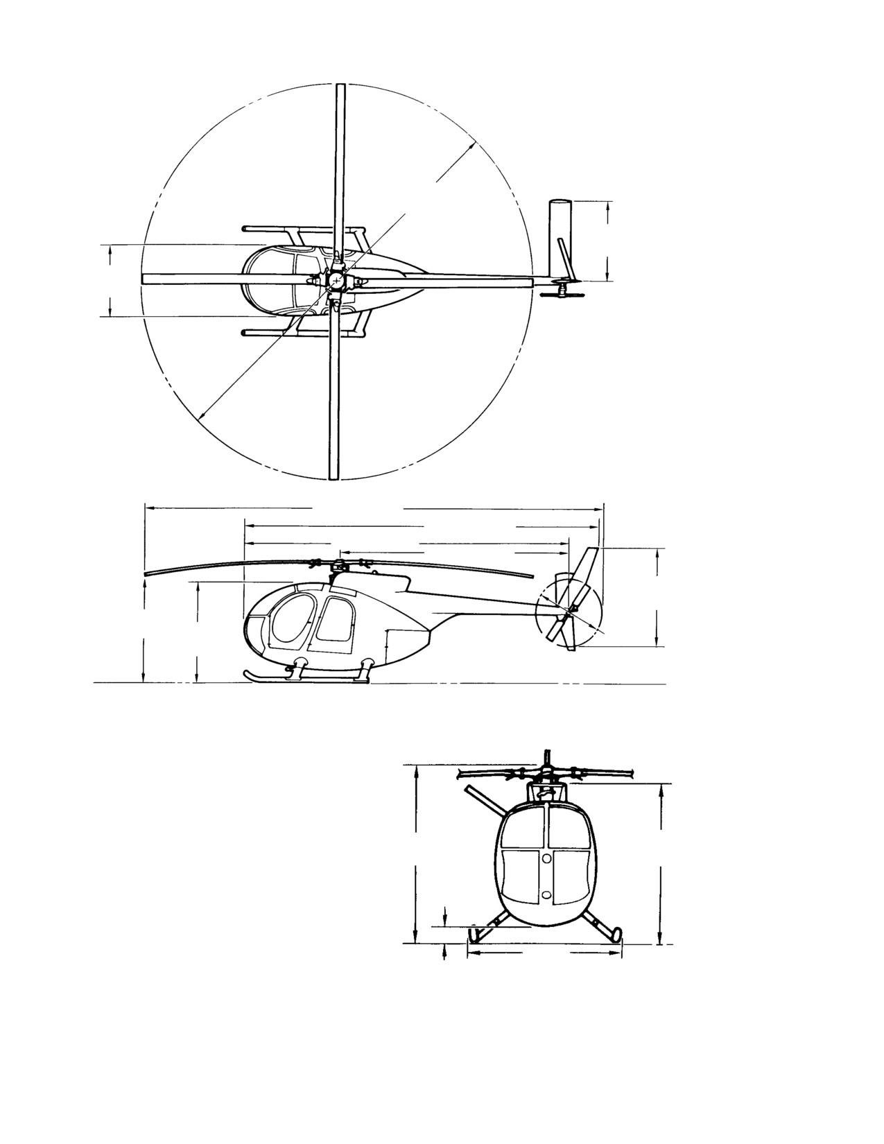
Figure 2-1. Principal Dimensions
Page 2-2
Revision 14

MD Helicopters, Inc.
CSP−H−2
500 Series - Basic HMI
2. Helicopter Fundamentals
receptacle. Any source of external 28 volt,
direct−current power may be connected
A. Principal Dimensions
provided the negative terminal of the plug
mates with the negative terminal of the
Principal dimension are shown in Figure 2−1.
receptacle and the amperage available is
B. Airframe Stations Locations
sufficient. Engine starting requirements are
approximately 375 amperes minimum.
Reference is occasionally made to ‘‘station" and
‘‘waterline" throughout the handbook. To assist
Before connecting external pow−
CAUTION
in locating the components being discussed,
er, make certain that the heli−
refer to the station diagram provided in
copter main electrical power selector switch
CSP−H−6. Station and waterline references
is in the OFF position. After power is con−
are also necessary for weight and balance
nected to the receptacle, the power switch
procedures.
must be at the EXT position to connect ex−
ternal power to the helicopter electrical sys−
C. Component Weights for Hoisting
tem.
The maximum weight for large components
NOTE: The positive (+) and negative (−) voltage
that may require hoisting are listed in
terminals are clearly marked on the base of
Table 2−1.
the receptacle to prevent reversing of polar−
ity if a standard auxiliary power plug is not
Table 2-1. Approximate Maximum Hoisting
available.
Weights of Components
B. Hoisting
Wgt
Item
Lb/kg
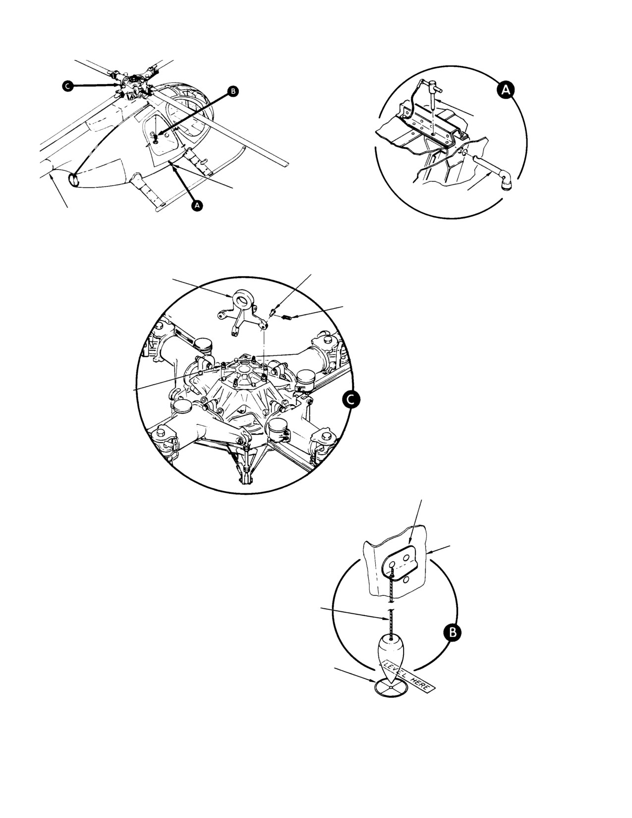
(Ref. Figure 2−2) Observe the following
precautions during any hoisting operation.
Tailboom
14/6
Main Rotor Hub
58/26
Use a hoist of no less than 3500
CAUTION
pound (1598 kg) capacity when
Main Transmission
79/36
hoisting the complete helicopter. Use hoist−
Engine (built up)
170/77
ing equipment of sufficient capacity (mini−
mum twenty−percent over−rate) to hoist the
Helicopter (less engine)
1000/455
heavier components if handled separately.
Helicopter (less main rotor hub,
(Ref. Table 2−1 for approximate weights.)
swashplate, scissors, and rotor blades)
998/453
(1). Install hoisting adapter (1, Table 2−2)
Helicopter (complete)
1170/531
on main rotor hub so that the four
hoisting eyebolts fit into the slots on the
3. Helicopter Ground Handling
hoisting adapter.
Ground handling of the helicopter includes
(2). Install the four clevis pins.
hoisting, jacking, leveling, parking and
mooring. The following paragraphs present the
(3). Attach cable from overhead hoist to the
instructions and precautions for all ground
adapter eye.
handling functions.
(4). Secure a line to the tailboom. Have an
A. Use of External Power
assistant hold the line to keep the
helicopter from swinging.
An external receptacle is located at the right
side of the pilot’s compartment seat structure.
(5). Hoist slowly and smoothly to maintain
The right door must be opened to use the
a steady lifting force.
Page 2-3
Revision 14
MD Helicopters, Inc.
CSP−H−2
500 Series - Basic HMI
LOCK PIN
FWD JACKING POINT
JACKING FITTING
BOTH SIDES (STA 96.9)
AFT JACKING PAD
(STA 197.2)
CLEVIS PINS
HOISTING ADAPTER
(4 PLCS)
(369A9904)
SAFETY PIN
(EACH CLEVIS)
HOISTING EYEBOLTS
(4 PLCS)
PLUMB LINE
SUPPORT CLIP
RH EDGE OF
CONTROLS TUNNEL
PLUMB LINE
TARGET PLATE
30−004C
Figure 2-2. Hoisting, Jacking and Leveling
Page 2-4
Revision 14
MD Helicopters, Inc.
CSP−H−2
500 Series - Basic HMI
C. Jacking
(7). After leveling helicopter, remove plumb
bob, reinstall trim and carpet and close
(Ref. Figure 2−2) Provisions for jacking the
compartment door.
helicopter are provided by two forward (side)
E. Parking
jacking point fittings and an aft jacking pad.
(Ref. Figure 2−4) To park the helicopter for
NOTE: When the helicopter is jacked from one
short intervals, perform steps (1). thru (4). For
side only, a cushioned saddle−type support
longer duration parking, also perform steps
should be placed under the tailboom at the
(5). and (6).
boom jacking fitting location for extra stabil−
ity.
To prevent rotor damage from
CAUTION
blade flapping
(droop stop
(1). Install jacking fittings (2, Table 2−2) in
pounding) as a result of air turbulence from
the fuselage jacking points. Secure the
other aircraft landing or taking off, or sud−
jacking fittings with the locking pins
den wind gusts, rotor blades should be se−
that are secured to the fuel cell access
cured whenever the aircraft is parked.
doors.
(1). Locate the helicopter slightly more than
(2). Place suitable jacks under jacking
blade clearance from near−by objects.
fittings, and under aft jacking pad.
(2). Apply friction to lock the cyclic stick so
(3). Raise the helicopter to the desired
that the friction control knobs are
height.
positioned on the lateral and longitudi−
nal travel stop guides as follows:
D. Leveling
neutral laterally (center of slot), and
one−third from full aft longitudinally
(Ref. Figure 2−2) Leveling is accomplished by
(one−third up from bottom of slot).
causing a plumb bob to intersect register
marks inscribed on the target plate located on
NOTE: If not all ready accomplished, apply a
the cargo compartment floor
paint mark on the edge of the guide to locate
the neutral position for future reference.
NOTE: Access to plumb line support bracket
(3). Locate the helicopter on the most level
and target plate on floor of passenger/cargo
ground available.
compartment requires removal of trim on
right side of controls tunnel and floor carpet
(4). Secure the main rotor blades as follows.
in aft compartment.
(a). Turn blades until they are at 45
(1). Suspend plumb line from bracket on
degrees angle to the fuselage center−
right side of controls tunnel at Sta.
line.
92.64, BL +6.20.
(b). Install blade socks (3, Table 2−2) on
all blades.
(2). Adjust plumb line swing to leveling
target plate on floor of passenger/cargo
When securing tiedown cords,
compartment.
CAUTION
take up slack but do not exert
bending loads on blades.
(3). With weight of helicopter supported by
load cells or jacks, adjust appropriate
(c). Secure blade sock tiedown cords to
jack until plumb line is centered.
fuselage jacking fittings.
(4). Adjust side jacks to level helicopter
(5). Install engine air inlet cover assembly
laterally.
(46 on engine air inlet front fairing.
(6). Install engine exhaust outlet cover (47)
(5). Adjust tailboom jack to level helicopter
on exhaust tailpipes.
longitudinally.
F. Mooring
(6). Recheck lateral and longitudinal levels
until the plumb bob exactly aligns with
(Ref. Figure 2−4) Whenever severe storm
marks on target plate.
conditions or wind velocities higher than 40
Page 2-5
Revision 14
MD Helicopters, Inc.
CSP−H−2
500 Series - Basic HMI
knots are forecast, the helicopter should be
(2). With ground handling wheels in the
hangared or evacuated to a safer area. If these
retracted position, align and engage the
precautions are not possible moor the helicop−
skid fittings.
ter in the following manner.
(3). Install jack handle in the wheel
(1). Park helicopter and remove main rotor
assembly socket, install lock pin, and
blades and install engine inlet and
rotate handle downward to lower the
exhaust covers.
wheels and raise the helicopter.
Hold downward pressure on
(2). Install pitot tube cover (4, Table 2−2).
WARNING
jack handle until the extend
lock snaps into lock position. If the lock
(3). Fill fuel tank (if possible).
is not properly engaged and the handle
is released, the upward swing of the
(4). Apply friction to lock the cyclic and
handle could cause serious personal in−
collective sticks.
jury.
(5). Secure the helicopter to the ground by
(4). Check that the extend lock is engaged;
attaching restraining lines (cable or
then release downward pressure and
rope) between the jacking fittings and
remove jack handle.
stakes or ground anchors.
(5). Install second ground handling wheel
G. Ground Handling Wheels
assembly in the same manner.
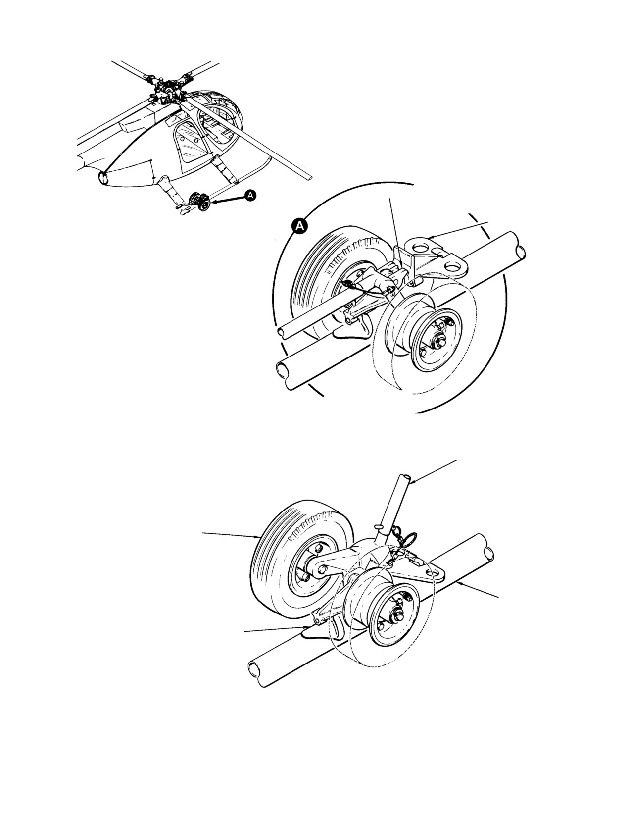
(Ref. Figure 2−3) Standard ground handling
(6). At regular intervals, the ground
wheels, available as a special tool (6,
handling wheels tire pressure should be
Table 2−2), are used for moving the helicopter.
checked for 80−90 psi (552−621 kPa)
The handling wheels consist of two, two−
and the wheel bearings lubricated with
wheeled jacking assemblies that can be
grease (18, Table 2−4).
straddle−mounted to the left and right landing
gear skids by use of the existing ground
H. Helicopter Moving and Towing
handling wheel fittings. The wheels are
manually lowered with detachable jack handle.
(1). Manually move the helicopter on
Either the straight handle (7) or the offset
ground handling wheels by balancing
handle (8) may be used depending on clearance
the tail boom and pushing on the rear
requirements. The wheels are held in down
fuselage portion of the airframe.
position (helicopter raised on wheels) by a
mechanical lock. The wheels are equipped with
The helicopter should always be
CAUTION
tow bar attach fittings. Attach the ground
towed at slowed speeds, not over
handling wheels as follows:
5 mph, except in extreme emergency condi−
tions. Do not allow the front end of the skid
NOTE: Special optional ground handling
tubes to drag on the ground. Avoid sudden
wheels (5) are used for moving the helicop−
stop and starts, and short turns which could
ter when equipped with option emergency
cause the helicopter to turn over. Allow the
floats (Ref. CSP−H−3). If helicopter with ex−
inside wheels to turn (not pivot) while the
tended gear is tilted back on the tail skid to
helicopter is being turned. The proper mini−
install ground handling wheels, approxi−
mum turning radius is approximately 20 ft.
mately one pint of oil is trapped in the tail
(6 M).
rotor gearbox. This condition will give a
false sight gage oil level indication after re−
(2). Towing the helicopter on ground
turn to a level attitude. The oil will return to
handling wheels by attaching a suitable
normal after ground runup.
tow bar to the two bar fittings. If the
tow bar is not equipped to keep the
(1). Position ground handling wheel
front ends of the skid tubes from
assembly over the skid tube at the
dragging, have an assistant balance the
location of the skid fitting.
helicopter at the tail boom.
Page 2-6
Revision 14
MD Helicopters, Inc.
CSP−H−2
500 Series - Basic HMI
WARNING
BE SURE LOCK SNAPS INTO
LOCK
POSITION SHOWN BEFORE
RELEASING JACK HANDLE
TOW BAR FITTING
WHEEL LOWERED
AND LOCKED
(HELICOPTER RAISED)
JACK HANDLE
GROUND HANDLING WHEELS
AND JACK ASSEMBLY
SKID TUBE
(RIGHT SIDE SHOWN)
SKID FITTING
WHEELS RAISED
(HELICOPTER LOWERED)
30−133
Figure 2-3. Ground Handling Wheels
Page 2-7
Revision 14
MD Helicopters, Inc.
CSP−H−2
500 Series - Basic HMI
Table 2-2. Ground Support Equipment and Special Tools
NOTE: Most of the equipment and tool items in this table are used to support and maintain all configurations of the
369H helicopter, except when an asterisk symbol ( * ) is part of the item number to indicate limited use. Limited
applications noted in the Application or Use column. Special tools used only for major disassembly-repair
and/or overhaul of components are listed in applicable section of CSP-H-3. See end of table for explanation
of deltas and daggers.
Item
Part No.
Nomenclature
Application or Use
No.
1
369A9904-501
Hoisting adapter
Hoisting entire helicopter or removing main
rotor.
2
369A2010
Jacking fittings
Jacking, leveling or tie down of helicopter.
3
369D2661
Blade socks
Main rotor blade tie downs.
4
369H4009
Pitot tube cover
Pitot tube protection.
5
369H90126
Ground handling wheels
Ground handling of helicopter equipped with
(one side)
utility or emergency floats. (Ref. CSP-H-3)
6
369A9905
Ground handling wheel
Ground handling of helicopter.
(one side less handle)
7
369H9801
Handle-Jack assembly ground
Raising and lowering helicopter with ground
handling (straight)
handling wheels.
8
369A9906
Handle-Jack assembly, ground
Raising and lowering helicopter with ground
handling (offset)
handing wheels when addition clearance is
required.
9
369H9925
Collective rigging fixture
Rigging of main rotor collective controls
(369HE and 369HS only).
10
369A9927
Collective rigging fixture
Rigging of main rotor collective controls
(369HM only).
11
369A9930
Mixer rigging plate
Rigging of main rotor collective and cyclic
controls.
12
369A9929-9
Longitudinal rigging fixture
Rigging of main rotor cyclic controls (369HE
and 369HS only).
13
369A9929-5
Longitudinal rigging fixture
Rigging of main rotor cyclic controls (369HM
only).
14
369A9928-9
Lateral rigging fixture
Rigging of main rotor cyclic controls (369HE
and 369HS only).
15
369A9928-5
Lateral rigging fixture
Rigging of main rotor cyclic controls (369HM
only).
16
369A9926-7 or
Main rotor blade tracking high intensity
Tracking of main rotor blades.
369A9926-5 (1)
strobe light installation and assembly
17
369A9958
Main rotor blade tab bending tool
Adjusting main rotor blade tab angle for
blade track.
18
369H9928
Main rotor blade tab bending tool
Adjusting main rotor blade tab angle for
blade track.
19
369A9934-601
Main rotor mast nut wrench
Loosening/Torquing of main rotor mast nut.
(replaced by 21)
20
369A9934
Main rotor mast nut wrench
Loosening/Torquing of main rotor mast nut
(non-slotted mast only).
Page 2-8
Revision 19
MD Helicopters, Inc.
CSP−H−2
500 Series - Basic HMI
Table 2-2. Ground Support Equipment and Special Tools (Cont.)
Item
Part No.
Nomenclature
Application or Use
No.
21
369A9829
Main rotor wrench assembly
Loosening/Torquing of main rotor mast nut.
22
369A9932
Hub puller
Breaking loose main rotor hub from mast.
369A9932 (2)
23
369A9949
Torque wrench adapter
Checking main rotor damper first stage
friction.
24
369A9933
Main rotor hub driver
Seating main rotor hub.
369A9933-5 (3)
25
369A9983
Torque wrench adapter
Torque tailboom attachment bolts.
26
369A9936
Bungee installation tool
Holding collective bungee spring in
compression for bungee removal and
installation.
27
369A9985
Bungee spring compression tool rod
Removing bungee installation tool and
and channel
disassembling bungee spring assembly.
28
369A9931 or
Tail rotor swashplate rigging tool
Rigging of tail rotor controls (fiberglass
369A9931-3
blades).
29
369A9931-5
Tail rotor swashplate rigging tool
Rigging of tail rotor controls (metal blades).
30
369A9937
Torque wrench adapter
Installing tail rotor nut.
31
369A9999 (4)
Tail rotor balancing kit
Strobe light analysis for balancing installed
tail rotors.
32
FRDH 101
Torque wrench adapter
Installing main rotor drive shaft bolts and
eyebolts.
33
RXT20-5
HYTIP insertion/extraction tool (mfg by
Installing and removing HYTIP electrical
(extraction)
Burndy, Norwalk, Connecticut)
contacts into and from terminal block
RTM20-9
modules.
(insertion)
34
M8ND &
HYTOOL M8ND (catalog No. Y14
Manual crimping of MINILOK and MODILOK
N14HTC
MRC); Die-Sets N22PCT-1 & -2, and
terminal block contact tips on electrical wire
N14HCT (mfg: same as item No. 33)
harness leads.
35
107-0970
Hand-operated crimping tool (Catalog
Hand crimping of removable contacts in
No. 107-0970) with positioners
rectangular connectors.
(Catalog No. 107-0976 and
107-0977)(mfg by Winchester
NOTE: Tool conforms to MS-3191-2
Electronics, Division of Litton
(MIL-T-22520, Class 1).
Industries, Main St. and Hillside Ave,
Oakville, Connecticut 06779)
36
107R1001 and
Removable contact removal tool
Removing and inserting removable contacts
107-1015
(Catalog No. 107R1001) and insertion
from and into inserts of rectangular
tool (Catalog No. 107-1015) (mfr:
connectors.
same as item No. 25)
37
Deleted
38
369A9948
Engine stand
Support for removal or replacement engine.
39
369A8009
Engine hoist
Removing and replacing engine in airframe.
Page 2-9
Revision 19
MD Helicopters, Inc.
CSP−H−2
500 Series - Basic HMI
Table 2-2. Ground Support Equipment and Special Tools (Cont.)
Item
Part No.
Nomenclature
Application or Use
No.
40
369A6001-
Left landing gear foot drill jig
Enlarging holes in left lockbolt-type landing
50506-1
gear struts for installation of
machine-bolt-attached skids.
41
369A6001-
Right landing gear foot drill jig
Enlarging holes in right lockbolt- type
50506-2
landing gear struts for installation of
machine-bolt-attached skids.
42
CIET 20
Insertion/extraction tool, No. 20 Wire
Connecting and disconnecting No. 20 Wire
Mate connector (mfd. by I. T. T.
Mate electric connectors.
Cannon Electric, 3208 Humbolt St.,
Los Angeles, Calif. 90031)
43
CIET 16
Insertion/extraction tool, No. 16 Wire
Connecting and disconnecting No. 16 Wire
Mate connector (mfr: same as No. 42)
Mate electrical connectors.
44
369A9822-5
Locknut torque wrench adapter
Installing and removing tail rotor
swashplate-to-control housing bearing nut.
45
369A9922-3
Pitch control assembly holding block
Holding tail rotor swashplate while removing
and installing nut.
46
369H9803
Engine air inlet cover
Covering for engine air inlet front fairing.
47
369H9804
Engine exhaust outlet cover
Covering for engine exhaust tailpipes.
48
369A1710-
Fiberglass tail rotor blade, static
Determination of fiberglass blade static
80901
balance moment fixture
balance moment.
49
369A9825
Pitch bearing stud wrench
Removing main rotor hub pitch bearing pivot
pin.
50
369A9826
Stud nut wrench
Holding main rotor hub pitch bearing pivot
pin nut.
51
369H9807
Main transmission drain hose
Draining main transmission oil.
52
2312-G
Turbine temperature indicating system
Test and calibration of the TOT indicating
test set (Barfield Instrument Corp.)
system.
BH112JA-36
Jetcal tester (Howell Instrument Inc.)
Test and calibration of the TOT indicating
system.
53
369A1600-
Bushing wrench
Installation and torquing tail rotor hub
80902
threaded bushing.
54
83006-809-
Arbor press fixture, 369A7951-5
Installing bearing in tail rotor pitch control
00090-1
bearing
link.
55
83006-809-
Staking tool, 369A7951-5 bearing
Staking bearing in tail rotor pitch control link.
00090-15
56
83006-809-
Staking tool, (pilot and punch), pitch
Installing bearing and swage ring in pitch
00068
control assembly double row bearing
control housing.
369A7951-45
57
WSI-HT-12AS
Installation tool, WSI-B-12AS
Installing grommets for tail rotor control rod.
grommet (mfd. by Western Sky
Industries, 21300 Cloud Way,
Hayward, CA 94545)
58
269A9232
Plug, 269A5050-18 bearing removal.
Removing double-row bearing from tail
rotor pitch control housing.
Page 2-10
Revision 19
MD Helicopters, Inc.
CSP−H−2
500 Series - Basic HMI
Table 2-2. Ground Support Equipment and Special Tools (Cont.)
Item
Part No.
Nomenclature
Application or Use
No.
59
Chadwick-Helmuth Balancer /
Equipment for tracking and balancing of
Analyzer Instrument Kit
dynamic components. Main/Tail rotor
vibration analyzer.
60
369D29999
Main rotor and tail rotor balance spare
Used with Item 59 to balance tail rotor and
kit
main rotor.
61
830006-809-
Arbor press fixture for 369A7951-15
Installation of bearing in main rotor blade.
00090-8
bearing
62
830006-809-
Staking tool for 369A7951-15 bearing
Staking of bearing in main rotor blade.
00090-20
63
36-D-284
Prop protractor
Measure angle of incidence.
NOTE:
(1) Main rotor blade tracking equipment 369A9926-7 and -5 each contain a strobe light 369A9925, magnetic
pickup 369A9944, one set of interrupters, a set of tracking cap reflectors and associated mounting
hardware. The 369A9942-27, -29, -31 and -33 Tip Cap Assemblies are to be ordered as replacement
for the 369A9942-7, -9, -11, and -13 and the 369A9942-501 Tip Cap Assemblies.
(2) Handle, frames and puller nut same as 369A9932; -31 thrust pad replaces -3 thrust pad.
(3) Hammer and handle same as 369A9933; -7 driver -3 driver.
(4) Tail rotor balancing equipment 369A9999 contains a vibration analyzer 369A9801, protractor assembly
369A9979, acceleration mounting bracket 369A9920 and associated attachment and balancing
hardware.
Page 2-11
Revision 19
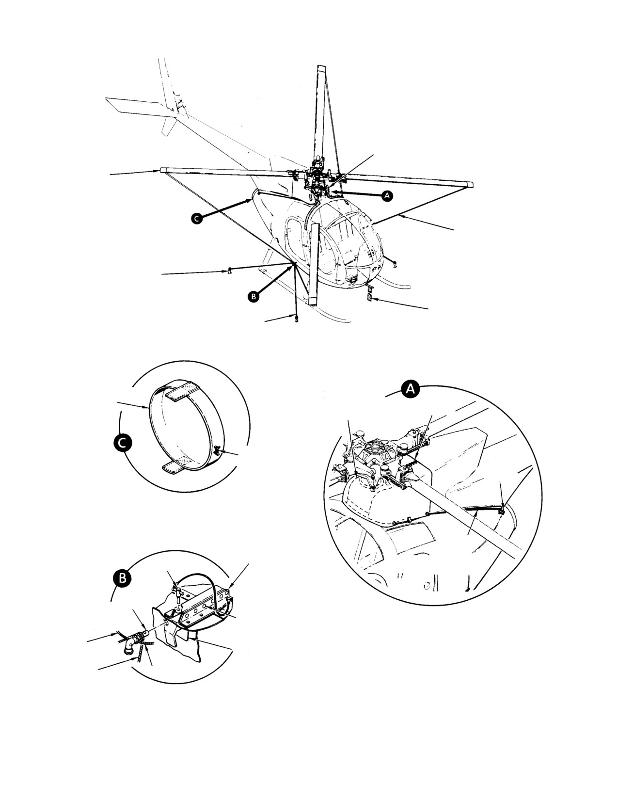
MD Helicopters, Inc.
CSP−H−2
500 Series - Basic HMI
OIL COOLER BLOWER/TRANSMISSION
COOLING AIR INLET PLUGS (2 PLCS)
BLADE SOCK
(369H26661)
(4 PLCS)
TIEDOWN TETHER
MOORING ANCHOR
(4 PLCS)
PITOT TUBE COVER
(369H4009)
CABLE OR MANILA ROPE
ENGINE EXHAUST
OUTLET COVER
AIR INLET FAIRING
ZIPPER
(369H9804)
COVER (369H9803)
EXTENSION SPRING
ACCESS
DOOR
LATCH
TIE CORD
FUEL CELL ACCESS DOOR
(TYP − 2 PLCS)
LOCKPIN
JACK FITTING
LOCKPIN STOWAGE
ENGINE AIR INLET FAIRING
WITH COVER INSTALLED
TO BLADE
SOCK
FUSELAGE STRUCTURE
JACKING FITTING
TO MOORING
TO BLADE SOCK
ANCHOR
30-005
Figure 2-4. Parking and Mooring
Page 2-12
Revision 14

MD Helicopters, Inc.
CSP−H−2
500 Series - Basic HMI
4. Servicing
B. Fuel System Draining
Fuel draining should be accomplished with
(Ref. Figure 2−5) Servicing of the helicopter
includes replenishment of fuel, changing or
helicopter as level as possible.
replenishment of oil and other such mainte−
(1). Fuel system may be defueled in either
nance functions. Fuels, oils, others servicing
of two ways:
materials and capacities are listed in
Table 2−3. Observe the following precautions
To avoid possible damage to fuel
when servicing the fuel system.
CAUTION
pump, do not operate fuel pump
with fuel tanks drained.
Turn off electrical switches
WARNING
and disconnect external
(a). Defuel through filler port using a
power from the helicopter.
pump.
(1). The helicopter must be electrically
(b). Open system drain valves on fuselage
grounded prior to refueling or defuel−
underside and in engine compart−
ing. The possibility of static discharge
ment.
(difference in electrical potential) and
presence of fuel vapors always presents
(2). Fuel supply line drain valves are spring
fire and explosion hazards.
loaded type and open by pushing valve
and attached drain line.
(2). The refueling vehicle should be parked
(3). Fuel cells drain valve is spring−loaded
a minimum of 20 ft. (6 M) from the
closed and is opened by pressing
helicopter during the fueling operation.
internal plunger.
Before starting the fueling operation,
always ground the fueling nozzle or fuel
C. Engine Oil System Filling
truck to the GROUND HERE recep−
tacle or to another bare metal location.
The engine oil filler cap is on the right side of
the helicopter. A liquid level plug for checking
Use extreme care when apply−
the oil level in the tank is visible through a
CAUTION
ing any type of lubricant
transparent window near the filler.
(grease, oil, dry−film, etc) in the vicinity of
teflon bearings. Most lubricant will form a
NOTE:
dirt retaining film or have other detrimental
D Before adding oil, the oil container must
effects that can cause rapid detertioration of
be shaken to ensure proper mixture of the
bearing surfaces.
anti−foaming additive.
A. Fuel System Filling
D If sight gauge does not permit positive de−
termination, remove filler cap and visual−
The fuel system has two fuel cells that are
ly check the oil level.
interconnected for simultaneous flow venting.
(1). Check oil level within 15 minutes of
The fuel filler cap is on the right side of the
engine shutdown; replenish if low.
helicopter.
(2). If engine oil level is low after helicopter
(1). Refuel helicopter with correct fuel as
has set for more than 15 minutes;
soon after landing as possible to
prevent moisture condensation and to
(a). Run engine for at least one minute at
keep the helicopter as heavy as possible
ground idle.
in case of winds.
Ensure engine oil pressure is at−
(2). Keep fuel nozzle free of all foreign
CAUTION
tained when starting engine
matter.
(Ref. applicable Pilot’s Flight Manual).
(3). Check filler cap for security after
(b). Shut down engine, check oil level,
fueling.
replenish if low.
Page 2-13
Revision 14
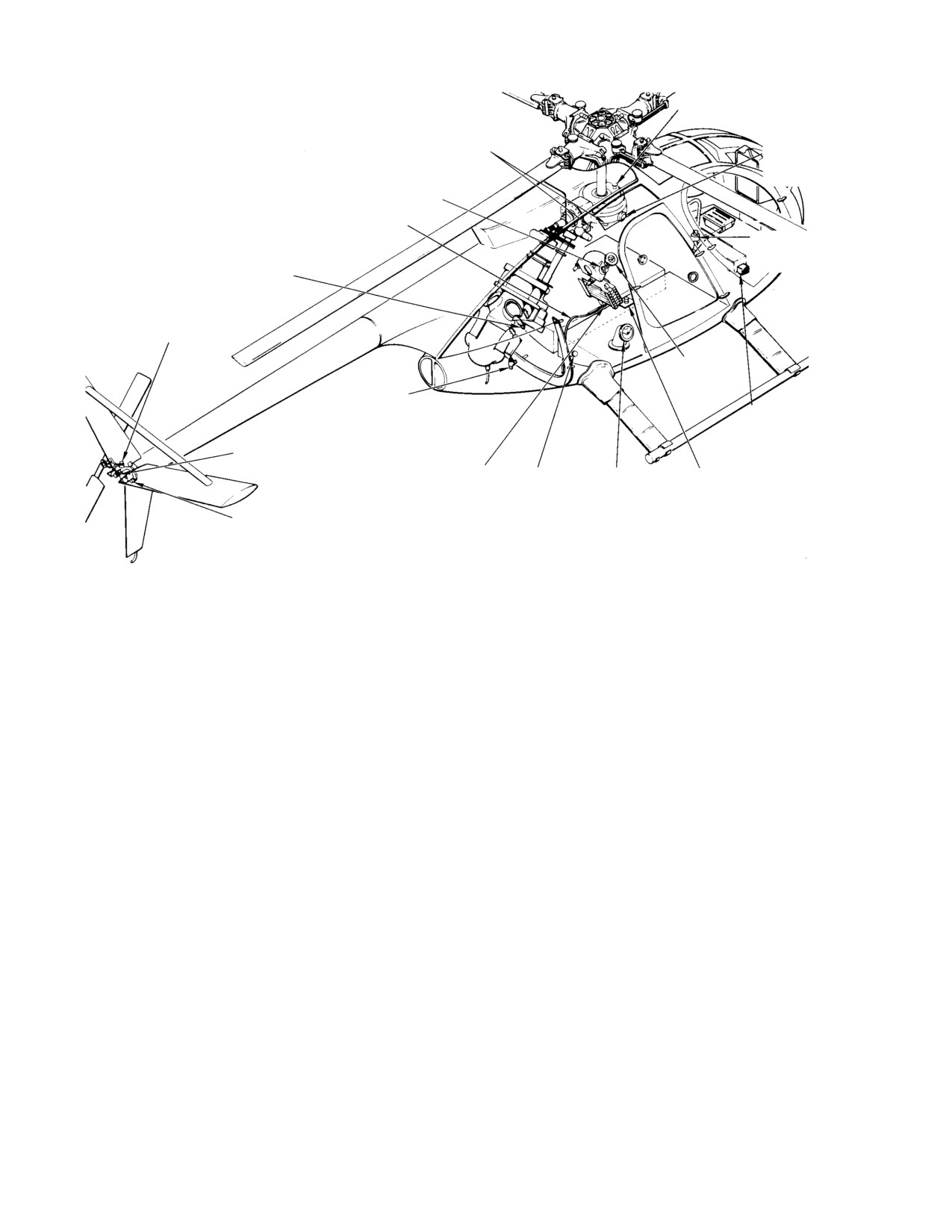
MD Helicopters, Inc.
CSP−H−2
500 Series - Basic HMI
NOTES:
MAIN TRANSMISSION
1.
SELF−CLOSING VALVE 50−60 IN. LB. (5.65−6.78 NM);
FILLER
CHIP DETECTOR (WITHOUT KNURLED DETECTOR
KNOB) 40−50 IN. LB. (4.52−5.65 NM).
MAIN TRANSMISSION
2.
ENGINE LOWER CHIP DETECTOR 60−80 IN. LB.
LIQUID LEVEL
DRAIN (NOTE 1)
(6.78−9.04 NM).
PLUG
3.
BREATHER−FILLER 45−55 IN. LB. (5.08−6.21 NM).
LIQUID LEVEL
PLUG
OVERBOARD OIL
DRAIN LINE
ONE−WAY LOCK
RESERVOIR
ENGINE ACCESSORY
GEARBOX DRAIN
(NOTE 2)
BREATHER−FILLER
(NOTE 3)
ENGINE OIL
TANK FILLER
FUEL SUPPLY LINE
DRAIN VALVE
EXTERNAL POWER
RECEPTACLE
LIQUID LEVEL
PLUG
OIL SUPPLY
GROUND
FUEL SYSTEM
FUEL CELLS
DRAIN VALVE
RECEPTACLE
FILLER
DRAIN VALVE
TAIL ROTOR
TRANSMISSION DRAIN
(NOTE 1)
30−006C
Figure 2-5. Servicing Points
NOTE:
(5). To drain residual oil from engine
accessory gearbox drain, remove wire
D Motoring engine can draw oil from the oil
lead and lower chip detector. Use
tank to the gearbox, giving low oil level
suitable container to catch oil. Check
indications.
that detector O−ring is serviceable
D If engine oil level indicates a low condi−
(replace if necessary); reinstall detector,
tion after setting overnight, engine check
torque to 50 − 60 inch−pounds (5.65 −
valve may be leaking oil from tank to en−
6.78 Nm) and reconnect wire lead.
gine gearcase.
E. Engine Oil System Draining (with Drain
(3). Ensure oil tank filler cap is securely
Valve Installed)
tightened immediately after servicing.
(1). Remove sound insulation from cargo
D. Engine Oil System Draining (with Sta.
compartment aft bulkhead right−hand
137.50 Bulkhead Drain Ports Installed)
access door (Ref. Figure 2−6). Remove
the right−hand access door.
(1). Open engine access doors.
(2). Place a suitable container under the
(2). Place suitable container under engine
overboard oil drain line where it exits
oil tank drain and remove engine oil
the fuselage underside at the firewall.
tank filler cap.
(3). Remove cap from oil tank filler. Pull out
(3). Remove engine oil tank drain cap.
knurled spring−loaded button to open
valve in engine oil drain line just below
(4). After draining oil from tank, reinstall
cooler. Rotate button and valve poppet
engine oil tank drain cap and oil tank
so that locking pin rest on shoulder of
filler cap.
pin slot.
Page 2-14
Revision 14
MD Helicopters, Inc.
CSP−H−2
500 Series - Basic HMI
(4). After draining the oil from the tank,
(a). Fill main transmission by lifting
reinstall the filler cap and close oil
breather−filler cap and inserting
drain valve; ensure that poppet pin is in
spout of oil can into opening. Check
stop slot.
that spring−loaded cap closes when
oil can spout is removed.
(5). Install access door and sound insula−
(b). Fill tail rotor transmission by remov−
tion.
ing lockwire, unscrewing breather−
filler and pouring oil into transmis−
(6). To drain approximately 1/2 pint (0.23 L)
sion. Check that filler O−ring is
of residual oil from engine accessory
serviceable (replace if necessary),
gearbox drain (Ref. Figure 2−5) remove
reinstall breather−filler and torque to
the wire lead and the lower chip
45 − 55 inch−pounds (5.08 − 6.21
detector. Use a suitable container to
Nm); secure with lockwire.
catch the oil. Check that detector
packing is serviceable (replace if
NOTE: Breather− filler plugs that have the
necessary), reinstall detector, torque to
threaded insert are installed with the
50 − 60 inch−pounds (5.65 − 6.78
breather hole rearward.
Nm), and reconnect wire lead.
H. Main Rotor Transmission Draining
F. Engine Oil System Flushing
(1). If installed, remove circular drain cover
plug and padding for main transmis−
The following procedure is for flushing oil that
sion from forward underside of trans−
as been contaminated or when changing the
mission cover panel. Otherwise remove,
type of oil.
in order, sound insulation, gearbox
access cover, transmission drain
(1). Drain oil from engine, oil tank and oil
assembly and main transmission cover).
cooler (Refer to Engine Oil System
(2). Position a suitable (min. 4 qt/4 L)
Draining).
container under main transmission
drains or drain current configuration
(2). Replace engine oil filter(s) (Ref. Allison
transmission using transmission drain
Operation and Maintenance Manual)
hose (41, Table 2−2).
NOTE: Two types of chip detector are installed
(3). Refill engine oil system (Refer to Filling
on the main transmission. The current type
− Engine Oil System).
chip detector have a knurled knob to remove
electrical chip detector probe. Hand−tighten
(4). Operate engine for five minutes, shut
knob when reinstalling.
down and repeat steps (1). thru (3).
(3). Remove wire leads, lockwire, chip
G. Main Rotor and Tail Rotor Transmission
detector and self−closing valves.
Filling
NOTE: The self−closing valve need not be re−
moved if special drain hose is used. Insert
Transmission (gearbox) oil should be replaced
hose fitting and turn to drain oil.
with new oil whenever it is drained from the
gearbox.
(4). If damaged, replace O−rings used with
chip detector and self−closing valves.
NOTE: Inspection of internal ring gear bolts is
(5). After oil has drained, install self−clos−
required after oil is drained from the main
ing valve and chip detectors. Torque
rotor transmission, at intervals specified in
chip detector,without the knurled chip
CSP−H−4, before refilling with oil.
detector probe knob, 40 − 50 inch−
pounds (4.52 − 5.65 Nm). Lockwire
(1). Check transmission oil level in liquid
valve to gearbox and detector to valve.
level plug.
Reconnect wire leads.
(2). Replenish with correct oil until the
(6). If used, reinstall padding and circular
level reaches FULL on the plug.
drain cover plug on forward underside
Page 2-15
Revision 14
MD Helicopters, Inc.
CSP−H−2
500 Series - Basic HMI
transmission cover panel. Otherwise,
to gearbox and detector to valve.
reinstall, in order, the main transmis−
Reconnect wire lead.
sion cover, the drain assembly, the main
(5). Wipe dry any oil spillage with a clean
gearbox access cover and the sound
cloth moistened with solvent (1,
installation.
Table 2−4).
NOTE:
K. Tail Rotor Transmission Oil System
D If equipped with a metal filter, the main
Flushing
transmission filter should be cleaned
whenever the oil is drained.
The following procedure is for flushing oil that
as been contaminated or when changing the
D If equipped with a paper filter, the main
type of oil.
transmission filter should be replaced
whenever the oil is drained.
(1). Drain oil from tail rotor transmission
(Ref. Tail Rotor Transmission Drain−
I. Main Rotor Transmission Oil System
ing).
Flushing
(2). Refill tail rotor transmission (Ref. Main
The following procedure is for flushing oil that
Rotor Transmission and Tail Rotor
as been contaminated or when changing the
Transmission Filling).
type of oil.
(3). Operate aircraft for five minutes, shut
(1). Drain oil from transmission and oil
down and repeat steps (1). and (2).
cooler (Ref. Main Rotor Transmission
Draining).
L. One-W ay Lock Control system Servicing
(2). If equipped with a metal filter, clean
(1). To check oil level, remove control access
the transmission oil filter (Ref. Trans−
cover.
mission Lubrication Pump Oil Filter
Cleaning). If equipped with a paper
NOTE: Reservoir should be 1/2 to 3/4 full.
filter, replace the filter.
(2). If oil level in reservoir is low, lift filler
(3). Refill transmission oil system (Ref.
cap and add oil as needed.
Main Rotor Transmission and Tail
(3). Reinstall pilot’s seat cover.
Rotor Transmission Filling).
NOTE:
(4). Operate aircraft for five minutes, shut
down and repeat steps (1). thru (3).
D If oil level is consistently low, one− way
lock should be repaired to stop oil leakage
J. Tail Rotor Transmission Draining
(Ref. Component Overhaul Manual).
(1). Position suitable container under the
D Hydraulic fluid leakage from any part of
tail rotor transmission drain.
one− way lock is not permissible. When
leakage is observed, assembly should be
(2). Remove wire lead, lockwire, chip
overhauled (Ref. Component Overhaul
detector and self−closing valve
Manual) as required and a serviceable
unit installed. If leaking one−way lock is
(3). If damaged, replace packings used with
not replaced when leakage occurs, contin−
chip detector and self−closing valve.
uation in service may result in mechani−
(4). After oil has drained install self−closing
cal malfunction that could be hazardous
valve and chip detector. Lockwire valve
to flight safety.
Page 2-16
Revision 16

MD Helicopters, Inc.
CSP−H−2
500 Series - Basic HMI
Table 2-3. Component Servicing and Materials
Item
Component
Capacity
Material
No.
1
Tail Rotor Transmission (1)(2)(5)
0.5 U.S. Pt. (0.23 Liter)
MIL-L(PRF)-23699
(3)
Mobil Oil SHC 626 (3)(6)
2
Main Transmission
4 U.S. Qt (3.78 L)
Refer to Item 1
3
Engine Oil Tank (4)
3 U.S. Qt (1.32 L)
Refer to Allison Engine
Operation and Mainte-
nance Manual
4
Fuel Cells
5
Standard nonself-sealing cells
Capacity
64.0 U.S. Gal. (242 Liters)
Refer to Appropriate
(416.0 pounds)
Pilot’s Flight Manual
6
Usable
62.1 U.S. Gal. (235 Liters)
Refer to Appropriate
(403.5 pounds)
Pilot’s Flight Manual
7
Optional self-sealing cells
Capacity
62.0 U. S. Gal. (234 Liters)
Refer to Appropriate
(402.0 pounds)
Pilot’s Flight Manual
8
Usable
59.9 U.S. Gal. (226.8 Liters)
Refer to Appropriate
(389.5 pounds)
Pilot’s Flight Manual
9
Overrunning Clutch
-11, -21, -31
1.52 U.S. Oz. (45cc)
MIL-L (PRF)-23699 (3)
10
-41,
-51
1.01 U.S. Oz. (30cc)
11
One-W ay Lock
0.67 U.S. Oz. (20 cc)
MIL-H-5606
12
Battery (Nicad)
As required
MS36300 or 0-B-41
Distilled Water
NOTES:
(1) Oils approved for use in MDHI 369 Series Helicopter main and tail rotor transmissions are synthetic
compounds having Ryder Gear Value in excess of 2500 pounds.
(2) Not a preferred lubricant for MDHI transmissions. Use MIL-L-7808 lubricating oil in transmissions only
when other oils listed are not available.
(3) Approved for use above -40°F (-40°C).
(4) For Model 250 Series engine oil change requirements and restrictions on mixing oils, refer to Allison
Commercial Service Letters.
CAUTION: Mixing of oils within an oil series not in the same group is permitted only in an emergency. Use
of mixed oils (oils not in the same group) in an engine is limited to five hours total running time. Adequate
maintenance records must be maintained to ensure that the five hour limit is not exceeded. Mixing of oils
from different series is not permitted.
(5) Listed is the basic Military Specification only. Check the specification sheet for the latest alpha change
letter to determine whether the materials being used conform.
(6) Mobil oil SHC 626 can be formulated such that it may have two different colors. The oil can still be mixed
with no adverse effects.
Page 2-17
Revision 18
MD Helicopters, Inc.
CSP−H−2
500 Series - Basic HMI
5. Battery Handling and Servicing
do not use potassium hydroxide
Precautions
solution.
(5). The state of charge of a nickel−cad−
The electrolyte used in nick−
mium can not be determined by either
WARNING
el− cadmium batteries con−
the specific gravity of the electrolyte
tains potassium hydroxide, a casuistic
nor the battery voltage. The specific
chemical agent. Serious burns will re−
gravity will remain the same whether is
sult if the electrolyte contacts skin. Ex−
charged are discharged or the electro−
plosive gases may be released from the
lyte mix contains potassium hydroxide
battery during charging. Before re−
or is contaminated with potassium
moving the battery from the helicopter,
carbonate. The voltage will not change
make sure that the power selector
appreciably until the battery is almost
switch is in the OFF position. Removal
completely discharged.
or installation of the battery connector
while the battery is under load may re−
(6). If sulfuric acid has been inadvertently
sult in explosions, electrical arcing or
mixed with the electrolyte in the
possible severe personal burns.
battery, the upper areas of the cells will
appear greenish in color. In such cases,
(1).
Satisfactory battery operation is largely
the battery must be replaced.
dependent upon proper operation of the
helicopter voltage regulator. Battery
6. Battery Servicing
problems may often be prevented or
Battery servicing consist of replenishing any
eliminated by maintaining the voltage
electrolyte water that may have been lost
regulator setting at the precise voltage
through normal gassing, venting or over−
specified.
charging. Lost water should be replaced with
pure distilled water only. Never use potassium
(2).
Nickel−cadmium batteries contain an
hydroxide solution.
electrolyte mixture of potassium
hydroxide and distilled water. Chemi−
The electrolyte level should be
CAUTION
cally, this is just the opposite of an acid.
checked only after the battery
Take every possible step to keep the
has been fully charged and then allowed to
nickle−cadmium battery as far away as
rest (stand idle) for a period of two hours. If
possible from the lead−acid type of
the helicopter has operated continuously for
battery. Do not use the same tools and
a minimum of one hour or more, the battery
materials (screwdrivers, wrenches,
may be considered fully charged.
syringes, gloves, apron, etc.) for both
(1). Turn power selector switch OFF.
types of batteries. Anything associated
with the lead−acid battery, even the air,
(2). Raise pilot compartment floor left
must never come in contact with the
access door and remove battery cover.
nickel−cadmium battery or its electro−
lyte. Even a trace of sulfuric acid fumes
Use care to avoid damaging bat−
CAUTION
from a lead−acid battery may result in
tery temperature sensing wires
damage to the nickel−cadmium battery.
and switch connections during cleaning and
servicing.
(3).
A low electrolyte does not necessarily
(3). Wipe tops of cells with clean cloth and
indicate that the water must be added
remove filler vent caps.
to the cells. The electrolyte level in the
cell will vary, depending upon battery’s
(4). Check electrolyte level in each cell. A
state of charge.
gage will be seen at the the bottom of
each filler cavity. The gage may be a
(4).
During operation of the battery, some
rod, a ball, or an orange−colored strip
water is lost from the electrolyte as a
with two notches in the sides. The
result of normal gassing, venting, or
electrolyte level should be just above
overcharging. This loss should be
the rod or ball, or between the notches
replaced with pure distilled water only;
in the orange stripe.
Page 2-18
Revision 14
MD Helicopters, Inc.
CSP−H−2
500 Series - Basic HMI
Do not add distilled water if the
or the battery case, and after any idle period of
CAUTION
battery has remained idle for
ninety (90) days or more.
more than two hours after flight (charging).
NOTE: Follow the manufacturer’s operating
The electrolyte level will drop in a longer
instruction for the battery charger; however,
time interval and any water would result in
all voltage values, discharge rates, and
overfilling.
charging schedules given (Ref. Battery Deep
NOTE: If electrolyte level has lowered to the ex−
Cycling) shall apply in event of conflict with
tent that it is not visible, remove battery
the constant potential battery charger
from helicopter for bench charging and serv−
instructions.
icing.
A. Normal Battery Charging
(5). Using a thoroughly clean bulb−type
Review the battery handling
syringe that has never been used for
WARNING
and servicing precautions
servicing a lead−acid battery, add pure
(Ref. Battery Handling and Service
distilled water as necessary to raise the
Precautions) before preforming the fol−
electrolyte 1/4 − 3/8 inch (6.35−9.525
lowing charging operations.
mm) above baffle (between level holes
or above nylon rod gage, as applicable).
(1). If battery is installed in the helicopter,
If there is surplus electrolyte, replace
turn power selector switch OFF and
the battery or remove the battery and
remove battery.
service it in accordance with manufac−
(2). Clean battery (Ref. Battery Cleaning).
turer’s instructions.
(3). Inspect battery for any damage that
NOTE: If a battery with surplus electrolyte is
would require battery replacement or
serviced, it must be checked for serviceabili−
repair.
ty according to manufacturer’s instructions
before reinstallation and reuse in the heli−
Do not add distilled water to the
CAUTION
copter
electrolyte prior to charging,
even if the electrolyte is not visible. The
(6). Reinstall filler vent caps.
electrolyte level will raise as charging prog−
resses.
(7). Reinstall battery cover, mounting
screws and washers; close and latch
(4). Charge the battery as follows:
access door.
NOTE: The following procedure provide
7. Battery Charging
instructions for charging with the constant
potential method. When charging by the
Nickel−cadmium battery charging is accom−
constant charging method, disregard the
plished by either the normal charging method
procedure in steps (a). and (b). below and
or the deep−cycling method, depending upon
charge the battery according to battery and
the circumstance. Normal battery charging
battery charger manufacturer’s instruc−
consist of charging the battery by the constant
tions. Charging is accomplished with cell
potential method or the constant current
filler vent caps installed. Temperature of
method and adjusting the electrolyte level if
battery may rise during charging.
required. Normal battery charging is accom−
(a). Using a constant potential charger,
plished when the need arises. Deep cycling
charge battery for 30 minutes taking
consists of intentionally discharging and then
care to maintain a constant and
recharging the battery, adjusting the electro−
accurate charging voltage of 28.0 to
lyte level, checking the battery output capabili−
28.5 Vdc for the full charging period.
ty (capacity discharge test), and again recharg−
ing. Deep cycling should be accomplished on a
(b). If necessary, monitor and manually
new battery before it is installed in the
adjust charging voltage to prevent
helicopter, if required, and at the inspection
any drop or rise in charging voltage.
intervals specified in CSP−H−4. Deep cycling
should also be accomplished after battery
(5). Switch charger OFF and then discon−
repairs such as replacement of individual cells
nect battery from charger.
Page 2-19
Revision 14
MD Helicopters, Inc.
CSP−H−2
500 Series - Basic HMI
(6). Remove filler vent caps and check
NOTE: Nominal individual cell voltage is 1.25
electrolyte level. Replenish with pure
volts for a normal, disconnected, fully
distilled water (Ref. Table 2−3) if
charged cell.
necessary, taking care not to over−fill.
(7). Replace and tighten filler vent caps.
(6). Switch charger OFF and then discon−
nect battery charger.
B. Battery Deep Cycling
Review the battery handling
WARNING
(7). Allow battery to rest for a minimum of
and servicing precautions
one hour maximum and a maximum of
(Ref. Battery Handling and Service
2 hours; adjust electrolyte level.
Precautions) before preforming the fol−
lowing charging operations.
(1).
Perform normal charging (Ref. Normal
(8). If electrolyte level is adjusted, recon−
Battery Charging).
nect battery to charger and allow the
battery continue charging for thirty
(2).
Connect a 9 ohm resistance (9 ohm, 200
minutes.
watt−resistor or three 3 ohm, 75 watt
resistors in series) across the battery
terminals and allow the battery to
If battery temperature exceeds
CAUTION
discharge for approximately 12 hours,
room temperature during initial
or until the battery voltage decrease
charging, battery temperature must be al−
below one volt.
low to decrease to room temperature before
recharging the second time.
(3).
Remove 9 ohm load resistance from
battery and loosen cell filler vent caps.
(9). After allowing battery temperature to
(4).
Charge battery until charging drops
decrease to room temperature, repeat
below 0.30 ampere.
the procedures described in steps (2).
(5).
While continuing to charge the battery
thru (8). above to cycle the battery a
at a rate less than 0.30 ampere, use an
second time.
accurate voltmeter to measure the
voltage across the terminals of each
individual battery cell. Each individual
NOTE: When making the individual cell volt−
cell should be within 0.05 volt of the cell
age measurement the second time, the volt−
voltage specified below for applicable
age of each individual cell must measure
charging voltage.
within the voltage limits specified in step e
above. If the voltage of any individual cell
Charging Voltage
Cell Voltage
does not measure within the specified volt−
(volts dc)
(volts dc)
age limits, the cell must be discarded. Re−
place a defective cell according to instruc−
28.0
1.47
tions.
28.1
1.48
28.2
1.48
(10). Switch charger off and then disconnect
28.3
1.49
battery from charger.
28.4
1.49
28.5
1.50
(11). Tighten cell filler vent caps.
Page 2-20
Revision 14
MD Helicopters, Inc.
CSP−H−2
500 Series - Basic HMI
Table 2-4. Maintenance Materials
Item
Specification
Commercial Products (2)
Material
No.
No. (1)
Name/No.
Mfr
1
Solvent, dry-cleaning
P-D-680
(3)
2
Lockwire (diameter as
MS200995C
CRES Safety wire
required)
(3)
3
Sealing compound
MIL-S-8802
890
Coast Pro Seal
(color as noted)
MIL-S-8516
3C-3007
Churchill Chemical Corp.
Class II
Los Angeles, CA
PR1422
Product Research
A1/2 Type I
RTV 730
Dow Corning
Type I
Midland, MI
4
Primer
MIL-P-85582
(3)
5
Chromic Acid solution
(4)
Dow #19 or equivalent
Dow Chemical Co.
(pH 2.6 to 3.4):
magnesium touch up
6
Lacquer, acrylic
MDM 15-1083
Black #17038
(3)
(Fed-Std-595)
Black #37038
Parchment #20371
Green #34151
Blue #15102
Blue #35044
Brown #30140
7
Primer, catalyzed acrylic
(Refer to item No. 6
(yellow)
8
Chemical film and
MIL-C-5541B
Iridite 14-2
Richardson Co.
chemical film materials
(Class 2, unless
Al-coat
Allied-Kelite Products Division
for aluminum and
noted. Grade and
2400 E. Devon Ave.
aluminum alloys.
type optional.)
Alodine 1201
Des Plaines, IL
9
Abrasive paper, silicon
P-P-101
(3)
carbide (grade as noted)
10
Surface cleaner
TT-C-490 or
WO #1
Turco Products, Inc.
(pre-painted solution with
MIL-C-10578,
Wilmington, CA
phosphoric acid base)
Type II
Page 2-21
Revision 19
MD Helicopters, Inc.
CSP−H−2
500 Series - Basic HMI
Table 2-4. Maintenance Materials (Cont.)
Item
Specification
Commercial Products (2)
Material
No.
No. (1)
Name/No.
Mfr
11
Paint remover
TT-R-248
Turco 5851 #A202
Turco Products, Inc.
(acid type for epoxy)
Cee-Bee Chemical Company
Paint remover
MIL-R-25134
(3)
(solvent type)
Plastic bead, spherical 20
Poly Plus 20/30
Polyrock Co.
- 30 mesh
(6)
4763 Murrita Ave.
Chino, CA 91710
Abrasive Cleaning Equip.
20122 State Rd.
Cerritos, CA 92701
Abrasives Unlimited
4653 S. 33rd St.
Phoenix, AZ 85040
12
Thinner, acrylic-
MIL-T-19544
Prepsol
E. I. DuPont Co.
nitrocellulose lacquer
(Dupont 3919)
Los Angeles, CA
13
Corrosion preventive,
MIL-C-8188
aircraft gas turbine
engine, synthetic base
14
Masking tape, pressure
UU-T-106
#216
3M Co.
sensitive
(High temp)
St. Paul, MN
15
Protective coating
MIL-C-6799
Type 1
16
Tape, pressure sensitive,
PPP-T-60
3M Co.
water-proof for
Class I
packaging and sealing
(width and thickness as
noted)
17
Silicone adhesive/
MIL-S-8660B
DC 4
Dow Corning
sealant
G-624 Silastic
General Electric
Silicone Products Dept
Waterford, NY
18
Grease, oscillating
MIL-G-25537
Aero Shell 14
Shell Oil Co.
bearing
TG-4851
Texaco Inc.
19
Adhesive, epoxy,
MIL-A-52194
Scotch-W eld
3M Co.
non-structural
EC 1838 (Part A&B)
Commercial
A-1 177-B
B. F. Goodrich
20
Abrasive cloth, aluminum
P-C-451
(3)
oxide (grade as noted)
Page 2-22
Revision 19
MD Helicopters, Inc.
CSP−H−2
500 Series - Basic HMI
Table 2-4. Maintenance Materials (Cont.)
Item
Specification
Commercial Products (2)
Material
No.
No. (1)
Name/No.
Mfr
21
Grease
MIL-G-81322
Mobil Grease 28
Mobil Oil Company
Aero Shell 22
Shell Oil Company
Braycote 622
Castrol Industries
1001 W. 31 st St.
Downers Grove, IL 60515
(630) 241-4000
(800) 621-2661
22
Methyl-ethyl-ketone
TT-M-261
(3)
(MEK)
23
Crocus cloth
P-C-458
(3)
24
Adhesive, silicone rubber
Silastic 140
Dow Corning
25
Lubricant, solid film
MIL-L-8937
Lubri-Bond 220
Electro-film Inc.
MIL-L-23398
(3)
7116 Laurel Canyon Blvd.
HMS 4-1078
P.O. Box 106,
Type I/XI
No. Hollywood, CA
Molykote 3402
Product Techniques, Inc.
(3)
511 E. 87th Pl.
Los Angeles, CA
Kal-Gard AD
Kal-Gard Coating & Mfg. Co.
(3)
16616 Shoenborn Street
Sepulveda, Ca. 91343
Pera-Silk G
Highway 52 N.W.
(3)
West Lafayette, IN 47906
26
Grease, aircraft and
MIL-G-23827
Braycoat 627
Bray Oil Company
instrument
9950 Flair Drive
El Monte, CA
Aero Shell 7
Shell Oil Company
Exxon 5114EP
Exxon Co.
Houston, TX
27
Acetone
O-A-51
(3)
28
Surface primer, locking
MIL-S-22473
Locquic
Loctite Inc.,
compound (grade and
702 No. Mountain Road,
form optional)
Newington, CT 06111
29
Sealing, locking and
MIL-S-22473
Loctite #35 or RC/609
Loctite, Inc.
retaining compounds;
MIL-R-46082
single component (grade
as noted)
30
Twine, nylon
MIL-T-713
(3)
Page
2-23
Revision 19
MD Helicopters, Inc.
CSP−H−2
500 Series - Basic HMI
Table 2-4. Maintenance Materials (Cont.)
Item
Specification
Commercial Products (2)
Material
No.
No. (1)
Name/No.
Mfr
31
Insulation sleeving,
MIL-I-631
(3)
electrical (vinyl tubing;
Type F, Form
size as noted)
U, Grade A,
Class I,
Category 1
32
Tape, pressure sensitive
PPP-T-66
Scotch Cal
3M Co.
(width and thickness as
Type I, Class A
#471 VEF
noted)
33
Loctite remover (for
Oakite 156
Oakite Product Inc.,
disassembled parts)
Los Angeles, CA
34
Petrolatum
VV-L-236
(3)
(petroleum jelly)
35
Lubricating oil, general
VV-L-800
(3)
purpose, preservative
36
Antiseize compound,
MIL-A-907
high temperature
37
Lacing cord, high
Type T-333
Warren Wire Co.
temperature
38
Dichloromethane
MIL-D-6998
(3)
(methylene chloride)
39
Ethylene chloride
MIL-E-10662
(3)
(ethylene dichloride EDC)
40
Gasket material
Scotchfoam
3M Co.
(adhesive on one side
# 4304
only)
41
Tape, pressure sensitive
PPP-T-97
(3)
adhesive, filament
reinforced
42
Tape, pressure sensitive
#Y8560
3M Co.
polyurethane (width as
noted)
43
Adhesive (epoxy),
Lefkoweld Type 109
Leffingwell Chemical Co.,
nonstructural
Resin/LM-52
Whittier, CA.
Activator
44
Barrier material, grease
MIL-B-121
(3)
proof
Type I, Gr A,
Class 2
MIL-B-131
Class 1
45
Cement
MIL-A-8576B
PS-18 S147
Rohm and Haas Co.
Swedlow, Inc.
46
Tetrahydrofuran (THF)
Foremost-McKesson Corp.
Chemical Dept.
Los Angeles CA
Page 2-24
Revision 19
MD Helicopters, Inc.
CSP−H−2
500 Series - Basic HMI
Table 2-4. Maintenance Materials (Cont.)
Item
Specification
Commercial Products (2)
Material
No.
No. (1)
Name/No.
Mfr
47
Lacquer, clear, aluminum
MIL-L-6066
clad alloy surfaces
48
Solder, tin alloy, rosin
QQ-S-571
(3)
core
(Composition
SN60WRP2
49
Emery cloth, fine
(3)
50
Patching material
5187
Uniroyal, Inc.
(inside/outside)
Fuel Container Dept.
Mishawaka, IN
51
Patching material
5200
Uniroyal Inc.
(outside only)
52
Soap paste
P-S-560
(3)
53
Cheesecloth
(3)
54
Cement
MIL-A91 17
EC-678
3M Co.
55
Solvent
3339
Uniroyal
56
Vinyl tape and activator
Tape: Scotch Cal
3M Co.
#455 Activator:
Scotch Title A-2
57
Grease
130A
Lubriplate Manufacturing
58
Grease
930A
Lubriplate Manufacturing
59
Naphtha, aliphatic
TT-N-95
(3)
60
Sealant
HT-4
61
1,1,1, Trichloroethane
O-T-620
(3)
technical inhibited
62
Tape, aluminum foil
# 425
3M Co.
63
Detergent, general
MIL-O-16791
(3)
purpose
64
Hydrofluoric Acid
O-H-795
(3)
65
Nitric Acid
O-N-350
(3)
66
Brazing flux, paste
O-F-499
(3)
67
Brazing alloy, silver base
MIL-B-15395
(3)
68
Tape, nitrile rubber
NE-71A
Armstrong Cork Co.
Lancaster, PA
69
Adhesive, bonding,
EC1300L
3M Co.
vulcanized (synthetic
rubber-to-steel)
70
Corrosion preventive
MIL-C-16173
Braycote
Bray Oil Company
compound, solvent
Grade 3
cutback, cold application
71
Isopropyl alcohol
TT-I-735
(3)
Page
2-25
Revision 19
MD Helicopters, Inc.
CSP−H−2
500 Series - Basic HMI
Table 2-4. Maintenance Materials (Cont.)
Item
Specification
Commercial Products (2)
Material
No.
No. (1)
Name/No.
Mfr
72
Zinc chromate putty,
MIL-P-81 16
Compound 3998
Fuller-O’Brien Paints
general purpose
Santa Fe Springs, CA
73
Non-slip tape, pressure
P-D-00455
(3)
sensitive, medium grade
(black)
74
Electric tape, plastic
MIL-I-7798
# 33
3M Co.
75
Cleaning compound,
MIL-C-25769
alkaline waterbase
76
Acetylene, technical
BB-A-106
(3)
grade
77
Oxygen, industrial grade
BB-O-925
(3)
Type I, Grade B
78
Welding rod, corrosion
MIL-T-9821B
21-6-9
Johnston Stainless Welding
and heat resisting alloys
or C
Rods
(Class or type as noted)
Nitronic 40
13729 E. Rosecrans
Santa Fe Springs, CA
79
Teflon tape
# 520
Permacel
# 48
3M Co.
80
Use item 19
81
Fiberglass repair kit
Cordokit RK-10
Ferro Corp.
Composites Division
34 Smith St.
Norwalk, CT 06852
82
Epoxy resin with catalyst,
MIL-R-9300
(3)
low pressure laminating
Type I
83
Adhesive
Epon 919
Shell Chemical Co.
Pittsburgh, PA
84
Fuel cell repair kit
RK3CL
Uniroyal
85
Rod, welding
QQ-R-566
(3)
CLFS RA12 or
RA143 (4043)
5% silicon
86
Solder, tin alloy, acid core
QQ-S-571
(3)
87
Insulation sleeving,
MIL-L-3190
(3)
electrical, fiberglass (size
as applicable)
88
Lubricant, solid film
MIL-L-46010
(3)
89
Tape, pressure sensitive
4104
3M Co.
(width as noted)
90
Tape, double-faced
E-706
Arno Adhesive Tapes Inc.,
Los Angeles, CA
91
Cement
C-1 11
Sta-Bond Corp.
Gardena, CA
Page 2-26
Revision 19
MD Helicopters, Inc.
CSP−H−2
500 Series - Basic HMI
Table 2-4. Maintenance Materials (Cont.)
Item
Specification
Commercial Products (2)
Material
No.
No. (1)
Name/No.
Mfr
92
Adhesive, polyurethane
U-136, (AC AAAA)
Sta-Bond Corp.
93
Tape
#850
3M Co.
94
Filler, resin
Epon 960F
Shell Chemical Co.
95
Filler, resin
#RP1257-3
Ren Plastics Inc.
96
Rubber cement
MIL-A-5092
(3)
97
Preservative oil, hydraulic
MIL-H-6083
Ref. Table 2-3
98
Grease
GD 568-S
GC Electronics,
Los Angeles, CA
99
Insulation varnish
Glyptal 1201
General Electric
Insulation Dept.,
Schenectidy, NY
100
Vinyl plastic tape
#330
Technical Tape Co.
New Rochelle, NY
101
Rust inhibitor spray
WD-40
Rocket Chemical Co.,
(aerosol)
Inc., San Diego, CA
102
Adhesive
MIL-A-46106,
RTV732
Dow Corning Corp.
Type I
103
High temperature tape
Temp-R
Insulectro Co.
(thickness as noted)
1410 W. Olympic
Los Angeles, CA
104
Corrosion preventive oil
Steelgard 1301
Harry Miller Corp.
Philadelphia, PA
105
Use item 17
106
Sealant
#5220
Fiber-Resin Corp.
170 W. Providencia Ave.
Burbank, CA
107
Epoxy coating
Poly-EP
Detroit Graphite Co.
Detroit, MI
108
Thinner (for item 107)
Poly-EP
Detroit Graphite Co.
109
Primer Resin (paint base
Q-881
Bee Chemical Company
for polycarbonate plastic)
Gardena CA
110
Thinner (for item 109)
T-80679
Bee Chemical Co.
111
Graphite, powdered
(3)
112
Tape
Temp R Tape
Connecticut Hard Rubber Co.
(Type TV)
New Haven, CT
113
Parting agent
Fre-Kote 33
Fre-Kote Inc.
114
Slip-Spray
E. I. DuPont Co.
Los Angeles, CA
115
Fastener tapes, nylon
Velcro
American Velcro, Inc.
hook and pile
Dow and Manchester St.
Manchester, NH
Page 2-27
Revision 19
MD Helicopters, Inc.
CSP−H−2
500 Series - Basic HMI
Table 2-4. Maintenance Materials (Cont.)
Item
Specification
Commercial Products (2)
Material
No.
No. (1)
Name/No.
Mfr
116
Kerosene
VV-K-21 1
(3)
117
Anti-seize compound,
MIL-T-5544
Thread Lube
Parker-Hannifin
low temperature
17325 Euclid Ave.
Cleveland, OH 44112
118
Fluorocarbon dry
S-122
Miller-Stephenson
lubricant
Chemical Co., Inc.
1001 E. First St.
Los Angeles, CA
119
Foam tape, adhesive
4104Y
3M Co.
backing
92772
120
Cement
2210
3M Co.
121
Adhesive (epoxy)
EA9330.3
Hysol Division
EA9314
Dexter Corporation
Pittsburg, CA
122
Adhesive
444R
Coast ProSeal
123
Tape, pressure sensitive
#471
3M Co.
124
Potting compound
MIL-S-8516B
727
Coast ProSeal
3C-737
Churchill Chemical Corp.
Vernon, CA
PR1201
Product Research Co.
125
Seal rubber extrusion
MIL-R-6855
1317
Rubbercraft Corp.
(main transmission)
Class I Grade 60
Torrance, CA
126
Paper, fine abrasive
(3)
127
Adhesive (2-part mix)
EC3549
3M Co.
128
Coating, logo white
Q881 (Color No. 484)
Bee Chemical Co.
129
Thinner (for item 128)
T-80695
Bee Chemical Co.
130
Paint
(5)
Advance Coating and Chemicals
2213 N. Tyler
S. El Monte, CA 91733
131
Epoxy primer /
1-1G-69 /
Advance Coating and Chemicals
Catalyst reducer
1-1H-75
132
Polyethylene tape
#483
3M Co.
133
Adhesive - cyanoacrylic
Hysol Super Drop
Hysol Division
(used for bonding acrylic
Cyanoacrylic
windows to geon strips)
3CI-1000
134
Accelerator (for item 133)
Hysol Super Drop
Hysol Division
Accelerator
135
Plastic steel
Devcon A
Devcon Corp.
Danvers, MA 01923
136
Tape, pressure sensitive
#471
3M Co.
137
Molybdenum disulfide
MIL-L-7866
powder, lubricant
Page 2-28
Revision 19
MD Helicopters, Inc.
CSP−H−2
500 Series - Basic HMI
Table 2-4. Maintenance Materials (Cont.)
Item
Specification
Commercial Products (2)
Material
No.
No. (1)
Name/No.
Mfr
138
Tape, pressure sensitive
-
-
#4508
3M Co.
(dimensions as noted)
139
Spray lubricant
-
-
Moly-Dee
Arthur Withrow
5511 District Blvd.
Los Angeles, CA
140
Adhesive primer
HMS 16-1069
Liquid primer
MDHI
Class I
141
Fluorocarbon release
6611N
E.I. DuPont Co.
agent, dry film lubricant
142
Sealer
HMS 16-1068
EA9313
Hysol Division
Dexter Corporation
143
Lubricant
LPS3
LPS Research laboratories Inc.
2050 Cotner Ave.
Los Angeles, CA
144
Cement
Grip
Talor Industries
City of Industry, CA
145
Catalyst reducer
1-1H-75
Advance Coating and Chemicals
146
Metal protector, aerosol
Molykote
Dow Corning Corp.
147
Wash primer
MIL-C-8514
(3)
148
Enamel, epoxy
MDM 15-1100
Black #37038
(3)
(Fed-Std-595)
Type II
White #37769
Tan #20318
Parchment #20371
Red #11958
Green #34151
Gray #36231
Yellow #13655
149
Lubricant, spray
Tri-Flow
Costa Mesa Lubricant
P.O. Box 125
Olive Branch, MS 38645
150
Washing compound with
Zip Wax (2)
Turtle Wax Inc.
wax
5565 W. 73rd St.
Chicago, IL 60638
151
Sealant
RTV106 (2)
General Electric
152
Tape
CT93C
Jones Industrial Supply
Culver City, CA
153
Tube, silicone
No. 4
Varflex Corp.
(H.A.I.)
Rome, NY
154
Sleeve, vinyl
No. 2
Borden Chemical
Resinate
Compton, CA
155
Thread sealant
P412
Permacel
156
Epoxy cement
Hughes HP16-1
Type II
Dow Corning Corp.
EC 1300L
Page
2-29
Revision 19
MD Helicopters, Inc.
CSP−H−2
500 Series - Basic HMI
Table 2-4. Maintenance Materials (Cont.)
Item
Specification
Commercial Products (2)
Material
No.
No. (1)
Name/No.
Mfr
157
Dry lubricant
MIL-L-46010A
Ecoalube
Everlube Corp.
No. 642
North Hollywood, CA
158
Leak detector, liquid
MIL-L-25567C
Leak-T ec
American Gas and Chemical Co.
Type I
Cresskill, NJ
159
Fiberglass cloth,
MIL-C-9084
(3)
0.022, 2 ply
No. 181
160
Polyester laminating
MIL-R-7575
(3)
resin
161
Sealing compound,
RTV11
General Electric
silicone
162
Dykem, red of blue
SP1100
Dykem Company
8501 Delport Dr.
St. Louis, MO 63114
163
Tape, duct
(3)
164
Xylene
(3)
165
Adhesive
A-4000
Dow Corning Corp.
166
Primer
A-4004
Dow Corning Corp.
167
Catalyst
xy22
Dow Corning Corp.
168
Adhesive, epoxy,
EC2216 2 Part
3M Co.
non-structural
Resin: B (White)
Activator: A (Gray)
169
Adhesive
Stabond G-304
Sta-Bond Corp.
170
Varnish, moisture
MIL-V-173
(3)
resistant
Type II
171
Sealing compound
MIL-S-81733
PR-1431 Type IV
Product Research
PR- 1436G Type II-
2
PR-1436GB-2
172
Cement
Uniroyal #3230
Uniroyal Inc.
Engineering Systems Dept.
Mishawaka, Indiana 46544
173
Repair kit, non-self-
Uniroyal
sealing cell
#RK-10-34
174
Patch material, self-
Uniroyal #5241/5241
sealing cell, exterior
sandwich
175
Alcohol, denatured
O-E-760
Type I
176
Catalyzed epoxy primer
Type I and Type II
Advance Coating and Chemicals
177
Pre-treatment
MIL-P-15328
(3)
178
Kit, dye penetrant
MIL-I-25135
(3)
179
Tape, pressure sensitive
Y-9132-B
3M Co.
sponge rubber
Page 2-30
Revision 19
MD Helicopters, Inc.
CSP−H−2
500 Series - Basic HMI
Table 2-4. Maintenance Materials (Cont.)
Item
Specification
Commercial Products (2)
Material
No.
No. (1)
Name/No.
Mfr
180
Adhesive, epoxy
EA9314
Part A & B
181
Tubing, vinyl, clear
PVC tubing
Sea Wire and Cable Inc.
Size 2 GA
P.O. Box 647
Clear 105C
Madison, AL 35758
1-800-633-7210
182
Release agent
TC7-527
EDP Industries
2055 E. 223 Street
Long Beach, CA 90810
225
Ram Chemical Co.
Gardena, CA
183
Cleaner
Desoclean 45
DeSoto Aerospace Coating, Inc.
1608 4th. St.
Berkley, CA 90621
(818) 549-7823
184
Adhesive
HMS16-1 149, T-5
Sta-Bond Corp.
185
Dielectric compound
DC4
Dow Corning Corp.
NOTES:
(1) Numbers are U.S.A. Specifications and Standards. Prefix symbols are defined as follows: AMS - American
Material Standard; MS - Military Standard; MIL - Military Specification; Single, double or triple alpha prefix
of same letter - Federal Specification; AN - Air Force-Navy Aeronautical Standard; NAS - National
Aerospace Standard.
(2) Primary selection. Any equivalent material may be used as an alternate selection.
(3) Use best comparable grade material when conformity of available materials of same type with listed
Specification No. cannot be determined.
(4) Several types of original protective treatment are used on magnesium alloy parts. With paint removed,
treatment process should be identifiable from coating appearance as outlined in following table. Parts
should not be reprocessed either completely or partially without first contacting MDHI Customer Service
Department. However, regardless of original process used, chromic acid brush-on treatment (Dow #19, or
equivalent) is acceptable for touchup of coatings removed by abrasion, scratches or rework.
(5) When ordering paint from Advance Coating and Chemicals, specify each paint by type (i.e., acrylic, epoxy,
polyurethane), by color, and by AC part number. Also include compatible HS or Fed. Std. No. to ensure that
correct type and color paint is provided. The color code numbers for finish paints used on new Model 369
helicopters are now being entered in helicopter log books prior to delivery of aircraft. Owners/operators of
earlier models should check sales order for paint numbers listed and enter them in some log books, or
sales orders. If so, ensure when ordering Advance Coating paints that AC No. and SA No. are compatible.
(6) Do not use over 50 psig air pressure for abrasive cleaning method. Mask or shield threaded areas or
critical surfaces where damage may result from abrasive blasting.
Page 2-30A
Revision 19
MD Helicopters, Inc.
CSP−H−2
500 Series - Basic HMI
Table 2-4. Maintenance Materials (Cont)
NOTE: (4) (Continued)
Normal Coating
Process
Applicable Specification
Thickness and Color
Dow #1
MIL-M-3171, Type I
Removes metal. Iridescent yellow or red;
(Chrome Pickle)
gray coatings are unacceptable.
Dow #7
MIL-M-3171, Type III
No dimensional change. Wrought or
extruded parts - chestnut brown; castings
- light brown to black; AZ91C-T6 and
AZ92A-T6 alloys - gray.
Dow #17
MIL-M-45202,
(Anodize)
Type I - light coat
Class C - 0.0002-0.0003; light green.
Type II - heavy coat
Class D - 0.0002-0.0035; dark green.
Dow # 19
MIL-M-3171, Type VI
No dimensional change. Gray to Black.
(Chromic Acid Brush on Treatment)
Page 2-30B
Revision 19
MD Helicopters, Inc.
CSP−H−2
500 Series - Basic HMI
8. Access and Inspection Provisions
(c). Inspect cover gasket for deterioration
or missing sections.
(Ref. Figure 2−6)
(3). Installation: (With main transmission
Any time maintenance work is
cover and drain assembly already
CAUTION
to be preformed near the engine
installed − shaft−driven blower.)
air inlet, use care to prevent entry of foreign
Position access cover and secure by
objects that might later be sucked into the
engaging turnlock fasteners.
compressor. Tape covers of cardboard or oth−
er suitable material in place over the engine
B. Main Transmission Drain Assembly (used
inlet screen in the plenum chamber. Plug
with Shaft-Driven Blower)
the oil cooler inlets. Covers should not be re−
moved until work is completed and debris is
thoroughly cleaned out of the area. Remov−
The main transmission drain assembly is a
able access doors and covers are provided in
clear polycarbonate plastic yoke−type collector
the helicopter for servicing, inspection, re−
that provides an overboard drain for water or
moval, installation and adjustment of com−
oil seepage from the transmission input pinion
ponents. Except for stress areas, the access
oil seal. Foam gaskets cushion and seal the
provisions provided in the outer fuselage,
amounting edges. The drain assembly must be
the pilot’s compartment, the cargo compart−
removed before the main transmission cover
ment and at bulkhead stations have turn−
can be removed.
lock fasteners. Screws are used to secure ac−
cess door in stress areas. Liquid level plugs
(1). Removal: (With main transmission
allow ‘‘sight" inspection of the lubricant lev−
cover removed.)
els of the main transmission, engine oil tank
and tail rotor transmission.
(a). Remove the two screws, two bolts
and washers securing the drain
A. Main Gearbox Access Cover
assembly to the structure, transmis−
sion shroud mount and blower scroll.
Different main gearbox access covers are used
with the shaft−driven and belt−driven oil
cooler blower installations. The cover provides
(b). Remove the one nut and washer from
access to the main transmission, oil cooler
the scroll stud under the drain outlet
blower and engine−to−transmission drive
tube. Lift drain assembly from
shaft. A silicone−rubber−sponge gasket along
shroud mount.
the upper edge of the fiberglass cover provides
a water−and dust−tight seal. Turnlock
(c). Unless replacing drain assembly,
fasteners secure the cover to the structure.
leave drain hose lockwired and
With the shaft−driven blower the cover must
attached.
be removed before the main transmission
drain assembly or the transmission cover can
be removed.
(2). Inspection: Inspect drain assembly for
cracks, gaskets for deterioration and
outlet tube for internal obstruction.
(1). Removal: Disengage turnlock fasteners
and remove cover.
(3). Installation: (With main transmission
(2). Inspection:
cover installed.)
(a). Inspect cover for cracks or other
(a). Position drain assembly on the
visible damage.
transmission shroud. Check that the
short plastic drain tube from the
(b). Inspect turnlock fasteners and
transmission input pinion seal drain
receptacles for improper fastening
port enters the drain assembly outlet
action.
tube port.
Page 2-31
Revision 14
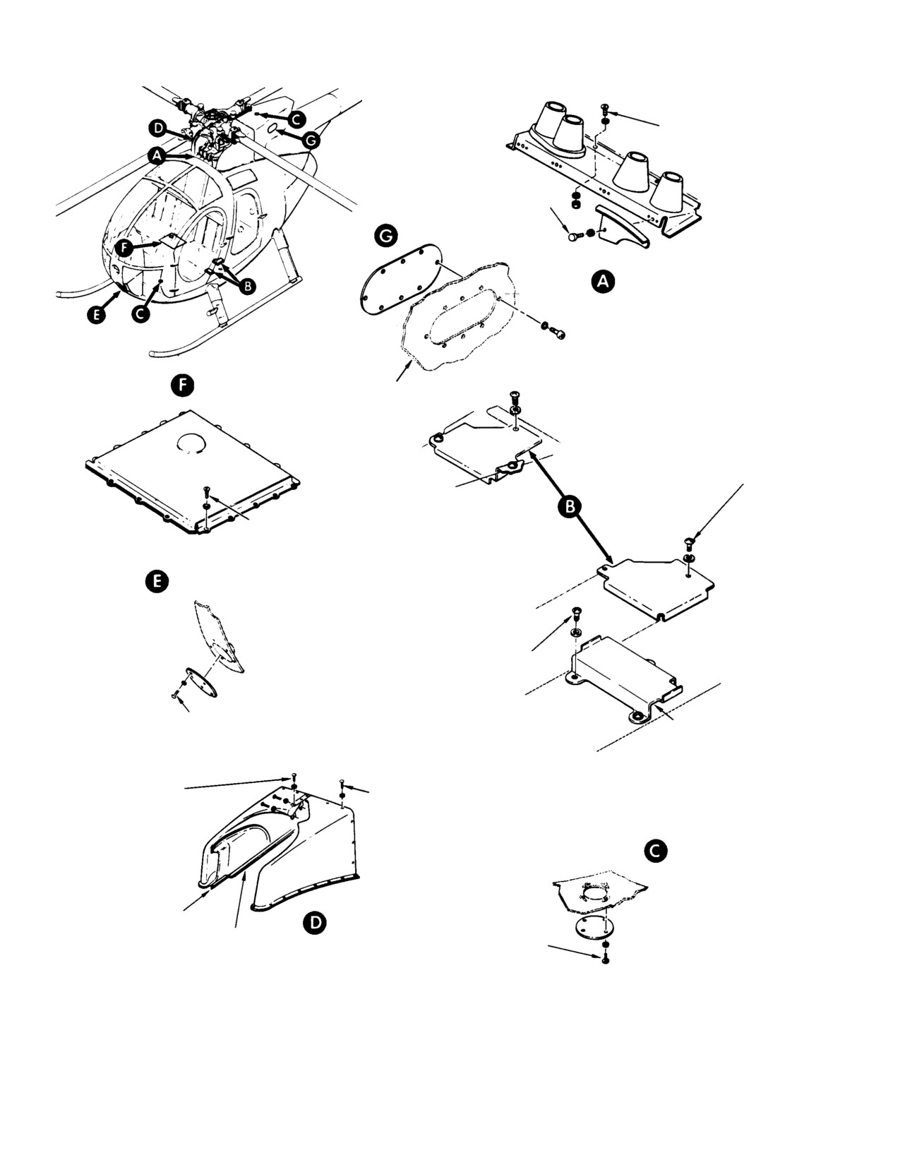
MD Helicopters, Inc.
CSP−H−2
500 Series - Basic HMI
3 SCREWS, NUTS
6 WASHERS
4 BOLTS, WASHERS
ACCESS COVER
CONTROLS TUNNEL COVER
PILOT’S SEAT
AFT FAIRING
COVER
2 SCREWS, WASHERS OR
3 SCREWS, WASHERS
EARLY TYPE
COLLECTIVE STICK
COVER
16 SCREWS, WASHERS
LANDING LIGHT COVER
CURRENT TYPE
3 SCREWS, WASHERS
5 SCREWS, WASHERS
WIRING COVER
17 SCREW, WASHERS
15 SCREWS, WASHER
(RIGHT HALF)
(LEFT HALF)
UPPER/LOWER
COLLISION LIGHT
COVER (TYP)
CLOSURE
ENGINE AIR INLET
(NOTE 1)
SEAL
FWD FAIRING
(NOTE 2)
4 SCREWS, WASHERS
NOTES:
1.
NOTE INSTALLED ON ALL HELICOPTERS.
2.
TAPE SEAL (42, TABLE 2−4).
30−007−1E
Figure 2-6. Access and Inspection Provisions (Sheet 1 of 6)
Page 2-32
Revision 14
//////////////////////////////////////////