CSP-H-2 BASIC HANDBOOK OF MAINTENANCE INSTRUCTIONS FOR MDHI 369H HELICOPTERS - page 12
MD Helicopters, Inc.
CSP−H−2
500 Series - Basic HMI
winding (terminal board stud C) of the
When performing as a generator, the starter/
starter/generator. During the time the START
generator has a maximum continuous duty
switch is depressed, the voltage regulator
rating of 30 volts, 150 amperes, over a range of
generator field circuit is open, so the starter
7200−13,000 rpm.
operates as a series motor.
NOTE: A similar and alternate starter/genera−
The generator system consists of the starter/
tor (Bendix 30B69−15−A) may be installed
generator, reverse current relay, voltage
to replace the standard starter/generator
regulator, an overvoltage relay, GENERATOR
(Lear Siegler (LSI) 23032− 020). Following
OUT light and the ammeter.
paragraphs provide maintenance informa−
tion for the standard starter/generator.
Generator operation is controlled by the
Starter limitations for engine compressor
GEN−OFF switch.
cleaning are given in Section 2.
At flight idle rpm and above, the voltage
A. Starter/Generator Removal
regulator automatically maintains the correct
generator output voltage by varying the
(1). Check that all electrical power is OFF.
generator field current.
(2). Disconnect electrical wiring from
The generator field circuit is protected by a 15
starter/generator terminal block;
ampere circuit breaker on the instrument
insulate wiring terminals. Reinstall
panel.
nuts and washers on studs.
When an overvoltage condition occurs, an
(3). Loosen mounting clamp that secures
overvoltage relay is energized by the voltage
starter/generator to mounting flange
regulator. The overvoltage relay opens the
and remove starter/generator.
switch circuit of the reverse current relay to
(4). Remove four nuts and washers; then
remove generator output from the bus.
remove mounting flange with gasket.
The reverse current relay prevents the battery
(5). Install a suitable protective closure over
from discharging through the generator when
opening in mounting flange.
the output voltage falls below battery voltage.
B. Starter/Generator Inspection
Electrical systems operate from the battery
when the generator is OFF and the power
(1). Preliminary Procedure
selector switch is at BATTERY.
(a). Remove lubricant from splines of
A terminal block on the starter/generator
drive shaft. Clean vibration dampen−
provides for connection of electrical wiring and
er.
houses a radio frequency−interference filter.
(b). Remove brush cover and fan cover.
Access to the brushes in the starter/generator
is provided by a brush cover that is rotatable
(c). Use clean, dry, compressed air to
in increments of 90 degrees.
blow out brush dust.
Page 19-39
Revision 15
MD Helicopters, Inc.
CSP−H−2
500 Series - Basic HMI
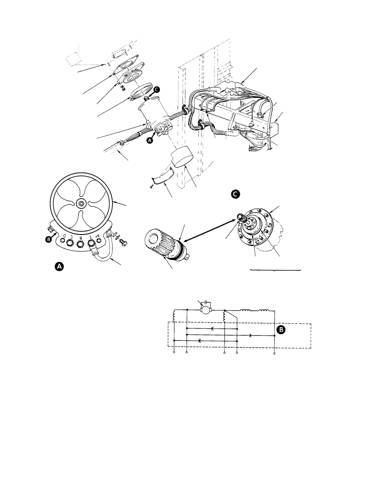
REVERSE CURRENT
ENGINE ACCESSORY
RELAY
GEARCASE
GASKET
ENGINE HARNESS
DISCONNECT
MOUNTING FLANGE
(NOTE 5)
OLEO SUPPORT
FITTING
MOUNTING CLAMP
TERMINAL BLOCK
GEN. OUTPUT
(AMMETER)
START RELAY
GROUND CONNECTION
CALIBRATION
RESISTOR (R3)
FIREWALL
STA 124
FAN COVER
DAMPER AND DRIVE SHAFT
BRUSH ACCESS COVER
END BELL
START/GEN. G300
(NOTE 4)
O−RING
DRY SPLINED
DRIVE SHAFT
(NOTE 2)
DAMPER
DAMPER
TERMINAL BLOCK
WIRE
CLUTCH
BACK PLATE
LOOKING FORWARD
P107B10
WET SPLINED
(ROTATED)
VIBRATION
DRIVE SHAFT
DAMPENER
(NOTE 6)
(NOTES 1, 3)
ARMATURE
COMPANSATING
INTERPOLE
SERIES
SHUNT
NOTES:
1.
DAMPENER CLUTCH MUST EXERT SPRING PRESSURE
RADIO NOISE
AGAINST BACK PLATE WITHOUT GAP BETWEEN CLUTCH
(RFI) FILTER
AND PLATE. MINIMUN CLUTCH SPRING THICKNESS
0.015 IN. (0.381 MM); MINIMUM BRONZE FRICTION
FACING THICKNESS IS 0.010 IN. (0.254 MM) ON PLATE.
C+ B+
A+ D
E−
2.
AT INSTALLATION, LUBRICATE SPLINES WITH GREASE
21, TABLE 2−4).
3.
LSI MODEL 23032−20 ONLY.
4.
LSI MODEL 23032−20 IS SHOWN ON THIS ILLUSTRATION;
BENDIX 30869−15−A IS SIMILAR.
5.
PROPER MOUNTING FLANGE MUST BE UTILIZED TO
INSURE PROPER SPLINE DEPTH.
6.
WET SPLINE STARTER GENERATOR. FOR CONVERSION
FROM DRY SPLINE TO WET SPLINE STARTER−GENERATOR,
REFER TO MDHI LETTER HL−72.
30−111F
Figure 19-15. starter/generator Replacement and Repair
Page 19-40
Revision 15

MD Helicopters, Inc.
CSP−H−2
500 Series - Basic HMI
(2). Exterior Inspection
SPRING
Replacement of a dampener
CAUTION
clutch or back plate is required
SLOT IN BRUSHES
if it does not meet following requirements.
(MAX WEAR POINT)
(a).
Check that dampener clutch exerts
pressure against dampener back−
END BELL VIEW
plate. Weak spring on clutch or gap
between these parts is not allowed.
30−112
(b).
Inspect dampener clutch for cracks,
warpage, loose rivets and excessive
Figure 19-16. Starter/Generator Bushing
wear on spring surface that mates
Wear Limits
with dampener back plate. Minimum
spring thickness is 0.015 inch (0.381
C. Starter/Generator Repair
mm).
NOTE: Complete overhaul instructions with
(c).
Inspect dampener back plate for
parts breakdown for the starter/generator is
cracks and bronze friction facing for
available from the Power Equipment Divi−
wear. Minimum facing thickness is
sion of Lear Siegler, Inc. (Ref. Table 2−15).
0.010 inch (0.254 mm).
Instructions for maintenance of generator
brushes and for testing of a removed starter/
(d).
Check splines on drive shaft for wear.
generator are the only repair information
provided in this paragraph.
(e).
Check fan for looseness on hub and
for cracked or bent condition.
(1). Removing Brushes
(f).
Inspect terminal block for cracks,
(a). Remove the four screws that secure
breaks, loose or damaged terminal
the fan cover and brush access cover
studs, and loose electrical connec−
to the generator end bell; remove fan
tions.
cover.
(g).
Inspect starter/generator housing for
any signs of damage, and inlet and
(b). Remove the screw from the lead
outlet blower screens for clogging.
terminal of each brush set and lift
out the brush sets.
(h).
Inspect mounting clamp and mount−
ing flange for condition, and mount−
(2). Checking Brush Spring Tension
ing flange attaching hardware for
security.
(a). Remove brushes from starter/genera−
tor.
(3). Interior Inspection
(b). Cut a groove down the center of both
(a). Inspect commutator for pitting,
edges and across the bottom of a new
scoring or burned areas.
brush. When prepared in this man−
ner, the brush will have a continuous
(b). Check brushes for cracks, chips,
groove around three sides.
frayed leads and loose shunt connec−
tions. Replace brushes if remaining
allowable wear (Ref. Figure 19−16)
(c). Place a fine wire around the brush in
might be exceeded before next
the groove; then insert the brush in
scheduled inspection.
one of the brush holders. Tie the two
ends of the wire together to form a
(c). Check brush holder and end bell for
loop and attach a fish−type spring
cracks and warpage.
scale that is graduated in ounces.
Page 19-41
Revision 15
MD Helicopters, Inc.
CSP−H−2
500 Series - Basic HMI
(d). Raise the brush by the scale until the
(4). Running−in Brushes and Testing
lower end of the brush is even with
starter/generator
the bottom edge of the brush holder.
When in this position, the brush
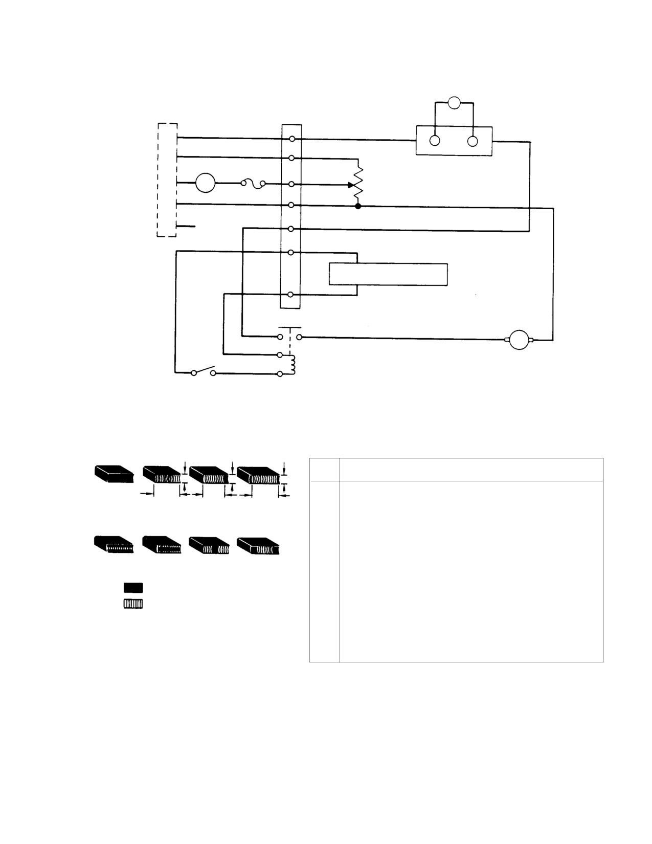
(a). Connect starter/generator and test
spring tension should be between 32
equipment as shown in Figure 19−17.
and 48 ounces. Take an average of
Mount starter/generator securely in
several readings. If the spring
suitable vee blocks.
tension is out of this range, replace
the spring.
Be sure switch Sl is OFF. Do not
CAUTION
(e). Raise the brush by the scale until the
exceed 14− 16 volts direct− cur−
lower end of the brush is even with
rent input; starter/generator may be dam−
the bottom edge of the brush holder.
aged.
(3). Replacing Brushes and Preliminary
(b).
Start variable direct−current genera−
Seating
tor and adjust output to 14−16 volts.
NOTE: New brushes must be properly seated
on the commutator surface. Although the
(c).
Connect 24 Vdc power supply.
brushes are of the instant− filming type,
they should be sanded and run−in for proper
(d).
Adjust the 25−ohm potentiometer to
seating before full load is applied to the
3 ohms using the multimeter; then
starter/generator. Failure to properly seat
connect potentiometer into test
the brushes can result in excessive sparking
circuit.
that will cause burning and pitting of the
commutator.
(e).
Turn switch S1 momentarily ON,
(a).
Place a strip of grade 5/0 or finer
and then OFF. Observe direction of
sandpaper (9, Table 2−4), slightly
the starter/generator shaft rotation.
wider than the combined width of the
Rotation should be CCW when
two brush halves, around the commu−
viewing drive end of generator.
tator with the sand side out. Cut the
sandpaper strip to 0.125 inch (3.175
(f).
Turn switch S1 ON. Note that drive
mm) less than the commutator
shaft rotates freely and that genera−
circumference. Secure one end of the
tor output is indicated on meter M1.
sandpaper strip to the commutator
Adjust 25−ohm potentiometer until
surface with masking tape so that
meter M1 indicates approximately 1
the taped end will lead in the direc−
ampere. Meter M2 should indicate
tion of rotation, and the other end
25−35 amperes at this time. Continue
will remain loose.
operation of starter/generator while
observing the sparking (commuta−
(b).
Install the brushes in place against
tion) at the brushes. As brushes wear
the sandpaper and set the brush
in, the sparking should decrease to
springs in position. Carefully rotate
pinpoints.
the armature by hand in the normal
direction of rotation (Ref.
Figure 19−16) until a full seat is
(g).
Turn off all electrical power and
obtained on each brush. Do not sand
inspect the brushes for proper
excessively.
seating. Brush faces should show
evidence of seating of 90 percent in
(c).
Lift the brushes, and remove the
axial direction and 100 percent of the
sandpaper. Remove all carbon dust
axial contact should show evidence of
with dry, compressed air, connect the
contact in the direction of rotation.
brush wire terminals, and proceed
Blow out all brush dust with clean
with the brush run−in operation.
dry compressed air.
Page 19-42
Revision 15
MD Helicopters, Inc.
CSP−H−2
500 Series - Basic HMI
0−200A
AMMETER
A
M2
STARTER−GENERATOR
TERMINAL
TERMINAL BLOCK
BOARD
C+
B+
3−OHM
50 MV, 200A
M1
FUSE
SHUNT
RHEOSTAT
A+
A
25−OHM, 100W
5A
5A
22−OHM
E−
D
NOTE
+
24 VDC POWER SUPPLY
−
A2
A1
+
−
X1
SWITCH
VARIABLE V
S1
POWER
X2
DC GENERATOR
RELAY
100%
100%
100%
ITEM
EQUIPMENT DESCRIPTION
NO.
1
VARIABLE VOLTAGE DC GENERATOR, 15AMPERE CAPACITY.
100%
90%
90%
2
0−5A DC, AMMETER (M1) (WESTON MODEL 931 OR EQUIVALENT).
SATISFACTORILY SEATED BRUSHES
3
50 MV, 200−AMPERE SHUNT (WESTON OR EQUIVALENT).
4
0−200A DC AMMETER (M2), 50−MV FULL SCALE (GENERAL ELECTRIC
TYPE DB13 OR EQUIVALENT).
5
POWER RELAY, 28 VDC, 200−AMPERE CONTACTS, SINGLE−POLE,
UNSATISFACTORILY SEATED BRUSHES
SINGLE−THROW (AN3371−2 OR EQUIVALENT).
NONSEATED AREAS
6
SWITCH (S1), SPST, 10 AMPERES AT 28 VDC.
SEATED AREAS
7
RHEOSTAT, 25−OHM, 1000−WATT (OHMITE MODEL U OR EQUIVALENT).
8
POWER SUPPLY, 10−36 VDC (N.J.E. MODEL 36−20 OR EQUIVALENT).
9
MULTIMETER (SIMPSON MODEL 260 OR EQUIVALENT).
NOTE: HELICOPTER AMMETER INDICATOR
CIRCUIT TERMINAL.
30−113A
Figure 19-17. Test Hookup for Starter/Generator and Brush Run-in
Page 19-43
Revision 15
MD Helicopters, Inc.
CSP−H−2
500 Series - Basic HMI
(h). Reconnect electrical power and
(b). Insert shaft end of starter/generator
repeat step (f). If additional brush
into opening in mounting flange and
run−in is required, continue opera−
hold starter/generator tightly against
tion at 1 ampere indication on meter
flange.
M1; if not, proceed to step (i).
(c). Install starter/generator V−clamp.
(i). Adjust the 25−ohm potentiometer
Torque clamp nut to 50 inch−
until meter M1 indicates 4 amperes.
pounds (5.65 Nm).
Meter M2 should indicate 25−35
(d). Tap around clamp with a rawhide
amperes.
mallet to seat clamp on flange.
Retorque clamp nut to 50 inch−
(j). Turn all power OFF and disconnect
pounds (5.65 Nm).
starter/generator. Remove from vee
blocks and reinstall brush cover.
(e). Continue tapping around clamp and
retorquing clamp nut until nut no
D. Starter/Generator Installation
longer turns when specified torque is
applied.
(1). Ensure that all electrical power is OFF.
(7). Install electrical leads, washers and
(2). Remove protective cover from opening
nuts. Tighten nuts and remove identify−
in engine.
ing tags.
(3). Install mounting flange with four nuts
20. Night Lighting System - Instrument Panel
and washers. Torque nuts to 100 − 140
Type B
inch−pounds (11.30 − 15.82 Nm).
On helicopters with instrument panel type B,
(4). Using a bottle brush and solvent (1,
the night lighting system is standard equip−
Table 2−4), clean the starter shaft and
ment as part of the electrical system. The
mating engine splines.
night lighting system is as described in
CSP−H−3, except as follows. Upper and lower
Before installation, check condi−
CAUTION
anti−collision lights are strobe type and
tion of seal in accessory drive
instrument panel lights for instruments and
gearbox. For wet− splined starter/genera−
indicators are bolt type lights built into the
tors, also ensure integrity of packing on
hood. Wiring provision are incorporated for
starter/generator drive shaft.
installation of optional incandescent anti−colli−
sion lights in place of strobe lights, if desired.
(5). Lubricate splines on drive shaft of
Interconnection wiring for the night lighting
starter/generator with grease (21).
system, except for instrument panel lights, is
shown in the applicable electrical wiring
(6). Install starter/generator.
diagram in Section 20. Wiring and other
Always support the weight of
information for the panel lights for instrument
CAUTION
the starter/generator during re−
and indicators on the hood is contained in
moval/installation. Damage can occur if
CSP−H−3. Dimming circuit information for
weight is supported by the shear shaft.
panel and instrument lights is provided in
Section 17. Otherwise, refer to CSP−H−3 for
(a). Align starter/generator with terminal
all other information on the night lighting
block down.
system.
Page 19-44
Revision 15
MD Helicopters, Inc.
CSP−H−2
500 Series − Basic HMI
Section
20
Wiring and
Schematic Diagrams
MD Helicopters, Inc.
CSP−H−2
500 Series − Basic HMI
This Page Intentionally Left Blank
MD Helicopters, Inc.
CSP-H-2
500 Series - Basic HMI
TABLE OF CONTENTS
Para/Figure/Table
Title
Page
Section 20 Wiring and Schematic Diagrams .
20−1
1.
Wiring and Schematic Diagram
20−1
A. Wire Identification
20−1
B. Symbols
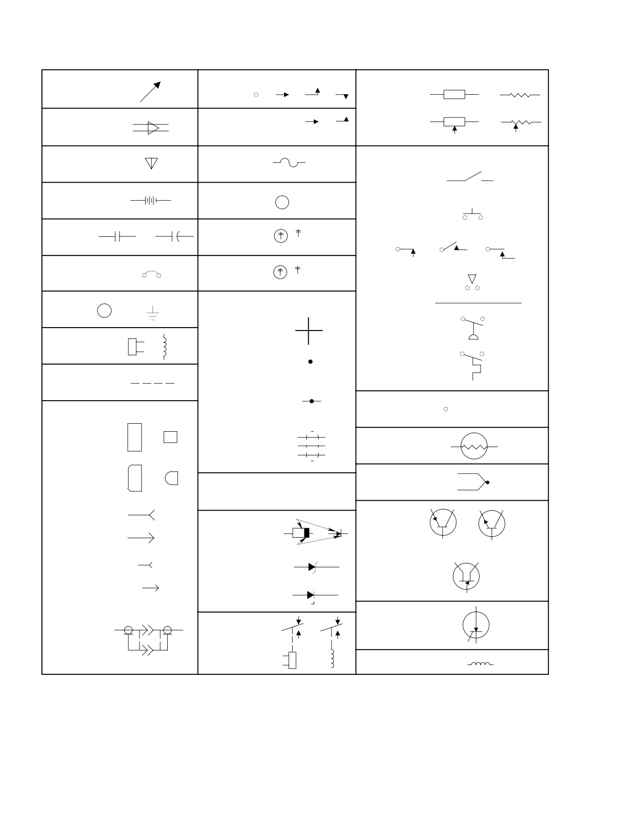
20−1
Figure 20−1. Electrical Symbols
20−2
C. Diagrams
20−3
D. Reference Designator List
20−3
Table 20−1. Reference Designator List
20−3
Figure 20−2. Fuselage Wiring Diagram (369HS; 0001 − 0100) (369HM; 001 − 100)
(Sheet 1 of 6)
20−16
Figure 20−3. Console Wiring Diagram, Instrument Panel Type A (369HS; 0001 − 0100)
(369HM; 001 − 100) (Sheet 1 of 4)
20−22
Figure 20−4. Fuselage Wiring Diagram (369HS; 0101 − 0200) (369HM; 101 − 200)
(Sheet 1 of 7)
20−26
Figure 20−5. Console Wiring Diagram, Instrument Panel Type A (369HS; 0101 − 0200)
(369HM; 101 − 200) (Sheet 1 of 4)
20−33
Figure 20−6. Fuselage Wiring Diagram (369HS; 0201 − 0410) (369HE; 101 − 215)
(369HM; 201 − 247) (Sheet 1 of 7)
20−37
Figure 20−7. Console Wiring Diagram, Instrument Panel Type A (369HS; 0201 − 0410)
(369HE; 101 − 215) (369HM; 201 − 247) (Sheet 1 of 4) .
20−44
Figure 20−8. Fuselage Wiring Diagram (369HS; 0411 − 0625) (Sheet 1 of 7) .
20−48
Figure 20−9. Console Wiring Diagram, Instrument Panel Type B (369HS; 0411 − 0625)
(Sheet 1 of 6)
20−55
Figure 20−10. Fuselage Wiring Diagram (369HS; 0626 & Subs) (Sheet 1 of 6) .
20−61
Figure 20−11. Console Wiring Diagram, Instrument Panel Type B (369HS; 0626 & Subs)
(Sheet 1 of 6)
20−67
Figure 20−12. Fuselage Wiring Diagram (369HM; 248 & Subs) (Sheet 1 of 6) .
20−73
Figure 20−13. Console Wiring Diagram, Instrument Panel Type T, with Center Console
(369HM; 248 & Subs) (Sheet 1 of 7)
20−79
Figure 20−14. Typical Electrical System Schematic, Instrument Panel Type A
(Sheet 1 of 6)
20−86
Figure 20−15. Typical Electrical System Schematic, Instrument Panel Type B
(Sheet 1 of 5)
20−92
Figure 20−16. Typical Electrical System Schematic, Instrument Panel Type T
(Sheet 1 of 6)
20−97
Page 20-i
Revision 20
MD Helicopters, Inc.
CSP-H-2
500 Series - Basic HMI
TABLE OF CONTENTS (Cont.)
Para/Figure/Table
Title
Page
This Page Intentionally Left Blank
Page 20-ii
Revision 20
MD Helicopters, Inc.
CSP−H−2
500 Series − Basic HMI
SECTION 20
WIRING AND SCHEMATIC DIAGRAMS
1. Wiring and Schematic Diagram
(4). The following letter indicates segment
of wire in a wire number where the
Wiring and schematic diagrams for the
wire passes through or branches at a
electrical system of the helicopter are provided
connector or terminal block.
in this section. Wire identification and symbol
information for the diagrams are also included.
(5). The number (or numbers) following the
segment designation is the standard
A. Wire Identification
AWG wire size.
Wiring in the helicopter is identified by code of
(6). If the wire is a ground portion of a
numbers and letters at intervals throughout
circuit, the suffix N is added to indicate
the wire length. The wiring indemnification
a ground return.
code is as follows:
(7). Where a wire code is duplicated, the
(1).
The initial number (is used) designates
unit number 1 or 2 is prefixed to
unit number.
differentiate between the two circuits.
(2).
The initial letter (or letters) designates
the circuit.
B. Symbols
(3).
The next number (or numbers) is the
The graphic electrical symbols in the schemat−
wire number that separates one section
ic, and in the wiring diagrams where symbols
or leg of the circuit from all others.
are used for clarity, are shown in Figure 20−1.
EXAMPLE: WIRE NUMBER 2P511A20N
2
P
511
A
20
N
Unit Number (if used)
Ground
Circuit Designation
Wire Size
Wire Number
Wire Segment
Circuit Designation
Circuit Function
A
Armament Control
C
Flight Control
D
Ammeter and Miscellaneous
E
Engine Instruments
F
Flight Instruments
H
Heating and Associated
J
Engine Reignition
K
Starting
L
Lighting
M
Utility
P
Dc Power Distribution
Q
Fuel and Oil
R V
*Vhf Radio and Intercom
X
Ac Power Distribution
NOTE: Function indicated with an asterisk ( * ) pertains to avionics equipment. Other miscellaneous circuit
designators are used for specific circuits of special equipment configurations and optional avionics and
navigation equipment.
Page 20-1
Revision 20
MD Helicopters, Inc.
CSP−H−2
500 Series − Basic HMI
CONTACT, ELECTRICAL:
RESISTOR:
ADJUSTABILITY
FIXED
OR
OR
OR
GENERAL
OR
*
WITH
ADJUSTABLE OR
OR
ADJUSTABLE
OR
AMPLIFIER
CONTACT
SLIDING
SWITCH:
ANTENNA
FUSE
GENERAL
( + COLOR
BATTERY,
INDICATED
MULTICELL
LAMP
+
BY LETTER)
PUSHBUTTON
MACHINE,
( ABBREVIATED
CAPACITOR
OR
ROTATING
NAME)
NONLOCKING
OR
OR
CIRCUIT
( ABBREVIATED
BREAKER
METER
SAFETY
NAME)
INTERLOCK
CLOSING
CIRCUIT
PATH TRANSMISSION;
RETURN
WIRING; CABLES;
E
OR
(GROUND)
WIRES CROSSING
AND NOT CONNECTED
PRESSURE
*
COIL, RELAY
OR
JUNCTION OR
CONNECTION
*
TEMPERATURE
CONNECTION,
*
MECHANICAL
*
SPLICE
SPLICE
(SIZE USED
CONNECTOR;
TERMINAL, CIRCUIT
AS REQUIRED)
DISCONNECTING DEVICE
JACK OR
OR
RECEPTACLE
SHIELDED CABLE
THERMISTOR
T
PLUG
OR
POLARITY
THERMOCOUPLE
POSITIVE +
*
*
NEGATIVE −
*
FEMALE CONTACT
ANODE
RECTIFIER
TRANSISTOR
OR
*
DIODE
OR
MALE CONTACT
*
CATHODE
PNP
NPN
ZENER
JACK
(AVALANCHE)
COAXIAL
*
DIODE
UNIJUNCTION
CONNECTOR
TRANSISTOR
PLUG
BREAKDOWN
*
DIODE
SILICON
CONTROLLED
COAXIAL
RECTIFIER
CONNECTORS
(SCR)
WITH OUTSIDE
G
RELAY
OR
CONDUCTOR
WINDING, MACHINE
OR TRANSFORMER
NOTE: ASTERISK ( * ) INDICATES SYMBOL RECOMMENDED BY INTERNATIONAL ELECTROTECHNICAL COMMISSION.
30-130
Figure 20-1. Electrical Symbols
Page 20-2
Revision 20
MD Helicopters, Inc.
CSP−H−2
500 Series − Basic HMI
C. Diagrams
version 500M helicopter with instrument
panel type T.
The electrical system wiring diagrams,
Figure 20−2 thru Figure 20−1, provide wiring
Electrical system diagrams for special versions
information for the basic electrical system.
of the 500M are provided in Section 20 of the
appropriate part of the 500M HMI Supple−
Wiring diagram application versus helicopter
ment.
model serial number is shown in the title of
each diagram and is listed below.
Electrical diagrams for optional equipment are
furnished in the applicable equipment group of
The wiring diagram show complete point−to−
HMI Appendix A.
point wiring interconnections between all basic
electrical system components.
D. Reference Designator List
The electrical system schematic diagrams,
Figure 20−14 thru Figure 20−16, schematically
Table 20−1 contains a list of electrical equip−
show typical electrical system for helicopters
ment items used in the helicopter and shown
with instrument panel types A, B and normal
in the wiring diagrams.
Table 20-1. Reference Designator List
Identification
Reference
End Use
AR500
369H4525
Audio Amplifier
B101
369A7171-9
Long. Trim Motor
B102
368A7170-7
Lat. Trim Motor
B103
368A7002
N2 Governor Motor
B250
369A8143
Start Pump Motor
B300
369H4533
Deicer Actuator Motor
B600
369H2488
Heater Actuator Motor
BT101
369A4530
Battery
368H4540
Battery
CB101
2TC12-5
Instrument
CB102
2TC12-5
Cyclic Trim
CB103
2TC12-5
N2 Governor
CB104
2TC12-5
Warning and Panel Light
CB105
2TC12-15
Gyros
CB106
2TC12-5
Engine Out
CB107
MS26574-2
ADF
CB108
2TC12-7-1/2
NAV/COM
CB109
2TC12-15
Cigar Lighter
CB110
2TC12-15
Landing / Hover Light
CB112
2TC12-15
Generator Field
CB115
MS24509-15
Anti-collision Light
CB117
MS24509-7
Utility Power
CB118
MS24509-7
Start Pump
CB119
MS24509-7
Position Light
CB120
MS24509-7
Pitot Heat
Page
20-3
Revision 20
MD Helicopters, Inc.
CSP−H−2
500 Series − Basic HMI
Table 20-1. Reference Designator List (Cont.)
Identification
Reference
End Use
CB121
2TC12-5
Emergency Floats
CB122
2TC12-15
Single Sideband
CB124
MS24509-7-1/2
Engine Re-Ignition
CB126
MS26574-1
Transponder
CB127
MS25244-35
Searchlight
CB128
2TC12-5
Searchlight
CB600
MS25244-50
Hoist
CB601
2TC12-7-1/2
Hoist
CB603
2TC12-15
Cargo Hook
DS10
369A4540/369A4540-3/369A4514-3
Engine Power Out Warning Unit
DS11
2245-1 (Autronics) /369H6425
Dimmer Control
DS100
MS25241-4581
Landing Light Lamp
DS105
SC628 (Mallory)
Engine Power Out warning Horn
DS200
30-0777-5
Strobe Light-Lower
DS201
30-0777-7
Strobe Light-Upper
DS201
1309 GE
Map Light-Pilot’s
DS202
1495 GE
Map Light
DS250
369A4589-3 / A7512-4
Left Position Light Lamp
DS251
369A4589-5 / A7512-24
Right Position Light Lamp
DS400
1683 (G.E.) 369A4588
Rear Position Light
DS401
4580 (G.E.)
Searchlight Left
DS402
4580 (G.E.)
Searchlight Right
E1
Under Floor, Center Web
Ground Stud
E2
Console, Left Side
Ground Stud
E3
Console, Left Side
Ground Stud
E4
Under Floor, Right Side
Ground Stud
E5
Under Seat, Left Side
Ground Stud
E6
Under Seat, Left Side
Ground Stud
E7
Under Seat, Right Side
Ground Stud
E8
Under Floor, Right Side
Ground Stud
E9
Canted Bulkhead, Left Side
Ground Stud
E10
Engine Compartment
E12
Engine Compartment, Right Side
E13
Engine Compartment, Left Side
E14
Canted Bulkhead, Right Side
Aft Cigar Lighter
E15
Canted Bulkhead, Right Side
E19
Pilot’s Map Light, Right Side
Page 20-4
Revision 20
MD Helicopters, Inc.
CSP−H−2
500 Series − Basic HMI
Table 20-1. Reference Designator List (Cont.)
Identification
Reference
End Use
E20
Under Seat, Left Side
E24
Under Pilot’s Floor
Heated pitot Tube
E502
Ant. Disconnect, Upper Air Intake Fairing
E503
Ant. Transponder
G200
369A4517
Rotor Tach Generator
G300
369A4550
Starter / Generator
G301
369A4517
N1 Tach Generator
G302
369A4517
N2 Tach Generator
HR1
C7SZ15052A (Ford Motor Co.)
Cigar Lighter, Front
HR2
369H6409
Heater-pitot Tube
HR3
C7SZ15052A (Ford Motor Co.)
Cigar Lighter, Rear
J3
MPS-LRH-19C
Audio Amplifier Connector
J4
M9PLSH19C (Winchester)
Instr. Cluster Connector
J9
MS3120F22-41S
Console Connector
J10
MS3120F14-19S
Console Connector
J11
MS3120F-18-1 1S
Console Connector
J12
SEE DS11
Dimmer Control
J13
32445 (AMP)
Compass LT. Splice
J14
32445 (AMP)
Compass LT. Splice
J15
32445 (AMP)
Right Upper Panel LT.
J16
32445 (AMP)
Left Upper Panel LT.
J20
32447 (AMP)
Aft Cigar Ltr.
J21
32447 (AMP)
Aft Cigar Ltr. Splice
J22
32447 (AMP)
Aft Cigar Ltr. Splice
J23
32445 (AMP)
Start Pump Light
J24
32445 (AMP)
Start Pump Light
J31
32445 (AMP)
Lower Panel Lt.
J100
AN2552A3A
Ext. Power Receptacle
J103
JR2/4CP27-CC (Viking)
Utility Power Connector
J109
XAC20SF0016 (Winchester)
Right Cyclic Stick Connector
J112
XAC9SF0016 (Winchester)
Right Collective Stick Connector
J113
XAC9SF0016 (Winchester)
Left Collective Stick Connector
J114
32445 (AMP)
Left Pos. Light Splice
J116
32445 (AMP)
Right Pos. Light Splice
J130
XAC20SF0016 (Winchester)
Left Cyclic Stick Connector
J133
32445 (AMP)
Right Pos. Light Splice
J134
32445 (AMP)
Left Pos. Light Splice
Page
20-5
Revision 20
MD Helicopters, Inc.
CSP−H−2
500 Series − Basic HMI
Table 20-1. Reference Designator List (Cont.)
Identification
Reference
End Use
J136
32445 (AMP)
Landing Light Relay Splice
J138
32445 (AMP)
Emergency Float Splice
J139
32445 (AMP)
Emergency Float Splice
J140
32445 (AMP)
Emergency Float Splice
J141
32445 (AMP)
Emergency Float Splice
J200
SG3102E28-66S (Bendix)
Armament Connector
J250
MS3116E8-3S
Start Pump Connector
J251
369A4599-3
Fuel Qty. Level Connector
J302
CA3100E10SL-3SF80
Auto-Reign. Kit Connector
J303
CA3100E22-19PF80
Engine Equipment Connector
J400
32445 (AMP)
Rear Position Light Splice
J401
32445 (AMP)
Rear Position Light Splice
J402
32445 (AMP)
T/R Chip Detector Splice
J605
MS3124E12-3S
Cargo Hook Connector
K3
369A4658
Landing Light Relay
K103
BE26-S28 (Babcock)
Overvoltage Relay
K300
A700-XA (Hartman)
Reverse Current Relay
K301
AN3371-2
Start Relay
K302
MS24166D
Searchlight Relay
K303
MS24166D
Searchlight Relay
M1
369H4518
Engine (N
2) and Rotor Tach. Indicator
M2
369A4516
N1 Tach Indicator
M3
369A4521
Turbine Outlet Temp. Indicator
M4
369H4234-21
Instrument Cluster, 4-Pack
M4
369H6417
Instrument Cluster, 3-Pack
M5
M5600-2 (Hobbs)
Hour Meter
M21
369H4526
Torque Indicator
M27
369H4505
Altimeter
M28
369H90041
Attitude Gyro
M29
(Supplied with Engine
Start Counter
M502
369H90042
Directional Gyro
MP102
369H90042
Directional Gyro
MP501
369H90041
Attitude Gyro
P1
369A4593
Dual Tach Indicator Plug
P2
369A4593
N1 Tach Plug
P3
369A4595
Audio Amplifier Plug
P4
M9S952RH19C
Instrument Cluster Connector
Page 20-6
Revision 20
MD Helicopters, Inc.
CSP−H−2
500 Series − Basic HMI
Table 20-1. Reference Designator List (Cont.)
Identification
Reference
End Use
P6
MS3196R16S-6S (C)
Voltage Regulator Connector
P7
369A4595
Audio Amplifier Plug
P8
MRAC26SJT6
Dimmer Control Connector
P9
KPTM06F22A-41P
Console Connector
P10
MS3126-F14-19P
Console Connector
P11
MS3126-F18-1 1P
Console Connector
P12
MS3126-F18-32S
Dimmer Control Connector
P13
32445 (AMP)
Compass Light Splice
P14
32445 (AMP)
Compass Light Splice
P19
KPT06F14-18S
Engine Power Out Warning (2200-3)
P130
MRAC20PJTC6H9
Left Cyclic Stick Connector
P20
32445 (AMP)
Splices
P21
32445 (AMP)
Splices
P22
32445 (AMP)
Splices
P23
32445 (AMP)
Splices
P24
32445 (AMP)
Splices
P105
MS3106R10SL-3S (C)
Longitudinal Trim Motor Connector
P106
MS3106R10SL-3S (C)
Lateral Trim Motor Connector
P107
MS3108R10SL-3S (C)
N2 Governor Connector
P108
SC06P24-9P (Bendix)
Battery Plug
P109
369A4599
Rotor Tachometer Generator
P112
XAC9PC0306X
Right Collective Stick Connector
P113
XAC9PC0306X
Left Collective Stick Connector
P200
CS3106A28-66P
Hoist
P202
369A4599
Rotor Tach Generator Connector
P250
MS3116E8-3S
Start Pump Connector
P251
369A4593
Fuel Transmitter Connector
P300
369H8144
Upper Engine Chip Detector Connect
P301
369H8144
Lower Engine Chip Detector Connect
P302
CA3106E10SL-3PF80
Auto Re-Ignition Kit Connector
P303
CA3106E22-19SF80
Engine Harness Disconnect Connector
P305
369A4599
N1 Tach Generator Connector
P306
369A4599
N2 Tach Generator Connector
P400
32445 (AMP)
Tail Light Splice
P402
32445 (AMP)
Tail Rotor Chip Detector Splice
P605
MS3216F12-3P
Cargo Hook Connector
P609
KPT06F8-4S
Heater Actuator Connector
Page 20-7
Revision 20
MD Helicopters, Inc.
CSP−H−2
500 Series − Basic HMI
Table 20-1. Reference Designator List (Cont.)
Identification
Reference
End Use
P612
KPT06F8-4S
Deicer Actuator Connector
R1
0200-C (Ohmite) 25Ω25 Watt
Instrument Cluster Resistor
R2
120Ω1 Watt
Over Voltage Relay Resistor
R3
3730 (Ohmite) 1Ω12 Watt
Instrument Cluster Resistor
R4
1006 (Ohmite)
TOT Calibration Resistor (TB9)
R6
50Ω5 Watt W / Wound
Map Light Dimming Resistor
R9
R10
3-1/2 TE57FSI (Ohmite)
Cigar Lighter Resistors
R11
1Ω55 Watt W / Wound
R12
R110
5KΩ2 Watt POT
Instrument Panel Dimming Resistor
R112
1-D-40A-F-20
(Ohmite)
Instrument Cluster Resistor
R251
369H4245-501
Fuel Qty. Level Resistor (Tank Unit)
R302
369A4534
Engine Oil Pressure Resistor (Sender)
R303
RV4LASA-101A (Allen-Bradley)
Eng. Oil Press Ind. Adj. Trim POT
R304
1511 (Ohmite) 30Ω 8 Watt
Eng. Oil Press Ind. Adj. Resistor
R305
1513 (Ohmite) 40Ω 8 Watt
Eng. Oil Press Ind. Adj. Resistor
R501
(Bendix Radio)
Intercom Side Tune POT
RT301
369A4533
Engine Oil Temperature Sender
S1
369A4548
Warn. Light Press-to-Test Switch
S2
MS25106-21
Battery / External Switch
S3
9577
Key Switch
S4
MS35059-22
Generator Switch
S10
369H92040
Auto Re-Ignition Pressure Switch
S11
MS35059-22
Auto Re-Ignition Arm Switch
S13
MS90311-231
Com 1 / Com 2 Switch
S104
369A4580
N2 Governor Switch
S105
369A4581
Landing Light Switch
S106
369A4582
Start Switch
S107
369A7313
Cyclic Trim
S107
RS36
Rear Map Light Switch
S199
MS27994-1
NR Disable Switch
S200
B-3707 (Tedeco)
Main Gearbox Chip Det. Switch (Fwd)
S201
B-3148A (Tedeco)
Main Gearbox Chip Det. Switch (Aft)
S202
369A5186 (Tedeco)
Main Gearbox Oil Temp. Switch
S203
M-4013-15
(Hobbs)
Main Gearbox Oil Pressure Switch
Page 20-8
Revision 20
MD Helicopters, Inc.
CSP−H−2
500 Series − Basic HMI
Table 20-1. Reference Designator List (Cont.)
Identification
Reference
End Use
S300
Furnished with engine
Engine Upper Chip Detector Switch
S301
Furnished with engine
Engine Lower Chip Detector Switch
S303
Furnished with engine
Fuel Filter Switch
S400
369A5160
T/R Gearbox Chip Detector Switch
S601
SS-39 (Stackpole)
Heater Switch
S602
SS-33 (Stackpole)
Deicer Switch
SP1
32445 (AMP)
Float System 369H92557
SP2
32445 (AMP)
Float System 369H92557
SP3
32445 (AMP)
Float System 369H92557
SP4
32445 (AMP)
Float System 369H92557
SP5
32445 (AMP)
Float System 369H92557
SP6
32445 (AMP)
Float System 369H92557
SP7
32445 (AMP)
Float System 369H92557
SP8
32445 (AMP)
Float System 369H92557
SP9
32445 (AMP)
Float System 369H92557
SP10
32445 (AMP)
Float System 369H92557
SP11
32445 (AMP)
Float System 369H92557
SP12
MS25181-2
Float System 369H92557
SP13
MS25181-2
Float System 369H92557
SP14
MS25181-2
Float System 369H92557
SP15
MS25181-2
Float System 369H92557
SP16
32445 (AMP)
Engine Re-Ignition 369H90118
SP17
32445 (AMP)
Engine Re-Ignition 369H90118
SP18
32445 (AMP)
Engine Re-Ignition 369H90118
SP20
32445 (AMP)
Float System 369H92557
SP21
32445 (AMP)
Float System 369H92557
SP22
32445 (AMP)
Float System 369H92557
SP23
32445 (AMP)
Float System 369H92557
SP24
32445 (AMP)
Float System 369H92557
SP25
32445 (AMP)
Float System 369H92557
SP26
32445 (AMP)
Float System 369H92557
SP27
MS25181-2
Chip Detector, Gearbox, 369H4121
SP28
MS25181-2
Caution Warning Unit
SP29
MS25181-2
Gyro
SP30
MS25181-2
Map Light
SP31
MS25181-2
Engine Out
SP32
MS25181-2
Warning Horn-Engine Out
Page
20-9
Revision 20
MD Helicopters, Inc.
CSP−H−2
500 Series − Basic HMI
Table 20-1. Reference Designator List (Cont.)
Identification
Reference
End Use
SP33
MS25181-2
Position Lights
SP38
32445 (AMP)
Anti-Collision Light Flashers
SP39
32445 (AMP)
Map Light Light Rear
SP40
32445 (AMP)
Map Light Light Rear
SP42
MS25181-2
Hoist
SP43
MS25181-2
Hoist
SP44
D121
Hoist
SP45
D121
Hoist
SP46
32447 (AMP)
Float System 369H92557
SP48
32445 (AMP)
Float System 369H92557
SP49
32445 (AMP)
Float System 369H92557
SP50
MS25181-1
Night Light Kit, 369H6420
SP51
32445 (AMP)
Night Light Kit, 369H90062
SP52
32445 (AMP)
Night Light Kit, 369H90062
SP53
32445 (AMP)
Night Light Kit, 369H90062
SP54
32445 (AMP)
Night Light Kit, 369H90062
SP55
32445 (AMP)
Night Light Kit, 369H90062
SP56
32445 (AMP)
Night Light Kit, 369H90062
SP57
32445 (AMP)
Night Light Kit, 369H90062
SP58
32445 (AMP)
Night Light Kit, 369H90062
SP59
32445 (AMP)
Night Light Kit, 369H90062
SP60
32445 (AMP)
Night Light Kit, 369H90062
SP61
32445 (AMP)
Night Light Kit, 369H90062
SP62
32445 (AMP)
Night Light Kit, 369H90062
SP63
32445 (AMP)
Night Light Kit, 369H90062
SP64
32445 (AMP)
Night Light Kit, 369H90062
SP65
32445 (AMP)
Night Light Kit, 369H90062
SP66
32445 (AMP)
Searchlight Kit, 369H90142
SP67
32445 (AMP)
Searchlight Kit, 369H90142
SP69
32445 (AMP)
Engine Out Warning, M50033
SP70
32445 (AMP)
Engine Out Warning, M50033
SP71
32445 (AMP)
Engine Out Warning, M50033
SP72
32445 (AMP)
Engine Out Warning, M50033
SP73
MS25181-2
Harness, 369H4126
SP74
MS25181
Console, 369H6416
SP75
MS25181
Console, 369H6416
SP76
MS25181
Console, 369H6416
Page 20-10
Revision 20
MD Helicopters, Inc.
CSP−H−2
500 Series − Basic HMI
Table 20-1. Reference Designator List (Cont.)
Identification
Reference
End Use
SP77
MS25181
Console, 369H6416
SP78
RBB22
Engine Out Warning, M50033
SP79
32445
Engine Start Counter C-20
SP80
32445
Engine Start Counter C-20
SP81
32445 (AMP)
Audio Warning (DS 105)
SP82
32445 (AMP)
Audio Warning (DS 105)
SP83
32445 (AMP)
Battery Temperature Warning
SP84
32445 (AMP)
Battery Temperature Warning
SP85
32445 (AMP)
Battery Temperature Warning
SP86
32445 (AMP)
Battery Temperature Warning
SP91
32445 (AMP)
Cigar Lighter Splice
SP114
32445 (AMP)
Left Skid Light Splice
SP115
32445 (AMP)
Left Skid Light Splice
SP116
32445 (AMP)
Right Skid Light Splice
SP117
32445 (AMP)
Right Skid Light Splice
SP119
32445 (AMP)
Strobe Light Splice
SP131
32445 (AMP)
Right Skid Light Splice
SP132
32445 (AMP)
Left Skid Light Splice
SP133
32445 (AMP)
Right Skid Light Splice
SP134
32445 (AMP)
Left Skid Light Splice
SP136
32445 (AMP)
Landing Light Splice
SP140
32445 (AMP)
Pitot Heater Splice
SP205
32445 (AMP)
Utility Light Splice
SP400
32445 (AMP)
Tail Light Splice
SP401
32445 (AMP)
Tail Light Splice
SP402
32445 (AMP)
Tail Rotor Chips Light Splice
SP1151
32445 (AMP)
Left Skid Light Splice
SP1171
32445 (AMP)
Right Skid Light Splice
SP1311
32445 (AMP)
Right Skid Light Splice
SP1321
32445 (AMP)
Left Skid Light Splice
TB1-1
A22DNN20-1
Module
TB1-2
A22DNN20-1
Module
TB1-3
A22DNN20-1
Module
TB1-4
A22DNN20-1
Module
TB1-5
A22DNN20-1
Module
TB1-6
A22DNN20-1
Module
TB1-7
A22DNN20-1
Module
Page 20-11
Revision 20
MD Helicopters, Inc.
CSP−H−2
500 Series − Basic HMI
Table 20-1. Reference Designator List (Cont.)
Identification
Reference
End Use
TB1-8
A22DNN20-1
Module
TB1-9
A22DNN20-1
Module
TB1-10
A22DNN20-1
Module
TB1-1 1
A22DNN20-1
Module
TB1-12
A4DNN20-1
Module
TB1-13
A4DNN20-1
Module
TB1-14
A4DNN20-1
Module
TB1-15
A22DNN20-1
Module
TB1-16
A22DNN20-1
Module
TB1-17
A4DNN20-1
Module
TB1-18
A4DNN20-1
Module
TB1-19
A4DNN20-1
Module
TB1-20
A4DNN20-1
Module
TB1-21
A4DNN20-1
Module
TB1-22
A4DNN20-1
Module
TB1-23
A4DNN20-1
Module
TB1-24
A4DNN20-1
Module
TB1-25
A4DNN20-1
Module
TB1-26
A4DNN20-1
Module
TB1-27
A4DNN20-1
Module
TB1-28
A4DNN20-1
Module
TB1-29
A22DNN20-1
Module
TB1-30
A22DNN20-1
Module
TB1-31
A4DNN20-1
Module
TB1-32
A4DNN20-1
Module
TB1-33
A4DNN20-1
Module
TB1-34
A4DNN20-1
Module
TB3-1
A22DNN20-1
Module
TB3-2
A4DNN20-1
Module
TB3-3
A4DNN20-1
Module
TB3-4
A4DNN20-1
Module
TB3-5
A4DNN20-1
Module
TB3-6
A4DNN20-1
Module
TB5-1
A22DNN20-1
Module
TB5-2
A22DNN20-1
Module
TB5-3
A4DNN20-1
Module
TB5-4
A4DNN20-1
Module
Page 20-12
Revision 20
MD Helicopters, Inc.
CSP−H−2
500 Series − Basic HMI
Table 20-1. Reference Designator List (Cont.)
Identification
Reference
End Use
TB5-6
A4DNN20-1
Module
TB6
MS27212-1-6
Ground Buss
TB7-1
A6SNN20T-1
Module
TB7-2
A6SNN20T-1
Module
TB7-3
A6SNN20T-1
Module
TB7-4
A6SNN20T-1
Module
TB7-5
A6SNN20T-1
Module
TB7-6
A32DNN20T-1
Module
TB7-7
A32DNN20T-1
Module
TB7-8
A32DNN20T-1
Module
TB7-9
A32DNN20T-1
Module
TB7-10
A32DNN20T-1
Module
TB7-1 1
A32DNN20T-1
Module
TB8
Board
Resistor Board
TB10
MS27212-2-4
Junction
TB11-1
A6SNN20T-1
Module
TB11-2
A6SNN20T-1
Module
TB11-3
A6SNN20T-1
Module
TB12-1
A22DNN20-1
Module
TB12-2
A4DNN20-1
Module
TB12-3
A22DNN20-1
Module
TB12-4
A22DNN20-1
Module
TB101
MS27212-2-2-7
Main 28V Buss
TB104
MS25036-101
Junction
TB105
MS25036-101
Junction
TB106
Ref. 369H6416
Audio Isolator
TB501
MS27212-1-4
28V Buss
TB502-1
A32DNN20T-1
Module
TB502-2
A32DNN20T-1
Module
TB502-3
A6SNN20T-1
Module
TB502-4
A6SNN20T-1
Module
TB502-5
A23DNN20T-1
Module
TB502-6
A32DNN20T-1
Module
TB502-7
A6SNN20T-1
Module
TB502-8
A6SNN20T-1
Module
TB502-9
A6SNN20T-1
Module
TB502-10
A32DNN20T-1
Module
Page
20-13
Revision 20
MD Helicopters, Inc.
CSP−H−2
500 Series − Basic HMI
Table 20-1. Reference Designator List (Cont.)
Identification
Reference
End Use
TB502-1 1
A32DNN20T-1
Module
TB502-12
A32DNN20T-1
Module
TB502-13
A23DNN20T-1
Module
TB502-14
A23DNN20T-1
Module
TB502-15
A32DNN20T-1
Module
TB502-16
A32DNN20T-1
Module
TB502-17
A32DNN20T-1
Module
TB502-18
A32DNN20T-1
Module
TB502-19
A23DNN20T-1
Module
TB502-20
A23DNN20T-1
Module
TB700-1
A6SNN20T-1
Module
TB700-2
A6SNN20T-1
Module
TB700-3
A6SNN20T-1
Module
TB700-4
A6SNN20T-1
Module
TB700-5
A6SNN20T-1
Module
TB700-6
A6SNN20T-1
Module
TB700-7
A6SNN20T-1
Module
TB700-8
A6SNN20T-1
Module
TC300
Supplied with Engine
Thermocouple
VR1
369H4550
Voltage regulator
W1
369H4232
Buss on S-2
W2
369H6460
Ground Buss (TB6)
W3
(Ref.)
Main Power Buss
XDS1
369A4572-7
Engine Out Warning Light
XDS2
369A4572-27
Eng. Oil Press. & Temp. Light
XDS3
369A4572-13
Chip Detector Light
XDS4
369A4572-15
Fuel Low Light
XDS5
369A4572-25
Fuel Filter Light
XDS6
369A4572-23
Generator Out Light
XDS7
369H4236
Start Pump On Light
XDS12
10410HS7-15
Trans. Oil Temperature Light
XDS13
10410HS7-14
Trans. Oil Pressure Light
XDS14
10410HS7-13
Engine Out Light
XDS15
10410HS7-16
Engine Chips Light
XDS16
10410HS7-19
Fuel Low Light
XDS17
10410HS7-21
Fuel Filter Light
XDS18
10410HS7-20
Generator Out
Page 20-14
Revision 20
MD Helicopters, Inc.
CSP−H−2
500 Series − Basic HMI
Table 20-1. Reference Designator List (Cont.)
Identification
Reference
End Use
XDS19
10410HS7-17
M/R Transmission Chip Light
XDS20
10410HS7-18
T/R Transmission Chip Light
XDS21
10410HS7-12
Press-T o-T est
XDS24
MS25041-4
Battery Temperature (Amber)
XDS25
MS25041-2
Battery Temperature (Red)
Page 20-15
Revision 20