HANDBOOK OF MAINTENANCE INSTRUCTIONS FOR MDHI 369D/E/FF-500/600N HELICOPTERS (ISSUED: 1990) - page 31
CSP−HMI−2
MD Helicopters, Inc.
MAINTENANCE MANUAL
6. CIT (Compressor Inlet Temperature)
(4.06 - 5.19 Nm). A slip fit of the rig
Sensor Replacement
pin through the control box, HMU lever
and HMU rig pin hole must be main
(Ref. Figure 202)
tained after final torque of bolt.
A. CIT Sensor Removal
(5). Install control cable end into engine
control box coupling and connect cable
(1). Detach electrical connector from CIT
nut. Torque nut to 50 inch pounds
sensor.
(5.64 Nm).
(2). Remove bolts, washers and CIT sensor.
(6). Rig engine control cable (Ref. Section
76-00-00).
B. CIT Sensor Installation
8. Engine Control Cable Replacement
(1). Install CIT sensor with bolts and
washers. Torque bolts to 36 - 46
(Ref. Figure 202)
inch-pounds (4.06 - 5.19 Nm).
A. Engine Control Cable Removal
(2). Attach electrical connector to CIT
sensor.
(1).
Disconnect control cable nut from
engine control box and remove cable
7. Engine Control Box Replacement
end from control box coupling.
A. Engine Control Box Removal
(2).
Remove screw, washers, spacer, clamp
and nut from control cable in engine
(1). Disconnect engine control cable nut
compartment.
from engine control box and remove
cable end from control box coupling.
(3).
Remove cotter pin, nut, bolt and
washers and disconnect control cable
(2). Remove bolts, washers and engine
from engine throttle bellcrank.
control box from the engine hydrome
chanical control unit.
(4).
Cable with Cable Bulkhead Swivel
- Remove screws, nuts and washers
B. Engine Control Box Installation
attaching control cable bulkhead swivel
to bracket.
NOTE: A 0.1540 in. (3.9116 mm) rig pin or
standard #23 drill must be inserted in rig
(5).
Loosen jam nut. Remove rod end
hole during installation of the engine con
bearing and jam nut.
trol box to the engine hydromechanical con
trol unit to maintain proper alignment.
(6).
Loosen jam nuts above and below
bracket and remove top jam nut and
(1). Install engine control box to engine
flat washer.
hydromechanical control unit with
600N7717-1 nut. Torque nut to 60 - 85
(7).
Pull engine control cable out of bracket.
inch-pounds (6.78 - 9.60 Nm) plus
drag torque. Minimum drag torque is
(8).
Cable with Cable Bulkhead Swivel
15 inch-pounds (1.69 Nm).
- Remove cable bulkhead swivel from
engine control cable.
(2). Measure gap between engine control
box and HMU.
(9).
Remove bottom jam nut from cable.
(3). Peel MHS5079-2346 shim washer for
(10).
Pull engine control cable aft through
gap in step (2). and ensure alignment to
control cable conduit and remove from
maintain full engagements of the
engine compartment.
serrations without binding the controls.
(11).
After cable is removed from helicopter,
(4). Install bolt, washer and shim washer.
refer to Engine Control Cable Shipping
Torque bolt to 36 - 46 inch pounds
and Handling.
Page 206
Revision 44
76-47-00
MD Helicopters, Inc.
CSP−HMI−2
MAINTENANCE MANUAL
B. Engine Control Cable Installation
NOTE: When installing a 600N7714-3 throttle
cable, the 600N7718-1 control cable brack
NOTE: When replacing 600N7714-1 or -3 en
et must be installed for proper control cable
gine control cable with 600N7714-7 cable,
alignment.
doubler
600N7720-1 and doubler
600N7720-3 must be installed on engine
(7). Cable without Cable Bulkhead
control cable bracket 600N7718-1.
Swivel - Install engine control cable in
bracket.
(1). Before installing a new engine control
cable;
(8). Install flat washer and jam nut on
cable. Do not tighten jam nut.
(a). Lay the cable straight.
(9). Install jam nut and rod end bearing on
(b). Grasp one end and shake.
engine control cable. Torque jam nut to
(c). This procedure aligns races and
40 inch pounds (4.51 Nm)
removes any twisting.
(10). Connect rod end bearing to engine
NOTE: When straightened, the cable will have
throttle bellcrank with bolt, washers,
a natural bend or curve.
nut and cotter pin. Torque nut to 30 -
40 inch pounds (3.38 - 4.51 Nm).
(d). Put marks on the cable housing to
show the natural bend plane of the
NOTE: Ensure there are no sharp bends in
cable.
cable when clamping into position.
(2). Push engine control cable through
(11). Install clamp, screw, washers, spacer
control cable conduit from engine
and nut attaching control cable to
compartment forward into the cockpit.
bracket in engine compartment. Torque
nut to 12 - 15 inch pounds (1.35 -
(3). Keep the cable natural bend plane
1.69 Nm).
aligned with the bends required to
route the cable.
(12). Run cable through full range of travel
(4). Install bottom jam nut on engine
to ensure smooth operation.
control cable.
Do not lubricate cable if cable
CAUTION
(5). Cable with Cable Bulkhead Swivel
action is not smooth. Lubricant
- Install cable bulkhead swivel on
attracts dirt which will damage the cable.
engine control cable.
(13). Install control cable end into engine
(6). Cable with Cable Bulkhead Swivel
control box coupling and connect cable
- Install cable bulkhead swivel in
nut. Torque nut to 50 inch pounds
bracket with screws, washers and nuts.
(5.64 Nm).
Torque nuts to 12 - 15 inch pounds
(1.35 - 1.69 Nm).
(14). Rig engine control cable.
Page 207
76-47-00
Revision 44
CSP−HMI−2
MD Helicopters, Inc.
MAINTENANCE MANUAL
DRIVE BELT
PULLEY
ELECTRICAL
PEDAL
HARNESS
PULLEY
BOLT
MOUNTING
BRACKET
DIRECTIONAL
PEDAL ASSY.
DIRECTIONAL
POTENTIOMETER
COLLECTIVE
ASSEMBLY
POTENTIOMETER
ASSEMBLY
SCREW
WASHER
SCREW
WASHER
ELECTRICAL HARNESS
MOUNTING BRACKET
ELECTRONIC
MOUNTING
CONTROL UNIT
BRACKET
EXISTING
PULLEY
NUTPLATE
PILOT'S
DRIVE BELT
WASHER
COLLECTIVE
STICK
PULLEY TO
BRACKET BOLT
BUSHING
WASHER
WASHER
BOLT
FS
LBL
126.675
7.52
SCREW
WASHER
LOCK WASHER
BOLT
BONDING
WASHER
JUMPER
WL
ELECTRICAL
46.75
HARNESS
CIT
INLET PLENUM
SENSOR
6G76-006-1
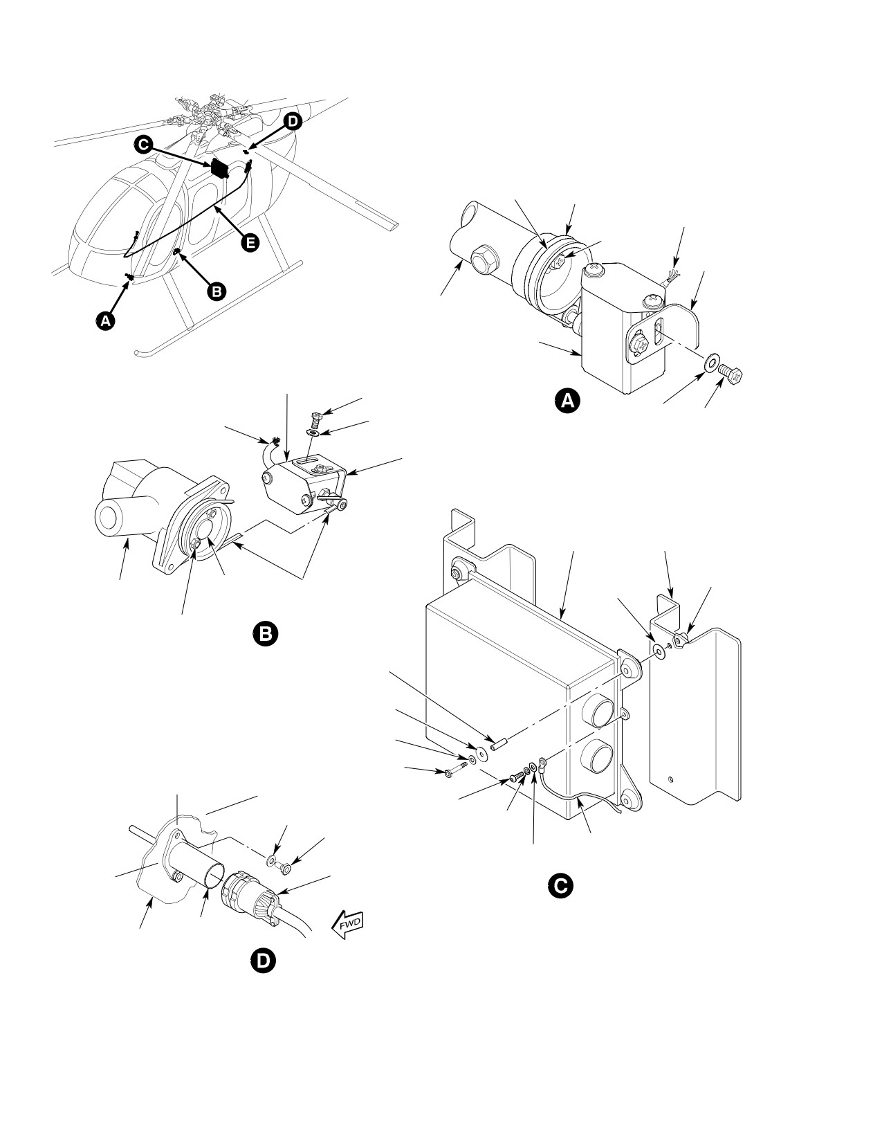
Figure 202. Engine Controls Installation (Sheet 1 of 2)
Page 208
Revision 44
76-47-00
MD Helicopters, Inc.
CSP−HMI−2
MAINTENANCE MANUAL
ENGINE THROTTLE
NUT
WASHER
BELLCRANK
COTTER PIN
JAM NUT
WASHER
BOLT
ROD END
BEARING
MOUNTING
SCREW
BRACKET
FLAT WASHER
(NOTE 1)
JAM NUT
ELECTRICAL
JAM NUT
CONDUIT
FLAT WASHER
CABLE BULKHEAD
SWIVEL
FLAT WASHER
FLAT WASHER
JAM NUT
CONTROL CABLE
CONDUIT
NUT
ENGINE CONTROL CABLE
RBL
ROD END
10.1
BEARING
SCREW
JAM NUT
JAM NUT
FLAT WASHER
BOLT
WASHER
FLAT
SHIM
WASHER
DOUBLER
RIG PIN HOLE
600N7720-1
(NOTE 2)
DOUBLER
FLAT WASHER
600N7720-3
ENGINE
JAM NUT
NUT
CONTROL BOX
ENGINE CONTROL
CABLE
ENGINE HYDROMECHANICAL
INSTALL CABLE END
CONTROL UNIT
INTO ENGINE CONTROL
BOX COUPLING
ENGINE CONTROL CABLE
NOTE:
VIEW ROTATED-LOOKING INBOARD AT RIGHT SIDE
1.
600N7718-1 MOUNTING
BRACKET MUST BE
6G76-006-2E
INSTALLED WHEN INSTALLING
THE 600N7714-3
ENGINE CONTROL CABLE
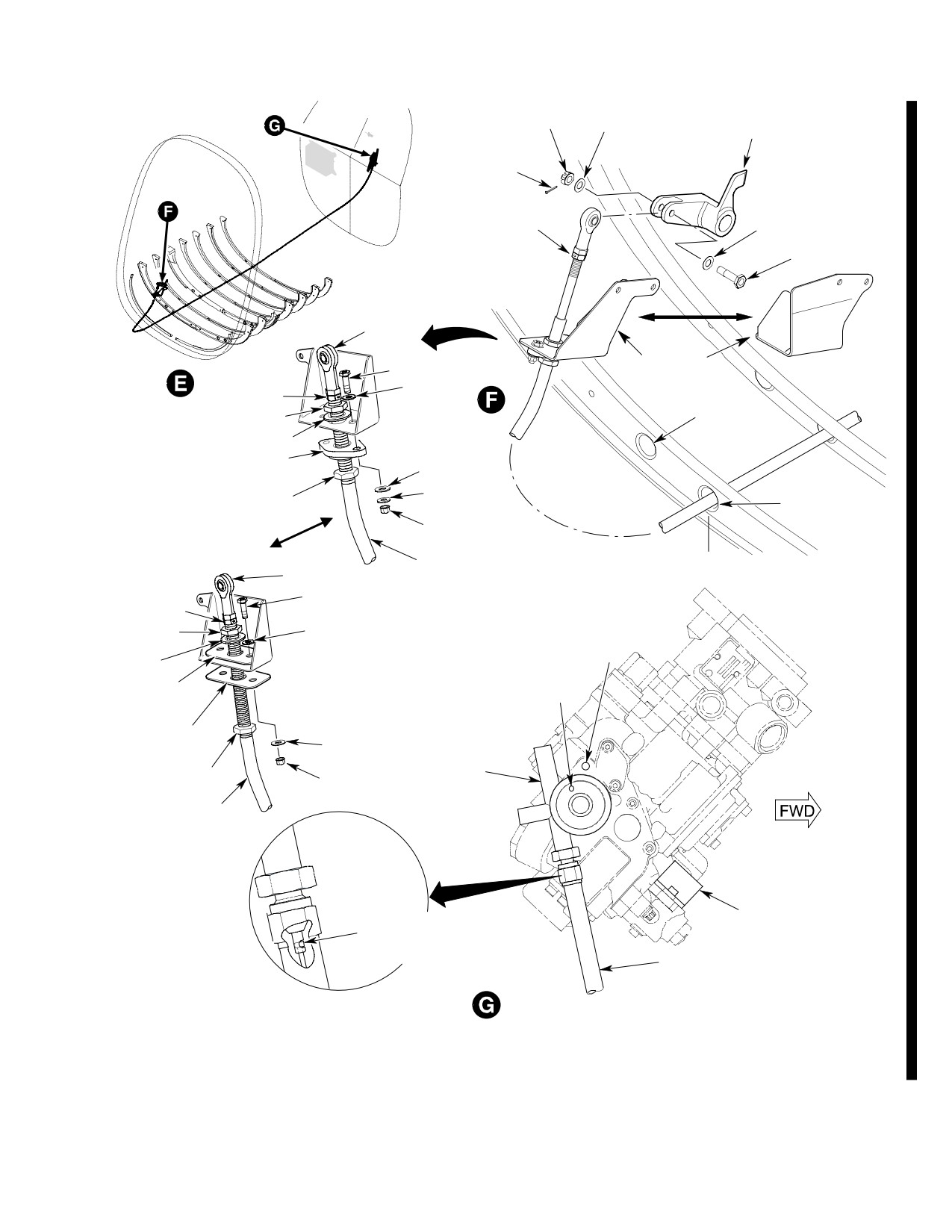
Figure 202. Engine Controls Installation (Sheet 2 of 2)
Page 209
76-47-00
Revision 44
CSP−HMI−2
MD Helicopters, Inc.
MAINTENANCE MANUAL
9. Engine Throttle Control Cable Mounting
(2).
Set lever on engine hydromechanical
Bracket Replacement
control unit to idle and insert
0.1535-0.1545 inch (3.8989-3.9243
(Ref. Figure 202)
mm) rig pin (or #23 drill blank) in rig
pin hole (ensure that rig pin engages
A. Engine Throttle Control Cable Mounting
the fuel control gearbox, gear, pointer
Bracket Removal
arm and casting.
(1). Disconnect throttle cable at collective
(3).
Set collective twist grip at idle detent
stick (Ref. Engine Control Cable
position.
Replacement).
(4).
Position the cable in the cable bulkhead
(2). Disconnect throttle cable from bracket
swivel or bracket so that the cable is
(Ref. Engine Control Cable Replace
not binding and tighten the jam nuts.
ment).
Torque jam nuts to 40 inch-pounds
(4.51 Nm).
(3). Remove two nuts, four washers, two
spacers and two bolts securing bracket
(5).
Remove rig pin (or drill blank).
to socket assembly.
(6).
Rotate the throttle twist grip to full and
(4). Slide bracket over end of throttle cable.
shutoff positions and verify that the
hydromechanical control unit lever
(5). Bracket with Doublers - Remove
contacts the stops at both settings.
nuts, washers and screws that attach
(7).
Rotate the throttle twist grip from full
doublers to bracket and remove
to idle positions and verify that the
doublers.
pointer on the hydromechanical control
B. Engine Throttle Control Cable Mounting
unit is between 30-40 degrees.
Bracket Installation
11. Engine Controls Inspection
(1). Bracket with Doublers - Attach
(1). Visually inspect ECU for damage and
doublers to bracket with screws,
security of installation.
washers and nuts. Torque nuts to 12 -
15 inch pounds (1.35 - 1.69 Nm).
(a). Inspect ECU for security of hard
ware. Torque or replace loose or
(2). Slide bracket over end of throttle cable
missing hardware.
and align with bolts holes in socket
assembly.
(b). Inspect electrical connectors, wire
harnesses and bonding jumper for
(3). Install bolts with washers through
chafing or cuts. None allowed.
bracket and socket assembly.
Ensure connectors are securely
attached.
(4). Install spacers, washers and nuts on
bolts (spacers are installed before
(2). Visually inspect collective and direction
washers).
al potentiometers for damage and
security of installation.
(5). Torque nuts to 12 - 15 inch-pounds
(1.36 - 1.69 Nm) plus drag torque.
(a). Inspect potentiometers for security of
hardware. Torque or replace loose or
(6). Connect throttle cable (Ref. Engine
missing hardware.
Control Cable Replacement).
(b). Inspect drive belts for cuts and
10. Engine Control Cable Rigging
excessive tension. None allowed.
(Ref. Figure 203)
(c). Inspect electrical connectors and wire
harnesses for chafing or cuts. None
(1). Loosen engine control cable jam nuts at
allowed. Ensure connectors are
cable bulkhead swivel or bracket.
securely attached.
Page 210
Revision 44
76-47-00
MD Helicopters, Inc.
CSP−HMI−2
MAINTENANCE MANUAL
BOLT
WASHER
RIG PIN HOLE
ENGINE THROTTLE
BELLCRANK
ENGINE
CONTROL BOX
ENGINE
JAM NUT
HYDROMECHANICAL
CONTROL UNIT
REF. ENGINE
CONTROL CABLE
JAM NUT
6G76-050C
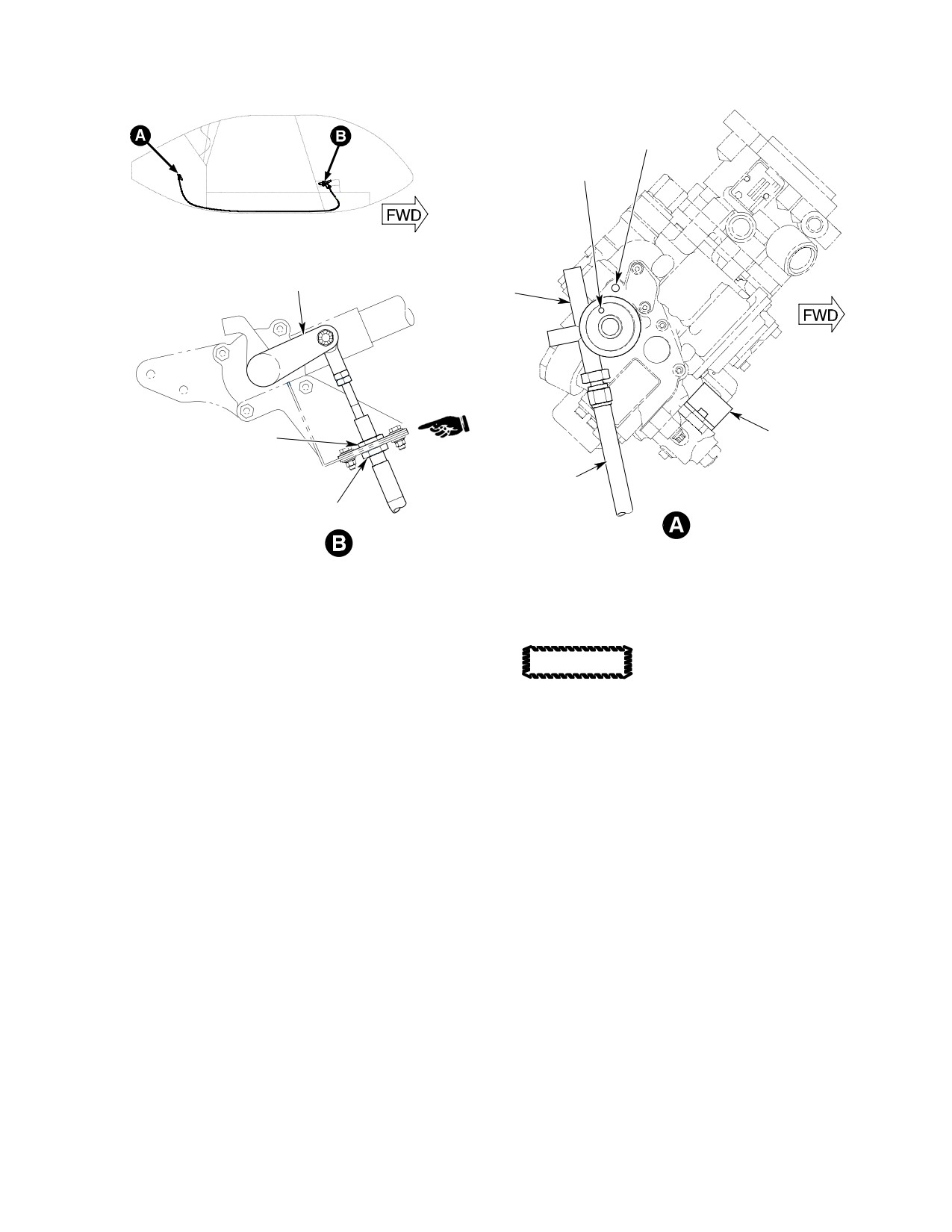
Figure 203. Engine Control Cable Rigging
(3). Visually inspect CIT sensor for damage
Do not lubricate cable if cable
CAUTION
and security of installation.
action is not smooth. Lubricant
attracts dirt which will damage the cable.
(b). Inspect engine control box and
(a). Inspect CIT sensor for security of
control cable for security of hard
hardware. Torque or replace loose or
ware. Torque or replace loose or
missing hardware.
missing hardware.
(c). Inspect control cable to control box
(b). Inspect electrical connector and wire
connection for security. Torque
harness for chafing or cuts. None
control cable nut.
allowed. Ensure connector is securely
12. Engine Control Cable Shipping and
attached.
Handling
(Ref. Figure 204) The following procedures
(4). Visually inspect engine control box and
should always be used when handling the
control cable for damage and security of
engine control cable. This cable can be
installation.
damaged if handled incorrectly.
A. Control Cable Removal From Shipping
(a). Inspect engine control cable for sharp
Box
bends, chafing, binding (smooth
The control cable is shipped in a “lazy figure 8”
operation through full range of
configuration.
travel), corrosion and dents. None
allowed.
(1). Lift control cable from box.
Page 211
76-47-00
Revision 44
CSP−HMI−2
MD Helicopters, Inc.
MAINTENANCE MANUAL
(2). Hold the cable upright in both hands.
B. Control Cable Installation into Shipping
Box
(3). Remove the shipping wire.
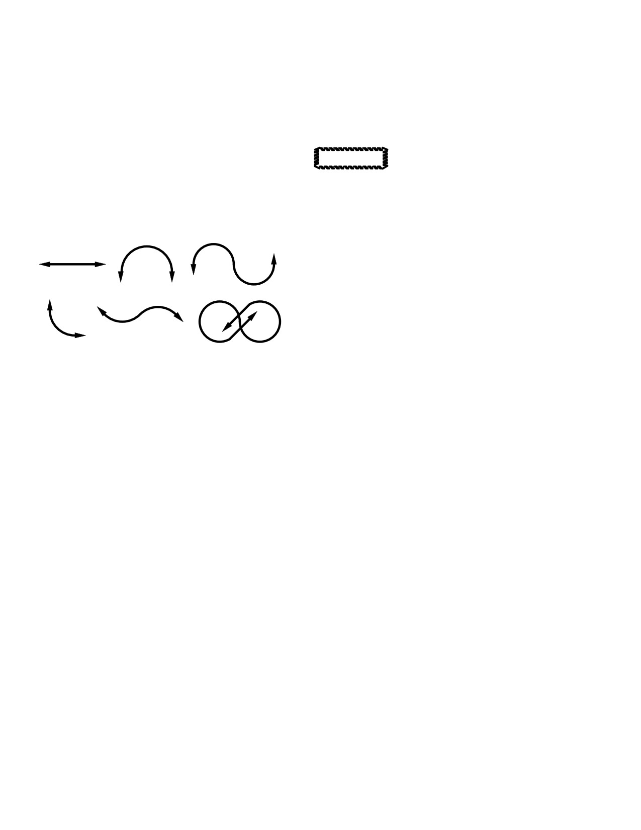
(Ref. Figure 204) The cable is to be folded into
(4). Starting with the nearest end fitting,
a “lazy figure 8” position whenever it is
pay out the loops of the cable, one at a
shipped.
time.
Never allow cable to be bent
CAUTION
more than 180 degrees effective
(5). Lay the cable straight.
bend angle, this will damage cable.
(6). Grasp one end fitting and shake the
NOTE: The following procedure may require
cable to align the races.
more than one person to perform.
(1). Lay cable flat.
(2). Grasp both ends of cable and gently
bend in opposite directions.
0°
180°
(3). Continue bending until you have a
0°
“figure 8”.
(4). To fit the cable into a shipping box, the
0°
cable may have to be bent into a double
90°
“figure 8”.
0°
76-006-3
(5). Gently wire the cable together in the
center of the “figure 8” to prevent
Figure 204. Effective Bend Angle
damage in shipping or storage.
Page 212
Revision 44
76-47-00

MD Helicopters, Inc.
CSP-HMI-2
MAINTENANCE MANUAL
Chapter
78
Engine Exhaust
System
MD Helicopters, Inc.
CSP-HMI-2
MAINTENANCE MANUAL
TABLE OF CONTENTS
Para/Figure/Table
Title
Page
78-20-00 Engine Exhaust System (250-C20B and 250-C20R/2)
A
Maintenance Practices
201
1. Description and Operation
201
2. Exhaust System Replacement
201
A. Exhaust System Removal
201
B. Exhaust System Installation
201
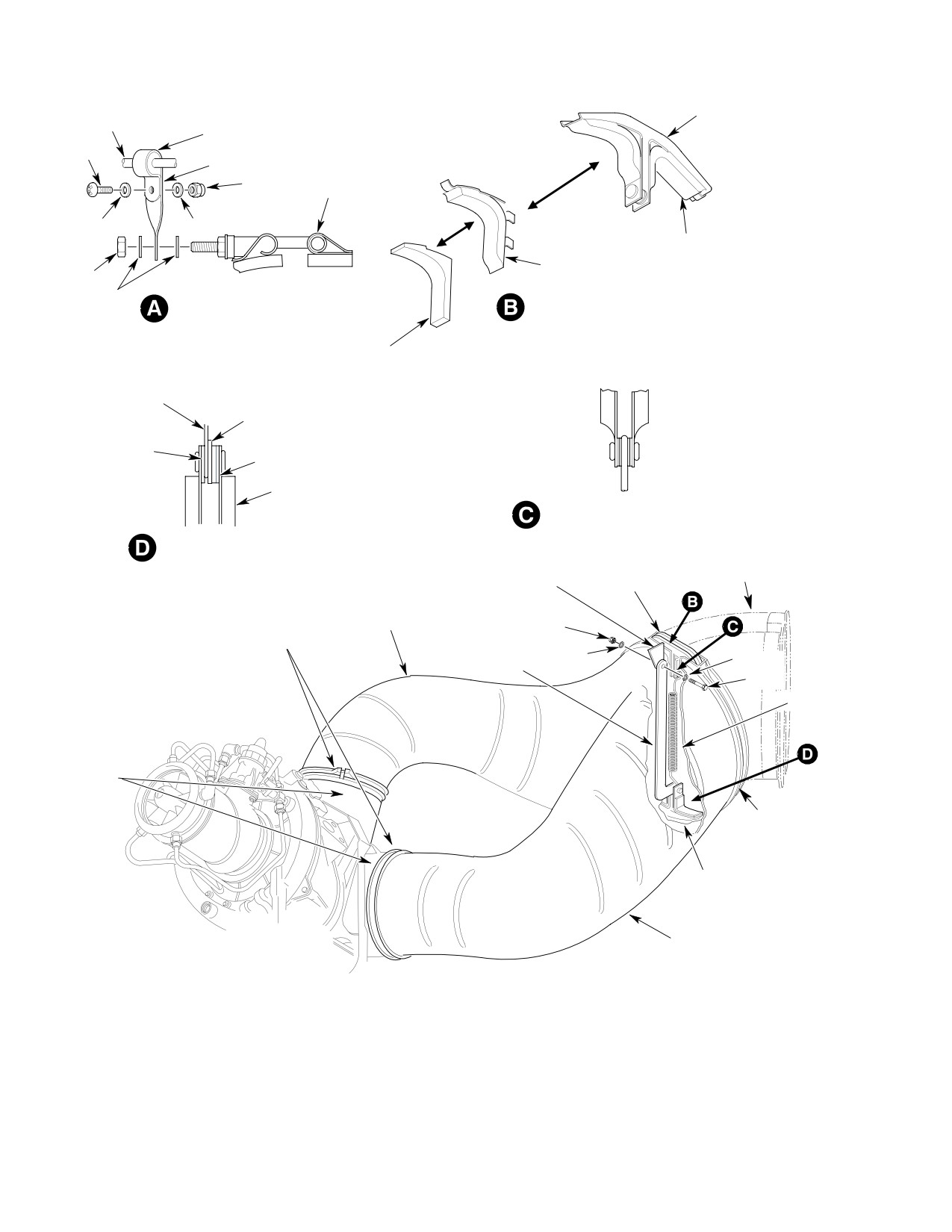
Figure 201. Exhaust System Installation
202
3. Exhaust System Inspection
203
A. Tailpipe Inspection
203
B. Supports and Fasteners Inspection
203
C. Clamp Inspection
203
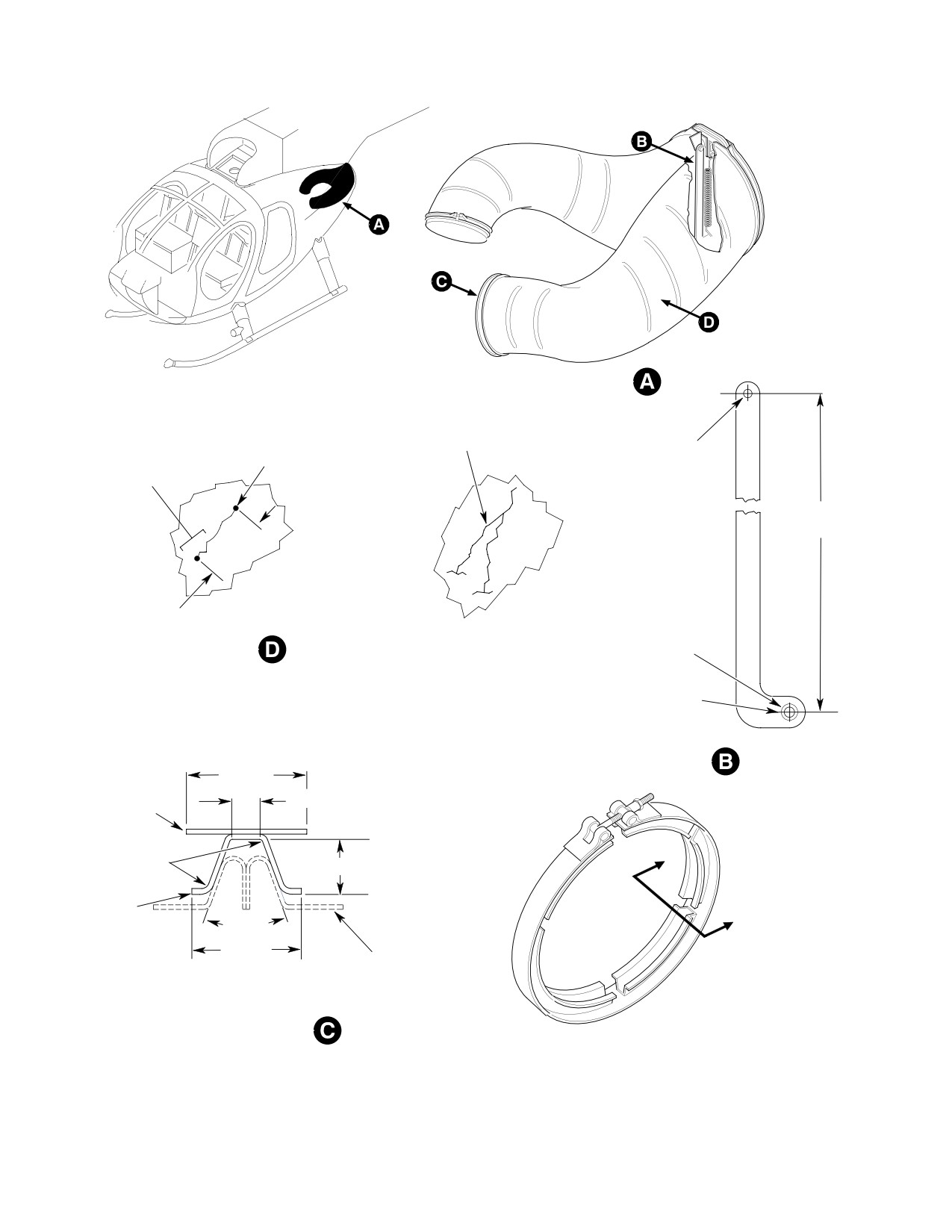
Figure 202. Exhaust System Inspection
204
4. Exhaust System Repairs
205
A. Tailpipe Repair
205
B. Hanger Cushion Repair
205
C. Tailpipe Clamp Repair
205
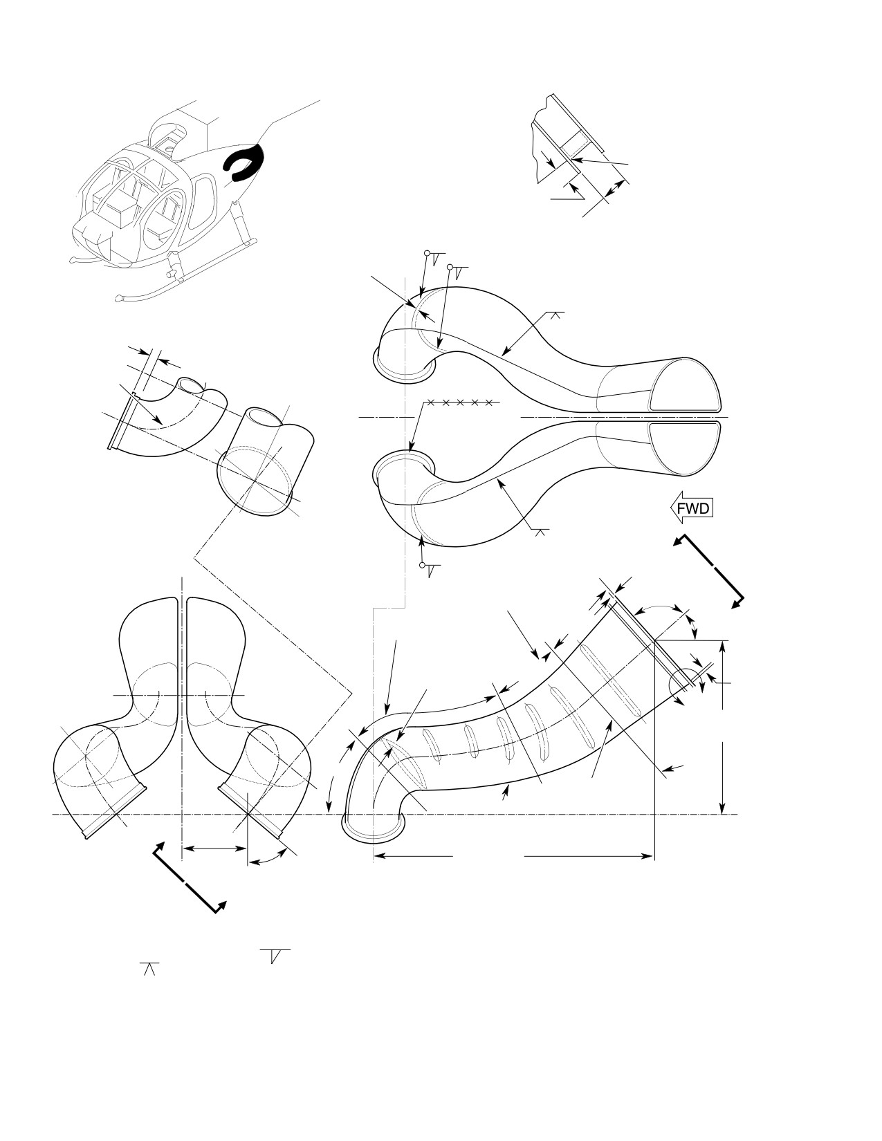
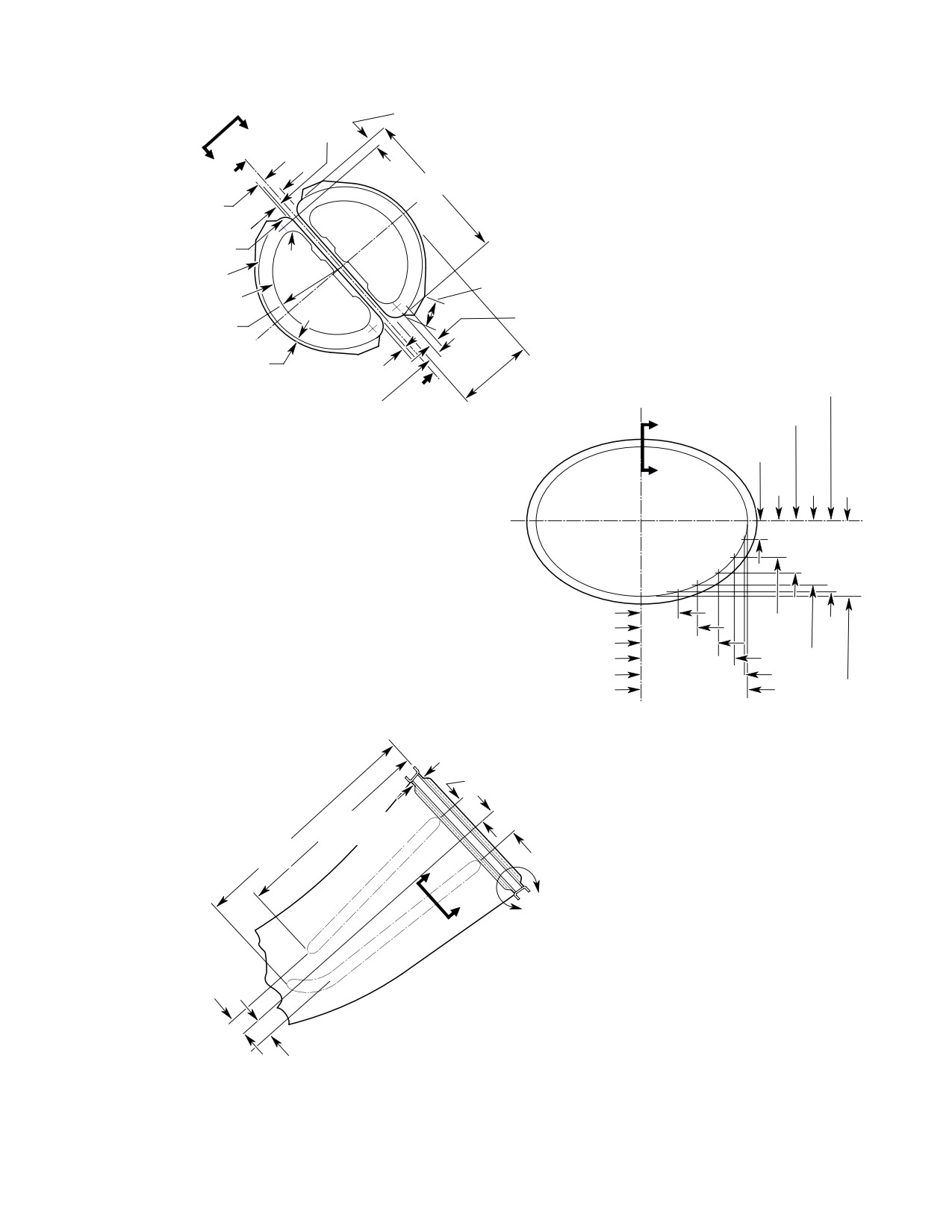
Figure 203. Exhaust System Repairs (Sheet 1 of 3)
206
Figure 204. Engine Exhaust Extension (500N)
209
78-30-00 Engine Exhaust System (250-C30 and 250-C47)
A
Maintenance Practices
201
1. Description and Operation
201
2. Exhaust System Replacement
201
A. Exhaust System Removal
201
B. Exhaust System Installation
201
3. Exhaust System Inspection
201
4. Exhaust System Repair
202
Figure 201. Engine Exhaust System Installation
203
Page i
78 Contents
Revision 35
CSP-HMI-2
MD Helicopters, Inc.
MAINTENANCE MANUAL
TABLE OF CONTENTS (Cont.)
Para/Figure/Table
Title
Page
This Page Intentionally Left Blank
Page ii
Revision 35
78 Contents
MD Helicopters, Inc.
CSP-HMI-2
MAINTENANCE MANUAL
Section
78−20−00
Engine Exhaust
System (250−C20B
and 250−C20R/2)
MD Helicopters, Inc.
CSP-HMI-2
MAINTENANCE MANUAL
EXHAUST SYSTEM
MAINTENANCE PRACTICES
1. Description and Operation
clamps. Locate clamp T-bolts at 6
o'clock position. Install washers and
The engine exhaust system consists of left and
nuts. Finger tighten clamp nuts.
right tailpipes attached to the engine by two
clamps and a flexible suspension system.
NOTE: Use only corrosion resistant fasteners.
Suspension hardware allows exhaust system
thermal expansion and contraction. Movement
(3).
Install lower hanger between tailpipe
is absorbed by a spring, upper and lower
aft flanges. Attach tailpipe support link
cushioned hanger assemblies and a pivoted
to airframe fitting. Install bolt, washers
link. The link suspends the tailpipes from an
and nut. Finger tighten nut.
airframe fitting above the exhaust outlet.
(4).
Install upper hanger between tailpipe
2. Exhaust System Replacement
flanges.
(Ref. Figure 201)
(5).
Attach spring hook to upper clip
A. Exhaust System Removal
bushing with two captive washers on
(1). Remove right side thermocouple
each side (Ref. View C).
hardware (Ref. View A).
(6).
Attach lower spring hook to clip
(2).
(500N) Remove clamp from around
bushing between support link and thin
tailpipes.
washer (Ref. View D).
(3). Remove tailpipe clamps.
(7).
Inject sealant (CM423) into cavity
(4). Remove airframe link attaching
around spring attach points. Allow
hardware.
sealant to cure per manufacturers
instructions.
(5). Remove two tailpipes as an assembly.
Cover engine exhaust ducts to
(8).
Torque engine/tailpipe clamp nuts to 15
CAUTION
keep FOD out of turbine section.
- 18 inch-pounds (1.69 - 2.03 Nm).
(6). Install covers on engine exhaust
(9).
Tap around both clamps with a rawhide
outlets.
mallet to seat clamps on flanges.
(7). Remove spring and hangers. Separate
Retorque clamp nuts 15 - 18 inch-
tailpipes.
pounds (1.69 - 2.03 Nm).
B. Exhaust System Installation
(10).
Continue tapping around clamp and
retorquing clamp nut until nut no
Consumable Materials
longer turns when specified torque is
(Ref. Section 91−00−00)
applied.
Item
Nomenclature
(11).
Install thermocouple wire support on
CM423
Sealant
right tailpipe clamp T-bolt with one
washer on each side of support. Install
(1). Remove exhaust duct covers.
nut (Ref. View A). Install thermocouple
wire, clamp, screw, washers and nut on
Support tailpipes during instal
CAUTION
support.
lation. Unsupported tailpipes
could damage mounting flanges or result in
(12).
Torque tailpipe support link nut to 12 -
clamp joint misalignment and subsequent
15 inch-pounds (1.36 - 1.69 Nm).
exhaust gas leakage.
Install cotter pin.
(2). Butt tailpipe flanges up to engine
exhaust duct flanges and install
(13).
(500N) Install clamp around tailpipe.
Page 201
78-20-00
Revision 38
CSP-HMI-2
MD Helicopters, Inc.
MAINTENANCE MANUAL
UPPER HANGER
WIRE
CLAMP
SCREW
SUPPORT
NUT
RH CLAMP T-BOLT
WASHER
WASHER
WIRE MESH OR
WIREMESH
SILICONE RUBBER
REPLACEMENT
CUSHION
NUT
CUSHION
WASHER
THERMOCOUPLE WIRE
HANGER INSTALLATION
SUPPORT INSTALLATION
(NOTE 1)
SILICONE RUBBER
REPLACEMENT CUSHION
SPRING HOOK
UPPER HANGER
(NOTE 3)
LINK
ASSEMBLY
ONE THIN
WASHERS (2)
WASHER
WASHERS (2)
WASHERS (2)
SPRING HOOK
LOWER HANGER ASSEMBLY
(NOTE 3)
UPPER HANGER SPRING
ATTACHMENT
LOWER HANGER SPRING
ATTACHMENT
EXTENDED TAILPIPE
AIRFRAME TAILPIPE
(500N ONLY)
SUPPORT FITTING
HANGER
TORQUE NUT
TORQUE TAILPIPE CLAMP
RIGHT TAILPIPE
12-15 IN. LBS.
15-18 IN. LBS. (1.69-2.03 NM)
(1.36-1.69 NM)
(NOTE 2)
WASHER
WASHER
SUPPORT LINK
BOLT
SPRING
ENGINE
EXHAUST
DUCT
CLAMP
(500N ONLY)
HANGER
LEFT TAILPIPE
NOTES:
1.
TYPICAL FOR UPPER AND LOWER HANGERS.
2.
LOCATE T-BOLTS AT 6 O'CLOCK POSITION.
3.
FILL CAVITY BETWEEN SPRING AND WASHERS
G78-0002B
WITH SEALANT (CM423)
Figure 201. Exhaust System Installation
Page 202
Revision 38
78-20-00
MD Helicopters, Inc.
CSP-HMI-2
MAINTENANCE MANUAL
3. Exhaust System Inspection
(2). Replace damaged hanger cushions.
(Ref. Figure 202)
(3). Check spring for cracks, pits, nicks,
kinks, gouges, evidence of overheating,
A. Tailpipe Inspection
wear and corrosion. Replace a spring
showing such damage.
(1). Inspect tailpipe flanges and duct
interior/exterior surfaces for cracks and
(a). Measure spring free length from hook
broken weld seams.
center to hook center. Spring free
length shall be 6.28 inches (15.951
(a). No cracks allowed across flange.
cm). Replace a stretched spring.
Replace tailpipe.
(b). Anchor one end of spring. Attach an
(b). Weld seams may be repaired pro
accurate weight scale to the other
vided cracks meet limits in the
end. Stretch spring to 7.10 inches
following steps.
(18.034 cm), hook center to center.
(c). Fluorescent penetrant inspect
Spring tension at specified length
suspected cracks to determine crack
must be 8-12 pounds (35.6-53.4 N).
ends and length.
Replace a spring failing tension
requirement.
(d). Nonintersecting single line cracks up
to 2.00 inches (5.08 cm) long may be
(4). Inspect hanger/clip rivets and washers
repaired if they do not affect the
for security. Inspect spring hook
forward flange.
bushings, washers and rivets for wear
(e). Intersecting cracks of any length
and security. Replace worn parts.
forming an acute angle and an
Repair loose rivets.
unsupported section may not be
(5). Inspect support link for cracks, corro
repaired.
sion and hole wear exceeding specifica
(2). Repair cracks or separations.
tions (Ref. Figure 202).
(3). Replace an unrepairable tail pipe.
(6).
(500N) Inspect clamp around tailpipes
for security and condition. Fiberglass
(4). Inspect engine and tailpipe flanges for
wrap for fraying and condition of
evidence of gas leakage.
sealant at ends.
(a). Gas leakage may be caused by flange
C. Clamp Inspection
misalignment, loose or improperly
installed flange clamp, cracked,
A failed exhaust duct clamp
CAUTION
warped, nicked, dented, gouged or
may present a serious inflight
distorted flange areas or a combina
problem. Replace any clamp you think is in
tion of causes.
marginal condition.
(5). Straighten flange distortions.
(1). Inspect T-bolt threads for condition.
Repair damaged threads.
(6). Replace a tailpipe having a cracked
forward flange.
(2). Check self locking nut for run-on
torque resistance. Replace a worn nut.
(7). Inspect entire duct for dents, crimps,
creases, wrinkles, sags and bulges.
(3). Inspect strap/channel spotwelds for
security.
(8). Repair distortions.
(4). Check strap for cracks, creases, bends,
B. Supports and Fasteners Inspection
joggles and other evidence of fatigue.
(1). Inspect hanger cushions for wear, tears
Replace clamps showing metal crystalli
and security.
zation or cracks anywhere on the strap.
(a). Inspect braided metal cushions for
(5). Inspect clamp channels for cracks,
spotweld security.
spread or crimp (Ref. Figure 202).
Page 203
78-20-00
Revision 38
CSP-HMI-2
MD Helicopters, Inc.
MAINTENANCE MANUAL
COMPLEX CRACKS AT ACUTE
STOP DRILL HOLE
INTERSECTING ANGLES ARE
0.040 IN. (1.016 MM)
NOT REPAIRABLE
0.190-0.194 IN.
SMALL SIMPLE CRACKS
(TYP)
(4.826-4.9276 MM)
WITH OBTUSE ANGLES
DIA. HOLE
ARE REPAIRABLE
9.80 IN.
(24.892 CM)
REPAIRABLE CRACK LENGTH
2.00 IN. (5.08 CM) MAXIMUM
CRACK REPAIR LIMITS
BUSHING
0.4360 0.4365 IN.
(11.0744-11.0871 MM)
DIA. HOLE
SUPPORT LINK
0.625 IN.
DIMENSIONAL LIM
(15.875 MM)
0.156 IN. (3.9624 MM)
CLAMP STRAP
0.022 0.052 IN.
A
(0.5588-1.3208 MM)
0.218 IN. (5.5372 MM)
R (TYP)
CHANNEL
A
40 ±5°
0.50 IN.
ENGINE FLANGE
(12.70 MM)
A - A
CLAMP CROSS-SECTION
CLAMP DIMENSIONAL LIMITS
G78-0003A
Figure 202. Exhaust System Inspection
Page 204
Revision 22
78-20-00
MD Helicopters, Inc.
CSP-HMI-2
MAINTENANCE MANUAL
4. Exhaust System Repairs
NOTE: Either bonded silicone rubber or welded
all metal original equipment cushions may
(Ref. Figure 203)
be installed. Replacement parts may be tab
attached metal or bonded silicone rubber
A. Tailpipe Repair
cushions.
Consumable Materials
(1). Replace original equipment metal
(Ref. Section 91−00−00)
cushions with tabbed metal cushions as
Item
Nomenclature
follows:
CM824
Welding rod
(a). Cut away cushion debris.
(b). Grind spot welds smooth and level
(1). Remove dents and distortions with a
with hanger surfaces.
suitably shaped form-block and mallet.
NOTE: Avoid weakening replacement cushion
(2). Repair cracks meeting repair limits as
tabs. Ensure cushions are correctly located
follows:
prior to bending tabs.
(a). Stop-drill crack ends with a 0.040
(c). Position cushion assembly on hanger.
inch (1.016 mm) diameter drill.
Bend cushion tabs to grip hanger
(b). Remove all carbon and debris from a
(Ref. View B).
one inch area bordering crack with a
(2). Replace original equipment metal
stainless steel brush. Clean inside
cushions with silicone rubber cushions
and outside surfaces.
as follows:
(c). Route out crack a minimum width
(a). Cut away cushion debris.
from end to end to expose bare metal.
(d). Flood back side of weld area with
(b). Grind spot welds smooth and level
inert gas or shield with a suitable
with hanger surfaces.
stainless steel flux.
(c). Clean hanger components and
(e). Tungsten inert gas weld crack with
cushion bond joint-surfaces per
21-6-9 CRES rod or wire (CM824).
sealant manufacturers instructions.
(f). Fluorescent penetrant inspect repairs
(d). Bond cushion to hanger with RTV
for cracks. Weld cracks as required.
106 sealant (CM423). Inject sealant
into cavity around spring attach
B. Hanger Cushion Repair
points. Allow sealant to cure per
manufacturers instructions.
Consumable Materials
C. Tailpipe Clamp Repair
(Ref. Section 91−00−00)
Item
Nomenclature
(1). Chase clamp T-bolt threads with a
CM423
Sealant
10-32NF-38 die or replace clamp, as
required.
Page 205
78-20-00
Revision 22
CSP-HMI-2
MD Helicopters, Inc.
MAINTENANCE MANUAL
0.06 IN. (1.524 MM) R
(TYP)
0.50 IN. (12.7 MM)
(TYP)
0.85 IN.
DETAIL
(21.59 MM)
A
NOTE 1
0.25-0.31 IN.
NOTE 1
(6.35-7.874 MM)
LAP
1.00 IN.
(2.54 CM)
5.00 IN.
0.25-0.31 IN.
(12.7 CM) R
(6.35-7.874 MM)
LAP
0.13 IN. (3.302 MM)
C
L
(2 PLCS) (TYP)
(NOTE 3)
B
0.18 IN.
NOTE 1
(4.572 MM)
FAIR FROM ELLIPSE TO SEMI
CIRCLE IN THIS AREA
91°
7.75 IN.
ELLIPSE ROTATED
B
(19.685 CM)
41°
IN THIS AREA
0.25-0.31 IN.
8.00 IN.
(6.35-7.874 MM)
(20.32 CM)
0.12 IN.
LAP
(3.048 MM
A
15.78 IN.
(40.082
CM)
STA.
45°
7.75
DUCT AREA TO BE
CONSTANT TO HERE
NOTE 2 (TYP)
C
26.33 IN.
6.12 IN.
(66.878 CM)
50°
(15.545 CM)
C
NOTES:
1.
FILLET WELD ALL AROUND, NEAR SIDE.
2.
BUTTWELD.
3.
STITCHWELD. X X X X
G78-0004-1A
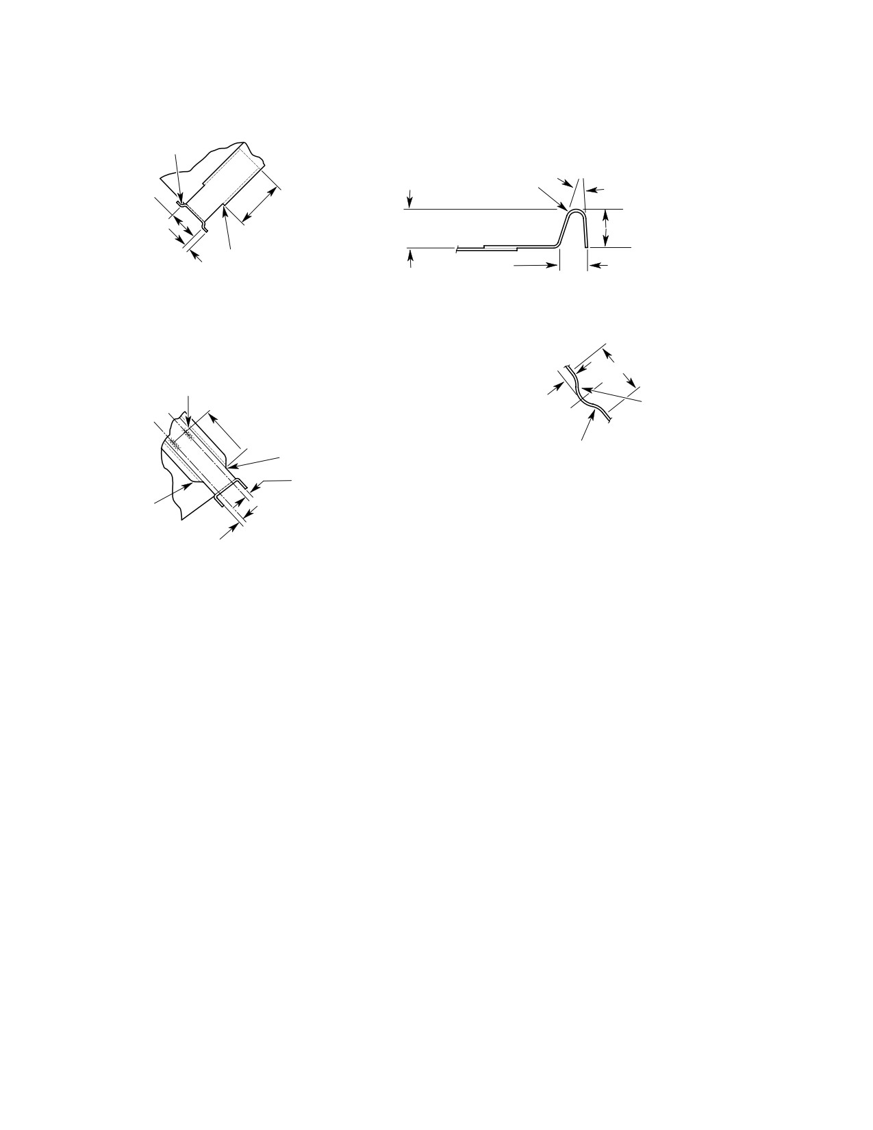
Figure 203. Exhaust System Repairs (Sheet 1 of 3)
Page 206
Revision 22
78-20-00
MD Helicopters, Inc.
CSP-HMI-2
MAINTENANCE MANUAL
0.68 IN. (17.272 MM)
0.16 IN.
(4.064 MM)
(TYP)
E
(TYP)
E
10.13-10.38 IN.
D
(25.7302-26.3652 CM)
0.46 IN. (11.684 MM)
0.92 IN. (23.368 MM)
0.68 IN. (17.272 MM) R
(TYP)
1.00 IN.
(2.54 CM)
T. E. STA
1.75 IN. (4.445 CM)
R (TYP)
STA. 7.75
(TYP)
0.50 IN. (12.7 MM)
4.25 IN. (10.795 CM) R
(TYP)
(TYP)
0.12 IN. (3.048 MM)
0.12 IN. (3.048 MM)
2.415 IN.
(TYP)
(TYP)
5.00-5.25 IN. (12.7-13.335 CM)
(6.1341 CM)
D
(TYP)
0.65-0.97 IN. (16.51-24.638 MM)
1.768 IN.
F
MINIMUM PREFERRED (TYP)
(4.4907 CM)
B−B
0.647 IN.
(16.4338 MM)
F
0.922 IN. (23.4188 MM)
1.250 IN.
1.781 IN. (4.5237 CM)
(3.175 CM)
2.519 IN. (6.3983 CM)
3.085 IN. (7.8359 CM)
2.165 IN.
3.441 IN. (8.7401 CM)
(5.4991 CM)
3.562 IN. (9.0475 CM)
2.500 IN.
(6.3500 CM)
C−C
ROTATED 40° C-CLOCKWISE
0.63 IN. (16.002 MM)
2.00 IN. (5.08 CM)
13.76 IN.
(34.9504 CM)
16.25 IN.
(41.275 CM)
2.00 IN. (5.08 CM)
G
G
H
SEAMWELD
1.25 IN. (3.175 CM)
D−D
1.25 IN. (3.175 CM)
G78-0004-2B
Figure 203. Exhaust System Repairs (Sheet 2 of 3)
Page 207
78-20-00
Revision 22
CSP-HMI-2
MD Helicopters, Inc.
MAINTENANCE MANUAL
0.06 IN. (1.524 MM) R
(TYP)
0.63 IN. (16.002 MM) R
0.85 IN. (21.59 MM)
20°
(TYP)
1.50 IN. (3.81 CM)
0.19 IN. (4.826 MM)
(TYP)
0.294 IN. (7.4676 MM) CONSTANT
0.289 IN. (7.3406 MM) CONSTANT
(TYP)
0.25 IN. (6.35 MM) R
0.190 IN. (4.826 MM)
FREE DIMENSION
E−E
F−F
1.00 IN. (2.54 CM)
CONTINUOUS SEAMWELD (REF)
SPOTWELD WHERE REQUIRED
0.19 IN. (4.826 MM)
0.31 IN. (7.874 MM) R
1.50 IN. (3.81 CM) (TYP)
0.442-0.562 IN.
0.06 IN. (1.524 MM) R
(11.2268-14.2748 MM) R
(TYP)
G−G
0.18 IN. (4.572 MM)
(TYP)
45° ANGLE FROM
FLAT PATTERN
0.18 IN. (4.572 MM)
H−H
(TYP)
G78-0004-3
Figure 203. Exhaust System Repairs (Sheet 3 of 3)
Page 208
Revision 22
78-20-00
MD Helicopters, Inc.
CSP-HMI-2
MAINTENANCE MANUAL
45°±1.0°
A
0.92-1.02 IN.
(2.337-2.591 MM)
6.00-6.25 IN.
(15.24-15.875 CM)
STIFFENER
C
A
STIFFENER
C
0.50 IN. (12.7 MM)
0.06 IN. (1.524 MM) R
B - B
0.25 IN. (6.35 MM)
SECTION A - A
SECTION D - D
45° (TYP)
0.12 IN. (3.048 MM)
R (TYP)
0.25 IN.
(6.35 MM)
R (TYP)
D
0.74 IN. (18.796 MM)
(TYP)
0.71-0.97 IN.
1.45-1.55 IN. (3.683-3.937 CM)
(18.034-24.638
MM) (TYP)
0.35 IN. (8.89 MM)
SECTION B - B
D
SECTION C - C
G78-0005
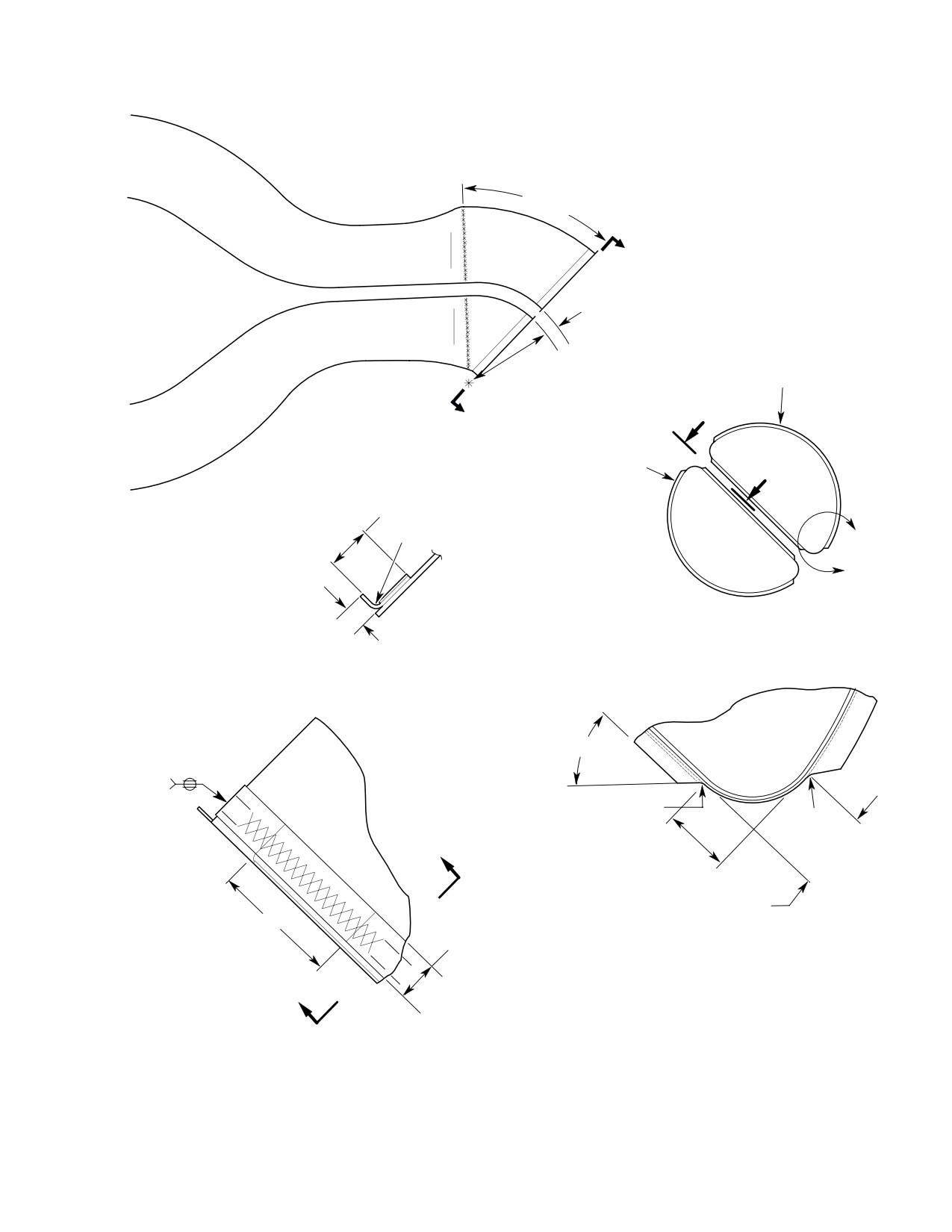
Figure 204. Engine Exhaust Extension (500N)
Page 209
78-20-00
Revision 22
CSP-HMI-2
MD Helicopters, Inc.
MAINTENANCE MANUAL
This Page Intentionally Left Blank
Page 210
Revision 44
78-20-00
MD Helicopters, Inc.
CSP-HMI-2
MAINTENANCE MANUAL
Section
78−30−00
Engine Exhaust
System (250−C30
and 250−C47)
MD Helicopters, Inc.
CSP-HMI-2
MAINTENANCE MANUAL
EXHAUST SYSTEM
MAINTENANCE PRACTICES
1. Description and Operation
Support aft ends of tailpipe dur
CAUTION
ing installation. Displacement
Engine exhaust is ducted through a tailpipe
from proper mounting position may damage
bolted to the engine exhaust duct flange and
forward mounting flanges.
supported by a flexible link mounting attached
to the aft fuselage. Figure 201 shows the
(3). Place tailpipe over engine exhaust duct
exhaust system and mounting details.
and secure with nuts, nutplate strips,
bolts and washers; torque bolts to 36 -
2. Exhaust System Replacement
46 inch-pounds (4.07 - 5.20 Nm)
plus drag torque.
(Ref. Figure 201)
(4). Install duct with duct clamp link
A. Exhaust System Removal
standing vertical.
(1). Detach tailpipe from engine exhaust
(5). When viewed from left side of helicop
duct by removing:
ter. turn torsion spring adjuster 150
±15 degrees clockwise and engage
(a). Six nuts, bolts, and 12 washers from
spring pin in nearest hole in adjuster.
exhaust pipe side flanges.
(6). Tighten tensioning bolt to adjust
(b). Two nutplate strips, 14 bolts and
spring.
washers from exhaust pipe fore and
aft flanges.
(7). Inspect for no contact between top of
exhaust and firewall retainer clips at
(2). Loosen the tensioning bolt passing
Sta. 155.75 fuselage ring.
through the hanger torsion spring
mandrel.
NOTE: If installing a new exhaust gasket, the
exhaust bolts should be retorqued after first
(3). Disengage the adjuster from the spring
flight. If bolts are found to be loose, retorque
pin.
after every flight until bolts retain torque.
Whenever tailpipes are re
CAUTION
moved, cover engine exhaust
3. Exhaust System Inspection
ducts with clean covers to prevent entry of
(Ref. Figure 201)
foreign materials into turbine section of en
gine.
(1). Inspect for cracks and broken weld
seams.
(4). Remove tailpipe and gasket.
(2). Inspect for dents and bends.
(5). Visually inspect bottom of upper aft
section firewall for contact marks with
(3). Using flashlight and mirror, look in
discoloration, holes or tears. Pay
engine bay through engine access doors
particular attention to firewall blanket
and look through engine oil filter access
retainer clips at Sta. 155.75 fuselage
cutout.
ring.
(a). Inspect top of engine exhaust duct for
B. Exhaust System Installation
contact marks and bottom of upper
(1). Remove protective cover from engine
aft section firewall for contact marks
exhaust duct.
with discoloration, holes or tears. Pay
particular attention to firewall
(2). Install gasket onto engine exhaust
blanket retainer clips at Sta. 155.75
flange.
fuselage ring.
Page 201
78-30-00
Revision 38
CSP-HMI-2
MD Helicopters, Inc.
MAINTENANCE MANUAL
4. Exhaust System Repair
(a). Using stainless steel brush, thor
oughly clean at least 1 inch (2.54 cm)
on all sides of cracked area. Cleaning
(Ref. Figure 201)
should remove all carbon from both
inner and outer surfaces and from
crack itself.
Consumable Materials
(b). Weld, using inert arc method, with
(Ref. Section 91−00−00)
rod (CM824). Shield back side of weld
Item
Nomenclature
with inert gas or suitable stainless
CM824
Welding rod
steel flux.
(c). Repair single cracks less than 2
inches (5.08 cm) in length by stop-
(1). Repair dents and bends using a form
drilling 0.040 inch (1.016 mm)
block and suitable mallet.
diameter hole at termination of each
end of crack. This method of repair
does not apply to intersecting cracks
(2). Repair cracks and breaks in tailpipes as
that form an acute angle leaving an
follows:
unsupported section.
Page 202
Revision 35
78-30-00
MD Helicopters, Inc.
CSP-HMI-2
MAINTENANCE MANUAL
EXHAUST DUCT SUPPORT
ASSEMBLY INSTALLATION
BUSHING
BRACKET
SPRING
LINK ASSY
SPRING PINS
BUSHING
DUCT ASSY
MANDREL
ADJUSTER
CLAMP
CUSHION
EXHAUST FLANGE BOLT
(20 PLCS)
EXHAUST DUCT INSTALLATION
GASKET
NUTPLATE
(TYP)
G78-3001
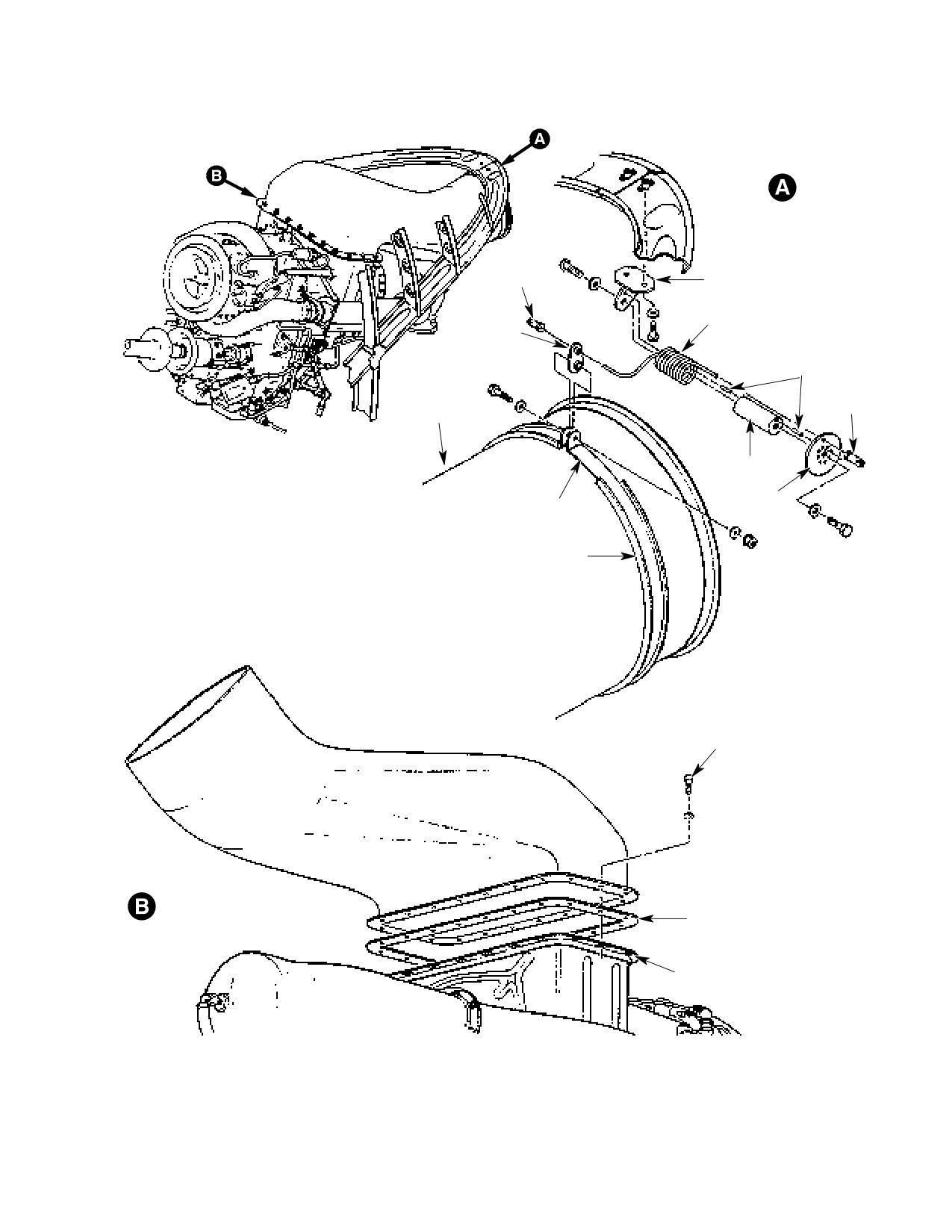
Figure 201. Engine Exhaust System Installation
Page 203
78-30-00
Revision 35
CSP-HMI-2
MD Helicopters, Inc.
MAINTENANCE MANUAL
This Page Intentionally Left Blank
Page 204
Revision 35
78-30-00

MD Helicopters, Inc.
CSP-HMI-2
MAINTENANCE MANUAL
Chapter
79
Engine Oil Supply
System
MD Helicopters, Inc.
CSP-HMI-2
MAINTENANCE MANUAL
TABLE OF CONTENTS
Para/Figure/Table
Title
Page
79-00-00 Engine Oil Supply System (369D/E/FF - 500/600N)
A
Description and Operation
201
1.
Engine Oil Supply System Description and Operation
201
A. Oil Supply System Description
201
B. Oil Supply System Operation
201
Figure 201. Engine Oil Supply System Schematic Diagram
202
2.
Engine Oil Supply System Fault Isolation
203
Table 201. Engine Oil Supply System Fault Isolation
203
3.
Oil Cooler Flushing
204
Figure 202. Oil Cooler Flush Equipment and Arrangement
205
4.
Oil Tank Replacement
205
A. Oil Tank Removal
205
B. Oil Tank Installation
205
5.
Oil Tank Sight Plug Replacement
206
A. Oil Tank Sight Plug Removal
206
B. Oil Tank Sight Plug Installation
206
6.
Oil Temperature Sender Replacement
206
7.
Oil Cooler Replacement
206
A. Oil Cooler Removal
206
B. Oil Cooler Installation
207
8.
Oil Tank Return Hose Replacement
207
A. Oil Tank Return Hose Removal
207
B. Oil Tank Return Hose Installation
207
Figure 203. Engine Oil Supply System (Sheet 1 of 2)
208
9.
Oil Supply Lines and Fittings Replacement
210
10. Oil Cooler Duct Replacement
210
A. Oil Cooler Duct Removal
210
B. Oil Cooler Duct Installation
210
11. Oil Tank Inspection
210
12. Oil Cooler Inspection
210
Table 202. Oil System Hardware Torque Values
210
Figure 204. Engine Oil Cooler Installation
211
13. One Time Mandatory Hose Inspection (369D Serial Numbers 0003D thru
0374D, Only)
212
14. Oil Lines and Fittings Inspection
212
15. Oil Tank Repair
212
16. Oil Cooler Repair
212
Page i
79 Contents
Revision 23
CSP-HMI-2
MD Helicopters, Inc.
MAINTENANCE MANUAL
TABLE OF CONTENTS (Cont.)
Para/Figure/Table
Title
Page
17. Oil Cooler Duct Repair
212
79-10-10 Airframe-Mounted Engine Scavenge Oil Filter
(369D/E/FF - 500N)
A
Maintenance Practices
201
1. Description and Operation
201
2. Scavenge Oil Filter Check
201
3. Scavenge Oil Filter Element Replacement
201
4. Scavenge Oil Filter Bypass Indicator Test
201
Figure 201. Facet Scavenge Oil Filter Assembly
202
Initial Installation
901
1. Scavenge Oil Filter Initial Installation
901
2. Post Installation Inspection
902
Figure 901. Scavenge Oil Filter Installation
903
Page ii
Revision 23
79 Contents
MD Helicopters, Inc.
CSP-HMI-2
MAINTENANCE MANUAL
Section
79−00−00
Engine Oil Supply
System (369D/E/FF −
500/600N)
MD Helicopters, Inc.
CSP-HMI-2
MAINTENANCE MANUAL
ENGINE OIL SUPPLY SYSTEM
DESCRIPTION AND OPERATION
1. Engine Oil Supply System Description
(3). The oil cooler is an all aluminum,
and Operation
radiator-type heat exchanger. A
thermostat in the oil cooler set at 140 -
A. Oil Supply System Description
180°F (60 - 82°C) returns cold oil
directly to the tank, bypassing the
(1). MDHI helicopters feature a dry sump,
cooler until the oil has reached operat
air cooled, recirculating engine oil
ing temperature. The oil cooler also
system consisting of an oil tank, oil
features a pressure-relief bypass valve
temperature sender, oil cooler/heat
that opens at 25-30 psi (172-207 kPa)
exchanger and air duct, thermostat,
and a one way ball type check valve
drain valve, check valve, hoses, tubes,
mounted on the oil cooler inlet fitting
fittings and attaching hardware.
that prevents oil from flowing back into
the engine after shut down.
B. Oil Supply System Operation
(4). A fiberglass duct guides cooling air
(1). Hot oil scavenged from the engine is
from the oil cooler blower to the oil
pumped through a one way check valve
cooler.
into the oil cooler. Oil cooler blower air
at ambient temperature is ducted
(5). The oil supply system drain valve is
through the cooler/heat exchanger. The
mounted on a bracket below the oil
oil cooler reduces oil temperature to
cooler. Tubes from the oil tank, oil
approximately 185°F (86°C). Cooled oil
cooler and overboard drain are con
is returned to the oil tank. Oil drawn
nected to the drain valve which is
from the tank by the suction side of the
spring-loaded closed.
engine driven pump is then distributed
NOTE: DN-72.1 discloses installation proce
through the engine under pressure to
dures modifying early 369D helicopter oil
cool and lubricate moving parts. The
tank and cooler drains for easier access.
heated oil drains into various engine
sumps, and the cycle is repeated.
(6). All oil supply system hoses and tubes
are lightweight assemblies incorporat
(2). An all welded, spherical aluminum
ing permanent fittings. Hoses installed
alloy oil tank is fitted with a filler neck,
near the engine are equipped with fire
optional filler neck strainer, locking
shields.
cap, vent tube, oil inlet and outlet
fittings, temperature sender, sight plug
(7). Refer to the applicable Allison Engine
and mounting support bosses. A
Operation and Maintenance Manual for
replaceable sight plug provides oil
specific engine oil system information
quantity information at a glance.
(Ref. Sec. 01-00-00).
Page 201
79-00-00
Revision 23
CSP-HMI-2
MD Helicopters, Inc.
MAINTENANCE MANUAL
TANK DRAIN
BULKHEAD
TUBE
FIREWALL
ELBOW
UNION
DRAIN
PORT
UPPER
INLET
OIL COOLER BLOWER
CONNECTOR
ENGINE-TO-COOLER
PORT
OIL HOSE
CHECK
CLAMP (2)
VALVE
COLLER DUCT
ELBOW
COOLER
DRAIN
OIL TANK
TUBE
LOWER CONNECTOR
RETURN HOSE
ENGINE OIL
ENGINE OIL
COOLER DRAIN
COOLER OUTLET
TANK DRAIN
PORT
TIE STRAP (2)
CURRENT CONFIGURATION
THERMOSTATIC
DIFFUSER
VALVE
ENGINE-TO-FILTER
GASKET
OIL HOSE
SHIELD
SPACER
SHIELD
FILTER-TO-COOLER
OIL HOSE
DEFLECTOR
ENGINE OIL
COOLER
FIREWALL
SCAVENGE OIL FILTER
(NOTE)
GASKET
EARLY CONFIGURATION
STA. 124.00
TANK DRAIN
COOLER INLET AND
TUBE
DRAIN CONNECTIONS
CAUTION:
AT REMOVAL OR INSTALLATION OF CHECK
LOCKWIRE
VALVE OR HOSE, FLATS ON PORT SHOULD
BE HELD TO PREVENT DEFORMATION OF
COOLER FRAME.
UNION
NOTE:
DRAIN
APPLICABLE TO ALL ALLISON 250-C20R/2
PORT
ENGINES. OPTIONAL EQUIPMENT FOR
ALLISON 250-C20B AND C30 ENGINES.
BRACKET
INLET PORT
DRAIN VALVE
(SEE CAUTION)
FILTER-TO-
COOLER OIL
O-RING
HOSE (NOTE)
ENGINE-TO-COOLER
OIL HOSE
CHECK VALVE
GROMMET
O-RING
DRAIN HOSE
COOLER DRAIN VALVE
EARLY CONFIGURATION
G79-0004
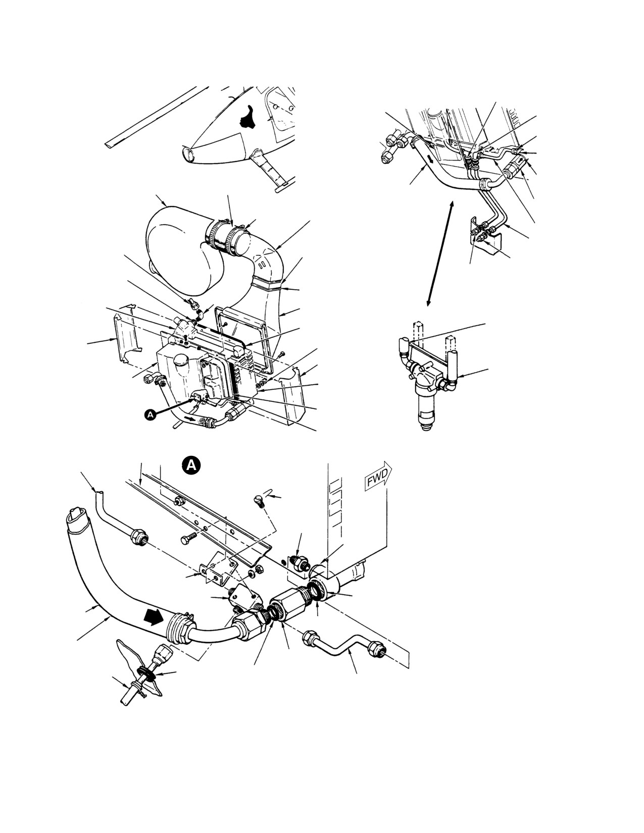
Figure 201. Engine Oil Supply System Schematic Diagram
Page 202
Revision 23
79-00-00
MD Helicopters, Inc.
CSP-HMI-2
MAINTENANCE MANUAL
2. Engine Oil Supply System Fault Isolation
Table 201. Engine Oil Supply System Fault Isolation
Symptom
Probable Trouble
Corrective Action
Low or zero oil pressure.
Oil tank empty.
Top off oil supply tank (Ref. Sec.
12−00−00).
Oil line restriction.
Inspect, clean or replace plumbing.
Restricted oil filter element.
Clean oil filter per Allison Operation
and Maintenance Manual.
Defective sensor or indicator.
Replace sensor and, or indicator.
Oil pressure regulator valve
Adjust regulator per Allison
improperly adjusted.
Operation and Maintenance Manual.
Contaminated oil.
Inspect filter and chip detectors.
Drain and flush oil system. Refill
system (Ref. Sec. 12−00−00).
Sudden oil pressure reduction or
Low oil quantity.
Check oil level and service system
pressure fluctuations.
(Ref. Sec. 12−00−00).
Oil contamination.
Inspect filter and chip detectors.
Drain and flush system. Replace oil
(Ref. Sec. 12−00−00).
Oil leak.
Repair or replace hoses, tubes or
engine components as required.
Defective sensor or indicator.
Replace sensor and, or indicator.
Oil filter or pressure regulator valve
Clean oil filter; adjust pressure
restriction.
regulator valve. Replace valve if oil
pressure can not be adjusted (refer
to applicable Allison Operation and
Maintenance Manual).
Defective oil pump.
Replace oil pump per applicable
Allison Operation and Maintenance
Manual.
High oil pressure.
Defective indicator.
Replace indicator.
Pressure regulator valve out of
Adjust pressure regulator valve per
adjustment.
Allison Operation and Maintenance
Manual.
Abnormally high oil temperature
Defective temperature sensor or
Replace temperature sensor and/or
indication.
indicator.
indicator.
Oil cooler bypass valve stuck closed.
Repair or replace oil cooler.
Oil cooler air passages blocked or
Repair or replace oil cooler.
damaged.
Oil cooler oil passages blocked or
Inspect oil filter and chip detectors.
damaged.
Repair or replace oil cooler.
Oil cooler blower intake air blockage.
Open intake airway.
Oil cooler blower failed or impeller
Repair or replace blower.
damaged.
Page 203
79-00-00
Revision 23

CSP-HMI-2
MD Helicopters, Inc.
MAINTENANCE MANUAL
Table 201. Engine Oil Supply System Fault Isolation
Symptom
Probable Trouble
Corrective Action
Abnormally low oil temperature
Defective temperature sensor or
Replace temperature sensor and/or
indication.
indicator.
indicator.
Oil cooler bypass valve stuck open. Repair or replace oil cooler.
Oil consumption exceeds 6.5 oz. Leakage; loose fittings or
Repair or replace fittings and
(192.21 cc) per hour.
connections.
connections.
Restricted vent lines.
Inspect and clean as necessary.
Defective engine bearing oil seals.
Repair or replace engine.
Chip detector warning light on.
Contaminated oil.
Inspect engine chip detectors per
Allison Operation and Maintenance
Manual.
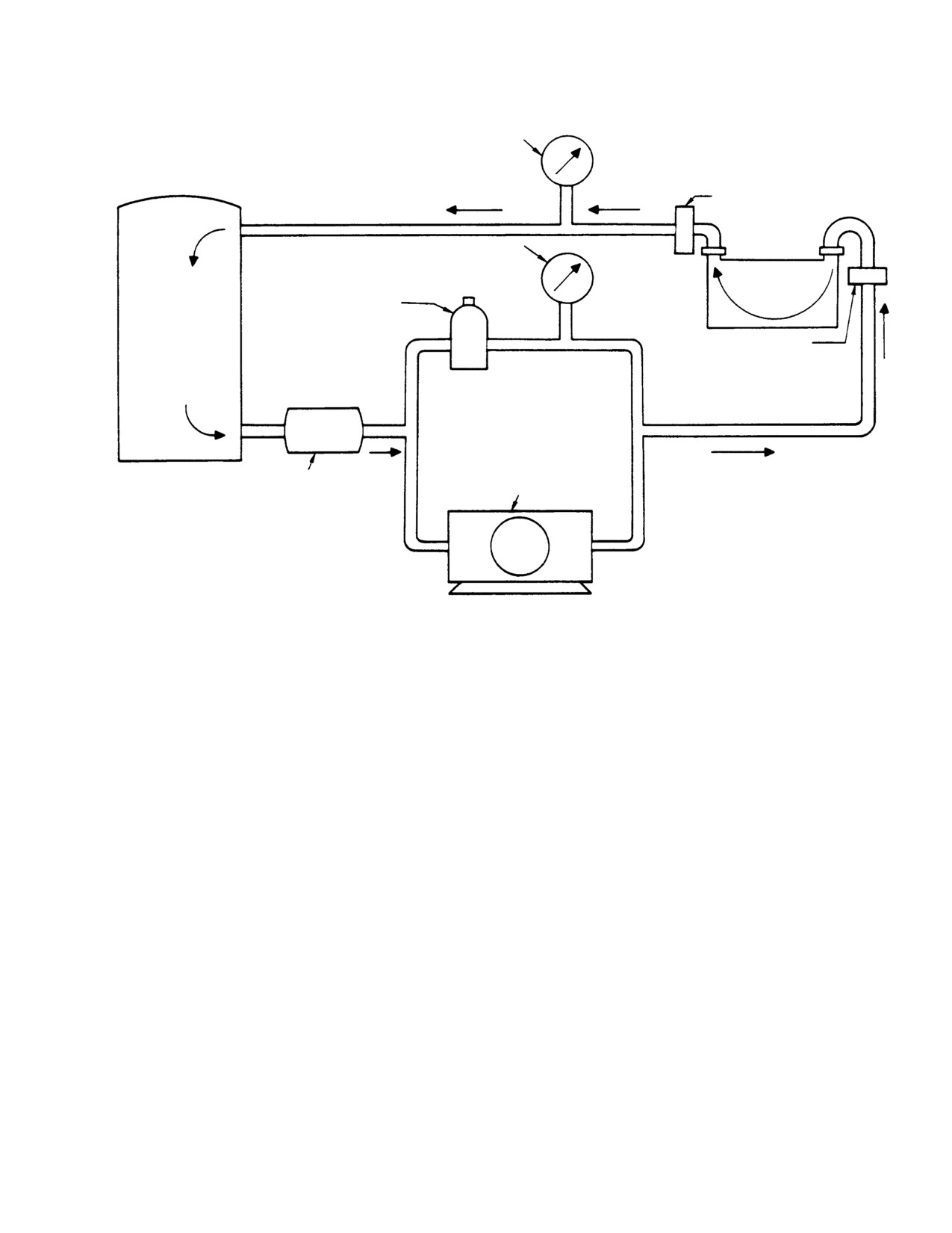
3. Oil Cooler Flushing
(a). Start with solvent (CM234) to flush
oil cooler interior. Initially reverse
(Ref. Figure 202)
solvent flow through cooler by
Connecting hose from pump dis
charge port to oil cooler outlet port.
Consumable Materials
(Ref. Section 91−00−00)
(b). Connect hose from storage tank to
Item
Nomenclature
inlet port of oil cooler.
CM226
Cleaning compound, alkaline waterbase
(c). Start cleaning equipment pump.
CM234
Solvent, dry-cleaning
Flush cooler for 30 minutes, or until
solution appears clean after passing
through unit.
NOTE: Maintain the engine oil cooler per the
following steps. For additional information,
(d). Shut down equipment and drain oil
refer to manufacturer's publications (Ref.
cooler.
Sec. 01-00-00). Where a conflict exists be
tween this manual and manufacturer's pub
NOTE: If metal particles are found, clean
lication, information in this manual super
screens with solvent (CM234) and blow dry
sedes manufactures data.
with clean, dry, filtered, low pressure com
pressed air.
(1). Remove thermostat, elbows, unions and
O-rings. Plug all openings.
(4). Examine filter screens for metal or
other foreign particles after flushing
Use only oil cooler manufactur
the unit per the following steps.
CAUTION
er's recommended cleaning so
lutions or a substitute that is stated as safe
(a). Flush oil cooler with compound
for use on aluminum. Copper or copper nick
(CM226) in direction opposite to
el cleaning compounds or solutions may cor
normal flow for 30 minutes.
rode the oil cooler. Cleaning equipment that
has been used with an unknown material, or
(b). Reverse hoses and flush oil cooler for
a known corrosive cleaning solution must be
10-15 minutes in normal flow
thoroughly flushed with the recommended
direction.
solution prior to use on the oil cooler.
(c). Rinse oil cooler with solvent (CM234)
(2). Steam clean oil cooler exterior surfaces.
for 10 minutes.
(3). Attach oil cooler to flushing setup
(5). Check filter screens. Replace oil cooler
shown. Flush oil cooler as follows:
if additional metal particles are found.
Page 204
Revision 23
79-00-00
MD Helicopters, Inc.
CSP-HMI-2
MAINTENANCE MANUAL
HYDRAULIC PRESSURE GAUGE
100 MESH SCREEN
INLET
HYDRAULIC PRESSURE GAUGE
COOLER
PRESSURE RELIEF VALVE
(SET FOR 75 PSI)
TANK
100 MESH SCREEN
OUTLET
CENTRIFUGAL PUMP
(28 - 56 GPM; 75 PSI
FULL-FLOW FILTER
DISCHARGE PRESSURE)
IN
OUT
G79-0002
Figure 202. Oil Cooler Flush Equipment and Arrangement
4. Oil Tank Replacement
(a). Install vent hose on tank.
(b). Install unions and O-rings on oil
(Ref. Figure 203)
return and supply hoses and tank
A. Oil Tank Removal
drain tube fittings.
(c). Install oil temperature sender and
(1). Drain oil system (Ref. Sec. 12-00-00).
gasket. Torque sender body to 100 -
(a). Remove engine oil cooler duct.
150 inch-pounds (11.30 - 16.95
Nm). Install lockwire. Torque wire
(b). Disconnect hose between tank and
terminal nut to 12 - 25 inch-
vent. Disconnect supply, return and
pounds (1.36 - 2.82 Nm).
tank drain lines from oil tank fit
(d). Install sight plug (Ref. Oil Tank
tings. Allow tank to drain dry.
Sight Plug Replacement).
(c). Disconnect oil temperature sender
(2). Position engine oil tank on Sta. 124.00
wires and remove sender.
firewall and secure with bolts and
washers.
(d). Remove oil filler seal, oil tank cap
retaining plate and oil tank.
(a). Install oil tank filler seal and retain
ing plate. Ensure filler seal fits over
(e). Unfasten and remove oil tank.
oil tank filler neck and is secure with
attaching hardware (Ref. Figure 203,
B. Oil Tank Installation
Detail B).
(1). Assemble tank as follows:
(b). Install oil tank filler seal clamp.
Page 205
79-00-00
Revision 23
CSP-HMI-2
MD Helicopters, Inc.
MAINTENANCE MANUAL
(3). Connect the following oil lines and
(4). Install oil tank (Ref. Oil Tank Replace
torque (Ref. Table 202, Oil System
ment).
Hardware Torque Values).
6. Oil Temperature Sender Replacement
(a). Connect return hose between engine
NOTE: 369A4533-BSC sensor is compatible
and cooler.
with the 369D296305-21, -23 and -31
(b). Connect supply hose between tank
instrument clusters only. 369A4533-3 sen
and engine.
sor is compatible with the 369D296305-33,
-35 and -37 instrument clusters only.
(c). Connect drain tubes to oil tank
fittings.
(1). Switch off and disconnect all electrical
power.
(d). Install O-ring and connect vent hose
(2). Drain oil tank.
between tank and engine.
(3). Disconnect electrical wire from oil
(e). Install oil cooler duct.
temperature sender, break lockwire and
remove sender from oil tank fitting.
5. Oil Tank Sight Plug Replacement
(a). Install oil temperature sender and
(Ref. Figure 203)
gasket. Torque sender body to 100 -
150 inch-pounds (11.30 - 16.95
Consumable Materials
Nm). Install lockwire. Torque wire
(Ref. Section 91−00−00)
terminal nut to 12 - 25 inch-
Item
Nomenclature
pounds (1.36 - 2.82 Nm).
CM125
Oil
(4). Fill oil tank (Ref. Sec. 12-00-00).
CM126
Oil, turbine
(5). Start engine (Ref. Pilot's Flight Manu
al). Check for oil leakage and tempera
A. Oil Tank Sight Plug Removal
ture gauge operation.
(1). Drain oil system.
(6). Install aft bulkhead access cover.
(2). Remove oil tank (Ref. Oil Tank Replace
7. Oil Cooler Replacement
ment).
(Ref. Figure 204)
(3). Break lockwire and remove sight plug.
Consumable Materials
B. Oil Tank Sight Plug Installation
(Ref. Section 91−00−00)
Item
Nomenclature
NOTE: Liquid level decal is applied after plug
is installed and torqued.
CM125
Oil
CM126
Oil, turbine
(1). Install a new O-ring on sight plug.
Coat O-ring and sight plug threads
with clean engine oil (CM125) or
A. Oil Cooler Removal
(CM126). Torque sight plug to 80 - 90
Avoid oil cooler damage. Use a
inch-pounds (9.04 - 10.17 Nm);
CAUTION
backup wrench to support oil
lockwire.
cooler port bosses when unfastening or
(2). Project a pencil line from the oil tank
torquing threaded fittings.
upper mount through the centers of
(1). Drain oil system (Ref. Sec.
nutplate and sight plug (Ref.
12-00-00).
Figure 203, view A).
(a). Remove oil cooler duct.
(3). Install sight plug decal on plug face
with decal water line (WL) marks
(b). Disconnect oil return hose from elbow
aligned with pencil line.
at cooler outlet fitting. Remove elbow.
Page 206
Revision 23
79-00-00
MD Helicopters, Inc.
CSP-HMI-2
MAINTENANCE MANUAL
(c). Remove cooler drain tube. Remove
(g). Install tank return hose elbow in
drain union and O-ring from cooler
cooler outlet port. Connect oil tank
inlet port.
return hose.
(d). Remove check valve.
(h). Install oil cooler duct (Ref. Oil Cooler
Duct Installation).
(e). Disconnect engine power turbine
cooling air duct from oil cooler
(i). Service tank with oil (CM125) or
deflector. Remove deflector from
(CM126) (Ref. Sec. 12-00-00).
cooler mounting flange.
(2). Operate engine per Pilot's Flight
(f). Remove oil cooler.
Manual. Inspect oil system for leaks.
(g). Remove lockwire and separate
8. Oil Tank Return Hose Replacement
shields from cooler, if installed.
B. Oil Cooler Installation
Consumable Materials
(Ref. Section 91−00−00)
Avoid oil cooler damage. Use a
Item
Nomenclature
CAUTION
backup wrench to support oil
CM125
Oil
cooler port bosses when unfastening or
CM126
Oil, turbine
torquing threaded fittings.
(1). Install oil cooler per the following steps.
A. Oil Tank Return Hose Removal
Refer to manufacturer's publications for
additional information as required (Ref.
(1). Remove trim and R/H bulkhead access
Sec. 01-00-00). This information
panel.
supersedes cooler manufacturer's data
wherever conflicting information exists.
(2). Drain oil supply system.
(a). On Harrison coolers only, position
Avoid oil cooler damage. Use a
shields on sides of oil cooler so that
CAUTION
backup wrench on oil cooler port
outboard shield without tab is
boss when removing or installing oil line fit
adjacent to oil inlet port. Secure
tings.
shields with one lockwire wrap
around cooler.
(3). Disconnect hose from oil cooler OUT
port elbow.
(b). Position oil cooler on firewall and
secure with attaching hardware.
(4). Remove oil cooler OUT port elbow.
(c). Position deflector on cooler mounting
(5). Disconnect hose from oil tank IN port
flange and secure with screws and
union. Remove union.
washers. Connect engine power
turbine cooling duct to oil cooler
B. Oil Tank Return Hose Installation
deflector.
(1). Lubricate male threads with clean
(d). Coat check valve threads with oil
engine oil (CM125) or (CM126) prior to
(CM125) or (CM126); Install check
installation. Thread hose straight end
valve.
fitting into oil tank. Attach opposite end
to oil cooler.
NOTE: Torque all oil cooler hardware per Oil
System Hardware Torque Values (Ref.
(2). Torque hose ends per Oil System
Table 202).
Hardware Torque Values (Ref.
Table 202).
(e). Install union and O-ring in cooler
drain port.
(3). Install bulkhead panel and trim.
(f). Connect cooler drain tube.
(4). Enter compliance in helicopter records.
Page 207
79-00-00
Revision 23
CSP-HMI-2
MD Helicopters, Inc.
MAINTENANCE MANUAL
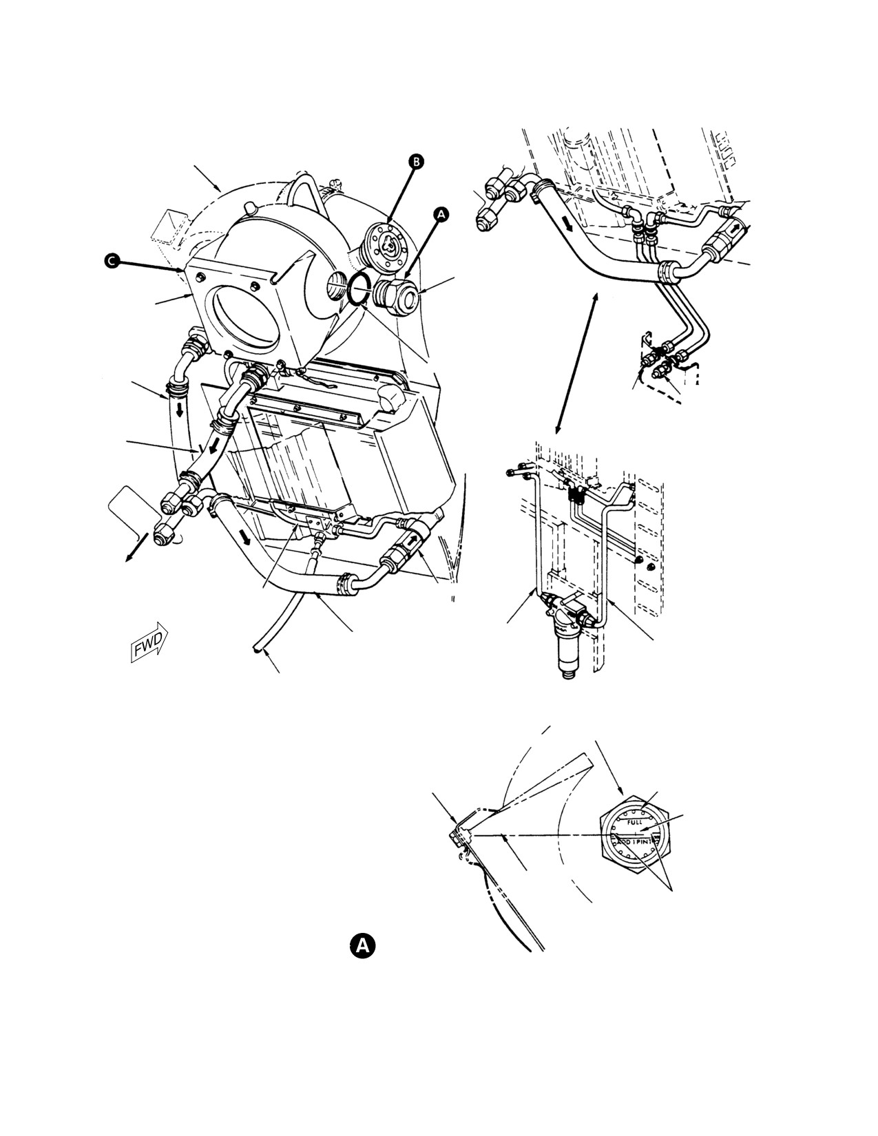
OIL COOLER
BLOWER
SIGHT PLUG
OIL TANK
O-RING
TANK-TO-ENGINE
VENT HOSE
OIL TANK
OIL COOLER
DRAIN
DRAIN
TANK-TO-ENGINE
CURRENT CONFIGURATION
OIL HOSE
TO ENGINE
CHECK VALVE
DRAIN TUBE
ENGINE-TO-FILTER
ENGINE-TO-COOLER
HOSE
FILTER-TO-COOLER
HOSE
OIL HOSE
OVERBOARD
DRAIN TUBE
SCAVENGE OIL FILTER INSTALLATION
(NOTE 1)
EARLY CONFIGURATION
SIGHT PLUG
UPPER MOUNT
DECAL
NUTPLATE
WL 48.63
NOTES:
(NOTE 1)
1.
WL - WATERLINE.
2.
APPLICABLE TO ALL
ALLISON 250-C20R/2 ENGINES.
OPTIONAL EQUIPMENT FOR ALLISON
PROJECTED LINE
250-C20B AND 250-C30 ENGINES.
WL LOCATOR
MARKS
SIGHT PLUG ALIGNMENT
(LOOKING INBOARD)
G79-0003-1
Figure 203. Engine Oil Supply System (Sheet 1 of 2)
Page 208
Revision 23
79-00-00
MD Helicopters, Inc.
CSP-HMI-2
MAINTENANCE MANUAL
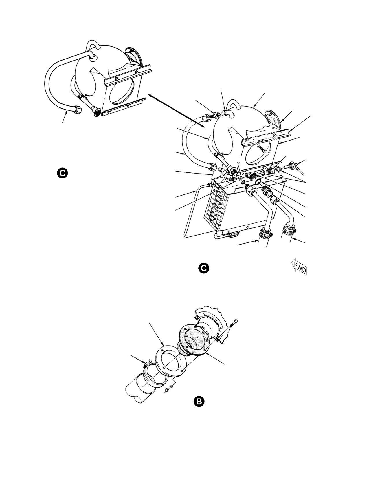
OIL TANK OUTLET
FITTING
OIL TANK
UNION
FILLER
STA. 124.00
FIREWALL
OIL TANK
TANK VENT HOSE
RETURN TUBE
OIL TANK SUPPORT
OIL TANK
BUSHING
RETURN HOSE
OIL TEMPERATURE
O-RING
SENSOR (NOTE 1)
OIL TANK
ENGINE OIL
(ALLISON 250-C20R/2 ENGINE)
COOLER DUCT
WASHER
OIL TANK
TANK DRAIN TUBE
INLET PORT
O-RING
UNION
UNION
TANK-TO-ENGINE
TANK-TO-ENGINE
OIL HOSE
VENT HOSE
OIL TANK INSTALLATION
(ALLISON 250-C20B ENGINE)
CAP RETAINING PLATE
CLAMP
FILLER SEAL
OIL TANK FILLER SEAL
INSTALLATION
G79-0003-2
Figure 203. Engine Oil Supply System (Sheet 2 of 2)
Page 209
79-00-00
Revision 23

CSP-HMI-2
MD Helicopters, Inc.
MAINTENANCE MANUAL
9. Oil Supply Lines and Fittings
(3). Remove attaching hardware from
Replacement
diffuser. Lift diffuser to separate from
cooler flange. Retain spacers.
(Ref. Figure 203)
B. Oil Cooler Duct Installation
Consumable Materials
Over tightening bolts can crack
(Ref. Section 91−00−00)
CAUTION
duct flange.
Item
Nomenclature
(1). Align diffuser on oil cooler flange with
CM125
Oil
spacers and gasket. Secure with
CM126
Oil, turbine
attaching hardware.
(a). Place lower connector on cooler duct
(1). Drain system before removing oil lines.
elbow, then slide connector over
diffuser. Secure lower connector to
NOTE:
cooler duct elbow and diffuser with
D Lubricate all fitting threads with oil
tie-straps.
(CM125) or (CM126) prior to installation.
(b). Place upper connector on cooler duct
D Torque hardware per Oil System Hard
elbow, then install elbow over oil
ware Torque Values (Ref. Table 202).
cooler blower scroll. Slide upper
Avoid oil system damage. Use a
connector over scroll; secure with
CAUTION
backup wrench to support
clamps.
bosses, fittings and subassemblies when un
fastening or torquing all threaded compo
11. Oil Tank Inspection
nents.
(1). Check oil tank for obvious damage,
(2). Install oil lines and fittings.
corrosion, evidence of leakage and
security.
10. Oil Cooler Duct Replacement
(2). Repair or replace oil tank as required.
(Ref. Figure 203)
12. Oil Cooler Inspection
A. Oil Cooler Duct Removal
(1). Inspect engine oil cooler for cracks,
(1). Remove clamps and separate cooler
corrosion, damaged or bulged plates,
duct elbow from oil cooler blower.
broken welds, clogged airways, oil leaks
Remove upper connector.
and security. Inspect all hoses and
fittings for oil leaks and security.
(2). Remove tie straps and separate cooler
duct elbow from diffuser. Remove lower
(2). Repair or replace oil cooler and compo
connector.
nents as required.
Table 202. Oil System Hardware Torque Values
Item
Torque
1/4 inch (6.35 mm) OD tube nuts
40 − 65 inch−pounds
(4.52 − 7.34 Nm)
5/16 inch (7.94 mm) OD tube nuts
60 − 80 inch−pounds
(6.78 − 9.04 Nm)
1/2 inch (12.70 mm) OD tube nuts
150 − 200 inch−pounds
(16.95 − 22.60 Nm)
1/4 inch (6.35 mm) OD hose nuts
70 − 120 inch−pounds
(7.91 − 13.56 Nm)
5/16 inch (7.94 mm) OD hose nuts
85 − 180 inch−pounds
(9.60 − 20.34 Nm)
1/2 inch (12.70 mm) OD hose nuts
210 − 420 inch−pounds
(23.73 − 47.45 Nm)
Page 210
Revision 23
79-00-00
MD Helicopters, Inc.
CSP-HMI-2
MAINTENANCE MANUAL
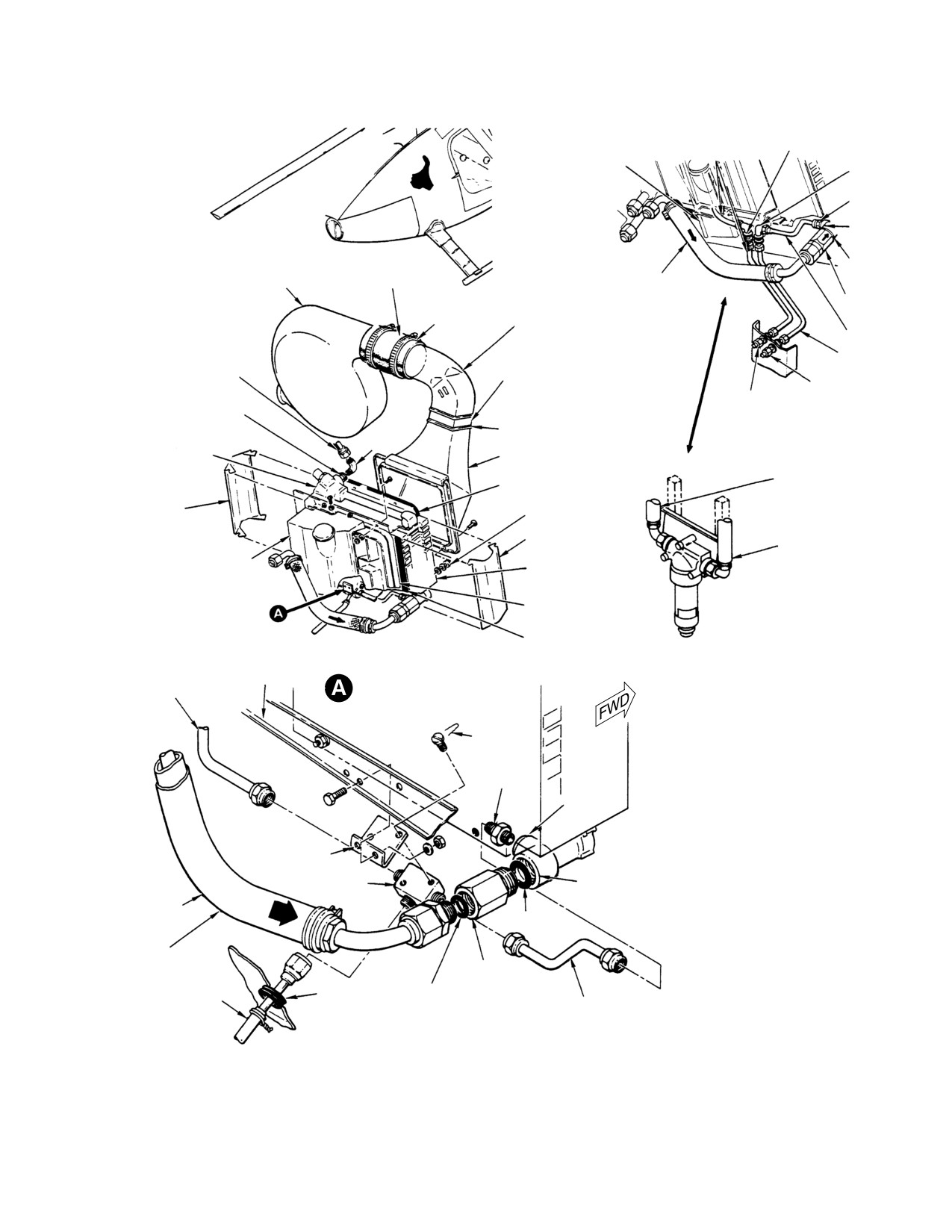
TANK DRAIN
BULKHEAD
TUBE
FIREWALL
ELBOW
UNION
DRAIN
PORT
UPPER
INLET
OIL COOLER BLOWER
CONNECTOR
ENGINE-TO-COOLER
PORT
OIL HOSE
CHECK
CLAMP (2)
VALVE
COLLER DUCT
ELBOW
COOLER
DRAIN
OIL TANK
TUBE
LOWER CONNECTOR
RETURN HOSE
ENGINE OIL
ENGINE OIL
COOLER DRAIN
COOLER OUTLET
TANK DRAIN
PORT
TIE STRAP (2)
CURRENT CONFIGURATION
THERMOSTATIC
DIFFUSER
VALVE
ENGINE-TO-FILTER
GASKET
OIL HOSE
SHIELD
SPACER
SHIELD
FILTER-TO-COOLER
OIL HOSE
DEFLECTOR
ENGINE OIL
COOLER
FIREWALL
SCAVENGE OIL FILTER
(NOTE)
GASKET
EARLY CONFIGURATION
STA. 124.00
TANK DRAIN
COOLER INLET AND
TUBE
DRAIN CONNECTIONS
CAUTION:
AT REMOVAL OR INSTALLATION OF CHECK
LOCKWIRE
VALVE OR HOSE, FLATS ON PORT SHOULD
BE HELD TO PREVENT DEFORMATION OF
COOLER FRAME.
UNION
NOTE:
DRAIN
APPLICABLE TO ALL ALLISON 250-C20R/2
PORT
ENGINES. OPTIONAL EQUIPMENT FOR
ALLISON 250-C20B AND C30 ENGINES.
BRACKET
INLET PORT
DRAIN VALVE
(SEE CAUTION)
FILTER-TO-
COOLER OIL
O-RING
HOSE (NOTE)
ENGINE-TO-COOLER
OIL HOSE
CHECK VALVE
GROMMET
O-RING
DRAIN HOSE
COOLER DRAIN VALVE
EARLY CONFIGURATION
G79-0004
Figure 204. Engine Oil Cooler Installation
Page 211
79-00-00
Revision 23
CSP-HMI-2
MD Helicopters, Inc.
MAINTENANCE MANUAL
13. One Time Mandatory Hose Inspection
(1). Remove sight plug, oil temperature
(369D Serial Numbers 0003D thru 0374D,
sender, unions and hoses.
Only)
(2). Flush tank with solvent (CM234).
(1). Remove trim and aft R/H bulkhead
access panel.
(3). Oxy-acetylene weld all cracks, loose
fittings, open seams, and tubes with
(2). Locate return hose between oil cooler
welding rod (CM825).
and tank. Check part number. Part
number 369D28309 hose must be
(4). Blend scratches and nicks with fine grit
replaced with a part number
aluminum oxide abrasive cloth
369D28311-3 hose assembly per
(CM802).
instructions in `Removal and Installa
tion'.
(5). Touch up reworked surfaces with
chemical film (CM206).
14. Oil Lines and Fittings Inspection
(6). Install sight plug, oil temperature
(1). Inspect tubes and hoses for uniform
sender, unions and hoses.
diameter, interference with adjoining
structure and the following:
16. Oil Cooler Repair
(a). Inspect tubes for kinks or dents
which could obstruct oil flow. Dents
Consumable Materials
may not exceed 0.015 inch (0.381
(Ref. Section 91−00−00)
mm) deep.
Item
Nomenclature
CM206
Chemical coating
(b). Look for cracks. No tubing cracks are
allowed.
CM802
Abrasive cloth, aluminum oxide
CM825
Welding rod
(c). Inspect coupling nut threads for
Cross-thread damage. No thread
damage allowed.
(1). Replace a defective thermostatic valve.
(d). Inspect tubing for chafe damage in
(2). Straighten bent cooling fins with a pair
excess of 0.010 inch (0.254 mm) deep.
of duckbill pliers ground to fit between
No chafe damage allowed on or near
cooling tubes.
flared tubing end.
(3). Weld all small holes, cracked seams or
(e). Look for nicks in excess of 0.010 inch
loose fittings with welding rod (CM825).
(0.254 mm) depth.
(4). Smooth scratches and nicks with fine
(f). Replace any tubes exceeding damage
grit aluminum oxide abrasive cloth
limits.
(CM802). Touch up surface with
chemical film (CM206).
15. Oil Tank Repair
17. Oil Cooler Duct Repair
Consumable Materials
(Ref. Section 91−00−00)
NOTE: Repairs must not restrict airflow, pre
Item
Nomenclature
vent proper mating or interfere with instal
lation.
CM206
Chemical coating
CM234
Solvent, dry-cleaning
(1). Repair cooler duct per standard
CM802
Abrasive cloth, aluminum oxide
fiberglass repair procedures in the
CM825
Welding rod
structural repair manual (CSP-
SRM-6).
Page 212
Revision 23
79-00-00
MD Helicopters, Inc.
CSP-HMI-2
MAINTENANCE MANUAL
Section
79−10−10
Airframe−Mounted
Engine Scavenge Oil
Filter (369D/E/FF −
500N)
MD Helicopters, Inc.
CSP-HMI-2
MAINTENANCE MANUAL
AIRFRAME−MOUNTED ENGINE SCAVENGE OIL FILTER
MAINTENANCE PRACTICES
1.
Description and Operation
(7). Install a new oil filter element.
(1). The optional scavenge oil filter is
3. Scavenge Oil Filter Element Replacement
installed in the return line between the
(Ref. Figure 201)
engine and oil cooler. The scavenge
filter supplements the engine oil filter
and provides the capacity to keep the
Consumable Materials
oil clean enough to operate extended
(Ref. Section 91−00−00)
hours (Ref. applicable Rolls-Royce
Item
Nomenclature
Maintenance Manual, Sec. 72-00-00,
CM701
Lockwire CRES
Table 602) between changes.
(2). The 10 micron filter element keeps
(1). Open engine access doors.
otherwise recirculated microscopic
(2). Break lockwire and remove bowl and
carbon and metal particles from
filter element. Inspect element, bowl
accumulating in the cooler, supply tank,
seal and inside of bowl. Clean bowl as
engine or on magnetic plugs.
required. Replace seal as required.
(3). The filter body is equipped with a
(3). Install a new filter element.
bypass valve and red impending bypass
warning indicator that extends when
(4). Hand tighten bowl snug into filter body.
differential pressure across the filter
Lockwire (CM701) bowl.
element reaches 6-8 psid (41-55 kPa).
(5). Motor engine until oil pressure is
The indicator is inoperative until the oil
indicated. Check oil quantity and top off
temperature exceeds 85-115°F
oil tank as required.
(30-46°C). The filter bypass valve opens
at 9-11 psid (62-76 kPa).
(6). Start and operate engine at idle for five
minutes per Pilot's Flight Manual. Shut
2.
Scavenge Oil Filter Check
down engine and check for oil leaks.
(Ref. Figure 201)
(7). Enter filter element change in helicop
ter records.
(1). Open engine access doors.
4. Scavenge Oil Filter Bypass Indicator Test
(2). Inspect red bypass indicator button on
bottom of filter bowl. Button extension
(Ref. Figure 201)
indicates a filter element impending
bypass condition.
Consumable Materials
(Ref. Section 91−00−00)
(3). Press and turn indicator button 90° to
Item
Nomenclature
reset.
CM701
Lockwire CRES
(4). Operate engine per Pilot's Flight
Manual until engine oil reaches normal
Special Tools
operating temperature.
(Ref. Section 91−00−00)
Item
Nomenclature
(5). Shut down engine. Check indicator
ST408
Test tool
button.
(6). If button has reappeared, investigate
(1). Open engine access doors.
cause of filter bypass condition per the
applicable Rolls-Royce Operation and
(2). Break lockwire and remove filter bowl
Maintenance Manual.
and element. Inspect element and
Page 201
79-10-10
Revision 44
CSP-HMI-2
MD Helicopters, Inc.
MAINTENANCE MANUAL
inside of bowl per the applicable
will not reset, contact Facet Enter
Rolls-Royce Operation and Mainte
prises, Inc., or your authorized Facet
nance Manual.
distributor (Ref. Sec. 01-00-00).
(3). Install Facet test tool (ST408) and
NOTE: The bypass indicator is functioning
reinstall bowl without lockwire.
properly if it extends.
NOTE: Bypass indicator remains inoperative
until oil temperature exceeds 85-115°F
(6). Shut down engine per Pilot's Flight
(30-46°C).
Manual. Remove filter bowl and test
tool. Clean filter bowl as required.
(4). Operate engine per Pilot's Flight
Manual until engine oil reaches normal
operating temperature and filter bypass
(7). Install a new seal kit and filter ele
indicator extends (about 10 minutes).
ment. Hand tighten bowl snug into
filter body. Lockwire (CM701) bowl.
Bypass indicator and bowl are
CAUTION
matched assemblies and factory
(8). Press and turn indicator button 90° to
set. Do not attempt to adjust or replace by
reset.
pass indicator assembly.
(5). If bypass indicator fails to extend or
(9). Drain and service engine oil system.
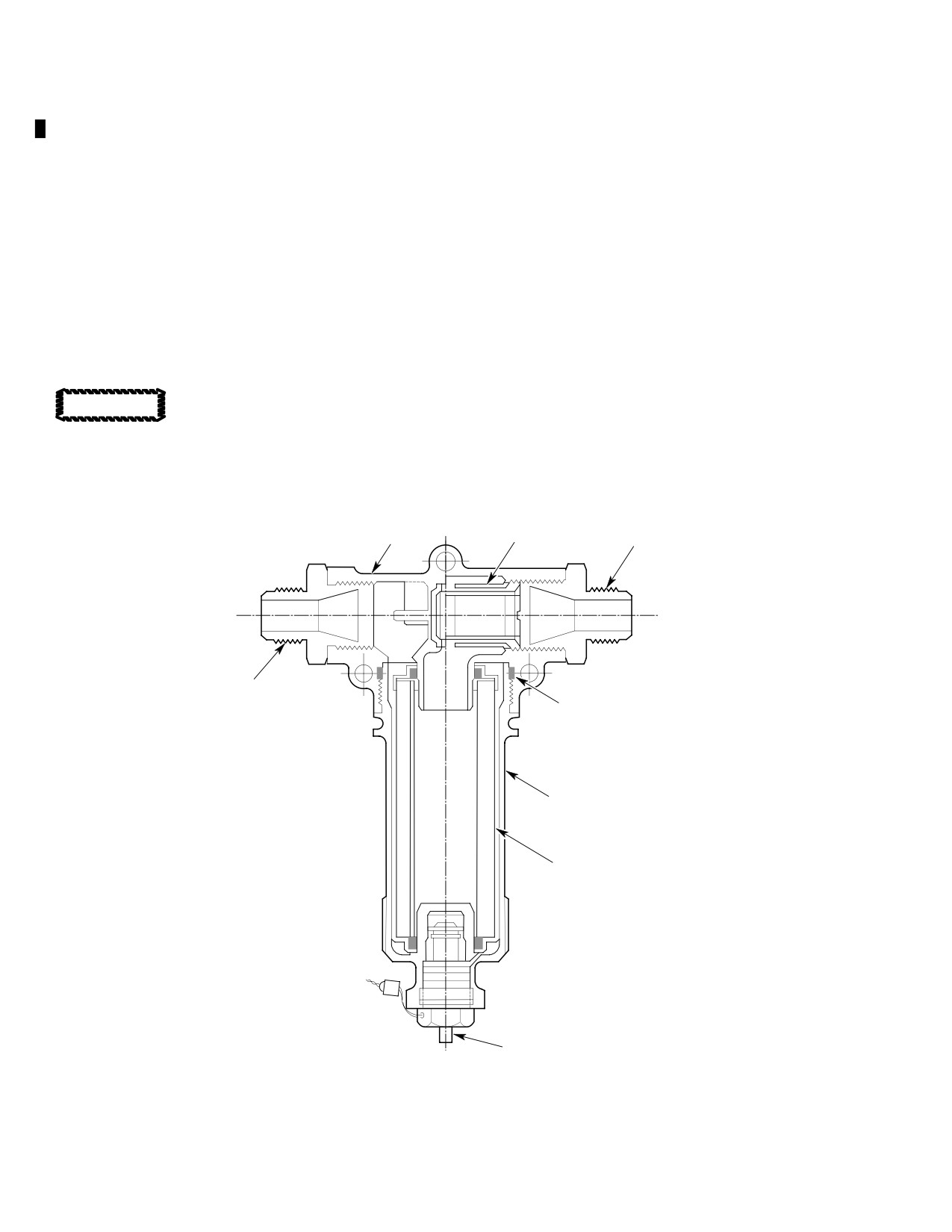
HEAD ASSY
SCREEN
REDUCER
REDUCER
SEAL
BOWL ASSY
FILTER ELEMENT
BYPASS INDICATOR
G79-1001
Figure 201. Facet Scavenge Oil Filter Assembly
Page 202
Revision 44
79-10-10

MD Helicopters, Inc.
CSP-HMI-2
MAINTENANCE MANUAL
AIRFRAME−MOUNTED ENGINE SCAVENGE OIL FILTER
INITIAL INSTALLATION
1. Scavenge Oil Filter Initial Installation
(9). Locate two vertical stiffeners located on
RBL 8.500 and RBL 15.250.
(Ref. Figure 901)
(10). Locate flanged horizontal stiffener on
WL 24.750. Stiffener is installed across
Consumable Materials
helicopter centerline between left and
(Ref. Section 91−00−00)
right BL 8.500 vertical stiffeners.
Item
Nomenclature
Avoid fatigue concentrations.
CM219
Methyl-ethyl-ketone
CAUTION
Do not scratch, score or gouge
CM318
Primer
firewall when removing insulation.
CM721
Tape, aluminum foil
(11). Remove insulation between RBL 8.500
and RBL 15.250 vertical stiffeners
Prevent installation errors and
beginning at WL 24.750 and down
CAUTION
equipment damage. Study in
about 6 inches (15.24 cm). Retain
stallation instructions before beginning
insulation.
work. Contact Facet Enterprises, Inc. for ad
Do not position mounting brack
ditional information (Ref. Sec. 01-00-00).
CAUTION
ets and filter lower than the
hoses will reach. Install filter so that line
(1). Disconnect external electric power. Set
connections can be made without straining
all switches OFF. Disconnect battery.
hoses.
(2). Open engine access doors.
(12). Locate and clamp LH mounting bracket
within 0.1250-0.3125 inch
(3). Drain engine oil tank, lines and cooler
(3.1750-7.9375 mm) of WL 24.75
(Ref. Sec. 12-00-00).
horizontal stiffener with bracket flange
facing inboard.
(4). Disconnect electrical plug from engine
gear case chip detector. Remove chip
(13). Locate and clamp RH mounting bracket
detector from gear case. Bag parts for
level with LH bracket and flange facing
reinstallation.
inboard.
(5). Disconnect scavenge oil line from gear
(14). Locate and clamp filter mounting plate
case OUT port union (Ref. Sec.
to brackets with plate flanges facing aft
79-00-00). Remove and discard union.
and triangular hole pattern pointing
up.
Avoid oil cooler damage. Use a
CAUTION
(15). Position filter on its mounting plate and
backup wrench on oil cooler port
loosely install spacers, bolts, washers
boss when removing or installing oil line fit
and nuts.
tings.
(16). Install O-ring on engine oil OUT port
(6). Disconnect scavenge oil hose from oil
reducer. Install and torque reducer per
cooler IN port check valve union.
requirements of the applicable Allison
Remove union from oil cooler check
Operation and Maintenance Manual.
valve. Discard union and hose.
Prevent oil cooler damage. Use a
(7). Unclamp wire bundle on BL 15.250
CAUTION
backup wrench on oil cooler
vertical stiffener. Bag clamp hardware
check valve while torquing reducer.
for reuse.
(17). Install O-ring on oil cooler IN port
(8). Locate airframe centerline on firewall
reducer. Relieve lightening hole for
bulkhead in engine compartment.
additional clearance as required. Install
Page 901
79-10-10
Revision 23
CSP-HMI-2
MD Helicopters, Inc.
MAINTENANCE MANUAL
reducer in oil cooler check valve and
(28). Install chip detector and torque to 60 -
torque to 280 - 305 inch-pounds
80 inch-pounds (6.78 - 9.04 Nm).
(31.64 - 34.46 Nm).
(29). Attach chip detector electrical connector
(18). Loosely install hose between engine
to chip detector.
gear case OUT port and filter IN port
(30). Select a location for filter bypass
with 90° hose fitting attached to filter.
indicator reset label in plain view on
upper LH corner of RH engine access
(19). Loosely install hose between filter OUT
door. Activate label adhesive with MEK
port and oil cooler IN check valve with
(CM219).
90° fitting attached to filter.
NOTE: Reposition brackets and filter as re
2. Post Installation Inspection
quired to relieve any strain on hoses before
It is possible to install the fil
drilling mounting bracket holes through
WARNING
ter with its IN and OUT
stiffeners. Relocate and drill three new filter
ports reversed. This condition renders
mounting bracket bolt holes when addition
both the impending bypass indicator
al hose strain relief is required.
and filter bypass valve inoperative.
Subsequent clogging of the outlet port
(20). Unclamp and move filter and mounting
screen will not provide any visual indi
plate assembly out of the way.
cation. If allowed to continue, the oil
Avoid fatigue concentrations.
flow reduction could have a disastrous
CAUTION
Do not scratch, score or gouge
effect on the engine and oil system
firewall while drilling stiffeners.
components.
(1). Ensure that the engine gear case oil
(21). Ensure bracket upper edges are lined
OUT port hose is connected to the
up and level. Drill three 0.189 inch
scavenge oil filter IN port. Ensure that
(4.8006 mm) diameter bolt holes
the filter OUT port hose is connected to
through left and right brackets and
the oil cooler IN port.
airframe stiffeners.
(2). Check for adequate hose clearances
(22). Unclamp brackets and deburr holes.
near structure and engine.
Coat holes with primer (CM318).
(3). Inspect attaching hardware for security
(23). Install brackets with bolts, washers and
and line connections for correct torque
nuts. Install wire harness clamp under
values.
upper right bolt.
(4). Service engine oil system (Ref. Sec.
(24). Attach insulation to firewall with
12-00-00).
aluminum foil tape (CM721).
(5). Connect battery.
(25). Torque three filter mounting nuts to 50
- 55 inch-pounds (5.65 - 6.21 Nm).
(6). Pick up tools and debris before closing
engine access doors.
(26). Attach filter mounting plate to airframe
brackets with bolts, washers and nuts.
(7). Operate engine per Pilot's Flight
Manual and inspect installation for oil
(27). Torque hose nuts to 280 - 305 inch-
leaks prior to releasing helicopter for
pounds (31.64 - 34.46 Nm).
flight.
Page 902
Revision 23
79-10-10
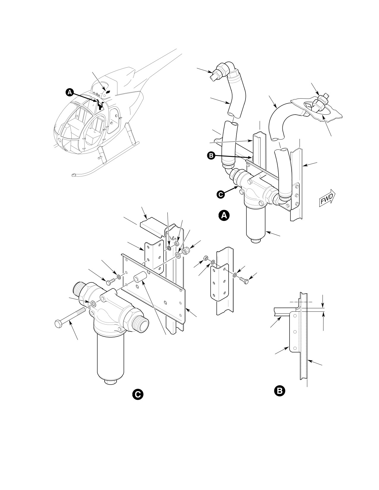
MD Helicopters, Inc.
CSP-HMI-2
MAINTENANCE MANUAL
INDICATOR RESET
LABEL
REDUCER
REDUCER
HOSE
HOSE ASSY
RBL
8.50
STA. 124.00
RBL
15.25
LIGHTENING
STIFFENER
HOLE
STIFFENER
STIFFENER
WASHER
WL 24.75
NUT
WASHER
NUT
FILTER ASSY
BRACKET
WASHER
WASHER
BOLT
NUT
BOLT
WASHER
0.125-0.3125 IN.
(3.1750-7.9375 MM)
GAP
WASHER
WL 24.75
BRACKET
STIFFENER
SPACER
BOLT
BRACKET
STIFFENER
FILTER ASSY
RBL
8.50
G79-1000A
Figure 901. Scavenge Oil Filter Installation
Page 903
79-10-10
Revision 23
CSP-HMI-2
MD Helicopters, Inc.
MAINTENANCE MANUAL
This Page Intentionally Left Blank
Page 904
Revision 44
79-10-10

MD Helicopters, Inc.
CSP-HMI-2
MAINTENANCE MANUAL
Chapter
91
Charts
MD Helicopters, Inc.
CSP−HMI−2
MAINTENANCE MANUAL
TABLE OF CONTENTS
Para/Figure/Table
Title
Page
91-00-00 Charts
A
Consumable Materials and Special Tools
1
1. General
1
2. Consumable Materials
1
3. Special Tools
1
4. Manufacturer/Supplier Number
1
Table 1. Consumable Materials
2
Table 2. Manufacturer/Supplier Number
11
Table 3. Special Tools
15
Table 4. Tool Manufacturer/Supplier Number
21
Page i
91 Contents
Revision 43
CSP−HMI−2
MD Helicopters, Inc.
MAINTENANCE MANUAL
TABLE OF CONTENTS (Cont.)
Para/Figure/Table
Title
Page
This Page Intentionally Left Blank
Page ii
Revision 43
91 Contents
MD Helicopters, Inc.
CSP-HMI-2
MAINTENANCE MANUAL
Section
91−00−00
Charts
CSP-HMI-2
MD Helicopters, Inc.
MAINTENANCE MANUAL
This Page Intentionally Left Blank
MD Helicopters, Inc.
CSP-HMI-2
MAINTENANCE MANUAL
CHARTS
CONSUMABLE MATERIALS AND SPECIAL TOOLS
1. General
D CM601 - Rubber Material
This chapter provides a table of Consumable
D CM701 - Lockwire, Fasteners and Tape
Materials and a table of Special Tools used on
the 500/600N Series Helicopter.
D CM801 - Miscellaneous Materials
The information in each table is divided into
3. Special Tools
groups. Within each group, materials or tools
Table 3 identifies special tools, necessary for
are identified by a number. Numbers have a
maintenance operations.
prefix of CM identifying a consumable
material, or a ST identifying a special tool. CM
Each tool is assigned an ST number, with an
and ST numbers are used throughout the
associated part number, descriptive title and
maintenance manual, allowing quick reference
function.
for Consumable Materials and Special Tools.
4. Manufacturer/Supplier Number
2. Consumable Materials
Table 2 lists Manufacturer/Supplier (Vendor)
Table 1 lists Consumable Materials, such as
Number with address. Table 2 is used with
fuels and oils used to support repair or
Table 1, Consumable Materials.
servicing procedures.
Table 4 lists Tool Manufacturer/Supplier
Consumable materials are assigned a CM
(Vendor) Number with address. Table 4 is used
number, with associated material name,
with Table 3, Special Tools.
specification number and commercial name.
D ST101 - Ground Handling
The following consumable materials are
approved for use on the 500/600N Series. Do
D ST201 - Jacking and Leveling
not use replacement materials unless equal in
quality and grade. Refer to notes at the end of
D ST301 - Main Transmission
Table 1.
D ST401 - Engine
For additional servicing information, such as
capacities Refer to Section 12-00-00.
D ST501 - Flight Controls
D CM101 - Lubricants
D ST601 - Anti-Torque
D CM201 - Solvents, Cleaners and Corrosion
D ST701 - Main Rotor
Preventative Compounds
D ST801 - Fuel
D CM301 - Paints, Primers and Coating
Compounds
D ST901 - Track and Balance
D CM401 - Adhesives, Cements and Sealants
D ST1001 - Electrical/Instrument/Avionic
D CM501 - Composite Materials
D ST2001 - Miscellaneous
Page 1
91-00-00
Revision 23
CSP-HMI-2
MD Helicopters, Inc.
MAINTENANCE MANUAL
Table 1. Consumable Materials
Item
Specification No. (1)
Vendor
No.
Material
Type Class Grade
Commercial Name/No. (2)
(Table 2)
Lubricants
CM101
Solid film lubricant
MIL-L-46010
(3)
CM102
Solid film lubricant
MIL-L-46010A
Ecoalube No. 642
MS27
CM103
Solid film lubricant
MIL-L-8937
Lubribond A
MS25
MIL-L-23398
Molyspray Type PT-101
MS63
HMS 4-1078 1
CM104
Lubricant, spray
Tri-Flow
MS37
Break-Free
MS43
CM105
Lubricant, spray
Moly-Dee
MS9
CM106
Fluorocarbon dry lubricant
S-122
MS53
CM107
Fluorocarbon release agent (dry
6611N
MS24
film lubricant)
CM108
Graphite, powdered
(3)
CM109
Molybdenum disulfide powder
MIL-L-7866
(3)
lubricant
CM110
Grease
GD568-S
MS35
CM111
Grease, aircraft
MIL-G-81322
Mobil Grease 28
MS54
Aero Shell 22
MS73
Braycote 622
MS13
CM112
Anti-seize compound high tem
MIL-PRF-907E
(3)
perature
CM113
Anti-seize compound low tem
MIL-T-5544
Thread Lube
MS59
perature
CM114
Petrolatum (petrolatum jelly)
MIL-G-6032
MS22
VV-P-236
MS70
MS81
CM115
Grease, oscillating bearing
MIL-G-25537
Aero Shell 14
MS73
MIL-A-8623
A-1177-B
MS12
CM116
Grease, aircraft and instrument
MIL-G-23827
Braycoat 627
MS13
Exxon 5114EP
MS28
Aero Shell 7
MS73
CM117
Grease
MIL-G-23872
(3)
CM118
Grease
930A
MS47
CM119
Grease
130A
MS47
CM120
Oil, corrosion preventive
Steelgard 1301
MS36
CM121
Preservation oil (general pur
VV-L-800
MS13
pose)
CM122
Preservative oil, hydraulic
MIL-H-6083
(3)
CM123
Hydraulic fluid
MIL-H-5606
(3)
CM124
Kerosene
VV-K-211
(3)
Page 2
TR12-001
91-00-00
MD Helicopters, Inc.
CSP-HMI-2
MAINTENANCE MANUAL
Table 1. Consumable Materials (Cont.)
Item
Specification No. (1)
Vendor
No.
Material
Type Class Grade
Commercial Name/No. (2)
(Table 2)
CM125
Oil (4) (7)
Pre-SB369D-209,
MS54
SB369E-104,
SB369F-090,
SB500N-045,
SB600N-053:
Mobil SHC 626 (6)
Post-SB369D-209,
SB369E-104,
SB369F-090,
SB500N-045,
SB600N-053:
Mobil AGL (6)
CM126
Oil, turbine (4) (5)
MIL-L (PRF)-23699
(3)
CM127
Grease, YSAS Actuator
168043
MS90
Solvents, Cleaners and Corrosion Preventative Compounds
CM201
Protective coating
MIL-C (PRF)-6799
(3)
1
CM202
Metal protector, aerosol
Molykote
MS22
CM203
Potting compound
MIL-S (PRF)-8516G
MS77
CM204
Compound, corrosion preventa
MIL-C (PRF)-16173E
Braycote
MS10
tive
3
MS13
4
MS88
CM205
Dielectric compound
DC-4
MS22
CM206
Chemical coating
MIL-C-5541
Iridite 14-2
MS67
Al-Coat
MS85
Alodine 1201
CM207
Chromic acid solution (pH 2.6 to
Dow #19 or equivalent
MS22
3.4, magnesium touchup)
CM208
Barrier material (grease-proof)
MIL-B (PRF)-121G
(3)
1
2
A
MIL-B (PRF)-131L
1
CM209
Putty, general purpose
MIL-P (PRF)-8116
Compound 3998
MS32
CM210
Corrosive preventive (aircraft
MIL-C (PRF)-8188
(3)
gas turbine, synthetic base)
CM211
Solvent
3339
MS82
CM212
Releasing agent
TC7-527
MS26
CM213
Releasing agent
225
MS64
CM214
Releasing agent
MIL-P (PRF)-23377
MS14
HMS 20-1245
MS17
CM215
Parting agent
Slip-Spray
MS24
Fre-Kote 33
MS31
Page 3
91-00-00
TR12-001
CSP-HMI-2
MD Helicopters, Inc.
MAINTENANCE MANUAL
Table 1. Consumable Materials (Cont.)
Item
Specification No. (1)
Vendor
No.
Material
Type Class Grade
Commercial Name/No. (2)
(Table 2)
CM216
Loctite remover (for disas
Oakite 156
MS17
sembled parts)
MS57
MS74
CM217
Isopropyl alcohol
TT-I-735
(3)
CM218
Alcohol, denatured
O-E-760
(3)
1
CM219
Methyl-ethyl-ketone
TT-M-261
(3)
CM220
Naphtha aliphatic
TT-N-95
(3)
2
CM221
Xylene
(3)
CM222
1,1,1-Trichloroethane
O-T-620
(3)
CM223
Acetone
O-A-51
(3)
CM224
Soap paste
P-S-560
(3)
CM225
Detergent, general purpose
MIL-O-16791
(3)
CM226
Cleaning compound, alkaline
MIL-C-25769
(3)
waterbase
CM227
Washing compound with wax
Turtle™ Zip Wax
(3)
CM228
Surface cleaner (pre-paint solu
TT-C-490
WO#1
MS79
tion with phosphoric acid base)
MIL-C-10578
2
CM229
Paint remover (acid-type for
TT-R-25134
MS79
epoxy)
CM230
Paint remover (solvent-type)
MIL-R-25314
(3)
CM231
Plastic bead, spherical 20 - 30
Poly Plus 20/30 (8)
MS1
mesh
MS2
MS61
CM232
Rust inhibitor spray
WD-40
MS68
CM233
Rust inhibitor spray
LPS3
MS46
CM234
Solvent, dry-cleaning
P-D-680
(3)
CM235
Cleaner
Desoclean 45
MS17
CM236
Paint remover
Turco 5351 (T-5469)
MS79
Paints (9), Primers and Coating Compounds
CM301
Pre-treatment
MIL-P-15328
(3)
CM302
Epoxy primer /
1-1G-69 /
MS3
Catalyst reducer
1-1H-75
CM303
Wash primer
MIL-C-8514
(3)
Page 4
TR12-001
91-00-00