HANDBOOK OF MAINTENANCE INSTRUCTIONS FOR MDHI 369D/E/FF-500/600N HELICOPTERS (ISSUED: 1990) - page 29

MD Helicopters, Inc.
CSP-HMI-2
MAINTENANCE MANUAL
L. Post−Installation Inspection
(5). Clean all debris from mast area.
(6). Install modified engine cooling air inlet
Consumable Materials
screen (Ref. Figure 903, detail B).
(Ref. Section 91−00−00)
(7). Install engine air inlet forward fairings.
Item
Nomenclature
Seal gap between reworked area of left
CM209
Zinc chromate putty
fairing and door cable with zinc
chromate putty (CM209) as required.
(1). Inspect all installation brackets, clamps
(8). Install all interior trim.
and fasteners for security.
(9). Check bypass door rigging (Ref. Air
(2). Check electrical wiring connectors,
Bypass Door Rigging).
clamps and attaching hardware for
(10). Perform a particle separator operation
proper installation and security.
al check (Ref. Scavenge Air Operational
Failure to inspect and thorough
Check).
CAUTION
ly clean debris from engine inlet
(11). Revise weight and balance records.
areas will result in engine FOD.
M. Weight and Balance
(3). Inspect plenum chamber for cleanli
ness. Remove all traces of debris with a
Weight and balance changes resulting from
vacuum cleaner.
installation of the particle separator are listed
in Table 901. Incorporate changes in helicopter
(4). Remove engine inlet covers.
weight and balance records.
Table 901. Weight and Balance Data
Configuration
Weight
Arm
Moment
Pounds (kg)
inches (cm)
in−lb (kg cm)
369H90148−503
10.8
(4.8987968)
124.2
(315.468)
13.4
(154.38408)
369H90148−505
13.5
(6.123496)
125.1
(317.754)
16.9
(194.70828)
369H90148−507
10.8
(4.8987968)
122.6
(311.404)
13.2
(152.07984)
369H90148−509
12.3
(5.5791852)
122.8
(311.912)
15.2
(175.12224)
369H90148−519
17.0
(7.7110691)
124.8
(316.992)
21.3
(245.40156)
369H90148−521
18.6
(8.4368167)
125.4
(318.516)
23.3
(268.44396)
369H90148−527
17.0
(7.7110691)
124.8
(316.992)
21.3
(245.40156)
369H90148−529
18.6
(8.4368167)
125.4
(318.516)
23.3
(268.44396)
500N90148−1 /−3
18.6
(8.4368167)
125.4
(318.516)
23.3
(268.44396)
Page 923
71-10-10
Revision 22
CSP-HMI-2
MD Helicopters, Inc.
MAINTENANCE MANUAL
This Page Intentionally Left Blank
Page 924
Revision 44
71-10-10
MD Helicopters, Inc.
CSP-HMI-2
MAINTENANCE MANUAL
Section
71−10−60
Engine Air Particle
Separator (600N)
MD Helicopters, Inc.
CSP-HMI-2
MAINTENANCE MANUAL
ENGINE AIR PARTICLE SEPARATOR
DESCRIPTION AND OPERATION
1.
Description and Operation
from a switch in the cockpit and bleed
air comes from the cabin heat system.
(1). The optional engine air particle separa
Pressure from the bleed air draws the
tor is mounted above the engine air
dirt out of the particle separator and
inlet plenum. Intake air is cleaned by
exhausts it through the ejectors.
the particle separator to prevent dirt or
foreign objects from entering the
(4). A differential pressure switch is
engine.
mounted with a reference to inside and
outside of the particle separator.
(2). Dirt is separated from the intake air by
Blockage of the particle separator will
centrifugal force created by the particle
cause a pressure decrease on the engine
separator vortex tubes. Clean air passes
plenum side and the switch will
through the tubes to the engine inlet
activate a warning light in the cockpit.
plenum.
(5). A cable from the cockpit is manually
(3). The separated dirt is removed from the
operated to open an engine bypass door
inside of the particle separator with
which allows unfiltered air into the
pressurized engine compressor bleed
engine inlet plenum if the particle
air. A solenoid shutoff valve is activated
separator is blocked.
Page 1
71-10-60
Revision 22
CSP-HMI-2
MD Helicopters, Inc.
MAINTENANCE MANUAL
This Page Intentionally Left Blank
Page 2
Revision 44
71-10-60
CSP-HMI-2
MD Helicopters, Inc.
MAINTENANCE MANUAL
This Page Intentionally Left Blank
Page 102
Revision 44
71-10-60
MD Helicopters, Inc.
CSP-HMI-2
MAINTENANCE MANUAL
ENGINE AIR PARTICLE SEPARATOR
REMOVAL/INSTALLATION
1. Particle Separator Replacement
(3). Remove bolts, washers and solenoid
valve.
(Ref. Figure 401)
B. Scavenge Air Solenoid Valve Installation
A. Particle Separator Removal
(1). Install solenoid valve with bolts and
(1). Remove left and right particle separator
washers. Torque bolts to 20 - 25
access panels.
inch-pounds (2.25 - 2.82 Nm).
(2). Connect tube nuts to solenoid valve.
(2). Disconnect left and right bleed air
Torque tube nuts to 110 - 130 inch-
tubes from particle separator.
pounds (12.42 - 14.68 Nm).
(3). Remove screws and washers attaching
(3). Attach electrical connector to solenoid
left and right ejectors to particle
valve.
separator.
3. Air Filter Bypass Switch Replacement
(4). Remove screws and washers and lift
particle separator from top of engine
A. Air Filter Bypass Switch Removal
inlet frame.
(1). Detach electrical wires at splices.
B. Particle Separator Installation
(2). Disconnect tube nut from switch.
(1). Install particle separator on top of
engine inlet frame with screws and
(3). Remove jam nut, washer and switch.
washers. Torque screws to 20 - 25
B. Air Filter Bypass Switch Installation
inch-pounds (2.25 - 2.82 Nm).
(1). Install switch with jam nut and washer.
(2). Attach left and right ejectors with
Torque jam nut to 65 - 80 inch-
screws and washers. Torque screws to
pounds (7.34 - 9.03 Nm).
20 - 25 inch-pounds (2.25 - 2.82
Nm).
(2). Connect tube nut to switch. Torque nut
to 25 - 35 inch-pounds (2.82 - 3.95
(3). Connect left and right bleed air tubes to
Nm).
particle separator. Torque particle
separator tube nuts to 460 - 500
(3). Attach electrical wires with splices.
inch-pounds (51.96 - 56.48 Nm).
4. Bypass Door Assembly Replacement
(4). Install left and right particle separator
access panels. Torque screws to
A. Bypass Door Assembly Removal
(1). Remove cotter pin and clevis pin and
2. Scavenge Air Solenoid Valve
disconnect bypass door linkage.
Replacement
(2). Drill out rivets and remove bypass door
(Ref. Figure 401)
assembly.
A. Scavenge Air Solenoid Valve Removal
B. Bypass Door Assembly Installation
(1). Detach electrical connector from
(1). Install bypass door assembly with
solenoid valve.
rivets.
(2). Disconnect tube nuts from solenoid
(2). Connect linkage with clevis pin and
valve.
cotter pin.
Page 401
71-10-60
Revision 22

CSP-HMI-2
MD Helicopters, Inc.
MAINTENANCE MANUAL
5. Bypass Door Cable Assembly
(2). Remove access door from side of
Replacement
particle separator.
A. Bypass Door Cable Assembly Removal
NOTE: There area eight rivets securing the
manifold in place. Four rivets secure the
(1). Remove cotter pin and clevis pin from
flange and four rivets, two per side, secure
bellcrank and cable end.
the tubes.
(2). Disconnect mounting clamps and
remove cable assembly.
(3). Remove rivets securing manifold and
remove from particle separator.
B. Bypass Door Cable Assembly Installation
Debris left in particle separator
(1). Install cable assembly and connect
CAUTION
must be removed to prevent
mounting clamps.
damage to engine.
(2). Install clevis pin through cable end and
bellcrank. Safety clevis pin with cotter
(4). Clean area thoroughly of any metal
pin.
shavings.
6. Bypass Door Seal Repair
(5). Thoroughly wipe rework area with
clean cloth dampened with solvent
(1). Drill out rivets attaching door stop and
(CM234) and allow to air dry.
seal to frame. Remove door stop with
seal.
(6). Install new manifold is particle separa
(2). Remove damaged seal.
tor.
(3). Clean faying surfaces.
(a). Secure with eight CR3212-4-2 (or
equivalent) rivets wet with primer
(4). Install new seal on door stop.
(CM318).
(5). Install door stop and seal with rivets.
Ensure rivets are properly
CAUTION
7. Particle Separator Manifold Replacement
installed to prevent damage to
engine.
(Ref. PA CD-01062-1D8L/R)
(b). Thoroughly clean heads of rivets and
(Ref. Figure 401) The following procedure is for
surrounding area with solvent
field replacement of the Pall Aerospace
(CM234) and allow to air dry.
particle separator manifold.
(c). Apply a small amount of sealing
Consumable Materials
compound (CM425) to seal rivet head
(Ref. Section 91−00−00)
to particle separator.
Item
Nomenclature
CM234
Solvent, dry-cleaning
(d). Allow sealing compound to cure
CM318
Primer
before reinstalling particle separator
CM425
Sealing compound
on helicopter.
(7). Reinstall access door on side of particle
Prevent engine FOD. Secure a
separator.
CAUTION
cover over the engine intake
prior to working inside plenum chamber.
(8). Remove cover from engine inlet.
Remove cover after completing work.
(1). Remove particle separator (Ref. Particle
(9). Reinstall particle separator (Ref.
Separator Replacement).
Particle Separator Replacement).
Page 402
Revision 29
71-10-60
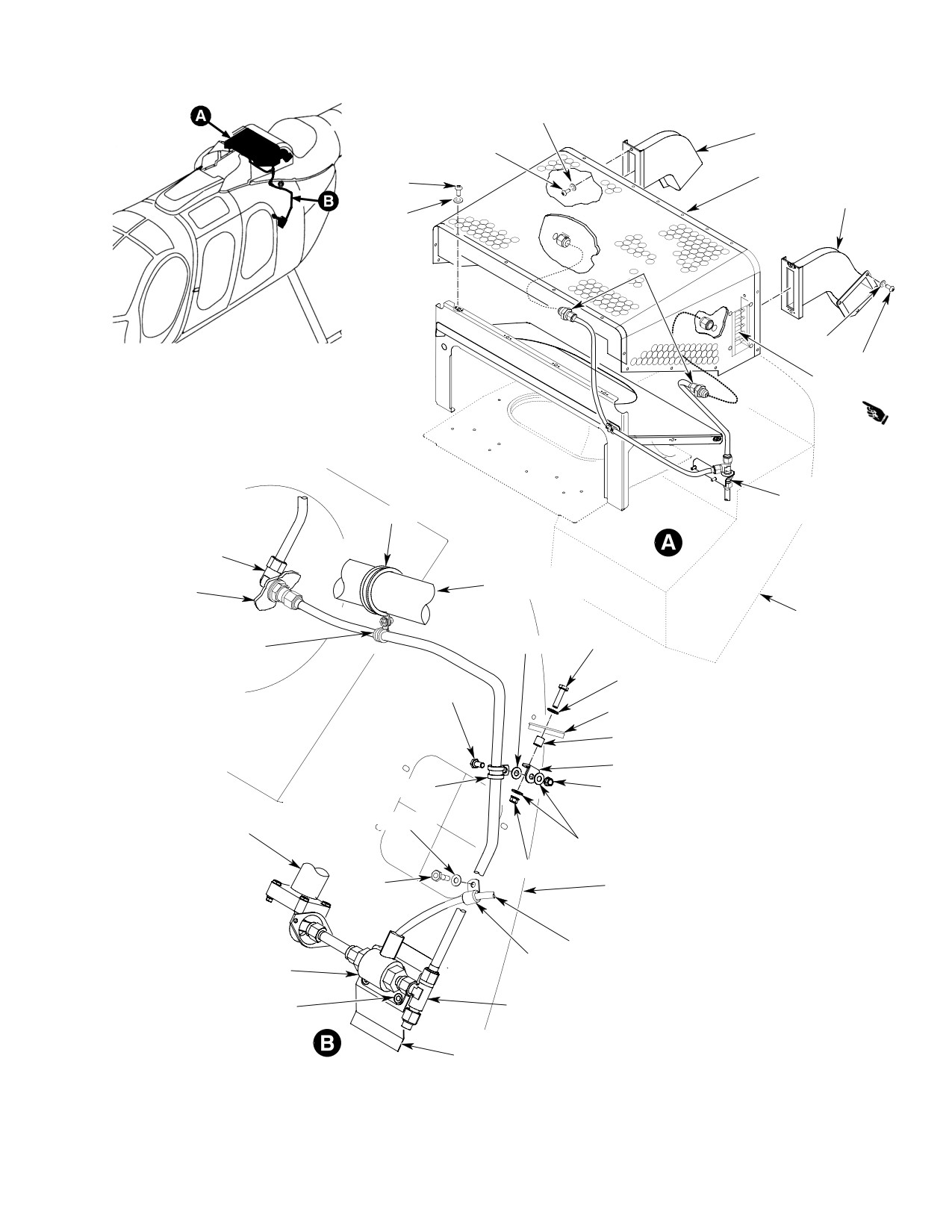
MD Helicopters, Inc.
CSP-HMI-2
MAINTENANCE MANUAL
WASHER
EJECTOR
SCREW
PARTICLE
SCREW
SEPARATOR
EJECTOR
WASHER
REDUCER
WASHER
SCREW
MANIFOLD
TEE
WASHER (2X)
CLAMP
NUT
ELBOW
CABIN HEAT
REF.
SYSTEM
PLENUM
PLENUM
CLAMP
SCREW
WASHER
SCREW
(2X) WASHER
NUT
WASHER
SCREW
REF. STRUCTURE
SPACER
BRACKET
CLAMP
NUT
REF.
WASHER
CABIN HEAT
SYSTEM
WASHER
NUT
BOLT
REF. FIREWALL
WIRE HARNESS
SOLENOID
CLAMP
VALVE ASSEMBLY
BOLT
TEE
(2X) WASHER
BRACKET ASSEMBLY
6G71-062B
Figure 401. Engine Air Particle Separator Installation
Page 403
71-10-60
Revision 29
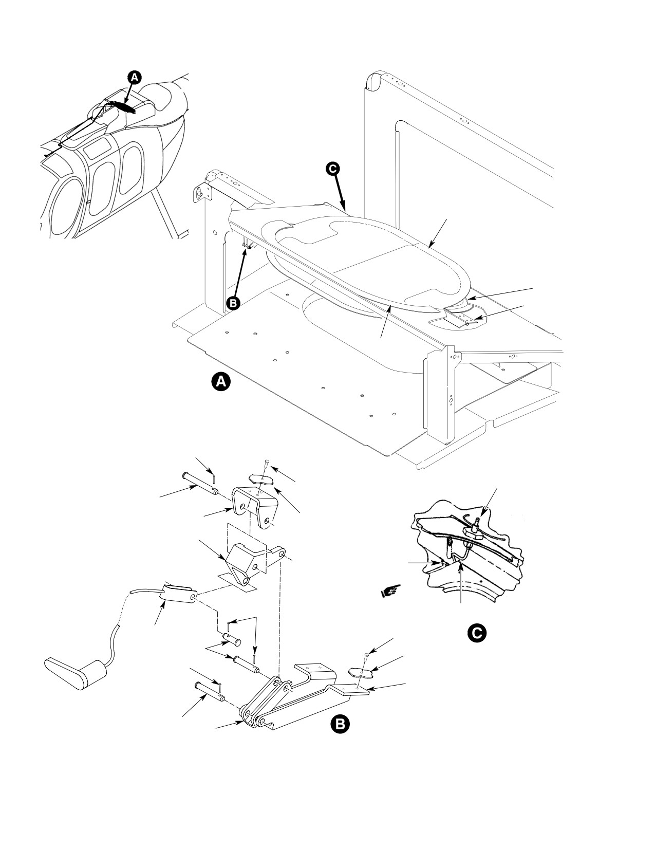
CSP-HMI-2
MD Helicopters, Inc.
MAINTENANCE MANUAL
DOOR ASSEMBLY
SEAL
HINGE
(2 PLCS)
SEAL
DOOR SHOWN OPEN
COTTER PIN
DIFFERENTIAL
PRESSURE SWITCH
RIVET (3 PL)
PIN
PIVOT
REF. FRAME
BELLCRANK
GROMMET
COTTER
PIN
TUBE ASSY
CABLE
RIVET (4 PL)
ASSEMBLY
PIN
REF. HINGE
COTTER PIN
CRANK
PIN
LINK
6G71-068A
Figure 402. Bypass Door Installation
Page 404
Revision 29
71-10-60
MD Helicopters, Inc.
CSP-HMI-2
MAINTENANCE MANUAL
ENGINE AIR PARTICLE SEPARATOR
INSPECTION/CHECK
1.
Engine Air Particle Separator Inspection
2. Bypass Door Inspection
(1). Visually inspect particle separator for
(1). Visually inspect bypass door stop for
damage and security of installation.
damage to seals. Replace damaged
seals.
(a). Inspect particle separator panel for
(2). Inspect bypass door hinges for opera
damage to axial flow dust separator
tion and security. Replace or repair as
tubes. No damage allowed.
required.
(b). Inspect particle separator for security
3. Bypass Door Cable Inspection
of installation. Torque or replace
loose or missing hardware.
(1). Visually inspect bypass door cable for
operation and security. Replace inoper
(c). Open access panels and inspect bleed
able cable. Torque or replace loose or
air tubes for security. Torque tube
missing hardware.
nuts.
(2). Visually inspect linkage for cracks,
(d). Inspect ejectors for security. Torque
deformation and security of hardware.
or replace loose or missing hardware.
Replace damaged linkage. Replace
missing hardware.
(2). Visually inspect bypass door for damage
and security of installation.
4. Air Pressure Sensing Switch Calibration
Check
(a). Open bypass door and inspect seal for
damage or leakage. None allowed.
(1).
Assemble test equipment (Ref.
Figure 601).
(b). Inspect bypass door for security of
(2).
Attach pressure switch to test equip
installation. Torque or replace loose
ment. Connect a suitable vacuum
or missing hardware.
source to pressure switch nipple and
u-tube.
(3). Visually inspect air filter bypass switch
for damage and security of installation.
(3).
Connect an ohmmeter or continuity
tester to pressure switch electrical
(a). Inspect switch for security. Torque
leads.
loose hardware.
(4).
Cycle switch from open to close several
(b). Inspect electrical wiring for chafing
times with vacuum. Watch meter for
or cuts. None allowed. Ensure
indication of switch closure. Release
connections are secure.
vacuum.
(4). Visually inspect scavenge air solenoid
(5).
Slowly apply vacuum. Note u-tube
valve for damage and security of
water height differential in both legs of
installation.
the tube relative to the switch closing
point. The total of the differential
(a). Inspect solenoid valve for security of
heights of both legs of the u-tube is
installation. Torque or replace loose
equal to switch actuation pressure.
or missing hardware.
(6).
Switch closing pressures shall be per
(b). Inspect electrical wiring for chafing
the applicable particle separator
or cuts. None allowed. Ensure
installation dash number shown (Ref.
connections are secure.
Figure 601).
Page 601
71-10-60
Revision 29
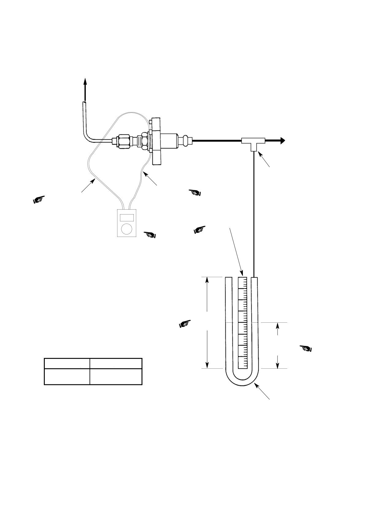
CSP-HMI-2
MD Helicopters, Inc.
MAINTENANCE MANUAL
TO R.H. FAIRING
SUCTION SOURCE
HOSE TEE
POWER LEAD
RETURN LEAD
24 IN (61 CM)
SCALE
OHMMETER OR
CONTINUITY
TESTER
24 IN (61 CM)
STRAIGHT
SECTION
12 IN (30.5 CM)
H2O STATIC
HEIGHT
OPEN
CLOSE
2.0
18.50±0.25
TYGON TUBING (OR EQUIVALENT)
BENT AND FILLED WITH H2O TO
STATIC HEIGHT AS SHOWN
G71-1029A
Figure 601. Air Pressure Sensing Switch Calibration Check
Page 602
Revision 33
71-10-60
MD Helicopters, Inc.
CSP-HMI-2
MAINTENANCE MANUAL
Section
71−20−00
Engine Mounts
(250−C20B,
250−C20R/2,
250−C30 and
250−C47)
MD Helicopters, Inc.
CSP-HMI-2
MAINTENANCE MANUAL
ENGINE MOUNTS
DESCRIPTION AND OPERATION
1. Description
D Unless otherwise required, remove and
replace only one engine mount at a time.
(1). The engine is bolted to the helicopter
D Do not disturb adjustable engine mount
airframe with one lower and two upper
fittings unless an engine-transmission
tubular steel, welded mount assem
alignment check is planned.
blies. Engine loads are transferred
through the mounting system into the
D Use box-end and socket wrenches on
airframe through six fittings and
mounting system hardware. Do not nick
special attaching fasteners. Left and
or scratch any of the mounting system
right upper engine mount assemblies
fasteners.
effect engine-transmission alignment
and may be adjusted by means of
2. Airframe Fittings
threaded fittings that are a part of each
(1). Airframe-engine mount structural
mount leg.
attach fittings and hoist fitting are
removed or replaced per the Structural
CAUTION
Repair Manual (SRM).
D Engine-transmission alignment shall be
NOTE: Structural attach fittings shall not be
inspected and adjusted whenever one or
removed unless structural damage is evi
more of the engine mount assemblies is
dent or engine-transmission misalignment
replaced or the existing adjustment is dis
is suspected as a result of a damaged struc
turbed.
tural fitting. Prior to attempting fitting re
D Do not remove engine mounts to remove
placement perform an engine-transmission
the engine.
alignment check per the SRM.
Page 1
71-20-00
Revision 22
CSP-HMI-2
MD Helicopters, Inc.
MAINTENANCE MANUAL
This Page Intentionally Left Blank
Page 2
Revision 44
71-20-00
MD Helicopters, Inc.
CSP-HMI-2
MAINTENANCE MANUAL
ENGINE MOUNTS
REMOVAL/INSTALLATION
1. Airframe Fittings Replacement
NOTE: All engine mount fitting bolts, washers
and nuts are corrosion resistant steel.
Remove/install airframe structural attach
fittings only if structural damage is present
(1). Install lower engine mount on bulkhead
per the Structural Repair Manual (SRM).
fittings with two bolts, four washers
and two new nuts.
2. Lower Engine Mount Replacement
(2). Install engine-mount attach bolt and
(250−C20/−C20R/2)
washer. Torque bolt to 100 - 140
A. Lower Engine Mount Removal
inch-pounds (11.30 - 15.82 Nm);
(250−C20/−C20R/2)
Lockwire installation.
(3). Torque airframe fitting hardware at
(Ref. Figure 401)
firewall to 50 - 70 inch-pounds (5.56
- 7.91 Nm) plus drag torque.
Special Tools
(Ref. Section 91−00−00)
3. Upper Engine Mounts Replacement
Item
Nomenclature
(250−C20/−C20R/2)
ST402
Engine hoist
A. Upper Engine Mounts Removal
(250−C20/−C20R/2)
(1).
Remove hardware attaching air duct
(Ref. Figure 401)
support bracket to overhead engine
hoist fitting.
(1). On upper right engine mount; unclamp
and move wire harness.
(2).
Install engine hoist (ST402). Back off
mount nuts 1/2 turn. Tension hoist to
(2). Remove gear case cooling duct clamp
relieve engine weight on lower mount
from left engine mount.
until bolts will turn freely.
(3). Disconnect upper mount forward attach
(3).
Release cargo compartment trim and
points from airframe fittings. Discard
upholstery to gain access to bolt-heads
nuts.
at bulkhead fitting.
(4). Disconnect aft ends of mounts from
(4).
Disconnect left and right forward ends
engine fittings.
of lower engine mount. Discard both
B. Upper Engine Mounts Installation
nuts.
(250−C20/−C20R/2)
(5).
Detach lower engine mount from engine
(Ref. Figure 401)
fitting.
Do not tighten airframe-mount
B. Lower Engine Mount Installation
CAUTION
bolts until engine fitting-mount
(250−C20/−C20R/2)
bolt is tightened.
(Ref. Figure 401)
NOTE: All engine mount fitting bolts, washers
and nuts are corrosion resistant steel.
CAUTION
(1). Install two bolts, four washers and two
new nuts to fasten mounts to airframe
D Do not tighten airframe-mount bolts un
fittings.
til engine fitting-mount bolt is torqued.
D If a new engine-mount fitting has been
NOTE: Retorque engine attach bolt after 3 to 5
installed; retorque engine-mount attach
hours flight time following a new engine
bolt after 3 to 5 hours of flight time.
mount fitting installation.
Page 401
71-20-00
Revision 26
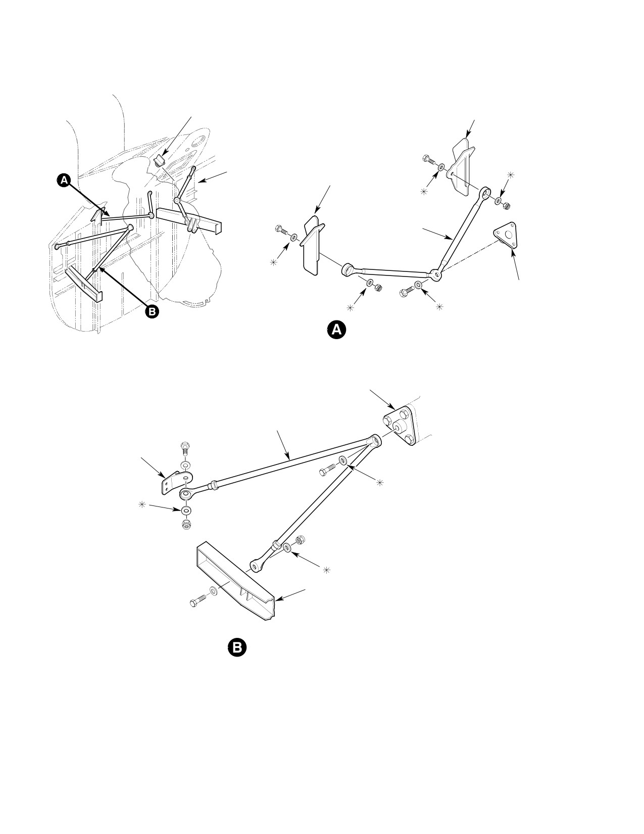
CSP-HMI-2
MD Helicopters, Inc.
MAINTENANCE MANUAL
ENGINE HOIST
BULKHEAD SPLICE
FITTING
FITTING
FIREWALL BULKHEAD
STA 124.00
BULKHEAD SPLICE
FITTING
LOWER ENGINE
MOUNT
LOWER ENGINE
MOUNT ATTACH
FITTING
LOWER ENGINE MOUNT - INSTALLATION
ENGINE
FITTING
UPPER ENGINE
MOUNT ASSY
AIRFRAME
FITTING
LANDING GEAR
DAMPER FITTING
UPPER ENGINE MOUNT - INSTALLATION
NOTE:
THICK WASHERS ARE USED IN LOCATIONS
MARKED WITH ASTERISK (*)
G71-2000
Figure 401. 250−C20/−C20R/2 Engine Mounts and Airframe Fittings
Page 402
Revision 22
71-20-00
MD Helicopters, Inc.
CSP-HMI-2
MAINTENANCE MANUAL
(2).
Install engine-mount washer and bolt.
B. Lower−Aft Engine Mount Installation
Torque bolt to 100 - 140 inch-pounds
(250−C30/−C47)
(11.30 - 15.82 Nm).
(Ref. Figure 402)
(3).
Torque upper engine mount fitting
hardware at firewall and landing gear
CAUTION
damper support to 30 - 40 inch-
pounds (3.39 - 4.52 Nm) plus drag
D Do not tighten airframe-mount bolts un
torque.
til engine fitting-mount bolt is torqued.
D If a new engine-mount fitting has been
(4).
Repeat the appropriate steps to install
installed; retorque engine-mount attach
the remaining upper engine mount.
bolt after 3 to 5 hours of flight time.
(5).
Remove engine hoist.
NOTE: All engine mount fitting bolts, washers
and nuts are corrosion resistant steel.
(6).
Install wire harness clamp on right
engine mount.
(1). Place ends of lower engine mount
against bulkhead fittings.
(7).
Install compressor air duct support
(2). Install aft engine mount as shown; use
bracket on airframe hoist fitting. Install
two bolts, four washers and two new
gear case cooling duct clamp on left
nuts at bulkhead attach fittings.
engine mount (Ref. Sec. 71-60-00).
(3). Install engine-mount attach bolt
4.
Lower−Aft Engine Mount Replacement
washers and new nut. Torque nut to 95
(250−C30/−C47)
- 110 inch-pounds (10.73 - 12.43
Nm) plus drag torque. Install cotter
pin as required.
A. Lower−Aft Engine Mount Removal
(250−C30/−C47)
(4). Torque airframe fitting hardware at
Sta. 137.50 to 95 - 110 inch-pounds
(Ref. Figure 402)
(10.73 - 12.43 Nm) plus drag torque.
5. Upper Engine Mounts Replacement
Special Tools
(250−C30/−C47)
(Ref. Section 91−00−00)
Item
Nomenclature
A. Upper Engine Mounts Removal
ST402
Engine hoist
(250−C30/−C47)
(Ref. Figure 402)
(1).
Remove hardware attaching upper
cooling air duct support bracket to
(1). Remove gear case cooling duct clamp
overhead engine hoist fitting.
from left side engine mount.
(2). Disconnect upper mount forward attach
(2).
Install engine hoist (ST402). Back off
points from airframe fittings. Discard
mount nuts 1/2 turn. Tension hoist to
nuts.
relieve engine weight on aft mount
until bolts will turn freely.
(3). Disconnect aft ends of mounts from
engine fittings.
(3).
Detach aft engine mount from engine
fitting.
B. Upper Engine Mounts Installation
(250−C30/−C47)
(4).
Disconnect left and right forward ends
of aft engine mount. Discard nuts.
(Ref. Figure 402)
Page 403
71-20-00
Revision 34
CSP-HMI-2
MD Helicopters, Inc.
MAINTENANCE MANUAL
(2). Install engine-mount washer and bolt.
CAUTION
Torque bolt to 220 - 360 inch-pounds
(24.86 - 40.67 Nm); lockwire bolt.
D Do not tighten airframe-mount bolts un
til engine fitting-mount bolt is torqued.
(3). Torque upper engine mount fitting
hardware at firewall and landing gear
D If a new engine-mount fitting has been
damper to 60 - 85 inch-pounds (6.78
installed; retorque engine-mount attach
- 9.60 Nm) plus drag torque.
bolt after 3 to 5 hours of flight time.
(4). Repeat the appropriate steps to install
NOTE: All engine mount fitting bolts, washers
the remaining upper engine mount.
and nuts are corrosion resistant steel.
(5). Remove engine hoist.
(1). Install two bolts, four washers and two
new nuts to fasten mounts to airframe
(6). Install gear case cooling duct clamp on
fittings.
left engine mount.
Page 404
Revision 34
71-20-00
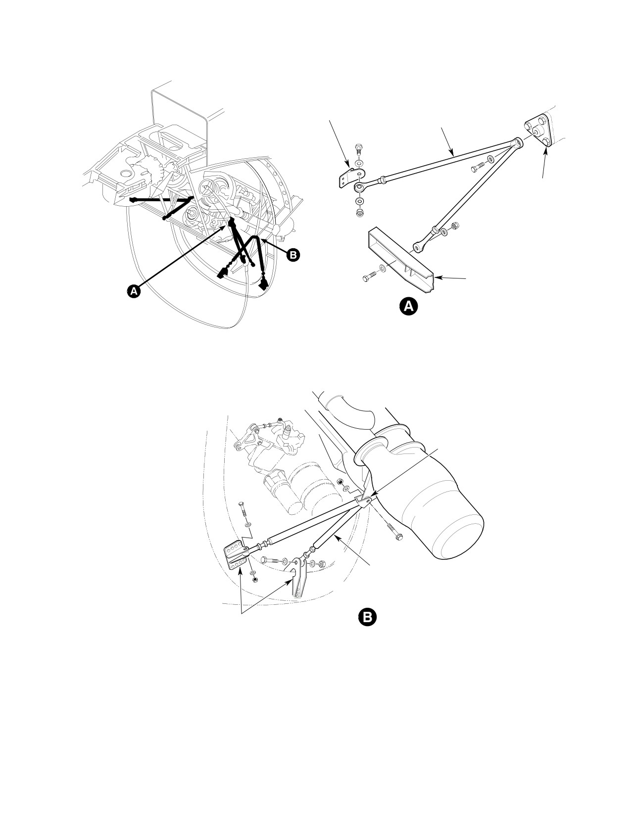
MD Helicopters, Inc.
CSP-HMI-2
MAINTENANCE MANUAL
UPPER ENGINE
MOUNT FITTING
(REF. SEC. 71-20-00)
UPPER ENGINE MOUNT
SIDE ENGINE MOUNT
ATTACH FITTING
LANDING GEAR
DAMPER FITTING
(REF. SEC. 71-20-00)
UPPER ENGINE MOUNT - INSTALLATION
ROTATED
ENGINE FITTING
LOWER ENGINE MOUNT
LOWER ENGINE MOUNT - INSTALLATION
LOWER ENGINE MOUNT
ATTACH FITTING
(REF. SEC. 71-20-00)
G71-0004A
Figure 402. Model 250−C30/−C47 Engine Mounts and Airframe Fittings
Page 405
71-20-00
Revision 22
CSP-HMI-2
MD Helicopters, Inc.
MAINTENANCE MANUAL
This Page Intentionally Left Blank
Page 406
Revision 44
71-20-00
MD Helicopters, Inc.
CSP-HMI-2
MAINTENANCE MANUAL
ENGINE MOUNTS
INSPECTION/CHECK
1.
Engine Mounts and Fittings Inspection
2. Upper Engine Mounts Adjustment
(1).
Inspect painted surfaces of engine
NOTE: Do not disassemble upper engine
mounts for condition.
mounts except for spares replacement or
magniflux inspection.
(2).
Inspect all engine mount tubes for
straightness. Hold steel straight edge
(1). Engine realignment is required when:
against tubes to reveal any warps or
(a). Mount assembly is from another
bends in tubes.
helicopter.
(3).
Check that jam nuts and lockwire on
mounts with adjustable fittings are
(b). One upper mount has been replaced.
secure and not disturbed. If not secure
(c). One upper mount adjustment has
or adjustment is disturbed, a check of
been disturbed.
engine-to-transmission alignment is
required per the Structural Repair
(2). Check engine-transmission alignment
Manual (SRM).
per the Structural Repair Manual
(SRM) and realign a reassembled or
(4).
Visually inspect all tubes and welded
cannibalized mount assembly.
joints for cracks and evidence of
corrosion. Magnetic-particle inspect
(3). Engine transmission realignment is
suspected engine mount assemblies. If
accomplished by adjusting the upper
crack(s) are evident, mount is unser
engine mounts using the tool specified
viceable.
by SRM instructions and as follows:
(5).
Inspect flanges and bosses of engine
(a). Adjust mounts to align engine with
mount fittings and lifting eye for
transmission. Tighten jamnuts and
flatness, cracks and corrosion. Replace
recheck alignment.
defective fittings.
(b). Lockwire jamnuts.
(6).
Inspect threaded steel insert for
damaged threads, corrosion and for full
(c). Paint a slippage mark across both
bottoming to seat of insert hole.
jamnuts on each leg.
Page 601
71-20-00
Revision 22
CSP-HMI-2
MD Helicopters, Inc.
MAINTENANCE MANUAL
This Page Intentionally Left Blank
Page 602
Revision 44
71-20-00
MD Helicopters, Inc.
CSP-HMI-2
MAINTENANCE MANUAL
ENGINE MOUNTS
REPAIRS
1. Engine Mount Repairs
(3). Perform an engine-transmission
alignment check per the Structural
Accomplish minor repairs as instructed below;
Repair Manual (CSP-SRM-6).
otherwise, replace defective engine mounts
that are cracked, twisted, bent or exceed
(4). A repaired mount shall be replaced
acceptable attach hole tolerances.
when engine-transmission misalign
ment occurs as a result of repair.
2. Mount Hole Repair (250−C20/−20R/2)
NOTE:
Upper engine mounts incorporate close
D Drilling one mount hole to the maximum
tolerance holes. Hole tolerances must be
0.3170 inch diameter does not normally
maintained within limits to get correct
cause misalignment beyond tolerance.
engine-transmission alignment.
D If both mounts are reworked, engine-
(1). Engine attachment hole diameter
transmission alignment must be checked.
normally is 0.3122-0.3132 inch
(7.92988-7.95528 mm).
3. Painted Surfaces Repair
(2). Ream a damaged hole to 0.3170 inch
(1). Repaint otherwise undamaged surfaces
(8.0518 mm) diameter maximum.
as necessary (Ref. Sec. 20-30-00).
Page 801
71-20-00
Revision 22
CSP-HMI-2
MD Helicopters, Inc.
MAINTENANCE MANUAL
This Page Intentionally Left Blank
Page 802
Revision 44
71-20-00
MD Helicopters, Inc.
CSP-HMI-2
MAINTENANCE MANUAL
Section
71−30−00
Engine Ignition
Control System
(250−C20B,
250−C20R/2 and
250−C30)
CSP-HMI-2
MD Helicopters, Inc.
MAINTENANCE MANUAL
This Page Intentionally Left Blank
MD Helicopters, Inc.
CSP-HMI-2
MAINTENANCE MANUAL
ENGINE IGNITION CONTROL SYSTEM
DESCRIPTION AND OPERATION
1.
Engine Ignition System Description and
Secondary ignition circuit
WARNING
Operation
voltage is lethal. Set battery
switch OFF, disconnect battery and ex
ternal power before working on sys
(1). The engine ignition system consists of
tem. Insulate all bare wires and cable
switches, wiring, ignition exciter and an
as required.
igniter plug.
2. Automatic Re−ignition System
Description and Operation
(2). Engine ignition power may be provided
(Ref. Figure 401) Engine automatic re-ignition
by the helicopter battery or external
equipment is installed on all Model 369D
auxiliary power as selected by battery
helicopters subsequent to S/N 1149 and all
switch position. Later helicopters are
369E/FF and 500N helicopters. The equipment
equipped with a standard start circuit
consists of a two-switch, four-lamp, indicating
breaker that may be installed on earlier
latching cluster (XDS9), and a toggle switch
machines.
(S11) for operational testing of the re-ignition
system, mounted on the lower left side of the
instrument panel face. Relays K104 and K304,
Refer to the Pilot's Flight Manu
and a diode isolator assembly (CR1 and CR2)
CAUTION
al for specific engine start proce
is located in the engine bay on the aft oleo
dures.
support fitting.
NOTE:
(3).
Placing the battery switch in either
D For information relative to optional auto
EXT PWR or BAT with the key switch
matic re-ignition equipment installed on
on, arms the start system. Pressing the
369D helicopters prior to S/N 1150, refer
START switch on the collective stick
to Auto Re-ignition Initial Installation.
applies 24 Vdc to the starter/generator
D For Instructions on modification to re-ig
and ignition exciter. The starter/genera
nition equipment for full time operation
tor motors the engine gas producer to
(Applicable to 369D helicopters, S/N 003 -
start speed while the exciter simulta
949 only), refer to Auto Re-ignition Modi
neously provides a high voltage spark
fication.
across the igniter plug gap. At about
D On 369E helicopters 384 and subs, and
15% rpm, fuel is added to the sequence
369FF helicopters 076 and subs auto re-
by moving the throttle out of cutoff to
ignition system has new design and op
idle. START button release de-ener
erational differences.
gizes the ignition exciter and starter/
generator.
D On 369E helicopter S/N 384 - 508, 369FF
helicopter S/N 076 - 091, and 500N heli
copters S/N 001 - 044 addition of air/
(4).
See the Allison Engine Operation and
ground switch S522 and terminal boards
Maintenance manual for specific
TB1001 and TB1003 are used. Relay
K304 and diodes CR1 and CR2 (located in
ignition system maintenance informa
the engine bay on the oleo panel) isolators
tion.
are not used.
D On 369E helicopters 509 & subs, 369FF
(5).
Refer to Auto Re-ignition for wiring
helicopters 092 & subs, and 500N helicop
data on the standard and automatic
ters 045 & subs the air/ground switch has
ignition system option.
been removed.
Page 1
71-30-00
Revision 22
CSP-HMI-2
MD Helicopters, Inc.
MAINTENANCE MANUAL
(1).
The Automatic re-ignition is initiated
(6).
Rotor/oil pressure switch S203 auto
when the Engine Power Out Warning
matically arms the audio circuitry with
(EPO) Unit senses an N1 speed of less
pressure.
than 55 percent or an NR speed of less
(7).
As the throttle is increased to the flight
than 98 percent (369D/E model helicop
idle position, the NR sensing function is
ters) or 95 percent (369FF and 500N
enabled after a time delay of 3.5
model helicopter).
seconds. The NR sensing function
(2).
When the EPO unit senses one or both,
remains enabled until the throttle is
re-ignition relay (K104) closes, which
decreased through the ground idle
completes a 28 volt circuit to the
position.
ignition exciter (SQ300), generating
(8).
A re-ignition test switch, S11, provides
high voltage across the igniter. In
a ground test of the auto re-ignition
addition, audible and visual warning
circuit. RE-IGN TEST switch S11
circuits are energized.
provides ground test of the auto
(3).
The auto re-ignition relay is de-ener
re-ignition circuit by bypassing the
gized when the EPO unit senses the
main transmission pressure switch,
appropriate N1 and NR speeds.
closing relay K104 to energize the
igniter.
(4).
Pressing a reset button resets the
(9).
ENG OUT audio alarm only is disabled
warning light circuit (relay K304
when the generator switch is OFF (On
opens).
369E helicopter S/N 384 - 508, 369FF
(5).
Automatic re-ignition is prevented
helicopter S/N 076 - 091, and 500N
during normal start-up and shutdown
helicopters S/N 001 - 044 audio
by an NR disable switch which senses
warning is disabled by air/ground
throttle position.
switch S522).
Page 2
Revision 22
71-30-00
MD Helicopters, Inc.
CSP-HMI-2
MAINTENANCE MANUAL
ENGINE IGNITION CONTROL SYSTEM
FAULT ISOLATION
1. Engine Ignition System Fault Isolation
NOTE: All troubleshooting presumes wire seg
ment continuity checks for OPEN or
(Ref. Table 101)
SHORT circuit conditions have been com
Before removing or install
pleted and indicator lamps are known to be
WARNING
ing components of the elec
good.
trical system, ensure all electrical pow
er is OFF. Serious injury or death can
result from voltage potentials in the ig
nition exciter. Voltages in other electri
cal system components can injure per
sonnel.
Table 101. Ignition System Fault Isolation
Symptom
Probable Trouble
Corrective Action
Engine will not start (starter
Oil fouled igniter plug
Attempt a second start.
operation normal)
Faulty ignition circuitry
Listen for spark igniter operation.
Check for fuel vapor from exhaust.
No power to ignition exciter due to
Replace defective switch or wiring.
faulty key switch, start switch or
wiring
Spark igniter fouled, grounded or
Clean or replace igniter plug.
open
Faulty high tension lead
Replace lead.
Igniter plug firing intermittently
Check exciter input voltage. Install
an operational exciter and test
ignition system.
Starter/generator does not motor
Circuit breaker open
Reset/replace circuit breaker.
engine when START switch is
Low battery voltage
Crank engine with an APU or charge
pressed
battery.
Defective start relay
Replace relay.
Page 101
71-30-00
Revision 22
CSP-HMI-2
MD Helicopters, Inc.
MAINTENANCE MANUAL
2. Automatic Re−ignition System Fault
NOTE: All troubleshooting presumes wire seg
Isolation
ment continuity checks for OPEN or
SHORT circuit conditions have been com
(Ref. Table 102 and Table 103)
pleted and indicator lamps known to be
Before removing or install
good.
WARNING
ing components of the elec
trical system, ensure all electrical pow
er is OFF. Serious injury or death can
result from voltage potentials in the ig
nition exciter. Voltages in other electri
cal system components can injure per
sonnel.
Table 102. Automatic Re−ignition System Fault Isolation (369D)
Symptom
Probable Trouble
Corrective Action
System functions normally, but
Defective lamp
Replace lamp XDS9.
RE−IGN lamps do not illuminate
Defective switch XDS9
Replace indicator switch XDS9.
Defective relay K304
Replace relay K304.
Start relay (K301) is energized
Diode CR2 defective, or START
Replace diode CR2 or diode isolator
during automatic re−ignition
switch (S106) closed
assembly or check START switch
and wiring for short circuit.
Equipment fails to function with 28
Relay K104 defective
Replace relay K104.
Vdc present at terminals D and E
of terminal board TB503−3 and
ARMED lamps illuminated
ARMED lamps not illuminated and
Switch S11 defective
Replace switch S11.
equipment fails to function with 28
Vdc at terminals D and E of
terminal board TB503−3
ARMED lamps not illuminated, but
Relay K304 and/ or lamps
Replace lamps and/or relay K304.
equipment functions
defective
ARMED and RE−IGN lamps
Diode CR1 defective
Replace diode CR1 or diode isolator
illuminated, 28 Vdc present at
assembly.
terminal 1 of diode CR1, but less
than 26 Vdc at terminal 2 of diode
CR1 and automatic re−ignition fails
Page 102
Revision 22
71-30-00
MD Helicopters, Inc.
CSP-HMI-2
MAINTENANCE MANUAL
Table 103. Automatic Re−ignition System Fault Isolation (369E/FF − 500N)
Symptom
Probable Trouble
Corrective Action
RE−IGN TEST switch ON, RE−IGN
Faulty diode CR1
Replace diode or diode isolator
P RST indicator lit, 28 Vdc present
assembly.
at pin 1 of CR1 (diode isolator
assembly) but less than 28 Vdc
present at pin 2 of CR1. Automatic
re−ignition does not occur
RE−IGN TEST switch ON, 28 Vdc
Faulty re−ignition relay K104
Replace re−ignition relay K104.
present at pin L of TB503−9.
Automatic re−ignition does not
occur
RE−IGN TEST switch ON, 28 Vdc
Faulty RE−IGN TEST switch S11
Replace RE−IGN TEST switch S11.
present at pin 6 of TB503−10.
Automatic re−ignition does not
occur and RE−IGN P RST indicator
does not light
Auto re−ignition system functions
Defective lamp
Replace lamp XDS9.
normally but RE−IGN P RST
Defective switch XDS9−S2
Replace indicator switch XDS9.
indicator does not light
Defective relay K304
Replace relay K304.
Page 103
71-30-00
Revision 22
CSP-HMI-2
MD Helicopters, Inc.
MAINTENANCE MANUAL
This Page Intentionally Left Blank
Page 104
Revision 44
71-30-00
MD Helicopters, Inc.
CSP-HMI-2
MAINTENANCE MANUAL
ENGINE IGNITION CONTROL SYSTEM
REMOVAL/INSTALLATION
1. Automatic Re−ignition System
Lampholder assembly has a po
CAUTION
Component Replacement
larizing key, and can only be in
stalled one way. Do not attempt to force it to
(Ref. Figure 401 thru Figure 403) Replace
seat.
affected components of the automatic re-igni
tion system as indicated in the following
(4). Insert new lamp into lampholder and
procedures.
reinstall lampholder assembly into
housing.
Ensure all electrical power
WARNING
D. Armed Lights/Switch (XDS9) Display
is OFF during removal and
replacement of electrical components.
Screen Replacement
(1). Pull screen and lampholder assembly
A. Automatic Re−ignition Test Switch (S11)
out of housing.
Replacement
(2). Remove screen by sliding it to left or
Replace switch per Control Switches Replace
right.
ment (Ref. Sec. 96-30-00).
(3). Slide replacement screen into position.
B. Armed Light/Switch (XDS9) Assembly
Replacement
Lampholder assembly has a po
CAUTION
larizing key, and can only be in
(1). Remove four screws and washers
stalled one way. Do not attempt to force it to
securing adapter plate to instrument
seat.
panel.
(4). Re-insert screen and lampholder
(2). Pull entire assembly away from panel.
assembly into housing.
(3). Remove nut, washer and screw secur
E. K104/K304 Relay Replacement
ing clamp to switch and push housing
through adapter plate.
Replace relays K104 and/or K304 as follows:
(4). Hold switch with one hand and housing
with other hand and apply breakaway
Consumable Materials
pressure to force two spring fingers on
(Ref. Section 91−00−00)
housing to release switch.
Item
Nomenclature
CM815
Solder
(5). Remove wires from defective compo
nents and reconnect to replacement
component as required.
(1). Remove nuts, four washers and two
screws attaching relay to mounting
(6). Reassemble components in reverse
bracket.
order of disassembly.
(2). Pull relay forward until wiring at back
C. Armed Light/Switch (XDS9) Lamps
of relay is accessible.
Replacement
(3). Note location of each wire and remove
(1). Pull display screen and lampholder
from back of relay.
assembly out of housing.
(4). Using solder (CM815) connect wires to
(2). Slide defective lamp out of lampholder.
new relay.
(3). Remove filter from defective lamp and
(5). Reinsert wiring and relay, and attach to
slip it over glass envelope of new lamp.
bracket with screws, washers and nuts.
Page 401
71-30-00
Revision 22
CSP-HMI-2
MD Helicopters, Inc.
MAINTENANCE MANUAL
F. CR1/CR2 Diode Replacement
ring, mica washer and flat washer in
place between bus and bracket.
Consumable Materials
(5). Insert threaded end of diode through
(Ref. Section 91−00−00)
bracket, ring, washers and bus. Install
Item
Nomenclature
terminal (CR1 only) and lockwasher on
CM313
Insulation varnish
threaded end of diode and secure with
AN316-4 nut. Do not use nut supplied
with diode.
(1). Open engine access doors.
(2). Remove lead wire from diode to be
(6). Reinstall terminal on diode with screw,
replaced by removing nut, two washers
two washers and nut.
and screw.
(7). Perform operational test of system
(3). Remove nut, lockwasher and terminal
(refer to applicable Pilot's Flight
(CR1) from diode. Holding flat washer,
Manual.
mica washer, and insulating ring under
bus, remove diode and mica washer
(8). After successful test, apply glyptol
from opposite side of bracket. Remove
(CM313) to exposed threads and tip of
washers and ring from under bus.
new diode.
(4). Install mica washer on threaded end of
replacement diode and hold insulating
(9). Close and secure engine access doors.
Page 402
Revision 22
71-30-00
MD Helicopters, Inc.
CSP-HMI-2
MAINTENANCE MANUAL
INSTRUMENT
PANEL
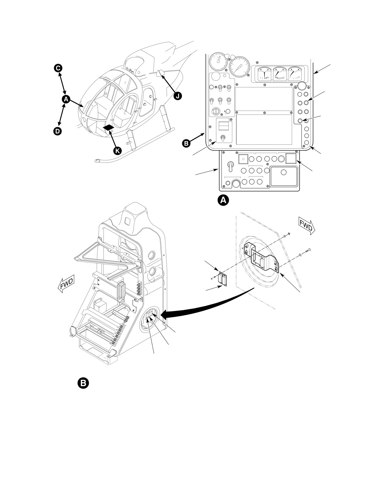
INST. CB101
ENG. OUT CB106
CIRCUIT BREAKER
AUTO RE-IGNITION
PANEL
(NOTES 2, 3)
RE-IGNITION PANEL
LOWER SWITCH AND CIRCUIT
(NOTE 1)
BREAKER PANEL
INSTRUMENT PANEL (SLIM LINE)
RELAY
K304
RELAY
BRACKET
K104
(NOTES 1, 2)
RELAY
K103
NOTES:
RELAY
1.
EFFECTIVE SHIPS 369D SERIAL NOS. 3 THRU 949.
K104
2.
EFFECTIVE SHIPS 369D SERIAL NOS. 950 THRU 1148.
RELAY
3.
EFFECTIVE SHIPS 369D SERIAL NOS. 1150 AND SUBS
K304
(WITH AUTO RE-IGNITION INSTALLED).
4.
EFFECTIVE SHIPS 369E/FF - 500N.
5.
EFFECTIVE SHIPS 369FF ONLY.
REAR VIEW (NOTE 3)
6.
SWITCH ASSEMBLY ARRANGEMENT VARIES WITH
HELICOPTER MODEL.
7.
EFFECTIVE 369E, 001 THRU 383; 369FF, 001 THRU 075.
8.
EFFECTIVE 369E, 384 AND SUBS; 369FF, 076 AND SUBS;
500N, 001 AND SUBS.
9.
NOT USED ON 369E, 384 AND SUBS; 369FF, 076 AND SUBS;
500N, 001 AND SUBS.
G96-1005-1A
Figure 401. Auto Re−ignition System Equipment (Sheet 1 of 3)
Page 403
71-30-00
Revision 22
CSP-HMI-2
MD Helicopters, Inc.
MAINTENANCE MANUAL
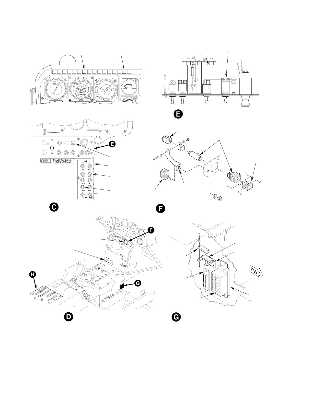
RE-IGN PRST
K104
RE-IGN
RE-IGN PRST
WARNING LT
(NOTE 7)
TEST SWITCH
WARNING LT
(NOTE 5)
0
120
10
9
0
1
110
1
20
1009
30
8
2
90
7
3
40
7
3
80
5
50
70
60
6
5
4
ALTITUDE
EDGE-LIGHTED PANEL-TOP VIEW
(NOTE 4)
SWITCH
XDS9
ANTI-COLL
PITOT
HOUSING
START PUMP
LT
HTR
RE IGNTEST
PULL
FOR
AIR
OFF
OFF
OFF
SCAV
POS
UTIL
OVSPD
FAULT
AIR
LTS
ANTI-ICE
PWR
TEST
TEST
OFF
OFF
OFF
OFF
OFF OFF
RE-IGN
SCREEN
TEST SWITCH
ASSEMBLY
CIRCUIT BREAKER
PANEL
PNL LT
CB104
SUPPORT
ENG. OUT
SWITCH S11
CB106
INSTRUMENT PANEL
RE-IGNITION
(NOTE 4)
SWITCH ASSY XDS9
(TYPICAL) (NOTE 6)
RE-IGNITION PANEL
(369D294201-705)
RELAY
K204
RE-IGNITION PANEL
RELAY BRACKET
(369D294201-703)
RELAY
K304
TB501
TB502
MODULE (NO. 20)
INSTRUMENT T-PANEL
CENTER CONSOLE (RIGHT SIDE)
(WITH CENTER CONSOLE)
(NOTES 1, 2)
G96-1005-2
Figure 401. Auto Re−ignition System Equipment (Sheet 2 of 3)
Page 404
Revision 22
71-30-00
MD Helicopters, Inc.
CSP-HMI-2
MAINTENANCE MANUAL
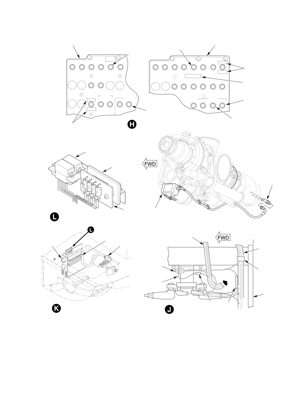
CIRCUIT BREAKER
CIRCUIT BREAKER
PANEL 369H92143
ENG. OUT
PANEL 369D294566
ENG. OUT
CB105
CB106
AUTO
RE-IGN
HEAT
TRIM
ENG
ENG
TEST
TRIM
ENG
ENG
INST
GYRO
AUTO
COVER EXISTING
MARKINGS WITH
DE-ICE
N
CYCLIC
START
OUT
N CYCLIC
START
OUT
RE-IGN
2
2
GOV
GOV
BLACK DECALS
AUTO RE-IGN
CARGO
CIG
XPDR ADF
ICS
VHF
UHF
VHF
ADD AUTO
RE-IGN DECAL
HOOK
LTR
FM
AM
AM
GYROS
INST
LIGHTS
LIGHTS
AUTO ATT
DIR
LDG
ANN
CB124
TOW LDG ANN INST
RE-IGN
HOVER PANEL
HOVER PANEL
ANN PANEL
CB104
ANN PANEL
CENTER CONSOLE PANEL
COVER EXISTING MARKINGS
(WITH T-SHAPE INSTRUMENT PANEL)
CB123
WITH BLACK DECALS
K104
TB1001
IGNITER
TB1003
IGNITION
EXCITER
TERMINAL BOARD AND RELAY ASSEMBLY
STATION
WIRE BUNDLE
137.50
TB200
J1201
ENGINE POWER OUT
WIRE
BUNDLE
DIODE ISOLATOR
ASSEMBLY
(CR1, CR2)
OLEO
TO
(NOTES 7, 9)
SUPPORT
P303
FITTING
START RELAY
(K301)
LOWER
RING
SECTION
SP17
SP18
BATTERY COMPARTMENT (NOTE 8)
ENGINE COMPARTMENT
G96-1005-3
Figure 401. Auto Re−ignition System Equipment (Sheet 3 of 3)
Page 405
71-30-00
Revision 22
CSP-HMI-2
MD Helicopters, Inc.
MAINTENANCE MANUAL
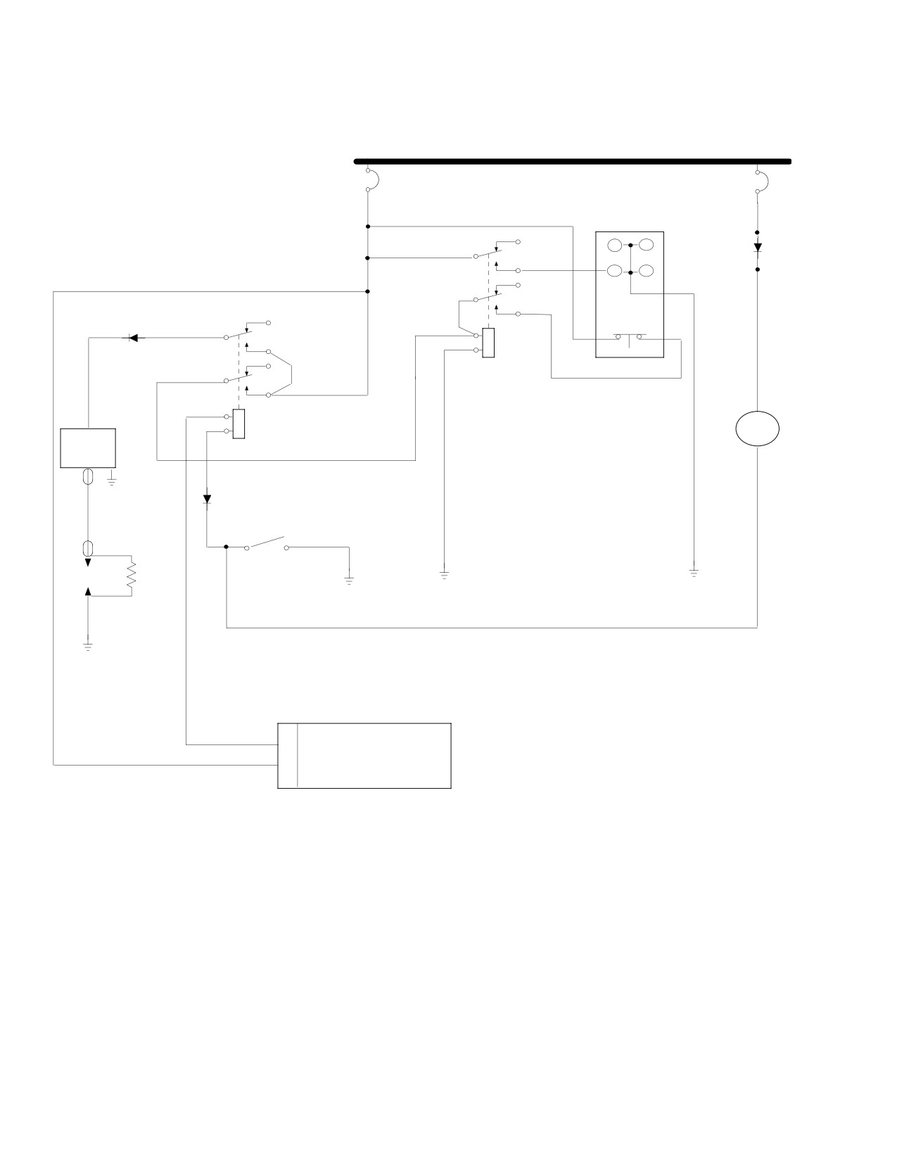
28 VDC BUS
CB106
INSTR
ENG OUT
CB101
XDS9
J
TB505 1/2
H
CR1
K304
PRESS TO TEST
+
AUTO REIGN
HR
M5
RELAY
IGNITION
METER
EXCITER
K104
_
SQ300
A
CR51
B
AUTO REIGN
IGNITER
SW S11
PLUG
P19
ENGINE POWER OUT BOX
U
AUTO RESTART 28 VDC/.5 A OUT
B
28 VDC IN
EFFECTIVITY:
369D;
ALL
369E;
001-383
369FF;
001-075
G96-1009-1
Figure 403. Auto Re−ignition Schematic (Sheet 1 of 3)
Page 412
Revision 22
71-30-00
MD Helicopters, Inc.
CSP-HMI-2
MAINTENANCE MANUAL
ENGINE IGNITION CONTROL SYSTEM
INSPECTION/CHECK
1. Automatic Re−ignition System Check
NOTE: Conducting test with engine motoring
(with Ground/Air Switch)
will require pushing the RE-IGN P RST in
dicator to reset the system (Refer to appro
369E
384 - 508
priate PFM for in-flight test of system).
369FF
076 - 091
500N
001 - 044
A. Normal Start
NOTE: Helicopters equipped with the ground/
Verify system operation of normal starting
air switch can be modified to eliminate the
circuit by performing a normal start as
switch (Ref. Sec. 96-10-00, Generator Con
described in appropriate Pilot's Flight Manual.
trol Unit Upgrade to Eliminate Squat
Switch).
2. Automatic Re−ignition System Check
(without Ground/Air Switch)
(1). The RE-IGN TEST switch (S11)
provides for an OFF and two test
369E
509 & subs
positions; GND (up) and FLT (center).
369FF
092 & subs
500N
045 & subs
(2). Both horn and audible warnings are
Verify system operation of automatic re-igni
disabled by ground/air switch (S522)
tion circuit as follows:
when the helicopter is on the ground,
except when RE-IGN TEST switch is
(1). Set BATTERY/OFF/EXT PWR (master)
placed in the GND position.
switch to OFF.
(3). The FLT position provides a complete
(2). Connect external 28 Vdc power.
in-flight systems test by simulating a
fault of the N1 input to the EPO.
(3). Set master switch to EXT PWR.
(4). Both on-ground and in-flight tests can
(4). Close ENG OUT circuit breaker.
be accomplished by selecting GND
position.
NOTE: Closing ENG OUT circuit breaker pro
vides power at re-ignition relay K104.
(5). On-ground test requires RE-IGN
TEST switch in the GND position.
(5). Set RE-IGN TEST switch to ON.
(a). With power applied, the ENG OUT
(6). Verify audible spark across engine
indicator should be flashing.
igniter gap.
(b). Press the press-to-test button and
(7). Verify Re-ignition indicator lights.
all warning lights should illuminate
momentarily.
(8). Set RE-IGN TEST switch to OFF.
(c). Set RE-IGN TEST switch to GND.
(9). Press Re-ignition indicator. Verify
indicator lamps go out.
(d). Verify horn, audio warning, RE-IGN
P RST indicator is illuminated and
(10). Open ENG OUT circuit breaker.
engine igniter firing.
(11). Set master switch to OFF.
(e). Return switch to OFF, the system
should reset.
(12). Disconnect external power.
Page 601
71-30-00
Revision 32
CSP-HMI-2
MD Helicopters, Inc.
MAINTENANCE MANUAL
This Page Intentionally Left Blank
Page 602
Revision 32
71-30-00
MD Helicopters, Inc.
CSP-HMI-2
MAINTENANCE MANUAL
ENGINE IGNITION CONTROL SYSTEM
REPAIRS
1. Auto Re−ignition System Modification
2. Instrument Panel Modification
(Ref. Figure 801)
This section provides for modification instruc
tions of the 369H900118-513 and -515 engine
automatic re-ignition equipment (369D
Consumable Materials
helicopters S/N 003 - 949 only). These
(Ref. Section 91−00−00)
instructions cover relocation of re-ignition
Item
Nomenclature
controls on the instrument panel and neces
CM302
Epoxy primer / Catalyst reducer
sary rewiring to provide full-time operation of
CM305
Lacquer, acrylic
the system.
A. Preparation for Modification
(1). Fabricate cover, as required, for hole
vacated by switch XDS9.
Preparing for modification of installed engine
automatic re-ignition equipment includes the
(2). Install cover on instrument panel.
following:
(3). Install plug button on instrument
panel.
(1). Place BATTERY-OFF-EXT PWR
(master) switch in OFF position.
(4). Paint out lettering at previous auto
re-ignition switch location with acrylic
(2). Disconnect wires from auto re-ignition
lacquer (CM305).
switches as follows:
(5). Fabricate plate as follows:
(a). Remove J501A20 from circuit break
(a). Make plate from 0.062 inch (1.5748
er (CB106-2) and ARM-OFF switch
mm) thick aluminum alloy sheet as
(S11-1) and discard wire.
shown in Figure 801.
(b). Disconnect J501AE20, J502E20,
(b). Apply one coat primer (CM302) and
J501B20, J502A20 and J502D20 at
dry for 1 to 2 hours.
switch (S11).
(c). Apply topcoat of acrylic lacquer
(c). Remove ARM-OFF switch (S11) from
(CM305) and air dry 4 hours mini
instrument panel.
mum.
(6). Install plate and auto re-ignition
(d). Remove J503D20 and J503EE20
switches (XDS9) and (S11, PN 882GK15
from terminal board (TB502-13A and
- Cutler Hammer or equivalent) at new
13C).
location on instrument panel.
(e). Remove J505A20N and J508A20N
(7). Fabricate and install decal on instru
from stud (E2).
ment panel.
(f). Remove J507AA20 from terminal
3. Electrical System Modification
board (TB502-13E).
(Ref. Figure 802)
(g). Remove E559AC22 from splice
(1). Revise wiring as follows:
(MS25181-1).
(a). Install diode at circuit breaker
(3). Remove relays (K304 and K104) and
CB101.
switch (XDS9). Remove all wires from
relays and switch and retain relays and
(b). Install diodes CR3 and CR4 on
switch for reuse.
switch S11.
Page 801
71-30-00
Revision 22
CSP-HMI-2
MD Helicopters, Inc.
MAINTENANCE MANUAL
(c). Install transzorb CR5 on relay K104.
(e). Reinstall relays K104 and K304 in
original position.
(2). Perform check of modified auto re-igni
(d). Rewire switches (S11 and XDS9) and
tion system (refer to the appropriate
relays (K104 and K304) as shown.
PFM).
369H6416 INSTRUMENT
PANEL ASSEMBLY
COVER (SEE VIEW D-D)
HS1957-2 SCREW NAS620A6L
WASHER MS21043 NUT
(OR EQUIVALENT)
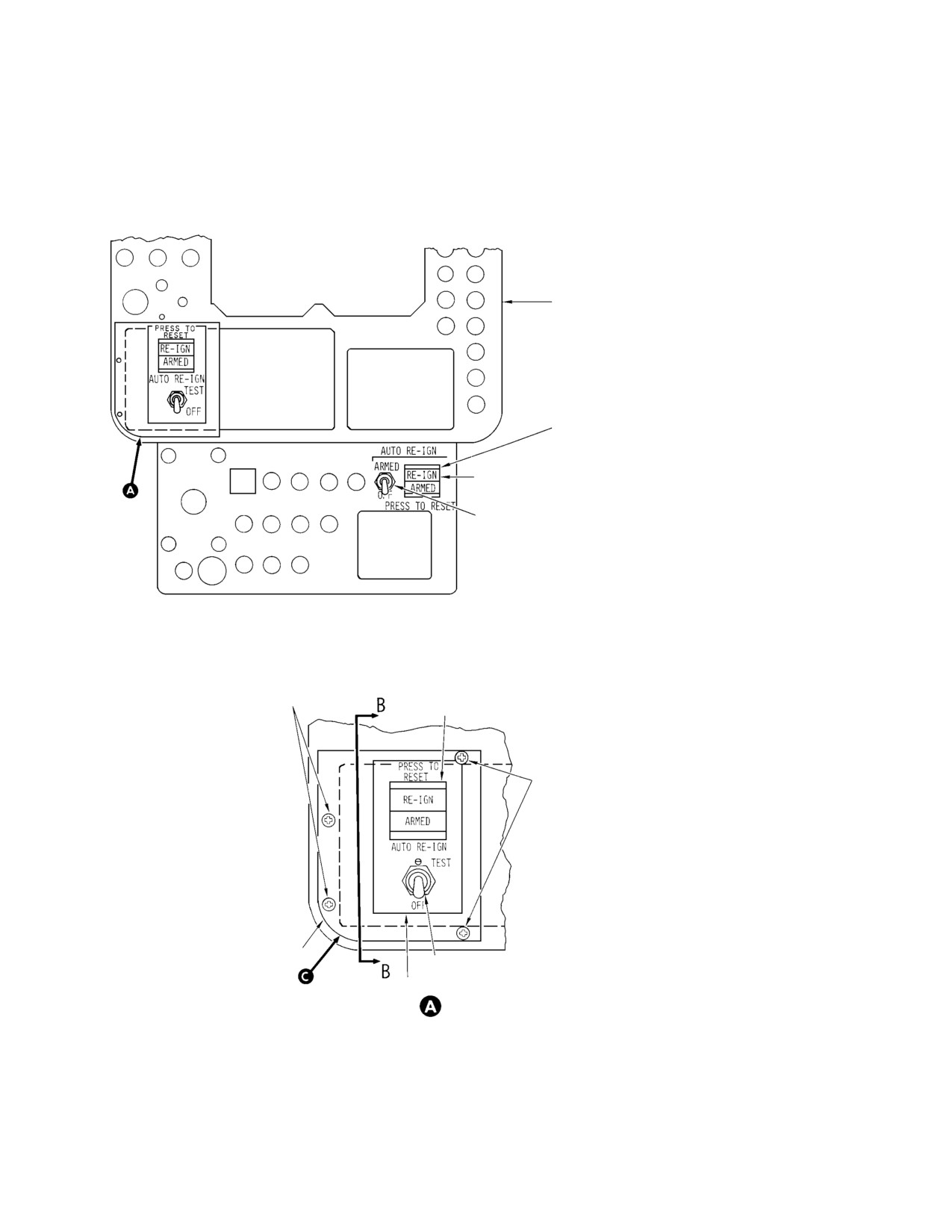
REMOVE AUTO RE-IGN SWITCHES AND
BLACK OUT LETTERING AND COVER UP
HOLES AFTER RELOCATION
SS48152 PLUG BUTTON OR EQUIVALENT
(CARR FASTENER COMPANY)
USE EXISTING HOLE IN PANEL,
USE 6-32 X 0.50 IN. (12.7 MM) LS
369H90118-105 SWITCH ASSEMBLY (RE).
SCREW AND WASHER (4 PLACES)
EXISTING SWITCH MAY BE REWIRED
DRILL0.218-0.221 IN. (5.5372-5.6134 MM) DIA
HOLES IN PANEL TO USE TINNERMAN NUT
``U'' TYPE NC, C42332BE-632 OR TAP DRILL
THREADS FOR 6-32 SCREW (REF)
PLATE
882GK15 SWITCH (CUTLER HAMMER)
INSTALL DECAL (SEE VIEW E-E)
G96-1007-1A
Figure 801. Relocation of Auto Re−ignition Controls (Sheet 1 of 2)
Page 802
Revision 22
71-30-00
MD Helicopters, Inc.
CSP-HMI-2
MAINTENANCE MANUAL
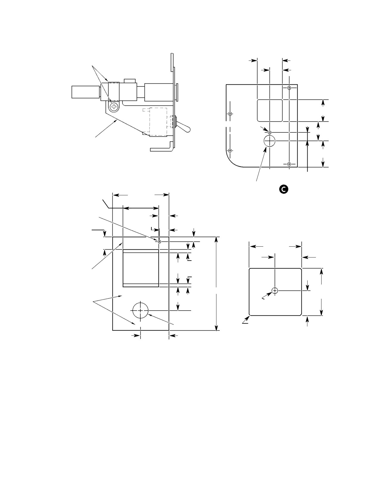
USE EXISTING CLAMP
1.125 IN.
AND HARDWARE
(2.8575 CM)
0.562 IN.
(14.2748 MM)
1.00 IN. 2.54 CM)
0.125 IN. (3.175 MM)
DIA. HOLE
0.87 IN. (22.098 MM)
MODIFY EXISTING
SUPPORT TO FIT
IF REQUIRED
1.12 IN. (2.8448 CM)
B-B
0.375 IN.
(9.525 MM)
0.500-0.505 IN.
1.44 IN.
(12.7-12.827 MM)
1.76 IN.
(3.6576 CM)
DIA. HOLE
(4.4704 CM)
0.175 IN.
(4.445 MM)
0.32 IN. (8.128 MM)
DIA.
0.30 IN. (7.62 MM)
0.15 IN. (3.81 MM)
0.50 IN.
(12.7 MM)
PRESS TO
1.18 IN.
RESET
(2.9972 CM)
0.59 IN.
0.12 IN.
(14.986 MM)
1.00 IN.
(3.048 MM)
6 POINT GOTHIC
(2.54 CM)
0.12 IN.
LETTERS
(3.048 MM)
1.06 IN.
3.00 IN. (7.62 CM)
(2.6924 CM)
AUTO RE-IGN
12 POINT GOTHIC
0.87 IN. (22.098 MM)
0.130-0.143 IN.
LETTERS
TEST
(3.302-3.6322 MM)
DIA. HOLE
0.50 IN.
0.03 in. (0.762 MM)
OFF
(12.7 MM)
R (TYP 4 PLCS)
0.53 IN.
0.88 IN.
(13.462 MM)
(22.352 MM)
COVER
(FOR 369H6416 INSTRUMENT PANEL)
DECAL
MADE FROM ALUMINUM ALLOY SHEET, 2024-T3, QQ-A-250/5,
MADE FROM 3650 SCOTCH CAL BRAND FILM, BLACK
TEMP T-3 0.03 X 1.062 X 1.187 IN. (0.762 X 26.9748 X 30.1498 MM).
BACKGROUND (COLOR NO. 37038) WITH WHITE
APPLY ONE COAT HMS-15-1082 PRIMER AND DRY FOR 1 TO 2
LETTERS (COLOR NO. 37875) PER FED-STD-595.
HOURS. APPLY TOPCOAT HMS-15-1083 ACRYLIC LACQUER AND
E-E
AIR DRY 4 HOURS MINIMUM.
D-D
G96-1007-2A
Figure 801. Relocation of Auto Re−ignition Controls (Sheet 2 of 2)
Page 803
71-30-00
Revision 22
MD Helicopters, Inc.
CSP-HMI-2
MAINTENANCE MANUAL
ENGINE IGNITION CONTROL SYSTEM
INITIAL INSTALLATION
1. Auto Re−ignition Initial Installation
D. Diode Isolator Assembly Installation
(Ref. Figure 401, Figure 402 and Figure 403)
Consumable Materials
This section provides instructions for installa
(Ref. Section 91−00−00)
tion of the 369H900118-513 and -515 engine
Item
Nomenclature
automatic re-ignition equipment. These
CM313
Insulation varnish
instructions cover removal or modification of
CM612
Tube, silicone
existing equipment to accommodate re-igni
tion equipment.
CM703
Tie strap
CM808
Lacing cord
NOTE: 369D helicopters S/N 003 - 949 did not
provide full time operation. Refer to Auto
NOTE: When providing ground for electrical
Re-ignition Rework for converting system
components, clean contacting surfaces to
to full time operation.
bare metal per Maintenance of Electrical
Bonding Connections (Ref. Chap. 96). Do
A. Reference Data
not tighten electrical clamps or secure elec
trical wiring to existing harnesses until all
The consumable and expendable materials
electrical wiring and components are in
listed are of a commercial nature that could be
stalled.
procurable locally. Alternate, but equivalent,
items might be available, but consultation
(1).
Remove nut and washer securing
with MDHI Customer Service Department is
forward end of K301 start relay to
recommended.
369A2537 oleo support.
(2).
Clean area for electrical bonding
B. Preparation for Installation
around large hole in bracket and that
portion of K301 start relay bracket
Preparing for installation of engine automatic
exposed by removal of nut and washer
re-ignition equipment includes the following:
in step (1). above.
(1). Place BATTERY-OFF-EXT PWR
(3).
Using nut and washer removed in step
(master) switch in OFF position.
(1). above, install diode isolator assem
bly so that lug type diode connectors
(2). Open engine right access door.
are aft.
(3). Identify all components, including
(4).
Locate wire J503C20 (open end) in
attaching hardware removed to gain
harness running vertically, just forward
access to work areas. Protect compo
of Sta. 135.50 bulkhead and approxi
nents from damage and contamination
mately 6 inches (15.24 cm) aft of diode
until installed.
isolator assembly. Place a 2.50 inch
(6.35 cm) length of silicone tubing
C. Automatic Re−ignition System
(CM612) on wire for use in step (6).
Installation
below.
(5).
Connect wire J503B20 from diode CR1
NOTE: The engine automatic re-ignition kits
of diode isolator assembly to the B-end
are supplied with as many parts assembled
of knife splice SPl8. Connect A-end of
as practical, however. some parts may re
same splice to wire J503C20 located in
quire assembly at installation. The follow
step (4). above.
ing procedures provide complete assembly
instructions. The operator should omit those
(6).
Slide silicone tubing over SPl8 splice
steps which may have already been accom
and secure with tie-strap (CM703) at
plished.
each end of splice.
Page 901
71-30-00
Revision 22
CSP-HMI-2
MD Helicopters, Inc.
MAINTENANCE MANUAL
(7).
Remove existing wire K502D20 from
(5). On left side of instrument panel
terminal X2 of K301 start relay. Cut off
structure, install relay K104 in center
existing terminal, remove and save
position and relay K304 in aft position,
existing terminal protector, slip 2.50
on bracket with screws, washers and
inch (6.35 cm) length of silicone tubing
nuts.
on wire, and connect wire to B-end of
NOTE: Bracket is installed in upper half of
knife splice SPl7.
largest lightening hole in left side structure
(8).
Connect A-end of SP17 splice to
of instrument panel.
K502CB20 wire from common connec
(6).
Clean area around ARM-OFF switch
tor 2 of CR1 and CR2 diodes of diode
(S11) mounting hole in lower switch
isolator assembly.
and circuit breaker panel, to prepare
(9).
Slide silicone tubing over splice and
bonding surface for switch support;
secure with tie-strap at each end of
clean all surfaces around holes in
SP17 splice.
support.
(10).
Place terminal protector removed in
(7).
Insert threaded shank of ARM-OFF
step (7). above, on wire K502CA20 of
switch through half-inch (12.7 mm)
diode isolator assembly. Connect wire to
hole in support followed by key washer
X2 terminal of K301 start relay and
with washer tang toward switch
slide terminal protector into place.
actuator arm.
(11).
Secure wiring with lacing cord (CM808)
(8).
Insert ARM-OFF switch through half
as required. making certain that
inch (12.7 mm) mounting hole in lower
sufficient wire slack remains so that
switch and circuit breaker panel; install
connectors are not stressed.
washer and nut making certain tang is
positioned in small hole adjacent to
(12).
After assembly and test apply insula
half-inch (12.7 mm) hole in panel.
tion varnish (CM313) to exposed
threads and tips.
(9).
Clean portion of cylindrical (coil)
housing to contact clamp; insert switch
(13).
Close engine access door.
assembly (XDS9), from front side of
panel. into square cut out mounting
E. Relay and Switch Assembly Installation
hole in lower switch and circuit breaker
panel.
Consumable Materials
(10).
Secure housing of switch (XDS9) to
(Ref. Section 91−00−00)
support with clamp, screw, washers and
Item
Nomenclature
nut.
CM703
Tie strap
CM812
Splice, knife
(11).
Install electrical wiring as follows:
(a). Route wire J502A20 from relay K104
(1). Remove instrument panel left and right
to ARM-OFF switch and connect to
side covers to expose lightening holes.
contact 3 of switch (S11).
(2). Remove ash tray and edge lighted panel
(b). Route wire J503EE20 from relay
from lower switch and circuit breaker
K104 and insert pin in contact C of
panel.
terminal block 502, module 13
(TB502-13).
(3). Remove screws and loosen lower switch
and circuit breaker panel.
(c). Route wire J508A20N from relay
K104 and connect to ground stud E2.
(4). Remove and discard square cutout and
adjacent round hole button covers
(d). Route wire J507AA20 from relay
located above PRESS TO RESET
K104 and insert pin in contact E of
placard.
TB502-13.
Page 902
Revision 22
71-30-00
MD Helicopters, Inc.
CSP-HMI-2
MAINTENANCE MANUAL
(e).
Route wire E559AC22 from relay
(14). Install edge-lighted panel and ash tray
K304 to closest proximity of GEN
on lower switch and circuit breaker
OUT wire E559A22; connect wires
panel.
E559AC22 and E559A22 with splice
(15). Perform Operational Check of engine
(CM812).
automatic re-ignition electrical system.
(f).
Route wire J501AE2O from relay
K304 to contact 1 of ARM-OFF
F. Relay and Switch Assembly Installation
switch (S11); install terminal
(T−Panel with Center Console)
(MS25036-102) on wire J501A20;
connect terminals of wires J501AE20
Consumable Materials
and J501A20 to contact 1 of ARM-
(Ref. Section 91−00−00)
OFF switch (S11). Route wire
Item
Nomenclature
J501A20, install terminal
CM612
Tube, silicone
(MS25036-149) and connect to
CM703
Tie strap
contact 2 of circuit breaker CB106.
CM812
Splice, knife
(g).
Route wire J502E20 from relay, K304
CM815
Solder
and connect to contact 4 of ARM-
OFF switch (S11).
NOTE: T-panels (-703 and -705) with center
(h).
Arrange relay wires to form smooth
console are identical except the -705 is
flow integrating with existing wire
equipped with 14 caution indicators.
bundles; use tie-straps (CM703) as
required to secure wire bundles.
(1). Remove console right side cover.
Ensure sufficient wire slack to avoid
stress on solder joints.
(2). Remove additional panels as required
to facilitate installation of engine
(i).
If bracket has been removed for
automatic re-ignition switches and
installation ease, clean bracket panel
wiring.
contact areas to ensure positive
ground; install bracket with screws
(3). Remove ARM-OFF and RE-IGN
and washers.
ARMED switch hole covers from
instrument panel.
(j).
Route ground wire J505A20N from
switch (XDS9) coil housing and
(4). Locate relay bracket (for relays K104
connect to ground stud E2.
and K304) on right side of console inner
panel.
(k).
Route wire J502D20 from RE-IGN
ARMED switch (XDS9) and connect
(5). Install relays K104 and K304 as
follows:
to contact 6 of ARM-OFF switch
(S11).
(a). Install relay K104 in outboard
(l).
Route wire J503D20 from switch
position, and relay K304 in inboard
(XDS9) and insert pin in contact A of
position on relay bracket, with
TB502-13.
screws, washers and nuts.
(m).
Route wire J501B20 from switch
(b). Arrange relay wires to form a smooth
(XDS9) and insert pin in contact A of
flow, integrating with existing wire
ARM-OFF switch (S11).
bundles; use tie-straps (CM703) as
required to secure wire bundles.
(12). Install instrument panel left side cover.
Ensure sufficient wire slack to avoid
stress on solder joints.
(13). Clean screw attach areas of lower
switch and circuit breaker panel to
(6). Install ARM-OFF switch (S11) and
ensure positive grounding bond; install
RE-IGN/ARMED switch assembly as
panel.
follows:
Page 903
71-30-00
Revision 22
CSP-HMI-2
MD Helicopters, Inc.
MAINTENANCE MANUAL
(a).
Clean area around ARM-OFF (S11)
2). Route wire E559AC22 from relay
switch-hole in instrument panel to
K304 to TB502 and insert pin in
prepare bonding surface for switch
contact C of TB502-20.
(XDS9) support; install AUTO
3). Install pin (MPCM20M-H2) on
RE-IGNITION decal
wire E559AB22; insert pin in
(369H90118-27). Clean all surfaces
contact A of TB502-20 and route
around holes in support.
wire to plug P12. Crimp pin on
(b).
Insert threaded shank of ARM-OFF
opposite end of wire E559AB22
switch (S11) through half-inch
and insert pin in contact D of P12.
mounting hole in support followed by
4). Install pin (MPCM20M-H2) on
key washer with washer tang toward
wire E559AA22; insert pin in
switch actuator arm.
contact B of TB502-20. Route
opposite end of wire E559AA22 to
(c).
Insert ARM-OFF switch (S11)
GEN OUT (XDS18) warning light
through half-inch mounting hole in
and solder (CM815) to contact 3.
instrument panel; install washer and
nut making certain key washer tang
(f). On aircraft equipped with
is in small hole adjacent to half-inch
369D294201-705 instrument panel
(12.7 mm) hole in panel.
face; install wire E559AC22 as
follows:
(d).
Clean portion of cylindrical (coil)
housing to contact clamp; insert
1). Route wire E559AC22 to closest
switch assembly (XDS9) into square
proximity of wire E17A22 (routed
cutout mounting hole in instrument
between P526-EE and P527-A).
panel.
2). Cut wire E17A22; install 2.50 inch
(e).
Secure housing of switch (XDS9) to
(6.35 cm) length of silicone tubing
support with clamp, screw, washers
(CM612) and splice (CM812) wires
and nut.
E559AC22 and E17A22. Slide
tubing over splice and secure with
(7). Install electrical wiring as follows:
tie-straps (CM703).
(a). Route wire J502A20 from relay K104
(g).
Route wire J5017E20 from relay
to ARM-OFF switch (S11) and
K304 and connect to contact 1 of
connect to contact 3 of ARM-OFF
ARM-OFF switch (S11).
switch (S11).
(h).
Route wire J502E20 and connect to
(b). Route wire J503EE20 from relay
contact 4 of ARM-OFF switch (S11).
K104 and insert pin in contact C of
(i).
Route ground wire J505A20N from
terminal block 502, module 13
switch (XDS9) and connect terminal
(TB502-13).
to ground stud E31.
(c). Route wire J508A20N from relay
(j).
Route wire J502D20 from switch
K104 and connect to ground stud
(XDS9) and connect terminal to
E31.
contact 6 of ARM-OFF switch (S11).
(d). Route wire J507AA20 and insert pin
(k).
Route wire J503D20 from switch
in contact E of TB502-13.
(XDS9) and insert pin in contact A of
TB502-13.
(e). On aircraft equipped with
369D294201-703 instrument panel
(l).
Route wire J501B20 from switch
face, install wire E559AC22 as
(XDS9) and connect to contact 3 of
follows:
ARM-OFF switch (S11).
1). Install module No. 20 on TB502.
(m).
Relocate wire J501A20 as follows:
Page 904
Revision 22
71-30-00
MD Helicopters, Inc.
CSP-HMI-2
MAINTENANCE MANUAL
1). On aircraft equipped with 369D
(9). Install console right cover.
294201-703 instrument panel face,
disconnect wire J501A20 from
(10). Secure all panels loosened or removed
CB124 on circuit breaker panel,
for access.
and connect to contact 2 of CB106.
(11). Perform Operational Check of engine
2). On aircraft equipped with 369D
automatic re-ignition system (refer to
294201-705 instrument panel face,
appropriate PFM).
disconnect wire J501A20 from
CB119 on circuit breaker panel,
G. Weight and Balance
and connect to contact 2 of CB105.
(8). Install black cover decals
Weight and balance changes resulting from
(369H90118-35 and -37) over AUTO
installation of engine automatic re-ignition
RE-IGN markings of previously used
equipment are listed in Table 901. After
circuit breaker position on edge lighted
installation of the engine automatic re-igni
circuit breaker panel; install new
tion system equipment, incorporate changes in
AUTO RE-IGN decal (369H90118-33).
helicopter weight and balance record.
Table 901. Weight and Balance Data
Weight
Arm
Moment
Pounds (kg)
inches (cm)
in.−lb
(kg cm)
Added
1.5
(0.6803884)
91.5
(232.41)
1.4
(16.12968)
Removed
0.0
0.0
0.0
Change
1.5
(0.6803884)
91.5
(232.41)
1.4
(16.12968)
Page 905
71-30-00
Revision 22
CSP-HMI-2
MD Helicopters, Inc.
MAINTENANCE MANUAL
This Page Intentionally Left Blank
Page 906
Revision 44
71-30-00
MD Helicopters, Inc.
CSP-HMI-2
MAINTENANCE MANUAL
Section
71−60−00
Engine Cooling
System (250−C20B,
250−C20R/2,
250−C30 and
250−C47)
MD Helicopters, Inc.
CSP-HMI-2
MAINTENANCE MANUAL
ENGINE COOLING SYSTEM
MAINTENANCE PRACTICES
1. Engine Cooling System Description and
3. Engine Cooling System Repair and
Operation
Replacement
(Ref. Figure 201 and Figure 202) Helicopter
(Ref. Figure 201 and Figure 202)
engine and transmission oil cooler blower air is
used to cool engine exterior surfaces. After
passing through the oil coolers, the relatively
Consumable Materials
temperate air is redirected by a system of
(Ref. Section 91−00−00)
supports, clamps, and ducts onto the ignition
Item
Nomenclature
exciter, engine gearcase, and compressor and
CM107
Fluorocarbon release agent
turbine section external surfaces. Exhaust air
is discharged overboard through a gap
CM712
Tape, pressure sensitive
between the engine exhaust pipe and engine
access doors.
(1). Unclamp and remove ducts.
2. Engine Cooling System Inspection
(Ref. Figure 201 and Figure 202)
(2). Patch duct damage with tape (CM712).
(1). Inspect ducts for holes, tears, cracks,
NOTE: Apply dry film lubricant (CM107) to
fraying and security. Repair duct
duct and seal mating surfaces prior to as
damage as required.
sembly.
(2). Inspect duct supports and clamps for
condition and security. Repair support
(3). Assemble duct, seals, clamps and
system as required.
attaching hardware.
Page 201
71-60-00
Revision 22
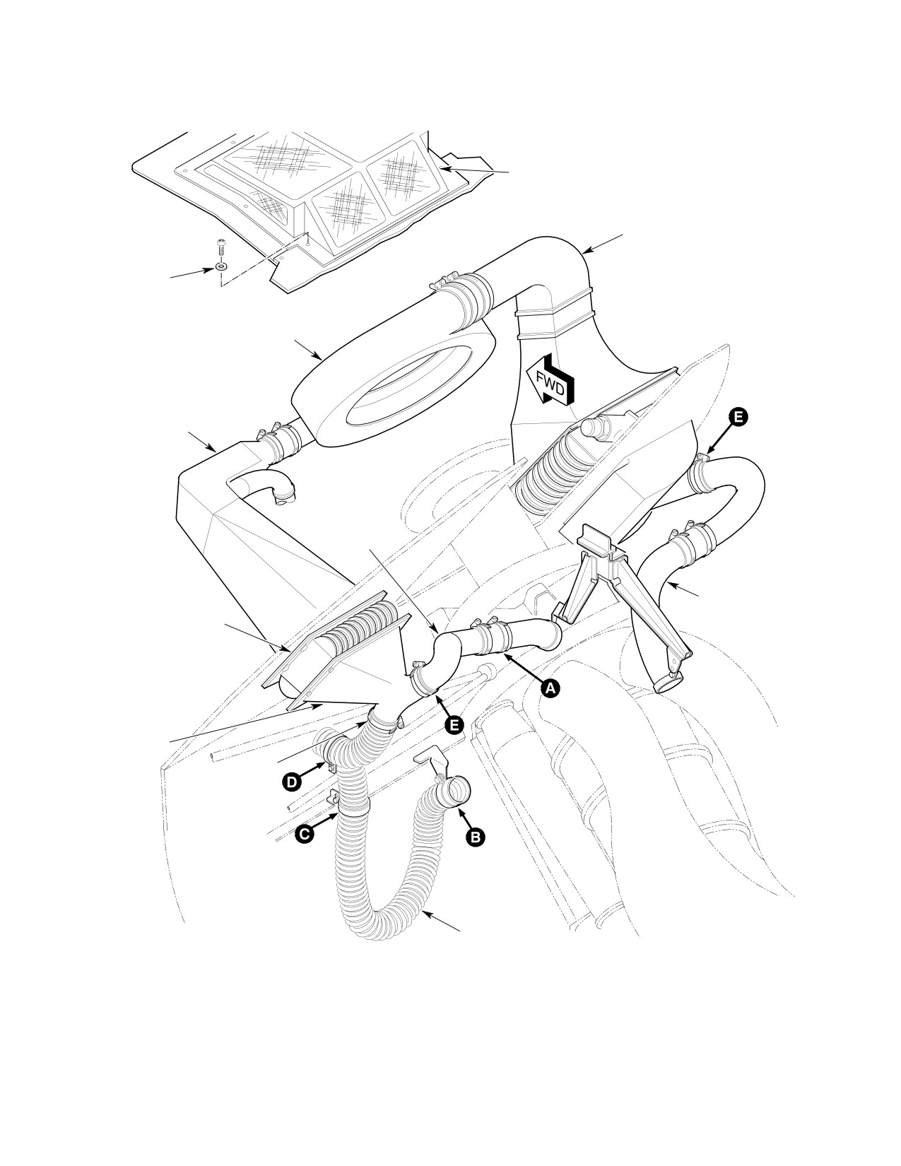
CSP-HMI-2
MD Helicopters, Inc.
MAINTENANCE MANUAL
ENGINE AIR COOLING
INLET SCREEN
ENGINE OIL
COOLER DUCT
WIDE AREA
WASHER
BLOWE
R
TRANSMISSION OIL
COOLING DUCT
COMPRESSOR
COOLING DUCT
POWER TURBINE
TRANSMISSION
COOLING DUCT
OIL COOLER
IGNITION EXCITER
COOLING DUCT
CLAMP
ENGINE GEARCASE
COOLING DUCT
(FLEX-HOSE)
G71-6000-1
Figure 201. Engine Air Cooling System − 250−C20B and 250−C20R/2 (Sheet 1 of 2)
Page 202
Revision 22
71-60-00
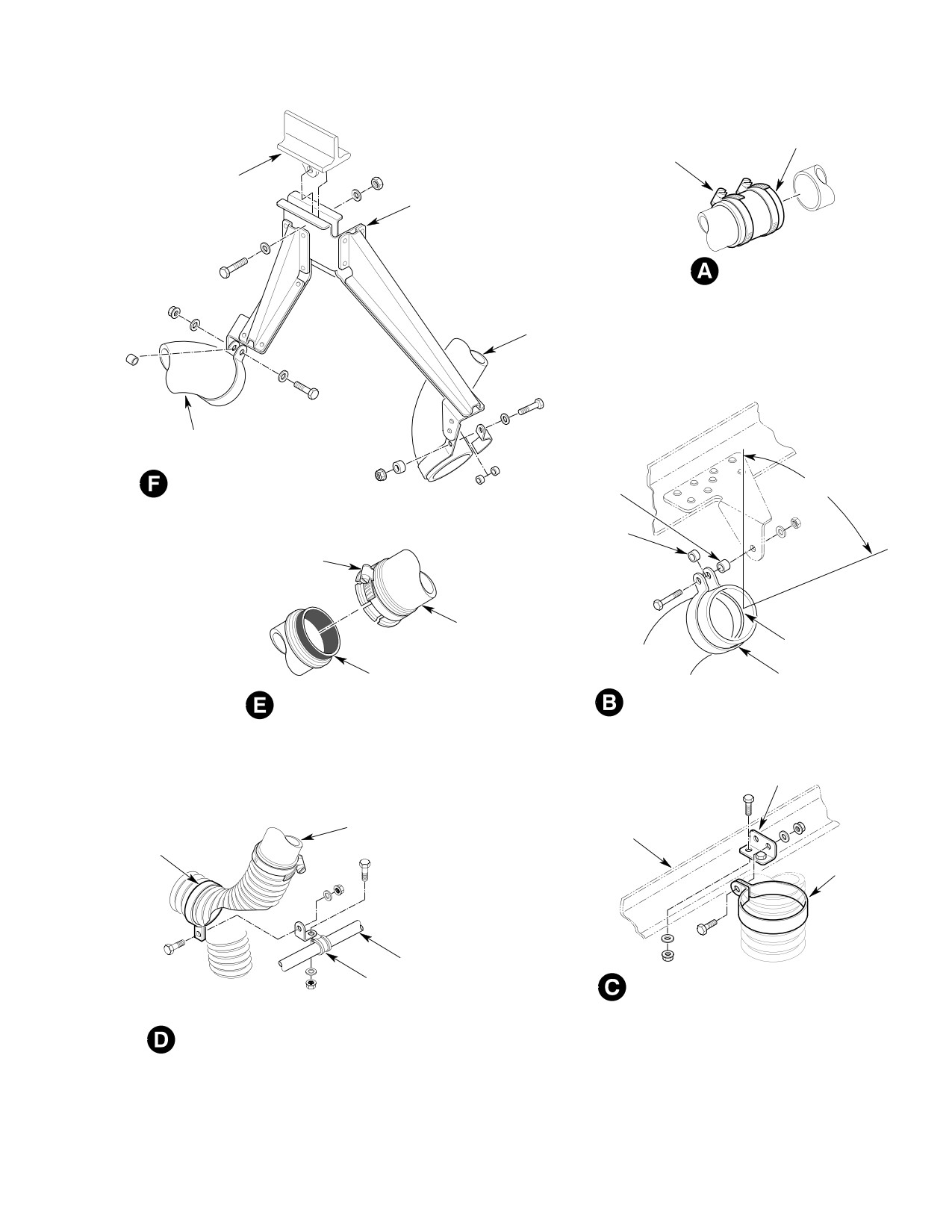
MD Helicopters, Inc.
CSP-HMI-2
MAINTENANCE MANUAL
CONNECTOR
CLAMP
HOISTING
SUPPORT
EYE FITTING
BRACKET
DUCT CONNECTION
POWER TURBINE
COOLING DUCT
COMPRESSOR
COOLING DUCT
9/32 INCH (7.14 MM)
OVERHEAD DUCT SUPPORT
SPACER
50°±10°
1/4 INCH (6.35 MM)
SPACER
CLAMP
COOLING
DUCT
DUCT SUPPORT
RING
SEAL
CLAMP
COOLING DUCT ATTACHMENT
GEARCASE COOLING DUCT ATTACHMENT
CLIP
LOWER TRANSMISSION
OIL COOLER DUCT
STA. 124.00 LOWER
CLAMP
SECTION FRAME
(NOTE)
CLAMP
(NOTE)
ENGINE MOUNT
CLAMP
GEARCASE COOLING DUCT SUPPORT
GEARCASE COOLING DUCT SUPPORT
NOTE:
INSTALL CHAFFING STRIP TO INSIDE SURFACE
OF CLAMP PRIOR TO INSTALLATION
G71-6000-2B
Figure 201. Engine Air Cooling System − 250−C20B and 250−C20R/2 (Sheet 2 of 2)
Page 203
71-60-00
Revision 22
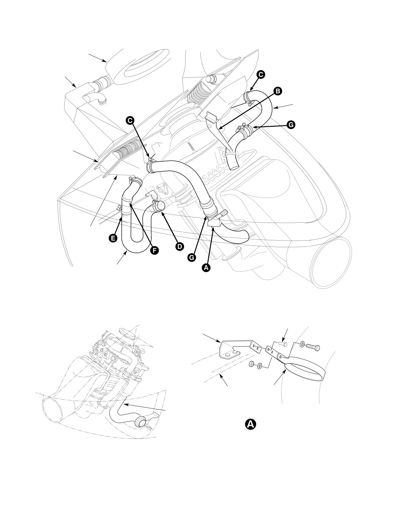
CSP-HMI-2
MD Helicopters, Inc.
MAINTENANCE MANUAL
BLOWER
TRANSMISSION OIL
COOLING DUCT
ENGINE OIL
COOLER DUCT
ENGINE OIL
COOLER
COMPRESSOR
COOLING DUCT
TRANSMISSION OIL
COOLER
IGNITION EXCITER
COOLING DUCT
ENGINE GEARCASE
COOLING DUCT
RIVET (2)
BRACKET
CLAMP
ENGINE DOOR
FRAME
STARTER-GENERATOR
COOLING DUCT
POWER TURBINE COOLING
DUCT INSTALLATION
G71-6001-1
Figure 202. Engine Air Cooling System − 250−C30 and 250−C47 (Sheet 1 of 2)
Page 204
Revision 22
71-60-00
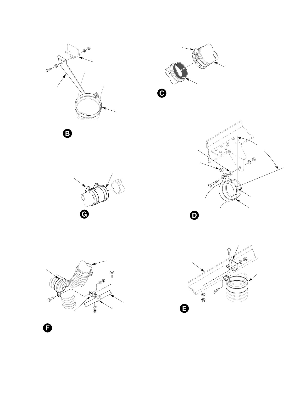
MD Helicopters, Inc.
CSP-HMI-2
MAINTENANCE MANUAL
CLAMP
HOISTING EYE
FITTING
COOLING
DUCT
SEAL
BRACKET
COOLING DUCT ATTACHMENT
CLAMP
(NOTE)
COMPRESSOR COOLING
DUCT INSTALLATION
9/32 INCH (7.14 MM)
50°±10°
SPACER
1/4 INCH (6.35 MM)
SPACER
CONNECTOR
CLAMP
DUCT SUPPORT
RING
CLAMP
DUCT CONNECTION
GEARCASE COOLING DUCT ATTACHMENT
CLIP
LOWER TRANSMISSION
STA. 124.00 LOWER
OIL COOLER DUCT
SECTION FRAME
CLAMP
(NOTE)
CLAMP
(NOTE)
ENGINE MOUNT
GEARCASE COOLING DUCT SUPPORT
CLAMP
CLIP
GEARCASE COOLING DUCT SUPPORT
NOTE:
INSTALL CHAFFING STRIP TO INSIDE SURFACE
OF CLAMP PRIOR TO INSTALLATION
G71-6001-2B
Figure 202. Engine Air Cooling System − 250−C30 and 250−C47 (Sheet 2 of 2)
Page 205
71-60-00
Revision 22
CSP-HMI-2
MD Helicopters, Inc.
MAINTENANCE MANUAL
This Page Intentionally Left Blank
Page 206
Revision 44
71-60-00

MD Helicopters, Inc.
CSP-HMI-2
MAINTENANCE MANUAL
Chapter
75
Engine Anti−Ice
System
MD Helicopters, Inc.
CSP-HMI-2
MAINTENANCE MANUAL
TABLE OF CONTENTS
Para/Figure/Table
Title
Page
75-10-00 Engine Anti-Icing System (250-C20B, 250-C20R/2, 250-C30
and 250-C47)
A
Maintenance Practices
201
1. Engine Anti-Icing System Description and Operation
201
2. Engine Anti-Icing System Fault Isolation
201
Table 201. 250-C20B Engine Anti-icing System Fault Isolation
201
Table 202. 250-C20/R2, 250-C30 and 250-C47 Engine Anti-icing System
Fault Isolation
202
3.
250-C20B Engine Anti-Icing Valve Control Cable Replacement
202
A. 250-C20B Engine Anti-Icing Valve Control Cable Removal
202
B. 250-C20B Engine Anti-Icing Valve Control Cable Installation
202
Figure 201. 250-C20/R2, 250-C30 and 250-C47 Engine Anti-Icing
System Wiring
203
4.
250-C20/R2, 250-C30 and 250-C47 Engine Anti-Icing System Controls
Replacement
203
5.
250-C20B Engine Anti-Icing System Inspection
203
6.
250-C20/R2, 250-C30 and 250-C47 Engine Anti-Icing System Inspection
204
7.
250-C20B Engine Anti-Icing System Test
204
8.
250-C20/R2, 250-C30 and 250-C47 Engines Anti-Icing System Test
204
9.
250-C20B Engine Anti-Icing System Control Cable Repair
204
10. 250-C20/R2, 250-C30 and 250-C47 Engine Anti-Icing Valve Repair
204
Figure 202. 250-C20B Engine Anti-Icing System
205
Figure 203. 250-C20/R2, 250-C30 and 250-C47 Engine Anti-Icing
Control Valve
206
Page i
75 Contents
Revision 22
CSP-HMI-2
MD Helicopters, Inc.
MAINTENANCE MANUAL
TABLE OF CONTENTS (Cont.)
Para/Figure/Table
Title
Page
This Page Intentionally Left Blank
Page ii
Revision 43
75 Contents
MD Helicopters, Inc.
CSP-HMI-2
MAINTENANCE MANUAL
Section
75−10−00
Engine Anti−Icing
System (250−C20B,
250−C20R/2,
250−C30 and
250−C47)