HANDBOOK OF MAINTENANCE INSTRUCTIONS FOR MDHI 369D/E/FF-500/600N HELICOPTERS (ISSUED: 1990) - page 27
CSP−HMI−2
MD Helicopters, Inc.
MAINTENANCE MANUAL
TABLE OF CONTENTS (Cont.)
Para/Figure/Table
Title
Page
A. Automatic Re-ignition Test Switch (S11) Replacement
401
B. Armed Light/Switch (XDS9) Assembly Replacement
401
C. Armed Light/Switch (XDS9) Lamps Replacement
401
D. Armed Lights/Switch (XDS9) Display Screen Replacement
401
E. K104/K304 Relay Replacement
401
F. CR1/CR2 Diode Replacement
402
Figure 401. Auto Re-ignition System Equipment (Sheet 1 of 3)
403
Figure 402. Auto Re-ignition Wiring Diagram (Sheet 1 of 6)
406
Figure 403. Auto Re-ignition Schematic (Sheet 1 of 3)
412
Inspection/Check
601
1. Automatic Re-ignition System Check (with Ground/Air Switch)
601
A. Normal Start
601
2. Automatic Re-ignition System Check (without Ground/Air Switch)
601
Repairs
801
1. Auto Re-ignition System Modification
801
A. Preparation for Modification
801
2. Instrument Panel Modification
801
3. Electrical System Modification
801
Figure 801. Relocation of Auto Re-ignition Controls (Sheet 1 of 2)
802
Figure 802. Auto Re-ignition Rewiring Diagram
804
Initial Installation
901
1. Auto Re-ignition Initial Installation
901
A. Reference Data
901
B. Preparation for Installation
901
C. Automatic Re-ignition System Installation
901
D. Diode Isolator Assembly Installation
901
E. Relay and Switch Assembly Installation
902
F. Relay and Switch Assembly Installation (T-Panel with Center Console)
903
G. Weight and Balance
905
Table 901. Weight and Balance Data
905
71-60-00 Engine Cooling System (250-C20B, 250-C20R/2, 250-C30 and 250-C47)
A
Maintenance Practices
201
1. Engine Cooling System Description and Operation
201
2. Engine Cooling System Inspection
201
3. Engine Cooling System Repair and Replacement
201
Figure 201. Engine Air Cooling System - 250-C20B and 250-C20R/2
(Sheet 1 of 2)
202
Page viii
Revision 36
71 Contents
MD Helicopters, Inc.
CSP−HMI−2
MAINTENANCE MANUAL
TABLE OF CONTENTS (Cont.)
Para/Figure/Table
Title
Page
Figure 202. Engine Air Cooling System - 250-C30 and 250-C47
(Sheet 1 of 2)
204
Page ix
71 Contents
Revision 36
CSP−HMI−2
MD Helicopters, Inc.
MAINTENANCE MANUAL
TABLE OF CONTENTS (Cont.)
Para/Figure/Table
Title
Page
This Page Intentionally Left Blank
Page x
Revision 36
71 Contents
MD Helicopters, Inc.
CSP-HMI-2
MAINTENANCE MANUAL
Section
71−00−00
Power Plant
(250−C20)
MD Helicopters, Inc.
CSP-HMI-2
MAINTENANCE MANUAL
POWER PLANT
DESCRIPTION AND OPERATION
1.
Power Plant Description
consist of a combined four stage axial
and single stage centrifugal flow
(1).
MDHI 369D/E helicopters may be
compressor, an annular combustion
powered by either a 250-C20B or
chamber and a four stage turbine
250-C20R/2 turboshaft engine man
system to extract power from the gas. A
ufactured by the Allison Engine
two-stage gas producer turbine drives
Company Inc.
the compressor, gas producer fuel
control, accessory gear train and N1
(2).
MDHI 500N helicopter is powered by a
tachometer-generator. A two-stage
250-C20R/2 turboshaft engine man
power turbine drives the helicopter
ufactured by the Allison Engine
rotor system, governor control and N2
Company Inc.
tachometer-generator. A start counter
is standard and part of the engine
(3).
The engine is secured in the helicopter
ignition system
by three mount assemblies and ac
cessed through two hinged, air-sealed
(2). Allison Engine Operation and Mainte
doors.
nance Manuals are the primary
(4).
A belt-driven blower provides external
information source for engine fault
cooling air through strategically
isolation and maintenance data (Ref.
positioned ducts that direct air onto
Sec. 01-00-00). Refer to these manuals
engine exterior surfaces and through
for specific engine maintenance proce
the engine and transmission oil cooler
dures.
heat exchangers. Spent blower air is
(3). Starter operational limitations are in
exhausted aft through an annular
the applicable Pilot's Flight Manual.
opening between the engine exhaust
pipes and fuselage.
3. Models 250−C20B and 250−C20R/2 Power
(5).
Engine intake air may be filtered
Plant Fault Isolation
through a standard screen or optional
air particle separator/mist eliminator
(Ref. Table 1)
assembly. Intake air is drawn through a
plenum chamber and into the engine
(1). Check engine support systems, i.e.; chip
detectors, instruments, fuel supply,
intake bell-mouth by the compressor.
electrical systems, etc., to ensure that
Engine compartment air is separated
helicopter equipment is functioning
from compressor intake air by a seal
correctly before disassembling engine
ring.
systems for an indicated fault.
Power Plant Operation
2.
(2). Inspect and isolate engine problems per
(1). Allison turboshaft engines installed in
the applicable Allison Engine Operation
369D/E - 500N model helicopters
and Maintenance Manual.
Table 1. Power Plant Fault Isolation
Symptom
Probable Trouble
Corrective Action
High frequency vibration (1)
Loose engine mount bolts.
Retorque engine mount bolts to 100
− 140 inch−pounds (11.30 − 15.82
Nm).
NOTES:
(1) High frequency vibrations may be caused by other drive and rotor system components.
Page 1
71-00-00
Revision 22
CSP-HMI-2
MD Helicopters, Inc.
MAINTENANCE MANUAL
This Page Intentionally Left Blank
Page 2
Revision 44
71-00-00
MD Helicopters, Inc.
CSP-HMI-2
MAINTENANCE MANUAL
POWER PLANT
REMOVAL/INSTALLATION
1. Engine Removal
(e). Disconnect ground jumper at center
firewall stud.
A. Engine Disconnecting for Removal
(f). Unclamp and remove electrical
(Ref. Figure 401 and Figure 402)
harness from right engine mount
After each opening, removal
(369D only).
WARNING
or replacement of any part
(5).
Remove combustion chamber drain line
of the engine and/or aircraft fuel sys
from burner drain valve.
tem between the aircraft fuel tank and
the engine fuel nozzle, the fuel system
(6).
Disconnect fuel inlet line from engine.
must be bled to remove trapped air.
Failure to comply with this procedure
(7).
Disconnect fuel pump seal drain line.
can result in engine flameout or power
loss.
(8).
Disconnect compressor cabin air bleed
outlet tube from tee fitting on engine
Cap fluid lines and fittings with
CAUTION
compressor scroll.
approved devices. Do not use
tape to cover fuel and oil openings. Tape
(9).
Loosen compressor cooling air ducts at
adhesives loosened by fuel or oil can con
firewall coupling and engine oil cooler
taminate systems.
deflector coupling (Ref. Sec. 71-60-00).
(1). Set all switches OFF. Disconnect
(10).
Disconnect duct support bracket at
external power. Disconnect battery.
hoisting eye. Remove ducts from engine
NOTE: Tag all hardware, wire terminals, fuel
compartment (Ref. Figure 401, view B).
and oil lines before removal to expedite en
(11).
Disconnect torque-meter oil line from
gine installation. Identify and bag loose
firewall.
parts to prevent loss or damage.
(2). Remove main transmission drive shaft
(12).
Disconnect oil pressure indicator line
(Ref. Sec. 63-10-00).
from firewall.
(3). Remove engine exhaust pipes (Ref. Sec.
(13).
Disconnect N2 control rod from idler
78-20-00). Cover engine exhaust
bellcrank. Secure control rod to fire
outlet.
wall.
(4). Disconnect electrical wiring from
(14).
Disconnect anti-icing system as follows:
engine;
(a). Model 250-C20B;
(a). Disconnect engine electrical harness
Disconnect anti-ice control valve
ground lead and plug from recep
lever (Ref. Figure 401, view A).
tacle.
(b). Model 250-C20R/2:
(b). Disconnect thermocouple wire leads
Remove electrical connector from
from terminal studs on engine
anti-ice solenoid valve. Unclamp and
compartment door frame (Ref.
remove wiring harness from horizon
Figure 401, view C).
tal firewall shield.
(c). Remove thermocouple lead clamps
from door frame and exhaust pipe
(15). Disconnect N1 control rod from gas
clamp.
producer lever. Secure control rod to
firewall.
(d). Disconnect terminals E, C, and B
from starter-generator.
(16). Disconnect accessory drive vent tube.
Page 401
71-00-00
Revision 22
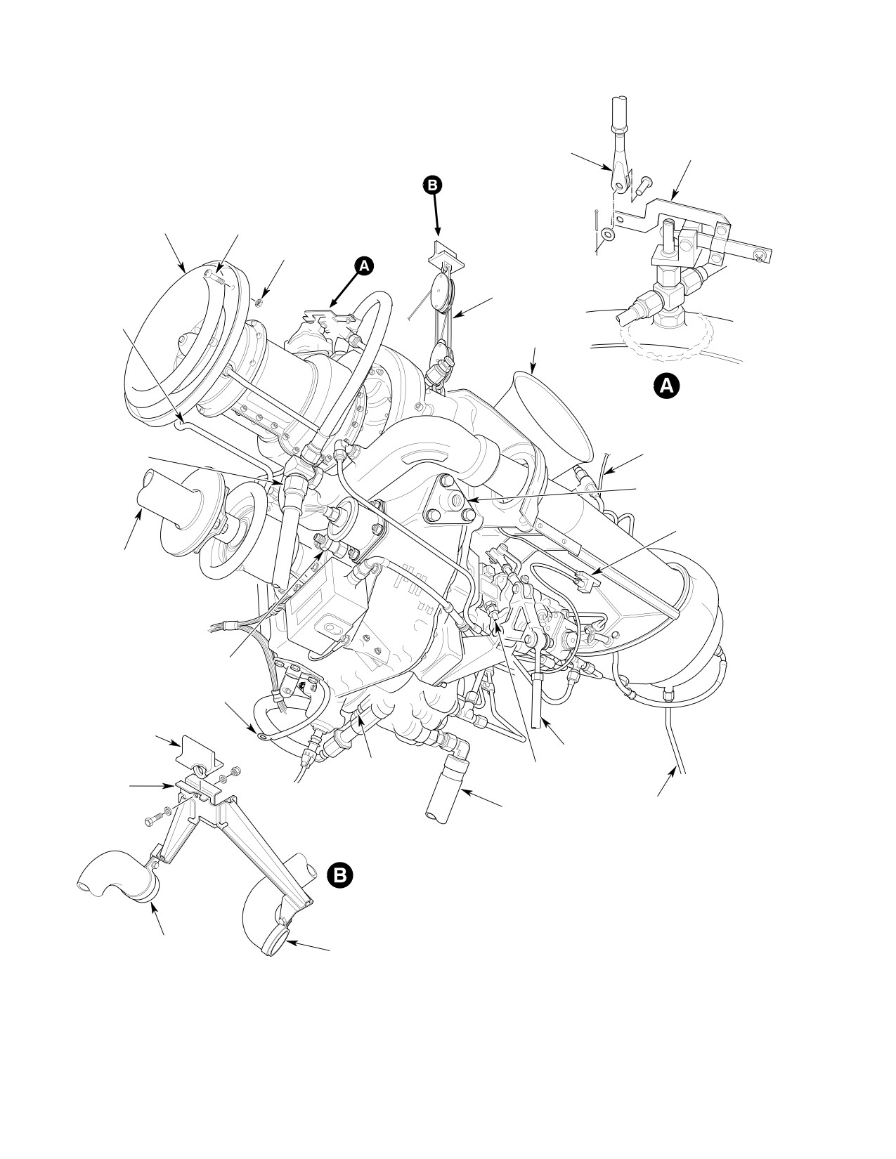
CSP-HMI-2
MD Helicopters, Inc.
MAINTENANCE MANUAL
CONTROL CABLE
CONTROL VALVE
CLEVIS
LEVER
SCREW (5 PLCS)
AIR INLET BELL
(NOTE 1)
NUT (5 PLCS)
(NOTE 1)
ENGINE HOIST
NO. 1 BEARING
OIL RETURN
LINE
EXHAUST DUCT
ANTI-ICING VALVE
INSTALLATION
(NOTE 2)
CABIN AIR
THERMOCOUPLE LEAD
OUTLET TUBE
MOUNT FITTING
P307
(NOTE 3)
DRIVESHAFT
TORQUEMETER
OIL LINE
GROUND JUMPER
AIRFRAME HOIST
FITTING
N2 CONTROL ROD
FUEL PUMP SEAL
FUEL CONTROL
BRACKET
DRAIN LINE
DRAIN LINE
COMBUSTION CHAMBER
FUEL SUPPLY HOSE
DRAIN LINE
ROTATED
NOTES:
1.
C20R/2 ENGINE (6 PLCS)
COMPRESSOR CASE
2.
C20B ENGINES ONLY.
TURBINE CASE
COOLING AIR DUCT
3.
C20R/2 ENGINES ONLY.
COOLING AIR DUCT
G71-0000-1
Figure 401. Allison 250−C20B and 250−C20R/2 Engine Removal and Installation (Sheet 1 of 2)
Page 402
Revision 22
71-00-00
MD Helicopters, Inc.
CSP-HMI-2
MAINTENANCE MANUAL
G71-0000-
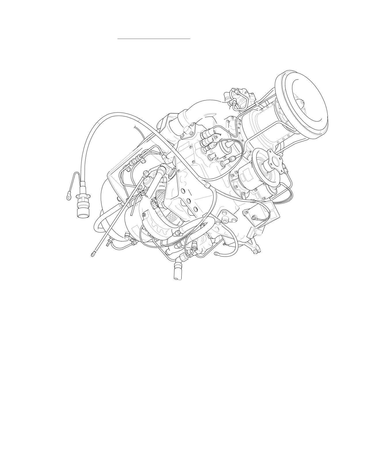
Figure 401. Model 250−C20B and 250−C20R/2 Engine Removal and Installation (Sheet 2 of 2)
Page 403
71-00-00
Revision 22

CSP-HMI-2
MD Helicopters, Inc.
MAINTENANCE MANUAL
(17). Disconnect fuel control drain line.
Do not use fuel or oil lines as
CAUTION
hand holds. Do not allow engine
The oil cooler is fragile. Unless
to strike airframe while maneuvering it out
CAUTION
otherwise required, disconnect
of the helicopter.
oil supply and return lines only at engine.
(5). Align engine stand (ST401) under
Support oil cooler port boss with a backup
engine with adjustable support shaft on
wrench when oil line removal is required.
left side (Ref. Figure 402).
Do not strain or bend unsupported tubes.
(6). Slowly lower engine out of helicopter.
(18). Disconnect and cap engine oil inlet,
Align engine side mount fittings
outlet and vent lines.
between fixed and adjustable support
shafts.
B. Removal of Disconnected Engine
(7). Screw in adjustable support shaft until
engine mount fittings are securely
(Ref. Figure 401 and Figure 402)
engaged with support shaft sockets.
(8). Insert detent pin through adjustable
Special Tools
support shaft.
(Ref. Section 91−00−00)
Item
Nomenclature
(9). Remove hoist from engine lift fitting.
ST401
Engine stand
(10). If engine is to be stored or transported,
ST402
Engine hoist
secure upper end of engine stand
transport and storage bar to engine
lifting eye fitting.
CAUTION
2. Engine Installation
A. Engine Installation in Mounts
D Do not remove engine mounts or disturb
engine mount adjustments to remove the
(Ref. Figure 401 and Figure 402)
engine (Ref. CSP-SRM-6).
D Engine-transmission alignment must be
Consumable Materials
inspected and realigned whenever one or
(Ref. Section 91−00−00)
more engine mount assemblies is re
Item
Nomenclature
placed or the existing engine-transmis
CM702
Lockwire CRES
sion alignment adjustment is disturbed.
Do not disturb adjustable engine mount
Special Tools
fittings unless an engine-transmission
(Ref. Section 91−00−00)
alignment check is planned.
Item
Nomenclature
(1). Install engine hoist apparatus (ST402)
ST402
Engine hoist
between airframe hoist fitting and
engine hoist eye.
(1). Open engine access doors.
(2). Have an assistant apply tension to
(2). Position engine to line up engine lifting
engine with hoist.
eye under airframe lift fitting.
(3). Remove detent pin from adjustable
(3). Maintain downward pressure on rear of
support shaft on engine stand. Detach
engine during mount bolt removal.
transport and storage bar from engine
Unbolt lower engine mount assembly
lift fitting.
from engine fitting.
(4). Install engine hoist (ST402) between
(4). Unbolt left and right engine mount
airframe fitting and engine hoist
assemblies from engine fittings.
fitting.
Page 404
Revision 22
71-00-00
MD Helicopters, Inc.
CSP-HMI-2
MAINTENANCE MANUAL
(5). Have an assistant tension hoist to
Proper tightening of engine
WARNING
support engine. Unscrew engine stand
tubing connections is criti
adjustable support shaft.
cal to flight safety. Correct torque val
ues must be used at all times. Excessive
torque on fuel or pneumatic sensing
(6). Move engine to disengage fixed shaft.
system connections can result in crack
Roll stand away from engine.
ing of the flare causing an air leak
which can cause flameout, power loss,
or overspeed.
CAUTION
(1). Connect torque-meter oil line to
D Do not use tubes or hoses as hand holds.
firewall.
Do not allow engine to strike airframe.
Avoid damaging engine intake bell.
(2). Connect oil pressure gauge line to
firewall.
D Prevent FOD, ensure that no foreign ob
jects are trapped in firewall seal ring.
(3). Connect engine oil vent line. Torque
line nut to 120 - 140 inch-pounds
(7).
Have hoist operator raise engine while
(13.56 - 15.82 Nm) (Ref. Figure 401).
while pushing down to maintain correct
Do not bend oil return line.
helicopter and engine alignment.
CAUTION
Bending loads are transferred to
oil cooler port and may fracture cooler.
(8).
Align left and right engine mount
assemblies with engine mount fittings
(4).
Connect engine oil inlet and outlet
and install bolts and washers (Ref.
lines. Hand-tighten until snug.
Figure 403). Torque bolts to 100 - 140
Wrench-tighten approximately 1/4 turn
inch-pounds (11.30 - 15.82 Nm).
or until definite resistance is felt.
Safety bolts to engine mounts using
lockwire (CM702).
(5).
Position accessory drive vent elbow and
connect with vent tube. Torque elbow
jamnut to 150 - 250 inch-pounds
(9).
Align hole in lower engine mount
(16.95 - 28.25 Nm). Torque tube nut to
assembly with engine mount fitting and
20 - 30 inch-pounds (2.26 - 3.39 Nm)
install bolt and washer. Torque bolt to
(Ref. Figure 402, detail B).
100 - 140 inch-pounds (11.30 - 15.82
Nm). Safety bolt to engine mount using
(6).
Connect Nl control rod to lever with
lockwire (CM702).
bolt, two washers and nut. Install bolt
with head outboard, one standard OD
(10).
Ensure engine air inlet firewall seal
washer under nut and one large 0.80
ring contacts firewall seal around its
inch (20.32 mm) diameter washer
entire circumference.
under bolt head. Torque nut to 40 - 45
inch-pounds (4.52 - 5.08 Nm). Install
a new cotter pin.
(11).
Remove hoist from helicopter.
(7).
Connect short N2
control rod to gover
B. Connecting an Installed Engine
nor lever with bolt head up, one
standard OD washer under head and
(Ref. Figure 401 and Figure 402)
one large 0.80 inch (20.32 mm) OD
washer under nut. Install a new cotter
pin. Connect long N2 control rod with
Consumable Materials
bolt head forward, two washers and
(Ref. Section 91−00−00)
nut. Install a new cotter pin.
Item
Nomenclature
(8).
Connect engine fuel pump seal drain
CM702
Lockwire CRES
line. Torque tube nut to 20 - 30 inch-
pounds (2.26 - 3.39 Nm).
Page 405
71-00-00
Revision 22
CSP-HMI-2
MD Helicopters, Inc.
MAINTENANCE MANUAL
ENGINE MOUNT
SCREW (5 PLCS)
FITTING
(NOTE 2)
ENGINE AIR
INLET BELL
VENT ELBOW
ANGLE
(NOTE 1)
WASHER
(NOTE 2)
O-RING
JAM NUT
VENT ELBOW INSTALLATION
GROUND JUMPER
ACCESSORY DRIVE
(NOTE 1)
ENGINE MOUNT FITTING
INSTALLATION (TYP)
N2 TACHOMETER
GENERATOR
NUT (5 PLCS)
(NOTE 2)
N1 TACHOMETER
GENERATOR
IGNITION EXCITER
OIL INLET COUPLING
LEAD
OIL OUTLET COUPLING
START COUNTER
KNIFE SPLICE
ELECTRICAL
HARNESS
CHIP DETECTOR
CONNECTORS
FUEL INLET REDUCER
FUEL FILTER SWITCH
KNIFE SPLICE
”D” WIRE LEAD
STARTER-GENERATOR
REDUCER
”A” WIRE LEAD
O-RING
OIL PRESSURE
SNUBBER
ENGINE STAND
O-RING
NOTES:
1.
APPLIES ONLY TO LOWER MOUNT.
OIL PRESSURE REDUCER
2.
C20R/2 ENGINES (6 PLCS).
FITTING INSTALLATION
3.
C20B ENGINES ONLY.
4.
REMOVE CLUTCH ASSEMBLY WITH SEAL, COUPLING
AND ASSOCIATED HARDWARE INTACT.
G71-0001-1B
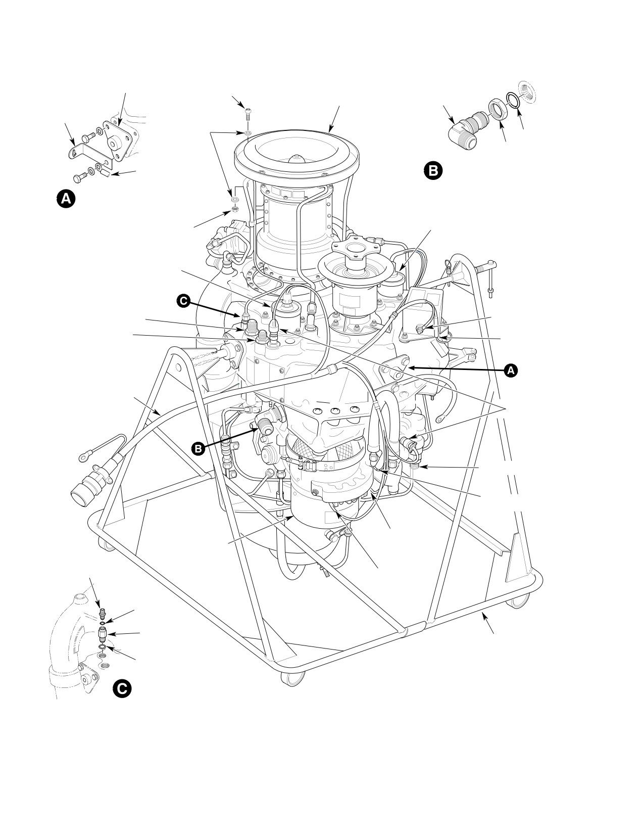
Figure 402. Model 250−C20B and 250−C20R/2 Engine Stripping and Buildup (Sheet 1 of 2)
Page 406
Revision 30
71-00-00
MD Helicopters, Inc.
CSP-HMI-2
MAINTENANCE MANUAL
AIR INLET
HOSE
BELL
FIREWALL SEAL RING
FUEL PUMP SEAL ELBOW NUT AND O-RING
SPECIAL TEE FITTING
BEFORE FILTER PORT (BF)
SCREW
JAM NUT
(5 PLCS)
O-RING
REDUCER
O-RING
NUT
(5 PLCS)
CABIN AIR FITTING
ANTI-ICE VALVE
INSTALLATION
(NOTE 3)
O-RING
FIREWALL SEAL
AFTER FILTER
PORT (AF)
OVERRUNNING
FITTING
CLUTCH
(NOTE 4)
PRESSURE SWITCH
SPARK IGNITER
BUSHING
LEAD
HOSE ASSEMBLY
FUEL CONTROL
HOSE
FUEL PRESSURE SWITCH
DRAIN UNION
INSTALLATION
3/8 IN. (9.525 MM)
DETENT PIN
DIA. BOLT
LIFT FITTING
5/16 IN. (7.9375 MM)
DIA. BOLT (2)
ENGINE LIFT FITTING
INSTALLATION
GOVERNOR CONTROL IDLER
SUPPORT, BELLCRANK AND
REDUCER
N2 CONTROL ROD ASSEMBLY
O-RING
SNUBBER
O-RING
ACCUMULATOR
TORQUE OIL PRESSURE FITTING
INSTALLATION
G71-0001-2
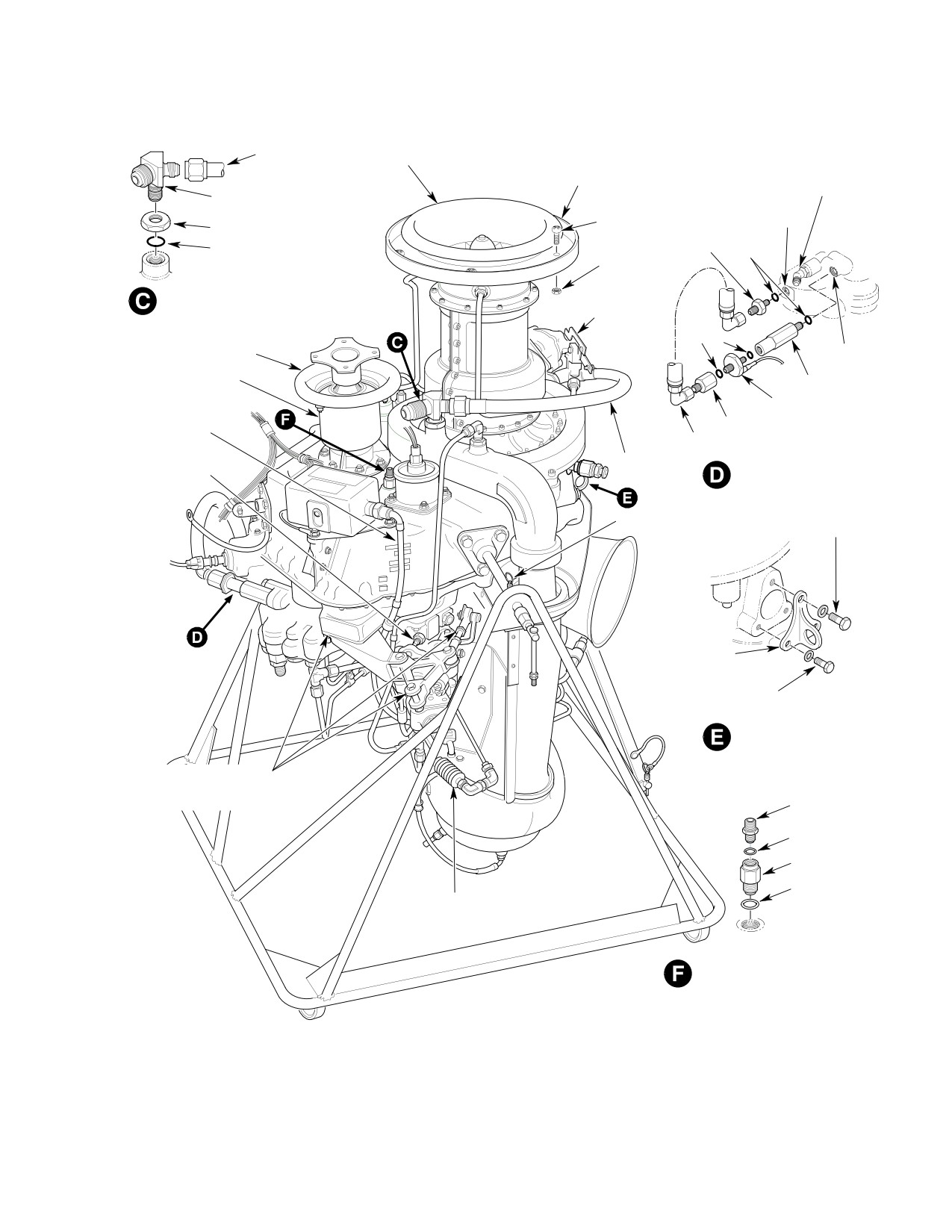
Figure 402. Model 250−C20B and 250−C20R/2 Engine Stripping and Buildup (Sheet 2 of 2)
Page 407
71-00-00
Revision 22
CSP-HMI-2
MD Helicopters, Inc.
MAINTENANCE MANUAL
(9). Connect fuel inlet line to fuel pump.
located on right upper engine door
Torque hose nut to 230 - 260 inch-
frame with chromel and alumel nuts.
pounds (25.99 - 29.38 Nm).
(17). Install main transmission drive shaft
NOTE: Ensure burner drain valve and plug are
(Ref. Sec. 63-10-00).
installed in combustion chamber with an O-
(18). Remove all identifying tags from wires
ring on each part. Ensure drain valve is in
and hardware.
the aft (lowest) position.
Misrigging of throttle controls
(10). Install combustion chamber drain line
CAUTION
can cause inadvertent flameout
on drain valve.
when throttle is rapidly closed to the idle po
sition.
(11). Connect fuel control drain line. Torque
drain line nut to 20 - 30 inch-pounds
(19). Rig gas producer (N1) and power
(2.26 - 3.39 Nm) (Ref. Figure 401).
turbine (N2) controls (Ref. Chap. 76).
(12). Connect anti-ice system as follows:
After each opening, removal
WARNING
or replacement of any part
(a). Model 250-C20B:
of the engine and/or aircraft fuel sys
Connect anti-icing control cable to
tem between the aircraft fuel tank and
anti-icing control valve lever with
the engine fuel nozzle, the fuel system
clevis pin and washer. Secure with
must be bled to remove trapped air.
cotter pin (Ref. Figure 401, detail A).
Failure to comply with this procedure
can result in engine flameout or power
(b). Model 250-C20R/2:
loss.
Install connector P307 to anti-ice
solenoid valve and secure anti-icing
(20). Perform fuel system bleed.
wiring harness with clamps.
(21). Perform an engine deceleration check
(13). Install cooling air ducts and air duct
per the Pilot's Flight Manual.
support bracket on hoisting eye above
NOTE: Make engine adjustments per the Alli
engine. Connect and tighten ducts on
son Engine Operation and Maintenance
firewall coupling and oil cooler deflec
Manual.
tor.
(22). Perform an anti-icing system opera
(14). Secure engine electrical harness to
tional check (Ref. Sec. 75-10-00).
engine mount with cushioned loop
clamp. Connect harness plug to recep
(23). Inspect engine installation and connec
tacle and safety with lockwire (CM702).
tions for proper routing and security.
(a). Install engine harness ground lead.
3. Engine Stripping
(Ref. Figure 402)
(b). Install E, C, and B generator leads on
starter-generator terminal block
with washers and nuts.
Special Tools
(Ref. Section 91−00−00)
(c). At lower engine mount fitting; install
Item
Nomenclature
bonding jumper on engine compart
ST401
Engine stand
ment firewall stud. Torque bolt to 100
ST402
Engine hoist
- 140 inch-pounds (11.30 - 15.82
Nm). Safety bolt to engine mount
using lockwire (CM702).
(1). Install engine in engine stand (ST401).
(15). Install engine exhaust pipes and
(2). Disconnect wire leads from generator A
thermocouple clamp support.
and D terminals.
(16). Attach thermocouple clamps in frame
(a). Loosen mounting clamp and remove
and leads to terminal block studs
starter-generator.
Page 408
Revision 22
71-00-00
MD Helicopters, Inc.
CSP-HMI-2
MAINTENANCE MANUAL
(b). Remove mounting flange and gasket.
(a). Remove hose, reducer and O-ring
from before filter (BF) port (Ref.
(c). Install cover on generator mounting
Figure 402, view D).
pad.
(b). Remove bushing, fuel pressure
(3). Disconnect electrical connectors from:
switch, fitting and O-rings from after
(a). Chip detectors.
filter (AF) port.
(b). Tachometer generators.
(12).
Remove engine air inlet bell and
firewall seal.
(c). Ignition exciter.
(13).
Model 250-C20B Only:
(d). Start counter.
Remove anti-icing valve lever assembly
(e). Fuel filter pressure switch.
from poppet guide (Ref. Figure 401,
view A).
(f). Unclamp and remove electrical
harness from overrunning clutch and
(14).
Remove fuel pump seal drain port
lower engine mount fitting.
elbow and jamnut.
(g). Remove entire engine electrical
(15).
Remove governor control idler support,
harness.
bellcrank and short N2 control rod as
an assembly. Install vacuum/hydraulic
NOTE: Discard all used O-ring packings.
pump pad cover.
(4). Remove fuel supply and return reduc
(16).
Remove overrunning clutch and
ers/unions.
firewall seal. Install cover on engine
(5). Remove oil supply and return reducers/
pad.
unions.
(17).
Remove fuel control drain fitting.
(6). Remove accessories drive vent elbow
and jamnut.
(18).
Remove pneumatic line accumulator
per Allison installation bulletin (Ref.
(7). Remove compressor bleed air hose, tee
Sec. 01-00-00).
and jamnut (Ref. Figure 402. view C).
(19).
Hoist (ST402) engine out of engine
(8). Remove oil pressure reducer/snubber.
stand.
(9). Remove torque-meter reducer/snubber.
(20).
Unbolt and remove engine mount
(10). Remove N1 and N2 tachometer genera
fittings.
tors and gaskets.
(21).
Install engine in shipping container.
(11). Remove fuel pressure switch installa
tion as follows:
(22).
Remove engine hoist fitting.
Page 409
71-00-00
Revision 22
CSP-HMI-2
MD Helicopters, Inc.
MAINTENANCE MANUAL
ENGINE HOIST
BULKHEAD SPLICE
FITTING
FITTING
FIREWALL BULKHEAD
STA 124.00
BULKHEAD SPLICE
FITTING
LOWER ENGINE
MOUNT
LOWER ENGINE
MOUNT ATTACH
FITTING
LOWER ENGINE MOUNT - INSTALLATION
ENGINE
FITTING
UPPER ENGINE
MOUNT ASSY
AIRFRAME
FITTING
LANDING GEAR
DAMPER FITTING
UPPER ENGINE MOUNT - INSTALLATION
NOTE:
THICK WASHERS ARE USED IN LOCATIONS
G71 0002
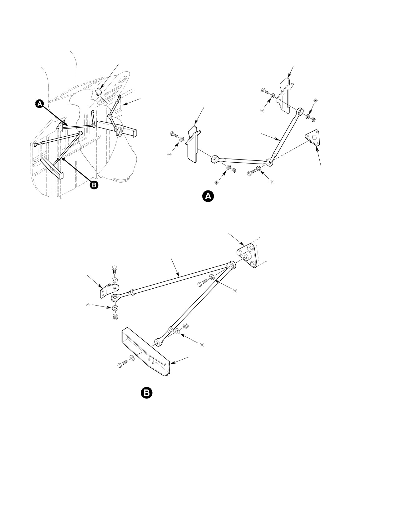
Figure 403. Model 250−C20B and 250−C20R/2 Engine Mounts and Airframe Fittings
Page 410
Revision 22
71-00-00

MD Helicopters, Inc.
CSP-HMI-2
MAINTENANCE MANUAL
4. Engine Buildup
(3). Hoist engine clear of shipping contain
er.
(Ref. Figure 402 and Figure 403)
(4). Inspect engine as follows:
Proper tightening of engine
WARNING
tubing connections is criti
(a). If shipping container moisture
cal to flight safety. Correct torque val
indicator was other than a light blue
ues must be used at all times. Excessive
color, examine engine for corrosion.
torque on fuel or pneumatic sensing
Perform corrosion corrective mainte
system connections can result in crack
nance per Allison Operation and
ing of the flare causing an air leak
Maintenance Manual as required.
which can cause flameout, power loss,
(b). Inspect inlet guide vanes for damage.
or overspeed.
(c). Exhaust and inlet openings for FOD.
Consumable Materials
(d). Turbine blades for damage.
(Ref. Section 91−00−00)
Item
Nomenclature
(e). Install covers over intake and
CM113
Anti-seize compound low temperature
exhaust ports.
CM114
Petrolatum
(f). All fasteners for security, slippage
CM118
Grease
marks for alignment, potting com
CM502
Sleeving, fiberglass
pound and, or correctly installed
lockwire where applicable.
CM702
Lockwire CRES
CM808
Lacing cord
(g). Tubes and hoses for damage.
(5). Record engine serial number and
Special Tools
start-counter reading in appropriate
(Ref. Section 91−00−00)
log.
Item
Nomenclature
ST401
Engine stand
Prevent damage to machined
CAUTION
surfaces and contamination. Re
move covers from engine one at a time as re
(1). Review Allison instructions for remov
quired by the installation sequence.
ing engine from shipping container in
Allison Operation and Maintenance
(6). Install lower engine mount fitting with
Manual.
angle and ground wire under aft bolt
head. Install side engine mount fittings,
Prevent FOD Inspect and clean
bolts and washers. Torque bolts to 140 -
CAUTION
all accessories and hardware
160 inch-pounds (15.82 - 18.08 Nm).
prior to installing parts on engine.
Install lockwire (CM702).
NOTE: Replace O-rings and gaskets with new
(7). Install engine in engine stand (ST401).
parts. Lubricate fuel line packings with
(8). Install accumulator in pneumatic line
clean jet fuel or petrolatum (CM114) prior to
per Allison installation bulletin (Ref.
installation. Lubricate oil line packings with
Sec. 01-00-00).
clean engine oil prior to installation. Apply a
thin coating of anti-seize compound
(9). Install fuel control drain fitting and
(CM113) to the male threads of unions and
O-ring.
fittings before torquing.
(10). Remove overrunning clutch pad cover.
(2). Install engine hoist lift fitting and bolts.
Install overrunning clutch, firewall seal
Torque 3/8 inch-diameter bolt to 160 -
and engine electrical harness angle and
190 inch-pounds (18.08 - 21.47 Nm).
clamp (Ref. Sec. 63-10-00).
Torque 5/16 inch-diameter bolts to 140
- 160 inch-pounds (15.82 - 18.08
(11). Install oil pressure gauge reducer/snub
Nm).
ber and O-ring.
Page 411
71-00-00
Revision 22

CSP-HMI-2
MD Helicopters, Inc.
MAINTENANCE MANUAL
(12). Install torque-meter reducer/snubber
(c). Install reducer and O-ring in BF
and O-ring.
port.
(d). Install hose assembly between AF
Engine spark igniter wire lead
CAUTION
and BF fittings.
may obstruct governor arm on a
new or overhauled engine.
(20). Lubricate splines with grease (CM118)
and install N1 and N2 tachometer
(13). Reroute engine spark igniter lead below
generators. Install washers and nuts.
governor as shown (Ref. Figure 402).
Torque nuts to 70 - 90 inch-pounds
Support igniter lead only with cush
(7.91 - 10.17 Nm).
ioned clamps and existing fasteners.
Replace and, or add clamps as required.
(21). Install special tee, jamnut and O-ring
in compressor scroll bleed air port. Do
(14). Remove vacuum/hydraulic pump pad
not torque at this time.
cover from gear case.
(22). Install hose between special tee and
(15). Install governor control idler support,
compressor bleed air elbow. Torque tee
bellcrank and short N2 control rod as
jamnut. Torque hose nuts to 150 - 250
an assembly. Do not connect control rod
inch-pounds (16.95 - 28.25 Nm).
to governor lever.
(23). Install accessory gear case vent elbow,
jamnut and O-ring. Do not torque at
Only high temperature all met
CAUTION
this time.
al self locking nuts shall be used
to fasten governor control idler support
(24). Install oil inlet and outlet couplings and
bracket to engine accessory pad.
O-rings.
(16). Install elbow with O-ring and jamnut
(25). Install fuel inlet reducer and O-ring.
in fuel pump seal drain port.
(26). Install starter/generator.
(17). Model 250-C20B Only:
Always support the weight of
Install anti-icing valve lever with
CAUTION
the starter/generator during re
attaching hardware on poppet guide.
moval/installation. Damage can occur if
Position poppet guide so that lever is
weight is supported by the shear shaft.
parallel with top of engine.
(a). Remove starter/generator pad cover.
(18). Install engine air inlet bell and firewall
Install starter/generator mount with
seal.
gasket, washers and nuts. Torque
nuts to 100 - 140 inch-pounds
(19). Install fuel pressure switch fitting and
(11.29 - 15.81 Nm).
O-ring in fuel pump AF port (Ref. Sec.
28-00-00).
(b). Install starter/generator with V-
clamp. Torque clamp nut to 50
Ensure both halves of the fuel
inch-pounds (5.64 Nm).
CAUTION
filter pressure switch are
(c). Tap around clamp with a rawhide
gripped by wrench when torquing the in
mallet to seat clamp on flange.
stallation. An asymmetrical wrench grip
Retorque clamp nut to 50 inch-
may cause shearing motion between assem
pounds (5.64 Nm).
bly halves. Such damage may result in leak
age or failure to operate FUEL FILTER
(d). Continue tapping around clamp and
caution/warning light, or both.
retorquing clamp nut until nut no
longer turns when specified torque is
(a). Install fuel filter pressure switch and
applied.
O-ring.
(27). Clamp engine electrical harness to
(b). Install bushing and O-ring on
lower engine mount and starter-gener
switch.
ator.
Page 412
Revision 26
71-00-00
MD Helicopters, Inc.
CSP-HMI-2
MAINTENANCE MANUAL
(28). Connect ignition exciter wire lead and
(1). Disconnect accessory drive overboard
starter-generator A and D wire leads.
vent tube from elbow on engine accesso
ry case; remove vent tube from helicop
(29). Attach electrical connectors to both chip
ter.
detectors and safety with lockwire
(CM702).
(2). Install extension tube to existing vent
(30). Connect N1 and N2 tachometer genera
tube as follows:
tors connectors.
(31). Connect start counter lead and fuel
(a). Position extension tube over vent
pressure switch wire lead splices.
tube. Drill rivet holes in line thru
Install fiberglass sleeving (CM502) over
tubing.
splices and secure with high tempera
ture lacing cord (CM808).
(b). Apply sealant (CM425) between
tubes. Install two NAS1738B4-2
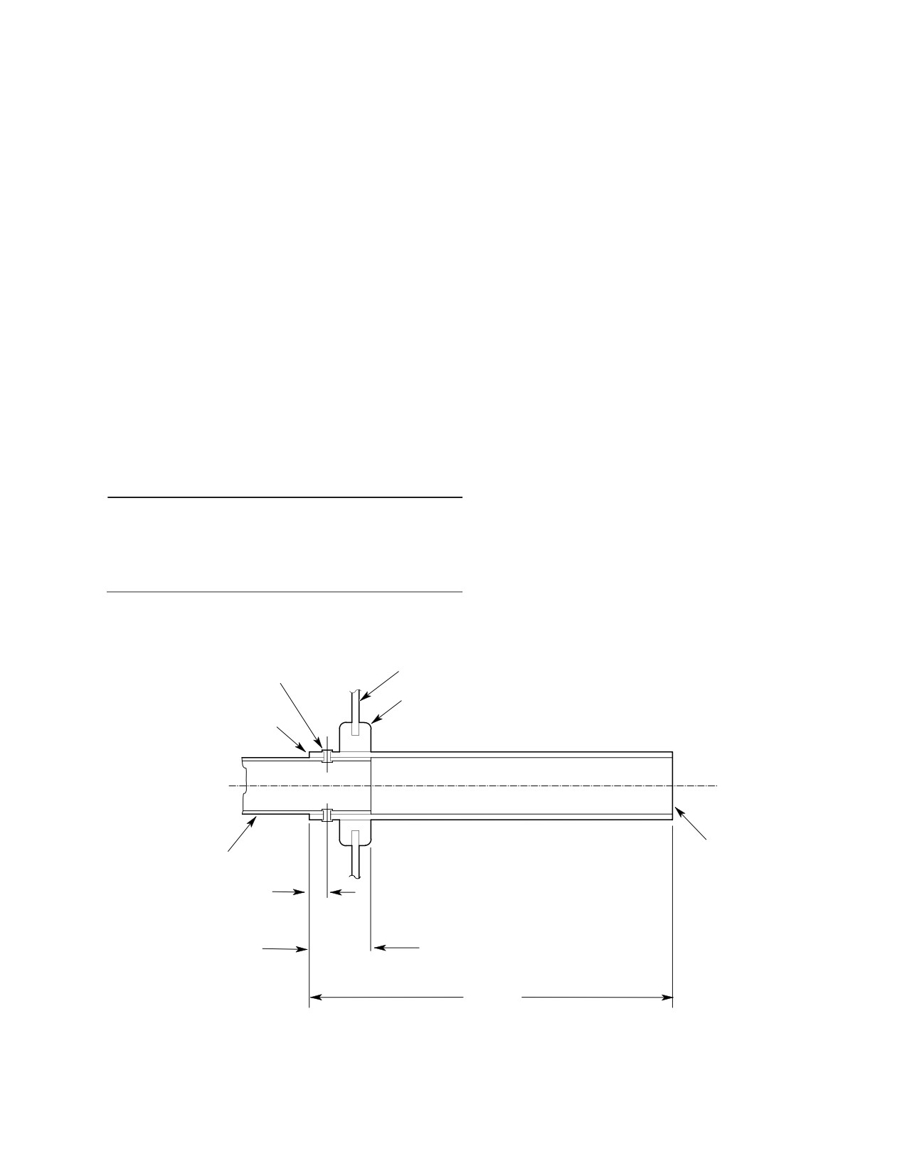
5. Modification of Accessory Drive Gearbox
rivets. Fillet seal around circumfer
Overboard Vent Tube (SN 0004D − 0519D)
ence of tubes.
(Ref. Figure 404) The following procedure adds
a four inch extension tube to the existing
(3). Remove existing grommet at lower
engine accessory drive gearbox vent tube to
fuselage Sta. 127.00 and install new
reduce oil spattering onto the lower fuselage.
MS35489-22 grommet.
Consumable Materials
(4). Insert extension tube thru grommet
(Ref. Section 91−00−00)
and connect vent tube to elbow on
Item
Nomenclature
engine accessory case. Torque line nut
CM425
Sealing compound
to 120 - 140 inch-pounds (13.56 -
15.82 Nm).
FUSELAGE SKIN
NAS1738B4-2 RIVET
STA. 127.00
(2 REQD.)
MS35489-22 GROMMET
NOTE
EXTENSION TUBE
369A8010-615
TUBE ASSY.
0.250 IN.
(6.35 MM)
0.84 IN.
(21.34 MM)
4.85 IN.
NOTE: SEAL BETWEEN TUBES
(12.319 CM)
BEFORE ASSEMBLY AND FILLET
88-295A
SEAL ABOUT CIRCUMFERENCE.
Figure 404. Extension of Engine Accessory Drive Overboard Vent Tube
Page 413
71-00-00
Revision 26
CSP-HMI-2
MD Helicopters, Inc.
MAINTENANCE MANUAL
This Page Intentionally Left Blank
Page 414
Revision 44
71-00-00
MD Helicopters, Inc.
CSP-HMI-2
MAINTENANCE MANUAL
Section
71−00−30
Power Plant
(250−C30)
MD Helicopters, Inc.
CSP-HMI-2
MAINTENANCE MANUAL
POWER PLANT
DESCRIPTION AND OPERATION
1.
Power Plant Description
sor, N1 tachometer-generator and
accessory gear train, and a two-stage
(1).
MDHI 369FF helicopter is powered by a
power turbine driving the spare
250-C30 turboshaft engine manufac
accessory pad, governor, N2 tachome
tured by the Allison Engine Company
ter-generator and helicopter rotor
Inc.
system. An overrunning clutch, drive
shaft, starter generator, fuel, oil, drain
(2).
The engine is secured in the helicopter
and bleed air lines, exhaust ducting,
by three mount assemblies and ac
mounting and hoist fittings and control
cessed through two hinged, air-sealed
levers adapt the engine to the helicop
doors.
ter.
(3).
A belt-driven blower forces external
(2). Allison Engine Operation and Mainte
cooling air through strategically
positioned ducts that direct the air onto
nance Manuals are the primary
engine exterior surfaces and through
information source for engine fault
the engine and transmission oil cooler
isolation and maintenance data (Ref.
heat exchangers. Spent cooling air is
Sec. 01-00-00). Refer to these manuals
exhausted aft through an annular
for specific engine maintenance proce
opening between the engine exhaust
dures.
duct and fuselage.
(3). Starter operational limitations are in
(4).
Engine intake air may be filtered
the applicable Pilot's Flight Manual.
through a standard screen or optional
air particle separator/mist eliminator
3. Model 250−C30 Power Plant Fault
assembly. Intake air is drawn through a
Isolation
plenum chamber and into the engine
intake bell-mouth by the compressor.
(Ref. Table 1)
Engine compartment air is separated
(1). Check engine support systems, i.e.; chip
from compressor intake air by a seal
detectors, instruments, fuel supply,
ring.
electrical systems, etc., to ensure that
2.
Power Plant Operation
helicopter equipment is functioning
correctly before disassembling engine
(1). The Allison 250-C30 turboshaft engine
systems for an indicated fault.
consists of a single stage centrifugal
flow compressor, a can-annular
(2). Inspect and isolate engine problems per
combustion chamber, a two-stage gas
the applicable Allison Engine Operation
producer turbine driving the compres
and Maintenance Manual.
Table 1. Power Plant Fault Isolation
Symptom
Probable trouble
Corrective action
High frequency vibration (1)
Loose engine mount bolts
Retorque engine mount bolts to 100
− 140 inch−pounds (11.30 − 15.82
Nm).
NOTES:
(1) High frequency vibrations may be caused by other drive and rotor system components.
Page 1
71-00-30
Revision 22
CSP-HMI-2
MD Helicopters, Inc.
MAINTENANCE MANUAL
This Page Intentionally Left Blank
Page 2
Revision 44
71-00-30
MD Helicopters, Inc.
CSP-HMI-2
MAINTENANCE MANUAL
POWER PLANT
REMOVAL/INSTALLATION
1. Engine Removal
(7).
Loosen and remove remaining engine
cooling air ducts from engine compart
A. Engine Disconnecting for Removal
ment (Ref. Figure 402, views A and D).
(Ref. Figure 401 and Figure 402)
(8).
Remove combustion chamber drain line
from burner drain valve.
After each opening, removal
WARNING
or replacement of any part
(9).
Disconnect fuel inlet line at engine-
of the engine and/or aircraft fuel sys
mounted fuel pump and cap line.
tem between the aircraft fuel tank and
the engine fuel nozzle, the fuel system
(10).
Disconnect and remove fuel pump seal
must be bled to remove trapped air.
drain line.
Failure to comply with this procedure
(11).
Disconnect and remove fireshield drain
can result in engine flameout or power
line.
loss.
(12).
Disconnect fuel control vent line and
Cap fluid lines and fittings with
CAUTION
cap line.
approved devices. Do not use
tape to cover fuel and oil openings. Tape
(13).
Disconnect customer bleed line at
adhesives loosened by fuel or oil can con
firewall.
taminate systems.
(14).
Disconnect torque-meter oil line from
(1). Set all switches OFF. Disconnect
firewall.
external power. Disconnect battery.
(15).
Disconnect oil pressure indicator line
NOTE: Tag all hardware, wire terminals, fuel
from firewall.
and oil lines before removal to expedite in
stallation. Identify and bag loose parts to
(16).
Disconnect N2 control rod from idler
prevent loss or damage.
bellcrank. Secure control rod to fire
wall.
(2). Remove main transmission drive shaft
(Ref. Sec. 63-10-00).
(17).
Disconnect N1 control rod from gas
producer lever. Secure control rod to
(3). Remove engine exhaust duct (Ref. Sec.
firewall.
78-30-00). Cover engine exhaust
(18).
Disconnect and remove starter-genera
outlet.
tor cooling air duct from starter and
(4). On left engine compartment door
fuselage bracket.
frame; unclamp and disconnect thermo
The oil cooler is fragile. Unless
couple wire leads from terminal studs
CAUTION
otherwise required, disconnect
(Ref. Figure 401, view B).
oil supply and return lines only at engine.
(5). Unplug engine-airframe electrical
Support oil cooler port boss with a backup
harness connector from engine recep
wrench when oil line removal is required.
tacle.
Do not strain or bend unsupported tubes.
(6). Disconnect thermal switch plug from
(19). Disconnect and cap engine oil inlet,
firewall.
outlet and vent lines.
Page 401
71-00-30
Revision 22
CSP-HMI-2
MD Helicopters, Inc.
MAINTENANCE MANUAL
COMBUSTION
CHAMBER DRAIN LINE
STARTER-GENERATOR
COOLING DUCT
LONG RANGE FUEL
FUEL PUMP
TANK LINE
INLET
ENGINE GEARCASE
COOLING DUCT
UPPER ENGINE MOUNT
LH SIDE SHOWN
GENERATOR
RH SIDE OPPOSITE
TERMINALS
UPPER ENGINE
N1 CONTROL ROD
(E, C, B ONLY)
MOUNT FITTING
THERMOCOUPLE
LEAD STUD (2)
ENGINE MOUNTING
PAD ASSY
THERMOCOUPLE LEAD
UPPER ENGINE MOUNT
ENGINE DOOR
FRAME
THERMOCOUPLE LEAD - INSTALLATION
LANDING GEAR
DAMPER FITTING
G71-0003-1
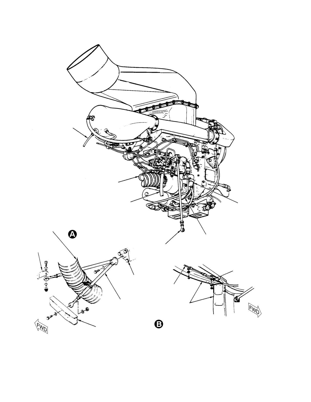
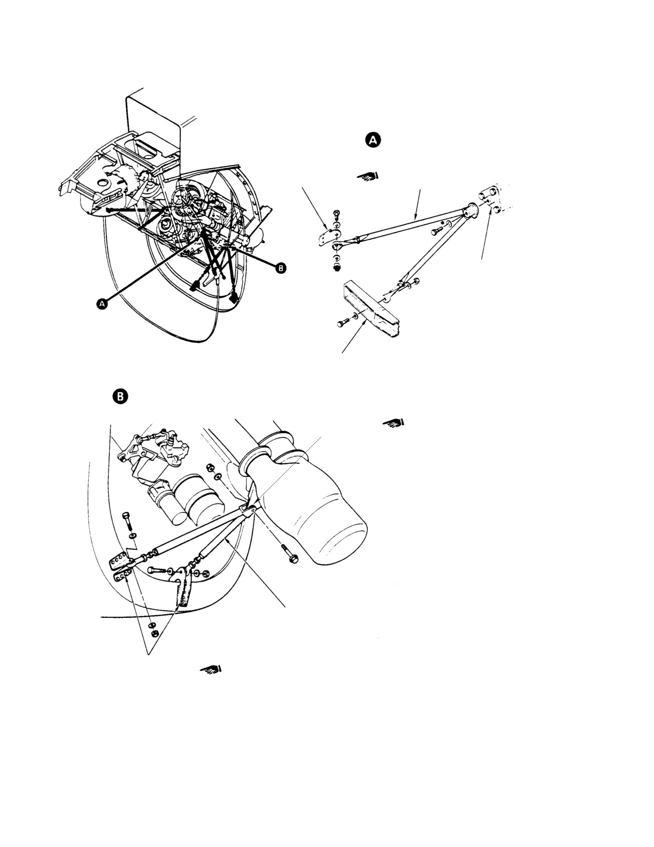
Figure 401. Model 250−C30 Engine Removal and Installation (Sheet 1 of 2)
Page 402
Revision 22
71-00-30
MD Helicopters, Inc.
CSP-HMI-2
MAINTENANCE MANUAL
LOWER ENGINE MOUNT
INSTALLATION
HOISTING EYE
FITTING
BRACKET
LOWER ENGINE
CLAMP
MOUNT
FIRESHIELD DRAIN
TUBE ASSY
POWER TURBINE COOLING
FUEL PUMP SEAL
DUCT INSTALLATION
LOWER ENGINE
DRAIN TUBE ASSY
MOUNT FITTING
ENGINE AIR
INLET BELL
ENGINE OIL
INLET LINE
BLEED DUCT
ENGINE OIL
OUTLET LINE
MAIN TRANSMISSION
DRIVESHAFT
TORQUEMETER
OIL PRESSURE
N2 CONTROL ROD
ENGINE MOUNTING
ENGINE HARNESS
PAD ASSY
DISCONNECT
G71-0003-2
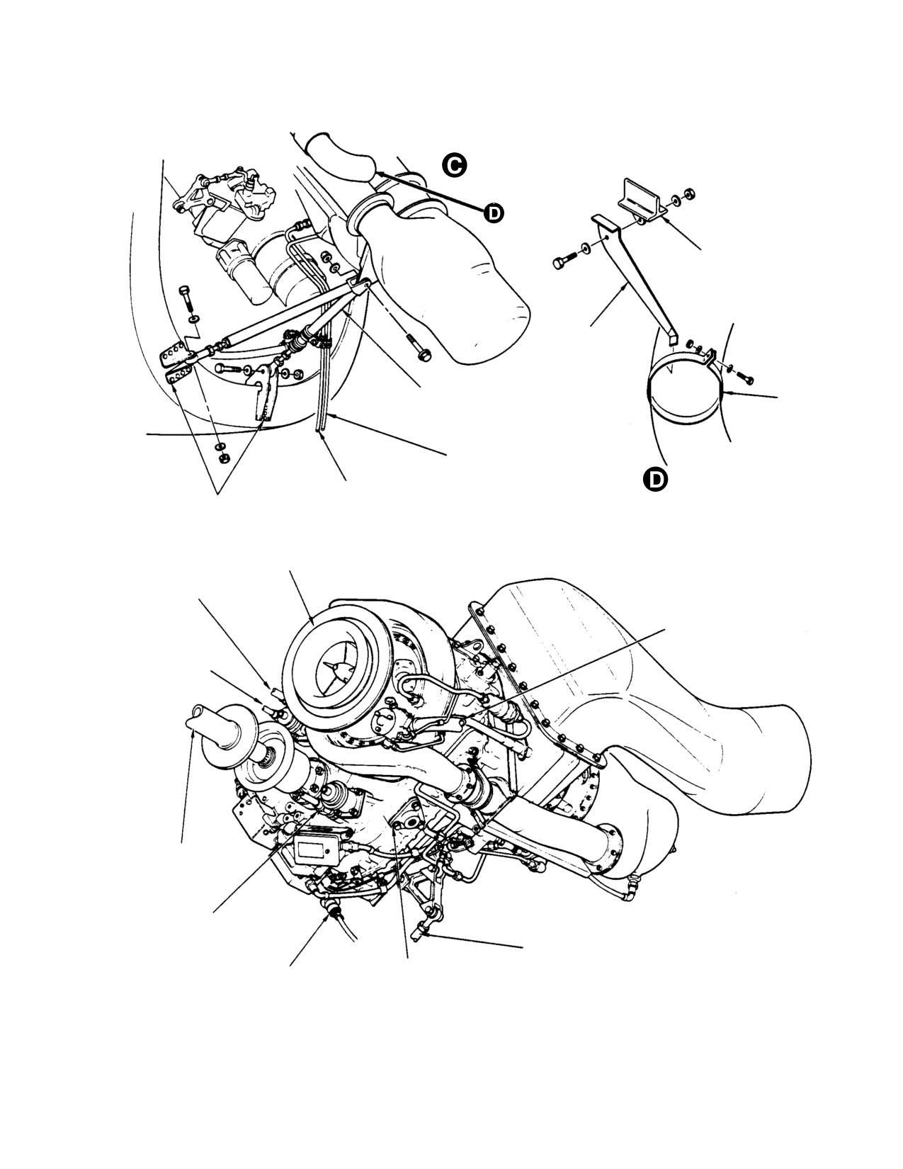
Figure 401. Model 250−C30 Engine Removal and Installation (Sheet 2 of 2)
Page 403
71-00-30
Revision 22

CSP-HMI-2
MD Helicopters, Inc.
MAINTENANCE MANUAL
B. Removal of Disconnected Engine
between fixed and adjustable support
shafts.
(Ref. Figure 401 and Figure 402)
(7). Screw in adjustable support shaft until
engine mount fittings are securely
Special Tools
engaged with support shaft sockets.
(Ref. Section 91−00−00)
Item
Nomenclature
(8). Insert detent pin through adjustable
support shaft.
ST401
Engine stand
ST402
Engine hoist
(9). Remove hoist from engine lift fitting.
(10). If engine is to be stored or transported,
secure upper end of engine stand
CAUTION
transport and storage bar to engine
lifting eye fitting.
D Do not remove engine mounts or disturb
engine mount adjustments to remove en
2. Engine Installation
gine.
D Engine-transmission alignment shall be
A. Engine Installation in Mounts
inspected whenever one or more engine
mount assemblies is replaced or the exist
(Ref. Figure 401 and Figure 402)
ing alignment is disturbed. Do not disturb
adjustable engine mount fittings unless
Consumable Materials
an engine-transmission alignment check
(Ref. Section 91−00−00)
is planned.
Item
Nomenclature
CM702
Lockwire CRES
(1). Install engine hoist apparatus (ST402)
between engine hoist eye and airframe
hoist fitting.
Special Tools
(Ref. Section 91−00−00)
(2). Have an assistant apply tension to
Item
Nomenclature
engine with hoist.
ST402
Engine hoist
(3). Maintain downward pressure on rear of
engine during mount bolt removal.
(1).
Open engine access doors.
Unbolt engine at lower engine mount
fitting. Take care not to damage rod end
(2).
Position engine to line up engine lifting
bearings.
eye under airframe lift fitting.
(3).
Remove detent pin from adjustable
(4). Unbolt left and right engine mount
support shaft on engine stand. Detach
assemblies from engine fittings.
transport and storage bar from engine
lift fitting.
Do not use fuel or oil lines as
CAUTION
hand holds. Do not allow engine
(4).
Install engine hoist (ST402) between
to strike airframe while maneuvering it out
airframe fitting and engine hoist
of the helicopter.
fitting.
(5). Align engine stand (ST401) under
(5).
Have an assistant tension hoist to
engine with adjustable support shaft on
support engine. Unscrew engine stand
left side.
adjustable support shaft.
(6). Slowly lower engine out of helicopter.
(6).
Move engine to disengage fixed shaft.
Align engine side mount fittings
Roll stand away from engine.
Page 404
Revision 22
71-00-30
MD Helicopters, Inc.
CSP-HMI-2
MAINTENANCE MANUAL
(2). Connect oil pressure gauge line to
CAUTION
firewall.
D Do not use tubes or hoses as hand holds.
(3). Connect engine oil vent line. Torque
Do not allow engine to strike airframe or
line nut to 120 - 140 inch-pounds
components. Avoid damaging engine in
(13.56 - 15.82 Nm).
take bell.
D Prevent FOD ensure that no foreign ob
Do not bend oil return line.
CAUTION
jects are trapped in firewall seal ring.
Bending loads are transferred to
oil cooler port and may fracture cooler.
(7). Have hoist operator slowly raise engine
while pushing engine down to maintain
(4).
Connect engine oil outlet and inlet
correct engine and transmission
lines. Hand-tighten until snug.
alignment.
Wrench-tighten approximately 1/4 turn
or until definite resistance is felt.
(8). Align left and right engine mount
assemblies with engine fittings. Install
(5).
Position accessory drive vent elbow and
bolts and washers (Ref. Figure 403).
connect with vent tube. Torque elbow
Torque bolts to 220 - 360 inch-pounds
jamnut to 150 - 250 inch-pounds
(24.86 - 40.67 Nm); Safety bolts to
(16.95 - 28.25 Nm). Torque tube nut to
engine mounts using lockwire (CM702).
20 - 30 inch-pounds (2.26 - 3.39
Nm).
(9). Align hole in lower engine mount
assembly with engine fitting. Install
(6).
Connect N1 control rod to lever with
bolt, washers and nut. Torque nut to 95
bolt, two washers and nut. Install bolt
- 110 inch-pounds (10.73 - 12.43
with head outboard, one standard OD
Nm); install cotter pin as required.
washer under nut and one large 0.8
inch diameter washer under head.
(10). Ensure engine air inlet firewall seal
Torque nut to 40 - 45 inch-pounds
ring contacts firewall seal around its
(4.52 - 5.08 Nm). Install a new cotter
entire circumference.
pin.
(11). Remove hoist from helicopter.
(7).
Connect short N2 control rod to gover
nor lever with bolt head up, one
B. Connecting an Installed Engine
standard OD washer under head, one
(Ref. Figure 401 and Figure 402)
large 0.80 inch (20.32 mm) OD washer
under nut and a new cotter pin.
Connect long N2
control rod with bolt
Consumable Materials
head forward, two washers, nut and a
(Ref. Section 91−00−00)
new cotter pin.
Item
Nomenclature
CM702
Lockwire CRES
(8).
Connect engine fuel pump seal drain
line. Torque tube nut to 50 - 65 inch-
pounds (5.65 - 7.34 Nm).
Proper tightening of engine
WARNING
tubing connections is criti
(9).
Connect fuel inlet line to fuel pump.
cal to flight safety. Correct torque val
Torque hose nut to 230 - 260 inch-
ues must be used at all times. Excessive
pounds (25.99 - 29.38 Nm).
torque on fuel or pneumatic sensing
system connections can result in crack
NOTE: Ensure burner drain valve and plug are
ing of the flare causing an air leak
installed in combustion chamber with an O-
which can cause flameout, power loss,
ring on each part. Ensure drain valve is in
or overspeed.
the aft (lowest) position.
(1). Connect torque-meter oil line to
(10). Install combustion chamber drain line
firewall.
on drain valve.
Page 405
71-00-30
Revision 34
CSP-HMI-2
MD Helicopters, Inc.
MAINTENANCE MANUAL
ROTATED
UPPER ENGINE MOUNT - INSTALLATION
UPPER ENGINE
MOUNT FITTING
(REF. SEC. 71-20-00)
UPPER ENGINE MOUNT
SIDE ENGINE MOUNT
ATTACH FITTING
LANDING GEAR
DAMPER FITTING
(REF. SEC. 71-20-00)
LOWER ENGINE MOUNT - INSTALLATION
ENGINE FITTING
LOWER ENGINE MOUNT
LOWER ENGINE MOUNT
ATTACH FITTING
(REF. SEC. 71-20-00)
G71-0004A
Figure 402. Engine Mounts and Structural Fittings
Page 406
Revision 34
71-00-30
MD Helicopters, Inc.
CSP-HMI-2
MAINTENANCE MANUAL
(11). Secure engine electrical harness to
(19). Perform an anti-icing system opera
engine mount with cushioned loop
tional check (Ref. Sec. 75-10-00).
clamp. Connect harness plug to recep
(20). Inspect engine installation and connec
tacle and safety with lockwire (CM702).
tions for proper routing and security.
(a). Install engine harness ground lead.
3. Engine Stripping
(b). Install E, C, and B generator leads on
(Ref. Figure 403)
starter-generator terminal block
with washers and nuts.
Special Tools
(c). Attach thermocouple leads to termi
(Ref. Section 91−00−00)
nal block studs located on right upper
Item
Nomenclature
engine door frame with chromel and
ST401
Engine stand
alumel nuts.
ST402
Engine hoist
(12). Install cooling air ducts and air duct
support bracket on airframe hoist
(1). Install engine in engine stand (ST401).
fitting. Connect and tighten ducts on
firewall coupling and oil cooler deflec
(2). Disconnect wire leads from generator A,
tor.
E and D terminals.
(3). Loosen mounting clamp and remove
(13). Install main transmission drive shaft
starter-generator.
(Ref. Sec. 63-10-00).
(4). Remove mounting flange and gasket.
(14). Install exhaust duct (Ref. Sec.
78-30-00).
(5). Install cover on generator mounting
pad.
(15). Remove all identifying tags from wires
and hardware.
(6). Disconnect electrical connectors from:
Improper rigging of throttle con
(a). Chip detectors.
CAUTION
trols can cause inadvertent
(b). Tachometer generators.
flameout when throttle is rapidly closed to
the idle position.
(c). Fuel filter pressure switch.
(16). Rig gas producer (N1) and power
(d). Unplug electrical harness connector
turbine (N2) controls (Ref. Chap. 76).
from front of engine.
After each opening, removal
(e). Unclamp and remove engine electri
WARNING
or replacement of any part
cal harness.
of the engine and/or aircraft fuel sys
NOTE: Discard all used O-ring packings.
tem between the aircraft fuel tank and
the engine fuel nozzle, the fuel system
(7). Remove oil vent line and associated
must be bled to remove trapped air.
hardware.
Failure to comply with this procedure
can result in engine flameout or power
(8). Remove fuel inlet fitting.
loss.
(9). Remove oil supply, return and vent
reducers/unions.
(17). Perform fuel system bleed.
(10). Remove oil pressure reducer/snubber.
(18). Perform an engine deceleration check
per the Pilot's Flight Manual.
(11). Remove torquemeter reducer/snubber.
NOTE: Make engine adjustments per the Alli
(12). Unclamp and remove compressor bleed
son Engine Operation and Maintenance
service line, fitting and associated
Manual.
clamps.
Page 407
71-00-30
Revision 22
CSP-HMI-2
MD Helicopters, Inc.
MAINTENANCE MANUAL
SCREEN
FITTING
ASSEMBLY
NUTPLATE
FITTING
SPACER
ENGINE OIL
(NOTE)
OUTLET
INLET
SEAL
ENGINE OIL
PRESSURE
INLET
BELL
ENGINE OIL
INLET
NUTPLATE
PLUG
ENGINE MOUNT
PAD ASSEMBLY
GAS PRODUCER
TURBINE
TACH/GEN (N1)
SUPPORT
ENGINE OIL
ASSEMBLY
TANK VENT
POWER TURBINE
TACH/GEN (N2)
TORQUEMETER
OIL PRESSURE
PACKING
BACKING
SEAL
BOLT
COUPLING
SHIM
CLUTCH
ASSEMBLY
NOTE:
SPACER BONDED TO INLET SEAL.
G71-0005-1A
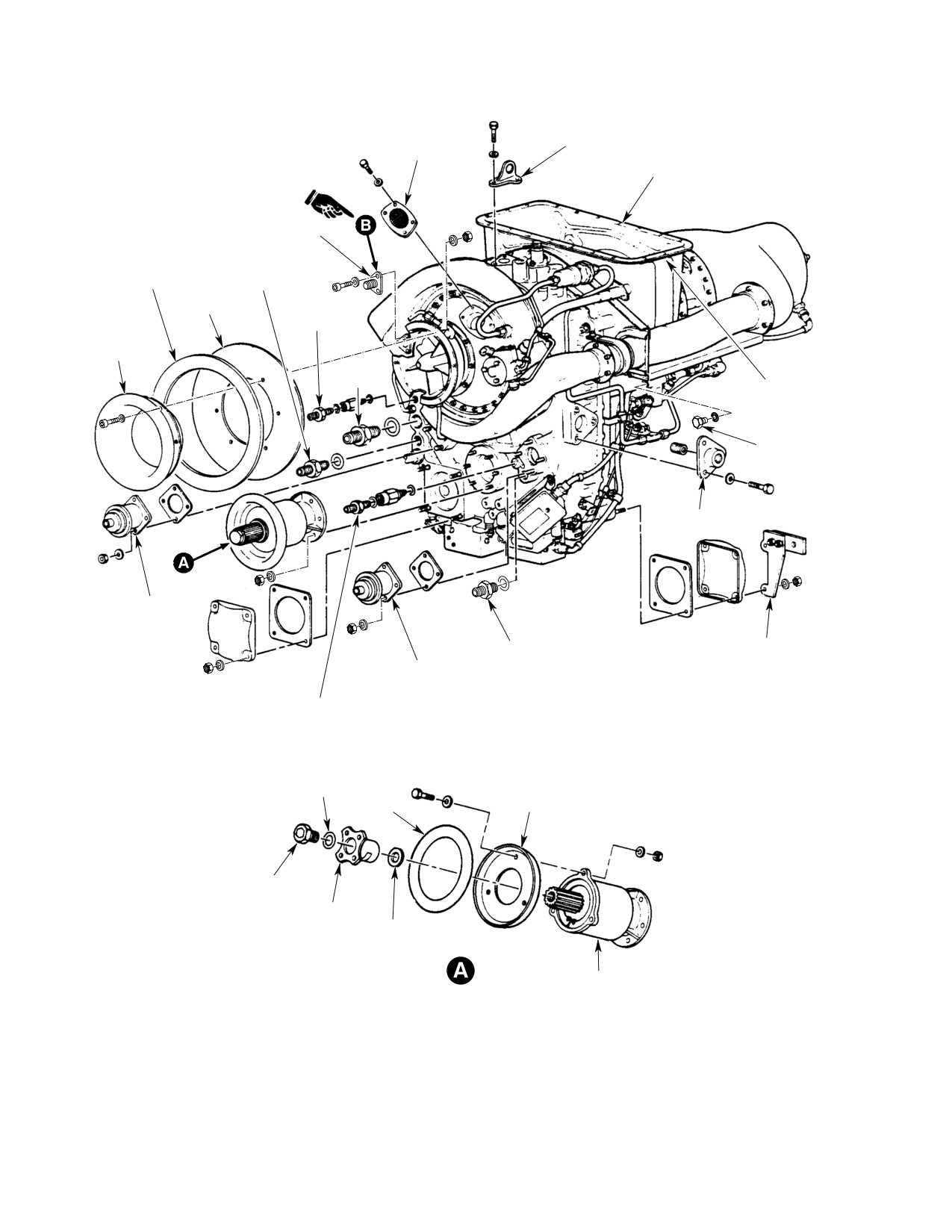
Figure 403. Model 250−C30 Engine Build−Up (Sheet 1 of 2)
Page 408
Revision 22
71-00-30
MD Helicopters, Inc.
CSP-HMI-2
MAINTENANCE MANUAL
ENGINE BLEED AIR
ASSEMBLY
REF.
FITTING
HI
POINTER
LO
VIEW LOOKING AFT
FUEL FLOW STOP ADJUSTER
TUBE ASSEMBLY
STARTER/GENERATOR
ENGINE MOUNTING
PAD ASSEMBLY
GASKET
FITTING
SWITCH
REDUCER
HOSE ASSEMBLY
G71-0005-2A
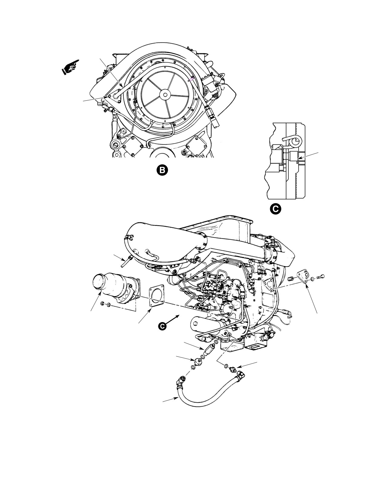
Figure 403. Model 250−C30 Engine Build−Up (Sheet 2 of 2)
Page 409
71-00-30
Revision 22
CSP-HMI-2
MD Helicopters, Inc.
MAINTENANCE MANUAL
(13).
Remove compressor bleed duct from
(1). Review Allison instructions for remov
bleed valve.
ing engine from shipping container in
Allison Operation and Maintenance
(14).
Unfasten and remove N1 and N2
Manual.
tachometer generators and gaskets.
Prevent FOD Inspect and clean
(15).
Remove hose and reducer from fuel
CAUTION
all accessories and hardware
pump after filter (AF) port.
prior to installing parts on engine.
(16).
Remove fuel pressure switch and fitting
NOTE: Replace O-rings and gaskets with new
from fuel pump before filter (BF) port
parts. Lubricate fuel line packings with
(Ref. Figure 403).
clean jet fuel or petrolatum (CM114) prior to
(17).
Remove engine air inlet bell and
installation. Lubricate oil line packings with
firewall seal. Cover engine inlet.
clean engine oil prior to installation. Apply a
thin coating of anti-seize compound
(18).
Remove fuel pump seal drain port
(CM113) to the male threads of unions and
union/reducer.
fittings before torquing.
(19).
Remove governor control idler support
(2). Install engine hoist fitting and bolts.
complete with bellcrank, short N2
Torque 3/8 inch diameter bolt to 160 -
control rod and lever. Do not dismantle
190 inch-pounds (18.08 - 21.47 Nm).
assembly.
Torque 5/16 inch-diameter bolts to 140
- 160 inch-pounds (15.82 - 18.08
(20).
Remove overrunning clutch and clutch
Nm).
firewall seal. Install cover on gear case.
(21).
Hoist (ST402) engine out of engine
(3). Hoist engine clear of shipping contain
stand.
er.
(22).
Unbolt and remove engine mount
(4). Inspect engine as follows:
fittings.
(a). If shipping container moisture
(23).
Install engine in shipping container.
indicator was other than a light blue
color, examine engine for corrosion.
(24).
Unbolt and remove hoist fitting.
Perform corrosion corrective mainte
nance per Allison Operation and
4. Engine Buildup
Maintenance Manual as required.
(Ref. Figure 403)
(b). Inspect inlet guide vanes for damage.
Consumable Materials
(c). Exhaust and inlet openings for FOD.
(Ref. Section 91−00−00)
Item
Nomenclature
(d). Turbine blades for damage.
CM113
Anti-seize compound low temperature
(e). Install covers over intake and
CM114
Petrolatum
exhaust ports.
CM118
Grease
CM502
Sleeving, fiberglass
(f). All fasteners for security, slippage
CM702
Lockwire CRES
marks for alignment, potting com
pound and, or correctly installed
CM808
Lacing cord
lockwire where applicable.
Special Tools
(g). Tubes and hoses for damage.
(Ref. Section 91−00−00)
Item
Nomenclature
(5). Record engine serial number and
ST401
Engine stand
start-counter reading in appropriate
log.
Page 410
Revision 22
71-00-30
MD Helicopters, Inc.
CSP-HMI-2
MAINTENANCE MANUAL
Prevent damage to machined
Torque nuts to 70 - 90 inch-pounds
CAUTION
surfaces and contamination. Re
(7.91 - 10.17 Nm).
move covers from engine one at a time as re
Proper tightening of engine
quired by the installation sequence.
WARNING
tubing connections is criti
(6). Install side engine mount fittings with
cal to flight safety. Correct torque val
bolts and washers. Torque bolts to 140 -
ues must be used at all times. Excessive
160 inch-pounds (15.82 - 18.08 Nm);
torque on fuel or pneumatic sensing
lockwire bolts.
system connections can result in crack
ing of the flare causing an air leak
(7). Install engine in engine stand (ST401).
which can cause flameout, power loss,
or overspeed.
(8). Set fuel flow stop adjuster as follows:
(16). Inspect torquemeter and engine oil
(a). For Bendix P/N 2524944-5 or
pressure snubber and reducer bores for
2524922-7 and subsequent, set
metal shavings and debris. Clean
pointer at LO position.
hardware as required. Preassemble
both snubbers as follows:
(b). For Bendix P/N 2524944-1, -2, -3,
-4 or 2524922-3, -4, -5, -6, set
(a). Thread torquemeter snubber onto
pointer midway between LO stamped
reducer and O-ring. Torque assembly
mark and the middle scribed mark.
to 65 - 75 inch-pounds (7.34 - 8.47
Nm).
(c). Torque jam nut to 20 - 25 inch-
(b). Thread oil pressure snubber onto
pounds (2.26 - 2.82 Nm); lockwire
reducer and O-ring. Torque assembly
nut.
to 95 - 105 inch-pounds (10.73 -
(9). Remove cover from gearcase clutch
11.86 Nm).
mounting pad.
(c). Apply a thin coat of engine oil to
snubber threads and O-rings and
(10). Install overrunning clutch on gearcase
install in gearcase ports (Ref.
mount pad with wire harness support
Figure 403)
angle between 4 and 5 o'clock position
looking aft (Ref. Sec. 63-10-00).
The gear case is magnesium
CAUTION
alloy. Using relatively high
(11). Loosely attach wire harness clamp to
torque values applicable to threaded fittings
support angle with screw, washer and
and fasteners in metals other than magne
nut.
sium may result in stripped threads. Refer
to Allison Engine Maintenance Manual for
(12). Attach clutch firewall seal to clutch
additional fastener torque information.
flange with one washer under each bolt
head and nut. Torque nuts to 25 - 35
(d). Torque oil pressure snubber assembly
inch-pounds (2.82 - 3.95 Nm).
to 50 - 65 inch-pounds (5.65 - 7.34
Nm).
NOTE: Use new O-ring packings and gaskets
on all installations where the parts are re
(e). Torque torquemeter snubber assem
quired. Lubricate O-rings with clean sys
bly to 25 - 35 inch-pounds (2.82 -
tem fluids prior to installation.
3.95 Nm).
(13). Remove tachometer-generator cover
(f). Install union and O-ring in gearcase
plates from gearcase mount pads.
oil supply (inlet) port. Torque union
to 450 - 500 inch-pounds (50.84 -
(14). Install a gasket under each tachome
56.49 Nm).
ter-generator.
(g). Install union and O-ring in gearcase
(15). Lubricate splines with grease (CM118)
oil return port. Torque union to 180 -
and install N1 and N2 tachometer
200 inch-pounds (20.34 - 22.60
generators. Install washers and nuts.
Nm).
Page 411
71-00-30
Revision 22
CSP-HMI-2
MD Helicopters, Inc.
MAINTENANCE MANUAL
(17). Install compressor bleed air duct with
(27). Assemble differential pressure switch.
screws washers and clamp (Ref.
(28). Install elbow with O-ring and jamnut
Figure 401).
in fuel pump seal drain port.
(18). Install inlet bell with one washer under
(29). Install oil inlet and outlet couplings and
each bolt head and nut. Install service
O-rings.
bleed air tube support bracket on aft
surface of engine inlet bell mounting
(30). Install fuel inlet reducer and O-ring.
flange at the 2 o'clock position looking
aft. Torque nuts to 5 - 7 inch-pounds
(31). Install starter/generator.
(0.56 - 0.79 Nm).
Always support the weight of
CAUTION
Only high-temperature self
the starter/generator during re
CAUTION
locking all metal nuts shall be
moval/installation. Damage can occur if
used to fasten governor control idler support
weight is supported by the shear shaft.
bracket to engine accessory pad.
(a). Remove starter/generator pad cover.
(19).
Install governor control idler support
Install starter/generator mount with
complete with bellcrank, short N2
gasket, washers and nuts. Torque
control rod and lever.
nuts to 100 - 140 inch-pounds
(11.29 - 15.81 Nm).
(20).
Attach short control rod to N2 governor
lever. Stack hardware with bolt head on
(b). Install starter/generator with V-
top, large washer under bolt head and
clamp. Torque clamp nut to 50
washer under castellated nut; Install
inch-pounds (5.64 Nm).
cotter pin.
(c). Tap around clamp with a rawhide
(21).
Install compressor bleed air service
mallet to seat clamp on flange.
fitting on compressor case with engine
Retorque clamp nut to 50 inch-
supplied washers and bolts. Lockwire
pounds (5.64 Nm).
bolts.
(d). Continue tapping around clamp and
retorquing clamp nut until nut no
(22).
Attach bleed air tube to service fitting.
longer turns when specified torque is
(23).
Install clamp on bleed air tube and
applied.
secure to support bracket with bolt,
(32).
Clamp engine electrical harness to
washer and nut. Torque bleed air tube
lower engine mount and starter-gener
nut on compressor case fitting to 450 -
ator.
500 inch-pounds (50.84 - 56.49 Nm).
Install a protective cap on tube end.
(33).
Connect ignition exciter wire lead and
starter-generator A and D wire leads.
(24).
Install union and O-ring in engine oil
tank vent gearcase boss. Torque union
(34).
Attach electrical connectors to both chip
to 180 - 200 inch-pounds (20.34 -
detectors and safety with lockwire
22.60 Nm).
(CM702).
(25).
Preassemble oil tank vent tube, clamp,
(35).
Connect N1 and N2 tachometer genera
union and hose. Torque union, hose and
tors.
tube end nuts to 450 - 500 inch
pounds (50.84 - 56.49 Nm).
(36).
Connect start counter lead and fuel
pressure switch wire lead splices.
(26).
Attach vent tube assembly to oil tank
Install fiberglass sleeving (CM502) over
vent gearcase union. Install tube clamp
splices and secure with high tempera
with screw, washer and nut. Using a
ture lacing cord (CM808).
backup wrench to hold union, torque
tube nut to 450 - 500 inch-pounds
(37).
Inspect engine connections for security
(50.84 - 56.49 Nm).
and proper routing.
Page 412
Revision 26
71-00-30
MD Helicopters, Inc.
CSP-HMI-2
MAINTENANCE MANUAL
Section
71−00−47
Power Plant
(250−C47)
MD Helicopters, Inc.
CSP-HMI-2
MAINTENANCE MANUAL
POWER PLANT
DESCRIPTION AND OPERATION
1.
Power Plant Description
centrifugal flow compressor section, a
can-annular combustion section, a
(1).
MDHI 600N helicopter is powered by a
two-stage gas producer turbine section
250-C47M turboshaft engine manufac
and power and accessory gearbox. The
tured by the Allison Engine Company
gas producer geartrain drives the
Inc.
compressor, hydromechanical control
unit, fuel pump and internal pressure
(2).
The engine is secured in the helicopter
and scavenge oil pumps. An overrun
by three mount assemblies and ac
ning clutch, drive shaft, starter genera
cessed through two hinged air-sealed
tor, fuel, oil, drain and bleed air lines,
doors.
exhaust ducting, mounting and hoist
(3).
A belt-driven blower forces external
fittings and control levers adapt the
cooling air through strategically
engine to the helicopter.
positioned ducts that direct the air onto
(2). Allison Engine Operation and Mainte
engine exterior surfaces and through
nance Manuals are the primary
the engine and transmission oil cooler
information source for engine fault
heat exchangers. Spent cooling air is
isolation and maintenance data (Ref.
exhausted aft through an annular
Sec. 01-00-00). Refer to these manuals
opening between the engine exhaust
for specific engine maintenance proce
duct and fuselage.
dures.
(4).
Engine intake air may be filtered
(3). Starter operational limitations are in
through a standard screen or optional
the applicable Pilot's Flight Manual.
air particle separator assembly. Intake
air is drawn through a plenum chamber
and into the engine intake bell-mouth
3. Model 250−C47 Power Plant Fault
by the compressor. Engine compart
Isolation
ment air is separated from compressor
(Ref. Table 1)
intake air by a seal ring.
(1). Check engine support systems, i.e.; chip
(5).
The engine is equipped with a full
detectors, instruments, fuel supply,
authority digital engine control (FA
electrical systems, etc., to ensure that
DEC) system. A hydromechanical
helicopter equipment is functioning
control manual system is provided for
correctly before disassembling engine
backup if the electronic system fails.
systems for an indicated fault.
2.
Power Plant Operation
(2). Inspect and isolate engine problems per
(1). The Allison 250-C47M turboshaft
the applicable Allison Engine Operation
engine consists of a single stage
and Maintenance Manual.
Table 1. Power Plant Fault Isolation
Symptom
Probable trouble
Corrective action
High frequency vibration (1)
Loose engine mount bolts
Retorque engine mount bolts to 100
− 140 inch−pounds (11.30 − 15.82
Nm).
NOTES:
(1) High frequency vibrations may be caused by other drive and rotor system components.
Page 1
71-00-47
Revision 22
CSP-HMI-2
MD Helicopters, Inc.
MAINTENANCE MANUAL
P / J1202 IMS27466T25F2451
F
P1067A16
GCUI
GENERATOR CONTROL UNIT
P1203
4
T
G
P1068B16
J
POWER IN
32 1
P1203
(200 AMP GEN WIRING SHOWN)
P1053A16N
L
POWER GNDCURRENT
MIT
E38
P1055A22N
G
NEGATIVE SENLI
N
#3 CURRENT SENSE
K
GCU1A22N WHT
C G
D
E1
E
#4 CURRENT SENSE
R
GCU1A22N ORN
GENERATOR SENSE
B
P1051A22
#2 CURRENT SENSE
F
P1052A22
P / J1201
#1 CURRENT SENSE
D
GCU1A22N BLU
70
W1250B22
S
GEN OUT LT.
FIELD
M
P1054A16
P1049A22
H
LINE CONTACTOR
S SENSE
A
P1050A22
P1069B22
P
GEN DISABBU
(369D24284-3)
2
AS301
BLU
52
2
1
P1125A22
WHT
51
64
CR204
B
TB1001
U
K308
FWD. LINE
S
CONTACT
P20003A10FEEDER
CR24
3
3
K1047B22
A2 A1
CR202
P1049C22
X1
JUMPER
5
6
X2
12 GA
CR2003
E37
C
P1048A22N
CB301
1
2
P1067A16
15A
JUMPER 16AWG
CB302
STARTER /
1
2
GENERATOR
JUMPER 22AWG
1A
D
G300
E
P1063AON
E12
A
B C
P1059AO
A1
A2
P1065AO
P1063AO
P1060A22
K312
CR301
X1
AFT LINE
X2
CONTACTOR
P1066A22NE13
TB201-1
D
A1
A2
K1047A22
C
K1062A0
K1
B
K1057B22
FADEC
P / J 113
K301
E38
CR33
X1
START
START RELAY
A
X2
RELAY
3
1
A B C
D
E13
S106
2
K1058A22N
5
START
1
6
8
SWITCH
TB200-7
J / P 112
ECU053A22N
4
1K1006D22
A B C D
2K1006D22
2
1K1006G22
S106
2
START SW.
ECU034B22
E F G H
2K1006G22
1
7
K1057A22
ECU035A22
J K L M
P1069B22
P1203-P
FROM AUTO RE-IGNITION RELAY
ECU049D22
N P R S
K4
P1049B22
J1072B22
L
IGNITION
T W Y Z
P1060A22
K312-X1
FADEC
P1049A22
M
EXCITER
IGN RELAY
IGN.
3
1
J / P 1301
GAP
5
6
8
E13
4
2
7
GENERATOR / STARTER CIRCUIT
6G71-064-1
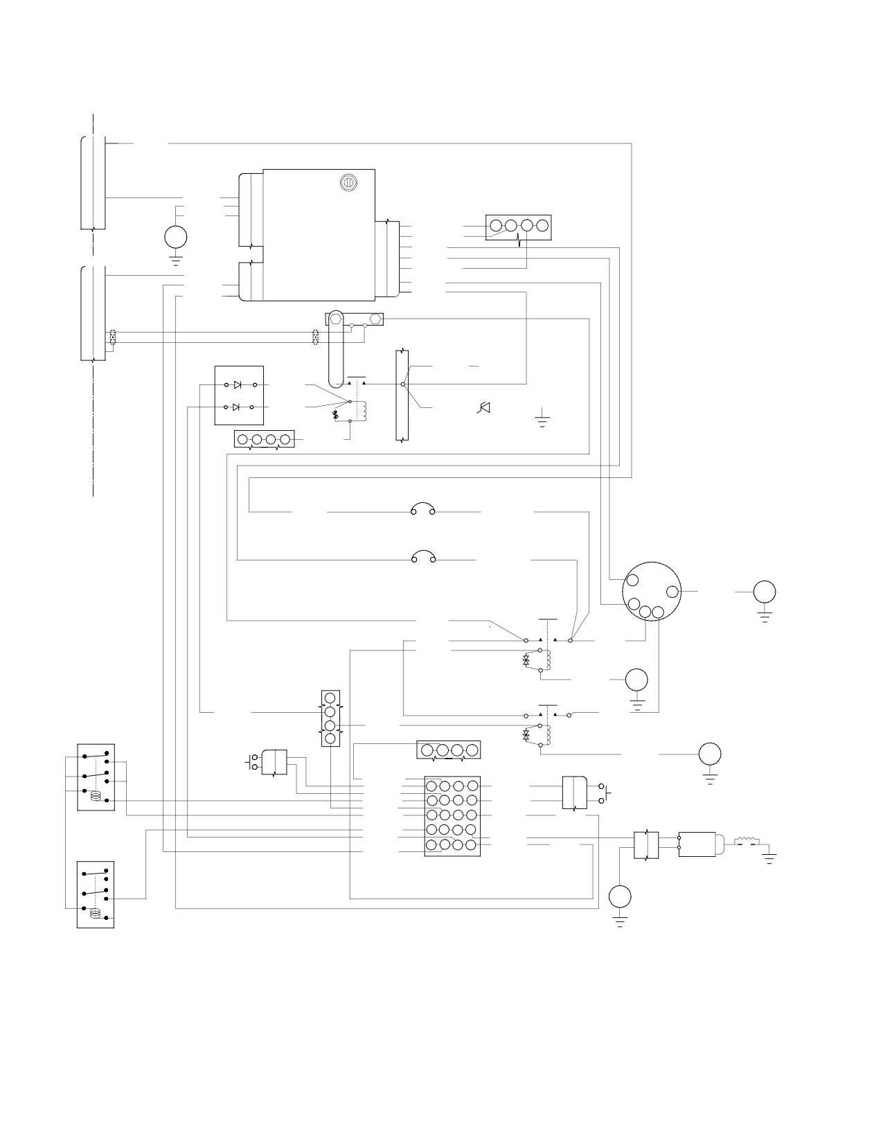
Figure 1. Starter/Generator System Wiring Diagram (Sheet 1 of 2)
Page 2
Revision 22
71-00-47
CSP-HMI-2
MD Helicopters, Inc.
MAINTENANCE MANUAL
This Page Intentionally Left Blank
Page 4
Revision 44
71-00-47
MD Helicopters, Inc.
CSP-HMI-2
MAINTENANCE MANUAL
POWER PLANT
REMOVAL/INSTALLATION
1. Model 250−C47 Engine Replacement
(5). Loosen clamps and remove engine
cooling air ducts from engine compart
A. Engine Disconnecting for Removal
ment.
(6). Loosen clamps and remove compressor
(Ref. Figure 401 and Figure 402)
bleed hose from engine compartment.
After each opening, removal
(7). Detach engine electrical connections.
WARNING
or replacement of any part
of the engine and/or aircraft fuel sys
(a). Detach engine electrical harness
tem between the aircraft fuel tank and
connector.
the engine fuel nozzle, the fuel system
must be bled to remove trapped air.
(b). Detach electrical connections from
starter/generator.
Failure to comply with this procedure
can result in engine flameout or power
(c). Detach splice connector from fuel
loss.
filter bypass switch.
Cap fluid lines and fittings with
(8). Disconnect fuel inlet line at engine
CAUTION
approved devices. Do not use
mounted fuel pump.
tape to cover fuel and oil openings. Tape
adhesives loosened by fuel or oil can con
(9). Disconnect hydromechanical unit
taminate systems.
(HMU) vent line and drain line.
(10). Disconnect customer bleed air line at
(1). Set all switches OFF. Disconnect
firewall elbow.
external power. Disconnect battery (Ref.
Sec. 96-05-00).
(11). Disconnect torquemeter oil line at
firewall.
NOTE: Tag all hardware, wire terminals, fuel
and oil lines before removal to expedite in
(12). Disconnect oil pressure indicator line at
stallation. Identify and bag loose parts to
firewall.
prevent loss or damage.
(13). Disconnect engine control cable from
engine control box on HMU.
(2). Remove main transmission drive shaft
(Ref. Sec. 63-10-00).
The oil cooler is fragile. Unless
CAUTION
otherwise required, disconnect
(3). Remove engine exhaust duct (Ref. Sec.
oil supply and return lines only at engine.
78-30-00). Cover engine exhaust
Support oil cooler port boss with a backup
outlet.
wrench when oil line removal is required.
Do not strain or bend unsupported tubes.
(4). Loosen clamps and remove starter
cooling air duct from engine compart
(14). Disconnect engine oil inlet, outlet and
ment.
vent lines.
Page 401
71-00-47
Revision 22
CSP-HMI-2
MD Helicopters, Inc.
MAINTENANCE MANUAL
INLET SEAL
ENGINE HOIST FITTING
INLET
BELL
SEAL
ASSEMBLY
LEFT SIDE SHOWN
CLUTCH
ASSEMBLY
ENGINE MOUNT PAD
6G71-066-1A
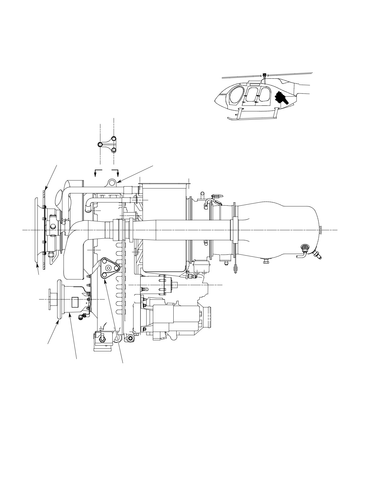
Figure 401. Engine Build−up Assembly (Sheet 1 of 2)
Page 402
Revision 22
71-00-47
MD Helicopters, Inc.
CSP-HMI-2
MAINTENANCE MANUAL
CUSTOMER
HYDROMECHANICAL
BLEED AIR
FUEL CONTROL UNIT
LINE
ENGINE
OIL TANK
VENT LINE
ENGINE OIL
PERMANENT
PRESSURE
MAGNET
ALTERNATOR
ENGINE OIL
INLET
FUEL FILTER
ENGINE
ASSEMBLY
CONTROL
ENGINE OIL
BOX
OUTLET
STARTER/
GENERATOR
FUEL DIFFERENTIAL
PRESSURE SWITCH
OIL FILTER
ASSEMBLY
VIEW LOOKING AFT
VIEW LOOKING FORWARD
O-RING
O-RING
REF. CLUTCH ASSEMBLY
BOLT
POWER TAKEOFF
PAD COVER
LOOKING INBOARD-LEFT SIDE
6G71-066-2A
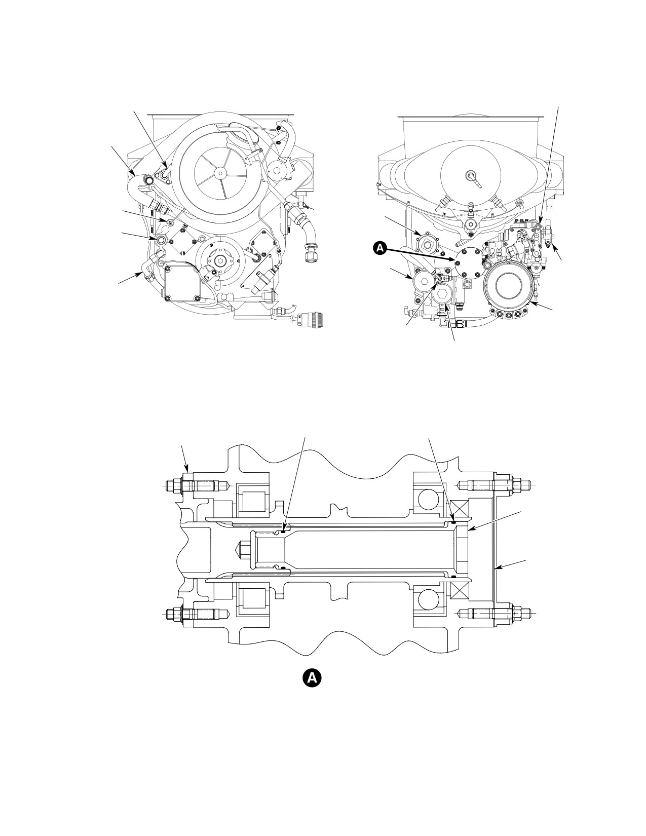
Figure 401. Engine Build−up Assembly (Sheet 2 of 2)
Page 403
71-00-47
Revision 22
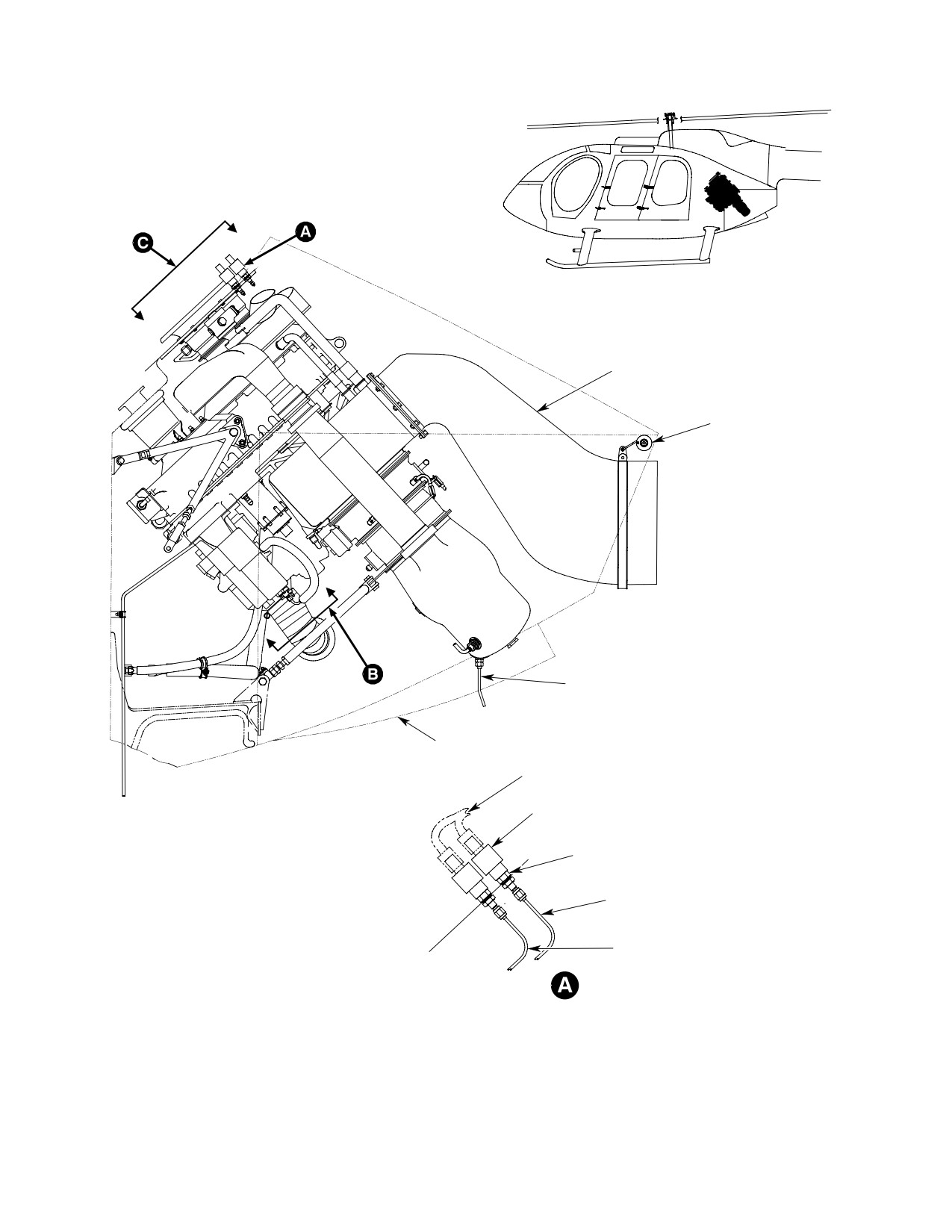
CSP-HMI-2
MD Helicopters, Inc.
MAINTENANCE MANUAL
EXHAUST DUCT
EXHAUST
SUPPORT
ASSEMBLY
COMBUSTOR DRAIN
ENGINE DOOR
ASSEMBLY
ELECTRICAL HARNESS
PRESSURE TRANSDUCER
BULKHEAD UNION
WASHER (2X)
NUT
ENGINE OIL PRESSURE LINE
ENGINE TORQUEMETER LINE
6G71-067-1A
Figure 402. Engine Installation (Sheet 1 of 2)
Page 404
Revision 22
71-00-47
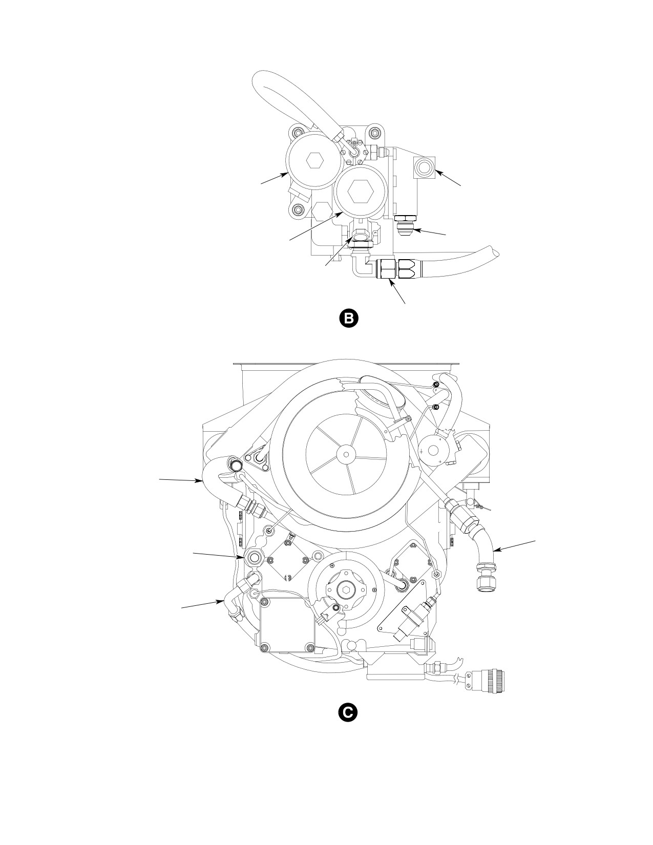
MD Helicopters, Inc.
CSP-HMI-2
MAINTENANCE MANUAL
FUEL FILTER
FUEL IN PORT
OIL OUT PORT
OIL FILTER
FUEL OUT PORT
OIL IN PORT
(EXISTING HOSE)
OIL TANK
ENGINE VENT
CONNECTION
CUSTOMER
BLEED AIR
ENGINE OIL IN
CONNECTION
CONNECTION
ENGINE OIL OUT
CONNECTION
(EXISTING HOSE)
6G71-067-2
Figure 402. Engine Installation (Sheet 2 of 2)
Page 405
71-00-47
Revision 22

CSP-HMI-2
MD Helicopters, Inc.
MAINTENANCE MANUAL
B. Removal of Disconnected Engine
transport and storage bar to engine
hoist fitting.
(Ref. Figure 401 and Figure 402)
C. Engine Installation in Mounts
Special Tools
(Ref. Figure 401 and Figure 402)
(Ref. Section 91−00−00)
Item
Nomenclature
Consumable Materials
ST401
Engine stand
(Ref. Section 91−00−00)
ST402
Engine hoist
Item
Nomenclature
CM702
Lockwire CRES
CAUTION
Special Tools
(Ref. Section 91−00−00)
D Do not remove engine mounts or disturb
Item
Nomenclature
engine mount adjustments to remove en
ST401
Engine stand
gine.
ST402
Engine hoist
D Engine to transmission alignment shall
be inspected whenever one or more en
gine mount assemblies is replaced or the
(1).
Open engine access doors.
existing alignment is disturbed. Do not
(2).
Position engine to line up engine hoist
disturb adjustable engine mount fittings
fitting under airframe hoist fitting.
unless an engine-transmission align
ment check is planned.
(3).
Remove detent pin from adjustable
support shaft on engine stand. Detach
(1). Install engine hoist tool (ST402)
transport and storage bar from engine
between engine hoist fitting and
hoist fitting.
airframe hoist fitting.
(4).
Install engine hoist (ST401) between
(2). Apply tension to engine with hoist and
airframe fitting and engine hoist
remove engine mount bolts.
fitting.
Do not use fuel or oil lines as
(5).
Apply tension to engine hoist to support
CAUTION
hand holds. Do not allow engine
engine. Unscrew engine stand adjust
to strike airframe while maneuvering it out
able support shaft.
of the helicopter.
(6).
Move engine to disengage fixed shaft.
(3). Align engine stand (ST401) under
Roll stand away from engine.
engine with adjustable support shaft on
left side.
CAUTION
(4). Slowly lower engine out of helicopter.
D Do not use tubes or hoses as hand holds.
Align engine side mount fittings
Do not allow engine to strike airframe or
between fixed and adjustable support
components. Avoid damaging engine in
shafts.
take bell.
(5). Screw in adjustable support shaft until
D Prevent FOD. Ensure that no foreign ob
engine mount fittings are securely
jects are in the engine plenum area.
engaged with support shaft sockets.
(7). Slowly raise engine while pushing back
(6). Insert detent pin through adjustable
of engine down to maintain correct
support shaft.
engine and transmission alignment.
(8). Align left and right engine mount
(7). Remove hoist from engine hoist fitting.
assemblies with engine mount fittings.
(8). If engine is to be stored or transported,
Install bolts and washers (Ref.
secure upper end of engine stand
Figure 403). Torque bolts to 220 - 360
Page 406
Revision 22
71-00-47
MD Helicopters, Inc.
CSP-HMI-2
MAINTENANCE MANUAL
inch-pounds (24.85 - 40.66 Nm).
tube nut to 75 - 85 inch-pounds (8.47
Safety bolts with lockwire (CM702).
- 9.60 Nm).
(9).
Align hole in lower engine mount
(2). Connect oil pressure gauge line to
assembly with engine fitting. Install
bulkhead union on firewall. Torque tube
bolt, washers and nut. Torque nut to 95
nut to 75 - 85 inch-pounds (8.47 -
- 110 inch-pounds (10.73 - 12.43
9.60 Nm).
Nm).
(3). Connect engine oil vent line. Torque
(10).
Ensure inlet seal assembly contacts
hose nut to 230 - 260 inch-pounds
firewall around its entire circumfer
(25.98 - 29.36 Nm).
ence.
Do not bend oil return line.
CAUTION
(11).
Remove hoist from helicopter.
Bending loads are transferred to
oil cooler port and may fracture cooler.
(12).
Perform engine to transmission
alignment if applicable (Ref. CSP-
(4). Connect engine oil out line to elbow.
SRM-6, Section 53-30-00).
Torque hose nut to 230 - 260 inch-
pounds (25.98 - 29.36 Nm).
(13).
Using a mirror and light, check for
clearance between airframe and bleed
(5). Connect engine oil in line to union.
valve, any clearance is acceptable.
Torque hose nut to 460 - 500 inch-
pounds (51.96 - 56.48 Nm).
(14).
If bleed valve contacts firewall, readjust
engine mounts for clearance.
(6). Connect customer bleed air line to
elbow. Torque hose nut to 460 - 500
(a). Move engine back by adjusting the
inch-pounds (51.96 - 56.48 Nm).
left and right mounts, increasing the
top and decreasing the bottom.
(7). Connect engine fuel pump seal drain
line. Torque tube nut to 50 - 65 inch-
(b). Only make adjustments one flat at a
pounds (5.64 - 7.34 Nm).
time until bleed valve clears firewall.
NOTE: One flat will move the engine approxi
(8). Connect fuel inlet line to fuel pump.
mately 0.020 inch (0.508 mm) aft.
Torque hose nut to 230 - 260 inch-
pounds (25.98 - 29.36 Nm).
(c). Adjust lower mount to insure no
preload exists.
NOTE: Ensure burner drain valve and plug are
installed in combustion chamber with an O-
(d). Perform engine to transmission
ring on each part. Ensure drain valve is in
alignment if applicable (Ref. CSP-
the aft (lowest) position.
SRM-6, Section 53-30-00).
(9). Install combustion chamber drain line
D. Connecting an Installed Engine
on drain valve. Torque tube nut to 50 -
65 inch-pounds (5.64 - 7.34 Nm).
(Ref. Figure 401 and Figure 402)
(10). Attach engine electrical connectors.
Proper tightening of engine
WARNING
tubing connections is criti
(a). Attach engine electrical wire harness
cal to flight safety. Correct torque val
to to airframe connector at firewall.
ues must be used at all times. Excessive
torque on fuel or pneumatic sensing
(b). Attach fuel pressure bypass switch
system connections can result in crack
splice connector.
ing of the flare causing an air leak
which can cause flameout, power loss,
(c). Attach starter/generator electrical
or overspeed.
connections (Ref. Figure 403).
(1). Connect torquemeter indicator oil line
(11). Install main transmission drive shaft
to bulkhead union on firewall. Torque
(Ref. Sec. 63-10-00).
Page 407
71-00-47
Revision 36
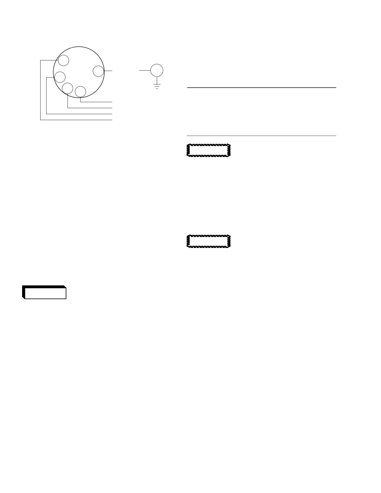
CSP-HMI-2
MD Helicopters, Inc.
MAINTENANCE MANUAL
STARTER / GENERATOR
(20). Inspect engine installation and connec
tions for proper routing and security.
D
2. Model 250−C47 Engine Stripping
E
P1063A0
E1
A
N
2
(Ref. Figure 401)
B
C
Special Tools
K1062A
(Ref. Section 91−00−00)
P1061A
Item
Nomenclature
0
8
ST401
Engine stand
2
6G71-085
ST402
Engine hoist
Figure 403. Starter/Generator Electrical
Connections
Cap fluid lines and fittings with
CAUTION
approved devices. Do not use
(12). Install cooling air ducts and air duct
tape to cover fuel and oil openings. Tape
support bracket on airframe hoist
adhesives loosened by fuel or oil can con
fitting. Connect ducts and tighten
taminate systems.
clamps on firewall coupling and oil
NOTE: Discard all used O-ring packings.
cooler deflector.
(1). Remove engine control box from HMU.
(13). Install compressor bleed hose and
tighten clamps.
(2). Remove reducers from HMU.
(3). Remove starter/generator.
(14). Install starter cooling air duct and
tighten clamps.
Always support the weight of
CAUTION
the starter/generator during re
(15). Install exhaust duct (Ref. Sec. 78-00).
moval/installation. Damage can occur if
weight is supported by the shear shaft.
(16). Connect and rig engine control cable
(Ref. Chap. 76).
(a). Loosen V-clamp and remove starter/
generator.
After each opening, removal
(b). Remove bolts, washers, mounting
WARNING
or replacement of any part
flange and gasket.
of the engine and/or aircraft fuel sys
tem between the aircraft fuel tank and
(4). Remove oil vent line and associated
the engine fuel nozzle, the fuel system
hardware.
must be bled to remove trapped air.
(5). Remove fuel inlet fitting.
Failure to comply with this procedure
can result in engine flameout or power
(6). Remove unions from oil in port and oil
loss.
tank vent unions from gearcase.
(17). Perform fuel system bleed (Ref. Chap.
(7). Remove oil pressure tube, clamps and
28).
attaching hardware and reducer/snub
ber.
(18). Perform an engine deceleration check
(8). Remove torquemeter tube, clamps and
per the Pilot's Flight Manual.
attaching hardware and expander.
NOTE: Make engine adjustments per the Alli
(9). Remove customer bleed air line,
son Engine Operation and Maintenance
associated clamps and hardware and
Manual.
fitting.
(19). Perform an anti-icing system opera
(10). Remove N1 and N2 tachometer genera
tional check (Ref. Chap. 75).
tors and gaskets.
Page 408
Revision 29
71-00-47

MD Helicopters, Inc.
CSP-HMI-2
MAINTENANCE MANUAL
(11). Remove hose, fuel pressure switch,
CAUTION
reducers, tee fitting and union from fuel
filter assembly.
D Prevent FOD. Inspect and clean all acces
sories and hardware prior to installing
(12). Remove engine air inlet bell and
parts on engine.
firewall inlet seal. Cover engine inlet.
D The gear case is magnesium alloy. Using
relatively high torque values applicable to
(13). Remove overrunning clutch and clutch
threaded fittings and fasteners in metals
firewall seal. Install cover on gear case.
other than magnesium may result in
stripped threads. Refer to Allison Engine
(14). Hoist engine and remove engine stand.
Maintenance Manual for additional fas
(15). Unbolt and remove engine mount
tener torque information.
fittings.
(b). Install engine hoist fitting and bolts.
Torque bolts to 140 - 160 inch-
(16). Install engine in shipping container.
pounds (15.81 - 18.07 Nm).
(17). Unbolt and remove hoist fitting.
(c). Install engine hoist tool (ST402)
between engine hoist fitting and
3. Model 250−C47 Engine Buildup
airframe hoist fitting.
(d). Raise engine off shipping container
(Ref. Figure 401)
base.
Proper tightening of engine
(2). Inspect engine as follows:
WARNING
tubing connections is criti
(a). If shipping container moisture
cal to flight safety. Correct torque val
indicator was other than a light blue
ues must be used at all times. Excessive
color, examine engine for corrosion.
torque on fuel or pneumatic sensing
Perform corrosion corrective mainte
system connections can result in crack
nance per Allison Operation and
ing of the flare causing an air leak
Maintenance Manual as required.
which can cause flameout, power loss,
or overspeed.
(b). Inlet guide vanes for damage.
(c). Exhaust and inlet openings for FOD.
Consumable Materials
(d). Install covers over intake and
(Ref. Section 91−00−00)
exhaust ports.
Item
Nomenclature
CM111
Grease, aircraft
(e). All fasteners for security, slippage
marks for alignment, potting com
CM126
Oil, turbine
pound and, or correctly installed
CM702
Lockwire CRES
lockwire where applicable.
(f). Tubes and hoses for damage.
Special Tools
(Ref. Section 91−00−00)
(3). Record engine serial number and
Item
Nomenclature
start-counter reading in appropriate
ST401
Engine stand
log.
ST402
Engine hoist
Prevent damage to machined
CAUTION
surfaces and contamination. Re
move covers from engine one at a time as re
(1). Prepare engine for buildup as follows:
quired by the installation sequence.
(a). Review Allison instructions for
(4). Install engine mount fittings with bolts
removing engine from shipping
and washers. Torque bolts to 140 - 160
container in Allison Operation and
inch-pounds (15.81 - 18.07 Nm).
Maintenance Manual.
Safety bolts with lockwire (CM702).
Page 409
71-00-47
Revision 29
CSP-HMI-2
MD Helicopters, Inc.
MAINTENANCE MANUAL
(5). Install engine in engine stand (ST401).
(8). Install expander with O-ring on
existing engine torquemeter line fitting.
(6). Install clutch assembly.
Torque expander to 50 - 70 inch-
pounds (5.64 - 7.90 Nm).
(a). Remove engine power take off pad
cover from aft side of engine gearbox
(9). Install engine oil tank vent line.
and protective cover from forward
(a). Install union with O-ring in engine
side of engine gearbox.
gearcase oil tank vent port. Torque
union to 280 - 305 inch-pounds
(b). Lubricate clutch assembly and
(31.62 - 34.45 Nm).
engine power output shaft splines
before assembly. Pack all voids and
(b). Install oil tank vent tube on union.
gaps with grease (CM111).
Torque tube nut to 230 - 260 inch-
pounds (25.98 - 29.36 Nm).
(c). Install clutch assembly with angle,
(c). Install union on oil tank vent tube.
washers and nuts. Torque nuts to 50
Torque union to 230 - 260 inch-
- 70 inch-pounds (5.64 - 7.90 Nm).
pounds (25.98 - 29.36 Nm).
Use caution when installing bolt
CAUTION
(d). Install vent hose on union. Torque
to avoid cutting O-ring. Liberal
hose nut to 230 - 260 inch-pounds
ly coat O-ring with grease and install with
(25.98 - 29.36 Nm).
twisting motion.
(10). Install union with O-ring in engine
NOTE: Use new O-ring packings and gaskets
gearcase oil inlet port. Torque union to
on all installations where the parts are re
550 - 600 inch-pounds (62.12 - 67.77
quired. Lubricate O-rings with clean sys
Nm).
tem fluids prior to installation.
(11). Install customer bleed air line.
(d). Lubricate O-rings with grease
(a). Install customer bleed air fitting with
(CM111) and install on bolt. Install
engine supplied gasket, washers and
bolt in aft end of engine power output
engine supplied bolts. Torque bolts to
shaft. Thread bolt into clutch shaft
20 - 25 inch-pounds (2.25 - 2.82
and torque bolt to 250 - 300 inch-
Nm). Safety bolts with lockwire
pounds (28.24 - 33.88 Nm).
(CM702).
(e). Reinstall engine power take off pad
(b). Install bleed hose assembly on bleed
cover. Torque nuts to 50 - 70 inch-
air fitting. Torque hose assembly to
pounds (5.64 - 7.90 Nm).
230 - 260 inch-pounds (25.98 -
29.36 Nm). Clamp line to strap
NOTE: Install firewall seal with split at 6
attached to inlet bell mount bolt.
O'clock position.
(12). Install fuel switch.
(f). Install seal at end of clutch assembly
(a). Install union with O-ring in fuel
with washers and screws. Torque
filter housing. Torque union to 95 -
screws to 15 - 20 inch pounds (1.69
105 inch-pounds (10.73 - 11.86
- 2.25 Nm).
Nm).
To avoid contamination of en
(b). Install tee on union with O-ring and
CAUTION
gine oil system, inspect reducer
jam nut. Torque jam nut to 38 - 42
and snubber bores for metal shavings and
inch-pounds (4.29 - 4.74 Nm).
debris.
(c). Install reducer with O-ring on end of
tee. Torque reducer to 95 - 105
(7). Install engine oil pressure snubber,
inch-pounds (10.73 - 11.86 Nm).
reducer and O-ring on engine gearbox.
Connect oil pressure tube to snubber.
(d). Install union with O-ring on 90
Torque tube nut to 20 - 30 inch-
degree fitting of tee. Torque restrictor
pounds (2.25 - 3.38 Nm). Clamp tube
to 95 - 105 inch-pounds (10.73 -
to existing engine line.
11.86 Nm).
Page 410
Revision 29
71-00-47
MD Helicopters, Inc.
CSP-HMI-2
MAINTENANCE MANUAL
(e). Install fuel switch with O-ring on
(c). Tap around clamp with a rawhide
reducer. Torque switch to 65 - 75
mallet to seat clamp on flange.
inch-pounds (7.34 - 8.47 Nm).
Retorque clamp nut to 50 inch-
pounds (5.64 Nm).
(f). Install reducer with O-ring in fuel
(d). Continue tapping around clamp and
filter housing. Torque reducer to 95 -
retorquing clamp nut until nut no
105 inch-pounds (10.73 - 11.86
longer turns when specified torque is
Nm).
applied.
(g). Install hose between fuel switch and
(15). Install engine control box on HMU.
reducer. Torque hose nuts to 20 - 30
(a). Hold engine control box in position
inch-pounds (2.25 - 3.38 Nm).
against HMU.
(13). Install inlet bell and inlet seal with
(b). Insert 0.1535-0.1545 inch
bolts, washers and nuts. Torque nuts to
(3.8989-3.9243 mm) rig pin (#23 drill
60 - 85 inch-pounds (6.77 - 9.60
blank) through engine control box,
Nm).
indexed HMU pointer and into HMU.
(c). Rotate serrated washer on shaft for
(14). Install starter/generator.
micro-adjustment until rig pin
inserts without interference.
Always support the weight of
CAUTION
the starter/generator during re
(d). Install mounting bolts, washers and
moval/installation. Damage can occur if
use shim washers as required
weight is supported by the shear shaft.
between engine control box and HMU
to prevent binding on rig pin. Torque
(a). Remove starter/generator pad cover.
bolts to 36 - 46 inch-pounds (4.06 -
Install starter/generator mount with
5.19 Nm).
gasket, washers and nuts. Torque
(e). Check rig pin fit again and repeat
nuts to 100 - 140 inch-pounds
previous steps as required.
(11.29 - 15.81 Nm).
(16). Install reducers with O-rings on HMU.
(b). Install starter/generator with V-
Torque reducers to 550 - 600 inch-
clamp. Torque clamp nut to 50
pounds (62.12 - 67.77 Nm) and 50 -
inch-pounds (5.64 Nm).
55 inch-pounds (5.64 - 6.21 Nm).
Page 411
71-00-47
Revision 29
CSP-HMI-2
MD Helicopters, Inc.
MAINTENANCE MANUAL
This Page Intentionally Left Blank
Page 412
Revision 44
71-00-47
MD Helicopters, Inc.
CSP-HMI-2
MAINTENANCE MANUAL
Section
71−10−00
Engine Air Intake
System (369D/E/FF −
500/600N)
MD Helicopters, Inc.
CSP-HMI-2
MAINTENANCE MANUAL
ENGINE AIR INTAKE SYSTEM
MAINTENANCE PRACTICES
1.
Description and Operation
intake air from accumulating in the
plenum chamber cavity.
(1).
The engine air intake system consists of
an air inlet screen, plenum chamber,
2. Air Inlet Screen Replacement
engine inlet bell, engine inlet firewall
A. Air Inlet Screen Removal (369D/E/FF −
seal, and engine firewall seal ring.
500N)
(2).
Air enters the inlet fairing, passes
(Ref. Figure 201)
through the inlet screen, plenum
chamber and air inlet bell into the
NOTE: The following procedures are to be used
engine compressor.
for all MDHI model helicopters. The differ
ent steps are noted for the 500N installa
(3).
The engine inlet screen assembly is
tion.
made of a lightweight 1/4 inch (6.35
mm) mesh metal screen material
(1). Remove engine air inlet forward
secured to a metal frame along its outer
fairings (Ref. Sec. 53-30-00/30).
edge. The engine air particle separator
option, when installed, replaces the
(2). Open plenum chamber bypass door.
inlet screen.
(3). Install a suitable cover over engine air
inlet bell though bypass door opening.
(4).
The inlet screen edge is 1-1/2 inches
(3.81 cm) from the top of air inlet
(4). On 500N installation, remove the
fairing to provide an intake air-bypass
engine plenum fairing attachment
area in the event that debris clogs the
hardware, open bypass door and
screen. The firewall seal separates
remove fairing assembly.
plenum chamber intake air from engine
compartment air.
Avoid FOD. Cover compressor
CAUTION
inlet prior to working in plenum
(5).
A differential pressure switch is
chamber. Vacuum all FOD debris out of ple
mounted with a reference to both sides
num chamber before removing protective
of the engine inlet screen. Blockage of
cover from engine inlet bell. Severe damage
the inlet screen will cause a pressure
to engine may result from entry of foreign
decrease on the engine plenum side and
objects.
the switch will activate a warning light
in the cockpit.
(5). Remove clamps or tie-down straps
securing tail rotor control rod boot to
(6).
A cable from the cockpit is manually
inlet screen fairing.
operated to open a bypass door which
(6). Disconnect Sta. 120.00 tail rotor control
allows unfiltered air into the engine
rod forward end. (Ref. Chap. 67).
inlet plenum if the engine inlet screen
is blocked.
(7). On 500N disconnect the intermediate
anti torque tube forward end. (Ref. Sec.
(7).
The molded nylon air inlet bell is
67-20-30).
retained on its mounting flange with
three flat springs and is required to
(8). Remove blower air inlet screen (Ref.
smooth air flow into the compressor.
Figure 201).
(8).
A plenum chamber drain system
(9). Remove attaching hardware and engine
prevents water condensed out of engine
air inlet screen.
Page 201
71-10-00
Revision 22
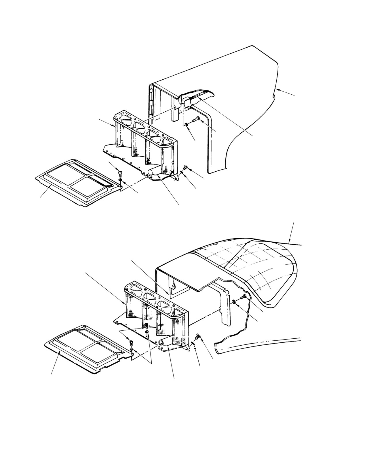
CSP-HMI-2
MD Helicopters, Inc.
MAINTENANCE MANUAL
FAIRING
ENGINE AIR INLET SCREEN
BOLT
PLENUM CHAMBER
WASHER
ACCESS DOOR
SCREW
SCREW
WASHER
WASHER
BLOWER AIR
INLET SCREEN
ANTI-TORQUE CONTROL
ROD BOOT SUPPORT
FAIRING
369D/E/FF INSTALLATION
PLENUM CHAMBER
ACCESS DOOR
ENGINE AIR INLET SCREEN
BOLT
WASHER
SCREW
WASHER
WASHER
BLOWER AIR
INLET SCREEN
ANTI-TORQUE CONTROL
ROD BOOT SUPPORT
500N INSTALLATION
G71-1021B
Figure 201. Engine Air Inlet Screen Installation (Sheet 1 of 2)
Page 202
Revision 22
71-10-00
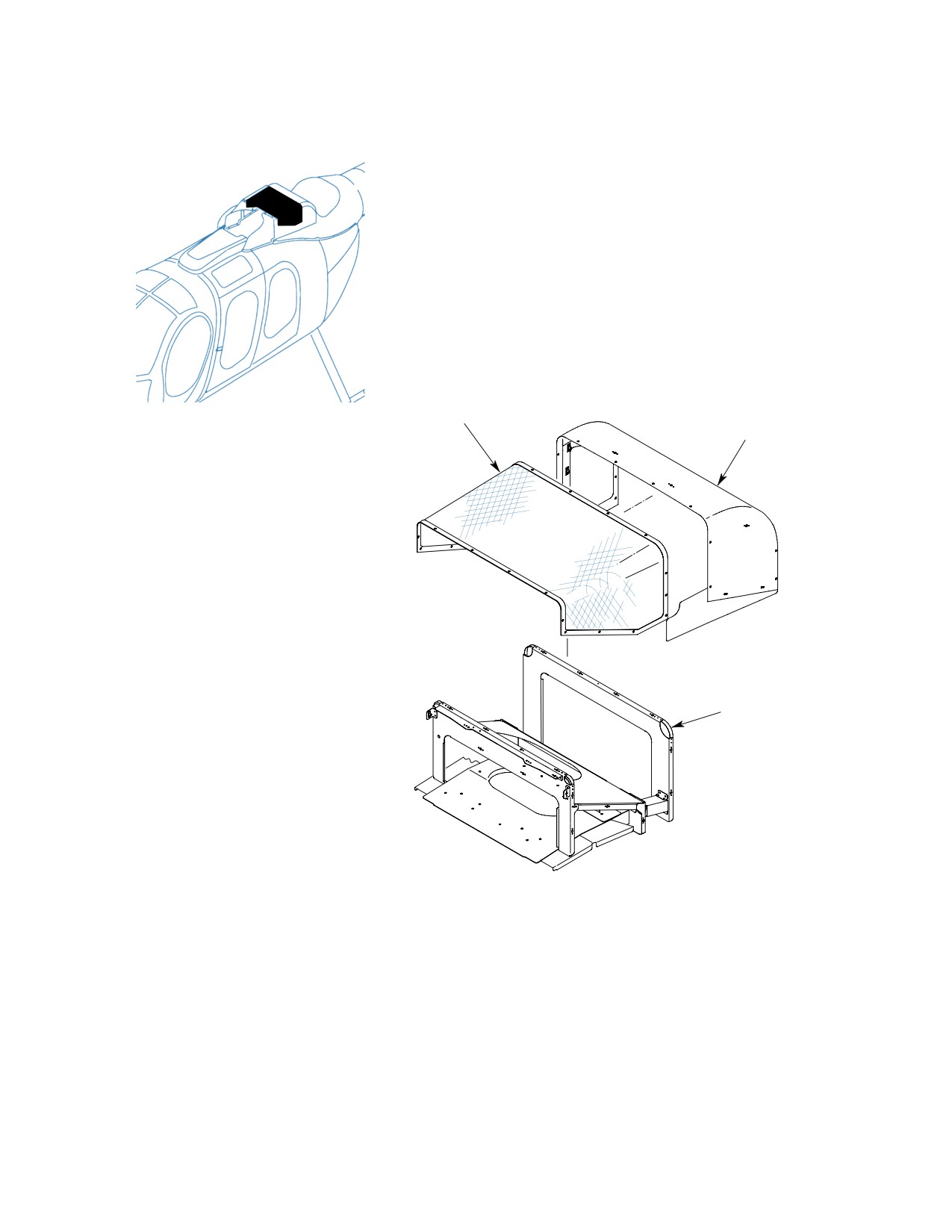
MD Helicopters, Inc.
CSP-HMI-2
MAINTENANCE MANUAL
ENGINE INLET
SCREEN ASSEMBLY
ENGINE PLENUM
ACCESS COVER
INLET FRAME
600N INSTALLATION
6G71-074
Figure 201. Engine Inlet Screen Installation (Sheet 2 of 2)
Page 203
71-10-00
Revision 22
CSP-HMI-2
MD Helicopters, Inc.
MAINTENANCE MANUAL
B. Engine Inlet Screen Removal (600N)
4. Firewall Seal Removal
(Ref. Figure 201)
(Ref. Figure 202)
(1). Remove screws, washers and inlet
screen from inlet frame.
Consumable Materials
(Ref. Section 91−00−00)
C. Air Inlet Screen Installation (369D/E/FF −
Item
Nomenclature
500N)
CM219
Methyl-ethyl-ketone
CM411
Adhesive, epoxy
(Ref. Figure 201)
Vacuum all FOD debris out of
CAUTION
(1). Remove engine.
plenum chamber before remov
ing protective cover from engine inlet bell.
(2). Pull seal from firewall.
Severe damage to engine may result from
entry of foreign objects.
Use Methyl ethyl ketone
WARNING
(MEK) in a well ventilated
(1). Install engine air inlet screen in reverse
area and away from heat and flame.
order of removal.
(3). Remove seal debris from firewall with a
D. Engine Inlet Screen Installation (600N)
wooden or plastic scraper.
(Ref. Figure 201)
(4). Remove residue from firewall with
(1). Install inlet screen on inlet frame with
MEK (CM219).
washers and screws. Torque screws to
20 - 25 inch-pounds (2.25 - 2.82
(5). Apply adhesive (CM411) to installation
Nm).
per manufacturers instructions. Center
seal over firewall opening and bond in
3. Air Inlet Bell Replacement
place.
A. Air Inlet Bell Removal
(6). Install engine.
(Ref. Figure 202)
5. Air Intake System Inspection
(1). Remove engine.
(1). Inspect air inlet screen for security,
deformation,inspect screen for cleanli
(2). Remove attaching hardware, air inlet
ness, clogged areas and foreign particle
bell and firewall seal ring.
accumulation. (Cleaning of engine air
inlet screens Ref. Sec. 20-20-00).
(3). Remove firewall seal ring from inlet
bell.
(2). Inspect screen for tears, cuts, breaks
and missing pieces.
B. Air Inlet Bell Installation
(3). Inspect anti-torque control rod boot for
(Ref. Figure 202)
condition and secure attachment (Ref.
(1). Model 250-C20B Only:
Chap. 67).
On early installations; attach firewall
(4). Inspect air inlet bell for cracks, breaks
seal ring to inlet bell by lifting and
and missing pieces. No cracks or
positioning leaf springs over bell flange.
missing pieces allowed.
(2). Position engine air inlet bell and seal
assembly on compressor inlet mounting
(5). Model 250-C20B Only:
flange and secure.
On early installations; inspect engine
firewall seal ring for cracked or weak
(3). Install engine.
springs.
Page 204
Revision 22
71-10-00
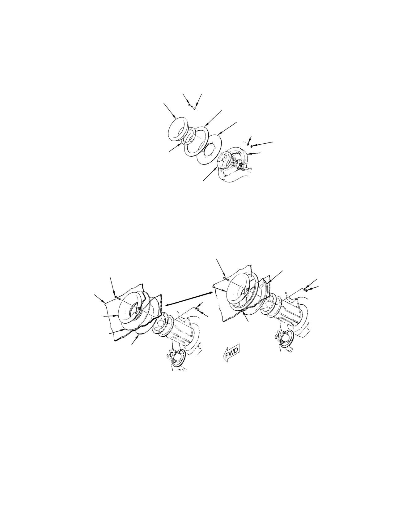
MD Helicopters, Inc.
CSP-HMI-2
MAINTENANCE MANUAL
SCREW
WASHER
AIR INLET BELL
FIREWALL SEAL
FIREWALL SEAL RING
WASHER
NUT
SPACER
ENGINE
MOUNTING FLANGE
250-C30 AND 250-C47 ENGINES
SCREW
FIREWALL SEAL RING
SCREW
WASHER
ENGINE AIR INLET BELL
NUT
FIREWALL
WASHER
AIR INLET BELL
NUT
FIREWALL SEAL
FIREWALL SEAL
FIREWALL SEAL RING
EARLY CONFIGURATION
CURRENT CONFIGURATION
250-C20B AND 250-C20R/2 ENGINES
G71-1020A
Figure 202. Firewall Seal Installation
Page 205
71-10-00
Revision 22
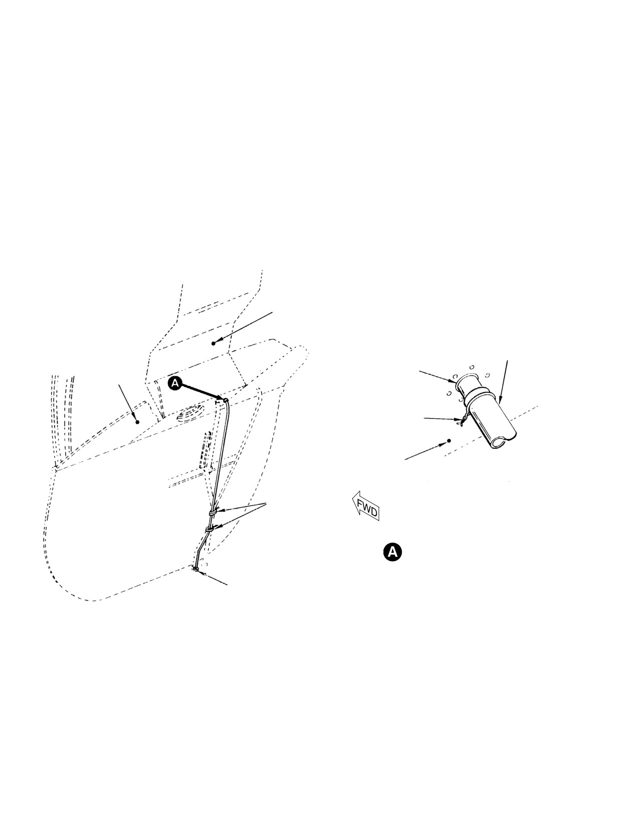
CSP-HMI-2
MD Helicopters, Inc.
MAINTENANCE MANUAL
(6). Inspect engine-to-firewall seal ring at
6. Firewall Seal Ring Repair
the firewall for cracks, corrosion or
Replace damaged or broken springs on early
damage preventing a positive and
installations.
complete seal. Repair or replace seal
installation as required.
7. Air Inlet Bell Repair
(7). Inspect air inlet-to-firewall seal for
Engine air inlet bell repairs are not autho
cracks, corrosion or damage preventing
rized; replace a defective bell.
a positive and complete seal. Repair or
replace seal installation as required.
8. Plenum Chamber Drain Tube Replacement
(Ref. Figure 203)
(8). Inspect plenum chamber drain tubing
for deformation and corrosion. Ensure
(1). Replace drain tubing using standard
drain is open.
practices and procedures.
PLENUM CHAMBER
PLENUM CHAMBER
DRAIN TUBE
FIREWALL FITTING
FIREWALL
LOCKWIRE
FIREWALL
NYLON TWINE
DRAIN TUBE ATTACHMENT
GROMMET
G71-1022
Figure 203. Drain System
Page 206
Revision 22
71-10-00
MD Helicopters, Inc.
CSP-HMI-2
MAINTENANCE MANUAL
Section
71−10−05
Engine Compressor
Water Wash Kit
(369D/E/FF −
500/600N)
MD Helicopters, Inc.
CSP-HMI-2
MAINTENANCE MANUAL
ENGINE COMPRESSOR WATER WASH KIT
MAINTENANCE PRACTICES
1. Engine Compressor Water Wash Kit
2. Engine Compressor Water Wash Kit
Maintenance
Inspection
(1). Inspect hoses for chafing, damage and
deterioration.
Replace hoses, clamps and other hardware
only when necessary.
(2). Inspect all clamps for damage and
security.
(3). Inspect elbow for damage and security.
Whenever working in the en
CAUTION
gine plenum area, cover engine
(4). Inspect spray assembly for loose rivets,
with cardboard or other suitable object to
secure hose and clamp, no damage to
prevent foreign objects from entering en
grommet and silicone sealant around
gine.
tube intact.
(5). Inspect all mounting brackets for loose
rivets.
(1). Remove appropriate access panels to
gain access to area of water wash kit to
(6). Inspect lanyard for security and
be worked on.
damage; cap installed.
Page 201
71-10-05
Revision 22