HANDBOOK OF MAINTENANCE INSTRUCTIONS FOR MDHI 369D/E/FF-500/600N HELICOPTERS (ISSUED: 1990) - page 26
MD Helicopters, Inc.
CSP-HMI-2
MAINTENANCE MANUAL
ANTI−TORQUE FLIGHT CONTROLS
(TWO AND FOUR BLADE)
INSPECTION/CHECK
1. Upper Fuselage and Tailboom Control
2. Tail Rotor Pedal Assembly Inspection
Linkage Inspection
(Ref. Figure 402)
(Ref. Figure 401)
(1).
Inspect rod end bearings for binding
NOTE: Inspect components at left and right po
and excessive wear, 0.040 inch (1.016
sition on the right-hand command models.
mm) maximum axial play. Inspect rivet
Check that corresponding pedals contact
at fixed rod end.
stops simultaneously.
(2).
Inspect control rod for surface damage
(1).
Inspect pedals and pedal arms for
and evidence of bending.
cracks, elongated pedal attach holes
(3).
Inspect rubber boot just forward of Sta.
and open drain holes. Inspect teflon-
137.50 bulkhead for condition.
reinforced bushing liners for deteriora
tion.
(4).
Inspect tailboom control rod surfaces
that pass through all grommets.
(2).
Inspect pedal-to-arm quick-release
Serviceable wear is limited to thickness
locking pin for condition and positive
of hard anodic coating. Check that all
spring action.
bushings are secure.
(5).
Inspect bellcranks for scratches, cracks,
(3).
Inspect links and bellcrank for cracks
corrosion and similar surface defects.
and bends, and bearings for excessive
play.
(6).
Inspect bellcrank bearings for looseness
and binding.
(4).
Inspect control rod fitting, torque tube
mounting bracket and pedal mounting
(7).
Inspect for obstructions in drain slot of
bracket for cracks and corrosion. Using
Sta. 284 bellcrank.
an 8-power magnifying glass, mirror
(8).
Inspect for corrosion or excessive wear
and flashlight, closely inspect pedal
on Sta. 284 bellcrank pivot pin.
link bellcrank fitting of pedal bracket in
center forward area where fitting (fork
(9).
Visually inspect doublers on Sta. 142
piece) joins tubular section. If any
bellcrank supports for cracking/da
cracks are detected, replace bracket
mage.
assembly. Inspect bracket bearings for
excessive looseness.
NOTE: MDHC Notice DN-49 contains infor
mation relative to repair of damaged dou
blers on bellcrank supports. MDHC Notice
(5).
Inspect torque tube for cracks,
DN-102 contains information required to
scratches, nicks, dents and similar
modify the particle separator fairing and
surface defects.
cover assemblies to prevent possible chafing
of the Sta. 120 tail rotor control rod.
(6).
Inspect pedal brackets for corrosion.
Page 601
67-20-10
Revision 21
CSP-HMI-2
MD Helicopters, Inc.
MAINTENANCE MANUAL
Table 601. Isolating Control System Troubles
Symptom
Isolating Step
Corrective Action
Binding, locking−up and erratic
Disconnect pitch control links from
If symptom is gone, replace tail rotor
action of foot pedals (Do not force
pitch control assembly.
assembly. Repair (Ref. COM).
controls).
Symptom remains.
Disconnect Sta. 284 aft boom
If symptom is gone, clean
bellcrank from pitch control
swashplate bore and output shaft
assembly.
splines. Lubricate splines. Replace
swashplate if necessary. Check for
elongation of bolt hole in support arm
portion of main housing assembly of
tail rotor gearbox, caused by
looseness of bellcrank fulcrum bolt
and nut. Repair (Ref. COM).
Symptom remains.
Disconnect floor−routed tail rotor
If symptom is gone, inspect tail rotor
control rod from foot pedal torque
control rods and bellcranks until
tube fitting.
defective part is located.
Symptom remains.
Loosen foot pedal torque tube
If symptom is gone, pedal torque
brackets mounted on front of floor
tube misaligned; shim for correct
structure.
alignment. If symptom remains,
disassemble and inspect tail rotor
control foot pedal installation until
defective part is located.
Trouble corrected.
Page 602
Revision 21
67-20-10
MD Helicopters, Inc.
CSP-HMI-2
MAINTENANCE MANUAL
ANTI−TORQUE FLIGHT CONTROLS
(TWO AND FOUR BLADE)
REPAIRS
1. Floor− and Tunnel−Routed Control Rods
(5). If removed, install rivet to secure rod
end.
(Ref. Figure 401 and Figure 402) The floor-
and tunnel-routed control rods connect the tail
(6). Check that slotted bushing is in place;
rotor pedal installation with the upper
then secure control rod in torque tube
fuselage and tailboom control linkage. The two
fitting or idler bellcrank with bolt, two
control rods are linked by a tail rotor idler
washers, nut and cotter pin.
bellcrank mounted on the underseat controls
(7). Install bungee spring.
support bracket.
(8). Install access doors.
2. Floor−Routed Tail Rotor Control Rod
Repair
(9). Check rigging of tail rotor controls (Ref.
Tail Rotor Controls Rigging).
(Ref. Figure 401) Replace rod end if bearing
axial play is more than 0.040 inch (1.016 mm).
3. Upper Fuselage and Tailboom Control
Riveted rod end bearing is replaceable without
Linkage Repair
rod removal if located at forward end of rod. If
(Ref. Figure 401)
riveted rod end is aft, rod removal is required
to replace rod end bearing.
Consumable Materials
NOTE: Floor-routed control rod normally does
(Ref. Section 91−00−00)
not require replacement unless helicopter
Item
Nomenclature
receives extensive impact or crash damage.
CM318
Primer
Remove control rod forward through land
CM431
Sealing, locking and retaining compound
ing light wiring grommet hole after landing
light (if installed) is removed (Ref. Chap.
CM802
Abrasive cloth, aluminum oxide
96).
(1). Perform straightness check on control
(1). Disconnect control rod from pedal
torque tube fitting or from tail rotor
rod that appears bent or bowed. Total
idler bellcrank (Ref. Figure 402).
length of Sta. 120 control rod, excluding
Remove bungee spring (Ref. Sec.
rod ends, must be straight within 0.040
67-10-00).
inch (1.016 mm), with straightness
variation limited to maximum of 0.010
(2). Accurately measure and record distance
inch (0.254 mm) in each foot of length.
between unchamfered edge of rod end
Total length of tailboom control rod,
jam nut and center of rod end bearing
excluding rod ends, must be straight
hole.
within 0.120 inch (3.048 mm), with
straightness variation limited to
Use care when drilling to re
maximum of 0.010 inch (0.254 mm) in
CAUTION
move or install riveted rod end;
each foot of length.
rod end is steel and rod is aluminum.
A dye check for cracking
(3). If necessary, drill out rivet. Loosen jam
WARNING
must always be performed
nut and unscrew rod end.
after cold-straightening. Replace
cracked rod, or cracked or bent rod
(4). Screw another rod end into rod to
end.
obtain same measurement made in step
(2). above. Align control rod ends so
(2). Cold-straighten bent rod that is not
that bearings have equal space for
within tolerance (step (1). above)
angular throw; tighten jam nut.
provided there are no nicks or sharp
Page 801
67-20-10
Revision 21
CSP-HMI-2
MD Helicopters, Inc.
MAINTENANCE MANUAL
dents in bend length. Do not use rod
(6). Repair minor surface defects such as
ends to support rod during straighten
scratches, nicks and corrosion on
ing process.
bellcranks and support bracket. Use
abrasive cloth, grade 400 - 600
Use care when drilling to re
(CM802), to smooth out and blend in
CAUTION
move or install riveted rod end;
such defects. Following rework limits
rod end is steel and rod and bearing adapter
represent total limits, including effects
are aluminum.
of all previous repairs to any given
area.
(3). Replace control rod end if bearing axial
play is more than 0.040 inch (1.016
NOTE: Parts identified (Ref. Figure 401) with
mm). Set initial control rod length and
an asterisk ( * ) may be either magnesium or
bearing angularity.
aluminum alloy. For corrosion control and
identification of magnesium and aluminum
(4). Replace unserviceable control rod
alloys, refer to Section 20-40-00.
bearing adapter. Trammel method (or
equivalent) may be used to establish
(a). Cast surfaces may be reworked to
rod length when replacing an adapter.
depth of 0.020 inch (0.508 mm).
(a). Measure length and record position
(b). Flat machined surfaces, except clevis
of rod end in adapter; then remove
inner ears, may be reworked to depth
affected rod end.
of 0.015 inch (0.381 mm). Clevis
inner ear surfaces may be reworked
(b). Comply with precaution above and
to depth of 0.020 inch (0.508 mm).
drill out rivets securing adapter to
rod and aft rod end.
(c). Machined holes may have 0.003 inch
(0.076 mm) removed from bore wall
(c). Install rod end in replacement
in an area no greater than 15 percent
adapter and position at recorded
of circumference and 50 percent of
measurement.
depth.
(d). Fit adapter into rod and position to
(d). All edges may have 0.030 inch (0.762
fit trammel point spacing; pick up
mm) removed except around ma
and drill through existing rivet holes
chined holes, which are limited to
in rod and install rivets to secure
0.010 inch (0.254 mm) chamfer.
adapter to rod; at aft end, drill and
rivet rod end to adapter.
(e). All rework must be smoothly blended
into adjacent surfaces and finish
(5). Replace unserviceable bellcrank and
must be restored (Ref. preceding
support pivot bearings. Install bearing
NOTE).
with grade A locking compound
(CM431). Make sure that bearing seats
(7). Repair surface abrasion on Sta. 120
against bore shoulder.
control rod by smoothing area with
grade 400 abrasive cloth (CM802) and
NOTE:
restoring protective finish with primer
(CM318). Replace rod if wear or depth
D Installation direction of Sta. 142 bell
of repair exceeds 0.004 inch (0.102
crank bearing may be from either side,
mm).
depending on location of bearing shoul
der. There must not be less than 0.010
(8). Replace tailboom control rod if hard
inch (0.254 mm) protrusion of bearing in
anodic coating is worn through and
ner race beyond sides of bellcrank after
aluminum base metal is visible.
bearing is installed.
D If contact is noted between Sta. 142 bell
(9). Replace split or torn boot. Remove Sta.
crank and mount bracket, rework bell
120 control rod. Replace boot and
crank to clear bracket (Ref. Figure 801).
reinstall Sta. 120 control rod.
Page 802
Revision 21
67-20-10
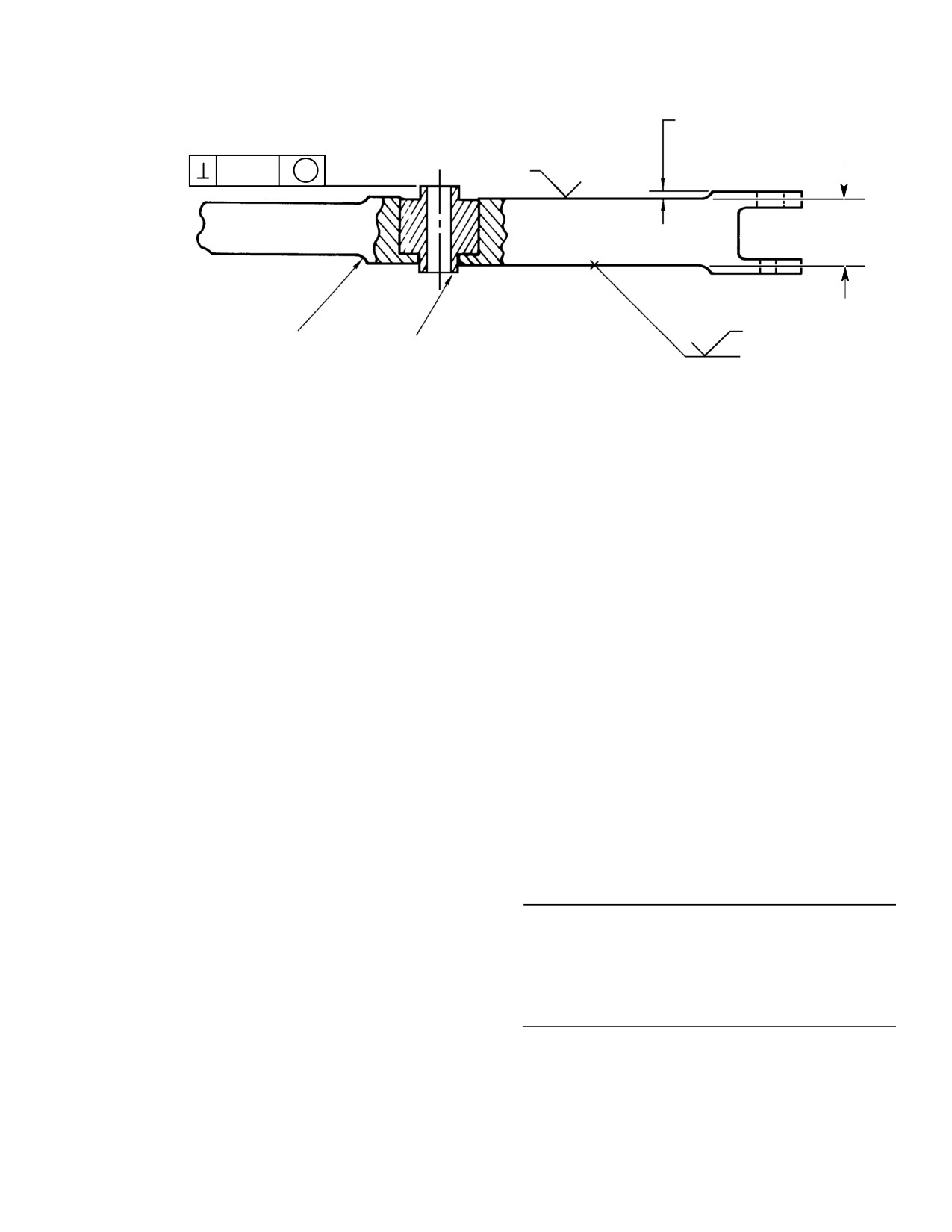
MD Helicopters, Inc.
CSP-HMI-2
MAINTENANCE MANUAL
BELLCRANK AND SUPPORT
(2 PLS) (NOTE 1)
0.002 IN.
NOTES
A S
(0.508 MM)
2 & 3
0.750 IN.
NOTES
(19.05 MM)
0.090 IN. (2.286 MM) R
2 & 3
MIN.
369A7951-23
(TYP)
BEARING
NOTES:
1.
0.010 MINIMUM CLEARANCE REQUIRED IN THIS AREA.
2.
TREAT MACHINED AREA WITH CHROMIC ACID SOLUTION (CM207).
3.
TOUCH UP COLOR 34151 GREEN (CM304).
G67-2003A
Figure 801. Rework of Sta. 142 Bellcrank Assembly
4. Station 78.50 Tail Rotor (Tunnel−Routed)
temporarily reinstall washer and nut
Control Rod
on bolt.
All tunnel-routed control rods are removed,
(5). Slide pedal bracket and pedal arms off
inspected, repaired and installed in same
end of torque tube.
manner. For initial length and rod end
(6). Do not remove two teflon-lined bush
angularity, Ref. Figure 402. For maintenance
ings from right pedal arm, unless
information, Ref. Sec. 67-10-00.
replacement is required.
A. Tail Rotor Idler Bellcrank
(7). Do not remove two stop bolts, jam nuts
(Ref. Controls Support Bracket and Bellcrank,
on stop bolts or bearings from pedal
Sec. 67-10-00)
bracket unless replacement is required.
(8). Slide torque tube bracket and control
5. Tail Rotor Pedal Disassembly
rod fitting off torque tube.
(Ref. Figure 402)
6. Tail Rotor Pedal Repair
(1). Before disassembly of tail rotor pedal
(Ref. Figure 402)
installation, matchmark mating pedal
arms, links and bellcranks with pedal
brackets to avoid intermixing compo
Consumable Materials
nents between locations at reassembly.
(Ref. Section 91−00−00)
Item
Nomenclature
(2). Disconnect links from pedal arms and
CM425
Sealing compound
bellcrank; remove links.
CM431
Sealing, locking and retaining compound
(3). Remove bellcrank from pedal bracket.
(4). Remove nut and washer of two bushing
(1). Replace parts that are cracked or have
assemblies that secure left pedal arm
elongated attachment holes. Do not
and control rod fitting to torque tube.
attempt to straighten bent torque tube
Carefully remove bushing bolt and
or pedal link.
Page 803
67-20-10
Revision 21
CSP-HMI-2
MD Helicopters, Inc.
MAINTENANCE MANUAL
(2). Replace unserviceable pedal covers.
mm). Torque nut to 50 - 80 inch-
Apply sealing compound (CM425) to
pounds (5.65 - 9.04 Nm) plus drag
approximately 30 percent of upper and
torque. Do not allow bolt to turn.
lower edge surfaces that contact pedal.
Cure according to container instruc
(6).
Check that each end of bushing assem
tions.
bly shank protrudes at least 0.002 inch
(0.051 mm). If not, loosen and repeat
(3). Replace complete pedal link if it is
step (4). above.
cracked or contains unserviceable
(7).
Check that slotted bushing is in place;
bearings; bearings are not replaceable.
then attach bellcrank to pedal bracket
(4). Replace unserviceable bearings in
with bolt, two washers, nut and cotter
mounting brackets or pedal link
pin.
bellcrank. Install replacement with
(8).
Check that slotted bushings are in
grade A locking compound (CM431).
place; then fasten each link to bellcrank
with bolt, two washers, nut and cotter
Right pedal arm bushings are
CAUTION
pin.
glass-filled phenolic. Make cer
tain that bushing does not cock during re
(9).
Check that slotted bushings are in
placement, and that it is fully seated in arm
place; then fasten each link in pedal
bore. Keep tools from contact with bushing
arm lugs with bolt, two washers, nut
liners to avoid fraying.
and cotter pin.
(5). Replace bearings in right pedal arm
(10).
Ensure outboard pedals clear windows
when teflon-reinforced liner is galled or
by a minimum of 0.20 inch (0.508 mm)
frayed. Pull bushing to remove; press to
with 20 pounds (88.96 N) of force
install.
applied.
(6). Remove corrosion from pedal brackets
8. Tail Rotor Bungee Spring Forward
(Ref. Sec. 20-40-00 and CSP-A-3,
Attachment Relocation
Corrosion Control Manual).
(Ref. Figure 802) The information given in this
7. Tail Rotor Pedal Reassembly
procedure is for the relocation of the tail rotor
bungee spring forward attachment on 369D
(Ref. Figure 402)
helicopters, Serial No. 003D - 0467D. This
rework allows for the installation of washers,
(1). When reassembling components, check
for bungee adjustment, to adjust for minimum
for correct matchmark identification.
pedal loads in cruise.
(2). If previously removed, thread jam nut
on each of two stop bolts and install two
Consumable Materials
stop bolts into threaded inserts of pedal
(Ref. Section 91−00−00)
brackets.
Item
Nomenclature
CM207
Chromic acid solution
(3). Slide torque tube bracket and control
rod fitting onto torque tube.
CM318
Primer
CM411
Adhesive, epoxy
(4). Locate pedal bracket and pedal arms
for correct position on torque tube; slide
bracket and arms onto torque tube.
(1). Remove access cover between pilot's
seats and/or passenger's footwell on aft
(5). Fasten left pedal arm and control rod
side of canted bulkhead.
fitting to torque tube with adjustable
bushing assemblies. Install bushing
(2). Block left tail rotor control pedal at full
bolt so that shank at bolt-head end
forward position to relieve tension on
protrudes at least 0.002 inch (0.051
bungee.
Page 804
Revision 21
67-20-10
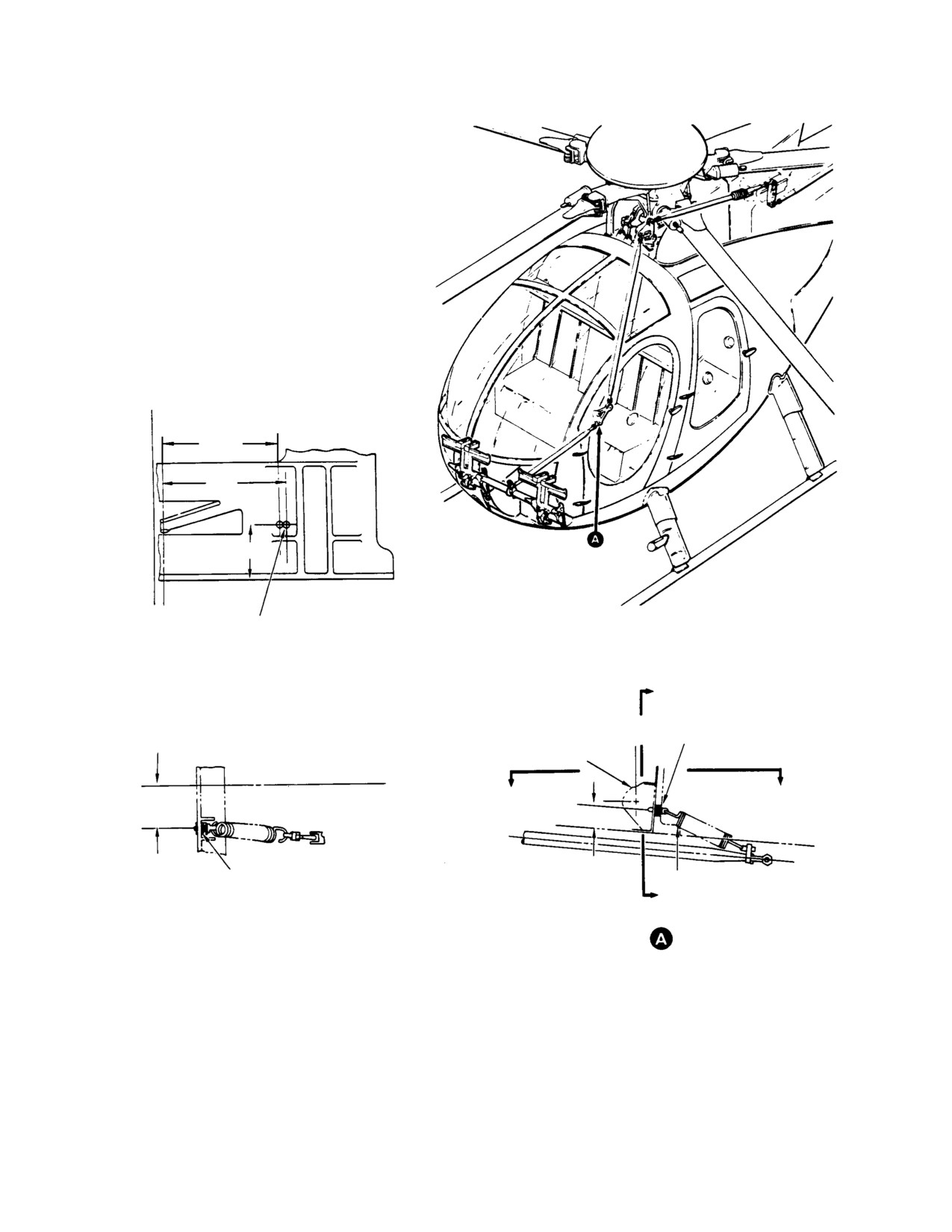
MD Helicopters, Inc.
CSP-HMI-2
MAINTENANCE MANUAL
C
L SHIP
OLD HOLE
3.25 IN. (8.255 CM)
NEW HOLE
3.37 IN. (8.5598 CM)
1.75 IN. (4.445 CM)
0.190-0.194 IN.
(4.826-4.9276 MM)DIA. HOLE
C - C
VIEW LOOKING AFT
C
AN42B-C10A EYEBOLT
AN970-3 WASHER (8 REQUIRED)
STA
MS21042-3 NUT
63.00
AN960-10L WASHER
369A2541 BRACKET
CL
SHIP
3.37 IN.
B
B
(8.5598 CM)
1.75
0.190-0.194 IN.
369D27521 SPRING
DIAMETER THRU BRACKET
(4.826-4.9276 MM)
C
B - B VIEW LOOKING DOWN
VIEW LOOKING INBOARD LH SIDE
G76-2007A
Figure 802. Relocation of Tail Rotor Bungee Spring Forward Attachment
Page 805
67-20-10
Revision 21
CSP-HMI-2
MD Helicopters, Inc.
MAINTENANCE MANUAL
(3). Disconnect bungee spring from eyebolt
end of 369D27521 bungee spring to
and remove and retain nut and washer
eyebolt. Insert eyebolt in new hole in
attaching eyebolt to bracket at Sta. 63,
369A2541 bracket and secure with
discard eyebolt.
washer and nut retained from prior
step. Torque nut to 20 - 25 inch-
(4). Locate position and drill new hole using
pounds (2.26 - 2.82 Nm).
No. 10 drill, deburr as required.
NOTE: If tail rotor pedal forces are not zero
(5). Seal old eyebolt hole with adhesive
during level flight at 130 - 140 knots, tail ro
(CM411). Allow to dry per manufactur
tor force adjustment may be accomplished
er's instructions.
by removing a desired number of AN970-3
washers.
(6). Treat edge of new hole with chromic
acid solution (CM207) and touch up
(8). Remove block from left tail rotor control
with zinc chromate primer (CM318).
pedal.
(7). Install eight AN970-3 washers on one
(9). Reinstall access cover between pilot's
AN42B-C10A eyebolt and hook forward
seats and/or passenger's footwell.
Page 806
Revision 21
67-20-10
MD Helicopters, Inc.
CSP-HMI-2
MAINTENANCE MANUAL
Section
67−20−30
NOTARr
Anti−Torque System
Flight Controls
(500/600N)
MD Helicopters, Inc.
CSP-HMI-2
MAINTENANCE MANUAL
NOTAR® ANTI−TORQUE SYSTEM FLIGHT CONTROLS
DESCRIPTION AND OPERATION
1. NOTAR Anti−Torque System Control
a stability augmentation system
Linkages Configuration and Description
(S.A.S.).
(1). The helicopter may be equipped with
2. Stability Augmentation System
either of two basic configurations,
Description and Operation
single left-hand command or right-
NOTE: Aircraft equipped with YSAS cannot be
hand command, (dual control are
flown with any component of the system re
optional).
moved.
NOTE:
(1).
The Yaw Stability Augmentation
D The 600N helicopter does not have a
System provides increased directional
spring on the splitter assembly like the
stability and allows for a lower pilot
500N helicopter.
workload in the directional axis.
D Some 600N helicopters are not equipped
(2).
The YSAS adds an actuator that is
with a YSAS system.
located inside the right side of the
horizontal stabilizer and is mechanical
D The 600N helicopter has a Sta. 95 bell
ly bolted to the horizontal stabilizer on
crank instead of a Sta. 97.50 Bellcrank.
the outboard side.
(2).
The control linkages for the foot pedals
(3).
Two access panels on the horizontal
installation are identical to the basic
stabilizer allows access to the actuator,
helicopter, with the exception of a pedal
bellcranks, control rod and electrical
friction mechanism with a preset
connectors.
friction tension. The pedal friction
mechanism (500N only) offers the pilot
(4).
A yaw rate gyro is located under the
an artificial feel or workload of a
pilot's seat structure on the foreword
conventional tail rotor system.
bulkhead. Access to the gyro is through
the rear access panel (footwell) Sta.
(3).
A splitter bungee spring (500N only)
78.50 canted bulked.
which is incorporated in the flight
control system at the mast base
The yaw rate gyro provides short term
between the 97.50 bellcrank support
rate signals to the computer, propor
bracket and splitter pinion gear
tional to the rate of angular displace
dampens control feedback.
ment about the axis perpendicular to
the gyro's mounting surface damping in
(4).
Fuselage controls linkages consist of
the directional axis signal electronical
Sta. 97.50 bellcrank and a support at
ly.
the front of the main rotor mast base,
(5).
A YSAS electronic control box (comput
fwd control tube, splitter bungee spring,
er) is installed below the rate gyro. It is
splitter assembly, intermediate control
equipped with an internally-mounted
tube, Sta. 137.50 support bracket and a
lateral accelerometer.
bellcrank at the fan transmission
support assembly, aft control tube and a
The lateral accelerometer enhances
two piece cable assembly to the thrust
direction stability by feeding back to
er.
the YSAS computer signals measured
during flight. The computer processes
(5).
Empennage controls consist of a
the signals received and sends them to
thruster installation, four piece cable
the actuator.
and drum assembly, a control rod,
vertical stabilizer control tubes and
(6).
The 600N helicopters come equipped
bellcranks and, in the case of the 500N,
with an indicator mounted in the
Page 1
67-20-30
Revision 34

CSP-HMI-2
MD Helicopters, Inc.
MAINTENANCE MANUAL
console to alert the pilot in case of a
YSAS failure.
3.
500NM7301 YSAS Fin Position Indicator
(U.K. Only)
(Ref. Table 1) The 500N helicopters sold in the
United Kingdom come equipped with an
indicating system to alert the pilot in case of a
YSAS failure. Because this is a very limited
option, the parts are not listed in CSP-IPC-4.
The following table is for ordering the major
components of this system.
Table 1. 500NM7301 YSAS Fin Position
Indicator Components
Component
Part Number
Edge light panel
369D26454−27
Indicator
500N7305−3
Vne card set
500N6530−31
369D24506−9
Indicator
PFM Flight Manual Supplement
CSP−520N−1C
369D26454−17
Decal
Page 2
Revision 25
67-20-30
MD Helicopters, Inc.
CSP-HMI-2
MAINTENANCE MANUAL
NOTAR® ANTI−TORQUE SYSTEM FLIGHT CONTROLS
REMOVAL/INSTALLATION
1. Anti−Torque Flight Controls
3. Forward Directional Control Tube
Replacement
NOTE:
(Ref. Figure 401)
D The NOTAR anti-torque control system
A. Forward Directional Control Tube
must be re-rigged after removal or re
Removal
placement of control rods, linkages and
components or if helicopter operation re
(1). Remove fairings, access covers and
veals a rigging deficiency.
doors necessary to facilitate mainte
D Refer to adjustment and test control rig
nance (Ref. Sec. 53-30-30, Upper Aft
ging, during flight control installation.
Section Fuselage).
(2). Disconnect forward directional control
2. Upper Fuselage Sta. 97.50 (500N) or Sta.
tube from Sta. 97.50 (Sta. 95) bellcrank.
95 (600N) Bellcrank and Support Bracket
(3). Disconnect forward directional control
Replacement
tube from the lever assembly gear
pinion rack Sta. 113.00 splitter and
(Ref. Figure 401)
remove control tube.
A. Sta. 97.50 (500N) or Sta. 95 (600N)
B. Forward Directional Control Tube
Bellcrank and Support Bracket Removal
Installation
(1). Disconnect anti-torque control tube
(1). Forward directional control rod initial
(Sta. 87.50) and Fwd directional control
length is 15.42 inches (39.17 cm),
tube from Sta. 97.50 (Sta. 95) bellcrank.
measured center of rod end to center of
rod end. Install forward directional
control tube on pinion gear rack lever
(2). Remove nuts, washers and bolts from
assembly Sta. 113.00 splitter and on
main rotor mast base support bracket.
Sta. 97.50 (Sta. 95) bellcrank.
Remove bellcrank and support bracket
as an assembly.
(2). Ensure slotted bushings are in place.
Split bushings must protrude 0.010 -
B. Sta. 97.50 (500N) or Sta. 95 (600N)
0.060 inch (0.254 - 1.524 mm) above
Bellcrank and Support Bracket
surface of bellcranks.
Installation
(3). Install washers, bolts and nuts. install
cotter pins and safety wire jamnuts as
(1). Position bellcrank and support bracket
required.
on mast base structure,and install
three bolts, seven washers and three
(4). Install fairings and panels.
nuts. Most forward bolt requires extra
thick washer under head of bolt. Torque
4. Splitter Bungee Spring Replacement
bolt to 80 - 100 inch-pounds (9.04 -
(500N)
11.30 Nm) plus drag torque.
(Ref. Figure 401)
(2). Ensure slotted bushings are in place
and connect anti-torque control tube
Special Tools
and fwd rod end of Fwd directional
(Ref. Section 91-00-00)
control tube to bellcrank and cotter pin.
Item
Nomenclature
Split bushings must protrude 0.010 -
ST601
Rigging pin
0.060 inch (0.254 - 1.524 mm) above
ST602
Spring tension removal tool
surface of bellcrank.
Page 401
67-20-30
Revision 18
CSP-HMI-2
MD Helicopters, Inc.
MAINTENANCE MANUAL
A. Splitter Bungee Spring Removal
(4). Remove nut, washer, link assy. and
spacer and disconnect intermediate
(1). Using two pieces of wood and C-clamp
control tube from gear pinion stud.
or rope, secure pilots pedals in mid
position so they are aligned.
(5). Remove four bolts and washers, and
remove splitter assembly.
(2). Insert rigging pin (ST601) into the
upper hole of bracket assembly and
B. Station 113.00 Splitter Assembly and
through the the slot marked ``M'' in the
Bellcrank Installation
gear pinion rack. (View B).
(1). Position splitter bracket on structure
and install four bolts and washers.
Bungee spring is under ten
WARNING
sion, use care to prevent per
(2). Position intermediate control tube on
sonal injuries or damage to aircraft.
gear pinion stud. Install link, spacer,
washer and nut; install cotter pin.
(3). Disconnect spring from links, either aft
or fwd., using a spring expansion tool
(3). During installation of walking lever
(ST602).
and bracket, align the index marks
together and install pivot bolt, spacer,
B. Splitter Bungee Spring Installation
washers and nut and torque to 50 - 60
inch-pounds (5.65 - 6.78 Nm).
(1). Insert rigging pin (ST601) into the
Ensure bushings and bearings are in
upper hole of bracket assembly and
place; install cotter pin.
through the the slot marked ``M'' in the
gear pinion rack Sta. 113.00 splitter.
(4). Install forward cable assembly rodend
and fwd directional control tube rodend.
(2). With a spring expansion tool (ST602),
Ensure bushings are in place. Torque
expand the spring the amount neces
nuts and install cotter pin.
sary to secure the spring to the forward
and aft links.
(5).
500N Only: Install splitter bungee
spring.
(3). Remove rigging pin.
6. Intermediate Control Tube Replacement
5. Upper Fuselage Station 113.00 Splitter
Assembly and Bellcrank Replacement
(Ref. Figure 402)
(Ref. Figure 402)
A. Intermediate Control Tube Removal
A. Station 113.00 Splitter Assembly and
(1).
500N Only: Remove splitter bungee
Bellcrank Removal
spring from Sta. 113.00 splitter assem
bly pinion gear (Ref. Splitter Bungee
(1).
500N Only: Remove splitter bungee
Spring Replacement (500N)).
spring from Sta. 113.00 splitter assem
bly pinion gear (Ref. Splitter Bungee
(2). Disconnect intermediate control tube
Spring Replacement (500N)).
from gear pinion stud by removing nut,
washer, link and spacer.
(2). Disconnect forward cable assembly
rodend and rodend of forward direction
(3). Disconnect aft end of intermediate
al control tube from walking lever.
control tube at Sta. 137.50 bellcrank by
depressing pin in head of bolt to release
NOTE: Note relationship of index marks on
locking ball while removing nut. With
splitter assembly.
pin still depressed, remove bolt.
(3). Align index marks on gear teeth.
(4). Remove control tube boot ty-strap, and
Remove walking lever from splitter
move control tube carefully forward
bracket by removing nut, pivot bolt,
through boot, support tube at plenum
washers and spacer.
chamber inlet.
Page 402
Revision 34
67-20-30
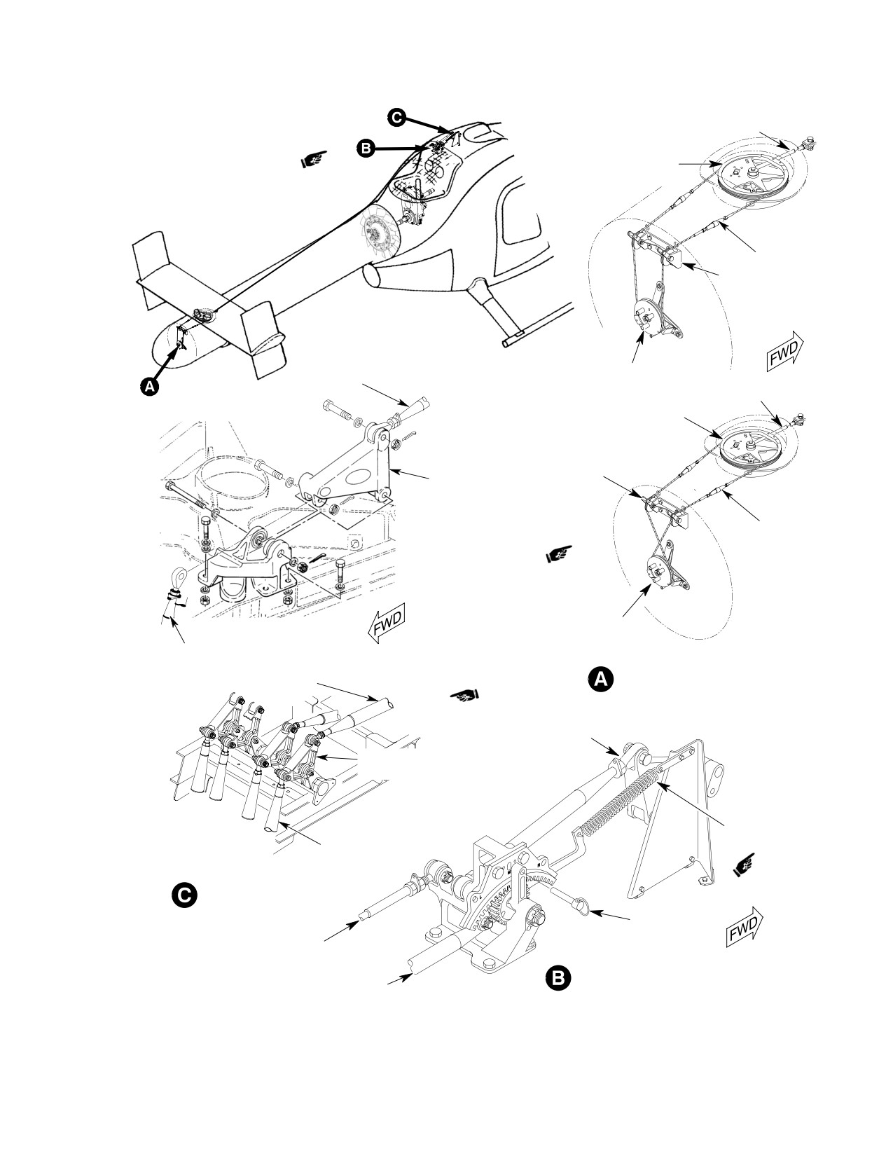
MD Helicopters, Inc.
CSP-HMI-2
MAINTENANCE MANUAL
AFT CONTROL ROD
SECTOR ASSEMBLY
TURNBUCKLE
IDLER PULLEY
MD500N
DRUM ASSEMBLY
FWD TUBE
ASSEMBLY
AFT CONTROL ROD
SECTOR ASSEMBLY
STA. 97.50
IDLER PULLEY
BELLCRANK
TURNBUCKLE
DRUM ASSEMBLY
MD500N
STA. 78.50
VIEW ROTATED 180°
MD600N
CONTROL ROD
FWD TUBE ASSEMBLY
DRUM AND SECTOR ASSEMBLY
FWD DIRECTIONAL
CONTROL TUBE
STA. 95
BELLCRANK
SPLITTER SPRING
STA. 78.50
(MD500N ONLY)
CONTROL ROD
MD600N
ROOF-MOUNTED CONTROLS
RIGGING PIN
FWD CONTROL
CABLE
INTERMEDIATE
SPLITTER ASSEMBLY
CONTROL TUBE
G67-2013A
Figure 401. Anti−Torque Control System
Page 403
67-20-30
Revision 18
CSP-HMI-2
MD Helicopters, Inc.
MAINTENANCE MANUAL
B. Intermediate Control Tube Installation
7. Station 137.50 Support Bracket and
Bellcrank Replacement
(1). Carefully feed intermediate control
(Ref. Figure 402)
tube through boot if installed and
forward air inlet to bellcrank at Sta.
A. Station 137.50 Support Bracket and
137.50.
Bellcrank Removal
(2). Connect control tube and check that
(1). Disconnect intermediate control tube
bushings are in place.
from upper end of Sta. 137.50 bellcrank
by depressing pin in head of bolt to
(3). Install impedance bolt as follows:
disengage and release locking ball and
removing nut. With pin still depressed,
NOTE: Install bolt-head up, nut facing down.
remove bolt.
(2). Disconnect link assembly at clevis,
(a). Depress pin in head of bolt to install
remove bolt in same manner as in
bolt though clevis assembly.
previous step.
NOTE: In the following step, pin is to remain
(3). Remove four support bracket assembly
depressed while nut is torqued.
bolts from fan transmission support.
(b). While pin is depressed, install nut
(4). Bellcrank and bracket assembly may be
and torque to 40 - 50 inch-pounds
separated by removing bolt.
(4.52 - 5.65 Nm).
B. Station 137.50 Support Bracket and
Bellcrank Installation
(c). Release pin and retorque nut to 75 -
90 inch-pounds (8.47 - 10.17 Nm)
NOTE: It is recommended to assemble link and
to ensure engagement of locking balls
bracket assembly to bellcrank before install
with nut.
ing bracket assembly on fan transmission
support bracket.
NOTE: Pin must be in the released position
(1). Reassemble bellcrank and bracket
(flush with bolt head) and bolt must pro
assembly if necessary.
trude past the nut for proper installation.
(2). Install impedance bolt as follows:
(d). Apply torque stripe.
(a). Depress pin in head of bolt to install
(4). Install alternate NAS6204-11D bolt
bolt through bracket and bellcrank.
and MS17826-4 nut as follows:
NOTE: In the following step, pin is to remain
depressed while nut is torqued.
(a). Install bolt, with one AN960KD416L
washer through clevis assembly.
(b). Install nut and torque to 100 - 120
inch-pounds (11.30 - 13.56 Nm).
(b). Install AN960KD416L washer and
(c). Release pin and torque nut to 200 -
nut and torque to 20 - 40 inch-
225 inch-pounds (22.60 - 25.42
pounds (2.26 - 4.52 Nm); install
Nm) to insure engagement of locking
MS24665-134 cotter pin.
ball with nut.
(5). Position rubber boot in place. Secure
NOTE: Pin must be in the released position
boot at support tube with nylon strap,
(flush with bolt head) and bolt must pro
then clamp directional control pedals in
trude past the nut for proper installation.
neutral, set free length of bellows
portion of boot at approximately 5.5
(d). Apply torque stripe.
inches (13.97 cm) and secure end to
(3). Install alternate NAS6206-29D bolt
control tube with nylon strap.
and MS17826-6 nut as follows:
(6).
500N Only: Install splitter bungee
(a). Install bolt, with one AN960KD616L
spring.
washer through clevis assembly.
Page 404
Revision 33
67-20-30
MD Helicopters, Inc.
CSP-HMI-2
MAINTENANCE MANUAL
(b). Install AN960KD616L washer and
NOTE: The Fan Pitch Control Tube can be re
nut and torque to 95 - 110 inch-
moved in either one of the following steps.
pounds (10.73 - 12.43 Nm); install
The fan assembly pitch bearing slider, pitch
MS24665-285 cotter pin.
bearing retainer, pitch plate bearings and
bearing retainer nut with aft control tube
(4). Install lower bolt at link assembly and
can be removed as a unit or individually.
bellcrank clevis, and upper bolt inter
Use extreme care do not damage parts.
mediate control tube Sta. 137.50
(1) Remove locking wire and remove nut and
bellcrank bolts as follows:
lock washer from fan pitch control tube.
NOTE: Install bolt-head up, nut facing down.
Remove locking wire and remove three
bolts and washers from pitch bearing re
(a). Depress pin in head of bolt to install
tainer housing. Pitch bearing slider, pitch
bolt through clevis end of bellcrank.
plate bearings and, bearing retainer nut
with aft control tube can be removed as a
NOTE: In the following step, pin is to remain
unit.
depressed while nut is torqued.
(2) Remove locking wire and remove six pitch
(b). While pin is depressed, install nut
bearing housing assembly bolts. Remove
and torque to 40 - 50 inch-pounds
pitch bearing retainer housing assembly
(4.52 - 5.65 Nm).
as a unit.
(c). Release pin and retorque nut to 75 -
B. Fan Pitch Control Tube Installation
90 inch-pounds (8.47 - 10.17 Nm)
to ensure engagement of locking balls
NOTE:
with nut.
D Refer to Fan Pitch Control Rigging during
installation.
NOTE: Pin must be in the released position
(flush with bolt head) and bolt must pro
D Before installing fan pitch control tube,
trude past the nut for proper installation.
perform Fan Pitch Control Tube Inspec
tion.
(d). Apply torque stripe.
(1). Install the aft control tube.
(5). Install alternate NAS6204-11D bolt
and MS17826-4 nut as follows:
(2). Install convoluted boot on fan gearbox
or clevis.
(a). Install bolt, with one AN960KD416L
washer through clevis assembly.
NOTE: In the following step, clevis should be
bottomed into control tube, approximately
(b). Install AN960KD416L washer and
one thread showing after engagement.
nut and torque to 20 - 40 inch-
pounds (2.26 - 4.52 Nm); install
(3). Install clevis assembly on aft control
MS24665-134 cotter pin.
tube. Ensure that clevis has full thread
engagement on control tube.
(6). Install four support bracket assembly
bolts and washers to fan transmission
(4). Ensure locking washer tang tip is in
support. Torque bolts to 70 - 90
slot. Tighten jam nut against locking
inch-pounds (7.91 - 10.17 Nm);
washer and safety wire from lock to
safety wire bolts.
nut. Ensure safety wire pigtail is on the
nut.
8. Fan Pitch Control Tube Replacement
(5). Install floating bushing in clevis.
A. Fan Pitch Control Tube Removal
(6). Install bolt, bolthead on floating
(1). Remove tail boom fairing and tail boom.
bushing side of clevis, through clevis
and link assembly as follows:
(2). Remove bolt and clevis assembly at Sta.
137.50 bellcrank. Remove convoluted
(a). Depress pin in head of bolt to install
boot from fan gearbox.
bolt through clevis end of bellcrank.
Page 405
67-20-30
Revision 38
CSP-HMI-2
MD Helicopters, Inc.
MAINTENANCE MANUAL
NOTE: In the following step, pin is to remain
of three threads protruding beyond the
depressed while nut is torqued.
face of the jam nut.
(b). While pin is depressed, install nut
(13). Install two lockwires on jamnut and
and torque to 40 - 50 inch-pounds
lockwasher.
(4.52 - 5.65 Nm).
NOTE:
After safety wiring nut and bolts, rotate
(c). Release pin and retorque nut to 75 -
fan and ensure that safety wires do not have
90 inch-pounds (8.47 - 10.17 Nm)
interference with each other on rotation.
to ensure engagement of locking balls
(14). Install tail boom (Ref. Sec. 53-40-30).
with nut.
NOTE: Pin must be in the released position
9. Forward Cable Assembly Replacement
(flush with bolt head) and bolt must pro
(Ref. Figure 402)
trude past the nut for proper installation.
A. Forward Cable Assembly Removal
(d). Apply torque stripe.
To prevent damage to the engine
(7). Install alternate NAS6204-11D bolt
CAUTION
install F.O.D. cover over engine
and MS17826-4 nut as follows:
air inlet.
(a). Install bolt, with one AN960KD416L
washer through clevis assembly.
(1).
Remove fairings, access doors and
panels necessary to facilitate mainte
(b). Install AN960KD416L washer and
nance (Ref. Sec. 53-30-30).
nut and torque to 20 - 40 inch-
pounds (2.26 - 4.52 Nm); install
(2).
Remove tailboom fairing.
MS24665-134 cotter pin.
(3).
Disconnect the aft end of the anti-
NOTE: Before installing fan pitch slider, per
torque control cable by turning outside
form Fan Pitch Slider Inspection.
collar sleeve counter-clockwise and
back to expose the inner cable.
(8). Install pitch bearing slider and bearing
retainer per rigging instructions.
(4).
Apply sufficient right pedal to expose
inner cables.
(9). Install pitch bearing and pitch bearing
retainer housing using three bolts and
(5).
Without bending cable, slide male
washers. Torque bolts to 70 - 80
connector out of female connector.
inch-pounds (7.91 - 9.04 Nm); safety
(6).
Disconnect cable assembly forward
wire bolts.
rodend from Sta. 113.00 splitter
(10). Install lockwasher so that the face of
assembly outboard bellcrank clevis.
the tang aligns with the tube assembly
(7).
Loosen jam nut at rodend and remove
keyway, and the lockwasher aligns with
rodend from cable; remove jam nut.
one of the six slots in the face of the
bearing retainer.
(8).
Remove safety wire, jam nuts and
washers from cable assembly support
(11). Install jamnut on aft control tube.
bracket, remove by pulling or sliding
(12). Torque nut to 95 -110 inch-pounds
cable assy. thru conduit and support
(10.73 - 12.43 Nm) leaving a minimum
bracket.
Page 406
Revision 34
67-20-30
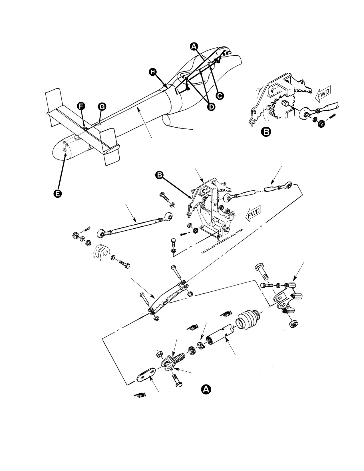
MD Helicopters, Inc.
CSP-HMI-2
MAINTENANCE MANUAL
CABLE ASSY
INTERMEDIATE
SPLITTER ASSY
TUBE ASSY
FORWARD
TUBE ASSY
STA. 137.50
BRACKET
STA. 137.50
BELLCRANK
NOTE 2
NOTE 1
FAN PITCH
CONTROL TUBE
FLOATING
BUSHING
NOTES:
ROTATED
1.
CLEVIS FULLY ENGAGED INTO FAN
LINK ASSY
PITCH CONTROL TUBE.
2.
SAFETY FROM LOCKING WASHER TO NUT.
G67-2008-1E
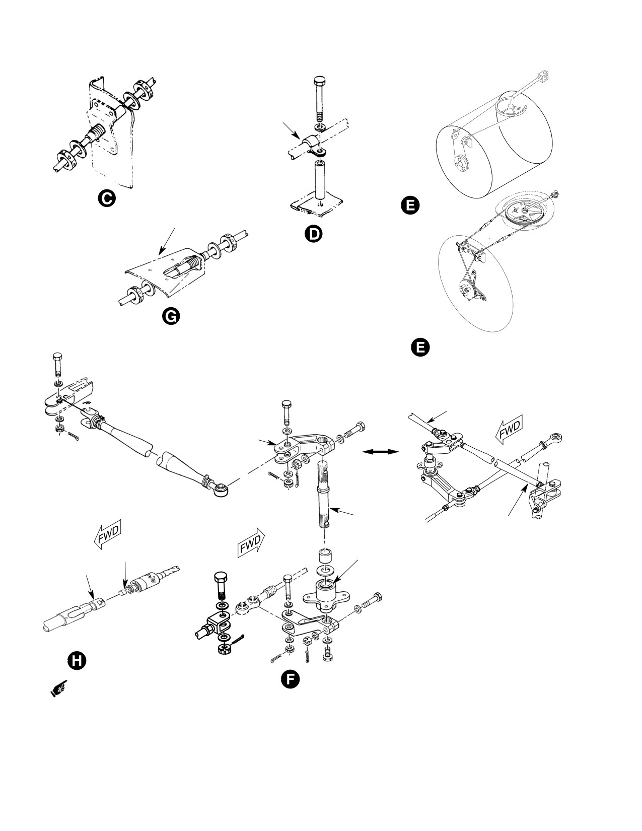
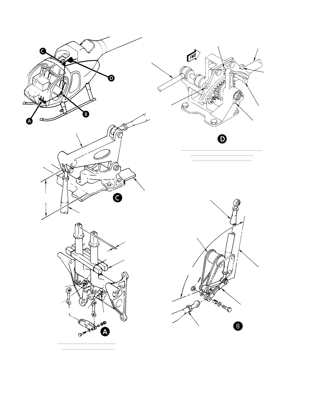
Figure 402. Upper Fuselage and Boom Control Linkage (Sheet 1 of 2)
Page 407
67-20-30
Revision 38
CSP-HMI-2
MD Helicopters, Inc.
MAINTENANCE MANUAL
CLAMP
STA. 304.00
MD500N
STA. 123.30
FITTING
SUPPORT BRACKETS
STA. 131.50 AND 151.00
SUPPORT BRACKET AND CABLE
ASSY. TAILBOOM STA. 264.00
STA. 303.30
MD600N
RIGHT CONTROL ROD
BELLCRANK
CENTER
BELLCRANK
LEFT CONTROL ROD
SHAFT
MD600N
INNER MALE
CONNECTOR
TORQUE TUBE
INNER FEMALE
HOUSING
CONNECTOR
FORWARD-TO-CENTER
CABLE CONNECTION
MD500N
VERTICAL STABILIZER
CONTROL RODS
G67-2008-2D
Figure 402. Upper Fuselage and Boom Control Linkage (Sheet 2 of 2)
Page 408
Revision 25
67-20-30
MD Helicopters, Inc.
CSP-HMI-2
MAINTENANCE MANUAL
B. Forward Cable Assembly Installation
(b). Without bending cable, insert inner
male connector into inner female
connector and ensure they are
Consumable Materials
properly engaged together.
(Ref. Section 91-00-00)
Item
Nomenclature
(c). Slide outside cable collar over
forward cable to engage locking
CM702
Lockwire CRES
device and turn clockwise until fully
locked.
Before installation of cable, in
CAUTION
spect cable (Ref. Forward and
(12). Verify rigging of cable assembly from
Center Cable Assembly Inspection).
Sta. 113.00 splitter assembly (Ref.
Adjustment/Test).
(1). Install one jam nut and washer on cable
and insert cable assembly through
(13). Install fairings, access doors and panels
support bracket and conduit.
removed for installation.
(2). Install washer and one jam nut on cable
10. Center Cable Assembly Replacement
forward side of support bracket.
(Ref. Figure 402)
(3). Ensure that the threaded portion is
A. Center Cable Assembly Removal
centered in the support bracket.
(1).
Remove rotating thruster cone (Ref.
NOTE: When tightening cable jamnuts, ensure
Sec. 53-40-30).
smooth action of cable and alignment of
cable hex end into cable socket.
(2).
Remove stationary thruster cone (Ref.
Sec. 53-40-30).
(4). Ensure cable hex end and cable socket
are aligned to ensure smooth action.
(3).
Remove cotter pin, nut, washers and
bolt from clevis end of control rod
(5). Slide cable in and out to ensure there is
double rodend.
no binding and tighten jamnuts.
(4).
Disconnect cable assembly double rod
(6). Slide cable in and out again to ensure
end bearing from center tailboom
there is no binding. If cable slides
bellcrank.
smoothly, safety jamnuts (CM702).
(5).
Remove double rod end from cable
(7). Install rodend bearing with locking
assembly.
device and jamnut.
(6).
Remove tailboom fairing.
(8). Ensure that threads protrude past
witness hole. Tighten jamnut and
(7).
Disconnect the forward end of the
safety wire nuts.
anti-torque control cable by turning
forward cable outside collar sleeve
(9). Connect cable assembly forward rodend
counter-clockwise and back to expose
to Sta. 113.00 splitter assembly out
the inner cable.
board bellcrank clevis.
(8).
Apply sufficient right pedal to expose
(10). Torque nut and install cotter pin.
inner cables.
(11). Reconnect forward and center control
(9).
Without bending cable, slide male
cable couplings.
connector out of female connector.
Failure to properly connect
(10).
Disconnect cable assembly forward
WARNING
thruster cables could result
rodend from Sta. 113.00 splitter
in uncoupling during flight and loss of
assembly outboard bellcrank clevis.
anti-torque authority.
(11).
Remove safety wire and aft jamnut
(a). Apply sufficient right pedal to expose
from cable assembly support bracket.
inner cable female connector.
Cable assembly can be removed by
Page 409
67-20-30
Revision 33
CSP-HMI-2
MD Helicopters, Inc.
MAINTENANCE MANUAL
sliding or pulling cable assembly
Failure to properly connect
WARNING
through support bracket and conduit
thruster cables could result
and through grommet.
in uncoupling during flight and loss of
anti-torque authority.
B. Center Cable Assembly Installation
(a). Apply sufficient right pedal to expose
inner cable female connector.
Before installation of cable, in
CAUTION
spect cable (Ref. Forward and
(b). Without bending cable, insert inner
Center Cable Assembly Inspection).
male connector into inner female
connector and ensure they are
(1). Install one jam nut and washer on cable
properly engaged together.
and route cable assembly thru conduit
(c). Slide outside cable collar over
of tailboom and thru support bracket.
forward cable to engage locking
device and turn clockwise until fully
(2). Install washer and jamnut on cable aft
locked.
side of support bracket.
(11). Verify rigging of cable assembly from
(3). Ensure that the threaded portion is
Sta. 113.00 splitter assembly to vertical
centered in the support bracket.
stabilizers is correct.
(12). Install stationary thruster cone.
NOTE: When tightening cable jamnuts, ensure
smooth action of cable and alignment of
(13). Install rotating thruster cone.
cable hex end into cable socket.
11. Aft Control Rod Assembly Replacement
(4). Ensure cable hex end and cable socket
(Ref. Figure 402)
are aligned to ensure smooth action.
A. Aft Control Rod Assembly Removal
(5). Slide cable in and out to ensure there is
(1). Remove thruster cone (Ref. Sec.
no binding and tighten jamnuts.
53-40-30).
(6). Slide cable in and out again to ensure
(2). Remove stationary thruster cone (Ref.
there is no binding. If cable slides
Sec. 53-40-30).
smoothly, safety jamnuts (CM702).
(3). Remove cotter pin, nut and washer
from sector input shaft.
(7). Install double rodend bearing with
locking device and jamnut.
(4). Remove pan cover.
(5). Remove cotter pin, nut, washers and
(8). Ensure that threads protrude past
bolt from clevis end of control rod at
witness hole. Tighten jamnut and
double rodend bearing of tailboom
safety wire nuts.
center cable assembly.
NOTE: The split bushing is installed at the top
(6). Remove and discard lockwire and then
of bellcrank. A minimum of 0.010 inch
remove control rod bolt from sector
(0.254 mm) and a maximum of 0.060 inch
assembly.
(1.524 mm) split bushing protrusion re
quired above surface.
(7). Remove control rod.
B. Aft Control Rod Assembly Installation
(9). Install double rodend bearing and
forward bearing to bellcrank with bolt,
washers and nut. Tighten nut and
Consumable Materials
install cotter pin.
(Ref. Section 91-00-00)
Item
Nomenclature
(10). Reconnect forward and center control
CM702
Lockwire CRES
cable couplings.
Page 410
Revision 33
67-20-30
MD Helicopters, Inc.
CSP-HMI-2
MAINTENANCE MANUAL
NOTE: Split bushing is installed at the top,
(6). Remove control rod bolt from sector
shoulder bushing is installed at bottom. A
assembly and lift sector assembly from
minimum of 0.010 inch (0.254 mm) and
shaft.
maximum of 0.060 inch (1.524 mm) split
(7). Remove clevis pins from sector assem
bushing protrusion required above surface.
bly and remove cables.
(1).
Connect thruster control rod clevis end
B. Sector Assembly and Control Cable
to double rod end aft bearing of center
Installation
cable assembly.
(2).
Install washer and bushing on bolt and
Consumable Materials
then insert through rod end into sector
(Ref. Section 91-00-00)
assembly.
Item
Nomenclature
(3).
Torque bolt to 30 - 40 inch-pounds
CM702
Lockwire CRES
(3.39 - 4.52 Nm) and install safety wire
(CM702).
(1). Position the cable assembly around
thruster sector bellcrank, install cable
(4).
Install bushings, bolt, washer and nut;
clevis pins and cotter pins.
Torque nut to 30 - 40 inch-pounds
(3.39 - 4.52 Nm) and install cotter pin.
(2). Install sector bellcrank on input shaft.
(5).
Install pan cover.
(3). Connect sector assembly aft control rod
to clevis.
(6).
Install washer and nut on sector input
shaft; torque nut to 95 - 110 inch-
(a). Install washer and bushing on bolt
pounds (10.73 - 12.43 Nm) and install
and then insert through rod end into
cotter pin.
sector assembly.
(7).
Install stationary thruster cone.
(b). Torque bolt to 30 - 40 inch-pounds
(3.39 - 4.52 Nm) and install safety
(8).
Install rotating thruster cone.
wire (CM702).
12. Sector Assembly and Control Cable
(4). Install bushing, washer on sector input
Replacement
shaft.
(5). Install pan cover.
(Ref. Figure 401)
(6). Install washer and nut on sector input
A. Sector Assembly and Control Cable
shaft; torque nut to 95 - 110 inch-
Removal
pounds (10.73 - 12.43 Nm) and install
(1). Remove rotating thruster cone (Ref.
cotter pin.
Sec. 53-40-30).
(7). Install rotating thruster cone.
NOTE: Removed safety clips from turnbuckles
(8). Perform a rigging check.
are not to be reused.
13. Drum Assembly and Idler Pulley
(2). Disconnect cables from turnbuckles in
Replacement
access hole provided (top of stationary
cone).
(Ref. Figure 401)
(3). Remove cotter pin, nut and washers
A. Drum Assembly and Idler Pulley Removal
from sector input shaft.
(1). Remove rotating thruster cone (Ref.
(4). Remove pan cover.
Sec. 53-40-30).
(5). Remove washer and bushing under pan
NOTE: Removed safety clips from turnbuckles
cover from sector bellcrank input shaft.
are not to be reused.
Page 411
67-20-30
Revision 33
CSP-HMI-2
MD Helicopters, Inc.
MAINTENANCE MANUAL
(2). Disconnect cables from turnbuckles in
(2). Install drum assembly on shaft and
access hole provided (top of stationary
install guard pins.
cone).
(3). Install HS306-233H flat washer
against the bearing.
(3). Remove cotter pin, nut and two wash
ers, remove drum assembly from shaft.
(4). Install washer and nut; torque nut to
160 - 190 inch-pounds (18.08 - 21.47
(4). Remove guard pins to remove cable
Nm) and install cotter pin.
assemblies.
(5). Install turnbuckles and cables.
B. Drum Assembly and Idler Pulley
(6). Perform a rigging check.
Installation (500N)
(7). Install rotating thruster cone.
NOTE: The long cable is 23.07 inches (58.60
cm) and is installed on the aft cable guide of
14. Anti−Torque Pedal Friction Replacement
the drum, or right side, up and around the
(Ref. Figure 403)
right idler pulley. The short cable is 22.82
inches (57.96 cm) long and is installed on
A. Anti−Torque Pedal Friction Removal
the fwd cable guide of the drum, or left side,
(1). Remove bolt, washer and bushing from
up and round the left idler pulley.
console support bracket.
(1). Install cables on drum assembly.
(2). Remove nut and washers, remove
spring, retainer, spring and friction
(2). Install drum assembly on shaft and
disc, and link.
install guard pins.
(3). Remove brace and clamp arm assembly
(3). Install HS306-233H flat washer
from anti-torque tube assembly.
against the bearing.
B. Anti−Torque Pedal Friction Installation
(4). Install washer and nut; torque nut to
(1). Using two pieces of wood and C-clamp
160 - 190 inch-pounds (18.08 - 21.47
or rope, secure pilot's pedals in mid
Nm) and install cotter pin.
position so they are aligned within 0.50
inch (1.27 cm) of each other.
(5). Install turnbuckles and cables.
(2). Install washer, bolt, bushing, and link
(6). Perform a rigging check.
assembly to bracket assembly on
instrument console.
(7). Install rotating thruster cone.
(3). Install brace and clamp arm assembly
C. Drum Assembly and Idler Pulley
to anti-torque tube assembly.
Installation (600N)
(4). Install friction disc, link, retainer and
spring, install washer (shim washers if
NOTE: The long cable is 23.76 inches (60.35
required) and nut.
cm) long and is installed on the aft cable
guide of the drum, or right side, over and
(5). Torque brace and arm assembly bolts
around the left idler pulley. The short cable
30 - 35 inch-pounds (3.39 - 3.95
is 23.51 inches (59.72 cm) long and is in
Nm). Torque nut against washer to
stalled on the fwd cable guide of the drum,
obtain a pedal friction of 5 - 8 pounds
or left side, over and round the right idler
(2.27 - 3.63 kg).
pulley.
15. Anti−Torque Pedal Assembly
(1). Install cables on drum assembly as
Replacement
follows:
(Ref. Figure 403)
(a). Install left cable on forward groove of
A. Anti−Torque Pedal Assembly Removal
drum and cross over to right pulley.
(1). Pull two hinge pins from pilot's com
(b). Install right cable on aft groove of
partment floor access door hinges and
drum and cross over to left pulley.
remove door.
Page 412
Revision 33
67-20-30
MD Helicopters, Inc.
CSP-HMI-2
MAINTENANCE MANUAL
STA. 97.50 BELLCRANK
STA. 97.50
(TUNNEL-ROUTED)
CONTROL ROD
CONTROLS SUPPORT
BRACKET
ANTI-TORQUE PEDAL
INITIAL CONTROL ROD LENGTH
FRICTION
- BEFORE RIG
SPRING FITTING
CONTROL
DIMENSION L
AFT EYEBOLT
TAIL ROTOR IDLER
ROD
INCHES (CM)
STA. 63.00
BELLCRANK
TUNNEL-ROUTED
57.95
(147.193)
BUNGEE
FLOOR-ROUTED
30.06
(76.3524)
SPRING
NOTE 2
FORWARD EYEBOLT
RIVET
NOTE 1
FLOOR-ROUTED
CONTROL ROD
L
MAXIMUM ALLOWABLE LOOSENESS
NOTE 2
0.040 IN. (1.016 MM)
NOTE 3
TORQUE TUBE
BUSHING ASSY
(NOTE 4)
* TORQUE TUBE BRACKET
NOTE 1
NOTE 3
(NOTE 5)
CONTROL ROD FITTING
PIN
NOTE 1
WASHER
NOTE 4
NOTE 1
* LEFT PEDAL
BEARING
BEARING
STOP BOLT
* RIGHT PEDAL
JAMNUT
NOTE 2
NOTE 3
NOTE 1
* PEDAL ARM
NOTE 1
* PEDAL BRACKET
BUSHING
* PEDAL ARM
(TEFLON-LINED)
NOTE 4
NOTE 2
BUSHING
(TEFLON-LINED)
NOTES:
1.
SHIM BETWEEN BRACKET AND BULKHEAD WITH AN960PD416
BUSHING ASSY
LINK
AND/OR -416L WASHERS AS REQUIRED FOR ALIGNMENT WITHIN
(NOTE 4)
NOTE 2
0.010 IN. (0.254 MM).
2.
EDGE OF BUSHING MUST PROTRUDE A MINIMUM OF 0.010 IN.
NOTE 2
(0.254 MM) TO A MAXIMUM OF 0.060 IN. (1.524 MM) ABOVE OUTSIDE
BEARING
SURFACE OF PART AFTER NUT IS TIGHTENED.
BELLCRANK
3.
DIRECTION OF BOLTS IS OPTIONAL.
4.
ADJUSTABLE BUSHINGS MUST HAVE A MINIMUM PROTRUSION OF
0.002 IN. (0.051 MM) AT EACH END.
5.
INSTALLED WITH BEARING RECESS FACING FITTING.
6.
ASTERISK (*) INDICATES PART THAT MAY BE EITHER MAGNESIUM OR
ALUMINUM ALLOY. FOR ALLOY IDENTIFICATION AND CORROSION
CONTROL REF. SEC. 20-40-00.
G67-2001-3
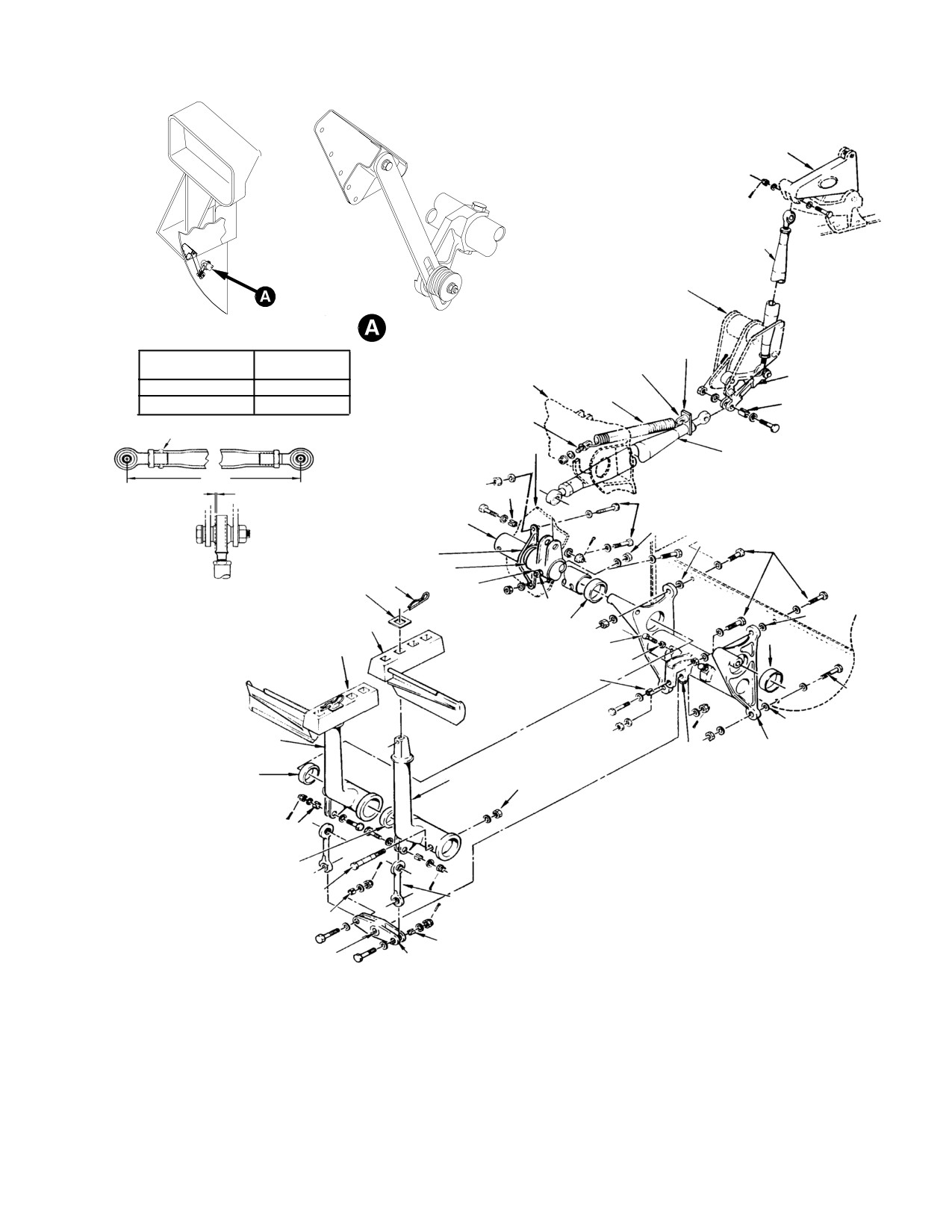
Figure 403. Pedal Installation (Sheet 1 of 2)
Page 413
67-20-30
Revision 25
CSP-HMI-2
MD Helicopters, Inc.
MAINTENANCE MANUAL
RIGHT POSITION
STOP BOLT
ANTI-TORQUE PEDALS
(2 EACH)
NOTE 1
NOTE 2
JAMNUT
ADJUSTABLE BUSHING
ASSEMBLY (NOTE 4)
NOTE 3
TORQUE TUBE
SLOTTED BUSHING
(TYPICAL) (NOTE 2)
SLEEVE
TORQUE TUBE
ADJUSTABLE BUSHING
ASSEMBLY (NOTE 4)
G67-2001-4
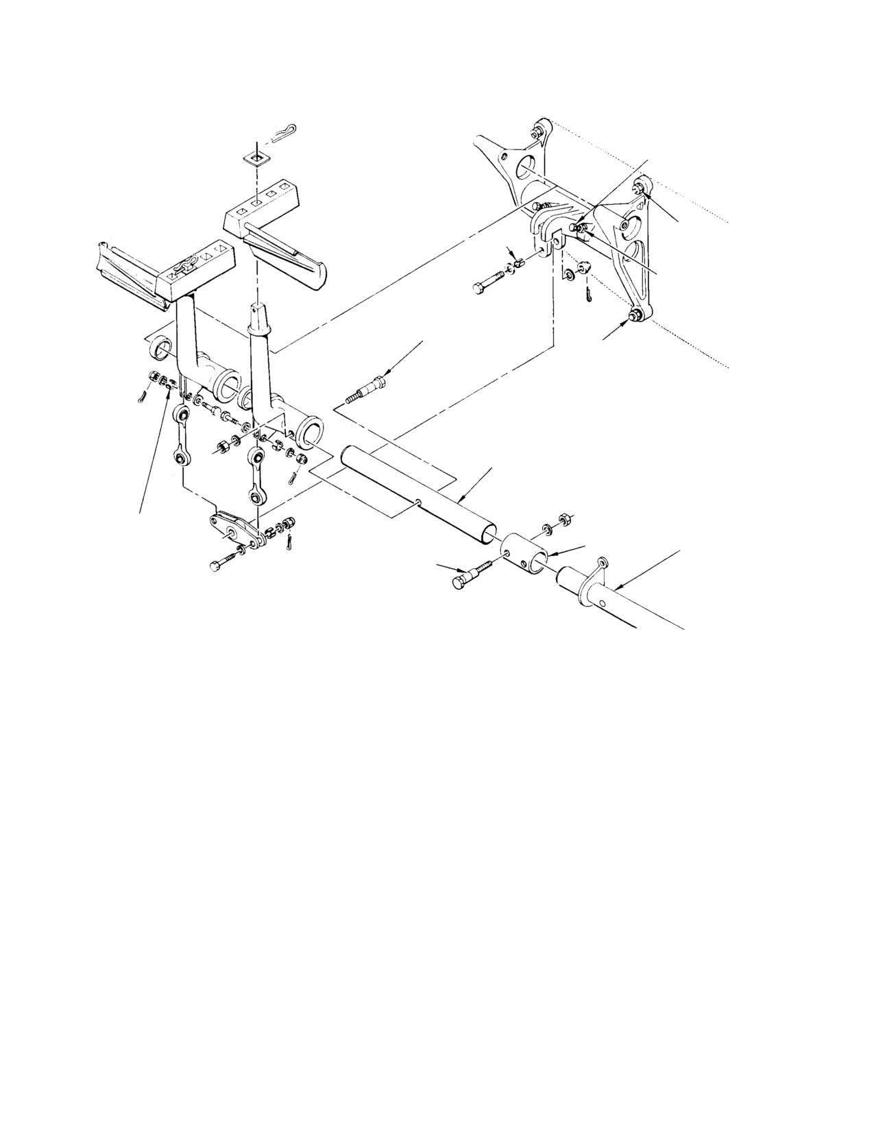
Figure 403. Pedal Installation (Sheet 2 of 2)
(2). Remove access panel from each side of
simplify torque tube alignment during
instruction panel lower support struc
reinstallation.
ture.
(8). Remove four nuts, eight washers, any
shims washers and four bolts that
(3). Remove battery (Ref. Sec. 96-00-00).
secure pedal bracket to bulkhead.
(4). Remove pins securing pedals to pedal
(9). Remove control pedal installation. Keep
arms and remove pedals.
shim washer selection with bracket for
reinstallation.
(5). Remove pedal friction mechanism.
B. Anti−Torque Pedal Assembly Installation
(6). Remove cotter pin, nut, two washers
(1). Install pedal bracket with four bolts,
and bolt that connect floor-routed
eight washers and four nuts.
control rod to torque tube fitting.
(2). Add shim washers as required at pedal
(7). Remove two nuts, four washers, any
bracket attachment points to keep
shim washers and two bolts that secure
centerline alignment of pedal bracket
torque tube bracket to bulkhead. Keep
bearings within 0.010 inch. Correct
shim washer selection with bracket to
alignment is indicated by free rotation
Page 414
Revision 30
67-20-30
MD Helicopters, Inc.
CSP-HMI-2
MAINTENANCE MANUAL
al movement of torque tube after nuts
NOTE: Observed and note position of vertical
are torqued with no evidence of binding.
stabilizer bellcrank for reinstallation pur
poses.
(3).
Position torque tube bracket over
(6). Remove vertical stabilizer torque tube
mating holes in bulkhead and check
(Ref. Sec. 53-50-30, Vertical Stabilizer
alignment with bulkhead.
Torque Tube and/or Bushing Replace
(4).
Add shim washers as required at
ment).
bracket attachment points to maintain
(7). Disconnect electrical connector from
bearing alignment established in step
actuator.
(2). above. Install two bolts, four
washers and two nuts.
(8). Disconnect S.A.S. actuator from control
rod.
(5).
Check that slotted bushing is in place,
(9). Remove bolts from actuator support
install floor-routed control rod in
bracket and carefully slide actuator out
torque tube fitting and install bolt, two
of access hole.
washers and nut; install cotter pin. A
minimum of 0.010 inch (0.254 mm) and
B. S.A.S. Actuator Installation
a maximum of 0.060 inch (1.524 mm)
split bushing protrusion required above
NOTE: Whenever S.A.S. actuator or control
surface.
tube is replaced, S.A.S. rigging must be per
formed.
(6).
Install anti-toque pedal friction
(1). Slide actuator through access panel and
mechanism.
attach actuator to support bracket.
(7).
Check rigging of pedal assembly
(2). Install vertical stabilizer torque tube
controls and pedal-to-canopy clear
(Ref. Sec. 53-50-30, Vertical Stabilizer
ance. Pedals should clear windows by a
Torque Tube Replacement).
minimum of 0.020 inch (0.508 mm) with
20 pounds (9.0718 Kg) of force applied.
(3). Connect actuator control tube to
vertical stabilizer torque tube bell
16. Stability Augmentation System (S.A.S.)
crank. Torque nut to 30 - 40 inch-
Actuator Replacement
pounds (3.39 - 4.52 Nm) and install
cotter pin.
(Ref. Figure 505)
NOTE: Care should be observed to position ver
tical stabilizer bellcrank in the same posi
A. S.A.S. Actuator Removal
tion as removed.
(1). Disconnect electrical power from
(4). Reinstall upper and lower R/H vertical
aircraft. Ensure that battery power is
stabilizers (Ref. Sec. 53-50-30, Vertical
disconnect.
Stabilizer Replacement).
(2). Remove horizontal stabilizer center
(5). Reconnect electrical connector to
access panels and R/H end cap access
actuator.
cover.
(6). Perform S.A.S. actuator rigging check
(Ref. Stability Augmentation System
(3). Remove upper and lower R/H vertical
Rigging Instructions).
stabilizers (Ref. Sec. 53-50-30, Vertical
Stabilizer Replacement).
(7). Install access panels.
(4). Disconnect actuator control tube from
17. S.A.S. Rate Gyro and Electronic Control
vertical stabilizer torque tube bell
Box (Computer) Replacement
crank.
Access to the rate gyro and electronic control
(5). Remove R/H vertical stabilizer torque
box (computer) is through the passenger
tube bellcrank.
compartment footwell access panels.
Page 415
67-20-30
Revision 30
CSP-HMI-2
MD Helicopters, Inc.
MAINTENANCE MANUAL
The units are mounted on a rack under the
(2). Disconnect and remove electrical plug.
pilot's seat structure against the seat structure
(3). Remove mounting hardware.
forward panel.
(4). Carefully remove component from rack.
The 500N has the components mounted
approximately 12 inches (30.48 cm) to the
B. S.A.S. Rate Gyro and Electronic Control
right of centerline.
Box (Computer) Installation
The 600N has the components mounted
(1). Install component on rack.
approximately 12 inches (30.48 cm) to the left
of centerline.
(2). Reinstall mounting hardware. Torque
screws to 12 - 15 inch-pounds (1.36 -
A. S.A.S. Rate Gyro and Electronic Control
1.69 Nm) plus drag torque.
Box (Computer) Removal
(3). Connect electrical plug.
(1). Remove appropriate passenger
compartment footwell fairing (Ref. Sec.
(4). Reinstall passenger compartment
52-50-00).
footwell fairing (Ref. Sec. 52-50-00).
Page 416
Revision 30
67-20-30
MD Helicopters, Inc.
CSP-HMI-2
MAINTENANCE MANUAL
NOTAR® ANTI−TORQUE SYSTEM FLIGHT CONTROLS
ADJUSTMENT/TEST
1. Directional Controls Rigging
(3). Assemble the pitch plate control
bearing into slider and attach the
NOTE:
bearing retainer plate using three bolts
and three washers.
D On the 500N, directional control rigging
is to be accomplished with the (Sta.
(4). Torque bolts to 70 - 80 inch-pounds
113.00) spring on the splitter assembly
(7.91 - 9.04 Nm) and safety (CM702).
disconnected.
D The NOTAR control system must be re-
NOTE: Every 60° turn on bearing retainer is
rigged after replacement of control rods,
equivalent to 0.6 degree change in fan pitch
linkages, and components or if helicopter
angle.
operation reveals a rigging deficiency.
(5). Using the TICK marks on the fan blade
2. Fan Pitch Control Rigging
assembly and on hub housing to
determine blade pitch angle, adjust
(Ref. Figure 501)
bearing retainer to obtain a fan blade
pitch angle of 26 ±1° (View D).
Consumable Materials
NOTE:
(Ref. Section 91−00−00)
Item
Nomenclature
D The aft control tube keyway should be in
stalled at the 12 O'clock position for ease
CM702
Lockwire CRES
of installation.
D Ensure that one of the six slots in the face
Special Tools
of the bearing retainer aligns with fan
(Ref. Section 91−00−00)
pitch-aft control tube key way (View C).
Item
Nomenclature
ST601
Rigging pin
(6).
Install lockwasher so that the face of
the lockwasher aligns with one of six
slots of the bearing retainer.
NOTE: Fan Pitch Control Rigging shall be ac
complished with the tailboom and engine air
(7).
Install jam nut, torque nut to 95 - 110
inlet fairings removed.
inch-pounds (10.73 - 12.43 Nm)
leaving a minimum of three threads
(1). Position Sta. 113.00 splitter assembly
protruding beyond the face of the jam
pinion gear so the rigging slot aligns
nut.
with lower rigging hole in the bracket
assembly; Insert the rigging pin
(8).
Check tick marks on fan blade assem
(ST601) (View A).
bly and hub housing, ensure that fan
pitch angle is 26 ±1°. If blade pitch is 26
(2). Adjust the bearing retainer so the
±1°, proceed to step (9). If not, remove
flange of bearing retainer is screwed in
jamnut and lockwasher and return to
on the tube assembly until it just
steps (5).
touches the shoulder of the fan pitch-
aft control tube (View B).
(9).
Safety wire (CM702) nut and lockwash
NOTE: A gap of 0.015-0.025 inch (0.381-0.635
er (2 places required).
mm) between pitch bearing housing and
bearing retainer plate must exist to ensure
(10).
Rotate fan to ensure the safety wire
proper clamp-up.
does not interfere.
Page 501
67-20-30
Revision 33
CSP-HMI-2
MD Helicopters, Inc.
MAINTENANCE MANUAL
UPPER RIGGING
HOLE
FWD CONTROL
CABLE
SEVENTEEN TO SEVENTY−SEVEN
BRACKET
DEGREES AT 5° INCREMENTS
ASSY
PINION GEAR
LOWER RIGGING
HOLE
500N9901
TICK MARKS
RIGGING TOOL
26° ±1° FAN C/L
FAN HUB ASSY
17°
SPLITTER ASSEMBLY
77°
RIGGING LOCATION
FAN BLADE ASSY
BEARING RETAINER
TICK MARK LOCATION
ASSEMBLY
ON FAN ASSEMBLY
PITCH PLATE
CONTROL BEARING
ONE OF
BEARING
SIX SLOTS
RETAINER
FAN PITCH
CONTROL TUBE
SLIDER
FAN PITCH CONTROL
BEARING RETAINER
TUBE ASSY
KEYWAY TUBE
LOCATION
BEARING RETAINER SLOT
AND KEYWAY ALIGNMENT
G67−2010
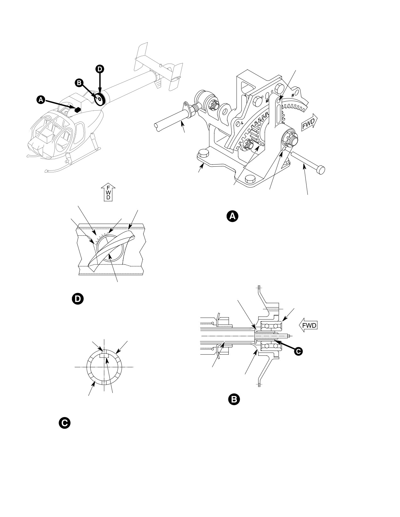
Figure 501. Fan Pitch Control Rigging
Page 502
Revision 18
67-20-30
MD Helicopters, Inc.
CSP-HMI-2
MAINTENANCE MANUAL
NOTE:
they are aligned (View A). Maximum
misalignment between pedals shall be
D If the required adjustment of bearing re
0.50 inch (1.27 mm).
tainer, lockwasher and jamnut cannot be
achieved, adjust the intermediate control
NOTE: Do not adjust the control rod beyond the
tube to meet requirements of specifica
witness hole. Do not tighten the locking
tions in steps (5). thru (10).
jamnut until after final adjustment.
D Do not adjust the control rodend beyond
the witness hole. Do not tighten jam nut
(3). Anti-torque idler bellcrank position to
until after final adjustment.
be checked as follows:
(11). Remove rigging pin.
(a). Position pilot's foot pedals in neutral
and floor-routed control rod length
(12). Fan Pitch Control Rigging shall
(initial control rod length is 30.06
produce the following results:
inches (76.35 cm) before rigging).
(a).
500N:
(b). Adjust floor-routed control rod so
1). Full left pedal, 69 - 73 degrees.
that centerline of bellcrank arm is
90° ±2 degrees to Sta. 78.50 canted
2). Full right pedal, 50 - 54 degrees.
bulkhead (View B).
(b).
600N;
(c). Sta. 97.50 bellcrank: Adjust the
tunnel-routed control rod so the
1). Full left pedal, 71 - 75 degrees.
centerline of the tunnel-routed
2). Full right pedal, 52 - 56 degrees.
control rod attach bolt in the transfer
bellcrank is 4.21 - 4.39 inches (10.69
NOTE: On the 600N helicopter, the pedal po
- 11.15 cm) above mast base struc
tentiometer rigging must be checked any
ture (View C).
time the anti-torque system has been ad
justed.
(4). Check witness holes for proper thread
engagement.
3. Pilot Pedal Rigging
(5). Tighten jamnuts and safetywire
(Ref. Figure 502)
(CM702) as required.
(6). Adjust rodends on the forward control
Consumable Materials
tube so the rigging pin can be inserted
(Ref. Section 91−00−00)
into the bracket assembly upper hole
Item
Nomenclature
and through the slot marked ``M” in the
CM702
Lockwire CRES
gear pinion rack Sta. 113.00 splitter
assembly (View D).
NOTE: Directional control rigging shall be ac
(7). Remove rigging pin and remove
complished with the (Sta.113) splitter
clamping device from foot pedal arms.
spring assembly disconnected (500N) and
the fan pitch control rigging complete.
Use care when actuating pedals
CAUTION
(1). Remove left-hand air inlet fairing to
to avoid damaging tool or wind
facilitate pedal rigging (Ref. Sec.
shield.
53-30-30).
(8). Loosen jamnuts on pedal stop-bolts
Remove pilot's pedals and copi
(View A).
CAUTION
lot's (if installed) to prevent pos
sible contact with lower windshield during
(9). Screw in pedal stop-bolts approximate
rigging sequence.
ly one-half inch (12.7 mm).
(2). Using two pieces of wood and C-clamp
(10). Adjust left-hand stop-bolt in the pilot's
or rope, secure pilot's foot pedal arms so
pedal support.
Page 503
67-20-30
Revision 20
CSP-HMI-2
MD Helicopters, Inc.
MAINTENANCE MANUAL
MID PEDAL
FWD CONTROL
RIGGING HOLE
TUBE
FWD. CABLE
ASSEMBLY
FULL RIGH
RIGGING H
FULL LEFT PEDAL
RIGGING HOLE
RIGGING PIN
LOWER
STA 97.50
RIGGING HOLE
BELLCRANK
FULL LEFT PEDAL AND FULL RIGHT PEDAL
MIDTRAVEL RIGGING LOCATIONS
STA 113.00 SPLITTER ASSEMBLY
STA 78.50 (TUNNEL
4.30
MAST BASE
ROUTED CONTROL ROD)
+0.090
−
STA 78.50 (TUNNEL
ROUTED CONTROL ROD)
CONTROLS SUPPORT
BRACKET
0.50 INCH MAXIMUM
MISALIGNMENT
BETWEEN PEDALS
CLAMPING BLOCKS
90°+ 2°
STA 78.50
−
CANTED BULKHEAD
RIGHT STOP BOLT
JAM NUT
ANTI TORQUE
IDLER BELLCRANK
LEFT STOP BOLT
JAM NUT
FLOOR MOUNTED
CONTROL ROD
PEDAL ARM ALIGNMENT AND
STOP BOLT ADJUSTMENT
G67−2011
Figure 502. Pilot Pedal Rigging
Page 504
Revision 18
67-20-30
MD Helicopters, Inc.
CSP-HMI-2
MAINTENANCE MANUAL
(11).
Apply full left pedal until the rigging
5. Thruster Control Rigging (500N)
pin can be inserted through the bracket
(Ref. Figure 503)
assembly upper hole and into the slot
marked ``L'' in the gear pinion rack Sta.
113.00 splitter assembly (View D).
Consumable Materials
(Ref. Section 91−00−00)
(12).
Adjust the left-hand stop-bolt in the
Item
Nomenclature
pilot's pedal support so that the stop
CM702
Lockwire CRES
just comes in contact with the link
assembly (View A).
Special Tools
(13).
Remove the rigging pin assembly and
(Ref. Section 91−00−00)
adjust right-hand stop-bolt in the
Item
Nomenclature
pilot's pedal support.
ST601
Rigging pin
(14).
Apply full right pedal until the rigging
pin assembly can be inserted through
NOTE:
the bracket assembly upper hole and
D Thruster control rigging to be accom
into the slot marked ``R'' in the gear
plished with the splitter spring installed,
pinion rack Sta. 113.00 splitter assem
the fan pitch control rigging completed,
bly (View D).
the tailboom sector control rod assembly
and stationary thruster cone installed.
(15).
Adjust the right-hand stop-bolt in the
pilot's pedal support so that the stop
D Do not adjust the control rodend beyond
just comes in contact with the link
the witness hole, do not tighten jamnuts
assembly (View A).
until after final adjustment.
NOTE: For dual installation, adjust the stop-
(1). Insert rigging pin (ST601) into the
bolts in the co-pilot's support bracket to
bracket assembly lower rigging hole
match the pilot's pedal travel. Repeat steps
and through the slot on the pinion gear
(11). thru (13).
rack Sta. 113.00 splitter assembly (View
D).
4. Anti−Torque Pedal Friction Installation
(2). Removed pan cover.
and Adjustment
(3). Adjust rodend until it can be attached
(Ref. Figure 403)
to input clevis of sector assembly (View
C).
(1). Using two pieces of wood and C-clamp
or rope, secure pilot's pedals in mid
(4). Connect sector clevis control rod.
position so they are aligned within 0.50
inch (1.27 cm) of each other.
(5). Install bushing, washer and bolt.
Torque bolt 30 - 40 inch-pounds (3.39
(2). Install washer, bolt, bushing, and link
- 4.52 Nm). Safety wire (CM702) bolt
assembly to bracket assembly on
(Ref. Anti-Torque Flight Control
instrument console.
Installation).
(3). Install brace and clamp arm assembly
(6). Remove rigging pin from splitter
to anti-torque tube assembly.
assembly.
(4). Install friction disc, link, retainer and
NOTE: Removed safety clips from turnbuckles
spring, install washer (shim washers if
are not to be reused.
required) and nut.
(7). Remove safety clips and adjust the two
(5). Torque brace and arm assembly bolts
turnbuckles until a second rigging pin
30 - 35 inch-pounds (3.39 - 3.95
(ST601) can be inserted through a slot
Nm). Torque nut against washer to
in the output drum assembly and
obtain a pedal friction of 5 - 8 pounds
through holes in drum output support
(2.27 - 3.63 kg).
(View A and B).
Page 505
67-20-30
Revision 30
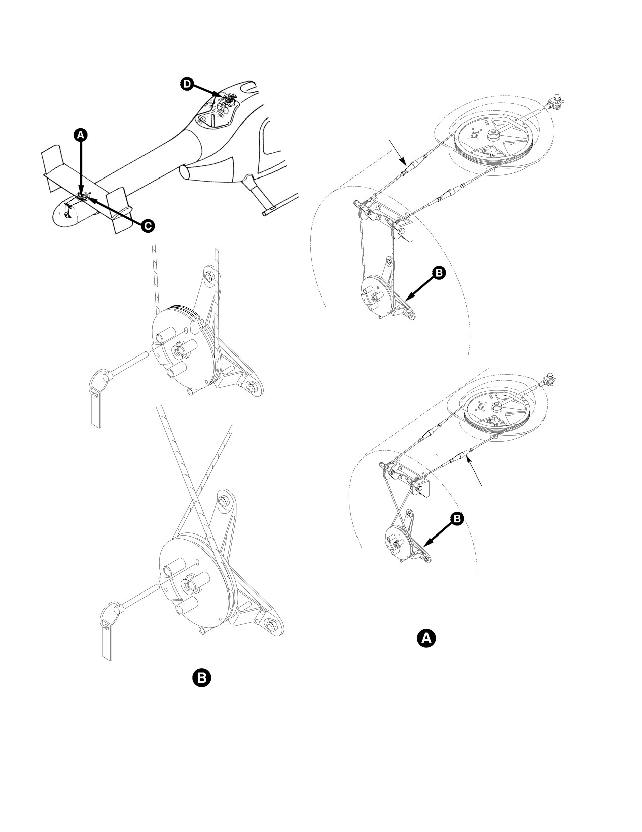
CSP-HMI-2
MD Helicopters, Inc.
MAINTENANCE MANUAL
CABLE
SAFETY CLIPS
500N
500N
CABLE
SAFETY CLIPS
600N
600N
G67−2014−1
Figure 503. Thruster Control Rigging (Sheet 1 of 2)
Page 506
Revision 18
67-20-30
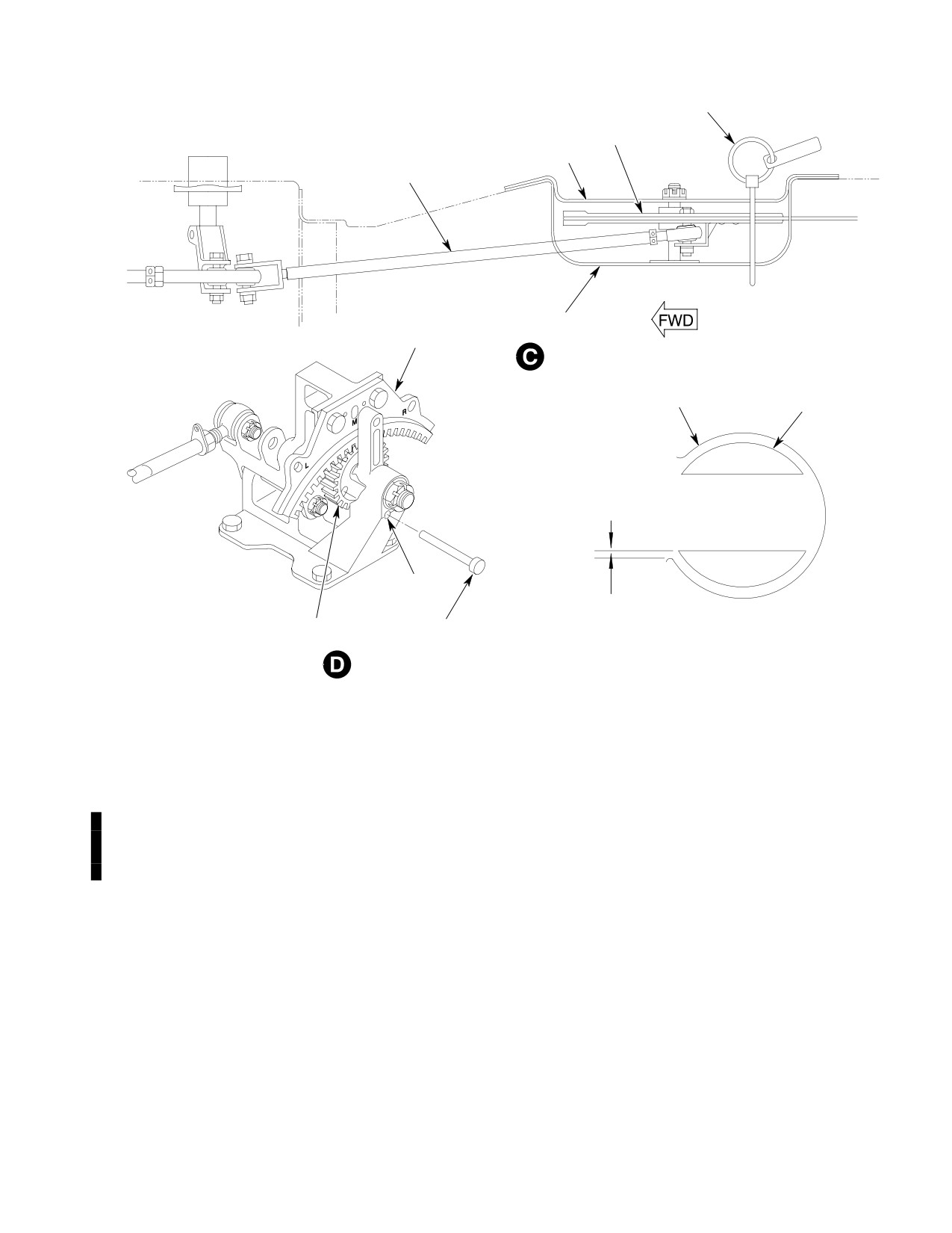
MD Helicopters, Inc.
CSP-HMI-2
MAINTENANCE MANUAL
RIGGING PIN
INPUT SECTOR
PAN COVER
ROD ASSEMBLY
PAN
RACK GEAR
ROTATING
STATIONARY
THRUSTER CONE
THRUSTER CONE
SLOT
0.00 +0.25 IN.
(0.00 +6.4 MM)
RIGGING PIN
VIEW LOOKING FORWARD
PINION GEAR
600N THRUSTER OPENING
G67-2014-2C
Figure 503. Thruster Control Rigging (Sheet 2 of 2)
(8). Using a cable tensiometer, adjust cable
(12). Safety wire (CM702) bolts.
tension to 20 - 40 pounds (9.07 -
(13). Thruster Control Rigging shall produce
18.14 kg).
the following results:
NOTE: Removed safety clips from turnbuckles
(a). Full left pedal; rotating thruster cone
are not to be reused.
to be fully open to the left side of the
(9). Install safety clips in turnbuckles.
tailboom.
(b). Full right pedal; rotating thruster
(10). Remove rigging pins.
cone to be open a minimum of 11.80
(11). Install rotating thruster cone using
inches (29.97 cm) when measured
three bolts and washers. Torque bolts
from the lower edge of the right
70 - 90 inch-pounds (7.91 - 10.17
opening to the upper lip of the
Nm).
rotating cone.
Page 507
67-20-30
Revision 26
CSP-HMI-2
MD Helicopters, Inc.
MAINTENANCE MANUAL
6. Thruster Control Rigging (600N)
(8). Using a cable tensiometer, adjust cable
tension to 20 - 40 pounds (9.07 -
18.14 Kg) by adjusting the two turn
(Ref. Figure 503)
buckles.
Consumable Materials
(9). Remove rigging pins.
(Ref. Section 91−00−00)
(10). Install rotating thruster cone using
Item
Nomenclature
three bolts and washers.
CM701
Lockwire CRES
(11). Push full left pedal and verify bottom
Special Tools
edge of rotating thruster opening is
(Ref. Section 91−00−00)
within 0.00 ±0.25 inch (0.0 ±6.4 mm) of
Item
Nomenclature
edge of stationary thruster cone (Ref.
Figure 503); adjust turnbuckles as
ST601
Rigging pin
necessary.
NOTE: Do not adjust the control rodend beyond
(12). Remove rotating thruster cone.
the witness hole, do not tighten jamnuts un
(13). Verify cable tension.
til after final adjustment.
(14). Reinstall rotating thruster cone; Torque
(1).
Insert rigging pin (ST601) into bracket
rotating thruster cone bolts to 70 - 90
assembly lower rigging hole and
inch-pounds (7.91 - 10.17 Nm).
through slot on the pinion gear Sta.
113.00 splitter assembly (Ref.
NOTE: On the 600N helicopter, the pedal po
Figure 503).
tentiometer rigging must be checked any
time the anti-torque system has been ad
justed.
(2).
Removed pan cover.
(15). Safety bolts with lockwire (CM701).
(3).
Adjust rodend until it can be attached
to input clevis of sector assembly and
(16). Safety turnbuckles with clips.
the rigging slot in input sector assem
bly aligns with the rigging hole in pan.
7. Left Vertical Stabilizer Assembly Rigging
(500N, and 600N with YSAS)
(4).
Connect sector clevis control rod.
(Ref. Figure 504)
(5).
Install bushing, washer and bolt.
Special Tools
Torque bolt 70 - 90 inch-pounds (7.91
(Ref. Section 91−00−00)
- 10.17 Nm). Safety bolt with lockwire
Item
Nomenclature
(CM701) (Ref. Anti-Torque Flight
ST601
Rigging pin
Control Installation).
NOTE:
(6).
Reinstall pan cover ensuring rigging
pin hole in pan cover aligns with
D Rigging to be accomplished with the tail
rigging hole in sector assembly. If pin
boom and vertical stabilizers, splitter as
cannot be inserted through fan cover,
sembly bungee spring and engine air inlet
sector assembly and pan, repeat above
fairings installed.
steps.
D Do not adjust the control rodend beyond
the witness hole, do not tighten jamnuts
(7).
Adjust the two turnbuckles until a
until after final adjustment.
second rigging pin can be inserted
through a slot in the output drum
(1).
500N helicopters: Insert rigging pin
assembly and through holes in drum
(ST601) into the bracket assembly
output support.
upper hole and into the slot marked
Page 508
Revision 30
67-20-30
MD Helicopters, Inc.
CSP-HMI-2
MAINTENANCE MANUAL
``R'' in the gear pinion rack Sta. 113.00
NOTE: The actuator and control tube can be
splitter assembly (View A) splitter
slid out the horizontal stabilizer end panel
assembly upper hole.
far enough to remove safety wire and loosen
the jamnuts. The control tube can be rotated
(a). Adjust the left vertical stabilizer to
and adjusted similar to a turnbuckle.
6.5 ±0.5 degrees on the horizontal
(6).
500N helicopters: Using the top rig
stabilizer degree plate (View C).
plate, adjust right vertical stabilizer to
4.0 ±0.5 degrees.
(b). Remove rigging pin.
(7).
600N helicopters: Using the top rig
(2).
600N helicopters: With pedals set to full
plate, adjust top right vertical stabilizer
right position, adjust tip of the left
to -1.75 ±0.25 degrees.
vertical stabilizer trailing edge to 12
degrees.
(8). After adjustment, slide actuator and
control tube out far enough to tighten
(3). Check witness holes for proper thread
and safety jamnuts.
engagement. Rodends are to be
(9). Reinstall actuator and control tube.
installed equal distance on torque tube
to within 0.020 inch (0.508 mm) of each
NOTE: On the 600N helicopter, the pedal po
other.
tentiometer rigging must be checked any
time the anti-torque system has been ad
8.
Stability Augmentation System Rigging
justed.
Instructions (500N, and 600N with YSAS)
9. Vertical Stabilizer Assembly Rigging
(Ref. Figure 505)
(600N without YSAS System)
(Ref. Figure 506)
Special Tools
(Ref. Section 91−00−00)
Special Tools
Item
Nomenclature
(Ref. Section 91−00−00)
ST1013
Yaw S.A.S. test box
Item
Nomenclature
ST601
Rigging pin
(1).
Turn OFF power supply, turn S.A.S.
switch on the instrument panel to the
NOTE:
OFF position.
D Rigging to be accomplished with the tail
boom and vertical stabilizers installed.
(2).
Install the Yaw S.A.S (ST1013). Test
Box to the computer located and
D Do not adjust the control rodend beyond
mounted on the co-pilot's seat structure
the witness hole, do not tighten jamnuts
forward bulkhead, the test box is now
until after final adjustment.
in series with the computer and
(1). Insert rigging pin (ST601) into the
actuator.
bracket assembly upper hole and into
the slot marked ``R'' in the gear pinion
(3).
Using the aircraft power supply or an
rack Sta. 113.00 splitter assembly.
external power source, activate S.A.S.
switch.
(2). Push trailing edge of left vertical
stabilizer to the right using only enough
(4).
Adjust actuator to the fully extended
force to eliminate freeplay (5-lb (0.3
position using the Yaw S.A.S. test box.
Kg) max).
(5).
Turn aircraft power OFF, actuator
(3). Adjust control rod for the left vertical
should remain in fully extended
stabilizer to 10.5 ±0.5 degrees on the
position.
horizontal stabilizer degree plate.
Page 509
67-20-30
Revision 37
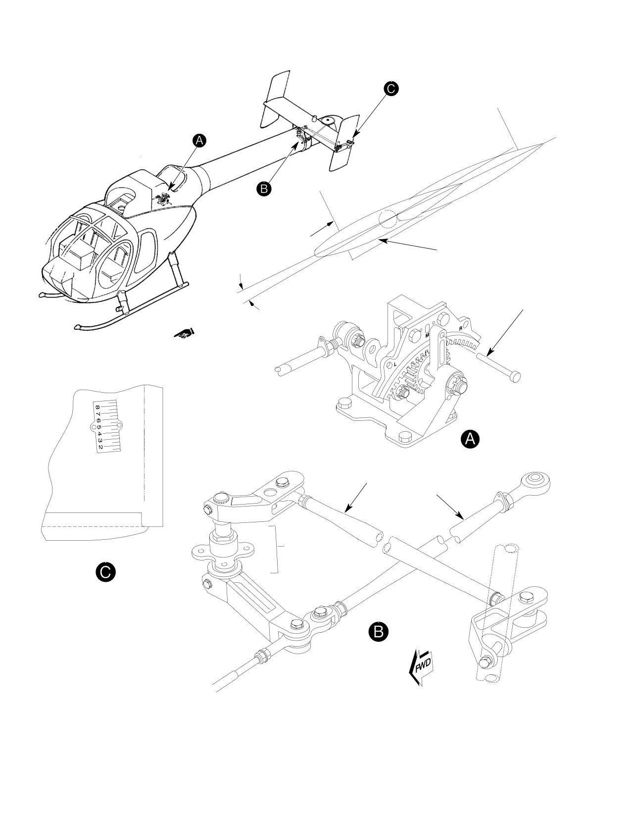
CSP-HMI-2
MD Helicopters, Inc.
MAINTENANCE MANUAL
HORIZONTAL
STABILIZER
VERTICAL STABILIZER
6.5° ± 0.5
(LEFT)
INCIDENCE
ANGLE
(TOP VIEW)
500N9901
0°
RIGGING PIN
500N SHOWN
CONTROL TUBE
(LEFT)
AFT CONTROL
ROD
STA 273.00
BELLCRANK
(TOP VIEW)
G67-2012A
Figure 504. Left Vertical Stabilizer Rigging (500N, and 600N with YSAS)
Page 510
Revision 30
67-20-30
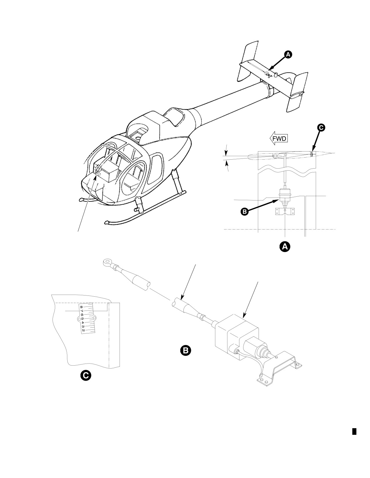
MD Helicopters, Inc.
CSP-HMI-2
MAINTENANCE MANUAL
0°
4.0 ± 0.5 DEGREES
COMPUTER AND
RATE GYRO
RIGHT CONTROL ROD
VIEW LOOKING DOWN
S.A.S. ACTUATOR
STABILITY AUGMENTATION
SYSTEM
RIG PLATE
(VIEW LOOKING DOWN)
500N
G67-2015-1A
Figure 505. Stability Augmentation System S.A.S. (Sheet 1 of 2)
Page 511
67-20-30
Revision 30
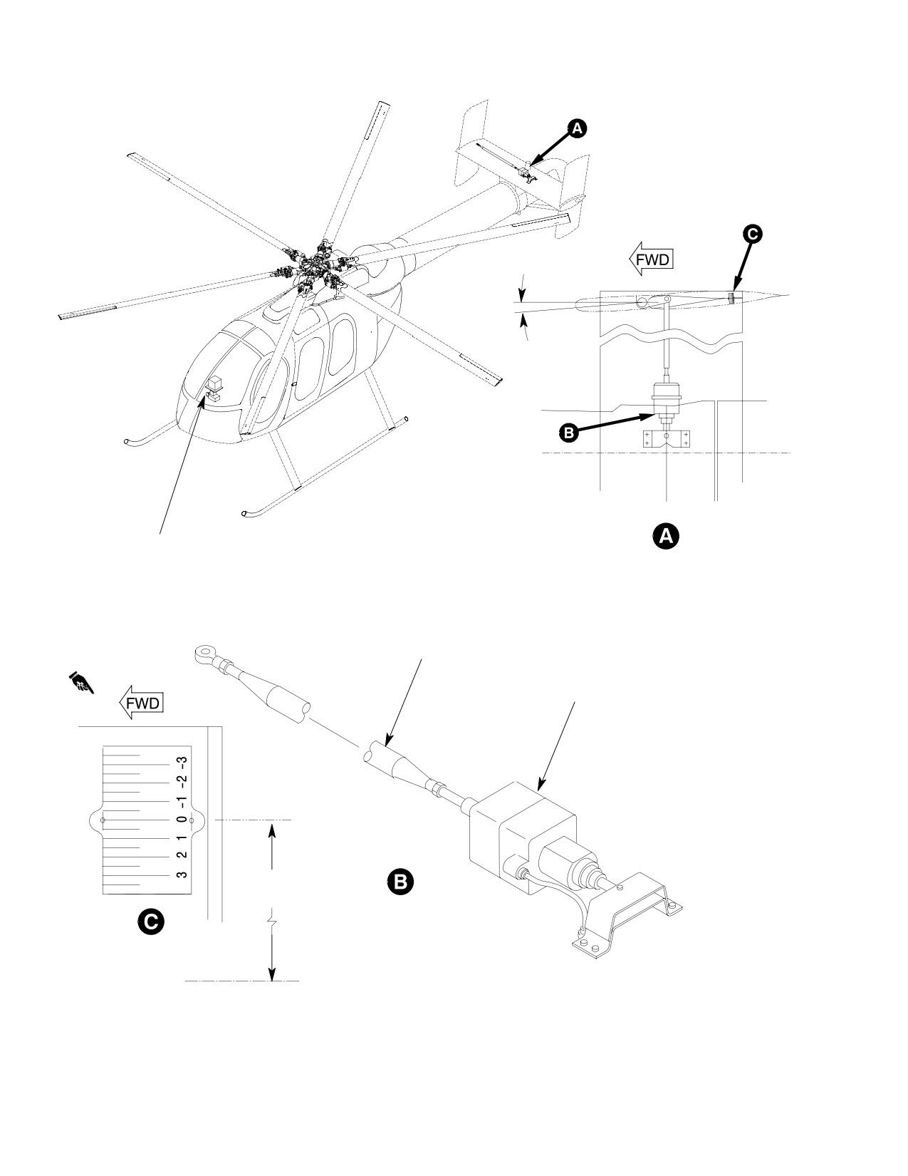
CSP-HMI-2
MD Helicopters, Inc.
MAINTENANCE MANUAL
0°
-1.75 ±0.25 DEGREES
BL 0.00
COMPUTER AND
RATE GYRO
VIEW LOOKING DOWN
RIGHT CONTROL ROD
S.A.S. ACTUATOR
37.07 IN.
(94.15 CM)
STABILITY AUGMENTATION
SYSTEM
RIG PLATE
(VIEW LOOKING DOWN)
BL 0.00
600N
G67−2015−2A
Figure 505. Stability Augmentation System S.A.S. (Sheet 2 of 2)
Page 512
Revision 36
67-20-30
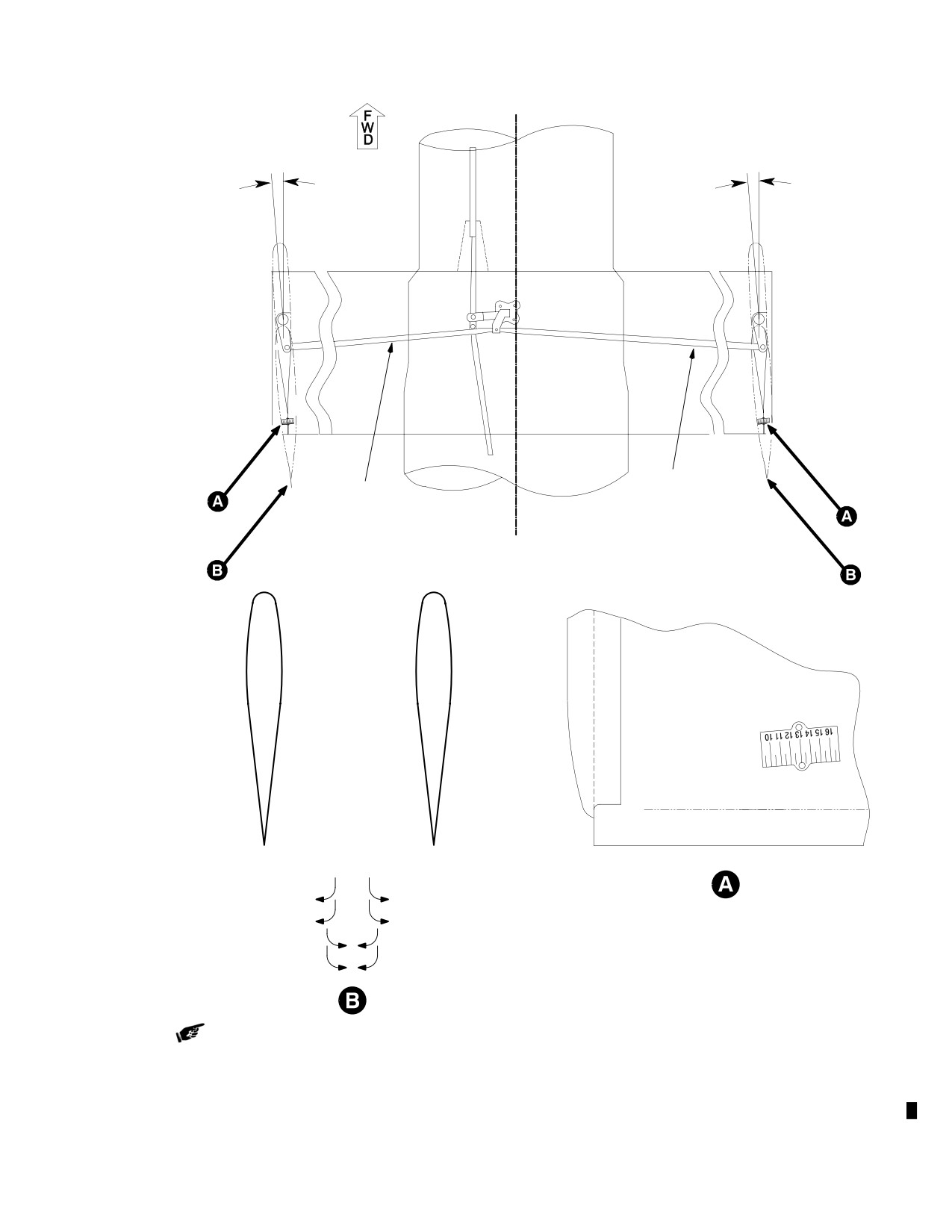
MD Helicopters, Inc.
CSP-HMI-2
MAINTENANCE MANUAL
10.5 + 0.5
14.5 + 0.5
DEGREES
DEGREES
RIGHT
LEFT
CONTROL
CONTROL
TUBE
TUBE
CL
LH
RH
INCREASE PRESSURE L PEDAL
INCREASE PRESSURE R PEDAL
BOTTOM VIEW
DECREASE PRESSURE R PEDAL
DECREASE PRESSURE L PEDAL
DECREASE PRESSURE L PEDAL
DECREASE PRESSURE R PEDAL
INCREASE PRESSURE R PEDAL
INCREASE PRESSURE R PEDAL
TRIM TAB ADJUSTMENT
6G67-092-1A
Figure 506. Vertical Stabilizer Rigging (600N without YSAS)
Page 513
67-20-30
Revision 30
CSP-HMI-2
MD Helicopters, Inc.
MAINTENANCE MANUAL
(4). Push trailing edge of right vertical
(c). File smooth all surfaces of spacer and
stabilizer to the right using only enough
plates.
force to eliminate freeplay, 5 lbs (0.3
(d). Chamfer one 9.00 inch (22.86 cm)
Kg) maximum.
edge of each plate, 0.060 x 0.100 inch
(5). Adjust control rod for the right vertical
(1.524 x 2.54 mm) (this will be the
stabilizer to 14.5 ±0.5 degrees on the
front of the tool) as indicated in
horizontal stabilizer degree plate.
Figure 507.
(6). Remove rigging pin.
(e). Stack plates, chamfered edges facing
each other with spacer between
NOTE: On the 600N helicopter, the pedal po
plates and flush with aft side of
tentiometer rigging must be checked any
plates (un-chamfered edge).
time the anti-torque system has been ad
justed.
(f). Drill and rivet angle tool together,
size and type of rivets optional.
10. Vertical Stabilizer Trim Tab Adjustment
B. Trim Tab Adjustment
and Tool Manufacturing (600N without
YSAS)
(Ref. Figure 506) Adjust vertical stabilizer trim
tabs to improve directional handling character
A. Trim Tab Tool Manufacturing
istics and to minimize pedal forces in forward
flight.
(Ref. Figure 507)
For best results, aircraft should be weighted
(1). Manufacture guide as follows:
down to normal operating weight during test
flights while doing tab adjustments.
(a). Cut guide from 0.130 inch (3.30 mm)
2024-T3 aluminum sheet 7.00 inch
NOTE:
(17.78 cm) x 4.50 inch (11.43 cm).
D Ensure vertical stabilizers are rigged cor
(b). Measuring 1.73 inch (4.39 cm) from
rectly (Ref. Vertical Stabilizer Assembly
bottom, make V-cut in guide 1.030
Rigging (600N)).
inch (2.62 cm) wide and 3.79 inch
D Ensure there is no play between the
(9.63 cm) deep.
500N7213-5 bellcrank assembly and the
500N7212-3 shaft.
(c). File 0.070 inch (1.78 mm) wide x
0.260 inch (6.60 mm) deep slot in aft
D Ensure there is minimal play between the
end of V-cut.
upper and lower vertical stabilizers.
D When installing new upper vertical stabi
(d). File smooth all surfaces of guide.
lizers, if previous tab settings were not re
corded, left trim tab should be set to zero
NOTE: Note the difference in the degree mark
degrees and right trim tab should be set
ings between the top and bottom of the
to 10° right (viewed looking forward from
guide.
the rear).
(e). Etch degree marks in guide as
D The right vertical stabilizer tends to af
indicated in Figure 507.
fect pedal pressure more than the left.
The left vertical stabilizer tends to affect
(2). Manufacture angle tool as follows:
flight characteristics more than the right.
(a). Cut two plates from 0.130 inch (3.30
Left Vertical Tab
Right Vertical Tab
mm) 2024-T3 aluminum sheet 9.00
inch (22.86 cm) x 2.00 inch (5.08 cm).
0°
10° Right
(b). Cut a spacer from 0.040 inch (1.016
(1). Determine which pedal requires excess
mm) 2024-T3 aluminum sheet 9.00
pressure to attain proper trim during
inch (22.86 cm) x 1.00 inch (2.54 cm).
straight flight.
Page 514
Revision 30
67-20-30
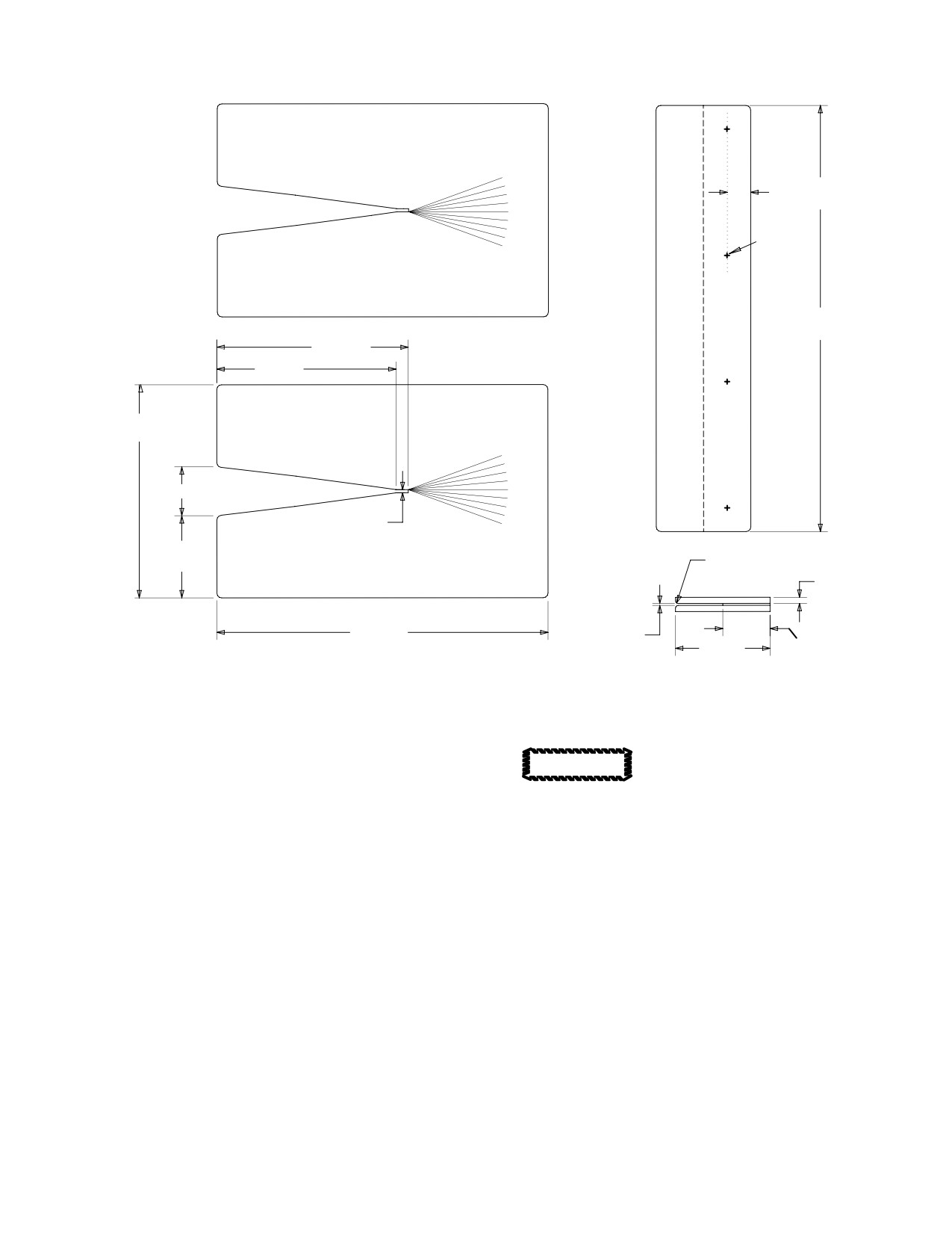
MD Helicopters, Inc.
CSP-HMI-2
MAINTENANCE MANUAL
20°
0.050 IN.
10°
(12.70 MM)
0°
10°
RIVETS
20°
(4 PLCS)
THIS SIDE UP
9.00 IN.
(22.86 CM)
4.05 IN.
(10.29 CM)
3.79 IN.
(9.63 CM)
4.50 IN
(11.43 CM)
20°
10°
1.03 IN. (2.62 CM)
0°
10°
0.07 IN.
(1.78 MM)
20°
1.73 IN.
(4.40 CM)
R0.060-0.100 IN.
THIS SIDE DOWN
(1.524-2.54 MM)
0.130 IN.
(3.302 MM)
MAX
7.00 IN.
0.040 IN.
(17.78 CM)
(1.016 MM)
2.00 IN.
1.00 IN.
(5.08 CM)
(2.54 CM)
GUIDE
6G67-092-2
Figure 507. Vertical Stabilizer Trim Tab Bending Tool
NOTE:
Do not bend tabs beyond 20° in
CAUTION
either positive or negative direc
D Always adjust right vertical stabilizer
tion. Tabs and/or vertical stabilizer skin can
trim tab first. If tab is bent to a maximum
be damaged.
of 20° before correct pedal pressure can be
NOTE:
achieved, go to left tab and continue ad
justments.
D Bending tabs to the right will decrease
left pedal pressure.
D Limit tab adjustments to 5° increments
D Tab angles are acceptable when left pedal
between flights.
forces are between 2 and 5 lbs. (0.91 and
2.27 Kg) in stabilized flight and the flight
D Exceeding 20° tab adjustments may cause
characteristics are acceptable.
a ”tail wag” condition.
(4). Bend tab in direction needed to relieve
pedal pressure and improve flight
(2). Position guide on right vertical stabiliz
characteristics.
er over trim tab.
(5). Remove tab tools and fly aircraft, see
chart below, to determine if pedal
(3). Position angle tool on trim tab.
pressure was relieved.
Page 515
67-20-30
Revision 30

CSP-HMI-2
MD Helicopters, Inc.
MAINTENANCE MANUAL
(6). Repeat above steps until pedal pressure
Pedal Position
Pedal Force
and handling characteristic are cor
rected.
Hover
*60 KIAS
NOTE: After trim tab adjustments, position
guide on both the top and bottom of trim tab
*80 KIAS
to ensure tab is straight.
*100 KIAS
(7). Log trim tab setting in log book.
*120 KIAS
*130 KIAS
NOTE: *Level flight
Handling: Low pedal forces might require bending
tabs in opposite directions.
Table 501. Flight Controls Troubleshooting
Pedal Kick−Thru or Binding
Noticeable hump in pedals (kick−thru) in flight.
yes ⇓
Are control cables Binding?
no Is there binding in control rod at
no Is there pedal binding in flight?
⇒ fan transmission?
⇒
yes ⇓
yes ⇓
yes ⇓
Replace worn or binding
Adjust control rod for proper
Check for dry roller bearings at
control cable(s).
clearance.
rotating cone.
Dutch Roll
Is there relative movement
no Is there play when holding cone
no Bend left tab to the left, starting
between upper and lower
⇒ and moving the vertical
⇒ with 5° left.
verticals?
stabilizers?
yes ⇓
yes ⇓
Check for loose attaching
Check for loose bellcrank at
hardware for the upper and
control shaft.
lower verticals (NOTE).
NOTE: When tightening hardware, do not torque fasteners beyond specified torque limits.
Page 516
Revision 30
67-20-30
MD Helicopters, Inc.
CSP-HMI-2
MAINTENANCE MANUAL
NOTAR® ANTI−TORQUE SYSTEM FLIGHT CONTROLS
INSPECTION/CHECK
1. Upper Fuselage and Tailboom Control
(4). Inspect control rod fitting, torque tube
Linkage Inspection
mounting bracket and pedal mounting
bracket for cracks and corrosion. Using
(Ref. Figure 401)
an 8X magnifying glass, mirror and
flashlight, closely inspect pedal link
(1). Inspect rod end bearings for binding
bellcrank fitting of pedal bracket in
and excessive wear (0.040 inch (1.016
center forward area where fitting (fork
mm) maximum axial play). Inspect
piece) joins tubular section. If any
rivet at fixed rod end.
cracks are detected, replace bracket
assembly. Inspect bracket bearings for
(2). Inspect control rod for surface damage
excessive looseness.
and evidence of bending.
(5). Inspect torque tube for cracks,
(3). Inspect rubber boot just forward of Sta.
scratches, nicks, dents and similar
137.50 bulkhead for condition.
surface defects.
(4). Inspect control rod surfaces serviceabil
(6). Inspect pedal brackets for corrosion.
ity, wear is limited to thickness of hard
3. Sta. 97.50 (500N) or Sta. 95 (600N)
anodic coating.
Bellcrank and Support Bracket Inspection
(5). Inspect bellcranks for scratches, cracks,
(1). Inspect bellcrank and support bracket
corrosion and similar surface defects.
for cracks, corrosion and other similar
Check that all bushings are secure.
surface defects.
(6). Inspect bellcrank bearings for looseness
(2). Check that all bushings are secure.
and binding.
Check bellcrank bearings for looseness
and binding.
(7). Visually inspect bellcrank supports for
cracking/damage.
(3). Inspect rod ends bearings for binding
and excessive wear (0.040 inch (1.016
mm) maximum axial play). Inspect
2.
Anti−Torque Pedal Assembly Inspection
control rod surface serviceability, wear
(Ref. Figure 502)
is limited to thickness of hard anodic
coating. Inspect for safety wire at
NOTE: Inspect components at left and right po
rodends and lockwasher as required.
sition on the right-hand command models.
Bolts for cotter pins as required.
Check that corresponding pedals contact
4. Forward and Intermediate Directional
stops simultaneously.
Control Tube, and Link Inspection
(1). Inspect pedals and pedal arms for
(1). Inspect rodend and link bearings for
cracks, elongated pedal attach holes
binding and excessive wear (0.040 inch
and open drain holes. Inspect teflon-
(1.016 mm) maximum axial play).
reinforced bushing liners for deteriora
tion.
(2). Inspect control tubes and link for
surface damage and wear. Inspect
(2). Inspect pedal-to-arm quick-release
control tubes surface serviceability,
locking pin for condition and positive
wear is limited to thickness of hard
spring action.
anodic coating.
(3). Inspect links and bellcrank for cracks
(3). Inspect for safety wire at rodends and
and bends, and bearings for excessive
lockwasher as required. Bolts for cotter
play.
pins as required.
Page 601
67-20-30
Revision 34
CSP-HMI-2
MD Helicopters, Inc.
MAINTENANCE MANUAL
5.
Splitter Bungee Spring Inspection (500N)
and female connectors for corrosion
pitting or cracks; none allowed.
(1). Inspect spring support bracket for loose
(8). Inspect center cable hex end for wear
rivets, loose screws, corrosion and
beyond allowable tolerance (Ref.
cracks and general condition.
Figure 601).
(2). Check link assemblies for cracks, bends
(9). Inspect collar for wear in locking
and dents.
groove.
(3). Inspect spring for condition and a
(10). Inspect relieved area, at Sta. 123.30,
positive spring action.
between threads and swage for crack or
evidence of corrosion.
6.
Sta. 113.00 Splitter Assembly and
(11). Inspect relieved area, at Sta. 164.00
Bellcrank Inspection
(500N) or Sta. 292.00 (600N), between
(1). Visually inspect bellcrank and support
threads and swage for crack or evidence
bracket for cracks and damage using 5X
of corrosion.
power magnifying glass.
(12). Inspect forward cable coupling opening
for proper dimension (Ref. Figure 601).
(2). Inspect for cracks, corrosion and other
similar surface defects.
(13). Using a bright light and 10x magnify
ing glass, inspect the swaged area of
(3). Check that all bushings and bearings
the telescopic swivel end for cracks
are secure.
(Ref. Figure 603).
(4). Inspect rodend bearings for binding and
(14). Inspect for any evidence of swivel ball
excessive wear (0.040 inch (1.016 mm)
separation.
maximum axial play). Inspect control
8. YSAS Actuator, Rate Gyro and Electronic
rod surface serviceability, wear is
Control Box Inspection
limited to thickness of hard anodic
coating. Inspect for safety wire at
(1). Inspect YSAS actuator for damage, no
rodends and lockwasher as required.
damage allowed.
Bolts for cotter pins as required.
(2). Inspect mounting hardware for proper
installation and general condition.
7.
Forward and Center Cable Assembly
Inspection
(3). Inspect wiring for condition, no fraying,
cracking of insulation or chafing
(1). Inspect for freedom of movement and
allowed.
no binding.
(4). Inspect grommet for proper installation
(2). Check rodend bearings for corrosion,
and deterioration, replace if deterio
and wear.
rated.
(3). Cable housing for fraying, and security.
(5). Inspect mounting bracket for cracks
(pay particular attention to area around
(4). Inspect cable couplings for wear,
four rivet attach holes) no cracks
deformation or damage (Ref.
allowed.
Figure 602).
(6). Inspect rate gyro and electronic control
(5). Inspect inner cable coupling hex for
box for damage, security in mount and
proper alignment with outer cable
ensure electrical plugs are secure.
coupling.
(7). Inspect mounting bracket for cracks, no
cracks allowed.
(6). Inspect cable inner couplings for
deformation or obvious damage.
9. Fan Pitch Control Tube Inspection
(7). Using a bright light and 10X magnify
(1). Inspect tube for dents, scratches, nicks,
ing glass, inspect inner coupling male
gouges and corrosion, none allowed.
Page 602
Revision 35
67-20-30
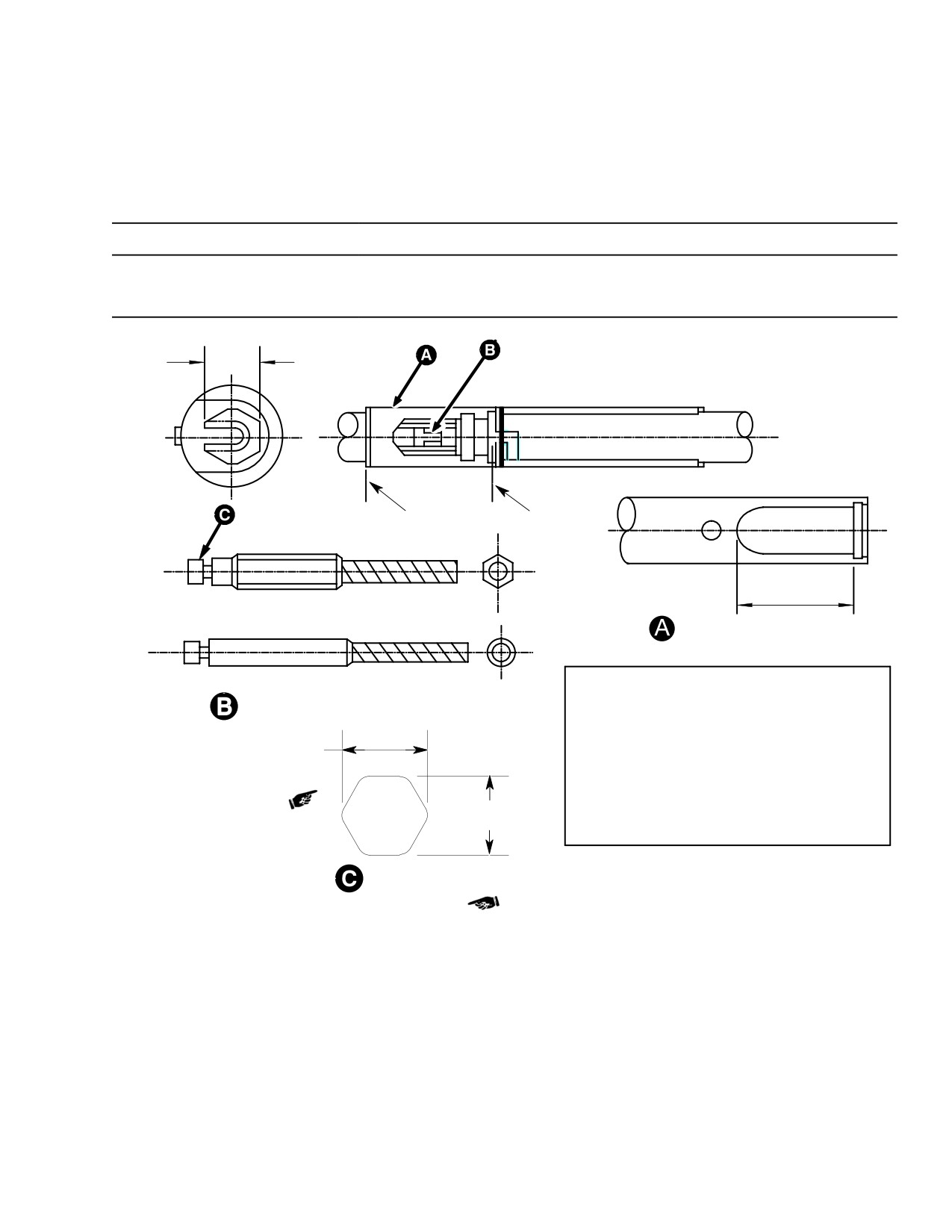
MD Helicopters, Inc.
CSP-HMI-2
MAINTENANCE MANUAL
(2). Inspect for visible step in splined area.
(b). Minimum measurement across pins
is 0.640 in. (16.256 mm).
(3). If step is evident:
(a). Measure across splines using 0.096
in. (2.4384 mm) diameter pins.
Table 601. Isolating Control System Troubles
Symptom
Isolating Step
Corrective Action
Binding, locking−up and erratic
Disconnect fwd control tube from
If symptom is gone, check from
action of foot pedals (Do not force
Sta. 113.00 splitter assembly.
splitter assembly aft.
controls).
0.250 INCH (6.35 MM)
HEX (REF)
CLOSED
OPEN
POSITION
POSITION
(REF TABLE)
HEX CONFIGURATION
FORWARD CABLE FEMALE END
ROUND CONFIGURATION
ACCEPTABLE DIMENSIONS
CENTER CABLE (-5) (INSIDE TAIL BOOM)
SLOT DIMENSION
MALE CONNECTOR
IN
(MM)
0.450
(11.43)
HEX CONFIGURATION
0.260 IN. (6.604 MM) MIN.
(NOTE)
0.685
(17.40)
ROUND CONFIGURATION
0.450
(11.43)
ROUND CONFIGURATION
0.250 IN.
UNACCEPTABLE DIMENSIONS
(6.35 MM)
0.685
(17.40)
HEX CONFIGURATION
DIMENSION ACROSS HEX
(ROTATED)
NOTE: WHEN DIMENSION REACHES 0.260 IN. (6.604 MM) ACROSS ANY
TWO OPPOSING POINTS OF HEX, CABLE HAS REACHED IT'S MAXIMUM
G67-2020B
WEAR AND MUST BE REPLACED WITH A SERVICEABLE CABLE.
Figure 601. Control Cable Coupling Inspection
Page 603
67-20-30
Revision 39
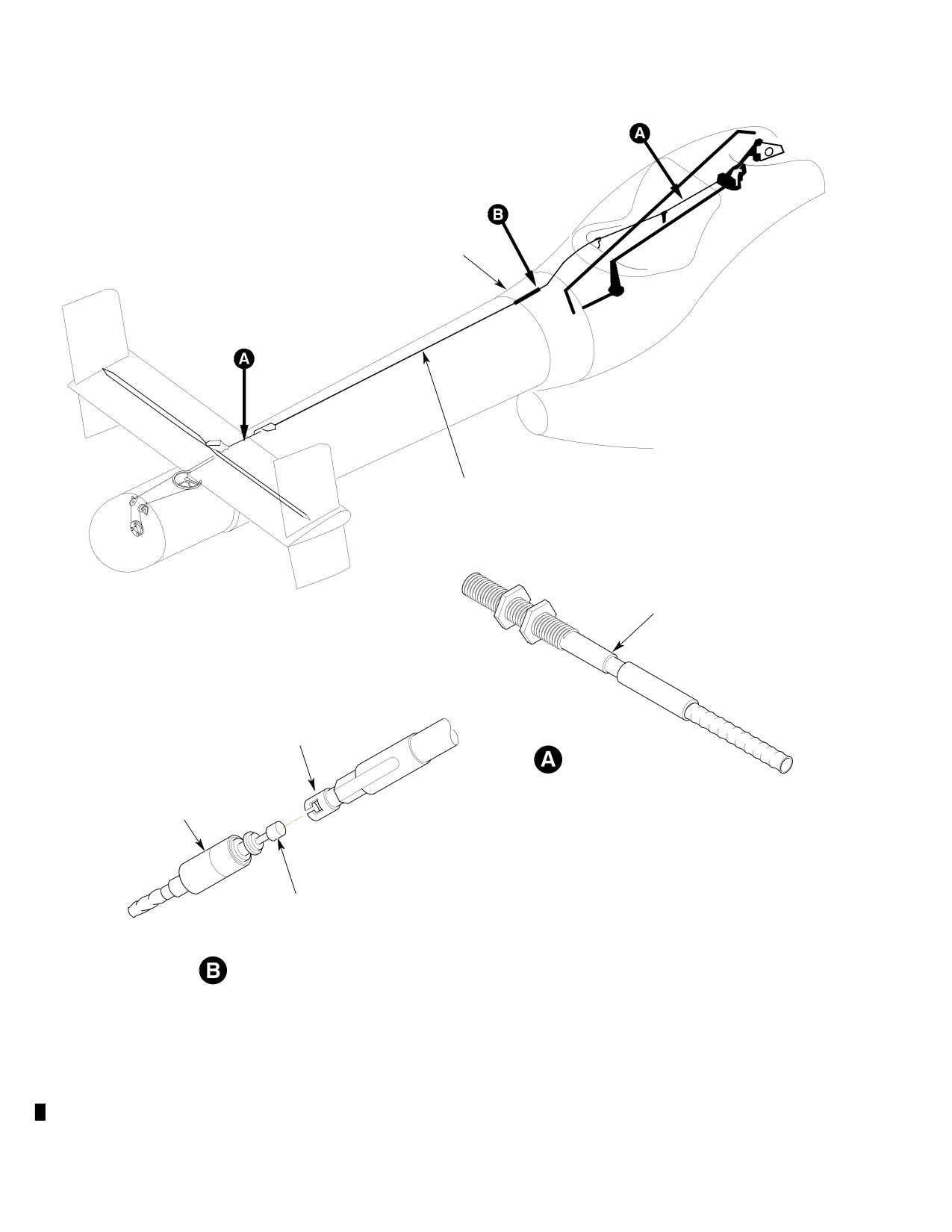
CSP-HMI-2
MD Helicopters, Inc.
MAINTENANCE MANUAL
TAILBOOM FAIRING
CABLE ASSY
RELIEF AREA
INSPECT FOR CRACK
INNER FEMALE
CONNECTOR
CABLE END RELIEF AREA
OUTSIDE COLLAR SLEEVE
(MUST BE FIRMLY LOCKED
IN PLACE BEFORE TAILBOOM
FAIRING IS INSTALLED)
INNER MALE
CONNECTOR
INNER COUPLING CONNECTOR
88_776
Figure 602. Forward and Center Cable Relief Area Inspection
Page 604
Revision 24
67-20-30
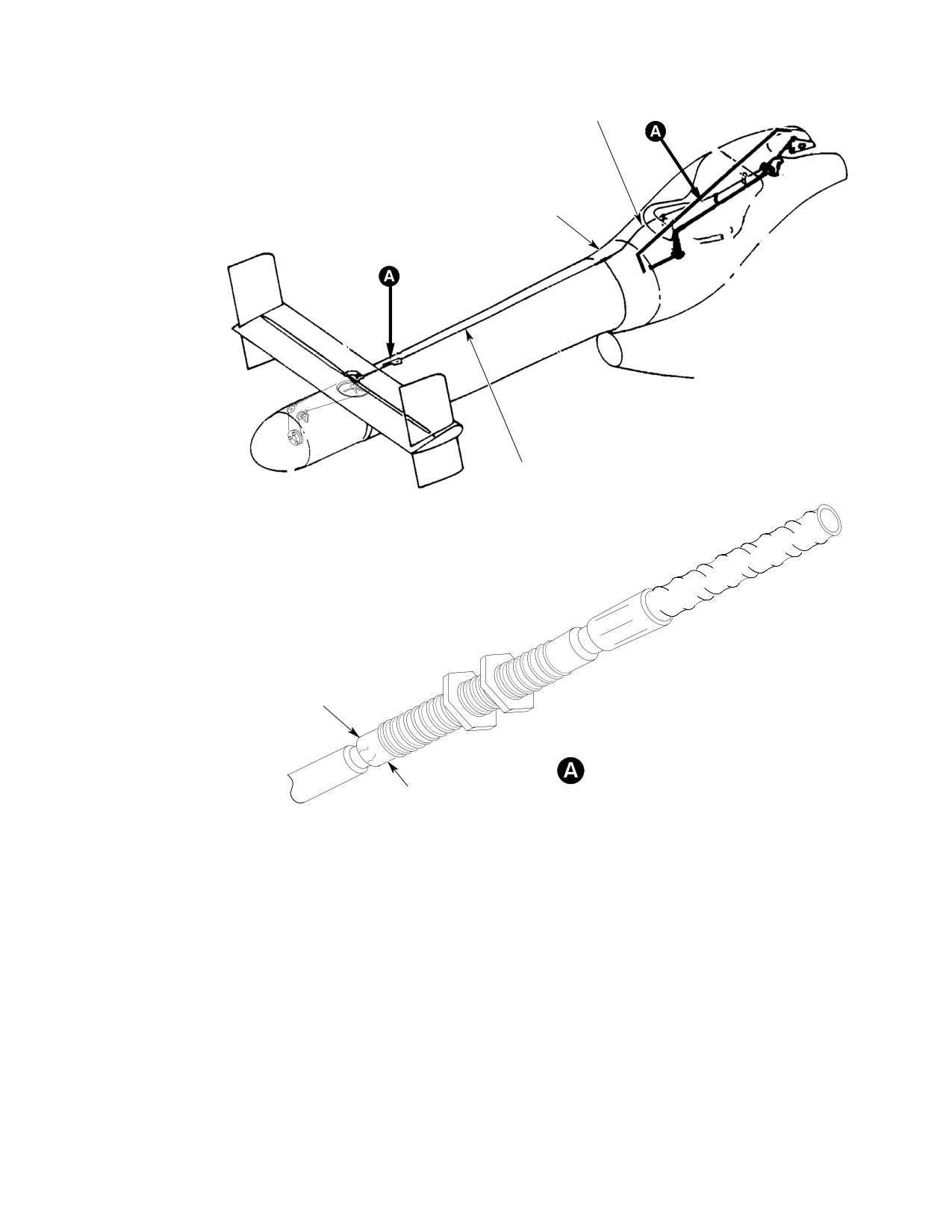
MD Helicopters, Inc.
CSP-HMI-2
MAINTENANCE MANUAL
FORWARD CABLE
TAILBOOM FAIRING
CENTER CABLE
ASSY
INSPECT TELESCOPIC SWIVEL END
FOR CRACKS AND/OR TELECOPTIC
SWIVEL SEPERATION FROM
THRUSTER CABLE CONDUIT CAP
TELESCOPIC SWIVEL END
CONDUIT CAP
88_777
Figure 603. Control Cable Telescopic Swivel End Inspection
Page 605
67-20-30
Revision 24
CSP-HMI-2
MD Helicopters, Inc.
MAINTENANCE MANUAL
10. Sector Assembly, Control Cables and
(a). Fraying or corrosion; no fraying or
Drum Assembly Inspection
corrosion allowed.
(Ref. Figure 402)
(b). Proper installation of turnbuckle
safety clips.
(1). Inspect sector assembly for:
(c). Corrosion or cracking on turnbuckles;
(a). Proper installation of mounting
no corrosion or cracking allowed.
hardware.
(d). Proper cable tension.
(b). Remove access cover from pan
assembly.
(6). Reinstall access cover on top of station
ary thruster assembly (600N).
(c). Center cable mounting bolt for
security and proper installation of
(7). Inspect control cable pulleys for:
safety wire.
(a). Proper installation of mounting
In the following step, ensure
hardware.
WARNING
the anti-torque pedals are
not moved, personal injury can occur.
(b). Guard pins installed.
(d). Check sector assembly for excess
(c). Excessive groove in pulleys; evident
up-and-down play.
in out-of-round pulley.
(e). Damage, cracks or corrosion; no
(8). Inspect drum assembly for:
damage, cracks or corrosion allowed.
(a). Proper installation of mounting
(f). Reinstall access cover on pan assem
hardware.
bly.
(b). Damage, cracks or corrosion; no
(2). Remove tip cap (500N).
damage, cracks or corrosion allowed.
(3). Remove rotating cone assembly.
(c). Guard pins installed.
(4). Remove access cover from top of
stationary thruster assembly (600N).
(9). Reinstall rotating cone assembly.
(5). Inspect control cables for:
(10). Reinstall tip cap (500N).
Page 606
Revision 39
67-20-30
MD Helicopters, Inc.
CSP-HMI-2
MAINTENANCE MANUAL
NOTAR® ANTI−TORQUE SYSTEM FLIGHT CONTROLS
REPAIRS
1. Anti−Torque Flight Control Repair −
have equal space for angular throw;
General
tighten jamnut.
Use care when drilling to re
(6). If removed, install rivet to secure
CAUTION
move or install riveted rod end;
rodend.
rod end is steel and rod and bearing adapter
(7). Ensure slotted bushing is in place.
are aluminum.
(8). Secure control rod in torque tube fitting
2. Sta. 97.50 (500N) or Sta. 95 (600N)
or idler bellcrank with bolt, two
Bellcrank and Support Bracket Repair
washers, nut and cotter pin.
4. Upper Fuselage Sta. 113.00 Splitter
Consumable Materials
Assembly Repair
(Ref. Section 91-00-00)
Item
Nomenclature
Refer to Field Service Department for repairs.
CM321
Surface primer locking compound
5. Intermediate Control Tube Repair
CM431
Sealing, locking and retaining compound
(1). Perform straightness check on inter
mediate control rod that appears bent
(1). Replace unserviceable bearings.
or bowed. Total length of control rod
(2). Install new bearings with surface
(excluding rod ends) must be straight
primer (CM321) and grade A locking
within 0.040 inch (1.016 mm), with
compound (CM431).
straightness variation limited to
maximum of 0.010 inch (0.254 mm) in
NOTE: When idler bellcrank bearing are re
each foot of length.
placed, ensure idler bellcrank spacers are
NOTE:
reinstalled between bearings.
D A dye check for cracking must always be
(3). Replace bellcranks or control support
performed after cold-straightening. Re
brackets that have cracks or enlongated
place cracked rod, or cracked or bent rod
holes.
end.
D Do not use rod ends to support rod during
3.
Forward Directional Control Tube Repair
straightening process.
(1). Replace control rod end if bearing axial
(2). Cold-straighten bent rod that is not
play is more than 0.040 inch (1.016
within tolerance provided there are no
mm). Set initial control rod length and
nicks or sharp dents in bend length.
bearing angularity.
(3). Replace control rod end if bearing axial
(2). Initial length forward directional
play is more than 0.040 inch (1.016
control tube is 15.42 inches (39.17 cm).
mm). Set initial control rod length and
Rod end angularity is 0 degrees
bearing angularity.
straight line within ±2 degrees.
(4). Replace unserviceable control rod
(3). Perform straightness check on control
bearing adapter if installed.
rods that appear bent or bowed.
(a). Measure length and record position
(4). Drill out rivet. Loosen jamnut and
of rod end in adapter.
unscrew rodend.
(b). Remove affected rod end. Initial
(5). Screw replacement rodend into rod to
installation length of intermediate
obtain same measurement made in step
control rod is 23.68 inches (60.15 cm).
b. Align control rodends so bearings
Rod end angularity is 40 ±2 degrees.
Page 801
67-20-30
Revision 18
CSP-HMI-2
MD Helicopters, Inc.
MAINTENANCE MANUAL
(c). Drill out rivets securing adapter to
(8). Repair minor surface defects such as
rod and aft rod end.
scratches, nicks and corrosion on
bellcranks and support bracket.
(d). Install rod end in replacement
(9). Use abrasive cloth (CM802), grade 400
adapter and position at recorded
- 600, to smooth out and blend in such
measurement.
defects.
6. Sta. 137.50 Support Bracket and Bellcrank
(10). Cast surfaces may be reworked to depth
Repair
of 0.020 inch (0.508 mm).
(11). Repair surface abrasion on control rod
by smoothing area with grade 400
Consumable Materials
(Ref. Section 91-00-00)
abrasive cloth (CM802) and restoring
Item
Nomenclature
protective finish with primer (CM318).
CM318
Primer
(12). Replace rod if wear or depth of repair
CM321
Surface primer locking compound
exceeds 0.004 inch (0.102 mm).
CM431
Sealing, locking and retaining compound
CM802
Abrasive cloth, aluminum oxide
(13). Replace tailboom control rod if hard
anodic coating is worn through and
aluminum base metal is visible.
(1).
Replace unserviceable bearings.
(14). Replace split or torn boot.
(2).
Install new bearings with surface
primer (CM321) and grade A locking
7. Fan Pitch Control Tube Repair
compound (CM431).
Refer to Field Service Department for repairs.
(3).
Flat machined surfaces, except clevis
8. Forward Cable Assembly Repair
inner ears, may be reworked to depth of
0.015 inch (0.381 mm).
Refer to Field Service Department for repairs.
(4).
Clevis inner ear surfaces may be
9. Center Cable Assembly Repair
reworked to depth of 0.020 inch (0.508
Refer to Field Service Department for repairs.
mm).
10. Aft Control Rod Repair
(5).
Machined holes may have 0.003 inch
(0.076 mm) removed from bore wall in
Refer to Field Service Department for repairs.
an area no greater than 15 percent of
circumference and 50 percent of depth.
11. Thruster Sector Assembly Repair
Refer to Field Service Department for repairs.
(6).
All edges may have 0.030 inch (0.762
mm) removed except around machined
12. Drum Assembly and Idler Pulleys Repair
holes, which are limited to 0.010 inch
(0.254 mm) chamfer.
Refer to Field Service Department for repairs.
(7).
All rework must be smoothly blended
13. Anti−Torque Pedal Disassembly
into adjacent surfaces and finish must
(Ref. Figure 403)
be restored.
NOTE: Before disassembly of pedal installa
NOTE: Installation direction of Sta. 137.50
tion, matchmark mating pedal arms, links
bellcrank bearing may be from either side,
and bellcranks with pedal brackets to avoid
depending on location of bearing shoulder.
intermixing components between locations
There must not be less than 0.010 inch
at reassembly.
(0.254 mm) protrusion of bearing inner race
beyond sides of bellcrank after bearing is in
(1). Disconnect links from pedal arms and
stalled.
bellcrank; remove links.
Page 802
Revision 18
67-20-30
MD Helicopters, Inc.
CSP-HMI-2
MAINTENANCE MANUAL
(2). Remove bellcrank from pedal bracket.
Right pedal arm bushings are
CAUTION
glass-filled phenolic. Do not
(3). Remove nut and washer of two bushing
cock bushings during replacement; ensure
assemblies that secure left pedal arm
bushing is fully seated in arm bore. Keep
and control rod fitting to torque tube.
tools from contact with bushing liners to
avoid fraying.
(4). Carefully remove bushing bolt and
temporarily reinstall washer and nut
(6). Replace bearings in right pedal arm
on bolt.
when teflon-reinforced liner is galled or
frayed. Pull bushing to remove; press to
(5). Slide pedal bracket and pedal arms off
install.
end of torque tube.
(7). Remove corrosion from pedal brackets
NOTE:
(Ref. Sec. 20-40-00 and CSP-A-3,
D Do not remove two teflon-lined bushings
Corrosion Control Manual).
from right pedal arm unless replacement
15. Anti−Torque Pedal Reassembly
is required.
D Do not remove two stop bolts, jam nuts on
(Ref. Figure 403)
stop bolts or bearings from pedal bracket
(1).
When reassembling components, check
unless replacement is required.
for correct matchmark identification.
(6). Slide torque tube bracket and control
(2).
If previously removed, thread jamnut
rod fitting off torque tube.
on each of two stop bolts and install two
stop bolts into threaded inserts of pedal
14. Anti−Torque Pedal Repair
brackets.
(3).
Slide torque tube bracket and control
Consumable Materials
rod fitting onto torque tube.
(Ref. Section 91-00-00)
Item
Nomenclature
(4).
Locate pedal bracket and pedal arms
CM425
Sealing compound
for correct position on torque tube; slide
CM431
Sealing, locking and retaining compound
bracket and arms onto torque tube.
(5).
Fasten left pedal arm and control rod
(1). Replace parts that are cracked or have
fitting to torque tube with adjustable
elongated attachment holes.
bushing assemblies.
Do not attempt to straighten
(6).
Install bushing bolt so shank at
CAUTION
bent torque tube or pedal link.
bolt-head end protrudes at least 0.002
inch (0.051 mm).
(2). Replace unserviceable pedal covers.
Apply sealing compound (CM425) to
(7).
Torque nut to 50 - 80 inch-pounds
approximately 30 percent of upper and
(5.65 - 9.04 Nm) plus drag torque; do
lower edge surfaces that contact pedal.
not allow bolt to turn.
Cure according to container instruc
tions.
(8).
Ensure each end of bushing assembly
shank protrudes a minimum of 0.002
(3). Replace complete pedal link if cracked
inch (0.051 mm). If not, loosen and
or contains unserviceable bearings;
repeat above steps.
bearings are not replaceable.
(9).
Ensure slotted bushing is in place; then
(4). Replace unserviceable bearings in
attach bellcrank to pedal bracket with
mounting brackets or pedal link
bolt, two washers, nut and cotter pin.
bellcrank.
(10).
Ensure slotted bushings are in place;
(5). Install replacement with grade A
then fasten each link to bellcrank with
locking compound (CM431).
bolt, two washers, nut and cotter pin.
Page 803
67-20-30
Revision 18
CSP-HMI-2
MD Helicopters, Inc.
MAINTENANCE MANUAL
(11). Ensure slotted bushings are in place;
(f). Remeasure and record dimension
then fasten each link in pedal arm lugs
``C''.
with bolt, two washers, nut and cotter
pin.
(6). Cut lockwire and remove the four
screws that hold the seal housing and
(12). Ensure outboard pedals clear windows
splined housing.
by a minimum of 0.20 inch (5.08 mm)
with 20 pounds (9.07 kg) of force
NOTE: It may be necessary to grasp the cylin
applied.
drical portion of the seal housing or splined
housing with a rubber-tipped clamping tool
16. YSAS Actuator Regrease Procedure
to loosen the housing because of primer ap
plied to the screws at assembly.
A. YSAS Actuator Disassembly
(7). If there is an inspection seal at the
(Ref. Figure 801)
housing joint, remove enough of the
Do not attempt to loosen or
label so that it cannot get pinched
CAUTION
between the housings when the actua
tighten nut by grasping actua
tor housing, damage to spline housing can
tor is re-assembled. Leave some of the
occur.
label on the actuator to aid in re-as
sembly. If there is no inspection seal,
(1). Cut and remove lockwire from lock
use pieces of tape.
washer and nut.
NOTE: Belleville spring, spacer and shims (if
(2). Hold hex end of output shaft and loosen
installed) are installed between the seal
nut.
housing and splined housing.
(3). Remove rod end, nut and lockwasher.
(8). Remove seal housing and splined
housing.
(4). Record output shaft orientation by
marking the notch on the connector
(9). Note the order of assembly of these
side of the shaft with a pencil.
parts.
(5). Measure endplay of the actuator as
follows:
(10). Measure and record the thickness of the
spacer and the total thickness of the
(a). Push the output shaft in towards the
shims (if installed) to avoid confusion
actuator housing by applying a load
with the spacer and shims on the other
of 20 -100 lbs (9.07 - 45.36 kg).
side of the splined housing.
(b). Using a depth gage, measure and
NOTE: The teflon washer attached to the end of
record dimension ``C''.
the LVDT core is a close fit to the bore
through the LVDT housing, it may be neces
(c). Screw the rod end into the output
sary to carefully tug a little to fully remove
shaft a few turns.
the shaft.
(d). Pull on the output shaft by applying
(11). Unscrew and remove the output shaft.
a load of 20 -100 lbs (9.07 - 45.36
This shaft has the LVDT core and
kg).
associated hardware attached to it; Do
not unscrew the nylon screw or the
(e). Unscrew and remove the rod end
LVDT core.
without changing dimension ``C''.
NOTE: If the variation in dimension ``C'' ex
(12). Note the orientation of the belleville
ceeds 0.013 inch (0.3302 mm), the actuator
spring, spacer and shims (if installed).
should be returned to the manufacturer for
Measure and record the thickness of the
repair rather than regrease.
spacer and shims.
Page 804
Revision 42
67-20-30
MD Helicopters, Inc.
CSP-HMI-2
MAINTENANCE MANUAL
Do not use any cleaning sol
NOTE: If you mix grease, only use Mobil
CAUTION
vents. Damage to the motor
Grease 28 which meets MIL-G-81322.
bearings and the molybdenum disulfide fin
(4). If necessary, mix 95% aircraft grease
ish on the acme nut and spline surfaces may
(CM111) with 5% molybdenum disulfide
occur.
powder (CM109) by weight.
(13). Wipe off old grease from all parts using
(5). Apply special grease (CM127) to acme
lint-free cloth.
screw threads until scale is balanced
(14). Using cotton swabs, remove grease
again.
from acme nut area. Be sure to reach
(6). Evenly distribute grease around the
into the cavity just beyond the acme
acme screw threads to form a fairly
nut threads to remove grease deposits.
even cylinder in order to fit through the
(15). Use the acme screw to remove grease
belleville spring without scraping off
from the acme nut threads.
too much grease.
(a). Run screw in and out, then wipe
(7). With belleville spring, spacer and shims
threads clean.
(if installed) in place within end bore in
motor housing, carefully assemble
(b). Repeat above step until no more
greased output shaft to actuator.
grease appears on screw threads.
(a). Screw in the shaft until the leading
B. YSAS Actuator Regrease and
edge of the spline on the shaft is
Reassembly
about flush with the end of the motor
housing and oriented so that the
(Ref. Figure 801)
splined housing can be put on in it's
proper orientation.
Consumable Materials
(8). Apply grease (CM127) to splined
(Ref. Section 91-00-00)
surfaces of splined housing until
Item
Nomenclature
grooves are completely full. Install
CM109
Molybdenum disulfide powder lubricant
splined housing as originally oriented.
CM111
Grease, aircraft
CM127
Grease, YSAS Actuator
(9). Apply film of grease (CM127) to
CM318
Primer
smallest inside diameter of seal
CM731
Lockwire CRES
housing.
(10). With belleville spring, spacer and shims
NOTE: Use YSAS actuator grease (CM127) or
(if installed) in place within end bore of
mix aircraft grease (CM111) and molybde
seal housing, slide seal housing into
num disulfide powder (CM109) to regrease
position over output shaft as originally
the actuator.
oriented.
(1). Prior to applying new grease, re-as
(11). Replace four screws which hold down
semble the output shaft with attached
seal housing; Use only
hardware (splined housing, belleville
NAS1352-04H8P screws.
spring, spacer and shims (if installed))
to the actuator to avoid confusion at
(a). Install screws with wet primer
re-assembly.
(CM318).
(2). Remove and weigh output shaft with
(b). Torque screws to 9 inch-pounds
LVDT core and associated hardware
(1.02 Nm).
attached; Record weight.
(c). Using lockwire (CM731), safety
(3). Adjust scale up 2.5 grams.
screws.
Page 805
67-20-30
Revision 42
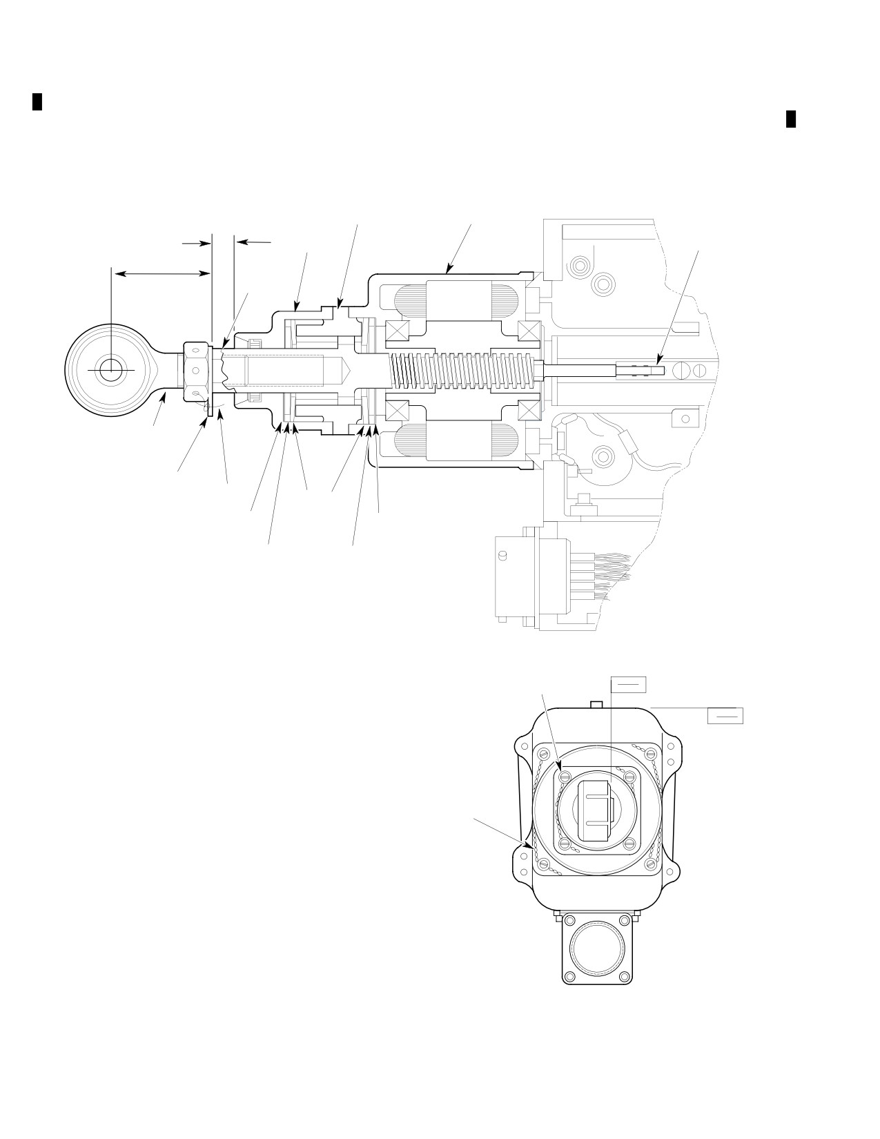
CSP-HMI-2
MD Helicopters, Inc.
MAINTENANCE MANUAL
(12). Re-install rod end, nut and lockwasher
(13). Using lockwire (CM731), safety nut to
with rod end face (surface ``A'') oriented
lockwasher, washer may be oriented
at 90° ±2° with respect to surface ``B''.
with lockwire end up or down.
Torque nut to 170 - 200 inch-pounds
(19.21 - 22.60 Nm).
SPLINED
MOTOR
HOUSING
HOUSING
SEAL
ÉÉÉÉÉ
C
HOUSING
VDT CORE
É
OUTPUT
1.10 ± 0.03 IN
SHAFT
(27.9"0.76 MM)
ROD
END
LOCKWASHER
LOCKWIRE
BELLEVILLE
SHIMS
SPRING
SHIMS
SPACERS
SPACERS
SCREW
A
B
SAFETY
WIRE
G67-2021
Figure 801. YSAS Actuator (Cross−Section View)
Page 806
Revision 42
67-20-30

MD Helicopters, Inc.
CSP-HMI-2
MAINTENANCE MANUAL
Chapter
71
Power Plant
MD Helicopters, Inc.
CSP−HMI−2
MAINTENANCE MANUAL
TABLE OF CONTENTS
Para/Figure/Table
Title
Page
71-00-00 Power Plant (250-C20)
A
Description and Operation
1
1. Power Plant Description
1
2. Power Plant Operation
1
3. Models 250-C20B and 250-C20R/2 Power Plant Fault Isolation
1
Table 1. Power Plant Fault Isolation
1
Removal/Installation
401
1. Engine Removal
401
A. Engine Disconnecting for Removal
401
Figure 401. Allison 250-C20B and 250-C20R/2 Engine Removal and
Installation (Sheet 1 of 2)
402
B. Removal of Disconnected Engine
404
2. Engine Installation
404
A. Engine Installation in Mounts
404
B. Connecting an Installed Engine
405
Figure 402. Model 250-C20B and 250-C20R/2 Engine Stripping and
Buildup (Sheet 1 of 2)
406
3. Engine Stripping
408
Figure 403. Model 250-C20B and 250-C20R/2 Engine Mounts and
Airframe Fittings
410
4. Engine Buildup
411
5. Modification of Accessory Drive Gearbox Overboard Vent Tube
(SN 0004D - 0519D)
413
Figure 404. Extension of Engine Accessory Drive Overboard Vent Tube
413
71-00-30 Power Plant (250-C30)
A
Description and Operation
1
1. Power Plant Description
1
2. Power Plant Operation
1
3. Model 250-C30 Power Plant Fault Isolation
1
Table 1. Power Plant Fault Isolation
1
Removal/Installation
401
1. Engine Removal
401
A. Engine Disconnecting for Removal
401
Figure 401. Model 250-C30 Engine Removal and Installation (Sheet 1 of 2) . .
402
B. Removal of Disconnected Engine
404
2. Engine Installation
404
A. Engine Installation in Mounts
404
Page i
71 Contents
Revision 36
CSP−HMI−2
MD Helicopters, Inc.
MAINTENANCE MANUAL
TABLE OF CONTENTS (Cont.)
Para/Figure/Table
Title
Page
B. Connecting an Installed Engine
405
Figure 402. Engine Mounts and Structural Fittings
406
3. Engine Stripping
407
Figure 403. Model 250-C30 Engine Build-Up (Sheet 1 of 2)
408
4. Engine Buildup
410
71-00-47 Power Plant (250-C47)
A
Description and Operation
1
1. Power Plant Description
1
2. Power Plant Operation
1
3. Model 250-C47 Power Plant Fault Isolation
1
Table 1. Power Plant Fault Isolation
1
Figure 1. Starter/Generator System Wiring Diagram (Sheet 1 of 2)
2
Figure 2. Engine Wire Harness Wiring Diagram
3
Removal/Installation
401
1. Model 250-C47 Engine Replacement
401
A. Engine Disconnecting for Removal
401
Figure 401. Engine Build-up Assembly (Sheet 1 of 2)
402
Figure 402. Engine Installation (Sheet 1 of 2)
404
B. Removal of Disconnected Engine
406
C. Engine Installation in Mounts
406
D. Connecting an Installed Engine
407
Figure 403. Starter/Generator Electrical Connections
408
2. Model 250-C47 Engine Stripping
408
3. Model 250-C47 Engine Buildup
409
71-10-00 Engine Air Intake System (369D/E/FF - 500/600N)
A
Maintenance Practices
201
1. Description and Operation
201
2. Air Inlet Screen Replacement
201
A. Air Inlet Screen Removal (369D/E/FF - 500N)
201
Figure 201. Engine Air Inlet Screen Installation (Sheet 1 of 2)
202
B. Engine Inlet Screen Removal (600N)
204
C. Air Inlet Screen Installation (369D/E/FF - 500N)
204
D. Engine Inlet Screen Installation (600N)
204
3. Air Inlet Bell Replacement
204
A. Air Inlet Bell Removal
204
B. Air Inlet Bell Installation
204
Page ii
Revision 36
71 Contents
MD Helicopters, Inc.
CSP−HMI−2
MAINTENANCE MANUAL
TABLE OF CONTENTS (Cont.)
Para/Figure/Table
Title
Page
4. Firewall Seal Removal
204
5. Air Intake System Inspection
204
Figure 202. Firewall Seal Installation
205
6. Firewall Seal Ring Repair
206
7. Air Inlet Bell Repair
206
8. Plenum Chamber Drain Tube Replacement
206
Figure 203. Drain System
206
71-10-05 Engine Compressor Water Wash Kit (369D/E/FF - 500/600N)
A
Maintenance Practices
201
1. Engine Compressor Water Wash Kit Maintenance
201
2. Engine Compressor Water Wash Kit Inspection
201
Initial Installation
901
1. Engine Compressor Water Wash Kit Initial Installation
901
A. Gaining Access to Work Area
901
B. Airframe Modification and Installation
901
2. Installation Inspection
901
Figure 901. Engine Compressor Water Wash Kit Installation
(Sheet 1 of 3)
902
71-10-10 Engine Air Particle Separator (369D/E/FF - 500N)
A
Description and Operation
1
1. Description and Operation
1
Table 1. Engine Air Particle Separator Configurations
2
Figure 1. Particle Separator Operating Principle - Early Type
(Donaldson Unit)
3
Figure 2. Particle Separator Operating Principle - Current Type
(APM Unit)
4
Fault Isolation
101
1. Engine Air Particle Separator Fault Isolation
101
Table 101. Engine Air Particle Separator Fault Isolation
101
Figure 101.
369H90148-503, -505, -507, -509 Particle Separator
Installation Wiring Diagram (Slim-Line Panel)
102
Figure 102.
369H90148-503, -505, -507, -509 Particle Separator Installation
Wiring Diagram (T-Panel with Center Console)
103
Figure 103.
369H90148-519, -521, -527, -529 Particle Separator
Installation Wiring Diagram
104
Figure 104.
369H90148-535,-537, -539, -541, -543, -545 and 500N90148-1, -3
Particle Separator Installation Wiring Diagram
105
Maintenance Practices
201
1. Air Bypass Door System Maintenance
201
Page iii
71 Contents
Revision 36
CSP−HMI−2
MD Helicopters, Inc.
MAINTENANCE MANUAL
TABLE OF CONTENTS (Cont.)
Para/Figure/Table
Title
Page
2. Solenoid Air Valve Cleaning
201
3. Air Pressure Sensing Switch Maintenance
202
4. Air Bypass Door Rigging (369D/E/FF)
202
5. Air Bypass Door Rigging (500N)
203
6. Particle Separator Cleaning
203
7. Mist Eliminator Maintenance
203
Figure 201. Air Bypass Door System (369D/E/FF) (Sheet 1 of 3)
204
Figure 202. Air Bypass Door System (500N)
207
Removal/Installation
401
1. PLM Particle Separator Replacement
401
A. PLM Particle Separator Removal
401
B. PLM Particle Separator Installation
401
2. PLM Scavenge Ejector Replacement
401
A. PLM Scavenge Ejector Removal
401
B. PLM Scavenge Ejector Installation
402
3. PLM Ejector Nozzle and Manifold Replacement
402
4. Mist Eliminator Replacement
402
A. Helicopters With Mist Eliminator Access Panel
402
B. Helicopters Without Mist Eliminator Access Panel
402
C. Mist Eliminator Installation
402
5. Donaldson Particle Separator Replacement
402
A. Donaldson Particle Separator Removal
402
B. Donaldson Particle Separator Installation
403
Inspection/Check
601
1. Engine Air Inlet Bypass Door 300-Hour Inspection
601
2. PLM Particle Separator Inspection
601
3. Donaldson Particle Separator Inspection
602
4. Scavenge Air Operational Check
602
5. Air Pressure Sensing Switch Calibration Check
603
6. Mist Eliminator Inspection
603
Figure 601. Air Pressure Sensing Switch Calibration Check
604
Repairs
801
1. PLM Particle Separator Repairs
801
A. Vortex Tube Plug Installation
801
B. Displaced Vortex Generator Tube
801
Figure 801. Vortex Generator Repairs
802
Page iv
Revision 36
71 Contents
MD Helicopters, Inc.
CSP−HMI−2
MAINTENANCE MANUAL
TABLE OF CONTENTS (Cont.)
Para/Figure/Table
Title
Page
C. Damaged Or Missing Vortex Generator Tube
803
D. Damaged Or Missing Vortex Generator and Outlet Tubes
803
E. PLM Particle Separator Gasket Replacement
803
F. Fairing Modifications (369D Only)
803
Figure 802. Fairing Modifications
804
2. Mist Eliminator Repair
805
3. Particle Separator Alignment and Joint Surface Repair (369D/E/FF)
805
4. Donaldson Particle Separator Repair (369D Only)
805
Figure 803. Donaldson Particle Separator Gasket Replacement
806
Figure 804. Mist Eliminator Bolt Repair
807
5. Donaldson Particle Separator Auxiliary Fairings and Seals Installation
808
Figure 805. Auxiliary Fairings and Seals Installation (Sheet 1 of 2)
810
Figure 806. Auxiliary Fairings and Supports Fabrication (Sheet 1 of 2)
812
Figure 807. Pressure Switch
814
Initial Installation
901
1.
Engine Air Particle Separator Initial Installation
901
A. Filter Bypass Door and Aft Cable
901
Figure 901. Air Bypass Door Installation (Sheet 1 of 2)
902
Figure 902. Aft Cable Installation (Sheet 1 of 2)
904
B. Cover Installation
906
C. Handle and Forward Cable Installation
906
D. Bleed Air System Installation (Helicopters Without Cabin Heat)
907
E. Bleed Air System Installation (Helicopters With Cabin Heat)
907
Figure 903. Handle and Forward Cable Installation (Sheet 1 of 3)
908
F. Scavenge Air System Installation
911
Figure 904. Modifications and Installation (Sheet 1 of 4)
912
G. Solenoid Valve and Pressure Switch Wire Harness Installation
916
Figure 905. Scavenge Air Equipment Installation
917
H. Ejector Duct Doubler and Rib Installation
918
I. Particle Separator Installation
918
Figure 906. Ejector Duct Doubler Installation
919
Figure 907. Wiring Harness Installation
920
J. Instrument Panel Modifications; T-Pedestal
922
K. Slimline Panel Modification
922
L. Post-Installation Inspection
923
M. Weight and Balance
923
Table 901. Weight and Balance Data
923
Page v
71 Contents
Revision 36
CSP−HMI−2
MD Helicopters, Inc.
MAINTENANCE MANUAL
TABLE OF CONTENTS (Cont.)
Para/Figure/Table
Title
Page
71-10-60 Engine Air Particle Separator (600N)
A
Description and Operation
1
1. Description and Operation
1
Fault Isolation
101
1. Engine Air Particle Separator Fault Isolation
101
Table 101. Engine Air Particle Separator Fault Isolation
101
Figure 101. Air Intake and Particle Separator Circuits Wiring Diagram
101
Removal/Installation
401
1.
Particle Separator Replacement
401
A. Particle Separator Removal
401
B. Particle Separator Installation
401
2.
Scavenge Air Solenoid Valve Replacement
401
A. Scavenge Air Solenoid Valve Removal
401
B. Scavenge Air Solenoid Valve Installation
401
3.
Air Filter Bypass Switch Replacement
401
A. Air Filter Bypass Switch Removal
401
B. Air Filter Bypass Switch Installation
401
4.
Bypass Door Assembly Replacement
401
A. Bypass Door Assembly Removal
401
B. Bypass Door Assembly Installation
401
5.
Bypass Door Cable Assembly Replacement
402
A. Bypass Door Cable Assembly Removal
402
B. Bypass Door Cable Assembly Installation
402
6.
Bypass Door Seal Repair
402
7.
Particle Separator Manifold Replacement
402
Figure 401. Engine Air Particle Separator Installation
403
Figure 402. Bypass Door Installation
404
Inspection/Check
601
1. Engine Air Particle Separator Inspection
601
2. Bypass Door Inspection
601
3. Bypass Door Cable Inspection
601
4. Air Pressure Sensing Switch Calibration Check
601
Figure 601. Air Pressure Sensing Switch Calibration Check
602
71-20-00 Engine Mounts (250-C20B, 250-C20R/2, 250-C30 and 250-C47)
A
Description and Operation
1
1. Description
1
Page vi
Revision 36
71 Contents
MD Helicopters, Inc.
CSP−HMI−2
MAINTENANCE MANUAL
TABLE OF CONTENTS (Cont.)
Para/Figure/Table
Title
Page
2. Airframe Fittings
1
Removal/Installation
401
1. Airframe Fittings Replacement
401
2. Lower Engine Mount Replacement (250-C20/-C20R/2)
401
A. Lower Engine Mount Removal (250-C20/-C20R/2)
401
B. Lower Engine Mount Installation (250-C20/-C20R/2)
401
3. Upper Engine Mounts Replacement (250-C20/-C20R/2)
401
A. Upper Engine Mounts Removal (250-C20/-C20R/2)
401
B. Upper Engine Mounts Installation (250-C20/-C20R/2)
401
Figure 401. 250-C20/-C20R/2 Engine Mounts and Airframe Fittings
402
4. Lower-Aft Engine Mount Replacement (250-C30/-C47)
403
A. Lower-Aft Engine Mount Removal (250-C30/-C47)
403
B. Lower-Aft Engine Mount Installation (250-C30/-C47)
403
5. Upper Engine Mounts Replacement (250-C30/-C47)
403
A. Upper Engine Mounts Removal (250-C30/-C47)
403
B. Upper Engine Mounts Installation (250-C30/-C47)
403
Figure 402. Model 250-C30/-C47 Engine Mounts and Airframe Fittings
405
Inspection/check
601
1. Engine Mounts and Fittings Inspection
601
2. Upper Engine Mounts Adjustment
601
Repairs
801
1. Engine Mount Repairs
801
2. Mount Hole Repair (250-C20/-20R/2)
801
3. Painted Surfaces Repair
801
71-30-00 Engine Ignition Control System (250-C20B, 250-C20R/2 and 250-C30)
A
Description and Operation
1
1. Engine Ignition System Description and Operation
1
2. Automatic Re-ignition System Description and Operation
1
Fault Isolation
101
1. Engine Ignition System Fault Isolation
101
Table 101. Ignition System Fault Isolation
101
2. Automatic Re-ignition System Fault Isolation
102
Table 102. Automatic Re-ignition System Fault Isolation (369D)
102
Table 103. Automatic Re-ignition System Fault Isolation (369E/FF - 500N) . .
103
Removal/Installation
401
1. Automatic Re-ignition System Component Replacement
401
Page vii
71 Contents
Revision 36