HANDBOOK OF MAINTENANCE INSTRUCTIONS FOR MDHI 369D/E/FF-500/600N HELICOPTERS (ISSUED: 1990) - page 24
MD Helicopters, Inc.
CSP-HMI-2
MAINTENANCE MANUAL
MAIN ROTOR FLIGHT CONTROLS
DESCRIPTION AND OPERATION
1. Main Rotor Flight Controls
provides inboard support for the collective
torque tube.
Main rotor flight controls consist of scissors,
rotating swashplate, stationary swashplate,
C. Collective Controls
mixer controls (lateral bellcrank, longitudinal
idler, collective pitch mixer bellcrank, longitu
Pilot's compartment collective controls consist
dinal bellcrank, longitudinal control-mixer
of collective pitch stick, collective bungee, and
link, longitudinal link, and two mixer links)
the interconnecting shaft and linkage. All
and five pitch control rods.
components, except the stick and tunnel-
routed collective mixer control rod, are located
within the pilot's seat structure. Dual control
Movement of collective pitch cyclic control
provisions are incorporated into the pilot's
sticks is transferred to mixer controls through
compartment collective controls installation.
control rods routed up through the controls
tunnel at the center of Sta. 78.50 bulkhead.
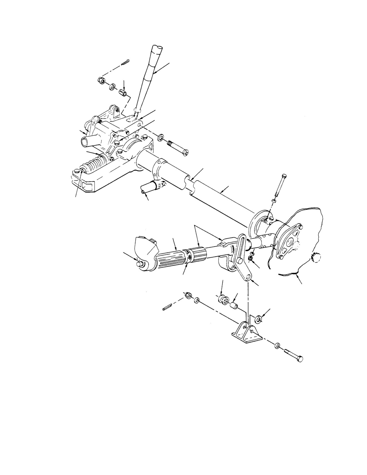
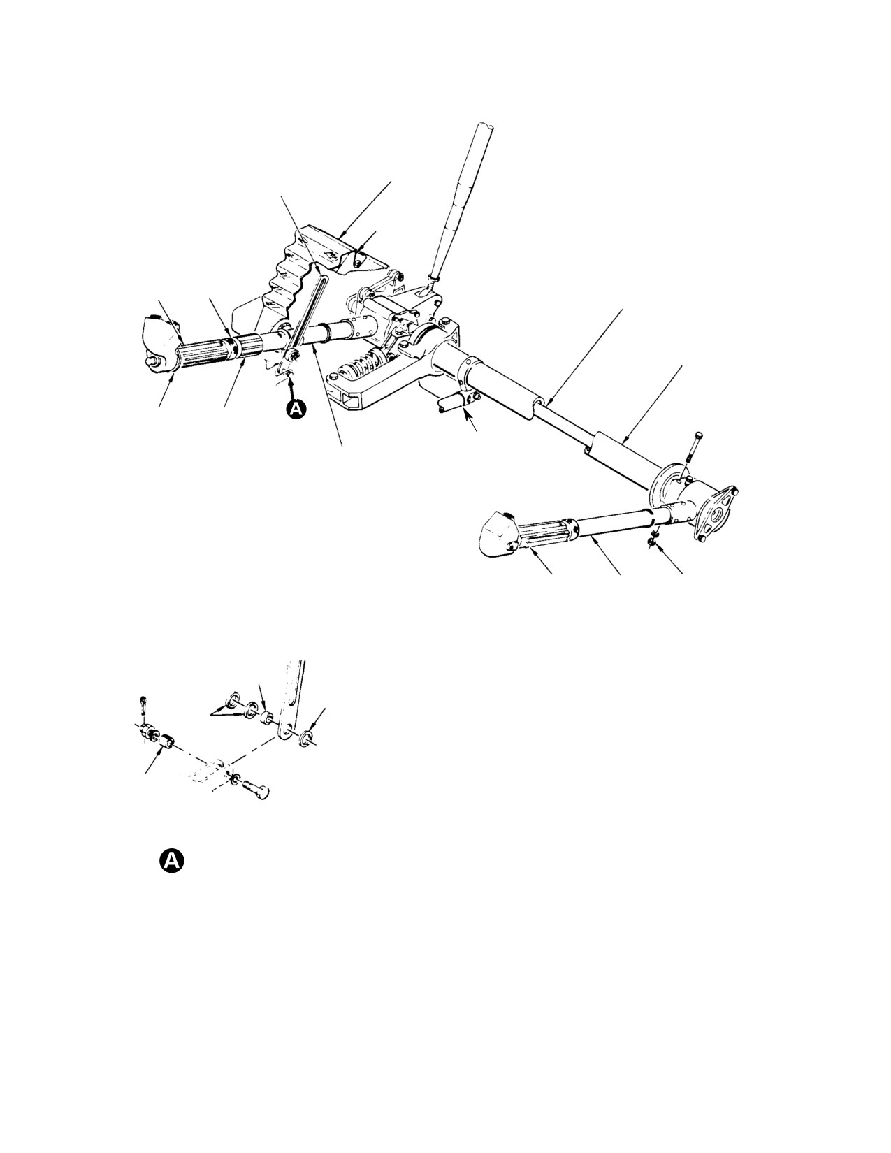
D. Pilot’s Collective Pitch Stick
Mixer controls transfer required combination
of collective, longitudinal and lateral travel
The pilot's collective pitch stick consists
through swashplates to main rotor blades. The
primarily of a switch housing, throttle grip and
helicopter may be equipped with either
friction mechanism, collective stick tube and
right-hand or left-hand control configurations
friction mechanism and gas producer control
consisting of cyclic, collective and anti-torque
shaft with right angle (pinion and bevel gear)
controls. The main rotor hub and blades,
drive. Collective pitch stick controls include:
swashplate and control linkage to the crew
the N1 throttle and idle stop release ring, N2
compartment controls are identical on either
governor trim switch, landing light switch,
basic configuration.
stick friction adjustment grip throttle friction
nut and a starter-ignition switch.
NOTE: This section contains information for
both L/H command and R/H command heli
E. Copilot’s Collective Pitch Stick
copters. Unless otherwise denoted, the in
formation in this section pertains to both
The copilot's collective stick consists primarily
type helicopters.
of a switch housing, N1 throttle grip, stick
tube, and internal gas producer control shafts
A. Collective Mixer, Lateral and Longitudinal
having right angle (pinion and bevel) gear
Mixer (Tunnel−Routed) Control Rods
drive. The gear drive linkage is essentially the
same as in pilot's collective stick housing.
Tunnel-routed control rods mechanically
Copilot's collective controls include an N2
transfer displacement of flight controls to
governor trim switch.
associated bellcranks and the idler at the front
of main rotor mast base. All tunnel-routed
F. Collective Pitch Stick Friction
control rods are removed, inspected, repaired
and installed in same manner.
Pilot's collective pitch stick friction allows the
pilot to vary amount of effort required to raise
B. Controls Support Bracket and Bellcranks
and lower the collective pitch stick as well as
increasing stick resistance to position change
The controls support bracket is below the
resulting from sudden changes in main rotor
pilot's seat cover, between right and left
collective forces. The grip is marked with
inboard sides of the seat structure. The
arrows indicating direction of rotation for
bracket provides the hingeline for longitudinal
increasing or decreasing friction. Friction can
and lateral idler bellcrank, tail rotor bellcrank,
be applied or released with one hand by
and the engine droop control bellcrank. It also
rotating the friction adjustment grip.
Page 1
67-10-00
Revision 21
CSP-HMI-2
MD Helicopters, Inc.
MAINTENANCE MANUAL
Collective stick friction mecha
bracket attachment is to counteract these
CAUTION
nism is designed so that stick
forces so that collective stick loads are
cannot be locked in maximum friction point.
relatively constant throughout full range of
Safety of flight considerations require that
travel. There are two adjustments provided to
pilot be able to instantly change any estab
establish or correct collective flight loads. The
lished collective pitch stick position, without
collective bungee spring corrects variation in
changing friction adjustment in event of a
collective load from low pitch (level flight) to
power failure. There is no suitable check
high pitch (climb). Setting of overcenter bolt to
that pilot can make, with helicopter on the
raise or lower bungee fitting reduces or
ground, to determine if maintenance adjust
increases overall collective forces in both low
ment of collective friction is correct. This is
pitch (level flight) and high pitch (climb).
due to large force application necessary to
I. Inboard Collective Stick Socket Assembly
override collective bungee and blades rest
ing on droop stops. If stick friction is inade
Inboard collective stick socket assembly is a
quate during flight, a maintenance check
cast magnesium housing that contains gas
should be performed. Once friction adjust
producer linkage and provisions for attach
ment is determined to be correct at low fric
ment of dual collective controls. Internal gas
tion point, any further mechanical adjust
producer drive gear linkage is essentially the
ment to alter (increase) friction at low point
same as that in the pilot's collective stick
can cause stripping of mechanism when grip
housing with the addition of a splined N1
is fully rotated for maximum friction.
pinion gear for simplified installation or
removal of a copilot's collective stick. The lower
G. Collective Control Interconnecting
end of the collective mixer (tunnel-routed)
Torque Tube
control rod is attached to the socket housing
The collective interconnecting torque tube
and the exterior bellcrank, idler and link
consists of the tube, bungee bracket, bungee
transfer movement of the pilot's collective stick
fitting and a tube support bearing. The torque
throttle to the gas producer controls routed
tube interconnects the pilot's collective pitch
through the fuselage to the engine.
stick and the inboard collective stick socket
J. Cyclic Controls
assembly. The torque tube is supported at the
left end by a bearing installed in seat struc
The cyclic pitch control system is a fully
ture, and at the right end by the controls
mechanical control system. Any combination of
support bracket.
lateral and longitudinal cyclic pitch stick
movement is mixed by cyclic lateral and
H. Collective Bungee
longitudinal control mixers and transferred to
the main rotor swashplate, which applies the
The collective bungee installation consists of a
combined motion through pitch control rods to
male bearing assembly, female bearing
the main rotor blades. Forward and rearward
assembly, spring and retainer. This unit
movement of the cyclic pitch stick causes
attaches between the bungee over-center
helicopter motion in a longitudinal direction,
fitting and bungee bracket of collective
while side-to-side movement provides motion
interconnecting torque tube. The collective
in a lateral direction. This action varies lift
bungee helps maintain selected collective pitch
developed by main rotor blades and serves as
stick position in flight by counteracting forces
primary control by horizontal flight. Pilot's
that are fed back in collective pitch stick(s)
compartment cyclic controls include the control
(blade pitching moments, rotor head strap
stick, a lateral interconnecting rod, lateral
pack torsion when collective pitch stick is
cyclic bellcrank, longitudinal cyclic control
raised or lowered from mid-position, and
interconnecting torque tube and lateral and
combined imbalance of forces in the controls
longitudinal friction mechanism.
system). Flight characteristics of the helicopter
are such that collective forces are relatively
K. Pilot’s Cyclic Control Stick
low during most stick travel from low to high
blade pitch. At a point near full pitch, stick
The pilot's cyclic control stick consists of a grip
forces reverse and become heavy. The purpose
and a tube riveted in a socket. The cyclic grip
of the adjustable bungee and the overcenter
contains a toggle switch for cyclic trim control
Page 2
Revision 21
67-10-00
MD Helicopters, Inc.
CSP-HMI-2
MAINTENANCE MANUAL
and a trigger switch for radio/interphone
should the check valve spring fail, the one-
communication. A blank switch socket is
way lock does not function to shunt longitudi
provided at the left of the trim switch for
nal feedback forces to structure. The unit is
optional equipment. Coiled, insulated and
mounted in two pivoting supports attached to
open-ended wiring is provided in the grip for
seat structure, and has a transparent, vented
connection to an optional switch.
reservoir with a capacity of approximately 0.67
fluid ounce (20 cc). The one-way lock control
L. Copilot’s Cyclic Control Stick
system is serviced through the filler with
hydraulic oil (6, Table 203).
The copilot's cyclic control stick is similar to
the pilot's except electrical wiring exits above
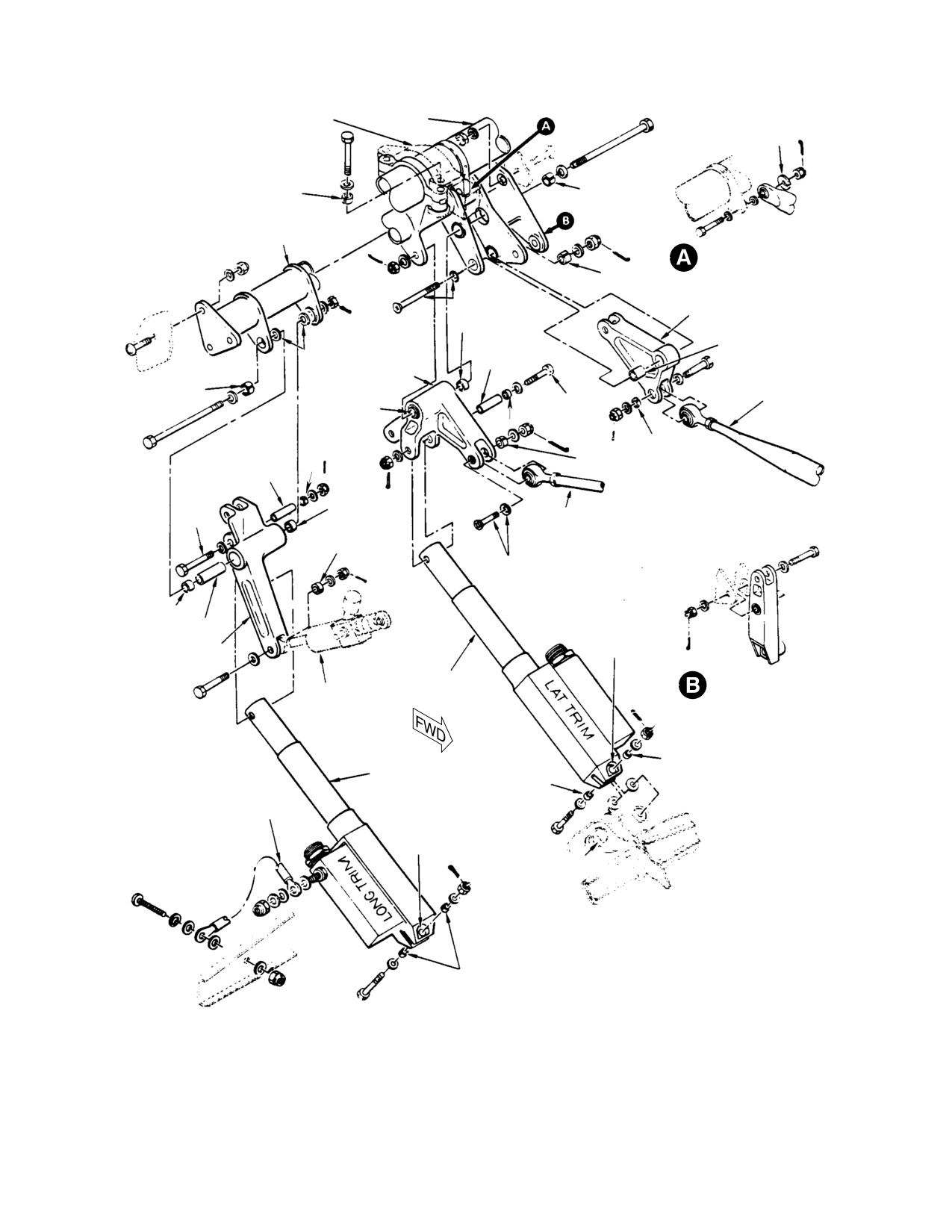
O. Cyclic Trim Actuators
the stick socket. The copilot's cyclic stick is
detachable and may be removed or installed by
Each of the two cyclic trim actuators consists
use of two quick-release pins.
of an actuator, housing support, trim tube and
spring assembly. The actuator is essentially a
M. Pilot’s Compartment Lateral and
motor-driven, variable length shaft that
Longitudinal Cyclic Control Linkage
compresses a spring assembly, counteracting
feedback forces from the main rotor and
Pilot's compartment lateral and longitudinal
compensating for imbalance conditions such as
cyclic control linkage consists of two control
those imposed by crosswinds or unevenly
rods and a bellcrank that interconnect lateral
distributed cargo. Cyclic trim is controlled by
control movement, and the cyclic torque tube
the cyclic trim switch on top of cyclic stick grip.
and one-way lock control system that inter
The cyclic trim switch has five positions:
connect longitudinal control movement of
normally OFF at the center, and momentary
pilot's cyclic stick to tunnel-routed mixer
FORWARD, AFT, LEFT, and RIGHT. When
control rods. R/H command configuration is
the trim switch is moved off center to any of
identical to L/H command except for an
the four trim positions, one of the trim motors
additional lateral control rod that attaches
operates to provide trim spring force in the
lower end of copilot's cyclic control stick to
desired direction. By momentarily activation of
lateral cyclic bellcrank.
the switch, very small trim increments are
obtained. Trim forces cannot be applied in two
N. One−Way Lock Control System
directions simultaneously; when both lateral
and longitudinal trim corrections are required,
The one-way lock of the cyclic control system
it is necessary to apply first one, then the
is located in longitudinal control linkage
other. Travel of the cyclic pitch control stick is
within the pilot's seat structure. The one-way
not limited by the cyclic trim mechanism; trim
lock control system is essentially a self-con
spring tension can be overridden at any time.
tained, closed-loop hydraulic unit - consisting
of a check valve, relief valve and pushrod
P. Roof−Mounted Control Rods (600N)
mechanism. The check valve is seated when
longitudinal control force (feed-back) origi
The roof-mounted control rods transmit cyclic
nated by main rotor tends to move the
and collective flight control input from the
one-way lock (and cyclic stick) in an aft
tunnel-routed control rods, via the forward
direction. Seating the check valve prevents
roof-mounted bellcranks, to the link assem
unwanted aft movement of cyclic stick and
blies, via the aft roof-mounted bellcranks, at
shunts feed-back force to helicopter structure.
the mixer assembly.
Normally, only very slight aft movement of the
cyclic stick is required to unseat the check
Q. Roof−Mounted Bellcranks (600N)
valve. Should the check valve (or pushrod
shaft that unseats the valve) gall and freeze in
The forward roof-mounted bellcrank transfer
the valve-closed position, a force of approxi
controls input from the tunnel-routed control
mately 30 pounds is necessary to open the
rods to the roof-mounted control rods. The aft
relief valve and bypass the check valve. This
roof-mounted control rods transfer controls
force is then required for each subsequent aft
input from the roof-routed control rods to the
movement of the cyclic stick. Conversely,
link assemblies.
Page 3
67-10-00
Revision 21
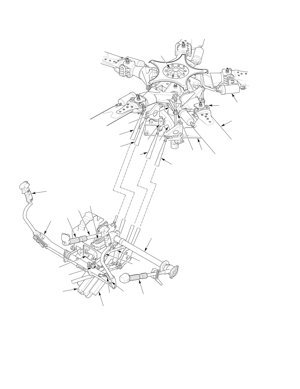
CSP-HMI-2
MD Helicopters, Inc.
MAINTENANCE MANUAL
1.
MAIN ROTOR DRIVE SHAFT
1
2.
DAMPER
3.
BLADE ATTACH PIN
4.
MAIN ROTOR BLADE
5.
ROTOR MAST SUPPORT
6.
ROTATING SWASHPLATE
7.
MAIN ROTOR CONTROLS (MIXER, IDLER
BELLCRANKS AND LINKS)
8.
LATERAL MIXER CONTROL ROD (CYCLIC)
9.
LONGITUDINAL MIXER CONTROL ROD (CYCLIC)
10. COLLECTIVE MIXER CONTROL ROD
11. STATIONARY SWASHPLATE
3
2
4
11
10
7
7
9
6
5
8
25
12. COLLECTIVE CONTROL TORQUE TUBE
27
13. COPILOT'S COLLECTIVE PITCH STICK
14. DROOP CONTROL OVERRIDE LINK
15. COPILOT'S CYCLIC STICK
24
16. LATERAL CYCLIC FRICTION KNOB
23
17. CYCLIC LATERAL CONTROL ROD
18. LATERAL CYCLIC TRIM ACTUATOR
26
22
19. LONGITUDINAL CYCLIC TRIM ACTUATOR
20. LONGITUDINAL CYCLIC FRICTION KNOB
21. ONE-WAY LOCK
22. CYCLIC CONTROL TORQUE TUBE
12
23. GAS PRODUCER CONTROL ROD
24. COLLECTIVE CONTROL BUNGEE
25. ANTI-TORQUE CONTROL ROD (REF)
26. PILOT'S COLLECTIVE PITCH STICK
27. PILOT'S CYCLIC STICK
14
15
21
20
19
17
16
13
18
G67-0000A
Figure 1. Main Rotor and Control System (369D/E/FF − 500N)
Page 4
Revision 21
67-10-00
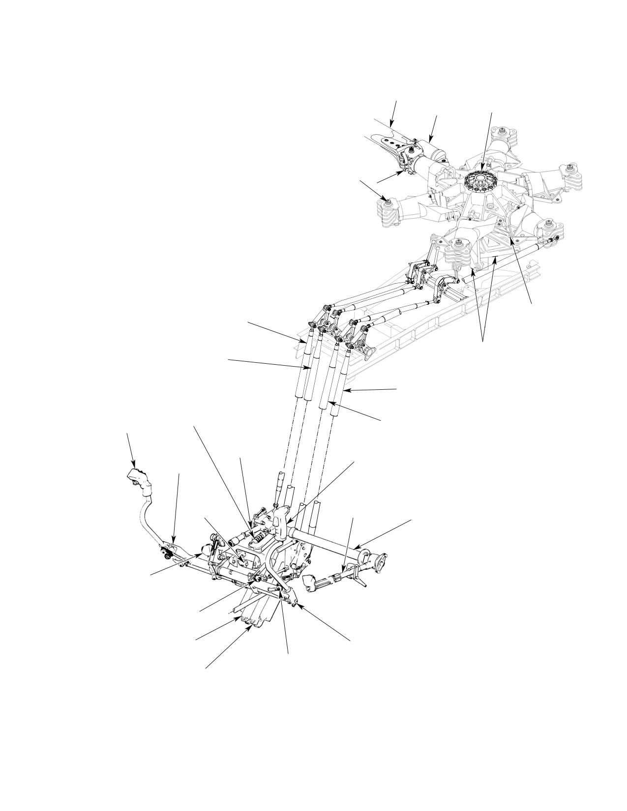
MD Helicopters, Inc.
CSP-HMI-2
MAINTENANCE MANUAL
1.
MAIN ROTOR DRIVE SHAFT
2.
DAMPER
3.
BLADE ATTACH PIN
4
4.
MAIN ROTOR BLADE
5.
ROTATING SWASHPLATE
2
1
6.
MAIN ROTOR CONTROLS (MIXER, IDLER
BELLCRANKS AND LINKS)
7.
LATERAL MIXER CONTROL ROD (CYCLIC)
8.
LONGITUDINAL MIXER CONTROL ROD (CYCLIC)
9.
COLLECTIVE MIXER CONTROL ROD
10.
COLLECTIVE CONTROL TORQUE TUBE
11.
COPILOT'S COLLECTIVE PITCH STICK
3
12.
COPILOT'S CYCLIC STICK
13.
LATERAL CYCLIC FRICTION KNOB
14.
CYCLIC LATERAL CONTROL ROD
15.
LATERAL CYCLIC TRIM ACTUATOR
16.
LONGITUDINAL CYCLIC TRIM ACTUATOR
17.
LONGITUDINAL CYCLIC FRICTION KNOB
18.
ONE-WAY LOCK
19.
CYCLIC CONTROL TORQUE TUBE
20.
GAS PRODUCER CONTROL ROD
21.
COLLECTIVE CONTROL BUNGEE
22.
ANTI-TORQUE CONTROL ROD (REF)
23.
PILOT'S COLLECTIVE PITCH STICK
24.
PILOT'S CYCLIC STICK
5
9
6
8
22
21
7
12
20
24
19
23
18
10
11
17
16
14
13
15
6G67-035A
Figure 2. Main Rotor and Control System (600N)
Page 5
67-10-00
Revision 21
CSP-HMI-2
MD Helicopters, Inc.
MAINTENANCE MANUAL
This Page Intentionally Left Blank
Page 6
Revision 44
67-10-00
MD Helicopters, Inc.
CSP-HMI-2
MAINTENANCE MANUAL
MAIN ROTOR FLIGHT CONTROLS
REMOVAL/INSTALLATION
1. Tunnel−Routed Control Rod Replacement
tube to angle up through the double
hole.
(Ref. Figure 401)
(9). Remove bolt from bottom of 7012 tube
A. Tunnel−Routed Control Rod Removal
and lower to belly of aircraft and angle
up through the double hole.
Special Tools
(10). Remove bolts from bottom of 7007 tube
(Ref. Section 91−00−00)
and lower to the belly of aircraft, then
Item
Nomenclature
angle up through the double hole.
ST508
Collective bungee installation tool
(11). Move 7009 tube to the other side of
center beam and angle up through the
Before disconnecting collec
double hole.
WARNING
tive pitch control rod, install
B. Tunnel−Routed Control Rod Installation
collective bungee installation tool to
prevent spring reaction due to droop
To reinstall tunnel-routed control rods,
stop load on control rod.
reverse the sequence of Tunnel-Routed
Control Rod Removal.
(1). Install collective bungee installation
tool (ST508) and remove collective
2. Roof−Mounted Control Rod Replacement
bungee.
(600N)
(2). For access to lower rod ends, remove
(Ref. Figure 402)
controls access door at base of canted
bulkhead in cargo compartment.
A. Roof−Mounted Control Rod Removal
(600N)
(3). Hand turn main rotor blades to align
blue blade to right side of aircraft.
Special Tools
(4). Disconnect upper end of control rod.
(Ref. Section 91−00−00)
Item
Nomenclature
(5). Remove double boot from control tunnel
ST508
Collective bungee installation tool
cover. All tubes will be removed
through the double hole.
(1). Install collective bungee installation
Use care during removal of con
tool (ST508) and remove collective
CAUTION
trol rods. Any surface damage
bungee.
caused by hasty removal may result in un
serviceable control rods.
(2). For access to roof-mounted control
rods, remove upper fuselage controls
(6). Move blue blade pitch housing down as
fairing.
far as it will go. This will allow the
tubes to go past the housing.
NOTE: If same rods are to be reinstalled, mark
rods for proper positioning upon reinstalla
(7). Remove bolts from bottom of 369A7009
tion. If new rods are installed, main rotor
and 7011 tubes.
flight controls must be re-rigged.
(8). Move cyclic controls so that the 7012
(3). Mark control rod for proper reinstalla
tube moves to its highest point. Place
tion.
7009 tube to the far right and lower out
of way. Lower 7011 tube to the left side
(4). Remove hardware from control rods
of center beam. This will allow 7011
and remove rods from aircraft.
Page 401
67-10-00
Revision 21
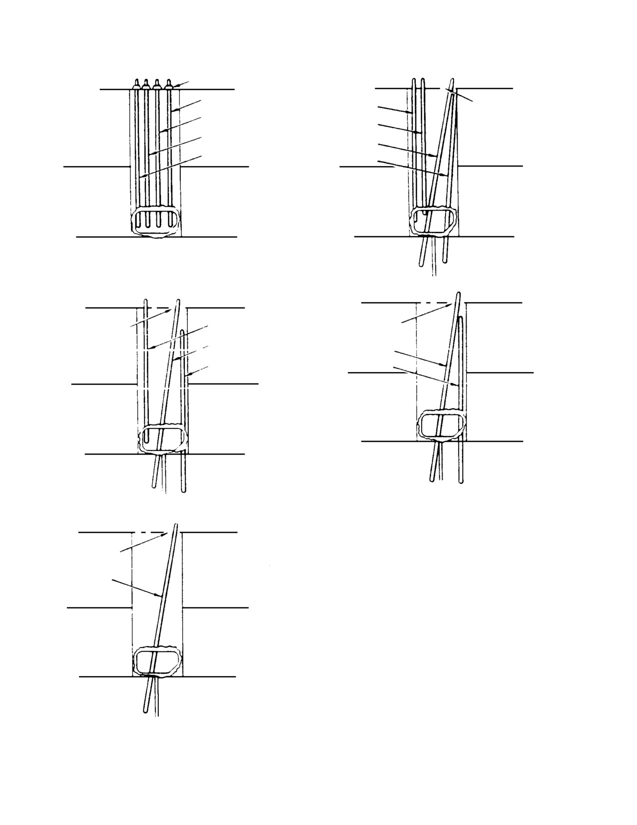
CSP-HMI-2
MD Helicopters, Inc.
MAINTENANCE MANUAL
DOUBLE BOOT
369A7009
369A7007
DOUBLE BOOT
369A7011
HOLE
369A7012
369A7012
369A7011
369A7007
369A7009
VIEW LOOKING FORWARD
VIEW LOOKING FORWARD
VIEW A
VIEW B
DOUBLE BOOT
369A7007
DOUBLE BOOT
HOLE
HOLE
369A7012
369A7007
369A7009
369A7009
VIEW LOOKING FORWARD
VIEW LOOKING FORWARD
VIEW D
VIEW C
DOUBLE BOOT
HOLE
369A7009
VIEW LOOKING FORWARD
VIEW E
G67 1001
Figure 401. Tunnel−Routed Control Rod Installation
Page 402
Revision 21
67-10-00
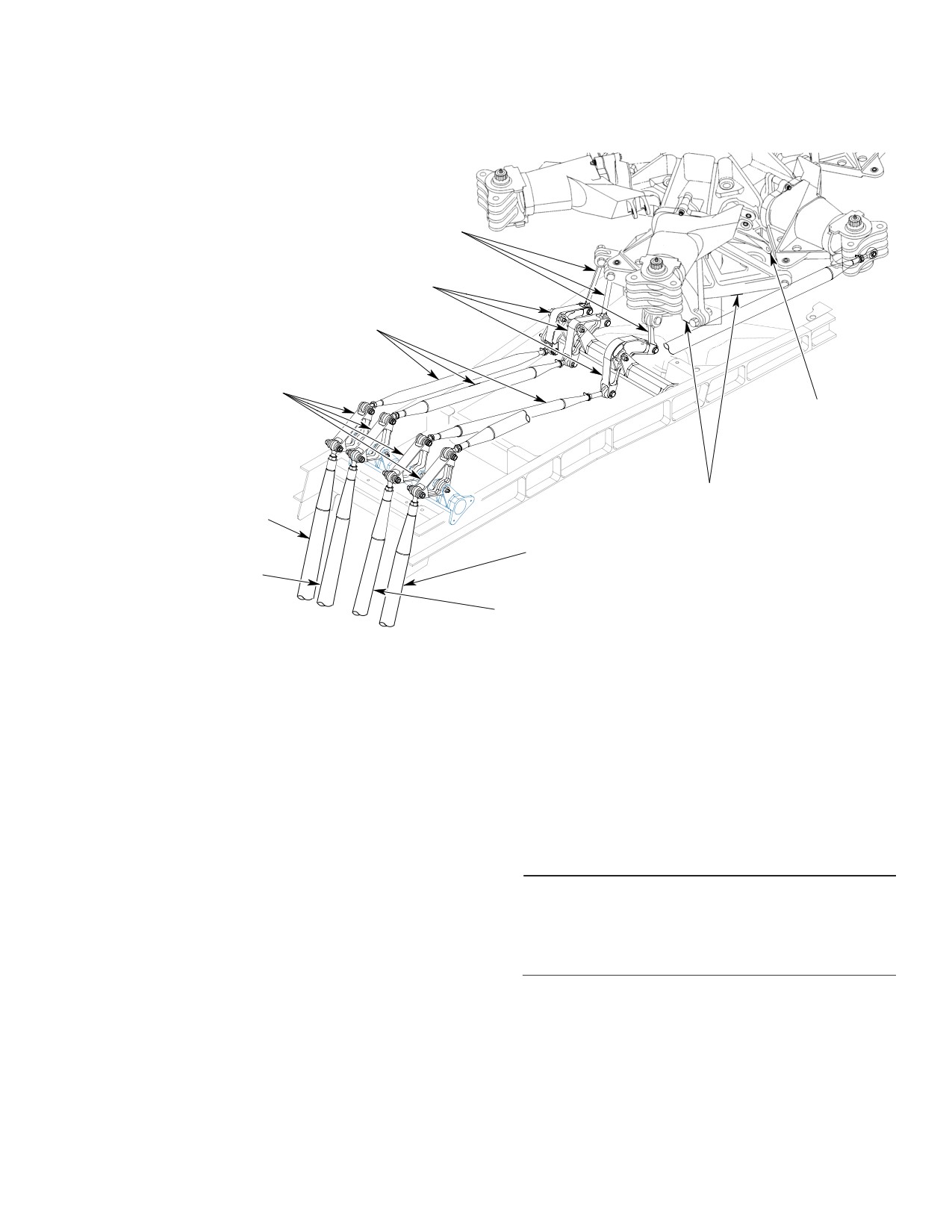
MD Helicopters, Inc.
CSP-HMI-2
MAINTENANCE MANUAL
LINK ASSEMBLY
AFT ROOF-MOUNTED
BELLCRANKS
ROOF-MOUNTED
CONTROL RODS
FORWARD
ROOF-MOUNTED
BELLCRANKS
ROTATING
SWASHPLATE
MAIN ROTOR CONTROLS
COLLECTIVE MIXER
(MIXER, IDLER BELLCRANKS
CONTROL ROD
AND LINKS)
DIRECTIONAL
LONGITUDINAL MIXER
CONTROL ROD
CONTROL ROD
(CYCLIC)
LATERAL MIXER
CONTROL ROD
(CYCLIC)
6G67-039
Figure 402. Roof−Mounted Controls Installation
B. Roof−Mounted Control Rod Installation
3. Roof−Mounted Bellcrank Replacement
(600N)
(600N)
(Ref. Figure 402) Replacement of the roof-
(1). Install control rods in bellcranks
mounted bellcranks is the same procedure for
ensuring RH threaded rod end is
the forward and aft bellcranks.
forward.
A. Roof−Mounted Bellcrank Removal (600N)
(2). Install hardware connecting control
rods. Torque nuts to 30 - 40 inch-
Special Tools
pounds (3.39 - 4.52 Nm) and install
(Ref. Section 91−00−00)
cotter pin.
Item
Nomenclature
ST508
Collective bungee installation tool
(3). Remove collective bungee installation
tool.
(1). Install collective bungee installation
tool (ST508) and remove collective
(4). Reinstall upper fuselage controls
bungee.
fairing.
(2). For access to roof-mounted control rods
and bellcranks, remove upper fuselage
(5). Perform flight controls rigging check.
controls fairing.
Page 403
67-10-00
Revision 21
CSP-HMI-2
MD Helicopters, Inc.
MAINTENANCE MANUAL
(3). Remove hardware connecting rod from
(2). Ensure bushing protrudes a minimum
bellcrank.
of 0.010 inch (0.254 mm) to a maximum
of 0.060 inch (1.524 mm) beyond the
(4). Remove hardware from bellcrank pivot
surface of mixer.
point and remove bellcrank.
(3). Torque nuts to 30 - 40 inch-pounds
B. Roof−Mounted Bellcrank Installation
(3.39 - 4.52 Nm) and install cotter pin.
(600N)
NOTE: Ensure bellcranks are installed in prop
(4). Remove collective bungee installation
er position. If bellcranks are install in the
tool.
wrong position, rigging will be impossible
(Ref. Illustrated Parts Catalog).
(5). Reinstall upper fuselage controls
fairing.
(1). Install bellcrank in mount with word
FORWARD facing up and arrow
5. Controls Support Bracket and Bellcrank
pointing towards front of aircraft.
Replacement
(2). Install hardware connecting bellcrank
(Ref. Figure 403)
to mount. Torque nuts to 30 - 40
inch-pounds (3.39 - 4.52 Nm) and
A. Controls Support Bracket and Bellcrank
install cotter pin.
Removal
(3). Reinstall disconnected control rods.
Special Tools
(4). Remove collective bungee installation
(Ref. Section 91−00−00)
tool.
Item
Nomenclature
(5). Reinstall upper fuselage controls
ST508
Collective bungee installation tool
fairing.
4. Link Assembly Replacement (600N)
(1). Remove foot fairings and controls
(Ref. Figure 402)
access door (Sta. 78.50) and pilot's seat
cover.
A. Link Assembly Removal (600N)
Before disconnecting collec
WARNING
tive pitch control rod, install
Special Tools
collective bungee installation tool to
(Ref. Section 91−00−00)
prevent spring reaction due to droop
Item
Nomenclature
stop load on control rod.
ST508
Collective bungee installation tool
(2). Install collective bungee installation
tool (ST508) and remove collective
(1). Install collective bungee installation
bungee.
tool (ST508) and remove collective
bungee.
(3). Disconnect tunnel-routed control rods.
(2). Remove upper fuselage controls fairing.
(4). Disconnect upper end of each cyclic
NOTE: Upper link bolt has a bushing in the
trim actuator.
mixer bellcrank.
(5). Disconnect floor-routed tail rotor
(3). Remove hardware from link and
control rod from tail rotor bellcrank.
remove link from aircraft.
(6). Disconnect Sta. 70 lateral control rod
B. Link Assembly Installation (600N)
from lateral idler bellcrank.
(1). Install link between lower bellcrank
and mixer bellcrank with hardware
(7). Disconnect one-way lock from longitu
previously removed.
dinal idler bellcrank.
Page 404
Revision 21
67-10-00
MD Helicopters, Inc.
CSP-HMI-2
MAINTENANCE MANUAL
COLLECTIVE TORQUE
BUNGEE SUPPORT BRACKET
TUBE
WASHER (SPECIAL)
* * CONTROLS SUPPORT
BRACKET
DROOP CONTROL
OVERRIDE LINK
(COUNTERSUNK)
* * TAIL ROTOR BELLCRANK
BEARING
BUSHING
BEARING
NOTE 2
(NOTE 3)
LATERAL IDLER
BELLCRANK
*
FLOOR-ROUTED TAIL
BEARING
3/16 IN.
ROTOR CONTROL ROD
AND SPACER
(4.7625 MM)
DIAMETER
BUSHING
*
(NOTE 3)
1/4 IN.
(6.35 MM)
BEARING
STA 70 LATERAL
DIA
CONTROL ROD
(COUNTERSUNK)
BEARING
SPACER
* * LONGITUDINAL
NOTE 6
IDLER BELLCRANK
LATERAL CYCLIC
STA. 72 DROOP
TRIM ACTUATOR
CONTROL BELLCRANK
ONE-WAY
LOCK
LONGITUDINAL CYCLIC
TRIM ACTUATOR
NOTE 4
NOTE 6
BOLT INSTALLATION
HOLE
2.
SHIM WASHERS USED AS REQUIRED TO OBTAIN NO SIDELOAD
ON ONE-WAY LOCK.
*
3.
BUSHING AND BOLT MUST NOT ROTATE WITH TRIM UNIT
AFTER INSTALLATION.
4.
BOND JUMPER ATTACHMENT TYPICAL FOR BOTH ACTUATORS.
NOTES:
5.
DOUBLE ASTERISK (**) INDICATES PARTS THAT MAY BE EITHER
1.
ASTERISK (*) IDENTIFIES SLOTTED BUSHINGS. EDGE OF BUSHINGS
MAGNESIUM OR ALUMINUM ALLOY.
MUST PROTRUDE A MINIMUM OF 0.010 IN. (0.254 MM) TO A MAXIMUM
6.
REPLACEMENT PARTS HAVE NUTPLATE RIVETED IN PLACE.
OF 0.080 IN. (2.032 MM) ABOVE OUTSIDE SURFACE OF PART AFTER
WASHER, NUT AND COTTER PIN NOT REQUIRED.
G67-1002A
NUT IS TIGHTENED
Figure 403. Controls Support Bracket, Idler Bellcranks and Cyclic Trim Actuators Installation
Page 405
67-10-00
Revision 21
CSP-HMI-2
MD Helicopters, Inc.
MAINTENANCE MANUAL
(8). Remove pilot's collective pitch stick.
(8). Connect floor-routed tail rotor control
rod to tail rotor bellcrank.
(9). Provide support for collective torque
tube. Remove bolts, washers and nuts
(9). Connect upper end of each cyclic trim
securing bungee support bracket and
actuator.
collective torque tube to controls
support bracket.
NOTE: Lateral actuator uses 3/16 inch (4.7625
mm) diameter bolt. The longitudinal actua
(10). Disconnect aft end of droop control
tor requires 1/4 inch (6.035 mm) diameter
override link from collective torque tube
bolt.
bracket.
(10). Connect lower ends of tunnel-routed
(11). Remove Sta. 72 droop control bellcrank
control rods.
from support bracket.
(11). Install collective bungee and remove
(12). Disconnect and remove support bracket
collective bungee installation tool.
from seat structure. Avoid striking any
bellcranks and pushrods.
6. Pilot’s Collective Pitch Stick Replacement
B. Controls Support Bracket and Bellcrank
(L/H Command)
Installation
(Ref. Figure 404)
(1). Carefully position assembled support
bracket and bellcranks between seat
A. Pilot’s Collective Pitch Stick Removal
structure bulkheads and secure with
(L/H Command)
attaching hardware.
Special Tools
(2). Position Sta. 72 droop control bellcrank
(Ref. Section 91−00−00)
in support bracket and install.
Item
Nomenclature
NOTE: Cap is matched to cradle of each control
ST508
Collective bungee installation tool
support bracket. Check that numbers on
each part are identical before accomplishing
step (3). below.
(1). Remove outboard collective stick cover.
(3). Check that two slotted bushings are in
(2). Disconnect pilot's collective stick
place in bungee support bracket.
electrical plug.
Position collective torque tube and
bungee bracket on support bracket
(3). Remove attaching hardware that
cradle and install cradle bolts, washers
secures guide to seat structure bracket.
and nuts. Ensure index groove, in edge
of cap that clamps torque tube to
Before disconnecting collec
WARNING
tive stick, install collective
support bracket cradle, mates with
matching index at bracket cradle
bungee installation tool to prevent
parting surface.
spring reaction due to droop stop load
on controls.
(4). Install pilot's collective pitch stick.
(4). Install collective bungee installation
(5). Connect aft end of droop control
tool (ST508).
override link to collective torque tube
droop control bracket.
(5). Remove collective bungee and inboard
collective socket. Disconnect droop
(6). Connect one-way lock to longitudinal
control override link (369D/E/FF -
idler bellcrank.
500N only), slide bungee bracket to
NOTE: For following steps, ensure that slotted
side, remove cradle cap and slide
bushing is in bellcrank ear.
collective torque tube inboard.
(7). Connect Sta. 70 lateral control rod to
(6). Remove attaching hardware that
lateral idler bellcrank.
connects stick housing to torque tube.
Page 406
Revision 37
67-10-00
MD Helicopters, Inc.
CSP-HMI-2
MAINTENANCE MANUAL
COLLECTIVE MIXER
TUNNEL-ROUTED
CONTROL ROD
NOTE 3
INBOARD COLLECTIVE
STICK SOCKET
BUNGEE OVER-CENTER
ADJUSTMENT BOLT
GAS PRODUCER
(NOTE 1)
CONTROL ROD
BUNGEE
GAS PRODUCER
INTERCONNECTING
TORQUE TUBE
COLLECTIVE CONTROL
INTERCONNECTING
TORQUE TUBE
BUNGEE SPRING
N2 DROOP CONTROL OVERRIDE
ADJUSTMENT NUT
LINK (369D/E/FF - 500N)
(NOTE 2 - SEE CAUTION)
COLLECTIVE STICK FRICTION
MECHANISM AND GUARD
THROTTLE
PILOT'S COLLECTIVE
PITCH STICK
NOTE 4
NOTE 5
THROTTLE
FRICTION
SLEEVE
GUIDE
FUSELAGE
BUSHING
SKIN
NOTE 5
NOTES:
1.
ROTATED CLOCKWISE TO INCREASE, COUNTERCLOCKWISE TO
DECREASE OVERALL COLLECTIVE DOWNLOADS.
2.
ROTATED CLOCKWISE TO INCREASE COUNTERCLOCKWISE TO
DECREASE, BUNGEE PRELOAD.
CAUTION: DO NOT ADJUST BUNGEE SPRING TENSION WHILE BUNGEE
INSTALLATION TOOL IS INSTALLED. USE OVER-CENTER ACTION OF STICK
TO COMPRESS SPRING TO REMOVE TOOL.
3.
BUSHINGS MUST PROTRUDE A MINIMUM OF 0.010 IN. (0.254 MM) TO
A MAXIMUM OF 0.060 IN. (1.524 MM) AFTER BOLT IS TIGHTENED.
4.
FOUR NUTS TORQUED EQUALLY AND BY SMALL INCREMENTS.
G67-1003B
Figure 404. Dual Collective Controls (L/H Command)
Page 407
67-10-00
Revision 21
CSP-HMI-2
MD Helicopters, Inc.
MAINTENANCE MANUAL
(7). Remove stick by sliding it outboard off
(1). Remove stick cover from seat structure.
torque tube.
(2). Disconnect pilot's collective stick
B. Pilot’s Collective Pitch Stick Installation
electrical plug.
(L/H Command)
(3). Remove attaching hardware that
Consumable Materials
secures guide to seat structure bracket.
(Ref. Section 91−00−00)
Item
Nomenclature
CM116
Grease, aircraft and instrument
Before disconnecting collec
WARNING
tive stick, install collective
bungee installation tool to prevent
(1).
Lubricate stick housing socket with
spring reaction due to droop stop load
grease (CM116).
on controls.
(2).
Install stick by sliding housing on
collective control interconnecting torque
(4). Install collective bungee installation
tube. Install bolts, washers and nuts.
tool (ST508).
Tighten nuts equally and by small
increments until correct torque is
(5). Remove collective bungee and inboard
applied.
collective socket. Disconnect droop
control override link (369D/E/FF -
(3).
Connect electrical plug.
500N only), slide bungee bracket to
(4).
Install outboard collective stick cover.
side, remove cradle cap and slide
Raise and lower stick; verify that
collective torque tube inboard.
wiring does not foul.
(6). Disconnect gas producer control rod.
(5).
Remove snap plug from exterior skin,
rotate throttle and visually check for
zero backlash between gas producer
(7). Remove attaching hardware that
interconnect torque tube and hexagonal
connects stick housing to torque tube.
interior surfaces of drive gearshaft in
stick housing. Eliminate any backlash
B. Pilot’s Collective Pitch Stick Installation
by tightening pipe plug in end of torque
(R/H Command)
tube; zero backlash is required at both
ends of tube.
Consumable Materials
(6).
Check that inboard stick socket gears
(Ref. Section 91−00−00)
are at mid-travel when pilot's stick
Item
Nomenclature
throttle grip is set to mid-travel. If not,
adjust collective stick gas producer
CM116
Grease, aircraft and instrument
control linkage.
7.
Pilot’s Collective Pitch Stick Replacement
(1). Lubricate surfaces that are in contact
(R/H Command)
during rotation with grease (CM116).
(Ref. Figure 405)
(2). Ensure that pilot's and copilot's throttle
A. Pilot’s Collective Pitch Stick Removal
grips are in same relative positions.
(R/H Command)
Slide pilot's stick housing on collective
interconnecting torque tube, align
Special Tools
matching holes and secure stick to
(Ref. Section 91−00−00)
torque tube. Connect gas producer
Item
Nomenclature
control rod. Align and/or match bell
ST508
Collective bungee installation tool
crank centerline, gearshaft assembly
gear cutout and pilot's throttle.
Page 408
Revision 21
67-10-00
MD Helicopters, Inc.
CSP-HMI-2
MAINTENANCE MANUAL
PILOT'S COLLECTIVE
COLLECTIVE
PITCH STICK COVER
FRICTION GUIDE
FLEXIBLE
CLOSURE
PILOT'S
THROTTLE
THROTTLE
FRICTION
NUT
GAS PRODUCER INTERCONNECTING
GRIP
TORQUE TUBE
COLLECTIVE CONTROL
INTERCONNECTING
TORQUE TUBE
IDLE STOP
COLLECTIVE
RELEASE RING
STICK FRICTION
CONTROL
N2 DROOP CONTROL
OVERRIDE LINK
PILOT'S COLLECTIVE
(369D/E/FF - 500N)
PITCH CONTROL STICK
COPILOT'S
COPILOT'S
NOTE 3
THROTTLE
COLLECTIVE PITCH
GRIP
CONTROL STICK
PLAIN
BUSHING
NOTE 1
NOTE 1
SLOTTED
BUSHING
(NOTE 2)
BUSHING INSTALLATION
NOTES:
1.
ARRANGE WASHERS TO LINE UP GUIDE WITH STICK; SPACE LOOSELY WITH
THREE WASHERS.
2.
SLOTTED BUSHING MUST PROTRUDE A MINIMUM OF 0.010 INCH (0.254 MM) TO A
MAXIMUM OF 0.060 INCH (1.524 MM) AFTER BOLT IS TIGHTENED.
3.
FOUR NUTS TORQUED; EQUALLY AND BY SMALL INCREMENTS.
4.
ALLOWABLE FREE PLAY IN CO-PILOT'S TWIST GRIP IS ±5°.
G67-1004A
Figure 405. Dual Collective Controls (R/H Command)
Page 409
67-10-00
Revision 21
CSP-HMI-2
MD Helicopters, Inc.
MAINTENANCE MANUAL
(3). Position friction guide in seat structure
(3). Remove hardware from stick tube
bracket with plain bushing, slotted
socket adapter and remove pitch stick
bushing, and three washers loosely
assembly by sliding it forward and off
spaced between bracket ears so guide is
the inboard stick housing.
in line (parallel) with stick. Install bolt,
B. Copilot’s Collective Pitch Stick
two washers, nut and new cotter pin.
Installation (L/H Command)
(4). Connect electrical plug.
Consumable Materials
(5). Perform operational check of collective
(Ref. Section 91−00−00)
stick friction and adjust friction
Item
Nomenclature
mechanism as necessary.
CM116
Grease, aircraft and instrument
(6). Install collective stick cover on seat
structure. Check that wiring is not
(1). Lubricate stick housing socket with
fouled when stick is raised and lowered.
grease (CM116).
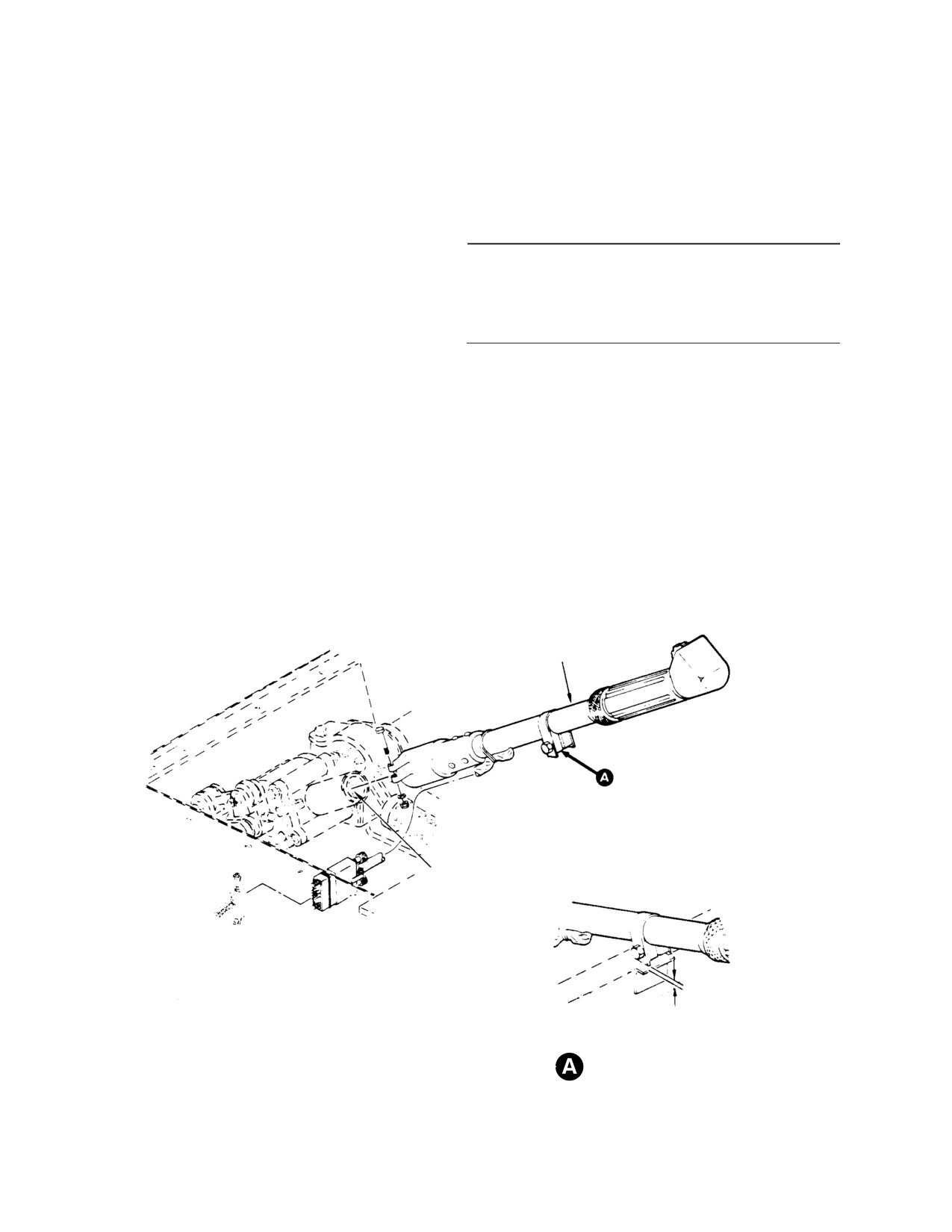
8. Copilot’s Collective Pitch Stick
(2). Rotate pilot's or copilot's throttle grips
Replacement (L/H Command)
so that the grip attach bolts are down.
(Ref. Figure 406)
(3). Install copilot's stick socket adapter on
the inboard housing socket extension
A. Copilot’s Collective Pitch Stick Removal
and, while moving copilot's throttle
(L/H Command)
back and forth slightly to get engage
ment of the socket pinion and adapter
(1). Remove collective stick cover from seat
splines, slide the adapter into place.
structure.
(4). Install attaching hardware to secure
(2). Disconnect electrical plug.
socket adapter.
STICK ASSEMBLY
COLLECTIVE PITCH STICK ASSEMBLY
NOTE 2
0.030-0.150 IN.
NOTES:
(0.762-3.81 MM)
1.
0.030-0.150 IN. (0.762-3.81 MM) MUST BE MAINTAINED BETWEEN
(NOTE 1)
STOP AND BRACKET WHEN PILOT COLLECTIVE CONTROL IS IN
FULL DOWN POSITION.
DOWNSTOP CLEARANCE
G67-1005A
2
LUBE SOCKET WITH GREASE BEFORE STICK INSTALLATION
Figure 406. CoPilot’s Collective Stick Assembly Installation (L/H Command)
Page 410
Revision 21
67-10-00
MD Helicopters, Inc.
CSP-HMI-2
MAINTENANCE MANUAL
(5). Connect electrical plug.
backlash is required at both ends of
tube.
(6). Position downstop assembly. Check that
0.030-0.150 inch (0.762-3.302 mm)
NOTE: The R/H command configuration collec
clearance exists between downstop and
tive friction mechanism is the same as L/H
seat structure with collective pitch stick
command except no separate friction guard
in full down position.
is provided, since the pilot's collective pitch
cover also functions as a guard for the fric
(7). Install collective cover on seat struc
tion mechanism.
ture. Check that wiring is not fouled
when stick is raised and lowered.
10. Collective Control Interconnecting Torque
Tube Replacement
9. Copilot’s Collective Pitch Stick
(Ref. Figure 407)
Replacement (R/H Command)
A. Collective Control Interconnecting
(Ref. Figure 404)
Torque Tube Removal
A. Copilot’s Collective Pitch Stick Removal
(R/H Command)
Special Tools
(Ref. Section 91−00−00)
Remove copilot's collective stick according to
Item
Nomenclature
instructions in Pilot's Collective Pitch Stick
ST508
Collective bungee installation tool
Removal (L/H Command) except disregard
information on friction guide.
Before disconnecting collec
B. Copilot’s Collective Pitch Stick
WARNING
tive pitch control rod, install
Installation (R/H Command)
collective bungee installation tool to
prevent spring reaction due to droop
stop load on control rod.
Consumable Materials
(Ref. Section 91−00−00)
(1).
Install collective bungee installation
Item
Nomenclature
tool (ST508) and remove collective
CM116
Grease, aircraft and instrument
bungee.
(2).
Remove inboard collective socket
(1).
Lubricate stick housing socket with
assembly.
grease (CM116).
(3).
Disconnect aft end of droop control
(2).
Slide stick housing on collective control
override link (369D/E/FF - 500N only)
interconnecting torque tube. Align
from torque tube droop control bracket.
matching holes and install bushings,
(4).
Remove hardware securing bungee
bolts, washers and nuts. Tighten
support bracket reinforcement strap
equally and by small increments until
and torque tube to controls support
proper torque is applied.
bracket. Slide bungee bracket aside and
remove controls bracket cradle cap and
(3).
Install outboard collective stick cover.
reinforcement strap.
Secure electrical plug and check that
wiring will not foul when stick is raised
(5).
Slide collective control torque tube
and lowered.
sufficiently toward right side of seat
structure to remove pilot's collective
(4).
Remove snap plug from exterior skin,
pitch stick housing from end of tube.
rotate throttle and visually check for
zero backlash between gas producer
(6).
Remove hardware that connects stick
interconnect tube and hexagonal ID of
housing to torque tube.
drive gearshaft in stick housing.
Eliminate any backlash by tightening
(7).
Remove stick by sliding it outboard and
pipe plug in end of torque tube; zero
off torque tube.
Page 411
67-10-00
Revision 21
CSP-HMI-2
MD Helicopters, Inc.
MAINTENANCE MANUAL
(8). Remove torque tube by sliding it
Position torque tube, controls bracket
approximately three inches toward
cradle cap, reinforcement strap and
right side of seat structure to disengage
bungee bracket on controls support
left end from support bearing inside left
bracket. Check that cap-to-cradle
torque tube support. Provide support at
index grooves are matched. Install with
seat structure lightening hole and care,
hardware removed. Apply thin layer of
fully withdraw torque tube from
grease (CM116) to sliding surfaces of
structure.
bungee overcenter fitting.
(9). Remove gas producer interconnect
(7). Install droop control override link
torque tube by carefully sliding it out of
(369D/E/FF - 500N only) to torque tube
collective torque tube.
droop control bracket.
B. Collective Control Interconnecting
(8). Install inboard collective socket
Torque Tube Installation
assembly.
(9). Complete installation of pilot's collec
Consumable Materials
tive stick.
(Ref. Section 91−00−00)
Item
Nomenclature
(10). Install collective bungee.
CM116
Grease, aircraft and instrument
11. Collective Bungee Replacement
(1). Install gas producer interconnect
(Ref. Figure 407)
torque tube by sliding it carefully into
place in collective control interconnect
A. Collective Bungee and Over−Center
ing torque tube.
Fitting − Removal
(2). Insert torque tube into lightening hole
in seat structure. Use care when
Special Tools
inserting tube into place to prevent
(Ref. Section 91−00−00)
scraping on edge of hole. Insert tube
Item
Nomenclature
only to a position that provides suffi
cient space between tube end and
ST508
Collective bungee installation tool
fuselage skin for installation of pilot's
stick housing on end of tube.
Before disconnecting collec
WARNING
(3). Lubricate pilot's stick housing with
tive pitch control rod, install
grease (CM116).
collective bungee installation tool to
prevent spring reaction due to droop
stop load on control rod.
(4). Slide pilot's stick housing on collective
control interconnecting torque tube.
(1). Remove pilot's seat cover from seat
NOTE: Stick housing must be placed on torque
structure.
tube before installing torque tube attaching
hardware.
(2). Raise collective stick and use torque
tube over-center action to compress
(5). Complete insertion of tube and position
bungee spring until bungee installation
left end of tube in fixed bearing bore.
tool (ST508) fits over spring retainers.
Rotate torque tube slowly back and
Secure tool halves in place with clamp.
forth until right end bearing rests in
cradle of controls support bracket.
(3). With stick in over-center position,
remove cotter pin, nut, washer and bolt
(6). Check that two slotted bushings are in
that secure male bearing to bungee
place in upper lugs of bungee bracket.
over-center fitting.
Page 412
Revision 29
67-10-00
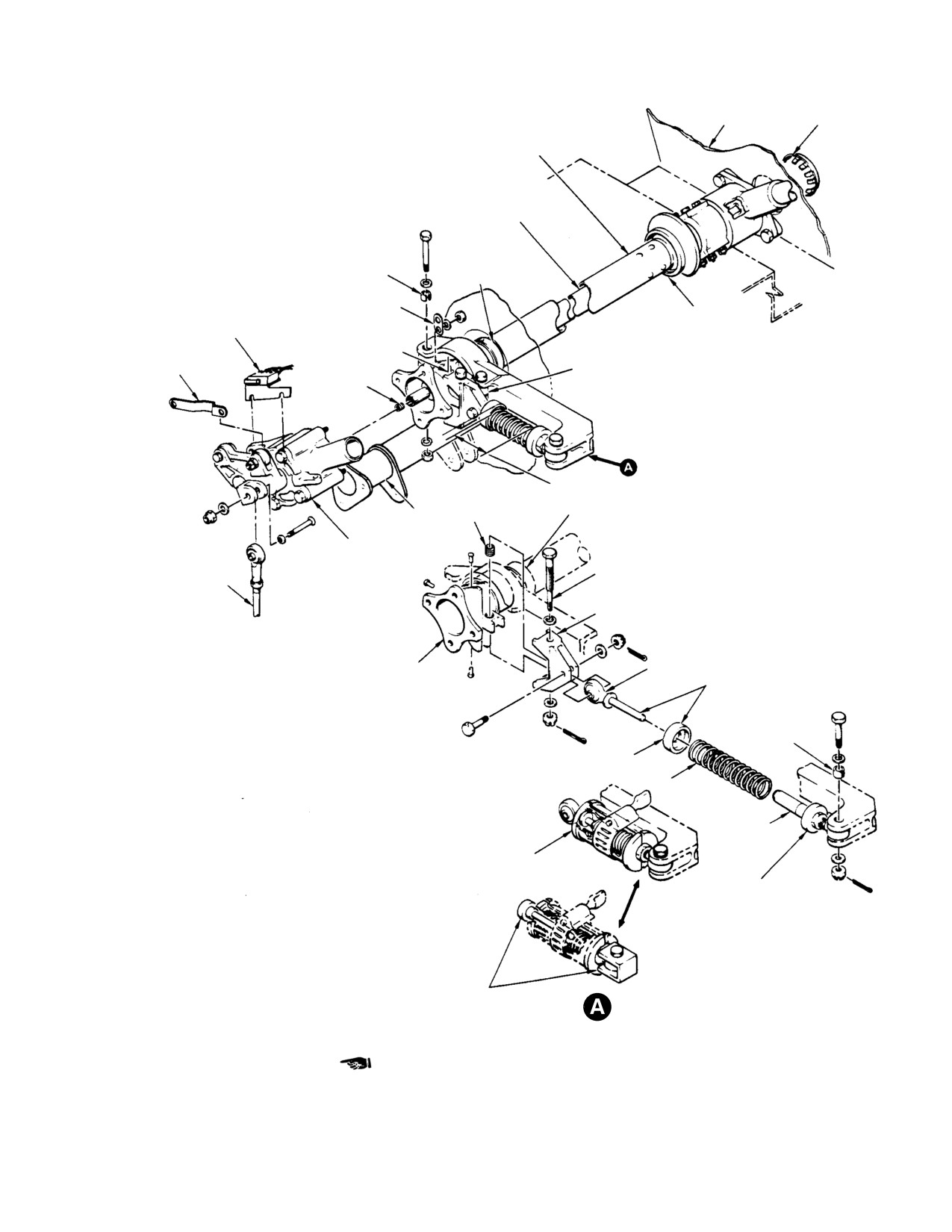
MD Helicopters, Inc.
CSP-HMI-2
MAINTENANCE MANUAL
FUSELAGE SKIN SNAP PLUG
COLLECTIVE CONTROL INTERCONNECTING
TORQUE TUBE
GAS PRODUCER INTERCONNECT
TORQUE TUBE
DROOP CONTROL
OVERRIDE LINK
BUSHING
BRACKET (NOTE 4)
(NOTE 1)
CLIP
NR DISABLE SWITCH
(3 PLACES)
TORQUE TUBE
AND BRACKET (NOTE 4)
SUPPORT BEARING
0.30 IN. (7.62 MM)
ACTUATING CAM
(NOTE 3)
CONTROLS BRACKET CRADLE
(NOTE 4)
INDEX GROOVE
PIPE PLUG
NOTE 5
THREADED
TORQUE TUBE SUPPORT
CONTROLS
INSERT
BEARING
SUPPORT
INBOARD
BRACKET
COLLECTIVE
BUNGEE OVER-CENTER
GAS PRODUCER
STICK SOCKET
ADJUSTMENT BOLT
CONTROL ROD
ASSEMBLY
BUNGEE OVER-CENTER
FITTING
FITTING
MALE BEARING
NOTE 2
SLOTTED
BUSHING
RETAINER
(NOTE 1)
SPRING
FEMALE
BEARING
ASSEMBLY
BUNGEE
(NOTE 2)
INSTALLATION TOOL
RETAINER
(NOTE 2)
NOTES:
1.
EDGE OF BUSHING MUST PROTRUDE A MINIMUM
OF 0.010 IN. (0.254 MM) TO A MAXIMUM OF 0.080 IN.
(2.032 MM) ABOVE OUTSIDE SURFACE OF PART
AFTER NUT IS TIGHTENED.
2.
LUBRICATION POINTS FOR GREASE.
3.
PRELIMINARY ADJUSTMENTS ONLY.
COMPRESSION TOOL
BUNGEE ASSEMBLY-EXPLODED VIEW
4.
USED ON 369D/E/FF - 500N HELICOPTERS ONLY.
ROD AND CHANNEL
5.
WITH COLLECTIVE STICK AT FULL DOWN POSITION,
PRELIMINARY ADJUSTMENT OF BUNGEE
INSTALLATION IS:
G67-1006B
369D/E/FF
500N; 2 20 ±0 05 IN (5 588 ±0 127 CM)
Figure 407. Collective Torque Tube, Gas Producer Torque Tube and Collective Bungee
Page 413
67-10-00
Revision 24
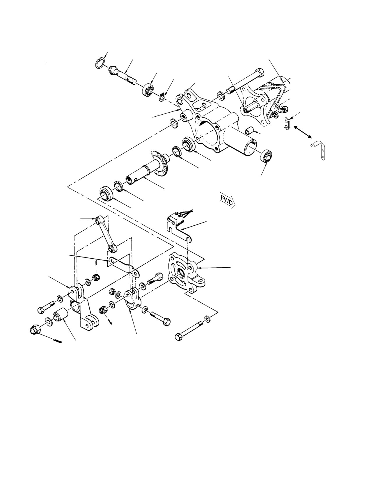
CSP-HMI-2
MD Helicopters, Inc.
MAINTENANCE MANUAL
SNAP RING
GAS PRODUCER INTERCONNECT
N1 PINION GEAR
TORQUE TUBE
AFT BEARING
(NOTE 4)
PIPE PLUG
SNAP RING
SLOTTED
BUSHING
CLIP
(3 PLCS)
SOCKET HOUSING
SPACER
(NOTE 1)
BEARING (NOTE 4)
BACKLASH SHIM
FORWARD BEARING
(NOTES 2, 4)
SHAFT ASSEMBLY
BACKLASH SHIM
BEARING
(NOTE 4)
LINK
NR DISABLE SWITCH
(NOTE 3)
AND BRACKET
(NOTE 5)
ACTUATING CAM
(NOTE 5)
HOUSING CAP
IDLER
BELLCRANK
IDLER BEARING
(NOTE 4)
NOTES:
1.
FOUR SPACERS USED ONLY ON REMOVED SOCKET ASSEMBLY TO KEEP ASSEMBLY INTACT.
2.
N1 PINION FORWARD BEARING IS LIGHT PRESS FIT IN HOUSING BORE.
3.
LINK MUST BE BOLTED TO BELLCRANK BEFORE BELLCRANK AND SHAFT ASSEMBLY ARE INSTALLED.
4.
BEARINGS INSTALLED WITH LOCKING COMPOUND. THE TWO SHAFT ASSEMBLY BEARINGS BONDED
ONLY AFTER SHIMMING FOR BACKLASH.
G67-1007B
Figure 408. Inboard Collective Stick Socket Assembly (L/H Command)
Page 414
Revision 21
67-10-00

MD Helicopters, Inc.
CSP-HMI-2
MAINTENANCE MANUAL
(4). Remove cotter pin, nut, two washers
Do not turn female bearing as
CAUTION
and bolt that attach female bearing end
sembly spring retainer while
of bungee to the bungee bracket.
bungee installation tool is spring loaded.
(5). Remove collective bungee and installa
(6). Raise collective stick so that torque
tion tool as a unit.
tube over-center action compresses
spring until bungee installation tool can
(6). Remove cotter pin, nut and washer
be removed; remove tool.
from over-center fitting.
(7). With collective stick at full down
(7). Remove bolt that secure over-center
position, preliminary adjustment of
fitting to collective torque tube and
bungee installation is:
remove fitting.
369D/E/FF - 500N; 2.2 ±0.05 inch
(5.588 ±0.127 cm)
B. Collective Over−Center Fitting and
600N; 2.70 ±0.05 inch (6.86 ±0.127 cm).
Bungee − Installation and Preliminary
Adjustment
(8). Flight test helicopter and complete
adjustment of collective bungee.
Consumable Materials
12. Inboard Collective Stick Socket Assembly
(Ref. Section 91−00−00)
Replacement
Item
Nomenclature
(Ref. Figure 408)
CM116
Grease, aircraft and instrument
A. Inboard Collective Stick Socket Assembly
Special Tools
Removal
(Ref. Section 91−00−00)
(1). Remove pilot's seat cover and controls
Item
Nomenclature
access door.
ST508
Collective bungee installation tool
(2). Disconnect collective mixer tunnel-
routed control rod.
(1).
Lubricate sliding surfaces of over-cen
ter fitting with grease (CM116) and
(3). Disconnect gas producer control rod
position on collective torque tube.
from idler.
(2).
Install bolt and washer though fitting
(4). Remove NR disable switch (369D/E/FF
and torque tube, and adjust to obtain
- 500N only) (Ref. Chap. 95).
0.30 in. (7.62 mm) preliminary adjust
(5). Remove four nuts and washers that
ment between upper surface of fitting
attach socket assembly to collective
and tips on torque tube fitting.
torque tube and remove assembly.
(3).
Install washer and nut on bolt and
NOTE: If disassembly is not intended, install
torque to 30 - 40 inch-pounds (3.39 -
four spacers and reinstall washers and nuts
4.52 Nm); install cotter pin.
on protruding bolts to keep assembly intact.
(4).
Position collective bungee, compressed
B. Inboard Collective Stick Socket Assembly
in installation tool (ST508), so that
Installation
female bearing assembly is forward and
aligns with mating hole in bungee
bracket. Check that slotted bushing for
Consumable Materials
bracket lug is in place, install bolt, two
(Ref. Section 91−00−00)
washers, nut and cotter pin.
Item
Nomenclature
CM318
Primer
(5).
Position male bearing to align with
mating hole in bungee over-center
fitting. Install bolt, washers, nut and
(1). Remove four nuts washers and spacers
install cotter pin.
from socket assembly mounting bolts.
Page 415
67-10-00
Revision 29
CSP-HMI-2
MD Helicopters, Inc.
MAINTENANCE MANUAL
(2). With throttle grip on pilot's collective
(10). Connect gas producer control rod to
stick at midtravel, rotate bellcrank
idler.
back and forth slightly to engage socket
(11). Connect collective mixer tunnel-routed
assembly to gearshaft on hexagonal end
control rod.
of gas producer interconnect torque
tube. Bellcrank centerline, N1 pinion
(12). Remove bungee installation tool.
gear centerline toothspace and pilot's
throttle must be as shown.
(13). Reinstall pilot's seat cover and the
controls access door.
NOTE:
(14). Check that inboard collective pitch stick
D With pilot's throttle grip at midtravel, two
socket gears are at midtravel when
grip attach bolts should be approximately
pilot's collective pitch stick throttle grip
straight down. Simultaneously, idler-to-
is set to midtravel. If not, adjust
gas producer control rod bolt holes should
collective pitch stick(s) gas producer
be in line with centerline of inboard stick
control linkage.
assembly housing cap.
D At midtravel, inboard N1 pinion gear
(15). Adjust NR disable switch (369D/E/FF -
spline wide toothspace should be at ap
500N only) (Ref. Chap. 95).
proximately one o'clock as viewed looking
aft into open end of socket.
13. Cyclic Control Stick Replacement
(Inboard)
(3).
Install NR disable switch (369D/E/FF -
500N only) (Ref. Sec. 95) and secure
(Ref. Figure 409)
socket assembly housing to collective
A. Cyclic Control Stick Removal (Inboard)
torque tube.
(1). Disconnect control stick electrical plug.
(4).
Rotate pilot's throttle and check for zero
backlash between gas producer inter
(2). Remove hardware that secures pilot's
connect torque tube and hexagonal
lateral control rod to stick socket.
interior of drive gearshaft in socket
assembly housing.
(3). Remove hardware that attaches lateral
friction mechanism link to cyclic torque
(5).
Eliminate backlash by removing
tube.
housing cap and gearshaft, and then
removing pipe plug in end of torque
(4). Remove hardware that attaches stick
tube.
socket to end of cyclic torque tube;
remove stick with lateral friction
(6).
Coat pipe plug with wet zinc chromate
mechanism attached.
primer (CM318), reinstall and tighten it
B. Cyclic Control Stick Installation (Inboard)
so there is no backlash between torque
tube and control gearshaft at each end
(1). Position pilot's cyclic control stick to
of the tube.
align with mating holes in torque tube.
(7).
If the normally installed plug does not
(2). Install attaching hardware.
sufficiently expand tube, a 1/8-27
internal-wrenching pipe plug 0.38 inch
(3). Check that slotted bushing is in place;
(9.65 mm) long may be substituted.
then align pilot's lateral control rod
Whichever plug is used, it must not
with stick socket. Install attaching
protrude more than 0.030 inch (0.762
hardware.
mm) when tightened.
(4). Position guide link to align with mating
(8).
Zero degree backlash is required at
hole in torque tube. Install bolt, sleeve
both ends of tube.
bushing three washers, nut and cotter
pin.
(9).
After plug is tightened, reinstall
gearshaft and housing cap.
(5). Connect electrical plug.
Page 416
Revision 29
67-10-00
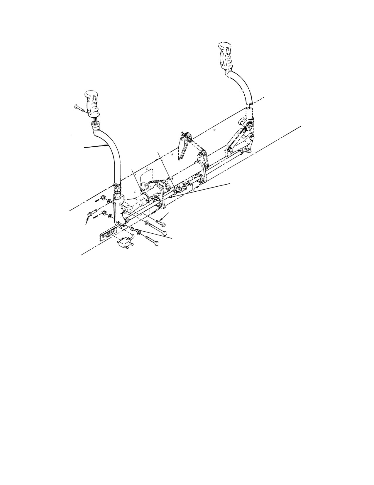
MD Helicopters, Inc.
CSP-HMI-2
MAINTENANCE MANUAL
LATERAL CYCLIC
CYCLIC STICK
BELLCRANK
ASSEMBLY
STRAP
LATERAL CONTROL ROD
(NOTE 2)
QUICK RELEASE
NOTES:
PIN
1.
EDGE OF BUSHING MUST PROTRUDE A MINIMUM
OF 0.010 IN. (0.254 MM) TO A MAXIMUM OF 0.060 IN.
QUICK
(1.524 MM) ABOVE OUTSIDE SURFACES OF PART
RELEASE
AFTER NUT IS TIGHTENED.
SLOTTED BUSHING
PIN
2.
CONTROL ROD END BEARINGS MUST NOT JAM
(NOTE 1)
THROUGHOUT FULL RANGE OF LONGITUDINAL
TRAVEL (34°).
G67-1008A
Figure 409. Cyclic Stick Assembly Installation (Inboard)
14. Cyclic Control Stick Replacement
(5). Remove stick tube from socket.
(Outboard)
B. Cyclic Control Stick Installation
(Ref. Figure 410)
(Outboard)
(1). Insert stick tube into stick socket and
A. Cyclic Control Stick Removal (Outboard)
install two quick-release pins.
(1). Disconnect control stick electrical plug.
NOTE: Omit steps (2). thru (4). when installing
stick without socket.
NOTE: Omit steps (2). and (3). below to remove
stick without removing stick socket.
(2). Position cyclic stick to align holes in
socket with mating holes in torque
(2). Remove cotter pin, nut, washers and
tube.
bolt securing copilot's lateral control rod
to stick socket.
(3). Install bolt, two washers, nut and new
cotter pin.
(3). Remove cotter pin, nut, washers and
bolt attaching stick socket to end of
(4). Check that slotted bushing is in place;
cyclic torque tube. Remove stick tube
then align copilot' s lateral control rod
with stick socket attached.
with stick socket. Install bolt, two
washers, nut and new cotter pin.
(4). Remove two quick-release pins attach
ing stick tube to stick socket.
(5). Connect electrical plug.
Page 417
67-10-00
Revision 29
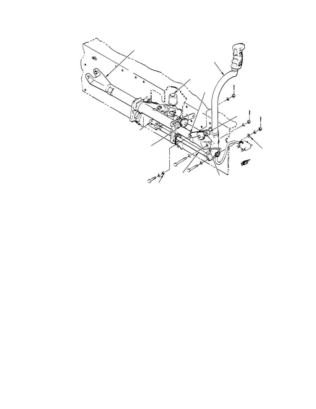
CSP-HMI-2
MD Helicopters, Inc.
MAINTENANCE MANUAL
CYCLIC PITCH
INTERCONNECTING
TORQUE TUBE
CYCLIC STICK
ASSEMBLY
ONE-WAY LOCK
ASSEMBLY
WASHER
LINK
STA. 67 LATERAL
CYCLIC BELLCRANK
LONGITUDINAL CONTROL
FRICTION MECHANISM
SLOTTED
BUSHING
(NOTE 1)
NOTES:
LATERAL CONTROL
LATERAL CONTROL
1.
EDGE OF BUSHING MUST PROTRUDE A MINIMUM OF
ROD (NOTE 2)
FRICTION MECHANISM
SLEEVE
0.010 IN. (0.254 MM) TO A MAXIMUM OF 0.080 IN. (2.032 MM)
ABOVE OUTSIDE SURFACE OF PART AFTER NUT IS TIGHTENED.
BUSHING
2.
CONTROL ROD END BEARINGS MUST NOT JAM THROUGHOUT
G67-1009B
FULL RANGE OF LONGITUDINAL TRAVEL (34°)
Figure 410. Cyclic Stick Assembly Installation (Outboard)
15. Lateral Control Rods and Sta. 67 Lateral
between rod end bearing centers for use
Cyclic Bellcrank Replacement (L/H
at replacement.
Command)
B. Lateral Control Rods and Sta. 67 Lateral
(Ref. Figure 411)
Cyclic Bellcrank Installation (L/H
Command)
A. Lateral Control Rods and Sta. 67 Lateral
Cyclic Bellcrank Removal (L/H Command)
(1). Check that slotted bushing is in upper
(1). Remove large (central) cyclic stick
web of seat structure fitting. Align Sta.
guard.
67 lateral cyclic bellcrank and install
attaching hardware.
(2). Remove pilot's seat cover, and controls
access door from Sta. 78.50 canted
(2). Check that slotted bushings are in
bulkhead.
place and install Sta. 70 lateral control
rod and pilot's lateral control rod.
(3). Remove pilot's lateral control rod, or
Sta. 70 lateral control rod, as applica
(3). Move cyclic stick full forward, then full
ble.
aft and set pilot's lateral control rod end
bearing angularity so that bearings do
(4). Remove Sta. 67 lateral cyclic bellcrank
not jam at full travel positions.
from seat structure fitting.
(5). If rod or rod ends require replacement,
(4). If control rod or rod ends are replaced,
accurately measure and record distance
perform a cyclic control rigging check.
Page 418
Revision 39
67-10-00
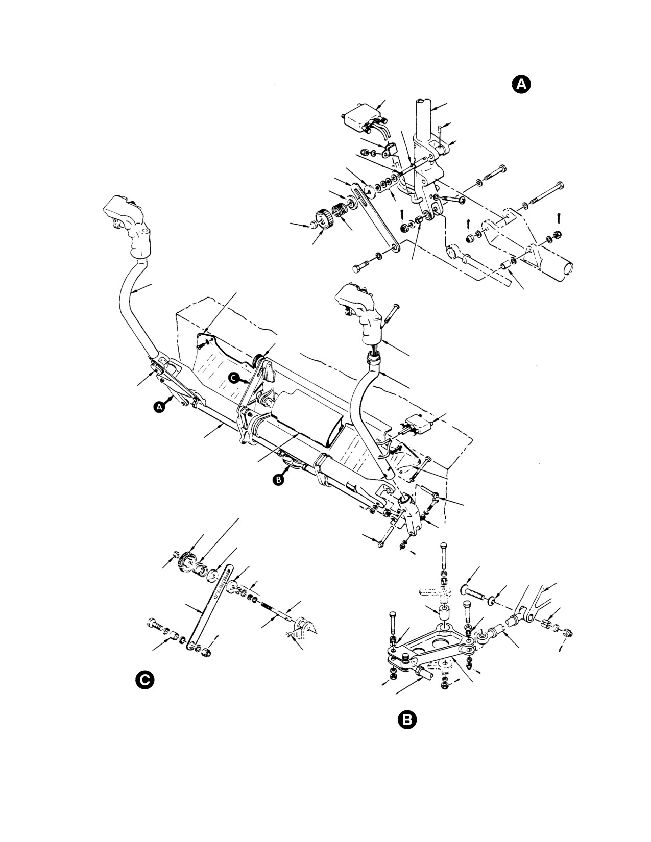
MD Helicopters, Inc.
CSP-HMI-2
MAINTENANCE MANUAL
NOTES:
1.
ASTERISK (*) IDENTIFIES SLOTTED BUSHING. EDGE OF BUSHING
ELECTRICAL
MUST PROTRUDE A MINIMUM OF 0.010 IN. (0.254 MM) TO A
PLUG
MAXIMUM OF 0.060 IN. (1.524 MM) ABOVE OUTSIDE SURFACE
TUBE
CYCLIC STICK SOCKET
OF PART AFTER NUT IS TIGHTENED.
AND LATERAL FRICTION
2.
WASHERS ARRANGED TO ALIGN LINK WITH TORQUE TUBE,
RIVET
INSTALLATION
PIN
LOOSELY SPACED WITH FOUR WASHERS.
CLAMP
SOCKET
3.
CONTROL RODS MUST NOT JAM THROUGHOUT FULL
RANGE OF LONGITUDINAL TRAVEL (34°).
FRICTION STUD
4.
INSTALLED WITH LOCKING COMPOUND.
FRICTION DISC
LATERAL GUIDE
RETAINER
NOTE 2
NUT
FRICTION
SPRING
FRICTION
KNOB
*
PILOT'S CYCLIC
STICK ASSEMBLY
PILOT'S CYCLIC
STICK GUARD
BUSHING
LONGITUDINAL
CONTROL FRICTION
MECHANISM
CYCLIC STICK GRIP
LATERAL
COPILOT'S CYCLIC
CONTROL
STICK ASSY
FRICTION
MECHANISM
ELECTRICAL PLUG
PILOT'S LATERAL
CONTROL ROD
(NOTE 3)
CYCLIC CONTROLS
CENTER GUARD
COPILOT'S CYCLIC
STICK GUARD
QUICK RELEASE PIN
FRICTION SPRING
FRICTION
KNOB
QUICK RELEASE
*
PIN
RETAINER
COUNTERSUNK
BOLT
FRICTION DISC
NUT
COUNTERSUNK
LATERAL
NOTE 2
WASHER
IDLER
BELLCRANK
FRICTION STUD
BEARING
LONGITUDINAL GUIDE
(NOTE 4)
*
SPRING
*
PIN
BUSHING
RIVET
STA 70 LATERAL
CONTROL ROD
LONGITUDINAL FRICTION INSTALLATION
PILOT'S LATERAL
STA 67 LATERAL CYCLIC
CONTROL ROD
BELLCRANK
LATERAL BELLCRANK CONNECTIONS
G67-1010A
Figure 411. Cyclic Controls (R/H Command)
Page 419
67-10-00
Revision 21
CSP-HMI-2
MD Helicopters, Inc.
MAINTENANCE MANUAL
16. Lateral Control Rods and Sta. 67 Lateral
each end with a bolt, two washers, nut
Cyclic Bellcrank Replacement (R/H
and new cotter pin.
Command)
(3). Move both cyclic sticks full forward,
then full aft and set both lateral control
(Ref. Figure 411)
rods so that rod end bearings do not
jam at full throw positions; hold rod
A. Lateral Control Rods and Sta. 67 Lateral
ends and tighten jam nuts.
Cyclic Bellcrank Removal (R/H
Command)
(4). If control rod or rod ends were replaced,
perform cyclic control rigging check.
(1).
Remove cyclic stick guards.
(5). Install cyclic stick guards, pilot's
collective pitch stick cover, controls
(2).
Install large (central) cyclic stick guard
access door, and foot fairing.
pilot's seat cover and controls access
door.
17. Cyclic Pitch Interconnecting Torque Tube
Replacement (L/H Command)
(3).
Remove pilot's collective pitch stick
cover, and controls access door and left
(Ref. Figure 412)
foot support fairing from Sta. 78.50
canted bulkhead.
A. Cyclic Pitch Interconnecting Torque Tube
Removal (L/H Command)
(4).
Remove cotter pin, two washers and
bolt from each end of pilot's lateral
(1).
Remove pilot's seat cover.
control rod, copilot's lateral control rod,
or Sta. 70 lateral control rod, as
(2).
Position pilot's cyclic stick to align holes
applicable; remove rod assembly.
in one-way lock support links with bolt
that attaches forward end of one-way
(5).
Remove cotter pin, nut, two washers
lock to torque tube; tighten longitudinal
and bolt securing Sta. 67 lateral cyclic
friction. Disconnect rod end from torque
bellcrank to seat structure fitting;
tube arm.
remove bellcrank.
(3).
Remove pilot's cyclic stick.
(6).
If rod or rod ends require replacement,
accurately measure and record distance
(4).
Remove all of cyclic stick guard instal
between rod end bearing centers for
lation except small guard next to pilot's
future reference; use trammel method,
cyclic stick.
or equivalent.
(5).
Remove longitudinal control friction
mechanism.
B. Lateral Control Rods and Sta. 67 Lateral
Cyclic Bellcrank Installation (R/H
(6).
Remove pilot's lateral control rod from
Command)
Sta. 67 lateral cyclic bellcrank.
(1). Check that slotted bushing is in upper
(7).
Cut lockwire and remove support nuts,
web of seat structure fitting. Align Sta.
support bolts and two wide (L/H)
67 lateral cyclic bellcrank and install
support spacers from seat structure
bolt, two washers, nut and new cotter
fitting lugs and torque tube. Prevent
pin.
torque tube from dropping as bolts are
removed.
(2). Check that slotted bushings are in
place and install Sta. 70 lateral control
(8).
Remove torque tube and two narrow
rod. Install both lateral control rods at
(R/H) support spacers.
Page 420
Revision 29
67-10-00
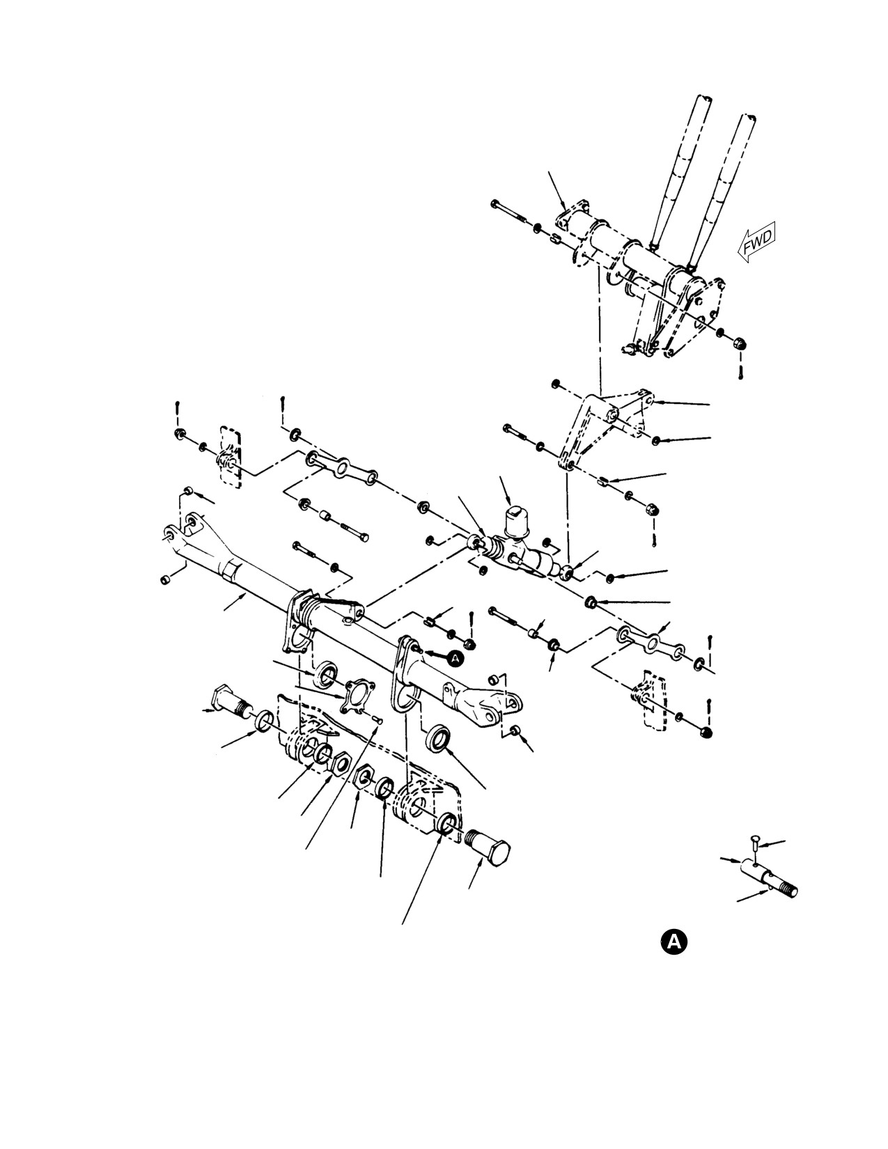
MD Helicopters, Inc.
CSP-HMI-2
MAINTENANCE MANUAL
NOTES:
CONTROLS
1.
EDGE OF BUSHING MUST PROTRUDE A MINIMUM OF
SUPPORT
0.010 IN. (0.254 MM) TO A MAXIMUM OF 0.080 IN. (2.032 MM)
BRACKET
ABOVE OUTSIDE SURFACE OF PART AFTER NUT IS TIGHTENED.
2.
MAY BE INSTALLED IN EITHER DIRECTION.
3.
MAY BE INTERCHANGED TO ALIGN ONE-WAY LOCK.
4.
INSTALLED WITH GREASE ON OUTSIDE CIRCUMFERENCE.
5.
INSTALLED WITH LOCKING COMPOUND.
6.
SHIM WASHERS AS REQUIRED TO ALIGN ONE-WAY LOCK (REMOVE
SIDELOAD).
CAUTION:
DO NOT HAMMER RIVETS: SQUEEZE ONLY.
LONGITUDINAL IDLER
BELLCRANK
SHIM WASHER
(NOTE 6)
ONE-WAY
LOCK
SLOTTED BUSHING
(NOTE 1)
INPUT END
CYCLIC STICK
PIVOT BEARING
OUTPUT
END
SHIM WASHER
(NOTE 6)
SLOTTED BUSHING
CYCLIC PITCH
(NOTE 1)
SLEEVE
PIVOT BUSHING
INTERCONNECTING
BUSHING
SUPPORT LINK
TORQUE TUBE
SUPPORT BEARING
(NOTE 5)
FLANGE
RETAINER
BUSHING
SUPPORT BOLT
(NOTE 2)
SUPPORT SPACER,
0.20 IN. (5.08 MM) WIDE
CYCLIC STICK
(NOTE 3)
PIVOT BEARING
SUPPORT SPACER, 0.430 IN.
SUPPORT BEARING
(10.29 MM) WIDE
(NOTE 4)
SUPPORT NUT
SUPPORT
RIVET
NUT
RIVET
STUD
(SEE CAUTION)
SUPPORT SPACER,
0.260 IN. (6.60 MM) WIDE
SUPPORT BOLT
SPRING PIN
(NOTE 3)
(NOTE 2)
SUPPORT SPACER, 0.520 IN.
STUD (FRICTION
(13.21 MM) WIDE
MECHANISM) (TYPICAL)
G67-1011A
Figure 412. Cyclic Torque Tube and One−Way Lock Installation
Page 421
67-10-00
Revision 21
CSP-HMI-2
MD Helicopters, Inc.
MAINTENANCE MANUAL
B. Cyclic Pitch Interconnecting Torque Tube
one-way lock support links; install
Installation (L/H Command)
attaching hardware.
(9). Install pilot's seat cover.
Consumable Materials
(Ref. Section 91−00−00)
18. Cyclic Pitch Interconnecting Torque Tube
Item
Nomenclature
Replacement (R/H Command)
CM702
Lockwire CRES
(Ref. Figure 411)
A. Cyclic Pitch Interconnecting Torque Tube
(1). Align cyclic torque tube support
Removal (R/H Command)
bearings with holes in structure fitting
Removal of torque tube is essentially the same
lugs. Place narrow support spacer on
as L/H command except note the following:
right side of each support bearing, and
install two wide support spacers and
(1). Remove pilot's collective pitch stick
support bolts.
cover.
NOTE: Support bolts may be installed from ei
(2). Remove pilot's cyclic stick and copilot's
ther direction, and two narrowest (R/H) sup
cyclic stick.
port spacers are to be interchanged for best
(3). Remove cyclic stick guards.
alignment of torque tube with one-way lock.
(4). Remove longitudinal control friction
(2).
Check that slotted bushing is in torque
mechanism.
tube arm, and fit one-way lock rod end
against unbushed lug of arm. If tighten
(5). Remove both lateral control rods from
ing of attachment bolt will apply
Sta. 67 lateral cyclic bellcrank.
sideload on the rod end, interchange
B. Cyclic Pitch Interconnecting Torque Tube
two narrowest (R/H) support spacers,
Installation (R/H Command)
and/or adjust lateral position shimming
of longitudinal idler bellcrank or
Installation of torque tube is essentially the
one-way lock rod ends until there is no
same as L/H command except note the
sideload on one-way lock control
following:
system. Check that no structural
interference results from spacer
(1). Install pilot's and copilot's lateral
interchange.
control rods (riveted rod ends) to Sta.
67 lateral cyclic bellcrank.
(3).
Without sideload on one-way lock,
(2). Install longitudinal control friction
install and tighten support nuts. Using
mechanism.
lockwire (CM702), safetywire each nut
to hole in threaded end of mating bolt.
(3). Install cyclic stick guards.
When installing lockwire do not
damage aluminum nut and bolt.
(4). Install pilot's cyclic stick and copilot's
cyclic stick.
(4).
Install pilot's lateral control rod (riveted
(5). Install pilot's collective pitch stick
rod) end to Sta. 67 lateral cyclic
cover.
bellcrank.
19. One−Way Lock Replacement
(5).
Install longitudinal control friction
mechanism.
(Ref. Figure 412)
(6).
Install cyclic stick guards.
A. One−Way Lock Removal
(7).
Install pilot's cyclic stick.
(1). Remove pilot's seat cover or inboard
collective pitch stick cover and controls
(8).
Position pilot's cyclic stick to align bolt
access door from Sta. 78.50 canted
holes in torque tube arm with holes in
bulkhead.
Page 422
Revision 29
67-10-00
MD Helicopters, Inc.
CSP-HMI-2
MAINTENANCE MANUAL
(2). Remove cyclic stick guard.
NOTE: Two narrowest (R/H) cyclic torque tube
support spacers may also be interchanged to
(3). Position pilot's cyclic stick to align holes
align one-way lock.
in one-way lock support links with bolt
(7). Without sideload on one-way lock,
that attaches forward end of one-way
secure each rod end bearing with
lock to cyclic torque tube; tighten
attaching hardware.
longitudinal friction. Disconnect rod
end from torque tube arm.
(8). Check reservoir fluid level (Ref. Sec.
12-00-00).
(4). Disconnect one-way lock lower rod end
from longitudinal idler bellcrank.
(9). Install cyclic stick guard.
(5). Disconnect upper end of each support
(10). Install pilot's seat cover or inboard
link from seat structure and remove
collective pitch stick cover and control
one-way lock with links attached.
access door.
(6). Remove two cotter pins, washers and
20. Cyclic Trim Actuator Replacement
links. Do not remove pivot bushings
(Ref. Figure 403)
from links unless replacement is
necessary.
A. Cyclic Trim Actuator Removal
B. One−Way Lock Installation
(1). Jack helicopter (Ref. Sec. 07-00-00)
until landing gear is fully extended and
(1).
Check that rod end bearing center-to-
clears ground.
center distance is correct.
(2). Remove foot fairing, controls access
(2).
Attach lower ends of links to one-way
door from Sta. 78.50 canted bulkhead
lock with bushings, washers and cotter
and open pilot's compartment floor
pins.
access door.
(3). Disconnect bonding jumper and
(3).
Align upper ends of links with mating
electrical connector from actuator
holes in seat structure fitting and
housing.
attach each link with bolt, sleeve
bushing, washer, nut and cotter pin.
(4). Disconnect upper end of trim actuator.
Keep pivot bushing with actuator
(4).
Check that slotted bushing is in place
unless actuator is being replaced.
in longitudinal idler bellcrank; then fit
lower rod end bearing against un
(5). Disconnect lower end of trim actuator.
bushed lug of bellcrank to check if
Access to attaching nut is through hole
sideloading occurs when attachment
in under-floor compartment aft
bolt is tightened. There must be no
bulkhead, near centerline beam.
sideloading of one-way lock mecha
(6). Remove trim actuator. Reinstall
nism. Arrange shim washers, as
original lower end attaching hardware
necessary, to position longitudinal idler
if actuator is being replaced; new
bellcrank and/or lower rod end for
actuator includes this hardware.
alignment without sideload.
B. Cyclic Trim Actuator Installation
(5).
Position pilot's cyclic stick to align holes
in support links with hingeline for
(1). Check trim actuator spring assembly
upper end of one-way lock and cyclic
for free play between spring and spring
torque tube arm; tighten longitudinal
adapters. Adjust spring adapter screw
friction.
until 0.010-0.050 inch (0.254-1.27 mm)
is felt while pushing or pulling on
(6).
Repeat check for sideload on one-way
spring assembly.
lock, step (4)., and arrange shim
washers, if necessary, to position upper
(2). Remove hardware supplied in housing
rod end for alignment without sideload.
end of new trim actuator.
Page 423
67-10-00
Revision 31
CSP-HMI-2
MD Helicopters, Inc.
MAINTENANCE MANUAL
(3). Check that slotted bushings are in
NOTE: Lateral actuator upper hingeline has
place in actuator housing. Place one
3/16 inch (4.7625 mm) bolt hole; longitudi
washer around each side of pivot
nal has 1/4 inch (6.35 mm) bolt hole.
bearing in center beam support lug and
align actuator housing with bearing.
(5). Connect bonding jumper. Connect
Install bolt, two washers and nut (and
electrical plug to actuator.
cotter pin if old style).
(6). With main rotor blades lifted off droop
(4). Align actuator with idler bellcrank.
stops, perform power-on operational
Check that slotted bushing is in
check of cyclic trim actuator. Actuator
bellcrank lug; install actuator pivot
must not bind throughout travel range
bushing if actuator is a replacement.
in either direction, and must maintain
Pivot bushing must rotate freely in
at least 0.015 inch (0.381 mm)minimum
actuator. Install bolt, two washers, nut
clearance with center beam structure.
and cotter pin. After bolt is tightened,
pivot bushing must not rotate in idler
bellcrank.
(7). Lower helicopter and remove jacks.
Page 424
Revision 29
67-10-00
MD Helicopters, Inc.
CSP-HMI-2
MAINTENANCE MANUAL
MAIN ROTOR FLIGHT CONTROLS
ADJUSTMENT/TEST
1. Cyclic and Collective Control System
(2). Release friction and raise pilot's
Rigging
collective stick. Position collective
rigging fixture (ST501) in outboard
Rigging of the main rotor control system must
lower end of slot in collective friction
be accomplished immediately after replace
guide link (view C).
ment of linkage that cannot be accurately
measured (by trameling, etc.) before it is
(3). Lower collective stick on rigging fixture
installed in the main rotor control system, or if
and tighten friction grip (drive gear).
helicopter operation reveals rigging deficiency.
(4). Position mixer rigging plate (ST503) on
NOTE:
mast support fitting.
D Cyclic and collective controls must be
rigged in sequence, starting with collec
NOTE: When installing the mixer rigging plate
tive controls. Control rod end bearing ad
on the 500N helicopter, removal of the split
justments are to be made to nearest half
ter bungee and bracket is required. (Ref. Sec
turn that produces correct rigging. When
67-20-30).
tightening jam nut at adjustable end of
control rods, always hold rod end with
wrench to prevent jamming of bearing.
(5).
Measure and record distance from
horizontal centerline of mast support
D On the 600N helicopter, make all rigging
bracket hingeline bolt (attaching
adjustments using the roof-mounted con
longitudinal idler bellcrank and
trol rods.
collective pitch mixer bellcrank to mast
D On the 600N helicopter, tunnel-routed
support bracket) to surface of mixer
control rods should only be adjusted if a
plate (view A). This dimension shall be
flight control component, forward of the
used as the basic dimension in rigging
roof-mounted bellcranks, has been re
the mixer controls.
placed.
(6).
Measure distance from horizontal
2. Collective Controls Rigging (L/H
centerline of bolt that attaches collec
Command) (369D/E/FF − 500N)
tive pitch mixer bellcrank to longitudi
nal pitch mixer bellcrank (view B) to
(Ref. Figure 501)
surface of mixer rigging plate; it should
be same as basic dimension recorded in
step (5). above. If not, loosen checknut,
Special Tools
disconnect upper end of collective
(Ref. Section 91−00−00)
control rod and adjust rod end (to
Item
Nomenclature
nearest half-turn of rod end bearing)
ST501
Collective rigging fixture
until dimensions are equal.
(LH command)
ST503
Mixer rigging plate
(7).
Reconnect control rod, remove collective
stick rigging fixture and check mixer
travel. With stick at down stop, center
(1). Remove main rotor blades, or manually
line of collective pitch mixer bellcrank
raise blades off droop stops by simulta
bolt (view B) should move down so that
neously lifting blade tips. All five blades
dimension recorded in step (5). above
must be off stops during rigging.
decreases not less than 0.74 inch
Padded supports should be used.
(18.796 mm).
Page 501
67-10-00
Revision 21
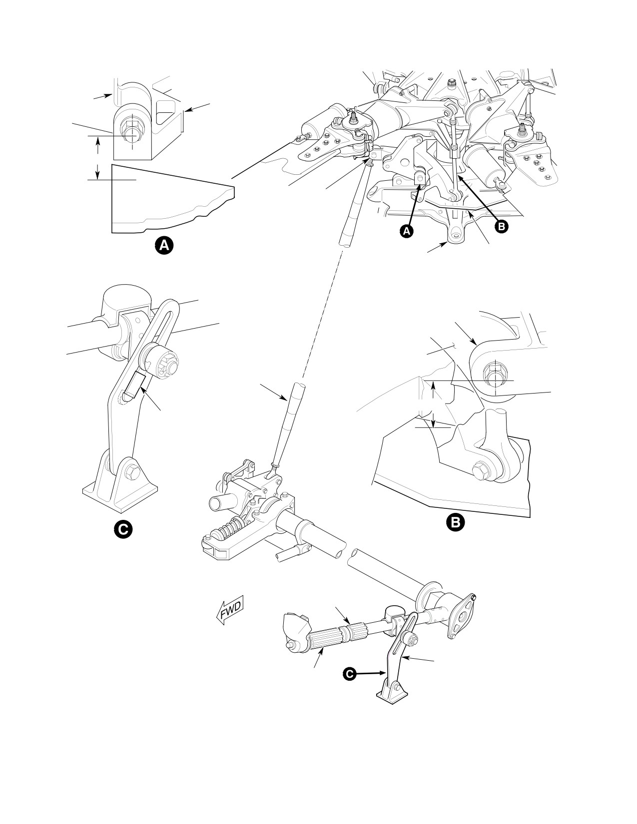
CSP-HMI-2
MD Helicopters, Inc.
MAINTENANCE MANUAL
LONGITUDINAL
MAST SUPPORT
PITCH IDLER
BRACKET
BELLCRANK
NOTE 1
BOLT (HEAD LEFT),
WASHERS, NUT,
COTTER PIN
MIXER RIGGING
MAST SUPPORT
PLATE
INITIAL RIGGING PLATE MEASUREMENT
FITTING
LONGITUDINAL PITCH
MIXER BELLCRANK
COLLECTIVE PITCH
MIXER BELLCRANK
COLLECTIVE PITCH
CONTROL ROD
NOTE 1
COLLECTIVE
RIGGING
FIXTURE
RIGGING PLATE MEASUREMENT
FIXTURE INSTALLATION
CONTROL
FRICTION GRIP
(DRIVE GEAR)
NOTES:
COLLECTIVE FRICTION
1.
ACTUAL DISTANCE TO BE MEASURED
PILOT'S COLLECTIVE
GUIDE LINK
AND RECORDED.
PITCH STICK
2.
TO BE SAME AS ACTUAL DISTANCE
MEASURED (VIEW A). (REFER TO TEXT)
3.
ELASTOMER RING THIS SIDE ON
G67-1012-1
Figure 501. Main Rotor Control System Rigging (369D/E/FF − 500N) (Sheet 1 of 3)
Page 502
Revision 21
67-10-00
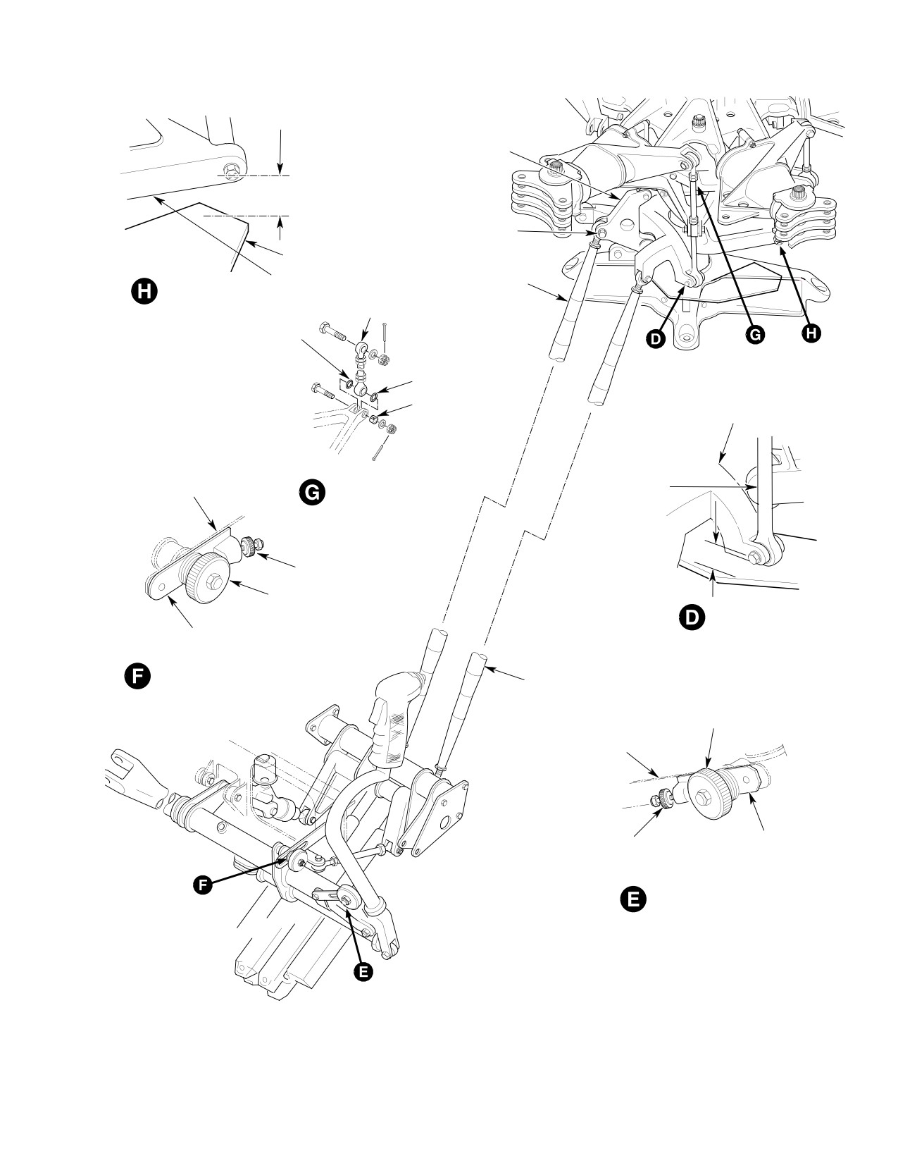
MD Helicopters, Inc.
CSP-HMI-2
MAINTENANCE MANUAL
LONGITUDINAL
PITCH IDLER
NOTE 2
BOLT (HEAD LEFT),
WASHERS, NUT,
MIXER RIGGING PLATE
COTTER PIN
LONGITUDINAL PITCH
LONGITUDINAL PITCH
CONTROL MIXER
MIXER TRAVEL
MIXER BELLCRANK
PITCH CONTROL ROD
ELASTOMER RING
(NOTE 3)
ELASTOMER RING
SLOTTED BUSHING
LATERAL BELLCRANK
LONGITUDINAL
FRICTION GUIDE
STATIONARY
PITCH CONTROL ROD
LINK
SWASHPLATE
INSTALLATION (5 PLACES)
MIXER LINK
NOTE 2
KNURLED THUMBNUT
FRICTION
KNOB
MIXER TRAVEL
CYCLIC STICK LONGITUDINAL
RIGGING FIXTURE
LONGITUDINAL RIGGING
FIXTURE INSTALLATION
LATERAL PITCH
CONTROL ROD
FRICTION KNOB
LATERAL FRICTION
GUIDE LINK
CYCLIC STICK LATERAL
KNURLED THUMBNUT
RIGGING FIXTURE
LATERAL RIGGING
FIXTURE INSTALLATION
G67-1012-2
Figure 501. Main Rotor Control System Rigging (369D/E/FF − 500N) (Sheet 2 of 3)
Page 503
67-10-00
Revision 21
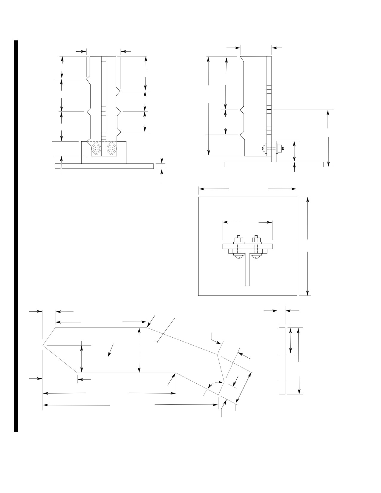
CSP-HMI-2
MD Helicopters, Inc.
MAINTENANCE MANUAL
0.75 IN. (19.05 MM)
0.75 IN. (19.05 MM)
1.190 IN.
(30.226 MM)
FWD
0.45 IN. (11.43 MM)
0.74 IN.
0.76 IN. (19.304 MM)
1.190 IN.
(18.796 MM)
(30.226 MM)
UP
0.43 IN.
2.25 IN.
(10.922 MM)
0.74 IN. (18.796 MM)
(57.15 MM)
RT
0.43 IN. (10.922 MM)
REF
NOM
NOM
NOM
0.57 IN.
0.50 IN. (12.70 MM)
0.74 IN. (18.796 MM)
(14.478 MM)
0.50 IN.
0.57 IN.
1.92 IN. (48.564 MM) REF
0.74 IN.
(12.70 MM)
(14.478 MM)
(18.796 MM)
LFT
AFT
DN
SIDE VIEW
0.32 IN.
1.05 IN
FRONT VIEW
(26.67MM)
(8.128 MM)
0.125 IN.
2.25 IN. (57.15 MM)
(3.175 MM)
1.00 IN.
GENERAL NOTES FOR BUILDING FIELD RIGGING AID:
(25.4 MM)
1.
MAKE FROM T-ANGLE STOCK TO DIMENSIONS SHOWN.
2.
SCREWS, NUTS AND WASHERS AS REQUIRED.
3.
HOLES IN VERTICAL T-ANGLE TO BE SLOTTED TO ADJUST
2.25 IN.
TO MIXER SUPPORT BOLT NOMINAL DIMENSION.
(57.15 MM)
4.
SCRIBE MARKING ON VERTICAL T-ANGLE AS SHOWN.
5.
MANUFACTURE FROM 2024-T4 AL ALY PLATE.
6.
IMPRESSION STAMP PART NO. AND INSTRUCTIONS.
SURFACE TO BE FLAT AFTER STAMPING.
TOP VIEW
0.81 IN. (20.57 MM)
.09 R
0.375 IN. (9.525 MM)
NOTE 5
1.75 IN. (44.45 MM)
6.71 IN. (170.43 MM)
1.12 IN. (28.45 MM)
1.75 IN. (44.45 MM)
NOTE 6
2.75 IN. (69.85 MM)
369A9930
THIS SIDE UP
4.18 IN.
(106.17 MM)
2.18 IN. (55.37 MM)
.09 R
8.56 IN. (217.42 MM)
90°
11.38 IN. (289.05 MM)
2.18 IN. (55.37 MM)
0.94 IN. (23.88 MM)
FIELD RIGGING AID
G67-1012-3E
Figure 501. Main Rotor Control System Rigging (369D/E/FF − 500N) (Sheet 3 of 3)
Page 504
Revision 42
67-10-00
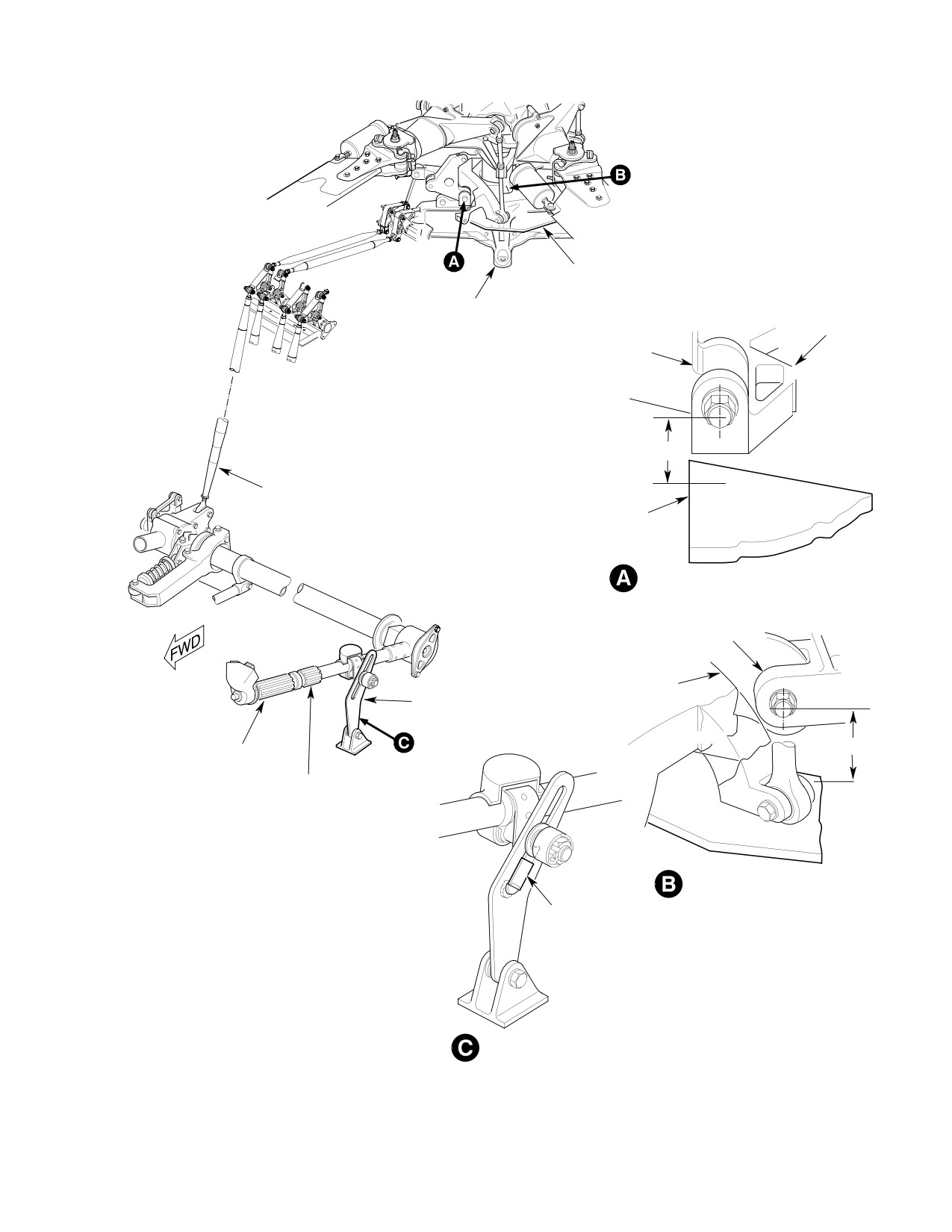
MD Helicopters, Inc.
CSP-HMI-2
MAINTENANCE MANUAL
MIXER
RIGGING PLATE
MAST
MAST
SUPPORT
SUPPORT FITTING
BRACKET
LONGITUDINAL PITCH
IDLER BELLCRANK
NOTE 1
COLLECTIVE MIXER
CONTROL ROD
MIXER RIGGING
PLATE
INITIAL RIGGING PLATE MEASUREMENT
LONGITUDINAL PITCH
MIXER BELLCRANK
COLLECTIVE PITCH
COLLECTIVE FRICTION
MIXER BELLCRANK
GUIDE LINK
NOTE 2
PILOT'S COLLECTIVE
PITCH STICK
CONTROL FRICTION GRIP
(DRIVE GEAR)
RIGGING PLATE MEASUREMENT
COLLECTIVE RIGGING
NOTES:
FIXTURE
1.
ACTUAL DISTANCE TO BE MEASURED AND RECORDED.
2.
TO BE SAME AS ACTUAL DISTANCE MEASURED
IN VIEW A (REFER TO TEXT).
3.
ELASTOMER RING THIS SIDE ON CURRENT
CONFIGURATION ONLY.
FIXTURE INSTALLATION
6G67-037-1B
Figure 502. Rigging Main Rotor Control System (600N) (Sheet 1 of 3)
Page 505
67-10-00
Revision 34
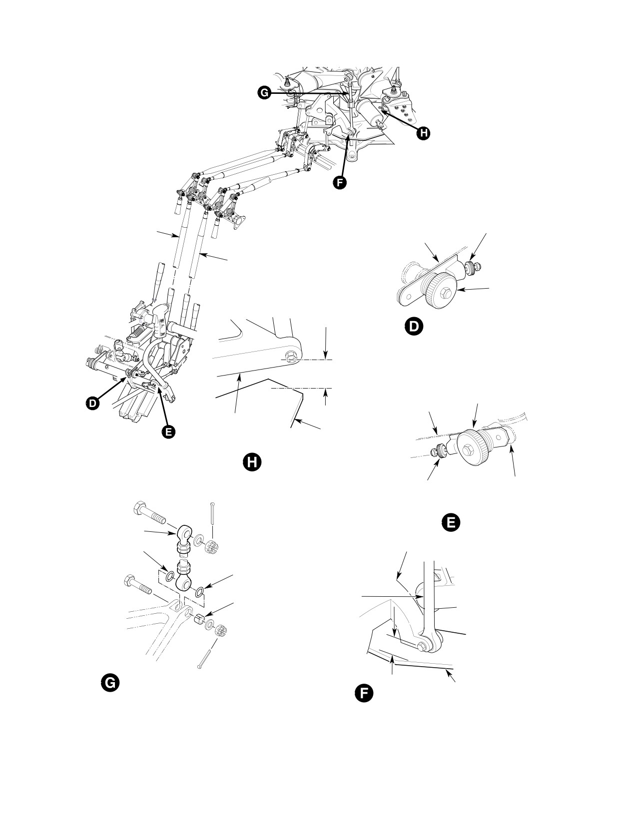
CSP-HMI-2
MD Helicopters, Inc.
MAINTENANCE MANUAL
LONGITUDINAL MIXER
LONGITUDINAL
KNURLED
CONTROL ROD
FICTION GUIDE
THUMBNUT
(CYCLIC)
LINK
LATERAL MIXER
CONTROL ROD
(CYCLIC)
FRICTION KNOB
LONGITUDINAL RIGGING
FIXTURE INSTALLATION
NOTE 2
LATERAL FRICTION
FRICTION KNOB
GUIDE LINK
LONGITUDINAL PITCH
MIXER BELLCRANK
MIXER RIGGING PLATE
MIXER TRAVEL
CYCLIC STICK LATERAL
KNURLED
RIGGING FIXTURE
THUMBNUT
LATERAL RIGGING
FIXTURE INSTALLATION
PITCH CONTROL ROD
LATERAL BELLCRANK
ELASTOMER RING
(NOTE 3)
ELASTOMER
RING
STATIONARY
SLOTTED
SWASHPLATE
BUSHING
MIXER LINK
NOTE 2
PITCH CONTROL ROD
INSTALLATION (6 PLACES)
MIXER RIGGING PLATE
MIXER TRAVEL
6G67-037-2A
Figure 502. Rigging Main Rotor Control System (600N) (Sheet 2 of 3)
Page 506
Revision 21
67-10-00
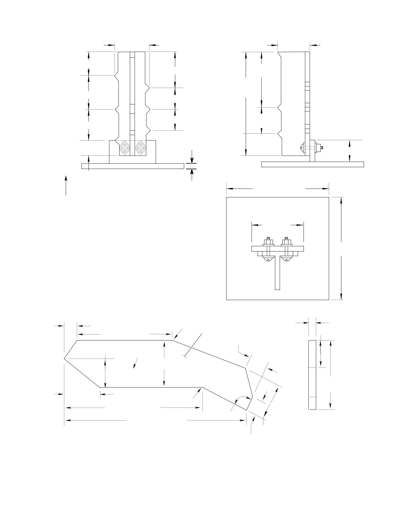
MD Helicopters, Inc.
CSP-HMI-2
MAINTENANCE MANUAL
0.75 IN. (19.05 MM)
1.05 IN.
0.75 IN. (19.05 MM)
(26.67 MM)
FWD
0.48 IN. (12.192 MM)
1.05 IN.
0.83 IN.
0.79 IN. (20.066 MM)
(26.67 MM)
(21.082 MM)
DN
0.37 IN
2.25 IN.
(9.398 MM)
(57.15 MM)
0.83 IN. (21.082 MM)
RT
REF
0.37 IN (9.398
NOM
NOM
NOM
0.65 IN.
0.52 IN. (13.208 MM)
0.71 IN. (18.034 MM)
0.52 IN.
(16.51 MM)
0.65 IN.
(13.208 MM)
0.71 IN.
(16.51 MM)
LFT
(18.034 MM)
AFT
UP
0.50 IN. (12.7 MM)
0.29 IN.
FRONT VIEW
SIDE VIEW
(7.366 MM)
0.125 IN.
2.25 IN. (57.15 MM)
(3.175 MM)
1.00 IN.
(25.4 MM)
GENERAL NOTES FOR BUILDING FIELD RIGGING AID:
2.25 IN.
1.
MAKE FROM T-ANGLE STOCK TO DIMENSIONS SHOWN.
(57.15 MM)
2.
SCREWS, NUTS AND WASHERS AS REQUIRED.
3.
HOLES IN VERTICAL T-ANGLE TO BE SLOTTED TO ADJUST
TO MIXER SUPPORT BOLT NOMINAL DIMENSION.
4.
SCRIBE MARKING ON VERTICAL T-ANGLE AS SHOWN.
5.
MANUFACTURE FROM 2024-T4 AL ALY PLATE.
6.
IMPRESSION STAMP PART NO. AND INSTRUCTIONS.
SURFACE TO BE FLAT AFTER STAMPING.
TOP VIEW
0.375 IN. (9.525 MM)
0.81 IN. (20.57 MM)
.09 R
NOTE 5
1.75 IN. (44.45 MM)
6.71 IN. (170.43 MM)
1.12 IN. (28.45 MM)
1.75 IN. (44.45 MM)
NOTE 6
2.75 IN. (69.85 MM)
369A9930
THIS SIDE UP
4.18 IN.
(106.17 MM)
2.18 IN. (55.37 MM)
.09 R
8.56 IN. (217.42 MM)
90°
11.38 IN. (289.05 MM)
2.18 IN. (55.37 MM)
0.94 IN. (23.88 MM)
FIELD RIGGING AID
6G67-037-3B
Figure 502. Rigging Main Rotor Control System (600N) (Sheet 3 of 3)
Page 507
67-10-00
Revision 34
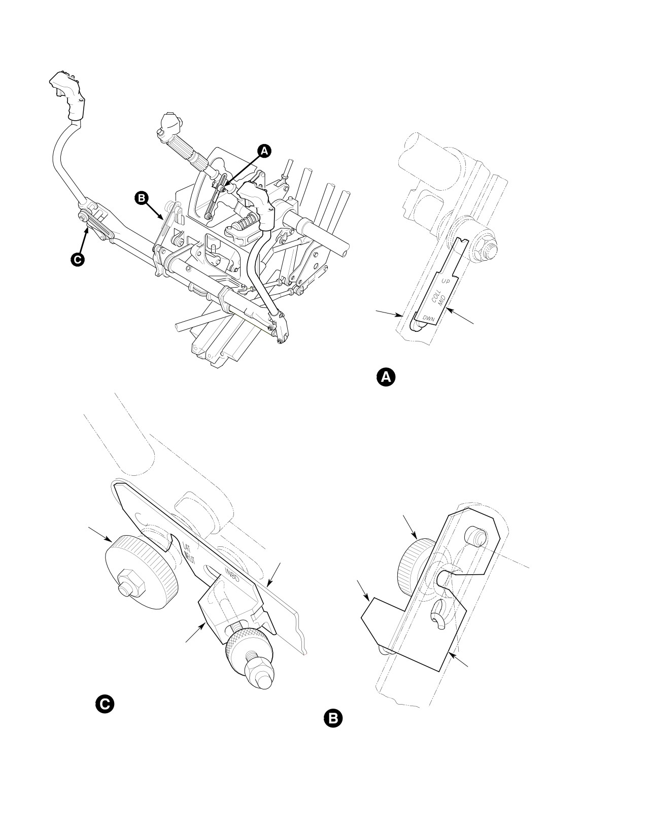
CSP-HMI-2
MD Helicopters, Inc.
MAINTENANCE MANUAL
COLLECTIVE
FRICTION GUIDE
COLLECTIVE RIGGING
FIXTURE
COLLECTIVE RIGGING
FIXTURE INSTALLATION
LONGITUDINAL
FRICTION KNOB
FRICTION
KNOB
LATERAL
FRICTION
CYCLIC STICK
GUIDE LINK
LONGITUDINAL
RIGGING FIXTURE
CYCLIC STICK LATERAL
RIGGING FIXTURE
LONGITUDINAL FRICTION
GUIDE LINK
CYCLIC STICK LATERAL RIGGING
FIXTURE INSTALLATION
CYCLIC STICK LONGITUDINAL
RIGGING FIXTURE INSTALLATION
G67-1013
Figure 503. Cyclic and Collective Controls Rigging Tools (R/H Command)
Page 508
Revision 21
67-10-00
MD Helicopters, Inc.
CSP-HMI-2
MAINTENANCE MANUAL
NOTE: To facilitate field rigging of the collec
used in inboard lower end of collective friction
tive control (up and down) and the cyclic
guide slot.
control (both forward and aft, and right and
left) a field rigging aid may be fabricated as
4. Collective Control System Rigging (L/H
illustrated (Ref. Figure 501, Sheet 3). If the
Command) (600N)
mixer bellcranks are in dimension with ref
(Ref. Figure 502)
erence to the mixer rigging plate (ST503)
the collective and cyclic controls are proper
ly rigged. The dimension attained in steps
Special Tools
(7). and (8). shall correspond to the dimen
(Ref. Section 91−00−00)
sions marked on the field rigging aid. If the
Item
Nomenclature
dimensions attained do not correspond, full
ST501
Collective rigging fixture
rigging procedures must be performed.
(LH command)
ST503
Mixer rigging plate
(8). With stick at up stop, centerline of
ST504
Longitudinal rigging fixture
collective pitch mixer bellcrank bolt
(LH command)
should move up so that dimension
ST506
Lateral rigging fixture
recorded in step (5). above increases
(LH command)
minimum of 0.74 inch (18.796 mm).
ST511
Test fixture
Do not adjust control rod end be
CAUTION
(1). Remove main rotor blades, or manually
yond witness hole. Tighten jam
raise blades off droop stops by simulta
nut after final adjustment. Failure to ob
neously lifting blade tips. All six blades
serve this precaution can result in parts
must be off stops during rigging.
damage and/or equipment failure.
Padded supports should be used.
(9). If necessary, adjust rod end of collective
(2). Release friction and raise pilot's
pitch control rod to meet limits speci
collective stick. Position collective
fied in steps (7). and (8). above. When
rigging fixture (ST501) in outboard
adjustment is complete, tighten jamnut
lower end of slot in collective friction
and make certain that length of control
guide link (view C).
rod does not change.
NOTE: The collective bungee has very high
(10). Remove mixer rigging plate. On the
over-center spring pressure. Ensure collec
500N helicopter reinstall the spitter
tive stick is fully seated on rigging fixture or
bungee and bracket. (Ref. Sec
rigging may not be correct.
67-20-30).
(3). Lower collective stick on rigging fixture
(11). Reconnect collective pitch control rod.
and tighten friction lock.
3. Collective Controls Rigging (R/H
(4). Adjust longitudinal cyclic trim for
Command) (369D/E/FF − 500N)
no-load and install longitudinal cyclic
rigging fixture (ST504) (Ref. View D).
(Ref. Figure 501 and Figure 503)
(5). Adjust lateral cyclic trim for no-load
and install lateral cyclic rigging fixture
Special Tools
(ST506) (Ref. View E).
(Ref. Section 91−00−00)
Item
Nomenclature
NOTE: For both longitudinal and lateral cyclic
ST502
Collective rigging fixture
rigging fixtures, ensure that the bolt of the
(RH command)
friction lock is engaged in the slot of the rig
ging fixture and that the hook of the fixture
is properly engaged with the checknut tight
Collective control rigging for the R/H command
ened.
helicopter is accomplished according to
instructions for L/H command helicopters,
(6). Position mixer rigging plate (ST503) on
except collective rigging fixture (ST502) is
mast support fitting.
Page 509
67-10-00
Revision 21
CSP-HMI-2
MD Helicopters, Inc.
MAINTENANCE MANUAL
NOTE: To facilitate field rigging of the collec
(a). With collective stick at down-stop,
tive control (up and down) and the cyclic
centerline of bolt in collective bell
control (both forward and aft and right and
crank (369N2664) shall move down a
left) a field rigging aid may be fabricated as
minimum of 0.71 inch (18.0 mm)
illustrated (Ref. Figure 502, Sheet 3). If the
below nominal setting.
mixer bellcranks are in dimension with ref
(b). With collective stick at up-stop,
erence to the mixer rigging plate (ST503)
centerline of bolt in collective bell
the collective and cyclic controls are proper
crank (369N2664) shall move up a
ly rigged. The dimension attained in the fol
minimum of 0.83 inch (21.0 mm)
lowing paragraphs shall correspond to the
above nominal setting.
dimensions marked on the field rigging aid.
If the dimensions attained do not corre
5. Collective Controls Rigging (R/H
spond, full rigging procedures must be per
Command) (600N)
formed.
(Ref. Figure 502 and Figure 503) Collective
control rigging for the R/H command helicopter
(7). Using a six inch (16 cm) scale, measure
is accomplished according to instructions for
and record distance from rigging
L/H command helicopters, except the following
plate-to-collective hinge bolt center,
rigging fixtures must be substituted.
this is your nominal setting, or, position
test fixture (ST511) on rigging plate
Special Tools
and adjust NOM indicator to centerline
(Ref. Section 91−00−00)
of collective hinge bolt.
Item
Nomenclature
ST502
Collective rigging fixture
Do not allow test fixture points
CAUTION
(RH command)
to scribe or mark the bolts.
ST503
Mixer rigging plate
ST505
Longitudinal rigging fixture
NOTE: Do not change the setting of the test fix
(RH command)
ture. This setting will be the basic NOMI
ST507
Lateral rigging fixture
NAL for locating, to the nearest half turn of
(RH command)
the respective control rod end fitting, the
ST511
Test fixture
height of the bolts.
(a). Adjust collective control rod so
6. Cyclic Controls Rigging (L/H Command)
centerline of bolt of the collective
(369D/E/FF − 500N)
bellcrank (369N2664) is at NOM, to
(Ref. Figure 501)
nearest half-turn on rod end bearing.
Special Tools
(b). Adjust longitudinal control rod so
(Ref. Section 91−00−00)
centerline of bolt of the longitudinal
Item
Nomenclature
bellcrank (369N2666) is at NOM, to
ST501
Collective rigging fixture
nearest half-turn on rod end bearing.
(LH command)
ST503
Mixer rigging plate
(c). Adjust lateral control rod so center
ST504
Longitudinal rigging fixture
line of bolt of the lateral bellcrank
(LH command)
(369N2670) is at NOM, to nearest
ST506
Lateral rigging fixture
half-turn on rod end bearing.
(LH command)
(8). Remove collective rigging fixture and
check travel as follows:
NOTE: All cyclic control rigging is done with
collective controls at mid-position.
NOTE: Adjust rod end, as required, to obtain
(1). Remove main rotor blades, or manually
the following limits.
raise blades off droop stops by simulta
Page 510
Revision 24
67-10-00
MD Helicopters, Inc.
CSP-HMI-2
MAINTENANCE MANUAL
neously lifting blade tips. All five blades
NOTE: Field rigging aid (Ref. Figure 501,
must be off stops during rigging.
Sheet 3) may be used to check dimensions
Padded supports should be used.
attained in steps (4). and (5).. If dimensions
attained do not correspond with dimensions
(2).
Release friction and raise pilot's
shown on rigging aid, full rigging proce
collective stick. Position collective
dures must be performed.
rigging fixture (ST501) in outboard
(9). Reposition mixer rigging plate to clear
lower end of slot in collective friction
longitudinal pitch mixer bellcrank.
guide link (view C).
With stick at aft stop, centerline of
(3).
Lower collective stick on rigging fixture
longitudinal pitch mixer bellcrank bolt
and tighten friction grip (drive gear).
(view B) should move down so that
basic dimension recorded in step (3).
(4).
Position mixer rigging plate (ST503) on
above decreases minimum of 0.570 inch
mast support fitting.
(14.478 mm).
(5).
Loosen longitudinal friction knob and
Do not adjust control rod beyond
CAUTION
set longitudinal cyclic trim for no load
witness hole. Tighten jamnut af
by neutralizing cyclic stick. Position
ter final adjustment. Failure to observe this
cyclic stick so that longitudinal rigging
precaution can result in parts damage and/
fixture (ST504) fits in outboard side of
or equipment failure.
slot in longitudinal friction guide link.
(10).
If necessary, adjust rod end of longitudi
(Index pin of fixture butts against
nal pitch control rod to meet limits
forward end of slot, and friction knob
specified in steps (4). and (5). above.
stud fits in fixture detent - view F.)
Adjust carefully; tolerance is only 1/2
turn. When adjustment is complete,
(6).
Secure fixture hook in aft end of slot.
tighten jamnut and ensure that length
Tighten knurled thumbnut to seat
of control rod does not change.
bushing at forward end and tighten
friction knob.
(11).
Reconnect control rod to longitudinal
pitch idler.
(7).
Measure and record distance from
horizontal centerline of bolt at aft end
(12).
Reinstall longitudinal rigging fixture;
of longitudinal pitch mixer bellcrank
reposition and secure mixer rigging
(view H) to surface of mixer rigging
plate.
plate. It should be same as distance
(13).
Loosen friction knob and set lateral
from horizontal centerline of mast
cyclic trim for no load by neutralizing
support bracket hingeline bolt to
cyclic stick. Position cyclic stick so that
surface of mixer plate (Ref. Collective
lateral rigging fixture (ST506) fits in
Controls Rigging (L/H Command), step
forward side of slot in lateral friction
(5).). If not, loosen jamnut, disconnect
guide link. (Index pin of fixture butts
longitudinal pitch control rod and
against outboard end of slot, and
adjust rod end, to nearest half turn of
friction knob stud fits in fixture detent
rod end bearing, until dimensions are
- view E.)
equal. This will be basic dimension for
cyclic control rigging.
(14).
Secure fixture hook in inboard end of
slot, tighten knurled thumbnut to seat
(8).
Reconnect control rod, remove longitu
bushing at outboard end, and tighten
dinal stick rigging fixture and check
friction knob.
mixer travel. With stick at forward
stop, centerline of longitudinal pitch
(15).
Measure distance from horizontal
mixer bellcrank bolt (view B) should
centerline of bolt connecting lateral
move up so that basic dimension
bellcrank to stationary swashplate
recorded in step (7). above is increased
mixer link to (view D) surface of mixer
minimum of 1.19 inches (3.0226 cm), or
rigging plate; it should be same as basic
a maximum of 1.22 inches (3.0988 cm).
dimension recorded in step (3).. If not,
Page 511
67-10-00
Revision 38
CSP-HMI-2
MD Helicopters, Inc.
MAINTENANCE MANUAL
loosen checknut, disconnect lateral
Check for interference between
CAUTION
pitch control rod and adjust rod end (to
rod end bearings and lugs of
nearest half-turn on rod end bearing)
pitch control housing. Adjust bearings as re
until dimensions are equal.
quired to provide clearance.
NOTE: Next step establishes initial adjust
ment of main rotor pitch controls links. Fi
(16). Reconnect control rod, remove lateral
nal adjustment is to be made by tracking
stick rigging fixture and check mixer
and autorotation rpm setting (Ref. Sec.
travel. With stick at left stop, centerline
18-10-00).
of lateral bellcrank bolt (view D) should
move down so that basic dimension
(21).
Remove and adjust length of each pitch
recorded in step (3). decreases a
control link (view G) so that centerline-
minimum of 0.50 inch (12.70 mm) or a
to-centerline distance between rod-end
maximum of 0.53 inch (13.462 mm).
bearings is 6.25 inches (15.875 cm).
Then install the pitch control links.
NOTE: The field rigging aid (Ref. Figure 501,
(22).
With collective stick full down and
sheet 3) may be used to check dimensions
cyclic stick full forward and full left,
attained in steps (12). and (13).. If the di
check clearance between the rotating
mensions attained do not correspond with
swashplate and the longitudinal pitch
dimensions shown on the rigging aid, full
idler bellcrank. Minimum clearance is
rigging procedures must be performed.
0.125 inch (3.175 mm). Adjust the
collective control rod as required.
(17). With stick at right stop, centerline of
(23).
With collective stick full up and cyclic
lateral bellcrank bolt should move up so
stick full left (any position fore or aft),
that basic dimension recorded in step
check clearance between lateral
(3). increases minimum of 0.43 inch
bellcrank and, collective pitch mixer
(10.922 mm).
bellcrank of the mixer controls. Mini
mum clearance is 0.030 inch (0.762
mm). Adjust lateral control rod as
Do not adjust control rod beyond
required.
CAUTION
witness hole. Tighten jamnut af
(24).
With collective stick full down and
ter final adjustment. Failure to observe this
cyclic stick full aft, check clearance
precaution can result in parts damage and/
between the aft longitudinal bellcrank
or equipment failure.
and the mast base. Minimum clearance
is 0.030 inch (0.762 mm). Adjust
longitudinal control rod (preferably) or
(18). If necessary, adjust rod end of lateral
collective control rod as required.
pitch control rod to meet limits speci
fied in steps (12). and (13). above. When
(25).
With collective stick full up and cyclic
adjustment is complete, tighten jamnut
stick full forward and full left, check
and make certain that length of control
clearance between rotating swashplate
rod does not change.
and scissors fitting. Also check clear
ance between scissors rotating link and
lower hub shoe. Minimum clearance in
(19). Reconnect control rod to lateral bell
both cases is 0.030 inch (0.762 mm).
crank.
Rotate hub 360 degrees to determine
location of minimum clearance. Adjust
collective control rod as required.
(20). Loosen friction control, friction knob,
knurled thumbnuts and hooks of
(26).
Repeat step (21). above with collective
rigging fixture and remove all three
stick full up and cyclic stick full forward
fixtures.
and full right.
Page 512
Revision 21
67-10-00
MD Helicopters, Inc.
CSP-HMI-2
MAINTENANCE MANUAL
(27).
With collective stick full up and cyclic
(2). Use lateral rigging fixture (ST507) on
stick full aft and full left, check clear
forward side of lateral friction guide,
ance between scissors link and edge of
with fixture cutout positioned over
pocket in rotating swashplate. Mini
friction knob stud (view C). Secure
mum clearance is 0.006 inch (0.1524
fixture hook in lower inboard end of
mm). Rotate hub 360 degrees to
slot, tighten knurled thumbnut to seat
determine location of minimum clear
bushing at upper outboard end and
ance. Repeat clearance check with
tighten lateral friction knob.
cyclic stick full aft and full right.
8. Cyclic Controls Rigging (L/H Command)
(28).
Repeat steps (17). thru (22). above to
(600N)
recheck all clearances.
(Ref. Figure 502)
(29).
Repeat steps (7). of Collective Controls
Rigging, step (4)., and steps (9). thru
Special Tools
(15). of Cyclic Controls Rigging, to
(Ref. Section 91−00−00)
recheck mixer control motion travels
Item
Nomenclature
and see that minimums are met.
ST501
Collective rigging fixture
(LH command)
(30).
Install main rotor blades or remove
supports and simultaneously lower all
ST503
Mixer rigging plate
five blades to normal position.
ST504
Longitudinal rigging fixture
(LH command)
(31).
Track main rotor blades and adjust
ST506
Lateral rigging fixture
autorotation rpm (Ref. Sec. 18-10-00).
(LH command)
7. Cyclic Controls Rigging (R/H Command)
NOTE: All cyclic control rigging is done with
(369D/E/FF − 500N)
collective stick on rigging fixture.
(Ref. Figure 501 and Figure 503) Rigging of
(1). Remove main rotor blades, or manually
cyclic controls for the R/H command helicopter
raise blades off droop stops by simulta
is accomplished according to instructions for
neously lifting blade tips. All six blades
L/H command helicopters except as follows:
must be off stops during rigging.
Padded supports should be used.
Special Tools
(2). Release friction and raise pilot's
(Ref. Section 91−00−00)
collective stick. Position collective
Item
Nomenclature
rigging fixture (ST501) in outboard
ST505
Longitudinal rigging fixture
lower end of slot in collective friction
(RH command)
guide link (view C).
ST507
Lateral rigging fixture
(3). Lower collective stick on rigging fixture
(RH command)
and tighten friction grip (drive gear).
(4). Adjust lateral cyclic trim for no-load
(1). Use longitudinal rigging fixture
and install lateral cyclic rigging fixture
(ST505) on outboard side of longitudi
(ST506).
nal friction guide, with fixture cutout
positioned over friction knob stud.
(5). Position mixer rigging plate (ST503) on
Bushing end of fixture butts against
mast support fitting.
upper end of slot in guide (Ref.
Figure 503, view B). Secure fixture
(6). Check longitudinal travel as follows:
hook in lower end of slot, tighten
knurled thumbnut to seat bushing at
NOTE: Adjust rod end, as required, to obtain
upper end, and tighten friction knob.
the following limits.
Page 513
67-10-00
Revision 21
CSP-HMI-2
MD Helicopters, Inc.
MAINTENANCE MANUAL
(a). With cyclic stick at forward stop,
(369N2670). The minimum allowable
centerline of bolt in longitudinal
clearance shall be 0.125 inch (3.175
bellcrank (369N2666) shall move up
mm). Adjust collective control rod as
a minimum of 1.05 inches (26.67 mm)
required.
above centerline of collective hinge
(13).
With collective stick full up and cyclic
bolt. Reposition mixer plate to clear
stick full left (any position fore and aft),
longitudinal bellcrank.
check for interference between lateral
(b). With cyclic stick at aft stop, center
bellcrank (369N2670) and collective
line of bolt in bellcrank (369N2666)
bellcrank (369N2664) of mixer controls.
shall move down a minimum of 0.65
When there is interference, lengthen
inch (16.51 mm) below centerline of
lateral mixer control rod (369A7012) to
collective hinge bolt.
maintain a minimum allowable clear
ance of 0.030 inch (0.762 mm).
(7). Adjust longitudinal cyclic trim for
(14).
With collective stick full down and
no-load and install longitudinal cyclic
cyclic stick full aft, check clearance
rigging fixture (ST504).
between aft longitudinal bellcrank
(8). Remove lateral cyclic rigging fixture.
(369N2668) and mast base. The
minimum allowable clearance shall be
(9). Check lateral travel as follows:
0.030 inch (0.762 mm). When clearance
is less than 0.030 inch (0.762 mm),
NOTE: Adjust rod end, as required, to obtain
adjust longitudinal control rod (prefera
the following limits.
ble) or collective control rod.
(a). With cyclic stick at left stop, center
(15).
With collective stick full up and cyclic
line of bolt head (fwd end) of bolt in
stick full forward and full left, check
lateral bellcrank (369N2670) shall
clearance between rotating swashplate
move down a minimum of 0.52 inch
and scissors fitting. Also check clear
(13.208 mm) below centerline of
ance between scissors fitting and lower
collective hinge bolt.
hub shoe. The minimum allowable
clearance in both cases is 0.030 inch
(b). With cyclic stick at right stop,
(0.762 mm). Rotate hub 360 degrees to
centerline of bolthead in lateral
determine location of minimum clear
bellcrank (369N2670) shall move up
ance. Adjust collective mixer control rod
a minimum of 0.37 inch (9.398 mm)
as required.
above centerline of collective hinge
bolt.
(16).
Repeat above step with collective stick
full up and cyclic stick full forward and
Do not adjust control rod beyond
CAUTION
full right.
witness hole. Tighten jamnut af
ter final adjustment. Failure to observe this
(17).
With collective stick full up and cyclic
precaution can result in parts damage and/
stick full aft and full left, check clear
or equipment failure.
ance between scissors link and edge of
pocket in rotating swashplate. Rotate
(10). Set pitch change links at nominal 6.25
hub 360 degrees to determine location
inch (158.75 mm).
of minimum clearance. Minimum
clearance is 0.006 inch (0.152 mm).
NOTE: Final adjustment of pitch change links
will be accomplished during tracking and
(18).
Repeat clearance check with cyclic stick
autorotation rpm settings.
full aft and full right.
(11). Remove all rigging fixtures.
(19).
Recheck all clearances from previous
steps.
(12). With collective stick full down and
cyclic stick forward and full left, check
(20).
Recheck control motion travels and
clearance between rotating swashplate
check that minimum clearances are
and longitudinal pitch idler bellcrank
met.
Page 514
Revision 21
67-10-00
MD Helicopters, Inc.
CSP-HMI-2
MAINTENANCE MANUAL
(21). Install main rotor blades or remove
(2). Remove backlash shims and gear shaft
supports and simultaneously lower all
assembly from socket housing.
six blades to normal position.
NOTE:
Note locations, mark and measure re
(22). Track main rotor blades and adjust
moved shim thicknesses to ensure reas
autorotation rpm (Ref. Sec. 18-10-00).
sembly at same places.
(3). Ensure that inboard collective pitch
9. Cyclic Controls Rigging (R/H Command)
stick socket internal gears are aligned
(600N)
and mated. If gears are correctly
(Ref. Figure 502 and Figure 503) Rigging of
aligned and mated, do not perform
cyclic controls for the R/H command helicopter
steps (4). thru (6). and continue with
is accomplished according to instructions for
step (7). If gears are misaligned,
L/H command helicopters except as follows:
perform steps (4). thru (6).
(4). Disconnect link from idler and remove
Special Tools
link and bellcrank as an assembly from
(Ref. Section 91−00−00)
gearshaft of inboard collective pitch
Item
Nomenclature
stick socket by removing bolt, two
ST501
Collective rigging fixture
washers and nut.
(LH command)
NOTE: During gear shaft rotation to establish
ST503
Mixer rigging plate
correct mid-position for gearshaft and pin
ST505
Longitudinal rigging fixture
ion in next step, gearshaft cutout is seen
(RH command)
through hole in rear of socket assembly
ST507
Lateral rigging fixture
housing.
(RH command)
(5). Rotate end of gas producer interconnect
torque tube in pilot's stick socket
(1).
Use longitudinal rigging fixture
housing until gear shaft-to-N1 pinion
(ST505) on outboard side of longitudi
gearmesh is at mid-travel and N1
nal friction guide, with fixture cutout
pinion gear wide toothspace is posi
positioned over friction knob stud.
tioned at approximately one o'clock.
Bushing end of fixture butts against
View pinion by looking aft into open
upper end of slot in guide). Secure
end of collective stick socket.
fixture hook in lower end of slot, tighten
knurled thumbnut to seat bushing at
(6). Attach inboard collective pitch stick
upper end, and tighten friction knob.
socket bellcrank to gearshaft and link
to idler. Bellcrank attachment bolt
(2).
Use lateral rigging fixture (ST507) on
must be installed with head slightly
forward side of lateral friction guide,
down and forward.
with fixture cutout positioned over
friction knob stud. Secure fixture hook
NOTE: Inboard collective N1 pinion gear must
in lower inboard end of slot, tighten
be held in correct position while steps (7).
thru (9). below are performed. If available,
knurled thumbnut to seat bushing at
optional copilot's collective pitch stick can be
upper outboard end and tighten lateral
used to hold gear in position by setting copi
friction knob.
lot's throttle grip attachment bolts at ap
proximately seven o'clock (looking aft) be
10. Gas Producer Linkage Adjustment
fore engaging stick and socket.
(Ref. Figure 504 and Figure 505) Adjust gas
(7). With inboard collective pitch stick
producer linkage in installed collective pitch
socket N1 pinion gear held at position
stick(s) and/or inboard socket assembly as
described in step (5)., rotate pilot's
follows:
collective pitch stick throttle grip to
(1). Remove cap and outboard bearing from
mid-travel position (grip attaching
pilot's collective pitch stick housing.
bolts approximately straight down).
Page 515
67-10-00
Revision 21